15-9-1

Welcome message from author
This document is posted to help you gain knowledge. Please leave a comment to let me know what you think about it! Share it to your friends and learn new things together.
Transcript

15-9-1

15-9-2
ø3.2, ø4
ø1/8"ø5/32"
20
0.3
100
1.5
180
2.7
230
3.5
260
4
390
6
460
7
660
10
790
12
920
14
1580
24
1710
26
ø3.2, ø4
ø1/8"ø5/32"
ø3.2, ø4, ø6
ø1/8", ø3/16"ø1/4", ø5/32"
ø6, ø8, ø10 ø8,ø10
ø3/16", ø1/4"ø5/16"
ø1/4", ø5/16"ø3/8"
ø4
ø5/32"
ø6 ø6 ø8 ø10 ø12
ø3/16" ø5/16" ø3/8" ø1/2"
ø10, ø12
ø3/8"ø1/4"
AS22 1F-01AS23 1F-01
AS22 1F-02AS23 1F-02
AS32 1FAS33 1F
AS42 1FAS43 1F
AS12 1F-M3AS13 1F-M3
AS12 1F-M5AS13 1F-M5
Model
Specifications
Flow Rate and Effective Area
Elbow type
Model
Metric size
Inch size
Effective area (mm2)
Flow rate �/min (ANR)
TubingO.D.
Controlledflow(Free flow)
Note 1) Flow rate values are measured at 0.5 MPa and 20°C.Note 2) U10/32 has the same specification as M5.
AS12�1F-M3
AS12�1F-M5
AS12�1F-U10/32
AS22�1F-01
AS22�1F-02
AS32�1F-02
AS32�1F-03
AS42�1F-04
Universal type Port size
Applicable tubing O.D. Applicable cylinder
bore size(mm)
Metric size
(1)
Inch size
M3 x 0.5
M5 x 0.8
10-32 UNF
R 1/8
R 1/4
R 1/4
R 3/8
R 1/2
2.5, 4, 6
6, 10, 16, 20
6, 10, 16, 20
20, 25, 32
20, 25, 32, 40
40, 50, 63
40, 50, 63
63, 80, 100
AS13�1F-M3
AS13�1F-M5
AS13�1F-U10/32
AS23�1F-01
AS23�1F-02
AS33�1F-02
AS33�1F-03
AS43�1F-04
3.2 4 6 8 10 12 1/8" 5/32" 3/16" 1/4" 5/16" 3/8" 1/2"
Fluid
Proof pressure
Max. operating pressure
Mini. operating pressure
Ambient and fluid temperature
Number of needle rotations
Applicable tubing material
Option
Air
1.5 MPa
1 MPa
0.1 MPa
–5 to 60°C (No freezing)
10 turns (8 turns )
Nylon, Soft nylon, Polyurethane
With seal, Hexagon lock nut (3), Electroless nickel plated (4)
(2)
(1)
Elbow type Universal typeJIS Symbol
P. 15-11-3
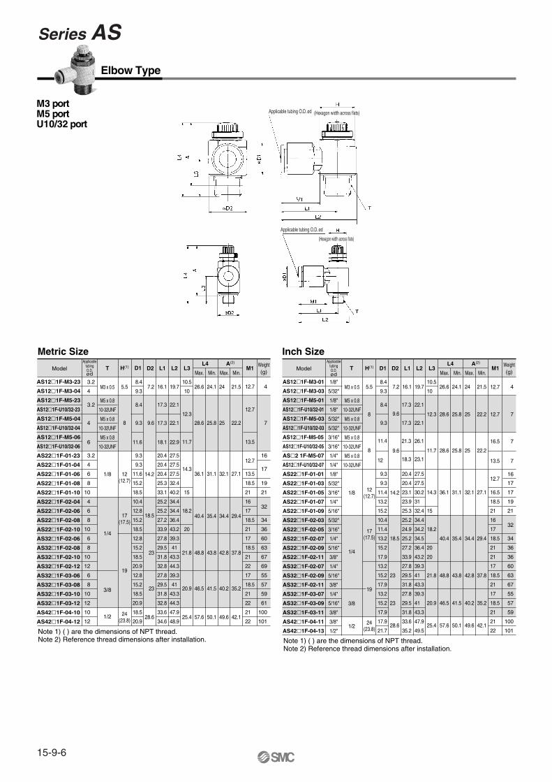
Series ASElbow Type/Universal Type
Speed Controller with One-touch Fitting
Note 1) ∗ Elbow type onlyNote 2) Meter-out and meter-in types can be visually differentiated by the lock nut.
The lock nut on the meter-out type is electroless nickel plated, while the meter-in type is black zinc chromate plated.
Note 3) Marking is electroless nickel plated, provided as standard. (N specificaitons)
Note 1) In the case of AS12�1F-M5, AS12�1F-U10/32, AS13�1F-M5, AS13�1F-U10/32Note 2) Use caution regarding the max. operating pressure when soft nylon or polyurethane tubing is used. (Refer to pages 15-6-3 to 15-6-5 for details.) Note 3) M3, M5, and 10-32UNF type ports are not available with seal. Note 4) Brass parts are all electroless nickel plated.
Be sure to read before handling. Refer to pages 15-18-3 to 15-18-4 for Safety Instructions and Common Precautions on the products mentioned in this catalog, and refer to pages 15-8-6 to 15-8-8 for Precautions on every series.
Sym
bol
Meter-out type Meter-in type
JIS
Sym
bol
Caution
Minimizes installation time and costReduces the mounting height and enables compact machinery design.Effective area is larger than the former model.
Tube swivels 360°Universal type permits 360° piping swivel.
Application to inch size tubing� Metric size (Release bushing: White color)
ø3.2, ø4, ø6, ø8, ø10, ø12� Inch size (Release bushing: Orange color)
ø1/8", ø5/32", ø3/16", ø1/4", ø5/16", ø3/8", ø1/2"
Maximum operating pressure1 MPa max.
Applicable tubing materialsNylon, soft nylon, and polyurethane tubing are applicable.
Retainer prevents accidental loss of needle.
OptionHexagonal lock nut, Nickel plated option
Number of needle rotations has been increased (8 to 10 turns)The increased number of needle rotations (8 to 10 turns) permits easy control at low speeds.
Flow Direction Symbols on Body

AS
ASP
ASN
AQ
ASV
AK
ASS
ASR
ASF
Speed Controller with One-touch FittingElbow Type/Universal Type
15-9-3
Series AS
How to Order
2 2 0 01 06 SAS 1F
Body sizeM3, M5 standard1/8, 1/4 standard
3/8 standard1/2 standard
1234
TypeElbow
Universal 23
Control type
With One-touch fitting
Meter-outMeter-in
01
Thread type
RUnified thread (10-32 UNF)
Metric thread (M3, M5)Nil
N
M3 x 0.5M5 x 0.8
10-32 UNF1/81/43/81/2
M5U10/32
01020304
M3
Port size
ø3.2ø4ø6ø8
ø10ø12
Metric size
∗Use ø1/8" tube.
0406081012
23
Applicable tubing O.D.
∗ ø1/8"ø5/32"ø3/16"ø1/4"ø5/16"ø3/8"ø1/2"
Inch size
030507091113
01
NoneWith seal
Hexagonal lock nutElectroless nickel plated
SKN
Nil
Option
∗ If more than one option is required, write option part numbers in the order of “S”, “K”, “N”.
Needle Valve/Flow Characteristics
NPT
Flo
w r
ate
(l/m
in (
AN
R))
Effe
ctiv
e ar
ea (
mm
2 )
Inlet pressure: 0.5 MPa
Number of needle rotations
Flo
w r
ate
(l/m
in (
AN
R))
Effe
ctiv
e ar
ea (
mm
2 )
Inlet pressure: 0.5 MPa
Number of needle rotations
Flo
w r
ate
(l/m
in (
AN
R))
Effe
ctiv
e ar
ea (
mm
2 )
Inlet pressure: 0.5 MPa
Number of needle rotations
Flo
w r
ate
(l/m
in (
AN
R))
Effe
ctiv
e ar
ea (
mm
2 )
Inlet pressure: 0.5 MPa
Number of needle rotations
Flo
w r
ate
(l/m
in (
AN
R))
Effe
ctiv
e ar
ea (
mm
2 )
Inlet pressure: 0.5 MPa
Number of needle rotations
Note) “-U10/32” is the same as “M5”.
Flo
w r
ate
(l/m
in (
AN
R))
Effe
ctiv
e ar
ea (
mm
2 )
Inlet pressure: 0.5 MPa
Number of needle rotations
AS1201F-M3, AS1211F-M3AS1301F-M3, AS1311F-M3
AS2201F-02, AS2211F-02AS2301F-02, AS2311F-02
AS3201F, AS3211FAS3301F, AS3311F
AS4201F, AS4211FAS4301F, AS4311F
AS1201F-M5, AS1211F-M5AS1301F-M5, AS1311F-M5
AS2201F-01, AS2211F-01AS2301F-01, AS2311F-01

Series AS
15-9-4
Elbow type Meter-out type
M3 portM5 portU10/32 port
M3 portM5 portU10/32 port
M3 portM5 portU10/32 port
M3 portM5 portU10/32 port
Universal typeMeter-out type
Meter-in typeMeter-in type
Construction

AS
ASP
ASN
AQ
ASV
AK
ASS
ASR
ASF
Speed Controller with One-touch FittingElbow Type/Universal Type
15-9-5
Series AS
No. Description Material NoteBody AHandleBody BNeedleNeedle guideSeat ringLock nutU-packingCassetteSealO-ringO-ringO-ringO-ringGasket
q
w
e
r
t
y
u
i
o
!0
!1
!2
!3
!4
!5
PBTPBT
Brass(1)
BrassBrassBrass
Brass(3)
HNBRPOM NBRNBRNBRNBRNBRNBR
Electroless nickel platedElectroless nickel platedElectroless nickel plated
Electroless nickel plated (4)
Component PartsNo. Description Material
Body AElbow bodyHandleBody BNeedleNeedle guideSeat ringLock nutU sealCassetteSealO-ringO-ringO-ringO-ringO-ringSpacerGasket
q
w
e
r
t
y
u
i
o
!0
!1
!2
!3
!4
!5
!6
!7
!8
PBTPBTPBT
Brass(1)
BrassBrassBrass
Brass(3)
HNBRPOM, Stainless steel
NBRNBRNBRNBRNBRNBR
PBT (5)
NBR, Stainless steel
Component Parts
Construction
Note 1) AS12�1F-M3 is made of stainless steel.Note 2) AS22�1F, AS32�1F-02: Electroless nickel plated.Note 3) AS2��1F type is made of steel.Note 4) Meter-in type is black zinc chromate plated.
Elbow typeMeter-out type
Universal typeMeter-out type
Meter-in type Meter-in type
Note
Electroless nickel platedElectroless nickel platedElectroless nickel plated
Electroless nickel plated(4)
Note 1) AS13�1F-M3 is made of stainless steel.Note 2) AS23�1F, AS33�1F-02: Electroless nickel plated.Note 3) AS2��1F type is made of steel. Note 4) Meter-in type is black zinc chromate plated.Note 5) ø3/16", ø3/8", ø1/2"are made of brass
AS13�1F (ø3.2, ø4, ø6, ø1/8", ø5/32, ø1/4), AS23�1F-�01(ø3.2, ø4, ø6, ø1/8", ø5/32) are POM.
AS3201F-02
AS3211F-02
AS3301F-02
AS3311F-02
(2)
(2)
Series AS
15-9-6
Elbow Type
Metric Size
Model
AS12�1F-M3-23
AS12�1F-M3-04
AS12�1F-M5-23
AS12�1F-U10/32-23
AS12�1F-M5-04
AS12�1F-U10/32-04
AS12�1F-M5-06
AS12�1F-U10/32-06
AS22�1F-01-23
AS22�1F-01-04
AS22�1F-01-06
AS22�1F-01-08
AS22�1F-01-10
AS22�1F-02-04
AS22�1F-02-06
AS22�1F-02-08
AS22�1F-02-10
AS32�1F-02-06
AS32�1F-02-08
AS32�1F-02-10
AS32�1F-02-12
AS32�1F-03-06
AS32�1F-03-08
AS32�1F-03-10
AS32�1F-03-12
AS42�1F-04-10
AS42�1F-04-12
5.5
8
12 (12.7)
17 (17.5)
12 (12.7)
19
24 (23.8) 24
(23.8)
14.2
18.5
23
23
28.6
7.2 16.1 19.7 26.6 24.1 24 21.5 48.4
9.3
10.5
1012.7
9.6
14.3 17
20.9
21.8
25.4
46.5
48.8
40.4
57.6
12.3
11.7
3.2
4
3.2
4
6
3.2
4
6
8
10
4
6
8
10
6
8
10
12
6
8
10
12
10
12
8.4
9.3
11.6
9.3
9.3
11.6
15.2
18.5
10.4
12.8
15.2
18.5
12.8 27.8
15.2
18.5
20.9
12.8
15.2
18.5
20.9
18.5
20.9
20.4 16
20.4
20.4 36.1
25.3
33.1
19
21
18.5
2115
25.2
25.2 18.2
27.2
33.9
16
1732
18.5
21
34
3620
29.5
31.8
32.8
27.8
29.5
31.8
32.8
33.6
34.6
17 60
18.5
21
22
17
18.5
21
22
21
22
63
67
69
55
57
59
61
100
101
17.3
17.3
18.1
22.1
22.1 28.6
41.5
43.8
35.4
50.1
31.1
25.8
40.2
42.8
34.4
49.6
32.1
25
35.2
37.8
29.4
42.1
27.1 13.5
22.2 7
22.9
39.3
27.5
27.5
27.5
32.4
40.2
34.4
34.4
36.4
43.2
41
43.3
44.3
39.3
41
43.3
44.3
47.9
48.9
12.7
13.5
12.7
T D1H(1) D2 L1 L2 L3 M1L4
Min. Max. Min.Max.
A(2) Weight(g)
M3 x 0.5
M5 x 0.8
10-32UNF
M5 x 0.8
10-32UNF
M5 x 0.8
10-32UNF
1/8
1/4
1/2
Note 1) ( ) are the dimensions of NPT thread.Note 2) Reference thread dimensions after installation. Note 1) ( ) are the dimensions of NPT thread.
Note 2) Reference thread dimensions after installation.
M3 portM5 portU10/32 port
3/8
Inch Size
Model
AS12�1F-M3-01
AS12�1F-M3-03
AS12�1F-M5-01
AS12�1F-U10/32-01
AS12�1F-M5-03
AS12�1F-U10/32-03
AS12�1F-M5-05
AS12�1F-U10/32-05
AS�2 1F-M5-07
AS12�1F-U10/32-07
AS22�1F-01-01
AS22�1F-01-03
AS22�1F-01-05
AS22�1F-01-07
AS22�1F-01-09
AS22�1F-02-03
AS22�1F-02-05
AS22�1F-02-07
AS22�1F-02-09
AS22�1F-02-11
AS32�1F-02-07
AS32�1F-02-09
AS32�1F-02-11
AS32�1F-03-07
AS32�1F-03-09
AS32�1F-03-11
AS42�1F-04-11
AS42�1F-04-13
ApplicabletubingO.D.ød
1/8"
5/32"
1/8"
1/8"
5/32"
5/32"
3/16"
3/16"
1/4"
1/4"
1/8"
5/32"
3/16"
1/4"
5/16"
5/32"
3/16"
1/4"
5/16"
3/8"
1/4"
5/16"
3/8"
1/4"
5/16"
3/8"
3/8"
1/2"
5.5
8
8
19
14.2 14.3
28.6
23
23
7.2 19.7 26.6 24.1 21.5 48.4
9.3
10.5
1012.7
9.6
9.6
25.4
21.8
57.6
48.8
12.3 28.6 25.8 22.2
8.4
9.3
11.4
12
9.3
9.3
11.4
10.4
11.4
13.2 18.5
15.2
17.9
13.2
15.2 41
17.9
13.2
15.2
17.9
17.9
21.7
27.5
17
17
16
19
21
27.5
30.2 36.1 31.1 27.1
11.7 28.6 25.8 22.2
13.2 31
15.2 32.4
34.4
34.2
16
1718.2
40.4
15
34.5 35.4 29.4
36.4 20
43.2
39.3
20
18.5
21
21
17
36
36
34
32
60
43.3
39.3
41
43.3
47.9
49.5
18.5 63
21
17
18.5
21
21
22
67
55
57
59
100
101
22.1
22.1
50.1
43.8
42.1
20.9 46.5 41.5
24
25
32.1
25
34.4
49.6
42.8
40.2 35.2
37.8
21
18.5
16.5
712.7
716.5
713.5
12.7
T M1Weight(g)
M3 x 0.5
M5 x 0.8
10-32UNF
M5 x 0.8
10-32UNF
M5 x 0.8
10-32UNF
M5 x 0.8
10-32UNF
1/8
1/4
3/8
1/2
D1 D2 L1 L2 L3L4
Min. Max. Min.Max.
16.1
29.5
20.4
20.4
23.1
25.2
24.9
25.2
27.2
33.9
27.8
31.8
27.8
29.5
31.8
33.6
35.2
23.9
25.3
17.3
17.3
26.1
23.1
21.3
18.3
17 (17.5)
H(1)A(2)
Applicable tubing O.D. ød
Applicable tubing O.D. ød
(Hexagon width across flats)
(Hexagon width across flats)
ApplicabletubingO.D.ød

AS
ASP
ASN
AQ
ASV
AK
ASS
ASR
ASF
Speed Controller with One-touch FittingElbow Type/Universal Type
15-9-7
Series AS
Universal Type
Metric Size
Model
AS13�1F-M3-23
AS13�1F-M3-04
AS13�1F-M5-23
AS13�1F-U10/32-23
AS13�1F-M5-04
AS13�1F-U10/32-04
AS13�1F-M5-06
AS13�1F-U10/32-06
AS23�1F-01-23
AS23�1F-01-04
AS23�1F-01-06
AS23�1F-01-08
AS23�1F-02-04
AS23�1F-02-06
AS23�1F-02-08
AS23�1F-02-10
AS33�1F-02-06
AS33�1F-02-08
AS33�1F-02-10
AS33�1F-02-12
AS33�1F-03-06
AS33�1F-03-08
AS33�1F-03-10
AS33�1F-03-12
AS43�1F-04-10
AS43�1F-04-12
5.5
8
12 (12.7)
12 (12.7)
17 (17.5)
17 (17.5)
24 (23.8)
24 (23.8)
19
14.2
18.5
23
23
28.6
7.228.3
24.1 244
5
8.4
9.3
9.6
18
28.7
3.2
4
3.2
4
6
3.2
4
6
8
4
6
8
10
6
8
10
12
6
8
10
12
10
12
8.4
9.3
11.6
8.4
9.3
11.6
15.2
10.4
12.8
15.2
18.5
12.8
15.2
18.5
20.9
12.8
15.2
18.5
20.9
18.5
21.7
17
21
36
33
32
4048.4
60
63
67
69
56
59
63
65
104
106
7.2
12.9
9.3
10.9
12.9
10.9
12.9
12.9
12.9
16.2
12.9
12.9
16.2
16.2
19.4
9.3
10.1
20.6
13.1
14
16.2
16.2
18.4
18.3
20.2
20.6
23
23
20.6
20.6
23
23
25.8
26.8
10.8
26.6
46.5
48.8
40.4
57.6
36.1
28.6
41.5
43.8
35.4
50.1
31.1
25.8
40
42.8
34.4
49.6
32.1
25
21.5
35
37.8
29.4
42.1
27.1
22.2 7
31.8
31.8
45.6
37.2
41.7
40.1
42.6
17.9
18.3
19.8
20.3
21.4
38.5
24.4
24.9
26.9
30.9
30.6
34
35.2
38.7
39.7
43.7
44.9
38.5
39.7
43.7
44.9
49.4
52
17.6
28.617.9
17.5
25.2
31
20.6
17.5
22.9
28.2
21.9
28.2
25.2
28.2
32.6
34.4
25.2
28.2
32.6
34.4
32.6
36.3
47
50
54.4
56.2
46.1
49.1
53.5
55.3
58
61.7
12.7
18.5
16
17
18.5
21
17
18.5
21
22
17
18.5
21
22
21
22
13.5
12.7
13.5
12.7
T D1H(1) D2 D3 L1 L2 L3 L4 M1L5
Min. Max. Min.Max.Weight(g) (g)
M3 x 0.5
M5 x 0.8
10-32UNF
M5 x 0.8
10-32UNF
M5 x 0.8
10-32UNF
1/8
1/4
1/2
3/8
Note 1) ( ) are the dimensions of NPT threadNote 2) Reference thread dimensions after installation.
Note 1) ( ) are the dimensions of NPT thread.Note 2) Reference thread dimensions after installation.
5
4
18
17
7
8
M3 portM5 portU10/32 port
Min. Max. Min.Max.
Inch Size
AS13�1F-M3-01
AS13�1F-M3-03
AS13�1F-M5-01
AS13�1F-U10/32-01
AS13�1F-M5-03
AS13�1F-U10/32-03
AS13�1F-M5-05
AS13�1F-U10/32-05
AS13�1F-M5-07
AS13�1F-U10/32-07
AS23�1F-01-01
AS23�1F-01-03
AS23�1F-01-05
AS23�1F-01-07
AS23�1F-01-09
AS23�1F-02-03
AS23�1F-02-05
AS23�1F-02-07
AS23�1F-02-09
AS23�1F-02-11
AS33�1F-02-07
AS33�1F-02-09
AS33�1F-02-11
AS33�1F-03-07
AS33�1F-03-09
AS33�1F-03-11
AS43�1F-04-11
AS43�1F-04-13
1/8"
5/32"
1/8"
1/8"
5/32"
5/32"
3/16"
3/16"
1/4"
1/4"
1/8"
5/32"
3/16"
1/4"
5/16"
5/32"
3/16"
1/4"
5/16"
3/8"
1/4"
5/16"
3/8"
1/4"
5/16"
3/8"
3/8"
1/2"
5.5
8
8
19
14.2
28.6
23
23
7.2 7.228.317.6
28.617.926.6 24.1 24 21.5
17.9
18.312.7
9.6
28.2 54.4
57.6
48.8
17.5 9.3 10.8
9.6 9.3 10.8
28.7 28.6 25.8 25 22.2
28.6 25.8 25 22.2
18.5
39.7
26.8 36.1 31.1 32.1 27.1
29.9
8.4
9.3
8.4
9.3
11.4
12
8.4
9.3
11.6
10.4
11.6
13.2
15.2
18.5
13.2
15.2
18.5
13.2
15.2
18.5
18.5
21.7
13.2
15.2 30.9
30.6
31.1
16
16.523.9 42.6
40.4
28.2 41.7
34.2 35.4 34.4 29.4
35.2 28.2 48.4
38.7
38.7
31 47
17
18.5
21
17
43.7
38.7
39.7
43.7
49.4
52
18.5
21
17
18.5
21
21
22
12.9
10.9
10.9
10.9
12.9
12.9
16.2
12.9
12.9
16.2
16.2
19.4
12.9
12.9
19.8
20.3
21.3
21.6
23.3
20.7
34.5
31.9
16.5
13.7
50.1
43.8
49.6
42.8
42.1
28.2 49.1 46.5 41.5 40.2 35.2
37.8
18.5
17
16.5
12.7
12.731.817.5 9.3 13.124.4
24.9
M3 x 0.5
M5 x 0.8
10-32UNF
M5 x 0.8
10-32UNF
M5 x 0.8
10-32UNF
M5 x 0.8
10-32UNF
1/8
1/4
3/8
1/2
10.1
20.6
14 31.823.9
16.2 40.121.9
16.2
18.3 45.625.6
18.3
20.2
20.6 5025.6
23
20.6
56.2
46.1
32.6
25.6
20.6
23 53.532.6
25.8
26.8
55.3
58
32.6
36.3
16.2 37.225.6
16.2
Model T D1 D2 D3 L1 L2 L3 L4 M1L5 Weight
19
21
32
33
36
39
40
60
63
69
56
59
65
104
106
H(1)A(2)A(2)
Applicable tubing O.D. ød
(Hexagon width across flats)
Applicable tubing O.D. ød
(Hexagon width across flats)
ApplicabletubingO.D.ød
ApplicabletubingO.D.ød

15-9-8
Speed controller with One-touch
fittings for metal body specifications
� Uses flame resistant resin as standard. (UL standard V-0)
Model
Model Port size
Applicable tubing O.D. Applicable cylinder
bore size (mm)
AS12�1-M5
AS22�1-01
AS22�1-02
AS32�1-03
AS42�1-04
M5 x 0.8
R
R
R
R
6, 10, 16, 20
20, 25, 32
20, 25, 32, 40
40, 50, 63
63, 80, 100
1 8
1 4
3 8
1 2
4 6 8 10 12
Tube size
With seal
0406081012
Thread sizeM501020304
JIS Symbol
How to Order
Control methodMeter-outMeter-in
0 With One-touch fitting
OptionNone
Hexagonal lock nutElectroless nickel plated
NilKN
1
F S K10 03 063 2AS
Speedcontroller
Elbow type
M5 standard01, 02 standard03 standard04 standard
1234
Body size
M5 x 0.8 R R R R
1 81 43 81 2
Construction
Fluid
Proof pressure
Max. operating pressure
Min. operating pressure
Ambient and fluid temperature
Number of needle rotations
Applicable tubing material
Option
Air
1.5 MPa
1 MPa
0.1 MPa
– 5 to 60°C (No freezing)
10 turns (8 turns (1))
Nylon, Soft nylon, Polyurethane
Hexagon lock nut, Electroless nickel plated (2)
Specifications
No.
Note 1) “AS22�1”: Electroless nickel platedNote 2) “AS22�1”: SteelNote 3) Meter-in type: Black zinc chromated
q
w
e
r
t
y
u
i
o
!0
!1
!2
!3
!4
!5
!6
MaterialZinc alloy
BrassBrassBrassBrass
Brass (2)
BrassPBT
PBT/Stainless steelNBRNBRNBRNBRNBRNBR
NBR/Stainless steel
NoteChromate plated
Electroless nickel platedElectroless nickel plated
Electroless nickel plated only with M5
Electroless nickel plated (3)
Electroless nickel plated
M5 port only
Component Parts
Note) marking is electroless nickel plated, provided as standard. (N specifications)
∗ If more than one option is required, write option part numbers in the or-der of “K”, “N”.
Meter-out and meter-in types can be visually differentiated by the lock nut.The lock nut on the meter-out type is electroless nickel plated while the meter-in type is black zinc chromate plated. Note 1) M5 sizeNote 2) Brass parts are all electroless nickel plated.
(1)
Speed Controller with One-touch Fitting
Series AS Elbow Type (Metal Body)
DescriptionBody ABody BNeedleNeedle guideSeat ringLock nutHandleBushingCassetteU-packingSealO-ringO-ringO-ringO-ringGasket
ø4ø6ø8
ø10ø12

Flow Rate and Effective Area
Needle Valve/Flow Characteristics
Dimensions
Model
Model
Note) Reference dimensions of thread M5, R after installation.
Applicable tubingO.D. ød
Controlled (Free) flowFlow rate (l /min (ANR))
Effective area (mm2)
ø6, ø8
230
3.5
ø4, ø6
100
1.5
AS22�1-01 AS22�1-02
ø8
790
12
ø6
390
6
ø8
460
7
ø10
920
14
ø10
1580
24
ø12
1710
26
AS32�1-03 AS42�1-04
2121.5
32.733.3
25.526
44.945.5
16171718.51718.518.5212122
12.712.533.730.756.352.192.987.6
153.8145.5
T
M5 x 0.8
R 1/8
R 1/4
R 3/8
R 1/2
H
8
12
17
19
24
D1
13
15.5
15.5
18.2
22.3
D2
9
14.6
19.5
24.3
28.5
L1
26.6
28.7
36.1
L2
33.9
38.5
50.4
L3
11.2
14.7
17.7
20.1
25.5
L4
28.3
36.4
40.8
46.9
55.6
A Note)
25.5
31.4
35.8
41.9
50.6
25
32.4
34.8
40.6
47.4
Max. Min. Max. Min.
22.2
27.4
29.8
35.6
42.4
M1Weight
(g)4668688
101012
AS12�1-M5
AS12�1-M5-F04AS12�1-M5-F06AS22�1-01-F06SAS22�1-01-F08SAS22�1-02-F06SAS22�1-02-F08SAS32�1-03-F08SAS32�1-03-F10SAS42�1-04-F10SAS42�1-04-F12S
Flo
w r
ate l/m
in (
AN
R)
Effe
ctiv
e ar
ea (
mm
2 )Inlet pressure: 0.5 MPa
Number of needle rotations
Flo
w r
ate l/m
in (
AN
R)
Effe
ctiv
e ar
ea (
mm
2 )
Inlet pressure: 0.5 MPa
Number of needle rotations
Flo
w r
ate l/m
in (
AN
R)
Effe
ctiv
e ar
ea (
mm
2 )
Inlet pressure: 0.5 MPa
Flo
w r
ate l/m
in (
AN
R)
Effe
ctiv
e ar
ea (
mm
2 )
Inlet pressure: 0.5 MPa
Flo
w r
ate l/m
in (
AN
R)
Effe
ctiv
e ar
ea (
mm
2 )
Inlet pressure: 0.5 MPa
Applicable tubingO.D. ød
(Hexagon width across flats)Applicable tubingO.D. ød
(Hexagon width across flats)
CautionBe sure to read before handling. Refer to pages 15-18-3 to 15-18-4 for Safety Instructions and Common Precautions on the products mentioned in this catalog, and refer to pages 15-8-6 to 15-8-8 for Precautions on every series.
Number of needle rotations
Number of needle rotations
Number of needle rotations
Tubing O.D.
15-9-9
Series ASSpeed Controller with One-touch FittingElbow Type (Metal Body)
AS
ASP
ASN
AQ
ASV
AK
ASS
ASR
ASF

Speed Controller with One-touch Fittings
Series AS In-line Type
Option∗None
Hexagonal lock nutElectroless nickel plated
∗ If more than one option is required, write option part numbers in the order of “K”, “N”.
NilKN
In-line type
Model
Model
Applicable tubing O.D.
Metric size Inch size
AS1001F
AS2001F
AS2051F
AS3001F
AS4001F
6,10, 16, 20
20, 25, 32
20, 25, 32, 40
40, 50, 63
63, 80, 100
18"3.2 4 6 8 10 12 5
32"3
16"1
4" 516"
38" 1
2"
How to Order
1F 12 K400AS
M5 standard1/8 standard1/4 standard3/8 standard1/2 standard
100200205300400
Body size
With One-touch fittings
Fluid
Proof pressure
Max. operating pressure
Min. operating pressure
Ambient and fluid temperature
Number of needle rotations
Applicable tubing material
Option
Air
1.5 MPa
1 MPa
0.1 MPa
–5 to 60°C (No freezing)
10 turns (8 turns(1))
Nylon, Soft nylon, Polyurethane
Hexagonal lock nut, Electroless nickel plated(3)
Specifications
Model
Metric size
Air flow �/min (ANR)
Effective area (mm2)
TubingO.D.
AS3001FAS2051F AS4001FAS2001FAS1001F
Flow Rate and Effective Area
Note 1) In the case of AS1001FNote 2) Use caution regarding the max. operating pressure when soft nylon or polyurethane tubing is used. (Refer to pages 15-6-3 to 15-6-5 for details.)Note 3) Brass parts are all electroless nickel plated.
Note) Flow rate values are measured at 0.5 MPa and 20°C.
Applicable cylinderbore size
(mm)
Note) Marking is electroless nickel plated, provided as standard. (N specifications)
(2)
Inch size
P. 15-11-3
ø12
1390
21
ø10
1050
16
ø6
420
6.5
ø8
660
10
ø10, ø12
920
14
ø6
290
4.5
ø8
460
7
ø4
130
2
ø6
230
3.5
ø3.2, ø4, ø6
100
1.5
ø1/8", ø5/32"ø3/16", ø1/4" ø5/32" ø3/16", ø1/4" ø3/16" ø1/4", ø5/16" ø1/4" ø5/16" ø3/8" ø3/8" ø1/2"
Sym
bol
JIS
Sym
bol
Flow Direction Symbols on Body
JIS Symbol
Minimizes installation time and costReduce the mounting height and enables compact machinery design. Effective area is larger than the former model.
Application to inch size tubing� Metric size (Release bushing: White color)
ø3.2, ø4, ø6, ø8, ø10, ø12� Inch size (Release bushing: Orange color)
ø1/8", ø5/32", ø3/16", ø1/4", ø5/16", ø3/8", ø1/2"
Maximum operating pressure1 MPa max.
Applicable tubing materialsNylon, soft nylon, and polyurethane tubing are applicable.
Retainer prevents accidental loss of needle.
OptionHexagonal lock nut,Nickel plated option
Number of needle rotations has been increased (8 to 10 turns)The increased number of needle rotations (8 to 10 turns) permits easy control at low speeds.
Controlled flow(Free flow)
Applicable tubing O.D.Metric size Inch size
ø3.2∗ø4ø6ø8
ø10ø12
230406081012
ø1/8"ø5/32"ø3/16"ø1/4"ø5/16"ø3/8"ø1/2"
∗ Use ø1/8" tube.
01030507091113
15-9-10

Needle Valve/Flow Characteristics
Flo
w r
ate
�/min
(A
NR
)
Effe
ctiv
e ar
ea (
mm
2 )
Inlet pressure: 0.5 MPa
Number of needle rotations
Flo
w r
ate
�/min
(A
NR
)
Effe
ctiv
e ar
ea (
mm
2 )
Inlet pressure: 0.5 MPa
Number of needle rotations
Flo
w r
ate
�/min
(A
NR
)
Effe
ctiv
e ar
ea (
mm
2 )
Inlet pressure: 0.5 MPa
Flo
w r
ate
�/min
(A
NR
)
Effe
ctiv
e ar
ea (
mm
2 )
Inlet pressure: 0.5 MPa
Flo
w r
ate
�/min
(A
NR
)
Effe
ctiv
e ar
ea (
mm
2 )
Inlet pressure: 0.5 MPa
CautionBe sure to read before handling. Refer to pages 15-18-3 to 15-18-4 for Safety Instructions and Common Precautions on the products mentioned in this catalog, and refer to pages 15-8-6 to 15-8-8 for Precautions on every series.
Number of needle rotations
Number of needle rotations
Number of needle rotations
15-9-11
Series ASSpeed Controller with One-touch FittingsIn-line Type
AS
ASP
ASN
AQ
ASV
AK
ASS
ASR
ASF

1/8"
5/32"
3/16"
1/4"
5/32"
3/16"
1/4"
3/16"
1/4"
5/16"
1/4"
5/16"
3/8"
3/8"
1/2"
8.4
9.3
11.4
12
9.3
11.4
13.2
11.4
13.2
15.2
13.2
15.2
17.9
17.9
21.7
38
39.2
48.7
40.7
40.7
50
52.2
52.2
54.4
59.8
59
64.4
70.8
76.9
83.1
4.5
5.2
5.2
6.2
7.1
6.2
7.1
8.1
7.4
8.2
9.5
10.3
11.6
23.5
24.2
32.6
33.6
34.5
34.6
35.5
36.5
38.3
39.1
40.3
51
52.4
20.7
21.4
27.6
28.6
29.5
29.6
30.5
31.5
33.3
34.1
35.3
43.5
44.9
6
7
12
9
12
18
21
24
26
31
42
46
53
97
106
16.5
13.7
12.7
16.5
17
16.5
17
18
17
18
21
21
22
12.710
10 6.2 25.2 22.4
11.8
19.8
26.5
14.8
Construction
In-line Type
Component PartsNo. q
w
e
r
t
y
u
i
o
!0
!1
DescriptionBody AHandleBody BNeedleNeedle guideLock nutU sealSpacerCassettePackingO-ring
PBTPBT
BrassBrassBrass
Brass(1)
HNBRPBT(2)
POM, Stainless steelNBRNBR
Electroless nickel platedElectroless nickel platedElectroless nickel platedElectroless nickel plated
Material Note
Metric Size
82 11.3
13.5
12.7
13.5
17
18
17
18
21
22
21
22
12.710
11.8
19.8
26.5
14.8
ModelWeight
D1 D2 L1 L2 M1L3
Max. Min. (g)Model
Weight D1 D2 L1 L2 M1
L3
Max. Min. (g)
Note 1) AS2��1F type is made of steel.Note 2) ø3/16", ø3/8", ø1/2" are made of brass.
AS1001F (ø3.2, ø4, ø6, ø1/8", ø5/32", ø1/4"), AS2001F (ø4, ø6, ø5/32") are POM.
Inch Size
AS1001F-23
AS1001F-04
AS1001F-06
AS2001F-04
AS2001F-06
AS2051F-06
AS2051F-08
AS3001F-06
AS3001F-08
AS3001F-10
AS3001F-12
AS4001F-10
AS4001F-12
3.2
4
6
4
6
6
8
6
8
10
12
10
12
8.4
9.3
11.6
9.3
11.6
12.8
15.2
12.8
15.2
18.5
20.9
18.5
20.9
38.0
39.2
40.7
40.7
44.8
53.2
59.8
59
64.4
71.6
76
4.5
5.2
6.2
5.2
6.3
6.7
8.1
7.4
8.2
9.8
11
23.5
24.2
25.2
32.6
33.7
35.2
36.5
38.3
39.1
40.6
41.8
51.1
52.1
20.7
21.4
22.4
27.6
28.7
30.2
31.5
33.3
34.1
35.6
36.8
43.6
44.6
6
7
8
12
13
26
31
18
21
32
33
36
40
AS1001F-01
AS1001F-03
AS1001F-05
AS1001F-07
AS2001F-03
AS2001F-05
AS2001F-07
AS2051F-05
AS2051F-07
AS2051F-09
AS3001F-07
AS3001F-09
AS3001F-11
AS4001F-11
AS4001F-13
Applicable tubing O.D. ød
ApplicabletubingO.D.ød
ApplicabletubingO.D.ød
Series AS
15-9-12

Related Products:Holder
Series TMH
Note) Mounting bracket is not available.This is an application example.
Ambient temperature
Material
Applicable tubing
–20 to 60°C
Polypropylene
WhiteColor
Accessory: Round head Phillips screw for mounting (Black zinc chromated).
SpecificationsA holder for securing a speedcontroller (In-line type) with One-touch fitting.Universal mounting
Dimensions
Correspondence of In-line Speed Controller and Holder
Metric Size
ModelModel Size
(Nominal x Height)Piece
1
Metric size Inch sizeTMH-23JTMH-04JTMH-06JTMH-06
TMH-10TMH-12
TMH-01JTMH-03JTMH-05TMH-07TMH-09TMH-11TMH-13
Model
Metric size Inch size
TMH-23JTMH-04J
TMH-06JTMH-06
TMH-08 TMH-10
TMH-12
AS1001FAS2001FAS2051FAS3001FAS4001F
TMH-01JTMH-03JTMH-05
TMH-07 TMH-09
TMH-11
TMH-13
ø3.2TMH-23J
TMH-04J TMH-06J
TMH-06 TMH-08
TMH-10 TMH-12
ø4 ø6 ø8 ø10 ø1223 04 06 08 10 12
øD2øD1 H1 H2 H3 H4 H5 L1 L2 L3 Symbol
8.4 9.311.711.613.113.515.518.818.221.222
1/8J1/32J3/16
61/48
5/16103/8121/2
M3 x 15
M4 x 25
M4 x 35
M3 x 20
3.3
3.3
4.3
4.3
4.5
6.3
7.1
9.5
4.6
6.4
7.2
9.6
7.5
9.3
11
14
6
7.7
10
14
12
15.4
20
28
7.2
8.5
11
14.2
6.6
8.3
10.6
14.6
18
21
26.5
34
Body size
Applicable tubing
Inch Size
AS1001FAS2001FAS2051FAS3001FAS4001F
ø1/8" ø5/32" ø3/16" ø1/4" ø5/16" ø3/8" ø1/2"01 03 05 07 09 11 13
TMH-01JTMH-03J
TMH-05TMH-07
TMH-09
TMH-11TMH-13
Body size
Applicable tubing
size
Applicable tubing
size
TMH-08
Adaptable for the manifold application. Note)
Can be mounted on the panel.
through
The holder can be used to secure an individual part.
15-9-13
AS
ASP
ASN
AQ
ASV
AK
ASS
ASR
ASF

Model
Specifications
Dual Speed Controller with One-touch Fitting
Series ASD
Flow Rate and Effective Area
ASD230F-M5ASD330F-01ASD430F-02ASD530F-02ASD530F-03ASD630F-04ASD230F-U10/32ASD330F-N01ASD430F-N02ASD530F-N02ASD530F-N03ASD630F-N04
M5 x 0.8
R 1/8
R 1/4
R 1/4
R 3/8
R 1/2
10-32 UNF
NPT 1/8
NPT 1/4
NPT 1/4
NPT 3/8
NPT 1/2
Part no. Port size
Applicable tubing O.D.Metric size Inch size
ø4
�
ø6
�
�
�
�
�
ø8
�
�
�
�
ø10
�
�
�
�
ø12
�
�
�
ø1/8"
�
ø5/32"
�
ø3/16"
�
�
ø1/4"
�
�
�
�
�
ø5/16"
�
�
�
�
ø3/8"
�
�
�
�
Fluid
Proof pressure
Max. operating pressure
Min. operating pressure
Ambient and fluid temperature
Number of needle rotations
Applicable tubing material (2)
Option
Air
1.5 MPa
1 MPa
0.1 MPa
–5 to 60°C (No freezing)
10 turns (8 turns (1))
Nylon, Soft nylon, Polyurethane
Hexagonal lock nut
Note 1) In the case of ASD230F typeNote 2) Use caution regarding the max. operating pressure when soft nylon or polyurethane
tubing is used. (Refer to pages 15-6-3 to 15-6-5 for details.)
Note) Flow rate values are measured at 0.5 MPa and 20°C.
Model
Tubing O.D.
Controlled flow(Free flow)
Metric size
Inch size
Flow rate l /min (ANR){N R/min}
Effective area (mm2)
ASD230F ASD330F ASD430F ASD530F ASD630F
ø4, ø6
75
1.1
ø6, ø8
175
2.7
ø6
— —
295
4.5
ø8, ø10
ø1/8"ø5/32"ø3/16"ø1/4"
ø3/16"ø1/4"
ø1/4"ø5/16"ø3/8"
350
5.3
ø6 ø8 ø10, ø12 ø10 ø12
ø1/4" ø5/16" ø3/8" ø3/8"
500 600 700 1200 1300
7.6 9.1 10.7 18.3 19.8
JIS Symbol
Flow Direction Symbols on Body
Meter-out type Meter-in type
Sym
bol
JIS
Sym
bol
Enables bi-directional flow control. Unrestricted 360° tube mounting
15-9-14

How to Order
23456
M5 standard1/8 standard1/4 standard3/8 standard1/2 standard
Body size
Type
With One-touch fitting
Thread type
3 Universal
NilMetric thread (M5)
Unified thread (10-32 UNF)R
NPT
Bore size
With seal
Option
M5U10/32
01020304
M5 x 0.810-32 UNF
1/81/43/81/2
NilK
NoneHexagonal lock nut
Applicable tubing O.D.Metric size Inch size
0406081012
ø4ø6ø8
ø10ø12
010305070911
ø1/8"ø5/32"ø3/16"ø1/4"ø5/16"ø3/8"
Needle Valve/Flow Characteristics (Inlet Pressure: 0.5 MPa)
ASD230F ASD330F ASD430F
ASD530F ASD630F
100
50
05 10
1.5
1.0
0.5
0
Number of needle rotations
Flo
w r
ate
(l/m
in (
AN
R))
Effe
ctiv
e ar
ea (
mm
2 )
200
05 10
3
2
1
0
Number of needle rotations
Flo
w r
ate
(l/m
in (
AN
R))
Effe
ctiv
e ar
ea (
mm
2 )
100
400
05 10
6
4
2
0
Number of needle rotations
Flo
w r
ate
(l/m
in (
AN
R))
Effe
ctiv
e ar
ea (
mm
2 )
100
200
300 06
07, 08, 09, 10, 11
1500
05 10
20
15
10
0Flo
w r
ate
(l/m
in (
AN
R))
Effe
ctiv
e ar
ea (
mm
2 )
500
10,1112
1000
5
Number of needle rotations
05 10
14
10
8
0Flo
w r
ate
(l/m
in (
AN
R))
Effe
ctiv
e ar
ea (
mm
2 )
500
1000
2
Number of needle rotations
12
6
4
06,07
10,11,1208,09
N
ASD 3 30F 01 06 S K
15-9-15
Dual Speed Controller with One-touch Fitting Series ASD
AS
ASP
ASN
AQ
ASV
AK
ASS
ASR
ASF

7.8
10.6
11
15.4
14
18.6
M5 x 0.8
R 1/8
R 1/4
R 1/4
R 3/8
R 1/2
8
12
17
19
19
24
4
6
6
8
6
8
10
6
8
10
12
6
8
10
12
10
12
9.3
11.6
11.6
15.2
12.8
15.2
18.5
12.8
15.2
18.5
20.9
12.8
15.2
18.5
20.9
18.5
20.9
9.6
14.2
18.5
23
23
28.6
10
11.8
15
19.8
19.8
26.5
11.7
14
15.8
18
19.7
20.3
23.1
20.3
23.1
25.9
29.4
32.5
38.5
44.8
43.5
46.5
49.3
48.3
51.3
54.1
55.9
48.3
51.3
54.1
55.9
64.3
66.1
17.5
20.6
22.9
28.2
25.2
28.2
31
25.2
28.2
32.6
34.4
25.2
28.2
32.6
34.4
32.6
34.4
28.3
39.6
38.9
41.7
46.9
46.9
64.8
25.5
34.6
33.9
36.7
41.9
41.9
57.3
28.6
36.1
40.4
48.8
46.5
57.6
25.8
31.1
35.4
43.8
41.5
50.1
25
32.1
34.4
42.8
40
49.6
22.2
27.1
29.4
37.8
35
42.1
12.9
13.7
13.7
18.5
17
18.5
21
17
18.5
21
22
17
18.5
21
22
21
22
12
13
29
31
53
55
58
74
76
80
83
74
93
98
101
177
179
Dimensions: Metric Size
d T H D1 D2 D3 L1 L2 L3Model
ASD230F-M5-04
ASD230F-M5-06
ASD330F-01-06S
ASD330F-01-08S
ASD430F-02-06S
ASD430F-02-08S
ASD430F-02-10S
ASD530F-02-06S
ASD530F-02-08S
ASD530F-02-10S
ASD530F-02-12S
ASD530F-03-06S
ASD530F-03-08S
ASD530F-03-10S
ASD530F-03-12S
ASD630F-04-10S
ASD630F-04-12S
L4 L5 A1∗A2∗ M
Max. Min. Max. Max.Min. Min.Weight
(g)
Applicable tubing O.D. ød
L2L3
M
L4L
1
L5 A1
A2
øD
3
øD
1
T
øD2
∗ Reference dimensions of M5 x 0.8, R threads after installation.
ASD230F
Metric Size
Applicable tubing O.D. ød
L2L3
M
L1
L4
T
L5 A1
A2
øD
3
øD
1
øD2
ASD330F/430FASD530F/630F
H(Hexagon width across flats)
H(Hexagon width across flats)
Series ASD
15-9-16

10-32UNF
NPT 1/8
NPT 1/4
NPT 1/4
NPT 3/8
NPT 1/2
7.8
10.6
11
15.4
14
18.6
d T H D1 D2 D3 L1 L2 L3Model
ASD230F-U10/32-01
ASD230F-U10/32-03
ASD230F-U10/32-05
ASD230F-U10/32-07
ASD330F-N01-05S
ASD330F-N01-07S
ASD330F-N01-09S
ASD430F-N02-07S
ASD430F-N02-09S
ASD430F-N02-11S
ASD530F-N02-07S
ASD530F-N02-09S
ASD530F-N02-11S
ASD530F-N03-07S
ASD530F-N03-09S
ASD530F-N03-11S
ASD630F-N04-11S
8
12.7
17.5
19
19
23.8
1/8"
5/32"
3/16"
1/4"
3/16"
1/4"
5/16"
1/4"
5/16"
3/8"
1/4"
5/16"
3/8"
1/4"
5/16"
3/8"
3/8"
8.4
9.3
11.4
12
11.6
13.2
15.2
13.2
15.2
18.5
13.2
15.2
18.5
13.2
15.2
18.5
9.6
14.2
18.5
23
23
28.6
10
11.8
15
19.8
19.8
26.5
11.7
14
15.8
18
19.7
20.3
23.1
20.3
23.1
25.9
29.4
39.5
42.2
44.8
43.9
46.5
49.3
48.7
51.3
54.1
48.7
51.3
54.1
64.3
17.5
23.9
25.6
28.2
25.6
28.2
31
25.6
28.2
32.6
25.6
28.2
32.6
28.3
39.6
38.9
41.7
46.9
46.9
64.8
25.5
34.6
33.9
36.7
41.9
41.9
57.3
28.6
36.1
40.4
48.8
46.5
57.6
25.8
31.1
35.4
43.8
41.5
50.1
25
32
34.6
43
40.3
49.6
22.2
27
29.6
38
35.3
42.1
12.9
16.5
17
18.5
17
18.5
21
17
18.5
21
17
18.5
21
L4 L5 A1∗A2∗ M
Max. Min. Max. Max.Min. Min.Weight
(g)
∗ Reference dimensions of U10/32 and NPT threads after installation.
Inch Size
Applicable tubing O.D. ød
L2L3
M
L4
L1
L5 A1
A2
øD
3
øD
1
T
øD2
øD2
ASD230FApplicable tubing O.D. ød
L2L3
M
L1
L4
T
L5 A1
A2
øD
3
øD
1
ASD330F/430FASD530F/630F
12
13
30
31
55
62
76
84
93
102
180
Dimensions: Inch Size
10-32UNF
8 9.6 10 11.7 28.3 25.5 28.6 25.8 25 22.235.2
32.6
23.3
20.7 7.8
16.5
13.5
15
13
H(Hexagon width across flats)
H(Hexagon width across flats)
15-9-17
Dual Speed Controller with One-touch Fitting Series ASD
AS
ASP
ASN
AQ
ASV
AK
ASS
ASR
ASF

Construction
Component PartsNo.q
w
e
r
t
y
u
i
o
!0
Body AElbow bodyHandleBody BBody BNeedleSeat ringNeedle guideLock nutLock nut
MaterialPBTPBTPBT
BrassBrassBrassBrassBrass
Brass(3)
Brass(3)
Note
Electroless nickel platedElectroless nickel platedElectroless nickel platedElectroless nickel platedElectroless nickel platedElectroless nickel platedBlack zinc chromate plated
Description No.!1
!2
!3
!4
!5
!6
!7
!8
!9
@0
@1
MaterialHNBRHNBR
POM, Stainless steel (1)
NBRNBRNBRNBRNBRNBR
Stainless steel, NBRPBT, Brass (2)
NoteDescriptionU sealU sealCassetteSealO-ringO-ringO-ringO-ringO-ringGasketSpacer
ASD230F only
!8 w @1 !4 !3
r i o e y !5 !6 !0
!7 @0 !1 q !2 t
r eo y !5 !6 q
!7 !0!1 i!2 tu
!8 w @1 !4 !3
ASD230F ASD330F/430FASD530F/630F
yi o e u r!9q
!6 !5 !7 !2 t !0!1
!8 w @1 !4 !3
ASD530F-02
Note 1) ø10, ø12, ø3/16", ø3/8" are made of POM, stainless steel and brass (Electroless nickel plated).
Note 2) ø3/16", ø1/4", ø3/8" are made of brass(Electroless nickel plated).
ASD230F (ø4, ø6, ø1/8", ø5/32", ø1/4"), ASD330F (ø6) are POM.Note 3) ASD330F and 430F types are made of steel.
Series ASD
15-9-18

ModelModel Applicable tubing O.D.
Metric size Inch sizeElbow type
AS22�IF-U01
AS22�IF-U02
AS32�IF-U02
AS32�IF-U03
AS42�IF-U04
AS23�IF-U01
AS23�IF-U02
AS33�IF-U02
AS33�IF-U03
AS43�IF-U04
Universal type
Con
nect
ion
thre
adU
ni th
read
18
14
14
38
12
183.2 4
�
6
�
�
8
�
�
10
�
�
12
�
�
�
�
� �
�
�
�
�
�
�
� �
" 532" 3
16" 14" 5
16" 38" 1
2"∗
Note 1) ∗ Elbow type onlyNote 2) � indicates the control type (“0” for meter-out and “1” for meter-in).Note 3) Models marked with “ ” are nickel plated as standard.
SpecificationsFluid
Max. operating pressure
Min. operating pressure
Proof pressure
Ambient and fluid temperature
Number of needle rotations
Applicable tubing material (1)
Mounting thread
Thread seal
Option
Air
1 MPa
0.1 MPa
1.5 MPa
–5 to 60°C (No freezing)
10 turns
Nylon, Soft-nylon, Polyurethane
Uni-thread
Gasket
Hexagon lock nut, Nickel plated (2)
Note 1) Use caution regarding the max. operating pressure when soft nylon or polyurethane tubing is used. (Refer to pages 15-6-3 to 15-6-5 for details.)
Note 2) Brass parts are all electroless nickel plated.
Flow Rate and Effective Area
AS22�IF-U01AS23�IF-U02
AS42�IF-U04AS43�IF-U04
AS22�IF-U02AS23�IF-U02
AS32�IFAS33�IF
Model
Tubing O.D.
Controlled flow(Free flow)
Metric size
Inch size
Effective area(mm2)
Flow rate (�/min (ANR))
ø3.2ø4
ø10ø12
18"
532"
180
2.7
ø4
532"
260
4
ø6
14"
660
10
ø8
516"
790
12
ø10
38" "
1580
24
ø12
12
1710
26
38"
920
14
ø6
316"
390
6
ø6, ø8ø4
316" 1
4"5
16"
,
230
3.7
ø8, ø10
14" 5
16"3
8"
,
460
7
Note 1) Flow rate values are measured at 0.5 MPa and 20°C.Note 2) � indicates the control type (“0” for meter-out and “1” for meter-in).
Shape of Uni thread ridgeUse of the chamfered surface of the famale thread as the seat surface and adoption of gaskets made by laminating NBR on both surfaces of stainless steel plates achieve secure seal ing regardless of the difference of diameters due to the female thread type, deviations due to the tolerance, or the size of the chamfered corner.(Any standard chamfered female thread can be used.)
A ridge shape has been created as a Uni thread for common applications for Rc, G, NPT and NPTF.
The male thread for pip-ing drastically cuts piping man-hours.
JIS Symbol
New-stand male threads for piping that reduces the screw-in time by 1/3.
Sym
bol
Meter-out type Meter-in type
JIS
Sym
bol
Flow Direction Symbols on Body
Gasket
Uni thread
Female thread
°
Speed Controller with Uni One-touch Fitting
Series ASElbow Type/Universal Type
15-9-19
AS
ASP
ASN
AQ
ASV
AK
ASS
ASR
ASF

How to Order
2 2 1 U02 06 KAS 1F
Body size1/8, 1/4 standard
3/8 standard 1/2 standard
234
TypeElbow
Universal 23
Control type
With One-touch fitting
Meter-outMeter-in
01
U01U02U03U04
Bore size
ø3.2∗
ø4 ø6 ø8ø10ø12
∗ Use ø1/8" tube.
0406081012
23
Applicable tubing O.D.Metric size Inch size
030507091113
01
NoneHexagonal lock nut
Electroless nickel plated
KN
Nil
Option∗
∗ If more than one option is required, write option part numbers in the order of “K”, “N”.
Needle Valve/Flow Characteristics
18
14
38
12
18"
532"
316"
14"
516"
38"
12"
Flo
w r
ate
(�/m
in (
AN
R))
Effe
ctiv
e ar
ea (
mm
2 )
Inlet pressure: 0.5 MPa
Number of needle rotations
Flo
w r
ate
(�/m
in (
AN
R))
Effe
ctiv
e ar
ea (
mm
2 )
Inlet pressure: 0.5 MPa
Number of needle rotations
Flo
w r
ate
(�/m
in (
AN
R))
Effe
ctiv
e ar
ea (
mm
2 )
Inlet pressure: 0.5 MPa
Number of needle rotations
Flo
w r
ate
(�/m
in (
AN
R))
Effe
ctiv
e ar
ea (
mm
2 )
Inlet pressure: 0.5 MPa
Number of needle rotations
AS2201F-01, AS2211F-01AS2301F-01, AS2311F-01
AS2201F-02, AS2211F-02AS2301F-02, AS2311F-02
AS3201F, AS3211FAS3301F, AS3311F
AS4201F, AS4211FAS4301F, AS4311F
Series AS
15-9-20

No. Description Material NoteBody AHandleBody BNeedleGasketSeat ringLock nutU sealCassetteSealO-ringO-ringO-ring
q
w
e
r
t
y
u
i
o
!0
!1
!2
!3
PBTPBT
BrassBrass
Stainless steel, NBRBrass
Brass(2)
HNBRPOM, Stainless steel
NBRNBRNBRNBR
Electroless nickel platedElectroless nickel plated
Electroless nickel plated(3)
Component Parts: Elbow TypeNo. Description Material
Body AElbow bodyHandleBody BNeedleGasketSeat ringLock nutU sealCassetteSealO-ringO-ringO-ringO-ringSpacer
q
w
e
r
t
y
u
i
o
!0
!1
!2
!3
!4
!5
!6
PBTPBTPBT
BrassBrass
Stainless steel, NBRBrass
Brass(2)
HNBRPOM, Stainless steel
NBRNBRNBRNBRNBR
PBT(4)
Component Parts: Universal Type
Construction/Component Parts
Note 1) Only AS22�1F-U01 and AS32�1F-U02 are electroless nickel plated.Note 2) AS22�1F type is made of steel.Note 3) Meter-in type is black zinc chromate plated.
Elbow type Meter-out type
Universal type Meter-out type
Meter-in type Meter-in type
Note
Electroless nickel platedElectroless nickel plated
Electroless nickel plated(3)
w
u
ty
q
i
e
o r!0
!2!3
!1
!4
!6!1woe
tiy
u!4!5!2qo
!7r!3
(1)
(1)
Note 1) Only AS22�1F-U01and AS32�1F-U02 are electroless nickel plated.Note 2) AS22�1F type is made of steel.Note 3) Meter-in type is black zinc chromate plated.Note 4) ø3/16", ø3/8", and ø1/2" are made of brass. AS23�1F-U01(ø3.2, ø4, ø6, ø1/8 and ø5/32) are made of POM.
15-9-21
Series ASSpeed Controller with Uni One-touch FittingElbow Type/Universal Type
AS
ASP
ASN
AQ
ASV
AK
ASS
ASR
ASF

ModelApplicable
tubing O.D. ød
TUni thread
H D1 D2 L1 L2 L3L4 A∗
Max. Min. Max. Min.M Weight
(g)AS22�1F-U01-23AS22�1F-U01-04AS22�1F-U01-06AS22�1F-U01-08AS22�1F-U01-10AS22�1F-U02-04AS22�1F-U02-06AS22�1F-U02-08AS22�1F-U02-10AS32�1F-U02-06AS32�1F-U02-08AS32�1F-U02-10AS32�1F-U02-12AS32�1F-U03-06AS32�1F-U03-08AS32�1F-U03-10AS32�1F-U03-12AS42�1F-U04-10AS42�1F-U04-12
3.2 4 6 810 4 6 810 6 81012 6 810121012
12
17
19
19
24
7.88.9
11.015.218.58.9
11.015.218.511.015.218.520.911.015.218.520.918.520.9
14.2
18.5
23.0
23.0
28.6
20.821.122.525.333.123.323.927.233.926.429.531.832.826.429.531.832.833.634.6
27.928.229.632.440.232.533.136.443.237.941.043.344.337.941.043.344.347.948.9
14.3
15.0
17.2
20.3
19.4
22.4
19
36.1 31.1 30.5 25.5
39.4 34.4 32.0 26.6
45.9 40.9 38.1 33.1
45.0 40.0 37.6 32.6
54.6 47.1 44.5 37.0
14.5
15.518.521.014.515.518.521.015.518.521.022.015.518.521.022.021.022.0
16.116.216.519.020.931.131.333.635.552.554.956.858.452.554.956.858.493.795.0
18
14
14
38
12
∗ Reference dimensions of Uni thread after installation.
ModelT
Uni threadH D1 D2 L1 L2
L5 A∗Max. Min. Max. Min.
M
AS23�1F-U01-23AS23�1F-U01-04AS23�1F-U01-06AS23�1F-U01-08AS23�1F-U02-04AS23�1F-U02-06AS23�1F-U02-08AS23�1F-U02-10AS33�1F-U02-06AS33�1F-U02-08AS33�1F-U02-10AS33�1F-U02-12AS33�1F-U03-06AS33�1F-U03-08AS33�1F-U03-10AS33�1F-U03-12AS43�1F-U04-10AS43�1F-U04-12
3.2 4 6 8 4 6 810 6 81012 6 810121012
12
17
19
19
24
7.88.9
11.015.28.9
11.015.218.511.015.218.520.911.015.218.520.918.520.9
14.29.3 13.4 24.8 18.9 33.2
12.9
16.2
18.5
23.0
23.0
28.6
14.516.215.616.718.319.618.920.622.523.518.920.622.523.525.326.8
D3
10.912.9
9.310.9
27.130.929.231.435.238.135.939.743.345.535.939.743.345.548.951.6
L3
20.624.718.920.624.426.820.624.428.329.320.624.428.329.328.330.8
L4
34.938.236.137.840.843.242.543.748.649.641.642.847.748.750.753.2
36.1 31.1 30.5 25.5
39.4 34.4 32.0 26.6
45.9 40.9 38.1 33.1
45.0 40.0 37.6 32.6
54.6 47.1 44.5 37.0
14.5
15.518.514.515.518.521.015.518.521.022.015.518.521.022.021.022.0
16.917.017.720.931.732.435.739.253.656.960.462.253.656.960.462.297.199.8
18
14
14
38
12
10.912.9
16.2
10.912.9
16.219.4
∗ Reference dimensions of Uni thread after installation.
Universal Type/Metric Size
Connecting thread T
H
L3
D1
ML1
L2
D2A
L4
Applicable tubing O.D. ød
HD1
D2L2L1
D3
L5
L4A
L3M
Connecting thread T
Applicable tubing O.D. ød
Elbow Type/Metric Size
(Hexagon width across flats)
(Hexagon widthacross flats)
Applicabletubing O.D.
ød
Weight(g)
Series AS
15-9-22

Elbow Type/Inch Size
Model Applicable tubingO.D.ød
TUni thread
H D1 D2 L1 L2 L3L4 A∗
Max. Min. Max. Min.M Weight
(g)AS22�1F-U01-01AS22�1F-U01-03AS22�1F-U01-05AS22�1F-U01-07AS22�1F-U01-09AS22�1F-U02-03AS22�1F-U02-05AS22�1F-U02-07AS22�1F-U02-09AS22�1F-U02-11AS32�1F-U02-07AS32�1F-U02-09AS32�1F-U02-11AS32�1F-U03-07AS32�1F-U03-09AS32�1F-U03-11AS42�1F-U04-11AS42�1F-U04-13
12
17
19
19
24
7.88.9
11.413.215.28.9
11.413.215.217.913.215.217.913.215.217.917.921.4
14.2
18.5
23.0
23.0
18.6
20.821.123.123.925.323.324.925.227.233.927.829.531.827.829.531.833.635.2
27.928.230.231.032.432.534.234.536.443.239.341.043.339.341.043.347.949.5
14.3
17.2
20.3
19.4
22.4
19
36.1 31.1 30.5 25.5
39.4 34.4 32.0 26.6
45.9 40.9 38.1 33.1
45.0 40.0 37.6 32.6
54.6 47.1 44.5 37.0
14.5
16.517.018.514.516.517.018.521.017.018.521.017.018.521.021.022.0
16.116.217.518.119.031.132.432.933.635.353.954.956.653.954.956.693.695.4
18
14
14
38
12
18"
532"
316"
14"
516"
532"
316"
14"
516"
38"
14"
516"
38"
38"
14"
516"
38"
12"
Model Applicable tubingO.D.øD
TUni thread
H D1 D2 L1 L2L5 A∗
Max. Min. Max. Min.M
Weight(g)
AS23�1F-U01-01AS23�1F-U01-03AS23�1F-U01-05AS23�1F-U01-07AS23�1F-U01-09AS23�1F-U02-03AS23�1F-U02-05AS23�1F-U02-07AS23�1F-U02-09AS23�1F-U02-11AS33�1F-U02-07AS33�1F-U02-09AS33�1F-U02-11AS33�1F-U03-07AS33�1F-U03-09AS33�1F-U03-11AS43�1F-U04-11AS43�1F-U04-13
12
17
19
19
24
7.88.9
11.413.215.28.9
11.413.215.217.913.215.217.913.215.217.917.921.7
14.2
9.3
12.9
13.4 24.8 18.9 33.2
18.5
23.0
23.0
28.6
14.215.216.215.616.417.418.319.619.620.622.519.620.622.525.326.8
D3
10.311.412.9
9.310.311.4
27.028.930.929.231.133.235.238.137.739.742.937.739.742.948.652.5
L3
21.522.324.718.921.522.324.426.822.324.428.322.324.428.328.330.8
L4
35.936.338.236.138.839.540.843.244.243.748.643.342.847.750.753.2
36.1 31.1 30.5 25.5
39.4 34.4 32.0 26.6
45.9 40.9 38.1 33.1
45.0 40.0 37.6 32.6
54.6 47.1 44.5 37.0
14.5
16.517.018.514.516.517.018.529.417.018.521.017.018.521.021.122.0
16.917.018.619.420.931.733.233.935.739.055.456.960.255.456.960.296.499.9
18
14
14
38
12
11.412.916.211.412.916.216.219.4
18"
532"
316"
14"
516"
532"
316"
14"
516"
38"
14"
516"
38"
14"
516"
38"
38"
12"
∗ Reference dimensions of Uni thread after installation.
Universal Type/Inch Size
Connecting thread T
H
L3
D1
ML1
L2
D2A
L4
Applicable tubing O.D. ød
HD1
D2L2L1
D3
L5
L4A
L3M
Connecting thread T
Applicable tubing O.D. ød
(Hexagon width across flats)
(Hexagon widthacross flats)
15-9-23
Series ASSpeed Controller with Uni One-touch FittingElbow Type/Universal Type
AS
ASP
ASN
AQ
ASV
AK
ASS
ASR
ASF

Speed Controller: Standard Type
Series ASElbow Type (Metal Body)
JIS Symbol
10-32UNFPort size
Applicable cylinder bore size (mm)
Proof pressure
Max. operating pressure
Min. operating pressure
Ambient and fluid temperature
Number of needle rotation
Option
Weight (g)
Controlled flow(Free flow)
Flow rate � /min (ANR)
Effective area (mm2)
AS1200-M3 AS1400-M3 AS12�0-M5 AS22�0-01 AS22�0-02 AS32�0-03 AS42�0-04
M5 x 0.8 1/8 1/4
20, 25, 32, 40
3/8
32, 40, 50, 63
1/2
6, 10, 15, 20, 25 80, 100
AS12�0-U10/32Specifications
Model/SpecificationsModel
1.5 MPa
1 MPa
0.1 MPa
–5 to 60°C (No freezing)
10 turns 10 turns8 turns
— Hexagonal lock nut With seal, Hexagonal lock nut, Nickel plated
18110664291063
20
0.3
1700
26
920
14
460
7
230
3.5
105
1.6Note 1) Flow rate values are measured at 0.5 MPa and 20°C.Note 2) Meter-in type not available on AS1200-M3, AS1400-M3. Note 3) Distinction between meter-out/meter-in types by appearance.
Those are distinguished by the lock nut. The meter-out type is electroless nickel plated, while the meter-in type is black zinc chromate plated.
Note 4) AS1200, AS1400, AS22�0 are electroless nickel plated as standard. (N specifications)
How to Order
01 SAS 2 2 0 0Body size1234
M3, M5 standard1 8
83
21
1 4
TypeDirect cylinder
elbow type
Direct cylinderflat elbow type
2
4
Control typeMeter-outMeter-in
01
Option
Bore size
SKN
NoneWith seal
Nil
Symbol Bore sizeApplicable
series
M3
M5U10/32
01020304
M3 x 0.5
M5 x 0.810-32UNF
1/81/43/81/2
AS1200-M3AS1400-M3
AS12�0-M5AS12�0-U10/32
AS22�0-01AS22�0-02AS32�0-03AS42�0-04
Hexagonal lock nutElectroless nickel plated
M3 x 0.5
2.5, 4, 6
1.05 MPa
0.7 MPa
0.1 MPa
P.15-11-3
AS1200-M5
AS2200-02AS2200-01
AS4200-04
AS3200-03
Minimizes installation time and costFittings and tubing are not necessary because this type screws directly into the actuator. Thus, piping labor and cost can be eliminated.
Body swivels 360°Swivel type allows free setting of piping.
Speed may be accurately controlled even at low speeds. Able to control and set a constant speed easily. Retainer prevents accidental loss of needle.
, standardstandardstandard
AS1400-M3
AS1200-M3
∗ If more than one option isrequired, write option partnumbers in the order of“S”, “K”, “N”.
Thread type
∗ Male thread comes with R thread.
Nil
Symbol
Metric thread (M3, M5)Unified thread (10-32UNF)
NPTNG ∗F
Cylinder sideR
Tube sideRc
15-9-24

Needle Valve/Flow Characteristics
Flo
w r
ate
(�/m
in (
AN
R))
Effe
ctiv
e ar
ea (
mm
2 )
Inlet pressure: 0.5 MPa
Number of needle rotations
Flo
w r
ate
(�/m
in (
AN
R))
Effe
ctiv
e ar
ea (
mm
2 )
Inlet pressure: 0.5 MPa
Number of needle rotations
Flo
w r
ate
(�/m
in (
AN
R))
Effe
ctiv
e ar
ea (
mm
2 )
Inlet pressure: 0.5 MPa
Number of needle rotations
Flo
w r
ate
(�/m
in (
AN
R))
Effe
ctiv
e ar
ea (
mm
2 )
Inlet pressure: 0.5 MPa
Number of needle rotations
Flo
w r
ate
(�/m
in (
AN
R))
Effe
ctiv
e ar
ea (
mm
2 )
Inlet pressure: 0.5 MPa
Number of needle rotations
Flo
w r
ate
(�/m
in (
AN
R))
Effe
ctiv
e ar
ea (
mm
2 )
Inlet pressure: 0.5 MPa
Number of needle rotations
AS1200-M3, AS1400-M3 AS12�0-M5, AS12�0-U10/32 AS22�0-01
AS22�0-02 AS32�0 AS42�0
CautionBe sure to read before handling. Refer to pages 15-18-3 to 15-18-4 for Safety Instructions and Common Precautions on the products mentioned in this catalog, and refer to pages 15-8-6 to 15-8-8 for Precautions on every series.
15-9-25
Series ASSpeed Controller: Standard TypeElbow Type (Metal Body)
AS
ASP
ASN
AQ
ASV
AK
ASS
ASR
ASF

Construction: AS1400-M3Construction: AS1200-M3, AS12�0-M5, AS22�0/32�0/42�0
AS2210, 3210, 4210
No. Description Material Note
q
w
e
r
t
y
u
i
o
!0
!1
!2
Body B
Body A
Needle
Lock nut
Handle
U seal
Needle guide
O-ring
O-ring
Steel ball
Gasket
Joint
Brass
Brass
Brass
Brass
Brass
HNBR
Brass
NBR
NBR
Chromium bearing steel
PVC
Brass
Electroless nickel plated
Electroless nickel plated
Electroless nickel plated
Electroless nickel plated
Electroless nickel plated
Electroless nickel plated
Electroless nickel plated
No. Description Material Note
q
w
e
r
t
y
u
i
o
!0
!1
!22
!3
Body A
Handle
Body B
Needle
Needle guide
Seat ring
Lock nut
U seal
O-ring
O-ring
O-ring
Bushing
O-ring
Zinc alloy
Brass
Brass
Brass
Brass
Brass
Brass(2)
NBR
NBR
NBR
NBR
PBT
NBR
PVC
NBR, Stainless steel
Electroless nickel plated
Electroless nickel plated
Electroless nickel plated
Electroless nickel plated
Electroless nickel plated(3)
Component Parts
Component Parts
!4 Gasket
01 to 04 type
01 to 04 type
M3 type
M5, U10/32 type
Note 1) AS22�0 type is electroless nickel plated.Note 2) AS22�0 type is made of steel.Note 3) Meter-in type is black zinc chromate plated.
(1)
AS2200, 3200, 4200Meter-out typeAS1200-M3, M5, U10/32
Meter-in typeAS1210-M5, U10/32
Series AS
15-9-26

Dimensions: AS-1200-M3, AS12�0-M5, AS22�0, 32�0, 42�0Dimensions: AS1400-M3
AS1200-M3AS12�0-M5AS12�0-U10/32
AS22�0, 32�0, 42�0
Dimensions
M3 x 0.5 M3 x 0.5 4.5 6.6 23.5 21.5 8 5 5 20.5 18.5
Max. Min. Max. Min.L1
L2 A(2)
L3H(1)T2T1 D1 D2Model
M5 x 0.8
10-32 UNF
1/8
1/4
3/8
1/2
M5 x 0.8
10-32 UNF
1/8
1/4
3/8
1/2
8 10 28.3 10.3 9 9 25 22.2
12 (12.7)
17 (17.5)
19
24 (23.8)
18
27.2
30
38.5
36.4
40.8
46.9
55.6
25.5
31.4
35.8
41.9
50.6
14.1
18
20.8
26.7
14.3
18
22.5
27.5
14.6
19.5
24.3
28.5
32.4
34.8
40.6
47.4
27.4
29.8
35.6
42.4
Note 1) ( ) are the dimensions of “NPT” thread. Note 2) Reference thread dimensions after installation.
AS1200-M3
AS1200-M5
AS1200-U10/32
AS22�0-01
AS22�0-02
AS32�0-03
AS42�0-04
(Hexagon width across flats)
(Hexagon width across flats)
15-9-27
Series ASSpeed Controller: Standard TypeElbow Type (Metal Body)
AS
ASP
ASN
AQ
ASV
AK
ASS
ASR
ASF

AS1000-M3
AS1000-M5
AS2000-01
AS2000-02
AS3000-02
AS3000-03
AS4000-02
AS4000-03
AS4000-04
AS5000-02
AS5000-03
AS5000-04
Model Port sizeApplicable cylinder
bore size (mm)Effective area(mm2)
Effective area(mm2)
Flow rate(� /min (ANR))
Flow rate(� /min (ANR))
Weight(g)
M3 x 0.5
M5 x 0.8
1/8
1/4
1/4
3/8
1/4
3/8
1/2
1/4
3/8
1/2
20
90
340
340
810
810
1,670
1,670
1,670
2,840
4,270
4,270
0.3
1.4
5.2
5.2
12.3
12.3
25.5
25.5
25.5
44
66
66
20
80
250
250
810
810
1,670
1,670
1,670
2,840
4,270
4,270
0.3
1.2
3.8
3.8
12.3
12.3
25.5
25.5
25.5
44
66
66
4.7
33
90
115
130
124
221
214
205
242
233
224
2.5, 4, 6
6, 10, 16, 20, 25
Air
1.5 MPa (1.05 MPa)
1 MPa (0.7 MPa)
0.05 MPa (0.1 MPa)
–5 to 60°C (No freezing)
8 turns (10 turns)
Free flow Controlled flow
20, 25, 32, 40
32, 40, 50, 63
40, 50, 6380, 100
40, 50, 6380, 100
Model/Flow Rate and Effective Area
Note) Flow rate values are measured at 0.5 Mpa and 20°C.
Note) ( ): Values for AS1000.
Note) AS1000 with nipple: AS1000-M5-N
Fluid
Proof pressure note)
Max. operating pressure note)
Min. operating pressure note)
Ambient and fluid temperature
Number of needle rotations note)
Specifications
AccessoryDescription Part no. Applicable model
Body size12345
M5AS 1 000
Bore sizeBore size Applicable series
M3M501020304
M3 x 0.5M5 x 0.8Rc 1/8Rc 1/4Rc 3/8Rc 1/2
AS1000AS1000AS2000
AS2000/3000/4000/5000AS3000/4000/5000
AS4000/5000
Thread type
NilMetric thread (M3, M5)
RcNPT
G
How to Order
M-5N AS1000Nipple
NF
OptionH (1)
L (2)
Note 1) AS5000 is available as special. AS1000 is not applicable.
Note 2) AS1000, AS2000 are not applicable.
High temperature (–5 to 80°C)Low temperature (–30 to 60°C)
Speed Controller: Standard Type
Series AS In-line Type
AS4000
AS2000 AS1000-M5AS1000-M3
AS3000
JIS Symbol
M3, M5 standard1 8
83
21
21
1 4, standardstandardstandardstandard
CautionBe sure to read before handling. Refer to pages 15-18-3 to 15-18-4 for Safety Instructions and Common Precautions on the products mentioned in this catalog, and refer to pages 15-8-6 to 15-8-8 for Precautions on every series.
Compact size saves space. Speed may be accurately controlled even at low speeds. Constant speed easily set. Retainer prevents an accidental loss of needle.
15-9-28

Needle Valve/Flow Characteristics
Construction: AS1000-M3
Construction: AS1000-M5
No. Description Material Noteq
w
e
r
t
y
u
i
o
Body BBody NeedleLock nutHandleU sealNeedle guideO-ringO-ring
BrassBrassBrassBrassBrassHNBRBrassNBRNBR
Electroless nickel platedElectroless nickel platedElectroless nickel platedElectroless nickel platedElectroless nickel plated
Electroless nickel plated4.5 x 3 x 0.752.2 x 0.8 x 0.7
Component Parts
Component Parts
No. Description Material Part no.t
y
u
i
Valve seatU sealO-ringGasket
BrassHNBRNBRPVC
1429138142964
ø9 x ø7 x ø1M-5G1
Replacement Parts
No. Description Materialq
w
e
r
Body NeedleLock nutNipple
Zinc alloyStainless steel
BrassStainless steel
No. Description Material Noteo
!0
!1
!2
O-ringNeedle guideHandleE type snap ring
NBRBrassBrassSteel
Electroless nickel platedElectroless nickel platedBlack oxidized coated
∗
∗ Electroless nickel plated
Flo
w r
ate l/m
in (
AN
R)
Effe
ctiv
e ar
ea (
mm
2 )
Inlet pressure: 0.5 MPa
Number of needle rotations
Flo
w r
ate l/m
in (
AN
R)
Effe
ctiv
e ar
ea (
mm
2 )Inlet pressure: 0.5 MPa
Number of needle rotations
Flow
rate
l/m
in (A
NR
)
Inlet pressure: 0.5 MPa
Number of needle rotations
Flo
w r
ate l/m
in (
AN
R)
Effe
ctiv
e ar
ea (
mm
2 )Inlet pressure: 0.5 MPa
Number of needle rotations
Flo
w r
ate l/m
in (
AN
R)
Flo
w r
ate l/m
in (
AN
R)
Effe
ctiv
e ar
ea (
mm
2 )
Effe
ctiv
e ar
ea (
mm
2 )
Effe
ctiv
e ar
ea (
mm
2 )
Inlet pressure: 0.5 MPa
Number of needle rotations
Inlet pressure: 0.5 MPa
Number of needle rotations
15-9-29
Series ASSpeed Controller: Standard TypeIn-line Type
AS
ASP
ASN
AQ
ASV
AK
ASS
ASR
ASF

Construction: AS4000
Construction: AS5000
Construction: AS2000/3000
No. DescriptionModel
Body Needle ∗
Lock nut ∗
ValveO-ringSpring
Zinc alloyBrassBrass
Aluminum alloyBrass
Carbon steel
Component Parts
Component Parts
Component Parts
Replacement Parts
q
w
r
No. DescriptionModel
143022143021143023
142831428414282
e
t
y
No. Description Material NoteBody CapCross-recessed head cap screwE type snap ringHandleRingLock nutNeedleO-ring
Aluminum alloyRolled steelSteel wire
Stainless steelZinc alloySteel wireZinc alloy
Aluminum alloyNBR
ChromatedZinc chromated
4 x 0.7 x 8JIS B 2805 Nominal 6Black zinc chromate plated
∗ Electroless nickel plated
q
w
e
r
t
y
u
i
!2
Zinc chromated
143112
ValveSpringO-ring
Replacement PartsNo. Description Material Parts no.
Stainless steelNBR
143145143146143147
NBR, Brasso
!0
!11
No. Description Material NoteBody CapCross-recessed head cap screwE type snap ringHandleRingLock nutNeedleO-ring
Aluminum alloyRolled steelSteel wire
Stainless steelZinc alloy
Stainless steelZinc alloy
Aluminum alloyNBR
ChromatedNickel plated
M4 x 0.7 x 8 Nickel platedJIS B 2805 Nominal 6
Chromated
q
w
e
r
t
y
u
i
!2
ChromatedChromated
JIS B 2401 P12
ValveSpringSeal
Replacement PartsNo. Description Material Parts no.
Stainless steel
NBR
141431414414147
NBR, Stainless steelo
!0
!1
AS2000 AS3000
AS2000 AS3000
Series AS
15-9-30

Dimensions: AS1000-M3
Dimensions: AS2000/3000
Dimensions: AS1000-M5
Dimensions: AS4000
Dimensions: AS5000
Dimensions
Max. Min.L1 L2 L3 L4 L5 L6
L7L8 DModel Bore size
AS2000-01AS2000-02AS3000-02, 03
Rc Rc
Rc ,
404056
303045.5
555.25
172325
1011.513.2
15.51720.6
54.55668
5051.561
162026
4.54.55.5
1 8
83
1 41 4
Male M5 x 0.8Female M5 x 0.8
2-port size
Effective thread depth 6
2-1/4 to 1/2
2-M4 x 0.7 Effective thread depth 7
2-1/4 to 1/2
15-9-31
Series ASSpeed Controller: Standard TypeIn-line Type
AS
ASP
ASN
AQ
ASV
AK
ASS
ASR
ASF

Speed Controller: Standard Type
Series AS Large Flow In-line Type
Caution
AS420-02
AS420-03
AS420-04
AS500-06
AS600-10
AS800-12
AS900-14
AS900-20
ModelPortsize
Applicablecylinder
bore size (mm)Effective
area (mm2)Effective
area (mm2)Flow rate
(� /min (ANR))Flow rate
(� /min (ANR))
Weight(g)
2,500
5,000
6,600
10,100
15,100
35,400
52,000
57,800
38
77
100
154
230
540
792
880
3,600
4,800
6,700
8,100
16,900
38,500
47,500
60,800
55
74
102
123
258
586
724
926
0.36
0.7
1.4
3.3
3.3
63, 80, 100, 125
Free flow Controlled flow
160, 180, 200, 250
140, 160, 180, 200
Model
Note) Flow rate values are measured at 0.5 MPa and 20°C.
300
0.34
0.33
0.32
1/4
3/8
1/2
3/4
1
1
1
2
1 4
1 2
Air
1.5 MPa
1 MPa
0.05 MPa
–5 to 60°C (No freezing)
10 turns (12 turns Note))Note) ( ): Values for AS800, AS900.
Fluid
Proof pressure
Max. operating pressure
Min. operating pressure
Ambient and fluid temperature
Number of needle rotations
Specifications
Body size4250608090
AS 42 0
Bore sizeBore size Applicable series
0203040610121420
1/43/81/23/41
1 1 2
1 41 2
AS500AS600AS800
AS420
AS900
Thread typeNil Rc
NPTG
How to Order
Needle Valve/Flow Characteristics
NF
02Option
H (1)
L (2)
Note 1) AS800 is available as special.Note 2) AS900 is available as special.
High temperature (–5 to 80°C)Low temperature (–30 to 60°C)
Nil None
JIS Symbol
Be sure to read before handling. Refer to pages 15-18-3 to 15-18-4 for Safety Instructions and common precautions on the products mentioned in this catalog, and refer to pages 15-8-6 to 15-8-8 for Precautions on every series.
Flo
w r
ate
(�/m
in (
AN
R))
Effe
ctiv
e ar
ea (m
m2 )
Inlet pressure: 0.5 MPa
Number of needle rotations
Flo
w r
ate
(�/m
in (
AN
R))
Effe
ctiv
e ar
ea (m
m2 )
Inlet pressure: 0.5 MPa
Number of needle rotations
Flo
w r
ate
(�/m
in (
AN
R))
Effe
ctiv
e ar
ea (m
m2 )
Inlet pressure: 0.5 MPa
Number of needle rotations
AS500/600AS420 AS800/900
1/2 standard3/4 standard1 standard
1 1/4 standard1 1/2 standard
AS900
AS420
AS600
AS500
AS800
Able to control and set a constant speed easily. Speed may be accurately controlled even at low speed. Retainer prevents accidental loss of needle.
15-9-32

Construction: AS420/500/600 Construction: AS800/900
Dimensions: AS420/500/600 Dimensions: AS800/900
Component PartsNo. Material NoteDescription
Body NeedleBottom coverHandle
Aluminum alloyBrass
Aluminum alloyZinc alloy
Chromated
ChromatedBlack painted
q
w
e
r
Component PartsNo. Description Material Note
Body Valve guideCheck valveNeedleHandle
Aluminum alloyAluminum alloy
BrassBrass
Carbon steel
ChromatedChromated
Rubber lining
q
w
e
r
t
Replacement Parts
No. DescriptionPart no.
1425414255
1427314275
JIS B 2401P-7
JIS B 2401P-48
JIS B 2401P-7
JIS B 2401P-38
AS420-500 AS600t
y
u
i
Check ValveSpring
O-ring
O-ring
Material
BrassStainless steel
NBR
NBR
Chromated
Replacement Parts
No.
O-ringO-ringSpring
Description Material
NBRNBR
Stainless steel
Part no.
JIS B 2401 P-12JIS B 2401 G-50
14115
JIS B 2401 P-16JIS B 2401 G-65
14124
AS800 AS900y
u
i
Dimensions
Model Port size
67.57490
AS420AS500AS600
1/4, 3/8, 1/23/41
384255
122115158
112105148
505062
L1 L2 DMin.
L3Max.
Dimensions
Model Port size
120150
AS800AS900
1 1 , 2
7493
204262
192250
8094
L1 L2 L4Min.
L3Max.
1 41 2
2-Port size2-Port size
15-9-33
Series ASSpeed Controller: Standard TypeLarge Flow In-line Type
AS
ASP
ASN
AQ
ASV
AK
ASS
ASR
ASF

JIS Symbol How to Order
Thread typeRc
NPTG
NilNF
Material for handleResinMetal
Nil2
Port size1/43/8
0203
02AS3500
Caution
Specifications
Port size
Applicable cylinder bore size (mm)
Proof pressure
Max. operating pressure
Min. operating pressure
Ambient and fluid temperature
Number of needle rotation
Weight
Free flow
Controlled flow
Flow rate (�/min (ANR))
Effective area (mm2)
Flow rate (�/min (ANR))
Effective area (mm2)
40, 50, 63
1.5 MPa
1 MPa
0.05 MPa
–5 to 60°C (No freezing)
8 turns
130 g (Metallic handle: 140 g)
810
12.3
810
12.3
Model Resin handle
Metal handle
Model/Specifications
1/4 3/8
AS3500-02
AS3500-02-2
AS3500-03
AS3500-03-2
Note) Flow rate values are measured at 0.5 MPa and 20°C.
Needle Valve/Flow Characteristics AS3500
Metal handleResin handle
Speed Controller: Standard Type
Series AS In-line Push Locking Type
Lock speed setting, with the touch of a buttonIt can be locked only by pushing the handle after adjustment.
Convenient opening indication scaleThe opening indication scale for the needle valve is provided on the handle to facilitate speed adjustments.
Easy speed control at low flow volume rangesPossible to control the mass velocityConstant handle constructed of metal to withstand heavy usage In addition to the standard handle made of resin, a heavy-duty metal handle is also available.
Retainer prevents an accidental loss of needle
Be sure to read before handling. Refer to pages 15-18-3 to 15-18-4 for Safety Instructions and Common Precautions on the products men-tioned in this catalog, and refer to pages 15-8-6 to 15-8-8 for Precau-tions on every series.
Flo
w r
ate
(�/m
in (
AN
R))
Effe
ctiv
e ar
ea (
mm
2 )
Inlet pressure: 0.5 MPa
Number of needle rotations
15-9-34

AS
ASP
ASN
AQ
ASV
AK
ASS
ASR
ASF
Speed Controller: Standard TypeIn-line Push Locking Type
15-9-35
Series AS
Construction
Component PartsNo. Description NoteMaterial
Dimensions
Replacement Parts
Body ValveCapNeedle
q
w
e
r
t
y
Handle
Aluminum alloyNBR
Rolled steelBrassPOM
Zinc alloy
Chromate plated
Electroless nickel plated
BlackBlack
No. Part no.Material14284NBR
DescriptionO-ring

JIS Symbol
Flow Direction Symbols on Body
How to Order
Body size1/8, 1/4 standard
3/8 standard1/2 standard
234
Port sizeR 1/8R 1/4R 3/8R 1/2
01020304
Applicable tubing O.D. (mm)
0406081012
TypeElbow
Universal 23
Control typeMeter-outMeter-in
01
With One-touch fitting
With residual pressure release valve
2 1 01 062AS 1 F E S K
AS22�1FE-01
AS22�1FE-02
AS32�1FE-03
AS42�1FE-04
Fluid
Proof pressure
Max. operating pressure
Min. operating pressure
Ambient and fluid temperature
Number of needle rotations
Effective area of residual exhaust valve
Applicable tubing material
Air
1.5 MPa
1.0 MPa
0.1 MPa
–5 to 60°C (No freezing)
10 turns
0.8 mm2
Nylon, Soft nylon, Polyurethane
Elbow type Applicable tubing O.D. (mm)
Note) Flow rate values are measured at 0.5 MPa and 20°C.
ø4
AS23�1FE-01
AS23�1FE-02
AS33�1FE-03
AS43�1FE-04
R 1/8
R 1/4
R 3/8
R 1/2
20, 25, 32
20, 25, 32, 40
40, 50, 63
63, 80, 100
�
�
�
�
�
�
�
�
�
�
�
�
�
�
Universal typeApplicable
cylinderbore size (mm)
Port sizein the
cylinder side
Model
Specifications
ø6 ø8 ø10 ø12
AS22�1FE-01AS23�1FE-01
AS22�1FE-02AS23�1FE-02
AS32�1FEAS33�1FE
AS42�1FEAS43�1FE
Model
Metric size ø4
180
2.7 3.5 4 6 7 10 12 14 24 26
230 260 390 460 660 790 920 1580 1710Flow rate (�/min (ANR))
Effective area (mm2)
Flow Rate and Effective Area
ø4 ø6
ø4 ø6 ø8ø10ø12
ø8ø10
ø6 ø8 ø10 ø12ø12ø10ø6
ø8ø10
With seal
Hexagonallock nut
(1)
Speed Controller with Residual Pressure Release Valve with One-touch Fitting
Series AS����FE Elbow Type/Universal Type
Sym
bol
Meter-out type Meter-in type
JIS
Sym
bol
Residual pressure can be easily released with one push of button.Eye-catching red color release button.
Note 1) Elbow type onlyNote 2) Distinction between meter-out/meter-in types by appearance
Those are distinguished by the lock nut. The meter-out type is electroless nickel plated, while the meter-in type is black zinc chromate plated.
TubingO.D.
Controlled flow(Free flow)
15-9-36

Needle Valve/Flow Characteristics
AS2201FE-01, AS2211FE-01AS2301FE-01, AS2311FE-01
AS4201FE, AS4211FEAS4301FE, AS4311FE
AS2201FE-02, AS2211FE-02AS2301FE-02, AS2311FE-02
AS3201FE, AS3211FEAS3301FE, AS3311FE
Be sure to read before handling. Refer to pages 15-18-3 to 15-18-4 for Safety Instructions and Common Precautions on the products mentioned in this catalog, and refer to pages 15-8-6 to 15-8-8 for Precautions on every series.
Flo
w r
ate
(�/m
in (
AN
R))
Effe
ctiv
e ar
ea (
mm
2 )
Inlet pressure: 0.5 MPa
Number of needle rotations
Flo
w r
ate
(�/m
in (
AN
R))
Effe
ctiv
e ar
ea (
mm
2 )
Inlet pressure: 0.5 MPa
Number of needle rotations
Flo
w r
ate
(�/m
in (
AN
R))
Effe
ctiv
e ar
ea (
mm
2 )
Inlet pressure: 0.5 MPa
Number of needle rotations
Flo
w r
ate
(�/m
in (
AN
R))
Effe
ctiv
e ar
ea (
mm
2 )
Inlet pressure: 0.5 MPa
Number of needle rotations
Caution
15-9-37
Speed Controller with Residual Pressure Release Valve with One-touch Fitting, Elbow Type/Universal Type
AS
ASP
ASN
AQ
ASV
AK
ASS
ASR
ASF

Construction
Elbow type, Meter-out type Universal typeMeter-out type
Meter-in type Meter-in type
No. Description Material Note
q
w
e
r
t
y
u
i
o
!0
!1
!2
!3
!4
!5
!6
!7
!8
Body A
Body B
Needle
Seat ring
Lock nut
Handle
Push button
Cassette
U seal
Seal
O-ring
O-ring
O-ring
Valve core
Elbow body
O-ring
Accidental release prevention screw
Spacer
PBT
Brass
Brass
Brass
Brass
Aluminum alloy
POM
POM, Stainless steel
White
Electroless nickel plated
Electroless nickel plated
Electroless nickel plated (2)
Red painted
Red
Component Parts
AS2��1FE-01 (3)
NBR
NBR
NBR
NBR
NBR
NBR, Brass, Stainless steel
PBT
NBR
Stainless steel
PBT (4)
Note 1) AS2��1FE type is electroless nickel plated.Note 2) Meter-in type is black zinc chromate plated.
Note 3) Only for AS2��1FE-01.Note 4) AS23�1FE-01 (ø4, ø6) is POM.
(1)
(2)
15-9-38

Dimensions
Elbow type
Dimensions
Universal type
Model Weight(g)T H1 H2 D1 D2 L1 L2 L3
L4 A∗M1
Max. Min.Max. Min.
AS22�1FE-01-04SK
AS22�1FE-01-06SK
AS22�1FE-01-08SK
AS22�1FE-01-10SK
AS22�1FE-02-04SK
AS22�1FE-02-06SK
AS22�1FE-02-08SK
AS22�1FE-02-10SK
AS32�1FE-03-06SK
AS32�1FE-03-08SK
AS32�1FE-03-10SK
AS32�1FE-03-12SK
AS42�1FE-04-10SK
AS42�1FE-04-12SK
4
6
8
10
4
6
8
10
6
8
10
12
10
12
9.3
11.6
15.2
18.5
10.4
12.8
15.2
18.5
12.8
15.2
18.5
20.9
18.5
20.9
20.4
20.4
25.3
33.1
25.2
25.2
27.2
33.9
27.8
29.5
31.9
32.8
33.6
34.6
27.5
27.5
32.4
40.2
34.4
34.4
36.4
43.2
39.3
41
43.3
44.3
47.9
48.9
12.7
13.5
18.5
21
16
17
18.5
21
16
18.5
21
22
21
22
26
27
29
31
36
37
39
42
57
60
62
64
103
105
R 1/8
R 1/4
R 3/8
R 1/2
12
17
19
24
12
14
14
17
14.2
28.6
23
18.5
14.3
15
18.2
20
20.9
25.4
53.9
52.2
57.8
64.7
48.9
47.2
52.8
59.7
49.9
46.2
51.5
56.5
44.9
41.2
46.5
51.5
∗ Reference dimensions of R thread after installation.
Weight(g)T H1 H2 D1 D2 D3 L1 L2 L3 L4
L5 A∗M1
Max. Min.Max. Min.
AS23�1FE-01-04SK
AS23�1FE-01-06SK
AS23�1FE-01-08SK
AS23�1FE-02-04SK
AS23�1FE-02-06SK
AS23�1FE-02-08SK
AS23�1FE-02-10SK
AS33�1FE-03-06SK
AS33�1FE-03-08SK
AS33�1FE-03-10SK
AS33�1FE-03-12SK
AS43�1FE-04-10SK
AS43�1FE-04-12SK
4
6
8
4
6
8
10
6
8
10
12
10
12
9.3
11.6
15.2
10.4
12.8
15.2
18.5
12.8
15.2
18.5
20.9
18.5
21.7
24.9
26.9
30.9
30.6
34
35.2
38.7
38.5
39.7
43.7
44.9
49.4
52
13.1
14
16.2
16.2
18.4
18.3
20.2
20.6
23
25.8
26.8
9.3
10.9
12.9
10.9
17.5
22.9
28.2
21.9
25.2
28.2
31
25.2
28.2
32.6
34.4
32.6
36.3
12.7
13.5
18.5
16
17
18.5
21
17
18.5
21
22
21
22
26
27
29
36
37
39
42
57
60
62
64
103
105
R 1/8
R 1/4
R 3/8
R 1/2
12
14
19
24
12
14
14
17
14.2
28.6
23
18.5
53.9
31.8
37.2
41.7
40.1
42.6
45.6
48.4
46.1
49.1
53.5
55.3
58
61.7
52.2
57.8
64.7
48.9
47.2
52.8
59.7
49.9
46.2
51.5
56.5
44.9
41.2
46.5
51.5
∗ Reference dimensions of R thread after installation.
16.2
19.4
16.2
12.9
12.9
Model
Applicable tubing O.D. ød
(Hexagon width across flats)(Hexagon width across flats)
Applicable tubing O.D. ød
(Hexagon width across flats)
(Hexagon width across flats)
ApplicabletubingO.D.ød
ApplicabletubingO.D.ød
15-9-39
Speed Controller with Residual Pressure Release Valve with One-touch Fitting, Elbow Type/Universal Type
AS
ASP
ASN
AQ
ASV
AK
ASS
ASR
ASF

E
Model/Flow Rate and Effective Area
AS2000E-01
AS2000E-02
AS3000E-02
AS3000E-03
AS4000E-02
AS4000E-03
AS4000E-04
Model
Applicablecylinder
bore size(mm)
Effectivearea (mm2)
Weight(g)
Port size
1/8
1/4
1/4
3/8
1/4
3/8
1/2
Controlled flow
20, 25, 32, 40
32, 40, 50, 63
40, 50, 6380, 100
Free flow
Flow rate(�/min (ANR))
Flow rate(�/min (ANR))
Flow rate(�/min (ANR))
340
810
1670
5.2
12.3
25.5
250
810
1670
3.8
12.3
25.5
90
115
130
225
Note) Flow rate values are measured at 0.5 MPa and 20°C.
Air
1.5 MPa
1.0 MPa
0.05 MPa
–5 to 60°C (No freezing)
8 turns
0.8 mm2
Fluid
Proof pressure
Max. operating pressure
Min. operating pressure
Ambient and fluid temperature
Number of needle rotations
Effective area of residual exhaust valve
Specifications
Body size234
1/8, 1/4 standard3/8 standard1/2 standard
01AS 2 000
Port sizePort size Applicable series
01020304
1/81/43/81/2
AS2000EAS2000E/3000E/4000E
AS3000E/4000EAS4000E
How to Order
Thread typeRc
NPTG
NilNF
Speed Controller with Residual Pressure Release Valve: Standard Type
Series AS����E In-line Type (Metal Body)
Be sure to read before handling. Refer to pages 15-18-3 to 15-18-4 for Safety Instructions and Common Precautions on the products mentioned in this catalog, and refer to pages 15-8-6 to 15-8-8 for Precautions on every series.
JIS Symbol
Caution
With residual pressure release valve
Residual pressure can be easily released with one push of button. Eye-catching red color release button.
15-9-40

Flo
w r
ate
(l/m
in (
AN
R)) Inlet pressure: 0.5 MPa Inlet pressure: 0.5 MPa Inlet pressure: 0.5 MPa Inlet pressure: 0.5 MPa
Needle Valve/Flow Characteristics
Construction
AS2000E/3000E AS4000E
No. Model
q
w
e
r
t
y
u
Description
Body
Needle
Lock nut
Valve core
Handle
Push button
Cap
AS2000
Zinc alloy
Brass
Brass
—
POM (Red)
Stainless steel
Aluminum alloy (Red painted)
AS3000
Aluminum alloy
Brass
Brass
—
POM (Red)
Stainless steel
Aluminum alloy (Red painted)
Component Parts Component Parts
No. Description MaterialPart no.
i
o
!0
!1
Valve
Spring
NBR
Stainless steel
Stainless steel
NBR
AS2000
143022
143023
M3 x 0.5 x 6
143021
AS3000
14283
14282
M4 x 0.7 x 8
14284
Replacement Parts
Cross-recessed head cap screw
O-ring
No. Description NoteMaterial
q
w
e
r
t
y
u
i
Replacement Parts
Aluminum alloy
SPC
Zinc alloy
Spring steel
Zinc alloy
Aluminum alloy
POM
Chromated
Nickel plated
Chromated(Red painted)
Zinc chromated
Chromated
Chromated
Red
Body
Cap
Handle
Ring
Lock nut
Needle
Valve core
Push button
No. Description NoteMaterial
o
!0
!1
!2
NBR/Brass
Stainless steel
NBR
Steel wire M4 x 0.7 x 8
Valve
Spring
O-ring
Cross-recessed head cap screw
q
w
e
r
t
y
u
i
o !0
!1
!2
Effe
ctiv
e ar
ea (
mm
2 )
Number of needle rotations
Flo
w r
ate
(l/m
in (
AN
R))
Effe
ctiv
e ar
ea (
mm
2 )
Effe
ctiv
e ar
ea (
mm
2 )
Inlet pressure: 0.5 MPa
Number of needle rotations
Flo
w r
ate
(l/m
in (
AN
R))
Inlet pressure: 0.5 MPa
Number of needle rotations
15-9-41
Speed Controller with Residual Pressure Release Valve: Standard Type, In-line Type (Metal Body)
AS
ASP
ASN
AQ
ASV
AK
ASS
ASR
ASF

Dimensions
AS2000E/3000E
AS4000E
AS2000E-01
AS2000E-02
AS3000E-02, 03
L7
Max. Min.L1 DL2 L3 L4 L5 L6 L8
40
40
56
30
30
45.5
5
5
5.25
17
23
25
10
12
13.25
15.5
17
20.6
61.5
63.5
76
57
59
69
16
20
26
4.5
4.5
5.5
Model
1/8
1/4
1/4, 3/8
Port size
2-port size
Effective thread depth 6
2-1/4 to 1/2
72 (M
ax. 8
0)
15-9-42
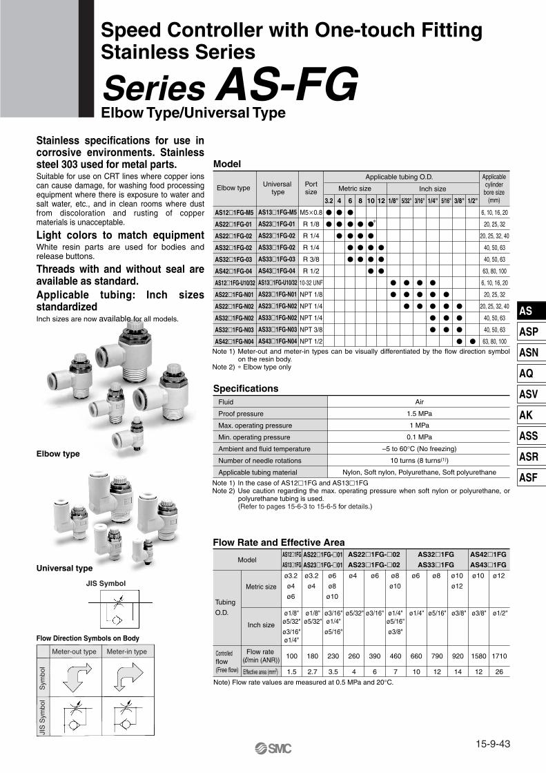
Model
Specifications
Speed Controller with One-touch FittingStainless Series
Series AS-FG Elbow Type/Universal Type
Flow Rate and Effective Area
AS12�1FG-M5
AS22�1FG-01
AS22�1FG-02
AS32�1FG-02
AS32�1FG-03
AS42�1FG-04
AS12�1FG-U10/32
AS22�1FG-N01
AS22�1FG-N02
AS32�1FG-N02
AS32�1FG-N03
AS42�1FG-N04
AS13�1FG-M5
AS23�1FG-01
AS23�1FG-02
AS33�1FG-02
AS33�1FG-03
AS43�1FG-04
AS13�1FG-U10/32
AS23�1FG-N01
AS23�1FG-N02
AS33�1FG-N02
AS33�1FG-N03
AS43�1FG-N04
M5�0.8
R 1/8
R 1/4
R 1/4
R 3/8
R 1/2
10-32 UNF
NPT 1/8
NPT 1/4
NPT 1/4
NPT 3/8
NPT 1/2
6, 10, 16, 20
20, 25, 32
20, 25, 32, 40
40, 50, 63
40, 50, 63
63, 80, 100
6, 10, 16, 20
20, 25, 32
20, 25, 32, 40
40, 50, 63
40, 50, 63
63, 80, 100
Elbow type Universal type
Portsize
Applicable tubing O.D. Applicablecylinder
bore size(mm)
Metric size Inch size
3.2
�
�
4
�
�
�
6
�
�
�
�
�
8
�
�
�
�
10
�
�
�
�
�
12
�
�
�
1/8"
�
�
5/32"
�
�
�
3/16"
�
�
�
1/4"
�
�
�
�
�
5/16"
�
�
�
�
3/8"
�
�
�
�
1/2"
�
Fluid
Proof pressure
Max. operating pressure
Min. operating pressure
Ambient and fluid temperature
Number of needle rotations
Applicable tubing material
Air
1.5 MPa
1 MPa
0.1 MPa
–5 to 60°C (No freezing)
10 turns (8 turns(1))
Nylon, Soft nylon, Polyurethane, Soft polyurethane
Model
Tubing
O.D.
Controlled flow(Free flow)
Metric size
Inch size
Flow rate (l/min (ANR))
Effective area (mm2)
AS12�1FG
AS13�1FG
AS22�1FG-�01
AS23�1FG-�01
AS22�1FG-�02
AS23�1FG-�02
AS32�1FG
AS33�1FG
AS42�1FG
AS43�1FG
100
1.5
ø3.2
ø4
ø6
ø1/8"ø5/32"
ø3/16"ø1/4"
ø3/16"ø1/4"
ø5/16"
ø1/4"ø5/16"
ø3/8"
ø1/8"ø5/32"
ø5/32" ø3/16" ø1/4" ø5/16" ø3/8" ø3/8" ø1/2"
ø6
ø8
ø10
ø4 ø6 ø8
ø10
ø10
ø12
ø6 ø8 ø10 ø12ø3.2
ø4
180
2.7
230
3.5
260
4
390
6
460
7
660
10
790
12
920
14
1580
12
1710
26
Note) Flow rate values are measured at 0.5 MPa and 20°C.
Elbow type
∗
Universal type
Stainless specifications for use in corrosive environments. Stainless steel 303 used for metal parts.Suitable for use on CRT lines where copper ions can cause damage, for washing food processing equipment where there is exposure to water and salt water, etc., and in clean rooms where dust from discoloration and rusting of copper materials is unacceptable.
Light colors to match equipmentWhite resin parts are used for bodies and release buttons.
Threads with and without seal are available as standard.Applicable tubing: Inch sizes standardizedInch sizes are now available for all models.
Note 1) Meter-out and meter-in types can be visually differentiated by the flow direction symbol on the resin body.
Note 2) ∗ Elbow type only
Note 1) In the case of AS12�1FG and AS13�1FGNote 2) Use caution regarding the max. operating pressure when soft nylon or polyurethane, or
polyurethane tubing is used.(Refer to pages 15-6-3 to 15-6-5 for details.)
JIS Symbol
Sym
bol
Meter-out type Meter-in type
JIS
Sym
bol
Flow Direction Symbols on Body
15-9-43
AS
ASP
ASN
AQ
ASV
AK
ASS
ASR
ASF

How to Order
AS
1234
M5 standard1/8, 1/4 standard
3/8 standard1/2 standard
NilMetric thread (M5)
Unified thread (10-32 UNF)R
NPT
23
ElbowUniversal
NilS
NoneWith seal∗
Body size
Type
Port size
Option
M5U10/32
01020304
M5 x 0.810-32 UNF
1/81/43/81/2
Applicable tubing O.D.Metric size Inch size
230406081012
01030507091113
ø1/8"ø5/32"ø3/16"ø1/4"ø5/16"ø3/8"ø1/2"
Needle Valve/Flow Characteristics
AS12�1FGAS13�1FG
AS22�1FG-�01AS23�1FG-�01
AS22�1FG-�02AS23�1FG-�02
AS32�1FGAS33�1FG
AS42�1FGAS43�1FG
Thread type
01
N
Meter-outMeter-in
Control type
01, 0
3, 0
4
05, 0
6, 0
7, 0
8, 0
9, 1
0
07, 0
8, 0
9, 1
0, 1
105
, 06
03, 0
4
10, 11, 12
08, 09
06, 07
12, 1310, 11
1032 F G 01 06
Stainless steel specifications (SUS303)
With One-touch fitting
∗ M5 and U10/32 are not available with seal.
∗ Use ø1/8" tube.
ø3.2∗
ø4 ø6 ø8ø10ø12
Flo
w r
ate
(�/m
in (
AN
R))
Effe
ctiv
e ar
ea (
mm
2 )
Inlet pressure: 0.5 MPa
Number of needle rotations
Flo
w r
ate
(�/m
in (
AN
R))
Effe
ctiv
e ar
ea (
mm
2 )
Inlet pressure: 0.5 MPa
Number of needle rotations
Flo
w r
ate
(�/m
in (
AN
R))
Effe
ctiv
e ar
ea (
mm
2 )
Inlet pressure: 0.5 MPa
Number of needle rotations
Flo
w r
ate
(�/m
in (
AN
R))
Effe
ctiv
e ar
ea (
mm
2 )
Inlet pressure: 0.5 MPa
Number of needle rotations
Flo
w r
ate
(�/m
in (
AN
R))
Effe
ctiv
e ar
ea (
mm
2 )
Inlet pressure: 0.5 MPa
Number of needle rotations
Series AS-FG
15-9-44

Construction: Elbow Type
Component PartsNo. Description Material Note
M5 type only
q
w
e
r
t
y
u
i
o
!0
!1
!2
!3
!4
!5
Body A
Handle
Body B
Needle
Needle guide
Seat ring
Lock nut
U seal
Cassette
Seal
O-ring
O-ring
O-ring
O-ring
Gasket
PBT
PBT
Stainless steel 303
Stainless steel 303
Stainless steel 303
Stainless steel 303
Stainless steel 303
HNBR
POM, Stainless steel
NBR
NBR
NBR
NBR
NBR
NBR/stainless steel 304
AS3201FG-02
AS3211FG-02
Be sure to read before handling. Refer to pages 15-18-3 to 15-18-4 for Safety Instructions and Common Precautions on the products mentioned in this catalog, and refer to pages 15-8-6 to 15-8-8 for Precautions on every series.
Caution
Meter-out typeM5 typeU10/32 type
Meter-in typeM5 typeU10/32 type
15-9-45
Series AS-FGSpeed Controller with One-touch FittingStainless Series, Elbow Type/Universal Type
AS
ASP
ASN
AQ
ASV
AK
ASS
ASR
ASF

Construction: Universal Type
Component PartsNo. Description Material Note
q
w
e
r
t
y
u
i
o
!0
!1
!2
!3
!4
!5
!6
!7
!8
Body A
Elbow body
Handle
Body B
Needle
Needle guide
Seat ring
Lock nut
U seal
Cassette
Seal
O-ring
O-ring
O-ring
O-ring
O-ring
Spacer
Gasket
PBT
PBT
PBT
Stainless steel 303
Stainless steel 303
Stainless steel 303
Stainless steel 303
Stainless steel 303
HNBR
POM, Stainless steel
NBR
NBR
NBR
NBR
NBR
NBR
PBT Note)
NBR, Stainless steel
Note) ø3/16", ø3/8" and ø1/2" are made of stainless steel 303. AS13�1FG(ø3.2, ø4, ø6, ø1/8", ø5/32", ø1/4"), AS23�1FG-�01(ø3.2, ø4, ø6, ø1/8", ø5/32") are made of POM.
AS3301FG-02
AS3311FG-02
Meter-out typeM5 typeU10/32 type
Meter-in typeM5 typeU10/32 type
Series AS-FG
15-9-46

Dimensions: Elbow Type
Metric Size
Model d TWeight(g)H D1 D2 L1 L2 L3
L4 A∗
Max. Min. Max. Min.M1 M1
AS12�1FG-M5-23
AS22�1FG-01-23
AS12�1FG-M5-04
AS12�1FG-M5-06
AS22�1FG-01-04
AS22�1FG-01-06
AS22�1FG-01-08
AS22�1FG-01-10
AS22�1FG-02-04
AS22�1FG-02-06
AS22�1FG-02-08
AS22�1FG-02-10
AS32�1FG-02-06
AS32�1FG-02-08
AS32�1FG-02-10
AS32�1FG-02-12
AS32�1FG-03-06
AS32�1FG-03-08
AS32�1FG-03-10
AS32�1FG-03-12
AS42�1FG-04-10
AS42�1FG-04-12
3.2
3.2
4
6
4
6
8
10
4
6
8
10
6
8
10
12
6
8
10
12
10
12
8.4
9.3
9.3
11.6
9.3
11.6
15.2
18.5
10.4
12.8
15.2
18.5
12.8
15.2
18.5
20.9
12.8
15.2
18.5
20.9
18.5
20.9
22.1
27.5
22.1
22.9
27.5
27.5
32.4
40.2
34.4
34.4
36.4
43.2
39.3
41
43.3
44.3
39.3
41
43.3
44.3
47.9
48.9
17.3
20.4
17.3
18.1
20.4
20.4
25.3
33.1
25.2
25.2
27.2
33.9
27.8
29.5
31.8
32.8
27.8
29.5
31.8
32.8
33.6
34.6
12.7
12.7
12.7
13.5
12.7
13.5
18.5
21
16
17
18.5
21
17
18.5
21
22
17
18.5
21
22
21
22
7
16
7
17
19
21
32
34
36
60
63
67
69
55
57
59
61
100
101
22.2
27.1
22.2
27.1
29.4
37.8
35.2
42.1
9.6
14.2
9.6
14.2
18.5
23
23
28.6
8
12
8
12
17
19
19
24
M5 � 0.8
M5 � 0.8 25
32.1
25
32.1
34.4
42.8
40.2
49.6
12.3
14.3
12.3
11.7
14.3
15
18.2
20
21.8
20.9
25.4
28.6
36.1
28.6
36.1
40.4
48.8
46.5
57.6
25.8
31.1
25.8
31.1
35.4
43.8
41.5
50.1
R 1/4
R 1/4
R 3/8
R 1/2
R 1/8
R 1/8
∗ Reference dimensions of M5 x 0.8, R threads after installation.
Inch Size
Model d TWeight(g)H D1 D2 L1 L2 L3
L4 A∗
Max. Min. Max. Min.
AS12�1FG-U10/32-01
AS12�1FG-U10/32-03
AS12�1FG-U10/32-05
AS12�1FG-U10/32-07
AS22�1FG-N01-01
AS22�1FG-N01-03
AS22�1FG-N01-05
AS22�1FG-N01-07
AS22�1FG-N01-09
AS22�1FG-N02-03
AS22�1FG-N02-05
AS22�1FG-N02-07
AS22�1FG-N02-09
AS22�1FG-N02-11
AS32�1FG-N02-07
AS32�1FG-N02-09
AS32�1FG-N02-11
AS32�1FG-N03-07
AS32�1FG-N03-09
AS32�1FG-N03-11
AS42�1FG-N04-11
AS42�1FG-N04-13
1/8"
5/32"
3/16"
1/4"
1/8"
5/32"
3/16"
1/4"
5/16"
5/32"
3/16"
1/4"
5/16"
3/8"
1/4"
5/16"
3/8"
1/4"
5/16"
3/8"
3/8"
1/2"
8.4
9.3
11.4
12
9.3
11.4
13.2
15.2
10.4
11.4
13.2
15.2
17.9
13.2
15.2
17.9
13.2
15.2
17.9
17.9
21.7
7
16
17
19
21
32
34
36
60
63
67
55
57
59
100
101
12.7
16.5
13.5
12.7
16.5
18.5
21
16
17
18.5
21
17
18.5
21
17
18.5
21
21
22
9.6
14.2
18.5
23
23
28.6
8
12.7
17.5
19
19
23.8
25
32.1
34.4
42.8
40.2
49.6
25.8
31.1
35.4
43.8
41.5
50.1
22.1
26.1
23.1
27.5
30.2
31
32.4
34.4
34.2
34.5
36.4
43.2
39.3
41
43.3
39.3
41
43.3
47.9
49.5
17.3
21.3
18.3
20.4
23.1
23.9
25.3
25.2
24.9
25.2
27.2
33.9
27.8
29.5
31.8
27.8
29.5
31.8
33.6
35.2
12.3
11.7
14.3
15
18.2
20
21.8
20.9
25.4
28.6
36.1
40.4
48.8
46.5
57.6
NPT1/4
NPT1/4
NPT3/8
NPT1/2
NPT1/8
10-32 UNF
∗ Reference dimensions of 10-32UNF and NPT threads after installation.
22.2
27.1
29.4
37.8
35.2
42.1
Applicable tubing O.D. ød (Hexagon width across flats)
Applicable tubing O.D. ød
(Hexagon width across flats)
M5 typeU10/32 type
15-9-47
Series AS-FGSpeed Controller with One-touch FittingStainless Series, Elbow Type/Universal Type
AS
ASP
ASN
AQ
ASV
AK
ASS
ASR
ASF

Series AS-FG
15-9-48
Dimensions: Universal Type
Metric Size
Model d TWeight(g)H D1 D2 L1 L2 L3
L5 A∗
Max. Min. Max. Min.M1
AS13�1FG-M5-23
AS13�1FG-M5-04
AS13�1FG-M5-06
AS23�1FG-01-23
AS23�1FG-01-04
AS23�1FG-01-06
AS23�1FG-01-08
AS23�1FG-02-04
AS23�1FG-02-06
AS23�1FG-02-08
AS23�1FG-02-10
AS33�1FG-02-06
AS33�1FG-02-08
AS33�1FG-02-10
AS33�1FG-02-12
AS33�1FG-03-06
AS33�1FG-03-08
AS33�1FG-03-10
AS33�1FG-03-12
AS43�1FG-04-10
AS43�1FG-04-12
3.2
4
6
3.2
4
6
8
4
6
8
10
6
8
10
12
6
8
10
12
10
12
8.4
9.3
11.6
8.4
9.3
11.6
15.2
10.4
12.8
15.2
18.5
12.8
15.2
18.5
20.9
12.8
15.2
18.5
20.9
18.5
20.9
19.8
20.3
21.4
24.4
24.9
26.9
30.9
30.6
34
35.2
38.7
38.5
39.7
43.7
44.9
38.5
39.7
43.7
44.9
49.4
52
10.8
13.1
14
16.2
16.2
18.4
18.3
20.2
20.6
23
20.6
23
25.8
26.8
12.7
13.5
12.7
13.5
18.5
16
17
18.5
21
17
18.5
21
22
17
18.5
21
22
21
22
7
17
18
21
32
33
36
40
60
63
67
69
56
59
63
65
104
105
9.6
14.2
18.5
23
23
28.6
D3
9.3
9.3
10.9
12.9
10.9
12.9
12.9
16.2
12.9
16.2
16.2
19.4
8
12
17
19
19
24
M5 � 0.8 25.8
31.1
35.4
43.8
41.5
50.1
22.2
27.1
29.4
37.8
35
42.1
25
32.1
34.4
42.8
40
49.6
28.6
36.1
40.4
48.8
46.5
57.6
L4
28.7
31.8
31.8
37.2
41.7
40.1
42.6
45.6
48.4
47
50
54.4
56.2
46.1
49.1
53.5
55.3
58
61.7
17.5
20.6
17.5
22.9
28.2
21.9
25.2
28.2
31
25.2
28.2
32.6
34.4
25.2
28.2
32.6
34.4
32.6
36.3
R 1/4
R 1/4
R 3/8
R 1/2
R 1/8
∗ Reference dimensions of M5 x 0.8, R threads after installation.
Inch Size
Model d TWeight(g)H D1 D2 L1 L2 L3
L5 A∗
Max. Min. Max. Min.M1
AS13�1FG-U10/32-01
AS13�1FG-U10/32-03
AS13�1FG-U10/32-05
AS13�1FG-U10/32-07
AS23�1FG-N01-01
AS23�1FG-N01-03
AS23�1FG-N01-05
AS23�1FG-N01-07
AS23�1FG-N01-09
AS23�1FG-N02-03
AS23�1FG-N02-05
AS23�1FG-N02-07
AS23�1FG-N02-09
AS23�1FG-N02-11
AS33�1FG-N02-07
AS33�1FG-N02-09
AS33�1FG-N02-11
AS33�1FG-N03-07
AS33�1FG-N03-09
AS33�1FG-N03-11
AS43�1FG-N04-11
AS43�1FG-N04-13
1/8"
5/32"
3/16"
1/4"
1/8"
5/32"
3/16"
1/4"
5/16"
5/32"
3/16"
1/4"
5/16"
3/8"
1/4"
5/16"
3/8"
1/4"
5/16"
3/8"
3/8"
1/2"
8.4
9.3
11.4
12
8.4
9.3
11.4
13.2
15.2
10.4
11.4
13.2
15.2
17.9
13.2
15.2
17.9
13.2
15.2
17.9
17.9
21.7
19.8
20.3
21.3
21.6
24.4
24.9
26.8
29.9
30.9
30.6
31.1
34.2
35.2
38.7
38.7
39.7
43.7
38.7
39.7
43.7
49.4
52
10.8
13.1
14
16.2
16.2
18.3
20.2
20.6
23
20.6
23
25.8
26.8
12.7
16.5
13.7
12.7
16.5
18.5
21
16
17
18.5
21
17
18.5
21
17
18.5
21
21
22
7
8
17
18
19
21
32
33
36
39
40
60
63
69
56
59
65
104
106
D3
9.3
9.3
10.9
12.9
10.9
12.9
12.9
16.2
12.9
16.2
16.2
19.4
9.6
14
19
23
23
29
8
12.7
17.5
19
19
23.8
10-32UNF
22.2
27.1
29.4
37.8
35.2
42.1
25
32.1
34.4
42.8
40.2
49.6
25.8
31.1
35
43.8
41.5
50.1
28.6
36.1
40.4
48.8
46.5
57.6
L4
28.7
34.5
31.9
31.8
37.2
41.7
40.1
42.6
45.6
48.4
47
50
54.4
56.2
46.1
49.1
53.5
55.3
58
17.5
23.3
20.7
17.5
23.9
25.6
28.2
21.9
23.9
25.6
28.2
31
25.6
28.2
32.6
25.6
28.2
32.6
32.6
36.3
NPT1/4
NPT1/4
NPT3/8
NPT1/2
NPT1/8
∗ Reference dimensions of 10-32UNF and NPT threads after installation.
Applicable tubing O.D. ød
(Hexagon width across flats)
Applicable tubing O.D. ød
(Hexagon width across flats)
M5 typeU10/32 type

AS
ASP
ASN
AQ
ASV
AK
ASS
ASR
ASF
15-9-49
Model
Specifications
Speed Controller with One-touch FittingsStainless Series
Series AS-FG In-line Type
Flow Rate and Effective Area
AS1001FG
AS2001FG
AS2051FG
AS3001FG
AS4001FG
6, 10, 16, 20
20, 25, 32
20, 25, 32, 40
40, 50, 63
63, 80, 100
Model
Applicable tubing O.D. Applicablecylinder
bore size(mm)
Metric size Inch size
3.2 4 6 8 10 12 1/8" 5/32" 3/16" 1/4" 5/16" 3/8" 1/2"
Fluid
Proof pressure
Max. operating pressure
Min. operating pressure
Ambient and fluid temperature
Number of needle rotations
Applicable tubing material (2)
Air
1.5 MPa
1 MPa
0.1 MPa
–5 to 60°C (No freezing)
10 turns (8 turns(1))
Nylon, Soft nylon, Polyurethane, Soft polyurethane
Model
Tubing
O.D.
Metric size
Inch size
Effective area (mm2)
AS1001FG AS2001FG AS2051FG AS3001FG AS4001FG
100
1.5
ø3.2
ø4
ø6
ø1/8"
ø5/32"
ø3/16"
ø3/16"ø1/4"
ø1/4"ø5/16"
ø5/32" ø3/16" ø1/4" ø5/16" ø3/8" ø3/8" ø1/2"
ø6 ø6 ø8ø10
ø12ø6 ø8 ø10 ø12ø4
130
2
230
3.5
290
4.5
460
7
420
6.5
660
10
920
14
1050
16
1390
21
Note) Flow rate values are measured at 0.5 MPa and 20°C.
� �
�
�
�
�
�
�
� �
�
�
�
� �
�
�
�
�
�
�
�
�
�
� �
� �
Controlled flow(Free flow)
Flow rate (l/min (ANR))
Note 1) In the case of AS1001FG typeNote 2) Use caution regarding the max. operating pressure when soft nylon or polyurethane, or soft
polyurethane tubing is used. (Refer to pages 15-6-3 to 15-6-5 for details.)
Flow Direction Symbols on Body
Sym
bol
JIS
Sym
bol

Series AS-FG
15-9-50
Flo
w r
ate
(l/m
in (
AN
R))
Effe
ctiv
e ar
ea (
mm
2 )
Inlet pressure: 0.5 MPa
Number of needle rotations
Flo
w r
ate
(l/m
in (
AN
R))
Effe
ctiv
e ar
ea (
mm
2 )
Inlet pressure: 0.5 MPa
Number of needle rotations
Flo
w r
ate
(l/m
in (
AN
R))
Effe
ctiv
e ar
ea (
mm
2 )
Inlet pressure: 0.5 MPa
Number of needle rotations
Flo
w r
ate
(l/m
in (
AN
R))
Effe
ctiv
e ar
ea (
mm
2 )
Inlet pressure: 0.5 MPa
Number of needle rotations
Flo
w r
ate
(l/m
in (
AN
R))
Effe
ctiv
e ar
ea (
mm
2 )
Inlet pressure: 0.5 MPa
Number of needle rotations
How to Order
AS 200
100200205300400
M5 standard1/8 standard1/4 standard3/8 standard1/2 standard
Body size Applicable tubing O.D.Metric size Inch size
230406081012
ø3.2 ∗ø4ø6ø8
ø10ø12
01030507091113
ø1/8"ø5/32"ø3/16"ø1/4"ø5/16"ø3/8"ø1/2"
Needle Valve/Flow Characteristics
1 F G 06
Stainless steel specifications (SUS303)
With One-touch fittings∗ Use ø1/8" tube.

AS
ASP
ASN
AQ
ASV
AK
ASS
ASR
ASF
15-9-51
Series AS-FGSpeed Controller with One-touch FittingsStainless Series, In-line Type
Construction
Metric Size
Dimensions
Model d Weight(g)
D1 D2 L1 L2L3
Max. Min.M1
AS1001FG-23AS1001FG-04AS1001FG-06AS2001FG-04AS2001FG-06AS2051FG-06AS2051FG-08AS3001FG-06AS3001FG-08AS3001FG-10AS3001FG-12AS4001FG-10AS4001FG-12
3.24 6 4 6 6 8 6 8
10 12 10 12
8.49.3
11.69.3
11.612.815.212.815.218.520.918.520.9
4.55.26.25.26.36.78.17.48.29.8
11
11.3
3839.240.740.744.853.259.85964.471.676
82
12.7
13.512.713.51718171821222122
678
12132631182132333640
10
11.8
14.8
19.8
26.5
20.721.422.427.628.730.227.633.334.135.636.843.644.6
23.524.225.232.633.735.232.638.339.140.641.851.152.1
Model d Weight(g)
D1 D2 L1 L2L3
Max. Min.M1
AS1001FG-01AS1001FG-03AS1001FG-05AS1001FG-07AS2001FG-03AS2001FG-05AS2001FG-07AS2051FG-05AS2051FG-07AS2051FG-09AS3001FG-07AS3001FG-09AS3001FG-11AS4001FG-11AS4001FG-13
1/8"5/32"3/16"1/4"
5/32"3/16"1/4"
3/16"1/4"
5/16"1/4"
5/16"3/8"3/8"1/2"
8.49.3
11.412
9.311.413.211.413.215.213.215.217.917.921.7
4.55.2
6.2
5.26.27.16.27.18.17.48.29.5
10.311.6
3839.248.740.740.75052.252.254.459.85964.470.876.983.1
12.7
16.513.712.716.51716.517181718212122
6789
12182124263142465397
106
10
11.8
14.8
19.8
26.5
20.721.4
22.4
27.628.629.529.630.527.633.334.135.343.544.9
23.524.2
25.2
32.633.634.534.635.532.638.339.140.35152.4
Inch Size
Component PartsNo. Description Material Note
q
w
e
r
t
y
u
i
o
!0
!1
Body A
Handle
Body B
Needle
Needle guide
Lock nut
U seal
Spacer
Cassette
Seal
O-ring
PBT
PBT
Stainless steel 303
Stainless steel 303
Stainless steel 303
Stainless steel 303
HNBR
PBT Note)
POM, Stainless steel
NBR
NBR
Note) ø3/16", ø3/8" and ø1/2" are made of stainless steel 303. AS1001FG(ø3.2, ø4, ø6, ø1/8", ø5/32", ø1/4"), AS2001FG(ø4, ø6, ø5/32") are POM.
Applicable tubing O.D. ød

15-9-52
ASD230FG-M5
ASD330FG-01
ASD430FG-02
ASD530FG-02
ASD530FG-03
ASD630FG-04
ASD230FG-U10/32
ASD330FG-N01
ASD430FG-N02
ASD530FG-N02
ASD530FG-N03
ASD630FG-N04
M5 x 0.8
R 1/8
R 1/4
R 1/4
R 3/8
R 1/2
10-32 UNF
NPT 1/8
NPT 1/4
NPT 1/4
NPT 3/8
NPT 1/2
Model Port size
Applicable tubing O.D.
Metric size Inch size
4 6 8 10 12 1/8" 5/32" 3/16" 1/4" 5/16" 3/8"
Fluid
Proof pressure
Max. operating pressure
Min. operating pressure
Ambient and fluid temperature
Number of needle rotations
Applicable tubing material(2)
Air
1.5 MPa
1 MPa
0.1 MPa
–5 to 60°C (No freezing)
10 turns (8 turns(1))
Nylon, Soft nylon, Polyurethane, Soft polyurethane
Note) Flow rate values are measured at 0.5 MPa and 20°C.
Model
Tubing O.D.
Metric size
Inch size
Effective area (mm2)
ASD230FG ASD330FG ASD430FG ASD530FG ASD630FG
ø4, ø6
75
1.1
ø6, ø8
175
2.7
ø6
—
295
4.5
ø8, ø10ø3/16"ø1/4"ø1/8"ø5/32"
ø3/16"ø1/4"
ø1/4"ø5/16"ø3/8"
350
5.3
ø6 ø8 ø10, ø12 ø10 ø12
ø1/4" ø5/16" ø3/8" — ø3/8"
500
7.6
600
9.1
700
10.7
1200
18.3
1300
19.8
JIS Symbol
Flow Direction Symbols on Body
Meter-out type Meter-in type
Sym
bol
JIS
Sym
bol
� �
�
�
�
�
�
�
�
�
�
�
�
�
�
�
�
� � �
�
�
�
�
�
�
�
�
�
�
�
�
�
�
Model
Specifications
Flow Rate and Effective Area
Dual Speed Controller with One-touch FittingStainless Series
Series ASD-FG
Controlled flow (Free flow)
Flow rate (l/min (ANR))
Two flow control valves and check valves have been integrated. Prevention of stick-slip phenomenon, and speed control of a single acting cylinder. Stable speed control is achievable even with load fluctuations.
Note 1) In the case of ASD230FG typeNote 2) Use caution regarding the max. operating pressure when soft nylon or polyurethane, or soft
polyurethane tubing is used. (Refer to pages 15-6-3 to 15-6-5 for details.)
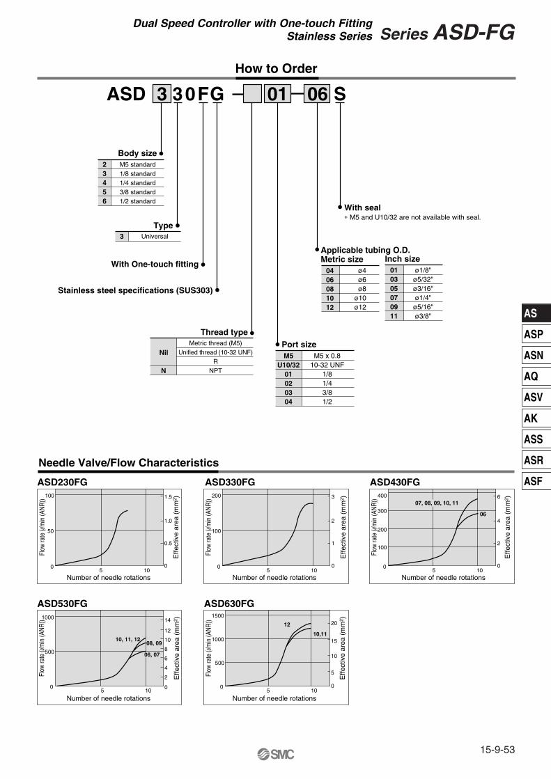
AS
ASP
ASN
AQ
ASV
AK
ASS
ASR
ASF
15-9-53
Series ASD-FGDual Speed Controller with One-touch FittingStainless Series
How to Order
ASD 3
23456
M5 standard1/8 standard1/4 standard3/8 standard1/2 standard
Body size
Type
With One-touch fitting
Stainless steel specifications (SUS303)
Thread type
3 Universal
NilMetric thread (M5)
Unified thread (10-32 UNF)R
NPT
Port size
With seal∗ M5 and U10/32 are not available with seal.
M5U10/32
01020304
M5 x 0.810-32 UNF
1/81/43/81/2
Applicable tubing O.D.Metric size Inch size
0406081012
ø4 ø6 ø8ø10ø12
010305070911
ø1/8"ø5/32"ø3/16"ø1/4"ø5/16"ø3/8"
Needle Valve/Flow Characteristics
ASD230FG ASD330FG ASD430FG
ASD530FG ASD630FG
100
50
05 10
1.5
1.0
0.5
0
Number of needle rotations
Effe
ctiv
e ar
ea (
mm
2 ) 200
05 10
3
2
1
0
Number of needle rotations
Effe
ctiv
e ar
ea (
mm
2 )
100
400
05 10
6
4
2
0
Number of needle rotations
Flow
rate
(l/m
in (A
NR))
Flow
rate
(l/m
in (A
NR))
Flow
rate
(l/m
in (A
NR))
Effe
ctiv
e ar
ea (
mm
2 )
100
200
300 06
07, 08, 09, 10, 11
1500
05 10
20
15
10
0
Effe
ctiv
e ar
ea (
mm
2 )
500
10,11
12
1000
5
Number of needle rotations
05 10
14
10
8
0
Flow
rate
(l/m
in (A
NR))
Flow
rate
(l/m
in (A
NR))
Effe
ctiv
e ar
ea (
mm
2 )
500
1000
2
Number of needle rotations
12
6
4
06, 07
10, 11, 1208, 09
30FG 01 06 S
N

Series ASD-FG
15-9-54
Construction
Component PartsNo.
q
w
e
r
t
y
u
i
o
!0
!1
Body A
Elbow body
Handle
Body B
Body B
Needle
Seat ring
Needle guide
Lock nut
Lock nut
U seal
Material
PBT
PBT
PBT
Stainless steel 303
Stainless steel 303
Stainless steel 303
Stainless steel 303
Stainless steel 303
Stainless steel 303
Stainless steel 303
HNBR
NoteDescription No.
!2
!3
!4
!5
!6
!7
!8
!9
@0
@1
U seal
Cassette
Seal
O-ring
O-ring
O-ring
O-ring
O-ring
Gasket
Spacer
Material
NBR
POM, Stainless steel
NBR
NBR
NBR
NBR
NBR
NBR
NBR, Steel
PBT Note)
Note
M5 type only
Description
Note) ø3/16", ø3/8" and ø1/2" are stainless steel 303. ASD230FG (ø4, ø6, ø1/8", ø5/32", ø1/4"), ASD330FG (ø6) are made of POM.
!3!4@1w !8 w!8 w
q
!0t
q
!0i
!0!6!5yeoir
t!2q!1@0!7 t!2u!1!7
!6!5yeor
!2!7!1!5!6
!9rueyoi
@1 !4 !3@1 !4 !3!8
ASD230FG ASD330FG/430FGASD530FG/630FG
ASD530FG-02

AS
ASP
ASN
AQ
ASV
AK
ASS
ASR
ASF
15-9-55
Series ASD-FGDual Speed Controller with One-touch FittingStainless Series
Dimensions: Metric Size
7.8
10.6
11
15.4
14
18.6
d T H D1 D2 D3 L1 L2 L3Model
ASD230FG-M5-04
ASD230FG-M5-06
ASD330FG-01-06S
ASD330FG-01-08S
ASD430FG-02-06S
ASD430FG-02-08S
ASD430FG-02-10S
ASD530FG-02-06S
ASD530FG-02-08S
ASD530FG-02-10S
ASD530FG-02-12S
ASD530FG-03-06S
ASD530FG-03-08S
ASD530FG-03-10S
ASD530FG-03-12S
ASD630FG-04-10S
ASD630FG-04-12S
M5 x 0.8
R 1/8
R 1/4
R 1/4
R 3/8
R 1/2
8
12
17
19
19
24
4
6
6
8
6
8
10
6
8
10
12
6
8
10
12
10
12
9.3
11.6
11.6
15.2
12.8
15.2
18.5
12.8
15.2
18.5
20.9
12.8
15.2
18.5
20.9
18.5
20.9
9.6
14.2
18.5
23
23
28.6
10
11.8
15
19.8
19.8
26.5
11.7
14
15.8
18
19.7
20.3
23.1
20.3
23.1
25.9
29.4
32.5
38.5
44.8
43.5
46.5
49.3
48.3
51.3
54.1
55.9
48.3
51.3
54.1
55.9
64.3
66.1
17.5
20.6
22.9
28.2
25.2
28.2
31
25.2
28.2
32.6
34.4
25.2
28.2
32.6
34.4
32.6
34.4
28.3
39.6
38.9
41.7
46.9
46.9
64.8
25.5
34.6
33.9
36.7
41.9
41.9
57.3
28.6
36.1
40.4
48.8
48.8
57.6
25.8
31.1
35.4
43.8
43.8
50.1
25
32.1
34.4
42.8
40
49.6
22.2
27.1
29.4
37.8
35
42.1
12.9
13.7
13.7
18.5
17
18.5
21
17
18.5
21
22
17
18.5
21
22
21
22
L4 L5 A1∗A2∗ M1
Max. Min. Max. Max.Min. Min.
L2L3
M1
L4
L1
H
L5 A1
A2
øD
3
øD
1
T
øD2
∗ Reference dimensions of M5 x 0.8, R threads after installation.
ASD230FG
Metric Size
Applicable tubing O.D. ød
Applicable tubing O.D. ødL2
L3M1
L1
L4
H
T
L5 A1
A2
øD
3
øD
1
øD2
ASD330FG/430FGASD530FG/630FG
(Hexagon widthacross flats)
(Hexagon widthacross flats)

Series ASD-FG
15-9-56
Dimensions: Inch Size
10-32UNF
NPT1/8
NPT 1/4
NPT 1/4
NPT 3/8
NPT 1/2
7.8
10.6
11
15.4
14
18.6
d T H D1 D2 D3 L1 L2 L3Model
ASD230FG-U10/32-01
ASD230FG-U10/32-03
ASD230FG-U10/32-05
ASD230FG-U10/32-07
ASD330FG-N01-05S
ASD330FG-N01-07S
ASD330FG-N01-09S
ASD430FG-N02-07S
ASD430FG-N02-09S
ASD430FG-N02-11S
ASD530FG-N02-07S
ASD530FG-N02-09S
ASD530FG-N02-11S
ASD530FG-N03-07S
ASD530FG-N03-09S
ASD530FG-N03-11S
ASD630FG-N04-11S
8
12.7
17.5
19
19
23.8
1/8"
5/32"
3/16"
1/4"
3/16"
1/4"
5/16"
1/4"
5/16"
3/8"
1/4"
5/16"
3/8"
1/4"
5/16"
3/8"
3/8"
8.4
9.3
11.4
12
11.6
13.2
15.2
13.2
15.2
18.5
13.2
15.2
18.5
13.2
15.2
18.5
18.5
9.6
14.2
18.5
23
23
28.6
10
11.8
15
19.8
19.8
26.5
11.7
14
15.8
18
19.7
20.3
23.1
20.3
23.1
25.9
29.4
35.2
32.6
38.5
42.2
44.8
43.9
46.5
49.3
48.7
51.3
54.1
48.7
51.3
54.1
64.3
17.5
23.3
20.7
23.9
25.6
28.2
25.6
28.2
31
25.6
28.2
32.6
25.6
28.2
32.6
32.6
28.3
39.6
38.9
41.7
46.9
46.9
64.8
25.5
34.6
33.9
36.7
41.9
41.9
57.3
28.6
36.1
40.4
48.8
46.5
57.6
25.8
31.1
35.4
43.8
41.5
50.1
25
32
34.6
43
40.3
46.9
22.2
27
29.6
38
35.3
42.1
12.9
16.5
13.5
16.5
17
18.5
17
18.5
21
17
18.5
21
17
18.5
21
21
L4 L5 A1∗A2∗ M1
Max. Min. Max. Max.Min. Min.
∗ Reference dimensions of 10-32UNF and NPT threads after installation.
Inch Size
Applicable tubing O.D. ød
L2L3
M1
L4
L1
H
L5 A1
A2
øD
3
øD
1
T
øD2
Applicable tubing O.D. ød
L2
L3M1
L1
L4
H
T
L5 A1
A2
øD
3
øD
1
øD2
ASD230FG ASD330FG/430FGASD530FG/630FG
(Hexagon widthacross flats)
(Hexagon widthacross flats)
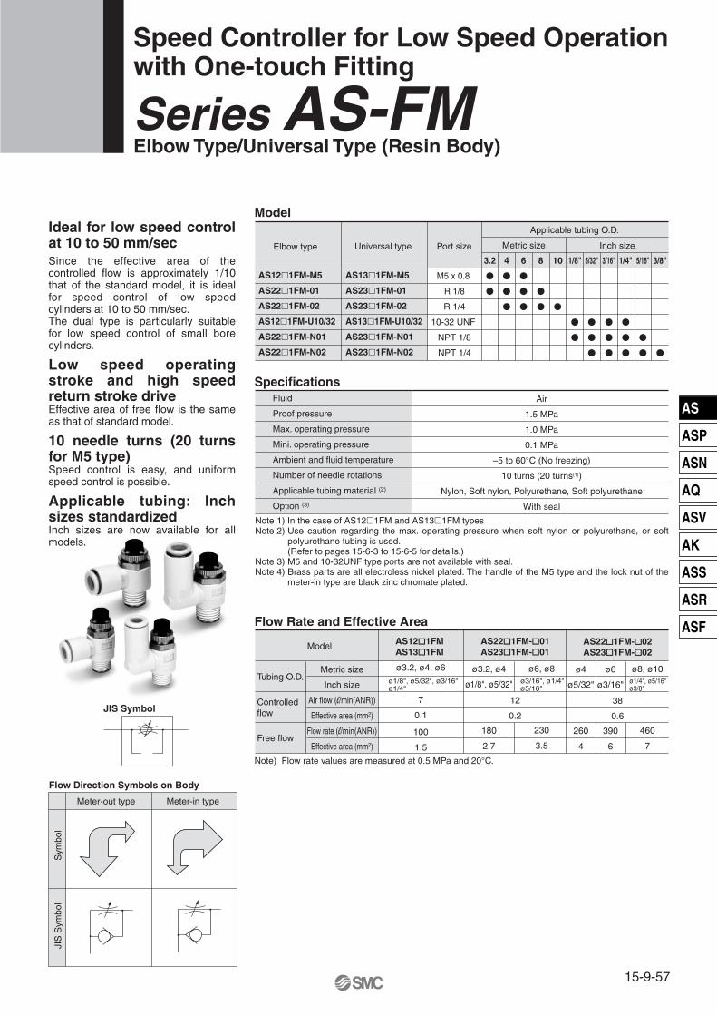
Model
Specifications
Flow Rate and Effective Area
Speed Controller for Low Speed Operationwith One-touch Fitting
Series AS-FM Elbow Type/Universal Type (Resin Body)
Port size
3.2
�
�
1/8"
�
�
5/32"
�
�
�
3/16"
�
�
�
5/16"
�
�
1/4"
�
�
�
3/8"
�
Applicable tubing O.D.
10
�
8
�
�
6
�
�
�
4
�
�
�
Fluid
Proof pressure
Max. operating pressure
Mini. operating pressure
Ambient and fluid temperature
Number of needle rotations
Applicable tubing material (2)
Option (3)
Air
1.5 MPa
1.0 MPa
0.1 MPa
–5 to 60°C (No freezing)
10 turns (20 turns(1))
Nylon, Soft nylon, Polyurethane, Soft polyurethane
With seal
ø1/8", ø5/32", ø3/16"ø1/4"
ø3/16", ø1/4"ø5/16"
ø3.2, ø4
ø1/8", ø5/32"
180
2.7
ø6, ø8
230
3.5
ø4
ø5/32"
260
4
ø6
ø3/16"
390
6
ø8, ø10
460
7
Note) Flow rate values are measured at 0.5 MPa and 20°C.
JIS Symbol
Flow Direction Symbols on Body
Meter-out type Meter-in type
Sym
bol
JIS
Sym
bol
Elbow type Universal type
Model AS12�1FM AS13�1FM
ø3.2, ø4, ø6
7
0.1
100
1.5
AS22�1FM-�01AS23�1FM-�01
12
0.2
AS22�1FM-�02AS23�1FM-�02
38
0.6
AS12�1FM-M5
AS22�1FM-01
AS22�1FM-02
AS12�1FM-U10/32
AS22�1FM-N01
AS22�1FM-N02
AS13�1FM-M5
AS23�1FM-01
AS23�1FM-02
AS13�1FM-U10/32
AS23�1FM-N01
AS23�1FM-N02
M5 x 0.8
R 1/8
R 1/4
10-32 UNF
NPT 1/8
NPT 1/4
Metric size Inch size
Metric size
Inch size
Air flow (l/min(ANR))
Effective area (mm2)
Flow rate (l/min(ANR))
Effective area (mm2)
ø1/4", ø5/16"ø3/8"
Ideal for low speed control at 10 to 50 mm/secSince the effective area of the controlled flow is approximately 1/10 that of the standard model, it is ideal for speed control of low speed cylinders at 10 to 50 mm/sec. The dual type is particularly suitable for low speed control of small bore cylinders.
Low speed operating stroke and high speed return stroke driveEffective area of free flow is the same as that of standard model.
10 needle turns (20 turns for M5 type)Speed control is easy, and uniform speed control is possible.
Applicable tubing: Inch sizes standardizedInch sizes are now available for all models.
Note 1) In the case of AS12�1FM and AS13�1FM typesNote 2) Use caution regarding the max. operating pressure when soft nylon or polyurethane, or soft
polyurethane tubing is used. (Refer to pages 15-6-3 to 15-6-5 for details.)
Note 3) M5 and 10-32UNF type ports are not available with seal. Note 4) Brass parts are all electroless nickel plated. The handle of the M5 type and the lock nut of the
meter-in type are black zinc chromate plated.
Tubing O.D.
Controlled flow
Free flow
15-9-57
AS
ASP
ASN
AQ
ASV
AK
ASS
ASR
ASF

How to Order
AS
12
M5 standard1/8, 1/4 standard
Body size
Type
With One-touch fitting
Thread type
23
ElbowUniversal
NilMetric thread (M5)
Unified thread (10-32 UNF)R
NPT
Port size
Option
M5U10/32
0102
M5 x 0.810-32 UNF
1/81/4
NilS
NoneWith seal
Applicable tubing O.D.Metric size Inch size
2304060810
ø3.2 ∗
ø4ø6ø8
ø10
010305070911
ø1/8"ø5/32"ø3/16"ø1/4"
ø5/16"ø3/8"
Needle Valve/Flow Characteristics
01
Meter-outMeter-in
Control type
2 2 0 1 F
For low speed control
M 01 06
N
∗ Use ø1/8" tube.
∗ M5 and U10/32 are not available with seal.
AS1201FM, AS1211FMAS1301FM, AS1311FM
AS2201FM-�01, AS2211FM-�01 AS2301FM-�01, AS2311FM-�01
AS2201FM-�02, AS2211FM-�02 AS2301FM-�02, AS2311FM-�02
Flo
w r
ate
(l/m
in (
AN
R))
Effe
ctiv
e ar
ea(m
m2 )
0.15
0.1
0.05
Number of needle rotations
10 20
10
5
0
Flo
w r
ate
(l/m
in (
AN
R))
Effe
ctiv
e ar
ea(m
m2 )
0.3
0.2
0.1
0
Number of needle rotations
5
20
10
0
Flo
w r
ate
(l/m
in (
AN
R))
Effe
ctiv
e ar
ea (
mm
2 )
0.8
0.6
0.4
0.2
0
Number of needle rotations
5 1010
50
40
30
20
10
00
Inlet pressure: 0.5 MPa Inlet pressure: 0.5 MPa Inlet pressure: 0.5 MPa
Series AS-FM
15-9-58

i
Component Parts
Component Parts
DescriptionNo. MaterialPBTPBT
BrassBrass
Brass
BrassBrass (2)
HNBR
POM, Stainless steel
NBRNBRNBRNBR
NBR, Stainless steel
NoteWhite
Black (1)
Electroless nickel platedElectroless nickel platedElectroless nickel plated,
M5 type only
Electroless nickel platedElectroless nickel plated (3)
M5 type only
Description MaterialPBTPBTPBT
BrassBrass
Brass
BrassBrass (2)
HNBR
POM, Stainless steel
NBRNBRNBRNBRNBR
PBT (4)
NBR, Stainless steel
NoteWhiteWhite
Black (1)
Electroless nickel platedElectroless nickel platedElectroless nickel plated,
M5 type only
Electroless nickel platedElectroless nickel plated (3)
M5 type only
No.
Construction: Elbow Type
Meter-out type
M5 typeU10/32 type
M5 typeU10/32 type
Meter-in type
Construction: Universal Type
Meter-out type Meter-in type
M5 typeU10/32 type
M5 typeU10/32 type
JIS Symbol JIS Symbol
JIS Symbol JIS Symbol
o !0 wure!2
!1
qi!3
y
o !0 wurte
!2
!1qi!3
y
!4
t
w
!2q
i
e
!3
ru
!7
r
e
!2q
o
!3
!4
t
!0
w
!1
!6
!5
y
!0
!1
!6
w
!5
Body AElbow bodyHandleBody BNeedle
Needle guide
Seat ringLock nutU seal
Cassette
SealO-ringO-ringO-ringO-ringSpacer
Gasket
Body AHandleBody BNeedle
Needle guide
Seat ringLock nutU seal
Cassette
SealO-ringO-ringO-ring
Gasket
q
w
e
r
t
y
u
i
o
!0
!1
!2
!3
!4
q
w
e
r
t
y
u
i
o
!0
!1
!2
!3
!4
!5
!6
!7
Note 1) M5 and U10/32 types are black zinc chromate plated.
Note 2) AS23�1FM type is made of steel. Note 3) Meter-in type is black zinc chromate plated.Note 4) AS13�1FM(ø3.2, ø4, ø6, ø1/8", ø5/32", ø1/4")
AS23�1FM-�01(ø3.2, ø4, ø6, ø1/8", ø5/32") is POM. AS13�1FM(ø3/16"), AS23�1FM(ø3/16", ø3/8") is brass.
Note 1) M5 and U10/32 types are black zinc chromate plated.
Note 2) AS22�1FM type is made of steel. Note 3) Meter-in type is black zinc chromate plated.
15-9-59
Series AS-FMSpeed Controller for Low Speed Operation With One-touch Fitting, Elbow Type/Universal Type (Resin Body)
AS
ASP
ASN
AQ
ASV
AK
ASS
ASR
ASF
� �� �
� �� �
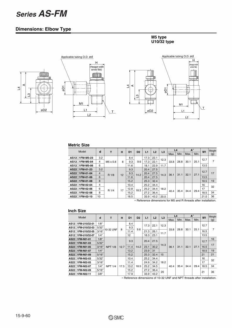
L4
A
L3
øD2
M1
L1
L2
H
(Hexagon widthacross flats)
øD
1
T
Applicable tubing O.D. ød
Dimensions: Elbow Type
Metric Size
d T
M5 x 0.8
R 1/8
R 1/4
H
8
12
17
D1
8.4 9.311.6 9.3 9.311.615.210.412.815.218.5
D2
9.6
14.2
18.5
L1
17.317.318.120.420.420.425.325.225.227.233.9
L2
22.122.122.927.527.527.532.434.434.436.443.2
L3
12.3
11.7
14.3
18.2
20.0
Max.
33.8
36.1
40.4
Max.
30.1
32.1
34.4
M1
12.7
13.5
12.7
13.518.516 17 18.521.0
Weight(g)
7
17
19
32
3436
∗ Reference dimensions for M5 and R threads after installation.
Min.
28.8
31.1
35.4
Min.
25.1
27.1
29.4
A∗L4
M5 typeU10/32 type
Model
AS12�1FM-M5-23 AS12�1FM-M5-04 AS12�1FM-M5-06 AS22�1FM-01-23 AS22�1FM-01-04 AS22�1FM-01-06 AS22�1FM-01-08 AS22�1FM-02-04 AS22�1FM-02-06 AS22�1FM-02-08 AS22�1FM-02-10
Inch Size
d
1/8"5/32"3/16"1/4"1/8"5/32"3/16"1/4"5/16"5/32"3/16"1/4"5/16"3/8"
T
10-32 UNF
NPT 1/8
NPT 1/4
H
8
12.7
17.5
D1
8.4 9.311.412
9.3
11.413.215.210.411.413.215.217.9
D2
9.6
14.2
18.5
L1
17.3
21.318.3
20.4
23.123.925.325.224.925.227.233.9
L2
22.1
26.123.1
27.5
30.231 32.434.434.234.536.443.2
L3
12.3
11.7
14.3
15
18.2
20
Max.
33.8
36.1
40.4
Max.
30.1
32.1
34.4
M1
12.7
16.513.5
12.7
16.518.521 16 17 18.5
21
Weight(g)
7
16
17
1921
32
34
36
∗ Reference dimensions of 10-32 UNF and NPT threads after installation.
Min.
28.8
31.1
35.4
Min.
25.1
27.1
29.4
A∗L4Model
øD
1
Applicable tubing O.D. ød
M1
L1
L2
T
H(Hexagon width
across flats)
L4
øD2
L3
A
AS12�1FM-U10/32-01AS12�1FM-U10/32-03AS12�1FM-U10/32-05AS12�1FM-U10/32-07AS22�1FM-N01-01AS22�1FM-N01-03AS22�1FM-N01-05AS22�1FM-N01-07AS22�1FM-N01-09AS22�1FM-N02-03AS22�1FM-N02-05AS22�1FM-N02-07AS22�1FM-N02-09AS22�1FM-N02-11
3.24 6 3.24 6 8 4 6 8
10
Series AS-FM
15-9-60

Dimensions: Universal Type
Metric Size
Model
AS13�1FM-M5-23 AS13�1FM-M5-04 AS13�1FM-M5-06 AS23�1FM-01-23 AS23�1FM-01-04 AS23�1FM-01-06 AS23�1FM-01-08 AS23�1FM-02-04 AS23�1FM-02-06 AS23�1FM-02-08 AS23�1FM-02-10
d T
M5 x 0.8
R 1/8
R 1/4
H
8
14.2
18.5
D1
8.4 9.311.6 8.4 9.311.615.210.412.815.218.5
D2
9.6
14.2
18.5
D3
9.3
9.3
10.912.910.912.9
12.9
L1
10.8
13.1
14 16.216.218.418.320.2
L2
19.820.321.424.424.926.930.930.634 35.238.7
L3
17.5
20.6
17.5
22.928.221.925.228.231
L4
28.7
31.8
31.8
37.241.740.142.645.648.4
Max.
33.8
36.1
40.4
Min.
28.8
31.1
35.4
L5Max.
30.1
32.1
34.4
Min.
25.1
27.1
29.4
A∗ M1
12.7
13.5
12.7
13.518.516 17 18.521
Weight(g)
8
17
1821
33
3640
∗ Reference dimensions for M5 and R threads after installation.
M5 type
L5
AL4
M1
L3
øD2 L1L2
øD
3H
(Hexagon widthacross flats)
øD1Applicable tubing O.D. ød
T øD2
L4
M1
L3
H(Hexagon width
across flats)
Applicable tubing O.D. ød
øD1
L5
A
T
L1
L2
øD
3
Inch Size
Model
AS13�1FM-U10/32-01AS13�1FM-U10/32-03AS13�1FM-U10/32-05AS13�1FM-U10/32-07AS23�1FM-N01-01SAS23�1FM-N01-03SAS23�1FM-N01-05SAS23�1FM-N01-07SAS23�1FM-N01-09SAS23�1FM-N02-03SAS23�1FM-N02-05SAS23�1FM-N02-07SAS23�1FM-N02-09SAS23�1FM-N02-11S
d
1/8"5/32"3/16"1/4"1/8"5/32"3/16"1/4"5/16"5/32"3/16"1/4"5/16"3/8"
T
10-32 UNF
NPT 1/8
NPT 1/4
H
8
12.7
17.5
D1
8.4 9.311.412 8.4 9.311.413.215.210.411.413.215.217.9
D2
9.6
14.2
18.5
D3
9.3
9.3
10.9
12.9
10.9
12.9
L1
10.8
13.1
14
16.2
16.2
18.3
20.2
L2
19.820.321.321.624.424.926.829.930.930.631.134.235.238.7
L3
17.5
23.320.7
17.5
23.925.628.221.923.925.628.231
L4
28.7
34.531.9
31.8
37.241.740.142.645.648.447
Max.
33.8
36.1
40.4
Min.
28.8
31.1
35.4
L5Max.
30.1
32.1
34.4
Min.
25.1
27.1
29.4
A∗ M1
12.7
16.513.7
12.7
16.518.521 16 17 18.5
21
Weight(g)
7
8
17
18
19213233363940
∗ Reference dimensions of 10-32 UNF and NPT threads after installation.
3.24 6 3.24 6 8 4 6 8
10
15-9-61
Series AS-FMSpeed Controller for Low Speed Operation With One-touch Fitting, Elbow Type/Universal Type (Resin Body)
AS
ASP
ASN
AQ
ASV
AK
ASS
ASR
ASF

AS
Model/Specifications
Needle Valve/Flow Characteristics
How to Order
Speed Controller for Low Speed Operation
Series AS-MStandard Type (Metal Body)
12
2 Meter-outMeter-in
Body sizeM5 standard
1/8, 1/4 standardType
Direct cylinderelbow type
Control type01
Metric thread (M5)Unified thread (10-32 UNF)
NPT
Cylinder sideR
Tube sideRc
Thread typeSymbol
Nil
N
For low speed control
NoneWith seal
NilS
Option
Applicable seriesAS12�0M-M5
AS12�0M-U10/32AS22�0M-01AS22�0M-02
Port sizeSymbol
M5U10/32
0102
Port size
Port size
Applicable cylinder bore size (mm)
Proof pressure
Max. operating pressure
Min. operating pressure
Ambient and fluid temperature
Number of needle rotation
Option
Weight (g)
Controlled flow
Free flow
Cylinder side
Tubing side
Model
Flow rate (l/min (ANR))
Effective area (mm2)
Flow rate (l/min (ANR))
Effective area (mm2)JIS Symbol
AS12�0M
6, 10, 15, 20, 25
20 turns
—
11.5
7
0.1
105
1.6
AS22�0M-�01
1.5 MPa
1.0 MPa
0.1 MPa
–5 to 60°C (No freezing)
36
12
0.2
280
4.3
20, 25, 32, 40
10 turns
With seal
AS22��0M-�02
74
38
0.6
420
6.5
M5 x 0.8 10-32 UNF NPT 1/8 NPT 1/4R 1/8
Rc 1/8
R 1/4
Rc 1/4
2 2 0 0 01M
M5 x 0.810-32 UNF
1/81/4
∗ M5 and U10/32 are not available with seal.
AS12�0M AS22�0M-�01 AS22�0M-�02
Flo
w r
ate
(l/m
in (
AN
R))
Effe
ctiv
e ar
ea (
mm
2 )
0.15
0.1
0.05
Number of needle rotations
10 20
10
5
0
Flo
w r
ate
(l/m
in (
AN
R))
Effe
ctiv
e ar
ea (
mm
2 )
0.3
0.2
0.1
0
Number of needle rotations
5 10
20
10
0
Flo
w r
ate
(l/m
in (
AN
R))
Effe
ctiv
e ar
ea (
mm
2 )
0.8
0.6
0.4
0.2
0
Number of needle rotations
5 10
50
40
30
20
10
00
Note 1) Flow rate values are measured at 0.5 MPa and 20°C.Note 2) Meter-out and meter-in types can be visually differentiated by the flow direction symbol on the
resin body. Meter-out type is electroless nickel plated, while meter-in type is black zinc chromate plated.
Note 3) Brass parts are all electroless nickel plated. The handle on all types and the lock nut on the meter-in type are black zinc chromate plated.
Inlet pressure: 0.5 MPa Inlet pressure: 0.5 MPa Inlet pressure: 0.5 MPa
P. 15-11-3
15-9-62

Construction
Dimensions
Meter-out type Meter-in type
Component PartsNo. Description Material
Zinc alloy
Brass
Brass
Brass
Brass
Brass
Brass(1)
NBR
PBT
NBR
NBR
NBR
NBR
NBR/Stainless steel
Note
Black zinc chromate plated
Electroless nickel plated
Electroless nickel plated
Electroless nickel plated
Electroless nickel plated
Electroless nickel plated (2)
Note 1) AS22�0M type is made of steel. Note 2) Meter-in type is black zinc chromate plated.
AS1200M AS2200M AS1210M AS2210M
u
w
t
e
r
!0
!1i
q
!4
u
w
r
e
!0
!1
q
i
!2
o!3 y
Body A
Handle
Body B
Needle
Needle guide
Seat ring
Lock nut
U seal
Bushing
O-ring
O-ring
O-ring
O-ring
Gasket
24.8
(M
AX
. 29.
8)
8
28.2
(M
AX
. 33.
2)
ø9
10.3
10
M5 x 0.8
M5 x 0.810-32 UNF
AS12�0M
Dimensions
T1 T2 H L1
10
18
27.2
Max.
33.2
36.4
39.9
Min.
28.2
31.4
35.9
L2L3
10.3
14.1
18
D2
9
14.6
19.5
D1
9
14.3
18
Max.
29.8
32.4
34.9
∗ Dimensions of R and NPT threads after installation.
Min.
24.8
27.4
29.9
A∗
AS22�0M-�0102
L2 A
L3
øD2
L1
øD
1
H
(Hexagon widthacross flats)
T1
T2
Model
AS12�0M-M5
AS12�0M-U10/32
AS22�0M-01
AS22�0M-N01
AS22�0M-02
AS22�0M-N02
M5 x 0.8
10-32 UNF
NPT 1/8
NPT 1/4
R 1/8
R 1/4
Rc 1/8
Rc 1/4
�9
8
12
12.7
17
17.5
q
w
e
r
t
y
u
i
o
!0
!1
!2
!3
!4
15-9-63
Series AS-MSpeed Controller for Low Speed OperationStandard Type (Metal Body)
AS
ASP
ASN
AQ
ASV
AK
ASS
ASR
ASF

Specifications
Flow Rate and Effective Area
Speed Controller for Low Speed Operationwith One-touch Fitting
Series AS-FMIn-line Type (Resin Body)
Applicable cylinderbore size
(mm)3.2
�
1/8"
�
5/32"
�
�
3/16"
�
�
�
1/4"
�
�
�
5/16"
�
Applicable tubing O.D.
8
�
6
�
�
�
4
�
�
Fluid
Proof pressure
Max. operating pressure
Min. operating pressure
Ambient and fluid temperature
Number of needle rotations
Applicable tubing material(2)
Air
1.5 MPa
1 MPa
0.1 MPa
�5 to 60°C (No freezing)
10 turns (20 turns (1))
Nylon, Soft nylon, Polyurethane, Soft polyurethane
Flow rate (�/min (ANR))
Effective area (mm2)
Flow rate( �/min (ANR))
Effective area (mm2)
ø1/8", ø5/32", ø3/16"ø1/4"
ø4
ø5/32"
130
2
ø6
ø3/16", ø1/4"
230
3.5
ø6
ø3/16"
290
4.5
ø8
ø1/4", ø5/16"
460
7
Note) Flow rate values are measured at 0.5 MPa and 20°C.
Model
Model AS1001FM
ø3.2, ø4, ø6
7
0.1
100
1.5
AS2001FM
12
0.2
AS2051FM
38
0.6
AS1001FM
AS2001FM
AS2051FM
6, 10, 16, 20
20, 25, 32
20, 25, 32, 40
Metric size Inch size
Metric size
Inch size
Model
Flow Direction Symbols on Body
Sym
bol
JIS
Sym
bol
Note 1) In the case of AS1001FM typeNote 2) Use caution regarding the max. operating pressure when soft nylon or polyurethane, or soft
polyurethane tubing is used. (Refer to pages 15-6-3 to 15-6-5 for details.)Note 3) Brass parts are all electroless nickel plated. The handle of the M5 type is black zinc chromate
plated.
Tubing O.D.
Controlled flow
Free flow
15-9-64

AS
ASP
ASN
AQ
ASV
AK
ASS
ASR
ASF
15-9-65
Series AS-FMSpeed Controller for Low Speed Operation With One-touch Fitting, In-line Type (Resin Body)
AS
Needle Valve/Flow Characteristics
How to Order
100200205
Body sizeM5 standard1/8 standard1/4 standard
23040608
Applicable tubing O.D.Metric size
ø3.2∗ ø4ø6ø8
0103050709
ø1/8"ø5/32"ø3/16"ø1/4"
ø5/16"
For low speed control
With one-touch fitting
200 1 F M 06
Inch size
∗ Use ø1/8" tube.
AS1001FM AS2001FM AS2051FM
Flo
w r
ate
(l/m
in (
AN
R))
Effe
ctiv
e ar
ea (
mm
2 )
0.15
0.1
0.05
Number of needle rotations
10 20
10
5
0
Flo
w r
ate
(l/m
in (
AN
R))
Effe
ctiv
e ar
ea (
mm
2 )
0.3
0.2
0.1
0
Number of needle rotations
5 10
20
10
0
Flo
w r
ate
(l/m
in (
AN
R))
Effe
ctiv
e ar
ea (
mm
2 )
0.8
0.6
0.4
0.2
0
Number of needle rotations
5 10
50
40
30
20
10
00
Inlet pressure: 0.5 MPa Inlet pressure: 0.5 MPa Inlet pressure: 0.5 MPa

Series AS-FM
15-9-66
Metric Size
d
3.24 6 4 6 6 8
D1
8.4 9.311.6 9.311.612.815.2
D2
10
11.8
14.8
L1
38 39.240.740.744.853.259.8
L2
4.55.26.25.26.36.78.1
Max.27.728.529.832.633.735.236.5
M1
12.7
13.712.713.717 18
Weight (g)
6 7 8 12132631
Min.24.925.526.627.628.730.231.5
L3Model
Inch Size
d
1/8"5/32"3/16"1/4"
5/32"3/16"1/4"
3/16"1/4"
5/16"
D1
8.4 9.311.412 9.311.413.211.413.215.2
D2
10
11.8
14.8
L1
38 39.248.740.740.750 52.252.254.459.8
L2
4.55.2
6.2
5.26.27.16.27.18.1
Max.27.728.5
27.7
32.633.634.534.635.536.5
M1
12.7
16.513.712.716.517 16.517 18
Weight (g) 6 7 8 9121821242631
Min.24.925.5
24.7
29.628.629.529.630.531.5
L3Model
AS1001FM-01AS1001FM-03AS1001FM-05AS1001FM-07AS2001FM-03AS2001FM-05AS2001FM-07AS2051FM-05AS2051FM-07AS2051FM-09
Construction
Dimensions
Component PartsNo. Description Material
PBT
PBT (1)
Brass
Brass
Brass
Brass (2)
HNBR
POM (3)
POM, Stainless steel (4)
NBR
NBR
Note
Black
Electroless nickel plated
Electroless nickel plated
Electroless nickel plated
Electroless nickel plated
Body A
Handle
Body B
Needle
Needle guide
Lock nut
U seal
Spacer
Cassette
Seal
O-ring
AS1001FM-23AS1001FM-04AS1001FM-06AS2001FM-04AS2001FM-06AS2051FM-06AS2051FM-08
q
w
e
r
t
y
u
i
o
!0
!1
Note 1) AS1001FM type is made of brass (black zinc chromate plated).Note 2) AS20�1FM type is made of steel. Note 3) ø3/16" is made of brass (electroless nickel plated). AS2001FM-07,
AS2051FM (ø6, ø8, ø1/4", ø5/16") are made of PBT. Note 4) ø3/16" is made of POM, stainless steel, and brass (electroless
nickel plated).
Applicable tubing O.D. ød

Dual Speed Controller for Low Speed Operationwith One-touch Fitting
Series ASD-FM Model
Specifications
Flow Rate and Effective Area
ASD230FM-M5ASD330FM-01ASD430FM-02ASD230FM-U10/32ASD330FM-N01ASD430FM-N02
Model
Applicable tubingMetric size Inch size
4
�
6
�
�
�
8
�
�
10
�
1/8"
�
5/32"
�
3/16"
�
�
1/4"
�
�
�
5/16"
�
�
3/8"
�
Fluid
Proof pressure
Max. operating pressure
Min. operating pressure
Ambient and fluid temperature
Number of needle rotations
Applicable tubing material(2)
Air
1.5 MPa
1 MPa
0.1 MPa
–5 to 60°C (No freezing)
10 turns (20 turns(1))
Nylon, Soft nylon, Polyurethane, Soft polyurethane
Note) Flow rate values are measured at 0.5 MPa and 20°C.
Model
Tubing O.D.
Controlled flow(Free flow)
Metric size
Inch size
Flow rate (l/min(ANR))
Effective area (mm2)
ASD230FM ASD330FM ASD430FM
ø4, ø6
7
0.1
ø6, ø8
12 38
0.60.2
ø8, ø10ø6
ø1/8", ø5/32"ø3/16", ø1/4"
ø1/4", ø5/16"ø3/8"
ø3/16", ø1/4"
JIS Symbol
Flow Direction Symbols on Body
Meter-out type Meter-in type
Sym
bol
JIS
Sym
bol
Two flow control valves and check valves integrated. Prevention of a stick-slip phenomenon, and speed control of a single acting cylinder.Stable speed control is achievable even with load fluctuations. Low speed control for small bore cylinders.
Note 1) In the case of ASD230FM type Note 2) Use caution regarding the max. operating pressure when soft nylon or polyurethane, or
soft polyurethane tubing is used. (Refer to pages 15-6-3 to 15-6-5 for details.)
Note 3) Brass parts are all electroless nickel plated. The meter-in side lock nut and the M5 type handle are black zinc chromate plated.
—
15-9-67
AS
ASP
ASN
AQ
ASV
AK
ASS
ASR
ASF

How to Order
ASD
234
M5 standard1/8 standard1/4 standard
Body size
Type
With one-touch fitting
Thread type
3 Universal
NilMetric thread (M5)
Unified thread (10-32 UNF)R
NPT
Port size
With seal∗ M5 and U10/32 types, as they are not available with seal.
M5U10/32
0102
M5 x 0.810-32 UNF
1/81/4
Applicable tubing O.D.Metric size Inch size
04060810
ø4 ø6 ø8ø10
010305070911
ø1/8"ø5/32"ø3/16"ø1/4"
ø5/16"ø3/8"
Needle Valve/Flow Characteristics
33 0 F
For low speed control
M 01 06 S
N
ASD230FM ASD330FM ASD430FM
Flo
w r
ate
(l/m
in (
AN
R))
Effe
ctiv
e ar
ea (
mm
2 )
0.15
0.1
0.05
Number of needle rotations10 20
10
5
0
Flo
w r
ate
(l/m
in (
AN
R))
Effe
ctiv
e ar
ea (
mm
2 )
0.3
0.2
0.1
0Number of needle rotations
5 10
20
10
0
Flo
w r
ate
(l/m
in (
AN
R))
Effe
ctiv
e ar
ea (
mm
2 )
0.8
0.6
0.4
0.2
0Number of needle rotations
5 10
50
40
30
20
10
00
Inlet pressure: 0.5 MPa Inlet pressure: 0.5 MPa Inlet pressure: 0.5 MPa
Series ASD-FM
15-9-68

Construction
Component PartsNo.
Body A
Elbow body
Handle
Body B
Body B
Needle
Seat ring
Needle guide
Lock nut
Lock nut
Material
PBT
PBT
PBT (1)
Brass
Brass
Brass
Brass
Brass
Brass (2)
Brass (2)
Note
Black
Electroless nickel plated
Electroless nickel plated
Electroless nickel plated
Electroless nickel plated
Electroless nickel plated
Electroless nickel plated
Black zinc chromated
Description No.
!1
!2
!3
!4
!5
!6
!7
!8
!9
@0
@1
Material
NBR
NBR
POM, Stainless steel (3)
NBR
NBR
NBR
NBR
NBR
NBR
NBR, Stainless steel
PBT (4)
Note
M5 type only
Description
U seal
U seal
Cassette
Seal
O-ring
O-ring
O-ring
O-ring
O-ring
Gasket
Spacer
ASD230FM ASD330FM/430FM
q
w
e
r
t
y
u
i
o
!0
!6 w !8 !3 !2
r u i e y !4 !5
!7 !0 q !1 t o
!6 w !8 !3 !2
r i e y !4 !5 q
!0 u !1 t o!7
Note 1) AS1001FM type is made of brass (black zinc chromate plated).Note 2) AS20�1FM type is made of steel. Note 3) ø3/16" and ø3/8 are made of POM, stainless steel, and brass
(electroless nickel plated). Note 4) ø3/16" and ø3/8 are are made of brass (electroless nickel
plated). ASD230FM (ø4, ø6, ø1/8", ø5/32", ø1/4"), ASD330FM (ø6) are POM.
15-9-69
Series ASD-FMDual Speed Controller for Low Speed Operation
With One-touch Fitting
AS
ASP
ASN
AQ
ASV
AK
ASS
ASR
ASF

Dimensions: Metric Size
7.8
10.6
11
d T H D1 D2 D3 L1 L2 L3Model
ASD230FM-M5-04
ASD230FM-M5-06
ASD330FM-01-06S
ASD330FM-01-08S
ASD430FM-02-06S
ASD430FM-02-08S
ASD430FM-02-10S
M5 x 0.8
R 1/8
R 1/4
8
12
17
4
6
6
8
6
8
10
9.3
11.6
11.6
15.2
12.8
15.2
18.5
9.6
14.2
18.5
10
11.8
15
11.7
14
15.8
18
19.7
29.4
32.5
38.5
44.8
43.5
46.5
49.3
17.5
20.6
22.9
28.2
25.2
28.2
31
34.6
39.6
38.9
41.8
29.6
34.6
33.9
36.8
33.8
36.1
40.4
28.8
31.1
35.4
30.1
32.1
34.4
25.1
27.1
29.4
12.9
13.7
13.7
18.5
17
18.5
21
L4 L5 A1∗A2∗ M1
Max. Min. Max. Max.Min. Min.
Weight(g)
Applicable tubing O.D. ød
L2L3
M1
L4
L1
H(Hexagon width
across flats) (Hexagon width
across flats)
L5 A1
A2
øD
3
øD
1
T
øD2
∗ Reference dimensions of M5 x 0.8, R threads after installation.
ASD230FM
Metric Size
12
13
29
31
53
55
58
Applicable tubing O.D. ød
L2L3
M1
L1
L4
H
T
L5 A1
A2
øD
3
øD
1
øD2
ASD330FM/430FM
Series ASD-FM
15-9-70

10-32UNF
NPT 1/8
NPT 1/4
7.8
10.6
11
d T H D1 D2 D3 L1 L2 L3Model
ASD230FM-U10/32-01
ASD230FM-U10/32-03
ASD230FM-U10/32-05
ASD330FM-U10/32-07
ASD330FM-N01-05S
ASD330FM-N01-07S
ASD330FM-N01-09S
ASD430FM-N02-07S
ASD430FM-N02-09S
ASD430FM-N02-11S
8
12.7
17.5
1/8"
5/32"
3/16"
1/4"
3/16"
1/4"
5/16"
1/4"
5/16"
3/8"
8.4
9.3
11.4
12
11.4
13.2
15.2
13.2
15.2
18.5
9.6
14.2
18.5
10
11.8
15
11.7
14
15.8
18
19.7
29.4
35.2
32.6
39.5
42.2
44.8
43.9
46.5
49.3
17.5
23.3
20.7
23.9
25.6
28.2
25.6
28.2
32.6
34.6
39.6
38.9
41.7
29.6
34.6
33.9
36.7
33.8
36.1
40.4
28.8
31.1
35.4
30.1
32
34.6
25.1
27
29.6
12.9
16.5
13.5
16.5
17
18.5
17
18.5
21
L4 L5 A1∗A2∗ M1
Max. Min. Max. Max.Min. Min.
Weight(g)
∗ Reference dimensions of 10-32UNF and NPT threads after installation.
Inch Size
Applicable tubing O.D. ød
L2L3
M1
L4
L1
H
L5 A1
A2
øD
3
øD
1
T
øD2
ASD230FM
Applicable tubing O.D. ød
L2L3
M1
L1
L4
H
T
L5 A1
A2
øD
3
øD
1
øD2
ASD330FM/430FM
12
13
14
15
30
31
55
62
Dimensions: Inch Size
(Hexagon widthacross flats)
(Hexagon widthacross flats)
15-9-71
Series ASD-FMDual Speed Controller for Low Speed Operation
With One-touch Fitting
AS
ASP
ASN
AQ
ASV
AK
ASS
ASR
ASF

Flow Rate and Effective Area
Specifications
Model
Model
Metric size
Inch size
Flow rate (l/min(ANR)
Effective area (mm2)
TubingO.D.
Controlledflow(Free flow)
AS3001FAS2051F AS4001F
ø12
ø1/2"
1390
21
ø10
ø3/8"
1050
16
ø6
ø1/4"
420
6.5
ø8
ø5/16"
660
10
ø10, ø12
ø3/8"
920
14
ø6
ø3/16"
290
4.5
ø8
ø1/4"
ø5/16"
460
7
AS2001F
ø4
ø5/32"
130
2
ø6
ø3/16"ø1/4"
230
3.5
AS1001F
Note) Flow rate values are measured at 0.5 MPa and 20°C.
Proof pressure
Max. operating pressure
Min. operating pressure
Ambient and fluid temperature
Number of needle rotations
Applicable tubing material
Air
1.5 MPa
1 MPa
0.1 MPa
–5 to 60°C (No freezing)
10 turns (8 turns)
Nylon, Soft nylon, Polyurethane
Note 1) In the case of AS1001F typeNote 2) Use caution regarding the max. operating pressure when soft nylon or polyurethane tubing is used. (Refer to pages 15-6-3 to 15-6-5 for details.)
Model
Applicable tubing O.D.
Metric size Inch size
AS1001F
AS2001F
AS2051F
AS3001F
AS4001F
6, 10, 16, 20
20, 25, 32
20, 25, 32, 40
40, 50, 63
63, 80, 100
18"3.2
� �
�
�
�
�
�
�
� �
�
�
�
� �
�
�
�
�
�
�
�
�
�
� �
� �
4 6 8 10 12 532"
316"
14" 5
16"3
8" 12"
Applicable cylinderbore size (mm)
Easy installation and removal
Installment of hexagon nuts on panel nuts up and down in two locations enables user to mount or remove it depending upon the situation.
Panel mount type
1 F 06 3200AS
M5 standard1/8 standard1/4 standard3/8 standard1/2 standard
100200205300400
Body size
With One-touch fittings
Applicable tubing O.D.
ø3.2 ∗
ø4 ø6 ø8
ø10 ø12
Metric size230406081012
ø1/8"ø5/32"ø3/16"ø1/4"ø5/16"ø3/8"ø1/2"
Inch size
∗ Use ø1/8" tube.
01030507091113
How to Order
Panel
Panel nut
Hexagon nut
Panel mount thickness: 35 mm at the maximum
(2)
(1)
Fluid
Flow Direction Symbols on Body
JIS Symbol
Speed Controller with One-touch FittingsPanel Mount Type
Series AS����1F-3In-line Type
ø3.2, ø4, ø6
100
1.5
ø1/8"ø5/32"
ø3/16", ø1/4"
Sym
bol
JIS
Sym
bol
15-9-72

Needle Valve/Flow Characteristics
Caution
Flo
w r
ate
(�/m
in (
AN
R))
Effe
ctiv
e ar
ea (
mm
2 )
Flo
w r
ate
(�/m
in (
AN
R))
Effe
ctiv
e ar
ea (
mm
2 )
Inlet pressure: 0.5 MPa
Inlet pressure: 0.5 MPa
Number of needle rotations
Number of needle rotations
Flo
w r
ate
(�/m
in (
AN
R))
Effe
ctiv
e ar
ea (
mm
2 )
Inlet pressure: 0.5 MPa
Number of needle rotations
Flo
w r
ate
(�/m
in (
AN
R))
Effe
ctiv
e ar
ea (
mm
2 )
Inlet pressure: 0.5 MPa
Number of needle rotations
Flo
w r
ate
(�/m
in (
AN
R))
Effe
ctiv
e ar
ea (
mm
2 )
Inlet pressure: 0.5 MPa
Number of needle rotations
AS1001F
AS3001F AS4001F
AS2001F AS2051F
Be sure to read before handling. Refer to pages 15-18-3 to 15-18-4 for Safety Instructions and Common Precautions on the products mentioned in this catalog, and refer to pages 15-8-6 to 15-8-8 for Precautions on every series.
15-9-73
Speed Controller with One-touch FittingsPanel Mount Type, In-line Type
AS
ASP
ASN
AQ
ASV
AK
ASS
ASR
ASF

Construction
No. q
w
e
r
t
y
u
i
o
!0
!1
!2
DescriptionBody AHandleBody BNeedleNeedle guideLock nut Panel nutU sealSpacerCassettePackingO-ring
PBTPBT
BrassBrassBrassBrassBrassHNBRPBT
POM, Stainless steelNBRNBR
Electroless nickel platedElectroless nickel platedElectroless nickel platedElectroless nickel platedElectroless nickel plated
Material Note
Model
AS1001F-23-3
AS1001F-04-3
AS1001F-06-3
AS2001F-04-3
AS2001F-06-3
AS2051F-06-3
AS2051F-08-3
AS3001F-06-3
L1
38
39.2
40.7
40.7
44.8
53.2
59.8
59
L2
4.5
5.2
6.2
5.2
6.3
6.7
8.1
7.4
L3
16.8
17.4
18.5
20.7
21.8
25.7
27
31.3
L5
37.6
38.2
39.3
48
49.1
53.5
54.8
60.1
Min.Max.34.4
35
36.1
42.5
43.6
48.1
49.4
54.7
M
12.7
13.5
12.7
13.5
17
18
17
AS3001F-08-3 64.4 8.2 32.1 60.9 55.5 18
AS3001F-10-3 71.6 9.8 33.7 62.5 57.1 21
AS3001F-12-3 76 11 34.9 63.7 58.3 22
AS4001F-10-382 11.3
35 69.3 61 21
AS4001F-12-3 36 70.3 62 22
d
1/8"
5/32"
3/16"
1/4"
5/32"
3/16"
1/4"
3/16"
H1
12
14
17
D1
8.4
9.3
11.4
12
9.3
11.4
13.2
11.4
L1
38
39.2
48.7
40.7
40.7
50
52.2
52.2
L2
4.5
5.2
6.2 18.5
5.2
6.2
7.1
6.2
L3
16.8
17.4
20.7
21.6
22.5
25.2
L4Max.
3.5
3.5
3.5
L5
37.6
38.2
39.3
48
48.9
49.8
53
Min.Max.34.4
35
36.1
42.5
43.4
44.3
47.6
M
12.7
16.5
13.7
12.7
16.5
17
16.5
1/4" 13.2 54.4 7.1 26 53.8 48.4 17
5/16" 15.2 59.8 8.1 27 54.8 49.4 18
1/4" 13.2 59 7.4 31.3 60.1 54.7 17
5/16" 2115.2 32.1 3.5 60.9 55.5 18
3/8" 17.2 33.3 62.1 56.7 21
3/8"27
H2
8
10
13
16
2117.9 34.9
3.569.2 60.9 21
1/2"
Model
AS1001F-01-3
AS1001F-03-3
AS1001F-05-3
AS1001F-07-3
AS2001F-03-3
AS2001F-05-3
AS2001F-07-3
AS2051F-05-3
AS2051F-07-3
AS2051F-09-3
AS3001F-07-3
AS3001F-09-3
AS3001F-11-3
AS4001F-11-3
AS4001F-13-3 21.7
64.4
70.8
76.9
83.1 36.3
8.2
9.5
10.3
11.6 70.6 62.3 22
Metric Size Inch Size
H1
L1
M M
(Hexagon width across flats)
H2
L4L3
øD
1
L2
L5
(Hexagon width across flats)
Applicable tubing O.D. ød
Dimensions
3.2
4
6
4
6
6
8
6
8
10
12
10
12
d
8.4
9.3
11.6
9.3
11.6
12.8
15.2
12.8
15.2
18.5
20.9
18.5
20.9
D1
12
14
17
21
27
H1
8
10
13
16
21
H2
3.5
3.5
3.5
3.5
3.5
L4Max.
10.5
12.5
15.5
18.5
24.5
Panel-cut dimensions
10.5
12.5
15.5
18.5
24.5
Panel-cut dimensions
Note)
Note) AS1001F(ø3.2, ø4, ø6, ø1/8", ø5/32", ø1/4"), AS2001F(ø4 , ø6,ø5/32") are made of POM. ø3/16" ,ø3/8" ,ø1/2" are made of brass(Electroless nickel plated).
w
r
y
t
u
!2
e
!1
!0
o
i
q
15-9-74

Model
Specifications
Speed Controller Adjustable by Flat Head Screwdriver with One-touch Fitting
Series AS���1F-DElbow Type/Universal Type
Flow Rate and Effective Area
JIS Symbol
Universal type
Elbow type
Fluid
Proof pressure
Max. operating pressure
Min. operating pressure
Ambient and fluid temperature
Number of needle rotations
Applicable tubing material
Model
Metric size ø3.2, ø4, ø6
ø1/8", ø5/32"
ø3/16", ø1/4"
100
1.5
180
2.7
230
3.5
260
4
390
6
460
7
660
10
790
12
920
14
1580
24
1710
26
ø3.2, ø4
ø1/8"
ø5/32"
ø6, ø8, ø10 ø8, ø10
ø3/16", ø1/4"
ø5/16"
ø1/4", ø5/16"
ø3/8"
ø4
ø5/32"
ø6 ø6 ø8 ø10 ø12
ø3/16" ø5/16" ø3/8" ø1/2"
ø10, ø12
ø3/8"ø1/4"Inch size
Effective area (mm2)
Flow rate (l/min (ANR))
TubingO.D.
Controlledflow(Free flow)
Air
1.5 MPa
1 MPa
0.1 MPa
–5 to 60°C (No freezing)
10 turns (8 turns (1))
Nylon, Soft nylon, Polyurethane
Note 1) In the case of AS121�F-M5 and AS12�1F-U10/32 types AS13�1F-M5, AS13�1F-U10/32Note 2) Use caution regarding the max. operating pressure when soft nylon or polyurethane tubing is used. (Refer to pages 15-6-3 to 15-6-5 for details.) Note 3) Brass parts are all electroless nickel plated, provided as standard.
Note) Flow rate values are measured at 0.5 MPa and 20°C.
(2)
AS22�1F-�01AS23�1F-�01
AS22�1F-�02AS23�1F-�02
AS32�1FAS33�1F
AS42�1FAS43�1F
AS12�1FAS13�1F
Elbow type
AS12�1F-M5
AS22�1F-01
AS22�1F-02
AS32�1F-02
AS32�1F-03
AS42�1F-04
AS12�1F-U10/32
AS22�1F-N01
AS22�1F-N02
AS32�1F-N02
AS32�1F-N03
AS42�1F-N04
Universal type Port size
Applicable tubing O.D. Applicable cylinder
bore size(mm)
Metric size
∗
Inch size
M5 x 0.8
R 1/8
R 1/4
R 1/4
R 3/8
R 1/2
10-32 UNF
NPT 1/8
NPT 1/4
NPT 1/4
NPT 3/8
NPT 1/2
�
�
�
�
�
�
�
�
�
�
�
�
�
�
�
�
�
�
�
�
�
�
�
�
�
�
�
�
�
�
�
�
�
�
�
�
�
�
�
�
�
�
� �
6, 10, 16, 20
20, 25, 32
20, 25, 32, 40
40, 50, 63
40, 50, 63
63, 80, 100
6, 10, 16, 20
20, 25, 32
20, 25, 32, 40
40, 50, 63
40, 50, 63
63, 80, 100
AS13�1F-M5
AS23�1F-01
AS23�1F-02
AS33�1F-02
AS33�1F-03
AS43�1F-04
AS13�1F-U10/32
AS23�1F-N01
AS23�1F-N02
AS33�1F-N02
AS33�1F-N03
AS43�1F-N04
3.2 4 6 8 10 12 1/8" 5/32" 3/16" 1/4" 5/16" 3/8" 1/2"
Flow Direction Symbols on Body
Meter-out type Meter-in type
Sym
bol
JIS
Sym
bol
Note 1) ∗ Elbow type onlyNote 2) Meter-out and meter-in types can be visually differentiated by the flow direction symbol on the
resin body.
Flow adjustable by flat head screwdriverPrevention of an unnecessarymanual operation
Flat head screwdriver
15-9-75
AS
ASP
ASN
AQ
ASV
AK
ASS
ASR
ASF

Flo
w r
ate
(l/m
in (
AN
R))
Effe
ctiv
e ar
ea (
mm
2 )
Inlet pressure 0.5 MPa
Number of needle rotations
Flo
w r
ate
(l/m
in (
AN
R))
Effe
ctiv
e ar
ea (
mm
2 )
Inlet pressure 0.5 MPa
Number of needle rotations
Flo
w r
ate
(l/m
in (
AN
R))
Effe
ctiv
e ar
ea (
mm
2 )
Inlet pressure 0.5 MPa
Number of needle rotations
Flo
w r
ate
(l/m
in (
AN
R))
Effe
ctiv
e ar
ea (
mm
2 )
Inlet pressure 0.5 MPa
Number of needle rotations
Flo
w r
ate
(l/m
in (
AN
R))
Effe
ctiv
e ar
ea (
mm
2 )
Inlet pressure 0.5 MPa
Number of needle rotations
How to Order
Body sizeM5 standard
1/8, 1/4 standard3/8 standard1/2 standard
1234
TypeElbow
Universal 23
Control
With One-touch fitting
Meter-outMeter-in
01
M5 x 0.8R 1/8R 1/4R 3/8R 1/2
10-32 UNFNPT 1/8NPT 1/4NPT 3/8NPT 1/2
01020304
U10/32N01N02N03N04
M5
Port size
ø3.2 ∗
ø4 ø6 ø8
ø10 ø12
Metric size
∗ Use ø1/8" tube.
0406081012
23
Applicable tubing O.D.
ø1/8"ø5/32"ø3/16"ø1/4"
ø5/16"ø3/8"ø1/2"
Inch size
030507091113
01
Type adjustable by flat head screwdriver
With seal
AS 2 2 1 1 F — 01 — 06 S D
Needle Valve/Flow Characteristics
Note) In the case that connecting port is either M5 or 10-32 UNF thread, it is not available with seal. With gasket is provided as standard.
AS1201FG, AS1211FG AS2201FG-01, AS2211FG-01 AS2201FG-02, AS2211FG-02
AS4201FG, AS4211FGAS3201FG, AS3211FG
15-9-76

Construction
M5 typeU10/32 port
M5 typeU10/32 port
Meter-in type
Universal typeMeter-out type
Elbow type Meter-out type
M5 typeU10/32 port
M5 typeU10/32 port
Meter-in type
15-9-77
Speed Controller Adjustable by Flat Head Screwdriver With One-touch Fitting, Elbow Type/Universal Type
AS
ASP
ASN
AQ
ASV
AK
ASS
ASR
ASF

Meter-out AS3311F-02Meter-out AS3301F-02
Universal typeMeter-out AS3301F-02
Elbow type Meter-out AS3201F-02
No. Description Material NoteBody A PBTBody B Brass Electroless nickel platedNeedle Brass Electroless nickel platedSeat ring Brass Electroless nickel platedSpring Steel wireU seal HNBRCassette POM, Stainless steel Note)
Seal NBRO-ring NBRO-ring NBRO-ring NBRO-ring POMGasket NBR, Stainless steelRetaining ring for hole type C Tool steel
Component Parts Component PartsNo. Description Material Note
Body AElbow body
PBT
Body BPBT
Electroless nickel platedNeedle
BrassElectroless nickel plated
Seat ringBrass
Electroless nickel platedSpring
Brass
U sealSteel wire
CassetteHNBR
SealPOM, Stainless steel (1)
O-ringNBR
O-ringNBR
O-ringNBR
O-ringO-ring
NBR
GasketSpacer
NBRNBR
POM (2)
NBR, Stainless steelTool steelRetaining ring for hole type C
Note 1) ø3/16", ø5/16", ø3/8", ø1/2" are made of POM, stainless steel, brass (Electroless nickel plated).Note 2) ø3/16", ø3/8", ø1/2" are made of brass (Electroless nickel plated).
Construction
Note) ø10, ø12, ø1/8", ø1/2" are made of POM, stainless steel, brass (Electroless nickel plated).
15-9-78

H
(Hexagon width across flats)
T
L5
øD3
L4
M1
L1
L2
øD2
øD
1
L3
A
Applicable tubing O.D. ød
Dimensions
Elbow type
∗ Reference dimensions of M5 x 0.8, R threads after installation. ∗ Reference dimensions of 10-32 UNF and NPT threads after installation.
M5 x 0.8
R 1/8
R 1/4
R 1/4
R 3/8
AS12�1F-M5-23D
AS12�1F-M5-04D
AS12�1F-M5-06D
AS22�1F-01-23SD
AS22�1F-01-04SD
AS22�1F-01-06SD
AS22�1F-01-08SD
AS22�1F-01-10SD
AS22�1F-02-04SD
AS22�1F-02-06SD
AS22�1F-02-08SD
AS22�1F-02-10SD
AS32�1F-02-06SD
AS32�1F-02-08SD
AS32�1F-02-10SD
AS32�1F-02-12SD
AS32�1F-03-06SD
AS32�1F-03-08SD
AS32�1F-03-10SD
AS32�1F-03-12SD
AS42�1F-04-10SD
AS42�1F-04-12SD
d
3.2
4
6
3.2
4
6
8
10
4
6
8
10
6
8
10
12
6
8
10
12
10
12
T
R 1/2
H
8
12
17
19
19
24
D1
8.4
9.3
11.6
8.4
9.3
11.6
15.2
18.5
10.4
12.8
15.2
18.5
12.8
15.2
18.5
20.9
12.8
15.2
18.5
20.9
18.5
20.9
D2
9.6
14.2
18.5
23
23
28.6
D3
4.7
7.2
7.2
9.8
9.8
12.4
L1
17.3
18.1
20.4
25.3
33.1
25.2
27.2
33.9
27.8
29.5
31.8
32.8
27.8
29.5
31.8
32.8
33.6
34.6
L2
22.1
22.9
27.5
32.4
40.2
34.4
36.4
43.2
39.3
41
43.3
44.3
39.3
41
43.3
44.3
47.9
48.9
L3
12.3
11.7
14.3
15
18.2
20
21.8
20.9
25.4
L4
31
35.6
40.7
55.3
53.7
63.8
L5
0.7
1.2
1.2
1.2
1.2
1.2
A
27.4
31.6
34.7
49.3
47.4
55.8
M1
12.7
13.5
12.7
13.5
18.5
21
16
17
18.5
21
17
18.5
21
22
17
18.5
21
22
21
22
Model
Metric Size Inch Size
AS12�1F-U10/32-01D
AS12�1F-U10/32-03D
AS12�1F-U10/32-05D
AS12�1F-U10/32-07D
AS22�1F-N01-01SD
AS22�1F-N01-03SD
AS22�1F-N01-05SD
AS22�1F-N01-07SD
AS22�1F-N01-09SD
AS22�1F-N02-03SD
AS22�1F-N02-05SD
AS22�1F-N02-07SD
AS22�1F-N02-09SD
AS22�1F-N02-11SD
AS32�1F-N02-07SD
AS32�1F-N02-09SD
AS32�1F-N02-11SD
AS32�1F-N03-07SD
AS32�1F-N03-09SD
AS32�1F-N03-11SD
AS42�1F-N04-11SD
AS42�1F-N04-13SD
d T H D1 D2 D3 L1 L2 L3 L4 L5 A M1Model
1/2"NPT 1/2 23.8
21.728.6 12.4
35.2 49.525.4 63.8 1.2 55.8
22
3/8" 17.9 33.6 47.9 21
3/8"
NPT 3/8 19
17.9
23 9.8
31.8 43.3
20.9 53.7 1.2 47.4
21
5/16" 15.2 29.5 41 18.5
1/4" 13.2 27.8 39.3 17
3/8"
NPT 1/4 19
17.9
23 9.8
31.8 43.3
21.8 55.3 1.2 49.3
21
5/16" 15.2 29.5 41 18.5
1/4" 13.2 27.8 39.3 17
3/8"
NPT 1/4 17.5
17.9
18.5 7.2
33.9 43.220
40.7 1.2 34.7
215/16" 15.2 27.2 36.4
1/4" 13.2 25.2 34.5
18.2
18.5
3/16" 11.4 24.9 34.2 17
5/32" 10.4 25.2 34.4 16
5/16"
NPT 1/8 12.7
15.2
14.2 7.2
25.3 32.4
35.6 1.2 31.6
21
1/4" 13.2 23.9 31
15
18.5
3/16" 11.4 23.1 30.214.3
16.5
5/32" 9.320.4 27.5 12.7
1/8" 8.4
1/4"
10-32 UNF
8
12
9.6 4.7
18.3 23.111.7
31 0.7 27.4
13.5
3/16" 11.4 21.3 26.1 16.5
5/32" 9.3 12.7
1/8" 8.417.3 22.1 12.3
∗ ∗
15-9-79
Speed Controller Adjustable by Flat Head Screwdriver With One-touch Fitting, Elbow Type/Universal Type
AS
ASP
ASN
AQ
ASV
AK
ASS
ASR
ASF

Dimensions
Universal type
(Hexagon width across flats)
T
A
L5
øD4
L3
øD2
øD
3
L1
L2
L4
HøD1
Applicable tubing O.D. ød
M1
L6
∗ Reference dimensions of M5 x 0.8, R threads after installation.∗ Reference dimensions of 10-32 UNF and NPT threads after installation.
M5 x 0.8
R 1/8
R 1/4
R 1/4
R 3/8
AS13�1F-M5-23D
AS13�1F-M5-04D
AS13�1F-M5-06D
AS23�1F-01-23SD
AS23�1F-01-04SD
AS23�1F-01-06SD
AS23�1F-01-08SD
AS23�1F-02-04SD
AS23�1F-02-06SD
AS23�1F-02-08SD
AS23�1F-02-10SD
AS33�1F-02-06SD
AS33�1F-02-08SD
AS33�1F-02-10SD
AS33�1F-02-12SD
AS33�1F-03-06SD
AS33�1F-03-08SD
AS33�1F-03-10SD
AS33�1F-03-12SD
AS43�1F-04-10SD
AS43�1F-04-12SD
d
3.2
4
6
3.2
4
6
8
4
6
8
10
6
8
10
12
6
8
10
12
10
12
T
R 1/2
H
8
12
17
19
19
24
D1
8.4
9.3
11.6
8.4
9.3
11.6
15.2
10.4 10.9
12.8
15.2
18.5
12.8
15.2
18.5
20.9
12.8
15.2
18.5
20.9
18.5
20.9
D2
9.6
14.2
18.5
23
23
28.6
4.7 10.8
7.2
7.2
9.8
9.8
12.4
D3
9.3
12.9
D4
13.19.3
12.9
16.2
20.6
23
L1
16.2
18.3
20.2
25.8
26.8
L2
21.4
38.7
L3 L4 L5 L6
31
35.6
40.7
55.3
53.7
63.8
27.4
31.6
34.7
49.3
47.4
55.8
A∗ Model
Metric Size Inch Size
16.2
19.4
12.9
16.2
20.6
23
38.5
39.7
43.7
44.9
38.5
39.7
43.7
44.9
49.4
52
16.2
18.4
35.2
30.6
34
10.9
12.9
26.9
30.9
24.4
24.9
14
19.8
20.3
M1
12.7
13.5
12.7
13.5
18.5
16
17
18.5
21
17
18.5
21
22
17
18.5
21
22
21
22
17.5
22.9
28.2
21.9
25.2
28.2
31
25.2
28.2
32.6
34.4
25.2
28.2
32.6
34.4
32.6
36.3
31.8
37.2
41.7
40.1
42.6
45.6
48.4
47
50
54.4
56.2
46.1
49.1
53.5
55.3
58
61.7
28.7
31.8
17.5
20.6
0.7
1.2
1.2
1.2
1.2
1.2
AS13�1F-U10/32-01D
AS13�1F-U10/32-03D
AS13�1F-U10/32-05D
AS13�1F-U10/32-07D
AS23�1F-N01-01SD
AS23�1F-N01-03SD
AS23�1F-N01-05SD
AS23�1F-N01-07SD
AS23�1F-N01-09SD
AS23�1F-N02-03SD
AS23�1F-N02-05SD
AS23�1F-N02-07SD
AS23�1F-N02-09SD
AS23�1F-N02-11SD
AS33�1F-N02-07SD
AS33�1F-N02-09SD
AS33�1F-N02-11SD
AS33�1F-N03-07SD
AS33�1F-N03-09SD
AS33�F-N03-11SD
AS43�1F-N04-11SD
AS43�1F-N04-13SD
d T H D1 D2 D3 D4 L1 L2 L3 L4 L5 L6Model
1/2"NPT 1/2 23.8
21.729
26.863.8
3/8" 17.9 25.8
19.4
16.2
3/8"
NPT 3/8 19
17.9
23
23
53.75/16" 15.2
1/4" 13.2
3/8"
NPT 1/4 19
17.9
23
23
55.35/16" 15.2
1/4" 13.2
3/8"
NPT 1/4 17.5
17.9
19
20.2
40.7
5/16" 15.2
1/4" 13.2
12.9
3/16" 11.4
5/32" 10.4
5/16"
NPT 1/8 12.7
15.2
14 35.6
1.2
1.2
1.2
1.2 34.7
1.2
1/4" 13.2
30.9
3/16" 11.4 14
5/32" 9.313.1
1/8" 8.4
1/4"
10-32 UNF 8
12
9.6 9.3
12.4
9.8
9.8
31.8
7.2
7.2
4.7 313/16" 11.4
5/32" 9.3
1/8" 8.4
52
49.4
43.7
39.7
38.7
43.7
39.7
38.7
38.7
35.2
34.2
31.1
30.6
36.3
32.6
32.6
28.2
25.6
32.6
28.2
25.6
31
28.2
25.6
23.9
21.9
29.9
26.8
24.9
24.4
21.6
21.3
20.3
19.8
A∗
0.7
55.8
47.4
49.3
31.6
37.4
M1
22
21
21
18.5
17
21
18.5
17
21
18.5
17
16
21
18.5
16.5
12.7
25.6
28.2
23.9
17.5
10.9
9.3
16.2
12.9
16.2
12.9
10.9 16.2
18.3
20.6
20.6
12.9
10.8
16.2
13.7
16.5
12.7
20.7
23.3
17.5
58
55.3
53.5
49.1
46.1
56.2
54.4
50
47
48.4
45.6
42.6
40.1
37.2
41.7
31.9
34.5
28.7
15-9-80

Sym
bol
JIS
Sym
bol
Model
Specifications
Speed Controller Adjustable by Flat Head Screwdriver with One-touch Fittings
Series AS���1F-DIn-line Type
JIS Symbol
Flow Direction Symbols on Body
Fluid
Proof pressure
Max. operating pressure
Min. operating pressure
Ambient and fluid temperature
Number of needle rotations
Applicable tubing material (2)
1.5 MPa
1 MPa
0.1 MPa
–5 to 60°C (No freezing)
10 turns (8 turns (1))
Nylon, Soft nylon, Polyurethane
Note 1) In the case of AS1001F typeNote 2) Use caution regarding the max. operating pressure when soft nylon or polyurethane ttubing is used. (Refer to pages 15-6-3 to 15-6-5 for details.)
Model
AS1001F
AS2001F
AS2051F
AS3001F
AS4001F
Applicable tubing O.D. Applicable cylinder
bore size(mm)
Metric size Inch size
6, 10, 16, 20
20, 25, 32
20, 25, 32, 40
40, 50, 63
63, 80, 100
� �
�
�
�
�
�
�
� �
�
�
�
� �
�
�
�
�
�
�
�
�
�
� �
� �
3.2 4 6 8 10 12 1/8" 5/32" 3/16" 1/4" 5/16" 3/8" 1/2"
Type adjustable by flat head screwdriver
1F 06 D200AS
M5 standard
1/8 standard
1/4 standard
3/8 standard
1/2 standard
100200205300400
Body size
With One-touch fittings
Applicable tubing O.D.
ø3.2∗
ø4
ø6
ø8
ø10
ø12
Metric size230406081012
ø1/8"
ø5/32"
ø3/16"
ø1/4"
ø5/16"
ø3/8"
ø1/2"
Inch size
∗ Use ø1/8" tube.
01030507091113
Model
Metric size
Inch size
Effective area (mm2)
TubingO.D.
Controlledflow(Free flow)
AS3001FAS2051F AS4001F
ø12
ø1/2"
1390
21
ø10
ø3/8"
1050
16
ø6
ø1/4"
420
6.5
ø8
ø5/16"
660
10
ø10, ø12
ø3/8"
920
14
ø6
ø3/16"
290
4.5
ø8
ø1/4"
ø5/16"
460
7
AS2001F
ø4
ø5/32"
130
2
ø6
ø3/16"
ø1/4"
230
3.5
AS1001F
ø3.2, ø4, ø6
ø1/8", ø5/32"
ø3/16", ø1/4"
100
1.5
Flow rate (�/min (ANR))
Note) Flow rate values are measured at 0.5 MPa and 20°C
How to Order
Flow Rate and Effective Area
Air
15-9-81
AS
ASP
ASN
AQ
ASV
AK
ASS
ASR
ASF

15-9-82
Flo
w r
ate
(l/m
in (
AN
R))
Effe
ctiv
e ar
ea (
mm
2 )
Inlet pressure: 0.5 MPa
Inlet pressure: 0.5 MPa
Number of needle rotations
Flo
w r
ate
(l/m
in (
AN
R))
Effe
ctiv
e ar
ea (
mm
2 )
Number of needle rotations
Flo
w r
ate
(l/m
in (
AN
R))
Effe
ctiv
e ar
ea (
mm
2 )
Inlet pressure: 0.5 MPa
Number of needle rotationsF
low
rat
e (l/
min
(A
NR
))
Effe
ctiv
e ar
ea (
mm
2 )
Inlet pressure: 0.5 MPa
Number of needle rotations
Flo
w r
ate
(l/m
in (
AN
R))
Effe
ctiv
e ar
ea (
mm
2 )
Inlet pressure: 0.5 MPa
Number of needle rotations
No. Note
Electroless nickel platedElectroless nickel plated
DescriptionBody ABody BNeedleSpringU sealSpacerCassetteSealO-ringRetaining ring for hole type C
MaterialPBT
BrassBrass
Steel wireHNBRPOM (1)
POM, Stainless steel (2)
NBRNBR
Tool steel
Component Parts
Needle Valve/Flow Characteristics
Construction
AS2001F to AS4001FAS1001F
Note 1) ø3/16", ø3/8", ø1/2" are made of brass (Electroless nickel plated). Note 2) ø3/16", ø5/16", ø3/8", ø1/2" are made of POM, stainless steel, and brass (Electroless
nickel plated).

AS
ASP
ASN
AQ
ASV
AK
ASS
ASR
ASF
15-9-83
Speed Controller Adjustable by Flat Head Screwdriver With One-touch Fittings, In-line Type
Dimensions
Metric Size Inch Size
AS4001F-12D 12
AS4001F-10D 10
AS3001F-12D 12
AS3001F-10D 10
AS3001F-08D 8
AS3001F-06D 6
AS2051F-08D 8
AS2051F-06D 6
AS2001F-06D 6
AS2001F-04D 4
AS1001F-06D 6
AS1001F-04D 4
AS1001F-23D 3.2
Model d
20.9
18.5
20.9
18.5
15.2
12.8
15.2
12.8
11.6
9.3
11.6
9.3
8.4
D1
26.5
19.8
14.8
11.8
10
D2
12.4
9.8
7.2
7.2
4.7
D3
82
76
71.6
64.4
59
59.8
53.2
44.8
40.7
40.7
39.2
38
L1
11.3
11
9.8
8.2
7.4
8.1
6.7
6.3
5.2
6.2
5.2
4.5
L2
56.4
55.4
48.5
47.3
45.8
45
36.5
35.2
33
31.9
27.7
26.6
26
L3
1.2
1.2
1.2
1.2
0.7
L4
22
21
22
21
18
17
18
17
13.5
12.7
13.5
12.7
M1
AS4001F-13D 1/2"
AS3001F-11D 3/8"
AS3001F-09D 5/16"
AS3001F-07D 1/4"
AS2051F-09D 5/16"
AS2051F-07D 1/4"
AS2051F-05D 3/16"
AS2001F-07D 1/4"
AS2001F-05D 3/16"
AS2001F-03D 5/32"
AS1001F-07D 1/4"
AS1001F-05D 3/16"
AS1001F-03D 5/32"
AS1001F-01D 1/8"
Model d
21.7
17.9
15.2
13.2
15.2
13.2
11.4
13.2
11.4
9.3
12
11.4
9.3
8.4
D1
19.8
14.8
11.8
10
D2
9.8
7.2
7.2
4.7
D3
83.1
70.8
64.4
59
59.8
54.4
52.2
52.2
50
40.7
40.7
48.7
39.2
38
L1
11.6
9.5
8.2
7.4
8.1
7.1
6.2
7.1
6.2
5.2
6.2
5.2
4.5
L2
56.9
47.2
46
45.2
36.7
35.7
34.9
33.7
32.8
31.9
27.7
26.6
26
L3
1.2
1.2
1.2
0.7
L4
22
21
AS4001F-11D 3/8" 17.926.5 12.4
76.9 10.3 55.51.2
21
18
17
18
17
16.5
17
16.5
12.7
13.7
16.5
12.7
M1
L1øD2
M1
Applicable tubing O.D. ød
øD
1
L2
L3
M1
L4
øD3

Model
Dual Speed Controller Adjustable by Flat Head Screwdriver with One-touch Fitting
Series ASD���F-D
Flow Rate and Effective Area
ASD230F-M5ASD330F-01ASD430F-02ASD530F-02ASD530F-03ASD630F-04ASD230F-U10/32ASD330F-N01ASD430F-N02ASD530F-N02ASD530F-N03ASD630F-N04
M5 x 0.8
R 1/8
R 1/4
R 1/4
R 3/8
R 1/2
10-32 UNF
NPT 1/8
NPT 1/4
NPT 1/4
NPT 3/8
NPT 1/2
Model Port size
Applicable tubing O.D.
Metric size Inch size
4
�
6
�
�
�
�
�
8
�
�
�
�
10
�
�
�
�
12
�
�
�
1/8"
�
5/32"
�
3/16"
�
�
1/4"
�
�
�
�
�
5/16"
�
�
�
�
3/8"
�
�
�
�
Note) Flow rate values are measured at 0.5 MPa and 20°C.
Model
Tubing O.D.
Controlled flow(Free flow)
Metric size
Inch size
Effective area (mm2)
ASD230F ASD330F ASD430F ASD530F ASD630F
ø4, ø6
75
1.1
ø6, ø8
175
2.7
ø6
—
295
4.5
ø8, ø10
ø1/8"ø5/32"ø3/16"ø1/4"
ø3/16"ø1/4"
ø1/4"ø5/16"ø3/8"
350
5.3
ø10, ø12
ø3/8"
700
ø6
ø1/4"
500
7.6
ø8
ø5/16"
600
9.1 10.7
ø10
—
1200
18.3
ø12
ø3/8"
1300
19.8
JIS Symbol
Flow rate (l/min (ANR))
Flow Direction Symbols on Body
Meter-out type Meter-in type
Sym
bol
JIS
Sym
bol
SpecificationsFluid
Proof pressure
Max. operating pressure
Min. operating pressure
Ambient and fluid temperature
Number of needle rotations
Applicable tubing material (2)
1.5 MPa
1 MPa
0.1 MPa
–5 to 60°C (No freezing)
10 turns (8 turns (1))
Nylon, Soft nylon, PolyurethaneNote 1) In the case of ASD230F typeNote 2) Use caution regarding the max. operating pressure when soft nylon or polyurethane tubing is used. (Refer to pages 15-6-3 to 15-6-5 for details.) Note 3) Brass parts are all electroless nickel plated, provided as standard.
Air
15-9-84

Needle Valve/Flow Characteristics
ASD230F ASD330F ASD430F
ASD530F ASD630F
100
50
05 10
1.5
1.0
0.5
0
Number of needle rotations
Flo
w r
ate
(l/m
in (
AN
R))
Effe
ctiv
e ar
ea (
mm
2 )
200
05 10
3
2
1
0
Number of needle rotations
Flo
w r
ate
(l/m
in (
AN
R))
Effe
ctiv
e ar
ea (
mm
2 )
100
400
05 10
6
4
2
0
Number of needle rotations
Flo
w r
ate
(l/m
in (
AN
R))
Effe
ctiv
e ar
ea (
mm
2 )
100
200
300 06
07,08,09,10,11
1500
05 10
20
15
10
0Flo
w r
ate
(l/m
in (
AN
R))
Effe
ctiv
e ar
ea (
mm
2 )
500
10,11
12
1000
5
Number of needle rotations
05 10
14
10
8
0Flo
w r
ate
(l/m
in (
AN
R))
Effe
ctiv
e ar
ea (
mm
2 )
500
1000
2
Number of needle rotations
12
6
4
06,07
10,11,1208,09
How to Order
Body sizeM5 standard1/8 standard1/4 standard3/8 standard1/2 standard
23456
TypeUniversal3
With One-touch fitting
M5 x 0.8R 1/8R 1/4R 3/8R 1/2
10-32 UNFNPT 1/8NPT 1/4NPT 3/8NPT 1/2
01020304
U10/32N01N02N03N04
M5
Port size
ø4ø6ø8
ø10 ø12
Metric size0406081012
Applicable tubing O.D.
ø1/8"ø5/32"ø3/16"ø1/4"
ø5/16"ø3/8"
Inch size
0305070911
01
Type adjustable by a flat head screwdriver
With seal
ASD 3 3 0 F — 01—06 S D
Note) In case that connecting port is either M5 or 10-32UNF thread, it is not available with seal. With gasket is provided as standard.
15-9-85
Dual Speed Controller Adjustable by Flat Head ScrewdriverWith One-touch Fitting
AS
ASP
ASN
AQ
ASV
AK
ASS
ASR
ASF

Construction
No. Description Material NoteBody A PBTElbow body PBT
Body B Brass Electroless nickel platedBody B Brass Electroless nickel plated
Needle Brass Electroless nickel platedSeat ring Brass Electroless nickel platedSpring Steel wireU seal HNBRU seal HNBRCassette POM, Stainless steel (1)
Seal NBRO-ring NBR
Component PartsNo. Description Material Note
O-ringO-ring
NBR
O-ringO-ring
NBR
GasketSpacer
NBRNBR
POM (2)
NBR, Stainless steelTool steelRetaining ring for hole type C
Note 1) ø3/16", ø5/16", ø3/8", ø1/2" are made of POM, stainless steel, brass (Electroless nickel plated).Note 2) ø3/16", ø3/8", ø1/2" are made of brass (Electroless nickel plated).
ASD230F ASD330F/430FASD530F/630F
ASD530F–02
15-9-86

Dimensions
Metric size
Metric Size
∗ Reference dimensions of M5 x 0.8, R threads after installation.
ASD230F-M5-04D
ASD230F-M5-06D
ASD330F-01-06SD
ASD330F-01-08SD
ASD430F-02-06SD
ASD430F-02-08SD
ASD430F-02-10SD
ASD530F-02-06SD
ASD530F-02-08SD
ASD530F-02-10SD
ASD530F-02-12SD
ASD530F-03-06SD
ASD530F-03-08SD
ASD530F-03-10SD
ASD530F-03-12SD
ASD630F-04-10SD
ASD630F-04-12SD
d
4
6
6
8
6
8
10
6
8
10
12
6
8
10
12
10
12
Model H
8
12
17
19
19
24
D1
9.3
11.6
11.6
15.2
12.8
15.2
18.5
12.8
15.2
18.5
20.9
12.8
15.2
18.5
20.9
18.5
20.9
D2
9.6
14.2
18.5
23
23
28.6
D3
10
11.8
15
19.8
19.8
26.5
D4
4.7
7.2
7.2
9.8
9.8
12.4
L1
11.7
14
15.8
18
19.7
20.3
23.1
20.3
23.1
25.9
L2
29.4
32.5
38.5
44.8
43.5
46.5
49.3
48.3
51.3
54.1
55.9
48.3
51.3
54.1
55.9
64.3
66.1
L3
17.5
20.6
22.9
28.2
25.2
28.2
31
25.2
28.2
32.6
34.4
25.2
28.2
32.6
34.4
32.6
34.4
L4
30.7
38.9
38.2
41.7
53.7
53.7
69.1
L5
31
35.6
40.7
55.3
53.7
63.8
L6
0.7
1.2
1.2
1.2
1.2
1.2
A1∗
27.4
31.6
34.7
49.3
47.4
55.8
A2∗
7.8
10.6
11
15.4
14
18.6
M1
12.9
13.7
13.7
18.5
17
18.5
21
17
18.5
21
22
17
18.5
21
22
21
22
T
M5 x 0.8
R 1/8
R 1/4
R 1/4
R 3/8
R 1/2
L1
M1
L3
L2
øD
1 Applicable tubing O.D. ød
øD2
L6
L4
øD
3
T
A1
L5
A2
H(Hexagon width
across flats)
øD4
øD4
L6
15-9-87
Dual Speed Controller Adjustable by Flat Head ScrewdriverWith One-touch Fitting
AS
ASP
ASN
AQ
ASV
AK
ASS
ASR
ASF

Dimensions
Inch size
∗ Reference dimensions of 10-32UNF and NPT threads after installation.
L1
M1
L3
L2
øD
1 Applicable tubing O.D. ød
øD2
L6
L4
øD
3
T
A1
L5
A2
H(Hexagon width
across flats)
øD4
øD4
L6
Inch Size
ASD230F-U10/32-01D
ASD230F-U10/32-03D
ASD230F-U10/32-05D
ASD230F-U10/32-07D
ASD330F-N01-05SD
ASD330F-N01-07SD
ASD330F-N01-09SD
ASD430F-N02-07SD
ASD430F-N02-09SD
ASD430F-N02-11SD
ASD530F-N02-07SD
ASD530F-N02-09SD
ASD530F-N02-11SD
ASD530F-N03-07SD
ASD530F-N03-09SD
ASD530F-N03-11SD
ASD630F-N04-11SD
d
1/8"
5/32"
3/16"
1/4"
3/16"
1/4"
5/16"
1/4"
5/16"
3/8"
1/4"
5/16"
3/8"
1/4"
5/16"
3/8"
3/8"
Model H
8
12.7
17.5
19
19
23.8
D1
8.4
9.3
11.4
12
11.6
13.2
15.2
13.2
15.2
18.5
13.2
15.2
18.5
13.2
15.2
18.5
18.5
D2
9.6
14.2
18.5
23
23
28.6
D3
10
11.8
15
19.8
19.8
26.5
D4
4.7
7.2
7.2
9.8
9.8
12.4
L1
11.7
14
15.8
18
19.7
20.3
23.1
20.3
23.1
25.9
L2
29.4
35.2
32.6
38.5
42.2
44.8
43.9
46.5
49.3
48.7
51.3
54.1
48.7
51.3
54.1
64.3
L3
17.5
23.3
20.7
23.9
25.6
28.2
25.6
28.2
31
25.6
28.2
32.6
25.6
28.2
32.6
32.6
L4
30.7
38.9
38.2
41.7
53.7
53.7
69.1
L5
31
35.6
40.7
55.3
53.7
63.8
L6
0.7
1.2
1.2
1.2
1.2
1.2
A1∗
27.4
31.6
34.7
49.3
47.4
55.8
A2∗
7.8
10.6
11
15.4
14
18.6
M1
12.9
16.5
13.5
16.5
17
18.5
17
18.5
21
17
18.5
21
17
18.5
21
21
T
10-32 UNF
NPT 1/8
NPT 1/4
NPT 1/4
NPT 3/8
NPT 1/2
15-9-88

Model/Specifications
How to Order
Speed Controller Adjustable by Flat Head Screwdriver: Standard Type
Series AS�2�0-DElbow Type (Metal Body)
JIS Symbol
1/410-32 UNFPort size
Applicable cylinder bore size (mm)
Fluid
Proof pressure
Max. operating pressure
Min. operating pressure
Ambient and fluid temperature
Number of needle rotations
Effective area (mm2)
1/8 1/4 3/8
32, 40, 50, 63
1/2
80, 10020, 25, 32, 406, 10, 16, 20, 25
AS12�0-M5 AS12�0-U10/32Specifications Model
Air
1.5 MPa
1 MPa
0.1 MPa
–5 to 60°C (No freezing)
105
1.6
1700
26
920
14
460
7
230
3.5
Note 1) Flow rate values are measured at 0.5 MPa and 20°C.Note 2) Meter-out and meter-in types can be visually differentiated by the flow direction symbol on the resin body. Note 3) Brass parts are all electroless nickel plated, provided as standard.
01 SAS 2 0 0
Body size1234
M5 standard1/8,1/4 standard3/8 standard1/2 standard
2
TypeElbow2
Control01
D
Type adjustable by flat head screwdriver
Port sizeSymbol Cylinder side In the side of solenoid valve
M501020304
F01F02F03F04
U10/32N01N02N03N04
M5 x 0.8R 1/8R 1/4R 3/8R 1/2R 1/8R 1/4R 3/8R 1/2
10-32 UNFNPT 1/8NPT 1/4NPT 3/8NPT 1/2
M5 x 0.8Rc 1/8Rc 1/4Rc 3/8Rc 1/2G 1/8G 1/4G 3/8G 1/2
10-32 UNFNPT 1/8NPT 1/4NPT 3/8NPT 1/2
M5 x 0.8
Flow rate (l/min (ANR))
AS42�0-�04AS32�0-�03AS32�0-�02AS22�0-�02AS22�0-�01
Meter-outMeter-in
10 turns8 turns
Controlled flow(Free flow)
With sealNote) In case that connecting port is
either M5 or 10-32 UNF thread, it is not available with seal. With gasket is provided as standard.
15-9-89
AS
ASP
ASN
AQ
ASV
AK
ASS
ASR
ASF

No. Note
Electroless nickel platedElectroless nickel platedElectroless nickel plated
DescriptionBody ABody BNeedleSeat ringSpringU sealO-ringO-ringO-ring
O-ringBushing
GasketRetaining ring for hole type C
MaterialZinc alloy
BrassBrassBrass
Steel wireHNBRNBRNBRNBR
NBRPBT
NBR, Stainless steelTool steel
Component Parts
Construction
AS3210-02-D
AS3200-02-D
AS2210-01-D
AS2200-01-DMeter-outM5 typeU10/32 port
Meter-outM5 typeU10/32 port
15-9-90

DimensionsL2
øD
1
øD2
L3
A
T2
T1L1
H
(Hexagon width across flats)
L4
øD3
∗ Reference thread dimensions after installation.
Dimensions
AS42�0-N04-SD NPT 1/2 23.8NPT 1/2AS42�0-F04-SD G 1/2AS42�0-04-SD Rc 1/2 24
R 1/2
AS32�0-N03-SD NPT 3/8NPT 3/8AS32�0-F03-SD G 3/8AS32�0-03-SD Rc 3/8
19 R 3/8
AS32�0-N02-SD NPT 1/4NPT 1/4AS32�0-F02-SD G 1/4AS32�0-02-SD Rc 1/4
19 R 1/4
AS22�0-N02-SD NPT 1/4 17.5NPT 1/4AS22�0-F02-SD G 1/4AS22�0-02-SD Rc 1/4 17 R 1/4
AS22�0-N01-SD NPT 1/8 12.7NPT 1/8AS22�0-F01-SD G 1/8AS22�0-01-SD Rc 1/8 12 R 1/8
AS12�0-U10/32-D 10-32 UNF10-32 UNFAS12�0-M5-D M5 x 0.8 8
M5 x 0.8Model T2 H D1T1 D2 D3 L1 L2 L3 L4 A ∗
9
14.3
18
22.5
22.5
27.5
9
14.6
19.5
24.3
24.3
28.5
4.7
7.2
7.2
9.8
9.8
12.4
31
35.6
40.7
55.3
53.7
63.8
10.3
14.1
18
22.4
20.8
26.7
0.7
1.2
1.2
1.2
1.2
1.2
27.4
31.6
36.7
49.3
47.4
55.8
10
18
27.2
30
30
38.5
15-9-91
Speed Controller Adjustable by Flat Head ScrewdriverStandard Type, Elbow Type (Metal Body)
AS
ASP
ASN
AQ
ASV
AK
ASS
ASR
ASF

Tamper Proof Speed Controller with One-touch Fitting
Series AS���1F-TElbow Type/Universal Type
How to Order
Fluid
Proof pressure
Max. operating pressure
Min. operating pressure
Ambient and fluid temperature
Number of needle rotations
Applicable tubing material (2)
Air
1.5 MPa
1 MPa
0.1 MPa
–5 to 60°C (No freezing)
10 turns (8 turns (1))
Nylon, Soft nylon, Polyurethane
Note 1) In the case of AS12�1F-M5 and AS12�1F-U10/32 types AS13�1F-M5, AS13�1F-U10/32Note 2) Use caution regarding the max. operating pressure when soft nylon or polyurethane tubing is used. (Refer to pages 15-6-3 to 15-6-5 for details.) Note 3) Brass parts are all electroless nickel plated, provided as standard.
Elbow type
Universal type
Elbow type
Note 1) ∗ Elbow type onlyNote 2) Meter-out and meter-in types can be visually differentiated by the flow direction symbol on the resin body.
Universal type Port size
Applicable tubing O.D. Applicablecylinder
bore size(mm)
Metric size Inch size
M5 x 0.8
R 1/8
R 1/4
R 1/4
R 3/8
R 1/2
10-32 UNF
NPT 1/8
NPT 1/4
NPT 1/4
NPT 3/8
NPT 1/2
6, 10, 16, 20
20, 25, 32
20, 25, 32, 40
40, 50, 63
40, 50, 63
63, 80, 100
6, 10, 16, 20
20, 25, 32
20, 25, 32, 40
40, 50, 63
40, 50, 63
63, 80, 100
3.2 4 6 8 10 12 1/8" 5/32" 3/16" 1/4" 5/16" 3/8" 1/2"
�
�
�
�
�
�
�
�
�
�
�
�
�
�
�
�
�
�
�
�
�
�
�
�
�
�
�
�
�
�
�
�
�
�
�
�
�
�
�
�
�
�
� �
AS12�1F-M5
AS22�1F-01
AS22�1F-02
AS32�1F-02
AS32�1F-03
AS42�1F-04
AS12�1F-U10/32
AS22�1F-N01
AS22�1F-N02
AS32�1F-N02
AS32�1F-N03
AS42�1F-N04
AS13�1F-M5
AS23�1F-01
AS23�1F-02
AS33�1F-02
AS33�1F-03
AS43�1F-04
AS13�1F-U10/32
AS23�1F-N01
AS23�1F-N02
AS33�1F-N02
AS33�1F-N03
AS43�1F-N04
Special tool Part number: AS-T-1
Body sizeM5 standard
1/8, 1/4 standard3/8 standard1/2 standard
1234
TypeElbow
Universal 23
Control
With One-touch fitting
Meter-outMeter-in
01
M5 x 0.8R 1/8R 1/4R 3/8R 1/2
10-32 UNFNPT 1/8NPT 1/4NPT 3/8NPT 1/2
01020304
U10/32N01N02N03N04
M5
Port size
ø3.2∗
ø4 ø6 ø8
ø10 ø12
Metric size
∗ Use ø1/8" tube.
0406081012
23
Applicable tubing O.D.
ø1/8"ø5/32"ø3/16"ø1/4"
ø5/16"ø3/8"ø1/2"
Inch size
030507091113
01
AS 2 2 1 1 F –01—06 ST
With sealNote) In case that connecting port
is either M5 or 10-32 UNF thread, it is not available with seal. With gasket is provided as standard.
Tamper proof Speed Controller requires a special tool for flow adjustment. Order separately with part number, AS-T-1.
Specifications
Model
Able to adjust flow by a special toolPrevention of an unnecessary manual operation
15-9-92

JIS Symbol Flow Direction Symbols on BodyMeter-out type Meter-in type
Sym
bol
JIS
Sym
bol
Flow Rate and Effective Area
Model
Metric size
390
6
460
7
180
2.7
ø3.2, ø4
ø1/8" ø5/32"
ø8, ø10
230
3.5
ø6, ø8, ø10
ø3/16", ø1/4"ø5/16"
ø1/4", ø5/16" ø3/8"
260
4
ø4
ø5/32"
ø6
ø3/16"
790
12
ø8
ø5/16"
1580
24
ø10
ø3/8"
1710
26
ø12
ø1/2"
920
14
ø10, ø12
ø3/8"
660
10
ø6
ø1/4"Inch size
Effective area (mm2)
Flow rate (l/min (ANR))
Tubing O.D.
Note) Flow rate values are at a pressure of 0.5 MPa and a temperature of 20°C.
AS22�1F-�01AS23�1F-�01
AS22�1F-�02AS23�1F-�02
AS32�1FAS33�1F
AS42�1FAS43�1F
ø3.2, ø4, ø6
ø1/8", ø5/32"ø3/16", ø1/4"
100
1.5
AS12�1FAS13�1F
Needle Valve/Flow Characteristics
AS12�1FAS13�1F
AS22�1F-�01AS23�1F-�01
AS22�1F-�02AS23�1F-�02
AS32�1FAS33�1F
AS42�1FAS43�1F
23,
01,
03,
04
05, 0
6, 0
7, 0
8, 0
9, 1
0
07, 0
8, 0
9, 1
0, 1
105
, 06
03, 0
4
10, 11, 12
08, 09
06, 07
12, 1310, 11
Controlled flow(Free flow)
Flo
w r
ate
(l/m
in (
AN
R))
Effe
ctiv
e ar
ea (
mm
2 )
Inlet pressure: 0.5 MPa
Number of needle rotations
Flo
w r
ate
(l/m
in (
AN
R))
Effe
ctiv
e ar
ea (
mm
2 )
Inlet pressure: 0.5 MPa
Number of needle rotations
Flo
w r
ate
(l/m
in (
AN
R))
Effe
ctiv
e ar
ea (
mm
2 )
Inlet pressure: 0.5 MPa
Number of needle rotations
Flo
w r
ate
(l/m
in (
AN
R))
Effe
ctiv
e ar
ea (
mm
2 )
Inlet pressure: 0.5 MPa
Number of needle rotations
Flo
w r
ate
(l/m
in (
AN
R))
Effe
ctiv
e ar
ea (
mm
2 )
Inlet pressure: 0.5 MPa
Number of needle rotations
15-9-93
Tamper Proof Speed Controller With One-touch Fitting, Elbow Type/Universal Type
AS
ASP
ASN
AQ
ASV
AK
ASS
ASR
ASF

Construction
Elbow typeMeter-out type
Universal typeMeter-out type
M5 typeU10/32 type
M5 typeU10/32 type
Meter-in type Meter-in type
M5 typeU10/32 type
M5 typeU10/32 type
e
t
w
!0
o
q
y
!1
r
i
w
!0
!5
!4
!1
r
y
e
!2
!0
q
u
!3
t
u !2 i
!4
r
t
e
!0
o
q
y
!2
!1
e
r
w
o
i
q
t
!0
y !2 u
!3 i !5 u
w !1
15-9-94

Construction
Elbow typeMeter-out type
Universal typeMeter-out type
Meter-in type Meter-in type
AS3201F-02 AS3301F-02
AS3211F-02 AS3311F-02
Component Parts Component PartsNo. Description Material Note
Electroless nickel plated
Electroless nickel plated
Electroless nickel plated
q
w
e
r
t
y
u
i
o
!0
!1
!2
!3
!4
Body A
Body B
Needle
Seat ring
Spring
U seal
Cassette
Seal
O-ring
O-ring
O-ring
O-ring
Gasket
Retaining ring for hole type C
PBT
Brass
Brass
Brass
Steel wire
HNBR
POM, Stainless steel Note)
NBR
NBR
NBR
NBR
NBR
NBR, Stainless steel
Tool steel
Note) ø10, ø12, ø3/8", ø1/2" are made of POM, stainless steel, and brass (Electroless nickel plated).
No. Description Material Note
Electroless nickel plated
Electroless nickel plated
Electroless nickel plated
q
w
e
r
t
y
u
i
o
!0
!1
!2
!3
!4
!5
!6
!7
Body A
Elbow body
Body B
Needle
Seat ring
Spring
U seal
Cassette
Seal
O-ring
O-ring
O-ring
O-ring
O-ring
Spacer
Gasket
Retaining ring for hole type C
PBT
PBT
Brass
Brass
Brass
Steel wire
HNBR
POM, Stainless steel (1)
NBR
NBR
NBR
NBR
NBR
NBR
POM (2)
NBR, Stainless steel
Tool steel
Note 1) ø3/16", ø5/16", ø3/8", ø1/2" are made of POM, stainless steel, brass (Electroless nickel plated).
Note 2) ø3/16", ø3/8", ø1/2" are made of brass (Electroless nickel plated).
e
r
t
!0
!1
o
q
y
!2
w
i
w
o
!6
!5
r
t
y
!2
!3
!0
q
u
!4
e!1
u !3 i
15-9-95
Tamper Proof Speed Controller With One-touch Fitting, Elbow Type/Universal Type
AS
ASP
ASN
AQ
ASV
AK
ASS
ASR
ASF

H(Hexagon width across flats)
T
L5
øD3
L4
M1L1
L2
øD2
øD
1
L3A
Applicable tubingO.D. ød
Dimensions
Elbow type
∗ Reference dimensions of M5 x 0.8, R threads after installation. ∗ Reference dimensions of 10-32 UNF and NPT threads after installation.
∗ Reference dimensions of M5 x 0.8, R threads after installation.∗ Reference dimensions of 10-32 UNF and NPT threads after installation.
AS12�1F-M5-23T
AS12�1F-M5-04T
AS12�1F-M5-06T
AS22�1F-01-23ST
AS22�1F-01-04ST
AS22�1F-01-06ST
AS22�1F-01-08ST
AS22�1F-01-10ST
AS22�1F-02-04ST
AS22�1F-02-06ST
AS22�1F-02-08ST
AS22�1F-02-10ST
AS32�1F-02-06ST
AS32�1F-02-08ST
AS32�1F-02-10ST
AS32�1F-02-12ST
AS32�1F-03-06ST
AS32�1F-03-08ST
AS32�1F-03-10ST
AS32�1F-03-12ST
AS42�1F-04-10ST
AS42�1F-04-12ST
Model
Metric Size Inch Size
AS12�1F-U10/32-01T
AS12�1F-U10/32-03T
AS12�1F-U10/32-05T
AS12�1F-U10/32-07T
AS22�1F-N01-01ST
AS22�1F-N01-03ST
AS22�1F-N01-05ST
AS22�1F-N01-07ST
AS22�1F-N01-09ST
AS22�1F-N02-03ST
AS22�1F-N02-05ST
AS22�1F-N02-07ST
AS22�1F-N02-09ST
AS22�1F-N02-11ST
AS32�1F-N02-07ST
AS32�1F-N02-09ST
AS32�1F-N02-11ST
AS32�1F-N03-07ST
AS32�1F-N03-09ST
AS32�1F-N03-11ST
AS42�1F-N04-11ST
AS42�1F-N04-13ST
Model
Dimensions
Universal type
T
AL5
øD4
L3
øD2
øD
3
L1L2
L4
HøD1Applicable tubing O.D. ød
M1
L6
Metric Size Inch SizeModelModel
(Hexagon width across flats)(Hexagon width across flats)
M5 x 0.8
R 1/8
R 1/4
R 1/4
R 3/8
AS13�1F-M5-23T
AS13�1F-M5-04T
AS13�1F-M5-06T
AS23�1F-01-23ST
AS23�1F-01-04ST
AS23�1F-01-06ST
AS23�1F-01-08ST
AS23�1F-02-04ST
AS23�1F-02-06ST
AS23�1F-02-08ST
AS23�1F-02-10ST
AS33�1F-02-06ST
AS33�1F-02-08ST
AS33�1F-02-10ST
AS33�1F-02-12ST
AS33�1F-03-06ST
AS33�1F-03-08ST
AS33�1F-03-10ST
AS33�1F-03-12ST
AS43�1F-04-10ST
AS43�1F-04-12ST
d
3.2
4
6
3.2
4
6
8
4
6
8
10
6
8
10
12
6
8
10
12
10
12
T
R 1/2
H
8
12
17
19
19
24
D1
8.4
9.3
11.6
8.4
9.3
11.6
15.2
10.4 10.9
12.8
15.2
18.5
12.8
15.2
18.5
20.9
12.8
15.2
18.5
20.9
18.5
20.9
D2
9.6
14.2
18.5
23
23
28.6
4.5 10.8
7
7
9.5
9.5
12
D3
9.3
12.9
D4
13.1 9.3
12.9
16.2
20.6
23
L1
16.2
18.3
20.2
25.8
26.8
L2
21.4
38.7
L3 L4 L5 L6
31
35.6
40.7
55.3
53.7
63.8
27.4
31.6
34.7
49.3
47.4
55.8
A∗
16.2
19.4
12.9
16.2
20.6
23
38.5
39.7
43.7
44.9
38.5
39.7
43.7
44.9
49.4
52
16.2
18.4
35.2
30.6
34
10.9
12.9
26.9
30.9
24.4
24.9
14
19.8
20.3
M1
12.7
13.5
12.7
13.5
18.5
16
17
18.5
21
17
18.5
21
22
17
18.5
21
22
21
22
17.5
22.9
28.2
21.9
25.2
28.2
31
25.2
28.2
32.6
34.4
25.2
28.2
32.6
34.4
32.6
36.3
31.8
37.2
41.7
40.1
42.6
45.6
48.4
47
50
54.4
56.2
46.1
49.1
53.5
55.3
58
61.7
28.7
31.8
17.5
20.6
0.7
1.5
1.5
1.5
1.5
1.5
AS13�1F-U10/32-01T
AS13�1F-U10/32-03T
AS13�1F-U10/32-05T
AS13�1F-U10/32-07T
AS23�1F-N01-01ST
AS23�1F-N01-03ST
AS23�1F-N01-05ST
AS23�1F-N01-07ST
AS23�1F-N01-09ST
AS23�1F-N02-03ST
AS23�1F-N02-05ST
AS23�1F-N02-07ST
AS23�1F-N02-09ST
AS23�1F-N02-11ST
AS33�1F-N02-07ST
AS33�1F-N02-09ST
AS33�1F-N02-11ST
AS33�1F-N03-07ST
AS33�1F-N03-09ST
AS33�1F-N03-11ST
AS43�1F-N04-11ST
AS43�1F-N04-13ST
d T H D1 D2 D3 D4 L1 L2 L3 L4 L5 L6
1/2"NPT 1/2 23.8
21.729
26.863.8
3/8" 17.9 25.8
19.4
16.2
3/8"
NPT 3/8 19
17.9
23
23
53.75/16" 15.2
1/4" 13.2
3/8"
NPT 1/4 19
17.9
23
23
55.35/16" 15.2
1/4" 13.2
3/8"
NPT 1/4 17.5
17.9
19
20.2
40.7
5/16" 15.2
1/4" 13.2
12.9
3/16" 11.4
5/32" 10.4
5/16"
NPT 1/8 12.7
15.2
14 35.6
1.5
1.5
1.5
1.5 34.7
1.5
1/4" 13.2
30.9
3/16" 11.4 14
5/32" 9.313.1
1/8" 8.4
1/4"
10-32 UNF 8
12
9.6 9.3
12
9.5
9.5
31.8
7
7
4.5 313/16" 11.4
5/32" 9.3
1/8" 8.4
52
49.4
43.7
39.7
38.7
43.7
39.7
38.7
38.7
35.2
34.2
31.1
30.6
36.3
32.6
32.6
28.2
25.6
32.6
28.2
25.6
31
28.2
25.6
23.9
21.9
29.9
26.8
24.9
24.4
21.6
21.3
20.3
19.8
A∗
0.7
55.8
47.4
49.3
31.6
27.4
M1
22
21
21
18.5
17
21
18.5
17
21
18.5
17
16
21
18.5
16.5
12.7
25.6
28.2
23.9
17.5
10.9
9.3
16.2
12.9
16.2
12.9
10.9 16.2
18.3
20.6
20.6
12.9
10.8
16.2
13.7
16.5
12.7
20.7
23.3
17.5
58
55.3
53.5
49.1
46.1
56.2
54.4
50
47
48.4
45.6
42.6
40.1
37.2
41.7
31.9
34.5
28.7
M5 x 0.8
R 1/8
R 1/4
R 1/4
R 3/8
d
3.2
4
6
3.2
4
6
8
10
4
6
8
10
6
8
10
12
6
8
10
12
10
12
T
R 1/2
H
8
12
17
19
19
24
D1
8.4
9.3
11.6
8.4
9.3
11.6
15.2
18.5
10.4
12.8
15.2
18.5
12.8
15.2
18.5
20.9
12.8
15.2
18.5
20.9
18.5
20.9
D2
9.6
14.2
18.5
23
23
28.6
D3
4.5
7
7
9.5
9.5
12
L1
17.3
18.1
20.4
25.3
33.1
25.2
27.2
33.9
27.8
29.5
31.8
32.8
27.8
29.5
31.8
32.8
33.6
34.6
L2
22.1
22.9
27.5
32.4
40.2
34.4
36.4
43.2
39.3
41
43.3
44.3
39.3
41
43.3
44.3
47.9
48.9
L3
12.3
11.7
14.3
15
18.2
20
21.8
20.9
25.4
L4
31
35.6
40.7
55.3
53.7
63.8
L5
0.7
1.5
1.5
1.5
1.5
1.5
A
27.4
31.6
34.7
49.3
47.4
55.8
M1
12.7
13.5
12.7
13.5
18.5
21
16
17
18.5
21
17
18.5
21
22
17
18.5
21
22
21
22
d T H D1 D2 D3 L1 L2 L3 L4 L5 A M1
1/2"NPT 1/2 23.8
21.728.6 12
35.2 49.525.4 63.8 1.5 55.8
22
3/8" 17.9 33.6 47.9 21
3/8"
NPT 3/8 19
17.9
23 9.5
31.8 43.3
20.9 53.7 1.5 47.4
21
5/16" 15.2 29.5 41 18.5
1/4" 13.2 27.8 39.3 17
3/8"
NPT 1/4 19
17.9
23 9.5
31.8 43.3
21.8 55.3 1.5 49.3
21
5/16" 15.2 29.5 41 18.5
1/4" 13.2 27.8 39.3 17
3/8"
NPT 1/4 17.5
17.9
18.5 7
33.9 43.220
40.7 1.5 34.7
215/16" 15.2 27.2 36.4
1/4" 13.2 25.2 34.5
18.2
18.5
3/16" 11.4 24.9 34.2 17
5/32" 10.4 25.2 34.4 16
5/16"
NPT 1/8 12.7
15.2
14.2 7
25.3 32.4
35.6 1.5 31.6
21
1/4" 13.2 23.9 31
15
18.5
3/16" 11.4 23.1 30.214.3
16.5
5/32" 9.320.4 27.5 12.7
1/8" 8.4
1/4"
10-32 UNF 8
12
9.6 4.5
18.3 23.111.7
31 0.7 27.4
13.5
3/16" 11.4 21.3 26.1 16.5
5/32" 9.3 12.7
1/8" 8.417.3 22.1 12.3
∗ ∗
15-9-96

Model
Specifications
Tamper Proof Speed Controller with One-touch Fittings
Series AS���1F-TIn-line Type
Flow Rate and Effective Area
How to Order
JIS Symbol
Flow Direction Symbols on Body
Fluid
Proof pressure
Max. operating pressure
Min. operating pressure
Ambient and fluid temperature
Number of needle rotations
Applicable tubing material (2)
Air
1.5 MPa
1 MPa
0.1 MPa
–5 to 60°C (No freezing)
10 turns (8 turns (1))
Nylon, Soft nylon, Polyurethane
Note 1) In the case of AS1001F typeNote 2) Use caution regarding the max. operating pressure when soft nylon or polyurethane tubing is used. (Refer to pages 15-6-3 to 15-6-5 for details.)
Model
AS1001F
AS2001F
AS2051F
AS3001F
AS4001F
Applicable tubing O.D. Applicable cylinder
bore size(mm)
Metric size Inch size
6, 10, 16, 20
20, 25, 32
20, 25, 32, 40
40, 50, 63
63, 80, 100
� �
�
�
�
�
�
�
� �
�
�
�
� �
�
�
�
�
�
�
�
�
�
� �
� �
3.2 4 6 8 10 12 1/8" 5/32" 3/16" 1/4" 5/16" 3/8" 1/2"
1F 06 T200AS
M5 standard
1/8 standard
1/4 standard
3/8 standard
1/2 standard
100200205300400
Body size
With One-touch fittings
Applicable tubing O.D.
ø3.2 ∗
ø4
ø6
ø8
ø10
ø12
Metric size230406081012
ø1/8"
ø5/32"
ø3/16"
ø1/4"
ø5/16"
ø3/8"
ø1/2"
Inch size
∗ Use ø1/8" tube.
01030507091113
Model
Metric size
Inch size
Effective area (mm2)
TubingO.D.
Flow rate (l/min (ANR))
Note) Flow rate values are measured at 0.5 MPa and 20°C.
AS3001FAS2051F AS4001F
ø12
ø1/2"
1390
21
ø10
ø3/8"
1050
16
ø6
ø1/4"
420
6.5
ø8
ø5/16"
660
10
ø10, ø12
ø3/8"
920
14
ø6
ø3/16"
290
4.5
ø8
ø1/4"
ø5/16"
460
7
AS2001F
ø4
ø5/32"
130
2
ø6
ø3/16"
ø1/4"
230
3.5
AS1001F
ø3.2, ø4, ø6
ø1/8", ø5/32"
ø3/16", ø1/4"
100
1.5
Controlled flow(Free flow)
Tamper proof Note) Speed controller requires a special tool for
flow adjustment. Order separately with part number, AS-T-1.
Sym
bol
JIS
Sym
bol
15-9-97
AS
ASP
ASN
AQ
ASV
AK
ASS
ASR
ASF
(Hexagon width across flats)

15-9-98
Flo
w r
ate
(l/m
in (
AN
R))
Effe
ctiv
e ar
ea (
mm
2 )
Inlet pressure: 0.5 MPa
Number of needle rotations
Flo
w r
ate
(l/m
in (
AN
R))
Effe
ctiv
e ar
ea (
mm
2 )
Inlet pressure: 0.5 MPa
Number of needle rotations
Flo
w r
ate
(l/m
in (
AN
R))
Effe
ctiv
e ar
ea (
mm
2 )
Inlet pressure: 0.5 MPa
Number of needle rotations
Flo
w r
ate
(l/m
in (
AN
R))
Effe
ctiv
e ar
ea (
mm
2 )
Inlet pressure: 0.5 MPa
Number of needle rotations
Flo
w r
ate
(l/m
in (
AN
R))
Effe
ctiv
e ar
ea (
mm
2 )
Inlet pressure: 0.5 MPa
Number of needle rotations
Needle Valve/Flow Characteristics
Construction
Component PartsNo. Description Material Note
Electroless nickel plated
Electroless nickel plated
q
w
e
r
t
y
u
i
o
!0
Body A
Body B
Needle
Spring
U seal
Spacer
Cassette
Seal
O-ring
Retaining ring for hole type C
PBT
Brass
Brass
Steel wire
HNBR
POM (1)
POM, Stainless steel (2)
NBR
NBR
Tool steel
Note 1) ø3/16", ø3/8", ø1/2" are made of brass (Electroless nickel plated). Note 2) ø3/16", ø5/16", ø3/8", ø1/2"are made of POM, stainless steel, brass (Electroless nickel plated).
AS1001F AS2001F to AS4001F
!0
e
r
w
o
i
u
y
t
q
e
r
w
o
i
u
y
t
q
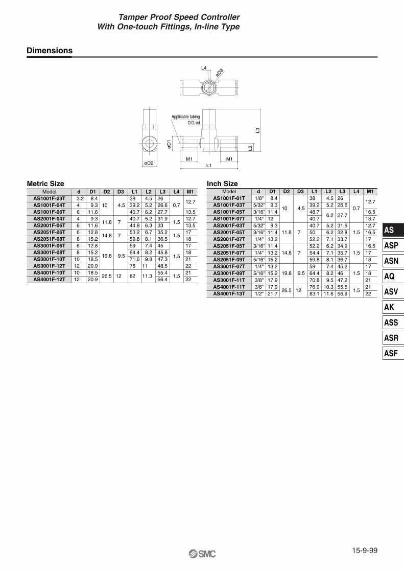
AS
ASP
ASN
AQ
ASV
AK
ASS
ASR
ASF
15-9-99
Tamper Proof Speed Controller With One-touch Fittings, In-line Type
Dimensions
Metric Size Inch SizeModel Model
L1øD2M1
Applicable tubingO.D. ød
øD
1
L2
L3
M1
L4
øD3
AS4001F-12T 12 AS4001F-10T 10 AS3001F-12T 12 AS3001F-10T 10 AS3001F-08T 8 AS3001F-06T 6 AS2051F-08T 8 AS2051F-06T 6 AS2001F-06T 6 AS2001F-04T 4 AS1001F-06T 6 AS1001F-04T 4 AS1001F-23T 3.2
d
20.918.520.918.515.212.815.212.811.6 9.311.6 9.3 8.4D1
26.5
19.8
14.8
11.8
10
D2
12
9.5
7
7
4.5
D3
82
76 71.664.459 59.853.244.840.740.739.238 L1
11.3
11 9.88.27.48.16.76.35.26.25.24.5L2
56.455.448.547.345.845 36.535.233 31.927.726.626 L3
1.5
1.5
1.5
1.5
0.7
L4
22 21 22 21 18 17 18 17 13.512.713.5
12.7
M1
AS4001F-13T 1/2"
AS3001F-11T 3/8"AS3001F-09T 5/16"AS3001F-07T 1/4"AS2051F-09T 5/16"AS2051F-07T 1/4"AS2051F-05T 3/16"AS2001F-07T 1/4"AS2001F-05T 3/16"AS2001F-03T 5/32"AS1001F-07T 1/4"AS1001F-05T 3/16"AS1001F-03T 5/32"AS1001F-01T 1/8"
d
21.7
17.915.213.215.213.211.413.211.4 9.312 11.4 9.3 8.4
D1
19.8
14.8
11.8
10
D2
9.5
7
7
4.5
D3
83.1
70.864.459 59.854.452.252.250 40.740.748.739.238 L1
11.6
9.5 8.2 7.4 8.1 7.1 6.2 7.1 6.2 5.2
6.2
5.2 4.5L2
56.9
47.246 45.236.735.734.933.732.831.9
27.7
26.626 L3
1.5
1.5
1.5
0.7
L4
22
21 AS4001F-11T 3/8" 17.9
26.5 12 76.9 10.3 55.5
1.521
18 17 18 17 16.517 16.512.713.716.5
12.7
M1

Model
Specifications
Tamper Proof Dual Speed Controller with One-touch Fitting
Series ASD���F-T
ASD230F-M5ASD330F-01ASD430F-02ASD530F-02ASD530F-03ASD630F-04ASD230F-U10/32ASD330F-N01ASD430F-N02ASD530F-N02ASD530F-N03ASD630F-N04
M5 x 0.8
R 1/8
R 1/4
R 1/4
R 3/8
R 1/2
10-32 UNF
NPT 1/8
NPT 1/4
NPT 1/4
NPT 3/8
NPT 1/2
Model Port size
Applicable tubing O.D.
Metric size Inch size
4
�
6
�
�
�
�
�
8
�
�
�
�
10
�
�
�
�
12
�
�
�
1/8"
�
5/32"
�
3/16"
�
�
1/4"
�
�
�
�
�
5/16"
�
�
�
�
3/8"
�
�
�
�
Fluid
Proof pressure
Max. operating pressure
Min. operating pressure
Ambient and fluid temperature
Number of needle rotations
Applicable tubing material (2)
Air
1.5 MPa
1 MPa
0.1 MPa
–5 to 60°C (No freezing)
10 turns (8 turns (1))
Nylon, Soft nylon, Polyurethane
Note 1) In the case of ASD230F typeNote 2) Use caution regarding the max. operating pressure when soft nylon or polyurethane tubing is used. (Refer to pages 15-6-3 to 15-6-5 for details.) Note 3) Brass parts are all electroless nickel plated, provided as standard.
JIS Symbol
Flow Direction Symbols on BodyFlow Rate and Effective Area
Note) Flow rate values are measured at 0.5 MPa and 20°C.
Model
Tubing O.D.
Metric size
Inch size
Effective area (mm2)
ASD230F ASD330F ASD430F ASD530F ASD630F
ø4, ø6
75
1.1
ø6, ø8
175
2.7
ø6
—
295
4.5
ø8, ø10
ø1/8"ø5/32"ø3/16"ø1/4"
ø3/16"ø1/4"
ø1/4"ø5/16"ø3/8"
350
5.3
ø6 ø8 ø10, ø12 ø10 ø12
ø1/4" ø5/16" ø3/8" — ø3/8"
500
7.6
600
9.1
700
10.7
1200
18.3
1300
19.8
Meter-out type Meter-in type
Sym
bol
JIS
Sym
bol
Flow rate (l/min (ANR))Controlled flow(Free flow)
15-9-100

AS
ASP
ASN
AQ
ASV
AK
ASS
ASR
ASF
Tamper Proof Dual Speed Controllerwith One-touch Fitting
15-9-101
Needle Valve/Flow Characteristics
ASD230F ASD330F ASD430F
ASD530F ASD630F
100
50
05 10
1.5
1.0
0.5
0
Number of needle rotations
Flow
rate
(l/m
in (A
NR))
Effe
ctiv
e ar
ea (
mm
2 )
Effe
ctiv
e ar
ea (
mm
2 )
Effe
ctiv
e ar
ea (
mm
2 )
Effe
ctiv
e ar
ea (
mm
2 )
Effe
ctiv
e ar
ea (
mm
2 )200
05 10
3
2
1
0
Number of needle rotations
Flow
rate
(l/m
in (A
NR))
100
400
05 10
6
4
2
0
Number of needle rotations
Flow
rate
(l/m
in (A
NR))
100
200
300 06
07,08,09,10,11
1500
05 10
20
15
10
0
Flow
rate
(l/m
in (A
NR))
500
10,11
12
1000
5
Number of needle rotations
05 10
14
10
8
0
Flow
rate
(l/m
in (A
NR))
500
1000
2
Number of needle rotations
12
6
4
06,07
10,11,1208,09
How to Order
Body sizeM5 standard1/8 standard1/4 standard3/8 standard1/2 standard
23456
TypeUniversal3
With One-touch fitting
M5 x 0.8R 1/8R 1/4R 3/8R 1/2
10-32 UNFNPT 1/8NPT 1/4NPT 3/8NPT 1/2
01020304
U10/32N01N02N03N04
M5
Port size
ø4ø6ø8
ø10 ø12
Metric size0406081012
Applicable tubing O.D.
ø1/8"ø5/32"ø3/16"ø1/4"
ø5/16"ø3/8"
Inch size
0305070911
01
ASD 3 3 0 F — 01— 06 S T
Tamper proof Note) Speed controller requires a special tool
for flow adjustment. Order separately with part number, AS-T-1.
With sealNote) In case that connecting port is either M5 or 10-32
UNF thread, it is not available with seal. With gasket is provided as standard.

Construction
ASD230F ASD330F/430FASD530F/630F
ASD530F-02
Component PartsNo. Description Material Note
Electroless nickel plated
Electroless nickel plated
Electroless nickel plated
Electroless nickel plated
q
w
e
r
t
y
u
i
o
!0
!1
!2
Body A
Elbow body
Body B
Body B
Needle
Seat ring
Spring
U seal
U seal
Cassette
Seal
O-ring
PBT
PBT
Brass
Brass
Brass
Brass
Steel wire
HNBR
HNBR
POM, Stainless steel (1)
NBR
NBR
No. Description Material Note
!3
!4
!5
!6
!7
!8
!9
O-ring
O-ring
O-ring
O-ring
Spacer
Gasket
Retaining ring for hole type C
NBR
NBR
NBR
NBR
POM (2)
NBR, Stainless steel
Tool steel
Note 1) ø3/16", ø5/16", ø3/8", ø1/2" are made of POM, stainless steel, brass (Electroless nickel plated). Note 2) ø3/16", ø3/8", ø1/2" are made of brass (Electroless nickel plated).
!8
t
y
e
!2
!1
!3
!6
u
e
!3
!4
i
!5 w !7 !0 o!6 w !7 !1 !0
!6 w !7 !1 !0
u q i !4 r y t
r
y !2 o !5 r u t
i o !2 r
!2 !4 u tt q
A A
A A
t
u
y
!3
q
!5
e
15-9-102

Dimensions
Metric size
Inch size
L1
M1L3
L2
øD
1 Applicable tubing O.D. ød
øD2L6
L4
øD
3
T
A1
L5
A2
H
øD4
øD4
L6
Metric Size
∗ Reference dimensions of M5 x 0.8, R threads after installation.
ASD230F-M5-04T ASD230F-M5-06T ASD330F-01-06STASD330F-01-08STASD430F-02-06STASD430F-02-08STASD430F-02-10STASD530F-02-06STASD530F-02-08STASD530F-02-10STASD530F-02-12STASD530F-03-06STASD530F-03-08STASD530F-03-10STASD530F-03-12STASD630F-04-10STASD630F-04-12ST
d466868
1068
101268
10121012
Model H D1 D2 D3 D4 L1 L2 L3 L4 L5 L6 A1 ∗ A2 ∗ M1T
L1
M1L3
L2
øD
1 Applicable tubing O.D. ød
øD2L6
L4
øD
3
T
A1
L5
A2
H
øD4
øD4
L6
∗ Reference dimensions of 10-32 UNF and NPT threads after installation.
Inch Size
ASD230F-U10/32-01TASD230F-U10/32-03TASD230F-U10/32-05TASD230F-U10/32-07TASD330F-N01-05STASD330F-N01-07STASD330F-N01-09STASD430F-N02-07STASD430F-N02-09STASD430F-N02-11STASD530F-N02-07STASD530F-N02-09STASD530F-N02-11STASD530F-N03-07STASD530F-N03-09STASD530F-N03-11STASD630F-N04-11ST
d1/8"5/32"3/16"1/4"3/16"1/4"5/16"1/4"5/16"3/8"1/4"5/16"3/8"1/4"5/16"3/8"3/8"
Model H D1 D2 D3 D4 L1 L2 L3 L4 L5 L6 A1 ∗ A2 ∗ M1T
(Hexagon width across flats)(Hexagon width across flats)
8
12
17
19
19
24
9.311.611.615.212.815.218.512.815.218.520.912.815.218.520.918.520.9
9.6
14.2
18.5
23
23
28.6
10
11.8
15
19.8
19.8
26.5
4.5
7
7
9.5
9.5
12
11.7
14 15.8
18
19.7
20.3
23.1
20.3
23.1
25.9
29.432.538.544.843.546.549.348.351.354.155.948.351.354.155.964.366.1
17.520.622.928.225.228.231 25.228.232.634.425.228.232.634.432.634.4
30.7
38.938.2
41.7
53.7
53.7
69.1
31
35.6
40.7
55.3
53.7
63.8
0.7
1.5
1.5
1.5
1.5
1.5
27.4
31.6
34.7
49.3
47.4
55.8
7.8
10.6
11
15.4
14
18.6
12.9 13.7 13.7 18.5 17 18.5 21 17 18.5 21 22 17 18.5 21 22 21 22
M5 x 0.8
R 1/8
R 1/4
R 1/4
R 3/8
R 1/2
8
12.7
17.5
19
19
23.8
8.4 9.311.412 11.613.215.213.215.218.513.215.218.513.215.218.518.5
9.6
14.2
18.5
23
23
28.6
10
11.8
15
19.8
19.8
26.5
4.5
7
7
9.5
9.5
12
11.7
14
15.8
18
19.7
20.3
23.1
20.3
23.125.9
29.4
35.232.638.542.244.843.946.549.348.751.354.148.751.354.164.3
17.5
23.320.723.925.628.225.628.231 25.628.232.625.628.232.632.6
30.7
38.9
38.2
41.7
53.7
53.7
69.1
31
35.6
40.7
55.3
53.7
63.8
0.7
1.5
1.5
1.5
1.5
1.5
27.4
31.6
34.7
49.3
47.4
55.8
7.8
10.6
11
15.4
14
18.6
12.9
16.513.516.517 18.517 18.521 17 18.521 17 18.521 21
10-32 UNF
NPT 1/8
NPT 1/4
NPT 1/4
NPT 3/8
NPT 1/2
(Hexagon width across flats)(Hexagon width across flats)
15-9-103
Tamper Proof Dual Speed Controllerwith One-touch Fitting
AS
ASP
ASN
AQ
ASV
AK
ASS
ASR
ASF

Model/ Specifications
How to Order
Tamper Proof Speed ControllerStandard Type
Series AS�2�0-TElbow Type (Metal Body)
JIS Symbol
1/410-32 UNFPort size
Applicable cylinder bore size (mm)
Fluid
Proof pressure
Max. operating pressure
Min. operating pressure
Ambient and fluid temperature
Number of needle rotations
Flow rate (l/min (ANR))
Effective area (mm2)
AS42�0-�04
1/8 1/4 3/8
32, 40, 50, 63
1/2
80, 10020, 25, 32, 406, 10, 16, 20, 25
AS12�0-M5 AS12�0-U10/32Specifications Model
Air
1.5 MPa
1 MPa
0.1 MPa
–5 to 60°C (No freezing)
10 turns8 turns
105
1.6
1700
26
920
14
460
7
230
3.5
Note 1) Flow rate values are measured at 0.5 MPa and 20°C.Note 2) Meter-out and meter-in types can be visually differentiated by the flow direction symbol on the resin body. Note 3) Brass parts are all electroless nickel plated, provided as standard.
M5 x 0.8
AS22�0-�01 AS32�0-�03AS32�0-�02AS22�0-�02
01 SAS 2 0 0
Body size1234
M5 standard1/8, 1/4 standard
3/8 standard1/2 standard
2
TypeElbow2
Control01
T
Port sizeSymbol Cylinder side In the side of solenoid valve
M501020304
F01F02F03F04
U10/32N01N02N03N04
M5 x 0.8R 1/8R 1/4R 3/8R 1/2R 1/8R 1/4R 3/8R 1/2
10-32 UNFNPT 1/8NPT 1/4NPT 3/8NPT 1/2
M5 x 0.8Rc 1/8Rc 1/4Rc 3/8Rc 1/2G 1/8G 1/4G 3/8G 1/2
10-32 UNFNPT 1/8NPT 1/4NPT 3/8NPT 1/2
Meter-outMeter-in
Tamper proof Note) Speed controller
requires a special tool for flow adjustment. Order separately with part number, AS-T-1.
With sealNote) When connecting port is either M5
or 10-32 UNF thread, it is not available with seal. With gasket is provided as standard.
Controlled flow(Free flow)
15-9-104

Flo
w r
ate l/m
in (
AN
R)
Effe
ctiv
e ar
ea (
mm
2 )
Inlet pressure: 0.5 MPa
Number of needle rotations
Flo
w r
ate l/m
in (
AN
R)
Effe
ctiv
e ar
ea (
mm
2 )
Inlet pressure: 0.5 MPa
Number of needle rotations
Flo
w r
ate l/m
in (
AN
R)
Effe
ctiv
e ar
ea (
mm
2 )
Inlet pressure: 0.5 MPa
Number of needle rotations
Flo
w r
ate l/m
in (
AN
R)
Effe
ctiv
e ar
ea (
mm
2 )
Inlet pressure: 0.5 MPa
Number of needle rotations
Flo
w r
ate l/m
in (
AN
R)
Effe
ctiv
e ar
ea (
mm
2 )
Inlet pressure: 0.5 MPa
Number of needle rotations
Needle Valve/Flow Characteristics
Construction
Component PartsNo. Description Material Note
Electroless nickel plated
Electroless nickel plated
Electroless nickel plated
q
w
e
r
t
y
u
Body A
Body B
Needle
Seat ring
Spring
U seal
O-ring
Zinc alloy
Brass
Brass
Brass
Steel wire
HNBR
NBR
No. Description Material Note
i
o
!0
!1
!2
!3
O-ring
O-ring
Bushing
O-ring
Gasket
Retaining ring for hole type C
NBR
NBR
PBT
NBR
NBR, Stainless steel
Tool steel
AS3200-02
AS3210-02
Meter-out typeM5 typeU10/32 port
Meter-in typeM5 typeU10/32 port
!3
e
t
w
o
u
!4
y
q
!2
w
e
t
o
u
q
!4
!1
!0
i
y
r
e
t
r
i
!0
q
y
!3
!2
!1
o
w
u
15-9-105
Tamper Proof Speed ControllerStandard Type, Elbow Type (Metal Body)
AS
ASP
ASN
AQ
ASV
AK
ASS
ASR
ASF

Dimensions
L2
øD
1
øD2
L3
A
T2
T1L1
H
L4
øD3
∗ Reference thread dimensions after installation.
Dimensions
AS42�0-N04-ST NPT 1/2NPT 1/2AS42�0-F04-ST G 1/2AS42�0-04-ST Rc 1/2R 1/2
AS32�0-N03-ST NPT 3/8NPT 3/8AS32�0-F03-ST G 3/8AS32�0-03-ST Rc 3/8R 3/8
AS32�0-N02-ST NPT 1/4NPT 1/4AS32�0-F02-ST G 1/4AS32�0-02-ST Rc 1/4R 1/4
AS22�0-N02-ST NPT 1/4NPT 1/4AS22�0-F02-ST G 1/4AS22�0-02-ST Rc 1/4R 1/4
AS22�0-N01-ST NPT 1/8NPT 1/8AS22�0-F01-ST G 1/8AS22�0-01-ST Rc 1/8R 1/8
AS12�0-U10/32-T 10-32 UNF10-32 UNFAS12�0-M5-T M5 x 0.8M5 x 0.8
Model T2 H D1T1 D2 D3 L1 L2 L3 L4 A∗
(He(Hexagon width across flats)xagon width across flats)(Hexagon width across flats)
23.8
24 27.5
19 22.5
19 22.5
17.5
17 18
12.7
12 14.3
8 9
28.5
24.3
24.3
19.5
14.6
9
12
9.5
9.5
7
7
4.5
38.5
30
30
27.2
18
10
63.8
53.7
55.3
40.7
35.6
31
26.7
20.8
22.4
18
14.1
10.3
1.5
1.5
1.5
1.5
1.5
0.7
55.8
47.4
49.3
36.7
31.6
27.4
15-9-106
Related Documents