The Graphics Programming Language R. A. Green As accepted by the RAG Software GPL Macro Assembler Edited by Lee Stewart (2016)

Welcome message from author
This document is posted to help you gain knowledge. Please leave a comment to let me know what you think about it! Share it to your friends and learn new things together.
Transcript

i
The GraphicsProgramming
Language
R. A. Green
As accepted by the RAGSoftware GPL Macro
Assembler
Edited by Lee Stewart (2016)

ii
Copyright © 1990 by R. A. Green

Table of Contents
1 Introduction................................................................................................................................12 Graphics memory (GRAM)........................................................................................................23 TI 99/4A GROM Operating System...........................................................................................3
3.1 System Power Up................................................................................................................3 3.2 GRAM/DSR Headers..........................................................................................................3 3.3 GRAM/DSR Chains...........................................................................................................4 3.4 GPL Callable Subroutines...................................................................................................4 3.5 Floating Point Numbers......................................................................................................4 3.6 Automatic Sound Processing..............................................................................................5 3.7 Automatic Sprite Motion....................................................................................................6 3.8 Keyboard Input...................................................................................................................7
4 CPU RAM PAD.........................................................................................................................8 4.1 Memory Map......................................................................................................................8 4.2 GPL Status Byte.................................................................................................................9 4.3 VDP Status Byte...............................................................................................................10 4.4 Floating Point Error Codes...............................................................................................10
5 VDP RAM Usage.....................................................................................................................116 Addressing Modes....................................................................................................................12
6.1 The Six Addressing Modes...............................................................................................12 6.1.1 Direct Memory Reference.........................................................................................12 6.1.2 Indirect Memory Reference......................................................................................12 6.1.3 Indexed Direct Memory Reference...........................................................................12 6.1.4 Indexed Indirect Memory Reference.........................................................................12 6.1.5 Immediate Data.........................................................................................................12 6.1.6 VDP Register Direct.................................................................................................12
6.2 Operand Notations............................................................................................................13 6.2.1 General Source – gsrc...............................................................................................13 6.2.2 General Destination – gdest......................................................................................14 6.2.3 Special Addresses.....................................................................................................14
7 Elements of the Language.........................................................................................................16 7.1 Assembler Statements.......................................................................................................16
7.1.1 Comment..................................................................................................................16 7.1.2 Assembler Directives................................................................................................16 7.1.3 Macro Directives.......................................................................................................16 7.1.4 Ordinary Statements..................................................................................................17 7.1.5 Macro Statements.....................................................................................................17
7.2 Assembler Symbols..........................................................................................................17 7.2.1 Ordinary Symbols.....................................................................................................17 7.2.2 Macro Symbols.........................................................................................................17
7.3 Macro Symbol Substring Notation....................................................................................18 7.4 Macro Definitions.............................................................................................................19
iii

7.5 The Location Counter.......................................................................................................19 7.6 Expressions.......................................................................................................................20 7.7 Constants..........................................................................................................................20 7.8 Definition of Terms...........................................................................................................20
8 Assembler Directives................................................................................................................22 8.1 AORG—Absolute Origin.................................................................................................22 8.2 BSS—Block Starting with Symbol...................................................................................22 8.3 BYTE—Define Byte Data................................................................................................22 8.4 COPY—Copy Source from File.......................................................................................23 8.5 DATA—Define Double Byte Data...................................................................................23 8.6 DEF—Define External Name...........................................................................................23 8.7 DORG—Dummy Origin...................................................................................................24 8.8 END—End of Assembly...................................................................................................24 8.9 EQU—Set Symbol Equal to Value...................................................................................24 8.10 FLOAT—Define Floating Point Data.............................................................................25 8.11 IDT—Identify Object......................................................................................................25 8.12 LIST—Resume Assembler Listing.................................................................................25 8.13 OBJREC—Write Object Record.....................................................................................25 8.14 PAGE—Start New Listing Page.....................................................................................26 8.15 REF—External Reference...............................................................................................26 8.16 STRI—Define ASCII String Constant............................................................................26 8.17 TEXT—Define ASCII Text Constant.............................................................................27 8.18 TITL—Define Listing Title............................................................................................27 8.19 UNL—Stop Assembler Listing.......................................................................................27
9 Ordinary Statements..................................................................................................................28 9.1 ABS DABS—Absolute Value..........................................................................................28 9.2 ADD DADD—Add..........................................................................................................28 9.3 ALL—Load Screen...........................................................................................................28 9.4 AND DAND—Logical And.............................................................................................29 9.5 B—Branch........................................................................................................................29 9.6 BACK—Load Background Colour...................................................................................29 9.7 BR—Branch on Reset.......................................................................................................30 9.8 BS—Branch on Set...........................................................................................................30 9.9 CALL—Call Subroutine...................................................................................................30 9.10 CARRY—Transfer CARRY to COND...........................................................................31 9.11 CASE DCASE—Select Case..........................................................................................31 9.12 CEQ DCEQ—Compare Equal........................................................................................31 9.13 CGE DCGE—Compare Greater Than or Equal..............................................................32 9.14 CGT DCGT—Compare Greater Than............................................................................32 9.15 CH DCH—Compare Logical High.................................................................................33 9.16 CHE DCHE—Compare Logical High or Equal..............................................................33 9.17 CLOG DCLOG—Compare Logical...............................................................................33 9.18 CLR DCLR—Zero Value...............................................................................................34 9.19 COINC—Coincidence Check.........................................................................................34
iv
9.20 COL—Set Current Column.............................................................................................35 9.21 CONT—Continue BASIC..............................................................................................35 9.22 CZ DCZ—Compare to Zero...........................................................................................35 9.23 DEC DDEC—Decrement by One...................................................................................36 9.24 DECT DDECT—Decrement by Two.............................................................................36 9.25 DIV DDIV—Divide........................................................................................................36 9.26 EX DEX—Exchange......................................................................................................37 9.27 EXEC—Execute BASIC.................................................................................................37 9.28 EXIT—Exit from Program.............................................................................................37 9.29 FEND—End of Formatted Screen Write........................................................................38 9.30 FETCH—Fetch Parameter..............................................................................................38 9.31 FMT—Formatted Screen Write......................................................................................38 9.32 FOR—Begin Formatted Screen Write Loop...................................................................39 9.33 GT—Transfer GT to COND...........................................................................................39 9.34 H—Transfer H to COND................................................................................................40 9.35 HCHA—Display Character Horizontally........................................................................40 9.36 HSTR—Display Character Horizontally.........................................................................40 9.37 HTEX—Display String Horizontally..............................................................................41 9.38 ICOL—Increment Current Column................................................................................41 9.39 INC DINC—Increment by One......................................................................................42 9.40 INCT DINCT—Increment by Two.................................................................................42 9.41 INV DINV—Invert Bits..................................................................................................43 9.42 IO—Special I/O..............................................................................................................43 9.43 IROW—Increment Current Row....................................................................................45 9.44 MOVE—Block Move.....................................................................................................45 9.45 MUL DMUL—Multiply.................................................................................................45 9.46 NEG DNEG—Negate.....................................................................................................46 9.47 OR DOR—Logical OR...................................................................................................46 9.48 OVF—Transfer OVF to COND......................................................................................47 9.49 PARSE—Parse for BASIC Token..................................................................................47 9.50 POP—Pop from Data Stack............................................................................................47 9.51 PUSH—Push onto Data Stack........................................................................................47 9.52 RAND—Generate Random Number...............................................................................48 9.53 ROW—Set Current Row................................................................................................48 9.54 RTN—Return from Subroutine.......................................................................................49 9.55 RTNB—Return from BASIC..........................................................................................49 9.56 RTNC—Return with COND...........................................................................................49 9.57 SCAN—Scan Keyboard.................................................................................................49 9.58 SCRO—Set Screen Offset..............................................................................................50 9.59 SLL DSLL—Shift Left Logical......................................................................................50 9.60 SRA DSRA—Shift Right Arithmetically........................................................................51 9.61 SRC DSRC—Shift Right Circular..................................................................................51 9.62 SRL DSRL—Shift Right Logical...................................................................................51 9.63 ST DST—Store...............................................................................................................52
v
9.64 SUB DSUB—Subtract....................................................................................................52 9.65 VCHA—Display Character Vertically............................................................................52 9.66 VTEX—Display String Vertically..................................................................................53 9.67 XML—Execute Machine Language...............................................................................53 9.68 XOR DXOR—Logical Exclusive OR.............................................................................54
10 Macro Directives.....................................................................................................................56 10.1 $END—End of Macro Definition...................................................................................56 10.2 $ERROR—Issue Error Message.....................................................................................56 10.3 $EXIT—Exit from Macro...............................................................................................57 10.4 $GOTO—Branch within Macro......................................................................................57 10.5 $IF—Conditional Branch within Macro.........................................................................57 10.6 $LABEL—Define Macro Label......................................................................................58 10.7 $MACRO—Begin Macro Definition..............................................................................58 10.8 $REM—Macro Reminder...............................................................................................59 10.9 $SET—Set Macro Symbol..............................................................................................59
Appendix A GPL Subroutines.....................................................................................................60 A.1 DSRLNK (GRAM Address >0010).................................................................................60 A.2 GSRRTN (GRAM Address >0012).................................................................................60 A.3 SUBCNS (GRAM Address >0014).................................................................................60 A.4 STDCHR (GRAM Address >0016).................................................................................61 A.5 UCCHAR (GRAM Address >0018)................................................................................61 A.6 BWARN (GRAM Address >001A).................................................................................61 A.7 BERR (GRAM Address >001C)......................................................................................61 A.8 BEXEC (GRAM Address >001E)...................................................................................61 A.9 PWRUP (GRAM Address >0020)...................................................................................61 A.10 SUBINT (GRAM Address >0022).................................................................................61 A.11 SUBPWR (GRAM Address >0024)...............................................................................61 A.12 SUBSQR (GRAM Address >0026)................................................................................62 A.13 SUBEXP (GRAM Address >0028)................................................................................62 A.14 SUBLOG (GRAM Address >002A)..............................................................................62 A.15 SUBCOS (GRAM Address >002C)...............................................................................63 A.16 SUBSIN (GRAM Address >002E)................................................................................63 A.17 SUBTAN (GRAM Address >0030)...............................................................................63 A.18 SUBATN (GRAM Address >0032)...............................................................................64 A.19 BEEP (GRAM Address >0034).....................................................................................64 A.20 HONK (GRAM Address >0036)...................................................................................64 A.21 BGETSS (GRAM Address >0038)................................................................................64 A.22 BITREV (GRAM Address >003B)................................................................................64 A.23 CASDSR (GRAM Address >003D)...............................................................................65 A.24 BPABSS (GRAM Address >003F)................................................................................65 A.25 BSETSU (GRAM Address >0042)................................................................................65 A.26 LCCHAR (GRAM Address >004A)..............................................................................65
Appendix B XML Routines.........................................................................................................66 B.1 XML >00 Undefined......................................................................................................66
vi

B.2 XML >01 Round FAC...................................................................................................66 B.3 XML >02 Round FAC at ARG......................................................................................66 B.4 XML >03 Set STATUS Depending on FAC..................................................................66 B.5 XML >04 Floating Point Underflow/Overflow..............................................................66 B.6 XML >05 Set Floating Point Overflow..........................................................................66 B.7 XML >06 Floating Point Add........................................................................................67 B.8 XML >07 Floating Point Subtract..................................................................................67 B.9 XML >08 Floating Point Multiply.................................................................................67 B.10 XML >09 Floating Point Divide..................................................................................67 B.11 XML >0A Floating Point Compare..............................................................................67 B.12 XML >0B Floating Point Stack Add............................................................................67 B.13 XML >0C Floating Point Stack Subtract......................................................................67 B.14 XML >0D Floating Point Stack Multiply.....................................................................68 B.15 XML >0E Floating Point Stack Divide........................................................................68 B.16 XML >0F Floating Point Stack Compare.....................................................................68 B.17 XML >10 Convert VDP String to Floating..................................................................68 B.18 XML >11 Convert String to Floating...........................................................................68 B.19 XML >12 Convert Floating to Integer..........................................................................68 B.20 XML >13 Get BASIC Symbol Table Entry.................................................................68 B.21 XML >14 Get BASIC Symbol Table Value.................................................................68 B.22 XML >15 Assign Value to BASIC Variable................................................................69 B.23 XML >16 Search BASIC Symbol Table......................................................................69 B.24 XML >17 Push Value onto VDP Stack........................................................................69 B.25 XML >18 Pop Value from VDP Stack.........................................................................69 B.26 XML >19 Search DSR ROM Chains...........................................................................69 B.27 XML >1A Search GROM Chains................................................................................69 B.28 XML >1B Get Next BASIC Byte.................................................................................69 B.29 XML >1C Undefined...................................................................................................69 B.30 XML >1D Undefined...................................................................................................69 B.31 XML >1E Undefined...................................................................................................69 B.32 XML >1F Undefined....................................................................................................69
Appendix C BASIC Tokens.........................................................................................................70 Appendix D Coincidence .........................................................................................................72 Appendix E GPL Operation Codes..............................................................................................76
E.1 GPL Operations................................................................................................................76 E.2 Format Suboperations.......................................................................................................81
Appendix F General Address Format...........................................................................................82
vii
1 Introduction 1
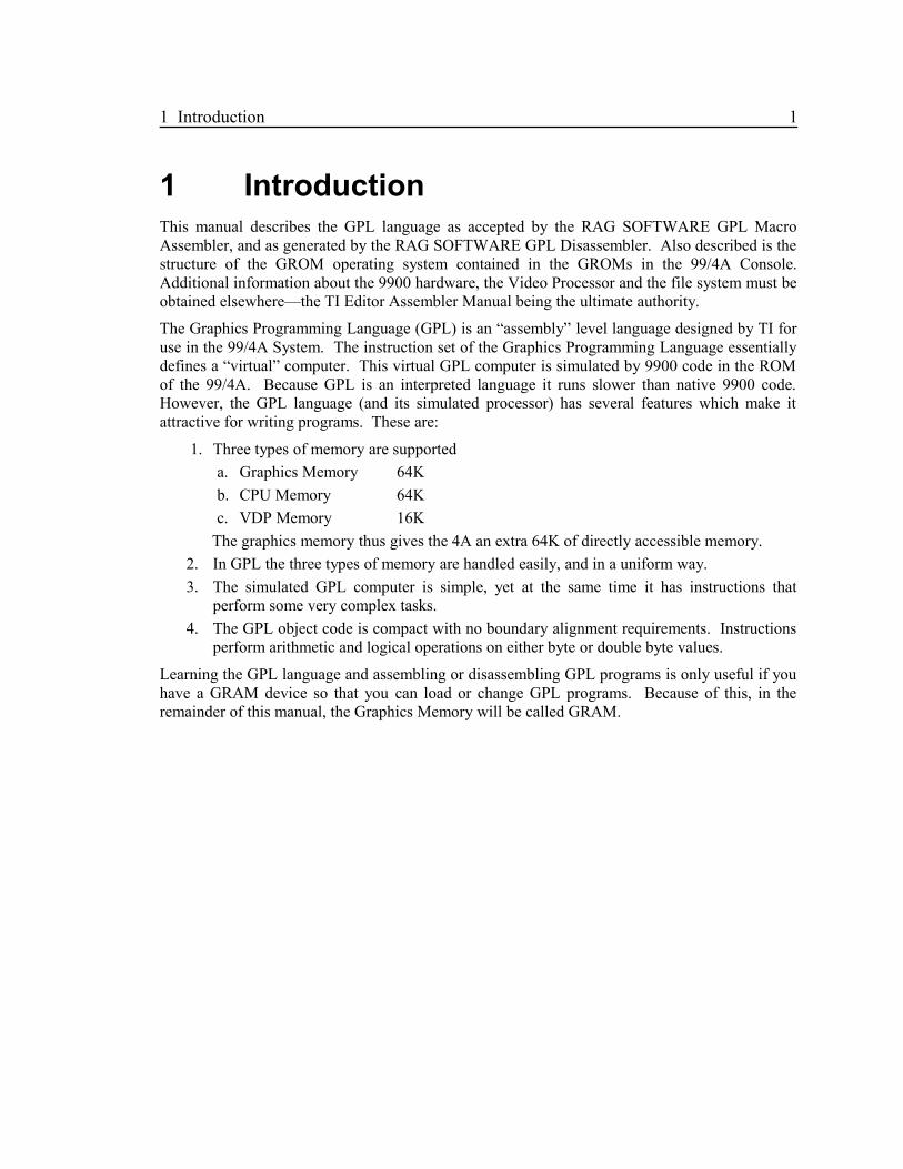
1 IntroductionThis manual describes the GPL language as accepted by the RAG SOFTWARE GPL MacroAssembler, and as generated by the RAG SOFTWARE GPL Disassembler. Also described is thestructure of the GROM operating system contained in the GROMs in the 99/4A Console.Additional information about the 9900 hardware, the Video Processor and the file system must beobtained elsewhere—the TI Editor Assembler Manual being the ultimate authority.
The Graphics Programming Language (GPL) is an “assembly” level language designed by TI foruse in the 99/4A System. The instruction set of the Graphics Programming Language essentiallydefines a “virtual” computer. This virtual GPL computer is simulated by 9900 code in the ROMof the 99/4A. Because GPL is an interpreted language it runs slower than native 9900 code.However, the GPL language (and its simulated processor) has several features which make itattractive for writing programs. These are:
1. Three types of memory are supported
a. Graphics Memory 64K
b. CPU Memory 64K
c. VDP Memory 16K
The graphics memory thus gives the 4A an extra 64K of directly accessible memory.
2. In GPL the three types of memory are handled easily, and in a uniform way.
3. The simulated GPL computer is simple, yet at the same time it has instructions thatperform some very complex tasks.
4. The GPL object code is compact with no boundary alignment requirements. Instructionsperform arithmetic and logical operations on either byte or double byte values.
Learning the GPL language and assembling or disassembling GPL programs is only useful if youhave a GRAM device so that you can load or change GPL programs. Because of this, in theremainder of this manual, the Graphics Memory will be called GRAM.

2 2 Graphics memory (GRAM)
2 Graphics memory (GRAM)GPL programs reside in GRAM. Each GRAM block was defined by TI to be 6K bytes within an8K address block. Some of the available GRAM devices have expanded this so that the full 8Kin each block is available. The GRAM device RAM like the VDP RAM is viewed by the 9900CPU as a memory mapped I/O device and is accessed one byte at a time through an I/O port asshown in the table below.
Port GRAM VDP RAM
Write Address >9C02 >8C02
Write Data >9C00 >8C00
Read Address >9802 —
Read Data >9800 >8800
The GRAM address is a 16 bit number allowing an address range of 64K which allows 8 GRAMblocks of either 6K or 8K bytes. There are 3 GROM blocks in the 4A console (which can beoverridden by some GRAM devices). The following table shows the standard layout of GRAM:
GRAM Base End EndBlock Address Address Extended Contents
0 >0000 >17FF >1FFF 4A O/S
1 >2000 >37FF >3FFF TI BASIC
2 >4000 >57FF >5FFF TI BASIC
3 >6000 >77FF >7FFF Cartridge
4 >8000 >97FF >9FFF Cartridge
5 >A000 >B7FF >BFFF Cartridge
6 >C000 >D7FF >DFFF Cartridge
7 >E000 >F7FF >FFFF Cartridge
3 TI 99/4A GROM Operating System 3
3 TI 99/4A GROM Operating SystemThis section describes the structure of the GROM operating System. This knowledge is requiredsince the GPL interpreter in the 4A ROM depends upon the structure. TI BASIC is entwined intothis structure as well, with several GPL operations dedicated to BASIC. The explanation of theTI BASIC interpreter is beyond the scope of this manual and will only be mentioned whennecessary in the description of some other item.
3.1 System Power Up
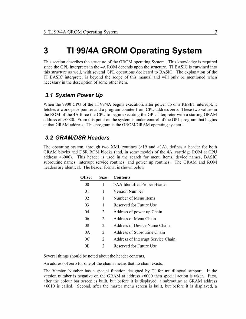
When the 9900 CPU of the TI 99/4A begins execution, after power up or a RESET interrupt, itfetches a workspace pointer and a program counter from CPU address zero. These two values inthe ROM of the 4A force the CPU to begin executing the GPL interpreter with a starting GRAMaddress of >0020. From this point on the system is under control of the GPL program that beginsat that GRAM address. This program is the GROM/GRAM operating system.
3.2 GRAM/DSR Headers
The operating system, through two XML routines (>19 and >1A), defines a header for bothGRAM blocks and DSR ROM blocks (and, in some models of the 4A, cartridge ROM at CPUaddress >6000). This header is used in the search for menu items, device names, BASICsubroutine names, interrupt service routines, and power up routines. The GRAM and ROMheaders are identical. The header format is shown below.
Offset Size Contents
00 1 >AA Identifies Proper Header
01 1 Version Number
02 1 Number of Menu Items
03 1 Reserved for Future Use
04 2 Address of power up Chain
06 2 Address of Menu Chain
08 2 Address of Device Name Chain
0A 2 Address of Subroutine Chain
0C 2 Address of Interrupt Service Chain
0E 2 Reserved for Future Use
Several things should be noted about the header contents.
An address of zero for one of the chains means that no chain exists.
The Version Number has a special function designed by TI for multilingual support. If theversion number is negative on the GRAM at address >6000 then special action is taken. First,after the colour bar screen is built, but before it is displayed, a subroutine at GRAM address>6010 is called. Second, after the master menu screen is built, but before it is displayed, a

4 3.2 GRAM/DSR Headers
subroutine at GRAM address >6013 is called. These two locations should contain unconditionalbranches to the processing routine. The routines should end with an RTN instruction. Theseroutines can use the full GPL/System facilities. If these routines modify the screen area of VDP,then upon return, this modified screen will be displayed. Locations >8300 through >836F in CPURAM may be used freely.
The Power Up routines in DSR ROM (at CPU address >4000) are executed first (via XML >19),then the GRAM power up routines are executed (via XML >1A). The power up routines may notuse XML >19 nor XML >1A. Locations >8304 through >8371 in CPU RAM may be used freely.
Interrupt Service routines exist only in device ROMs.
3.3 GRAM/DSR Chains
The GRAM and DSR chains are identical in format. The chain format is shown below:
Offset Size Contents
0 2 Address of next chain item
2 2 Routine starting address
4 1 Length of following text
5 n Text for: Menu Item, BASIC Subroutine Name or Device Name
A chain address of zero indicates no further items in the chain. The text length and the text arenot used for power up or interrupt service chains.
3.4 GPL Callable Subroutines
The GROM Operating System provides several routines that can be called by GPL programs.They are called by the GPL CALL statement. All of the routines are located in GROM 0 of theconsole. Each is described in Appendix A, “GPL SUBROUTINES”.
There are a number of subroutines located within the interpreter that can be called via the XMLinstruction. Especially useful are the floating point arithmetic routines. The XML routines aredescribed in Appendix B, “XML ROUTINES”.
3.5 Floating Point Numbers
The GPL interpreter provides an implementation of floating point arithmetic. The variousroutines are accessed via the XML instruction.
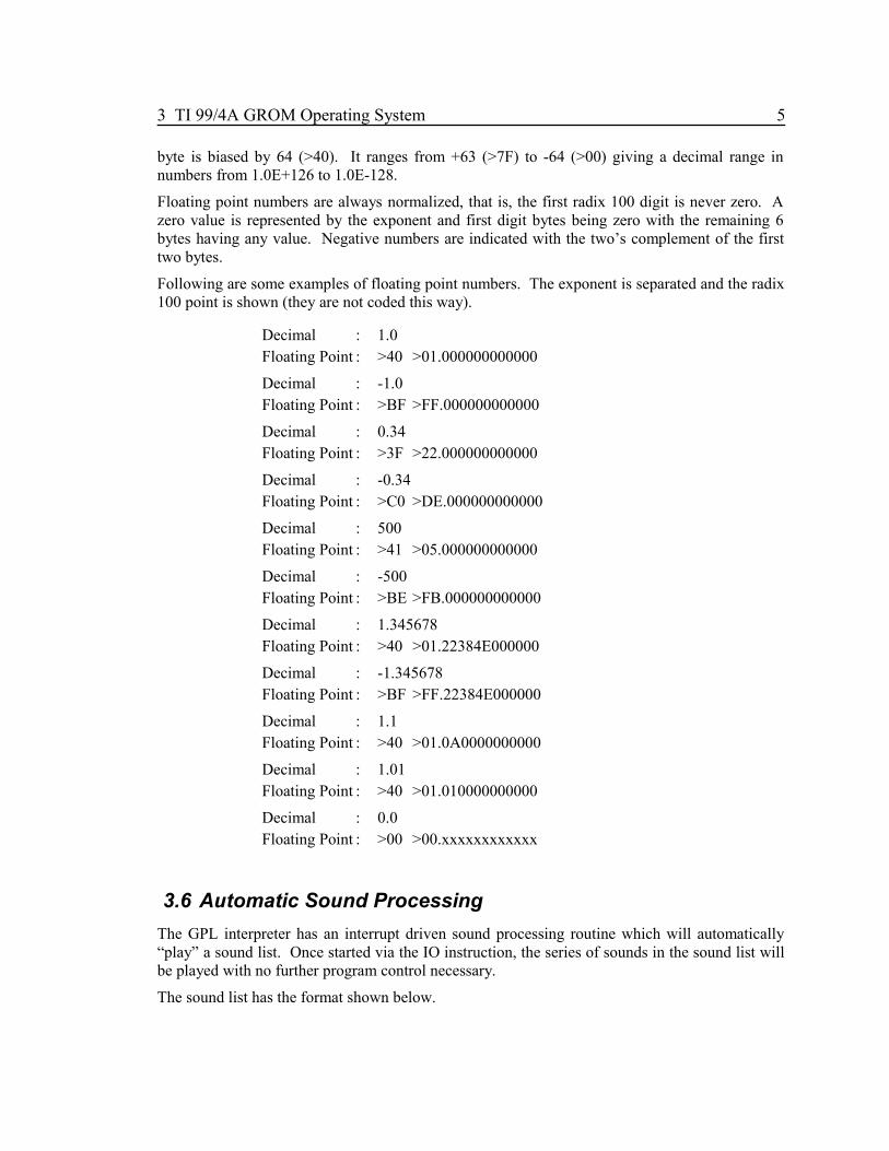
Floating point numbers are 8 bytes, a one byte exponent followed by a 7 byte mantissa. Thenumbers are in radix 100 form. Each byte in the radix 100 mantissa represents a number from 0to 99. The seven byte mantissa thus corresponds to 13 or 14 decimal digits.
The radix 100 point is assumed to be after the first digit. The exponent indicates the number ofpositions to move the point, either left (negative) or right (positive). The exponent thusrepresents a power of 100 by which the mantissa is multiplied. The exponent in the exponent
3 TI 99/4A GROM Operating System 5
byte is biased by 64 (>40). It ranges from +63 (>7F) to -64 (>00) giving a decimal range innumbers from 1.0E+126 to 1.0E-128.
Floating point numbers are always normalized, that is, the first radix 100 digit is never zero. Azero value is represented by the exponent and first digit bytes being zero with the remaining 6bytes having any value. Negative numbers are indicated with the two’s complement of the firsttwo bytes.
Following are some examples of floating point numbers. The exponent is separated and the radix100 point is shown (they are not coded this way).
Decimal : 1.0Floating Point : >40 >01.000000000000
Decimal : -1.0Floating Point : >BF >FF.000000000000
Decimal : 0.34Floating Point : >3F >22.000000000000
Decimal : -0.34Floating Point : >C0 >DE.000000000000
Decimal : 500Floating Point : >41 >05.000000000000
Decimal : -500Floating Point : >BE >FB.000000000000
Decimal : 1.345678Floating Point : >40 >01.22384E000000
Decimal : -1.345678Floating Point : >BF >FF.22384E000000
Decimal : 1.1Floating Point : >40 >01.0A0000000000
Decimal : 1.01Floating Point : >40 >01.010000000000
Decimal : 0.0Floating Point : >00 >00.xxxxxxxxxxxx
3.6 Automatic Sound Processing
The GPL interpreter has an interrupt driven sound processing routine which will automatically“play” a sound list. Once started via the IO instruction, the series of sounds in the sound list willbe played with no further program control necessary.
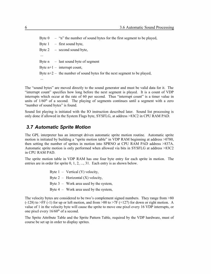
The sound list has the format shown below.
6 3.6 Automatic Sound Processing
Byte 0 – “n” the number of sound bytes for the first segment to be played,
Byte 1 – first sound byte,
Byte 2 – second sound byte, ...
Byte n – last sound byte of segment
Byte n+1 – interrupt count,
Byte n+2 – the number of sound bytes for the next segment to be played, ...
The “sound bytes” are moved directly to the sound generator and must be valid data for it. The“interrupt count” specifies how long before the next segment is played. It is a count of VDPinterrupts which occur at the rate of 60 per second. Thus “interrupt count” is a timer value inunits of 1/60th of a second. The playing of segments continues until a segment with a zero“number of sound bytes” is found.
Sound list playing is initiated with the IO instruction described later. Sound list processing isonly done if allowed in the System Flags byte, SYSFLG, at address >83C2 in CPU RAM PAD.
3.7 Automatic Sprite Motion
The GPL interpreter has an interrupt driven automatic sprite motion routine. Automatic spritemotion is initiated by building a “sprite motion table” in VDP RAM beginning at address >0780,then setting the number of sprites in motion into SPRNO at CPU RAM PAD address >837A.Automatic sprite motion is only performed when allowed via bits in SYSFLG at address >83C2in CPU RAM PAD.
The sprite motion table in VDP RAM has one four byte entry for each sprite in motion. Theentries are in order for sprite 0, 1, 2, ..., 31. Each entry is as shown below.
Byte 1 – Vertical (Y) velocity,
Byte 2 – Horizontal (X) velocity,
Byte 3 – Work area used by the system,
Byte 4 – Work area used by the system,
The velocity bytes are considered to be two’s complement signed numbers. They range from >80(-128) to >FF (-1) for up or left motion, and from >00 to >7F (+127) for down or right motion. Avalue of 1 in the velocity byte will cause the sprite to move one pixel every 16 VDP interrupts, orone pixel every 16/60th of a second.
The Sprite Attribute Table and the Sprite Pattern Table, required by the VDP hardware, must ofcourse be set up in order to display sprites.

3 TI 99/4A GROM Operating System 7
3.8 Keyboard Input
The GPL SCAN instruction and most Assembler Language programs make use of a routine in theconsole ROM (at address >000E) to scan the keyboard/joysticks. This KSCAN routine makesuse of tables in GRAM 0 (at addresses >16E0 to >17EF) to translate the keyboard/joystick matrixinto the defined ASCII characters or joystick values.

8 4 CPU RAM PAD
4 CPU RAM PADThe 256 bytes of memory contained within the 9900 microprocessor at address >8300 to >83FFmay be the only CPU RAM available (in systems without expanded memory). This section ofmemory is given the name RAM PAD. The GPL interpreter and the GPL language assumes thatcertain parts of RAM PAD are defined and used as shown below. It is recommended that thenames shown below are used to reference the various values, so that in all GPL programs it willbe obvious what values are being used.
4.1 Memory Map
>834A FAC (8 bytes). Floating Point Accumulator.
>835C ARG (8 bytes). Floating Point Argument.
>8354 ERCODE (1 byte). Floating Point Error Code.
>8356 VPAB (2 bytes). VDP Address of the PAB name length.
>836E VSTACK (2 bytes). Floating Point Value Stack Pointer. The stack is in VDP.
>8370 MAXMEM (2 bytes). Contains the highest available VDP RAM address. This valueis set and used especially by the Disk Peripheral to allocate and find itsbuffers in high VDP RAM. Possible contents are:
>3FFF – no disk on system,
>3BE3 – CALL FILES(1)
>39DD – CALL FILES(2)
>37D7 – CALL FILES(3) – Normal
>35D1 – CALL FILES(4)
>2BB3 – CALL FILES(9)
>8372 DATSTK (1 byte). GPL Data Stack Pointer. The data stack is at >83xx where xx isthe value of DATSTK. Initial value is >A0.
>8373 SUBSTK (1 byte). GPL Subroutine Stack Pointer. The subroutine stack is at >83xxwhere xx is the value of SUBSTK. Initial value is >80.
>8374 KBNO (1 byte). Keyboard Number. Used by the SCAN instruction.
>8375 KEY (1 byte). Key Code Value. Set by the SCAN instruction.
>8376 JOYY (1 byte). Joystick Y Value. Set by the SCAN instruction.
>8377 JOYX (1 byte). Joystick X Value. Set by the SCAN instruction.
>8378 RANDNO (1 byte). Random Number. Set by the RAND instruction.
>8379 TIMER (1 byte). VDP Interrupt Timer. This value is incremented every 1/60second by the VDP interrupt routine.
>837A SPRNO (1 byte). Highest Sprite Number in Auto-motion.
>837B VSTAT (1 byte). VDP Status. The VDP status is set on every VDP interrupt.

4 CPU RAM PAD 9
>837C STATUS (1 byte). GPL Status Byte. The GPL status byte is set by most GPLinstructions, and is tested by the conditional branch instructions.
>837D VCHAR (1 byte). VDP Character Buffer. Storing a character at VCHAR causesthe character to be written to the screen at the position defined by VROWand VCOL.
>837E VROW (1 byte). VDP Screen Row.
>837F VCOL (1 byte). VDP Screen Column.
>8380 (32 bytes). Normal Subroutine Stack.
>83A0 (32 bytes). Normal Data Stack.
>83C0 (32 bytes). Interrupt Workspace. Some fields are defined as shownbelow.
>83C0 RSEED (2 bytes). Random Number Seed.
>83C2 SYSFLG System Flags.
Bit 0 = 1, Disable all of the following,
Bit 1 = 1, Disable sprite auto-motion,
Bit 2 = 1, Disable sound processing,
Bit 3 = 1, Disable QUIT key checking,
Bit 4 to 7, Unused.
>83C4 USRINT (2 bytes). User Interrupt Routine Address.
>83CC SNDLST (2 bytes). Sound List Address. Set by the IO instruction.
>83CE SNDCNT (1 byte). Sound List Count. Set by the IO instruction.
>83D4 VDPR1 (1 byte). VDP R1 Contents. Used by the key scan routine to restore thescreen after it has blanked.
>83D6 (2 bytes). Screen Timeout Counter. Incremented on every VDP interrupt.The screen is blanked when this value is incremented to zero. It is set tozero on every key press by the key scan routine.
>83E0 (32 bytes). GPL Interpreter Workspace. Some fields are defined asshown below.
>83FD (1 byte). System Flags.
Bit 6 = 1, Screen is in multi-colour mode.
Bit 7 = 1, Sound list is in VDP; else GRAM.
>83FE (2 bytes). VDP Write Address Port (>8C02).
4.2 GPL Status Byte
The GPL Status Byte, STATUS, at >837C indicates the results of most GPL instructions. Thestatus byte is similar to the 9900 microprocessor Status Register. The bits in the status byte aredefined as follows.

10 4.2 GPL Status Byte
Bit 0 H bit. High or Logically greater than [zero]. This bit can be transferredto the COND bit via the H instruction.
Bit 1 GT bit. Greater than or Arithmetically greater than [zero]. This bit can betransferred to the COND bit via the GT instruction.
Bit 2 COND bit. Condition or Zero or Equal to [zero]. This bit is tested by theBranch Set (BS) and Branch Reset (BR) instructions.
Bit 3 CARRY bit. Indicates a carry from the leftmost bit in arithmetic and shiftoperations. Represents overflow for logical arithmetic. This bitcan be transferred to the COND bit via the CARRY instruction.
Bit 4 OVF bit. Indicates overflow in two’s complement arithmetic and shiftoperations. This bit can be transferred to the COND bit via theOVF instruction.
4.3 VDP Status Byte
The VDP status byte, VSTAT, at >837B is a copy of the actual VDP status byte and is set onevery VDP interrupt. The bits are defined as shown below.
Bit 0 Set for every interrupt request.
Bit 1 Fifth Sprite Bit. Set when there are 5 sprites on any line.
Bit 2 Coincidence Bit. Set when there is sprite coincidence.
Bit 3-7 Is the number of the fifth sprite on a line when bit 1 is set.
4.4 Floating Point Error Codes
The floating point routines and the GRAM 0 GPL Subroutines may set an error code at >8354,ERCODE. The following is a list of the possible codes.
1 Overflow error
2 Syntax error
3 Integer overflow on conversion
4 Square root of negative number
5 Negative number raised to non-integer power
6 Log of negative number or zero
7 Invalid argument to trig function

5 VDP RAM Usage 11
5 VDP RAM UsageThe GPL instructions that deal directly with displaying data on the video screen assume a“standard” setup for the VDP. Additionally, some GPL Callable and some XML routines assume“standard” VDP usage. Below is a memory map of this “standard” setup.
>0000 – Screen Image Table (>300 bytes), VDP R2 = >00.
>0300 – Sprite Attribute Table (>80 bytes), VDP R5 = >06.
>0380 – Colour Table (>20 bytes). VDP R3 = >0E.
>03A0 – Free (>20 bytes).
>03C0 – RAM PAD Save Area (>1A bytes).
>03DA – Free (>3C0 bytes).
>0780 – Sprite Motion Table (>80 bytes).
>0800 – Pattern Table (>800 bytes), VDP R4 = >01.
>1000 – Free.
12 6 Addressing Modes
6 Addressing ModesThe GPL instruction set supports the use of three types of memory: CPU RAM, VDP RAM andGRAM. It also supports six addressing modes.
6.1 The Six Addressing Modes
The addressing modes are listed below.
6.1.1 Direct Memory Reference
In this mode, the instruction contains the memory address to be referenced.
6.1.2 Indirect Memory Reference
In this mode, the instruction contains a CPU RAM address that in turn contains the memoryaddress to be referenced. The indirect address for CPU RAM references is a byte valueindicating an address in RAM PAD (>8300 – >83FF). The indirect address for VDP RAM orGRAM is a double byte value containing the full address.
6.1.3 Indexed Direct Memory Reference
In this mode, the instruction contains an offset value and the CPU RAM address of a double byteindex value. The offset value is added to the index value to give the memory address to bereferenced. The double byte index must be located in RAM PAD (>8300 to >83FF).
6.1.4 Indexed Indirect Memory Reference
In this mode, the instruction contains an offset value and the CPU RAM address of a double byteindex value. The offset value is added to the index value to give a CPU RAM address, the valueat that location is the memory address to be referenced. The double byte index must be located inRAM PAD. The indirect address for CPU RAM references is a byte value indicating an addressin RAM PAD (>8300 – >83FF). The indirect address for VDP RAM or GRAM is a double bytevalue containing the full address.
6.1.5 Immediate Data
In this mode, the instruction contains the data value itself. This addressing mode cannot be usedas a destination operand.
6.1.6 VDP Register Direct
In this mode, the instruction contains a VDP register number. This mode is used only as thedestination operand of the MOVE instruction.

6 Addressing Modes 13
6.2 Operand Notations
Not all combinations of memory type and addressing mode are legal, and not all modes aresupported for all instructions. The descriptions of the individual instructions will indicate thetype of addressing supported. The type of addressing is specified by the way the operand iscoded. The various notations are shown below, where “expr” is an Assembler Expression.
Notation Memory Addressed
expr Immediate Data
@expr CPU RAM Direct
V@expr VDP RAM Direct
G@expr GRAM Direct
*expr CPU RAM Indirect
V*expr VDP RAM Indirect
G*expr GRAM Indirect
@expr(@expr) CPU RAM Indexed
V@expr(@expr) VDP RAM Indexed
G@expr(@expr) GRAM Indexed
*expr(@expr) CPU RAM Indexed Indirect
V*expr(@expr) VDP RAM Indexed Indirect
R@expr VDP Register Direct
Since the Branch and Call instructions allow only the GRAM Direct mode of addressing thenotation is modified slightly for these instructions. The target GRAM address may be specifiedwith or without the “G@” notation. Also, since the index value is always in CPU RAM, it maybe specified with or without the “@”.
It is useful in the description of individual instructions to collect these addressing modes intogroups and to give the groups names.
6.2.1 General Source – gsrc
This group represents the modes allowable as the source operand of many GPL instructions. Itincludes the following addressing modes.
expr Immediate Data
@expr CPU RAM Direct
V@expr VDP RAM Direct
*expr CPU RAM Indirect
V*expr VDP RAM Indirect

14 6.2 Operand Notations
expr Immediate Data
@expr(@expr) CPU RAM Indexed
V@expr(@expr) VDP RAM Indexed
*expr(@expr) CPU RAM Indexed Indirect
V*expr(@expr) VDP RAM Indexed Indirect
6.2.2 General Destination – gdest
This group represents the modes allowable as the destination operand of many GPL instructions.It includes the following addressing modes.
@expr CPU RAM Direct
V@expr VDP RAM Direct
*expr CPU RAM Indirect
V*expr VDP RAM Indirect
@expr(@expr) CPU RAM Indexed
V@expr(@expr) VDP RAM Indexed
*expr(@expr) CPU RAM Indexed Indirect
V*expr(@expr) VDP RAM Indexed Indirect
6.2.3 Special Addresses
There are two special CPU RAM addresses that may be used in instructions. These specialaddresses cause data to be accessed that is not at the address specified.
A CPU RAM direct reference to VCHAR at address >837D actually references the data from thescreen image table in VDP RAM at the row and column specified by VROW and VCOL (>837Eand >837F). For example:
DCLR @VROW Row and Col zero
ST 'A',@VCHAR Put "A" at 0,0
INC @VROW
INC @VCOL
ST 'B',@VCHAR Put "B" at 1,1
CEQ >20,@VCHAR Blank at (VROW,VCOL)?

6 Addressing Modes 15
A CPU RAM indirect reference to STATUS at >837C actually references the data on the top ofthe data stack and causes the data stack pointer, DATSTK at >8372, to be decremented. Forexample:
ST *STATUS,@>8300 Pop data off stack
ST *DATSTK,@>8300 Equivalent
DEC @DATSTK
POP @>8300 Equivalent
16 7 Elements of the Language
7 Elements of the LanguageIn order to understand and use the GPL assembler language there are a number of definitions andconventions that must be understood.
7.1 Assembler Statements
Each line of Assembler code is called a statement. There are five types of statements, each ofwhich is defined below.
7.1.1 Comment
These statements provide notes for the person reading the code. The assembler ignorescomments except for printing them in the listing. Comment statements are identified by anasterisk in position one of the statement.
7.1.2 Assembler Directives
These statements give the assembler directions on how you want your code assembled.Assembler directive statements have the following format.
[label] operation operands [comment]
Each of the four fields in the statement are separated by one or more blanks or spaces. The labeland comment fields are always optional. The label if present must begin in position one of thestatement. If no label is coded, at least one blank must precede the operation field. Someassembler directives have no operands in which case the comment field immediately follows theoperation field. Individual operands within the operands field are separated from each other bycommas. No blanks must occur within the operand field unless the operand is enclosed in quotes.The operation field names the assembler directive. All the assembler directives are describedlater.
7.1.3 Macro Directives
These statements give the assembler directions on how to interpret and assemble your macros.Macro directives occur only within a “macro definition”. Macro directives have the formatshown below.
$operation operands [comment]
Each of the three fields in the statement are separated by one or more blanks or spaces. Macrodirectives are recognized by the dollar sign coded in position one of the statement. The commentfield is always optional. Some macro directives have no operands, in which case the commentfield immediately follows the operation field. Individual operands within the operands field areseparated from each other by commas. No blanks must occur within the operand field unless theoperand is enclosed in quotes. The operation field names the macro directive. All the macrodirectives are described later.

7 Elements of the Language 17
7.1.4 Ordinary Statements
These statements represent GPL instructions which are to be assembled. The bulk of your codewill be ordinary statements. Ordinary statements have the following format.
[label] operation operands [comment]
Each of the four fields in the statement are separated by one or more blanks or spaces. The labeland comment fields are always optional. The label if present must begin in position one of thestatement. If no label is coded, at least one blank must precede the operation field. Individualoperands within the operands field are separated from each other by commas. No blanks mustoccur within the operand field unless the operand is enclosed in quotes. The operation fieldnames the GPL instruction to be assembled. All of the predefined GPL instructions are describedlater. Some GPL instructions have no operands in which case the comment field immediatelyfollows the operation field.
7.1.5 Macro Statements
These statements cause a macro to be invoked. Statements “generated” by a macro are assembledas though they appeared in the source file. Macro statements look just like ordinary statements asshown below.
[label] operation operands [comment]
The operation field names the macro definition that is to be used. The interpretation of the labelfield and the operands field is completely controlled by the macro definition.
7.2 Assembler Symbols
There are two kinds of assembler symbols.
7.2.1 Ordinary Symbols
These symbols represent memory addresses or data values. Ordinary symbols are defined byappearing in the label field of an ordinary statement, an assembler directive statement or in theoperand field of a REF directive. The value of an ordinary symbol is a 16-bit unsigned number.Unless otherwise specified, the value assigned to a symbol is the current location counter atwhich the statement is assembled.
Ordinary symbols are 1 to 6 characters in length. The first character must be a letter, “A” to “Z”.The second and following characters can be a letter (A-Z), a number (0-9) or one of the characters“$”, “#”, “%” or “_”. The upper and lower case letters are equivalent.
7.2.2 Macro Symbols
These are special predefined symbols used within a macro definition. The value of a macrosymbol is a character string with a length of 0 to 60 characters. The names of the macro symbolsare of the form &tn. Where the ampersand identifies a macro symbol. If you wish to code anampersand that is not part of a macro symbol name within a macro definition you must code apair of ampersands. The “t” in the macro symbol name is the type of symbol. There are fourtypes of macro symbols: “P” for Parameter macro symbol, “L” for Local macro symbol, “G” for

18 7.2 Assembler Symbols
Global macro symbol and “S” for System macro symbol. The “n” in the macro symbol name is asingle digit from 0 to 9. Thus each type has ten different symbols and there are 40 macrosymbols in total.
Parameter macro symbols have as their values the label field and the operands of the macrostatement that invoked the macro. &P0 contains the label field, &P1 contains the first operand,&P2 contains the second operand, and so on. A macro statement can therefore have a maximumof 9 operands.
System macro symbols have values assigned by the assembler. These are:
&S0 = value from the OPTIONS prompt.
&S1 = the number of macros processed so far in the assembly. This value is useful forgenerating unique names within macros. The number is represented as a fivecharacter string with leading zeros.
&S2 = the number of operands on the macro statement. The number is represented as afive character string with leading zeros.
&S3 = a single character, “1” indicating the first pass of the assembler, “2” indicatingthe second pass of the assembler and “3” indicating the third pass of theassembler.
&S4 = the information entered for the ID/DATE prompt.
&S5 = the source file name.
The remainder of the system macro symbols are currently not used and have a null value.
Local macro symbols have values set via the $SET macro directive. All local macro symbols arereset to null at the beginning of each macro invocation.
Global macro symbols have values set via the $SET macro directive. All global macro symbolsare reset to null at the beginning of each pass of the assembler. Global symbols can be used tocommunicate from one macro invocation to another within the same assembler pass.
7.3 Macro Symbol Substring Notation
Substrings of the macro symbol values are allowed. The general form for a macro symbol withsubstring notation is: &tn(s.l). Where “s” is the starting position for the substring and “l” is thelength of the substring. Note that “s” and “l” are separated by a period not a comma.
As is usual for substring notation, if “s” specifies a position past the end of the string a null stringwill result. Also, if “l” specifies a length greater than the remainder of the string only theremainder is used. The “l” and the period are optional. If only “s” is specified then the remainderof the string is used.

7 Elements of the Language 19
Assume that the macro symbol &L2 has the value 'ABCDEFGHIJKLMNOPQRSTUVWXYZ',then:
&L2(25) has the value 'YZ'
&L2(1.4) has the value 'ABCD'
&L2(24.8) has the value 'XYZ'
&L2(27.8) has the value ''
There are cases where you may want a macro symbol to be followed by a bracketed expressionthat is not substring notation (i.e. in an indexed symbolic memory reference). This can be doneby following the macro symbol with a period such as: &L2.(2). In fact any period following amacro symbol will be considered part of the macro symbol name and will be removed when thevalue of the macro symbol is substituted.
7.4 Macro Definitions
The macro facility gives you a shorthand way of coding GPL programs. It can also be thought ofas providing you with a slightly higher level of language (i.e. a language level somewherebetween pure assembler and, say, BASIC). Usually, coding a single macro statement will causeseveral ordinary assembler statements to be generated and assembled into your program.
If you find yourself repeatedly coding the same group or sequence of statements with only slightdifferences, these could be coded within a macro definition and then replaced in your sourceprograms by a single macro statement. This reduction in the number of statements in yourprogram has several advantages. The source program is smaller thus easier to read andunderstand. Once the code generated by the macro is debugged then you need not debug eachoccurrence of it in your program. Less statements means less typing and less errors.
Macro definitions can be placed in the macro file or can be placed in the source file. Macrodefinitions in the source file must precede the first use of the macro.
A macro definition consists of macro directives, ordinary assembler statements or assemblerdirectives. No macro statements may occur within a macro definition. During macro processing,the macro directives are executed by the assembler. Ordinary assembler statements andassembler directives are scanned and any macro symbols are replaced by their values. Afterreplacement of macro symbols, the ordinary statements and assembler directives are assembledjust as though they were read from the source file.
A macro definition must begin with the $MACRO macro directive and end with the $END macrodirective.
7.5 The Location Counter
The GPL Assembler maintains a “location counter” (similar in purpose to the computer's ProgramCounter) as it assembles code or data. This location counter is the “address” at which the code ordata will be loaded into GRAM. The location counter value is an absolute value, it is the exactGRAM address at which the code or data must be loaded.

20 7.5 The Location Counter
The Assembler begins with its location counter at zero. The AORG and DORG AssemblerDirectives can be used to assign values to the Assembler's location counter. As symbols areencountered in the source code, they are assigned values usually based on the location counter.
The value of the Assembler's location counter can be referenced by the special symbol “$”.
7.6 Expressions
The Assembler allows the use of an arithmetic expression for most operands (“string” operandsare an exception). These expressions can contain ordinary symbols, constants and the operators:“+”, “-”, “*” and “/”. Expressions are evaluated in strict left to right order with no operatorprecedence rules. For example, “2+3*5” evaluates to 25 not to 17 as would a BASIC expression.Parentheses are not allowed in Assembler expressions.
All expressions are evaluated using 16-bit unsigned arithmetic.
7.7 Constants
The Assembler allows three types of constants. Decimal integers are written in the usual form.Hexadecimal numbers are identified by a leading “>” followed by hex digits 0-9 and A-F.Character constants are identified by enclosing the characters in single quotes “'”. The character“'” in a character constant is represented by two single quote marks. Note that character constantscan be used in expressions as numbers. The following DATA statements demonstrate the varioustypes of constants.
DATA 10 Decimal 10
DATA 10*2 Decimal 20
DATA >F Hexadecimal (decimal value 15)
DATA >000F Same as above
DATA 'A' Character (decimal value 65)
DATA 'A'+1 Char (decimal value 65+1=66)
Note that character constants are not the same as strings which are defined later.
7.8 Definition of Terms
The following terms are used in the descriptions of the Assembler statements in later sections ofthis manual.
Valuemeans a data value or an expression which evaluates to a data value.
Labelis an ordinary symbol in the label field of a statement. Labels begin in position one of thestatement.
Nameis an ordinary symbol used in an operand field.
7 Elements of the Language 21
Destinationis the result field. For example in A=B, A is the destination. Allowable ways of coding the destination operand is specified in the description of the statement.
Sourceis the source field. For example in A=B, B is the source field. Allowable ways of codingthe source operand is specified in the description of the statement.
Stringis a string of characters. Strings can be coded in one of three ways. First, the characters can be enclosed in single quotation marks (a single quote within the string is represented by two single quotes). Second, the characters can be enclose in double quote marks (a double quote within the string is represented by two double quotes). Third, by a sequenceof hexadecimal digits preceded by the hex indicator, “>”. The following three strings are all identical:
'ASDF'
"ASDF"
>41534446
22 8 Assembler Directives
8 Assembler Directives
8.1 AORG—Absolute Origin
[label] AORG value [comments]
The AORG directive assigns an absolute value to the assembler's location counter. The “label” ifcoded is assigned the new value of the location counter. The “value” expression must containonly previously defined symbols.
Examples:
NEWORG AORG >F000 Absolute code at >F000
AORG NEWORG+>400 Absolute code at >F400
8.2 BSS—Block Starting with Symbol
[label] BSS value [comment]
The BSS directive reserves a block of GRAM. The “label” if coded is assigned the address of thefirst byte of the reserved block of storage. The number of bytes reserved is specified by the“value” operand. The “value” expression must contain only previously defined symbols.
Examples:
SKIP BSS 10 Reserve 10 bytes
SIZE EQU 25
BSS SIZE*2 Reserve 50 bytes
8.3 BYTE—Define Byte Data
[label] BYTE value,value,... [comment]
The BYTE directive causes constant data values to be assembled into bytes. A number of bytevalues can be specified on a single statement by separating the value expressions by commas.
Examples:
CON1 BYTE 10 One byte value of 10
CON2 BYTE >20,'A',12 Three constants
SIZE EQU 25
NUMBER BYTE SIZE*2
8 Assembler Directives 23
8.4 COPY—Copy Source from File
[label] COPY string [comment]
The COPY directive causes the file named in the operand field to be read as part of the sourcefile. The name of the file to be read is specified in the usual way in the “string” operand. Notethat if the forth character of the file name is an asterisk then the disk number of the source file issubstituted. A COPY directive may only occur within the source file and not within a “copy”file.
Examples:
COPY "DSK1.SRC2" Include 2nd part of source
X COPY 'DSK*.SRC3' SRC3 file from source disk
8.5 DATA—Define Double Byte Data
[label] DATA value,value,... [comment]
The DATA directive causes double byte data values to be assembled. The “value” may be anexpression or an external symbol. A number of double byte values can be specified on a singlestatement by separating the value expressions by commas.
Examples:
CON1 DATA 10 Value of 10
CON2 DATA >20,'AB',12 Three constants
SIZE EQU 25
NUMBER DATA SIZE*2 Value of 50
8.6 DEF—Define External Name
[label] DEF name,name,... [comment]
The DEF directive specifies that the names in the operand field are “external”, that is, they can bereferenced by other separately assembled programs. The names listed in the operand field mustbe defined elsewhere in the program being assembled.
Example:
DEF SUB1,SUB2 Define subroutine entries

24 8.7 DORG—Dummy Origin
8.7 DORG—Dummy Origin
[label] DORG value [comment]
The DORG directive assigns an absolute value to the assembler's location counter. It also directsthe assembler not to produce object code for the following code. The assembler operatesnormally, defining any symbols which occur and producing a listing if required, except that noobject code is written to the object file. The assembler will resume normal operation if an AORGdirective is encountered after the DORG.
If a label is coded in the label field it will be assigned the new location counter value.
Examples:
A DORG 100 Begin dummy code
DORG A+1000
AORG >F000 Resume code
8.8 END—End of Assembly
[label] END [comment]
The END directive is the last statement in the program being assembled.
Example:
END
8.9 EQU—Set Symbol Equal to Value
[label]|EQU|value|[comment]
The EQU directive is used to assign a value directly to a symbol. The symbol in the label field isassigned the value of the expression in the operand field.
Examples:
TEN EQU 10 Symbolic value 10
TWENTY EQU TEN*2
X BSS 2
Y EQU X+1 2nd byte of X

8 Assembler Directives 25
8.10 FLOAT—Define Floating Point Data
[label] FLOAT value,value,... [comment]
The FLOAT directive causes constant floating point data values to be assembled into 8 bytes. Anumber of floating point constants can be specified on a single statement by separating theconstants by commas. Note, floating point expressions are not allowed.
Examples:
TEN FLOAT 10 Floating 10
PI FLOAT 3.1415927,6.28
TENPI FLOAT 3.14E+001
SMALL FLOAT 1.00E-100
8.11 IDT—Identify Object
[label] IDT string [comment]
The IDT directive causes the 1 to 8 character string to be used in the identification field in theobject code. If more than one IDT directive is used, the last string specified is used.
Example:
IDT 'JONES'
8.12 LIST—Resume Assembler Listing
[label] LIST [comment]
The LIST directive causes the object listing to be resumed after it has been halted by an UNLdirective. The LIST directive has no operands.
Example:
LIST
8.13 OBJREC—Write Object Record
{BEFORE }
[label] OBJREC {AFTER },string [comment]
{NOW }
The OBJREC directive allows arbitrary records to be written into the object file. One importantuse for this directive could be to add control statements to the object file for use by a linker.

26 8.13 OBJREC—Write Object Record
The first operand is a coded value which tells the assembler where in the object file the record isto be written: BEFORE the first object record, AFTER the last object record, or NOW at thecurrent position in the object file.
The OBJREC directives can be placed anywhere in the source program. In particular, theBEFORE text is collected during pass 1 and written, in order, before pass 3 begins, and theAFTER text is collected during pass 3 and written, in order, at the end of pass 3. The NOW textis written as encountered during pass 3 after writing any partial object record that may exist.
The “string” is the text to be placed in the object record. There is a limit to the amount of textthat can be saved for either BEFORE or AFTER.
Examples:
OBJREC BEFORE,'LOAD DSK*.SUBS'
OBJREC AFTER,"ENTRY MAIN"
8.14 PAGE—Start New Listing Page
[label] PAGE [comment]
The PAGE directive causes the Assembler to start a new page in the listing file.
Example:
PAGE Start new page
8.15 REF—External Reference
[label] REF name,name,... [comment]
The REF directive defines the names in the operand field to be references to symbols defined in aseparately assembled program. Note that external references may be used only in B, CALL andDATA statements.
Example:
REF SUB1 Define SUB1 and SUB2
CALL SUB1 Call Subroutine 2
8.16 STRI—Define ASCII String Constant
[label] STRI string [comment]
The STRI directive assembles a string constant into the program. A string constant has the lengthof the text as the first byte. This is similar to the TEXT directive except for the leading lengthbyte.

8 Assembler Directives 27
Examples:
S1 STRI 'STRING CONSTANT'
S2 STRI "ANOTHER STRING"
S3 STRI >52414720534F465457415245
8.17 TEXT—Define ASCII Text Constant
[label] TEXT string [comment]
The TEXT directive assembles an ASCII character constant into the program.
Examples:
T1 TEXT 'ASCII CHARACTERS'
T2 TEXT "ARE ASSEMBLED INTO"
T3 TEXT >5448452050524F47414D
8.18 TITL—Define Listing Title
[label] TITL string [comment]
The TITL directive provides up to 25 characters to be printed in the listing page heading. If TITLis the first statement in the source file then the string will be printed on the first page of thelisting. The title can be changed during assembly, the new title string will appear on the nextpage printed.
Example:
TITL 'NEW PAGE HEADING'
8.19 UNL—Stop Assembler Listing
[label] UNL [comment]
The UNL directive stops the listing of source and object. The listing can be resumed by the LISTdirective.
Example:
UNL

28 9 Ordinary Statements
9 Ordinary Statements
9.1 ABS DABS—Absolute Value
[label] ABS destination [comment]
[label] DABS destination [comment]
The destination operand value, which is considered to be a signed number, is made positive. Ifthe destination value is already positive, no change takes place. The operand value is a singlebyte for ABS and a double byte for DABS. STATUS is not affected by this instruction. Thedestination operand may be specified in any of the “gdest” forms.
Examples:
X ABS @A Absolute value of byte A
ABS V@>020C Absolute value VDP byte
Y DABS *A Abs of double byte -> to by A
9.2 ADD DADD—Add
[label] ADD source,destination [comment]
[label] DADD source,destination [comment]
The source operand value is added to the destination operand value, the sum replacing thedestination operand value. The source and destination values are bytes for ADD and doublebytes for DADD. The source operand can be coded as “gsrc” and the destination operand as“gdest”. The two values may represent either signed or unsigned numbers. The resultant sum iscompared to zero to set STATUS. The CARRY and OVF status bits may be set.
Examples:
X ADD @A,@B B = A + B
ADD V@>100,@B B = Byte at Vaddr >100 + B
DADD 5,V*B Add 5 to VDP dbl byte -> by B
9.3 ALL—Load Screen
[label] ALL value [comment]
The single byte immediate value is placed in all positions of the screen image table in VDP.STATUS is not affected.

9 Ordinary Statements 29
Examples:
X ALL >20 Blank screen
ALL >80 Blank screen in BASIC
9.4 AND DAND—Logical And
[label] AND source,destination [comment]
[label] DAND source,destination [comment]
The logical AND the of source operand value and the destination operand value replaces thedestination operand value. The source and destination values are bytes for AND and doublebytes for DAND. The result is compared to zero to set STATUS. The source operand can becoded as “gsrc” and the destination operand as “gdest”.
Examples:
X AND >F0,@A Isolate 1st nibble of A
AND V*B,*A
DAND >0F0F,V@C
9.5 B—Branch
[label] B destination [comment]
Branch to, or continue execution at, the destination address. The destination is specified as aGRAM direct address. The destination may be a REF symbol. STATUS is not affected.
Examples:
X B G@A Continue at label A
B A Same as above, G@ is optional
REF SUB External routine
A B SUB B to external routine SUB
9.6 BACK—Load Background Colour
[label] BACK value [comment]
The single byte immediate value is loaded into VDP register 7, setting the foreground andbackground colours. STATUS is not affected.

30 9.6 BACK—Load Background Colour
Example:
X BACK >F5 Set colours
9.7 BR—Branch on Reset
[label] BR destination [comment]
Branch to, or continue execution at, the destination address if the COND bit in STATUS is notset. The destination is specified as a GRAM direct address. The GRAM address must be withinthe same GRAM block as the BR instruction. The COND bit in STATUS is reset.
Examples:
X BR G@A Branch if reset to label A
BR A G@ is optional
9.8 BS—Branch on Set
[label] BS destination [comment]
Branch to, or continue execution at, the destination address if the COND bit in STATUS is set.The destination is specified as a GRAM direct address. The GRAM address must be within thesame GRAM block as the BS instruction. The COND bit in STATUS is reset.
Examples:
X BS G@A Branch if COND set to A
BS A G@ is optional
9.9 CALL—Call Subroutine
[label] CALL destination [comment]
The subroutine at the destination address is called. The current GRAM address is pushed ontothe Subroutine Stack pointed to by SUBSTK so that the called routine can return via the RET orRETC instructions. The destination is specified as a GRAM direct address. The destination maybe a REF symbol. STATUS is not affected.
Examples:
X CALL G@A Call subroutine A
CALL A The G@ is optional
REF XSUB External subroutine
CALL XSUB Call external sub
9 Ordinary Statements 31
9.10 CARRY—Transfer CARRY to COND
[label] CARRY [comment]
This instruction transfers the state of the CARRY status bit to the COND bit where it can betested with BR or BS. Other status bits are unaffected. Note that there is no operand.
Example:
X CARRY Test for CARRY
BS ISCARY And branch if so
9.11 CASE DCASE—Select Case
[label] CASE destination [comment]
[label] DCASE destination [comment]
The destination operand value is used as an index to select the case. The destination operandvalue is a byte for CASE and a double byte for DCASE. This instruction causes a branch to thebyte following the instruction plus two times the destination value. The COND bit in STATUS isreset. The CASE or DCASE statement is usually followed by a series of BR instructions. Thedestination operand is coded in any of the “gdest” forms.
Examples:
X CASE V@A CASE on VDP byte A
BR CASE0 Select code for CASE
BR CASE1
BR CASE2
BR CASE3
DCASE @DOUBLE
9.12 CEQ DCEQ—Compare Equal
[label] CEQ source,destination [comment]
[label] DCEQ source,destination [comment]
The destination operand value is compared to the source operand value. The source anddestination values are bytes for CEQ and double bytes for DCEQ. The COND bit in STATUS isset if the two operands are equal and reset otherwise. The source operand can be coded as “gsrc”and the destination operand as “gdest”.

32 9.12 CEQ DCEQ—Compare Equal
Examples:
X CEQ @A,@B Is A equal B
BR NOTEQ B no
CEQ V@X,V*B Two VDP bytes equal?
DCEQ >0001,*B Double byte pointed to by B=1?
9.13 CGE DCGE—Compare Greater Than or Equal
[label] CGE source,destination [comment]
[label] DCGE source,destination [comment]
The destination operand value is compared to the source operand value. The source anddestination values are bytes for CGE and double bytes for DCGE. The COND bit in STATUS isset if the destination value is arithmetically greater than or equal to the source operand value, andis reset otherwise. The source operand can be coded as “gsrc” and the destination operand as“gdest”.
Examples:
X CGE @A,@B B >= to A?
BS BGTEQ B yes
CGE >20,V@Y VDP byte at Y GE >20?
9.14 CGT DCGT—Compare Greater Than
[label] CGT source,destination [comment]
[label] DCGT source,destination [comment]
The destination operand value is compared to the source operand value. The source anddestination values are bytes for CGT and double bytes for DCGT. The COND bit in STATUS isset if the destination value is arithmetically greater than the source operand value, and is resetotherwise. The source operand can be coded as “gsrc” and the destination operand as “gdest”.
Examples:
X DCGT @A,@B B > A?
BS BGTA B yes
CGT >20,V@Y VDP byte at Y GT >20?
9 Ordinary Statements 33
9.15 CH DCH—Compare Logical High
[label] CH source,destination [comment]
[label] DCH source,destination [comment]
The destination operand value is compared to the source operand value. The source anddestination values are bytes for CH and double bytes for DCH. The COND bit in STATUS is setif the destination value is logically greater than the source operand value, and is reset otherwise.The source operand can be coded as “gsrc” and the destination operand as “gdest”.
Examples:
X DCH @A,@B B L> A?
BS BHIGH B yes
CH >20,V@Y VDP byte at Y H >20?
9.16 CHE DCHE—Compare Logical High or Equal
[label] CHE source,destination [comment]
[label] DCHE source,destination [comment]
The destination operand value is compared to the source operand value. The source anddestination values are bytes for CHE and double bytes for DCHE. The COND bit in STATUS isset if the destination value is logically greater than or equal to the source operand value, and isreset otherwise. The source operand can be coded as “gsrc” and the destination operand as“gdest”.
Examples:
X CHE @A,@B B L>= A?
BS BHIEQ B yes
DCHE >2000,V@Y VDP double byte at Y H> 2000?
9.17 CLOG DCLOG—Compare Logical
[label] CLOG source,destination [comment]
[label] DCLOG source,destination [comment]
The source operand value and the destination operand value are Logically ANDed bit by bit. Thesource and destination values are bytes for CLOG and double bytes for DCLOG. The COND bitin STATUS is set if the result of the AND is zero, and is reset otherwise. Neither the source northe destination operand is changed. This operation can be thought of as a “test bits” operation.The source operand can be coded as “gsrc” and the destination operand as “gdest”.
34 9.17 CLOG DCLOG—Compare Logical
Examples:
X DCLOG >8000,@B Test first bit of B
BS NOBIT B if not one
CLOG >E0,V@PAB+1 Any error bits on?
9.18 CLR DCLR—Zero Value
[label] CLR destination [comment]
[label] DCLR destination [comment]
The destination operand value is set to zero. The destination operand value is a byte for CLR anda double byte for DCLR. STATUS is not affected by this instruction. The destination operandmay be specified in any of the “gdest” forms.
Examples:
X CLR @A Zero A
CLR V@>020C(@A) Zero VDP byte >20C indexed by A
Y CLR *A Zero byte pointed to by A
9.19 COINC—Coincidence Check
[label] COINC source,destination [comment]
This instruction checks for coincidence of the source operand object and the destination operandobject. The COND bit of STATUS is set if the objects are in coincidence, otherwise it is reset.Both the source and destination operands are coded in the “gdest” form. Both operand valuesspecify a vertical and horizontal coordinate pair. The coordinates are each a byte specifying thevertical and horizontal location of the objects that are to be checked for coincidence. Coordinatesare measured in units from the upper left corner.
The COINC instruction must be followed by two data values. The first parameter is a byte“mapping value”. Mapping value 0 gives 1 unit (pixel) resolution, value 1 gives 2 unit resolutionand value 2 gives 4 unit resolution. The second parameter following the COINC instruction is aGRAM address that specifies the location of the coincidence table. See APPENDIX D for detailsof the construction of the coincidence table.
Example:
COINC V@>300,V@>304 Coinc of Sprite 0 and 1
BYTE 0 1 pixel resolution
DATA CTABLE Addr of Coinc table
BS HIT Branch if coincident
9 Ordinary Statements 35
9.20 COL—Set Current Column
[label] COL value [comment]
This instruction is a suboperation of the formatted screen write instruction and is only valid afteran FMT instruction and before the corresponding FEND instruction. The “value” operand is anassembler expression that specifies the screen column number for the next screen write. Thecurrent column number, VCOL, at CPU RAM PAD location >837F is set. The column numbervalue must be in the range 0 to 255. STATUS is unaffected by this instruction. Although a“label” is allowed, it is illegal to branch to a formatted write suboperation.
Example:
FMT Formatted screen write
···
ROW 10 Row 10
COL 1 Col 1
···
FEND End formatted write
9.21 CONT—Continue BASIC
[label] CONT [comment]
This instruction is used only in the TI BASIC interrupter. This instruction has no operands.
9.22 CZ DCZ—Compare to Zero
[label] CZ destination [comment]
[label] DCZ destination [comment]
The destination operand value is compared to zero. The destination operand value is a byte forCZ and a double byte for DCZ. The COND bit of STATUS is set if the destination operand valueis zero, and is reset otherwise. The destination operand may be specified in any of the “gdest”forms.
Examples:
X DCZ @A Is A zero?
BS ISZERO Branch yes
Y CZ V*A Is byte pointed to by A zero?

36 9.23 DEC DDEC—Decrement by One
9.23 DEC DDEC—Decrement by One
[label] DEC destination [comment]
[label] DDEC destination [comment]
The destination operand value is decremented by one. The destination value is a byte for DECand a double byte for DDEC. The destination operand may be specified in any of the “gdest”forms. The result is compared to zero to set STATUS. The CARRY and OVF status bits may beset.
Examples:
X DEC @A Decrement value of A
BS ZERO B if result is zero
DDEC V@>020C Decr value VDP double byte
Y DEC *A Decr byte pointed to by A
9.24 DECT DDECT—Decrement by Two
[label] DECT destination [comment]
[label] DDECT destination [comment]
The destination operand value is decremented by two. The destination value is a byte for DECTand a double byte for DDECT. The destination operand may be specified in any of the “gdest”forms. The result is compared to zero to set STATUS. The CARRY and OVF status bits may beset.
Examples:
X DDECT @A Decrement value of A by 2
BS ZERO B if result is zero
DECT V@>020C Sub 2 from VDP byte
Y DECT *A Byte pointed to by A - 2
9.25 DIV DDIV—Divide
[label] DIV source,destination [comment]
[label] DDIV source,destination [comment]
The source operand value is divided into the destination operand value, the destination operandvalue is replaced by the quotient and remainder. For DIV, the source is a byte value and thedestination a double byte value. For DDIV, the source is a double byte value and the destinationa four byte value. The source operand can be coded as “gsrc” and the destination operand as
9 Ordinary Statements 37
“gdest”. The divide is of the signed type. The resultant quotient is compared to zero to setSTATUS. The OVF status bit may be set.
Examples:
X DCLR @B Prepare for divide
DDIV @A,@B B=quotient, B+2=remainder
DIV 5,V*B Divide 5 into VDP byte -> by B
9.26 EX DEX—Exchange
[label] EX source,destination [comment]
[label] DEX source,destination [comment]
The source operand value and the destination operand value are exchanged. The source anddestination operand values are bytes for EX and double bytes for DEX. STATUS is not affectedby this instruction. The source operand can be coded as “gdest” and the destination operand as“gdest”. Note: the source operand cannot be an immediate value.
Examples:
X EX @A,@B Exchange bytes at A and B
DEX @A,V*B Exchange double byte values
9.27 EXEC—Execute BASIC
[label] EXEC [comment]
This instruction is used only by the BASIC interpreter. The instruction has no operands.
9.28 EXIT—Exit from Program
[label] EXIT [comment]
This instruction causes an exit from a program to the “Power Up” routine. This instruction hasno operands.
Example:
X EXIT ABANDON SHIP
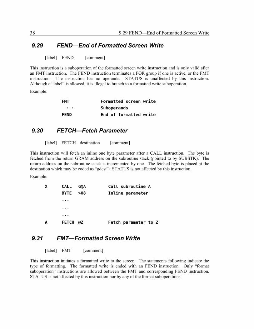
38 9.29 FEND—End of Formatted Screen Write
9.29 FEND—End of Formatted Screen Write
[label] FEND [comment]
This instruction is a suboperation of the formatted screen write instruction and is only valid afteran FMT instruction. The FEND instruction terminates a FOR group if one is active, or the FMTinstruction. The instruction has no operands. STATUS is unaffected by this instruction.Although a “label” is allowed, it is illegal to branch to a formatted write suboperation.
Example:
FMT Formatted screen write
··· Suboperands
FEND End of formatted write
9.30 FETCH—Fetch Parameter
[label] FETCH destination [comment]
This instruction will fetch an inline one byte parameter after a CALL instruction. The byte isfetched from the return GRAM address on the subroutine stack (pointed to by SUBSTK). Thereturn address on the subroutine stack is incremented by one. The fetched byte is placed at thedestination which may be coded as “gdest”. STATUS is not affected by this instruction.
Example:
X CALL G@A Call subroutine A
BYTE >08 Inline parameter
···
···
···
A FETCH @Z Fetch parameter to Z
9.31 FMT—Formatted Screen Write
[label] FMT [comment]
This instruction initiates a formatted write to the screen. The statements following indicate thetype of formatting. The formatted write is ended with an FEND instruction. Only “formatsuboperation” instructions are allowed between the FMT and corresponding FEND instruction.STATUS is not affected by this instruction nor by any of the format suboperations.

9 Ordinary Statements 39
Example:
X FMT Format screen
ROW 3 Set to row 3
COL 2 Column 2
HTEX "R3 C2" Display text
FEND End format screen
9.32 FOR—Begin Formatted Screen Write Loop
[label] FOR value [comment]
This instruction is a suboperation of the formatted screen write instruction and is only valid afteran FMT instruction and before the corresponding FEND instruction. The FOR instruction beginsa group of suboperations that are to be executed repeatedly. The next FEND suboperation definesthe end of the group. The “value” operand is an assembler expression that specifies the numberof times the group is to be repeated. The repetition count must be in the range 1 to 16. STATUSis unaffected by this instruction. Although a “label” is allowed, it is illegal to branch to aformatted write suboperation.
Example:
FMT Formatted screen write
···
FOR 10 Loop 10 times
···
FEND End of FOR loop
···
FEND End of formatted write
9.33 GT—Transfer GT to COND
[label] GT [comment]
This instruction transfers the state of the GT status bit to the COND bit where it can be testedwith BR or BS. Other status bits are unaffected. Note that there is no operand field.
Example:
X GT Transfer GT bit
BS ISGT Branch if greater

40 9.34 H—Transfer H to COND
9.34 H—Transfer H to COND
[label] H [comment]
This instruction transfers the state of the H status bit to the COND bit where it can be tested withBR or BS. Other status bits are unaffected. Note that there is no operand field.
Example:
X H Transfer high bit
BS ISHIGH Branch if logical high
9.35 HCHA—Display Character Horizontally
[label] HCHA count,char [comment]
This instruction is a suboperation of the formatted screen write instruction and is only valid afteran FMT instruction and before the corresponding FEND instruction. The HCHA instructiondisplays the “char” on the screen “count” times beginning at the current row and column. Therow and column are advanced by the number of characters written. The “count” operand is anassembler expression that specifies the number of times the character is to be written, it must bein the range 1 to 32. The “char” operand is an assembler expression that specifies the character tobe written. STATUS is unaffected by this instruction. Although a “label” is allowed, it is illegalto branch to a formatted write suboperation.
Example:
FMT Formatted screen write
···
HCHA 10,'A' 10 A's on the screen
···
FEND End of formatted write
9.36 HSTR—Display Character Horizontally
[label] HSTR count,source [comment]
[LES: I think this one ought to be “Display String Horizontally”,which copies count characters of string from source.]
This instruction is a suboperation of the formatted screen write instruction and is only valid afteran FMT instruction and before the corresponding FEND instruction. The HSTR instructiondisplays the character at “source” on the screen “count” times beginning at the current row andcolumn. The row and column are advanced by the number of characters written. The “count”operand is an assembler expression that specifies the number of times the character is to bewritten, it must be in the range 1 to 27. The “source” operand is written in any of the “gesd”

9 Ordinary Statements 41
forms. STATUS is unaffected by this instruction. Although a “label” is allowed, it is illegal tobranch to a formatted write suboperation.
Example:
FMT Formatted screen write
···
HSTR 10,@A Char at A, 10 times
···
FEND End of formatted write
9.37 HTEX—Display String Horizontally
[label] HTEX string [comment]
This instruction is a suboperation of the formatted screen write instruction and is only valid afteran FMT instruction and before the corresponding FEND instruction. The HSTR instructiondisplays the “string” on the screen beginning at the current row and column. The row andcolumn are advanced by the number of characters written. STATUS is unaffected by thisinstruction. Although a “label” is allowed, it is illegal to branch to a formatted writesuboperation.
Example:
FMT Formatted screen write
···
HTEX 'HI THERE' Display message
HTEX >01020304 Display characters
···
FEND End of formatted write
9.38 ICOL—Increment Current Column
[label] ICOL value [comment]
This instruction is a suboperation of the formatted screen write instruction and is only valid afteran FMT instruction and before the corresponding FEND instruction. The “value” operand is anassembler expression that specifies the increment to be added to the current column number. Thecurrent column number, VCOL, at CPU RAM PAD location >837F is set. The increment valuemust be in the range 1 to 32. STATUS is unaffected by this instruction. Although a “label” isallowed, it is illegal to branch to a formatted write suboperation.

42 9.38 ICOL—Increment Current Column
Example:
FMT Formatted screen write
···
ICOL 2 Column number + 2
···
FEND End formatted write
9.39 INC DINC—Increment by One
[label] INC destination [comment]
[label] DINC destination [comment]
The destination operand value is incremented by one. The destination value is a byte for INC anda double byte for DINC. The destination operand may be specified in any of the “gdest” forms.The result is compared to zero to set STATUS. The CARRY and OVF status bits may be set.
Examples:
X INC @A Increment value of A
BS ZERO B if result is zero
DINC V@>020C Incr value VDP double byte
Y INC *A Incr byte pointed to by A
9.40 INCT DINCT—Increment by Two
[label] INCT destination [comment]
[label] DINCT destination [comment]
The destination operand value is incremented by two. The destination value is a byte for INCTand a double byte for DINCT. The destination operand may be specified in any of the “gdest”forms. The result is compared to zero to set STATUS. The CARRY and OVF status bits may beset.
Examples:
X DINCT @A Increment value of A by 2
BS ZERO B if result is zero
INCT V@>020C Add 2 to VDP byte
Y INCT *A Byte pointed to by A + 2

9 Ordinary Statements 43
9.41 INV DINV—Invert Bits
[label] INV destination [comment]
[label] DINV destination [comment]
The destination operand value bits are inverted. This is the ones complement. The destinationvalue is a byte for INV and a double byte for DINV. The destination operand may be specified inany of the “gdest” forms. STATUS is not affected by this instruction.
Examples:
X INV @A Complement value of A
DINV V@>020C Invert VDP dble byte
Y INV *A Invert byte -> to by A
9.42 IO—Special I/O
[label] IO source,destination [comment]
This instruction is used to control a variety of special Input/Output devices including cassette,sound and CRU. The destination operand gives the address of a parameter list whose formatdepends upon the type of I/O specified by the single byte source operand value. STATUS is notaffected by this instruction. The source operand can be coded as “gsrc” and the destinationoperand as “gdest”. Note: the form of the operands may be restricted by the type of Special I/O,but the Assembler does not check for the restrictions.
The supported values for the source operand which specifies the type of I/O are:
0 = Start Auto Sound List in GRAM
1 = Start Auto Sound List in VDP RAM
2 = CRU Input
3 = CRU Output
4 = Cassette Write
5 = Cassette Read
6 = Cassette Verify
For I/O types 0 and 1, sound processing, the destination operand gives the CPU address of adouble byte area which contains the “sound list” address.
Example:
X DST >0475,@>8358 Sound list pointer to >8358
IO >00,@>8358 Start SL in GRAM at >0475
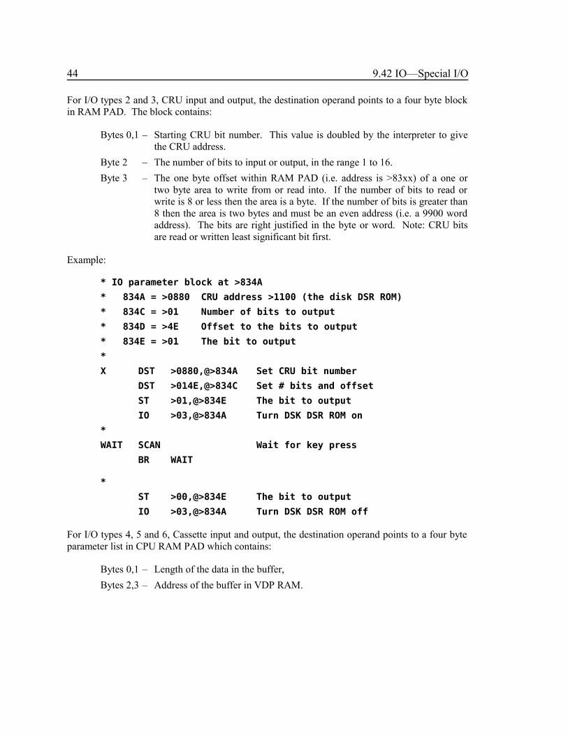
44 9.42 IO—Special I/O
For I/O types 2 and 3, CRU input and output, the destination operand points to a four byte blockin RAM PAD. The block contains:
Bytes 0,1 – Starting CRU bit number. This value is doubled by the interpreter to givethe CRU address.
Byte 2 – The number of bits to input or output, in the range 1 to 16.
Byte 3 – The one byte offset within RAM PAD (i.e. address is >83xx) of a one ortwo byte area to write from or read into. If the number of bits to read orwrite is 8 or less then the area is a byte. If the number of bits is greater than8 then the area is two bytes and must be an even address (i.e. a 9900 wordaddress). The bits are right justified in the byte or word. Note: CRU bitsare read or written least significant bit first.
Example:
* IO parameter block at >834A
* 834A = >0880 CRU address >1100 (the disk DSR ROM)
* 834C = >01 Number of bits to output
* 834D = >4E Offset to the bits to output
* 834E = >01 The bit to output
*
X DST >0880,@>834A Set CRU bit number
DST >014E,@>834C Set # bits and offset
ST >01,@>834E The bit to output
IO >03,@>834A Turn DSK DSR ROM on
*
WAIT SCAN Wait for key press
BR WAIT
*
ST >00,@>834E The bit to output
IO >03,@>834A Turn DSK DSR ROM off
For I/O types 4, 5 and 6, Cassette input and output, the destination operand points to a four byteparameter list in CPU RAM PAD which contains:
Bytes 0,1 – Length of the data in the buffer,
Bytes 2,3 – Address of the buffer in VDP RAM.

9 Ordinary Statements 45
9.43 IROW—Increment Current Row
[label] IROW value [comment]
This instruction is a suboperation of the formatted screen write instruction and is only valid afteran FMT instruction and before the corresponding FEND instruction. The “value” operand is anassembler expression that specifies the increment to be added to the current row number. Thecurrent row number, VROW, at CPU RAM PAD location >837E is set. The increment valuemust be in the range 1 to 32. STATUS is unaffected by this instruction. Although a “label” isallowed, it is illegal to branch to a formatted write suboperation.
Example:
FMT Formatted screen write
···
IROW 2 Row number + 2
···
FEND End formatted write
9.44 MOVE—Block Move
[label] MOVE length,source,destination [comment]
Data is moved from the source operand to the destination operand. The number of bytes moved isspecified by the length operand value. The source operand may be specified using any of theaddressing modes except “immediate data” and “VDP Register direct”. The destination operandmay be specified in any of the addressing modes except “immediate data”. The length operanddouble byte value may be specified in any of the “gsrc” forms. STATUS is unaffected by thisinstruction.
Examples:
X MOVE 10,G@DATA,V@>1000 Move 10 from GROM to VDP
STD 10,@>8300 Set length
MOVE @>8300,V@>1000,G@DATA Move it back
MOVE 7,G@VREGS,R@1 Set VDP regs 1 to 7
9.45 MUL DMUL—Multiply
[label] MUL source,destination [comment]
[label] DMUL source,destination [comment]
The source operand value is multiplied by the destination operand value, the destination operandvalue is replaced by the double length result. For MUL the source and the destination values are

46 9.45 MUL DMUL—Multiply
a byte and the result is a double byte value. For DMUL the source and the destination values aredouble byte values and the result is a four byte value. The source operand can be coded as “gsrc”and the destination operand as “gdest”. The multiply is of the unsigned type. STATUS isunaffected by this instruction.
Examples:
X MUL 10,@B B=B*10
ST @B+1,@B Truncate double result
DMUL @A,@B B=B*A
DST @B+2,@B Truncate double result
9.46 NEG DNEG—Negate
[label] NEG destination [comment]
[label] DNEG destination [comment]
The destination operand value is negated. This is the two’s complement. The destination value isa byte for NEG and a double byte for DNEG. The destination operand may be specified in any ofthe “gdest” forms. STATUS is not affected by this instruction.
Examples:
X NEG @A Negative value of A
DNEG V@>020C Neg value VDP double byte
Y NEG *A Neg byte pointed to by A
9.47 OR DOR—Logical OR
[label] OR source,destination [comment]
[label] DOR source,destination [comment]
The logical OR of the source operand value and the destination operand value replaces thedestination operand value. The source and destination operands are byte values for OR anddouble byte values for DOR. The source operand can be coded as “gsrc” and the destinationoperand as “gdest”. The result is compared to zero to set STATUS.
Examples:
X OR >F0,@B B=B OR >F0
DOR @A,@B OR double byte values
BS ZERO B if both A and B zero
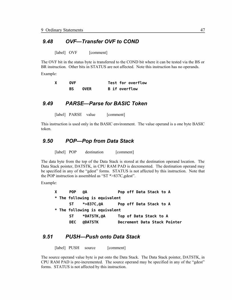
9 Ordinary Statements 47
9.48 OVF—Transfer OVF to COND
[label] OVF [comment]
The OVF bit in the status byte is transferred to the COND bit where it can be tested via the BS orBR instruction. Other bits in STATUS are not affected. Note this instruction has no operands.
Example:
X OVF Test for overflow
BS OVER B if overflow
9.49 PARSE—Parse for BASIC Token
[label] PARSE value [comment]
This instruction is used only in the BASIC environment. The value operand is a one byte BASICtoken.
9.50 POP—Pop from Data Stack
[label] POP destination [comment]
The data byte from the top of the Data Stack is stored at the destination operand location. TheData Stack pointer, DATSTK, in CPU RAM PAD is decremented. The destination operand maybe specified in any of the “gdest” forms. STATUS is not affected by this instruction. Note thatthe POP instruction is assembled as “ST *>837C,gdest”.
Example:
X POP @A Pop off Data Stack to A
* The following is equivalent
ST *>837C,@A Pop off Data Stack to A
* The following is equivalent
ST *DATSTK,@A Top of Data Stack to A
DEC @DATSTK Decrement Data Stack Pointer
9.51 PUSH—Push onto Data Stack
[label] PUSH source [comment]
The source operand value byte is put onto the Data Stack. The Data Stack pointer, DATSTK, inCPU RAM PAD is pre-incremented. The source operand may be specified in any of the “gdest”forms. STATUS is not affected by this instruction.

48 9.51 PUSH—Push onto Data Stack
Example:
X PUSH @A Put A on data stack
* The following is equivalent
INC @DATSTK Pre-increment stack ptr
ST @A,*DATSTK Put A on data stack
9.52 RAND—Generate Random Number
[label] RAND value [comment]
This instruction generates a random number between zero and the operand value specified. Theoperand value is a byte value. The resulting random number is stored in RANDNO at CPU RAMPAD address >8378. STATUS is not affected by this instruction.
Example:
X RAND 5 Random between 0 and 5
ST @RANDNO,@A Random number to A
9.53 ROW—Set Current Row
[label] ROW value [comment]
This instruction is a suboperation of the formatted screen write instruction and is only valid afteran FMT instruction and before the corresponding FEND instruction. The “value” operand is anassembler expression that specifies the screen row number for the next screen write. The currentrow number, VROW, at CPU RAM PAD location >837E is set. The row number value must bein the range 0 to 255. STATUS is unaffected by this instruction. Although a “label” is allowed,it is illegal to branch to a formatted write suboperation.
Example:
FMT Formatted screen write
···
ROW 10 Row 10
COL 1 Col 1
···
FEND End formatted write

9 Ordinary Statements 49
9.54 RTN—Return from Subroutine
[label] RTN [comment]
This instruction causes an return from a CALLed GPL subroutine. The return address is poppedoff the “Subroutine Stack” pointed to by SUBSTK at CPU RAM PAD address >8373. TheCOND bit in STATUS is reset. This instruction has no operands.
Example:
X RTN Return to caller
9.55 RTNB—Return from BASIC
[label] RTNB [comment]
This instruction is used only by the BASIC interpreter. The instruction has no operands.
9.56 RTNC—Return with COND
[label] RTNC [comment]
This instruction causes an return from a CALLed GPL subroutine. The return address is poppedoff the “Subroutine Stack” pointed to by SUBSTK at CPU RAM PAD address >8373. TheCOND bit in STATUS is left unchanged. This instruction has no operands.
Example:
X CZ @A Set COND
RTNC Return to caller with COND
9.57 SCAN—Scan Keyboard
[label] SCAN [comment]
This instruction causes a scan of the keyboard. The keyboard number, KBNO, at CPU RAMPAD address >8374 specifies the scan mode. The key pressed is returned at KEY in CPU RAMPAD >8375. The joystick values are returned at JOYY and JOYX in CPU RAM PAD ataddresses >8376 and >8377. The COND bit in STATUS is set if a new key is pressed otherwiseit is reset. Note that there is no operand field.
Note that the SCAN routine uses the GPL subroutine stack pointed to by SUBSTK at CPU RAMPAD address >8372.
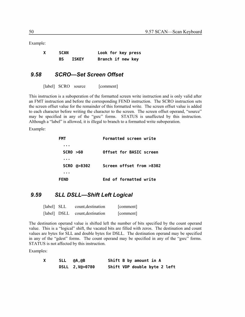
50 9.57 SCAN—Scan Keyboard
Example:
X SCAN Look for key press
BS ISKEY Branch if new key
9.58 SCRO—Set Screen Offset
[label] SCRO source [comment]
This instruction is a suboperation of the formatted screen write instruction and is only valid afteran FMT instruction and before the corresponding FEND instruction. The SCRO instruction setsthe screen offset value for the remainder of this formatted write. The screen offset value is addedto each character before writing the character to the screen. The screen offset operand, “source”may be specified in any of the “gsrc” forms. STATUS is unaffected by this instruction.Although a “label” is allowed, it is illegal to branch to a formatted write suboperation.
Example:
FMT Formatted screen write
···
SCRO >60 Offset for BASIC screen
···
SCRO @>8302 Screen offset from >8302
···
FEND End of formatted write
9.59 SLL DSLL—Shift Left Logical
[label] SLL count,destination [comment]
[label] DSLL count,destination [comment]
The destination operand value is shifted left the number of bits specified by the count operandvalue. This is a “logical” shift, the vacated bits are filled with zeros. The destination and countvalues are bytes for SLL and double bytes for DSLL. The destination operand may be specifiedin any of the “gdest” forms. The count operand may be specified in any of the “gsrc” forms.STATUS is not affected by this instruction.
Examples:
X SLL @A,@B Shift B by amount in A
DSLL 2,V@>0780 Shift VDP double byte 2 left

9 Ordinary Statements 51
9.60 SRA DSRA—Shift Right Arithmetically
[label] SRA count,destination [comment]
[label] DSRA count,destination [comment]
The destination operand value is shifted right the number of bits specified by the count operandvalue. This is an “arithmetic” shift, the “sign” bit is propagated through all vacated bits. Thedestination and count values are bytes for SRA and double bytes for DSRA. The destinationoperand may be specified in any of the “gdest” forms. The count operand may be specified inany of the “gsrc” forms. STATUS is not affected by this instruction.
Examples: [LES: Corrected example comments.]
X SRA @A,V@B Shift B by amount in A
DSRA 2,@X(@I) Shift double byte 2 right
9.61 SRC DSRC—Shift Right Circular
[label] SRC count,destination [comment]
[label] DSRC count,destination [comment]
The destination operand value is shifted right the number of bits specified by the count operandvalue. The vacated bits on the left end are filled with the bits shifted out of the right end of thevalue. The destination and count values are bytes for SRC and double bytes for DSRC. Thedestination operand may be specified in any of the “gdest” forms. The count operand may bespecified in any of the “gsrc” forms. STATUS is not affected by this instruction.
Examples: [LES: Corrected example comments.]
X SRC V@A,@B Shift B by amount in A
DSRA 2,@X(@I) Shift double byte 2 right circularly
9.62 SRL DSRL—Shift Right Logical
[label] SRL count,destination [comment]
[label] DSRL count,destination [comment]
The destination operand value is shifted right the number of bits specified by the count operandvalue. This is a “logical” shift, the vacated bits are filled with zeros. The destination and countvalues are bytes for SRL and double bytes for DSRL. The destination operand may be specifiedin any of the “gdest” forms. The count operand may be specified in any of the “gsrc” forms.STATUS is not affected by this instruction.
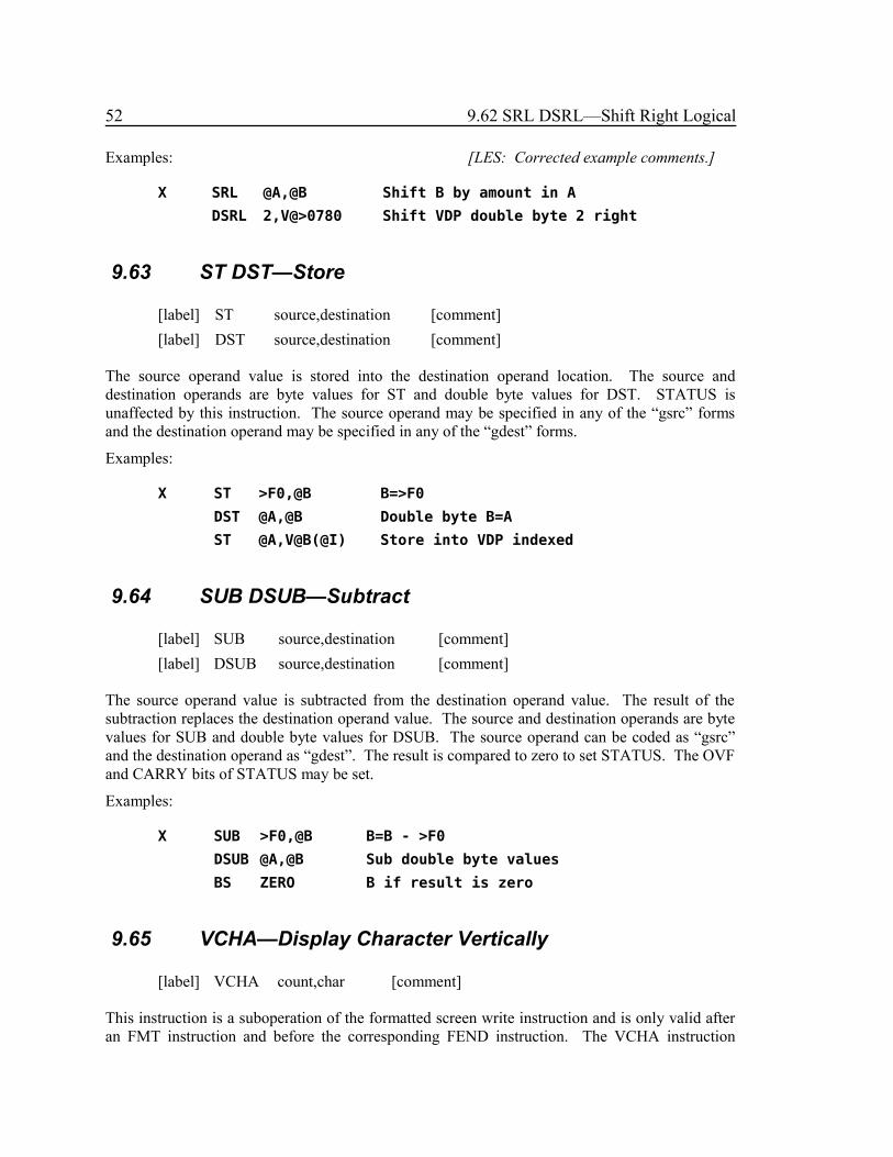
52 9.62 SRL DSRL—Shift Right Logical
Examples: [LES: Corrected example comments.]
X SRL @A,@B Shift B by amount in A
DSRL 2,V@>0780 Shift VDP double byte 2 right
9.63 ST DST—Store
[label] ST source,destination [comment]
[label] DST source,destination [comment]
The source operand value is stored into the destination operand location. The source anddestination operands are byte values for ST and double byte values for DST. STATUS isunaffected by this instruction. The source operand may be specified in any of the “gsrc” formsand the destination operand may be specified in any of the “gdest” forms.
Examples:
X ST >F0,@B B=>F0
DST @A,@B Double byte B=A
ST @A,V@B(@I) Store into VDP indexed
9.64 SUB DSUB—Subtract
[label] SUB source,destination [comment]
[label] DSUB source,destination [comment]
The source operand value is subtracted from the destination operand value. The result of thesubtraction replaces the destination operand value. The source and destination operands are bytevalues for SUB and double byte values for DSUB. The source operand can be coded as “gsrc”and the destination operand as “gdest”. The result is compared to zero to set STATUS. The OVFand CARRY bits of STATUS may be set.
Examples:
X SUB >F0,@B B=B - >F0
DSUB @A,@B Sub double byte values
BS ZERO B if result is zero
9.65 VCHA—Display Character Vertically
[label] VCHA count,char [comment]
This instruction is a suboperation of the formatted screen write instruction and is only valid afteran FMT instruction and before the corresponding FEND instruction. The VCHA instruction
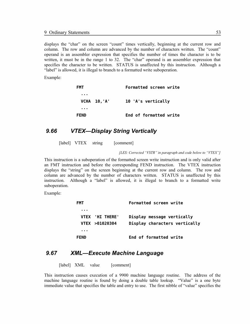
9 Ordinary Statements 53
displays the “char” on the screen “count” times vertically, beginning at the current row andcolumn. The row and column are advanced by the number of characters written. The “count”operand is an assembler expression that specifies the number of times the character is to bewritten, it must be in the range 1 to 32. The “char” operand is an assembler expression thatspecifies the character to be written. STATUS is unaffected by this instruction. Although a“label” is allowed, it is illegal to branch to a formatted write suboperation.
Example:
FMT Formatted screen write
···
VCHA 10,'A' 10 'A's vertically
···
FEND End of formatted write
9.66 VTEX—Display String Vertically
[label] VTEX string [comment]
[LES: Corrected “VSTR” in paragraph and code below to “VTEX”]
This instruction is a suboperation of the formatted screen write instruction and is only valid afteran FMT instruction and before the corresponding FEND instruction. The VTEX instructiondisplays the “string” on the screen beginning at the current row and column. The row andcolumn are advanced by the number of characters written. STATUS is unaffected by thisinstruction. Although a “label” is allowed, it is illegal to branch to a formatted writesuboperation.
Example:
FMT Formatted screen write
···
VTEX 'HI THERE' Display message vertically
VTEX >01020304 Display characters vertically
···
FEND End of formatted write
9.67 XML—Execute Machine Language
[label] XML value [comment]
This instruction causes execution of a 9900 machine language routine. The address of themachine language routine is found by doing a double table lookup. “Value” is a one byteimmediate value that specifies the table and entry to use. The first nibble of “value” specifies the

54 9.67 XML—Execute Machine Language
table number, 0 to 15, and the second nibble specifies the entry within that table, 0 to 15. Thesetting of STATUS is dependent upon the machine language routine.
Some XML routines are provided as part of the GPL interpreter and are described in APPENDIXB. The 16 XML tables are located in CPU RAM at addresses coded in a ROM table as shownbelow. The addresses marked with an asterisk may vary depending upon the model of theconsole.
Table # Address Note
0 >0D1A* Floating Point Routines
1 >12A0* Conversion and BASIC Routines
2 >2000 In Low Memory Expansion
3 >3FC0 In Low Memory Expansion
4 >3FE0 In Low Memory Expansion
5 >4010 In DSR Address Space
6 >4030 In DSR Address Space
7 >6010 In Cartridge Address Space
8 >6030 In Cartridge Address Space
9 >7000 In Cartridge Address Space
10 >8000 No RAM in 4A
11 >A000 In High Memory Expansion
12 >B000 In High Memory Expansion
13 >C000 In High Memory Expansion
14 >D000 In High Memory Expansion
15 >8300 In CPU RAM PAD
Example:
MOVE 8,G@A,@FAC FAC = A
MOVE 8,V@B,@ARG ARG = B
ADD XML >06 Floating FAC=A+B
9.68 XOR DXOR—Logical Exclusive OR
[label] XOR source,destination [comment]
[label] DXOR source,destination [comment]
The logical Exclusive OR of the source operand value and the destination operand value replacesthe destination operand value. The source and destination operand values are bytes for XOR anddouble bytes for DXOR. The source operand can be coded as “gsrc” and the destination operandas “gdest”. The result is compared to zero to set STATUS.

9 Ordinary Statements 55
Examples:
X XOR >F0,@B B=B OR >F0
DXOR @A,@B OR double byte values
BS ZERO B if A XOR B is zero
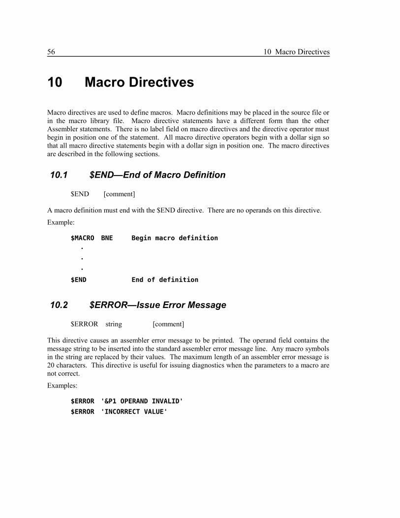
56 10 Macro Directives
10 Macro Directives
Macro directives are used to define macros. Macro definitions may be placed in the source file orin the macro library file. Macro directive statements have a different form than the otherAssembler statements. There is no label field on macro directives and the directive operator mustbegin in position one of the statement. All macro directive operators begin with a dollar sign sothat all macro directive statements begin with a dollar sign in position one. The macro directivesare described in the following sections.
10.1 $END—End of Macro Definition
$END [comment]
A macro definition must end with the $END directive. There are no operands on this directive.
Example:
$MACRO BNE Begin macro definition
·
·
·
$END End of definition
10.2 $ERROR—Issue Error Message
$ERROR string [comment]
This directive causes an assembler error message to be printed. The operand field contains themessage string to be inserted into the standard assembler error message line. Any macro symbolsin the string are replaced by their values. The maximum length of an assembler error message is20 characters. This directive is useful for issuing diagnostics when the parameters to a macro arenot correct.
Examples:
$ERROR '&P1 OPERAND INVALID'
$ERROR 'INCORRECT VALUE'

10 Macro Directives 57
10.3 $EXIT—Exit from Macro
$EXIT [comment]
The $EXIT macro indicates the end of macro generation. Note that the $END directive whichdefines the physical end of a macro definition also indicates the end of macro generation. The$EXIT directive has no operands.
10.4 $GOTO—Branch within Macro
$GOTO label [comment]
This directive causes a GOTO within a macro definition. The operand field contains the targetlabel which must appear on a $LABEL directive. The operand field is scanned and any macrosymbols are replaced by their value before the search for the label is begun.
Examples:
$GOTO XYZ
$GOTO &L2
$GOTO X&G3
$GOTO &P1(1.2)
10.5 $IF—Conditional Branch within Macro
$IF expr1,relop,expr2,label [comment]
This directive causes a conditional branch within the macro definition. The two expressions areevaluated in the same way as the expression on a $SET directive. The two results are thencompared as character strings. If the relation specified by the relational operator, “relop”, is truethen a $GOTO is executed to the label specified as the fourth operand. The relational operatorsare:
EQ – equal
NE – not equal
GT – greater than
GE – greater than or equal
LT – less than
LE – less than or equal
If the two strings being compared are different lengths and are the same up to the length of theshorter, then the shorter string is less than the longer. For example, 'XYZ' is less than 'XYZA'.

58 10.5 $IF—Conditional Branch within Macro
Examples:
$IF '&P1',EQ,'XYZ',ISXYZ
$IF &P2,LT,3,L21
$IF '&P3',NE,'&G1&G2',NEW
$IF '&P4',GE,'A123',&G5
···
$LABEL ISXYZ
···
$LABEL L21
···
$LABEL NEW
10.6 $LABEL—Define Macro Label
$LABEL label [comment]
This directive defines a label which may be the target of a $GOTO or $IF directive. The operandfield contains the label. The label must be 1 to 6 characters, the first of which is a letter. Nomacro symbols are allowed.
Examples:
$LABEL XYZ
$LABEL A12345
10.7 $MACRO—Begin Macro Definition
$MACRO name [comment]
A macro definition must begin with the $MACRO directive. The “name” specified is the macroname and is used as an operation code to invoke the macro. The name must be from 1 to 6characters the first of which must be a letter. Macro names must be different from any predefinedinstruction operation code or assembler directive operation code.
Examples:
$MACRO BNE
$MACRO TEST23
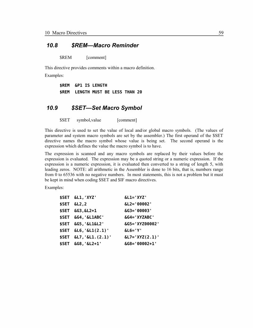
10 Macro Directives 59
10.8 $REM—Macro Reminder
$REM [comment]
This directive provides comments within a macro definition.
Examples:
$REM &P1 IS LENGTH
$REM LENGTH MUST BE LESS THAN 20
10.9 $SET—Set Macro Symbol
$SET symbol,value [comment]
This directive is used to set the value of local and/or global macro symbols. (The values ofparameter and system macro symbols are set by the assembler.) The first operand of the $SETdirective names the macro symbol whose value is being set. The second operand is theexpression which defines the value the macro symbol is to have.
The expression is scanned and any macro symbols are replaced by their values before theexpression is evaluated. The expression may be a quoted string or a numeric expression. If theexpression is a numeric expression, it is evaluated then converted to a string of length 5, withleading zeros. NOTE: all arithmetic in the Assembler is done to 16 bits, that is, numbers rangefrom 0 to 65536 with no negative numbers. In most statements, this is not a problem but it mustbe kept in mind when coding $SET and $IF macro directives.
Examples:
$SET &L1,'XYZ' &L1='XYZ'
$SET &L2,2 &L2='00002'
$SET &G3,&L2+1 &G3='00003'
$SET &G4,'&L1ABC' &G4='XYZABC'
$SET &G5,'&L1&L2' &G5='XYZ00002'
$SET &L6,'&L1(2.1)' &L6='Y'
$SET &L7,'&L1.(2.1)' &L7='XYZ(2.1)'
$SET &G8,'&L2+1' &G8='00002+1'

60 Appendix A GPL Subroutines
Appendix A GPL Subroutines
A.1 DSRLNK (GRAM Address >0010)
This routine searches for and links to device service routines and subroutines defined in bothGRAM and device ROMs.
Input: One parameter byte is FETCHed. This byte is the offset within the header at whichsearching is to begin.
>08 for Device Service Link
>0A for Subroutine Link
VPAB (>8356) contains the VDP RAM address of the name string. The name string is aone byte length followed by the name. For device links VPAB would point to thePAB+9.
Example: MOVE 32,G@PAB,V@>1000DST >1009,@VPABCALL DSRLNKBYTE >08
Notes: GRAM device/subroutine routines should return by calling the GSRRTN routine.
A.2 GSRRTN (GRAM Address >0012)
This routine is used to return from a GRAM device service routine or subroutine which wascalled by DSRLNK or GSRLNK.
A.3 SUBCNS (GRAM Address >0014)
This routine converts a floating point number into a string.
Input: FAC (>834A) contains the radix 100 floating point number to be converted.
FAC+11 (>8355) contains a flag to indicate the mode of the output string.
FAC+11=0. Output string is in scientific notation.
FAC+11=non-zero. Output string is in normal decimal point form.
FAC+12 (>8356) is the number of significant digits.
FAC+13 (>8357) is the number of digits to the right of the decimal point.
Output: FAC is modified.
FAC+11 (>8355) contains a one byte displacement from >8300 to the result string. Thatis, the output string is at address >83xx, where xx is the contents of >8355.
FAC+12 (>8356) contains the one byte length of the output string.

Appendix A GPL Subroutines 61
A.4 STDCHR (GRAM Address >0016)
This routine loads the large size upper case character set. This is the character set used on themaster selection menu. Patterns are loaded for characters >20 (blank) to >5F.
Input: FAC (>834A) contains the VDP RAM address for the >20 character pattern.
A.5 UCCHAR (GRAM Address >0018)
This routine loads the normal upper case character set. Patterns are loaded for characters >20(blank) to >5F.
Input: FAC (>834A) contains the VDP RAM address for the >20 character pattern.
A.6 BWARN (GRAM Address >001A)
This routine issues a TI BASIC warning message.
A.7 BERR (GRAM Address >001C)
This routine issues a TI BASIC error message.
A.8 BEXEC (GRAM Address >001E)
This routine begins execution of a TI BASIC program in GRAM.
Input: Four bytes are FETCHed. The first two specify the GRAM address of the first byte ofthe line number table. The second two bytes specify the GRAM address of the last byteof the line number table.
A.9 PWRUP (GRAM Address >0020)
This routine initializes the system, then presents the “colour bar screen” and the master selectionmenu.
A.10 SUBINT (GRAM Address >0022)
This routine calculates the greatest integer from a floating point number.
Input: FAC (>834A) contains the radix 100 floating point number.
Output: FAC (>834A) contains the double byte integer value.
A.11 SUBPWR (GRAM Address >0024)
This routine raises a floating point number to a floating point power.
Input: FAC (>834A) contains the radix 100 floating point power.
ARG (>835C) contains the floating point number.

62 A.11 SUBPWR (GRAM Address >0024)
Output: FAC (>834A) contains the result.
STATUS (>837C) is set according to the value of the result.
ERCODE (>8354), the floating point error code may be set.
VSTACK (>836E), the pointer to the VDP floating point stack is used.
RAM PAD locations >8375 and >8376 are used as a work area.
RAM PAD locations >8310 to >832A are used as a work area, their contents is written toVDP RAM at address >03C0 and restored.
A.12 SUBSQR (GRAM Address >0026)
This routine calculates the square root of a floating point number.
Input: FAC (>834A) contains the radix 100 floating point number.
Output: FAC (>834A) contains the resulting square root.
STATUS (>837C) is set according to the value of the result.
ERCODE (>8354), the floating point error code may be set.
VSTACK (>836E), the pointer to the VDP floating point stack is used.
RAM PAD locations >8375 and >8376 are used as a work area.
RAM PAD locations >8310 to >832A are used as a work area, their contents is written toVDP RAM at address >03C0 and restored.
A.13 SUBEXP (GRAM Address >0028)
This routine calculates “e” (the natural log base) to a floating point power. This is the inversenatural log.
Input: FAC (>834A) contains the radix 100 floating point power.
Output: FAC (>834A) contains the resulting power of e.
STATUS (>837C) is set according to the value of the result.
ERCODE (>8354), the floating point error code may be set.
VSTACK (>836E), the pointer to the VDP floating point stack is used.
RAM PAD locations >8375 and >8376 are used as a work area.
RAM PAD locations >8310 to >832A are used as a work area, their contents is written toVDP RAM at address >03C0 and restored.
A.14 SUBLOG (GRAM Address >002A)
This routine calculates the natural log of a floating point number.
Input: FAC (>834A) contains the radix 100 floating point number.
Output: FAC (>834A) contains the resulting natural log.

Appendix A GPL Subroutines 63
STATUS (>837C) is set according to the value of the result.
ERCODE (>8354), the floating point error code may be set.
VSTACK (>836E), the pointer to the VDP floating point stack is used.
RAM PAD locations >8375 and >8376 are used as a work area.
RAM PAD locations >8310 to >832A are used as a work area, their contents is written toVDP RAM at address >03C0 and restored.
A.15 SUBCOS (GRAM Address >002C)
This routine calculates the cosine of a floating point number representing an angle in radianmeasure.
Input: FAC (>834A) contains the radix 100 floating point angle.
Output: FAC (>834A) contains the resulting cosine value.
STATUS (>837C) is set according to the value of the result.
ERCODE (>8354), the floating point error code may be set.
VSTACK (>836E), the pointer to the VDP floating point stack is used.
RAM PAD locations >8375 and >8376 are used as a work area.
RAM PAD locations >8310 to >832A are used as a work area, their contents is written toVDP RAM at address >03C0 and restored.
A.16 SUBSIN (GRAM Address >002E)
This routine calculates the sine of a floating point number representing an angle in radianmeasure.
Input: FAC (>834A) contains the radix 100 floating point angle.
Output: FAC (>834A) contains the resulting sine value.
STATUS (>837C) is set according to the value of the result.
ERCODE (>8354), the floating point error code may be set.
VSTACK (>836E), the pointer to the VDP floating point stack is used.
RAM PAD locations >8375 and >8376 are used as a work area.
RAM PAD locations >8310 to >832A are used as a work area, their contents is written toVDP RAM at address >03C0 and restored.
A.17 SUBTAN (GRAM Address >0030)
This routine calculates the tangent of a floating point number representing an angle in radianmeasure.
Input: FAC (>834A) contains the radix 100 floating point angle.
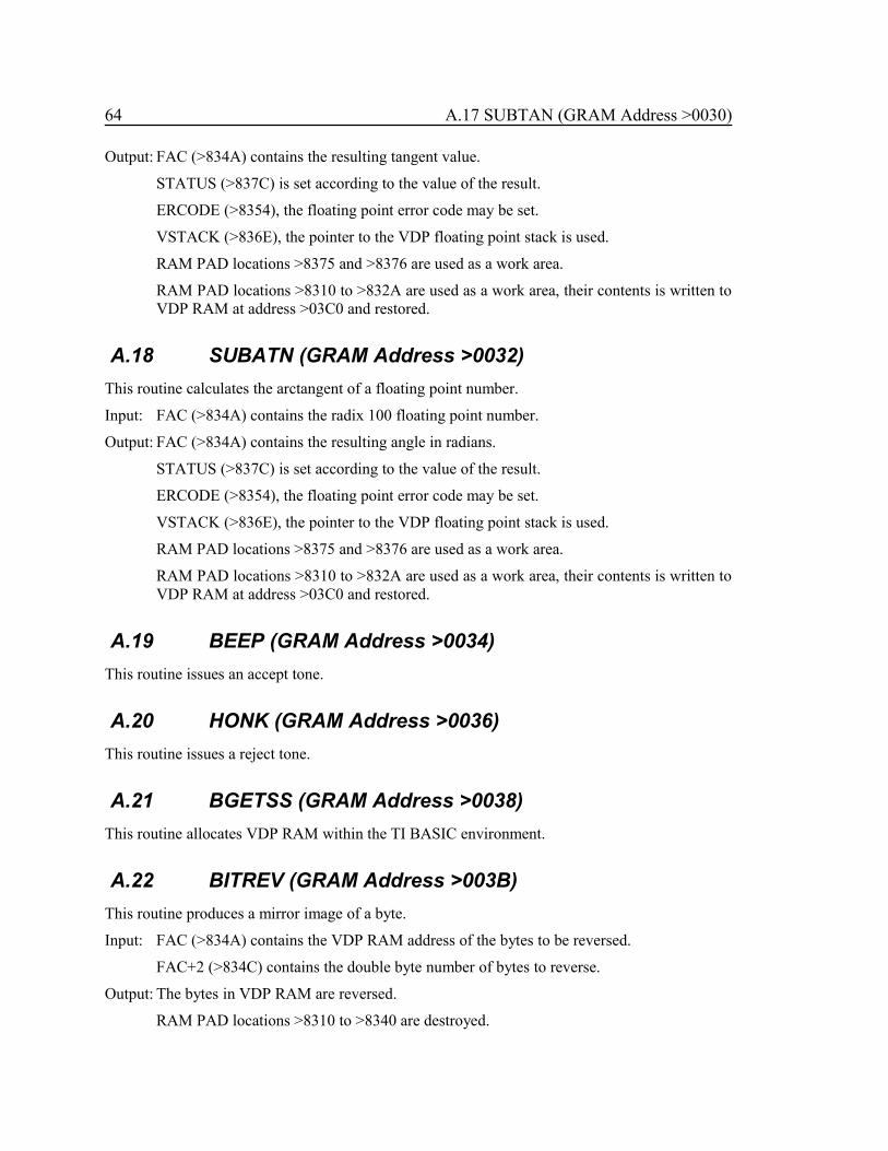
64 A.17 SUBTAN (GRAM Address >0030)
Output: FAC (>834A) contains the resulting tangent value.
STATUS (>837C) is set according to the value of the result.
ERCODE (>8354), the floating point error code may be set.
VSTACK (>836E), the pointer to the VDP floating point stack is used.
RAM PAD locations >8375 and >8376 are used as a work area.
RAM PAD locations >8310 to >832A are used as a work area, their contents is written toVDP RAM at address >03C0 and restored.
A.18 SUBATN (GRAM Address >0032)
This routine calculates the arctangent of a floating point number.
Input: FAC (>834A) contains the radix 100 floating point number.
Output: FAC (>834A) contains the resulting angle in radians.
STATUS (>837C) is set according to the value of the result.
ERCODE (>8354), the floating point error code may be set.
VSTACK (>836E), the pointer to the VDP floating point stack is used.
RAM PAD locations >8375 and >8376 are used as a work area.
RAM PAD locations >8310 to >832A are used as a work area, their contents is written toVDP RAM at address >03C0 and restored.
A.19 BEEP (GRAM Address >0034)
This routine issues an accept tone.
A.20 HONK (GRAM Address >0036)
This routine issues a reject tone.
A.21 BGETSS (GRAM Address >0038)
This routine allocates VDP RAM within the TI BASIC environment.
A.22 BITREV (GRAM Address >003B)
This routine produces a mirror image of a byte.
Input: FAC (>834A) contains the VDP RAM address of the bytes to be reversed.
FAC+2 (>834C) contains the double byte number of bytes to reverse.
Output: The bytes in VDP RAM are reversed.
RAM PAD locations >8310 to >8340 are destroyed.

Appendix A GPL Subroutines 65
A.23 CASDSR (GRAM Address >003D)
This routine searches for and executes GRAM DSR routines (especially the cassette DSR).
Input: The PAB in VDP RAM.
FAC (>834A) contains the device name.
RAM PAD location >8354 contains the double byte length of the device name.
RAM PAD location >8356 contains the VDP RAM address of the first character after thename in the PAB.
RAM PAD location >836D must be set to >08 to indicate a DSR call.
STATUS (>837C) must be set to zero.
RAM PAD location >83D0 and >83D1 should be set to zero.
A.24 BPABSS (GRAM Address >003F)
This routine is used in the TI BASIC environment to allocate VDP RAM space for PABs.
A.25 BSETSU (GRAM Address >0042)
This routine is used in the TI BASIC environment to fetch the next byte from a BASIC statement.
A.26 LCCHAR (GRAM Address >004A)
This routine loads the normal lower case character set. Patterns are loaded for characters >60 to>7F.
Input: FAC (>834A) contains the VDP RAM address for the >60 character pattern.

66 Appendix B XML Routines
Appendix B XML RoutinesThe XML Routines described in this appendix are contained in the 99/4A ROM as part of theGPL interpreter.
B.1 XML >00 Undefined
There is no defined function for this XML routine.
B.2 XML >01 Round FAC
The nine byte floating point number in FAC is rounded to an 8 byte floating point number. Thefloating point error code, ERCODE, may be set to >01 to indicate overflow. STATUS is setaccording to the value in FAC.
B.3 XML >02 Round FAC at ARG
The floating point number in FAC is incremented by one at the radix 100 digit number specifiedby the byte in ARG. This routine could be used as part of a rounding routine. The floating pointerror code, ERCODE, may be set to >01 to indicate overflow. STATUS is set according to thevalue in FAC.
B.4 XML >03 Set STATUS Depending on FAC
The double byte value in FAC is used to set STATUS. Note that because of the method ofimplementing floating point numbers, this routine works for both fixed point double byte andfloating point numbers.
B.5 XML >04 Floating Point Underflow/Overflow
The sign of the byte at >8376 determines whether underflow or overflow has occurred. If thebyte at >8376 is negative then underflow has occurred and FAC is set to zero. If the byte at>8376 is not negative then overflow has occurred and FAC is set to the maximum number withthe same sign as the byte at >8375. If overflow has occurred the floating point error code,ERCODE, is set to >01. STATUS is set according to the result in FAC.
B.6 XML >05 Set Floating Point Overflow
The floating point error code, ERCODE, is set to >01 and FAC is set to the maximum numberwith the same sign as the byte at >8375. STATUS is set according to the result in FAC.
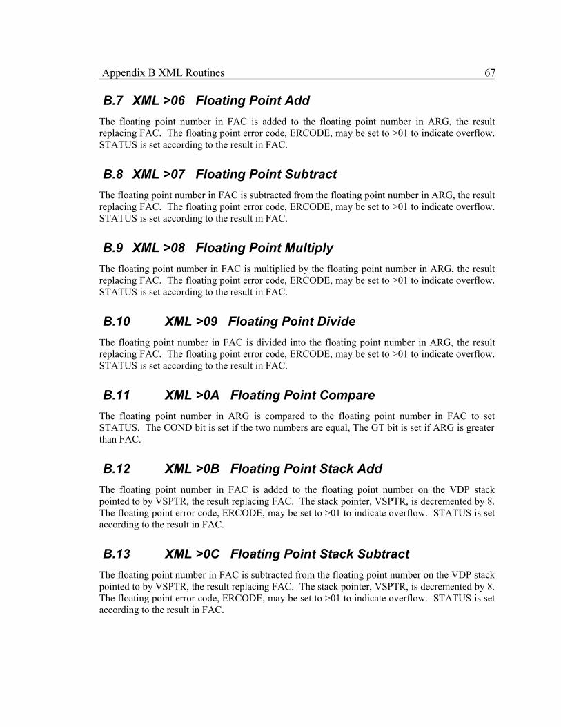
Appendix B XML Routines 67
B.7 XML >06 Floating Point Add
The floating point number in FAC is added to the floating point number in ARG, the resultreplacing FAC. The floating point error code, ERCODE, may be set to >01 to indicate overflow.STATUS is set according to the result in FAC.
B.8 XML >07 Floating Point Subtract
The floating point number in FAC is subtracted from the floating point number in ARG, the resultreplacing FAC. The floating point error code, ERCODE, may be set to >01 to indicate overflow.STATUS is set according to the result in FAC.
B.9 XML >08 Floating Point Multiply
The floating point number in FAC is multiplied by the floating point number in ARG, the resultreplacing FAC. The floating point error code, ERCODE, may be set to >01 to indicate overflow.STATUS is set according to the result in FAC.
B.10 XML >09 Floating Point Divide
The floating point number in FAC is divided into the floating point number in ARG, the resultreplacing FAC. The floating point error code, ERCODE, may be set to >01 to indicate overflow.STATUS is set according to the result in FAC.
B.11 XML >0A Floating Point Compare
The floating point number in ARG is compared to the floating point number in FAC to setSTATUS. The COND bit is set if the two numbers are equal, The GT bit is set if ARG is greaterthan FAC.
B.12 XML >0B Floating Point Stack Add
The floating point number in FAC is added to the floating point number on the VDP stackpointed to by VSPTR, the result replacing FAC. The stack pointer, VSPTR, is decremented by 8.The floating point error code, ERCODE, may be set to >01 to indicate overflow. STATUS is setaccording to the result in FAC.
B.13 XML >0C Floating Point Stack Subtract
The floating point number in FAC is subtracted from the floating point number on the VDP stackpointed to by VSPTR, the result replacing FAC. The stack pointer, VSPTR, is decremented by 8.The floating point error code, ERCODE, may be set to >01 to indicate overflow. STATUS is setaccording to the result in FAC.

68 B.14 XML >0D Floating Point Stack Multiply
B.14 XML >0D Floating Point Stack Multiply
The floating point number in FAC is multiplied by the floating point number on the VDP stackpointed to by VSPTR, the result replacing FAC. The stack pointer, VSPTR, is decremented by 8.The floating point error code, ERCODE, may be set to >01 to indicate overflow. STATUS is setaccording to the result in FAC.
B.15 XML >0E Floating Point Stack Divide
The floating point number in FAC is divided into the floating point number on the VDP stackpointed to by VSPTR, the result replacing FAC. The stack pointer, VSPTR, is decremented by 8.The floating point error code, ERCODE, may be set to >01 to indicate overflow. STATUS is setaccording to the result in FAC.
B.16 XML >0F Floating Point Stack Compare
The floating point number on the VDP stack pointed to by VSPTR is compared to the floatingpoint number in FAC to set STATUS. The COND bit is set if the two numbers are equal, TheGT bit is set if stack number is greater than FAC. The stack pointer, VSPTR, is decremented by8.
B.17 XML >10 Convert VDP String to Floating
The ASCII string in VDP RAM at the address contained in >8356 is converted to a floating pointnumber. The result is returned in FAC. The conversion processes characters from the VDP untila character not legal in a floating point number is found. The VDP address of the last characterprocessed is left in >8356. The floating point error code, ERCODE, may be set to >01 to indicateoverflow.
B.18 XML >11 Convert String to Floating
This routine is the same as XML >10 except that the ASCII string may be in either VDP RAM orGRAM. If the byte at >8389 is zero the string is in VDP RAM, otherwise it is in GRAM.
B.19 XML >12 Convert Floating to Integer
The floating point number in FAC is converted to a double byte integer, the result replacing FAC.The floating point error code, ERCODE, may be set to >01 to indicate overflow.
B.20 XML >13 Get BASIC Symbol Table Entry
This routine is used by the TI BASIC interpreter.
B.21 XML >14 Get BASIC Symbol Table Value
This routine is used by the TI BASIC interpreter.

Appendix B XML Routines 69
B.22 XML >15 Assign Value to BASIC Variable
This routine is used by the TI BASIC interpreter.
B.23 XML >16 Search BASIC Symbol Table
This routine is used by the TI BASIC interpreter.
B.24 XML >17 Push Value onto VDP Stack
This routine is used by the TI BASIC interpreter.
B.25 XML >18 Pop Value from VDP Stack
This routine is used by the TI BASIC interpreter.
B.26 XML >19 Search DSR ROM Chains
This routine is used to search DSR ROM headers and chains. The byte value at >836D is theoffset into the header for the chain to be searched. The byte value at >8355 is the length of thename to search. The name to be searched is in FAC.
B.27 XML >1A Search GROM Chains
This routine is the same as XML >19 except that GRAM headers and chains are searched.
B.28 XML >1B Get Next BASIC Byte
This routine is used by the TI BASIC interpreter.
B.29 XML >1C Undefined
There is no defined function for this XML routine.
B.30 XML >1D Undefined
There is no defined function for this XML routine.
B.31 XML >1E Undefined
There is no defined function for this XML routine.
B.32 XML >1F Undefined
There is no defined function for this XML routine.
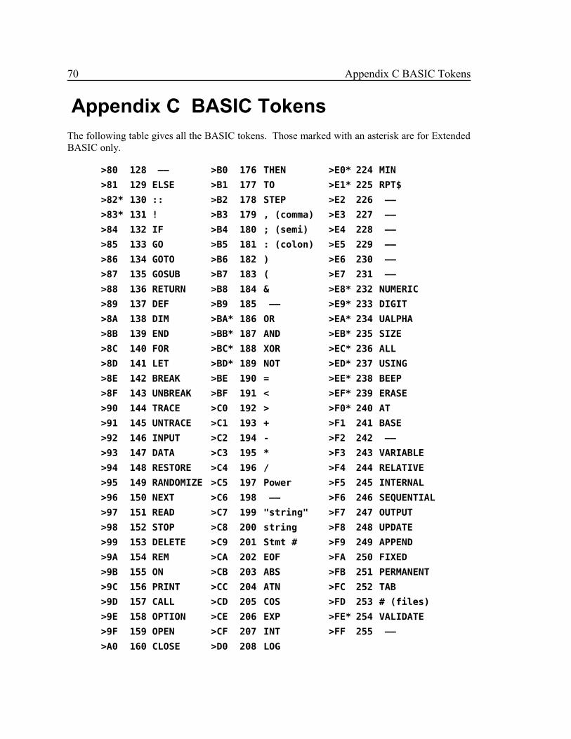
70 Appendix C BASIC Tokens
Appendix C BASIC TokensThe following table gives all the BASIC tokens. Those marked with an asterisk are for ExtendedBASIC only.
>80 128 —— >B0 176 THEN >E0* 224 MIN
>81 129 ELSE >B1 177 TO >E1* 225 RPT$
>82* 130 :: >B2 178 STEP >E2 226 ——
>83* 131 ! >B3 179 , (comma) >E3 227 ——
>84 132 IF >B4 180 ; (semi) >E4 228 ——
>85 133 GO >B5 181 : (colon) >E5 229 ——
>86 134 GOTO >B6 182 ) >E6 230 ——
>87 135 GOSUB >B7 183 ( >E7 231 ——
>88 136 RETURN >B8 184 & >E8* 232 NUMERIC
>89 137 DEF >B9 185 —— >E9* 233 DIGIT
>8A 138 DIM >BA* 186 OR >EA* 234 UALPHA
>8B 139 END >BB* 187 AND >EB* 235 SIZE
>8C 140 FOR >BC* 188 XOR >EC* 236 ALL
>8D 141 LET >BD* 189 NOT >ED* 237 USING
>8E 142 BREAK >BE 190 = >EE* 238 BEEP
>8F 143 UNBREAK >BF 191 < >EF* 239 ERASE
>90 144 TRACE >C0 192 > >F0* 240 AT
>91 145 UNTRACE >C1 193 + >F1 241 BASE
>92 146 INPUT >C2 194 - >F2 242 ——
>93 147 DATA >C3 195 * >F3 243 VARIABLE
>94 148 RESTORE >C4 196 / >F4 244 RELATIVE
>95 149 RANDOMIZE >C5 197 Power >F5 245 INTERNAL
>96 150 NEXT >C6 198 —— >F6 246 SEQUENTIAL
>97 151 READ >C7 199 "string" >F7 247 OUTPUT
>98 152 STOP >C8 200 string >F8 248 UPDATE
>99 153 DELETE >C9 201 Stmt # >F9 249 APPEND
>9A 154 REM >CA 202 EOF >FA 250 FIXED
>9B 155 ON >CB 203 ABS >FB 251 PERMANENT
>9C 156 PRINT >CC 204 ATN >FC 252 TAB
>9D 157 CALL >CD 205 COS >FD 253 # (files)
>9E 158 OPTION >CE 206 EXP >FE* 254 VALIDATE
>9F 159 OPEN >CF 207 INT >FF 255 ——
>A0 160 CLOSE >D0 208 LOG

Appendix C BASIC Tokens 71
>A1 161 SUB >D1 209 SGN
>A2 162 DISPLAY >D2 210 SIN
>A3* 163 IMAGE >D3 211 SQR
>A4 164 ACCEPT >D4 212 TAN
>A5* 165 ERROR >D5 213 LEN
>A6* 166 WARNING >D6 214 CHR$
>A7* 167 SUBEXIT >D7 215 RND
>A8* 168 SUBEND >D8 216 SEG$
>A9 169 RUN >D9 217 POS
>AA* 170 LINPUT >DA 218 VAL
>AB 171 —— >DB 219 STR$
>AC 172 —— >DC 220 ASC
>AD 173 —— >DD* 221 PI
>AE 174 —— >DE 222 REC
>AF 175 —— >DF* 223 MAX

72 Appendix D Coincidence
Appendix D Coincidence The COINC instruction is designed to detect the coincidence of two sprites. Its function isgeneral enough, however, to detect the coincidence of any two objects, given their Y and Xpositions and a coincidence table. All measurements are in units (that may be pixels) relative tothe top left corner.
The coincidence table is an array of bits which indicate coincidence for the various positions ofthe objects when they are in contact. To construct the coincidence table for mapping value zerofor two objects, the source (S) and destination (D), with dimensions (Vs, Hs) and (Vd, Hd), youmust imagine the 2 rectangles with the given dimensions just touching at the lower right corner ofS and the upper left corner of D.
Hs
┌───────┐│ ││ S │ Vs│ │└───────┼──────────┐ │ │ │ │ │ D │ Vd │ │ │ │ └──────────┘ Hd
Beginning with this position then moving right across the columns then down the rows until:
┌──────────┐ │ │ │ │ │ D │ Vd │ │ │ │ └──────────┼───────┐ Hd │ │ │ S │ Vs │ │ └───────┘ Hs
A one bit is put into the coincidence table for each position for which coincidence is true and azero otherwise. This will give a sequence of Hs+Hd+1 bits in each of Vs+Vd+1 rows. Thecoincidence table is then constructed as shown below.

Appendix D Coincidence 73
BYTE # of rows of bits less 1
BYTE # of bits in a row less 1
BYTE Vs
BYTE Hs
BYTE the bits packed into bytes with padding if necessary
As an example, consider the two objects shown below which we will say are in coincidence whenany two pixels overlap.
┌───┐ ┌───┐ │ │ │ │ │ │ │ │ ├ └───┐ ┌───┘ └───┐│ S │ │ D ││ │ │ │└───┴───┘ └───┴───┴───┘
Then Vs = 2, Hs = 2 and Vd = 2, Hd = 3. The 5 rows of bits then are derived as shown below.
Row 0 gives 6 bits “000000”.
┌───┐ ┌───┐│ │ │ ││ │ │ │├ └───┐ ├ └───┐│ S │ ======> │ S ││ │ ====== > │ │└───┴───┘ ┌───┐ ======> ┌───┐ └───┴───┘ │ │ │ │ │ │ │ │ ┌───┘ └───┐ ┌───┘ └───┐ │ D │ │ D │ │ │ │ │ └───┴───┴───┘ └───┴───┴───┘
Row 1 gives 6 bits “001100”.
┌───┐ ┌───┐│ │ │ ││ │ │ │├ └───┐ ┌───┐ ┌───┐ ├ └───┐│ S │ │ │ ======> │ │ │ S ││ │ │ │ ====== > │ │ │ │└───┴───┼───┘ └───┐ ======> ┌───┘ └───┼───┴───┘ │ D │ │ D │ │ │ │ │ └───┴───┴───┘ └───┴───┴───┘

74 Appendix D Coincidence
Row 2 gives 6 bits “011110”.
┌───┐ ┌───┐ ┌───┐ ┌───┐│ │ │ │ │ │ │ ││ │ │ │ ======> │ │ │ │├ └───┬───┘ └───┐ ====== > ┌───┘ └───┤ └───┐│ S │ D │ ======> │ D │ S ││ │ │ │ │ │└───┴───┴───┴───┴───┘ └───┴───┴───┴───┴───┘
Row 3 gives 6 bits “001110”.
┌───┐ ┌───┐ │ │ │ │ │ │ │ │ ┌───┐ ┌───┘ └───┐ ┌───┘ └───┬───┐ │ │ │ D │ ======> │ D │ │ │ │ │ │ ====== > │ │ │ ├ └───┼───┴───┴───┘ ======> └───┴───┴───┤ └───┐│ S │ │ S ││ │ │ │└───┴───┘ └───┴───┘
Row 4 gives 6 bits “000000”.
┌───┐ ┌───┐ │ │ │ │ │ │ │ │ ┌───┘ └───┐ ┌───┘ └───┐ │ D │ ======> │ D │ │ │ ====== > │ │ ┌───┐ └───┴───┴───┘ ======> └───┴───┴───┼───┐│ │ │ ││ │ │ │├ └───┐ ├ └───┐│ S │ │ S ││ │ │ │└───┴───┘ └───┴───┘
Then the Bit Table is:
0 1 2 3 4 5
0 0 0 0 0 0 0
1 0 0 1 1 0 0
2 0 1 1 1 1 0
3 0 0 1 1 1 0
4 0 0 0 0 0 0

Appendix D Coincidence 75
and the coincidence table is:
BYTE 4 # of rows less 1
BYTE 5 # of bits less 1
BYTE 2 Vs
BYTE 2 Hs
BYTE >00,>C7 The 30 bits
BYTE >8E,>00 Plus pad of 2 bits
To construct the coincidence table for mapping value one, first construct the bit table for mappingvalue 0 as shown above. Then beginning at row Vs and column Hs in the table mark the table offin 2 bit wide rows and columns.
Mapping Value 0 Mapping Value 1
Hs
0 1 2 3 4 5 0 1 2
0 0 0 0 0 0 0 0 0 1 0
1 0 0 1 1 0 0 1 0 1 1
Vs 2 0 1 1 1 1 0 2 0 0 0
3 0 0 1 1 1 0
4 0 0 0 0 0 0
Then output one bit for each group of bits in the table. Note that some groups may have only 2bits. In our example, the coincidence table for mapping value 1 would be:
BYTE 2 # of rows less 1
BYTE 2 # of bits less 1
BYTE 2 Vs
BYTE 2 Hs
BYTE >4C,>00 The 9 bits plus padding
Note that the coincidence table for two normal sprites at mapping value 0 is the same as for thesprites magnified at mapping value 1.
To construct the coincidence table for mapping value 2 use the same procedure as for mappingvalue 1 except that the bits are grouped into 4 by 4 groups.

76 Appendix E GPL Operation Codes
Appendix E GPL Operation CodesThe following table lists the GPL operation codes in numeric order. The operands are describedas:
IMB – Immediate Byte
IMD – Immediate Double Byte
GRAM – GRAM Direct
GDEST – General Destination, “gdest”
E.1 GPL Operations
Opcode Instruction Operands Function
00 RTN none Return from subroutine
01 RTNC none Return from subroutine
02 RAND IMB Generate random number
03 SCAN none Scan keyboard
04 BACK IMB Load VDP R7
05 B GRAM Branch
06 CALL GRAM Call subroutine
07 ALL IMB Fill screen
08 FMT none Formatted screen write
09 H none HIGH bit to COND
0A GT none GT bit to COND
0B EXIT none Exit from program
0C CARRY none CARRY bit to COND
0D OVF none OVF bit to COND
0E PARSE IMB Parse BASIC
0F XML IMB Execute machine language
10 CONT none Continue BASIC
11 EXEC none Execute BASIC
12 RTNB none Return to BASIC
2x MOVE CNT,FROM,TO Block move to GRAM
3x MOVE CNT,FROM,TO Block move to CPU or VDP
4x BR GRAM Branch COND reset
5x BR GRAM Branch COND reset
6x BS GRAM Branch COND set
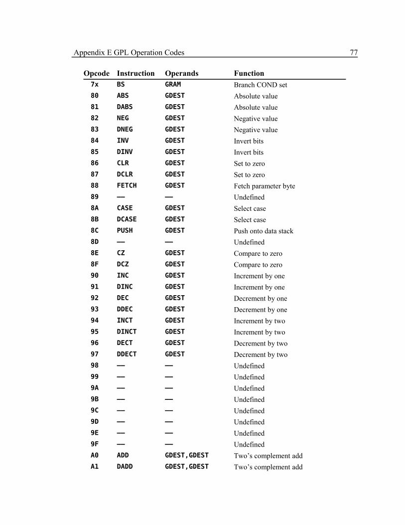
Appendix E GPL Operation Codes 77
Opcode Instruction Operands Function7x BS GRAM Branch COND set
80 ABS GDEST Absolute value
81 DABS GDEST Absolute value
82 NEG GDEST Negative value
83 DNEG GDEST Negative value
84 INV GDEST Invert bits
85 DINV GDEST Invert bits
86 CLR GDEST Set to zero
87 DCLR GDEST Set to zero
88 FETCH GDEST Fetch parameter byte
89 —— —— Undefined
8A CASE GDEST Select case
8B DCASE GDEST Select case
8C PUSH GDEST Push onto data stack
8D —— —— Undefined
8E CZ GDEST Compare to zero
8F DCZ GDEST Compare to zero
90 INC GDEST Increment by one
91 DINC GDEST Increment by one
92 DEC GDEST Decrement by one
93 DDEC GDEST Decrement by one
94 INCT GDEST Increment by two
95 DINCT GDEST Increment by two
96 DECT GDEST Decrement by two
97 DDECT GDEST Decrement by two
98 —— —— Undefined
99 —— —— Undefined
9A —— —— Undefined
9B —— —— Undefined
9C —— —— Undefined
9D —— —— Undefined
9E —— —— Undefined
9F —— —— Undefined
A0 ADD GDEST,GDEST Two’s complement add
A1 DADD GDEST,GDEST Two’s complement add
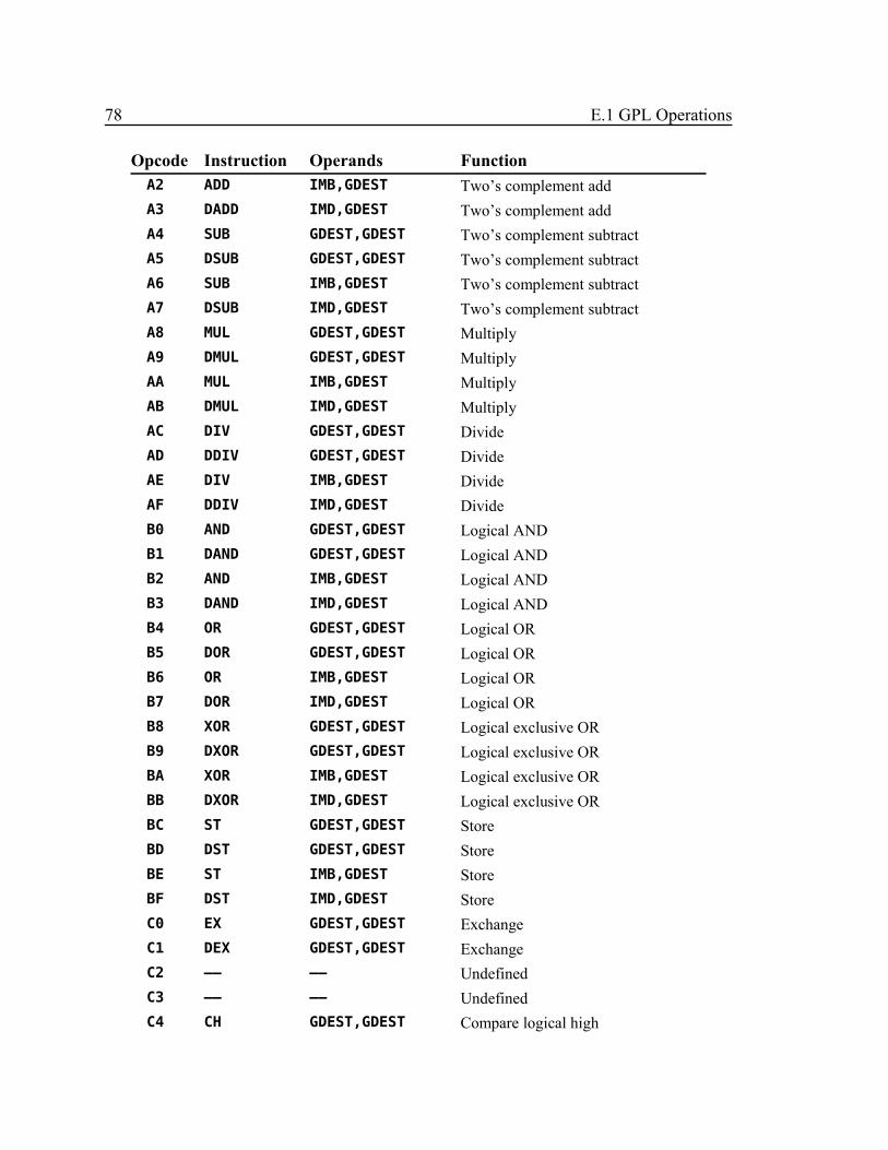
78 E.1 GPL Operations
Opcode Instruction Operands FunctionA2 ADD IMB,GDEST Two’s complement add
A3 DADD IMD,GDEST Two’s complement add
A4 SUB GDEST,GDEST Two’s complement subtract
A5 DSUB GDEST,GDEST Two’s complement subtract
A6 SUB IMB,GDEST Two’s complement subtract
A7 DSUB IMD,GDEST Two’s complement subtract
A8 MUL GDEST,GDEST Multiply
A9 DMUL GDEST,GDEST Multiply
AA MUL IMB,GDEST Multiply
AB DMUL IMD,GDEST Multiply
AC DIV GDEST,GDEST Divide
AD DDIV GDEST,GDEST Divide
AE DIV IMB,GDEST Divide
AF DDIV IMD,GDEST Divide
B0 AND GDEST,GDEST Logical AND
B1 DAND GDEST,GDEST Logical AND
B2 AND IMB,GDEST Logical AND
B3 DAND IMD,GDEST Logical AND
B4 OR GDEST,GDEST Logical OR
B5 DOR GDEST,GDEST Logical OR
B6 OR IMB,GDEST Logical OR
B7 DOR IMD,GDEST Logical OR
B8 XOR GDEST,GDEST Logical exclusive OR
B9 DXOR GDEST,GDEST Logical exclusive OR
BA XOR IMB,GDEST Logical exclusive OR
BB DXOR IMD,GDEST Logical exclusive OR
BC ST GDEST,GDEST Store
BD DST GDEST,GDEST Store
BE ST IMB,GDEST Store
BF DST IMD,GDEST Store
C0 EX GDEST,GDEST Exchange
C1 DEX GDEST,GDEST Exchange
C2 —— —— Undefined
C3 —— —— Undefined
C4 CH GDEST,GDEST Compare logical high

Appendix E GPL Operation Codes 79
Opcode Instruction Operands FunctionC5 DCH GDEST,GDEST Compare logical high
C6 CH IMB,GDEST Compare logical high
C7 DCH IMD,GDEST Compare logical high
C8 CHE GDEST,GDEST Compare logical high or equal
C9 DCHE GDEST,GDEST Compare logical high or equal
CA CHE IMB,GDEST Compare logical high or equal
CB DCHE IMD,GDEST Compare logical high or equal
CC CGT GDEST,GDEST Compare greater than
CD DCGT GDEST,GDEST Compare greater than
CE CGT IMB,GDEST Compare greater than
CF DCGT IMD,GDEST Compare greater than
D0 CGE GDEST,GDEST Compare greater than or equal
D1 DCGE GDEST,GDEST Compare greater than or equal
D2 CGE IMB,GDEST Compare greater than or equal
D3 DCGE IMD,GDEST Compare greater than or equal
D4 CEQ GDEST,GDEST Compare equal
D5 DCEQ GDEST,GDEST Compare equal
D6 CEQ IMB,GDEST Compare equal
D7 DCEQ IMD,GDEST Compare equal
D8 CLOG GDEST,GDEST Compare logical
D9 DCLOG GDEST,GDEST Compare logical
DA CLOG IMB,GDEST Compare logical
DB DCLOG IMB,GDEST Compare logical
DC SRA GDEST,GDEST Shift right algebraic
DD DSRA GDEST,GDEST Shift right algebraic
DE SRA IMB,GDEST Shift right algebraic
DF DSRA IMD,GDEST Shift right algebraic
E0 SLL GDEST,GDEST Shift left logical
E1 DSLL GDEST,GDEST Shift left logical
E2 SLL IMB,GDEST Shift left logical
E3 DSLL IMD,GDEST Shift left logical
E4 SRL GDEST,GDEST Shift right logical
E5 DSRL GDEST,GDEST Shift right logical
E6 SRL IMB,GDEST Shift right logical
E7 DSRL IMD,GDEST Shift right logical

80 E.1 GPL Operations
Opcode Instruction Operands FunctionE8 SRC GDEST,GDEST Shift right circular
E9 DSRC GDEST,GDEST Shift right circular
EA SRC IMB,GDEST Shift right circular
EB DSRC IMD,GDEST Shift right circular
EC —— —— Undefined
ED COINC GDEST,GDEST Coincidence detection
EE —— —— Undefined
EF —— —— Undefined
F0 —— —— Undefined
F1 —— —— Undefined
F2 —— —— Undefined
F3 —— —— Undefined
F4 IO GDEST,GDEST Special input/output
F5 —— —— Undefined
F6 IO IMB,GDEST Special input/output
F7 —— —— Undefined
F8 —— —— Undefined
F9 —— —— Undefined
FA —— —— Undefined
FB —— —— Undefined
FC —— —— Undefined
FD —— —— Undefined
FE —— —— Undefined
FF —— —— Undefined

Appendix E GPL Operation Codes 81
E.2 Format Suboperations
Opcodes Instruction Assembled as
0x - 1x HTEX >00+(count-1),text
2x - 3x VTEX >20+(count-1),text
4x - 5x HCHA >40+(count-1),char
6x - 7x VCHA >60+(count-1),char
8x - 9x ICOL >80+(count-1)
Ax - Bx IROW >80+(count-1)
Cx - Dx FOR >C0+(count-1)
Ex HSTR >E0+(count-1),gsrc
FB FEND >FB {End of FMT}
FB FEND >FB,GGGG {End of FOR}
FC SCRO >FC,IMB
FD SCRO >FC,gsrc
FE ROW >FE,row
FF COL >FE,col
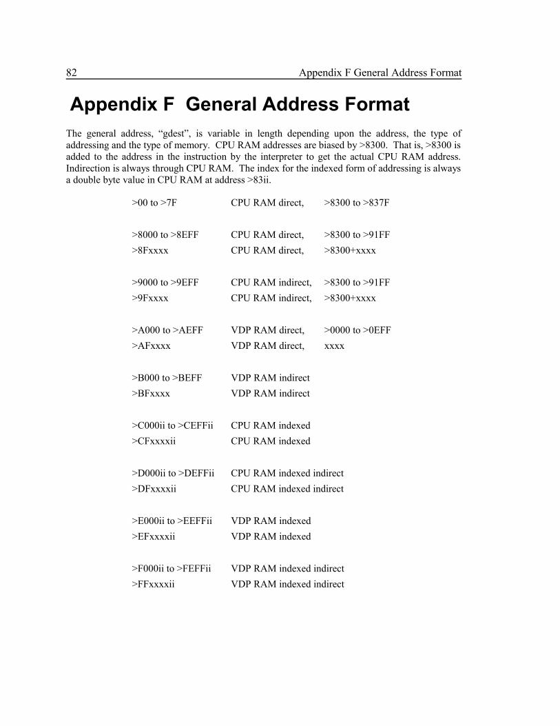
82 Appendix F General Address Format
Appendix F General Address FormatThe general address, “gdest”, is variable in length depending upon the address, the type ofaddressing and the type of memory. CPU RAM addresses are biased by >8300. That is, >8300 isadded to the address in the instruction by the interpreter to get the actual CPU RAM address.Indirection is always through CPU RAM. The index for the indexed form of addressing is alwaysa double byte value in CPU RAM at address >83ii.
>00 to >7F CPU RAM direct, >8300 to >837F
>8000 to >8EFF CPU RAM direct, >8300 to >91FF
>8Fxxxx CPU RAM direct, >8300+xxxx
>9000 to >9EFF CPU RAM indirect, >8300 to >91FF
>9Fxxxx CPU RAM indirect, >8300+xxxx
>A000 to >AEFF VDP RAM direct, >0000 to >0EFF
>AFxxxx VDP RAM direct, xxxx
>B000 to >BEFF VDP RAM indirect
>BFxxxx VDP RAM indirect
>C000ii to >CEFFii CPU RAM indexed
>CFxxxxii CPU RAM indexed
>D000ii to >DEFFii CPU RAM indexed indirect
>DFxxxxii CPU RAM indexed indirect
>E000ii to >EEFFii VDP RAM indexed
>EFxxxxii VDP RAM indexed
>F000ii to >FEFFii VDP RAM indexed indirect
>FFxxxxii VDP RAM indexed indirect
Related Documents


