Aruba 7005 Controller The Aruba 7005 Controller is a wireless LAN controller that connects, controls, and intelligently integrates wireless Access Points (APs) and Air Monitors (AMs) into a wired LAN system. The 7005 controller includes four ethernet ports, one Console port, one Mini-USB console port, and one USB port. This device supports up to 16 APs and 1024 users. Package Contents Aruba 7005 Controller Mini-USB Console Cable Installation Guide (this document, printed) Quick Start Guide (Printed) End User License Agreement (Printed) 7005 Components This section introduces the different components and their location in the Aruba 7005 controller. Figure 1 shows the front panel of the Aruba 7005 controller and Figure 2 shows the back panel of the Aruba 7005 controller. Figure 1 Front Panel of the 7005 Controller Figure 2 Back Panel of the 7005 Controller Ethernet Ports The Aruba 7005 controller is equipped with four 10/100/ 1000BASE-T Gigabit Ethernet ports (0 to 3). Gigabit Ethernet uses all eight wires and each pair is bi- directional, which means, the same pair is used for both data transmission and data reception. Figure 3 illustrates the Gigabit Ethernet port pin-out for an RJ-45 connector. The pins paired on a 10/100/1000BASE-T Gigabit Ethernet port are: 1/ 2, 3/6, 4/5, and 7/8. Figure 3 Gigabit Ethernet Port Pin-Out Ethernet Port LEDs Each 10/100/1000BASE-T Ethernet port is equipped with two LEDs that allow basic monitoring of link/port status and activity. LINK/ACT: Placed on the left side of the port, this LED displays the link status and activity of the port. STATUS: Placed on the right side of the port, this LED displays the status of the port based on the CLI. The following table describes the LED behavior for each mode: Console Port The serial console port allows connecting the controller to a serial terminal or a laptop for direct local management. This port is an RJ-45 female connector with the pinouts described in Figure 4. Connect it directly to a terminal or terminal server using an Ethernet cable. Figure 4 Serial Console Port Pin-Out The communication settings for the Console port is shown in the following table: Serial Console Port Adaptor A modular adaptor can be used to convert the female RJ-45 connector to a male DB9 connector. See Figure 5 for complete details. Figure 5 RJ-45 (Female) to DB9 (Male) Modular Adapter Conversion Mini-USB Console Connector The Aruba 7005 controller is equipped with one Mini-USB (type B) connector that provides console access for direct local access. If both Mini-USB and RJ-45 Console ports are connected, the Mini-USB connection takes precedence over the RJ-45 Console connection. Mini-USB Driver To use the Mini-USB console port, install the Aruba Mini-USB driver on the computer that will manage your controller. To download the driver, perform the following steps: 1. Go to https://support.arubanetworks.com. 2. Click on the Tools & Resources tab. 3. Open the USB Console Driver folder. 4. Open the Mobility Controller and Mobility Access Switch folder. 5. Select the appropriate file for your application. The corresponding operating system is in the file name. USB Interface The Aruba 7005 controller is equipped with one USB 2.0 interface. A USB storage device can be used to save and upload configurations to the controller. Power and Status LEDs The front panel also includes power and status LEDs that provide basic monitoring of the overall status of the Aruba 7005 controller Kensington Security Slot The Aruba 7005 controller is equipped with a Kensington security slot for additional security. DC Power Socket The AC-DC adapter kit with the following specification is used to power the Aruba 7005 controller: 12V/ 2A power interface Center-positive 1.7/4.0 mm circular plug, 9.5 mm length Make sure to securely route the DC cable through the slot provided. See Figure 6. Figure 6 DC Cable Routing Slot Installing the 7005 Controller Installation Recommendations For proper air circulation, leave at least 10 cm (4 inches) clearance for the vents on the left, right, front, and rear side of the controller. Leave additional space in front and rear side of the controller to access power cords, network cables, and indicator LEDs. Avoid placing anything that covers the vents on top of the controller. Covering the vents can lead to overheating of the controller. Avoid placing this controller on any other device because the heat dissipated from the other device may overheat the controller. Installation Using the Integrated Wall-Mounting Slots The keyhole-shaped slots on the bottom of the controller can be used to attach the device upright (front port facing downwards) to an indoor wall or shelf. Since the ports are on the front of the device, make sure to mount the controller in such a way that there is a clear path to the Ethernet port, such as a predrilled hole in the mounting surface. 1. At the mounting location, install two screws on the wall or shelf, 120 mm apart. If you are attaching the device to drywall, it is recommended that you use appropriate wall anchors (not included). See Figure 7. Figure 7 Mounting Using the Integrated Wall-Mounting Slots 2. Align the mounting slots on the bottom of the controller over the screws and slide the unit into place. See Figure 8 Figure 8 Wall Mounting Aruba 7005 Product Specifications Physical Device Dimensions (HxWxD): 4.09 cm x 20 cm x 20 cm Device Weight: 2.03 lbs (0.92 kg) Electrical Ethernet: 4 x 10/100/1000BASE-T auto-sensing Ethernet RJ-45 Interfaces MDI/MDX Power over Ethernet (IEEE 802.3af or IEEE 802.3at compliant), 48V DC (nominal) and 56V DC (maximum)/ 350 mA (see Figure 3 for pin configuration) The 7005 controller requires ArubaOS 6.4.1.0 or later. Optional accessories are available for use with the Aruba 7005 controller and are sold separately. Contact your Aruba sales representative for details and assistance. In the Aruba 7005 controller, the orange numbering on port 0 indicates that it is a PoE powered device (PoE-PD) port and the gray numbering on ports 1, 2, and 3 indicate that they are non-PoE ports. 1000Base-T Gigabit Ethernet Port RJ-45 Female Pin-Out Signal Name 1 2 3 4 5 6 7 8 BI_DC+ BI_DC- BI_DD+ BI_DD- BI_DA+ BI_DA- BI_DB+ BI_DB- Function Bi-directional pair +C Bi-directional pair -C Bi-directional pair +D Bi-directional pair -D Bi-directional pair +A Bi-directional pair -A Bi-directional pair +B Bi-directional pair -B Table 1 10/100/1000BASE-T Ethernet Port LEDs LED Function Mode Indicator Status LINK/ACT Link status N/A Green (Solid) Link has been established Green (Blinking) Port is transmitting or receiving data Off No link on port STATUS Port status Speed Green (Solid) 1000 Mbps Off 10/100 Mbps Table 2 Console Terminal Settings Baud Rate Data Bits Parity Stop Bits Flow Control 9600 8 None 1 None ! CAUTION The CONSOLE port is compatible only with RS-232 devices. Non-RS-232 devices, such as APs, are not supported. ! CAUTION Do not connect the Console port to an Ethernet switch or a PoE power source. This may damage the controller. Serial Console Port 1 2 3 4 5 6 7 8 TxD GND RxD RJ-45 Female Pin-Out Direction Input Output GND 3 4 5 2 5 6 3 RJ-45 DB-9 Internal Connections TxD GND RxD 1 2 3 4 5 6 7 8 TxD GND RxD RJ-45 Female Pin-Out DB-9 Male Pin-Out TxD RxD Ground 5 4 3 2 1 9 8 7 6 If the 7005 controller is powered from IEEE 802.3at PSE then the USB port remains enabled. If the 7005 controller is powered from IEEE 802.3af PSE, then the USB port is automatically disabled. Table 3 Power and Status LEDs LED Function Indicator Status Power System powers Green (Solid) Powered from DC adapter Amber (Solid) Powered from PoE source Off Power Off Status System status Green (Solid) Operational Green (Blinking) Device is loading software Amber (Blinking) Major Alarm Amber (Solid) Critical Alarm Off No power Service to all Aruba Networks, Inc. products should be performed by trained service personnel only.

Welcome message from author
This document is posted to help you gain knowledge. Please leave a comment to let me know what you think about it! Share it to your friends and learn new things together.
Transcript
Aruba 7005 Controller
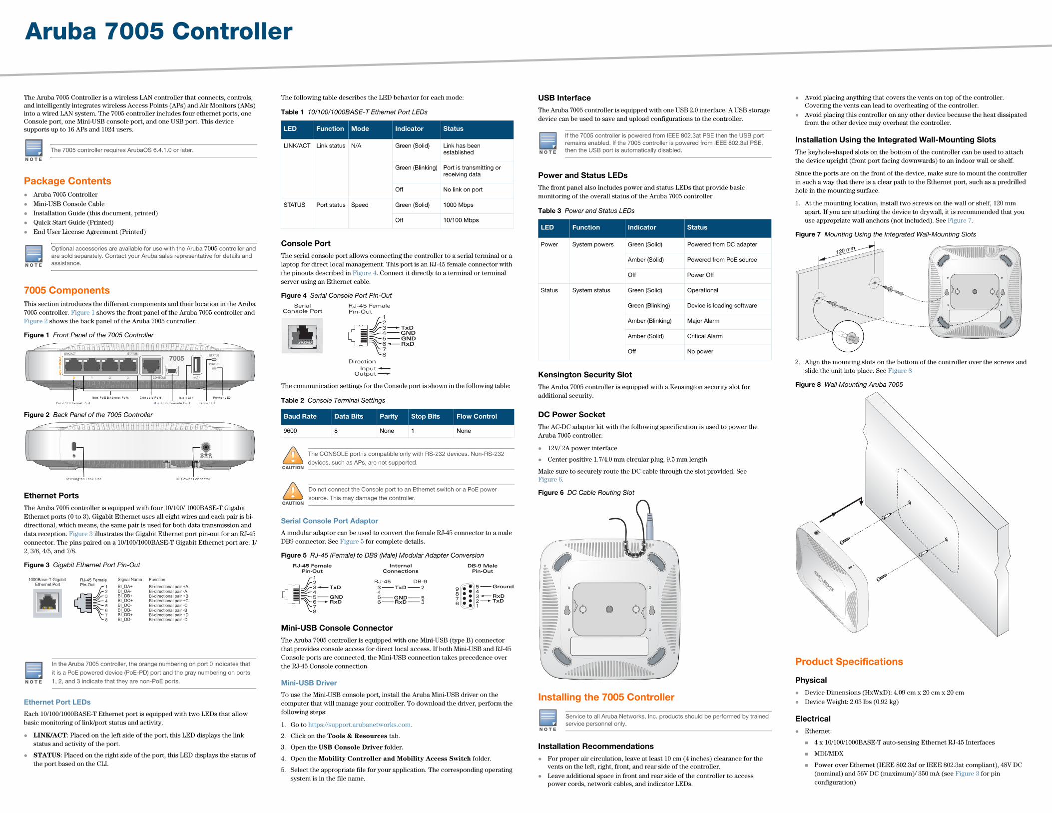
The Aruba 7005 Controller is a wireless LAN controller that connects, controls, and intelligently integrates wireless Access Points (APs) and Air Monitors (AMs) into a wired LAN system. The 7005 controller includes four ethernet ports, one Console port, one Mini-USB console port, and one USB port. This device supports up to 16 APs and 1024 users.
Package Contents Aruba 7005 Controller Mini-USB Console Cable Installation Guide (this document, printed) Quick Start Guide (Printed) End User License Agreement (Printed)
7005 ComponentsThis section introduces the different components and their location in the Aruba 7005 controller. Figure 1 shows the front panel of the Aruba 7005 controller and Figure 2 shows the back panel of the Aruba 7005 controller.
Figure 1 Front Panel of the 7005 Controller
Figure 2 Back Panel of the 7005 Controller
Ethernet PortsThe Aruba 7005 controller is equipped with four 10/100/ 1000BASE-T Gigabit Ethernet ports (0 to 3). Gigabit Ethernet uses all eight wires and each pair is bi-directional, which means, the same pair is used for both data transmission and data reception. Figure 3 illustrates the Gigabit Ethernet port pin-out for an RJ-45 connector. The pins paired on a 10/100/1000BASE-T Gigabit Ethernet port are: 1/2, 3/6, 4/5, and 7/8.
Figure 3 Gigabit Ethernet Port Pin-Out
Ethernet Port LEDs
Each 10/100/1000BASE-T Ethernet port is equipped with two LEDs that allow basic monitoring of link/port status and activity.
LINK/ACT: Placed on the left side of the port, this LED displays the link status and activity of the port.
STATUS: Placed on the right side of the port, this LED displays the status of the port based on the CLI.
The following table describes the LED behavior for each mode:
Console PortThe serial console port allows connecting the controller to a serial terminal or a laptop for direct local management. This port is an RJ-45 female connector with the pinouts described in Figure 4. Connect it directly to a terminal or terminal server using an Ethernet cable.
Figure 4 Serial Console Port Pin-Out
The communication settings for the Console port is shown in the following table:
Serial Console Port Adaptor
A modular adaptor can be used to convert the female RJ-45 connector to a male DB9 connector. See Figure 5 for complete details.
Figure 5 RJ-45 (Female) to DB9 (Male) Modular Adapter Conversion
Mini-USB Console ConnectorThe Aruba 7005 controller is equipped with one Mini-USB (type B) connector that provides console access for direct local access. If both Mini-USB and RJ-45 Console ports are connected, the Mini-USB connection takes precedence over the RJ-45 Console connection.
Mini-USB Driver
To use the Mini-USB console port, install the Aruba Mini-USB driver on the computer that will manage your controller. To download the driver, perform the following steps:
1. Go to https://support.arubanetworks.com.
2. Click on the Tools & Resources tab.
3. Open the USB Console Driver folder.
4. Open the Mobility Controller and Mobility Access Switch folder.
5. Select the appropriate file for your application. The corresponding operating system is in the file name.
USB InterfaceThe Aruba 7005 controller is equipped with one USB 2.0 interface. A USB storage device can be used to save and upload configurations to the controller.
Power and Status LEDsThe front panel also includes power and status LEDs that provide basic monitoring of the overall status of the Aruba 7005 controller
Kensington Security SlotThe Aruba 7005 controller is equipped with a Kensington security slot for additional security.
DC Power SocketThe AC-DC adapter kit with the following specification is used to power the Aruba 7005 controller:
12V/ 2A power interface
Center-positive 1.7/4.0 mm circular plug, 9.5 mm length
Make sure to securely route the DC cable through the slot provided. See Figure 6.
Figure 6 DC Cable Routing Slot
Installing the 7005 Controller
Installation Recommendations For proper air circulation, leave at least 10 cm (4 inches) clearance for the
vents on the left, right, front, and rear side of the controller. Leave additional space in front and rear side of the controller to access
power cords, network cables, and indicator LEDs.
Avoid placing anything that covers the vents on top of the controller. Covering the vents can lead to overheating of the controller.
Avoid placing this controller on any other device because the heat dissipated from the other device may overheat the controller.
Installation Using the Integrated Wall-Mounting SlotsThe keyhole-shaped slots on the bottom of the controller can be used to attach the device upright (front port facing downwards) to an indoor wall or shelf.
Since the ports are on the front of the device, make sure to mount the controller in such a way that there is a clear path to the Ethernet port, such as a predrilled hole in the mounting surface.
1. At the mounting location, install two screws on the wall or shelf, 120 mm apart. If you are attaching the device to drywall, it is recommended that you use appropriate wall anchors (not included). See Figure 7.
Figure 7 Mounting Using the Integrated Wall-Mounting Slots
2. Align the mounting slots on the bottom of the controller over the screws and slide the unit into place. See Figure 8
Figure 8 Wall Mounting Aruba 7005
Product Specifications
Physical Device Dimensions (HxWxD): 4.09 cm x 20 cm x 20 cm Device Weight: 2.03 lbs (0.92 kg)
Electrical Ethernet:
4 x 10/100/1000BASE-T auto-sensing Ethernet RJ-45 Interfaces
MDI/MDX
Power over Ethernet (IEEE 802.3af or IEEE 802.3at compliant), 48V DC (nominal) and 56V DC (maximum)/ 350 mA (see Figure 3 for pin configuration)
The 7005 controller requires ArubaOS 6.4.1.0 or later.
Optional accessories are available for use with the Aruba 7005 controller and are sold separately. Contact your Aruba sales representative for details and assistance.
In the Aruba 7005 controller, the orange numbering on port 0 indicates that it is a PoE powered device (PoE-PD) port and the gray numbering on ports 1, 2, and 3 indicate that they are non-PoE ports.
1000Base-T Gigabit Ethernet Port
RJ-45 FemalePin-Out
Signal Name
12345678
BI_DC+BI_DC-
BI_DD+BI_DD-
BI_DA+BI_DA-BI_DB+
BI_DB-
Function
Bi-directional pair +CBi-directional pair -C
Bi-directional pair +DBi-directional pair -D
Bi-directional pair +ABi-directional pair -ABi-directional pair +B
Bi-directional pair -B
Table 1 10/100/1000BASE-T Ethernet Port LEDs
LED Function Mode Indicator Status
LINK/ACT Link status N/A Green (Solid) Link has been established
Green (Blinking) Port is transmitting or receiving data
Off No link on port
STATUS Port status Speed Green (Solid) 1000 Mbps
Off 10/100 Mbps
Table 2 Console Terminal Settings
Baud Rate Data Bits Parity Stop Bits Flow Control
9600 8 None 1 None
!CAUTION
The CONSOLE port is compatible only with RS-232 devices. Non-RS-232 devices, such as APs, are not supported.
!CAUTION
Do not connect the Console port to an Ethernet switch or a PoE power source. This may damage the controller.
SerialConsole Port
12345678
TxD
GNDRxD
RJ-45 FemalePin-Out
DirectionInput
Output
GND
345
2
56 3
RJ-45 DB-9
InternalConnections
TxD
GNDRxD
12345678
TxD
GNDRxD
RJ-45 FemalePin-Out
DB-9 MalePin-Out
TxDRxD
Ground54321
9876
If the 7005 controller is powered from IEEE 802.3at PSE then the USB port remains enabled. If the 7005 controller is powered from IEEE 802.3af PSE, then the USB port is automatically disabled.
Table 3 Power and Status LEDs
LED Function Indicator Status
Power System powers Green (Solid) Powered from DC adapter
Amber (Solid) Powered from PoE source
Off Power Off
Status System status Green (Solid) Operational
Green (Blinking) Device is loading software
Amber (Blinking) Major Alarm
Amber (Solid) Critical Alarm
Off No power
Service to all Aruba Networks, Inc. products should be performed by trained service personnel only.
Aruba 7005 ControllerInstallation Guide
www.arubanetworks.com1344 Crossman AvenueSunnyvale, California 94089Phone: 408.227.4500Fax 408.227.4550
Aruba 7005 Controller | Installation GuidePart Number 0511563-02 | June 2014
Contacting Aruba Networks
Web Support
Main Site http://www.arubanetworks.com
Support Site https://support.arubanetworks.com
Airheads Social Forums and Knowledge Base community.arubanetworks.com
North American Telephone 1-800-943-4526 (Toll Free)1-408-754-1200
International Telephones arubanetworks.com/support-services/aruba-support-program/contact-support/
Software Licensing Site licensing.arubanetworks.com/login.php
Wireless Security IncidentResponse Team (WSIRT)
arubanetworks.com/support/wsirt.php
Support Email Addresses
Americas and APAC [email protected]
EMEA [email protected]
Americas and APAC Support Email [email protected]
WSIRT EmailPlease email details of any securityproblem found in an Aruba product.
Copyright© 2014 Aruba Networks, Inc. AirWave®, Aruba Networks®, Aruba Mobility Management System®, Bluescanner, For Wireless That Works®, Mobile Edge Architecture, People Move. Networks Must Follow., RFProtect®, The All Wireless Workplace Is Now Open For Business, and The Mobile Edge Company® are trademarks of Aruba Networks, Inc. All rights reserved. All other trademarks are the property of their respective owners.
Open Source CodeCertain Aruba products include Open Source software code developed by third parties, including software code subject to the GNU General Public License ("GPL"), GNU Lesser General Public License ("LGPL"), or other Open Source Licenses. The Open Source code used can be found at this site:http://www.arubanetworks.com/open_source
Legal NoticeThe use of Aruba Networks, Inc. switching platforms and software, by all individuals or corporations, to terminate other vendors' VPN client devices constitutes complete acceptance of liability by that individual or corporation for this action and indemnifies, in full, Aruba Networks, Inc. from any and all legal actions that might be taken against it with respect to infringement of copyright on behalf of those vendors.
WarrantyThis hardware product is protected by an Aruba warranty. For details, see Aruba Networks standard warranty terms and conditions.
Power:
12V DC power interface, supports powering through an 12V DC, 2A AC-to-DC power adapter
PoE support on port 0: supports PoE-PD IEEE 802.3af/at
Environmental Operating:
Temperature: 0° C to +40° C (+32° F to +122° F)
Humidity: 10% to 90% non-condensing
Storage and transportation:
Temperature: -40° C to +70° C (-40° F to +158°)
For additional specifications on this product, please refer to the data sheet. The data sheet can be found at www.arubanetworks.com.
Safety and Regulatory ComplianceAruba Networks provides a multi-language document that contains country-specific restrictions and additional safety and regulatory information for all Aruba controllers. This document can be viewed or downloaded from the following location: www.arubanetworks.com/safety_addendum
FCC Class B Part 15This device complies with Part 15 of the Federal Communications Commission (FCC) Rules. Operation is subject to the following two conditions:
This device may not cause harmful interference.
This device must accept any interference received, including interference that may cause undesired operation.
This equipment has been tested and found to comply with the limits for a Class B digital device, pursuant to Part 15 of the FCC Rules. This equipment generates, uses and can radiate radio frequency energy and, if not installed and used in accordance with the manufacturer’s instructions, may cause interference harmful to radio communications.
If this equipment does cause interference, which can be determined by turning the equipment off and on, the user is encouraged to try to correct the interference by one or more of the following measures:
Reorient or relocate the receiving antenna.
Increase the separation between the equipment and receiver.
Connect the equipment to an outlet on a circuit different from that to which the receiver is connected.
Consult the dealer or an experienced radio or TV technician for help.
Industry CanadaThis product complies with the Class B limits for radio noise emissions as set out in the interference-causing equipment standard entitled “Digital Apparatus,” ICES-003 of Industry Canada.
Cet apareil numerique de la classe B respecte toutes les exigencies du Reglement sur le materiel brouilleur du Canada.
EU Regulatory Conformance This product is CE marked according to the provisions of the EMC
Directive (2004/108/EC) - CE. Aruba Networks Inc., hereby declares that 7005 controller device models are in compliance with the essential requirements and other relevant provisions of Directive (2004/108/EC). CE The Declaration of Conformity made under Directive 1999/5/EC is available for viewing at the following location in the EU community.
Battery Statements
Japan VCCI
This product is a Class B product based on the standard of the VCCI Council. If this is used near a radio or television receiver in a domestic environment, it may cause radio interference. Install and use the equipment according to the instruction manual.
Proper Disposal of Aruba Equipment
Waste of Electrical and Electronic EquipmentAruba products at end of life are subject to separate collection and treatment in the EU Member States, Norway, and Switzerland and therefore are marked with the symbol shown at the left (crossed-out wheelie bin). The treatment applied at end of life of these products in these countries shall comply with the applicable national laws of countries implementing Directive
2002/96EC on Waste of Electrical and Electronic Equipment (WEEE).
European Union RoHSAruba products also comply with the EU Restriction of Hazardous Substances Directive 2011/65/EC (RoHS). EU RoHS restricts the use of specific hazardous materials in the
manufacture of electrical and electronic equipment. Specifically, restricted materials under the RoHS Directive are Lead (including Solder used in printed circuit assemblies), Cadmium, Mercury, Hexavalent Chromium, and Bromine. Some Aruba products are subject to the exemptions listed in RoHS Directive Annex 7 (Lead in solder used in printed circuit assemblies). Products and packaging will be marked with the “RoHS” label shown at the left indicating conformance to this Directive.
India RoHSThis product complies with RoHS requirements as prescribed by E-Waste (Management & Handling) Rules, governed by the Ministry of Environment & Forests, Government of India.
China RoHSAruba products also comply with China environmental declaration requirements and are labeled with the “EFUP 10” label shown at the left.
!CAUTION
Changes or modifications to this unit not expressly approved by the party responsible for compliance could void the user’s authority to operate this equipment.
!CAUTION
Use of controls or adjustments of performance or procedures other than those specified in this manual may result in hazardous radiation exposure
!CAUTION
Although this controller has been tested up to 1kV per CE immunity requirements, it requires surge protection to be provided as part of the building installation to protect against unidirectional surges resulting from electrical switching and lightning strikes. For protection against these surges in an outdoor installation, any exposed wiring must be shielded, and the shield for the wiring must be grounded at both ends.
!CAUTION
Il y a danger d’explosion s’il y a remplacement incorrect de la batterie.Remplacer uniquement avec une batterie due même type ou d’un équivalent recommandé par le constructeur.Mettre au rebut les batteries usagées conformément aux unstruction du fabricant.
!CAUTION
The battery supplied with this product may contain perchlorate material. Special handling may apply in California and other certain states. See www.dtsc.ca.gov/hazardouswaste/perchlorate for more information.
WARNING
Risk of explosion if battery is replaced by an incorrect type. Dispose of used batteries according to the instructions.
10
Hazardous Materials Declaration
(Hazardous Substance)
(Parts)
(PCA Boards)
(Mechanical Sub-Assemblies)
SJ/T11363-2006Indicates that the concentration of the hazardous substance in all homogeneous materials in the parts is below the relevant threshold of the SJ/T11363-2006 standard.
Indicates that the concentration of the hazardous substance of at least one of all homogeneous materials in the parts is above the relevant threshold of the SJ/T11363-2006 standard.
This table shows where these substances may be found in the supply chain of electronic information products, as of the date of sale of the enclosed product.
The Environment- Friendly Use Period (EFUP) for all enclosed products and their parts are per the symbol shown here. The Environment- Friendly Use Period is valid only when the product is operated under the conditions defined in the product manual.
Related Documents