Artist-friendly Framework for Stylized Rendering (アーティストによる陰影デザインのためのフレームワーク) by Hideki Todo 藤堂 英樹 A Doctor Thesis (Abstract) 博士論文(要約) Submitted to the Graduate School of the University of Tokyo on September 27, 2013 in Partial Fulfillment of the Requirements for the Degree of Doctor of Information Science and Technology in Computer Science Thesis Supervisor: Takeo Igarashi 五十嵐 健夫 Professor of Computer Science

Welcome message from author
This document is posted to help you gain knowledge. Please leave a comment to let me know what you think about it! Share it to your friends and learn new things together.
Transcript
Artist-friendly Framework for Stylized
Rendering(アーティストによる陰影デザインのためのフレームワーク)
by
Hideki Todo
藤堂 英樹
A Doctor Thesis (Abstract)
博士論文(要約)
Submitted to
the Graduate School of the University of Tokyo
on September 27, 2013
in Partial Fulfillment of the Requirements
for the Degree of Doctor of Information Science and Technology
in Computer Science
Thesis Supervisor: Takeo Igarashi五十嵐 健夫
Professor of Computer Science

ABSTRACT
In recent days, 3D computer graphics techniques are widely used in digital animation andvideo games for efficiently producing animation. Advances in stylized rendering techniques thatcan emulate hand-drawn stylized shading styles make 3D cartoon characters more common indigital animation films. However, these stylized rendering results are generated from physicallighting result according to predefined procedures. Providing efficient and intuitive interface forartists to design their expressive shading styles remains as a challenge.
In this thesis, we introduce a new framework,integration of artistic depictions with physics-based lighting, for designing artist-friendly shading model and interface. This framework isbased on two principles: (1) directable shading model for artistic control and (2) seamless in-tegration with 3D lighting. Based on the principles, we apply this framework to the followingthree different levels of shading design process, from small scale to large scale control.
First, we presentlocally controllable shading with intuitive paint interface. For directablecontrol over shaded area, we propose a method to modify computed lighting term with a scalaroffset function, obtained by painting process. Our approach enables appearance-based design forthe desired changes to light and shade.
Second, we presentshading stylization based on model features. This method allows inter-active design for lighting enhancements based on model features, which would require time con-suming painting process with the first method. Our system enables commonly used hand-drawnlighting effects, such as straight lighting effect on flat planes and edge emphasizing lighting effecton sharp edges.
Third, we presentpractical shading model for expressive shading stylesfor even larger scalecontrol. In this method we focus on overall shading appearance while the first and second meth-ods are limited to simple shading tones. The artist can design his shading style directly on areference sphere. Our system then transfers the designed shading style to the target model basedon 3D light and view settings.
Our framework enables interactively design of expressive stylized shading styles using com-pact and consistent representations. These successful results suggest the validity of our twoprinciples for stylized shading. Finally, we discuss limitations and future research directionsbased on our finding in the thesis.
論文要旨
近年,3DCGは効率よくアニメーションを制作できるため,映像作品やゲームに幅広く
利用されている.3DCGの陰影を手描き風に表現する技術も身近になり,手描きと 3DCG
を組み合わせたアニメーション作品も数多く見られるようになった.しかし,既存の手描
き風の陰影表現の技術では,物理計算された明るさ情報を直接機械的に手描き風の陰影に
変換しており,アーティストが陰影を自在に制御するという点では課題が多く残っている.
そこで,我々は,アーティストが演出を行うための陰影の表現形式とインターフェース
を設計する際の指針として「物理と演出を融合した手描き陰影表現のフレームワーク」を
提案する.より詳細には,直観的かつ効率的な陰影のデザインを支援するため,(1)アー
ティストが演出可能な陰影モデルと (2)既存のライティングとの親和性の双方を満たすよ
うな形で設計する.本論文ではこの設計指針に基づき,局所的制御から大域的制御まで異
なる 3つのレベルの特性に応じたデザイン手法を提案する.
第一に,「ペイントによる局所的な陰影制御法」を提案する.この手法では,局所制御に
よる陰影の演出を実現するため,物理的に計算されたライティング結果をペイント情報に
基づいて補正する,というアプローチを取った.直観的なペイント UI を提供することで,
見た目ベースでの陰影のデザインを実現できる.
第二に,「形状の特徴表現のためのライティング強調手法」を提案する.この手法は,第
一の手法では調整が難しい大域的な形状の特徴部分に対し,アーティストのライティング
演出のデザインを支援するものである.手描きによく見られるような平坦さを強調する直
線的なライティングや鋭さを強調する輪郭線付近のライティングを,インタラクティブに
デザインすることができる.
第三に,さらに全体の見た目を調整する手法として,「手描風陰影のマテリアルデザイン
手法」を提案する.この手法では,第一・第二の手法では調整することができない陰影全
体の見た目に注目している.アーティストはガイドとなる球に手描き独特の陰影効果をペ
イントでデザインすることができ,デザインした陰影効果はライトの動きに合わせて3次
元オブジェクト全体に反映される.
どのシステムにおいても,物理と演出の融合を意識し,既存のライティングとの親和性
を実現している.提案したフレームワークを用いることで,アーティストの複雑な陰影表
現を,コンパクトかつ整合性のある表現形式でインタラクティブに作成することができる.
これらの結果は,我々が提案した物理と演出を融合したフレームワークの有効性を示唆し
ている.また,本研究で得られた知見を基に,将来研究の方向性についても議論する.
Acknowledgements
I would like to thank everybody who has supported me in this work.
First of all, my deepest appreciation goes to my supervisor, Takeo Igarashi, for intro-ducing me to the pleasure of user interface and computer graphics research. He alwaysencouraged me to explore new findings with his creative way of thinking, precious ad-vices, interesting ideas. Without his continuous support, I would never have completedthis work. Besides my supervisor, my sincere thanks also goes to my thesis committeemembers: Shigeo Takahashi, Katsushi Ikeuchi, Akiko Aizawa, Shigeo Morishima, Ya-sushi Yamaguchi, for providing insightful comments essential for improving this thesis.
One of the most important research activities in my life was a work experience at OLMDigital, Inc. as an intern and employee. Most of the ideas in this thesis were advancedin this experience. I would like to express my deepest gratitude to Ken Anjyo, who wasmy advisor there. He has taught me how to focus on important things for future anima-tion industry. Discussions with him have been illuminating ways for progress in gooddirections. He has also introduced me to many researchers who work in different fields,which gives me many interesting problems and important hints for solving the problems.I would like to thank William Baxter, who provided me with insightful comments andsuggestions to complete my SIGGRAPH and CASA paper [90, 91]. It was also a valu-able experience for me to have intense discussions with Pascal Barla, who is one of topresearchers in Non-Photorealistic Rendering research field. During my work experienceon CREST project, I was able to start new projects about facial animation [3,89], whichare unfortunately not included in this thesis. For these projects, I would like to thank J.P.Lewis and Jaewoo Seo, who provided inspirational, supportive feedbacks. I would alsothank to CREST team members: Yoshinori Dobashi, Kei Iwasaki, Masato Wakayama,Hiroyuki Ochiai, Yoshihiro Mizoguchi, Shizuo Kaji, Shun’ichi Yokoyama. In particu-lar, Shun’ichi Yokoyama offered many suggestions and comments as a collaborator toaccomplish my CGI paper [92]. Special thanks also to other OLM members: AyumiKimura, Satoshi Mizubata, Satoru Yamagishi, Yosuke Katsura, Marc Salvati, TatsuoYotsukura, Miki Kinoshita, Yuki Ishii, Shinji Morohashi, Makoto Sato, Jun Toyoshima,Jun Kondo, Masashi Kobayashi, Yoshinori Moriizumi. Without their guidances and per-sistent helps, this thesis would not be possible.
I would also thank to lab members: Shigeru Owada, Kazutaka Kurihara, Makoto Okabe,Masatomo Kobayashi, Yasushi Maruyama, Kenji Hara, Takashi Ijiri, Takeshi Nishida,Yoshinori Kawasaki, Nayuko Watanabe, Hidehiko Abe, HyoJong Shin, Kaisuke Naka-jima, Yuki Igarashi, Kenshi Takayama, Jun Kato. In particular, I would thank MakotoOkabe for continuing the stimulating discussions, encouragements even after my grad-uation. After I moved back to the University of Tokyo, I spent good time with newlab mates and ERATO members: Daisuke Skamoto, Makoto Nakajima, Yuki Koyama,Naoki Sasaki, Koumei Fukahori, Genki Furumi, Fangzhou Wang, Masaaki Miki, ChenHsiang-Ting, Li-feng Zhu, Lasse Laursen, Daniel Rea, Morten Nobel-Jørgensen, NobuyukiUmetani, Yutaro Hiraoka.

Finally, I would like to thank my family. To my parents, Tsuyoshi and Eiko, who hasalways provided me with devoted love, financial support, and endless encouragements.To my wife, Saori, who always believes in me and support whole my life.
Additional thanks go to OLM Digital, Inc., AIM@SHAPE Shape Repository, and Keenan’s3D Model Repository for the 3D models used in this thesis. This work was funded in partby grants from IPA (Information Technology Promotion Agency Japan), JSPS ResearchFellowship, the Japan Science and Technology Agency, CREST project.
v
Contents
1 Introduction 11.1 Integration of Artistic Depictions with Physics-Based Lighting . . . . .21.2 Experimental Systems . . . . . . . . . . . . . . . . . . . . . . . . . .31.3 Contributions . . . . . . . . . . . . . . . . . . . . . . . . . . . . . . . 41.4 Outline . . . . . . . . . . . . . . . . . . . . . . . . . . . . . . . . . . 51.5 Publications . . . . . . . . . . . . . . . . . . . . . . . . . . . . . . . . 5
2 Related Work 82.1 Lighting Design for Photorealistic Scenes . . . . . . . . . . . . . . . .92.2 Early Stylized Rendering . . . . . . . . . . . . . . . . . . . . . . . . .10
2.2.1 Artistic Stylization for 2D Static Images . . . . . . . . . . . . .102.2.2 Stylized Rendering for 3D Scenes . . . . . . . . . . . . . . . .10
2.3 Style Extensions for Expressive Shading . . . . . . . . . . . . . . . . .112.3.1 2D Color Map Functions . . . . . . . . . . . . . . . . . . . . .112.3.2 Surface Feature Enhancement . . . . . . . . . . . . . . . . . .12
2.4 Directable Control for Stylized Rendering . . . . . . . . . . . . . . . .122.5 Directable Control for Expressive Shading . . . . . . . . . . . . . . . .142.6 Other Stylized Rendering Methods . . . . . . . . . . . . . . . . . . . .14
2.6.1 Painterly Rendering . . . . . . . . . . . . . . . . . . . . . . .142.6.2 Line Drawing . . . . . . . . . . . . . . . . . . . . . . . . . . .15
2.7 Summary . . . . . . . . . . . . . . . . . . . . . . . . . . . . . . . . .16
3 Our Approach for Artist-Friendly Stylized Shading Design 173.1 Analysis of General Cartoon Shading Process . . . . . . . . . . . . . .173.2 Our Approach for Directable Shading Model . . . . . . . . . . . . . .183.3 Summary . . . . . . . . . . . . . . . . . . . . . . . . . . . . . . . . .19
4 Locally Controllable Shading with Intuitive Paint Interface 204.1 Overview . . . . . . . . . . . . . . . . . . . . . . . . . . . . . . . . .204.2 Introduction . . . . . . . . . . . . . . . . . . . . . . . . . . . . . . . .204.3 Background . . . . . . . . . . . . . . . . . . . . . . . . . . . . . . . .224.4 User Interaction . . . . . . . . . . . . . . . . . . . . . . . . . . . . . .234.5 Algorithm . . . . . . . . . . . . . . . . . . . . . . . . . . . . . . . . . 23
4.5.1 Overall Process . . . . . . . . . . . . . . . . . . . . . . . . . .234.5.2 The Lighting Offset Function and Key-framing . . . . . . . . .254.5.3 RBF Approximation of The Lighting Offset Function . . . . . .284.5.4 Additional Brushes . . . . . . . . . . . . . . . . . . . . . . . .284.5.5 Extensions . . . . . . . . . . . . . . . . . . . . . . . . . . . .304.5.6 Lighting Offset Function Interpolation Based on Light Parameters30
4.6 Implementation . . . . . . . . . . . . . . . . . . . . . . . . . . . . . .304.7 Results and Discussion . . . . . . . . . . . . . . . . . . . . . . . . . .314.8 Summary . . . . . . . . . . . . . . . . . . . . . . . . . . . . . . . . .33
vi

5 Shading Stylization Based on Model Features 375.1 Overview . . . . . . . . . . . . . . . . . . . . . . . . . . . . . . . . .375.2 Introduction . . . . . . . . . . . . . . . . . . . . . . . . . . . . . . . .375.3 Background . . . . . . . . . . . . . . . . . . . . . . . . . . . . . . . .405.4 User Interaction . . . . . . . . . . . . . . . . . . . . . . . . . . . . . .405.5 Light Shape Control . . . . . . . . . . . . . . . . . . . . . . . . . . . .42
5.5.1 Light Coordinate System . . . . . . . . . . . . . . . . . . . . .425.5.2 Transform Orientation Control . . . . . . . . . . . . . . . . . .44
5.6 Threshold Offset to Enhance Multiple Features . . . . . . . . . . . . .445.6.1 Edge Enhancement . . . . . . . . . . . . . . . . . . . . . . . .465.6.2 Detailed Lighting Effect . . . . . . . . . . . . . . . . . . . . .48
5.7 Implementation . . . . . . . . . . . . . . . . . . . . . . . . . . . . . .485.8 Results and Discussion . . . . . . . . . . . . . . . . . . . . . . . . . .495.9 Summary . . . . . . . . . . . . . . . . . . . . . . . . . . . . . . . . .52
6 Practical Shading Model for Expressive Shading Styles 566.1 Overview . . . . . . . . . . . . . . . . . . . . . . . . . . . . . . . . .566.2 Introduction . . . . . . . . . . . . . . . . . . . . . . . . . . . . . . . .566.3 Background . . . . . . . . . . . . . . . . . . . . . . . . . . . . . . . .596.4 User Interaction . . . . . . . . . . . . . . . . . . . . . . . . . . . . . .606.5 Dynamic Lit-Sphere: Defining The Light Space Normals . . . . . . . .60
6.5.1 Original Lit-Sphere Model . . . . . . . . . . . . . . . . . . . .616.5.2 Dynamic Diffuse Behavior . . . . . . . . . . . . . . . . . . . .626.5.3 Dynamic Specular Behavior . . . . . . . . . . . . . . . . . . .636.5.4 Light Space Definition . . . . . . . . . . . . . . . . . . . . . .64
6.6 Shading Stylizations: Transforming The Light Space Normals . . . . .666.6.1 Highlight Shape Transforms . . . . . . . . . . . . . . . . . . .676.6.2 Lighting Offset for Feature Enhancements . . . . . . . . . . . .67
6.7 Implementation . . . . . . . . . . . . . . . . . . . . . . . . . . . . . .696.8 Results . . . . . . . . . . . . . . . . . . . . . . . . . . . . . . . . . . .706.9 Summary . . . . . . . . . . . . . . . . . . . . . . . . . . . . . . . . .71
7 Discussions 777.1 Comparison of 1D Color Mapping and 2D Color Mapping . . . . . . .787.2 Comparison of Lighting Transform and Lighting Offset . . . . . . . . .787.3 Comparison of Lighting Offset Spaces . . . . . . . . . . . . . . . . . .817.4 Summary . . . . . . . . . . . . . . . . . . . . . . . . . . . . . . . . .82
8 Conclusion 838.1 Summary of Contributions . . . . . . . . . . . . . . . . . . . . . . . .838.2 Limitations . . . . . . . . . . . . . . . . . . . . . . . . . . . . . . . .848.3 Future Directions . . . . . . . . . . . . . . . . . . . . . . . . . . . . .85
8.3.1 Example-based Shading Model from Painted Artwork . . . . .858.3.2 Applying the Framework to Different Stylized Rendering Elements868.3.3 Stylized Control for Realistic Shading . . . . . . . . . . . . . .86
References 87
A Additional Examples 95A.1 Implementation . . . . . . . . . . . . . . . . . . . . . . . . . . . . . .95A.2 Results . . . . . . . . . . . . . . . . . . . . . . . . . . . . . . . . . . .96
vii
List of Figures
1.1 Cartoon shading process. . . . . . . . . . . . . . . . . . . . . . . . . .11.2 Comparison of hand-drawn shading with conventional cartoon shading
result. . . . . . . . . . . . . . . . . . . . . . . . . . . . . . . . . . . . 61.3 Conventional tricks to modify undesirable shading result. . . . . . . .71.4 Integration of artistic depictions with physics-based lighting. . . . . . .7
2.1 Stylized rendering methods. . . . . . . . . . . . . . . . . . . . . . . .82.2 Blinn-Phong lighting model. . . . . . . . . . . . . . . . . . . . . . . . 92.3 Examples of typical stylized rendering methods for 3D scenes. . . . . .102.4 Example of a 2D color map from X-Toon. . . . . . . . . . . . . . . . .112.5 Example of a 2D color map using Lit-Sphere. . . . . . . . . . . . . . .122.6 Surface Feature Enhancement. . . . . . . . . . . . . . . . . . . . . . .132.7 Directable control of stylized rendering. . . . . . . . . . . . . . . . . .132.8 Various shading styles presented by Vanderhaeghe et al. . . . . . . . . .142.9 Painterly rendering. . . . . . . . . . . . . . . . . . . . . . . . . . . . .152.10 Line drawing styles presented in WYSIWYG NPR. . . . . . . . . . . .15
4.1 Comparison of conventional cartoon shading with our result. . . . . . .214.2 Intuitive user interface proposed in our system. . . . . . . . . . . . . .224.3 A screen snapshot of our prototype system. . . . . . . . . . . . . . . .244.4 Modifying a shaded are with the paint brush interface. . . . . . . . . . .254.5 Creating key-frame animation using lighting offset data . . . . . . . . .274.6 The boundary constraint points used in finding the new offset function. .274.7 Contours of the intensity distribution as influenced by our brush operations.294.8 Editing shade and highlights. . . . . . . . . . . . . . . . . . . . . . . .344.9 Modifying shading with gradations. . . . . . . . . . . . . . . . . . . .354.10 Editing light and shade on a highly deforming object. . . . . . . . . . .354.11 Limitation: our method cannot give sharp features. . . . . . . . . . . .354.12 Limitation: our method cannot move a highlight. . . . . . . . . . . . .36
5.1 Hand-drawn stylized lighting effects. . . . . . . . . . . . . . . . . . . .385.2 Cartoon shading results with different lighting. . . . . . . . . . . . . .395.3 User interface for straight lighting effects. . . . . . . . . . . . . . . . .415.4 User interface for edge enhancement effects. . . . . . . . . . . . . . . .425.5 User interface for detail lighting effects. . . . . . . . . . . . . . . . . .425.6 Light coordinate system for the initial lighting design. . . . . . . . . . .435.7 Lighting offset for multiple enhancements. . . . . . . . . . . . . . . . .455.8 Image space edge detection. . . . . . . . . . . . . . . . . . . . . . . .465.9 Edge intensity at a sampling pixel. . . . . . . . . . . . . . . . . . . . .475.10 Lighting offset with edge offset functions. . . . . . . . . . . . . . . . .475.11 Lighting offset with detail offset functions. . . . . . . . . . . . . . . .485.12 Typical lighting examples. . . . . . . . . . . . . . . . . . . . . . . . .505.13 Edge enhancement and detailed lighting effects on an aircraft. . . . . .51
viii
5.14 Straight lighting effects and edge enhancements for crystal appearance.525.15 Edge enhancement for a highly deforming object. . . . . . . . . . . . .545.16 Limitations of our method. . . . . . . . . . . . . . . . . . . . . . . . .55
6.1 Typical hand-drawn shading style. . . . . . . . . . . . . . . . . . . . .576.2 Lit-Sphere shading. . . . . . . . . . . . . . . . . . . . . . . . . . . . .586.3 Lit-Sphere issue 1: static lighting appearance. . . . . . . . . . . . . . .586.4 Lit-Sphere issue 2: artifacts of small-scale stylizations. . . . . . . . . .596.5 Lit-Sphere design for shading tones. . . . . . . . . . . . . . . . . . . .616.6 Highlight shape design. . . . . . . . . . . . . . . . . . . . . . . . . . .616.7 Rim lighting effects and shading stokes. . . . . . . . . . . . . . . . . .626.8 The original view Lit-Sphere shading model compared to the dynamic
diffuse Lit-Sphere (our approach). . . . . . . . . . . . . . . . . . . . .626.9 The specular Lit-Sphere map based on the Blinn-Phong model. . . . . .636.10 Comparison between Phong and Blinn-Phong models. . . . . . . . . .646.11 Comparison between original Blinn-Phong and modified Blinn-Phong
(our method). . . . . . . . . . . . . . . . . . . . . . . . . . . . . . . .656.12 Rotation of the camera view to light view. . . . . . . . . . . . . . . . .656.13 Lighting orientation comparisons for symbolic highlight. . . . . . . . .666.14 Lighting orientation comparisons for a long thin highlight. . . . . . . .666.15 Highlight shape transforms. . . . . . . . . . . . . . . . . . . . . . . . .676.16 Lighting offset for feature enhancements. . . . . . . . . . . . . . . . .686.17 Rim lighting effects. . . . . . . . . . . . . . . . . . . . . . . . . . . .696.18 Shading stroke variation. . . . . . . . . . . . . . . . . . . . . . . . . .696.19 Material variation. . . . . . . . . . . . . . . . . . . . . . . . . . . . . .716.20 Minimal shading style. . . . . . . . . . . . . . . . . . . . . . . . . . .726.21 Illustrative shading style. . . . . . . . . . . . . . . . . . . . . . . . . .736.22 Stylized metallic appearance produced with our system. . . . . . . . . .746.23 The shading tones and stylizations are coherently animated on the highly
deformed cape. . . . . . . . . . . . . . . . . . . . . . . . . . . . . . .756.24 Limitation 1: our shading model is limited to single light source. . . . .766.25 Limitation 2: our shading model does not permit direct shading design
on a target model. . . . . . . . . . . . . . . . . . . . . . . . . . . . . .76
7.1 Summary of our methods for an artist-friendly shading design system. .777.2 Comparison of 1D and 2D color mapping. . . . . . . . . . . . . . . .787.3 Operation example of lighting shape controls. . . . . . . . . . . . . . .797.4 Comparison of the lighting transform and lighting offset. . . . . . . . .807.5 Comparison of different lighting offset definitions. . . . . . . . . . . .82
8.1 Limitation of our brush stroke styles. . . . . . . . . . . . . . . . . . .85
A.1 Brush stroke styles for local lighting effects. . . . . . . . . . . . . . .97A.2 Edge enhancements for expressive shading styles. . . . . . . . . . . .98
ix

List of Tables
4.1 Algorithm performance for strokes of various sizes. . . . . . . . . . . .32
5.1 User control parameters of our shading model. . . . . . . . . . . . . . .41
6.1 User operations of our system. . . . . . . . . . . . . . . . . . . . . . .606.2 Performance of our shading process. . . . . . . . . . . . . . . . . . . .71
7.1 Lighting offset errors as a function of the number of key offsets used toapproximate the straight lighting effect. . . . . . . . . . . . . . . . . .80
7.2 Local lighting offset errors as a function of the number of key offset dataused to approximate the edge enhancement. . . . . . . . . . . . . . . .81
x

Chapter 1
Introduction
Recent progress in computer graphics has led to many 3D rendering techniques that arewidely used in digital animation and video games. In 3D computer graphics, characteranimations with illuminations are efficiently produced from pre-designed 3D scenes byphysical simulations. Accordingly, researches of stylized rendering have focused onmaking use of 3D scenes to reproduce abstracted styles of artists. For example, Lakeet al. [50] proposed a real-time rendering technique to produce the banded, multi-toneshading of traditional hand-drawn cartoons. In this technique, the continuous gradationof light in diffuse, specular lighting is converted to multi-tone colors through a simple1D color mapping process (see Figure 1.1). This technique, widely known as a cartoonshading, is now available as the built-in feature of much commercial 3D software [8–10, 60]. Beside the simple cartoon shading, artists can use various stylized shadingtechniques [11,36,37,50,58,87,107]. As a result, 3D characters now commonly exhibitstylized shading [19,59,72,102].
Figure 1.1: Cartoon shading process. (Left) Physical lighting, showing gradation oflight. The brightness values are computed from diffuse and specular reflectance models.(Right) Cartoon shading. The banded multi-tone appearance is obtained through simple1D color mapping of the brightness values.
However, conventional stylized shading techniques that produce rendering results as asimple conversion of a physical lighting model are insufficient for most artists. In thecase of stylized shading applications such as digital cel animation, lights and shadesoften include artistic depictions to not only convey illumination or material, but alsoto emphasize character’s mood or geometric feature. Such shading effects are morelikely to be artificial, thus conventional shading approaches often result in undesirable
1

shading. The top images in Figure 1.2 show such an example in the case of cartoonshading, where the artist may want to add a shaded area below the right eye, as shownon the left image. In the second example (middle images), the artist may desire straightlighting with edge enhancement to show the flatness and sharp feature of the object.The bottom images show another example, where the artist may want small-scale strokestyles to have more expressive visual appearance. In all examples, the artist would liketo have the directability to modify the rendered shading.
To modify such undesirable shading results, conventional tricks are often used in produc-tion work (see Figure 1.3). Additional lights would be a simple and efficient approachto design small local lighting effects. However, it is difficult to design artificial shadingeffects since this approach is strongly constrained by a physical lighting mechanism.This physical constraint can be relaxed by changing the geometry, but its indirect editingprocess requires additional trials and errors to obtain a desired result. The most flexibleway for designing physically-incorrect shading effects would be animating textures, butit requires a lot of time consuming manual painting and key-framing tasks for artists.Despite the crucial demands for an artist-friendly control of stylized shading, it is dif-ficult to handle them just using conventional tricks. In production environments, artistsneed both flexible and efficient way to support their creative process.
In the stylized rendering research fields, there are a few significant methods to supportstylized shading design tasks of artists. Related to the first and second issues in Fig-ure 1.2, several approaches provide the artist with highlight shape control [4,5,20,68,74].However, their approaches are not sufficient for the shading case in the first issue, wherethe artist want to freely design an arbitrary shape that requires more integrations withoriginal lighting than the highlight case. In addition, they cannot be used for shadingstylizations in the second issue since their shape controls are applied to the overall light-ing shapes. For the third issue, the multiple layered material design system [96] allowsthe artist to design complicated shading styles beyond simple cartoon shading styles.However, small-scale stroke styles as shown in Figure 1.2 cannot be designed usingtheir system. The challenge remains to provide an efficient and intuitive interface forartists to design their own expressive shading styles.
1.1 Integration of Artistic Depictions with Physics-Based Lighting
The goal of this thesis is to establish efficient and effective stylized shading design meth-ods for such practical demands in production work. As a first step toward a newmethodology, we consider how to improve shading design processes to overcome theconventional shading issues shown in Figure 1.2. In contrast to previous researches,our shading design targets are difficult because of two requirements: more fine-grainedcontrols over shading appearances and their 3D lighting interactions. First, artists wantto design more detailed physically-incorrect shading effects (arbitrary lighting shapes,feature-dependent lighting effects, or small-scale stroke styles) beyond simple globallight shape controls. Second, we need to provide suitable interactions between thephysically-incorrect lighting effects and existing lighting controls to make use of theefficiency of 3D lighting mechanisms. To fulfill these two requirements, we introducea new framework,integration of artistic depictions with physics-based lighting, for de-signing an artist-friendly stylized shading model and its interface. Figure 1.4 illustratesthis framework, which consists of two principles:
2
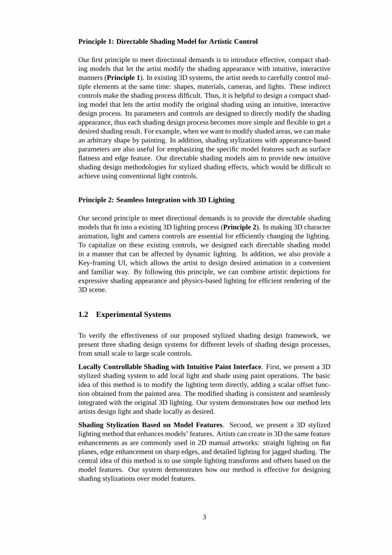
Principle 1: Directable Shading Model for Artistic Control
Our first principle to meet directional demands is to introduce effective, compact shad-ing models that let the artist modify the shading appearance with intuitive, interactivemanners (Principle 1). In existing 3D systems, the artist needs to carefully control mul-tiple elements at the same time: shapes, materials, cameras, and lights. These indirectcontrols make the shading process difficult. Thus, it is helpful to design a compact shad-ing model that lets the artist modify the original shading using an intuitive, interactivedesign process. Its parameters and controls are designed to directly modify the shadingappearance, thus each shading design process becomes more simple and flexible to get adesired shading result. For example, when we want to modify shaded areas, we can makean arbitrary shape by painting. In addition, shading stylizations with appearance-basedparameters are also useful for emphasizing the specific model features such as surfaceflatness and edge feature. Our directable shading models aim to provide new intuitiveshading design methodologies for stylized shading effects, which would be difficult toachieve using conventional light controls.
Principle 2: Seamless Integration with 3D Lighting
Our second principle to meet directional demands is to provide the directable shadingmodels that fit into a existing 3D lighting process (Principle 2). In making 3D characteranimation, light and camera controls are essential for efficiently changing the lighting.To capitalize on these existing controls, we designed each directable shading modelin a manner that can be affected by dynamic lighting. In addition, we also provide aKey-framing UI, which allows the artist to design desired animation in a convenientand familiar way. By following this principle, we can combine artistic depictions forexpressive shading appearance and physics-based lighting for efficient rendering of the3D scene.
1.2 Experimental Systems
To verify the effectiveness of our proposed stylized shading design framework, wepresent three shading design systems for different levels of shading design processes,from small scale to large scale controls.
Locally Controllable Shading with Intuitive Paint Interface . First, we present a 3Dstylized shading system to add local light and shade using paint operations. The basicidea of this method is to modify the lighting term directly, adding a scalar offset func-tion obtained from the painted area. The modified shading is consistent and seamlesslyintegrated with the original 3D lighting. Our system demonstrates how our method letsartists design light and shade locally as desired.
Shading Stylization Based on Model Features. Second, we present a 3D stylizedlighting method that enhances models’ features. Artists can create in 3D the same featureenhancements as are commonly used in 2D manual artworks: straight lighting on flatplanes, edge enhancement on sharp edges, and detailed lighting for jagged shading. Thecentral idea of this method is to use simple lighting transforms and offsets based on themodel features. Our system demonstrates how our method is effective for designingshading stylizations over model features.
3

Practical Shading Model for Expressive Shading Styles. Third, we present a 3D styl-ized material design system for designing overall shading appearance with prominentfeatures. Our system lets the artist paint his shading style on a reference sphere. Thedesigned shading style is interactively transferred to the target model while the artistmanipulates the light source. The basic idea is to introduce a new 2D texture projectionprocess for expressive shading styles based on light space surface normals. We also ex-plore practical shading stylization techniques by making use of the light space normalrepresentation. Our system demonstrates how our method is useful for designing com-monly used shading styles, such as minimal shading, illustrative shading, and stylizedmetallic, etc.
1.3 Contributions
Our goal is to provide an artist-friendly shading model and user interface for designingstylized shading effects which are effective for production work. The contributions ofthis work include the proposed framework for this goal and three experimental systemsbased on the framework.
New framework for an artist-friendly shading model and user interface. We presenta new framework, called “integration of artistic depictions with physics-based lighting”,as a general key guideline for efficient and effective stylized shading design. We pro-pose two principles for this key guideline.Principle 1 is directable shading model forartistic control, which allows the artist to interactively design shading appearance usingintuitive user interfaces.Principle 2 is seamless integration of the directable shadingwith 3D lighting, which enables dynamic controls of shading appearance using familiar3D UIs. By following these principles, we can merge non-physical behavior of artisticdepictions and physical behavior of 3D lighting, which makes the shading design pro-cess more flexible to make stylized character animation. In contrast to previous systems,our framework can handle more detailed non-physical lighting effects with suited 3Dlighting interactions.
Three experimental shading design systems. Based on the proposed framework, wedeveloped shading design systems for small scale local shaded areas, middle scale modelfeatures, large scale shading materials. The first system was developed to control localshaded areas, where we provided a paint brush user interface to modify shaded area.This system allows the artist to freely design arbitrary shapes of the target shaded areafor small scale controls. The second system was developed to enhance model featuressuch as surface normals and edges, where we provided a 3D light UI for straight light-ing effects and appearance-based parameters for edge enhancement and detail lightingeffects. This system allows the artist to design the feature-dependent lighting effectsfor middle scale controls. The third system was developed to design overall shadingmaterials, where we introduced a new shading model to design an expressive shadingstyle beyond simple cartoon shading styles. This system allows the artist to design light-dependent shading stylizations for large scale controls. All systems are carefully de-signed according to principles of our framework, which provides efficient and effectivestylized shading design process for each design target.
4
1.4 Outline
This thesis is organized as follows. In Chapter 2, we review existing methods of stylizedshading. After briefly describing the overview, we review the stylized shading methodsused in three major areas of research: early stylized rendering, style extensions, anddirectable cartoon shading. The last topic features artistic controls that are closely relatedto our framework. We also briefly discuss other rendering techniques related to stylizedshading design.
In Chapter 3, we describe our approach for the artist-friendly shading design framework.We first review and analyze a general cartoon shading process used in typical produc-tion work. We then consider appropriate representation of directable shading models inaccordance with two proposed principles: directable shading model for artistic control(Principle 1) and seamless integration with 3D lighting (Principle 2).
In Chapters 4-6, we present three experimental systems for the different levels of shadingdesign process: locally controllable shading with intuitive paint interface (smallscale) in Chapter 4,shading stylization based on model features(middle scale) inChapter 5, practical shading model for expressive shading styles(large scale) inChapter 6.
In Chapter 7, we examine the capabilities of the three experimental systems. We firstsummarize the overall features of the three methods from the perspective of our frame-work, and then compare the directable mechanisms used in these systems.
Chapter 8 presents our conclusions. We summarize the contributions of the experimentalsystems, and then discuss the limitations of the framework. Finally, we discuss futureresearch directions.
1.5 Publications
The work presented in this thesis is the result of collaborations and projects that havebeen published as follows:
• The system forlocally controllable shading with intuitive paint interfacedescribedin Chapter 4 was presented as “Locally controllable stylized shading” [90] atACM SIGGRAPH 2007 in San Diego, USA, in collaboration with Ken Anjyo andWilliam Baxter from OLM Digital, Inc. and Takeo Igarashi from the Universityof Tokyo.
• The system forshading stylization based on model featuresdescribed in Chapter 5was presented as “Stylized lighting for cartoon shader” [91] at the 22nd AnnualConference on Computer Animation and Social Agents (CASA 2009) in Amster-dam, the Netherlands, in collaboration with Ken Anjyo from OLM Digital, Inc.and Takeo Igarashi from the University of Tokyo.
• The system forpractical shading model for expressive shading stylesdescribedin Chapter 6 was presented as “Lit-Sphere extension for artistic rendering” [92]at Computer Graphics International (CGI 2013) in Hannover, Germany, in collab-oration with Ken Anjyo from OLM Digital, Inc. and Shun’ichi Yokoyama fromIMI, Kyushu University.
5

Figure 1.2: Comparison of hand-drawn shading (left) with conventional cartoon shad-ing (right). (Top) The cartoon shading fails to render the shaded area blow the right eyethat emphasize the character’s fierceness. (Middle) The cartoon shading fails to cap-ture shading stylizations that enhances model’s flatness and sharpness. (Bottom) Thecartoon shading fails to represent small-scale stroke styles.
6

Figure 1.3: Conventional tricks to modify undesirable shading result.
Figure 1.4: Integration of artistic depictions with physics-based lighting. (Left) Artistscan modify the original shading result using intuitive appearance-based UIs or parame-ters. (Right) Artists can manipulate the designed shading using existing 3D lighting andanimation controls.
7

Chapter 2
Related Work
In this chapter, we review existing methods for stylized rendering and discuss how theyrelate to our approach. Figure 2.1 shows the methods relevant to our work, the chaptersections in which they are discussed, and their classification according to two prop-erties: directability (from less to highly directable) and expressiveness (from less tohighly expressive). Highly directable methods focus on how to provide intuitive andinteractive controls over shading appearance, whereas less directable methods permitlimited controls using more automatic approaches. Highly expressive methods focus onhow to achieve a rich variety of shading styles with prominent features, whereas lessexpressive methods are limited to simple shading styles such as cartoon shading. InSection 2.2, we review several fundamental methods for interactive 3D stylized render-ing. In Section 2.3, these fundamental methods are extended to yield more expressiveshading. There are several significant methods for directable control (Section 2.4 andSection 2.5), which are the main focus, which are the main focus of this thesis. Theseareas of research include our methods described in Chapters 4 and 5. We further ex-plore how to establish both directability and expressiveness in Chapter 6. Finally, inSection 2.6 we briefly review two several other stylized rendering methods: painterlyrendering and line drawing.
Figure 2.1: Stylized rendering methods.
8

2.1 Lighting Design for Photorealistic Scenes
Before describing the stylized rendering methods, we review the lighting design methodsfor photorealistic scenes, which form the foundations for the stylized rendering methods.For photorealistic appearance, simple reflectance models can be used: Lambert (diffuse),Phong (specular) [71], and Blinn-Phong (specular) [15]. For example, a lighting modelfor diffuse and specular effects can be defined as:
c= cdId +csIs, (2.1)
where diffuse termId ∈ R and specular termIs ∈ R are obtained from the specific re-flectance model. The final colorc is adjusted by the diffuse colorcd and the specularcolor cs. Figure 2.2 illustrates a typical example using the Blinn-Phong lighting model.This model uses as inputs a light vectorL , a view vectorV, a surface normal vectorN,and the half vectorH := (L +V)/∥L +V∥. The diffuse termId and specular termIs areobtained by the dot products ofL ·N andH ·N respectively.
Figure 2.2: Blinn-Phong lighting model. (Top) Vectors for computing Blinn-Phonglighting. The diffuse term Id and specular term Is are defined by dot products of thesevectors. (Bottom) Visual illustration of the Binn-Phong equation.
Beyond these simple reflectance models, more physically-plausible lighting effects canbe modeled by using a bidirectional reflectance distribution function (BRDF) [6,7,23,55,104] and related techniques: bidirectional scattering distribution function (BSDF) [38],and bidirectional surface scattering reflectance distribution function (BSSRDF) [32].The fundamental difficulty in using these shading models is to finding the optimal lightplacement and the choice of parameters to obtain the desired shading. Several good ap-proaches have attempted to measure the scattering profiles of physical materials [1, 26,31,41,76,83,94,103,105]. Other approaches have tried to find the proper light placementfrom user-designated highlights and shadows in the scene [2,22,48,51,63,69,85,88].
The advantage of BRDF related approaches is their ability to illuminate models withvisual realism. Once the appropriate parameters are found for a specific material, it
9

can be successfully used for 3D animation. On the other hand, these approaches area difficult for artists to use. Therefore, most stylized rendering approaches use simplelighting models for their fundamental mechanisms.
2.2 Early Stylized Rendering
2.2.1 Artistic Stylization for 2D Static Images
In the early stage of stylized rendering techniques, most of these shading represen-tations were 2D static grayscale images, which are used to reproduce traditional art-works. In 1976, Floyd and Steinberg [35] proposed the fundamental idea of digital half-toning where the brightness values are converted into black and white pixels throughthresholded quantization. Similar to this seminal work, 2D static grayscale brightnesshad been used for various printing artworks: stippling [29, 86], pen-and-ink illustra-tion [30,79–81], digital engraving [34,66,67], and woodcut illustration [57,108].
In summary, their idea is to define a color map functioncm: R 7→ C for the brightnessvalue I ∈ R, whereC denotes a color space. They considered only the simple case ofstatic 2D input of the brightness valueI . Thus, they were limited in handling dynamicshading changes. In this thesis, we focus more on 3D rendering techniques, which pro-vide the artist with interactive shading design for 3D character animation.
2.2.2 Stylized Rendering for 3D Scenes
In 3D rendering, stylized shading is based on the simple lighting models described inEquation 2.1. For example, The Technical Illustration Shader of Gooch and Gooch[36,37] uses the Half-Lambertian diffuse term to produce cool-to-warm color gradients.One significant invention by Lake et al. [50] is an interactive cartoon shader where thediffuse term is converted into banded multi-tone colors through simple 1D color map-ping. Mitchell et al. [58] modified the Lambertian and the Phong shading models for acustomized illustrative look in their video game applications.
Figure 2.3: Examples of typical stylized rendering methods for 3D scenes. (Left) Tech-nical Illustration Shader developed by Gooch and Gooch [36,37] (c⃝1999 ACM). (Mid-dle) Interactive stylized rendering proposed by Lake et al. [50] (c⃝2000 ACM). (Right)Illustrative rendering used by Mitchell et al. [58] (c⃝2007 ACM).
The primary advantage of these approaches is their simplicity: a single 1D color mapfunction is sufficient to model the stylized shading. The final shading colorc ∈ C isobtained by:
c= cm1Dd (Id)+cm1D
s (Is), (2.2)
10
where the 1D color map functionscm1Dd : R 7→ C andcm1D
s : R 7→ C are applied to thediffuse termId and specular termIs. This simple mechanism permits interactive shadingdesign using a 3D lighting process, so it is widely used as a foundation for other stylizedrendering methods. In the next section, we review existing methods for more expressiveshading styles derived from the 1D color map approach.
2.3 Style Extensions for Expressive Shading
2.3.1 2D Color Map Functions
More complex effects can be obtained using 2D color map functions. Winnemoller andBangay [107] introduced a 2D color map function to capture the stylistic behavior ofspecular effects:
c= cm2D(Id, Is), (2.3)
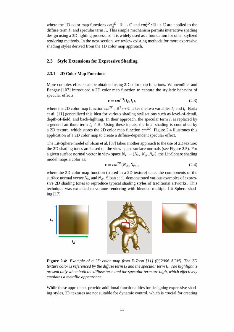
where the 2D color map functioncm2D : R2 7→C takes the two variablesId andIs. Barlaet al. [11] generalized this idea for various shading stylizations such as level-of-detail,depth-of-field, and back-lighting. In their approach, the specular termIs is replaced bya general attribute termIa ∈ R. Using these inputs, the final shading is controlled bya 2D texture, which stores the 2D color map functioncm2D. Figure 2.4 illustrates thisapplication of a 2D color map to create a diffuse-dependent specular effect.
The Lit-Sphere model of Sloan et al. [87] takes another approach to the use of 2D texture:the 2D shading tones are based on the view-space surface normals (see Figure 2.5). Fora given surface normal vector in view spaceNv := (Nvx,Nvy,Nvz), the Lit-Sphere shadingmodel maps a color as:
c= cm2D(Nvx,Nvy), (2.4)
where the 2D color map function (stored in a 2D texture) takes the components of thesurface normal vectorNvx andNvy. Sloan et al. demonstrated various examples of expres-sive 2D shading tones to reproduce typical shading styles of traditional artworks. Thistechnique was extended to volume rendering with blended multiple Lit-Sphere shad-ing [17].
Figure 2.4: Example of a 2D color map from X-Toon [11] (c⃝2006 ACM). The 2Dtexture color is referenced by the diffuse term Id and the specular term Is. The highlight ispresent only when both the diffuse term and the specular term are high, which effectivelyemulates a metallic appearance.
While these approaches provide additional functionalities for designing expressive shad-ing styles, 2D textures are not suitable for dynamic control, which is crucial for creating
11

Figure 2.5: Example of a 2D color map using Lit-Sphere [87]. The 2D texture color isreferenced by the view space normal vectorNv := (Nvx,Nvy,Nvz). This enables a view-dependent shading effect with effective 2D shading tones.
animation. In contrast, all of our methods presented in Chapters 4- 6 permit dynamiccontrol, which is seamlessly integrated with the familiar 3D shading design process.
2.3.2 Surface Feature Enhancement
Several approaches have used shape depiction to extend conventional stylized shadingstyles. In practical applications such as video games, ambient occlusion [18, 70] iswidely used to add occluded shadow effects to diffuse shading. Exaggerate shading [75]uses multiple scale normals to show the bumpy details of an object (see the left imageof Figure 2.6). The 3D Unsharp Masking technique of Ritschel et al. [73] modifies theoutgoing radiance to enhance local contrast. Vergne et al. proposed methods to enhanceshape depiction based on view-dependent geometric features [97, 98] (see the middleimage of Figure 2.6). They also proposed radiance scaling techniques [99, 100] that areextensions of their previous methods for precomputed radiance data (see the right imageof Figure 2.6).
In summary, these methods define a vector transform functionfL : S2×G 7→ S2 for thelight vectorL ∈ S2 based on the geometric propertyG ∈G, whereG denotes the spaceof the geometric property. The methods focus on use of the geometric propertyG forproviding better visual perception of geometric appearance. In contrast, our shading styl-ization method presented in Chapter 5 focus on appearance-based control, determinedby model features.
2.4 Directable Control for Stylized Rendering
One important requirement of a shading design system is to provide the artist with di-rectable control over the shading appearance. The cartoon highlights of [4, 5, 96] deal
12
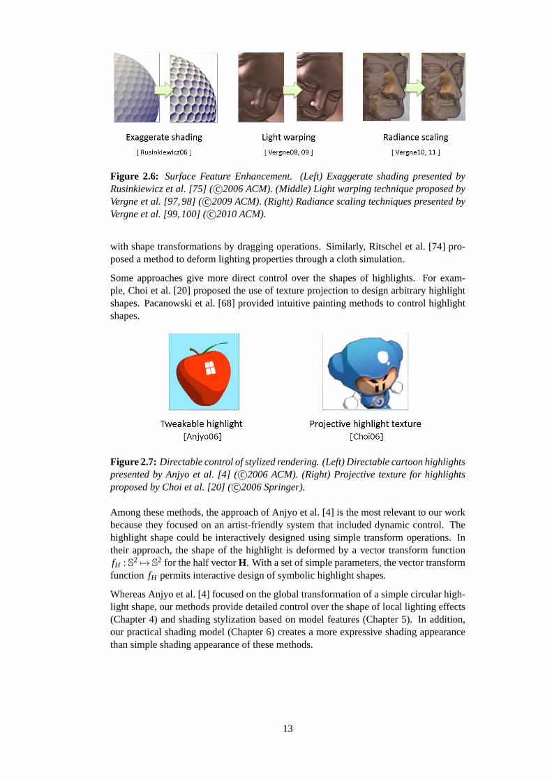
Figure 2.6: Surface Feature Enhancement. (Left) Exaggerate shading presented byRusinkiewicz et al. [75] (c⃝2006 ACM). (Middle) Light warping technique proposed byVergne et al. [97,98] (c⃝2009 ACM). (Right) Radiance scaling techniques presented byVergne et al. [99,100] (c⃝2010 ACM).
with shape transformations by dragging operations. Similarly, Ritschel et al. [74] pro-posed a method to deform lighting properties through a cloth simulation.
Some approaches give more direct control over the shapes of highlights. For exam-ple, Choi et al. [20] proposed the use of texture projection to design arbitrary highlightshapes. Pacanowski et al. [68] provided intuitive painting methods to control highlightshapes.
Figure 2.7: Directable control of stylized rendering. (Left) Directable cartoon highlightspresented by Anjyo et al. [4] (c⃝2006 ACM). (Right) Projective texture for highlightsproposed by Choi et al. [20] (c⃝2006 Springer).
Among these methods, the approach of Anjyo et al. [4] is the most relevant to our workbecause they focused on an artist-friendly system that included dynamic control. Thehighlight shape could be interactively designed using simple transform operations. Intheir approach, the shape of the highlight is deformed by a vector transform functionfH : S2 7→ S2 for the half vectorH. With a set of simple parameters, the vector transformfunction fH permits interactive design of symbolic highlight shapes.
Whereas Anjyo et al. [4] focused on the global transformation of a simple circular high-light shape, our methods provide detailed control over the shape of local lighting effects(Chapter 4) and shading stylization based on model features (Chapter 5). In addition,our practical shading model (Chapter 6) creates a more expressive shading appearancethan simple shading appearance of these methods.
13

2.5 Directable Control for Expressive Shading
Providing directable control of expressive shading is major challenge in stylized ren-dering researches and their applications. There is a significant demand for fine-grainedcontrol over expressive shading styles. However, there have been very few studies onhow to provide the interactive techniques to meet this demand.
Figure 2.8: Various shading styles presented by Vanderhaeghe et al. [96] (c⃝2011ACM). Their method allows the design of multiple shading primitives, including dynamiccontrol over shapes and reflectance properties.
Among the many shading techniques, one recently proposed by Vanderhaeghe et al. [96]may provide the best solution to date to the difficult problem of dynamic control. Theirmethod gives the artist control over shapes of multiple lighting and their reflectanceproperties, based on proposed shading primitives. However, each shading primitive canhandle only conventional 1D, not 2D shading tones.
Inspired by their work, we explored practical shading models to design 2D shading toneswith suitable dynamic shading stylization (see Chapter 6). Although additional capabil-ities are required to meet the many demands of artists, we believe that our approachprovides a practical solution to the key challenge of dynamic control of shading designin stylized rendering.
2.6 Other Stylized Rendering Methods
In this section, we briefly review other stylized rendering methods for expressive artisticstyles, although not specifically related to shading.
2.6.1 Painterly Rendering
The approaches described so far focused on effective shading models for specific targetappearances. On the other hand, painterly rendering techniques focus on overlappingbrush strokes. In 1996, Meier [56] proposed a painterly rendering pipeline, in whichthe system applies a brush stroke style to static object-space particles. This work wasextended to dynamic particle systems [12, 14, 47], where the particles are placed bytemporally coherent noise function. In this approach, shading information is used onlyto specify the color of each particle. Kulla et al. [49] and Yen et al. [109] relied moreon shading information to determine the transition of brush stroke styles affected bybrightness values.
14
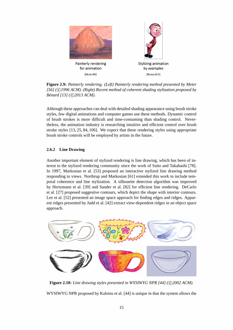
Figure 2.9: Painterly rendering. (Left) Painterly rendering method presented by Meier[56] ( c⃝1996 ACM). (Right) Recent method of coherent shading stylization proposed byBenard [13] ( c⃝2013 ACM).
Although these approaches can deal with detailed shading appearance using brush strokestyles, few digital animations and computer games use these methods. Dynamic controlof brush strokes is more difficult and time-consuming than shading control. Never-theless, the animation industry is researching intuitive and efficient control over brushstroke styles [13, 25, 84, 106]. We expect that these rendering styles using appropriatebrush stroke controls will be employed by artists in the future.
2.6.2 Line Drawing
Another important element of stylized rendering is line drawing, which has been of in-terest to the stylized rendering community since the work of Saito and Takahashi [78].In 1997, Markosian et al. [53] proposed an interactive stylized line drawing methodresponding to views. Northrup and Markosian [61] extended this work to include tem-poral coherence and line stylization. A silhouette detection algorithm was improvedby Hertzmann et al. [39] and Sander et al. [82] for efficient line rendering. DeCarloet al. [27] proposed suggestive contours, which depict the shape with interior contours.Lee et al. [52] presented an image space approach for finding edges and ridges. Appar-ent ridges presented by Judd et al. [42] extract view-dependent ridges in an object spaceapproach.
Figure 2.10: Line drawing styles presented in WYSIWYG NPR [44] (c⃝2002 ACM).
WYSIWYG NPR proposed by Kalnins et al. [44] is unique in that the system allows the
15

artist to design annotated strokes and brush styles directly on the 3D model. They ex-tended this work to maintain temporal coherency for stylized silhouettes [45]. OverCoat,a system recently presented by Schmid et al. [84] also aims to provide an artist-friendlyframework for line drawing.
Although this thesis is focused on shading design, line drawing is also an importantvisual element of stylized rendering. More expressive results could be obtained by com-bining such line stylization techniques with the shading methods of our system.
2.7 Summary
In this chapter, we reviewed existing methods of stylized rendering from the perspectiveof directable controls which are essential for an artist-friendly stylized shading designframework. Like the stylized shading methods described above, our approach is alsobased on the fundamental methods of early stylized rendering in Section 2.2. Style ex-tensions in Section 2.3 provide additional functionalities for designing expressive shad-ing styles, but often lack the capability for dynamic control of the shading appearancethrough an intuitive and interactive interface. Some approaches allow more direct con-trol over the lighting shape (Section 2.4) but provide little in the way of shading stylecontrols.
Inspired by these approaches, we sought to provide an intuitive and interactive methodsfor stylized shading design for production work using our artist-friendly shading designframework. In contrast to other researches, our methods in Chapters 4- 6 provide newshading representations for efficient shading design to meet typical directional demandswhere non-physical artistic depictions are seamlessly integrated into physics-based light-ing.
16

Chapter 3
Our Approach for Artist-Friendly Stylized ShadingDesign
In the reminder of this thesis, we will apply the proposed principles to different lev-els of shading editing to verify the effectiveness of our artist-friendly shading designframework. To achieve this, introducing well-designed behavior of shading models isessential for an intuitive and efficient design process. In this chapter, we consider appro-priate representations of directable shading models for different levels of shading designprocesses, from small scale to large scale control. We start by reviewing and analyzingthe general cartoon shading process, that is commonly used in a production work. Basedon this analysis, we introduce directable shading mechanisms for the proposed shadingdesign systems in Chapters 4- 6.
3.1 Analysis of General Cartoon Shading Process
A general cartoon shading model is strongly constrained by a physical lighting model,therefore it is difficult to control the shading appearance in an intuitive and appearance-based way. To explain its shading mechanism more concisely, we details the cartoonshading process in Equation 2.2:
c= cm1Dd (L ·N)+cm1D
s (H ·N), (3.1)
where the inputs are the light vectorL , the surface normal vectorN, and the half vectorH := (L +V)/∥L +V∥, whereV is the viewing vector. Based on the diffuse termL ·N∈[−1,1] and specular termH ·N ∈ [−1,1], the final colorc is obtained from the 1D colormapping functionscm1D
d : [−1,1] → C for diffuse shading andcm1Ds : [−1,1] → C for
specular shading. These elements are affected by the following sub design tasks:
• Shape modeling: a shape consists of a surface position and the surface normalN. The surface normalN affects both the diffuse and specular term. The surfaceposition indirectly affects the half vectorH since per-position view vectorsV areused to compute the half vector.
• Material design: the artist designs the color mapping functions (cm1Dd , cm1D
s ) usinga few simple parameters. These functions are used to determine sample shadingcolors based on the brightness terms (diffuse, specular).
• Camera design: camera manipulation affects the view vectorV, which is used toobtain the half vectorH.
17

• Lighting design: the light vectorL is determined by the location of the light sourceand the type of light. It is used to compute the diffuse term and affects the halfvectorH.
In these design tasks, the artist needs to control the shading elements carefully to obtainthe desired appearance. However, these indirect controls for shading design are time-consuming and impractical in production environments. Ideally, artists would use moreintuitive and directable controls to obtain the shading desired.
3.2 Our Approach for Directable Shading Model
As explained above, the issue of the general cartoon shading process is that its editingtasks are interconnected and indirect for changing the shading appearance. To solvethe issue, we consider appropriate directable shading models by following our artist-friendly shading design framework. In accordance withPrinciple 1, the requirement ofa directable shading model is to provide intuitive controls which directly affect specificvisual features. In accordance withPrinciple 2, we extend the original cartoon shadingmodel to achieve seamless integration with existing 3D lighting controls. Accordingly,we introduce a general form of directable shading model as:
c= cmd( fd(L ,N)+od(x))+cms( fs(H,N)+os(x)), (3.2)
where we use key directable mechanisms: lighting transforms and lighting offsets. Thelighting transformsfd(L ,N) and fs(H,N) deform the diffuse and specular lighting tochange the overall lighting shape. The lighting offsetsod(x) andos(x) are used to addsmaller scale local lighting effect. With these input lighting, the final colorc is ob-tained through the color mapping functionscmd andcms. To meet directional demandsfor different levels of the shading editing, we reformulate these key directable shadingmechanisms for each shading design system in Chapters 4- 6 as follows.
Locally controllable shading with intuitive paint interface : Our shading model inChapter 4 lets the artist modify the shaded area with a local painting operation. Weprovide the directable control by adding lighting offsets to the brightness term directly:
c= cm1Dd (L ·N+o1D
d (p))+cm1Ds (H ·N+o1D
s (p)), (3.3)
where the diffuse termL ·N and specular termH ·N are modified by adding the corre-sponding scalar offset functionso1D
d (p) ∈ [−1,1] ando1Ds (p) ∈ [−1,1] that are defined
on a surface pointp. This method is suitable for an artist who wants to freely add locallighting effects. The paint operation has no direct effect on the light vectorL , surfacevectorN, or the half vectorH. In addition, the modification must be local on the paintedarea. We therefore use the scalar offset functions defined on the surface in this method.
Shading stylization based on model features: Our shading model in Chapter 5 al-lows the artist to design commonly used feature enhancements such as straight lighting,edge enhancement, and detailed lighting effects. We provide the directable control byapplying lighting transforms and lighting offsets based on model features:
c= cm1Dd ( fd(L ,N)+o1D
d (E))+cm1Ds ( fs(H,N)+o1D
s (E)), (3.4)
where the diffuse and specular lighting are deformed by applying lighting transformfunctions fd(L ,N) ∈ [−1,1] and fs(H,N) ∈ [−1,1], respectively.o1D
d (E) ando1Ds (E)
are lighting offset functions whereE ∈R is the edge distance. These lighting transformsand lighting offset are designed based on the model features: the flat surface normal
18
and the edge distance field. To show an object’s flatness, we linked the straight light-ing with the surface normal vectorN. We chose to use the lighting transforms for thislighting effect, because they are effective to control the shape of the lighting. In the caseof edge enhancements, the lighting effect is considered a local effect, compared withstraight lighting effect. Therefore, we chose the scalar offset functions defined in theedge distance field for this lighting effect.
Practical shading model for expressive shading styles: Our shading model in Chap-ter 6 lets the artist design an overall material with detailed shading appearance. Weprovide directable control by introducing a new lighting procedure:
c= cm2Dd ( f 2D
d (L ,N)+o2Dd (h))+cm2D
s ( f 2Ds (H,N)+o2D
s (h)), (3.5)
where we introduce the 2D shading functions for more expressive global 2D shadingeffects. The lighting transform functionsf 2D
d (L ,N) ∈ [−1,1]× [−1,1] and f 2Ds (H,N) ∈
[−1,1]× [−1,1] are reformulated to fit into the 2D coordinate representations. We alsoreformulate the offset functionso2D
d (h) ando2Ds (h) as functions of the attribute value
h ∈ [−1,1]. The final colorc is obtained by the 2D color mapping functionscm2Dd :
[−1,1]× [−1,1] 7→ C andcm2Ds : [−1,1]× [−1,1] 7→ C. The primary challenge here is
to achieve more expressive shading styles beyond the simple styles of cartoon shading.We chose the 2D shading representation because it can represent a more complex 2Dcolor distributions than the limited 1D color distributions of cartoon shading.
3.3 Summary
In this chapter, we introduced key directable shading mechanisms for our artist-friendlystylized shading design framework. Analyzing the general cartoon shading process usedin production work, we found that the main difficulty consists in that conventional con-trols are indirect for changing the shading appearance. Based on the analysis, our di-rectable shading models aim to achieving intuitive behaviors for supporting creative de-sign of artists.
In the following Chapters 4-6, we will present how these directable shading models ingreater detail and verify the effectiveness of our proposed framework.
19

Chapter 4
Locally Controllable Shading with Intuitive PaintInterface
4.1 Overview
The first experiment is to apply our framework to artist-friendly user interface for localedits of stylized shading. In the case of local controls, the ability to add intentional, butoften unrealistic shading effects is indispensable for cartoon animations. In this chapter,we present an interactive system that allow the artist to freely paint local lights andshades to a model. In accordance withPrinciple 1 (directable shading model for artisticcontrol), we design the shading model which enables an intuitive, direct manipulationmethod based on a paint-brush metaphor, to control and edit the light and shade asdesired. The key idea for this directable shading model is to modify brightness termdirectly, adding a scalar lighting offset function. This complies with ourPrinciple 2(seamless integration with 3D lighting) in that the modified shading can be manipulatedby multiple different light types of light sources such as directional lights, points lights,and spot lights. Besides, artists can also use a convenient key-framing technique forfine-tuning of stylistic animation in a familiar way. Finally, our system demonstrateshow our method can enhance both the quality and range of applicability of conventionalstylized shading for interactive applications.
4.2 Introduction
Here we consider the problem of how to provide artists with intuitive, fine-grained con-trol over stylized light and shade on a 3D object. Over the past decade, a variety ofstylized rendering techniques have been developed to facilitate visual interpretation of3D objects. Most of these techniques are designed to elucidate particular attributes in-herent to the object. For example, Gooch and Gooch [36] developed a lighting modelthat changes hue to convey surface orientation, edge locations, and highlights for 3Dtechnical illustration. The multi-scale shading method by [75] depicts 3D shape detailsat all frequencies possible.
On the other hand, in application fields such as digital animation and video games,there is a significant demand for locally controllable stylized light and shade, whichcan achieve results that are directable, intentional, and often fictive, yet ultimately moreattractive for it. For example, the conventional cartoon shader used routinely in 3D an-imation often creates undesirable shaded areas. These can arise from the complexity ofthe underlying geometry or the complexity of the lighting, or just as a result of the basic
20
ResultOur result
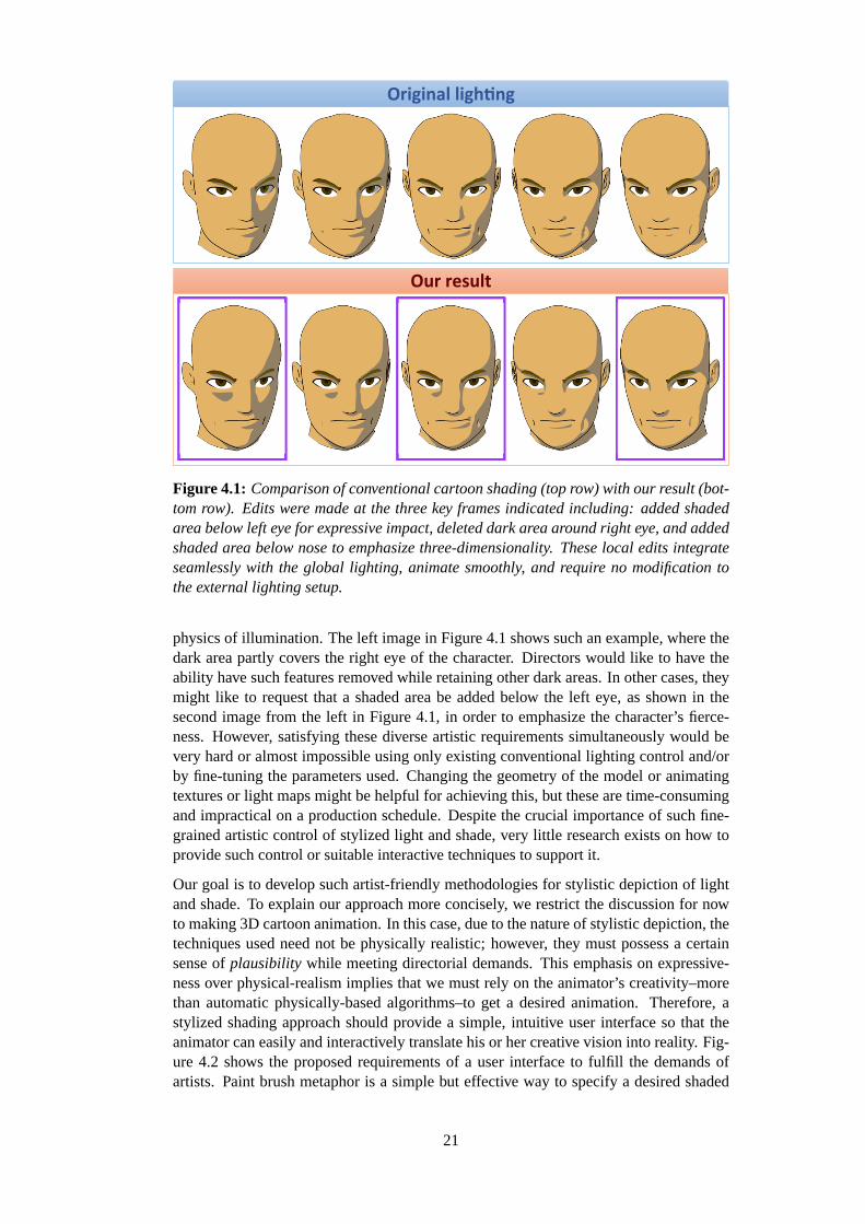
Original lighting
Figure 4.1: Comparison of conventional cartoon shading (top row) with our result (bot-tom row). Edits were made at the three key frames indicated including: added shadedarea below left eye for expressive impact, deleted dark area around right eye, and addedshaded area below nose to emphasize three-dimensionality. These local edits integrateseamlessly with the global lighting, animate smoothly, and require no modification tothe external lighting setup.
physics of illumination. The left image in Figure 4.1 shows such an example, where thedark area partly covers the right eye of the character. Directors would like to have theability have such features removed while retaining other dark areas. In other cases, theymight like to request that a shaded area be added below the left eye, as shown in thesecond image from the left in Figure 4.1, in order to emphasize the character’s fierce-ness. However, satisfying these diverse artistic requirements simultaneously would bevery hard or almost impossible using only existing conventional lighting control and/orby fine-tuning the parameters used. Changing the geometry of the model or animatingtextures or light maps might be helpful for achieving this, but these are time-consumingand impractical on a production schedule. Despite the crucial importance of such fine-grained artistic control of stylized light and shade, very little research exists on how toprovide such control or suitable interactive techniques to support it.
Our goal is to develop such artist-friendly methodologies for stylistic depiction of lightand shade. To explain our approach more concisely, we restrict the discussion for nowto making 3D cartoon animation. In this case, due to the nature of stylistic depiction, thetechniques used need not be physically realistic; however, they must possess a certainsense ofplausibility while meeting directorial demands. This emphasis on expressive-ness over physical-realism implies that we must rely on the animator’s creativity–morethan automatic physically-based algorithms–to get a desired animation. Therefore, astylized shading approach should provide a simple, intuitive user interface so that theanimator can easily and interactively translate his or her creative vision into reality. Fig-ure 4.2 shows the proposed requirements of a user interface to fulfill the demands ofartists. Paint brush metaphor is a simple but effective way to specify a desired shaded
21

area. A keyframe-based technique is appropriate, since it allows fine-tuning of stylisticanimation in a traditional, but convenient and familiar way for animators. Additionally,real-time preview of the animation is also indispensable. These basic requirements formaking stylized animation have led us to consider naıve key-framing as a first approachtowards a new methodology.
The central idea of our approach is to effect the desired changes to light and shadeboundaries by modifying the LambertianL ·N brightness term directly, adding a scalarlighting offset function. This avoids the need to manipulate light vectors and normalsand can be efficiently implemented using scalar-valued radial basis functions [101]. Theright images in Figure 4.1 are from an animation created using our techniques, while theleftmost shows the scene before modifications.
The rest of the chapter is organized as follows. After briefly surveying related work inSection 4.3, we describe the main ideas underlying the algorithms in Section 4.5. In Sec-tion 4.6, we describe some implementation details of our prototype system. Section 4.7demonstrates animation examples and discusses our results. We conclude with somelimitations and future work in Section 4.8.
Paint brush metaphor Key-framing
Figure 4.2: Intuitive user interface proposed in our system. (Left) Paint brush metaphorprovides an easy way to modify the shaded area. (Right) Key-framing is convenient andfamiliar for artists to control animation.
4.3 Background
A number of stylized rendering techniques, such as those in [36], have been developedto emulate various stylistic appearances. For stylized rendering of 3D objects, Lakeet al. [50] proposed several fundamental real-time rendering techniques, including atraditional cartoon shader. The Lit-Sphere method by Sloan et al. [87] can describeview-independent tone detail, using a painted spherical environment map. The WYSI-WYG system by Kalnins et al. [44] allows direct drawing of strokes onto 3D objects,while learning strokes by example. The multi-scale shading technique by Rusinkiewiczet al. [75] can also control the appearance of shape detail by tuning parameters of thelighting model. Barla et al. [11] proposed an extension of the traditional cartoon shader,which can control view-dependent tone detail, including such effects as aerial perspec-tive and depth of field. The cartoon highlights in [4, 96] allows a user to directly click-and-drag the highlights on a surface to design and animate them. After our work waspublished, Pacanowski et al [68] proposed an intuitive painting method for highlightdesign.
22

Existing work on user-specified indirect lighting design for photorealistic scene render-ing is to some extent related to our approach as well. The design issue in photorealisticlighting is to find the light placement that results in the user-specified highlights andshadows in the scene (see [51] for more detailed discussion). There exist several goodapproaches ( [48,69,85], for instance). The geometry-dependent lighting method by [51]may also be a useful indirect light design tool for visualizing scientific data. Okabe etal. [63] and Akers et al. [2] take other approaches to modifying lighting, providing anintuitive painting method for modifying the illumination of 3D models.
Our approach is inspired by all of the above methods. However, ours is unique in that itallows a user to add light and shade by painting them directly onto 3D objects withoutelaborate lighting control, to make stylistic animation by key-framing. In addition, wedemonstrate that continuous tone detail can also be painted and animated as an extensionof our approach.
4.4 User Interaction
This section describes a typical shading design process using our prototype system. Asillustrated in Figure 4.3, our approach is based on the direct painting of shaded areas,displayed on a 3D view. For making animation, our system also provides a time slider tospecify a target frame for each painting operation. The overall process of the approachwe propose is:
1. Begin by making an initial 3D scene, which includes the lighting and animationsettings, using a conventional 3D software tool. Multiple directional and/or lightsources can be used for the initial lighting design.
2. At each keyframe, the artist designs and/or modifies the shaded area on a sur-face, using a paint-brush interface. This process is performed at interactive rates,prescribing the boundary constraint of the obtained area. Thereafter the new sur-face brightness distribution is automatically generated considering the boundaryconstraint.
3. The new surface brightness distributions at the keyframes are automatically trans-mitted to all the frames by linear interpolation. We thus obtain the desired anima-tion of the shaded areas.real-time preview of the stylistic animation.
During the shading design process, the artist can freely change the viewpoint. Our sys-tem also provides real-time feedback to the editing actions at any time.
4.5 Algorithm
4.5.1 Overall Process
We begin by restricting ourselves to 3D cartoon animation, where each shaded area isassigned a uniform color by 1D color mapping [50]. Starting from a 3D scene cre-ated using conventional lighting and key-framing techniques, we consider how to lo-cally add light and shade onto surfaces. In particular, we describe how to use a paint-brush metaphor to design the shaded area at keyframes. The painting process at a givenkeyframe involves interactively adding light and shade details or sculpting the shapes ofshade boundaries. Such editing is straightforward with our technique, while it would bevery time-consuming and difficult to manage using conventional lighting.
23

Figure 4.3: A screen snapshot of our prototype system. On the 3D view, the user canpaint shaded areas with real-time preview. The time slider is used to specify a targetframe to paint.
Our implementation is capable of dealing with deforming geometry and multiple direc-tional, point, and/or spot light sources; however, without loss of generality, we explainour idea below in the context of a single light source. The extension to deformations andmultiple light sources is straightforward. For a given threshold 0< d0 < 1 a thresholded1D color mapping creates two (possibly disconnected) regions, which we will call thelight anddark areas. More precisely, using set notation we define thelight areaB0 on asurfaceS, for a given thresholdd0 to be:
B0 := {p ∈ S | L(p) ·N(p)≥ d0}, (4.1)
whereL(p) andN(p) are the unit vectors representing the light direction and surfacenormal at a pointp on S, respectively. The boundary between light and dark areas isobtained by replacing inequality (≥ d0) with equality (= d0) above. We will refer tothe dot productL(p) ·N(p) in Equation 4.1 as theintensity distribution. Given thesedefinitions, let us consider how to enlarge a portion of the light area, for example onthe character’s face in Figure 4.4, where the light areaB0 is flesh colored. Let the areaC0 with boundary∂C0 (drawn in red in Figure 4.4) be an area painted with our brush-type interface (see the next section for specifics). The areaC0 −B0 is the area thatthe user wishes to add to the original areaB0. The core idea behind our approach isto modify the intensity distributionin order to make the light area change as desired,i.e. so that it becomesB0∪C0. The intensity distribution is a scalar function, so thisgreatly simplifies the problem when compared to working directly with light vectorsand normals. The overall strategy is as follows. We first construct anoffset functiono1(p) defined globally onS. This prescribes the new light area by replacing the originalintensity distribution in Equation 4.1 withL(p) ·N(p)+o1(p)(see Figure 4.4). Note that,
24

∂B0∩(D0-C0)∂C0-B0
B0
C0
D0
paint operation
∂D0
∂C0
B0
o1(p)d0
modified(L・N+o1)
original(L・N)
Figure 4.4: Modifying a shaded areaB0 with the paint brush interface: The result-ing new areaB0∪C0 can be represented functionally by introducing an offset functionthat modifies the standardL ·N lighting term. The bottom graph shows a 1D intensitydistribution along the green line.
though globally defined, the offset function should be mostly zero except in the regionimmediately surrounding the desired edit.
After making a modification at one keyframe, we can create a different offset function todefine the light area at a second keyframe. By smoothly interpolating the offset functionsbetween keyframes, we can achieve smooth animation of the light areas between framesas well. The procedure can be repeated for every pair of adjacent keyframes, resultingin an animated light area onS using just local edits with a paint-brush.
4.5.2 The Lighting Offset Function and Key-framing
Next, we describe how to construct the lighting offset function for a “painted” light area.Given the original light areaB0 from Equation 4.1 and the painted areaC0, as shown inFigure 4.4. The offset functiono1(p) for B0∪C0 should satisfy
B1 := {p ∈ S | L(p) ·N(p)+o1(p)≥ d0}= B0∪C0, (4.2)
whereo1(p) is generated when the user finishes drawingC0. To fulfill condition (Equa-tion 4.2), it is clear that the offset function should take values that are equal tod0 −L(p) ·N(p)(≥ 0) on the new boundary∂C0−B0. On the other hand, to make the offsetfunction “active” only in the neighborhood ofC0, we wish to have an areaD0, whichincludesC0, that limits the extent of the domain where modifications to the lighting are
25
applied (see Figure 4.4). In our current implementation, the distance between∂D0 and∂C0 is controlled by a slider in the user interface. The size of this region gives the usera way to limit the scope of modification (also see the detail in Section 4.7). Thereforeo1(p) should minimally satisfy the following conditions:
o1(p) ={
0 p ∈ (S−D0)∪ (∂B0∩ (D0−C0))d0−L(p) ·N(p) p ∈ ∂C0−B0
(4.3)
If we choose foro1 a continuous function satisfying the above conditions, then the re-sultant areaB1 will have a continuous boundary. We can consider the new shaded areaB1, to have a “generalized” intensity distribution given byL(p) ·N(p)+o1(p), insteadof L(p) ·N(p). The above procedure can be repeated for each stroke, building upon theoffset function created by the previous stroke. The user’skth stroke providesCk andDk.From this new input, the resulting light area can be defined recursively as:
Bk+1 := {p ∈ S | L(p) ·N(p)+ok+1(p)≥ d0}= Bk∪Ck, (4.4)
where we assume thatok+1(p) is a continuous function satisfying the constraints:
ok+1(p) ={
ok(p) p ∈ (S−Dk)∪ (∂Bk∩ (Dk−Ck))d0−L(p) ·N(p) p ∈ ∂Ck−Bk
. (4.5)
Dk includesCk and serves the same role forCk asD0 does forC0. The conditions inEquation 4.3 can be seen to be a special case of (Equation 4.5) if we defineo0 = 0.Again we note that, outside ofDk, no modifications will be made to the lighting (i.e.,ok+1(p)= ok(p)). In theDk−Ck region, no modification will be visible under the currentlighting conditions, but some modification may be visible when either the lights or themodel are moved. Having aDk −Ck band allows for smooth transition from modifiedok(p) values to the original values.
To make the above strategy computationally tractable at interactive rates, we representthe offset functionok(p) with a sum of Radial Basis Functions (RBF), denoted by ˆok(p).Thus in practice we use:
Bk := {p ∈ S | L(p) ·N(p)+ ok(p)≥ d0} (4.6)
in place ofBk, and the boundary constraint (Equation 4.5) is only discretely enforcedat a finite number of points. The RBF approximationBk is made from the shaded areaobtained by the paint operation. Rigorously, the boundary ofBk may not exactly matchthat of the original painted area. To allow fine adjustment, we provide two additionaltypes of brushes: anintensity brushand asmoothing brush, which will be described inSection 4.5.4.
Keyframing: Modifications made according to the above algorithm integrate smoothlywith standard lighting equations, and for many animations a single offset functionok
may suffice. However, in order to create more elaborate modifications, it is possibleto create several keyframes, with a unique offset functionok, f at each framef , leadingto more complex animation of light and shade. Lighting of the animation as a wholecan then be accomplished by interpolating the offset functionsok, f (see Figure 4.5).In our prototype we have used simple linear blending for this purpose, though morecomplicated blending functions are possible and worth exploring.
26

Key-frame Animation
Offset Data
Figure 4.5: Creating key-frame animation (top row) using lighting offset data (bottomrow). (orange arrow) In order to allow the user to modify shaded area at several key-frames, we construct and store unique lighting offset data at each painted key-frame inthe process as described previous. (blue arrow) Lighting offset distributions betweenkey-frames are interpolated from key-frame offset data used simple linear functions.Then the final cartoon shading result can be obtained based on these offset distribu-tions.
∂Bk∩(Dk-Ck)∂Ck-BkBk
Ck
Dk
∂Dk
∂Ckxi
pmpn
xj
Figure 4.6: The boundary constraint points used in finding the new offset functionok+1(p). The orange points{xi} take the value d0 − L ·N, while the blue points areconstrained to ok(p).
27

4.5.3 RBF Approximation of The Lighting Offset Function
Suppose thatS consists of polygon meshes, as shown in Figure 4.6. We will assumefor simplicity thatBk = Bk. After obtainingok(p) andBk in Equation 4.6, we want tofind ok+1(p), which satisfies the boundary conditions (Equation 4.5) at a finite number ofdiscrete points. We find a set of such points{xi} ∈ ∂Ck−Bk by the following procedure.For each vertexpm insideCk, we check adjacent edges for intersection with the boundary∂Ck−Bk. For each intersecting edge, linear interpolation betweenpm and the vertex atthe other end,pn, is used to determine the approximate location of the boundary pointxi . Note that we record stroke data per-vertex only and reconstruct the stroke linearly,thus no edge can cross the boundary more than once.
Now let f ≡ ok+1. We find a continuousf satisfying Equation 4.5 for{xi} in the follow-ing form [33,95,101]:
f (x) =l
∑i=1
wiφ(x−xi)+P(x), (4.7)
whereφ is a radial basis function,{wi} are weights, andP is a polynomial whose degreedepends upon the choice ofφ . In our case,l is the number of the boundary constraintpoints shown in Figure 4.6.
We employφ(x) = ∥x∥ as the basis function after experimenting with various options.This corresponds to the solution of a generalized thin-plate spline problem onR3 [33,101], and the curvature minimizing properties of this basis function seem to be wellsuited to this task. Satisfying a discretized version of Equation 4.5 reduces to solvinga linear system of equations for the unknown weights{wi}, and the four coefficients ofthe linear polynomialP onR3.
4.5.4 Additional Brushes
The previous sections described how we enable users to add and editlight areas using apaint-brush metaphor. In a similar way we can add and editdark areas. In that case theonly difference is the selection of boundary points used in Equation 4.5. Instead of using∂Ck−Bk, we use the opposite half of∂Ck, that is,∂Ck∩Bk. The user simply switchesthe editing mode fromlight to dark. In both cases, the paint brush is used for roughlyspecifying the shading boundary. We call this type of brush aboundary brush.
The boundary brush works well to get a desired shape, but the intensity distributionmay not change as smoothly as desired. This can be due to the radial basis functionwe select or due to too many conflicting constraints. For example, we have seen in ourexperiments that even a smooth radial basis function may result in a rapidly changingintensity distribution in the area where the distribution contours are very close to oneanother. This may cause the resulting keyframe animation to look unnatural. For thiscase, we have created asmoothing brush. By painting on the surface with the smoothingbrush, the lighting offset values are filtered, while preserving the original value ofL(p) ·N(p). In our implementation, the offset values stored per vertex are updated using asimple weighted average of values at connected vertices for each stroke operation. In thisway we achieve shading effects that fade in and out more gradually and have smootherboundaries (see Figure 4.7).
In some cases it is useful to be able simply to add or remove an isolated light or darkarea. For these situations we provide a simpler alternative to the boundary brush, whichwe call theintensity brush. This brush simply adds to or subtracts from the lighting
28
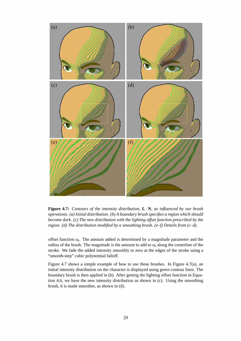
(a) (b)
(c) (d)
(e) (f)
Figure 4.7: Contours of the intensity distribution,L ·N, as influenced by our brushoperations. (a) Initial distribution. (b) A boundary brush specifies a region which shouldbecome dark. (c) The new distribution with the lighting offset function prescribed by theregion. (d) The distribution modified by a smoothing brush. (e–f) Details from (c–d).
offset functionok. The amount added is determined by a magnitude parameter and theradius of the brush. The magnitude is the amount to add took along the centerline of thestroke. We fade the added intensity smoothly to zero at the edges of the stroke using a“smooth-step” cubic polynomial falloff.
Figure 4.7 shows a simple example of how to use these brushes. In Figure 4.7(a), aninitial intensity distribution on the character is displayed using green contour lines. Theboundary brush is then applied in (b). After getting the lighting offset function in Equa-tion 4.6, we have the new intensity distribution as shown in (c). Using the smoothingbrush, it is made smoother, as shown in (d).
29

4.5.5 Extensions
In order to get more variations of stylized light and shade, we add a few simple, butuseful, extensions of the main algorithms above.
Specular Highlight: We can deal with stylized highlights in the same framework asthe shaded area. In our system we simply need to replace the Lambertian term (the dotproduct,L ·N) in Equation 4.6 withH ·N from Blinn’s specular highlight model [15],whereH is the normalized half-way vector between the light and the eye. The user caneasily edit the highlights by the brushes in the same manner as the shaded area.
Continuous tone control: The thresholdd0 in Equation 4.1 is a global constant whichcontrols the shaded area in accordance with Equation 4.6, but this is not an essentialassumption. Similarly, we can use the paint-brush metaphors to locally control and editcontinuous tone on a surface by dispensing with the threshold and defining the lightnessat a given point to be simplyL(p) ·N(p)+ok(p), or any continuous function thereof.
4.5.6 Lighting Offset Function Interpolation Based on Light Parameters
The methods presented so far assumes the key-framing control for lighting offset func-tions. In order to apply our method to more interactive applications, we extend ourmethods to a light-dependent framework. The user interface is almost same: the artistmodifies shaded area at each state of light parameters. Similar to the key-framing case,it is possible to create several key-offset functions, with a unique offset functionok,PLi
for each state of light parametersPL i . With the necessary set of offset functions, we caninteractively animate designed lighting by interpolating offset functions{ok,PLi} basedon the input light parametersPL .
Here we also use the RBF interpolation for this purpose. Now letf ≡ ok,PL representinglighting offset function for arbitrary input light parameter setPL . In this case, we designa continuous functionf satisfying the following conditions for{PL i}:
f (PL i) = ok,PLi , (4.8)
where the states of light parameters{PL i} is used for the conditions of Equation 4.7, byreplacing the constraint points{xi} with them. This functionf lets the user change thelight setting interactively with the desired shading designed using our system.
However, computing the RBF for each vertex is time-consuming due to the large numberof vertices. To reduce the heavy computation, we approximate the RBF interpolationfby pose space interpolation. We first replace the RBF conditions in Equation 4.8 with:
f ′(PL i) = t i , (4.9)
wheret i is the pose weight vector for each state of light parametersPL i . In interpolationprocess, we first compute the pose weight vectort for the input light parametersPL .With the weight vector, the final lighting offset function is obtained by simple blendingof offset functions{ok,PLi}.
4.6 Implementation
We implemented our prototype system as a Maya plug in. As we described in Section 3,our system is based on the highly customizable feature of Maya.
30

GPU Implementation
To greatly reduce CPU’s load, we have implemented the rendering algorithms usingMaya’s hardware shader functionality that allows shader code to be written using stan-dard OpenGL and GLSL. In our rendering algorithms, for each vertexi with positionvi on surface meshes, the lighting offset function valueok, f (vi) at each keyframe is as-signed and stored as a vertex color data in Maya. To transfer the offset function value toGPU as a varying parameter, the vertex color data is interpolated and decoded in CPUprocess. In our GPU programs, the intensity value is efficiently updated in the vertexshader, then the conventional cartoon shading process is computed in the pixel shaderusing the modified intensity value. Our rendering algorithms are quite simple, but effec-tive and efficient for our use.
Paint-brush Metaphor
We need to find all of the vertices inside the brush stroke region and calculate theirdistances from the stroke centerline. This information is used to determine the locationsof the points on the boundary in Figure 4.6, as well as to implement the smooth falloff ofthe intensity brush. We accomplish this using a depth first search from seed points alongthe brush centerline. From each seed point, we find all the vertices with distance lessthan the brush radius, and set their distance values using the minimum of their currentvalue and their distance from the current seed point. This data is needed only for theduration of a single stroke operation and can be discarded immediately afterward. Afterthe locations of points on boundary are computed, we can use an RBF interpolationtechnique to obtain lighting offset values as described in Section 4.5.3. The obtainedoffset values are encoded as the vertex color data in Maya for rendering process as wedescribed above.
4.7 Results and Discussion
We have applied our prototype system to making various stylistic animations. Our sys-tem currently runs at interactive rates on a 2.16GHz Intel P4 Core Duo CPU with anNVIDIA GeForce QuadroFX 350M GPU. In editing and previewing the animations, theframe rate ranges from 6 to 20 fps for all the examples in this chapter.
In making facial animation, controlling light and shade on the face is crucial. Figure 4.1illustrates how effectively and efficiently our algorithms work for this important case. Asshown in the figure, even for making a simple facial animation, a 3D head model oftencreates many unnecessary dark areas, and it is very hard to remove them selectivelyusing conventional lighting control. On the other hand, our approach can eliminate themeasily and interactively. Moreover it allows the user to successfully add a variety ofeffects, each of which dramatically changes the character’s impression.
Figure 4.8 demonstrates a typical case where an artist uses our system to make the ani-mation less realistic, but more expressive. Comparing with the animation under conven-tional lighting (left of Figure 4.8), we note several effects that have been added to theanimation. Most obvious is the smoothing and simplification of the moving highlighton the protruding forehead. But also for example, the artist has added a light area toaccentuate the jawline; a bright, firm line above the left eye; and delayed emergence ofthe face into the light, as shown in the right of Figure 4.8. Some of these effects might be
31
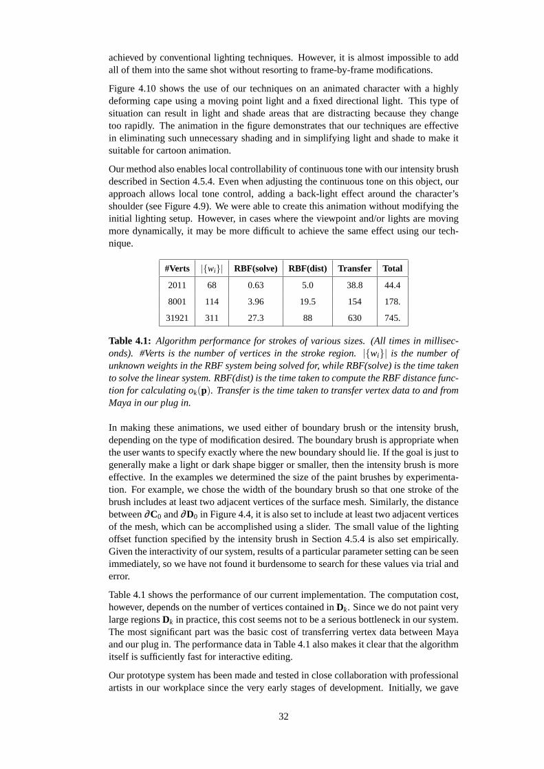
achieved by conventional lighting techniques. However, it is almost impossible to addall of them into the same shot without resorting to frame-by-frame modifications.
Figure 4.10 shows the use of our techniques on an animated character with a highlydeforming cape using a moving point light and a fixed directional light. This type ofsituation can result in light and shade areas that are distracting because they changetoo rapidly. The animation in the figure demonstrates that our techniques are effectivein eliminating such unnecessary shading and in simplifying light and shade to make itsuitable for cartoon animation.
Our method also enables local controllability of continuous tone with our intensity brushdescribed in Section 4.5.4. Even when adjusting the continuous tone on this object, ourapproach allows local tone control, adding a back-light effect around the character’sshoulder (see Figure 4.9). We were able to create this animation without modifying theinitial lighting setup. However, in cases where the viewpoint and/or lights are movingmore dynamically, it may be more difficult to achieve the same effect using our tech-nique.
#Verts |{wi}| RBF(solve) RBF(dist) Transfer Total
2011 68 0.63 5.0 38.8 44.4
8001 114 3.96 19.5 154 178.
31921 311 27.3 88 630 745.
Table 4.1: Algorithm performance for strokes of various sizes. (All times in millisec-onds). #Verts is the number of vertices in the stroke region.|{wi}| is the number ofunknown weights in the RBF system being solved for, while RBF(solve) is the time takento solve the linear system. RBF(dist) is the time taken to compute the RBF distance func-tion for calculating ok(p). Transfer is the time taken to transfer vertex data to and fromMaya in our plug in.
In making these animations, we used either of boundary brush or the intensity brush,depending on the type of modification desired. The boundary brush is appropriate whenthe user wants to specify exactly where the new boundary should lie. If the goal is just togenerally make a light or dark shape bigger or smaller, then the intensity brush is moreeffective. In the examples we determined the size of the paint brushes by experimenta-tion. For example, we chose the width of the boundary brush so that one stroke of thebrush includes at least two adjacent vertices of the surface mesh. Similarly, the distancebetween∂C0 and∂D0 in Figure 4.4, it is also set to include at least two adjacent verticesof the mesh, which can be accomplished using a slider. The small value of the lightingoffset function specified by the intensity brush in Section 4.5.4 is also set empirically.Given the interactivity of our system, results of a particular parameter setting can be seenimmediately, so we have not found it burdensome to search for these values via trial anderror.
Table 4.1 shows the performance of our current implementation. The computation cost,however, depends on the number of vertices contained inDk. Since we do not paint verylarge regionsDk in practice, this cost seems not to be a serious bottleneck in our system.The most significant part was the basic cost of transferring vertex data between Mayaand our plug in. The performance data in Table 4.1 also makes it clear that the algorithmitself is sufficiently fast for interactive editing.
Our prototype system has been made and tested in close collaboration with professionalartists in our workplace since the very early stages of development. Initially, we gave
32

a 20-minute tutorial to the artists. Since our system is implemented as a Maya plug-in,they were able to try it out on their own models immediately. The reaction has beenpositive: they do seem to find the system capable of producing the desired results easilyand quickly. Most of the animations in this chapter were designed with the artists soas to clearly display the capabilities of the proposed technique. Typically animationssuch as those shown in this chapter take a few hours to complete, which is a drasticimprovement over the previous techniques available to the artists. They also claimedthat the conventional tricks such as texture animation or modifications to the character’sgeometry would make it difficult to maintain consistency between different shots withthe same character. Therefore, with such conventional techniques, these kind of editswould simply be infeasible on a production schedule.
We also tried to integrate the experimental system into an animation production pipeline.Some of the results are shown in animated feature films. First example is the Tamagotchifeature film: “Tamagotchi: Happiest Story in the Universe!” [93], produced by OLMDigital, Inc. In this film, our system is used to modify undesired shading of a charac-ter’s lip. The artist could create a desired shading appearance easily in a way similarto the case of making facial animation (see Figure 4.1). Another example is TakashiMurakami’s digital animation film: “Kaikai&Kiki” [43]. In making one of the scenesof this film, the conventional lighting method created distracting shaded areas on a char-acter’s face due to the rapid movement of the character’s head. Similar to the case ofdeforming cape, our system is also effective in eliminating the undesired light and shademovements to be suited for cartoon animation. These examples demonstrate that oursystem is capable of improving quality of the animation in professional use. The mod-ified version of this system is presented as a production tool: “Shade Painter” on OLMDigital R&D web site [65].
We feel that there are considerable applications of our algorithms not only in featurefilms, but also for television animation and even illustrative visualization. In addition,our extension lets the user animate the designed shading with dynamic lighting, whichis suited for interactive video games. In these contexts, our system could be useful forartists to pursuit animation of desired shading, since playback using our technique islightweight and real-time on any modern GPU.
4.8 Summary
In this chapter, we proposed a system for directalbe stylistic depiction of light and shadein 3D animation. According to our interface design framework, we introduced a shadingmodel for local and interactive edits of light and shade by painting directly on 3D objects.Moreover the local edits integrate seamlessly with the conventional global lighting andanimate smoothly regardless of the conventional lighting setup used. The animationexamples illustrate these advantages over previous methods.
These algorithms, however, are exploratory. There are several things left to accomplish.In our approach, the RBF-based algorithm is used to obtain the rough boundary of thepainted shaded area. In addition, we make the assumption that the vertices defining theobject will not be added or removed during animation. We do not handle objects thatchange topology during an animation. We may need a more sophisticated algorithm toobtain a more precise approximation of the painted area. When applying this methodto cartoon animation, highlights with very sharp edges are sometimes desired. But ourper-vertex offsetting cannot give such a sharp highlight directly. Providing boolean op-erations as in [4] may be of use here (see Figure 4.11).
33
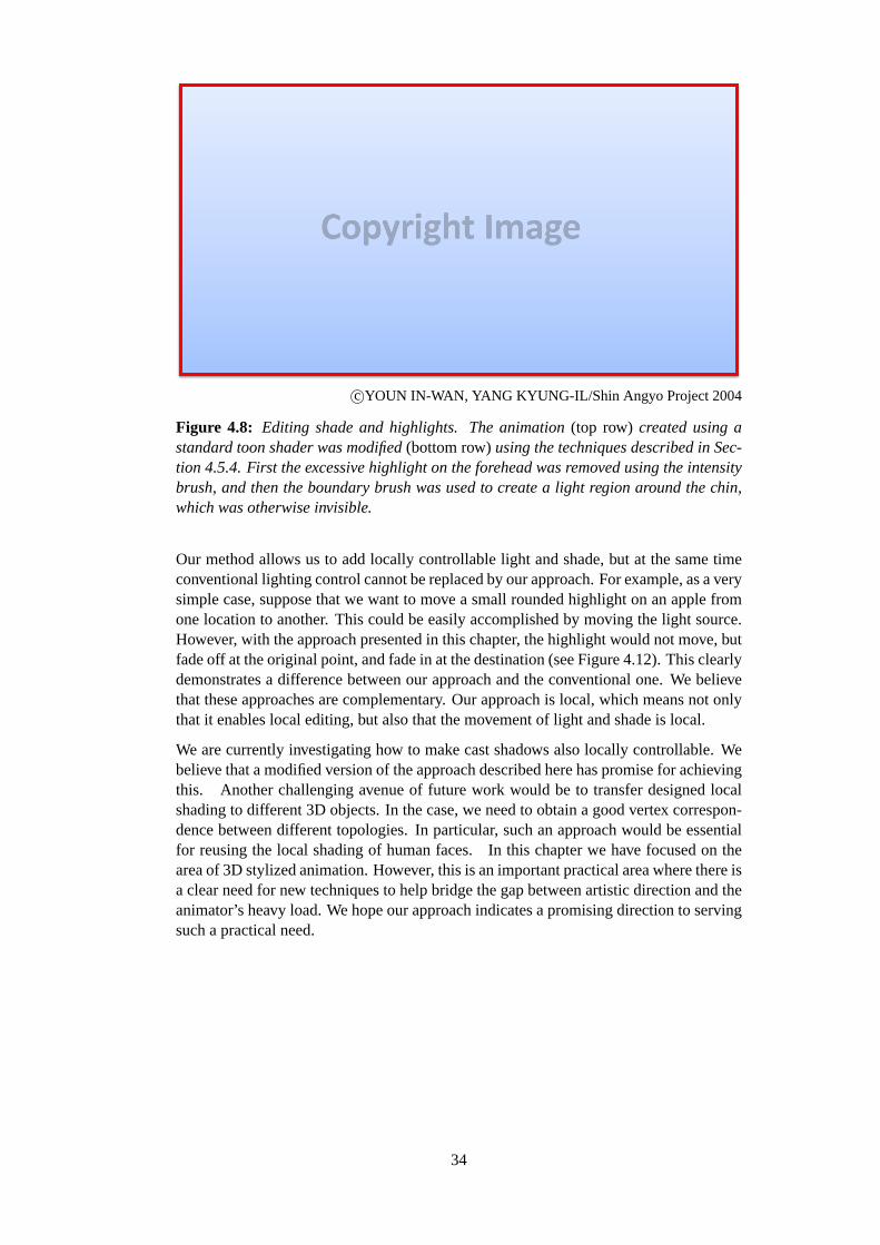
c⃝YOUN IN-WAN, YANG KYUNG-IL/Shin Angyo Project 2004
Figure 4.8: Editing shade and highlights. The animation(top row) created using astandard toon shader was modified(bottom row)using the techniques described in Sec-tion 4.5.4. First the excessive highlight on the forehead was removed using the intensitybrush, and then the boundary brush was used to create a light region around the chin,which was otherwise invisible.
Our method allows us to add locally controllable light and shade, but at the same timeconventional lighting control cannot be replaced by our approach. For example, as a verysimple case, suppose that we want to move a small rounded highlight on an apple fromone location to another. This could be easily accomplished by moving the light source.However, with the approach presented in this chapter, the highlight would not move, butfade off at the original point, and fade in at the destination (see Figure 4.12). This clearlydemonstrates a difference between our approach and the conventional one. We believethat these approaches are complementary. Our approach is local, which means not onlythat it enables local editing, but also that the movement of light and shade is local.
We are currently investigating how to make cast shadows also locally controllable. Webelieve that a modified version of the approach described here has promise for achievingthis. Another challenging avenue of future work would be to transfer designed localshading to different 3D objects. In the case, we need to obtain a good vertex correspon-dence between different topologies. In particular, such an approach would be essentialfor reusing the local shading of human faces. In this chapter we have focused on thearea of 3D stylized animation. However, this is an important practical area where there isa clear need for new techniques to help bridge the gap between artistic direction and theanimator’s heavy load. We hope our approach indicates a promising direction to servingsuch a practical need.
34
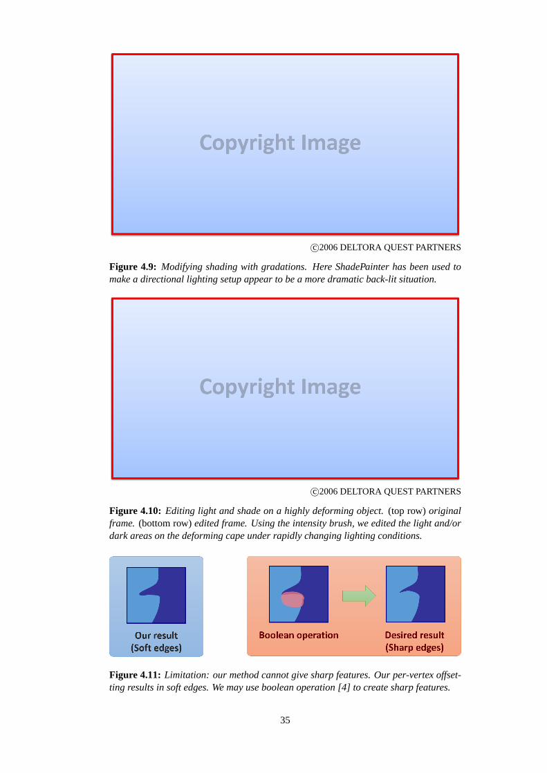
c⃝2006 DELTORA QUEST PARTNERS
Figure 4.9: Modifying shading with gradations. Here ShadePainter has been used tomake a directional lighting setup appear to be a more dramatic back-lit situation.
c⃝2006 DELTORA QUEST PARTNERS
Figure 4.10: Editing light and shade on a highly deforming object.(top row)originalframe. (bottom row)edited frame. Using the intensity brush, we edited the light and/ordark areas on the deforming cape under rapidly changing lighting conditions.
Figure 4.11: Limitation: our method cannot give sharp features. Our per-vertex offset-ting results in soft edges. We may use boolean operation [4] to create sharp features.
35

Figure 4.12: Limitation: our method cannot move a highlight. Edits were made at thetwo key frames indicated. Highlight would fades off at the original point, and fade in atthe destination.
36

Chapter 5
Shading Stylization Based on Model Features
5.1 Overview
The second experiment is to apply our framework to an artist-friendly user interface forshading stylizations based on model features such as surface normals and edges. In thischapter, we focus on how to control feature-dependent lighting effects, rather than thelocal shading effects described in Chapter 4. In the context of stylized shading design formechanical objects, it is helpful for the artist to have a method for designing the shadingappearance derived from the geometric properties or artistic directions. We present aninteractive system that enables straight lighting, edge enhancement, and detailed lightingeffects, all of which are commonly used in 2D hand-drawn cartoon animations. In ac-cordance withPrinciple 1 (directable shading model for artistic control), we design theshading model which allows the artist to interactively design the these stylized lightingeffects for mechanical objects using simple 3D light UIs and appearance-based param-eters. The key idea for this directable shading model is to introduce simple lightingtransforms and lighting offset based on the model features, such as surface flatness andedge distance field. This complies withPrinciple 2 (seamless integration with 3D light-ing) in that the proposed stylized shading effects can be manipulated by multiple pointlight sources. Besides, our system also enables dynamic control over these lighting ef-fects base on a familiar key-framing technique. Thanks to the simple formulations of ouralgorithms, shading process can be implemented on GPU for real-time preview. Finally,we demonstrate our system by presenting several stylized shading animation results thatare effectively designed using our method.
5.2 Introduction
Here we consider the problem of how to provide artists with intuitive and useful con-trol over shading stylization based on model features. First we show 2D hand-drawnexamples, where an artist draws typical stylized lighting effects. Figure 5.1 (a) showsstraight lighting on windows, which is used to emphasize the flatness of the objects. InFigure 5.1(b), the artist combines the lighting effects derived from the model features.Around the edge of the aircraft, a sharp lighting effect was used to enhance the edge.Another example is a detailed lighting effect, which was used to show that a surface isbumpy. Because of the recent increase in the use of hybrid 2D and 3D models, it isdesirable to achieve these lighting effects in a 3D system.
As described in previous Chapter 4, cartoon shading [50] is a standard approach used todesign 3D shading in a cartoon style. In this process, the final shading color is obtained
37
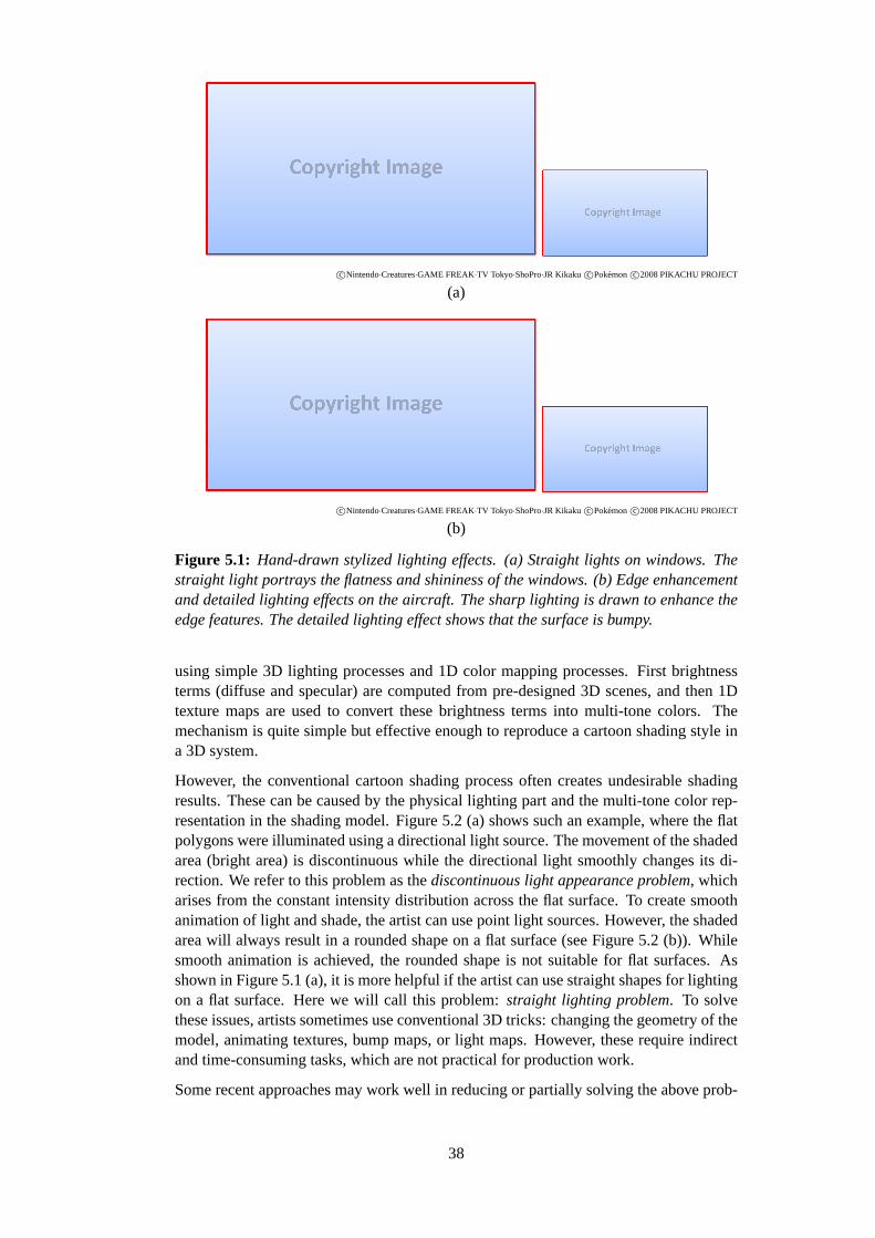
c⃝Nintendo·Creatures·GAME FREAK·TV Tokyo·ShoPro·JR Kikaku c⃝Pokemon c⃝2008 PIKACHU PROJECT
(a)
c⃝Nintendo·Creatures·GAME FREAK·TV Tokyo·ShoPro·JR Kikaku c⃝Pokemon c⃝2008 PIKACHU PROJECT
(b)
Figure 5.1: Hand-drawn stylized lighting effects. (a) Straight lights on windows. Thestraight light portrays the flatness and shininess of the windows. (b) Edge enhancementand detailed lighting effects on the aircraft. The sharp lighting is drawn to enhance theedge features. The detailed lighting effect shows that the surface is bumpy.
using simple 3D lighting processes and 1D color mapping processes. First brightnessterms (diffuse and specular) are computed from pre-designed 3D scenes, and then 1Dtexture maps are used to convert these brightness terms into multi-tone colors. Themechanism is quite simple but effective enough to reproduce a cartoon shading style ina 3D system.
However, the conventional cartoon shading process often creates undesirable shadingresults. These can be caused by the physical lighting part and the multi-tone color rep-resentation in the shading model. Figure 5.2 (a) shows such an example, where the flatpolygons were illuminated using a directional light source. The movement of the shadedarea (bright area) is discontinuous while the directional light smoothly changes its di-rection. We refer to this problem as thediscontinuous light appearance problem, whicharises from the constant intensity distribution across the flat surface. To create smoothanimation of light and shade, the artist can use point light sources. However, the shadedarea will always result in a rounded shape on a flat surface (see Figure 5.2 (b)). Whilesmooth animation is achieved, the rounded shape is not suitable for flat surfaces. Asshown in Figure 5.1 (a), it is more helpful if the artist can use straight shapes for lightingon a flat surface. Here we will call this problem:straight lighting problem. To solvethese issues, artists sometimes use conventional 3D tricks: changing the geometry of themodel, animating textures, bump maps, or light maps. However, these require indirectand time-consuming tasks, which are not practical for production work.
Some recent approaches may work well in reducing or partially solving the above prob-
38

Figure 5.2: Cartoon shading results with different lighting. (Top row) Directional light.Thediscontinuous light appearance problemoccurs from the second frame to the thirdframe when the directional light smoothly changes its direction. (Middle row) Pointlight. This type of shading results in smooth animation; however, thestraight lightingproblemis not addressed. (Bottom row) Our stylized lighting effect. Straight shadedareas and edge lighting effects are achieved in smooth light and shade animation.
lems. Our method for local light and shade described in Chapter 4 and the cartoonhighlight shader [4] are helpful for designing the arbitrary shaped lights. However, withthese methods it is difficult to enhance the model features, which may become a time-consuming task of adding edge enhancement or emphasizing a bumpiness feature. Toenhance the model features, the multi-scale shading method [75] or XToon [11] can beused to control the shading appearance based on geometric features, such as edge en-hancement, depth of field, or back lighting. However, these methods support only oneadditional defined stylization of the original shading result.
Our goal is to develop new 3D lighting methods that can achieve stylized lighting controlbased on multiple model features. As an initial step toward this goal, we focus on theintegration of straight lighting, edge enhancement, and detailed lighting for reproducingthe important elements of 2D manual stylized shading styles. To achieve this, we extendthe lighting part and texture mapping part of a typical cartoon shading process as follows:
• We introduce a light coordinate system to produce a smooth animation of straightlighting effects. The central idea for straight lighting is to apply a lighting trans-form to the incoming light vectors based on the surface normal. Our light coordi-nate system defines the local transformation space according to the designed 3Dlighting.
• We extend the conventional texture mapping part to enhance multiple features. Inour extension, the threshold values of multi-tone texture are deformed by scalarlighting offset functions. We separately design the offset functions for edge en-
39

hancement and detailed lighting in a manner whereby the artist can control eacheffect using intuitive, appearance-based parameters.
5.3 Background
As in Chapter 4, our main focus is on cartoon shading [50], which is commonly used inproduction environments. Based on the computed brightness terms, this approach effec-tively reproduces multi-tone shading styles in cartoon animation. Similar to this work,several methods have been proposed to reproduce particular stylized shading styles from3D scenes. Gooch and Gooch [36] proposed the technical illustration shader for cool-to-warm shading effects. The Lit-Sphere method [87] can describe view-independenttone detail, using a painted spherical environment map. Mitchell et al. [58] presentedan illustrative shading style for video game applications. However, these fundamentalapproaches often lack the ability to control the shading appearance to establish symboliclighting and enhancements of model features.
Several methods have been developed to change the original lighting result, and henceprovide symbolic lighting effects in cartoon animation. DeCoro et al. [28] proposedseveral stylized shadow effects using image space deformations. Our method describedin Chapter 4 allows the artist to paint local lighting effects directly onto a 3D model.Anjyo et al. [4] proposed a cartoon highlight shader which can make various symbolichighlight shapes. While these methods provide creative control over the shape of thelighting, artists may desire further control over the smaller scale appearance.
A number of methods have been developed to design the shading based on geomet-ric or scene properties, providing such control. For instance, the multi-scale shadingmethod [75] and the 3D unsharp masking method [73] can accentuate the edges or thesilhouettes of a target model. Several methods focus on the geometric deformation with2D texture inputs, including bump mapping [16], displacement mapping [24], and re-lief mapping [64]. More complex extension is obtained with 2D tone controls. Barlaet al. [11] proposed X-Toon, where a 2D texture is used to integrate additional controls,including depth of field, back lighting effects, and diffuse-dependent specular effects.These techniques allow the artist to control the appearance of a specified model feature,but they do not permit the integration of multiples features.
In contrast to related work, our approach provides a simple interactive method for styl-ized shading design, where a symbolic lighting effect (straight lighting) is seamlesslyintegrated with enhancements based on multiple model features (edge enhancement, anddetailed lighting).
5.4 User Interaction
In our approach, shading stylizations can be controlled with three proposed lightingeffects: straight lighting effect, edge enhancement effect, and detail lighting effect. In thelighting design process, their parameters can be dynamically modified to check results inreal-time. User control parameters of our shading model are summarized in Table 5.1.
To provide convenient and familiar methods for artists, we propose the overall processin the following manner. The artist begins by making an initial 3D scene, including thegeometries of the models and their animation settings, using a conventional 3D softwaretool. In the next step, the artist designs the straight lighting effect by manipulating a 3D
40
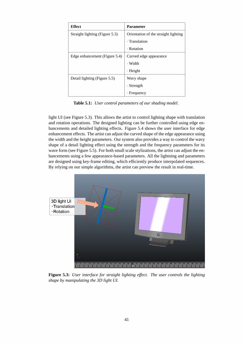
Effect Parameter
Straight lighting (Figure 5.3) Orientation of the straight lighting
· Translation
· Rotation
Edge enhancement (Figure 5.4)Curved edge appearance
· Width
· Height
Detail lighting (Figure 5.5) Wavy shape
· Strength
· Frequency
Table 5.1: User control parameters of our shading model.
light UI (see Figure 5.3). This allows the artist to control lighting shape with translationand rotation operations. The designed lighting can be further controlled using edge en-hancements and detailed lighting effects. Figure 5.4 shows the user interface for edgeenhancement effects. The artist can adjust the curved shape of the edge appearance usingthe width and the height parameters. Our system also provides a way to control the wavyshape of a detail lighting effect using the strength and the frequency parameters for itswave form (see Figure 5.5). For both small scale stylizations, the artist can adjust the en-hancements using a few appearance-based parameters. All the lightning and parametersare designed using key-frame editing, which efficiently produce interpolated sequences.By relying on our simple algorithms, the artist can preview the result in real-time.
Figure 5.3: User interface for straight lighting effect. The user controls the lightingshape by manipulating the 3D light UI.
41
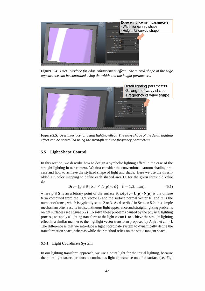
Figure 5.4: User interface for edge enhancement effect. The curved shape of the edgeappearance can be controlled using the width and the height parameters.
Figure 5.5: User interface for detail lighting effect. The wavy shape of the detail lightingeffect can be controlled using the strength and the frequency parameters.
5.5 Light Shape Control
In this section, we describe how to design a symbolic lighting effect in the case of thestraight lighting in our context. We first consider the conventional cartoon shading pro-cess and how to achieve the stylized shape of light and shade. Here we use the thresh-olded 1D color mapping to define each shaded areaDi for the given threshold valueδi :
Di := {p ∈ S | δi−1 ≤ Id(p)< δi} (i = 1,2, ...,m), (5.1)
wherep ∈ S is an arbitrary point of the surfaceS, Id(p) := L(p) ·N(p) is the diffuseterm computed from the light vectorL and the surface normal vectorN, andm is thenumber of tones, which is typically set to 2 or 3. As described in Section 5.2, this simplemechanism often results in discontinuous light appearance and straight lighting problemson flat surfaces (see Figure 5.2). To solve these problems caused by the physical lightingprocess, we apply a lighting transform to the light vectorL to achieve the straight lightingeffect in a similar manner to the highlight vector transform proposed by Anjyo et al. [4].The difference is that we introduce a light coordinate system to dynamically define thetransformation space, whereas while their method relies on the static tangent space.
5.5.1 Light Coordinate System
In our lighting transform approach, we use a point light for the initial lighting, becausethe point light source produce a continuous light appearance on a flat surface (see Fig-
42

(a)
(b)
Figure 5.6: Light coordinate system for the initial lighting design. (a) Light shape con-trol with the light coordinate system. The light vector is transformed through the straightfunction according to the projection coordinates (Lu,Lv). (b) Automatic transform direc-tion control. The new transformation axis dvnew is assigned depending on the surfacenormal direction (Nu, Nv).
ure 5.2 (b)). With the location of point light sourcepl , we introduce a light coordinatesystem to specify the transform orientation (see Figure 5.6). We use additional coordi-nate axes (du, dv, dw) for light shape control. With these elements, we can introduce adifferent representation of the light vectorL :
L(p) = Lu(p)du+Lv(p)dv+Lw(p)dw, (5.2)
whereLu, Lv, andLw are the projection coordinates which are computed fromLu :=L ·du, Lv := L ·dv, andLw := L ·dv. Based on this representation of the light vector,we can apply a vector transform to control the light shape. To create a straight lightingeffect on a flat surface, we define a straight functionfst as:
fst(L) := Lu(p)du+(1−α)Lv(p)dv+Lw(p)dw, (5.3)
where the directional scaling term 1−α is applied to the projection coordinateLv(p).The straight functionfst makes the light vector straight along thedv direction if α ap-proaches 1. As shown in Figure 5.2, the point light vector transformed by the straightfunction successfully produces a straight lighting shape. In our system, the artist cancontrol the transform direction by manipulating the position and rotation of a 3D line-shaped light UI, which is easily converted into the elements of the light coordinate sys-tem (pl , du, dv, dw).
43

5.5.2 Transform Orientation Control
In the previous section, we described a simple case where the transform orientation wasconstantdv. Here we consider a transform orientation control for the more general caseof multiple polygons. From our observations, artists typically use different transformorientations for different polygons. The obvious solution is local control, whereby theanimator can set the transform direction for each flat polygon. However, such localcontrols would require a time consuming key-framing process to create the animation.To reduce the artist’s workload, we introduce automatic transform orientation control.Here we try to satisfy the following requirements in our transform orientation control:
• The transform orientations are perpendicular to the surface normal vector (Re-quirement 1).
• Stable and coherent motion of the transform orientation during the animation (Re-quirement 2).
For these practical requirements, we provide a method for automatically defining coor-dinate axes (du, dv, dw) depending on the surface normal directionN (see Figure 5.6(b)). Similar to Equation 5.3, we can introduce a representation of the surface normalvector for the given coordinate axes (du, dv, dv):
N(p) = Nu(p)du+Nv(p)dv+NL(p)dw, (5.4)
whereNu, Nv, andNw are defined in the same way asLu, Lv, andLw in Equation 5.3. FortheNu andNv, we first consider a new transform orientationdv1 that satisfies Require-ment 1:
dv1 = normalize(Nvdu−Nudv), (5.5)
wheredv1 is the vector perpendicular toN anddw. This definition satisfies Require-ment 1; however, Requirement 2 is not satisfied. For instance, suppose that an animatorrotates the light along thedu direction. This results in an undesirable rotation of shadedarea, whereby the angle betweendw andN approaches 0◦. To avoid such undesirablerotations, and to satisfy Requirement 2, we integrate stable behavior into the definitionin Equation 5.4 by rewriting the definition of Equation 5.5 as:
dvnew= normalize(φ(Nu,Nv)Nvdu−Nudv), (5.6)
where the scaling functionφ(Nu,Nv) is applied to the projection coordinateNv. Wedesigned the scaling functionφ(Nu,Nv) as follows:
φ(Nu,Nv) :=
0 if ∥(Nu,Nv)∥< r1
∥(Nu,Nv)∥−r1r2−r1
r1 ≤ ∥(Nu,Nv)∥< r2
1 otherwise
(5.7)
wherer1 and r2 are the user-given parameters satisfying that 0< r1 < r2 < 1. Withthis scaling function, our method can seamlessly blenddv1 (φ(Nu,Nv) = 1) anddv(φ(Nu,Nv) = 0).
5.6 Threshold Offset to Enhance Multiple Features
In this section, we consider how to apply multiple enhancements to the designed straightlighting result. Barla et al. [11] used a 2D texture to extend the conventional texture
44
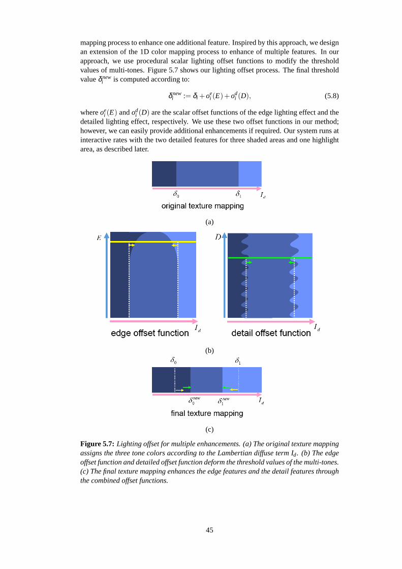
mapping process to enhance one additional feature. Inspired by this approach, we designan extension of the 1D color mapping process to enhance of multiple features. In ourapproach, we use procedural scalar lighting offset functions to modify the thresholdvalues of multi-tones. Figure 5.7 shows our lighting offset process. The final thresholdvalueδ new
i is computed according to:
δ newi := δi +oe
i (E)+odi (D), (5.8)
whereoei (E) andod
i (D) are the scalar offset functions of the edge lighting effect and thedetailed lighting effect, respectively. We use these two offset functions in our method;however, we can easily provide additional enhancements if required. Our system runs atinteractive rates with the two detailed features for three shaded areas and one highlightarea, as described later.
(a)
(b)
(c)
Figure 5.7: Lighting offset for multiple enhancements. (a) The original texture mappingassigns the three tone colors according to the Lambertian diffuse term Id. (b) The edgeoffset function and detailed offset function deform the threshold values of the multi-tones.(c) The final texture mapping enhances the edge features and the detail features throughthe combined offset functions.
45

5.6.1 Edge Enhancement
Here we describe a method for providing intuitive control over the edge appearancewith our lighting offset approach. Edge enhancement typically uses a sharp curvedlighting effect around the edge of the object (see Figure 5.1 (b)). To achieve this, wedesign the edge offset functionoe
i that is a function of the edge intensity value and afew appearance-based parameters (width control and height control). The edge inten-sity value is referenced from the image space edge field computed from the 3D scene.With the input edge intensity value, the final edge appearance can be controlled usingthe defined appearance-based parameters.
Image Space Edge Field
To specify a deformation space, we need to define an edge field on the target 3D model.While our method is independent of the choice of the edge intensity representation, wechose the image space edge field, because it can be dynamically extracted from screen-space information, which provides an efficient way to control the edge appearance inreal-time.
To compute the image space edge field, we use an approach similar to the ray-tracingalgorithm for the NPR-Line [21], where the feature lines are extracted based on theparametric distance of sampling points. Figure 5.8 shows an overview of our imagespace edge detection algorithm. The parametric distance is computed from the imagespace property vectors:
d(x,y) := ||P(x)−P(y)||, (5.9)
wherex and y are the sampling points,P(x) is the surface property vector atx, andd(x,y) is the parametric distance betweenx andy. Figure 5.9 describes the overall
Figure 5.8: Image space edge detection. (Left) A scene rendered with color mappedsurface normals. Each surface normal is used as part of an image space property vectorin our edge detection algorithm. (Right) Our image space edge detection algorithmsearches for discontinuities in the property vectors to compute the image space edgefield.
process of computing an edge intensity at a sampling pixelx. Based on the paramet-ric distance definition, a nearby pixely aroundx can be classified as a similar pixel(d(x,y) ≤ c ) or a dissimilar pixel (d(x,y) > c) using a threshold valuec. We use theminimum distancedE(x) between the sampling pixelx and the dissimilar pixels to definethe edge intensityE(x):
E(x) := max(0,1− tdE(x)), (5.10)
wheret is the thickness control parameter for an image space edge field. To reducethe computational expense, we approximate the edge intensity using sparse sampling.
46

Figure 5.9: Edge intensity at a sampling pixel (the blue point). Based on the parametricdistance, each nearby pixel is classified as a similar pixel (the green points) or a dissim-ilar pixel (the red points). The minimum distance dE between the sampling pixel and thedissimilar pixels is used to compute the edge intensity E.
The precision of the edge intensity depends on the number of sampling pointsM. Weuse 16≤ M ≤ 32, which we have found provides a trade-off between precision andefficiency.
Edge Offset Function
Figure 5.10: Lighting offset with edge offset functions. Our edge offset functions de-form the threshold values with appearance-based parameters (width control and heightcontrol).
With the definition of the image space edge field, we design the edge offset functionto deform the threshold values using a few simple appearance-based parameters (seeFigure 5.10). For the computed the edge intensity valueE, the edge offset functionoe
i (E) is defined as:
oei (E) := β w
i (1−sin(acos(E−β h
i
1.0−β hi
)), (5.11)
47
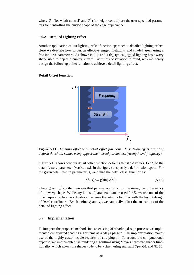
whereβ wi (for width control) andβ h
i (for height control) are the user-specified parame-ters for controlling the curved shape of the edge appearance.
5.6.2 Detailed Lighting Effect
Another application of our lighting offset function approach is detailed lighting effect.Here we describe how to design effective jagged highlights and shaded areas using afew intuitive parameters. As shown in Figure 5.1 (b), typical jagged lighting has a wavyshape used to depict a bumpy surface. With this observation in mind, we empiricallydesign the following offset function to achieve a detail lighting effect.
Detail Offset Function
Figure 5.11: Lighting offset with detail offset functions. Our detail offset functionsdeform threshold values using appearance-based parameters (strength and frequency).
Figure 5.11 shows how our detail offset function deforms threshold values. LetD be thedetail feature parameter (vertical axis in the figure) to specify a deformation space. Forthe given detail feature parameterD, we define the detail offset function as:
odi (D) := γs
i sin(γ fi D), (5.12)
whereγsi andγ f
i are the user-specified parameters to control the strength and frequencyof the wavy shape. While any kinds of parameter can be used forD, we use one of theobject-space texture coordinatesv, because the artist is familiar with the layout designof (u,v) coordinates. By changingγs
i andγ fi , we can easily adjust the appearance of the
detailed lighting effect.
5.7 Implementation
To integrate the proposed methods into an existing 3D shading design process, we imple-mented our stylized shading algorithms as a Maya plug-in. Our implementation makesuse of the highly customizable features of this plug-in. To reduce the computationalexpense, we implemented the rendering algorithms using Maya’s hardware shader func-tionality, which allows the shader code to be written using standard OpenGL and GLSL.
48
Since the tessellation of mechanical objects is generally not suited for per-vertex light-ing, we need to calculate the lighting process using a pixel shader.
Straight Lighting Effect
To implement the straight lighting effects, we provided a simple 3D line-shaped lightUI to specify the position and the orientation of the light coordinate system. These dataand the parameters for the shape control are transferred to the pixel shader, and then thelighting transforms are applied to the per-pixel light vector.
Image Space Edge Field
The most time-consuming part of our rendering algorithms is computing the edge dis-tance field. To perform this process in real-time, we compute the per-pixel edge intensityon the GPU using multiple passes. In the first pass, the target 3D model data are raster-ized into three property textures: the surface depth, the surface normal, and the surfacematerial ID. In the second pass, we use the pixel shader to compute the per-pixel edgeintensity values of these property textures. Finally, our system merges these edge fieldsby choosing the maximum edge intensity value. The computed edge field is referencedby the edge offset process, which is implemented as a part of lighting process in the pixelshader. In our prototype system, we can compute an edge field at interactive rates withan image resolution of 512×512 pixels.
5.8 Results and Discussion
We applied our prototype system to create various stylistic animations. Our system runsat interactive rates on a 2.16GHz Intel P4 Core Duo CPU with an NVIDIA GeForceQuadroFX 350M GPU. In editing and previewing the animations, the frame rate was inthe range 6 - 20 fps for all of the examples in this chapter.
The continuous appearance of straight lights is crucial for creating 3D animations ofmechanical objects composed of multiple flat polygons, and suggest that the surfaces areflat and shiny. Figure 5.12 (a) demonstrates how effective and efficient our algorithmsare for such requirements. As described in Section 5.2, even for a simple object such asa computer monitor, conventional lighting results in the discontinuous light appearanceproblem and the straight lighting problem on flat surfaces. In contrast, our stylizedlighting method enables interactive design of the straight lighting effect by manipulatinga 3D light source UI. Moreover, the designed lighting can be further controlled usingedge enhancement and the detailed lighting effects, which can give the viewer differentimpressions or nuances of the objects. (see the right of Figure 5.12 (a)).
49

(a)
(b)
Figure 5.12: Typical lighting examples. (a) A computer monitor model including mul-tiple flat surfaces. The left image is illuminated using a point light source and the rightis designed using our method. Our straight lighting and detailed lighting effects por-tray the flatness as well as the bumpiness of the surface. (b) A model of a gun. Theleft image was illuminated using a point light source and the right is designed usingour method. Our straight lighting effect produced the straight shaded areas on the flatpolygons, while rounded shaded areas were preserved on the smooth surface.
In creating animations with the gun model shown in Figure 5.12 (b), lighting control ismore difficult due to the complexity of the geometry. Compared to the results generatedusing a point light source (the left of Figure 5.12 (b)), our method allows the artist todesign the straight lighting effect easily and interactively. Note that the rounded shadedareas are preserved on the smooth surface. This would be difficult to achieve usingconventional lighting control without locally controlling the lighting on a per-polygonbasis.
Edge enhancement and detailed lighting are important when drawing mechanical ob-jects, as shown in Figure 5.1 (b). Figure 5.13 demonstrates an example where an artistused our system to design such expressive shading styles for a mechanical object. Theconventional lighting was limited to a simple shading appearance, and it was difficult toadd detail. In contrast, our approach enabled interactive control of the detailed appear-ance (using edge enhancement, and detailed lighting effects) by adjusting a few simpleappearance-based parameters.
Figure 5.14 shows another example where our tools were used to produce a crystal ap-pearance. In this example, it would be desirable to design a straight lighting effect to
50

Stylized lighting result
Original lighting result(close-up)
Our lighting result(close-up)
c⃝Nintendo·Creatures·GAME FREAK·TV Tokyo·ShoPro·JR Kikaku c⃝Pokemon c⃝2008 PIKACHU PROJECT
Figure 5.13: Edge enhancement and detailed lighting effects on an aircraft. Top row:our stylized lighting result (left), close-up of the original lighting result using a pointlight (middle), and close-up of our stylized lighting result (right). Middle row and bottomrow: a comparison between the original lighting result and our lighting result. Thesharpness and the bumpiness of the aircraft are emphasized using our edge enhancementand detailed lighting effects.
emphasize the shiny surface properties of the crystal. However, a discontinuous lightappearance would be problematic if using a directional light source, as shown in thetop row of Figure 5.14. The bottom row of Figure 5.14 demonstrates that our straightlighting effects allows a continuous light appearance for flat surfaces, making it suitablefor the images of crystals. In addition, our edge enhancement effects allows the artist todesign sharp lighting on the edges.
While these examples do not include any deforming object, our techniques can be ap-plied to a highly deforming object (see Figure 5.15). In this case, it would be time-consuming to compute the edge field in the object space because the geometry changesrapidly. On the other hand, our image space algorithm extracts the edge features inter-actively due to the mechanism independence of the complexity of the target geometry.
Our prototype system has been tested by professional artists in our work place. Mostof the animations in this chapter were easily and quickly designed, taking only a fewhours to complete. In addition, we were able to demonstrate the system and examples tomany artists. Their reactions were positive: they felt that the methods were effective forreproducing typical lighting styles that are commonly used in hand-drawn cartoon im-ages. Furthermore, they commented that conventional lighting processes are not capableof producing such stylized lighting results, and that manually drawing the lighting frameby frame is the most reliable way to achieve these effects using existing methods. We
51

c⃝Nintendo·Creatures·GAME FREAK·TV Tokyo·ShoPro·JR Kikaku c⃝Pokemon c⃝2008 PIKACHU PROJECT
Figure 5.14: Straight lighting effects and edge enhancements for crystal appearance.(Top row) The original lighting result using a directional light. (Bottom row) Our light-ing result using the straight lighting and the edge enhancement effects. First, a discon-tinuous light appearance was replaced by our smooth straight lighting effects; then, thesharp lighting was designed using the edge enhancement.
feel that there is considerable potential for our methods to replace these time-consumingtasks for artists.
5.9 Summary
In this chapter, we presented a system for shading stylization based on model features,including straight lighting, edge enhancement, and detailed lighting effects. Accordingto our interface design framework, we extended the simple cartoon shading model, pro-viding additional control over specific model features based on the lighting transformsand the lighting offsets. Moreover, our shading stylization can be seamlessly integratedwith the conventional lighting techniques that use point light sources. The animationexamples illustrate the advantages of our system over existing methods.
Some additional capabilities are required to realize the full potential of our system inpractice. For example, our stylized lighting methods only permit global controls tochange the shading appearance. As shown in Section 5.8, our methods allow the artistto quickly design plausible lighting results to generate expressive shading appearances.However, the artist may require local controls over the highlights and shading of eachsurface patch for fine-tuning (see the left image of Figure 5.16). Besides, small scalecontrols for complex edge appearance would also be effective for further adjustment ofthe character’s appearance (see the right image of Figure 5.16). Establishing such localcontrols with suited interactive design process is an important area of future work, andis planned to integrate the experimental system into an animation production pipeline.
Our image space edge field is effective for interactive design of effects; however, for off-line rendering, we may require a more precise approach to obtain a temporally coherentedge field. In restricting ourselves to 3D cartoon animation, we feel that the currentprototype system has the capability to create good results with high resolution images.
52
We are also investigating stylized shadow effects. The main challenge is thus to establisha generalized framework and interface that allows the artist to easily create a number ofsimultaneous light effects using the global lighting, local lighting, and shadows.
53

Stylized lighting result
Original lighting result(close-up)
Our lighting result(close-up)
Our result
Original lighting
Figure 5.15: Edge enhancement for a highly deforming object. The silhouettes of thedeforming cape were emphasized using our edge enhancement.
54

c⃝Nintendo·Creatures·GAME FREAK·TV Tokyo·ShoPro·JR Kikaku c⃝Pokemon c⃝2008 PIKACHU PROJECT
Figure 5.16: Limitations of our method. (Left) Our stylized methods only permit globalcontrols. (Right) Our edge enhancement cannot handle a complex shape beyond oursimple formulation.
55

Chapter 6
Practical Shading Model for Expressive ShadingStyles
6.1 Overview
The third experiment is to apply our framework to artist-friendly user interface for prac-tical shading model for stylized shading styles. In this chapter, we focus on how todesign overall appearance with expressive shading styles whereas the first and secondmethods are limited to simple shading tones. For global control of stylized shadingappearance, the Lit-Sphere shading model proposed by Sloan et al. [87] is state-of-artmethod for emulating expressive stylized shading styles. Assuming that stylized shad-ing styles are described by view space normals, this model produces a variety of stylizedshading scenes beyond traditional 3D lighting control. However, it is limited to the staticlighting case: the shading effect is only dependent on the camera view. In addition, itcannot support small-scale brush stroke styles. To address these issues, we propose anextension of the Lit-Sphere shading model that allows the artist to design expressiveshading styles for dynamic lighting. In accordance withPrinciple 1 (directable shad-ing model for artistic control), we design the directable shading model which providesintuitive painting process for the Lit-Sphere shading and appearance-based controls forprominent features. The key idea for the directable shading model is to reformulatethe Lit-Sphere shading model using light space surface normals. Thanks to the lightspace representation, our shading model addresses the issues of the original Lit-Sphereapproach, and allows artists to use a light source to obtain dynamic diffuse and spec-ular shading. Besides, the shading appearance can be refined using stylization effectsincluding highlight shape control, sub lighting effects, and brush stroke styles. Our ex-tension complies withPrinciple 2 (seamless integration with 3D lighting) in that all theproposed shading effects can be controlled by a single global directional or point lightsource. Besides, the designed shading style results in coherent animation, to which 3Dobject deformation can be applied. Finally, our algorithms are easy to implement onGPU, so that our system allows interactive shading design.
6.2 Introduction
Stylized rendering techniques in computer graphics have been widely used to emulateshading styles of artists. Among them, cartoon shading is popular in a variety of produc-tion software, including AutodeskR⃝ MayaR⃝ and 3ds MaxR⃝. This approach is basedon computed illumination, and effectively reproduces the abstracted shading styles of
56

Figure 6.1: Typical hand-drawn shading style. Pictorial shading tones are enhancedwith rim lighting effects and shading strokes.
comics or cartoons. However, the shading appearance is limited to simple shading tones,whereas hand-drawn shading styles may have rich variations as follows.
Figure 6.1 shows a typical hand-drawn shading style. In this scheme, the artist designscomplicated shading tones in the pictorial space, which cannot be simply described bythe typical diffuse and specular terms. We term such shading tonespictorial shadingtones. These shading tones can be enhanced using the following stylization effects. Thecharacter silhouette is accentuated by a sharp lighting effect, which is commonly calledrim lighting (also known as back lighting). In addition, the boundary of the shading tonesare often drawn with brush strokes, which we will refer to asshading strokes. Here wewill call these kinds of effects:secondary stylizations.
In this chapter, we consider how to design such stylized shading with dynamic 3D light-ing. As with the static lighting case, the Lit-Sphere shading model [87] is attractivebecause it can deal withpictorial shading tones(see Figure 6.2). Versions of this ap-proach have been successfully used in commercially available software tools such asMudBox R⃝ and ZBrushR⃝. However, the Lit-Sphere model is limited to this static light-ing appearance; the resulting shading will not be dynamically affected by the lightingsince the shading effect is totally dependent on the view space normals (see Figure 6.3).In addition, the generation of small-scale stylizations such asshading strokesusing thismethod may result in unwanted visual artifacts (see Figure 6.4).
We propose to extend the Lit-Sphere model with dynamic lighting and shading styliza-tions while preserving pictorial shading tones. To achieve this, we introduce the conceptof the light space normals, which enhance the Lit-Sphere model by including the follow-ing new features:
• Light-dependent diffuse and specular behavior.
• Secondary stylizations including highlight shape control, rim lighting, and shadingstrokes.
• Coherent animation of the shading styles, to which 3D object deformation can beapplied.
The remainder of this chapter is organized as follows. First, we briefly summarize re-
57

lated work in Section 6.3 and then we explain how to extend the Lit-Sphere approach fordynamic diffuse and specular behavior in Section 6.5. In Section 6.6, we describe howthe secondary stylizations can be combined with the original shading tones. Combiningthese techniques, we demonstrate a variety of shading appearances in Section 6.8. Fi-nally, we discuss the limitations and possible extensions of our approach in Section 6.9.
Figure 6.2: Lit-Sphere shading. The pictorial shading tones are captured using theLit-Sphere model.
Figure 6.3: Lit-Sphere issue 1: static lighting appearance. Manipulations of the lightdo not affect the shading result.
58

Figure 6.4: Lit-Sphere issue 2: artifacts of small-scale stylizations. The regular patternof shading strokes is extremely deformed in Lit-Sphere shading result.
6.3 Background
Early stylized rendering techniques are typically described by simplified shading tonescomputed using diffuse and specular terms. Gooch and Gooch [36] used cool-to-warmshading tones for their technical illustration shader. Alternative 1D texture representa-tion has been used to emulate illustrative shading styles for video games [58]. For morecomplex shading styles, X-Toon [11] extends 1D shading tones to a 2D function, storedin a 2D texture. The additional dimension is used to convey specular, depth or surfaceorientation. However, this kind of simple mapping of the computed diffuse and specularshading tones permits less control over the shading appearance.
To give the artists more control on the top of stylized rendering results, several tech-niques have been developed that modify the shape of the shading effect. The cartoonhighlights of [4] [96] deal with shape transformation by dragging operations. The styl-ized highlight shape is adjusted via translation, rotation and scaling operators achievedusing vector-field transforms. Ritschel et al. [74] describe a shading deformation tech-nique that is based on a virtual piece of cloth. By modifying sample points of the shadingcomponents, reflections and shadows can be dragged on the surface. Todo et al. [90] andPacanowski et al. [68] give more direct control on the highlight shapes by providing in-tuitive painting methods. Although these methods allow additional flexibility to achievethe desired shape of the shading effects, the final shading appearance is limited to thespecification of the stylized materials.
For further shading stylizations, several good approaches have been developed that allowartists to design custom textures to achieve finer controls over the shading appearance.The Lit-Sphere model [87] allows an artist to design shading tones in pictorial spaceusing a 2D texture of a shaded sphere; however, this approach does not support dynamiclighting. As for hatching styles, Kulla et al. [49] and Yen et al. [109] proposed proceduralmethods for generating coherent stroke animation using structured brush stroke textures.These methods focus on variation in shading styles, but shape control is not considered.
The Lit-Sphere model [87] has the advantage that complex shading tones can be de-
59
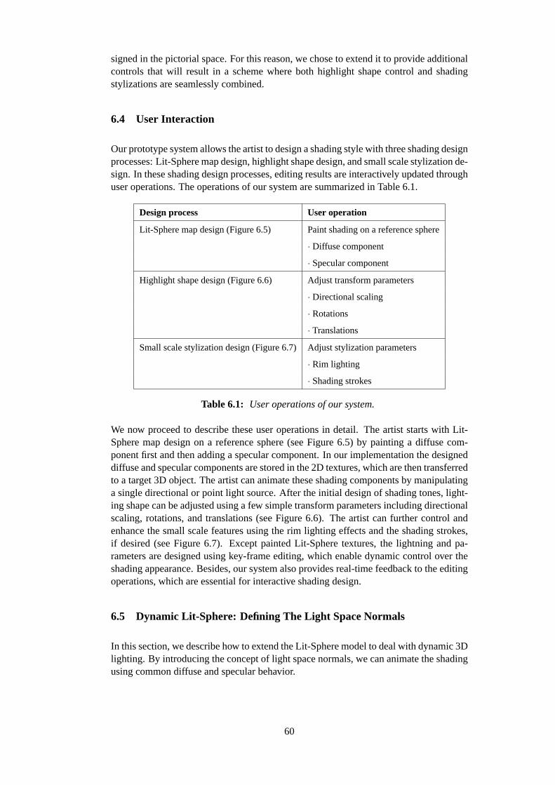
signed in the pictorial space. For this reason, we chose to extend it to provide additionalcontrols that will result in a scheme where both highlight shape control and shadingstylizations are seamlessly combined.
6.4 User Interaction
Our prototype system allows the artist to design a shading style with three shading designprocesses: Lit-Sphere map design, highlight shape design, and small scale stylization de-sign. In these shading design processes, editing results are interactively updated throughuser operations. The operations of our system are summarized in Table 6.1.
Design process User operation
Lit-Sphere map design (Figure 6.5) Paint shading on a reference sphere
· Diffuse component
· Specular component
Highlight shape design (Figure 6.6) Adjust transform parameters
· Directional scaling
· Rotations
· Translations
Small scale stylization design (Figure 6.7)Adjust stylization parameters
· Rim lighting
· Shading strokes
Table 6.1: User operations of our system.
We now proceed to describe these user operations in detail. The artist starts with Lit-Sphere map design on a reference sphere (see Figure 6.5) by painting a diffuse com-ponent first and then adding a specular component. In our implementation the designeddiffuse and specular components are stored in the 2D textures, which are then transferredto a target 3D object. The artist can animate these shading components by manipulatinga single directional or point light source. After the initial design of shading tones, light-ing shape can be adjusted using a few simple transform parameters including directionalscaling, rotations, and translations (see Figure 6.6). The artist can further control andenhance the small scale features using the rim lighting effects and the shading strokes,if desired (see Figure 6.7). Except painted Lit-Sphere textures, the lightning and pa-rameters are designed using key-frame editing, which enable dynamic control over theshading appearance. Besides, our system also provides real-time feedback to the editingoperations, which are essential for interactive shading design.
6.5 Dynamic Lit-Sphere: Defining The Light Space Normals
In this section, we describe how to extend the Lit-Sphere model to deal with dynamic 3Dlighting. By introducing the concept of light space normals, we can animate the shadingusing common diffuse and specular behavior.
60

Figure 6.5: Lit-Sphere design for shading tones. The artist designs Lit-Sphere maps byintuitive painting process. The designed shading tones are stored into 2D texture, andthen transferred to the target 3D model. The artist can manipulate the shading tonesusing a single directional or point light source.
Figure 6.6: Highlight shape design. These simple transform parameters including di-rectional scaling, rotation, and translations are used to adjust the highlight shape.
6.5.1 Original Lit-Sphere Model
Sloan et al. [87] described an effective method for generating stylized shading using areference sphere map. The essence of the technique is to capture the shading style ofan object as a function of view space normals (see Figure 6.8). This function is storedin a 2D texture, which is then transferred to a target 3D object. We compute the texturecoordinates(u,v) ∈ [−1,1]× [−1,1] at a pointp on a surfaceS as follows:
(u(p),v(p)) = (Nvx(p),Nvy(p)). (6.1)
We use the texture coordinates to sample color from the texture, andNvx(p) andNvy(p)are the components of the view space normalNv(p) := (Nvx(p),Nvy(p),Nvz(p)), whereNvx := (N ·Vx) andNvy := (N ·Vy) are obtained from the surface normal vectorN andview plane vectorsVx, Vy. This approach is effective for designing pictorial shadingtones for static scenes. Here, we want to obtain such expressiveness with dynamic light-ing.
61
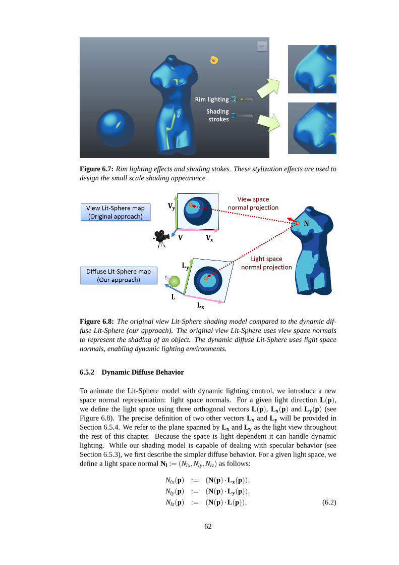
Figure 6.7: Rim lighting effects and shading stokes. These stylization effects are used todesign the small scale shading appearance.
Figure 6.8: The original view Lit-Sphere shading model compared to the dynamic dif-fuse Lit-Sphere (our approach). The original view Lit-Sphere uses view space normalsto represent the shading of an object. The dynamic diffuse Lit-Sphere uses light spacenormals, enabling dynamic lighting environments.
6.5.2 Dynamic Diffuse Behavior
To animate the Lit-Sphere model with dynamic lighting control, we introduce a newspace normal representation: light space normals. For a given light directionL(p),we define the light space using three orthogonal vectorsL(p), L x(p) andL y(p) (seeFigure 6.8). The precise definition of two other vectorsL x andL y will be provided inSection 6.5.4. We refer to the plane spanned byL x andL y as the light view throughoutthe rest of this chapter. Because the space is light dependent it can handle dynamiclighting. While our shading model is capable of dealing with specular behavior (seeSection 6.5.3), we first describe the simpler diffuse behavior. For a given light space, wedefine a light space normalNl := (Nlx,Nly,Nlz) as follows:
Nlx(p) := (N(p) ·L x(p)),
Nly(p) := (N(p) ·L y(p)),
Nlz(p) := (N(p) ·L(p)), (6.2)
62
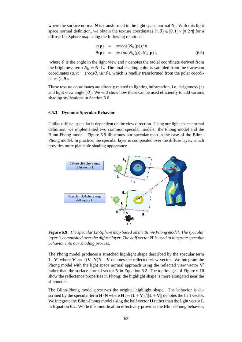
where the surface normalN is transformed to the light space normalNl . With this lightspace normal definition, we obtain the texture coordinates(r,θ) ∈ [0,1]× [0,2π] for adiffuse Lit-Sphere map using the following relations:
r(p) = arccos(Nlz(p))/π,θ(p) = arctan(Nly(p)/Nlx(p)), (6.3)
whereθ is the angle in the light view andr denotes the radial coordinate derived fromthe brightness termNlz = N ·L . The final shading color is sampled from the Cartesiancoordinates(u,v) = (rcosθ , rsinθ), which is readily transformed from the polar coordi-nates(r,θ).
These texture coordinates are directly related to lighting information, i.e., brightness(r)and light view angle(θ). We will show how these can be used efficiently to add variousshading stylizations in Section 6.6.
6.5.3 Dynamic Specular Behavior
Unlike diffuse, specular is dependent on the view direction. Using our light space normaldefinition, we implemented two common specular models: the Phong model and theBlinn-Phong model. Figure 6.9 illustrates our specular map in the case of the Blinn-Phong model. In practice, the specular layer is composited over the diffuse layer, whichprovides more plausible shading appearance.
Figure 6.9: The specular Lit-Sphere map based on the Blinn-Phong model. The specularlayer is composited over the diffuse layer. The half vectorH is used to integrate specularbehavior into our shading process.
The Phong model produces a stretched highlight shape described by the specular termL ·V′ whereV′ := 2(V ·N)N−V denotes the reflected view vector. We integrate thePhong model with the light space normal approach using the reflected view vectorV′
rather than the surface normal vectorN in Equation 6.2. The top images of Figure 6.10show the reflectance properties in Phong: the highlight shape is more elongated near thesilhouettes.
The Blinn-Phong model preserves the original highlight shape. The behavior is de-scribed by the specular termH ·N whereH := (L +V)/∥L +V∥ denotes the half vector.We integrate the Blinn-Phong model using the half vectorH rather than the light vectorLin Equation 6.2. While this modification effectively provides the Blinn-Phong behavior,
63
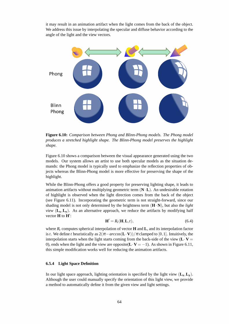
it may result in an animation artifact when the light comes from the back of the object.We address this issue by interpolating the specular and diffuse behavior according to theangle of the light and the view vectors.
Figure 6.10: Comparison between Phong and Blinn-Phong models. The Phong modelproduces a stretched highlight shape. The Blinn-Phong model preserves the highlightshape.
Figure 6.10 shows a comparison between the visual appearance generated using the twomodels. Our system allows an artist to use both specular models as the situation de-mands: the Phong model is typically used to emphasize the reflection properties of ob-jects whereas the Blinn-Phong model is more effective for preserving the shape of thehighlight.
While the Blinn-Phong offers a good property for preserving lighting shape, it leads toanimation artifacts without multiplying geometric term(N ·L). An undesirable rotationof highlight is observed when the light direction comes from the back of the object(see Figure 6.11). Incorporating the geometric term is not straight-forward, since ourshading model is not only determined by the brightness term(H ·N), but also thelightview (L x,L y). As an alternative approach, we reduce the artifacts by modifying halfvectorH to H′:
H′ = Rt(H,L , t), (6.4)
whereRt computes spherical interpolation of vectorH andL , and its interpolation factoris t. We definet heuristically as 2(π−arccos(L ·V))/π clamped to[0,1]. Intuitively, theinterpolation starts when the light starts coming from the back-side of the view (L ·V =0), ends when the light and the view are opposite(L ·V =−1). As shown in Figure 6.11,this simple modification works well for reducing the animation artifacts.
6.5.4 Light Space Definition
In our light space approach, lighting orientation is specified by the light view(L x,L y).Although the user could manually specify the orientation of this light view, we providea method to automatically define it from the given view and light settings.
64
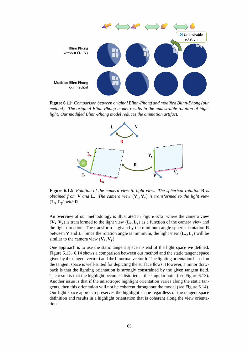
Figure 6.11: Comparison between original Blinn-Phong and modified Blinn-Phong (ourmethod). The original Blinn-Phong model results in the undesirable rotation of high-light. Our modified Blinn-Phong model reduces the animation artifact.
Figure 6.12: Rotation of the camera view to light view. The spherical rotationR isobtained fromV and L . The camera view(Vx,Vy) is transformed to the light view(L x,L y) with R.
An overview of our methodology is illustrated in Figure 6.12, where the camera view(Vx,Vy) is transformed to the light view(L x,L y) as a function of the camera view andthe light direction. The transform is given by the minimum angle spherical rotationRbetweenV andL . Since the rotation angle is minimum, the light view(L x,L y) will besimilar to the camera view(Vx,Vy).
One approach is to use the static tangent space instead of the light space we defined.Figure 6.13, 6.14 shows a comparison between our method and the static tangent spacegiven by the tangent vectort and the binormal vectorb. The lighting orientation based onthe tangent space is well-suited for depicting the surface flows. However, a minor draw-back is that the lighting orientation is strongly constrained by the given tangent field.The result is that the highlight becomes distorted at the singular point (see Figure 6.13).Another issue is that if the anisotropic highlight orientation varies along the static tan-gents, then this orientation will not be coherent throughout the model (see Figure 6.14).Our light space approach preserves the highlight shape regardless of the tangent spacedefinition and results in a highlight orientation that is coherent along the view orienta-tion.
65

Figure 6.13: Lighting orientation comparisons for symbolic highlight. Static tangentspace causes distortion near to the singular point at the pole. The light space preservesthe highlight shape regardless of the tangent space definition.
Figure 6.14: Lighting orientation comparisons for a long thin highlight. The highlightorientation varies along the static tangent direction. Employing the light space resultsin the coherent orientation along the view orientation.
6.6 Shading Stylizations: Transforming The Light Space Normals
In this section, we describe how to apply secondary stylizations to the designed shadingtones. Thanks to the light space representation of our Lit-Sphere extension, transforma-tion of the light space results in shading transformations. In the following sections, wedescribe how we can use such transformations to implement secondary stylizations.
66

6.6.1 Highlight Shape Transforms
To give users finer control over the highlight shape, we apply lighting transforms similarto those described in Section 5.5 and [4]. While these methods used a vector-field todeform the highlight shape, we can use simple texture transforms to achieve the sameeffects.
The texture transforms are designed as a composite transform functionA : [−1,1]×[−1,1]→ [−1,1]× [−1,1] for the texture coordinates(u,v) such that
A(u,v) := Ad(Ar(At(u,v))), (6.5)
whereAt is the translation operator,Ar is the rotation operator, andAd is the directionalscaling operator.
The translation operatorAt is defined by two parametersα andβ as follows:
At(u,v) := (u−α,v−β ). (6.6)
The rotation operatorAr is defined by one parameterφ as follows:
Ar(u,v) := (u,v)
cos(−φ) sin(−φ)
−sin(−φ) cos(−φ)
. (6.7)
The directional scaling operatorAd is defined by two parametersγ andδ as follows:
Ad(u,v) := (u/γ,v/δ ). (6.8)
Figure 6.15: Highlight shape transforms. Starting from the initial state in the leftmostimage, the highlight shape is deformed by the transform operations.
Figure 6.15 demonstrates how these operations deform the highlight shape. The pa-rameters are simple and straightforward so that the artist can adjust the highlight shapeintuitively.
6.6.2 Lighting Offset for Feature Enhancements
An artist can control and enhance the small-scale features using our lighting offset tech-nique. This process is illustrated in Figure 6.16. In a similar manner to the traditionalbump mapping process, the attribute valueh∈ [−1,1] is used to modify the brightnessvalue (specific examples ofh will be described later). Whenh is a maximum (h = 1)shading will be bright whereas at the minimum (h=−1) shading will be dark.
67

Figure 6.16: Lighting offset for feature enhancements. The original shading color issampled from the polar coordinates(r,θ). With the user-defined attribute value h, thecoordinate r is deformed to r′. Final shading is enhanced by the attribute with thedeformed polar coordinates(r ′,θ).
In contrast to bump mapping, our approach provides more direct control over the bright-ness value without transforming the surface normal vectors. Thanks to the light spacerepresentation of the texture coordinates(r,θ), we can modify the brightness value bydeforming the radial coordinater to r ′. For h = 0 (no offset), we use the coordinater ′ = r. For the brightest values (h= 1), we use the coordinater ′ = 0 corresponding tothe brightest point in the texture map. For the darkest values (h= −1), we use the co-ordinater ′ = 1 corresponding to the darkest point in the texture map. For intermediatevalues ofh, r ′ is interpolated according to
r ′ =
C(h,−1,0)(r −1)+1 (−1≤ h≤ 0)
(1−C(h,0,1))r (0≤ h≤ 1), (6.9)
whereC(x,a,b) ∈ [0,1] computes the interpolation term ofx ∈ R betweena ∈ R andb ∈ R. The functionC was a clamped cubic Hermite interpolation via the commonsmoothstepfunction, which is available as a built-in feature of most GPU shading lan-guages. Then the termr ′ in Equation 6.9 is used to sample the final shading color.
Using various choices ofh in Equation 6.9, we can easily specify different stylizations.In the following, we will present typical usages ofh to achieve rim lighting and shadingstrokes.
Rim lighting:
The rim lighting effect is the result of a light behind the objects. It results in a brightglow effect on the shading around silhouettes. We can implement such effects using the
68

facing ratio (N ·V) and defining the offsethr : S2×S2 → [−1,1]:
hr(N,V) := µC(|arccos(N ·V)|,η ,0), (6.10)
whereµ ∈ [−1,1] controls the brightness of the glow,η ∈ [0,π] is the size of the glowandC is the same cubic Hermite interpolation function as in Equation 6.9. Figure 6.17shows how different values ofµ andη allow an artist to design rim lighting appearances.With a largerη , the rim lighting effect becomes sharper. Note thatµ can be negative,which corresponds to darkening.
Figure 6.17: Rim lighting effects. By varyingµ andη , different rim lighting effects areobtained. The designed effects are seamlessly integrated with the original shading tones.
Shading strokes:
As shown in Figure 6.4, specifying the shading strokes directly in the Lit-Sphere mapmay result in shading artifacts. Therefore, we separate the shading strokes from theshading tones. We use a structured brush stroke texture maphs(s, t) ∈ [−1,1] for theshading stroke attribute, where(s, t) are the object space texture coordinates attached tothe model (see the middle image of Figure 6.16). By changing the structured texturemaps, we can combine various stroke styles with the original shading tones (see Fig-ure 6.18). In contrast to the original Lit-Sphere approach, our shading strokes maintaincoherent motion using the object space textures as demonstrated in Section 6.8.
Figure 6.18: Shading stroke variation. By changing the structured brush stroke texturemaps, various shading stroke styles can be designed.
6.7 Implementation
To integrate the proposed methods into existing 3D shading design process, we imple-mented our Lit-Sphere extension as a Maya plug-in.
69

GPU Shading Process
To perform the rendering process at interactive rate, our rendering algorithms were im-plemented using a CgFX shader that allows to design a custom GPU shading process.The diffuse and specular Lit-Sphere maps are stored into 2D textures, which are ref-erenced in the shading process. In our GPU program, most of the shading processare computed in the pixel shader, including the secondary stylization (highlight shapetransforms and lighting offset). We use additional 2D brush stroke textures for shadingstrokes, which is assigned to the object space texture coordinates.
Lit-Sphere Painting on A Reference Sphere
Separately from the GPU shading process, we use a CPU-based Maya painting mecha-nism for our painting process for Lit-Sphere maps. Our system dynamically updates theper-vertex texture coordinates of a reference sphere when the light and the view change.The computational cost depends on the number of vertices of the reference sphere. Sincewe do not need a highly tesselated sphere in practice, this computation is not a seriousbottleneck in our system. In making examples, we used the reference sphere with 1000vertices for our Lit-Sphere painting.
6.8 Results
We have applied our prototype system to designing various artistic shading styles. Inmaking the following examples, our system enables interactive shading design withNVIDIA Quadro 600 (more than 30fps for our examples). A variety of shading stylesare achievable by combining all of the system features (see Figure 6.19). These shadingstyles can be dynamically controlled by a light source with coherent shading behaviorover time. In the following, we describe in more detail how we can achieve the typicalshading styles.
Typical artwork shading styles can be obtained by combining a few stepped shadingtones and simple stylization effects. In Figure 6.20, we demonstrate the use of ourshading model to achieve a minimal shading style similar to the illustration in [40].We used simple black and white colors for the shading tones, and then applied shadingstrokes to enhance the surface features.
A more complex illustrative shading style is shown in Figure 6.21, which is obtainedby layering diffuse and specular components. To create this style, we applied highlightshape transforms to adjust the size and location of the highlight areas. As shown in thefigure, our shading model results in coherent transitions while maintaining the secondarystylizations.
A stylized metallic appearance can be designed using complex reflection patterns. Thisis illustrated in Figure 6.22, where we designed multiple long thin highlights to generatea gold appearance. Our shading model can animate anisotropic diffuse and specularshading, whereas this type of shading property would be hardly designed with existingstylized rendering techniques.
Figure 6.23 shows the use of our technique with an animated object with a deformingcape. Strong deformations of an object can often result in a lack of coherence of thestylization. The animation in the figure shows that our techniques effectively createcoherent motion using the object space structured texture.
70
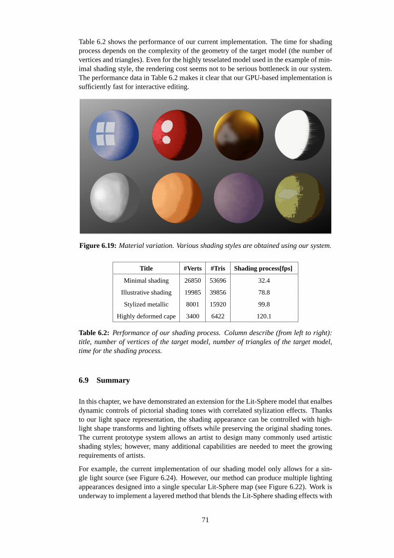
Table 6.2 shows the performance of our current implementation. The time for shadingprocess depends on the complexity of the geometry of the target model (the number ofvertices and triangles). Even for the highly tesselated model used in the example of min-imal shading style, the rendering cost seems not to be serious bottleneck in our system.The performance data in Table 6.2 makes it clear that our GPU-based implementation issufficiently fast for interactive editing.
Figure 6.19: Material variation. Various shading styles are obtained using our system.
Title #Verts #Tris Shading process[fps]
Minimal shading 26850 53696 32.4
Illustrative shading 19985 39856 78.8
Stylized metallic 8001 15920 99.8
Highly deformed cape 3400 6422 120.1
Table 6.2: Performance of our shading process. Column describe (from left to right):title, number of vertices of the target model, number of triangles of the target model,time for the shading process.
6.9 Summary
In this chapter, we have demonstrated an extension for the Lit-Sphere model that enalbesdynamic controls of pictorial shading tones with correlated stylization effects. Thanksto our light space representation, the shading appearance can be controlled with high-light shape transforms and lighting offsets while preserving the original shading tones.The current prototype system allows an artist to design many commonly used artisticshading styles; however, many additional capabilities are needed to meet the growingrequirements of artists.
For example, the current implementation of our shading model only allows for a sin-gle light source (see Figure 6.24). However, our method can produce multiple lightingappearances designed into a single specular Lit-Sphere map (see Figure 6.22). Work isunderway to implement a layered method that blends the Lit-Sphere shading effects with
71

Our result
Figure 6.20: Minimal shading style.
the brightness term of each light source to give artists more direct control with multiplelight sources.
Another limitation of the current implementation is that our shading strokes only provideindirect control whereas an artist may want to directly design brush strokes over theshading tones (see Figure 6.25). Therefore, integrating more direct inverse stylizationmethods [49] [109] into our system is an area for future direction.
A promising avenue would be dynamic control of brush stroke styles, taking into accountthe temporal coherence. In our approach, we can obtain coherent shading strokes dueto the fixed stroke placement using the object space texture coordinates. Therefore, thestroke placement itself is static during animation. Integrating the recent temporally co-herent Image Analogy technique [13] might be helpful for establishing an artist-friendlybrush stroke control.
Since these demands depend on the range of shading styles and control that artists maywant, we plan to conduct extensive user feedback investigations to target areas whereadditional functionality is desired, as well as ways to improve both effectiveness andusability of our work.
72
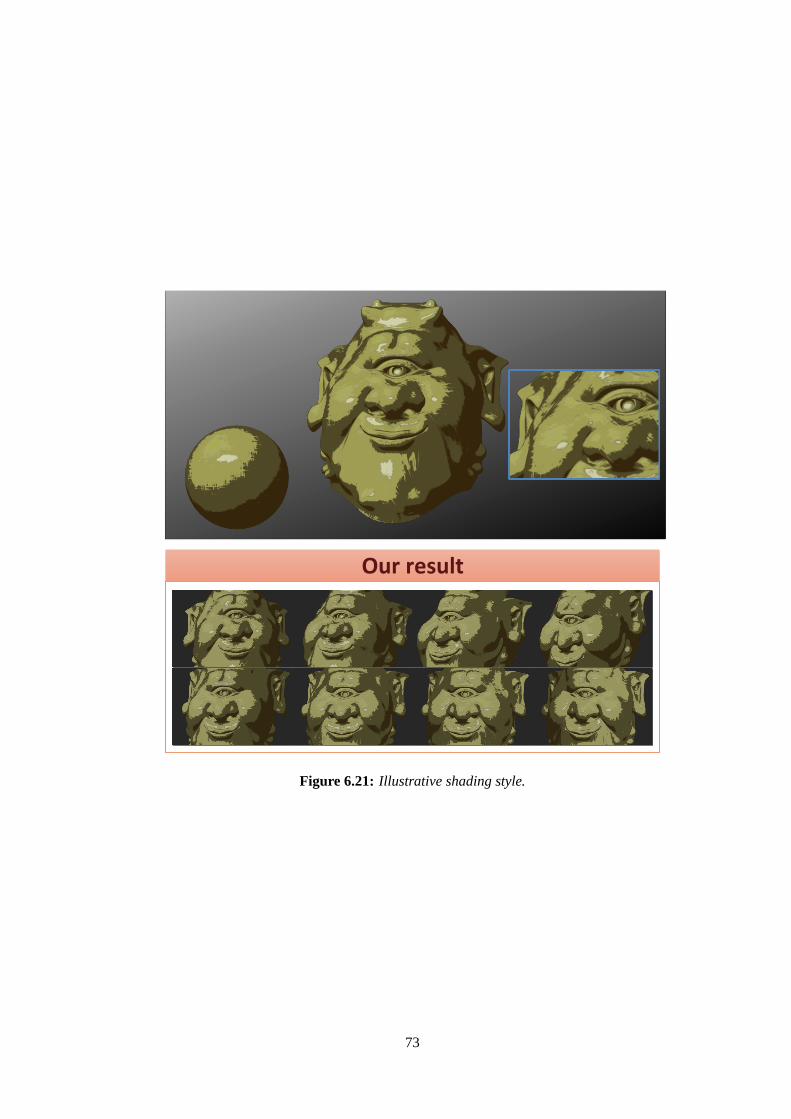
Our result
Figure 6.21: Illustrative shading style.
73
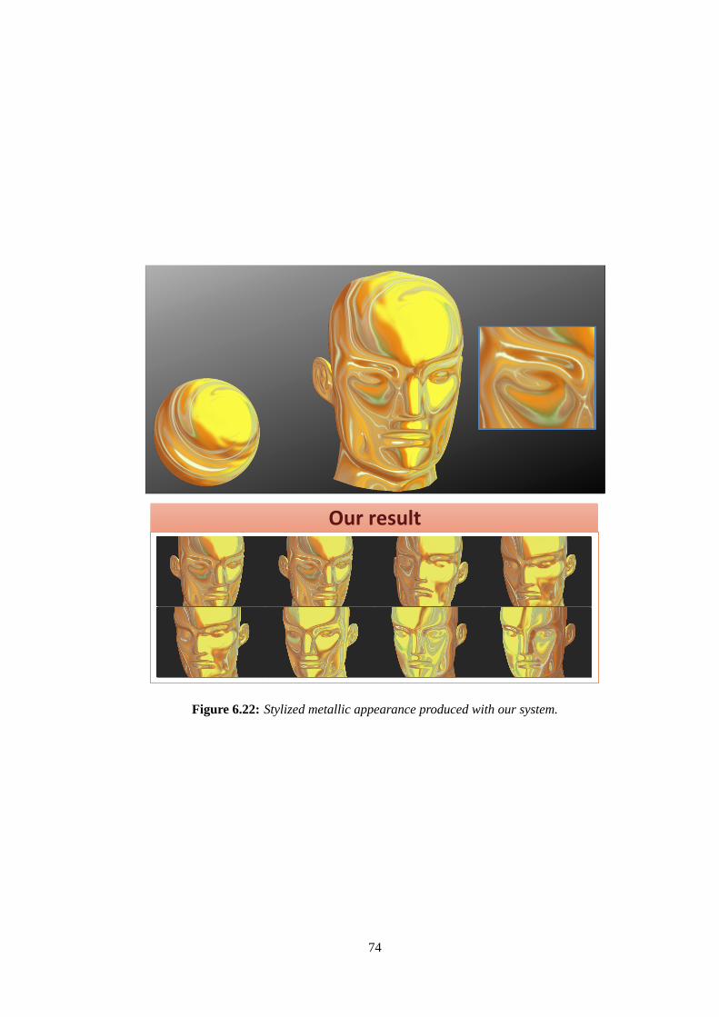
Our result
Figure 6.22: Stylized metallic appearance produced with our system.
74
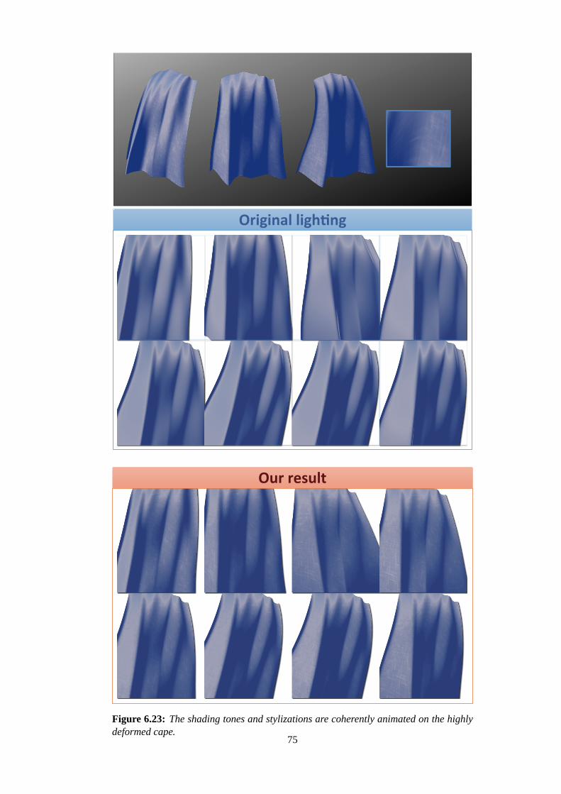
Our result
Original lighting
Figure 6.23: The shading tones and stylizations are coherently animated on the highlydeformed cape.
75

Figure 6.24: Limitation 1: our shading model is limited to single light source.
Figure 6.25: Limitation 2: our shading model does not permit direct shading design ona target model.
76

Chapter 7
Discussions
In this chapter, we examine the capabilities of the three methods proposed in this thesis,clarifying their strengths and weaknesses. Figure 7.1 summarizes our methods from theperspective of the proposed framework. Depending on the level of the design process,we introduced appropriate directable shading models that are seamlessly integrated intoexisting 3D lighting controls.
Principle 1: For the directable shading models, we use three kinds of mechanisms:lighting offset, lighting transform, and 2D color mapping. The lighting offset offers thesmallest scale control by directly modifying the brightness term. The lighting transformprovides larger scale control over the shape of the lights. The 2D color mapping providesthe largest scale control of the overall shading than the previous two mechanisms.
Principle 2: Our systems make use of these directable mechanisms with existing 3Dlighting controls. Multiple light sources can be used with both the lighting offset and thelighting transform since the both methods are applied to the variables used for lightingcomputation. On the other hand, we reformulated the entire lighting computation in thecase of 2D color mapping. Our reformulation provides expressive shading appearanceat the expense of limiting the control to a single light source.
In the following sections, we make detailed comparisons of three directable mechanisms.
Figure 7.1: Summary of our methods for an artist-friendly shading design system.
77

7.1 Comparison of 1D Color Mapping and 2D Color Mapping
We have demonstrated how our methods achieve expressive shading appearance. We usetwo types of color mapping for our shading models. The first is 1D color mapping usedin Chapters 4 and 5. The second is 2D color mapping used in Chapter 6.
Figure 7.2 shows a comparison of these methods. With 1D color mapping, we simply usethe computed brightness as the input of the color mapping function. Since the brightnessdistribution is determined by the angle between the surface normal vector and the lightvector (or the half vector for specular effects), the final shading colors are distributed ina circular shape (top row of Figure 7.2).
With 2D color mapping, the 2D Lit-Sphere maps are projected onto the target 3D modelbased on light space normals. Since the projection coordinates are defined by light spacenormals, this shading model allows the artist to design normal-dependent shading styles.The bottom row of Figure 7.2 illustrates how 2D color mapping is effective for emulatingmultiple lighting appearance.
In summary, 1D color mapping is limited to simple shading appearance, according tothe brightness distribution. On the other hand, 2D color mapping enables a normal-dependent color distribution, which produces more expressive shading styles.
Figure 7.2: Comparison of 1D and 2D color mapping. (Top row) 1D color mappingproduces circular tone distributions. (Bottom row) 2D color mapping allows the artistto design more complex normal-dependent tone distributions.
7.2 Comparison of Lighting Transform and Lighting Offset
To change the shape of lighting, we use two types of directable lighting mechanisms:lighting transform and lighting offset. Figure 7.3 shows operation examples edited bythese lighting shape control mechanisms. In the second system (Chapter 5), lighting
78

transform functions are used to change the round shape of lighting. Edge lighting offsetsprovide a more local control over the shape of lighting based on specific model features.In the first system (Chapter 4), local lighting offsets are calculated based on user pain-ing operations, which enables fine-tuning of the lighting shape. In the following, wecompare these lighting shape control mechanisms with simple operation examples.
Figure 7.3: Operation example of lighting shape controls. Starting from the initial stateobtained with a point light source in the leftmost image, the lighting shape is deformedby our lighting shape control mechanisms.
Figure 7.4 compares lighting transform and lighting offset for the case where a straightlighting effect (lighting transform) is approximated by lighting offsets. For the compar-ison, we begin with a simple flat surface illuminated by a point light source (first row).The second row shows the ground truth for a straight lighting effect, where the lightingtransform function is applied to the light vector of original lighting result. The third rowshows an approximation of the straight lighting result by the offset function, using 10key offset data calculated from the differences between the original lighting and straightlighting results. 5 in-between frames shown in the third row were interpolated from thekey offset data. The fourth row of illustrates the regions where the lighting offset errorsare larger than 0.04. The red regions show positive errors and the blue region show nega-tive errors. We can observe that the red regions are caused by insufficient blended offsetdata, where the brightness values are less than those of the lighting transform result. Theblue regions are caused by the original lighting distributions, where the strong circularlights are placed near the blue regions.
Table 7.1 summarizes the maximum lighting offset errors of in-between frames withvarious numbers of key offset data. We observed that the quality of the lighting offsetsdepended heavily on the number of key offset data used. Even for this simple model, 10key offset data were insufficient to approximate the straight lighting result. To obtain asmooth flow of the straight lighting effect, we needed at least 40 key offset data. Thismeans that use of the offset function requires numerous time-consuming paint operationsto obtain a straight lighting effect. Therefore, the lighting transform approach is moresuitable for a straight lighting effect.
On the other hand, the lighting offsets cannot be fully replaced by lighting transforms. Indesigning the shading for cartoon animation, it is often necessary to adjust the lightingin local areas in addition to adjusting the overall lighting shape. Figure 7.3 illustratessuch an example where we used the edge and local lighting offsets for fine-tuning. Thisis easily designed by using the lighting offset approach which enables local lightingeffects. However, it is difficult to design such local lighting effects using the lightingtransform approach since it is limited to simple controls using its pre-defined transforms.Therefore, integration of these two approaches are desirable.
79
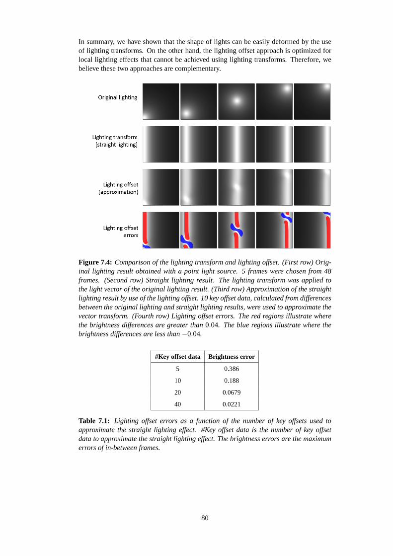
In summary, we have shown that the shape of lights can be easily deformed by the useof lighting transforms. On the other hand, the lighting offset approach is optimized forlocal lighting effects that cannot be achieved using lighting transforms. Therefore, webelieve these two approaches are complementary.
Figure 7.4: Comparison of the lighting transform and lighting offset. (First row) Orig-inal lighting result obtained with a point light source. 5 frames were chosen from 48frames. (Second row) Straight lighting result. The lighting transform was applied tothe light vector of the original lighting result. (Third row) Approximation of the straightlighting result by use of the lighting offset. 10 key offset data, calculated from differencesbetween the original lighting and straight lighting results, were used to approximate thevector transform. (Fourth row) Lighting offset errors. The red regions illustrate wherethe brightness differences are greater than0.04. The blue regions illustrate where thebrightness differences are less than−0.04.
#Key offset data Brightness error
5 0.386
10 0.188
20 0.0679
40 0.0221
Table 7.1: Lighting offset errors as a function of the number of key offsets used toapproximate the straight lighting effect. #Key offset data is the number of key offsetdata to approximate the straight lighting effect. The brightness errors are the maximumerrors of in-between frames.
80
7.3 Comparison of Lighting Offset Spaces
In our shading models, the lighting offset functions are designed for different spaces.In this section, we compare two representative examples: a local lighting offset definedon a local area of a surface (Chapter 4) and an edge lighting offset defined in an edgefeature space (Chapter 5).
Figure 7.5 compares an edge enhancement that was controlled by using these two ap-proaches. Similar to the previous section, we first introduced a ground truth result andthen we approximated it. The first row shows the original lighting result obtained usingthe lighting transform to simulate a straight lighting effect. The second row shows theground truth result, in which the edge enhancement was controlled by the edge light-ing offset function defined in the edge distance field. This animation was quite simple,created from three key-frames using the edge lighting offset parameters. We then ap-proximated this operation by using local lighting offsets defined on a local area of asurface. The third row shows 5 in-between frames interpolated from the key offset data.The fourth row of Figure 7.5 illustrates the regions where the local offset function errorsare greater than 0.02.
Table 7.2 lists the local lighting offset errors as a function of the number of key off-set data. Compared to the result in the previous section, the approximation errors arerelatively small. We observed that 10 key offset data provided a visually sufficient ap-proximation. However, we still needed a greater number of key offset data than thenumber of key-frames for the edge function. Also, the continuous change of the edgeappearance would not be possible with a paint operation. Therefore, a specific modelfeature is better enhanced by a suitable lighting offset function defined in the modelfeature space.
On the other hand, local lighting offsets are still required for designing an arbitraryshape. Figure 7.3 illustrates such an example, where we used the local lighting offsetsto adjust a small portion of the lighting shape. This could be easily achieved by a locallighting offset function constructed from a paint operation, whereas the offset functionbased on model features would be insufficient for representing the arbitrary shape be-yond the limited feature space. Therefore, local lighting offsets cannot be replaced by alighting offset based on a specific model feature.
In summary, enhancing an edge by using an offset function benefits by defining theoffset function in a suitable model feature space. On the other hand, a local lightingoffset function is still the most effective for designing an arbitrary shape. Both types oflighting offsets are desirable as directable controls.
#Key offset data Brightness error
5 0.3743
10 0.1304
20 0.0386
40 0.0104
Table 7.2: Local lighting offset errors as a function of the number of key offset data usedto approximate the edge enhancement. #Key offset data is the number of key offset datato approximate the ground truth data. The brightness errors are the maximum errors ofin-between frames.
81

Figure 7.5: Comparison of different lighting offset definitions. (First row) Originallighting result obtained using a straight lighting effect. 5 frames were chosen from 48frames. (Second row) Edge enhancement result. Edge lighting offset function applied tothe original lighting result. (Third row) Approximation of the edge enhancement resultby use of the local lighting offset. 10 key offset data, calculated from differences be-tween the original lighting and edge enhancement results, were used to approximate theedge lighting offset function. (Fourth row) Local lighting offset errors. The red regionsillustrate where the brightness errors are greater than0.02.
7.4 Summary
In this chapter, we examined the capabilities of three directable mechanisms: 2D colormapping, lighting transform, and lighting offset. Each directable shading mechanism hasa different degree of controllability. The comparisons in this chapter are summarized asfollows:
• The 2D color mapping better emulates a complex color distribution better than the1D color mapping, but it cannot be used with multiple light sources.
• The lighting transform is suitable for changing the overall shape of lighting than isthe lighting offset, but it cannot give a local lighting effect like the lighting offset.
• The lighting offset function defined in a model feature space provides better con-trollability for a specific model feature than a lighting offset function defined onthe local area of the surface, but it cannot be used to create an arbitrary lightingshape through a paint operation.
From these comparisons, we found that each directable shading mechanism is effectivefor a specific design target and complementary to other directable mechanisms. Thissuggests that our directable shading mechanisms are well-designed with suitable controlsfor each shading design target.
82

Chapter 8
Conclusion
In this chapter, we conclude the thesis by first summarizing our contributions, then dis-cussing the limitations of our methods, and finally describing some possible directionsfor future research.
8.1 Summary of Contributions
In this thesis, we focused on how to improve the design process of stylized shading in3D animations. We found that existing approaches for shading design are difficult touse intuitively and lack dynamic controls over the shading appearance. In many cases,the existing stylized rendering methods are insufficient to meet the demands of artists.Therefore, the artist must spend substantial time developing work-arounds, which onlywork in special cases. To address this problem, we proposed a new framework,inte-gration of artistic depictions with physics-based lighting, for designing an artist-friendlystylized shading model and interface. The framework is based on the following twoprinciples.
• Principle 1: Directable shading model for artistic control. We simplified diffi-cult shading design process by introducing appropriate shading models that allowartistic control. Our shading models provide artists with not only easy and intu-itive user interfaces but also interactive and dynamic controls, which are essentialfor the animation design process.
• Principle 2: Seamless integration with 3D lighting. The proposed shading mod-els are carefully designed to be seamlessly integrated into existing 3D lightingcontrols. This allows artists to efficiently create animation with the desired shad-ing appearances through use of 3D scene elements (models, lights, and cameras),with which they are already familiar.
To verify the effectiveness of this artist-friendly framework for stylized shading design,we provided three interactive systems that are appropriate for different levels of the de-sign process, from small scale to large scale. We explored the capabilities of thesesystems to improve the stylized shading design in production work. These interactivesystems are as follows.
• Locally controllable shading with intuitive paint interface (small scale). First,we presented a 3D stylized shading system for adding local light and shade usingpaint operations. The basic idea behind locally controllable shading is to modifythe brightness term directly, by adding a lighting offset function. With the light-ing offset, obtained from the painted area, our shading model provides additional
83
flexibility for changing an animated character’s appearance. The proposed offsetfunction mechanism is consistent and seamlessly integrated into the commonlyused 3D lighting process, including multiple light sources and different types oflights (directional lights, points lights, and spot lights). We demonstrated with an-imation examples how our method allows the artists to design the desired shadingappearance in making 3D animation.
• Shading stylization based on model features(middle scale). Our first systempermitted only local control using a paint operation, which is not suitable for de-signing lighting enhancement of a specific feature of a model. Our second systemprovided easy and intuitive controls for such practical requirements. This methoduses a lighting transforms to design a straight lighting effect. This effect can be en-hanced by the edge enhancement and the detail lighting effect, which are providedthrough lighting offset functions defined in the feature spaces. These methods areseamlessly integrated into 3D lighting, with one exception: point lights must useour straight light functions. Even with this limitation, our animation examplesdemonstrate that artists can design commonly used feature enhancements.
• Practical shading model for expressive shading styles(large scale). This systemfocuses on the overall shading appearance, whereas the first and second systemsare limited to simple shading tones of the conventional cartoon shading process.As an extension of the Lit-Sphere model, our shading model enables more ex-pressive 2D shading tones for diffuse and specular effects. For control of lightshape and correlated lighting effects, we reintroduced the lighting transforms andthe lighting offsets in a manner that is suitable for a 2D color map representa-tion of the shading model. Although this shading model allows for only a singlelight source, our animation examples demonstrate that the system is effective fordesigning many commonly used artistic styles.
We carefully designed these systems to fulfill the requirement of the proposed frame-work: integration of artistic depictions with physics-based lighting. Our systems allowthe artists to design their expressive shading styles using an intuitive editing process,which would be difficult to accomplish by using only existing lighting controls or con-ventional stylized shading systems. In addition, the designed shading appearance isdynamically controlled, and seamlessly integrated into the 3D lighting. This provides aflexible and efficient shading design process. All of the animation examples designedusing our systems indicate the effectiveness of the framework.
8.2 Limitations
While the proposed systems provide directable and efficient shading design mechanisms,our methods are still inadequate to fulfill the growing demands of artists.
For example, most of the stylized rendering using our methods is limited to shadingeffects. Our shading model cannot handle stroke-based rendering, which is used in manypainterly rendering techniques (Figure 8.1). In our shading model, we have focused onproviding directable controls for creating commonly desired shading. Our extensions arerelatively small because we wanted to maintain the integration with the usual 3D lightingprocess. The lighting transforms and the lighting offset of our methods can handle onlyshape controls. Even our Lit-Sphere extension, which enables effective shading strokesfor brush stroke styles, is still limited to shading effects.
On the other hand, typical painterly rendering methods can deal with overlapped strokes
84

Overlapped brush strokes in painterly renderingOur result
Figure 8.1: Limitation of our brush stroke styles. (Left) Brush stroke style obtainedby using our approach. (Right) Overlapped brush stroke styles taken from painterlyrendering methods. Our approach, while effective for emulating brush strokes, cannotfully support these kinds of overlapped brush stroke styles.
to emulate brush-based artistic styles. Each stroke placement is defined by various prop-erties: camera-space positions, user-defined density parameters, and brightness terms.These properties are also used to specify the color and the size of the brush strokes,which adjusts the painterly rendering style. In stroke-based rendering methods, shadingis only one element that defines a brush stroke style, therefore it would be difficult tohandle such stroke-based rendering styles using only our shading-based approach.
Another limitation is that our methods cannot deal with extreme changes form the initiallighting conditions. As discussed in Chapter 7, each directable shading mechanism hasa different degree of controllability; thus, each must be carefully controlled in an appro-priate manner that is suitable for each shading design requirement. Our shading controlmechanisms, including the initial lighting, cannot be replace one other.
In summary, most styles designed using our systems are limited to shading effects, whichare based on the commonly used shading models: cartoon shading and the the Lit-Sphereshading. Stroke-based rendering styles like those in painterly rendering systems wouldbe difficult to model in our system, even with our extension of the Lit-Sphere. Oursystems require appropriate controls of each shading mechanism to benefit from thecapabilities of the proposed methods. Exploring the shading styles and control thatartists want is essential for further improving both the effectiveness and usability ofour artist-friendly framework.
8.3 Future Directions
In this thesis, we have focused on establishing an artist-friendly framework that is basedon the integration of artistic depictions with physics-based lighting. Exploring a well-designed artist-friendly framework opens up several interesting avenues for future re-search in stylized rendering and its applications.
8.3.1 Example-based Shading Model from Painted Artwork
In the future, we would like to integrate more advanced example-based techniques intoour shading models. In this thesis, we demonstrated that our methods provide control-lability to obtain desired shading with suited design process. Although these directablemechanisms are effective for changing the designed shading appearance, artists maywant a more rapid prototyping of shading style in the early stage.
85

Kulla et al. [49] and and Yen et al. [109] used manually painted examples to extractshading models for their painterly rendering styles. Their key idea was to separate brushstrokes from shading tones. We could use a similar approach for our Lit-Sphere-basedshading representation. For other lighting effects using our shading models, the learningapproach used for pen-and-ink illustrations [46] might be appropriate. In their approach,painting examples are analyzed with a focus on line-drawing style. If, in the future,these kinds of example-based techniques are combined with our directable mechanisms,artists would be able to obtain a desired shading style more quickly.
8.3.2 Applying the Framework to Different Stylized Rendering Elements
Another direction for future research is to apply our artist-friendly design framework toother stylized rendering elements. In this thesis, we dealt only with two key stylizedrendering elements: diffuse shading and specular highlights. It would be desirable tointegrate directable mechanisms into other stylized rendering elements, such as shadowsand contours.
One possible idea is to reintroduce models of shadows and contours using the same ap-proach of our lighting transforms and offset functions. However, the models would needto handle discontinuous occlusions. It is very challenging to establish temporally coher-ent directable mechanisms against discontinuous properties. Our approach described inthis thesis will provide a good start point for such further researches.
8.3.3 Stylized Control for Realistic Shading
In this thesis, we focused on designing stylized shading styles, mainly for cartoon shad-ing. We believe that our stylized shading design methods are also useful for more re-alistic shading styles. One possible application is Hollywood cartoon animation films,where 3D characters are commonly designed with realistic shading styles, that clearlyrequire directable artistic depictions.
For example, Disney explored physically-based shading techniques for their realisticshading styles [54, 62, 77]. It would be an interesting challenge to integrate our di-rectable shading mechanisms into such realistic shading styles for further fine-tuning.We believe it is essential to pursue a well-designed artist-friendly system to make signif-icant contributions to the improvement of the shading design process in production workas well as to the progress of rendering techniques for artists.
86

References
[1] Miika Aittala, Tim Weyrich, and Jaakko Lehtinen. Practical svbrdf capture in thefrequency domain.ACM Transactions on Graphics., 32(4):110:1–110:12, July2013.
[2] David Akers, Frank Losasso, Jeff Klingner, Maneesh Agrawala, John Rick, andPat Hanrahan. Conveying shape and features with image-based relighting. InProceedings of IEEE Visualization 2003, pages 349–354, 2003.
[3] Ken Anjyo, Hideki Todo, and J. P. Lewis. A practical approach to direct manipu-lation blendshapes.J. Graphics, GPU, & Game Tools, 16(3):160–176, 2012.
[4] Ken Anjyo, Shuhei Wemler, and William Baxter. Tweakable light and shade forcartoon animation. InProceedings of NPAR 2006, pages 133–139, 2006.
[5] Ken-ichi Anjyo and Katsuaki Hiramitsu. Stylized highlights for cartoon renderingand animation.IEEE Comput. Graph. Appl., 23(4):54–61, July 2003.
[6] Michael Ashikhmin and Peter Shirley. An anisotropic phong brdf model.J.Graphics. Tools, 5(2):25–32, February 2000.
[7] Michael Ashikmin, Simon Premoze, and Peter Shirley. A microfacet-based brdfgenerator. InProceedings of SIGGRAPH 2000, pages 65–74, New York, NY,USA, 2000. ACM Press/Addison-Wesley Publishing Co.
[8] Autodesk, Inc. Autodesk 3ds max.http://www.autodesk.com/products/autodesk-3ds-max.
[9] Autodesk, Inc. Autodesk maya.http://www.autodesk.com/products/autodesk-maya.
[10] Autodesk, Inc. Autodesk softimage.http://www.autodesk.com/products/autodesk-softimage.
[11] Pascal Barla, Joelle Thollot, and Lee Markosian. X-Toon: an extended toonshader. InProceedings of NPAR 2006, pages 127–132, 2006.
[12] Pierre Benard, Adrien Bousseau, and Joelle Thollot. Dynamic solid textures forreal-time coherent stylization. InProceedings of the 2009 symposium on Interac-tive 3D graphics and games (I3D 2009), pages 121–127, New York, NY, USA,2009. ACM.
[13] Pierre Benard, Forrester Cole, Michael Kass, Igor Mordatch, James Hegarty, Mar-tin Sebastian Senn, Kurt Fleischer, Davide Pesare, and Katherine Breeden. Styl-izing animation by example.ACM Transactions on Graphics. (Proceedings ofSIGGRAPH 2013), 32(4):119:1–119:12, July 2013.
[14] Pierre Benard, Ares Lagae, Peter Vangorp, Sylvain Lefebvre, George Drettakis,and Joelle Thollot. A dynamic noise primitive for coherent stylization.Com-
87

puter Graphics Forum (Proceedings of the Eurographics Symposium on Render-ing 2010), 29(4):1497–1506, june 2010.
[15] J. Blinn. Models of light reflection for computer synthesized pictures.ComputerGraphics, 11(2):192–198, 1977.
[16] James F. Blinn. Simulation of wrinkled surfaces.Proceedings of SIGGRAPH1978, 12(3):286–292, 1978.
[17] Stefan Bruckner and Meister Eduard Groller. Style transfer functions for illustra-tive volume rendering.Computer Graphics Forum. (Proceedings of Eurographics2007), 26(3):715–724, 2007.
[18] Michael Bunnell. Dynamic ambient occlusion and indirect lighting. InGPUGems 2. Addison-Wesley, 2005.
[19] Capcom Co., Ltd. Okami, 2006, 2012.http://www.capcom.co.jp/o-kami/.
[20] Jung-Ju Choi and Hwan-Jik Lee. Rendering stylized highlights using projectivetextures.Visual Computer, 22(9):805–813, September 2006.
[21] A.N.M. Imroz Choudhury and Steven G. Parker. Ray tracing npr-style featurelines. In Proceedings of NPAR 2009, pages 5–14, New York, NY, USA, 2009.ACM.
[22] Mark Colbert, Sumanta Pattanaik, and Jaroslav Krivanek. Brdf-shop: Creatingphysically correct bidirectional reflectance distribution functions.IEEE Comput.Graph. Appl., 26:30–36, January 2006.
[23] R. L. Cook and K. E. Torrance. A reflectance model for computer graphics.ACMTransactions on Graphics., 1(1):7–24, January 1982.
[24] Robert L. Cook. Shade trees. InProceedings of SIGGRAPH 1984, pages 223–231, New York, NY, USA, 1984. ACM.
[25] Eric Daniels. Deep canvas in disney’s tarzan. InACM SIGGRAPH 99 Conferenceabstracts and applications, pages 200–, New York, NY, USA, 1999.
[26] Paul Debevec, Tim Hawkins, Chris Tchou, Haarm-Pieter Duiker, WestleySarokin, and Mark Sagar. Acquiring the reflectance field of a human face. InProceedings of SIGGRAPH 2000, pages 145–156, New York, NY, USA, 2000.ACM Press/Addison-Wesley Publishing Co.
[27] Doug DeCarlo, Adam Finkelstein, Szymon Rusinkiewicz, and Anthony Santella.Suggestive contours for conveying shape.ACM Transactions on Graphics. (Pro-ceedings of SIGGRAPH 2003), 22(3):848–855, July 2003.
[28] Christopher DeCoro, Forrester Cole, Adam Finkelstein, and SzymonRusinkiewicz. Stylized shadows. InProceedings of NPAR 2007, pages 77–83,New York, NY, USA, 2007. ACM.
[29] Oliver Deussen, Stefan Hiller, Cornelius van Overveld, and Thomas Strothotte.Floating points: A method for computing stipple drawings.Computer GraphicsForum, 19:40–51, 2000.
[30] Oliver Deussen and Thomas Strothotte. Computer-generated pen-and-ink illus-tration of trees. InProceedings of SIGGRAPH 2000, pages 13–18, New York,NY, USA, 2000. ACM Press/Addison-Wesley Publishing Co.
88

[31] Yue Dong, Jiaping Wang, Xin Tong, John Snyder, Yanxiang Lan, Moshe Ben-Ezra, and Baining Guo. Manifold bootstrapping for svbrdf capture.ACM Trans-actions on Graphics. (Proceedings of SIGGRAPH 2010), 29(4):98:1–98:10, July2010.
[32] Craig Donner, Jason Lawrence, Ravi Ramamoorthi, Toshiya Hachisuka, Hen-rik Wann Jensen, and Shree Nayar. An empirical bssrdf model.ACM Transactionson Graphics. (Proceedings of SIGGRAPH 2009), 28(3):30:1–30:10, July 2009.
[33] J. Duchon. Splines minimizing rotation-invariant semi-norms in sobolev spaces.In Constructive Theory of Functions of Several Variables number 571 in LectureNotes in Mathematics, pages 85–100. Springer-Verlag, 1977.
[34] Frdo Durand, Victor Ostromoukhov, Mathieu Miller, Francois Duranleau, andJulie Dorsey. Decoupling strokes and high-level attributes for interactive tradi-tional drawing. InProceedings of Eurographics Workshop on Rendering Tech-niques, pages 71–82, London, 2001. Springer.
[35] Robert W. Floyd and Louis Steinberg. An Adaptive Algorithm for SpatialGreyscale. InProceedings of the Society for Information Display, volume 17,pages 75–77, 1976.
[36] Bruce Gooch and Amy Gooch.Non-Photorealistic Rendering. AK Peters Ltd,2001.
[37] Bruce Gooch, Peter-Pike J. Sloan, Amy Gooch, Peter Shirley, and RichardRiesenfeld. Interactive technical illustration. InProceedings of I3D 1999, pages31–38, New York, NY, USA, 1999. ACM.
[38] Pat Hanrahan and Wolfgang Krueger. Reflection from layered surfaces due tosubsurface scattering. InProceedings of SIGGRAPH 1993, pages 165–174, NewYork, NY, USA, 1993. ACM.
[39] Aaron Hertzmann and Denis Zorin. Illustrating smooth surfaces. InProceed-ings of SIGGRAPH 2000, pages 517–526, New York, NY, USA, 2000. ACMPress/Addison-Wesley Publishing Co.
[40] Burne Hogarth.Dynamic Light and Shade. Watson-Guptill, 1991.
[41] Piti Irawan and Steve Marschner. Specular reflection from woven cloth.ACMTransactions on Graphics. (Proceedings of SIGGRAPH 2012), 31(1):11:1–11:20,February 2012.
[42] Tilke Judd, Fredo Durand, and Edward Adelson. Apparent ridges for line draw-ing. ACM Transactions on Graphics. (Proceedings of SIGGRAPH 2007), 26(3),July 2007.
[43] Kaikai Kiki Co., Ltd. Kaikai&Kiki, 2008.
[44] R.D. Kalnins, L. Markosian, B.J. Meier, M.A Kowalski, J.C. Lee, P.L. Davivn,M.Webb, J.F. Hughes, and A. Finkelstein. WYSIWYG NPR: drawing strokesdirectly on 3D models.ACM Transactions on Graphics. (Proceedings of SIG-GRAPH 2002), 21(3):755–762, 2002.
[45] Robert D. Kalnins, Philip L. Davidson, Lee Markosian, and Adam Finkelstein.Coherent stylized silhouettes.ACM Transactions on Graphics. (Proceedings ofSIGGRAPH 2003), 22(3):856–861, July 2003.
89

[46] Evangelos Kalogerakis, Derek Nowrouzezahrai, Simon Breslav, and Aaron Hertz-mann. Learning hatching for pen-and-ink illustration of surfaces.ACM Transac-tions on Graphics., 31(1):1:1–1:17, February 2012.
[47] Michael Kass and Davide Pesare. Coherent noise for non-photorealistic render-ing. ACM Transactions on Graphics., 30(4):30:1–30:6, July 2011.
[48] John K. Kawai, James S. Painter, and Michael F. Cohen. Radioptimization: goalbased rendering. InProceedings of SIGGRAPH 1993, Computer Graphics Pro-ceedings, Annual Conference Series, pages 147–154, 1993.
[49] Christopher D. Kulla, James D. Tucek, Reynold J. Bailey, and Cindy M. Grimm.Using texture synthesis for non-photorealistic shading from paint samples. InProceedings of PG 2003, pages 477–481, Washington, DC, USA, 2003. IEEEComputer Society.
[50] Adam Lake, Carl Marshall, Mark Harris, and Marc Blackstein. Stylized renderingtechniques for scalable real-time 3D animation. InProceedings of NPAR 2000,pages 13–20, New York, NY, USA, 2000. ACM Press.
[51] Chang Ha Lee, Xuejun Hao, and Amitabh Varshney. Geometry-dependent light-ing. IEEE Transactions on Visualization and Computer Graphics, 12(2):197–207,2006.
[52] Yunjin Lee, Lee Markosian, Seungyong Lee, and John F. Hughes. Line draw-ings via abstracted shading.ACM Transactions on Graphics. (Proceedings ofSIGGRAPH 2007), 26(3), July 2007.
[53] Lee Markosian, Michael A. Kowalski, Daniel Goldstein, Samuel J. Trychin,John F. Hughes, and Lubomir D. Bourdev. Real-time nonphotorealistic rendering.In Proceedings of SIGGRAPH 1997, pages 415–420, New York, NY, USA, 1997.ACM Press/Addison-Wesley Publishing Co.
[54] Stephen McAuley, Stephen Hill, Naty Hoffman, Yoshiharu Gotanda, Brian Smits,Brent Burley, and Adam Martinez. Practical physically-based shading in film andgame production. InACM SIGGRAPH 2012 Courses, pages 10:1–10:7, NewYork, NY, USA, 2012. ACM.
[55] Michael D. McCool, Jason Ang, and Anis Ahmad. Homomorphic factorizationof brdfs for high-performance rendering. InProceedings of SIGGRAPH 2001,pages 171–178, New York, NY, USA, 2001. ACM.
[56] Barbara J. Meier. Painterly rendering for animation. InProceedings of SIG-GRAPH 1996, pages 477–484, New York, NY, USA, 1996. ACM.
[57] V. B. Mello, C. R. Jung, and M. Walter. Virtual woodcuts from images. InPro-ceedings of the 5th international conference on Computer graphics and interac-tive techniques in Australia and Southeast Asia, GRAPHITE ’07, pages 103–109,New York, NY, USA, 2007. ACM.
[58] Jason Mitchell, Moby Francke, and Dhabih Eng. Illustrative rendering in TeamFortress 2. InProceedings of NPAR 2007, pages 71–76, New York, NY, USA,2007. ACM.
[59] Namco Bandai Games Inc. Dragon ball z: Ultimate tenkaichi, 2011.http:
//b.bngi-channel.jp/dba/.
[60] NewTek, Inc. Lightwave 3d.http://www.lightwave3d.com/.
90

[61] J. D. Northrup and Lee Markosian. Artistic silhouettes: a hybrid approach. InProceedings of NPAR 2000, pages 31–37, New York, NY, USA, 2000. ACM.
[62] Derek Nowrouzezahrai, Jared Johnson, Andrew Selle, Dylan Lacewell, MichaelKaschalk, and Wojciech Jarosz. A programmable system for artistic volumetriclighting. ACM Transactions on Graphics. (Proceedings of SIGGRAPH 2011),30(4):29:1–29:8, July 2011.
[63] Makoto Okabe, Yasuyuki Matsushita, Li Shen, and Takeo Igarashi. Illuminationbrush: Interactive design of all-frequency lighting. InPacific Graphics 2007,pages 171–180, Washington, DC, USA, 2007. IEEE Computer Society.
[64] Manuel M. Oliveira, Gary Bishop, and David McAllister. Relief texture mapping.In Proceedings of SIGGRAPH 2000, pages 359–368, New York, NY, USA, 2000.ACM Press/Addison-Wesley Publishing Co.
[65] OLM Digital, Inc. OLM Digital R&D. http://www.olm.co.jp/rd/.
[66] Victor Ostromoukhov. Digital facial engraving. InProceedings of SIGGRAPH1999, pages 417–424, New York, NY, USA, 1999. ACM Press/Addison-WesleyPublishing Co.
[67] Victor Ostromoukhov and Roger D. Hersch. Multi-color and artistic dithering. InProceedings of SIGGRAPH 1999, pages 425–432, New York, NY, USA, 1999.ACM Press/Addison-Wesley Publishing Co.
[68] Romain Pacanowski, Xavier Granier, Christophe Schlick, and Pierre Poulin.Sketch and Paint-based Interface for Highlight Modeling. InProceedings of SBIM2008, Annecy, France, 2008.
[69] Fabio Pellacini, Parag Tole, and Donald P. Greenberg. A user interface for inter-active cinematic shadow design.ACM Transactions on Graphics. (Proceedingsof SIGGRAPH 2002), 21(3):563–566, 2002.
[70] Matt Pharr and Simon Green. Ambient occlusion. InGPU Gems. Addison-Wesley, 2004.
[71] Bui Tuong Phong. Illumination for computer generated pictures.Commun. ACM,18(6):311–317, June 1975.
[72] Production I.G., Sanzigen and Ishimori Productions. 009 re:cyborg, 2012.http:
//009.ph9.jp/.
[73] Tobias Ritschel, Kaleigh Smith, Matthias Ihrke, Thorsten Grosch, KarolMyszkowski, and Hans-Peter Seidel. 3D unsharp masking for scene coherentenhancement. InACM Transactions on Graphics. (Proceedings of SIGGRAPH2008), pages 1–8, New York, NY, USA, 2008. ACM.
[74] Tobias Ritschel, Thorsten Thormahlen, Carsten Dachsbacher, Jan Kautz, andHans-Peter Seidel. Interactive on-surface signal deformation.ACM Transactionson Graphics. (Proceedings of SIGGRAPH 2010), 29(4):Article 36, 2010.
[75] Szymon Rusinkiewicz, Michael Burns, and Doug DeCarlo. Exaggerated shadingfor depicting shape and detail.ACM Transactions on Graphics. (Proceedings ofSIGGRAPH 2006), 25(3):1199–1205, 2006.
[76] Iman Sadeghi, Oleg Bisker, Joachim De Deken, and Henrik Wann Jensen. Apractical microcylinder appearance model for cloth rendering.ACM Transactionson Graphics., 32(2):14:1–14:12, April 2013.
91

[77] Iman Sadeghi, Heather Pritchett, Henrik Wann Jensen, and Rasmus Tamstorf. Anartist friendly hair shading system.ACM Transactions on Graphics. (Proceedingsof SIGGRAPH 2010), 29(4):56:1–56:10, July 2010.
[78] Takafumi Saito and Tokiichiro Takahashi. Comprehensible rendering of 3-dshapes. InProceedings of SIGGRAPH 1990, pages 197–206, New York, NY,USA, 1990. ACM.
[79] Michael P. Salisbury, Sean E. Anderson, Ronen Barzel, and David H. Salesin.Interactive pen-and-ink illustration. InProceedings of SIGGRAPH 1994, pages101–108, New York, NY, USA, 1994. ACM.
[80] Michael P. Salisbury, Michael T. Wong, John F. Hughes, and David H. Salesin.Orientable textures for image-based pen-and-ink illustration. InProceed-ings of SIGGRAPH 1997, pages 401–406, New York, NY, USA, 1997. ACMPress/Addison-Wesley Publishing Co.
[81] Mike Salisbury, Corin Anderson, Dani Lischinski, and David H. Salesin. Scale-dependent reproduction of pen-and-ink illustrations. InProceedings of SIG-GRAPH 1996, pages 461–468, New York, NY, USA, 1996. ACM.
[82] Pedro V. Sander, Xianfeng Gu, Steven J. Gortler, Hugues Hoppe, and John Sny-der. Silhouette clipping. InProceedings of SIGGRAPH 2000, SIGGRAPH ’00,pages 327–334, New York, NY, USA, 2000. ACM Press/Addison-Wesley Pub-lishing Co.
[83] Yoichi Sato, Mark D. Wheeler, and Katsushi Ikeuchi. Object shape and re-flectance modeling from observation. InProceedings of SIGGRAPH 1997, pages379–387, New York, NY, USA, 1997. ACM Press/Addison-Wesley PublishingCo.
[84] Johannes Schmid, Martin Sebastian Senn, Markus Gross, and Robert W. Sumner.Overcoat: an implicit canvas for 3d painting.ACM Transactions on Graphics.(Proceedings of SIGGRAPH 2011), 30(4):28:1–28:10, July 2011.
[85] Chris Schoeneman, Julie Dorsey, Brian Smits, James Arvo, and Donald Green-burg. Painting with light. InProceedings of SIGGRAPH 1993, Computer Graph-ics Proceedings, Annual Conference Series, pages 143–146, 1993.
[86] Adrian Secord. Weighted voronoi stippling. InProceedings of NPAR 2002, pages37–43, New York, NY, USA, 2002. ACM.
[87] Peter-Pike J. Sloan, William Martin, Amy Gooch, and Bruce Gooch. The litsphere: a model for capturing npr shading from art. InProceedings of GraphicsInterface 2001, pages 143–150, 2001.
[88] Mumehiro Tada, Yoshinori Dobashi, and Tsuyoshi Yamamoto. Feature-basedinterpolation for the interactive editing of shading effects. InProceedings of the11th ACM SIGGRAPH International Conference on Virtual-Reality Continuumand its Applications in Industry (VRCAI 2012)., pages 47–50, New York, NY,USA, 2012. ACM.
[89] Hideki Todo and Ken Anjyo. Hybrid framework for blendshape manipulations.In SIGGRAPH Asia 2011 Posters, pages 40:1–40:1, New York, NY, USA, 2011.ACM.
92
[90] Hideki Todo, Ken Anjyo, William Baxter, and Takeo Igarashi. Locally control-lable stylized shading.ACM Transactions on Graphics. (Proceedings of SIG-GRAPH 2007), 26(3):Article 17, 2007.
[91] Hideki Todo, Ken Anjyo, and Takeo Igarashi. Stylized lighting for cartoon shader.Comput. Animat. Virtual Worlds, 20(2‐ 3):143–152, June 2009.
[92] Hideki Todo, Ken Anjyo, and Shun’ichi Yokoyama. Lit-sphere extension forartistic rendering.The Visual Computer, 29(6-8):473–480, 2013.
[93] TOHO (Distributor) and BANDAI, WiZ, Namco Bandai Games,SHOGAKUKAN, ADK, OLM, BANDAI NETWORKS (Production Studios).Tamagotchi: Happiest Story in the Universe!, 2008.http://tamaeiga.com/.
[94] Borom Tunwattanapong, Graham Fyffe, Paul Graham, Jay Busch, XuemingYu, Abhijeet Ghosh, and Paul Debevec. Acquiring reflectance and shape fromcontinuous spherical harmonic illumination.ACM Transactions on Graphics.,32(4):109:1–109:12, July 2013.
[95] Greg Turk and James F. O’Brien. Shape transformation using variational implicitfunctions. InProceedings of SIGGRAPH 1999, Computer Graphics Proceedings,Annual Conference Series, pages 335–342, 1999.
[96] David Vanderhaeghe, Romain Vergne, Pascal Barla, and William Baxter. Dy-namic stylized shading primitives. InProceedings of NPAR 2011, pages 99–104,New York, NY, USA, 2011. ACM.
[97] Romain Vergne, Pascal Barla, Xavier Granier, and Christophe Schlick. Apparentrelief: a shape descriptor for stylized shading. InProceedings of NPAR 2008,pages 23–29, New York, NY, USA, 2008. ACM.
[98] Romain Vergne, Romain Pacanowski, Pascal Barla, Xavier Granier, andChristophe Schlick. Light warping for enhanced surface depiction.ACM Trans-actions on Graphics. (Proceedings of SIGGRAPH 2009), 28(3):25:1–25:8, July2009.
[99] Romain Vergne, Romain Pacanowski, Pascal Barla, Xavier Granier, andChristophe Schlick. Radiance scaling for versatile surface enhancement. InPro-ceedings of the 2010 ACM SIGGRAPH symposium on Interactive 3D Graphicsand Games (I3D 2010), pages 143–150, New York, NY, USA, 2010. ACM.
[100] Romain Vergne, Romain Pacanowski, Pascal Barla, Xavier Granier, andChristophe Schlick. Improving Shape Depiction under Arbitrary Rendering.IEEE Transactions on Visualization and Computer Graphics, 17(8):1071 – 1081,June 2011.
[101] Grace Wahba.Spline Models for Observational Data. SIAM, 1990.
[102] Walt Disney Animation Studios and Walt Disney Pictures. Paperman, 2012.http://www.disneyanimation.com/projects/paperman.
[103] Jiaping Wang, Shuang Zhao, Xin Tong, John Snyder, and Baining Guo. Modelinganisotropic surface reflectance with example-based microfacet synthesis.ACMTransactions on Graphics. (Proceedings of SIGGRAPH 2008), 27(3):41:1–41:9,August 2008.
[104] Gregory J. Ward. Measuring and modeling anisotropic reflection. InProceedingsof SIGGRAPH 1992, pages 265–272, New York, NY, USA, 1992. ACM.
93
[105] Tim Weyrich, Jason Lawrence, Hendrik P. A. Lensch, Szymon Rusinkiewicz, andTodd Zickler. Principles of appearance acquisition and representation.Found.Trends. Comput. Graph. Vis., 4(2):75–191, February 2009.
[106] Brian Whited, Eric Daniels, Michael Kaschalk, Patrick Osborne, and Kyle Oder-matt. Computer-assisted animation of line and paint in disney’s paperman. InACM SIGGRAPH 2012 Talks, pages 19:1–19:1, New York, NY, USA, 2012.ACM.
[107] Holger Winnemoller and Shaun Bangay. Geometric approximations towards freespecular comic shading.Computer Graphics Forum. (Proceedings of Eurograph-ics 2002), 21(3):309–316, 2002.
[108] Holger Winnemoller, Jan Eric Kyprianidis, and Sven C. Olsen. Xdog: An ex-tended difference-of-gaussians compendium including advanced image styliza-tion. Computers & Graphics, 36(6):740–753, 2012.
[109] Chung-Ren Yen, Ming-Te Chi, Tong-Yee Lee, and Wen-Chieh Lin. Stylized ren-dering using samples of a painted image.IEEE Transactions on Visualization andComputer Graphics, 14(2):468–480, March 2008.
94

Appendix A
Additional Examples
In this appendix, we present additional examples where we combined the shading effectsof the three independent systems in Chapters 4-6. While we have not yet implementeda single unified system to combine our systems, we can combine some of the proposedshading effects for off-line rendering. In the off-line rendering process, our directableshading mechanisms are implemented as node components, which provide more flexibleshading functionalities by making networks of nodes. In making these examples, wefirst separately design shading effects using each system, and then combine the effectsmaking use of Maya’s off-line rendering framework.
A.1 Implementation
As described in Chapters 4-6, our systems are based on Maya’s hardware shading func-tionality that allows GPU shading process. This offers interactive shading process; how-ever, the implemented shading pipelines are processed independent from Maya’s off-linerendering process, which is used for final rendering. This off-line rendering process isbased on node components, which provide more flexible shading mechanisms by makingnetworks of nodes. To integrate our shading effects into the off-line rendering process,we implemented some of the our directable shading mechanisms as Maya software ren-dering node plug-ins. In our off-line rendering process, we make use of the followingnode plug-ins and built-in features.
• Dynamic Lit-Sphere node. This node provides dynamic Lit-Sphere shading pro-cess. It computes the projection coordinates(u,v) of the Lit-Sphere shading ac-cording to the inputs of light and view setting and the geometry of a target model.We also provide a user controlled parameter that interpolate diffuse and specularshading behaviors.
• Lighting transform node. This node transforms the lighting shape for the 2D co-ordinate representation of a dynamic Lit-Sphere node. It allows the artist to con-trol the lighting shape intuitively based on the simple transform functions such astranslations, directional scaling, and rotations.
• Lighting offset node. This deforms the brightness for the 2D coordinate represen-tation of a dynamic Lit-Sphere node. By changing input attributes, various smallscale stylization can be designed.
• Object space edge field node. In our current implementation for off-line renderingprocess, edge field is computed in object space, which is much slower than theGPU-based image space algorithm but more suitable for Maya’s off-line rendering
95
framework. Similar to the image space edge field described in Chapter 5, weprovide a parameter to control the thickness. The edge field value is used for alighting offset node to design an edge enhancement effect.
• Local lighting offset texture (built-in feature). In our off-line rendering process,local lighting effects are stored into 2D textures. These textures are simply con-structed from the per-vertex key-frame local lighting offset data used in Chapter 4.Local lighting offset data between key-frames are interpolated from key-frame off-set textures used simple linear functions. The final offset data is used for a lightingoffset node to add a local lighting effect.
In the following, we experimentally apply these nodes and components to combine someof the proposed effects.
A.2 Results
In making a facial animation, local lighting effects are effective to change the character’simpression. Figure A.1 shows typical cases where we designed further small scale styl-izations by applying brush strokes styles to the designed local lighting effects. To createthese styles, we first designed the local shading effects to obtain desired shading appear-ances by painting operations as described in Chapter 4. Then we applied brush strokestyles to the designed local lighting effects using lighting offset approach described inSection 6.6.2. The examples in the figure demonstrates that our lighting offset mech-anism also works well for combining brush stroke styles with local lighting effects toapply small scale stylizations to the original shading.
In designing a shading style for mechanical objects, controlling edge appearance is cru-cial. Figure A.2 demonstrates how our off-line rendering enables edge enhancements asin Chapter 5 and the integration of expressive shading styles as in Chapter 6. As shownin the original shading results of the figure, a variety of shading styles can be designedeven on flat surfaces using our dynamic Lit-Sphere approach with a single point lightsource. In addition, our lighting offset mechanism can deal with edge enhancement ef-fects taking the edge field as an input attribute of offsetting process. The examples in thefigure suggests that combining these directable mechanisms have a flexibility to controlmore detailed shading behaviors, which would be difficult to achieve the same effectusing a single system.
96

Figure A.1: Brush stroke styles for local lighting effects. Brush texture is a 2D struc-tured texture to specify a brush stroke style. (Top) Original lighting result. The locallighting effects were designed by user paint operations as described in Chapter 4. (Mid-dle and bottom) Brush stroke styles combined with the original lighting result. Usingour shading strokes in Section 6.6.2, we applied brush stroke styles to the local lightingeffects.
97

Figure A.2: Edge enhancements for expressive shading styles. Diffuse map is a Lit-Sphere map to design the diffuse shading effect. Brush texture is a 2D structured textureto specify a brush stroke style. Each diffuse map and brush texture were used to createthe original shading result illuminated by a single point light source. We then appliededge enhancement effects to these original lighting results.
98
Related Documents