Search Tips Advanced Search Artificial Intelligence and Expert Systems for Engineers by C.S. Krishnamoorthy; S. Rajeev CRC Press, CRC Press LLC ISBN: 0849391253 Pub Date: 08/01/96 Search this book: Preface Chapter 1—Introduction 1.1 General 1.2 Developments in Artificial Intelligence 1.3 Developments in Expert Systems 1.4 Role of AI and Expert Systems in Engineering Chapter 2—Search Techniques 2.1 Introduction 2.2 Problem Definition and Solution Process 2.3 Production Systems 2.4 Search Techniques 2.4.1 Breadth-First Search 2.4.2 Depth-First Search 2.4.3 Heuristic Search 2.4.4 Generate and Test 2.4.5 Best-First Search 2.4.6 Agenda-Driven Search 2.5 Problem Decomposition and AND-OR Graphs Chapter 3—Knowledge-Based Expert System 3.1 Introduction 3.2 What is KBES?

Welcome message from author
This document is posted to help you gain knowledge. Please leave a comment to let me know what you think about it! Share it to your friends and learn new things together.
Transcript

Search Tips
Advanced Search
Artificial Intelligence and Expert Systems for Engineersby C.S. Krishnamoorthy; S. RajeevCRC Press, CRC Press LLCISBN: 0849391253 Pub Date: 08/01/96
Search this book:
Preface
Chapter 1—Introduction1.1 General
1.2 Developments in Artificial Intelligence
1.3 Developments in Expert Systems
1.4 Role of AI and Expert Systems in Engineering
Chapter 2—Search Techniques2.1 Introduction
2.2 Problem Definition and Solution Process
2.3 Production Systems
2.4 Search Techniques
2.4.1 Breadth-First Search
2.4.2 Depth-First Search
2.4.3 Heuristic Search
2.4.4 Generate and Test
2.4.5 Best-First Search
2.4.6 Agenda-Driven Search
2.5 Problem Decomposition and AND-OR Graphs
Chapter 3—Knowledge-Based Expert System3.1 Introduction
3.2 What is KBES?

3.3 Architecture of KBES
3.3.1 Knowledge Base
3.3.2 Inference Mechanisms
3.3.3 Inexact Reasoning
3.3.4 Non-Monotonic Reasoning
3.3.5 Reasoning Based on Certainty Factors
Chapter 4—Engineering Design Synthesis4.1 Introduction
4.2 Synthesis
4.3 Decomposition Model for Synthesis
4.4 Role of a Synthesiser in KBES Environment
4.5 An Architecture for a Synthesiser - A Generic Tool
4.6 Generic Synthesis Tool - GENSYNT
4.6.1 Application Examples
Chapter 5—Criticism and Evaluation5.1 Introduction
5.2 Methodologies Used in a Knowledge-Based Environment
5.3 A Framework for Critiquing and Evaluation
5.3.1 Knowledge Representation Framework
5.3.2 Inference Mechanism
5.3.3 Algorithm for Overall Rating of a Hierarchical Solution
5.4 Generic Critiquing Tool - Gencrit
5.4.1 Critiquing Knowledge Base in GENCRIT
5.4.2 Working of GENCRIT
Chapter 6—Case-Based Reasoning6.1 Introduction
6.2 Applications of Case-Based Reasoning
6.2.1 Planning
6.2.2 Design
6.2.3 Diagnosis
6.3 Case-Based Reasoning Process
6.3.1 Case Retrieval
6.3.1.1 Selection by search conditions
6.3.1.2 Classification by relevance
6.3.1.3 Classification by performance
6.3.1.4 Illustration of the case retrieval process
6.3.2 Solution Transformation
6.3.2.1 Problem detection
6.3.2.2 Focusing on appropriate parts
6.3.2.3 Solution transformation

6.3.2.4 Evaluation and testing
6.3.3 Case Storing
6.4 A Framework for CBR in Engineering Design (CASETOOL)
6.4.1 Case Retrieval
6.4.2 Solution Transformation
6.4.3 Case Storing
6.5 Architecture of CASETOOL
6.6 Application Example
6.6.1 Architecture of VASTU
6.6.2 CBR Process in VASTU
Chapter 7—Process Models and Knowledge-Based Systems7.1 Introduction
7.2 Expert Systems for Diagnosis
7.2.1 Understanding of Domain Knowledge
7.2.2 Evolution of Knowledge Nets
7.2.3 Transformation of Knowledge from Nets to Rule Base
7.3 Blackboard Model of Problem Solving
7.3.1 Blackboard Architecture
7.3.2 Blackboard Framework
7.3.3 Integrated Engineering System
7.3.4 Illustrative Example
7.4 ODESSY - An Integrated System for Preliminary Design of Reinforced ConcreteMultistory Office Buildings
7.4.1 Task Analysis of Building Design
7.4.2 Synthesis-Criticism-Modification Model
7.4.3 Layout Planning
7.4.4 Conceptual and Preliminary Design
7.4.5 Architecture of ODESSY
7.5 Conceptual Design of a Car Body Shape
7.5.1 Functional Requirements
7.5.2 Design Parameters
7.5.3 Design Decoupling
7.5.4 Synthesis and Critiquing of Solutions
7.5.5 Case-Based Evaluation of Shapes
7.6 SETHU - An Integrated KBES for Concrete Road Bridge Design
7.6.1 Task Analysis of Bridge Design Process
7.6.2 Process Model
7.6.3 KBES Development Tool
7.6.4 SETHU: Architecture
7.7 Future Trends
7.7.1 Genetic Algorithms
7.7.2 Artificial Neural Networks
7.7.3 Concurrent Engineering

Appendix A
Appendix B
Appendix C
Index
Products | Contact Us | About Us | Privacy | Ad Info | Home
Use of this site is subject to certain Terms & Conditions, Copyright © 1996-2000 EarthWeb Inc. All rightsreserved. Reproduction whole or in part in any form or medium without express written permission of
EarthWeb is prohibited. Read EarthWeb's privacy statement.

Search Tips
Advanced Search
Artificial Intelligence and Expert Systems for Engineersby C.S. Krishnamoorthy; S. RajeevCRC Press, CRC Press LLCISBN: 0849391253 Pub Date: 08/01/96
Search this book:
Table of Contents
PrefaceThe book is aimed at bringing out a comprehensive presentation of Artificial Intelligence (AI) basedmethodologies and software tools wherein, for the first time, the focus is on addressing a wide spectrum ofproblems in engineering.
Expert system methodology has been applied in the past to a number of problems of planning, design,diagnostics etc. However, the problems of engineering design have not been adequately addressed, since theseproblems have to be addressed in an integrated manner with knowledge from different domains and sources.Continued research in the last ten years has recently resulted in the emergence of new methodologies whichwill enable building of automated integrated design systems that will have the ability to handle the entiredesign process. These methodologies include design synthesis, design critiquing, case-based reasoning etc.,leading to concurrent engineering. Details of these methodologies and tools are at present available only in theform of technical papers and reports of research projects that have been carried out in academic and otherinstitutions.
Many research and development projects have been carried out by the authors in the past few years, andprototype systems have been developed for specific applications to engineering systems. During this process,the authors have proposed generic frameworks and have developed efficient software tools to meet therequirements of engineering design. This intensive work, coupled with the teaching of a graduate course onComputer-Aided Design, motivated the authors to write a book on the subject with descriptions of differentmethods and a presentation of software tools that meet the requirements of integrated knowledge-basedsystems in engineering. The authors hope that the book will serve as a textbook for students and teachers, andthe software frameworks and tools will provide the requisite resource material to researchers andprofessionals who are interested in developing knowledge-based systems in various disciplines ofengineering.
The book is divided into seven chapters. The first chapter presents an overview of the developments in theareas of AI and Knowledge-Based Expert System (KBES) applications to engineering. The relevance andimportance of the use of AI-based methodologies for solving engineering problems are well brought out inthis chapter.
The predominant component of any AI-based program is in the extensive use of search techniques. Depending

on the nature of the problem being solved and the context, appropriate search techniques are to be adopted.Chapter 2 presents different search techniques used in AI-based programs.
KBES is the most popular and successful of the AI-based tools, that have been evolved to address problems inplanning, diagnosis, classification, monitoring and design. Different knowledge representation schemes suchas rules, semantic nets and frames are presented in Chapter 3. Inference mechanisms which drive theknowledge base are also presented with the help of simple engineering examples. The architecture of anexpert system shell, developed by the authors, called DEKBASE (Development Environment forKnowledge-Based Systems in Engineering) is presented along with the examples illustrating the use ofDEKBASE to develop production rule-based expert systems.
Chapter 4 presents the concepts of design synthesis and the techniques used to generate multiple solutionswith predefined constraints. The domain decomposition-recomposition technique useful for engineeringdesign is explained with examples. The architecture and framework for design synthesis and computerimplementation of a generic tool, GENSYNT (GENeric SYNthesizing Tool), are presented and the use ofGENSYNT is explained through examples.
Engineering design process involves use of knowledge sources from different domains. Any feasible solutiongenerated from the consideration of one domain has to be evaluated for satisfaction of the concerns of otherdomains participating in the process. A methodology for design critiquing and evaluation of a solution ispresented in Chapter 3. The architecture of GENCRIT (GENeric CRItiquing Tool) is explained with sampleproblems.
Another major development in AI-based methodology is the emergence of Case-Based Reasoning (CBR)which aims at generation of solutions based on past cases stored in casebases with the application ofappropriate reasoning mechanisms. The requirements of a CBR-based model for engineering design and ageneric frame work, CASETOOL (CASE-based reasoning TOOL), are presented in Chapter 6.
Engineering design involves a class of complex generative tasks whose solutions depend on the cooperativeparticipation of multiple specialists. In order to develop a knowledge-based system an analysis of all the tasksinvolved has to be performed. Based on the task analysis the developer has to identify the AI methodologiesneeded and propose a process model for the system. The process model should facilitate horizontal andvertical integration of the tasks involved in the entire design process. For a better understanding of the processmodels needed for developing knowledge-based systems for real-life problems, case studies of typicalprototype systems are presented in chapter 7.
It is felt by the authors that an understanding of AI-based methodologies, and the generic framework and toolspresented in the book, can be made more effective, if readers get an opportunity to use these tools oncomputers and acquire hands-on experience. Educational versions of the four software tools are provided inthe floppy diskette. The software DEKBASE with a rule base inference engine and a frame managementsystem provides a platform for inclusion of other generic tools, GENSYNT, GENCRIT and CASETOOL. Thetools are implemented on PC-based systems under a DOS environment. The use of the software tools isillustrated in the Appendices I to III for the examples described in various chapters of the book.
The authors would like to acknowledge that it was the Indo-US project under the NSF grant INT 8913816 onKBES for Civil Engineering Design, in collaboration with Professor Steven J. Fenves of Carnegie-MellonUniversity, that had significantly contributed to the development of the software tools, particularlyDEKBASE, presented in this book. The authors would like to express their gratitude to Professor Steven J.Fenves for his interaction through the above project which provided the motivation to the authors for theresearch and development work in this area.
The four software modules presented in this book are due to the dedicated efforts of the Indo-US project teamand the authors would like to place on record their deep appreciation and gratitude to the project officers,affectionately referred to as Indo-Americans, M/s. C.S. Rao, S. Suresh and H. Shiva Kumar. The authorsthank Mr. Shaikh Karimulla Raja for his contribution to the development of a few modules of DEKBASE andto a number of graduate students for testing DEKBASE. The authors would also like to acknowledge Mr. H.Shiva Kumar and Mr. S. Suresh for their contributions in the development of two prototype systems SETHUand ODESSY which are presented as case studies in this book and for their inputs at various stages of writingthis book. The case study dealing with the design of the shape of the body of a car was based on the projectwork carried out by M/s. Harshawardhan Shetty and Biju Baby under the direction of Dr. N. Ramesh Babu ofthe Mechanical Engineering Department at IIT, Madras, and the authors would like to thank them forcontributing to the development of the system described in Chapter 7.
The authors would like to thank their faculty colleagues Professor V. Kalyanaraman and Professor N.

Rajagopalan for their technical contribution as co-investigators of the Indo-US project. The description inChapter 7 of GENESIS, a prototype system for plannnig and design of steel industrial structures, and of thearchitecture of the Integrated Engineering System (IES), is based on the work of Dr. S. Sakthivel under thedirection of our colleague Professor V. Kalyanaraman. The authors would like to thank them for making itpossible to include them in this book.
The authors sincerely thank Mr. R. S. Jeevan, Project Associate, for his excellent support in typesetting andpreparation of camera-ready format for the book and Mr. S. Suresh for assistance at various stages in thepreparation of the manuscript. Thanks are due to Manoj Thomas and to Muthusamy and Sankari of theDepartmental Computer Facility and Ambika Devi for their help.
The authors would like to thank the authorities of the Indian Institute of Technology, Madras and particularlyacknowledge the CE Departmental Computer Facility where the software development work was carried out.
The fillip to write this book came from Professor W.F. Chen of Purdue University. It was his suggestion thatthe authors write a book under a series that he has been editing. The authors would like to thank ProfessorChen for his encouragement and to Mr. Navin Sullivan and Ms. Felicia Shapiro of CRC Press for theirsupport in the publication of this book.
C. S. KrishnatnoorthyS. Rajeev
Table of Contents
Products | Contact Us | About Us | Privacy | Ad Info | Home
Use of this site is subject to certain Terms & Conditions, Copyright © 1996-2000 EarthWeb Inc. All rightsreserved. Reproduction whole or in part in any form or medium without express written permission of
EarthWeb is prohibited. Read EarthWeb's privacy statement.

Search Tips
Advanced Search
Artificial Intelligence and Expert Systems for Engineersby C.S. Krishnamoorthy; S. RajeevCRC Press, CRC Press LLCISBN: 0849391253 Pub Date: 08/01/96
Search this book:
Previous Table of Contents Next
Chapter 1Introduction
1.1 General
Engineer utilise principles of science and mathematics to develop certain technologies. These technologies arethen used to create engineered artifacts such as products, structures, machines, processes or entire systems.
However, this is too abstract a definition for the engineer’s sphere of operation. It must be analysed in greaterdetail for an understanding of how engineers create the artifacts that improve the quality of life. When anengineer creates an artifact in any area of application, he has to employ a host of related activities likeplanning, conceptual design, analysis, detailing, drafting, construction, manufacturing and maintenance.Depending on the type of problem that is being addressed and the domain, different combinations anddifferent sequences of these activities are undertaken. Right from the days of ENIAC, the first digitalcomputer, computers have been extensively used by the engineering community to expedite or automate someof the numerous tasks. The history of the use of computers in engineering problems parallels thedevelopments in computer hardware and software technology. Such developments have advanced at such anunbelievable pace in the past fifteen years that today’s desktop computers are far more capable than themainframe computers of the last decade. Developments are not constrained to faster CPUs alone. Theemergence of improved paradigms such as parallel and distributed computing, backed up by appropriatesoftware environments, has virtually transformed the direction of research in computer usage in engineering.From the development of faster and faster algorithms, we have moved to developments for evolving improvedmethods of assistance. This has resulted in the transformation of computers from large numerical computingmachines to aids to engineers at every stage of problem solving.
Numerical computing-intensive tasks were the early applications attempted to be solved with the aid ofcomputers in the early days of computer usage by the engineering community. Research in the areas ofcomputer graphics, database management systems and Artificial Intelligence (AI) along with the developmentof faster and more powerful hardware platforms accelerated and widened the use of computers forengineering problem solving. Computer graphics tools improved the visualisation capabilities, therebymaking it possible for complete graphical simulation of many engineering processes. DataBase Management

Systems (DBMS) provided engineers with necessary tools for handling and manipulating the large amount ofdata generated during processing in a systematic and efficient manner. Integration of spatial informationhandling and graphical presentation with DBMS provided a very powerful tool, viz., the GeographicalInformation System (GIS), which has really revolutionised computer-assisted execution of many tasks inmany disciplines of engineering. Still, all these developments helped only numerical computing-intensive,data-intensive and visualisation-based problems. One of the major tasks in many of the activities mentionedearlier is decision making, which is required in different stages of execution of each of the tasks. Decisionmaking requires processing of symbolic information in contrast to the conventional data processing, handlingof facts and inference using domain knowledge. Inference is nothing but search through the knowledge baseusing the facts. The intensive research carried out in the area of AI in the last four decades resulted in theemergence of a number of useful techniques which can be used for solving many complex problems.
1.2 Developments in Artificial Intelligence
In the early 1950s Herbert Simon, Allen Newell and Cliff Shaw conducted experiments in writing programsto imitate human thought processes. The experiments resulted in a program called Logic Theorist, whichconsisted of rules of already proved axioms. When a new logical expression was given to it, it would searchthrough all possible operations to discover a proof of the new expression, using heuristics. This was a majorstep in the development of AI. The Logic Theorist was capable of quickly solving thirty-eight out of fifty-twoproblems with proofs that Whitehead and Russel had devised [1]. At the same time, Shanon came out with apaper on the possibility of computers playing chess [2].
Though the works of Simon et al and Shanon demonstrated the concept of intelligent computer programs, theyear 1956 is considered to be the start of the topic Artificial Intelligence. This is because the first AIconference, organised by John McCarthy, Marvin Minsky, Nathaniel Rochester and Claude Shanon atDartmouth College in New Hampshire, was in 1956. This conference was the first organised effort in the fieldof machine intelligence. It was at that conference that John McCarthy, the developer of LISP programminglanguage, proposed the term Artificial Intelligence. The Dartmouth conference paved the way for examiningthe use of computers to process symbols, the need for new languages and the role of computers for theoremproving instead of focusing on hardware that simulated intelligence.
Newell, Shaw and Simon developed a program called General Problem Solver (GPS) in 1959, that couldsolve many types of problems. It was capable of proving theorems, playing chess and solving complexpuzzles. GPS introduced the concept of means-end analysis, involving the matching of present state and goalstate. The difference between the two states was used to find out new search directions. GPS also introducedthe concept of backtracking and subgoal states that improved the efficiency of problem solving [3].Backtracking is used when the search drifts away from the goal state from a previous nearer state, to reachthat state. The concept of subgoals introduced a goal-driven search through the knowledge. The majorcriticism of GPS was that it could not learn from previously solved problems. In the same year, JohnMcCarthy developed LISP programming language, which became the most widely used AI programminglanguage [4].
Previous Table of Contents Next
Products | Contact Us | About Us | Privacy | Ad Info | Home
Use of this site is subject to certain Terms & Conditions, Copyright © 1996-2000 EarthWeb Inc. All rightsreserved. Reproduction whole or in part in any form or medium without express written permission of
EarthWeb is prohibited. Read EarthWeb's privacy statement.

Search Tips
Advanced Search
Artificial Intelligence and Expert Systems for Engineersby C.S. Krishnamoorthy; S. RajeevCRC Press, CRC Press LLCISBN: 0849391253 Pub Date: 08/01/96
Search this book:
Previous Table of Contents Next
Kenneth Colby at Stanford University and Joseph Weizenbaum at MIT wrote separate programs in 1960,which simulated human reasoning. Weizenbaum’s program ELIZA used a pattern-matching technique tosustain very realistic two-way conversations [5]. ELIZA had rules associated with keywords like ‘I’, ‘you’,‘like’ etc., which were executed when one of these words was found. In the same year, Minsky’s group atMIT wrote a program that could perform visual analogies [6]. Two figures that had some relationship witheach other were described to the program, which was then asked to find another set of figures from a set thatmatched a similar relationship.
The other two major contributions to the development of AI were a linguistic problem solver STUDENT [7]and a learning program SHRDLU [8]. The program STUDENT considered every sentence in a problemdescription to be an equation and processed the sentences in a more intelligent manner. Two significantfeatures of SHRDLU were the ability to make assumptions and the ability to learn from already solvedproblems.
Parallel to these developments, John Holland at the University of Michigan conducted experiments in theearly 1960s to evolve adaptive systems, which combined Darwin’s theory of survival-of-the-fittest and naturalgenetics to form a powerful search mechanism [9]. These systems with their implicit learning capability gaverise to a new class of problem-solving paradigms called genetic algorithms. Prototype systems of applicationsinvolving search, optimisation, synthesis and learning were developed using this technique, which was foundto be very promising in many engineering domains [10].
Extensive research and development work has been carried out by many to simulate learning in the humanbrain using computers. Such works led to the emergence of the Artificial Neural Network (ANN) [11,12] as aparadigm for solving a wide variety of problems in different domains in engineering. Different configurationsof ANNs are proposed to solve different classes of problems. The network is first trained with an available setof inputs and outputs. After training, the network can solve different problems of the same class and generateoutput. The error level of the solution will depend on the nature and number of problem sets used for trainingthe network. The more the number and the wider the variety of data sets used for training, the lesser will bethe error level in the solutions generated. In fact, this technique became very popular among the engineeringresearch community, compared to other techniques such as genetic algorithms, due to simplicity in itsapplication and reliability in the results it produced.
All these developments that took place in the field of AI and related topics can be classified into eightspecialised branches:

1. Problem Solving and Planning: This deals with systematic refinement of goal hierarchy, planrevision mechanisms and a focused search of important goals [13].
2. Expert Systems: This deals with knowledge processing and complex decision-making problems[14–16].
3. Natural Language Processing: Areas such as automatic text generation, text processing, machinetranslation, speech synthesis and analysis, grammar and style analysis of text etc. come under thiscategory [17].
4. Robotics: This deals with the controlling of robots to manipulate or grasp objects and usinginformation from sensors to guide actions etc. [18].
5. Computer Vision: This topic deals with intelligent visualisation, scene analysis, image understandingand processing and motion derivation [6].
6. Learning: This topic deals with research and development in different forms of machine learning[19].
7. Genetic Algorithms: These are adaptive algorithms which have inherent learning capability. Theyare used in search, machine learning and optimisation [9–10].
8. Neural Networks: This topic deals with simulation of learning in the human brain by combiningpattern recognition tasks, deductive reasoning and numerical computations [11].
Out of these eight topics, expert systems provided the much needed capability to automate decision making inengineering problem solving.
1.3 Developments in Expert Systems
Although ANN and Genetic Algorithms (GA) provided many useful techniques for improving theeffectiveness and efficiency of problem solving, expert systems and developments in related topics made itpossible to address many down-to-earth problems. Expert system technology is the first truly commercialapplication of the research and development work carried out in the AI field. The first successful expertsystem DENDRAL, developed by Fiegenbaum, demonstrated a focused problem-solving technique whichwas not characterised in AI research and development [20]. The program simulated an expert chemist’sanalysis and decision-making capability. A number of expert systems in different domains, such as geologicalexploration, medical diagnosis etc., were developed using the concepts presented by Fiegenbaum inDENDRAL. There was apprehension among the AI community to accept expert systems as AI programs,since they used specific knowledge of a domain to solve narrow problems. Development of practicalapplications using the techniques of expert systems accelerated with the introduction of two new concepts,viz., scripts and frames. Roger Schank in 1972 introduced the concept of ‘script’ that represents a set offamiliar events that can be expected from an often-encountered setting [21]. Minsky in 1975 proposed theconcept of ‘frame’, which helps in a structured representation of scenarios and objects [6]. A combination ofheuristics with scripts or frames considerably improved the capability of knowledge representation andinference strategies in expert systems. Many knowledge-based expert systems were developed in engineeringand non-engineering domains. Stand-alone expert systems did not appeal much to the engineering communitydue to their limited applicability to narrow problem domains. Expert systems were found to be ideal forintegrating different programs in a domain resulting in the development of decision support systems. Decisionsupport systems integrate heuristic knowledge-based inference, description of scenarios and situations using anetwork of frames, objects or scripts, conventional programs and databases.
Previous Table of Contents Next
Products | Contact Us | About Us | Privacy | Ad Info | Home
Use of this site is subject to certain Terms & Conditions, Copyright © 1996-2000 EarthWeb Inc. All rightsreserved. Reproduction whole or in part in any form or medium without express written permission of
EarthWeb is prohibited. Read EarthWeb's privacy statement.

Search Tips
Advanced Search
Artificial Intelligence and Expert Systems for Engineersby C.S. Krishnamoorthy; S. RajeevCRC Press, CRC Press LLCISBN: 0849391253 Pub Date: 08/01/96
Search this book:
Previous Table of Contents Next
Parallel to these developments in AI, researchers in different engineering disciplines concentrated onidentifying the generic nature of problem-solving tasks and on the application of the AI techniques to solvethe tasks in a generic manner. Such an approach gave rise to a number of generic problem-solving modelsdepending on the nature of the knowledge required and the nature of the information being processed [22].
Though expert systems using heuristic models are useful to represent different types of knowledge, they areinadequate to address engineering design problems in an integrated manner. Engineering design generallyfollows a generate-and-test philosophy, in which solution(s) are generated and then evaluated againstacceptability criteria. Generation and evaluation of one solution at a time may not be an effective approach inmany situations, where the number of possible solutions that can be generated is combinatorially explosive.Knowledge-based models such as design synthesis, design critiquing, case-based reasoning etc., wereproposed to address specific types of problems in engineering design. Detailed descriptions of these genericdesign methodologies are presented in Chapters 4, 5 and 6, respectively, along with discussions onimplementation issues and illustrative examples. Design synthesis deals with knowledge-based generation ofmultiple solutions. Evaluation of solutions generated and their ranking is done using design critiquing.Case-based reasoning deals with generation of solutions from a casebase generated using past cases.
1.4 Role of AI and Expert Systems in Engineering
It has already been seen that different tasks in engineering problem solving require different computationaltools. Inference or deduction from a set of facts, which simulate intelligent decision making, plays a majorrole in many problem-solving tasks. For instance, the design stage is a highly creative decision-makingactivity. Creativity implies the ability to produce novel solutions which are better than previous solutions. Thecomputational tools that assist designers should be such that they should make the designers more creative.Just as creativity is linked to the intelligence and experience that the designer has, the computational tools thatassist the designers to be more creative should also have intelligence built into them and they should be ableto use expert knowledge of the problem domain for decision making. AI and expert systems technology alongwith tools such as GAs and ANNs provide techniques for simulating intelligence in decision making,evolution and learning in computers. Like design, activities such as planning and management also can beimproved with the use of intelligent tools.
Development of comprehensive software solutions in many engineering disciplines requires a seamlessintegration of different types of computational tools. Simple techniques of knowledge-based systems

technology such as problem decomposition, knowledge organisation in different forms and at different levelsand easy control of knowledge processing provide ideal techniques for the smooth integration of differenttasks in an application. In addition, adaptation of problem solving to varying environments and requirementscan be easily achieved using techniques provided by AI and expert systems.
Any problem-solving process has to be transparent to the engineer. This requires that the model adoptedshould be simple and the process carried out in the most natural manner. It minimises the number oftransformations that the information goes through resulting in retention of clarity and simplicity ofimplementation. The problem-solving models adopted vary depending on the tasks the problem constitutes,the kind of information used for processing, the method of solving different tasks and the nature of data flowfrom one task to the other. Also, different models can be applied to the same task; the selection of modelbeing decided by the number of factors characterising the domain. Consider, for instance, a design task. Mostdesign processes in engineering follow the generate-and-test philosophy, in which solutions are generatedfirst, and then evaluated for different functional requirements. Numerical models used in optimisationtechniques can be used for generating design solutions.
Different AI-based search techniques can also be employed for generating designs. Some techniques generatejust one solution at a time, whereas some other techniques simultaneously generate many feasible solutions.Mathematical optimisation techniques and rule-based expert systems generate just one solution for evaluation.GAs and design synthesis can generate many feasible solutions, resulting in a choice of design solutions forthe designers to select from. The case-based reasoning technique uses past solutions stored in a case base togenerate a solution for the present requirement. It is the nature of the problem domain and the grainsize of thefunctional requirements that decides the appropriateness of a model to be used for a task. Similar is the casewith evaluation. Depending on the nature of the knowledge, the data and the interaction between them,different models can be used for evaluation or critiquing of a generated design or a plan. Developments thattook place in AI and engineering problem solving in the past few years resulted in the emergence of manycomputational models for different engineering tasks. The book deals in detail concepts, architecture andimplementation issues, with real life examples on many such AI-based models.
In the real-world application of computers in engineering, the current trend is to integrate the various tasks ofa given problem. Depending on the type of task, the knowledge and processing required may involve use ofnumerical models, database systems, visualisation tools and decision-making models to provide solutions thatneed human expertise. Thus to address a wide spectrum of tasks, AI and expert system technologies providethe much-needed software tools to integrate the various processes to build knowledge-based systems forcomputer aided engineering [23]. To meet these demands of the future, the AI and expert systemmethodologies are presented in the following chapters of the book. These methodologies and associated toolswill be required to provide solutions for various tasks and to build integrated systems for computer aidedengineering.
Previous Table of Contents Next
Products | Contact Us | About Us | Privacy | Ad Info | Home
Use of this site is subject to certain Terms & Conditions, Copyright © 1996-2000 EarthWeb Inc. All rightsreserved. Reproduction whole or in part in any form or medium without express written permission of
EarthWeb is prohibited. Read EarthWeb's privacy statement.

Search Tips
Advanced Search
Artificial Intelligence and Expert Systems for Engineersby C.S. Krishnamoorthy; S. RajeevCRC Press, CRC Press LLCISBN: 0849391253 Pub Date: 08/01/96
Search this book:
Previous Table of Contents Next
References1. Newell, A., Shaw, J. C. and Simon, H. A., Empirical explorations with the logic theory machine: acase study in heuristics, in Computers and Thought, Feigenbaum, E. A. and Feldman, J. (Eds.),McGraw Hill, New York, 1963.
2. Shanon, C. E., Programming a computer for playing chess, Philosophical Magazine, Series 7, 41,256–275, 1950.
3. Newell, A., Shaw, J. C. and Simon, H. A., A variety of intelligent learning in a general problemsolver, in Self Organising Systems, Yovits, M. C. and Cameron, S. (Eds.), Pergamon Press, New York,1960.
4. McCarthy, J., Recursive functions of symbolic expressions and their computation by machine,Communications of the ACM, 7, 184–195, 1960.
5. Weizenbaum, J., ELIZA - A computer program for study of natural language communicationbetween man and machine, Communications of the ACM, 9(1), 36–44, 1966.
6. Minsky, M., A framework for representing knowledge, in The Psychology of Computer Vision,Winston, P. H. (Ed.), McGraw Hill, New York, 1975.
7. Bobrow, D. G., Natural language input for a computer problem solving system, in SemanticInformation Processing, Minsky, M. (Ed.), MIT Press, Cambridge, 1968.
8. Winograd, T., Understanding Natural Language, Academic Press, New York, 1972.
9. Holland, J. H., Adaptation in Natural and Artificial Systems, The University of Michigan Press,Ann Arbor, 1975.
10. Goldberg, D. E., Genetic Algorithms in Search, Optimisation and Learning, Addison-WesleyPublishing Co., Reading, Mass., 1989.
11. Selfridge, O. G., Pandemonium: a paradigm for learning, in Proc. Symposium on Mechanisation ofThought Processes, Balke, D. and Uttley, A. (Eds.), H. M. Stationery Office, London, 1959.
12. Minsky, M. and Papert, S., Perceptrons, MIT Press, Cambridge, Mass., 1972.
13. Hewitt, C., PLANNER: A language for proving theorems in robots, Proc. IJCAI, 2, 1971.
14. Feigenbaum, E. A., The art of artificial intelligence: themes and case studies in knowledgeengineering, Proc. IJCAI, 5, 1977.

15. Newell, A. and Simon, H. A., Computer science as empirical enquiry: symbols and search,Communications of the ACM, 19(3), 1976.
16. Shortliffe, E. H., Computer-Based Medical Consultations: MYCIN, Elsevier, New York, 1976.
17. Hayes-Roth, F. and Lesser V. R., Focus of attention in the HEARSAY-II system, Proc. IJCAI, 5,1977.
18. Engelberger, J. F., (1980), Robotics in Practice, Kogan Page, London, 1980.
19. Smith, R. G., Mitchell, T. M., Chestek, R. A. and Buchanan, B. G., A model for learningsystems, Proc. IJCAI, 5, 1977.
20. Lindsay, R. K., Buchanan, B. G., Feigenbaum, E. A. and Lederberg, J., Applications ofArtificial Intelligence for Organic Chemistry: The DENDRAL Project, McGraw Hill, New York, 1980.
21. Shanck, R. C. and Abelson, R. P., Scripts, Plans, Goals and Understanding, Erlbaum, Hillsdale,N.J, 1977.
22. Takeda, H., Veerkamp, P., Tomiyama, T. and Yoshikawa, H., Modeling design processes, AIMagazine, Winter 1990, 37–48, 1990.
23. Green, M. (Ed.), Knowledge Aided Design, Academic Press, London, 1993.
Previous Table of Contents Next
Products | Contact Us | About Us | Privacy | Ad Info | Home
Use of this site is subject to certain Terms & Conditions, Copyright © 1996-2000 EarthWeb Inc. All rightsreserved. Reproduction whole or in part in any form or medium without express written permission of
EarthWeb is prohibited. Read EarthWeb's privacy statement.

Search Tips
Advanced Search
Artificial Intelligence and Expert Systems for Engineersby C.S. Krishnamoorthy; S. RajeevCRC Press, CRC Press LLCISBN: 0849391253 Pub Date: 08/01/96
Search this book:
Previous Table of Contents Next
Chapter 2Search Techniques
2.1 Introduction
Artificial Intelligence (AI) technology provides techniques for developing computer programs for carryingout a variety of tasks, simulating the intelligent way of problem solving by humans. The problems thathumans solve in their day-to-day life are of a wide variety in different domains. Though the domains aredifferent and also the methods, AI technology provides a set of formalisms to represent the problems andalso the techniques for solving them. What AI technology provides us is what is described in the abovesentences. Based on this, it is very difficult to precisely define the term artificial intelligence. Differentpeople working in this topic for many years have proposed different definitions. According to Rich, AI isthe study of how to make computers do things at which, at the moment, people are better [1]. It is observedthat it is equally difficult to define human intelligence. Some of the essential activities associated withintelligence are listed in reference [1–2] and they are given below.
a) To respond to situations flexibly
b) To make sense out of ambiguous or contradictory messages
c) To recognise the relative importance of different elements of a situation
d) To find similarities between situations despite differences which may separate them
e) To draw distinctions between situations despite similarities which may link them
Simulation of the above activities in a computer is difficult. Also, most of the above actions are used byengineers in carrying out tasks such as planning, design, diagnosis, classification, monitoring etc. Hence, itis essential to look at them more closely in order to understand how they can be formally represented andused.
Newell and Simon [3] proposed the physical symbol system hypothesis in 1972, which forms the heart of allthe research and development work that takes place in the field of AI. It consists of a definition of a symbolstructure and then a statement of the hypothesis, which is given below.

“A physical symbol system consists of a set of entities called symbols, which are physical patterns that canoccur as components of another type of entity called an expression (or symbol structure). Thus, a symbolstructure is composed of a number of instances or symbols related in some physical manner (such as oneinstance being next to another). At any instant of time the system will contain a collection of these symbolstructures. Besides these structures, the system also contains a collection of processes that operate onexpressions, creation, modification, reproduction and destruction. A physical symbol system is a machinethat produces through time an evolving collection of symbol structures. Such a system exists in a world ofobjects wider than just these symbolic expressions themselves.”
They then state the hypothesis as:
A physical system has the necessary and sufficient means for general intelligent actions.
The only way this hypothesis can be validated is by experimental and empirical means.
Design solutions of engineering systems can be visualised as a symbol structure with collection of instancesthat are related to one another in some manner. Consider the case of a building system. It can be visualisedas a collection of two subsystems, viz., a lateral load-resisting system and a gravity load-resisting system.These two systems are independent of each other and have no direct relationship with one another. But theyare the successors of the system building. Hence they are related through the parent system. Each of thesesubsystems can further be visualised as a collection of subsystems. The lateral load-resisting system can bea reinforced concrete (RC) rigid frame, consisting of many beams and columns. The objects beam andcolumn can have their own generic symbol structure with different attributes. Each of these can have manyinstances representing individual beams and columns, which are semantically related to the generic symbolbeam or column.
Engineering is a collection of a set of intelligent tasks, consisting of different activities such as planning,analysis, design, construction, management and maintenance. The five different manifestations ofintelligence enumerated above are used at different stages of engineering of any system or artifact. Sometypical instances in building engineering are presented below, in order to visualise the different situationsthat may arise requiring intelligent processing of information.
a) To respond to situations flexibly
During the planning stage of a building, the architect tries to generate the plan of a typical floor as acombination of different rooms or facilities. To begin with, only the area required for each facility, possiblythe adjacency information among the facilities and the required orientation from the functionalrequirements are given. Any planning system first comes up with a plan, which may not fit into a propershape and/or there may be voids in between. Now the system has to respond to this situation, which isgoing to be unique for different data sets, and generate decisions so that an acceptable plan is generated.This is a typical instance of an intelligent task, in which the system is expected to respond to situationsflexibly.
b) To recognise the relative importance of different elements of a situation
There are many situations in a design process, where multiple solutions are generated, and it is required toselect the best one from the alternatives. The system has to recognise the relative importance of thedifferent solutions and then make a selection. Consider the following situation. Basic heuristics states that:
IF number of stories < 15 THEN provide RC rigid frame for lateral load resistance IF number of stories > 20 THEN provide shear wall also along with RC rigid frame for lateral load resistance.
Now if the number of stories is between 15 and 20, other factors are also to be considered, such as windzone, type of live load that is going to come on the floors, spacing of columns in the RC rigid frame etc., todecide whether shear wall is to be provided or not. The system has to recognise the relative importance ofdifferent scenarios and take an appropriate decision.
c) To find similarities between situations despite differences which may separate them
Previous Table of Contents Next

Products | Contact Us | About Us | Privacy | Ad Info | Home
Use of this site is subject to certain Terms & Conditions, Copyright © 1996-2000 EarthWeb Inc. All rightsreserved. Reproduction whole or in part in any form or medium without express written permission of
EarthWeb is prohibited. Read EarthWeb's privacy statement.

Search Tips
Advanced Search
Artificial Intelligence and Expert Systems for Engineersby C.S. Krishnamoorthy; S. RajeevCRC Press, CRC Press LLCISBN: 0849391253 Pub Date: 08/01/96
Search this book:
Previous Table of Contents Next
Consider a situation where there are inclined columns in an RC rigid frame of a building system. The memberdesign procedures to be adopted for these inclined beams are similar to those of columns, since all thecolumns are designed as beam-columns. The horizontal beams are designed only for flexure and not for anyaxial force, but inclined beams are to be designed as beam-columns. Despite differences in orientation, thesimilarity in structural behaviour requires the same member design methods for columns and inclined beams.
d) To draw distinctions between situations despite similarities which may link them
Such situations arise in the diagnosis of buildings in distress. For instance, two different buildings can showsimilar symptoms of distress. One cannot extend the diagnosis of the first situation to the second one also,because other factors such as soil conditions, quality of construction, design detailing etc. may be totallydifferent in the two situations. Though the symptoms are similar, the system has to come out with the properdiagnosis, which may be different due to differences in other influencing factors.
The above illustrations presented a few instances when intelligent actions are required in engineering problemsolving. The two important aspects to be considered to make the computer programs simulate intelligentproblem solving are precise definition of the problem and systematic problem-solving techniques. The rest ofthis chapter focuses on these two aspects with emphasis on different search methods used for intelligentproblem solving.
2.2 Problem Definition and Solution Process
The first task when solving any problem is the precise definition of the problem in terms of specifications fordifferent situations during the solution process. The starting and the final situations form the core of problemdefinition. Specification defining the final situation constitutes acceptable solutions to the problem.
Once the problem is precisely defined, the next step is to choose an appropriate solution technique. For this,the problem has to be analysed to understand its important features and their influence on different solutiontechniques. It may be noted that though different solution techniques can be used to solve the same problem,one of them alone will solve it most efficiently.
All AI problems use knowledge to solve each task during problem solving and the solution process uses acontrol strategy to carry out the solution. As control strategies are generic and can be used to act onknowledge in different domains in different situations, it has to be separated from knowledge. The isolateddomain knowledge has to be properly represented, so that it can be easily accessed and manipulated during

problem solving.
Now choose the most appropriate control strategy and apply it to solve the problem for given situations.Solution of any AI problem follows the above-described four tasks [4–5].
To make a computer program work in an intelligent manner, the program has to simulate the intelligentbehaviour enumerated as five distinct features in the earlier section. One way this can be achieved is bymatching patterns and then deducing inferences. For this, the knowledge has to be represented as patterns ofentities. Appropriate patterns have to be selected, matched with existing patterns and then decisions are to bemade for further selection and matching. This process continues until a predefined final situation (goalsituation) is arrived at. Matching patterns can result in either success or failure. A success will add validpatterns defining the current state of the problem being solved in a database. Further matching will be donewith these patterns in the database. This leads to the fact that for both selection and matching, the solutionprocess has to search for patterns both in the database of deduced patterns and in domain knowledge.
Thus the core of any AI program is the search through the knowledge. This is one striking difference betweena conventional procedural program and an AI program. Thus to make an AI program efficient, the two basiccomponents, viz., knowledge representation schemes and control strategy for search should be made mostappropriate and efficient. Knowledge representation is elaborated in the next chapter on Knowledge-BasedExpert System (KBES) and, hence, is not described here. The emphasis of this chapter is on the searchtechniques used in AI programs.
2.3 Production Systems
Production systems provide appropriate structures for performing and describing search processes. Aproduction system has four basic components as enumerated below.
• A set of rules following the classical IF-THEN construct. If the conditions on the left-hand side aresatisfied, the rule is fired, resulting in the performance of actions on the right-hand side of the rule.
• A database of current facts established during the process of inference.
• A control strategy which specifies the order in which the rules are selected for matching ofantecedents by comparing the facts in the database. It also specifies how to resolve conflicts in selectionof rules or selection of facts.
• A rule firing module.
Use of production system concepts for developing knowledge-based expert systems is dealt with in moredetail in Chapter 3. Only the different search strategies generally adopted in AI programs are elaborated here.
2.4 Search Techniques
Typical AI problems can have solutions in two forms. The first one is a state, which satisfies therequirements. The second one is a path specifying the way in which one has to traverse to get a solution. Agood search technique should have the following requirements.
• A search technique should be systematic
• A search technique should make changes in the database
Previous Table of Contents Next
Products | Contact Us | About Us | Privacy | Ad Info | Home
Use of this site is subject to certain Terms & Conditions, Copyright © 1996-2000 EarthWeb Inc. All rightsreserved. Reproduction whole or in part in any form or medium without express written permission of
EarthWeb is prohibited. Read EarthWeb's privacy statement.

Search Tips
Advanced Search
Artificial Intelligence and Expert Systems for Engineersby C.S. Krishnamoorthy; S. RajeevCRC Press, CRC Press LLCISBN: 0849391253 Pub Date: 08/01/96
Search this book:
Previous Table of Contents Next
Most AI books use the standard 8-puzzle problem to illustrate different search techniques. A simple searchproblem of configuration of bridge components is used here for better understanding of the working ofdifferent types of search techniques. The bridge configuration shown in Figure 2.1 has four components, viz.,girder(G), deck(D), pier(P) and foundation(F). The components are represented by the letters G, D, P and F,respectively. An acceptable configuration is DGPF, showing the load flow pattern; i.e., load flows from deckto girder, girder to pier and pier to foundation. Any other sequence such as PDGF is not acceptable. Thesearch is to arrive at an acceptable sequence, from a given initial sequence, say PDFG. Each of suchsequences represents a state. PDFG is the given initial state and GDPF is the goal state. The search processhas to carry out a search through the different states from the initial to the goal. Such searches are termedstate-space-search, since they search in a space represented by different states which form solutions to aproblem. To carry out the search, it is required to generate new states from the current state by applying somerules. The rule applied in the current problem is, swap two position values to generate a new state. Forinstance, DPFG, FDPG and GDFP are three states obtained by swapping the first position value with theother three values of the initial state PDFG. It should also be noted that the next swapping should not lead tothe original values, which are already evaluated. The state space formed by all the possible 16 combinationsalong with the rules used for swapping position values are given in Figure 2.2. The root node of the tree is thegiven initial state. By swapping the values at the first position with the other three positions, three successorstates of the state at root node are generated. The positions swapped to get each successor state are alsoshown in the figure. Each node at this level can have two successor nodes. The states at these nodes aregenerated by swapping values at positions such that the state at the parent node is not generated again. Thisprocess is repeated until all the possible combinations are generated.
Figure 2.1 Components of a bridge system
Figure 2.2 State space to be searched for the bridge problem
2.4.1 Breadth-First Search
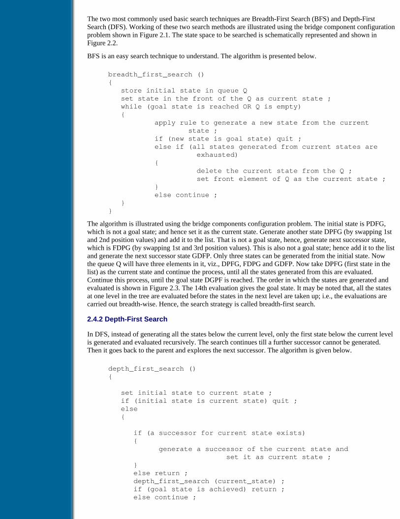
The two most commonly used basic search techniques are Breadth-First Search (BFS) and Depth-FirstSearch (DFS). Working of these two search methods are illustrated using the bridge component configurationproblem shown in Figure 2.1. The state space to be searched is schematically represented and shown inFigure 2.2.
BFS is an easy search technique to understand. The algorithm is presented below.
breadth_first_search () { store initial state in queue Q set state in the front of the Q as current state ; while (goal state is reached OR Q is empty) { apply rule to generate a new state from the current state ; if (new state is goal state) quit ; else if (all states generated from current states are exhausted) { delete the current state from the Q ; set front element of Q as the current state ; } else continue ; } }
The algorithm is illustrated using the bridge components configuration problem. The initial state is PDFG,which is not a goal state; and hence set it as the current state. Generate another state DPFG (by swapping 1stand 2nd position values) and add it to the list. That is not a goal state, hence, generate next successor state,which is FDPG (by swapping 1st and 3rd position values). This is also not a goal state; hence add it to the listand generate the next successor state GDFP. Only three states can be generated from the initial state. Nowthe queue Q will have three elements in it, viz., DPFG, FDPG and GDFP. Now take DPFG (first state in thelist) as the current state and continue the process, until all the states generated from this are evaluated.Continue this process, until the goal state DGPF is reached. The order in which the states are generated andevaluated is shown in Figure 2.3. The 14th evaluation gives the goal state. It may be noted that, all the statesat one level in the tree are evaluated before the states in the next level are taken up; i.e., the evaluations arecarried out breadth-wise. Hence, the search strategy is called breadth-first search.
2.4.2 Depth-First Search
In DFS, instead of generating all the states below the current level, only the first state below the current levelis generated and evaluated recursively. The search continues till a further successor cannot be generated.Then it goes back to the parent and explores the next successor. The algorithm is given below.
depth_first_search () {
set initial state to current state ; if (initial state is current state) quit ; else {
if (a successor for current state exists) { generate a successor of the current state and set it as current state ; } else return ; depth_first_search (current_state) ; if (goal state is achieved) return ; else continue ;

} }
Figure 2.4 shows the tree generated by the DFS for the bridge component configuration problem. The searchreached the goal state after evaluating 11 states.
Since DFS stores only the states in the current path, it uses much less memory during the search compared toBFS. The probability of arriving at goal state with a fewer number of evaluations is higher with DFScompared to BFS. This is because, in BFS, all the states in a level have to be evaluated before states in thelower level are considered. DFS is very efficient when more acceptable solutions exist, so that the search canbe terminated once the first acceptable solution is obtained. BFS is advantageous in cases where the tree isvery deep. An ideal search mechanism is to combine the advantages of BFS and DFS. What is explained sofar is unconstrained BFS and DFS. If constraints are imposed on the search, then the above algorithm needsto be modified. One such constrained DFS is described in Chapter 4, where multiple acceptable solutions fordesign problems are generated.
Figure 2.3 Sequence of nodes generated in BFS
Figure 2.4 Sequence of nodes generated in DFS
Previous Table of Contents Next
Products | Contact Us | About Us | Privacy | Ad Info | Home
Use of this site is subject to certain Terms & Conditions, Copyright © 1996-2000 EarthWeb Inc. All rightsreserved. Reproduction whole or in part in any form or medium without express written permission of
EarthWeb is prohibited. Read EarthWeb's privacy statement.

Search Tips
Advanced Search
Artificial Intelligence and Expert Systems for Engineersby C.S. Krishnamoorthy; S. RajeevCRC Press, CRC Press LLCISBN: 0849391253 Pub Date: 08/01/96
Search this book:
Previous Table of Contents Next
2.4.3 Heuristic Search
It can be noted that both these search methods are systematic and force mobility, which are primaryrequirements of any good search process. In the context of AI, many times one may not get the best solution.In such cases it is required to obtain a very good solution. A very good solution is not a best solution, but is anacceptable one. The introduction of ‘heuristics’ can improve the efficiency of the search process, possiblysacrificing the completeness. Heuristics generally guide the search process towards the region where theacceptable solutions lie. Heuristics to be adopted in a search generally depend on the problem being solved.For the bridge component configuration problem, how a heuristic can expedite the search is illustrated below.
The goal state DGPF gives us two important pieces of information. They are positions of each component andthe sequence in which two components should appear in the solution. Let the initial state be PDFG and thethree successors of this state are DPFG, FDPG and GDFP. When these states are evaluated using a heuristicbased on the position values and sequences, the following deductions can be drawn.
DPFG : one position correct (D); no sequence correct
FDPG : one position correct (P); no sequence correct
GDFP : no position correct; no sequence correct
Since the first two states evaluate to the same level, either of them can be considered for the next evaluation.Let us take the second state FDPG. The two successors of this state are DFPG and GDPF. The evaluation ofthese states based on the heuristic gives:
DFPG : two positions correct (DP); no sequence correct
GDPF : two positions correct (PF); one sequence correct
The heuristic shows that the second state is closer to the goal state compared to the first. Hence consider thesecond state for evaluation. The only successor for this state is DGPF, which is the goal state. Hence, thesearch is terminated. From this it can be seen that when a simple heuristic is combined with BFS, theefficiency of the search improved resulting in only 7 evaluations to reach the goal state as shown in Figure2.5. Indeed the number of evaluations would have been more, if DPFG was considered at the first levelinstead of FDPG.
Such heuristics can be represented as constraints and the search becomes constrained BFS or DFS search.
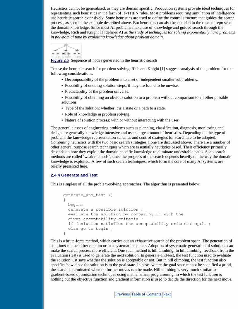
Heuristics cannot be generalised, as they are domain specific. Production systems provide ideal techniques forrepresenting such heuristics in the form of IF-THEN rules. Most problems requiring simulation of intelligenceuse heuristic search extensively. Some heuristics are used to define the control structure that guides the searchprocess, as seen in the example described above. But heuristics can also be encoded in the rules to representthe domain knowledge. Since most AI problems make use of knowledge and guided search through theknowledge, Rich and Knight [1] defines AI as the study of techniques for solving exponentially hard problemsin polynomial time by exploiting knowledge about problem domain.
Figure 2.5 Sequence of nodes generated in the heuristic search
To use the heuristic search for problem solving, Rich and Knight [1] suggests analysis of the problem for thefollowing considerations.
• Decomposability of the problem into a set of independent smaller subproblems.
• Possibility of undoing solution steps, if they are found to be unwise.
• Predictability of the problem universe.
• Possibility of obtaining an obvious solution to a problem without comparison to all other possiblesolutions.
• Type of the solution: whether it is a state or a path to a state.
• Role of knowledge in problem solving.
• Nature of solution process: with or without interacting with the user.
The general classes of engineering problems such as planning, classification, diagnosis, monitoring anddesign are generally knowledge intensive and use a large amount of heuristics. Depending on the type ofproblem, the knowledge representation schemes and control strategies for search are to be adopted.Combining heuristics with the two basic search strategies alone are discussed above. There are a number ofother general purpose search techniques which are essentially heuristics based. Their efficiency primarilydepends on how they exploit the domain-specific knowledge to eliminate undesirable paths. Such searchmethods are called ‘weak methods’, since the progress of the search depends heavily on the way the domainknowledge is exploited. A few of such search techniques, which form the core of many AI systems, arebriefly presented here.
2.4.4 Generate and Test
This is simplest of all the problem-solving approaches. The algorithm is presented below:
generate_and_test () { begin: generate a possible solution ; evaluate the solution by comparing it with the given acceptability criteria ; if (solution satisfies the acceptability criteria) quit ; else go to begin ; }
This is a brute-force method, which carries out an exhaustive search of the problem space. The generation ofsolutions can be either random or in a systematic manner. Adoption of systematic generation of solutions canmake the search process more efficient. One such method is hill climbing. In hill climbing, feedback from theevaluation (test) is used to generate the next solution. In generate-and-test, the test function used to evaluatethe solution just says whether the solution is acceptable or not. But in hill climbing, the test function alsospecifies how close the solution is to the goal state. In cases where the goal state cannot be specified a priori,the search is terminated when no further moves can be made. Hill climbing is very much similar togradient-based optimisation techniques using mathematical programming, in which the test function isnothing but the objective function and gradient information is used to decide the direction for the next move.
Previous Table of Contents Next

Products | Contact Us | About Us | Privacy | Ad Info | Home
Use of this site is subject to certain Terms & Conditions, Copyright © 1996-2000 EarthWeb Inc. All rightsreserved. Reproduction whole or in part in any form or medium without express written permission of
EarthWeb is prohibited. Read EarthWeb's privacy statement.

Search Tips
Advanced Search
Artificial Intelligence and Expert Systems for Engineersby C.S. Krishnamoorthy; S. RajeevCRC Press, CRC Press LLCISBN: 0849391253 Pub Date: 08/01/96
Search this book:
Previous Table of Contents Next
2.4.5 Best-First Search
This method combines the advantages of the DFS and BFS methods. In this method, a single path is followedat a time, but paths are switched when more-promising paths than the current one are found. This is illustratedusing the bridge components configuration problem. To some extent, it is similar to the heuristic searchdescribed above. But instead of using a qualitative heuristic, the evaluation of steps is quantified.
For evaluation of a state the following criteria are adopted, which is little different from the heuristic usedearlier. A weightage of 100 is assigned to a state for each of the correct position values. This results in aweightage of 400 for the goal state, since all four components are in their respective positions. In addition tothis, weightages of 100 are assigned for getting a correct position after a swap. The three successors of theinitial states are generated and their scores are evaluated. The scores evaluated are given in Figure 2.6. For thefirst successor node, a score of 100 is obtained. Since none of the components is in the correct position, 0weightage is assigned from the first criterion. Three possible paths can be generated from this state byswapping the first component with the 2nd, 3rd and 4th. First swapping will bring D to the first position,which is a correct one; hence a value of 100 is assigned. The second and third swappings will not bring any ofthe components to the correct positions, resulting in no additional weightages. Hence the score for the stateDPFG becomes 100. Similarly the second state FDPG gets a score 300 and the third stage GDFP gets a score100.
The scores indicate that the state FDPG is more promising for further exploration than the other two; hence itis pursued. Generate the two successors of FDPG, viz., DFPG and GDPF. The evaluation assigns weightages200 for DFPG and 300 for GDPF. Hence select GDPF for further exploration. The only successor of GDPF isDGPF, which is the goal state. The complete tree generated after the search is shown in Figure 2.6. The goalstate is arrived after 7 evaluations, which is same as in the case of heuristic search. But the selection criteria isquantified here and there was no conflict at the second level. It may be noted that each of the paths forms analternate search path for solution of the problem. Hence, the tree is called an OR Graph. The best-first searchis a simplification of A* algorithm originally presented by Hart et al. [6].
2.4.6 Agenda-Driven Search
Agenda-driven search is an improvement on the best-first search. In best-first search, only a queue is used torecord the states being evaluated or the path traversed. But in agenda-driven search the queue is replaced by

an agenda, which has a list of tasks that a system could perform. Each task in the agenda is associated withtwo items: justification for the task (the reason why a task is proposed) and a rating representing theusefulness of the task. The tasks are generally stored in the agenda in the order of their ratings. The searchprocess can create new tasks or modify the rating of existing tasks. In such cases, as and when new tasks arecreated or ratings are modified, they are inserted at proper places in the agenda. As AI programs become largeand more complex having a number of knowledge sources and requiring different reasoning strategies fordifferent knowledge sources, techniques such as agenda-driven search become very useful and handy.
Figure 2.6 Sequence of nodes generated in BFS
2.5 Problem Decomposition and AND-OR Graphs
When a problem become large, the law is divide and conquer. The problem is decomposed into subproblemsone level after the other until the subproblem at the lowermost level is trivial and easy to solve. Solutions tosuch subproblems are combined at appropriate levels to obtain a solution to the problem in total. Thus theproblem decomposition or problem reduction simplifies the solution process. The graphs or trees generated byreducing such problems are called AND-OR graphs. Such graphs can have both AND nodes and OR nodes.One AND node may point to any number of successor nodes, all of which must be resolved in order to provethe AND node. But it is also possible to represent alternative solution paths from a node, similar to the case ofan OR node. This implies that a node can have both AND and OR paths. Such a structure is called anAND-OR graph or tree. A typical AND-OR node is shown in Figure 2.7. The node represents a goal: loadbearing IS by RC rigid frame. There are two alternative paths to reach the goal. If successor 1 is satisfied, thenthe goal is TRUE; or if both successors 2 and 3 are satisfied, then also the goal is TRUE.
Figure 2.7 Typical AND-OR node
The knowledge base in a KBES can be represented as an AND-OR graph, combining many AND-OR nodes.Typical knowledge nets, which are combinations of AND-OR nodes are presented and are explained in thenext chapter. The knowledge contained in an AND-OR graph can be conveniently represented usingproduction rules having the well-known IF-THEN construct. The search methods described so far, viz., BFS,DFS, best first search etc., cannot be directly used for searching for a solution in an AND-OR graph. Otherappropriate techniques have to be used to search the AND-OR graphs. The AO* search algorithm is onepopular algorithm generally used to generate solutions in an AND-OR graph [1]. Problems such asclassification, diagnosis, monitoring etc. are represented using AND-OR graphs for solution. In suchproblems, the path from an initial state to the goal state forms a solution. Two most popular search techniques,backward chaining and forward chaining, in AND-OR graphs are presented in Chapter 3. Hence they are notdescribed here.
Problem classes such as planning and design can be viewed as problems of constraint satisfaction. In suchproblems it is required to arrive at a problem state satisfying a given set of constraints. To do this, theavailable constraints are propagated to the extent possible. If a solution is obtained in this process, then thesearch is terminated; else a local search is carried out for further exploration.
In addition to the search techniques described above, there are a number of other search methods such assimulated annealing, genetic algorithms etc. They are not presented here as they are beyond the scope of thischapter.
This chapter presented an introduction to AI problems and a few important search techniques commonly usedto solve AI problems. These search techniques are used in development of different generic problem-solvingtechniques such as KBES, design synthesis, case-based reasoning etc. which are dealt with in detail in thefollowing chapters.
Previous Table of Contents Next

Products | Contact Us | About Us | Privacy | Ad Info | Home
Use of this site is subject to certain Terms & Conditions, Copyright © 1996-2000 EarthWeb Inc. All rightsreserved. Reproduction whole or in part in any form or medium without express written permission of
EarthWeb is prohibited. Read EarthWeb's privacy statement.

Search Tips
Advanced Search
Artificial Intelligence and Expert Systems for Engineersby C.S. Krishnamoorthy; S. RajeevCRC Press, CRC Press LLCISBN: 0849391253 Pub Date: 08/01/96
Search this book:
Previous Table of Contents Next
References1. Rich, E. and Knight, K., Artificial Intelligence, McGraw Hill, NewYork, 1992.
2. Nilsson, N. J., Principles of Artificial Intelligence, Morgan Kauffman, San Mateo, Calif., 1980.
3. Newell, A. and Simon, H., Human Problem Solving, Prentice Hall, New York, 1972.
4. Winston, P. H., Artificial Intelligence, Addision-Wesley, Reading, Mass., 1984.
5. Minsky, M., A framework for representing knowledge, in Psychology of Computer Vision, Winston,P. H. (Ed.), McGraw Hill, New York, 1975.
6. Hart, P. E., Nilsson, N. J. and Raphael, B., A formal basis for the heuristic determination ofminimum cost paths, in IEEE Trans. on SSC 4, 100–107, 1968.
Previous Table of Contents Next
Products | Contact Us | About Us | Privacy | Ad Info | Home
Use of this site is subject to certain Terms & Conditions, Copyright © 1996-2000 EarthWeb Inc. All rightsreserved. Reproduction whole or in part in any form or medium without express written permission of
EarthWeb is prohibited. Read EarthWeb's privacy statement.

Search Tips
Advanced Search
Artificial Intelligence and Expert Systems for Engineersby C.S. Krishnamoorthy; S. RajeevCRC Press, CRC Press LLCISBN: 0849391253 Pub Date: 08/01/96
Search this book:
Previous Table of Contents Next
Chapter 3Knowledge-Based Expert System
3.1 Introduction
The Knowledge-Based Expert System (KBES) is the first realisation of research in the field of ArtificialIntelligence (AI), in the form of a software technology. For developers of application software, particularly inmedical and engineering disciplines, it was a boon, as it addressed the decision-making process with the useof symbols rather than numbers. Tasks belonging to the classification and diagnosis category were the first tobenefit from the emergence of KBES technology. Though AI researchers were carrying out symbolicprocessing much earlier, the results of such research could be taken from lab to field only when KBES wasintroduced as a software tool for addressing a class of problems that required simulation of theknowledge-based decision-making process.
A number of articles appeared in many journals, technical papers were presented in conferences and booksappeared in the market on this topic in the late 1970s and early 1980s [1–5]. In addition to these, a number ofarticles appeared in different journals specifically on the two expert systems, viz., MYCIN and DENDRAL.These gave an insight into the anatomy of KBES and its working [6,7]. A number of leading researchers, whowere responsible for the realisation of this technology, worked for the development of these systems.Researchers working in the area of Computer-Aided Engineering (CAE) in many leading universities showedan active interest in further development of this technology by exploring its different aspects and applicabilityto different fields of engineering [8–13]. Later a number of researchers all over the world joined the fray incarrying out research and development to take this technology forward and to make it more useful forproblem solving. As a result of all these developments, industries started realising the potential of thetechnology and have since moved in the direction of taking the prototype systems from lab to full-fledgedworking systems in the field. This chapter presents the technology of KBES, its architecture, the descriptionof its components, problem-solving methodologies with illustration and application development. The AIsearch techniques and the related concepts such as problem reduction, AND-OR graphs etc., presented inChapter 2 are elaborated here and their use in designing and developing expert systems is presented in thischapter. An expert system development environment DEKBASE is presented at the end of the chapter, whichwill give the readers a deep insight into the different aspects of the expert system development process.

3.2 What is KBES?
KBESs are computer programs designed to act as an expert to solve a problem in a particular domain. Theprogram uses the knowledge of the domain coded in it and a specified control strategy to arrive at solutions.As knowledge base forms an integral, but implicitly understood part of a KBES, the adjectiveknowledge-based is often not used. The terms expert system and knowledge-based expert system can thereforebe used interchangeably. An expert system is not called a program, but a system, because it encompassesseveral different components such as knowledge base, inference mechanisms, explanation facility etc. Allthese different components interact together in simulating the problem-solving process by an acknowledgedexpert of a domain.
A close examination of any decision-making process by an expert reveals that he/she uses facts and heuristicsto arrive at decisions. If the decision to be made is based on simple established facts using a heuristic such asa rule of thumb, then it may be a trivial process. For instance, if the span of a beam is 12 feet, then the depthof the beam is fixed as 12 inches. Here the fact used to take the decision is span of beam is 12 feet and theheuristic used is provide one inch depth for each foot of span or, in other words, depth of beam = span/12.The solution obtained for a case of a 12-foot span is acceptable. But the heuristic cannot be blindly applied inall cases. Consider a span of 4 feet. A beam with a depth of 4 inches is not acceptable because a beam shouldhave some minimum depth. Similarly a beam cannot be excessively deep, due to many considerations. Hence,while using the above heuristic, the engineer also checks for other conditions so that the solution obtained isacceptable. An expert system simulates such decision-making processes using the available facts andknowledge. More than one unit of knowledge is required for the above decision-making process. In additionto the knowledge contained in the heuristic, limiting conditions on the depth are to be checked, which theengineer knows from his experience or based on provisions given in design codes. Essentially a KBES worksthe way the decision is made in the above case. Let us try to understand the different components of thesystem with the above simple problem as an illustrative example. The following is a formal representation ofthe steps followed for the decision making.
1. Obtain span of the beam
2. Use the heuristic and arrive at value for depth of beam
3. Check the value obtained for beam depth for any violation of acceptable values
The components of a knowledge-based decision-making system can be identified from the above statements.We have used two entities, viz., span of beam and depth of beam. When appropriate values are assigned tothese entities, they become facts. For example, span of beam = 12 feet is a fact. The heuristic uses this fact toarrive at a value for the entity depth of beam. The heuristic can be formally written in the following manner.
IF span of beam is knownTHEN depth of beam is (span of beam/12)
The heuristic written above using the well-known IF-THEN construct contains the knowledge required to takethe decision on depth of beam. The decision obtained is incomplete, unless it is verified for a valid range asdescribed. Two other statements using the same IF-THEN constructs can be written to represent theknowledge required for such verification.
IF depth of beam < 9 inchesTHEN limit the depth of beam to 9 inchesIF depth of beam > 3 feetTHEN limit the depth of beam to 3 feet
Previous Table of Contents Next

Products | Contact Us | About Us | Privacy | Ad Info | Home
Use of this site is subject to certain Terms & Conditions, Copyright © 1996-2000 EarthWeb Inc. All rightsreserved. Reproduction whole or in part in any form or medium without express written permission of
EarthWeb is prohibited. Read EarthWeb's privacy statement.

Search Tips
Advanced Search
Artificial Intelligence and Expert Systems for Engineersby C.S. Krishnamoorthy; S. RajeevCRC Press, CRC Press LLCISBN: 0849391253 Pub Date: 08/01/96
Search this book:
Previous Table of Contents Next
It may be noted that the heuristic type of knowledge and other rules of thumb or guidelines specified in designcodes can very well be represented in the form of IF-THEN constructs called production rules. Not only arethey easy to understand, but their representation is also very simple thus resulting in an easy implementationin a computer. Based on the above, the main two components of an expert system can be identified as:
Knowledge Base Collection of knowledge required for problem solving
Control Mechanism Checks the available facts, selects appropriate knowledge source fromknowledge base, matches the facts with the knowledge, and generatesadditional facts
Only three production rules are used to represent the knowledge in the above illustration. But as the problemgrows, more and more facts have to be generated based on already established facts. For example, afterestablishing the depth of beam, if one wants to check the available clear headroom, an additional source ofknowledge is required, which can also be represented in the form of rules. Thus in an application, decisionsare made or facts are established in a sequential manner, using already established facts. This process of usingcurrent facts and knowledge contained in the knowledge base to establish additional facts or decisionscontinues as a chain, until a fact specified as a goal is established. The control mechanism primarily carriesout symbolic processing called inference. There can be a number of different ways in which the knowledgecontained in the rules can be used for inference. Hence, the control mechanism can consist of many differentinference strategies. Thus these two - knowledge base and inference mechanisms - form the main componentsof a KBES.
3.3 Architecture of KBES
As described in the previous section, a knowledge base and an inference engine consisting of one or moreinference mechanisms form the major components of an expert system. When an expert system starts theprocess of inference, it is required to store the facts established for further use. The set of established factsrepresents the context, i.e., the present state of the problem being solved. Hence, this component is oftencalled context or working memory.
Whenever an expert gives a decision, one is curious to know how the expert arrived at that decision. Also,when the expert prompts for information or data, one would like to know why that piece of information isrequired. The expert uses the knowledge he/she has and the context of the problem to answer the queries such

as how a decision is arrived at? or why a data is needed? A separate module called an explanation facilitysimulates the process of answering the why and how queries. This module also forms an integral part of anyexpert system.
The process of collecting, organising and compiling the knowledge and implementing it in the form of aknowledge base is a labourious task. It does not end with the development of the system. The knowledge basehas to be continuously updated and/or appended depending on the growth of knowledge in the domain. Aknowledge acquisition facility, which will act as an interface between the expert/knowledge engineer and theknowledge base, can form an integral component of an expert system. As it is not an on-line component, itcan be implemented in many ways.
A user of the expert system has to interact with it for giving data, defining facts and monitoring the status ofproblem solving. Conveying of information, be it textual or graphical, to the user should also be done in avery effective manner. Thus, a user-interface module with the capability to handle textual and graphicalinformation forms another component of the expert system. Figure 3.1 shows the architecture of a KBES withits components and the way the components interact with each other.
Figure 3.1 Architecture of a KBES
As seen so far, the knowledge base and the inference engine are the most important components in a KBES.Hence, a detailed look at these are required for better understanding of the technology. The following sectionspresent a detailed description of the knowledge base and inference mechanisms.
3.3.1 Knowledge Base
The knowledge base contains the domain-specific knowledge required to solve the problem. The knowledgebase is created by the knowledge engineer, who conducts a series of interviews with the expert and organisesthe knowledge in a form that can be directly used by the system. The knowledge engineer has to have theknowledge of KBES technology and should know how to develop an expert system using a developmentenvironment or an expert system development shell. It is not necessary that the knowledge engineer beproficient in the domain in which the expert system is being developed. But a general knowledge andfamiliarity with the key terms used in the domain is always desirable, since this will not only help in betterunderstanding the domain knowledge but will also reduce the communication gap between the knowledgeengineer and the expert. Before deciding on the structure of the knowledge base, the knowledge engineershould have a clear idea of different knowledge representation schemes and the suitability of each underdifferent circumstances.
The knowledge that goes into problem solving in engineering can be broadly classified into three categories,viz., compiled knowledge, qualitative knowledge and quantitative knowledge. Knowledge resulting from theexperience of experts in a domain, knowledge gathered from handbooks, old records, standard specificationsetc., forms compiled knowledge. Qualitative knowledge consists of rules of thumb, approximate theories,causal models of processes and common sense. Quantitative knowledge deals with techniques based onmathematical theories, numerical techniques etc. Compiled as well as qualitative knowledge can be furtherclassified into two broad categories, viz., declarative knowledge and procedural knowledge [14]. Declarativeknowledge deals with knowledge on physical properties of the problem domain, whereas proceduralknowledge deals with problem-solving techniques.
Previous Table of Contents Next

Products | Contact Us | About Us | Privacy | Ad Info | Home
Use of this site is subject to certain Terms & Conditions, Copyright © 1996-2000 EarthWeb Inc. All rightsreserved. Reproduction whole or in part in any form or medium without express written permission of
EarthWeb is prohibited. Read EarthWeb's privacy statement.

Search Tips
Advanced Search
Artificial Intelligence and Expert Systems for Engineersby C.S. Krishnamoorthy; S. RajeevCRC Press, CRC Press LLCISBN: 0849391253 Pub Date: 08/01/96
Search this book:
Previous Table of Contents Next
Development of an expert system in an engineering domain would require use of all these forms ofknowledge. Of course, it is the application domain that determines the nature of knowledge that goes into it.Consider, for instance, the domain of diagnosis for distress in buildings. It is required to find out how a crackis formed on the brick wall of a building. To arrive at the causes for the crack, the system should haveknowledge about the position of the wall, the type of wall (load bearing, infill or partition), the thickness ofthe wall, the proportion of the mix used for mortar, the type of construction of the building etc. Depending onthe type of wall, knowledge on foundation,soil type, design details of beams and columns in the floor etc. arerequired. In addition to the above, knowledge on how to use the available information to deduce the reasonsfor the crack is also required. The first part of the knowledge (declarative knowledge) mentioned abovedescribes the scenario, whereas the second part of the knowledge describes how to use the knowledge(procedural knowledge) to arrive at the decision. Thus for the development of a KBES, one should know thedifferent knowledge representation schemes and the possible modes of interaction between them.
Developing an expert system involves tasks such as acquiring knowledge from an acknowledged domainexpert, documenting it and organising it, generating a knowledge net to check the relationships betweendifferent knowledge sources, checking for consistency in the knowledge and finally transforming theknowledge net into a computer program using appropriate tools. Such a program, called an expert system, is aformal system for storing facts and their relationships and the strategies for using them. In general, an expertsystem has knowledge about physical objects, relationships among them, events, relationships among eventsand relationships between objects and events. In addition, required types of search mechanisms must berepresented to drive the system. Depending on the type of problems, other types of knowledge, such as timerelationships, uncertainty levels of facts and assertions, performance levels, difference in behaviour of objectsin different situations, assumptions, justifications, knowledge about knowledge (meta knowledge), additionalexplanations on facts and relationships etc., have to be represented. It points to the fact that formalisation ofknowledge and problem-solving strategies forms a major part in expert systems development. The same pieceof knowledge can be represented using more than one formal scheme, but with varying degrees of difficulty.The difficulty is not in the representation of the knowledge, but in its usage. The decision on selection of ascheme primarily depends on the type of application being built. Also, different knowledge representationschemes can be adopted for developing one application. The knowledge engineer has to decide which portionof the knowlege should be represented in what form, depending on the nature of the knowledge and theefficiency of its use. The most common methods of knowledge representation are:
1. Predicate logic

2. Production rules
3. Frames (objects) and semantic networks
4. Conventional programs
Predicate Logic
Predicate logic provides mechanisms for representation of facts and reasoning based on syntacticmanipulation of logic formulae. It uses predefined rules of inference for assertion or deduction of facts. In thefirst-order predicate logic, the formulae are manipulated purely based on their form or structure. The majordisadvantage of this scheme is that it cannot consider the meaning or semantic content of the formula. Forbetter understanding of the concept, consider the following example. Consider a bridge system consisting oftwo girders and three piers as shown in Figure 3.2.
Figure 3.2 A bridge configuration with two girders and three piers
The following statements can be written to state the facts regarding the bridge system.
A is-a girder; B is-a girder;C is-a pier; D is-a pier; E is-a pier;C supports A; D supports A;D supports B; E supports B;
In this, the terms is-a and supports are called predicates and A, B, C, D and E are called symbols. The tripletsgiven above are called sentences. An inference rule is specified as given below:
If x supports y then x gets-load-from y
Another predicate gets-load-from is introduced in the inference rule. Any symbol of proper type can besubstituted for the place holders x and y for assertion of facts. Using the given inference rule, the followingfacts can be asserted.
C gets-load-from A; D gets-load-from A;D gets-load-from B; E gets-load-from B;
In predicate logic, all deductions are based on logic statements, and inference rules are guaranteed to becorrect. In addition, a logic program will generate all possible inferences that can be drawn from the facts andrules. Though such predicate logic systems deduce all possible facts, their ability to carry out a constrainedsearch through the facts and inferences is limited. This is primarily due to their inability to carry out guidedsearch and also to represent search strategies. As new facts are generated, the inference rules are applied toassert newer facts. This process continues leading to combinatorial explosion until a goal state is reached.Only a constrained assertion of facts can improve the situation, which is difficult in predicate logic. Inaddition, predicate logic systems try to apply all the inference rules to all the facts. There is no mechanism togroup facts and associate specific inference rules to different groups. Even in a small real-life AI-basedsystem, there can be a number of facts and inference rules. Due to the above-mentioned limitations, itbecomes difficult to apply predicate logic-based knowledge representation in expert systems. A goodknowledge representation scheme should have the capability to represent real-life situations (objects andrelationships among them), which can be exploited by efficient guided search strategies and which betterreflect the way humans perceive and think.
Previous Table of Contents Next

Products | Contact Us | About Us | Privacy | Ad Info | Home
Use of this site is subject to certain Terms & Conditions, Copyright © 1996-2000 EarthWeb Inc. All rightsreserved. Reproduction whole or in part in any form or medium without express written permission of
EarthWeb is prohibited. Read EarthWeb's privacy statement.

Search Tips
Advanced Search
Artificial Intelligence and Expert Systems for Engineersby C.S. Krishnamoorthy; S. RajeevCRC Press, CRC Press LLCISBN: 0849391253 Pub Date: 08/01/96
Search this book:
Previous Table of Contents Next
Production Rules
Production rules are simple but powerful forms of knowledge representation providing the flexibility ofcombining declarative and procedural representation for using them in a unified form. A production rule has aset of antecedents and a set of consequents. The antecedents specify a set of conditions and the consequents aset of actions. A few typical rules are given below:
1. IF span of beam is knownTHEN depth of beam is (span of beam/12)
2. IF flow is open channel flowAND Froud number > 1THEN flow is supercritical
3. IF flow is open channel flowAND Froud number = 1THEN flow is critical
4. IF the object has two openingsAND opening at top is larger than that at the bottomAND enough space is available on left sideAND space available on right side is too smallTHEN take the pipe by the left side of the objectAND take pipe into the object from top opening
The conditions specified in rules 1 and 2 are very simple, but those in rule 3 are complex. A value assigned toa variable can be used to represent facts in the first two rules. But in the case of rule 4, physical objects andtheir properties have to be defined to represent facts, which cannot be done just by a variable-operator-valuetriplet. In all the above cases, when the IF portion of a rule is satisfied by the facts stored in the context or factestablished by a user input, the actions specified in the THEN portion are performed, and the rule is then saidto be fired. The knowledge stored in rules can be schematically represented in the form of a network. Tworules are represented in the knowledge net shown in Figure 3.3. One rule can be formed by considering nodes1, 3 and 4, which is the rule 2 given above. The other rule can be formed by considering nodes 2, 3, and 4.
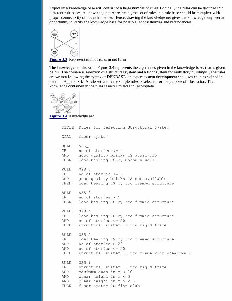
Typically a knowledge base will consist of a large number of rules. Logically the rules can be grouped intodifferent rule bases. A knowledge net representing the set of rules in a rule base should be complete withproper connectivity of nodes in the net. Hence, drawing the knowledge net gives the knowledge engineer anopportunity to verify the knowledge base for possible inconsistencies and redundancies.
Figure 3.3 Representation of rules in net form
The knowledge net shown in Figure 3.4 represents the eight rules given in the knowledge base, that is givenbelow. The domain is selection of a structural system and a floor system for multistory buildings. (The rulesare written following the syntax of DEKBASE, an expert system development shell, which is explained indetail in Appendix I.) A rule set with very simple rules is selected for the purpose of illustration. Theknowledge contained in the rules is very limited and incomplete.
Figure 3.4 Knowledge net
TITLE Rules for Selecting Structural System
GOAL floor system
RULE SSS_1 IF no of stories <= 5 AND good quality bricks IS available THEN load bearing IS by masonry wall
RULE SSS_2 IF no of stories <= 5 AND good quality bricks IS not available THEN load bearing IS by rcc framed structure
RULE SSS_3 IF no of stories > 5 THEN load bearing IS by rcc framed structure
RULE SSS_4 IF load bearing IS by rcc framed structure AND no of stories <= 20 THEN structural system IS rcc rigid frame
RULE SSS_5 IF load bearing IS by rcc framed structure AND no of stories > 20 AND no of stories <= 35 THEN structural system IS rcc frame with shear wall
RULE SSS_6 IF structural system IS rcc rigid frame AND maximum span in M < 10 AND clear height in M < 3 AND clear height in M > 2.5 THEN floor system IS flat slab

RULE SSS_7 IF structural system IS rcc rigid frame AND maximum span in M > 8 AND maximum span in M < 20 AND clear height in M > 3 THEN floor system IS waffle slab
RULE SSS_8 IF structural system IS rcc rigid frame AND maximum span in M < 8 AND clear height in M > 3 THEN floor system IS beam and slab
The knowledge net represents the schematic diagram of the knowledge base. There are 11 nodes in theknowledge net. As the knowledge given is only a portion of a large knowledge base for selection of structuralsystems and preliminary dimensioning of structural elements in multistory buildings, further knowledge fordimensioning of shear wall (node 5) and load bearing by brick wall (node 3) is not included. There are tworules for deducing load bearing by an rc frame. Hence, node 4 is made an OR node with two different sets ofconditions. Unless otherwise specified all other nodes except 1, 2, 7 and 8 are AND nodes. Nodes 1, 2, 7 and8 represent initial states; i.e., the user has to give data for establishing facts represented by those nodes. Thenodes 9, 10 and 11 represent different states of the same variable and are the goal nodes implying that theinference will terminate once the process reaches one of these nodes. The use of knowledge contained in theknowledge base for decision making is explained in detail in the section on inference mechanisms.
Previous Table of Contents Next
Products | Contact Us | About Us | Privacy | Ad Info | Home
Use of this site is subject to certain Terms & Conditions, Copyright © 1996-2000 EarthWeb Inc. All rightsreserved. Reproduction whole or in part in any form or medium without express written permission of
EarthWeb is prohibited. Read EarthWeb's privacy statement.

Search Tips
Advanced Search
Artificial Intelligence and Expert Systems for Engineersby C.S. Krishnamoorthy; S. RajeevCRC Press, CRC Press LLCISBN: 0849391253 Pub Date: 08/01/96
Search this book:
Previous Table of Contents Next
It is a common practice in the development of expert systems to logically divide the rules into smaller rulebases and to control from a higher-level rule base which has knowledge about the different rule bases in theknowledge base. If there are more than one rule bases, each of them should have separate contexts. Thehigher-level rule base having meta rules will control the overall inference process and will have a globalcontext. The inference engine of the expert system shell should properly handle different contexts for propersolution of the problem. To illustrate the use of meta-level knowledge bases, a second rule base having threerules is presented below, which arrives at the span-to-depth ratio for beams based on the number of stories inthe building.
TITLE Rules for obtaining beam depths GOAL span to depth ratio
RULE Beam 1 IF no of stories <= 5 THEN span to depth ratio = 15
RULE Beam 2 IF no of stories > 5 AND no of stories <= 8 THEN span to depth ratio = 12
RULE Beam 3 IF no of stories > 8 THEN span to depth ratio = 10
Now the inference process has to invoke this rule base only if the floor system selected is beam and slab. Ameta-level rule base is written which initiates the overall inference process. The meta-level rule base for thiscase is given below.
TITLE Rules for controlling inference GOAL inference completed
RULE Meta 1 IF floor system selection completed AND beam depth ratio is required

OR beam depth ratio is not required THEN inference completed
RULE Meta 2 IF NOT floor system IS_DEFINED THEN LOAD SSS AND floor system selection completed
RULE Meta 3 IF floor system IS beam and slab AND NOT span to depth ratio of beams IS_DEFINED THEN beam depth ratio is required AND LOAD BEAM AND beam depth ratio obtained
RULE Meta 4 IF NOT floor system IS beam and slab THEN beam depth ratio is not required
The rules in the above rule base are meta rules; i.e., they have knowledge about the other two rule bases. Inthe above meta rule base the variables ‘floor system’ and ‘span to depth ratio of beams’ are defined as globalvariables. In their respective rule bases also they are defined as global variables, thereby defining the scopeacross its own rule base and meta rule base. The process of inference and control of the overall inferenceprocess by the inference engine are illustrated in the section on inference mechanisms.
Frames (Objects) and Semantic Networks
Objects are very powerful forms of representing facts in expert systems. They are ideally suited forrepresentation of declarative knowledge, which describes physical entities and semantic relationships betweenthem. Any engineering activity is centered around an artifact or a facility, and detailed information about theartifact is required to make decisions concerning it. Different attributes of the artifact may be used at differentstages of a problem such as planning, analysis, detailing, manufacturing/construction etc. Hence, it isappropriate to use objects with attributes encapsulated in order to have a more-structured representation offacts in the context, during execution of the expert system. Also, the rules should be able to interact with theobjects. For instance, the rule that we wrote earlier can be written as:
IF beam.span is known THEN beam.depth = beam.span/12
In the above rules, the object beam and its two attributes are used. As early as in 1975, Minsky introduced theconcept of ‘frame’ to represent stereotyped situations. A frame is defined as a unit of a knowledge sourcedescribed by a set of slots. The slots can be of two types, viz., abstract or concrete. This classification is madebased on the type of information associated with them. A concrete slot would contain a specific value, such as‘span of beam = 12’, i.e., a value 12 is associated with the slot ‘span’ of frame ‘beam’. An abstract slot wouldcontain descriptions that characterise any possible value for the slot. For example, the slot ‘span’ of the frame‘beam’ can have a description attached to it such as ‘get span from the slot bay-width of frame building’. Hereno specific value is attached to the slot; instead the description given has to obtain a value as indicated. Thedescription shown above can be implemented by attaching functions to the slots. Such functions are called‘demons’. Demons are sleeping programs, which are invoked by some specific events. The working ofdemons is described later in the section on inference mechanisms.
Previous Table of Contents Next

Products | Contact Us | About Us | Privacy | Ad Info | Home
Use of this site is subject to certain Terms & Conditions, Copyright © 1996-2000 EarthWeb Inc. All rightsreserved. Reproduction whole or in part in any form or medium without express written permission of
EarthWeb is prohibited. Read EarthWeb's privacy statement.

Search Tips
Advanced Search
Artificial Intelligence and Expert Systems for Engineersby C.S. Krishnamoorthy; S. RajeevCRC Press, CRC Press LLCISBN: 0849391253 Pub Date: 08/01/96
Search this book:
Previous Table of Contents Next
The slots in a frame can also be made relational in nature, wherein the slot contains information on therelationship of the frame with other frames. Consider for example, two frames ‘beam’ and ‘building’. Theframe beam can have a slot ‘part-of’, which can take the value ‘building’, which is the name of another frame.Another frame beam_5 can have a slot ‘is-a’, which can take a value beam, which is also the name of a frame.The ‘is-a’ relationship implies that beam_5 is an instance of frame beam and beam_5 gets all the genericproperties of the frame beam. Only values for specific slots are to be explicitly obtained. This concept is verymuch similar to ‘classes’ and ‘instances’ of object-oriented programming. The facility to have slots describingrelationships with other frames provides a mechanism for defining networks of frames in the context, withlinks (relationships) described using semantics. Such networks are called semantic networks. They are verypowerful in expressing the declarative knowledge about an artifact. A typical semantic network describedusing four frames is shown in Figure 3.5. Four frames, viz., bridge, deck, main-girder and main-girder_1 areshown in the figure with values attached to a few slots. Only a few typical slots are shown for each frame forthe purpose of illustration. Consider the slot ‘span-lengths’. It is a multivalue slot, in which an array of valuesis attached to it, the first value being the length of span 1, the second for span 2 … etc. The first slot in theframe ‘deck’ is ‘part-of’ having value ‘bridge’, which is the name of another frame. It indicates that deck ispart of bridge’. The two frames are semantically connected through the slot ‘part-of’. Similarly the framemain_girder also has a slot ‘part-of’ with value ‘deck’, implying that main_girder is a part of deck. Likewiseexamine the relationship between frame ‘main-girder’ and ‘main-girder_1’, These two are related through aslot ‘is-a’. This indicates that the frame ‘main-girder_1’ is an instance of frame ‘main-girder’. Since there aresix main girders, the system has to generate six instances of the frame ‘main-girder’ and all the valuescommon to the main girder are inherited by the instances from the generic frame. Only values which arespecific to each instance are obtained through inference for respective instances.
Figure 3.5 A typical semantic network represented using frames
This illustrates how frames and semantic networks can be used to represent declarative knowledge in adomain. In expert systems developed for real-life applications, a combination of rules and frames is requiredto represent the domain knowledge.
Procedural Programs

Engineering problem solving involves numerical computations, in addition to inference using knowledge. In areal-life expert system, the system has to perform numerical computations at different stages of the solutionprocess. The amount of computations may be very small in some cases and quite large in many cases. Basedon the values inferred, a detailed analysis of the artifact may have to be carried out to evaluate the correctnessof the parameters arrived at. The quantitative knowledge required for such computations can be represented asfunctions/programs written in high-level programming languages such as FORTRAN or C. An expert systemshould be able to call these programs as and when required during problem solving. Hence, they also formpart of the knowledge base of the expert system.
Most expert system development shells provide facilities to represent knowledge in the three forms, viz.,rules, frames and functions in procedural languages. The predicate logic form of knowledge representation isthe natural form in Prolog, one of the specialised AI languages. Prolog provides predicate logic-basedrepresentation with backtracking inference, which is inadequate for developing large expert systems forpractical applications.
3.3.2 Inference Mechanisms
Inference mechanisms are control strategies or search techniques, which search through the knowledge baseto arrive at decisions. The knowledge base is the state space and the inference mechanism is a search process.As expert systems predominantly process symbols, the inference process manipulates symbols by selection ofrules, matching the symbols of facts and then firing the rules to establish new facts. This process is continuedlike a chain until a specified goal is arrived at. In an expert system, inference can be done in a number ofways. The two popular methods of inference are backward chaining and forward chaining. Backward chainingis a goal-driven process, whereas forward chaining is data driven. Working of the methods is illustrated usinga typical knowledge base presented in the previous section on knowledge representation. The knowledge basecontains three rule bases, one for selection of a structural system, the second for arriving at span-to-depthratios for beams and the third the meta rule base. The inference process for the first rule base is presented firstfor understanding the two methods, viz., backward chaining and forward chaining.
The knowledge net consists of 11 nodes (see Figure 3.4). Each node represents a state in the state space.Nodes 1, 2, 7 and 8 are initial states, since those states cannot be deduced based on any facts. The user has tosupply data for establishing states represented by them, whereas all the other nodes represent states which areto be deduced based on already established facts. There are two paths for reaching node 4; i.e., there are twoways in which the state or fact represented by node 4 can be established. Hence, that node is represented as anOR node. The working of backward chaining with a goal to arrive at a floor system is described first.
Previous Table of Contents Next
Products | Contact Us | About Us | Privacy | Ad Info | Home
Use of this site is subject to certain Terms & Conditions, Copyright © 1996-2000 EarthWeb Inc. All rightsreserved. Reproduction whole or in part in any form or medium without express written permission of
EarthWeb is prohibited. Read EarthWeb's privacy statement.

Search Tips
Advanced Search
Artificial Intelligence and Expert Systems for Engineersby C.S. Krishnamoorthy; S. RajeevCRC Press, CRC Press LLCISBN: 0849391253 Pub Date: 08/01/96
Search this book:
Previous Table of Contents Next
Backward Chaining
As stated earlier, backward chaining is a goal-driven process. It tries to establish goals in the order in whichthey appear in the knowledge base. The goal variable defined in the rule base for selection of a structuralsystem is ‘floor system’. The inference process will stop once this variable gets a value. The three dynamicdata structures used during the inference process are working memory (context), a rule stack and a goal stack.Whenever any one of the actions of the inference process, viz., select, match and execute occur, one or moreof these data structures get modified. Studying the effect of these actions on the data structures during theinference process is a better way of studying the mechanisms of inference processes. Hence, working of theinference process is described here through the changes that occur to the context, a rule stack and a goal stack.Rule stack and goal stack are temporary data structures created for bookkeeping. When the process starts, thecontext is empty and the goal variable is pushed to the goal stack. Then the process selects the first rule in therule base with a goal variable in the THEN part and pushes it into the rule stack. In the present rule base, rule6 is the first rule having the goal variable in the consequent. Hence, rule 6 is pushed to the rule stack and thegoal variable to the goal stack. The status of the context, goal stack and rule stack at that instance is shown inFigure 3.6.
Figure 3.6 Status of context, goal stack and rule stack - I
It can be seen that rule 6 is the first rule having the goal variable ‘floor system’ in the consequent. Once therule 6 is SELECTED, it starts MATCHING antecedents in the order in which they appear in the rule. The firstcondition is ‘structural system IS rcc rigid frame’. Matching of the rule can be pursued further only if this factis established. Hence, the inference process sets the variable ‘structural system’ as the current goal. It is set bypushing it into the goal stack and also pushing the first rule in the list having the current goal variable in theTHEN part into the rule stack. Thus rule 4 is selected for evaluation. The state of context and goal and rulestacks at this instance is shown in Figure 3.7.
Figure 3.7 Status of context, goal stack and rule stack - II

Now the inference process starts checking the first condition of rule 4, which is ‘load bearing IS by rcc framedstructure’. As a result, the variable ‘load bearing’ becomes the current goal and is pushed into the goal stackand the rule 1 is pushed into the rule stack. The status of context and rule and goal stacks at that instance isshown in Figure 3.8.
Figure 3.8 Status of context, goal stack and rule stack - III
The first condition of rule 1 is on ‘no of stories’, which is represented in the knowledge net by an initial state.Hence, there is no rule in the rule list with this variable in the THEN part, implying that the user has to supplythe data for this variable. Let the user response to the query for this variable be 15. This response establishesthe first fact and it is stored in the context. This results in the condition ‘no of stories <= 5’ to be FALSE andrule 1 cannot be fired and is discarded. This is done by popping the rule stack. The inference process takes thenext rule with the same consequent (which is rule 2) and pushes it into the rule stack and starts evaluating thefirst condition in the antecedent. As that also evaluates to FALSE, rule stack is popped and the next rule withthe current goal variable (‘load bearing’) in consequent (rule 3) is pushed to the stack. The condition in theantecedent is matched with that in the context and it evaluates to TRUE and the rule is fired. This establishesthe current goal and the fact is stored in the context. As the current goal is established, and the rule is fired,both the rule stack and goal stack are popped. The status of the stacks and the context at this instance is shownin Figure 3.9.
Figure 3.9 Status of context, goal stack and rule stack - IV
Now the current goal is the one which is on the top of the goal stack, i.e., ‘structural system’ and the currentrule is rule 4. Both the conditions of this rule evaluate to TRUE by comparing them with the facts in context.This results in firing of the rule and the new fact established ‘structural system IS rcc rigid frame’ is added tothe context. Both the stacks are popped and the current goal becomes ‘floor system’ and the current rulebecomes rule 6, which are on top of the respective stacks. The first condition of the current rule evaluates toTRUE and the second condition is taken. As that variable is in an initial state in the knowledge net, the user isasked to provide a value for the same. Let the user response be 7. This results in evaluation of the condition toFALSE, the rule is rejected, and the rule stack is popped. The next rule with current goal variable inconsequent is selected, i.e., rule 7, which is also discarded since the second condition evaluates to FALSE.Now the next rule (rule 8) is selected by pushing it into the rule stack. The first two conditions of the ruleevaluate to TRUE and the user is prompted for the variable in the third condition. Let the user response be3.2, which evaluates the condition to TRUE and the rule is FIRED. This results in getting a value ‘beam andslab’ for the goal variable. Since the rule is fired, both the stacks are pushed and the newly established fact isadded to the context. Now both the stacks are empty and the inference process is completed. The status ofcontext at this instance is shown in Figure 3.10.
Figure 3.10 Status of context, goal stack and rule stack - V
Previous Table of Contents Next
Products | Contact Us | About Us | Privacy | Ad Info | Home
Use of this site is subject to certain Terms & Conditions, Copyright © 1996-2000 EarthWeb Inc. All rightsreserved. Reproduction whole or in part in any form or medium without express written permission of
EarthWeb is prohibited. Read EarthWeb's privacy statement.

Search Tips
Advanced Search
Artificial Intelligence and Expert Systems for Engineersby C.S. Krishnamoorthy; S. RajeevCRC Press, CRC Press LLCISBN: 0849391253 Pub Date: 08/01/96
Search this book:
Previous Table of Contents Next
The explanation facility of the expert system provides a mechanism for querying the context for getting thevalue of a variable (what?) and knowing how a fact is established (how?). The answer to the first query isdirectly obtained from the context, whereas the answer to the second query, i.e., how, requires reference to theknowledge base. The process associated with the query how? searches for the rule with the required fact in theTHEN part and displays the rule, which shows how the fact is established. Obtaining an answer to a querywhat if? would be very useful, if the user of the system wants to experiment with the decision-makingprocess, by modifying a user input. This can be done in two stages. First, those facts which are dependent onthe modified variable have to be undone. Then they have to reestablished by continuing the inference processfrom that point. This is quite complex and requires maintenance of the complete line of reasoning with thedependencies of facts in the context. The inference process builds a complete dependency network based onTMS (Truth Maintenance System). This dependency network will help to backtrack from any stage to anyprevious stage by undoing the relevant actions, resulting in removal of many facts from the context. Thisbacktracking continues until the establishment of a fact with the variable, the value of which is modified withthe what if query. The inference process restarts from that point and continues until a final goal is established.Because of the difficulty involved in maintaining the dependency network of decisions made, manycommercially available tools do not have this feature.
Forward Chaining
Forward chaining is a data-driven inference process. The user of the system has to give all the available databefore the start of the inference. The inference mechanism tries to establish the facts as they appear in theknowledge base until the goal is established. Consider the same rule base. The user gives the available dataand the state of the context before start of the inference as shown in Figure 3.11.
Figure 3.11 State of context before start of inference
The inference process selects the first rule in the rule base and discards it since the first condition itselfevaluates to FALSE. Then it goes to the second rule, which is also discarded. The condition in the third rule

evaluates to TRUE and it is fired resulting in a new fact being added to the context. Rule 4 is also fired, butdiscards 5, 6 and 7. Finally rule 8 is fired establishing the goal, which terminates the inference process. It sohappened in the present case that in one iteration itself, the goal is established. In large rule bases, a number ofiterations may be required before the goal is established. The order in which rules appear in the rule baseplays a major role in the way inference is carried out in forward chaining, whereas such order does not playany role in backward chaining. But the order in which conditions are listed in a rule is important in backwardchaining. The order in which questions are asked to the user for response depends on this order. Hence, beforeformulating the rule base, the knowledge engineer should decide whether backward chaining or forwardchaining is going to be adopted for reasoning.
The third inference strategy is the hybrid inference mechanism. It is a combination of the backward andforward chaining process. Backward chaining is suitable, if there are few goal states and many initial states.The sequence in which the data are requested depends on the flow of the inference process. In forwardchaining all the data that the user knows have to be given a priori and the system does not prompt for anydata. If the data are sufficient the goal may be reached; otherwise it may exit stating that the goal isunreachable with the available data. Hence, the forward chaining process is suitable only when there are veryfew initial states and many goal states. In large expert systems, many initial and goal states can exist. Also theuser may not be able to give all the necessary data a priori, as he/she may not be able to visualise the flow ofthe inference process. In this context, a hybrid inference mechanism seems to be suitable. It starts in theforward chaining mode with an empty context by trying to establish the facts as they appear in the rule baseand then backward chains to prove or disprove them. The overall direction of the hybrid chaining process isforward with backward chaining being invoked as and when facts are to be established. The user does notgive all the data a priori, but gives data as and when prompted for.
Large expert systems can have a number of rule bases and each one can have its own inference strategy withinits scope. At the meta level also the knowledge engineer can select any strategy for reasoning. Inference withmore than one rule base is illustrated with the three rule bases given in the previous section. Let the inferenceprocess start with the meta-level rule base and the strategy selected be backward chaining. The goal at themeta-level is ‘inference completed’. To prove this, the variable ‘floor system selection completed’ and eitherof the variables ‘beam depth ratio is required’ or ‘beam depth ratio is not required’ should evaluate to TRUE.Evaluation of the two variables to TRUE will ensure that the floor system is selected (by loading the rule baseSSS and carrying out inference in that) and if the floor system selected is beam and slab, then thespan-to-depth ratio is obtained (by loading the rule base BEAM and inferring with it). If the floor systemselected is not beam and slab, then the rule base BEAM will not be loaded. This is ensured by introducing theadditional variable ‘beam depth ratio not required’. The rules in meta-level rule base are also organised forbackward chaining. The ordering of variables in the first rule is very important, which imposes the sequencein which other rule bases are to be loaded and inferred. Thus the complete problem-solving sequence with anumber of rule bases can be effectively controlled using meta-level rules.
If frames are also used along with rules to represent knowledge, facts related to variables defined in framesare stored in a separate context called frame base. A frame base can have a number of frames defined in it,with a concrete or abstract type of slot. Frames can also be related using semantic relationships, which createsemantic networks for representing declarative knowledge. But generally, chaining is done on rule basevariables and not on the frame variables. Hence all the variables defining the inference process are to bedefined as rule base variables.
Previous Table of Contents Next
Products | Contact Us | About Us | Privacy | Ad Info | Home
Use of this site is subject to certain Terms & Conditions, Copyright © 1996-2000 EarthWeb Inc. All rightsreserved. Reproduction whole or in part in any form or medium without express written permission of
EarthWeb is prohibited. Read EarthWeb's privacy statement.

Search Tips
Advanced Search
Artificial Intelligence and Expert Systems for Engineersby C.S. Krishnamoorthy; S. RajeevCRC Press, CRC Press LLCISBN: 0849391253 Pub Date: 08/01/96
Search this book:
Previous Table of Contents Next
Inference Using Knowledge in Frames
A number of different types of inferences can be achieved using the knowledge represented in frames. Thoseinferences will not generally form the control strategy for overall problem solving as in the case of rule baseinference. But they demonstrate many intelligent features that human beings use in the process of problemsolving. One such feature is simulation of common sense. An example is presented below, which illustratessimulation of common sense using frames.
Consider a situation, where someone tells you that A is father of B and B is male. Later a reference to son of Abrings to your mind that B is son of A. No explicit statement is made at any time that B is son of A. Butbecause of the common sense (based on knowledge you have on the relationship between parent and child)you are able to make a statement B is son of A. Similar situations, i.e., inference based on common sense, canbe simulated in computer programs using techniques associated with frames and frame management. Howthis can be achieved is described below.
The two basic features of a frame management system are that frames are created during run time and thatslots and values are added dynamically during the inference process.
Let A and B be two frames having two slots name and father_of for A and name and sex for B. Let the slotname be assigned respective names A and B and the slot sex of frame B be assigned a value male. Specifying astatement A is father of B is achieved by assigning a value B to the slot father of in frame A. A demon(procedure) of IF_ADDED type is attached to the slot father_of of frame A. This demon is activated, once avalue is assigned to the slot. Figure 3.12 shows the state of the frame before activation of the demon.
When a value is assigned to the slot father_of of frame A, the demon attached to the slot gets automaticallytriggered, which adds a slot son_of to the frame B and assigns the value A to it. The knowledge of relationshipis encapsulated in the demon attached to the slot Status of the frames after invocation of the demon attachedto the father_of slot of frame A is shown in Figure 3.13.
Figure 3.12 Status of frames A and B before activation of demon

Figure 3.13 Status of frames A and B after activation of demon
The knowledge engineer who designs the knowledge base attaches the demon to the slot, which isautomatically activated when the event of assigning a value of a slot occurs. This simulates inference based oncommon sense. The same effect can be achieved by attaching an IF_NEEDED demon to the son_of slot offrame B. This demon is invoked if a reference is made to the son_of slot of frame B. An advantage of thisapproach is that value is inferred and added to a slot only if a reference to the slot is made. Another type ofdemon is IF_DELETED. These types of demons are invoked if a slot is deleted from a frame. Such demonsare very useful in many engineering problems, in which the contexts are to be updated during problem solvingbased on any modification in assumptions or based on some values computed. Many different types of suchinferences can be simulated using the concept of demons. The facilities of the frame management system aredescribed in detail later in the presentation of DEKBASE, an expert system development shell.
3.3.3 Inexact Reasoning
One of the most important capabilities of human experts and one of the most difficult to faithfully replicate inan expert system is the ability to deal with imprecise, incomplete and sometimes uncertain information.However, efforts have been made and techniques have been proposed by researchers working in the field, toincorporate inexact reasoning based on uncertain information in expert systems. Uncertainty is obviouslypresent in most expert system algorithms because experts can rarely be sure of the statements they make. Asthe attention continues to shift to real-world problems of practical importance, however, it has becomeapparent that corresponding domain and problem knowledge is usually less than certain. On the other hand,the classical methods of forming inferences are derived from logic and use techniques such as resolutionmethods which deal with categorical information. Hence, the concern is how the uncertain knowledge can beused to find inferences that are well founded even if they are not categorical.
Uncertainty arises from various sources and in a variety of ways. Hence, the method through which thesystem handles uncertain information forms a critical component of its overall performance. The techniquesthat have been implemented in existing systems are all variations of a few major themes, with varying degreesof success.
Major sources of uncertain information in knowledge bases of expert systems can be the following: unreliableinformation, imprecise descriptive languages, inference with incomplete information and poor combination ofknowledge from different experts [5].
1. Ill-defined domain concepts or inaccurate data lead to unreliable information. When an expert isunable to establish a concrete correlation between a rule premise and its conclusion, the resultingknowledge base suffers.
2. The ambiguities and impreciseness in the use of natural languages give rise to lack of precisionduring translation to a knowledge base. As a result the rules are not expressed precisely in a formallanguage that can be interpreted.
3. The inference carried out with incomplete information leads to establishment of incorrect facts andresults in unacceptable decisions.
4. Involvement of more experts from the same domain can lead to disagreement between them and aconsensus can lead to more confusion than correctness.
Previous Table of Contents Next
Products | Contact Us | About Us | Privacy | Ad Info | Home
Use of this site is subject to certain Terms & Conditions, Copyright © 1996-2000 EarthWeb Inc. All rightsreserved. Reproduction whole or in part in any form or medium without express written permission of
EarthWeb is prohibited. Read EarthWeb's privacy statement.

Search Tips
Advanced Search
Artificial Intelligence and Expert Systems for Engineersby C.S. Krishnamoorthy; S. RajeevCRC Press, CRC Press LLCISBN: 0849391253 Pub Date: 08/01/96
Search this book:
Previous Table of Contents Next
This points to the fact that expert systems should have the capability to handle uncertainty as every domaincontains information that is inherently inexact and incomplete. In processing such uncertainties in an expertsystem, what is primarily required is formal representation of the notion of uncertainty, quantification ofdegrees of belief, and a mechanism for reasoning under uncertainty. The best-known formalism forrepresenting uncertainty is the probability theory. But the apparent practical difficulties in applyingprobability theory to model complexities of uncertain knowledge led to development of a variety ofalternative methods. These include heuristic approximations to probability represented as certainty factors orconfidence levels associated with facts, fuzzy set theory designed to handle linguistic imprecision,non-monotonic reasoning and default reasoning and interval representations as defined in Dempster-Shaferbelief functions. None of these methods was without shortcomings. Their failure can either be because theywere combined with simplified uncertainty propagation mechanisms or because they were axiomaticallyimplied in contradiction with reality. Also, some of them are of an intuitive type and are difficult formathematical manipulation.
Reasoning systems based on predicate logic are intellectually appealing and conceptually elegant as they areprecise and rigorous. They work on the principle ‘using formal logic truth that can be derived with equalassurance’. Once established, truth is always true. Moreover, derived truth will never produce a contradiction,given no contradiction exists within axioms. These characteristics make predicate logic a monotonicreasoning system, implying that it continuously moves in one direction adding more truth. Although suchmonotonic reasoning systems are consistent and give reliable inference, their applicability to real-worldproblems is limited. The reasoning process required for inferring in practical situations which are generallyunstructured must recognise the following facts.
1. At least at any given instance of the decision-making process, available information is incomplete;
2. Conditions can change over time;
3. There is a need to make an efficient, but possibly incorrect guess when reasoning reaches a deadend.
3.3.4 Non-Monotonic Reasoning
Beliefs play a major role in augmenting absolute truth, which can change when more facts are given. Thesebeliefs, which are based on default assumptions, are made because of lack of evidence. A non-monotonicreasoning system includes a set of premises, which are to be immutably true. In addition to these truths, the
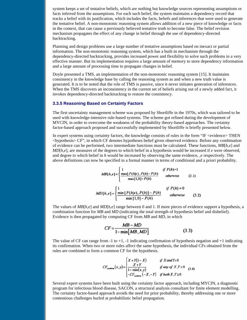
system keeps a set of tentative beliefs, which are nothing but knowledge sources representing assumptions orfacts inferred from the assumptions. For each such belief, the system maintains a dependency record thattracks a belief with its justification, which includes the facts, beliefs and inferences that were used to generatethe tentative belief. A non-monotonic reasoning system allows addition of a new piece of knowledge or factsin the context, that can cause a previously believed tentative truth to become false. The belief revisionmechanism propagates the effect of any change in belief through the use of dependency-directedbacktracking.
Planning and design problems use a large number of tentative assumptions based on inexact or partialinformation. The non-monotonic reasoning system, which has a built-in mechanism through thedependency-directed backtracking, provides increased power and flexibility to solve such problems in a veryeffective manner. But its implementation requires a large amount of memory to store dependency informationand a large amount of processing time to propagate changes in belief.
Doyle presented a TMS, an implementation of the non-monotonic reasoning system [15]. It maintainsconsistency in the knowledge base by calling the reasoning system as and when a new truth value isgenerated. It is to be noted that the role of TMS is passive, since it never initiates generation of inferences.When the TMS discovers an inconsistency in the current set of beliefs arising out of a newly added fact, itinvokes dependency-directed backtracking to restore the consistency.
3.3.5 Reasoning Based on Certainty Factors
The first uncertainty management scheme was proposed by Shortliffe in the 1970s, which was tailored to beused with knowledge-intensive rule-based systems. The scheme got refined during the development ofMYCIN, in order to overcome the weakness of the probability theory-based approaches. The certaintyfactor-based approach proposed and successfully implemented by Shortliffe is briefly presented below.
In expert systems using certainty factors, the knowledge consists of rules in the form “IF <evidence> THEN<hypothesis> CF”, in which CF denotes hypotheses belief given observed evidence. Before any combinationof evidence can be performed, two intermediate functions must be calculated. These functions, MB[h,e] andMD[h,e], are measures of the degrees to which belief in a hypothesis would be increased if e were observed,and degree to which belief in h would be increased by observing the same evidence, ,e respectively. Theabove definitions can now be specified in a formal manner in terms of conditional and a priori probability.
The values of MB[h,e] and MD[h,e] range between 0 and 1. If more pieces of evidence support a hypothesis, acombination function for MB and MD (indicating the total strength of hypothesis belief and disbelief).Evidence is then propagated by computing CF from MB and MD, in which
The value of CF can range from -1 to +1, -1 indicating confirmation of hypothesis negation and +1 indicatingits confirmation. When two or more rules affect the same hypothesis, the individual CFs obtained from therules are combined to form a common CF for the hypothesis.
Several expert systems have been built using the certainty factor approach, including MYCIN, a diagnosticprogram for infectious blood disease, SACON, a structural analysis consultant for finite element modelling.The certainty factor-based approach avoids the need for prior probability, thereby addressing one or morecontentious challenges hurled at probabilistic belief propagation.

Previous Table of Contents Next
Products | Contact Us | About Us | Privacy | Ad Info | Home
Use of this site is subject to certain Terms & Conditions, Copyright © 1996-2000 EarthWeb Inc. All rightsreserved. Reproduction whole or in part in any form or medium without express written permission of
EarthWeb is prohibited. Read EarthWeb's privacy statement.

Search Tips
Advanced Search
Artificial Intelligence and Expert Systems for Engineersby C.S. Krishnamoorthy; S. RajeevCRC Press, CRC Press LLCISBN: 0849391253 Pub Date: 08/01/96
Search this book:
Previous Table of Contents Next
A number of other techniques are also proposed by researchers to handle uncertain knowledge and carry outinexact reasoning. A few of them are subjective probability theory, Dempster-Shafer theory based onmathematical theory of evidence, belief functions, possibility theory as an extension of the theory of fuzzysets and evidence propagation. As the objective of the present chapter is to give the reader an idea on the needfor handling uncertainty in knowledge and a general approach to carry out inexact reasoning in KBES,detailed presentation of the above is not attempted. Also none of the schemes reported in the literature waswithout shortcomings. A complex uncertain reasoning mechanism necessarily involves additional efforts onthe part of the expert and the knowledge engineer to incorporate the mathematical content of the schemes intothe expert system. This places an undesirable constraint on the expert in the knowledge elicitation process. Inusing a simple scheme, knowing the shortcomings involved makes it possible to avoid the pitfalls and build arobust prototype system. A simple implementation of certainty factor based reasoning adopted in DEKBASEis presented below.
Consider a simple rule shown below. The rule can be considered to be a black box receiving an input(antecedents) and outputs some actions (consequents).
RULE example 1 for CF IF A AND B AND C THEN D AND E
Assume that A, B and C are true with confidences of 90, 80 and 85, respectively. (Here confidence factors areused such that they can take values between 0 and 100.) What are the confidences of D and E? It is moreappropriate to consider all conjunctions to be equal as in the case of links in a chain. The chain is only asstrong as the weakest link. Therefore, the confidence of B governs the overall confidence of the input. Theconfidence of D and E are therefore set to a value of 80. Now consider another rule.
RULE example 2 for CF IF A OR B AND C THEN D AND E
Here the only difference is that a disjunction is introduced in the form of OR. The disjunction A or Bevaluates to true with a confidence value equal to the confidence value of the antecedent with the highestindividual confidence in the disjunction. This is logical because it is necessary that any one antecedent needs

to be true and the inference process aims to establish facts with the greatest possible confidence. Therefore inthe above rule, the overall input confidence is taken as the minimum of 90 and 85. The value 90 is an outcomeof the consideration that it is the maximum of the values 90 and 80. D and E are therefore assigned aconfidence value of 85. Now let us see what happens if confidence values are assigned to consequents in therule. Consider the following rule:
RULE example 3 for CF IF A OR B AND C THEN D CF 90 AND E CF 80
In the above rule, when the conditions in the antecedent part are satisfied, the deduction that D is true can bemade with a confidence of 90 and E with a confidence of 80. The additional uncertainty in the knowledgeshould now be combined with the uncertainty of the facts, i.e., A, B and C. When confidence values arespecified, confidence of the output is attenuated by the CF values after the overall confidence of the input isevaluated. In the above example, the overall input confidence is 85. D is then assigned a confidence of 76.5(0.85 × 90) and E is assigned a confidence value of 68 (0.85 × 80). Now consider the following rule, which isjust a restatement of the previous rule, but the order in which the first two conditions appear is interchanged.
RULE example 4 for CF IF B OR A AND C THEN D CF 90 AND E CF 80
If all antecedents in a disjunction are not considered, then A would not be considered at all and we wouldestablish D and E with confidence values of 72 and 64, which are quite different from the previous case. Theessential knowledge is the same. It is for the reason of consistent handling of uncertainty that ruleinterpretation is different when CONFIDENCE mode is toggled.
The way a rule is interpreted by the inference engine depends on the status of the confidence mode. In fact,the more important aspect is the manner in which the inference engine fires the rules in a rule base. The issueof rule triggering in the chaining process and conflict resolution aspects are presented with inexact reasoningboth disabled and enabled. Consider a simple rule base having five rules.
RULE R1 IF B THEN C CF 80 AND F CF 90
RULE R2 IF A THEN C CF 90 AND F CF 80
RULE R3 IF P THEN D
RULE R4 IF Q AND R THEN D
RULE R5 IF C AND D THEN E
Assume that the goal is E and that A, B, P, Q and R are true with a confidence value of 100. First consider thecase when inexact reasoning is disabled and the chaining mode is backward. The chaining process will be asshown below.
Attempt R5. C is requiredAttempt R2. C is established with a confidence of 100Attempt R5. D is requiredAttempt R3. D is established with a confidence of 100Attempt R5. E is established with a confidence of 100

The following can be noted in the process of inference. There are two rules, which will establish C. Instead ofselecting the first one (R1), the inference mechanism selected R2. This is because the conflict resolutionstrategy attempts establishing a fact in the decreasing order of CF values corresponding to the consequentestablishing the fact in the respective rules. Had the goal been F instead of E, then R1 would have beenattempted in place of R2. Also, when a rule establishes a fact, the other rules establishing the rule are nottried, implying that as R2 establishes C, R1 will not be attempted. Since inexact reasoning is disabled, aconfidence of 100 is assigned to all the facts established.
Previous Table of Contents Next
Products | Contact Us | About Us | Privacy | Ad Info | Home
Use of this site is subject to certain Terms & Conditions, Copyright © 1996-2000 EarthWeb Inc. All rightsreserved. Reproduction whole or in part in any form or medium without express written permission of
EarthWeb is prohibited. Read EarthWeb's privacy statement.

Search Tips
Advanced Search
Artificial Intelligence and Expert Systems for Engineersby C.S. Krishnamoorthy; S. RajeevCRC Press, CRC Press LLCISBN: 0849391253 Pub Date: 08/01/96
Search this book:
Previous Table of Contents Next
The chaining process will be different, when inexact reasoning is enabled. Assume that A, B, P, Q and R areTRUE with confidence levels 85, 80, 75, 90 and 80, respectively. The chaining process is as shown below.
Attempt R5. C is requiredAttempt R2. C is established with a confidence of 76Attempt R1. C is NOT reestablished because confidence is 64Attempt R5. D is requiredAttempt R3. D is established with a confidence of 75Attempt R4. D is reestablished with a higher confidence of 80Attempt R5. E is established with a confidence of 76
A comparison of the two chaining processes shows many differences. First, all the rules trying to establish afact are attempted. If a rule establishes a fact with a higher confidence than the existing value, it is triggered.Otherwise the rule is ignored. This criterion is applied to all consequents in a rule independently. Tounderstand this concept better, consider the following two rules, in which it is required to establish a fact X.
RULE X1 IF A THEN X CF 80 AND Y CF 95
RULE X2 IF B THEN X CF 90 AND Y CF 90
IF A and B are TRUE with confidence values of 100, then rule X2 establishes X and Y with a confidence of90. When rule X1 is attempted, X can be established only with a confidence of 80 and so the rule is nottriggered as far as X is concerned, but Y will be reestablished with a new confidence of 95.
One difficulty in the use of confidence levels as explained above is that, when confidence values arepropagated over several levels, they tend to diminish rapidly. Some type of normalisation of confidence levels

at every level can overcome this difficulty, but no reliable mechanism is available for such normalisation.Formalisation of uncertainty in knowledge is so difficult and involved that both the knowledge engineer andthe expert will find it extremely difficult to quantify the qualitative nature of the uncertainty even to the levelof confidence factors. Then one can imagine the efforts required to use highly mathematical theories forrepresentation of uncertain knowledge and use them for inexact reasoning.
Expert System Development Shell
So far an overview of KBES technology is presented with detailed descriptions on knowledge representationand inference mechanisms with illustrative examples. To develop an expert system, one has to use eitherspecialised languages or expert system development shells. An expert system development shell is moreconvenient to use since it provides an environment for the knowledge engineer or the developer to code andimplement the knowledge without much difficulty. It also provides different knowledge representationschemes and inference mechanisms so that the developer can concentrate more on elicitation and organisationof knowledge and its implementation as a knowledge base, rather than going into the details of datastructuring and coding the algorithms for inference processes. A brief review of the requirements of an expertsystem development tool is presented below.
Selection of a KBES development tool appropriate to the application area is an important step in thedevelopment of KBES. A number of criteria have been identified based on which a tool can be evaluatedregarding its suitability for the development of a KBES in a particular domain. The important criteria are
Knowledge Representation: The tool should have enough expressive power for representing engineeringconcepts. The combination of scientific knowledge, that is often exact and complete, and heuristicinformation, which is based on empirical observations, is a critical issue in the development of a KBES.Ideally a combination of rules following the IF-THEN construct to represent the procedural knowledge andobjects or frames to represent declarative knowledge can provide a powerful environment for development ofa KBES in engineering disciplines. The combination should be such that the rules and frames should be ableto interact with each other during the problem solving.
Inference Mechanism: The tool should have different inference mechanisms, such as backward chaining,forward chaining and hybrid chaining, so that a developer can select an appropriate one depending on thenature of the knowledge and the problem-solving strategy. It should also have mechanisms for implementingdifferent types of inferences in a frame base environment. One such technique is use of different types ofdemons in frames. The knowledge representation and inference mechanism together should providetechniques to develop process models such as blackboard architecture with non-monotonic reasoning andother models which use components such as engineering design synthesis, design critiquing etc.
Developer Interface: A good developer interface should provide the expert system developer with tools suchas a knowledge base editor, a knowledge debugging environment with a trace through the line of reasoning,facilities to examine context and modify values etc.
User Interface: Once the KBES has been implemented, its usability depends largely on the end user interface.The user interface should enable the user to interact efficiently with the KBES and should include menusystems, an interactive graphics facility and explanation facilities to make the system user friendly.
Programming Language Considerations: In addition to the structure and paradigms supported by a tool, thelanguage in which the tool is written is of major importance. The language plays a major role in thecompatibility and portability of the KBES. Similar considerations relate to the tool having language hooks foraccessing other programs or database hooks for accessing information stored in popular databases. The KBESmust also be able to call functions or programs written in other languages.
Hardware: The computers supported by the various tools are primarily a function of the language andoperating system in which they are written, and the memory, processing and graphics display capabilities ofindividual computers. Software tools that require special purpose hardware are to be selected only if theKBES that is to be implemented is to be made available only in such systems.
Previous Table of Contents Next

Products | Contact Us | About Us | Privacy | Ad Info | Home
Use of this site is subject to certain Terms & Conditions, Copyright © 1996-2000 EarthWeb Inc. All rightsreserved. Reproduction whole or in part in any form or medium without express written permission of
EarthWeb is prohibited. Read EarthWeb's privacy statement.

Search Tips
Advanced Search
Artificial Intelligence and Expert Systems for Engineersby C.S. Krishnamoorthy; S. RajeevCRC Press, CRC Press LLCISBN: 0849391253 Pub Date: 08/01/96
Search this book:
Previous Table of Contents Next
Cost: The cost of the tool is a very important criterion. The cost of the tools used for implementing a KBESwill reflect on the price of the product and in turn on the market for the KBES.
Other criteria for evaluating a development tool include ability of the tool to handle complex arithmetic,extensibility of the tool by way of incorporating new problem-solving and knowledge representationstrategies that may evolve over a period of time and the degree of support offered by the vendors.
A number of KBES development tools are available now with different capabilities, which offer tools fordeveloping expert systems in engineering. A few of them are OPS5 and OPS83, INSIGHT, Level5 Object,Prolog, VP-Expert, Teknowledge, Personal Consultant Plus, GEPSE, KEE, ART and KnowledgeCraft. Out ofthese OPS5, OPS83 and Prolog are more of a programming language type and others are specialiseddevelopment tools. Important features of a few of the tools are presented below so that the readers can have acomparison.
OPS5 is a general purpose production system language for rule-based programming. Its main advantage is itsstability and efficiency as has been demonstrated by its use in the development of a number of prototypesystems, including R1 and XSEL. Though OPS5 provides a compound data type to define objects, itsexpressive power in representing declarative knowledge is inferior to that of the frame-based knowledgerepresentation scheme. While the OPS5 inference engine is a forward chaining engine, the programmer canwrite rules to effect his own control strategies. External function and procedure calls in other languages aresupported by some implementations of OPS5. The main disadvantages of OPS5 are its lack of awell-developed user interface and special editing and explanation facilities, and the lack of a formal method torepresent structured objects.
OPS83 is an improvement on OPS5, which enables programmers to write very efficient and compactproduction system code. The data-typing features and user-defined functions and procedures of OPS83resemble those in modern procedural languages. OPS83 is a hybrid programming tool in that it allows formultiple knowledge representation and inference schemes.
INSIGHT is a PC-based development environment for rule-based expert systems. INSIGHT uses a compilerfor knowledge bases. This not only allows large knowledge bases to run in systems with less memory, butalso makes knowledge bases run faster than interpretative systems such as Prolog. It provides a ProductionRule Language (PRL) for development of knowledge bases. It has a number of facilities such as directinterfacing with databases, activation of programs written in other languages, use of confidence factors and

inexact reasoning, a function key-driven environment and user-friendly interface. Level5 Object is also fromthe same company, which provides frame-based knowledge representation and a Windows-based environmentfor KBES development.
GEPSE is an environment for developing KBES for engineering problems. The key features of GEPSE are anObject Network Language (ONL) that simplifies construction of objects and rule bases, function libraries,functions for developing a user interface and a facility for meta-level control. The graphics functionssupported by GEPSE provide facility to develop user interfaces for applications.
Prolog is an example of languages that are based on predicate logic, known as logic programming languages.Traditionally, computation in Prolog is viewed as a refutation of a goal using the rule of inference calledresolution. However, Prolog can also be viewed as a backward chaining rule-based language with veryspecific information on what to do next. It has been widely used in Europe and Japan for implementing a widevariety of expert systems.
KEE is a widely used programming environment for implementing large and sophisticated KBES. KEEprovides both rule base and frame base for knowledge representation schemes. It allows hierarchicalmodelling of objects with facilities for inheritance of hierarchies with defaults and demon procedures attachedwith slots. It has an open architecture with facility for user-defined inference methods, a truth maintenancesystem, logical operators, integration with C, accessing databases and LISP programs. KEE has been used forapplications in diagnosis, monitoring, real-time process control, planning, design and simulation.
ART is a versatile tool incorporating a sophisticated workbench for use with advanced AI machines. ART’sstrong point is viewpoints, a technique that allows hypothetical non-monotonic reasoning in which multiplesolutions are carried along in parallel until constraints are violated or better solutions are found. At suchpoints, inappropriate solutions are discarded. It provides graphical interfaces for browsing both its viewpointand schema networks. ART has a flexible graphic workbench through which graphics interfaces andsimulations can be created. It is particularly suitable for planning, scheduling, simulation and designapplications. Both ART and KEE are expensive compared to the other tools.
The salient features of a KBES development environment provided by the expert system development shell ofDEKBASE (Development Environment for Knowledge-Based Systems in Engineering) is presented inAppendix I.
Previous Table of Contents Next
Products | Contact Us | About Us | Privacy | Ad Info | Home
Use of this site is subject to certain Terms & Conditions, Copyright © 1996-2000 EarthWeb Inc. All rightsreserved. Reproduction whole or in part in any form or medium without express written permission of
EarthWeb is prohibited. Read EarthWeb's privacy statement.

Search Tips
Advanced Search
Artificial Intelligence and Expert Systems for Engineersby C.S. Krishnamoorthy; S. RajeevCRC Press, CRC Press LLCISBN: 0849391253 Pub Date: 08/01/96
Search this book:
Previous Table of Contents Next
DEKBASE
The motivation behind the development of DEKBASE is the objective of developing prototype expertsystems in engineering domains. Existing tools do not meet with all the requirements. Moreover, largeprototypes are rather rare in engineering domains, and it was felt through a study of the problems arisingduring the prototype development process, the features required to address these problems could be devisedand incorporated into the shell. Such an approach would result in identifying the architecture of a generalpurpose expert system shell for developing real-life prototypes in engineering, as also providing such ashell for realising the prototypes. The features of DEKBASE are described with an objective of enabling abeginner to understand how to use it to develop prototype expert systems [16,17]. Emphasis is placed onthe different aspects of expert systems development, so that the readers can design and developknowledge-based expert systems for problems such as diagnosis, classification, planning, monitoring anddesign in different domains of engineering. DEKBASE also provides interface to other knowledge-basedsystems development modules such as GENSYNT (module for design synthesis), GENCRIT (module fordesign criticism) and CASETOOL (module for case-based reasoning), which are explained in subsequentchapters of the book.
A typical example with three rule bases is presented in the section on knowledge representation, and theway the knowledge is used for inference is described in the section on inference techniques. Two moreexamples of the use of rule bases for two different types of problems are presented here. First is a systemfor selection of bearings having 16 rules. The second problem is a relatively large problem for planning,analysis and design of steel industrial structures.
Example 1: Selection of Bearings
This problem is a relatively trivial one and typically illustrates a simple classification task. The knowledgenet for the problem is presented in Figure 3.14. The knowledge net has 16 nodes representing 6 goal states,7 initial states and 3 intermediate states. The knowledge coded in the rule base is typically adaptable forbackward chaining. The rule base representing the knowledge in the knowledge net is given below.
TITLE Expert System for Bearing Selection BOOLEAN silent running important, shaft misalignment with housing, moderate axial loading,
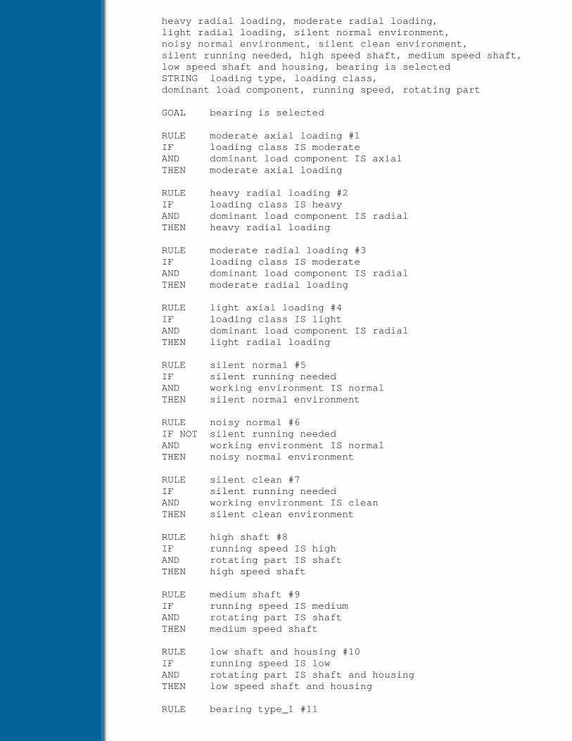
heavy radial loading, moderate radial loading, light radial loading, silent normal environment, noisy normal environment, silent clean environment, silent running needed, high speed shaft, medium speed shaft, low speed shaft and housing, bearing is selected STRING loading type, loading class, dominant load component, running speed, rotating part
GOAL bearing is selected
RULE moderate axial loading #1 IF loading class IS moderate AND dominant load component IS axial THEN moderate axial loading
RULE heavy radial loading #2 IF loading class IS heavy AND dominant load component IS radial THEN heavy radial loading
RULE moderate radial loading #3 IF loading class IS moderate AND dominant load component IS radial THEN moderate radial loading
RULE light axial loading #4 IF loading class IS light AND dominant load component IS radial THEN light radial loading
RULE silent normal #5 IF silent running needed AND working environment IS normal THEN silent normal environment
RULE noisy normal #6 IF NOT silent running needed AND working environment IS normal THEN noisy normal environment
RULE silent clean #7 IF silent running needed AND working environment IS clean THEN silent clean environment
RULE high shaft #8 IF running speed IS high AND rotating part IS shaft THEN high speed shaft
RULE medium shaft #9 IF running speed IS medium AND rotating part IS shaft THEN medium speed shaft
RULE low shaft and housing #10 IF running speed IS low AND rotating part IS shaft and housing THEN low speed shaft and housing
RULE bearing type_1 #11

IF loading type IS radial and axial AND of shaft misalignment with housing AND moderate axial loading AND high speed shaft AND silent normal environment THEN bearing is selected AND DISPLAY type_1
RULE bearing type_2 #12 IF loading type IS radial and axial AND NOT shaft misalignment with housing AND heavy radial loading AND high speed shaft AND noisy normal environment THEN bearing is selected AND DISPLAY type_2
RULE bearing type_3 #13 IF loading type IS radial AND NOT shaft misalignment with housing AND light radial loading AND medium speed shaft AND silent clean environment THEN bearing is selected AND DISPLAY type_3
RULE bearing type_4 #14 IF loading type IS radial and axial AND shaft misalignment with housing AND moderate radial loading AND medium speed shaft AND noisy normal environment THEN bearing is selected AND DISPLAY type_4
RULE bearing type_5 #15 IF loading type IS radial and axial AND shaft misalignment with housing AND heavy radial loading AND low speed shaft and housing AND noisy normal environment THEN bearing is selected AND DISPLAY type_5
RULE bearing type_6 #16 IF loading type IS radial and axial AND NOT shaft misalignment with housing AND moderate radial loading AND high speed shaft AND noisy normal environment THEN bearing is selected AND DISPLAY type_6 END
The rule base is coded following the syntax of DEKBASE, which is described in Appendix I. TheDISPLAY tags mentioned in the rule base (type_1 to type_6) are not given here. The complete knowledgebase is given in the diskette provided with the book.
Figure 3.14 Knowledge net for bearing selection problem

Previous Table of Contents Next
Products | Contact Us | About Us | Privacy | Ad Info | Home
Use of this site is subject to certain Terms & Conditions, Copyright © 1996-2000 EarthWeb Inc. All rightsreserved. Reproduction whole or in part in any form or medium without express written permission of
EarthWeb is prohibited. Read EarthWeb's privacy statement.

Search Tips
Advanced Search
Artificial Intelligence and Expert Systems for Engineersby C.S. Krishnamoorthy; S. RajeevCRC Press, CRC Press LLCISBN: 0849391253 Pub Date: 08/01/96
Search this book:
Previous Table of Contents Next
Example 2: Planning and Design of Steel Industrial Structures
Use of KBES technology is illustrated using a problem of planning and design of steel industrial structures[18]. The aim of this example is to illustrate how a complex engineering design problem can be planned andimplemented using a knowledge-based approach.
A very brief description of the industrial building design process is given to place the ensuing illustration inproper perspective. The perspective view of a typical industrial building is shown in Fig. 3.15. The buildingessentially consists of a roof supported on purlins which rest on trusses. The trusses in turn rest on columnsthat finally carry the loads down to the foundation located below the ground.
Figure 3.15 Steel industrial building
The first task in the design process is to determine the shape of the building, the sizes of the varioussegments and the height from the floor to the ceiling at various points in the building. These have to bedecided based on the kind of equipment to be housed, the direction of process flow etc.
Following the spatial planning, the columns have to be located. Constraints may be placed on columnlocations because of the need to provide unobstructed space to house large machines. The location ofcolumns is arrived at by generating Column Lines (CLs). Column lines are potential lines along whichcolumns can be located. For arriving at the actual column locations, CLs are generated in the twoorthogonal directions (these are called Longitudinal Column Lines, LCLs, and Transverse Column Lines,TCLs). Columns are then placed at the intersection of these lines.
Once the location of columns is decided, the type of trusses to be used is determined. The truss typedepends on the spacing between columns. Once the trusses for the building have been chosen, a detailedanalysis is carried out to determine the response of the structure to loads. The various individual structuralcomponents are then configured to resist the design forces and the details of how the members are to beconnected at joints is also done. Finally the construction drawings are prepared.

This is a complex problem involving knowledge-based inference, procedural programs, access to databasesand communication of information between knowledge modules and program modules through frames. Theknowledge base consists of six rule bases, which are fairly large, and a number of frames, C functions andexternal programs. Only a few representative rules are presented here, which will help the readersunderstand how a complex problem is reduced to a sequence of smaller problems of knowledge and dataprocessing. Figure 3.16 shows the problem reduction and the organisation of different modules. A briefdescription of the rule bases are given below. (An extension .RL is used to indicate rule bases and .EXE isused to indicate external executable programs).
INIT.RL This rule base initialises the session. Since every session starts with user specification ofa problem, the external programs for obtaining the problem data, planning etc. areinvoked. After completing the inference, it loads another rule base PLAN.RL.
TITLE Initialising Session RULE for obtaining input IF NOT input obtained THEN RUN input # run external pgm AND FLOAD_FBASE layout.fbs AND FSELECT_FBASE layout.fbs AND input obtained AND LOAD plan #loads plan.rl END
PLAN.RL This rule base generates column lines in both longitudinal and transverse directions foreach rectangular portion. The values along with the data obtained from the programinput.exe are required for configuring the components of the industrial building. Aprocedural program plan.exe is called from this rule base to carry out the planning anddetailed configuration. The rule base CONFIG.RL that does the job of configuring iscalled from this rule base. Planning and configuration have to be done for each segmentseparately, implying that inference using this rule base has to be carried out in aniterative manner. The iteration is forced when rule 8 is fired, which has an actionRESTART. It may be noted that at the beginning of each iteration, the variables whichget modified during the inference are initialised. This is achieved using a qualifierCLEAR in the declarations of those variables. The program plan.exe modifies the framebase layout.fbs, which is loaded before loading the next rule base CONFIG.RL.
Figure 3.16 Organisation of knowledge modules for industrial building design system
TITLE Assigning LCL Spacings to Segments /* only typical variable declarations are given */
BOOLEAN lcl spacing assigned, all segments have been considered, current segment is known, recorded values in frame INTEGER segment number NUMERIC minimum lcl spacing, maximum lcl spacing, clear height in segment STRING current segment, class name
CLEAR lcl spacing assigned CLEAR clear height in segment CLEAR all segments have been considered CLEAR current segment is known CLEAR minimum lcl spacing
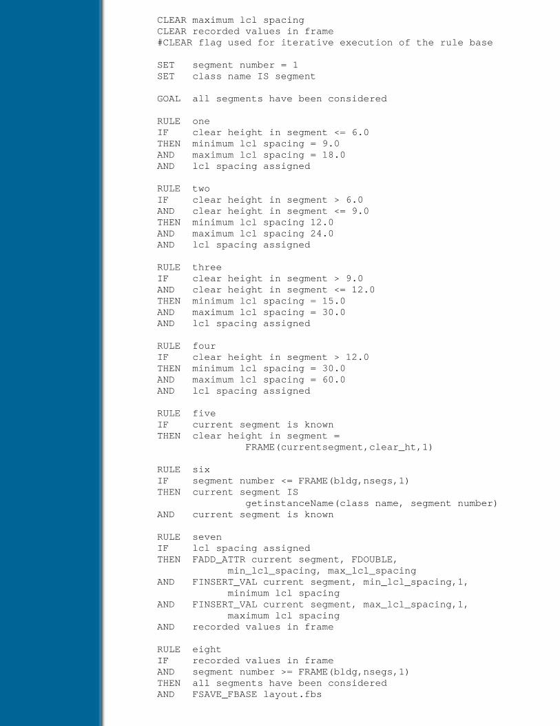
CLEAR maximum lcl spacing CLEAR recorded values in frame #CLEAR flag used for iterative execution of the rule base
SET segment number = 1 SET class name IS segment
GOAL all segments have been considered
RULE one IF clear height in segment <= 6.0 THEN minimum lcl spacing = 9.0 AND maximum lcl spacing = 18.0 AND lcl spacing assigned
RULE two IF clear height in segment > 6.0 AND clear height in segment <= 9.0 THEN minimum lcl spacing 12.0 AND maximum lcl spacing 24.0 AND lcl spacing assigned
RULE three IF clear height in segment > 9.0 AND clear height in segment <= 12.0 THEN minimum lcl spacing = 15.0 AND maximum lcl spacing = 30.0 AND lcl spacing assigned
RULE four IF clear height in segment > 12.0 THEN minimum lcl spacing = 30.0 AND maximum lcl spacing = 60.0 AND lcl spacing assigned
RULE five IF current segment is known THEN clear height in segment = FRAME(currentsegment,clear_ht,1)
RULE six IF segment number <= FRAME(bldg,nsegs,1) THEN current segment IS getinstanceName(class name, segment number) AND current segment is known
RULE seven IF lcl spacing assigned THEN FADD_ATTR current segment, FDOUBLE, min_lcl_spacing, max_lcl_spacing AND FINSERT_VAL current segment, min_lcl_spacing,1, minimum lcl spacing AND FINSERT_VAL current segment, max_lcl_spacing,1, maximum lcl spacing AND recorded values in frame
RULE eight IF recorded values in frame AND segment number >= FRAME(bldg,nsegs,1) THEN all segments have been considered AND FSAVE_FBASE layout.fbs

AND FDEL_FBASE layout.fbs AND RUN plan # do the planning AND FLOAD_FBASE layout.fbs AND FSELECT_FBASE layout.fbs AND LOAD config # loads config.rl ELSE segment number = segment number + 1 # goto next segment AND RESTART # restart for next segment END
CONFIG.RL This rule base assigns a framing type for each aisle and arrives at the shape of the trussto be provided. Only two types of trusses are considered for illustration. It may be notedthat a C function getInstNo () is called in a rule to obtain the current aisle number.Another rule base TRUSS.RL is loaded after completing all the tasks of configuration.Only typical rules are given.
TITLE assign framing type in each aisle GOAL all aisles have been considered RULE for current aisle IF current aisle is known THEN clear height in aisle FRAME(current isle,clear_ht,1) AND floor height in aisle FRAME(current isle,floor_ht,1) AND eave height of truss = clear height in aisle + floor height in aisle AND flow direction IS FRAME (current aisle,flow_dir,1) AND truss spacing=FRAME(current aisle, truss_spacing,1) AND aisle x1 = FRAME (current aisle,aisle_area_x1,1) AND aisle y1 = FRAME (current aisle, aisle_area_y1,1) AND aisle x2 = FRAME (current aisle, aisle_area_x2,1) AND aisle y2 = FRAME (current aisle, aisle_area_y2,1)
RULE for span of truss IF flow direction IS EAST_WEST THEN span of truss = aisle y2 - aisle y1 ELSE span of truss = aisle x2 - aisle x1
RULE getting instance IF aisle number <= FRAME (bldg,naisles,1) THEN current aisle IS getInstNo (class name, aisle number) AND current aisle is known
RULE storing values IF truss type assigned THEN FADD_ATTR current aisle, FSTRING, truss_shape AND FINSERT_VAL current aisle, truss_shape, shape of truss AND recorded values in frame
RULE for truss type 1 IF span of truss <= 8.0 THEN shape of truss IS North_Light_Type AND rise of truss = span of truss /5 # overridable
Previous Table of Contents Next

Products | Contact Us | About Us | Privacy | Ad Info | Home
Use of this site is subject to certain Terms & Conditions, Copyright © 1996-2000 EarthWeb Inc. All rightsreserved. Reproduction whole or in part in any form or medium without express written permission of
EarthWeb is prohibited. Read EarthWeb's privacy statement.

Search Tips
Advanced Search
Artificial Intelligence and Expert Systems for Engineersby C.S. Krishnamoorthy; S. RajeevCRC Press, CRC Press LLCISBN: 0849391253 Pub Date: 08/01/96
Search this book:
Previous Table of Contents Next
… Other rules for configuring are omitted…
RULE for loading rule base TRUSS IF all aisles have been considered THEN run TRUSS AND configuration completed END
TRUSS.RL This rule base first obtains truss details by loading the frame base created by thepreceding rule base and arrives at parameters such as number of panels for the truss,cross section of purlins, viz., angle or channel. The section properties are obtained from adatabase, using a database query DBMS from the rule base. It also computes loads on thetruss and calls a C function ConfigureTruss(), which creates a data file for analysis. Atthe end, the rule base loads an executable file TRUSS.EXE to carry out analysis andstore results in an output file for further processing. Only typical rules are presented foreach process.
TITLE Truss Configuration and Design GOAL building details obtained, truss details obtained, purlin designation, configuration over,analysis is over
RULE to read details from frame #1 IF FEXIST_FRAME bldg THEN latitude of site = FRAME(bldg,latitude,1) AND terrain type IS FRAME(bldg,terrain,1) AND basic wind speed = FRAME(bldg,wind_speed,1) AND design life of building = FRAME(bldg,design_life,1) AND process type IS FRAME (bldg,process,1) AND natural lighting IS FRAME(bldg,nat_lighting,1) AND permeability of bldg IS FRAME(bldg, permeability, 1) AND length of building = FRAME(bldg,length,1) AND width of building = FRAME(bldg,width,1)
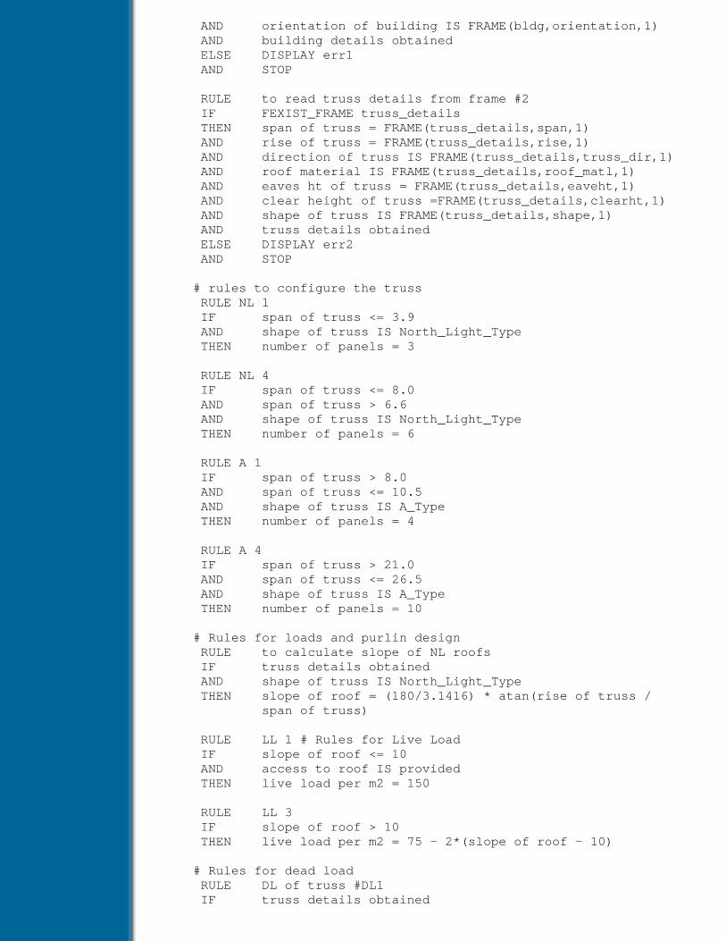
AND orientation of building IS FRAME(bldg,orientation,1) AND building details obtained ELSE DISPLAY err1 AND STOP
RULE to read truss details from frame #2 IF FEXIST_FRAME truss_details THEN span of truss = FRAME(truss_details,span,1) AND rise of truss = FRAME(truss_details,rise,1) AND direction of truss IS FRAME(truss_details,truss_dir,1) AND roof material IS FRAME(truss_details,roof_matl,1) AND eaves ht of truss = FRAME(truss_details,eaveht,1) AND clear height of truss =FRAME(truss_details,clearht,1) AND shape of truss IS FRAME(truss_details,shape,1) AND truss details obtained ELSE DISPLAY err2 AND STOP
# rules to configure the truss RULE NL 1 IF span of truss <= 3.9 AND shape of truss IS North_Light_Type THEN number of panels = 3
RULE NL 4 IF span of truss <= 8.0 AND span of truss > 6.6 AND shape of truss IS North_Light_Type THEN number of panels = 6
RULE A 1 IF span of truss > 8.0 AND span of truss <= 10.5 AND shape of truss IS A_Type THEN number of panels = 4
RULE A 4 IF span of truss > 21.0 AND span of truss <= 26.5 AND shape of truss IS A_Type THEN number of panels = 10
# Rules for loads and purlin design RULE to calculate slope of NL roofs IF truss details obtained AND shape of truss IS North_Light_Type THEN slope of roof = (180/3.1416) * atan(rise of truss / span of truss)
RULE LL 1 # Rules for Live Load IF slope of roof <= 10 AND access to roof IS provided THEN live load per m2 = 150
RULE LL 3 IF slope of roof > 10 THEN live load per m2 = 75 - 2*(slope of roof - 10)
# Rules for dead load RULE DL of truss #DL1 IF truss details obtained
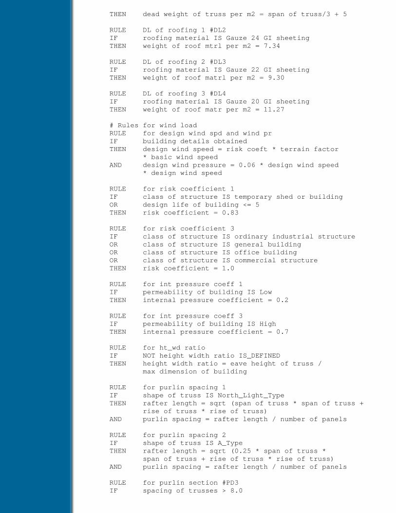
THEN dead weight of truss per m2 = span of truss/3 + 5
RULE DL of roofing 1 #DL2 IF roofing material IS Gauze 24 GI sheeting THEN weight of roof mtrl per m2 = 7.34
RULE DL of roofing 2 #DL3 IF roofing material IS Gauze 22 GI sheeting THEN weight of roof matrl per m2 = 9.30
RULE DL of roofing 3 #DL4 IF roofing material IS Gauze 20 GI sheeting THEN weight of roof matr per m2 = 11.27
# Rules for wind load RULE for design wind spd and wind pr IF building details obtained THEN design wind speed = risk coeft * terrain factor * basic wind speed AND design wind pressure = 0.06 * design wind speed * design wind speed
RULE for risk coefficient 1 IF class of structure IS temporary shed or building OR design life of building <= 5 THEN risk coefficient = 0.83
RULE for risk coefficient 3 IF class of structure IS ordinary industrial structure OR class of structure IS general building OR class of structure IS office building OR class of structure IS commercial structure THEN risk coefficient = 1.0
RULE for int pressure coeff 1 IF permeability of building IS Low THEN internal pressure coefficient = 0.2
RULE for int pressure coeff 3 IF permeability of building IS High THEN internal pressure coefficient = 0.7
RULE for ht_wd ratio IF NOT height width ratio IS_DEFINED THEN height width ratio = eave height of truss / max dimension of building
RULE for purlin spacing 1 IF shape of truss IS North_Light_Type THEN rafter length = sqrt (span of truss * span of truss + rise of truss * rise of truss) AND purlin spacing = rafter length / number of panels
RULE for purlin spacing 2 IF shape of truss IS A_Type THEN rafter length = sqrt (0.25 * span of truss * span of truss + rise of truss * rise of truss) AND purlin spacing = rafter length / number of panels
RULE for purlin section #PD3 IF spacing of trusses > 8.0
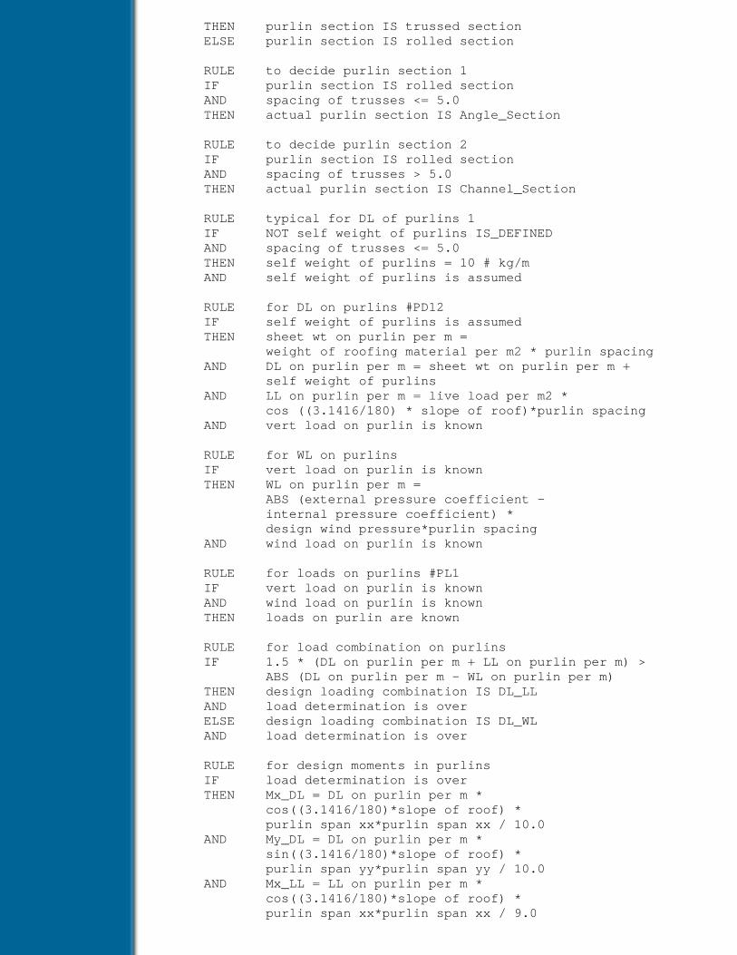
THEN purlin section IS trussed section ELSE purlin section IS rolled section
RULE to decide purlin section 1 IF purlin section IS rolled section AND spacing of trusses <= 5.0 THEN actual purlin section IS Angle_Section
RULE to decide purlin section 2 IF purlin section IS rolled section AND spacing of trusses > 5.0 THEN actual purlin section IS Channel_Section
RULE typical for DL of purlins 1 IF NOT self weight of purlins IS_DEFINED AND spacing of trusses <= 5.0 THEN self weight of purlins = 10 # kg/m AND self weight of purlins is assumed
RULE for DL on purlins #PD12 IF self weight of purlins is assumed THEN sheet wt on purlin per m = weight of roofing material per m2 * purlin spacing AND DL on purlin per m = sheet wt on purlin per m + self weight of purlins AND LL on purlin per m = live load per m2 * cos ((3.1416/180) * slope of roof)*purlin spacing AND vert load on purlin is known
RULE for WL on purlins IF vert load on purlin is known THEN WL on purlin per m = ABS (external pressure coefficient - internal pressure coefficient) * design wind pressure*purlin spacing AND wind load on purlin is known
RULE for loads on purlins #PL1 IF vert load on purlin is known AND wind load on purlin is known THEN loads on purlin are known
RULE for load combination on purlins IF 1.5 * (DL on purlin per m + LL on purlin per m) > ABS (DL on purlin per m - WL on purlin per m) THEN design loading combination IS DL_LL AND load determination is over ELSE design loading combination IS DL_WL AND load determination is over
RULE for design moments in purlins IF load determination is over THEN Mx_DL = DL on purlin per m * cos((3.1416/180)*slope of roof) * purlin span xx*purlin span xx / 10.0 AND My_DL = DL on purlin per m * sin((3.1416/180)*slope of roof) * purlin span yy*purlin span yy / 10.0 AND Mx_LL = LL on purlin per m * cos((3.1416/180)*slope of roof) * purlin span xx*purlin span xx / 9.0
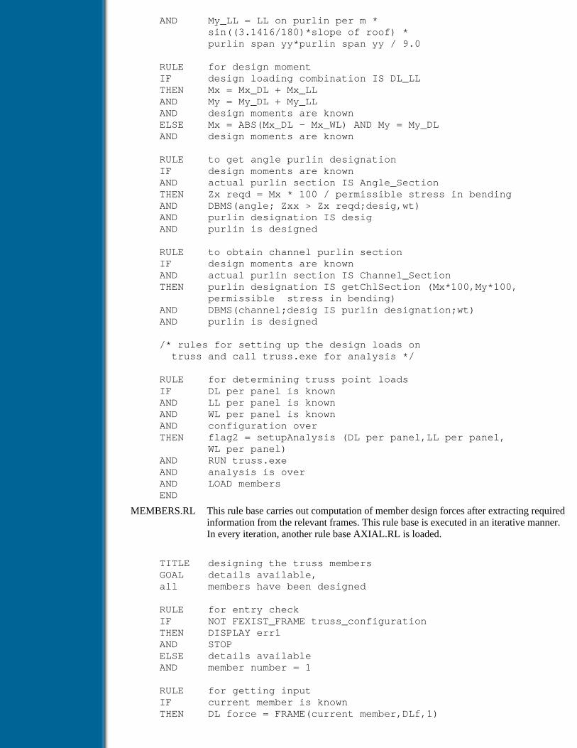
AND My_LL = LL on purlin per m * sin((3.1416/180)*slope of roof) * purlin span yy*purlin span yy / 9.0
RULE for design moment IF design loading combination IS DL_LL THEN Mx = Mx_DL + Mx_LL AND My = My_DL + My_LL AND design moments are known ELSE Mx = ABS(Mx_DL - Mx_WL) AND My = My_DL AND design moments are known
RULE to get angle purlin designation IF design moments are known AND actual purlin section IS Angle_Section THEN Zx reqd = Mx * 100 / permissible stress in bending AND DBMS(angle; Zxx > Zx reqd;desig,wt) AND purlin designation IS desig AND purlin is designed
RULE to obtain channel purlin section IF design moments are known AND actual purlin section IS Channel_Section THEN purlin designation IS getChlSection (Mx*100,My*100, permissible stress in bending) AND DBMS(channel;desig IS purlin designation;wt) AND purlin is designed
/* rules for setting up the design loads on truss and call truss.exe for analysis */
RULE for determining truss point loads IF DL per panel is known AND LL per panel is known AND WL per panel is known AND configuration over THEN flag2 = setupAnalysis (DL per panel,LL per panel, WL per panel) AND RUN truss.exe AND analysis is over AND LOAD members END
MEMBERS.RL This rule base carries out computation of member design forces after extracting requiredinformation from the relevant frames. This rule base is executed in an iterative manner.In every iteration, another rule base AXIAL.RL is loaded.
TITLE designing the truss members GOAL details available, all members have been designed
RULE for entry check IF NOT FEXIST_FRAME truss_configuration THEN DISPLAY err1 AND STOP ELSE details available AND member number = 1
RULE for getting input IF current member is known THEN DL force = FRAME(current member,DLf,1)

AND LL force = FRAME(current member,LLf,1) AND WL force = FRAME(current member,WLf,1) AND length of member =FRAME(current ember,length,1)
AND member class IS FRAME(current member,type,1) AND DL_LL force = DL force + LL force AND DL_WL force = DL force + WL force
RULE for determining design forces IF DL_LL force < 0.0 THEN comp force in member = DL_LL force AND tension force in member = DL_WL force ELSE comp force in member = DL_WL force AND tension force in member = DL_LL force
RULE for current instance IF member number <= FRAME(truss_configuration,nmembs,1) THEN current member IS getInstanceName (class name, member number) AND current member is known
RULE recording values in frame IF current member is designed THEN FADD_ATTR current member, FSTRING, desig AND FINSERT_VAL current member, desig,1,axial member designation AND recorded values in frame AND DISPLAY d11 AND UNDEFINE current member is designed AND UNDEFINE axial member designation
RULE looping control IF recorded values in frame AND member number >= FRAME(truss_configuration,nmembs,1) THEN all members have been designed AND flag1 = setupTrussDrg(connection material code) ELSE member number = member number + 1 AND RESTART
RULE for section of member IF member class IS RAFTER OR member class IS MAIN_TIE OR member class IS MAIN_SLING THEN member section IS Double_Angle_Section ELSE member section IS Single_Angle_Section
RULE for effective length 1 IF member section IS Single_Angle_Section THEN effective length of mbr = 0.85 * length of member
RULE for effective length 2 IF member section IS Double_Angle_Section THEN effective length of mbr = 0.70 * length of member
RULE for designing the current member IF axial member frame is created THEN FADD_ATTR axial_member_details, FDOUBLE, m_eff_length, m_length, m_comp,m_tension

AND FADD_ATTR axial_member_details, FSTRING, m_section,m_con_matl,m_role AND FINSERT_VAL axial_member_details, m_length,1,length of member AND FINSERT_VAL axial_member_details, m_eff_length,1, effective length of member AND FINSERT_VAL axial_member_details, m_comp,1,comp force in member AND FINSERT_VAL axial_member_details, m_tension,1,tension force in member AND FADD_ATTR current member, FSTRING, section AND FINSERT_VAL current member, section,1,member section AND FINSERT_VAL axial_member_details, m_section,1,member section AND FINSERT_VAL axial_member_details, m_con_matl,1,connection material AND FINSERT_VAL axial_member_details, m_role,1,member class AND current member is designed AND DISPLAY d12 AND LOAD axial END
AXIAL.RL This rule base uses the frame axial member details having all the data for design.Information required for carrying out design is stored in the frame base, which is loadedwhen the rule base is loaded. This rule base is called for design of each axial member.All the results are stored in the frame base, which are later used by drawing programs.(Rule bases and functions required for preparation of detailed drawing are not presentedhere.) The design procedure itself is iterative. Depending on the section type desired, theinference process starts with the first available section. It computes the compression andtension capacities of the selected section and if found satisfactory, returns the control tothe calling rule base, or else it explores the next section and restarts.
TITLE design of truss member for axial load GOAL axial member details available, axial member designation
RULE for entry check IF NOT FEXIST_FRAME axial_member_details THEN DISPLAY err1 AND STOP ELSE axial member details available AND trial count = 0
RULE for downloading info IF axial member details available THEN length = FRAME (axial_mbr_details,m_length,1) AND compression = FRAME (axial_mbr_details, m_comp,1) * -1.0 AND tension = FRAME (axial_mbr_details, m_tension,1) AND section IS FRAME (axial_mbr_details, m_section,1) AND connection mtrl IS FRAME(axial_mbr_details,matl,1)
RULE for checking eff_length IF NOT FEXIST_ATTR axial_mbr_details,m_eff_length THEN effective length = effective length factor * length ELSE effective length = FRAME (axial_mbr_details,m_eff_length,1)
RULE for getting trial section 1 IF NOT trial member IS_DEFINED

THEN trial member IS getTrialSection (section,trial count)
RULE for getting the properties from database 1 IF trial member obtained AND section IS Single_Angle_Section OR section IS Double_Angle_Section THEN DBMS (angle;desig IS trial member; area, rxx, rvv,depth,width,tf)
RULE for checking comp 2 IF actual stress in comp <= allowable stress in comp AND slenderness is ok THEN comp check ok ELSE trial count = trial count + 1 AND RESTART
RULE for success IF comp check ok AND tension check ok THEN axial member designation IS trial member AND current member is designed AND DISPLAY figure AND LOAD members
/* rules for slender check and tension check are not included */ END
Previous Table of Contents Next
Products | Contact Us | About Us | Privacy | Ad Info | Home
Use of this site is subject to certain Terms & Conditions, Copyright © 1996-2000 EarthWeb Inc. All rightsreserved. Reproduction whole or in part in any form or medium without express written permission of
EarthWeb is prohibited. Read EarthWeb's privacy statement.

Search Tips
Advanced Search
Artificial Intelligence and Expert Systems for Engineersby C.S. Krishnamoorthy; S. RajeevCRC Press, CRC Press LLCISBN: 0849391253 Pub Date: 08/01/96
Search this book:
Previous Table of Contents Next
This example illustrates how a complex problem requiring different types of computational models aredecomposed into smaller problems and then solved using an appropriate problem-solving strategy. Theexample reported is part of a complete prototype developed for Planning, Analysis and Design and SteelIndustrial Structures. Only modules required for planning, truss configuration and design of truss membersare presented with typical rules. The objective of this presentation is to give the readers an idea on design andimplementation of large knowledge-based systems. The concepts such as problem decomposition process,modular development of rule bases, communication between rule bases through frames, access of databasequery from rules, invoking procedural programs and functions from rules etc. are illustrated through thepresentation of the example.
References1. Newell A., Heuristic programming, in Ill-Structured Problems in Progress in Operations Research,Ed. I. S. Aronofsky, John Wiley and Sons, New York, 2, 363, 1969.
2. Noble, C. E., Solving ill-structured management problems, Business, 1, 22, 1979.
3. Hayes-Roth, F., Watermann, D. A., and Lenat, D. A., Building Expert System, Addison-Wesley,Reading, Mass., 1983.
4. Davis, R., and King, J., J., An overview of production systems, Machine Intelligence, Elcock, E.and Michie, D. (Eds.), Horwood, England, 1982.
5. Buchanan, B. G. and Shortliffe, E. H., Rule Based Expert System, Addison-Wesley, Reading,Mass., 1984.
6. Shortliffe, E. H., Buchanan, B. G. and Fiegenbaum, E. A., Knowledge engineering for medicaldecision making: A review of computer based clinical decision aids, Proc. of the IEEE, 67, 1207–1224,1979.
7. Buchanan, B. G. and Feigenbaum, E. A., DENDRAL and Meta-DENDRAL: Their applicationsdimension, Artificial Intelligence, 11, 5–24, 1978.
8. Maher, M. L., Sriram, D., and Fenves, S. J., Tools and techniques for knowledge-based expertsystem for engineering design, Advances in Engineering. Software, Vol. 6, 1984.
9. Wigan, M. R., Engineering tools for building knowledge-based systems on micro systems, MicroComputers in Civil Engineering, 1, 52, 1986.
10. Kostem, C. N. and Maher, M. L. (Eds.), Expert systems in civil engineering, Proc. of First

Symposium on Expert Systems in Civil Engineering, ASCE, Seatle, Washigton, 1986.
11. Sriram, D., Maher, M. L. and Fenves, S. J., Knowledge-based expert systems in structuraldesign, Computers and Structures, Seattle, Washington, 20(1–3), 1, 1985.
12. Dixon, J. R., Artificial intelligence and design: a mechanical engineering view, in AAAI-86 Proc.5th National Conference on Artificial Intelligence, Morgan Kauffman, New York, 1986, 872.
13. Maher, M. L., Expert systems for structural design, Jl. of Computing in Civil Engineering, ASCE,1(4), 270, 1987.
14. Krishnamoorthy, C. S. and Rajeev, S., Computer Aided Design - Software and Analytical Tools,Narosa Publishing House, New Delhi, India and Springer Verlag, New York, 1992.
15. Doyle, J., A truth maintenance system, Artificial Intelligence, 12(3), 231–272, 1979.
16 Krishnamoorthy, C. S., Shivakumar, H., Rajeev, S. and Suresh, S., A knowledge-based systemwith generic tools for structural engineering, Structural Engineering Review - An International Journal,5(2), 121–131, 1993.
17. Krishnamoorthy, C. S., Karimalla Raja, S., Rajeev, S. and Shiva Kumar, H., Developmentenvironment for knowledge-based system for engineering design, Proc. 2nd Int. Conf on theApplication of AI Techniques to Civil and Structural Engineering, Oxford, England, 165–174, 1991.
18. Srinivasa Rao, C., Kalyanaraman, V., Krishnamoorthy, C. S. and Rajeev, S.,Knowledge-based system for design of steel industrial structures (INDUS), Research Report R-94-4,Civil Engineering Department, Indian Institute of Technology, Madras, India, 1994.
Previous Table of Contents Next
Products | Contact Us | About Us | Privacy | Ad Info | Home
Use of this site is subject to certain Terms & Conditions, Copyright © 1996-2000 EarthWeb Inc. All rightsreserved. Reproduction whole or in part in any form or medium without express written permission of
EarthWeb is prohibited. Read EarthWeb's privacy statement.

Search Tips
Advanced Search
Artificial Intelligence and Expert Systems for Engineersby C.S. Krishnamoorthy; S. RajeevCRC Press, CRC Press LLCISBN: 0849391253 Pub Date: 08/01/96
Search this book:
Previous Table of Contents Next
Chapter 4Engineering Design Synthesis
4.1 Introduction
The engineering design process consists of different, though not entirely distinct, stages such as theconceptual design phase, the preliminary design phase, analysis, design, detailing and drafting, and so on.Each of these in turn can be further divided into subtasks. The conceptual design phase wherein the designerinvestigates many potential alternatives and makes fundamental choices that have major impact on thedownstream decisions is one of the important areas to be considered from the standpoint of automation.Creativity on the part of the designer is vital in obtaining desirable solutions. The problem of creativity iscompounded by the fact that at this stage of the design, every parameter of design may correspond to a fairlylarge set of options. Deficient reasoning at this stage results in more iterations at later stages of the designprocess since the basic form of the solution is identified in this phase. An important characteristic feature ofconceptual design is that typically several feasible design solutions are developed and evaluated.
It has been brought out in earlier publications that commonly used representation schemes inknowledge-based systems such as rules, frames etc., and control mechanisms such as forward chaining,backward chaining or hybrid chaining do not provide efficient strategies for building design process modelsfor real-life applications [1–6]. In this chapter the generic nature of the approach to conceptual design isbrought out as design synthesis. The use of design synthesis is shown to be efficient for dealing withspecialised design subtasks such as proposing a set of feasible solutions and it provides a powerfulmethodology for building flexible knowledge-based systems [7–9]. A software tool, GENSYNT, for designsynthesis is described [9]. The use of GENSYNT is illustrated through examples.
4.2 Synthesis
Design synthesis involves the generation of one or more design solutions consistent with the requirementsdefined during formulation of the design problem and any additional requirements identified during synthesis.During design synthesis the form of the solution is identified and arrived at. This phase of the design processis not well supported by computer-based tools unless the problem can be formulated in mathematical terms, in

which case certain classes of synthesis problems can be formulated as an objective function and constraintsand optimisation techniques can be used to solve them.
In general such formulations are always nonlinear and mathematical programming techniques are used toobtain optimal solution. In spite of research in this area for a long period of time, not much impact could bemade on the application of these optimisation techniques to practical problems. The reasons include (a)mathematical programming techniques require complete definition of the problem, whereas in real-lifesituations even the number of design variables themselves cannot be fixed a priori as in the case of shapeoptimisation problems, and (b) many of the practical considerations, such as the availability of only a set ofdiscrete sizes etc., cannot be handled so well in these techniques.
However in the last few years research and development in Genetic Algorithms (GA) show promise forapplication to design optimisation. It has been shown that GA-based methodologies can be developed whichcan take into account many of the practical considerations of design [10,11]. Since the synthesis processinvolves generation of a number of feasible solutions, process models can be developed using the GA-basedapproach with an additional advantage of obtaining an optimal solution.
The recent use of knowledge-based systems for synthesis design descriptions has shown promise and hasformed the basis for various models that have been proposed for design synthesis. Several process models forsynthesis have been proposed and reported in the literature [8,12]. The three broad approaches to designsynthesis which can be used for engineering design are problem reduction, case-based reasoning andtransformation.
Synthesis by problem reduction (problem decomposition-solutionrecomposition)
A design problem in engineering can be resolved into a set of smaller subproblems. Each subproblem in turnmay consist of a further set of subproblems and so on until eventually terminating in making a functional orphysical selection. Such a representation is termed as decomposition [7,8]. Decomposition continues until asubproblem can be managed without further decomposition. At this stage, the subproblem can be solved bysimple selection amongst a set of possible values or by applying a simple method or procedure to resolve theproblem. To apply the problem reduction approach, it is necessary to express the knowledge about theproblem in a hierarchical manner. Usually this involves identification of physical objects comprising thesolution and defining the hierarchy formed by them. Then, considering the interaction between subsystemsand the constraints, solutions can be recomposed into coherent whole solutions. The details of domaindecomposition and recomposition are illustrated through examples in the next section.
Synthesis by case-based reasoning
This approach requires past cases or examples of designs (solutions) and knowledge about how to transform aprevious design (solution) so that it will satisfy the present requirements [13]. A case represents an instance ofpast design solutions. Cases can be episodic or can represent the result of abstraction and generalisation overseveral episodes. Successful use of the case-based approach needs efficient algorithms and knowledgerepresentation schemes to retrieve relevant cases and transform a past case to suit the requirements of thepresent situation. A framework and software tool required for carrying out case-based reasoning is describedin Chapter 6.
Previous Table of Contents Next
Products | Contact Us | About Us | Privacy | Ad Info | Home
Use of this site is subject to certain Terms & Conditions, Copyright © 1996-2000 EarthWeb Inc. All rightsreserved. Reproduction whole or in part in any form or medium without express written permission of
EarthWeb is prohibited. Read EarthWeb's privacy statement.

Search Tips
Advanced Search
Artificial Intelligence and Expert Systems for Engineersby C.S. Krishnamoorthy; S. RajeevCRC Press, CRC Press LLCISBN: 0849391253 Pub Date: 08/01/96
Search this book:
Previous Table of Contents Next
Synthesis by transformation approach
Transformation, like case-based reasoning, adopts a holistic approach to design, but unlike case-basedreasoning which uses specific episodes, it uses generalisations. In the transformation model, designknowledge is expressed as a set of transformational rules in which the left-hand side (LHS) of the rule isreplaced by the right-hand side (RHS) of the rule. The most common application of the transformation modelis manifested as grammars. The issues associated with using this model are representation of the designdescription, control in selection of an eligible transformational rule and termination of the application of rules[12].
4.3 Decomposition Model for Synthesis
The most ubiquitous of the synthesis models is the decomposition model [8]. It originates from the idea ofdividing large complex problems into smaller less complex problems for ease of solution. In this model, theartifact to be designed is decomposed into a hierarchical network of systems and attributes. Each system is, inturn, decomposed into its subsystems and attributes until eventually terminating in a physical or functionalselection. The leaf-level entity in the tree is called an attribute. All the other nodes in the hierarchical treeincluding the root node are referred to as systems. Also when referring to systems at two intermediate levelsof abstraction (in the tree), the system in the lower level is referred to as a subsystem of its parent system.Thus the process of decomposition continues till every leaf node in the tree is an attribute and the value of theattribute has to be assigned or computed. The process of generating a solution consists of progressivelybuilding up the smaller components from the attribute level and using them to build up larger components andso on until the complete solution is obtained. This process of starting at the lowest level and proceeding up thetree assembling systems is called recomposition.
An important issue that arises with respect to decomposition knowledge is regarding what is decomposed.Decomposing a problem into subproblems can be viewed in two ways: (1) Decomposing a domain intovarious physical components that are used to construct the solution. Decomposing a building system into itsvarious physical components like beams and columns is an example of this type of decomposition, (2)Decomposing it into various functions that must be provided for by the design solution. The same buildingsystem can also be decomposed into the subsystems on the basis of the functions that they are supposed toserve, viz., the various types of loads that they are supposed to resist. The first approach can be referred to asdecomposition in terms of form while the latter is a function-centred approach to decomposition.

Since design knowledge comprises knowledge of both types (function and form), one approach to avoid thedilemma of decomposition based on function or form is to ignore the distinction and evolve a uniformrepresentation for both function and form. In such an approach, every node in the decomposition hierarchy istermed as a goal and may in turn represent a function or form.
To understand decomposition and the alternate solutions generated as synthesis proceeds, consider a simpleexample of a system A as shown in Figure 4.1.
Consistent with the discussion presented earlier, every node in this decomposition (denoted in uppercaseletters) is a goal. The decomposition tree has the form of an AND/OR graph. The system A (artifact) isdecomposed into attributes A1 and A2, and system B, which thus becomes a subsystem of A. System B inturn is decomposed into its attributes B1 and B2. In synthesis terminology, A1, A2, B1 and B2 which are theleaf nodes of the decomposition tree are the attributes, and can take any one of the values, say, a1, a2, a3, a4;b1, b2, b3, b4, respectively.
Figure 4.1 Decomposition of system A
The synthesis process builds up the solution by assigning values to the attributes at the lowest level in thehierarchical tree and combining them to form systems leading to the artifact. It is a depth-first search becauseit moves deeper into the hierarchy before completing a level.
There are sixteen possible solutions to the synthesis problem represented by the tree shown in Figure 4.1, i.e.,sixteen different ways in which system A can be recomposed. These possible solutions are given in Table 1and the sequence in which the solutions are generated follows the depth-first search.
Table 1 Sixteen Possible Solutions
S. No. 1A.A1 = a1A.A2 = a3B.B1 = b1B.B2 = b3
S. No. 5A.A1 = a1A.A2 = a4B.B1 = b1B.B2 = b3
S. No. 9A.A1 = a2A.A2 = a3B.B1 = b1B.B2 = b3
S. No. 13A.A1 = a2A.A2 = a4B.B1 = b1B.B2 = b3
S. No. 2A.A1 = a1A.A2 = a3B.B1 = b1B.B2 = b4
S. No. 6A.A1 = a1A.A2 = a4B.B1 = b1B.B2 = b4
S. No. 10A.A1 = a2A.A2 = a3B.B1 = b1B.B2 = b4
S. No. 14A.A1 = a2A.A2 = a4B.B1 = b1B.B2 = b4
S. No. 3A.A1 = a1A.A2 = a3B.B1 = b2B.B2 = b3
S. No. 7A.A1 = a1A.A2 = a4B.B1 = b2B.B2 = b3
S. No. 11A.A1 = a2A.A2 = a3B.B1 = b2B.B2 = b3
S. No. 15A.A1 = a2A.A2 = a4B.B1 = b2B.B2 = b3
S. No. 4A.A1 = a1A.A2 = a3B.B1 = b2B.B2 = b4
S. No. 8A.A1 = a1A.A2 = a4B.B1 = b2B.B2 = b4
S. No. 12A.A1 = a2A.A2 = a3B.B1 = b2B.B2 = b4
S. No. 16A.A1 = a2A.A2 = a4B.B1 = b2B.B2 = b4
Besides having knowledge of the system hierarchy, it is desirable to have knowledge to rule out anincompatible assemblage of individual components. Constraints in synthesis are in the form of directives thatprevent infeasible solutions from emerging. The knowledge base may also contain knowledge that helps tomodify the knowledge depending on the context. This type of knowledge is stated as planning rules. Thisincludes situations where a particular reordering of attributes is called for, or when multiple instances of aparticular system are to be generated. In order to start the synthesis process, data are to be supplied by the useror by the expert system when it is used in a Knowledge-Based Expert System (KBES) environment. Thesedata are referred to as preconditions.
Three examples are presented in this chapter to illustrate the synthesis process as applied to simple real-lifeproblems. Following the description of the problems, the decomposition tree for each of the problems is

illustrated in this section. The use of the software (GENSYNT) to obtain solutions for these examples isdescribed in section 4.6.1.
Previous Table of Contents Next
Products | Contact Us | About Us | Privacy | Ad Info | Home
Use of this site is subject to certain Terms & Conditions, Copyright © 1996-2000 EarthWeb Inc. All rightsreserved. Reproduction whole or in part in any form or medium without express written permission of
EarthWeb is prohibited. Read EarthWeb's privacy statement.

Search Tips
Advanced Search
Artificial Intelligence and Expert Systems for Engineersby C.S. Krishnamoorthy; S. RajeevCRC Press, CRC Press LLCISBN: 0849391253 Pub Date: 08/01/96
Search this book:
Previous Table of Contents Next
Example 1. Steel Industrial Building
The design problem is to obtain feasible structural configurations for the building. A feasible solution shouldinclude the type of trusses, their spans and rises, the roofing, siding, and end framing materials, and thenumber of bents and bay spacings. The components of a steel industrial building are shown in Figure 4.2.
Following the concepts of the synthesis model described earlier, the decomposition tree for the building isshown in Figure 4.3. The main system is bldg_frame. This is decomposed into its attributes and its subsystemtruss. The truss system in turn is decomposed into its attributes. The basic data needed for the synthesisprocess are as follows: nobays (number of bays), bldg_width (width of the building), length (length of thebuilding) and rise (rise of the truss). Any other constraints pertaining to a specific situation can also be statedand these are handled as constraints.
Figure 4.2 Steel industrial building
Figure 4.3 Decomposition tree for a steel industrial building
Example 2. Building Plan Layout at a Site
Consider another example of the layout of a building at a site of given length and breadth. The problem hereis to determine (i) length and breadth of the building, (ii) number of floors required in the building and (iii)position and size of service cores. The service core houses the lifts, staircases, lobby, toilets, and fire exits.The resultant solution should be able to provide the necessary floor area in the building and the service coresshould be able to house sufficient lifts to cater to the peak vertical transportation requirements. A simplified

plan of a typical configuration of a building system is shown in Figure 4.4.
This example clearly demonstrates the issue of form versus function in decomposition. In the decompositiongoals such as core, length, width and area are physical attributes of a building while a goal like service is afunctional abstraction of the space that is to be set apart to locate the service components in the building. Bothfunctional goals, viz., service and goals like length that describe the form of the artifact, are representeduniformly.
Figure 4.4 Building plan layout at a site
The decomposition tree for this problem is shown in Figure 4.5. Although length and width are continuousvariables, from a practical point of view, only a few discrete combinations of these variables are consideredfor the building. The p-length and p-width attributes fix the length and width of the building, respectively, as apercentage of the maximum allowable dimensions. The actual dimensions are then arrived at by multiplyingthe maximum available dimensions by p-length or p-width as the case may be. For illustrative purpose,p-length and p-width are restricted to three possible values each. In the decomposition tree, FLOOR andS_AREA are treated as separate subsystems, although their attributes could very well have been treated asattributes of systems building and service, respectively. This is necessitated by certain implementation-relatedlimitations of the software GENSYNT. This limitation as well as the details of the GENSYNT tool areexplained in later sections.
The above problem has been solved using GENSYNT and the details are given in the next section.
Figure 4.5 Decomposition tree for building plan layout
Example 3. Preliminary Design of a Gearbox
The purpose of the example is to design a gearbox, a typical line sketch of which is shown in Figure 4.6. Theobjective in this problem is to obtain the gear ratio for any stage subjected to the constraint that the ratio doesnot exceed 6 and it gets a value assigned from any one of the given standardised values. The gear ratio is theratio of the output shaft speed (rad/s) to that of the input. The procedures are specified with an aim that theproduct of the synthesised gear ratios for the stages is closest to the user input. They also take care of thedesign parameters involving power transmission and synthesises the design subjected to user-given sizeconstraints.
A standard pressure angle of 20° is considered for the gears. To ensure that there is no undercutting, thenumber of teeth on the pinion is taken to be 18. The gear ratio is one of the inputs from the user, which isfurther subjected to the constraint that the number of teeth is a whole number. Addenda of the gears are takenas one module. As a common practice spur gears are used. But if the gear velocity exceeds 400 rad/s the gearis generated as helical, in order to reduce the developed noise and vibration during the operation.
To simplify the problem certain assumptions are made as follows:
• Maximum number of reduction pairs is three.
• Module values are limited to 1, 5 and 10 (mm).
• Shaft material is assumed to be mild steel with a yield stress in shear of 150 MPa.
• In the case of hollow shafts the inner diameter is assumed to be 0.6 times the outer diameter.
The decomposition tree for the present problem is shown in Figure 4.7. The decomposition for the first gearrow as shown in the figure holds good for the rest of the gear rows too. The problem has been solved usingGENSYNT and the details are presented in section 4.6.1.
Previous Table of Contents Next

Products | Contact Us | About Us | Privacy | Ad Info | Home
Use of this site is subject to certain Terms & Conditions, Copyright © 1996-2000 EarthWeb Inc. All rightsreserved. Reproduction whole or in part in any form or medium without express written permission of
EarthWeb is prohibited. Read EarthWeb's privacy statement.

Search Tips
Advanced Search
Artificial Intelligence and Expert Systems for Engineersby C.S. Krishnamoorthy; S. RajeevCRC Press, CRC Press LLCISBN: 0849391253 Pub Date: 08/01/96
Search this book:
Previous Table of Contents Next
4.4 Role of a Synthesiser in KBES Environment
From the foregoing discussion and examples, it is evident that the process of synthesis is very useful at theconceptual and preliminary design stages. In many of these situations the synthesis process will beadvantageous compared to rule-based systems as it is possible to generate a number of feasible solutions.However, it must be emphasized here, that synthesis cannot be an independent process or activity within theoverall design process but should form part of a knowledge-based environment. Thus, a module for synthesisshould function as a generic module within an integrated system. A generic module is one that has a clearlydefined function, is independent of problem domain and is repeatedly invokable. An inference engine is anexample of a typical generic module. A module for accomplishing synthesis is termed a synthesiser.
Figure 4.6 Line sketch of a gearbox
Figure 4.7 Decomposition tree of a gearbox
To function as a generic module, the synthesiser should be capable of functioning in two different ways as (a)a stand-alone shell for processing knowledge to generate alternate solutions and (b) a tool or genericcomponent in KBESs.
Usually prototypes are built incrementally, and in an environment wherein different solution strategies areinvolved, it is necessary to be able to build and verify the various logical parts of the prototypes individually.In such a situation the synthesiser as a stand-alone shell will be helpful for processing design knowledge togenerate feasible solutions.
As a generic component of KBESs, an inference engine can call upon the synthesiser from within a
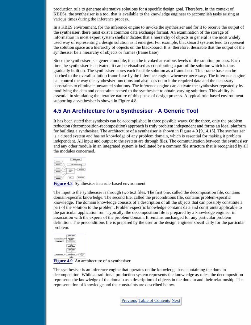
production rule to generate alternative solutions for a specific design goal. Therefore, in the context ofKBESs, the synthesiser is a tool that is available to the knowledge engineer to accomplish tasks arising atvarious times during the inference process.
In a KBES environment, for the inference engine to invoke the synthesiser and for it to receive the output ofthe synthesiser, there must exist a common data exchange format. An examination of the storage ofinformation in most expert system shells indicates that a hierarchy of objects in general is the most widelyused way of representing a design solution as it emerges. For example, blackboard systems tend to representthe solution space as a hierarchy of objects on the blackboard. It is, therefore, desirable that the output of thesynthesiser be a hierarchy of objects or frames (frame base).
Since the synthesiser is a generic module, it can be invoked at various levels of the solution process. Eachtime the synthesiser is activated, it can be visualised as contributing a part of the solution which is thusgradually built up. The synthesiser stores each feasible solution as a frame base. This frame base can bepatched to the overall solution frame base by the inference engine whenever necessary. The inference enginecan control the way the synthesiser functions and also pass on to it the required data and the necessaryconstraints to eliminate unwanted solutions. The inference engine can activate the synthesiser repeatedly bymodifying the data and constraints passed to the synthesiser to obtain varying solutions. This ability isessential in simulating the iterative nature of this phase of design process. A typical rule-based environmentsupporting a synthesiser is shown in Figure 4.8.
4.5 An Architecture for a Synthesiser - A Generic Tool
It has been stated that synthesis can be accomplished in three possible ways. Of the three, only the problemreduction (decomposition-recomposition) approach is truly problem independent and forms an ideal platformfor building a synthesiser. The architecture of a synthesiser is shown in Figure 4.9 [9,14,15]. The synthesiseris a closed system and has no knowledge of any problem domain, which is essential for making it problemindependent. All input and output to the system are through files. The communication between the synthesiserand any other module in an integrated system is facilitated by a common file structure that is recognised by allthe modules concerned.
Figure 4.8 Synthesiser in a rule-based environment
The input to the synthesiser is through two text files. The first one, called the decomposition file, containsdomain-specific knowledge. The second file, called the preconditions file, contains problem-specificknowledge. The domain knowledge consists of a description of all the objects that can possibly constitute apart of the solution to the problem. Problem-specific knowledge contains data and constraints applicable tothe particular application run. Typically, the decomposition file is prepared by a knowledge engineer inassociation with the experts of the problem domain. It remains unchanged for any particular problemdefinition. The preconditions file is prepared by the user or the design engineer specifically for the particularproblem.
Figure 4.9 An architecture of a synthesiser
The synthesiser is an inference engine that operates on the knowledge base containing the domaindecomposition. While a traditional production system represents the knowledge as rules, the decompositionrepresents the knowledge of the domain as a description of objects in the domain and their relationship. Therepresentation of knowledge and the constraints are described below.
Previous Table of Contents Next

Products | Contact Us | About Us | Privacy | Ad Info | Home
Use of this site is subject to certain Terms & Conditions, Copyright © 1996-2000 EarthWeb Inc. All rightsreserved. Reproduction whole or in part in any form or medium without express written permission of
EarthWeb is prohibited. Read EarthWeb's privacy statement.

Search Tips
Advanced Search
Artificial Intelligence and Expert Systems for Engineersby C.S. Krishnamoorthy; S. RajeevCRC Press, CRC Press LLCISBN: 0849391253 Pub Date: 08/01/96
Search this book:
Previous Table of Contents Next
Domain Decomposition and Its Representation
As noted earlier in the conceptual and preliminary design stages the designer must be provided with severalalternative solutions. Evaluation of these solutions leads to the final choice of a solution. Hence, anycomputational model must be able to generate all possible solutions to the problem. However, to becomputationally tractable, one must be able to dynamically prune the search in the solution space throughconstraints.
The decomposition model for the synthesis process has already been described in section 4.3. An artifact to bedesigned is decomposed hierarchically into systems and subsystems, finally ending into attributes. Anattribute can be assigned a value, which may be an integer, real or string. When each attribute is assigned avalue, we arrive at a solution by the process of recomposition. By assigning different values to attributes in asystematic manner we generate alternative solutions, as has been shown through an example in section 4.3. Atthis stage, it is necessary to deal with the syntax and representation scheme that are followed in the computerimplementation of a generic tool. In the following discussion, the syntax followed in GENSYNT is used toillustrate the above aspects needed for development of a synthesiser. The details of GENSYNT are explainedin section 4.6.
An attribute taking any ONE_OF values can be expressed as:
attrname ONE_OF symbol 1, symbol 2,.......
The symbols are literal values that can be assigned to the attribute alternatively. For example, the sidingmaterial for the building frame (Example 1) described in section 4.3 is expressed as:
siding_material ONE_OF AC_sheets, GI_sheets, masonry_wall.
In the domain decomposition, a system will consist of subsystems. In the above example, a building frameconsists of truss as a subsystem. An attribute such as truss is called a SUBSYSTEM attribute to the mainsystem. This is declared as:
attrname SUBSYSTEM subsystem name

For the system building frame, the declaration of two attributes is given below:
SYSTEM bldg_frame
....................................................
siding_material ONE_OF AC_sheets, GI_sheets, masonry_wall
...................... ...................... truss SUBSYSTEM truss
An attribute to a subsystem is treated like any other attribute. When in its turn the attribute is to be assigned avalue, the subsystem attached to the attribute will have to be synthesised entirely before the next attribute istaken up. This is the essence of the problem solution by the decomposition-recomposition approach. Forexample, in the subsystem truss (Figure 4.3), the attribute type is expressed as:
SYSTEM truss type ONE_OF King_Post, Compound_Fink, Warren
The ONE_OF construct can also be used to associate an attribute with different systems. In such instances, theattribute is synthesised by assigning different subsystems to the attribute at different times. The declaration isas follows:
attrname ONE_OF subsystem 1,subsystem2, . . .
For the problem of synthesis of system A, whose decomposition is shown in Figure 4.1, the syntax to befollowed in GENSYNT is given below:
SYSTEM A
A1 ONE_OF a1, a2 A2 ONE_OF a3, a4 B SUBSYSTEM B
END_SYSTEM
SYSTEM B
B1 ONE_OF b1, b2 B2 ONE_OF b3, b4
END_SYSTEM
During synthesis the values of certain attributes require numerical computation, which may be performedthrough EXPRESSION, PROCEDURE or PROGRAM depending on the level of complexity of numericalprocessing involved.
If an algebraic expression is needed to express the value of an attribute, it is declared as follows:
attrmame EXPRESSION expression
The algebraic expression may involve design data, values of attributes of other systems and use ofmathematical functions provided by the particular implementation of synthesiser.
For example, in the building frame system, the attributes no_bays and bay_spacing are expressed as,

no_bays EXPRESSION nobays bay_spacing EXPRESSION (length/nobays)
The attribute will be assigned the value returned by the expression at synthesis time. When the level ofcomputation is not high and can be handled by using the in-built programming language provided by theimplementation, the attribute can be of type PROCEDURE. If this is not possible, an external program maybe called to do the computation and return the value to the attribute. Such attributes, which are assignedvalues returned by external programs are of type PROGRAM. These are expressed in the following form.
attrname PROCEDURE/PROGRAM proc/prog- name (arg1,arg2,...)
The first name defined in the decomposition file defines the whole artifact and is the one synthesisedultimately. It encompasses the entire design. The physical ordering of the other systems in the decompositiontree is not significant.
Previous Table of Contents Next
Products | Contact Us | About Us | Privacy | Ad Info | Home
Use of this site is subject to certain Terms & Conditions, Copyright © 1996-2000 EarthWeb Inc. All rightsreserved. Reproduction whole or in part in any form or medium without express written permission of
EarthWeb is prohibited. Read EarthWeb's privacy statement.

Search Tips
Advanced Search
Artificial Intelligence and Expert Systems for Engineersby C.S. Krishnamoorthy; S. RajeevCRC Press, CRC Press LLCISBN: 0849391253 Pub Date: 08/01/96
Search this book:
Previous Table of Contents Next
Planning Rules
It can be seen that fundamentally there are two ways through which an attribute can have a value assigned toit. The first is selection from amongst a set of alternatives and the second is computation. Computation resultsin a distinct value that can be assigned to the attribute but selection is not always so obvious. In the exampleof the building frame, assigning the value masonry_wall to the attribute siding_material has no ambiguityassociated with it. But assigning the value King_Post to the attribute type of truss subsystem raises a question.Precisely, how many trusses are there in the building frame? It is not possible to specify the number of trussesthat a building has in the coding of the decomposition file since it depends on the context, i.e., problem data.During synthesis, we need to generate as many trusses as necessary. Such knowledge is expressed as planningrules. A system description may contain, in addition to the attributes, several planning rules which resembleIF_THEN rules in production systems.
Planning rules are of two types. The first type is used to generate multiple instances of a subsystem within asystem when certain conditions are satisfied and has the following form:
IF (condition 1 AND condition 2 And.......) THEN FOR index = expression 1, expression 2 REPEAT system_name.
The second type has no conditions and is explained as,
FOR index = expression 1, expression 2 REPEAT system_name
For example, the planning rule for the building frame can be specified as,
IF (bldg_frame. no_bents > 1) THEN FOR t_count=1, bldg_frame.no_bents REPEAT truss
In the term bldg_frame.no_bents, no_bents is an attribute of the system bldg_frame. The dot operatorspecifies the path connecting the attribute to its parent system.

Constraints
In order to generate all possible solutions to a problem, the synthesiser has to assign all possible values to anattribute in a systematic manner in such a way that by changing the value of precisely one attribute in theentire solution process we arrive at an alternative solution. By this process we may arrive at solutions whichare not acceptable or permissible. For example, according to practical considerations the attribute values ofroofing_material and siding_material must be the same; otherwise the solution is not acceptable.
Such knowledge is expressed as constraints. In terms of the admissibility of a solution on which they areapplied, constraints can be classified as feasibility constraints and desirability constraints. A feasibilityconstraint is a hard constraint and can either be satisfied or violated, and accordingly the solution is eitheradmissible or nonadmissible. A desirability constraint, on the other hand, is a soft constraint and can besatisfied with varying degrees of acceptability. Feasibility constraints are applied during the synthesis phasewhile desirability constraints are applied during evaluation. Synthesis constraints that are not specific to anygiven problem are called static constraints. Static constraints are treated as part of domain knowledge and areincluded in the decomposition file. Typical static constraints for the building_frame example can be expressedas:
IF (bldg_frame.roofing_material = = AC_sheets) THEN bldg_frame.siding_material = = AC_sheets IF (bldg_frame.roofing_material = = GI_sheets) THEN bldg_frame.siding_material = = GI_sheets
Constraints can also arise in a problem-specific manner. For example, the attribute roofing_material can beassigned the values AC_sheets or GI_sheets. If it is economically not viable in certain situations to useAC_sheets then we do not want solutions with AC_sheets generated. This constraint is specific to a particularapplication and such constraints are called run time constraints. The above constraint can be expressed as:
bldg_frame.roofing_material ! = AC_sheets
Run time constraints are part of a problem definition and thus form part of the data to the problem. They arethus specified in the preconditions file.
To enable flexible representation of various types of constraints, three forms of constraints are provided.
(i) Attribute constraints express explicit constraints on an attribute of a system with reference to theproblem data. For example, if AC_sheets are not available or not preferable to use, this can beexpressed as a constraint on the roofing_material as given in the above example of run time constraints.Such a constraint is attached to the attribute by the synthesiser. As soon as an attribute is synthesised,all attribute constraints attached to it are checked for. If any one constraint is violated, the solutionbeing synthesised is aborted and the next alternative solution is taken up. There can be any number ofattribute constraints for a particular attribute.
(ii) Meta constraints have the form:
IF (set of conditions)THEN set of conditions
The set of conditions in the THEN part are imposed on the solution only if the set of conditions in theIF part evaluates to TRUE. The example of a static constraint given earlier is a meta constraint.
(iii) Constraint functions are the most powerful form of constraints available. They have the form:
function_name ( )for example, FAR_check ( )
Here FAR_check ( ) is a constraint that has to evaluate the Floor Area Ratio (FAR) of the building outlinebeing synthesised and checks whether it violates permissible limits or not. FAR is defined as the ratio of thetotal area of the building footprint to the available site area. Building codes specify restrictions on this ratioand it is typically related to the number of floors in the building. It is quite evident that a mere expressionwould not be sufficient to specify this constraint and a function would be required to express it. Constraintfunctions can be used to handle such situations.

It can express constraints of any complexity. A constraint function returns either TRUE or FALSE to thesynthesiser indicating whether the constraint has been met or not by the solution being synthesised. Asexplained later, the syntax of the function is similar to that of C language. Since the constraint functions areconsidered part of domain knowledge, they are included in the decomposition file.
Previous Table of Contents Next
Products | Contact Us | About Us | Privacy | Ad Info | Home
Use of this site is subject to certain Terms & Conditions, Copyright © 1996-2000 EarthWeb Inc. All rightsreserved. Reproduction whole or in part in any form or medium without express written permission of
EarthWeb is prohibited. Read EarthWeb's privacy statement.

Search Tips
Advanced Search
Artificial Intelligence and Expert Systems for Engineersby C.S. Krishnamoorthy; S. RajeevCRC Press, CRC Press LLCISBN: 0849391253 Pub Date: 08/01/96
Search this book:
Previous Table of Contents Next
Design Data
Design data includes all the data required to define a problem and is specified in the precondition file asfollows:
Variable = value
In the building frame example, the nobays, bldg_width, length and rise need to be specified as design data.Such data is global and is used in expressions and passed on to procedures and external programs. The datacan be either integer, real number or string.
4.6 Generic Synthesis Tool - GENSYNT
In the earlier section the issues to be addressed and capabilities to be provided for to perform the synthesisprocess by a generic tool have been discussed. An architecture has been presented along with a knowledgerepresentation scheme that can be adopted by a developer of a system. While it will be beyond the scope ofthis book to discuss all the implementation aspects of the above architecture, a brief description of internalorganisation of a Generic Synthesis Tool, GENSYNT, is given in Figure 4.10. This will help the reader tounderstand the functioning and usage of a synthesiser. In a later section, examples are presented to illustratethe use of GENSYNT [16].
Components of GENSYNT Knowledge modules
The domain knowledge consists of descriptions of all the objects that can possibly constitute a part of thesolution to the problem. The implementation provides a structured language or syntax for representing theknowledge following the scheme explained in the previous section. A system description may also containknowledge that helps to modify the knowledge depending on the context. This type of knowledge is stated asplanning rules. These may also contain knowledge that describes an incompatible assemblage of certainsystems. Such a knowledge is static and can be expressed as constraints. Detailed descriptions have beengiven earlier on the representation of planning rules and constraints.
The knowledge modules consisting of domain decomposition of the artifact, planning rules, and staticconstraints are expressed in specified syntax, which broadly follows the form given in the earlier section, and
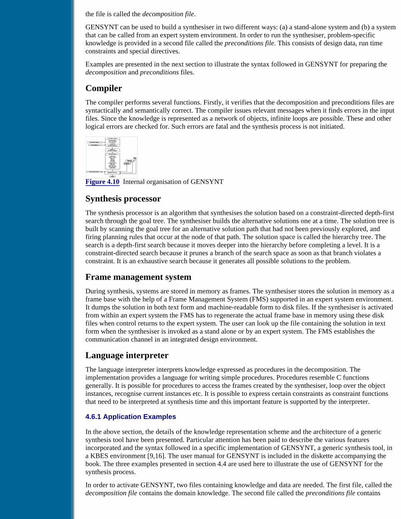
the file is called the decomposition file.
GENSYNT can be used to build a synthesiser in two different ways: (a) a stand-alone system and (b) a systemthat can be called from an expert system environment. In order to run the synthesiser, problem-specificknowledge is provided in a second file called the preconditions file. This consists of design data, run timeconstraints and special directives.
Examples are presented in the next section to illustrate the syntax followed in GENSYNT for preparing thedecomposition and preconditions files.
Compiler
The compiler performs several functions. Firstly, it verifies that the decomposition and preconditions files aresyntactically and semantically correct. The compiler issues relevant messages when it finds errors in the inputfiles. Since the knowledge is represented as a network of objects, infinite loops are possible. These and otherlogical errors are checked for. Such errors are fatal and the synthesis process is not initiated.
Figure 4.10 Internal organisation of GENSYNT
Synthesis processor
The synthesis processor is an algorithm that synthesises the solution based on a constraint-directed depth-firstsearch through the goal tree. The synthesiser builds the alternative solutions one at a time. The solution tree isbuilt by scanning the goal tree for an alternative solution path that had not been previously explored, andfiring planning rules that occur at the node of that path. The solution space is called the hierarchy tree. Thesearch is a depth-first search because it moves deeper into the hierarchy before completing a level. It is aconstraint-directed search because it prunes a branch of the search space as soon as that branch violates aconstraint. It is an exhaustive search because it generates all possible solutions to the problem.
Frame management system
During synthesis, systems are stored in memory as frames. The synthesiser stores the solution in memory as aframe base with the help of a Frame Management System (FMS) supported in an expert system environment.It dumps the solution in both text form and machine-readable form to disk files. If the synthesiser is activatedfrom within an expert system the FMS has to regenerate the actual frame base in memory using these diskfiles when control returns to the expert system. The user can look up the file containing the solution in textform when the synthesiser is invoked as a stand alone or by an expert system. The FMS establishes thecommunication channel in an integrated design environment.
Language interpreter
The language interpreter interprets knowledge expressed as procedures in the decomposition. Theimplementation provides a language for writing simple procedures. Procedures resemble C functionsgenerally. It is possible for procedures to access the frames created by the synthesiser, loop over the objectinstances, recognise current instances etc. It is possible to express certain constraints as constraint functionsthat need to be interpreted at synthesis time and this important feature is supported by the interpreter.
4.6.1 Application Examples
In the above section, the details of the knowledge representation scheme and the architecture of a genericsynthesis tool have been presented. Particular attention has been paid to describe the various featuresincorporated and the syntax followed in a specific implementation of GENSYNT, a generic synthesis tool, ina KBES environment [9,16]. The user manual for GENSYNT is included in the diskette accompanying thebook. The three examples presented in section 4.4 are used here to illustrate the use of GENSYNT for thesynthesis process.
In order to activate GENSYNT, two files containing knowledge and data are needed. The first file, called thedecomposition file contains the domain knowledge. The second file called the preconditions file contains

problem-specific knowledge.
The structure of the decomposition file is as follows:
.TITLE .DECLARATION .DECOMPOSITION .STATIC CONSTRAINTS .END
The preconditions file contains the data and run time constraints.
Previous Table of Contents Next
Products | Contact Us | About Us | Privacy | Ad Info | Home
Use of this site is subject to certain Terms & Conditions, Copyright © 1996-2000 EarthWeb Inc. All rightsreserved. Reproduction whole or in part in any form or medium without express written permission of
EarthWeb is prohibited. Read EarthWeb's privacy statement.

Search Tips
Advanced Search
Artificial Intelligence and Expert Systems for Engineersby C.S. Krishnamoorthy; S. RajeevCRC Press, CRC Press LLCISBN: 0849391253 Pub Date: 08/01/96
Search this book:
Previous Table of Contents Next
Example 1. Steel Industrial Building
The components and the hierarchical decomposition tree of a steel industrial building are described in section4.3. The decomposition file and preconditions file, following the syntax of GENSYNT, are given below. Itmay be noted that the synthesiser can generate 112 different solutions. The two static constraints and one runtime constraint restrict the solution to the four given as output results of this problem.
TITLE Decomposition file for industrial building framework
SYSTEM bldg_frame, truss
PROGRAM nobents
DECOMPOSITION SYSTEM bldg_frame
roofing_material ONE_OF ACC_sheets,GI_sheets siding_material ONE_OF ACC_sheets, GI_sheets, masonry_wall no_bays EXPRESSION nobays bay_spacing EXPRESSION (length/bldg_frame.no_bays) end_framing ONE_OF masonry_wall,
end_braced_frame no_bents PROGRAM nobents(bldg_frame.no_bays, bldg_frame.end_framing)
truss SUBSYSTEM truss

IF (bldg_frame.no_bents > 1) THEN FOR t_count=1,bldg_frame.no_bents REPEAT truss
END_SYSTEM
SYSTEM truss
type ONE_OF King_Post,Compound_Fink,Warren span EXPRESSION bldg_width rise EXPRESSION rise END_SYSTEM
CONSTRAINTS IF (bldg_frame.roofing_material==AC_sheets) THEN bldg_frame.siding_material==AC_sheets IF (bldg_frame.roofing_material==GI_sheets) THEN bldg_frame.siding_material==GI_sheets
END
PRECONDITIONS nobays = 2 bldg_width = 6.5 length = 8 rise = 1.8
CONSTRAINTS
truss.type==King_Post
Output Results
Solution No: 1
bldg_frame.roofing_material = AC_sheets bldg_frame.siding_material = AC_sheets bldg_frame.bay_spacing = 4 bldg_frame.end_framing = masonry_wall bldg_frame.no_bents = 1 truss.type = king_post truss.span = 6.500 truss.rise = 1.800
Solution No: 2
bldg_frame.roofing_material = AC_sheets bldg_frame.siding_material = Ac_sheets bldg_frame.bay_spacing = 4 bldg_frame.end_framing=end_braced_frame bldg_frame.no_bents = 3 truss[1].type = king_post truss[1].span = 6.500 truss[1].rise = 1.800 truss[2].type = king_post truss[2].span = 6.500 truss[2].rise = 1.800 truss[3].type = king_post truss[3].span = 6.500 truss[3].rise = 1.800

Solution No: 3
bldg_frame.roofing_material = GI_sheets bldg_frame.siding_material = GI_sheets bldg_frame.bay_spacing = 4 bldg_frame.end_framing = masonry_wall bldg_frame.no_bents = 1 truss.type = king_post truss.span = 6.500 truss.rise = 1.800
Solution No: 4
bldg_frame.roofing_material = GI_sheets bldg_frame.siding_material = GI_sheets bldg_frame.bay_spacing = 4 bldg_frame.end-framing=end_braced_frame bldg_frame.no-bents = 3 truss[1].type = king_post truss[1].span = 6.500 truss[1].rise = 1.800 truss[2].type = king_post truss[2].span = 6.500 truss[2].rise = 1.800 truss[3].type = king_post truss[3].span = 6.500 truss[3].rise = 1.800
Example 2. Building Plan Layout at a Site
The decomposition and preconditions files are given in Appendix II for the hierarchical tree for the problemshown in Figure 4.4. In order to simplify the presentation here, it has been assumed that the offset of thebuilding outline from the site limits on all four sides of the site is the same. But in actual practice this isdecided by the zonal regulations of the town-planning authorities. Also, only three possible variations oflength and breadth are considered. They are fixed at 80%, 90% and 100% of the maximum dimensions. Thisis done by defining attributes p-length and p-breadth and specifying these three possible values through aONE-OF relation. The number of service cores and their attributes are decided by using procedure-orientedprograms. The aspect ratio and the slenderness ratio of the building are stated as static constraints. There areeighteen solutions possible and a typical solution is given in Appendix II under Output Results.
Example 3. Preliminary Design of a Gearbox
The maximum number of gear rows is restricted to three, to reduce the problem size. The decomposition andpreconditions files are given in Appendix II. With the static constraints GENSYNT generated 12 feasiblesolutions out of the 72 possible solutions without the constraints.
The present example has the input of the overall length, breadth and height of the gearbox as 0.50 m, 0.50 mand 0.50 m, respectively. The input speed (in speed) is 400.0 rad/s and the output speed (out speed) requiredis 50 rad/s. The required power transmission is 40 kW. A typical solution is given in Appendix II underOutput Results.
Previous Table of Contents Next

Products | Contact Us | About Us | Privacy | Ad Info | Home
Use of this site is subject to certain Terms & Conditions, Copyright © 1996-2000 EarthWeb Inc. All rightsreserved. Reproduction whole or in part in any form or medium without express written permission of
EarthWeb is prohibited. Read EarthWeb's privacy statement.

Search Tips
Advanced Search
Artificial Intelligence and Expert Systems for Engineersby C.S. Krishnamoorthy; S. RajeevCRC Press, CRC Press LLCISBN: 0849391253 Pub Date: 08/01/96
Search this book:
Previous Table of Contents Next
References1. Sriram, D., Maher, M. L. and Fenves, S. J., Knowledge-based expert systems in structural design,Computers and Structures, 20(1–3), 1, 1985.
2. Dixon, J. R., Artificial intelligence and design: a mechanical engineering view, in AAAI-86 Proc.5th National Conference on Artificial Intelligence, Morgan Kauffman, New York, 1986, 872.
3. Maher, M. L., Expert systems for structural design, Jl. of Computing in Civil Engineering, ASCE,1(4), 270, 1987.
4. Maher, M. L., Synthesis and evaluation of preliminary designs, Artificial Intelligence in Design,Ed. Gero, J. S., Springer, Berlin, 1989, 3.
5. Sause, R. and Powell, G. H., A design process model for computer integrated structuralengineering, Engineering with Computers, 6, 129, 1990.
6. Sause, R. and Powell, G. H., A design process model for computer integrated structuralengineering: design phases and tasks, Engineering with Computers, 7, 145, 1991.
7. Maher, M. L., Engineering design synthesis: a domain independent implementation, ArtificialIntelligence in Engineering Design, Analysis and Manufacturing, 1(3), 207, 1987
8. Maher, M. L., Process models for design synthesis, AI Magazine, Winter, 49, 1990.
9. Krishnamoorthy, C. S., Srinivasa Rao, C. and Rajeev, S., A design synthesizer for KBES,Structural Engineering Review, 5(2), 107, 1993.
10. Rajeev, S. and Krishnamoorthy, C. S., Discrete optimization of structures using geneticalgorithms, Jl. of Structural Engineering, ASCE, 118(5), 1205, 1992.
11. Rajeev, S., Genetic algorithms-based methodologies for design optimisation of framed structures,Ph.D. Thesis, I.I.T., Madras, 1993.
12. Fenves, S. and Baker, N., Spatial and functional representation language for structural design,Expert Systems in Computer-Aided Design, Ed. Gero, J., Amsterdam: Elsevier, 511, 1987.
13. Kolodner, J., Case-Based Reasoning, Morgan Kauffman, Inc., San Mateo, C.A., 1993.
14. Krishnamoorthy, C. S., Srinivasa Rao, C. and Rajeev, S., Architecture of a design synthesizerfor KBES, in Proc. CIVIL-COMP 91, 2nd int. conf. on Application of Artificial IntelligenceTechniques to Civil and Structural Engineering Ed. B. H. V. Topping,, Civil-Comp Press, Edinburgh,

England, 79, 1991.
15. Krishnamoorthy, C. S., Srinivasa Rao, C. and Rajeev, S., Synthesis in engineering design, Jl ofStructural Engineering, 18(4), 125, 1992.
16. Srinivasa Rao, C., Krishnamoorthy, C. S. and Rajeev, S., Generic tool for engineering designsynthesis (GENSYNT), Research report R-94-2, Department of Civil Engineering, Indian Institute ofTechnology, Madras, 1994.
Previous Table of Contents Next
Products | Contact Us | About Us | Privacy | Ad Info | Home
Use of this site is subject to certain Terms & Conditions, Copyright © 1996-2000 EarthWeb Inc. All rightsreserved. Reproduction whole or in part in any form or medium without express written permission of
EarthWeb is prohibited. Read EarthWeb's privacy statement.

Search Tips
Advanced Search
Artificial Intelligence and Expert Systems for Engineersby C.S. Krishnamoorthy; S. RajeevCRC Press, CRC Press LLCISBN: 0849391253 Pub Date: 08/01/96
Search this book:
Previous Table of Contents Next
Chapter 5Criticism and Evaluation
5.1 Introduction
In many engineering domains, various feasible solutions can be generated for a given problem using thesynthesis process explained in the previous chapter. Thus the outcome of the synthesis step is a set of feasiblealternatives to the design problem. However, it is not possible to incorporate all the requirements andpreferences in the synthesis process. As a result, such generated solutions, although feasible, do not satisfy alldesign objectives and hence need to be evaluated. This evaluation process is termed critiquing. It involves anevaluation of the proposed alternatives against a set of performance criteria to determine how well they meetthe desired objectives.
As already mentioned in the previous chapter constraints applied during synthesis are hard feasibilityconstraints that check the admissibility of a solution. During the evaluation process, the soft desirabilityconstraints are applied to check the degree of acceptability of the solution being critiqued.
Several large design problems in engineering require cooperative participation of multiple specialists fromdifferent domains. In general, each specialist is focused deeply in his own domain and tends to have limitedknowledge of the other domains with which he must communicate and interact. In such situations thegenerated solutions need to be separately evaluated from each of the participating domains. The critiquingprocess is used here for evaluation through the expert knowledge of all the participating domains.
The following definition due to Fenves describes the role of a design critic: A critic is a tool or called as anagent in the same way that a synthesiser or analyser is a tool [1]. Its role is to apply to its input aspects,knowledge which is not available to the tool that generated or proposed the input aspect(s). Critiquing is bestdone by a source not directly connected with synthesising the solution. In an engineering context, wheredesign is often a multiclient, multiparticipant problem, with each client or participant having a distinct set ofrequirements, it is not possible to incorporate every requirement and preference of each participating agentwhile synthesising a design solution [2]. Critiques may be provided from each of the client or participantdomains that govern the final designed artifact. For the design of a large complex artifact, cooperativeparticipation of several distinct agents is required and it involves application of a number of design critics,

each of which represents a given agent’s evaluation criteria.
In this chapter the methodologies available for critiquing a solution are briefly described. Critiquing is aknowledge-based activity and a framework can be devised to represent the knowledge pertaining to thecritiquing of solution/s. Since design solutions have a hierarchical structure, critiques of individual aspects ofthe solution have to be hierarchically combined to determine the overall worth of the solution. An algorithm ispresented here to combine the ratings of the evaluated items to arrive at the overall rating of the solution.
A complex design activity typically involves the application of several critics at various stages of the designprocess. Building each critic from scratch is a tedious process as the critiquing of the individual aspects of thesolution and hierarchical aggregation have to be explicitly programmed. A generic framework is presentedhere and a particular implementation of GENCRIT (GENeric CRItiquing Tool) is described. The use ofGENCRIT in a Knowledge-Based Expert System (KBES) environment is discussed with applicationexamples.
5.2 Methodologies Used in a Knowledge-Based Environment
In a knowledge-based approach to engineering design, the design task is formulated as a search problem andsome control strategy is applied to search through the state space to arrive at one or more solutions. In thedecomposition-based synthesis process we generate solutions based on hierarchical decomposition andrecomposition strategy and necessary constraints are incorporated to prune the search and to weed outinfeasible solutions. However, in this process the constraints do not reflect the aspects to be considered fromthe other participating domains.
The basic strategy that can be used is generate_and_test where all possible solutions can be generated andtested to satisfy the given requirements [3]. Maher has modified this approach tohierarchical_generate_and_test through which partial solutions are generated and tested using the domainknowledge [4]. This is an example of guided search because of the use of domain knowledge in pruningcorrectly the search tree. This approach to design is exemplified in HI_RISE, a system for the preliminarystructural design of multistory office buildings [4]. EDESYN is a domain-independent implementation of thehierarchical generate-and-test model that facilitates the development and use of a knowledge base for design[5]. EDESYN has been used to develop design expert systems like STRYPES, STANLAY and FOOTER thatform part of a large design environment for integrated building design [6].
A variation of the generate-and-test model that has been successfully applied to design problem solving is theconstraint satisfaction approach. In this approach, the evolving design is tested to see if constraints areviolated [3]. The focus here is on how constraints are formulated and propagated as the design evolves. Luthet al. [7] proposed a framework for conceptual structural design and the framework uses aformulate-propagate-satisfy constraints approach to achieve the task. The constraints are classified asstructural constraints and exogenous constraints. The knowledge modules for structural constraints deal withfunctional, behaviour, performance, geometry, product and reliability aspects of structural elements andsystems. The exogenous constraints are constraints outside structural engineering and deal with architectural,mechanical, electrical and plumbing (MEP), constructibility and owner aspects that should be considered inthe design process. The reasoning process generates alternative solutions and they are evaluated by usingcost/value as a measuring yardstick. This model has been used to implement a floor framing generator forsteel office buildings that are rectangular in plan [8].
Previous Table of Contents Next
Products | Contact Us | About Us | Privacy | Ad Info | Home
Use of this site is subject to certain Terms & Conditions, Copyright © 1996-2000 EarthWeb Inc. All rightsreserved. Reproduction whole or in part in any form or medium without express written permission of
EarthWeb is prohibited. Read EarthWeb's privacy statement.

Search Tips
Advanced Search
Artificial Intelligence and Expert Systems for Engineersby C.S. Krishnamoorthy; S. RajeevCRC Press, CRC Press LLCISBN: 0849391253 Pub Date: 08/01/96
Search this book:
Previous Table of Contents Next
The hierarchical generate-and-test and constraint satisfaction approaches do not address all the issuesinvolved in cooperative problem solving. The blackboard architecture is recognised as one of the effectiveapproaches to solve problems that require interaction with experts (knowledge sources) from differentdomains at every stage of evolution of a design. In this approach a global database called a blackboard iscreated and an emerging solution is posted on the blackboard. Different knowledge modules participating inthe design process can evaluate or modify the solution similar to a team of experts looking at a solution fromdifferent perspectives/domains. The nature of involvement of participating domains in the solution process isthus opportunistic. These are well explained in references [3,9,10,11].
For qualitative evaluation of candidate designs, multifactor decision models have been proposed by Daru andVanglis, Boer and Dong but these methods are not proved to be amenable for development of a tool forevaluation in engineering design process models [12–14]. Saaty introduced the Analytic Hierarchy Process(AHP) for modelling multifactor decision making [15]. In this process, the decision is decomposedhierarchically. The hierarchy reveals the factors to be considered as well as various alternatives in thedecision. Then pair-wise comparisons are made, which result in the determination of factor weights and factorevaluation. The alternative with the highest weighted score is selected as the best alternative. In automatedsystems for preliminary design, the number and composition of the solutions are known to the critic only atrun time. Therefore, an approach that calls for direct comparison of solutions is not suitable forimplementation of design critics.
Concurrent engineering is emerging as an important knowledge-based approach in mechanical engineering. Inthis approach, while evolving/designing a product the various life-cycle issues, i.e., manufacturing, testing,installation, field tuning and maintenance, are considered. In the design process, one of the important tasks isto ensure compatibility of the elements/components with each other and satisfaction of various designspecifications and constraints. Artificial Intelligence (AI) techniques have been used to develop a frameworkcalled Design Compatibility Analysis (DCA) [16]. The compatibility issues from different aspects mentionedabove are represented in the knowledge base and the overall degree of compatibility of a proposed design isevaluated. The theory of fuzzy measure has been used by Ishii [17] to evaluate compatibility or the MatchIndex (MI) as the utility of design.
5.3 A Framework for Critiquing and Evaluation
In situations when we generate several feasible solutions and also in real-world applications involving
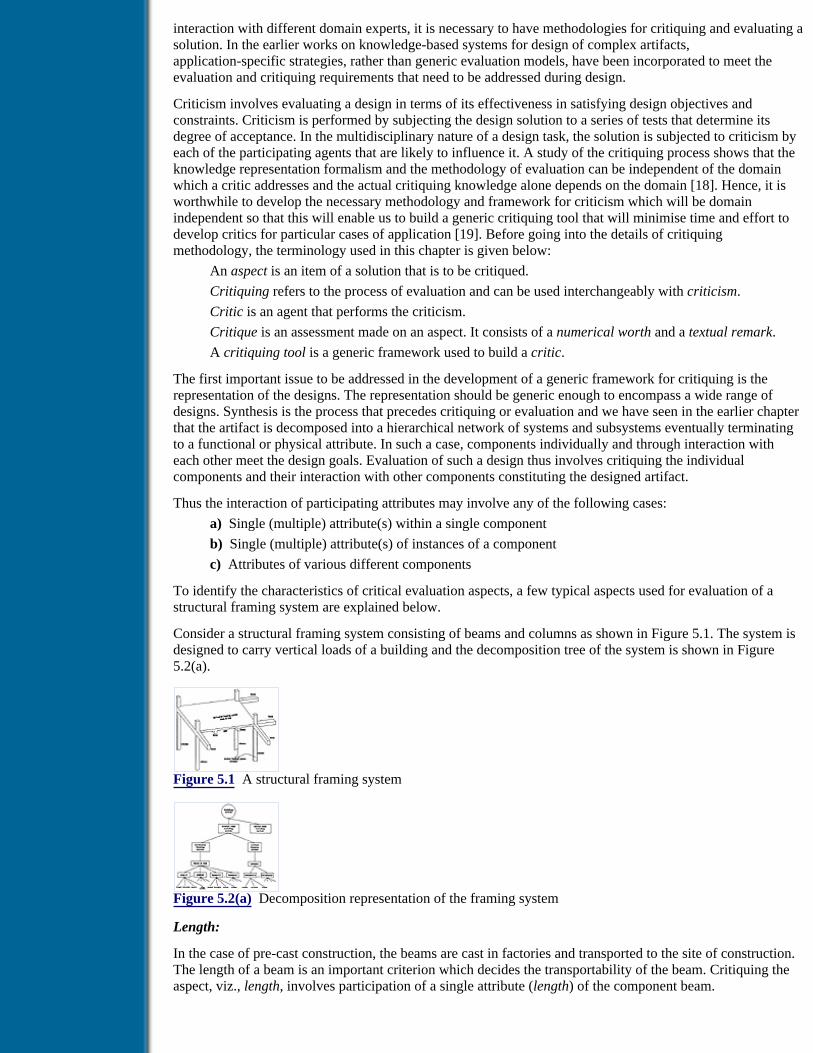
interaction with different domain experts, it is necessary to have methodologies for critiquing and evaluating asolution. In the earlier works on knowledge-based systems for design of complex artifacts,application-specific strategies, rather than generic evaluation models, have been incorporated to meet theevaluation and critiquing requirements that need to be addressed during design.
Criticism involves evaluating a design in terms of its effectiveness in satisfying design objectives andconstraints. Criticism is performed by subjecting the design solution to a series of tests that determine itsdegree of acceptance. In the multidisciplinary nature of a design task, the solution is subjected to criticism byeach of the participating agents that are likely to influence it. A study of the critiquing process shows that theknowledge representation formalism and the methodology of evaluation can be independent of the domainwhich a critic addresses and the actual critiquing knowledge alone depends on the domain [18]. Hence, it isworthwhile to develop the necessary methodology and framework for criticism which will be domainindependent so that this will enable us to build a generic critiquing tool that will minimise time and effort todevelop critics for particular cases of application [19]. Before going into the details of critiquingmethodology, the terminology used in this chapter is given below:
An aspect is an item of a solution that is to be critiqued.
Critiquing refers to the process of evaluation and can be used interchangeably with criticism.
Critic is an agent that performs the criticism.
Critique is an assessment made on an aspect. It consists of a numerical worth and a textual remark.
A critiquing tool is a generic framework used to build a critic.
The first important issue to be addressed in the development of a generic framework for critiquing is therepresentation of the designs. The representation should be generic enough to encompass a wide range ofdesigns. Synthesis is the process that precedes critiquing or evaluation and we have seen in the earlier chapterthat the artifact is decomposed into a hierarchical network of systems and subsystems eventually terminatingto a functional or physical attribute. In such a case, components individually and through interaction witheach other meet the design goals. Evaluation of such a design thus involves critiquing the individualcomponents and their interaction with other components constituting the designed artifact.
Thus the interaction of participating attributes may involve any of the following cases:
a) Single (multiple) attribute(s) within a single component
b) Single (multiple) attribute(s) of instances of a component
c) Attributes of various different components
To identify the characteristics of critical evaluation aspects, a few typical aspects used for evaluation of astructural framing system are explained below.
Consider a structural framing system consisting of beams and columns as shown in Figure 5.1. The system isdesigned to carry vertical loads of a building and the decomposition tree of the system is shown in Figure5.2(a).
Figure 5.1 A structural framing system
Figure 5.2(a) Decomposition representation of the framing system
Length:
In the case of pre-cast construction, the beams are cast in factories and transported to the site of construction.The length of a beam is an important criterion which decides the transportability of the beam. Critiquing theaspect, viz., length, involves participation of a single attribute (length) of the component beam.

Previous Table of Contents Next
Products | Contact Us | About Us | Privacy | Ad Info | Home
Use of this site is subject to certain Terms & Conditions, Copyright © 1996-2000 EarthWeb Inc. All rightsreserved. Reproduction whole or in part in any form or medium without express written permission of
EarthWeb is prohibited. Read EarthWeb's privacy statement.

Search Tips
Advanced Search
Artificial Intelligence and Expert Systems for Engineersby C.S. Krishnamoorthy; S. RajeevCRC Press, CRC Press LLCISBN: 0849391253 Pub Date: 08/01/96
Search this book:
Previous Table of Contents Next
Slenderness ratio:
The deflection of the beam, which is a serviceability conditions, depends on the length and depth of the beam.It is reflected by the value of the slenderness ratio, computed as length/depth. Thus the aspect of slendernessratio involves interaction of two attributes, length and depth of the component beam.
Uniformity of beams:
This aspect is used for evaluating the economy of using the same form work for beams at a floor level. If thedepths are different it becomes uneconomical. This critiquing aspect involves participation of one attributedepth of the various instances of the component beam.
Beam-column compatibility:
From a construction point of view it is desirable to have the same breadth for beam and column at a joint. Thesolution needs to be critiqued for this aspect of interaction of two attributes, viz., breadth of beam and breadthof column of the components beam and column.
The above aspects to be critiqued are shown in the hierarchical tree in Figure 5.2(b). The characteristics of thecritiquing aspects can be categorised into the following four types:
1. Individual aspects - the aspects of this critiquing involve a single attribute of a component, e.g.,length of the component beam.
2. Group aspects - the aspects that fall under this category are characterised by the interaction betweentwo or more attributes within a component, e.g., slenderness ratio (length/depth where length and depthare the attributes of the component beam).
3. Metagroup aspects - this is the same as above except that the attributes participating belong todifferent components, e.g., beam-column compatibility (breadth of beam and breadth of column areattributes of two different components beam and column).
4. Multiple instance aspects - these aspects are characterized by the participation of a single attribute orgroup of attributes of all multiple instances of a component, e.g., uniformity-of-beam.
Critiquing Methodology
Having identified the categories of the critiquing aspects, the next task is how to apply the given critiquing
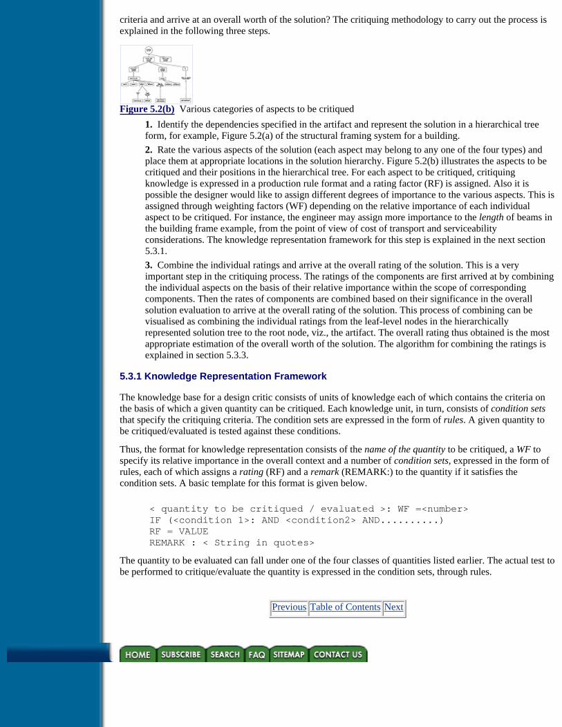
criteria and arrive at an overall worth of the solution? The critiquing methodology to carry out the process isexplained in the following three steps.
Figure 5.2(b) Various categories of aspects to be critiqued
1. Identify the dependencies specified in the artifact and represent the solution in a hierarchical treeform, for example, Figure 5.2(a) of the structural framing system for a building.
2. Rate the various aspects of the solution (each aspect may belong to any one of the four types) andplace them at appropriate locations in the solution hierarchy. Figure 5.2(b) illustrates the aspects to becritiqued and their positions in the hierarchical tree. For each aspect to be critiqued, critiquingknowledge is expressed in a production rule format and a rating factor (RF) is assigned. Also it ispossible the designer would like to assign different degrees of importance to the various aspects. This isassigned through weighting factors (WF) depending on the relative importance of each individualaspect to be critiqued. For instance, the engineer may assign more importance to the length of beams inthe building frame example, from the point of view of cost of transport and serviceabilityconsiderations. The knowledge representation framework for this step is explained in the next section5.3.1.
3. Combine the individual ratings and arrive at the overall rating of the solution. This is a veryimportant step in the critiquing process. The ratings of the components are first arrived at by combiningthe individual aspects on the basis of their relative importance within the scope of correspondingcomponents. Then the rates of components are combined based on their significance in the overallsolution evaluation to arrive at the overall rating of the solution. This process of combining can bevisualised as combining the individual ratings from the leaf-level nodes in the hierarchicallyrepresented solution tree to the root node, viz., the artifact. The overall rating thus obtained is the mostappropriate estimation of the overall worth of the solution. The algorithm for combining the ratings isexplained in section 5.3.3.
5.3.1 Knowledge Representation Framework
The knowledge base for a design critic consists of units of knowledge each of which contains the criteria onthe basis of which a given quantity can be critiqued. Each knowledge unit, in turn, consists of condition setsthat specify the critiquing criteria. The condition sets are expressed in the form of rules. A given quantity tobe critiqued/evaluated is tested against these conditions.
Thus, the format for knowledge representation consists of the name of the quantity to be critiqued, a WF tospecify its relative importance in the overall context and a number of condition sets, expressed in the form ofrules, each of which assigns a rating (RF) and a remark (REMARK:) to the quantity if it satisfies thecondition sets. A basic template for this format is given below.
< quantity to be critiqued / evaluated >: WF =<number> IF (<condition 1>: AND <condition2> AND..........) RF = VALUE REMARK : < String in quotes>
The quantity to be evaluated can fall under one of the four classes of quantities listed earlier. The actual test tobe performed to critique/evaluate the quantity is expressed in the condition sets, through rules.
Previous Table of Contents Next

Products | Contact Us | About Us | Privacy | Ad Info | Home
Use of this site is subject to certain Terms & Conditions, Copyright © 1996-2000 EarthWeb Inc. All rightsreserved. Reproduction whole or in part in any form or medium without express written permission of
EarthWeb is prohibited. Read EarthWeb's privacy statement.

Search Tips
Advanced Search
Artificial Intelligence and Expert Systems for Engineersby C.S. Krishnamoorthy; S. RajeevCRC Press, CRC Press LLCISBN: 0849391253 Pub Date: 08/01/96
Search this book:
Previous Table of Contents Next
5.3.2 Inference Mechanism
The role of the inference mechanism in a critic processor is to apply the critiquing/evaluation criteria to thevarious quantities and assign ratings and remarks. In an engineering design environment a system isdecomposed into component subsystems and attributes forming a hierarchical tree. Hence, while evaluatingan item the processor simultaneously attaches the evaluated RF and WF to the various items in the hierarchyat their appropriate positions. Items of systems are attached just below the system of which they form a part.Metagroup-level items are attached at the same level as the highest system referred to in their attribute paths.Items under the instances head are attached at the same level of the tree as that of the instances themselves. Incase the instances involved in the critique do not emanate from the same parent system, a fictitious parentnode is created at the same level as the parents of the instances involved in the critique and the item is thenattached below that node. Finally, the processor should combine the ratings of the evaluated items to get theoverall rating of the solution. The combining algorithm is explained through an illustration [18,20].
5.3.3 Algorithm for Overall Rating of a Hierarchical Solution
The process of combining individual ratings and propagating the value up the system hierarchy is describedbelow using a sample system network.
Figure 5.3 Sample solution tree
For purposes of illustration, consider the solution tree shown in Figure 5.3. In this tree:
A is the root node.
B[1], B[2] are two instances of a subsystem B of system A (artifact). C is another subsystem of systemA.
D[1] is a subsystem of B[1], while D[2] and D[3] are subsystems of B[2].
In its first stage, GENCRIT assembles these components in memory as shown in the figure. In GENCRIT
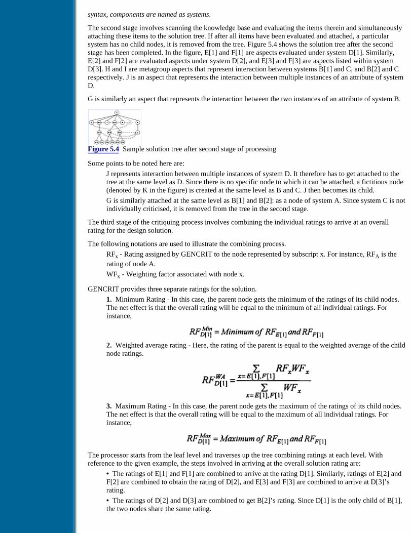
syntax, components are named as systems.
The second stage involves scanning the knowledge base and evaluating the items therein and simultaneouslyattaching these items to the solution tree. If after all items have been evaluated and attached, a particularsystem has no child nodes, it is removed from the tree. Figure 5.4 shows the solution tree after the secondstage has been completed. In the figure, E[1] and F[1] are aspects evaluated under system D[1]. Similarly,E[2] and F[2] are evaluated aspects under system D[2], and E[3] and F[3] are aspects listed within systemD[3]. H and I are metagroup aspects that represent interaction between systems B[1] and C, and B[2] and Crespectively. J is an aspect that represents the interaction between multiple instances of an attribute of systemD.
G is similarly an aspect that represents the interaction between the two instances of an attribute of system B.
Figure 5.4 Sample solution tree after second stage of processing
Some points to be noted here are:
J represents interaction between multiple instances of system D. It therefore has to get attached to thetree at the same level as D. Since there is no specific node to which it can be attached, a fictitious node(denoted by K in the figure) is created at the same level as B and C. J then becomes its child.
G is similarly attached at the same level as B[1] and B[2]: as a node of system A. Since system C is notindividually criticised, it is removed from the tree in the second stage.
The third stage of the critiquing process involves combining the individual ratings to arrive at an overallrating for the design solution.
The following notations are used to illustrate the combining process.
RFx - Rating assigned by GENCRIT to the node represented by subscript x. For instance, RFA is therating of node A.
WFx - Weighting factor associated with node x.
GENCRIT provides three separate ratings for the solution.
1. Minimum Rating - In this case, the parent node gets the minimum of the ratings of its child nodes.The net effect is that the overall rating will be equal to the minimum of all individual ratings. Forinstance,
2. Weighted average rating - Here, the rating of the parent is equal to the weighted average of the childnode ratings.
3. Maximum Rating - In this case, the parent node gets the maximum of the ratings of its child nodes.The net effect is that the overall rating will be equal to the maximum of all individual ratings. Forinstance,
The processor starts from the leaf level and traverses up the tree combining ratings at each level. Withreference to the given example, the steps involved in arriving at the overall solution rating are:
• The ratings of E[1] and F[1] are combined to arrive at the rating D[1]. Similarly, ratings of E[2] andF[2] are combined to obtain the rating of D[2], and E[3] and F[3] are combined to arrive at D[3]’srating.
• The ratings of D[2] and D[3] are combined to get B[2]’s rating. Since D[1] is the only child of B[1],the two nodes share the same rating.

• Similarly K gets the same rating as node J.
• As far as minimum and maximum ratings are concerned, the same process is repeated at the nextlevel as well, to obtain the resultant rating of node A. For weighted average rating, at the levelpreceding the root node, an additional computation is performed.
• WFs only represent the relative importance of a node compared to the other child nodes of its parent.The depth of the tree, and hence the proportion of the solution represented by a particular node is notaccounted for by WF. Hence at the level preceding the root node, the WF of the nodes are augmentedby a factor which represents the portion of the solution carried by that node. In this example, B[1],B[2], G, H, I, and K are the child nodes of A. Two nodes (E[1] and F[1]) are descendants of B[1]. Fournodes (E[2], F[2], E[3], F[3]) are descendants of B[2]. J is the lone descendant of K. There are thus atotal of 7 leaf nodes. Hence 2/7, which represents the fraction of the total number of leaf nodes belownode B[1], is added to the WF of node B[1], 4/7 is added to that of B[2] and 1/7 is added to the WF ofthe fictitious node K. The modified WFs are then used to arrive at the weighted average rating of theroot node A.
Previous Table of Contents Next
Products | Contact Us | About Us | Privacy | Ad Info | Home
Use of this site is subject to certain Terms & Conditions, Copyright © 1996-2000 EarthWeb Inc. All rightsreserved. Reproduction whole or in part in any form or medium without express written permission of
EarthWeb is prohibited. Read EarthWeb's privacy statement.

Search Tips
Advanced Search
Artificial Intelligence and Expert Systems for Engineersby C.S. Krishnamoorthy; S. RajeevCRC Press, CRC Press LLCISBN: 0849391253 Pub Date: 08/01/96
Search this book:
Previous Table of Contents Next
5.4 Generic Critiquing Tool - Gencrit
In the earlier section a general framework for developing a critic processor has been discussed along withvarious aspects of critiquing methodology. In a KBES environment a critiquing tool can be used to build acritic that carries out either of the following two tasks.
(1) The critic can be used to evaluate a given set of solutions using the knowledge contained in thecritiquing knowledge base and grade the solution in an order of preference. This is predominantly anevaluation task.
(2) In situations where interaction with more than one domain is involved, critics can be used to testwhether a generated solution satisfies the criteria of other domains. This approach provides an alternatemechanism for handling multidisciplinary knowledge as compared to the blackboard framework whereeach knowledge source can opportunistically react to changes in the blackboard and a monitor enablesthis intervention.
A generic critiquing tool is needed in a KBES environment so that a process model for a prototype system caneffectively make use of it. GENCRIT (GENERIC CRITIQUING TOOL) is one such tool developed for use ina KBES environment [21,22]. The architecture of GENCRIT is shown in Figure 5.5.
The main components that go into the functioning of GENCRIT are briefly described below and the syntaxused for developing a critic is explained in the subsequent sections.
Figure 5.5 Architecture of GENCRIT
Critic Knowledge Base

GENCRIT’s knowledge base is in the form of constraints that direct the processor to assign a certain ratingand an associated remark to an aspect if a set of conditions is satisfied. The aspect to be evaluated may belongto one of the four categories explained in section 5.3.
Compiler
The GENCRIT compiler verifies that the critic knowledge base is syntactically and semantically correct.After performing the various checks it loads the contents of the knowledge base into relevant data structuresin memory.
Processor
It is the inference mechanism of GENCRIT and the processor performs the task in three stages:
1. Loads the solution, which is stored in the form of a frame base in the disk, into memory andassembles the various systems of the solution in hierarchical form.
2. Evaluates the various aspects in the knowledge base and attaches them to the relevant locations inthe solution hierarchy, along with their ratings and associated remarks.
3. Finally the processor combines the individual ratings to arrive at the overall rating of the solution.
In order to facilitate the reader to understand knowledge representation in the critiquing knowledge base, thestructure and syntax followed in GENCRIT are briefly explained in the following section.
5.4.1 Critiquing Knowledge Base in GENCRIT
GENCRIT’s knowledge base representation follows the framework of critiquing discussed earlier. Thestructure of the knowledge base is as follows:
TITLE
DECLARATIONS
CRITIQUING KNOWLEDGE
END
In addition the file(s) containing procedures in C language are to be linked with the GENCRIT library.
Title
Every knowledge base must have a title and the syntax is:
TITLE < title name of any length >
Declarations
All the systems, external programs and procedures used in the knowledge base must be declared to enable thecompiler to ensure that logical errors are avoided. The form of a declaration is:
< type > <name 1>, <name 2>,........
where type can be one of SYSTEM, PROGRAM or PROCEDURE.
As it will be evident from the ensuing sections on GENCRIT’s knowledge, system references in GENCRITcan be made either in the SYSTEM and METAGROUP knowledge segments or within procedures.
Critiquing Knowledge
The end of the declarations section and commencement of the knowledge section is demarcated by thekeyword CRITIQUE. This is followed by the critiquing knowledge. Critiquing knowledge is specified underthree heads: SYSTEM, INSTANCES, and METAGROUP.
SYSTEM critiquing knowledge pertains to critique on individual attributes of a system and on the interactionbetween attributes of that system. All the knowledge for a particular system is written under the headingSYSTEM. The systems can be arranged arbitrarily. The processor will scan the solution frame base andassemble the component systems in hierarchical form.
The syntax for describing the critique knowledge for a particular system is as follows:

SYSTEM <system-name> WF = <weighting - factor>{ <item>: WF = <weighting-factor>
<value-1> = <procedure | external program>, <value-2> = <procedure | external program>,}
IF(<condition-1> AND <condition-2> AND ...){ RF = < value> REMARK: < text>}
The various components in the system critiquing knowledge are described below.
WF
The WF is a number that signifies the relative importance of an item being evaluated, in comparison withother such items at the same level. Thus, if an item is relatively less significant or more significant than theother items at its level, it would have a WF less than 1 or more than 1, as the case may be. WF is an optionalitem. If no WF is specified for a particular item to be evaluated, GENCRIT assigns that item a WF of 1 bydefault.
Item
Within a system, the item to be evaluated may either be a single attribute of the system or the interactionbetween different attributes of that system. Every item has to have a name. Any valid symbol can be used toname such an item. The optional WF facilitates the user to specify the relative importance of the item. Theattribute(s) of the system that contribute to the rating of this item figure in the constraints that follow itsdefinition.
Value
For evaluation of an item various values need to be obtained from external programs or procedures. Suchvalues can be defined as shown above and used in the constraints that check the worth of the solutioncritically. Any number of such values can be defined.
Constraints
Constraints encapsulate the criteria used to evaluate the concerned item. The constraints direct the processorto assign a rating and an associated remark to the item to be evaluated, if a set of conditions is satisfied. Thesyntax for a condition is
<expression-1> <Logical operator> <expression-2>
Previous Table of Contents Next
Products | Contact Us | About Us | Privacy | Ad Info | Home
Use of this site is subject to certain Terms & Conditions, Copyright © 1996-2000 EarthWeb Inc. All rightsreserved. Reproduction whole or in part in any form or medium without express written permission of
EarthWeb is prohibited. Read EarthWeb's privacy statement.

Search Tips
Advanced Search
Artificial Intelligence and Expert Systems for Engineersby C.S. Krishnamoorthy; S. RajeevCRC Press, CRC Press LLCISBN: 0849391253 Pub Date: 08/01/96
Search this book:
Previous Table of Contents Next
RF
Each item gets a rating depending on which set of conditions it satisfies. The rating to be assigned to the itemis specified by RF. Rating is a number between 0 and 100. A rating of 0 indicates complete unacceptability,while a perfectly satisfactory item evaluates to a rating of 100.
Remarks
The remarks are a qualitative translation of the significance of the rating. There is thus a remark associatedwith every rating. Remarks are stated in English text form. GENCRIT also facilitates printing of variablevalues within remarks.
While representing the critique knowledge, the developer must take care to see that the constraints are writtenin the order of increasing rating that he assigns to the item being evaluated. This is because GENCRIT makesno attempt to check that the conditions are mutually exclusive. Hence, it may happen that more than one set ofconditions are satisfied. The strategy adopted by the GENCRIT processor when evaluating a particular item isto stop with the first set of conditions that is satisfied and assign the associated rating and remark to that item.By writing the condition sets in the order of increasing rating that they assign, the user can ensure that the firstcondition set satisfied is the one that assigns the least rating to the item.
When multiple instances of a system exist, critiquing knowledge needs to be specified only once. Theprocessor automatically performs the evaluation as many times as there are instances.
Instances
Multiple instances of a particular system are a very common occurrence in engineering design. A commonkind of critique in design relates to the interaction between several instances of one particular attribute of suchsystems. The items that are stated under the INSTANCES head pertain to this kind of criticism. The form ofknowledge is represented as follows:
INSTANCESSYSTEM <system-name>{
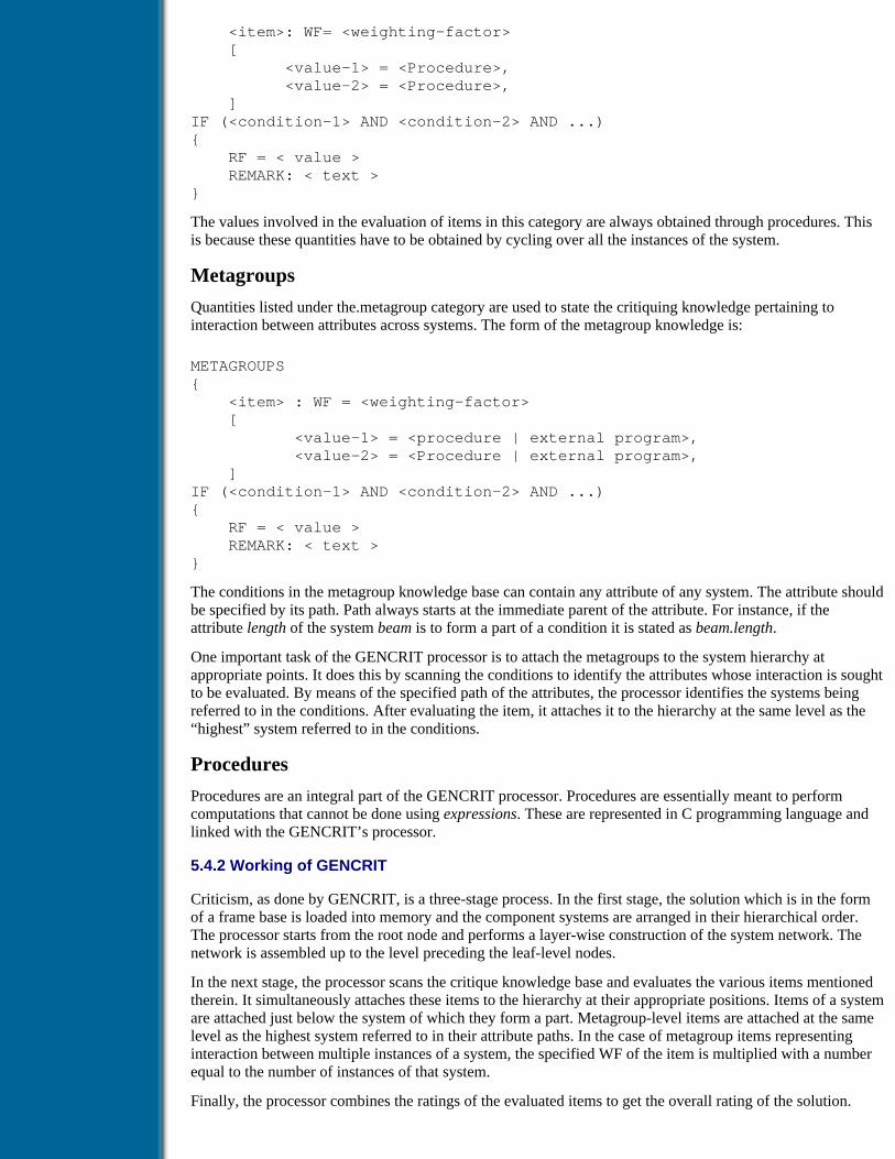
<item>: WF= <weighting-factor> [ <value-1> = <Procedure>, <value-2> = <Procedure>, ]IF (<condition-1> AND <condition-2> AND ...){ RF = < value > REMARK: < text >}
The values involved in the evaluation of items in this category are always obtained through procedures. Thisis because these quantities have to be obtained by cycling over all the instances of the system.
Metagroups
Quantities listed under the.metagroup category are used to state the critiquing knowledge pertaining tointeraction between attributes across systems. The form of the metagroup knowledge is:
METAGROUPS{ <item> : WF = <weighting-factor> [ <value-1> = <procedure | external program>, <value-2> = <Procedure | external program>, ]IF (<condition-1> AND <condition-2> AND ...){ RF = < value > REMARK: < text >}
The conditions in the metagroup knowledge base can contain any attribute of any system. The attribute shouldbe specified by its path. Path always starts at the immediate parent of the attribute. For instance, if theattribute length of the system beam is to form a part of a condition it is stated as beam.length.
One important task of the GENCRIT processor is to attach the metagroups to the system hierarchy atappropriate points. It does this by scanning the conditions to identify the attributes whose interaction is soughtto be evaluated. By means of the specified path of the attributes, the processor identifies the systems beingreferred to in the conditions. After evaluating the item, it attaches it to the hierarchy at the same level as the“highest” system referred to in the conditions.
Procedures
Procedures are an integral part of the GENCRIT processor. Procedures are essentially meant to performcomputations that cannot be done using expressions. These are represented in C programming language andlinked with the GENCRIT’s processor.
5.4.2 Working of GENCRIT
Criticism, as done by GENCRIT, is a three-stage process. In the first stage, the solution which is in the formof a frame base is loaded into memory and the component systems are arranged in their hierarchical order.The processor starts from the root node and performs a layer-wise construction of the system network. Thenetwork is assembled up to the level preceding the leaf-level nodes.
In the next stage, the processor scans the critique knowledge base and evaluates the various items mentionedtherein. It simultaneously attaches these items to the hierarchy at their appropriate positions. Items of a systemare attached just below the system of which they form a part. Metagroup-level items are attached at the samelevel as the highest system referred to in their attribute paths. In the case of metagroup items representinginteraction between multiple instances of a system, the specified WF of the item is multiplied with a numberequal to the number of instances of that system.
Finally, the processor combines the ratings of the evaluated items to get the overall rating of the solution.

Three ratings are provided by GENCRIT, viz., maximum rating, minimum rating and weighted average. Theprocess of combining individual ratings and propagating these values up the system hierarchy is described insection 5.3.3 using a sample system network.
If after attaching the various evaluated items, the processor finds that a particular system has no leaf nodesattached to it, it removes the system from the network. This kind of situation arises when no attribute of thatsystem plays any role in the performance of the synthesised solution. In such a case, no reference at all will bemade of that system in the critique knowledge base.
Previous Table of Contents Next
Products | Contact Us | About Us | Privacy | Ad Info | Home
Use of this site is subject to certain Terms & Conditions, Copyright © 1996-2000 EarthWeb Inc. All rightsreserved. Reproduction whole or in part in any form or medium without express written permission of
EarthWeb is prohibited. Read EarthWeb's privacy statement.

Search Tips
Advanced Search
Artificial Intelligence and Expert Systems for Engineersby C.S. Krishnamoorthy; S. RajeevCRC Press, CRC Press LLCISBN: 0849391253 Pub Date: 08/01/96
Search this book:
Previous Table of Contents Next
Example 1
Consider the same problem of building planning addressed in Chapter 4. A typical solution generated by thesynthesiser for the decomposition shown in Figure 4.5 (in Chapter 4) is shown in hierarchical form in Figure5.6. We show how this solution can be subjected to criticism based on considerations not included in thesynthesiser.
Four main criteria are used to critique the solution. These are orientation, daylight and view, and efficiency ofbuilding, which represent architectural criteria and suitability for lateral systems which is from a structuralviewpoint.
Figure 5.7 shows the critiquing tree after the final stage of critiquing. The individual ratings and weights ofattributes and the generated ratings for the parent systems and the root node on execution of GENCRIT’scombining algorithm are given in Figure 5.7.
The actual critiquing knowledge is listed below.
TITLE A Critic that evaluates overall office building configurations
SYSTEM site, bldg_system, service, coreCRITIQUESYSTEM service WF = 1.2{/* Item No. 1*/suitability_for_lateral_system: WF = 1.0
IF(core_location == center) {
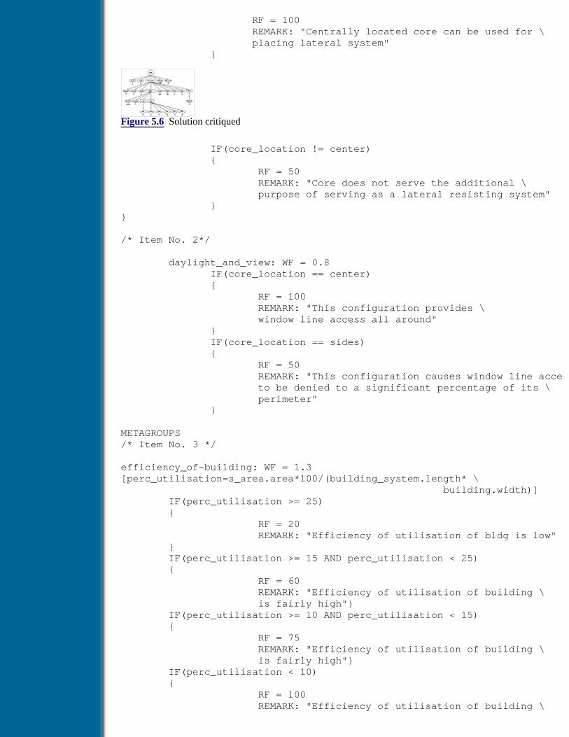
RF = 100 REMARK: "Centrally located core can be used for \ placing lateral system" }
Figure 5.6 Solution critiqued
IF(core_location != center) { RF = 50 REMARK: "Core does not serve the additional \ purpose of serving as a lateral resisting system" }}
/* Item No. 2*/
daylight_and_view: WF = 0.8 IF(core_location == center) { RF = 100 REMARK: "This configuration provides \ window line access all around" } IF(core_location == sides) { RF = 50 REMARK: "This configuration causes window line acce to be denied to a significant percentage of its \ perimeter" }
METAGROUPS/* Item No. 3 */
efficiency_of-building: WF = 1.3[perc_utilisation=s_area.area*100/(building_system.length* \ building.width)] IF(perc_utilisation >= 25) { RF = 20 REMARK: "Efficiency of utilisation of bldg is low" } IF(perc_utilisation >= 15 AND perc_utilisation < 25) { RF = 60 REMARK: "Efficiency of utilisation of building \ is fairly high"} IF(perc_utilisation >= 10 AND perc_utilisation < 15) { RF = 75 REMARK: "Efficiency of utilisation of building \ is fairly high"} IF(perc_utilisation < 10) { RF = 100 REMARK: "Efficiency of utilisation of building \

is very good" }/* Item No. 4*/orientation: WF=0.8 IF(site.orientation == NS AND bldg_system.length > \ bldg_system.width) { RF=100 REMARK: "The building is ideally oriented for \ tropical climactic conditions" } IF(site.orientation == NS AND bldg_system.width > \ bldg_system.length) { RF=50 REMARK: "The building is likely to get heated \ excessively as its longer \ edges are exposed to sun" } IF(site.orientation == EW AND bldg_system.width > \ bldg_system.length) { RF=100 REMARK: "The building is ideally oriented for \ tropical climactic conditions" } IF(site.orientation == NS AND bldg_system.length > \ bldg_system.width) { RF=50 REMARK: "The building is likely to get heated \ excessively as its longer edges are exposed to the su }END
Example 2
In this example the details of a design critic developed using GENCRIT are presented. The design beingcritiqued is that of a single-story RC building. The example design solution that is to be critiqued from thepoint of view of ease of constructibility of the design is shown in Figure 5.8. Various aspects of the solutionthat influence the constructibility, like uniformity of longitudinal spacing, uniformity of transverse spacing,beam-to-beam compatibility, longitudinal beam-to-column compatibility, transverse beam-to-columncompatibility, piping interference in same direction, and piping interference in across direction, are critiqued.
The building system in this example is decomposed into four major subsystems, viz., lng_layout, trn_layoug,beam, and column. The lng_layout and trn_layout subsystems are in turn decomposed into subsystem bay. Thesolution will then consist of several instances of these subsystems, viz., four bays in longitudinal direction,three in the transverse direction, nine beams and twenty columns. The representation of the solution after thefirst stage of criticism is shown in Figure 5.9.
Figure 5.7 Critiquing tree after final stage of critiquing
The items of the solution that are critiqued are explained below:
Uniformity of layout

When bays repeat, as will happen when the spacings are uniform, construction cost is considerably reduced.
Beam-column compatibility in both directions
If the dimensions of the beams and columns framing into each other at a joint are compatible, form work costis reduced.
Beam-beam compatibility
When beams running in orthogonal directions meet at a joint the cost of form work can be adversely affectedif they have different depths.
Previous Table of Contents Next
Products | Contact Us | About Us | Privacy | Ad Info | Home
Use of this site is subject to certain Terms & Conditions, Copyright © 1996-2000 EarthWeb Inc. All rightsreserved. Reproduction whole or in part in any form or medium without express written permission of
EarthWeb is prohibited. Read EarthWeb's privacy statement.

Search Tips
Advanced Search
Artificial Intelligence and Expert Systems for Engineersby C.S. Krishnamoorthy; S. RajeevCRC Press, CRC Press LLCISBN: 0849391253 Pub Date: 08/01/96
Search this book:
Previous Table of Contents Next
Interference between piping systems and structural components in both thedirections
The layout of pipes at the roof level of the building is handled by service specialists. If this task is donewithout proper communication with the structural specialist, the locations of the pipes can interfere with thebeams at the roof level. Such interference may call for costly drilling of holes through beams to accommodatethe pipes.
Figure 5.8 Network of beams in the RC building
The critiquing knowledge coded in GENCRIT syntax and procedures in ‘C’ are listed in Appendix II. Thedetails regarding the attachment of evaluated items to the solution tree at the second stage and combining ofindividual ratings to obtain the overall rating in the third stage are presented in Figures 5.10 and 5.11. The twonumbers against each item represent RF and WF, respectively.
Example 3 Preliminary design of gear trains
The objective is to critique the preliminary design of gear trains using GENCRIT which has been synthesisedusing GENSYNT. The solution critiqued is shown in Figure 5.12. The criteria taken into consideration duringcritiquing are wear equalisation, contact ratio, factor of safety, sufficiency of maximum dimensions given bythe user as inputs to GENSYNT and vibrational stability. These criteria are not used in the process ofsynthesis.
Figure 5.9 Solution after first stage
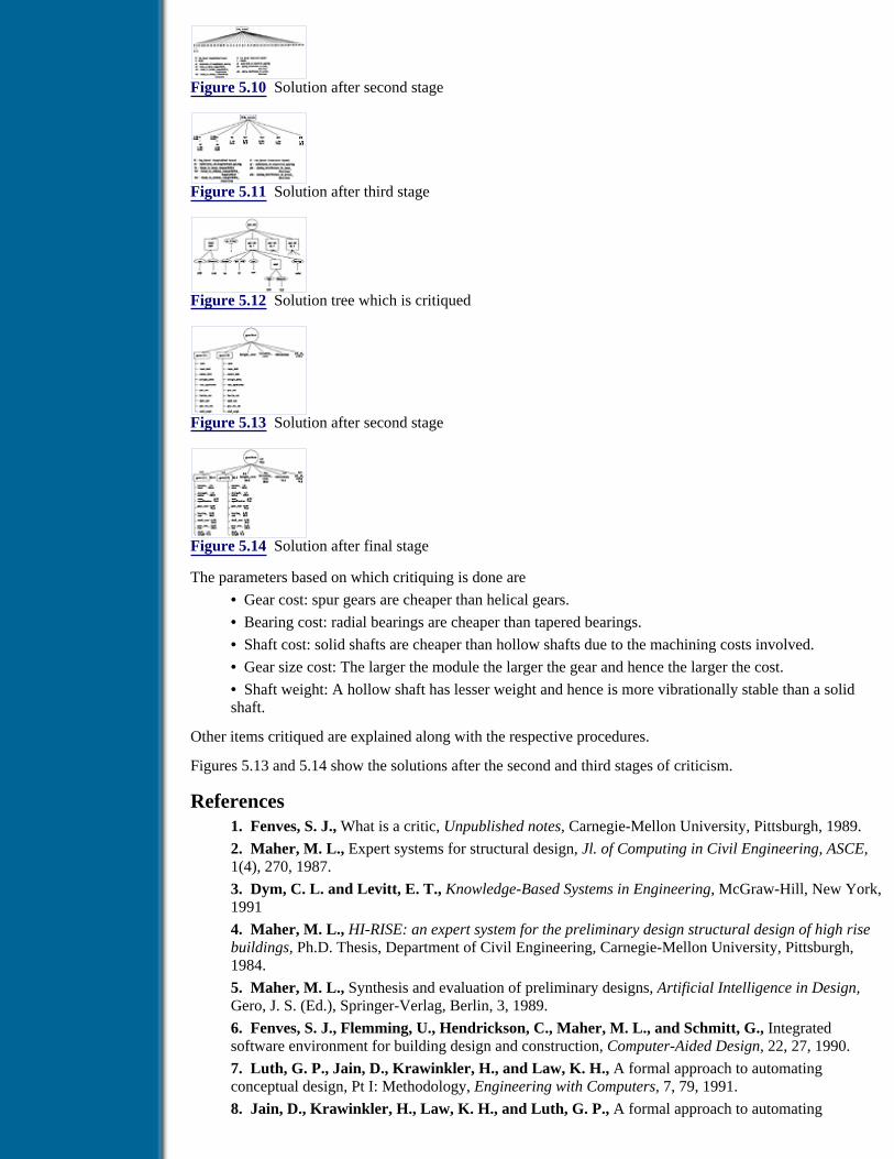
Figure 5.10 Solution after second stage
Figure 5.11 Solution after third stage
Figure 5.12 Solution tree which is critiqued
Figure 5.13 Solution after second stage
Figure 5.14 Solution after final stage
The parameters based on which critiquing is done are
• Gear cost: spur gears are cheaper than helical gears.
• Bearing cost: radial bearings are cheaper than tapered bearings.
• Shaft cost: solid shafts are cheaper than hollow shafts due to the machining costs involved.
• Gear size cost: The larger the module the larger the gear and hence the larger the cost.
• Shaft weight: A hollow shaft has lesser weight and hence is more vibrationally stable than a solidshaft.
Other items critiqued are explained along with the respective procedures.
Figures 5.13 and 5.14 show the solutions after the second and third stages of criticism.
References1. Fenves, S. J., What is a critic, Unpublished notes, Carnegie-Mellon University, Pittsburgh, 1989.
2. Maher, M. L., Expert systems for structural design, Jl. of Computing in Civil Engineering, ASCE,1(4), 270, 1987.
3. Dym, C. L. and Levitt, E. T., Knowledge-Based Systems in Engineering, McGraw-Hill, New York,1991
4. Maher, M. L., HI-RISE: an expert system for the preliminary design structural design of high risebuildings, Ph.D. Thesis, Department of Civil Engineering, Carnegie-Mellon University, Pittsburgh,1984.
5. Maher, M. L., Synthesis and evaluation of preliminary designs, Artificial Intelligence in Design,Gero, J. S. (Ed.), Springer-Verlag, Berlin, 3, 1989.
6. Fenves, S. J., Flemming, U., Hendrickson, C., Maher, M. L., and Schmitt, G., Integratedsoftware environment for building design and construction, Computer-Aided Design, 22, 27, 1990.
7. Luth, G. P., Jain, D., Krawinkler, H., and Law, K. H., A formal approach to automatingconceptual design, Pt I: Methodology, Engineering with Computers, 7, 79, 1991.
8. Jain, D., Krawinkler, H., Law, K. H., and Luth, G. P., A formal approach to automating

conceptual design, Pt II: Application to floor framing generation, Engineering with Computers, 7, 91,1991.
9. Engelmore, R. and Morgon, T., Blackboard Systems, Addison-Wesley, England, 1988.
10. Bushnell, M. L. and Haren P., Blackboard systems for AI, AI in Engineering, 67, 1986.
11. Nii, H. P., Feigenbaum, E. A., Anton, J. and Rockmore, A., Signal-to-symbol transformation:HASP / SLAP case study, AI Magazine, 3, 2, 1982.
12. Daru, R. and Vanglis, A., Design graphics (ADG): Criteria for development and evaluation, inCAPE ’86, Copenhagen, 1986.
13. Boer, D. E., Jr, Selection techniques in methodical design, in Proc. International Conference onEngineering Design, Boston, 1987.
14. Dong, Z., Evaluating design alternatives and fuzzy operations, in Proc. Int. Conference onEngineering Design, Boston, 1987.
15. Thomas, L. S., The Analytic Hierarchy Process, McGraw-Hill, New York, 1980.
16. Ishii, K., Alder, R., and Barkan, P., Application of design compatibility analysis to simultaneousengineering, Artificial Intelligence for Engineering Design, Analysis and Manufacturing, 2(1), 53,1988.
17. Ishii, K., Concurrent engineering: Automation, Tools, and Techniques, (Ed.) Andrew K., 1989.
18. Rajeev, S., Suresh, S., and Krishnamoorthy, C. S., Design criticism: a generic component inknowledge-based systems for engineering design, Proc. 2nd Int. Conf. Application of AI Techniques toCivil and Structural Engineering, Oxford, B. H. V. Topping (Ed.), Civil-Comp Press, Edinburgh, 1991.
19. Krishnamoorthy, C. S., Shiva Kumar, H., Rajeev, S., and Suresh, S., A knowledge-basedsystem with generic tools for structural engineering, Structural Engineering Review, 5(2), 121, 1991.
20. Rajeev, S., Krishnamoorthy, C. S., Suresh, S., and Shiva Kumar, H., Design evaluation usingknowledge-based techniques, Jl. of Structural Engineering, SERC, Madras, 151, 1992.
21. Shiva Kumar, H., Suresh, S., Krishnamoorthy, C. S., Fenves, S. J. and Rajeev, S., GENCRIT:A tool for knowledge-based critiquing in engineering design, Artificial Intelligence for EngineeringDesign, Analysis and Manufacturing, 8, 239, 1994.
22. Shiva Kumar, H., Suresh, S., Rajeev, S., Fenves, S. J. and Krishnamoorthy, C. S., Generic toolfor engineering design critiquing (GENCRIT), Research report, R-94-3, 1994.
Previous Table of Contents Next
Products | Contact Us | About Us | Privacy | Ad Info | Home
Use of this site is subject to certain Terms & Conditions, Copyright © 1996-2000 EarthWeb Inc. All rightsreserved. Reproduction whole or in part in any form or medium without express written permission of
EarthWeb is prohibited. Read EarthWeb's privacy statement.

Search Tips
Advanced Search
Artificial Intelligence and Expert Systems for Engineersby C.S. Krishnamoorthy; S. RajeevCRC Press, CRC Press LLCISBN: 0849391253 Pub Date: 08/01/96
Search this book:
Previous Table of Contents Next
Chapter 6Case-Based Reasoning
6.1 Introduction
In the earlier chapters three AI-based techniques have been presented. Rule-based models are appropriate fordomains where the knowledge can be represented in the form of heuristics or thumb rules. This technique iswell suited for classification and diagnostics problems. In engineering design problems, the artifact can bedecomposed into various systems and subsystems, and the subsystems and components can be designedseparately from a suitable solution space. By combining the solutions of subsystems forming the systems andsatisfying the compatibility requirements, many feasible solutions can be generated using the synthesisprocess. In multiclient problems the solutions generated by the synthesis process must be tested or evaluatedfor the satisfaction of constraints from different domains. This evaluation can be carried out by the critiquingprocess.
At this stage it may be worthwhile to analyse briefly the ways and means adopted by human experts to solveproblems. According to Stephen Slade [1]: An expert is one who has vast specialised experience, havingwitnessed numerous cases in the domain and generalised this experience to apply it to new situations. Whenconfronted with a problem, the expert is reminded of previous similar problems and their respectiveresolutions. It might be that the expert has so many exemplary cases for a given problem that the experiencehas been distilled into a general rule to be applied. Still, this general rule has its root in actual experience.Hence it can be stated that the design expert derives the knowledge from experience and the basic unit ofknowledge is case but not rules. Experts gain knowledge through accumulating new design episodes,remembering their own experiences and the lessons learnt from mistakes. They can reason by analogy andsolve the new problems.
Reasoning based on the similar past problem-solving experience helps the designer to exploit the usefuldetails for application to a particular similar case. This problem-solving strategy is termed case-basedreasoning (CBR) [2–4]. It is based on the observation that human reasoning processes are founded on specificexperience rather than a set of general guidelines. Thus compared to other AI-based reasoning methods, CBRis a process of considering past cases and arriving at decisions on comparison between the current situation

and the old cases. The solutions to problems are accomplished from past experience, stored in the form ofcases, rather than from rules or first principles. That is, the case-based problem solver works by recallingwhat has happened in the past in similar situations rather than by projecting what could work in the future[2].
CBR provides many advantages to problem solving in a knowledge-based environment [5]. It allows one topropose solutions quickly, thus avoiding the long process of decomposition and recomposition involved in asynthesis process. It is useful in situations where the domain knowledge is not completely available ordifficult to obtain. The past cases may help to provide warnings of potential problems that have occurred inthe past and to avoid repeating the mistakes. However, it is to be emphasised that blind use of past cases tocurrent situations should be avoided and knowledge/expertise is needed to transform or to adapt the past caseto the current problem.
In this chapter the potential areas of application of CBR are discussed. The processes involved in CBR areexplained. A framework is presented for building CBR systems and the use of a generic tool, CASETOOL,(CASE-based reasoning TOOL kit) in a Knowledge-Based System (KBS) environment is illustrated throughan example.
6.2 Applications of Case-Based Reasoning
As discussed in the earlier section, CBR reduces considerably the time required for solving problems as itprovides solutions from the past cases, thus avoiding the long inference chains typical of rule-based reasoningor the synthesis process. CBR has successfully been applied to a wide variety of problem-solving tasks inplanning, design and diagnosis. In this section the potential of CBR application to various tasks is brieflydescribed.
6.2.1 Planning
The process of planning is concerned with arriving at a sequence of steps or a schedule for achieving somedesired state of the world [5]. The end result of the planning process is a set of steps to achieve the goal,satisfying a given set of constraints. The earliest case-based planner that was developed was CHEF [2,6,7].The system CHEF creates new recipes based on the cases of recipes stored in its case base. The details ofworking and implementation of CHEF are described in reference [5].
Previous Table of Contents Next
Products | Contact Us | About Us | Privacy | Ad Info | Home
Use of this site is subject to certain Terms & Conditions, Copyright © 1996-2000 EarthWeb Inc. All rightsreserved. Reproduction whole or in part in any form or medium without express written permission of
EarthWeb is prohibited. Read EarthWeb's privacy statement.

Search Tips
Advanced Search
Artificial Intelligence and Expert Systems for Engineersby C.S. Krishnamoorthy; S. RajeevCRC Press, CRC Press LLCISBN: 0849391253 Pub Date: 08/01/96
Search this book:
Previous Table of Contents Next
6.2.2 Design
Typically, engineering design is identified as the process of problem solving where an artifact is designed tomeet the functional, behavioural and other requirements. Thus it is a problem of finding a solution thatsatisfies a set of constraints which represent the requirements. It involves a wide range of domain-specificknowledge and requires considerable skills and experience to come up with concise and unambiguousspecifications of the artifact to be designed [8]. The experience of an ‘expert’ which is gathered over a longperiod of practice may not be readily available in an organised and compiled form. In such situations itbecomes difficult to apply the AI approaches such as rule-based reasoning for design. It is worthwhile tostudy how experienced designers (experts) approach and solve design problems. Experienced designersanalyse the problem at hand to check whether it matches with any of the problems they have already solved.For this purpose, they compare the problem definitions, viz., requirements, conditions, constraints and otherimportant aspects of the current problem with that of the past cases. Avoiding paths that led to undesirableintermediate results (encountered in the past problem-solving episodes), they generate solutions for thepresent problem from the past cases. It thus suggests that CBR is well suited for design problems whichinvolve complex and multiple domain constraints as design cases provide illustrations of the way multipledomain constraints have been handled in solutions of the past.
Several case-based design systems have been built and reported in the literature. A few of the systems arebriefly mentioned here. The system JULIA [5,9] plans meals. For landscape design CBR was used inCYCLOPS [10]. CBR combined with model-based reasoning is used in KRITIK and KRITIK-2 for design ofsmall mechanical and electrical devices [11]. ARCHIE and ARCHIE-2 have been built to help architects inthe conceptual design [12,13]. One of the systems that is used in industry is CLAVIER [14] which helps toarrive at a layout for aeroplane components made of composite materials for curing in an autoclave. DEJAVU[15] is one of the first domain independent and flexible systems developed to assist mechanical designers.There are three main components and they are (a) a knowledge base of design plans, (b) an evaluation modulein the form of a design plan systems and (c) a blackboard-based adaptation system. A hybrid case-baseddesign process model, CADSYN [16] uses CBR and knowledge base of domain decomposition (andconstraints) knowledge for adapting design cases. This process model has been demonstrated through anexample of a building design problem [17].
6.2.3 Diagnosis

In diagnosis, we are given a set of symptoms and asked to explain. A case-based approach can use the pastcases to suggest explanation for symptoms and also to warn of explanations that have been found to beinappropriate in the past. One of the systems developed early is SHRINK [18] and has been designed to be apsychiatric diagnostician. The system CASEY [19] diagnoses heart problems by adapting the diagnoses ofprevious heart patients to new patients. It is to be pointed out here that the diagnostician cannot assume that acase-based suggestion is the answer. The suggestion must be validated. However, it is often found thatvalidation of a suggested diagnosis is much easier than generation of a plausible diagnosis. In such kinds ofdomains CBR will be advantageous.
6.3 Case-Based Reasoning Process
In CBR the search is guided by previous problem-solving exercises which are stored as past cases and hence,solutions to the problems already solved need only to be retrieved rather than be computed again [20]. Thekey issues in CBR are
a) the ability to identify the most appropriate case
b) application of that case to the current situation
c) storage of cases as complete patterns of experience including the reasoning process.
These issues are addressed in CBR process through the following three tasks [5]:
1. Case retrieval
2. Solution transformation
3. Case storing
The above three tasks are explained in the following sections.
Previous Table of Contents Next
Products | Contact Us | About Us | Privacy | Ad Info | Home
Use of this site is subject to certain Terms & Conditions, Copyright © 1996-2000 EarthWeb Inc. All rightsreserved. Reproduction whole or in part in any form or medium without express written permission of
EarthWeb is prohibited. Read EarthWeb's privacy statement.

Search Tips
Advanced Search
Artificial Intelligence and Expert Systems for Engineersby C.S. Krishnamoorthy; S. RajeevCRC Press, CRC Press LLCISBN: 0849391253 Pub Date: 08/01/96
Search this book:
Previous Table of Contents Next
6.3.1 Case Retrieval
The most important task of CBR is retrieval of appropriate cases. Recalling past cases is done based on thesimilarities between the current case and the past cases. It is possible that many cases may be available for acurrent problem situation. How do we make the computer select the appropriate case for the currentsituation? A case, in general, is a contextualised piece of knowledge representing an experience and itrepresents knowledge at an operational level; that is, it contains specific knowledge that was applied or theparticular strategies that were applied for solving a problem. Thus, there are two parts of a case: (1) theknowledge it contains and (2) the context in which it can be used. It is this second part which is important forus to select or retrieve a case for a given context. One of the widely adopted techniques is to use indices forselecting cases.
Proper indexing of the cases is of critical importance for selecting relevant cases. There are several issuesconnected with indexing and the following points should be considered.
1. Indices must be truly relevant and predictive to enable selection of cases which fit the new problemrequirements.
2. Indices must be generalised and be abstract enough to provide coverage for choosing all the closelyfitting cases.
3. Indices should not be overgeneralised to include very loosely fitting cases.
In engineering design domains, the cases are characterized by various qualitative and quantitative governingfactors leading to numerous details. The efficiency of CBR system depends on the efficiency of the caseretriever. Various models of case retrievers are proposed by researchers working in this area. The retriever ofARCHIE [12,13] uses a literal string as an index, which encapsulates all the important aspects of a case.DEJAVU [15] and PANDA [21] also use similar retrieval techniques and have weightages associated with theimportant literal aspects of the case for determining the most suitable case. The weights of each matchedaspect are added to score the event and the one with the highest score is chosen. The retriever of STRUPLE[22] has a means of checking the numerical values of governing factors during retrieval within suitable limitsaccording to the given context.
While an exhaustive treatment of various techniques adopted for indexing and case retrieval can be found inthe book by Kolodner [5], it is proposed to describe the method adopted in the framework of the generic tool,CASETOOL, for the CBR process in a knowledge-based environment [23]. The framework has been

designed to address the issues concerned with engineering design.
A case retriever is a very important component of a CBR system as the efficiency of the system dependsheavily on it. In engineering domains it is possible to group the governing attributes into qualitative andquantitative types. Depending on the type of attributes, procedures can be developed for determining theactual similarities of the retrieved cases with the current problem and potential failures associated with eachretrieved case. Thus the case retrieval process is categorised into following three subtasks.
1. Deriving indices that reflect the important features of a given case which can be used for retrieval.The qualitative attributes are mostly used for assigning indices.
2. Weeding out remotely related cases which will not have any effect on solution generation.Quantitative attributes are used for this purpose.
3. Classifying cases into various categories based on the following considerations:
(a) Similarities between old and current situations
(b) Past performance of the retrieved cases as evaluated by critics.
The first subtask of identifying suitable attributes and arriving at proper indices is a knowledge-intensive jobwhich has to be handled by the knowledge engineer and the domain expert. This is illustrated through anexample in the next section.
The next two subtasks can be accomplished by developing a generic methodology applicable to variousdomains. In the framework of CASETOOL, the generic methodology involves three steps and they are asfollows:
1. Selection by search conditions: Selecting a set of cases after weeding out all the loosely connectedcases that are chosen based on index.
2. Classification by relevance: Classifying cases based on the degree of similarity between the givensituation and the selected cases.
3. Classification by performance: Classifying cases based on the past performance.
Figure 6.1 shows the case retrieval process and the above three steps are explained below in detail.
Figure 6.1 Schematic diagram of case retrieval process
6.3.1.1 Selection by search conditions
In engineering domains, problems are defined in terms of functional requirements and design constraints.These are expressed through quantitative (for example, length, breadth, area etc.) and qualitative (forexample, soil conditions, aesthetics, type of construction, manufacturing process, etc.) attributes. It is notpossible to exactly reflect in the case index the quantitative attributes of a design solution. Hence, the casesthat are selected based on case index may not be totally relevant to the given context. That is, when theattributes of the past cases are compared with that of the current problem, some of the cases chosen based onindices may be found to be loosely connected. Such cases need to be weeded out in order to select only thosecases that are suitable for further processing.
Some domains are characterised by many governing attributes that are to be considered for selection of pastcases. Comparing all these attributes at the same time to select past cases may become tedious. The process ofselection can be made efficient by grouping the governing attributes into various sets and ordering theseattribute sets for comparison in such a way that most of the irrelevant cases are weeded out early. In order toselect appropriate cases, search conditions are set which specify acceptable limits of numerical values forquantitative attributes and the required properties/values for qualitative attributes. The task of decidingacceptable limits of numerical values and the required properties/values is knowledge intensive. Hence, therequired value limits and properties for the governing attributes are set through a knowledge base.

Previous Table of Contents Next
Products | Contact Us | About Us | Privacy | Ad Info | Home
Use of this site is subject to certain Terms & Conditions, Copyright © 1996-2000 EarthWeb Inc. All rightsreserved. Reproduction whole or in part in any form or medium without express written permission of
EarthWeb is prohibited. Read EarthWeb's privacy statement.

Search Tips
Advanced Search
Artificial Intelligence and Expert Systems for Engineersby C.S. Krishnamoorthy; S. RajeevCRC Press, CRC Press LLCISBN: 0849391253 Pub Date: 08/01/96
Search this book:
Previous Table of Contents Next
6.3.1.2 Classification by relevance
After weeding out loosely connected cases by the selection process, the relevance of the selected cases isdetermined in the next stage based on the deviation of attribute values of cases from that of the currentsituation and the relative importance of the attributes. Cases that are more relevant to the current situation arefirst determined for the solution generation process.
The similarity between past cases and the present problem situation is determined using Relevance Norm (R).The value of R is the normalised weighted least square estimation of deviations [24]. Let v1, v2, v3,....,vn be thevalues of n attributes of the past design case and c1, c2, c3,....,cn be the corresponding values of the currentsituation. Let w1, w2, w3,....,wn be weights (i.e., relative importance factors) of these attributes. Then R can beevaluated from the following equation,
where ui is the upper limit specified for ith variable and li is the lower limit specified for ith variable.
The cases are classified as perfect (approximately exact) and close (partial) matches based on the values of R.The limiting or range of values of R for classifying cases as perfect or close are domain dependent and, hence,are to be obtained through a knowledge base. The selected cases are ordered and taken up for solutiontransformation. This classification of cases using the relevance norm R is also helpful to decide later whetheror not the new case should be stored in the case base. Since literal values of the governing qualitativeattributes would have exactly matched with that of the current problem in the previous selection stage, onlythe numerical values of attributes are considered at this stage to compute the relevance norm and theclassification of the extent of match, viz., perfect or close. Also, in engineering design domains as thegoverning attributes represent different properties of the design artifact and hence are associated with differentunits corresponding to the properties they represent (for instance, attributes that represent the property anglewill be associated with degree or radian and those representing length will be in meter or feet), these attributevalues will have to be normalised (i.e., converted to nondimensional value). Note in the above equation thatthe quantity (vi - ci) is divided by (ui - li) to estimate the deviations in terms of a dimensionless value. (vi -ci)/(ui - li), wi, and n are dimensionless quantities.

6.3.1.3 Classification by performance
It is necessary to have information/knowledge about the performance of the cases stored so that we can avoidsituations that might lead to average and bad performances of the evolving solution. The design criticism andevaluation methodology described in the earlier chapter can be used to classify cases as very good, good,average and bad based on the rating assigned to a case by the critiquing process. The task of deciding on theconditions for classification is domain dependent and knowledge intensive. Hence, this is accomplishedthrough a knowledge base. The performance classification is also used in the ordering of the cases to be takenup for solution transformation.
6.3.1.4 Illustration of the case retrieval process
As explained in the above subsections the task of the case retrieval process consists of the following steps: (1)indexing, (2) selection by search conditions, (3) classification by relevance and (4) classification byperformance. The case indexing is a knowledge-intensive task and suitable schema have to be deviseddepending on the requirements of the domain of application. A generic methodology has been adopted for theremaining steps which enable us to carry out the two subtasks of case retrieval process: (a) weeding outremotely related cases using quantitative attributes through selection by search conditions and (b) theirclassification by relevance and performance.
The generic methodologies explained in sections 6.3.1.1 to 6.3.1.3 are illustrated through the followingexample.
Consider an artifact A shown in Figure 6.2 containing six components B, C, D, E, F and G, and thirteenattributes, a,b,c,d,......,m. The sample solution tree shown in Figure 6.2 is used here to explain the caseretrieval process. Let p,q,r,s, and t be the governing attributes as they are important to define a case and wp,wq, wr, ws and wt be the corresponding weights that define the relative importance of these attributes. If pi, qi,ri, si and ti are the values of these attributes for the ith case stored in the case base, then the three steps arecarried out as follows.
Figure 6.2 Sample solution tree
Previous Table of Contents Next
Products | Contact Us | About Us | Privacy | Ad Info | Home
Use of this site is subject to certain Terms & Conditions, Copyright © 1996-2000 EarthWeb Inc. All rightsreserved. Reproduction whole or in part in any form or medium without express written permission of
EarthWeb is prohibited. Read EarthWeb's privacy statement.

Search Tips
Advanced Search
Artificial Intelligence and Expert Systems for Engineersby C.S. Krishnamoorthy; S. RajeevCRC Press, CRC Press LLCISBN: 0849391253 Pub Date: 08/01/96
Search this book:
Previous Table of Contents Next
Selection by search conditions:
The search conditions have to be specified for quantitative and qualitative attributes. Based on the domainknowledge, acceptable lower and upper limits for numerical values of governing quantitative attributes andthe required literal values of qualitative governing attributes are specified as search conditions for weedingout the loosely connected cases. A check is made to see whether or not the corresponding numerical values ofthe past cases fall in the specified limits and literal values match with any of the specified literal values, andthose cases that satisfy these search conditions are selected. Let p and q be qualitative, and r,s and t bequantitative governing attributes. These can be grouped into two sets, viz., p and q as the first set, and r,s and tas the second, for selecting the cases by weeding out loosely connected cases in two stages, first by checkingthe qualitative and then the quantitative governing attributes.
Classification by relevance:
Cases that successfully pass through the above selection by search conditions are examined to determine theirrelevance to the current situation. For the problem taken up for illustration here, wr, ws,and wt are the weights
for the quantitative attributes. Let and be the values of their attributes for case i and ar, as and at bethe values of the attributes r,s and t respectively. Then the relevance norm R for case i is calculated usingequation 6.1.
where ur&lr, us&ls and ut< are upper and lower limits specified for attributes r, s, and t respectively.
The retrieved cases are classified as perfect and close matches depending on the given allowable deviations interms of R. For example, the conditions for classifying cases based on the deviations can be specified as givenbelow.
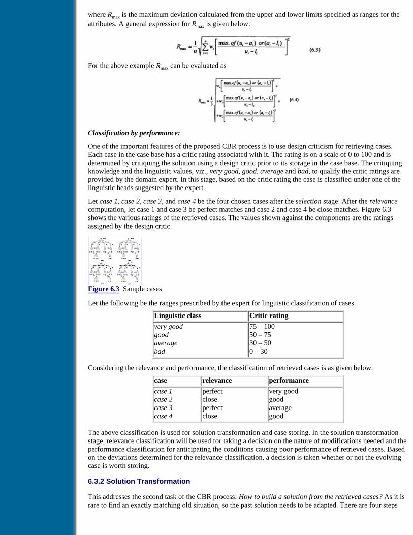
where Rmax is the maximum deviation calculated from the upper and lower limits specified as ranges for theattributes. A general expression for Rmax is given below:
For the above example Rmax can be evaluated as
Classification by performance:
One of the important features of the proposed CBR process is to use design criticism for retrieving cases.Each case in the case base has a critic rating associated with it. The rating is on a scale of 0 to 100 and isdetermined by critiquing the solution using a design critic prior to its storage in the case base. The critiquingknowledge and the linguistic values, viz., very good, good, average and bad, to qualify the critic ratings areprovided by the domain expert. In this stage, based on the critic rating the case is classified under one of thelinguistic heads suggested by the expert.
Let case 1, case 2, case 3, and case 4 be the four chosen cases after the selection stage. After the relevancecomputation, let case 1 and case 3 be perfect matches and case 2 and case 4 be close matches. Figure 6.3shows the various ratings of the retrieved cases. The values shown against the components are the ratingsassigned by the design critic.
Figure 6.3 Sample cases
Let the following be the ranges prescribed by the expert for linguistic classification of cases.
Linguistic class Critic rating
very goodgoodaveragebad
75 – 10050 – 7530 – 500 – 30
Considering the relevance and performance, the classification of retrieved cases is as given below.
case relevance performance
case 1case 2case 3case 4
perfectcloseperfectclose
very goodgoodaveragegood
The above classification is used for solution transformation and case storing. In the solution transformationstage, relevance classification will be used for taking a decision on the nature of modifications needed and theperformance classification for anticipating the conditions causing poor performance of retrieved cases. Basedon the deviations determined for the relevance classification, a decision is taken whether or not the evolvingcase is worth storing.
6.3.2 Solution Transformation
This addresses the second task of the CBR process: How to build a solution from the retrieved cases? As it israre to find an exactly matching old situation, so the past solution needs to be adapted. There are four steps

involved in the solution transformation:
1. Problem detection
2. Focusing on appropriate parts
3. Solution transformation
4. Evaluation and testing
These steps are described in the following subsections.
6.3.2.1 Problem detection
The issue addressed at this step is: How to identify and avoid mistakes/problems that led to poor performanceor failure in the similar past cases? Some of the cases that are retrieved may turn out to provide a goodsolution or found to be associated with problems and failures. These cases are termed to be successful andfailed cases, respectively. Failed cases are stored in the case base with feedback information about what wentwrong and how to rectify them, if they are to be rectified. This information is useful as it warns the reasonerof the potential failure in similar situations and thus enables one in the reasoning process to avoid repeatingthe same mistake. Successful cases highlight the salient features to be concentrated upon for solution building.In the case-based system, the failed cases are given priority as avoiding the repetition of similar failures ismore important [5].
Previous Table of Contents Next
Products | Contact Us | About Us | Privacy | Ad Info | Home
Use of this site is subject to certain Terms & Conditions, Copyright © 1996-2000 EarthWeb Inc. All rightsreserved. Reproduction whole or in part in any form or medium without express written permission of
EarthWeb is prohibited. Read EarthWeb's privacy statement.

Search Tips
Advanced Search
Artificial Intelligence and Expert Systems for Engineersby C.S. Krishnamoorthy; S. RajeevCRC Press, CRC Press LLCISBN: 0849391253 Pub Date: 08/01/96
Search this book:
Previous Table of Contents Next
6.3.2.2 Focusing on appropriate parts
This step precedes the solution transformation and addresses the issue: How to handle large cases during thesolution transformation? In the engineering environment, due to problem size, the recalled cases couldcontain a very large number of components/attributes which are too cumbersome to handle. And, the retrievedcase may find limited use in the sense that it may not be appropriate for all subgoals in the solution-buildingprocess. In such situations, the entire case need not be considered for case-based inference. Only those partsof the cases that are relevant to the current goal of the new problem need be scrutinised. Since both successfuland failed cases are useful in the CBR process, focusing on the appropriate parts can be achieved in two ways:for a successful case, the current goal in the new problem decides the portion to be focused on; however, forfailure, that part which caused failure should be studied.
6.3.2.3 Solution transformation
This addresses the issue: How to build a solution from the past similar solutions? As it is rare to find anexactly matching old solution, the past solution needs to be adapted. In general, one of the following fourmethods is used for solution transformation [5]:
1. Direct solution transfer [25].
2. Solution transfer with modifications.
3. Solution building using the same methods adopted in a similar previous case [26].
4. Schema-based solution transfer.
Application of each of the above methods depends on various factors. Method 1 is applicable if the old casefits exactly with the current problem (new case). Methods 2, 3 or 4 are adopted if the previous case does notfit the new case exactly. Method 2 is adopted when the old solution can be adapted with minimummodification. If the extent of modification is too large, method 3 is used. The solution-building methodologyadopted in the previous case is transferred and a new solution is built. Method 4 is used in the absence ofwell-defined solution-building methodologies, by creating an abstraction of problem description from a fewcases, extending it to fit the solutions of the previously solved problems and applying the schema to the newproblem data to get a solution.
6.3.2.4 Evaluation and testing

In the last step, the issue addressed is: How to validate the solution generated? Here, the solution is evaluatedto see whether or not it satisfies all the requirements and, thus, this step can be thought of as validation of theproposed solution [5]. This step is carried out by the following methods:
(a) Comparing and contrasting the proposed solution with other similar solutions
(b) Proposing hypothetical situations and checking the robustness
(c) Running a simulation and checking the results.
This process may require retrieval of additional cases and may result in repair of the proposed solution.
In situations where it is possible to try out the solution in the real world, a feedback about the real things thathappened during the execution of solution is obtained and analysed. If the results are as expected, the solutionwill be stored as a successful case. Otherwise, explanations for the failures are built and the solution is storedas a failed case with possible suggestions to overcome such failures in the future (by storing the methodadopted to rectify the solution along with the case). The testing stage helps in noticing the unforeseenopportunities and identifying the problems associated with the solutions.
6.3.3 Case Storing
The last task in the CBR process is to store the generated solution in the case base for later use. This taskaddresses the issue: How to enhance the knowledge of the case-based system? The differences between theexisting and the new case are examined to determine whether or not the new case is worth storing as a case.This is an important task of the CBR process as the new case enhances the case base and thus helps futureproblem solving.
The new cases stored in the case base contain the problem description, solution details and the processadopted for arriving at the solution, including all the alternatives considered. Such details are very usefulwhen modifications are to be made to suit the requirements of a future problem [20].
It is also worthwhile to consider storing the solution generated by other means, such as design experts, othercomputer systems etc. Such cases are stored in the case base following the representation scheme adopted inthe particular case-based system.
6.4 A Framework for CBR in Engineering Design (CASETOOL)
From the description of the three tasks of the CBR process it is evident that it is possible to develop a genericframework which is domain independent. Such a framework will be useful to the developer of an integratedknowledge-based system for a given application. CASETOOL is one such generic framework developed [23]and implemented as an integral part of the KBES development environment DEKBASE [27,28]. Themethodologies adopted in the implementation of CASETOOL for carrying out the three tasks of CBR, viz.,case retrieval, solution transformation, and case storing are briefly described in the following subsections.
6.4.1 Case Retrieval
The methodology described in section 6.3.1 is implemented in CASETOOL for case retrieval. First a relevantgroup of cases is chosen based on an index. Indexing of cases for a particular application domain isknowledge intensive and it is discussed in section 6.3.1. An exhaustive search is carried out within the groupof cases selected based on indices. Search conditions are represented as a range of numerical values for thequantitative attributes. This process of selection is well explained in section 6.3.1.1. The selected cases mayrepresent a set of potential candidates that can be considered for case-based design. However, the selectedcases may differ from the numerical values for certain of the attributes.
The relevance of the selected cases is determined from the actual deviations of the past cases from the currentsituation based on the deviations of the attribute values and then relative importance. This step is carried outthrough evaluation of the relevance norm described in section 6.3.1.2. Then, using design critics theperformances of the selected cases are classified very good, good, average and bad, as explained in section6.3.1.3. Figure 6.1 shows the various steps followed in the case retrieval process and the entire process hasbeen illustrated through an example in section 6.3.1.4.
Previous Table of Contents Next

Products | Contact Us | About Us | Privacy | Ad Info | Home
Use of this site is subject to certain Terms & Conditions, Copyright © 1996-2000 EarthWeb Inc. All rightsreserved. Reproduction whole or in part in any form or medium without express written permission of
EarthWeb is prohibited. Read EarthWeb's privacy statement.

Search Tips
Advanced Search
Artificial Intelligence and Expert Systems for Engineersby C.S. Krishnamoorthy; S. RajeevCRC Press, CRC Press LLCISBN: 0849391253 Pub Date: 08/01/96
Search this book:
Previous Table of Contents Next
6.4.2 Solution Transformation
The cases selected based on the case retrieval process may not match exactly with the current problem and thepast solution needs to be adapted to meet the requirements of the current situation. This process is calledsolution transformation and as described in section 6.3.2. it consists of four steps:
Problem detection:
In the proposed framework the critical evaluation results as obtained from a critic (say for example usingGENCRIT [29]) are stored along with the cases and are used as a basis for problem detection. The cases thatare classified as average and bad during the case retrieval process are taken up and the conditions that areresponsible for such poor ratings are identified. These conditions are used later in the solution transformationto avoid repetition of such conditions in the emerging solution. In a hierarchical representation, the lowratings are due to problems associated with certain components representing the subgoals of the overall designgoal. Hence, the components that are associated with poor ratings are first identified and taking up suchcomponents is avoided at the solution-building stage.
Focusing on appropriate parts:
It is envisaged that the solution building/transformation will be done in a hierarchical representation, i.e.,using the synthesis concept of decomposition. Hence, only those cases that are suited for the current subgoalin the solution transformation are to be focused on. The focusing on appropriate parts is done in two stages. Inthe first stage, the relevance and performance classification are used as criteria for focusing on the cases. Thecases having perfect match are considered first and within the cases having perfect match, the one with a verygood performance classification is taken up first. It may happen that a few cases that match with the currentsituation have similar relevance and performance classification, although the solution details may be different.Then it becomes very difficult to decide upon any one of these cases for solution transformation. In suchcases, focus is centred on the component of the case corresponding to the current goal in the solutiongeneration process. In the second stage of processing, the tie between the similarly matching cases is resolvedby ordering them in the decreasing order of the rating associated with the corresponding component of thecase.
Solution transformation:

The general methodologies that can be used for solution transformation have been discussed in subsection6.3.2.3. In engineering design, hierarchical decomposition of a system into subsystems and componentsenables us to build up a system as described in Chapter 4 on Design Synthesis. In the CBR process, it ispossible for a given situation that, we may retrieve more than one case. Based on the retrieved cases,appropriate parts from different cases can be combined to build the solution. This process is termed snippetsynthesis [10,30] and the framework of CASETOOL can be used for this approach. When components ofdifferent cases are extracted and put together to form a system/solution the compatibility between thesecomponents has to be ensured. This is achieved in the proposed framework through a dependency net andconstraint rules which simulate a multidisciplinary problem-solving environment. The solution obtained frompast cases is checked to see whether or not it satisfies compatibility conditions. If it does not satisfy, eitherthat particular part of the case is modified or the next available alternative is taken up. The process ofgenerating a solution in the framework is shown in Figure 6.4.
The first component to be focused on for the current subgoal is taken up and checked for the conditions thatmight lead to poor performance and undesirable properties. If there exists any potential failure, the componentcurrently considered is either modified or another competing alternative is considered for solutiontransformation. The modification is attempted first and if modification is not feasible, i.e., the knowledge formodification is not available in the knowledge base, the framework checks whether or not another componentis available from another case. If it is, the process is repeated. When no component is available, the solutionfor that subgoal is obtained through other techniques such as rule-based inference or synthesis. Thus, everysubgoal is solved and the overall solution is built incrementally.
Figure 6.4 The solution transformation
Evaluation and testing:
The framework currently supports only evaluation. Solution to the current problem is evaluated by the designcritic, which can be developed using GENCRIT as described in Chapter 5. If any low rating is observed,modification is made to the component using the knowledge base [31], and thus information of low rating isalso stored with the case for future use.
Testing has to be done externally, through simulation or field trial, and the feedback information is to beadded to the case. This feedback information will be useful for problem detection, when we attempt to obtaina solution for a new problem/situation.
6.4.3 Case Storing
In the present framework, the relevance determined by R values, number of modifications made to theexisting cases to arrive at a suitable solution, number of different cases that contribute to the evolving solutionand design critic ratings are used as guidelines to decide whether or not a solution is worth storing.
If a case not generated by the system is to be stored in the case base, first it has to be represented according tothe schema given in the subsequent section. Then the case should be critiqued by the design critics and storedappropriately in the case base.
Previous Table of Contents Next

Products | Contact Us | About Us | Privacy | Ad Info | Home
Use of this site is subject to certain Terms & Conditions, Copyright © 1996-2000 EarthWeb Inc. All rightsreserved. Reproduction whole or in part in any form or medium without express written permission of
EarthWeb is prohibited. Read EarthWeb's privacy statement.

Search Tips
Advanced Search
Artificial Intelligence and Expert Systems for Engineersby C.S. Krishnamoorthy; S. RajeevCRC Press, CRC Press LLCISBN: 0849391253 Pub Date: 08/01/96
Search this book:
Previous Table of Contents Next
6.5 Architecture of CASETOOL
CASETOOL is a generic framework for CBR and has been implemented as an integral part of DEKBASE.The architecture of CASETOOL is shown in Figure 6.5. It has five processors RETRIEVER,ANTICIPATOR, TRANSFORMER, MODIFIER and STORER and other functions that are required fordesigning an artifact using CBR problem-solving techniques. These tools are activated through rule bases.Figure 6.5 shows various modules that constitute the CBR model and the interaction of CBR tools and rulebases.
Figure 6.5 Architecture of CASETOOL
The CONTROLLER is a rule base which invokes other rule bases that constitute CBR modules. The threetasks of the CBR process, retrieval, solution transformation and case storing, are carried out by the followingmodules and functions.
RETRIEVER retrieves cases on the basis of a generated case index by invoking the functionCBR_load_case_card. If a card is successfully loaded, it checks whether or not the name assigned to thecurrent problem episode is unique by invoking CBR_case_name_okay. This step is important if the case hasto be stored in the case base. Then to weed out loosely connected cases and classify the cases based on theirrelevance to the current problem and past performance, it first sets the attribute value ranges by invokingCBR_set_ranges and then specifies the classification conditions through the invocation ofCBR_set_relevance_conditions and CBR_set_performance_conditions respectively. After setting up all theranges and conditions, it invokes the function CBR_search_case_card to perform the three step retrieval, viz.,selection, relevance, and performance.
After the case retrieval, the process control is switched to TRANSFORMER. It, in turn, invokesANTICIPATOR and MODIFIER when required. For the goal under consideration, when the moduleANTICIPATOR is called to assist TRANSFORMER, it first sets the ranges for certain aspects to be focusedon by invoking CBR_set_focusing_ranges. Based on the feedback obtained from the focusing, it then arrangesthe cases in the order in which they are to be considered for problem solving by invoking CBR_order_cases.

Once this task is accomplished, to free the memory and make it available for the transformation process, itremoves unwanted focusing information from memory by invoking CBR_unload_focusing_ranges. This stepis important for those systems that are intended to run on platforms with less memory.
When the control is returned from ANTICIPATOR, the TRANSFORMER first checks whether or not casesexist to solve the current goal under consideration by invoking CBR_check_case_exist. If cases do not exist,the system requires another means (AI or other methodologies) to accomplish the goal. When cases exist, itobtains the name of the first case from amongst the cases under consideration for transformation by invokingCBR_get_case. With this information, it transfers the values required to the current problem by invokingCBR_get_value. This step of transferring values triggers the MODIFIER. The control is automaticallytransferred to MODIFIER which ensures the compatibility and suitability of those values obtained from pastcases. Thus, the TRANSFORMER builds the solution subgoal by subgoal.
Finally when the control is switched to STORER, it ascertains whether or not the current problem episode isa new one and accordingly creates a new case card to store it by invoking CBR_create_case_card. Then itadds the new case to the case card by invoking CBR_add_case. It secures the new case card or the modifiedone, depending on the context, by updating the case base by invoking CBR_update_case_card. Once the casecard is secured in the case base, it removes it from memory by invoking CBR_unload_case_card to enable thefreed memory to be of use for other purposes.
The steps involved and functions to be called for building a case-based model using CASETOOL in theDEKBASE environment are explained in the Manual given in the diskette.
6.6 Application Example
In this section a case-based system, VASTU developed using CASETOOL, for planning rooms of aresidential building is explained. This domain is chosen since it is familiar to engineers. However, planning alayout of a residential building for a given set of requirements is a complex task. A number of factors are to beconsidered such as lighting, air circulation, ventilation, heating and air-conditioning, privacy, etc. The expertarchitects, who deal with layout planning, prefer to use past similar episodes and try to adapt them to suit thecurrent situation instead of trying to build the solution based on heuristics every time they face a designproblem. A system developed using CBR helps to improve its performance by adding new cases, thusenriching the case base.
Developing a case-based system is more difficult since the number of tasks and their interdependencies arequite complex in the case of engineering design. CASETOOL through its interaction with the DEKBASEinference engine provides several functions as tools to address the several subtasks in the whole process. Themain aim of presenting the case-based system VASTU is to demonstrate the features of CASETOOL, and,hence, its scope as given below is limited to placing various rooms in appropriate positions based on user’srequirements.
Scope and limitations of VASTU:
• Only single-story residential buildings with two to five bedrooms are considered.
• The number of bedrooms is decided based on the requirements of the occupants. However, the usercan override VASTU’s decision by increasing and decreasing the number of bedrooms within the scopeexplained above.
• In the CBR process, only the case retrieval, anticipation and focusing on appropriate parts, solutiontransformation and case storing are explained. Due to the complex nature of the modification criteria,which requires knowledge about shape grammar and reasoning, only a brief description of themodification process is presented here, i.e., the module for modification is not included in the currentversion of VASTU.
• Since the main emphasis is placed on CBR, evaluation and testing modules are not included here.These can be developed using the GENCRIT tool described in the previous chapter.
Previous Table of Contents Next

Products | Contact Us | About Us | Privacy | Ad Info | Home
Use of this site is subject to certain Terms & Conditions, Copyright © 1996-2000 EarthWeb Inc. All rightsreserved. Reproduction whole or in part in any form or medium without express written permission of
EarthWeb is prohibited. Read EarthWeb's privacy statement.

Search Tips
Advanced Search
Artificial Intelligence and Expert Systems for Engineersby C.S. Krishnamoorthy; S. RajeevCRC Press, CRC Press LLCISBN: 0849391253 Pub Date: 08/01/96
Search this book:
Previous Table of Contents Next
6.6.1 Architecture of VASTU
The architecture of VASTU is shown in Figure 6.6.
Figure 6.6 Architecture of VASTU
The system consists of six knowledge sources (KSs) which are represented through rule bases usingDEKBASE and they are, control, index, retriev, trans, anticptr and storer. The knowledge source controlis the one that controls the overall process. It schedules and monitors the entire process of layout generationfor the given user requirements. It invokes index for deriving an appropriate case card index and then invokessearch retriev to recall relevant past cases. The KS retriev sets various search conditions and selects thosecases that are relevant to the current situation. When the KS trans is invoked by control, it first calls anticptrto set up conditions for focusing and anticipating.
On the basis of the specified order of cases to be taken up, trans adapts the solution to suit the currentrequirements. After completing the task of layout planning, the case is stored in the case base, if it is founduseful for future problem solving. The various functions that are supported in CASETOOL for use by variousKSs are given in Figure 6.5. The KSs and the description of functions that are used to build VASTU are givenin the diskette accompanying the book. The CBR carried out by VASTU is explained in the following section.
6.6.2 CBR Process in VASTU
The CBR process in VASTU is illustrated through an example which starts with a user specifying therequirements as given in Table 6.1.
Table 6.1 The user requirements
Two bedroom house in a plot of 42ft × 30ft
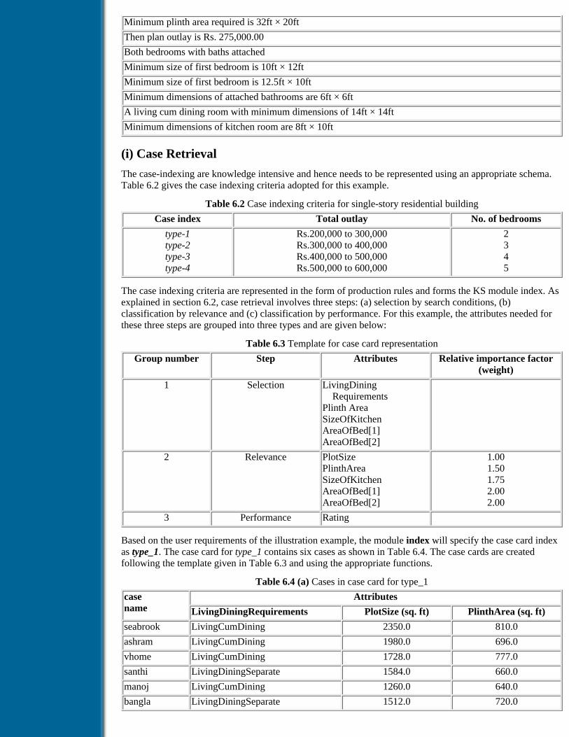
Minimum plinth area required is 32ft × 20ft
Then plan outlay is Rs. 275,000.00
Both bedrooms with baths attached
Minimum size of first bedroom is 10ft × 12ft
Minimum size of first bedroom is 12.5ft × 10ft
Minimum dimensions of attached bathrooms are 6ft × 6ft
A living cum dining room with minimum dimensions of 14ft × 14ft
Minimum dimensions of kitchen room are 8ft × 10ft
(i) Case Retrieval
The case-indexing are knowledge intensive and hence needs to be represented using an appropriate schema.Table 6.2 gives the case indexing criteria adopted for this example.
Table 6.2 Case indexing criteria for single-story residential building
Case index Total outlay No. of bedrooms
type-1type-2type-3type-4
Rs.200,000 to 300,000Rs.300,000 to 400,000Rs.400,000 to 500,000Rs.500,000 to 600,000
2345
The case indexing criteria are represented in the form of production rules and forms the KS module index. Asexplained in section 6.2, case retrieval involves three steps: (a) selection by search conditions, (b)classification by relevance and (c) classification by performance. For this example, the attributes needed forthese three steps are grouped into three types and are given below:
Table 6.3 Template for case card representation
Group number Step Attributes Relative importance factor(weight)
1 Selection LivingDining RequirementsPlinth AreaSizeOfKitchenAreaOfBed[1]AreaOfBed[2]
2 Relevance PlotSizePlinthAreaSizeOfKitchenAreaOfBed[1]AreaOfBed[2]
1.001.501.752.002.00
3 Performance Rating
Based on the user requirements of the illustration example, the module index will specify the case card indexas type_1. The case card for type_1 contains six cases as shown in Table 6.4. The case cards are createdfollowing the template given in Table 6.3 and using the appropriate functions.
Table 6.4 (a) Cases in case card for type_1
casename
Attributes
LivingDiningRequirements PlotSize (sq. ft) PlinthArea (sq. ft)
seabrook LivingCumDining 2350.0 810.0
ashram LivingCumDining 1980.0 696.0
vhome LivingCumDining 1728.0 777.0
santhi LivingDiningSeparate 1584.0 660.0
manoj LivingCumDining 1260.0 640.0
bangla LivingDiningSeparate 1512.0 720.0

Table 6.4 (b) Cases in case card for type_1 (contd..)
casename
Attributes
SizeOfKitchen (sq.ft)
AreaOfBed[1] (sq.ft)
AreaOfBed[2] (sq.ft)
Rating (sq. ft)
seabrook 96.0 180.0 180.0 77.05
ashram 49.0 144.0 144.0 77.95
vhome 80.0 143.0 170.0 73.59
santhi 80.0 140.0 110.0 66.22
manoj 80.0 120.0 120.0 85.00
bangla 60.0 150.0 154.0 87.69
Previous Table of Contents Next
Products | Contact Us | About Us | Privacy | Ad Info | Home
Use of this site is subject to certain Terms & Conditions, Copyright © 1996-2000 EarthWeb Inc. All rightsreserved. Reproduction whole or in part in any form or medium without express written permission of
EarthWeb is prohibited. Read EarthWeb's privacy statement.

Search Tips
Advanced Search
Artificial Intelligence and Expert Systems for Engineersby C.S. Krishnamoorthy; S. RajeevCRC Press, CRC Press LLCISBN: 0849391253 Pub Date: 08/01/96
Search this book:
Previous Table of Contents Next
(a) Selection by search conditions
The KS retriev retrieves cases by setting appropriate ranges for selection and conditions for classification.The attribute value ranges for selection of relevant cases are set using the appropriate function and for thecurrent problem the values are given below in Table 6.5.
Table 6.5 Frame containing ranges for case selection
RangeData Position 1 Position 2 Position 3
GROUP_NUM 1
LivingDiningRequirements LivingCumDining LivingCumDining
PlinthArea 640.0 640.0 704.0
SizeOfKitchen 80.0 76.0 84.0
AreaOfBed[1] 120.0 114.0 126.0
AreaOfBed[2] 125.0 118.75 134.25
The value of frame attribute GROUP_NUM is 1, which deals with attributes for selection. In the above tablethe Position 1, Position 2 and Position 3 are the three slots in the frame RangeData, giving scope for enteringthree values for the corresponding attribute. The search conditions are set by assigning values including upperand lower limits, and these are specified in the knowledge module retriev. For example, the qualitativeattribute LivingDiningRequirements has been associated with the same value as that of the current situationfor selection. For the quantitative attribute PlinthArea, the lower limit is taken as the current value itself(Position 2 in Table 6.5) and the upper limit is taken as 10% more than the current value (Position 3 in Table6.5). Similarly, for the other three attributes, viz., SizeOfKitchen, AreaOfBed[1] and AreaOfBed[2], the lowerlimit is taken as 5% less than the current value and the upper limit is taken as 5% more than the current value.
However, the magnitude of these percentages for fixing lower and upper limits is knowledge dependent andmay vary from expert to expert. Based on these search conditions, VASTU selects case manoj as suitable forfurther classification.
(b) Classification by relevance

The process of setting ranges for relevance is similar to that of selection stage. For this purpose an appropriatefunction is used and the conditions for classifying the case as perfect and close are also specified. The rangesare set for attributes under Relevance (denoted by GROUP_NUM=2 in Table 6.3), and the values are asspecified in Table 6.5. The classification conditions for relevance are set as given in Table 6.6.
Table 6.6 Conditions for relevance classification
Classification lower R Value Upper R Value
Perfect 0.0 0.071
Close 0.071 0.236
For the given problem Rmax is calculated using Equation 6.4,
The R value of manoj is calculated using Equation 6.2.
Based on these values, and conditions given in Table 6.6, the case manoj is classified as close.
(c) Classification by performance
For the attributes categorized under performance (Group Number = 3 in Table 6.3) and the conditions forperformance classification are specified through functions. The values used in the current examples are givenbelow in Table 6.7.
Table 6.7 Values for performance classification
Classification Lower rating Upper rating
Very good 80.0 100.0
Good 60.0 80.0
Average 40.0 60.0
Poor 0.0 40.0
Based on the rating, the selected case manoj is classified as very good.
The plan of the retrieved case is shown in Figure 6.7 and its representation in frame base is given in Figure6.8.
Previous Table of Contents Next
Products | Contact Us | About Us | Privacy | Ad Info | Home
Use of this site is subject to certain Terms & Conditions, Copyright © 1996-2000 EarthWeb Inc. All rightsreserved. Reproduction whole or in part in any form or medium without express written permission of
EarthWeb is prohibited. Read EarthWeb's privacy statement.

Search Tips
Advanced Search
Artificial Intelligence and Expert Systems for Engineersby C.S. Krishnamoorthy; S. RajeevCRC Press, CRC Press LLCISBN: 0849391253 Pub Date: 08/01/96
Search this book:
Previous Table of Contents Next
(ii) Solution Transformation
Problem detection and focusing on appropriate parts - The current problem consists of six goals, viz.,planning the six rooms - a living cum dining room, two bedrooms, two attached bathrooms and a kitchenroom. For the current problem there is only one case available in the case base for layout planning. However,CASETOOL has a facility by which it can consider each instance of a component as a separate solution forthe goal of that instance. For example, there are two instances of Bed Room and Attached Bath Room,respectively. Therefore, when trying to place the first instance of the current situation, the ordering of thecomponents from case/cases may be such that the second instance will be taken up first. This situation mayarise due to higher rating that is associated with the second instance. The goals and ordering of componentsare given in Table 6.8. The focusing and anticipating are done for each subgoal as explained below.
Living cum dinning room:
For the given problem there is only one case selected and this particular room does not have any otherinstance. Therefore, it does not require any focusing. However, if two cases are selected for any othersituation, then the ranges for focusing are set through the rule base. The upper and lower limits are set suchthat interchanging of length and breadth are taken care of. The upper and lower limits that are stored in aframe base are given in Table 6.9.
Table 6.8 Ordering of cases for solution transformation
goal cases
LivingCumDiningAttachedBathRoom[1]BedRoom[1]AttachedBathRoom[2]BedRoom[2]KitchenRoom
manojmanoj(AttachedBathRoom[1])manoj(BedRoom[2])manoj(AttachedBathRoom[1])manoj(BedRoom[2])manoj
manoj(AttachedBathRoom[2])manoj(BedRoom[1])manoj(AttachedBathRoom[2])manoj(BedRoom[1])
Figure 6.7 Plan of the retrieved case
Figure 6.8 Representation of manoj in frame base
Table 6.9 Frame containing the focusing ranges for living cum dining room.
RangeData (Position 1) (Position 2)
LivingCumDining.Length 11.2 16.8
LivingCumDining.Breadth 11.2 16.8
Similarly, the focusing ranges are set for other subgoals, viz., BedRoom[1], BedRoom[2],AttachedBathRoom[1], AttachedBathRoom[2] and Kitchen Room. The values are given in Table 6.10.
Table 6.10 Focusing ranges for subgoals
Attribute Focusing ranges
lower limit upper limit
AttachedBathRoom[1].length 4.8 7.2
AttachedBathRoom[1].breadth 4.8 7.2
BedRoom[1].length 10.0 13.2
BedRoom[1].breadth 10.0 13.2
AttachedBathRoom[2].length 4.8 7.2
AttachedBathRoom[2].breadth 4.8 7.2
BedRoom[2].length 10.0 13.75
BedRoom[2].breadth 10.0 13.75
KitchenRoom.length 8.0 11.0
KitchenRoom.breadth 8.0 11.0
Solution transformation and modification:
In this stage, the solution is built goal by goal, i.e., placing one room after another, in the order given in Table6.8. First, the left bottom coordinates of the living cum dining room are found out as (11,17) from the casemanoj (Figure 6.7). Since this room is the first one, there will not be any interference. The next room to betaken up is AttachedBathRoom[1]. The location of this room is taken as (5,21). When the location ofBedRoom[1] is taken up as the next goal, the part to be considered is BedRoom[2] of manoj (see Table 6.8)and the coordinates are (5,5) (Figure 6.7). Each time when the coordinates of a room are fixed (goals in thisexample), a heuristic check on interference is made whether the coordinates of the top-right and bottom-leftcorners fall within the room that is already transformed. Since the length and breadth requirements ofBedRoom[1] are known (12ft and 10ft, respectively) the coordinates of BedRoom[1] are fixed. Since there isno interference, the modification module (not given here and is left as an exercise for the reader to develop)shifts the location of AttachedBathRoom[1] (bottom left coordinate, 5,21) to (5,15). Now when the next goalis taken up for locating the AttachedBathRoom[2], the left bottom coordinates are fixed as (5,21) and they donot interfere with any of the existing rooms. The next goal is to locate BedRoom[2]. From the case manoj thecoordinates of BedRoom[2] are (5,5) which interferes with the first bedroom instance. Therefore, the modifiertakes the next part as BedRoom[1] of manoj and fixes the coordinates as (5,27). The coordinates of thekitchen are fixed using manoj. At this stage of transformation the location of various rooms is as shown inFigure 6.9.

Figure 6.9 The modified plan
By using the knowledge module the solution is further modified in such a way that the rooms are adjacent toeach other and are located as closely as possible. The modifications carried out are summarised in Table 6.11and the final solution for layout of the building is shown in Figure 6.10.
Previous Table of Contents Next
Products | Contact Us | About Us | Privacy | Ad Info | Home
Use of this site is subject to certain Terms & Conditions, Copyright © 1996-2000 EarthWeb Inc. All rightsreserved. Reproduction whole or in part in any form or medium without express written permission of
EarthWeb is prohibited. Read EarthWeb's privacy statement.

Search Tips
Advanced Search
Artificial Intelligence and Expert Systems for Engineersby C.S. Krishnamoorthy; S. RajeevCRC Press, CRC Press LLCISBN: 0849391253 Pub Date: 08/01/96
Search this book:
Previous Table of Contents Next
(iii) Case Storing
For the present example various rooms, except for the location and orientation of the first bedroom, have beenadopted to suit the current requirements. However, since the entire solution has been obtained using a singlecase (viz., manoj) and the R value is less than 50% of Rmax, the case is not stored in the case base.
Figure 6.10 The transformed plan
Table 6.11 Summary of solution transformation
goal solution fromcase new solution remark
LivingCumDining (11,17) (11.5, 15) Location Modified
AttachedBathRoom[1] (5,15) (5,15) Not Modified
BedRoom[1] (5,5) (5,5) Not Modified
AttachedBathRoom[2] (2,21) (5,22) Location Modified
BedRoom[2] (5,27) (5,29) Orientation and Location Modified
KitchenRoom (17,5) (17,5) Orientation Modified
References1. Slade, S., Case-based reasoning: A research paradigm, AI Magazine, 12(1), 42, 1991.
2. Hammond, K. J., CHEF: A model of case-based planning, in Proc. AAAI-86, Cambridge, MA,MIT Press, 1, 267, 1986.
3. Kolodner, J. L., Extending problem solving capabilities through case-based inferences, in Proc.Fourth International Workshop on Machine Learning, 167, 1987.
4. Riesbeck, C. K. and Schank, R. C., Inside Case-Based Reasoning, Hillsdale, NJ: LawrenceErilbaum, 1989.
5. Kolodner, J. L., Case-Based Reasoning, Morgan Kaufmann Publishers, San Mateo, CA, 1993.
6. Hammond, K. J., Learning to anticipate and avoid planning problems through the explanation offailures, in Proc. AAAI-86, Cambridge, MA, MIT Press, 1986.
7. Hammond, K. J., Case-Based Planning: Viewing Planning as a Memory Task, Academic Press,Boston, 1989.
8. Dym, C. L. and Levitt, R. E., Knowledge-Based Systems in Engineering design, McGraw-Hill,New York, 1991.
9. Hinrichs, D. and Kolodner, J. L., The role of adaptation in case-based design, in Proc. NinthNational Conference on AI, AAAI-91, Cambridge,MA, MIT Press, 1, 28, 1991.
10. Navinchandra, D., Case-based reasoning in CYCLOPS, a design problem solver, in Proc. DARPAWorkshop on Case-Based Reasoning, 286, 1988.
11. Goel, A. and Chandrasekaran, B., Use of device model in adaptation of design cases, in Proc. ofthe DARPA Workshop on Case-Based Reasoning, Pensacola Beach, FL, 100, 1989.
12. Goel, A., Kolodner, J., Pearce, M., and Billington, R., Towards a case-based tool for aidingconceptual design problem solving, in Proc. of the DARPA Workshop on Case-Based Reasoning,Washington, DC, 109, 1991.
13. Domeshek, E. and Kolodner, J., Using the points of large cases, AIEDAM, 7(2), 87, 1993.
14. Mark, W., Case-based reasoning for autoclave management, in Proc. of the DARPA Workshop onCase-Based Reasoning, Pensacola Beach, FL, San Mateo, CA, 1989.
15. Bardasz, T. and Zeid, I., DEJAVU: Case-based reasoning for mechanical design, AIEDAM, 7(2),111, 1993.
16. Maher, M. L. and Zhang, D. M., CADSYN: Using cases and decomposition knowledge fordesign synthesis, in Artificial Intelligence in Design, Ed., Gero, J. S., Butterworth Heinemann, Oxford,137, 1991.
17. Maher, M. L. and Zhang, D. M., CADSYN: A case-based design process model, AIEDAM, 7(2),97, 1993.
18. Kolodner, J. L., The role of experience in development of expertise, in Proc. of AAAI-82, AAAIPress, Cambridge, MA, 1982.
19. Koton, P., Reasoning about evidence in casual explanation, in Proc. of AAAI-88, AAAI press,Cambridge, MA, 1988.
20. Rosenman, M. A., Gero, J. S., and Oxman, R. E., What’s in a case: the use of case-bases,knowledge-bases and databases in design, CAAD Futures’91, Ed., Schmitt, G., N., Vieweg, Wiesbaden,285, 1992.
21. Roderman, S. and Tsatsoulis, C., PANDA: A case-based system to aid novice designers,AIEDAM, 7(2), 125, 1993.
22. Zhao, F. and Maher, M. L., Using analogical reasoning to design buildings, Engineering withComputers, 4, 107, 1988.
23. Shiva Kumar, H. and Krishnamoorthy, C. S., A frame work for case-based reasoning inengineering design, AIEDAM, 9, 161, 1995.
24. Bergan, P. L. and Clough, R. W., Convergence criteria for iterative processes, AIAA, 10(8), 1107,1978.
25. Corbonell, J. G., Learning by analogy: Formulation and generalizing plans from past experience,in Machine Learning: An Artificial Intelligence Approach, Tioga Publishing Company, Palo Alto, CA,1983.
26. Corbonell J. G., Derivational analogy: a theorem of reconstructive problem solving and expertiseacquisition, machine learning, in An Artificial Intelligence Approach, Morgan Kaufman Publishers, LosAltos, CA, 1986.
27. Krishnamoorthy, C. S., Rajeev, S., Karimulla Raja, S., and Shiva Kumar, H., Development

environment for knowledge based systems in engineering design, in Proc. of Second InternationalConference on Applications of Artificial Intelligence Techniques to Civil and Structural Engineering,Ed., Topping, B. H. V., Oxford, England, 165, 1991.
28. Krishnamoorthy, C. S., Shiva Kumar, H., Rajeev, S., and Suresh, S., Knowledge-based systemwith generic tools for structural engineering design, Structural Engineering Review, 5, 121, 1995.
29. Shiva Kumar, H., Suresh, S., Krishnamoorthy, C. S., Fenves, S. J. and Rajeev, S., GENCRIT:A tool for knowledge-based critiquing in engineering design, AIEDAM, 8(3), 239, 1994.
30. Kolodner, J. L., Extending problem solving capabilities through case-based inferences, in Proc. ofFourth International Workshop on Machine Learning, Morgan Kaufmann, Irvine, CA, 167, 1987.
31. Shiva Kumar, H., An integrated knowledge-based approach to concrete road bridge design, Ph.D.Thesis, Indian Institute of Technology, Madras, India, 1995.
Previous Table of Contents Next
Products | Contact Us | About Us | Privacy | Ad Info | Home
Use of this site is subject to certain Terms & Conditions, Copyright © 1996-2000 EarthWeb Inc. All rightsreserved. Reproduction whole or in part in any form or medium without express written permission of
EarthWeb is prohibited. Read EarthWeb's privacy statement.

Search Tips
Advanced Search
Artificial Intelligence and Expert Systems for Engineersby C.S. Krishnamoorthy; S. RajeevCRC Press, CRC Press LLCISBN: 0849391253 Pub Date: 08/01/96
Search this book:
Previous Table of Contents Next
Chapter 7Process Models and Knowledge-Based Systems
7.1 Introduction
The preceding chapters presented different generic tools and techniques useful to engineering problemsolving. Each tool or technique can be used only for those specific tasks for which they are ideally suited. Forinstance, expert systems are ideal for tasks involving reasoning based on heuristics and expert knowledge ofthe domain. Classification, diagnosis and monitoring types of tasks can be addressed efficiently usingrule-based inference. This technique can also be used to develop front ends to many planning and designproblems. Development of expert systems for diagnosis problems is illustrated in section 7.2 through a casestudy of one such system involving a complex knowledge net. Design synthesis is an ideal technique forgeneration of alternate solutions. The alternate solutions generated can be evaluated and graded using thecritiquing tool. There can be instances, where solutions have to be generated or critiquing has to be done bycomparing with already available successful solutions. Case-based reasoning provides the technique forcarrying out such tasks.
Engineering Design
The engineering design domain has proved to be far more complex than the domains for whichknowledge-based programming techniques were originally applied. One major source of complexity is thatdesign tasks cannot be addressed through knowledge-based techniques alone. Although preliminary designtasks are characterised by the use of a large number of heuristics, some of the tasks require numericcomputing using the algorithms pertaining to the execution of these tasks. Hence, a combination of proceduraland knowledge-based techniques is required to address these tasks.
Multiagent and Cooperative Problem Solving
Design of any engineering system or component usually involves the participation of multiple specialists. Inpractice, each specialist is narrowly focused and tends to have limited knowledge of other domains withwhich the specialist must communicate and interact. The result is that even as the specialist approaches the

design task in a manner aimed to achieve his/her local goals to the best possible extent, the same effort maynot be reflected in the global objectives of the project. In other words, the best global solution should beevolved, after taking the concerns of all the participating agents into consideration. The globally acceptablesolution will invariably involve compromises among the participants. The focus of recent research has beentowards bringing together the knowledge-based design systems that are capable of performing well only innarrow limits and automated integrated design systems that have the ability to handle the entire designprocess. The main requirement for such systems is an organisational framework, in order to coordinate theactivities of the individual modules of specialised expertise and also to guide and evaluate the compositeglobal solution as it evolves, to ensure adherence with the overall objectives and satisfaction of concerns of allthe participating agents. Various models have been proposed to organise the cooperative problem-solvingenvironment with varying degrees of flexibility and philosophies regarding communication and control. Oneof the models used for this purpose is the Blackboard model and is explained in section 7.3 of this chapter.
Process Models
Another recent development is the attempt to develop explicit models of the design process. Design processmodels have resulted from research in design theory and have offered a new insight into the way integratedsystems need to be developed [1]. The motivation for developing such models comes from the difficulty indeveloping integrated design systems using existing knowledge-based system development tools; the need towork within the capabilities of the development tool can be too constraining. The contention is that the moreappropriate approach would be to conceive a model of the design process and then develop a computingframework for the realisation. of the model as a computable entity. This framework can then be used todevelop the integrated system. A design process model attempts to structure the design process at an overalllevel by defining the activities that comprise it. At the task level, the model advocates the use of a designmethodology that allows reasoning and creativity within that formalised representation of design.Knowledge-Based Systems (KBSs) developed based on explicit design process models do not suffer from thelimitations faced by earlier integrated systems.
Integrated KBS Development
In order to build an integrated KBS the right approach is to undertake a detailed task analysis of the domainwhich involves detailed examination of the various tasks and subtasks of the entire design process for thedomain and identification of the issues that need to be addressed to arrive at integrated solution(s). Based onthe task analysis, an explicit design process model can be abstracted. Appropriate Artificial Intelligence (AI)methodologies and tools can then be identified for realising this model as a computing framework. Thisframework can then be used to develop an integrated system for the chosen domain problem. Case studies ofthree KBSs are presented in sections 7.4 to 7.6 to illustrate the development process involved in buildingintegrated systems.
Other Methodologies and Techniques
Engineering design problems do not have unique solutions and an exhaustive generation of all feasiblesolutions using traditional Knowledge-based techniques can be quite inefficient unless sufficient constraintscan be applied early in the generation process to prune infeasible solutions. Recent research has shown thatGenetic Algorithms (GA) can be used to develop efficient methodologies for arriving at optimal designsolutions. In the development of ODESSY described in section 7.4 the GA-based methodology has beenintegrated in a knowledge-based framework leading to a hybrid model for arriving at optimal designsolutions. The new trends in the use of GAs leading to evolutionary computing and the promise it holds for awider role it can play in engineering design are described in section 7.7.1.
One of the problems cited with generalised problem solving using expert system approaches is the difficultyinvolved in eliciting knowledge from experts. The ability to generalise from specific problem-solvingknowledge is now being recognised as a desirable feature of automated systems. It is in this context thatArtificial Neural Networks (ANN) have gained importance. Research and development work is in progress inintegrating knowledge-based techniques into ANNs. A brief introduction to ANN and its potential when usedin a KBS environment are given in section 7.7.2.
In the concluding section of the chapter, attention is focused on Concurrent Engineering, which is emergingas a new methodology that offers potential for developing integrated systems to meet the future needs of theengineering industry.

Previous Table of Contents Next
Products | Contact Us | About Us | Privacy | Ad Info | Home
Use of this site is subject to certain Terms & Conditions, Copyright © 1996-2000 EarthWeb Inc. All rightsreserved. Reproduction whole or in part in any form or medium without express written permission of
EarthWeb is prohibited. Read EarthWeb's privacy statement.

Search Tips
Advanced Search
Artificial Intelligence and Expert Systems for Engineersby C.S. Krishnamoorthy; S. RajeevCRC Press, CRC Press LLCISBN: 0849391253 Pub Date: 08/01/96
Search this book:
Previous Table of Contents Next
7.2 Expert Systems for Diagnosis
REPCON is an expert system developed for diagnosis of causes of distress in buildings in distress andsuggestion of repair methods [2]. Issues involved in its development, such as organising the domainknowledge, evolution of knowledge nets pertaining to defects in masonry walls and transformation ofknowledge nets into rules, are presented in this section. The objective of the presentation is to give the readersan idea about the steps that one has to go through in the process of developing an expert system. The systemis intended to assist building repair consultants and township maintenance engineers, who are increasinglybeing called upon to solve problems associated with strengthening, modification, repair and renovation ofbuildings. Evolution of knowledge nets and their transformation to rules for one of the knowledge bases onCracking in Brick Masonry are briefly presented here.
7.2.1 Understanding of Domain Knowledge
Cracking is common in brick masonry construction, irrespective of whether the building is constructedentirely with brick masonry or whether it contains extensive masonry components. Hence, it is appropriate toincorporate a more elaborate and detailed knowledge base for this in the expert system. In fact, the majorthrust of this developmental effort was to study and structure the complex knowledge of the domain. Tostructure the knowledge base, a proper understanding of the following factors is essential.
• First, the function of the structural subsystem affected by cracking should be understood. Forinstance, a wall can be either load bearing, or be an infill in a reinforced concrete frame or be afree-standing wall. Furthermore, it should be known whether the wall is external, internal, partition orjust a panel wall.
• The shape of the crack can be vertical, horizontal, diagonal, random or ripping.
• Location of the crack.
• Extent of the crack.
• Activity of the crack (whether the crack is active or dormant).
With the years of cumulative experience of various experts and from the published literature, it is possible tospeculate on the locations that are most vulnerable to cracking in any particular subsystem. One can also linkthe occurrence of cracking in these locations to its possible cause. For instance, in external walls of a load

bearing structure, vertical cracking occurs most commonly at the corners of a side wall of a long building,near the quoins in the front elevation of a long building having short return walls, at the corners of thetopmost story of a building with a reinforced concrete roof, below window jambs, around balconies etc. In aparticular instance, if it is known that vertical cracks are located near a balcony, it can be safely inferred thatthe probable cause is drying shrinkage and thermal movement of the wall and the floor around the balcony,leading to cracking.
7.2.2 Evolution of Knowledge Nets
Having diagnosed the cause, one has to select an appropriate method of repair from among the wide variety ofchoices available. Generally, cracks in brick masonry are repaired by grouting and sealing with various typesof mortars depending upon the type of materials used in construction, stitching with reinforced concrete ormetal ties or sealing with bitumen. Also in particular cases, one may need to undertake remedial measures inaddition to repair. The major factors that weigh in the choice of a proper repair and remedial method are (1)width of crack; (2) activity of crack (whether the crack is active or dormant); (3) type of bricks used (whetherabsorbent or non-absorbent); and (4) type of mortar used (whether relatively rich or weak).
Figure 7.1 Static net for diagnosis and suggestion of repair method
Knowledge nets are evolved over two distinct stages. First, the net representing the conceptual structure of theknowledge base is constructed. It may be composed of one or more context types. This is called a staticknowledge net. Figure 7.1 shows the static net for cracking in brick masonry. It is a structured frameworkestablished for the diagnosis and suggestion of a repair method for cracking in brick masonry. The static netwas used to guide the evolution of the instance net. For this, each node in the static net is initialised with allthe possible parameters. The resultant net, called the instance knowledge net, reflects the structure of the staticknowledge net and represents the paths that could be taken during the consultation interaction. For developingthe instance net, the node structural subsystem was instantiated first, including all its context types. Further,each of the context instances were developed fully, one by one, up to the node cause. Figure 7.2 illustrates theevolution of the instance net from the static net for an example data set. The transformation of instance net torules was done simultaneously. Based on the experience during implementation, the instance net was refinedfurther, incorporating suitable revisions. Once this part of the knowledge base was validated, the net for thenext instance was constructed. The complexity of the knowledge was thus dealt with by the incrementalevolution of the instance net, followed by its representation as rules, implementation and feedback leading tothe final refinement of the net.
Further, having constructed the knowledge net for the diagnosis of cause, the instance net was then expandedfurther up the static net, up to the goal node, i.e., suggestion of repair method. This part of the knowledge wasrelatively simple compared with the complexity of the diagnostic process.
Previous Table of Contents Next
Products | Contact Us | About Us | Privacy | Ad Info | Home
Use of this site is subject to certain Terms & Conditions, Copyright © 1996-2000 EarthWeb Inc. All rightsreserved. Reproduction whole or in part in any form or medium without express written permission of
EarthWeb is prohibited. Read EarthWeb's privacy statement.

Search Tips
Advanced Search
Artificial Intelligence and Expert Systems for Engineersby C.S. Krishnamoorthy; S. RajeevCRC Press, CRC Press LLCISBN: 0849391253 Pub Date: 08/01/96
Search this book:
Previous Table of Contents Next
7.2.3 Transformation of Knowledge from Nets to Rule Base
In the initial stages of construction of knowledge nets, it was decided to use rules for representingknowledge. Several factors weighed in favour of using production rules for knowledge representation.
As is evident from the static nets, the root node of all the knowledge bases in the system is repair methodor remedial measure. This node is represented as the goal of the rule base. An example rule is given below.
Figure 7.2(a) Instance net showing a typical path (contd..)
RULE for active cracks due to movement of ground IF cause IS movement of ground AND confidence (cause) < 75 AND type of crack IS active AND crack width in mm > 1.5 THEN repair method suggested IS flexible apron AND DISPLAY method of repair in detail
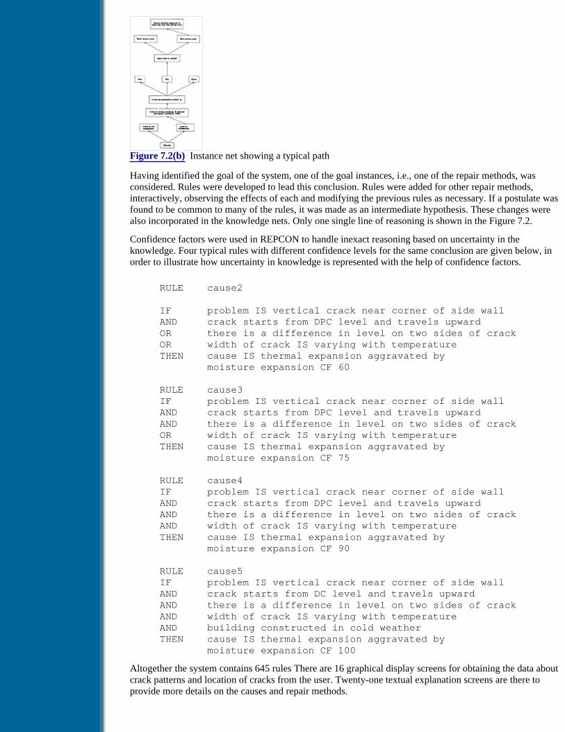
Figure 7.2(b) Instance net showing a typical path
Having identified the goal of the system, one of the goal instances, i.e., one of the repair methods, wasconsidered. Rules were developed to lead this conclusion. Rules were added for other repair methods,interactively, observing the effects of each and modifying the previous rules as necessary. If a postulate wasfound to be common to many of the rules, it was made as an intermediate hypothesis. These changes werealso incorporated in the knowledge nets. Only one single line of reasoning is shown in the Figure 7.2.
Confidence factors were used in REPCON to handle inexact reasoning based on uncertainty in theknowledge. Four typical rules with different confidence levels for the same conclusion are given below, inorder to illustrate how uncertainty in knowledge is represented with the help of confidence factors.
RULE cause2
IF problem IS vertical crack near corner of side wall AND crack starts from DPC level and travels upward OR there is a difference in level on two sides of crack OR width of crack IS varying with temperature THEN cause IS thermal expansion aggravated by moisture expansion CF 60
RULE cause3 IF problem IS vertical crack near corner of side wall AND crack starts from DPC level and travels upward AND there is a difference in level on two sides of crack OR width of crack IS varying with temperature THEN cause IS thermal expansion aggravated by moisture expansion CF 75
RULE cause4 IF problem IS vertical crack near corner of side wall AND crack starts from DPC level and travels upward AND there is a difference in level on two sides of crack AND width of crack IS varying with temperature THEN cause IS thermal expansion aggravated by moisture expansion CF 90
RULE cause5 IF problem IS vertical crack near corner of side wall AND crack starts from DC level and travels upward AND there is a difference in level on two sides of crack AND width of crack IS varying with temperature AND building constructed in cold weather THEN cause IS thermal expansion aggravated by moisture expansion CF 100
Altogether the system contains 645 rules There are 16 graphical display screens for obtaining the data aboutcrack patterns and location of cracks from the user. Twenty-one textual explanation screens are there toprovide more details on the causes and repair methods.

7.3 Blackboard Model of Problem Solving
In production rule systems, the entire domain knowledge is represented as IF-THEN rules only. When thedomain is very large and complex, production rule representation and associated inference lead to a largeand inefficient knowledge base causing very poor focus of attention. The example problem presented inChapter 3 on ‘Planning and Design of Steel Industrial Structures’ illustrates how a production rule-basedsystem is developed for such a complex problem. The same problem can be designed in a more efficientmanner using blackboard architecture. The difficulties posed by a large and inefficient knowledge base andpoor focus of attention in production systems are overcome in the blackboard model, in which the domainknowledge is decomposed into smaller modules called knowledge sources, and a dynamic and flexibleknowledge application strategy is used. The same concept can be extended to problems requiringinvolvement of multiple agents representing different domains. Many design problems in engineering fallunder the category of multiagent problem solving, in which a solution proposed by one agent may not beacceptable to other agents. The blackboard model reacts as and when conflicts arise during problem solvingand uses conflict-resolution knowledge sources in an opportunistic manner. Essentially, the blackboardmodel provides a high-level abstraction of knowledge and solution techniques for dynamic control andallows use of the knowledge for opportunistic and incremental problem solving. A number of systems havebeen developed and reported in the literature, where the blackboard model is used for structuring theproblems and solving them [3]. A brief overview of blackboard architecture, a review of majordevelopments which helped in evolution of the model, typical applications, a review of blackboarddevelopment shells, and steps involved in development of a major application are presented in this section.A typical example of the design of a plate girder is taken for illustration of the model.
Previous Table of Contents Next
Products | Contact Us | About Us | Privacy | Ad Info | Home
Use of this site is subject to certain Terms & Conditions, Copyright © 1996-2000 EarthWeb Inc. All rightsreserved. Reproduction whole or in part in any form or medium without express written permission of
EarthWeb is prohibited. Read EarthWeb's privacy statement.

Search Tips
Advanced Search
Artificial Intelligence and Expert Systems for Engineersby C.S. Krishnamoorthy; S. RajeevCRC Press, CRC Press LLCISBN: 0849391253 Pub Date: 08/01/96
Search this book:
Previous Table of Contents Next
7.3.1 Blackboard Architecture
The three basic components of a blackboard system are knowledge sources, blackboard data structure andcontrol. In the backboard model, knowledge required to solve a problem is decomposed into smallerindependent knowledge sources. The knowledge sources can be represented using any of the knowledgerepresentation schemes. Generally, the active problem-solving knowledge is represented in IF-THEN rules.Each rule set or knowledge source contains knowledge for resolving one task in a design process. Dependingon the nature of the problem, frames, procedures and databases can also be used as and when required. Theblackboard holds the global data and the information on problem-solving states. Activation of knowledgesources modifies the states in the blackboard leading to an incremental generation of the solution to theproblem. Knowledge sources interact with each other only through the blackboard. The blackboard can bevisualised as a collection of objects (frames) with slots for storing the solution as it gets generated in anincremental manner. The objects in the blackboard also store the status of the problem being solved and anagenda of events. The control decides issues such as what knowledge to apply, when to apply, which part ofthe blackboard is being currently addressed etc., depending on the status of the problem solving. The generalarchitecture of the blackboard model is shown in Figure 7.3.
Figure 7.3 Blackboard model (KS = Knowledge Source)
As was mentioned earlier, the blackboard holds all the data objects. A hierarchical organisation is generallyadopted for abstraction of these data objects resulting in two main advantages. (1) Knowledge sources areorganised in such a way that they use information at one level as input and produce information for the nextlevel. (2) The terminology associated with different concepts is made explicit and accessible at the appropriatelevels of abstraction.
Since the problem-solving strategy is decomposed into a hierarchical organisation, the concept of eventbecomes predominant in blackboard-based problem solving. Any change in the blackboard is considered to be

an event. Any change in the solution state either due to generation of additional information or modificationof existing information is immediately recorded in the blackboard. The controller notes this change and takesnecessary actions by invoking an appropriate knowledge source. This process repeats until the final solutionfor the problem is obtained. Another important point to be noted is that a subsequent change in informationcan make a previously taken decision false. In such cases, corresponding stages have to be undone bybacktracking, leading to the reasoning to be non-monotonic. To carry out such backtracking, all the decisionsmade along with their dependencies have to be stored. The dependency network has to be built incrementallyas the decisions are made using the knowledge sources. It not only helps in carrying out backtracking, but alsohelps in reviewing the progress of the problem-solving process.
7.3.2 Blackboard Framework
In a blackboard framework, the knowledge representation methods, techniques for scheduling knowledge, andpartitioning of the solution space and the domain knowledge depend on the nature of the domain. Theblackboard framework gives a description of the system components grounded on actual computationalconstructs and is a prescriptive model describing what goes into the blackboard. The problem to be solved isfirst decomposed into loosely coupled subtasks corresponding to the different specialised areas within thetask. Functional decomposition of the tasks in a hierarchical manner allows common functions to be shared bymany subsystems.
For development of an application, first the blackboard is hierarchically partitioned into objects defining theattributes of the solution space. The objects are connected through the links which can represent relationshipsbetween the objects. Such decomposition both at the knowledge level and at the blackboard level allowsmaximum flexibility during the development stage and the problem-solving phases. Such abstraction alsoreduces the computational needs by restricting the manipulations of smaller entities. After partitioning thesolution space and the domain knowledge, the control information is added. In this framework, the blackboardserves as the structured working memory. Each knowledge source has a set of production rules andprocedures and the control contains the strategy for application of the rules.
Details of implementation of the blackboard system are not attempted here, as there are many books andpapers available on this topic [4–7]. A number of prototype applications were developed from as early as1980, in different domains which contributed to the development of the model to the present state.
HEARSAY II, one of the earliest blackboard-based systems developed at Carnegie Melon University [8], wasintended to answer queries about and retrieve documents from a collection of computer science abstracts inthe area of AI, covering a selected vocabulary of around 1000 words. HASP/SIAP is another blackboardmodel-based system, which was used to develop and maintain a situation board that reflects the activities ofthe platforms (surface ships and submarines) in a region under surveillance [9]. Input to the system was acontinuous stream of acoustic signals produced by objects in the region and intelligence reports containinginformation about movements of friendly and hostile platforms and routine commercial shipping activities.CRYSALIS, a system that determines the structures of proteins, given their animo acid sequence and X-raydiffraction data, for the first time introduced use of multiple hierarchies on the blackboard through panels[10]. Ong et al. [11] developed a mobile robot position estimator system based on the blackboard model for arobot with a limited sensory capability moving in a fixed environment, in which the details of theenvironment are suitably stored in the robot database. In this system, there are two blackboard panels,containing solution space details and control details. In both blackboard panels, the abstraction hierarchylabels are the same and only the attributes and values are different. The knowledge sources are classified asspecialist and scheduling knowledge sources.
Previous Table of Contents Next
Products | Contact Us | About Us | Privacy | Ad Info | Home
Use of this site is subject to certain Terms & Conditions, Copyright © 1996-2000 EarthWeb Inc. All rightsreserved. Reproduction whole or in part in any form or medium without express written permission of
EarthWeb is prohibited. Read EarthWeb's privacy statement.

Search Tips
Advanced Search
Artificial Intelligence and Expert Systems for Engineersby C.S. Krishnamoorthy; S. RajeevCRC Press, CRC Press LLCISBN: 0849391253 Pub Date: 08/01/96
Search this book:
Previous Table of Contents Next
DESTINY is a conceptual model for integrated structural design, proposed by Sriram [12]. In DESTINY, theblackboard is divided into levels depicting an a priori plan of the solution state with decomposition natural tothe problem domain. The hypotheses in the blackboard are related through structural relationships. DESTINYhas three levels of knowledge sources, viz., strategy level, specialist level and resource level. Strategy-levelknowledge sources determine the course of the next action based on an analysis of the current solution state.Specialist knowledge sources contribute to solution generation in the blackboard, for example, knowledge forconfiguration generation, preliminary analysis, detailing consultant and critical evaluation of different designsfrom specialist knowledge sources. Resource knowledge sources contain the analytical knowledge andinformation on specification and codal provision.
GENESIS is a prototype system for planning and design of steel industrial structures proposed by Sakthiveland Kalyanaraman [13]. It is capable of performing engineering activities consisting of structural planning,preliminary design, analysis and detailed design of single-story steel industrial buildings in an integratedmanner. Starting from any arbitrary plant layout and spatial constraints specified by the user, GENESISdevelops the geometric layout of structural systems at different levels of abstraction and designs typicalstructural components in the layout. In GENESIS, geometric space contains objects describing the geometricattributes of every structural component or system in an industrial building. The design space is generated byselecting typical structural elements, possibly corresponding to more than one instance of the geometric spaceobjects, for detailed design. Geometric and design space frame objects are stored in a frame library andinstantiated whenever required through various knowledge sources on the respective solution blackboardpartitions.
In GENESIS, the control events in the control blackboard are divided into meta events, planning events anddesign events. Meta events describe planning and design activities at a higher level of abstraction. Planningand design events describe specific subevents in the planning and design process. Different control knowledgeevents are used at different problem-solving stages to control the process of engineering of steel industrialstructures. The functional knowledge sources are grouped into six knowledge modules, viz., structuralplanning knowledge module, design space generation knowledge module, preliminary design knowledgemodule, analysis knowledge module, detailed design knowledge module and design criticism knowledgemodule. Each knowledge module contains many knowledge sources to perform the engineering activitiesassociated with different types of structural systems that can be adopted. The database is used to store staticand dynamic data. The steel section properties of different rolled shapes, design tables such as standard cranedata and numeric tables from governing codes such as wind pressure coefficients are stored in the static

database. The schema for storing analysis results, nodal loads, design results, structural configurations etc. areprovided at the time of knowledge base development and are used for storing these results at run time. Thedynamic databases are specific to a problem. A schematic representation of GENESIS is shown in Figure 7.4.
Figure 7.4 Architecture of GENESIS
Development of a number of blackboard models and prototypes has eventually led to general purposeblackboard shells. Most of these shells have been developed using the experience gained in developingprototype or application systems. For example, the experience with HASP and CRYSALIS led to ageneralised blackboard system AGE (Attempts to GEneralise) at Stanford University. AGE permits the userto build blackboard systems in which attention is focused on a particular node of the blackboard object tree atany point of problem solving, and scheduling is done based on a set of priorities [14]. The main contributionof AGE has been in the design of subsequent general blackboard shells. HEARSAY III is the blackboardgeneralisation from the experience in the earlier projects HEARSAY I and II. The major contribution of thisshell is a knowledge-based control procedure having a separate scheduling blackboard to make the controlinformation visible and accessible to control knowledge sources. It has an integral context mechanism thatallows simultaneous and alternative interpretations. BBI is the third generalisation in blackboard systemshaving a full-fledged separated blackboard architecture for controlling the execution of the domain knowledgesources [15]. It has graphical user interface for building knowledge bases, blackboards and knowledgesources.
Previous Table of Contents Next
Products | Contact Us | About Us | Privacy | Ad Info | Home
Use of this site is subject to certain Terms & Conditions, Copyright © 1996-2000 EarthWeb Inc. All rightsreserved. Reproduction whole or in part in any form or medium without express written permission of
EarthWeb is prohibited. Read EarthWeb's privacy statement.

Search Tips
Advanced Search
Artificial Intelligence and Expert Systems for Engineersby C.S. Krishnamoorthy; S. RajeevCRC Press, CRC Press LLCISBN: 0849391253 Pub Date: 08/01/96
Search this book:
Previous Table of Contents Next
7.3.3 Integrated Engineering System
The integrated Engineering System (IES) is an extended blackboard framework proposed by Shaktivel andKalyanaraman [16], which addresses the complex demands posed by engineering processes on the computingenvironment. The salient features of IES are:
• ability to handle a diversity of numeric, graphic and symbolic parameters;
• ability to use a variety of knowledge, methods and procedures efficiently;
• management of a large volume of static and dynamic data uniformly and efficiently;
• representation of the solution at various levels of abstraction starting from the most general to themost specific;
• ability to handle problems covering the entire range of the derivation-formation spectrum; and
• modelling and control of the cooperative process of engineering.
A schematic view of the IES architecture is presented in Figure 7.5. IES provides a framework in which acooperative engineering process is modelled in an extended blackboard system. In IES, the blackboard is acommon global data structure which serves as a communication medium between various independentknowledge sources. As the solution progresses, the schedule knowledge source posts a solution on theblackboard and also retrieves the necessary information posted by other knowledge sources for its problemsolving. In IES, the blackboard is partitioned into solution blackboard and control blackboard panels. Thesolution blackboard panel stores the solution generated during the problem-solving process. The informationis stored in objects along with their relations in a hierarchical form. The objects are instantiated in the solutionblackboard at run time from the frame library which contains the objects and their attribute descriptions. Therelational links between the objects in the solution blackboard are created through knowledge sources. Inaddition to storage of values, a limited amount of reasoning can be done in the objects through multipleinheritances as well as demons. Knowledge sources can also be invoked through the demons.

Figure 7.5 Architecture of IES
The control blackboard stores the status of control events as the solution progresses. Control events describethe problem state in the most abstract form. For instance, an event analysis can have different states (status)such as ‘cannot be started’, ‘can be started’, and ‘completed’. At run time, the instance-specific control eventsare generated dynamically depending on the number of instantiations of the object on the solution blackboardin which the control event is focused. The status of the control events are modified by the knowledge sources,as the solution progresses. The control event status information is used by the knowledge source selector toinvoke an appropriate knowledge source at any given problem state. In IES, the knowledge sources arefunctionally classified into three categories, viz., control knowledge sources, functional knowledge sourcesand task-specific knowledge sources. Based on the inference process, knowledge sources are classified asautonomous knowledge sources, interacting knowledge sources and coordinating knowledge sources.Autonomous knowledge sources work independently and model the infrequent interaction during cooperatingproblem solving by different experts by allowing communication between the different knowledge sourcesonly through the blackboard. Interacting knowledge sources are used to represent knowledge in coupledsubtasks. IES allows knowledge to be represented in each knowledge source in its own language and noconstraint is placed on the syntax and semantics used by the different knowledge sources. The coordinationbetween various interacting knowledge sources is achieved through mapping provided in a coordinatingknowledge source. Whenever a coordinating knowledge source is invoked, the reasoner takes the coordinatingknowledge source as the common objective of the set of interacting and independent knowledge sourcesspecified in the coordinating knowledge source and tries to achieve the goal with the help of knowledgeavailable in those sets of knowledge sources. IES provides four reasoning mechanisms, viz., forward,backward, hybrid and fire-all techniques. Different reasoning strategies can be used in different knowledgesources.
Previous Table of Contents Next
Products | Contact Us | About Us | Privacy | Ad Info | Home
Use of this site is subject to certain Terms & Conditions, Copyright © 1996-2000 EarthWeb Inc. All rightsreserved. Reproduction whole or in part in any form or medium without express written permission of
EarthWeb is prohibited. Read EarthWeb's privacy statement.

Search Tips
Advanced Search
Artificial Intelligence and Expert Systems for Engineersby C.S. Krishnamoorthy; S. RajeevCRC Press, CRC Press LLCISBN: 0849391253 Pub Date: 08/01/96
Search this book:
Previous Table of Contents Next
7.3.4 Illustrative Example
To get a better insight into the problem solving based on blackboard model, a simple problem of Design ofPlate Girder is taken up. The details of formulation and implementation using IES are presented below. As allthe variable and control event names are self-explanatory, detailed descriptions are not given. The followingcontrol events are identified for the problem.
1. User Input
2. Load Estimation
3. Web Design
4. Flange Modelling
5. Flange Design
6. Stiffener Design
7. Output
The system has ten knowledge sources, and the salient features of the knowledge sources are briefly describedbelow. A typical knowledge source has the following sections.
default goal termination criteria of the knowledge source
precondition describes the status of control events for the knowledge source to getactivated
knowledge sourcetype
whether knowledge source is independent, interacting or coordinating type
inference strategy inference strategy to be used for the knowledge source
rules knowledge in the form of rulesrules can interact with objects in the blackboard
To have a better understanding of blackboard-based problem solving, the status of control events and actionstaken at different stages for the problem under consideration are presented below. At the beginning ofproblem solving, the status of control events is as shown below.
User Input not completed
Load Estimation not completed
Web Design not completed
Flange Modelling not completed
Flange Design not completed
Stiffener Design not completed
Output not completed
The knowledge source for input is invoked which in turn invokes a procedure to get the required input fromthe user. At the end of execution of the knowledge source the status of control event User Input is set to‘completed’ and the status of Load Estimation set to ‘can be started’ as shown below.
User Input completed
Load Estimation can be started
Web Design not completed
Flange Modelling not completed
Flange Design not completed
Stiffener Design not completed
Output not completed
The knowledge source for load estimation is invoked at this stage. The controller of the blackboard systemidentifies the appropriate knowledge source by checking the preconditions given in the knowledge sources.For instance, the precondition in the load estimation knowledge source is as given below
IF status of control event User Input IS completed AND status of control event Load Estimation IS can be started
The controller of the blackboard monitors the status of the control events and the preconditions of theknowledge sources, and invokes the appropriate knowledge source. The knowledge source in turn modifiesthe status of the control events in the blackboard. The process continues until, the status of all the eventsbecomes ‘completed’. In the process of problem solving, conflicts can arise, in case more than one knowledgesource tries to establish a value for the same variable. Such situations are indicated in the blackboard.Appropriate knowledge sources are invoked at this time for conflict resolution, if such a situation arises.
Parallel and distributed processing can be introduced at different levels in the blackboard paradigm. Asemantic synchronisation of blackboard data is required for effective parallelisation of the blackboard model.Attempts have been made by researchers in the past to parallelise the blackboard model for specific problems.Corkill has proposed a model for concurrent execution of knowledge source instances, wherein a multithreadexecution of knowledge sources is carried out based on a predefined priority rating [17]. Rice et al. [18]proposed two models, (1) a blackboard framework designed to operate on distributed-memorymultiprocessors and (2) a blackboard framework to operate on shared-memory models. They reportedconsiderable speedup, as a 0result of distributed implementation of blackboard model [18].
Object-oriented blackboard architecture for model-based diagnostic reasoning proposed by Buttner et al. is animproved scheduling of knowledge source activation, where a strategy knowledge source orders the triggeredknowledge sources before they are actually activated [19]. A number of researchers are still continuing workto evolve object-oriented blackboard models to operate on machines with multiprocessors.
7.4 ODESSY - An Integrated System for Preliminary Design ofReinforced Concrete Multistory Office Buildings
Building design is a very complex engineering activity involving the cooperative participation of multiplespecialists representing disparate domains like architectural, structural, construction, HVAC (Heating,Ventilation and Air-Conditioning) etc. In practice, the building industry is characterised by fragmentationamong the various phases of the design process, like layout planning, conceptual design, preliminary design,analysis, detailed design and construction [20]. Interaction and feedback among the participants that are soessential to the generation of globally acceptable designs are either inadequate or occur too late in the designprocess. This often results in suboptimal designs that might entail costly rework, thus causing unforeseen

delays in the execution of the project. Design integration is seen as the means by which the coordinationconcerns in the building industry can be addressed. Recent attempts to develop integrated computer systemsfor design have indicated that KBSs can serve as vehicles for promoting integration, both vertically across themany phases of planning and design and horizontally across the many subdisciplines involved [21–23]. In thefollowing subsections, a process model that has been proposed and used [24,25] to address the tasks involvedin the integrated design of multistory office buildings is explained.
7.4.1 Task Analysis of Building Design
Based on a study of the design process as performed by a set of experienced designers solving building designproblems, the following issues have been identified as central to integrated building design.
Previous Table of Contents Next
Products | Contact Us | About Us | Privacy | Ad Info | Home
Use of this site is subject to certain Terms & Conditions, Copyright © 1996-2000 EarthWeb Inc. All rightsreserved. Reproduction whole or in part in any form or medium without express written permission of
EarthWeb is prohibited. Read EarthWeb's privacy statement.

Search Tips
Advanced Search
Artificial Intelligence and Expert Systems for Engineersby C.S. Krishnamoorthy; S. RajeevCRC Press, CRC Press LLCISBN: 0849391253 Pub Date: 08/01/96
Search this book:
Previous Table of Contents Next
Multidisciplinary nature of problem-solving knowledge
Many disparate knowledge sources contribute to the evolution of a building design. Their individualcontributions might often come into conflict with each other. Therefore, a globally acceptable solution usuallyrepresents a compromise among the knowledge sources whose preferred local solutions are not fullycompatible.
Existence of multiple solution paths
The preliminary stages of building design are characterised by the existence of multiple solutions. Eachsolution path needs to be pursued till such time as it is proved to be decidedly inferior to its alternatives.Issues concerning multiple solution generation include knowledge representation for generation and efficientconstraint application strategies for early pruning of infeasible paths.
Qualitative nature of evaluation
In the preliminary stages of design, the nature of evaluation is qualitative and is expressed in imprecise,linguistic form. Hence decision support tools that can handle knowledge in imprecise, qualitative form areneeded to perform evaluation.
Need to enforce consistency
An offshoot of the multiagent nature of the building design domain is that decisions have to be made andrevised during reasoning. This affects the integrity of the solution. Hence, strategies need to be speciallydevised to enforce consistency of the solution during the reasoning process.
Horizontal and vertical integration
The multiphase, multiagent nature of the building design task necessitates integration, both vertically acrossthe many phases of the design process and horizontally over the disciplines affecting the design.
7.4.2 Synthesis-Criticism-Modification Model

The first step towards arriving at an integrated solution for building design is to evolve a process model forbuilding design that addresses all the issues discussed above. An examination of the process models reportedby the researchers [26–28] shows that the existing models do not satisfactorily address all the issues identifiedabove.
A process model, called the Synthesis-Criticism-Modification (SCM) model, proposed recently [25] viewsbuilding design as consisting of multiple phases of a three-step process of synthesis, criticism andmodification. The scope of the model is limited to two phases, viz., layout planning and conceptual andpreliminary design of reinforced concrete multistory office buildings. In each phase, the synthesis stepgenerates multiple solutions. Each of these solutions is then critiqued from the viewpoint of everyparticipating knowledge source. In the final step, one or a few highly rated solutions are modified, ifnecessary, based on the feedback provided by the critics. Figure 7.6 shows the architecture of the SCMprocess in a typical phase of design. The knowledge representation schemes and inference strategies for eachof the components are briefly described below.
Figure 7.6 Architecture of the SCM process
Design Synthesis
In Chapter 4, the concept of design synthesis and the decomposition model used in the synthesis process havebeen explained in detail. This model is found to be most suitable for the synthesis step of the proposed modelbecause (i) the building domain lends itself easily to hierarchical decomposition and (ii) the model facilitatesmultiple solution generation. GENSYNT described in Chapter 4 is used for developing the synthesisers thatform part of the integrated system. The decomposition representation of the layout of the building, which isused in the first phase, viz., layout planning, is shown in Figure 7.7.
Figure 7.7 Decomposition tree for layout synthesis
Design Critiquing
Design synthesis ensures that every generated solution is feasible. Since building design is a multiagentprocess, it is inevitable that each solution will meet the local preferences of each participating agent withvarying degrees of satisfaction. Design critiquing, explained in Chapter 5, is the process of evaluating asolution to determine its desirability. It also creates a feedback loop of information that can be used toimprove the solution. In a multiagent design context, critiquing will have to be done by each agentparticipating in the solution-building process.
During the knowledge elicitation stage, it has been observed that at the preliminary design stage, preferencesare stated in a qualitative manner. The Fuzzy Weighted Averaging (FWA) technique provides a rationalmeans to evaluate solutions based on such qualitative criteria [29–31].
A fuzzy-based model has been proposed for design critiquing [25]. The highlights of the model are (i) ataxonomy for aspects to be critiqued based on the complexity of attribute interaction involved in theassessment (the hierarchical tree used in GENCRIT is adopted for this purpose), (ii) a formalism forrepresenting critiquing knowledge that enables assigning of fuzzy linguistic ratings and weights for evaluatedaspects, (iii) membership functions for internal representation of fuzzy linguistic variable values, (iv) a FWAprocess for generating overall solution ratings, (v) a Ranking Index (RI) scheme for ranking solutions and (vi)generation of both user-readable and machine-readable critiques that justify the fuzzy rating and providespecific suggestions for improving the solution.
A domain-independent generic tool for performing design critiquing, called FUZCRIT (FUZzy CRItiquingTool) has been developed that aids in rapid development of critics [25]. The architecture of FUZCRIT isshown in Figure 7.8.

Figure 7.8 Architecture of FUZCRIT
Design Modification
In an automated environment, the system itself has to respond to the critiques made by the participatingagents to effect any possible improvement to the solution. This step is termed modification. Modification is aknowledge-intensive task, depending largely on the expertise available to make decisions. Designmodification poses two major problems: (i) Conflicts may arise between the suggestions made by the variouscritics and these have to be resolved before effecting a modification. (ii) Design modification entails revisionof decisions already made, thus affecting the consistency of the solution. Hence, whenever a modification isto be made to the solution, measures have to be initiated to preserve the consistency of the solution.
Previous Table of Contents Next
Products | Contact Us | About Us | Privacy | Ad Info | Home
Use of this site is subject to certain Terms & Conditions, Copyright © 1996-2000 EarthWeb Inc. All rightsreserved. Reproduction whole or in part in any form or medium without express written permission of
EarthWeb is prohibited. Read EarthWeb's privacy statement.

Search Tips
Advanced Search
Artificial Intelligence and Expert Systems for Engineersby C.S. Krishnamoorthy; S. RajeevCRC Press, CRC Press LLCISBN: 0849391253 Pub Date: 08/01/96
Search this book:
Previous Table of Contents Next
The design modification model
A model for design modification that addresses the two issues stated above has been proposed and developed[25]. The input to the modifier consists of the solution to be modified and the set of critiques generated by thecritics that have evaluated the solution. For the modifier to respond to the critiques made by various critics,the critiques have to be very specific. A template that has been proposed for representing critiques is shown inFigure 7.9.
Figure 7.9 Template for representation of machine-readable critique
Every critic that evaluates a solution posts its critiques into a modifier table in the global space. A multilevelpriority specification strategy has been proposed to resolve conflicts among critiques in the modifier table.Following the resolution of all conflicts, the final resolved set of critiques is posted on to an execute tablewhich is then used by the modifier to trigger changes to the solution.
Since considerable dependencies exist between the attributes of a solution, consequences of a change to anattribute of the solution can be extensive. A revision-propagation mechanism that has been proposed in thethesis enables the consequences of a change to a solution attribute to be propagated to the appropriate extentautomatically.
The KBS Development Tool
The SCM-based process model has been implemented using DEKBASE and two generic tools GENSYNTand FUZCRIT. The application of the SCM model to the two identified phases of the preliminary buildingdesign process are described below.
7.4.3 Layout Planning
Layout planning forms the first phase of the conceptual design of a building, wherein the allocation of spacefor the various functions of the building is performed taking into account multidisciplinary criteria. This phaseof the design is characterised by the existence of a potentially large number of alternatives, and a systematicand computationally efficient methodology is needed to enumerate all the feasible solutions. Since the space
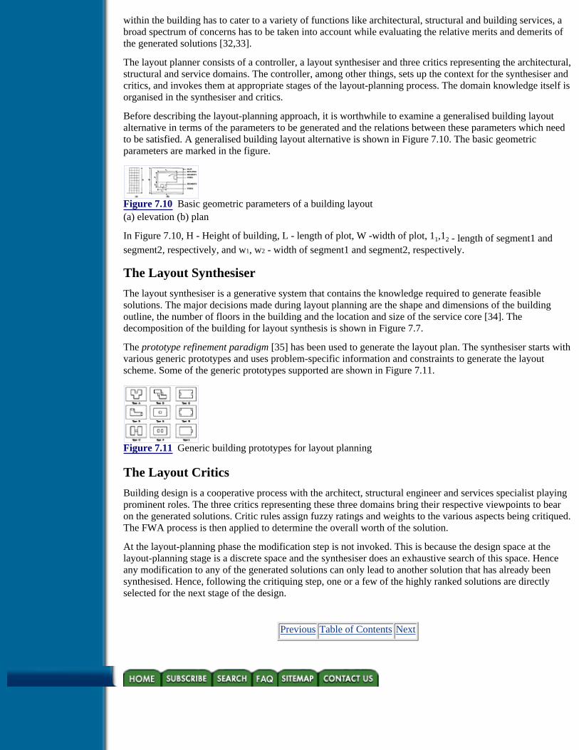
within the building has to cater to a variety of functions like architectural, structural and building services, abroad spectrum of concerns has to be taken into account while evaluating the relative merits and demerits ofthe generated solutions [32,33].
The layout planner consists of a controller, a layout synthesiser and three critics representing the architectural,structural and service domains. The controller, among other things, sets up the context for the synthesiser andcritics, and invokes them at appropriate stages of the layout-planning process. The domain knowledge itself isorganised in the synthesiser and critics.
Before describing the layout-planning approach, it is worthwhile to examine a generalised building layoutalternative in terms of the parameters to be generated and the relations between these parameters which needto be satisfied. A generalised building layout alternative is shown in Figure 7.10. The basic geometricparameters are marked in the figure.
Figure 7.10 Basic geometric parameters of a building layout(a) elevation (b) plan
In Figure 7.10, H - Height of building, L - length of plot, W -width of plot, 11,12 - length of segment1 andsegment2, respectively, and w1, w2 - width of segment1 and segment2, respectively.
The Layout Synthesiser
The layout synthesiser is a generative system that contains the knowledge required to generate feasiblesolutions. The major decisions made during layout planning are the shape and dimensions of the buildingoutline, the number of floors in the building and the location and size of the service core [34]. Thedecomposition of the building for layout synthesis is shown in Figure 7.7.
The prototype refinement paradigm [35] has been used to generate the layout plan. The synthesiser starts withvarious generic prototypes and uses problem-specific information and constraints to generate the layoutscheme. Some of the generic prototypes supported are shown in Figure 7.11.
Figure 7.11 Generic building prototypes for layout planning
The Layout Critics
Building design is a cooperative process with the architect, structural engineer and services specialist playingprominent roles. The three critics representing these three domains bring their respective viewpoints to bearon the generated solutions. Critic rules assign fuzzy ratings and weights to the various aspects being critiqued.The FWA process is then applied to determine the overall worth of the solution.
At the layout-planning phase the modification step is not invoked. This is because the design space at thelayout-planning stage is a discrete space and the synthesiser does an exhaustive search of this space. Henceany modification to any of the generated solutions can only lead to another solution that has already beensynthesised. Hence, following the critiquing step, one or a few of the highly ranked solutions are directlyselected for the next stage of the design.
Previous Table of Contents Next

Products | Contact Us | About Us | Privacy | Ad Info | Home
Use of this site is subject to certain Terms & Conditions, Copyright © 1996-2000 EarthWeb Inc. All rightsreserved. Reproduction whole or in part in any form or medium without express written permission of
EarthWeb is prohibited. Read EarthWeb's privacy statement.

Search Tips
Advanced Search
Artificial Intelligence and Expert Systems for Engineersby C.S. Krishnamoorthy; S. RajeevCRC Press, CRC Press LLCISBN: 0849391253 Pub Date: 08/01/96
Search this book:
Previous Table of Contents Next
7.4.4 Conceptual and Preliminary Design
The second phase of the building design process concerns the conceptual and preliminary design of thebuilding.
Ideally, the conceptual and preliminary design module should be able to take in an arbitrary complex buildingplan, formed with orthogonal boundary lines and having one or more service cores located anywhere in thebuilding plan, as input and be able to generate and evaluate a wide range of alternatives both from costconsiderations as well as from less precise and more qualitative viewpoints like constructibility. The selectedsolution should then respond to criticism, if necessary, and modify such of its aspects as are evaluated by thecritics as less desirable from an overall project viewpoint. Existing KBSs for this phase of design do notadequately address these requirements [36–39].
Unlike in the layout-planning stage, the design space at this stage is more densely populated and an explicitgeneration and evaluation of all these alternatives is practically infeasible. Besides, the identification of costas one of the major criteria in arriving at a satisfactory preliminary design solution points to the use ofoptimisation techniques for generating the solution. However, at this stage of design, when the form of thesolution itself is unknown, the formulation of design as an optimisation problem presents several difficulties.Also, qualitative considerations like constructibility, that fall outside the purview of optimisation, also need tobe incorporated in the evaluation process.
Obviously, neither decomposition-based synthesis nor optimisation techniques by themselves can handle thisphase of design. Hence, a hybrid approach in which the two complement each other’s strengths has beenproposed.
In this approach, the structural framing generation task is handled by a combination of heuristic andoptimisation techniques while the task of selecting and configuring the structural systems for the chosenframing plan is performed by the synthesiser.
Zonal Decomposition of the Building Plan
Framing plan generation is accomplished by first generating sets of column lines in orthogonal directions andthen locating the columns at the intersection of these lines. For this purpose, the complex building plan isdecomposed into several rectangular zones in either direction. The zones are classified as either free or
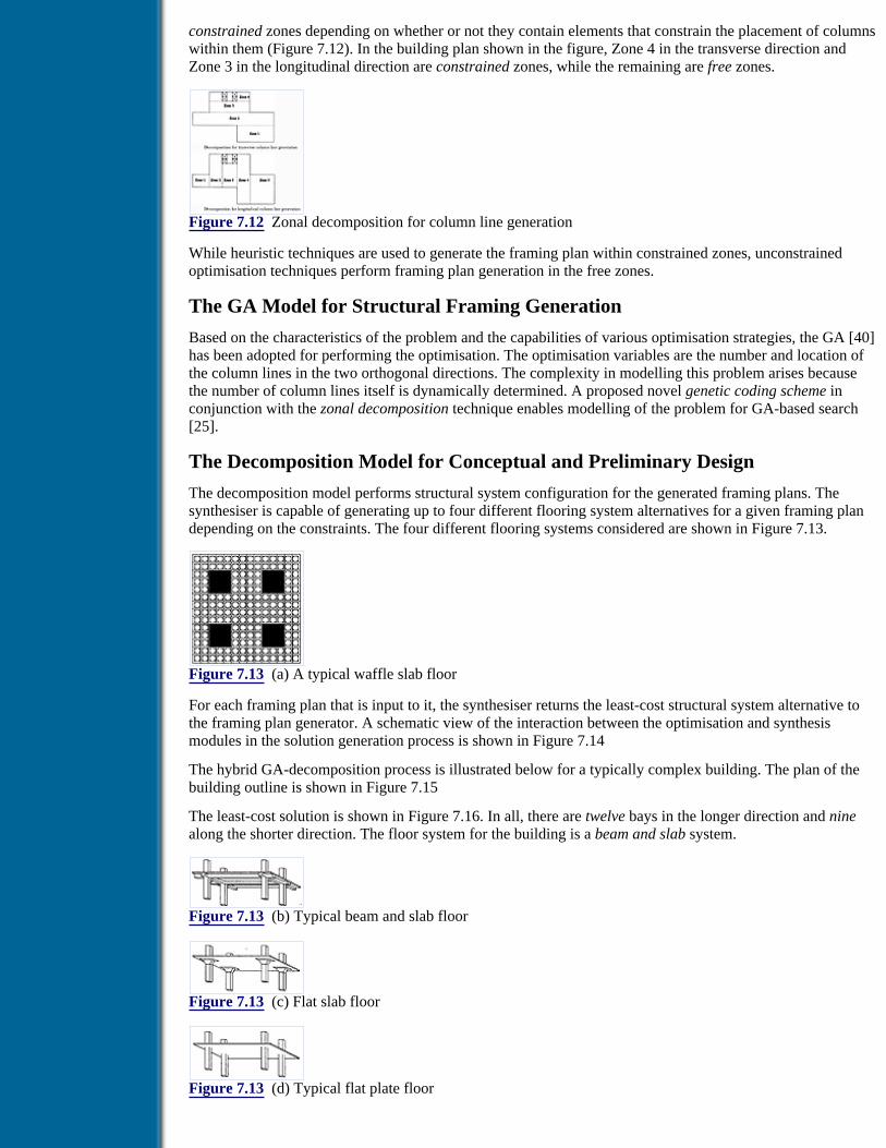
constrained zones depending on whether or not they contain elements that constrain the placement of columnswithin them (Figure 7.12). In the building plan shown in the figure, Zone 4 in the transverse direction andZone 3 in the longitudinal direction are constrained zones, while the remaining are free zones.
Figure 7.12 Zonal decomposition for column line generation
While heuristic techniques are used to generate the framing plan within constrained zones, unconstrainedoptimisation techniques perform framing plan generation in the free zones.
The GA Model for Structural Framing Generation
Based on the characteristics of the problem and the capabilities of various optimisation strategies, the GA [40]has been adopted for performing the optimisation. The optimisation variables are the number and location ofthe column lines in the two orthogonal directions. The complexity in modelling this problem arises becausethe number of column lines itself is dynamically determined. A proposed novel genetic coding scheme inconjunction with the zonal decomposition technique enables modelling of the problem for GA-based search[25].
The Decomposition Model for Conceptual and Preliminary Design
The decomposition model performs structural system configuration for the generated framing plans. Thesynthesiser is capable of generating up to four different flooring system alternatives for a given framing plandepending on the constraints. The four different flooring systems considered are shown in Figure 7.13.
Figure 7.13 (a) A typical waffle slab floor
For each framing plan that is input to it, the synthesiser returns the least-cost structural system alternative tothe framing plan generator. A schematic view of the interaction between the optimisation and synthesismodules in the solution generation process is shown in Figure 7.14
The hybrid GA-decomposition process is illustrated below for a typically complex building. The plan of thebuilding outline is shown in Figure 7.15
The least-cost solution is shown in Figure 7.16. In all, there are twelve bays in the longer direction and ninealong the shorter direction. The floor system for the building is a beam and slab system.
Figure 7.13 (b) Typical beam and slab floor
Figure 7.13 (c) Flat slab floor
Figure 7.13 (d) Typical flat plate floor

Figure 7.14 Schematic view of the hybrid GA-decomposition process
Figure 7.15 Input layout plan
Figure 7.16 Least-cost framing plan
The Preliminary Design Critic
The least-cost alternative generated through the hybrid approach is subjected to criticism from bothconstructibility and architectural viewpoints. Various aspects affecting the constructibility and architecturalexpressiveness of the design have been formalised and represented in the critic.
The Design Modifier
The modifier attempts to improve the critiqued solution by incorporating the critiques posted on themodification table. The tradeoff that is required, in terms of cost, to convert a least-cost alternative (the onegenerated by the optimiser) to a more constructible and architecturally expressive solution (the same solutionafter criticism and modification) is presented to the user.
7.4.5 Architecture of ODESSY
The integrated prototype system called ODESSY (Office Building DESign System) has been developed usingthe SCM model [25]. The architecture of the system is shown in Figure 7.17. As seen in the figure, theODESSY controller facilitates two points of entry into the system and thus can either be used to perform oneof the two individual tasks, viz., layout planning and conceptual and preliminary design, or to perform theentire preliminary design process. Information relating to the current status of problem solving in ODESSY isheld in global variables. Frame bases hold solution information that is to be shared by various modules.
Figure 7.17 Architecture of ODDESSY
Previous Table of Contents Next

Products | Contact Us | About Us | Privacy | Ad Info | Home
Use of this site is subject to certain Terms & Conditions, Copyright © 1996-2000 EarthWeb Inc. All rightsreserved. Reproduction whole or in part in any form or medium without express written permission of
EarthWeb is prohibited. Read EarthWeb's privacy statement.

Search Tips
Advanced Search
Artificial Intelligence and Expert Systems for Engineersby C.S. Krishnamoorthy; S. RajeevCRC Press, CRC Press LLCISBN: 0849391253 Pub Date: 08/01/96
Search this book:
Previous Table of Contents Next
7.5 Conceptual Design of a Car Body Shape
Conceptual design of car body shape is a typical problem in which many of the concepts discussed in earlierchapters are used. The problem involves use of both mathematical constraints and heuristics. This sectionpresents an illustration of an integrated approach to an application development using tools such as designsynthesis, criticism and case-based reasoning. The size of the problem is sufficiently large and several of therequirements are conflicting in nature. The problem also provides sufficient scope for subjective evaluation.
7.5.1 Functional Requirements
The functional requirements of the conceptual design of a car body shape are defined as the minimum set ofindependent requirements that completely satisfy the design objectives for a specific need and are describedbelow [41–45].
Stability Directional stability is the tendency of a car to maintain its existing course. Thisrequires a high positive pitch moment, implying low front lift and high rear lift.
Response This is a measure of ability of the car to respond to changes in its direction. For betterresponse, the front lift should be high and the rear lift low resulting in low positivepitch moment.
Maintenance This refers to the mud deposition on the body of the car.
Entry and Exit This refers to the ease with which entry into the car may be effected.
Drag This is the aerodynamic drag experienced by the car body because of its shape.
Visibility This is the ease with which a person inside the car may view the road ahead.
Ventilation High ventilation indicates that there is proper ventilation of air inside the car.
VolumeEffectiveness
This indicates the ratio of the interior volume of the car to the three-dimensionalparking volume of the car.
Aesthetics This refers to the beauty of the car and is a highly subjective requirement.
The objective of the exercise is to obtain the best solution with respect to the above functional requirements.

7.5.2 Design Parameters
After a detailed study of the design process of automobile bodies, the following design parameters areidentified. Design parameters are defined as the key variables that characterise the physical entity created bythe design process to fulfil the functional requirements. The design parameters are shown in Figure 7.18.
• Grille area length
• Grille area inclination
• Cowl length
• Cowl angle
• Windscreen length
• Windscreen inclination
• Roof length
• Rear angle
• Boot length
• Underclearance
• Side height (till tumblehome inclination)
• Tumblehome inclination
• Breadth
Figure 7.18 Design parameters considered for car body shape
Out of the nine functional requirements stated above, only five features, viz., front lift, rear lift, maintenance,entry and exit, and drag, are considered for generating the solutions by the synthesis process. The solutionsobtained are evaluated/critiqued for the remaining functional requirements later.
The 13 design parameters are grouped into five major categories which are in accordance with the designaxiom. The groups are:
1. Front This includes grille area length, grille area inclination, cowl angle, cowl length,windscreen length and windscreen inclination
2. Mid This includes roof length3. Rear This includes rear angle, boot length and boot height4. Side This includes side height, tumblehome inclination and breadth5. Underclearance
For simplicity, the car body was assumed to consist strictly of straight edges.
7.5.3 Design Decoupling
Once the functional requirements and design parameters are identified, design decoupling is done to make thefunctional requirements independent of each other. The axiomatic approach proposed by Suh [46] provides amechanism for controlling the functional requirements independently. This can overcome difficulties such asdependency-related modification of the design parameters leading to a large number of iterations. Hence, it ispossible to obtain a decoupled design matrix to ensure the independent control of functional requirements.
Design decoupling generates a decoupled design matrix, which exhibits the characteristics of the designproblem. The design problem is represented in the form of an equation involving the design matrix [A], whichrelates the functional requirements [FR] and design parameters [DP] as shown below:
[FR] = [A] [DP]
According to the axiom proposed by Suh, in an acceptable design, the design parameters and functionalrequirements are related in such a way that specific design parameters can be adjusted to satisfy thecorresponding functional requirements without affecting the other functional requirements. For this, thematrix [A] has to be decoupled. A design is said to be uncoupled, when the functional requirements are

independent of each other, and is represented by a diagonal matrix. A lower or upper triangular matrixrepresents a decoupled design. FRi is dependent only on DPi in an uncoupled design. Since such situationdoes not occur in large engineering design problems, off diagonal elements do exist in [A].
Previous Table of Contents Next
Products | Contact Us | About Us | Privacy | Ad Info | Home
Use of this site is subject to certain Terms & Conditions, Copyright © 1996-2000 EarthWeb Inc. All rightsreserved. Reproduction whole or in part in any form or medium without express written permission of
EarthWeb is prohibited. Read EarthWeb's privacy statement.

Search Tips
Advanced Search
Artificial Intelligence and Expert Systems for Engineersby C.S. Krishnamoorthy; S. RajeevCRC Press, CRC Press LLCISBN: 0849391253 Pub Date: 08/01/96
Search this book:
Previous Table of Contents Next
Algorithm for Decoupling1. Shuffle the rows and columns of matrix [A] to determine whether it is already a shuffled lowertriangular matrix, in which case it is already decoupled.
2. If the matrix is not already decoupled, then all possible permutations of rows and columns aregenerated and the matrices corresponding to every permutation of the rows and columns are created.For any such matrix, if a single diagonal element takes a value zero, that matrix is rejected. Formatrices that are not rejected, this step returns all the non-zero elements in the upper triangular part ofthe matrix.
3. The solutions returned from the above step are inspected for overlapping, in the sense that a solutionwhich is a subset of another solution is considered to be superior and the matrix corresponding to thesuperset solution is abandoned.
This algorithm finally returns the row and column numbers of the elements that have to be forced to zero fordecoupling. All the elements which have to be forced to zero form the solution set. It may be noted that thealgorithm for design decoupling is approximately of order factorial n. This is because all the possiblepermutations of the rows and columns have to be considered.
The first step in design decoupling.is generation of a design matrix. It is done after a detailed study of thedependency of the functional requirements on each design parameter. A brief description of the dependenciesis presented below.
Front lift The front lift of the car depends on grille area length, grille area inclination, cowllength, cowl angle, windscreen length and windscreen inclination. The front lift is dueto the flow of air over the front of the car. This creates a region of low pressure,resulting in lift. Also, the higher the vorticity of the flow, the lower is the pressure.
Rear lift Rear lift depends on the design parameters of the rear and the side. The dependencyon the rear is due to the flow velocity and vortex as explained in the front lift. Thedependency on the side is due to the fact that the wake structure, which varies withthe type of the car (and depends on predominantly tumblehome angle), affects the rearlift. As long as the air flow over the roof gets reattached on the trailing edge of theboot, the rear lift constantly goes down with reduced rear angles. A similarexplanation is applicable to the effects of boot length elongation on rear lift.

Maintenance Maintenance is a function of the rear and the underclearance. The air flowing into theunderclearance of the car picks up mud and dirt from the road. The air entering intothe front of the underclearance is not equal to the air leaving from the rear of theunderclearance. This occurs due to the pressure drop in the flow from the front to therear of the underclearance. Hence, there will be some flow from the side of theunderclearance to account for continuity. The flow leaving the underclearance fromthe side and the rear moves up to hit the body of the car. The shape of the rear of thecar is a significant determinant of the type of the rear wake. The type of rear wakedetermines the amount of flow out of the rear of underclearance which hits the rearwalls of the car body, thus controlling the mud deposition (maintenance) on the rearof the car.
Entry and Exit Entry and exit depends on front, mid, rear and side. Whenever data is not available onany functional requirement it is assumed to be dependent on all the functionalrequirements. However, the under clearance dependency has been left out, because itis difficult to envisage a car in which the entry and exit is through the underclearance.Also it is assumed that entry and exit through any other position of the car isindependent of the value taken by the design parameter underclearance.
Drag Drag is a function of all five of the design parameters, the front, mid, rear, side andthe underclearance. The air flowing over the car causes drag due to the effect ofviscous friction. Hence, all parts of the car contribute to the drag. The velocity andvorticity of the flow are predominant characteristics of the flow which affect the drag.The vorticity of the flow depends on the design parameters in some cases, such asside, because the type of flow depends on the design parameters explained in rear lift.
Decoupling of the design matrix led to 25 design solutions. In essence, the functional requirements have beenrendered independent of each other and the solution characteristics of such a design have been determined.Now the designs are synthesised subject to these characteristics. The first solution of decoupling is {(2,4),(4,4)}. (2,4) indicates that the rear lift must be independent of the side and (4,4) indicates that the entry-exitmust be independent of the side. This constraint was imposed during synthesis. The decomposition tree forthe problem for carrying out synthesis is shown in Figures 7.19 to 7.23. The decoupling requirements aresatisfied by enforcing the following conditions. First, the vortex at the side of the car is made to zero.Secondly, the door position is set at mid, hinging it along the length of the car and by keeping the length ofthe door in the perpendicular direction to the hinge (breadth) not equal to the breadth of the car. This settingensured prevention of the air from flowing over the side of the car, thus achieving the decoupling. Preventingair flow over the side results in an increase of air flow over other parts of the car. This may have secondaryeffects. The net effect on the car is a result of all these effects and is, therefore, determined through anevaluation process.
7.5.4 Synthesis and Critiquing of Solutions
The solutions generated by the synthesiser were evaluated for all the functional requirements; exceptaesthetics. Aesthetics is not included because it cannot be rated by methods adopted for any of the otherfunctional requirements. Only 120 solutions out of many thousands possible are generated and evaluated.
Previous Table of Contents Next
Products | Contact Us | About Us | Privacy | Ad Info | Home
Use of this site is subject to certain Terms & Conditions, Copyright © 1996-2000 EarthWeb Inc. All rightsreserved. Reproduction whole or in part in any form or medium without express written permission of
EarthWeb is prohibited. Read EarthWeb's privacy statement.

Search Tips
Advanced Search
Artificial Intelligence and Expert Systems for Engineersby C.S. Krishnamoorthy; S. RajeevCRC Press, CRC Press LLCISBN: 0849391253 Pub Date: 08/01/96
Search this book:
Previous Table of Contents Next
7.5.5 Case-Based Evaluation of Shapes
Aesthetic evaluation of car bodies is very much a subjective process. The rating obtained after aestheticevaluation by a designer is usually based on his own taste and the market forces. This rules out any standardevaluation procedure which would be guided by the shapes of existing cars in the market. Case-basedevaluation using the CASETOOL described in Chapter 6 was used for carrying out evaluation for aesthetics.
Each of the existing cases is stored in the knowledge base as a case card. Comparison of the present caseobtained after synthesis with the past cases from the case base is done based on different ratios. These ratiosindicate the proportions of the dimensions of the car body. Five cases of each of the four types of car shapes(fastback, notchback, hatchback and wagontype) are selected from the available data [41], and the cases werestored in the case card along with the knowledge of the type of the car.
The ratios identified were used for determining the relevance of the present case with the stored cases. Foreach of the five cases, the ratios for the current case are compared with those from the stored cases, and therelevance norm is computed. The case with the lowest value of relevance norm is taken as the most acceptableform from the aesthetic point of view.
7.6 SETHU - An Integrated KBES for Concrete Road Bridge Design
Early researchers in the field of bridges [47–51] treated the preliminary stages of the bridge design process asconsisting of heuristic knowledge which was expressed in the form of production rules. However, the bridgedesign process is characterised by the involvement of complex knowledge which cannot be represented usingproduction rules alone. A more comprehensive work has been carried out to identify these complexities andaddress the preliminary design stages of the bridge design process [52]. Based on this work, which adequatelyaddresses the issues of complex bridge design knowledge representations, a process model has beendeveloped using appropriate AI-based methodologies. In the following subsections the methodologiesadopted in the process model and the SETHU system are briefly described.

Figure 7.19 Decomposition tree - I
Figure 7.20 Decomposition tree - II
Figure 7.21 Decomposition tree - III
Figure 7.22 Decomposition tree - IV
Figure 7.23 Decomposition tree - V
7.6.1 Task Analysis of Bridge Design Process
In actual practice, the bridge design process is carried out in two different ways. When presented with a newproblem, the bridge design experts first try to recall a similar problem that has been solved before. In case theexperts fail to recall a similar case, they build the solution systematically from scratch using their generalisedknowledge of the domain. This approach involves exploring all the possible alternatives at every intermediatestage of the solution generation process. It is called the heuristics-based approach. If they do recall a similarpast case, they adapt it to suit the new requirements. This is called the case-based approach, and in AIparlance it falls in the realm of problem solving by case-based reasoning, explained in Chapter 6. In thefollowing sections, a task analysis of the preliminary design process, as approached by the two differentstrategies introduced above, is presented with a view to identify various complex knowledge forms and toabstract a model of the design process.
Heuristic-Based Approach
Site selection

During the site selection stage, alternate bridge construction sites are chosen based on field and laboratorytests. These sites are evaluated from economy and serviceability criteria to eliminate inferior ones. Variousaspects such as total length, alignments, geological conditions, construction facilities and hydraulic aspectsthat govern the serviceability and economy of a site are used to evaluate the alternate sites. For this purpose,these aspects are classified into various categories. This categorisation facilitates evaluation of the desirabilityof the site from these individual viewpoints. An overall rating for the site is then arrived at based on therelative importance associated with each individually critiqued aspect. It was found that the knowledge forclassifying the site data into categories for critical evaluation can be efficiently represented and processedusing production rule-based techniques, and the critical evaluation of sites requires a critiquing technique thatevaluates various individual aspects of a site and arrives at an overall rating on the basis of their relativeimportance [53].
Bridge layout planning
At the selected site, a layout (location of piers/arrangements of spans shown in Figure 7.24) is decided whichsatisfies the economy, clearance, hydraulic and geotechnical requirements. This process can be visualised asan interaction between four design experts, viz., layout planner, traffic engineer, hydraulic expert andfoundation expert. Hence, bridge layout planning involves multidisciplinary efforts to find a satisfactorysolution. Therefore, constraint-satisfaction techniques that enable modelling of such multidisciplinaryprocesses are suitable for this task. The layout-planning knowledge can be represented as production rules andthe clearance, hydraulic and geotechnical requirements can be represented as constraints. The reasoningprocess is non-monotonic and backtracking is necessary to maintain solution consistency. Therefore, arule-based technique for layout planning with dependency-based backtracking and constraint posting forsolution consistency are appropriate problem-solving techniques.
Figure 7.24 Representation of bridge structure
Previous Table of Contents Next
Products | Contact Us | About Us | Privacy | Ad Info | Home
Use of this site is subject to certain Terms & Conditions, Copyright © 1996-2000 EarthWeb Inc. All rightsreserved. Reproduction whole or in part in any form or medium without express written permission of
EarthWeb is prohibited. Read EarthWeb's privacy statement.

Search Tips
Advanced Search
Artificial Intelligence and Expert Systems for Engineersby C.S. Krishnamoorthy; S. RajeevCRC Press, CRC Press LLCISBN: 0849391253 Pub Date: 08/01/96
Search this book:
Previous Table of Contents Next
Conceptual design of structural systems
In this step, various feasible structural systems are proposed for a given bridge layout and the inferior ones areeliminated based on a critical evaluation of the candidates from the viewpoints of economy, aesthetics,constructibility, etc. The bridge structure can be viewed as a hierarchical network consisting of variouscomponents and subcomponents as its nodes, as shown in Figure 7.24. Each component will in turn havevarious attributes whose values are to be determined and each of these attributes can take various possiblevalues for a given situation. The decomposition tree for the conceptual design of bridge structural systems isshown in Figure 7.25. Decomposition-based representation of designs enables easy generation of all feasiblecandidates. Feasibility is ensured by eliminating incompatible assemblages through the application ofconstraints. This process of solution generation is termed synthesis and is explained in Chapter 4.Synthesising solutions using the decomposition tree requires a set of preconditions, which represent thecontext. These preconditions can be generated dynamically through a rule base. Therefore, for this stage,rule-based inference (to generate preconditions), (decomposition and constraint-based) synthesis, and criticalevaluation (that critiques various individual aspects of a conceptual design and arrives at an overall rating onthe basis of their relative importance) are appropriate problem-solving techniques.
Preliminary dimensioning of structural components
Using heuristics gained through years of design practice, design experts arrive at preliminary dimensions ofthe structural components of the chosen structural systems. These heuristics can be represented as productionrules. The preliminary dimensions thus arrived at are used to compute the gross weight of the structures whichcan then be compared to determine the relatively lightweight alternatives. Therefore, for this stage, productionrule-based preliminary dimensioning and comparative critiquing are appropriate.
Case-Based Approach
Site selection
In the case-based approach, similar past episodes of site selection are recalled from records and the criteriaused on that occasion for selection or elimination of sites are ascertained. Potential sites are short-listed bydirectly applying these criteria. At this stage, experts also tend to look ahead at the later decisions that weremade in the matching cases, to anticipate if the emerging solution may turn out to be undesirable.
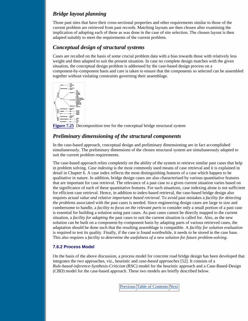
Bridge layout planning
Those past sites that have their cross-sectional properties and other requirements similar to those of thecurrent problem are retrieved from past records. Matching layouts are then chosen after examining theimplication of adopting each of these as was done in the case of site selection. The chosen layout is thenadapted suitably to meet the requirements of the current problem.
Conceptual design of structural systems
Cases are recalled on the basis of some crucial problem data with a bias towards those with relatively lessweight and then adapted to suit the present situation. In case no complete design matches with the givensituation, the conceptual design problem is addressed by the case-based design process on acomponent-by-component basis and care is taken to ensure that the components so selected can be assembledtogether without violating constraints governing their assemblage.
Figure 7.25 Decomposition tree for the conceptual bridge structural system
Preliminary dimensioning of the structural components
In the case-based approach, conceptual design and preliminary dimensioning are in fact accomplishedsimultaneously. The preliminary dimensions of the chosen structural system are simultaneously adapted tosuit the current problem requirements.
The case-based approach relies completely on the ability of the system to retrieve similar past cases that helpin problem solving. Case indexing is the most commonly used means of case retrieval and it is explained indetail in Chapter 6. A case index reflects the most distinguishing features of a case which happen to bequalitative in nature. In addition, bridge design cases are also characterised by various quantitative featuresthat are important for case retrieval. The relevance of a past case to a given current situation varies based onthe significance of each of these quantitative features. For such situations, case indexing alone is not sufficientfor efficient case retrieval. Hence, in addition to index-based retrieval, the case-based bridge design alsorequires actual value and relative importance based retrieval. To avoid past mistakes a facility for detectingthe problems associated with the past cases is needed. Since engineering design cases are large in size andcumbersome to handle, a facility to focus on the relevant parts to consider only a small portion of a past caseis essential for building a solution using past cases. As past cases cannot be directly mapped to the currentsituation, a facility for adapting the past cases to suit the current situation is called for. Also, as the newsolution can be built on a component-by-component basis by adapting parts of various retrieved cases, theadaptation should be done such that the resulting assemblage is compatible. A facility for solution evaluationis required to test its quality. Finally, if the case is found worthwhile, it needs to be stored in the case base.This also requires a facility to determine the usefulness of a new solution for future problem-solving.
7.6.2 Process Model
On the basis of the above discussion, a process model for concrete road bridge design has been developed thatintegrates the two approaches, viz., heuristic and case-based approaches [52]. It consists of aRule-based-inference-Synthesis-Criticism (RSC) model for the heuristic approach and a Case-Based-Design(CBD) model for the case-based approach. These two models are briefly described below.
Previous Table of Contents Next

Products | Contact Us | About Us | Privacy | Ad Info | Home
Use of this site is subject to certain Terms & Conditions, Copyright © 1996-2000 EarthWeb Inc. All rightsreserved. Reproduction whole or in part in any form or medium without express written permission of
EarthWeb is prohibited. Read EarthWeb's privacy statement.

Search Tips
Advanced Search
Artificial Intelligence and Expert Systems for Engineersby C.S. Krishnamoorthy; S. RajeevCRC Press, CRC Press LLCISBN: 0849391253 Pub Date: 08/01/96
Search this book:
Previous Table of Contents Next
RSC Model
The RSC model consists of three process engines, viz., a rule-based inference engine (RBIE), a synthesizingtool and a critiquing tool as shown in Figure 7.26. RBIE uses the knowledge represented in the form ofproduction rules for site data processing, layout planning, precondition generation for synthesis andpreliminary dimensioning, decision making and overall process control. The synthesising tool uses theknowledge in the form of decomposition tree and elimination constraints for conceptual design of structuralsystems. The critiquing tool uses evaluation criteria represented in the form of aspects to be critiqued, ratingsand their weights. RBIE also invokes the well-structured algorithmic procedures (represented usingconventional procedural programming languages) for performing any computations that may be requiredduring the bridge design process [53].
Figure 7.26 The RSC model
CBD Model
The CBD model consists of five processors, viz., RETRIEVER, ANTICIPATOR, TRANSFORMER,MODIFIER and STORER, as shown in Figure 6.5. The general framework and the generic tool, CASETOOLdiscussed in Chapter 6 are used for developing the CBD model.
7.6.3 KBES Development Tool
From the above sections it is clear that the following facilities are required for the development of anintegrated KBS for concrete road bridge design:
• Rule-based inference with decision revision mechanism that works based on dependency-basedbacktracking.
• Decomposition tree and elimination constraint-based synthesis.
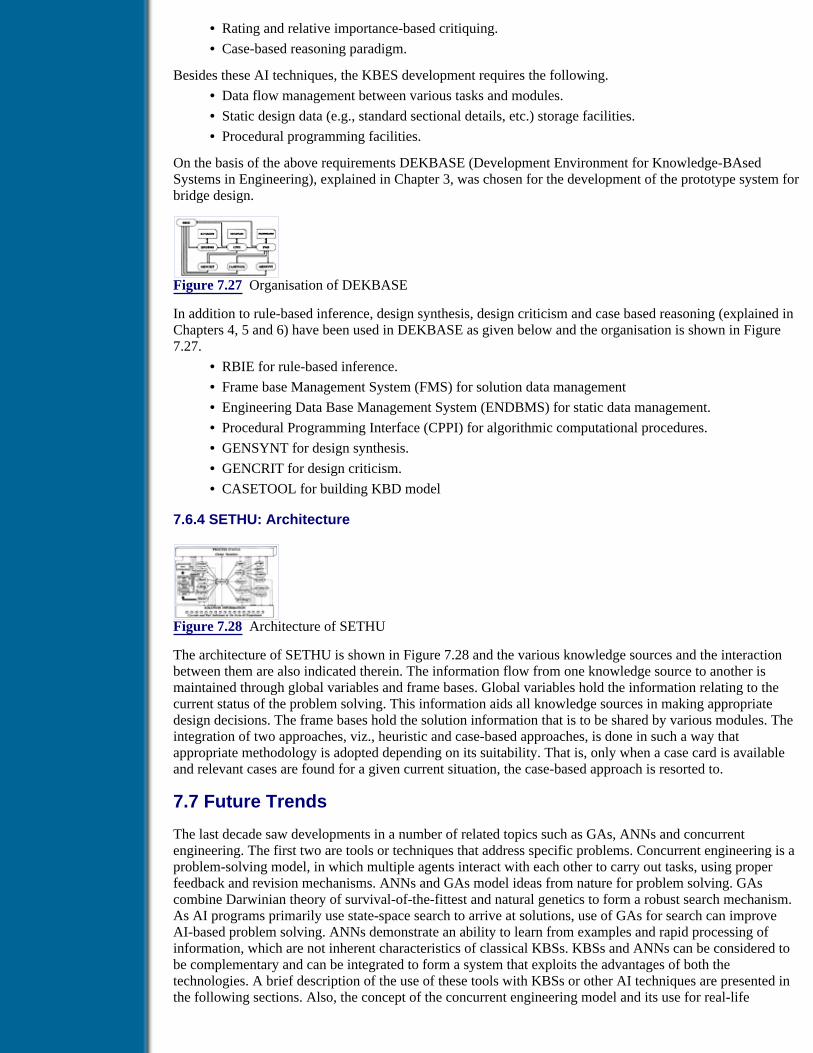
• Rating and relative importance-based critiquing.
• Case-based reasoning paradigm.
Besides these AI techniques, the KBES development requires the following.
• Data flow management between various tasks and modules.
• Static design data (e.g., standard sectional details, etc.) storage facilities.
• Procedural programming facilities.
On the basis of the above requirements DEKBASE (Development Environment for Knowledge-BAsedSystems in Engineering), explained in Chapter 3, was chosen for the development of the prototype system forbridge design.
Figure 7.27 Organisation of DEKBASE
In addition to rule-based inference, design synthesis, design criticism and case based reasoning (explained inChapters 4, 5 and 6) have been used in DEKBASE as given below and the organisation is shown in Figure7.27.
• RBIE for rule-based inference.
• Frame base Management System (FMS) for solution data management
• Engineering Data Base Management System (ENDBMS) for static data management.
• Procedural Programming Interface (CPPI) for algorithmic computational procedures.
• GENSYNT for design synthesis.
• GENCRIT for design criticism.
• CASETOOL for building KBD model
7.6.4 SETHU: Architecture
Figure 7.28 Architecture of SETHU
The architecture of SETHU is shown in Figure 7.28 and the various knowledge sources and the interactionbetween them are also indicated therein. The information flow from one knowledge source to another ismaintained through global variables and frame bases. Global variables hold the information relating to thecurrent status of the problem solving. This information aids all knowledge sources in making appropriatedesign decisions. The frame bases hold the solution information that is to be shared by various modules. Theintegration of two approaches, viz., heuristic and case-based approaches, is done in such a way thatappropriate methodology is adopted depending on its suitability. That is, only when a case card is availableand relevant cases are found for a given current situation, the case-based approach is resorted to.
7.7 Future Trends
The last decade saw developments in a number of related topics such as GAs, ANNs and concurrentengineering. The first two are tools or techniques that address specific problems. Concurrent engineering is aproblem-solving model, in which multiple agents interact with each other to carry out tasks, using properfeedback and revision mechanisms. ANNs and GAs model ideas from nature for problem solving. GAscombine Darwinian theory of survival-of-the-fittest and natural genetics to form a robust search mechanism.As AI programs primarily use state-space search to arrive at solutions, use of GAs for search can improveAI-based problem solving. ANNs demonstrate an ability to learn from examples and rapid processing ofinformation, which are not inherent characteristics of classical KBSs. KBSs and ANNs can be considered tobe complementary and can be integrated to form a system that exploits the advantages of both thetechnologies. A brief description of the use of these tools with KBSs or other AI techniques are presented inthe following sections. Also, the concept of the concurrent engineering model and its use for real-life

engineering problem solving are presented at the end.
7.7.1 Genetic Algorithms
The adaptive nature of a genetic search simulates learning from the problem environment as the searchprogresses. Such learning guides the search technique to arrive at global optimal solutions. Integration of GAsand KBSs have been attempted by a few researchers in order to exploit the advantages of both systems.
Previous Table of Contents Next
Products | Contact Us | About Us | Privacy | Ad Info | Home
Use of this site is subject to certain Terms & Conditions, Copyright © 1996-2000 EarthWeb Inc. All rightsreserved. Reproduction whole or in part in any form or medium without express written permission of
EarthWeb is prohibited. Read EarthWeb's privacy statement.

Search Tips
Advanced Search
Artificial Intelligence and Expert Systems for Engineersby C.S. Krishnamoorthy; S. RajeevCRC Press, CRC Press LLCISBN: 0849391253 Pub Date: 08/01/96
Search this book:
Previous Table of Contents Next
Integration of GAs with Expert Systems
Powel et al. [54] introduced a technique called interdigitation, which effectively combines numericaloptimisation techniques, expert systems and GAs. The technique worked successfully for engineering designoptimisation problems. Powel used GA for global search and expert system and numerical optimisation forlocal hill climbing. The authors used an expert system as a preprocessor for GA-based design optimisation ofstructural systems. The ranges of design variables and values for other GA parameters are selected by anexpert system, which has a knowledge base containing knowledge on the nature of the problem being solvedand knowledge gained based on many such problems solved in the past. As the progress of optimisation andconvergence to a globally optimal solution very much depends on the ranges of variables selected and thevalues selected for GA parameters such as probabilities of crossover and mutation, population size andconvergence criteria adopted, it is required to get the most appropriate values so as to improve the efficiencyand effectiveness of the problem-solving technique. Such serial integration of KBS and GA proved to be veryuseful in large problems of engineering design.
Hamada et al. [55] presented a hybrid model for GAs and KBSs for production planning in steel plants. Theyhave decomposed the problems into subproblems, and then combined procedural methods, a rule-based expertsystem and a GA. First, procedural programs are used for charge grouping, then an expert system is used togenerate coarse solutions and finally the charge group ordering is optimised using GAs. This is also a serialapproach of integrating KBS and GA.
Another manner in which the concepts of KBS and GA are integrated is by augmenting the operator crossoverand mutation using domain knowledge. Grefenstette et al. [56] developed a greedy, heuristic crossoveroperator for the classical travelling salesman problem. Augmentation of the operators with domain knowledgehelped in reducing the search space, resulting in faster convergence.
Classifier Systems
As GAs are primarily adaptive search techniques, the implicit learning that takes place during the problemsolving can be exploited for improving search in a KBS. Classifier systems, such as Genetics-Based MachineLearning (GBML) systems, use genetic search as their primary discovery of heuristics [57]. A classifiersystem consists of three components, viz., rule and message system, apportionment of credit system and GA.The rule and message system is a kind of production rule used in KBSs. In classifier systems, rules are

represented as fixed-length strings. The rule and message system forms the computational backbone of thesystem. Information flows from the environment through the detectors (eyes and ears of the classifier system),where it is decoded to one or more fixed-length messages (strings). These messages are posted to a messagelist, where they can activate string rules called classifiers. On activation, a classifier posts a message to themessage list. These messages can then invoke other classifiers (just as addition of new working memoryelements that fire further rules) or cause actions to be taken through the action triggers of the system calledeffectors. This simulates combining environmental clues and internal thoughts to determine what to do andthink next. Classifier systems activate rules parallelly in contrast to the sequential activation of rules inclassical expert systems. Also, rating of rules, which are programmer specified in expert systems, aregenerated in classifier systems. The GA works on the binary coded messages in the message list (rules) togenerate new rules using the operators, reproduction, crossover and mutation. Such generation of new rules,called rule discovery, plays an important role in genetic-based machine learning. Such integration of KBSconcepts and GA concepts can find many applications in ineering problem solving.
Previous Table of Contents Next
Products | Contact Us | About Us | Privacy | Ad Info | Home
Use of this site is subject to certain Terms & Conditions, Copyright © 1996-2000 EarthWeb Inc. All rightsreserved. Reproduction whole or in part in any form or medium without express written permission of
EarthWeb is prohibited. Read EarthWeb's privacy statement.

Search Tips
Advanced Search
Artificial Intelligence and Expert Systems for Engineersby C.S. Krishnamoorthy; S. RajeevCRC Press, CRC Press LLCISBN: 0849391253 Pub Date: 08/01/96
Search this book:
Previous Table of Contents Next
GA methodologies in conceptual design
A totally different type of integration between GA concepts and AI-based design concepts has been presentedby a research group at the University of Sydney. It is neither a serial nor a parallel integration, but the GAconcepts such as natural selection (reproduction), crossover and mutation are used in AI-based techniquessuch as analogical reasoning. Hibs and Gero [58] have presented an evolutionary process model forengineering design. They have described a model of design as a series of transformation processes and extendthat model initially to include the behaviour of the designed artifact in its environment. This extended modelis then recast through an analogy with natural evolution as an evolutionary process model of design throughthe inclusion of the evolutionary style processes of cross over and mutation and the introduction of designgenes and the notion of inheritance from one generation to the next. The concept of design crossover proposedby Hibs and Gero has a mechanism to combine different design concepts to achieve an entirely newbehaviour. It is regarded as a combination of individual design genes or their parts, that is, a blend of sets ofinstruction for production related to two or more structures. Jo and Gero [59] proposed design mutation as acomputational approach to creative design. Design mutation, operating on design prototypes as therepresentation schema, plays the role of a transformation process which produces new design prototypesthrough the cumulative generation and selection of mutated variables. Gero and Maher [60] proposed acomputational model of creative process in design, which is founded on the use of mutation and an analogyprocess working in tandem using design prototypes as the representation schema. An analogical reasoningmodel is adopted for finding an analogous situation and using the knowledge from the previous situation tothe new situation. Two useful techniques are derived from research in AI, viz., memory indexing andtransformation, that help to carry out analogical reasoning in the creative design process. Memory indexing isused to facilitate information flow across contexts on which analogical reasoning is based. Design prototypesare grouped and retrieved according to their similarities of characteristics through indices. The indices arerelated to specific knowledge categories, viz., functions, structures and behaviours. Once an appropriatesource design prototype is identified, it is required to transform the knowledge required to establish itsrelevance to the new design context. In the model for creative design proposed by Gero and Maher [60] thecurrent context is defined by the selected design prototype in the target space. The source knowledge foraccommodating the introduction of a new variable in the target space is the retrieved design prototype. Theyhave used a structure-mapping approach to implement the same.
Integration of the concepts of GAs and AI techniques at different levels of abstraction can lead to many usefulmodels for engineering problem solving. Increased activity of research and development in evolutionary

computing and genetic algorithms indicates that a number of promising tools and techniques are on the anvil,for the engineering community.
7.7.2 Artificial Neural Networks
ANNs develop their own solutions from examples for a class of problems. They are also called connectionistsystems, that simulate the low-level operations of the central nervous system. The desirableinformation-processing characteristics are manifested in the brain such as learning, generalisation and errortolerance, and they are captured and mimicked in ANNs. An ANN can be visualised as a collection of neuronsinterconnected to form a network. The neurons in the network process information parallelly and collectivelywithin the structure of the network. Neural networks can be classified into different types based on theconnection patterns of the neurons, mode of operations and the way the networks are trained. Appropriatecombinations of these characteristics are to be formed depending on the problem being solved. A typicalANN is shown in Figure 7.29 that has a feed-forward connection scheme and synchronous operations of allneurons (nodes or cells). For the network shown in the figure, a Generalised Delta Rule (GDR) is adopted fortraining. Networks that use GDR for training are called back propagation networks, since training processrequires errors measured at output neurons to be propagated backward through the different layers of thenetwork. The network shown in the figure has three layers of neurons, viz., an input layer, an output layer anda hidden layer. Information about the features of the problems are presented to the network at the input layer.The solution is obtained at the output layer. Problem-solving activity is performed at the hidden layer (therecan be any number of hidden layers) [61]. Lapdes and Farber [62] have suggested additional layers for moreefficient solution of problems. As the working of ANNs is available elsewhere in the literature, it is notattempted here. Only the issues related to integration of ANNs and KBSs are described.
Figure 7.29 Schematic representation of a layered feed-forward ANN
The basic difference between ANNs and KBSs is that ANNs do not require a knowledge base or equivalentduring problem solving. But they require a number of solved problems (input and output sets) in order to trainthe network. KBSs and ANNs can be combined together so as to take advantages of their strengths. Johnstonet al. [63] implemented a rule-based system within a neural network environment for scheduling the activitiesof a space telescope. A feed-forward back propagation has been integrated with a set of production rules todevelop a Gearbox Design Supervisor. Several approaches of integration of ANNs and KBSs were presentedby various researchers [64–70]. Some typical approaches as reported by the above authors are brieflypresented here, in order to give an overview on the topic to the reader.
In most approaches KBSs are used as the basis for developing ANNs or vice versa. Such an approach isuseful, where one model is available and it is expected that the other model will provide betterproblem-solving characteristics. Such an integration is called developmental integration.
Previous Table of Contents Next
Products | Contact Us | About Us | Privacy | Ad Info | Home
Use of this site is subject to certain Terms & Conditions, Copyright © 1996-2000 EarthWeb Inc. All rightsreserved. Reproduction whole or in part in any form or medium without express written permission of
EarthWeb is prohibited. Read EarthWeb's privacy statement.

Search Tips
Advanced Search
Artificial Intelligence and Expert Systems for Engineersby C.S. Krishnamoorthy; S. RajeevCRC Press, CRC Press LLCISBN: 0849391253 Pub Date: 08/01/96
Search this book:
Previous Table of Contents Next
In cases where neither of the models exist and it is easier to develop one model first and then use it to generatethe other, a transposition integration can be adopted. Fu [71] presented a transposition scheme, in which aKBS is mapped into an ANN scheme. Such an approach is useful, when an improvement is sought to getmore generalised solutions. In Fu’s model, a rule is transformed into a link in the ANN and a conclusion inthe rule base is mapped onto a neuron, strength of a rule is translated to a weight and the inference process ischaracterised by propagating and combining activation. In this model, a rule will fire, if a premise node isactivated. A conclusion is drawn from the level of activation of an output neuron. The system can be made toadapt to a changing problem environment by implementing a back propagation learning scheme which willwork in a recursive manner.
A trained ANN can also be transformed into a KBS, in which each neuron is converted into a rule [69]. Theantecedents of the rule are formed using the weights of the input connections to a layer of hidden neurons andthe biases associated with the hidden neurons. Similarly significance of the rule is formed by weights of theconnection to the output neurons. This form of integration can be adopted in cases where one has to generateknowledge after solving a large number of example problems due to lack of available knowledge. Thisapproach can also be adopted in cases where a KBS is preferred in order to have better transparency of theprocess.
A third type of integration is termed exemplification, in which an ANN is queried to generate a set of rules todevelop a KBS or a KBS is used to generate examples for training an ANN. In transposition methods, there isa one-to-one correspondence between the components of a KBS and an ANN. In cases where such acorrespondence cannot be established, the exemplification approach is desirable. But it may be noted that anANN can provide generalised solutions, which are not available in the knowledge base of a KBS. In thesecond model of exemplification, heuristic knowledge is extracted by carrying out a sensitivity analysis of anANN. This heuristic knowledge is used to extend the knowledge base of a KBS. Since an ANN adapts itselfto changing problem environments, this approach helps in refining the knowledge base. One has to be verycautious in this kind of integration, because the quality of derived knowledge very much depends on thequality of examples selected for training the ANN. Bochereau et al. [70] and Fu [71] have presented casesemploying this type of integration. Extraction of decision rules in a legal domain from a multilayer neuralnetwork is presented by Bochereau. A universal system for translating the mapping functions of a backpropagation ANN into a set of production rules is presented by Fu [71].
The schemes for integrating ANNs and KBSs discussed so far finally produces either a KBS or an ANN at the

end. The objective of the approach is to generate one model from the other. But a more useful approach is toevolve a model, in which both an ANN and a KBS work together to solve a problem. The advantages of boththe models can be exploited here for the solution process. Two basic approaches of such usage of ANNs andKBSs were tried and a comprehensive review is presented by Kartam et al. [69]. There are serial and paralleloperations. In the serial operation, one component (ANN or KBS) processes the information before the resultsare passed on to the other. Whereas, in parallel operation, both ANNs and KBSs work in parallel on parts ofthe problems, to which they are best suited. A brief review of work already reported in the literature [69] ispresented below.
Barker [64] proposed a hybrid approach for the analysis of the financial welfare of a business, in which anexpert system shell controls the overall functions and the neural network development environment is trainedusing case histories stored in a database. In the work of Dagli [67], a KBS is used to describe the problemdomain for generating optimal Flexible Manufacturing System (FMS) schedules. Then two ANNs are used, aback propagation network for classifying jobs and a Hopfield network for generating optimal sequences ofjobs. The Hopfield neural network is primarily an optimising ANN, which takes the time to completedifferent jobs as input and generates a plan of sequence that minimises the time to complete an entire set ofjobs. This model can very well be used in many applications in which problem description and general controlparameters are handled by a KBS, whereas recognition of multiple patterns represented by case histories arethe ANN’s task.
Use of a KBS for interpretation and analysis of output of an ANN is very useful in cases where an in-depthreasoning and justification for the result obtained from an ANN is required. This approach of integrated usageof a KBS and an ANN is very useful in classification and diagnosis type of problems. Full exploitation ofcapabilities of an ANN and a KBS is achieved by this approach. Ferrada et al. [65] developed an activatedsludge troubleshooting guide and a rotary system fault diagnosis guide. Ace [73] has reported a work based ona similar model, in which the system detects and diagnoses chatter in cold strip mills.
The models presented above fall under the category of serial operations of ANNs and KBSs. A typical systemusing the model of parallel operation is developed by Rabelo and Alptekin [66] for generation of optimalmanufacturing schedules for FMS. In this, a KBS uses an ANN to obtain implicit features of a database,develop innovative knowledge acquisition strategies and provide an initial approach to problem solving.
There are a number of problems where neither ANN nor KBS can give satisfactory solutions and in suchsituations a hybrid approach is highly recommended. But one has to closely examine the problem and identifythe processes that are suitable for respective models and then adopt an appropriate hybrid scheme forimplementation.
Previous Table of Contents Next
Products | Contact Us | About Us | Privacy | Ad Info | Home
Use of this site is subject to certain Terms & Conditions, Copyright © 1996-2000 EarthWeb Inc. All rightsreserved. Reproduction whole or in part in any form or medium without express written permission of
EarthWeb is prohibited. Read EarthWeb's privacy statement.

Search Tips
Advanced Search
Artificial Intelligence and Expert Systems for Engineersby C.S. Krishnamoorthy; S. RajeevCRC Press, CRC Press LLCISBN: 0849391253 Pub Date: 08/01/96
Search this book:
Previous Table of Contents Next
7.7.3 Concurrent Engineering
The classical design approach considers only the behavioural aspects of the artifact during the design stage, inwhich the artifact is designed for strength and sometimes for serviceability requirements. Such a design maybe acceptable from the primary strength considerations, but it may have deficiencies from manufacturability,assembly, recyclability, etc. An ideal design should cater to the life-cycle requirements of the product; thelife-cycle consisting of both the user’s life-cycle requirements as well as the life-cycle cost of the product.Concurrent engineering is a practice of incorporating various life-cycle values into the early stages of design.It deals with organisation of information and processes for concurrent consideration of difficult life-cyclerequirements.
The different processes involved in concurrent engineering design are communication between differentagents involved in design, design reviews of different stages of development, application of valueengineering, monitoring of quality at every stage, etc. Automation of the tasks enumerated above oncomputers leads to computer-aided concurrent engineering. Though the concept of Computer-AidedConcurrent Engineering Design (CACED) was talked about many years back, it could not be realised due tonon-availability of appropriate tools and techniques for implementing the concept. Development of AI-basedtools and evolution of models for multiagent problem solving in the past few years have made CACED areality.
Many of the early tools were aimed at assisting human engineers during different stages of the design process.Later works concentrated on identification of generic methodologies that can be used in any applicationdomain. The key issue to be addressed in CACED is a tool or technique for evaluation of a candidate designfrom the consideration of different life-cycle values. Design For Assembly (DFA) is a program by Boothroydand Dewhurst [74], which reviews a candidate design from the assembly point of view. It is considered to be apioneering work in simultaneous engineering. Though usage of the program was difficult, acceptability ofDFA in the industry was high becuase of the sound methodology it had. Simmons and Dixon [75] exploreduse of AI technology for CACED. Tools such as feature-based design environment and object-orientedprogramming were used by Turner and Anderson [76]. A team at Carnegie Mellon University worked on apowerful design representation scheme to have consistent linkage between geometry modeling systems andassembly systems [77].
Ishii et al. proposed Design Compatibility Analysis (DCA) which is a model of design reviews in which

experts from different domains judge the candidate design from different points of view [78,79]. Althoughthis framework does not consider every aspect of life-cycle design it has proved to be versatile and adaptable.This method models round-table design reviews, wherein different experts discuss the proposed design andsuggest improvements. The suggestions focus on modification of a candidate design but may also suggestrespecification of the process (such as use of an alternate machine etc.) or negotiation for modifying userrequirements. The model also checks how the design team combines everybody’s comments and makescompromises. It uses a knowledge-based technique for computing a normalised measure of compatibility. Themodel allows the designers to check the candidate design at any time in the development process bycomparing the proposed design with the compatibility knowledge base. The model carries out a reasoningabout characteristics of the candidate design and their implications on the specifications. A rule-basedapproach is adopted for such reasoning. A schematic presentation of the DCA is shown in Figure 7.30.
Figure 7.30 Schematic presentation of DCA
DCA proposed a quantitative index called a compatibility index, which is computed after analysing theindividual elements/attributes relative to the specifications. The compatibility knowledge base is used to mapadjective descriptors such as excellent, very good, good, fair, bad, etc. to numerical code between 0 and 1. Amatch index is computed after a design compatibility analysis, in which ratings assigned to different attributesof the artifact are also considered. DAISIE (Designers AId for SImultaneous Engineering) is anobject-oriented programming environment, which is an implementation of the life-cycle design concept DCA[80]. Several life-cycle design aids have been developed using the framework DAISIE.
Appropriate integration of the concepts presented in Chapters 4 and 5 of this book, viz., design synthesis anddesign criticism (design evaluation), provide ideal mechanisms for developing a model for computer aidedconcurrent engineering. A typical example of simultaneous consideration of different life-cycle values in adesign problem was presented earlier in the chapter for the design of car body shapes, wherein the designsgenerated by the synthesis process are evaluated for stability, response, maintenance/repair, entry and exit,drag, visibility, ventilation, etc. The concept can be extended for concurrent engineering design of the wholeautomobile. Another example presented in this chapter, viz., building design in section 7.4, addresses issuessuch as knowledge processing in multiagent problem solving, existence of multiple solutions, qualitative aswell as quantitative evaluation, consistency and compatibility maintenance, horizontal integration of differentdisciplines affecting the design and vertical integration of many phases of the design process. The SCMmodel is essentially a framework for CACED, with systematic representation of knowledge and use ofappropriate knowledge-processing techniques at generate (synthesis), test (criticise) and modify stages.
The current trend in concurrent engineering is to include market and customer focus also in its realm.Research is also in progress to synchronise time, cost and quality improvements with customer demand. Themain reason for not achieving this is due to difficulty in communicating between development, sales andmarketing due to divergent competencies, languages and objectives. Integration of these issues in concurrentengineering is also essential for realising the objectives laid out for CACED.
Previous Table of Contents Next
Products | Contact Us | About Us | Privacy | Ad Info | Home
Use of this site is subject to certain Terms & Conditions, Copyright © 1996-2000 EarthWeb Inc. All rightsreserved. Reproduction whole or in part in any form or medium without express written permission of
EarthWeb is prohibited. Read EarthWeb's privacy statement.

Search Tips
Advanced Search
Artificial Intelligence and Expert Systems for Engineersby C.S. Krishnamoorthy; S. RajeevCRC Press, CRC Press LLCISBN: 0849391253 Pub Date: 08/01/96
Search this book:
Previous Table of Contents Next
References1. Takada, H., Veerkamp, P., Tomiyama, T. and Yoshikawa, H., Modeling design processes, AIMagazine, Winter 1990, 37–48, 1990.
2. Kalyanasundaram, P., Rajeev, S. and Udayakumar, H., REPCON: Building repair consultant, Jl.of Computing in Civil Engineering, ASCE, 4(2), 84–101, 1990.
3. Jagannathan, V., Dodhiawala, R. and Baum, L.S., Blackboard Architectures and Applications,Academic Press, Boston, 1989.
4. Amarel, S., Basic themes and problems in current AI research, Proc. Fourth Annual AIMWorkshop, Ceilsielske, V. B. (Ed.), Rutgers University, 28–46, 1978.
5. Bushnell, M. L. and Pierre, H. (Eds.), Blackboard systems for AI: special issue, AI in Engineering,67–123, 1986.
6. Draper, B. A., Collins, R. T., Brolio, J., Hanfon, A. R. and Riseman, E. M., Issues indevelopment of a blackboard based schema system for image understanding, Englemore, R. andMorgon, T. (Eds.), Blackboard Systems, Addison-Wesley, Reading, MA, 189–219, 1989.
7. Englemore, R. and Morgon, T. (Eds.), Blackboard Systems, Addison Wesley, Reading, MA, 1988.
8. Erman, L. D., Hayes-Roth, F., Lesser, V. R. and Reddy, D. R., The Hearsay-II speechunderstanding system:integrating knowledge to resolve uncertainty, ACM Computing Survey, 12,213–253, 1980.
9. Nii, H. P., Fiegenbaum, E. A., Anton, J. J. and Rockmore A. J., Signal to symbol transformation:HASP/SIAP case study, AI Magazine, 3(2), 23–35, 1982.
10. Terry, A., The CRYSALIS project: hierarchical control of production systems, Tech. Rep. HPP.89–19, Heuristic Programming Project, Stanford University, CA, 1983.
11. Ong, K. K., Seviora, R.R. and Dasiewiiz, P., Knowledge-based position estimation for amultisensor house robot, Int. Conf. on Applications of Artificial Intelligence in Engineering Problems,119–130, 1986.
12. Sriram, D., Knowledge-Based Approaches for Structural Design, Computational MechanicsPublications, Southampton, 1987.
13. Sakthivel, T. S. and Kalyanaraman, V., A decision revision mechanism for blackboard systems,Jl. of Structural Engineering, SERC, 19(1), 1992.
14. Nii, H. P. and Aiello, N., A knowledge-based program for building knowledge-based programs,Proc. Sixth Int. Joint. Conf. on Artificial Intelligence (AI-79), 645–655, 1979.
15. Hayes-Roth, B., BB1: An architecture for blackboard system that control, explain and learn abouttheir own behaviour, Tech. Rep. HPP. 84-16, Stanford University, 1984.
16. Sakthivel, T. S. and Kalyanaraman, V., Standards processing in an integrated engineeringsystem, in Artificial Intelligence and Structural Engineering, Topping, B. H. V (Ed.), Civilcomp Press,Edinburgh, UK, 247–255, 1991.
17. Corkill, D. D., Design alternatives for parallel and distributed blackboard systems, in BBArchitectures and Applications, Jegannathan, V., et al. (Eds.), Academic Press, San Diego, CA,99–136, 1989.
18. Rice, J., Aiello, N. and Nii, P., See how they run... The architecture and performance of twoconcurrent blackboard systems, in BB Architectures and Applications, Jegannathan, V. et al. (Eds.),Academic Press, San Diego, CA, 153–178, 1989.
19. Buttner, K., Sriram, D. and Freiling, M., An object oriented black board for model-baseddiagnostic reasoning, in BB Architectures and Applications, Jegannathan, V. et al. (Eds.), AcademicPress, 403–431, 1989.
20. Morse, D. V. and Hendrickson, C. Model for communication in automated interactiveengineering design, Jl. of Computing in Civil Engineering, ASCE, 6(1), 85–105, 1990.
21. Fenves, S. J., Flemming, U., Hendrickson, C., Maher, M. L. and Schmitt, G., Integratedsoftware environment for building design and construction, Computer Aided Design, 22(1), 27–35,1990.
22. Kumar, B. and Topping, B. H. V., INDEX: An industrial building design expert, CivilEngineering Systems, 5, 65–76, 1988.
23. Sakthivel, T. S., A knowledge-based approach to integrated engineering of steel structures, Ph.D.Thesis, Indian Institute of Technology, Madras, India, 1993.
24. Rajeev, S., Suresh, S. and Krishnamoorthy, C. S., A criticism-based model for coperativeproblem solving, Int Jl of Computing Systems in Engineering, 4(2–3), 201–210, 1993.
25. Suresh, S., A knowledge-based approach to the integrated design of reinforced concretemultistorey office buildings, Ph.D. Thesis, Indian Institute of Technology, Madras, India, 1996.
26. Sause, R. and Powell, G. H. A design process model for computer integrated structuralengineering, Engineering with Computers, 6, 129–143, 1990.
27. Bedard, C. and Gowri, K., Automating building design process with KBES, Journal ofComputing in Civil Engineering, ASCE, 4(2), 69–83, 1990.
28. Luth, P. L., Jain, D., Krawinkler, H. and Law, K. H., A formal approach to automatingconceptual structural design, Part I: Methodology, Engineering with Computers, 7, 79–89, 1991.
29. Zadeh, L. A., Fuzzy sets, Information and Control, 8, 338–353, 1965.
30. Tee, A. B. and Bowman, M. D., Bridge condition assessment using fuzzy weighted averages, CivilEngineering Systems, 7, 49–57, 1991.
31. Wong, F. S. and Dong, W., Fuzzy information processing in engineering analysis, in Proc. of FirstInt. Conf. on Applications of Artificial Intelligence in Engineering Problems, Eds. Sriram, D. and Adey,R., Southampton University, U.K., 1986.
32. Dym, C. L., Henchey, R. P., Delis, E. A. and Gonick, S., Representation and control issues inautomated architectural code checking, Computer Aided Design 20(3), 137–145, 1988.
33. Bedard, C. and Ravi, M., Knowledge-based approach to overall configuration of multistoreyoffice buildings, Journal of Computing in Civil Engineering, ASCE, 5(4), 336–353, 1991.
34. NBC, National Building Code of India, Bureau of Indian Standards, New Delhi, 1983.
35. Schmitt, G., ARCHPLAN - An architectural planning front end to engineering design expertsystems, in Rychener, M. D. (Ed.), Expert Systems for Engineering Design, Academic Press, NewYork, 257–278, 1988.
36. Maher, M. L., Process models for design synthesis, AI Magazine, Winter, 49–58, 1990.
37. Jain, D., Krawinkler, H., Law, K. H. and Luth, G. P., A formal approach to automatingconceptual structural design, Part II: Application to floor framing generation, Engineering withComputers, 7, 91–107, 1991.
38. Flemming, U., Coyne, R., Glavin, T. and Rychener, M., A generative expert system for the
design of building layouts - version 2, in J. Gero (Ed.) Artificial Intelligence in Engineering: Design,Elsevier (Computational Mechanics Publications), 445–464, 1988.
39. Reddy, R. B., Gupta, A. and Singh, R. P., Heuristic, symbolic logic and knowledge-basedapproach to the design and construction of buildings, Technical Note, Computers and Structures, 43(6),1191–1197, 1992.
40. Rajeev, S., Genetic algorithms-based methodologies for design optimisation of framed structures,Ph.D. Thesis, Indian Institute of Technology, Madras, India, 1993.
41. Autocar journals, 1988–89.
42. Buchheim, R., Maretzke, J. and Piatek, R., The control of aerodynamic parameters influencingvehicle dynamics, SAE Transactions, 1985.
43. Gilhaus, A. and Renn, V., Drag and driving stability related aerodynamic forces and theirindependence - results of measurements on 3/8 scale basic car shapes, SAE Transactions, 1986.
44. Lajos, T., Preszler, L. and Finta, L., Styling and aerodynamics of buses, Int. J. of Vehicle Design,9(1), 1988.
45. Technical Note: New Volvo 440, Int. Jl. of Vehicle Design, 9(1)., 1988.
46. Suh, N. P., Principles of Design, Oxford University Press, New York, 1990.
47. Welch, J. G. and Biswas, M., Applications of expert systems in the design of bridges, TransportResearch Record, 1072, USA, 65–70, 1986.
48. Burgoyne, C. J. and Sham, S. R. H., Application of expert systems to prestressed concrete design,Civil Engineering Systems, 4, 14–19, 1987.
49. Spences, W. J., Atkins, R. M. and Podlaha, P., Development of an expert system for thepreliminary design of bridges, Civil Engineering Systems, 6, 51–57, 1987.
50. Moore, C. J. and Miles, J. C., The development and verification of a user oriented KBS for theconceptual design of Bridges, Civil Engineering Systems, 8, 81–86, 1991.
51. Choi, C. K. and Choi, I. H., An expert system for selecting types of bridges, Computers andStructures, 48(2), 183–192, 1993.
52. Shiva Kumar, H., An integrated knowledge-based approach to concrete road bridge design, Ph.D.Thesis, Indian Institute of Technology, Madras, India, 1995.
53. Shiva Kumar, H., Krishnamoorthy C. S. and Rajagopalan N., A process model forknowledge-based concrete bridge design, Engineering Application of Artificial Intelligence, 8(4),435–447, 1995.
54. Powell, D., Skolnick, M. and Tong, S., Interdigitation: A hybrid technique for engineering designoptimization employing Genetic algorithms, expert systems and numerical optimization, in Handbookof Genetic Algorithms, L. Davis (Ed.), Van Nostrand Reinhold, New York, 312–331, 1991.
55. Hamada, K., Baba, T., Suto, K. and Yufu, M., Hybridizing a genetic algorithm with rule-basedreasoning for production planning, IEEE Expert, October, 60–67, 1995.
56. Grefenstette, J. J., Gopal, R., Rosmaita, B. J. and Van Gucht, D., Genetic algorithms fortravelling salesman problem, Proc. Int. Conf. on Genetic Algorithms and Applications, 160–168, 1985.
57. Goldberg, D. E., Genetic Algorithms in Search, Optimization and Machine Learning, AddisonWesley Publishing Company, Reading, MA, 1989.
58. Hibs, I. and Gero, J. S., An evolutionary process model of design, Design Studies, 13 (3),273–290, 1992.
59. Jo, J. H. and Gero, J. S., Design Mutation as a Computational Process, Proc. Conf. TheTechnology of Design, 135–143, 1991.
60. Gero, J. S. and Maher, M. L., Mutation and analogy to support creativity in computer-aideddesign, in CADD Futures ’91, G. N. Schmitt (Ed.), Vieweg, Wiesbaden, 261–270, 1992.
61. Hecht-Nielsen, R., Theory of the back propagation neural networks, In Proc. Int.Joint Conf. onNeural Networks, Vol. I, Washington, D.C., 593–605, 1989.
62. Lapdes, A. and Farber, R., How neural networks work, In Proc. of the First IEEE Conf. onNeural Information Processing Systems, Denver, CO, 442–446, 1987.
63. Johnston, M., SPIKE: Artificial intelligence scheduling for Hubble Space Telescope, Proc. FifthConf. AI for Space Applications, NASA CP 3037, 11–18, 1990.
64. Barker, D., Analysing financial health: Integrating neural networks and expert systems, PC AI,May/June, 1990.
65. Ferrada, J. J., Grizzaffi, P. A. and Osborne-Lee, I. W., Applications of neural networks inchemical engineering - Hybrid systems, All Annual Meeting of American Meeting of ChemicalEngineers, Chicago, Illinois, 29, 1990.
66. Rabelo, L. and Alptekin, S., Integrating scheduling and control functions in computer integratedmanufacturing using artificial intelligence, Comput. Ind. Eng., 17(4), 101–106, 1989.
67. Dagli, C., Intelligent scheduling in manufacturing using neural networks, J. Neural NetworkComput., Spring, 4–10, 1991.
68. Glover, C. W. and Spelt, P. F., Hybrid intelligent perception system: intelligent perceptionthrough combining artificial neural networks and an expert system, Workshop on Neural Networks, vol.1, Academic/Industrial/NASA/Defense, 13, 1990.
69. Kartam, N., Flood, I. and Tongthong, T., Integrating knowledge-based systems and artificialneural networks for engineering, Artificial Intelligence for Engineering Design, Analysis andManufacturing, 9, 13–22, 1995.
70. Bochereau, L., Bourcier, D. and Bourgine, P., Extracting legal knowledge by means of amultilayer neural network application to municipal jurisprudence, Proc. Third Int. Conf. ArtificialIntelligence and Law, 288–296, 1991.
71. Fu, L., Translating neural networks into rule based expert systems, IJCNN, 2, 947–954, 1991.
72. Ferrada, J., Osborne-Lee, I. W. and Grizzaffi, P. A., Hybrid system for fault diagnosis usingscanned input: A tutorial, Natl. Am. Inst. of Chemical Engineers Meeting, Houston, 37, 1991.
73. Ace, J., A neural net/ES hybrid, PC AI, May/June, 1992.
74. Boothroyd, G. and Dewhurst, P., Design for Assembly: A Designer’s Handbook, BothroydDewhurst., Wakerfield, 1983.
75. Simmons, M. K. and Dixon, J. R., Expert systems in a CAD environment: injection molding partdesign as an example, ASME Computers in Engineering, 2, 77–83, 1985.
76. Turner, G. P. and Anderson, D. C., An object-oriented approach to interactive, feature-baseddesign for quick turnaround manufacturing, ASME Computers in Engineering, 1, 551–555, 1988.
77. Pinilla, J. M., Finger, S. and Prinz, R. A., Shape feature description and recognition using anaugmented topology graph grammer, in Proc. 1989 NSF Engineering Design Research Conference,1989.
78. Ishii, K., Adler, R. and Barkan, P., Application of design compatibility analysis to simultaneousengineering, Artificial Intelligence for Engineering Design, Analysis and Manufacturing (AI EDAM),2(1), 53–65, 1988.
79. Ishii, K. and Barkan, P., Design compatibility analysis: a framework for expert systems,Mechanical System Design, ASME Computers in Engineering, 1, 95–102, 1987.
80. Adler, R. E. and Ishii, K., Designer’s aid for simultaneous engineering, ASME Computers inEngineering, 1, 19–26, 1989.
Previous Table of Contents Next
Products | Contact Us | About Us | Privacy | Ad Info | Home
Use of this site is subject to certain Terms & Conditions, Copyright © 1996-2000 EarthWeb Inc. All rightsreserved. Reproduction whole or in part in any form or medium without express written permission of
EarthWeb is prohibited. Read EarthWeb's privacy statement.

Search Tips
Advanced Search
Artificial Intelligence and Expert Systems for Engineersby C.S. Krishnamoorthy; S. RajeevCRC Press, CRC Press LLCISBN: 0849391253 Pub Date: 08/01/96
Search this book:
Table of Contents
Appendix IThis appendix describes the expert system development shell DEKBASE with the syntax and other facilitiesprovided for developing expert systems in any domain. The rule base language of DEKBASE and facilitiesprovided for creating and managing frames from rules are presented. The example rule bases presented inChapter 3 are written using the syntax of DEKBASE. The information given in this appendix will helpreaders understand the examples and also use the shell given in the accompanying disk.
DEKBASE provides an elegant language for expressing the expert’s knowledge. The language is English-likeand is highly readable. Such a syntax allows an expert (who is not familiar with computers and programming)to go through the knowledge base listing and understand the way the knowledge is expressed. The main formof knowledge representation is production rules and frames. It is possible to use multiple knowledge bases forbuilding a prototype. Such a division of knowledge is usually dependent on the problem domain and on howknowledge pertaining to the domain can be further subclassified. Use of multiple knowledge bases promotesefficiency and encourages structured development of prototypes. The formal structure of a knowledge base inDEKBASE has the following form.
Title Statement
General Directives (*)
Variable Declarations
Variable Flags (*)
Variable Initialisations (*)
Statement of Goal/Goal Hierarchy
Rules
Information Definitions (*)
End Statement
Those items marked with an asterisk (*) are optional items. The rule bases are text files with an extension. RLextension (RL stands for Rule base Language). The rule base can be created using any text editor. A briefdescription of each item of the rule base language of DEKBASE is presented in this appendix. While readingthe description the reader has to follow some notations:

• Information given in <...> is compulsory and should be replaced with an appropriate value by theuser.
• Items of information separated by | are alternatives, of which only one should be used at the givenposition.
• Information in {...} is compulsory and one of the stated options must be provided.
• Information in [...] is optional.
• EOL is used to indicate end of a line.
Title Block
It contains the name of the knowledge base and some general information that is to be displayed at thebeginning of a session with the expert system, when the rule base is loaded for inference. It has the followingform:
TITLE <title-string> EOL
The title string identifies the rule base and it can have a maximum of 80 characters.
General Directives
This is an optional item. DEKBASE provides four directives as shown below:
CONFIDENCE { ON | OFF }THRESHOLD <value>GOALSELECT { ON | OFF }CHAINMODE { FORWARD | BACKWARD | HYBRID }
The CONFIDENCE directive controls the mode of confidence evaluation. This directive has significantinfluence on the inference process, since the interpretation of rules and facts with and without confidencefactors is different. Even though confidence factors are specified in rule base, a directive, CONFIDENCEOFF, ignores them.
The THRESHOLD directive is used to specify a threshold confidence. A condition is deemed to have beensatisfied only if the overall confidence of the premise exceeds the specified threshold value. This can take avalue between 1 and 99. The threshold directive is ignored, if CONFIDENCE is set to OFF.
In a problem domain, a hierarchy of goals can be specified. It is required when the knowledge engineer wantsto give an option of selecting a part of a knowledge base for inference. If the GOALSELECT directive is setto ON in the rule base, the inference process prompts the user for selecting the required goals from thehierarchy by displaying the relevant goals. The default of this directive is OFF and in that case all the goalsspecified in the rule are pursued.
The CHAINMODE directive is provided to specify one of the three available inference modes, viz.,backward, forward and hybrid chaining for inferring the rule base. Though the knowledge engineer sets thedirective in the rule base, the user can modify it during run time. By default, CHAINMODE is set tobackward chaining, the most frequently used inference mechanism.
Variable Declarations
Facts are represented as variables having values assigned to them. DEKBASE expects all the variables used inthe rule base to be declared. DEKBASE allows variable names of up to 80 characters, which can even haveblank spaces in them. For instance, ‘design of lateral load resisting system completed’ is a valid variable namein DEKBASE. The variables are declared by prefixing the name of the data type with the variable name. Thedata types supported by DEKBASE are:
BOOLEAN: A boolean variable can take a value True or False.
INTEGER: This data type is identical to int of C programming language and can lie in the range -32768to 32767.
DOUBLE: This data type represents a floating point value, and can lie in the range 1.7E-308 to1.7E+308.
Integer and double data can be used in expressions with different arithmetic operators supported byDEKBASE. They are:

+ adds the operands
- subtracts the operand in rhs from that in lhs of the sign (This can also be used in unary mode)
* multiplies the operands
/ divides the operand on lhs by that on right hand side
^ raises the operand on lhs to the power of that on left hand side
( ) is used to represent complex expressions for their clarity and also for overriding the precedence ofthe operators
In addition to the above, DEKBASE also provides some functions, viz., SIN, COS, TAN, ABS and CONF,which can be directly used in expressions. The first four functions are mathematical functions, whereas thefunction CONF returns the confidence factor attached to a fact passed as argument to it. The numericquantities can be compared using the logical operators, <, <=, >, >=, == and !=. The meaning of the operatorsis the same as those in C.
STRING: This data type can be used to represent strings. String constants with up to 80 characters canbe assigned to a string variable.
GROUP: This data type represents set. Any number of strings can be assigned to a variable of this type.
A declaration statement in DEKBASE has the following form:
[scope] <data-type> <list of variables separated by commas>
The scope of a variable can either be GLOBAL or LOCAL. By default, all variables are LOCAL, whichmeans that these variables are created when the rule base is loaded and are removed when the inferenceengine loads another rule base. GLOBAL variables remain in memory until the inference engine exits, butthey will be accessible to another rule base unless that rule base also declares the variable as GLOBAL.
There can be any number of declaration statements. Each statement must start on a new line. A singlestatement can be extended over several lines by appending a backslash character at the end of the continuedlines.
Variable Flags
In addition to type, scope and value of variables, there are other characteristics called flags, which can controlthe inference process. Default values are used if flags are not specified for variables. Declaration of variableflags has the following form:
[Flag]<list-of-variables> EOL
The four flags supported by DEKBASE are HIDE, CLEAR, OVERRIDABLE and VOLUNTEERABLE.
Setting a HIDE flag to a variable makes it invisible to the explanation facility. Usually for variables whichrepresent intermediate nodes in a knowledge net or which are of temporary nature the HIDE flag is set. To usea set of rules in a cyclic manner such that after reaching the goal, the inference process has to be restartedonce over again by removing a few facts from the context, a restart action can be specified in a rule. If theCLEAR flag of a variable is set, the variable or the fact will be removed from the context when restartingoccurs. Setting the OVERRIDABLE flag makes the inference process notify the user when a fact isestablished, so that the user gets an option to change the value of the variable. Setting theVOLUNTEERABLE flag makes the inference process query the user for a value for the variable and for theuser to give a value instead of arriving at it after inference. If the user chooses not to supply a value, it can bedone. Depending on the situation, the knowledge engineer sets appropriate flags for variables in a rule base. Itmay be noted that setting of flags itself is optional.
Variable Initialisations
The knowledge engineer can initialise variables by assigning values to them in an explicit manner. Especiallysince the forward chaining inference process is data driven, it needs all the facts to be established by inputdata to be available in the context before the inference process starts. This is achieved using this facility.Depending on the variable type, the initialisation statements vary. The different forms of variable initialisationstatements are given below.
Boolean variables:
SET <list-of-variables> [CF value] EOL
This statement makes the value of all the variables specified in the list TRUE, with the specified confidence
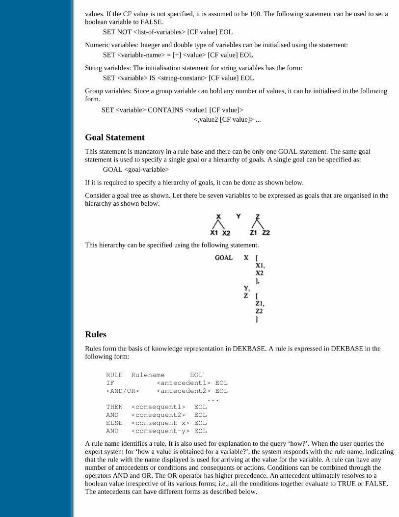
values. If the CF value is not specified, it is assumed to be 100. The following statement can be used to set aboolean variable to FALSE.
SET NOT <list-of-variables> [CF value] EOL
Numeric variables: Integer and double type of variables can be initialised using the statement:
SET <variable-name> = [+] <value> [CF value] EOL
String variables: The initialisation statement for string variables has the form:
SET <variable> IS <string-constant> [CF value] EOL
Group variables: Since a group variable can hold any number of values, it can be initialised in the followingform.
SET <variable> CONTAINS <value1 [CF value]><,value2 [CF value]> ...
Goal Statement
This statement is mandatory in a rule base and there can be only one GOAL statement. The same goalstatement is used to specify a single goal or a hierarchy of goals. A single goal can be specified as:
GOAL <goal-variable>
If it is required to specify a hierarchy of goals, it can be done as shown below.
Consider a goal tree as shown. Let there be seven variables to be expressed as goals that are organised in thehierarchy as shown below.
This hierarchy can be specified using the following statement.
Rules
Rules form the basis of knowledge representation in DEKBASE. A rule is expressed in DEKBASE in thefollowing form:
RULE Rulename EOL IF <antecedent1> EOL <AND/OR> <antecedent2> EOL ... THEN <consequent1> EOL AND <consequent2> EOL ELSE <consequent-x> EOL AND <consequent-y> EOL
A rule name identifies a rule. It is also used for explanation to the query ‘how?’. When the user queries theexpert system for ‘how a value is obtained for a variable?’, the system responds with the rule name, indicatingthat the rule with the name displayed is used for arriving at the value for the variable. A rule can have anynumber of antecedents or conditions and consequents or actions. Conditions can be combined through theoperators AND and OR. The OR operator has higher precedence. An antecedent ultimately resolves to aboolean value irrespective of its various forms; i.e., all the conditions together evaluate to TRUE or FALSE.The antecedents can have different forms as described below.

a) Check whether a fact is established or not
<variable-name> IS_DEFINED [TH value]
This statement checks whether a fact involving the given variable is established or not. TH is the threshold;value specified, which is optional.
b) Check whether a boolean value is established or not
<variable-name> [TH value]
If the confidence value is on, then the fact is checked with the given threshold; otherwise confidenceprocessing is ignored.
c) Compare strings
<variable-name> IS <value/variable-name> [TH value]
Here the right-hand side can either be a value (string constant) or another string variable for a which a valuehas already been assigned.
d) Check whether a set contains a value
<variable-name> CONTAINS <value1> [<value2> . [TH value]
The condition evaluates to TRUE if the specified values are available in the set defined by the variable onLHS.
e) Comparison of two expressions
The expressions on either side of an operator can contain numeric variables, arithmetic operators and themathematical functions supported by DEKBASE.
The basic form of a consequent is the one that assigns a value to a variable for establishing a fact. Sincededuction of a new fact involves assigning a value to a variable, this is the essential form of a consequent of aproduction rule. The various forms that a consequent can take are
a) Set a boolean variable to TRUE or FALSE
<variable-name> [CF value] EOL sets TRUENOT <variable-name> [CF value] EOL sets FALSE
b) Assign a value to a string variable
<variable-name> IS <string-var | string-constant> [CF] EOL
c) Include a value in a set
<variable-name> CONTAINS <list of values> [CF] EOL
d) Assign a numeric value of an expression to a variable
<variable-name> = <expression> [CF value] EOL
e) Assign a numeric value returned by a C function to a variable
<variable-name> = <C-function> EOL
Here the C function should return a value of type Integer or Double.
f) Carry out unconditional actions
Many times it may be necessary to carry out unconditional actions in both the antecedent and consequentparts of a rule. Traditionally actions are not meant to be used in the left-hand side of a rule. Such a facility hasadvantages and disadvantages. Use of actions in the IF part of a rule should be done with sufficient reason andcaution. Certain actions, when used in antecedents, cause problems especially when uncertain reasoning isbeing carried out. Various unconditional actions that should be available in a rule are the following:
a) Facility to load another rule base
This action causes the inference engine to suspend the inference process of the current knowledge base andload a new knowledge base for inference. The following rule loads another rule base.
IF design for vertical load resisting system completedTHEN LOAD lateral

The knowledge base should contain a rule base with the name ‘lateral’ and should be linked together withother rule bases. Only then it can be loaded.
b) Run an external program
This action temporarily suspends the inference process and executes an external program (an EXE program inDOS), which is available in the current directory. This feature can be used to carry out some analysis usingdata generated as a result of the inference process. It can also be used to load other interactive programs toobtain additional data.
IF bridge type is selectedTHEN RUN dispfig.exe
When the above rule is fired, the executable program DISPFIG.EXE available in the current directory isexecuted.
c) Write items to a data file
The WRITE action facilitates the file write operation. This is required to write values from the context to datafiles, so that either external programs invoked later can access them or the data can be used for any furtherprocessing. This facility is essential to build large prototype expert systems, in which external programsinteract with the expert system. The syntax for write is as shown below:
WRITE <filename> > [NUMERIC: <expression list>][STRING: <variable | value list> ]
The following statements are two typical WRITE statements.
WRITE outdat NUMERIC: 2, 3.0, il*i3+230WRITE outdat NUMERIC: 2, 3.0 STRING: shape, size
If the file is not there in the working directory, then the file is created before writing. If the file already exists,then the data are appended to the existing file.
d) Read items from a file
Just as the file output facility, the file read facility helps in organising data and also improves interaction withexternal programs. By using this facility, the inference engine can read the output generated by externalprograms. As the values read from the file are assigned to rule base variables, reading of values establishesnew facts in the context. The syntax is:
READ <filename> <variable list>
e) Display a text message
This is a very useful facility, using which a text message can be displayed during the inference process. Ithelps the user of the expert system monitor the progress of the inference process. Display of appropriatemessages with values taken from the context allows the user not only to know the state of inference but alsohelps in having a better interaction with the expert system. The statement has the following form:
DISPLAY <display-tag>
The display tag can be an identifier made up of any combination of alphanumeric characters. This is explainedlater in information definitions
f) Show a picture
The display of messages with pictures can convey information in a much more effective manner than displayof text messages. The facility should display figures created using standard graphics packages or scannedimages. The statement has the following form:
SHOW <name-of-bit-map-file>
The bitmap file should be a valid bitmap file with an extension .BMP.
g) Undefine a variable
Just before start of the inference, the context is empty and all the rule base variables are set to beUNDEFINED. This state of a variable changes the moment a value is assigned to it. If the inference has to seta variable back to UNDEFINED, this facility can be used. The syntax for this is
UNDEFINE <variable-name>
h) Restart the inference process

This action directs the inference engine to suspend the inference process and start again from the beginning.The context is reset with making all the variables UNDEFINED. A facility of selective removal of items fromcontext would be very useful, when the action restart is invoked.
Information Definitions
Information definitions are some facilities provided by DEKBASE to handle text messages. Text messagescan be used in any of the following three situations.
1. DISPLAY messages from within the rules
2. EXPLAIN to the user some variables if required
3. QUERY the user with a meaningful question for data input
The syntax of the display message is:
DISPLAY <display-tag> “text message” [<list of variables>]
When a rule having a DISPLAY action in the consequent is fired, the inference engine displays the textmessage given in quotes to the output screen. The text message can be of any size. But a maximum size of 20lines is appropriate, since it will not scroll up. Values of variables can also be displayed within the textmessage using a format specifier. The following example illustrates this.
IF length > = 2 * breadthTHEN lateral load analysis is requiredAND DISPLAY lla
Here, lla is a tag associated with a text message. The expansion for the tag is provided below:
DISPLAY lla ”
It is not required to analyse the building for
lateral load as the length and breadth are %% and %%
respectively.”, [length, breadth]
When the text message given within the quotes is displayed, the first %% symbol is replaced by the currentvalue of the variable length and the second %% symbol is replaced by value of the variable breadth.
The EXPLAIN facility is used to associate an explanatory text with a variable. During the inference process,if the user wants further explanation of a variable, then a text giving the required explanation can beassociated with the variable. The syntax has the following form:
EXPLAIN <variable-name> “ text message”
During the inference process, if it is required to obtain the value of a variable from the user, the inferenceengine displays the variable name on the screen followed by a question mark as a prompt. In case only shortvariable names are used, the user may not know what is expected. Associating a QUERY with a variablehelps in such situations. The meaningful query associated with the variable is displayed when data for thevariable are required from the user. The query has the following syntax:
QUERY <variable-name> “ query ”, [<low>, <high>]
Whenever a query is associated with a variable, it is also possible to define a lower and upper bound value forthe variable. Range specification is optional. During the inference process, if the user input does not satisfythe specified range, the inference engine does not accept the value. It keeps prompting the user until a valuewithin the range is obtained.
Other Features
DEKBASE provides many other features, which help in better organisation and development of rule bases.
Comments in rule base
As in any programs written in high-level languages, comments are useful for documenting the knowledgebases. Comments can be specified in two ways in DEKBASE rule base. In the first form, all the text to theright of a # symbol ignored. The second form is similar to that in C language, i.e., any text with a /* and */symbol is ignored by the compiler.

File Inclusions
DEKBASE allows one level of file inclusions. Any number of files can be included in a rule base. The syntaxfor file inclusion is:
$INCLUDE <file-name>
The $ symbol should start in the first column itself and the file name should be given in single quotes. Thisfacility can very well be used for better organisation of rule bases. For example, all the variable declarationscan be put in one file, and so all the infodefs. The rule base will have only the rules with two includestatements for including variables declarations and directives, and for including infodefs.
Frames
Use of frames for knowledge representation is a major facility of DEKBASE. It helps in better organisation ofdeclarative knowledge. Implementation of frames in DEKBASE is briefly described in this section.
A frame is a collection of slots (attributes) and values attached to the slots. Frames are created and usedduring the inference process. A collection of frames is called a frame base. Any number of frame bases can becreated in a knowledge base. But only one frame base can be active at a time. It is also possible to dump aframe base to a disk file and load it again during inference. Frames are global in nature and all the rule basescan access them. Rules can interact with the frames either for storing or accessing information. Frameoperations can be specified either in the antecedent or the consequent part of a rule. Various operationspermitted on a frame base are discussed below. The statements described below for frame operations can beused directly in rules.
The facilities for frame operations are divided into two groups, viz., those for managing frame bases and thosefor managing frames.
Frame Base Operations
A frame base is a collection of frames. It is not necessary that the frames in a frame base be related. Anynumber of frame bases can be created during run time, but only one can be active at a time. Operations onframe bases and frames are considered unconditional actions by the inference engine and are carried out asand when encountered. A brief description of the syntax for six frame base operations is enumerated below.
1. Creating frame bases
FCREATE_FBASE <list-of-frame-bases>
All the frame bases in the list are created using the above statement.
2. Selecting a frame base
Before commencing any frame operation, the frame base has to be selected to make it active. The followingstatement selects a frame base.
FSELECT_FBASE <frame-base>
3. Deleting frame bases
When a frame base is deleted, all the frames in the base are also deleted. The following statement deletesframe bases.
FDELETE_FBASE {list-of-frame-bases>
4. Saving frame bases
A frame base can be stored as a disk file. The name of the file is the same as that of the frame base. Hence, itis recommended that the name of a frame base be limited to eight characters. DEKBASE adds an extension.FBS to the file name for identification.
FSAVE_FBASE <list-of-frame-bases>
5. Loading frame bases
The following statement is used to load frame bases during inference.
FLOAD_FBASE <list-of-frame-bases>
Frame Operations

A frame is always referred to by its unique name. In DEKBASE, frames can have any number of slots andeach slot can have any number of values attached to it. The value attached to a slot should be of any of thedata types, integer, double or string. Instances of a generic frame can be created using the frame duplicationfacility provided. The various frame operations are enumerated below.
1. Create frames: All the frames given in the list are created.
FCREATE_FRAME <list-of-frames>
2. Delete frames: All the frames in the list are deleted.
FDEL_FRAME <list-of-frames>
3. Add attributes to frames:
FADD_ATTR<frame>,{FINTEGER|FDOUBLE|FSTRING},<attr_list>
4. Delete attributes from frame:
FDEL_ATTR <frame>, <list-of-attributes>
5. Add values to attributes: This action inserts a value to the position specified. The value can also be ageneral expression in terms of rule base variables. In the interactive mode, the user has to ensure thatthe value supplied is of the same data type specified as that of the attribute. The syntax has thefollowing form:
FINSERT_VAL <frame>, <attribute>, <position>, <value>
6. Delete a value: This action matches the value specified against the existing values in the slot anddeletes the value. If a value at the intermediate position is deleted, the position of all the subsequentvalues gets modified.
FDEL_VAL <frame>, <attribute>, <value>
7. Modify a value: This action modifies the value existing at the specified position by the valuesupplied.
FMOD_POS <frame>, <attribute>, <position>, <value>
8. Delete value at specified position: The value of an attribute at the specified position is deleted.
FDEL_POS <frame>, <attribute>, <position>
9. Duplicate a frame: This action duplicates the specified frame. Each duplicated frame is an instanceand is identified by an instance number. For example, the ith instance of a frame ‘beam’ is given aname ‘beam[i]’. The instance number varies from the stated starting and ending values.
FDUPLICATE <frame>, <start>, <end>
The two knowledge bases presented in Chapter 3 are written using the syntax of DEKBASE. The source codeof one of the examples is provided in the accompanying floppy diskette.
Table of Contents
Products | Contact Us | About Us | Privacy | Ad Info | Home
Use of this site is subject to certain Terms & Conditions, Copyright © 1996-2000 EarthWeb Inc. All rightsreserved. Reproduction whole or in part in any form or medium without express written permission of
EarthWeb is prohibited. Read EarthWeb's privacy statement.

Search Tips
Advanced Search
Artificial Intelligence and Expert Systems for Engineersby C.S. Krishnamoorthy; S. RajeevCRC Press, CRC Press LLCISBN: 0849391253 Pub Date: 08/01/96
Search this book:
Table of Contents
Appendix IIThis appendix lists decomposition and preconditions files for Examples 2 and 3 on design synthesispresented in Chapter 4. The representation follows the syntax of GENSYNT, which has been described inthe chapter. For each of the examples, the snapshot of the output, which in this case is a typical solution, isalso enumerated.
Example 2
TITLE Decomposition for building outline generation SYSTEM site, building, service, floor, core, s_area PROGRAM BuildDim, CoreDim, NumCores, CorePos,NoFloors,SerArea DECOMPOSITION
SYSTEM Site
length EXPRESSION length width EXPRESSION width req_area EXPRESSION req_area building SUBSYSTEM building
END_SYSTEM
SYSTEM building
peak_pop EXPRESSION peak_pop max_length EXPRESSION site.length-10 max_width EXPRESSION site.width-10 perc_length ONE_OF P100,P90,P80

perc_width ONE_OF P100,P90,P80 length PROGRAM BuildDim(building.max_length, building.perc_length) width PROGRAM BuildDim(building.max_width, building.perc_width) service SUBSYSTEM service floor SUBSYSTEM floor END_SYSTEM
SYSTEM service
pos_core ONE_OF center,sides num_cores PROGRAM NumCores(service.pos_core) core SUBSYSTEM core s_area SUBSYSTEM s_area IF(service.num_cores > 1) THEN FOR c_count=1,service.num_cores REPEAT core
END_SYSTEM
SYSTEM core
length PROGRAM CoreDim(len,service.pos_core, building.peak_pop) width PROGRAM CoreDim(wid,service.pos_core, building.peak_pop) area EXPRESSION core_length*core.width left_x PROGRAM CorePos(x,c_count, service.pos_core,core.length,building.length) bot_y PROGRAM CorePos(y,c_count, service.pos_core,core.width,building.width)
END_SYSTEM
SYSTEM floor
num_floors PROGRAM NoFloors(site.req_area, building.length,building.width,s_area.area)
END_SYSTEM
SYSTEM s_area
area PROGRAM SerArea(service.pos_core)
END_SYSTEM
CONSTRAINTS
IF(floor.num_floors >0) THEN floor.num_floors <= max_floors IF(building.length > 0) THEN building.length/building.width <= 4 IF(building.width > 0) THEN floor.num_floors*ht/building.width <= 10
END
PRECONDITIONS
length = 70

width = 50 req_area = 25000 max_floors = 15 peak_pop = 250 ht = 3.5
Output Results
Solution
site.length = 70 site.width = 50 site.req_area = 25,000 building.peak_pop = 250 building.max_length = 60 building.max_width = 40 building.length = 54 building.width = 32 building.p_length = 90% building.p-width = 80% floor.num_floors = 10 service.pos_core = sides service.num_cores = 2 s_area.area = 400 core[1].length = 20 core[1].width = 10 core[1].area = 200 core[1].left_x = 0 core[1].bot_y = 11 core[2].length = 20 core[2].width = 10 core[2].area = 200 core[2].left_x = 34 core[2].bot_y = 11
Example 3
TITLE Decomposition file for preliminary design of gear trains SYSTEM gearbox,gear PROGRAM norows,shaftdia,ratio, velocity,module,checking DECOMPOSITION
SYSTEM gearbox
max_length EXPRESSION length max_breadth EXPRESSION breadth max_height EXPRESSION height power_in EXPRESSION power in_speed EXPRESSION inspeed out_speed EXPRESSION outspeed in_shaft_type ONE_OF hollow,solid no_rows PROGRAM norows(inspeed, outspeed) no_teeth EXPRESSION input_teeth in_torque EXPRESSION (power/gearbox.in_speed) in_shaftdia_in PROGRAM shaftdia(gearbox.in_torque, gearbox.in_shaft_type,2) in_shaftdia_out PROGRAM shaftdia(gearbox.in_torque, gearbox.in_shaft_type,1)

gear SUBSYSTEM gear IF(gearbox.no_rows>1) THEN FOR t_count=1,gearbox.no_rows REPEAT gear
END_SYSTEM
SYSTEM gear
shaft_type ONE_OF hollow,solid gear_ratio PROGRAM ratio(t_count) teeth_in EXPRESSION (18*gear.gear_ratio) gear_velocity PROGRAM velocity(t_count) gear_torque EXPRESSION (gearbox.power_in/ gear.gear_velocity) shaft_dia_in PROGRAM shaftdia(gear.gear_torque, gear.shaft_type,2) shaft_dia_out PROGRAM shaftdia(gear.gear_torque, gear.shaft_type,1) gear_modules PROGRAM module(height,gear.teeth_in, gear.shaft_dia) gear_type ONE_OF spur,helical bearing_type ONE_OF tapered,radial modules ONE_OF M1,M5,M10 check PROGRAM checking(gear.modules, gear.gear_modules)
END_SYSTEM
CONSTRAINTS
IF(gear.modules == M1 ) THEN gear.check == 0 IF (gear.modules == M5 ) THEN gear.check == 0 IF (gear.modules == M10 ) THEN gear.check == 0 IF(gear.gear_velocity>400) THEN gear.gear_type==helical IF(gear.gear_velocity==400) THEN gear.gear_type==helical IF(gear.gear_velocity<400) THEN gear.gear_type==spur IF(gear.gear_type==helical) THEN gear.shaft_type==solid IF(gear.gear_type==helical) THEN gear.bearing_type==tapered END
PRECONDITIONS
length = 0.5 breadth = 0.5 height = 0.5 inspeed = 400.0 outspeed = 50.0 power = 40000.0 input_teeth = 18
Output Results

Solution
gear_box.num_rows = 2 input_shaft.type = solid input_shaft.diameter = 0.3 gear_row[1].module = M1 gear_row[1].gear_ratio = 0.9 gear_row[1].type = helical gear_row[1].shaft_type = solid gear_row[1].shaft_dia = 0.3 gear_row[1].bearings = tapered gear_row[2].module = M1 gear_row[2].gear_ratio = 0.8 gear_row[2].type = helical gear_row[2].shaft_type = solid gear_row[2].shaft_dia = 0.4 gear_row[2].bearings = tapered
Table of Contents
Products | Contact Us | About Us | Privacy | Ad Info | Home
Use of this site is subject to certain Terms & Conditions, Copyright © 1996-2000 EarthWeb Inc. All rightsreserved. Reproduction whole or in part in any form or medium without express written permission of
EarthWeb is prohibited. Read EarthWeb's privacy statement.

Search Tips
Advanced Search
Artificial Intelligence and Expert Systems for Engineersby C.S. Krishnamoorthy; S. RajeevCRC Press, CRC Press LLCISBN: 0849391253 Pub Date: 08/01/96
Search this book:
Table of Contents
Appendix IIIThis appendix lists the critiquing knowledge base and associated C functions for Example 2 described inChapter 5. The knowledge representation follows the syntax of GENCRIT, which has been described in thechapter.
Example 2
The critiquing knowledge:
TITLE A constructibility critic for single-story concrete buildings
SYSTEM bldg_system, lng_layout1
trn_layout2
PROCEDURE DetermineNoOfSpacings, DetermineBmtoBmCompatibilityNumber, DetermineBmtoCmLngCompatibilityNumber, DetermineBmtoCmTrnCompatibilityNumber, DetermineInterferenceInSameDirection, DetermineInterferenceInAcrossDirection CRITIQUE SYSTEM lng_layout { /* Item No. 1 */ uniformity_of_longitudinal_spacing: WF = 1.0 [rating=DetermineNoOfSpacings()] IF(rating == 0) { RF = 0
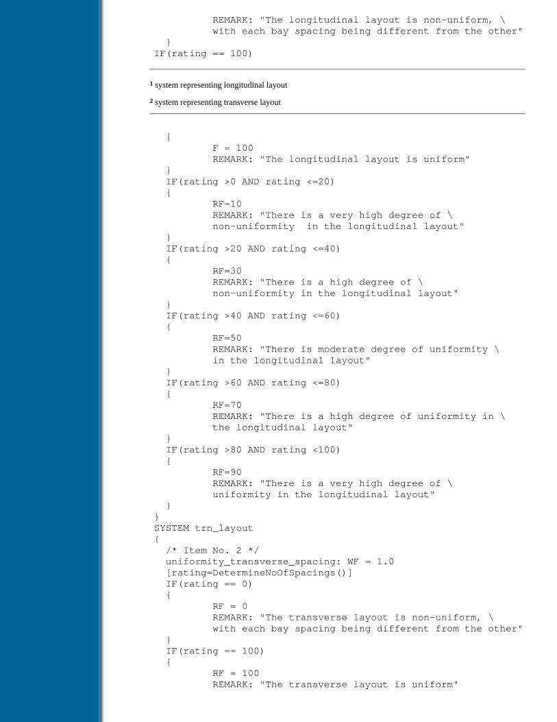
REMARK: "The longitudinal layout is non-uniform, \ with each bay spacing being different from the other" } IF(rating == 100)
1 system representing longitudinal layout
2 system representing transverse layout
{ F = 100 REMARK: "The longitudinal layout is uniform" } IF(rating >0 AND rating <=20) { RF=10 REMARK: "There is a very high degree of \ non-uniformity in the longitudinal layout" } IF(rating >20 AND rating <=40) { RF=30 REMARK: "There is a high degree of \ non-uniformity in the longitudinal layout" } IF(rating >40 AND rating <=60) { RF=50 REMARK: "There is moderate degree of uniformity \ in the longitudinal layout" } IF(rating >60 AND rating <=80) { RF=70 REMARK: "There is a high degree of uniformity in \ the longitudinal layout" } IF(rating >80 AND rating <100) { RF=90 REMARK: "There is a very high degree of \ uniformity in the longitudinal layout" } } SYSTEM trn_layout { /* Item No. 2 */ uniformity_transverse_spacing: WF = 1.0 [rating=DetermineNoOfSpacings()] IF(rating == 0) { RF = 0 REMARK: "The transverse layout is non-uniform, \ with each bay spacing being different from the other" } IF(rating == 100) { RF = 100 REMARK: "The transverse layout is uniform"
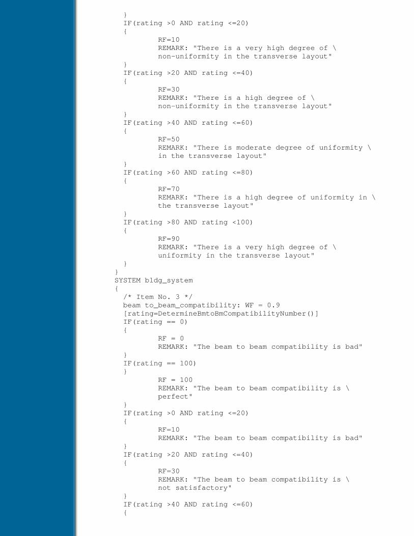
} IF(rating >0 AND rating <=20) { RF=10 REMARK: "There is a very high degree of \ non-uniformity in the transverse layout" } IF(rating >20 AND rating <=40) { RF=30 REMARK: "There is a high degree of \ non-uniformity in the transverse layout" } IF(rating >40 AND rating <=60) { RF=50 REMARK: "There is moderate degree of uniformity \ in the transverse layout" } IF(rating >60 AND rating <=80) { RF=70 REMARK: "There is a high degree of uniformity in \ the transverse layout" } IF(rating >80 AND rating <100) { RF=90 REMARK: "There is a very high degree of \ uniformity in the transverse layout" } } SYSTEM bldg_system { /* Item No. 3 */ beam to_beam_compatibility: WF = 0.9 [rating=DetermineBmtoBmCompatibilityNumber()] IF(rating == 0) { RF = 0 REMARK: "The beam to beam compatibility is bad" } IF(rating == 100) } RF = 100 REMARK: "The beam to beam compatibility is \ perfect" } IF(rating >0 AND rating <=20) { RF=10 REMARK: "The beam to beam compatibility is bad" } IF(rating >20 AND rating <=40) { RF=30 REMARK: "The beam to beam compatibility is \ not satisfactory" } IF(rating >40 AND rating <=60) {
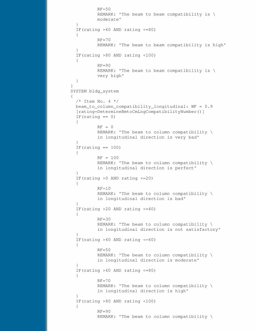
RF=50 REMARK: "The beam to beam compatibility is \ moderate" } IF(rating >60 AND rating <=80) { RF=70 REMARK: "The beam to beam compatibility is high" } IF(rating >80 AND rating <100) { RF=90 REMARK: "The beam to beam compatibility is \ very high" } } SYSTEM bldg_system { /* Item No. 4 */ beam_to_column_compatibility_longitudinal: WF = 0.9 [rating=DetermineBmtoCmLngCompatibilityNumber()] IF(rating == 0) { RF = 0 REMARK: "The beam to column compatibility \ in longitudinal direction is very bad" } IF(rating == 100) { RF = 100 REMARK: "The beam to column compatibility \ in longitudinal direction is perfect" } IF(rating >0 AND rating <=20) { RF=10 REMARK: "The beam to column compatibility \ in longitudinal direction is bad" } IF(rating >20 AND rating <=40) { RF=30 REMARK: "The beam to column compatibility \ in longitudinal direction is not satisfactory" } IF(rating >40 AND rating <=60) { RF=50 REMARK: "The beam to column compatibility \ in longitudinal direction is moderate" } IF(rating >60 AND rating <=80) { RF=70 REMARK: "The beam to column compatibility \ in longitudinal direction is high" } IF(rating >80 AND rating <100) { RF=90 REMARK: "The beam to column compatibility \
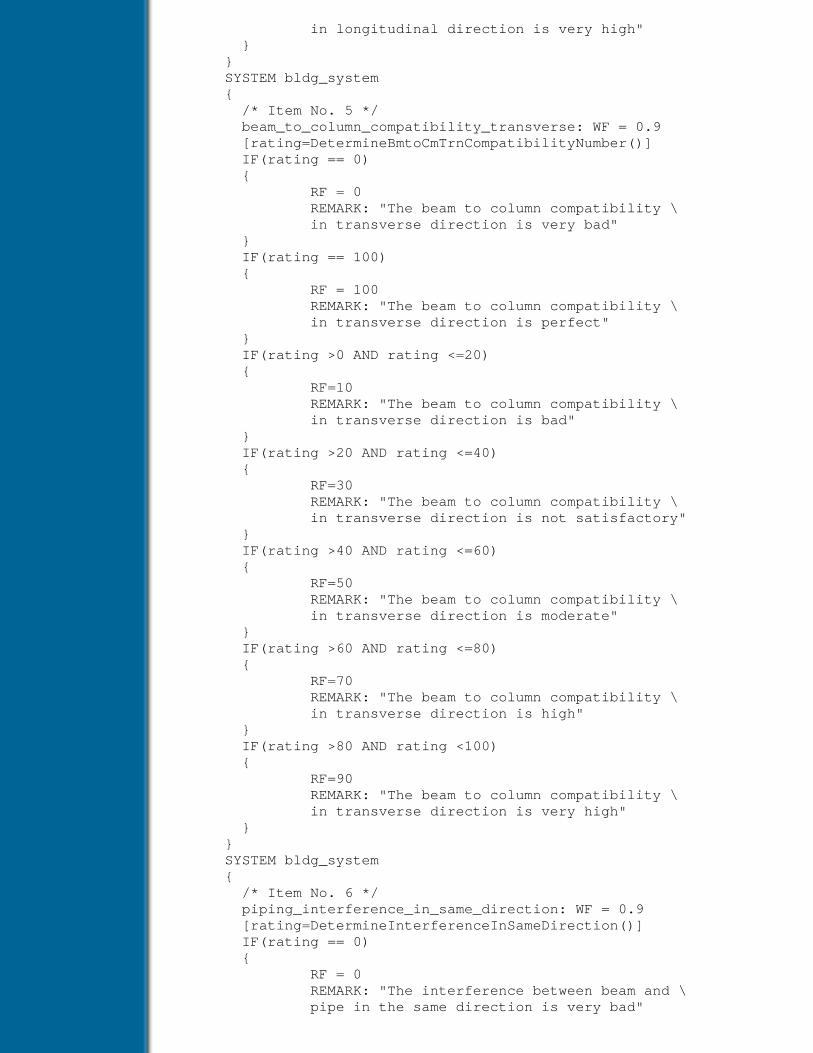
in longitudinal direction is very high" } } SYSTEM bldg_system { /* Item No. 5 */ beam_to_column_compatibility_transverse: WF = 0.9 [rating=DetermineBmtoCmTrnCompatibilityNumber()] IF(rating == 0) { RF = 0 REMARK: "The beam to column compatibility \ in transverse direction is very bad" } IF(rating == 100) { RF = 100 REMARK: "The beam to column compatibility \ in transverse direction is perfect" } IF(rating >0 AND rating <=20) { RF=10 REMARK: "The beam to column compatibility \ in transverse direction is bad" } IF(rating >20 AND rating <=40) { RF=30 REMARK: "The beam to column compatibility \ in transverse direction is not satisfactory" } IF(rating >40 AND rating <=60) { RF=50 REMARK: "The beam to column compatibility \ in transverse direction is moderate" } IF(rating >60 AND rating <=80) { RF=70 REMARK: "The beam to column compatibility \ in transverse direction is high" } IF(rating >80 AND rating <100) { RF=90 REMARK: "The beam to column compatibility \ in transverse direction is very high" } } SYSTEM bldg_system { /* Item No. 6 */ piping_interference_in_same_direction: WF = 0.9 [rating=DetermineInterferenceInSameDirection()] IF(rating == 0) { RF = 0 REMARK: "The interference between beam and \ pipe in the same direction is very bad"
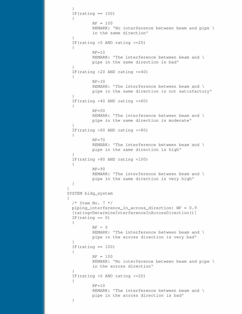
} IF(rating == 100) { RF = 100 REMARK: "No interference between beam and pipe \ in the same direction" } IF(rating >0 AND rating <=20) { RF=10 REMARK: "The interference between beam and \ pipe in the same direction is bad" } IF(rating >20 AND rating <=40) { RF=30 REMARK: "The interference between beam and \ pipe in the same direction is not satisfactory" } IF(rating >40 AND rating <=60) { RF=50 REMARK: "The interference between beam and \ pipe in the same direction is moderate" } IF(rating >60 AND rating <=80) { RF=70 REMARK: "The interference between beam and \ pipe in the same direction is high" } IF(rating >80 AND rating <100) { RF=90 REMARK: "The interference between beam and \ pipe in the same direction is very high" } } SYSTEM bldg_system { /* Item No. 7 */ piping_interference_in_across_direction: WF = 0.9 [rating=DetermineInterferenceInAcrossDirection()] IF(rating == 0) { RF = 0 REMARK: "The interference between beam and \ pipe in the across direction is very bad" } IF(rating == 100) { RF = 100 REMARK: "No interference between beam and pipe \ in the across direction" } IF(rating >0 AND rating <=20) { RF=10 REMARK: "The interference between beam and \ pipe in the across direction is bad" }
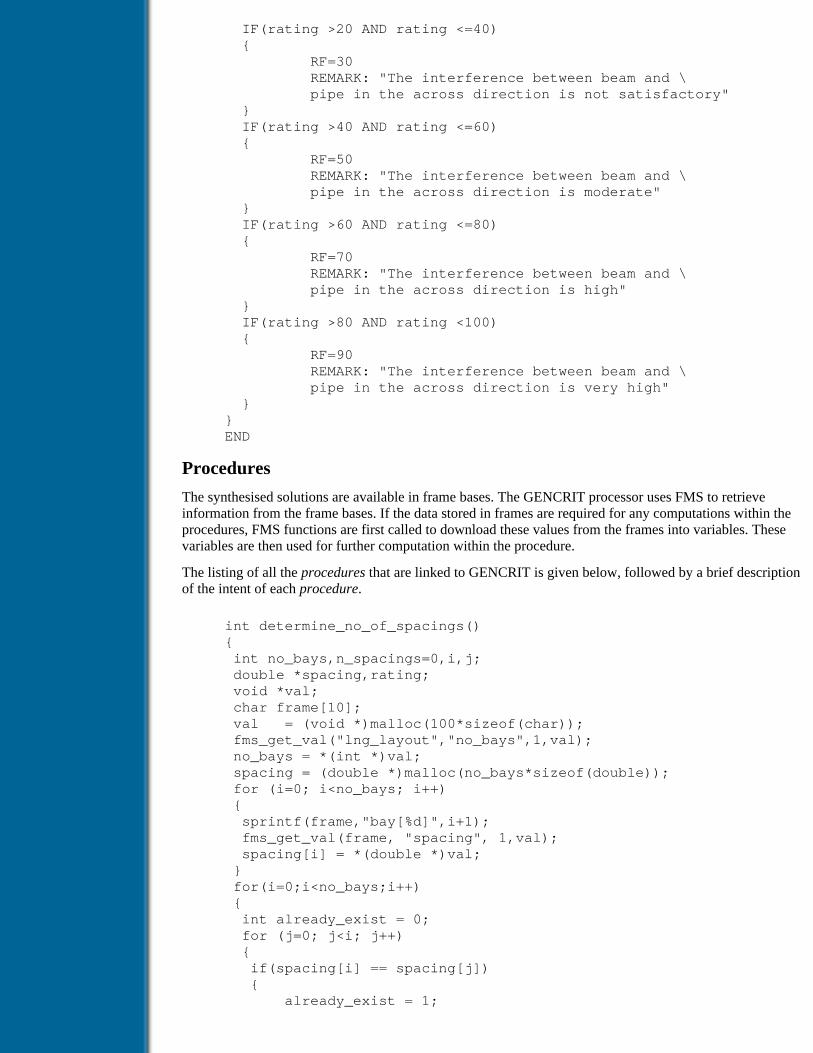
IF(rating >20 AND rating <=40) { RF=30 REMARK: "The interference between beam and \ pipe in the across direction is not satisfactory" } IF(rating >40 AND rating <=60) { RF=50 REMARK: "The interference between beam and \ pipe in the across direction is moderate" } IF(rating >60 AND rating <=80) { RF=70 REMARK: "The interference between beam and \ pipe in the across direction is high" } IF(rating >80 AND rating <100) { RF=90 REMARK: "The interference between beam and \ pipe in the across direction is very high" } } END
Procedures
The synthesised solutions are available in frame bases. The GENCRIT processor uses FMS to retrieveinformation from the frame bases. If the data stored in frames are required for any computations within theprocedures, FMS functions are first called to download these values from the frames into variables. Thesevariables are then used for further computation within the procedure.
The listing of all the procedures that are linked to GENCRIT is given below, followed by a brief descriptionof the intent of each procedure.
int determine_no_of_spacings() { int no_bays,n_spacings=0,i,j; double *spacing,rating; void *val; char frame[10]; val = (void *)malloc(100*sizeof(char)); fms_get_val("lng_layout","no_bays",1,val); no_bays = *(int *)val; spacing = (double *)malloc(no_bays*sizeof(double)); for (i=0; i<no_bays; i++) { sprintf(frame,"bay[%d]",i+1); fms_get_val(frame, "spacing", 1,val); spacing[i] = *(double *)val; } for(i=0;i<no_bays;i++) { int already_exist = 0; for (j=0; j<i; j++) { if(spacing[i] == spacing[j]) { already_exist = 1;

break; } } if(!already_exist) n_spacings++; } rating=(double)(no_bays_n_spacings)/(no_bays-1)*100; 3GENCRIT_proc_value.Dou=rating; return(DOU); }
3 the computed value of rating (a double value) is returned to the critiquing knowledge
The procedure calculates the number of different bay spacings in a particular direction within the layout andreturns the number of “different” bays as a percentage of the total number of bays in that direction.
int determine_beam_to_beam_compatibility_number() { int no_beams,no,ns_jns=0,comp_no=0,i,j,found=0,ch_no; double rating, *depth; void *val; char frame[10],orientation[5],f_orient[5]; val = (void *)malloc(100*sizeof(char)); fms_get_val("bldg_system","no_beams",1,val); no_beams = *(int *)val; depth = (double *)malloc(no_beams*sizeof(double)); for (i=0; i<no_beams; i++) { sprintf(frame,"beam[%d]",i+1); fms_get_val(frame, "depth",1,val); depth[i] = *(double *)val; fms_get_val(frame,"orientation",1,val); strcpy (orientation,(char *)val); if (i == 0) strcpy(f_orient,val); if (!found &38;&38; strcmp(f_orient,orientation)!=0) { found=1; ch_no=i; } } for(i=0;i<ch_no;i++) { for (j=ch_no; j<no_beams; j++) { no_jns++; if(depth[i] != depth[j]) comp_no++; } } rating=(double)(no_jns-comp_no)/(no_jns)*100; GENCRIT_proc-value.Dou=rating; return(DOU); }
This procedure calculates the percentage of total joints in the building in which the beams framing in havecompatible depths and returns this number
int determine_beam_to_column_lng_compatibility_number()

{ void *val; int i, no_columns, comp_no=0; char frame[25], frame1[25]; double width, dim_trn, rating; val = (void *)malloc(100*sizeof(char)); fms_get_val("bldg_system","no_colunms",1,val); no_columns = *(int *)val; for (i=0; i<no_columns; i++) { sprintf(frame,"column[%d]",i+1); fms_get_val(frame,"adj_lng_beam",1,val); strcpy (frame1,(char *)val); fms_get_val(frame1,"width",1,val); width = *(double *)val; fms_get_val(frame,"dim_trn",1,val); dim_trn = *(double *)val; if (width != dim_trn) comp_no++; } rating=(double)(no_columns-comp_no)/(no_columns)*100; GENCRIT_proc_value.Dou=rating; return(DOU); }
A longitudinal beam and a column that supports it are said to be compatible if the width of the beam is equalto the transverse cross-sectional dimension of that column. The procedure calculates the percentage of thetotal joints in the building in which such a compatibility exists and returns this number.
int determine_beam_to_column_trn_compatibility_number() { void *val; int i, no_columns, comp_no=0; char frame[25], frame1[25]; double dim_lng, width, rating; val =(void *)malloc(100*sizeof(char)); fms_get_val("bldg_system","no_columns",1,val); no_columns = \*(int *)val; for (i=0; i<no_columns; i++) { sprintf(frame,"column[%d]",i+1); fms_get_val(frame,"adj_trn_beam",1,val); strcpy (frame1,(char *)val); fms_get_val(frame 1, "width",1,val); width = *(double *)val ; fms_get_val(frame,"dim_lng",1,val); dim_lng = *(double *)val; if (width != dim_lng) comp_no++; } rating=(double)(no_columns-comp_no)/(no_columns)* 100; GENCRIT_proc_value.Dou=rating; return(DOU); }
This function similarly returns the percentage of total joints in the building in which compatibility betweentransverse beams and columns exists.
int detemiine_interference_in_same_direction() { void *val;

int i, j, no_pipes, no_beams, intr_no=0; char drn_p[10], drn_b[10], frame[10], frame1[10]; double dia, \pos_b, pos_p, pos_b1, pos_b2, flr_height; double width, depth, height, rating, z_coord, saf_height; val = (void *)malloc(100*sizeof(char)); fms_get_val("bldg_system","no_pipes",1,val); no_pipes = *(int *)val; fms_get_val("bldg_system","flr_height",1,val); flr_height = *(double *)val; fms_get_val("bldg_system","no_beams",1,val); no_beams = *(int *)val; for (i=0; i<no_pipes; i++) { sprintf(frame,"pipe[%d]",i+1); fms_get_val(frame,"z_coord",1,val); z_coord = *(double *)val; fms_get_val(frame, "position",1,val); pos_p = *(double *)val; fms_get_val(frame,"dia",1,val); dia = *(double *)val; height = z_coord+dia/2; fms_get_val(frame, "orientation",1,val); strcpy (drn_p,(char *)val); for (j=0; j<no_beams; j++) { sprintf(frame1,"beam[%d]",j+1); fms_get_val(frame1,"orientation",1,val); strcpy (drn_b,(char *)val); if (strcmp(dm_p,drn_b)==0) { fms_get_val(frame1,"position",1,val); pos_b = *(double *)val; fms_get_val(frame1,"width",1,val); width = *(double *)val; fms_get_val(frame1,"depth",1,val); depth = *(double *)val; saf_height = flr_height - depth; pos_b1 = pos_b+width/2+dia; pos_b2 = pos_b-width/2-dia; if(pos_b2<=pos_p &38;&38; pos_p<=pos_b1 &38;&38; \ height>saf_height) intr_no++; } } } rating=(double)(no_pipes-intr_no)/(no_pipes)* 100; GENCRIT_proc_value.Dou=rating; return(DOU); }
A pipe is said to interfere with a beam running along the same direction if they lie in the same vertical planeand if their z-coordinates overlap. This procedure returns the percentage of the total pipes that interfere withbeams running along their direction.
int determine_interference_in_across_direction() { void *val; int i, j, no_pipes, no_beams, intr_no=0, no_jns=0; char drn_p[10], drn_b[10], frame[10], frame1[10]; double dia, pos_b, pos_p, flr_height; double width, depth, height, rating, z_coord, saf_height; val = (void *)malloc(100*sizeof(char));

fms_get_val("bldg_system","no_pipes",1,val); no_pipes = *(int *)val; fms_get_val("bldg_system","flr_height",1,val); flr_height = *(double *)val; fms_get_val("bldg_system","no_beams",1,val); no_beams = *(int *)val; for (i=0; i<no_pipes; i++) { sprintf(frame,"pipe[%d]",i+1); fms_get_val(frame,"z_coord",1,val); z_coord = *(double *)val; fms_get_val(frame, "position",1,val); pos_p = *(double *)val; fms_get_val(frame,"dia",1,val); dia = *(double *)val; height = z_coord+dia/2; fms_get_val(frame,"orientation",1,val); strcpy (drn_p,(char *)val); for (j=0; j<no_beams; j++) { sprintf(frame1,"beam[%d]",j+1,val); fms_get_val(frame1,"orientation",1,val); strcpy (drn_b,(char *)val); if (strcmp(drn_p,drn_b)!=0) { fms_get_val(frame1,"width",1,val); width = *(double *)val; fms_get_val(frame1,"depth",1,val); depth = *(double *)val; saf_height = flr_height - depth; if height > saf_height intr_no++; no_jns++; } } } rating=(double)(no_jns_intr_no)/(no_jns)*100; GENCRIT_proc_value.Dou=rating; return(DOU); }
This procedure similarly returns the percentage of pipes that interfere with beams that run across them.
Table of Contents
Products | Contact Us | About Us | Privacy | Ad Info | Home
Use of this site is subject to certain Terms & Conditions, Copyright © 1996-2000 EarthWeb Inc. All rightsreserved. Reproduction whole or in part in any form or medium without express written permission of
EarthWeb is prohibited. Read EarthWeb's privacy statement.

Search Tips
Advanced Search
Artificial Intelligence and Expert Systems for Engineersby C.S. Krishnamoorthy; S. RajeevCRC Press, CRC Press LLCISBN: 0849391253 Pub Date: 08/01/96
Search this book:
Table of Contents
INDEXAGE 199
Analytic Hierarchy Process 120
ARCHIE 151
Artificial Intelligence 2, 3, 11
Artificial Neural Network 5, 241
back propagation 241
hybrid approach 245
KBS integration 243
Back propagation networks 242
Backtracking 3
Backward chaining 45
Beam and slab 215
Bearings selection 66
Belief function 58
Blackboard model 194
architecture 195
control 195
framework 196
knowledge sources 195
object oriented 205
parallel and distributed 204
shared memory 205
Brick masonry 188
cracking 188
Bridge design 225
case-based approach 232
conceptual design 231
heuristic based approach 230
integrated KBS 225
layout planning 230
process model 234
CBD model 235
RSC model 234
task analysis 229
Building design 205
conceptual and
preliminary 213, 215
design critiquing 208
design modification 209
design synthesis 207
GA model 214
layout planning 210
ODESSY 205, 218
task analysis 205
CADSYN 152
Car body shape 219
conceptual design 219
design parameters 220
functional requirements 219
design decoupling 221
Case-based reasoning 6, 149
CASETOOL 150
framework 164
process 152, 153, 161, 163
CASETOOL 164
architecture 168
case retrieval 164
case storing 167
processors 168
solution transformation 165
Certainty factor 56
CHEF 150
Classification 156
performance 157
relevance 156
Classifier systems 239
CLAVIER 151
Common sense 52
Computer-aided engineering 8
Computer vision 4
Concurrent engineering 120, 245
computer-aided 246
Connectionist systems 241
Constraints 106, 117
attribute 107
desirability 106, 117
feasibility 106, 117
functions 108
meta 107
runtime 107
static 107
Cooperative participation 117
Cooperative problem solving 185
Cracking 188
brick masonry 188
Criticism 117, 120
Critiquing 117, 120
framework 120
combining algorithm 126
fuzzy-based model 208

inference mechanism 126
knowledge-based 131
knowledge
representation 125
methodology 124
tool 121
GENCRIT 129
CRYSALIS 197
Decomposition model for
synthesis 91
file 101
form 92
function 92
hierarchy 92
goal 92
node 92
representation 102
tree 93
attributes 93
leaf nodes 93
DEJAVU 151
DEKBASE 30, 65, 171, 236,255
Demons 52
DENDRAL 29
Design compatibility
analysis 120, 246
Design critiquing 6, 117
Design data 109
Design decoupling 221
algorithm 222
Design for assembly 246
Design modification 209
model 210

Design process models 186
Design review 246
Design synthesis 6, 89
Design theory 186
DESTINY 197
Diagnosis
expert systems 188
problems 29
EDESYN 119
Engineering design synthesis 89
steel building 94
Evaluation 117
framework 120
Expert systems 4, 5
development shell 62
ART 65
DEKBASE 65
GEPSE 64
INSIGHT 64
KEE 64
Knowledge craft 64
Level 5
object 64
OPS5 64
File 111
Flat plate floor 216
Flat slab floor 216
Frames (object) 5, 42-44
demon 52
inference 52
Frame management system 52
FUZCRIT 209
architecture 209

Fuzzy-based model 208
Fuzzy sets 55
weighted averaging 208
Gearbox design 97, 141
GENCRIT 118, 129
architecture 130
compiler 130
critic knowledge
base 130, 131
processor 130
Generate-and-test 6, 23
GENESIS 198
architecture 199
Genetic algorithms 4, 5, 90, 238
classifier systems 239
expert systems 238
structural framing 260
GENSYNT 89, 108
compiler 109
components 109
frame management 110
knowledge modules 109
language interpreter 111
organisation 110
synthesis processor 110
GIS 2
Goals 45
stack 46
state 16
HASP/SIAP 197
HEARSAY II 196
Heuristics 5, 31
Hierarchical

generate-test 118
HI-RISE 119
Hybrid inference mechanism 50
Hybrid GA 215
decomposition 215, 216
Indices 153
Inference mechanisms 32, 45
backward chaining 45
engine 33
forward chaining 50
hybrid chaining 50
Instance net 191, 192
Integrated design systems 186
Integrated engineering
architecture 201
system (IES) 200
Integrated KBS development 188
Intelligence 11
human 11
JULIA 151
Knowledge base 34
Knowledge-based
expert system 29, 30
architecture 32
context 32
explanation facility 32
inference mechanisms 33
knowledge acquisition 33
knowledge-base 33, 34
components 32
heuristic 31
IF-THEN construct 13, 31
production rules 37
Knowledge net 38, 39, 189
Knowledge
representation 15, 35, 62
consequent 37
conventional programs 35
frames object 35, 42
predicate logic 35, 36
production rules 37
rule base 41
semantic networks 35, 42
KRITIK 151
Layout critic 212
Layout planner 211
synthesiser 211
Learning 4
Linguistic class 161
LISP 3
Mathematical programming 90
Multiagent cooperative
problem solving 185
Multistory building 205
MYCIN 29
Natural language processing 4
Neural network 5, 241
ODESSY 205
architecture 218
process model 206
SCM model 206,
task analysis 205
Office building 205
OPS5 64
Optimisation techniques 90
PANDA 153
Planning rules 94, 105
Plate girder 202
Preconditions 94
Predicate logic 36
Problem decomposition 25, 90

AND-OR graphs 25
Problem reduction 90
Process models 186
Production rule 37
Production systems 15
Prototype refinement
paradigm 212
Rating 128
Rating factor 124, 133
Reasoning
certainty factors 56
inexact 53
monotonic 55
non-monotonic 55
Recomposition 90
Relevance
classification 154, 156
close 156
norm 156
perfect 156
Remark 125, 133
Repair method 189
REPCON 188
Robotics 4
Rules 37
rule base 42
rule stack 46
SACON 57
Scripts 5
Search conditions 154
selection 155
Search techniques
agenda-driven 24
backward chaining 26, 45
best-first 23
breadth-first 17
depth-first 19
forward chaining 26, 50
generate and test 23
heuristic 20
production systems 21
Selection of bearings 66
SETHU 225
architecture 237
process model 234
task analysis 229
SHRINK 152
Solution recomposition 90
Solution transformation 161
Steel industrial building 94, 112
Steel industrial structures 198
STRUPLE 153
Synthesis 89
case-based reasoning 91
decomposition model 91
KBES environment 98
problem reduction 90
transformation approach 91
Synthesis-Criticism
Modification model 206
architecture 207
Synthesiser 98
architecture 101
System
attributes 91
subsystems 91
Task analysis 187
Tree 25
AND node 25, 26
OR node 25, 26
Truth maintenance system 49, 56

Uncertainty in reasoning 54
VASTU 170
architecture 171
CBR process 172
Waffle slab floor 215
Weighting factor 124, 132
Table of Contents
Products | Contact Us | About Us | Privacy | Ad Info | Home
Use of this site is subject to certain Terms & Conditions, Copyright © 1996-2000 EarthWeb Inc. All rightsreserved. Reproduction whole or in part in any form or medium without express written permission of
EarthWeb is prohibited. Read EarthWeb's privacy statement.
Related Documents