Article The Testing Blind Spot Battery interconnect strength testing by Chris Davies and Conor McCarthy Battery lifetime and stability play important roles in the development of next-generation electric cars. The automotive sector is booming in relation to electric vehicles, and some manufacturers already have well-established electric cars on the market today. The Organization of the Petroleum Exporting Countries (OPEC) predicts that there will be 1.7 million electric cars on the road by 2020, while Bloomberg New Energy Finance estimates it will be closer to 7.4 million, with 2 million sold in 2020 alone. Bloomberg also expects electric cars to make up 35 percent of light vehicle sales by 2040. With so many of these vehicles being introduced onto our roads in the coming years, their safety and reliability is becoming an increasing focal point. The reliability of these vehicles will depend on overcoming the technical challenges around battery lifetime. Battery suppliers and manufacturers need to make sure that they can match the endurance of well-established components found in a combustion engine which typically last around 10 years or 150,000miles. All car functions including safety features and driver aids require uninterrupted battery power during different stages of a vehicle journey. If electric car batteries cannot maintain a consistent power output and performance, the acceptance of electric vehicles as a suitable alternative to the combustion engine will not be realized. Currently, there are three types of battery configurations which are widely used: cylindrical, prismatic and pouch. Each one has its potential application whether it be in automotive or renewable storage. Here, we are exclusively focused on discussing the battery packs made of cylindrical units for use in electric vehicles, shown in Figure 2. Figure 2. A typical Ni cathode Li-ion rechargeable cell and a fully assembled pack with multiple wire bonds, found in an automotive battery pack. Figure 1. Battery packs within the rapidly-increasing number of electric cars must be robust and have proven long term reliability Anode Separator Cathode Metal Case +ve/-ve Terminals and Safety Vent

Welcome message from author
This document is posted to help you gain knowledge. Please leave a comment to let me know what you think about it! Share it to your friends and learn new things together.
Transcript
Article
The Testing Blind SpotBattery interconnect strength testing by Chris Davies and Conor McCarthy
Battery lifetime and stability play important roles in the development of next-generation electric cars. The automotive sector is booming in relation to electric vehicles, and some manufacturers already have well-established electric cars on the market today. The Organization of the Petroleum Exporting Countries (OPEC) predicts that there will be 1.7 million electric cars on the road by 2020, while Bloomberg New Energy Finance estimates it will be closer to 7.4 million, with 2 million sold in 2020 alone. Bloomberg also expects electric cars to make up 35 percent of light vehicle sales by 2040.
With so many of these vehicles being introduced onto our roads in the coming years, their safety and reliability is becoming an increasing focal point. The reliability of these vehicles will depend on overcoming the technical challenges around battery lifetime. Battery suppliers and manufacturers need to make sure that they can match the endurance of well-established components found in a combustion engine which typically last around 10 years or 150,000miles. All car functions including safety features and driver aids require uninterrupted battery power during different stages of a vehicle journey. If electric car batteries cannot maintain a consistent power output and performance, the acceptance of electric vehicles as a suitable alternative to the combustion engine will not be realized. Currently, there are three types of battery configurations which are widely used: cylindrical, prismatic and pouch. Each one
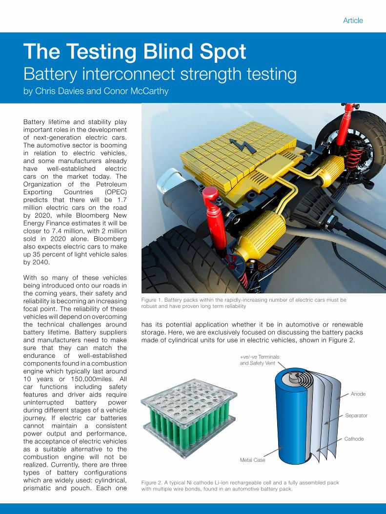
has its potential application whether it be in automotive or renewable storage. Here, we are exclusively focused on discussing the battery packs made of cylindrical units for use in electric vehicles, shown in Figure 2.
Figure 2. A typical Ni cathode Li-ion rechargeable cell and a fully assembled pack with multiple wire bonds, found in an automotive battery pack.
Figure 1. Battery packs within the rapidly-increasing number of electric cars must be robust and have proven long term reliability
Anode
Separator
Cathode
Metal Case
+ve/-ve Terminals and Safety Vent
Article
The importance of the cell interconnects
To match the power outputs required by highly desirable fully-electric or hybrid cars, batteries must be energy-dense with high current-carrying connections that are as reliable as the fuel system in a conventional combustion engine. Currently, most battery testing is focused on the cell electrochemistry or overall pack robustness, such as: temperature cycling tests, environmental tests, charge/discharge tests and vibration tests. However, one critical area is being overlooked: the intercell connection components. These connections are crucial to managing the flow of current between each individual cell and delivering sufficient energy to the powertrain. Connections that are formed with high resistance can lead to heating effects when current is drawn from them. Likewise, should several of these connections break within a pack, the same current will be drawn from a smaller number of cells leading to overheating and in the worst cases even fires.
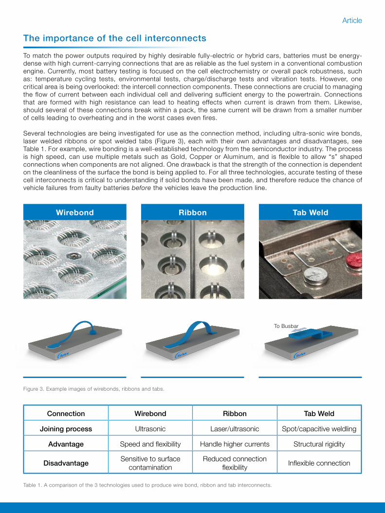
Several technologies are being investigated for use as the connection method, including ultra-sonic wire bonds, laser welded ribbons or spot welded tabs (Figure 3), each with their own advantages and disadvantages, see Table 1. For example, wire bonding is a well-established technology from the semiconductor industry. The process is high speed, can use multiple metals such as Gold, Copper or Aluminum, and is flexible to allow “s” shaped connections when components are not aligned. One drawback is that the strength of the connection is dependent on the cleanliness of the surface the bond is being applied to. For all three technologies, accurate testing of these cell interconnects is critical to understanding if solid bonds have been made, and therefore reduce the chance of vehicle failures from faulty batteries before the vehicles leave the production line.
Figure 3. Example images of wirebonds, ribbons and tabs.
Wirebond Ribbon Tab Weld
Connection Wirebond Ribbon Tab Weld
Joining process Ultrasonic Laser/ultrasonic Spot/capacitive weldling
Advantage Speed and flexibility Handle higher currents Structural rigidity
Disadvantage Sensitive to surface contamination
Reduced connectionflexibility Inflexible connection
To Busbar
Table 1. A comparison of the 3 technologies used to produce wire bond, ribbon and tab interconnects.
Article
Safety critical reliability testing– The benefits of Bondtesting
To repeatedly charge and discharge high currents over time without failure, the formation of the interconnects between individual cells must be controlled carefully to ensure high quality. Due to the density of materials and dimensions of fully assembled battery packs, many visual inspection techniques cannot be used to identify quality issues. Used in isolation, top down visual inspection is effective but has limitations. The connections may appear attached to the surface, however there may be a layer of contamination between the connection and surface meaning the interconnect has not formed a strong bond with the surface below. It can also be possible that the connection is made but is very weak due to a small bonded area caused by a fundamentally weak bonding process. In these cases, using a physical test (such as Bondtesting) to mechanically stress the bond, reveals the true strength of the electrical interconnect.
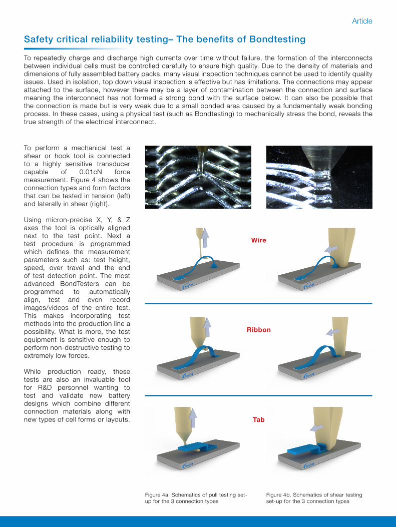
Figure 4a. Schematics of pull testing set-up for the 3 connection types
Figure 4b. Schematics of shear testing set-up for the 3 connection types
To perform a mechanical test a shear or hook tool is connected to a highly sensitive transducer capable of 0.01cN force measurement. Figure 4 shows the connection types and form factors that can be tested in tension (left) and laterally in shear (right).
Using micron-precise X, Y, & Z axes the tool is optically aligned next to the test point. Next a test procedure is programmed which defines the measurement parameters such as: test height, speed, over travel and the end of test detection point. The most advanced BondTesters can be programmed to automatically align, test and even record images/videos of the entire test. This makes incorporating test methods into the production line a possibility. What is more, the test equipment is sensitive enough to perform non-destructive testing to extremely low forces.
While production ready, these tests are also an invaluable tool for R&D personnel wanting to test and validate new battery designs which combine different connection materials along with new types of cell forms or layouts.
Wire
Ribbon
Tab

Article
To understand how an interconnect has failed, the bonded site can be analyzed post-test to give detailed information on the adhesion and reliability of the original interconnect. This means a process engineer can record and understand which element of an upstream process may need settings altered to improve the bond adhesion.
Testing the bond in more than one direction is required to fully-characterize a bond’s quality and reliability. Both shear and pull tests simulate different loading conditions that could be experienced by a battery within a vehicle which is navigating bumps and shunts from all directions. The pack design considerations, such as cell orientation and bond length and direction, will not always be the same. Cells are often “floating”, loosely held, within flexible polymers in a pack for thermal expansion purposes, which can exert 3D stresses on the interconnect. Geometries of the connection itself can lean towards only shearing or only pulling on the connection but it’s still important not to neglect the opposing load condition. Shear loading of the interconnect will help to imitate a lateral load whereas pull will simulate a tensile loadThe battery connections can be characterized in two modes and each give different levels of information:
Figures 5. Process of completing a destructive and non-destructive Bond test
Programme automated test pattern
Destructive test Non-destructive test
Post-test surface image + force graph Statistical results
Failure force recorded
Full evaluation of interconnect
Sample testing only
Device damaged
Device is not damaged
100% connections tested
Full failure mode not recorded
Understanding Failure Modes
Destructive testing for new product development to characterize new welds or bond processes or batch quality tests.
Non-destructive testing for safety assurance by testing
100 percent of connections, before use in a final product.
Surface image pre-test

Article
Summary
Emerging automobile technologies like electric powertrains, autonomous control systems, driver health monitoring, remote engine shut down, and live car tracking require high levels of battery power. As vehicles integrate more electronics, the need for more advanced batteries is increasing. Additionally, vehicles move in a harsh, ever-changing environment of vibration so any loose connections could be dislodged and lead to battery failure and potentially even fire. In this article we describe how the battery interconnects between cells can become the weak link in the entire electric vehicle if the bonding process has not been successful. Similar to the BondTesting quality assurance procedures which are well established in the semiconductor industry, the emergence of mechanical stress testing of cell interconnects can play a pivotal role in ensuring electric vehicles achieve the highest safety standards, as part of a wider test suite in a battery production line.
To find out more about Nordson DAGE and the 4600 Battery Bondtester, contact:
Conor McCarthy, Product Manager – Bond Test and Materials Test,at 25 Faraday Rd, Aylesbury, Buckinghamshire HP19 8RY, UK
+44 (0) 1296 317800E-mail: [email protected]: www.nordsondage.com
Related Documents