WELDING RESEARCH SUPPLEMENT | 87-s RESEARCH/DEVELOPMENT/RESEARCH/DEVELOPMENT/RESEARCH/DEVELOPMENT/RESEARCH/DEVELOPMENT BY M. A. QUINTANA AND M. Q. JOHNSON Dilution from FCAW-S weld metals influences SMAW mechanical properties The Effects of Intermixed Weld Metal on Mechanical Properties — Part I ABSTRACT. It is common for individual weld joints to be fabricated using a com- bination of electrode types and welding processes. While this situation arises most often as a result of repair welding, it also can arise due to scheduled fabri- cation sequencing, which requires a change from one electrode and/or pro- cess to another within the same weld joint. When weld metals deriving their properties from different metallurgical mechanisms are intermixed in the same joint, the resulting properties of the com- bination have caused some concern. This work is the first in a series that ex- amines the intermixing of conventional carbon-manganese weld metals with various self-shielded flux cored arc weld metals. In this case, two different shielded metal arc weld metals are combined with various self-shielded flux cored arc weld metals. The effects of dilution from the underlying self-shielded flux cored root layers on the mechanical properties of shielded metal arc weld metal are examined. Variations in both tensile and Charpy V-notch impact prop- erties have been documented. The effect on tensile results is limited to relatively minor changes in ductility. Reductions in Charpy V-notch impact energies were noted in all cases. The results are evalu- ated in terms of the chemical composi- tion gradients and weld microstructure variations that result from dilution. Possi- ble mechanisms are discussed. Introduction Welding is an integral part of most modern construction and manufacturing operations. On any given project, welding operations frequently involve a range of welding consumables and processes. It is often necessary to repair flaws that form as a result of service or defects created dur- ing manufacture. Repair welds are often made with welding consumables and pro- cesses different from those used in the original joint construction. For example, shielded metal arc welding (SMAW) re- pairs in submerged arc welding (SAW) de- posits, gas metal arc welding (GMAW) deposits, gas-shielded flux cored arc welding (FCAW-G) deposits or self- shielded flux cored arc welding (FCAW-S) deposits are common. For many applica- tions, the use of different welding con- sumables and processes in a single weld joint is planned in the normal fabrication sequence. Often, it is not practical or cost- effective to fabricate a welded joint using a single consumable and process. For ex- ample, many line pipe welds are pro- duced using SMAW for the root pass and FCAW-S for the fill passes. Fabrication of large components or structures often in- volves shop welding using GMAW and FCAW-G, followed by FCAW-S or SMAW in the field. The process of fitting and tack welding is often accomplished using SMAW, with the remainder of the struc- ture welded using processes that achieve higher deposition rates. These are examples of applications in which intermixing of different weld met- als can occur in a single weld joint. These examples indicate that, while not occur- ring in every case, intermixing does occur rather frequently as a normal part of the fabrication process. By contrast, most welding consumables are opti- mized without considering dilution ef- fects from either the underlying base metal or a weld metal of different chem- ical composition. Welding consumable specifications standardize on the type of base material to be used for certification and conformance testing. Accordingly, electrodes are designed to produce weld metal mechanical properties through op- timization of the alloy design and the use of slag/metal reactions to create the proper composition and microstructure. Depending on the anticipated service re- quirements and the operating character- istics desired, the alloy levels and slag systems are optimized in different ways. The introduction of elements through di- lution/intermixing at levels not originally intended can alter the weld metal prop- erties and resulting weld performance. For example, when welding high carbon or microalloyed base metal, high con- centrations of carbon or microalloying elements in the weld metal can occur through dilution. Similar dilution effects occur when one welding consumable is deposited over another of significantly different composition. Further dilution may also result in a loss of alloy elements in the weld, if the base material or un- derlying weld metal possesses a “leaner” composition than the welding consum- able used to fabricate the balance of the weld joint. In either case, a shift in chem- ical composition away from optimum can occur. The effect of such unexpected varia- tions in chemical composition can be undesirable changes in the mechanical properties of the weld metal. While a great deal of study has been devoted to dilution effects from base metals, only limited study has been conducted on the effects of intermixing weld metals de- posited by different processes/electrode types. Most arc welding processes rely on a protective slag and/or a shielding gas to protect the weld metal from the atmo- sphere during welding. In this respect, the FCAW-S process is unique. FCAW-S consumables produce very little shield- ing gas and rely on the addition of large M. A. QUINTANA is with The Lincoln Electric Company, Cleveland, Ohio. M. Q. JOHNSON is with Edison Welding Institute, Columbus, Ohio. Paper presented at the AWS Annual Meeting, April 13–17, 1997, Los angeles, Calif. KEY WORDS Carbon-Manganese Weld Metal Charpy V-Notch Dilution Electrodes FCAW Multipass Welds Primary Metal Retransformed Metal SMAW

Welcome message from author
This document is posted to help you gain knowledge. Please leave a comment to let me know what you think about it! Share it to your friends and learn new things together.
Transcript
WELDING RESEARCH SUPPLEMENT | 87-s
RE
SE
AR
CH
/DE
VE
LO
PM
EN
T/R
ES
EA
RC
H/D
EV
EL
OP
ME
NT
/RE
SE
AR
CH
/DE
VE
LO
PM
EN
T/R
ES
EA
RC
H/D
EV
EL
OP
ME
NT
BY M. A. QUINTANA AND M. Q. JOHNSON
Dilution from FCAW-S weld metals influencesSMAW mechanical properties
The Effects of Intermixed Weld Metalon Mechanical Properties — Part I
ABSTRACT. It is common for individualweld joints to be fabricated using a com-bination of electrode types and weldingprocesses. While this situation arisesmost often as a result of repair welding,it also can arise due to scheduled fabri-cation sequencing, which requires achange from one electrode and/or pro-cess to another within the same weldjoint. When weld metals deriving theirproperties from different metallurgicalmechanisms are intermixed in the samejoint, the resulting properties of the com-bination have caused some concern.This work is the first in a series that ex-amines the intermixing of conventionalcarbon-manganese weld metals withvarious self-shielded flux cored arcweld metals. In this case, two differentshielded metal arc weld metals arecombined with various self-shielded fluxcored arc weld metals. The effects ofdilution from the underlying self-shieldedflux cored root layers on the mechanicalproperties of shielded metal arc weldmetal are examined. Variations in bothtensile and Charpy V-notch impact prop-erties have been documented. The effecton tensile results is limited to relativelyminor changes in ductility. Reductions inCharpy V-notch impact energies werenoted in all cases. The results are evalu-ated in terms of the chemical composi-tion gradients and weld microstructurevariations that result from dilution. Possi-ble mechanisms are discussed.
Introduction
Welding is an integral part of mostmodern construction and manufacturingoperations. On any given project, weldingoperations frequently involve a range ofwelding consumables and processes. It isoften necessary to repair flaws that form asa result of service or defects created dur-
ing manufacture. Repair welds are oftenmade with welding consumables and pro-cesses different from those used in theoriginal joint construction. For example,shielded metal arc welding (SMAW) re-pairs in submerged arc welding (SAW) de-posits, gas metal arc welding (GMAW)deposits, gas-shielded flux cored arcwelding (FCAW-G) deposits or self-shielded flux cored arc welding (FCAW-S)deposits are common. For many applica-tions, the use of different welding con-sumables and processes in a single weldjoint is planned in the normal fabricationsequence. Often, it is not practical or cost-effective to fabricate a welded joint usinga single consumable and process. For ex-ample, many line pipe welds are pro-duced using SMAW for the root pass andFCAW-S for the fill passes. Fabrication oflarge components or structures often in-volves shop welding using GMAW andFCAW-G, followed by FCAW-S or SMAWin the field. The process of fitting and tackwelding is often accomplished usingSMAW, with the remainder of the struc-ture welded using processes that achievehigher deposition rates.
These are examples of applications inwhich intermixing of different weld met-als can occur in a single weld joint. Theseexamples indicate that, while not occur-ring in every case, intermixing doesoccur rather frequently as a normal partof the fabrication process. By contrast,most welding consumables are opti-
mized without considering dilution ef-fects from either the underlying basemetal or a weld metal of different chem-ical composition. Welding consumablespecifications standardize on the type ofbase material to be used for certificationand conformance testing. Accordingly,electrodes are designed to produce weldmetal mechanical properties through op-timization of the alloy design and the useof slag/metal reactions to create theproper composition and microstructure.Depending on the anticipated service re-quirements and the operating character-istics desired, the alloy levels and slagsystems are optimized in different ways.The introduction of elements through di-lution/intermixing at levels not originallyintended can alter the weld metal prop-erties and resulting weld performance.For example, when welding high carbonor microalloyed base metal, high con-centrations of carbon or microalloyingelements in the weld metal can occurthrough dilution. Similar dilution effectsoccur when one welding consumable isdeposited over another of significantlydifferent composition. Further dilutionmay also result in a loss of alloy elementsin the weld, if the base material or un-derlying weld metal possesses a “leaner”composition than the welding consum-able used to fabricate the balance of theweld joint. In either case, a shift in chem-ical composition away from optimumcan occur.
The effect of such unexpected varia-tions in chemical composition can beundesirable changes in the mechanicalproperties of the weld metal. While agreat deal of study has been devoted todilution effects from base metals, onlylimited study has been conducted on theeffects of intermixing weld metals de-posited by different processes/electrodetypes. Most arc welding processes rely ona protective slag and/or a shielding gas toprotect the weld metal from the atmo-sphere during welding. In this respect,the FCAW-S process is unique. FCAW-Sconsumables produce very little shield-ing gas and rely on the addition of large
M. A. QUINTANA is with The Lincoln ElectricCompany, Cleveland, Ohio. M. Q. JOHNSONis with Edison Welding Institute, Columbus,Ohio. Paper presented at the AWS AnnualMeeting, April 13–17, 1997, Los angeles,Calif.
KEY WORDS
Carbon-Manganese WeldMetal
Charpy V-NotchDilutionElectrodesFCAWMultipass WeldsPrimary MetalRetransformed MetalSMAW
amounts of deoxidizers (primarily alu-minum) to react with oxygen and nitro-gen from the atmosphere during metaltransfer. FCAW-S welds typically containbetween 0.8 and 1.6 wt-% aluminum.Since aluminum is a strong ferrite former,it can be balanced with the addition of anaustenite stabilizer such as carbon, man-ganese or nickel to avoid primary solidi-fication and stabilization of δ-ferrite athigh temperatures. As a result, manyFCAW-S weld deposits can contain sub-stantially higher carbon (up to 0.45wt-%), lower manganese (as low as 0.5wt-%), lower oxygen (as low as 30 ppm)and significantly higher nitrogen (up to700 ppm) than found in weld metals pro-duced by other arc welding processes.
Because of the unique chemical com-position of FCAW-S weld metal, inter-mixing FCAW-S weld metal withconventional arc weld metals can pro-duce unexpected results. Thus, fabrica-tion or repair procedures that result inhybrid mixtures of different weld metaltypes should be carefully considered(Refs. 1, 2). A review of literature involv-ing intermixing of FCAW-S welds andwelds produced using other processes re-vealed only two studies. In the first study,
Keeler and Garland (Ref. 3) report a largedecrease in toughness in the root regionwhen FCAW-S was deposited as a rootpass and high toughness SAW was usedfor the fill passes. The average Charpy V-notch (CVN) energy absorbed at –25°C(–13°F) was reduced from 100 J (74 ft-lb)when the root was deposited using aSMAW consumable to 35 J (26 ft-lb)when FCAW-S was used. Similarly, crackopening displacement (COD) results at–10°C (14°F) fell from an average of0.71 mm (0.028 in.) for the SMAW rootto an average of 0.14 mm (0.006 in.) forthe FCAW-S root, with failure initiating inthe intermixed region. Similarly, a sec-ond study (Ref. 4) showed that the –20°C(–4°F) CVN toughness of E7018 SMAWrepairs made in E70T-4 weld metalranged from 68 J (50 ft-lb) when only onepass (high dilution of SMA weld metalwith E70T-4) was used to 83 J (61 ft-lb)when three SMA passes (lower dilutionwith E70T-4) were used to make a simu-lated repair.
Experimental Approach
Accordingly, a study was undertakento determine the intermixing effects on
E7018 and E7018-1 weld metals, as aresult of intermixing with various FCAW-Sdeposits (E70T-4, E70T-7, E70T-6,E70TG-K2 and E71T-8). Multipass weldswere produced to provide mechanicalproperty, chemical composition and mi-crostructural data. Bead-on-plate weldswere produced to provide additional in-formation regarding the effects of inter-mixing on microstructural evolution andchemical composition. Welding and test-ing details are shown in Table 1.
Multipass Welds
Each of five FCAW-S electrodes(E70T-4, E70T-7, E70T-6, E70TG-K2 andE71T-8) was used to deposit two rootlayers. The welds were completed with4-mm (5⁄32-in.) diameter SMAW electrodes(E7018 and E7018-1) for a total of tencombinations involving two electrodeseach. All multipass test welds were 25mm (1 in.) thick with a joint geometry in-corporating a 45-deg included angle anda 12-mm (1⁄2-in.) root opening. Thepass/layer sequence and welding condi-tions for SMAW were standardized to re-flect standard practice in conformancetest welds. Following deposition of theroot layers, a two-pass-per-layer tech-
RE
SE
AR
CH
/DE
VE
LO
PM
EN
T/R
ES
EA
RC
H/D
EV
EL
OP
ME
NT
/RE
SE
AR
CH
/DE
VE
LO
PM
EN
T/R
ES
EA
RC
H/D
EV
EL
OP
ME
NT
88-s | MARCH 1999
Groove Welds
Fill Electrode Root Electrode Test Summary
E7018 AWT, CVN selected temp.4 mm (5⁄32 in.) and transition curve, chem.
analysis, metallography
E70T-4 AWT, CVN selected temp.3 mm (0.120 in.) and transition curve, chem.
E7018 E70T-6 analysis, metallography,
4 mm (5⁄32 in.) 2.4 mm (3⁄32 in.) hardness/chem. profile
E70T-72.8 mm (7⁄64 in.)
E70TG-K2 AWT, CVN selected temp.,2.8 mm (7⁄64 in.) chem. analysis
E71T-82 mm (5⁄64 in.)
E7018-1 AWT, CVN selected temp.4 mm (5⁄32 in.) and transition curve, chem.
analysis, metallography
E70T-4 AWT, CVN selected temp.3 mm (0.120 in.) and transition curve, chem.
E70T-6 analysis, metallography,
E7018-1 2.4 mm (3⁄32 in.) hardness/chem. profile
4 mm (5⁄32 in.) E70T-72.8 mm (7⁄64 in.)
E70TG-K2 AWT, CVN selected temp.,2.8 mm (7⁄64 in.) chem. analysis
E71T-82 mm (5⁄64 in.)
Bead-on-Plate Welds
Cap Electrode Base Electrode Test Summary
E70T-4 Chem. analysis,3 mm (0.120 in.) metallography
E7018 E70T-64 mm (5⁄32 in.) 2.4 mm (3⁄32 in.)
E70T-72.8 mm (7⁄64 in.)
E70TG-K2 Chem. analysis2.8 mm (7⁄64 in.)
E71T-82 mm (5⁄64 in.)
E70T-4 Chem. analysis,3 mm (0.120 in.) metallography
E70T-6E7018-1 2.4 mm (3⁄32 in.)4 mm (5⁄32 in.) E70T-7
2.8 mm (7⁄64 in.)
E70TG-K2 Chem. analysis2.8 mm (7⁄64 in.)
E71T-82 mm (5⁄64 in.)
AWT (all weld tensile located at max. dilution), CVN at selected temperatures (impact tests for near surface, max. dilution and root locations), CVN transition curve(impact tests to develop full transition curve for max. dilution location only), chemical analysis (at near surface and max. dilution locations in transverse section of groovewelds, in cap only for bead-on-plate welds), metallography (evaluation of microstructure in E7018 and E7018-1 fill and cap passes), hardness/chemical composition pro-file (microhardness and composition as a function of distance from the fill/root fusion boundary in groove welds).
Table 1— Summary of Tests Conducted

nique was employed until the finish. Thefinal layer was deposited using threepasses. This joint geometry and pass se-quence was selected to ensure that themechanical test specimens could be lo-cated to sample weld metal in a mannerconsistent with typical AWS confor-mance testing (i.e., from the overlappingregion of two weld beads). Welding pa-rameters were maintained at 22 V and160 A, which produced a heat input ofapproximately 2.4 kJ/mm (60 kJ/in.) forall SMA welds. An interpass temperaturerange of 121 to 149°C (250 to 300°F) wasmaintained for all test weld fabrication.
The wide root opening and relativelyhigh heat input facilitated dilution of theSMAW fill from the underlying root lay-ers. The test weld geometries were de-signed with the intent of facilitatinglocation of mechanical test specimens ina high-dilution region with reasonablecertainty. Although this test does not nec-essarily represent any specific produc-tion application, it is anticipated thatconditions may exist in the field thatresult in both higher and lower levels ofdilution/intermixing than measured inthese welds.
The effects of dilution from the un-derlying FCAW-S root layers on SMAweld metal mechanical properties wereexamined by comparison of the baselinetest welds fabricated entirely with E7018and E7018-1 electrodes, with weld met-als produced by welding over the variousFCAW-S root passes. The complete testmatrix is presented in Table 1.
Standard (Ref. 5) 12.5-mm-diameter(0.500 in.) all-weld-metal tensile speci-mens were removed from the locationrepresenting maximum dilution illus-trated in Fig. 1. The possible effect of in-termixing on tensile ductility was ofprimary interest. Accordingly, both elon-gation and reduction in area wererecorded, along with ultimate tensilestrength, yield strength (0.2% offset) andyield point. Results are reported for theas-welded and aged conditions. An agingtreatment of 104°C (220°F) for 48 h (Ref.6) was used for one tensile specimenfrom each weld. The remaining speci-men was tested in the as-welded condi-tion without aging.
CVN impact specimens were re-moved from three locations in the com-pleted test welds, as illustrated in Fig. 1.The near surface and root specimenswere removed from within 1.5 mm(1⁄16 in.) of the top and bottom plate sur-faces, respectively. The specimens atmaximum dilution were positioned suchthat the bottom surface at the weld cen-terline was coincident with the fusionboundary between SMAW fill passes and
WELDING RESEARCH SUPPLEMENT | 89-s
RE
SE
AR
CH
/DE
VE
LO
PM
EN
T/R
ES
EA
RC
H/D
EV
EL
OP
ME
NT
/RE
SE
AR
CH
/DE
VE
LO
PM
EN
T/R
ES
EA
RC
H/D
EV
EL
OP
ME
NT
(A) Charpy V-notchspecimens at near
surface and root locations
(B) Charpy V-notchand tensile specimens at
location of maximum dilution
Fig. 1 — Test specimen locations.
Hillard’s CircularIntercept Line
PolygonalFerrite Grain
Ferrite with AlignedSecond-Phase Colony
Fig. 2 — Schematic of the linear intercept method used to measure apparent grain size.
Fig. 3 — Influence of intermixing on tensile ductility.

RE
SE
AR
CH
/DE
VE
LO
PM
EN
T/R
ES
EA
RC
H/D
EV
EL
OP
ME
NT
/RE
SE
AR
CH
/DE
VE
LO
PM
EN
T/R
ES
EA
RC
H/D
EV
EL
OP
ME
NT
90-s | MARCH 1999
Table 2 — Groove Weld Test Summary
Electrodes Tensile Test Results Weld Deposit Composition (% by weight)
UTS YP YS EL RA Loca-Fill Root (ksi) (ksi) (ksi) (%) (%) tion C S P Si Mn Ni Al Ti N* O*
E7018 AW 78.3 69.2 64.2 28 74 S 0.070 0.012 0.020 0.54 1.08 0.03 0.01 0.001AG 77.6 69.0 63.7 30 73 MD 0.067 0.012 0.020 0.54 1.07 0.04 0.01 0.002 90 395
E70T-4 AW 80.0 70.5 64.4 25 61 S 0.067 0.013 0.017 0.51 1.05 0.03 0.01 0.001AG 79.3 69.7 63.4 30 74 MD 0.086 0.010 0.017 0.56 1.08 0.03 0.02 0.001 85 385
E70T-7 AW 82.6 72.0 67.0 20 43 S 0.070 0.012 0.018 0.53 1.10 0.03 0.01 0.002AG 81.3 70.7 64.7 29 72 MD 0.145 0.008 0.010 0.30 0.72 0.02 0.98 0.002 111 400E7018 E70T-6 AW 82.0 71.7 67.5 24 63 S 0.066 0.012 0.020 0.56 1.08 0.03 0.01 0.001AG 81.4 72.8 67.2 29 77 MD 0.098 0.008 0.013 0.34 1.35 0.02 0.60 0.028 105 410
E70TG-K2 AW 80.5 71.5 66.1 24 63 S 0.068 0.013 0.018 0.52 1.06 0.03 0.01 0.002AG 79.8 71.7 64.5 29 73 MD 0.075 0.007 0.012 0.44 1.17 0.51 0.37 0.002 90 390
E71T-8 AW 80.1 70.2 65.7 26 55 S 0.061 0.012 0.019 0.52 1.06 0.03 0.01 0.002AG 81.8 71.5 66.5 27 70 MD 0.100 0.008 0.012 0.45 0.90 0.02 0.22 0.021 110 390
E7018-1 AW 79.3 73.8 67.2 26 77 S 0.059 0.014 0.012 0.52 1.37 0.04 0.01 0.009AG 80.7 73.6 67.0 28 70 MD 0.063 0.013 0.013 0.53 1.36 0.04 0.01 0.010 65 310
E70T-4 AW 83.1 72.6 69.1 29 74 S 0.060 0.013 0.013 0.53 1.37 0.04 0.01 0.009AG 83.1 76.0 69.4 30 76 MD 0.089 0.011 0.012 0.56 1.37 0.04 0.04 0.013 90 330
E70T-7 AW 83.3 74.6 70.1 19 39 S 0.061 0.014 0.014 0.53 1.40 0.04 0.01 0.009AG 84.2 73.0 71.1 29 73 MD 0.123 0.009 0.013 0.57 1.32 0.03 0.13 0.015 80 350E7018-1 E70T-6 AW 81.8 75.5 68.2 30 76 S 0.061 0.013 0.013 0.53 1.39 0.04 0.00 0.009AG 82.4 76.0 66.7 30 76 MD 0.067 0.012 0.013 0.54 1.45 0.04 0.03 0.011 80 325
E70TG-K2 AW 81.2 73.6 67.2 29 71 S 0.060 0.013 0.013 0.53 1.34 0.04 0.01 0.010AG 80.1 72.5 67.0 30 77 MD 0.063 0.012 0.013 0.53 1.37 0.13 0.02 0.010 65 315
E71T-8 AW 83.1 76.7 69.7 28 74 S 0.060 0.014 0.012 0.53 1.37 0.04 0.01 0.010AG 83.8 77.4 70.1 28 71 MD 0.075 0.012 0.011 0.51 1.27 0.03 0.04 0.013 75 315
*Parts per million (ppm).
AW designates as-welded. AG designates aged.S designates surface. MD designates maximun dilution.
Table 3 — Typical FCAW-S Chemical Compositions
FCAW-SElectrode Type C S P Si Mn Ni Al Ti N* O*
E70T-4 0.23 <0.003 0.011 0.28 0.50–0.52 0.02 1.5–2.0 <0.01 500–700 40–70E70T-7 0.22–0.26 <0.003 0.007 0.10–0.11 0.43–0.45 0.01 1.5–2.0 <0.01 550–700 70–80E70T-6 0.09 0.007 0.010 0.25–0.26 1.4–1.5 0.01 0.7–1.0 0.04 300–400 450–550E70TG-K2 0.06–0.07 <0.003 0.008 0.19–0.22 1.2–1.4 1.2–1.4 1.1–1.5 <0.01 230–350 60–80E71T-8 0.15–0.17 <0.003 0.005–0.007 0.29–0.30 0.53–0.69 0.01 0.5–0.7 0.05–0.06 200–350 250–340
*Parts per million (ppm).
Note: All chemical test results are reported in % by weight unless otherwise noted.
Table 4 — Bead-On-Plate Test Summary
Cap Base DilutionElectrode Electrode (%) C S P Si Mn Ni Al Ti N* O*
E70T-4 29 0.113 0.008 0.009 0.52 1.08 0.05 0.21 0.002 125 325E70T-7 29 0.114 0.008 0.008 0.52 1.07 0.05 0.18 0.002 200 285
E7018 E70T-6 35 0.070 0.009 0.009 0.43 1.16 0.05 0.09 0.005 145 505E70TG-K2 34 0.068 0.007 0.008 0.47 1.20 0.35 0.16 0.002 135 390E71T-8 25 0.090 0.008 0.008 0.45 1.04 0.05 0.09 0.006 155 470
E70T-4 31 0.113 0.008 0.013 0.58 1.34 0.03 0.22 0.013 250 255E70T-7 30 0.116 0.008 0.011 0.56 1.30 0.03 0.19 0.016 200 260
E7018-1 E70T-6 33 0.074 0.010 0.010 0.48 1.19 0.03 0.13 0.013 205 395E70TG-K2 33 0.064 0.009 0.011 0.54 1.43 0.35 0.17 0.012 220 320E71T-8 37 0.087 0.010 0.010 0.48 1.19 0.03 0.10 0.013 145 405
*Parts per million (ppm).
Note: All chemical test results are reported in wt-% unless otherwise noted.

FCAW-S root passes. The specimen loca-tions were recorded to facilitate removalof comparable specimens from theE7018 and E7018-1 baseline welds. FiveCVN impact tests were conducted ateach of two temperatures, –18°C and–29°C (0°F and –20°F) for all combina-tions at the near surface and maximumdilution locations. Most root specimenswere tested at these same test tempera-tures. The exception is for the E70T-4root, which was tested at room tempera-ture and 0°C (32°F).
Chemical analysis was conducted atboth the near surface and maximum dilu-
tion locations in a transverse macrosectionthat was removed from each groove weld.Bulk chemical composition of the experi-mental weld metals was determined usinga BAIRD Model DV 4 emission spectrom-eter and LECO analysis equipment. Sam-ples for carbon, sulfur and aluminumanalyses were taken by collecting chipsafter drilling at the same locations. Totalaluminum content was determined byatomic absorption spectroscopy followingdissolution in Aqua Regia/hydrogen fluo-ride and fuming in perchloric acid.
To develop a more detailed under-standing of the specific effects of inter-
mixing weld metals, additional tests wereconducted for both E7018 and E7018-1welded over E70T-4 and E70T-6. Fulltransition CVN curves for the maximumdilution location were developed to as-sess changes in transition temperatureand upper shelf energies. Comparisonwas made with CVN transition curves de-veloped for the E7018 and E7018-1 base-line welds. Selected fracture surfacesrepresenting lower shelf, transition re-gion and upper shelf were examined forany changes in the nature of fracture thatmight be attributed to dilution effects.
Due to dilution with the FCAW-S root
WELDING RESEARCH SUPPLEMENT | 91-s
RE
SE
AR
CH
/DE
VE
LO
PM
EN
T/R
ES
EA
RC
H/D
EV
EL
OP
ME
NT
/RE
SE
AR
CH
/DE
VE
LO
PM
EN
T/R
ES
EA
RC
H/D
EV
EL
OP
ME
NT
Fig. 4 — Charpy impact toughness, E7018 over various FCAW-S.
(A) Charpy V-notch Impact Energy,Three Locations, Two Test Temperatures
(B) Charpy V-notch Fracture Appearance,Three Locations, Two Test Temperatures
(A) Charpy V-notch Impact Energy,Three Locations, Two Test Temperatures
(B) Charpy V-notch Fracture Appearance,Three Locations, Two Test Temperatures
Fig. 5 — Charpy impact toughness, E7018-1 over various FCAW-S.
92-s | MARCH 1999
RE
SE
AR
CH
/DE
VE
LO
PM
EN
T/R
ES
EA
RC
H/D
EV
EL
OP
ME
NT
/RE
SE
AR
CH
/DE
VE
LO
PM
EN
T/R
ES
EA
RC
H/D
EV
EL
OP
ME
NT
welds, the SMA weld metals are ex-pected to have chemical compositionsnominally different than those depositedover SMA root passes. Specifically, forsome root and fill electrode combina-tions, increases in aluminum, carbon andnitrogen concentrations (as well as de-creases in manganese concentrations)were expected. Thus, it was important tomeasure the extent of these dilution ef-fects. The chemical composition gradi-ent in the intermixed weld metal abovethe SMAW/FCAW-S fusion boundary wasdetermined by successive sectioning.Chemical analysis by optical emissionspectroscopy was conducted on longitu-dinal sections parallel to the top surfacesof the test welds and above the fusionboundaries. The first analysis was con-ducted at an approximate distance of 4–5mm (0.157–0.197 in.) from the fusionboundary. This allowed the entire areasampled in each analysis to be located ata consistent elevation relative to the fu-sion boundary. Successive grinding oper-ations between analyses permitteddetermination of the weld metal chemical
composition as afunction of dis-tance from theSMAW/FCAW-Sfusion boundary.
Bead-on-PlateWelds
To more clearlyidentify thechanges in chemi-cal compositionand microstruc-ture occurring inthe first layer ofSMAW depositedover each of theFCAW-S deposits,
bead-on-plate welds were prepared foreach SMAW/FCAW-S combination. Di-lution from the base plate was minimizedby gouging troughs into a 25-mm (1-in.)thick plate and filling them with two lay-ers of FCAW-S. The weld reinforcementswere machined flush with the baseplates. A single bead of SMAW was de-posited on each, using the same weldingprocedure employed for the multipasswelds. FCAW-S and SMAW electrodesfor the base and cap passes, respectively,were from the same production runs usedfor the multipass welds. Samples were re-moved from each of the ten welds formetallographic examination and chemi-cal analysis, using the same techniquesemployed for the groove welds. In addi-tion, oxygen and nitrogen analyses wereconducted by inert gas fusion, followedby infrared and thermal conductivity de-tection, respectively.
Metallographic Examination
Detailed metallographic evaluation
was limited to the intermixed combina-tions for which full CVN transition curveswere developed. These included E7018/E70T-4, E7018/E70T-6, E7018-1/E70T-4,E7018-1/E70T-6 and the correspondingbaseline welds fabricated entirely withE7018 and E7018-1. Two types of sam-ples were characterized — transversesections from multipass welds and trans-verse sections from bead-on-plate welds.One sample of each type was providedfor each intermixed combination. The ex-perimental weld metals were prepared foroptical and scanning electron micro-scopy (SEM) evaluation by sectioning thewelds normal to the welding direction,grinding and polishing through 1 µm. Fol-lowing specimen preparation, the pol-ished surfaces were etched by immersionin a 2% nital solution for approximately15–20 s. Photographs of the weld metalmicrostructures were taken at magnifica-tions of 200, 400 or 1000X. SEM was usedfor higher magnification examinations.
Regions corresponding to the variousCVN locations (near surface, maximumdilution and root) were marked on themultipass samples to allow for easy iden-tification of the respective regions. Thebalance of root weld metal and fill weldmetal were measured in the region ofmaximum dilution. Additionally, the rel-ative amounts of primary weld metal andreheated weld metal in the maximum di-lution and near-surface regions weremeasured at magnifications of 10–40X.
Due to the heterogeneous nature ofweld metal microstructures producedduring multipass welding, characteriza-tion of microstructures found at the CVNlocations using the conventional IIWmethod (Ref. 7) was not practical. Sincethe microstructures in these regions arecomposed of a wide range of microcon-stituents with a range of shapes and sizes,
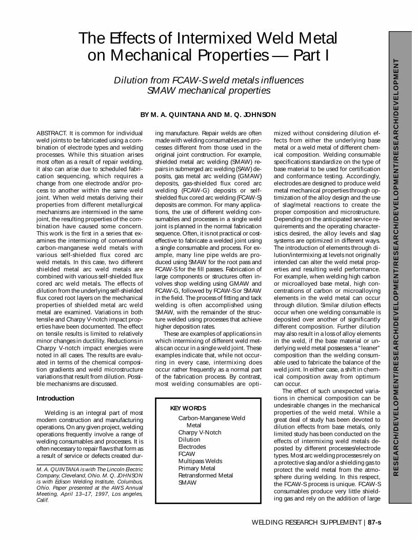
Fig. 6 — Charpy transition curves, E7018 over E70T-4 and E70T-6. Fig. 7 — Charpy transition curves, E7018-1 over E70T-4 and E70T-6.
(A) (B)
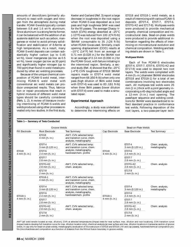
Fig. 8 — Effect of intermixing on Charpy fracture appearance (uniformdeformation typical of CVN fractures on the right, nonuniform deforma-tion typical of intermixed weld metal on the left).

an assessment of grain size as potentialflaw size in a given microstructure wasconsidered more meaningful. Accord-ingly, manual measurement of apparentgrain size was used. This approach con-siders a potential crack length in a givenmicrostructure. In this modified tech-nique, ferrite colonies with an alignedsecond phase are treated as individualgrains. In all other respects, this tech-nique is identical to the three-circlemethod outlined in ASTM E112 (Ref. 8).Microstructures found in the first two lay-ers of weld metal in the maximum dilu-tion region were classified using thecircular intercept procedure for compar-ison purposes. Microstructures found inthe near-surface welds were also clas-sified using the circular intercept pro-cedure. The modified circular interceptprocedure is shown schematically inFig. 2.
As previously mentioned, the weldmetal microstructures found in the regionof maximum dilution consisted almostentirely of reheated (retransformed) weldmetal. Thus, it was difficult to determinewhether or not dilution from the FCAW-Sroot weld metal actually caused any sig-nificant changes in the transformation be-havior of the SMA fill weld metals.Accordingly, the microstructures of theprimary weld metal in the bead-on-platesamples were quantified following theguidelines set forth by IIW (Ref. 7).
Results and Discussion
Strength and Ductility
The tensile test results are presented inTable 2. When comparing undiluted anddiluted weld metal, it is apparent that di-lution from the FCAW-S root layers hadlittle, if any, effect on ultimate tensilestrength, yield point or yield strength.
WELDING RESEARCH SUPPLEMENT | 93-s
RE
SE
AR
CH
/DE
VE
LO
PM
EN
T/R
ES
EA
RC
H/D
EV
EL
OP
ME
NT
/RE
SE
AR
CH
/DE
VE
LO
PM
EN
T/R
ES
EA
RC
H/D
EV
EL
OP
ME
NT
Fig. 9 — Chemical composition profile for E7018 over E70T-4 andE70T-6.
Fig. 10 — Chemical composition profile for E7018-1 over E70T-4 andE70T-6.
(A)
(B)
(C)
50 µm
50 µm
50 µm
(A)
(B)
(C)
50 µm
50 µm
50 µm
Fig. 11 — Microstructures observed in themaximum dilution region in E7018 weldmetal deposited over: A — E7018; B — E70T-4; and C — E70T-6.
Fig. 12 — Microstructures observed in themaximum dilution region in E7018-1 weldmetal deposited over: A — E7018-1; B —E70T-4; and C — E70T-6.
Che
mic
al C
ompo
sitio
n at
.-%
Che
mic
al C
ompo
sitio
n at
.-%
Distance From SMAW/FCAW-S Fusion Boundary (mm) Distance From SMAW/FCAW-S Fusion Boundary (mm)

Variation in tensile properties from onetest weld to another in this regard was onthe same order expected from either ofthe two SMAW electrode deposits with-out dilution effects.
The primary reason for tensile testingwas to examine the possible effects onductility. The FCAW-S electrodes usedfor root welding in this investigation typ-ically produce diffusible hydrogen levelsthat are twice as high as diffusible hy-drogen levels typically produced by theE7018 and E7018-1 electrodes used forthe fill passes. Any detrimental effects ofhydrogen on the tensile properties, if any,could easily be determined from tensileductility measurements, particularly re-duction in area measurements, for the as-welded condition. The tensile ductilityresults are presented graphically in Fig. 3.It is apparent that tensile ductility is notaffected for the E7018-1 deposits, except
in the case of dilution from E70T-7. How-ever, there is a relatively small reductionin ductility in the as-welded conditionas a result of dilution in all of the E7018deposits. Some hydrogen effects (such assmall fisheyes and hydrogen flakes) wereobserved in the fractured tensile speci-mens from these welds. This effect wasmost pronounced in E7018 and E7018-1weld metal deposited over the E70T-7root layers. Comparing results of theE7018/E70T-7 ductility with the E7018baseline weld, elongation decreasedfrom 28 to 20% and the reduction in areadecreased from 74 to 43%. Similarly, forthe E7018-1/E70T-7 compared with theE7018-1 baseline weld, elongation de-creased from 26 to 19% and the reduc-tion in area decreased from 77 to 39%.All evidence of hydrogen effects waseliminated after a standard aging treat-ment. In general, dilution from the
FCAW-S root layers produced no mea-surable effect on strength and only aminor effect on ductility.
Charpy V-Notch Impact Toughness
The most significant effect of dilutionfrom FCAW-S root layers on E7018 andE7018-1 weld metals was a consistentdecrease of CVN impact toughness thatwas measured in regions of maximum di-lution. Test results at two test tempera-tures for E7018 and E7018-1 multipasswelds are presented in Figs. 4 and 5, re-spectively. The average of five measure-ments is represented by each bar shownin the graphs. The average CVN tough-ness at the near surface locations wasfound to be independent of the root elec-trodes used. The variation in near surfacetoughness from one weld to the next wasconsistent with the variation typically ob-
94-s | MARCH 1999
RE
SE
AR
CH
/DE
VE
LO
PM
EN
T/R
ES
EA
RC
H/D
EV
EL
OP
ME
NT
/RE
SE
AR
CH
/DE
VE
LO
PM
EN
T/R
ES
EA
RC
H/D
EV
EL
OP
ME
NT
Table 5 — Relative Fractions of Root/Fill at Root Charpy Locations, Relative Fractions of Primary/Retransformed Metal at Maximum Dilutionand Near Surface Charpy Locations
Root Electrode Max. Dilution Top Surface
Fill Root Sample ID % Root % Fill % Primary % Retransformed % Primary % Retransformed
E70T-4 PV504 70 30 20 80 13 87E70T-7 PV495 67 32 7 93 25 75
E7018-1 E70TG-K2 PV492 60 40 14 86 17 83E70T-6 PV509 50 50 7 93 18 82E71T-8 PV517 50 50 15 85 8 92E7018-1 PV524 N/A N/A 9 91 20 80
E70T-4 PV488 56 44 8 92 24 76E70T-7 PV476 60 40 3 97 3 97
E7018 E70TG-K2 PV478 62 38 5 95 11 89E70T-6 PV470 65 45 3 97 13 87E71T-8 PV473 62 38 5 95 5 957018 PV483 N/A N/A 7 93 2 98
Fig. 13 — Apparent grain size measured in the first layer, second layerand top surface of the E7018 weld metal deposited over the various rootelectrodes.
Fig. 14 — Apparent grain size measured in the first layer, second layerand top surface of the E7018-1 weld metal deposited over the variousroot electrodes.
served for weld metals deposited bythese E7018 and E7018-1 electrodes.
It is noted there is some variation inCVN toughness from one location to an-other within the SMAW baseline welds,as indicated by the first grouping at eachtest temperature in Figs. 4 and 5. Thenear surface location produced consis-tently higher levels of CVN energy thanroot and “maximum dilution” locations,which were nearly equal. This variationwith location in a single weld joint isattributed to differences in toughnessbetween primary and reheated/retrans-formed regions in the same weld metal.
Comparing results for maximum dilu-tion location, both E7018 and E7018-1exhibit a reduction in impact toughnesswhen intermixed with FCAW-S. The re-duction in impact energy correspondswell with a shift in fracture appearance tomore brittle behavior (i.e., lower percentshear). With results for each combinationat only two test temperatures and the typ-ically high scatter in individual CVNmeasurements in the transition region, itwas difficult to quantify the magnitude oftoughness decrease resulting from the in-termixing of weld metals. Therefore, itwas not possible to rank the relative ef-fects of the various FCAW-S on SMAWperformance. It was possible to deter-mine only that there was a significantreduction in the SMAW toughness.
To better characterize the toughnessresponse, full CVN transition curveswere developed for both E7018 andE7018-1 deposited over the E70T-4 andE70T-6 root materials. These two FCAW-S electrodes were selected because theyrepresent extremes in terms of C, Al, Mn,O and N concentrations. Typical compo-sitions for all the various root weld de-posits are given in Table 3, while thechemical compositions of the bead-on-plate weld metals are given in Table 4.The results of CVN testing are presentedin Figs. 6 and 7. When compared toE7018 and E7018-1 weld metals withoutdilution from FCAW-S root passes,intermixing the SMAW/FCAW-S con-sumables caused a shift in the 50% frac-ture appearance transition temperature(FATT) to higher levels, with the E70T-4root passes having a slightly greater effecton the intermixed weld metal toughnessthan the E70T-6. Lower shelf energies areunaffected, while upper shelf energiesare consistently lower for both SMAwelds deposited over these FCAW-S.
Several fractured specimens fromeach CVN curve were selected for frac-tographic analysis. The fracture surfaceswere evaluated in samples tested at tem-peratures within the near transition re-gion (~50% shear) and at temperatures
coincident with the upper shelf of theCVN transition curve. For the SMA weldsintermixed with the E70T-4 and E70T-6FCAW-S, the shear lips and stretch zoneat the notch tip was not uniform. Shearlips were often less pronounced at thebottom surfaces of the CVN sample near-est the FCAW-S root passes. This relativedifference in fracture characteristics is il-lustrated in Fig. 8.
Further, it was noted that fracture ori-gins were located within 1–3 mm of theSMAW/FCAW-S interface in the region ofmaximum dilution. Under most circum-stances, weld fracture is expected to ini-tiate midway along the Charpy notch, atvarying distances from the notch root.Further, it should be noted that each ofthe fracture origins was examined at highmagnification for evidence of initiation atinclusions or other artifacts. None wasfound. All fractures initiated with largecleavage facets without artifacts. In gen-eral, the cleavage facets in the E7018weld metals were larger than those ob-served in the E7018-1 weld metals. In arecent study on the scattering of the localfracture stress, Chen, et al. (Ref. 9), re-ported that most of the initiation sites inC-Mn weld metal originated in the mid-thickness region from 4 to 6 mm (0.157
to 0.236 in.) relative to the bottom surfaceof the CVN specimen. The shift in frac-ture initiation sites from a central locationto a region associated with maximum di-lution of SMAW with FCAW-S stronglysuggests that the region of maximum di-lution is primarily responsible for thedecreased CVN toughness measured inintermixed weld metals. The shift alsosuggests that the effects of intermixingSMAW with E70T-4 and E70T-6 do notextend past the first one or two layers ofSMAW deposited.
The impact toughness in the root re-gions of the groove welds (Figs. 4, 5) alsoserves to illustrate the large influence ofinitiation on CVN energy. As indicated bythe results reported in Table 5, thenotches in these root-location specimenswere comprised of ~60% FCAW-S and~40% SMAW. Since the fractions of
WELDING RESEARCH SUPPLEMENT | 95-s
RE
SE
AR
CH
/DE
VE
LO
PM
EN
T/R
ES
EA
RC
H/D
EV
EL
OP
ME
NT
/RE
SE
AR
CH
/DE
VE
LO
PM
EN
T/R
ES
EA
RC
H/D
EV
EL
OP
ME
NT
(A)
(B)
(C)
10 µm
10 µm
10 µm
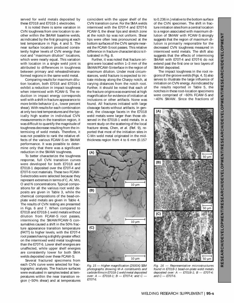
Fig. 15 — Higher magnification (2500X) SEMphotographs showing M-A constituents andcarbide films in E7018-1 weld metal depositedover: A — E7018-1; B — E70T-4; and C —E70T-6.
(A)
(B)
(C)
50 µm
50 µm
50 µm
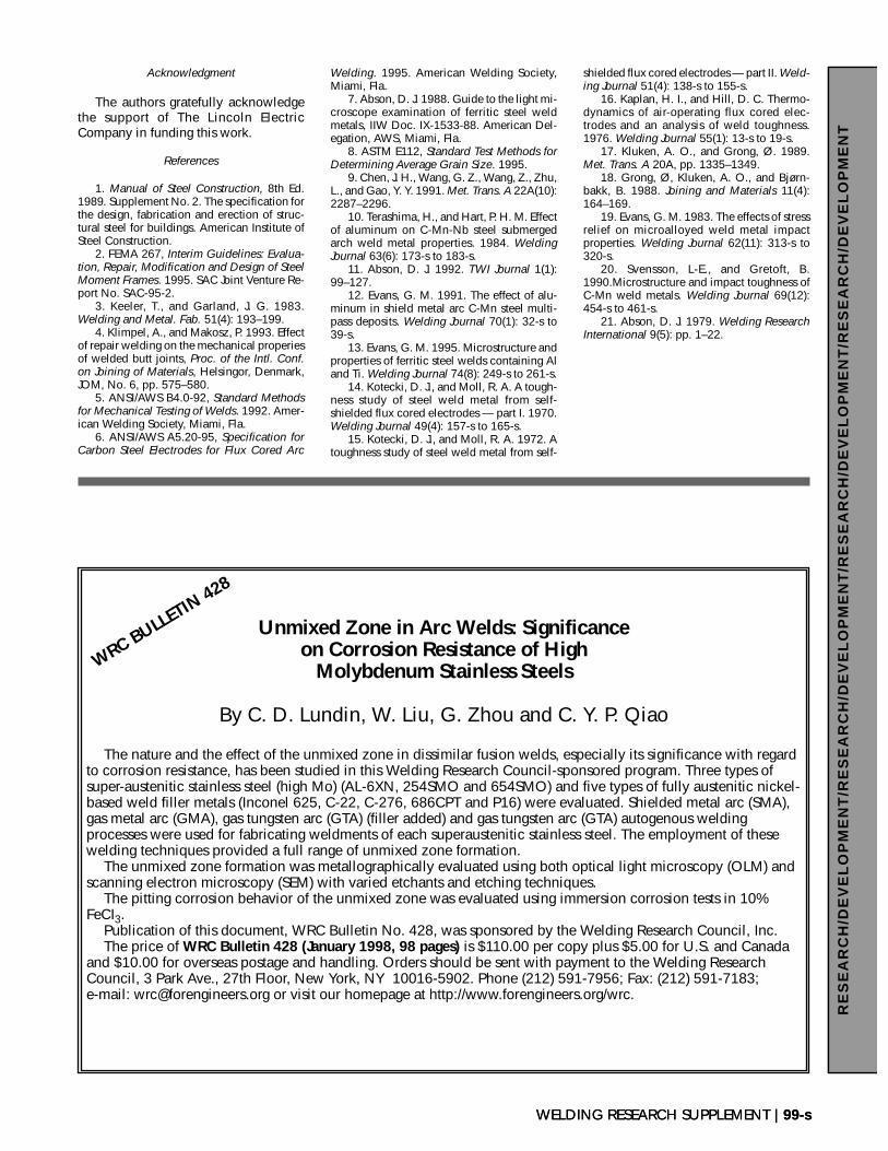
Fig. 16 — Representative microstructuresfound in E7018-1 bead-on-plate weld metalsdeposited over: A — E7018-1; B — E70T-4;and C — E70T-6.

FCAW-S and SMAW in these specimenswere reasonably consistent, it can beconcluded that any toughness changesoccurring at the root location were notstrongly influenced by the minor differ-ences in the proportions of root and fillweld metals. While the potential causesof reduced toughness measured in theroot specimens were not examined ingreat detail, some preliminary conclu-sions can be drawn from the results. Inthe case of the SMAW electrodes de-posited over E70T-4 and E70T-7 FCAW-S,the reduced toughness of the compositeCVN specimen is consistent with thelower toughness typically achieved inE70T-4 and E70T-7 weld deposits. Thissuggests that the lower toughness mate-rial in the composite specimens is pre-dominantly responsible for performanceof the entire specimen. It is important tonote that minimum levels of toughnessare not required for weld deposits pro-duced with E70T-4 or E70T-7 electrodes(Ref. 6). Lower than expected toughnessalso was measured in composite speci-mens containing the SMA weld metaland E70T-6, E70TG-K2 and E71T-8. Inthese cases, the toughness exhibited bythe composite CVN specimens was typi-cally lower than the toughness expectedfor the respective individual weld metals.In several cases, the toughness measuredfor the composite specimens was on thesame order as the toughness measuredfor the maximum dilution locations in thesame welds. This suggests that the dilutedSMA weld metal had a strong influenceon the toughness exhibited by the rootCVN specimens from these welds. Verifi-cation would require additional study, in-cluding fractographic analysis of thebroken specimens. The evidence sug-gests that the toughness in the root spec-
imens was con-trolled by the leasttough weld metalalong the CharpyV-notch in eachcouple.
Chemical Analysis
Considering theresults of chemicalanalyses taken inthe transverse crosssections summa-rized in Table 2, itbecame clear thatreliable and consis-tent measurementof chemical com-position of SMAweld metal directlyabove the FCAW-Sroot was difficult.
In many cases, it appeared that the chem-ical composition of the SMA weld metalsdid not change significantly, when com-pared to the undiluted SMA weld metals.For example, the increase in Al at themaximum dilution location is not consis-tent for E7018 and E7018-1 deposits overthe same FCAW-S root. Some of these in-consistencies arise from the difficulty inprecisely locating a 6-mm (0.25-in.) di-ameter target for emission spectroscopyat the required location in the transverseweld cross sections. Another reason forsuch unexpected results is that the dilu-tion effects did not extend much past thefirst layer of SMAW deposited, while theanalytical techniques employed measurethe composition of a much larger areathan one weld layer. Any potentially sig-nificant changes in composition of thefirst layer would be masked by the aver-aging effect of the larger sample area,providing that the sample area was ontarget.
Consequently, two alternative ap-proaches were taken to determine thechemical composition of the SMA weldmetal in the region of maximum dilution.First, chemical analysis was conductedon longitudinal sections parallel to thetop surfaces of the test welds and abovethe SMAW/FCAW-S fusion boundariesusing emission spectroscopy. These re-sults are presented in Figs. 9 and 10 foreach of the SMAW electrodes depositedover E70T-4 and E70T-6 FCAW-S roots.
The second approach was to examinethe composition of a single E7018 orE7018-1 bead deposited over the variousFCAW-S deposits in the bead-on-plateconfiguration previously described. Thispermitted analysis of a single bead rep-resenting maximum dilution without in-terference from subsequent weld passes.
Comparison of chemical compositionsmeasured in the groove welds (Table 2)with the bead-on-plate welds (Table 3)clearly shows that bulk chemical analy-sis of the region of maximum dilution inthe transverse cross section, normal tothe direction of travel using emissionspectrography, can give results that arenot representative of the maximumdilution weld metal. Considering thebead-on-plate welds, the chemical com-positions measured were consistent withthose predicted from the dilution with theSMA welds. In general, increased alu-minum, nitrogen and carbon (for E70T-7and E70T-4) concentrations were mea-sured. In some combinations, lowermanganese and oxygen concentrationswere measured. Further discussion offactors controlling the chemical compo-sitions of the bead-on-plate welds willfollow in a subsequent paper.
As shown in Figs. 9 and 10, aluminumconcentrations ranging from 0.09–0.22wt-% were measured in the region ofmaximum dilution in the vicinity of theSMAW/FCAW-S fusion boundaries. Sev-eral studies have documented the effectsof aluminum concentration on the tough-ness of SAW (Ref. 10), FCAW-G (Ref. 11),SMAW (Refs. 12, 13) and FCAW-S (Refs.14–16) weld metals. Reviews of thesestudies clearly indicate that except forFCAW-S, aluminum concentrations ex-ceeding 0.05 wt-% are generally detri-mental to weld metal toughness. It isclear that the optimal aluminum concen-trations in weld metals will depend pri-marily on attaining an adequate balanceof aluminum with oxygen and nitrogen.The proposed mechanisms for toughnessreduction with increasing levels of alu-minum include the formation of coarserinclusions and reduction of the titaniumconcentration present on the surfaceof oxide inclusions. The presence oftitanium-rich oxides on the surface ofinclusions is speculated to increase thepotency of inclusions as sites for intra-granular nucleation of ferrite. Addition-ally, several studies have proposeddifferent Al:O ratios and unbalancefactors required for optimal toughness,assuming no other significant Al inter-actions. The aluminum levels in FCAW-Sdeposits are quite high, when comparedto those found in steel-based metals andwelds deposited by other processes.Kotecki (Refs. 14, 15) and Kaplan (Ref.16) both suggest that toughness is de-creased when an excess amount of solu-ble aluminum is present in the weldmetal. Examination of the microstruc-tures and inclusions of this study suggeststhat the mechanism of embrittlementwith high aluminum concentrations is
96-s | MARCH 1999
RE
SE
AR
CH
/DE
VE
LO
PM
EN
T/R
ES
EA
RC
H/D
EV
EL
OP
ME
NT
/RE
SE
AR
CH
/DE
VE
LO
PM
EN
T/R
ES
EA
RC
H/D
EV
EL
OP
ME
NT
Fig. 17 — Bead-on-plate microstructures quantified in the E7018-1 weldmetals deposited over the indicated root electrodes.

different than those reported in studiesusing SAW, FCAW-G and SMAW.
In previous work (Ref. 17) using sub-merged-arc weld metals, the substantialcoarsening of inclusions that occurredwith higher aluminum concentrations(which decreased upper shelf energy andincreased transition temperature) alongwith the decreased amount of acicularferrite were factors thought to causelower toughness in higher aluminumweld metals. Additionally, Grong, et al.(Ref. 18), also suggested that AlN inclu-sions were responsible for cleavage initi-ation in self-shielded flux cored arcwelds when long electrode extensionswere used. It was clear from both thefractographic investigations and the mi-crostructural results in this investigationthat the higher aluminum concentrationsdid not adversely influence the mi-crostructures or promote the formation ofcoarse inclusions that initiated cleavagein the transition region. Note that the Allevels reported in this investigation(0.09–0.22%) are significantly lowerthan ranges studied by other investigators(Refs. 14–16, 18). Review of the literatureshows that very little work has been con-ducted on the toughness of weld metalswith aluminum concentrations in therange found in the intermixed weld met-als reported here.
Calculations of free aluminum in theintermixed weld metals, assuming thataluminum combines preferentially withoxygen and nitrogen to form Al2O3 andAlN, respectively, suggest that substantialquantities of free aluminum should bepresent in E7018/E7018-1 weld metalsdeposited over the E70T-4 and E70T-7root passes. By contrast, most of thealuminum would be combined in E7018/E7018-1 welds deposited over theE70TG-K2, E70T-6 and E71T-8 rootpasses. This calculation is overly conser-vative, since it is likely that the oxide in-clusions are not entirely Al2O3 andsubstantially higher aluminum and nitro-gen concentrations are required for theprecipitation of AlN. Most likely, all ofthe intermixed welds contain an excessof free aluminum and possibly an excessof free nitrogen (since AlN precipitateswere not observed in the intermixed weldmetals at the SEM magnifications used inthis investigation). The most probablereason for the decreased toughness in theintermixed weld metals is the presence ofexcess free aluminum and free nitrogenthat effectively decrease the fracturestress without substantially altering themicrostructure. Although it is generallyaccepted that elevated concentrations offree aluminum are deleterious to tough-ness, there is little, if any, information
available for Al in C-Mn weld metal atlevels above 0.1 wt-%. Any discussionregarding the effects of free aluminum onthe fracture behavior is speculative, atbest, and should be considered as a sub-ject of future research.
Microstructure Analyses
In an effort to understand the reduc-tions in CVN toughness observed, weldmetal microstructures were evaluated atvarious locations in the transverse sec-tions consistent with the CVN locationsfor both SMA weld metals deposited overE70T-4 and E70T-6 root layers. Primaryweld metal is defined as weld metal in amultipass weld that does not reach suffi-cient temperature to cause retransforma-tion to austenite, although it may havebeen reheated. During multipass weld-ing, underlying weld metal is often re-heated to high enough temperatures tocause either partial or complete transfor-mation to austenite. Upon cooling fromthe austenite region, these regions trans-form to a different secondary microstruc-ture than found in the primary weldmetal. For definition purposes, these re-gions will be referred to as retransformedor reheated regions.
In most cases, the amount of primaryweld metal did not exceed 15–20% at themaximum dilution and near surface CVNlocations. Comparison of the intermixedwelds with welds produced entirely ofE7018 or E7018-1 indicates that the re-duced toughness in the regions of maxi-mum dilution was not due to changes inthe relative fractions of primary and re-transformed weld metal.
Microstructures found in the first layerE7018 and E7018-1 weld metals de-posited over selected self-shielded fluxcored arc root welds are shown in Figs.11A–C and 12A–C. The microstructuresshown in Figs. 11 and 12 are representa-tive of microstructures found ahead of theCVN notch in the region of maximum di-lution. These microstructures consist al-most entirely of polygonal ferrite, sincethey represent a region that is almost en-tirely retransformed by subsequent passes.Careful comparison of microstructures inFigs. 11 and 12 reveals that the intermixedweld metal microstructures appear morerefined than microstructures of undilutedweld metals produced entirely with E7018or E7018-1.
As mentioned in the experimental ap-proach section, the apparent grain size ofthe microstructures found in the first layerof intermixed weld metal, second layer ofintermixed weld metal and the near sur-face weld metals were quantified using amodified linear intercept procedure. The
results of the apparent grain size mea-surements are shown graphically in Figs.13 and 14. Figure 13 shows that mi-crostructural refinement occurred in theE7018 weld metal up to the near surfaceregions when diluted with either FCAW-S root material. In contrast, Fig. 14 seemsto indicate that E7018-1 weld metal ex-periences very little change in grain size.Examination of microstructures in thesecond layer up from the E7018-1/E70T-4 and E7018-1/E70T-6 boundaries re-vealed that the effects of dilution with theFCAW-S root deposits had essentially dis-appeared. The microstructures at this lo-cation were essentially identical to thosefound in undiluted E7018-1 weld metals.
Normally, the best way to obtain acombination of high strength and hightoughness is through grain refinement.The classical model of cleavage fracturesuggests that cleavage occurs at a tem-perature where the yield strength ex-ceeds the fracture stress. Considering thatthe fracture stress and yield stress both in-crease with decreasing grain size, in-creased toughness was expected in thesesamples. It is apparent that the toughnessincrease normally experienced withgrain refinement is being offset in theintermixed weld metals by some otherfactor.
In some cases, toughness can be de-creased by the presence of high-volumefractions of second-phase carbides, M-Aconstituent or pearlite colonies that formeither intergranularly or along grainboundaries. To verify if toughness wasdetrimentally influenced by increasedsecond-phase volume fractions, theweld metals found in the region of max-imum dilution were examined at highermagnifications using SEM. Figure 15shows carbide films and M-A con-stituents found in the “maximum dilu-tion” location of undiluted E7018-1weld metal and the maximum dilutionlocations in E7018-1/E70T-4 and E7018-1/E70T-6 intermixed weld metals. It isapparent that the volume fraction of car-bide films in the undiluted E7018-1weld metal was comparable to thatfound in the E7018-1/E70T-4 andE7018-1/E70T-6 weld metals. Similarbehavior was found in the E7018 weldmetals. Point counting at higher magni-fications revealed that the amount ofsecond phase measured in the inter-mixed weld metals was no more than2–4% higher than that found in the un-diluted weld metals. For both fill elec-trodes, it should also be noted that theSMA weld metal deposited over theE70T-6 appeared to be “dirtier” (con-tained more inclusions) than compara-
WELDING RESEARCH SUPPLEMENT | 97-s
RE
SE
AR
CH
/DE
VE
LO
PM
EN
T/R
ES
EA
RC
H/D
EV
EL
OP
ME
NT
/RE
SE
AR
CH
/DE
VE
LO
PM
EN
T/R
ES
EA
RC
H/D
EV
EL
OP
ME
NT

ble weld metal deposited over E70T-4 orundiluted weld metal. However, exami-nation of the CVN fracture surfaces didnot reveal inclusions or second-phaseparticles at cleavage initiation sites justahead of the notches. This would sug-gest that the lower toughness in the in-termixed regions was not due toincreased fractions of AlN or deoxidiza-tion products.
Examination of the primary SMA weldmetals in the region of maximum dilutionwas difficult because of the small beadsize and extensive reheating that oc-curred during weld deposition. As a re-sult, the bead-on-plate welds were usedto characterize the primary weld metalmicrostructures. The microstructuralchanges induced in the E7018 bead-on-plate weld metals as a result of intermix-ing are shown in Fig. 16. The relativeproportions of the various microcon-stituents in the E7018 welds were quan-tified according to the IIW classificationscheme, as shown graphically in Fig. 17.Comparison of the undiluted weld metalmicrostructures (Fig. 16A) with those de-posited over the FCAW-S base shows thatdilution from the FCAW-S promoted mi-crostructural refinement in both SMAweld metals. Acicular ferrite increased atthe expense of both grain boundary fer-rite and aligned ferrite. The increasedacicular ferrite was particularly apparentin the E7018 weld metal, which had only20–30 vol-% acicular ferrite in the undi-luted condition. In addition to mi-crostructural quantification, prioraustenite grain size was measured in thediluted weld metals. Both the SMA weldmetals deposited over the E70T-4 hadfiner prior austenite grain sizes than thosethat were deposited over the E70T-6.
As with the trends in retransformedweld metal microstructures in the re-gions of maximum dilution, the refine-ment of the primary weld metals andincrease in acicular ferrite suggests thattoughness of this region should improverelative to undiluted weld metal. Com-parison of the E7018 and E7018-1 weldmetals shows that less grain boundaryferrite, less aligned ferrite and moreacicular ferrite are associated with theE7018-1 than the E7018. Consequently,the E7018-1 weld metals are expected toexhibit higher toughness based on as-welded microstructure alone. The CVNresults presented here are not consistentwith this expectation because thenotched samples contained retrans-formed weld metal almost exclusively.
The microstructural trends observedin the retransformed weld metals and theprimary bead-on-plate weld metals wereconsistent with those reported by other re-
searchers. Several other researchers havereported improvements in the primaryweld metal microstructures andrefinement of the retransformed weldmetal microstructures with carbon in-creases up to 0.12 wt-% in SMA welds.(Refs. 19–21). Evans (Ref. 19) reportedonly a minor influence of carbon ontoughness of weld metals containing anintermediate range of manganese con-centrations. When manganese concen-trations were optimal, there was littleeffect of carbon on microstructure ortoughness, provided that carbon concen-tration remained less than 0.12 wt-%. In-creasing carbon concentration at highermanganese concentrations (1.8 wt-%) re-sulted in an increased grain boundarycarbide thickness and slightly lowertoughness. Similarly, Svensson andGretoft (Ref. 20) concluded that in-creased carbon concentrations at highermanganese concentrations (~2.2 wt-%Mn) promoted the formation of segre-gated microphases that, along withslightly higher nitrogen concentrations,were believed to decrease weld metaltoughness. Further, several researchers(Refs. 20, 21) report that austenite grainsize decreased with increased carbonconcentration. In the present experi-ment, similar trends were observed in theintermixed weld metals deposited overthe higher carbon FCAW-S root elec-trodes. Given the fact that there was verylittle difference in the volume fraction ofcementite film and M-A constituentamong the various multipass welds, andthat microstructure improved in thebead-on-plate welds when diluted withself-shielded flux cored arc weld metal, itis most likely that transfer of carbon fromthe various root weld metals to the SMAfill passes played only a minor role incontrolling the toughness measured inthe intermixed weld metals.
Summary and Conclusions
1) There was no measurable effect ofdilution from the FCAW-S root layers onultimate tensile strength, yield point oryield strength of the E7018 and E7018-1weld metals. There was a relatively smallreduction in tensile ductility, as mea-sured by reduction in area for the E7018deposits only.
2) Reduction of toughness relative totypical E7018 and E7018-1 performancewas measured in both the maximum di-lution and root location Charpy V-notchtests for all combinations. This study sug-gests that the toughness measured in themaximum dilution and root weld metalswas controlled by fracture initiation inthe lowest toughness region.
3) While a significant reduction in
CVN impact toughness was measured asa result of dilution from FCAW-S rootpasses, both E7018 and E7018-1 elec-trodes are expected to produce impactenergies exceeding 27 J (20 ft-lb) attemperatures as low as –18°C (0° F) whenintermixed with FCAW-S.
4) The major microstructural andcompositional changes occurring as a re-sult of using E7018 and E7018-1 elec-trodes to weld over E70T-4 and E70T-6self-shielded flux cored arc weld metalswere limited only to a small region ofweld metal, typically the first layer de-posited. Toughness of the near surfaceweld metals was essentially identical tothat found in undiluted weld metals, al-though there was evidence of grain re-finement in the E7018 weld metaldeposited over E70T-4 and E70T-6 roots.
5) Microstructural examination ofthese intermixed weld metals did notprovide any clear indication of possiblemechanisms causing the reduced tough-ness. While a slight increase in second-phase carbide content (grain boundarycarbide films, M-A constituent andpearlite) was measured in the intermixedweld metals relative to the undilutedweld metal, the second-phase volumewas not extensive enough to cause theobserved decrease in toughness.
6) Refinement of the reheated weldmetal and increased fractions of acicularferrite in primary weld metal were docu-mented in the weld metals diluted withE70T-4 and E70T-6. Considering that thefracture stress and yield stress both in-crease with decreasing grain size, in-creased toughness was expected. It isapparent that the toughness increase nor-mally experienced with grain refinementwas offset in the intermixed weld metalsby some other factor.
7) It is proposed that the observedtoughness decrease with dilution mayresult from the presence of excess freealuminum and/or free nitrogen, whichthese SMAW deposits are not designed toaccommodate. Speculations regardingthe influence of free aluminum and/orfree nitrogen on fracture stress requireadditional research for resolution.
8) The conclusions and observationspresented here should be considered tobe product specific. There are numerouselectrodes classified under any singleclassification that do not result in thesame weld metal compositions em-ployed in this study. Consequently, otherE7018 and E7018-1 electrodes may notexhibit the same response to intermixingwith the FCAW-S presented here. Thespecific nature of various FCAW-S elec-trodes within a given classification canalso be expected to produce different re-sults in the E7018 and E7018-1 deposits.
98-s | MARCH 1999
RE
SE
AR
CH
/DE
VE
LO
PM
EN
T/R
ES
EA
RC
H/D
EV
EL
OP
ME
NT
/RE
SE
AR
CH
/DE
VE
LO
PM
EN
T/R
ES
EA
RC
H/D
EV
EL
OP
ME
NT
Acknowledgment
The authors gratefully acknowledgethe support of The Lincoln ElectricCompany in funding this work.
References
1. Manual of Steel Construction, 8th Ed.1989. Supplement No. 2. The specification forthe design, fabrication and erection of struc-tural steel for buildings. American Institute ofSteel Construction.
2. FEMA 267, Interim Guidelines: Evalua-tion, Repair, Modification and Design of SteelMoment Frames. 1995. SAC Joint Venture Re-port No. SAC-95-2.
3. Keeler, T., and Garland, J. G. 1983.Welding and Metal. Fab. 51(4): 193–199.
4. Klimpel, A., and Makosz, P. 1993. Effectof repair welding on the mechanical properiesof welded butt joints, Proc. of the Intl. Conf.on Joining of Materials, Helsingor, Denmark,JOM, No. 6, pp. 575–580.
5. ANSI/AWS B4.0-92, Standard Methodsfor Mechanical Testing of Welds. 1992. Amer-ican Welding Society, Miami, Fla.
6. ANSI/AWS A5.20-95, Specification forCarbon Steel Electrodes for Flux Cored Arc
Welding. 1995. American Welding Society,Miami, Fla.
7. Abson, D. J. 1988. Guide to the light mi-croscope examination of ferritic steel weldmetals, IIW Doc. IX-1533-88. American Del-egation, AWS, Miami, Fla.
8. ASTM E112, Standard Test Methods forDetermining Average Grain Size. 1995.
9. Chen, J. H., Wang, G. Z., Wang, Z., Zhu,L., and Gao, Y. Y. 1991. Met. Trans. A 22A(10):2287–2296.
10. Terashima, H., and Hart, P. H. M. Effectof aluminum on C-Mn-Nb steel submergedarch weld metal properties. 1984. WeldingJournal 63(6): 173-s to 183-s.
11. Abson, D. J. 1992. TWI Journal 1(1):99–127.
12. Evans, G. M. 1991. The effect of alu-minum in shield metal arc C-Mn steel multi-pass deposits. Welding Journal 70(1): 32-s to39-s.
13. Evans, G. M. 1995. Microstructure andproperties of ferritic steel welds containing Aland Ti. Welding Journal 74(8): 249-s to 261-s.
14. Kotecki, D. J., and Moll, R. A. A tough-ness study of steel weld metal from self-shielded flux cored electrodes — part I. 1970.Welding Journal 49(4): 157-s to 165-s.
15. Kotecki, D. J., and Moll, R. A. 1972. Atoughness study of steel weld metal from self-
shielded flux cored electrodes — part II. Weld-ing Journal 51(4): 138-s to 155-s.
16. Kaplan, H. I., and Hill, D. C. Thermo-dynamics of air-operating flux cored elec-trodes and an analysis of weld toughness.1976. Welding Journal 55(1): 13-s to 19-s.
17. Kluken, A. O., and Grong, Ø. 1989.Met. Trans. A 20A, pp. 1335–1349.
18. Grong, Ø, Kluken, A. O., and Bjørn-bakk, B. 1988. Joining and Materials 11(4):164–169.
19. Evans, G. M. 1983. The effects of stressrelief on microalloyed weld metal impactproperties. Welding Journal 62(11): 313-s to320-s.
20. Svensson, L-E., and Gretoft, B.1990.Microstructure and impact toughness ofC-Mn weld metals. Welding Journal 69(12):454-s to 461-s.
21. Abson, D. J. 1979. Welding ResearchInternational 9(5): pp. 1–22.
WELDING RESEARCH SUPPLEMENT | 99-sWELDING RESEARCH SUPPLEMENT | 99-s
RE
SE
AR
CH
/DE
VE
LO
PM
EN
T/R
ES
EA
RC
H/D
EV
EL
OP
ME
NT
/RE
SE
AR
CH
/DE
VE
LO
PM
EN
T/R
ES
EA
RC
H/D
EV
EL
OP
ME
NT
Unmixed Zone in Arc Welds: Significanceon Corrosion Resistance of High
Molybdenum Stainless Steels
By C. D. Lundin, W. Liu, G. Zhou and C. Y. P. Qiao
The nature and the effect of the unmixed zone in dissimilar fusion welds, especially its significance with regardto corrosion resistance, has been studied in this Welding Research Council-sponsored program. Three types ofsuper-austenitic stainless steel (high Mo) (AL-6XN, 254SMO and 654SMO) and five types of fully austenitic nickel-based weld filler metals (Inconel 625, C-22, C-276, 686CPT and P16) were evaluated. Shielded metal arc (SMA),gas metal arc (GMA), gas tungsten arc (GTA) (filler added) and gas tungsten arc (GTA) autogenous weldingprocesses were used for fabricating weldments of each superaustenitic stainless steel. The employment of thesewelding techniques provided a full range of unmixed zone formation.
The unmixed zone formation was metallographically evaluated using both optical light microscopy (OLM) andscanning electron microscopy (SEM) with varied etchants and etching techniques.
The pitting corrosion behavior of the unmixed zone was evaluated using immersion corrosion tests in 10%FeCI3.
Publication of this document, WRC Bulletin No. 428, was sponsored by the Welding Research Council, Inc.The price of WRC Bulletin 428 (January 1998, 98 pages) is $110.00 per copy plus $5.00 for U.S. and Canada
and $10.00 for overseas postage and handling. Orders should be sent with payment to the Welding ResearchCouncil, 3 Park Ave., 27th Floor, New York, NY 10016-5902. Phone (212) 591-7956; Fax: (212) 591-7183; e-mail: [email protected] or visit our homepage at http://www.forengineers.org/wrc.
WRC BULLETIN 428
Related Documents