...... Start up guide Specification and installation ARTDriveS-EV Brushless Servodrive XVy-EV

Welcome message from author
This document is posted to help you gain knowledge. Please leave a comment to let me know what you think about it! Share it to your friends and learn new things together.
Transcript
...... Start up guideSpecification and installation
ART
Driv
eS-E
V
Brushless Servodrive
XVy-EV

Thank you for choosing this Gefran-Siei product.
We will be glad to receive any possible information which couldhelp us improving this manual. The e-mail address is thefollowing: [email protected] using the product, read the safety instruction sectioncarefully.)Keep the manual in a safe place and available to engineeringand installation personnel during the product functioning period.Gefran Spa has the right to modify products, data anddimensions without notice.The data can only be used for the product description and theycan not be understood as legally stated properties.All rights reserved.
This manual is updated according to software version 4.0.
NOTE! Refer to the “Drive programmation with MDPlc” (inside the XVytools cd-rom) to use the drive with the Plc function in thededicated MDPlc development environment.
The identification number of the software version can be readon the inverter nameplate or on the label on the FLASHmemories mounted on the regulation card.

ARTDriveS User’s Guide Table of Contents • 3
Tables of ContentsSafety Symbol Legend - Precautions de securité ............................................................ 8Chapter 0 - Safety Precautions ........................................................................................ 9Chapter 1 - Functions and General Features ................................................................. 15
1.1 Motors and Encoders ............................................................................................................... 171.1.1 Motors ................................................................................................................................................... 17
Chapter 2 - Inspection Procedures, Components Identification and StandardSpecifications ............................................................................................... 18
2.1 Delivery Inspection Procedures ................................................................................................ 182.1.1 General ................................................................................................................................................... 182.1.2 Drive type designation ........................................................................................................................... 192.1.3 Nameplate .............................................................................................................................................. 20
Figure 2.1.3.1: Identification nameplate ........................................................................................................................................................ 20Figure 2.1.3.2: Firmware & Card revision level nameplate .............................................................................................................................. 20Figure 2.1.3.3: Nameplates position ............................................................................................................................................................... 20
2.2 Component identification ......................................................................................................... 21Figure 2.2.1: Basic Setup of drive .................................................................................................................................................................. 21Figure 2.2.2: Drive view & components .......................................................................................................................................................... 22
2.3 Standard specifications ........................................................................................................... 232.3.1 Permissible environmental conditions .................................................................................................... 23Disposal of the Device ..................................................................................................................................... 242.3.2 AC Input/Output Connection .................................................................................................................. 24
Table 2.3.2.1: Input / Output Specifications .................................................................................................................................................... 252.3.3 Rated and overload currents .................................................................................................................. 26I x T Algorithm ................................................................................................................................................ 27
Table 2.3.3.1: Rated and overload currents with I x T algorithm ..................................................................................................................... 27I2T Algorithm ................................................................................................................................................ 30
Table 2.3.3.2: Rated and overload currents with I2 x T algorithm ................................................................................................................... 30
Chapter 3 - Installation Guidelines ................................................................................. 343.1 Mechanical Specification ......................................................................................................... 34
Figure 3.1.1: Drive Dimensions, XVy-EV 10306 ... XVy-EV 32550 sizes .......................................................................................................... 34Figure 3.1.2: Drive dimensions, XVy-EV 43570 ... XVy-EV 8280400 sizes ....................................................................................................... 35Figure 3.1.3: Drive dimensions, C and CP sizes .............................................................................................................................................. 36Figure 3.1.4: Drive dimensions, C and CP -IP00 sizes .................................................................................................................................... 36Figure 3.1.5: Drive dimensions, XVy-EV 9470670-DC-IP00 and XVy-EV 9560800-DC-IP00 sizes .................................................................. 37
3.2 Watts Loss, Heat Dissipation, Internal Fans and Minimum Cabinet Opening Suggested for theCooling ................................................................................................................................... 38Table 3.2.1: Heat dissipation and Required Air Flow ....................................................................................................................................... 38Table 3.2.2: Minimum cabinet opening suggested for the cooling ................................................................................................................... 38
3.2.1 Cooling Fans Power Supply .................................................................................................................... 39Figure 3.2.1: UL type fans connections ........................................................................................................................................................... 39Figure 3.2.2: Example for external connection ................................................................................................................................................ 39
3.3 Installation Mounting Clearance .............................................................................................. 40Figure 3.3.1: Max. Angle of Inclination ........................................................................................................................................................... 40Figure 3.3.2: Mounting Clearance .................................................................................................................................................................. 40
Chapter 4 - Wiring Procedure ........................................................................................ 414.1 Accessing the Connectors (IP20 models) ................................................................................ 41
4.1.1 Removing the Covers ............................................................................................................................. 41Figure 4.1.1: Removing the covers (XVy-EV 10306 to XVy-EV 32550 sizes ) ................................................................................................... 41Figure 4.1.2: Removing the covers (XVy-EV 43570 to XVy-EV 9560650 sizes) ............................................................................................... 42
4.1.2. Wiring Suggestion ................................................................................................................................. 424.2 Power Section .......................................................................................................................... 43
4.2.1 Terminal Assignment on Power Section / Cable Cross-Section ............................................................. 43Table 4.2.1.1: Power Section Terminals from XVy-EV 10306 to XVy-EV 32550 ............................................................................................... 43Table 4.2.1.2: Power Section Terminals from XVy-EV 43570 to XVy-EV 9560650 ........................................................................................... 44

4 • Table of Contents ARTDriveS User’s Guide
Table 4.2.1.3: Power Section Terminals XVy-EV ...-IP00 sizes ........................................................................................................................ 44Table 4.2.1.4: Maximum cable cross section for power terminals ................................................................................................................ 45
4.3 Regulation Section ................................................................................................................... 464.3.1 R-XVy-EV Regulation Card ...................................................................................................................... 46
Figure 4.3.1: Connectors Location .................................................................................................................................................................. 47Table 4.3.1.1: Jumpers on Regulation Card .................................................................................................................................................... 47
4.3.2 Terminal Assignments on Regulation Section ........................................................................................ 48Table 4.3.2.1: Plug-in Terminal Strip Assignments on Regulation Card ............................................................................................................ 48Table 4.3.2.2: Maximum permissible cable cross-section on the plug-in terminals of the regulator section .................................................... 49Table 4.3.2.3: Maximum Control Cable Lengths .............................................................................................................................................. 49Figure 4.3.2.1: Potentials of the control section .............................................................................................................................................. 50
4.4 Feedback Devices .................................................................................................................... 51Table 4.4.1: Feedback devices ....................................................................................................................................................................... 51
4.4.1 XE Connector Assignments .................................................................................................................... 52Table 4.4.1.1: XE Connector Assignments ...................................................................................................................................................... 52
4.4.2 XER Encoder Connector Assignments (for auxiliary encoders) .............................................................. 52Table 4.4.2.1: XER Connector Assignments .................................................................................................................................................... 52
4.4.3 Feedback /Drive Connections ................................................................................................................. 53Table 4.4.3.1: Resolver/Encoder jumpers settings .......................................................................................................................................... 53
4.3.3.1 Resolver Connections (RES) ............................................................................................................. 534.4.3.2 Sinusoidal Encoder SinCos Connections (SESC) .............................................................................. 534.4.3.3 Digital Encoder with Hall Effect Sensors Connections (DEHS) ......................................................... 544.4.3.4 Absolute Encoder Connections (SSi / EnDat /Hiperface protocols) .................................................. 554.4.3.5 Encoder /Resolver Specifications (XE connector) ............................................................................. 554.4.3.6 Encoder Simulation / Repetition, Auxiliary Encoder Input (XER/EXP Connector) .............................. 56
4.4.4 Encoder Cable Length ............................................................................................................................. 574.4.5 Checking Encoder / Drive Connections ................................................................................................. 58
4.5 CANopen Connection ............................................................................................................... 594.6 Fast Link Connections .............................................................................................................. 60
Figure 4.6.1: XFL-OUT Connector (FAST LINK Output) .................................................................................................................................... 60Figure 4.6.2: XFL-IN Connector (FAST LINK Input) .......................................................................................................................................... 60
4.6.1 Fast Link Data ........................................................................................................................................ 604.7 Serial Interface ......................................................................................................................... 61
4.7.1 Serial Interface Description .................................................................................................................... 61Figure 4.7.1: RS485 Serial Interface ............................................................................................................................................................... 61
4.7.2 RS 485 Serial Interface Connector Description ...................................................................................... 62Table 4.7.2.1: Assignment of the plug XS connector for the RS 485 serial interface ........................................................................................ 62
4.8 Standard Connection Diagram ................................................................................................. 634.8.1 ARTDriveS Connections ......................................................................................................................... 63
Figure 4.8.1.1: Typical connection .................................................................................................................................................................. 63Figure 4.8.1.2: Typical connection diagram for XVy-EV ...-DC versions. .......................................................................................................... 64
4.8.2 Parallel Connection on the AC (Input) and DC (Intermediate Circuit) Side of Several Drives .................. 65Figure 4.8.2.1: Parallel Connection on the AC and DC Side of Several Drives ................................................................................................. 65
4.9 Circuit Protection ..................................................................................................................... 664.9.1 External Fuses for the Power Section .................................................................................................... 66
Table 4.9.1.1: External Fuse Types for AC input side ....................................................................................................................................... 664.9.2 External Fuses for the Power Section DC Input Side .............................................................................. 67
Table 4.9.2.1: External fuses type for DC input side ........................................................................................................................................ 674.9.3 Internal Fuses ......................................................................................................................................... 68
Table 4.9.3.1: Internal fuses ........................................................................................................................................................................... 68
4.10 Chokes / Filters ...................................................................................................................... 68Figure 4.10.1: Input/output choke dimensions ................................................................................................................................................ 68
4.10.1 AC Input Chokes ................................................................................................................................... 69Table 4.10.1.1: 3-Phase AC Input Chokes ....................................................................................................................................................... 69
4.10.2 Output Chokes ...................................................................................................................................... 69Table 4.10.2.1: Recommended values for output chokes ................................................................................................................................ 70
4.10.3 Interference Suppression Filters .......................................................................................................... 71Table 4.10.3.1: Recommended EMI filters ...................................................................................................................................................... 71Figure 4.10.3.1: Filter dimension .................................................................................................................................................................... 72

ARTDriveS User’s Guide Table of Contents • 5
4.11 Braking Units ......................................................................................................................... 73Figure 4.11.1: Operation with Braking Unit (Principle) .................................................................................................................................... 73
4.11.1 Internal Braking Unit ............................................................................................................................. 73Table 4.11.1.1: Technical data of the internal braking units ............................................................................................................................ 74
4.11.2 Internal and External Braking Resistors ................................................................................................ 74Figure 4.11.2.1: Connection with internal Braking Unit and external braking resistor ...................................................................................... 74Table 4.11.2.1: Lists and technical data of the external standard resistors .................................................................................................... 75Figure 4.11.2.2: External resistors .................................................................................................................................................................. 75Figure 4.11.2.3: Limit operating braking cycle with typical triangular power profile ........................................................................................ 76Figure 4.11.2.4: Braking cycle with TBR / TC = 20% ..................................................................................................................................... 76Figure 4.11.2.5: Generic braking cycle with triangular profile ......................................................................................................................... 77
4.11.3 Control of the External Braking Power .................................................................................................. 784.11.4 External Resistance Interaction with the System Parameters ............................................................. 784.11.5 Choice of the Thermal Relay for Brake Resistor ................................................................................... 78
4.12 Buffering the Regulator Supply .............................................................................................. 80Table 4.12.1: DC Link Buffer Time .................................................................................................................................................................. 80Figure 4.12.1: Buffering the Regulator Supply by Means of Additional Intermediate Circuit Capacitors ........................................................... 81
4.13 Discharge Time of the DC-Link ............................................................................................... 82Table 4.13.1: DC Link Discharge Time ........................................................................................................................................................... 82
Chapter 5 - Sizing Criteria .............................................................................................. 835.1 Motor Check ............................................................................................................................ 845.2 Check of the Drive Size ............................................................................................................ 855.3 Application Example: Flying Cut .............................................................................................. 86
Chapter 6 - Maintenance ................................................................................................ 886.1 Care ......................................................................................................................................... 886.2 Service ..................................................................................................................................... 886.3 Repairs ..................................................................................................................................... 886.4 Customer Service ..................................................................................................................... 88
Chapter 7 - Settings and Commissioning ....................................................................... 897.1 PC Configurator ........................................................................................................................ 897.2 Commissioning ........................................................................................................................ 89
7.2.1 Connection with the PC .......................................................................................................................... 897.2.2 Essential Parameters Set up .................................................................................................................. 917.2.3 Speed Mode Configuration Example ...................................................................................................... 927.2.4 Position Mode Configuration Example .................................................................................................... 937.2.5 Electrical Line Shaft Mode Configuration Example ................................................................................. 94
7.3 Download Firmware ................................................................................................................. 957.4 Automatic Electric Phasing Procedure for Encoder/Resolver ................................................... 96
Chapter 8 - Keypad Operation ........................................................................................ 998.1 Keypad Description .................................................................................................................. 99
8.1.1 LED ......................................................................................................................................................... 998.1.2 Function Keys ....................................................................................................................................... 1008.1.3 Display - Using keypad ......................................................................................................................... 101
Figure 8.1.3.1: Navigation within the menus ................................................................................................................................................ 101
8.2 Keypad operations ................................................................................................................. 1028.2.1 Errors .................................................................................................................................................... 104
Table 8.2.1.1: Errors list ............................................................................................................................................................................... 104
8.3 Alarms and Errors Handling ................................................................................................... 1058.3.1 Alarms (Failure register) ....................................................................................................................... 105
Figure 8.3.1: Led Status and Keypad ............................................................................................................................................................ 105Table 8.3.1.1: Alarms list .............................................................................................................................................................................. 105
8.3.2 Alarm description ................................................................................................................................. 106
Chapter 9 - Block Diagrams ......................................................................................... 109
6 • Table of Contents ARTDriveS User’s Guide
Chapter 10 - Parameters and Functions ....................................................................... 11310.1 Parameters menu ................................................................................................................. 11310.2 Legend ................................................................................................................................. 11510.3 Parameters Description and Functions ................................................................................ 116
MONITOR ......................................................................................................................................... 116SAVE / LOAD PAR ............................................................................................................................ 117DRIVE CONFIG ................................................................................................................................. 118MOTOR DATA ................................................................................................................................... 120ENCODER PARAM ........................................................................................................................... 121RAMP .............................................................................................................................................. 123SPEED .............................................................................................................................................. 124SPD / POS GAIN ............................................................................................................................... 125TORQUE ........................................................................................................................................... 126CURRENT GAINS ............................................................................................................................. 127FLUX ................................................................................................................................................ 128DIGITAL INPUTS ............................................................................................................................... 128DIGITAL OUTPUTS ........................................................................................................................... 136ANALOG INPUTS ............................................................................................................................. 141ANALOG OUTPUTS .......................................................................................................................... 143ENC REPETITION .............................................................................................................................. 145JOG FUNCTION ................................................................................................................................ 146MULTISPEED .................................................................................................................................... 147MULTIRAMP .................................................................................................................................... 148SPEED DRAW .................................................................................................................................. 149MOTOR POT ..................................................................................................................................... 149BRAKE CONTROL ............................................................................................................................. 151POWERLOSS .................................................................................................................................... 152POSITION ......................................................................................................................................... 154EL LINE SHAFT ................................................................................................................................. 176BRAKING RES .................................................................................................................................. 180ALARMS .......................................................................................................................................... 180FIELDBUS ......................................................................................................................................... 183TUNING ............................................................................................................................................ 195KEYPAD PSW ................................................................................................................................... 197SERVICE ........................................................................................................................................... 199
Chapter 11 - Parameters Index .................................................................................... 206IPA ................................................................................................................................................ 206
Chapter 12 - Motor Cables ........................................................................................... 217Figure 12.1: Cable SBM Motor Series / Sinusoidal Encoder ......................................................................................................................... 217Figure 12.2: Cable SBM Motor Series / Digital Encoder + Hall Sensors ...................................................................................................... 218Figure 12.3: Cable SBM Motor Series / Absolute Encoder with SSi - EnDat Protocol ................................................................................... 219Figure 12.4: Cable SBM Motor Series / Resolver ......................................................................................................................................... 220Figure 12.5: Cable SHJ Motor Series / Sinusoidal Encoder .......................................................................................................................... 221Figure 12.6: Cable SHJ Motor Series / Digital Encoder + Hall Sensors ....................................................................................................... 222Figure 12.7: Cable SHJ Motor Series / Resolver .......................................................................................................................................... 223Figure 12.8: SBM 5-7 Motor Series Power Cable ......................................................................................................................................... 224Figure 12.9: SBM 5-7 Motor Series Power + Brake Cable .......................................................................................................................... 225Figure 12.10: SHJ Motor Series Power Cable .............................................................................................................................................. 226Figure 12.11: SHJ Motor Series Brake Cable ............................................................................................................................................... 227
ARTDriveS User’s Guide Table of Contents • 7
Chapter 13 - EMC Directive .......................................................................................... 228Appendix - Field bus and serial interface .................................................................... 229
1.0 Integrated CANopen Interface ........................................................................................... 2291.1 CANopen Functions ............................................................................................................... 229
1.1.1 Pre-defined Master/Slave Connection .................................................................................................. 2291.1.2 NMT Services (Network Management) ............................................................................................... 2291.1.3 Initialization .......................................................................................................................................... 2301.1.4 Communication Object ......................................................................................................................... 230
Table 1.4.1: Communication Objects ............................................................................................................................................................ 2301.1.5 Object Dictionary Elements .................................................................................................................. 231
Table 1.5.1: Objects used by the CANopen communication profile ............................................................................................................... 2311.1.6 Rx PDO Entries ..................................................................................................................................... 2311.1.7 Tx PDO Entries ..................................................................................................................................... 2321.1.8 SDO Entries .......................................................................................................................................... 2321.1.9 COB-ID SYNC Entries ........................................................................................................................... 2321.1.10 COB-ID Emergency ............................................................................................................................. 233
1.2 CANopen Management .......................................................................................................... 2331.3 Process Data Channel Control ................................................................................................ 234
1.3.1 PDC Input Configuration (FB XXX MS Parameter) ................................................................................ 2351.3.2 PDC Output Configuration (FB XXX SM Parameter) ............................................................................. 2361.3.3 Use of the PDC in MDPlc Applications ................................................................................................ 236
1.4 SDO Management .................................................................................................................. 2361.5 Alarms ................................................................................................................................... 238
2.0 Modbus ............................................................................................................................... 2392.1 Modbus Functions ................................................................................................................. 2392.2 Error Management ................................................................................................................. 239
2.2.1 Exception codes ................................................................................................................................... 2392.3 System Configuration ............................................................................................................. 2402.4 Appendix - Register and Coil Modbus Tables ......................................................................... 2402.5 Modbus example ................................................................................................................... 240
03 Read Output register : ........................................................................................................................... 24006 Preset single register : .......................................................................................................................... 24116 Preset multiple registers : ..................................................................................................................... 242
3.0 DeviceNet Interface (XVy-DN) ........................................................................................... 2433.1 DeviceNet General Description .............................................................................................. 2433.2 Connection ............................................................................................................................. 2433.3 Leds ....................................................................................................................................... 243
Table 3.3.1: AL-OP leds status codification ................................................................................................................................................... 243
3.4 Interface ................................................................................................................................. 2443.5 DeviceNet Function ................................................................................................................ 2443.6 Object description .................................................................................................................. 244
3.6.1 Object Model ........................................................................................................................................ 2453.6.2 How Objects Affect Behavior ............................................................................................................... 2453.6.3 Defining Object Interface ...................................................................................................................... 245
3.7 Data transfert via Explicit Messaging .................................................................................... 2463.7.1 Drive Parameter Access ....................................................................................................................... 246
3.7.1.1 Class Code ..................................................................................................................................... 2463.7.1.2 Class attributes .............................................................................................................................. 2463.7.1.3 Instance Attributes ......................................................................................................................... 2463.7.1.4 Common Services .......................................................................................................................... 2463.7.1.5 Object Specific Services ................................................................................................................. 246

8 • Chapter 0 Safety ARTDriveS User’s Guide
Safety Symbol Legend - Precautions de securité
Indicates a procedure, condition, or statement that, if not strictlyobserved, could result in personal injury or death.Indique le mode d'utilisation, la procédure et la conditiond'exploitation. Si ces consignes ne sont pas strictement respectées, ily a des risques de blessures corporelles ou de mort.
Indicates a procedure, condition, or statement that, if notstrictly observed, could result in damage to or destruction ofequipment.Indique et le mode d'utilisation, la procédure et la conditiond'exploitation. Si ces consignes ne sont pas strictement respectées, ily a des risques de détérioration ou de destruction des appareils
Indicates a procedure, condition, or statement that should bebe strictly followed in order to optimize these applications.Indique le mode d'utilisation, la procédure et la condition d'exploitation.Ces consignes doivent être rigoureusement respectées pour optimiserces applications..
NOTE! Indicates an essential or important procedure, condition, orstatement.Indique un mode d'utilisation, de procédure et de condition d'exploitationessentiels ou importants
Warning
Caution
Attention
3.7.1.6 Behavior ......................................................................................................................................... 2463.7.2 Drive Parameter Access ....................................................................................................................... 247
3.7.2.1 Class Code ..................................................................................................................................... 2473.7.2.2 Class attributes .............................................................................................................................. 2473.7.2.3 Instance Attributes ......................................................................................................................... 2473.7.2.4 Common Services .......................................................................................................................... 2473.7.2.5 Object Specific Services ................................................................................................................. 2483.7.2.6 Behavior ......................................................................................................................................... 248
Table 3.7.1: Error codes for the parameter access ....................................................................................................................................... 251Table 3.7.2: Parameter format ...................................................................................................................................................................... 251
3.8 Polling Function ...................................................................................................................... 2523.9 XVy-DN Interface configuration .............................................................................................. 252
3.9.1 Fieldbus Menu ...................................................................................................................................... 2523.9.2 Error Codes ........................................................................................................................................... 252
3.10 Alarms ................................................................................................................................. 2533.10.1 XVy-DN Alarms .................................................................................................................................. 2533.10.2 Drive alarm handling .......................................................................................................................... 2533.10.3 Alarm reset ........................................................................................................................................ 253
3.11 Process Data Channel Control .............................................................................................. 2533.11.1 PDC Input Configuration (SYS_FB_XXX_MS parameter) ................................................................... 2543.11.2 PDC Output Configuration (SYS_FB_XXX_SM Parameter) ............................................................... 2543.11.3 Configuration of the Virtual Digital I/Os ............................................................................................. 2543.11.4 Use of the PDC in MDPlc Applications ............................................................................................... 254

ARTDriveS User’s Guide Chapter 0 Safety • 9
Chapter 0 - Safety Precautions
According to the EEC standards the ARTDRiveS and accessoriesmust be used only after checking that the machine has been pro-duced using those safety devices required by the 89/392/EEC setof rules, as far as the machine industry is concerned. Thesestandards do not apply in the Americas, but may need to beconsidered in equipment being shipped to Europe.Drive systems cause mechanical motion. It is the responsibilityof the user to insure that any such motion does not result in anunsafe condition. Factory provided interlocks and operating limitsshould not be bypassed or modified.Selon les normes EEC, les drives ARTDRiveS et leurs accessoiresdoivent être employés seulement après avoir verifié que la machineait été produit avec les même dispositifs de sécurité demandés par laréglementation 89/392/EEC concernant le secteur de l’industrie.Les systèmes provoquent des mouvements mécaniques. L’utilisateurest responsable de la sécurité concernant les mouvementsmécaniques. Les dispositifs de sécurité prévues par l’usine et leslimitations operationelles ne doivent être dépassés ou modifiés.
Electrical Shock and Burn Hazard:When using instruments such as oscilloscopes to work on liveequipment, the oscilloscope’s chassis should be grounded anda differential amplifier input should be used. Care should beused in the selection of probes and leads and in the adjustmentof the oscilloscope so that accurate readings may be made. Seeinstrument manufacturer’s instruction book for proper operationand adjustments to the instrument.Décharge Èlectrique et Risque de Brúlure :Lors de l’utilisation d’instruments (par example oscilloscope) sur dessystémes en marche, le chassis de l’oscilloscope doit être relié à laterre et un amplificateur différentiel devrait être utilisé en entrée.Les sondes et conducteurs doivent être choissis avec soin poureffectuer les meilleures mesures à l’aide d’un oscilloscope. Voir lemanuel d’instruction pour une utilisation correcte des instruments.
Fire and Explosion Hazard:Fires or explosions might result from mounting Drives in hazard-ous areas such as locations where flammable or combustiblevapors or dusts are present. Drives should be installed away fromhazardous areas, even if used with motors suitable for use in theselocations.Risque d’incendies et d’explosions:L’utilisation des drives dans des zônes à risques (présence de vapeursou de poussières inflammables), peut provoquer des incendies ou desexplosions. Les drives doivent être installés loin des zônesdangeureuses, et équipés de moteurs appropriés.
Warning

10 • Chapter 0 Safety ARTDriveS User’s Guide
Strain Hazard:Improper lifting practices can cause serious or fatal injury. Liftonly with adequate equipment and trained personnel.Attention à l’Élévation:Une élévation inappropriée peut causer des dommages sérieux oufatals. Il doit être élevé seulement avec des moyens appropriés et pardu personnel qualifié.
Drives and motors must be ground connected according to theNEC.Tous les moteurs et les drives doivent être mis à la terre selon le CodeElectrique National ou équivalent.
Replace all covers before applying power to the Drive. Failure todo so may result in death or serious injury.Remettre tous les capots avant de mettre sous tension le drive. Deserreurs peuvent provoquer de sérieux accidents ou même la mort.
Adjustable frequency drives are electrical apparatus for use in in-dustrial installations. Parts of the Drives are energized during op-eration. The electrical installation and the opening of the deviceshould therefore only be carried out by qualified personnel. Im-proper installation of motors or Drives may therefore cause thefailure of the device as well as serious injury to persons or mate-rial damage.Drive is not equipped with motor overspeed protection logic otherthan that controlled by software. Follow the instructions given in thismanual and observe the local and national safety regulations applicable.Les drives à fréquence variable sont des dispositifs électriques utilisésdans des installations industriels. Une partie des drives sont sous ten-sion pendant l’operation. L’installation électrique et l’ouverture desdrives devrait être executé uniquement par du personel qualifié. Demauvaises installations de moteurs ou de drives peuvent provoquerdes dommages materiels ou blesser des personnes.On doit suivir lesinstructions donneés dans ce manuel et observer les régles nationalesde sécurité.
Always connect the Drive to the protective ground (PE) via themarked connection terminals (PE2) and the housing (PE1).Brushless Drives and AC Input filters have ground dischargecurrents greater than 3.5 mA. EN 50178 specifies that withdischarge currents greater than 3.5 mA the protective conductorground connection (PE1) must be fixed type and doubled forredundancy.Il faut toujours connecter le variateur à la terre (PE) par les des bornes(PE2) et le châssis (PE1). Le courant de dispersion vers la terre estsupérieur à 3,5 mA sur les variateurs Brushless et sur les filtres àcourant alterné (CA). Les normes EN 50178 spécifient qu'en cas decourant de dispersion vers la terre, supérieur à 3,5 ma, la mise à laterre (PE1) doit avoir une double connexion pour la redondance.
Warning
ARTDriveS User’s Guide Chapter 0 Safety • 11
The drive may cause accidental motion in the event of a failure,even if it is disabled, unless it has been disconnected from theAC input feeder.En cas de panne, le variateur peut causer une mise en marcheaccidentelle, même s'il est désactivé, sauf s'il a été débranché del'alimentateur à courant alterné.
Never open the device or covers while the AC Input power supplyis switched on. Minimum time to wait before working on the ter-minals or inside the device is listed in section 4.10 on Instructionmanual .Ne jamais ouvrir l’appareil lorsqu’il est suns tension. Le temps mini-mum d’attente avant de pouvoir travailler sur les bornes ou bien àl’intérieur de l’appareil est indiqué dans la section 4.10.
If the front plate has to be removed because of ambienttemperature higher than 40 degrees, the user has to ensure thatno occasional contact with live parts may occur.Si la plaque frontale doit être enlevée pour un fonctionnement avec latempérature de l’environnement plus haute que 40°C, l’utilisateur doits’assurer, par des moyens opportuns, qu’aucun contact occasionnelne puisse arriver avec les parties sous tension.
Do not connect power supply voltage that exceeds the standardspecification voltage fluctuation permissible. If excessive voltageis applied to the Drive, damage to the internal components willresult.Ne pas raccorder de tension d’alimentation dépassant la fluctuationde tension permise par les normes. Dans le cas d’ une alimentation entension excessive, des composants internes peuvent êtreendommagés.
Power supply and groundingIn case of a three phase supply not symmetrical to ground, aninsulation loss of one of the devices connected to the samenetwork can cause functional problem to the drive, if the useof a wye / delta transformer is avoided.1 Gefran-Siei drives are designed to be powered from standard
three phase lines that are electrically symmetrical with respectto ground (TN or TT network).
2 In case of supply with IT network, the use of wye/deltatransformer is mandatory, with a secondary three phase wiringreferred to ground.
Please refer to the following connection sample.
Do not operate the Drive without the ground wire connected. Themotor chassis should be grounded to earth through a ground leadseparate from all other equipment ground leads to prevent noise cou-pling.
Warning

12 • Chapter 0 Safety ARTDriveS User’s Guide
Ne pas faire fonctionner le drive sans prise de terre. Le chassis du moteurdoit être mis à la terre à l’aide d’un connecteur de terre separé desautres pour éviter le couplage des perturbations. Le connecteur de terredevrait être dimensionné selon la norme NEC ou le Canadian Electricalcode.
The grounding connector shall be sized in accordance with theNEC or Canadian Electrical Code. The connection shall be madeby a UL listed or CSA certified closed-loop terminal connectorsized for the wire gauge involved. The connector is to be fixedusing the crimp tool specified by the connector manufacturer.Le raccordement devrait être fait par un connecteur certifié et mentionnéà boucle fermé par les normes CSA et UL et dimensionné pourl’épaisseur du cable correspondant. Le connecteur doit être fixé a l’aided’un instrument de serrage specifié par le producteur du connecteur.
Do not perform a megger test between the Drive terminals or onthe control circuit terminals.Ne pas exécuter un test megger entre les bornes du drive ou entre lesbornes du circuit de contrôle.
Because the ambient temperature greatly affects Drive life andreliability, do not install the Drive in any location that exceeds theallowable temperature. Leave the ventilation cover attached fortemperatures of 104° F (40° C) or below.Étant donné que la température ambiante influe sur la vie et la fiabilitédu drive, on ne devrait pas installer le drive dans des places ou latemperature permise est dépassée. Laisser le capot de ventilation enplace pour températures de 104°F (40°C) ou inférieures.
If the Drive’s Fault Alarm is activated, consult the TROUBLE-SHOOTING section of this instruction book, and after correctingthe problem, resume operation. Do not reset the alarm automati-cally by external sequence, etc.
Caution
Safetyground
L1
L2
L3
Earth
U1/L
1
V1/L
2
W1/L
3
U2/T
1
V2/T
2
W2/T
3
PE
2/
All wires (including motor ground) mustbe connected inside the motor terminal box
AC
OU
TP
UT
CH
OK
E
AC
Main
Supply
AC
INP
UT
CH
OK
E
PE
1/

ARTDriveS User’s Guide Chapter 0 Safety • 13
Si la Fault Alarm du drive est activée, consulter la section du manuelconcernant les défauts et après avoir corrigé l’erreur, reprendre l’opération.Ne pas réiniliatiser l’alarme automatiquement par une séquence externe, etc
Be sure to remove the desicant dryer packet(s) when unpackingthe Drive. (If not removed these packets may become lodged inthe fan or air passages and cause the Drive to overheat).Lors du déballage du drive, retirer le sachet déshydraté. (Si celui-cin’est pas retiré, il empêche la ventilation et provoque une surchauffe dudrive).
The Drive must be mounted on a wall that is constructed of heatresistant material. While the Drive is operating, the temperatureof the Drive's cooling fins can rise to a temperature of 194° F(90°C).Le drive doit être monté sur un mur construit avec des matériauxrésistants à la chaleur. Pendant le fonctionnement du drive, latempérature des ailettes du dissipateur thermique peut arriver à 194°F(90°).
Do not touch or damage any components when handling thedevice. The changing of the isolation gaps or the removing of theisolation and covers is not permissible.Manipuler l’appareil de façon à ne pas toucher ou endommager desparties. Il n’est pas permis de changer les distances d’isolement oubien d’enlever des matériaux isolants ou des capots.
Protect the device from impermissible environmental conditions(temperature, humidity, shock etc.)Protéger l’appareil contre des effets extérieurs non permis(température, humidité, chocs etc.).
No voltage should be connected to the output of the drive (terminalsU2, V2 W2). The parallel connection of several drives via the outputsand the direct connection of the inputs and outputs (bypass) are notpermissible.Aucune tension ne doit être appliquée sur la sortie du convertisseur(bornes U2, V2 et W2). Il n’est pas permis de raccorder la sortie deplusieurs convertisseurs en parallèle, ni d’effectuer une connexiondirecte de l’entrée avec la sortie du convertisseur (Bypass).
A capacitative load (e.g. Var compensation capacitors) should notbe connected to the output of the drive (terminals U2, V2, W2).Aucune charge capacitive ne doit être connectée à la sortie du convertisseur(bornes U2, V2 et W2) (par exemple des condensateurs de mise en phase).
Caution

14 • Chapter 0 Safety ARTDriveS User’s Guide
The electrical commissioning should only be carried out by quali-fied personnel, who are also responsible for the provision of asuitable ground connection and a protected power supply feederin accordance with the local and national regulations. The motormust be protected against overloads.La mise en service électrique doit être effectuée par un personnel qualifié.Ce dernier est responsable de l’existence d’une connexion de terreadéquate et d’une protection des câbles d’alimentation selon les pre-scriptions locales et nationales. Le moteur doit être protégé contre lasurcharge
No dielectric tests should be carried out on parts of the drive. Asuitable measuring instrument (internal resistance of at least 10kΩΩΩΩΩ/////V) should be used for measuring the signal voltages.Il ne faut pas éxécuter de tests de rigidité diélectrique sur des parties duconvertisseurs. Pour mesurer les tensions, des signaux, il faut utiliserdes instruments de mesure appropriés (résistance interne minimale 10kΩ/V).
NOTE! If the Drives have been stored for longer than two years, the operationof the DC link capacitors may be impaired and must be “reformed”.Before commissioning devices that have been stored for long periods,connect them to a power supply for two hours with no load connectedin order to regenerate the capacitors, (the input voltage has to beapplied without enabling the drive).En cas de stockage des variateurs pendant plus de trois ans, il estconseillé de contrôler l'état des condensateurs CC avant d'en effectuerle branchement. Avant la mise en service des appareils, ayant étéstockés pendant longtemps, il faut alimenter variateurs à vide pendantdeux heures, pour régénérer les condensateurs : appliquer une tensiond'alimentation sans actionner le variateur .
NOTE! The terms “Inverter”, “Controller” and “Drive” are sometimes usedinterchangably throughout the industry. We will use the term “Drive” inthis document.Les mots “Inverter”, “Controller” et “Drive” sont interchangeables dansle domaine industriel. Nous utiliserons dans ce manuel seulement lemot “Drive”.
Caution

ARTDriveS User’s Guide Chapter 1 Functions and General Features • 15
Chapter 1 - Functions and General Features
ARTDriveS represents a new concept in motion control technology; thisvery fast servodrive based on the DSP (digital signal processor)VECONTM is aimed at providing real-time control of servosystems andit is integrated with versatile and innovative power hardware.
ARTDriveS is an IGBT servodrive particularly suitable for high band-width applications with brushless servomotors. Thanks to the innovativesoftware installed on the flash eprom, it can be considered as a combi-nation of a digital drive and a PLC using a special software tool calledE@syDrives.
ARTDriveS features full-digital regulation with a 16KHz cycle, a 5KHzcurrent loop bandwidth, a position loop with zero tracking failure, ananalog interface, some dedicated digital interface and I/O expansion.
The drive position loop, (PI type) is based on two symmetrical registercircuits, which store the desired and the actual information. The PIDspeed loop (a position loop derivative) and the PID2 acceleration control(a second position loop derivative) are added to increase the accuracyof the controlled axes, both in a feedback and in a feedforward condition.
The drive has the following features:• Torque control• Speed control• Position control• Electrical line shaft• PID function.• Brake control.• Flux reduction.• Motor-driven potentiometer• Sequential position control (multi-position controller)• Power interrupt management• Linear motor control• Plc functions with MDPlc dedicated software environment; stand-
ard languages according to IEC 61131• “E@syDrives” Windows ® configurator via Slink3 protocol• 1 configurable main encoder / resolver input• 1 configurable auxiliary encoder input / encoder repetition / simula-
tion output• 2 analog differential inputs (11 bits + sign)• 2 analog outputs (11 bits + sign)• 7 programmable digital inputs• 6 programmable digital outputs• 1 digital relay output 1A 250V• RS485 asynchronous opto-isolated multi-drop serial port• 2 fast synchronous serial ports for a master-slave communications
between drives (Fast Link connectors)• Fiber optical communication adapters

16 • Chapter 1 Functions and General Features ARTDriveS User’s Guide
• Standard Fieldbus communication: CANopen, Modbus and (only onXVy ....-...-PDP drive) Profibus-DP
• IP20 (NEMA 1) protection, book case, removable connectors, serialencoder interface brought out via 1/2 D-sub connectors, ground con-nection screws for shielded cables mounted on board.
Options (Maximum one expansion card per drive)
• ENC-ADPT card. Encoder connection adapter.Terminals 1 to 15 with point-to-point connection to the VGA-typeconnector.
• EXP-ABS-EV card. Expansion card for absolute encoder with SSI /EnDat and Hyperface protocols.
• EXP-FO card. Expansion card for a digital encoder output + 5V.• EXP-E card. Expansion card for a digital encoder output + 5V… +15V /
+24V• EXP-D8R4 card. Expansion card for digital I/Os, 8 inputs + 4 outputs.• EXP-D8-120 card. Expansion card for digital I/Os: 12 digital inputs, opto-
isolated, 120V, 8 digital outputs, opto-isolated, 15…30V.• EXP-D14-A4F card. Expansion card for digital I/Os, 8 inputs + 6 outputs,
2 analogue inputs ±10V or 0÷20mA or 4÷20mA, 2 analogue outputs±10V, 1 input in opto-isolated frequency for encoder, channels: A/A-,with +5V or 15..24V, 150kHz max; B/B-, with +5V or 15..24V, 150kHzmax; 0/0-, with +5V or 15..24V, 150kHz max; zero reset input (C/C-)with 15...30V. (1) .
• EXP-D16 card. Expansion card for digital I/Os: 8 digital outputs, opto-isolated, 15…30V, 8 digital inputs, opto-isolated, 15…30V.
• EXP-D20-A6 card. Expansion card for digital I/Os: 12 digital inputs, opto-isolated, 15…30V, 8 digital outputs, opto-isolated, 15…30V, 2 analogueinputs, ±10V / 0…20mA, 2 analogue outputs, ±10V, 2 analogue outputs,0…20mA.
• EXP-F2E card. Expansion card for an opto-isolated encoder input, ableto provide the repeat of the encoder data.Channels: A/A-, with +5V or 15..24V, 150kHz max; B/B-, with +5V or15..24V, 150kHz max; C/C-, with +5V or 15..24V, 150kHz max; zeroreset input (QC+ / QC- denied) with 15...30V (1)
• EXP-FI card. Opto-isolated encoder input expansion card. Channels:A/A-, with +5V or 15..24V, 150kHz max; B/B-, with +5V or 15..24V,150kHz max; 0/0-, with +5V or 15..24V, 150kHz max; zero reset input(C/C-) with 15...30V. (1) .
• EXP-FIO card. Expansion card for an opto-isolated encoder input, ableto provide the repeat of the encoder data. Channels: A/A-, with +5V or15..24V, 150kHz max; B/B-, with +5V or 15..24V, 150kHz max; 0/0-,with +5V or 15..24V, 150kHz max. (1) .
• EXP-FIH card. Opto-isolated encoder input expansion card. Channels:A/A-, with 15..24V, 150kHz max; B/B-, with 15..24V, 150kHz max. (1) .
NOTE! (1) If a supplementary type digital encoder is used (A, Anot, B, Bnot),the encoder missing signal is available.
ARTDriveS User’s Guide Chapter 1 Functions and General Features • 17
1.1 Motors and EncodersThe ARTDriveS drives are designed for the field oriented regulation ofbrushless servomotors. A sinusoidal - digital - absolute encoder orresolver can be used to feedback a signal to the position / speed regulator(see chapter 4.4. for more details).
1.1.1 MotorsWhat motor data is required for connecting the drive?Nameplate specifications- Motor rated voltage- Motor rated current- Number of poles- Motor rated speed- Motor thermal protection type
Motor protection
ThermistorsPTC thermistors according to DIN 44081 or 44082 fitted in the motor canbe connected directly to the drive via PIN 2 and PIN 7 of the XE connector.PTC type of sensor must be selected in the MOTOR DATA menu , IPA20004 = [0] PTC.
Temperature-dependent contacts in the motor windingTemperature-dependent contacts "Klixon" type can be connected directlyto the drive via PIN2 and PIN 7 of the XE connectors. Klixon type ofsensors must be selected in the MOTOR DATA menu.
NOTE! The motor PTC interface circuit (or Klixon) has to be considered astreated as signal circuit. The connection cables to the motor PTC mustbe made of twisted pair shielded cable; the cable route should not beparallel to motor cables or it must be separated by at least 20 cm.

18 • Chapter 2 Inspection ... and Standard Specification ARTDriveS User’s Guide
Chapter 2 - Inspection Procedures, ComponentsIdentification and Standard Specifications
2.1 Delivery Inspection Procedures2.1.1 GeneralA high degree of care is taken in packing the ARTDriveS drives andpreparing them for delivery. They should only be transported with suitabletransport equipment (see weight data). Observe the instructions printedon the packaging. This also applies when the device is unpacked andinstalled in the control cabinet.
Upon delivery, check the following:• the packaging for any external damage• whether the delivery note matches your order.Open the packaging with suitable tools. Check whether:• any parts were damaged during transport• the device type corresponds to your order
In the event of any damage or of an incomplete or incorrect deliveryplease notify the responsible sales offices immediately.The devices should only be stored in dry rooms within the specifiedtemperature ranges .
NOTE! A certain degree of moisture condensation is permissible if this arisesfrom changes in temperature (see section 2.3.1, “Permissible Environ-mental Conditions”). This does not, however, apply when the devicesare in operation. Always ensure that there is no moisture condensationin devices that are connected to the power supply!

ARTDriveS User’s Guide Chapter 2 Inspection ... and Standard Specification • 19
2.1.2 Drive type designationThe main technical characteristic of the drive are showed in the productcode and in the nameplate. I.e. product code:
Standard sizesXVy-EV X XX XX-XXX-PDP
Drive Series XVy EvolutionEnclosure dimension identificationRated current (A rms)Maximum output current (A rms, see table 2.3.3.1)K=Keypad, X=without keypadB=Internal Brake Unit, X= without brake unitSoftware versionPDP = Includes Profibus DP interface card
Example: XVy-EV10306-KBXDrive type XVy-EV, size 1, rated current 3 A rms, max output current 6 A rms, with keypad, internalbraking unit, standard software.
Compact sizes (C/CP)XVy-EV X XXX XXX-X-XXX-PDP-IP00
Drive Series XVy EvolutionEnclosure dimension identificationRated current (A rms)Maximum output current (A rms, see table 2.3.3.1)C/CP=compact versionK=Keypad, X=without keypadB=Internal Brake Unit, X= without brake unitSoftware versionPDP = Includes Profibus DP interface cardOpen housing IP00
Example: XVy-EV9470650-C-KBX-IP00Drive type XVy-EV, size 9, rated current 470 A rms, max output current 650 A rms, with keypad,internal braking unit, standard software, IP00 open housing.
Slim sizesXVy-EV X S XXX XXX-XXX-PDP
Drive Series XVy EvolutionEnclosure dimension identificationS= Slim versionRated current (A rms)Maximum output current (A rms, see table 2.3.3.1)K=Keypad, X=without keypadB=Internal Brake Unit, X= without brake unitSoftware versionPDP = Includes Profibus DP interface card
Example: XVy-EV5S100180-KBX-PDPDrive type XVy-EV, size 5, rated current 100 A rms, max output current 180 A rms, with keypad,internal braking unit, standard software, with Profibus DP interface card.

20 • Chapter 2 Inspection ... and Standard Specification ARTDriveS User’s Guide
2.1.3 NameplateCheck that all the data stated in the nameplate enclosed to the drivecorrespond to what has been ordered.
Figure 2.1.3.1: Identification nameplate
Type : XVy-EV 10306 -KBX AC servo S/N 02006233
Inp: 230-480 Vac (Fctry Set=400) 50/60Hz 3Ph
2.9A@230Vac 2.9A@480Vac With line choke
Out : 0-480Vac 0-450Hz 3Ph 1.5kW@480Vac 2Hp@480Vac
3A@230V Cont. Serv. 2.6A@480V
LISTED
INDUSTRIAL CONTROL EQUIPMENTLL
Type: Drive modelS/N: Serial numberMain Power In: Power supply voltage, AC Input current, FrequencyMain Power Out: Output voltage, Output current, Output frequency
Figure 2.1.3.2: Firmware & Card revision level nameplate
Firmware HW release S/N Prod.
Release D F P R S BU SW. CFG CONF
2.300 0.A 0.A 0.A 2.300 A1
02006233
Figure 2.1.3.3: Nameplates position
ARTDriveS User’s Guide Chapter 2 Inspection ... and Standard Specification • 21
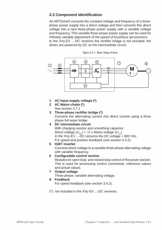
2.2 Component identificationAn ARTDriveS converts the constant voltage and frequency of a three-phase power supply into a direct voltage and then converts this directvoltage into a new three-phase power supply with a variable voltageand frequency. This variable three-phase power supply can be used forinfinitely variable adjustment of the speed of brushless servomotors.In the XVy-EV ...-DC versions the rectifier bridge is not included: thedrives are powered by DC on the intermediate circuit.
Figure 2.2.1: Basic Setup of drive
1 AC Input supply voltage (*)2 AC Mains choke (*)
See section 4.7.13 Three-phase rectifier bridge (*)
Converts the alternating current into direct current using a threephase full wave bridge.
4 DC intermediate circuitWith charging resistor and smoothing capacitor.Direct voltage (UDC) = √2 x Mains voltage (ULN)In the XVy-EV ...-DC versions the DC voltage = 600 Vdc.For speed and position feedback (see section 3.4.2).
5 IGBT inverterConverts direct voltage to a variable three-phase alternating voltagewith variable frequency.
6 Configurable control sectionModules for open-loop and closed-loop control of the power section.This is used for processing control commands, reference valuesand actual values.
7 Output voltageThree-phase, variable alternating voltage.
8 FeedbackFor speed feedback (see section 3.4.2).
(*) not included in the XVy-EV ...-DC versions.
22 • Chapter 2 Inspection ... and Standard Specification ARTDriveS User’s Guide
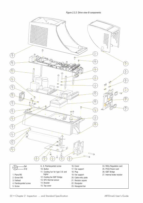
Figure 2.2.2: Drive view & components
1. Piana M52. Grover M53. Fairlead4. Flamboyanted screw5. Screw
6...9. Flamboyanted screw10. Button11. Cooling fun for type 3-6 and
higher12. Cooling fan IGBT Bridge13. NTC thermal sensor14. Bracket15. Top cover
16. Cover17. Fan support18. Plug19. Fan support20. Cable entry plate21. Resistor square22. Dissipator23. Hexagonal bar
24. RXVy Regulation card25. PV33 Power card26. IGBT Bridge27. Internal brake resistor
6 Ref.4 Q.ty
ARTDriveS User’s Guide Chapter 2 Inspection ... and Standard Specification • 23
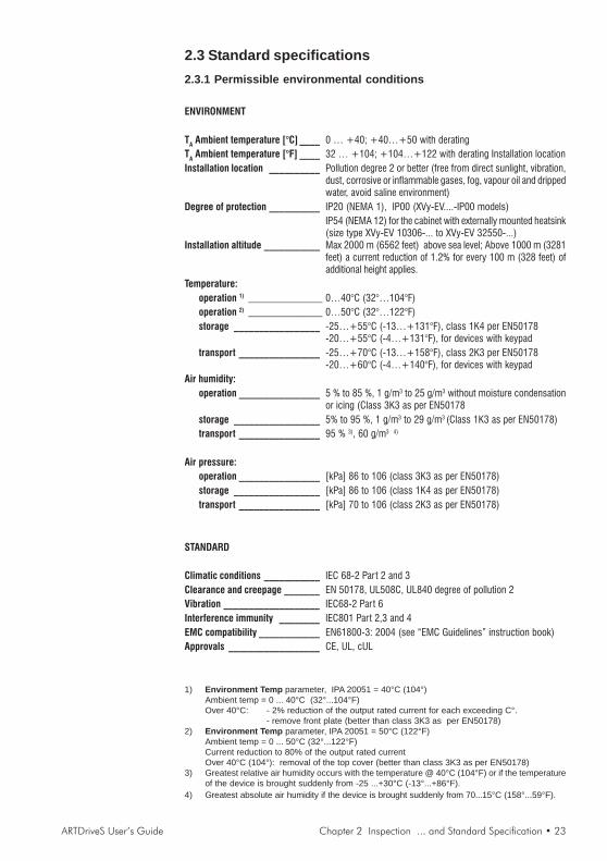
2.3 Standard specifications2.3.1 Permissible environmental conditions
ENVIRONMENT
TA Ambient temperature [°C] ____ 0 … +40; +40…+50 with deratingTA Ambient temperature [°F] ____ 32 … +104; +104…+122 with derating Installation locationInstallation location __________ Pollution degree 2 or better (free from direct sunlight, vibration,
dust, corrosive or inflammable gases, fog, vapour oil and drippedwater, avoid saline environment)
Degree of protection __________ IP20 (NEMA 1), IP00 (XVy-EV....-IP00 models)IP54 (NEMA 12) for the cabinet with externally mounted heatsink(size type XVy-EV 10306-... to XVy-EV 32550-...)
Installation altitude ___________ Max 2000 m (6562 feet) above sea level; Above 1000 m (3281feet) a current reduction of 1.2% for every 100 m (328 feet) ofadditional height applies.
Temperature:operation 1) _________________________ 0…40°C (32°…104°F)operation 2) _________________________ 0…50°C (32°…122°F)storage _________________ -25…+55°C (-13…+131°F), class 1K4 per EN50178
-20…+55°C (-4…+131°F), for devices with keypadtransport ________________ -25…+70°C (-13…+158°F), class 2K3 per EN50178
-20…+60°C (-4…+140°F), for devices with keypadAir humidity:
operation ________________ 5 % to 85 %, 1 g/m3 to 25 g/m3 without moisture condensationor icing (Class 3K3 as per EN50178
storage _________________ 5% to 95 %, 1 g/m3 to 29 g/m3 (Class 1K3 as per EN50178)transport ________________ 95 % 3), 60 g/m3 4)
Air pressure:operation ________________ [kPa] 86 to 106 (class 3K3 as per EN50178)storage _________________ [kPa] 86 to 106 (class 1K4 as per EN50178)transport ________________ [kPa] 70 to 106 (class 2K3 as per EN50178)
STANDARD
Climatic conditions ___________ IEC 68-2 Part 2 and 3Clearance and creepage _______ EN 50178, UL508C, UL840 degree of pollution 2Vibration ___________________ IEC68-2 Part 6Interference immunity ________ IEC801 Part 2,3 and 4EMC compatibility ____________ EN61800-3: 2004 (see “EMC Guidelines” instruction book)Approvals __________________ CE, UL, cUL
1) Environment Temp parameter, IPA 20051 = 40°C (104°)Ambient temp = 0 ... 40°C (32°...104°F)Over 40°C: - 2% reduction of the output rated current for each exceeding C°.
- remove front plate (better than class 3K3 as per EN50178)2) Environment Temp parameter, IPA 20051 = 50°C (122°F)
Ambient temp = 0 ... 50°C (32°...122°F)Current reduction to 80% of the output rated currentOver 40°C (104°): removal of the top cover (better than class 3K3 as per EN50178)
3) Greatest relative air humidity occurs with the temperature @ 40°C (104°F) or if the temperatureof the device is brought suddenly from -25 ...+30°C (-13°...+86°F).
4) Greatest absolute air humidity if the device is brought suddenly from 70...15°C (158°...59°F).

24 • Chapter 2 Inspection ... and Standard Specification ARTDriveS User’s Guide
Disposal of the DeviceThe drive can be disposed as electronic scrap in accordance with thecurrently valid national regulations for the disposal of electronic parts.The plastic covers of the Drives (up to size XVy-EV 32550-...) arerecyclable: the material used is >ABS+PC< .
2.3.2 AC Input/Output ConnectionThe drive must be connected to an AC mains supply capable of deliveringa symmetrical short circuit current (at 480V +10% Vmax) lower or equalto the values indicated on following table. For the use of an AC inputchoke see chapter 4.7.1.No external connection of the regulator power supply to the existing ACInput supply is required since the power supply is taken from the DCLink circuit. When commissioning, set the Mains voltage parameter tothe value of the AC Input voltage concerned. This automatically sets thethreshold for the Undervoltage alarm at the appropriate level. All drivesare capable of operation at 480 Vac, therefore cannot be damaged byconnection to lower voltages down to 208Vac. After connection, simplyselect in the menu the proper line voltage under “Drive Config”
NOTE! In some cases AC Input chokes, and possibly noise suppression filtersshould be fitted on the AC Input side of the device. See chapter “Chokes/Filters”.
Adjustable Frequency Drives and AC Input filters have ground dischargecurrents greater then 3.5 mA. EN 50178 specifies that with dischargecurrents greater than 3.5 mA the protective conductor ground connec-tion (PE1) must be fixed type.
XVy-EV ...-DC versionsIn this version, the drive must be powered by a rectified DC supply of600 Vdc.The use of Gefran-Siei SM32 series power supplies is recommendedfor this, available with an output current from 185 to 2000A.

ARTDriveS User’s Guide Chapter 2 Inspection ... and Standard Specification • 25
Table 2.3.2.1: Input / Output Specifications
Typ
e-
XV
y-E
V
10306
10408
10612
20816
21020
21530
32040
32550
43366
43570
44590
455110
570140
5100180
5S100180
6125230
6S125230
7145290
7190350
7S190350
7230420
7S230420
8280400
8350460
9470670
9470650-C
9560800
9560650
-CP
Invert
er
Ou
tpu
tfo
rco
nti
nu
ou
s
serv
ice,IE
C146
cla
ss
1[k
VA
]2.1
3.1
4.2
5.5
7.6
10.3
14.1
20.1
22.9
27
36.7
45
55.4
67.2
67.2
86.6
110
132
132
159
159
194
242
326
326
388
388
PN
Ou
tpu
tp
ow
er
for
co
nti
nu
ou
sserv
ice
(reco
mm
en
ded
mo
tor
ou
tpu
t),IE
C146
cla
ss
1:
@U
LN=
230V
ac;f S
W=
defa
ult
[kW
]0.7
51.1
1.5
2.2
34
5.5
7.5
911
18.5
22
22
30
30
37
55
55
55
75
75
90
100
125
125
160
160
@U
LN=
400V
ac;f S
W=
defa
ult
[kW
]1.5
2.2
34
5.5
7.5
11
15
18.5
22
30
37
45
55
55
75
90
110
110
132
132
160
200
250
250
315
315
@U
LN=
460V
ac;f S
W=
defa
ult
[Hp]
23
35
7.5
10
15
20
25
30
40
50
60
75
75
100
125
150
150
175
175
200
250
300
300
350
350
U2
Max
ou
tpu
tvo
ltag
e[V
rms]
f 2M
ax
ou
tpu
tfr
eq
uen
cy
[Hz]
400
400
400
400
400
400
200
400
200
400
400
200
200
200
200
I 2N
Co
nti
nu
ou
so
utp
ut
cu
rren
tfo
rco
nti
nu
ou
sserv
ice,IE
C146
cla
ss
1:
@U
LN=
230-4
00V
ac;f S
W=
defa
ult
[Arm
s]
34.5
68
10.9
14.8
20.3
29
33
39
53
65
80
97
97
125
159
190
190
230
230
--
--
--
@U
LN=
400V
ac;f S
W=
defa
ult
[Arm
s]
34.5
68
10.9
14.8
20.3
29
33
39
53
65
80
97
97
125
159
190
190
230
230
280
350
470
470
560
560
@U
LN=
460V
ac;f S
W=
defa
ult
[Arm
s]
2.6
3.9
5.2
710.5
12.9
18.9
26.1
28.7
33.9
46.1
56.5
69.6
84.4
84.4
108.7
138.3
165.3
165.3
200
200
243.6
305
408
470
548.8
487.2
f SW
sw
itch
ing
freq
uen
cy
(Defa
ult
)[k
Hz]
24
2
f SW
sw
itch
ing
freq
uen
cy
(Hig
her)
[kH
z]
28
2
Iovld
(Ix
t)[A
rms]
Dera
tin
gfa
cto
r:
KV
at460/4
80V
ac
0.9
60.8
70.9
30.9
0
KT
for
am
bie
ntte
mpera
ture
KF
for
sw
itchin
gfr
equency
UL
NA
CIn
pu
tvo
ltag
e(1
)[V
rms]
FL
NA
CIn
pu
tfr
eq
uen
cy
[Hz]
I NA
CIn
pu
tcu
rren
tfo
rco
nti
nu
ou
sserv
ice,IE
C146
cla
ss
1:
-C
onnection
with
3-p
hase
choke
@230V
ac
[Arm
s]
2.9
45.5
7.0
9.5
14
18.2
25
33
39
55
69
84
98
98
122
158
192
192
231
231
n.a
.n.a
.n.a
.n.a
.n.a
.n.a
.
@400V
ac
[Arm
s]
3.3
4.5
6.2
7.9
10.7
15.8
20.4
28.2
35
44
62
77
94
110
110
137
177
216
216
242
242
309
362
(2)
520
(2)
(3)
600
(3)
@460V
ac
[Arm
s]
2.9
3.9
5.4
6.5
9.3
13.8
17.8
24.5
39
37
53
66
82
96
96
120
153
188
188
210
210
268
316
(2)
468
(2)
(3)
540
(3)
-C
onnection
without3-p
hase
choke
@230V
ac
[Arm
s]
4.4
6.8
7.9
13.1
15.5
21.5
27.9
35.4
@400V
ac
[Arm
s]
4.8
7.4
914.3
16.9
24.2
30.3
40
@460V
ac
[Arm
s]
4.2
6.4
7.8
12.1
14.7
21
26.4
34.8
Max
sh
ort
cir
cu
itp
ow
er
wit
ho
ut
lin
ere
acto
r(Z
min
=1%
)[k
VA
]210
310
420
550
760
1.0
30
1410
2010
2290
2700
3670
4.5
00
5540
6720
6720
8660
11100
13200
13200
15900
15900
19400
24200
32600
32600
38800
38800
Overv
olt
ag
eth
resh
old
[V]
Bra
kin
gIG
BT
Un
it
(sta
nd
ard
dri
ve)
txv0
01
0
Exte
rnalbra
kin
gunit
(optional)
Option
inte
rnal(w
ith
exte
rnal
resis
tor)
;B
rakin
gto
rque
150%
0.7
for
hig
her
f SW
230
V-1
5%
...480
V+
10%
,3P
h400
V-1
5%
...480
V+
10%
,3P
h
820
VD
C
406
VD
C(f
or
415
VA
Cm
ain
s),
431
VD
C(f
or
440
VA
Cm
ain
s),
450
VD
C(f
or
480
VA
Cm
ain
s)
[V]
44
2
42
OU
TP
UT
IN
PU
T
Un
derv
olt
ag
eth
resh
old
50/6
0H
z±5%
0.9
8x
UL
N(A
CIn
putvoltage)
450
8
8
For
these
types
an
exte
rnalin
ducta
nce
ism
andato
ry
See
table
2.3
.3.1
Sta
ndard
inte
rnal;
Bra
kin
gto
rque
150%
225
VD
C(f
or
230
VA
Cm
ain
s),
372
VD
C(f
or
380
VA
Cm
ain
s),
392
VD
C(f
or
400
VA
Cm
ain
s)
0.8
@50°C
(122°F
)
16
0.8
70.8
70.9
7
(1) for DC versions: rectified voltage supply up to 700 VDC); (2) 550ADC @ 600VDC for XVy-EV ...-DC version;(3) 650ADC @ 600VDC for XVy-EV ...-DC version
26 • Chapter 2 Inspection ... and Standard Specification ARTDriveS User’s Guide
2.3.3 Rated and overload currentsThe XVy-EV drive manages two different overload algorithms which canbe selected by the user through the IPA 18778 Overload
Control parameter according to the application:
• I xT algorithm dedicated to high-dynamics solutions where theoverload can reach up to 200% of the rated current (default setting).
• I2xT algorithm dedicated to applications where a limited overload isrequired for a longer period of time (limit = 136% In Class 1 for 60severy 300s).
The current rated and overload values change according to the type ofselected algorithm as shown in tables 2.3.3.1 and 2.3.3.2 below.

ARTDriveS User’s Guide Chapter 2 Inspection ... and Standard Specification • 27
I x T Algorithm
Table 2.3.3.1: Rated and overload currents with I x T algorithm
Thsin
k
45°C
40
40
20
10
10
10
20
20
20
16 8 8 8 8 8 12
12
12
12 8 8 8 17
13
17
15
17 6
Thsin
k
5°C
2400
2400
2400
2400
2400
2384
2400
2400
2400
1969
1992
1957
1980
1979
1979
1978
1978
1977
1983
1983
1983
1983
1029
754
1021
15
17 6
Thsin
k
45°C 4 4 2 1 1 1 2 2 2 2 1 1 1 1 1 1,5
1,5
1,5
1,5 1 1 1 4 4 4 4 4 4
Thsin
k
5°C
240
240
240
240
240
240
240
240
240
240
240
240
240
240
240
240
240
240
240
240
240
240
240
240
240
4 4 4
Iovld
dura
tion
6,0
9,0
12,0
16,0
21,8
30
41
58
66
71
97
118
146
177
177
228
228
290
347
347
420
420
400
460
670
650
800
650
In 3,0
4,5
6,0
8,0
10,9
15
20
29
33
39
53
65
80
97
97
125
125
159
190
190
230
230
280
350
470
470
560
560
Recovery
@90%
In
27
27
54
54
54
54
54
108
108
108
108
108
108
108
108
108
108
108
108
108
108
108
54
54
54
54
54
54
In
dura
tion
1 1 1 0,9
0,9
0,5
0,9
0,9
0,9
0,9
0,5
0,5
0,5
0,5
0,5 1 1 1 1 0,5 1 0,5 1 1 1 1 1 1
Iovld
6,0
9,0
12,0
16,0
22
30
41
58
66
71
97
118
146
177
177
228
228
290
347
347
420
420
400
400
670
560
800
560
@3
Hz
3,0
4,5
6,0
8,0 11
15
20,3
29
33
39
53
65
80
97
97
125
125
159
190
190
230
230
280
350
470
470
560
560
@0
Hz
3,0
4,5
6,0
8,0
8,6 12
16
21
26
31
40
50
63
76
76
99
99
127
156
156
170
170
250
250
420
420
500
500
1,5
2,2
3,0
4,0
5,5
7,5 11
15
19
22
30
37
45
55
55S
75
75S
90
110
110S
132
132S
160
200
250-I
P00
250-C
-IP
20
315-I
P00
315-C
-IP
20
XV
y-E
V10306
XV
y-E
V10408
XV
y-E
V10612
XV
y-E
V20816
XV
y-E
V21020
XV
y-E
V21530
XV
y-E
V32040
XV
y-E
V32550
XV
y-E
V43366
XV
y-E
V43570
XV
y-E
V44590
XV
y-E
V455110
XV
y-E
V570140
XV
y-E
V5100180
XV
y-E
V5S
100180
XV
y-E
V6125230
XV
y-E
V6S
125230
XV
y-E
V7145290
XV
y-E
V7190350
XV
y-E
V7S
190350
XV
y-E
V7230420
XV
y-E
V7S
230420
XV
y-E
V8280400
XV
y-E
V8350460
XV
y-E
V9470670
XV
y-E
V9470650-C
XV
y-E
V9560800
XV
y-E
V9560650-C
P
(1)
3H
z<
fe<
10
Hz
Type
[s]
[s]
fs<
3H
z
Pot
[Arm
s]
[kW
]
In
[Arm
s]
[Arm
s]
[Arm
s]
fs>
10H
z
[s]
Recovery
@90%
In
Iovld
dura
tion
(2)
[s]
(1) For frequencies between 3 to 10Hz all time duration values have to be calculatedwith a linear interpolation of values at 3 Hz and at 10 Hz.
(2) Minimum granted overload. For temperatures lower than 20°C (Tsink < 45°C) themaximum overload time is automatically increased.

28 • Chapter 2 Inspection ... and Standard Specification ARTDriveS User’s Guide
The I x T algorythm depends on the output frequency and also on theambient temperature, as specified in table 2.3.3.1.For output frequencies from 0 to 3 Hz the I x T algorythm does notdepend from ambient temperature and the recovery from overloadconditions will be asymmetrical (the IxT integral charge and dischargeoperations are different), while from output frequencies higher than 10Hz the overload duration times will be dependent from ambienttemperature and the recovery from overload conditions will besymmetrical. (The IxT integral will have the same charge and discharge).For output frequencies between 3 and 10 Hz the overload and therecovery times of the IxT algorythm can be obtained with a linearinterpolation between the 3 Hz and the 10 Hz values.
DefinitionsTovld is the lasting period of an overload on the Iovld current (as
mentioned in the table 2.3.3.1, column 4,9 and 10).Imot is the instantaneous motor output currentIn is the drive nominal current at the drive output frequency
(as stated in table 2.3.3.1, column 2 and 7)
Here follows an example that shows how to perform the selection of thedrives.
The overload stated in the Drive Ovld Fact parameter, IPA 19607(MONITOR menu) is calculated by the drive firmware as follows:
Drive Ovld Fact = ovld % = * 100 ( I - I ) dtmot n .
( I - I ) Tovld n ovld.
Example: considering the XVy-EV 10612 drive, it is possible to see thatthe In rated current (with 400Vrms main supply) = 6 Arms, the Iovld overloadcurrent = 12 Arms and the Tovld overload time = 2 seconds (if f > 10 Hz andthe ambient temperature is 20°C).See the table 2.3.3.1, column 2, 4, 13 line XVy-EV 10612.
Assuming that the Imot output current = 10 Arms, the time used by ovld%to reach 100% is:
T = = 3 [sec](I - I ) * Tovld ovldn
(I - I )mot n
Now the current limit is reduced to In and the drive is in an overloadcondition.Another overload is possible if ovld% is brought to zero by reducing theImot current.For example, if Imot = 5 Arms, the current limit returns to its maximumvalue after:

ARTDriveS User’s Guide Chapter 2 Inspection ... and Standard Specification • 29
T = = 12 [sec](I - I ) * Tovld ovldn
(I - I )mot n
and therefore it will be possible to perform a new overload.Let us consider now the following load cycle to select the proper drive touse:
Time (sec) 0 1 2 3 4 5 6 Speed (rpm) 0 2000 2000 1000 2000 1000 0 Motor current (A) 38 12 -14 20 -14 -14 0
t
I(A)38
-14
0 1 2 3 4 5 6 7 8 9 10 11 12
2000 2000
N(rpm)
12
20
1000
2000 2000
1000
N(rpm)
This cycle will be repeated continuously.
The average motor current value will be 16 Arms.
The peak current is 38 Arms and the peak duration is 1 second.
Assuming to use a XVy-EV 32040 with In=20.3 Arms and Iolvd=40.6 Arms, itis possible to calculate that during the acceleration phase ovld%increases up to 43.6%.During the following 6 seconds the current is lower than In, therefore itis possible to consider the average current = 12.33 Arms and ovld% ≅0%.
Looking these results we can say that the XVy-EV 32040 is suitable forthis application.

30 • Chapter 2 Inspection ... and Standard Specification ARTDriveS User’s Guide
I2T AlgorithmTable 2.3.3.2: Rated and overload currents with I2 x T algorithm
0,5
0,5
0,5
0,5
0,5
0,5
0,5
0,5
0,5
0,5
0,5
0,5
0,5
0,5
0,5
0,5
0,5
0,5
0,5
0,5
0,5
0,5
0,5
0,5
0,5
0,5
0,5
0,5
60
60
60
60
60
60
60
60
60
60
60
60
60
60
60
60
60
60
60
60
60
60
60
60
60
60
60
60
3 3 3 3 3 3 3 3 3 7 7 7 3 3 3 3 3 3 3 3 3 3 3 3 3 3 3 3
Ifa
st
ovld
7,3
10
,2
13
,7
17
,6
23
,1
32
,4
45
,4
60
,4
71
,4
86
,0
11
5,3
14
4,6
17
0,2
20
8,6
20
8,6
25
9,9
25
9,9
33
8,6
38
4,3
38
4,3
45
7,5
45
7,5
59
2,9
73
2,0
88
7,6
88
7,6
10
61
,4
10
61
,4
Islo
wo
vld
5,4
7,6
10
,2
13
,1
17
,1
24
,1
33
,7
44
,9
53
,0
63
,9
85
,7
10
7,4
12
6,5
15
5,0
15
5,0
19
3,1
19
3,1
25
1,6
28
5,6
28
5,6
34
0,0
34
0,0
44
0,6
54
4,0
65
9,6
65
9,6
78
8,8
67
2,8
In 4,0
5,6
7,5
9,6
12
,6
17
,7
24
,8
33
,0
39
,0
47
,0
63
,0
79
,0
93
,0
11
4,0
11
4,0
14
2,0
14
2,0
18
5,0
21
0,0
21
0,0
25
0,0
25
0,0
32
4,0
40
0,0
48
5,0
48
5,0
58
0,0
58
0,0
Ifa
st
ovld
5,5
8,2
11
,0
14
,6
16
,1
22
,7
31
,8
42
,3
50
,0
60
,2
80
,7
10
1,2
11
9,1
14
6,0
14
6,0
18
1,9
18
1,9
23
7,0
26
9,0
26
9,0
32
0,3
32
0,3
41
5,0
51
2,4
62
1,3
62
1,3
74
3,0
74
3,0
Islo
wo
vld
4,1
6,1
8,2
10
,9
12
,0
16
,9
23
,6
31
,4
37
,1
44
,7
60
,0
75
,2
88
,5
10
8,5
10
8,5
13
5,2
13
5,2
17
6,1
19
9,9
19
9,9
23
8,0
23
8,0
30
8,4
38
0,8
46
1,7
46
1,7
55
2,2
47
1,0
In 3,0
4,5
6,0
8,0
8,8
12
,4
17
,4
23
,1
27
,3
32
,9
44
,1
55
,3
65
,1
79
,8
79
,8
99
,4
99
,4
12
9,5
14
7,0
14
7,0
17
5,0
17
5,0
22
6,8
28
0,0
33
9,5
33
9,5
40
6,0
40
6,0
1,5
2,2
3,0
4,0
5,5
7,5
11
,0
15
,0
18
,5
22
,0
30
,0
37
,0
45
,0
55
,0
55
S
75
,0
75
S
90
,0
11
0,0
11
0S
13
2,0
13
2S
16
0,0
20
0,0
25
0-I
P0
0
25
0-C
-IP
20
31
5-I
P0
0
31
5-C
-IP
20
XV
y-E
V1
03
06
XV
y-E
V1
04
08
XV
y-E
V1
06
12
XV
y-E
V2
08
16
XV
y-E
V2
10
20
XV
y-E
V2
15
30
XV
y-E
V3
20
40
XV
y-E
V3
25
50
XV
y-E
V4
33
66
XV
y-E
V4
35
70
XV
y-E
V4
45
90
XV
y-E
V4
55
11
0
XV
y-E
V5
70
14
0
XV
y-E
V5
10
01
80
XV
y-E
V5
S1
00
18
0
XV
y-E
V6
12
52
30
XV
y-E
V6
S1
25
23
0
XV
y-E
V7
14
52
90
XV
y-E
V7
19
03
50
XV
y-E
V7
S1
90
35
0
XV
y-E
V7
23
04
20
XV
y-E
V7
S2
30
42
0
XV
y-E
V8
28
04
00
XV
y-E
V8
35
04
60
XV
y-E
V9
47
06
70
XV
y-E
V9
47
06
50
-C
XV
y-E
V9
56
08
00
XV
y-E
V9
56
06
50
-CP
Tslo
wo
vld
[s]
Tfa
st
ovld
[s]
[Arm
s]
[Arm
s]
F1
[Hz]
Po
t
[kW
]
Typ
e
[Arm
s]
[Arm
s]
[Arm
s]
fou
t>F
1
[Arm
s]
fou
t=
0H
z
Fo
rfr
eq
ue
ncie
s
be
twe
en
0H
zto
F1
all
cu
rre
nts
ha
ve
to
be
ca
lcu
late
dw
ith
a
line
ar
inte
rpo
latio
n
of
va
lue
sa
t0
Hz
an
d
at
F1
.
0H
z<
fou
t<f1
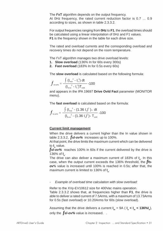
ARTDriveS User’s Guide Chapter 2 Inspection ... and Standard Specification • 31
The I2xT algorithm depends on the output frequency.At 0Hz frequency, the rated current reduction factor is 0.7 … 0.9according to sizes, as shown in table 2.3.3.2.
For output frequencies ranging from 0Hz to F1, the overload times shouldbe calculated using a linear interpolation of 0Hz and F1 values.F1 is the frequency shown in the table for each drive size.
The rated and overload currents and the corresponding overload andrecovery times do not depend on the room temperature.
The I2xT algorithm manages two drive overload levels:1. Slow overload (136% In for 60s every 300s)2. Fast overload (183% In for 0.5s every 60s)
The slow overload is calculated based on the following formula:
sl-ov% =∫ (I - I ) dtmot n
2 2
(I - I )Tsl-ov n ovld
2 2 ·100
and appears in the IPA 19697 Drive Ovld Fact parameter (MONITORmenu).
The fast overload is calculated based on the formula:
fs-ov% =∫ (I - (1.36 I dtmot n
2 2) )·
(I - ) Tfs-ov ovld
2(1.36 I )n
2 ··100
Current limit managementWhen the drive delivers a current higher than the In value shown intable 2.3.3.2, fsl-ov% increases up to 100%.At that point, the drive limits the maximum current which can be deliveredto In value.fsl-ov% reaches 100% in 60s if the current delivered by the drive is136% of In.The drive can also deliver a maximum current of 183% of In. In thiscase, when the output current exceeds the 136% threshold, the ffs-ov% value is increased until 100% is reached in 0.5s; after that, themaximum current is limited to 136% of In.
- Example of overload time calculation with slow overload:
Refer to the XVy-EV10612 size for 400Vac mains operation.Table 2.3.3.2 shows that, at frequencies higher than F1, the drive isable to deliver a rated current of 7.5Arms, with a maximum of 13.73Armsfor 0.5s (fast overload) or 10.20Arms for 60s (slow overload).
Assuming that the drive delivers a current Im = 9A ( In < Im < 136%In),only the fsl-ov% value is increased. .

32 • Chapter 2 Inspection ... and Standard Specification ARTDriveS User’s Guide
The maximum overload time Tsl is:
Tsl =(I - I )sl-ov n
2 2
· Tsl-ov
(I - I )mot n
2 2= [s]
Tsl =(10.20 - 7.5 )
2 2
· 60
(9 - 7.5 )2 2
= 118.85 s
When the Tovl time has elapsed, the Drive Ovld Fact parameter hasreached 100% and the maximum current is decreased to the rated one= 7.5Arms.The drive will be able to deliver the maximum current of 183%In againonly when Drive Ovld Fact returns to 0%.
The time required for fsl-ov% discharge depends on the currentdelivered by the drive (should be lower than In).Assuming that I mot = 3Arms, the recovery time will be:
Trec =(I - I ) . Tsl-ov n sl-ov
2 2
(I - I )n mot
2 2
Trec =(10.20 - 7.5 ) . 60
2 2
(7.5 - 3 )2 2
= 60.68 s
- Example of overload time calculation in case of fast overload:
Refer to the XVy-EV10612 size for 400Vac mains operation.
Table 2.3.3.2 shows that, at frequencies higher than F1, the drive isable to deliver a rated current of 7.5Arms, with a maximum of 13.73Armsfor 0.5s (fast overload) or 10.20Arms for 60s (slow overload).
Assuming that the drive delivers a currentIm = 12A ( 136%In < Im < 183%In)
the values of fsl-ov% and ffs-ov% are both increased.
The maximum overload time Tfs is:
Tfs =(I - I ) . Tfs-ov sl-ov fs-ov
2 2
(I - I )2 2
mot sl-ov
Tfs =(13.73 - 10.20 ) . 0.5
2 2
(12 - 10.20 )2 2
= 1.06 s
At the same time, the fsl-ov% value is also increased to reach thevalue
fsl-ov% = (Imot2-In
2) . Tfs = (122-752) . 1.06 = 93 count = 3.24%

ARTDriveS User’s Guide Chapter 2 Inspection ... and Standard Specification • 33
[Max fsl-ov% =(Isl-ov2 - In2) . Tsl-ov =(10.22-7.52).60= 2867.4 count = 100%]
Now, the current limit is lowered to 136% In.This current value can be kept for:
Tsl-ov =(I - I ) . T -sl-ov n sl-ov
2 2fsl-ov*
(I - I )2 2
mot n
= 52.98 sTsl-ov =(10.20 - 7.5 ) . 60 - 93
2 2
(10.20 - 7.5 )2 2

34 • Chapter 3 Installation Guidelines ARTDriveS User’s Guide
Chapter 3 - Installation Guidelines
3.1 Mechanical SpecificationFigure 3.1.1: Drive Dimensions, XVy-EV 10306 ... XVy-EV 32550 sizes
Mounting wall (D)Mounting with external dissipator (E)
E2 E4
E5
E3
E1
d
10306
10408
10612
20816
21020
21530
32040
32550
a mm (inch)
b mm (inch)
c mm (inch)
d mm (inch)
D1 mm (inch)
D2 mm (inch)
E1 mm (inch)
E2 mm (inch)
E3 mm (inch)
E4 mm (inch)
E5 mm (inch)
Ø d
Weight kg (lbs) 3.6 (7.9)
txv0020
208 (8.2)
323 (12.7)
240 (9.5)
168 (6.6)
84 (3.3)
310.5 (12.2)
164 (6.5)
284 (11.2)
306.5 (12.0)
199.5 (7.8)
69 (2.7)
199 (7.8)
296.5 (11.6)
315 (12.4)299.5 (11.7)
151.5 (5.9)
115 (4.5)
115 (4.5)
XVy-EV Type
Drive dimensions:
105.5 (4.1)
145.5 (5.7)
4.95 (10.9)
62 (2.4)
69 (2.7)
M5
3.7 (8.1)
99.5 (3.9)
299.5 (11.8)
8.6 (19)
9 (0.35)

ARTDriveS User’s Guide Chapter 3 Installation Guidelines • 35
Figure 3.1.2: Drive dimensions, XVy-EV 43570 ... XVy-EV 8280400 sizes
D1
D2 D2
D3 D3 D3 D3
D4
Mounting wall (D)
43
36
6
43
57
0
44
59
0
45
511
0
57
01
40
51
00
18
0
5S
10
01
80
61
25
23
0
6S
12
52
31
71
45
29
0
71
90
35
0
7S
19
03
50
72
30
42
0
7S
23
04
20
82
80
40
0
83
50
46
0
a mm (inch) 376 (14.7) 309 (12.1) 509 (20) 309 (12.1) 309 (12.1) 509 (20) 309 (12.1)
b mm (inch) 564 (22.2) 639 (25.2) 741 (29.2) 789 (31) 789 (31) 909 (35.8) 789 (31)
c mm (inch) 268 (10.5) 328 (12.9) 297.5 (11.7) 378 (14.9) 378 (14.9) 297.5 (11.7) 378 (14.9)
D1 mm (inch) 225 (8.8) 225 (8.8) 225 (8.8) 225 (8.8)
D2 mm (inch) 150 (5.9)
D3 mm (inch) 100 (3.9) 100 (3.9)
D4 mm (inch) 625 (24.6) 725 (28.5) 773 (30.4) 773 (30.4) 891 (35) 773 (30.4)
Ø
Weight kg 18 22 22.2 34 31.4 59 36.2 75.4 80.2 42.2 86.5 --
lbs 39.6 48.5 48.9 74.9 69.2 130 79.8 166.1 176.7 93 190.6 --
txv0030
109
240.3
442 (17.4)
475 (18.7)
M6
947 (37.3)
509 (20)509 (20)
909 (35.8)
XVy-EV type
Drive dimensions:
965 (38)
309 (12.1)
489 (19.2)
308 (12.1)
550 (21.6)
100 (3.9)
297.5 (11.7)
100 (3.9)
891 (35)
225 (8.8)

36 • Chapter 3 Installation Guidelines ARTDriveS User’s Guide
Figure 3.1.3: Drive dimensions, C and CP sizes
430
800
b
1114
c
U2-V
2-W
2
D-C
-U-V
-W
D4
a
D2 D2 D252.5 M8
22
65 205.5 170.5 209.5 125.5
Ø d
U2 V2 W227.
5
40
WVUC
22D
40
31
400 68 115 68 68 60
0V 230V(**)
D2 D2 D2Ø d
Figure 3.1.4: Drive dimensions, C and CP -IP00 sizes
bD4
a
D2 D2 D2
1114
52.5 M8
c
22
65 205.5 170.5 209.5 125.5
Ø d
U2 V2 W227.
5
40
WVUC
22D
40
31
400 68 115 68 68 60
0V 230V(**)
(**) External fan power supply
D2 D2 D2Ø d
9470650-C 9560650-CP
a mm (inch) 776 (30.6) 776 (30.6)
b mm (inch) 1091 (43) 1091 (43)
c mm (inch) 450 (17.7) 450 (17.7)
D2 mm (inch) 225 (8.9) 225 (8.9)
D4 mm (inch) 947 (37.3) 947 (37.3)
Ø M8 M8
Weight kg 155 155
lbs 341.7 341.7
txv0034
XVy-EV type
Drive dimensions:

ARTDriveS User’s Guide Chapter 3 Installation Guidelines • 37
Figure 3.1.5: Drive dimensions, XVy-EV 9470670-DC-IP00 and XVy-EV 9560800-DC-IP00 sizes
ca
a1
123 34357 114.5104270
1187
U V W
PE
C
D
a1 a1 a1
M12x35
M10x20
M12x35
188
40
40
b1
30
30
764.5
b
**
**: External Fan power supply
U, V, W
D,C
Nota: inverter bridge only, power supplier not included.
9470670 9560800
a mm (inch) 726.5 (28.55) 726.5 (28.55)
a1 mm (inch) 150 (5.9) 150 (5.9)
b mm (inch) 1443 (56.71) 1443 (56.71)
b1 mm (inch) 1410 (55.41) 1410 (55.41)
c mm (inch) 481 (18.9) 481 (18.9)
Weight kg 193 193
lbs 425.27 425.27
txv0036
XVy-EV type
Drive dimensions:
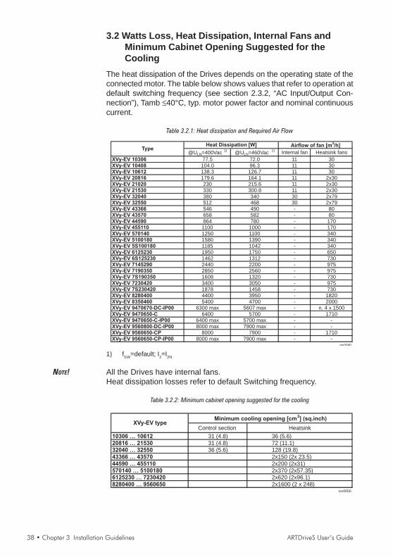
38 • Chapter 3 Installation Guidelines ARTDriveS User’s Guide
3.2 Watts Loss, Heat Dissipation, Internal Fans andMinimum Cabinet Opening Suggested for theCooling
The heat dissipation of the Drives depends on the operating state of theconnected motor. The table below shows values that refer to operation atdefault switching frequency (see section 2.3.2, “AC Input/Output Con-nection”), Tamb ≤40°C, typ. motor power factor and nominal continuouscurrent.
Table 3.2.1: Heat dissipation and Required Air Flow
@ULN=400Vac1)
@ULN=460Vac1) Internal fan Heatsink fans
XVy-EV 10306 77.5 72.0 11 30XVy-EV 10408 104.0 96.3 11 30XVy-EV 10612 138.3 126.7 11 30XVy-EV 20816 179.6 164.1 11 2x30XVy-EV 21020 230 215.6 11 2x30XVy-EV 21530 330 300.8 11 2x30XVy-EV 32040 380 340 30 2x79XVy-EV 32550 512 468 30 2x79XVy-EV 43366 546 490 - 80XVy-EV 43570 658 582 - 80XVy-EV 44590 864 780 - 170XVy-EV 455110 1100 1000 - 170XVy-EV 570140 1250 1100 - 340XVy-EV 5100180 1580 1390 - 340XVy-EV 5S100180 1185 1042 - 340XVy-EV 6125230 1950 1750 - 650XVy-EV 6S125230 1462 1312 - 730XVy-EV 7145290 2440 2200 - 975XVy-EV 7190350 2850 2560 - 975XVy-EV 7S190350 1608 1320 - 730XVy-EV 7230420 3400 3050 - 975XVy-EV 7S230420 1878 1458 - 730XVy-EV 8280400 4400 3950 - 1820XVy-EV 8350460 5400 4700 - 2000XVy-EV 9470670-DC-IP00 6300 max 5607 max - n. 4 x 1500XVy-EV 9470650-C 6400 5700 - 1710XVy-EV 9470650-C-IP00 6400 max 5700 max - -XVy-EV 9560800-DC-IP00 8000 max 7900 max - -XVy-EV 9560650-CP 8000 7900 - 1710XVy-EV 9560650-CP-IP00 8000 max 7900 max - -
txv0040
Heat Dissipation [W] Airflow of fan [m3/h]
Type
1) fSW=default; I2=I2N
NOTE! All the Drives have internal fans.Heat dissipation losses refer to default Switching frequency.
Table 3.2.2: Minimum cabinet opening suggested for the cooling
Control section Heatsink
10306 … 10612 31 (4.8) 36 (5.6)20816 … 21530 31 (4.8) 72 (11.1)32040 … 32550 36 (5.6) 128 (19.8)43366 … 43570 2x150 (2x 23.5)44590 … 455110 2x200 (2x31)570140 … 5100180 2x370 (2x57.35)6125230 … 7230420 2x620 (2x96.1)8280400 … 9560650 2x1600 (2 x 248)
txv0050
Minimum cooling opening [cm2] (sq.inch)
XVy-EV type

ARTDriveS User’s Guide Chapter 3 Installation Guidelines • 39
3.2.1 Cooling Fans Power SupplySizes XVy-EV 10306 to XVy-EV 5100180Power supply (+24VAC) for these fans are provided from the internaldrive power supply unit.
Sizes XVy-EV 6125230 to XVy-EV 9560650Power supply for these fans is externally connected by the user. ACInput voltage is connected at the power terminal strip:
XVy-EV type Drive fansFan power supply
(values for 1 fan)6125230 0,8A@115V/60Hz, 0,45A@230V/50Hz7145290 ... 7230420 1,2A@115V/60Hz, 0,65A@230V/50Hz8280400 ... 8350460 1,65A@115V/60Hz, 0,70A@230V/50Hz9470670-DC-IP00 2 0.94A/190W@1x230Vac,50/60Hz9470650-C 2 1.03A/215W@1x230Vac,50/60Hz9470650-C-IP00 2 1.03A/215W@1x230Vac,50/60Hz9560800-DC-IP00 2 0.94A/190W@1x230Vac,50/60Hz9560650-CP 2 1.03A/215W@1x230Vac,50/60Hz9560650-CP-IP00 2 1.03A/215W@1x230Vac,50/60Hz
txv0057
Figure 3.2.1: UL type fans connections
M
~
U3
2V3
1V3
0
115
230
AU
TOTR
AFO
230VAC fans
Drive
M
~
U3
2V3
1V3
No.2 115VAC fansM
~
Drive
XVy-EV7145290 - XVy-EV7190350 XVy-EV6125230 e XVy-EV8280400
Figure 3.2.2: Example for external connection
U3
2V3
1V3
230VAC
U3
2V3
1V3
115VAC
Drive Drive
(*)
*) Only for XVy-EV6125230 and XVy-EV8280400 sizes
NOTE! An internal fuse (2.5A 250VAC slo-blo) for XVy-EV 7145290 and XVy-EV 7190350. sizes is provided.On XVy-EV 6125230 and XVy-EV 8280400sizes the fuse must bemounted externally.

40 • Chapter 3 Installation Guidelines ARTDriveS User’s Guide
3.3 Installation Mounting Clearance
NOTE! The dimensions and weights specifed in this manual should be takeninto consideration when the device is mounted. The technical equipmentrequired (carriage or crane for large weights) should be used. Improperhandling and the use of unsuitable tools may cause damage.
Figure 3.3.1: Max. Angle of Inclination
The maximum angle of inclination is 30°
NOTE! The drives must be mounted in such a way that the free flow of air isensured. The clearance to the device must be at least 150 mm (6 inches).A space of at least 50 mm (2 inches) must be ensured at the front.From XVy-EV 8280400 size the top and bottom clearance must be atleast 380 mm (15 inches), on front and sides must be ensured a space ofat least 140 mm (5.5 inches). Devices that generate a large amount ofheat must not be mounted in the direct vicinity of the drive.
Figure 3.3.2: Mounting Clearance
10 mm ( 0.4" )[140mm (5.5")]
150 mm ( )6"[380mm (15")]
50 mm ( 2" )[140mm (5.5”)]
20 mm ( 0.8" )[140mm (5.5")]
150 mm ( )6"[380mm (15")]
10 mm ( 0.4" )[140mm (5.5")]
[...] from XVy-EV8280400 size
NOTE! Fastening screws should be re-tightened after a few days of operation.

ARTDriveS User’s Guide Chapter 4 Wiring Procedure • 41
Chapter 4 - Wiring Procedure
4.1 Accessing the Connectors (IP20 models)4.1.1 Removing the Covers
NOTE! Observe the safety instructions and warnings given in this manual. Thedevices can be opened without the use of force. Only use the toolsspecified.
See figure 2.2.2 “Drive view & components” to identify the single part.
Figure 4.1.1: Removing the covers (XVy-EV 10306 to XVy-EV 32550 sizes )
2
1
3
2
no. 2 for20-40 ...30-60
size
XVy-EV 10306 to XVy-EV 21530 sizes :The terminal cover and cable entry plate of the device must be removedin order to fit the electrical connections:- unscrew the screw (1), remove the cover of devices (2) by pressing
on both sides as shown on the above figure (3).- unscrew the two screws (4) to remove the cable entry plate.The top cover must be removed in order to mount option cards andchange the internal jumper settings:- remove the keypad and disconnect the connector (5)- lift the top cover on the bottom side (over the connector level) and
then push it to the top (6).
XVy-EV 32040 to XVy-EV 32550 sizes :The terminal cover and cable entry plate of the device must be removedin order to fit the electrical connections:- unscrew the two screws (1) and remove the cover of devices- unscrew the two screws (4) to remove the cable entry plate.The top cover must be removed in order to mount the option card andchange the internal jumper settings:- remove the keypad and disconnect the connector (5)- lift the top cover on the bottom side (over the connector level) and thenpush it to the top (6)
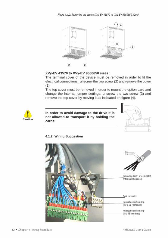
42 • Chapter 4 Wiring Procedure ARTDriveS User’s Guide
Figure 4.1.2: Removing the covers (XVy-EV 43570 to XVy-EV 9560650 sizes)
2 2
1
3
3
4
XVy-EV 43570 to XVy-EV 9560650 sizes :The terminal cover of the device must be removed in order to fit theelectrical connections: unscrew the two screw (2) and remove the cover(1)The top cover must be removed in order to mount the option card andchange the internal jumper settings: unscrew the two screw (3) andremove the top cover by moving it as indicated on figure (4).
4.1.2. Wiring Suggestion
Grounding 360° of a shieldedcable on Omega plug
CAN connector
Regulation section strip(17 to 32 terminals)
Regulation section strip(1 to 16 terminals)
In order to avoid damage to the drive it isnot allowed to transport it by holding thecards!Caution
Omega connector
Shield
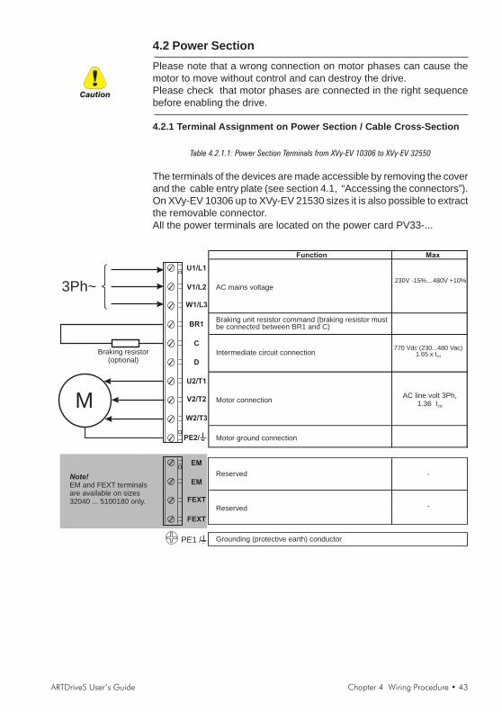
ARTDriveS User’s Guide Chapter 4 Wiring Procedure • 43
4.2 Power SectionPlease note that a wrong connection on motor phases can cause themotor to move without control and can destroy the drive.Please check that motor phases are connected in the right sequencebefore enabling the drive.
4.2.1 Terminal Assignment on Power Section / Cable Cross-Section
Table 4.2.1.1: Power Section Terminals from XVy-EV 10306 to XVy-EV 32550
The terminals of the devices are made accessible by removing the coverand the cable entry plate (see section 4.1, “Accessing the connectors”).On XVy-EV 10306 up to XVy-EV 21530 sizes it is also possible to extractthe removable connector.All the power terminals are located on the power card PV33-...
Function Max
Motor ground connection
Braking unit resistor command (braking resistor mustbe connected between BR1 and C)
Intermediate circuit connection
AC mains voltage230V -15%…480V +10%
Motor connectionM
3Ph~
PE1 / Grounding (protective earth) conductor
U1/L1
V1/L2
W1/L3
BR1
U2/T1
V2/T2
W2/T3
C
D
PE2/
EM
EM
FEXT
FEXT
-
770 Vdc (230...480 Vac)1.65 x I2N
AC line volt 3Ph,1.36 I2N
Braking resistor(optional)
Reserved
-
Note!
EM and FEXT terminalsare available on sizes32040 ... 5100180 only.
Reserved
Caution

44 • Chapter 4 Wiring Procedure ARTDriveS User’s Guide
Table 4.2.1.2: Power Section Terminals from XVy-EV 43570 to XVy-EV 9560650
The terminals of the devices are made accessible by removing the cover(see section 4.1, “Accessing the connectors”).
M
3Ph~
U1/L1
V1/L2
W1/L3
BR1
U2/T1
V2/T2
W2/T3
C
D
PE2/
PE1 /
EM
EM
FEXT
FEXT
MaxFunction
Motor ground connection
Braking unit resistor command (braking resistor mustbe connected between BR1 and C)Available in XVy-EV 43570 ... 5100180 sizes,not including XVy-EV 5S100180.
Intermediate circuit connection
AC mains voltageTerminations not included in the XVy-EV ...-DCversions.
230V -15%…480V +10%
Motor connection
Grounding (protective earth) conductor
770 Vdc (230...480 Vac)1.65 x I2N
AC line volt 3Ph,1.36 I2N
Reserved
Reserved
Note!
EM and FEXT terminalsare available on sizes32040 ... 5100180 only.
Braking resistor(optional)
-
-
Table 4.2.1.3: Power Section Terminals XVy-EV ...-IP00 sizes
M
3Ph~
U2/T1
V2/T2
W2/T3
C
D
PE /
MaxFunction
Grounding (protective earth) conductor, Motor ground connection
Intermediate circuit connection
AC mains voltage 400V -15%…480V +10%
Motor connection
770 Vdc (400...480 Vac)1.65 x I2N
AC line volt 3Ph,1.36 I2N
U1/L1
V1/L2
W1/L3

ARTDriveS User’s Guide Chapter 4 Wiring Procedure • 45
Maximum cable sizes for power terminals U1, V1, W1, U2, V2, W2, C, D,PE
Table 4.2.1.4: Maximum cable cross section for power terminals
TypeTightening
torque
Tightening
torque
Tightening
torque
XVy-EV AWG mm2 Nm AWG mm
2 Nm AWG mm2 Nm
10306 14 2 0.5 … 0.6 14 2 0.5 … 0.6 14 2 0.5 … 0.6
10408 14 2 0.5 … 0.6 14 2 0.5 … 0.6 14 2 0.5 … 0.6
10612 14 2 0.5 … 0.6 14 2 0.5 … 0.6 14 2 0.5 … 0.6
20816 10 4 0.5 … 0.6 10 4 0.5 … 0.6 10 4 0.5 … 0.6
21020 10 4 0.5 … 0.6 10 4 0.5 … 0.6 10 4 0.5 … 0.6
21530 10 4 0.5 … 0.6 10 4 0.5 … 0.6 10 4 0.5 … 0.6
32040 8 8 1.2 … 1.5 8 8 1.2 … 1.5 8 8 1.2 … 1.5
32550 6 10 1.2 … 1.5 6 10 1.2 … 1.5 6 10 1.2 … 1.5
43366 6 16 2 10 6 0.9 6 16 2
43570 6 16 2 10 6 0.9 6 16 2
44590 4 25 3 8 10 1.6 6 16 3
455110 2 35 4 8 10 1.6 6 16 3
570140 2 35 4 6 16 3 6 16 3
5100180 1/0 50 4 6 16 3 2 50 4
5S100180 1/0 50 10 nd nd nd 2 50 10
6125230 2/0 70 12 nd nd nd 2 50 4
6S125230 2/0 70 10 nd nd nd 2 50 10
7145290 4/0 95 12 nd nd nd 2 50 4
7190350 (300) 150 10 … 30 nd nd nd 2 50 4
7S190350 (300) 150 10 nd nd nd 2 50 10
7230420 (350) 185 10 … 30 nd nd nd 2 50 4
7S230420 (350) 185 10 nd nd nd 2 50 10
8280400 4xAWG2 4x35 10 … 30 nd nd nd 2 50 4
8350460 150 * 10 … 30 nd nd nd 2 50 4
9470670-DC-IP00 1/0 (500) 50…240 50 nd nd nd 1/0 (500) 50…240 50
9470650-C 1/0 (500) 50…240 50 nd nd nd 1/0 (500) 50…240 50
9470650-C-IP00 1/0 (500) 50…240 50 nd nd nd 1/0 (500) 50…240 50
9470650-C-DC-IP00 1/0 (500) 50…240 50 nd nd nd 1/0 (500) 50…240 50
9560800-DC-IP00 1/0 (500) 50…240 50 nd nd nd 1/0 (500) 50…240 50
Type 1/0 (500) 50…240 50 nd nd nd 1/0 (500) 50…240 50
9560650-CP-IP00 1/0 (500) 50…240 50 nd nd nd 1/0 (500) 50…240 50
9560650-CP-DC-IP00 1/0 (500) 50…240 50 nd nd nd 1/0 (500) 50…240 50
txv0060
(…) = kcmils, *=copper bar
PE1, PE2 terminalsBR1 terminalsU1,V1,W1, U2,V2,W2,C,D
terminals
The grounding conductor of the motor cable may conduct up to twicethe value of the rated current if there is a ground fault at the output ofthe ARTDriveS drive.
NOTE! Use 60/75°C copper conductor only.
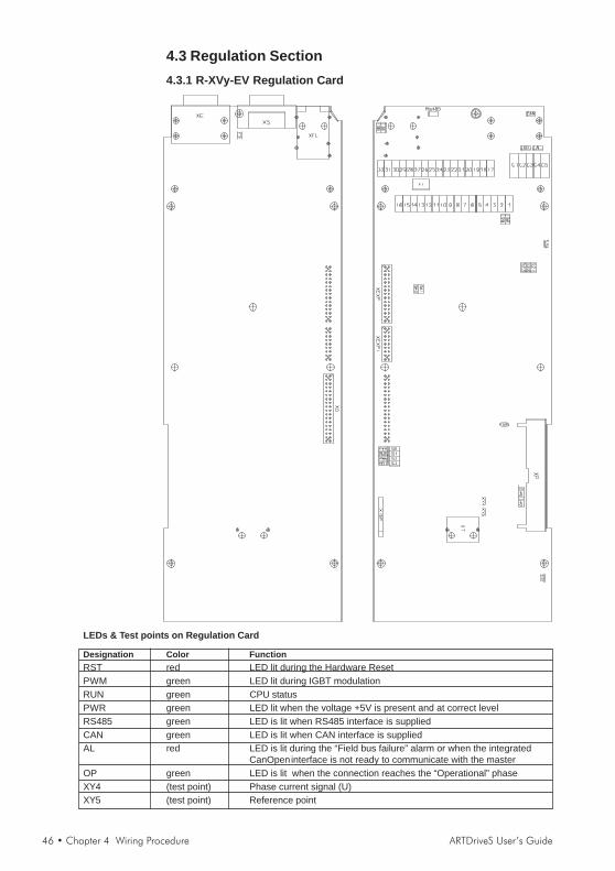
46 • Chapter 4 Wiring Procedure ARTDriveS User’s Guide
4.3 Regulation Section4.3.1 R-XVy-EV Regulation Card
LEDs & Test points on Regulation Card
Designation Color FunctionRST red LED lit during the Hardware ResetPWM green LED lit during IGBT modulationRUN green CPU statusPWR green LED lit when the voltage +5V is present and at correct levelRS485 green LED is lit when RS485 interface is suppliedCAN green LED is lit when CAN interface is suppliedAL red LED is lit during the “Field bus failure” alarm or when the integrated
CanOpeninterface is not ready to communicate with the masterOP green LED is lit when the connection reaches the “Operational” phaseXY4 (test point) Phase current signal (U)XY5 (test point) Reference point

ARTDriveS User’s Guide Chapter 4 Wiring Procedure • 47
Figure 4.3.1: Connectors Location
Table 4.3.1.1: Jumpers on Regulation Card
Designation Function Factory settingS0 Service only ! (Test and software loading: bootstrap-loader) OFFS1 Service only ! (Test and software loading: monitor mode) OFFS2 Service only ! (Test and software loading: boot-sector protection) OFFS3 Service only ! (Test and software loading: manual reset) OFF
Terminating resistor for the serial interface RS485 (*)ON = Termination resistor INOFF = No termination resistor
Adaptation to the input signal of analog input 0 (terminals 1 and 2)
ON = 0..20 mA / 4..20 mAOFF = 0..10V / -10..+10 V
Adaptation to the input signal of analog input 1 (terminals 3 and 4)
ON = 0..20 mA / 4..20 mAOFF = 0..10V / -10..+10 V
S21-S22-S23 Hall sensor settingsON = Hall sensorsOFF = No Hall sensors
S45-S46 INTERNAL USE - Do not modify factory setting OFFtxv0070
S5-S6
S8
S9
OFF
ON
OFF
OFF
(*) on multidrop connection the jumpers must be ON only for the last drop of a serial line
NOTE! See chapter 4.4.3, Feedback drive connection for more details on S21 ... S23 jumpersettings .
The devices are factory set accordingly.When fitting a regulation card as a spare, remember to set againthe encoders jumpers.Caution
1 5
6 9
1 5
11 156 10
XE XS
1 5
11 156 10
XER
XFL (OUT)
XFL (IN)
X1 (1...16 terminals )X1 (17...32 terminals )
CAN (C1...C5 terminals )
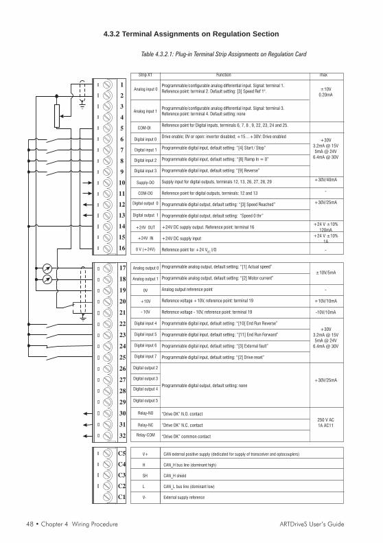
48 • Chapter 4 Wiring Procedure ARTDriveS User’s Guide
4.3.2 Terminal Assignments on Regulation Section
Table 4.3.2.1: Plug-in Terminal Strip Assignments on Regulation Card
1
2
3
4
5
6
7
8
9
10
11
12
13
14
15
16
Digital input 0
Digital input 1
0 V (+24V)
+24V OUT
Analog input 0
Analog input 1
Analog output 0
0V
+10V
Digital input 4
Digital input 5
Digital input 6
Digital input 7
Digital output 3
Relay-NO
Relay-COM
17
18
19
20
21
22
23
24
25
26
27
28
29
30
31
32
Digital input 2
Digital input 3
Supply-DO
COM-DO
Digital output 0
Digital output 1
+24V IN
COM-DI
Analog output 1
- 10V
Digital output 2
Digital output 4
Digital output 5
Relay-NC
Strip X1 Function max
Programmable/configurable analog differential input. Signal: terminal 1.Reference point: terminal 2. Default setting: [3] Speed Ref 1".
Programmable/configurable analog differential input. Signal: terminal 3.Reference point: terminal 4. Default setting: none
Reference point for Digital inputs, terminals 6, 7, 8 , 9, 22, 23, 24 and 25.
Drive enable; 0V or open: inverter disabled; +15…+30V: Drive enabled
Programmable digital input, default setting: “[4] Start / Stop”
Programmable digital input, default setting: “[8] Ramp In = 0”
Programmable digital input, default setting: “[9] Reverse”
Supply input for digital outputs, terminals 12, 13, 26, 27, 28, 29
Reference point for digital outputs, terminals: 12 and 13
Programmable digital output, default setting: “[3] Speed Reached”
Programmable digital output, default setting: “Speed 0 thr”
+24V DC supply output. Reference point: terminal 16
+24V DC supply input
Reference point for +24 VDC I/O
Programmable analog output, default setting: “[1] Actual speed”
Programmable analog output, default setting: “[2] Motor current”
Analog output reference point
Reference voltage +10V, reference point: terminal 19
Reference voltage - 10V, reference point: terminal 19
Programmable digital input, default setting: “[10[ End Run Reverse”
Programmable digital input, default setting: “[11] End Run Forward”
Programmable digital input, default setting: “[3] External fault”
Programmable digital input, default setting: “[2] Drive reset”
Programmable digital output, default setting: none
“Drive OK” N.O. contact
“Drive OK” N.C. contact
“Drive OK” common contact
±10V0.20mA
+30V3.2mA @ 15V5mA @ 24V
6.4mA @ 30V
+30V/40mA
-
+30V/25mA
+24 V ±10%120mA
+24 V ±10%1A
-
±10V/5mA
-
+10V/10mA
-10V/10mA
+30V3.2mA @ 15V5mA @ 24V
6.4mA @ 30V
+30V/25mA
250 V AC1A AC11
C5
C4
C3
C2
C1
CAN external positive supply (dedicated for supply of transceiver and optocouplers)
CAN_H bus line (dominant high)
CAN_H shield
CAN_L bus line (dominant low)
External supply reference
V+
H
SH
L
V-
ARTDriveS User’s Guide Chapter 4 Wiring Procedure • 49
The + 24Vdc voltage used for external power for the control card mustbe stabilised, with a tolerance of ±10%; maximum absorption 1A.Power supplies obtained from a single rectifier and capacitor filter arenot sufficient.
Maximum Cable Sizes for control terminals
Table 4.3.2.2: Maximum permissible cable cross-section on the plug-in terminals of the regulatorsection
Maximum Permissible Cable Cross-Section Tightening
[mm2] torque
flexible multi-core [Nm]
1 ... 29 0.14 ... 1.5 0.14 ... 1.5 28 ... 16 0.4
30 ... 32 0.14 ... 1.5 0.14 ... 1.5 28 ... 16 0.4txv0065
AWGTerminals
The use of a 75 x 2.5 x 0.4 mm (3 x 0.1 x 0.02 inch) flat screwdriver isrecommended. Remove 6.5 mm (0.26 inch) of the insulation at the cableends. Only one unprepared wire (without ferrule) should be connectedto each terminal point.
Maximum Cable Length
Table 4.3.2.3: Maximum Control Cable Lengths
Cable section [mm2] 0.22 0.5 0.75 1 1.5
Max. length m [feet] 27 [88] 62 [203] 93 [305] 125 [410] 150 [492]txv0055
Potentials of the control sectionThe potentials of the regulation section are isolated and can be discon-nected via jumpers from ground. The connections between each potentialare shown in Figure 4.3.2.1.The analog inputs are designed as differential amplifiers.The digital inputs are optocoupled with the control circuit. The digitalinputs have terminal 5 as reference point.The analog outputs are not designed as differential amplifiers and havea common reference point (terminal 19).The analog outputs and the ±10V reference point have same potential(terminal 19).The digital outputs are optocoupled with the control circuit. Terminals12 to 13 and 26 to 29 have terminal 11 as a common reference pointand terminal 10 as common supply.
Caution
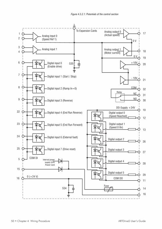
50 • Chapter 4 Wiring Procedure ARTDriveS User’s Guide
Figure 4.3.2.1: Potentials of the control section
1
2
3
4
5
15
16
Analog input 0(Speed Ref 1)
Analog input 1
Internal powersupply fromPower Card
0 (+24 V)
Analog output 1(Motor current)
17
0 V
18
20
19
21
+10V
- 10V
0 V
31
30
14
To Expansion Cards
S35
Analog output 0(Actual speed)
6
7
8
9
22
23
24
25
Digital input 0(Enable drive)
Digital input 1 (Start / Stop)
Digital input 2 (Ramp In=0)
Digital input 3 (Reverse)
Digital input 4 (End Run Reverse)
Digital input 5 (End Run Forward)
Digital input 6 (External fault)
Digital input 7 (Drive reset)
COM DI
32COM
NC
NO
Digital output 0(Speed Reached)
Digital output 1(Speed 0 thr)
Digital output 2
Digital output 3
Digital output 4
Digital 5output
COM DO
DO-Supply +24V
12
11
10
Relay
Fuse
16
S34
13
27
28
29
26
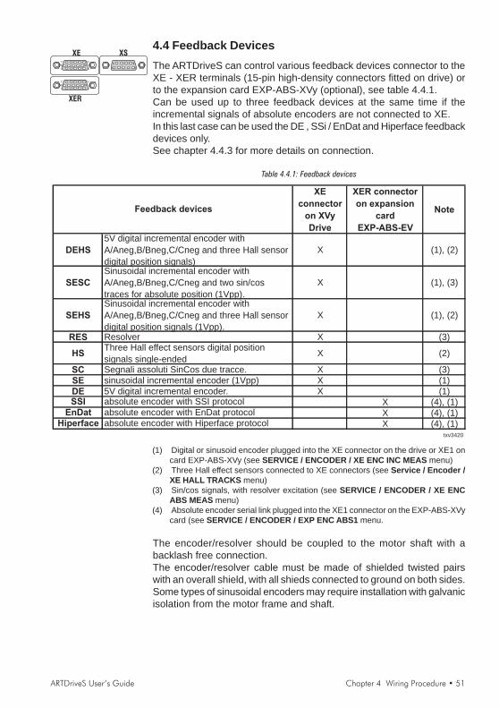
ARTDriveS User’s Guide Chapter 4 Wiring Procedure • 51
4.4 Feedback DevicesThe ARTDriveS can control various feedback devices connector to theXE - XER terminals (15-pin high-density connectors fitted on drive) orto the expansion card EXP-ABS-XVy (optional), see table 4.4.1.Can be used up to three feedback devices at the same time if theincremental signals of absolute encoders are not connected to XE.In this last case can be used the DE , SSi / EnDat and Hiperface feedbackdevices only.See chapter 4.4.3 for more details on connection.
Table 4.4.1: Feedback devices
XE
connector
on XVy
Drive
XER connector
on expansion
card
EXP-ABS-EV
Note
DEHS
5V digital incremental encoder with
A/Aneg,B/Bneg,C/Cneg and three Hall sensor
digital position signals)
X (1), (2)
SESC
Sinusoidal incremental encoder with
A/Aneg,B/Bneg,C/Cneg and two sin/cos
traces for absolute position (1Vpp).
X (1), (3)
SEHS
Sinusoidal incremental encoder with
A/Aneg,B/Bneg,C/Cneg and three Hall sensor
digital position signals (1Vpp).
X (1), (2)
RES Resolver X (3)
HSThree Hall effect sensors digital position
signals single-endedX (2)
SC Segnali assoluti SinCos due tracce. X (3)
SE sinusoidal incremental encoder (1Vpp) X (1)
DE 5V digital incremental encoder. X (1)SSI absolute encoder with SSI protocol X (4), (1)
EnDat absolute encoder with EnDat protocol X (4), (1)Hiperface absolute encoder with Hiperface protocol X (4), (1)
txv3420
Feedback devices
(1) Digital or sinusoid encoder plugged into the XE connector on the drive or XE1 oncard EXP-ABS-XVy (see SERVICE / ENCODER / XE ENC INC MEAS menu)
(2) Three Hall effect sensors connected to XE connectors (see Service / Encoder /XE HALL TRACKS menu)
(3) Sin/cos signals, with resolver excitation (see SERVICE / ENCODER / XE ENCABS MEAS menu)
(4) Absolute encoder serial link plugged into the XE1 connector on the EXP-ABS-XVycard (see SERVICE / ENCODER / EXP ENC ABS1 menu.
The encoder/resolver should be coupled to the motor shaft with abacklash free connection.The encoder/resolver cable must be made of shielded twisted pairswith an overall shield, with all shieds connected to ground on both sides.Some types of sinusoidal encoders may require installation with galvanicisolation from the motor frame and shaft.
1 5
6 9
1 5
11 156 10
XE XS
1 5
11 156 10
XER

52 • Chapter 4 Wiring Procedure ARTDriveS User’s Guide
4.4.1 XE Connector AssignmentsThe connection with the drive is through a 15 pole high density sub-Dconnector (VGA type female). Please note that it is mandatory to use ashielded cable with at least 80 % coverage. The shield should beconnected to ground on both sides of the connector, but not groundedat the motor end.Please note that for resolver feedback it is mandatory to use a twistedpair cable with shields on each pair and an overall shield.
Table 4.4.1.1: XE Connector Assignments
5 1
10 6
15 11
Back View of VGA
D-sub connector (solder side)
1 B– Incremental Encoder B- I2 PTC Motor temperature sensor I3 Z+ Zero channel Z (+) I4 Z– Zero channel Z (–) I5 A+ Incremental Encoder A (+) I6 A– Incremental Encoder A (–) I7 0VE Encoder Supply 0V reference O8 B+ Incremental Encoder B(+) I9 +5VE Encoder Supply O
10 SIN+ / H1 Sin / resolver input (+) / Hall 1 input I11 SIN– / H2 Sin / resolver (–) / Hall 2 input I12 COS+ / H3 Cos / resolver (+) / Hall 3 input I13 COS– Cos / resolver (–) I14 EXC+ Resolver excitation (+) O15 EXC– Resolver excitation (–) O
txv0090
I=Input
O=OutputAssignment Function
4.4.2 XER Encoder Connector Assignments (for auxiliary encoders)A +5V auxiliary incremental digital encoder can be plugged into the XERconnector (controller card) or an expansion card (e.g. EXP-D14A4F,EXP-F2E, EXPFI, EXP-FO, EXP-FIH, etc.)The connection with the drive is through a 15 pole high density sub-Dconnector (VGA type female).
Table 4.4.2.1: XER Connector Assignments
1 B– Digital incremental channel B (–) Input / Repetition I / O23 Z+ Zero pulse (+) channel Input / Repetition I / O4 Z– Zero pulse (–) channel Input / Repetition I / O5 A+ Digital incremental channel A (+) Input / Repetition I / O6 A– Digital incremental channel A (–) Input / Repetition I / O7 0VR Encoder Supply 0V reference O8 B+ Incremental channel B(+) Input / Repetition I / O9 +5VR Encoder supply O
txv0100
10 … 15
Assignment FunctionI=Input
O=Output

ARTDriveS User’s Guide Chapter 4 Wiring Procedure • 53
4.4.3 Feedback /Drive ConnectionsThe ARTDriveS drive can handle several feedback devices (see para-graph 4.4) selectable through the setting of jumpers on the regulationboard. The jumper setting will be as follows:
Table 4.4.3.1: Resolver/Encoder jumpers settings
S21 S22 S23DE / DEHS ON ON ONSE / SEHS ON ON ONSESC / SC OFF OFF OFFHS ON ON ONRES OFF OFF OFFSSI / ENDAT / Hiperface OFF OFF OFF
txv0110
EncoderJumpers settings
In the following paragraphs are specified the connections between ART-DriveS drives and the feedback sensors installed on standard motors.
4.3.3.1 Resolver Connections (RES)The following table shows the connections between the ARTDriveS drivesand the signal connector on servomotors by Gefran-Siei (see chapter12 for more details on cable).
SBM Motors
19 Poles
connector
SHJ Motors
10 Poles
connector
FunctionXVy drive
15 Pole XE connector
Cable section
[mm2]
A
B (SHIELD) F (SHIELD) Cable shieldSHIELD to
connector bodyC B Resolver Cos+ 12D G Resolver Cos- 13E C Resolver Sin- 11F H Resolver Sin+ 10GHJKLMNPR
S (PTC) I (PTC) Motor Temperature Sensor 7T (PTC) J (PTC) Motor Temperature Sensor 2
U A Resolver Excitation+ 14V E Resolver Excitation- 15
txv0240
(2 x 0.25) + sfr
(2 x 0.25) + sfr
(2 x 0.25) + sfr
(2 x 0.25) + sfr
For resolver cable use twisted pair shielded cable; the pairs should bethe signal wires cos+/cos-,sin+/sin-, exc+/ exc-, motor temperaturesensor wires. All the shields must be connected together to cableshield pin of resolver connector on the motor side and to connectorbody on drive side.
4.4.3.2 Sinusoidal Encoder SinCos Connections (SESC)The following table shows the connections between the ARTDriveS drivesand the signal connector on servomotors by Gefran-Siei (see chapter12 for more details on cable).

54 • Chapter 4 Wiring Procedure ARTDriveS User’s Guide
SBM Motors
19 Poles
connector
SHJ Motors
19 Poles
connector
FunctionXVy drive
15 Pole XE connector
Cable section
[mm2]
A 12 Encoder supply 0VDC reference 7 0.5
B (SHIELD) 19 (SHIELD) Cable shieldSHIELD to
connector bodyC 15 Cos+ input 12D 11 Cos- Input 13E 14 Sin- Input 11F 10 Sin+ Input 10GH 4 Incremental Encoder B+ 8J 8 Incremental Encoder B- 1K 7 Incremental Encoder A- 6L 3 Incremental Encoder A+ 5M 5 Zero Channel Z+ 3N 9 Zero Channel Z- 4P 2 Encoder supply +5VDC 9 0.5R
S (PTC) 17 (PTC) Motor Temperature Sensor 7 n.c.T (PTC) 18 (PTC) Motor Temperature Sensor 2 0.25
UV
txv0220
(2 x 0.14) + sfr
2 x 0.14
2 x 0.14
(2 x 0.14) + sfr
(2 x 0.14) + sfr
For encoder cable use twisted pair shielded cable; the pairs should bethe signal wires A+/A-,B+/B-,Z+/Z-,cos+/cos-,sin+/sin-, motortemperature sensor wires, encoder supply wires. All the shields mustbe connected together to cable shield pin of encoder connector on themotor side and to connector body on drive side.
4.4.3.3 Digital Encoder with Hall Effect Sensors Connections (DEHS)The following table shows the connections between the ARTDriveS drivesand the signal connector on servomotors by Gefran-Siei (see chapter12 for more details on cable).
SBM Motors
19 Poles
connector
SHJ Motors
19 Poles
connector
FunctionXVy drive
15 Pole XE connector
Cable section
[mm2]
A 6 Encoder supply 0VDC reference 7 0.5
B (SHIELD) 7 (SHIELD) Cable shieldSHIELD to
connector bodyC 5 Hall 3 input 12 2 x 0.14DE 4 Hall 2 Input 11 1 x 0.25FG 3 Hall 1 Input 10 2 x 0.14H 13 Incremental Encoder B+ 8J 1 Incremental Encoder B- 1K 11 Incremental Encoder A+ 5L 10 Incremental Encoder A- 6M 14 Zero Channel Z+ 3N 9 Zero Channel Z- 4P 12 Encoder supply +5VDC 9 0.5R
S (PTC) 15 Motor Temperature Sensor 7 n.c.T (PTC) 16 Motor Temperature Sensor 2 0.25
UV
txv0230
(2 x 0.14) + sfr
(2 x 0.14) + sfr
(2 x 0.14) + sfr
For encoder cable use twisted pair shielded cable; the pairs should be thesignal wires A+/A-, B+/B-, Z+/Z-, motor temperature sensor wires, encodersupply wires. All the shields must be connected together to cable shield

ARTDriveS User’s Guide Chapter 4 Wiring Procedure • 55
pin of encoder connector on the motor side and to connector body ondrive side.
4.4.3.4 Absolute Encoder Connections (SSi / EnDat /Hiperfaceprotocols)
EXP-ABS-EV expansion board has to be connected:- to XVy-EV drive though the cable supplied with the board (XE2
connector on EXP-ABS-EV, XE connector on XVY-EV drive).- to the encoder signals connector (XE1 connector on EXP-ABS-EV).
Please refer to the following table:
Pin Signal Description1 B- (Sine-) Incremental encoder B- signal2 PTC Motor thermal protection signal (referred to GND)3 Reserved4 Reserved5 A+ (Cosine+) Incremental encoder A+ signal6 A- (Cosine-) Incremental encoder A- signal7 GND Ground of encoder supply voltage8 B+ (Sine+) Incremental encoder B+ signal9 ALIM Encoder supply voltage
10 EQP / SENSE- Equipotential(1)
signal or SENSE-(2)
signal (only for monitoring)
11 CLK+ Encoder CLOCK+ signal (ENDAT or SSI only)12 CLK- Encoder CLOCK- signal (ENDAT or SSI only)13 DT+ Encoder DATA+ signal14 DT- Encoder DATA- signal
15 SENSE+ SENSE+(2)
signal (only for monitoring)t0010g
For encoder cable use twisted pair shielded cable; the pairs should bethe signal wires A+/A-, B+/B-, clock+/clock-, data+/data-, motortemperature sensor wires, encoder supply wires. All the shields mustbe connected together to cable shield pin of encoder connector on themotor side and to connector body on drive side.
4.4.3.5 Encoder /Resolver Specifications (XE connector)Sinusoidal encodersmax. frequency ______________ 200 kHz ( select the appropriate number of pulses depending
on required max. speed )Number of pulses per revolution __ min 1, max 65535Channels ___________________ three-channel, differential, TTL 5V compatible. An encoder loss
detection is possible via firmware setting.Power supply ________________ + 5 V (Internal supply) *Load capacity _______________ > 8.3 mA pp per channelSuggested cable _____________ see chapter 12.
Digital encodersmax. frequency ______________ 250 kHz ( select the appropriate number of pulses depending
on required max. speed )Number of pulses per revolution __ min 1, max 65535Channels ___________________ three-channel, differential. An encoder loss detection is possible
via firmware setting.

56 • Chapter 4 Wiring Procedure ARTDriveS User’s Guide
Power supply ________________ + 5 V (Internal supply) *Load capacity _______________ > 4.5 mA / 6.8 ... 10 mA per channelSuggested cable _____________ see chapter 12
* Via keypad (030 - ENCODER PARAM menu) it is possible to select 4 differentvalues of internal encoder supply voltage to compensate the voltage reduction dueto encoder cable length and load current encoder. Selection available are: 0=5.2V,1=5.6V, 2=6.1V, 3=6.5V via XE Enc Supply (IPA 20012) or XER Enc Supply (IPA20019). parameter.
Absolute EncoderAbsolute trace frequency _______ 500 kHz (on the EXP-ABS-EV expansion card)Incremental trace max. frequency 200 kHzMax encoder resolution ________ 29 bit (17 bit/rev.* 12 bit rev.). Note: from the fw 2.41 version.Interface electrical level ________ differential RS-485Interface signals _____________ clock and data (bidirectional)Clock synchronous period ______ 2μsEncoder supply ______________ +5V(TTL) /+15V(HTL) +5V / +15V...+24V with external
supplymax absorption of encoder supply 250 mA maxSuggested cable _____________ see chapter 12
Resolver interfaceResolver excitation ____________ sinusoidalResolver excitation voltage ______ 6V rmsResolver excitation current ______ 50mA rms maxResolver excitation frequency ____ 8kHzResolver input _______________ differentialResolver input impedence ______ 4kΩResolver transformation ratio ____ 1:1 - 1:2 - 1:3Suggested cable _____________ see chapter 12
4.4.3.6 Encoder Simulation / Repetition, Auxiliary Encoder Input(XER/EXP Connector)
Digital encoder inputmax. frequency ______________ 400 kHz ( select the appropriate number of pulses depending
on required max. speed )Number of pulses per revolution __ min 1, max 65535Channels ___________________ three-channel, differential. Encoder loss detection is not possible.Power supply ________________ + 5 V (Internal supply) *Load capacity _______________ > 4.5 mA / 6.8 ... 10 mA per channelSuggested cable _____________ see chapter 12
* Via keypad (030 - ENCODER PARAM menu) it is possible to select 4 differentvalues of internal encoder supply voltage to compensate the voltage reduction dueto encoder cable length and load current encoder. Selection available are: 0=5.2V,1=5.6V, 2=6.1V, 3=6.5V via XE Enc Supply (IPA 20012) or XER Enc Supply (IPA20019). parameter.
On the regulation board there is available an incremental encoder output,with TTL Line Driver levels, that can be used as simulation of the servo-motor feedback device.

ARTDriveS User’s Guide Chapter 4 Wiring Procedure • 57
This function is performed by the microprocessor and it is possible tosimulate an encoder output with a programmable number of pulses/rev,or to repeat the signals of the motor encoder. The encoder output signalsare available on the XER connector (see table 4.4.2.1):
Digital encoder simulation (XER Port)Interface ___________________ opto-isolatedSimulation __________________ differential digital incrementalStandard outputs _____________ A+, A-, B+, B-,I+, I-Outputs levels _______________ Standard TTLVoltage limits on the TTL high-state outputs (on the pins)(Uhigh TTL) _________________ > 2.5VVoltage limits on the TTL low-state outputs (on the pins)(Ulow TTL) _________________ < 0,5VTTL load capacity ____________ 20mA max. eachParallel connection of standard ARTDriveS inputswith a TTL outputs ____________ 3 inputsMax. frequency ______________ 400kHz ( select the appropriate number of pulses depending
on required max. speed )Max absorption of the encoder simulationpower supply ________________ 150mA@5VMechanics __________________ Male high density 15-pole D-sub connector (type VGA) for
standard inputs and extractable terminals to be connected to a0.14..1.5 mm2 power supply section
4.4.4 Encoder Cable Length
The following figures show the maximum encoder frequency as functionof the encoder cable length. For this figures we have considered cableswith the following specifications:
Distributed capacitance: 90pF/m
CABLE LENGHT (Sinusoidal encoder)
0
50
100
150
200
100 120 140 160 180 200
Encoder frequency [KHz]
Le
ng
ht
[mt]

58 • Chapter 4 Wiring Procedure ARTDriveS User’s Guide
CABLE LENGHT (Digital encoders)
0
20
40
60
80
100
120
140
160
180
200
100 200 300 400 500 600
Encoder frequency [KHz]L
en
gh
t[m
t]
XER Port
XE Port
The following figure shows the voltage drop as function of the cablelength and of the current absorbtion:
VOLTAGE DROP (Cable Cross-section 0.2 mm2)
0
50
100
150
200
0 1 2 3 4 5
Voltage drop [V]
Le
ng
ht
[mt] 20mA
50mA
100mA
150mA
4.4.5 Checking Encoder / Drive ConnectionsIt is strongly recommended to follow the next instructions (parametersto be check are only those for used feedback devices, see next table) :- rotate manually clockwise the motor shaft- check “... pos” parameters values increasing up to “360” and than
come back to “0”- check “... rev” parameters values increasing on each turn.
XER conn.SC (SinCos) HS (Hall+Dig) RES (resolver) DE (Dig.Enc.)
Inc Data Pos (IPA 19002) X XInc Data N Rev (IPA 19003) X X
Abs Turn Pos (IPA 19017) X XAbs Rev (IPA 19018) X X
XER/EXP Turn Pos (IPA 19011) XXER/EXP Rev (IPA 19012) X
XE Hall Pos (IPA 19022) XXE Hall Rev (IPA 19026) X
txv0255
menu: SERVICE / ENCODER / XE HALL TRACKS
XE conn.
menu: SERVICE / ENCODER / XE ENC INC MEAS
menu: SERVICE / ENCODER / XE ENC ABS MEAS
menu: SERVICE / ENCODER / XER/EXP Inc Enc

ARTDriveS User’s Guide Chapter 4 Wiring Procedure • 59
4.5 CANopen ConnectionThe ARTDriveS brushless drive can be connected in a CANopennetwork, the pins are:
V+ H SH L V-
Pin / Signal Description
V- External supply referenceL CAN_L bus line (dominant low)
SH CAN_H shieldH CAN_H bus line (dominant high)
V+CAN external positive supply +24V (*), dedicated for supply of
transceiver and optocouplerstxv0245
(*) The supplier size have to be according to the used bus specification (CANopen orDeviceNet). Card absorption is 30 mA@24V.
The Bus connection is provided via a shielded loop to be placed farfrom the power cables, with a minimum distance of 20 cm. The cableshielding must be ground connected on both ends.If the cable shieldings are ground connected on different points of thesystem, use the equipotential connection cables to reduce the currentflow between the drives and the CAN bus master.
NOTE ON TERMINATING RESISTOR:
The first and last network components must have a 120 ohm resistance between pinsC2 and C4.Attention

60 • Chapter 4 Wiring Procedure ARTDriveS User’s Guide
4.6 Fast Link ConnectionsOn the XFL connectors a fast serial connection is available, that isoptimized to exchange I/O and regulation parameters between differentdrives. This synchronous serial interface is named FAST LINK. Thisinterface can have two different connection architectures :
- Multi Point : one drive is configured as master (transmitting) and theothers as slaves (receiving).
- Peer-to-Peer: This software is not yet released, but is supported bythe existing hardware.
Figure 4.6.1: XFL-OUT Connector (FAST LINK Output)
Pin Function Description
1 -
2 -3 DT_OUT+ Data output Fast-Link (+)4 DT_OUT- Data output Fast-Link (-)5 CLK_OUT+ Clock ouput Fast-Link (+)6 CLK_OUT- Clock ouput Fast-Link (-)7 -8 -
txv0200
Figure 4.6.2: XFL-IN Connector (FAST LINK Input)
Pin Function Description
1 -
2 -3 DT_IN+ Data input Fast-Link (+)4 DT_IN- Data input Fast-Link (-)5 CLK_IN+ Clock input Fast-Link (+)6 CLK_IN- Clock input Fast-Link (-)7 -8 -
txv0210
4.6.1 Fast Link DataMax number of drops __________ 8 (1 Master + 7 Slaves)Max length __________________ 1.5 meters (with conductor shielded cables), 40 meters (with
plastic optical fiber)Baud rate ___________________ 3 MbitMax Data Exchanged __________ 15 words + 1 CRC / Info every 250 μS in synchronous way
from master to slavePWM ______________________ Drive Synchronization8 conductors shielded cable (*) __ L= 65 cm (code S7QK7), L=115 cm (code S7QK8)Plastic optical fiber cable _______ L=5 m (code 8S895B), L=10 m (code 8S896B), L=20 m
(code 8S897B), L=30 m (code 8S899B)Optical fiber interface kit _______ Trasmitter and receiver (code S370E)
(*) Ferrite on Slave side

ARTDriveS User’s Guide Chapter 4 Wiring Procedure • 61
4.7 Serial Interface4.7.1 Serial Interface DescriptionThe RS 485 serial interface enables data transfer via a loop made oftwo symmetrical, twisted conductors with a common shield. Themaximum transmission distance is 1200 m (3936 feet) with a transferrate of up to 38,400 KBaud. The transmission is carried out via adifferential signal. RS 485 interfaces are bus-compatible in half-duplexmode, i.e. sending and receiving take place in sequence. Up to 31ARTDriveS devices (up to 128 address selectable) can be networkedtogether via the RS 485 interface. Address setting is carried out via theDrive Serial Add (IPA 18031) parameter, DRIVE CONFIG / COMMCONFIG menu. Further information concerning the parameters to betransferred, their type and value range is given in the table contained insection 10, “Parameter lists”.
Figure 4.7.1: RS485 Serial Interface
12345
9 8 7 6
150 R
TxA/RxA
TxB/RxB
0 V S
+5 V S
S5 S6
PE
RS485
XS
100
R
470
R
470
R
+5 V
The RS 485 on the ARTDriveS series devices is located on the Regulationcard in the form of a 9-pole SUB-D socket connector (XS). The commu-nication may be with or without galvanic isolation: when using galvanicisolation an external power supply is necessary (+5V). Communicationwithout galvanic isolation is suggested only in case of temporary con-nections for setup with one drive connected. The differential signal istransferred via PIN 3 (TxA/RxA) and PIN 7 (TxB/RxB). Bus terminatingresistors must be connected at the physical beginning and end of anRS 485 bus in order to prevent signal reflection. The bus terminatingresistors on ARTDriveS drives are connected via jumpers S5 and S6.This enables a direct point-to-point connection with a PLC or PC.
NOTE! Ensure that only the first and last drop of an RS 485 bus have a bus
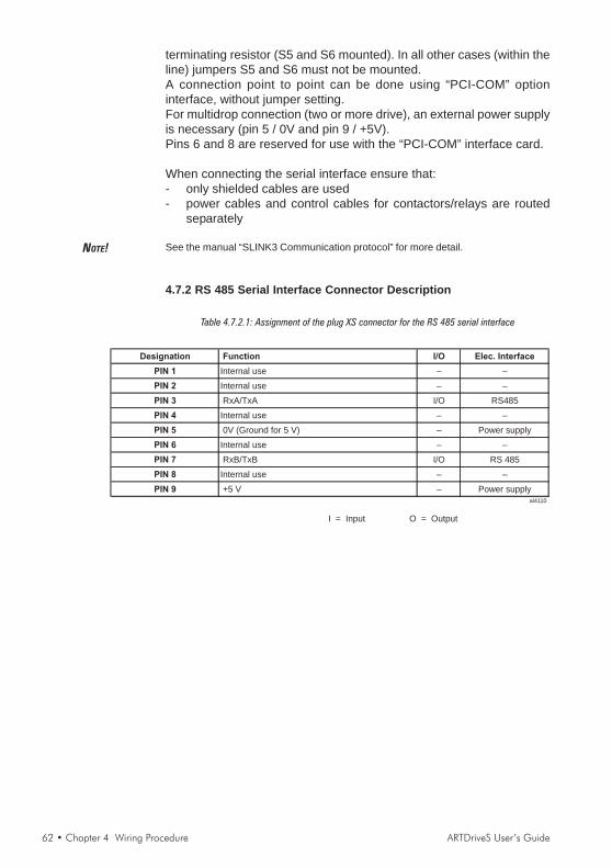
62 • Chapter 4 Wiring Procedure ARTDriveS User’s Guide
terminating resistor (S5 and S6 mounted). In all other cases (within theline) jumpers S5 and S6 must not be mounted.A connection point to point can be done using “PCI-COM” optioninterface, without jumper setting.For multidrop connection (two or more drive), an external power supplyis necessary (pin 5 / 0V and pin 9 / +5V).Pins 6 and 8 are reserved for use with the “PCI-COM” interface card.
When connecting the serial interface ensure that:- only shielded cables are used- power cables and control cables for contactors/relays are routed
separately
NOTE! See the manual “SLINK3 Communication protocol” for more detail.
4.7.2 RS 485 Serial Interface Connector Description
Table 4.7.2.1: Assignment of the plug XS connector for the RS 485 serial interface
Designation Function I/O Elec. Interface
PIN 1 Internal use – –
PIN 2 Internal use – –
PIN 3 RxA/TxA I/O RS485
PIN 4 Internal use – –
PIN 5 0V (Ground for 5 V) – Power supply
PIN 6 Internal use – –
PIN 7 RxB/TxB I/O RS 485
PIN 8 Internal use – –
PIN 9 +5 V – Power supplyai4110
I = Input O = Output

ARTDriveS User’s Guide Chapter 4 Wiring Procedure • 63
4.8 Standard Connection Diagram4.8.1 ARTDriveS Connections
Figure 4.8.1.1: Typical connection
+ 24V
U1/L1
M1
K1M
5
F1
L1L2
L3N
PE
K2
G1
0 V24
CD
1 2
3 46
K1M
SM
PS
K0
L1
Ther
mis
tor
1
EXC-EXC+COS-
COS+/H3SIN-/H2
SIN+/H1+5VE
+B0VE
A-A+
Z-Z+
PTCB
56
87
9
XE
COM DI
14
16
59
87
6
Dig. Inp.1(Start)
Digital Inp. 0(Enable drive)
30
31
32
Ok
rela
y
RS 485
Key
pad
20
21
+ 10 V
- 10 V
0 V 10
0FW
DR
EV
R1
(2..
.5
kohm
)
21
Ana
log
inpu
t0
Ana
log
inpu
t1
-
34-
++
E
PE1
V1/L2
W1/L3
U2/T1
V2/T2
W2/T3
Dig. Inp.7(Drive Reset)
Ana
log
outp
ut1
18
Ana
log
outp
ut0
17
28
11
29
Dig. Out.4
Dig. Out.5
1V
3U
32V
3
M 3~
Dig. Inp.2(Ramp in = 0)
Dig. Inp.3(Reverse)
34
10
11
12
22
23
24
25
19
12
13
Dig. Out.0
Dig. Out.1
26
27
Dig. Out.2
Dig. Out.3
COM DO
10
DO supply
13
14
15
2
PE2
Dig. Inp.6(External fault)
Dig. Inp.5(End Run fwd)
Dig. Inp.4(End Run rev)
NavigationDriveControls DriveControls
+To
rque
-To
rque
-To
rque
Ala
rmA
larm
Ena
ble
Zero
Spee
dLi
mit
He
lpA
larm
Ho
me
+
Esc
ap
e
Ente
rS
hif
t
Press2sec.todisable
Jo
g
Sp
eed
The circuit diagram is for the standard configuration of the drive as delivered.EMC installation and wiring techniques are not shown.For this see appropriate chapter. The connection of option card is also shown separately.The automatic restart of the drive after a failure alarm is not included.Nota! U3/2V3 and 1V3 only from sizes 75kW. For more details see chapter 4.2.1

64 • Chapter 4 Wiring Procedure ARTDriveS User’s Guide
Figure 4.8.1.2: Typical connection diagram for XVy-EV ...-DC versions.
+ 24V
M1
K2
G1
0 V24
CD
K1M
SM
PS
K0
Ther
mis
tor
1
EXC-EXC+COS-
COS+/H3SIN-/H2
SIN+/H1+5VE
+B0VE
A-A+
Z-Z+
PTCB
56
87
9
XE
COM DI
14
16
59
87
6Dig. Inp.1(Start)
Digital Inp. 0(Enable drive)
30
31
32
Ok
rela
y
RS 485
Key
pad
20
21
+ 10 V
- 10 V
0 V 10
0FW
DR
EV
R1
(2..
.5
kohm
)
21
Ana
log
inpu
t0
Ana
log
inpu
t1
-
34-
++
E
PE1
U2/T1
V2/T2
W2/T3
Dig. Inp.7(Drive Reset)
Ana
log
outp
ut1
18
Ana
log
outp
ut0
17
28
11
29
Dig. Out.4
Dig. Out.5
1V
3U
32V
3
M 3~
Dig. Inp.2(Ramp in = 0)
Dig. Inp.3(Reverse)
34
10
11
12
22
23
24
25
19
12
13
Dig. Out.0
Dig. Out.1
26
27
Dig. Out.2
Dig. Out.3
COM DO
10
DO supply
13
14
15
2
PE2
Dig. Inp.6(External fault)
Dig. Inp.5(End Run fwd)
Dig. Inp.4(End Run rev)
NavigationDriveControls DriveControls
+To
rque
+To
rque
-To
rque
-To
rque
Ala
rmEn
able
Zero
Spee
dLi
mit
He
lpA
larm
Ho
me
+
Esc
ap
e
Ente
rS
hif
t
Press2sec.todisable
Jo
g
Sp
eed
K1M
5
F1
L1L2
L3N
PE
1 2
3 46
L1
SM
32
orD
CP
ower
supp
ly
The circuit diagram is for the standard configuration of the drive as delivered.EMC installation and wiring techniques are not shown.For this see appropriate chapter. The connection of option card is also shown separately.
The automatic restart of the drive after a failure alarm is not included.

ARTDriveS User’s Guide Chapter 4 Wiring Procedure • 65
4.8.2 Parallel Connection on the AC (Input) and DC (IntermediateCircuit) Side of Several Drives
Features and Limits:1 The inverters used have to be all the same size.2 AC line chokes (see chapter 4.10.1) have to be the same (provided
by the same supplier).3 The mains power supply has to be simultaneous for all inverters,
i.e. a single switch /line contactor has to be used.4 Such connection is suitable for a maximum of 6 inverters.5 If required, dissipate the braking power; it is necessary to use one
internal "BU" braking unit (with external resistance) or one (or more)external braking units ("BU32-.., BUy..") of which one has to beconfigured as master and the others as slave.
6 Fast fuses (F12...F62) have to be fitted on the dc-link side ( C and Dterminals) of each inverters (see chapter 4.9.2).
Figure 4.8.2.1: Parallel Connection on the AC and DC Side of Several Drives
M13
M23
M63
F11 L1
F21 L2
F61 L6
U
V
W
U2
V2
W2
C
D
DRIVE 1
U
V
W
U2
V2
W2
C
D
DRIVE 2
BR
F12
F22
F62
U
V
W
U2
V2
W2
C
D
DRIVE 6
BR
CR C
D
BU-32-...(B y-...)U
(MASTER)
7 8 9 10
RBR
F7
RBR
L1
L2
L3
K1
M..3
F.. L..
U
V
W
U2
V2
W2
C
D
DRIVE ..
F..
(*) (*) Do not connect if externalbraking unit are used
Caution

66 • Chapter 4 Wiring Procedure ARTDriveS User’s Guide
4.9 Circuit Protection4.9.1 External Fuses for the Power SectionThe drive must be fused on the AC Input side. Use fast fuses only.Connections with three-phase inductance on AC input are not essentialbut will improve the DC link capacitors lifetime and drive reliability inunusual power events.
Table 4.9.1.1: External Fuse Types for AC input side
Europe
10306 25000 GRD2/10 (F4D13) or Z14GR10 (F4M03) A70P10 FWP10 (S7G49)
10408 25000
10612 10000
20816 25000 GRD2/20 (F4D15) or Z14GR20 (F4M07) A70P20 FWP20 (S7G48)
21020 25000 GRD2/25 (F4D16) or Z14GR25 (F4M09) A70P25 FWP25 (S7G51)
21530 10000 GRD3/35 (F4D20) or Z22GR40 A70P35 FWP35 (S7G86)
32040 25000 GRD3/50 (F4D21) or Z22GR40 A70P40 FWP40 (S7G52)
32550 10000 GRD3/50 (F4D21) or Z22GR50 (F4M15) A70P40 FWP40 (S7G52)
43366 ... 8350460 10000
10306 50000 GRD2/10 (F4D13) or Z14GR10 (F4M03) A70P10 FWP10 (S7G49)
10408 50000 A70P10 FWP10 (S7G49)
10612 50000
20816 50000
21020 50000 GRD2/20 (F4D15) or Z14GR20 (F4M07) A70P20 FWP20 (S7G48)
21530 50000 GRD2/25 (F4D16) or Z14GR25 (F4M09) A70P25 FWP25 (S7G51)
32040 50000 GRD3/50 (F4D21) or Z22GR40 A70P35 FWP35 (S7G86)
32550 50000 GRD3/50 (F4D21) or Z22GR50 (F4M15) A70P40 FWP40 (S7G52)
43366 30000
43570 25000
44590 25000 S00C+üf1/80/80A/660V or Z22gR80 A70P80 FWP80 (S7G54)
455110 25000 S00C+üf1/80/100A/660V or M00üf01/100A/660V (F4G18) A70P100 FWP100 (S7G55)
570140 25000
5100180 25000
5S100180 25000
6125230 25000
6S125230 25000
7145290 25000
7190350 25000
7S190350 25000
7230420 25000
7S230420 25000
8280400 25000
8350460 25000 S2üf1/110/500A/660V or M2üf1/500A/660V (F4G30) A70P500 FWP500 (S7G63)
9470650-C 25000 S2üf1/110/630A/660V (F4E31) A70P600 FWP600 (S7G65)
9470650-C-IP00 25000 S2üf1/110/630A/660V (F4E31) A70P600 FWP600 (S7G65)
9560650-CP 25000 S2üf1/110/630A/660V (F4E31) A70P600 FWP600 (S7G65)
9560650-CP-IP00 25000 S2üf1/110/630A/660V (F4E31) A70P600 FWP600 (S7G65)
txv0150
S2üf1/110/400A/660V or M2üf1/400A/660V (F4G34) A70P400 FWP400 (S7G62)
S1üf1/110/250A/660V or M1üf1/250A/660V (F4G28) A70P300 FWP300 (S7G60)
S00C+üf1/80/160A/660V or M00üf01/160A/660V (F4E15) A70P175 FWP175 (S7G57)
GRD3/50 (F4D21) or Z22GR50 A70P50 FWP50 (S7G53)
GRD2/16 (F4D14) or Z14GR16 (F4M05) A70P20 FWP20 (S7G48)
For these types an external reactor is mandatory if the
AC input impedence is equal or less than 1%
Connections without three-phase reactor
GRD2/16 (F4D14) or Z14GR16 (F4M05) A70P20 FWP20 (S7G48)
Drive type
XVy-EV
DC link
capacitors life
time [h]
F1 - Fuses type (Code)
America
Connections without three-phase reactor
Fuse manufacturers:Type GRD2... (E27), GRD3... (E33), M... (blade fuses),Z14... 14 x 51 mm, Z22... 22 x 58 mm, S.... Jean Müller, EltvilleA70P... Gould ShawmutFWP... Bussmann
NOTE! The technical data of the fuses, e.g. dimensions, weights, heatdissipation, auxiliary contactors, are found in the manufacturers datasheets.

ARTDriveS User’s Guide Chapter 4 Wiring Procedure • 67
4.9.2 External Fuses for the Power Section DC Input SideUse the following fuses when an external bus supply is used.
Table 4.9.2.1: External fuses type for DC input side
Fuses type Code Code
10306
10408
10612
20816
21020 Z14GR20 F4M07 A70P20-1 FWP20A14F S7G48
21530 Z14GR32 F4M11 A70P30-1 FWP30A14F S7I50
32040 Z14GR40 F4M13 A70P40-4 FWP40B S7G52
32550 Z22GR63 F4M17 A70P60-4 FWP60B S7I34
43366
43570
44590 S00C+/üf1/80/100A/660V F4EAG A70P100 FWP100 S7G55
455110 S00C+/üf1/80/125A/660V F4EAJ A70P150 FWP150 S7G56
570140 S00C+/üf1/80/160A/660V F4EAL A70P175 FWP175 S7G57
5100180
5S100180
6125230
6S125230
7145290 S1üF1/110/315A/660V F4G30 A70P350 FWP350 S7G61
7190350
7S190350
7230420
7S230420
8280400
8350460 S2üf1/110/630A/660V F4E31 A70P600 FWP600 S7G65
9470670-DC-IP00
9470650-C
9470650-C-IP00
9470650-C-DC-IP00
9560800-DC-IP00
9560650-CP
9560650-CP-IP00
9560650-CP-DC-IP00
txv0160
S7813S3üF1/110/800A/660V F4H02 A70P800 FWP800
S7G62S1üF1/110/400A/660V F4G34 A70P400 FWP400
S7G58
S1üF1/110/250A/660V F4G28 A70P250 FWP250 S7G59
S7G54
S1üF1/110/500A/660V F4E30 A70P500 FWP500 S7G63
S00üF1/80/200A/660V F4G23 A70P200 FWP200
S00C+/üf1/80/80A/660V F4EAF A70P80 FWP80
S7G49
Z14GR16 F4M05 A70P20-1 FWP20A14F S7G48
Z14GR10 F4M03 A70P10 FWP10A14F
Drive type
XVy-EV
Europe America
Fuses type
Fuse manufacturers:Type Z14..., Z22, S00 ..., S1..., S2... Jean Müller, EltvilleA70P... Gould ShawmutFWP... Bussmann
NOTE! The technical data of the fuses, e.g. dimensions, weights, heatdissipation, auxiliary contactors, are found in the manufacturers datasheets.
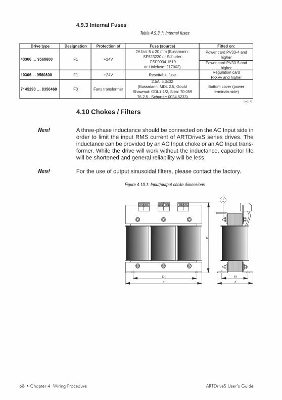
68 • Chapter 4 Wiring Procedure ARTDriveS User’s Guide
4.9.3 Internal FusesTable 4.9.3.1: Internal fuses
Drive type Designation Protection of Fuse (source) Fitted on:
Power card PV33-4 and
higher
Power card PV33-5 and
higher
10306 ... 9560800 F1 +24V Resettable fuseRegulation card
R-XVy and higher
7145290 … 8350460 F3 Fans transformer
2.5A 6.3x32
(Bussmann: MDL 2.5, Gould
Shawmut: GDL1-1/2, Siba: 70 059
76.2,5 , Schurter: 0034.5233)
Bottom cover (power
terminals side)
txv0170
2A fast 5 x 20 mm (Bussmann:
SF523220 or Schurter:
FSF0034.1519
or Littlefuse: 217002)
43366 … 9560800 F1 +24V
4.10 Chokes / Filters
NOTE! A three-phase inductance should be connected on the AC Input side inorder to limit the input RMS current of ARTDriveS series drives. Theinductance can be provided by an AC Input choke or an AC Input trans-former. While the drive will work without the inductance, capacitor lifewill be shortened and general reliability will be less.
NOTE! For the use of output sinusoidal filters, please contact the factory.
Figure 4.10.1: Input/output choke dimensions

ARTDriveS User’s Guide Chapter 4 Wiring Procedure • 69
4.10.1 AC Input ChokesTable 4.10.1.1: 3-Phase AC Input Chokes
Mains
inductance
Rated
current
Saturat.
current
Freq.
[mH] [A] [A] [Hz] a b c D1 E1
10306 3.69 3.7 7.4 50/60 LR3y-1015 S7AAE 1.8 (4.0)
10408 2.71 5.5 11 50/60 LR3y-1022 S7AAF
10612 2.3 6.7 14 50/60 LR3y-1030 S7AB3
20816 1.63 8.7 18 50/60 LR3y-2040 S7AAG 2 (4.4)
21020 1.29 11.8 24.5 50/60 LR3y-2055 S7AB5 2.2 (4.4) 120 (4.7) 125 (4.9) 75 (2.6) 100 (3.9) 55 (2.2)
21530 0.89 17.4 36.5 50/60 LR3y-2075 S7AB6 4.9 (10.8) 150 (5.9) 155 (6.1) 79 (3.1) 90 (3.5) 54 (2.1)
32040 0.68 22.4 46.5 50/60 LR3y-3110 S7AB7 5 (11) 150 (5.9) 155 (6.1) 79 (3.1) 90 (3.5) 54 (2.1)
32550 0.51 30 61 50/60 LR3y-3150 S7AB8 6.2 (13.7) 150 (5.9) 168 (6.6) 100 (3.9) 90 (3.5) 69 (2.7)
43366
43570
44590 0.24 58 120 50/60 LR3-030 S7FF3 9.5 (20.9) 180 (7.1) 160 (6.3) 170 (6.7) 150 (5.9) 80 (3.1)
455110 0.18 71 145 50/60 LR3-037 S7FF2 9.5 (20.9) 180 (7.1) 160 (6.3) 180 (7.1) 150 (5.9) 80 (3.1)
570140
5100180
5S100180
6125230
6S125230
7145290
7190350
7S190350
7230420
7S230420
8280400
8350460 0.085 380 710 50/60 LR3-200 S7AE9 54 (119) 300 (11.8) 270 (10.6) 355 (13.9) 250 (9.8) 130 (5.1)
9470670
9470650-C
9560800
9560650-CP
txv0180
Drive type
XVy-EV
Three-phases main chokes
Model Cod.Weight
kg (lbs)
Dimensions : mm (inch)
120 (4.7) 125 (4.9) 65 (2.6)1.9 (4.2)
12.5 (27.6) 240 (9.4) 215 (8.5) 180 (7.1)
55 (121.3) 300 (11.8)
100 (3.9) 45 (1.8)
182 (7.2) 130 (5.1) 150 (5.9) 70 (2.8)
150 (5.9) 80 (3.1)
LR3-022 S7FF4 7.8 (17.2) 180 (7.1)
LR3-055 S7FF10.13 102 212 50/60
0.35 41 83 50/60
LR3-090 S7D190.148 173 350 50/60 265 (10.4) 210 (8.3) 250 (9.8) 85 (3.3)
LR3-160 S7D40 44 (97.0) 300 (11.8) 270 (10.6) 260 (10.2) 250 (9.8) 120 (4.7)
0.06 550 1050 50/60 LR3-315 S7D28 110 (242.5) 375 (14.8) 545 (21.5) 255 (10) 250 (9.8) 133 (5.2)
0.085 297 600 50/60
For all the sizes an input choke is strongly recommended in order to:- prolong the life time of the DC link capacitors and the reliability of
the input rectifier.- reduce the AC mains harmonic distortion- reduce the problems due to a low impedance AC mains ( ≤ 1%).
NOTE! The current rating of these inductors (reactors) is based on the nominalcurrent of standard motors, listed in table 2.3.2.1 in section 2.3.2, “ACInput/Output Connection”.
4.10.2 Output ChokesFor motors with long cable runs (typically over 30 m [98.5 feet]) anoutput choke is recommended to maintain the voltage waveform withinthe specified limits. Suggested choke ratings and part numbers are listedin table 4.10.2.1.The rated current of the filters should be approx. 20% above the ratedcurrent of the frequency drive in order to take into account additionallosses due to PWM waveform.
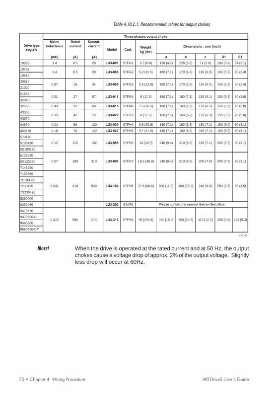
70 • Chapter 4 Wiring Procedure ARTDriveS User’s Guide
Table 4.10.2.1: Recommended values for output chokes
Drive type
XVy-EV
Mains
inductance
Rated
current
Saturat.
current
[mH] [A] [A] a b c D1 E1
10306 1.4 9.5 20 LU3-001 S7FG1 2.7 (6.0) 120 (4.7) 128 (5.0) 71 (2.9) 100 (3.9) 54 (2.1)
10408
10612
20816
21020
21530
32040
32550 0.43 32 68 LU3-015 S7FM2 7.5 (16.5) 180 (7.1) 160 (6.3) 170 (6.7) 150 (5.9) 70 (2.8)
43366
43570
44590 0.24 58 100 LU3-030 S7FH4 9.5 (20.9) 180 (7.1) 160 (6.3) 180 (7.1) 150 (5.9) 80 (3.1)
455110 0.18 76 130 LU3-037 S7FH5 9.7 (21.4) 180 (7.1) 160 (6.3) 180 (7.1) 150 (5.9) 80 (3.1)
570140
5100180
5S100180
6125230
6S125230
7145290
7190350
7S190350
7230420
7S230420
8280400
8350460 LU3-200 S7AF0
9470670
9470650-C
9560800
9560650-CP
txv0190
Model
310 [12.2] 250 [9.8] 134 [5.3]
Please contact the nearest Gefran-Siei office
0.022 580 1100 LU3-315 S7FH9 95 [209.4] 380 [15.0] 500 [10.7]
240 (9.4) 250 (9.8) 90 (3.5)S7FH8 27.5 (60.6) 300 (11.8) 260 (10.2)0.041 310 540 LU3-160
210 (8.3) 200 (7.9) 200 (7.9) 80 (3.1)
180 (7.1) 200 (7.9) 80 (3.1)
0.07 180 310 LU3-090 S7FH7 18.5 (40.8) 240 (9.4)
S7FH6 14 (30.9) 240 (9.4) 210 (8.3)0.12 110 192 LU3-055
160 (6.3) 170 (6.3) 150 (5.9) 70 (2.8)
130 (5.1) 150 (5.9) 70 (2.8)
0.33 42 72 LU3-022 S7FH3 8 (17.6) 180 (7.1)
S7FG4 8 (17.6) 180 (7.1) 180 (7.1)0.51 27 57 LU3-011
170 (6.7) 110 (4.3) 150 (5.9) 60 (2.4)
110 (4.3) 150 (5.9) 60 (2.4)
0.87 16 34 LU3-005 S7FG3 5.8 (12.8) 180 (7.1)
S7FG2 5.2 (11.5) 180 (7.1) 170 (6.7)1.4 9.5 20 LU3-003
Three-phases output choke
Cod.Weight
kg (lbs)
Dimensions : mm (inch)
NOTE! When the drive is operated at the rated current and at 50 Hz, the outputchokes cause a voltage drop of approx. 2% of the output voltage. Slightlyless drop will occur at 60Hz.

ARTDriveS User’s Guide Chapter 4 Wiring Procedure • 71
4.10.3 Interference Suppression FiltersARTDriveS drives must be equipped with an external EMI filter in orderto reduce the radiofrequency emissions on the mains line as requiredfor operation in Europe.The filter selection is depending on the drive size and the installationenvironment.For more information, see the “EMC guide” on the cd-rom included.In the Guide it is also indicated how to install the drive in an enclosure(connection of filter and mains reactors, cable shield, ground, etc.) inorder to make it EMC compliant according the EMC Directive 89/336/EEC. The document describes the present situation concerning theEMC standards and the compliance tests made on the drives as requiredby CE.
Table 4.10.3.1: Recommended EMI filters
a b c d D1 E1 R P M
10306 … 10612 (2) EMI FFP 480-9 S7DEQ 1.1 (2.4) 375 (14.8) 104 (4.1) 45 (1.8) - 360 (14.2) 59 (2.3) - M5 Ø6
20816 … 21530 (2) EMI FFP 480-24 S7DER 1.4 (3.1) 375 (14.8) 150 (5.9) 45 (1.8) - 360 (14.2) 105 (4.1) - M5 Ø6
32040 (2) EMI FFP 480-30 S7DES 1.6 (3.5) 390 (15.4) 200 (7.9) 45 (1.8) - 375 (14.8) 155 (6.1) - M5 Ø6
32550 (2) EMI FFP 480-40 S7DET 2.3 (5.1) 390 (15.4) 200 (7.9) 45 (1.8) - 375 (14.8) 155 (6.1) - M5 Ø6
43366 … 43570 (3) EMI 480-45 S7DFU 1.3 (2.9) 250 (9.8) 85 (3.3) 90 (3.5) - 235 (9.3) 60 (2.4) - - M6
44590 … 455110 (3) EMI 480-70 S7DFZ 2.6 (5.7) 270 (10.6) 90 (3.5) 150 (5.9) - 255 (10.0) 65 (2.6) - - M6
570140 … 5S100180 (3) EMI 480-100 S7DGA 2.6 (5.7) 270 (10.6) 90 (3.5) 150 (5.9) - 255 (10.0) 65 (2.6) - - M6
6125230 - 6S125230 (3) EMI 480-150 S7DGB 4.4 (9.7) 400 (15.7) 120 (4.7) 170 (6.7) - 365 (14.4) 102 (4.0) - - M6
7145290 (3) EMI 480-180 S7DGC 4.4 (9.7) 400 (15.7) 120 (4.7) 170 (6.7) - 365 (14.4) 102 (4.0) - - M6
7190350 - 7S190350 (3) EMI 480-250 S7DGG 13 (28.7) 300 (11.8) 260 (10.2) 135 (5.31) - 120 (4.72) 235 (9.25) - - M10
7230420 - 7S230420 (3) EMI 480-250 S7DGG 13 (28.7) 300 (11.8) 260 (10.2) 135 (5.31) - 120 (4.72) 235 (9.25) - - M10
8280400 (3) EMI 480-320 S7DGH 13.2 (29.1) 300 (11.8) 260 (10.2) 135 (5.31) - 120 (4.72) 235 (9.25) - - M10
8350460 (3) EMI 480-400 S7DGI 13.4 (29.5) 300 (11.8) 260 (10.2) 135 (5.31) - 120 (4.72) 235 (9.25) - - M10
9470650-C (3) EMI-480-600 S7DGL 40 (88.2) 300 (11.8) 260 (10.2) 135 (5.31) - 120 (4.72) 235 (9.25) - - M10
9560800 (3) EMI-480-800 S7DGM 40 (88.2) 350 (13.8) 280 (11.0) 150 (5.9) - 145 (5.7) 255 (10.0) - - M10
9560650-CP (3) EMI-480-800 S7DGM 40 (88.2) 350 (13.8) 280 (11.0) 150 (5.9) - 145 (5.7) 255 (10.0) - - M10
10306 … 10612 (2) EMI FFP 480-9 S7DEQ 1.1 (2.4) 375 (14.8) 104 (4.1) 45 (1.8) - 360 (14.2) 59 (2.3) - M5 Ø6
20816 … 21530 (2) EMI FFP 480-24 S7DER 1.4 (3.1) 375 (14.8) 150 (5.9) 45 (1.8) - 360 (14.2) 105 (4.1) - M5 Ø6
32040 (2) EMI FFP 480-30 S7DES 1.6 (3.5) 390 (15.4) 200 (7.9) 45 (1.8) - 375 (14.8) 155 (6.1) - M5 Ø6
32550 (2) EMI FFP 480-40 S7DET 2.3 (5.1) 390 (15.4) 200 (7.9) 45 (1.8) - 375 (14.8) 155 (6.1) - M5 Ø6
43366 … 43570 (3) EMI 480-45 S7DFU 1.3 (2.9) 250 (9.8) 85 (3.3) 90 (3.5) - 235 (9.3) 60 (2.4) - - M6
44590 (3) EMI 480-55 S7DFV 2 (4.4) 250 (9.8) 85 (3.3) 90 (3.5) - 235 (9.3) 60 (2.4) - - M6
455110 (3) EMI 480-70 S7DFZ 2.6 (5.7) 270 (10.6) 90 (3.5) 150 (5.9) - 255 (10.0) 65 (2.6) - - M6
570140 … 5S100180 (3) EMI 480-100 S7DGA 2.6 (5.7) 270 (10.6) 90 (3.5) 150 (5.9) - 255 (10.0) 65 (2.6) - - M6
6125230 … 7145290 (3) EMI 480-150 S7DGB 4.4 (9.7) 400 (15.7) 120 (4.7) 170 (6.7) - 365 (14.4) 102 (4.0) - - M6
7190350 - 7S190350 (3) EMI 480-180 S7DGC 4.4 (9.7) 400 (15.7) 120 (4.7) 170 (6.7) - 365 (14.4) 102 (4.0) - - M6
7230420 - 7S230420 (3) EMI 480-250 S7DGG 13 (28.7) 300 (11.8) 260 (10.2) 135 (5.31) - 120 (4.72) 235 (9.25) - - M10
8280400 (3) EMI 480-250 S7DGG 13 (28.7) 300 (11.8) 260 (10.2) 135 (5.31) - 120 (4.72) 235 (9.25) - - M10
8350460 (3) EMI 480-400 S7DGI 13.4 (29.5) 300 (11.8) 260 (10.2) 135 (5.31) - 120 (4.72) 235 (9.25) - - M10
9470650-C (3) EMI-480-600 S7DGL 40 (88.2) 300 (11.8) 260 (10.2) 135 (5.31) - 120 (4.72) 235 (9.25) - - M10
9560800 (3) EMI-480-600 S7DGL 40 (88.2) 300 (11.8) 260 (10.2) 135 (5.31) - 120 (4.72) 235 (9.25) - - M10
9560650-CP (3) EMI-480-600 S7DGL 40 (88.2) 300 (11.8) 260 (10.2) 135 (5.31) - 120 (4.72) 235 (9.25) - - M10
10306 … 32040 (1), (2) EMI-C 480-25 S7DFA 0.96 (2.1) 105 (4.1) 100 (3.9) 57 (2.2) - 57 (2.2) 95 (3.7) M5 4.5x3
10306 … 9560650-CP (4) ECF1 F4ZZ1 150 (5.9) 70 (2.76) 55 (2.17) - 100 (3.94) - - M5 -
10306 … 9560650-CP (4) ECF3 F4ZZ2 150 (5.9) 85 (3.3) 120 (4.72) - 100 (3.94) - - M6 -
txv0195
Mains supply : 400V ±10%
Mains supply : 500V ±10%
Mains supply : 230 - 400V ±15%, 460 - 480 +10%
Mains supply : 230 - 400V ±15%
Mains supply : 460 - 480 +10%
Weight
kg (lbs)
Dimensions : mm (inch)Drive type
XVy-EVClass
Model Cod.
(1): Drive/motor cable lengths max 5 metres.(2): EN61800-3, 1st environment restricted distribution, conducted emission.(3): EN61800-3, 2nd environment unrestricted distribution, conducted emission.(4): EN61800-3, 2nd environment restricted distribution, conducted emission.
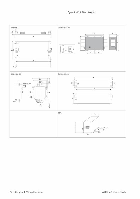
72 • Chapter 4 Wiring Procedure ARTDriveS User’s Guide
Figure 4.10.3.1: Filter dimension
D1
E1b
LIN
E
LO
AD
a
c
M
P
EMI 480-250...800EMI FFP ...
c
M4
M5
Wires 2.5 mmblock
2
LOADL1 L2 L3
LINE
L1 L2 L3P1
D1
b2
00
±2
02
00
±2
0
E1
4.5x3
a
EMI-C 480-25
a
c
D1
E1M
b
EMI 480-45...180
28
43
T225
5-8
a
b
c
D1
E1
D1
M
b
c
a
b1
25
25D1
ECF ..
P
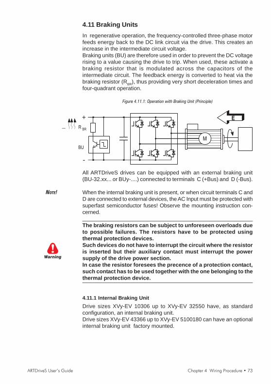
ARTDriveS User’s Guide Chapter 4 Wiring Procedure • 73
4.11 Braking UnitsIn regenerative operation, the frequency-controlled three-phase motorfeeds energy back to the DC link circuit via the drive. This creates anincrease in the intermediate circuit voltage.Braking units (BU) are therefore used in order to prevent the DC voltagerising to a value causing the drive to trip. When used, these activate abraking resistor that is modulated across the capacitors of theintermediate circuit. The feedback energy is converted to heat via thebraking resistor (RBR), thus providing very short deceleration times andfour-quadrant operation.
Figure 4.11.1: Operation with Braking Unit (Principle)
E
M
_R
BR
BU
All ARTDriveS drives can be equipped with an external braking unit(BU-32.xx... or BUy-....) connected to terminals C (+Bus) and D (-Bus).
NOTE! When the internal braking unit is present, or when circuit terminals C andD are connected to external devices, the AC Input must be protected withsuperfast semiconductor fuses! Observe the mounting instruction con-cerned.
The braking resistors can be subject to unforeseen overloads dueto possible failures. The resistors have to be protected usingthermal protection devices.Such devices do not have to interrupt the circuit where the resistoris inserted but their auxiliary contact must interrupt the powersupply of the drive power section.In case the resistor foresees the precence of a protection contact,such contact has to be used together with the one belonging to thethermal protection device.
4.11.1 Internal Braking UnitDrive sizes XVy-EV 10306 up to XVy-EV 32550 have, as standardconfiguration, an internal braking unit.Drive sizes XVy-EV 43366 up to XVy-EV 5100180 can have an optionalinternal braking unit factory mounted.
Warning

74 • Chapter 4 Wiring Procedure ARTDriveS User’s Guide
Table 4.11.1.1: Technical data of the internal braking units
Drive type IRMS IPK T Minimum RBR
XVy-EV [A] [A] [s] [ohm]
10306 …20816 4.1 7.8 19 100
21020 … 21530 6.6 12 16 67
32040 12 22 17 36
32550 17 31 16 26
43366 - 43570 18 52 42 15
44590 37 78 23 10
455110 29 78 37 10
570140 … 5S100180 50 104 22 7.5
6125230 … 9560650
txv0260
External braking unit (optional)
IRMS Nominal current of the braking unitIPK Peak current deliverable for 60 seconds max.T Minimum cycle time for a working at IPK for 10 seconds
4.11.2 Internal and External Braking ResistorsThe ARTDriveS drives, up to size XVy-EV 32550, are equipped with anInternal Braking Resistor according to the following table:
Drive Resistor PNBR RBR EBR
Type Type [W] [Ohm] [kJ]
10306 …10612 CBR-100R 100 100 11
21020 … 21530 CBR-67R 150 67 11
32040 RFI1300-36R 200 36 16
32550 RFI1300-26R 200 26 16
txv0225
For bigger sizes, the braking resistor is optional and has always to bemounted externally. For parameter settings refer to the section 10,BRAKING RES menu. The figure below shows the configuration forinternal brake unit operation.
Figure 4.11.2.1: Connection with internal Braking Unit and external braking resistor
Brakingresistor
3Ph~
PE
1/
U1/L
1
V1/L
2
W1/L
3
BR
1
U2/T
1
V2/T
2
W2/T
3
C D
PE
2/
F1
BrakingUnit
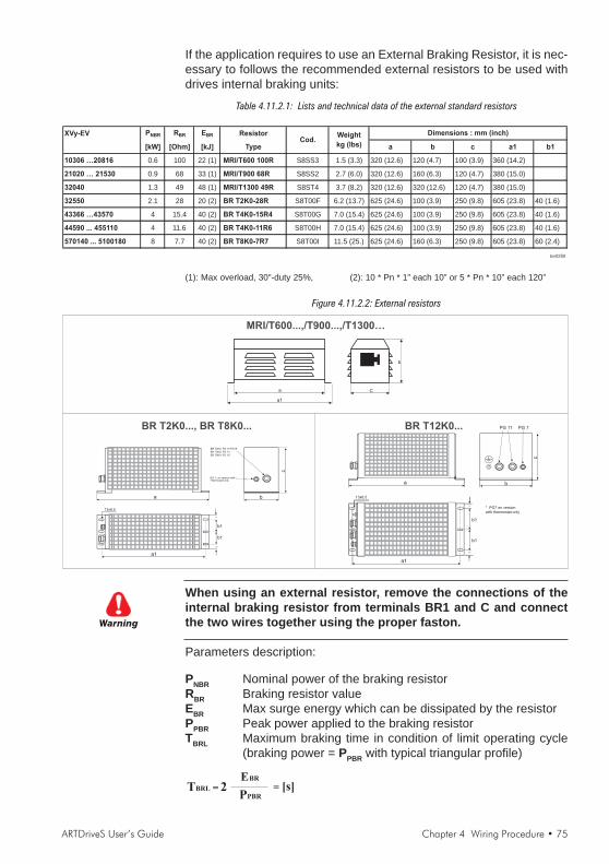
ARTDriveS User’s Guide Chapter 4 Wiring Procedure • 75
If the application requires to use an External Braking Resistor, it is nec-essary to follows the recommended external resistors to be used withdrives internal braking units:
Table 4.11.2.1: Lists and technical data of the external standard resistors
XVy-EV PNBR RBR EBR Resistor
[kW] [Ohm] [kJ] Type a b c a1 b1
10306 …20816 0.6 100 22 (1) MRI/T600 100R S8SS3 1.5 (3.3) 320 (12.6) 120 (4.7) 100 (3.9) 360 (14.2)
21020 … 21530 0.9 68 33 (1) MRI/T900 68R S8SS2 2.7 (6.0) 320 (12.6) 160 (6.3) 120 (4.7) 380 (15.0)
32040 1.3 49 48 (1) MRI/T1300 49R S8ST4 3.7 (8.2) 320 (12.6) 320 (12.6) 120 (4.7) 380 (15.0)
32550 2.1 28 20 (2) BR T2K0-28R S8T00F 6.2 (13.7) 625 (24.6) 100 (3.9) 250 (9.8) 605 (23.8) 40 (1.6)
43366 …43570 4 15.4 40 (2) BR T4K0-15R4 S8T00G 7.0 (15.4) 625 (24.6) 100 (3.9) 250 (9.8) 605 (23.8) 40 (1.6)
44590 ... 455110 4 11.6 40 (2) BR T4K0-11R6 S8T00H 7.0 (15.4) 625 (24.6) 100 (3.9) 250 (9.8) 605 (23.8) 40 (1.6)
570140 ... 5100180 8 7.7 40 (2) BR T8K0-7R7 S8T00I 11.5 (25.) 625 (24.6) 160 (6.3) 250 (9.8) 605 (23.8) 60 (2.4)
txv0250
Cod.Weight
kg (lbs)
Dimensions : mm (inch)
(1): Max overload, 30"-duty 25%, (2): 10 * Pn * 1” each 10” or 5 * Pn * 10” each 120”
Figure 4.11.2.2: External resistors
a
b
C
a1
MRI/T600...,/T900...,/T1300…
BR T2K0..., BR T8K0...
a
c
BR T2K0: PG 11/PG16
b
BR T4K0: PG 13
BR T8K0: PG 16
PG 7: on version withThermostat only
a
b1
c
13x6.5
b
a1
b1
=
=
PG 11 PG 7
* PG7 on versionwith thermostat only
BR T12K0...
When using an external resistor, remove the connections of theinternal braking resistor from terminals BR1 and C and connectthe two wires together using the proper faston.
Parameters description:
PNBR Nominal power of the braking resistorRBR Braking resistor valueEBR Max surge energy which can be dissipated by the resistorPPBR Peak power applied to the braking resistorTBRL Maximum braking time in condition of limit operating cycle
(braking power = PPBR with typical triangular profile)
Warning
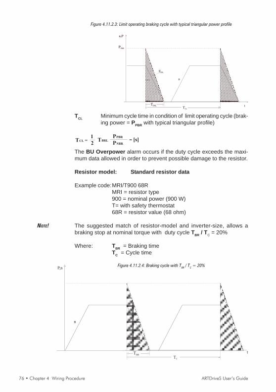
76 • Chapter 4 Wiring Procedure ARTDriveS User’s Guide
Figure 4.11.2.3: Limit operating braking cycle with typical triangular power profile
TCL
n,P
PPBR
TBRL
n
EBR
t
TCL Minimum cycle time in condition of limit operating cycle (brak-ing power = PPBR with typical triangular profile)
The BU Overpower alarm occurs if the duty cycle exceeds the maxi-mum data allowed in order to prevent possible damage to the resistor.
Resistor model: Standard resistor data
Example code:MRI/T900 68RMRI = resistor type900 = nominal power (900 W)T= with safety thermostat68R = resistor value (68 ohm)
NOTE! The suggested match of resistor-model and inverter-size, allows abraking stop at nominal torque with duty cycle TBR / TC = 20%
Where: TBR = Braking timeTC = Cycle time
Figure 4.11.2.4: Braking cycle with TBR / TC = 20%
TC
P,n
TBR
n
t

ARTDriveS User’s Guide Chapter 4 Wiring Procedure • 77
These resistors, whose technical data are reported in the table 4.11.2.1,have been sized to tolerate an overload equal to 4 times their nominalpower for 10 seconds.In any event they can tolerate also an overload, whose energy dissipationis the same of the maximum power level defined by:
Where: VBR = braking unit thresholdWith reference to the figure 4.11.2.3, where the power profile is thetypical triangular one, the following example can be taken intoconsideration (see also table 4.11.2.1).
Resistor model: MRI/T600 100R
Nominal power PNBR = 600 [W]Maximum energy EBR = 4 x 600[W] x 10[s] = 24000[J]Inverter mains supply = 460VVoltage threshold: VBR =780V
TBRL = 2EBR
PPBR
=24000
6084= 7.8[s]2PPBR =
VBR
RBR
2
=780
100
2
= 6084 [W]
It is necessary to consider the following relation:
A) If TBR < EBR / PNBR verify:1) PMB < 2 * EBR / TBRWhere: PMB is the maximum cycle power
(see figure 4.11.2.5)
2)x
The average power of the cycle must not be higher than thenominal power of the resistor.
B) If TBR > EBR / PNBR that is to say, in case of very long brakingtime, it must be dimensioned PMB < PNBR
Figure 4.11.2.5: Generic braking cycle with triangular profile
TC
n,P
PPBR
TBR t
PMB

78 • Chapter 4 Wiring Procedure ARTDriveS User’s Guide
If one of the above mentioned rules is not respected, it is necessary toincrease the nominal power of the resistor, respecting the limit of theinternal braking unit as stated in the table 4.11.1.
Generally the following condition must be satisfied
IRMS1 P TPBR BR
R TBR C2
4.11.3 Control of the External Braking PowerThe braking resistance average power is defined by the following formula:
P = 0.2 · Jtot · ωωωωω2 · f
where: P = Dissipated powerJtot = Total inertia ( Kgm2 )ωωωωω = Max speed ( rad/sec )f = Cycle frequency in Herz (number of cycles per sec-ond).f = 1/TBR (sec)
4.11.4 External Resistance Interaction with the System ParametersWhen the external braking resistance is installed it is always necessaryto carry out some modifications in the parameters.See chapter 10, BRAKING RES menu for furthers details.
4.11.5 Choice of the Thermal Relay for Brake ResistorHere is a procedure aimed at stating the coordination of a thermal relayfor the protection of the resistor bank in case of a sudden componentfailure (not detected), when the DC bus power supply is continuouslyconnected to the braking resistance.It is important to remember that the drives are supplied with a I2t functionfor the resistor bank protection; such a function is in a position to avoidany possible overload but it cannot protect against component failurethat might render impossible the logical control of the braking resistorcurrent.As stated in the dimensioning procedure for the bus braking system,the resistor bank has, with a given ambient condition, a possibleinstantaneous overload defined as
Emax BR in [Joule] or as a product given byPmax_BR x Tmax_BR [Joule]
supplied by the producer of the resistor. Such parameters are able todefine the resistor overload possibility in case of continuous maximumpower peaks.According to Emax BR and to the peak power value, which the resistorbank is subject to, PPBR = V2
BR / RBR (VBR= 780 V, default) the maxi-mum time for the peak power application is calculated as
ARTDriveS User’s Guide Chapter 4 Wiring Procedure • 79
Tmax BR = Emax BR / PPBR
Furthermore, the peak current on the resistors isIPK = VBR / RBR
Therefore, the time/current curves of the thermal relays are must have anoverload ratio requiring a thermal relay intervention time lower than Tmax
BR.Given that K, the overload ratio obtained from the curves, the currentvalue to which the thermal relay has to be set is:
Iterm = I PK / k
Now it is necessary to check that the product VBR x Iterm is higher thanthe average power, which can be dissipated on the resistor bank; suchvalue is stated during the dimensioning procedure of the braking system.In case the above-mentioned conditions are not satisfied, it is necessaryto use a thermal relay with a time/current feature able to obtain a Kfactor lower than the one stated above.The thermal relays to be used are those coordinated for the protectionof three-phase motors. In this case it is advisable to use all the threecontacts which have to be connected in series to be able to break thesubstantial DC voltage involved.

80 • Chapter 4 Wiring Procedure ARTDriveS User’s Guide
4.12 Buffering the Regulator SupplyWhen no external power supply is available on the terminals 15 and 16of the regulation card, the power supply of the control section is derivedfrom a switching power supplier (SMPS) of the DC link circuit. The driveis disabled as soon as the voltage of the DC Link circuit is below thethreshold value (UBuff). The regulator supply is buffered by the energy ofthe DC Link circuit until the limit value (Umin) is reached. The buffer timeis determined by the capacitance of the DC Link capacitors. The minimumvalues are shown in the table below. The buffer time (tBuff) can beextended (only on 11 kW drive and higher) by connecting externalcapacitors in parallel (on terminal C (+ bus) and D(- bus)).
Table 4.12.1: DC Link Buffer Time
Internal Buffer time tBuff Maximum Maximum
capacitance (minimum value) with the permissible power required
XVy-EV internal capacitance at : external by switched
AC Input AC Input capacitance mode power
Cstd voltage =400V voltage =460V supply
[µF] [s] [s] Cext [µF] PSMPS [W]
10306 220 0.165 0.25 0 65
10408 330 0.24 0.37 0 65
10612 330 0.24 0.37 0 65
20816 830 0.62 0.95 0 65
21020 830 0.62 0.95 0 65
21530 830 0.62 0.95 0 65
32040 1500 1.12 1.72 1500 65
32550 1500 1.12 1.72 1500 65
43366 1800 1.54 2.3 4500 70
43570 1800 1.54 2.3 4500 70
44590 2200 1.88 2.8 4500 70
455110 3300 2.83 4.2 4500 70
570140 4950 4.24 6.3 4500 70
5100180 4950 4.24 6.3 4500 70
6125230 6600 5.6 8.1 0 70
7145290 6600 5.6 8.1 0 70
7190350 9900 8.4 12.1 0 70
7230420 14100 12.8 17.2 0 70
8280400 14100 12.8 17.2 0 70
8350460 14100 12.8 17.2 0 70
9470670 29700 12.1 36.4 0 140
9470650 29700 12.1 36.4 0 140
9560800 56400 12.1 36.4 0 140
9560650 56400 12.1 36.4 0 140
txv0270SMPS = Switched Mode Power Supply

ARTDriveS User’s Guide Chapter 4 Wiring Procedure • 81
Figure 4.12.1: Buffering the Regulator Supply by Means of Additional Intermediate CircuitCapacitors
3Ph~
PE
1/
U1
/L1
V1
/L2
W1/L
3
BR
1
U2/T
1
V2
/T2
W2/T
3
C D
PE
2/
F1
1
Cx
1
C1x
1
C2x= +
C 900 V orX DC
NOTE! When connecting the intermediate circuit terminals C and D the ACInput side must be protected with superfast semiconductor fuses!Formula for calculating the size of the external capacitors:
fA018
Cext =2 P SMPS t Buff 10 6
U2Buff - U2
min
- Cstd
Cext, Cstd [μF]PSMPS [W] UBuff = 400 V at ULN = 400 VtBuff [s] UBuff = 460 V at ULN = 460 VUBuff, Umin [V] Umin = 250 V
Calculation exampleA XVy-EV 43570 drive is operated with an AC Input supply ULN = 400 V.A voltage failure buffer is required for max. 1.5 s.
PSMPS 70 W tBuff 1.5 sUBuff 400 V Umin 250 VCstd 1800 μF
C ext =(400 V) 2 - (250 V) 2
- 1800F = 2154 F - 1800 F = 354F2 . 70 W . 1.5 s . 10 F / F6
µ
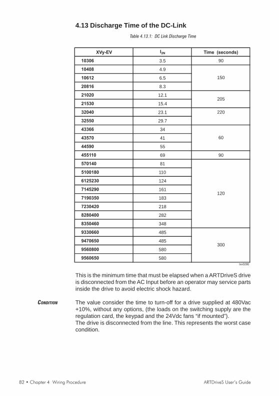
82 • Chapter 4 Wiring Procedure ARTDriveS User’s Guide
4.13 Discharge Time of the DC-LinkTable 4.13.1: DC Link Discharge Time
XVy-EV I2N Time (seconds)
10306 3.5 90
10408 4.9
10612 6.5
20816 8.3
21020 12.1
21530 15.4
32040 23.1 220
32550 29.7
43366 34
43570 41
44590 55
455110 69 90
570140 81
5100180 110
6125230 124
7145290 161
7190350 183
7230420 218
8280400 282
8350460 348
9330660 485
9470650 485
9560800 580
9560650 580txv0280
300
205
150
60
120
This is the minimum time that must be elapsed when a ARTDriveS driveis disconnected from the AC Input before an operator may service partsinside the drive to avoid electric shock hazard.
CONDITION The value consider the time to turn-off for a drive supplied at 480Vac+10%, without any options, (the loads on the switching supply are theregulation card, the keypad and the 24Vdc fans “if mounted”).The drive is disconnected from the line. This represents the worst casecondition.

ARTDriveS User’s Guide Chapter 5 Sizing Criteria • 83
Chapter 5 - Sizing Criteria
Because of the high performance obtained by the drive/brushless motorset, the dynamic performance of the entire system is strongly influencedby the mechanics of the system itself.
In particular, the following considerations are important:- the degree of precision depends on the sensor and not on the motor- the response speed depends on the transmission rigidity (mechani-
cal passband)- the system audible noise, sometimes very strong, does not depend
on the motor and/or on the electronics, but on a mechanical designwhich is not suitable for the required performance.
- the motor noise is due to continuous acceleration and braking. Insuch conditions, motor overheating may occur, which may not bedue to a too-small motor.
- the passband controlling the drive depends on the mechanics, as itis not possible to stabilize the electronics to a period less than 3times the ring time of the system mechanical oscillations.
The choice of the mechanical transmission must be carried out, therefore,according to the application. In mandrel applications, with significanttransmitted power and marginal dynamic performance, common reducertransmissions are used. In this case, that is the optimum economicalchoice.
In case of axis applications, where the system dynamic performance isfundamental, the required torque is often equal to the sum of the motorand load inertial torques. The use of a reduction ratio in the transmissionreduces, on one side, the load inertia influence, but, on the other, itincreases the motor side. In such applications, therefore, direct couplingis normally used.With direct coupling, the system dynamics are influenced by the shafttorsional rigidity and by the relative resonance frequency. The driveand motor are capable of much higher bandwidth than the mechanics.After choosing the motor and the transmission, it is necessary to checkthe application.In case of applications whose speed and load are constant or variablefor periods longer than the motor time constant, it is sufficient to checkthat the maximum load is within the capacity limits stated for the motorand the drive.
On the contrary, in applications where the load changes according to afaster cycle, do the following:- Trace a cycle speed/time diagram, remembering that the reaching
of a precise position or speed value requires, apart from the timeset by the system limit accelerations, a settling period equal to 3times the period of the system passband.
- Refer the system inertia and loads back to the motor axis.- Calculate the acceleration cycle and the cycle of the relative inertial

84 • Chapter 5 Sizing Criteria ARTDriveS User’s Guide
torques.- State the cycle torque/time diagram by adding the inertial torques to
the loads.- Calculate from the torque/time diagram the cycle effective torque.
If the cycle is made up of n duration segments t1, t2, ... tn, and oftheir corresponding torques C1, C2, ... Cn, the cycle effective torqueis given by:
C =eff
t + t + … + t1 2 n
C1 1 2 2 n n
2 2 2t + C t + … + C t
- Calculate, with the same formula, the average quadratic speed.- Calculate the cycle average torque.- Calculate the maximum duration period of the cycle maximum torque.- Calculate the torque required with the cycle maximum speed.- Calculate the cycle maximum torque.
The motor and the electronic have to be checked on the basis of theobtained data.
5.1 Motor CheckThe motor check phases are:- check of the peak torque- thermal Sizing- electrical Sizing
Check of the demagnetization currentSuch control is performed by comparing directly the maximum value ofthe peak current, which is obtained using the following formula, and themotor demagnetization current.
Kt
Cpk
I =pk 2
where:Cpk = cycle peak torqueKt = motor torque constant
Check of the thermal sizingCheck first that the point Ceff , ωeff is within the area of the motorcontinuous operating range.In particular, calculate the motor temperature increase, given by the rela-tion:
T =max Ln
65 2
n
eff
L0L +n
2
Tn
Ceff
where:Ln = motor rated lossesTn = motor rated torqueωn = motor rated speed

ARTDriveS User’s Guide Chapter 5 Sizing Criteria • 85
L0 = motor rated losses in ωn
If the maximum temperature is higher than the motor maximum, a biggermotor is needed.
Check of the electric sizingIn this case, it is necessary to check that at maximum speed, the voltagerequired by the motor is lower or equal to that supplied by the drive withthe minimum expected power supply voltage. The following relation mustbe satisfied:
V =max Ke pk w+ RKt
Cpk 2
2
PN 2
Kt
Cpk pk wL+ Emin
where:Emin = minimum voltage supplied by the driveKe = motor voltage constantωpk = cycle maximum speedRw = motor terminal to terminal resistanceCpk = cycle maximum torqueKt = motor torque constantPN = motor pole numberLw = motor terminal to terminal inductance
If such condition is not satisfied, it is necessary to choose a motor witha winding suitable for a higher speed; in this case a higher current willbe needed.
5.2 Check of the Drive SizeThe drive size is chosen according to the torque to be supplied to themotor with a specific winding, from where the needed energy is derived.The peak and average currents required by the drive are provided by:
I =aveKt Kt
CaveCpk
I =max
where:Cpk = cycle maximum torqueCave = cycle average torqueKt = motor torque constant
The drive must be in a position to develop continuous and peak currentshigher than the calculated values; remember that the drive maximumcurrent must be compared to Imax only if the relative time is lower than 2seconds; if not, the drive must have a rated current higher than Imax.

86 • Chapter 5 Sizing Criteria ARTDriveS User’s Guide
5.3 Application Example: Flying CutConsider a continuous belt moving cutter.The cutter is mounted on a carriage. The belt speed is 5 m/s.The cutter must, with a command, increase its speed till reaching thebelt, get synchronized with the belt speed, keep such speed for 300 ms(cutting time Tt), brake and return to the rest position.The total stroke of the cutter carriage is 5 m. The cutter weighs 80 kilosplus the motor weight.As the mechanical transmission system is rather complex, it is necessaryto provide a speed stabilization time Tst with transients to about 150 ms.
The cutting space with a constant speed is given by:St = Vt x (Tt + Tst) = 5 x (300 x 10-3 + 150 x 10-3) = 2.25 m
The carriage will run across the remaining space during its accelerationand deceleration phase. If these two spaces are equal:
Sacc = Sdec = (Stot - St) / 2 = (5 - 2.25) / 2 = 1.375 m
The average speed during the acceleration is:Vmed = Vmax / 2 = 5 / 2 = 2.5 m/s
The acceleration and deceleration times are:Tacc = Sacc / Vmed = 1.375 / 2.5 = 550 ms
The acceleration (and deceleration) is:a = Vmax / Tacc = 5 / 0.55 = 9.091 m/s2
Assuming that the motor weight is about 20 kilos, the required inertialpower is:
F = a x (Mcarr + Mmot) = 9.091 x (80 + 20) = 909.091 N
The total semi-cycle time is:Tsc = 2 x Tacc + Tst + Tt = 2 x 0.550 + 0.150 + 0.300 = 1.55 s
The transmission is carried out via a pinion and a rack. The pinion di-mensions are:
diameter Dp = 40 mmlength hp = 30 mm
The speed, acceleration and inertia brought to the motor axis are:
Speed: ωmax = Vmax / (Dp/2) = 5 / (0.04/2) = 250 rad/s
Acceleration: ma = a / (Dp/2) = 9.091/ (0.04/2) = 454.545 rad/s2
Inertia: J = Mtot x (Dp/2)2 = 100 x (0.04/2)2 = 0.04 kgm2
The pinion inertia is given by:
Jp = (Dp/2)4 x hp x π x δ = 5.806 x 10⁻⁵ Kgm2
ARTDriveS User’s Guide Chapter 5 Sizing Criteria • 87
where δ is the density of the material forming the pinion (steel).
Check now a SBM75.30.3 motor with an inertia of 0.0017 kgm2.
The total inertia is:
Jtot = J + Jp + 0.0017 = 0.04 + 5.806 x 10⁻⁵ + 0.0017 = 0.0417 kgm2
Assuming a pinion efficiency equal to 0.95, the maximum torque(overload) required to the motor is:
Cmax = ma x Jtot / 0.95 = 454.545 x 0.0417 / 0.95 = 19.98 Nm
The average (continuative) and effective torques are therefore, supposingnull the torque at constant speed:
Cmed = Cmax x Tacc x 2 / Tsc = 14.179 Nm
Ceff = Cmax x (2 x Tacc / Tsc)1/2 = 16.832 Nm
As the cycle effective torque is higher than the motor rated torque atnominal speed, a motor of a bigger size must be chosen.Repeating the operations for a SBM77.30.3 motor with an inertia of 0.0023kgm2, the obtained average torque is 14.383 Nm while the effective torqueis 17.073 Nm. The motor is therefore suitable for the application with ahigh margin, considering that its nominal torque at nominal speed is 18.8Nm.Given the torque constant Kt = 1.50, the average and maximum currentabsorbed by the motor are:
Imax = Cmax / Kt = 12.8 Arms
Imed = Cmed / Kt = 9.09 Arms
The drive size to be used with the present application is therefore XVy-EV21020.
88 • Chapter 6 Maintenance ARTDriveS User’s Guide
Chapter 6 - Maintenance
6.1 CareThe drives of the XVy series must be installed according to the relevantinstallation regulations. They do not require any particular maintenance.They should not be cleaned with a wet or moist cloth. The power supplymust be switched off before cleaning.
6.2 ServiceThe screws of all terminals on the drive should be re-tightened two weeksafter initial commissioning.This should be repeated each year. If the drives have been stored formore than three years, the capacitance of the intermediate circuitcapacitors may have been impaired. Before commissioning these drives,it is advisable to supply power to the drives for at least two hours inorder to regain the capacitor original ratings.To this purpose apply an input voltage without applying any load onthe output.After these steps, the drive is ready to be installed without limits.
6.3 RepairsRepairs of the drive should only be carried out by qualified personnel(suggested by the manufacturer).If you carry out a repair on your own, observe the following points:- When ordering spare parts do not only state the drive type but also
the drive serial number. It is also useful to state the type of theregulation card and the system software version.
- When changing the cards ensure that the positions of switches andjumpers are observed!
6.4 Customer ServiceFor customer service, please refer to your Gefran-Siei office.

ARTDriveS User’s Guide Chapter 7 Settings and Commissioning • 89
Chapter 7 - Settings and Commissioning7.1 PC ConfiguratorThe configurator E@syDrives is a program supplied together with theproduct.Its installation requires a PC with MS Windows ® 95/98/ME/XP or Win-dows NT®4/2000 system, with minimum 8 Mb RAM.The configurator communicates with the drive using the Slink-3 proto-col.Together with the drive parameterization, the configurator allowsdownloading the firmware in order to create some personalized appli-cations using the MDPlc development environment.
7.2 CommissioningBefore powering up the drive, carry out the following verifications:- Check the connections with the line L1, L2, L3- Check the connections with the motor U, V, W- Check the breaking resistance connection (if present)- Check the connections between the encoder and XE connector- Check the input connection 24Vdc (if present)- Check the I/O connections- Check all the drive and motor ground connectionsAfter having checked as shown above, it’s possible now to power thedrive; then check:- Line voltage (max permissible voltage 480Vac + 10%)- Voltage of the intermediate circuit DC bus (270-350 for input volt-
age 230Vac, 480-650Vdc for input voltage 400Vac, 432-528 for inputvoltage 480Vac; if the measured voltage is not in the indicated range,check the line voltage)
7.2.1 Connection with the PCThe drive is delivered from the factory with a standard configuration inthe speed mode. The input and output state is already programmed asin the following example; therefore user is able to start up the drivecontrol and run the motor immediately (when used a motor series SBMwith encoder sin.cos at 2048 p/r).To perform the correct parameter settings, it’s necessary to use theconfigurator E@syDrives. Connect the drive to your PC using the serialcommunication as suggested in the manual; check that the terminationresistance switch is on the 120 ohm position.
E@syDrives configurator1) Install the E@syDrives application from the attached CD-rom
(setup.exe, in E@syDrives folder).2) Install the XVyBasic application from the attached CD-rom
(setup.exe, in XVyBasic folder).3) From Windows Start / Programs / SIEI PC Tools menu run the
E@syDrives command to start the configurator.
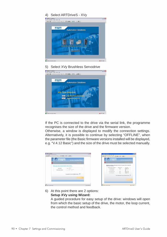
90 • Chapter 7 Settings and Commissioning ARTDriveS User’s Guide
4) Select ARTDriveS - XVy
5) Select XVy Brushless Servodrive
If the PC is connected to the drive via the serial link, the programmerecognises the size of the drive and the firmware version.Otherwise, a window is displayed to modify the connection settings.Alternatively, it is possible to continue by selecting “OFFLINE”, whenthe parameter file (the Basic firmware versions installed will be displayed,e.g. “V.4.12 Basic”) and the size of the drive must be selected manually.
6) At this point there are 2 options:Setup XVy using Wizard:A guided procedure for easy setup of the drive: windows will openfrom which the basic setup of the drive, the motor, the loop current,the control method and feedback.

ARTDriveS User’s Guide Chapter 7 Settings and Commissioning • 91
Edit the XVy parameter listFor expert users, a list is displayed of all parameters resident in thedrive: the data are subdivided into several windows and intoWindows-type tree-structure menus.
7.2.2 Essential Parameters Set upThe essential parameters to check before starting the motor are:
MENU PARAMETERMONITOR IPA 20053, Drive sizeDRIVE CONFIG IPA 20000, Drive Max CurrMOTOR DATA IPA 20002, Motor polesENCODER PARAM IPA 20010, XE Enc Type
IPA 20011, XE Enc pprIPA 20012, XE Enc Supply
SPEED IPA 20003, Full Scale Speed
It’s now possible to enable the drive and rotate the motor in the functionof the inputs configuration and setup. As an example three types ofconfigurations are described.

92 • Chapter 7 Settings and Commissioning ARTDriveS User’s Guide
7.2.3 Speed Mode Configuration Example
1
2
3
4
5
6
7
8
9
10
11
12
13
14
15
16
Digital input 0
Digital input 1
0 V (+24V)
+24V OUT
Analog input 0
Analog input 1
Analog output 0
0V
+10V
Digital input 4
Digital input 5
Digital input 6
Digital input 7
Digital output 3
Relay-NO
Relay-COM
17
18
19
20
21
22
23
24
25
26
27
28
29
30
31
32
Digital input 2
Digital input 3
Supply-DO
COM-DO
Digital output 0
Digital output 1
+24V IN
COM-DI
Analog output 1
- 10V
Digital output 2
Digital output 4
Digital output 5
Relay-NC
Strip X1 Function max
Programmable/configurable analog differential input. Signal: terminal 1.Reference point: terminal 2. Default setting:"[3] Speed Ref 1".
Programmable/configurable analog differential input. Signal: terminal 3.Reference point: terminal 4. Default setting: none
Reference point for Digital inputs, terminals 6, 7, 8 , 9, 22, 23, 24 and 25.
Drive enable; 0V or open: inverter disabled; +15…+30V: Drive enabled
Programmable digital input, default setting: “[4] Start / Stop”
Programmable digital input, default setting: “[8] Ramp In = 0””
Programmable digital input, default setting: “[9] Reverse”
Supply input for digital outputs
Reference point for digital outputs, terminals: 12 and 13
Programmable digital output, default setting: “[3] Speed Reached”
Programmable digital output, default setting: “Speed 0 thr”
+24V DC supply output. Reference point: terminal 16
+24V DC supply input
Reference point for +24 VDC I/O
Programmable analog output, default setting: “[1] Actual speed”
Programmable analog output, default setting: “[2] Motor current”
Analog output reference point
Reference voltage +10V, reference point: terminal 19
Reference voltage - 10V, reference point: terminal 19
Programmable digital input, default setting: “[10] End Run Reverse”
Programmable digital input, default setting: “[11] End Run Forward”
Programmable digital input, default setting: “[3] External fault”
Programmable digital input, default setting: “[2] Drive reset”
Programmable digital output, default setting: none
“Drive OK” N.O. contact
“Drive OK” N.C. contact
“Drive OK” common contact
±10V0.25mA
+10V/10mA-10V
+30V3.2mA @ 15V5mA @ 24V
6.4mA @ 30V
+30V/40mA
-
+30V/40mA
+22...28V120mA@24V
-
-
±10V/5mA
-
+10V/10mA
-10V/10mA
+30V3.2mA @ 15V5mA @ 24V
6.4mA @ 30V
+30V/40mA
250 V AC1A AC11

ARTDriveS User’s Guide Chapter 7 Settings and Commissioning • 93
7.2.4 Position Mode Configuration Example
1
2
3
4
5
6
7
8
9
10
11
12
13
14
15
16
Digital input 0
Digital input 1
0 V (+24V)
+24V OUT
Analog input 0
Analog input 1
Analog output 0
0V
+10V
Digital input 4
Digital input 5
Digital input 6
Digital input 7
Digital output 3
Relay-NO
Relay-COM
17
18
19
20
21
22
23
24
25
26
27
28
29
30
31
32
Digital input 2
Digital input 3
Supply-DO
COM-DO
Digital output 0
Digital output 1
+24V IN
COM-DI
Analog output 1
- 10V
Digital output 2
Digital output 4
Digital output 5
Relay-NC
Strip X1 Function max
Not configured
Not configured
Reference point for Digital inputs, terminals 6, 7, 8 , 9, 22, 23, 24 and 25.
Drive enable; 0V or open: inverter disabled; +15…+30V: Drive enabled
Programmable digital input, configured as: “[1009] POS Start Pos”
Programmable digital input, configured as: “[1007] POS 0 Search”
Programmable digital input, configured as: “[1015] POS 0 Sensor”
Supply input for digital outputs
Reference point for digital outputs, terminals: 12 and 13
Programmable digital output, configured as: “[1002] POS Pos reached”
Programmable digital output, default setting: “Speed 0 thr”
+24V DC supply output. Reference point: terminal 16
+24V DC supply input
Reference point for +24 VDC I/O
Programmable analog output, default setting: “[1] Actual speed”
Programmable analog output, default setting: “[2] Motor current”
Analog output reference point
Programmable digital input, default setting: “[10] End Run Reverse”
Programmable digital input, default setting: “[11] End Run Forward”
Programmable digital input, default setting: “[3] External fault”
Programmable digital input, default setting: “[2] Drive reset”
Programmable digital output, default setting: none
“Drive OK” N.O. contact
“Drive OK” N.C. contact
“Drive OK” common contact
±10V0.20mA
+30V3.2mA @ 15V5mA @ 24V
6.4mA @ 30V
+30V/40mA
-
+30V/25mA
+24 V ±10%120mA
+24 V ±10%1A
-
±10V/5mA
-
+10V/10mA
-10V/10mA
+30V3.2mA @ 15V5mA @ 24V
6.4mA @ 30V
+30V/25mA
250 V AC1A AC11
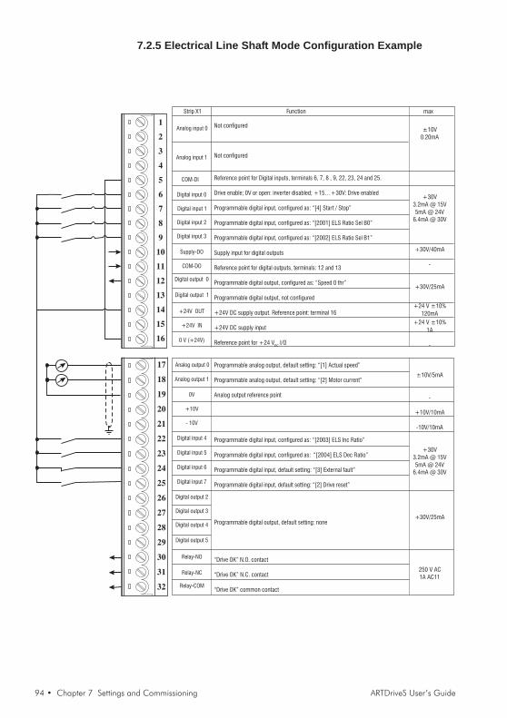
94 • Chapter 7 Settings and Commissioning ARTDriveS User’s Guide
1
2
3
4
5
6
7
8
9
10
11
12
13
14
15
16
Digital input 0
Digital input 1
0 V (+24V)
+24V OUT
Analog input 0
Analog input 1
Analog output 0
0V
+10V
Digital input 4
Digital input 5
Digital input 6
Digital input 7
Digital output 3
Relay-NO
Relay-COM
17
18
19
20
21
22
23
24
25
26
27
28
29
30
31
32
Digital input 2
Digital input 3
Supply-DO
COM-DO
Digital output 0
Digital output 1
+24V IN
COM-DI
Analog output 1
- 10V
Digital output 2
Digital output 4
Digital output 5
Relay-NC
Strip X1 Function max
Not configured
Not configured
Reference point for Digital inputs, terminals 6, 7, 8 , 9, 22, 23, 24 and 25.
Drive enable; 0V or open: inverter disabled; +15…+30V: Drive enabled
Programmable digital input, configured as: “[4] Start / Stop”
Programmable digital input, configured as: “[2001] ELS Ratio Sel B0”
Programmable digital input, configured as: “[2002] ELS Ratio Sel B1”
Supply input for digital outputs
Reference point for digital outputs, terminals: 12 and 13
Programmable digital output, configured as: “Speed 0 thr”
Programmable digital output, not configured
+24V DC supply output. Reference point: terminal 16
+24V DC supply input
Reference point for +24 VDC I/O
Programmable analog output, default setting: “[1] Actual speed”
Programmable analog output, default setting: “[2] Motor current”
Analog output reference point
Programmable digital input, configured as: “[2003] ELS Inc Ratio”
Programmable digital input, configured as: “[2004] ELS Dec Ratio”
Programmable digital input, default setting: “[3] External fault”
Programmable digital input, default setting: “[2] Drive reset”
Programmable digital output, default setting: none
“Drive OK” N.O. contact
“Drive OK” N.C. contact
“Drive OK” common contact
±10V0.20mA
+30V3.2mA @ 15V5mA @ 24V
6.4mA @ 30V
+30V/40mA
-
+30V/25mA
+24 V ±10%120mA
+24 V ±10%1A
-
±10V/5mA
-
+10V/10mA
-10V/10mA
+30V3.2mA @ 15V5mA @ 24V
6.4mA @ 30V
+30V/25mA
250 V AC1A AC11
7.2.5 Electrical Line Shaft Mode Configuration Example

ARTDriveS User’s Guide Chapter 7 Settings and Commissioning • 95
7.3 Download FirmwareThe standard firmware loaded at the factory is an application calledBasic.The Basic Application Firmware consists of 2 files:- the firmware (XVyBasicVX_XX.sre)- the parameter file, the user's tool for the drive tuning
(XVyBasicVX_XX.par).
The firmware upgrade can be performed making reference to thefollowing points.1. Open the E@syDrives configurator.2. Select the used drive in the displayed window and enable the
communication with the drive via the "Target/connect" menu.3 Open the parameter file of the old firmware version4 Read all parameters through the “Read All” command in the
“Parameter” menu5. Perform the Browse command via the "Service / Load firmware"
menu.6. The XVyBasicVX_XX.sre file of the last version is default (*) stated;
choose this file and perform the Load command.
(*) In case it is not found, search the .sre file with the Browserbutton (the file is default located in the path \Programs\SIEI PC Tools\E@syDrives\XVyBasic\Vx.xx\Service).
7. Now the firmware download is active; the display shows the quantityof data (Byte number) which are being transferred.
8. Reset the drive with the configurator reset command or disable andafterwards enable again the 24 VDC voltage.
9. Perform the "Load default drives values" command via the"Parameters" menu and answer yes to the question "Save theminto target ?".
10. Reset the drive using the configurator "reset" command or switchthe device off and then on again.
11. The firmware update is now over; the user can reload the parametersvia the “Write All” command in the “Parameter” menu or he can tunethe drive
Upgrade from version 3.XX to version 4.XXThe XVy-EV drive is not compatible with 3.X versions.It is therefore not possible to load firmware earlier than version 4.X ontothis drive.
96 • Chapter 7 Settings and Commissioning ARTDriveS User’s Guide
7.4 Automatic Electric Phasing Procedure for Encoder/Resolver
The knowledge of the right phase relation between the current and themotor magnetic angle is fundamental for the drive performances.The simple electric and automatic phasing sequence of the XVy driveallows to store the phasing angle in a drive parameter (electric phasing)in order to constantly supply precise information about the phase of theposition/speed motor feedback (encoder/resolver).Such procedure has to be performed every time the XVy drive is usedwith NON-Gefran-Siei motors. All Gefran-Siei motors, on the contrary,are factory-phased (mechanical phasing).Before performing the automatic electric phasing, it is advisable to checkthe encoder/resolver connections (as described in the paragraph"Encoder Control/Drive Connections") and the power/U-V-W phasesequence connections.
Note! The following procedure must be performed using incremental encoders with zeropulse.If using an encoder without zero pulse the procedure cannot be completed and willbe aborted as unsuccessful.
ProcedureIf this procedure is performed using the software of the E@syDrivesconfigurator, the following sequence has to be respected:1. Start the software of the E@syDrives configurator (from the Windows
Start menu)2. Enable the "MONITOR Window" function3. Display in MONITOR Window the Enc Mech Offset (IPA 20058)
parameter and the Enc Offset (IPA 20057) parameter (from theService->Phasing menu)
4. Remove any mechanical coupling from the motor shaft, so that itcan move freely
5. Set the Mot Nominal Curr (IPA 20001) parameter, with the valuereferring to the motor rated current (from the TUNING / PHASINGmenu)
6. Set the Application Sel (IPA 18140) parameter as "Phasing" (fromthe TUNING menu)
7. Save the parameters (Command "Save parameters” (*) ).8. Perform the command "Drive Reset" or switch the drive off and on
again9. Enable the drive using the Digital 0 Input10. Check that the drive performs a current ramp till the limit set in the
Mot Nominal Curr (IPA 20001) parameter while the motor rotorcarries out a small movement
11. After a few seconds the motor starts rotating and stops in a fixedposition after performing a revolution. If the motor is SIEI-marked,make sure that it rotates in a clockwise direction (from the motorshaft side); with NON- Gefran-Siei,motors, check the wiring on thepower cables between the drive and the motor.The counting of the encoder/revolver must increase (see 4.4.5

ARTDriveS User’s Guide Chapter 7 Settings and Commissioning • 97
"Encoder Control/Drive Connections" paragraph ) during the motorrotation.
12. Check the value of the Enc Mech Offset (IPA 20058) parameterkeeping the drive enabled. If the motor has been supplied by Gefran-Siei, the parameter value has to be near the zero (values in therange of ±4 degrees are allowed) because Gefran-Siei motors arefactory phased (mechanically) with the XVy-EV Gefran-Siei drives.
13. Perform the command "Save parametesr” (*) by keeping the driveenabled. The current value of the phasing angle is stored in the EncMech Offset (IPA 20058) parameter
14. Disable the drive15. Set the Application Sel (IPA 18140) parameter (from the SERVICE
menu) with the original selection "Basic" (factory default) or "Plc"16. Save the parameters (command "Save parameters” (*))17. Use the command "Drive Reset" or switch the drive off and on again
At the end of this electric and automatic phasing procedure, it issuggested to configure the XVy drive with a speed mode and to checkthe motor functioning procedure.
(*) it is possible to run “Save parameters” in the following ways:- Ctrl+Alt+S- from the Parameters menu- “Save parameters into target” key

98 • Chapter 7 Settings and Commissioning ARTDriveS User’s Guide

ARTDriveS User’s Guide Chapter 8 Keypad Operation • 99
Chapter 8 - Keypad Operation
8.1 Keypad Description
Navi
gati
on
Dri
veC
ontr
ols
Dri
veC
ontr
ols
+Torque- Torque- Torque Alarm Enable ZeroSpeed Limit
Help Alarm
Home
+
Escape
Enter Shift
Pre
ss2
se
c.
tod
isa
ble
Jog
Speed
The keypad consists of an LCD display with two lines of 16 characterseach, seven LEDs and nine function keys.
It is used to:- control operation, when this user option is selected (DRIVE CONFIG
/ KEYPAD, Enable I-O Keys IPA20022 = Keys Enabled)- display speed, voltage, diagnostics, etc., during operation- set parameters
8.1.1 LEDThe LEDs meaning can be summarized as follows:
- Torque (yellow) This LED is ON when the drive is running withnegative torque.
+ Torque (yellow) This LED is ON when the drive is running withpositive torque.
Alarm (red) This LED starts to blink in case of a fault condi-tion of the drive. During normal operation this LEDwill be OFF.
• Enable (green) This LED is ON when the drive is power suppliedand enabled.
ZeroSpeed (yellow) This LED is ON when the motor speed is zero.LIMIT (yellow) This LED is ON if the drive reaches its torque
limit. During normal operation this LED will beOFF.

100 • Chapter 8 Keypad Operation ARTDriveS User’s Guide
8.1.2 Function KeysThe keypad has nine function keys with different modes defined by thestate of the keypad itself.
ControlKeys
+
Jog
Help
Alarm
Escape
Home
Enter
Shift
Text reference
START
STOP
+[Jog] (*)
-[Rotationcontrol] (*)
Down[Help]
Up[Alarm]
Left[Escape]
Enter[Home]
Shift
Function
START key commands the drive to Enable and StartThe Enable I-O Keys parameter must be enabled (DRIVE CONFIG /KEYPAD menu)
STOP key commands to Stop and disable; holding it for 2 seconds disablesthe drive. The Enable I-O Keys parameter must be enabled (DRIVE CONFIG/ KEYPAD menu).
The “plus” key increases the reference velocity for the Motor pot. function[Jog, when the Shift key is pressed first].See paragraph 8.2
The “minus” key reduces the reference velocity for the Motor pot. function[Control of direction of rotation. When the Shift key is pressed, it changesthe motor direction of rotation (in Jog mode and in Motor pot function)].See paragraph 8.2
Used to scroll down menu items in menu navigation, picklists in selectors,or digit values in numeric editing.[After pressing Shift key, an item-specific information menu is entered whenapplicable]
Used to scroll up menu items in menu navigation, picklists in selectors, ordigit values in numeric editing.[After pressing Shift key, the Alarm list display mode is entered. Active alarmsand Alarms pending for acknowledge can be browsed with Up / Down arrowskeys. Left arrow key returns to normal mode.
Used to go down one level in menu navigation; to scroll digits in numericedit mode, to return to normal mode from alarm list or Help modes.[After pressing Shift key, it is used to Escape out of numeric edit or selectionwith no change].
Used to go up one level in menu navigation; to enter Selections or numericvalues after editing, to issue commands, to acknowledge alarms in the Alarmlist mode.[Home second function, return to Monitor menu from any main menu level].
Shift button enables the keypad second functions (Rotation control, Jog,Help, Alarm, Escape, Home)
[...] Secondary function. Press Shift to activate these functions.(*) The Jog and + / - keys (Motor potentiometer) can be activated only when the speed and current are displayed (press
Left in the Monitor menu)

ARTDriveS User’s Guide Chapter 8 Keypad Operation • 101
8.1.3 Display - Using keypad
At drive power on, the display shown: drive configuration (Basic or Plc)and the firmware version.
After few seconds the display will shown the speed in rpm.
By pressing the Down or Up key, the load in Arms will be displayed.
Pressing LEFT causes the display to show the parameter mode. Thefirst MONITOR menu is displayed.
Press Enter to go to the MONITOR menu and display the Start Statusparameter.
Pressing Down displays the next parameter Ramp Output
Pressing Enter displays the value of the parameter.
1) Menu This field shows the index for the menu currently displayed(E.g. MONITOR menu).
2) Parameter This field shows the name of the parameter currentlydisplayed (E.g. Start Status = IPA 20500).
3)Select / Value This field shows the selection or true value of the parameterselected.
Figure 8.1.3.1: Navigation within the menus
EnterXVyBasic
MONITOR
XVyBasic
SAVE / LOAD PAR
XVyBasic
......
XVyBasic
<-
<-
<-
<-
Enter
Enter
Enter
POSITION
POSITION FUNC
POSITION
POS THR CONFIG
<-
<-
Enter<-
<-
Main Menu 2nd Level Menu 3rd Level Menu
POSITION
POS PRESET 0 <-
Enter
<- POS PRESET 0
ANALOG POS REF<-
Enter
POSITION <-
Full list of menus and parameters in chapter 10.
XVyBasic
Sync FW V. 4.XX
Enter
XVyBasic
MONITOR
Flt Motor Speed
0.0 rpm
MONITOR
Start Status
Enter
MONITOR
Ramp Output
Ramp Output
0.0 rpm
<-
<-
<-
1)
1)
1)
2)
2)
2)
3)
Out Current
0.0 Arms
2)
3)
2)
3)
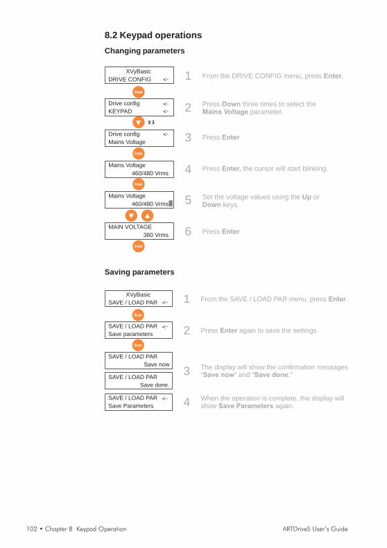
102 • Chapter 8 Keypad Operation ARTDriveS User’s Guide
8.2 Keypad operationsChanging parameters
XVyBasic
DRIVE CONFIG <-
Enter
Drive config
KEYPAD <-
Drive config
Mains Voltage
X 3
<-
<-
Enter
MAIN VOLTAGE
380 Vrms
Enter
1
2
3
6
From the DRIVE CONFIG menu, press Enter.
Press three times to select theparameter.
DownMains Voltage
Press Enter
Press Enter
Mains Voltage
460/480 Vrms 4
Set the voltage values using the orkeys.
UpDown
Enter
Mains Voltage
460/480 Vrms 5
Press the cursor will start blinking.Enter,
Saving parameters
XVyBasic
SAVE / LOAD PAR <-
SAVE / LOAD PAR
Save parameters
<-
Enter
Enter
1
2
3
From the SAVE / LOAD PAR menu, press .Enter
Press again to save the settings.Enter
SAVE / LOAD PAR
Save now
SAVE / LOAD PAR
Save done.
SAVE / LOAD PAR
Save Parameters
<-
The display will show the confirmation messages“ ” and “ ”Save now Save done.
4 When the operation is complete, the display willshow again.Save Parameters

ARTDriveS User’s Guide Chapter 8 Keypad Operation • 103
Loading default parametersThe default parameters relate to the size of the drive, which is not modified by thisoperation.
XVyBasic
SAVE / LOAD PAR <-
SAVE / LOAD PAR
Load Default Par
<-
Enter
Enter
1
3
4
From the SAVE / LOAD PAR menu, press Enter.
Press Enter
SAVE / LOAD PAR
Load now
SAVE / LOAD PAR
Load done.
SAVE / LOAD PAR
Load Default Par
<-
The display will show the confirmation messages“ ” and “ ”Load now Load done.
5 When the operation is complete, the display willshow the parameter again.Load Default Par
SAVE / LOAD PAR
Save parameters
<-2 Press the key to select the
parameter.Down
Load Default Par
Reset alarms and drivesSee section 8.3.1.
Jog functionThe drive should be enabled: + 24Vdc at terminal 6.
XVyBasic
MONITOR <-
Shift
Flt Motor Speed
0.0 rpm
<-
<-
1
2
3
From the MONITOR menu, press toactivate, then press
StartLeft
The speed display is enabled (or pressor to enable current display).Down Up,
Press to enable the secondaryfunctions, then press to increase thereference speed
Shift+
4Press to revert the rotation directionand press to decrease the referencespeed
–+
Flt Motor Speed
150.0 rpm
Flt Motor Speed
-150.0 rpm
<-

104 • Chapter 8 Keypad Operation ARTDriveS User’s Guide
Motor potentiometer functionThe drive should be enabled: + 24Vdc at terminal 6.
XVyBasic
MONITOR <-
Shift
Flt Motor Speed
0.0 rpm
<-
<-
1
2
3
From the MONITOR menu, press toactivate, then press
StartLeft
The speed display is enabled (or pressor to enable current display)
DownUp,
Press to increase the reference speed.+
4Press to enable the secondary functions,then press to revert the direction rotation andpress to decrease the reference speed
Shift–
+
Flt Motor Speed
150.0 rpm
Flt Motor Speed
-150.0 rpm
<-
8.2.1 ErrorsIf the operator will try to give to a parameter a wrong value (e.g. outsidethe Min/Max permitted values), the display will show an "E" followed bythe numeric code of the error (e.g. E 04); to move back to Status Index2 "Parameter Display" press any function key of the keypad.
Table 8.2.1.1: Errors list
Code E 01 Error code 1 Parameter does not existCode E 02 Error code 2 System errorCode E 03 Error code 3 Type does not existCode E 04 Error code 4 Read-only parameterCode E 05 Error code 5 Write enabled only when drive is enabledCode E 06 Error code 6 Value outside min valueCode E 07 Error code 7 Value outside max valueCode E 08 Error code 8 System errorCode E 09 Error code 9 Value exceed limit

ARTDriveS User’s Guide Chapter 8 Keypad Operation • 105
8.3 Alarms and Errors Handling8.3.1 Alarms (Failure register)In the event of an alarm, the “Alarm” LED flashes red, while the keypaddisplays an alarm code and description.
Figure 8.3.1: Led Status and Keypad
A 01IGBT desaturat
A 01RD RA
+Torque- Torque- Torque Alarm Enable ZeroSpeed Limit
Enter
+Torque- Torque- Torque Alarm Enable ZeroSpeed Limit
- RA (Reset Alarm) To reset the alarm, enable the drive and pressEnter, then select RA with the Up or Down keysand press Enter.
- RD (Reset Drive) To reset the drive, enable the drive and pressEnter, then select RD with the Up or Down keysand press Enter.
Table 8.3.1.1: Alarms list
Code A 01 Alarme Code 1 (*) IGBT desaturatCode A 02 Alarme Code 2 (*) OvercurrentCode A 03 Alarme Code 3 (*) OvervoltageCode A 04 Alarme Code 4 (*) Heatsink OtCode A 05 Alarme Code 5 Parameter ErrorCode A 06 Alarme Code 6 (*) Current Fbk LossCode A 07 Alarme Code 7 (*) Motor OvertempCode A 08 Alarme Code 8 CPU errorCode A 09 Alarme Code 9 Enable key errorCode A 11 Alarme Code 11 Bad Flash ParCode A 12 Alarme Code 12 Bad Flash DeviceCode A 13 Alarme Code 13 (*) Brake OverpowerCode A 14 Alarme Code 14 (*) Reg Pwr FailureCode A 16 Alarme Code 16 (*) Main LossCode A 18 Alarme Code 18 (*) Encoder Fbk LossCode A 19 Alarme Code 19 (*) Encoder SimulatCode A 20 Alarme Code 20 (*) UndervoltageCode A 21 Alarme Code 21 (*) Intake Air OtCode A 22 Alarme Code 22 (*) Regulation OtCode A 23 Alarme Code 23 (*) Module OvertempCode A 25 Alarme Code 25 Reset RequiredCode A 26 Alarme Code 26 (*) FieldBus FailureCode A 27 Alarme Code 27 (*) Enable Seq ErrorCode A 28 Alarme Code 28 (*) Fast Link ErrorCode A 29 Alarme Code 29 (*) Position ErrorCode A 30 Alarme Code 30 (*) Drive OverloadCode A 31 Alarme Code 31 (*) External FaultCode A 32 Alarme Code 32 PLC Application
(*) alarms resettable with an ALARM RESET command

106 • Chapter 8 Keypad Operation ARTDriveS User’s Guide
8.3.2 Alarm description
(A 01) IGBT desaturatShort circuit on the motor winding or on the power bridge.
(A 02) OvercurrentOvercurrent protection intervention.The cause could be an incorrect setting of the current regulator gainsas compared
(A 03) OvervoltageOvervoltage on the intermediate circuit.The braking resistance is not connected in the right way or it is open.The threshold is 950V.
(A 04) Heatsink OtDrive thermal protection.The working cycle is too high for the drive size.
(A 05) Parameter ErrorParameters setting error.The IPAs are showed on IPA 1 Par Set (IPA 24110) and IPA 2 Par Set(IPA 24111)
(A 06) Current Fbk LossCurrent feedback sensor failure.
(A 07) Motor OvertempIntervention of the motor thermal protection.Overtemperature on the motor winding or PTC sensor not connected tothe drive.
(A 08) CPU errorOn CPU Err Al Cause (IPA 18143) the cause is specified.
(A 09) Enable key errorWrong enabling key for Plc and/or DeviceNet.
(A 11) Bad Flash ParThe parameter value is not recognized.Do the Parameter Saving and Drive Reset commands with the correctparameters.
(A 12) Bad Flash DeviceAlarm on a non preset flash. Firmware error.
(A 13) Brake OverpowerThe internal braking resistance is too warm because of a too high workingcycle. Wait 30 seconds and give the Drive Reset command. Theresistance temperature is calculated by an algorithm of the drive.

ARTDriveS User’s Guide Chapter 8 Keypad Operation • 107
(A 14) Reg Pwr Failure±15V internal power supply of regulation board R-XVy is not working.
(A 16) Main LossPower supply failureThe Powerloss function is activated.
(A 18) Encoder Fbk LossError detected in encoder feedback. Failure cause is specified inparameter Enc Warning Case (IPA 20016, ALARMS menu)
(A 19) Encoder SimulatEncoder simulation alarm.Check the encoder simulation parameters..
(A 20) UndervoltageAlways active when the drive is enabled.The threshold level depends on the power supply level selected inparameter Mains Voltage (IPA 20050), according to the following table.
Main supply DC-bus threshold undervoltage230 VAC 225.4 VAC380 VAC 372.3 VAC400 VAC 391.9 VAC415 VAC 406.6 VAC440 VAC 431.1 VAC460 VAC 450.7 VAC
(A 21) Intake Air OtTemperature of intake air too high; detected by TAC sensor.
(A 22) Regulation OtOvertemperature of regulation board; detected by sensor on reg board.
(A 23) Module OvertempIGBT module Overtemperature; detected by sensors on Power stage.
(A 25) Reset RequiredThere has been a modification of one or more parameters that requiresa DRIVE RESET to be active.
(A 26) FieldBus FailureBus communication not present
(A 27) Enable Seq ErrorSequence error alarmWhen the drive is power supplied (after the drive reset), it is active if thedigital input 0 is high.
(A 28) Fast Link ErrorFast Link communication alarm.

108 • Chapter 8 Keypad Operation ARTDriveS User’s Guide
It occurs in slave drives when the fast link serial communication isphysically interrupted.
(A 29) Position ErrorPosition error alarm.It happens in the position slaves and with the electric shaft mode whenthe error is higher than the Max Pos Error (IPA 18123) parameter.
(A 30) Drive OverloadDrive overload alarm.Drive overload duration is too high. Check drive sizing using the overloadtable specified in section 2.3.3 IxT Algorythm
(A 31) External FaultExternal alarm present.A digital input has been programmed as an external alarm, but +24V isnot available on this terminal.
(A 32) PLC ApplicationMDPlc application not loaded.Active only if the application selected is MDPlc.

ARTDriveS User’s Guide Chapter 9 Block Diagram • 109
Chapter 9 - Block Diagrams
I/OP
aram
eter
Par
amet
erIn
tern
alva
riabl
e
Dig
ital
inp
ut
Dig
ital
ou
tpu
t
Spe
edR
efer
ence
A
An
Out
0W
rite
An
Out
1W
rite
An
Out
Val
ue
An
Out
1V
alue
An
Out
0S
cale
An
Out
1S
cale xx
++
An
Out
0O
ffset
An
Out
1O
ffset
An
alo
go
utp
ut
67
89
2223
2425
DI4
DI0
DI1
DI2
DI3
DI5
DI6
DI7
DO0
DO1
DO2
DO3
DO4
DO5
1213
2627
2829
-10V
+0V
+10
V
1920 21
Pos
Spe
edLi
mit
Neg
Spe
edLi
mit
Act
Spe
edR
atio
Ram
pO
utpu
tRef
eren
ce=
0
1416
NO
NC
CO
M
+24V
0V
FAIL
UR
E
Dis
able
driv
e
Driv
eO
K
Driv
eR
eset
Ala
rmR
eset
Ala
rmS
tatu
s
Driv
eF
ault
Spe
edT
hr
Spe
edT
hr
Spe
edT
hr
Spe
edT
hrO
ffset
Act
ualS
peed
Spe
edR
efer
ence
Spe
edR
each
ed
Spe
ed0
Thr
Mot
orC
urre
ntTo
rque
Thr
Sta
teTo
rque
Thr
RampSelBit1
RampSelBit01 2 3
MultiRampIndex
MultiRampConf
INP
UT
S,O
UT
PU
TS
,R
EF
ER
EN
CE
S
0V
0V
ref
An
Inp
0R
ead
An
Inp
1R
ead
+
An
Inp
0D
_BP
os
An
Inp
0D
_BN
eg
An
Inp
0S
cale
An
Inp
0V
alue
x
An
Inp
0O
ffsetD
isab
leA
nIn
0
+
An
Inp
1D
_BP
os
An
Inp
1D
_BN
eg
An
Inp
1S
cale
An
Inp
1V
alue
x
An
Inp
1O
ffsetD
isab
leA
nIn
1
An
alo
gin
pu
t0
An
alo
gin
pu
t11 2 3 4
GN
D
AO
0
AO
1
21 2319
X
Mot
orP
otM
ode
Spe
edD
raw
Rat
io
Mot
orP
otO
utpu
t
Torq
ueS
peed
Lim
itR
ever
se
A
End
Run
Rev
End
Run
For
war
d
JogSpeedLimit
JogReference
*(-
1)
Ram
pIn
=0
MP
otO
utpu
t
MP
otm
ode
MotorPotEn
MotorPotUp
MotorPotDown
MotorPotMemoMotorPotReset
MotorPotRev
MP
OT
Jog
CW
Jog
CC
W
Mot
orP
otU
pLi
m
Mot
orP
otLo
Lim
Mot
orP
otA
cc&
Dec
Mot
orP
otIn
it
Mot
orP
otM
ode
Mul
tiS
peed
Con
f
Mul
tiS
peed
Inde
x
1 7
SpeedSelBit1
SpeedSelBit2
SpeedSelBit0
Spe
edR
ef1(
rpm
)
Spe
edR
ef2
(rpm
)
Ram
pE
nabl
eJo
gE
nabl
eTo
rque

110 • Chapter 9 Block Diagram ARTDriveS User’s Guide
Pw
m
Mod
.
Act
ual
posi
tion
regi
sterM
otor
flux
angl
e
+
+
-
-
+
-
Ki Ki
Hig
hsp
eed
deflu
xal
gorit
hm
Id Iq
Inv.
park
tran
sf.
Iq*
Id*
Par
ktr
ansf
Enc
oder
Xn.
npo
sitio
nco
mm
and
from
elec
tric
gear
ELSRatioSelB0
ELSRatioSelB1R
atio
03 2 1R
atio
ELSIncRatio
ELSDecRatio
Els
delta
time
Act
ualR
atio
Els
Rat
ioIn
dex
Els
Rat
io/S
lip
1B
-
2P
TC
3Z
+
4Z
-
5A
+
6A
-
70V
EN
C
8B
+
9+
5VE
NC
10S
IN+
/H1
11S
IN-/
H2
12C
OS
+/H
3
13C
OS
-
14E
XC
+
SENSOR CONNECTOR XE SENSOR CONNECTOR XER
RE
GU
LA
TIO
ND
IAG
RA
M
15E
XC
-
1B
-
2 3Z
+
4Z
-
5A
+
6A
-
70V
EN
C
8B
+
9+
5VE
NC
10 11 12 13 14 15
Targ
etsp
eed
posi
tion
regi
ster
Spe
edR
efer
ence
Pos
ition
Ref
Trq
Spe
edLi
mit
S2
S1
S3
S4
Els
Ref
1 2 3
1
1
2
2
Torq
ue
Spe
ed
Con
trol
Mod
e
Pos
ition
Line
Sha
ft
AccGain
PositionGain
SpeedGain
PositionIGain
Torq
ueR
ef1
Max
Pos
Torq
ueM
axN
egTo
rque
Torq
ueR
ef2
Fas
tLin
kT
rqR
ef
FL
Trq
Sca
le
12
Abs
olut
epo
sitio
n
Xn
To
rqu
eL
imite
dT
rue
To
rqu
eM
od
e
S1
12
11
1
S2
11
13
2
S3
11
21
1
S4
12
11
1
To
rqu
e
Co
ntr
olM
od
e
Sw
itch
Sp
ee
dE
lsP
ositio
n

ARTDriveS User’s Guide Chapter 9 Block Diagram • 111
Pos
ition
set
Ram
pse
tS
peed
set
Pos
acc/
dec
0P
osac
c/de
c1
Pos
acc/
dec
2P
osac
c/de
c3
Pos
acc/
dec
6
Pos
acc/
dec
5
Pos
acc/
dec
4
Pos
acc/
dec
(8..6
3)
Pos
Pre
set0
Pos
Pre
set1
Pos
Pre
set2
Pos
Pre
set3
Pos
Pre
set6
Pos
Pre
set7
Pos
Pre
set5
Pos
Pre
set4
Pos
Pre
set(
8..6
3)
Pos
spee
d0
Pos
spee
d1
Pos
spee
d2
Pos
spee
d3
Pos
spee
d6
Pos
spee
d7
Pos
spee
d5
Pos
spee
d4
Pos
spee
d(8
..63)
Spe
edlim
itTo
rque
limit
Uni
txR
ev
Uni
txR
evD
iv
Max
Prs
Abs
Val
Min
Prs
Abs
Val
Max
Pre
setV
alue
Mul
tiP
osE
n
Pos
ition
ing
Mod
e
Pos
Torq
ue
Pos
0S
earc
h
PosReturnAcc
PosReturnSpeed
PosReturnDec
Pos
inde
x
Pos
Sta
rtP
os
Pos
ition
refe
renc
e
Pos
Zer
oF
ound
&
&
Des
tinat
ion
Pos
Sto
pB
yR
amp
Pos
Sto
pD
ec
ZE
RO
FO
UN
DC
ON
F
PO
SR
ET
UR
NC
ON
F
PO
SIT
ION
BLO
CK
PosReturn
PosReturn
PosStartPos
Pos0Search
PosZeroFound
Act
ualP
ositi
on
Pos
ition
Exc
eede
d
Pos
Thr
Clo
se1
Pos
Thr
Clo
se1
Pos
Thr
Clo
se2
Pos
Thr
Clo
se2
Abs
Pos
Thr
Pos
ition
Exc
eede
d
Pos
Abs
Thr
Pos
Rea
ched
Pos
ition
Zer
oP
osT
hrO
ffset
1 2 3
&
Hom
eM
axS
pd
Hom
eS
pdR
ef
CCWHomePosDec
CCWHomePosAcc
CWHomePosAcc
CWHomePosDec
Hom
eF
ine
Spd
Pos
0S
enso
rZ
ero
Sen
sor
En
Inde
xen
code
r
12
12

112 • Chapter 9 Block Diagram ARTDriveS User’s Guide

ARTDriveS User’s Guide Chapter 10 - Parameters and Functions • 113
Chapter 10 - Parameters and Functions
10.1 Parameters menu

114 • Chapter 10 - Parameters and Functions ARTDriveS User’s Guide

ARTDriveS User’s Guide Chapter 10 - Parameters and Functions • 115
10.2 Legend
NOTA! - FLT_M = 3.4028234738
- In order to perform the Save Parameters, the Reset Drivecommand, or Load Default Par (*) via the serial line, the number ofthe parameter index to be brought to a high logic level
Save Parameters = 18011Reset Drive = 18010Load Default Par = 18017
(*) the default command does not change the parameters:- Mains Voltage, IPA 20050- Application Sel, IPA 18140
ENCODER PENCODER PENCODER PENCODER PENCODER PARAMARAMARAMARAMARAMENC EXP BOARD
20038 ABS1 Enc Div Rev [--] Dword R/Z/* 8192 1 8192Number of division per rev of the abs tracks of the abs enc. n.1
IPA Description [Unit] Format Access Default Min Max
Parameter number
Parameter unit of measure(u.u.=user unit)
Access: mode parameterR = read onlyW = writeZ = write only when drive disabled* = the enabling function, related to the parameter, is active only after
the drive reset command
Parameter default valueS = function datum of the drive size
Parameter maximumvalueS = function datum of the drivesize
Parameter name
Parameter minimum valueS = function datum of the drive size
Format : parameter formatInt = integer signed 16 bitsEnum = integer signed 16 bitsWord = integer unsigned 16 bitsLong = integer signed 32 bitsDword = integer unsigned 32 bitsFloat = floating pointBool = 1 bit
Main menu
2nd level

116 • Chapter 10 - Parameters and Functions ARTDriveS User’s Guide
10.3 Parameters Description and Functions
The standard factory-loaded XVy-EV configuration (IPA 18140=0=Basic in SERVICE menu) allows torque, speed,position and electric shaft regulation. The drive is supplied defaulted to run as a speed regulator. The four regulationmodes are correlated one with the other and are enabled via a suitable bit parameter which can be addressed as adigital input.The parameter list sorted as shown on the keyboard and E@syDrives (default setting) is given below.
MONITMONITMONITMONITMONITOROROROROR20500 Start Status [--] Word R
Condition of the drive start command.21212 Ramp Output [rpm] Float R
Parameter reading the speed reference on the output of the ramp block.
Speed
1 2
time(msec/rpm)
3 4
1 CW Acc Ramp
2 CW Dec Ramp
3 CCW Acc Ramp
4 CCW Dec Ramp
18735 Out Current [Arms] Float RMotor present current (filtered).
18805 Torque Current [Arms] Float RPresent value of the quadrature axis current (filtered).
18806 Flux Current [Arms] Float RPresent value of the direct axis current (filtered).
18807 Act Out Curr Lim [Arms] Float RPresent value of the maximum current to be supplied by the drive.
18732 Act Pos Trq Lim [%] Float RPresent torque upper limit. 100% equal to the motor rated torque.
18746 Act Neg Trq Lim [%] Float RPresent torque lower limit. 100% equal to the motor rated torque.
18739 Act Torque [%] Float RTorque applied to motor (filtered). 100% is the rated torque of the IPA 18800 motor, Base Torque
18776 Act Torque Nm [Nm] Float RTorque applied to motor in Nm.
18800 Base Torque [Nm] Float RMotor rated torque.
18748 Ramp Reference [rpm] Float RRamp reference.
18749 Speed Reference [rpm] Float RSpeed reference.
18777 Motor Speed [rpm] Float RSpeed of motor.
IPA Description [Unit] Format Access Default Min Max

ARTDriveS User’s Guide Chapter 10 - Parameters and Functions • 117
IPA Description [Unit] Format Access Default Min Max
18782 Act Out Power [kW] Float RValue of the motor Output Power. This parameter is the resulting of the value between Torque and speed.
18754 Act Pos Spd Lim [rpm] Float RPositive speed limit.
18755 Act Neg Spd Lim [rpm] Float RNegative speed limit.
18756 Enc Postition [mech. deg] Float RSpeed/pos feedback position.
18757 Enc Revolution [--] Float RRevolutions number for speed/pos feedback.
18742 Out Frequency [Hz] Float ROutput frequency
18736 DC Link Voltage [V] Float RDC link voltage (filtered).
18772 Output Voltage [Vrms] Float ROutput voltage
18710 Heatsink Temp [°C] Int RDrive heatsink temperature
18711 Intake Air Temp [°C] Int RInput air temperature. If the temperature probe is not present, the parameter always shows an invalid value.
18712 Reg Card Temp [°C] Int RRegulation card temperature
20022 FW Version [--] Float RFirmware version
19607 Drive Ovld Fact [%] Word RDrive overload factor: when it reaches 100%, the drive automatically limits the output current to the drive ratedcurrent. The maximum peak current can be supplied again by reducing the drive supplied current to a valuelower than the rated one till the I2T integral value returns to zero.
SASASASASAVE / LVE / LVE / LVE / LVE / LOOOOOAD PAD PAD PAD PAD PARARARARAR18011 Save Parameters [--] Bool R/W 0 0 1
Any changes to the value of the parameters have an immediate effect on the running of the drive, but are notautomatically stored in memory. The Save Parameters instruction is used to store the value of the currentparameters to the permanent store.All unsaved modifications will be lost when the drive is powered down.0 = Save Now1 = Save Done
18017 Load Default Par [--] Bool R/W 0 0 1The factory setting parameters will be restored.0 = Load Now1 = Load Done
18070 Load Param PAD [--] Bool R/W 0 0 1Loading values of parameters on the keypad to the drive memory.0 = Load Now1 = Load Done
18071 Save Param PAD [--] Bool R/W 0 0 1The values of the drive parameters are saved in the keypad memory.0 = Save Now1 = Save Done

118 • Chapter 10 - Parameters and Functions ARTDriveS User’s Guide
IPA Description [Unit] Format Access Default Min Max
18010 Reset Drive [--] Bool R/W 0 0 1Resets the drive0 = Reset Now1 = Drive Working
DRIVE CONFIGDRIVE CONFIGDRIVE CONFIGDRIVE CONFIGDRIVE CONFIG20023 Control Mode [--] Enum R/W/* 2 1 8
Configuration of the drive working mode. It is possible to select four different modes: torque, speed, electricaxis and position control (as for the selection see the next table).The drive is factory programmed for speed control.1=Torque2=Speed4=Position8=Els
Function configuration Bit0 Bit1 Bit2 Bit3 Bit4 Bit5...15 (*)
Drive disabled 0 0 0 0 0 0
Torque control 1 0 0 0 0 0
Speed control 0 1 0 0 0 0
Position control 0 0 1 0 0 0
Electric line shaft control 0 0 0 1 0 0txv9030
(*) These bits have to be set at 0 to be compatible with future versions.
The different working modes can be selected also via a suitably programmed digital input.See Digital inputs for further details.
20050 Mains Voltage [--] Enum R/Z/* 1 0 5Main voltage supply0=230 Vrms1=400 Vrms2=460/480 Vrms3=380 Vrms4=415 Vrms5=440 Vrms
20051 Environment Temp [--] Enum R/Z/* 0 0 1Environment temperature0=0..40°C (32°..104°F)1=0..50°C (32°..122°F)
20052 PWM Frequency [--] Enum R/W/* 0 6 3Switching frequency:0=Default (see table 2.3.2.1)2= 2 kHz4= 4 kHz8= 8 kHz
20000 Drive Max Curr [Arms] Float R/Z IP18701 0 IPA18703Setting the drive maximum current output to the motor.
18778 Overload Control [--] Enum R/Z* 0 0 1Choice of algorithm to calculate drive overload:0 = IxT1 = I2xT

ARTDriveS User’s Guide Chapter 10 - Parameters and Functions • 119
IPA Description [Unit] Format Access Default Min Max29004 Act Ctrl Mode [--] Enum R
It states the selected functioning method, see IPA 200231=Torque2=Speed4=Position8=ElsNote! When the IPA 18104 Application Sel parameter = “Autotuning” or “Phasing” or “Test generator”, the
Act Ctrl Mode parameter is displayed as “* * *”20053 Drive size [--] Enum R
Display size of drive.Example: : 10306 = XVy-EV 10306
18701 Drive Nom Curr [Arms] Float RDrive nominal current (see I2N table 2.3.2.1)
18704 Drv Nom Curr 0Hz [Arms] Float RNominal current of drive at 0Hz (see table 2.3.3.1).
18703 Max Ovld Curr [Arms] Float RMaximum overload current.
KEYPAD20021 Enable I-O Keys [--] Bool 0 0 1
Enables Start (I) and Stop (O) keys on keypad.0= Disabled1 = Enabled
COMM CONFIG18031 Drive Serial Add [--] Word R/W/* 0 0 127
Drive address when it is connected via the RS485 serial line.18032 Serial Prot Type [--] Word R/Z/* 0 0 1
Configuration of the communication protocol of the drive 485 serial line:0=Slink1= Modbus
20024 Serial Baud Rate [--] Enum R/W/* 38400 1200 38400Configuration of the communication speed (baudrate) of the drive serial line.It is possible to select one of the following values: 1200, 2400, 4800, 9600, 19200, 38400.If this value is modified, it is advisable to mark the drive with a label if you change the default to highlight thedifferent serial line configuration; in this way, possible communication problems between the drive and theE@syDrives configurator, whose default setting is 38400, will be avoided. E@syDrives window, see IPA 20025.
20025 Serial Line Conf [--] Enum R/W/* 32785 32785 32927Configuration of the drive RS485 serial port. It is possible to select one of the following values:N,8,1=32785 (NO parity, 8 data bit, 1 stop bit)O,8,1=36919 (Odd parity, 8 data bit, 1 stop bit)E,8,1=32823 (Even parity, 8 data bit, 1 stop bit)N,8,2=32793 (No parity, 8 data bit, 2 stop bit)O,8,2=36927 (Odd parity, 8 data bit, 2 stop bit)E,8,2=32831 (Even parity, 8 data bit, 2 stop bit)The factory configuration is 32785 (N,8,1). In this case too, as for the previous parameter, it is advisable tomark the drive with a label.
Attention ! The change of the serial port configuration becomes active only after the drive Reset hasbeen performed. The E@syDrives configurator has to be configured as the drive in theCommunication Settings menu.

120 • Chapter 10 - Parameters and Functions ARTDriveS User’s Guide
IPA Description [Unit] Format Access Default Min Max
20026 Serial Del Time [msec] Word R/W 0 0 800Setting of the minimum delay between the drive reception of the last byte and the beginning of its response.Such delay avoids any conflict on the serial line when the RS485 interface is not set for an automatic TX / RXswitching.
18110 Fast Link Addr [--] Word R/Z/* 0 0 8Enable of fast link on the XT-IN and XT-OUT connectors. Using fast link in electrical line shaft configuration,it is necessary to configure this parameter.0 The fast link is disabled1 Fast link enable (the drive is the master)> 1 Fast link enable (the drive is the slave).
18124 FstLnk Slow Sync [--] Bool R/Z/* 0 0 1Enabling synchronisation of slow task0=OFF1=ON
MOMOMOMOMOTTTTTOR DOR DOR DOR DOR DAAAAATTTTTAAAAA20002 Motor Poles [--] Word R/Z/* 8 2 8
Settings of motor poles.Note: the motor pole number has to be lower than the pulse number/revolution of the motor mounted
encoder.20001 Mot Nominal Curr [Arms] Float R/Z/* IPA18701 0.0 IPA18703
Motor nominal current18360 Mot Nom K Torque [Nm/Arms] Float R/Z 1.5 0.1 100
Motor torque constant.20004 Mot Thermal Prot [--] Enum R/Z/* 1 0 1
Thermal protection type of servomotors.0=PTC1=NC Contact
MOTOR PARAM18313 LKG Inductance [H] Float R/Z/* 0.005 10-6 20
Motor inductance.
MOTOR OVERLOAD20080 Mot Ovld Control [--] Enum R/Z/* 0 0 1
Enabled the motor protection to excessive overload.20081 Mot Ovld Curr [A] Float R/Z IPA18701 0 IPA18703
Motor overload current.0 = Disabled1= Enabled When this is selected the Mot Ovld Time and Mot Ovld Factor parameters
must be set.
Note: The Mot Ovld Time and Mot Ovld Factor parameters are only used to calculate the I2t motor limit.20082 Mot Ovld Time [sec] Float R/Z 5 0,1 2097
Motor overload time.20083 Mot Ovld Factor [%] Int R
Motor overload factor.When 100% has been reached, the current limit is reduced to the value Mot Nominal Curr (IPA 20001) tillwhen Mot Ovld Factor goes back to zero.It is calculated with the following formula:

ARTDriveS User’s Guide Chapter 10 - Parameters and Functions • 121
IPA Description [Unit] Format Access Default Min Max
Mot Ovld Factor .(%) = 100 ( I - ) dtmot
2 2Mot Nominal Curr .
( - )Mot Ovld Curr r . Mot Ovld Time2 2
Mot Nominal Cu r
ENCODER PENCODER PENCODER PENCODER PENCODER PARAMARAMARAMARAMARAMThe signals coming from the position sensors are mainly used in two points of the brushless motor control system: Firstis to modulate the three stator currents in order to obtain an equivalent field presenting a 90 electric degree phase shiftas compared to the field of the permanent magnets. They are also used for feedback of the speed/space loop. Thesetwo functions are usually performed by two different position sensors, which are usually integrated into one singleencoder. The features of the two sensors are, in fact, different. One determines commutation, the other, speed andsinewave accuracy. In order to keep the stator field in the desired position, it is necessary to know, also at power-on,the absolute position in the electrical revolution; for this purpose resolvers are normally used, but digital encoders withhall channels are also supported.The feedback of the speed/space loop requires the maximum possible resolution; the loop quality defines the limit ofthe control loop. We recommend for best accuracy and smoothness, the resolver, or a Sin-Cos type encoder.The ARTDriveS drive digitizes the data of the sinewave in a resolver or SinCos encoder to a resolution of 212 (16,384 pulsesequivalent), thus obtaining a high precision level and very good behaviour in conditions of low speed and locked shaft.In the ARTDriveS drives (as default configuration), after the initialization phasing procedure (executed at power on andalarm reset), the field modulation is based on the reading of the sensor with the highest resolution, which becomesabsolute since the sensor mechanical position is known.The above working mode can be changed through the parameters on SERVICE / ENCODER menu.20007 Mot Enc Source [--] Enum R/Z/* 1 1 4
Motor encoder source1=XE Main Encoder2=Riservato3=EXP ABS1 Encoder4=Reserved
20008 Spd-Pos Enc Sour [--] Enum R/Z/* 0 0 4Speed/pos encoder source0=Same as motor1=XE Main Encode2=XER/EXP Aux Enc3=EXP ABS1 Encoder4=Reserved
20010 XE Enc Type [--] Enum R/Z/* 1 0 10Software setting of the encoder type used for the feedback, to be connected to the XE connector (standardconnection). To select the encoder type the ARTDriveS drives needs a software parameter setting and also ahardware setting through jumpers. This is necessary to allow so many kinds with so few connectors.0=Off1=Sincos 5 tracks Absolute sine and cosine once per revolution, incremental and sinusoidal A and
B, I zero slot or index2=Dig + Hall Hall sensors, incremental digital A-B channel, I zero marker or index3=Abs1 encoder ABS1.4=Hall Hall sensors5=Sincos 2 tracks Absolute sine and cosine once per revolution.6=Ana + Hall8=Resolver Two pole resolver9=Only Ana Inc Tracks Incremental encoder with analog tracks (*)10=Only Dig Inc Trk Incremental encoder with digital tracks (*)(*) When using these encoders, each time the drive is reset and the enable command is performed, the drive

122 • Chapter 10 - Parameters and Functions ARTDriveS User’s Guide
IPA Description [Unit] Format Access Default Min Maxexecutes an internal phasing procedure for approx. 5 sec.Warning! During this procedure the motor shaft performs a limited number of rotations.
20011 XE Enc ppr [--] Word R/Z/* 2048 1 65535Number of pulses per revolution of the encoder.
20012 XE Enc Supply [V] Enum R/Z 0 0 3It is possible to program the encoder supply level between the minimum 5.2V and the maximum 6.5V value,in order to balance possible voltage drops on a long encoder cable, so that the level of the motor feedbacksignals is suitable to be read by the drive.0=5.2V1=5.6V2=6.1V3=6.5V
20020 Resolver Poles [--] Word R/Z/* 0 0 1Number of poles on resolver.
20036 Aux Enc Type [--] Enum R/Z/* 1 0 2Auxiliary encoder type: XER connector0=OFF XER port disabled1=XER/EXP rip/sim out XER used for secondary encoder input and encoder output on expansion card.2=XER in and EXP rip out XER and output on expansion used for repeat/simulation of motor encoder.3=XER rip out and EXP in XER used as encoder repeat output and encoder input on expansion card.
20037 XER/EXP Enc ppr [--] Word R/Z/* 2048 1 65535Auxiliary encoder pulses per revolution.
20019 XER Enc Supply [V] Enum R/W 0 0 3Auxiliary encoder supply. See XE Enc Supply, IPA 20012.0=5.2V1=5.6V2=6.1V3=6.5V
ENC EXP BOARD20040 ABS1 Enc Type [--] Enum R/Z 0 0 4
First absolute enc. type: ABS1 connector.0 = Off1 = EnDat + 2 ana inc2 = SSI3 = EnDat4 = SSI + 2 ana inc5 = Hiperface
20039 ABS1 Enc Revol [--] Word R/Z/* 4096 1 4096Number of rev of the abs tracks of the abs enc. n.1.
20038 ABS1 Enc Div Rev [--] Dword R/Z/* 8192 1 131072Number of division per rev of the abs tracks of the abs enc. n.1.
20042 ABS1 Enc ppr [--] Word R/Z/* 512 1 65535Number of pulses per rev of the inc tracks (if present) of the abs enc. n.1
20041 ABS1 Enc Supply [--] Enum R/W 0 0 3Absolute encoder n.1 encoder supply.0 = 5.2V1 = 5.6V2 = 6.1V3 = 6.5V

ARTDriveS User’s Guide Chapter 10 - Parameters and Functions • 123
IPA Description [Unit] Format Access Default Min Max20043 EnDat Del Comp [--] Enum R/W 0 0 2
Signal propagation delay compensation on EnDat cable:0 = No delay comp1 = 1 us delay comp2 = 2 us delay comp
RAMPRAMPRAMPRAMPRAMPThe acceleration and deceleration of the speed reference is set by the CW Acc Ramp / CW Dec Ramp parameters forclockwise rotation direction and by CCW Acc Ramp / CCW Dec Ramp for counterclockwise rotation direction.The Fast stop function allows stopping the motor in the shortest possible time in case of emergency regardless of thenormal ramps set. Set a digital input as Fast/stop.These parameters are active in the only in the speed control configuration; for a position control application see thespecific paragraph..
Ramp In=0
Speed Pos Lim
Speed Neg Lim
Ramp Output
Reference = 0
Ramp Enable Jog enable
The drive behaviour after the Start command depends on the parameter settings:- If the ramp circuit is used (Ramp Enable = enable) the motor reaches the desired speed at set ramp rate. If commandedto stop, the drive stops with the deceleration ramp time. If during the deceleration time a new start command is given, thedrive regains the set speed.- If the ramp circuit is not used (Ramp Enable = disable) the motor reaches the desired speed in the shortest possibletime limited only by current.
When the motor is stopped, the drive is torque-enabled. The drive can be disabled by opening the Enable drive command.The Jog function does not require the Start command, but requires the enable.In case the Start and Jog+ or Jog- commands are given simultaneously, the start command has the priority.21115 Fast Stop Dec [ms/krpm] Float R/W 100 0 IPA21111
Setting of the Fast Stop deceleration time21116 End Run Dec [ms/krpm] Float R/W 100 0 IPA21111
Setting of the End Run deceleration time21210 Ramp Enable [--] Enum R/W 1 0 1
Ramp enabling command :0=Disabled1=Enabled
21102 CW Acc Ramp [ms/krpm] Float R/W 336.1 0 IPA21111Setting of the clockwise acceleration time.
21103 CCW Acc Ramp [ms/krpm] Float R/W 336.1 0 IPA21111Setting of the counterclockwise acceleration time.
21104 CW Dec Ramp [ms/krpm] Float R/W 336.1 0 IPA21111Setting of the clockwise deceleration time.
21105 CCW Dec Ramp [ms/krpm] Float R/W 336.1 0 IPA21111Setting of the counterclockwise deceleration time.

124 • Chapter 10 - Parameters and Functions ARTDriveS User’s Guide
IPA Description [Unit] Format Access Default Min Max21110 Ramp Exp Factor [--] Int R/W 1 1 1000
Ramp expansion factor, used to increase the maximum value allowed for the ramp parameters.The cycle time of the speed control loop is 125 μs and if the parameter Ramp Exp Factor is set to 1, theramp generator updates the ramp output every 125 μs; this means that the slowest ramp will increase thespeed by 1count/125 μs every 125 μs and this will limit the maximum value of the ramp parameters to 8738msec/krpm (with a 2048 ppr encoder); if this parameter is set to a value N higher than 1 this means that theramp output will be updated every N x 125 μs and this will mean that the maximum value of the rampparameters will be limited to N x 8738 msec/krpm. In the following table there are some examples about theinfluence of the Ramp Exp Factor parameter on all the ramp parameters settings:
Encoder pulses/rev Ramp Exp Factor Max Ramp Rate
2048 1 8738 msec/krpm2048 4 34952 msec/krpm2048 10 87355 msec/krpm1024 1 4369 msec/krpm512 2 4369 msec/krpm
txv9065
21111 Max Ramp Rate [ms/krpm] Float RMax ramp time
SPEEDSPEEDSPEEDSPEEDSPEEDThe value of the speed reference determines the value of the motor speed, while the sign defines the rotation direction.When the ramp is enabled (parameter Ramp Enable = enable), the speed reference (Speed Ref) follows the time setin the acc and dec parameters (CW - CCW).The Speed Ref 1, Speed Ref 2, Pos Speed Lim and Neg Speed Lim parameters are active only in the Speed loopconfiguration. See the specific paragraph for the Position loop configuration
Speed Ref 1(rpm)
Speed Ref (rpm)
Reverse End Run ReverseEnd Run Forward
Speed Ref 2 (rpm)
Jog Ref Multi Speed
+
Jog CW Jog CCW
* (-1)
Ramp in=0
Speed Pos Lim
Speed Neg Lim
20003 Full Scale Speed [rpm] Float R/Z/* 3000 0 100000Setting of the motor maximum speed. The drive maximum speed is limited according to the value set in thisparameter.
21200 Speed Ref 1 [rpm] Float R/W 0 -IPA20003 IPA20003Speed reference 1. Setting of the speed reference if no analog input has been set as [3] Speed Ref 1 . Incase an analog input is set as [3] Speed Ref 1, the parameter is read-only.
21201 Speed Ref 2 [rpm] Float R/W 0 -IPA20003 IPA20003Speed reference 2. Setting of the speed reference 2 if no analog input has been set as [4] Speed Ref 2. Incase an analog input is set as [4] Speed Ref 2, the Speed Ref 2 parameter is read-only. The total referenceis the result of the sum of the values of Speed Ref 1 and Speed Ref 2.
Example 1: Speed Ref 1 = 1500 rpmSpeed Ref 2 = 500 rpmSpeed Ref = 1500 + 500 = 2000 rpm
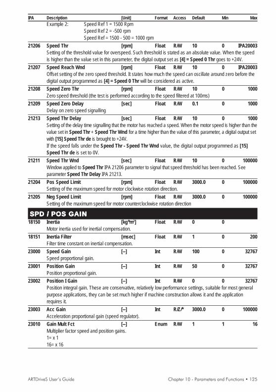
ARTDriveS User’s Guide Chapter 10 - Parameters and Functions • 125
IPA Description [Unit] Format Access Default Min MaxExample 2: Speed Ref 1 = 1500 Rpm
Speed Ref 2 = -500 rpmSpeed Ref = 1500 - 500 = 1000 rpm
21206 Speed Thr [rpm] Float R/W 10 0 IPA20003Setting of the threshold value for overspeed. Such threshold is stated as an absolute value. When the speedis higher than the value set in this parameter, the digital output set as [4] = Speed 0 Thr goes to +24V.
21207 Speed Reach Wnd [rpm] Float R/W 10 0 IPA20003Offset setting of the zero speed threshold. It states how much the speed can oscillate around zero before thedigital output programmed as [4] = Speed 0 Thr will be considered as active.
21208 Speed Zero Thr [rpm] Float R/W 10 0 1000Zero speed threshold (the test is performed according to the speed filtered at 100ms)
21209 Speed Zero Delay [sec] Float R/W 0.1 0 1000Delay on zero speed signalling
21213 Speed Thr Delay [sec] Float R/W 10 0 1000Setting of the delay time signalling that the motor has reached a speed. When the motor speed is higher than thevalue set in Speed Thr + Speed Thr Wnd for a time higher than the value of this parameter, a digital output setwith [15] Speed Thr de is brought to +24V.If the speed falls under the Speed Thr - Speed Thr Wnd value, the digital output programmed as [15]Speed Thr de is set to 0V.
21211 Speed Thr Wnd [sec] Float R/W 10 0 100000Window applied to Speed Thr IPA 21206 parameter to signal that speed threshold has been reached. Seeparameter Speed Thr Delay IPA 21213.
21204 Pos Speed Limit [rpm] Float R/W 3000.0 0 100000Setting of the maximum speed for motor clockwise rotation direction.
21205 Neg Speed Limit [rpm] Float R/W 3000.0 0 100000Setting of the maximum speed for motor counterclockwise rotation direction
SPD / POS GAINSPD / POS GAINSPD / POS GAINSPD / POS GAINSPD / POS GAIN18150 Inertia [kg*m2] Float R/W 0 0
Motor inertia used for inertial compensation.18151 Inertia Filter [msec] Float R/W 1 0 200
Filter time constant on inertial compensation.23000 Speed Gain [--] Int R/W 100 0 32767
Speed proportional gain.23001 Position Gain [--] Int R/W 50 0 32767
Position proportional gain.23002 Position I Gain [--] Int R/W 0 0 32767
Position integral gain. These are conservative, relatively low performance settings, suitable for most generalpurpose applications, they can be set much higher if machine construction allows it and the applicationrequires it.
23003 Acc Gain [--] Int R/Z/* 3000.0 0 100000Acceleration proportional gain (speed regulator).
23010 Gain Mult Fct [--] Enum R/W 1 1 16Multiplier factor speed and position gains.1= x 116= x 16
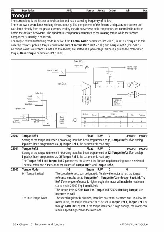
126 • Chapter 10 - Parameters and Functions ARTDriveS User’s Guide
IPA Description [Unit] Format Access Default Min Max
TTTTTORORORORORQQQQQUEUEUEUEUEThe current loop is the fastest control section and has a sampling frequency of 16 kHz.There are two current loops working simultaneously. The components of the forward and quadrature current arecalculated directly from the phase currents read by the AD converters; both components are controlled in order toobtain the desired behaviour. The quadrature component contributes to the rotating torque while the forwardcomponent is (usually) set at zero.The torque control functioning mode is active if the Control Mode parameter (IPA 20023) is set as "Torque". In thiscase the motor supplies a torque equal to the sum of Torque Ref 1 (IPA 22000) and Torque Ref 2 (IPA 22001)..All torque values (references, limits and thresholds) are stated as a percentage. 100% is equal to the motor ratedtorque, Base Torque parameter (IPA 18800).
+
+
-
-
+
-
Ki
Ki
High speeddefluxalgorithm
Iq*
Id*
Targetspeed
positionregister
SpeedReference
Position Ref
Trq Speed Limit
S2
S1
S3
S4
Els Ref
1
2
3
1
1
2
2
Torque
Speed
Control Mode
Position
Line Shaft
Acc
Gai
n
Pos
ition
Gai
n
Spe
edG
ain
Pos
ition
I Gai
n
Torque Ref 1
Max Pos TorqueMax Neg Torque
Torque Ref 2
FastLink Trq Ref
FL Trq Scale
1
2Torque Limited True Torque Mode
S1 1 2 1 1 1
S2 1 1 1 3 2
S3 1 1 2 1 1
S4 1 2 1 1 1
Torque
Control Mode
SwitchSpeed Els Position
22000 Torque Ref 1 [%] Float R/W 0 -IPA22012 IPA22012Setting of the torque reference if no analog input has been programmed as [1] Torque Ref 1. If an analoginput has been programmed as [1] Torque Ref 1, the parameter is read-only.
22001 Torque Ref 2 [%] Float R/W 0 -IPA22012 IPA22012Setting of the torque reference if no analog input has been programmed as [2] Torque Ref 2. If an analoginput has been programmed as [2] Torque Ref 2, the parameter is read-only.The Torque Ref 1 and Torque Ref 2 parameters are active if the Torque loop functioning mode is selected.The total reference is the sum of the values of Torque Ref 1 and Torque Ref 2.
22002 Torque Mode [--] Enum R/W 0 0 10 = Torque Limited The speed reference can be ignored. To allow the motor to run, the torque
reference must be set to Torque Ref 1, Torque Ref 2 or through FastLink TrqRef. If the torque reference is high enough, the motor will reach the maximumspeed set in 22009 Trq Speed Limit.The torque limits (22004 Max Pos Torque and 22005 Max Neg Torque) areoperative as well.
1 = True Torque Mode The speed regulator is disabled, therefore no control is carried out. To allow themotor to run, the torque reference must be set to Torque Ref 1, Torque Ref 2 orthrough FastLink Trq Ref. If the torque reference is high enough, the motor canreach a speed higher than the rated one.

ARTDriveS User’s Guide Chapter 10 - Parameters and Functions • 127
IPA Description [Unit] Format Access Default Min MaxThe torque limits (22004 Max Pos Torque and 22005 Max Neg Torque) areoperative as well.
22003 Trq Lim Config [--] Enum R/W 0 0 20 = Torque lim symm Symmetric torque limits. The limit is considered equal to the value of the Max
Pos Torque parameter (IPA 22004).1=Torque lim +/- Asymmetric torque limits.
Max Pos Torque = positive torque limit,Max Neg Torque = negative torque limit.
2 = Torque lim motor/brake Different torque limits for the functioning of the drive as a motor (Max PosTorque) and as a brake (Max Neg Torque)
22004 Max Pos Torque [%] Float R/W 100 0 IPA22012Setting of the positive torque limit.
22005 Max Neg Torque [%] Float R/W 100 0 IPA22012Setting of the negative torque limit.
22007 Torque Thr [Arms] Float R/W 0 0 IPA20000Setting of the torque threshold defined with an absolute value. When the torque is higher than the value set inthis parameter, the digital output set as [6] Torque Thr is brought to +24V.
22009 Trq Speed Limit [rpm] Float R/W 3000 0 10000Speed limit during the torque control. When Torque Mode is selected as Torque Limited.
22010 Torque Thr Delay [sec] Float R/W 10 0 10Setting of the delay time signaling that the level of the torque supplied by the motor has been reached. Whenthe motor supplied torque is higher than that set in Torque Thr for a period longer than the value of thisparameter, the digital output programmed as [16] Torque Thr Del is brought to +24V.
22011 Torque Reduction [%] Float R/W 50 0 IPA22012Active torque limit when the digital input set as Torque reduction is brought to +24V.
22013 FastLink Trq En [--] Bool R/W/Z 0 0 1If this function is enabled, the torque reference coming from a drive master through Fast Link is added toTorque Ref 1 and Torque ref 2.This function is normally used to perform a Helper configuration between two motors.
22515 FL Trq Scale [--] Float R/W 1 -10 +10Torque reference scale coming from the drive master. If the scale which has been set is negative, the torquedirection is inverted compared to the master.
22012 Max Torque [%] Float RMaximum torque value supplied by the drive-motor system equal to Mot Nom K Torque * Drive Max Curr,stated as a percentage of the motor rated torque.
22014 FastLink Trq Ref [%] Float RTorque reference reading from Fast Link (after the scaling).
18800 Base Torque [Nm] Float RRated torque of motor matching rated current of motor.
CURRENT GAINSCURRENT GAINSCURRENT GAINSCURRENT GAINSCURRENT GAINSThe current loop is controlled by a PID regulator; the maximum control bandwidth is 5 kHz. The gains of this loop arefactory set with appropriate values for the motors and specifically for the motor purchased if this drive was bought with amotor. For advanced applications such values have to be optimized according to the motor used.18100 Curr Prop Gain [--] Int R/W S 0 32767
Current loop proportional gain.18101 Curr Integr Gain [--] Int R/W S 0 32767
Current loop integral gain.

128 • Chapter 10 - Parameters and Functions ARTDriveS User’s Guide
IPA Description [Unit] Format Access Default Min Max
18102 Curr Deriv Gain [--] Int R/W 0 0 32767Current loop derivative gain.
18345 Curr Gain Calc [--] Enum R/W 0 0 10=Off : no calculation1=Calc from motor parameter the current gains are recalculated according to the motor parameters (LKG
Inductance , IPA 18313).
FLFLFLFLFLUXUXUXUXUXFlux reduction functionIn the brushless motor, the flux is constant, generated by the permanent magnets.It is possible to implement the flux reduction function by passing a negative current through the stator windings withvectors oriented to reduce overall flow.
Caution ! If the drive is disabled when the motor is running above nominal speed, the voltage on the motor couldreach values that might damage the drive.
Normally it is possible to run the motor up to 150% of nominal speed, without taking special precautions.In order to reach higher speeds, and avoid damage to the drive, an independent braking unit must be used, to brakethe load at least up to the motor’s nominal speed.For information on how to reach speeds greater than 150% of nominal, contact the Gefran-Siei technical supportcentre.18320 Max Deflux Curr [Arms] Float R/Z/* 0 IPA20000 0
Maximum flux reduction current of motor (only negative values are permitted).18321 User Vlt Max Lim [Vrms] Int R/W 400 10 612
Setting flux reduction starting voltage. Only values below mains voltage have an effect.It is used to reduce the maximum working voltage of the motor.
18322 Out Volt Filter [msec] Float R/W 10 1 500Filter time constant on output voltage.
18325 Volt Prop Gain [--] Int R/W 500 0 32767Proportional gain on voltage loop
18326 Volt Int Gain [--] Int R/W 500 0 32767Integral gain on voltage loop
18328 Out Vlt Max Lim [Vrms] Int RMonitor flux reduction starting voltage.
DIGITDIGITDIGITDIGITDIGITAL INPUTSAL INPUTSAL INPUTSAL INPUTSAL INPUTSThe regulation board of the ARTDriveS drive has 8 digital inputs. Seven digital inputs can be programmed to differentfunctions and they are located on the I/O terminal block on R-XVy regulation board.Refreshing time = 8ms.The changes in the digital input setting can be enabled by resetting the drive.This rule can be applied also to the virtual inputs.20101 Digital Input 1 [--] Enum R/W 4 0 2007
Choice of the parameters to be set on Digital Input 1. The possibilities listed as “Choices for the digitalinput association” are available. Default = Start/stop
Choices for the digital input association:0 = OFF Unconfigured input.2 = Drive reset Alarm Reset command.Momentary input active on the edge. The drive must be disabled for a reset to occur.

ARTDriveS User’s Guide Chapter 10 - Parameters and Functions • 129
IPA Description [Unit] Format Access Default Min Max3 = External fault External alarm signal.It is active on the leading edge.4 = Start/stop Start /stop command.It is active on the leading edge. In the current and speed configuration this command must be programmed ona digital input. If its value is high, it starts the drive operation; if its value is low, the drive will stop. When thiscommand is active, if a speed reference is present, the motor goes to the set speed.5 = Fast/stop Emergency stop command. Active on the drop wire leading edge.It is active on the leading edge, it stops the speed command instantly, braking the motor with no decel ramp inthe shortest possible time till zero speed has been reached.The Fast/stop command is used in emergency and dangerous situations in order to stop the drive in theshortest possible time. If a digital input is set as Fast/stop, this input must be high to run in any mode.The Fast/stop command must be present before the drive enabling command (Enable command).By disabling the voltage on this input while the drive is active, it is possible to cause a braking stop with theshortest possible time.With a start following a Fast/stop command it is necessary to set the Enable digital input with a lowlogic status and the Fast/stop digital input with a high logic status; before a jog function can beperformed.6 = Jog CW Jog forward function command.It is active only in the speed and position configurations. When this input is active, the speed reference andthe ramp times are those set in the Jog parameter menu.7 = Jog CCW Jog reverse function command.It is active only in the speed and position configurations. When this input is active, the speed reference andthe ramp times are those set in the Jog parameter menu.8 = Ramp in = 0 Ramp In = 0 command.It is active only in the speed and position configurations. When this input is active (high logic status), itreplaces the present reference with a zero reference and uses the set ramp. This digital zero keeps the motorrotor stopped in a torque condition, without any offset drift typical for A/D (analog/digital) converters.9 = Reverse Inverse command.When the command is active, it changes the motor rotation direction by following the set ramp.10 = End Run Reverse Clockwise end run command.It is active only in the speed and position configuration. It only allows, regardless of reference, motor x rotationin a clockwise (CW) direction.11 = End Run Forward Counterclockwise end run command. It is active only in the speed and positionconfiguration. It only allows, regardless of reference, motor rotation in a counterclockwise (CCW) direction.12 = Reference = 0 Speed reference = 0.It has the same function as Ramp In = 0 but it does not perform the decel ramp, it stops immediately.14 = Torque loop It selects the Torque Regulation mode.15 = Speed loop Select the mode to Speed regulation.16 = Position loop Select the mode to Position regulation.17 = Line Shaft loop It selects the Electric Axis mode.18 = Disable An Inp 0 Command Disabling analog input 0 (both the value and the offset are disabled).With a high logic level analog input 0 is disabled.19 = Disable An Inp 1 Command Disabling analog input 1 (both the value and the offset are disabled).With a high logic level the analog input 1 is disabled.
Speed sel bit 0...2The number given by the binary combination of these digital inputs selects a digital speed reference set in theparameters of the Multispeed function.21 = Speed sel Bit 0 Multi-speed function, Bit 0 selection.22 = Speed sel Bit 1 Multi-speed function, Bit 1 selection.23 = Speed sel Bit 2 Multi-speed function, Bit 1 selection.

130 • Chapter 10 - Parameters and Functions ARTDriveS User’s Guide
IPA Description [Unit] Format Access Default Min MaxRamp sel bit 0...1The number given by the binary combinations of these digital inputs selects the ramp times set in theparameters of the Multiramp function.24 = Ramp sel Bit 0 Multi-ramp function, Bit 0 selection.25 = Ramp sel Bit 1 Multi-ramp function, Bit 1 selection.26 = Virtual DI OK When the virtual digital input 14 (only this one) is set with VIRTUAL DI OK, allthe set Virtual digital inputs are active only if this input is equal to 1 (high logic level). In other words, thisenables virtual digital input to be used.27 = Alarm reset When this digital input is active, it is possible to reset all the active alarm (highlogic level). The reset is executed only if the alarm cause is no more present.28 = Virtual Enable Virtual Enable, it functions in parallel with the physical one (Digital Input 0).29 = Torque Reduct It enables the torque reduction. When it is active, the torque limits are set by theTorque Reduction parameter, IPA 22011.
Motor potentiometer selection30 = Motor Pot Up Increases speed reference according to the ramp time set in Motor Pot Acc.31 = Motor Pot Down Reduces speed reference according to the ramp time set in Motor Pot Dec.32 = Motor Pot Enable Enables motor potentiometer function33 = Motor Pot Reset Reset memory34 = Motor Pot Mode Operational mode of the motor potentiometer:
Low state = speed reference is added to Ramp ReferenceHigh state = the motor potentiometer acts as a Ramp Reference multiplier
35 = Motor Pot Memo Storage of reference setting in memoryHigh state = storage of last speed setting in memory. After Start, the motoraccelerates automatically up to the speed setting.Low state = After Start, the motor stops, waiting for the Motor Pot Up command
36 = Motor Pot Rev Speed reference polarityLow state = positive reference, High state = negative reference
Sequential position control selectionInputs active only in Sequential position control configuration. The number given of the binary combination ofthe digital inputs set as POS Event Bit 0...7, forms the parameter value IPA 30800 Pos Actual Event whichis the event that causes the multiposition controller to go to "Event Match" or "Dwell + Event".37 = POS Event Bit 038 = POS Event Bit 139 = POS Event Bit 240 = POS Event Bit 341 = POS Event Bit 442 = POS Event Bit 543 = POS Event Bit 644 = POS Event Bit 745 = Multi Pos Enable Enabling multi-position controller46 = Multi Pos Abort Ends position sequence.
Powerloss47 = PL Mains status It signals the mains voltage reset to the drive
Pos-preset 0...5These inputs are only active with the position configuration. The number given by the binary combination ofthe digital inputs set as Pos Preset (0...5) selects the number of the active position preset.Example: with a three-position positioner, all Pos Preset parameters must have a default value (=0) with the
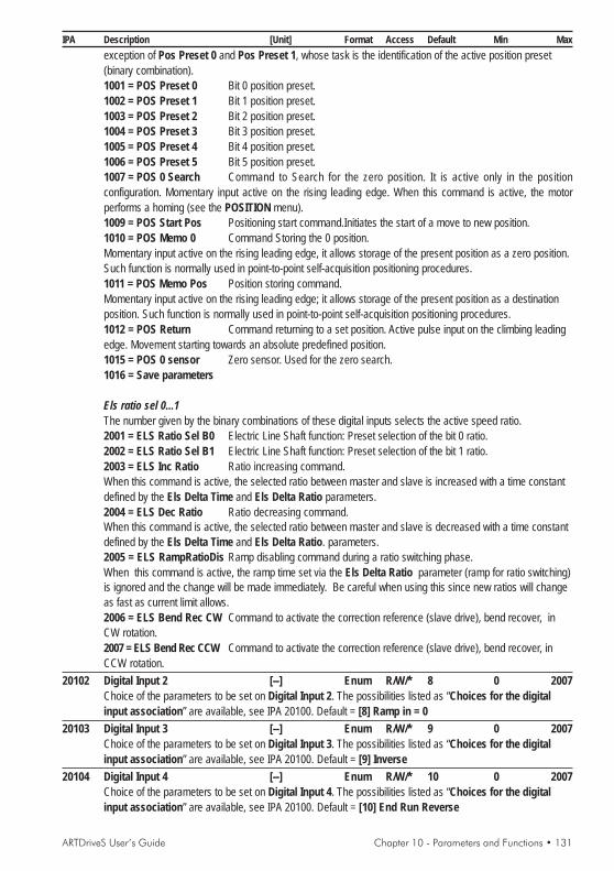
ARTDriveS User’s Guide Chapter 10 - Parameters and Functions • 131
IPA Description [Unit] Format Access Default Min Maxexception of Pos Preset 0 and Pos Preset 1, whose task is the identification of the active position preset(binary combination).1001 = POS Preset 0 Bit 0 position preset.1002 = POS Preset 1 Bit 1 position preset.1003 = POS Preset 2 Bit 2 position preset.1004 = POS Preset 3 Bit 3 position preset.1005 = POS Preset 4 Bit 4 position preset.1006 = POS Preset 5 Bit 5 position preset.1007 = POS 0 Search Command to Search for the zero position. It is active only in the positionconfiguration. Momentary input active on the rising leading edge. When this command is active, the motorperforms a homing (see the POSITION menu).1009 = POS Start Pos Positioning start command.Initiates the start of a move to new position.1010 = POS Memo 0 Command Storing the 0 position.Momentary input active on the rising leading edge, it allows storage of the present position as a zero position.Such function is normally used in point-to-point self-acquisition positioning procedures.1011 = POS Memo Pos Position storing command.Momentary input active on the rising leading edge; it allows storage of the present position as a destinationposition. Such function is normally used in point-to-point self-acquisition positioning procedures.1012 = POS Return Command returning to a set position. Active pulse input on the climbing leadingedge. Movement starting towards an absolute predefined position.1015 = POS 0 sensor Zero sensor. Used for the zero search.1016 = Save parameters
Els ratio sel 0...1The number given by the binary combinations of these digital inputs selects the active speed ratio.2001 = ELS Ratio Sel B0 Electric Line Shaft function: Preset selection of the bit 0 ratio.2002 = ELS Ratio Sel B1 Electric Line Shaft function: Preset selection of the bit 1 ratio.2003 = ELS Inc Ratio Ratio increasing command.When this command is active, the selected ratio between master and slave is increased with a time constantdefined by the Els Delta Time and Els Delta Ratio parameters.2004 = ELS Dec Ratio Ratio decreasing command.When this command is active, the selected ratio between master and slave is decreased with a time constantdefined by the Els Delta Time and Els Delta Ratio. parameters.2005 = ELS RampRatioDis Ramp disabling command during a ratio switching phase.When this command is active, the ramp time set via the Els Delta Ratio parameter (ramp for ratio switching)is ignored and the change will be made immediately. Be careful when using this since new ratios will changeas fast as current limit allows.2006 = ELS Bend Rec CW Command to activate the correction reference (slave drive), bend recover, inCW rotation.2007 = ELS Bend Rec CCW Command to activate the correction reference (slave drive), bend recover, inCCW rotation.
20102 Digital Input 2 [--] Enum R/W/* 8 0 2007Choice of the parameters to be set on Digital Input 2. The possibilities listed as “Choices for the digitalinput association” are available, see IPA 20100. Default = [8] Ramp in = 0
20103 Digital Input 3 [--] Enum R/W/* 9 0 2007Choice of the parameters to be set on Digital Input 3. The possibilities listed as “Choices for the digitalinput association” are available, see IPA 20100. Default = [9] Inverse
20104 Digital Input 4 [--] Enum R/W/* 10 0 2007Choice of the parameters to be set on Digital Input 4. The possibilities listed as “Choices for the digitalinput association” are available, see IPA 20100. Default = [10] End Run Reverse

132 • Chapter 10 - Parameters and Functions ARTDriveS User’s Guide
IPA Description [Unit] Format Access Default Min Max
20105 Digital Input 5 [--] Enum R/W/* 11 0 2007Choice of the parameters to be set on Digital Input 5. The possibilities listed as “Choices for the digitalinput association” are available, see IPA 20100. Default = [11] End Run Forward
20106 Digital Input 6 [--] Enum R/W/* 3 0 2007Choice of the parameters to be set on Digital Input 6. The possibilities listed as “Choices for the digitalinput association” are available, seee IPA 20100. Default = [3] External fault
20107 Digital Input 7 [--] Enum R/W/* 2 0 2007Choice of the parameters to be set on Digital Input 7. The possibilities listed as “Choices for the digitalinput association” are available, see IPA 20100. Default = [2] Drive reset
20162 Dig Inp Rev Mask [--] DWord R/W 0H 0H 0FFFFFFFFHThis parameter allows changing the logic level of the set digital inputs. Normally digital inputs become activewhen switching from a low to a high logic level occurs. Through this bit-set parameter it is possible to decidewhether to change the logic condition, i.e. active low logic level, inactive high logic level. This parameter cannotmodify the logic level of digital input 0.
Example: The intervention of two limit switches (End Run Forward and End Run Reverse) has to be set ontwo digital inputs, digital input 3 and digital input 4; the limit switch intervention has to be active with a lowlogic level.
DIGITAL INPUT 7 6 5 4 3 2 1 0
Dig Inp Rev Mask 0 0 0 1 1 0 0 0txv9110
1 8
It is necessary to set Dig Inp Rev Mask = 18H20100 Dig Inp 0 Status [--] Enum R
Drive enabled.20163 Dig Inp Status [--] Word R
Read-only parameter stating the present condition (high logic level 1 and low logic level 0) of the digitalinputs. It is an hexadecimal parameter.Example: The digital inputs are:DIG IN 0 = 1 DIG IN 1 = 1 DIG IN 6 = 1
DIGITAL INPUT 7 6 5 4 3 2 1 0
DIG IN STATUS 0 1 0 0 0 0 1 1txv9111
4 3
The value displayed by the Dig Inps Status parameter is 43H .
EXP DIG INPUTSInside the ARTDriveS drive it is possible to install an option expansion card of the digital inputs and outputs. It ispossible to add up to 8 programmable digital inputs through the following parameters. The programming procedure isthe same as the one for the digital inputs.20150 Exp Dig Inp 0 [--] Enum R/W/* 0 0 2007
Choice of the programmable parameters on a digital input. The same possibilities stated for the digital inputsare available. See “Choices for the digital input association” list on IPA 20101.
20151 Exp Dig Inp 1 [--] Enum R/W/* 0 0 2007Scelta dei parametri programmabili su un ingresso digitale. Sono disponibili le stesse possibilità degliingressi digitali. Vedere la lista “Codifica per l’associazione degli ingressi” IPA 20101.
20152 Exp Dig Inp 2 [--] Enum R/W/* 0 0 2007Choice of the programmable parameters on a digital input. The same possibilities stated for the digital inputsare available. See “Choices for the digital input association” list on IPA 20101.

ARTDriveS User’s Guide Chapter 10 - Parameters and Functions • 133
IPA Description [Unit] Format Access Default Min Max
20153 Exp Dig Inp 3 [--] Enum R/W/* 0 0 2007Choice of the programmable parameters on a digital input. The same possibilities stated for the digital inputsare available. See “Choices for the digital input association” list on IPA 20101.
20154 Exp Dig Inp 4 [--] Enum R/W/* 0 0 2007Choice of the programmable parameters on a digital input. The same possibilities stated for the digital inputsare available. See “Choices for the digital input association” list on IPA 20101.
20155 Exp Dig Inp 5 [--] Enum R/W/* 0 0 2007Choice of the programmable parameters on a digital input. The same possibilities stated for the digital inputsare available. See “Choices for the digital input association” list on IPA 20101.
20156 Exp Dig Inp 6 [--] Enum R/W/* 0 0 2007Choice of the programmable parameters on a digital input. The same possibilities stated for the digital inputsare available. See “Choices for the digital input association” list on IPA 20101.
20157 Exp Dig Inp 7 [--] Enum R/W/* 0 0 2007Choice of the programmable parameters on a digital input. The same possibilities stated for the digital inputsare available. See “Choices for the digital input association” list on IPA 20101.
20164 Exp Dig Inp Stat [--] Word ROnly-reading parameter stating the present condition (high logic level 1 and low logic level 0) of the digitalinputs on the EXP-D14A4F expansion card. It is an hexadecimal parameter.
Example: The digital inputs are: Exp Dig Inp 0 = 1Exp Dig Inp 5 = 1Exp Dig Inp 7 = 1
EXP DIGIT INPUT 7 6 5 4 3 2 1 0
EXP DIG IN STATUS 1 0 1 0 0 0 0 1txv9112
A 1
The value displayed by the Exp Dig Inp Stat parameter is A1 H.
VIRT DIG INPUTSDigital virtual inputs which are not physically present on the terminals but which are available to program possiblecommands, configured through the serial interface or field bus. When an external application needs to use some driveprogrammable functions through digital input, it is always necessary :
- Set the desired functionality see list “Choices for the digital input association” IPA 20101- Write the status of the virtual digital inputs (see IPA 20186).
20170 Virt Dig Inp 0 [--] Enum R/W/* 0 0 2007Choice of the programmable parameters on Virt Dig Inp 0. The same possibilities stated for the digitalinputs are available. See “Choices for the digital input association” list on IPA 20101.
20171 Virt Dig Inp 1 [--] Enum R/W/* 0 0 2007Choice of the programmable parameters on Virt Dig Inp 1. The same possibilities stated for the digitalinputs are available. See “Choices for the digital input association” list on IPA 20101.
20172 Virt Dig Inp 2 [--] Enum R/W/* 0 0 2007Choice of the programmable parameters on Virt Dig Inp 2. The same possibilities stated for the digitalinputs are available. See “Choices for the digital input association” list on IPA 20101.
20173 Virt Dig Inp 3 [--] Enum R/W/* 0 0 2007Choice of the programmable parameters on Virt Dig Inp 3. The same possibilities stated for the digitalinputs are available. See “Choices for the digital input association” list on IPA 20101.
20174 Virt Dig Inp 4 [--] Enum R/W/* 0 0 2007Choice of the programmable parameters on Virt Dig Inp 4. The same possibilities stated for the digitalinputs are available. See “Choices for the digital input association” list on IPA 20101.

134 • Chapter 10 - Parameters and Functions ARTDriveS User’s Guide
IPA Description [Unit] Format Access Default Min Max
20175 Virt Dig Inp 5 [--] Enum R/W/* 0 0 2007Choice of the programmable parameters on Virt Dig Inp 5. The same possibilities stated for the digitalinputs are available. See “Choices for the digital input association” list on IPA 20101.
20176 Virt Dig Inp 6 [--] Enum R/W/* 0 0 2007Choice of the programmable parameters on Virt Dig Inp 6. The same possibilities stated for the digitalinputs are available. See “Choices for the digital input association” list on IPA 20101.
20177 Virt Dig Inp 7 [--] Enum R/W/* 0 0 2007Choice of the programmable parameters on Virt Dig Inp 7. The same possibilities stated for the digitalinputs are available. See “Choices for the digital input association” list on IPA 20101.
20178 Virt Dig Inp 8 [--] Enum R/W/* 0 0 2007Choice of the programmable parameters on Virt Dig Inp 8. The same possibilities stated for the digitalinputs are available. See “Choices for the digital input association” list on IPA 20101.
20179 Virt Dig Inp 9 [--] Enum R/W/* 0 0 2007Choice of the programmable parameters on Virt Dig Inp 9. The same possibilities stated for the digitalinputs are available. See “Choices for the digital input association” list on IPA 20101.
20180 Virt Dig Inp 10 [--] Enum R/W/* 0 0 2007Choice of the programmable parameters on Virt Dig Inp 10. The same possibilities stated for the digitalinputs are available. See “Choices for the digital input association” list on IPA 20101.
20181 Virt Dig Inp 11 [--] Enum R/W/* 0 0 2007Choice of the programmable parameters on Virt Dig Inp 11. The same possibilities stated for the digitalinputs are available. See “Choices for the digital input association” list on IPA 20101.
20182 Virt Dig Inp 12 [--] Enum R/W/* 0 0 2007Choice of the programmable parameters on Virt Dig Inp 12. The same possibilities stated for the digitalinputs are available. See “Choices for the digital input association” list on IPA 20101.
20183 Virt Dig Inp 13 [--] Enum R/W/* 0 0 2007Choice of the programmable parameters on Virt Dig Inp 13. The same possibilities stated for the digitalinputs are available. See “Choices for the digital input association” list on IPA 20101.
20184 Virt Dig Inp 14 [--] Enum R/W/* 0 0 2007Choice of the programmable parameters on Virt Dig Inp 14. The same possibilities stated for the digitalinputs are available. See “Choices for the digital input association” list on IPA 20101.
20185 Virt Dig Inp 15 [--] Enum R/W/* 0 0 2007Choice of the programmable parameters on Virt Dig Inp 15. The same possibilities stated for the digitalinputs are available. See “Choices for the digital input association” list on IPA 20101.
20186 Virt DI Status [--] Word R/W 0000H 0000H FFFFHIt displays and sets the status of the virtual digital inputs. Hexadecimal setting.
Programming exampleIf the virtual digital inputs have to be enabled via the serial input:Virt Dig Inp 0 Programmed as POS Preset 0Virt Dig Inp 1 Programmed as POS Preset 1Virt Dig Inp 2 Programmed as POS Preset 2Virt Dig Inp 3 Programmed as POS Preset 3If we set to high logic level :- the bit 0 referring to Virt Dig Inp 0 = 1- the bit 1 referring to Virt Dig Inp 1 = 1- the bit 2 referring to Virt Dig Inp 2 = 1- the bit 3 referring to Virt Dig Inp 3 = 1
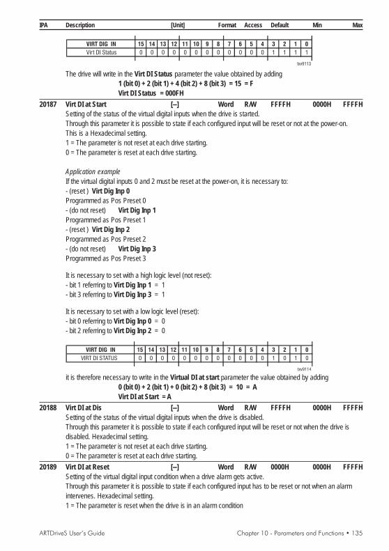
ARTDriveS User’s Guide Chapter 10 - Parameters and Functions • 135
IPA Description [Unit] Format Access Default Min Max
VIRT DIG IN 15 14 13 12 11 10 9 8 7 6 5 4 3 2 1 0
Virt DI Status 0 0 0 0 0 0 0 0 0 0 0 0 1 1 1 1
txv9113
The drive will write in the Virt DI Status parameter the value obtained by adding1 (bit 0) + 2 (bit 1) + 4 (bit 2) + 8 (bit 3) = 15 = FVirt DI Status = 000FH
20187 Virt DI at Start [--] Word R/W FFFFH 0000H FFFFHSetting of the status of the virtual digital inputs when the drive is started.Through this parameter it is possible to state if each configured input will be reset or not at the power-on.This is a Hexadecimal setting.1 = The parameter is not reset at each drive starting.0 = The parameter is reset at each drive starting.
Application exampleIf the virtual digital inputs 0 and 2 must be reset at the power-on, it is necessary to:- (reset ) Virt Dig Inp 0Programmed as Pos Preset 0- (do not reset) Virt Dig Inp 1Programmed as Pos Preset 1- (reset ) Virt Dig Inp 2Programmed as Pos Preset 2- (do not reset) Virt Dig Inp 3Programmed as Pos Preset 3
It is necessary to set with a high logic level (not reset):- bit 1 referring to Virt Dig Inp 1 = 1- bit 3 referring to Virt Dig Inp 3 = 1
It is necessary to set with a low logic level (reset):- bit 0 referring to Virt Dig Inp 0 = 0- bit 2 referring to Virt Dig Inp 2 = 0
VIRT DIG IN 15 14 13 12 11 10 9 8 7 6 5 4 3 2 1 0
VIRT DI STATUS 0 0 0 0 0 0 0 0 0 0 0 0 1 0 1 0
txv9114
it is therefore necessary to write in the Virtual DI at start parameter the value obtained by adding0 (bit 0) + 2 (bit 1) + 0 (bit 2) + 8 (bit 3) = 10 = AVirt DI at Start = A
20188 Virt DI at Dis [--] Word R/W FFFFH 0000H FFFFHSetting of the status of the virtual digital inputs when the drive is disabled.Through this parameter it is possible to state if each configured input will be reset or not when the drive isdisabled. Hexadecimal setting.1 = The parameter is not reset at each drive starting.0 = The parameter is reset at each drive starting.
20189 Virt DI at Reset [--] Word R/W 0000H 0000H FFFFHSetting of the virtual digital input condition when a drive alarm gets active.Through this parameter it is possible to state if each configured input has to be reset or not when an alarmintervenes. Hexadecimal setting.1 = The parameter is reset when the drive is in an alarm condition

136 • Chapter 10 - Parameters and Functions ARTDriveS User’s Guide
IPA Description [Unit] Format Access Default Min Max0 = The parameter is not reset when the drive is in an alarm condition.The procedure to be followed is the same as the one used for the Virt DI at Start parameter.
DIGITDIGITDIGITDIGITDIGITAL OUTPUTSAL OUTPUTSAL OUTPUTSAL OUTPUTSAL OUTPUTSIn the regulation board of the ARTDriveS drives there is one slow Relay Output and six fast Digital Outputs. The relayoutput has one N.O. and one N.C. contact, and it is used as “Drive OK”. Refreshing time = 8ms.The changes in the digital output setting can be enabled by resetting the drive.The same rule can be applied also to the virtual outputs.
NOTE! It is possible to set all the drive alarms on a digital output. The logic status is normally low and itbecomes high when the drive is in an alarm condition.
20005 DO Reset at Fail [--] Long R/W 0H 0H FFFFHSetting of the digital output state when a drive alarm gets active: only for alarm code 1...6, 8...12, 18...32,which disable PWM. This parameter allows to state, when an alarm condition intervenes, which digital output,corresponding to the set bit, is brought to a 0 logic level. Hexadecimal setting.The bits 0 ... 5 refer to the digital outputs, the bits 8 ... 13 refer to the digital outputs of the expansion card.0 = The output does not change its logic level1 = The output is reset and set with 0.
20006 DO Set at Fail [--] Long R/W 0H 0H FFFFHSetting of the digital output state when a drive alarm gets active: only for alarm code 1...6, 8...12, 18...32,which disable PWM. This parameter allows to state, when a drive alarm intervenes, which digital output,corresponding to the set bit, is brought to a high logic level. Hexadecimal setting.The bits 0 ... 5 refer to the digital outputs, the bits 8 ... 13 refer to the digital outputs of the expansion card.0 = The output does not change its logic level1 = The output is set to an high logic level.
20200 Digital Output 0 [--] Enum R/W/* 3 0 1010Choice of the programmable parameters on Digital Output 0. The possibilities listed as “Choices for Digitaloutput association” are available. Deafult = Speed Reached
Choices for digital output association:0 = OFF Output not configured.1 = Drive Enable The digital output reaches high logic status when the drive is power supplied,enabled (enable command active) and no alarm is present.2 = Drive OK The digital output acquires the high logic status when the drive is power suppliedand no alarm is present.3 = Speed Reached Reached speed.The digital output reaches high logic status when the motor present speed is equal to the reference within awindow defined by the Speed Thr Wnd parameter.4 = Speed 0 Thr Speed = 0.The digital output reaches high logic status when the motor speed is zero with an dead band (positive andnegative) defined by the Speed Zero Delay parameter5 = Torque Limit Torque limit.The digital output acquires the high logic status with a torque limit functioning condition.6 = Torque Thr Overcome torque.The digital output acquires the high logic status when the motor supplied torque, with an absolute value, ishigher than the one set in the Torque Thr parameter.7 = Speed Thr Overcome current.The digital output acquires the high logic status if the speed, with an absolute value, is higher than the valueset in the Speed Thr parameter.8 = AD Index (XE ) Repetition of incremental encoder index connected on XE connector. The signal
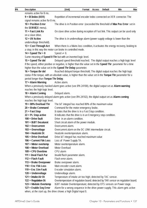
ARTDriveS User’s Guide Chapter 10 - Parameters and Functions • 137
IPA Description [Unit] Format Access Default Min Maxremains active for 8 ms.9 = DI Index (XER) Repetition of incremental encoder index connected on XER connector. Thesignal remains active for 8 ms.10 = Position Error The drive is in Position error (exceeded the threshold of Max Pos Error set inthe SERVICE menu).11 = Fast Link Rx On slave drive active during reception of Fast link. This output can be used onlyon a slave drive.12 = UV Active The drive is in undervoltage alarm (power supply voltage is lower than theundervoltage threshold).13 = Cost Through Act When there is a Mains loss condition, it activates the energy recovery, braking toa stop; in this way the motor can brake in controlled mode.14 = Speed Thr > 0 Speed ≠ 0.Same meaning of Speed 0 Thr but with an inverted logic level.15 = Speed Thr del Delayed speed threshold reached. The digital output reaches a high logic levelif the speed, either positive or negative, is higher than the value set in the Speed Thr parameter for a timehigher than the value set in the Speed Thr Delay parameter.16 = Torque thr del Reached delayed torque threshold. The digital output reaches the high logicstatus if the torque, with an absolute value, is higher than the value set in the Torque Thr parameter for aperiod longer than Torque Thr Delay.17 = Alarm Warning Active alarm.When a previously masked alarm goes active (see IPA 24100), the digital output set as Alarm warningreaches the high logic level.18 = Alarm Coming Delayed alarm.When a previously delayed alarm gets active (see IPA 24102), the digital output set as Alarm comingreaches the high logic level.19 = 80% Overload Thr The IxT integral has reached 80% of the maximum value20 = Brake Command Command for the motor emergency brake.21 = Fast Stop It states that the drive is in a Fast Stop condition.22 = PL Stop active It indicates that the drive is in an Emergency stop condition.100 = Drive fault Drive in an alarm condition.101 = IGBT Desaturat Short circuit alarm of the power module.102 = Overcurrent Overcurrent alarm.103 = Overvoltage Overcurrent alarm on the DC LINK intermediate circuit.104 = Heatsink Ot Heatsink overtemperature alarm.105 = Drive Overload Drive IxT integral has reached maximum value106 = Current Fbk Loss Loss of Power Supply TA.107 = Motor overtemp Motor overtemperature alarm.108 = Motor Overload Motor Overload109 = CPU Overtime CPU alarm111 = Inval Flash Par Invalid flash parameter alarm.112 = Flash Fault Flash error alarm.113 = Brake Overpower Brake overpower alarm.118 = Enc Fbk Loss Main encoder count alarm.119 = Enc Sim Fault Encoder simulation alarm.120 = Undervoltage Undervoltage alarm.121 = Intake Air Ot Temperature of intake air too high; detected by TAC sensor.122 = Regulation Ot Overtemperature of regulation board; detected by TAR sensor on regulation board.123 = Module Overtemp IGBT module Overtemperature; detected by OTS sensors on Power stage.127 = Enable Seq Error Alarm for a wrong sequence in the drive power supply. This alarm gets activewhen, at the start up, the drive shows a high Digital input 0.

138 • Chapter 10 - Parameters and Functions ARTDriveS User’s Guide
IPA Description [Unit] Format Access Default Min Max128 = Fast Link Error Fast link communication error.129 = Position Fault The drive is in Position error (A 29) alarm.131 = Sequence Fault External alarm for the drive.1001 = Position Zero Position 0 reached.The digital output reaches high logic status when the motor present position is equal to the zero position withan dead band defined by the Pos 0 Thr Offset parameter.1002 = Pos Reached The digital output acquires the high logic status when the control finishes thepositioning procedure and the position is equal to the destination position +- Pos Window for a period equalto Pos Window Time.1003 = Position Exceeded Position threshold.The digital output acquires the high logic status when the difference between the present position and thestarting position is higher than the value set in the Positon Thr parameter.1004 = Pos Abs Thr Absolute position threshold.The digital output reaches high logic status if the position is higher than the value set in the Pos Abs Thr.parameter.1005 = Pos Zero Found Found zero position.The digital output reaches high logic status at the end of the zero searching phase.1006 = Pos Thr Close 1 Reached position threshold 1.The digital output acquires the high logic status when the difference between the motor present position andthe destination position is lower or equal to the Pos Thr Close 1 parameter.1007 = Pos Thr Close 2 Reached position threshold 2.The digital output acquires the high logic status when the difference between the motor present position andthe destination position is lower or equal to the Pos Thr Close 2 parameter.1008 = Pos Out Of Lim A value has been set up out of range Min Preset Value/Max Preset Value. If avalue required is out of range, it is not executed and the digital output programmed as Pos Out Of Limchanges to high logic status.1009 = Pos Loop Active It states that the drive present functioning mode is Position1010 = Pos Not Reached The digital output has a logic state high when position control has ended, andthe position is not entered in the +- Pos Window for a period at least equal to Pos Window Time.Takes the low logic state when a new POS Start Pos command is issued.1011 = Mpos end cycle The output becomes high when the multi-positioning sequence is complete
20201 Digital Output 1 [--] Enum R/W/* 4 0 1010Choice of the programmable parameters on Digital Output 1 The possibilities listed as “Choices for Digitaloutput association” are available, see IPA 20200. Default = Speed 0 thr
20202 Digital Output 2 [--] Enum R/W/* 5 0 1010Choice of the programmable parameters on Digital Output 2 The possibilities listed as “Choices for Digitaloutput association” are available, see IPA 20200.Default = Torque Limit
20203 Digital Output 3 [--] Enum R/W/* 100 0 1010Choice of the programmable parameters on Digital Output 3 The possibilities listed as “Choices for Digitaloutput association” are available, see IPA 20200. Default = Drive Fault
20204 Digital Output 4 [--] Enum R/W/* 131 0 1010Choice of the programmable parameters on Digital Output 4 The possibilities listed as “Choices for Digitaloutput association” are available, see IPA 20200. Default = External Fault
20205 Digital Output 5 [--] Enum R/W/* 1 0 1010Choice of the programmable parameters on Digital Output 5 The possibilities listed as “Choices for Digitaloutput association” are available, see IPA 20200. Default = Drive Enable
20254 Dig Out Reverse [--] Dword R/W 00H 0H FFFFFFFFHThis parameter allows to change the logic level of the programmed digital outputs. The digital outputs usuallyhave a 0 logic level when they are inactive and they switch to a high logic level when they become active. Via

ARTDriveS User’s Guide Chapter 10 - Parameters and Functions • 139
IPA Description [Unit] Format Access Default Min Maxthis bit-mapped parameter it is possible to choose which output the normal logic level has to be switched to.Hexadecimal setting.
Example: the digital outputs 1, 4 and 5 have to be programmed with an inverted condition:
DIGITAL OUTPUT 5 4 3 2 1 0
Dig Out Reverse 1 1 0 0 1 0
3 2 txv9115
It is necessary to set Dig Out Reverse = 32H20255 Dig Out Status [--] Word R
Only-reading parameter stating the present condition (high logic level 1 and low logic level 0) of the digitaloutputs. It is an hexadecimal parameter.
Example: the digital outputs are:
DIGITAL OUTPUT 5 4 3 2 1 0
Dig Out Status 0 0 1 0 0 0
0 8 txv9116
DIG OUT 3 = 1The value displayed by the Dig Out Status parameter is 8H
EXP DIG OUTPUTSIt is possible to install inside the drive a card for the digital inputs and outputs expansion. Up to six Digital Outputs canbe expanded and programmed through the below parameters. The programming procedure for the expanded digitaloutputs is the same as for the digital outputs. Refreshing time = 8ms.20250 Exp Dig Out 0 [--] Enum R/W/* 0 0 1010
Choice of the programmable parameters on Exp Dig Out 0. The same possibilities stated for the digitaloutputs are available. See “Choices for the digital output association” list on IPA 20200..
20251 Exp Dig Out 1 [--] Enum R/W/* 0 0 1010Choice of the programmable parameters on Exp Dig Out 1. The same possibilities stated for the digitaloutputs are available. See “Choices for the digital output association” list on IPA 20200..
20252 Exp Dig Out 2 [--] Enum R/W/* 0 0 1010Choice of the programmable parameters on Exp Dig Out 2. The same possibilities stated for the digitaloutputs are available. See “Choices for the digital output association” list on IPA 20200..
20253 Exp Dig Out 3 [--] Enum R/W/* 0 0 1010Choice of the programmable parameters on Exp Dig Out 3. The same possibilities stated for the digitaloutputs are available. See “Choices for the digital output association” list on IPA 20200..
20257 Exp Dig Out 4 [--] Enum R/W/* 0 0 1010Choice of the programmable parameters on Exp Dig Out 4. The same possibilities stated for the digitaloutputs are available. See “Choices for the digital output association” list on IPA 20200..
20258 Exp Dig Out 5 [--] Enum R/W/* 0 0 1010Choice of the programmable parameters on Exp Dig Out 5. The same possibilities stated for the digitaloutputs are available. See “Choices for the digital output association” list on IPA 20200..0.
20259 Exp Dig Out 6 [--] Enum R/W/* 1 0 1010Choice of the programmable parameters on Exp Dig Out 6. The same possibilities stated for the digitaloutputs are available. See “Choices for the digital output association” list on IPA 20200..
20260 Exp Dig Out 7 [--] Enum R/W/* 1 0 1010Choice of the programmable parameters on Exp Dig Out 7. The same possibilities stated for the digitaloutputs are available. See “Choices for the digital output association” list on IPA 20200..

140 • Chapter 10 - Parameters and Functions ARTDriveS User’s Guide
IPA Description [Unit] Format Access Default Min Max
20256 Exp Dig Out Stat [--] Word ROnly-reading parameter stating the present condition (high logic level 1 and low logic level 0) of the digitaloutputs set on the EB-DIO expansion card.
VIRT DIG OUTPUTSVirtual digital outputs, which are not physically present on the terminals but which are available to set possible Digitaloutputs to be read via the serial line or the field bus.By setting the Virtual digital outputs, the Digital outputs on the terminal strip are still available. The function performedby a digital output programmed on a Digital output or on a Virtual digital output is the same.The programming procedure is the same as the one stated for the digital outputs.20270 Virt Dig Out 0 [--] Enum R/W/* 0 0 1010
Choice of the programmable parameters on Virt Dig Out 0. The same possibilities stated for the digitaloutputs are available. See “Choices for the digital output association” list on IPA 20200.
20271 Virt Dig Out 1 [--] Enum R/W/* 0 0 1010Choice of the programmable parameters on Virt Dig Out 1. The same possibilities stated for the digitaloutputs are available. See “Choices for the digital output association” list on IPA 20200.
20272 Virt Dig Out 2 [--] Enum R/W/* 0 0 1010Choice of the programmable parameters on Virt Dig Out 2. The same possibilities stated for the digitaloutputs are available. See “Choices for the digital output association” list on IPA 20200.
20273 Virt Dig Out 3 [--] Enum R/W/* 0 0 1010Choice of the programmable parameters on Virt Dig Out 3. The same possibilities stated for the digitaloutputs are available. See “Choices for the digital output association” list on IPA 20200.
20274 Virt Dig Out 4 [--] Enum R/W/* 0 0 1010Choice of the programmable parameters on Virt Dig Out 4. The same possibilities stated for the digitaloutputs are available. See “Choices for the digital output association” list on IPA 20200.
20275 Virt Dig Out 5 [--] Enum R/W/* 0 0 1010Choice of the programmable parameters on Virt Dig Out 5. The same possibilities stated for the digitaloutputs are available. See “Choices for the digital output association” list on IPA 20200.
20276 Virt Dig Out 6 [--] Enum R/W/* 0 0 1010Choice of the programmable parameters on Virt Dig Out 6. The same possibilities stated for the digitaloutputs are available. See “Choices for the digital output association” list on IPA 20200.
20277 Virt Dig Out 7 [--] Enum R/W/* 0 0 1010Choice of the programmable parameters on Virt Dig Out 7. The same possibilities stated for the digitaloutputs are available. See “Choices for the digital output association” list on IPA 20200.
20278 Virt Dig Out 8 [--] Enum R/W/* 0 0 1010Choice of the programmable parameters on Virt Dig Out 8. The same possibilities stated for the digitaloutputs are available. See “Choices for the digital output association” list on IPA 20200.
20279 Virt Dig Out 9 [--] Enum R/W/* 0 0 1010Choice of the programmable parameters on Virt Dig Out 9. The same possibilities stated for the digitaloutputs are available. See “Choices for the digital output association” list on IPA 20200.
20280 Virt Dig Out 10 [--] Enum R/W/* 0 0 1010Choice of the programmable parameters on Virt Dig Out 10. The same possibilities stated for the digitaloutputs are available. See “Choices for the digital output association” list on IPA 20200.
20281 Virt Dig Out 11 [--] Enum R/W/* 0 0 1010Choice of the programmable parameters on Virt Dig Out 11. The same possibilities stated for the digitaloutputs are available. See “Choices for the digital output association” list on IPA 20200.
20282 Virt Dig Out 12 [--] Enum R/W/* 0 0 1010Choice of the programmable parameters on Virt Dig Out 12. The same possibilities stated for the digitaloutputs are available. See “Choices for the digital output association” list on IPA 20200.

ARTDriveS User’s Guide Chapter 10 - Parameters and Functions • 141
IPA Description [Unit] Format Access Default Min Max
20283 Virt Dig Out 13 [--] Enum R/W/* 0 0 1010Choice of the programmable parameters on Virt Dig Out 13. The same possibilities stated for the digitaloutputs are available. See “Choices for the digital output association” list on IPA 20200.
20284 Virt Dig Out 14 [--] Enum R/W/* 0 0 1010Choice of the programmable parameters on Virt Dig Out 14. The same possibilities stated for the digitaloutputs are available. See “Choices for the digital output association” list on IPA 20200.
20285 Virt Dig Out 15 [--] Enum R/W/* 0 0 1010Choice of the programmable parameters on Virt Dig Out 15. The same possibilities stated for the digitaloutputs are available. See “Choices for the digital output association” list on IPA 20200.
20289 Virt DO at Reset [--] Word R/W 0000H 0000H FFFFHSetting of the virtual digital output state when a drive alarm gets active: only for alarm code 1...6, 8...12,18...32, which disable PWM. This parameter allows to state, when an alarm condition intervenes, which virtualoutput, corresponding to the set bit, is brought to a 0 logic level. Hexadecimal setting.0 = The output does not change its logic level1 = The output is reset and set with 0.
20290 Virt DO at Fail [--] Word R/W 0000H 0000H FFFFHSetting of the virtual digital output state when a drive alarm gets active: only for alarm code 1...6, 8...12,18...32, which disable PWM. This parameter allows to state, when a drive alarm intervenes, which virtualdigital output, corresponding to the set bit, is brought to a high logic level. Hexadecimal setting.0 = The output does not change its logic level1 = The output is set to an high logic level.
20286 Virt DO Status [--] Word ROnly-reading parameter stating the present condition of the virtual digital outputs (high logic level 1 andlow logic level 0). Hexadecimal setting.
ANANANANANALALALALALOG INPUTSOG INPUTSOG INPUTSOG INPUTSOG INPUTSThe regulation board of the ARTDriveS drive has two programmable analog inputs.The Analog Input channels are available on the I/O Terminal Block.
NOTE! Input maximum value: 10.81 V.Resolution = 12 bit (11 bit + sign).Bandwith = 1,5 kHz.
An Inp 0Read
An Inp 1Read
+
An Inp 0D_B Pos
An Inp 0D_B Neg
An Inp 0Scale
An Inp 0Value
x
An Inp 0Offset
DisableAn In 0
+
An Inp 1D_B Pos
An Inp 1D_B Neg
An Inp 1Scale
An Inp 1Value
x
An Inp 1Offset
DisableAn In 1
Analoginput 0
Analoginput 1
1
2
3
4

142 • Chapter 10 - Parameters and Functions ARTDriveS User’s Guide
IPA Description [Unit] Format Access Default Min Max
20300 Analog Inp 0 Sel [--] Enum R/W 3 0 24Choice of the parameter to be programmed on analog_input_0. The possibilities listed as “Choices forAnalog Input association” are available. Default = Speed Ref 1.
Choices for Analog Input association0 = OFF The analog input is not configured.1 = Torque Ref 1 (500 us) Torque reference 1, active in the configuration of the torque
control (1)2 = Torque Ref 2 (500 us) Torque reference 2, active in the configuration of the torque
control (1)3 = Speed Ref 1 (500 us) Speed 1 reference signal. (2)4 = Speed Ref 2 (500 us) Speed 2 reference signal. (2)5 = Speed Pos Lim (8 ms) Signal setting the maximum speed for clockwise rotation direction. (2)6 = Speed Neg Lim (8 ms) Signal setting the max speed for CCW rotation direction. (2)7 = Speed limit (8 ms) Signal setting the same maximum speed for both clockwise and a
counterclockwise rotation direction. (2)8 = Jog Ref (8 ms) Reference signal for jog function.
10V=par. Jog Speed Limit parameter, JOG FUNCTION menu.9 = Torque Limit + (8 ms) Setting of the positive torque limit. (1)10 = Torque Limit - (8 ms) Setting of the negative torque limit. (1)11 = Torque Limit (8 ms) Setting of the positive and negative torque limit. (1)12 = Max Spd Trq Lim (8 ms) Speed limit with torque control (speed limited). (2)13 = Pos Speed (8 ms) Speed reference during positioning procedures. (2)14 = Pos Speed Ref 0 (8 ms) Speed reference during zero search.
10V = Home Max Spd parameter, ZERO FOUND CONF menu15 = Speed Threshold (8 ms) Analog signal setting the “over-speed” threshold. (2)16 = Torque Thr (8 ms) Setting of the reached torque threshold. (1)17 = Multi Speed 1 (8 ms) Analog input of Speed 1 reference for the multi-speed function.(2)18 = Multi Speed 2 (8 ms) Analog input of Speed 2 reference for the multi-speed function.(2)19 = Multi Speed 4 (8 ms) Analog input of Speed 4 reference for the multi-speed function.(2)20 = Els Rb Spd Ref (8 ms) An. signal to set the bend recover ref. in electrical line shaft mode.
10V = Els Max RB Speed parameter, EL SHAFT R BEND menu21 = Els Ratio [0] (8 ms) An.signal to set the active ratio (ratio 0) with an electric axis mode. (3)22 = Els Ratio [1] (8 ms) An.signal to set the active ratio (ratio 1) with an electric axis mode. (3)23 = Els Ratio [2] (8 ms) An.signal to set the active ratio (ratio 2) with an electric axis mode. (3)24 = Els Ratio [3] (8 ms) An.signal to set the active ratio (ratio 3) with an electric axis mode. (3)25 = Pos Preset 0 (8 ms) Position reference.. (4)26 = Speed Ratio (8 ms) Speed reference multiplication factor (5)
(1): 10V = 2 * Base Torque parameter, TORQUE menu(2): 10V = Full Scale Speed parameter , SPEED menu(3): 10V = Els Max RB Speed parameter , EL SHAFT R BEND menu(4): 10V = Max Prs Abs Val parameter , POSITION FUNC menu
0V = Min Prs Abs Val parameter , POSITION FUNC menu(5) 10V = multiplication factor 2.00
20301 Analog Inp 1 Sel [--] Enum R/W 1 0 65535Choice of the parameter to be programmed on Analog Inp 1 Sel. The possibilities listed as “Choices forAnalog Input association” are available, see IPA 20300. Default = Torque Ref 1

ARTDriveS User’s Guide Chapter 10 - Parameters and Functions • 143
IPA Description [Unit] Format Access Default Min Max
ANALOG INPUT 020320 An Inp 0 Offset [V] Float R/W 0 -10 10
Writing parameter for the offset setting to be algebraically added to the analog signal.20330 An Inp 0 D_B Pos [V] Float R/W 0 0 10
Writing parameter for the setting of a positive reference threshold, under which the analog value is set to 0.20340 An Inp 0 D_B Neg [V] Float R/W 0 -10 0
Writing parameter for the setting of a negative reference threshold, under which the analog value is set to 0.20350 An Inp 0 Scale [--] Float R/W 1 -3.0 3
Writing parameter for the setting of a multiplication factor of the analog signal.20310 An Inp 0 Read [V] Float R
Parameter reading the voltage value of the analog input20360 An Inp 0 Value [V] Float R
Read-only parameter of the analog input after the offset, the scaling and the dead band.
ANALOG INPUT 120321 An Inp 1 Offset [V] Float R/W 0 -10 10
Writing parameter for the offset to be algebraically added to the analog signal.20331 An Inp 1 D_B Pos [V] Float R/W 0 -10 10
Writing parameter for the setting of a positive reference threshold under which the analog value is set to 0.20341 An Inp 1 D_B Neg [V] Float R/W 0 -10 10
Writing parameter for the setting of a negative reference threshold under which the analog value is set to 0.20351 An Inp 1 Scale [--] Float R/W 1 -3.0 3
Writing parameter for the setting of a multiplication factor of the analog signal.20311 An Inp 1 Read [V] Float R
Parameter reading the analog input.20361 An Inp 1 Value [V] Float R
Read-only parameter of the analog input after the offset, the scaling and the dead band.
ANANANANANALALALALALOG OUTPUTSOG OUTPUTSOG OUTPUTSOG OUTPUTSOG OUTPUTSThe drives of the ARTDriveS series are equipped with 2 ±10V differential analog outputs and a 12-bit (11 bit + sign) A/D converter. Basic Software allows to program up to two Analog Outputs.Bandwith = 280 Hz
An Out 0 Write
An Out 1 Write
An Out Value
An Out 1 Value
An Out 0 Scale
An Out 1 Scale
x
x
+
+
An Out 0 Offset
An Out 1 Offset
Analog output
0 V GND
AO0
AO1
21
23
19
20400 Analog Out 0 Sel [--] Enum R/W 1 0 12Choice of the parameter to be programmed on Analog Out 0 Sel. The possibilities listed as “Choices for

144 • Chapter 10 - Parameters and Functions ARTDriveS User’s Guide
IPA Description [Unit] Format Access Default Min MaxAnalog Output association” are available. Deafult =Actual speed (8 ms)
Choices for Analog Output association:0=Off The analog output is not configured.1=Actual Speed (8 ms) Analog signal proportional to the actual motor speed.With a scale factor equal to 1, the analog output supplies 10V when the speed is equal to the Full ScaleSpeed parameter.2=MotorCurrent (8 ms) Analog signal proportional to the actual current supplied by the drive. With ascale factor equal to 1, the analog output supplies 10V when the current is equal to the Drive Max Currparameter.3=Motor Torque (8 ms) Analog signal proportional to the torque supplied by the motor. With a scaleequal to 1, the analog output supplies 10V when the torque is equal to 200% of the Base Torque parameter(IPA 18800, 001 - MONITOR or TORQUE menu).4=DC Link Voltage (8 ms) Analog signal proportional to the Voltage of the DC+/ DC- drive intermediatecircuit (DC Bus). With a scale factor equal to 1, the analog output supplies 10V when the voltage is equal to1000 V.5=Drive Temp (8 ms) Analog signal proportional to the drive internal temperature. With a scale factorequal to 1, the analog output supplies 10V when the temperature is equal to 100°C (212°F).NOTE! The drive internal fan is normally stopped. It becomes active when the temperature exceeds 55°C
(131°F).6=Ramp Output (8 ms) Analog signal proportional to the output of the ramp circuit.With a scale factor equal to 1, the analog output supplies 10V when the output voltage of the ramp circuit isequal to the Full Scale Speed parameter.7=+10V (8 ms) +10V Analog signal. Signal available for possible potentiometer connections forthe drive references. Unit of measure : Volt.8= -10V (8 ms) -10V Analog signal. Signal available for possible potentiometer connections forthe drive references. Unit of measure : Volt.9=Position Error (8 ms) Analog signal proportional to the position error. The analog output reaches 10Vwhen the position error is equal to the AnOut MaxPosErr parameter (IPA 32200).10=Flt Act Speed (8 ms) Actual speed value with low pass filter (400 msec)11=Flt Motor Curr (8 ms) Motor current value with low pass filter (400 msec)12=Flt Motor Torque Value of the motor torque with low-pass filter (400 msec)13 = PL Next Factor Speed reference multiplication factor.
20401 Analog Out 1 Sel [--] Enum R/W 2 0 12Choice of the parameter to be programmed on Analog Out 1 Sel. The possibilities listed as “Choices forAnalog Output association” are available. Default = [2] Motor current (1 ms).
32200 AnOut MaxPosErr [deg] Float R/W 90 0 2880Position error to scale the Analog Output.
ANALOG OUT 020420 An Out 0 Scale [--] Float R/W 1 -3.0 3
Parameter for the setting of a multiplication factor of the analog signal.20430 An Out 0 Offset [V] Float R/W 0 -10 10
Parameter for the offset setting to be algebraically added to the analog signal.20410 An Out 0 Write [V] Float R
Parameter reading the analog output.20440 An Out 0 Value [V] Float R
Parameter reading the actual voltage of the analog output 0.

ARTDriveS User’s Guide Chapter 10 - Parameters and Functions • 145
IPA Description [Unit] Format Access Default Min Max
ANALOG OUT 120421 An Out 1 Scale [--] Float R/W 1 -3.0 3
Parameter for the setting of a multiplication factor of the analog signal.20431 An Out 1 Offset [V] Float R/W 0 -10 10
Parameter for the offset setting to be algebraically added to the analog signal.20411 An Out 1 Write [V] Float R
Parameter reading the analog output.20441 An Out 1 Value [V] Float R
Parameter reading the real value of the analog output 1.
EXP ANALOG OUTIt is possible to install inside the drive a card for the analog outputs expansion. Up to two Analog Outputs can beexpanded and programmed through the below parameters.The programming procedure for the expanded analog outputs is the same as for the digital inputs.Refreshing time = 8ms.20402 Exp Analog Out 0 [--] Enum R/W 0 0 12
Choice of the parameter to be programmed on Exp Analog Out 0. The possibilities listed as “Choices forAnalog Output association” are available, see IPA 20400.
20403 Exp Analog Out 1 [--] Enum R/W 0 0 12Choice of the parameter to be programmed on Exp Analog Out 1.The possibilities listed as “Choices for Analog Output association” are available, see IPA 20400.
EXP AN OUT 020422 ExAn Out 0 Scale [--] Float R/W 1 -3.0 3
Writing parameter for the setting of a multiplication factor of the analog signal.20432 ExAn Out 0 Offse [V] Float R/W 0 -10 10
Writing parameter for the offset setting to be algebraically added to the analog signal.20412 ExAn Out 0 Write [V] Float R
Parameter reading the analog output.20442 ExAn Out 0 Value [V] Float R
Parameter reading the actual voltage of the analog output.
EXP AN OUT 120423 ExAn Out 1 Scale [--] Float R/W 1 -3.0 3
Writing parameter for the setting of a multiplication factor of the analog signal.20433 ExAn Out 1 Offse [V] Float R/W 0 -10 10
Writing parameter for the offset setting to be algebraically added to the analog signal.20413 ExAn Out 1 Write [V] Float R
Parameter reading the analog output.20443 ExAn Out 1 Value [V] Float R
Parameter of the actual voltage of the analog output 1.
ENC REPETITIONENC REPETITIONENC REPETITIONENC REPETITIONENC REPETITIONThe signal coming from the encoder/resolver and used as a feedback for the speed/space loop can be repeated/simulated (as a digital encoder) on the XER port with a desired ratio. This port can be configured both as an input(frequency reference, coming from the master encoder, for the electric axis) or as an output.The repetition can be enabled/disabled via the software (in order to avoid possible failures the XER connector is defaultconfigured as an input).The maximum repetition frequency is 500 kHz; if such frequency is exceeded, a drive alarm occurs as the counting

146 • Chapter 10 - Parameters and Functions ARTDriveS User’s Guide
IPA Description [Unit] Format Access Default Min Maxstorage can not be assured.The index can be repeated up to a total accumulated limit of 131070 pulses.It is possible to set the position of the first repeated index pulse as compared to the first master index after the indexrepetition has been enabled.The following indexes will be repeated with a frequency set independently of the master index.20035 Enc Rep Sim Cfg [--] Enum R/Z/* 0 0 1
The following possibilities are available:0=Main Enc Repet Hw repetition of motor encoder (not available on motor with resolver)1=Spd Pos Enc Sim Simulation of motor encoder.2=Aux Enc Repeater Hw repetition of the auxiliary encoder (XER).
20030 PPR Simulation [--] Dword R/Z/* 1024 1 131071Parameter setting the pulse/revolution number for the encoder simulation signal.
20032 Index Puls Simul [--] Dword R/Z/* 1024 1 536871000Parameter setting the gain for the simulation of the zero slot. It states the pulse frequency with which theencoder index is repeated. For example, 100 means that a zero index is obtained every 100 repeated pulses.
20033 Index Offset Sim [--] Long R/Z/* 0 1 536871000Parameter setting the offset for the simulation of the index signal. With this parameter it is possible to programthe position of the first repeated index pulse as compared to the first master index, after the index repetition hasbeen enabled. Following indexes will be repeated with the set frequency (Index Puls Simul parameter)independently of the master index.
19040 Enc Err Simul [mech.deg.] Float REncoder simulation error.
JOG FUNCTIONJOG FUNCTIONJOG FUNCTIONJOG FUNCTIONJOG FUNCTIONThe JOG function can be used both with a speed control and with a position control. By programming specific digitalinputs, “Jog CW” and/or “Jog CCW”, it is possible to replace the Speed ref speed reference (position 1 for the switch) withthe jog one (position 2 for the switch). Speed ref (speed reference) is active when is present the START command whilethe jog reference is active when is present Jog CW or Jog CCW.In case both the START and the JOG command are present, the START command has the priority.
+
Speed Ref 1(rpm)
Speed Ref 2 (rpm)
Jog Speed Limit (rpm)
Jog Reference (rpm)
Jog Ref (%)
+Speed Reference
1
2
21000 Jog Speed Limit [rpm] Float R/W 1500.0 0 IPA2003Parameter setting the maximum reference limit for the jog function.
21001 Jog Reference [%] Float R/W 10 0 100Jog function reference, which can be set also via an analog input. Its percentage value states the jog
21003 CW Jog Acc [ms/krpm] Float R/W 336.1 0 IPA2111Setting of the clockwise acceleration time (active on the Jog CW reference).
21004 CCW Jog Acc [ms/krpm] Float R/W 336.1 0 IPA2111Setting of the counterclockwise acceleration time (active on the Jog CCW reference).

ARTDriveS User’s Guide Chapter 10 - Parameters and Functions • 147
IPA Description [Unit] Format Access Default Min Max
21005 CW Jog Dec [ms/krpm] Float R/W 336.1 0 IPA2111Setting of the clockwise deceleration time (active on the Jog CW reference).
21006 CCW Jog Dec [ms/krpm] Float R/W 336.1 0 IPA2111Setting of the counterclockwise deceleration time (active on the Jog CCW reference).
MULMULMULMULMULTISPEEDTISPEEDTISPEEDTISPEEDTISPEEDAs an alternative to the Speed ref analog reference (in the speed control configuration), it is possible to enable theMultispeed function. Enabling some digital inputs configured as Speed sel bit X (see IPA 20101). it is possible to recallup to seven fixed speeds set in the Multi Speed XX. parameters.The references can be supplied with signs, so that their definition sets the desired rotation direction.In case the digital inputs programmed as Speed Sel Bit are all at 0, the reference Speed Ref 1/2 remains active
Speed sel bit 0 Speed sel bit 1 Speed sel bit 2
Multi speed 1 high low low
Multi speed 2 low high low
Multi speed 3 high high low
Multi speed 4 low low high
Multi speed 5 high low high
Multi speed 6 low high high
Multi speed 7 high high high
txv9201
Speed Reference (rpm)
Speed Ref 1 (rpm)
Speed Ref 2 (rpm)
Jog Ref (rpm)
+
Jog CW Jog CCW
1
7
Speed Sel Bit 1
Speed Sel Bit 2
Speed Sel Bit 0
Multi Spd Index
Multi Speed Conf
21301 Multi Speed 1 [rpm] Float R/W 0 -IPA2003 IPA2003Setting of the multispeed 1 speed reference
21302 Multi Speed 2 [rpm] Float R/W 0 -IPA2003 IPA2003Setting of the multispeed 2 speed reference
21303 Multi Speed 3 [rpm] Float R/W 0 -IPA2003 IPA2003Setting of the multispeed 3 speed reference
21304 Multi Speed 4 [rpm] Float R/W 0 -IPA2003 IPA2003Setting of the multispeed 4 speed reference
21305 Multi Speed 5 [rpm] Float R/W 0 -IPA2003 IPA2003Setting of the multispeed 5 speed reference
21306 Multi Speed 6 [rpm] Float R/W 0 -IPA2003 IPA2003Setting of the multispeed 6 speed reference
21307 Multi Speed 7 [rpm] Float R/W 0 -IPA2003 IPA2003Setting of the multispeed 7 speed reference

148 • Chapter 10 - Parameters and Functions ARTDriveS User’s Guide
IPA Description [Unit] Format Access Default Min Max
21310 Multi Spd Index [--] Word R/W 0 0 7Read parameter, if Multi Speed Conf = Digital input. It states the currently used speed reference.Read/write parameter if Multi Speed Conf = Parameter. Setting of the multi speed reference.
21311 Multi Speed Conf [--] Enum R/W 0 0 1Parameter for the selection of the commands enabling the multi speed references.0 = Digital input Reference selection via digital input1 = Parameter Reference selection via the Multi Spd Index parameterIt is also possible to select up to 3 analog references as Multispeed (see IPA 20300), which can be recalledvia the selection of three digital inputs.
MULMULMULMULMULTIRAMPTIRAMPTIRAMPTIRAMPTIRAMPThe Multiramp function allows to recall up to three different ramps (in addition to the main ramp).The acceleration and deceleration times can be set in an independent way. The recall of the desired ramp is carried outvia a / two digital signals programmed as Ramp sel bit 0 and ramp sel bit 1 (see IPA 20201).The selection of each different ramp allows the reference to follow the new ramp during the acceleration anddeceleration phase.
Ramp sel bit 0 Ramp sel bit 1
Ramp 1 high low
Ramp 2 low high
Ramp 3 high high
txv9202
Ramp Output
Reference = 0
Ramp Enable Jog enable
Ramp Sel Bit 1
Ramp Sel Bit 0
123
Multi Ramp Index
Multi Ramp Conf
21440 Multi Ramp Index [--] Word R/W 0 0 3Read parameter if Multi Ramp Conf = Digital input. It states the ramp being used. Read/write parameter ifMulti Ramp Conf = Parameter. Setting of the multi-ramp selection.
21441 Multi Ramp Conf [--] Enum R/W 1 0 1Parameter for the selection of the multi-ramp enabling commands0 = Digital input Ramp selection via digital input1 = Parameter Ramp selection via the Multi Ramp Index
MULTIRAMP 121401 M Ramp 1 CW Acc [ms/krpm] Float R/W 336.1 0 IPA21111
Rate 1 setting of the clockwise acceleration

ARTDriveS User’s Guide Chapter 10 - Parameters and Functions • 149
IPA Description [Unit] Format Access Default Min Max
21411 M Ramp 1 CCW Acc [ms/krpm] Float R/W 336.1 0 IPA21111Rate 1 setting of the counterclockwise acceleration
21421 M Ramp 1 CW Dec [ms/krpm] Float R/W 336.1 0 IPA21111Rate 1 setting of the clockwise deceleration
21431 M Ramp 1 CCW Dec [ms/krpm] Float R/W 336.1 0 IPA21111Rate 1 setting of the counterclockwise deceleration
MULTIRAMP 221402 M Ramp 2 CW Acc [ms/krpm] Float R/W 336.1 0 IPA21111
Rate 2 setting of the clockwise acceleration21412 M Ramp 2 CCW Acc [ms/krpm] Float R/W 336.1 0 IPA21111
Rate 2 setting of the counterclockwise acceleration21422 M Ramp 2 CW Dec [ms/krpm] Float R/W 336.1 0 IPA21111
Rate 2 setting of the clockwise deceleration21432 M Ramp 2 CCW Dec [ms/krpm] Float R/W 336.1 0 IPA21111
Rate 2 setting of the counterclockwise deceleration
MULTIRAMP 321403 M Ramp 3 CW Acc [ms/krpm] Float R/W 336.1 0 IPA21111
Rate 3 setting of the clockwise acceleration21413 M Ramp 3 CCW Acc [ms/krpm] Float R/W 336.1 0 IPA21111
Rate 3 setting of the counterclockwise acceleration21423 M Ramp 3 CW Dec [ms/krpm] Float R/W 336.1 0 IPA21111
Rate 3 setting of the clockwise deceleration21433 M Ramp 3 CCW Dec [ms/krpm] Float R/W 336.1 0 IPA21111
Rate 3 setting of the counterclockwise deceleration
SPEED DRASPEED DRASPEED DRASPEED DRASPEED DRAWWWWWThe Speed Draw functional enables the speed reference from the ramp unit to be multiplied by a value between 0 and2 (0-200%). This value can be entered manually via the configurator, bus or entered from an external analoguereference.The SPEED DRAW function is working only if parameter 20023 Control Mode is set as Speed; in all other modes, thisfunction is bypassed (ratio = 1). The function is bypassed in case of Jog run as well.20085 Speed Draw Ratio [--] Float R/W 1 0 2
Multiplication factor20086 Speed Draw Out [rpm] Float R
Resulting reference speed.20089 Speed Draw In [rpm] Float R
Speed reference input at SPEED DRAW function.20092 Act SpdDrw Ratio [%] Float R
Speed ratio currently used.
MOMOMOMOMOTTTTTOR POOR POOR POOR POOR POTTTTTThe Motor potentiometer function allows the speed of the drive to be varied, with the command entered from thekeypad, from digital inputs, from the serial link or the field bus.Changes are made by setting a ramp time. The Motor-potentiometer reference can be added or multiplied with theoutput from the ramp.The Jog function is separate from the Motor potentiometer function.
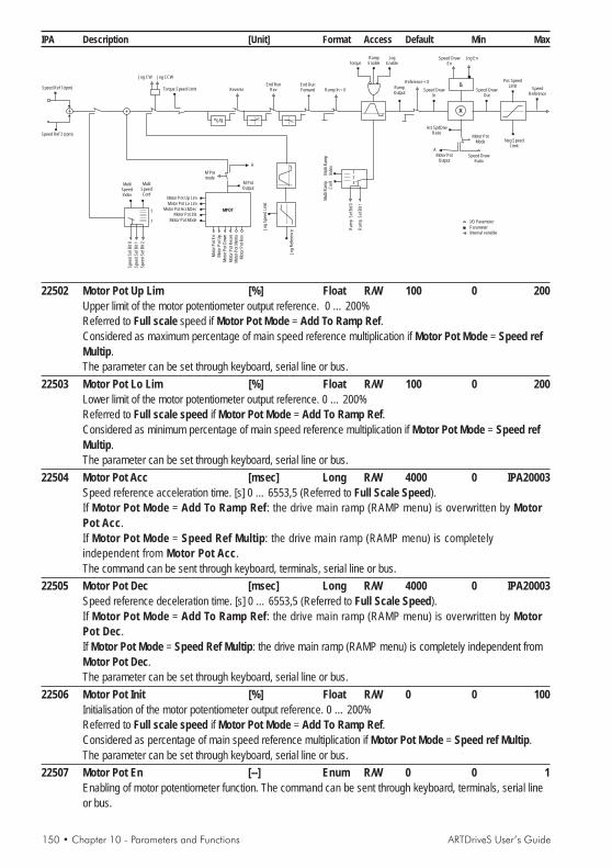
150 • Chapter 10 - Parameters and Functions ARTDriveS User’s Guide
IPA Description [Unit] Format Access Default Min Max
I/O Parameter
ParameterInternal variable
RampOutput
Reference = 0
Speed DrawIn
Speed DrawOut
Ram
pS
elB
it1
Ram
pS
elB
it0
123
Mul
tiR
amp
Inde
xM
ulti
Ram
pC
onf
A
&Speed
Reference
Pos SpeedLimit
Neg SpeedLimit
Act SpdDrwRatio
Speed DrawEn
Jog En
X
Motor PotMode
Speed DrawRatio
Motor PotOutput
Torque Speed Limit Reverse
A
End RunRev
End RunForward
Jog
Spe
edLi
mit
Jog
Ref
eren
ce
* (-1)
Ramp In = 0
M PotOutput
M Potmode
Mot
orP
otE
n
Mot
orP
otU
p
Mot
orP
otD
own
Mot
orP
otM
emo
Mot
orP
otR
eset
Mot
orP
otR
ev
MPOT
Jog CW Jog CCW
Motor Pot Up Lim
Motor Pot Lo Lim
Motor Pot Acc&DecMotor Pot Init
Motor Pot Mode
MultiSpeedConf
MultiSpeedIndex
1
7
Spe
edS
elB
it1
Spe
edS
elB
it2
Spe
edS
elB
it0
Speed Ref 1(rpm)
Speed Ref 2 (rpm)
RampEnable
JogEnableTorque
22502 Motor Pot Up Lim [%] Float R/W 100 0 200Upper limit of the motor potentiometer output reference. 0 … 200%Referred to Full scale speed if Motor Pot Mode = Add To Ramp Ref.Considered as maximum percentage of main speed reference multiplication if Motor Pot Mode = Speed refMultip.The parameter can be set through keyboard, serial line or bus.
22503 Motor Pot Lo Lim [%] Float R/W 100 0 200Lower limit of the motor potentiometer output reference. 0 … 200%Referred to Full scale speed if Motor Pot Mode = Add To Ramp Ref.Considered as minimum percentage of main speed reference multiplication if Motor Pot Mode = Speed refMultip.The parameter can be set through keyboard, serial line or bus.
22504 Motor Pot Acc [msec] Long R/W 4000 0 IPA20003Speed reference acceleration time. [s] 0 … 6553,5 (Referred to Full Scale Speed).If Motor Pot Mode = Add To Ramp Ref: the drive main ramp (RAMP menu) is overwritten by MotorPot Acc.If Motor Pot Mode = Speed Ref Multip: the drive main ramp (RAMP menu) is completelyindependent from Motor Pot Acc.The command can be sent through keyboard, terminals, serial line or bus.
22505 Motor Pot Dec [msec] Long R/W 4000 0 IPA20003Speed reference deceleration time. [s] 0 … 6553,5 (Referred to Full Scale Speed).If Motor Pot Mode = Add To Ramp Ref: the drive main ramp (RAMP menu) is overwritten by MotorPot Dec.If Motor Pot Mode = Speed Ref Multip: the drive main ramp (RAMP menu) is completely independent fromMotor Pot Dec.The parameter can be set through keyboard, serial line or bus.
22506 Motor Pot Init [%] Float R/W 0 0 100Initialisation of the motor potentiometer output reference. 0 … 200%Referred to Full scale speed if Motor Pot Mode = Add To Ramp Ref.Considered as percentage of main speed reference multiplication if Motor Pot Mode = Speed ref Multip.The parameter can be set through keyboard, serial line or bus.
22507 Motor Pot En [--] Enum R/W 0 0 1Enabling of motor potentiometer function. The command can be sent through keyboard, terminals, serial lineor bus.

ARTDriveS User’s Guide Chapter 10 - Parameters and Functions • 151
IPA Description [Unit] Format Access Default Min Max0 = Disabled1 = Enabled
22508 Motor Pot Reset [--] Float R/W 0 0 1Reset memory and initialisation of Motor Pot Output to a value set in Motor Pot Init.0 = Disabled1 = Enabled ResetThe command can be sent through keyboard, terminals, serial line or bus.
22509 Motor Pot Mode [--] Enum R/W 0 0 1Operational mode of the motor potentiometer:0 = Add to Ramp Ref Speed reference is added to Speed Ref1 = Ramp Ref Multip The motor potentiometer acts as a Speed Ref multiplier. In this case, the drive
Speed Draw function is used.Note: if the Speed Ratio parameter is set to analog input, this takes the priority over the motor-potentiometerfunction.The command can be sent through keyboard, terminals, serial line or bus.
22510 Motor Pot Memo [--] Float R/W 0 0 1Storage of reference setting in memory0 = Disabled Restart from default configuration
If Motor Pot Mode = Add To Ramp Ref: the speed reference is set to the valueshown in Motor Pot Lo Lim.If Motor Pot Mode = Speed Ref Multip: the speed ratio is set to 100%.The command can be sent through keyboard, terminals, serial line or bus.
1 = Enabled Storage of last speed or speed ratio set.If Motor Pot Mode = Add To Ramp Ref: after Start, the motor acceleratesautomatically up to the preset speed.If Motor Pot Mode = Speed Ref Multip: after Start, the motor follows the speedreference multiplied by the preset ratio.
22511 Motor Pot Dir [--] Bool R/W 0 0 1Polarity inversion of speed reference.0=Forward direct1=Reverse reversed referenceThe command can be sent through keyboard, terminals, serial line or bus.
22501 Motor Pot Output [%] Float RMonitor for motor potentiometer setting 0 … 200%.The command can be sent through keyboard, serial line or bus.
BRAKE CONTRBRAKE CONTRBRAKE CONTRBRAKE CONTRBRAKE CONTROLOLOLOLOLThe brake function allows to control in a suitable way the motor emergency brake with a drive digital outputprogrammed as [20] Brake Command..The drive enabling and disabling requires the use of a digital input programmed as [28] Virtual Enable.In case an alarm occurs or the digital input 0 drops out during the functioning procedure, the output controlling thebrake drops out when the motor speed is lower than the programmable threshold.

152 • Chapter 10 - Parameters and Functions ARTDriveS User’s Guide
IPA Description [Unit] Format Access Default Min Max
Digita Input = 0
Virtual Enable(DI)
Drive Enable(DO)
Start / Stop(DI)
RampReference
Motor Speed
BrakeCommand (DO) Brake OFF Delay8msec 8msec 8msec
Brake ON Spd Thr
Brake ON Delay
Brake OFF Delay Brake OFF Delay
Brake ON Delay
Note! In case an alarm occurs, the behavior is the same as the one used for the Digital Input 0 drop.20600 Brake Enable [--] Enum R/W 0 0 1
0 = Disabled Disabled brake function.1 = Enabled Enabled brake function
20601 Brake OFF Delay [sec] Float R/W 0 0 10Delay stated in seconds from the brake opening command to the reference enabling.
20602 Brake ON Delay [sec] Float R/W 0 0 10Delay stated in seconds from the brake closing command to the drive disabling (non-torque motor).
20603 Brake ON Spd Thr [rpm] Float R/W 100 0 20000Speed threshold closing the brake in case an alarm occurs or the digital input 0 drops out.
POPOPOPOPOWERLWERLWERLWERLWERLOSSOSSOSSOSSOSSThe Powerloss function controls the loss of power whether transient or long term. When running in Powerloss mode,the system is controlled so as to use the motor’s kinetic energy, keeping the DC link voltage value high.The function is activated automatically for a cut-in threshold of around 78% of normal operating voltage of the DC Link(e.g.: for a 400 V AC supply, the threshold is 440 V DC).The function's activation can be detected by the programmable PL Stop Active parameter on the digital output.
There are two operating modes implemented: Coast through and Emergency Stop.The choice is made from the Powerloss Config. parameter.
Coast-through modeThis mode is designed to allow the controlled motor to pass through a mains dip with as little loss of speed as possible.When the function activation threshold is detected, the motor speed is controlled by a PI regulator, in order to maintainthe DC Link voltage constant at a predefined value of 12% above the voltage drop threshold.The gains on the PI regulator are set via P Loss Prop Gain and P Loss Int Gain.The function is automatically deactivated when the mains power returns, restoring the motor to the operating conditionsprior to the break.If the power loss is permanent, or the motor speed drops too low to allow kinetic energy to be recovered, the drive stopsin the Main Power Loss (A16) alarm conditions.
Emergency Stop modeThis mode is designed for use in applications where the motor or motors installed in a machine have to be stopped in a

ARTDriveS User’s Guide Chapter 10 - Parameters and Functions • 153
IPA Description [Unit] Format Access Default Min Maxcontrolled and synchronised way, including where mains power is lost.When the function activation threshold is detected, the drive reduces the output frequency according to the P LossRamp setting, causing the motor to operate as a generator, recharging the DC Link to the value specified in the P LossVolt Ref parameter. The motor speed is then controlled via a PI regulator and regulated to keep the DC Link voltageconstant. The gains on the PI regulator are set via P Loss Prop Gain and P Loss Int Gain.While operating in Powerloss the drive current limit is set with P Loss Trq Limit.When the motor speed drops below the threshold set in P Loss Spd 0 Thr, the drive stops in Main Power Loss (A16)alarm conditions.The PL Next Factor parameter, that can be set on the analogue output, provides the speed reference (Motor Speed /Speed Reference). It can be used as a speed reference multiplier for the other motors installed on the machine, topermit synchronised stop.The drive can be notified that the mains voltage is restored via the PL Mains Status parameter or via a digital input.When the parameter value returns to the high state, and if the motor speed is above the threshold set in P Loss NoResThr, the system accelerates the motor again to the operating conditions prior to the break, with the standard systemramp (RAMP menu).18138 PL Mains status [--] Bool R/W 0 0 1
It signals the mains voltage reset to the drive. The command can be sent through keyboard, programmabledigital input, serial line or bus.0 = Off1 = On
18130 Powerloss Config [--] Enum R/W/* 0 0 2Configuration of Powerloss function.0 = Disabled1 = Coast - Through2 = Emergency Stop
18131 P Loss Prop Gain [--] Int R/W 500 0 32767Proportional gain of Powerloss function regulation algorithm.
18132 P Loss Int Gain [--] Int R/W 500 0 32767Integral gain of Powerloss function regulation algorithm.
18133 P Loss Volt Ref [V] Float R/W 790 100 820Reference value for Emergency stop function algorithm.
18134 P Loss Ramp [ms/krmp] Float R/W 336.1 0 FLT_MAXRamp value used for activation of Emergency stop function algorithm.
18135 P Loss Trq Lim [%] Float R/W 100 0 FLT_MAXMaximum value of braking torque in Emergency Stop phase.
18136 P Loss Spd 0 Thr [rpm] Float R/W 10 0 FLT_MAXMain Loss alarm (A 16) activation threshold..
20088 P Loss NoRes Thr [rpm] Float R/W 10 0 100000Speed threshold below which operation can no longer be restored to the state prior to a break in power, whenthe power returns.
18137 PL Next Factor [--] Float RProvides the speed reference (Motor Speed / Speed Reference). It can be used as a speed referencemultiplier for the other motors installed on the machine, to permit synchronised stop. The parameter can beset to a programmable analog output.
20087 Loss Active [--] ENUM R 0 0 1Power loss function activity state.0 = Not Active1 = Active

154 • Chapter 10 - Parameters and Functions ARTDriveS User’s Guide
IPA Description [Unit] Format Access Default Min Max
POSITIONPOSITIONPOSITIONPOSITIONPOSITIONThe drives can be configured in Position Control; the default mode is however Speed Control.DRIVE CONFIG / Control Mode -> Position
Caution! In order to perform a right positioning, the drive has to reach the position 0 (or homingposition) at least once. When the home position has been found, it is maintained till the drive is switchedoff or reset. It is possible to perform a new 0 search (or homing) at any moment by rising the digital inputprogrammed as Pos zero search.
There are 8 point-point conditions available, with constant acceleration profile, configurable in absolute or relativemode, and with options of various speed and acceleration settings for each position.
Absolute mode:- Position Mode parameter= [0] Absolute : used to vary distances between stations, by modifying the position of eachindividual station, and in the event of an unwanted stop, allowing easier return to the zero position (home).- Position Mode parameter= [1] IncAbs : movements are incremental, in absolute steps.Example: if the preset position is 2000 u.u., the destination settings are 2000, 4000, 6000,
Relative mode:- Position Mode parameter = [2] Incremental : movements are incremental with respect to the starting positionExample: if the selected position preset is 2000 u.u. (user unit), with each Pos start pos command the positionincreases by 2000 u.u.
For each movement, the parameters can be set:Pos Preset X Setting initial sectorPos Speed X Setting speedPos Acc X Setting accelerationPos Dec X Setting deceleration
The parameters for managing functions are in the Position menu:- Find Zero- Position start- Position reference from analogue input- Self-learning measurements- Sequential position control (multi-position controller)
Zero search ( Pos 0 search )The zero search phase can be performed following different procedures:A - Using the zero sensor and the encoder slot (default mode)B - Using only the zero sensorC - Using the encoder slotD - With parameter IPA 30045, 0 Pos at Startup (ZERO FOUND CONF menu)

ARTDriveS User’s Guide Chapter 10 - Parameters and Functions • 155
IPA Description [Unit] Format Access Default Min Max
A - Using the zero sensor and the encoder slot (default mode):
Zero Sensor En = Enabled;Zero Index En = Enabled.
(DI) Enable
Home Src Direc = positive
Zero Sensor En = enabled
Zero Index En = enabled
(DI) Pos 0 Sensor
Index encoder
Speed
(DO) Pos Zero Found
Home Spd Ref
Home Fine Spd
(DI) POS 0 Search
1) Abilitare il drive: ingresso digitale “Enable” a stato logico alto.2) Abilitare (stato logico alto) l’ingresso digitale programmato come POS 0 Search.3) When the motor receives the POS 0 Search command, it starts moving in the direction stated by the Home
Src Direc parameter (positive = motor clockwise rotation direction) with the Home Spd Ref reference. Whenthe sensor is used (high POS 0 Sensor ), the motor changes its rotation direction and the active speedreference becomes Home Fine Spd. The motor stops at the first encoder slot after freeing the sensor (lowPOS 0 Sensor) The position of the encoder slot is acquired as position 0.
If the sensor is used at the motor start up (high POS 0 Sensor) the motor starts rotating in an opposite direction ascompared to the one stated by the Home Src Direc parameter (positive = the motor rotates in an anti-clockwisedirection) with the Home Fine Spd reference. The motor stops at the first encoder slot after freeing the sensor (lowPOS 0 Sensor). The position of the encoder slot is acquired as position 0.The Inside Index Src parameter allows to define if the encoder index corresponding to zero is internal or external tothe sensor.The Zero Sensor Edge parameter allows to choose the active edge of the zero sensor. For further information see theZERO FOUND CONFIG menu.
B - Using only the zero sensor
Zero Sensor En = Enabled;Zero Index En = Disabled.
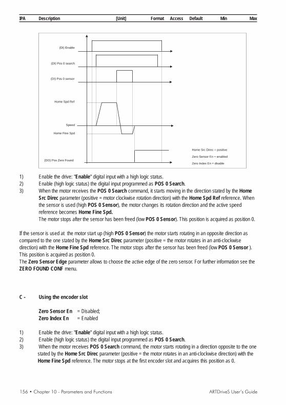
156 • Chapter 10 - Parameters and Functions ARTDriveS User’s Guide
IPA Description [Unit] Format Access Default Min Max
(DI) Enable
Home Src Direc
Zero Sensor En = enabled
Zero Index En = disable
= positive
(DI) Pos 0 sensor
Speed
(DO) osP Zero Found
Home Spd Ref
Home Fine Spd
(DI) Pos 0 search
1) Enable the drive: "Enable" digital input with a high logic status.2) Enable (high logic status) the digital input programmed as POS 0 Search.3) When the motor receives the POS 0 Search command, it starts moving in the direction stated by the Home
Src Direc parameter (positive = motor clockwise rotation direction) with the Home Spd Ref reference. Whenthe sensor is used (high POS 0 Sensor), the motor changes its rotation direction and the active speedreference becomes Home Fine Spd.The motor stops after the sensor has been freed (low POS 0 Sensor). This position is acquired as position 0.
If the sensor is used at the motor start up (high POS 0 Sensor) the motor starts rotating in an opposite direction ascompared to the one stated by the Home Src Direc parameter (positive = the motor rotates in an anti-clockwisedirection) with the Home Fine Spd reference. The motor stops after the sensor has been freed (low POS 0 Sensor ).This position is acquired as position 0.The Zero Sensor Edge parameter allows to choose the active edge of the zero sensor. For further information see theZERO FOUND CONF menu.
C - Using the encoder slot
Zero Sensor En = Disabled;Zero Index En = Enabled
1) Enable the drive: "Enable" digital input with a high logic status.2) Enable (high logic status) the digital input programmed as POS 0 Search.3) When the motor receives POS 0 Search command, the motor starts rotating in a direction opposite to the one
stated by the Home Src Direc parameter (positive = the motor rotates in an anti-clockwise direction) with theHome Fine Spd reference. The motor stops at the first encoder slot and acquires this position as 0.

ARTDriveS User’s Guide Chapter 10 - Parameters and Functions • 157
IPA Description [Unit] Format Access Default Min Max
(DI) Enable
POS SENSOR SEARCH DIR = positive
ZERO SENSOR ENABLE = disable
ZERO INDEX ENABLE = enabled
Index encoder
Speed
(DO) Pos Zero Found
Pos speed line 0
(DI) Pos 0 search
NOTE! If Zero Sensor En = Disabled and Zero Index En = Disabled by rising POS 0 Search the motor stands stilland the home search is not performed.
If in the A and B condition the limit switch is found (End Run Forward if the speed is positive and End Run Reverse ifthe speed is negative) before using the sensor, the motor changes its rotation direction maintaining the Home Spd Refreference speed. When the sensor is used (high POS 0 Sensor), the active speed reference is Home Fine Spd, butthe motor does not change its rotation direction. The motor stops when the sensor is freed (low POS 0 Sensor). Thisposition is acquired as position 0. This is useful when the 0 sensor is not placed at one of the stroke ends.
(DI) Enable
Home Src Direc = positive
Zero Sensor En = enabled
Zero Index En = enable
(DI) End Run forward
Index encoder
Speed
(DO) osP Zero Found
Home Spd Ref
Home Fine Spd
(DI) Pos 0 search
(DI) Pos 0 Sensor
If an offset is set for the zero position (Home Pos Offset different from 0), during the zero search the motor behaves aspreviously described. The only difference is that in the home point the position is equal to -Home Pos Offset.Through the Home Pos Offs En parameter it is possible to stop the motor at 0 user units, i.e. a movement of - HomePos Offset as compared to the encoder slot.

158 • Chapter 10 - Parameters and Functions ARTDriveS User’s Guide
IPA Description [Unit] Format Access Default Min Max
D - With parameter IPA 30045, 0 Pos at Startup (ZERO FOUND CONF menu)
1) Enable parameter IPA 30045, 0 Pos at Startup (ZERO FOUND CONF menu)2) Next time the drive is turned on it will sample the position of the encoder which will be acquired as Zero
position (Home).
Note: If a further zero search is made with one of the above methods, the initial zero position will be overwritten.
Position Start
At the end of the zero search phase it is possible to carry out the position start. The motor, when the drive (enabled)receives the POS Start Pos command, starts rotating with the reference Pos Speed and reaches the set value. Thereare 64 registers where it is possible to store the desired values and to recall them via digital inputs programmed as PosPreset 0,1,2,3,4,5. (They are used to state in a binary way the positioning value. It is not necessary to use them all. Ifthey have not been programmed, the bits are set at 0).For each value of the first 8 registers it is possible to set a maximum speed and a personalized acceleration anddeceleration ramp. As for the other registers, the speed, the acceleration and deceleration ramp is the same forthem all.
Position reference from analogue input
For absolute positioning (IPA 30091, Position Mode = 1) with continuous sampling enabled (IPA 30099, Pos An Mode= 1 ) an analogue input can be sampled to set the position reference Pos Preset 0.The sampled reference will go from Min Prs Abs Val to Max Prs Abs Val
Example: 0V = Min Prs Abs Val, 10V = Max Prs Abs Val
The analogue reference is followed as long as the POS-Start Pos remains active, and when it is deactivated the valueis frozen as the final position.Other parameters dedicated to the function: IPA 30098, Pos An Filter; IPA 30097, Pos An Stdy Wind; IPA 30096, PosAn Wind Del .
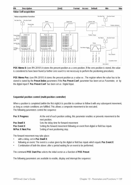
ARTDriveS User’s Guide Chapter 10 - Parameters and Functions • 159
IPA Description [Unit] Format Access Default Min MaxValue Self-acquisition
Position set Ramp set Speed set
Pos
Pre
set0
Pos
Pre
set0
Pos
Pre
set0
Pos
Pre
set1
Pos
Pre
set1
Pos
Pre
set1
Pos
Pre
set2
Pos
Pre
set2
Pos
Pre
set2
Pos
Pre
set3
Pos
Pre
set3
Pos
Pre
set3
Pos
Pre
set4
Pos
Pre
set4
Pos
Pre
set4
Pos
Pre
set5
Pos
Pre
set5
Pos
Pre
set5
Pos Acc/Dec CW/CCW 0 Pos Speed 0
Pos 1Acc/Dec CW/CCW Pos 1SpeedPos 2Acc/Dec CW/CCW Pos 2SpeedPos 3Acc/Dec CW/CCW Pos 3Speed
Pos 6Acc/Dec CW/CCW Pos 6SpeedPos 7Acc/Dec CW/CCW Pos 7Speed
Pos 5Acc/Dec CW/CCW Pos 5SpeedPos 4Acc/Dec CW/CCW Pos 4Speed
Pos (8..63)Acc/Dec Pos (8..63)Speed
Ramp
Ramp
Speed limit Current limit
Unit Per Rev
Position Torque
Pos 0 Search
Pos Return Speed
Pos
Ret
urn
Acc
Pos
Ret
urn
Dec
Preset Index
Pos PresetConf
PositionMode
Pos Start Pos
Position reference
to position return
Pos Zero Found
&
&
Preset Index
Pos
Ret
urn
Pos Return
&
Zero search
Value acquisition function Pos Start Pos Pos Zero Found
Pos Zero FoundPos Preset 0Pos 1PresetPos 2PresetPos 3Preset
Pos 6PresetPos 7Preset
Pos 5PresetPos 4Preset
Pos (8..63)Preset
POS Memo 0: (see IPA 20101) it stores the present position as a zero position. If the zero position is stored, the valueis considered to have been found (a further zero search is not necessary to perform the positioning procedure).
POS Memo Pos: (see IPA 20101) it stores the present position as a value xx . The register where the value has to bestored is stated by the Preset Index parameters if the Pos Preset Conf parameter has been set as Parameter, or bythe digital input if Pos Preset Conf has been set as Digital Input.
Sequential position control (multi-position controller)
When a position is completed (within the first eight) it is possible to continue to follow it with any subsequent movement,as long as certain conditions are fulfilled. This allows a composite movement to be executed.The following parameters control the sequence
Pos X Progress At the end of each position setting, this parameter enables or prevents movement to thenext position.
Pos Dwell X Sets the delay time for forward movementPos Event X Setting the forward movement following an event from digital or field bus inputsM Pos X Next Pos Setting of next positioning step.
The forward movement may take place:• with a delay, set in Pos Dwell X• following an event. The event is a value given by the digital or field bus inputs which equals Pos Event X• Combination of both the above: after a period waiting for an event to be performed.
The command POS Start Pos selects the initial sector as a function of POS Preset
The following parameters are available to enable, display and interrupt the sequence:
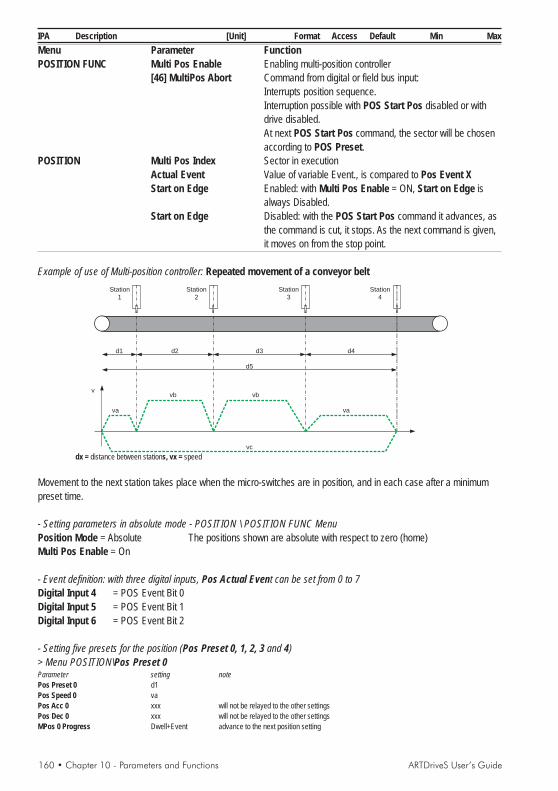
160 • Chapter 10 - Parameters and Functions ARTDriveS User’s Guide
IPA Description [Unit] Format Access Default Min MaxMenu Parameter FunctionPOSITION FUNC Multi Pos Enable Enabling multi-position controller
[46] MultiPos Abort Command from digital or field bus input:Interrupts position sequence.Interruption possible with POS Start Pos disabled or withdrive disabled.At next POS Start Pos command, the sector will be chosenaccording to POS Preset.
POSITION Multi Pos Index Sector in executionActual Event Value of variable Event., is compared to Pos Event XStart on Edge Enabled: with Multi Pos Enable = ON, Start on Edge is
always Disabled.Start on Edge Disabled: with the POS Start Pos command it advances, as
the command is cut, it stops. As the next command is given,it moves on from the stop point.
Example of use of Multi-position controller: Repeated movement of a conveyor beltStation
1Station
2Station
3Station
4
d1 d2 d3 d4
d5
va
vb vb
va
vc
v
dx = distance between stations, vx = speed
Movement to the next station takes place when the micro-switches are in position, and in each case after a minimumpreset time.
- Setting parameters in absolute mode - POSITION \ POSITION FUNC MenuPosition Mode = Absolute The positions shown are absolute with respect to zero (home)Multi Pos Enable = On
- Event definition: with three digital inputs, Pos Actual Event can be set from 0 to 7Digital Input 4 = POS Event Bit 0Digital Input 5 = POS Event Bit 1Digital Input 6 = POS Event Bit 2
- Setting five presets for the position (Pos Preset 0, 1, 2, 3 and 4)> Menu POSITION\Pos Preset 0Parameter setting notePos Preset 0 d1Pos Speed 0 vaPos Acc 0 xxx will not be relayed to the other settingsPos Dec 0 xxx will not be relayed to the other settingsMPos 0 Progress Dwell+Event advance to the next position setting

ARTDriveS User’s Guide Chapter 10 - Parameters and Functions • 161
IPA Description [Unit] Format Access Default Min MaxMPos 0 Dwell 100 arrived at station 1, waits 100 msecMPos 0 Event 3 waits until Pos Actual Event word equals 3, so that the digital inputs 4 and 5 are high.MPos 0 Next Pos 1 advancement to Pos Preset 1
> Menu POSITION\Pos Preset 1Parameter setting notePos Preset 1 d1+d2Pos Speed 1 vbMPos 1 Progress Dwell+Event advance to the next position settingMPos 1 Dwell 100 arrived at station 2, waits 100 msecMPos 1 Event 7 waits until Pos Actual Event word equals 7, so that the digital inputs 4, 5 and 6 are high.MPos 1 Next Pos 2 advancement to Pos Preset 2
> Menu POSITION\Pos Preset 2Parameter setting notePos Preset 2 d1+d2+d3Pos Speed 2 vbMPos 2 Progress = Dwell+Event advance to the next position settingMPos 2 Dwell = 100 arrived at station 3, waits 100 msecMPos 2 Event = 1 waits until Pos Actual Event word equals 1, so that the digital input 4 is high.MPos 2 Next Pos 3 advancement to Pos Preset 3
> Menu POSITION\Pos Preset 3Parameter setting notePos Preset 3 d1+d2+d3+d4Pos Speed 3 vaMPos 3 Progress Dwell+Event advance to the next position settingMPos 3 Dwell 100 arrived at station 4, waits 100 msecMPos 3 Event 2 waits until Pos Actual Event word equals 2, so that the digital input 2 is high.MPos 3 Next Pos 4 advancement to Pos Preset 4
> Menu POSITION\Pos Preset 4Parameter setting notePos Preset 4 0 HomePos Speed 4 vcMPos 4 Progress Dwell+Event advance to the next position settingMPos 4 Dwell 100 arrived at home waits 100 msecMPos 4 Event 5 waits until Pos Actual Event word equals 5, so that the digital inputs 4 and 5 are high.MPos 4 Next Pos 0 advancement to Pos Preset 0
> Menu POSITION\Pos Preset 5 ... 8Parameter setting noteMPos 5 Progress ... MPos 8 Progress None default
30000 Unit Per Rev [--] Float R/Z/* 1000 -10000 100000Setting of distance (in u.u.) covered by one motor revolution. Parameter used for the conversion of theposition into engineering units; by setting a negative value it is possible to combine positive positioningprocedures with motor anti-clockwise rotations.
30001 Unit Per Div [--] Float R/Z/* 1 1 10000.0This parameter is used as divider to calculate the number of motor pulses per user unit, and to avoid roundingerrors introduced by mechanical ratios.As example let’s consider a mechanical system made with a 10 mm pitch ballscrew and a 1:3 gear ratio. If wewant to express the distances in millimeters we can set the parameters as follows:Unit Per Rev (IPA 30000) = 10Unit Per Div (IPA 30001) = 3
30002 Multi Pos Enable [--] Bool R/W 0 0 1Enabling multi-position controller0 = Disabled1 = Enabled

162 • Chapter 10 - Parameters and Functions ARTDriveS User’s Guide
IPA Description [Unit] Format Access Default Min Max
30010 Pos CW Acc [ms/krpm] Float R/W 336.1 0 IPA21111Setting of the clockwise acceleration rate during the positioning procedures (ramp rate active for the positionsset by the registers 8 to 63)..
30011 Pos CCW Acc [ms/krpm] Float R/W 336.1 0 IPA21111Setting of the counterclockwise acceleration rate during the positioning procedures (ramp rate active for thepositions set by the registers 8 to 63).
30012 Pos CW Dec [ms/krpm] Float R/W 336.1 0 IPA21111Setting of the clockwise deceleration rate during the positioning procedures (ramp rate active for the positionsset by the registers 8 to 63).
30013 Pos CCW Dec [ms/krpm] Float R/W 336.1 0 IPA21111Setting of the counterclockwise deceleration rate during the positioning procedures (ramp rate active for thepositions set by the registers 8 to 63)
30014 Position Speed [rpm] Float R/W 3000.0 0 IPA20003It is active if the Pos_speed analog input is not programmed.Setting of the speed reference during the positioning procedures (active for the positions set by theregisters 8 to 63).
30042 Start on Edge [--] Enum R/W 0 0 10 = Disabled If the POS Start Pos command is disabled during a positioning phase, the
motor stops in accordance with the IPA 30043 Stop by Ramp. parameter.1 = Enable During the positioning phase the motor can be stopped only disabling the drive.The change of this parameter is active only after a homing phase.The change to this parameter is active only after the drive is reset.
30043 Stop by Ramp [--] Enum R/W 0 0 10 = Disabled If Start on Edge = Disabled, the motor stops without ramp if the POS Start Pos
command is disabled during a positioning phase.1 = Enable If Start on Edge = Disabled, the motor stops with a ramp time set in the Pos
Stop Dec parameter if the POS Start Pos command is disabled during apositioning phase.
The change to this parameter is active only after the drive is reset.30044 Pos Reach Behav [--] Enum R/W 0 0 1
0 = Disabled1 = Enable
Pos Reached
Pos Start Pos
Pos Reached
Pos Start Pos
0 = Disabled 1 = Enabled
30057 Back Lash Window [u.u.] Float R/W 2000.0 0 IPA30018This parameter sets the width of the position window where it is possible to correct the positioning errorscaused by some mechanical clearance. During the positioning process if the input defined as [1010] POSMemo 0 becomes active the drive will complete the move, but it will be consider that the starting point ofthe next move command will be the position where POS Memo 0 input become active. If the input definedas POS Memo 0 becomes active outside the position window defined in Back Lash Window, the drive willnot start the next position command until new zero search will be completed. This function is active only in“Inc Abs”
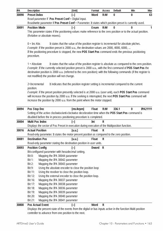
ARTDriveS User’s Guide Chapter 10 - Parameters and Functions • 163
IPA Description [Unit] Format Access Default Min Max30090 Preset Index [--] Word R/W 0 0 63
Read parameter if Pos Preset Conf = Digital input.Read/write parameter if Pos Preset Conf = Parameter. It states which position preset is currently used.
30091 Position Mode [--] Enum R/W 0 0 1This parameter states if the positioning values make reference to the zero position or to the actual position.(Relative or absolute moves).
0 = Inc Abs It states that the value of the position register is incremental for absolute pitches.Example: if the position preset is 2000 u.u., the destination values are 2000, 4000, 6000, ...If the positioning procedure is stopped, the new POS Start Pos command ends the previous positioningprocedure.
1 = Absolute It states that the value of the position register is absolute as compared to the zero position.Example: If the currently selected position preset is 2000 u.u., with the first command of POS Start Pos thedestination position is 2000 u.u. (referred to the zero position); with the following commands (if the register isnot modified) the position will not change.
2=Incremental It indicates that the position register setting is incremental compared to the currentposition.Example: if the preset position presently selected is at 2000 u.u. (user unit), each POS Start Pos commandwill increase the position by 2000 u.u. If the seeking is interrupted, the next POS Start Pos command willincrease the position by 2000 u.u. from the point where the motor stopped.
30094 Pos Stop Dec [ms/krpm] Float R/W 336.1 0 IPA21111Setting of the active clockwise/anti-clockwise deceleration time when the POS Start Pos command isdisabled before the in process positioning procedure is completed.
30004 Multi Pos Index [--] Int RDisplays the sector of Pos Preset in execution during execution of the Multiposition function.
30016 Actual Position [u.u.] Float RRead-only parameter. It states the motor present position as compared to the zero position.
30081 Destination Pos [u.u.] Float RRead-only parameter stating the destination position in user units.
30093 Position Config [--] Dword RBit-configured parameter with hexadecimal setting.Bit 0: Mapping the IPA 30044 parameterBit 1: Mapping the IPA 30042 parameterBit 2: Mapping the IPA 30043 parameterBit 9: Using the absolute encoder to close the position loopBit 11: Using the revolver to close the position loop.Bit 12: Using the external encoder to close the position loop.Bit 16: Mapping the IPA 30037 parameterBit 17: Mapping the IPA 30038 parameterBit 18: Mapping the IPA 30036 parameterBit 19: Mapping the IPA 30039 parameterBit 20: Mapping the IPA 30040 parameterBit 21: Mapping the IPA 30041 parameter
30800 Pos Actual Event [--] Word RDisplays the present state of the events from the digital or bus inputs active in the function Multi positioncontroller to advance from one position to the next.

164 • Chapter 10 - Parameters and Functions ARTDriveS User’s Guide
IPA Description [Unit] Format Access Default Min Max
POSITION LIMIT30015 Position Torque [%] Float R/W 100 0 IPA22012
Setting of the maximum torque during the positioning procedures (active for all positions set in the recordsfrom 0 to 63).
30017 Min Preset Value [u.u.] Float R/Z/* -4194304 -223 223-1Parameter stating the minimum value to be set in the different position registers. In case the setting of aposition is lower than this value, such setting is not accepted.
30018 Max Preset Value [u.u.] Float R/Z/* 4194303 -223 223-1Parameter stating the maximum value to be set in the different position registers. In case the setting of aposition is higher than this value, such setting is not accepted.
30056 Max Prs Abs Val [u.u.] Float R/W 0 -223 223-1Software limit switch: maximum absolute value. When it is equal to Min Prs Abs Val, it is not enabled. If thedestination value is higher than this value, the command is not performed and the drive enables the digitaloutput [1008] Pos Out Of Lim.
30055 Min Prs Abs Val [u.u.] Float R/W 0 -223 223-1Software limit switch: minimum absolute value. When it is equal to Max Prs Abs Val, it is not enabled. If thedestination value is lower than this value, the command is not performed and the drive enables the digitaloutput [1008] Pos Out Of Lim.
POS THR CONFIG30050 Pos Abs Thr [u.u.] Float R/W 0 -223 223-1
Setting of the threshold indicating the machine has passed the position referred to the zero position. Whenthe position is higher than the value set in this parameter, the digital output programmed as [1004] Pos AbsThr goes to +24V.
30051 Pos Exceeded [u.u.] Float R/W 0 0 IPA30018Setting of the threshold signaling the "overcome position" referred to the last positioning procedure:| present position - starting position | > Positon Thr, the "Position Exceeded" output is set.
30052 Pos 0 Thr Offset [u.u.] Float R/W 0 0 IPA30018Setting the offset of the position threshold. When the absolute value position is lower than the value set in thisparameter, the digital output programmed as [1001] Position Zero is active.
30053 Pos Thr Close 1 [u.u.] Float R/W 0 0 IPA30018Reached position threshold 1. The digital output reaches high logic status when the motor present position isequal to the destination position minus the Pos Thr Close 1 parameter
30054 Pos Thr Close 2 [u.u.] Float R/W 0 0 IPA30018Reached position threshold 2. The digital output reaches high logic status when the motor present position isequal to the destination position minus the Pos Thr Close 2 parameter
30058 Pos Window [u.u.] Float R/W 0 0 IPA30018This parameter, together with Pos Window Time, defines the behavior of the [1002] Pos Reached digitaloutput. The output is set when, after terminating the positioning procedure, the present position is equal to thedestination position +- Pos Window for a period equal to Pos Window Time.
30059 Pos Window Time [sec] Float R/W 0 0 30This parameter sets the time delay for the correct positioning inside Pos Window, IPA 30058).Used with digital output set to [1002] Pos Reached.
30060 Pos Window Tout [sec] Float R/W 0 0 0This parameter defines the period of time within which the position is considered as not reached.Used with digital output set to [1010] Pos Not Reached (see IPA 30058).

ARTDriveS User’s Guide Chapter 10 - Parameters and Functions • 165
IPA Description [Unit] Format Access Default Min Max
POS PRESET 030100 Pos Preset 0 [u.u.] Float R/W 0 IPA30017 IPA30018
Setting of the position value in the register 0.30200 Pos Speed 0 [rpm] Float R/W 0 0 IPA20003
Maximum speed setting during the positioning phase of preset 0.If this value is set with 0 (rpm) the Pos Speed parameter in the POSITION menu becomes active.
30300 Pos CW Acc 0 [ms/krpm] Float R/W 336.1 0 IPA21111Setting of the clockwise acceleration rate during the positioning phase of preset 0.
30400 Pos CW Dec 0 [ms/krpm] Float R/W 336.1 0 IPA21111Setting of the clockwise acceleration rate during the positioning phase of preset 0.
30380 Pos CCW Acc 0 [ms/krpm] Float R/W 336.1 0 IPA21111Setting of the counterclockwise acceleration rate during the positioning phase of preset 0.
30490 Pos CCW Dec 0 [ms/krpm] Float R/W 336.1 0 IPA21111Setting of the counterclockwise acceleration rate during the positioning phase of preset 0.
30500 Pos 0 Progress [--] Enum R/W 0 0 3Setting performance of the Multi-position controller function to reach the required setting0 = None The position control sequence is interrupted1 = Dwell When the position is reached before going to the next phase, waits for the
period set with MPos 0 Dwel2 = Event match When the position is reached before going to the next phase, waits until the Pos
Actual Event parameter equals MPos 0 Event3 = Dwell+Event When the position is reached before going to the next phase, waits for the time
set in MPos 0 Dwell and then until the Pos Actual Event parameter equalsMPos 0 Event
30600 Pos Dwell 0 [msec] Long R/W 0 0 32000Delay in reaching the specified value and moving onto the next station.
30700 Pos Event 0 [--] Word R/W 0 0 65535Value of Pos Actual Event variable, from which to move on to the next value.
30710 MPos 0 Next Pos [--] Word R/W 1 0 7Setting of next positioning step.0= Pos Preset 0 ... 7=Pos Preset 7
ANALOG POS REF30096 Pos An Wind Del [msec] Word R/W 20 0 65
Delay time after entering the Pos An Stdy Wind window to ensure that the position reference is stable.Usually, Pos An Wind Del should be increased according to the Pos An Stdy Wind increase.
30097 Pos An Stdy Wind [u.u.] Float R/W 0.5 0 -Windows expressed in u.u., within which the position analog reference can oscillate without changing PosPreset 0. The window is controlled according to the last stable position. An increase of the Pos An StdyWind value as regards the default value will result in a stability increase, but also in a delay in following therequired position. Pos An Stdy should however be set to a value higher than the max. position resolutiondefined by the analog input.
Example:Min Prs Abs Val = 0 [u.u.], Max Prs Abs Val = 10000 [u.u.],10000 / 2047 = 4.88, set Pos An Stdy Wind = 2 * 4.88 = 10[u.u.]
30098 Pos An Filter [msec] Float R/W 0.2 0 10Filter on sampling of Position 0 from analogue input.

166 • Chapter 10 - Parameters and Functions ARTDriveS User’s Guide
IPA Description [Unit] Format Access Default Min Max30099 Pos An Mode [--] Bool R/W 0 0 1
Enables continuous sampling of the Position reference 0 (typically where it is assigned to an analogue input);this function is active only when the Position Mode parameter is set to Absolute.0 = Step1 = Continuous
POS PRESET 130101 Pos Preset 1 [u.u.] Float R/W 0 IPA30017 IPA30018
Setting of the position value in the register 1.30201 Pos Speed 1 [rpm] Float R/W 0 0 IPA20003
Maximum speed setting during the positioning phase of preset 1. If this value is set with 0 (rpm) the PosSpeed parameter in the POSITION menu becomes active.
30301 Pos CW Acc 1 [ms/krpm] Float R/W 336.1 0 IPA21111Setting of the clockwise acceleration rate during the positioning phase of preset 1.
30401 Pos CW Dec 1 [ms/krpm] Float R/W 336.1 0 IPA21111Setting of the clockwise acceleration rate during the positioning phase of preset 1.
30481 Pos CCW Acc 1 [ms/krpm] Float R/W 336.1 0 IPA21111Setting of the counterclockwise acceleration rate during the positioning phase of preset 1.
30491 Pos CCW Dec 1 [ms/krpm] Float R/W 336.1 0 IPA21111Setting of the counterclockwise acceleration rate during the positioning phase of preset 1.
30501 Pos 1 Progress [--] Enum R/W 0 0 3Setting performance of the Multi-position controller function to reach the required setting0 = None The position control sequence is interrupted1 = Dwell When the position is reached before going to the next phase, waits for the
period set with MPos 1 Dwell2 = Event match When the position is reached before going to the next phase, waits until the Pos
Actual Event parameter equals MPos 1 Event3 = Dwell+Event When the position is reached before going to the next phase, waits for the time
set in MPos 1 Dwell and then until the Pos Actual Event parameter equalsMPos 1 Event
30601 Pos Dwell 1 [msec] Long R/W 0 0 32000Delay in reaching the specified value and moving onto the next station.
30701 Pos Event 1 [--] Word R/W 0 0 65535Value of Pos Actual Event variable, from which to move on to the next value.
30711 MPos 1 Next Pos [--] Word R/W 2 0 7Setting of next positioning step.0= Pos Preset 0 ... 7=Pos Preset 7
POS PRESET 230102 Pos Preset 2 [u.u.] Float R/W 0 IPA30017 IPA30018
Setting of the position value in the register 2.30202 Pos Speed 2 [rpm] Float R/W 0 0 IPA20003
Maximum speed setting during the positioning phase of preset 2. If this value is set with 0 (rpm) the PosSpeed parameter in the POSITION menu becomes active.
30302 Pos CW Acc 2 [ms/krpm] Float R/W 336.1 0 IPA21111Setting of the clockwise acceleration rate during the positioning phase of preset 2.
30402 Pos CW Dec 2 [ms/krpm] Float R/W 336.1 0 IPA21111Setting of the clockwise acceleration rate during the positioning phase of preset 2.

ARTDriveS User’s Guide Chapter 10 - Parameters and Functions • 167
IPA Description [Unit] Format Access Default Min Max
30482 Pos CCW Acc 2 [ms/krpm] Float R/W 336.1 0 IPA21111Setting of the counterclockwise acceleration rate during the positioning phase of preset 2.
30492 Pos CCW Dec 2 [ms/krpm] Float R/W 336.1 0 IPA21111Setting of the counterclockwise acceleration rate during the positioning phase of preset 2.
30502 Pos 2 Progress [--] Enum R/W 0 0 3Setting performance of the Multi-position controller function to reach the required setting0 = None The position control sequence is interrupted1 = Dwell When the position is reached before going to the next phase, waits for the
period set with MPos 2 Dwell2 = Event match When the position is reached before going to the next phase, waits until the Pos
Actual Event parameter equals MPos 2 Event3 = Dwell+Event When the position is reached before going to the next phase, waits for the time
set in MPos 2 Dwell and then until the Pos Actual Event parameter equalsMPos 2 Event
30602 Pos Dwell 2 [msec] Long R/W 0 0 32000Delay in reaching the specified value and moving onto the next station.
30702 Pos Event 2 [--] Word R/W 0 0 65535Value of Pos Actual Event variable, from which to move on to the next value.
30712 MPos 2 Next Pos [--] Word R/W 3 0 7Setting of next positioning step.0= Pos Preset 0 ... 7=Pos Preset 7
POS PRESET 330103 Pos Preset 3 [u.u.] Float R/W 0 IPA30017 IPA30018
Setting of the position value in the register 3.30203 Pos Speed 3 [rpm] Float R/W 0 0 IPA20003
Maximum speed setting during the positioning phase of preset 3. If this value is set with 0 (rpm) the PosSpeed parameter in the POSITION menu becomes active.
30303 Pos CW Acc 3 [ms/krpm] Float R/W 336.1 0 IPA21111Setting of the clockwise acceleration rate during the positioning phase of preset 3.
30403 Pos CW Dec 3 [ms/krpm] Float R/W 336.1 0 IPA21111Setting of the clockwise acceleration rate during the positioning phase of preset 3.
30483 Pos CCW Acc 3 [ms/krpm] Float R/W 336.1 0 IPA21111Setting of the counterclockwise acceleration rate during the positioning phase of preset 3.
30493 Pos CCW Dec 3 [ms/krpm] Float R/W 336.1 0 IPA21111Setting of the counterclockwise acceleration rate during the positioning phase of preset 3.
30503 Pos 3 Progress [--] Enum R/W 0 0 3Setting performance of the Multi-position controller function to reach the required setting0 = None The position control sequence is interrupted1 = Dwell When the position is reached before going to the next phase, waits for the
period set with MPos 3 Dwell2 = Event match When the position is reached before going to the next phase, waits until the Pos
Actual Event parameter equals MPos 3 Event3 = Dwell+Event When the position is reached before going to the next phase, waits for the time
set in MPos 3 Dwell and then until the Pos Actual Event parameter equalsMPos 3 Event
30603 Pos Dwell 3 [msec] Long R/W 0 0 32000Delay in reaching the specified value and moving onto the next station.

168 • Chapter 10 - Parameters and Functions ARTDriveS User’s Guide
IPA Description [Unit] Format Access Default Min Max30703 Pos Event 3 [--] Word R/W 0 0 65535
Value of Pos Actual Event variable, from which to move on to the next value.30713 MPos 3 Next Pos [--] Word R/W 4 0 7
Setting of next positioning step.0= Pos Preset 0 ... 7=Pos Preset 7
POS PRESET 430104 Pos Preset 4 [u.u.] Float R/W 0 IPA30017 IPA30018
Setting of the position value in the register 430204 Pos Speed 4 [rpm] Float R/W 0 0 IPA20003
Maximum speed setting during the positioning phase of preset 4. If this value is set with 0 (rpm) the PosSpeed parameter in the POSITION menu becomes active.
30304 Pos CW Acc 4 [ms/krpm] Float R/W 336.1 0 IPA21111Setting of the clockwise acceleration rate during the positioning phase of preset 4.
30404 Pos CW Dec 4 [ms/krpm] Float R/W 336.1 0 IPA21111Setting of the clockwise acceleration rate during the positioning phase of preset 4.
30484 Pos CCW Acc 4 [ms/krpm] Float R/W 336.1 0 IPA21111Setting of the counterclockwise acceleration rate during the positioning phase of preset 4.
30494 Pos CCW Dec 4 [ms/krpm] Float R/W 336.1 0 IPA21111Setting of the counterclockwise acceleration rate during the positioning phase of preset 4.
30504 Pos 4 Progress [--] Enum R/W 0 0 3Setting performance of the Multi-position controller function to reach the required setting0 = None The position control sequence is interrupted1 = Dwell When the position is reached before going to the next phase, waits for the
period set with MPos 4 Dwell2 = Event match When the position is reached before going to the next phase, waits until the Pos
Actual Event parameter equals MPos 4 Event3 = Dwell+Event When the position is reached before going to the next phase, waits for the time
set in MPos 4 Dwell and then until the Pos Actual Event parameter equalsMPos 4 Event
30604 Pos Dwell 4 [msec] Long R/W 0 0 32000Delay in reaching the specified value and moving onto the next station.
30704 Pos Event 4 [--] Word R/W 0 0 65535Value of Pos Actual Event variable, from which to move on to the next value.
30714 MPos 4 Next Pos [--] Word R/W 5 0 7Setting of next positioning step.0= Pos Preset 0 ... 7=Pos Preset 7
POS PRESET 530105 Pos Preset 5 [u.u.] Float R/W 0 IPA30017 IPA30018
Setting of the position value in the register 5.30205 Pos Speed 5 [rpm] Float R/W 0 0 IPA20003
Maximum speed setting during the positioning phase of preset 5. If this value is set with 0 (rpm) the PosSpeed parameter in the POSITION menu becomes active.
30305 Pos CW Acc 5 [ms/krpm] Float R/W 336.1 0 IPA21111Setting of the clockwise acceleration rate during the positioning phase of preset 5.
30405 Pos CW Dec 5 [ms/krpm] Float R/W 336.1 0 IPA21111Setting of the clockwise acceleration rate during the positioning phase of preset 5.

ARTDriveS User’s Guide Chapter 10 - Parameters and Functions • 169
IPA Description [Unit] Format Access Default Min Max
30485 Pos CCW Acc 5 [ms/krpm] Float R/W 336.1 0 IPA21111Setting of the counterclockwise acceleration rate during the positioning phase of preset 5.
30495 Pos CCW Dec 5 [ms/krpm] Float R/W 336.1 0 IPA21111Setting of the counterclockwise acceleration rate during the positioning phase of preset 5.
30505 Pos 5 Progress [--] Enum R/W 0 0 3Setting performance of the Multi-position controller function to reach the required setting0 = None The position control sequence is interrupted1 = Dwell When the position is reached before going to the next phase, waits for the
period set with MPos 5 Dwell2 = Event match When the position is reached before going to the next phase, waits until the Pos
Actual Event parameter equals MPos 5 Event3 = Dwell+Event When the position is reached before going to the next phase, waits for the time
set in MPos Dwell and then until the Pos Actual Event parameter equals MPos5 Event
30605 Pos Dwell 5 [msec] Long R/W 0 0 32000Delay in reaching the specified value and moving onto the next station.
30705 Pos Event 5 [--] Word R/W 0 0 65535Value of Pos Actual Event variable, from which to move on to the next value.
30715 MPos 5 Next Pos [--] Word R/W 6 0 7Setting of next positioning step.0= Pos Preset 0 ... 7=Pos Preset 7
POS PRESET 630106 Pos Preset 6 [u.u.] Float R/W 0 IPA30017 IPA30018
Setting of the position value in the register 6.30206 Pos Speed 6 [rpm] Float R/W 0 0 IPA20003
Maximum speed setting during the positioning phase of preset 6. If this value is set with 0 (rpm) the PosSpeed parameter in the POSITION menu becomes active.
30306 Pos CW Acc 6 [ms/krpm] Float R/W 336.1 0 IPA21111Setting of the clockwise acceleration rate during the positioning phase of preset 6.
30406 Pos CW Dec 6 [ms/krpm] Float R/W 336.1 0 IPA21111Setting of the clockwise acceleration rate during the positioning phase of preset 6.
30486 Pos CCW Acc 6 [ms/krpm] Float R/W 336.1 0 IPA21111Setting of the counterclockwise acceleration rate during the positioning phase of preset 6.
30496 Pos CCW Dec 6 [ms/krpm] Float R/W 336.1 0 IPA21111Setting of the counterclockwise acceleration rate during the positioning phase of preset 6.
30506 Pos 6 Progress [--] Enum R/W 0 0 3Setting performance of the Multi-position controller function to reach the required setting0 = None The position control sequence is interrupted1 = Dwell When the position is reached before going to the next phase, waits for the
period set with MPos 6 Dwell2 = Event match When the position is reached before going to the next phase, waits until the Pos
Actual Event parameter equals MPos 6 Event3 = Dwell+Event When the position is reached before going to the next phase, waits for the time
set in MPos 6 Dwell and then until the Pos Actual Event parameter equalsMPos 6 Event
30606 Pos Dwell 6 [msec] Long R/W 0 0 32000Delay in reaching the specified value and moving onto the next station.

170 • Chapter 10 - Parameters and Functions ARTDriveS User’s Guide
IPA Description [Unit] Format Access Default Min Max
30706 Pos Event 6 [--] Word R/W 0 0 65535Value of Pos Actual Event variable, from which to move on to the next value.
30716 MPos 6 Next Pos [--] Word R/W 7 0 7Setting of next positioning step.0= Pos Preset 0 ... 7=Pos Preset 7
POS PRESET 730107 Pos Preset 7 [u.u.] Float R/W 0 IPA30017 IPA30018
Setting of the position value in the register 7.30207 Pos Speed 7 [rpm] Float R/W 0 0 IPA20003
Maximum speed setting during the positioning phase of preset 7. If this value is set with 0 (rpm) the PosSpeed parameter in the POSITION menu becomes active.
30307 Pos CW Acc 7 [ms/krpm] Float R/W 336.1 0 IPA21111Setting of the clockwise acceleration rate during the positioning phase of preset 7.
30407 Pos CW Dec 7 [ms/krpm] Float R/W 336.1 0 IPA21111Setting of the clockwise acceleration rate during the positioning phase of preset 7.
30487 Pos CCW Acc 7 [ms/krpm] Float R/W 336.1 0 IPA21111Setting of the counterclockwise acceleration rate during the positioning phase of preset 7.
30497 Pos CCW Dec 7 [ms/krpm] Float R/W 336.1 0 IPA21111Setting of the counterclockwise acceleration rate during the positioning phase of preset 7.
30507 Pos 7 Progress [--] Enum R/W 0 0 3Setting performance of the Multi-position controller function to reach the required setting0 = None The position control sequence is interrupted1 = Dwell When the position is reached before going to the next phase, waits for the
period set with MPos 7 Dwell2 = Event match When the position is reached before going to the next phase, waits until the Pos
Actual Event parameter equals MPos 7 Event3 = Dwell+Event When the position is reached before going to the next phase, waits for the time
set in MPos 7 Dwell 7 and then until the Pos Actual Event parameter equalsMPos 7 Event
30607 Pos Dwell 7 [msec] Long R/W 0 0 32000Delay in reaching the specified value and moving onto the next station.
30707 Pos Event 7 [--] Word R/W 0 0 65535Value of Pos Actual Event variable, from which to move on to the next value.
30717 MPos 7 Next Pos [--] Word R/W 0 0 7Setting of next positioning step.0= Pos Preset 0 ... 7=Pos Preset 7
POS PRESET (8-63)30108 Pos Preset 8 [u.u.] Float R/W 0 IPA30017 IPA30018
Setting of the position value in the register 8.........30163 Pos Preset 63 [u.u.] Float R/W 0 IPA30017 IPA30018
Setting of the position value in the register 63.

ARTDriveS User’s Guide Chapter 10 - Parameters and Functions • 171
IPA Description [Unit] Format Access Default Min Max
ZERO FOUND CONF (Zero Configuration)
Inside Index Src Zero Sensor Edge(IPA 30039) = Disabled, (IPA 30040) = Rising
CW rotation
Search with = Enabled, = Enabled= Positive
Zero Sensor En Zero Index EnHome Src Direc
(IPA 30037) (IPA 30038)(IPA 30036)
Pos O Sensor
Index
End Run Forward
Start outside the position sensorSpeed 1
Speed 2
Start inside the position sensorSpeed 2
Start outside the Home sensorwith End Run sensor
Start outside the positionsensor
Speed 1 Speed 2
Start inside the position sensor
Start outside the Home sensorwith End Run sensor
Speed 1Speed 2
Speed 2
Speed 2
Speed 2
Speed 1
Speed 1
Speed 2 Speed 1
Start outside the positionsensor
Speed 1
Speed 2
Start inside the position sensor
Speed 1
Speed 2 Speed 1
Inside Index Src Zero Sensor Edge(IPA 30039) = Enabled, (IPA 30040) =Falling
Speed 2
Inside Index Src Zero Sensor Edge(IPA 30039) = Enabled, (IPA 30040) = Rising
Start outside the positionsensor
Speed 1 Speed 2
Start inside the position sensor
Start outside the Home sensorwith End Run sensor
Inside Index Src Zero Sensor Edge(IPA 30039) = Disabled, (IPA 30040) =Falling
Speed 2
Speed 1
Speed 2
Speed 1
Speed 2
Speed 1 = *Home Spd Ref Home Max Spd (IPA 30024)100
Speed 2 = Home Fine Spd (IPA 30027)
Start outside the Home sensorwith End Run sensor

172 • Chapter 10 - Parameters and Functions ARTDriveS User’s Guide
IPA Description [Unit] Format Access Default Min Max
Inside Index Src Zero Sensor Edge(IPA 30039) = Disabled, (IPA 30040) = Rising
CW rotation
Search with = Enabled, = EnabledZero Sensor En (IPA 30037) Zero Index En (IPA 30038)Home Src Direc (IPA 30036) = Negative
Pos O Sensor
End Run Reverse
Start outside the position sensorSpeed 1
Speed 2
Start inside the position sensorSpeed 2
Start outside the position sensorSpeed 1Speed 2
Start inside the position sensor
Speed 1
Speed 2
Speed 2
Speed 2
Speed 2
Speed 1
Speed 1
Speed 2Speed 1
Start outside the position sensorSpeed 1Speed 2
Start inside the position sensor
Speed 1
Speed 2Speed 1
Inside Index Src Zero Sensor Edge(IPA 30039) = Disabled, (IPA 30040) =Falling
Speed 2
Inside Index Src Zero Sensor Edge(IPA 30039) = Enabled, (IPA 30040) = Rising
Start outside the position sensorSpeed 1Speed 2
Start inside the position sensor
Inside Index Src Zero Sensor Edge(IPA 30039) = Enabled, (IPA 30040) =Falling
Speed 2
Speed 2
Speed 1
Index
Speed 1
Speed 2
Speed 1 = Home Spd Ref * Home Max Spd (IPA 30024)100
Speed 2 = Home Fine Spd (IPA 30027)
Start outside theHome sensor withEnd Run sensor
Start outside theHome sensor withEnd Run sensor
Start outside theHome sensor withEnd Run sensor
Start outside theHome sensor withEnd Run sensor

ARTDriveS User’s Guide Chapter 10 - Parameters and Functions • 173
IPA Description [Unit] Format Access Default Min Max
Home Src Direc Inside Index Src Zero Sensor Edge(IPA 30036) = Positive, (IPA 30039) = Indifferente, (IPA 30040) = Rising
CW rotation
Search with = Enabled , = DisabledZero Sensor En Zero Index En(IPA 30037) (IPA 30038)
Pos O Sensor
End Run Forward
Start outside the position sensorSpeed 1
Start inside the position sensorSpeed 2
Start outside the position sensorSpeed 1 Speed 2
Start inside the position sensor
Speed 1
Speed 2
Speed 1
Speed 2 Speed 1
Start outside the position sensorSpeed 1
Start inside the position sensor
Speed 1
Speed 2Speed 1
Home Src Direc Inside Index Src Zero Sensor Edge(IPA 30036) = Negative, (IPA 30039) = Indifferente, (IPA 30040) = Rising
Home Src Direc Inside Index Src Zero Sensor Edge(IPA 30036) = Positive, (IPA 30039) = Indifferente, (IPA 30040) = Falling
Start outside the position sensorSpeed 1Speed 2
Start inside the position sensor
Home Src Direc Inside Index Src Zero Sensor Edge(IPA 30036) = Negative, (IPA 30039) = Indifferente, (IPA 30040) =Falling
Pos O Sensor
End Run Reverse
Speed 2
Speed 2
Speed 1
Speed 1
Speed 1 = Home Spd Ref * Home Max Spd (IPA 30024)100
Speed 2 = Home Fine Spd (IPA 30027)
Start outside the Home sensorwith End Run sensor
Start outside the Home sensorwith End Run sensor
Start outside theHome sensor withEnd Run sensor
Start outside theHome sensor withEnd Run sensor
Speed 2
Speed 2

174 • Chapter 10 - Parameters and Functions ARTDriveS User’s Guide
IPA Description [Unit] Format Access Default Min Max
Home Src Direc (IPA 30036) = Positive
CW rotation
Search with = Indifferent, = IndifferentInside Index Src Zero Sensor EdgeZero Sensor En Zero Index En
(IPA 30039) (IPA 30040)(IPA 30037) = Disabled, (IPA 30038) = Enabled
Pos Speed Fine 0
Index
Home Src Direc (IPA 30036) = Negative
CW rotation
Pos Speed Fine 0
Index
30020 CW Home Pos Acc [ms/krpm] Float R/W 336.1 0 IPA21111Clockwise acceleration during the home search.
30021 CCW Home Pos Acc [ms/krpm] Float R/W 336.1 0 IPA21111Counterclockwise acceleration during the home search.
30022 CW Home Pos Dec [ms/krpm] Float R/W 336.1 0 IPA21111Clockwise deceleration during the home search.
30023 CCW Home Pos Dec [ms/krpm] Float R/W 336.1 0 IPA21111Counterclockwise deceleration during the home search.
30024 Home Max Spd [rpm] Float R/W 1500.0 0 100000Maximum speed during the home search.
30025 Home Spd Ref [%] Float R/W 10 -100.0 100Speed reference during the home search, stated as a percentage of Home Max Spd
30027 Home Fine Spd [rpm] Float R/W 50.0 0 100000Speed reference while searching the home absolute position.
30028 Home Pos Offset [u.u.] Float R/W 0 IPA 30017 IPA30018Offset della posizione di home. Vedere IPA 30041.
30036 Home Src Direc [--] Enum R/W 0 0 1Position indicator of the found home.0 = Positive The motor rotates clockwise1 = Negative The motor rotates counterclockwise.
30037 Zero Sensor En [--] Enum R/W 1 0 10 = Disabled The [1015] POS 0 sensor input is not used during the searching of home1 = Enabled The [1015] POS 0 sensor input is used during the searching of home.
30038 Zero Index En [--] Enum R/W 1 0 10 = Disabled The 0 index of the encoder is not used during the searching of home1 = Enabled The 0 index of the encoder is used during the searching of home
30039 Inside Index Src [--] Enum R/W 0 0 1If both index and sensor are used, the home position corresponds to the first code0 = Disabled placed outside the sensor.1 = Enabled placed inside the sensor.
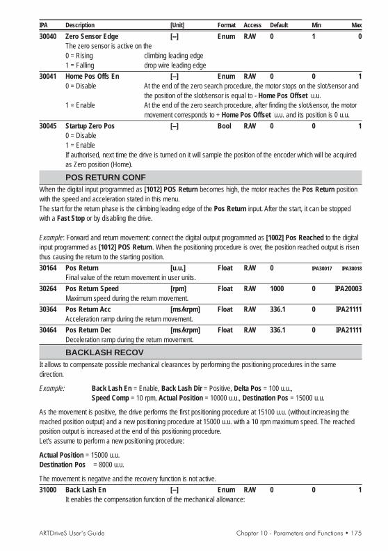
ARTDriveS User’s Guide Chapter 10 - Parameters and Functions • 175
IPA Description [Unit] Format Access Default Min Max
30040 Zero Sensor Edge [--] Enum R/W 0 1 0The zero sensor is active on the0 = Rising climbing leading edge1 = Falling drop wire leading edge
30041 Home Pos Offs En [--] Enum R/W 0 0 10 = Disable At the end of the zero search procedure, the motor stops on the slot/sensor and
the position of the slot/sensor is equal to - Home Pos Offset u.u.1 = Enable At the end of the zero search procedure, after finding the slot/sensor, the motor
movement corresponds to + Home Pos Offset u.u. and its position is 0 u.u.30045 Startup Zero Pos [--] Bool R/W 0 0 1
0 = Disable1 = EnableIf authorised, next time the drive is turned on it will sample the position of the encoder which will be acquiredas Zero position (Home).
POS RETURN CONFWhen the digital input programmed as [1012] POS Return becomes high, the motor reaches the Pos Return positionwith the speed and acceleration stated in this menu.The start for the return phase is the climbing leading edge of the Pos Return input. After the start, it can be stoppedwith a Fast Stop or by disabling the drive.
Example: Forward and return movement: connect the digital output programmed as [1002] Pos Reached to the digitalinput programmed as [1012] POS Return. When the positioning procedure is over, the position reached output is risenthus causing the return to the starting position.30164 Pos Return [u.u.] Float R/W 0 IPA30017 IPA30018
Final value of the return movement in user units.30264 Pos Return Speed [rpm] Float R/W 1000 0 IPA20003
Maximum speed during the return movement.30364 Pos Return Acc [ms/krpm] Float R/W 336.1 0 IPA21111
Acceleration ramp during the return movement.30464 Pos Return Dec [ms/krpm] Float R/W 336.1 0 IPA21111
Deceleration ramp during the return movement.
BACKLASH RECOVIt allows to compensate possible mechanical clearances by performing the positioning procedures in the samedirection.
Example: Back Lash En = Enable, Back Lash Dir = Positive, Delta Pos = 100 u.u.,Speed Comp = 10 rpm, Actual Position = 10000 u.u., Destination Pos = 15000 u.u.
As the movement is positive, the drive performs the first positioning procedure at 15100 u.u. (without increasing thereached position output) and a new positioning procedure at 15000 u.u. with a 10 rpm maximum speed. The reachedposition output is increased at the end of this positioning procedure.Let’s assume to perform a new positioning procedure:
Actual Position = 15000 u.u.Destination Pos = 8000 u.u.
The movement is negative and the recovery function is not active.31000 Back Lash En [--] Enum R/W 0 0 1
It enables the compensation function of the mechanical allowance:

176 • Chapter 10 - Parameters and Functions ARTDriveS User’s Guide
IPA Description [Unit] Format Access Default Min Max0 = Disable1 = Enable
31001 Back Lash Dir [--] Enum R/W 0 0 1It detects the movement direction:0 = Positive1 = NegativeNOTE! A positive direction is able to generate a positive position delta.
31002 Delta Pos [u.u.] Float R/W 10 0 IPA30018u.u. position added or taken away from the destination position.
31003 Speed Comp [rpm] Float R/W 100 0 IPA20003Maximum speed of the return "positioning" procedure.
EL LINE SHAFTEL LINE SHAFTEL LINE SHAFTEL LINE SHAFTEL LINE SHAFTIn the configuration Electrical line shaft it is possible to provide synchronism between 2 or more motors. The masterencoder can be connected to XER or it is possible to use the fast link.Moreover, it is possible to save into the drive up to 4 ratios selectable through 2 programmed digital input as [2001]ELS Ratio Sel B0, [2002] ELS Ratio Sel B1. Whatever ratio is actually selected, it is possible to increase/decrease bytwo programmed digital inputs as [2003] ELS Inc Ratio ed [2004] ELS Dec Ratio.
Connection of a digital encoder using repetition
Master Slave
XER XER
Master ARTDriveS: The connector XER give the encoder repetition / simulation to the connector XER of theslave drive. Set up the parameters as follows:- IPA 20036: Aux Enc Type = XER/EXP Rep/Sim- IPA 20035: Enc Rep Sim Cfg = Select encoder repetition or simulationIf you select encoder simulation then you must program the correct number of pulses with the parameter PPRSimulation (IPA 20030).
Slave ARTDriveS: The connector XER receives the encoder repetition / simulation from the connector XERof the master drive. Set up the parameters as follows:- IPA 20036: Aux Enc Type = XER In_EXP Out- IPA 32009: Els Master Sel = XER/EXP Aux Enc
Fast link connection instead of encoder connection
Master ARTDriveS: XT-OUT connector (master), connected to the XT-IN connector (slave)Set up: enable the fast link, parameter Fast Link Addr (IPA 18110) set as 1 (Master)Slave ARTDriveS: Connector XT-IN (slave).Set up: enable the fast link, parameter Fast Link Addr (IPA 18110) set as >1 (Slave).The fast link is active only after a reset drive command.
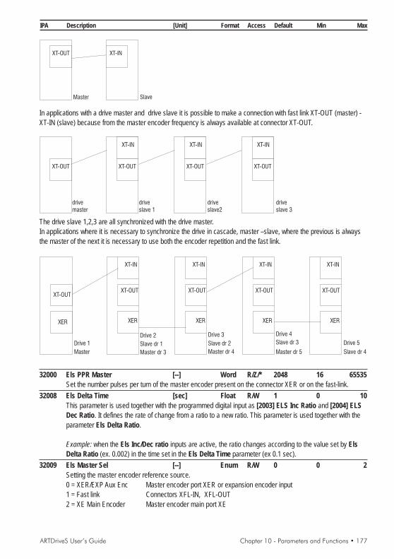
ARTDriveS User’s Guide Chapter 10 - Parameters and Functions • 177
IPA Description [Unit] Format Access Default Min Max
Master Slave
XT-OUT XT-IN
In applications with a drive master and drive slave it is possible to make a connection with fast link XT-OUT (master) -XT-IN (slave) because from the master encoder frequency is always available at connector XT-OUT.
drivemaster
driveslave 1
driveslave2
driveslave 3
XT-OUT
XT-IN
XT-OUT
XT-IN
XT-OUT
XT-IN
XT-OUT
The drive slave 1,2,3 are all synchronized with the drive master.In applications where it is necessary to synchronize the drive in cascade, master –slave, where the previous is alwaysthe master of the next it is necessary to use both the encoder repetition and the fast link.
Drive 1
Drive 2 Drive 3 Drive 4
Drive 5
Master
Slave dr 1 Slave dr 2 Slave dr 3
Slave dr 4Master dr 3 Master dr 4 Master dr 5
XT-OUT
XER
XT-OUT
XT-IN
XER
XT-OUT
XT-IN
XER
XT-OUT
XT-IN
XER
XT-OUT
XT-IN
XER
32000 Els PPR Master [--] Word R/Z/* 2048 16 65535Set the number pulses per turn of the master encoder present on the connector XER or on the fast-link.
32008 Els Delta Time [sec] Float R/W 1 0 10This parameter is used together with the programmed digital input as [2003] ELS Inc Ratio and [2004] ELSDec Ratio. It defines the rate of change from a ratio to a new ratio. This parameter is used together with theparameter Els Delta Ratio.
Example: when the Els Inc/Dec ratio inputs are active, the ratio changes according to the value set by ElsDelta Ratio (ex. 0.002) in the time set in the Els Delta Time parameter (ex 0.1 sec).
32009 Els Master Sel [--] Enum R/W 0 0 2Setting the master encoder reference source.0 = XER/EXP Aux Enc Master encoder port XER or expansion encoder input1 = Fast link Connectors XFL-IN, XFL-OUT2 = XE Main Encoder Master encoder main port XE

178 • Chapter 10 - Parameters and Functions ARTDriveS User’s Guide
IPA Description [Unit] Format Access Default Min Max
32010 Els Mec Ratio [--] Float R/W 1 1e-007 20Setting this parameter equal to :Master mechanical ratio / Slave mechanical ratioThe Els Ratio X parameters show directly the ratio/slip between the speed of the slow shafts.
32011 Els FL Source [--] Enum R/W 0 0 20 = Spd Pos Enc Mst The slave follows the Master encoder which closes the speed/position loop (IPA
20008 Master).2 = XER Master The slave follows the motor auxiliary encoder.
32012 ElsMec Ratio Mul [--] Float R/W 1 1 -Multiplication factor in the mechanical ratio for electrical shaft.
32013 ElsMec Ratio Div [--] Float R/W 1 1 -Divisor factor in the mechanical ratio for electrical shaft.
32014 Els Delta Ratio [--] Float R/W 1 IPA32090 IPA32090Define how much the ratio should increment (or decrement) every cycle of slow task (8msec).
Example: if through the digital input a new ratio is selected changing from 1.000 up to 2.000 the change is notimmediate but follows a ramp profile with a set increase in this parameter.If Els Delta Ratio is set 1.000 means an increment of 1.000 every 8msec, therefore it changes to the newratio in 8msec.If Els Delta Ratio is set 0.010 means a change of 0.01 every 8msec, therefore it changes to the new ratio(2.000) in 800msec.Through a programmed digital input, [2005] ELS RampRatioDis it’s possible to disable this time to ramp.
32016 Els Control Mode [--] Enum R/W 0 0 1Selects the speed control method0 = Speed The drive is set to speed control1 = Position The drive is set to position control
32020 Els Ratio / Slip [--] Enum R/W 0 0 10 = Slip The parameters Els Ratio 0, 1, 2, 3 are not set as ratio but as % of slipping
from the Master. For instance 10 % slip correspond to 110% of the speedmaster, or ratio of 1.1: Els Ratio = 1 + Els Slip / 100By default, when the ratio is sampled from the analog input, 10V correspond towhat is set in parameter 32021 Els Slip Limit.
1 = Ratio If set up to Ratio the ratio is activated.By default, when the ratio is sampled from the analog input, 10V correspond towhat is set in parameter 32090 Els Ratio Range.
When changing the setting from “Slip” to “Ratio”, check parameters 32014, 32001, 32002, 32003 and 32004.32021 Els Slip Limit [--] Int R/W 100 0
Limit of slippage sampled from analogue input.At default conditions, with 10V on the analog input, the set slippage is Els Slip Limit.The Els Ratio ratio corresponds to 1 + (Slip sampled by analog input / 100).
32090 Els Ratio Range [--] Word R/W 8 4 64Value of max. ratio for ELS. A high value can reduce the ELS accuracy level.Available range: 4, 8, 16, 32 e 64.
NOTE! This parameter shows the limits for the ratio between the speed of the motor shafts, therefore forthe product Els Mec Ratio * Els Ratio.
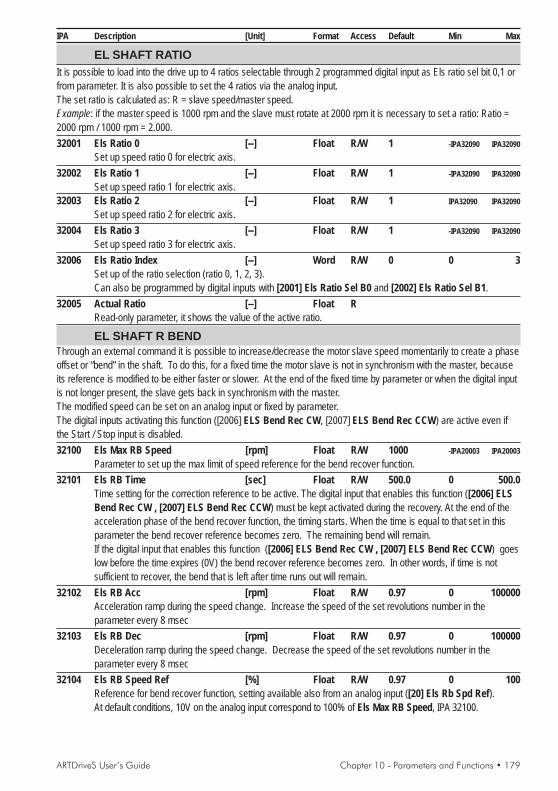
ARTDriveS User’s Guide Chapter 10 - Parameters and Functions • 179
IPA Description [Unit] Format Access Default Min Max
EL SHAFT RATIOIt is possible to load into the drive up to 4 ratios selectable through 2 programmed digital input as Els ratio sel bit 0,1 orfrom parameter. It is also possible to set the 4 ratios via the analog input.The set ratio is calculated as: R = slave speed/master speed.Example: if the master speed is 1000 rpm and the slave must rotate at 2000 rpm it is necessary to set a ratio: Ratio =2000 rpm / 1000 rpm = 2.000.32001 Els Ratio 0 [--] Float R/W 1 -IPA32090 IPA32090
Set up speed ratio 0 for electric axis.32002 Els Ratio 1 [--] Float R/W 1 -IPA32090 IPA32090
Set up speed ratio 1 for electric axis.32003 Els Ratio 2 [--] Float R/W 1 IPA32090 IPA32090
Set up speed ratio 2 for electric axis.32004 Els Ratio 3 [--] Float R/W 1 -IPA32090 IPA32090
Set up speed ratio 3 for electric axis.32006 Els Ratio Index [--] Word R/W 0 0 3
Set up of the ratio selection (ratio 0, 1, 2, 3).Can also be programmed by digital inputs with [2001] Els Ratio Sel B0 and [2002] Els Ratio Sel B1.
32005 Actual Ratio [--] Float RRead-only parameter, it shows the value of the active ratio.
EL SHAFT R BENDThrough an external command it is possible to increase/decrease the motor slave speed momentarily to create a phaseoffset or “bend” in the shaft. To do this, for a fixed time the motor slave is not in synchronism with the master, becauseits reference is modified to be either faster or slower. At the end of the fixed time by parameter or when the digital inputis not longer present, the slave gets back in synchronism with the master.The modified speed can be set on an analog input or fixed by parameter.The digital inputs activating this function ([2006] ELS Bend Rec CW, [2007] ELS Bend Rec CCW) are active even ifthe Start / Stop input is disabled.32100 Els Max RB Speed [rpm] Float R/W 1000 -IPA20003 IPA20003
Parameter to set up the max limit of speed reference for the bend recover function.32101 Els RB Time [sec] Float R/W 500.0 0 500.0
Time setting for the correction reference to be active. The digital input that enables this function ([2006] ELSBend Rec CW , [2007] ELS Bend Rec CCW) must be kept activated during the recovery. At the end of theacceleration phase of the bend recover function, the timing starts. When the time is equal to that set in thisparameter the bend recover reference becomes zero. The remaining bend will remain.If the digital input that enables this function ([2006] ELS Bend Rec CW , [2007] ELS Bend Rec CCW) goeslow before the time expires (0V) the bend recover reference becomes zero. In other words, if time is notsufficient to recover, the bend that is left after time runs out will remain.
32102 Els RB Acc [rpm] Float R/W 0.97 0 100000Acceleration ramp during the speed change. Increase the speed of the set revolutions number in theparameter every 8 msec
32103 Els RB Dec [rpm] Float R/W 0.97 0 100000Deceleration ramp during the speed change. Decrease the speed of the set revolutions number in theparameter every 8 msec
32104 Els RB Speed Ref [%] Float R/W 0.97 0 100Reference for bend recover function, setting available also from an analog input ([20] Els Rb Spd Ref).At default conditions, 10V on the analog input correspond to 100% of Els Max RB Speed, IPA 32100.
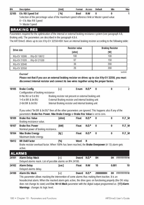
180 • Chapter 10 - Parameters and Functions ARTDriveS User’s Guide
IPA Description [Unit] Format Access Default Min Max
32105 Els RB Speed Sel [ %] Bool R/W 0 0 1Selection of the percentage value of the maximum speed reference limit or Master speed value0 = Els Max RB Speed1= Master Speed
BRAKING RESBRAKING RESBRAKING RESBRAKING RESBRAKING RESParameters required for the optimization of the internal or external braking resistance system (see paragraph 4.8,Braking unit). The parameters are described in the paragraph 4.8.4.The ARTDriveS drives up to size XVy-EV 32550-KBX have an internal braking resistor according to the following table:
XVy-EV 10306 … XVy-EV 10612
XVy-EV 21020 … XVy-EV 21530
XVy-EV 32040
XVy-EV 32550
txv9340
Resistor value Braking Resistor
[ohm] [W]
26
100
150
200
200
Drive size
100
67
36
CAUTION!Please not that if you use an external braking resistor on drives up to size XVy-EV 32550, you mustdisconnect internal resistor and connect its two wires together using the proper faston.
18105 Brake Config [--] Enum R/Z/* 0 0 2Configuration of braking resistance0=No BU or Ext BU Braking resistor not present or external braking unit1=Ext BR & Int BU External Braking resistor and internal braking unit2=Int BR & Int BU Internal Braking resistor and internal braking unit
If you select “Int BR & Int BU” then all the other parameters are ignored. This happens also if any of theparameters Brake Res Power, Max Brake Energy or Brake Res Value is set to zero.
18109 Brake Res Value [ohm] Float R/Z/* 0 0 FLT_MBraking resistance value.
18107 Brake Res Power [kW] Float R/Z/* 0 0 FLT_MNominal power of braking resistance.
18104 Max Brake Energy [kJ] Float R/Z/* 0 0 FLT_MMaximum brake energy.
18412 BR Ovld Factor [%] Word RBrake resistor overload factor. When 100% has been reached, the Brake Overpower (A 13) alarm getsactive.
ALARMSALARMSALARMSALARMSALARMS24101 Alarm Delay Mask [--] Dword R/Z/* 0H 0H FFFFFFFFH
Delayed alarms mask. List of possible alarms on IPA 24100.24102 Alarm Delay [sec] Float R/W 10 0.001 10
Delayed alarms delay.24100 Alarm Dis Mask [--] Dword R/Z/* 20000000H 0H FFFFFFFFH
This parameter allows masking the intervention of some alarms thus making them inactive. It is anhexadecimal alarm. When the masked alarm gets active, the drive goes on functioning properly (the OK relaydoes not change its state) and Enc W->A Mask parameter with the digital output programmed as [17] AlarmWarnings changes its logic level.

ARTDriveS User’s Guide Chapter 10 - Parameters and Functions • 181
IPA Description [Unit] Format Access Default Min MaxList of possible excluded alarms:
Motor Overtemp (error code 7)Encoder Fbk Loss (error code 18)Encoder Simulat (error code 19)Undervoltage (error code 20)Field Bus failure (error code 26)Enable Seq Error (error code 27)Fast link (error code 28)Position Error (error code 29)Drive Overload (error code 30)External Fault (error code 31)
Example for a parameter setting :
32 31 30 29 28 27 26 25 24 23 22 21 20 19 18 17 16 15 14 13 12 11 10 9 8 7 6 5 4 3 2 1
0 0 0 1 1 0 0 0 0 0 0 0 0 0 0 0 0 0 0 0 0 0 0 0 0 0 0 0 0 0 0 0
0 0txv9118
0 0 0 01 8
Alarm Dis Mask = 18000000h (disabled Position error and Fast link alarms)Note: The Position Error alarm is disabled as default.1° row: Alarm code2° row: Setting of the alarm functions : 0 = active, 1 = masked3° row: Parameter hexadecimal setting
18042 Alarm List Clear [--] Enum R/W 0 0 1It cancels the whole alarm history. It can be made permanent by saving the parameters:0=Off1=Clear Al History
24000 Alarm Status [--] Dword RAlarm status. See the alarm list, table 8.3.1.1.
24120 Warning Status [--] Dword RWarnings state. See the alarm list, table 8.3.1.1.
20016 Enc Warning Cause [--] Enum R
N. bit IPA 20018=Meaning Cause0 = None Encoder is OK1=Low Enc AD Level Check encoder supply.2=Low Enc AN level Check encoder supply.3=Hall Sens Error The sequence of the Hall effect sensors is not correct. Check encoder wiring.4=Aux DI Enc Loss No encoder on expansion input.9=Abs 1 Ini Res Er EN DAT reset failure. Check encoder parameters setting (ENC EXP BOARD
menu) and encoder connections.10=Abs 1 Ini RX Er Reception problem at power on (EN DAT, SSI). Check encoder parameters
setting (ENC EXP BOARD menu) and encoder connections.11=Abs 1 RX Error Checksum error in the serial communication of the absolute data. Check noise
on the encoder signals.12=Abs 1 Alarm bit The error bit on the absolute encoder (EN DAT) is active.13=Abs 1 RX Tout Er Time-out error of absolute data serial communication.17=Phasing Loss The incremental channel and the absolute channel of the encoder shows a
misalignment.

182 • Chapter 10 - Parameters and Functions ARTDriveS User’s Guide
IPA Description [Unit] Format Access Default Min Max18=Enc Pulses Loss The number of incremental pulses detected between two index signals is not
correct. Check noise on encoder signals.25= Idx Out Of Site Index signal in the incremental encoder channel is not in the correct place.
Check noise on encoder signal.26= Idx Not Presen Index signal in the incremental encoder channel is not detected. Check encoder
connections.20018 Enc W->A Mask [--] Dword R
This mask shows active encoder warnings. If encoder alarms are not disabled warnings becomesimmediately alarms. If encoder alarms are disabled, Alarm Dis Mask signals a problem on the encoder evenif there are no alarm active. The meaning of each bit is listed in the table 8.3.1.1.
24109 Par Set Cause Al [--] Enum RIt shows the cause of the Error alarm in the parameter setting:0 = None1 = HW Unavailable2 = Resource Unavail3 = Mot Fbk Not Supp4 = Mot Fbk Undefin5 = Spd/Pos Fbk Und6 = Enc Par Range7 = Enc Not Pow of 28 = Motor Res Poles20 = Magn Induc Range21 = Rotor Res Range22 = Flux Fact Range23 = Slip Fact Range24 = Slip Value Range30 = Size Code Err31 = Brake Volt Thr40 = Value Not Supp
24110 IPA 1 Par Set [--] Word RIPA of the first parameter that causes Parameter Error (A 05) alarm
24111 IPA 2 Par Set [--] Word RIPA of the second parameter that causes Parameter Error (A 05) alarm.
24112 IPA 3 Par Set [--] Word RIPA of the third parameter that causes Parameter Error (A 05) alarm.
18143 CPU Err Al Cause [--] Enum RCPU overtime alarm cause :0 = None1 = Ph In Fst Tsk OT (Phase In Fast Task Overtime)2 = PhExe Fst Tsk OT (Phase Execution Fast Task Overtime)3 = PhOut Fst Tsk OT (Phase Out Fast Task Overtime)4 = PhAux Fst Tsk OT (Phase Auxiliary Fast Task Overtime)5= Slow Tsk OT6 = System Tsk OT7 = DSP Tsk OT8 = Backgnd Tsk OT20 = CPU Fault21 = Watchdog Alarm

ARTDriveS User’s Guide Chapter 10 - Parameters and Functions • 183
IPA Description [Unit] Format Access Default Min Max
18391 PLC Err Cause [--] Word RCause of the "PLC not running" alarm:0 = None1 = Wrong PLC ID2 = Wrong PLC Tsk N (Wrong PLC Task Number)3 = Wrong PLC Tgt ID4 = Wrong Build N6 = Wrong PLC Tsk ID7 = Missing Tsk info8 = PLC Code Chckerr9 = DB Code Chk Err20 = Wrong Enable KeyIn the cases from 1 to 8 it is necessary to reload the fw; in case 20 it is necessary to enter the right activationkey in the PLC Enable Key, IPA 41001 parameter.
18751 Load Def Err IPA [--] Word RPar IPA that caused load default error.
FIELDBFIELDBFIELDBFIELDBFIELDBUSUSUSUSUSUsing Process Data Channel (PDC), it is possible to exchange up to 8 words on the input and 8 words on the output.For each PDC it is possible to choose, via the FB Assign XXX X parameters, one of the following modes for the dataexchange according to the following table:
- Parameter:The parameters are entered into engineering units and are exchanged in an asynchronous way.The FB Format M->S 1 parameter sets the parameter writing format. The format can be different from theparameter original one.The FB Exp M->S 1 parameter defines the 10th power which the parameter is multiplied by before beingtransferred to the drive.- Direct Access:The parameters are entered into internal counts and are exchanged in an asynchronous way (one every 8msec). The writing format identified by the FB Format M->S 1 parameter (see the following table) mustcoincide with the drive internal format.As for parameters with a float internal format, it is possible to choose "32 bit integer" and the conversion into afloat format between the received datum and the internal datum is performed automatically.
Before establishing the Profibus communication between the Master and the drive, it is necessary to assign the driveparameters to the Process Channel. These parameters can be activated by resetting the drive.
cnts=Speed (rpm)
cnts=Max Ramp Rate
Ramp [ms / krpm]
cnts=Current [Arms]
Arms Conv Fact
cnts=Torque [%]* Base Torque
100 * Torque Conv Fact
Dimension Format Conversion
Speed INT 32
Ramp INT 16
Position FLOAT User unit
Torque INT 16
Current INT 16
Rpm Conv Fact

184 • Chapter 10 - Parameters and Functions ARTDriveS User’s Guide
IPA Description [Unit] Format Access Default Min MaxAttention: The conversion parameters (ex. Rpm Conv Fact) are in the FIELDBUS / UNITS menu and area function of the motor data, of the drive size and of the encoder. It is therefore necessary to read them afterconfiguring the drive.
40000 Field Bus Type [--] Enum R/Z/* 0 0 3Type of expansion board if installed0 = Not Used1 = Profibus2 = CanOpen3 = DeviceNet
40001 Bus Baude Rate [kbits/s] Dword] R/Z/* 50 0 232-1Baud rate of expansion board installed, if any
40100 Bus Address [--] Word R/Z/* 0 0 65535Address of expansion board installed
40110 CC Enabling [--] Enum R/Z/* 0 0 65535Enables or disables the CC0 = OFF1 = ON
40111 PDC Enabling [--] Enum R/Z/* 0 0 65535Enables or disables the PDC channel0 = OFF1 = ON
40115 FB Alarm Watch [--] Enum R/Z/* 0 0 65535Field bus communication alarm control when drive disabled.0 = OFF control inactive1 = ON control active
40116 Float Word Order [--] Word R/W 0 0 65535Identical configuration of words for Direct Access and Parameter modes
40113 Field Bus Status [--] Enum RStatus of FB device
40114 FB Fail Cause [--] Dword RFailure cause of FB card
FB 1st M->S PAR40190 FB Assign M->S 1 [--] Enum R/Z/* 0 0 5
Exchange data mode.0 = Not assigned1 = Parameter3 = Direct Acc Par Direct access parameter (8ms)4 = Filling5 = Fast Access Par Fast access parameter (250uS)
40200 FB IPA M->S 1 [--] Word R/Z/* 0 0 65535Parameter index (IPA) to write into XVy-EV with PDC channel
40210 FB Format M->S 1 [--] Enum R/Z/* 1 0 65535Format of the parameter to write into XVy-EV1 = 16 Bit Integer2 = 16 Bit Uns Int3 = 32 Bit Integer

ARTDriveS User’s Guide Chapter 10 - Parameters and Functions • 185
IPA Description [Unit] Format Access Default Min Max4 = 32 Bit Uns Int6 = Floating Point
40220 FB Exp M->S 1 [--] Int R/Z/* 0 -9 9Power of 10 used to multiply the parameter value to write into XVy-EV.
FB 2ndM->S PAR40191 FB Assign M->S 2 [--] Enum R/Z/* 0 0 5
Exchange data mode.0 = Not assigned1 = Parameter3 = Direct Acc Par Direct access parameter (8ms)4 = Filling5 = Fast Access Par Fast access parameter (250uS)
40201 FB IPA M->S 2 [--] Word R/Z/* 0 0 65535Parameter index (IPA) to write into XVy-EV with PDC channel
40211 FB Format M->S 2 [--] Word R/Z/* 1 0 65535Format of the parameter to write into XVy-EV1 = 16 Bit Integer2 = 16 Bit Uns Int3 = 32 Bit Integer4 = 32 Bit Uns Int6 = Floating Point
40221 FB Exp M->S 2 [--] Enum R/Z/* 0 -9 9Power of 10 used to multiply the parameter value to write into XVy-EV.
FB 3rd M->S PAR40192 FB Assign M->S 3 [--] Enum R/Z/* 0 0 5
Exchange data mode.0 = Not assigned1 = Parameter3 = Direct Acc Par Direct access parameter (8ms)4 = Filling5 = Fast Access Par Fast access parameter (250uS)
40202 FB IPA M->S 3 [--] Word R/Z/* 0 0 65535Parameter index (IPA) to write into XVy-EV with PDC channel
40212 FB Format M->S 3 [--] Enum R/Z/* 1 0 65535Format of the parameter to write into XVy-EV1 = 16 Bit Integer2 = 16 Bit Uns Int3 = 32 Bit Integer4 = 32 Bit Uns Int6 = Floating Point
40222 FB Exp M->S 3 [--] Int R/Z/* 0 -9 9Power of 10 used to multiply the parameter value to write into XVy-EV.
FB 4th M->S PAR40193 FB Assign M->S 4 [--] Enum R/Z/* 0 0 5
Exchange data mode.0 = Not assigned1 = Parameter

186 • Chapter 10 - Parameters and Functions ARTDriveS User’s Guide
IPA Description [Unit] Format Access Default Min Max3 = Direct Acc Par Direct access parameter (8ms)4 = Filling5 = Fast Access Par Fast access parameter (250uS)
40203 FB IPA M->S 4 [--] Word R/Z/* 0 0 65535Parameter index (IPA) to write into XVy-EV with PDC channel
40213 FB Format M->S 4 [--] Enum R/Z/* 1 0 65535Format of the parameter to write into XVy-EV1 = 16 Bit Integer2 = 16 Bit Uns Int3 = 32 Bit Integer4 = 32 Bit Uns Int6 = Floating Point
40223 FB Exp M->S 4 [--] Int R/Z/* 0 -9 9Power of 10 used to multiply the parameter value to write into XVy-EV.
FB 5th M->S PAR40194 FB Assign M->S 5 [--] Int R/Z/* 0 0 5
Exchange data mode.0 = Not assigned1 = Parameter3 = Direct Acc Par Direct access parameter (8ms)4 = Filling5 = Fast Access Par Fast access parameter (250uS)
40204 FB IPA M->S 5 [--] Word R/Z/* 0 0 65535Parameter index (IPA) to write into XVy-EV with PDC channel
40214 FB Format M->S 5 [--] Enum R/Z/* 1 0 65535Format of the parameter to write into XVy-EV1 = 16 Bit Integer2 = 16 Bit Uns Int3 = 32 Bit Integer4 = 32 Bit Uns Int6 = Floating Point
40224 FB Exp M->S 5 [--] Int R/Z/* 0 -9 9Power of 10 used to multiply the parameter value to write into XVy-EV.
FB 6th M->S PAR40195 FB Assign M->S 6 [--] Enum R/Z/* 0 0 5
Exchange data mode.0 = Not assigned1 = Parameter3 = Direct Acc Par Direct access parameter (8ms)4 = Filling5 = Fast Access Par Fast access parameter (250uS)
40205 FB IPA M->S 6 [--] Word R/Z/* 0 0 65535Parameter index (IPA) to write into XVy-EV with PDC channel
40215 FB Format M->S 6 [--] Enum R/Z/* 1 0 65535Format of the parameter to write into XVy-EV1 = 16 Bit Integer2 = 16 Bit Uns Int3 = 32 Bit Integer

ARTDriveS User’s Guide Chapter 10 - Parameters and Functions • 187
IPA Description [Unit] Format Access Default Min Max4 = 32 Bit Uns Int6 = Floating Point
40225 FB Exp M->S 6 [--] Int R/Z/* 0 -9 9Power of 10 used to multiply the parameter value to write into XVy-EV.
FB 7th M->S PAR40196 FB Assign M->S 7 [--] Enum R/Z/* 0 0 5
Exchange data mode.0 = Not assigned1 = Parameter3 = Direct Acc Par Direct access parameter (8ms)4 = Filling5 = Fast Access Par Fast access parameter (250uS)
40206 FB IPA M->S 7 [--] Word R/Z/* 0 0 65535Parameter index (IPA) to write into XVy-EV with PDC channel
40216 FB Format M->S 7 [--] Enum R/Z/* 1 0 65535Format of the parameter to write into XVy-EV1 = 16 Bit Integer2 = 16 Bit Uns Int3 = 32 Bit Integer4 = 32 Bit Uns Int6 = Floating Point
40226 FB Exp M->S 7 [--] Int R/Z/* 0 -9 9Power of 10 used to multiply the parameter value to write into XVy-EV.
FB 8th M->S PAR40197 FB Assign M->S 8 [--] Enum R/Z/* 0 0 5
Exchange data mode.0 = Not assigned1 = Parameter3 = Direct Acc Par Direct access parameter (8ms)4 = Filling5 = Fast Access Par Fast access parameter (250uS)
40207 FB IPA M->S 8 [--] Word R/Z/* 0 0 65535Parameter index (IPA) to write into XVy-EV with PDC channel
40217 FB Format M->S 8 [--] Enum R/Z/* 1 0 65535Format of the parameter to write into XVy-EV1 = 16 Bit Integer2 = 16 Bit Uns Int3 = 32 Bit Integer4 = 32 Bit Uns Int6 = Floating Point
40227 FB Exp M->S 8 [--] Int R/Z/* 0 -9 9Power of 10 used to multiply the parameter value to write into XVy-EV.
FB 9th M->S PAR41198 FB Assign M->S 9 [--] Enum R/Z/* 0 0 5
Exchange data mode.0 = Not assigned1 = Parameter
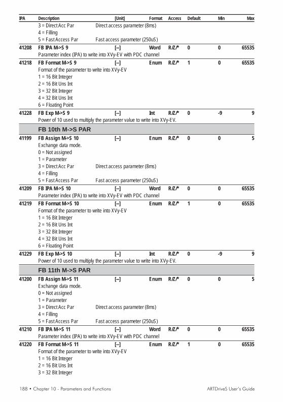
188 • Chapter 10 - Parameters and Functions ARTDriveS User’s Guide
IPA Description [Unit] Format Access Default Min Max3 = Direct Acc Par Direct access parameter (8ms)4 = Filling5 = Fast Access Par Fast access parameter (250uS)
41208 FB IPA M->S 9 [--] Word R/Z/* 0 0 65535Parameter index (IPA) to write into XVy-EV with PDC channel
41218 FB Format M->S 9 [--] Enum R/Z/* 1 0 65535Format of the parameter to write into XVy-EV1 = 16 Bit Integer2 = 16 Bit Uns Int3 = 32 Bit Integer4 = 32 Bit Uns Int6 = Floating Point
41228 FB Exp M->S 9 [--] Int R/Z/* 0 -9 9Power of 10 used to multiply the parameter value to write into XVy-EV.
FB 10th M->S PAR41199 FB Assign M->S 10 [--] Enum R/Z/* 0 0 5
Exchange data mode.0 = Not assigned1 = Parameter3 = Direct Acc Par Direct access parameter (8ms)4 = Filling5 = Fast Access Par Fast access parameter (250uS)
41209 FB IPA M->S 10 [--] Word R/Z/* 0 0 65535Parameter index (IPA) to write into XVy-EV with PDC channel
41219 FB Format M->S 10 [--] Enum R/Z/* 1 0 65535Format of the parameter to write into XVy-EV1 = 16 Bit Integer2 = 16 Bit Uns Int3 = 32 Bit Integer4 = 32 Bit Uns Int6 = Floating Point
41229 FB Exp M->S 10 [--] Int R/Z/* 0 -9 9Power of 10 used to multiply the parameter value to write into XVy-EV.
FB 11th M->S PAR41200 FB Assign M->S 11 [--] Enum R/Z/* 0 0 5
Exchange data mode.0 = Not assigned1 = Parameter3 = Direct Acc Par Direct access parameter (8ms)4 = Filling5 = Fast Access Par Fast access parameter (250uS)
41210 FB IPA M->S 11 [--] Word R/Z/* 0 0 65535Parameter index (IPA) to write into XVy-EV with PDC channel
41220 FB Format M->S 11 [--] Enum R/Z/* 1 0 65535Format of the parameter to write into XVy-EV1 = 16 Bit Integer2 = 16 Bit Uns Int3 = 32 Bit Integer

ARTDriveS User’s Guide Chapter 10 - Parameters and Functions • 189
IPA Description [Unit] Format Access Default Min Max4 = 32 Bit Uns Int6 = Floating Point
41230 FB Exp M->S 11 [--] Int R/Z/* 0 -9 9Power of 10 used to multiply the parameter value to write into XVy-EV.
FB 12th M->S PAR41201 FB Assign M->S 12 [--] Enum R/Z/* 0 0 5
Exchange data mode.0 = Not assigned1 = Parameter3 = Direct Acc Par Direct access parameter (8ms)4 = Filling5 = Fast Access Par Fast access parameter (250uS)
41201 FB IPA M->S 12 [--] Word R/Z/* 0 0 65535Parameter index (IPA) to write into XVy-EV with PDC channel
41221 FB Format M->S 12 [--] Enum R/Z/* 1 0 65535Format of the parameter to write into XVy-EV1 = 16 Bit Integer2 = 16 Bit Uns Int3 = 32 Bit Integer4 = 32 Bit Uns Int6 = Floating Point
41231 FB Exp M->S 12 [--] Int R/Z/* 0 -9 9Power of 10 used to multiply the parameter value to write into XVy-EV.
FB 1st S->M PAR40290 FB Assign S->M 1 [--] Enum R/Z/* 0 0 5
Exchange data mode.0 = Not assigned1 = Parameter3 = Direct Acc Par Direct access parameter (8ms)4 = Filling5 = Fast Access Par Fast access parameter (250uS)
40300 FB IPA S->M 1 [--] Word R/Z/* 0 0 65535Parameter index (IPA) to read from XVy-EV with PDC channel
40310 FB Format S->M 1 [--] Enum R/Z/* 1 0 65535Format of the parameter to read into XVy-EV1 = 16 Bit Integer2 = 16 Bit Uns Int3 = 32 Bit Integer4 = 32 Bit Uns Int6 = Floating Point
40320 FB Exp S->M 1 [--] Int R/Z/* 0 -9 9Power of 10 used to multiply the parameter value to read into XVy-EV.
FB 2nd S->M PAR40291 FB Assign S->M 2 [--] Enum R/Z/* 0 0 5
Exchange data mode.0 = Not assigned1 = Parameter

190 • Chapter 10 - Parameters and Functions ARTDriveS User’s Guide
IPA Description [Unit] Format Access Default Min Max3 = Direct Acc Par Direct access parameter (8ms)4 = Filling5 = Fast Access Par Fast access parameter (250uS)
40301 FB IPA S->M 2 [--] Word R/Z/* 0 0 65535Parameter index (IPA) to read from XVy-EV with PDC channel
40311 FB Format S->M 2 [--] Enum R/Z/* 1 0 65535Format of the parameter to read into XVy-EV1 = 16 Bit Integer2 = 16 Bit Uns Int3 = 32 Bit Integer4 = 32 Bit Uns Int6 = Floating Point
40321 FB Exp S->M 2 [--] Int R/Z/* 0 -9 9Power of 10 used to multiply the parameter value to read into XVy-EV.
FB 3rd S->M PAR40292 FB Assign S->M 3 [--] Enum R/Z/* 0 0 5
Exchange data mode.0 = Not assigned1 = Parameter3 = Direct Acc Par Direct access parameter (8ms)4 = Filling5 = Fast Access Par Fast access parameter (250uS)
40302 FB IPA S->M 3 [--] Word R/Z/* 0 0 65535Parameter index (IPA) to read from XVy-EV with PDC channel
40312 FB Format S->M 3 [--] Enum R/Z/* 1 0 65535Format of the parameter to read into XVy-EV1 = 16 Bit Integer2 = 16 Bit Uns Int3 = 32 Bit Integer4 = 32 Bit Uns Int6 = Floating Point
40322 FB Exp S->M 3 [--] Int R/Z/* 0 -9 9Power of 10 used to multiply the parameter value to read into XVy-EV.
FB 4th S->M PAR40293 FB Assign S->M 4 [--] Enum R/Z/* 0 0 5
Exchange data mode.0 = Not assigned1 = Parameter3 = Direct Acc Par Direct access parameter (8ms)4 = Filling5 = Fast Access Par Fast access parameter (250uS)
40303 FB IPA S->M 4 [--] Word R/Z/* 0 0 65535Parameter index (IPA) to read from XVy-EV with PDC channel
40313 FB Format S->M 4 [--] Enum R/Z/* 1 0 65535Format of the parameter to read into XVy-EV1 = 16 Bit Integer2 = 16 Bit Uns Int3 = 32 Bit Integer
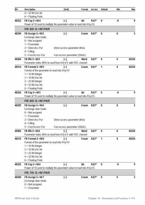
ARTDriveS User’s Guide Chapter 10 - Parameters and Functions • 191
IPA Description [Unit] Format Access Default Min Max4 = 32 Bit Uns Int6 = Floating Point
40323 FB Exp S->M 4 [--] Int R/Z/* 0 -9 9Power of 10 used to multiply the parameter value to read into XVy-EV.
FB 5th S->M PAR40294 FB Assign S->M 5 [--] Enum R/Z/* 0 0 5
Exchange data mode.0 = Not assigned1 = Parameter3 = Direct Acc Par Direct access parameter (8ms)4 = Filling5 = Fast Access Par Fast access parameter (250uS)
40304 FB IPA S->M 5 [--] Word R/Z/* 0 0 65535Parameter index (IPA) to read from XVy-EV with PDC channel
40314 FB Format S->M 5 [--] Enum R/Z/* 1 0 65535Format of the parameter to read into XVy-EV1 = 16 Bit Integer2 = 16 Bit Uns Int3 = 32 Bit Integer4 = 32 Bit Uns Int6 = Floating Point
40324 FB Exp S->M 5 [--] Int R/Z/* 0 -9 9Power of 10 used to multiply the parameter value to read into XVy-EV.
FB 6th S->M PAR40295 FB Assign S->M 6 [--] Enum R/Z/* 0 0 5
Exchange data mode.0 = Not assigned1 = Parameter3 = Direct Acc Par Direct access parameter (8ms)4 = Filling5 = Fast Access Par Fast access parameter (250uS)
40305 FB IPA S->M 6 [--] Word R/Z/* 0 0 65535Parameter index (IPA) to read from XVy-EV with PDC channel
40315 FB Format S->M 6 [--] Enum R/Z/* 1 0 65535Format of the parameter to read into XVy-EV1 = 16 Bit Integer2 = 16 Bit Uns Int3 = 32 Bit Integer4 = 32 Bit Uns Int6 = Floating Point
40325 FB Exp S->M 6 [--] Int R/Z/* 0 -9 9Power of 10 used to multiply the parameter value to read into XVy-EV.
FB 7th S->M PAR40296 FB Assign S->M 7 [--] Enum R/Z/* 0 0 5
Exchange data mode.0 = Not assigned1 = Parameter

192 • Chapter 10 - Parameters and Functions ARTDriveS User’s Guide
IPA Description [Unit] Format Access Default Min Max3 = Direct Acc Par Direct access parameter (8ms)4 = Filling5 = Fast Access Par Fast access parameter (250uS)
40306 FB IPA S->M 7 [--] Word R/Z/* 0 0 65535Parameter index (IPA) to read from XVy-EV with PDC channel
40316 FB Format S->M 7 [--] Enum R/Z/* 1 0 65535Format of the parameter to read into XVy-EV1 = 16 Bit Integer2 = 16 Bit Uns Int3 = 32 Bit Integer4 = 32 Bit Uns Int6 = Floating Point
40326 FB Exp S->M 7 [--] Int R/Z/* 0 -9 9Power of 10 used to multiply the parameter value to read into XVy-EV.
FB 8th S->M PAR40297 FB Assign S->M 8 [--] Enum R/Z/* 0 0 5
Exchange data mode.0 = Not assigned1 = Parameter3 = Direct Acc Par Direct access parameter (8ms)4 = Filling5 = Fast Access Par Fast access parameter (250uS)
40307 FB IPA S->M 8 [--] Word R/Z/* 0 0 65535Parameter index (IPA) to read from XVy-EV with PDC channel
40317 FB Format S->M 8 [--] Enum R/Z/* 1 0 65535Format of the parameter to read into XVy-EV1 = 16 Bit Integer2 = 16 Bit Uns Int3 = 32 Bit Integer4 = 32 Bit Uns Int6 = Floating Point
40327 FB Exp S->M 8 [--] Int R/Z/* 0 -9 9Power of 10 used to multiply the parameter value to read into XVy-EV.
FB 9th S->M PAR41298 FB Assign S->M 9 [--] Enum R/Z/* 0 0 5
Exchange data mode.0 = Not assigned1 = Parameter3 = Direct Acc Par Direct access parameter (8ms)4 = Filling5 = Fast Access Par Fast access parameter (250uS)
41308 FB IPA S->M 9 [--] Word R/Z/* 0 0 65535Parameter index (IPA) to read from XVy-EV with PDC channel
41318 FB Format S->M 9 [--] Enum R/Z/* 1 0 65535Format of the parameter to read into XVy-EV1 = 16 Bit Integer2 = 16 Bit Uns Int3 = 32 Bit Integer

ARTDriveS User’s Guide Chapter 10 - Parameters and Functions • 193
IPA Description [Unit] Format Access Default Min Max4 = 32 Bit Uns Int6 = Floating Point
41328 FB Exp S->M 9 [--] Int R/Z/* 0 -9 9Power of 10 used to multiply the parameter value to read into XVy-EV.
FB 10th S->M PAR41299 FB Assign S->M 10 [--] Enum R/Z/* 0 0 5
Exchange data mode.0 = Not assigned1 = Parameter3 = Direct Acc Par Direct access parameter (8ms)4 = Filling5 = Fast Access Par Fast access parameter (250uS)
41309 FB IPA S->M 10 [--] Word R/Z/* 0 0 65535Parameter index (IPA) to read from XVy-EV with PDC channel
41319 FB Format S->M 10 [--] Enum R/Z/* 1 0 65535Format of the parameter to read into XVy-EV1 = 16 Bit Integer2 = 16 Bit Uns Int3 = 32 Bit Integer4 = 32 Bit Uns Int6 = Floating Point
41329 FB Exp S->M 10 [--] Int R/Z/* 0 -9 9Power of 10 used to multiply the parameter value to read into XVy-EV.
FB 11th S->M PAR41300 FB Assign S->M 11 [--] Enum R/Z/* 0 0 5
Exchange data mode.0 = Not assigned1 = Parameter3 = Direct Acc Par Direct access parameter (8ms)4 = Filling5 = Fast Access Par Fast access parameter (250uS)
41310 FB IPA S->M 11 [--] Word R/Z/* 0 0 65535Parameter index (IPA) to read from XVy-EV with PDC channel
41320 FB Format S->M 11 [--] Enum R/Z/* 1 0 65535Format of the parameter to read into XVy-EV[1] 16 Bit Integer[2] 16 Bit Uns Int[3] 32 Bit Integer[4] 32 Bit Uns Int[6] Floating Point
41331 FB Exp S->M 11 [--] Int R/Z/* 0 -9 9Power of 10 used to multiply the parameter value to read into XVy-EV.
FB 12th S->M PAR41301 FB Assign S->M 12 [--] Enum R/Z/* 0 0 5
Exchange data mode.0 = Not assigned1 = Parameter
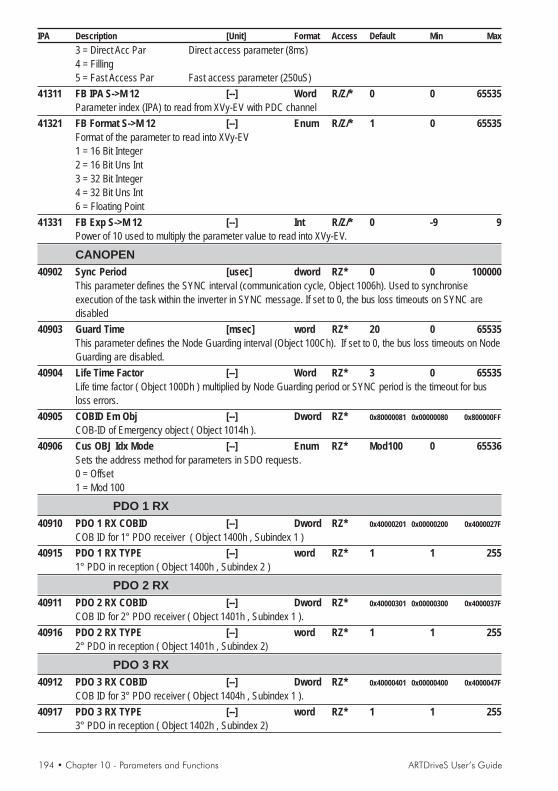
194 • Chapter 10 - Parameters and Functions ARTDriveS User’s Guide
IPA Description [Unit] Format Access Default Min Max3 = Direct Acc Par Direct access parameter (8ms)4 = Filling5 = Fast Access Par Fast access parameter (250uS)
41311 FB IPA S->M 12 [--] Word R/Z/* 0 0 65535Parameter index (IPA) to read from XVy-EV with PDC channel
41321 FB Format S->M 12 [--] Enum R/Z/* 1 0 65535Format of the parameter to read into XVy-EV1 = 16 Bit Integer2 = 16 Bit Uns Int3 = 32 Bit Integer4 = 32 Bit Uns Int6 = Floating Point
41331 FB Exp S->M 12 [--] Int R/Z/* 0 -9 9Power of 10 used to multiply the parameter value to read into XVy-EV.
CANOPEN40902 Sync Period [usec] dword RZ* 0 0 100000
This parameter defines the SYNC interval (communication cycle, Object 1006h). Used to synchroniseexecution of the task within the inverter in SYNC message. If set to 0, the bus loss timeouts on SYNC aredisabled
40903 Guard Time [msec] word RZ* 20 0 65535This parameter defines the Node Guarding interval (Object 100Ch). If set to 0, the bus loss timeouts on NodeGuarding are disabled.
40904 Life Time Factor [--] Word RZ* 3 0 65535Life time factor ( Object 100Dh ) multiplied by Node Guarding period or SYNC period is the timeout for busloss errors.
40905 COBID Em Obj [--] Dword RZ* 0x80000081 0x00000080 0x800000FFCOB-ID of Emergency object ( Object 1014h ).
40906 Cus OBJ Idx Mode [--] Enum RZ* Mod100 0 65536Sets the address method for parameters in SDO requests.0 = Offset1 = Mod 100
PDO 1 RX40910 PDO 1 RX COBID [--] Dword RZ* 0x40000201 0x00000200 0x4000027F
COB ID for 1° PDO receiver ( Object 1400h , Subindex 1 )40915 PDO 1 RX TYPE [--] word RZ* 1 1 255
1° PDO in reception ( Object 1400h , Subindex 2 )
PDO 2 RX40911 PDO 2 RX COBID [--] Dword RZ* 0x40000301 0x00000300 0x4000037F
COB ID for 2° PDO receiver ( Object 1401h , Subindex 1 ).40916 PDO 2 RX TYPE [--] word RZ* 1 1 255
2° PDO in reception ( Object 1401h , Subindex 2)
PDO 3 RX40912 PDO 3 RX COBID [--] Dword RZ* 0x40000401 0x00000400 0x4000047F
COB ID for 3° PDO receiver ( Object 1404h , Subindex 1 ).40917 PDO 3 RX TYPE [--] word RZ* 1 1 255
3° PDO in reception ( Object 1402h , Subindex 2)

ARTDriveS User’s Guide Chapter 10 - Parameters and Functions • 195
IPA Description [Unit] Format Access Default Min Max
PDO 1 TX40920 PDO 1 TX COBID [--] Dword RZ* 0x40000181 0x00000181 0x400001FF
COB ID of 1° PDO in transmission ( Object 1800h , Subindex 1 ).40925 PDO 1 TX TYPE [--] word RZ* 1 1 255
1° PDO in transmission ( Object 1800h , Subindex 2 ).40930 PDO 1 TX INH [100us] word RZ* 40 0 65535
Inhibition time of 1° PDO in transmission ( Object 1800h , Subindex 3 ).
PDO 2 TX40921 PDO 2 TX COBID [--] Dword RZ* 0x40000281 0x00000281 0x400002FF
COB ID of 2° PDO in transmission ( Object 1801h , Subindex 1 ).40926 PDO 2 TX TYPE [--] word RZ* 1 1 255
2° PDO in transmission ( Object 1801h , Subindex 2 ).40931 PDO 2 TX INH [100us] word RZ* 40 0 65535
Inhibition time of 2° PDO in transmission ( Object 1801h , Subindex 3 )
PDO 3 TX40922 PDO 3 TX COBID [--] Dword RZ* 0x40000381 0x00000381 0x400003FF
COB ID of 3° PDO in transmission ( Object 1802h , Subindex 1 ).40927 PDO 3 TX TYPE [--] word RZ* 1 1 255
3° PDO in transmission ( Object 1802h , Subindex 2 ).40932 PDO 3 TX INH [100us] word RZ* 40 0 65535
Inhibition time of 3° PDO in transmission ( Object 1802h , Subindex 3 )
UNITS18700 Arms Conv Fact [Arms/cnts] Float R
Current conversion factor.18752 Rpm Conv Fact [rpm/cnts] Float R
Speed conversion factor.18753 Pos Conv Fact [deg/cnts] Float R
Position conversion factor.18790 Torque Conv Fact [Nm/cnts] Float R
Torque conversion factor.
TUNINGTUNINGTUNINGTUNINGTUNING18140 Application Sel [--] Enum R/Z/* 0 0 65535
Application selection parameter. It is possible to select different applications:0=Basic2=Phasing3=Test Generator4=Autotuning
AUTOTUNING18330 Tuning Status [--] Enum R
Tuning developing process0 = Off1 = Lsigma Tuning...2 = Rs Tuning...3 = Magn Tuning...4 = Rr Tuning...

196 • Chapter 10 - Parameters and Functions ARTDriveS User’s Guide
IPA Description [Unit] Format Access Default Min Max90 = Done100 = Err Drive Dis110 = Err Lsigma TOut111 = Err Lsigma Range130 = Err Rs Range150 = Err Lm Range151 = Err Lm Neg Value160 = Err Imagn Range170 = Err Rr Range
18313 LKG Inductance [H] Float RMotor inductance
PHASING20058 Enc Mech Offset [el.deg.] Float R/Z/* 0 -180 180
Offset between electrical angle zero of motor phases and encoder feedback device.20057 Enc Offset [mech deg] Float R/Z/* 0 -180 180
Offset between absolute and incremental tracks on encoder feedback device.20059 Phasing Speed [rpm] Float 5 0 100
Motor speed during Phasing procedure
TEST GENERATOR20060 Test Gen Ref [--] Enum R/Z 0 0 1
Used to select current or speed loop adjusting procedure :0 = Current Ref: current loop adjust1 = Pos \ Spd Ref speed loop adjust
CURR TEST GEN20061 Period Test Gen [ms] Int R/W 16 0 32767
In current generator mode (current loop adjustment), this is the period of the generated square wave.20062 Hig Curr Ref Gen [Apk] Float R/W IPA18703 S S
Maximum value of the current reference as compared to the motor U phase.20063 Low Curr Ref Gen [Apk] Float R/W 0 S
Minimum value of the current reference as compared to the motor U phase.
SPD/POS TESTGEN20070 CW Rev Test Gen [rev] Float R/W 5
Number of clockwise revolutions performed by the motor during the speed generator Test as compared to thestarting position.
20071 CCW Rev Test Gen [rev] Float R/W 5Number of anti-clockwise revolutions performed by the motor during the speed generator Test as compared tothe starting position.
20072 Speed Test Gen [rpm] Float R/W 100 0 100000Motor speed during speed generator test

ARTDriveS User’s Guide Chapter 10 - Parameters and Functions • 197
IPA Description [Unit] Format Access Default Min Max
KEYPKEYPKEYPKEYPKEYPAD PSWAD PSWAD PSWAD PSWAD PSW18145 Keypad PSWD [--] Dword R/W 00000000H
The drive manages two password access levels:- level 1 “user” access to prevent any unauthorised modification of drive configuration parameters. SeeEntering the user Password.- level 2 to access the Service menu (reserved for use by GEFRAN-SIEI technicians).
Both Passwords are entered from the keypad in the Keypad PSWD (*) parameter.The default value for the Keypad PSWD parameter is 00000000H. If it is not changed, access is alwaysallowed to the complete list of menus and parameters (except the SERVICE menu).If a user password has been configured, access is only allowed to the MONITOR menu.Access to the complete list of menus and parameters (except the Service menu) is only allowed if the correctpassword is entered in the Keypad PSWD parameter
Entering the user Password.1) When the drive is turned on the motor speed is shown on the display. Press Escape (Shift + ) to accessthe menus.2) Press Escape to display the MONITOR menu, then Enter to show all the measurements.3) In the MONITOR menu, press to display all the drive menus in sequence until the Keypad PSWDparameter appears. Press Enter to display the value 00000000H.4) Enter a value from 1 up to a maximum of 8 digits.5) Press Enter to confirmPress to return to the menu list.6) To make the password operational, store it using the Save Parameter command.The protection will be enabled the next time the inverter is turned off and then on again.
Temporarily disabling the Password1) Select the Keypad PSWD parameter (see points 1 to 3 in the previous section).2) Press Enter to display the value 00000000H.3) Enter the correct password value.4) Press Enter to confirm5) Press to exit the password parameter and return to the MONITOR menu.In this menu, press to display all the drive menus in sequence.The password is automatically re-enabled the next time the inverter is turned off and then on again.
Removing the Password1) After temporarily disabling the password as described in the previous point, return to the Keypad PSWDparameter.2) Press Enter to display the value 00000000H.3) Press Enter to confirm4) Press to exit the password parameter5) Store using the Save Parameter command.You can now access the complete list of menus and parameters again (except the SERVICE menu) evenafter turning the inverter off and then on again.
Repeat the “Entering the user Password” procedure to enter a new password.
(*) The Keypad PSWD parameter is not visible via the E@syDrives tool.

198 • Chapter 10 - Parameters and Functions ARTDriveS User’s Guide
IPA Description [Unit] Format Access Default Min MaxUsing the E@syDrives tool the password (only required to enable the SERVICE menu) can beentered in the File / Password pull-down menu.
NOTA ! The KEYPAD PSWD menu is shown on the keypad:- with the user password enabled after the MONITOR menu- without a password (or password disabled) after the TUNING menu- with the Service password enabled after the SERVICE menu
NOTA ! With the E@syDrives tool you can always display all the menus except the SERVICE menu:0 - Basic Level only the MONITOR menu is displayed1 - User Menu (default) all the menus are displayed except the SERVICE menu3 - Service Menu all the menus are displayed (reserved for use by GEFRAN-SIEI
technicians)
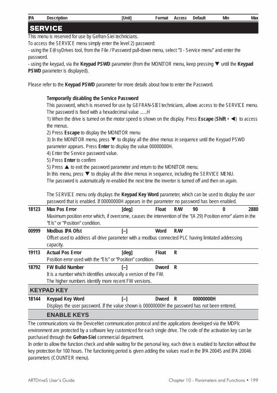
ARTDriveS User’s Guide Chapter 10 - Parameters and Functions • 199
IPA Description [Unit] Format Access Default Min Max
SERSERSERSERSERVICEVICEVICEVICEVICEThis menu is reserved for use by Gefran-Siei technicians.To access the SERVICE menu simply enter the level 2) password:- using the E@syDrives tool, from the File / Password pull-down menu, select “3 - Service menu” and enter thepassword.- using the keypad, via the Keypad PSWD parameter (from the MONITOR menu, keep pressing until the KeypadPSWD parameter is displayed).
Please refer to the Keypad PSWD parameter for more details about how to enter the Password.
Temporarily disabling the Service PasswordThis password, which is reserved for use by GEFRAN-SIEI technicians, allows access to the SERVICE menu.The password is fixed with a hexadecimal value …..H1) When the drive is turned on the motor speed is shown on the display. Press Escape (Shift + ) to accessthe menus.2) Press Escape to display the MONITOR menu3) In the MONITOR menu, press to display all the drive menus in sequence until the Keypad PSWDparameter appears. Press Enter to display the value 00000000H.4) Enter the Service password value.5) Press Enter to confirm5) Press to exit the password parameter and return to the MONITOR menu.In this menu, press to display all the drive menus in sequence, including the SERVICE MENU.The password is automatically re-enabled the next time the inverter is turned off and then on again.
The SERVICE menu only displays the Keypad Key Word parameter, which can be used to display the userpassword that is enabled. If 00000000H appears in the parameter no password has been enabled.
18123 Max Pos Error [deg] Float R/W 90 0 2880Maximum position error which, if overcome, causes the intervention of the "(A 29) Position error" alarm in the"Els" or "Position" condition.
00999 Modbus IPA Ofst [--] Word R/WOffset used to address all drive parameter with a modbus connected PLC having limitated addressingcapacity.
19113 Actual Pos Error [deg] Float RPosition error used with the “Els” or “Position” condition.
18792 FW Build Number [--] Dword RIt is a number which identifies univocally a version of the FW.The higher numbers identify more recent FW versions.
KEYPAD KEY18144 Keypad Key Word [--] Dword R 00000000H
Displays the user password. If the value shown is 00000000H the password has not been entered.
ENABLE KEYSThe communications via the DeviceNet communication protocol and the applications developed via the MDPlcenvironment are protected by a software key customized for each single drive. The code of the activation key can bepurchased through the Gefran-Siei commercial department.In order to allow the function check and while waiting for the personal key, each drive is enabled to function without thekey protection for 100 hours. The functioning period is given adding the values read in the IPA 20045 and IPA 20046parameters (COUNTER menu).

200 • Chapter 10 - Parameters and Functions ARTDriveS User’s Guide
IPA Description [Unit] Format Access Default Min Max
41000 DeviceNet Enable [--] Dword R/W*DeviceNet activation code.
41001 PLC Enable Key [--] Dword R/W*Key disabling the Plc functions.
41050 DNet En Key Stat [--] Word RStatus of the DeviceNet enabling key:0 = Disabled1 = Enabled60 = 200 Hours Free 200h free for valuation.
41051 PLC En Key Stat [--] Word RStatus of the Plc enabling key0 = Disabled1 = Enabled60 = 200 Hours Free 200h free for valuation.
41020 En Keys Mask [--] Word REnabled key mask.
18504 Ser Num En Keys [--] Word RSerial number used to enable the key codes.
COUNTER20044 Load Def Counter [--] Dwor R
Counter for the number of performed loading procedures for the factory-set parameters.20045 Tot Life Hours [Hour] Float R
Life hours at last power on.20046 Act Life Hours [Hour] Float R
Hours from last power on.20047 Power Fail Count [--] Dwor R
Counter listing the number of times the drive has been switched off.20048 Save Param Count [--] Dwor R
Save parameters counter.20049 SW Reset Count [--] Dwor R
Software reset counter.
ENCODER20017 Enc Inc Tracks [--] Enum R/Z/* 1 0 1
Incremental encoder enabling for current regulation0=Disabled1=Enabled
20031 Enc Inc Index [--] Enum R/Z/* 1 0 1Indicates if index on incremental encoder is present.0=Not Present1= Present
20028 Enc No Idx Range [--] Word R/W 2 0 65535Maximum number of revolutions to be performed without reading the zero slot. 0...65535. If 0, the control isdisabled.
20029 Enc M Lost Puls [--] Word R/W 2 0 65535Maximum number of lost incremental pulses for each revolution.
20034 Max Loss Pos [mech deg] Float R/Z/* 90.0 0 180Maximum allowed position loss.

ARTDriveS User’s Guide Chapter 10 - Parameters and Functions • 201
IPA Description [Unit] Format Access Default Min Max
20013 Phasing Err [el deg] Float RActual phasing error
20014 Act Enc Pos Loss [mech deg] Float RActual position loss
20015 Act Mot El Angle [el deg] Float RMotor electrical angle.
XE ENC INC MEAS18744 Inc Data Min Mod [cnts] Int R/W 11000 0 32767
AD minimum allowed module.18741 Inc Data Act Mod [cnts] Int R
AD measured module.19002 Inc Data Pos [mech deg] Float R
AD incremental position, main fbk.19003 Inc Data N Rev [--] long R
AD incremental revolution, main fbk.19096 Index Position [mech deg] Float R
AD index position, main fbk.19004 Inc Pulses / Rev [--] Dword R
AD incremental pulses/revolution, main fbk.19006 Inc B Data Count [cnts] Int R
AD incremental B channel, main fbk (XE pin 8-1)19005 Inc A Data Count [cnts] Int R
AD incremental A channel, main fbk (XE pin 5-6)
XE ENC ABS MEAS18747 Resolver Gain [times] Enum R/Z/* 1 0 3
Resolver input gain0 = 5 times1 = 2 times2 = 1.25 times3 = 1 times
18126 Res Shift Time [cnts] Int R/W 580 -4000 4000Resolver sampling shift time. 1cnts=33.3 ns.
18745 Abs Data Min Mod [cnts] Int R/W 17000 0 32767AN minimum allowed module.
18760 Abs Comp En [--] Enum R/W 1 0 1Enable offset compensation and amplitudes difference of AN channel.0 = Disabled1 = Enabled
18761 Abs Comp TAU [--] Int R/W 100 1 32767AN comp time constant.
18767 Abs Max Noise [count] INT 0 0 65535Maximum value of electrical noise on AN transducer.
18740 Abs Act Module [cnts] Int RAN measured module.
19017 Abs Turn Pos [mech deg] Float RAN position, main fbk.

202 • Chapter 10 - Parameters and Functions ARTDriveS User’s Guide
IPA Description [Unit] Format Access Default Min Max
19018 Abs Rev [--] Long RAN revolution, main fbk.
18762 Abs Sin Offset [cnts] Int RAN SIN ch. compensed offset, main fbk (XE pin 10-11).
18763 Abs Cos Offset [cnts] Int RAN COS ch. compensed offset, main fbk (XE pin 12-13).
18764 Abs Gain Err [%] Float RAN SIN/COS ch. compensed gain error
18766 Abs Meas Noise [count] INT 0 0 65535Momentary value of electrical noise on AN transducer.
19019 Abs Sin Meas [--] Int RAN SIN ch., main fbk (XE pin 10-11)
19020 Abs Cos Meas [--] Int RAN COS ch., main fbk (XE pin 12-13)
XER/EXP Inc Enc19011 XER/EXP Turn Pos [mech deg] Float R
DI incremental position, aux encoder (XER connector)19012 XER/EXP Rev [--] Long R
DI incremental revolution, aux encoder (XER connector)19013 XER/EXP Puls Rev [--] Dword R
DI incremental pulses/revolution, aux encoder (XER connector)19095 XER/EXP Ind Pos [el deg] Float R
DI index position, aux encoder (XER connector)
XE HALL TRACKS19022 XE Hall Pos [el deg] Float R
HA position, main fbk (XE connector).19026 XE Hall Rev [--] Long R
HA electrical revolution, main fbk (XE connector).19027 XE Hall Meas [--] Word R
HA inputs pins H1, H2, H3, main fbk (XE connector).19028 XE Hall N Error [--] Int R
Number of times when the 000 or 111 wrong configuration has appeared during the probe reading.
EXP ENC ABS119030 ABS1 Al Bit En [--] Enum R/W 1 0 1
ABS1 alarm bit check enable (EnDat only).0=Disabled1=Enabled
19031 EXP ABS1 Pos [mech deg] Float RABS1 absolute position, main fbk.
19032 EXP ABS1 Sw Rev [--] Long RNumber of calculated absolute turns.This parameter can be greater than max number of revolutions set by encoders hardware limit.
19033 EXP ABS1 Hw Rev [--] Int RNumber of absolute revolutions.This number has a maximum value, the maximum number of revolutions that encoder can measure. Aftermaximum value, count starts from zero.

ARTDriveS User’s Guide Chapter 10 - Parameters and Functions • 203
IPA Description [Unit] Format Access Default Min Max
19034 ABS1 Rx N Err [--] Int RABS1 total communication error.
19035 ABS1 Alarm Bit [--] Enum RABS1 alarm bit value (EnDat only).
FAST LINK ENC29103 RX Rev [--] Long R
Number of incremental revolutions of the speed/position loop encoder, fast link receiver.29104 RX Pos [--] Long R
Incremental position of the speed/position loop encoder, fast link receiver.29106 TX Rev [--] Long R
Number of incremental revolutions of the speed/position loop encoder, fast link transmitter.29107 TX Pos [--] Long R
Incremental position of the speed/position loop encoder, fast link transmitter.29108 RX Rev Aux [--] Long R
Number of incremental revolutions of the auxiliary encoder, fast link receiver.29109 RX Pos Aux [--] Long R
Incremental position of the auxiliary encoder, fast link receiver.29110 TX Rev Aux [--] Long R
Number of incremental revolutions of the auxiliary encoder, fast link transmitter.29111 TX Pos Aux [--] Long R
Incremental position of the auxiliary encoder, fast link transmitter.32015 FL Error [--] INT16 R
Incremental number of the fast link reception errors. It is active only on the FL slaves configured with thefunctioning of the electric shaft. A drive reset takes it back to zero.
RESERVED18111 XER/EXP Enc Mod [--] Enum R/Z/* 0 0 2
0 = Fourfold1 = A=UpB=Dir2 = A=UpB=Down
18112 XER/EXP Enc Flt [--] Word R/Z/* 4 0 7DI glitches digital filter
18113 XE Inc Enc Flt [--] Word R/Z/* 4 0 7AD glitches digital filter
18114 XE Index Mask [--] Enum R/Z/* 1 0 10=original ChZ1=ChZ & ChA & ChB
18121 Spd Loop Filter [msec] Float R/W 1 0 50Speed loop output LP filter time constant.
18122 XE Enc Abs Flt [msec] Float R/W 1 0 50AN filter time constant.
18119 Curr Comp Time [msec] Float R/W 0 -1000 1000Current sampling compensation time.
18120 Over Mod Factor [%] Float R/W 15 0 50Overmodulation factor.
18103 Brake Volt Thr [V] Float R/Z/* 780 (*) 820BU intervention threshold.

204 • Chapter 10 - Parameters and Functions ARTDriveS User’s Guide
IPA Description [Unit] Format Access Default Min Max(*): function of IPA 20050
40901 FBCFGNot to be modified, reserved for internal use.
DEBUG18146 Debug Mode [--] Enum R/W 0 0 1
Enabling the “Debug mode”0 = Disabilitato1 = Abilitato.
18392 PLC Correct ChkS [--] DWord R 0 0 65535Restricted
18390 PLC Saved ChkS [--] DWord R 0 0 65535Restricted
18773 Quadrature Volt [Vrms] Float RQuadrature output voltage.
18774 Direct Volt [Vrms] Float RDirect output voltage.
18765 Measured Speed [rpm] Float RSpeed measurement deriving from feedback devices.
TASK MEASURES18726 MaxIn Ph Exe T [us] Word R/W 0 0 62
Maximum task INPUT phase execution time.18727 MaxFst Tsk Exe T [us] Word R/W 0 0 62
Maximum task EXECUTE phase execution time.18728 MaxOut Ph Exe T [us] Word R/W 0 0 62
Maximum task OUTPUT phase execution time.18729 MaxAux Ph Exe T [us] Word R/W 0 0 62
Maximum task AUXILIARY phase execution time.18721 MaxSl Tsk Exe T [us] Long R/W 0 0 8000
Maximum slow task execution task time.18709 MaxSys Tsk Exe T [us] Long R/W 0 0 64000
Maximum system task execution task time.18781 MaxBkg Tsk Exe T [msec] Long R/W 0 0 8000
Maximum execution time of the "Background Task".18771 MaxDSP Exe T [cnts] Word R/W 0 0 1875
Maximum DSP execution time. DSP. 1 cnts=33.3 nsec.18722 Inp Phase Exe T [us] Word R
Present execution time of the fast task "INPUT phase".18723 Fst Tsk Exe T [us] Word R
Actual fast task EXECUTE phase execution time.18724 Out Phase Tsk T [us] Word R
Actual task OUTPUT phase execution time.18725 Aux Phase Exe T [us] Word R
Actual task AUXILIARY phase execution time.18720 Slow Tsk Exe T [us] Long R
Actual slow task execution time.

ARTDriveS User’s Guide Chapter 10 - Parameters and Functions • 205
IPA Description [Unit] Format Access Default Min Max
18708 Sys Tsk Exe T [us] Long RActual system task execution time.
18780 Bkg Tsk Exe T [msec] Long RPresent execution time of the "Background Task".
18770 DSP Exe Time [cnts] Word RActual DSP execution time 1 cnts=33.3 nsec.

206 • Chapter 11 - Parameters Index ARTDriveS User’s Guide
Chapter 11 - Parameters IndexIn UPPERCASE = MenuIn lowercase = Parameter description
IPA
00999, pg.19918010, pg.11818011, pg.11718017, pg.11718031, pg.11918032, pg.11918042, pg.18118070, pg.11718071, pg.11718100, pg.12718101, pg.12718102, pg.12818103, pg.20318104, pg.18018105, pg.18018107, pg.18018109, pg.18018110, pg.12018111, pg.20318112, pg.20318113, pg.20318114, pg.20318119, pg.20318120, pg.20318121, pg.20318122, pg.20318123, pg.19918124, pg.12018126, pg.20118130, pg.15318131, pg.15318132, pg.15318133, pg.15318134, pg.15318135, pg.15318136, pg.15318138, pg.15318140, pg.19518143, pg.18218144, pg.19918145, pg.19718146, pg.20418150, pg.12518151, pg.12518313, pg.120, 19618320, pg.12818321, pg.128
18322, pg.12818325, pg.12818326, pg.12818328, pg.12818330, pg.19518360, pg.12018390, pg.20418391, pg.18318392, pg.20418412, pg.18018504, pg.20018700, pg.19518701, pg.11918703, pg.11918704, pg.11918708, pg.20518709, pg.20418710, pg.11718711, pg.11718720, pg.20418721, pg.20418722, pg.20418723, pg.20418724, pg.20418725, pg.20418726, pg.20418727, pg.20418728, pg.20418729, pg.20418732, pg.11618735, pg.11618736, pg.11718739, pg.11618740, pg.20118741, pg.20118742, pg.11718744, pg.20118745, pg.20118746, pg.11618747, pg.20118748, pg.11618749, pg.11618751, pg.18318752, pg.19518753, pg.19518754, pg.11718755, pg.117
18756, pg.11718757, pg.11718760, pg.20118761, pg.20118762, pg.20218763, pg.20218764, pg.20218765, pg.20418766, pg.20218767, pg.20118770, pg.20518771, pg.20418772, pg.11718774, pg.20418776, pg.11618777, pg.11618778, pg.11818780, pg.20518781, pg.20418782, pg.11718790, pg.19518792, pg.19918800, pg.116, 12718805, pg.11618806, pg.11618807, pg.11619002, pg.20119003, pg.20119004, pg.20119005, pg.20119006, pg.20119011, pg.20219012, pg.20219013, pg.20219017, pg.20119018, pg.20219019, pg.20219020, pg.20219022, pg.20219026, pg.20219027, pg.20219028, pg.20219030, pg.20219031, pg.20219032, pg.20219033, pg.20219034, pg.203

ARTDriveS User’s Guide Chapter 11 - Parameters Index • 207
19035, pg.20319040, pg.14619095, pg.20219096, pg.20119113, pg.19919607, pg.11720000, pg.11820001, pg.12020002, pg.12020003, pg.12420004, pg.12020005, pg.13620006, pg.13620007, pg.12120008, pg.12120010, pg.12120011, pg.12220012, pg.12220013, pg.20120014, pg.20120015, pg.20120016, pg.18120017, pg.20020018, pg.18220019, pg.12220020, pg.12220021, pg.11920022, pg.11720023, pg.11820024, pg.11920025, pg.11920026, pg.12020028, pg.20020029, pg.20020030, pg.14620031, pg.20020032, pg.14620033, pg.14620034, pg.20020035, pg.14620036, pg.12220037, pg.12220038, pg.12220039, pg.12220040, pg.12220041, pg.12220042, pg.12220043, pg.12320044, pg.20020045, pg.20020046, pg.20020047, pg.20020048, pg.20020049, pg.200
20050, pg.11820051, pg.11820052, pg.11820053, pg.11920057, pg.19620058, pg.19620059, pg.19620060, pg.19620061, pg.19620062, pg.19620063, pg.19620070, pg.19620071, pg.19620072, pg.19620080, pg.12020081, pg.12020082, pg.12020083, pg.12020085, pg.14920086, pg.14920087, pg.15320088, pg.15320089, pg.14920092, pg.14920100, pg.13220101, pg.12820102, pg.13120103, pg.13120104, pg.13120105, pg.13220106, pg.13220107, pg.13220150, pg.13220151, pg.13220152, pg.13220153, pg.13320154, pg.13320155, pg.13320156, pg.13320157, pg.13320162, pg.13220163, pg.13220164, pg.13320170, pg.13320171, pg.13320172, pg.13320173, pg.13320174, pg.13320175, pg.13420176, pg.13420177, pg.13420178, pg.13420179, pg.13420180, pg.134
20181, pg.13420182, pg.13420183, pg.13420184, pg.13420185, pg.13420186, pg.13420187, pg.13520188, pg.13520189, pg.13520200, pg.13620201, pg.13820202, pg.13820203, pg.13820204, pg.13820205, pg.13820250, pg.13920251, pg.13920252, pg.13920253, pg.13920254, pg.13820255, pg.13920256, pg.14020257, pg.13920258, pg.13920259, pg.13920260, pg.13920270, pg.14020271, pg.14020272, pg.14020273, pg.14020274, pg.14020275, pg.14020276, pg.14020277, pg.14020278, pg.14020279, pg.14020280, pg.14020281, pg.14020282, pg.14020283, pg.14120284, pg.14120285, pg.14120286, pg.14120289, pg.14120290, pg.14120300, pg.14220301, pg.14220310, pg.14320311, pg.14320320, pg.14320321, pg.14320330, pg.14320331, pg.14320340, pg.143

208 • Chapter 11 - Parameters Index ARTDriveS User’s Guide
20341, pg.14320350, pg.14320351, pg.14320360, pg.14320361, pg.14320400, pg.14320401, pg.14420402, pg.14520403, pg.14520410, pg.14420411, pg.14520412, pg.14520413, pg.14520420, pg.14420421, pg.14520422, pg.14520423, pg.14520430, pg.14420431, pg.14520432, pg.14520433, pg.14520440, pg.14420441, pg.14520442, pg.14520443, pg.14520500, pg.11620600, pg.15220601, pg.15220602, pg.15220603, pg.15221000, pg.14621001, pg.14621003, pg.14621004, pg.14621005, pg.14721006, pg.14721102, pg.12321103, pg.12321104, pg.12321105, pg.12321110, pg.12421111, pg.12421115, pg.12321116, pg.12321200, pg.12421201, pg.12421204, pg.12521205, pg.12521206, pg.12521207, pg.12521210, pg.12321211, pg.12521212, pg.11621213, pg.125
21301, pg.14721302, pg.14721303, pg.14721304, pg.14721305, pg.14721306, pg.14721307, pg.14721310, pg.14821311, pg.14821401, pg.14821402, pg.14921403, pg.14921411, pg.14921412, pg.14921413, pg.14921421, pg.14921422, pg.14921423, pg.14921431, pg.14921432, pg.14921433, pg.14921440, pg.14821441, pg.14822000, pg.12622001, pg.12622002, pg.12622003, pg.12722004, pg.12722005, pg.12722007, pg.12722009, pg.12722010, pg.12722011, pg.12722012, pg.12722013, pg.12722014, pg.12722501, pg.15122502, pg.15022503, pg.15022504, pg.15022505, pg.15022506, pg.15022507, pg.15022508, pg.15122509, pg.15122510, pg.15122515, pg.12723000, pg.12523001, pg.12523002, pg.12523003, pg.12523010, pg.12524000, pg.18124100, pg.180
24101, pg.18024102, pg.18024109, pg.18224110, pg.18224111, pg.18224112, pg.18224120, pg.18129004, pg.11929103, pg.20329104, pg.20329106, pg.20329107, pg.20329108, pg.20329109, pg.20329110, pg.20329111, pg.20330000, pg.16130001, pg.16130002, pg.16130004, pg.16330010, pg.16230011, pg.16230012, pg.16230013, pg.16230014, pg.16230015, pg.16430016, pg.16330017, pg.16430018, pg.16430020, pg.17430021, pg.17430022, pg.17430023, pg.17430024, pg.17430025, pg.17430027, pg.17430028, pg.17430036, pg.17430037, pg.17430038, pg.17430039, pg.17430040, pg.17530041, pg.17530042, pg.16230043, pg.16230044, pg.16230050, pg.16430051, pg.16430052, pg.16430053, pg.16430054, pg.16430055, pg.16430056, pg.16430057, pg.162

ARTDriveS User’s Guide Chapter 11 - Parameters Index • 209
30058, pg.16430059, pg.16430060, pg.16430081, pg.16330090, pg.16330091, pg.16330093, pg.163, 17530094, pg.16330096, pg.16530097, pg.16530098, pg.16530099, pg.16630100, pg.16530101, pg.16630102, pg.16630103, pg.16730104, pg.16830105, pg.16830106, pg.16930107, pg.17030108, pg.17030163, pg.17030164, pg.17530200, pg.16530201, pg.16630202, pg.16630203, pg.16730204, pg.16830205, pg.16830206, pg.16930207, pg.17030264, pg.17530300, pg.16530301, pg.16630302, pg.16630303, pg.16730304, pg.16830305, pg.16830306, pg.16930307, pg.17030364, pg.17530380, pg.16530400, pg.16530401, pg.16630402, pg.16630403, pg.16730404, pg.16830405, pg.16830406, pg.16930407, pg.17030464, pg.17530481, pg.16630482, pg.16730483, pg.167
30484, pg.16830485, pg.16930486, pg.16930487, pg.17030490, pg.16530491, pg.16630492, pg.16730493, pg.16730494, pg.16830495, pg.16930496, pg.16930497, pg.17030500, pg.16530501, pg.16630502, pg.16730503, pg.16730504, pg.16830505, pg.16930506, pg.16930507, pg.17030600, pg.16530601, pg.16630602, pg.16730603, pg.16730604, pg.16830605, pg.16930606, pg.16930607, pg.17030700, pg.16530701, pg.16630702, pg.16730703, pg.16830704, pg.16830705, pg.16930706, pg.17030707, pg.17030710, pg.16530711, pg.16630712, pg.16730713, pg.16830714, pg.16830715, pg.16930716, pg.17030717, pg.17030800, pg.16331000, pg.17531001, pg.17631002, pg.17631003, pg.17632000, pg.17732001, pg.17932002, pg.17932003, pg.17932004, pg.179
32005, pg.17932006, pg.17932008, pg.17732009, pg.17732010, pg.17832011, pg.17832012, pg.17832013, pg.17832014, pg.17832015, pg.20332016, pg.17832020, pg.17832021, pg.17832090, pg.17832100, pg.17932101, pg.17932102, pg.17932103, pg.17932104, pg.17932200, pg.14440000, pg.18440001, pg.18440100, pg.18440110, pg.18440111, pg.18440113, pg.18440114, pg.18440115, pg.18440116, pg.18440190, pg.18440191, pg.18540192, pg.18540193, pg.18540194, pg.18640195, pg.18640196, pg.18740197, pg.18740200, pg.18440201, pg.18540202, pg.18540203, pg.18640204, pg.18640205, pg.18640206, pg.18740207, pg.18740210, pg.18440211, pg.18540212, pg.18540213, pg.18640214, pg.18640215, pg.18640216, pg.18740217, pg.18740220, pg.185
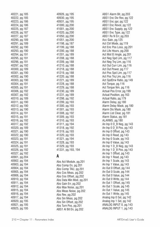
210 • Chapter 11 - Parameters Index ARTDriveS User’s Guide
40221, pg.18540222, pg.18540223, pg.18640224, pg.18640225, pg.18740226, pg.18740227, pg.18740290, pg.18940291, pg.18940292, pg.19040293, pg.19040294, pg.19140295, pg.19140296, pg.19140297, pg.19240300, pg.18940301, pg.19040302, pg.19040303, pg.19040304, pg.19140305, pg.19140306, pg.19240307, pg.19240310, pg.18940311, pg.19040312, pg.19040313, pg.19040314, pg.19140315, pg.19140316, pg.19240317, pg.19240320, pg.18940321, pg.19040322, pg.19040323, pg.19140324, pg.19140325, pg.19140326, pg.19240327, pg.19240901, pg.20440902, pg.19440903, pg.19440904, pg.19440905, pg.19440906, pg.19440910, pg.19440911, pg.19440912, pg.19440915, pg.19440916, pg.19440917, pg.19440920, pg.19540921, pg.19540925, pg.195
40926, pg.19540930, pg.19540931, pg.19541000, pg.20041001, pg.20041020, pg.20041050, pg.20041051, pg.20041198, pg.18741199, pg.18841200, pg.18841201, pg.18941208, pg.18841209, pg.18841210, pg.18841218, pg.18841219, pg.18841220, pg.18841221, pg.18941228, pg.18841229, pg.18841230, pg.18941231, pg.18941298, pg.19241299, pg.19341300, pg.19341301, pg.19341308, pg.19241309, pg.19341310, pg.19341311, pg.19441318, pg.19241319, pg.19341320, pg.19341321, pg.19441328, pg.19341329, pg.19341331, pg.193, 194
AAbs Act Module, pg.201Abs Comp En, pg.201Abs Comp TAU, pg.201Abs Cos Meas, pg.202Abs Cos Offset, pg.202Abs Data Min Mod, pg.201Abs Gain Err, pg.202Abs Max Noise, pg.201Abs Meas Noise, pg.202Abs Rev, pg.202Abs Sin Meas, pg.202Abs Sin Offset, pg.202Abs Turn Pos, pg.201ABS1 Al Bit En, pg.202
ABS1 Alarm Bit, pg.203ABS1 Enc Div Rev, pg.122ABS1 Enc ppr, pg.122ABS1 Enc Revol, pg.122ABS1 Enc Supply, pg.122ABS1 Enc Type, pg.122ABS1 Rx N Err, pg.203Acc Gain, pg.125Act Ctrl Mode, pg.119Act Enc Pos Loss, pg.201Act Life Hours, pg.200Act Mot El Angle, pg.201Act Neg Spd Lim, pg.117Act Neg Trq Lim, pg.116Act Out Curr Lim, pg.116Act Out Power, pg.117Act Pos Spd Lim, pg.117Act Pos Trq Lim, pg.116Act SpdDrw Ratio, pg.149Act Torque, pg.116Act Torque Nm, pg.116Actual Pos Error, pg.199Actual Position, pg.163Actual Ratio, pg.179Alarm Delay, pg.180Alarm Delay Mask, pg.180Alarm Dis Mask, pg.180Alarm List Clear, pg.181Alarm Status, pg.181ALARMS, pg.180An Inp 0 D_B Neg, pg.143An Inp 0 D_B Pos, pg.143An Inp 0 Offset, pg.143An Inp 0 Read, pg.143An Inp 0 Scale, pg.143An Inp 0 Value, pg.143An Inp 1 D_B Neg, pg.143An Inp 1 D_B Pos, pg.143An Inp 1 Offset, pg.143An Inp 1 Read, pg.143An Inp 1 Scale, pg.143An Inp 1 Value, pg.143An Out 0 Offset, pg.144An Out 0 Scale, pg.144An Out 0 Value, pg.144An Out 0 Write, pg.144An Out 1 Offset, pg.145An Out 1 Scale, pg.145An Out 1 Value, pg.145An Out 1 Write, pg.145Analog Inp 0 Sel, pg.142Analog Inp 1 Sel, pg.142ANALOG INPUT 0, pg.143ANALOG INPUT 1, pg.143

ARTDriveS User’s Guide Chapter 11 - Parameters Index • 211
ANALOG INPUTS, pg.141ANALOG OUT 0, pg.144Analog Out 0 Sel, pg.143ANALOG OUT 1, pg.145Analog Out 1 Sel, pg.144ANALOG OUTPUTS, pg.143ANALOG POS REF, pg.165AnOut MaxPosErr, pg.144Application Sel, pg.195Arms Conv Fact, pg.195AUTOTUNING, pg.195Aux Enc Type, pg.122Aux Phase Exe T, pg.204
BBack Lash Dir, pg.176Back Lash En, pg.175BACKLASH RECOV, pg.175Base Torque, pg.116, 127Bkg Tsk Exe T, pg.205BR Ovld Factor, pg.180Brake Config, pg.180BRAKE CONTROL, pg.151Brake Enable, pg.152Brake ON Delay, pg.152Brake ON Spd Thr, pg.152Brake Res Power, pg.180Brake Res Value, pg.180Brake Volt Thr, pg.203BRAKING RES, pg.180Bus Address, pg.184Bus Baude Rate, pg.184
CCANOPEN, pg.194CC Enabling, pg.184CCW Acc Ramp, pg.123CCW Dec Ramp, pg.123CCW Home Pos Acc, pg.174CCW Home Pos Dec, pg.174CCW Jog Acc, pg.146CCW Jog Dec, pg.147CCW Rev Test Gen, pg.196COBID Em Obj, pg.194COMM CONFIG, pg.119Control Mode, pg.118COUNTER, pg.200CPU Err Al Cause, pg.182Curr Comp Time, pg.203Curr Deriv Gain, pg.128Curr Gain Calc, pg.128Curr Integr Gain, pg.127Curr Prop Gain, pg.127
CURR TEST GEN, pg.196CURRENT GAINS, pg.127Cus OBJ Idx Mode, pg.194CW Acc Ramp, pg.123CW Dec Ramp, pg.123CW Home Pos Acc, pg.174CW Home Pos Dec, pg.174CW Jog Acc, pg.146CW Jog Dec, pg.147CW Rev Test Gen, pg.196
DDC Link Voltage, pg.117DEBUG, pg.204Debug Mode, pg.204Delta Pos, pg.176Destination Pos, pg.163DeviceNet Enable, pg.200Dig Inp 0 Status, pg.132Dig Inp Rev Mask, pg.132Dig Inp Status, pg.132Dig Out Reverse, pg.138Dig Out Status, pg.139Digital Input 1, pg.128Digital Input 2, pg.131Digital Input 3, pg.131Digital Input 4, pg.131Digital Input 5, pg.132Digital Input 6, pg.132Digital Input 7, pg.132DIGITAL INPUTS, pg.128Digital Output 0, pg.136Digital Output 1, pg.138Digital Output 2, pg.138Digital Output 3, pg.138Digital Output 4, pg.138Digital Output 5, pg.138DIGITAL OUTPUTS, pg.136Direct Volt, pg.204DNet En Key Stat, pg.200DO Reset at Fail, pg.136DO Set at Fail, pg.136DRIVE CONFIG, pg.118Drive Max Curr, pg.118Drive Nom Curr, pg.119Drive Ovld Fact, pg.117Drive Serial Add, pg.119Drive size, pg.119Drv Nom Curr 0Hz, pg.119DSP Exe Time, pg.205
EEL LINE SHAFT, pg.176
EL SHAFT R BEND, pg.179EL SHAFT RATIO, pg.179Els Control Mode, pg.178Els Delta Ratio, pg.178Els Delta Time, pg.177Els FL Source, pg.178Els Master Sel, pg.177Els Max RB Speed, pg.179Els Mec Ratio, pg.178Els PPR Master, pg.177Els Ratio / Slip, pg.178Els Ratio 0, pg.179Els Ratio 1, pg.179Els Ratio 2, pg.179Els Ratio 3, pg.179Els Ratio Index, pg.179Els Ratio Range, pg.178Els RB Acc, pg.179Els RB Dec, pg.179Els RB Speed Ref, pg.179Els RB Time, pg.179Els Slip Limit, pg.178ElsMec Ratio Div, pg.178ElsMec Ratio Mul, pg.178En Keys Mask, pg.200Enable I-O Keys, pg.119ENABLE KEYS, pg.199Enc Err Simul, pg.146ENC EXP BOARD, pg.122Enc Inc Index, pg.200Enc Inc Tracks, pg.200Enc M Lost Puls, pg.200Enc Mech Offset, pg.196Enc No Idx Range, pg.200Enc Offset, pg.196Enc Postition, pg.117Enc Rep Sim Cfg, pg.146ENC REPETITION, pg.145Enc Revolution, pg.117Enc W->A Mask, pg.182Enc Warning Cause, pg.181ENCODER, pg.200ENCODER PARAM, pg.121End Run Dec, pg.123EnDat Del Comp, pg.123Environment Temp, pg.118ExAn Out 0 Offse, pg.145ExAn Out 0 Scale, pg.145ExAn Out 0 Value, pg.145ExAn Out 0 Write, pg.145ExAn Out 1 Offse, pg.145ExAn Out 1 Scale, pg.145ExAn Out 1 Value, pg.145ExAn Out 1 Write, pg.145

212 • Chapter 11 - Parameters Index ARTDriveS User’s Guide
EXP ABS1 Hw Rev, pg.202EXP ABS1 Pos, pg.202EXP ABS1 Sw Rev, pg.202EXP AN OUT 0, pg.145EXP AN OUT 1, pg.145EXP ANALOG OUT, pg.145Exp Analog Out 0, pg.145Exp Analog Out 1, pg.145Exp Dig Inp 0, pg.132Exp Dig Inp 1, pg.132Exp Dig Inp 2, pg.132Exp Dig Inp 3, pg.133Exp Dig Inp 4, pg.133Exp Dig Inp 5, pg.133Exp Dig Inp 6, pg.133Exp Dig Inp 7, pg.133Exp Dig Inp Stat, pg.133EXP DIG INPUTS, pg.132Exp Dig Out 1, pg.139Exp Dig Out 2, pg.139Exp Dig Out 3, pg.139Exp Dig Out 4, pg.139Exp Dig Out 5, pg.139Exp Dig Out 6, pg.139Exp Dig Out 7, pg.139Exp Dig Out Stat, pg.140EXP DIG OUTPUTS, pg.139EXP ENC ABS1, pg.202
FFast Link Addr, pg.120FAST LINK ENC, pg.203Fast Stop Dec, pg.123FastLink Trq En, pg.127FastLink Trq Ref, pg.127FB 10th M->S PAR, pg.188FB 10th S->M PAR, pg.193FB 11th M->S PAR, pg.188FB 11th S->M PAR, pg.193FB 12th M->S PAR, pg.189FB 12th S->M PAR, pg.193FB 1st M->S PAR, pg.184FB 1st S->M PAR, pg.189FB 2nd S->M PAR, pg.189FB 2ndM->S PAR, pg.185FB 3rd M->S PAR, pg.185FB 3rd S->M PAR, pg.190FB 4th M->S PAR, pg.185FB 4th S->M PAR, pg.190FB 5th M->S PAR, pg.186FB 5th S->M PAR, pg.191FB 6th M->S PAR, pg.186FB 6th S->M PAR, pg.191
FB 7th M->S PAR, pg.187FB 7th S->M PAR, pg.191FB 8th M->S PAR, pg.187FB 8th S->M PAR, pg.192FB 9th M->S PAR, pg.187FB 9th S->M PAR, pg.192FB Alarm Watch, pg.184FB Assign M->S 10, pg.188FB Assign M->S 11, pg.188FB Assign M->S 12, pg.189FB Assign M->S 2, pg.185FB Assign M->S 3, pg.185FB Assign M->S 4, pg.185FB Assign M->S 5, pg.186FB Assign M->S 6, pg.186FB Assign M->S 7, pg.187FB Assign M->S 8, pg.187FB Assign M->S 9, pg.187FB Assign S->M 1, pg.189FB Assign S->M 10, pg.193FB Assign S->M 11, pg.193FB Assign S->M 12, pg.193FB Assign S->M 2, pg.189FB Assign S->M 3, pg.190FB Assign S->M 4, pg.190FB Assign S->M 5, pg.191FB Assign S->M 6, pg.191FB Assign S->M 7, pg.191FB Assign S->M 8, pg.192FB Assign S->M 9, pg.192FB Exp M->S 1, pg.185FB Exp M->S 10, pg.188FB Exp M->S 11, pg.189FB Exp M->S 12, pg.189FB Exp M->S 2, pg.185FB Exp M->S 3, pg.185FB Exp M->S 4, pg.186FB Exp M->S 5, pg.186FB Exp M->S 6, pg.187FB Exp M->S 7, pg.187FB Exp M->S 8, pg.187FB Exp M->S 9, pg.188FB Exp S->M 1, pg.189FB Exp S->M 10, pg.193FB Exp S->M 11, pg.193FB Exp S->M 12, pg.194FB Exp S->M 2, pg.190FB Exp S->M 3, pg.190FB Exp S->M 4, pg.191FB Exp S->M 5, pg.191FB Exp S->M 6, pg.191FB Exp S->M 7, pg.192FB Exp S->M 8, pg.192FB Exp S->M 9, pg.193
FB Fail Cause, pg.184FB Format M->S, pg.185FB Format M->S 1, pg.184FB Format M->S 10, pg.188FB Format M->S 11, pg.188FB Format M->S 12, pg.189FB Format M->S 3, pg.185FB Format M->S 4, pg.186FB Format M->S 5, pg.186FB Format M->S 6, pg.186FB Format M->S 7, pg.187FB Format M->S 8, pg.187FB Format M->S 9, pg.188FB Format S->M 1, pg.189FB Format S->M 10, pg.193FB Format S->M 11, pg.193FB Format S->M 12, pg.194FB Format S->M 2, pg.190FB Format S->M 3, pg.190FB Format S->M 4, pg.190FB Format S->M 5, pg.191FB Format S->M 6, pg.191FB Format S->M 7, pg.192FB Format S->M 8, pg.192FB Format S->M 9, pg.192FB IPA M->S 1, pg.184FB IPA M->S 10, pg.188FB IPA M->S 11, pg.188FB IPA M->S 12, pg.189FB IPA M->S 2, pg.185FB IPA M->S 3, pg.185FB IPA M->S 4, pg.186FB IPA M->S 5, pg.186FB IPA M->S 6, pg.186FB IPA M->S 7, pg.187FB IPA M->S 8, pg.187FB IPA M->S 9, pg.188FB IPA S->M 1, pg.189FB IPA S->M 10, pg.193FB IPA S->M 11, pg.193FB IPA S->M 12, pg.194FB IPA S->M 2, pg.190FB IPA S->M 3, pg.190FB IPA S->M 4, pg.190FB IPA S->M 5, pg.191FB IPA S->M 6, pg.191FB IPA S->M 7, pg.192FB IPA S->M 8, pg.192FB IPA S->M 9, pg.192FBCFG, pg.204Field Bus Status, pg.184FIELDBUS, pg.183FL Trq Scale, pg.127Float Word Order, pg.184

ARTDriveS User’s Guide Chapter 11 - Parameters Index • 213
FLUX, pg.128Flux Current, pg.116Fst Tsk Exe T, pg.204FstLnk Slow Sync, pg.120Full Scale Speed, pg.124FW Build Number, pg.199FW Version, pg.117
GGuard Time, pg.194
HHeatsink Temp, pg.117Hig Curr Ref Gen, pg.196Home Fine Spd, pg.174Home Max Spd, pg.174Home Pos Offs En, pg.175Home Pos Offset, pg.174Home Spd Ref, pg.174Home Src Direc, pg.174
IInc A Data Count, pg.201Inc B Data Count, pg.201Inc Data Act Mod, pg.201Inc Data Min Mod, pg.201Inc Data N Rev, pg.201Inc Data Pos, pg.201Inc Pulses / Rev, pg.201Index Offset Sim, pg.146Index Position, pg.201Index Puls Simul, pg.146Inertia, pg.125Inertia Filter, pg.125Inp Phase Exe T, pg.204Inside Index Src, pg.174Intake Air Temp, pg.117IPA 1 Par Set, pg.182IPA 2 Par Set, pg.182
JJOG FUNCTION, pg.146Jog Reference, pg.146Jog Speed Limit, pg.146
KKEYPAD, pg.119KEYPAD KEY, pg.199Keypad Key Word, pg.199KEYPAD PSW, pg.197Keypad PSWD, pg.197
LLife Time Factor, pg.194LKG Inductance, pg.120, 196Load Def Counter, pg.200Load Def Err IPA, pg.183Load Default Par, pg.117Load Param PAD, pg.117Loss Active, pg.153Low Curr Ref Gen, pg.196
MM Ramp 1 CCW Acc, pg.149M Ramp 1 CCW Dec, pg.149M Ramp 1 CW Acc, pg.148M Ramp 1 CW Dec, pg.149M Ramp 2 CCW Acc, pg.149M Ramp 2 CCW Dec, pg.149M Ramp 2 CW Acc, pg.149M Ramp 2 CW Dec, pg.149M Ramp 3 CCW Acc, pg.149M Ramp 3 CCW Dec, pg.149M Ramp 3 CW Acc, pg.149M Ramp 3 CW Dec, pg.149Mains Voltage, pg.118Max Brake Energy, pg.180Max Deflux Curr, pg.128Max Loss Pos, pg.200Max Neg Torque, pg.127Max Ovld Curr, pg.119Max Pos Error, pg.199Max Pos Torque, pg.127Max Preset Value, pg.164Max Prs Abs Val, pg.164Max Ramp Rate, pg.124Max Torque, pg.127MaxAux Ph Exe T, pg.204MaxBkg Tsk Exe T, pg.204MaxDSP Exe T, pg.204MaxFst Tsk Exe T, pg.204MaxIn Ph Exe T, pg.204MaxOut Ph Exe T, pg.204MaxSl Tsk Exe T, pg.204MaxSys Tsk Exe T, pg.204Measured Speed, pg.204Min Preset Value, pg.164Min Prs Abs Val, pg.164Modbus IPA Ofst, pg.199Mot Enc Source, pg.121Mot Nom K Torque, pg.120Mot Nominal Curr, pg.120Mot Ovld Control, pg.120Mot Ovld Factor, pg.120Mot Ovld Time, pg.120
Mot Thermal Prot, pg.120MOTOR DATA, pg.120MOTOR OVERLOAD, pg.120MOTOR PARAM, pg.120Motor Poles, pg.120MOTOR POT, pg.149Motor Pot Acc, pg.150Motor Pot Dec, pg.150Motor Pot Dir, pg.151Motor Pot En, pg.150Motor Pot Init, pg.150Motor Pot Lo Lim, pg.150Motor Pot Memo, pg.151Motor Pot Mode, pg.151Motor Pot Output, pg.151Motor Pot Reset, pg.151Motor Pot Up Lim, pg.150Motor Speed, pg.116MPos 0 Next Pos, pg.165MPos 1 Next Pos, pg.166MPos 2 Next Pos, pg.167MPos 3 Next Pos, pg.168MPos 4 Next Pos, pg.168MPos 5 Next Pos, pg.169MPos 6 Next Pos, pg.170MPos 7 Next Pos, pg.170Multi Pos Enable, pg.161Multi Pos Index, pg.163Multi Ramp Conf, pg.148Multi Ramp Index, pg.148Multi Spd Index, pg.148Multi Speed 1, pg.147Multi Speed 2, pg.147Multi Speed 3, pg.147Multi Speed 4, pg.147Multi Speed 5, pg.147Multi Speed 6, pg.147Multi Speed 7, pg.147Multi Speed Conf, pg.148MULTIRAMP, pg.148MULTIRAMP 1, pg.148MULTIRAMP 2, pg.149MULTIRAMP 3, pg.149MULTISPEED, pg.147
NNeg Speed Limit, pg.125
OOut Current, pg.116Out Frequency, pg.117Out Phase Tsk T, pg.204Out Vlt Max Lim, pg.128

214 • Chapter 11 - Parameters Index ARTDriveS User’s Guide
Out Volt Filter, pg.128Output Voltage, pg.117Over Mod Factor, pg.203Overload Control, pg.118
PP Loss Int Gain, pg.153P Loss NoRes Thr, pg.153P Loss Prop Gain, pg.153P Loss Ramp, pg.153P Loss Spd 0 Thr, pg.153P Loss Trq Lim, pg.153P Loss Volt Ref, pg.153Par Set Cause Al, pg.182PDC Enabling, pg.184PDO 1 RX, pg.194PDO 1 RX COBID, pg.194PDO 1 RX TYPE, pg.194PDO 1 TX, pg.195PDO 1 TX COBID, pg.195PDO 1 TX INH, pg.195PDO 1 TX TYPE, pg.195PDO 2 RX, pg.194PDO 2 RX COBID, pg.194PDO 2 RX TYPE, pg.194PDO 2 TX, pg.195PDO 2 TX INH, pg.195PDO 2 TX TYPE, pg.195PDO 3 RX, pg.194PDO 3 RX COBID, pg.194PDO 3 RX TYPE, pg.194PDO 3 TX, pg.195PDO 3 TX COBID, pg.195PDO 3 TX INH, pg.195PDO 3 TX TYPE, pg.195Period Test Gen, pg.196PHASING, pg.196Phasing Speed, pg.196PL Mains status, pg.153PLC Correct ChkS, pg.204PLC En Key Stat, pg.200PLC Enable Key, pg.200PLC Err Cause, pg.183PLC Saved ChkS, pg.204Pos 0 Progress, pg.165Pos 0 Thr Offset, pg.164Pos 1 Progress, pg.166Pos 2 Progress, pg.167Pos 3 Progress, pg.167Pos 4 Progress, pg.168Pos 5 Progress, pg.169Pos 6 Progress, pg.169Pos 7 Progress, pg.170
Pos Abs Thr, pg.164Pos Actual Event, pg.163Pos An Filter, pg.165Pos An Mode, pg.166Pos An Stdy Wind, pg.165Pos An Wind Del, pg.165Pos CCW Acc, pg.162Pos CCW Acc 0, pg.165Pos CCW Acc 1, pg.166Pos CCW Acc 3, pg.167Pos CCW Acc 4, pg.168Pos CCW Acc 5, pg.169Pos CCW Acc 6, pg.169Pos CCW Acc 7, pg.170Pos CCW Dec, pg.162Pos CCW Dec 0, pg.165Pos CCW Dec 1, pg.166Pos CCW Dec 2, pg.167Pos CCW Dec 3, pg.167Pos CCW Dec 4, pg.168Pos CCW Dec 5, pg.169Pos CCW Dec 6, pg.169Pos CCW Dec 7, pg.170Pos Conv Fact, pg.195Pos CW Acc, pg.162Pos CW Acc 0, pg.165Pos CW Acc 1, pg.166Pos CW Acc 2, pg.166Pos CW Acc 3, pg.167Pos CW Acc 4, pg.168Pos CW Acc 5, pg.168Pos CW Acc 6, pg.169Pos CW Acc 7, pg.170Pos CW Dec, pg.162Pos CW Dec 0, pg.165Pos CW Dec 1, pg.166Pos CW Dec 2, pg.166Pos CW Dec 3, pg.167Pos CW Dec 4, pg.168Pos CW Dec 5, pg.168Pos CW Dec 6, pg.169Pos CW Dec 7, pg.170Pos Dwell 0, pg.165Pos Dwell 1, pg.166Pos Dwell 2, pg.167Pos Dwell 3, pg.167Pos Dwell 4, pg.168Pos Dwell 5, pg.169Pos Dwell 6, pg.169Pos Dwell 7, pg.170Pos Event 0, pg.165Pos Event 1, pg.166Pos Event 2, pg.167Pos Event 3, pg.168
Pos Event 4, pg.168Pos Event 5, pg.169Pos Event 6, pg.170Pos Event 7, pg.170Pos Exceeded, pg.164POS PRESET 6, pg.169POS PRESET 7, pg.170POS PRESET (8-63), pg.170POS PRESET 0, pg.165Pos Preset 0, pg.165POS PRESET 1, pg.166Pos Preset 1, pg.166POS PRESET 2, pg.166Pos Preset 2, pg.166POS PRESET 3, pg.167Pos Preset 3, pg.167POS PRESET 4, pg.168Pos Preset 4, pg.168POS PRESET 5, pg.168Pos Preset 5, pg.168Pos Preset 6, pg.169Pos Preset 63, pg.170Pos Preset 7, pg.170Pos Preset 8, pg.170Pos Reach Behav, pg.162Pos Return, pg.175Pos Return Acc, pg.175POS RETURN CONF, pg.175Pos Return Dec, pg.175Pos Return Speed, pg.175Pos Speed 0, pg.165Pos Speed 1, pg.166Pos Speed 2, pg.166Pos Speed 3, pg.167Pos Speed 4, pg.168Pos Speed 5, pg.168Pos Speed 6, pg.169Pos Speed 7, pg.170Pos Speed Limit, pg.125Pos Stop Dec, pg.163Pos Thr Close 1, pg.164Pos Thr Close 2, pg.164POS THR CONFIG, pg.164Pos Window, pg.164Pos Window Time, pg.164Pos Window Tout, pg.164POSITION, pg.154Position Config, pg.163Position Gain, pg.125Position I Gain, pg.125POSITION LIMIT, pg.164Position Mode, pg.163Position Speed, pg.162Position Torque, pg.164

ARTDriveS User’s Guide Chapter 11 - Parameters Index • 215
Power Fail Count, pg.200POWERLOSS, pg.152Powerloss Config, pg.153PPR Simulation, pg.146Preset Index, pg.163PWM Frequency, pg.118
QQuadrature Volt, pg.204
RRAMP, pg.123Ramp Enable, pg.123Ramp Exp Factor, pg.124Ramp Output, pg.116Ramp Reference, pg.116Reg Card Temp, pg.117Res Shift Time, pg.201RESERVED, pg.203Resolver Gain, pg.201Resolver Poles, pg.122Rpm Conv Fact, pg.195RX Pos, pg.203RX Pos Aux, pg.203RX Rev, pg.203RX Rev Aux, pg.203
SSAVE / LOAD PAR, pg.117Save Param Count, pg.200Save Param PAD, pg.117Save Parameters, pg.117Ser Num En Keys, pg.200Serial Baud Rate, pg.119Serial Del Time, pg.120Serial Line Conf, pg.119Serial Prot Type, pg.119SERVICE, pg.199Slow Tsk Exe T, pg.204SPD / POS GAIN, pg.125Spd Loop Filter, pg.203Spd-Pos Enc Sour, pg.121SPD/POS TESTGEN, pg.196SPEED, pg.124Speed Comp, pg.176SPEED DRAW, pg.149Speed Draw In, pg.149Speed Draw Out, pg.149Speed Draw Ratio, pg.149Speed Gain, pg.125Speed Reach Wnd, pg.125Speed Ref 1, pg.124Speed Reference, pg.116
Speed Test Gen, pg.196Speed Thr, pg.125Speed Thr Delay, pg.125Speed Thr Wnd, pg.125Speed Zero Delay, pg.125Speed Zero Thr, pg.125Start on Edge, pg.162Start Status, pg.116Startup Zero Pos, pg.175Stop by Ramp, pg.162SW Reset Count, pg.200Sync Period, pg.194Sys Tsk Exe T, pg.205
TTASK MEASURES, pg.204Test Gen Ref, pg.196TEST GENERATOR, pg.196TORQUE, pg.126Torque Conv Fact, pg.195Torque Current, pg.116Torque Mode, pg.126Torque Reduction, pg.127Torque Ref 1, pg.126Torque Ref 2, pg.126Torque Thr, pg.127Torque Thr Delay, pg.127Tot Life Hours, pg.200Trq Lim Config, pg.127Trq Speed Limit, pg.127TUNING, pg.195Tuning Status, pg.195TX Pos, pg.203TX Rev, pg.203
UUnit Per Div, pg.161Unit Per Rev, pg.161UNITS, pg.195User Vlt Max Lim, pg.128
VVirt DI at Dis, pg.135Virt DI at Reset, pg.135Virt DI at Start, pg.135Virt DI Status, pg.134Virt Dig Inp 0, pg.133Virt Dig Inp 1, pg.133Virt Dig Inp 10, pg.134Virt Dig Inp 11, pg.134Virt Dig Inp 12, pg.134Virt Dig Inp 13, pg.134Virt Dig Inp 14, pg.134
Virt Dig Inp 15, pg.134Virt Dig Inp 2, pg.133Virt Dig Inp 3, pg.133Virt Dig Inp 4, pg.133Virt Dig Inp 5, pg.134Virt Dig Inp 6, pg.134Virt Dig Inp 7, pg.134Virt Dig Inp 8, pg.134Virt Dig Inp 9, pg.134VIRT DIG INPUTS, pg.133Virt Dig Out 0, pg.140Virt Dig Out 1, pg.140Virt Dig Out 10, pg.140Virt Dig Out 11, pg.140Virt Dig Out 12, pg.140Virt Dig Out 13, pg.141Virt Dig Out 14, pg.141Virt Dig Out 15, pg.141Virt Dig Out 2, pg.140Virt Dig Out 3, pg.140Virt Dig Out 4, pg.140Virt Dig Out 5, pg.140Virt Dig Out 6, pg.140Virt Dig Out 7, pg.140Virt Dig Out 8, pg.140Virt Dig Out 9, pg.140VIRT DIG OUTPUTS, pg.140Virt DO at Fail, pg.141Virt DO at Reset, pg.141Virt DO Status, pg.141Volt Int Gain, pg.128Volt Prop Gain, pg.128
WWarning Status, pg.181
XXE Enc Abs Flt, pg.203XE ENC ABS MEAS, pg.201XE ENC INC MEAS, pg.201XE Enc ppr, pg.122XE Enc Supply, pg.122XE Enc Type, pg.121XE Hall Meas, pg.202XE Hall N Error, pg.202XE Hall Pos, pg.202XE Hall Rev, pg.202XE HALL TRACKS, pg.202XE Inc Enc Flt, pg.203XE Index Mask, pg.203XER Enc Supply, pg.122XER/EXP Enc Flt, pg.203XER/EXP Enc Mod, pg.203

216 • Chapter 11 - Parameters Index ARTDriveS User’s Guide
XER/EXP Enc ppr, pg.122XER/EXP Ind Pos, pg.202XER/EXP Puls Rev, pg.202XER/EXP Rev, pg.202XER/EXP Turn Pos, pg.202
ZZERO FOUND CONF, pg.171Zero Index En, pg.174Zero Sensor Edge, pg.175Zero Sensor En, pg.174
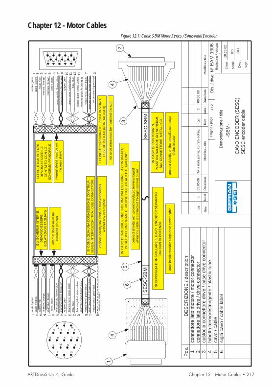
ARTDriveS User’s Guide Chapter 12 - Motor Cables • 217
Chapter 12 - Motor CablesFigure 12.1: Cable SBM Motor Series / Sinusoidal Encoder
10
11
12
13
2
4
3
SE
SC
-SB
M
INC
AS
OD
IC
US
TO
DIA
IN
PL
AS
TIC
AS
AL
DA
RE
GL
IS
CH
ER
MI
SU
LC
ON
NE
TT
OR
EM
ETA
LL
ICO
INC
AS
OD
IIN
TE
RR
UZ
ION
EIN
TE
RM
ED
IAE
SE
GU
IRE
LA
CO
NT
INU
ITA
'
DE
GL
IS
CH
ER
MIT
RA
MIT
EM
OR
SE
TT
OIS
OL
AT
OD
AL
GR
OU
ND
IC
ON
DU
TT
OR
IN
ON
UT
ILIZ
ZA
TI
DE
VO
NO
ES
SE
RE
ISO
LA
TI
(NO
NTA
GL
IAT
I)
SI
CO
NS
IGL
IAU
NA
CO
NN
ES
SIO
NE
CO
NT
INU
A
SE
NZ
AIN
TE
RR
UZ
ION
IT
RA
ID
UE
CO
NN
ET
TO
RI
SI
CO
NS
IGL
IAD
IIN
STA
LL
AR
EIL
CA
VO
EN
CO
DE
RS
EP
AR
AT
O
DA
IC
AV
ID
IP
OT
EN
ZA
B
C
D
E
R V
S
P
A
G
F
N
M
U
TH
J
L
K
5 4
10
3 1
7
2
9 8 6
1112131415
GL
IS
CH
ER
MI
INT
ER
NI
DE
VO
NO
ES
SE
RE
ISO
LA
TI
(NO
NTA
GL
IAT
I)
ve
rde
/g
ree
n
ma
rro
ne
-gia
llo/
bro
wn
-ye
llow
ara
ncio
/o
ran
ge
ma
rro
ne
/b
row
n
ne
ro/
bla
ck
ma
rro
ne
-blu
/b
row
n-b
lue
gia
llo/
ye
llow
ma
rro
ne
-ro
sso
/b
row
n-r
ed
grig
io/
gre
y
bia
nco
-ne
ro/
wh
ite
-bla
ck
blu
/b
lue
bia
nco
-gia
llo/
wh
ite
-ye
llow
rosso
/re
d
ve
rde
-ro
sso
/g
ree
n-r
ed
ve
rde
-ne
ro/
gre
en
-bla
ck
ma
rro
ne
-grig
io/b
row
n-g
rey
GL
IS
CH
ER
MI
INT
ER
NI
DE
VO
NO
ES
SE
RE
A
CO
NTA
TT
OC
ON
LO
SC
HE
RM
OP
RIN
CIP
AL
E
SE
SC
-SB
M
14
5
DE
SC
RIZ
ION
E/
de
scrip
tio
n
co
nn
ett
ore
lato
mo
tore
/m
oto
rco
nn
ecto
rco
nn
ett
ore
lato
drive
/d
rive
co
nn
ecto
rcu
sto
dia
co
nn
ett
ore
drive
/ca
se
drive
co
nn
ecto
r
tub
ett
ote
rmo
restr
ing
en
te/
pla
stic
tub
eca
vo
/ca
ble
sig
laca
vo
/ca
ble
lab
el
Po
s.
1 2 3 4 5 6
6
231 4 5 6 78 9
TMJ N L K AH P F E C D B
ve
rde
/g
ree
n
ara
ncio
/o
ran
ge
ma
rro
ne
/b
row
n
ne
ro/
bla
ck
ma
rro
ne
-blu
/b
row
n-b
lue
gia
llo/
ye
llow
ma
rro
ne
-ro
sso
/b
row
n-r
ed
grig
io/
gre
y
blu
/b
lue
rosso
/re
d
ma
rro
ne
-gia
llo/
bro
wn
-ye
llow
bia
nco
-ne
ro/
wh
ite
-bla
ck
bia
nco
-gia
llo/
wh
ite
-ye
llow
ve
rde
-ro
sso
/g
ree
n-r
ed
ve
rde
-ne
ro/
gre
en
-bla
ck
ma
rro
ne
-grig
io/b
row
n-g
rey
inte
rna
lsh
ield
mu
st
be
insu
late
d(n
ocu
t)
sch
erm
o/
sh
ield
inte
rna
lsh
ield
mu
st
be
on
the
ma
insh
ield
no
tu
se
dw
ire
sm
ust
be
insu
late
d(n
ocu
t)
co
nn
ect
dire
ctly
the
ca
ble
tob
oth
co
nn
ecto
rs
with
ou
ta
ny
inte
rru
ptio
n
co
nn
ect
sh
ield
sw
ith
gro
un
din
su
late
dte
rmin
alb
oa
rd
wh
en
the
ca
ble
isco
nn
ecte
dth
rou
gh
term
ina
lb
oa
rd
co
nn
ect
sh
ield
so
nth
em
eta
llic
co
nn
ecto
r
ifp
lastic
ca
se
do
n't
insta
lle
nco
de
rca
ble
ne
ar
po
we
rca
ble
Denom
inazio
ne
/title
CA
VO
EN
CO
DE
R(S
ES
C)
SE
SC
en
co
de
rca
ble
Dis
./dw
g.N
°E
AM
19
06
Da
te
Sca
le
Dw
g.
sig
n
DL
L
Pa
gin
a/
pa
ge
1/
2
Re
vis
ion
e/
rele
ase
18
.10
.02
0
Modific
a/
title
Da
ta/d
ate
lab
el
00
.00
.00
Re
v.M
odific
a/
title
Da
ta/d
ate
lab
el
Re
v.
00
0
0:0
-SB
M-
05
.05
.06
00
1To
lta
no
tap
on
te,
co
rre
ttico
lleg
.
S7

218 • Chapter 12 - Motor Cables ARTDriveS User’s Guide
Denom
inazio
ne
/title
CA
VO
EN
CO
DE
R(D
EH
S)
DE
HS
en
co
de
rca
ble
Dis
./dw
g.N
°E
AM
19
06
/1
Da
te
Sca
le
Dw
g.
sig
n
DL
L
Pa
gin
a/
pa
ge
1/
2
Re
vis
ion
e/
rele
ase
18
.10
.02
0
Modific
a/
title
Da
ta/d
ate
lab
el
00
.00
.00
Re
v.M
odific
a/
title
Da
ta/d
ate
lab
el
05
.05
.06
Re
v.
00
01
00
0:0
10 712
2
4
3
DE
HS
-SB
M
INC
AS
OD
IC
US
TO
DIA
IN
PL
AS
TIC
AS
AL
DA
RE
GL
IS
CH
ER
MI
SU
LC
ON
NE
TT
OR
EM
ETA
LL
ICO
INC
AS
OD
IIN
TE
RR
UZ
ION
EIN
TE
RM
ED
IAE
SE
GU
IRE
LA
CO
NT
INU
ITA
'
DE
GL
IS
CH
ER
MIT
RA
MIT
EM
OR
SE
TT
OIS
OL
AT
OD
AL
GR
OU
ND
IC
ON
DU
TT
OR
IN
ON
UT
ILIZ
ZA
TI
DE
VO
NO
ES
SE
RE
ISO
LA
TI
(NO
NTA
GL
IAT
I)
SI
CO
NS
IGL
IAU
NA
CO
NN
ES
SIO
NE
CO
NT
INU
A
SE
NZ
AIN
TE
RR
UZ
ION
IT
RA
ID
UE
CO
NN
ET
TO
RI
SI
CO
NS
IGL
IAD
IIN
STA
LL
AR
EIL
CA
VO
EN
CO
DE
RS
EP
AR
AT
OD
AI
CA
VI
DI
PO
TE
NZ
A
B
C
D
E
R V
S
P
A
G
F
N
M
U
TH
J
L
K
5 410
3 1
7
2
9 8 611
12
13
14
15
GL
IS
CH
ER
MI
INT
ER
NI
DE
VO
NO
ES
SE
RE
ISO
LA
TI
(NO
NTA
GL
IAT
I)
ve
rde
/g
ree
n
ma
rro
ne
-gia
llo/
bro
wn
-ye
llow
ara
ncio
/o
ran
ge
ma
rro
ne
/b
row
n
ne
ro/B
lack
ma
rro
ne
-blu
/b
row
n-b
lue
gia
llo/
ye
llow
ma
rro
ne
-ro
sso
/b
row
n-r
ed
grig
io/
gre
y
bia
nco
-ne
ro/
wh
ite
-bla
ck
blu
/b
lue
bia
nco
-gia
llo/
wh
ite
-ye
llow
rosso
/re
d
ve
rde
-ro
sso
/g
ree
n-r
ed
ve
rde
-ne
ro/
gre
en
-bla
ck
ma
rro
ne
-grig
io/b
row
n-g
rey
GL
IS
CH
ER
MI
INT
ER
NI
DE
VO
NO
ES
SE
RE
A
CO
NTA
TT
OC
ON
LO
SC
HE
RM
OP
RIN
CIP
AL
E
DE
HS
-SB
M
14
5
DE
SC
RIZ
ION
E/
de
scrip
tio
n
co
nn
ett
ore
lato
mo
tore
/m
oto
rco
nn
ecto
rco
nn
ett
ore
lato
drive
/d
rive
co
nn
ecto
rcu
sto
dia
co
nn
ett
ore
drive
/ca
se
drive
co
nn
ecto
r
tub
ett
ote
rmo
restr
ing
en
te/
pla
stic
tub
eca
vo
/ca
ble
sig
laca
vo
/ca
ble
lab
el
Po
s.
1 2 3 4 5 6
6
231 4 5 6 78 9
TMJ N K L AH P G C B
ve
rde
/g
ree
n
ara
ncio
/o
ran
ge
ma
rro
ne
/b
row
n
ne
ro/b
lack
ma
rro
ne
-blu
/b
row
n-b
lue
gia
llo/
ye
llow
ma
rro
ne
-ro
sso
/b
row
n-r
ed
grig
io/
gre
y
blu
/b
lue
rosso
/re
d
ma
rro
ne
-gia
llo/
bro
wn
-ye
llow
bia
nco
-ne
ro/
wh
ite
-bla
ck
bia
nco
-gia
llo/
wh
ite
-ye
llow
ve
rde
-ro
sso
/g
ree
n-r
ed
ve
rde
-ne
ro/
gre
en
-bla
ck
ma
rro
ne
-grig
io/b
row
n-g
rey
inte
rna
lsh
ield
mu
st
be
insu
late
d(n
ocu
t)
sch
erm
o/
sh
ield
inte
rna
lsh
ield
mu
st
be
on
the
ma
insh
ield
no
tu
se
dw
ire
sm
ust
be
insu
late
d(n
ocu
t)
co
nn
ect
dire
ctly
the
ca
ble
tob
oth
co
nn
ecto
rsw
ith
ou
t
an
yin
terr
up
tio
n
co
nn
ect
sh
ield
sw
ith
gro
un
din
su
late
dte
rmin
alb
oa
rdw
he
nth
eca
ble
isco
nn
ecte
dth
rou
gh
term
ina
lb
oa
rd co
nn
ect
sh
ield
so
nth
em
eta
llic
co
nn
ecto
rif
pla
stic
ca
se
do
n't
insta
lle
nco
de
rca
ble
ne
ar
po
we
rca
ble
E
-SB
M-
S
11
To
lta
no
tap
on
te,
co
rre
ttico
lleg
.
Figure 12.2: Cable SBM Motor Series / Digital Encoder + Hall Sensors
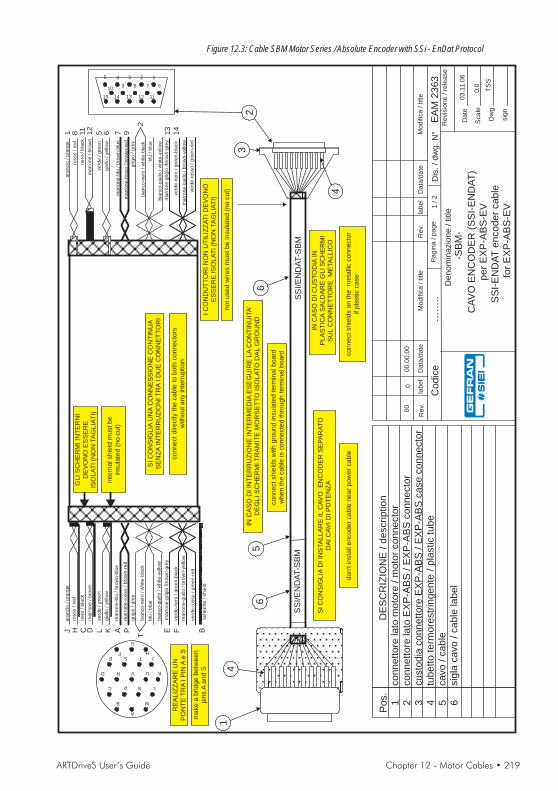
ARTDriveS User’s Guide Chapter 12 - Motor Cables • 219
Denom
inazio
ne
/title
CA
VO
EN
CO
DE
R(S
SI-
EN
DA
T)
pe
rE
XP
-AB
S-E
VS
SI-
EN
DA
Te
nco
de
rca
ble
for
EX
P-A
BS
-EV
Dis
./dw
g.N
°E
AM
23
63
Date
Scale
Dw
g.
sig
n
TS
S
Pagin
a/page
1/2
Revis
ione
/re
lease
03.1
1.0
6
Modific
a/title
Data
/date
label
Rev.
Modific
a/title
Data
/date
label
00.0
0.0
0
Rev.
00
0:0
2
4
3
SS
I/E
ND
AT-S
BM
INC
AS
OD
IC
US
TO
DIA
INP
LA
ST
ICA
SA
LD
AR
EG
LIS
CH
ER
MI
SU
LC
ON
NE
TT
OR
EM
ETA
LLIC
O
INC
AS
OD
IIN
TE
RR
UZ
ION
EIN
TE
RM
ED
IAE
SE
GU
IRE
LA
CO
NT
INU
ITA
'D
EG
LIS
CH
ER
MIT
RA
MIT
EM
OR
SE
TT
OIS
OLA
TO
DA
LG
RO
UN
D
IC
ON
DU
TT
OR
IN
ON
UT
ILIZ
ZA
TID
EV
ON
OE
SS
ER
EIS
OLA
TI(N
ON
TA
GLIA
TI)
SIC
ON
SIG
LIA
UN
AC
ON
NE
SS
ION
EC
ON
TIN
UA
SE
NZ
AIN
TE
RR
UZ
ION
IT
RA
ID
UE
CO
NN
ET
TO
RI
SIC
ON
SIG
LIA
DIIN
STA
LLA
RE
ILC
AV
OE
NC
OD
ER
SE
PA
RA
TO
DA
IC
AV
ID
IP
OT
EN
ZA
B
C
D
E
R V
S
P
A
G
F
N
M
U
TH
J
L
K
RE
ALIZ
ZA
RE
UN
PO
NT
ET
RA
IP
INA
eS
5 4
10
3 1
7
2
9 8 6
1112131415
GLIS
CH
ER
MIIN
TE
RN
ID
EV
ON
OE
SS
ER
EIS
OLA
TI(N
ON
TA
GLIA
TI)
verd
e/gre
en
marr
one-g
iallo
/bro
wn-y
ello
w
ara
ncio
/ora
nge
marr
one
/bro
wn
nero
/bla
ck
marr
one-b
lu/bro
wn-b
lue
gia
llo/yello
w
marr
one-r
osso
/bro
wn-r
ed
grigio
/gre
y
bia
nco-n
ero
/w
hite-b
lack
blu
/blu
e
bia
nco-g
iallo
/w
hite-y
ello
w
rosso
/re
d
verd
e-r
osso
/gre
en-r
ed
verd
e-n
ero
/gre
en-b
lack
marr
one-g
rigio
/bro
wn-g
rey
SS
I/E
ND
AT-S
BM
14
5
DE
SC
RIZ
ION
E/
de
scrip
tio
nco
nn
ett
ore
lato
mo
tore
/m
oto
rco
nn
ecto
rco
nn
ett
ore
lato
EX
P-A
BS
/E
XP
-AB
Sco
nn
ecto
rcu
sto
dia
co
nn
ett
ore
EX
P-A
BS
/E
XP
-AB
Sca
se
co
nn
ecto
rtu
be
tto
term
ore
str
ing
en
te/
pla
stic
tub
eca
vo
/ca
ble
sig
laca
vo
/ca
ble
lab
el
Po
s.
1 2 3 4 5 6
6
verd
e/gre
en
ara
ncio
/ora
nge
marr
one
/bro
wn
nero
/bla
ck
marr
one-b
lu/bro
wn-b
lue
gia
llo/yello
w
marr
one-r
osso
/bro
wn-r
ed
grigio
/gre
y
blu
/blu
e
rosso
/re
d
marr
one-g
iallo
/bro
wn-y
ello
w
bia
nco-n
ero
/w
hite-b
lack
bia
nco-g
iallo
/w
hite-y
ello
w
verd
e-r
osso
/gre
en-r
ed
verd
e-n
ero
/gre
en-b
lack
marr
one-g
rigio
/bro
wn-g
rey
inte
rnalshie
ldm
ustbe
insula
ted
(no
cut)
scherm
o/shie
ld
notused
wires
mustbe
insula
ted
(no
cut)
connectdirectly
the
cable
toboth
connecto
rsw
ithoutany
inte
rruption
connectshie
lds
with
gro
und
insula
ted
term
inalboard
when
the
cable
isconnecte
dth
rough
term
inalboard c
onnectshie
lds
on
the
meta
llic
connecto
rif
pla
stic
case
don't
insta
llencoder
cable
near
pow
er
cable
make
abridge
betw
een
pin
sA
and
S
0
-SB
M-
……
..C
od
ice
6
J H C D L K A P E
T
F B
1 8 11
12
5 6 7 9 13
14
2
Figure 12.3: Cable SBM Motor Series / Absolute Encoder with SSi - EnDat Protocol

220 • Chapter 12 - Motor Cables ARTDriveS User’s Guide
Denom
inazio
ne
/title
CA
VO
RE
SO
LV
ER
reso
lve
rca
ble
Dis
./dw
g.N
°E
AM
19
06
/3
Da
te
Sca
le
Dw
g.
sig
n
DL
L
Pa
gin
a/
pa
ge
1/
2
Re
vis
ion
e/
rele
ase
21
.10
.02
0
Modific
a/
title
Da
ta/d
ate
lab
el
00
.00
.00
Re
v.M
odific
a/
title
Da
ta/d
ate
lab
el
Re
v.
00
0
0:0
2
4
3
RE
S-S
BM
INC
AS
OD
IC
US
TO
DIA
IN
PL
AS
TIC
AS
AL
DA
RE
GL
IS
CH
ER
MI
SU
LC
ON
NE
TT
OR
EM
ETA
LL
ICO
INC
AS
OD
IIN
TE
RR
UZ
ION
EIN
TE
RM
ED
IAE
SE
GU
IRE
LA
CO
NT
INU
ITA
'
DE
GL
IS
CH
ER
MIT
RA
MIT
EM
OR
SE
TT
OIS
OL
AT
OD
AL
GR
OU
ND
SI
CO
NS
IGL
IAU
NA
CO
NN
ES
SIO
NE
CO
NT
INU
A
SE
NZ
AIN
TE
RR
UZ
ION
IT
RA
ID
UE
CO
NN
ET
TO
RI
SI
CO
NS
IGL
IAD
IIN
STA
LL
AR
EIL
CA
VO
RE
SO
LV
ER
SE
PA
RA
TO
DA
IC
AV
ID
IP
OT
EN
ZA
B
C
D
E
R V
S
P
A
G
F
N
M
U
TH
J
L
K
5 410
3 1
7
2
9 8 611
12
13
14
15
GL
IS
CH
ER
MI
INT
ER
NI
DE
VO
NO
ES
SE
RE
ISO
LA
TI
(NO
NTA
GL
IAT
I)
ve
rde
/g
ree
n
ara
ncio
/o
ran
ge
ma
rro
ne
/b
row
n
ne
ro/b
lack
gia
llo/
ye
llow
rosso
/re
d
GL
IS
CH
ER
MI
INT
ER
NI
DE
VO
NO
ES
SE
RE
A
CO
NTA
TT
OC
ON
LO
SC
HE
RM
OP
RIN
CIP
AL
E
RE
S-S
BM
14
5
DE
SC
RIZ
ION
E/
de
scrip
tio
n
co
nn
ett
ore
lato
mo
tore
/m
oto
rco
nn
ecto
rco
nn
ett
ore
lato
drive
/d
rive
co
nn
ecto
rcu
sto
dia
co
nn
ett
ore
drive
/ca
se
drive
co
nn
ecto
r
tub
ett
ote
rmo
restr
ing
en
te/
pla
stic
tub
eca
vo
/ca
ble
sig
laca
vo
/ca
ble
lab
el
Po
s.
1 2 3 4 5 6
6
11
12
10
7 213
EC F S TD B
ve
rde
/g
ree
n
ara
ncio
/o
ran
ge
ma
rro
ne
/b
row
n
ne
ro/b
lack
gia
llo/
ye
llow
rosso
/re
d
inte
rna
lsh
ield
mu
st
be
insu
late
d(n
ocu
t)
sch
erm
o/
sh
ield
inte
rna
lsh
ield
mu
st
be
on
the
ma
insh
ield
co
nn
ect
dire
ctly
the
ca
ble
tob
oth
co
nn
ecto
rsw
ith
ou
t
an
yin
terr
up
tio
n
co
nn
ect
sh
ield
sw
ith
gro
un
din
su
late
dte
rmin
alb
oa
rdw
he
nth
eca
ble
isco
nn
ecte
dth
rou
gh
term
ina
lb
oa
rd
co
nn
ect
sh
ield
so
nth
em
eta
llic
co
nn
ecto
rif
pla
stic
ca
se
do
n't
insta
llre
so
lve
rca
ble
ne
ar
po
we
rca
ble
U V
ma
rro
ne
/b
row
n
ne
ro/b
lack
ma
rro
ne
/b
row
n
ne
ro/b
lack
14
15
-SB
M-
05
.05
.06
00
1To
lta
no
tap
on
te.
Figure 12.4: Cable SBM Motor Series / Resolver

ARTDriveS User’s Guide Chapter 12 - Motor Cables • 221
Denom
inazio
ne
/title
CA
VO
EN
CO
DE
R(S
ES
C)
SE
SC
en
co
de
rca
ble
Dis
./dw
g.N
°E
AM
19
06
/4
Da
te
Sca
le
Dw
g.
sig
n
DL
L
Pa
gin
a/
pa
ge
1/
2
Re
vis
ion
e/
rele
ase
21
.10
.02
0
Modific
a/
title
Da
ta/d
ate
lab
el
00
.00
.00
Re
v.M
odific
a/
title
Da
ta/d
ate
lab
el
Re
v.
00
0
0:0
10
11
12
13
2
4
3
SE
SC
-SH
J
INC
AS
OD
IC
US
TO
DIA
IN
PL
AS
TIC
AS
AL
DA
RE
GL
IS
CH
ER
MI
SU
LC
ON
NE
TT
OR
EM
ETA
LL
ICO
INC
AS
OD
IIN
TE
RR
UZ
ION
EIN
TE
RM
ED
IAE
SE
GU
IRE
LA
CO
NT
INU
ITA
'
DE
GL
IS
CH
ER
MIT
RA
MIT
EM
OR
SE
TT
OIS
OL
AT
OD
AL
GR
OU
ND
IC
ON
DU
TT
OR
IN
ON
UT
ILIZ
ZA
TI
DE
VO
NO
ES
SE
RE
ISO
LA
TI
(NO
NTA
GL
IAT
I)
SI
CO
NS
IGL
IAU
NA
CO
NN
ES
SIO
NE
CO
NT
INU
A
SE
NZ
AIN
TE
RR
UZ
ION
IT
RA
ID
UE
CO
NN
ET
TO
RI
SI
CO
NS
IGL
IAD
IIN
STA
LL
AR
EIL
CA
VO
EN
CO
DE
RS
EP
AR
AT
O
DA
IC
AV
ID
IP
OT
EN
ZA
5 410
3 1
7
2
9 8 611
12
13
14
15
GL
IS
CH
ER
MI
INT
ER
NI
DE
VO
NO
ES
SE
RE
ISO
LA
TI
(NO
NTA
GL
IAT
I)
ve
rde
/g
ree
n
ma
rro
ne
-gia
llo/
bro
wn
-ye
llow
ara
ncio
/o
ran
ge
ma
rro
ne
/b
row
n
ne
ro/b
lack
ma
rro
ne
-blu
/b
row
n-b
lue
gia
llo/
ye
llow
ma
rro
ne
-ro
sso
/b
row
n-r
ed
grig
io/
gre
y
bia
nco
-ne
ro/
wh
ite
-bla
ck
blu
/b
lue
bia
nco
-gia
llo/
wh
ite
-ye
llow
rosso
/re
d
ve
rde
-ro
sso
/g
ree
n-r
ed
ve
rde
-ne
ro/
gre
en
-bla
ck
ma
rro
ne
-grig
io/b
row
n-g
rey
GL
IS
CH
ER
MI
INT
ER
NI
DE
VO
NO
ES
SE
RE
A
CO
NTA
TT
OC
ON
LO
SC
HE
RM
OP
RIN
CIP
AL
E
SE
SC
-SH
J
14
5
DE
SC
RIZ
ION
E/
de
scrip
tio
n
co
nn
ett
ore
lato
mo
tore
/m
oto
rco
nn
ecto
rco
nn
ett
ore
lato
drive
/d
rive
co
nn
ecto
rcu
sto
dia
co
nn
ett
ore
drive
/ca
se
drive
co
nn
ecto
r
tub
ett
ote
rmo
restr
ing
en
te/
pla
stic
tub
eca
vo
/ca
ble
sig
laca
vo
/ca
ble
lab
el
Po
s.
1 2 3 4 5 6
6
231 4 5 6 78 9
1858 9 3 7
124 2
10
14
15
11
19
ve
rde
/g
ree
n
ara
ncio
/o
ran
ge
ma
rro
ne
/b
row
n
ne
ro/b
lack
ma
rro
ne
-blu
/b
row
n-b
lue
gia
llo/
ye
llow
ma
rro
ne
-ro
sso
/b
row
n-r
ed
grig
io/
gre
y
blu
/b
lue
rosso
/re
d
ma
rro
ne
-gia
llo/
bro
wn
-ye
llow
bia
nco
-ne
ro/
wh
ite
-bla
ck
bia
nco
-gia
llo/
wh
ite
-ye
llow
ve
rde
-ro
sso
/g
ree
n-r
ed
ve
rde
-ne
ro/
gre
en
-bla
ck
ma
rro
ne
-grig
io/b
row
n-g
rey
inte
rna
lsh
ield
mu
st
be
insu
late
d(n
ocu
t)
sch
erm
o/
sh
ield
inte
rna
lsh
ield
mu
st
be
on
the
ma
insh
ield
no
tu
se
dw
ire
sm
ust
be
insu
late
d(n
ocu
t)
co
nn
ect
dire
ctly
the
ca
ble
tob
oth
co
nn
ecto
rsw
ith
ou
t
an
yin
terr
up
tio
n
co
nn
ect
sh
ield
sw
ith
gro
un
din
su
late
dte
rmin
alb
oa
rdw
he
nth
eca
ble
isco
nn
ecte
dth
rou
gh
term
ina
lb
oa
rd co
nn
ect
sh
ield
so
nth
em
eta
llic
co
nn
ecto
rif
pla
stic
ca
se
do
n't
insta
lle
nco
de
rca
ble
ne
ar
po
we
rca
ble
2
1
12
11
10
18
98
17
7
16
6515
4
3
14
13 1
9
-SH
J-
17
7
05
.05
.06
00
1To
lta
no
tap
on
te,
co
rre
ttico
lleg
.
Figure 12.5: Cable SHJ Motor Series / Sinusoidal Encoder
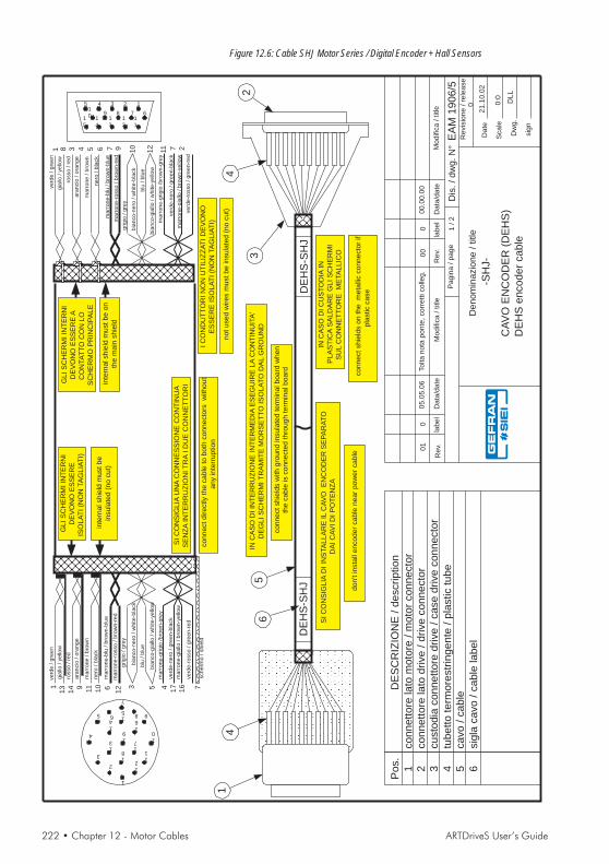
222 • Chapter 12 - Motor Cables ARTDriveS User’s Guide
Denom
inazio
ne
/title
CA
VO
EN
CO
DE
R(D
EH
S)
DE
HS
en
co
de
rca
ble
Dis
./dw
g.N
°E
AM
19
06
/5
Da
te
Sca
le
Dw
g.
sig
n
DL
L
Pa
gin
a/
pa
ge
1/
2
Re
vis
ion
e/
rele
ase
21
.10
.02
0
Modific
a/
title
Da
ta/d
ate
lab
el
00
.00
.00
Re
v.M
odific
a/
title
Da
ta/d
ate
lab
el
Re
v.
00
0
0:0
10
11
12
2
4
3
DE
HS
-SH
J
INC
AS
OD
IC
US
TO
DIA
IN
PL
AS
TIC
AS
AL
DA
RE
GL
IS
CH
ER
MI
SU
LC
ON
NE
TT
OR
EM
ETA
LL
ICO
INC
AS
OD
IIN
TE
RR
UZ
ION
EIN
TE
RM
ED
IAE
SE
GU
IRE
LA
CO
NT
INU
ITA
'
DE
GL
IS
CH
ER
MIT
RA
MIT
EM
OR
SE
TT
OIS
OL
AT
OD
AL
GR
OU
ND
IC
ON
DU
TT
OR
IN
ON
UT
ILIZ
ZA
TI
DE
VO
NO
ES
SE
RE
ISO
LA
TI
(NO
NTA
GL
IAT
I)
SI
CO
NS
IGL
IAU
NA
CO
NN
ES
SIO
NE
CO
NT
INU
A
SE
NZ
AIN
TE
RR
UZ
ION
IT
RA
ID
UE
CO
NN
ET
TO
RI
SI
CO
NS
IGL
IAD
IIN
STA
LL
AR
EIL
CA
VO
EN
CO
DE
RS
EP
AR
AT
O
DA
IC
AV
ID
IP
OT
EN
ZA
5 410
3 1
7
2
9 8 611
12
13
14
15
GL
IS
CH
ER
MI
INT
ER
NI
DE
VO
NO
ES
SE
RE
ISO
LA
TI
(NO
NTA
GL
IAT
I)
ve
rde
/g
ree
n
ma
rro
ne
-gia
llo/
bro
wn
-ye
llow
ara
ncio
/o
ran
ge
ma
rro
ne
/b
row
n
ne
ro/b
lack
ma
rro
ne
-blu
/b
row
n-b
lue
gia
llo/
ye
llow
ma
rro
ne
-ro
sso
/b
row
n-r
ed
grig
io/
gre
y
bia
nco
-ne
ro/
wh
ite
-bla
ck
blu
/b
lue
bia
nco
-gia
llo/
wh
ite
-ye
llow
rosso
/re
d
ve
rde
-ro
sso
/g
ree
n-r
ed
ve
rde
-ne
ro/
gre
en
-bla
ck
ma
rro
ne
-grig
io/b
row
n-g
rey
GL
IS
CH
ER
MI
INT
ER
NI
DE
VO
NO
ES
SE
RE
A
CO
NTA
TT
OC
ON
LO
SC
HE
RM
OP
RIN
CIP
AL
E
DE
HS
-SH
J
14
5
DE
SC
RIZ
ION
E/
de
scrip
tio
n
co
nn
ett
ore
lato
mo
tore
/m
oto
rco
nn
ecto
rco
nn
ett
ore
lato
drive
/d
rive
co
nn
ecto
rcu
sto
dia
co
nn
ett
ore
drive
/ca
se
drive
co
nn
ecto
r
tub
ett
ote
rmo
restr
ing
en
te/
pla
stic
tub
eca
vo
/ca
ble
sig
laca
vo
/ca
ble
lab
el
Po
s.
1 2 3 4 5 6
6
231 4 5 6 78 9
16
141 9 11
10 6
13
12 3 5 7
ve
rde
/g
ree
n
ara
ncio
/o
ran
ge
ma
rro
ne
/b
row
n
ne
ro/b
lack
ma
rro
ne
-blu
/b
row
n-b
lue
gia
llo/
ye
llow
ma
rro
ne
-ro
sso
/b
row
n-r
ed
grig
io/
gre
y
blu
/b
lue
rosso
/re
d
ma
rro
ne
-gia
llo/
bro
wn
-ye
llow
bia
nco
-ne
ro/
wh
ite
-bla
ck
bia
nco
-gia
llo/
wh
ite
-ye
llow
ve
rde
-ro
sso
/g
ree
n-r
ed
ve
rde
-ne
ro/
gre
en
-bla
ck
ma
rro
ne
-grig
io/b
row
n-g
rey
inte
rna
lsh
ield
mu
st
be
insu
late
d(n
ocu
t)
sch
erm
o/
sh
ield
inte
rna
lsh
ield
mu
st
be
on
the
ma
insh
ield
no
tu
se
dw
ire
sm
ust
be
insu
late
d(n
ocu
t)
co
nn
ect
dire
ctly
the
ca
ble
tob
oth
co
nn
ecto
rsw
ith
ou
t
an
yin
terr
up
tio
n
co
nn
ect
sh
ield
sw
ith
gro
un
din
su
late
dte
rmin
alb
oa
rdw
he
nth
eca
ble
isco
nn
ecte
dth
rou
gh
term
ina
lb
oa
rd co
nn
ect
sh
ield
so
nth
em
eta
llic
co
nn
ecto
rif
pla
stic
ca
se
do
n't
insta
lle
nco
de
rca
ble
ne
ar
po
we
rca
ble
4
-SH
J-
2
1
12
11
10
18
98
17
7
16
6515
4
3
14
13 1
9
05
.05
.06
00
1To
lta
no
tap
on
te,
co
rre
ttico
lleg
.
17
7
Figure 12.6: Cable SHJ Motor Series / Digital Encoder + Hall Sensors

ARTDriveS User’s Guide Chapter 12 - Motor Cables • 223
Denom
inazio
ne
/title
CA
VO
RE
SO
LV
ER
reso
lve
rca
ble
Dis
./dw
g.N
°E
AM
19
06
/6
Da
te
Sca
le
Dw
g.
sig
n
DL
L
Pa
gin
a/
pa
ge
1/
2
Re
vis
ion
e/
rele
ase
21
.10
.02
0
Modific
a/
title
Da
ta/d
ate
lab
el
00
.00
.00
Re
v.M
odific
a/
title
Da
ta/d
ate
lab
el
26
.11
.02
Re
v.
00
01
00
0:0
2
4
3
RE
S-S
HJ
INC
AS
OD
IC
US
TO
DIA
IN
PL
AS
TIC
AS
AL
DA
RE
GL
IS
CH
ER
MI
SU
LC
ON
NE
TT
OR
EM
ETA
LL
ICO
INC
AS
OD
IIN
TE
RR
UZ
ION
EIN
TE
RM
ED
IAE
SE
GU
IRE
LA
CO
NT
INU
ITA
'
DE
GL
IS
CH
ER
MIT
RA
MIT
EM
OR
SE
TT
OIS
OL
AT
OD
AL
GR
OU
ND
SI
CO
NS
IGL
IAU
NA
CO
NN
ES
SIO
NE
CO
NT
INU
A
SE
NZ
AIN
TE
RR
UZ
ION
IT
RA
ID
UE
CO
NN
ET
TO
RI
SI
CO
NS
IGL
IAD
IIN
STA
LL
AR
EIL
CA
VO
RE
SO
LV
ER
SE
PA
RA
TO
DA
IC
AV
ID
IP
OT
EN
ZA
5 410
3 1
7
2
9 8 611
12
13
14
15
GL
IS
CH
ER
MI
INT
ER
NI
DE
VO
NO
ES
SE
RE
ISO
LA
TI
(NO
NTA
GL
IAT
I)
ve
rde
/g
ree
n
ara
ncio
/o
ran
ge
ma
rro
ne
/b
row
nn
ero
/b
lack
gia
llo/
ye
llow
rosso
/re
d
GL
IS
CH
ER
MI
INT
ER
NI
DE
VO
NO
ES
SE
RE
A
CO
NTA
TT
OC
ON
LO
SC
HE
RM
OP
RIN
CIP
AL
E
RE
S-S
HJ
14
5
DE
SC
RIZ
ION
E/
de
scrip
tio
n
co
nn
ett
ore
lato
mo
tore
/m
oto
rco
nn
ecto
rco
nn
ett
ore
lato
drive
/d
rive
co
nn
ecto
rcu
sto
dia
co
nn
ett
ore
drive
/ca
se
drive
co
nn
ecto
r
tub
ett
ote
rmo
restr
ing
en
te/
pla
stic
tub
eca
vo
/ca
ble
sig
laca
vo
/ca
ble
lab
el
Po
s.
1 2 3 4 5 6
6
11
12
10
7 213
CB H I JG F
ve
rde
/g
ree
n
ara
ncio
/o
ran
ge
ma
rro
ne
/b
row
nn
ero
/b
lack
gia
llo/
ye
llow
rosso
/re
d
inte
rna
lsh
ield
mu
st
be
insu
late
d(n
ocu
t)
sch
erm
o/
sh
ield
inte
rna
lsh
ield
mu
st
be
on
the
ma
insh
ield
co
nn
ect
dire
ctly
the
ca
ble
tob
oth
co
nn
ecto
rsw
ith
ou
t
an
yin
terr
up
tio
n
co
nn
ect
sh
ield
sw
ith
gro
un
din
su
late
dte
rmin
alb
oa
rdw
he
nth
eca
ble
isco
nn
ecte
dth
rou
gh
term
ina
lb
oa
rd
co
nn
ect
sh
ield
so
nth
em
eta
llic
co
nn
ecto
rif
pla
stic
ca
se
do
n't
insta
llre
so
lve
rca
ble
ne
ar
po
we
rca
ble
A E
ma
rro
ne
/b
row
nn
ero
/b
lack
ma
rro
ne
/b
row
nn
ero
/b
lack
14
15
B
C
G
F
A H
JED
I
-SH
J-
CH
AN
GE
DP
OS
ITIO
NP
INC
-H
Figure 12.7: Cable SHJ Motor Series / Resolver

224 • Chapter 12 - Motor Cables ARTDriveS User’s Guide
Denom
inazio
ne
/title
CA
VO
PO
TE
NZ
A
po
we
rca
ble
Dis
./dw
g.N
°E
AM
19
07
Da
te
Sca
le
Dw
g.
sig
n
DL
L
Pa
gin
a/
pa
ge
1/
3
Re
vis
ion
e/
rele
ase
22
.10
.02
0
Modific
a/
title
Da
ta/d
ate
lab
el
00
.00
.00
Re
v.M
odific
a/
title
Da
ta/d
ate
lab
el
00
.00
.00
Re
v.
00
00
00
0:0
2
INC
AS
OD
IIN
TE
RR
UZ
ION
EIN
TE
RM
ED
IAE
SE
GU
IRE
LA
CO
NT
INU
ITA
'
DE
GL
IS
CH
ER
MIT
RA
MIT
EC
OL
LA
RIN
O
PO
T-S
BM
14
5
DE
SC
RIZ
ION
E/
de
scrip
tio
n
co
nn
ett
ore
lato
mo
tore
/m
oto
rco
nn
ecto
rco
llarin
o/
36
0°
gro
un
dte
rmin
al
tub
ett
ote
rmo
restr
ing
en
te/
pla
stic
tub
eca
vo
/ca
ble
sig
laca
vo
/ca
ble
lab
el
Po
s.
1 2 3 4 5 6
6
sch
erm
o/
sh
ield
co
nn
ect
sh
ield
sw
ith
36
0°
gro
un
dte
rmin
al
wh
en
the
ca
ble
isco
nn
ecte
dth
rou
gh
term
ina
lb
oa
rd
B C
A D
A1
B2
C3
D
gia
llo-v
erd
e/
ye
llow
-gre
en
U2
/T1
1
V2
/T2
2
W2
/T3
3
PE
2
5 6
5 6
gia
llo-v
erd
e/
ye
llow
-gre
en
PO
T-S
BM
SI
CO
NS
IGL
IAU
NA
CO
NN
ES
SIO
NE
CO
NT
INU
A
SE
NZ
AIN
TE
RR
UZ
ION
IT
RA
ID
UE
CO
NN
ET
TO
RI
co
nn
ect
dire
ctly
the
ca
ble
tob
oth
co
nn
ecto
rsw
ith
ou
t
an
yin
terr
up
tio
n
topowerterminalboarddrive
IC
ON
DU
TT
OR
IN
ON
UT
ILIZ
ZA
TI
DE
VO
NO
ES
SE
RE
ISO
LA
TI
(NO
NTA
GL
IAT
I)
no
tu
se
dw
ire
sm
ust
be
insu
late
d(n
ocu
t)
IC
ON
DU
TT
OR
IN
ON
UT
ILIZ
ZA
TI
DE
VO
NO
ES
SE
RE
ISO
LA
TI
(NO
NTA
GL
IAT
I)
no
tu
se
dw
ire
sm
ust
be
insu
late
d(n
ocu
t)
SB
M5
/7
sch
erm
o/
sh
ield
Figure 12.8: SBM 5-7 Motor Series Power Cable

ARTDriveS User’s Guide Chapter 12 - Motor Cables • 225
Denom
inazio
ne
/title
CA
VO
PO
TE
NZ
A+
FR
EN
Op
ow
er
+b
rake
ca
ble
Dis
./dw
g.N
°E
AM
19
07
/1
Da
te
Sca
le
Dw
g.
sig
n
DL
L
Pa
gin
a/
pa
ge
1/
3
Re
vis
ion
e/
rele
ase
22
.10
.02
0
Modific
a/
title
Da
ta/d
ate
lab
el
00
.00
.00
Re
v.M
odific
a/
title
Da
ta/d
ate
lab
el
00
.00
.00
Re
v.
00
00
00
0:0
2
INC
AS
OD
IIN
TE
RR
UZ
ION
EIN
TE
RM
ED
IAE
SE
GU
IRE
LA
CO
NT
INU
ITA
'
DE
GL
IS
CH
ER
MIT
RA
MIT
EC
OL
LA
RIN
O
PO
T+
B-S
BM
14
5
DE
SC
RIZ
ION
E/
de
scrip
tio
n
co
nn
ett
ore
lato
mo
tore
/m
oto
rco
nn
ecto
rco
llarin
o/
36
0°
gro
un
dte
rmin
al
tub
ett
ote
rmo
restr
ing
en
te/
pla
stic
tub
eca
vo
/ca
ble
sig
laca
vo
/ca
ble
lab
el
Po
s.
1 2 3 4 5 6
6
sch
erm
o/
sh
ield
co
nn
ect
sh
ield
sw
ith
36
0°
gro
un
dte
rmin
al
wh
en
the
ca
ble
isco
nn
ecte
dth
rou
gh
term
ina
lb
oa
rd
B C
F
A
E
D
A1
B2
C3
D
gia
llo-v
erd
e/
ye
llow
-gre
en
U2
/T1
1
V2
/T2
2
W2
/T3
3
PE
2
E5
F6
5 6
gia
llo-v
erd
e/
ye
llow
-gre
en
PO
T+
B-S
BM
SI
CO
NS
IGL
IAU
NA
CO
NN
ES
SIO
NE
CO
NT
INU
A
SE
NZ
AIN
TE
RR
UZ
ION
IT
RA
ID
UE
CO
NN
ET
TO
RI
co
nn
ect
dire
ctly
the
ca
ble
tob
oth
co
nn
ecto
rsw
ith
ou
t
an
yin
terr
up
tio
n
bra
ke
wire
stopowerterminalboarddrive
SB
M5
/7
sch
erm
o/
sh
ield
Figure 12.9: SBM 5-7 Motor Series Power + Brake Cable

226 • Chapter 12 - Motor Cables ARTDriveS User’s Guide
Denom
inazio
ne
/title
CA
VO
PO
TE
NZ
Ap
ow
er
ca
ble
Dis
./dw
g.N
°E
AM
19
07
/2
Da
te
Sca
le
Dw
g.
sig
n
DL
L
Pa
gin
a/
pa
ge
1/
3
Re
vis
ion
e/
rele
ase
22
.10
.02
0
Modific
a/
title
Da
ta/d
ate
lab
el
00
.00
.00
Re
v.M
odific
a/
title
Da
ta/d
ate
lab
el
00
.00
.00
Re
v.
00
00
00
0:0
2
INC
AS
OD
IIN
TE
RR
UZ
ION
EIN
TE
RM
ED
IAE
SE
GU
IRE
LA
CO
NT
INU
ITA
'
DE
GL
IS
CH
ER
MIT
RA
MIT
EC
OL
LA
RIN
O
PO
T-S
HJ
14
5
DE
SC
RIZ
ION
E/
de
scrip
tio
n
co
nn
ett
ore
lato
mo
tore
/m
oto
rco
nn
ecto
rco
llarin
o/
36
0°
gro
un
dte
rmin
al
tub
ett
ote
rmo
restr
ing
en
te/
pla
stic
tub
eca
vo
/ca
ble
sig
laca
vo
/ca
ble
lab
el
Po
s.
1 2 3 4 5 6
6
sch
erm
o/
sh
ield
co
nn
ect
sh
ield
sw
ith
36
0°
gro
un
dte
rmin
al
wh
en
the
ca
ble
isco
nn
ecte
dth
rou
gh
term
ina
lb
oa
rd
B C
A D
A1
B2
C3
D
gia
llo-v
erd
e/
ye
llow
-gre
en
U2
/T1
1
V2
/T2
2
W2
/T3
3
PE
2
5 6
5 6
gia
llo-v
erd
e/
ye
llow
-gre
en
PO
T-S
HJ
SI
CO
NS
IGL
IAU
NA
CO
NN
ES
SIO
NE
CO
NT
INU
A
SE
NZ
AIN
TE
RR
UZ
ION
IT
RA
ID
UE
CO
NN
ET
TO
RI
co
nn
ect
dire
ctly
the
ca
ble
tob
oth
co
nn
ecto
rsw
ith
ou
t
an
yin
terr
up
tio
n
topowerterminalboarddrive
IC
ON
DU
TT
OR
IN
ON
UT
ILIZ
ZA
TI
DE
VO
NO
ES
SE
RE
ISO
LA
TI
(NO
NTA
GL
IAT
I)
no
tu
se
dw
ire
sm
ust
be
insu
late
d(n
ocu
t)
IC
ON
DU
TT
OR
IN
ON
UT
ILIZ
ZA
TI
DE
VO
NO
ES
SE
RE
ISO
LA
TI
(NO
NTA
GL
IAT
I)
no
tu
se
dw
ire
sm
ust
be
insu
late
d(n
ocu
t)
-SH
J-
Figure 12.10: SHJ Motor Series Power Cable
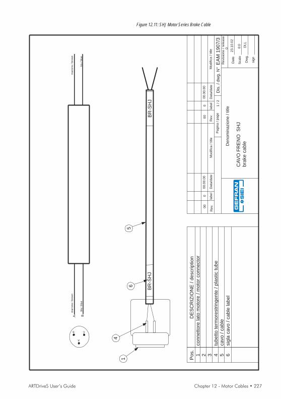
ARTDriveS User’s Guide Chapter 12 - Motor Cables • 227
Denom
inazio
ne
/title
CA
VO
FR
EN
OS
HJ
bra
ke
ca
ble
Dis
./dw
g.N
°E
AM
19
07
/3
Da
te
Sca
le
Dw
g.
sig
n
DL
L
Pa
gin
a/
pa
ge
1/
2
Re
vis
ion
e/
rele
ase
23
.10
.02
0
Modific
a/
title
Da
ta/d
ate
lab
el
00
.00
.00
Re
v.M
odific
a/
title
Da
ta/d
ate
lab
el
00
.00
.00
Re
v.
00
00
00
0:0
BR
-SH
J
1
4
5
DE
SC
RIZ
ION
E/
de
scrip
tio
n
co
nn
ett
ore
lato
mo
tore
/m
oto
rco
nn
ecto
r
tub
ett
ote
rmo
restr
ing
en
te/
pla
stic
tub
eca
vo
/ca
ble
sig
laca
vo
/ca
ble
lab
el
Po
s.
1 2 3 4 5 6
6
A B
BR
-SH
J
B C
A
ma
rro
ne
/b
row
n
blu
/b
lue
ma
rro
ne
/b
row
n
blu
/b
lue
Figure 12.11: SHJ Motor Series Brake Cable
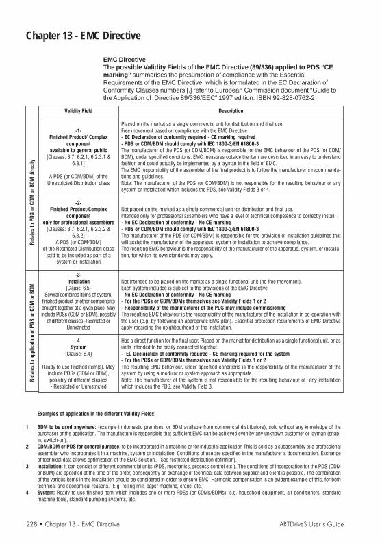
228 • Chapter 13 - EMC Directive ARTDriveS User’s Guide
Chapter 13 - EMC Directive
EMC DirectiveThe possible Validity Fields of the EMC Directive (89/336) applied to PDS “CEmarking” summarises the presumption of compliance with the EssentialRequirements of the EMC Directive, which is formulated in the EC Declaration ofConformity Clauses numbers [.] refer to European Commission document “Guide tothe Application of Directive 89/336/EEC” 1997 edition. ISBN 92-828-0762-2
Validity Field
-1-Finished Product/ Complex
componentavailable to general public
[Clauses: 3.7, 6.2.1, 6.2.3.1 &6.3.1]
A PDS (or CDM/BDM) of theUnrestricted Distribution class
-2-Finished Product/Complex
componentonly for professional assemblers
[Clauses: 3.7, 6.2.1, 6.2.3.2 &6.3.2]
A PDS (or CDM/BDM)of the Restricted Distribution class
sold to be included as part of asystem or installation
-3-Installation
[Clause: 6.5]Several combined items of system,
finished product or other componentsbrought together at a given place. Mayinclude PDSs (CDM or BDM), possibly
of different classes -Restricted orUnrestricted
-4-System
[Clause: 6.4]
Ready to use finished item(s). Mayinclude PDSs (CDM or BDM),possibly of different classes- Restricted or Unrestricted
Description
Placed on the market as a single commercial unit for distribution and final use.Free movement based on compliance with the EMC Directive- EC Declaration of conformity required - CE marking required- PDS or CDM/BDM should comply with IEC 1800-3/EN 61800-3The manufacturer of the PDS (or CDM/BDM) is responsible for the EMC behaviour of the PDS (or CDM/BDM), under specified conditions. EMC measures outside the item are described in an easy to understandfashion and could actually be implemented by a layman in the field of EMC.The EMC responsibility of the assembler of the final product is to follow the manufacturer’s recommenda-tions and guidelines.Note: The manufacturer of the PDS (or CDM/BDM) is not responsible for the resulting behaviour of anysystem or installation which includes the PDS, see Validity Fields 3 or 4.
Not placed on the marked as a single commercial unit for distribution and final use.Intended only for professional assemblers who have a level of technical competence to correctly install.- No EC Declaration of conformity - No CE marking- PDS or CDM/BDM should comply with IEC 1800-3/EN 61800-3The manufacturer of the PDS (or CDM/BDM) is responsible for the provision of installation guidelines thatwill assist the manufacturer of the apparatus, system or installation to achieve compliance.The resulting EMC behaviour is the responsibility of the manufacturer of the apparatus, system, or installa-tion, for which its own standards may apply.
Not intended to be placed on the market as a single functional unit (no free movement).Each system included is subject to the provisions of the EMC Directive.- No EC Declaration of conformity - No CE marking- For the PDSs or CDM/BDMs themselves see Validity Fields 1 or 2- Responsibility of the manufacturer of the PDS may include commissioningThe resulting EMC behaviour is the responsibility of the manufacturer of the installation in co-operation withthe user (e.g. by following an appropriate EMC plan). Essential protection requirements of EMC Directiveapply regarding the neighbourhood of the installation.
Has a direct function for the final user. Placed on the market for distribution as a single functional unit, or asunits intended to be easily connected together.- EC Declaration of conformity required - CE marking required for the system- For the PDSs or CDM/BDMs themselves see Validity Fields 1 or 2The resulting EMC behaviour, under specified conditions is the responsibility of the manufacturer of thesystem by using a modular or system approach as appropriate.Note: The manufacturer of the system is not responsible for the resulting behaviour of any installationwhich includes the PDS, see Validity Field 3.
Examples of application in the different Validity Fields:
1 BDM to be used anywhere: (example in domestic premises, or BDM available from commercial distributors), sold without any knowledge of thepurchaser or the application. The manufacture is responsible that sufficient EMC can be achieved even by any unknown customer or layman (snap-in, switch-on).
2 CDM/BDM or PDS for general purpose: to be incorporated in a machine or for industrial application This is sold as a subassembly to a professionalassembler who incorporates it in a machine, system or installation. Conditions of use are specified in the manufacturer’s documentation. Exchangeof technical data allows optimization of the EMC solution.. (See restricted distribution definition).
3 Installation: It can consist of different commercial units (PDS, mechanics, process control etc.). The conditions of incorporation for the PDS (CDMor BDM) are specified at the time of the order, consequently an exchange of technical data between supplier and client is possible. The combinationof the various items in the installation should be considered in order to ensure EMC. Harmonic compensation is an evident example of this, for bothtechnical and economical reasons. (E.g. rolling mill, paper machine, crane, etc.)
4 System: Ready to use finished item which includes one or more PDSs (or CDMs/BDMs); e.g. household equipment, air conditioners, standardmachine tools, standard pumping systems, etc.
Rela
tes
to P
DS o
r CD
M o
r BD
M d
irect
lyRe
late
s to
app
licat
ion
of P
DS o
r CDM
or B
DM

ARTDriveS User’s Guide Appendix - Field bus and serial interface • 229
Appendix - Field bus and serial interface
1.0 Integrated CANopen Interface
CANopen is a communication profile for CAL-based industrial systems.The reference document is the CANopen CAL-Base COMMUNICATIONPROFILE for Industrial Systems; CiA Draft Standard 301 Version 3.0.Issue October 1996 by CAN in Automation e. V.The CAN protocol (ISO 11898) is CAN2.0A with an 11-bit identifier.The integrated CANopen interface is developed as a “Minimum CapabiltyDevice”.The data exchange is cyclic; the Master unit reads the Slave input dataand writes the Slave output data; the Baud Rates for the interface arethose foreseen by the CANopen specification.
1.1 CANopen FunctionsThis chapter describes the controlled functions of the CANopen com-munication profile. The main features are:1) The “Minimum Boot-up” is managed; the “Extended Boot-up (CAL)”
is not managed.2) The SYNC function is implemented.3) The PDO asynchronous assignment and RTR are managed.4) The Node Guarding is managed.5) The emergency message is managed (“EMERGENCY”).6) The Dynamic ID distribution function (DBT slave) is not managed.7) A “Pre-Defined Master/Slave connection” is implemented to sim-
plify the Master tasks during the initialization phase. “Inhibit-Times”(in units of 100 uS) can be modified up to a value of 1 min.
8) The high-resolution synchronization is not supported.9) “TIME STAMP” is not managed.10) On the access of the structured parameters, the OFFhex option
subindex (access to the whole object) is not managed.11) In order to obtain a higher efficiency level, only the “Expedited” data
transfer (max. 4 Bytes) of the SDO services is managed.
1.1.1 Pre-defined Master/Slave ConnectionThe “Pre-defined Master/Slave connection” allows a peer-to-peer com-munication between one Master and 127 Slaves; the Broadcast addressis zero.
1.1.2 NMT Services (Network Management)The NMT “mandatory” services are:- Enter_Pre-Operational_State CS = 128- Reset_Node CS = 129- Reset_Communication CS = 130Being that the “Minimum Boot-up” is used, also the following NMT serv-ices are managed:- Start_Remote_Mode CS = 1
CiA : CAN in Automation, userinternational group.
CAN : Controller Area Net-work.
DBT: Distributor. It is a serv-ice element of the CAN Appli-cation Layer in the CAN Ref-erence Model; the DBT hasthe task to assign COB-ID tothe COBs used by the CMS.
PDO: Process Data Object,service messages withoutconfirmation used for the realtime data transfer from/to thedevice.
SDO: Service Data Object,service messages with confir-mation used for the acyclicdata transfer from/to the de-vice.

230 • Appendix - Field bus and serial interface ARTDriveS User’s Guide
- Stop_Remote_Mode CS = 2
The COB-ID * of an initialization NMT service is always at 0; CS is theCommand Specifier defining the NMT service.
1.1.3 InitializationThe XVy drive supports the Node Guarding mechanism. The NodeGuarding configuration can be performed through the master via thestandard Object Dictionary elements (1006h, 100Ch, 100Dh).The drive checks the master functioning conditions through the LifeGuarding. If the check fails, the drive enables the "Buss Loss" alarm.The Life Guarding threshold can be calculated as follows:
Value/Condition60msDefault. No parameterization of the Node Guarding.SYNC_PERIOD (*)LIFE_TIME_FACTORUse of the synchronous mode. If not stated by the master, theLIFE_TIME_FACTOR default value is equal to 3.NODE_GUARDING_PERIOD (*)LIFE_TIME_FACTORNODE_GUARDING_PERIOD set by the masterIf not otherwise stated, the LIFE_TIME_FACTOR value is equal to 3
1.1.4 Communication ObjectThis chapter describes the communication objects of the CANopen pro-tocol; they are managed by the interface card. The managedcommunication objects are:1) 1 SDO reception Server.2) 1 SDO transmission Server.3) 2 reception PDOs.4) 2 transmission PDOs.5) 1 Emergency Object.6) 1 Node Guarding - Life Guarding.7) 1 SYNC object.The following table lists the used communication objects with their pri-ority level and the Message Identifier; the “Resulting COB-ID” is obtainedby adding the Node-ID (card address) to the number.
OBJECT PRIORITY MESSAGE ID1st SDO rx 6 15361st SDO tx 6 14081st PDO rx 2 5121st PDO tx 2 3842nd PDO rx 2 7682nd PDO tx 2 640EMERGENCY 1 220NODE GUARDING not used 1792SYNC 0 128
Table 1.4.1: Communication Objects
NMT: Network Management.It is a service element of theCAN Application Layer in theCAN Reference Model; itinitializes, configures andcontrols the errors of a CANnetwork.
CS: Command Specifier; itdefines the NMT service.
COB = CommunicationObject (CAN Message). It isa transport unit inside a CANnetwork. The data must besent in network inside a COB.
COB-ID = COB-Identifier. Itidentifies a COB inside thenetwork. It also states theCOB priority.

ARTDriveS User’s Guide Appendix - Field bus and serial interface • 231
Node Guarding has no priority because it is a special NMT service; ithas the Message-ID because it is not a Broadcast service.
1.1.5 Object Dictionary ElementsThe Object Dictionary is accessible from a master CANopen and fromthe keypad configurator.The following table shows the communication objects used andaccessibility with master CANopen, keypad configurator.
Index (hex) IPA Parameter Name1000 Device Type1001 Error Register1002 Manufacturer status register1005 COB-ID SYNC Message1006 40902 Communication cycle period1008 Manufacterer Device Name1010 Store parameter1009 Manufacterer Hardware Version100A Manufacterer Software Version100C 40903 Guard Time100D 40904 Life Time Factor100F Number of PDOs supported1014 40905 COB-ID Emergency1018 Identity object1400 40910, 40915 1st Receive PDO1401 40911, 40916 2nd Receive PDO1402 40912, 40917 3rd Receive PDO1600 Receive PDO1 mapping parameter1601 Receive PDO2 mapping parameter1602 Receive PDO3 mapping parameter1A00 Transmit PDO1 mapping parameter1A01 Transmit PDO2 mapping parameter1A02 Transmit PDO3 mapping parameter1800 40920, 40925, 40930 1st Transmit PDO1801 40921, 40926, 40931 2nd Transmit PDO1802 40922, 40927, 40932 3rd Transmit PDO
Table 1.5.1: Objects used by the CANopen communication profile
The objects shown in bold in the table allow writing of theparameters assigned with the exchange of data in the PDO.The allocation criterion is variable, and depends on the size (inbytes) of the parameter exchanged.
NOTE! It is possible to save the objects permanently to the drive flash memory:
1) via configurator, only for objects with parameter reference(e.g.: index 1000 -> IPA 40902)
2) with the SAVE function from CANopen (object index 1010).
1.1.6 Rx PDO EntriesThe structure of the PDO Communication Parameter (index 1400h, 1401h)is:1) Subindex 0 (Number of supported entries ) = 22) The structure of Subindex 1 (COB-ID used by the PDO) is:

232 • Appendix - Field bus and serial interface ARTDriveS User’s Guide
- Bit 31 (valid/invalid PDO) can be set via SDO.- Bit 30 (RTR Remote Transmission Request) = 0 because this func-
tion is not supported.- Bit 29 = 0 because the 11-bit ID is used (CAN 2.0A).- Bits 11-28 are not used.- Bit 0-10 COB-ID (see table 1.4.1).3) Cyclic-synchronous Subindex 2 (Transmission Type), or synchro-
nous according to the master performed setting (1 if SYNC has beenforeseen, 254...255 if asynchronous). If not stated, the synchronousmode is active.
1.1.7 Tx PDO EntriesThe structure of the PDO Communication Parameter (index 1800h, 1801h)is:1) Subindex 0 (Number of supported entries ) = 32) The structure of Subindex 1 (COB-ID used by the PDO) is:- Bit 31 (valid/invalid PDO) can be set via SDO.- Bit 30 (RTR Remote Transmission Request) = 0 because this func-
tion is not supported.- Bit 29 = 0 because the 11-bit ID is used (CAN 2.0A).- Bits 11-28 are not used.- Bit 0-10 COB-ID (see table 1.4.1).3) Cyclic-synchronous Subindex 2 (Transmission Type), or synchro-
nous according to the master performed setting (1 if SYNC has beenforeseen, 254...255 if asynchronous). If not stated, the synchronousmode is active.
4) Inhibit time
1.1.8 SDO EntriesOnly the “Expedited” data transfer mode (max. 4 Bytes) is used.The structure of the SDO Communication Parameter is:1) Subindex 0 (Number of supported entries ) = 3 because the device
is a Server of the SDO service.2) The structure of the Subindex 1 and 2 (COB-ID used by the SDO)
is:- Bit 31 (valid/invalid SDO); it is equal to 1 because just the Default
SDOs are used.- Bit 30 reserved = 0.- Bit 29 = 0 because the 11-bit ID is used (CAN 2.0A).- Bits 11-28 are not used.- Bit 0-10 COB-ID (see table 1.4.1).The element “node ID of SDO’s client resp. server” is not supportedbecause just the Default SDOs are used.
1.1.9 COB-ID SYNC EntriesThe structure of the 32 bits contained in the COB-ID SYNC communi-cation parameter is:- Bit 31 = 1 because the CANopen interface card is a “consumer” of
SYNC messages.- Bit 30 = 0 because the interface card does not create SYNC mes-

ARTDriveS User’s Guide Appendix - Field bus and serial interface • 233
sages.- Bit 29 = 0 because the 11-bit ID is used (CAN 2.0A).- Bits 11-28 are not used.- Bit 0-10 COB-ID (see table 1.4.1).
1.1.10 COB-ID EmergencyThe structure of the 32 bits contained in the COB-ID Emergency Messagecommunication parameter is:- Bit 31 = 0 because the CANopen interface card is not a “consumer”
of Emergency messages.- Bit 30 = 0 because the interface card creates Emergency messages.- Bit 29 = 0 because the 11-bit ID is used (CAN 2.0A).- Bits 11-28 are not used.- Bit 0-10 COB-ID (see table 1.4.1).
1.2 CANopen ManagementThe user interface of the CANopen protocol is performed via the driveparameters. The parameters are controlled via hierarchical menus. Allthe writing parameters referring to the field bus are active only after thedrive reset. Here following is a list of drive parameters useful to controlthe CANopen protocol.
Fieldbus menuThe CANopen protocol can be enabled by setting the IPA 40000 FieldBus Type parameter as "Can Open". The other parameters of this menuare:
IPA Par. Name Type Default valueAttr.40100 Bus Address 1 byte unsigned 0 Write40001 Bus Baude Rate 4 bytes unsigned 0 Write40110 CC Enabling Enum Enabled Write40111 PDC Enabling Enum Enabled Write40114 FB Fail Casue 4 bytes unsigned 0 Read only
- Bus Address = address of the node;- Bus Baude Rate = network baud rate. The baudrate is stated
directly in baud (ex. 125kb = 125000);- PDC Enabling and CC Enabling” = allow the user to enable/disable
the corresponding channels. With the PDC channel it is possible toexchange up to 8 parameters
The FB Fail Cause parameter defines the error cause. Presently thefollowing causes are provided:
Cod. Meaning1 Protocol incorrect18..24 Configuration error on M2S reception channel25..31 Configuration error on S2M transmission channel32 Too many bytes on M2S reception channel33 Too many bytes on S2M transmission channel34-35 errored IPA for PLC allocation

234 • Appendix - Field bus and serial interface ARTDriveS User’s Guide
36 More than 4 words allocated as Fast250 us on M2S37 More than 4 words allocated as Fast250 us on S2M100 Baud rate not correct101 Node address not correct103 Non expedited SDO type not supported104 SDO length not correct105 Error on NMT messages106 NMT code not supported107 Can line on “Bus-off” status108 Impossible to be operational (can never happen)111 RPDO dimension exceeded112 TPDO dimension exceeded
1.3 Process Data Channel ControlThis function allows to allocate the drive parameters or application vari-ables to the Process Data Channel data.As for the CANopen protocol, the PDC is performed via the PDO mes-sages ((Process data Object).The CANopen protocol uses a number of words for the Process DataChannel (abbr. PDC Process Data Channel ), which can always be set.The fieldbus Process Data Channel configuration is the following:
Data 0 Data... Data n
The drive can both read and write the Process Data Channel data.A datum can be made both of 2 and 4 bytes. The word "data" refers toany quantity of bytes included between 0 and 8, if the byte total numberrequired is not higher than 16.
ExampleIt is possible to have:- from 0 to 12 data with 2 bytes- 1 datum with 4 bytes + from 0 to 10 data with 2 bytes- 2 data with 4 bytes + from 0 to 8 data with 2 bytes- 3 data with 4 bytes + from 0 to 6 data with 2 bytes- 4 data with 4 bytes + from 0 to 4 data with 2 bytes- 5 data with 4 bytes + from 0 to 2 data with 2 bytes- 6 data with 4 bytes
The data exchanged via the PDC can be of two types: drive parametersand variables of an MDPlc application. The use of the MDPlc variablesis described in par. 7.5.3.3The composition of the PDC input and output data is defined via suitableparameters as described in the paragraphs 1.3.1 and 1.3.2.The master writes the data defined as PDC input and reads the datadefined as PDC output.
Input
Output
Drive
PDCCanOpenInterface
PDO Rx
PDO Tx

ARTDriveS User’s Guide Appendix - Field bus and serial interface • 235
1.3.1 PDC Input Configuration (FB XXX MS Parameter)The configuration of the PDC input channel can be performed via 12menus with the same structure.
IPA Par. Name Typo Default value Attr. Unit40190 FB Assign M->S 1 Enum Not assign Writing40200 FB IPA M->S 1 2 bytes unsigned 0 Writing --40210 FB Format M->S 1 Enum 16 bit int Writing --40220 FB Exp M->S 1 2 bytes unsigned 16 bit integer Writing
This structure refers to the first input parameter. The structure is repeated12 times for the 12 possible input parameters. The following parameterindexes are 40201..40221, 40202..40222 etc.The FB Assign M->S 1 parameter can be selected as follows:
- Parameter: the PDC corresponding datum is combined to aparameter identified by FB IPA M->S 1. The parameters are enteredinto engineering units and are exchanged in an asynchronous way.The FB Format M->S 1 parameter sets the parameter writing format.The format can be different from the parameter original one.The FB Exp M->S 1 parameter defines the 10th power which theparameter is multiplied by before being transferred to the drive.
A practical example for the parameter use:The Els Ratio 0 - IPA 32001, parameter, with a float format is writtenby the master. It must be written with an integer format, signed andthree decimal digits. Set the parameters as follows:40200 FB IPA M->S 1 @ 3200140210 FB Format M->S 1 @ “16 bit integer”40220 FB Exp M->S 1 @ 3In this way the master must write:1000 to set the value 1.000-1234 to set the value -1.234.
- Direct Access: the PDC corresponding datum is combined to aparameter identified by FB IPA M->S 1.1.The parameters are entered into internal counts and are exchangedin an asynchronous way (one every 8 msec). The writing formatidentified by the FB Format M->S 1 parameter (see the table in theFIELDBUS menu) must coincide with the drive internal format.As for parameters with a float internal format, it is possible to choose"32 bit integer" and the conversion into a float format between thereceived datum and the internal datum is performed automatically.
- Filling: the corresponding PDC datum is not associated with anyparameter, but a number of bytes is inserted equal to 0 correspondingto the parameter FB Format M->S 1.
- Fast Access parameter (250 us): the corresponding PDC datum isassociated with a parameter identified by FB IPA M->S 1.The parameters are emitted in internal counts and exchangedsynchronously (every 250 usec). The write format identified by

236 • Appendix - Field bus and serial interface ARTDriveS User’s Guide
parameter FB Format M->S 1 (see FIELDBUS menu table) mustmatch that within the drive.With this data exchange mode, up to 4 words from the 12 availablecan be assigned.
Before establishing the Profibus communication between the Masterand the drive, it is necessary to assign the drive parameters to theProcess Channel. These parameters can be activated by resetting thedrive.
1.3.2 PDC Output Configuration (FB XXX SM Parameter)The output configuration of the PDC channel can be performed via 12menus with the same structure.
IPA Par. Name Typo Default value Attr. Unit40290 FB Assign S->M 1 Enum Not assign Writing --40300 FB IPA S->M 1 2 bytes unsigned 0 Writing --40310 FB Format S->M 1 Enum 16 bit int Writing --40320 FB Exp S->M 1 2 bytes unsigned 16 bit integer Writing --
This is the structure for the first output parameter. The structure is re-peated 12 times for the 12 possible output parameters. The indexes ofthe following parameters are 40301..40321, 40302..40322 etc.The FB Assign S->M 1, FB IPA S->M 1 and FB Format S->M 1 and FBIPA S->M 1 parameters have the same meaning as those described inpoint 1.3.1.
1.3.3 Use of the PDC in MDPlc ApplicationsIt is possible to configure both the PDC input and output data in order toallow the data direct access via the MDPlc application code.For more details see the manual “Drive programming with MDPlc” on“XVy tools” cd-rom.
1.4 SDO ManagementThe SDO service is available only if the 40110 CC Enabling parameteris ON.The drive parameters can be accessed via the “MSPA” ManufacturerSpecific Profile Area (2000hex< index <5FFFhex).
As the drive parameter indexes (IPA) normally exceed the CANopenMSPA, the XVy drive is supplied with an offset value allowing the accessto the drive parameters.The index to be shown in the SDO command to access a drive parameteris obtained via the following rules:
- Offset modeSDO index = 2000 hex + IPA-OFFSETThe OFFSET value can also be accessed (and modified) via the 5FFFhex index of the CANopen Object Dictionary. The default value is 1000.The Subindex field has always to be set with 0, if not, an error messageis displayed.

ARTDriveS User’s Guide Appendix - Field bus and serial interface • 237
- Mode Mod. 100SDO index = IPA/100 + 2000 hex (if parameters)SDO index = IPA/100 + 4000 hex (direct access)SDO subindex = IPA%100 (parameters and direct access)
The Data field must contain the value of the drive parameter.
Example (mod Offset):Writing the value 1000 in the 23000 (Speed Gain) parameter.
Set, for example, the OFFSET value (5FFF hex index of the CANopenObject Dictionary) at 18000.The required information is:1) The SDO index resulting from the formula is
2000 hex + 23000dec - 18000 dec = 13192 dec (3388 hex)2) The value to be written is 1000, corresponding to 03E8 hex.
Drive parameter value tobe assigned to SDO
Index Subindex Value
Subindex always 0
Drive parameter index
88 33 00 E8 03 00 00hex hex hex hex hex hex hex
Example (mod 100):Value 1000 written to parameter 23001 (Position Gain).
First of all set 40906 (Cus OBJ Idx Mode) to Mod.100The following information is required:1) The SDO index is
2000 hex + 23001 dec /100 = 8422 dec (20E6 hex)2) Sub-index: 23001 Mod. 100 = 1 dec (1 hex)3) Value to be written 1000, corresponding to 03E8 hex.
In case an error occurs during the parameter reading or setting, theCANopen interface sends an Abort domain transfer message; the valueof Application-error-codes has the following meanings:
Error class Error code Additional code (hex) Meaning6 0 0 Parameter doen't exist8 0 22 Acces failed because of present device state6 1 2 Read/Write only error8 0 0 Generic error6 9 32 Minimum value6 9 31 Maximum value5 4 0 SDO time_out5 4 1 Invalid command3 9 30 Invalid value
238 • Appendix - Field bus and serial interface ARTDriveS User’s Guide
1.5 AlarmsFieldbus alarmsThe bus failure is signaled via the 26-"Field bus failure" alarm. As forCANopen, the possible failure causes are:- "Bus-off" condition of the CAN line;- th drive has not been enabled in the "Operational" mode;- the "Life Guarding" threshold has been overcome.This alarm becomes active only when the drive is enabled.If ON, the 40115 FB Alarm Watch parameter enables the generation ofthe "Field bus failure" alarm also when the drive is disabled.
Drive alarm handlingConsidering that the fieldus must function with different firmware appli-cation systems, the "drive alarm status" is not foreseen.The "drive alarm status" is not therefore given any special treatment.The XVy firmware provides a series of parameters capable of detectingthe drive status.
Alarm resetThe alarm reset is one of the drive standard functions, i.e. eachapplication provides the same parameter for this function. It is thereforepossible to reset the alarms via the configuration channel on the firmwareof all the different drives.The alarm reset can be performed by sendingthe value 1 to the parameter 18012.The XVy firmware provides the "Virtual Digital Input" function, throughwhich it is possible effect a bit-controlled alarm reset.

ARTDriveS User’s Guide Appendix - Field bus and serial interface • 239
2.0 Modbus
Refer to “MODBUS RTU Protocol, chapters 1 and 2“ Instruction manual(SIEI code 1S5E68).
NOTE! Do not use address 0 in the Modbus protocol (Drive Serial Add, IPA18031) since it is reserved for broadcast command.Set Serial Prot Type (IPA 18032) as "Modbus".
2.1 Modbus FunctionsThe following functions are implemented on the drive:
Code Function Description01 (*) Read coil status This function allows to require the ON or OFF condition of
the Drive discrete parameters (Coil). The broadcast mode is notallowed.
02 (*) Read input status This function allows to require the ON or OFF condition ofthe Drive discrete parameters (input). The broadcast mode is notallowed.
03 (*) Read holding registers This function allows to require the value of 16-bit (word)registers containing Drive parameters. The broadcast mode is notallowed.
06 Preset single register This function allows to set the value of a single 16-bit register.The broadcast mode is allowed.
16 (*) Preset multiple registers This function allows to set the value of a consecutive blockmade of 16-bit registers. The broadcast mode is allowed.
Note: For a detailed function description refer to “MODBUS RTU Protocol, chapter 3”Instruction manual
(*) Multiple request cannot be executed. Only one parameter can be accessed at the time.
NOTE! The 16-bit Drive parameter (word or integer type) is referred to as 16-bitModbus register; a 32-bit Drive parameter (Dword, long or float type)covers therefore two Modbus registers.For the float format, the first word is the most significative part of the 32-bit data. For the Dword or long format, the first word is the lesssignificative part of the 32-bit data. Each word is the register. The registersrequire two bytes where the first one contains the most significativesection.
2.2 Error ManagementRefer to “MODBUS RTU Protocol, chapter 4” Instruction manual (SIEIcode 1S5E68).
2.2.1 Exception codesThe protocol implemented on the drive foresees the following exceptioncodes.
Code Name Meaning00 ILLEGAL ADDRESS Address is not valid.01 ILLEGAL FUNCTION The received function code does not correspond to a
function allowed on the addressed slave.

240 • Appendix - Field bus and serial interface ARTDriveS User’s Guide
02 ILLEGAL DATA ADDRESS The address number, which the data field refers to, isnot a register allowed on the addressed slave.
03 ILLEGAL DATA VALUE The value to be allocated, which the data field refers to,is not allowed for this register.
04 SLAVE FAIL The Slave cannot execute the requested command05 SLAVE ACK The Slave has accept and is executing the requested command06 SLAVE BUSY The Slave is busy07 NAK - NEGATIVE The function can not be performed with the present operating
ACKNOWLEDGEMENT conditions or attempt to write an only-reading parameter.
IMPORTANT! The settings of Serial Baud Rate (IPA 20024) is enabled with the drivestart-up; it is therefore required to store it and to switch the drive off.
2.3 System ConfigurationTo use the Modbus protocol within the drive, the user must configurethe Serial Prot type (IPA 18032) = [1] Modbus protocol and the addressDriveSerial Add (IPA 18031) which cannot be = 0 (DRIVE CONFIG/COMM CONFIG menu).The serial port configuration is managed by the DRIVE CONFIG / CommConfig menu (parameters: Drive Serial Add (IPA 18031), Serial BaudRate (IPA 20024), Serial Line Conf (IPA 20025), Serial Del Time (IPA20026) and Serial Prot Type“ (IPA 18032).In order to communicate with the drive through the E@syDrivesconfigurator in Modbus Protocol, it is necessary to set “Modbus” in the“Communication setup” on Target windows.
2.4 Appendix - Register and Coil Modbus TablesIn the drive the register number and parameter index (IPA) are thesame.
2.5 Modbus exampleThe following functions are implemented :
03 Read Output register :This function is used to read the parameters . It is possible to read 16-bits parameters ( word & int ) and 32bit parameters ( dword & float ) .Only one parameter can be accessed on each request :16 bit parameters are read by reading the register corresponding to theIPA, while 32 bits parameters are accessed by reading 2 registers startingfrom the one corresponding to the IPA of the drive . It is not possible toread more than two registers .
Example with int ( word is the same ) :reading 18710 Heatsink Temp .
The following bytes should be sent through the RS-485 line :
01,03,49,15,00,01,83,92

ARTDriveS User’s Guide Appendix - Field bus and serial interface • 241
With this meaning :01 is the address of the drive (as in 18031 Drive Serial Add).
Each drive must have a unique address, starting from 1,because 0 is reserved.
03 is the function number Read Output register49 , 15 is the register number corresponding to IPA 18710 . This is
0x4915 in hex, MSB first .
Modbus addresses start from 1 , so this is 18710-1 in hex .00 , 01 is the number of 16 bit registers to read .83 , 92 is the calculated CRC16 of the message
The drive should answer in a similar way (temperature may be different):01, 03, 02, 00, 1D, 78, 4DIf the heatsink temperature is 29°C.If the answer looks different or there is no answer at all , see the section"Errors" below .
Example with dword :
If we want to read the status of the alarms, IPA 24000 Alarm Status ,this is the message to send :01, 03, 5D, BF, 00, 02 , E6 , 43
This is the answer of the drive ( no active alarms ) :01, 03, 04, 00, 00, 00, 00, FA, 33Dwords are exchanged in this order : LSW MSW . In each word : MSB, LSB .
Example with float :
Let's try to read 18735 Out Current:01, 03, 49, 3E, 00, 02, B3 , 9B
This is the answer ( drive is not running ) :01, 03, 04, 00, 00, 00, 00, FA, 33
If for instance the current is 40:01, 03, 04, 87, D7, 42, 1F, 13, D7
The binary format of the floating point numbers is beyond the scope ofthis document.
06 Preset single register :This function sets single 16 bit parameter . Please do not use on a 32 bitparameter .
To set for example 23000 Speed Gain to 100, send the following string01, 06, 59, D7 , 00, 64 , 2A , 85

242 • Appendix - Field bus and serial interface ARTDriveS User’s Guide
The drive will answer :01, 06, 59, D7, 00, 64, 2A, 85If everything is ok .Please note that this function can be used in broadcast mode (address0):00, 06, 59, D7 , 00, 64 ,2B,54
In this case the drive does not answer , but will apply the value anyway.
16 Preset multiple registers :This function is used to set parameters . Only one parameter can be seton each request . It is not possibile to set multiple parameters .
Example with int :
writing to 23000 Speed Gain , value is 10001, 10, 59, D7 , 00, 01, 2,00,64 ,7C , 99
It is necessary to write the register address , the number of registers (1for 16 bit parameters ) , the number of data bytes ( 2 for 16 bit parameters)and then the data .
The drive answers in this way :01, 10, 59, D7, 00, 01, A3, 6D
Example with dword:
writing to 20162 DIG_IN_NEG01, 10, 4E, C1 , 00, 02, 4,00,00,00,00,43,90
For 32 bits parameters , number of registers is 2 and number of databytes is 4 .Answer :01, 10, 4E, C1, 00, 02, 07, 1C
The byte order is the same as in function 03 .
Example with float:
writing to 21200 Speed Ref 101, 10, 52, CF , 00, 02, 4,00,00,00,00,5A,DC
Sets speed ref 1 to 0 .
The answer is :01, 10, 52, CF, 00, 02, 61, 4F

ARTDriveS User’s Guide Appendix - Field bus and serial interface • 243
3.0 DeviceNet Interface (XVy-DN)
This chapter describes the software for connecting of XVy drives toDeviceNet networks.It is intended for design engineeres and technicians responsible for themaintenance, commissioning and operation of DeviceNet systems.A basic knowledge of DeviceNet is assumed and may be found in thefollowing manuals:- DeviceNet Specifications. Volume 1 - DeviceNet Communication
Model and Protocol (Issued by ODVA).- DeviceNet Specifications. Volume 2 - DeviceNet Device Profiles and
Object Library (Issued by ODVA)
3.1 DeviceNet General DescriptionDeviceNet is a profile of communication for industrial systems basedon CAN.As protocol CAN (ISO 11898) is used CAN2.0A with the 11 bit identifier.TheXVy-DN driver is developed as “Slave UCMM Capable Device” foroperating only in “Predefined Master/Slave Connection Set”.The data transfer is carried out cyclically; the Master unit reads the datasupplied by the Slaves and writes the Slave reference data; the BaudRate supported by the SBI card are:
- 125 kbit- 250 kbit- 500 kbit .
The physical support is given by the RS485 serial line; a maximum of64 Slaves can be connected to the Bus.
3.2 ConnectionThe CAN terminals allows to connect the XVy drive to DeviceNet net-work. Refer to chapter 4.3.6 of this manual for more details.
3.3 LedsThe DeviceNet connection leds are behind the CAN connector.
Name Colour FunctionCAN Green The led is ON when the connection is powered (pin C1, C5)AL Red DeviceNet connection status see next tableOP Green DeviceNet connection status see next table
Table 3.3.1: AL-OP leds status codification
OP AL MeaningON ON Card power-upBLINK BLINK Self test and Duplicate MAC-ID check is runningBLINK OFF Master configuration and/or I/O Polling wait not activeON OFF I/O Polling active, operative statusOFF BLINK Minor fault (DUP MAC-ID fail, bus-off, bus-loss)OFF ON Major fault (configuration error, internal error)OFF OFF DeviceNet not configurated
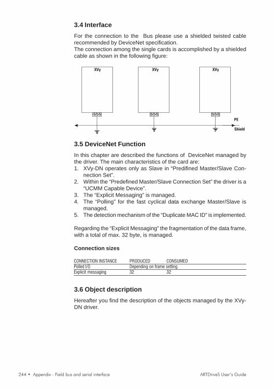
244 • Appendix - Field bus and serial interface ARTDriveS User’s Guide
3.4 InterfaceFor the connection to the Bus please use a shielded twisted cablerecommended by DeviceNet specification.The connection among the single cards is accomplished by a shieldedcable as shown in the following figure:
XVy
PE
Shield
XVy XVy
3.5 DeviceNet FunctionIn this chapter are described the functions of DeviceNet managed bythe driver. The main characteristics of the card are:1. XVy-DN operates only as Slave in “Predifined Master/Slave Con-
nection Set”.2. Within the “Predefined Master/Slave Connection Set” the driver is a
“UCMM Capable Device”.3. The “Explicit Messaging” is managed.4. The “Polling” for the fast cyclical data exchange Master/Slave is
managed.5. The detection mechanism of the “Duplicate MAC ID” is implemented.
Regarding the “Explicit Messaging” the fragmentation of the data frame,with a total of max. 32 byte, is managed.
Connection sizes
CONNECTION INSTANCE PRODUCED CONSUMEDPolled I/O Depending on frame settingExplicit messaging 32 32
3.6 Object descriptionHereafter you find the description of the objects managed by the XVy-DN driver.

ARTDriveS User’s Guide Appendix - Field bus and serial interface • 245
3.6.1 Object ModelThe following figure shows the XVy-DN “Object Model”.
Application Objects
Drive memory
accessDrive par
Message
Router
DeviceNet
IDENTITY
ExplicitI/O
Connection
The following table shows:1. The object classes of XVy-DN driver.2. If the class is mandatory.3. The number of instances included in every class.See “DeviceNet Specifications” for the Standard classes.
Object Optional/Required # of InstancesIdentity Required 1Message Router Required 1DeviceNet Required 1Connection Required 1 I/O, 3 ExplicitParameter Optional manyDrive Parameter Access Optional manyDrive memory Access Optional many
3.6.2 How Objects Affect BehaviorThe “Affect Behaviour” of the objects is reported in the following table:
Object Effect on BehaviorIdentity Supports “Reset Service”Message Router No effectDeviceNet Port attributes configurationConnection Contains the number of logical portsParameter Drive parameters read/writeDrive Parameter Access Drive parameters read/writeDrive Memory Access Drive parameters read/write
3.6.3 Defining Object InterfaceThe object interface of the XVy-DN driver is the following:
Object InterfaceIdentity Message routerMessage Router Explicit Messaging Connection InstanceDeviceNet Message routerConnection Message routerParameter Message routerDrive Parameter Access Message routerDrive memory Access Message router

246 • Appendix - Field bus and serial interface ARTDriveS User’s Guide
3.7 Data transfert via Explicit MessagingThe data transfer via Explicit Messaging is made through two new ob-jects: one for accessing the Drive parameters, the other to direct accessthe drive memory.
3.7.1 Drive Parameter AccessFor read/write of Drive parameters, the Drive Parameter Access objectis defined with the following properties:- Class ID: Fh.- Class Attribute: Revision- Instance Attribute: This instance does not have attributes.
3.7.1.1 Class CodeClass code: F hex
3.7.1.2 Class attributes
NumberNeed in
implementationAccess Rule Name
DeviceNet
Data Type
Description
of Attribute
Semantics of
values
1 Optional Get Revision UINTRevision of
this object
dn345
3.7.1.3 Instance Attributes
NumberNeed in
implementationAccess Rule Name
DeviceNet
Data Type
Description
of Attribute
Semantics of
values
dn350
This instance does not provide attributes
3.7.1.4 Common ServicesThis object has no common services.
3.7.1.5 Object Specific Services
Class Instance
0hex n/a Required Get_Attribute_Single Read drive parameter value
10hex n/a Required Set_Attribute_Single Writes drive parameter value
dn356
Service Code
Need in
implementation Service Name Description of Service
3.7.1.6 BehaviorThis object is the interface between the DeviceNet and all driveparameters.The Drive parameter is accessed via the parameter index itself.
For example, reading a parameter (IPA 24000:- Run a Get_Attribute_Single from class Fh,- instance = 24000 (5DC0 hex)- class 1 attribute- the drive responds with 4 bytes (Dword format).

ARTDriveS User’s Guide Appendix - Field bus and serial interface • 247
For example, writing a parameter (IPA 23000):- Run a Set_Attribute_Single from class Fh,- instance = 23000 (53D8 hex)- class 1 attribute- to set value 20, select “Word 2 byte” (parameter format is INT, 16 bit)- the drive does not respond if there is an error (timeout).
Low byte - Low word drive parameter drive
High byte - Low word drive parameter drive
Low byte - High word drive parameter drive
High byte - High word drive parameter drive
dn357
byte VALUE XX
The number of bytes in the “Value” field depends on the length of driveparameter;
Example:if the type of drive parameter is “Integer” the length of VALUE is 2 bytes.
3.7.2 Drive Parameter AccessFor read/write of Drive parameters, the Drive Parameter Access objectis defined with the following properties:- Class ID: 66h.- Class Attribute: Revision- Instance Attribute: This instance does not have attributes.
3.7.2.1 Class CodeClass code: 66 hex
3.7.2.2 Class attributes
NumberNeed in
implementationAccess Rule Name
DeviceNet
Data Type
Description
of Attribute
Semantics of
values
1 Optional Get Revision UINTRevision of
this object
dn345
3.7.2.3 Instance Attributes
NumberNeed in
implementationAccess Rule Name
DeviceNet
Data Type
Description
of Attribute
Semantics of
values
dn350
This instance does not provide attributes
3.7.2.4 Common ServicesThis object has no common services.

248 • Appendix - Field bus and serial interface ARTDriveS User’s Guide
3.7.2.5 Object Specific Services
Class Instance
32hex n/a Required Get_Drive_Value Read drive parameter value
33hex n/a Required Set_Drive_Value Writes drive parameter value
34hex n/a Required Get_Typed_Drive_Valu
e
Read drive parameter value
indicating the data type
35hex n/a Required Set_Typed_Drive_Value Writes drive parameter value
indicating the data type
dn355
Service
Code
Need in
implementation Service Name Description of Service
3.7.2.6 BehaviorThis object is the interface between the DeviceNet network and all Driveparameters. The access to the Drive parameter is carried out by theparameter index; if the parameter does not exist or may not be accessedfor any reason (for example: try to write a read only parameter) an errorcode will be returned. Drive parameters in text format cannot beaccessed.In the following are repeted patterns of how the data frame of data hasto be composed for reading/writing Drive parameters.
A) Write Drive ParameterIn this example the writing of a Drive parameter is shown; the cases ofpositive or wrong writing are distinguished.
A-1) Write Drive Parameter RequestThe data frame for writing a drive parameter is composed as follows:
DATA TYPE FIELD VALUE MEANING
Byte Service Code 33hex Set Drive Parameter - Object Specific Service
Class ID 66hex Drive Parameter Access Class Object
Instance ID XXXX Drive Parameter Index in format Low byte-High byte
XX Low byte-Low word drive parameter value
XX High byte-Low word drive parameter value
XX Low byte-High word drive parameter value
XX High byte-High word drive parameter value
dn360
See Note 1)
Byte 2) VALUE
1) Byte or Word depending on the type of allocation executed by the Master.2) The number of bytes of the “Value”-field depends on the length of the Drive parameter;
i.e.: if the Drive parameter type is “Integer” the length of VALUE is 2 bytes.
A-2) Write drive parameter - Reply OKIf the Drive parameter is written correctly, the response is:
DATA TYPE FIELD VALUE MEANING
Byte Service Code 33hex OR 80hexSet Drive Parameter Reply code- Object Specific
Service.
Word Result 0000Result field equal to zero means writing correctly
executed.
dn365
A-3) Write drive parameter - Reply ErrorIf the writing of the drive parameter has been rejected, the response is
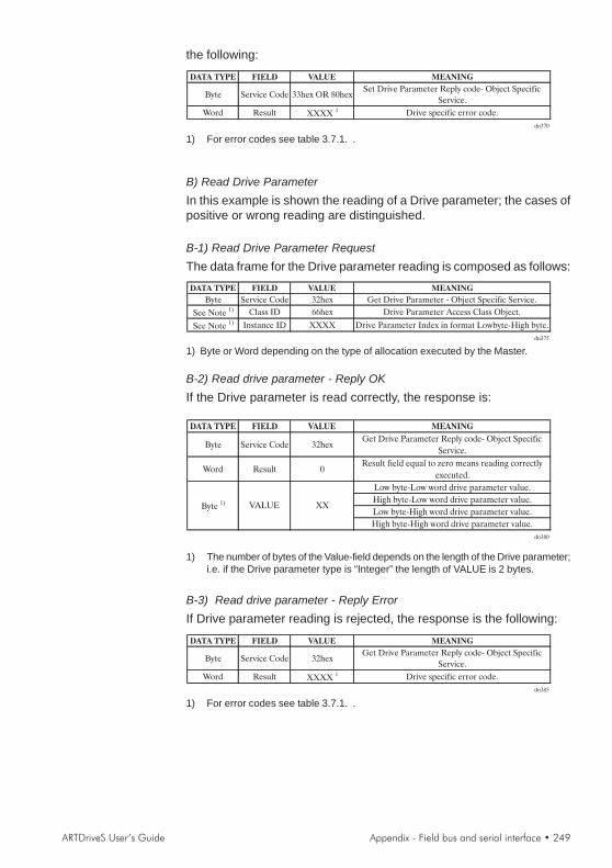
ARTDriveS User’s Guide Appendix - Field bus and serial interface • 249
the following:
DATA TYPE FIELD VALUE MEANING
Byte Service Code 33hex OR 80hexSet Drive Parameter Reply code- Object Specific
Service.
Word Result XXXX 1 Drive specific error code.
dn370
1) For error codes see table 3.7.1. .
B) Read Drive ParameterIn this example is shown the reading of a Drive parameter; the cases ofpositive or wrong reading are distinguished.
B-1) Read Drive Parameter RequestThe data frame for the Drive parameter reading is composed as follows:DATA TYPE FIELD VALUE MEANING
Byte Service Code 32hex Get Drive Parameter - Object Specific Service.
See Note 1) Class ID 66hex Drive Parameter Access Class Object.
See Note 1) Instance ID XXXX Drive Parameter Index in format Lowbyte-High byte.
dn375
1) Byte or Word depending on the type of allocation executed by the Master.
B-2) Read drive parameter - Reply OKIf the Drive parameter is read correctly, the response is:
DATA TYPE FIELD VALUE MEANING
Byte Service Code 32hexGet Drive Parameter Reply code- Object Specific
Service.
Word Result 0Result field equal to zero means reading correctly
executed.
Low byte-Low word drive parameter value.
High byte-Low word drive parameter value.
Low byte-High word drive parameter value.
High byte-High word drive parameter value.
dn380
XXByte 1) VALUE
1) The number of bytes of the Value-field depends on the length of the Drive parameter;i.e. if the Drive parameter type is “Integer” the length of VALUE is 2 bytes.
B-3) Read drive parameter - Reply ErrorIf Drive parameter reading is rejected, the response is the following:
DATA TYPE FIELD VALUE MEANING
Byte Service Code 32hexGet Drive Parameter Reply code- Object Specific
Service.
Word Result XXXX 1 Drive specific error code.
dn385
1) For error codes see table 3.7.1. .

250 • Appendix - Field bus and serial interface ARTDriveS User’s Guide
C) Write Typed Drive ParameterIn this example the writing of a Drive parameter is shown; the cases ofpositive or wrong writing are distinguished.In this case, it is shown the parameter IPA number, the value and thedata type used in the data transmission.The optional data type conversion is automatically executed by thefirmware.
C-1) Write Drive Parameter RequestThe data frame for writing a drive parameter is composed as follows:DATA TYPE FIELD VALUE MEANING
Byte Service Code 35hex Set Drive Parameter - Object Specific Service
Class ID 66hex Drive Parameter Access Class Object
Instance ID XXXX Drive Parameter Index in format Low byte-High byte
Byte 2) DATA
TYPEXX Value data type
XX Low byte-Low word drive parameter value
XX High byte-Low word drive parameter value
XX Low byte-High word drive parameter value
XX High byte-High word drive parameter value
dn390
See Note 1)
Byte 3) VALUE
1) Byte or Word depending on the type of allocation executed by the Master.2) The coding of the possible data type is listed in table 3.7.2.3) The number of bytes of the “Value”-field depends on the length of the Drive parameter;
i.e.: if the Drive parameter type is “Integer” the length of VALUE is 2 bytes.
C-2) Write drive parameter - Reply OKIf the Drive parameter is written correctly, the response is:DATA TYPE FIELD VALUE MEANING
Byte Service Code 33hexSet Drive Parameter Reply code- Object Specific
Service.
Word Result 0000Result field equal to zero means writing correctly
executed.
dn395
C-3) Write drive parameter - Reply ErrorIf the writing of the drive parameter has been rejected, the response isthe following:DATA TYPE FIELD VALUE MEANING
Byte Service Code 33hexSet Drive Parameter Reply code- Object Specific
Service.
Word Result XXXX 1 Drive specific error code.
dn400
1) For error codes see table 3.7.1. .
D) Read Drive ParameterIn this example is shown the reading of a Drive parameter; the cases ofpositive or wrong reading are distinguished.In this case, it is shown the parameter IPA number, the value and thedata type used in the data transmission.The optional data type conversion is automatically executed by thefirmware.
D-1) Read Drive Parameter RequestThe data frame for the Drive parameter reading is composed as follows:
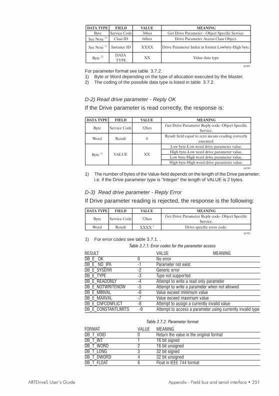
ARTDriveS User’s Guide Appendix - Field bus and serial interface • 251
DATA TYPE FIELD VALUE MEANING
Byte Service Code 36hex Get Drive Parameter - Object Specific Service.
See Note 1) Class ID 66hex Drive Parameter Access Class Object.
See Note 1) Instance ID XXXX Drive Parameter Index in format Lowbyte-High byte.
Byte 2) DATA
TYPEXX Value data type
dn405
For parameter format see table 3.7.2.1) Byte or Word depending on the type of allocation executed by the Master.2) The coding of the possible data type is listed in table 3.7.2.
D-2) Read drive parameter - Reply OKIf the Drive parameter is read correctly, the response is:
DATA TYPE FIELD VALUE MEANING
Byte Service Code 32hexGet Drive Parameter Reply code- Object Specific
Service.
Word Result 0Result field equal to zero means reading correctly
executed.
Low byte-Low word drive parameter value.
High byte-Low word drive parameter value.
Low byte-High word drive parameter value.
High byte-High word drive parameter value.
dn380
XXByte 1) VALUE
1) The number of bytes of the Value-field depends on the length of the Drive parameter;i.e. if the Drive parameter type is “Integer” the length of VALUE is 2 bytes.
D-3) Read drive parameter - Reply ErrorIf Drive parameter reading is rejected, the response is the following:
DATA TYPE FIELD VALUE MEANING
Byte Service Code 32hexGet Drive Parameter Reply code- Object Specific
Service.
Word Result XXXX 1 Drive specific error code.
dn385
1) For error codes see table 3.7.1. .Table 3.7.1: Error codes for the parameter access
RESULT VALUE MEANINGDB_E_ OK 0 No errorDB_E_ NO_IPA -1 Parameter not existDB_E_SYSERR -2 Generic errorDB_E_TYPE -3 Type not supportedDB_E_READONLY -4 Attempt to write a read only parameterDB_E_NOTWRITENOW -5 Attempt to write a parameter when not allowedDB_E_MINVAL -6 Value exceed minimum valueDB_E_MAXVAL -7 Value exceed maximum valueDB_E_CNFCONFLICT -8 Attempt to assign a currently invalid valueDB_E_CONSTANTLIMITS -9 Attempt to access a parameter using currently invalid type
Table 3.7.2: Parameter format
FORMAT VALUE MEANINGDB_T_VOID 0 Return the value in the original formatDB_T_INT 1 16 bit signedDB_T_WORD 2 16 bit unsignedDB_T_LONG 3 32 bit signedDB_T_DWORD 4 32 bit unsignedDB_T_FLOAT 6 Float in IEEE 744 format

252 • Appendix - Field bus and serial interface ARTDriveS User’s Guide
3.8 Polling FunctionThis type of DeviceNet-function is used for a fast cyclic exchange ofDrive-parameters between Master and XVy drive.The characteristics of the Polling-function are:1. The data frame length is configurable through specific drive param-
eter (see chapter 10, FIELDBUS menu) and can vary from 1 to 10word for both directions (Slave->Master and Master->Slave).
2. The card, as it is a Slave, during the Polling consumes Output dataand produces Input data as response.
The configuration of the Drive parameters transferred via Polling is setby using configuration parameter allocated in the drive (see chapter 10,FIELDBUS menu).
3.9 XVy-DN Interface configurationThe DeviceNet interface configuration is performed via the drive pa-rameters. The parameters are controlled via hierarchical menus. All thewriting parameters referring to the DeviceNet interface are active onlyafter the drive reset. Here following is a list of drive parameters useful tocontrol the DeviceNet interface
3.9.1 Fieldbus MenuThe XVy-DN communication card can be enabled by setting the IPA40000 Field Bus Type parameter as "Devicenet". The other parametersof this menu are:
IPA Par. Name Type Default val. Attr.40100 Bus Address 1 byte unsigned 0 writing40001 Bus Baude Rate 4 bytes unsigned 0 writing40110 CC Enabling Enum Enabled writing40111 PDC Enabling Enum Enabled writing40114 FB Fail Casue 4 bytes unsigned 0 read only
- Bus Address (IPA 40100) = address of the node; admitted values 1... 63.
- Bus Baude Rate (IPA 40001) = network baud rate. The baudrate isstated directly in kbaud (ex. 125kb = 125); admitted values 125,250, 500.
- PDC Enabling (IPA 40111) and CC Enabling (IPA 40110) = allowthe user to enable/disable the corresponding channels. With thePDC channel it is possible to exchange up to 8 parameters.
- FB Fail Casue (IPA 40114) = error cause. See the following table
3.9.2 Error CodesCod. Meaning1 Protocol incorrect18..24 Configuration error on M2S reception channel25..31 Configuration error on S2M reception channel32 Too many bytes on M2S reception channel33 Too many bytes on S2M transmission channel34-35 Errored IPA for PLC allocation36 More than 4 words allocated as Fast250 us on M2S

ARTDriveS User’s Guide Appendix - Field bus and serial interface • 253
37 More than 4 words allocated as Fast250 us on S2M100 Baud-rate value not correct101 Node address not correct107 CAN line in “Bus-off” state108 Dnet internal error109 MAC-ID duplicated (there is already a node with the same address)110 Software key for authorisation invalid or expired
3.10 Alarms3.10.1 XVy-DN AlarmsThe XVy-DN interface provides two possible alarms:Alarm (A 26) FieldBus Failure, is automatically enabled if there is nocommunication on the bus at a PDC level (polling I/O). This alarmbecomes active only when the drive is enabled.If ON, the FB Alarm Watch parameter (IPA 40115) enables the genera-tion of the "Field bus failure" alarm also when the drive is disabled.
3.10.2 Drive alarm handlingConsidering that the card must function on different firmware applicationsystems, the "drive alarm status" is not foreseen.The "drive alarm status" is not therefore given any special treatment.The XVy-EV firmware, provides a series of parameters capable of detectingthe drive status. Refer to chapter 10, Alarms and Fieldbus menu for moreinformation.
3.10.3 Alarm resetThe alarm reset is one of the drive standard functions, i.e. eachapplication provides the same parameter for this function. It is thereforepossible to reset the alarms via the configuration channel on the firmwareof all the different drives.The alarms can be reset by sending the value1 to the 18012 parameter.The reset of the bit-controlled alarms can be performed also via the"Virtual Digital Input" function.
3.11 Process Data Channel ControlThis function allows to allocate the drive parameters or application vari-ables to the Process Data Channel data.The XVy-DN interface uses a number of words for the Process DataChannel (abbr. PDC Process Data Channel ), which can always be set.The Process Data Channel configuration for the XVy-DN interface isthe following:
DATUM 0 DATUM... DATUMn
The Slave can both read and write the Process Data Channel data.The DeviceNet data read by the Slave are defined as input data; thedata written in DeviceNet by the Slave are defined as output data.A datum can be made both of 2 and 4 bytes. The word "data" refers toany quantity of bytes included between 0 and 10, if the byte total numberrequired is not higher than 20.

254 • Appendix - Field bus and serial interface ARTDriveS User’s Guide
ExampleIt is possible to have:
- from 0 to 10 data items of 2 byte- 1 datum of 4 bytes + from 0 to 8 data items of 2 bytes- 2 data items of 4 bytes + from 0 to 6 data items of 2 bytes- 3 data items of 4 bytes + from 0 to 4 data items of 2 bytes- 4 data items of 4 bytes + from 0 to 2 data items of 2 bytes- 5 data items of 4 bytes
The data exchanged via the PDC can be of two types:-drive parameters-variables of an MDPlc application
The composition of the PDC input and output data is defined via suitableparameters as described in the paragraphs 3.11.1 and 3.11.2.The master cyclically writes the data defined as PDC input and cyclicallyreads the data defined as PDC output.
Input
Output
Drive
PDC XVy-DN
3.11.1 PDC Input Configuration (SYS_FB_XXX_MS parameter)See section 1.3.1, Appendix.
3.11.2 PDC Output Configuration (SYS_FB_XXX_SM Parameter)See section 1.3.1, Appendix.
3.11.3 Configuration of the Virtual Digital I/OsThe XVy-EV firmware, provides the "Virtual Digital I/O" function, whichallows to exchange discrete signals between the master and the slaveand vice versa. See the chapter 10 (DIGITAL INPUTS / VIRT DIGINPUTS e DIGITAL OUTPUTS / VIRT DIG OUTPUTS.menu) for adetailed description of these parameters.Other application firmware, for example MDPlc, does not provide the"Virtual Digital I/O" function.
3.11.4 Use of the PDC in MDPlc ApplicationsIt is possible to configure both the PDC input and output data in order toallow the data direct access via the MDPlc application code.For more details see the manual “Drive programming with MDPlc” on“XVy tools” cd-rom.

Gef
ran
wo
rld
wid
e
GEFRAN SENSORIvia Cave, 1125050 PROVAGLIO D’ISEO (BS) ITALYPh. +39 030 9291411Fax. +39 030 [email protected]
GEFRAN BENELUXLammerdries, 14AB-2250 OLENPh. +32 (0) 14248181Fax. +32 (0) [email protected]
GEFRAN BRASILELETROELETRÔNICAAvenida Dr. Altino Arantes,377/379 Vila Clementino04042-032 SÂO PAULO - SPPh. +55 (0) 1155851133Fax +55 (0) [email protected]
GEFRAN DEUTSCHLANDPhilipp-Reis-Straße 9a63500 SELIGENSTADTPh. +49 (0) 61828090Fax +49 (0) [email protected]
GEFRAN SUISSERue Fritz Courvoisier, 402302 LA CHAUX-DE-FONDSPh. +41 (0) 329684955Fax +41 (0) [email protected]
GEFRAN SIEI - FRANCE4, rue Jean Desparmet - BP 823769355 LYON Cedex 08Ph. +33 (0) 478770300Fax +33 (0) [email protected]@sieifrance.fr
GEFRAN ISI8 Lowell AvenueWINCHESTER - MA 01890Toll Free 1-888-888-4474Ph. +1 (781) 7295249Fax +1 (781) [email protected]
SIEI AREG - GERMANYZachersweg, 17D 74376 - GemmrigheimPh. +49 7143 9730Fax +49 7143 [email protected]
GEFRAN SIEI - UK7 Pearson Road, Central ParkTELFORD, TF2 9TX Ph. +44 (0) 8452 604555Fax +44 (0) 8452 [email protected]@sieiuk.co.uk
GEFRAN SIEI - ASIANo.160 Paya Lebar Road05-07 Orion Industrial Building409022 SingaporePh. +65 6 8418300Fax +65 6 [email protected]
GEFRAN SIEI Electric Pte LtdBlock B, Gr.Flr, No.155, Fu Te Xi Yi Road,Wai Gao Qiao Trade Zone 200131 ShanghaiPh. +86 21 5866 7816Ph. +86 21 5866 1555Ph. +86 21 5866 [email protected]
SIEI DRIVES TECHNOLOGYNo.1265, B1, Hong De Road,Jia Ding District201821 ShanghaiPh. +86 21 69169898Fax +86 21 [email protected]
SIEI AMERICA - USA14201 D South Lakes DriveNC 28273 - CharlottePh. +1 704 3290200Fax +1 704 [email protected]
GEFRAN S.p.A.Via Sebina 7425050 Provaglio d’Iseo (BS) ITALYPh. +39 030 98881Fax +39 030 [email protected]
Motion ControlVia Carducci 2421040 Gerenzano [VA] ITALYPh. +39 02 967601Fax +39 02 [email protected]
Technical Assistance : [email protected]
Customer Service : [email protected]. +39 02 96760500Fax +39 02 96760278
Related Documents


