Cavitation Erosion in Hydraulic Turbine Components and Mitigation by Coatings: Current Status and Future Needs Raghuvir Singh, S.K. Tiwari, and Suman K. Mishra (Submitted April 21, 2010; in revised form May 16, 2011) Cavitation erosion is a frequently observed phenomenon in underwater engineering materials and is the primary reason for component failure. The damage due to cavitation erosion is not yet fully understood, as it is influenced by several parameters, such as hydrodynamics, component design, environment, and material chemistry. This article gives an overview of the current state of understanding of cavitation erosion of materials used in hydroturbines, coatings and coating methodologies for combating cavitation erosion, and methods to characterize cavitation erosion. No single material property fully characterizes the resis- tance to cavitation erosion. The combination of ultimate resilience, hardness, and toughness rather may be useful to estimate the cavitation erosion resistance of material. Improved hydrodynamic design and appropriate surface engineering practices reduce damage due to cavitation erosion. The coatings suggested for combating the cavitation erosion encompasses carbides (WC Cr 2 C 3 , Cr 3 C 2 , 20CrC-80WC), cermets of different compositions (e.g., 56W 2 C/Ni/Cr, 41WC/Ni/Cr/Co), intermetallic composites, intermetallic matrix composites with TiC reinforcement, composite nitrides such as TiAlN and elastomers. A few of them have also been used commercially. Thermal spraying, arc plasma spraying, and high velocity oxy-fuel (HVOF) processes have been used commercially to apply the coatings. Boronizing, laser surface hardening and cladding, chemical vapor deposition, physical vapor deposition, and plasma nitriding have been tried for surface treatments at laboratory levels and have shown promise to be used on actual components. Keywords cavitation, coating methods, coatings, corrosion, erosion, hydroturbine, steels 1. Introduction Hydroturbine components, such as guide vane, runner blade, labyrinth, pivot ring, pump, compressor, etc., are known to be affected by cavitation or combination of cavitation, erosion, and corrosion, as illustrated in Fig. 1. Cavitation-led erosion/pitting may exceed 40-mm depth beyond which a hydroturbine runner is considered undesirable for operation and is generally taken out from the service for maintenance (Ref 1, 2). The cavitation penetration rate of critical components, such as impellor, turbine blade, and casing were found as high as 10 mm/year (Ref 1). Typical metal loss experienced by the turbine runner due to cavitation is reported to be 5 kg/m 2 /10,000 h, and it is about 200 kg loss after a few years of operation (Ref 1). Trailing edge (of the size 800 9 250 9 8 mm) of a turbine blade lost about 40-60 kg of metal after 6000-8000 h of operation (Ref 2). A huge quantity of metal loss clearly indicates cavitation erosion as a serious problem particularly in the South Asian countries belonging to Himalayan regions (such as India, China, and Nepal) (Ref 3–5). One of the major causes of this is the presence of large contents of quartz (90% or 5000- 20,000 ppm) in the silt (SiO 2 , Al 2 O 3 , Fe 2 O 3 , MgO, CaO, etc.), particularly during monsoon season (Ref 6). Quartz which is known to have an extremely high hardness (7 on MohÕs scale compared to 10 for diamond) can thus easily wear out the components in service. Thus, emphasis on the cavitation- and silt-assisted erosion is important for countries, such as India, Nepal, and China, as a major portion of hydropower in these countries is being produced from the Himalayan Rivers that contain excessive silt contents. The hydropower potential in India is estimated to be 120,000 MW from the Himalayan regions which is currently about 32,000 MW (Ref 7). Approx- imately 20% electricity is being generated worldwide from the hydropower, and the components used therein are highly susceptible to cavitation erosion. In New Zealand, approxi- mately 80% of operational power stations are hydrostations (Ref 1). Canada, the largest power producer in the world, has more than 60% (>67,000 MW) power being produced from hydropower (Ref 8). The extent of cavitation erosion damage varies with the location of power stations and seasons, as they influence the silt contents in water. For instances, the cavitation erosion of the turbine at various power stations in India ranges from severe (needs repair after every two monsoon) to considerable damage (needs repair after every 7-8 monsoon) (Ref 9). The cavitation erosion-led damages, in recent times, have further aggravated due to increase in operational pressure, speed of hydraulic systems, and miniaturization of components to enhance the capacity of turbines (Ref 10). Development and use of more resistant materials, applica- tion of coatings, modification of componentÕs design, and minimizing silt contents in the water have been attempted to reduce the cavitation erosion. The micro-injection of bubbles (of non-condensable gases) to cover the component surface has Raghuvir Singh, S.K. Tiwari, and Suman K. Mishra, Council of Scientific & Industrial Research-National Metallurgical Laboratory (CSIR-NML), Jamshedpur 831007, India. Contact e-mails: raghujog@ yahoo.co.in and [email protected]. JMEPEG (2012) 21:1539–1551 ÓASM International DOI: 10.1007/s11665-011-0051-9 1059-9495/$19.00 Journal of Materials Engineering and Performance Volume 21(7) July 2012—1539

Welcome message from author
This document is posted to help you gain knowledge. Please leave a comment to let me know what you think about it! Share it to your friends and learn new things together.
Transcript

Cavitation Erosion in Hydraulic Turbine Components andMitigation by Coatings: Current Status and Future Needs
Raghuvir Singh, S.K. Tiwari, and Suman K. Mishra
(Submitted April 21, 2010; in revised form May 16, 2011)
Cavitation erosion is a frequently observed phenomenon in underwater engineering materials and is theprimary reason for component failure. The damage due to cavitation erosion is not yet fully understood, asit is influenced by several parameters, such as hydrodynamics, component design, environment, andmaterial chemistry. This article gives an overview of the current state of understanding of cavitation erosionof materials used in hydroturbines, coatings and coating methodologies for combating cavitation erosion,and methods to characterize cavitation erosion. No single material property fully characterizes the resis-tance to cavitation erosion. The combination of ultimate resilience, hardness, and toughness rather may beuseful to estimate the cavitation erosion resistance of material. Improved hydrodynamic design andappropriate surface engineering practices reduce damage due to cavitation erosion. The coatings suggestedfor combating the cavitation erosion encompasses carbides (WC Cr2C3, Cr3C2, 20CrC-80WC), cermets ofdifferent compositions (e.g., 56W2C/Ni/Cr, 41WC/Ni/Cr/Co), intermetallic composites, intermetallic matrixcomposites with TiC reinforcement, composite nitrides such as TiAlN and elastomers. A few of them havealso been used commercially. Thermal spraying, arc plasma spraying, and high velocity oxy-fuel (HVOF)processes have been used commercially to apply the coatings. Boronizing, laser surface hardening andcladding, chemical vapor deposition, physical vapor deposition, and plasma nitriding have been tried forsurface treatments at laboratory levels and have shown promise to be used on actual components.
Keywords cavitation, coating methods, coatings, corrosion,erosion, hydroturbine, steels
1. Introduction
Hydroturbine components, such as guide vane, runner blade,labyrinth, pivot ring, pump, compressor, etc., are known to beaffected by cavitation or combination of cavitation, erosion, andcorrosion, as illustrated in Fig. 1. Cavitation-led erosion/pittingmay exceed 40-mm depth beyond which a hydroturbine runneris considered undesirable for operation and is generally takenout from the service for maintenance (Ref 1, 2). The cavitationpenetration rate of critical components, such as impellor,turbine blade, and casing were found as high as 10 mm/year(Ref 1). Typical metal loss experienced by the turbine runnerdue to cavitation is reported to be 5 kg/m2/10,000 h, and it isabout 200 kg loss after a few years of operation (Ref 1).Trailing edge (of the size 8009 2509 8 mm) of a turbine bladelost about 40-60 kg of metal after 6000-8000 h of operation(Ref 2). A huge quantity of metal loss clearly indicatescavitation erosion as a serious problem particularly in the SouthAsian countries belonging to Himalayan regions (such as India,China, and Nepal) (Ref 3–5). One of the major causes of this isthe presence of large contents of quartz (�90% or 5000-
20,000 ppm) in the silt (SiO2, Al2O3, Fe2O3, MgO, CaO, etc.),particularly during monsoon season (Ref 6). Quartz which isknown to have an extremely high hardness (7 on Moh�s scalecompared to 10 for diamond) can thus easily wear out thecomponents in service. Thus, emphasis on the cavitation- andsilt-assisted erosion is important for countries, such as India,Nepal, and China, as a major portion of hydropower in thesecountries is being produced from the Himalayan Rivers thatcontain excessive silt contents. The hydropower potential inIndia is estimated to be �120,000 MW from the Himalayanregions which is currently about 32,000 MW (Ref 7). Approx-imately 20% electricity is being generated worldwide from thehydropower, and the components used therein are highlysusceptible to cavitation erosion. In New Zealand, approxi-mately 80% of operational power stations are hydrostations(Ref 1). Canada, the largest power producer in the world, hasmore than 60% (>67,000 MW) power being produced fromhydropower (Ref 8). The extent of cavitation erosion damagevaries with the location of power stations and seasons, as theyinfluence the silt contents in water. For instances, the cavitationerosion of the turbine at various power stations in India rangesfrom severe (needs repair after every two monsoon) toconsiderable damage (needs repair after every 7-8 monsoon)(Ref 9). The cavitation erosion-led damages, in recent times,have further aggravated due to increase in operational pressure,speed of hydraulic systems, and miniaturization of componentsto enhance the capacity of turbines (Ref 10).
Development and use of more resistant materials, applica-tion of coatings, modification of component�s design, andminimizing silt contents in the water have been attempted toreduce the cavitation erosion. The micro-injection of bubbles(of non-condensable gases) to cover the component surface has
Raghuvir Singh, S.K. Tiwari, and Suman K. Mishra, Council ofScientific & Industrial Research-National Metallurgical Laboratory(CSIR-NML), Jamshedpur 831007, India. Contact e-mails: [email protected] and [email protected].
JMEPEG (2012) 21:1539–1551 �ASM InternationalDOI: 10.1007/s11665-011-0051-9 1059-9495/$19.00
Journal of Materials Engineering and Performance Volume 21(7) July 2012—1539

also been tried to combat the cavitation erosion. Among these,coatings/surface engineering appears most viable option toenhance the lifetime of the component. Extensive reviewsaddressing the physical and chemical processes involved withthe cavitation erosion and response of materials have beenpresented earlier (Ref 11, 12). A few case studies related to thedeclined performance of hydroturbine components due tocavitation erosion have also been described (Ref 11, 12). Thisarticle reviews various coatings and coating methodologiesdeveloped to increase the cavitation erosion resistance. Briefdiscussion on various aspects of cavitation erosion, metallur-gical properties related to cavitation, and methods to charac-terize cavitation erosion have also been presented. The newerand the future coatings to enhance the performance ofunderwater components have also been highlighted.
2. Some Aspects of Cavitation Erosion
2.1 Pure Cavitation
Cavitation erosion of equipment is remarkable consequenceof cavitation together with the cavitation led vibrations andnoise, which reduces the efficiency of power plants. Cavitationis a physical phenomenon which represents the formation,growth, and collapse of bubbles (Ref 13). It generally occursin situations where high-velocity liquid flow encounters apressure change. High fluid velocity in throttling area reducesthe local pressure below the overall fluid vapor pressureresulting in the formation of vapor bubbles. The ‘‘cavitationnumber’’ (r) is widely used to estimate the cavitating potentialof flowing liquid and is generally expressed as:
r ¼ P � Pvð Þ=ð1=2qV 2Þ ðEq 1Þ
where P is upstream pressure, Pv is downstream pressure; qand V are density and velocity of liquid flow, respectively.Critical value of cavitation (rcrit) can be determined for alltypes of equipment at specific hydrodynamic conditions;higher value of rcrit indicates the likeliness of cavitation e.g.,r > rcrit implies occurrence of cavitation, and r < rcrit
implies no cavitation.For nuclei to trigger to a cavity or bubble, it must be
subjected under the tensile forces for sufficient time. Number of
cavitation bubbles is proportional to the amount of tension (T),time (t) below the critical pressure, number, and size of thenuclei (Ref 14) i.e.,
No: of bubbles ¼ f T ; t; number; and size of nucleið Þ
As bubble moves to high-pressure regions, it collapses withintense shock waves emerging from its center. It is the bubblecollapse which is responsible for the erosion or loss of metal.The mechanism of cavitation erosion is though not yet clearlyunderstood; the current understanding follows two explanationsof cavitation erosion (Ref 15, 16). When a bubble collapseswithin the liquid volume (symmetrical collapse), a shock waveemanates to the surrounding liquid. However,, bubble incontact with or very close to the solid boundary collapses inasymmetrical fashion. Here, the cavity is perturbed from theside, away from the solid boundary, and finally the fluidpenetrates through the cavity in the form of micro-jet. Thesemechanisms also lack explanation as shock waves are atten-uated rapidly, and the radius of the cavity (micro-jet) is toosmall to cause the cavitation erosion (Ref 17, 18). The collapseof the cavity cloud may rather have more severe effect on theadjacent surface/solid boundary (Ref 19). The process ofrepeated collapsing of bubble cloud can induce a pressure ashigh as 1000 MPa, which is sufficient to bring about plasticdeformation and consequent removal of metals/alloys (Ref 20).Plastic deformation, as a result of cavitation, is often evidencedby the undulations/deformation bands and pile ups in theunderlying material. Early stages of cavitation have been wellmonitored and documented by Chen and Weite (Ref 21); theyshowed that the cavitation-induced plastic deformation and thepile up evolved along twin boundaries and surrounding thecarbide (along grain boundaries) in Alloy 690. Interphase andgrain boundaries in the materials are the preferred sites fordeformation where failures initiate. Increase in deformations/dislocations were observed with the time of exposure tocavitation, which subsequently coalesced as cracks and resultedinto the removal of material (Ref 21).
Cavitation erosion (in the absence of solid particles) is oftenpredicted by measuring the impact energy of the bubblecollapse (Ref 22). This is done with an assumption that only thecavitation impacts with the energy larger than a certainthreshold level will cause the erosion of materials. Thresholdimpacts of the bubble collapse are important as they initiatefatigue fracture of the surface. Impacts due to collapsing of
Fig. 1 Runner blades showing cavitation erosive failure (Ref 6)
1540—Volume 21(7) July 2012 Journal of Materials Engineering and Performance

bubbles are reported to correspond to the fatigue limit of thematerials (Ref 23). The impact energy below such thresholdcannot produce elastic or plastic deformation and hence nometal loss. Threshold levels of impact energy have beenrevealed experimentally for aluminum, copper, and resin byusing cavitating jet at different conditions. The increase inimpact energy (RFi
2) has been shown to decrease thresholdlevel to cause cavitation erosion (Ref 22). Hattori et al.measured the bubble impact load during collapse of bubble byusing sensor at various standoff distances from the specimensurface as shown in Fig. 2 (Ref 24). They found impact energyto decrease with increase in standoff distance from the locationof bubble collapse, as shown in Fig. 2. The erosion-affectedarea, therefore, remained up to a certain limited distance (a fewmicrometer) from the point of bubble collapse. Changes in RFi
2
also correlated well with the mass-loss data; increase in RFi2
was reported to enhance the erosion rate as illustrated by theFig. 3 (Ref 24)., In their study, they used vibratory test methodto measure bubble impact and cavitation. Correspondingerosion rates (MDE) for various alloys such as stainless steeland aluminum vary linearly with the impact energy (e) (Fig. 3)and is related as given by (Ref 25):
e ¼ DT=qc� F2i ðEq 2Þ
where DT is holding time and considered to be a constantirrespective of impact load, q is density of the test liquid, c isthe velocity of sound in liquid, and Fi is impact load.
The cumulative impact energy E (i.e., Re) is given as
E / RF2i ðEq 3Þ
where RFi2 is calculated as R(Fi
2 9 ni, ni being number ofimpacts).
2.2 Solid Particle-Assisted Cavitation Erosion
In most practical situations, cavitation erosion is assisted bythe solid particles present in the liquid media. This results intomuch higher erosion rate than the sum of erosion due to silt andliquid separately. It is often referred to as the synergetic erosion
(Ref 26, 27). Figure 4 clearly demonstrates and differentiatesthe damage of Peltron turbine needle due to pure sand andcombined effects of sand and cavitation erosion (Ref 27). Theneedle under the combined effect of cavitation and sand erosionshows much deeper and severe attack as compared to thecavitation only. Nanda (Ref 28) reported that the medium siltcontent (in the water) causes 4 times higher erosion than thecavitation in clean water (without silt), and the combined effectof cavitation and erosion is 16 times higher than cavitationalone. The particle entrainment in the cavitating mediumincreases the concentration of bubble nuclei and consequentlypromotes the occurrence of cavitation. A 10-15% increase inthe incipient cavitation number (bubble nucleation) was
Fig. 2 Impact load due to bubble collapse at various standoff dis-tances from the specimen surface (Ref 24)
Fig. 3 Change in erosion rate with increase in impact energy (RFi2)
(Ref 24)
Pure sand erosion (wavy pattern)
Combination of cavitation and sand erosion
Fig. 4 Damage in Peltron turbine needle due to pure sand andcombined effect of sand and cavitation erosion (Ref 27)
Journal of Materials Engineering and Performance Volume 21(7) July 2012—1541

reported by Toshima et al. (Ref 29) in silt-laden water ascompared to the tap water. Cavitation erosion in presence ofsolid particles is further dependent on the impingement angleand properties including the shape, size, and hardness of theerodent. The effect of incidence angle of the erodent on thevariation of erosion rate of brittle and ductile material isillustrated in Fig. 5. The ductile materials are susceptible toerosion at relatively low impingement angles as opposed to thebrittle materials which are eroded severely at relatively largerangles. Particles impinging at angles >90� cause low-cyclefatigue and accumulation of plastic deformation that promotesmaterial detachment. On the other hand, at low angles (<90�)micro-cutting governs the material damage (Ref 30). Forductile materials, the shape and kinetic energy of erodent arethe most important factors to determine the erosion rate (Ref31), while, for brittle materials, the erosion rate is caused bykinetic energy, particle size, hardness, and toughness of theerodent (Ref 32). Micro-model on the silt-accelerated erosionsuggests that the micro jet, from the collapsing of bubble,actually enhances the velocity of solid particle much higherthan the flow rate (in the absence of bubble) (Ref 33). Further,the solid particle within the cavity gains the drag forces andtorque, by the micro jet that initiates micro-cutting action.Erosion is often correlated to the velocity of solid particle aserosion P velocityn, where the value of exponent ‘‘n’’ varieswith material and other operating conditions. Researchers haveworked out the values of �n’’ for various materials; for instance,Truscott (Ref 34) showed it to be 1.7 for steel; Zhang et al. (Ref35) showed it to be 3-4.5 for non-metallic coatings. Similarly,Arnold and Hutchings (Ref 36) found the velocity exponent forelastomers between 2.9 and 5.1 at impingement angles �30�and 90�, respectively. Bjordal et al. (Ref 37) observed erosionrate to depend upon the particle flux rate (i.e., concentration ofimpacting particles per unit area on the specimen) and showedit to be related as erosion rate P concentration0.25-1.27 fordifferent metals and coatings. The exponent value was closeto 1 for most of the materials when tested for longer periods.
Several models have dealt with the erosion in the liquid inpresence of solid particles, such as for silt erosion conditions.Bardal (Ref 38) described the most general formula for pureerosion as
W ¼ KmatKenvcVnf ðaÞ ðEq 4Þ
where W is erosion rate in mm/year, Kmat is material constant,and Kenv is constant depending upon environment, c is concen-tration of particles, and ƒ(a) is the function of impingementangle, V is velocity of particle, and n is the exponent of velocity.
Truscott (Ref 34) presented following equation to predict thecavitation erosion of a pump assuming sliding of sphericalparticle over the surface of pump:
Erosion / ðqp � qÞd3pK V 3=D� �
ðEq 5Þ
where V is the characteristic velocity of liquid, D is the char-acteristic dimension of the machine, qp is density of particle,d is diameter of particle, p is number of particles per unit sur-face area, q is density of the liquid, and K is experimentalcoefficient depending upon the nature of abrasive. This equa-tion is proportional to the experimental coefficient which isdependent on the abrasive nature of particles. Tsuguo (Ref39) showed an empirical equation for cavitation erosion ofturbine, based on the erosion data obtained (over the 8 yearsof time) from 18 hydropower plants. It was based on the uni-form thickness loss of material and expressed as follows:
W ¼ bCxayk1k2k3nyxVn ðEq 6Þ
where b is turbine coefficient at the eroded part, C is the con-centration of suspended sediment, and V is relative velocity.The term a is average grain size coefficient on the basis ofunit value for grain size �0.05 mm. The terms k1 and k2 arethe shape and hardness coefficients of sand particles, respec-tively, and k3 is abrasion-resistant coefficient of material. Thex, y, and n are exponent values for concentration, size coeffi-cient, and velocity, respectively. The values of x and y areclose to the unity; any deviation in linear proportionality isdetermined from the plot of wear versus parameter.
2.3 Electrochemical (Corrosion)-Assisted Cavitation Erosion
The cavitation erosion is aggravated by the electrochemicalreaction occurring on the alloy surface. The repeated bubbleformation and collapsing may cause the rupture of electro-chemically formed protective passive film which is generallyresponsible for the corrosion resistance of metals/alloys. Theaggressiveness of the electrochemical reaction, however,depends upon the pH, concentration of corrosives (e.g., Cl�),fluid flow, and pressure. At low fluid velocity, the passiveoxide/scale remains intact to the surface but may be washed/swept away at relatively higher velocities and surface mayappear clean. Corrosion in some situations is found to be anunderlying cause of the damage of turbine components whichcould be the consequence of cavitation (Ref 40, 41). It has beenreported that the corrosion-assisted erosion or combinederosion-corrosion is a serious concern in offshore industries(Ref 42). Various interactive zones among cavitation, erosion,and corrosion are well represented by the schematic shown inFig. 6 (Ref 42). The total erosion loss due to variousmechanisms is expressed as follows (Ref 43):
WTotal ¼ Werosion þWcorrosion þ DWerosion þ DWcorrosion ðEq 7Þ
where DWerosion + DWcorrosion is synergy. DWcorrosion is ero-sion-enhanced corrosion, and DWerosion is corrosion-enhancederosion. The effect of cavitation is included in the DEerosion
as mechanical synergy.
Ero
sion
rat
e
Incident angle (degree)
Brittle material Ductile material
0 15 30 45 60 75 90
Fig. 5 Effect of incidence angle of erodent on erosion rate ofbrittle and ductile material
1542—Volume 21(7) July 2012 Journal of Materials Engineering and Performance

3. Cavitation Erosion-resistant Alloysfor Hydroturbine
Although great efforts have been made to develop thecavitation-resistant materials and improve the hydroturbinedesign, the problem of cavitation/silt erosion yet remainsunsolved. Martensitic stainless steels (such as 13Cr-4Ni, 13Cr-0.5Ni, manganese steels) are, by far, the most popular choicesfor fabricating turbine components where cavitation erosion isprimary concern. For instances, runner blades are fabricatedfrom 13Cr-1Ni, 13Cr-4Ni, 16Cr-5Ni, and 18Cr-8Ni stainlesssteels (Ref 44); guide vanes and labyrinth (rotating) seal aremade from 13Cr-4Ni, and 16Cr-5Ni; and labyrinth (stationary)seal from nickel aluminum bronze (JM7) alloy. The martensiticstainless steels possess higher cavitation erosion resistance thanthe austenitic, while the ferritic stainless steels have the lowestresistance (Ref 45). It has been observed that the cavitationerosion of martensitic stainless steels increases with increase inthe hardness (Ref 46). DIN 4112 (Fe, 18.5% Cr, 1.15% Mo, 1%Mn, 1% Si, and 0.91% C) shows higher cavitation erosionresistance than the BS 431S29 (Fe, 15.6% Cr, 2.34% Ni, 1%Mn, 0.8% Si,and 0.11% C) for similar heat-treatment condi-tions. This is due to the difference in the carbon content and to alesser degree, the chromium content (Ref 42). Carbon in thealloy has both positive and negative effects on cavitationerosion resistance. High carbon content in DIN 4112 showshigh hardness of its martensitic matrix, but it increases theformation of the coarse chromium carbides that provide sitesfor the initiation of erosion damage (Ref 46). The NiTiNOL(Ni-55%, Ti-45%) has also been suggested as an alternativematerial for components of turbine as it offers high fatigueresistance and mechanical properties (Ref 46). The martensiticphase in NiTiNOL has good damping characteristic andprovides self-accommodating twinned structure. High cost ofthis alloy may, however, restrict its use as turbine components.The surface alloying or cladding of NiTiNOL on stainlesssteels, using high-power lasers, may be an alternative choice toreduce the cost of component. Iron-based alloy (CaviTech)containing alloying elements, such as cobalt, chromium, andmanganese (altogether to the maximum of 9%) has beendeveloped, which has demonstrated significantly high cavita-tion erosion resistance (Ref 1).
4. Dependence of Cavitation Erosion Resistanceon Various Metallurgical Properties
Material damage due to cavitation erosion is dependent onthe cavitation intensity of the medium, erodent properties, andresistance of the materials to cavitation. Cavitation resistance isnot precisely a definable property of material. One-to-onecorrespondence, therefore, with any independent measurablemetallurgical property has not been reported. It is generallypostulated that the cavitation erosion resistance is high for thematerials which contain lower stacking fault energy, as they canundergo easier planar slips formation (Ref 47) and stressinduced phase transformation (Ref 48). Such materials havehigh work hardenability, and good elastic properties withhomogeneous small-grained structure such as Stellite (Ref 49).An excellent cavitation resistance of cobalt-based alloys is wellknown since the early 1970s (Ref 1). The key microstructuralfactor for these alloys is the fine deformation twins accompa-nied by the cavitation-induced phase transformation. Martens-itic stainless steels have also demonstrated high cavitationerosion resistance; they, however, have certain drawbacks suchas susceptibility to intergranular corrosion that can enhance therate of cavitation erosion (Ref 50). Such stainless steels aregenerally used in the tempered condition. Tempering ofmartensitic stainless steel causes the intergranular chromiumcarbide precipitation which reduces the erosion resistance (Ref50). Investigations showed that the maximum susceptibility tointergranular corrosion is observed in steel tempered in thetemperature ranges 500-600 �C. Tempering the stainless steel at>600 �C reduces sensitization to the lowest level or avoids itcompletely. Early statistical research pointed out hardness as aprimary correlation factor and showed that the increase inhardness reduces the cavitation resistance (Ref 51–53). This,however, is contradicted by several other researchers whoconcluded that hardness or the strength/toughness alone cannotrepresent the cavitation resistance of materials (Ref 54–57).Competing theories involved a few other mechanical proper-ties, such as combination of ultimate tensile strength and elasticmodulus (ultimate resilience) (Ref 54), the combination ofultimate resilience and hardness (Ref 55), energy absorptioncharacteristics (Ref 56), and fatigue strength (Ref 57) torepresent the cavitation resistance in a better manner. Ultimateresilience is the combined material property shown by the areaunder the triangle obtained by raising the yield point to thelevel of ultimate tensile strength. Based on these, followingmathematical formulations have been proposed and reported(Ref 54–56):
Ultimate resilience URð Þ ¼ UTSð Þ2=2E ðEq 8Þ
Modified ultimate resilience MURð Þ¼ UTS�Hardness of substrateð Þ=2E ðEq 9Þ
Compositemodified resilience CMRð Þ¼ UTSof substrate�Hardness of coatingð Þ=2Youngmodulus of substrate ðEq 10Þ
Higher value of the above parameters indicates greaterresistance of materials against cavitation erosion. Contradic-tions to the above correlations were also quite common. Forinstance, borided 13Cr-4Ni stainless steel though showed thehigher UR �3.6 J/cm3 than the base 13Cr-4Ni (1.9 J/cm3), it
Cor
rosi
on d
omin
ated
zon
e
Cav
itat
ion-
eros
ion-
corr
osio
n zo
ne
Cav
itat
ion-
eros
ion
zone
Fig. 6 Various interactive zone among cavitation, erosion, and cor-rosion
Journal of Materials Engineering and Performance Volume 21(7) July 2012—1543

did not produce the highest cavitation resistance (Ref 58). Itwas rather reported to be dependent upon the strain energy. Thebase 13Cr-4Ni with the highest strain energy �112.1 J/cm3
showed better cavitation resistance than the borided + tem-pered (64.7 J/cm3) and borided alone (6.3 J/cm3) (Ref 58).Materials with lower grain sizes and higher mechanicalproperties exhibited better cavitation resistance (Ref 59).Nanomaterials or nano-crystallite structures can enhance thecavitation erosion resistance as they possess good plasticproperties with the hardness higher than the conventionalmaterials. Materials containing the grain size below 100 nm aregenerally called nanomaterials, although the grains (crystallites)smaller than 20 nm are preferred (Ref 60, 61) to achieve specialproperties. Higher grain boundary area in the fine grained thanin the conventional materials is the reason for special proper-ties. For instance, 50% of the volume is occupied by the grainboundaries in a material containing 5 nm grains (Ref 62). In thematerials with larger grain boundary percentage (nanomateri-als), grain boundary sliding acts as a main deformationmechanism unlike dislocations in the conventional materials.If grain size is too small (below 15 nm), then the grainboundary sliding causes the decrease in hardness, although, itimproves the stretching, and hence, the reduction in erosionresistance of materials.
5. Surface Engineering and Coatingsfor Preventing Cavitation Erosion
To overcome cavitation/erosion related failures, threeapproaches have generally been considered: optimization ofhydraulic design of the components, development of a newcavitation-erosion-resistant alloy, and coatings of the compo-nents. Cavitation-free geometry may also become susceptible toerosion damage if a surface roughness is increased by theabrasive effects of sand. Higher roughness on the surfacegenerally enhances the cavitation intensity and erosion of thesolid surface. The hydraulic design and a new alloy develop-ment are beyond the scope of objective of the present review.The study that has been carried out on coatings and surfaceengineering to improve the cavitation/erosion resistance, and isavailable in the literature, has been discussed in the forthcom-ing sections.
5.1 Coating Systems for General Cavitation and ErosionResistance
Among various coating systems, hard metallics, intermetal-lics, carbides, borides, oxides, carbonitrides, metal-ceramic(cermets), silicides, and non-metallic materials have beenwidely used for cavitation erosion resistance. Such coatingsare produced either by reinforcing the ready-to-use coatingmaterials or in-situ fabricated coating (by mixing variouspowder precursors in the preferred ratio) by using suitable heatsource. Hard chromium coatings have been used to enhance thewear/abrasion and cavitation resistance of components belong-ing to earthmovers, mining, transport systems, and mould forplastics. Metal nitrides such as TiN, CrN, etc. have beenmodified to the multi component (e.g., TiAlN, TiCN) andmultilayer coatings (e.g., TiN/TiAlN) for various engineeringcomponents. Multilayer coatings offer multifunctional charac-teristics, such as low residual stresses, good adherence to
substrate, improved hardness to toughness ratio, and lowfriction coefficient (Ref 63). The mechanism of deterioration ofcoating in multiple phases, however, is very complex. Increasein the number of coating layers will increase the physicalinterphase boundaries (weak sites) which may become thepreferred sites for failure (either mechanical or corrosion) tooriginate. Performance of the coatings during fluid flow showsdependence on several parameters, such as ratio of the size ofcoating particles to the erodent, relative hardness, shape of theerodent, and conditions of the flow (Ref 64). The latestgeneration of coatings are represented by the nanocomposites(such as TiN + DLC) and lubricating coatings to improve thesurface tribology. Cermets, such as WC, Cr2C3, and Cr3C2
particles, embedded in a metal binder (a pure metal or a mixtureconsisting of Ni, Cr, and Co) are widely used to improvecavitation, erosion, and corrosion resistance of stainless steels(Ref 65). Carbides with more than one binder matrix, such asWC-CrNi, WC/CrC-CoCr, and NiCrSiFeC are increasinglyused to tailor high cavitation, abrasion, and corrosion-resistantsurfaces (Ref 37, 66). Partial or complete substitution of WC byCr3C2 in the NiCr-type corrosion-resistant matrix, using HVOFmethod, showed better tribological properties (Ref 66). It hasbeen reported that the erosion mechanism of the cermetcoatings is controlled either by the carbide particles (such as inWC-Cr3C2-Ni, Cr3C2-NiCr) or metallic binders (such as inWC-Co, WC-Co-Cr). In situations where binder matrix ishighly corrosion resistant (such as Cr3C2-NiCr), erosion occursby the removal of carbide particles due to impact. In case of alow resistant binder (such as in WC-Co), it corrodes and loosenthe carbide particle that results into the erosion of the material.This has also been supported by Toma et al. (Ref 65) whofound the best erosion-corrosion resistance of HVOF sprayedCr3C2-NiCr coating due to its high corrosion-resistant matrix(NiCr). They assessed and compared the erosion resistance ofseveral coatings by using solid particle erosion method. Thesize of the silica particles used for this purpose was in the rangebetween 100 and 500 lm and they were blown at the rate of100 g/L. The results of this investigation are shown in Table 1(Ref 65). The cavitation erosion resistance of AISI 316 stainlesssteels was shown to improve significantly with the ceramicpowders reinforced by the laser heating source (Ref 67). TheCrB2 and WC coatings enhanced the cavitation resistance ofas-received AISI 316 by about 9.4 and 8.5 times, respectively.The increase in the cavitation resistance obtained by usingCr3C2 and SiC was observed by a factor of 4.8 and 2,respectively (Ref 67). The TiC and Cr2O3 have neitherimproved nor reduced the cavitation resistance of stainlesssteel (Ref 67). The hard particle-matrix interphase is weakerlocation and is found vulnerable to corrosion and erosion. Alsosuch zones of phase difference undergo preferential corrosiondue to formation of galvanic coupling between the two phases.
Laser cladding of AISI 420 (martensitic stainless steel) withNiAl-Ni3Al intermetallic composites (IC) and intermetallicmatrix composites (IMC) with TiC reinforcement was reportedto enhance the cavitation resistance of the substrate by 3.3 and3.6 times, respectively (Ref 10). The improvement by lasercladding has been attributed to the high work hardening abilityof the nickel aluminide coating. The cavitation resistance wasfurther improved by strengthening the matrix with TiCreinforcement. No correlation was, however, found betweenerosion resistance and hardness over a range of processparameters studied. This indicates that the hardness alonecannot improve the erosion resistance of materials (Ref 10).
1544—Volume 21(7) July 2012 Journal of Materials Engineering and Performance

Similar coatings containing Ni and Al, applied by using thecathode arc plasma (CAP) and ion plating processes werereported to improve the cavitation resistance of AISI 1045carbon steel, in 3.5% NaCl and HCl solutions, by 10 and 2.5folds, respectively (Ref 68). Laser melting of NiTi powder,applied by the plasma spraying, has been attempted to enhancethe cavitation erosion resistance of Ti6Al4V alloy (Ref 68, 69).The mixture of 62% Ni and 38% Ti powders sprayed on surfaceof Ti6Al4V was remelted at >69 108 W/m2 power densityusing high-power laser. The cavitation resistance of thuscladded titanium alloy was observed to increase by 380 folds.
5.2 Coating Systems for Silt Erosion and Cavitationin Hydroturbine Components
The most preferable characteristics of a protective coatingunder heavy silt conditions are (i) cavitation resistance, (ii)abrasion resistance, (iii) strong bonding to the substrate, (iv)corrosion resistance, (v) vibration damping, and (vi) easyapplicability at the site. Surface boriding is a hardfacing processfrequently used for improving the sliding and abrasive wearbehavior of low alloy and chrome-moly steels, and cobaltalloys. Boronization of hydroturbine steel (13Cr-4Ni) hasshown varied cavitation resistance, and often depends upon thepost boronizing treatment or on the state of base substrate (Ref58, 70). The boronization of 13Cr-4Ni stainless steel, per-formed by pack cementation technique, has shown to reducethe cavitation resistance drastically, despite attaining a high
coating hardness (�750 HV). Tempering of the boridedcomponent at 600 �C though improved the cavitation resis-tance; it yet remained below the untreated 13Cr-4Ni steel (Ref58). Improvement in cavitation resistance on tempering 13Cr-4Ni seemed due to the retention of the reverted austenite oncooling (Ref 58). The failure has been attributed to extremelybrittle nature of the coating, reduction in elongation (from 14.8to 0.8%) and lower strain energy (1/19th of the as receive alloy)as compared to the bare 13Cr-4Ni. The coarse microstructure ofsteel produced as a result of boriding is reported to cause thebrittle failure (Ref 58). In a comparative study that encom-passed various coatings including boronizing (by pack cemen-tation), the highest cavitation erosion was exhibited by theborided T410 martensitic stainless steel (Ref 9) (Table 2). Theborided 13Cr-4Ni stainless steel was found to have crackswhich were responsible for enhanced volume loss under thehigh impact energy. On the other hand, boriding of hydraulicvalve made from AISI 440C stainless steel showed excellentperformance (Ref 70). Under various ASTM test conditions,boron carbide (B4C) with the highest hardness showed bettererosion resistance than the tungsten carbide/cobalt (Ref 71);whereas tungsten carbide/cobalt with the highest toughnessshowed better abrasion resistance than the boron carbide. It wasconcluded that the combination of hardness and toughness inthe composite carbide coating led to the superior performanceof steel against both erosion and abrasion. The wear resistanceof various coatings studied is shown in Table 3 (Ref 71).
Table 1 Performance of various hard coatings (Ref 65)
Corrosion rate, mm/yearErosion-corrosion rate,
mm/year
NaOH H2SO4 Sea water NaOH Sea water
WC-Cr3C2-Ni 0.38 0.15 NA 0.4 NACr3C2-NiCr 0.17 0.077 NA 0.17 NAWC-Co NA NA 0.76 NA 1.6WC-Co-Cr NA NA 0.32 NA 0.55Cr2O3-Al2O3-TiO2 3.169 10�5 3.649 10�4 NA 0.27 NACr2O3 7.69 10�4 1.59 10�3 NA 0.35 NA
Erosion-corrosion tests are performed using 100 g/L silica sand grain size varying from 100 to 500 lm added to the solution of NaOH and sea water,test duration �48 h, temperature �20± 2 �C; �NA� indicates not available
Table 2 Properties and erosion resistance of 13Cr-4Ni stainless steel �as received� and after boriding, nitriding,and with ceramic coating (Ref 9)
Materials steel/coatings DensityMicrohardness,
HVCoating thickness,
lmVolume-loss mm3/cm2/kg
of erodent
13Cr-4Ni steel as grounded 7.8 288-300 … 1.3813Cr-4Ni steel plasma nitrided 7.8 1000-1050 200-250 1.3913Cr-4Ni steel borided 7.1 1650-1700 50-60 0.9013Cr-4Ni steel hard chrome plated 7.14 700-750 50-60 1.2813Cr-4Ni steel D-gun sprayed WC + 12Co 12.5 1100-1150 200-250 0.7713Cr-4Ni steel D-gun sprayed Cr3C2 + 25NiCr 6.25 750-800 200-250 2.39T410 steel borided 7.1 1950-2000 50-60 0.33
Test conditions. Erodent size and shape: 80-170 mesh mean particle size 135 lm of irregular shape; erodent type: mineral sand of hardness 1100 HV;erodent concentration and flow rate: 2000 ppm and 40 g/min; water velocity and flow rate: 75 m/s and 20 l/min; water temperature: inlet 28 �C andoutlet 47 �C; chamber pressure: 330 mm of water column; experimental error: ±3.2%; wear rate measurement error: ±0.5%; impact energy: 10.5 lJbased upon mean particle size; specimen size: 12.76/ = 12.76 mm long. Impact energy 1/2 mv2 = pqd3 v2, where m is the mass, q the density, v thevelocity and d is the diameter of the particles
Journal of Materials Engineering and Performance Volume 21(7) July 2012—1545

Cermets which are also among the most commonly usedcoating precursors to increase the cavitation or wear resistancegenerally contain WC, Cr3C2, Cr2O3, etc. with various metalbinders. A Cr3C2 coating has lower wear resistance but higherfracture toughness than the WC-Co-based coatings (Ref 63).Mann and Vivek (Ref 72) have shown that the WC coating on13Cr-4Ni stainless steel, applied by HVOF process, did notreally improve the erosion resistance, during droplet erosiontest. The coating was removed in a layer-wise manner duringthe test. Sugiyama et al. have carried out slurry erosion test onvarious cermets-coated martensitic stainless steel (SCS6) byusing HP/HVOF process (Ref 73). The 20CrC-80WC coating,obtained by using combined HP/HVOF spraying, has shownthe improvement in erosion resistance (by 86-143 times)followed by arc-sprayed 56W2C/Ni/Cr (6-9 times), and spray-fused 41WC/Ni/Cr/Co coating (9 times) (Ref 73). The cavita-tion resistance of coatings was found to be affected by thenumber of pores present in the coating regardless of hardness.The coating with smaller pore density produced better results ascompared to the larger pore density. The erosion rates recordedwere found to be lower at the slurry impingement angles lowerthan 60� and increased between 60-90�. Plasma nitrided steel,in another study, showed poor abrasive and erosive wearresistances because of their lower microhardness values thanthe erodent hardness (<1100 HV of mineral sand) (Ref 74).Among the two different steels subjected to plasma nitriding,12Cr performed much better than the 13Cr-4Ni steels. Hardchrome-plated steel has been identified as a potential erosionshield for I.D. fan blades of thermal power plants (Ref 75). TheWC/Co in Fe-Cr-Ni matrix (E-C 29123) and T 35MXC (Al2O3-reinforced high-carbon steel) has been deposited by the oxy-fuel powder (OFP) and wire arc spraying (WAS) methods,respectively, onto the AISI 304 steel (Ref 30). Performance ofthese coatings were evaluated by slurry erosion method (slurrybeing the mixture of distilled water and 10% quartz particleswith mean diameter in the range 200-300 lm) and comparedwith CA6NM (martensitic stainless steel) and AISI 431stainless steels which are used for turbine components (Francishydraulic turbine) (Ref 30). Coated stainless steels haveperformed better than the uncoated CA6NM and AISI 431 asshown in Fig. 7 (Ref 30). The better performance of T35 MXCand WC/Co in E-C29123 coatings have been attributed to theirhigh hardness and Young modulus, respectively. The wearmechanism on the coated steel was observed to change frommicro-cutting of matrix to spalling of the hard phases (Al2O3 inT 35MXC and WC in E-C29123) with increase in test duration(Ref 30).
Laser hardening of the martensitic stainless steels has beenshown to produce better erosion resistance than the steel withhard carbide coatings during droplet erosion test (Ref 72). Thelaser-hardened AISI 440 martensitic stainless steel showedthree-fold increase in cavitation resistance as compared with thebase substrate (Ref 76). The higher cavitation resistance has
been attributed to the higher content of retained austenite andprecipitation of finer carbides during intense laser heating.Improvement in cavitation resistance of AISI 420 martensiticstainless steels is also reported by the laser melting (Ref 77).This has been attributed to the higher retained austenite (89%)and hardness (450 HV) than the as-received steel (220 HV)(Ref 77). A technology has been developed for laser transfor-mation hardening of leading edge of steam turbine (LP) blades,by using CO2 laser, which was subsequently put in service (Ref78).
Alternatively, non-metallic coatings have been tried out byseveral researchers to improve the cavitation resistance ofhydroturbine components (Ref 34, 79, 80). Nuttall (Ref 80), hasobserved 10 times better erosion resistance of polyurethaneelastomers than that of the cast iron containing flaky graphite.Basu et al. (Ref 79) have also supported a good cavitationresistance of polyurethane coatings. Epoxy resin coatingsapplied on the axial pumps, impellers, and a Francis turbinerunner showed satisfactory performance under abrasive condi-tions; contradictory conclusions, however, have been drawn bythe other authors (Ref 34). Zhang et al. have studied theabrasion and combined abrasion-cavitation of five differentpolymer coatings selected from three generic classes, such asepoxy, nylon, and polyurethane elastomers (Ref 35). The epoxyresin reinforced with synthetic corundum particles and castablepolyether-based polyurethane rubber demonstrated the mostresistant behavior to both abrasion and combined abrasion-cavitation damage (Ref 35). Corundum particles reinforcementenhanced the resistance of the epoxy resin to erosion damageby more than 10 times, primarily due to increase in hardness ofthe resin matrix. It was also noticed that the polyurethane withhigh elasticity has the highest resistance to cavitation, while abrittle epoxy resin has the lowest resistance in high-silt-contentwater. Cavitation resistance of the epoxy coating has beenshown to improve by modifying the epoxy with liquid rubbers,thermoplastics, and elastomer powder fillers (Ref 81).
Table 3 Wear results of B4C, WC/6% Co, and WC/MO2C coating evaluated by various ASTM methods (Ref 71)
Material B4C WC/6% Co ROCIEC100 (WC/Mo2C)
ASTM G76: 200 lm SiC, cm3 g�1 1.49 10�5 1.39 10�4 3.29 10�6
200 lm erosion profile, cm3 g�1 1.39 10�5 NT 3.1910�6
ASTM G76: 50 lm SiC, cm3 g�1 5.69 10�6 1.69 10�4 4.1910�6
ASTM G65, cm�3 115 450 600ASTM B611, cm�3 13 28.7 1476.9
Fig. 7 Effects of various coatings on erosion loss of stainless steel304 and uncoated ASTM A743 and AISI 431 alloys (Ref 30)
1546—Volume 21(7) July 2012 Journal of Materials Engineering and Performance

6. Existing Coating Methodologies for CavitationErosion
Several advanced surface engineering techniques, such asplasma nitriding, chemical vapor deposition (CVD), physicalvapor deposition (PVD), detonation gun, flame spraying,HVOF, laser cladding, and hardening have been used tomodify the surface properties of engineering materials atlaboratory level. Each of these methods produces differentcoating characteristics, such as microstructure, adhesion, bondstrength, and hardness. The application of specific surfaceengineering technique depends upon the ease of equipmenthandling, coating precursor, portability of equipments at site,and geometry of the work piece. It is evidenced from theliterature that not many technologies are available to engineer/coat the surface of components related to hydroturbine. Out of afew known methods, thermal spray-based methods, such as arcplasma spraying (APS), detonation gun, and HVOF have beencommercially used on components of turbine to improve thecavitation erosion resistance. In detonation gun process,acetylene and oxygen gases are mixed into the barrel.Detonation using spark generates waves of high temperatureand pressure, which causes melting of the powder particles.Particle velocity of the order of 750 or 1000 m/s (super D gun)can be achieved by changing certain parameters (Ref 66). Thecoating with high bond strength and minimum porosity can beproduced by a detonation gun method. Coating thickness of50-500 lm can be achieved by using this process. In HVOFprocess, fuel mixture (such as propane, propylene, hydrogen, oracetylene) and oxygen are burnt in the chamber. Powderintroduced axially is melted and accelerated at a high velocity(600-1200 m/s) over the work piece. It provides sufficientlyhigh coating adhesion (>70 MPa) to the substrate surface.There are, however, certain disadvantages of thermal sprayprocesses such as oxidation and decomposition of the powderor wire feed stock which can affect the overall quality andcomposition of the finished coating. Carbides or cermets duringplasma spraying are decomposed and subsequently react withthe metallic binder due to high temperature of plasma flame.The decarburization of WC followed by the formation ofunpreferable carbides such as W2C, complex Co-W-C, andmetallic tungsten often takes place during plasma spraying inthe oxidizing atmosphere. HVOF spray process, as compared todetonation gun (�4000 �C) and arc plasma (�7000 �C), resultsin less frequent phase change due to lower flame temperature(�2700 �C). The HVOF process also produces relatively densecoatings (Ref 65). Microstructure of a spray coating is usuallyinhomogeneous. Discontinuities, such as pores, oxide lamellas,or incomplete, molten spray particles remain in the sprayed
coatings. Thermal spray coatings have very limited strain tofracture, even if the coatings are made from pure metals whichare normally expected to be very ductile (Ref 65). Coatingsproduced by thermal spray contain residual tensile stresseswhich can lead to cracking or spalling of the coating. Laserheating source has recently shown promise in producingcavitation-resistant surfaces (Ref 10, 67, 69, 82). It has beenused for melting or hardening the outermost surface andcladding with hard powder (metallic/ceramic) particles. Lasersurface melting of the martensitic stainless steels dissolves thelarge carbides, produces refined microstructure, and homoge-nizes the chemical composition (Ref 83, 84). This leads toimprovement in hardness, toughness, wear resistance, andcorrosion resistance of steels (Ref 83, 84). In a laser-hardenedmartensitic stainless steel, the volume of retained austeniteimproves the behavior of the modified surface against erosion.Retained austenite up to 10% has been found to increase thewear resistance of T410 steel (Ref 85). In another report,retained austenite up to 20-25% increased the rolling fatiguelife of the bearing steel by 11.3 times (Ref 86). Various ceramicor alloy powders can be laser cladded on the surface of acomponent to enhance cavitation resistance. Commercialapplication of laser cladding to obtain better erosion andtribological properties are being increasingly used. A few suchapplications, on various components, made by the differentindustries are listed in Table 4 (Ref 78, 82). A typical laser-cladding process is shown schematically in Fig. 8. The lasersource, powder feeder, and a device for specimen manipulationare put together for cladding or laser alloying purpose. Lasercladding can produce good metallurgical bonding between thecoating and surface of the substrate, contrary to mechanicalbonding evolved from various other coating methodologies. Asignificantly thick 1-3 mm clad layer can be fabricated by laser
Table 4 Commercial application of laser cladding on various components
Laser cladded components Clad materials and powder fed methods User industries
Turbine blade, shroud interlock Triballoy/nimonics powder fed Rolls RoyceTurbine blade, shroud interlock PWA 694/nimonics preplace chips Pratt & WhitneyValve seat Satellite 32, CrC2, Cr, Ni, Mo/Cast Fe powder feed, preplaced powder Toyota FiatNuclear plant boiler tube Co-based alloy preplaced chip Ishikawa Heavy IndustryTurbine blade Stellite 6 powder feed GEC AlsthomTurbine blade Satellite, colmonoy preplaced, gravity feed WestingshouseTurbine blade Stellite 6 powder feed Japan Steel CorporationAutomotive Cast iron system General MotorsAerospace Stellite, T-800 Rockwell
Fig. 8 Diagram showing the laser surface cladding method
Journal of Materials Engineering and Performance Volume 21(7) July 2012—1547

cladding, depending upon the laser power density and powderfeed rate. The powder precursor to be cladded or alloyed on thesurface is either pre-placed in pre-determined thickness on thetest surface followed by laser melting, or it may be fed throughthe powder feeder at various feed rates coupled with the laserbeam. Various laser parameters, such as laser power, scanspeed, and powder feed rate are optimized to achieve thepreferred clad surface. However, large difference in thermalexpansion coefficient of precursor and base substrate can causecracking in the cladded layer.
7. Determination of Cavitation Erosion Resistance
Various methods have been employed to measure thecavitation erosion resistance of materials and coatings. Asimple vibratory test method, documented as ASTM G32 (Ref87), is the most widely used for generating the pure cavitationerosion data (Ref 10, 52, 57). In this method, a magnetostrictiveor piezoelectric ultrasonic transducer is used to produceoscillations of test specimen in distilled water at a frequencyof 20± 0.5 kHz. This is demonstrated by a schematic illus-trated in Fig. 9. Transducer is connected to the horn (velocitytransformer) to produce controlled oscillations. Monitoring offrequency and amplitude is made with a suitable calibrateddevice. A specimen of suitable dimension (diameter15.9± 0.05 mm) is fitted at the other threaded end of the hornwhich is immersed in a beaker containing distilled water orappropriate experimental solution at 25± 2 �C. The minimumvolume of liquid container should be around 2 L so that theliquid height can be maintained at �100 mm and immersiondepth of test sample at �12± 4 mm. The weights of specimenbefore and after the test are accurately measured to producecumulative weight-loss data at fixed intervals. Specimensurface is prepared to a maximum surface roughness of�0.8 lm. Final polishing up to 600 grit emery paper issufficient, provided no visible pit or scratch is left on thesurface. Such sites can otherwise serve as preferential/nucle-
ation site for cavitation attack. The experimental solution andother parameters may be chosen to suit the purpose or tosimulate the actual material-process conditions. Typical damagecharacteristic curves due to cavitation erosion shows threedifferent stages. The incubation period during which internalstresses are accommodated in the outer surface without materialloss, accelerative erosion resulting into significant mass loss asa result of cyclic impact load exceeding the fatigue limit of thematerial, and a steady-state mass loss. This is illustrated by aschematic in Fig. 10. Due to a nonlinearity in the cumulativemass-loss or mean depth of erosion (MDE) versus time curve(Fig. 10), comparison of erosion resistance of different alloys isdifficult and needs careful evaluation. The erosion rate of aspecific material should be reported with respect to maximum,terminal, and incubation rate/time as shown in Fig. 10.
Mechanism of cavitation erosion in vibratory facility isdifferent as compared to that encountered by the hydraulicmachinery (Ref 88). This difference is mainly due to the modeof bubble formation, development, and its implosion. Inhydraulic machineries, cavitation is actually generated in thezones at low pressure of moving liquids (under vaporizationpressure) while implosions take place in the zones of highpressure. In the vibratory facility, the bubble formation andimplosion occurs at the same spot and therefore, it is moresevere as compared to that in the hydraulic machineries. Alsohydraulic machineries suffer from solid particle erosion inconjunction with the cavitation or combined cavitation-particleerosion damage.
Rotatory disk apparatus (RDA) has also been frequentlyused for accelerating the cavitation erosion (Ref 27, 58).Contrary to the vibratory horn (in ASTM G32), cavitation inRDA test method is generated in the flowing state of fluid,which actually resembles the underwater processes. It consistsof a test chamber having disk of 340-mm diameter. The diskcontains groves at a certain distance from the center wherespecimens are mounted. The brass cavity inducers are fixednear the specimens to generate bubbles in the water. Diskrotates at various speeds in water-filled chamber, during whichcavitation occurs and causes erosion when bubble implodes.With RDA, cavitation and erosion can be determined indepen-dently or in combination of abrasive particles (Ref 27).
Fig. 9 Simple vibratory test method for cavitation erosion
Exposure time t1
Maximum rate line
Cum
ulat
ive
eros
ion
rate
Terminal rate line
Tangent rate line
Fig. 10 Typical damage characteristic curves due to cavitationerosion
1548—Volume 21(7) July 2012 Journal of Materials Engineering and Performance
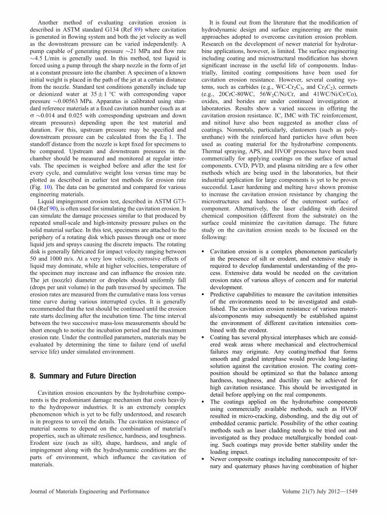
Another method of evaluating cavitation erosion isdescribed in ASTM standard G134 (Ref 89) where cavitationis generated in flowing system and both the jet velocity as wellas the downstream pressure can be varied independently. Apump capable of generating pressure �21 MPa and flow rate�4.5 L/min is generally used. In this method, test liquid isforced using a pump through the sharp nozzle in the form of jetat a constant pressure into the chamber. A specimen of a knowninitial weight is placed in the path of the jet at a certain distancefrom the nozzle. Standard test conditions generally include tapor deionized water at 35± 1 �C with corresponding vaporpressure �0.00563 MPa. Apparatus is calibrated using stan-dard reference materials at a fixed cavitation number (such as atr �0.014 and 0.025 with corresponding upstream and downstream pressures) depending upon the test material andduration. For this, upstream pressure may be specified anddownstream pressure can be calculated from the Eq 1. Thestandoff distance from the nozzle is kept fixed for specimens tobe compared. Upstream and downstream pressures in thechamber should be measured and monitored at regular inter-vals. The specimen is weighed before and after the test forevery cycle, and cumulative weight loss versus time may beplotted as described in earlier test methods for erosion rate(Fig. 10). The data can be generated and compared for variousengineering materials.
Liquid impingement erosion test, described in ASTM G73-04 (Ref 90), is often used for simulating the cavitation erosion. Itcan simulate the damage processes similar to that produced byrepeated small-scale and high-intensity pressure pulses on thesolid material surface. In this test, specimens are attached to theperiphery of a rotating disk which passes through one or moreliquid jets and sprays causing the discrete impacts. The rotatingdisk is generally fabricated for impact velocity ranging between50 and 1000 m/s. At a very low velocity, corrosive effects ofliquid may dominate, while at higher velocities, temperature ofthe specimen may increase and can influence the erosion rate.The jet (nozzle) diameter or droplets should uniformly fall(drops per unit volume) in the path traversed by specimen. Theerosion rates are measured from the cumulative mass loss versustime curve during various interrupted cycles. It is generallyrecommended that the test should be continued until the erosionrate starts declining after the incubation time. The time intervalbetween the two successive mass-loss measurements should beshort enough to notice the incubation period and the maximumerosion rate. Under the controlled parameters, materials may beevaluated by determining the time to failure (end of usefulservice life) under simulated environment.
8. Summary and Future Direction
Cavitation erosion encounters by the hydroturbine compo-nents is the predominant damage mechanism that costs heavilyto the hydropower industries. It is an extremely complexphenomenon which is yet to be fully understood, and researchis in progress to unveil the details. The cavitation resistance ofmaterial seems to depend on the combination of material�sproperties, such as ultimate resilience, hardness, and toughness.Erodent size (such as silt), shape, hardness, and angle ofimpingement along with the hydrodynamic conditions are theparts of environment, which influence the cavitation ofmaterials.
It is found out from the literature that the modification ofhydrodynamic design and surface engineering are the mainapproaches adopted to overcome cavitation erosion problem.Research on the development of newer material for hydrotur-bine applications, however, is limited. The surface engineeringincluding coating and microstructural modification has shownsignificant increase in the useful life of components. Indus-trially, limited coating compositions have been used forcavitation erosion resistance. However, several coating sys-tems, such as carbides (e.g., WC-Cr2C3, and Cr3C2), cermets(e.g., 20CrC-80WC, 56W2C/Ni/Cr, and 41WC/Ni/Cr/Co),oxides, and borides are under continued investigation atlaboratories. Results show a varied success in offering thecavitation erosion resistance. IC, IMC with TiC reinforcement,and nitinol have also been suggested as another class ofcoatings. Nonmetals, particularly, elastomers (such as poly-urethane) with the reinforced hard particles have often beenused as coating material for the hydroturbine components.Thermal spraying, APS, and HVOF processes have been usedcommercially for applying coatings on the surface of actualcomponents. CVD, PVD, and plasma nitriding are a few othermethods which are being used in the laboratories, but theirindustrial application for large components is yet to be provensuccessful. Laser hardening and melting have shown promiseto increase the cavitation erosion resistance by changing themicrostructures and hardness of the outermost surface ofcomponent. Alternatively, the laser cladding with desiredchemical composition (different from the substrate) on thesurface could minimize the cavitation damage. The futurestudy on the cavitation erosion needs to be focused on thefollowing:
• Cavitation erosion is a complex phenomenon particularlyin the presence of silt or erodent, and extensive study isrequired to develop fundamental understanding of the pro-cess. Extensive data would be needed on the cavitationerosion rates of various alloys of concern and for materialdevelopment.
• Predictive capabilities to measure the cavitation intensitiesof the environments need to be investigated and estab-lished. The cavitation erosion resistance of various materi-als/components may subsequently be established againstthe environment of different cavitation intensities com-bined with the erodent.
• Coating has several physical interphases which are consid-ered weak areas where mechanical and electrochemicalfailures may originate. Any coating/method that formssmooth and graded interphase would provide long-lastingsolution against the cavitation erosion. The coating com-position should be optimized so that the balance amonghardness, toughness, and ductility can be achieved forhigh cavitation resistance. This should be investigated indetail before applying on the real components.
• The coatings applied on the hydroturbine componentsusing commercially available methods, such as HVOFresulted in micro-cracking, disbonding, and the dig out ofembedded ceramic particle. Possibility of the other coatingmethods such as laser cladding needs to be tried out andinvestigated as they produce metallurgically bonded coat-ing. Such coatings may provide better stability under theloading impact.
• Newer composite coatings including nanocomposite of ter-nary and quaternary phases having combination of higher
Journal of Materials Engineering and Performance Volume 21(7) July 2012—1549

hardness, strength, toughness, and adhesion should bestudied for future applications. A combination of the softand the hard phases can meet such complex demand.
Acknowledgments
The authors offer their sincere thanks to the Director, NationalMetallurgical Laboratory, Jamshedpur, for granting permission topublish this article. Help received from Shri Mukesh Kumar andDeepak Kumar in preparing the manuscript is sincerely acknowl-edged.
References
1. D. Whale and D. Hart, A Review of Cavitation-Erosion-resistant WeldSurfacing for Hydro Turbines, Proceedings of the Asian-PacificWelding Conference (Auckland, New Zealand), 1996
2. G.I. Nikitenko, Studies to Reduce Cavitation Erosion of the Impellersin the Hydro Turbines at the Sayano-Shushenskoe Hydroelectric Plant,Hydrotech. Constr., 1998, 32(9), p 570–573
3. B.S.K. Naidu, Renovation and Modernization of Silt Prone Hydro-power Stations in India, Workshop on Silting Problems in Hydroelec-tric Power Stations, June 25–26, 1987 (New Delhi), 1987, p 13–16
4. D.P. Sharma and S. Singh, Operational Problems of Water Turbine inU.P.—with Special Reference to Tiloth Power Station, All IndiaSeminar on Metallurgical Problems in Power Projects, October 30–31,1987 (Lucknow), 1987, p 18–35
5. B.S.K. Naidu, Silt Damages to Equipment in Hydro Power Stationsand Remedial Measures, CBIP Workshop, July 25–26, 1996 (NewDelhi), 1996
6. S.K. Singhal and S. Ratnendra, Proceedings of the Himalayan SmallHydropower Summit, Held During October 12–13, 2006 (Dehradun),2006, p 200–207
7. M.K. Kesharwani, Proceedings of the Himalayan Small HydropowerSummit, Held During October 12–13, 2006 (Dehradun), 2006, p 44–57
8. P. Stelio. Renewable Energy in Canada Status Report 2002. A NationalReport Prepared for the Renewable Energy Working Party (REWP) ofthe International Energy Agency (IEA), Ontario, Canada, 2002, p 1–43
9. B.S. Mann, High Energy Particle Impact Wear Resistance of HardCoatings and Their Application in Hydro Turbines, Wear, 2000, 237,p 140–146
10. M. Duraiselvam, R. Galun, V. Wesling, B.L. Mordike, R. Reiter, and J.Oligmuller, Cavitation Erosion Resistance of AISI, 420 MartensiticStainless Steel Laser-Clad with Nickel Aluminide Intermetallic Com-posites and Matrix Composite with TiC Reinforcement, Surf. Coat.Technol., 2006, 201, p 1289–1295
11. A. Karimi and J.L. Martin, Cavitation Erosion of Materials, Int. Mater.Rev., 1986, 31, p 1–26
12. K. Padhy Mamta and R.P. Saini, A Review on Silt Erosion in HydroTurbines, Renew. Sustain. Energy Rev., 2008, 12, p 1974–1987
13. M.G. Fontana, Corrosion Engineering, McGraw Hill, Singapore, 1986,p 104
14. H. Brekke, Hydraulic Design of Turbines, Abrasive Erosion andCorrosion of Hydraulic Machinery, C.G. Duan and V.Y. Karelin, Ed.,ICP, London, 2003,
15. W.S. Lamb, Cavitation and Aeration in Hydraulic Systems, BHRGroup, Bedfordshire, 1987, p 114
16. R. Knapp, W. Daily, and F. Hammitt, Cavitation, McGraw-Hill,Singapore, 1970, p 578
17. C.M. Hansson and I.L.H. Hansson, ASM Handbook: Friction, Lubr.Wear Technol., 1992, 18, p 214–220
18. C.M. Preece, Treatise on Materials Science and Technology, Volume16, Erosion, Academic Press Inc., New York, 1979, p 249–308
19. K. Timo, Cavitation in Fluid Power, Proceedings of the 1st FPNI-PhDSymposium (Hamburg), 2000, p 371–382
20. B. Vyas and C.M. Preece, Stress Produced in a Solid by Cavitation,J. Appl. Phys., 1976, 47, p 5133–5138
21. J.-H. Chen and W. Wu, Cavitation Erosion Behavior of Inconel 690Alloy, Mater. Sci. Eng. A, 2008, 489, p 451–456
22. H. Soyama and H. Kumano, The Fundamental Threshold Level—ANew Parameter for Predicting Cavitation Resistance, J. Test. Eval.,2002, 30, p 421–431
23. Y. Iwai, T. Okada, and S. Tanaka, A Study of Cavitation BubbleCollapse Pressures and Erosion Part 2: Estimation of Erosion from theDistribution of Bubble Collapse Pressures,Wear, 1989, 133, p 233–243
24. S. Hattori, T. Hirose, and K. Sugiyama, Prediction Method forCavitation Erosion Based on Measurement of Bubble Collapse ImpactLoads, J. Phys. Conf. Ser., 2009, 147, p 1–9
25. S. Hattori, B.H. Sun, F.G. Hammitt, and T. Okada, An Application ofBubble Collapse Pulse Height Spectra to Venture Cavitation Erosion of1100 O Aluminum, Wear, 1985, 103, p 119–131
26. S. Li, Cavitation Enhancement in Silt Erosion: Obstacles & WayForward, Fifth International Symposium on Cavitation (CAV2003),November 1–4, 2003 (Osaka, Japan), 2003, p 1–7
27. B. Thapa, P. Chaudhury, O.G. Dahlhaug, and P. Upadhyay, Study ofCombined Effect of Sand Erosion and Cavitation in HydraulicTurbines. International Conference on Small Hydropower—Hydro SriLanka, October 22–24, 2007, p 1–6
28. V.K. Nanda, Parameters Affecting Abrasion and Remedial Measures,Proceedings of the 1st International Conference on Silting Problems inHydro Power Plants (New Delhi), 1999, p 43–52
29. M. Toshima, T. Okamura, J. Satoh, K. Usami, and S. Tanabe, BasicStudy of Coupled Damage Caused by Silt Abrasion and CavitationErosion, JSME B, 1991, 57, p 20–25
30. J.F. Santa, J.C. Baena, and A. Toro, Slurry Erosion of Thermal SprayCoatings and Stainless Steels for Hydraulic Machinery, Wear, 2007,263, p 258–264
31. I. Hussainova and I. Kleis, Investigation of Particle—Wall ImpactProcess, Wear, 1999, 233–235, p 168–173
32. A. Ball and Z. Feng, The Erosion of Four Materials Using SevenErodent—Toward an Understanding, Wear, 1999, 233–235, p 674–684
33. S. Li, Cavitation Enhancement of Silt Erosion—An Envisaged MicroModel, Wear, 2006, 260, p 1145–1150
34. G.F. Truscott, A Literature Survey on Abrasive Wear in HydraulicMachinery, Wear, 1972, 20, p 29–50
35. J. Zhang, M.O.W. Richardson, G.D. Wilcox, J. Min, and X. Wang,Assessment of Resistance of Non-Metallic Coatings to Silt Abrasionand Cavitation Erosion in a Rotating Disk Test Rig, Wear, 1996, 194,p 149–155
36. J.C. Arnold and I.M. Hutchings, The Mechanisms of Erosion ofUnfilled Elastomers by Solid Particle Impact, Wear, 1990, 138, p 33–46
37. M. Bjordal, E. Bardal, T. Rogne, and T.G. Eggen, Erosion andCorrosion Properties of WC Coatings and Duplex Stainless Steel inSand-Containing Synthetic Sea-Water, Wear, 1995, 186–187, p 508–514
38. E. Bardal, Korrosjon og korrosjonsvern, Tapir, Trondheim, 1985 (inNorwegian)
39. N. Tsuguo, Estimation of Repair Cycle of Turbine due to AbrasionCaused by Suspended Sand and Determination of Desilting BasinCapacity, Proceedings of the International Seminar on SedimentHandling Technique, NHA, Kathmandu, 1999
40. S.C. Li, ‘‘Cavitation Damage: Three Gorge Turbines (Phenomenon,Implication & Unknowns…),’’ Presentations at the Three Gorge PowerStation (19 March 2006), the Beijing University (28 March 2006) andthe National Research Institute of Hydro Power (March 2006)
41. P. Linhardt and A. Nichtawitz, MIC in Hydroelectric Power Plants,Corrosion 2003, NACE International Houston, Texas, Paper No. 03564
42. R.J.K. Wood and J.A. Wharton, Investigation of Erosion-CorrosionProcesses Using Electrochemical Noise Measurement, Tribol. Int.,2002, 35, p 631–641
43. M. Kjelsden, ‘‘Cavitation in Hydraulic Machinery,’’ Dr. Ing. Thesis,NTNU, 1996, p 63
44. Y. Tetsuyuk, Anti-Erosion Materials for Hydroturbine, Turbomachin-ery, 2000, 28, p 577–581
45. C.J. Heathcock, B.E. Protheroe, and A. Ball, Cavitation Erosion ofStainless Steels, Wear, 1982, 81, p 311–327
46. K.Y. Chiu, F.T. Cheng, and H.C. Man, Laser Cladding of AusteniticStainless Steel Using NiTi Strips for Resisting Cavitation Erosion,Mater. Sci. Eng. A, 2005, 402, p 126–134
47. B.C.S. Rao and D.H. Buckley, Deformation and Erosion of F.C.C.Metals and Alloys Under Cavitation Attack, Mater. Sci. Eng. A, 1984,67, p 55
1550—Volume 21(7) July 2012 Journal of Materials Engineering and Performance

48. Z.D. Cui, H.C. Man, F.T. Cheng, and T.M. Yue, Cavitation Erosion-Corrosion Characteristics of Layer Surface Modified NiTi ShapeMemory Alloy, Surf. Coat. Technol., 2003, 162, p 147–153
49. C.T. Kowk, F.T. Cheng, and H.C. Man, Laser Surface Modification ofUNS S31603 Stainless Steel Using NiCrSiB Alloy for EnhancingCavitation Erosion Resistance, Surf. Coat. Technol., 1998, 107, p 31–40
50. N. Alonso-Falleiros, M. Magri, and I.G.S. Falleiros, IntergranularCorrosion in a Martensitic Stainless Steel Detected by ElectrochemicalTests, Corrosion, 1999, 55, p 769–778
51. F.J. Heymann, Toward Quantitative Prediction of Liquid ImpactErosion, ASTM STP, 1970, 474, p 212
52. S. Hattori, R. Ishikura, and Q. Zhang, Construction of Database onCavitation Erosion and Analyses of Carbon Steel Data, Fifth Interna-tional Symposium on Cavitation, November 1–4, 2003 (Osaka, Japan),2003
53. H. Niinaka, A. Hirose, and S. Sogabe, Hiroshi Noguchi: 13Cr-3.5Martensitic Stainless Steel Casting for Hydraulic Turbine Runner.Kawasaki Steel Technical Report No. 14, March 1986, p 141–152
54. R. Garcia and F.G. Hammitt, Cavitation Damage and Correlation withMechanical and Fluid Properties, J. Basic Eng. D, 1967, 89, p 753–763
55. P. Veerabhadra Rao, C.S. Martin, B.C. Syamala Rao, and N.S.Lakshaman Rao, Estimation of Cavitation Erosion with IncubationPeriods and Material Properties, J. Test. Eval. A, 1981, 9, p 189–197
56. A. Thiruvengadam and S. Waring, Mechanical Properties of Metals andCavitation Damage Resistance, J. Ship Res., 1966, 10, p 1–9
57. R.H. Richman and W.P. McNaughton, Correlation of CavitationErosion Behavior with Mechanical Properties of Metals, Wear, 1990,14, p 63–82
58. B.S. Mann, Boronizing of Cast Martensitic Chromium Nickel StainlessSteel and Its Abrasion and Cavitation-Erosion Behavior, Wear, 1997,208, p 125–131
59. K. Alicja and C. Andrzej, Cavitation Erosion Resistance of Cr-NCoating Deposited on Stainless Steel, Wear, 2006, 260, p 1324–1332
60. J.Y. Ying, Ed., Nanostructured Materials, Academic Press, San Diego,2001, p 168–198
61. R.W. Siegel and G.E. Fougere, Mechanical Properties of NanophaseMetals, Nanostruct. Mater., 1995, 6, p 205–216
62. H.S. Nalwa, Ed., Handbook of Nanostructured Materials and Nano-technology: Synthesis and Processing, Vol 1, Academic Press, SanDiego, 2000
63. R.J.K. Wood, Tribo-Corrosion of Coatings: A Review, J. Phys. D Appl.Phys., 2007, 40, p 5502–5521
64. V.A.D. Souza and A. Neville, Aspects of Microstructure on theSynergy and Overall Material Loss of Thermal Spray Coatings inErosion-Corrosion Environments, Wear, 2007, 263, p 339–346
65. D. Toma, W. Brandl, and G. Marginean, Wear and CorrosionBehaviour of Thermally Sprayed Cermet Coatings, Surf. Coat.Technol., 2001, 138, p 149–158
66. V.A.D. Souza and A. Neville, Linking Electrochemical CorrosionBehaviour and Corrosion Mechanisms of Thermal Spray CermetCoatings (WC-CrNi and WC/CrC-CoCr), Mater. Sci. Eng. A, 2003,352, p 202–211
67. F.T. Cheng, C.T. Kwok, and H.C. Man, Laser Surfacing of S31603Stainless Steel with Engineering Ceramics for Cavitation ErosionResistance, Surf. Coat. Technol., 2001, 139, p 14–24
68. T. Chang, C.H. Yeh, J.L. He, and K.C. Chen, Cavitation Erosion andCorrosion Behavior of Ni-Al Intermetallic Coatings, Wear, 2003, 255,p 162–169
69. H. Hiraga, T. Inoue, H. Shimura, and A. Matsunawa, CavitationErosion Mechanism of NiTi Coating Made by Laser Plasma HybridSpraying, Wear, 1999, 231, p 272–278
70. D.H. Graham and A. Bell, Particle Erosion of Candidate Materials forHydraulic Valves, Wear, 1989, 133, p 125–132
71. E. Ness and R. Zibbell, Abrasion and Erosion of Hard MaterialsRelated to Wear in the Abrasive Water Jet,Wear, 1996, 196, p 120–125
72. B.S. Mann and A. Vivek, HVOF Coating and Surface Treatment forEnhancing Droplet Erosion Resistance of Steam Turbine Blades, Wear,2003, 254, p 652–667
73. K. Sugiyama, S. Nakahama, S. Hattori, and K. Nakano, Slurry Wearand Cavitation Erosion of Thermal-Sprayed Cermets, Wear, 2005, 258,p 768–775
74. B.S. Mann and A. Vivek, Abrasive and Erosive Wear Characteristics ofPlasma Nitriding and HVOF Coatings: Their Application in HydroTurbines, Wear, 2001, 249, p 354–360
75. P.W. Alexiff, Research and Development on Axial Fan Blade Erosion,Combustion, 1979, 7, p 12–16
76. K.H. Lo, F.T. Cheng, and H.C. Man, Laser Transformation Hardeningof AISI, 440C Martensitic Stainless Steel for Higher Cavitation ErosionResistance, Surf. Coat. Technol., 2003, 173, p 96–104
77. C.T. Kwok, H.C. Man, and F.T. Cheng, Cavitation Erosion and PittingCorrosion Behaviour of Laser Surface-Melted Martensitic StainlessSteel UNS S42000, Surf. Coat. Technol., 2000, 126, p 238–255
78. K. Venugopal and A. Manish, Application of High Power Lasers inMaterial Processing, BHEL J., 2007, 28(1), p 20–30
79. S. Basu, A.M. Sinnar, and G.S. Bohlander, Measurement of CavitationResistance of Organic Marine Coatings, Mechanical Properties.Performance and Failure Modes of Coatings, Cambridge UniversityPress, Cambridge, 1984, p 85
80. R.J. Nuttall, The Selection of Abrasion Resistant Lining Materials,Bulk Solids Handl., 1985, 5, p 1041–1047
81. I.M. Kats, Investigation of the Cavitation Resistance of Elastic PolymerCoatings, Power Technol. Eng., 1974, 8, p 539–544
82. Y.P. Kathuria, Some Aspects of Laser Surface Cladding in the TurbineIndustry, Surf. Coat. Technol., 2000, 132, p 262–269
83. L. Ahman, Microstructure and Its Effect on Toughness and WearResistance of Laser Surface Melted and Post Heat Treated High SpeedSteel, Metall. Trans. A, 1984, 15, p 1829–1835
84. P.A. Molian and M.J. Hsu, Proceedings of Surface ModificationTechnologies, I.S. Sudarshan and D.G. Bhat, Ed., The MaterialsSociety, Warrendale, PA, 1988, p 155
85. J. Hu, Z. Li, Y. Wang, H. Wang, J. Lu, and L. Wang, Trans. Met. HeatTreat., 1990, 2, p 19–25
86. K. Toda, T. Mikami, and T. Hoshino, Effect of Ridge Around Dent andRetained Austenite on Rolling Fatigue Life, J. Jpn. Inst. Met., 1994,58, p 1473–1478
87. ‘‘ASTM G32-03 Standard Test Method for Cavitation Erosion UsingVibratory Apparatus,’’ ASTM Standards, Vol. 03.02, p 98–111
88. I. Bordeasu, M. Voda, V.A. Serban, and C. Codrean, CavitationErosion for G-X5crni13-14 Martensitic Stainless Steel with VariousHeat Treatments, The 6th International Conference on HydraulicMachinery and Hydrodynamics Timisoara, October 21–22, 2004(Romania), 2004
89. ‘‘ASTM G134-03 Standard Test Method for Erosion of Solid Materialsby a Cavitating Liquid Jet,’’ ASTM Standards, Vol. 03.02, p 559–571
90. ‘‘ASTM G73-04 Standard Practice for Liquid Impingement ErosionTesting,’’ ASTM Standards, Vol. 03.02, p 273–290
Journal of Materials Engineering and Performance Volume 21(7) July 2012—1551
Related Documents