Gessi SpA - Parco Gessi 13037 Serravalle Sesia (Vercelli) - Italy Phone +39 0163 454111 - Facsimile +39 0163 459273 www.gessi.com - [email protected] Art. 31432 PROGRAMMA TERMOSTATICO THERMOSTATIC PROGRAM PROGRAMME THERMOSTATIQUE THERMOSTATISCHES PROGRAMM PROGRAMA TERMOSTÁTICO ПРОГРАММА ТЕРМОСТАТИЧЕСКИХ СМЕСИТЕЛЕЙ

Welcome message from author
This document is posted to help you gain knowledge. Please leave a comment to let me know what you think about it! Share it to your friends and learn new things together.
Transcript

Gessi SpA - Parco Gessi 13037 Serravalle Sesia (Vercelli) - Italy
Phone +39 0163 454111 - Facsimile +39 0163 459273
www.gessi.com - [email protected]
Art. 31432
PROGRAMMA TERMOSTATICOTHERMOSTATIC PROGRAM
PROGRAMME THERMOSTATIQUETHERMOSTATISCHES PROGRAMM
PROGRAMA TERMOSTÁTICOПРОГРАММА ТЕРМОСТАТИЧЕСКИХ СМЕСИТЕЛЕЙ
2
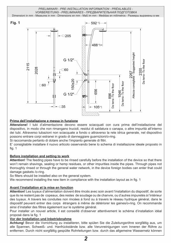
Prima dell’installazione e messa in funzioneAttenzione! I tubi d’alimentazione devono essere sciacquati con cura prima dell’installazione del dispositivo, in modo che non rimangano trucioli, residui di saldatura o canapa, o altre impurità all’interno dei tubi. Attraverso tubazioni non sciacquate a fondo o attraverso la rete idrica generale, nel dispositivo possono entrare corpi estranei in grado di danneggiare guarnizioni/o-ring. Si raccomanda pertanto di dotare anche l’impianto generale di filtri.E’ consigliabile installare il nuovo articolo osservando bene lo schema di installazione ideale proposto in fig. 1
Before installation and setting to workAttention! The feeding pipes have to be rinsed carefully before the installation of the device so that there won’t remain shavings, sealing or hemp residues, or other impurities inside the pipes. Through pipes not thoroughly rinsed or through the general water network, in the device foreign bodies can enter that could damage gaskets /o-ring. So filters should be installed also on the general system.We recommend installing the new item in compliance with the installation layout as in fig. 1
Avant l’installation et la mise en fonctionAttention! Les tuyaux d’alimentation doivent être rincés avec soin avant l’installation du dispositif, de sorte que ils ne restent pas de copeaux, des restes de soudage ou de chanvre, ou d’autres impuretés à l’intérieur des tuyaux. A travers les conduites non rincées à fond ou à travers le réseau hydrique général, dans le dispositif peuvent entrer des corps étrangers à même de détériorer les gaines/o-ring. On recommande ainsi d’installer des filtres également sur le système général.Pour installer un nouvel article, il est conseillé d’observer attentivement le schéma d’installation idéal proposé dans la fig. 1 Vor der Installation und InbetriebnahmeAchtung! Bevor die Vorrichtung zu installieren, bitte spülen Sie die Zuleitungsröhre sorgfältig aus, um alle Spannen, Schweiß- und. Hanfrückstände bzw. alle Verunreinigungen vom Inneren der Röhre zu entfernen. Durch nicht sorgfältig gespülte Rohrleitungen bzw. durch das allgemeine Wassernetz können
Fig. 1
PRELIMINARI - PRE-INSTALLATION INFORMATION - PRÉALABLES - VORBEREITUNG - PRELIMINARES - ПРЕДВАРИТЕЛЬНАЯ ПОДГОТОВКА
Dimensioni in mm - Measures in mm - Dimensions en mm - Maß im mm - Medidas en milímetros - Размеры выражены в мм

3
Fremdkörper in den Korpen eintreten, die die Dichtungen bzw. die O-Ringe beschädigen können. Es ist dann empfehlenswert, die allgemeine Anlage mit Filtern auszustatten.Bei der Installation des neuen Artikels ist es empfehlenswert, den im Abb. 1 gezeigten Anweisungen zur idealen Installation zu folgen.
Antes de la instalación y la puesta en función¡Cuidado! Los tubos de alimentación tienen que ser enjuagados escrupulosamente antes de instalar el dispositivo de manera que no haya virutas, residuos de soldadura o cáñamo u otras impurezas al interior de los tubos. A través de los tubos no perfectamente enjuagados o de la red hídrica general pueden entrar en el dispositivo unos cuerpos extraños que pueden dañar guarniciones, o-rings y/o. Les recomendamos por lo tanto que instalen los filtros en la planta general también.Les aconsejamos que instalen el nuevo artículo observando bien el esquema de instalación ideal proporcionado en la fig. 1
Перед установкой и началом использованияВнимание! Перед установкой устройства необходимо тщательно промыть водопроводные трубы, чтобы в них не оставались стружка, шлак от сварки, лен или другие посторонние тела. Через плохо промытые водопроводные трубы или через общую водопроводную сеть в устройство могут попасть посторонние тела, способные повредить уплотнения и уплотнительные кольца. Поэтому, рекомендуется оснастить фильтрами также и общую систему.Рекомендуется устанавливать новый артикул, тщательно соблюдая идеальную схему установки, предложенную на рис. 1.
PRELIMINARI - PRE-INSTALLATION INFORMATION - PRÉALABLES - VORBEREITUNG - PRELIMINARES - ПРЕДВАРИТЕЛЬНАЯ ПОДГОТОВКА

4
Contenuto della confezione:A - Corpo miscelatoreB - SoffioneC - Supporto soffioneD - Prolunga inferiore E - Fissaggio a pareteF - Raccordo G - EccentriciH - Maschera di foratura
Package content:A - Mixer bodyB - Shower headC - Shower head supportD - Lower extensionE - Wall fasteningF - ConnectionG - EccentricsH - Piercing jig
Contenu de l’emballage:A - Corps mélangeurB - PommeC - Support pommeD - Rallonge inférieureE - Fixation muraleF - RaccordG - ExcentriquesH - Gabarit de perçage
Inhalt der Verpackung:A - MischerkörperB - BrausekopfC - Stütze für den BrausekopfD - Unteres AnsatzrohrE - WandbefestigungF - RaccordG - ExzenterscheibenH - Bohrschablone
Contenido del embalaje:A - Cuerpo mezclador B - RociadorC - Soporte rociadorD - Alargadera inferior E - Fijación a la pared F - RacorG - ExcéntricosH - Plantilla de horadación
Содержимое упаковки:A - Корпус смесителяB - Душевая лейкаC - Суппорт душевой лейкиD - Нижний удлинитель E - Крепление к стене F - ШтуцерG - ЭксцентрикиH - Кондуктор для сверления
Fig. 2
PRELIMINARI - PRE-INSTALLATION INFORMATION - PRÉALABLES - VORBEREITUNG - PRELIMINARES - ПРЕДВАРИТЕЛЬНАЯ ПОДГОТОВКА

5
Fig. 3
- Utensili necessari per l’installazione - Tools for installation - Outils nécessaires pour l’installation - Für die Installation notwendige Werkzeuge - Herramienta necesaria para la instalación- Инструмент, необходимый для установки
PRELIMINARI - PRE-INSTALLATION INFORMATION - PRÉALABLES - VORBEREITUNG - PRELIMINARES - ПРЕДВАРИТЕЛЬНАЯ ПОДГОТОВКА
3 mm
2,5 mm
Ch. 30 mm
Ch. 14 mm

6
CALDAHOT
FREDDACOLD
Parete finitaTiled wall 150±20
G 1/2"
0÷12
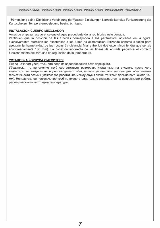
INSTALLAZIONE DEL CORPO MISCELATOREPrima di iniziare assicurarsi che l’acqua della rete idrica sia chiusa.Verificare che la posizione delle tubazioni rientri nei parametri indicati in figura, quindi avvitare gli eccentrici ai tubi di alimentazione utilizzando della canapa o teflon per garantire la tenuta sui filetti (l’interasse finale tra i due eccentrici dovrà essere di circa 150mm). L’errata connessione delle utenze d’ingresso pregiudica il corretto funzionamento della cartuccia regolatrice di temperatura.
MIxER BODy INSTALLATIONBefore starting make sure the water network is off.Check that the position of pipes is within the parameters in the figure, then screw the eccentrics on supply pipes using hemp or Teflon to guarantee tightness on threads (the final center distance between the two eccentrics shall be of around 150mm). The wrong connection of inlet devices disrupts proper operation of temperature adjustment cartridge.
INSTALLATION Du CORPS MÉLANgEuRAvant de commencer s’assurer que l’alimentation du réseau de distribution est coupée.Vérifier que la position des tuyauteries est conforme aux paramètres indiqués sur la figure, puis visser les excentriques sur les tubes d’alimentation en utilisant du chanvre ou du téflon pour garantir l’étanchéité sur les filets (la distance finale entre les axes des deux excentriques devra être d’environ 150mm). Un branchement erroné des alimentations d’entrée compromet le fonctionnement correct de la cartouche régulatrice de température.
INSTALLATION DES MISChERköRPERSBevor zu starten, ist es sicherzustellen, dass die Wasserleitungen gesperrt sind.Überprüfen Sie, dass die Position der Leitungen den im Bild angegebenen Parametern folgt, dann schrauben Sie die Exzenterscheiben an die Versorgungsleitungen mittels Hanf oder Teflon an, um die Dichtheit der Gewinden zu gewährleisten (am Ende soll der Achsabstand zwischen den zwei Exzenterscheiben etwa
CALDAHOT
FREDDACOLD
Parete finitaTiled wall 150±20
G 1/2"
0÷12
CALDAHOT
FREDDACOLD
Parete finitaTiled wall 150±20
G 1/2"
0÷12
Fig. 4
INSTALLAZIONE - INSTALLATION - INSTALLATION - INSTALLATION - INSTALACIÓN - УСТАНОВКА
Dimensioni in mm - Measures in mm - Dimensions en mm - Maß im mm - Medidas en milímetros - Размеры выражены в мм
Ch. 14 mm
7
150 mm. lang sein). Die falsche Verbindung der Wasser-Einleitungen kann die korrekte Funktionierung der Kartusche zur Temperaturregelegung beeinträchtigen.
INSTALACIÓN CuERPO MEZCLADORAntes de empezar asegúrense que el agua procedente de la red hídrica esté cerrada.Verifiquen que la posición de las tuberías corresponda a los parámetros indicados en la figura, sucesivamente atornillen los excéntricos a los tubos de alimentación utilizando cáñamo o teflón para asegurar la hermeticidad de las roscas (la distancia final entre los dos excéntricos tendrá que ser de aproximadamente 150 mm). La conexión incorrecta de las líneas de entrada perjudica el correcto funcionamiento del cartucho de regulación de la temperatura.
УСТАНОВКА КОРПУСА СМЕСИТЕЛЯПеред началом убедитесь, что вода из водопроводной сети перекрыта.Убедитесь, что положение труб соответствует размерам, указанным на рисунке, после чего навинтите эксцентрики на водопроводные трубы, используя лен или тефлон для обеспечения герметичности резьбы (межосевое расстояние между двумя эксцентриками должно быть около 150 мм). Неправильное подключение труб на входе отрицательно сказывается на исправности работы регулировочного картриджа температуры.
INSTALLAZIONE - INSTALLATION - INSTALLATION - INSTALLATION - INSTALACIÓN - УСТАНОВКА
8
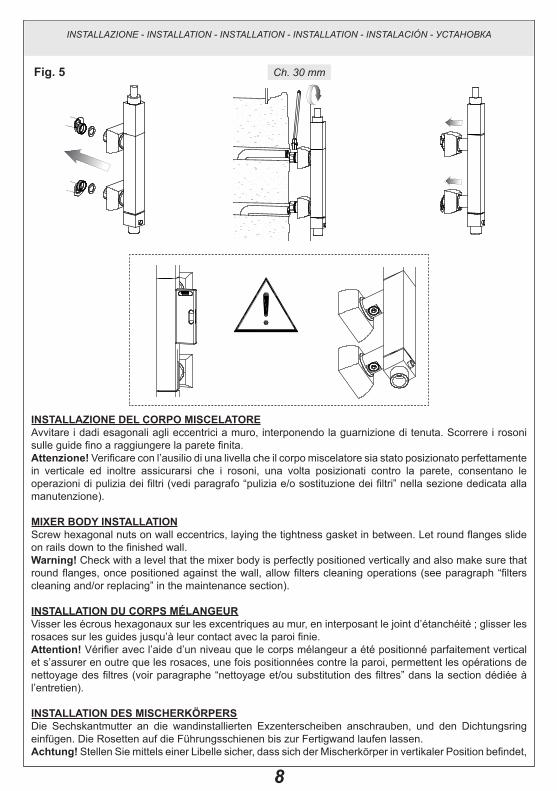
INSTALLAZIONE DEL CORPO MISCELATOREAvvitare i dadi esagonali agli eccentrici a muro, interponendo la guarnizione di tenuta. Scorrere i rosoni sulle guide fino a raggiungere la parete finita.Attenzione! Verificare con l’ausilio di una livella che il corpo miscelatore sia stato posizionato perfettamente in verticale ed inoltre assicurarsi che i rosoni, una volta posizionati contro la parete, consentano le operazioni di pulizia dei filtri (vedi paragrafo “pulizia e/o sostituzione dei filtri” nella sezione dedicata alla manutenzione).
MIxER BODy INSTALLATIONScrew hexagonal nuts on wall eccentrics, laying the tightness gasket in between. Let round flanges slide on rails down to the finished wall.Warning! Check with a level that the mixer body is perfectly positioned vertically and also make sure that round flanges, once positioned against the wall, allow filters cleaning operations (see paragraph “filters cleaning and/or replacing” in the maintenance section).
INSTALLATION Du CORPS MÉLANgEuRVisser les écrous hexagonaux sur les excentriques au mur, en interposant le joint d’étanchéité ; glisser les rosaces sur les guides jusqu’à leur contact avec la paroi finie.Attention! Vérifier avec l’aide d’un niveau que le corps mélangeur a été positionné parfaitement vertical et s’assurer en outre que les rosaces, une fois positionnées contre la paroi, permettent les opérations de nettoyage des filtres (voir paragraphe “nettoyage et/ou substitution des filtres” dans la section dédiée à l’entretien).
INSTALLATION DES MISChERköRPERSDie Sechskantmutter an die wandinstallierten Exzenterscheiben anschrauben, und den Dichtungsring einfügen. Die Rosetten auf die Führungsschienen bis zur Fertigwand laufen lassen.Achtung! Stellen Sie mittels einer Libelle sicher, dass sich der Mischerkörper in vertikaler Position befindet,
CALDAHOT
FREDDACOLD
Parete finitaTiled wall 150±20
G 1/2"
0÷12
CALDAHOT
FREDDACOLD
Parete finitaTiled wall 150±20
G 1/2"
0÷12
CALDAHOT
FREDDACOLD
Parete finitaTiled wall 150±20
G 1/2"
0÷12
CALDAHOT
FREDDACOLD
Parete finitaTiled wall 150±20
G 1/2"
0÷12
CALDAHOT
FREDDACOLD
Parete finitaTiled wall 150±20
G 1/2"
0÷12
CALDAHOT
FREDDACOLD
Parete finitaTiled wall 150±20
G 1/2"
0÷12
Fig. 5
INSTALLAZIONE - INSTALLATION - INSTALLATION - INSTALLATION - INSTALACIÓN - УСТАНОВКА
Ch. 30 mm

9
und dass die Rosetten die Reinigung der Filter ermöglichen, nachdem sie an die Wand installiert worden sind (siehe “Reinigung und/oder Wechsel der Filter” in dem Paragraph über die Instandhaltung).
INSTALACIÓN CuERPO MEZCLADORAtornillen las tuercas hexagonales a los excéntricos en la pared, interponiendo la junta de cierre. Hagan deslizar los florones sobre las guías hasta alcanzar la pared acabada.¡Cuidado! Verifiquen con la ayuda de un nivel que el cuerpo del mezclador se encuentre perfectamente posicionado en vertical y, además, asegúrense que los florones, tras haber sido posicionados contra la pared, no perjudiquen las operaciones de limpieza de los filtros (vean párrafo “Limpieza y/o sustitución de los filtros” en la sección dedicada al mantenimiento).
УСТАНОВКА КОРПУСА СМЕСИТЕЛЯПривинтите шестигранные гайки к настенным эксцентрикам, устанавливая уплотнительную прокладку. Сдвиньте розетки по направляющим вплоть до отделанной стены.Внимание! Проверьте по уровню, что корпус смесителя правильно установлен по вертикали, кроме того, убедитесь, что розетки, после того, как они были приложены к стене, позволяют прочищать фильтры (см. параграф “чистка и/или замена фильтров” в разделе, посвященном обслуживанию).
INSTALLAZIONE - INSTALLATION - INSTALLATION - INSTALLATION - INSTALACIÓN - УСТАНОВКА

10
FORATuRE PER FISSAggIO A PARETEUtilizzare la maschera di foratura come mostrato in figura per individuare i punti in cui effettuare i fori per il fissaggio a parete. Per fare questo è importante che i rosoni del corpo dell’articolo siano ben appoggiati alla parete in modo tale da permettere alla maschera di foratura di essere il più precisa possibile.Togliere la maschera di foratura e realizzare i fori profondi minimo 50mm con una punta Ø8mm per inserirvi i tasselli in dotazione.
WALL INSTALLATION hOLESUse the drilling jig as shown in the picture to individuate the points where to make the drills for the wall mounting. To do this, it is important that the covering rings of the body of the item are well laid against the wall, in order to obtain maximum accuracy from the drilling jig. Remove the piercing jig and make holes deep at least 50mm with a drill Ø8mm to insert the plugs supplied.
PERÇAgES POuR FIxATION À PAROIUtiliser le gabarit de forage comme il est montré dans la figure pour déterminer les points ou il faut effectuer les trous pour le fixage à la paroi. Pour faire cela il est important que les roses du corps de l’article sont bien appuyés à la paroi pour permettre au gabarit de forage pour être la plus précise possible. Retirer le gabarit de perçage et pratiquer des trous profonds au minimum de 50mm avec une pointe Ø8mm pour y insérer les chevilles fournies en dotation.
BOhRuNgEN ZuR WANDINSTALLATIONWie gezeigt, verwenden Sie die Bohrschablone, um die für die Wandbefestigung notwendigen Bohrungspunkte zu lokalisieren. Zu diesem Zweck, sollen die Scheiben des Teilkörpers an der Wand befestigt sein, so dass die höchste Genauigkeit der Bohrschablone gewährleistet wird.
CALDAHOT
FREDDACOLD
Parete finitaTiled wall 150±20
G 1/2"
0÷12
Fig. 6
Ø8
50
CALDAHOT
FREDDACOLD
Parete finitaTiled wall 150±20
G 1/2"
0÷12
Ø8
50
Ø8
50
INSTALLAZIONE - INSTALLATION - INSTALLATION - INSTALLATION - INSTALACIÓN - УСТАНОВКА
Dimensioni in mm - Measures in mm - Dimensions en mm - Maß im mm - Medidas en milímetros - Размеры выражены в мм

11
Die Bohrschablone ausziehen und die Löcher mit einer mindesten Tiefe von 50mm durch einen Bohrer von Ø8mm anbohren, um die serienmäβigen Dübel einzufügen.
hORADACIÓN PARA LA FIJACIÓN A LA PAREDUtilicen la plantilla de horadación, como indicado en la figura, para individuar los puntos en los cuales hay que realizar los huecos para la fijación a la pared. Para hacer esto es importante que los florones del cuerpo del artículo queden bien apoyados a la pared para que la plantilla de horadación pueda utilizarse de la manera más precisa posible.Quiten la plantilla de horadación y realicen los huecos profundos, como mínimo 50mm, con una broca de Ø8mm para introducir los tacos incluidos en el suministro.
СВЕРЛЕНИЕ дЛЯ НАСТЕННОгО КРЕПЛЕНИЯИспользуйте кондуктор для сверления, как показано на рисунке, чтобы определить точки для крепления к стене. Для этого необходимо, чтобы розетки корпуса изделия хорошо прилегали к стене, чтобы кондуктор сверления был как можно более точным.Снимите кондуктор для сверления и просверлите отверстия глубиной минимум 50 мм сверлом Ø8 мм, чтобы вставить туда входящие в комплект дюбели.
INSTALLAZIONE - INSTALLATION - INSTALLATION - INSTALLATION - INSTALACIÓN - УСТАНОВКА

12
INSTALLAZIONE PROLuNgA INFERIOREIndividuare tutti i componenti del fissaggio, quindi applicare la placchetta alla parete facendo coincidere i fori con quelli dei tasselli. Fissare con le apposite viti in dotazione. Pre-montare sulla prolunga inferiore i componenti restanti del fissaggio a parete.Attenzione! Per evitare di danneggiare la superficie della colonna doccia bloccare temporaneamente il fissaggio avvitando LEGGERMENTE la vite al supporto della prolunga.
INSTALLATION OF LOWER ExTENSIONFind all the components for the fastening and apply the plate to the wall with holes coinciding with those of the plugs. Fasten with the special screws supplied. Pre-install on the lower extension the remaining components of wall fastening.Warning! To avoid damaging the surface of the shower column temporarily block the fastening SLIGHTLY tightening the screw on the support of the extension.
INSTALLATION RALLONgE INFÉRIEuREIdentifier tous les composants de la fixation, puis appliquer la plaquette à la paroi en faisant coïncider les trous avec ceux des chevilles. Fixer avec les vis spéciales fournies. Pré-monter sur la rallonge inférieure les composants restants de la fixation à paroi.Attention! Pour éviter d’endommager la superficie de la colonne douche bloquer temporairement la fixation en serrant LÉGÈREMENT la vis sur le support de la rallonge.
INSTALLATION DES uNTEREN ANSATZROhRSAlle zur Befestigung notwendigen Bestandteile bestimmen, dann das Plättchen an die Wand befestigen und dafür sorgen, dass seine Löcher mit denen der Dübel zusammenfallen. Mit den serienmäβigen Schrauben befestigen. Die Restbestandteile der Wandbefestigung auf das untere Ansatzrohr vormontieren.
Fig. 7
CALDAHOT
FREDDACOLD
Parete finitaTiled wall 150±20
G 1/2"
0÷12
Ø8
50
Ø8
50
Ø8
50
Ø8
50
INSTALLAZIONE - INSTALLATION - INSTALLATION - INSTALLATION - INSTALACIÓN - УСТАНОВКА
3 mm

13
Achtung! Um die Beschädigung der Duschsäulenoberfläche zu vermeiden, ist die Befestigung vorläufig zu blockieren, indem die Schraube zur Stütze des Ansatzrohrs LEICHT eingeschraubt wird.
INSTALACIÓN ALARgADERA INFERIORIndividúen todos los componentes de fijación, sucesivamente apliquen la placa a la pared haciendo coincidir sus huecos con aquellos de los tacos. Fijen con los tornillos correspondientes incluidos en el suministro. Efectúen el premontaje sobre la alargadera inferior de los demás componentes para la fijación a la pared.¡Cuidado! Para no dañar la superficie de la columna ducha bloqueen temporáneamente la fijación atornillando LIGERAMENTE el tornillo al soporte de la alargadera.
УСТАНОВКА НИжНЕгО УдЛИНИТЕЛЯНайдите все компоненты крепления, после чего приложите к стене накладку, совмещая ее отверстия с отверстиями дюбелей. Закрепите входящими в комплект винтами. Установите на нижний удлинитель остальные компоненты крепления к стене.Внимание! Чтобы не повредить поверхность душевой колонны, временно затяните крепление, СЛЕГКА завинчивая крепежный винт удлинителя.
INSTALLAZIONE - INSTALLATION - INSTALLATION - INSTALLATION - INSTALACIÓN - УСТАНОВКА

14
REgISTRAZIONE DEL FISSAggIO A PARETEIl fissaggio a parete è stato ideato in modo tale da consentire all’installatore la possibilità di compensare la distanza tra la parete finita e la colonna doccia. Per effettuare la registrazione del fissaggio inserire la vite in uno dei tre fori posti sul supporto della prolunga ed avvitarla leggermente. L’asola posta sul raccordo a parete permette poi di scorrere il tutto fino a raggiungere la distanza desiderata. Se al primo tentativo non si raggiungesse la condizione ottimale svitare la vite e inserirla nel foro precedente e/o successivo e procedere come prima descritto.
WALL FASTENINg ADJuSTMENTWall fastening was conceived so to allow the installer to compensate the distance between the finished wall and the shower column. To adjust the fastening insert the screw in one of the three holes on the support of the extension and slightly tighten it. The buttonhole on the wall connection allows the sliding of all until reaching the required distance. If at first attempt the optimal condition is not achieved loosen the screw and insert it in the previous and/or successive hole and follow the above description.
RÉgLAgE DE LA FIxATION À PAROILa fixation à paroi è été conçue de façon à donner à l’installateur la possibilité de compenser la distance entre la paroi finie et la colonne douche. Pour effectuer le réglage de la fixation insérer la vis dans l’un des trois trous disposés sur le support de la rallonge et la visser légèrement. La fente placée sur le raccord à paroi permet ensuite de faire glisser le tout jusqu’à atteindre la distance désirée. Si l’on n’obtient pas à la première tentative la condition optimale, desserrer la vis et l’insérer dans le trou précédent et/ou successif et procéder comme décrit ci-dessus.
EINSTELLuNg DER WANDBEFESTIguNgDie Wandbefestigung ist so gedacht worden, dass der Rohrleger die Möglichkeit hat, den Abstand zwischen Fertigwand und Duschsäule auszugleichen. Um die Befestigung einzustellen soll die Schraube in eins der drei Löcher an der Stütze des Ansatzrohrs eingefügt und leicht eingeschraubt werden. Die Öse auf dem Wand-Verbindungsstück ermöglicht dann den Schub bis zum gewünschten Abstand. Soll der beste Zustand nicht mit dem ersten Versuch erreicht werden, schrauben Sie die Schraube ab und fügen Sie sie in das vorhergehende/nachstehende Loch, bevor die Operation wie oben beschrieben zu erledigen.
AJuSTE DE LA FIJACIÓN A LA PAREDLa fijación a la pared ha sido concebida de manera que el instalador pueda compensar la distancia entre
Fig. 8
INSTALLAZIONE - INSTALLATION - INSTALLATION - INSTALLATION - INSTALACIÓN - УСТАНОВКА
3 mm

15
la pared acabada y la columna ducha. Para efectuar el ajuste de la fijación introduzcan el tornillo en uno de los tres huecos realizados sobre el soporte de la alargadera y atorníllenlo ligeramente. El ojal alojado sobre el racor de pared permite el deslizamiento del conjunto hasta alcanzar la distancia deseada. Si después de la primera tentativa todavía no se ha alcanzado la condición optima, destornillen el tornillo, introdúzcanlo en el agujero precedente y/o sucesivo y sigan como indicado anteriormente.
РЕгУЛИРОВКА НАСТЕННОгО КРЕПЛЕНИЯКрепление к стене было разработано таким образом, чтобы предоставить установщику возможность компенсировать расстояние между готовой стеной и душевой колонной. Для регулировки крепления вставьте винт в одно из трех отверстий на суппорте удлинителя и слегка завинтите винт. Прорезь на настенном соединении позволяет сместить все вплоть до достижения необходимого расстояния. Если с первой попытки не будет достигнуто оптимальное условие, отвинтите винт и вставьте его в предыдущее и/или следующее отверстие, после чего действуйте как описано выше.
INSTALLAZIONE - INSTALLATION - INSTALLATION - INSTALLATION - INSTALACIÓN - УСТАНОВКА

16
INSTALLAZIONE PROLuNgA INFERIOREInserire la prolunga inferiore nel corpo fino a battuta e avvicinarla alla placchetta a muro andando ad avvitare LEGGERMENTE le viti di fissaggio a parete.Verificare mediante una livella il perfetto allineamento della colonna doccia (vedi il paragrafo “Registrazione del fissaggio a parete” nella sezione dedicata all’installazione) e stringere la vite per bloccarne la posizione.
INSTALLATION OF LOWER ExTENSIONInsert the lower extension in the body down to the stop and approach it to the wall plate tightening SLIGHTLY the wall fastening screws.Check with a level shower column’s perfect alignment (see paragraph “Wall fastening adjustment” in the maintenance section) and tighten the screw to stop its position.
INSTALLATION RALLONgE INFÉRIEuREInsérer la rallonge inférieure dans le corps jusqu’à la butée et la rapprocher de la plaquette au mur en serrant LÉGÈREMENT les vis di fixation à la paroi.Vérifier au moyen d’un niveau l’alignement parfait de la colonne douche (voir le paragraphe “Réglage de la fixation à paroi” dans la section dédiée à l’installation) et serrer la vis pour bloquer sa position.
INSTALLATION DES uNTEREN ANSATZROhRSDas untere Ansatzrohr in den Körper bis Anschlag einfügen und es ans Wandplättchen annähren, indem die Schrauben zur Wandbefestigung LEICHT eingeschraubt werden.Stellen Sie mittels einer Libelle sicher, dass die Duschsäule perfekt aufgereiht ist (siehe “Einstellung der Wandbefestigung” im Paragraph über die Installation) und klemmen Sie die Schraube fest, um sie in ihrer Position zu blockieren.
Fig. 9
2
1
INSTALLAZIONE - INSTALLATION - INSTALLATION - INSTALLATION - INSTALACIÓN - УСТАНОВКА
3 mm 3 mm

17
INSTALACIÓN ALARgADERA INFERIORIntroduzcan la alargadera inferior en el cuerpo hasta el tope y acérquenla a la placa a la pared atornillando LIGERAMENTE los tornillos de fijación a la pared.Verifiquen con la ayuda de un nivel la perfecta alineación de la columna ducha (vean párrafo “Ajuste de la fijación a la pared” en la sección dedicada a la instalación) y cierren el tornillo para bloquear su posición.
УСТАНОВКА НИжНЕгО УдЛИНИТЕЛЯВставьте нижний удлинитель в корпус до упора и подведите его к настенной накладке, слегка завинчивая винты крепления к стене.Проверьте по уровню правильное выравнивание душевой колонны (см. параграф “Регулировка крепления к стене” в разделе, посвященном установке) и затяните винт, чтобы заблокировать его положение.
INSTALLAZIONE - INSTALLATION - INSTALLATION - INSTALLATION - INSTALACIÓN - УСТАНОВКА

18
INSTALLAZIONE PROLuNgA INFERIOREIdentificare poi la posizione perfettamente verticale della prolunga aiutandosi con la livella e stringere con forza le viti di fissaggio.Importante! Verificare che la maniglia per il controllo della temperatura ruoti in maniera fluida. Nel caso risultasse troppo dura ripetere le operazioni di allineamento descritte nell’installazione della prolunga inferiore.Infine scorre il rosone fin contro la parete.
INSTALLATION OF LOWER ExTENSIONThen find the perfectly vertical position of the extension with the help of the level and tighten strongly the fastening screws.Important! Check that the temperature control handle turns fluidly. If it is too hard repeat the alignment operations described in the installation of the lower extension. Then let round flange slide down to the wall.
INSTALLATION RALLONgE INFÉRIEuREDéfinir ensuite la position parfaitement verticale de la rallonge en s’aidant du niveau et serrer avec force les vis de fixation.Important! Vérifier que le levier de contrôle de la température tourne avec douceur. Dans le cas où il serait trop dur répéter les opérations d’alignement décrites dans l’installation de la rallonge inférieure.Enfin pousser la rosace contre la paroi.
INSTALLATION DES uNTEREN ANSATZROhRSDie perfekt vertikale Position des Ansatzrohrs mittels einer Libelle bestimmen, und die Befestigungsschrauben festschrauben.Wichtig! Stellen Sie sicher, dass der Handgriff zur Kontrolle der Temperatur leicht drehen kann. Falls er
Fig. 10
CALDAHOT
FREDDACOLD
Parete finitaTiled wall 150±20
G 1/2"
0÷12
INSTALLAZIONE - INSTALLATION - INSTALLATION - INSTALLATION - INSTALACIÓN - УСТАНОВКА
3 mm

19
zu fest ist, wiederholen Sie die zur Installation des unteren Ansatzrohrs beschriebenen Operationen zur Aufreihung.Die Rosette bis zur Wand laufen lassen.
INSTALACIÓN ALARgADERA INFERIORIdentifiquen sucesivamente la posición perfectamente vertical de la alargadera y cierren con fuerza los tornillos de fijación.¡Importante! Verifiquen que la maneta para el control de la temperatura gire de manera fluida. En el caso de que fuera demasiado dura repitan las operaciones de alineación descritas en la instalación de la alargadera inferior.Finalmente hagan deslizar el florón contra la pared.
УСТАНОВКА НИжНЕгО УдЛИНИТЕЛЯЗатем найдите строго вертикальное положение удлинителя, помогая себе в этом уровнем, после чего затяните с усилием крепежные винты.Важно! Убедитесь, что ручка для регулировки температуры свободно вращается. Если она вращается слишком туго, то повторите операции выравнивания, описанные в установке нижнего удлинителя.Наконец, сместите розетку до стены.
INSTALLAZIONE - INSTALLATION - INSTALLATION - INSTALLATION - INSTALACIÓN - УСТАНОВКА
20
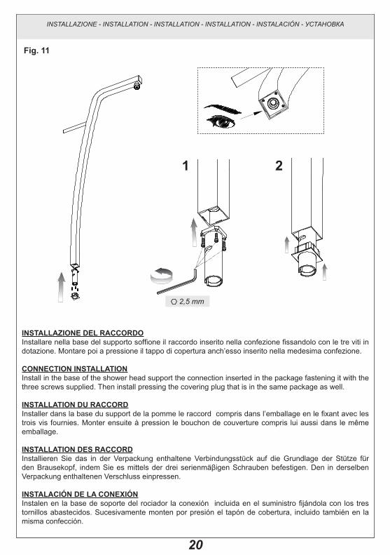
INSTALLAZIONE DEL RACCORDOInstallare nella base del supporto soffione il raccordo inserito nella confezione fissandolo con le tre viti in dotazione. Montare poi a pressione il tappo di copertura anch’esso inserito nella medesima confezione.
CONNECTION INSTALLATIONInstall in the base of the shower head support the connection inserted in the package fastening it with the three screws supplied. Then install pressing the covering plug that is in the same package as well.
INSTALLATION Du RACCORDInstaller dans la base du support de la pomme le raccord compris dans l’emballage en le fixant avec les trois vis fournies. Monter ensuite à pression le bouchon de couverture compris lui aussi dans le même emballage.
INSTALLATION DES RACCORDInstallieren Sie das in der Verpackung enthaltene Verbindungsstück auf die Grundlage der Stütze für den Brausekopf, indem Sie es mittels der drei serienmäβigen Schrauben befestigen. Den in derselben Verpackung enthaltenen Verschluss einpressen.
INSTALACIÓN DE LA CONExIÓNInstalen en la base de soporte del rociador la conexión incluida en el suministro fijándola con los tres tornillos abastecidos. Sucesivamente monten por presión el tapón de cobertura, incluido también en la misma confección.
Fig. 11
1 2
INSTALLAZIONE - INSTALLATION - INSTALLATION - INSTALLATION - INSTALACIÓN - УСТАНОВКА
2,5 mm

21
УСТАНОВКА ФИТИНгАУстановите на основание суппорта душевой лейки находящийся в упаковке фитинг, закрепляя его тремя входящими в комплект винтами. Затем установите с нажимом закрывающую пробку, также включенную в эту же упаковку.
INSTALLAZIONE - INSTALLATION - INSTALLATION - INSTALLATION - INSTALACIÓN - УСТАНОВКА

22
INSTALLAZIONE SuPPORTO SOFFIONEIndividuare tutti i componenti del fissaggio, quindi applicare la placchetta alla parete facendo coincidere i fori con quelli dei tasselli. Fissare con le apposite viti in dotazione. Pre-montare sul supporto soffione i componenti restanti del fissaggio a parete.Attenzione! Per evitare di danneggiare la superficie della colonna doccia bloccare temporaneamente il fissaggio avvitando LEGGERMENTE la vite al supporto della prolunga.
ShOWER hEAD SuPPORT INSTALLATIONFind all the components for the fastening and apply the plate to the wall with holes coinciding with those of the plugs. Fasten with the special screws supplied. Pre-install on shower head support the remaining components of wall fastening.Warning! To avoid damaging the surface of the shower column temporarily block the fastening SLIGHTLY tightening the screw on the support of the extension.
INSTALLATION Du SuPPORT DE LA POMMEIdentifier tous les composants de la fixation, puis appliquer la plaquette à la paroi en faisant coïncider les trous avec ceux des chevilles. Fixer avec les vis spéciales fournies. Pré-monter sur le support de la pomme les composants restants de la fixation à paroi.Attention! Pour éviter d’endommager la superficie de la colonne douche bloquer temporairement la fixation en serrant LÉGÈREMENT la vis sur le support de la rallonge.
INSTALLATION DER STüTZE FüR DEN BRAuSEkOPFAlle zur Befestigung notwendigen Bestandteile bestimmen, dann das Plättchen an die Wand befestigen und dafür sorgen, dass seine Löcher mit denen der Dübel zusammenfallen. Mit den serienmäβigen
Fig. 12
CALDAHOT
FREDDACOLD
Parete finitaTiled wall 150±20
G 1/2"
0÷12
Ø8
50
Ø8
50
INSTALLAZIONE - INSTALLATION - INSTALLATION - INSTALLATION - INSTALACIÓN - УСТАНОВКА
3 mm

23
Schrauben befestigen. Die Restbestandteile der Wandbefestigung auf das untere Ansatzrohr vormontieren.Achtung! Um die Beschädigung der Duschsäulenoberfläche zu vermeiden, ist die Befestigung vorläufig zu blockieren, indem die Schraube zur Stütze des Ansatzrohrs LEICHT eingeschraubt wird.
INSTALACIÓN SOPORTE FLORÓNIndividúen todos los componentes de fijación, sucesivamente apliquen la placa a la pared haciendo coincidir sus huecos con aquellos de los tacos. Fijen con los tornillos correspondientes incluidos en el suministro. Efectúen el premontaje sobre el soporte de los demás componentes para la fijación a la pared.¡Cuidado! Para no dañar la superficie de la columna ducha bloqueen temporáneamente la fijación atornillando LIGERAMENTE el tornillo al soporte de la alargadera.
УСТАНОВКА СУППОРТА дУшЕВОй ЛЕйКИНайдите все компоненты крепления, после чего приложите к стене накладку, совмещая ее отверстия с отверстиями дюбелей. Закрепите входящими в комплект винтами. Установите на суппорт душевой лейки остальные компоненты крепления к стене.Внимание! Чтобы не повредить поверхность душевой колонны, временно затяните крепление, СЛЕГКА завинчивая крепежный винт удлинителя.
INSTALLAZIONE - INSTALLATION - INSTALLATION - INSTALLATION - INSTALACIÓN - УСТАНОВКА

24
REgISTRAZIONE DEL FISSAggIO A PARETEIl fissaggio a parete è stato ideato in modo tale da consentire all’installatore la possibilità di compensare la distanza tra la parete finita e la colonna doccia. Per effettuare la registrazione del fissaggio inserire la vite in uno dei tre fori posti sul supporto della prolunga ed avvitarla leggermente. L’asola posta sul raccordo a parete permette poi di scorrere il tutto fino a raggiungere la distanza desiderata. Se al primo tentativo non si raggiungesse la condizione ottimale svitare la vite e inserirla nel foro precedente e/o successivo e procedere come prima descritto.
WALL FASTENINg ADJuSTMENTWall fastening was conceived so to allow the installer to compensate the distance between the finished wall and the shower column. To adjust the fastening insert the screw in one of the three holes on the support of the extension and slightly tighten it. The buttonhole on the wall connection allows the sliding of all until reaching the required distance. If at first attempt the optimal condition is not achieved loosen the screw and insert it in the previous and/or successive hole and follow the above description.
RÉgLAgE DE LA FIxATION À PAROILa fixation à paroi è été conçue de façon à donner à l’installateur la possibilité de compenser la distance entre la paroi finie et la colonne douche. Pour effectuer le réglage de la fixation insérer la vis dans l’un des trois trous disposés sur le support de la rallonge et la visser légèrement. La fente placée sur le raccord à paroi permet ensuite de faire glisser le tout jusqu’à atteindre la distance désirée. Si l’on n’obtient pas à la première tentative la condition optimale, desserrer la vis et l’insérer dans le trou précédent et/ou successif et procéder comme décrit ci-dessus.
EINSTELLuNg DER WANDBEFESTIguNgDie Wandbefestigung ist so gedacht worden, dass der Rohrleger die Möglichkeit hat, den Abstand zwischen Fertigwand und Duschsäule auszugleichen. Um die Befestigung einzustellen soll die Schraube in eins der drei Löcher an der Stütze des Ansatzrohrs eingefügt und leicht eingeschraubt werden. Die Öse auf dem Wand-Verbindungsstück ermöglicht dann den Schub bis zum gewünschten Abstand. Soll der beste Zustand nicht mit dem ersten Versuch erreicht werden, schrauben Sie die Schraube ab und fügen Sie sie in das vorhergehende/nachstehende Loch, bevor die Operation wie oben beschrieben zu erledigen.
Fig. 13
INSTALLAZIONE - INSTALLATION - INSTALLATION - INSTALLATION - INSTALACIÓN - УСТАНОВКА
3 mm

25
AJuSTE DE LA FIJACIÓN A LA PAREDLa fijación a la pared ha sido concebida de manera que el instalador pueda compensar la distancia entre la pared acabada y la columna ducha. Para efectuar el ajuste de la fijación introduzcan el tornillo en uno de los tres huecos realizados sobre el soporte de la alargadera y atorníllenlo ligeramente. El ojal alojado sobre el racor de pared permite el deslizamiento del conjunto hasta alcanzar la distancia deseada. Si después de la primera tentativa todavía no se ha alcanzado la condición optima, destornillen el tornillo, introdúzcanlo en el agujero precedente y/o sucesivo y sigan como indicado anteriormente.
РЕгУЛИРОВКА НАСТЕННОгО КРЕПЛЕНИЯКрепление к стене было разработано таким образом, чтобы предоставить установщику возможность компенсировать расстояние между готовой стеной и душевой колонной. Для регулировки крепления вставьте винт в одно из трех отверстий на суппорте удлинителя и слегка завинтите винт. Прорезь на настенном соединении позволяет сместить все вплоть до достижения необходимого расстояния. Если с первой попытки не будет достигнуто оптимальное условие, отвинтите винт и вставьте его в предыдущее и/или следующее отверстие, после чего действуйте как описано выше.
INSTALLAZIONE - INSTALLATION - INSTALLATION - INSTALLATION - INSTALACIÓN - УСТАНОВКА

26
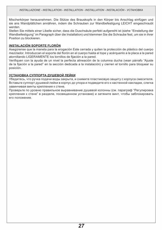
INSTALLAZIONE SuPPORTO SOFFIONEAssicurarsi che la maniglia per l’erogazione sia chiusa e togliere la protezione in plastica dal corpo miscelatore. Inserire il supporto soffione nel corpo fino a battuta e avvicinarlo alla placchetta a muro andando ad avvitare LEGGERMENTE le viti di fissaggio a parete.Verificare mediante una livella il perfetto allineamento della colonna doccia (vedi il paragrafo “Registrazione del fissaggio a parete” nella sezione dedicata all’installazione) e stringere la vite per bloccarne la posizione.
ShOWER hEAD SuPPORT INSTALLATIONMake sure the supply handle is off and remove plastic protection from mixer body. Insert the shower head support in the body down to the stop and approach it to the wall plate SLIGHTLY tightening the fastening screws to the wall.Check with a level shower column’s perfect alignment (see paragraph “Wall fastening adjustment” in the maintenance section) and tighten the screw to stop its position.
INSTALLATION Du SuPPORT DE LA POMMES’assurer que le levier de commande de l’ouverture est fermé et retirer la protection plastique du corps mélangeur. Insérer le support de la pomme dans le corps jusqu’ à la butée et la rapprocher de la plaquette au mur en serrant LÉGÈREMENT les vis di fixation à la paroi.Vérifier au moyen d’un niveau l’alignement parfait de la colonne douche (voir le paragraphe “Réglage de la fixation à paroi” dans la section dédiée à l’installation) et serrer la vis pour bloquer sa position.
INSTALLATION DER STüTZE FüR DEN BRAuSEkOPFSicherstellen, dass der Handgriff zur Wasserversorgung zu ist, und den Plastikschutz aus dem
Fig. 14
2
1
INSTALLAZIONE - INSTALLATION - INSTALLATION - INSTALLATION - INSTALACIÓN - УСТАНОВКА
3 mm
3 mm
27
Mischerkörper herausnehmen. Die Stütze des Brauskopfs in den Körper bis Anschlag einfügen und sie ans Wandplättchen annähren, indem die Schrauben zur Wandbefestigung LEICHT eingeschraubt werden.Stellen Sie mittels einer Libelle sicher, dass die Duschsäule perfekt aufgereiht ist (siehe “Einstellung der Wandbefestigung” im Paragraph über die Installation) und klemmen Sie die Schraube fest, um sie in ihrer Position zu blockieren.
INSTALACIÓN SOPORTE FLORÓNAsegúrense que la maneta para la erogación Este cerrada y quiten la protección de plástico del cuerpo mezclador. Introduzcan el soporte del florón en el cuerpo hasta el tope y acérquenlo a la placa a la pared atornillando LIGERAMENTE los tornillos de fijación a la pared.Verifiquen con la ayuda de un nivel la perfecta alineación de la columna ducha (vean párrafo “Ajuste de la fijación a la pared” en la sección dedicada a la instalación) y cierren el tornillo para bloquear su posición.
УСТАНОВКА СУППОРТА дУшЕВОй ЛЕйКИУбедитесь, что ручка подачи воды закрыта, и снимите пластиковую защиту с корпуса смесителя. Вставьте суппорт душевой лейки в корпус до упора и подведите его к настенной накладке, слегка завинчивая винты крепления к стене.Проверьте по уровню правильное выравнивание душевой колонны (см. параграф “Регулировка крепления к стене” в разделе, посвященном установке) и затяните винт, чтобы заблокировать его положение.
INSTALLAZIONE - INSTALLATION - INSTALLATION - INSTALLATION - INSTALACIÓN - УСТАНОВКА

28
INSTALLAZIONE SuPPORTO SOFFIONEIdentificare poi la posizione perfettamente verticale del supporto soffione aiutandosi con la livella e stringere con forza le viti di fissaggio.Importante! Verificare che la maniglia per l’erogazione ruoti in maniera fluida. Nel caso risultasse troppo dura ripetere le operazioni di allineamento descritte nell’installazione del supporto soffione.Infine scorre il rosone fin contro la parete.
ShOWER hEAD SuPPORT INSTALLATIONThen find the perfectly vertical position of the shower head support with the help of the level and tighten strongly the fastening screws.Important! Check that supply handle turns fluidly. If it is too hard repeat the alignment operations described in the installation of the shower head support.Then let round flange slide down to the wall.
INSTALLATION Du SuPPORT DE LA POMMEDéfinir ensuite la position parfaitement verticale du support de la pomme en s’aidant du niveau et serrer avec force les vis de fixation.Important! Vérifier que le levier de contrôle du débit tourne avec douceur. Au cas où il serait trop dur répéter les opérations d’alignement décrites dans l’installation du support de la pomme.Enfin pousser la rosace contre la paroi.
INSTALLATION DER STüTZE FüR DEN BRAuSEkOPFDie perfekt vertikale Position des Stütze für den Brausekopf mittels einer Libelle bestimmen, und die Befestigungsschrauben festschrauben.Wichtig! Stellen Sie sicher, dass der Handgriff zur Kontrolle der Temperatur leicht drehen kann. Falls
Fig. 15
CALDAHOT
FREDDACOLD
Parete finitaTiled wall 150±20
G 1/2"
0÷12
INSTALLAZIONE - INSTALLATION - INSTALLATION - INSTALLATION - INSTALACIÓN - УСТАНОВКА
3 mm

29
er zu fest ist, wiederholen Sie die zur Installation des unteren Ansatzrohrs beschriebenen Operationen zur Aufreihung.Die Rosette bis zur Wand laufen lassen.
INSTALACIÓN SOPORTE FLORÓNIdentifiquen con la ayuda de un nivel que el soporte del florón se encuentre perfectamente posicionado en vertical y cierren con fuerza los tornillos de fijación.¡Importante! Verifiquen que la maneta para la erogación gire de manera fluida. En el caso de que fuera demasiado dura repitan las operaciones de alineación descritas en la instalación de la alargadera inferior.Finalmente hagan deslizar el florón contra la pared.
УСТАНОВКА СУППОРТА дУшЕВОй ЛЕйКИЗатем найдите строго вертикальное положение суппорта душевой лейки, помогая себе в этом уровнем, после чего затяните с усилием крепежные винты.Важно! Убедитесь, что ручка для подачи воды свободно вращается. Если она вращается слишком туго, то повторите операции выравнивания, описанные в установке суппорта душевой лейки.Наконец, сместите розетку до стены.
INSTALLAZIONE - INSTALLATION - INSTALLATION - INSTALLATION - INSTALACIÓN - УСТАНОВКА

30
INSTALLAZIONE SOFFIONETogliere la striscia adesiva che protegge la guarnizione inserita all’interno del raccordo superiore del soffione ed assicurare lo stesso al proprio supporto avvitando con forza la ghiera (aiutarsi in questa operazione con una chiave da 30mm).
INSTALLATION OF ShOWER hEADRemove adhesive strip that protects the gasket inserted in the upper connection of the shower head and fasten it to its support screwing strongly the ring nut (in this operation a 30mm wrench can be useful).
INSTALLATION POMMERetirer la bande adhésive qui protège le joint inséré à l’intérieur du raccord supérieur de la pomme et fixer celle-ci sur son propre support en vissant avec force la bague (on peut s’aider pour cette opération avec une clef de 30mm).
INSTALLATION VON BRAuSkOPFDen aufklebenden Band zum Schützen der Dichtung beim oberen Ansatzrohr des Brausekopfs herausnehmen und den Ring festschrauben (zu diesem Zweck kann ein Schlüssel von 30mm angewandt werden), um den Brauskopf auf seiner Stütze zu befestigen.
INSTALACIÓN POMO DE DuChAQuiten la tira adhesiva que protege la junta introducida al interior del racor superior del florón y fíjenlo a su soporte atornillando con fuerza la virola (es posible, durante esta operación, utilizar una llave de 30mm).
УСТАНОВКА дУшЕВОй ЛЕйКИСнимите липкую ленту, защищающую уплотнение, вставленное в верхнее соединение душевой лейки, и прикрепите лейку к суппорту, туго завинтив круглую гайку (используйте в этой операции ключ на 30 мм).
Fig. 16
INSTALLAZIONE - INSTALLATION - INSTALLATION - INSTALLATION - INSTALACIÓN - УСТАНОВКА

31
PUSH
38° C <
OPEN
Fig. 18 38° C >38° C
Fig. 17
USO - USE - USAGE - GEBRAUCH - USO - ИСПОЛЬЗОВАНИЕ
uSO- Ruotare la maniglia di 90° verso destra per abilitare l’erogazione a piena portata. - Se la maniglia è in posizione di riposo l’acqua viene erogata a 38° C (vedi taratura della cartuccia
termostatica). Per diminuire la temperatura ruotare la maniglia verso destra. Per aumentare la temperatura oltre i 38° C ruotare la maniglia verso sinistra premendo il pulsante di sicurezza.
uSE- Turning the handle 90° degrees to the right to allow the distributions working at full flow.- If the handle is in standing position, the water is distributed at 38°C (see “thermostatic cartridge
adjustment”). To decrease the temperature, just turn right the handle. To increase the temperature over 38°C just turn left the handle while pushing the safety-button.
uSAgE - Tournez la poignée de 90° à droite afin de mettre en marche la distribution de l’eau à plein débit.- Si la poignée se trouve dans sa position de repos, l’eau est distribuée à la température de 38°C (voir
le tarage de la cartouche thermostatique). Tournez la poignée à droite pour diminuer la température. Pour augmenter la température au dessus de 38°C, tournez la poignée à gauche et appuyez sur l’interrupteur de sécurité.
gEBRAuCh- Den Handgriff um 90° nach rechts drehen, um die Wasserversorgung mit voller Leistung zu
betätigen. - Wenn sich der Handgriff in der Ruheposition befindet, wird das Wasser mit 38° C versorgt (siehe die
Kalibrierung der thermostatischen Kartusche). Um die Temperatur zu senken, drehen Sie den Handgriff nach rechts. Um die Temperatur auf über 38° C zu erhöhen, drehen Sie den Handgriff nach links und drücken Sie den Sicherheitsknopf.

32
USO - USE - USAGE - GEBRAUCH - USO - ИСПОЛЬЗОВАНИЕ
uSO- Giren la maneta de 90° hacia la derecha para habilitar la erogación del agua con caudal máximo.- Si la maneta se encuentra en posición de reposo la erogación del agua ocurre a 38°C (vean la
calibración del cartucho termostático). Para disminuir la temperatura, giren la maneta hacia la derecha. Para aumentar la temperatura sobre 38°C giren la maneta hacia la izquierda, pulsando el botón de seguridad.
ИСПОЛЬЗОВАНИЕ- Поверните ручку на 90° вправо, чтобы включить максимальную подачу воды.- Если ручка находится в исходном положении, вода подается при температуре 38°C (см.
настройку термостатического картриджа). Для снижения температуры поверните ручку вправо. Для повышения температуры сверх 38°C поверните ручку влево, нажимая предохранительную кнопку.

33
Parti di ricambio:1 - Maniglia regolazione temperatura2 - Cartuccia termostatica3 - Vitone4 - Maniglia regolazione portata 5 - Filtro interno6 - Eccentrico con guarnizioni 7 - Fissaggio a parete
Spare parts:1 - Temperature adjustment handle2 - Thermostatic cartridge3 - Head valve4 - Flow rate adjustment handle 5 - Internal filter6 - Eccentric with gaskets 7 - Wall fastening
Pièces de rechange:1 - Poignée réglage température2 - Cartouche thermostatique3 - Tête4 - Poignée réglage débit 5 - Filtre interne6 - Excentrique avec joints 7 - Fixation à paroi
Ersatzteile:1 - Handgriff zur Temperaturregelung2 - Thermostatische Kartusche3 - Oberteil4 - Handgriff zur Strömungsregelung5 - Innerer Filter6 - Exzenterscheibe mit Dichtungen 7 - Wandbefestigung
Piezas de repuesto:1 - Maneta de regulación de la temperatura 2 - Cartucho termostático 3 - Montura 4 - Maneta regulación del caudal 5 - Filtro interno 6 - Excéntrico con juntas 7 - Fijación a la pared
Запасные части:1 - Регулировочная ручка температуры2 - Термостатический картридж3 - Букса4 - Ручка для регулировки производительности5 - Внутренний фильтр6 - Эксцентрик с уплотнением7 - Крепление к стене
Fig. 19
MANUTENZIONE - MAINTENANCE - ENTRETIEN - WARTUNG - MANUTENCIÓN - ОБСЛУЖИВАНИЕ

34
SOSTITuZIONE DEL VITONEPrima di effettuare tale operazione assicurarsi che l’acqua della rete idrica sia chiusa.A - Smontare il soffione dal proprio supporto svitando la ghiera (è possibile per questa operazione aiutarsi
con una chiave da 30mm). Attenzione: eseguire l’operazione con cautela a causa delle importanti dimensioni e del ragguardevole peso del soffione.B - Allontanare il rosone dalla parete.C - Svitare le viti che assicurano la colonna doccia alla parete.D - Estrarre dal corpo la parte superiore del monocomando termostatico.E - Svitare la vite di fissaggio della maniglia e sfilare la stessa dal vitone. Per fare questa operazione è
necessario inclinare la maniglia mentre la si estrae. E’ molto importante durante questa operazione non smarrire gli anelli plastici inseriti nella maniglia.
Fig. 20 A B
C D
CALDAHOT
FREDDACOLD
Parete finitaTiled wall 150±20
G 1/2"
0÷12
E F
MANUTENZIONE - MAINTENANCE - ENTRETIEN - WARTUNG - MANUTENCIÓN - ОБСЛУЖИВАНИЕ
3 mm
3 mm
Ch. 30 mm

35
F - Svitare la ghiera che assicura il vitone al corpo ed estrarre il tutto per la sostituzione.Prima di installare la nuova parte di ricambio verificare che la sede sia pulita da impurità o calcare quindi procedere nella sequenza inversa mantenendo i corretti riferimenti.
hEAD VALVE REPLACEMENTBefore this operation make sure that water network is off.A - Disassemble the shower head from its support unscrewing the ring nut (in this operation a 30mm
wrench can be useful). Warning: carry out the operation carefully due to the large size and the heavy weight of the shower head.B - Take the round flange away from the wall.C - Loosen the screws that fasten the shower column to the wall.D - Remove from the body the upper part of the thermostatic single-lever.E - Loosen the fastening screw of the handle and remove it from the head valve. For this operation incline
the handle as you remove it. It is very important during this operation not to loose the plastic rings inserted in the handle.
F - Unscrew the ring nut that fastens the head valve to the body and remove all for replacement.Before fitting up the new spare part, please check that the seat was clean of impurities or limestone, then proceed in the opposite sequence keeping the common references.
SuBSTITuTION DE LA TêTEAvant d’effectuer cette opération s’assurer que l’alimentation du réseau hydrique est coupée.A - Démonter la pomme de son propre support en dévissant la bague (on peut s’aider pour cette opération
avec une clef de 30mm). Attention: exécuter l’opération avec précaution à cause des dimensions importantes et du poids notable de la pomme.B - Éloigner la rosace de la paroi.C - Desserrer les vis qui fixent la colonne douche sur la paroi.D - Extraire du corps la partie supérieure du contrôle central thermostatique.E - Desserrer la vis di fixation de la poignée et retirer celle-ci de la tête. Pour exécuter cette opération il est
nécessaire d’incliner la poignée pendant qu’on l’extrait. Il est très important de ne pas perdre pendant cette opération les anneaux plastiques insérés dans la poignée.
F - Dévisser la bague qui fixe la tête sur le corps et extraire le tout pour la substitution.Avant d’installer la nouvelle pièce de rechange, vérifier que la base soit bien nettoyée de toutes impuretées ou calcaire, ensuite procéder de manière inverse en suivant les memes procédés auparavant éxécutés.
WEChSEL DES OBERTEILSBevor diese Operation zu erledigen, sorgen Sie dafür, dass die Wasserleitungen gesperrt sind.A - Den Ring abschrauben, um den Brausekopf aus seiner Stütze abzumontieren (bei dieser Operation
kann ein Schlüssel von 30 mm verwandt werden).Achtung: Wegen der großen Abmessungen und des hohen Gewichts des Brauskopfs soll diese Operation mit der höchsten Vorsicht erledigt werden.B - Die Rosette von der Wand entfernen.C - Die Schrauben zur Befestigung der Duschsäule an der Wand abschrauben.D - Das obere Teil des thermostatischen Einhebels aus dem Körper herausnehmen.E - Die Schraube zur Befestigung des Handgriffs abschrauben und diesen aus dem Oberteil herausnehmen.
Um diese Operation zu erledigen, soll der Handgriff geneigt werden, während sie herausgenommen wird. Es ist sehr wichtig, dass die Kunststoffringe im Inneren des Handgriffs während dieser Operation nicht verloren werden.
F - Den Ring zur Befestigung des Oberteils an den Körper abschrauben und alle Bestandteile herausnehmen, um mit dem Wechsel fortzuschreiten.
Bevor das Ersatzteil installiert wird, beachten Sie bitte, dass die Stelle sauber von Unreinheiten und Kalkstein ist, dann gehen Sie weiter in die umgekehrte Folge und halten Sie sich an die korrekte Hinweise.
MANUTENZIONE - MAINTENANCE - ENTRETIEN - WARTUNG - MANUTENCIÓN - ОБСЛУЖИВАНИЕ

36
SuSTITuCIÓN DE LA MONTuRAAntes de efectuar dicha operación asegúrense que el agua de la red hídrica esté cerrada.A - Desmonten el florón de su soporte, destornillando la virola (es posible, durante esta operación, utilizar
una llave de 30 mm). Cuidado: efectúen la operación con cuidado debido a las grandes dimensiones y al peso del florón.B - Alejen el florón de la pared.C - Destornillen los tornillos que aseguran la columna ducha a la pared.D - Extraigan del cuerpo la parte superior del monomando termostático.E - Destornillen el tornillo de fijación y suéltenlo de la montura. Para efectuar dicha operación es necesario
inclinar la maneta durante la extracción. Es muy importante, durante esta operación, poner cuidado para no perder los anillos de plástico introducidos en la maneta.
F - Destornillen la virola que asegura la montura al cuerpo y extraigan todo el grupo para su sustitución.Antes de instalar el repuesto nuevo, verificar que la sede esté libre de impurezas o cal y seguir entonces según el orden inverso manteniendo las referencias correctas.
ЗАМЕНА бУКСыПеред выполнением этой операции убедитесь, что вода из водопроводной сети перекрыта.A - Снимите душевую лейку с суппорта, отвинчивая круглую гайку (для выполнения этой операции
можно воспользоваться ключом на 30 мм). Внимание: ввиду больших размеров и существенного веса душевой лейки, выполняйте эту операцию осторожно.B - Отодвиньте розетку от стены.C - Отвинтите винты, крепящие душевую колонну к стене.D - Снимите с корпуса верхнюю часть однокоманднтермостатического смесителя.E - Отвинтите крепежный винт ручки и снимите ее с буксы. Для выполнения этой операции
необходимо наклонить ручку во время ее извлечения. Во время этих операций крайне важно не потерять пластиковые кольца, вставленные в ручку.
F - Отвинтите круглую гайку, крепящую буксу к корпусу, и выньте узел в сборе для замены.Перед установкой новой запчасти убедитесь, что гнездо очищено от примесей и водного камня, после чего действуйте в обратной последовательности, соблюдая правильность установки.
MANUTENZIONE - MAINTENANCE - ENTRETIEN - WARTUNG - MANUTENCIÓN - ОБСЛУЖИВАНИЕ
37
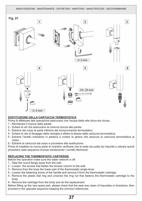
SOSTITuZIONE DELLA CARTuCCIA TERMOSTATICAPrima di effettuare tale operazione assicurarsi che l’acqua della rete idrica sia chiusa.1 - Allontanare il rosone dalla parete.2 - Svitare le viti che assicurano la colonna doccia alla parete.3 - Estrarre dal corpo la parte inferiore del monocomando termostatico.4 - Svitare la vite di fissaggio della maniglia e sfilare la stessa dalla cartuccia termostatica. 5 - Estrarre l’anello indicatore in plastica e svitare la ghiera che assicura la cartuccia termostatica al
corpo.6 - Estrarre la cartuccia dal corpo e procedere alla sostituzione.Prima di installare la nuova parte di ricambio verificare che la sede sia pulita da impurità o calcare quindi procedere nella sequenza inversa mantenendo i corretti riferimenti.
REPLACINg ThE ThERMOSTATIC CARTRIDgEBefore this operation make sure the water network is off.1 - Take the round flange away from the wall.2 - Loosen the screws that fasten the shower column to the wall.3 - Remove from the body the lower part of the thermostatic single-lever.4 - Loosen the fastening screw of the handle and remove it from the thermostatic cartridge. 5 - Remove the plastic dial ring and unscrew the ring nut that fastens the thermostatic cartridge to the
body.6 - Remove the cartridge from the body and do the replacement.Before fitting up the new spare part, please check that the seat was clean of impurities or limestone, then proceed in the opposite sequence keeping the common references.
Fig. 211 2
4 5 6
3
MANUTENZIONE - MAINTENANCE - ENTRETIEN - WARTUNG - MANUTENCIÓN - ОБСЛУЖИВАНИЕ
3 mm
3 mm
Ch. 25 mm

38
SuBSTITuTION DE LA CARTOuChE ThERMOSTATIquEAvant d’effectuer cette opération s’assurer que l’alimentation du réseau hydrique est coupée.1 - Éloigner la rosace de la paroi.2 - Desserrer les vis qui fixent la colonne douche sur la paroi.3 - Extraire du corps la partie inférieure du contrôle central thermostatique.4 - Desserrer la vis di fixation de la poignée et la retirer de la cartouche thermostatique. 5 - Extraire l’anneau indicateur en plastique et dévisser la bague qui fixe la cartouche thermostatique sur
le corps.6 - Extraire la cartouche du corps et procéder à la substitution.Avant d’installer la nouvelle pièce de rechange, vérifier que la base soit bien nettoyée de toutes impuretées ou calcaire, ensuite procéder de manière inverse en suivant les memes procédés auparavant éxécutés.
WEChSEL DER ThERMOSTATISChEN kARTuSChEBevor diese Operation zu erledigen, sorgen Sie dafür, dass die Wasserleitungen gesperrt sind.1 - Die Rosette von der Wand entfernen.2 - Die Schrauben zur Befestigung der Duschsäule an der Wand abschrauben.3 - Das untere Teil des thermostatischen Einhebels aus dem Körper herausnehmen.4 - Die Schraube zur Befestigung des Handgriffs abschrauben und diesen aus der thermostatischen
Kartusche herausnehmen.5 - Den Anzeigerring aus Kunststoff herausnehmen und den Ring zur Befestigung der thermostatischen
Kartusche an den Körper abschrauben.6 - Die Kartusche aus dem Körper herausnehmen und sie wechseln.Bevor das Ersatzteil installiert wird, beachten Sie bitte, dass die Stelle sauber von Unreinheiten und Kalkstein ist, dann gehen Sie weiter in die umgekehrte Folge und halten Sie sich an die korrekte Hinweise.
SuSTITuCIÓN DEL CARTuChO TERMOSTáTICOAntes de efectuar dicha operación asegúrense que el agua de la red hídrica esté cerrada.1 - Alejen el florón de la pared.2 - Destornillen los tornillos que aseguran la columna ducha a la pared.3 - Extraigan del cuerpo la parte inferior del monomando termostático.4 - Destornillen el tornillo de fijación y suéltenlo del cartucho termostático. 5 - Extraigan el anillo indicador de plástico y destornillen la virola que asegura el cartucho termostático al
cuerpo.6 - Extraigan el cartucho del cuerpo y sustitúyanlo.Antes de instalar el repuesto nuevo, verificar que la sede esté libre de impurezas o cal y seguir entonces según el orden inverso manteniendo las referencias correctas.
ЗАМЕНА ТЕРМОСТАТИЧЕСКОгО КАРТРИджАПеред выполнением этой операции убедитесь, что вода из водопроводной сети перекрыта.1 - Отодвиньте розетку от стены.2 - Отвинтите винты, крепящие душевую колонну к стене.3 - Снимите с корпуса нижнюю часть термостатического смесителя.4 - Отвинтите крепежный винт ручки и снимите ее с термостатического картриджа.5 - Извлеките пластиковое индикаторное кольцо и отвинтите круглую гайку, крепящую
термостатический картридж к корпусу.6 - Снимите картридж с корпуса и замените его.Перед установкой новой запчасти убедитесь, что гнездо очищено от примесей и водного камня, после чего действуйте в обратной последовательности, соблюдая правильность установки.
MANUTENZIONE - MAINTENANCE - ENTRETIEN - WARTUNG - MANUTENCIÓN - ОБСЛУЖИВАНИЕ

39
Fig. 22
Fig. 24
Fig. 26
Fig. 23
Fig. 27
Fig. 25
MANUTENZIONE - MAINTENANCE - ENTRETIEN - WARTUNG - MANUTENCIÓN - ОБСЛУЖИВАНИЕ
3 mm
3 mm
40
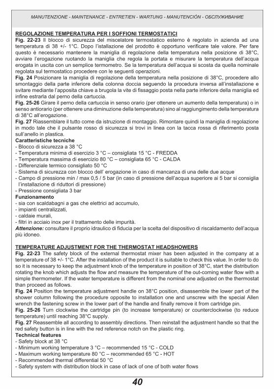
REgOLAZIONE TEMPERATuRA PER I SOFFIONI TERMOSTATICIFig. 22-23 Il blocco di sicurezza del miscelatore termostatico esterno è regolato in azienda ad una temperatura di 38 +/- 1°C. Dopo l’istallazione del prodotto è opportuno verificare tale valore. Per fare questo è necessario mantenere la maniglia di regolazione della temperatura nella posizione di 38°C, avviare l’erogazione ruotando la maniglia che regola la portata e misurare la temperatura dell’acqua erogata in uscita con un semplice termometro. Se la temperatura dell’acqua si scosta da quella nominale regolata sul termostatico procedere con le seguenti operazioni.Fig. 24 Posizionare la maniglia di regolazione della temperatura nella posizione di 38°C, procedere allo smontaggio della parte inferiore della colonna doccia seguendo la procedura inversa all’installazione e svitare mediante l’apposita chiave a brugola la vite di fissaggio posta nella parte inferiore della maniglia ed infine estrarla dal perno della cartuccia.Fig. 25-26 Girare il perno della cartuccia in senso orario (per ottenere un aumento della temperatura) o in senso antiorario (per ottenere una diminuzione della temperatura) sino al raggiungimento della temperatura di 38°C all’erogazione. Fig. 27 Riassemblare il tutto come da istruzione di montaggio. Rimontare quindi la maniglia di regolazione in modo tale che il pulsante rosso di sicurezza si trovi in linea con la tacca rossa di riferimento posta sull’anello in plastica.Caratteristiche tecniche- Blocco di sicurezza a 38 °C- Temperatura minima di esercizio 3 °C – consigliata 15 °C - FREDDA- Temperatura massima di esercizio 80 °C – consigliata 65 °C - CALDA- Differenziale termico consigliato 50 °C- Sistema di sicurezza con blocco dell’ erogazione in caso di mancanza di una delle due acque- Campo di pressione min / max 0,5 / 5 bar (in caso di pressione dell’acqua superiore ai 5 bar si consiglia
l’installazione di riduttori di pressione)- Pressione consigliata 3 barFunzionamento- sia con scaldabagni a gas che elettrici ad accumulo,- impianti centralizzati,- caldaie murali,- filtri in acciaio inox per il trattamento delle impurità.Attenzione: consultare il proprio idraulico di fiducia per la scelta del dispositivo di riscaldamento dell’acqua più idoneo.
TEMPERATuRE ADJuSTMENT FOR ThE ThERMOSTAT hEADShOWERSFig. 22-23 The safety block of the external thermostat mixer has been adjusted in the company at a temperature of 38 +/- 1°C. After the installation of the product it is suitable to check this value. In order to do so it is necessary to keep the adjustment knob of the temperature in position of 38°C, start the distribution rotating the knob which adjusts the flow and measure the temperature of the out-coming water flow with a simple thermometer. If the water temperature is different from the nominal one adjusted on the thermostat than proceed as follows.Fig. 24 Position the temperature adjustment handle on 38°C position, disassemble the lower part of the shower column following the procedure opposite to installation one and unscrew with the special Allen wrench the fastening screw in the lower part of the handle and finally remove it from cartridge pin.Fig. 25-26 Turn clockwise the cartridge pin (to increase temperature) or counterclockwise (to reduce temperature) until reaching 38°C supply. Fig. 27 Reassemble all according to assembly directions. Then reinstall the adjustment handle so that the red safety button is in line with the red reference notch on the plastic ring.Technical features - Safety block at 38 °C- Minimum working temperature 3 °C – recommended 15 °C - COLD- Maximum working temperature 80 °C – recommended 65 °C - HOT- Recommended thermal differential 50 °C- Safety system with distribution block in case of lack of one of both water flows
MANUTENZIONE - MAINTENANCE - ENTRETIEN - WARTUNG - MANUTENCIÓN - ОБСЛУЖИВАНИЕ

41
- Pressure field min / max 0,5 / 5 bar (in case of water pressure higher than 5 bar it is recommended to install pressure reducers)
- Recommended pressure 3 barOperation- both with gas water-heater as well as electric accumulation water-heater,- centralised installations,- wall boilers,- stainless steel filters for the treatment of the impuritiesWarning: contact the plumber for the choice of the best water heating device.
RÉgLAgE DE LA TEMPÉRATuRE POuR LES SOuFFLETS ThERMOSTATIquESFig. 22-23 Le bloc de sécurité du mélangeur thermostatique extérieur est réglé dans la maison même où il est fabriqué à une température de 38 +/- 1°C. Après l’installation du produit il faut vérifier cette valeur. Pour faire cela, il faut maintenir la poignée de réglage de la température à la position de 38°C, démarrer la distribution en tournant la poignée qui règle la porte et mesurer la température de l’eau distribuée en sortie avec un simple thermomètre. Si la température de l’eau se déplace de celle nominale réglée sur le thermostat il faut procéder avec les opérations suivantes.Fig. 24 Placer le levier de réglage de la température sur la position de 38°C, procéder au démontage de la partie inférieure de la colonne douche suivant la procédure inverse de l’installation et desserrer au moyen de la clef à vis à 6 pans creux prévue à cet effet la vis de fixation placée dans la partie inférieure du levier et enfin l’extraire du tourillon de la cartouche.Fig. 25-26 Tourner le tourillon de la cartouche dans le sens des aiguilles d’une montre (pour obtenir un augmentation de la température) ou dans le sens inverse des aiguilles d’une montre (pour obtenir une diminution de la température) jusqu’à l’obtention de la température de 38°C à l’ouverture. Fig. 27 Ré assembler le tout en suivant les instructions de montage. Remonter ensuite le levier de réglage de façon à ce que le bouton rouge de sécurité se trouve aligné avec le repère rouge de référence placé sur l’anneau de plastique.Caractéristiques techniques- Bloc de sécurité à 38 °C- Température minimum d’exercice 3 °C – conseillée 15 °C - FROIDE- Température maximum d’exercice 80 °C – conseillée 65 °C - CHAUDE - Différentiel thermique conseillé 50 °C- Système de sécurité avec le bloc de la distribution en cas de manque d’une des deux eaux- Champ de pression min / max 0,5 / 5 bar (en cas de pression de l’eau supérieure aux 5 bar nous
conseillons l’installation de réducteurs de pression)- Pression conseillée 3 barFonctionnement- soit avec des chauffe-bain à gaz qu’électriques à accumulation,- installations centralisées,- chaudières murales,- filtres en acier inox pour le traitement des impuretés.Attention: consulter le plombier pour le choix du dispositif de réchauffement de l’eau le plus approprié.
TEMPERATuREINSTELLuNg FüR DIE ThERMOSTATISChEN BRAuSEköPFEAbb. 22-23 Die Sicherheitssperre der externen thermostatischen Mischbatterie ist werkseitig auf eine Temperatur von 38 +/- 1°C eingestellt. Nach der Installation des Produktes wäre es angebracht diesen Wert zu überprüfen. Um dieses zu tun, muß man den Drehgriff für die Temperatureinstellung in der Position von 38°C festhalten, die Wasserabgabe starten, indem man den Drehgriff, der die Durchflußleistung reguliert, dreht und die Temperatur am Wasserabgabepunkt mit einem einfachen Thermometer messen. Wenn die Wassertemperatur von dem, auf dem Thermostat eingestellten Nennwert abweicht, verfährt man entsprechend der anschließend beschriebenen Tätigkeiten.Abb. 24 Den Handgriff zur Temperaturregelung bei 38°C positionieren, dann das untere Teil der Duschsäule abmontieren, indem die Prozedur zu ihrer Installation umgekehrt wiederholt wird. Die Befestigungsschrauben beim unteren Teil des Handgriffs mittels eines geeigneten Innensechskantschlüssels abschrauben und ihn
MANUTENZIONE - MAINTENANCE - ENTRETIEN - WARTUNG - MANUTENCIÓN - ОБСЛУЖИВАНИЕ

42
aus dem Stift der Kartusche herausnehmen.Abb. 25-26 Den Stift der Kartusche im Uhrzeigersinn (um die Temperatur zu erhöhen) bzw. gegen Uhrzeigersinn (um die Temperatur zu reduzieren) drehen, bis eine Temperatur von 38°C beim Auslauf erreicht wird. Abb. 27 Alle Bestandteile wieder montieren, wie bei den Installationsanweisungen beschrieben. Den Handgriff zur Temperaturregelung also wieder montieren, damit der rote Sicherheitsschalter aufgereiht mit der roten Referenzmarke auf dem Kunststoffring ist.Technische Eigenschaften- Sicherheitssperre bei 38 °C- Minimale Betriebstemperatur 3 °C – empfohlener Wert 15 °C - CALT- Maximale Betriebstemperatur 80 °C – empfohlener Wert 65 °C - WARM- Empfohlenes Wärmedifferential 50 °C- Sicherheitssystem mit Abgabesperre, wenn es zum Fehlen einer der beiden Wasserversorgungen
kommt- Druckbereich min. / max. 0,5 / 5 bar (sollte der Wasserdruck einen Wert von 5 bar überschreiten, empfiehlt
es sich Druckminderventile zu installieren)- Empfohlener Betriebsdruck 3 barFunktion- sowohl mit Gasboilern, als auch mit elektrischen Heißwasserspeichern,- zentralisierte Anlagen,- Wandkessel,- Filter aus Inoxstahl zum Schutz vor Verunreinigungen.Achtung: zur Wahl der best anpassenden Wasserheizvorrichtung, bitte wenden Sie sich an Ihren Vertrauensinstallateur.
REguLACIÓN TEMPERATuRA PARA POMOS DE DuChAS TERMOSTáTICOSFig. 22-23 El bloque de seguridad del mezclador está ajustado en fábrica a una temperatura de 38 ± 1°C. Tras haber instalado el producto es preciso verificar dicho valor. Para hacer esto es necesario mantener la maneta de regulación de la temperatura en la posición de 38°C, empezar la erogación girando la maneta de regulación del caudal y medir la temperatura del agua a la salida con un termómetro. Si la temperatura del agua es diferente de la temperatura nominal regulada en el termostático efectúen las siguientes operaciones.Fig. 24 Posicionen la maneta de regulación de la temperatura en la posición de 38°C, desmonten la parte inferior de la columna ducha según el procedimiento inverso de la instalación y destornillen con la ayuda de la correspondiente llave de allén el tornillo de fijación alojado en la parte inferior de la maneta y, finalmente, extráiganlo del pivote del cartucho.Fig. 25-26 Giren el pivote del cartucho en el sentido de las agujas del reloj (para obtener un aumento de la temperatura) o en el sentido contrario a las agujas del reloj (para obtener una disminución de la temperatura) hasta alcanzar la temperatura de 38°C en el momento de la erogación.Fig. 27 Vuelvan a ensamblar el conjunto como indicado en las instrucciones de montaje. Vuelvan a montar la maneta de regulación de manera que el botón rojo de seguridad se encuentre alineado con la muesca roja de referencia sobre el anillo de plástico.Características técnicas - Bloque de seguridad a 38 °C- Temperatura mínima de ejercicio 3°C – aconsejada 15°C - FRIA- Temperatura máxima de ejercicio 80°C – aconsejada 65°C - CALIENTE- Diferencial técnico aconsejado 50°C- Sistema de seguridad con bloqueo de la erogación en caso de falta de una de las dos aguas- Campo de presión mín. / máx. 0,5 / 5 bares (en caso de presión del agua superior a los 5 bar, les
aconsejamos instalar unos reductores de presión)- Presión aconsejada 3 baresFuncionamiento- con calderas tanto de gas como eléctricas de acumulación,- instalaciones centralizadas,
MANUTENZIONE - MAINTENANCE - ENTRETIEN - WARTUNG - MANUTENCIÓN - ОБСЛУЖИВАНИЕ

43
- calderas murales,- filtros de acero inoxidable para el tratamiento de las impurezas.Cuidado: consúltense con su fontanero para elegir el dispositivo de calefacción del agua más adecuado.
РЕгУЛИРОВКА ТЕМПЕРАТУРы дЛЯ ТЕРМОСТАТИЧЕСКИХ дУшЕВыХ ЛЕЕКРис. 22-23 Предохранительная блокировка наружного термостатического смесителя отрегулирована на заводе на температуру 38 +/- 1°C. После установки изделия рекомендуется проверить это значение. После установки изделия рекомендуется проверить это значение. Для этого необходимо удерживать регулировочную ручку температуры в положении 38°C, включить воду, поворачивая ручку, регулирующую подачу, и измерить температуру воды на выходе обычным термометром. Если температура воды отличается от номинальной, отрегулированной на термостатическом смесителе, выполните следующие действия.Рис. 24 Установите регулировочную ручку температуры в положение 38°C, снимите нижнюю часть душевой колонны, выполняя операции установки в обратной последовательности, отвинтите специальным шестигранным ключом крепежный винт, находящийся в нижней части ручки, и, наконец, снимите ее с пальца картриджа.Рис. 25-26 Поверните палец картриджа по часовой стрелке (для увеличения температуры) или против часовой стрелки (для снижения температуры) вплоть до достижения температуры подаваемой воды 38°C. Рис. 27 Соберите узел, выполняя инструкции по монтажу. Установите на место ручку, чтобы красная предохранительная кнопка находилась на одной линии с красной меткой на пластиковом кольце.Технические характеристики- Предохранительное ограничение температуры на 38 °C- Минимальная рабочая температура: 3 °C, рекомендуемая: 15 °C - для ХОЛОДНОЙ воды- Максимальная рабочая температура: 80 °C, рекомендуемая 65 °C - для ГОРЯЧЕЙ воды- Рекомендуемая разница температуры: 50 °C- Предохранительная система с перекрытием подачи в случае отсутствия холодной или горячей
воды- Пределы давления мин-макс: 0,5 - 5 бар (в случае давления воды, превышающего 5 бар,
рекомендуется установка редукторов давления)- Рекомендуемое давление: 3 барРабота- как с газовыми водонагревателями, так и с электроводонагревателями накопительного типа,- централизованные системы,- настенные котлы,- фильтры из нержавеющей стали для улавливания примесей.Внимание: для выбора наиболее пригодного средства нагрева воды обращайтесь к вашему сантехнику.
MANUTENZIONE - MAINTENANCE - ENTRETIEN - WARTUNG - MANUTENCIÓN - ОБСЛУЖИВАНИЕ

44
PuLIZIA E/O SOSTITuZIONE DEI FILTRINel caso in cui si verifichi una scarsa fuoriuscita d’acqua dal miscelatore è opportuno verificare le condizioni dei filtri posizionati sui raccordi a parete posti dietro il corpo della colonna doccia. Prima di effettuare tale operazione assicurarsi che l’acqua della rete idrica sia chiusa.Svitare i raccordi su cui sono posizionati i filtri. Procedere con le operazioni di pulizia utilizzando acqua corrente per eliminare le impurità. Verificare che anche le sedi siano pulite da impurità o calcare.In fine, seguendo la procedura in modo inverso, sistemare i filtri nelle proprie sedi e verificare che tutto funzioni correttamente.
NB. Nel caso si accerti il danneggiamento dei filtri è possibile chiederne la sostituzione e operare l’avvicendamento seguendo quanto sopra descritto.
FILTERS CLEANINg AND/OR SuBSTITuTIONIf little water is supplied by the mixer it is appropriate to check the conditions of filters positioned on the wall connections behind the body of shower column. Before this operation make sure that water network is off.Loosen the connections on which filters are positioned. Keep on with cleaning operations using running water to remove impurities. Verify that also the seats were clean from impurities or limestone.Finally, following the opposite sequence, place filters in their seats and check that all works properly.
NB. If filters are damaged they can be replaced according to the above description.
Fig. 28
MANUTENZIONE - MAINTENANCE - ENTRETIEN - WARTUNG - MANUTENCIÓN - ОБСЛУЖИВАНИЕ
6 mm

45
NETTOyAgE ET/Ou SuBSTITuTION DES FILTRESDans le cas où il se produirait une faible perte d’eau sur le mélangeur il est opportun de vérifier la condition des filtres placés sur les raccords à paroi disposés derrière le corps de la colonne douche. Avant d’effectuer cette opération s’assurer que l’alimentation du réseau hydrique est coupée.Dévisser les raccords sur lesquels sont montés les filtres. Procéder aux opérations de nettoyage en utilisant l’eau courante pour éliminer les impuretés. Vérifier également que les bases soient nettoyées de toutes impuretées ou calcaire.Enfin, en suivant la procédure inverse, mettre les filtres dans leurs propres logements et vérifier que tout fonctionne correctement.
NB. Au cas où l’on observerait un endommagement des filtres il est possible d’en demander la substitution et de procéder à leur remplacement
REINIguNg uND/ODER WEChSEL DER FILTERBei einem evtl. geringen Wasserausfluss aus dem Mischer, ist es empfehlenswert, den Zustand der Filter auf den Wand-Verbindungsstücken hinten dem Körper der Duschsäule zu überprüfen.Bevor diese Operation zu erledigen, ist es zu überprüfen, dass die Wasserleitungen gesperrt sind. Die Verbindungsstücke, auf denen die Filter positioniert sind, abschrauben. Die Teile mit fließendem Wasser spülen, um alle Unreinheiten zu entfernen. Bitte prüfen Sie, dass auch die Anschlusse sauber von Unreinheiten und Kalkstein sind.Die Prozedur dann umgekehrt wiederholen, um die Filter in ihre Sitze zu stellen, und sicherstellen, dass alles korrekt funktioniert.
Anm. Bei der evtl. Beschädigung der Filter, können diese ersetzt werden, bevor die oben beschriebenen Wechseloperationen zu erledigen.
LIMPIEZA y/O SuSTITuCIÓN DE LOS FILTROS En el caso de que ocurra una erogación escasa de agua procedente del mezclador es preciso verificar las condiciones de los filtros, alojados en los racores de pared por detrás del cuerpo de la columna ducha. Antes de efectuar dicha operación asegúrense que el agua de la red hídrica esté cerrada.Destornillen los racores sobre los cuales están alojados los filtros. Efectúen las operaciones de limpieza utilizando agua corriente para eliminar las impurezas. Verificar que las sedes estén limpias de impurezas o cal. Finalmente, efectúen el procedimiento de manera inversa para alojar los filtros en sus asientos y verifiquen que todo funcione correctamente.
NB. En el caso de que los filtros resulten dañados, será posible pedir su sustitución y reemplazarlos como indicado anteriormente.
ЧИСТКА И/ИЛИ ЗАМЕНА ФИЛЬТРОВПри обнаружении недостаточного вытекания воды из смесителя, рекомендуется проверить состояние фильтров, находящихся на настенных точках подключения, за корпусом душевой колонны. Перед выполнением этой операции убедитесь, что вода из водопроводной сети перекрыта.Отвинтите соединения, на которые установлены фильтры. Выполните чистку в проточной воде для устранения примесей. Убедитесь, что гнезда также очищены от грязи и водного камня.Наконец, выполняя процедуру в обратной последовательности, поместите фильтры в их гнезда и проверьте исправность работы всего комплекса.
ПРИМ.: В случае обнаружения повреждения фильтров можно заказать их замену, действуя для этого описанным выше образом.
MANUTENZIONE - MAINTENANCE - ENTRETIEN - WARTUNG - MANUTENCIÓN - ОБСЛУЖИВАНИЕ

46
...........................................................................................................................................................................................
...........................................................................................................................................................................................
...........................................................................................................................................................................................
...........................................................................................................................................................................................
...........................................................................................................................................................................................
...........................................................................................................................................................................................
...........................................................................................................................................................................................
...........................................................................................................................................................................................
...........................................................................................................................................................................................
...........................................................................................................................................................................................
...........................................................................................................................................................................................
...........................................................................................................................................................................................
...........................................................................................................................................................................................
...........................................................................................................................................................................................
...........................................................................................................................................................................................
...........................................................................................................................................................................................
...........................................................................................................................................................................................
...........................................................................................................................................................................................
...........................................................................................................................................................................................
...........................................................................................................................................................................................
...........................................................................................................................................................................................
...........................................................................................................................................................................................
...........................................................................................................................................................................................
...........................................................................................................................................................................................
...........................................................................................................................................................................................
...........................................................................................................................................................................................
...........................................................................................................................................................................................
NOTE - NOTES - NOTES - ANMERKUNG - NOTAS - ПРИМЕЧАНИЕ:


ET 41697 - R0
Related Documents