LABORATORY RESEARCH REPORT NR 15 '0 FLYING IN TUmu-DMMsIoNAL SPACE Wr SIX DI~DGE OF FREEDOM I SOctober 1900 I Second Printi*, April 196.. ARMY MISSILE TEST CENTER WHITE SAN MISSILE RANGE New Me I ~ II

Welcome message from author
This document is posted to help you gain knowledge. Please leave a comment to let me know what you think about it! Share it to your friends and learn new things together.
Transcript

LABORATORY RESEARCH REPORT NR 15
'0
FLYING IN TUmu-DMMsIoNAL SPACEWr SIX DI~DGE OF FREEDOM I
SOctober 1900 I
Second Printi*, April 196..
ARMY MISSILE TEST CENTERWHITE SAN MISSILE RANGE
New Me
I ~ II

BestAvailable
Copy
1Wh.-TMu MLGHT ANALYSISFOOAM2" FOR THE OMM3,TION OF A MAMSDDI F M A IN 3 ,1 Z.D M ZO•L1.,IACI SU DMREES OF Fn MWx.
LASORATORY RESEARCH REPOT NR 11;D •,t RePort W r 12
Septeuber 196
fteparedby
Analog S1uilation fRach,, FmI, UL
Aralog SiMUlation Vrantob FMSL, M
Revieed, by
".Aef, Sizniuatio Theory raanch, Ucc
Ch, pilogt SaulmAtion Laboratory JDLIi
S..........O. LAf.RAEJCTRO-DOMCALgC LADDPATMW
VIMT BSAS )aW=~ RARI INW 1MIOO ~

ABSTRACT
Methods are explained for derving the- differential equations des-cribing a general joissile airfrnw flying in three-dimensional space.All the forces and moments acting on the missile are written as vectors.7Aese vectors are readily expressed in suitable coordinate systems.After they are so expressed, they are trnaformed: to a common coordinatesystem where the solutions are carried out. The desired output informa-tion Is then transformed to a fixed system on the ground and presented interms of that-system. A short exposition of vector analysis$ to the ex-tent required, is included, and matrix notation is emphasized throughout.
*thOds (utilizing vector azalysis and coordinate system transforma-tiom) are presented for handling thrust misalignment, the general momentof inertia tensor, curvature of the zarth, rotiation of the earth, targets,etc.
The methods, as t-4loyed; generate an exact representation of theflying missile; hewever, wherever possible, approximations are auggestedwhich simplify the equations. Errors, not only from approximations, butfrom, other sources, are pointed out -when such situations arise.
Since there are so many types of guidance philosophies, only verygeneral statements are made concerning guidance. However, the guidancephilosophies for two specific types of missiles are included as exmples.
9

CONTENTB
IIM0NCTION o- o oo---- aao o o-- o o -
Vectors -- a.. . . .aDerivatives in Rotating Cooimts 4ptow .-..... . 32
aer AMUe Transfomntion w a w a w . - 15Derivati•n of t3e Buler Angles . .. . 2D
h wl1A a'st a . . -. . . . . . . ... . . . .Derivatio of the Azgles of Attak and
The Thzrst Bysta * -a - 28Kinemuatcan& Relative Win. 29
TheTranulatioal Acelont caw -e--m--n--a- 30The Rotational Aoeeleatims ft 33Nelatly. andExternal VIS Aa aamm 36
Externl Fores h Moments - - - ------- 38Repretentation of Aer aa cx a a . . a . a
Fin Deflections---. .a a - a a a a a a a a am ~Transfer Pitmctes a a a a a a a a a a a a a a a a. 1lathma'tial, ModelBloOk Dlagm .m..... ...
Targets,,aaaa - aa
oulduft coa tmI "wtm for a Veml Mao mamamSh. Q3tfm a a =.. a a a ft a a ft a a a a 8
Nmd4otIve Rod.n CUUWMO *Vtmf .. a . m a . am .. 6
It"i
o i.
.................. ii

F1NDAMEWS W3 T U C .O' C. A MAE 'l0L FOE A MESSIL I .T=REi-
DIM. SI-OAL SPACE WW.E SIX A_.4M OF FREEDOM.
The following series of notes givea the dewvatiom for. the gener'alequations vlevh describe anr missile system in three dmensional space.WVL7 people have expressed a desire to have these fendauentala xpounded . indetail and also have the derwvations, themselves, in printed form for futurtrederence; hence tkas series.
These notes,, vbhch vill also be g.ven as lectures, have previouslybeen given to a select group in a sort of "dry rum". M.at group felt -thatthese notes would provide a valuable reference. and cild be used also as a±'tmdametal basis in deriving equations for any missile systdkj, since thee:,uations for a ge:reral missile system are of the same typa no mtter vbattype of missile is ujed. Te airframe equations (-1•ch tihese lectures anepý.dma•rly concerned .ith) are more or less fIddae idntical in evereass of a fl3vltg missile. We are dealing with a self-powered free-free ber"n spa-e -a.ich is acta! upon by aeroiynamic, roaputlv•e, and Xmvitatioal
forces. No matter what type of missile we are using tbhesame forces will beact1-m on it. The method for obtainin the accelerations and trajectory follmothe basic physics of the free-free beam configution.
Of co•z'e, by th-r-e dinenslonal space Ve mean the atmosphere thichw_- r ' us. The .rRSe "six C.ugrees of freedom" describes the number ofequations reTzired to solve this system: three for the solution of the for-e as and tthv~p. =sre i:alca give solutions for the mooents. From these, ie aesable to obtain enough ladepe&dezt e.lrattonr to detemine completely tb'e us-•.o'q st:'.±es co.ce_.eg the missile. The term frea-free bem mentionedearlie'r simply describe3 thR appeaarance of a flying missile.
We will bea -with th1e very basic f=Jamentals and. etep by step, aWar"tŽa neztessary te•mi to campletgy cr.be the mie.;ile sys'tem, Ma sa case.the ±nfo-matlon v•-'h Is iuo.'talt in this do.mzt . W be sameting vlah the
ader Imw well arr it 1 .411 be a rad~danoy. Hifez', for many others whoLaNq not haW tht oppoetun'.ty to meet thin eft~osa4tici, this will not be the
The besao orgami4 ation v_1l proceed frm th developmeat of the famewad namat equatico~s &DI t!)e daveloizuct of tbe coordinate systas necessaryto describe the for'ces and non to the mtrlx t'ansformtions vheah o beemployed. Along the -ar ws will introduc Um concept of relative vial enmethods by v?4.oz vs my stbudy sucoh thing as thust, mstsallomnt. ans ecoo~lecturd period vi1.1 be devorted to describing tbe aspects o! veatot analysiswhich we will zeed for' our problem. If the r'eader or listener Is ±.wwith this vector algebra he may a* this peut with no ices of %asr~atmIt Is lAcluded hers primally to review and rwd4 us vt part of the lagbody of k .i ege called vector analysLs ve will ui...
A!-I ¾ iI

wbons we wish to solve eIAtios s concerning W missile systm weewe primarI4 Interested in detemining how ligh or hov fr the missile villp. The fina result ve wdsh to obtain trom a, series of cT ,Ums ave the
uaM *ar/ velocities at my Instant of time. If we can obtain estessio(mvtAh deto:e the positim of the mdssile with respect to some fied place,we vll hese the soluztion to aolut a.1l probims with vhich ve will be dsl•ngjeetaiua, these concerned e wth trajectory -V- tIc.
We vinl beoon by describing the ffoces acting an the missile. To do tbissve vill solve Newbon ' so-cLead second lav of mation, the forc equation. Inveeto notatian this Is:
Sthe veetewIF is the toial foce, m Is the mes of the missile at anIntmat, ead vector: is the acceleration. We can imineitel break beewtem dw izbo tho foeoing form.
I 7F = F÷r4454.4 + For..
n this ea esimAsr Is the piavtational fams the nae teo Is the amo-4$nAmi@ tworo fqa.aoed by the tbrust force. TO mke thing oaqglete a tazmIs p in eamd s F~ in mae our ,•sslle bas sme oed type of foc vwhchto wtb contained In tbb Smaltatiocal# mowodynaic, or thrust temi. For am-
a rotating missili se~O mca-e - -'4 for alled the 3b~as Effect--Ca fce Ifch =ald be 1z i~-e in or in gomesl tboe xly forces
&OaS angc the Missile "~ t't. -a~ttoA foe, the atrodynodc force, andthe poe or thrust foroe. M*gb•out theas 2a 4es ures we idl assm that thereIs no wother' ftrce V=h forz¢e as Cor -.? .o.e a:.,,! centrifuga force aweftis~cal forces vt-oh merely teacelbe thttanf o between a nom-aw~ol-
ated o -ste systaem and e wich ..i a:.elswated. In this de•nivatioMoeve will be no tesi4,ty fmor ver iwnmz4-..4!, rsc~ 'flational* forces spciftl'-s
uy*. If ve V.sh to sac' ally look at thjL, tA7 can be ftmd in the eeutiom,
gth=9* we U•p as stated abmp ih fon am e,
a

Thus:
We!
In this case, the earth vould rotate aroud the Ninertal s-mb hnIch re-m•ins fixed at the c-cter of tk* earth. The point of latmoh, tns, wouldrotate vith the earth vith velocity equal to the tangential velocity of theearth's surface, Howeverj, for ease of derivation, ve are ging to ss4Mthat the earth does not rotate. (Since the rotation is slov, la m•q casesthe induced error is small n•oS.h to be Ignored.) If it becomes necessary(and It vould If ve vere working with long range issiles) ve could put ourinertial systin at the center of the earth and the transfmation@ to besubsequent described would be of exactly the saoe type. Sir~8this seriesof lectuxes is intended to lmpart informationo, ve vil not go into the do-tail of the transformations from the center of the earth. T only thingthat this type of transfomrtion would do would be to Lve more omplexityto the resulting equations but add notting to the theory. Another tbhthat ve are going to assume is that the earth is flat.* Generally theerror, because of this, is not great if the trajectory is relstively sbo*.If the trajectory were long it would require that ve make corrections toou•r eqoutic to take into account the caavatur- of the earth. Apian thismeey amaos the restating equations " comlicated and, since It addsnothing partioularly to the theory, ve viLl not go Into this aspect of th
We vIll beVtn by aseidag cur Inertial acordimat system to be fInsdto the earth at the Plae. of laanch of the M18mil.. as imrUal system, orthe penyMuste as we midcll' oa22 ±te a rW-ht~nde orrteialset of exars. MW wIS be defined by thrae wdt vestoirs andBefore we ame Prooed o as wtbsr VC ant, defife ftA we L ands
n~lsavotmasst~as a• • 1•a. I w • a •l~I
direction, i k a mit r m poats. So foUmu" 41agms v L JwA
Thatve USR 1 Poitiv ratuca

Ifie rotate about any of the t!ee unit vectors# or szaes then the rotationvil be positive if, vhan % ara rotatfng about the first unit vector, .oi therotation is from unit vector number tvo t4vard unit vector mumber three. Ifwe rotate about the secon4 tnit vector, the rotation is positive if 83 rotatestoWMr . Rotstions pcsitive about the third vector If the rotation Is inthe 8= •from 4 to-go. Te.mefore, vhenever we rotate If ve alvays rotate inthese d1reties, that Is# from me to two, tmo to three, and three to Mae,then ow rotation vi be positive, and all the equations vii automtiatAyhav the coect sip.
Wes an a In a position to further define *the forces In the previousequatime . r eimple the pavitaticual fores almays points to the center ofthe _arth. If ve assue that or- thir4 ground ax.e, that is, 73, Is Pointing%W&- from the esater of the earth then tke gavitational force Is givea as:
Me aeced c foram,, on the other hwan, are related specfcallo y to thedirectton vmcah the mimile is flying. It voU.d be extremely difficult todescribe the ae a a mid forces In team of the pomd system which we bayejust defined above. bereforep for this puWase, we vil define a new coord-inate syste called the wind, system. It Is another or goAl Cartesiancoord•iste syste Aith three vnit vectors and v , In this systm vsvwite dwo, enel tUS aerodynami forces In eu sq,•,,ns 2bese uewrIttem "I:
ft. the W•i, sstem the tamn. sd for the aero4yesmic force are dra, aideforce,, vd lft and theUs te , refer only to aetneeda forces defined int wind srstem. Ths wie.d system Is so set up, tkat the first unit vector
p In the d4*t-et•. of the relative wind vector. T othertwo ectrs j~and V. ane xviih that vi can rotate through two acngles, cal 10d
angles of a"tac &2 ntobeas Vubtor3 wl.U be oriented with the body of the
So thrmt e Ae,* w.ll be dfned In a system called the thrust, J-t.m The corl12e ie3be lesipated by three ortbogonal unit vecor Pp,U WA, ad 3.-We a *oe ' ratbe than OtO for thrust, bscause A"t Ail be usadas t VWe , tWumand refrie . to the taret In other equtions . A. tUy"we n o Y e she te •pueh of the adise. VWe wl describe the thvst systemý
6 ~tht Los the tooso thatb tam fua'e to US~ ejection of material ft=m thesImdSe8,, te =0 , Ots U the directio•e e . Men Vs ean Wool rate
throw&g two =40 ft arder ft line I* Car thrus System wlith the Xissil, body.If ve agamo thm Is s thrust - -, ait , them the euls between the "p*System a the atmel. bw wIlI beim -nd the -- ust, wIU t , be pemed to"eat v the amsl e eaoMmteis. It me wih to ±uvestt thrust mis-rIue ts we Il & Wa• lTe de havehe -I tti as do" so.
as wl uso" to desaIbe me Otha esoadivte sy"tM *Oee P~l~oaeowai bo• m e m sn a s lAt%'• sap the boo sSystem, aid is ""sig-"t" by tVetie =11% velste'__ ftm Isare actuull soda to solve&al at Ca Lar ~ Am e IM systeOM is defied In the tbllw.Sag SO: the .j~ that SA the bo"Mg" 4s eliped so that It Is aUft theeater 11N2 of V- idssle. We ieU asianto tbRt the arIgn of this syste, is

at the center of gravity of the missile. ThO other tVo vectores bi and b3 o canbe defined more or less st the analyst's discretion. Howevers, it is apparent,or at least will be apparent, that cetain types of orientations are better thanothers.
The follovIng diagrm illustrate# the coordinate systems vhich have Jstbeen described: those coordinate system vwhich we called the pound systm, thebody system, the thrust system and the wind systam.
.b
SI
Unit Veetora
In the work itich ve are concerned viths, that is the description ofmissiles, their trajectories, and responses,. the most powerful athemticaltool we can use Is "rectox analysis. In aryv tpeea, say tVc-dimensional ort hree-dizmensional in wV!%oh ve are gnereal•y comerne in this type of study.,we can defV-ne the position of any point by means of two lines an a plane orby three 21-nes in a tbret-4imensiomla space, so Icing ss those lines do notcoincide. For eoxwope, if V" 3.-av tVo lizes Ir a plane as in the follovindiagram.,
A
then ve can gt to any point an this plane by anaw only pamllel tothese two lines. In the above diagam we vent neptively &lon A and thinvent positively along Ni'vrs positive is In 'the direction of the arzm.oIf ue set M a Mdub2a $Gale on tho I q A W a D so that tAe hao-.adefinite length, and if ve decide that they point In a certain VdizUta#then thes are called vetons. It the li1.e• A and ve of *=I 4A lmsh (ISany measring system) thay are oa3led wit vectors. Piw-moez we vMe
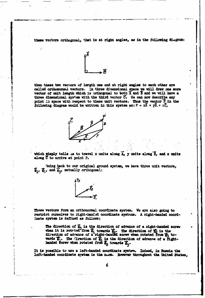
these vectorb orthogonal., tbat lit at right. angles# as in the folloving ftavpm:
then these two rect or of learSh me and at right ngle to each other arecalled orWbmhnoml vectors, n three d.mensional spaoe vwe will dra one morevector of =mit Iw5th vbldh in arthoaE1 to both I and I and we will have ath.ee dimensional sytem with the third vector re We mn nov descrie anypoint la space vith respect to these unit vectors* Tus the vecor P in thefollowing diagram vou.2A be vritten in this system as: P A + Y§-.4 ZtV
*Which sinsa~y tells is to travel x units along A, yr units alongiB, and s unitsalongt to arrive at point P.
loing back to our original ground system,, ve have three unit vectors.,gl,p g4,. SMd g~j, mtually oxthogonal:
These vectors form an orthonor•al coordinate system. We a" a"o going torestrict ourselves to right-handed coordinate syst6ms. A ri•h-handed coord-mate system is deflned as follows:
Meh direction of * Is the direction of advance of a right-handed s•arevihea it is rotetod from I,' tovards *. The direction of rois thedi. sotion of advnme of a it-a4dscrew when rotated frm -I. to-vardW Me Te lrection of g1 is the direction of advanne of a jigbt-handed L"; v hen rotated from to r3
It Is possible to use a left-handed ooordinats Veto%. ndeed, in Rusa theloft•-h• 0d coordnate s92%tnm Is the num. Hovever tbrougot the United states,,
Ragland and xmzc-l of E,:ope V-03 Standard in the right-banided coodinte±~t lyatmEit is the on•e evw us harde and it is the WS in *Iob It Is Met May tovisualize otw ftmetioas.
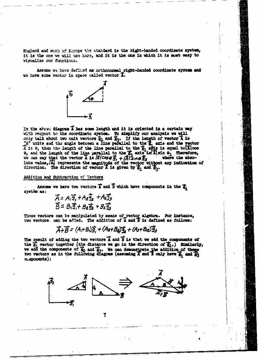
Assume we have defnei an orthnoxna1 r ht-bmnded coodimate sy"M #Adwe have scme vector in space called vector'
95'
in the ab"c disum bes some length and It is orientd In a certain wy
with reawsct to the eooord1ntc systems oc *,h 2ilxl ly c4 analysis ves V .orly tao about ,to unit vectors Ik and 9 f the lenath Of vectorl is"A" units; &a d ta angle beftors a line paealal to te s9 ds and the voctor
A~ is 04, tbhi tho iangth of the line parallel to the' 1 * Is OqMl toitlac080., and the lanath Of the n.2 parallel to thel adx is &sA in 0. 2brth rej~,Te vam say that the vector A is IXICySO4an + o#Ii , en' Vhsbe the abso-lute vaes, ra4 represents the theton of the a.Ctn viteut as ioaos:direction. The direction of veeor is given by -1 &AC
tion and eMbtraetimo of Ve• t•rs
o AeAsums ,e ave two vectors •eand • 3 • ich have componeyts in the
syst)m as: !A + A -& S
These vectors can be mani.1pulated by means of-vco algebra. For Instance,,two vectors . can be ad Ud. The &&U~ttou of A and IF s defined as followa:
;4÷a*' (A Sj8,) * 64a+841~ + f+Q3'The msult of adding the two ventors A and BIs that ve amu th iws nnU
th ector together (th,, dist~nce ve 6o in the direction of T1,) BSindJariy,e&Zthe components of g~and g~ We candm om~t Aea tion of h
two vectore as 13% the following Rlapa ( assumi ng ony aveg edc~aponents)z
Lai
.-. 1~..... 7.-
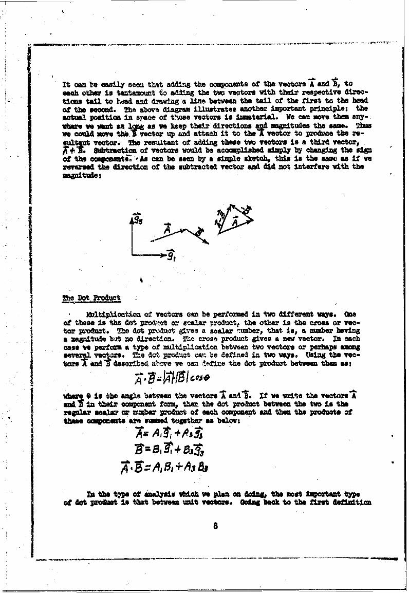
It can to easlO y seen that addiM the c=ponents of the vectors A and B, toeach other is teatam mt to adding the tvp vectors with their rspective dir-w-time tan to hiad and draving a line between the tail of the first to the beadof the second. The above diagram LvlAtrates another Important principle: theactual position in space of t'hse vectors is ,material. We can move thnm any-vbm e nt ail Ag as we keep their directions d v intudes the ame. Tbmve coulA move te. vector p and attach it to thel vector to produce the re-
~l~Yt vctor. reaw.zJtant of adding those two vectors Is a tbird vector,b0traction of vectors woul be accrp24baed uivv4 by changing the sin
of the ocopomentse 'As can be seen by a sIAle sketch, this in the am as if werevased the direction of the subtracted vector and did not interfere vith the=8atuite:
The Dot- Product.
)eltip;Uoation of vectors on be performed in tvo different vays. Oneof these it the d&, produot or sealer product. the other is the wosos or vea-I or product. The dot pr~zzt gives a scalar -tuber., that In.. a numiber hovinga inagnitue bit no direction. The crose product gives a new vector. In eachcase w pe Mfm a type of multiplicmtion betw6en two vaectors or perhaps amonseveral vetpors. T•he det product can. be defined in two ways. UsL'g the vec-tors andl described &~cve owa A• 4 ef ne the dot product betveen them as:
vbl .I he angze beten the vectors " and'. If ve write the vectors 1Aand* In their cm~onct fo=u, then the do produt befteen the two is therega•r sa&l, or wmb' Vroduat of each coampoent and then the products ofthee e are mand toeter as belme:
ma ahe tmpe of amalis wifch ve plun on odn the most 1wortant tyeof dot pmftt Is thst betwen =cIt vectwos. Oodag back to the first daflnitX=o
let us take a 4.71p... as wi tald a regular algehraic product betvae twopoZzda. * :
At this pO,,t we stz.ofd mp.,ionc that the scalars mi1tip3lring vectows can befactoxed end moved to the frorlt of the eashion. Tbas the first tam~ in
.. b% so Ve Mt find the dot product 'Sl and " In ech of theal
above terms if ve use the first etafirtion of the dot product ve see that vehave the falondrg fo•m for the product of these tvo vectrs:
A tA~ A,8. 13f01cs.*4j II3Iat 8: In ltlIau #4.1t CO 00A~b31i3f 14 AS
We see that the dot product between 's, and I. si the product of the napitu.••t~g Imes the coolte of the angle bftnea thle. In this case the umo~titudes
are one timea one 5d the angle bet•,, al and &. is. of oou~eA slr. #aren-f.d ga Is sqzzaZ to o=O. Ot the o _hnd te produt g. s oIe t~1iescue, t•mes the cosine of the angle btvee T•ad 13. We have dei'aed oticoozlAte syetm so the 'i is orbbosnal to - and therefore, the azle be-tveez: ai~i 9 0 Re couime of 90 is Iwro. ftmpseg .. zero.e ora termu 1tt are the first ard last termias ýIw othe dot product is A1B +A B* Tbis allow us to state in vards a rue for thedot products of vectors ¶dled defined in orthono2el syatma: "The Gotbetween =I.t vectors eVAls one If the unit vectors ae the usre and it eqmlszero If they are riot the same."
The Cross _rod.ct
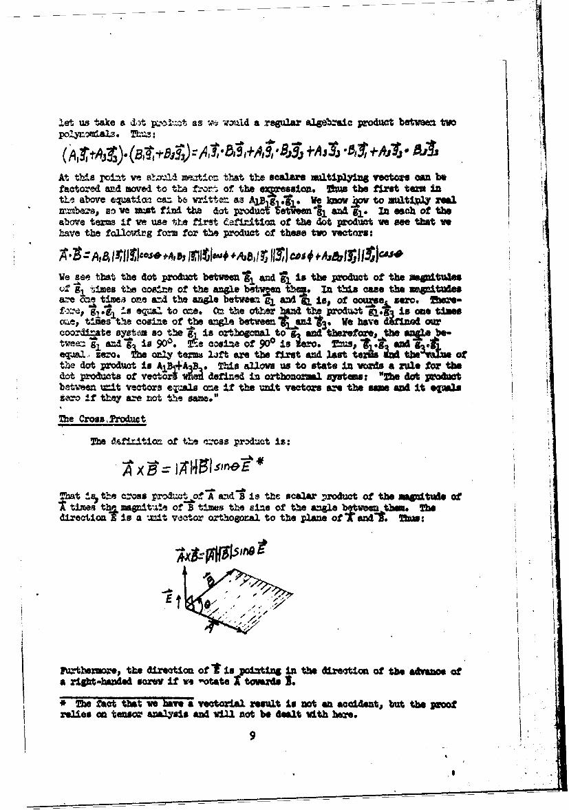
The f.t.f•ltion of the czoss product is:
"'bat .s• the cross prodat of A aV.d B is thC scalar product of the MnpitUde of1 times the magat'Ae of B t!mes the sine of the angle between th_ . Thedirection * is a 21.4- vector orthogora to the plane of TMand-. fths:
Furthezuows, tUe direction of Iis poitin In the direction of the afvance ofa right-handed screw if ve "tate o ts.
* The fact that ve haS vectorial remsut is not an accldent, but the proof
relies an tensor analysis avid vill not be dealt %d~th here.
9

so P s= of cr oss A, then* vol be In the direction of the aftaneo itf a " baned som If we rotate I towards ,L,_ is can be seen fr the
fuwe a= say tbat:
Ahi~ -• "
-Wi n 'os product between unlt "ectoors, vwhih we vif genwaW be coancendwrlh 11 Iss 962mov:
Wft the Inli~tlcn, ')i1II. h:,if ABth SOu m.04n144'.oe me" products of the rj vectora ane:
• Am ae statehdL aov the a b product produes a nos vector the n"e lineasyelt,# Inu t• temp• tovmu Use memocma1. Ift th delatl,, of poitiveL
A oamsvient method of dte mingn the oross prtat of two vet.,Usby wingUs the Getlmot defined below
10

IThe two definittons for th- cxoss paduct, that ls the deter.izgmt
metbod and the d torA H sn , ame cowpletely equivalent.TbA proof of this is easily s•omn by ezpensioz and vill not be given here.
Througot vroz work iz the amalysis of missile system ve -V beusing the dot pxodlt beten imit vectors and the cross product be enunit vectors. This is be•ase we vill always describe our forces, our mo-meats and other aspects -)f the response of the missile in terms of mapitude,with the directioms indicated by the unit vectors.
Triple Cross Pxodut and f-iple Scalear Product
Pro time to time vactor proctrts of the forme-&(l ) arise. Such avector is called the triple cross product or triple vectcm produ•. That thetriple cross •product il t necessarily associative is very important. Shat
L Sl () X 1 4 A,( t) is 1. veryv easy to shoVw. suppose that
r-n to solve the productSX(•I$') we first fin.!:
~+ / 62+Oc Se C,,,-~~ -~e e') &c1
(r c- I 51 C3 ',a(A ~-4AC,~j*$
su fom 4'• • ,,..o. .at "io fo a• ;a-u=s o1 on'8. he,.-fore, except for the case .•4xb•).9, the recto.- trip2.poec is itl nssool.-ative.
e triple soaar o ct is of the typ e:
orrI-~~ (Ao iCI-A~e le
fore ca epi~ite~, tohIOck e prthe vector.c tr.1)A porw Is no e anig-
less. Also mince the dot product is comatative.
Next ve can mm A.. B"XC"Z- = .CXAs-o,.
SAoexC. 8, ,a = -6 . V'.A'5XCUX C,~ =A~(8CXA
C,G* ~ M cross pm'dnet is distributive. That Is# WO ix14e. aim mae am
be msiJ2 dstrated byr e1sn8,ng the tvo sides of the equatio•.,
JUVAIV 33 ROUTM~ COOQRMEAn ffSTD
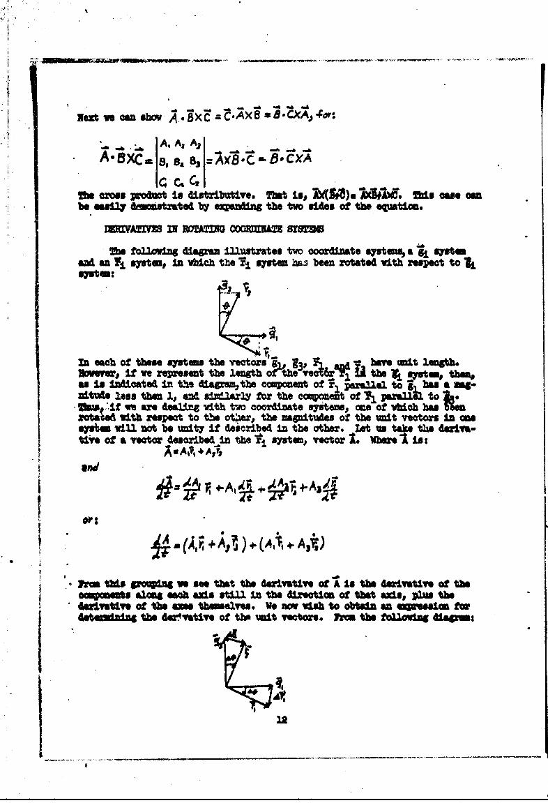
On folloing diagam Illustrates tw coordinate ystu% •a gi OA=aud an ILr systalj, In -,ich the i system has been rotated oith respect to Isystem:
In each of these systems the vectorshe06 qP b• u ove t lmgeh.Swever, If ve rersent the length 0ec 6iraP, the~ syT m t"nas Is Indicated in the diapam~tbe component of 'Fl parsuael to 1 bas a mg-
Miueloss then 1., and u&iialar4y for the cceonefit of 11 panaflk tOw *TIf it v are dealing vith t-w coordinate syitemw, mre of vbIch bas
rot'sm with respec to tall ot~erq the zampitudus of the vnit vectors In one"Ayim will not be unity if described In the other. Lat us take the derIvamtive of a vector described in thel, system, vector . Whrea*i;:
and
+ .1
Fro ths gmlIng we se that the derivative of AIs the derivative of theAi nts alma eac ads still In th direction of ta ads, plus the
*4wrivtive af the an.. thumelves. We am v wsh to obtain an cqwwesio for4e dan tUe 4Wrvative of tUP =it vectors. ft=n the flovlloi Giagrm:
22

if coi -CL~ed -,lt azi : coincxlcded vith , then after a rotation tIbmug
A e., the aw and 43 a~ir',W'l eTj.rj4Y say ra4s. ol e
If 60 is very r•-Ma.i the: a.. an w7.ite the approdimtions:
%:-&ij~"A a nd 6:II~f
or:
Arz-A a4&d and
Dividing by t gives:
-3a an4 X-rA
Which in the liz.to as &-Ools mectly:
This glve3 "w a:- e•-ession for the derivatives of the =t veat"a.However,O te--re i± a more convele=et methoo for determining tlis. If Q isthe aniL;a ,pesd of rotation then:
Ae-r ýo4t
Define the vector &ýs.Az velocity as:
that i, Its dIecti ' ±m al2g the wxds of rotaticn. ame cross pao s OeC and the various va Yctors is:
0 =O r-
13
DA by definition:
-Cad
r et ve can vrite:
Opet
and by extension:
rLa
Returning to the equation for the deri-vative of A:
•( A 4.4. -(A ,+j3+AY +-A -A C)
Defore Ve Oni tb13s p•a. of t:ae -2.scussion, let us look at the e"tion for
.A 1 60AAt o A3I
s is ex amctly tht part of the dulvativ duo to tbo rotation of the
o~oz8±Mnte system. TMujs;
SA+A A+ + XA

We are .o. :Ln a position to make rules concering the derivative of avector. Fizrst ,e have the derivative of the scala- camponents of the vectore-in terms of the ro4atL-g coordinate system. To tE" ' must add the cro sproduct of the a-.g1ar velocity of the rotating coordlnau- system time thevector itself, as defined 6i the rotating eystem. This g:ve.3 us an e imof the form:
• hehr&e the superscripts "1g" ard "r" .:t the derivatives are to be tAkenIn the g' and,.ri-.systems, respectively;r:a the superscripta on the right.mean th7a -the! Components of the vector are to be expressed in the td'citewosystem..,
We obsei,'-ed, in the foregoing analyis, that somethIng vbich rotat cbe described effectively by assig±ng its vectow direction &long the a3ds ofrotation. If the rotation 13 positive, it vould advmne a right-hanld s1w.This vaa previously defined as positive in the coordinate sysem. Of cou Vic=u immediately define a negative rotation as we did above.
The above analysis covers &UJ of the essential points whieh are l•iIe o tobe enctontered with the use of veet.o. analysis i3 the stuay of adsa.l4 squtms.The algebra and the study of ve.•*o.s covers a far vider fleld than ve have domeabove.* Hovever, we r.rely need to get !r.to the other aspects. It Is 11ke'that ve vill encounter situations where ve need a petezr eowvlodp of vecoranalysis, but most of the analysis for the type of work vwth vwhch we are oan-ceried here, can be done by obaering the fev s~l•e rUes as we have defind then.
M=U AN= TRAORMAI'ION
So far in our anas•iYs of idssile system we bar* oly desoribed an om".ton for the fames. Ma this a•c =n ve needed to deteuine three typo ccfazrte. Me Vv1rta a ore w" l i be Witten : go 1qpresum that v know t:e me" of the nds:lo; owtairly & i a m, thehAtion &~a to grVityq Is kaS so the pav~itatio"I tau. Us OOlstWY dwsfle&RBwuver, ve do wot k-ov the thrUat "asue'm, wv. Whettv = nAt we ehOw" toput tho thrift in a tbaust syse Aith fiitae ngles Of 3dealigmot, vo sti3mint Gatendw the tharta~ in the body system. In Sww1. vo ane gv am*sort of aw~e" or equation, %fth vili fteacrbe the moitdU4 of tM*s UnAw veOUr. If ve pa• the tbxt In the bo4y sysao (te ammig tbat the hbetween the th.wt ocoafta systtm wa the body system axesasuv) we MIA
*J~ these io widsh to patew the subjeat frt, h"w = mtreatens. For =yal. see 1ecto "d 1'nio Awaysl by" 1ary ass
bM * 00.,P 1V
15

Sachieve acme z- Ji )f :esc'bi•ng the effect of the th_,st on the bodyand the conse•q-yt mwn.w-,a tbt the nAoile All whdergo.
I xlsaile bod -- l be f2llzg an arched trajectory; It will be mv-lng frn side to side emd it m= even be rolling back and forth, or., -,I *aw.oases, spimmins aro'JA 1ts o"r awde . Tb4s ve need to ba " soe sort of Math-mtical ethod for dete:wu±ng the orientation of the missile body at awInstant of time with respect to o-' fixed unebanodn axes on the ground. Wewill develop the att•tutl angles betwen the missile and the groun by meamof *at is I=n= as an Vler amgle seqmnce. WtbeticaAy, ve u emm thatve knaw the amab of .neuX1r ratation the body has undergone at any time.
hen, it vs amr able to or~letey describe all subsequeat forces viich causethe nisa±la to rorAte fthe~nby- moving Its fixed body *~oard~natex vith it) veawe able to kee track of the cbaV In theze angles, a ve will alv•es a 4othe orimztAtion of the body vith respect to the pamA~i.
Ot~andard vaege t iug~rA this country in the vs-zious air-plane and,ssvile induistries .. e b kiatated that certsam sybole are to be used for oer-
tain angles. RIeara vbo hAVr Used sph•iC1 COOMIAc• Oe or oliU&IcalooQi=-tes abould roa•a±e &t i-tYo point tiat the *o•±zatoe trzanfostionsw awe descr-L az e am t nt same .a Altb.,ugh these coordinate transformaticmesse:=tialy coxvrt a rectwua- ar coo.-eato system tbrougt rotarf angles toazother systm it is not the same as t-eo:mg frm a rec angular system 'tosay, a spherical ore. We obtain the boiY srjsem by a series of rot- ions; aspherieal ooorxAe eyits t obta:nez± by q ±etg varioua vectors Cato;4wresp tbe =pwmts so ;zc te.Aa datexminig the ý'-7zthj, dirt~c,74 andsits of t-1e -ýYo coor'et' ;!~r
3woawe of sta=e- v~nag ve -eAll make the following deflnitions: ifvS roAtae a•:•t a=ax &J l .... •' I. . oM., a3 f OX exampe thhe11 asid, or*say, tbe "t, ax!.e, wre -,4-- ^.l s a "roll" a . Whrh e: ve rotate arounda nm~ber t-w wxd'a, of &ay sys t, -d- -sdl caL.2. th" a a "prltcah" angle. Ui a likexKa=.., arw rtat _ au w tZe, vW V'A1l call a "1YaV'P rotak-U=. 1z the ez ! t•;•- n ý.yj.t:e to '%t-* body oystemy the rollAr-ng is d.efiw-A as 0, t! : .. .l !eftlp *- • a3 Q, and the yov angle 1s
aaq~ r.4 "r ana tnyin to o ' d we ts"-form co-ora±-ates is t.s fwmi: ; 3"+.a: at, sa•y, thb gro•i and rot•a•e our axistbxoash tbree sogl. tze 4-V.ý; 'y &_- all ;^!-txz it *the sax!ý dixectioneste aew ot tsa r7yt, tc *a -ft are fo- g. (1a this case the tr•ns-
£oxwd vtator. VU. Jxd~t -4- t::a "We tizroýZ a t b, unit reto1,wthe =44' E) -14 --- i.1.1 &4h ' tu Ct • as t e Voctore, sd thetrusa me4 te vmszb -0O. ue ale to, t the11 Vet o I a
a~~~ ~ g;8y J~a sen tbyn Isotmges±~ly
Ini phqtioan, as gwm%' y taW.t 1z sobwo syt tmanfortIon b*-woms oooz-41imte systems is pe.?f armd by a roll, Altch, roll sem o Thrason for this War±UwAlr. type of Utarstoaftion; I do not kno. In our
wwk we i UM ot restrict ownsaivew to eq part4cu3ar type 0'" rxemao tiOw se#uee of anale !s as good as anoth erus "ww ith mne restriction.Far eaiple sqose vs decide to go tbou a roll, Idh.to yaw sezumac. Sathe restriction m~ t;;Is #,*ve "Is* that the seondM a~l (in this case,, 91,
am never be ýr go' Me -WU reaso fr tis L thet the second aNgI* arpears
in the final transformation as a tangent. If the secnd angle nears 90o0 thenthe tangent of this angle approaches infinity. Other than the restriction on -
the second angle we can take such sequences as , 4 which 14 a pitch, yav,roll sequence. We can take a sequence such as 0, O,*. This is a pitch, roll,yaw sequence, etc. No matter which type of sequence we care to use, we ustadhere to the definitions of pitch, yaw and roll, that is, the pitch is arounda number two axis, a*roll is arvand a number one axis, and yav is around 4 um-ber three axis. The methods used for all transformations between the groundand body by an Eultr sequence, are the same. Certainly, the method of solvingthe equations rill be similar.
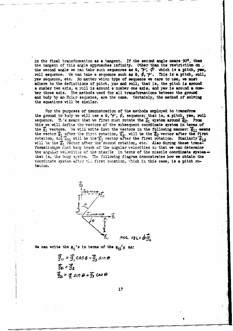
For the purposes of demonstration of the methods employed to transformthe ground to 1boy we will use a Q, 'j', 0, sequence; that is, a pitchA yaV, rollsequence. M *.s meaw:i that we first mast rotate the gij system around g2 . Fromthis we will define the. vectors of the subsequent coordinate system in terms ofthe r, vectors. We will write down the vectors in the following manner: gll meansthe vector gl after the fi:ot rotation, g•. will be the 92 vector after the firstrotation, rAd -Il will be the g 3 vector after the first rotation. Similarly glawill be the g! v'ector after the second rotation, etc. Also during these trans-formationsýve :xust kcLp track of the angular velocities so that we can determinethe angular velociti•s of the missfle in terns of the missile coordinate system-that is, the bcdiy sist-m. Th7 following diagram demonstrates how we obtain thecoort±nate systemr~ itd±r ti... first rotation, ,.hich in this case, is a pitch ro-tat ion.
ý3
fl -71
Ve can vrito the gi's in terms of the gjj/3 U:
C&56 coO 7 3 Sir;6
931 ~ 6i* CJ~
17

FJ~vin obtained the coordinate system kfich w e i131 -call the g4 a1 ten a4terthe first rotation we vill now rotate through the second uler angle, f, a[ ~ ~ ~ ~ ~ 1 0a ~aln:i'h~ ytm We =ust rotte about a mmiber three axis,
M rtaton"* I' +hpgq ýSysteznso ve v1,l rotate about g31 . The Zolming diagra illustrates the derivationof the zoordinate system ifter the second rotationt
ANC. VA.
In order to traneform the growA system azbs so that the corrsponldingnumbered unit vectors are parallel t- the correaponding nmbered. unit vectorsof the body axes, it is necessary to use three distinct angular rotations. Wehave used two nnguiar rotations so that one more rotation is requiired to alignour ground system viyh the bedy system. The final rotation is a 0 or roll agle..This means we must rotate aboat - that is, the first gi vector a&ter the secondrotation. Since we vil1 ow be a2 ned in thelb:-e]tem: ouiltird motation is:
A96-. VEk,.: b
We now have expressions relating, by a series of rotations, the groun4 systemto the body system. Also v" have keyt track of the. ngular velocities for eachrotation which we performed.'
18
;-It'

he ¢orm of the Euler angle relatioenhips in makid to use, so As apact tool ve will introduce the transformticG matrix relating the groun md
bodyr vectors, In matrix -zotaticl,. the vecetor an Ye*ab& to the itors 7:
•' I/c°o~e 0.
I a like ==oer ve cam remsent the retors of the' Is afte the n
inas.,
c~osv- sinr Y\(
and the bj Tectors 'in terms of the g, vecttws after the w~cmd rata-wn.• ~II
if ve represent these matvix equationsa in a more ccxoact notation~ we anVrito the followin &T•at"ons:
Mien substtituig in th equation tr )e v obtain the fo11ovift eqmp
19
S. . ......
Stion:
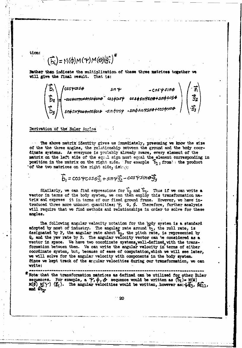
Father than idicate the multiplication of these three matrices together veil give the final result. That is:
co- ~-oa in 83.si,'/
Derivation of the Euler A .8s -
- The above matrix identiVy gives us Imnediately, presuming we know the sizeof the the three angles, the relationship 'between the ground and the body coor-dinate systems. As everyone is probably alreay aware, every element of thematrix on the left side of the equ._ sign must ecqval the element corresponding inposition in the matrix on the right aide. For example % from`; the product
"of the two matrices on the right side):ies';.%-.-
*~ ~ b = CosG e 5 ;nCOskIhO
Similarly, we can find expressions for b½ and " 3 . Thus if we can write avector in terms of the body system, we can then employ this transformation ma-trix and express it in terms of our fixed ground frame. However, we have' in-troduced three more unkr. quantities; t, 0,, 0. Therefore, further analysisvill require that we find methods and relationships in order to solve for theseangle.
The. following angular velocity notation for the boy system is a standard
adopted by most of industry. The angul tate around bl, the roll rate, isdesignated by P, the angular rate about , the pitch rate, is represented byQ, and the yaw rate by R. The angular ve ocity vector can be considered as avector in space. We have two coordinate systems vell-definedývith the trans-formation between them. We can write the angulaý velocity in terms of eithercoordinate system, but, because of ease of computation~hich we will see later,ve will solve for the angular velocity with components in the body system.Since we kept track of the ar.ular velocities during .our transformation, we canwrite:
---------------------------- ft ------------------------------- ft ------ -*Note-that the transformation matriaes as defined can be utilized fo• other Eulers ences. For example, a ', •, . sequence would be vritten as ). M(G)M ( The angular velocities would be written, however as'3
"20
"1" -- - . . . .-..--. .- ~ . . .
Pbj+Qb+ R' 1) 0b 1 *.J01 j++IX0 + CO
We mm now able to solve for the angular =teo, as mpested in the boW qs.tern in toen of trigonometric fmuntionsa md rafts of the biler malls tbhýselves. Taking the dot or scalar product an each #M4e of the equatio ith%gives:
In addition w fitn Q t, taking the scalar product cc exch si4 of t eequal sign i , an ve am fin R ty taking the scoalar product v, 3neach aide of the equal sign. Ths gives uu the follovwig series of tbresequations:
, I.+
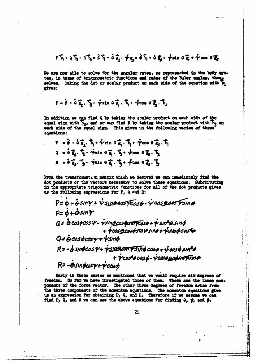
Pic the tranwformat-n mntrix which we derived we ow I1sGiatly MI• thedot produots of the yeators necessary to solve these equations. Ombetitut"nin the a8ropriate trigaonmetrIc functios for all of the dot prodcts givesus the following ewresslmi for P, Q an R:
+ 4svn 0,10 44"OCOas0 C 05CO 1 Vw n# ~ *',s~''%n
+I
Early In these series vo montionsd that we vould require six dope"s or
poents of the force veator. h otbhe fthne degeems of fredm atles fromthe thfte compoents of the-manentus equations. fhe momentum equatios giveus an ez••suion for obtaining P., q, and S. fterefore if we asm we cmfidP, P aM R ve can use the above equations for finding 0, w, a 0 •.
21
- - - -- -I-- - - , - - ~ - - - . - - - . - -. . . -

Mm matrix ncattion the above can be vritten ast
/1 sin'* o
In Caqit notation, represent the above equation IV:
liNMR
At this* point ve shuL~d digress soumewat to explein the terml'ortbagoaml'matrix. In order to bolve the above matrix equation for 6, and + we caistfin the inverse or the matrix VhIch relates P, Q ed R to the derivatives.71',* inverse is found fram the equation.
. 4
%ftioh gives us anexpression for '~9,9 and ~
In the anal~ysis thich ye did for the transformation from ground to bodycoodinate systems, we obtained the transfozration matrix vhich related thebodyr and the ground systems. This transformation matrix possesses a uniqueproperty& because of its nature, the inverse of this matrix is equal to itstranspose. If ye vrite the relationship betveen the ground and! bdy systems
than GM V#BG: M'-1 ., J,
f Hvarer, for this matrix ve am e that
4 U .vwe' cal•do•h4** tht Mt*ix" astrix1 '009; -.the % *fbriti•to•"zAtvi'Xy tomsailed ortbagonal,
The matrix relatIf. the Wa4u4la rote, in the body yrstem, P, Qp, R Vith
fte derivatives of the Baler mmgle ts not an orthogoval matrix. Therefore.,ve -n ooeled to dert. its Inwves. Without going into the actual cor-.putat•one of this, the inverse matrix is:
22
)*

0COOS
We am nov In a position to know at ow' latent of tim the anles 00,, •rely t intagrativg their derivatives v'tt reapeat to tim. Bover, at
this point ve have merely replaced the three irnwirn Opv Q, * three odweumns Pp Q aid R.
In body coordizates we can write tha :ýnrce vector as:
We can solve for each of the companens of the foa'v in the_ bo uytem 1 thesimple expeftent of takinig the dot pr'oduct withr b1 ,% -~ M 3 SUCOIT64y.Doing this ve obtain the following tUvc spations:
F.44 - .•,+Wb, ,
Sine ve already have the transformatioc matrix betvwen the ground ad bodysystem ve can vrIte dovn the trigoweetric functions •1*i•i relate the grow.tatiaml fore,# Fi.r, to the body, stan6 This gives us the series of equatioms:
t ~ ~ ~ ~ ~ A +fcS*JA*~b s4
2= V=V m8um
As yet ve do not know • at the tranfomaticm is between fhe 1 -id oforee wetor ed the bodw Uyam. Me z eseted It abowe 1, the sgeniewr t

S•_ -i •_L • _a ~ *F¶p• •uWt - • "r .... *-• r f.•.t r ...# . ' . ,'ar . o.... •r
Irtween ew-h unit vector in the body system, and the aerodynmic force vector,"F . As stated before, the aerodynmics are represented in the wind system,wch is defined so ihat I always points pa:Lllel to the relative vind. Wewil define the total relative wind vector a X The vector i* represented as:
& -A
Mhere the "W." hiich is not a vctorm is the s1tude of the relative wind.
The Madyne oic forces eaise entirely from the effect of the relative vindasg~ist the missile body. Therefoze ve need to represent the relative wind ina aty stem mhich we can Wefine. The force acting on the missile will be a forcepaallel to the dixoction of the relative wind. In order to perform this a-lysis we will transform the body system into the vind system by rotating thraugbtwo angles, called the angles of attack. 7hese angles ame O( and "0. o( iscalled the pitch angle of attack or, often, the angle of attack. S is calledthe ym angle of attack or the sideslip angle. Collectively, we call t andthe angles of attack.
P'evusuly when we were transforming from the ground to the body system,it vwa stated that three Ruler angles were required in order to align the threeground aWs vectors parallel to the corresponding body vectors. la the trans-
Sfo!itan frm the body system to the vind system we are interested in aligningthe& b vector vith the V, vector only. To do this, ve only need to rotatetbm h two angles. The body two and body three vectors, of course, will be ro-tated at the saw time, but, because we ae Interested in aligaing onl7 onevector,, Wvsill. all the'# and-# unit vectors, those vectors which resultfrom the b and' vectors after rotating the body system through the two anglesof attak This simplifies the derivation a great deal, since ve needn't definea third angle.
The method of transormtion ts similar to the oe used before. First vswil rotate througb a pitch angle of attack, that Is, O , and then t1hgb they aengle of attaek, d. Atain we will observe our criterion for positive ro-tatAcas. The following diagrams determins the tronsformtione required to gof the body system to the wind sytemi
ca tx3O -b sm oc
-A3 1
24

Uri , ICOSAjba e4i
FrIo thse erssionIs w obtain a trensfomtics matrix bstwep the body =Athe vInd sytmi Mihs matrix (which Is orthcal) is:
C-MC41 Slo eaocsr# cs
U~tilizing the trsnsfoxvmtionm itrix which we found during this rotation,,we a nov rvpresemt the aeroy•dmic fore1s, which an Wined In the vindsystas, In terw of the body coordinate vetors. Thus w am write the follov-
g equation:
F.4 =0 UY U1+, C h,-- t b, +N b37be toerj D,, 8 nd L in the wind syst~a ane gives the following se:e V isthe dre", 9 is the @si"fd e ,e, &*A L is the lift. "tHIs ane • a sl*Ieh m qp4 to the merodymi forms in the seifle A el ctiom wa aml ,%m= tbey are deflnel In the wind sston. the tsn In the bat wvetm eCo the abr fornce YWfrepSdX the mooo lbet w th
amms Lives to the specific Strokysma for"$s defined AQ lcloordinate syste. It we am tale the dot prcaowt vsueoessive~j w obtai aipreesions for the chord Yaa
thewevl frmin teme of the dreg, side for 0ee, lift. TOM *t "Aeutsoin toeof the tuiacomtrio fumainotuo af the wgis of att*A, em I* ae~found from, the ttrtnsfation matrix vhlah va jut derived.
95!

D~erivt~ton of Ancles of Attack
So far ve still seem to be behind. We mW "sum that the rag, sidefore, and lift m functions or curves hieh vs know, but wo bwe intsriducedtwo aknw quantities, the angles of attack. owrever, we cam &stemx.me theseangles of attack rather simpty by means of the followvng derivation:
We eam "~Pee the relative wind vector am
wheiw w1, wH, and w3 ane te c• p •ts of the relative vind defined in tboaydtr ?akIzi the scalar product of the relative i windvth 16j gives:
w•-W,Ar,, b ,•,+wIw
%h*eh, wben we utilize th transfomstio matrix just deflned, gives:
WWiS + Wit I511"14 - Wi4/SIfl0CC4510
'ib @ "I product of the relative w vecto vith ,
v2 gives:
or
and the scalar prOeuct oith gi
U6. + i j A,
or0zW11f + W COS'x
861" the os~teqation z vobai
Ve am am dm a triangle wibh gives us. the reitsloomip of a twnwt of(C~
26

WI3
Pie thi , w atiza stn (.0() MA Col(.l j, wioab se:smn(-o•=-s1hox -
COS(-4c/%:O$c(:.=
If ve nm wltiply the firs' of the prxious equations by si the mIV oaf~d wrd add, ve obtain~
WwSiml/= WOd
or
Itfv mW ~1ti the first equati01 by ooe the oem by eta me mib-tlosv obtairm
t 14j1 "
W .M 4+PSIA
mc 2+|

"7tus, ,w have obtained e.xact expressions for the angles of attack, CA, 4, i-terms of the componenta of the relative wind in the body system. The ang].esof attack are no longer unknowns; the terms of the relative wind ere the new un-kno•ns.
M TMRW I SYS
The only force vhich has not been defined in the body ystm at t10i timin the thrust. Previously we said we were defining the thrust 3o that it vasparallel with a p vector. It io necessary for the paersn who is doiag a study
S41th thk Aestle io decide his own thrust misali~ment. This a•ans that thethrst vector (hihch ulvays acts in he i.1az of the -exlt noale, not at t~hethrust) c=n haws a directionCt error (by'error we mean it does not act alongthe missile center Une) as well u an assumuptio that the thrust vector doesnot act at the center of the eidt noixle. Thus ve can create an error in posi-tion an in the folloin dtagr=,-
A.Vr OF AMXr#VM
As wmen aa a directItnal error as shown in the folloring diaiem:
The a1y's dilcretlon determines ho large the thriet misali•am tangle" v1l *.* In gener•l, thrust misalignaent angles amt, at most, a fewdegrees. Ouce ve choose the r.salignment angles, ve can *nsate a tranrsfomr•.tion altrix# as ve did before Abetween the thrust ais systim and the bodyisy m -- t7 transforying the vector into the *i vector. As v4 th +h*e sro-dyn:mice uti1sing the angles of attack, we need only defiW e two r'ai&ljg;Tz tan4les. rf we cell the pitch and rY the ypv miasallInent fntles,. andasams a traiafaoxmtILPA frw the body to the thrust syvtea by seans of a rP
s s.us'oe, the twmnsfornation matric is precisely like that fbr the vinal
stntwth ot. repated %o' 7p and rnsod1 J"'r Timt/Co ro Ctu ry -Smnrpc4 r'y
* In m cases it is possible that am* tort of thrust misallgraert angleswill be fuztnih•eL but In general we will inwestIgate a apectru• of valuesbetmeen sa reasonoble liitms choeen by the analyat.

If the thrust mi slignrment angles were zero, of courzep 'this iplies (themore uuuw case) that the thrust ects along the mitsile center line and Isparlslel to the ' vector. In any caes, because of the avy aisslle. aremazpifactured, ve can assume tV-t the thrust miisaligment angles are verymall, and utilize the "mall angle" approxLastion. This gives the tivwfor-nation matrix the form:
(-ry biz
vharle vassmemd rr
If w "- Vumm that ve h# )o sam sort of curv or function *Gah rwro-sente the thrust characteridtics of the tu alumissle with which ve w bedealing, ve can rzp*mt the thrust as:
F =TIP, = T,,,,b ,*,Tb3
Taking the scalar product vith- 12, ueuetiel3ly, ve obtain thwie Oq~tions for the magnitudes of the thrua• pirallel to the body coodiniat awda:
1. -.
Ts TP/,4 ---Tr
XUUC& AMD WIA WIND
At this p•it noa wk ý baw bem soved, but it qearo tbA ex fetas vo salvo thm we MA new ones to tbs their pi•ams. omrtan thMs istv~w vith the relative viid. Dsfomr ve efion. the relative wind, *1ab is aoonlnatIon Of the miasile vwwlity with rwspect to the inertial frow wA wextarwil vials,, ve vill investigate the amissle velocity with rexpew toth
29
oi

The differential equations describing the motion of a missile SYftem mustalways be referred to the ground or inertial reference frame for solution. Thisis not meant to imply that every comlputation is done in the ground system -to
£ the contrary, most comnputations are performed elsewhere. It does mean that, thebasic equations of motion must be referred to the inertial system and computa-tious in other systems related to the inertial frame by appropriate transforma-tion.
To develop the transformations between the inertial frame and rotatirgfra- we tre at liberty to choose a vector, assume it is in space, and defineit i" texas of its components in any cooruinate system which we desire. Butonce we have choen such a vector, subsequent differentiation and integrationmust involve the motions of the rotating frame.
Mien we describe a missile system, we are never likely to need range ex-pressed in body coordinates, but we will need the range In the ground frame.We do need the velocity in body coordinates because the aerodynamics are basedon missile velocity through air, so, in general, for our kinematics we wish todefine motion by means of the velocity vector. Thus:
6r
If we know the velocities in the body sys'.em then, '.imply finding the dotproduc.ts -with gl' g2, and g3, rep.*ctively, we can obtain the velocities inthe ground system. The terms u, v, v are standard accepted symbols for thevelocities in terms of the indicated body coordinate ax•r. The notation above,that is the superscripts "g" and "b", irndicate in which coordinate system thesevectors are defined. •Note that it is not always necessary to state in whichcoordinate system a vector is defined).
AccordinZ to the above equations the velocity vector in the ground systemis directly equal to the velocity -ector in the body system. (We could have
* chosen the range and represented it in the same way., or we could hve-- osnthe acceleration). In order to derive the kinematics, we will differentiatethe velocity vector in the body system for the acceleration, integrate it inthe body systu, and then transform it to the ground system.
We previously found an expression relating the forces to the accelerations.Abmu we achieved an expression relating the velocities in the missile to the
30b

velocities in the grvand. We will nov dexive the aceeleratios in the bodysystem. Nevton's laws of notion are valid only in an inertial s ,ytmD thUS U
muct differentiate the expression for the velocity in the lxertial Systemf.That is:
It in "immediately apparent that the exrre$siCm on the right side of the equalsign Is mixed and. ve can't "oyt with it as it Is. We define the deri•Utivevit•. 2spect to time in the inertial or groml systf as the aperator.
so that
(J ,-.+,
It Is nov apparent ahy we went to such trouble, previously, to illustrate theequivalence between differentiation end cross product multiplication In a rotatincoordinate system.
Ccupleting the above differentiation gives:
P 0 R
+ 4- c jr (QW~-R )b,*(R'u -s~
+ ,1 " - bi
31-
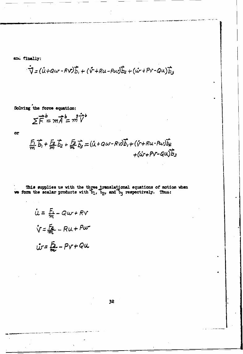
"- • (C ÷4,,r- R0",, .-" ( •IRt -Ps•v•,+ +(""" Pc'-hi4.
Scavizmg the force equation:
or
This supplies us with the three rmnelational equations ot motion when
ve torn the scalar products with bl, b2 , and-%3 respectively. Thue:
Lr- •- Pv" Q4V
32

The Rotational AcceleratIons
In the last nection we developed three very pretty equations for the trans-lational accelerations in the body system. However we still have the three un-knowas, P, Q, and R which must be determined. P. Q, aMd R are also wed forcoMPUtJnC', Q., and 0. These ter• which arise from the rotation of the bodysystem, require three additional independent equationa for their solution. Wecan fiA three such equations Whcause the rotational accelerations are Inde-pendent of the translational accelerations. As was done, in the last sectlon,we find the rotational accelerations by solving revton's second 1w of motion,in term. of the rotational accelerations.
We can write the equation for the torque as
Vhere dTris the torque -d/dt means the derivative Is taken In the ground coor-dina+e system, and (1t) is che angular momentum, where I Xi the vmont of inertiatensor. and-' is the angular velocity.
This rotational equation exactly parallels t+he translational equation pre-viously defined.* 1, the moment of inertia, corremponds to the msas of thetranslational equation, and ', the rotational velocity, corzesponds to thetranslational velocity. As pointed out in our previous discussio•,in order totake the derivative in the ground system we must replace d/drt CC te ground systemby its equivalent operator in the body system. Thus:
which gives:
Mote that in the abovw equation we have the termcx(16). This cannot be writtenas I( W r )(which is equal to zero) even though the inertia might be coqioed ofconstant termsýbecause I is a tensor. In general, "I" is repsaite. as a mtrix(or tensor) containing nine terms. Thus:
z= l-oa,. eq +"o I is
Tshe translational equt iont , tt is, the t* rate of changeof the linear momentum is equal to the sum ol the extenral foreu.
33

Uovwverp, In evez7 rotating "bysal systen;, it cap be proved that there exist-three specific axes In w hich anl tam- except -those oi the =ain diagonlml"s'MuMzo L- 'vs can obtain the following utrix using aAsUitble ,thf'rint 6o.
I: 0. 0
'. ~0
' st-l o n. :b1ee .lb Ptv at• t m t "o wof lDotaw
o possibt e tom• fi such urns. ',.sm~• • b 'oles•'h p-"u beJ~. o"w 1 :lm l, g efJ =o • ars ! *0to 'ad them '"iev e fieta"d•.' oU i
n bfmd by qssIsi-I. Iwe take a S amte a asrmotricelbodyp then- we con locate, these prinopal axw. lof Ietta b7 inspection. If veas"o " at our ami.sil system Is a. tal Joo genecu boay, tun thePrincipal &af of Inertia v" Ile at the snae aes ar the bod • syte exme W- m am tof e p*ima reasons wez boe to w ait In this system. at courset
the amiss Is not a l gpous bod, but for stablity roasons, It Is generallyvery elms to beincmrt o .e a ost &a the before %v can &ss=mo, quite scouw-mto3l, thAt the cipel u• e of 1 i 1 u ten boy aes ooianc e. VIit"ve neowesa&' to be norzu eot @M~ aftinl2 use the oaqUe torn of the amenstof inatlia teasor, the easiest metbiod. 9br.suan~ei %vouM be to Locate the Wrin-oipel szos of Inertia,. define the vit veotoz parallel to them, aM solve ourzotatomel equatiow. In tkat system. MUi %vou2 necessitate a transformtion.fftuthe systew In which the princi~pal azes of Inertia an located, to the 9'odysystem. this Invai~ve a gmet deal of extra work (Sn the se way that trans-forming frrm a ncnrotatlxg systems at the center of the euart to a rotating oneon the surface of the owAth requires extra work) and so vs will just mption,this ftat but not go into details of calculations. If It ever becom necessaryfor the mn~yst to deal with the gweneal msunt of Inertia tensor, he mast usethe sm concepts that we have been 4.wlo~pIzi throughot this peper.
~ wa, that the princlipal nem. of inertia wa the body axes coin-cide,, the tern 1;0 Is:
In I,, InR'
a 1..- (..I.b
fttwnoro,~~~ ~ ~ ~ Thatuiei bm ,WR4 w ~uf bu
hm -M MM d b3- f" Is

the mmnt of Inertia about b3 f wa that about b2,0 axe qi~stantIsl24 the sawTherefore., we can set 22 - 33 aM this gives us for Ir03
IdO a IPb 1 IP02~ + IP1~b
vhereve hve pa I
f ,. ( 33 -lZ$.We am ov write the equtica for- ti torque as:z
b b
treatong the momnts of Inertia asee did the mne (tat Is, we win a:tact theinst'Antaneous value of the iariabs Ahn we use it) we obtain:
T- IFbl t [IP4+V(zn-4p)j' 2 + [SP(ý-Ujb
or component v.se
T3'/d~(I b2t *t+* b2 .N
where•L, M, N are snaeaw a notato for the external mub oofcdet In the
stats "te tie rteo 1chos Taf the anglt amodutm o (the Ic~mt Of thentorue
•rl•1•j, b2 • 3* vS obtain
* 0'
Ths eqa ote sa n wfit heeexeral aticas the aapti ' efo oa lm sts:
3,)
r cI
a _-.0
Sd/dtIcO
if we kww the exitnal mmwnU In the toMM IL, Mi, AM ID, we can solvefor P, Q, aMnd R, by ':nto• t•tng the respective angular aScleretions.
It qMear that ve hm sub1titts,4d the MmoM, sL, U N aMn N for theother tmkm= P, Q, .a it, but vo am dot4=1M the exterl Ammust by phuical~e rls-o , whereas it aw be diffiult to got the Sag r Mt.
we no hbve six a noma M quantites which ut be evaluated. Fkm thetIAIstlnil eqUaticas ve needed three e oro n-- tons D, 8 an L. Job from
Srotationm l equatiomns v bh ve thr more m ' 4 0 term =ootaln d In * L,UsN, a 2I. Vs• vi Gisius these s .orty.
flelative #Ad Ikbera. VIM
lh fam souc (as for wa #, air-vetber at wno) ve need to obt&aMUM- for the sa3truml vI. an valxm hich vs get for the external •I•Mvill be givaa to us In toms of .irectim osuh as north or east, e. Frus thegiven dlectiU I we met obtain the oa ommoU &ION each of our urI m am.
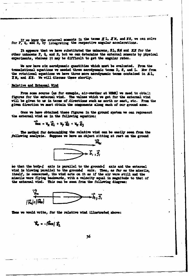
* Owe vs have obtaind tthee fjgures in the 6ZWAd syptow vo can ersnthe extena'm vIM as In the fo2.1awft eqpation:
w mmtbOd for LMte--•iag the remltive wI an be g•sr seof frm theSna sa. & e vbew an object sitting at rest on the grnmd
io thet the bodjid axis is panalll to the growxi' axi aM the extenaVIW SA b2.ovw perAlll to thea grom" AXle. Mme, asfar as the a,"s 11.,Itself, is .. rmed, Us I acts on it as If the sAr vr. stAiI se theai•ssiM y M7126 bacwardsq with a wiocity equal In m•L•tu& to that ofthe extenal viM. 2s can be sOen frC4 the folloWn disgana:
O ve w M vwrite, for the elativ* vIM illetated above:
Irv

That is, if ve knov the direction in vhich the external vid is bloving, thenthe effect on the missile is merely the neative value of this quantity.
In our original equation for the external vind, ve assumed that the symbolsfor the ccuponents vere positive nuambers. Ma sign of the c •omnts In dater-mined by the direction the air is movng.
Ma first thing ve mast do vith the external vind vector Is tanfo ItInto the body syrtem. That Is:
Wxa WJ1+ W2+ Z3 Wulb1 + VOZ0 2 + e3t
The cCqOOPMts of the e2tr W~ vIM n the body system, are foun by ain thedot ~du t hrith T2. b ,~~il~ and uti~iazing the transformation
matrix. This gives:
4sKZw- W4J S$M-/* WyCA$CASI-. fr1p$IA#"
W~j+ + I
The velocity of the missile 18:
va - :u .+ * + -3
4Dtigv that the relativ vI W,,, is the w3locity of the alaille mulna the ft.terual viM, ve ave:
where
ls-uv- Hex1
aV
W3 mv4ve 3
and ve ba" oaAltely defined tUs reltive vIrA.
.57

MMUM~NA FQRCkS AND 1(MDMMM!
At this point ve have derived mix "ndeeet equations dascribing theal40'/ Notion:
7/. +P• - Al
S
" Ma + (a. -,f
The ms, a, and the mments of inertia are functions or curves vhich areobtained, either frin the manufacturer or fri derivations of dta obtainablefrm the a•in facturer. Assuming that these curves are sayllble, the =knasin our equations, as yet, are the external ments for the rotatlonl equationsand the external forces for the translatonal equations. Te extelmal forcesarise from three sources: gravity, aerodynamics, and thrst. we gravitational.and thrust forces vere discussed sarlier, so the marodymosa forces am the onl7ones which ve need to discuss In greater detail. The exteraml mmnU are of twoty s: aerod••mic ent and =wMnt caused by thrust aisalig nt.
larlaer ve defined the thrust axis systea. Rzternal m nts vil arise inthe boWy system due to the position and direction of the thrust vector. Thisearlier disram is:9
f tt43
Mwre an three c nant•s of the thrust actilg In the boWY syste. 2hese arefowA by trasforming the thrust vector (as was doa beforo) Into the bod system.Thi gives us the equation:
T = T-ý + T2 b2 +T, b3 .
1zam~ng that the point of appllcation Is " pictured ebom, the vector fromthe origin of the body system to the point of applicatlon of the thrt vectorIs:
38
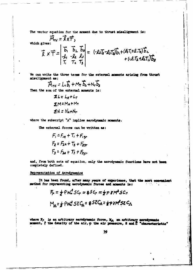
The vector equation for the xomnt due to thrust u1sl,1nmut is*
vhich gives:
We can write the three term for the exteral ma t arising fre thrusta1seU net as:
MrV Lr~ +M+ N$3nme the sui of the external mments Is:
£M: MA ÷ M,
vhere the subscript "A" imples erodynanicmments.
The external forces can be vritten as:
:Ft F, + , +Ft jr
and, fr both sets of equatlon, on4 the saro4pnamle functions hiem nt bee
culetely deflned.
Bpresentation Of 6!721 amcs
It has boen found, afttr muW yeers of m taws the W"n ememtintbd for representing aero4mic foare" d n- mint. •st
WberS 7tl IN SU Wz~trZa7 a hIts!! 1- ~ftre MA 4a "tbima0-41Mamut, e the dmslty of the air, p ta m & S gx, a ,-L "13P3
, 9}

surface and legth,, rspoctivel_•/ v t)e ratio of the heat tcapc.tes of themedium: Cp•/C -- which for air ia about # Is )bh wzber, Wr the
r ive ?ind, Cp an& CA the for.e #du momnt oeffticients, end q La theeait pressure.
3Jk tios in the post (ad still fairly often) we yere given the aerody-wage forcep and a polition on bt Adsslle eALX• center of pressure. Tzcenter of pressure Is the point mt vhicb tim aerodmaio forces act on themissile. Since the missile. in saca IA e free-froe berm, ve can represent the
m ts and force", i. ep entley, en acting at the center of gravity. The souof the external fQrces acts through the *.g., a the sua of the externa2 =mcentaact as torqtme arouM the c.g. One poi•Lt cf view Is equivalent to tb÷ otbrrThis con be observed froa the feolo•i •g lia. em:
.T *NA -Wf"
The equatlons, as defined earlier, asui th•t• vr havr force" wotig -bru.bi.the oenter--of-gravity and that we have oment. tanug to rotate tU rsa ile aboutthe 04..
"the air dewity,, In the force an ont M q ,•w-is 441eramd fro a"standard atmosphere*.. We treat the points on the curve fr. ea va did the
pinte oa the cur-'es for sus, mcent of Lwertla md tbrust. Prm, the abm-,equtions., then, only )bch nmaber and the c Motientii ar, l.ftn.fi d. Mc.nuber is defined *a:
vera V is tb* local speed of nound. V. can rnr -sonted as a function ofaltiiA. t Is gerwrealy a "standard" Curve, U- is t:-A air density.
The three rare* oe cients are defined W ... ind syt as follow:
$ - drg fo.-e* coefficient
CS a side force CoefficientCL .- lft force 0efcienJt
Tinthe area, of t crossecti of MA i having the great
.00

or if they .are defined in the body system they are named:
Cc - chord force coefficient
Cy - yav force coefficient
CN - normal force ootfficia-t
The moment coefficients, defined in the body system, are:
C1 - ro]liog m nt coefficient
Cm a pitchi. momnt coefficient
Cn - yaving =oat coefficient
Notice that the subscripts are capital letters for forces; lower ow lotters*.or moments.
It w bneu fowd in mot cases that ve can represent the aezo4Asucu. *ag ma ooeffi±cents, each of vhich is a functio of two variablas, am of thomVocz muber. Inetead of Mbch nmber, w oomstlIms use 1ioA maber for lawrvlocities, and ve my use a psrwwpter e&ti..d ?iou4o's nmber fur very h)gh al-titWM v " tbe air ea~ot '.v* ccsz.4a&'v as s. conzam~us asin4.iu But, "s fars W #re 6owrned, our in~t.erdext b vifl be Mach mber. I.r nt
paposm. Awt few varlabie-4 &t fuw~tloo* f Ywh nmber, v4_11l suffice to 4..-Ocriboe th6 & dyna- f Por er,, of, , Vr a.le )f attack In pltch,
vX2. somet Lwar*r-3t-a t on 8% ef -Um t*t4 aerodni~nic Pitcking ftrceor zo~t. 4,W sif-l w ezl or %ýV*l Of. attachd, vill do the *afor the I&V am or v'U( - T~w seccoa wact imortant puvmmt (f r~M the3tetd'4'1t of r-4041-14 It it ue WCAsot h1or1~nt) is the fin Unftfet~on
Id ition to tb two =,at~ tiozed ea"..e that is aisles ofattack a.A ftin cins, ¢her paranners used am the .queVr of tb.anglen of attack,. the tim r~te Of &j~ to the 4ftles Of atzack, ths g4ciULft,ywving, and rol.lng ratf, wA cmirAttaO of., sa, te *ogles of attack adfin defle~Xo -- and other I aur4,evement Wpmters.
3h me.t representations of miaslUs ytf we 6tlimarl"Oe thek r *We can writ, the aeroamLU cofficent, sy Case a fwatin of ite WarI
r - r i
able, ,
___________
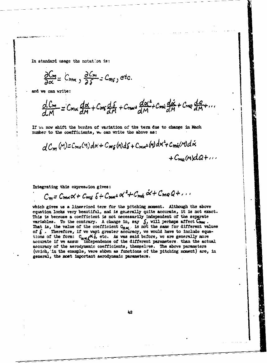
In standard usage the notat on is:
and we can write:
+ Cmi ++;1-
If w'• now shift the bur&.n of mriation of the tern due to change in Machnumber to the coeffcients, w can vrite the above as:
Integrating this expresilon gives:" C,= +
which gives us a lineerized terv for the pitching mment. Although the aboveequation looks very beautiful, and is geaerally quite accurate, it is not exact.This is because a coefficient is not necessarily independent of the separatevariables. To the contrary. A change in, say S, will perhaps affect CGW.That is, the value of the coefficient CmW • is not the same for different valuesof j . Therefore, if we want greater accuracy, we would have to include equa-ti.ons of the form: e•, etc. As was said before, we are generally moreaccurate if we assurt=ependence of the different parameters. than the actualaccuracy of the aerodynamic coefficients, thep.el'Is. The above parameters(,nich, *in the exai~le, were sbbvn as functions of the pitching mownt) arem, ingeneral, the maet inportant aerodynamic parameters.
142

At this point let us digres- and show that is not necesssrily the sawas Q. The folloving diagram Illustrates a chage in Q vith no change in c:
On the other hand, the folloving diagram
sho a oha4C in O( that Is equal to Q.
With the advent of the lastseries of equations, pres* that the mn-ufacturer or designer of the pe..ticU ar vehicle under study has providdfunctions for the aerodynamics, then ,U the unioovs ch began vith theoriginal force equation, are wv kno-, except for 'O. n aewotnaM -und-tion. furnished by the manufacturer vin probably not be in exactly the fbzmshown. For exawle, some missiles only requlm such aerodynamic functionsare, say, C(, f, and Q. Other manufacturers brirg in eolqtelty dlffezmtparmneters. For exonple, the aerodynamics of on mlisle use. the bank ern~g2This Is an angle vhich lies betveen the pitch angle of attack ad the b1yptemmegenerated by the side slip angle and the pitch angle of attack. ThU is ilns?trated in the folUoving diagrams
.0 ,
WdO"P

Notice that the "hypotenuse" is actually the total angle of attaCk, 0 Wh.t-ever form the aerodynamics are represented in, their relationships are of theforn ubown above.
As sm tixme bappens, linearized representation of the aerodynamics Isnot sufficient. (Repetp'ly, througbout this peper, attention hba been calledto possle sources of error, approximtions used, etc. Fbr ezsale, it vaspointed out that the surface of the earth iu not actul~y an Inertial systemnor is it f•at; and that we bad to fid a set of am=s,. other than the body&%*s, to correspond exactly to the principal Am of inertia). Generally,our error in lizasrization is not very great. If It is, then we asit findother wthods for determiniag the aero4ynics. If, for easaple, we representC30 v a curm, and if it Is linearized, It will be a plot scmewbat as follows:
Where M Is Mach mober. If, however, CIM were also a function of, sayp, j, theroll angle, then our curve would have to be "three dimensional" so that bymoving in the "third dtmension" (corresponding to a change of 0j we would findthe desired coefficient as a point on the surface.
TRAJECTRY ORMATION
Mhe ultiute purpose of an analysis, such as this, is to deteraine the tra-Jectory of the missile under the influence of the various psrameters. As wasstated earlier, we nade our velocity vector the invariant between the inertialsystem and the rotatig, or body system. As a general nae,,, tr-,ectory lufor-isition demands the range vectors as a function of tlm. We wish to kov therangw, but we wish to knov these razges PL the ground system. Therefore, vewill integrute the accelerations in the body. system, that isu 0 f , pr andobtain u, v, v. the velocittes, a•d transform them into the ground system.Thes are:
V~Vx +V9,x ub, bi~vi-'&V1, V and VA are found by forming the dot product with S,~ ~ epotive and utilizing the transformation matrix. To obtain the three ranges Inthe ground system, we now Integrate. these three ccuonents of velocity. Thisgives us our ground range. If we keep track of the elapsed time during carn-putet:Sw, ev ham a representation of the ranges in the ground system at anyInstant of time.
------------------ - 4

FIN D&LIXTIONS
Assuming that the analysis just developed is for a missile with guidance,then there is some form of external "guidance signal" which is an input to theguidace circuitry. Let us represent the "guidance signal" or "guidance coemmaby &c. Se may be a radar signal, a doppler shit, signals from a stable plat-form, etc. The "fin deflection" my not, literally be an angle, but =m be aproportional angle, a spoiler effect, a dwell-time, etc. , but in any ease ve anrepresent the relationship of the "delta command," 4, to the "delta achieysd",g, by means of a transfer function. Thus:
With dc. as yet, our only unknown, we can represent the entire missile airframe(vith th e guidance represented as rW(s) - J) by means of block diagrams.These block diagrams help us to visualize the interrelationships and nterdepen-dences of the equations which we have been deriving. On the following Pae isa block diagram of our system of equations.
The mthematics for every missile system will be baaicallJy slilar to the. mathematics we have derived. This system, described, is far from being comlete.
As yet ye have not mentioned guidance, vhich will involve such things as seekers,targetsj, radars, preprograms, etc. What ve have done, however, Is mathematical•ydescribe the missile dynamicst and indicate methods for more exact analysis Ifneeded.
TRAWSM FUNCTON8
In the previous analysis ve had but one unknown, the fin deflection, or.The "fin deflection" represents either the actual fin position an an angle, ora "duma'" parameter representative of the fin deflection. If & Is the comndto the missile. we can then represent the process between Sc and r am a trans-rer function, 18.(s). A transfer function is merely a Laplace traneform of thehardvare in the missile vith zero initial conditions. Transfer functions., assuch,v willno be taken up in this paper. Suffice to say, there .xelt a na berof good texte on the laplace transform and transfer unctlons*.
*For ea; see: Thaler,. . . nd Brown, . ., Servochaim a ,
oGrav-XLll., 103.
14m

(41
LaLq
0 LL
4W4
NA!EEATCALIWKDNodDIAt*M
I46
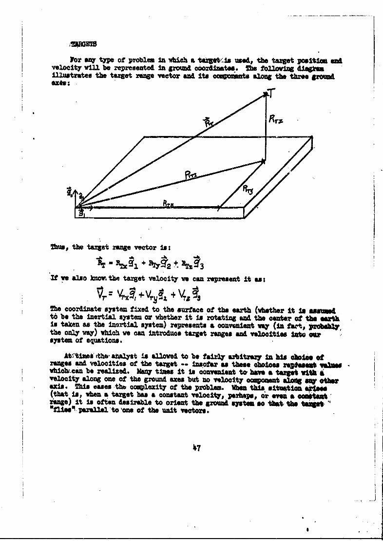
For any tpe of problem In wich a rSzes us ed, the target posltui CAvelocity will be represented In groomd, following d~igknmIllustrates the target range wetor and its cansU along the three pomd
2hus, the target range vector Is:
If we also knom th tenget velocity ve can represent it as:
Vr =VN v a,+VS+VThe coordinate system fixed to the surface of the earth (vbetber It i asmedt6 be the inertia.l system or whetser It Is rotating and the center Of the earthIs taken as the Inertial system) represents a convenient Vey (in f "ta, )drob y,the only way) which We caA Introduce target ranges and velooities Int Msystem of equations.
At:V•time ithe, analyst Is aUovad to be fairly abitrtary In his aokio otranges and velocities -of the target.. Insofar a these choices r*qtsea vaUevhl,•.rcan be realized. Many times it is zovueniet to have a tare ith lvelocity along one of the ground axes but no vlocity oaqpo&et aLo m, othebaxis. This eases the ocolexity of the problem. Mm this situati a1•sle(that Isp when a target bas a constant velocity., perhaps, or eam a eCeenitsuzinge) it Is often desirable to orient the ground system so that tUe tupt.
'fisparallel'to 'one of the unit vectors.
47j
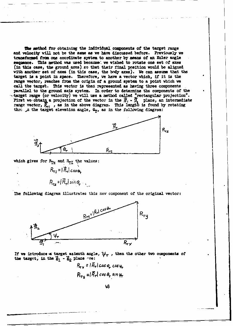
Owe thod for obtaining the individual ccuponents of the target rangeand velocity will not be the sme as we have discussed before. Previously wetransftoxw tram one coordinate system to another by maw of an ftler angleseqence . This method vwa used because" we wished to rotate one set of axes(in this ce, the ground axes) so that their final position would be alignedwith another set of axes (in this case, the body axes). We can assume that thetarget is a point in space. Therefore, we have a vector which, if it is therange vector, reaches from the origin of a ground system to a point which wecall the target. This vector is then represented as having three componentsparallel to the ground axis system. In order to determine the components of the
-,arlet rue (or velocity) we will use a method called "rectangular projection".First we obtai7 a projection of the vector in the • " • plane, an intermediaterange vector, IR4 , as in the above diagram. ThM lenaib Is found by rotatingthrc: ., the target elevation angle, OT, as in the folloving diagram:
vhich gives for 1TZ and Th tpe values:
RTzIFT ls 1T
The following diagram illustrates this new component of the original vector:
If we introduce a target azimuth angle. . , then the other two components ofthe target, in the gl 2 plane re:
and ve have completely represented the aret position vector, .
The projection, as defined above, assumes that our Intezedlate vectorIn projected onto the horizontal plane that is# thelt -Plune. onemuy vander if It wouldn 't be as correct to project th ori18a rangevector onto a ver-tical plane such .as the -"3 or s2 -13 plans, and,from the lntermediate vector so projected, get Iha comoonenta of the r eVeator. Mathmenatcally and geowetricaly., either method in equivalant.Thse first method corresponU to a 9 projection followed by a &'proJectim)the second to a '*, 0 projection.
The limitations iMposed on the choice of the projeation depends anvhich angles are measured. In the above Instance "'fT and QZ# asagl~ uof a tpe vwhch a radar syste might measure. Mhe ertical 1044 O. r Ismeasured.by a radar from the horixontal plane, that Us, the S, -'%.plane,and the horizontal angle Is•- measured In this sae horisatal plane.In sUoh a situation, we aL forced to =e a vert•a3. projection f-sl..This can be ,duotrated by reference to the fo33ving figure:
1A
if we project first onto the Z-Z plane through the angle ~,then for theasiinth angle we have:
if we project first onto the X-Y planos than the sine of the auimath =49,
Is:I
S IH Ol
7Firthewep projecting first on the 2-5 plane gives
for the elevatioL angle, and
SIN OR=

if we first project the ravge vector onto the horizontal plane.
Obviously our projection metbo4 depends upon which angles weremeasured. Madar angles necessarily proceed through a Q projectionfolloved by a
At this point it is difficult to sy what vin be done with the tar-get range and the target velocities once they are expresed in the grounacoordinate system. Bach kid of missile has a different guidance pilosopk-and vill., therefore, uttilize these parameters In &ifferent .ays. But, inevery cae, the guidance philosopW mnst use tha in one way or another.* will not attemt to discuss guidance now, but vill Illustrate sow typeslater. Suffice to say, we can transfozm the target velocity vector into, ..
ar missile body coodiymtes if ve wish; ve can use the target range for aredar grou.A station; or we can utilize both these vectors in several dif-ferent ways. If, pbwbapos the guidance of the .missile needs the distanceof the missile to the target, then ve can find the relative distance betwee..target and missile sinuply by subtracting the conionents in the~ground Ber.end then, if ve wish to express these relative compnents in missile badycoordinates, we can trmnufora them immediately with the aid of the transfor-nation matrix.
An a closing paregrqh to this subject ve might mention two situatiowlIn which we vould need to transform these vectors. For example, if thM.
-guidance of the missile depends upon the intensity of soe source of radia-tion relative to a guidance head in the missile, such as infra-red radiation,"then the brightness of the radiation at the surface of th6 detector woulddepend upon the distance of the missile from the source. In this case wewould like to know how far the missile is frcm the source. After findingthis distance, we would need to transform it into missile coordinates sothat we could find the relationship betveen the direction of the detectorand the missile heading direction - and determine tracking error, capability,etc. As another example, the maneuvers of the missile might depend upon therelative velocity of the taret with respect to the mlaiile. In this casewe would find the relative velocity between the taret and missile and trans-form the resultant coponents into the body systea. This would give desired.Infornation to the miSDlAe.
Before beginning the discussion of yroe w would like to Insert atthis point a demnstration of a statemat Whch ve will need later In thediscussion. 'e recall that earlier ve derived a trawsfomtton matrix
.between the ground and body systems. hIs partIcular matrix vas called an"orthagooal matrix. Ons prvperty of this matrix, Vhich is lwortant inthe folloving discussion, Is that each elmsnt of the matrix is equal toits co-factor. for exuple, a matrix ums the 'V v , nd O, Is:
&SOP JdW&* JM dPM-
30
Vw tern ia the upper left-hand corner of the above mtrix han) Its co-factorpthe deterninant found by deleting the first rW and firet columr. If we solvethis determimnt we get the foling term:
vbich Is the tint term in the mtriz. Thi saw type of operaticn cm be ohmsfor every elment of the -- trix.
In a mis l1e which obtal Its position by mn.n of yoSmp gmwz•Wl twotvo-degree-of-freedan grcs mr aemployed. These gyros an "slaveud* in order tomeasure all of the angles. The folloving two disoero illitrate. this. * achdbgra hoves'a scheatic of a gyroscope having a pitch ''xtule glmbal.
•( J
SI I

Gyroscopes, of course, may have fixed outside gimbals other than pitch.There are six poss'bilities in all: two pitch, two yaw, and two roll. Thesecond angle further differentiates between tnwes of gy7ro*, there being twopossibilities for each type, as is illustrated in the above diagrma.
At the center of each gyroscope is a spining mes whose axes of rotatiow•remaz n fixed in space. If the initial direction of thes ax- is known withreseect to the ground coordinates, then, within the missile ltself, is a vectorvihch retains a ftzad direction in ground coordinates. The fixed axis Is spi--ni very rapidly, but by integration of the spinner angulsr velocity an angleabout this axis can be determind. We will not actually use this angle bec"aeit vr- 4 not be accurate. We will use only plck-off angles of the two outerSlab&. rsi. We can wee that a sequence of angles frm the intermost spiDirZgmse to thb outer iabal riag, which is fixed to the missile, will give a so-qpenoe of angles which datermine the missile position in spawe with respect tothe ground coordinate stem.
We canot "arbitrarily" ch'ooe the Suler angle sequence of the angles inthe gyroseope as we did in thi transformation between the ground and the bod•y.Once the yroscope is mounted., the sequence of angles is fixed* The necessaryBuler angle sequenre can, however, be determined tr inspection.
The pick-off angles of the gyroscope uniquely deteraine the orientationof the macaile. We can demonstrite this very easily in the falling ower.The auJuar velocity vector can be represented as:
vlere the subscript "g" represents the iyroscopic pick-off angles. The yro-scopie pick-off angles are the integrals of the following quantities:
pJ•.•, +b3" R, .
The integral of the equations show that the pick-off arngles are unique sinceth.W are determined entirely ty the orientation of the missile In x~iace.
In diagram "Is the sequence (as can be seen by inspection) ts a yaw az-& -(4ith refleence to the spinner) then a roll adgle folloved t a pitch arqe.I Idlagrm an* , the sequence is a roll angle (correspamding to the spinar) fa m,9ty a yaw angle and then b, a pitch anle. The two seqaences are from the "in-side out%. We can write the two transformation equations in matrix notation aut
•MW the 's seresnt trantzomatim matrioes In the indicated mes.
52

let us determine the transfcrmation for the two types of gyros illus-trated. For diagras 'T ', wirll indicate the angles by writing subscript'Y" for each angle. In the second one we will use a subscript "H" for es-Iangle. These subscripts meamn that the first gyroscope is "vertically fixed,and the second is "horizontally fixed". That is, the spinner position isvertical or horizcmta.l, re•pectively. From the vantAge point of our previeusknowledge, we can choose the ittermediate matrices for pitch, yaw, and roll.We will indicate these matrices below:
/Cos& 0 -Sin e
0 I 0
s. 0 5n0 Cos,9
-a• s 0 /ooCOS Sin )
- S 1 n~ COs U
/cs0 0 /
Mg these three =mtril•t araelatle adchoosing the pubscript "To fo-r-.k
first trwnsforasti-=, and the subscript "IT for th second trea.orntice vwobtaint
1 SV C
C ON -)Fv CV Vt 5 0 + ox O.34"
S7 (

Now that we have the actual values of the transformation matrices, we will
rewrite the last two transformition matrices in a slightly easier to handlenotation. Let the following two 'trices represent the "verticalV and"horizontal" matrices respectively:
R/
Vo Va V13 sit,Da, V3% V sv,7
V, I 4~ V2t VU g
(i IN,9 H13 SRiNr& H13, SHa
The spinner has special significance. The orientation of the spinner axisremains fixed throughout the time that the gyroscope is in operation. (This isnot quite true since we are assuming that the earth is flat, and the orienta-tion of the gyio'v wii] tain fixed vith'respect to space rather than the earth'ssurface. It will appear that the direction of the vectors changes by an angleequal to the change of the normal vector of the earth's surface due to its cur-vature. However. for this discussion we wili assume this angle is &M33 enoughto Ignore). If the missile is originally "on the ground" and its vectors, thebody axes, are aligned parallel to the ground axes, we can make the followingstatement:
6Ab
That ll, the third axis of the vertically fixed gyroscope always points in thedirection of the third ground axis, and the third axis of the horizontally fixedgyroscope alway points in the same direction as the first ground axis. Let usnv write the transformation matrix which we originally bad between the groundand body systen in short hand n6tation as follows:
b 3 ~ anl a32 03 3

Then ve can write, after replacing the t 3 vector by g- in the first traforms-tion %trux for the gyzucopes:
2j.•, =V3
wA from the trannfonstlon matrix between boo~ and groamd v obtain:
S-a,,
so we can write:
V03 :
V13 = a.•s
V31= a,,
In the traneformtIon matrix for the "11% groc~pe. ve can replace " by Sj.his gives us the three equations:
-4 a % - I
H 31and frm the twrsawftmton matrix between body wa gamd ve obtain:
~a
allj

I
Therefore, we can write;
H =a3
and we now write for the tansformation matrix between body and ground:
V,3 3• H~a 1 V ,
\H,, a3 Vj/
Utilizing the properties of orthogonal matrices explained at the beginningof this section, we can solve for the middle column of the above matrix.This is:
H31 Vj,
HI, V3,
We have nwv coopletely determined the angles between the body and the groundframe in terms of the pick-off angles of the gyros.
In the transforztions between the gym system and the body system, thevertically fixed gyro used the sequence: yaws roll, and pitch. The horizontallyfixed amro used the sequence roll, ya•, and pitch. It was pointed out, when wewere performing the transformation between body and ground, that the secondangle ust never approach very close to 900. This w becausa, when determin-Ing the rolirates of the issile, It was necessary to us* the secant of thesecond angle. If the second angle ever approached 900, than the value of the
I.

onr,-tire ter.n would Mon ±r,,l¢irmIVt, An analogous sltuation exists with theI-yro &ncle. If tho ±coi- angle goes to 900 then a situation ariaes calle'"gimabal i, A". Thvzrefore• in the verttical-fxed gyro, the roll must neverapproach 900, and in the horizontal - fixed gyro, the yaw must never approach900. If they do, and gJmbai lock occurs, thern it is no longer possible toknow the orientation of the miisile. The physical reaction of the, gyros isoften a complete 1800 turn of the entire gyro setup -- and e. new set of orienta-tion vectors.
With our previous knowledge of transformation between systems, we were ableto obtain the complex trans'fonation equations for utilization of the gyro pick-off angles very readily. If we tried to v1sualize the cc=plicated interrela-tionships of the pick-off angles to each other and also the interrelationshipoto the transformation angles between the ground and the body, it would have beenianipoAble to solve the equations. But with the utilization of coordinate .systemsand transformation mtrices between these systems, we can find the valuesin a very sirple manner. It is not until we try to evaluate the terms derived,such as the Vts, the R's, and the a's of the matrices that the equations beginto look complicated. Even then they are not difficult, they merely have a greatmany terms.
A separate section will not be introduced for an explanation of stable plat-forms. The main difference between the representation of stable platform andgyroscopes is that a stable platform (which is stabilized by means of gyroscopephas available three pick-off angles. In our analysis, using gyroscopes, we re-quired two of them in order to determine the three angles. Had we decided topick-off the angle for the spinner and evaluate its size (by integration of thespinner angle), we could have done a very similar thing as a stable platformwould do. As a matter of fact we "pretended" in our transformation between thegyro system and the body system that vw actually had this fixed direction angle.We did not use this fixed angle, but determined the orientation angles of thebody with respect to the ground from only the outer two pick-off angles. Ifanyone who is using theae notes finis it necessary to determine the equationsrelating a missile system to a stable platform, then he need on47 remember thathe transforms from the stable platform to the body system through three anglec.And also there is no second gyroscope to vorry about. Therefore, the stableplatform is more simple, in essence, than the gyroscopes which we Just Inves-tigated.
Included in the aocu'parqing settions are typical examples of guldanae andsome of the nmenclatuxre ow is likely to encounter.
57
S.....

OUIDA AND CONTROL SYSTM FOR A TYPICAL RADIo C(NtAD MISILE 5YBFsBy: Harrj WcJunin
In such a systan, the chief inputs into the ground computer are theposition coordinates of the target and of the missile. These coordinates,for the typical case, are range, elevation angle and azimuth wngle asmeasured by radar instrumentation,
The ground computer transforms these coordinates into rectangular co-ordinates in a comon frame. The target coordinates are time differenti-ated to detemmine present target velocity, then the time of missile flightto a predicted intercept of the target is determined from use of presenttarget position, present target velocity, and stored missile capabilitycurves. Of course the ccqrtations are modified to take care of the offset
tr =sient time needed for most effective use of the warhead.
Other functions necessary for efficient steering of the missile aregenerated fran their established dependence on the coordinates of the pre-dicted burst point. These functions iaclde. such items as initial diveorder, glide bias, and missile velocity correction. The dive order iscomposed of acceleration o,-des to the missile causing it to turn frau itsinitial nearly vertical trajectory (given during the boost phase which isnot controlled) into a seni-parabolic path tovards the predicted interceptpoint. The glide bias orders are commands, ceparate from steering orders,causing the missile to always have a certain fraction of I g acceleration ina nearly vertical direction. The missile velocity correction added to"present" missile velocity during steering provides more accurate determina-tion of time-to-go and consequently of the eteGring orders.
The steering orders are determined, essentiallys, as error quantitiesproportional to the differences between the required closing velocity coor-dinatea, and th: actual closiz velocity coordinates. The i closingvelocity coordinates. are the differences between missile pos =oncoordi-nates and corresponding target position coordinates, divided by the time-of-flight to 'he predicted intercept. The "present" target altitude is modifiedto furnish an a'-in point above the target for most of the trajectory, andthus provide greater missile end-game maneuverability.
Daring a large part of the trajectory, the remining tlme-of-flight iscontinually recalculated in tenr of present nissile and target velocities.This function, called tim-to-go, replaced the function initially termedtim-of-flight. The vulocities of missile and target, as well as targetascelerstions, ame deterained by analog type differentiation devices. Theactual cloesig elocity coordinates are found by simly subtracting theUija velocity coordinate fru corresponding miss l3e velocity coordinates.Of courae these closing velocity coordinates are modified by the aissilevelocity correction function, and by present taxet acceleration comonents.
The error qaactities, described above, ara basically velocity differ%moe. in tow fixed rectanular ground from associated with tither the launch-
** point, th. amssile tracking radar, or the target tracking radar. TMmequantitis are onprted into coaenta in a reotanular fram nearly paral-3.1 to the "peeno" missile fras -- & fixed from attached to the aissile.

This conversion is accom ,ished by a yrv, pitch, yaw sequence asfollows;
First rotate aboutg through angle A, vhere A Is the azizzth angle ofthe computed intercept point.
On•C COSI 1
Next rotate about -i through a "cleib angle 9.,(Q vi12. be derived later)
B q ='1 C.OSP+ 1 Sind
-Ai
Finall.y rotate about"' through a *turn angle" 9,( viii be dor A later)
-1r Z.0 51% 1 np + 4 %'" 1
0001.uing thwese xa trU form ve get thle trawfonatioa vatrix below ftrthe 1e 1oielfrm
'9

These rotations are pictured in the follovlin diagram:
Alt this poInt the tvo azfg1.s 1 9 and ane wt knmov. Angle A is. knwnvaft" the coordiates of the Intercept point have presumabl3y alrsy bonn
If we ssme there Is no anl.e of attack v my say
60

vr Iv. - V72+ ÷V2
taking the dot proiuccs wIttk g, g," end , respectively, we obtain:
Vb Vx V(-SIN 'COSH -COS'COS SINN)
V- =-V, V(SI Y -t COSY'C339 COSA)Vb - v -VI VCOSY'SING
If we mltiply (1) by coo A an (2) by sin A and add ve obtain:
VosCn0 +VXC :-VySINfllY
and f we wilt,•ly (1) by ain A and (2) by •,e uAndsubtr.t (1) fr, (2)then:
-Vx SIN i + VICOA = VCOS YCOSG
Xultillyina (14) by sin 0 and (3) bY Coll 0 anid subtracting (4i) fr(M (3) veget:
SI$NG1/N Vy COSA&5N 9 +VC OS 19Oand dividing by cos 0:
tan 0 (Vx si A V Y co•• A) + V -oor ta 0 - \/r
Sine, the missile is setbil.zed at a known ange of roll about Ita lagltndt.nal axis; and with respect to the plane containing the velocity veetor, t+econversion of error quantities into the "pseudo* aissile frame can te cc•.pleted. The lateral control directions of the aisslle asarly oo$oWlde withthe lateral axes of the pseudo istiile frame.
Time-to-go Is continuawUy deterained during a larg part of fligt asPrvlusyIQV mentione". This is done in such a way that a%4 lateraj wnmsto the malsils are different from zero, since normaly there In nqlJbecoutrol in tbe longitudinal direction thrgh use of e3avon catrol.
Ftual%3 the lateral error quantities, which have diSmalo0 of veloity,,are converted to dimensions of a.ce2*ration trough divisio by UtMI-to-o;then these are scaled to the proper order pltudus through siltip-1astiby a oonstant factor. The orders are next sent to comand airocuit whichconvert the oziers to coded electrical pulse groupe. Mmse oqe wi beigenerated •neIttectly an alternatively at audio frequency. Me radartransmitter accept• these puloe orders and transmits the vuman electrwmgnetie link to the massile receiver.
61

The missile receiver recognizes properly coded signals, reconverts theseto pulse groups, and sends these to a signal data converter. Each time apulsed group is recognizedj a hold-off signal may be issued to burst controlcircuits and an activating signal sent to the missile beacon. If insuffi-
.cient autopilot control slals are received the bold-off pulse may be dis-continued and the detonation circuits become operative.
The signal data converter usually recovers in dc anal form the groundcooter acceleration orders to the Lissile. These orders are sent to theautopilot control systems. The lateral acceleration control systems areusually identical in form, each exercising control In a plane perpendicularto the hinge linb of the control flu of the systean. For a supersonicmissile the lateral control direction is nearly nomri to the loitudinal&,As of the al"sle.
A lateral control systin m be cori~ed of a steering amlifier vith"associated input -iin networks, a bydrsulic system to control servo poweran actuator assembly driven by this power, a mechanical linkage to the con-trol elevws, and several feedback signal to the steering amplifier. Thesefeedbacks , inclue signals representing the missile acceleration achievedin the desired dirtction, missile angular velocity in the control plane, andaverase control tin position. Ow comnd signals are coarted to thesefeedback signals which are developed by missile flight instrmnts*. The net-vor'rs associated vith the steering wlifIer, and into vhich the orders "ndfeedbacks are InputA, coare saubat contluwouly the present responseconditions of the missile to the present steering cm ad. The result Is amoth response to order., and a preservation of missile stability through-ot the flight.
The roll control system operates very uwh like one of the lateralontral systms, excepting that the roll control signal arises frm the
mlssile rolling sre or less than the desired roll stabillation angle, asdescribed above. Useful faedback signaLs ma be angular roll velocity androll elveon position.
Stficint aissile sV-amt may utilise tatera. control ealvons to achieveroll coutrol a vella u lateral acoeleration control. For such system themecaical linkages are arruaged to that average control eleven position inaorrect fIor the desired lateral acceleration, hile U iferentil betweer
ppo.Its fin daflations Is oorrect for achieving roll control.
MwfollowIft diagrams Illustrate a typical radar-caman roll-stabilizedsysten a described sabove
The fo1Ioving diagrams illustrate a typical radIar co:=and rollstabilized system as above described:
Target position, HT
Prelaimch C•cputer
1. Diferentiation to obtain t of flAt T0Velocity
2. C•utation of Intercept point gide b iscoordinates "Missil v'ýyMnn
3. coutation of at.gDOfumctiom, 0 j -m
out" of this block Intercept "!;tW
Prelaunch Ground Ouztations
COAttIon Of required 0l10in" velocityI vector
1. 4dification of 1 to obtal, altingPoint: - _I _ l
tion 2. Subtraction:t 4 TbaA
?ieT ofla s Fl.
Tor timeto go, 3. U o o
flJMM 200writatium Of ftulewd C3losiz Tslocity Vector
63

Computation of Actual Closing Velocity Vector
1. Differentiation of and to obtain
'RT and
2. •cclfieation of HT by observation of presentSacceleration
T cr' 3. Modification of &g by velocity correction, eo"eM l ILEMu
e i. Bztract of vectors
RX- PTIG R3•-Mt. 3
Cll%-t-tion of velocity error vector,$ and onvmrsto pseudo missile frml
ib~trction of ±from Pr
I.- - R
2. Conversion of R c ta Into pseudo missile
A frome, unit veD rAT"I.tur -7a. Ccmpatation of 16angle 0adtrturn angle '
B pus A)
0 b. omptation of pseudo from umit vectors
a. Conversion of e into b fro., to obtaaft
I+, + .. + + _ • +,t+,++..... + +, • + ,. -j ib+++ +. o o++ .+•
ýqtfttion of time-to-go, am converuion of Velocity
L. oPreing of the lon~gitudi~nal comotient of velocity T 7bfg2,3erro tozero
11b - b, a.0; solve forT 2ma
Ooaveermim~ of f Into corr'soty scal~ed maccelra-St±on orA- Tb visile
via COMMAcircuta
P I~/TorI7c and radar
Y resur pzensure vlae O~
0 1'

=a-AMPEV HOKLIO (;JJJA=C YSYMRI
B Nerle Lesoing
an a semi-ective hwing guidance system, a proposed target is radiatedWith RP (radio frequeney) ewergy from sacme 8ource 6xternal to the missileo, and'the missile utilizes the energy reflected off of the target to derive gul..A*a.cinforfu'tiom. For exsple, a ground based CW (continumi . vive) ilnmi'.ator tracck•the Pl-,VSed target and radiates it with RF energy. The missile receives the;eft•'-%ed eneig through & gimballed, forward-lookirg antena dish. 7he smrtezmaha L mutatirz beam iich allows the missile to deriva trackidg errors which
ute the disg to. et.e pocnt ttyaat the target.
In oider t o detect and to continu l due to the especific target cat ofthe potsible targts a thaet or. A b ithin the bea m width of the Iissilnater, te•inti!,-a circuitry may be equipped with a very narrow velocity "gate'* which 11',
S uses to resolve a sinl~e tar ot TI~ h e- =ten trackir errors can thet "ne•Sderived, for this mne taret Ike velocity gate makes use of the doppler shift)
which is the ahlif in frequency of a signal due to the radial velocity betw *eenthe transmitter an the reflector. A "rearward-Ic~ktn•" entenna in the missileheterodynes a sample of the transmitted ewrgy frcm the Ilu33mi r with the re-flected target signal received at the front antenna. The dlLference in fre-quency, called. the "doppler" ts proportional to the rmd&al or "clo.ol " velocityof the target with respect to the missile.
7Me rompe of " lW3er frequenci•s" oi all the possible targets %hat mightour for this type of guidance can be determined. The bond is quite narrow.7e velocity gate is swept through the possible freqeer-ies until a "doppler"appears in the gate. The antenna then `locks on" to the target which has thisdopPler frequency and obtains pointii errors tfra this one target waybr.
of the missile in locked on to a particlar tAýxGet, then the directionof the t•aget is known. Using the known direction of the ante=&, control in-fomation for the mispile is derived so as to prtouie a trajectory which willintercept the taret.
7he hming-type guidance oei .einloy seezval alteriative methods for Intes-oeption. The most simple gtaidace, of conrue, Yould auniver the missile sotat It i a always hed6d toward the taoget. The drawbacks to this procedurears Izmmediatey obrious. If the target mineuvers, the missile might 'expand so
* mash of Its ener correcti& Lts course, that it is unable to maintain s@ 1ft-cdent speed to re~ch int.rp€y. Alaom if the Arget na" a high speed, themissAle s voud bwVe to &&s it, again exei a great deal of energy.
Oannnal3p a tMp of guidence is aPWlced -At&$ih utilizing the targe*relicty wAa diractic3, derives a predicted intercept Voint; *I*e -is.le isdirvec toard this point. This mathod is Called proq tioa naigation.By proptioal•fa igation wmem that the Mto) CIO a O Uf missile heaing
i6
-.. . . . . .. . . .... . . . _ _ - •
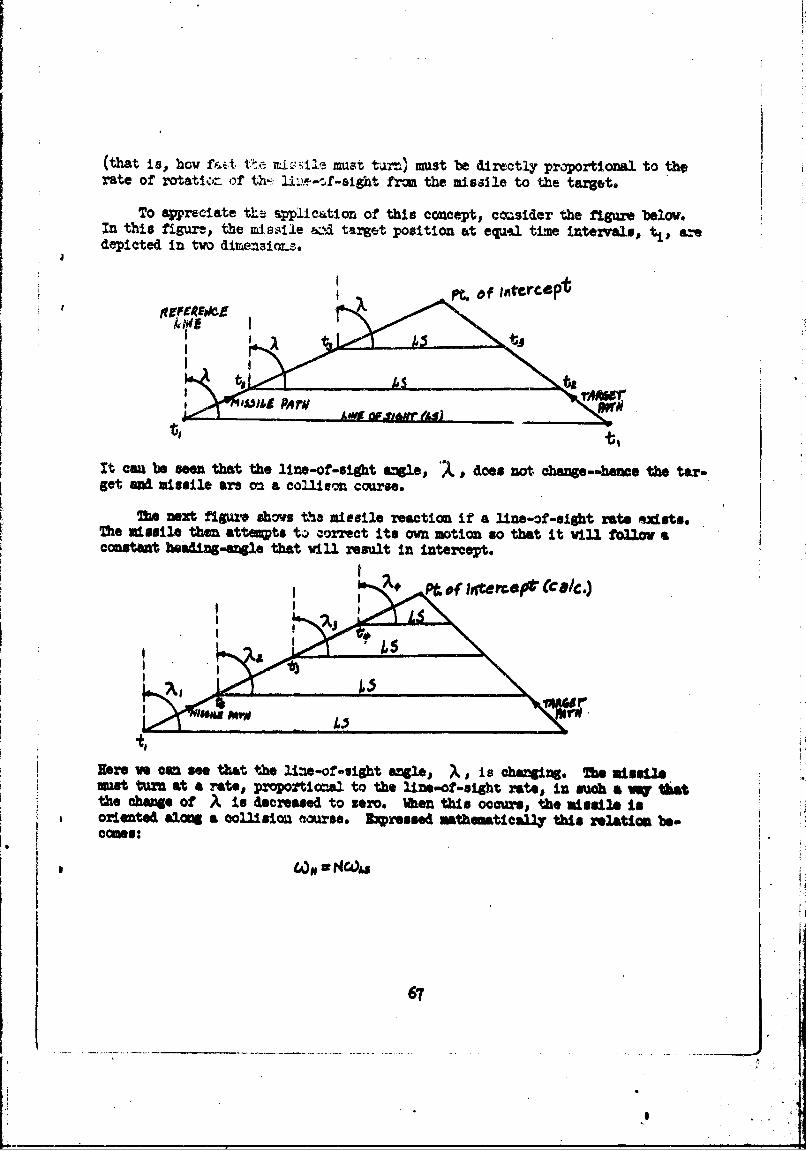
(that is, how f:Et t.t .mna e mst tarr.) must be directly proportional to therate of rotatior, of th'- 1i'-,--sight from the misaile to the target.
To appreciate the aplication of this concept, cmsider the figure below.In this figure, the missile &::i target position at equ.l time intervals, t 1 , aedepicted in tvo dimensior.s
II • f iA4Nrcp OW
It cau be seen that the line-of-sight "le, 2 d, does not change--hme the tar-get end missile are on a co~lieon course.
Mhe next figura shovs the missile reaction if a line-of-sight rate nidsts.The missile then atta•pts t. correct its own notion so that it vill follow aconstant heading-angle that vill result in intercept.
Pt.e frwtr *9*MO(CDC/C.)
Be re we con sae tht toe life-of-sightf a is aTb. misslegmist turn at a rates proportionza to the i~ne-of-sight rates in such a vo tl~tthe change of A is decreased to zero. 1•n= this occurs# the missile ,Isoriented along a collisiou (course. Epressed mathematically this relation be.comes:
67
• ,
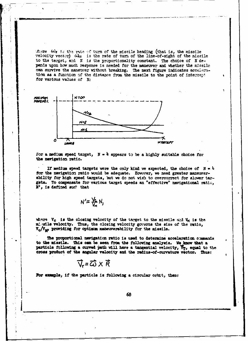
• I..re C4:n . th.• -.f turn of the missile heading (that is, the missilevelocity vector) c4s is the rate of turf of the line-of-sight of the miesileto the target, a~i N is the proportionality constant. The choice of N de-"pends upon how much responee is needed for the maneuver and whether the mIssil1can survive the mane'oer without breakirg. The next figure indicates acce!--r..-tiCM as a function of the distance from the missile to the point of intee ..tfor various values of N:
N=,?
for a medium speed target, N - appears to be a highly suitable choice forthe navigation ratio.
If medium spee targets were the only kind we expected, the choice of N-for the navigatiom ratio wol be adequate. Howier., we need greater maneuver-ability for high speed targets, but we do not wia% to overeorrect for slower tar-9ets. To cagensate for various target speeds an "effective" navigational ratio,N', in defined suc.Y that
*.ira VYe is the closing velocity of the taget to the missile si Vpq. is theat.-'sie velocity. Zhus, the closing velocity gv-erms the size of the ratio,V,/VX, providing for optism maneuverability for the missile.
The proportional nvigation ratio is used to detemini acceleration amotarIsto the missile. This a be seen from the fol3oing analysis. We _iv that aparticle folloting a curved path will have a tangential velocity, lVT, equal to tthe
aoss product of the angular velocity and the redius-of-currature vector. Thus:
lFb eampl if the particle is following a circular orbit, thent
68

VT "
o R o .
The centkiyetal, or lateral, acceleratioa in the chae of ' vith respectto the aWalw rate. Thus, vs have:
L 4) -r 61x (6-x R) o ojS 1 a
00 0
or
ApplylMz ths fossils to.&a tot&]l velocity, V*1 r~..nrat of tua of' es m 1 .ileM ve hoen
.. Ak
SIffw s that
Vm RVE and 6) J*Or* I amd Y &iw vit vectors for the velocity eveadelr, rat reg-Peotivellp we cn mvit.e
69
S......
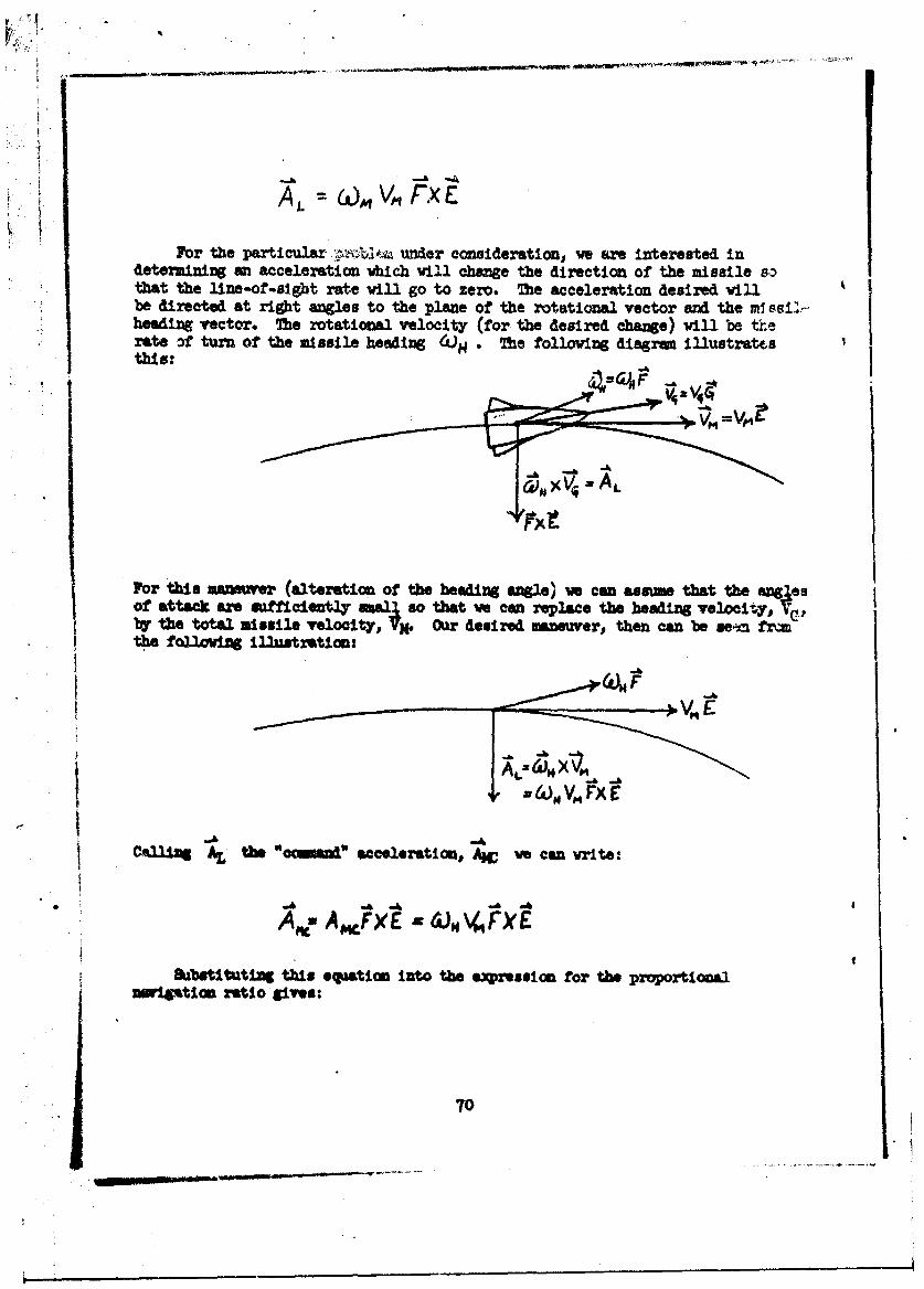
MA,_ =& V.FXE
For the particular- ',:blo• under consideration, ve are interested indetermining an acceleration vhich vill change the direction of the missile sothat the line-of-sight rate will go to zero. The acceleration desired willbe directed at right angles to the plane of the rotational vector and the m1.ssi'-heading vector. The rotational velocity (for the desired change) will be therate, of turn of the mssile heading 4')H . The folloving diagmru illustratesthis:
For ts mamnver (alteration of the headirg angle) we can asme that the angesof attack are =ficiently mall so that w can replace the heading velocity, v(!.,ba the total missile velocity, VX. Our desired maneuver, then can be sei fr=the following illustration:
i
Cailing AL the "wome acceleration, AIC ve can vrite:
Ae, A MFXe E A V, X E
&abfktlttint this equation into the epreunion for the proportional=W10tion ratio gives:
70
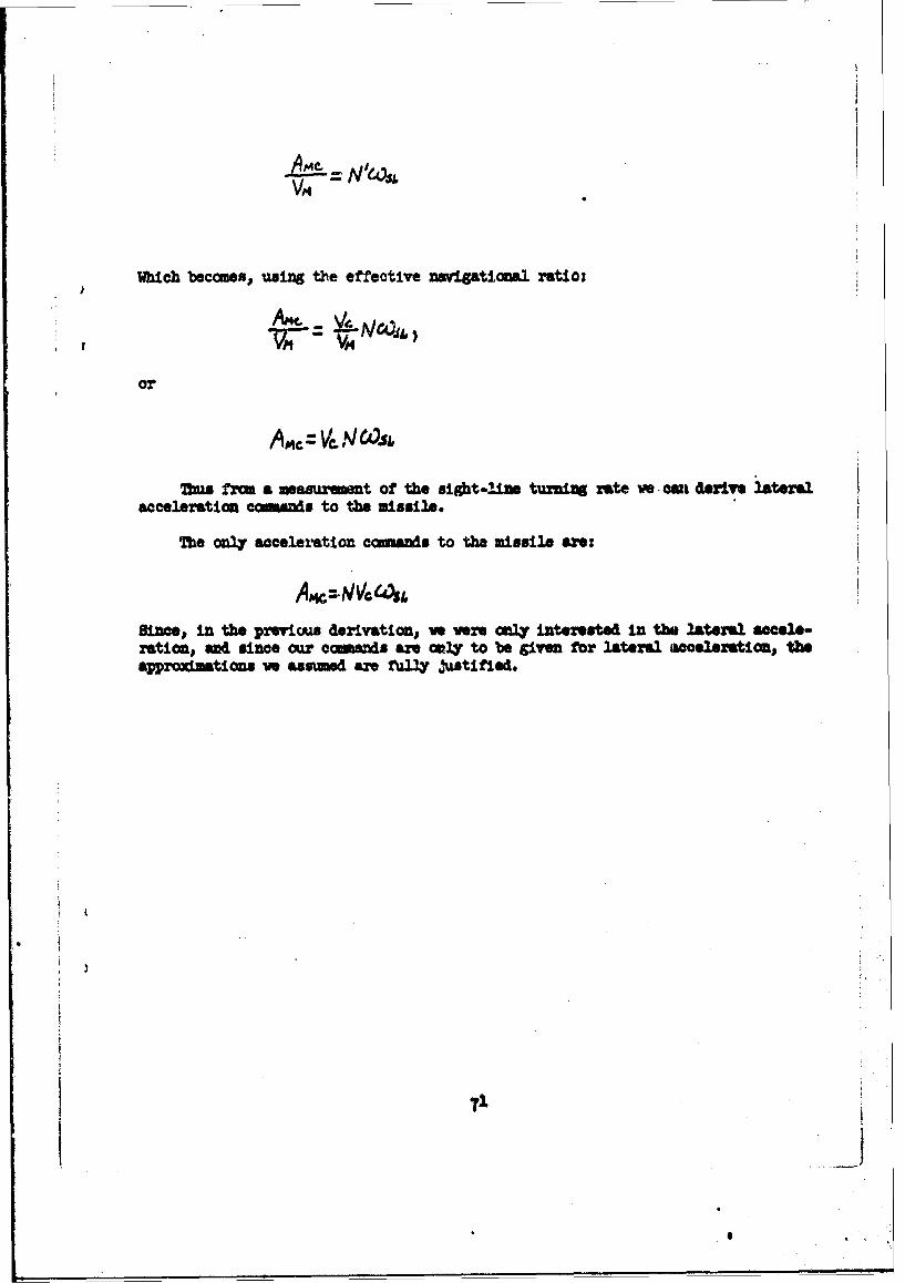
Which becomes, using the effective navigational ratio:
A.9 : VA N.Os&
7us frm a measur t of the sight-line turniM rate we ca derive lateralacceleration cesna to the missile.
The only acceleration comaids to the missile an:
Since, in the prvicus derivation, w ere =4ly interested in the lateral aele-ration, asd since our coiands are enly to be given for lateral aeelerstion, theaprwd•ations ve aswsued are fully ýuxtifled.
71
I
6)
Related Documents