This is tutorial for buckling analysis in NX 9 software. For doing this tutorial you need to have basic information of software and also you need to be familiar with buckling subject. This tutorial is made by Armin Yousefi Kanani, In the first step you need to make geometry of the model. The thickness of a plate should be equal to: the layer thickness * the number of the layer. In this example the 8 layer with 0.5mm thickness is considered for this sample. Therefore the thickness of the plate would be 4mm. Armin Yousef Kanani

Welcome message from author
This document is posted to help you gain knowledge. Please leave a comment to let me know what you think about it! Share it to your friends and learn new things together.
Transcript

This is tutorial for buckling analysis in NX 9 software. For doing this tutorial you need to have basic
information of software and also you need to be familiar with buckling subject.
This tutorial is made by Armin Yousefi Kanani,
In the first step you need to make geometry of the model. The thickness of a plate should be equal to:
the layer thickness * the number of the layer.
In this example the 8 layer with 0.5mm thickness is considered for this sample. Therefore the thickness
of the plate would be 4mm.
Armin
Youse
f Kan
ani
1
Typewriter
1
Typewriter

In the second step you need to save the file and go to the advance simulation section. In this step you
have to decide your analysis will be 2D or 3D. For this example 2D analysis is considered. Thus, click on
the mid surface with face pair. In the solid body section choose geometry and then click on
automatically create
Armin
Youse
f Kan
ani
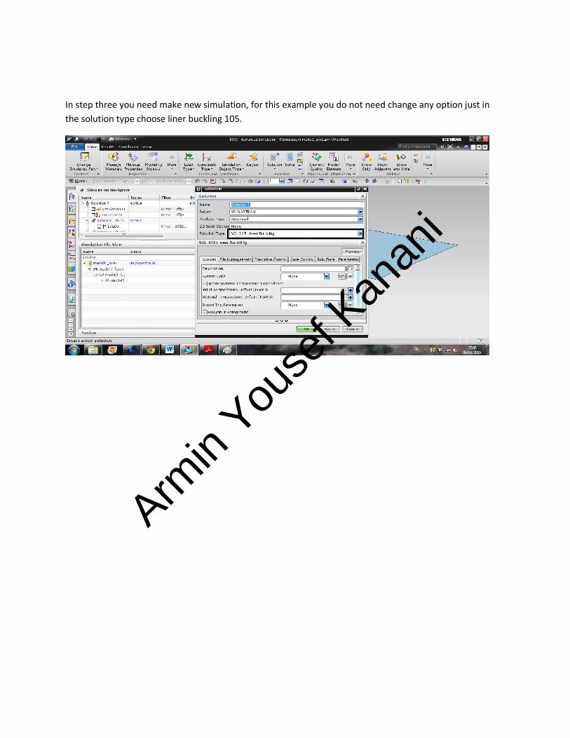
In step three you need make new simulation, for this example you do not need change any option just in
the solution type choose liner buckling 105.
Armin
Youse
f Kan
ani

In this section, the mesh will apply to the model. In mesh section you have to do mesh sensitivity. By
changing mesh size eigenvalue amount will change. Thus you need to find proper mesh size and mesh
type. In CQUAD 4, the mesh size should not be above 5 mm but this depends on your computer to be
able to process the operation.
Armin
Youse
f Kan
ani
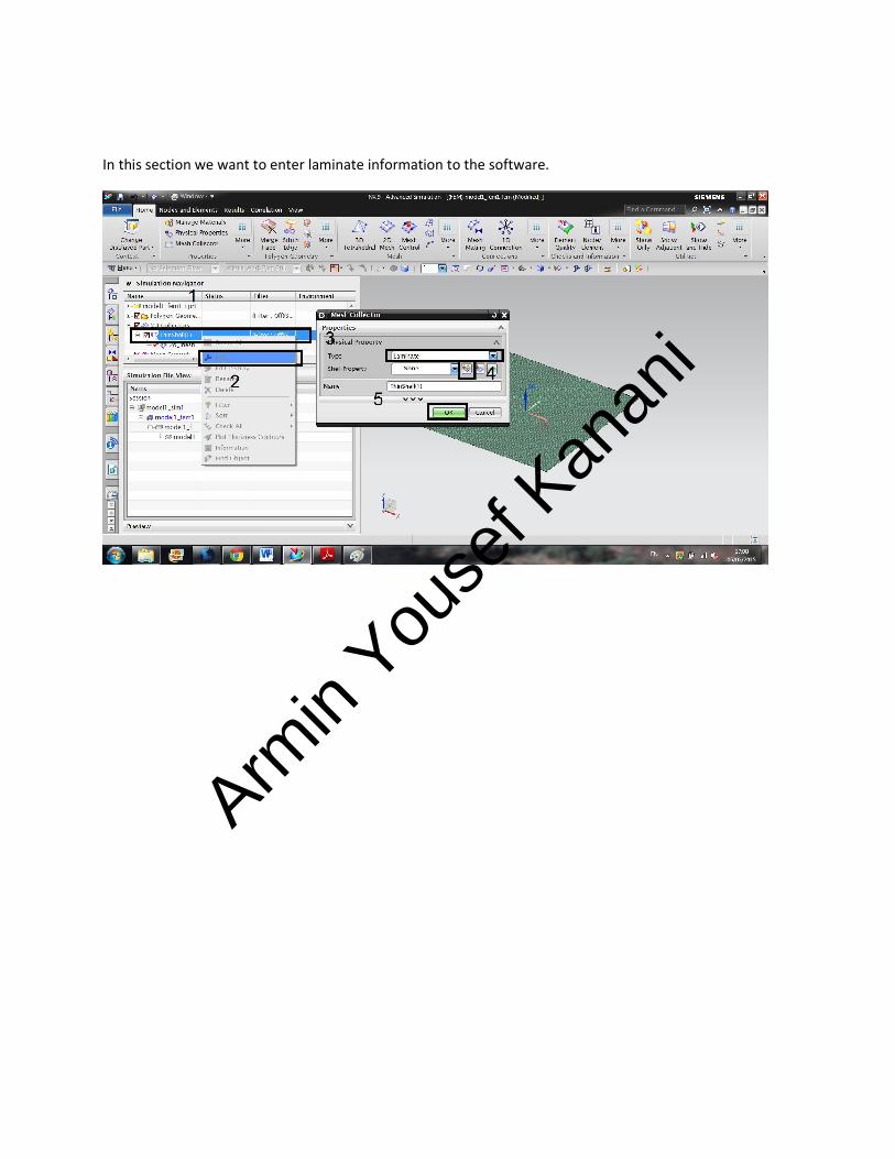
In this section we want to enter laminate information to the software.
Armin
Youse
f Kan
ani
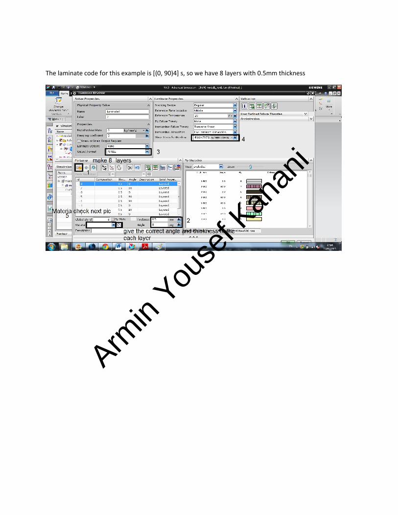
The laminate code for this example is [(0, 90)4] s, so we have 8 layers with 0.5mm thickness
Armin
Youse
f Kan
ani
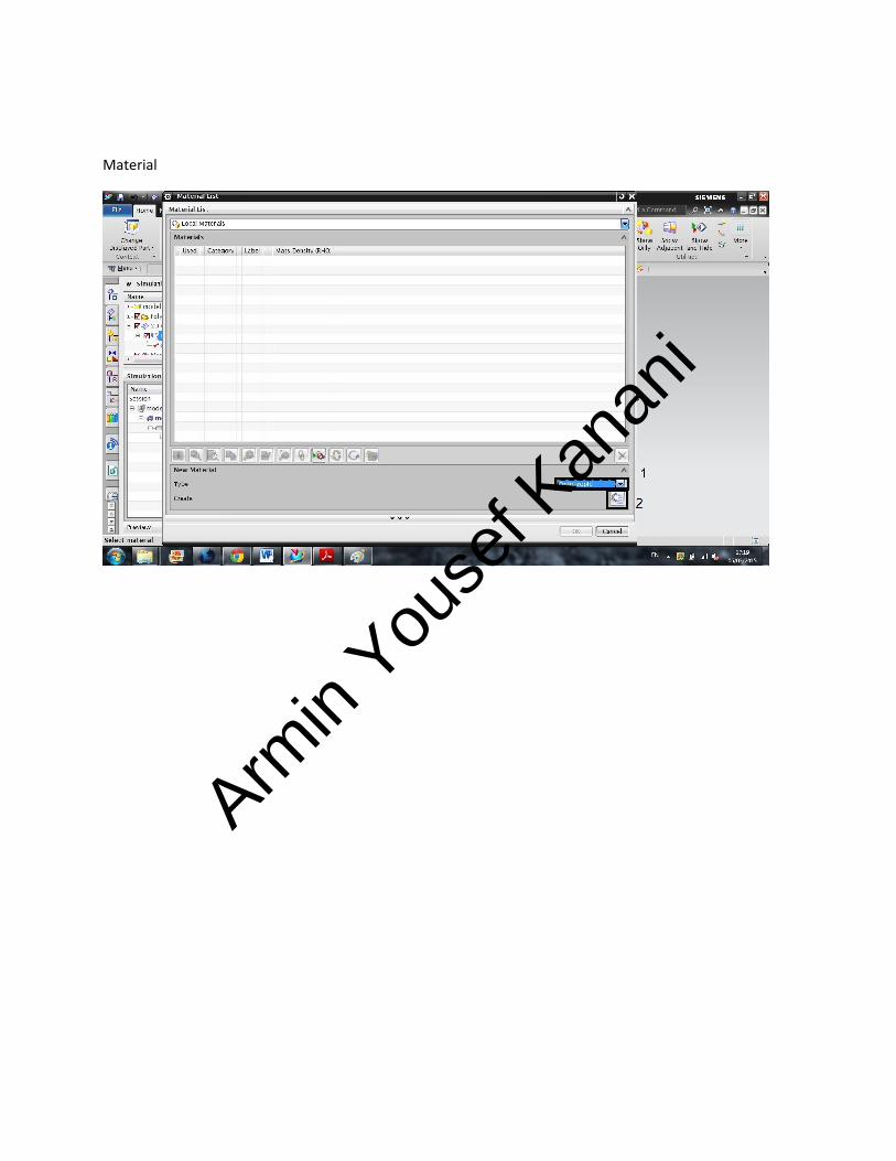
Material
Armin
Youse
f Kan
ani

Material details
E1:172 Gpa
E2:6.89 Gpa
v12=v21=0.25
After entering information you need to give orthopedic material to each layer like previous section
Armin
Youse
f Kan
ani
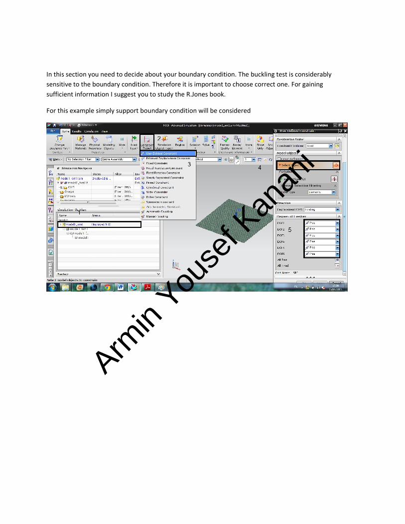
In this section you need to decide about your boundary condition. The buckling test is considerably
sensitive to the boundary condition. Therefore it is important to choose correct one. For gaining
sufficient information I suggest you to study the R.Jones book.
For this example simply support boundary condition will be considered
Armin
Youse
f Kan
ani

DOF1: X / DOF 2 : Y/ DOF3: Z / DOF 4:Mx / DOF 5: My/ DOF 6: Mz
For simply supported boundary condition same as the R.Jones Book. This part is significantly important,
so if you want to do this tutorial please get enough information about the kind of the boundary
condition.
Point: The edge should not be fixing in the applied forces direction
Armin
Youse
f Kan
ani
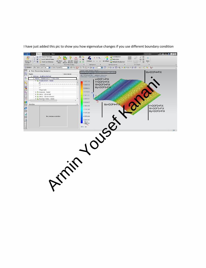
I have just added this pic to show you how eigenvalue changes if you use different boundary condition
Armin
Youse
f Kan
ani
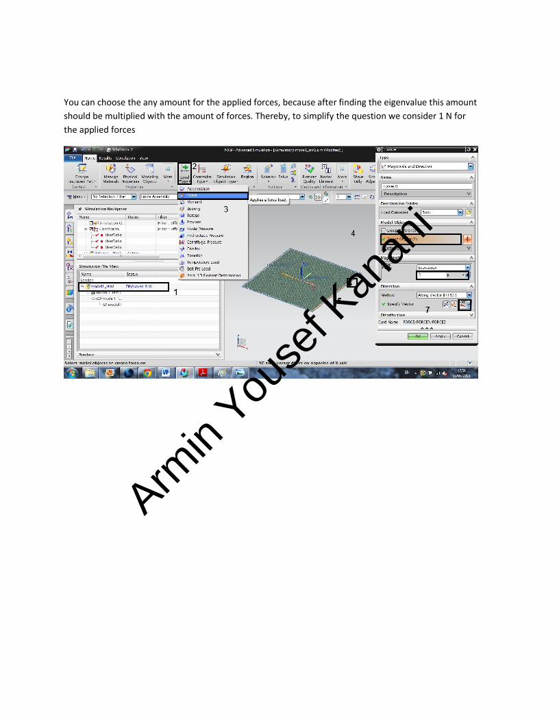
You can choose the any amount for the applied forces, because after finding the eigenvalue this amount
should be multiplied with the amount of forces. Thereby, to simplify the question we consider 1 N for
the applied forces
Armin
Youse
f Kan
ani
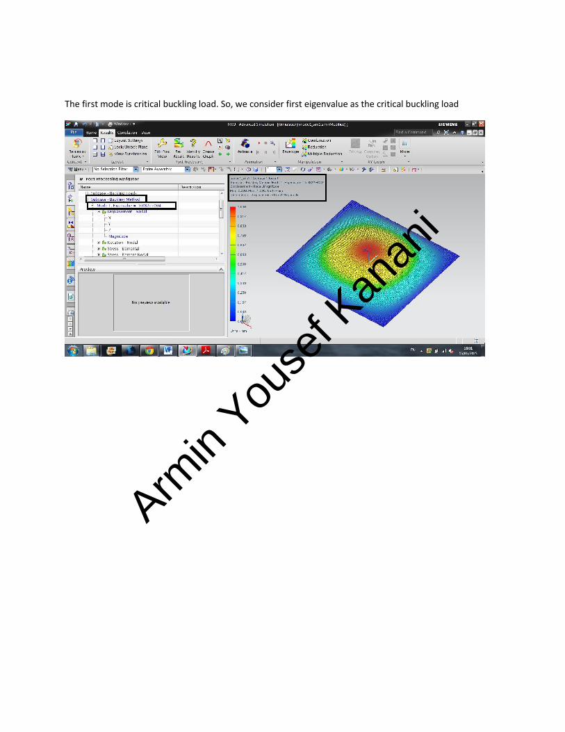
The first mode is critical buckling load. So, we consider first eigenvalue as the critical buckling load
Armin
Youse
f Kan
ani
Related Documents