Arithmetic Logic Unit (ALU) Introduction to Computer Yung-Yu Chuang with slides by Sedgewick & Wayne ( introcs.cs.princeton.edu ), Nisan & Schocken ( www.nand2tetris.org ) and Harris & Harris (DDCA)

Welcome message from author
This document is posted to help you gain knowledge. Please leave a comment to let me know what you think about it! Share it to your friends and learn new things together.
Transcript
Arithmetic Logic Unit (ALU)
Introduction to ComputerpYung-Yu Chuang
with slides by Sedgewick & Wayne (introcs.cs.princeton.edu), Nisan & Schocken (www.nand2tetris.org) and Harris & Harris (DDCA)
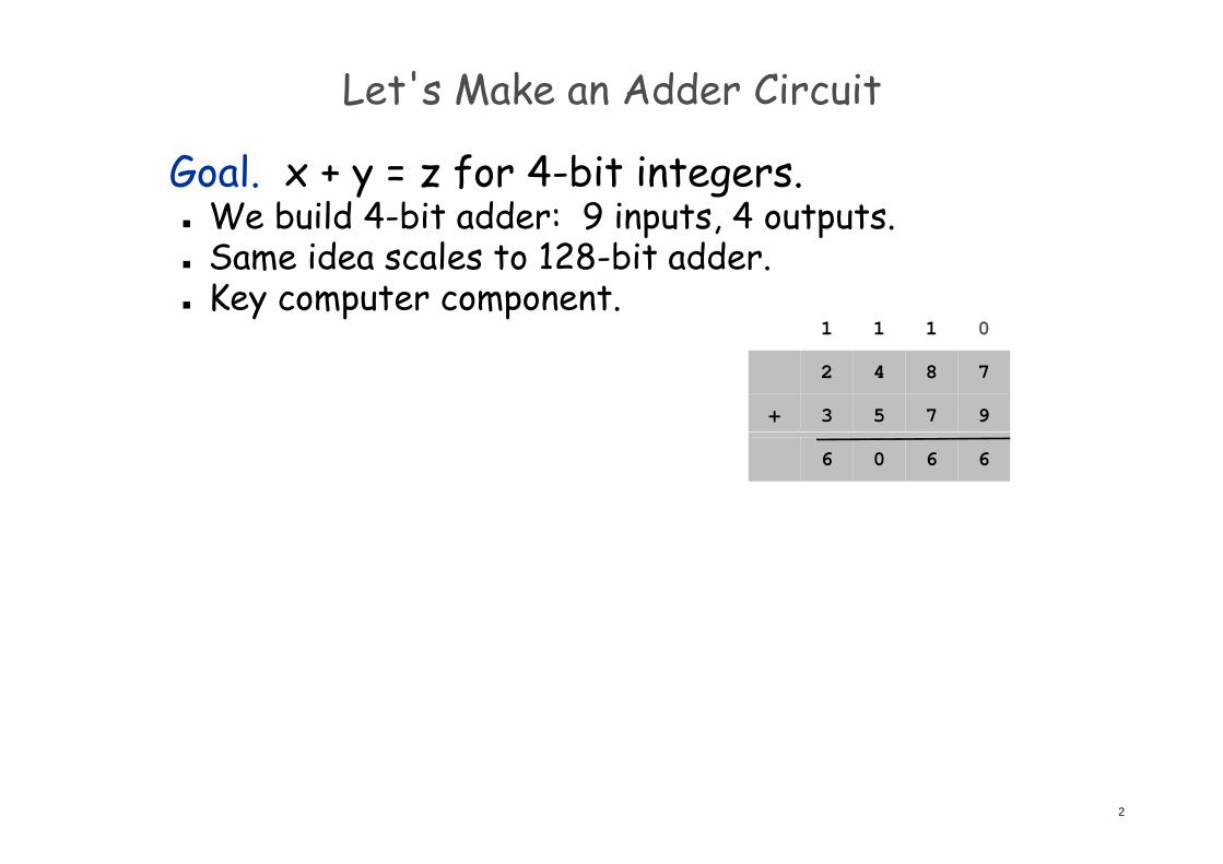
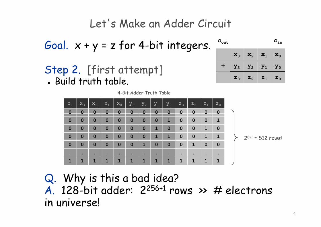
Let's Make an Adder Circuit
Goal. x + y = z for 4-bit integers. We build 4-bit adder: 9 inputs, 4 outputs.p p Same idea scales to 128-bit adder. Key computer component.
111 0
842 7
753 9+
111 0
606 6
2
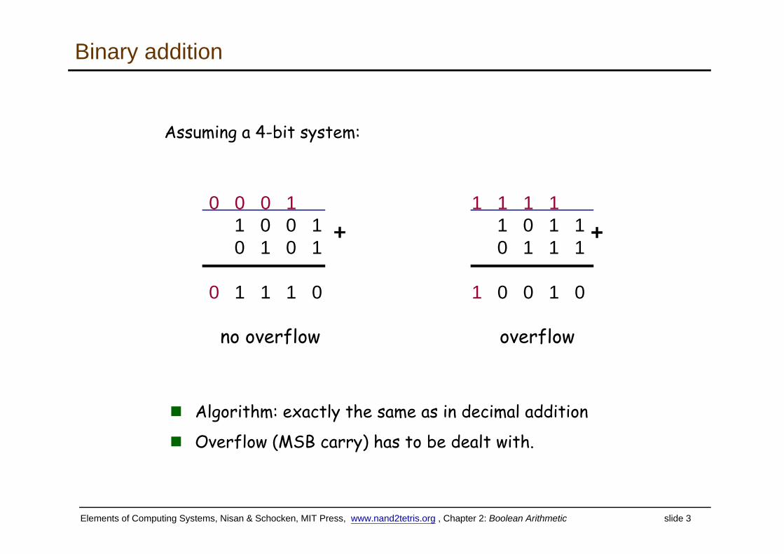
Binary addition
Assuming a 4-bit system:
0 0 0 1 1 1 1 11 0 0 10 1 0 1
+ 1 0 1 10 1 1 1
+
no overflow overflow
0 1 1 1 0 1 0 0 1 0
no overflow overflow
Algorithm: exactly the same as in decimal addition
Overflow (MSB carry) has to be dealt with.
Elements of Computing Systems, Nisan & Schocken, MIT Press, www.nand2tetris.org , Chapter 2: Boolean Arithmetic slide 3
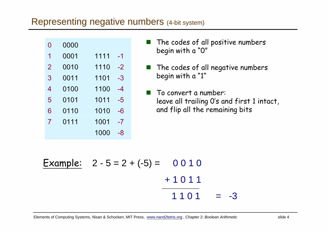
Representing negative numbers (4-bit system)
The codes of all positive numbers begin with a “0”
0 00001 0001 1111 -1
The codes of all negative numbers begin with a “1“
b
2 0010 1110 -23 0011 1101 -34 0100 1100 -4 To convert a number:
leave all trailing 0’s and first 1 intact,and flip all the remaining bits
4 0100 1100 -45 0101 1011 -56 0110 1010 -67 0111 1001 -7
1000 -8
Example: 2 - 5 = 2 + (-5) = 0 0 1 0p
+ 1 0 1 1
1 1 0 1 = 3
Elements of Computing Systems, Nisan & Schocken, MIT Press, www.nand2tetris.org , Chapter 2: Boolean Arithmetic slide 4
1 1 0 1 = -3
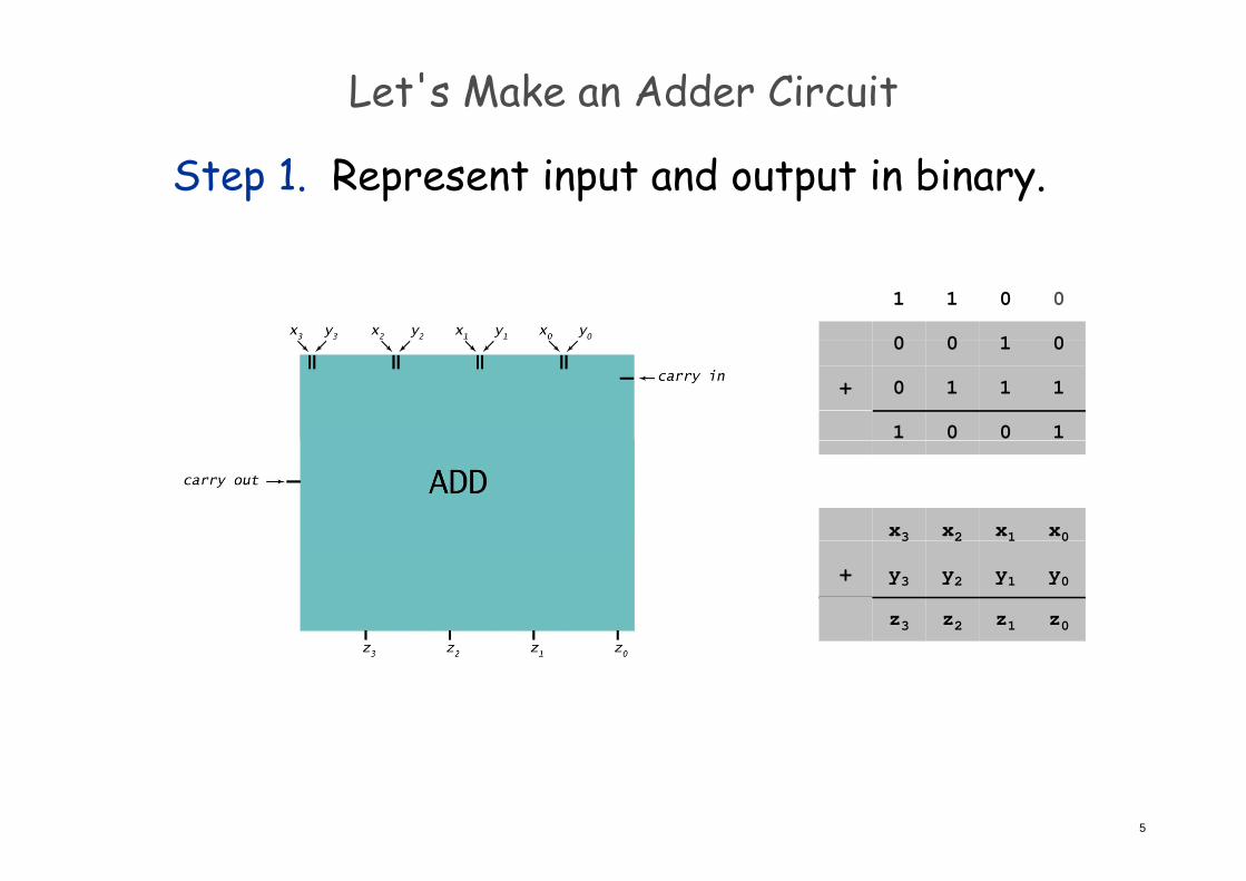
Let's Make an Adder Circuit
Step 1. Represent input and output in binary.
100 0
011 0
100 0
110 1+
001 1
x1x2x3 x0123 0
y1y2y3 y0+
z1z2z3 z0
5
Let's Make an Adder Circuit
Goal. x + y = z for 4-bit integers.x1x2x3 x0
cincout
Step 2. [first attempt] Build truth table.
y1y2y3 y0+
z1z2z3 z0
4-Bit Adder Truth Table
y2y3
00
x0x1
00
x2x3
00
y0y1
00
z2z3
00
z0z1
00
c0
0 0
0
0
0
0
0
0
0
0
0
0
0
0
0
0
0
0
0
0
0
0
0
0
0
0
1
0
1
0
0
1
1
0
0
0
0
0
0
0
0
0
1
0
1
0
0
1
1 28+1 = 512 rows!
0
0
0
0
1
.
1
0
.
1
0
.
1
0
.
1
0
.
1
0
.
1
0
.
1
0
.
1
1
.
1
0
.
1
0
.
1
0
.
1
2 512 rows!0
.
1
Q. Why is this a bad idea?A 128-bit adder: 2256+1 rows >> # electrons
6
A. 128-bit adder: 2 56 rows >> # electrons in universe!
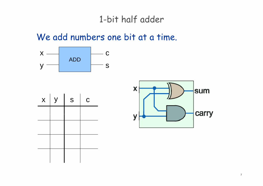
1-bit half adder
We add numbers one bit at a time.
ADDxy
cs
x y s c
7
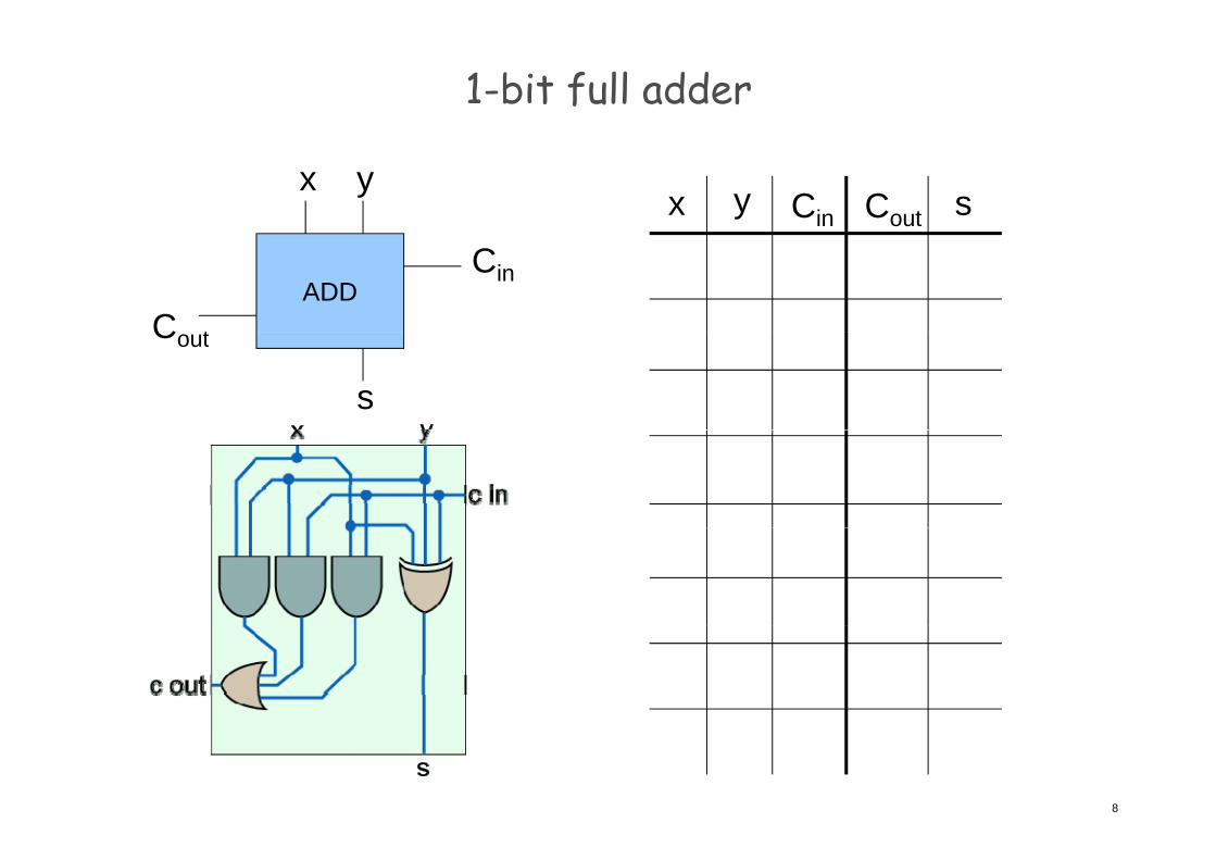
1-bit full adder
x y sx y
CoutCin
ADDC t
Cin
Cout
s
8
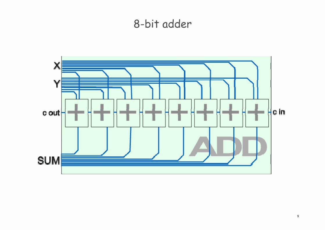
8-bit adder
9
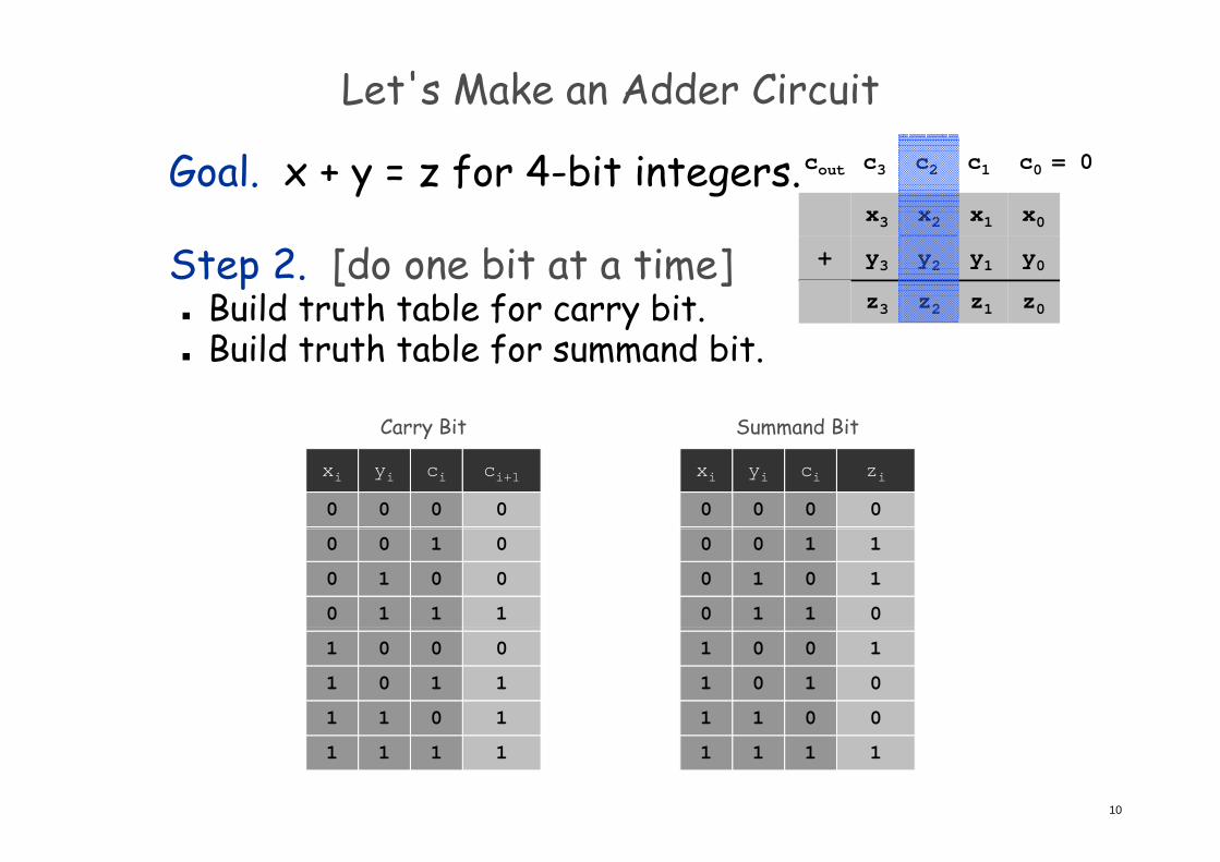
Let's Make an Adder Circuit
Goal. x + y = z for 4-bit integers.x1x2x3 x0
c1c2c3 c0 = 0cout
Step 2. [do one bit at a time] Build truth table for carry bit.
y1y2y3 y0+
z1z2z3 z0
Build truth table for summand bit.
Carry Bit Summand BitCarry Bit
ci ci+1yixi
0000
Summand Bit
ci ziyixi
0000
0
0
1
1
0
1
0
1
1
0
0
0
1
1
0
1
0
1
0
1
1
0
0
0
0
1
1
0
1
0
0
0
1
1
1
1
1
0
0
0
1
0
0
0
1
1
1
1
10
1111 1111
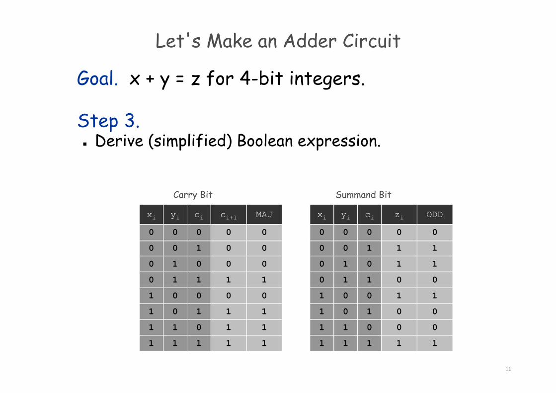
Let's Make an Adder Circuit
Goal. x + y = z for 4-bit integers.
Step 3. Derive (simplified) Boolean expression.
Carry Bit Summand Bit
MAJ
0
ODD
0
ci ci+1yixi
0000
ci ziyixi
0000
Carry Bit Summand Bit
0
0
1
1
1
0
0
0
1
1
0
1
0
1
1
0
0
0
1
1
0
1
0
1
0
1
1
0
0
0
0
1
1
1
0
0
0
1
1
0
1
0
0
0
1
1
1
1
1
0
0
0
1
0
0
0
1
1
1
1
11
1 11111 1111
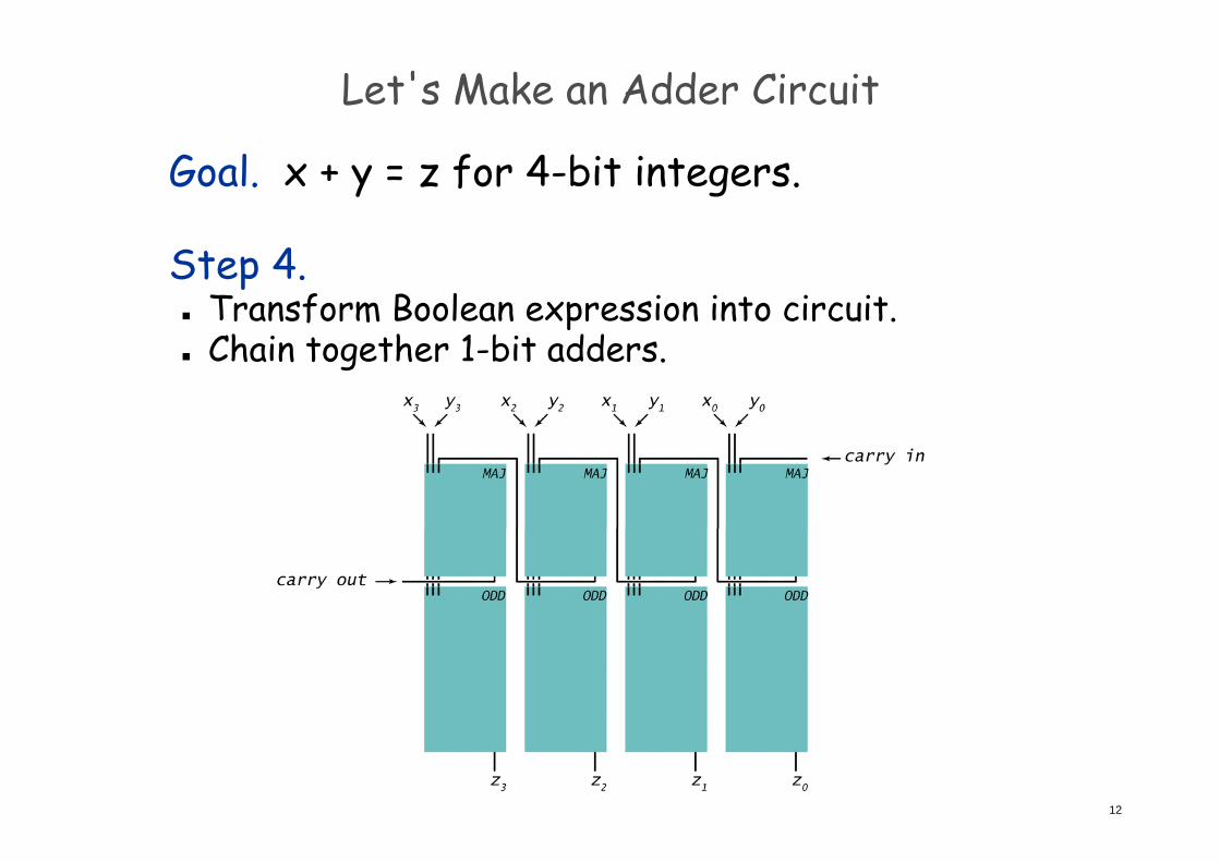
Let's Make an Adder Circuit
Goal. x + y = z for 4-bit integers.
Step 4. Transform Boolean expression into circuit. Chain together 1-bit adders.
12
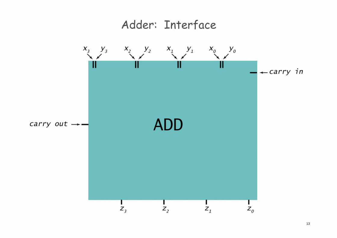
Adder: Interface
13
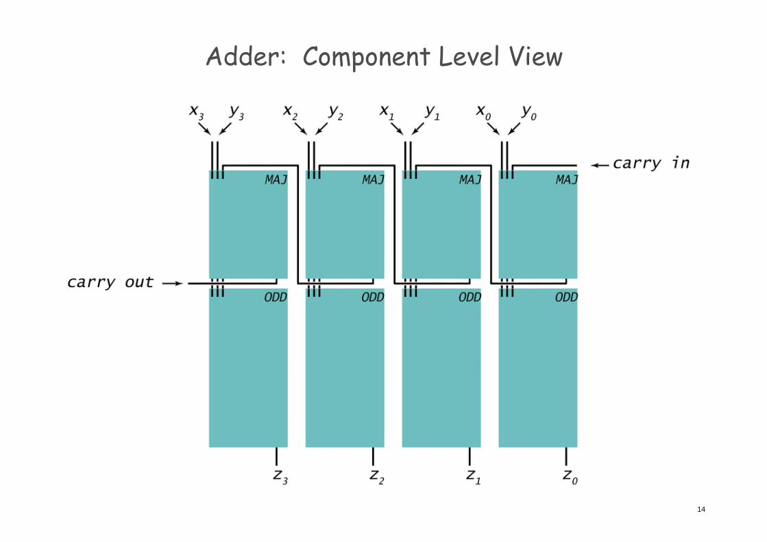
Adder: Component Level View
14
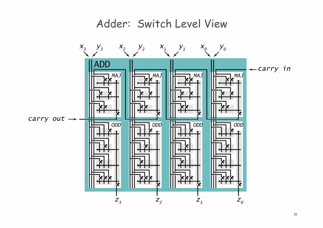
Adder: Switch Level View
15
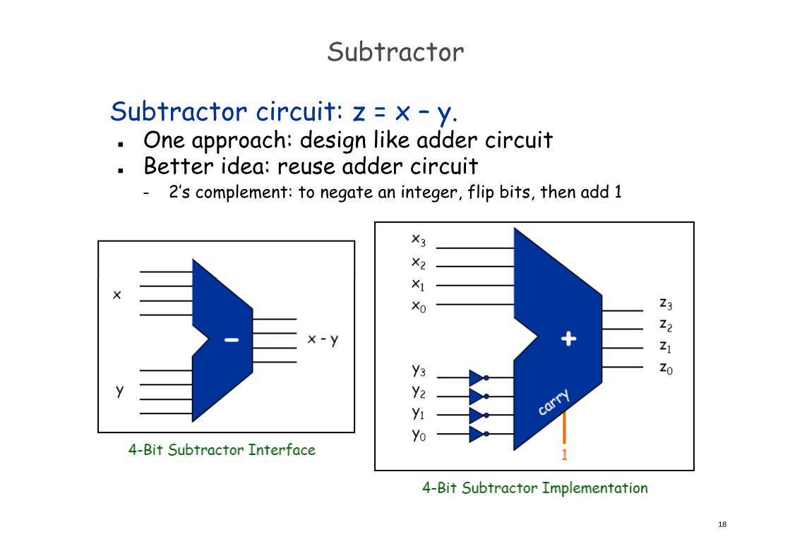
Subtractor
Subtractor circuit: z = x – y. One approach: design like adder circuitpp g
Subtractor
Subtractor circuit: z = x – y. One approach: design like adder circuitpp g Better idea: reuse adder circuit
– 2’s complement: to negate an integer, flip bits, then add 1
17
Subtractor
Subtractor circuit: z = x – y. One approach: design like adder circuitpp g Better idea: reuse adder circuit
– 2’s complement: to negate an integer, flip bits, then add 1
18
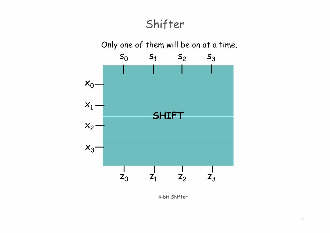
Shifter
s0 s1 s2 s3
Only one of them will be on at a time.
x0
SHIFTx1
SHIFTx2
x3
4 bit Shift
z0 z1 z2 z3
19
4-bit Shifter
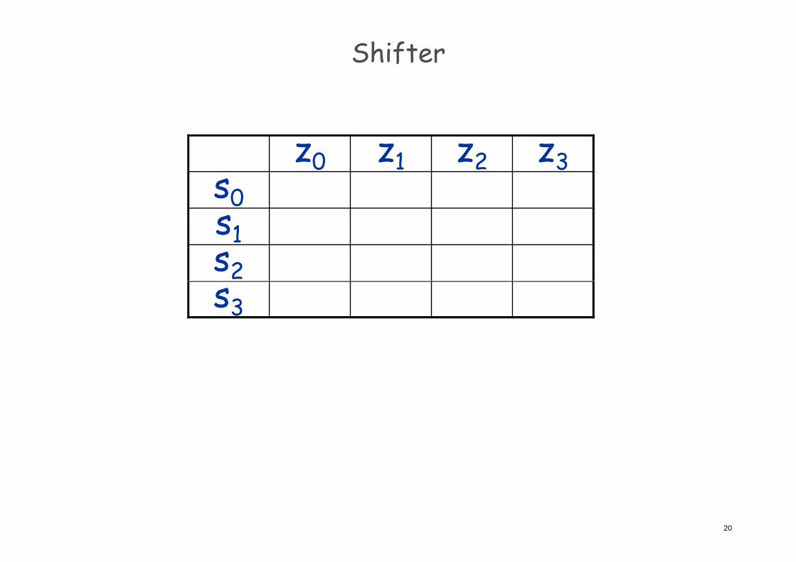
Shifter
z0 z1 z2 z3z0 z1 z2 z3s0ss1s2s3
20
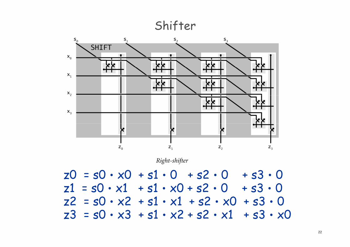
Shifter
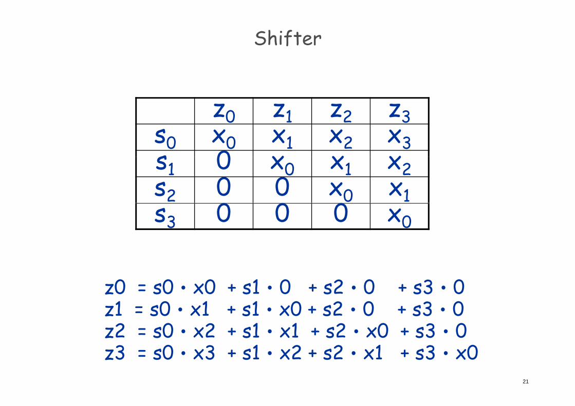
z0 z1 z2 z3z0 z1 z2 z3s0 x0 x1 x2 x3s 0 x x xs1 0 x0 x1 x2s2 0 0 x0 x1
0 0 0s3 0 0 0 x0
z0 = s0‧x0 + s1‧0 + s2‧0 + s3‧0z1 = s0‧x1 + s1‧x0 + s2‧0 + s3‧0z2 = s0‧x2 + s1‧x1 + s2‧x0 + s3‧0
21
z3 = s0‧x3 + s1‧x2 + s2‧x1 + s3‧x0
Shifter
z0 = s0‧x0 + s1‧0 + s2‧0 + s3‧0z1 = s0‧x1 + s1‧x0 + s2‧0 + s3‧0z2 = s0‧x2 + s1‧x1 + s2‧x0 + s3‧0
22
z3 = s0‧x3 + s1‧x2 + s2‧x1 + s3‧x0
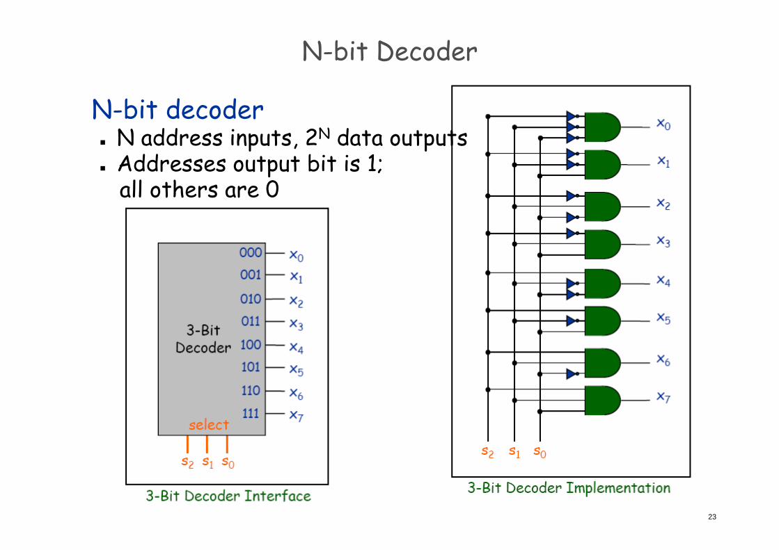
N-bit Decoder
N-bit decoder N address inputs, 2N data outputsp p Addresses output bit is 1;
all others are 0
23
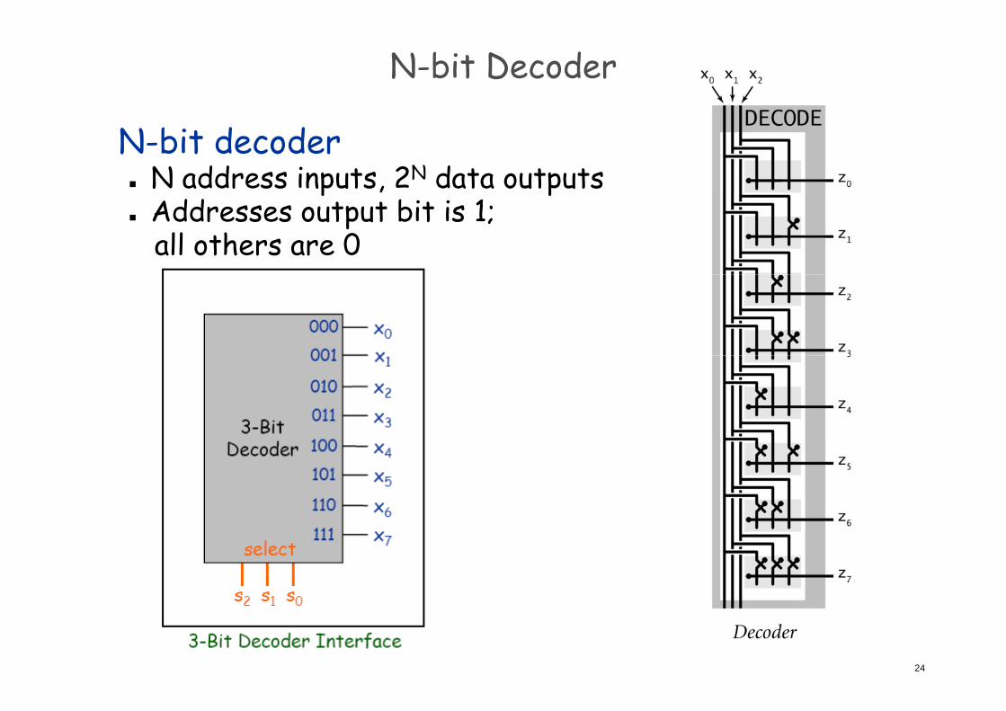
N-bit Decoder
N-bit decoder N address inputs, 2N data outputsp p Addresses output bit is 1;
all others are 0
24

2-Bit Decoder Controlling 4-Bit Shifter
Ex. Put in a binary amount to shift.r0r1
25
Arithmetic Logic Unit
Arithmetic logic unit (ALU). Computes all operations in parallel.p p Add and subtract. Xor.
A d And. Shift left or right.
Q. How to select desired answer?Q
26
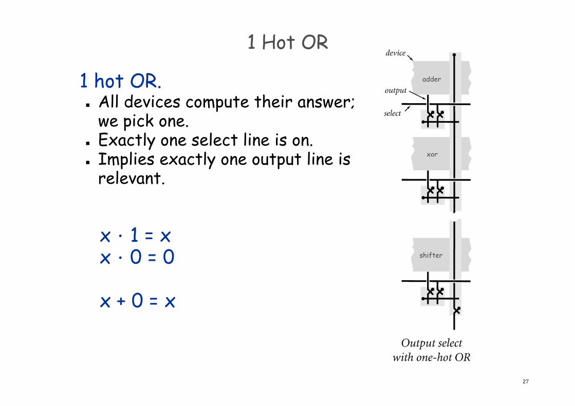
1 Hot OR
1 hot OR. All devices compute their answer;
adder
pwe pick one.
Exactly one select line is on.Implies exactly one output line is xor
Implies exactly one output line is relevant.
x.1 = x0 0 shifterx.0 = 0
0 x + 0 = x
27
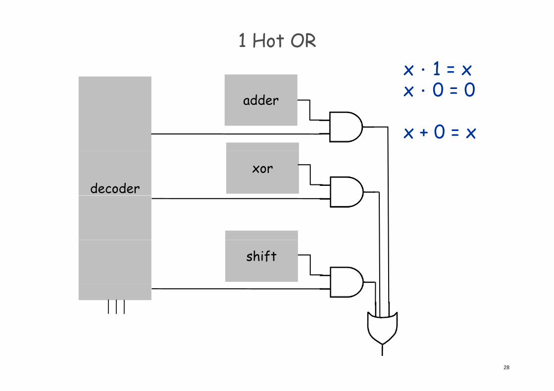
1 Hot OR1
adder
x.1 = xx.0 = 0
x + 0 = x
xordecoder
shift
28
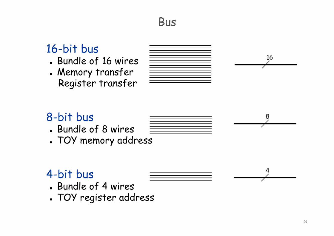
Bus
16-bit bus Bundle of 16 wiresu f w Memory transfer
Register transfer
8-bit bus8-bit bus Bundle of 8 wires TOY memory addressy
4 bit b4-bit bus Bundle of 4 wires
TOY register address
29
TOY register address
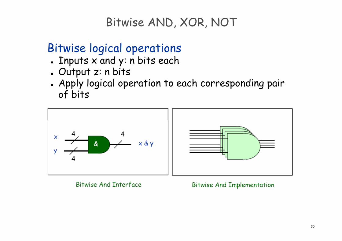
Bitwise AND, XOR, NOT
Bitwise logical operations Inputs x and y: n bits eachp y Output z: n bits Apply logical operation to each corresponding pair
of bitsof bits
30
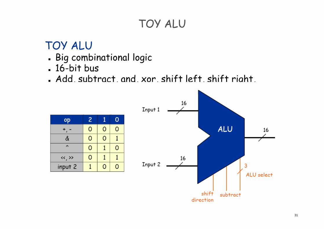
TOY ALU
TOY ALU Big combinational logic g g 16-bit bus Add, subtract, and, xor, shift left, shift right,
copy input 2copy input 2
31
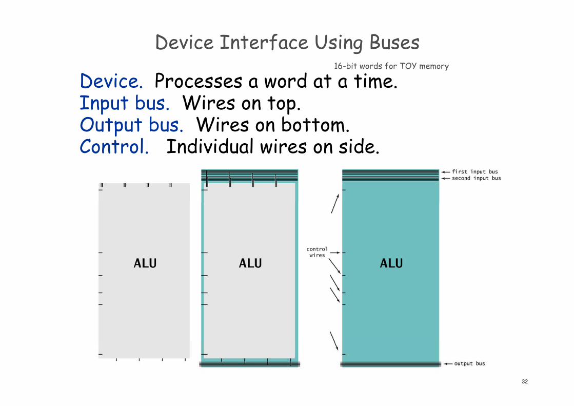
Device Interface Using Buses16 bit words for TOY memory
Device. Processes a word at a time.Input bus. Wires on top.
16-bit words for TOY memory
p pOutput bus. Wires on bottom.Control. Individual wires on side.
32
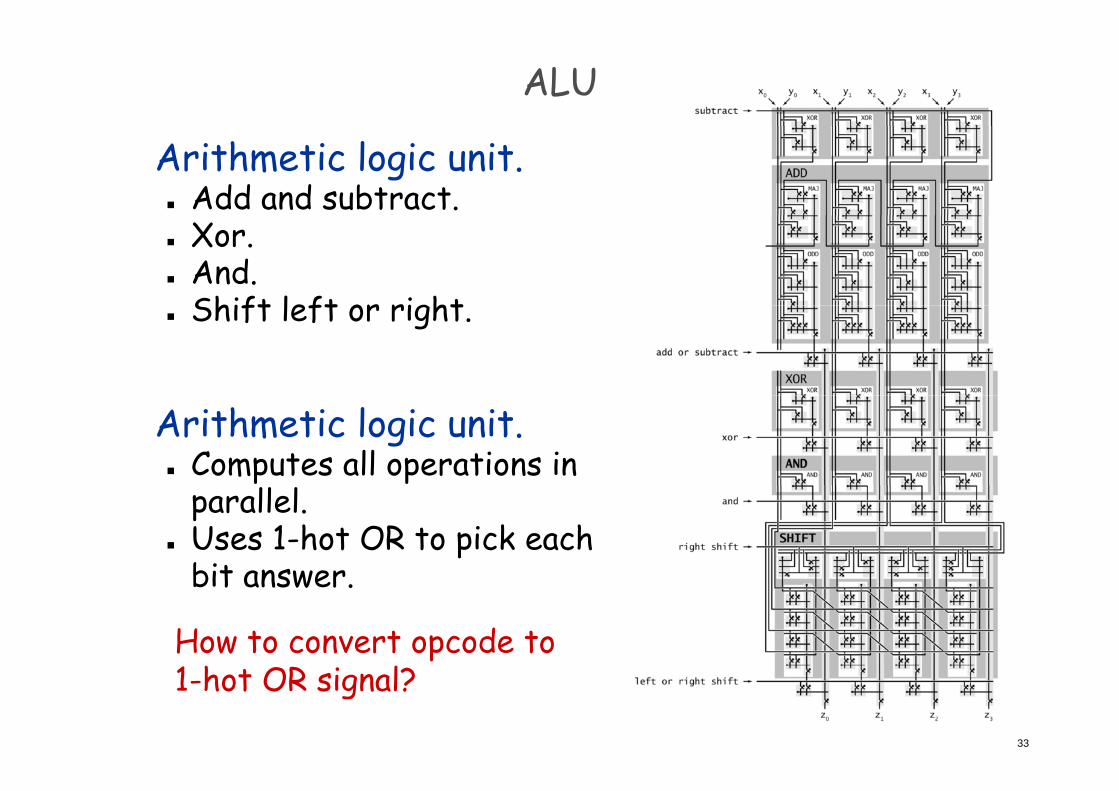
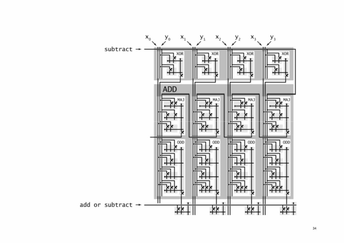
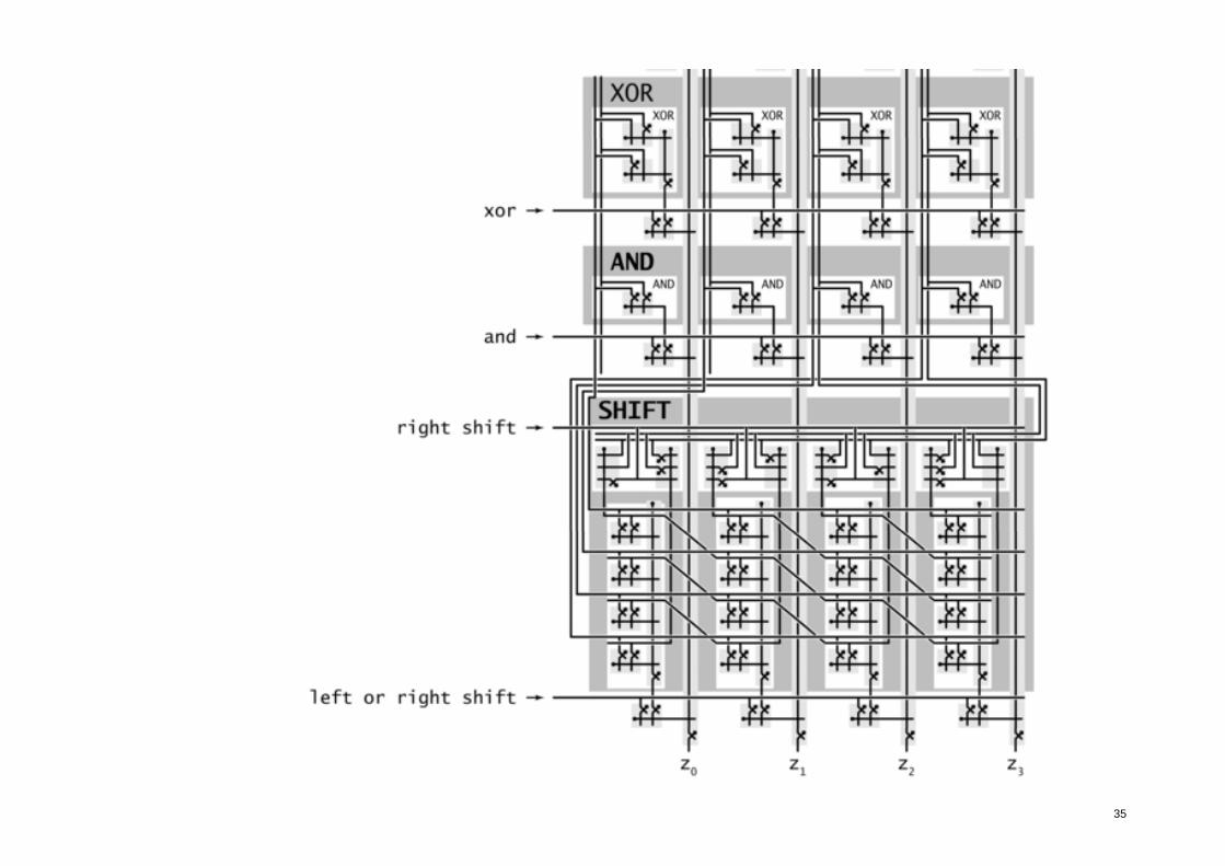
ALU
Arithmetic logic unit. Add and subtract. Xor. And.
Shift left or right Shift left or right.
Arithmetic logic unit. Computes all operations in
parallel. Uses 1-hot OR to pick each
bit answerbit answer.
How to convert opcode to
33
1-hot OR signal?
34
35
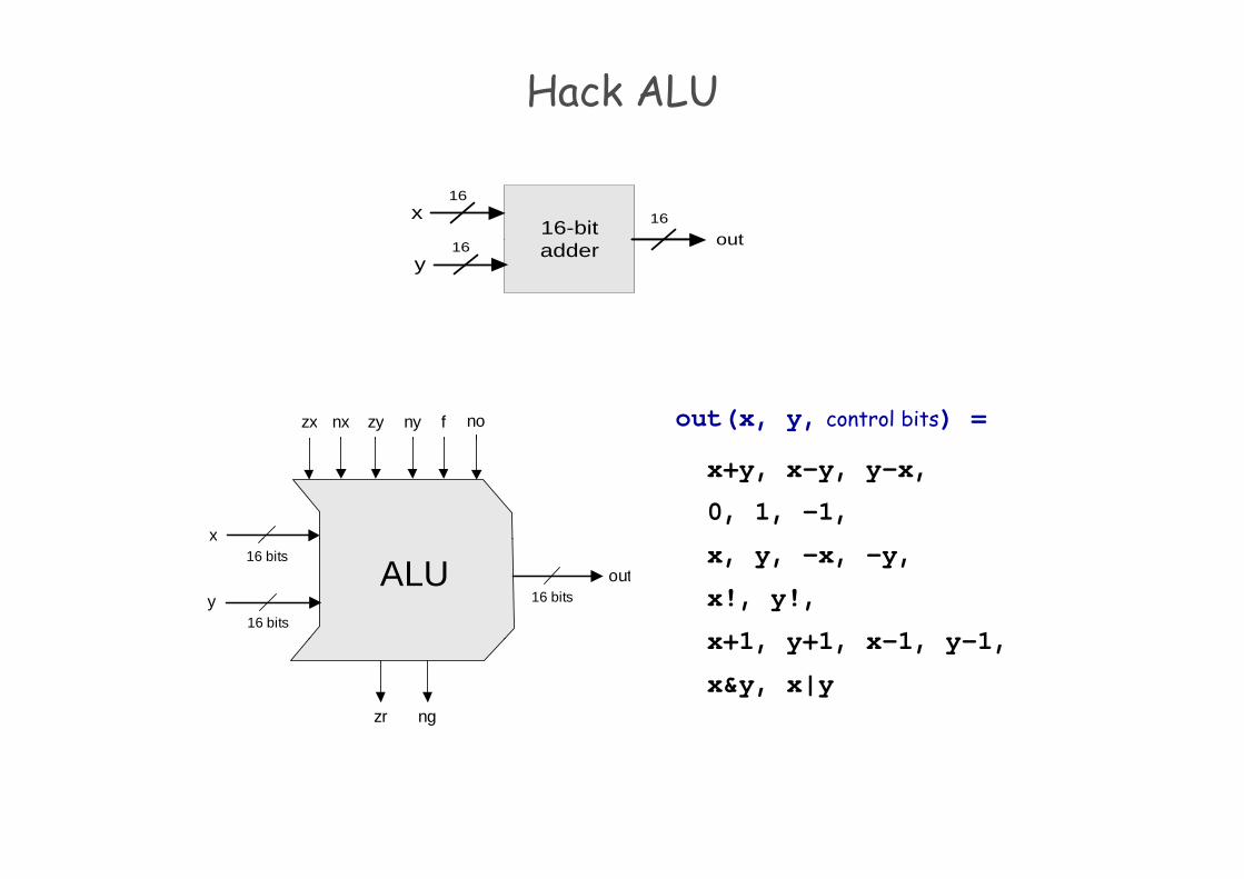
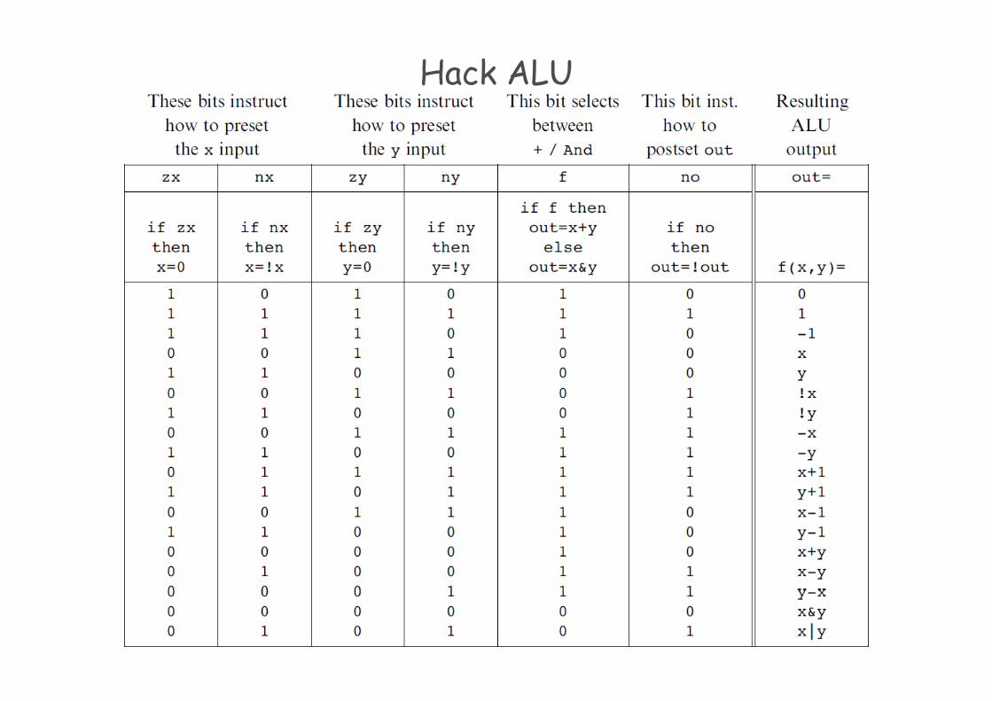
Hack ALU
outx
16
16-bit 16outadder
y16
zx nonx zy ny f out(x, y, control bits) =
x
x+y, x-y, y–x,
0, 1, -1,
ALU16 bits
16 bits
x
y 16 bitsout
x, y, -x, -y,
x!, y!,
x+1 y+1 x 1 y 1
zr ng
x+1, y+1, x-1, y-1,
x&y, x|y
Hack ALU
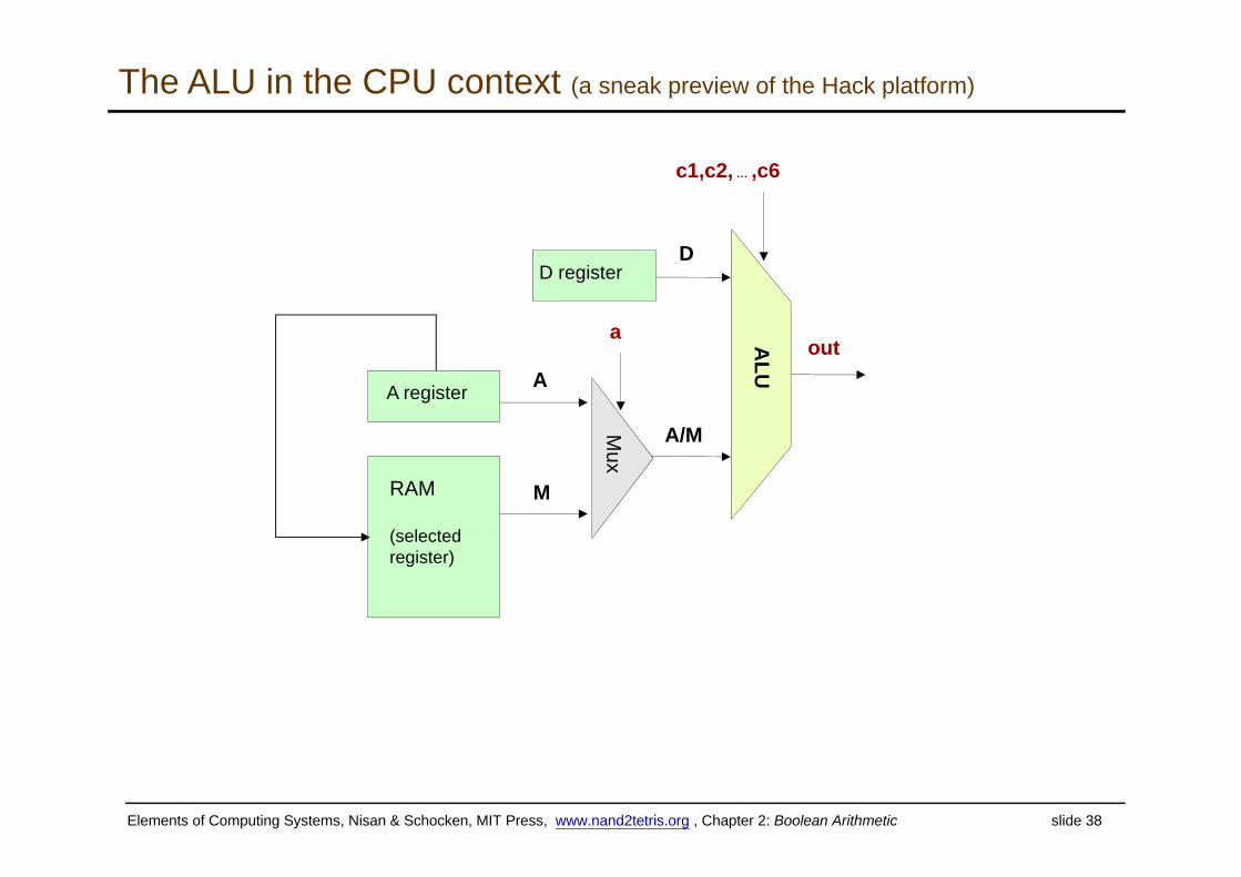
The ALU in the CPU context (a sneak preview of the Hack platform)
c1,c2, … ,c6
D
a
D register
ALU
M
out
A/M
A register A
Mux
A/M
MRAM
(selected(selected register)
Elements of Computing Systems, Nisan & Schocken, MIT Press, www.nand2tetris.org , Chapter 2: Boolean Arithmetic slide 38
Perspective
Combinational logic
Our adder design is very basic: no parallelism Our adder design is very basic: no parallelism
It pays to optimize adders
Our ALU is also very basic: no multiplication, no division
Wh is th s t f m d n d m th p ti ns? Where is the seat of more advanced math operations?a typical hardware/software tradeoff.
Elements of Computing Systems, Nisan & Schocken, MIT Press, www.nand2tetris.org , Chapter 2: Boolean Arithmetic slide 39
Related Documents