ARIES Meeting, UCSD L. M. Waganer, 14-15 June 2006 An Approach for Low Cost Fabrication of the Coil Structure L. M. Waganer With Support from Kevin Slattery and John Waldrop-III The Boeing Company ARIES Meeting University of California, San Diego 14-15 June 2006

ARIES Meeting, UCSD L. M. Waganer, 14-15 June 2006 An Approach for Low Cost Fabrication of the Coil Structure L. M. Waganer With Support from Kevin Slattery.
Dec 21, 2015
Welcome message from author
This document is posted to help you gain knowledge. Please leave a comment to let me know what you think about it! Share it to your friends and learn new things together.
Transcript

ARIES Meeting, UCSD L. M. Waganer, 14-15 June 2006
An Approach for Low Cost Fabrication of the Coil Structure
L. M. WaganerWith Support from
Kevin Slattery and John Waldrop-IIIThe Boeing Company
ARIES MeetingUniversity of California, San Diego
14-15 June 2006

ARIES Meeting, UCSD L. M. Waganer, 14-15 June 2006Page 2
Material: JK2LB low carbon, boron steel
Mass: ~ 3 x 10⁶ kg for 3 field periods
Construction: Monolithic for field period
Fabrication Location: At construction site
Fabrication: Additive machining – arc deposition of near net shape, final machining of coil grooves by robot milling machines on inner surface and field period interfaces
Coil Fabrication: Coil cables will be wound into the grooves with robot winding machines
Accuracy of Coils: EM forces will be analyzed to determine displacement. Placement of the grooves will be compensated so the coils will be in proper location when coils are energized.
Fabrication of the Coil Structure
Interior grooves show on exterior for clarity

ARIES Meeting, UCSD L. M. Waganer, 14-15 June 2006Page 3
Nominal Cross-Section
This is the nominal coil cross-section to be fabricated. The thicknesses will vary depending on the predicted local EM forces, thicker inboard and thinner outboard.
00
28 cm
20 cm
Strongback
Inter-coil Structure
Range 10 to 35 cm
Range 20 to 45 cm
Coil dimensions18.4 cm x 67.2 cm
Cover plate 5 cm thick

ARIES Meeting, UCSD L. M. Waganer, 14-15 June 2006Page 4
Heating the Structure
These are suggested approaches for cooling the coil structure, either A) externally with brazed or welded tubes that can be located where desired or B & C) with internal cooling channels fabricated in place. Since the preferred cooling method is to run the coolant channels parallel to the coils, the number of channels for the inter coil cooling will have to be adjusted with manifolds or branches as the width between the coils varies.
Volumetric heating in 28 cm strongback
0.00E+00
2.00E-03
4.00E-03
6.00E-03
8.00E-03
1.00E-02
1.20E-02
1.40E-02
1.60E-02
360 365 370 375 380 385 390 395
Radius, cm
Vo
lum
etri
c H
eati
ng
, W
/cc
Volumetric Heating in 20 cm intercoil structure
0.00E+00
2.00E-01
4.00E-01
6.00E-01
8.00E-01
1.00E+00
1.20E+00
340 345 350 355 360 365
Radius, cm
Vo
lum
etri
c H
eati
ng
, W
/cc
Cooling the Structure
20 cm
28 cm
2 cm x 67.1 cm cover plate
Approach A
6 cm ID Tubes on 20 cm centersbrazed or welded to structureto yield 5% coolant fraction
20 cm
28 cm
6 cm ID channels (holes)on 20 cm centers to yield5% coolant fraction
2 cm x 67.1 cm cover plate
Approach B
20 cm
28 cm
2 cm ID channels (holes)on ~ 8 cm centers to yield5% coolant fraction
2 cm x 67.1 cm cover plate
Approach C

ARIES Meeting, UCSD L. M. Waganer, 14-15 June 2006Page 5
Plasma Arc Deposition
The deposition wire is fed into the plasma arc and the material deposited in layers
Overhanging features can be created with cooled slip plates

ARIES Meeting, UCSD L. M. Waganer, 14-15 June 2006Page 6
Plasma Arc Deposition
Features can be added as the material is deposited by starting and stopping the deposition. These features (such as coil grooves and mounting interfaces) are near-net shape that require only minimal machining. All other surfaces probably will require no machining.
ARIES Meeting, UCSD L. M. Waganer, 14-15 June 2006Page 7
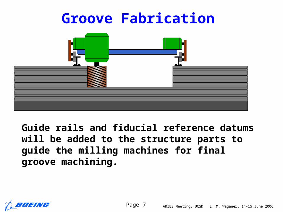
Groove Fabrication
Guide rails and fiducial reference datums will be added to the structure parts to guide the milling machines for final groove machining.

ARIES Meeting, UCSD L. M. Waganer, 14-15 June 2006Page 8
Groove Fabrication
A similar machine will use the same rails and fiducial datums to install the superconducting cables into the coil groove

ARIES Meeting, UCSD L. M. Waganer, 14-15 June 2006Page 9
Securing Coil Cover
After all the cable is in place for the coil, the cover place will be installed and friction-stir welded in place to secure the coil.

ARIES Meeting, UCSD L. M. Waganer, 14-15 June 2006Page 10
Concept to Fabricate Structure1. Start with solid base

ARIES Meeting, UCSD L. M. Waganer, 14-15 June 2006Page 11
Concept to Fabricate Structure1. Start with solid base2. Begin to create structure

ARIES Meeting, UCSD L. M. Waganer, 14-15 June 2006Page 12
Concept to Fabricate Structure1. Start with solid base2. Begin to create structure3. Continue to add layers

ARIES Meeting, UCSD L. M. Waganer, 14-15 June 2006Page 13
Concept to Fabricate Structure1. Start with solid base2. Begin to create structure3. Continue to add layers4. Ditto

ARIES Meeting, UCSD L. M. Waganer, 14-15 June 2006Page 14
Concept to Fabricate Structure1. Start with solid base2. Begin to create structure3. Continue to add layers4. Ditto

ARIES Meeting, UCSD L. M. Waganer, 14-15 June 2006Page 15
Concept to Fabricate Structure1. Start with solid base2. Begin to create structure3. Continue to add layers4. Ditto5. Until it is complete for a
field period

ARIES Meeting, UCSD L. M. Waganer, 14-15 June 2006Page 16
Multiple robots will be required to build a field period in roughly a year Each robot will be assigned a zone to build
Employing Multiple Build Robots
Plan View

ARIES Meeting, UCSD L. M. Waganer, 14-15 June 2006Page 17
•The most cost effective approach is to construct one field period at a time, but staged to move deposition, heat treatment, and machining equipment from one FP to another as required.
•After the first FP is completed, it will be moved into place in the Reactor Building.
•All three FPs should be completed in roughly 3 years.
Staging of Field Period Structures
Deposition Heat Treatment
Machining Features

ARIES Meeting, UCSD L. M. Waganer, 14-15 June 2006Page 18
Construction Sequence•The coil sectors will probably be fabricated close to the Reactor Building and moved inside the Reactor Building
ARIES Meeting, UCSD L. M. Waganer, 14-15 June 2006Page 19
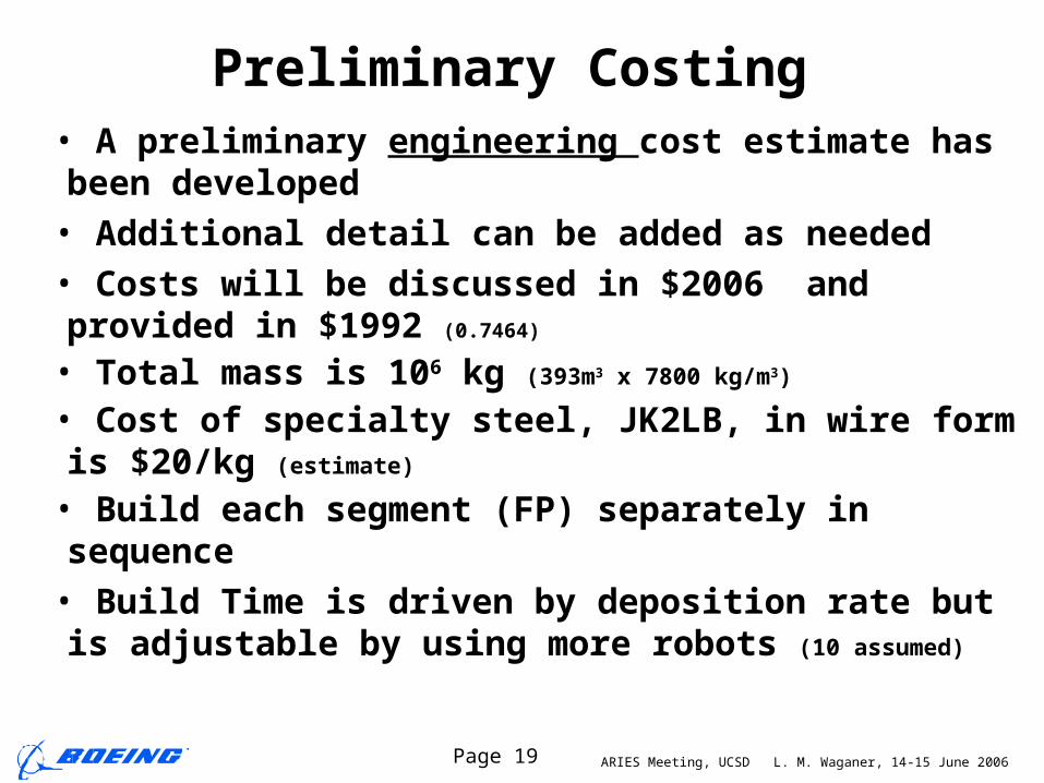
Preliminary Costing• A preliminary engineering cost estimate has been developed
• Additional detail can be added as needed
• Costs will be discussed in $2006 and provided in $1992 (0.7464)
• Total mass is 106 kg (393m3 x 7800 kg/m3)
• Cost of specialty steel, JK2LB, in wire form is $20/kg (estimate)
• Build each segment (FP) separately in sequence
• Build Time is driven by deposition rate but is adjustable by using more robots (10 assumed)

ARIES Meeting, UCSD L. M. Waganer, 14-15 June 2006Page 20
Cost of DepositionDEPOSITION Segment Weight kg 1,000,000 Wire Unit Cost $/kg $20Material Cost $ $20,000,000Deposition Rate Per Robot kg/hr 20# of Deposition Robots 10Deposition Rate kg/hr 200Up Time (availability) 0.85Deposition Time days 245Robot Unit Cost $/robot $500,000Total Robot Cost $ $5,000,000Raising Platform Cost $ $1,000,000Control System Cost $ $1,000,000Deposition System Cost $ $7,000,000Amortization Segments 6 Amortization Cost $/hr $198Electricity Unit Cost $/kwh $0.05Electricity Usage Per Robot kw 100 Electricity Cost $/hr $50Operator Cost/hr $/hr $100# of Operators 4 Labor Cost $/hr $400Overhead Factor 1.5 Deposition Rate $/hr $973Deposited Segment Cost $ $25,720,588
Awaiting Kobe Steel quote
Assumption of 10 robots
Driving schedule item
Representative cost
Most significant cost
ARIES Meeting, UCSD L. M. Waganer, 14-15 June 2006Page 21
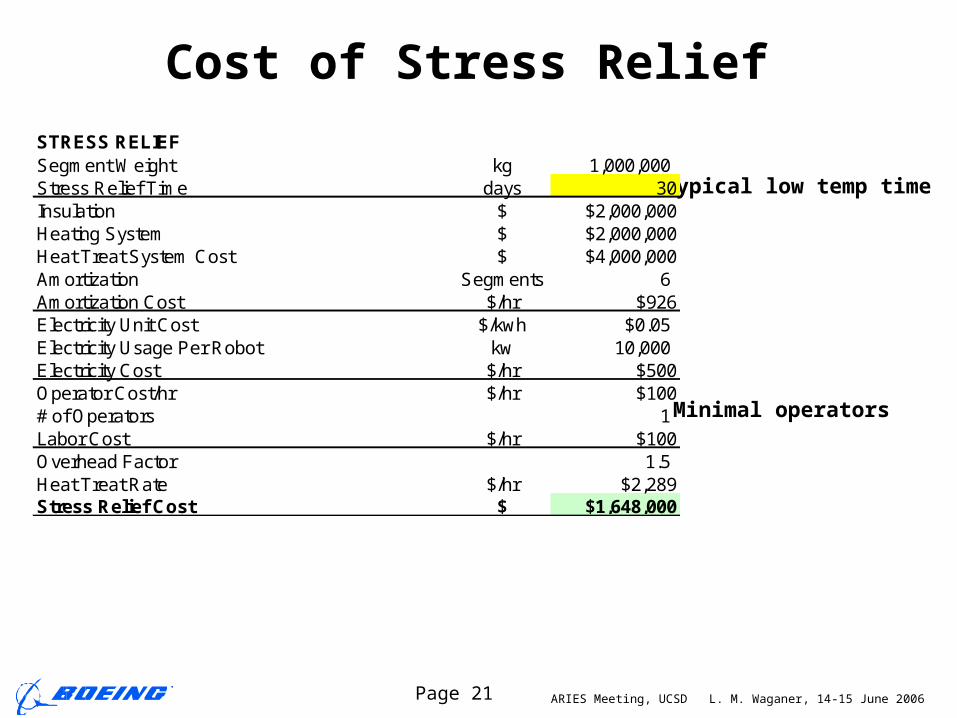
Cost of Stress Relief
Typical low temp time
Minimal operators
STRESS RELIEFSegment Weight kg 1,000,000 Stress Relief Time days 30Insulation $ $2,000,000Heating System $ $2,000,000Heat Treat System Cost $ $4,000,000Amortization Segments 6 Amortization Cost $/hr $926Electricity Unit Cost $/kwh $0.05Electricity Usage Per Robot kw 10,000 Electricity Cost $/hr $500Operator Cost/hr $/hr $100# of Operators 1 Labor Cost $/hr $100Overhead Factor 1.5 Heat Treat Rate $/hr $2,289Stress Relief Cost $ $1,648,000

ARIES Meeting, UCSD L. M. Waganer, 14-15 June 2006Page 22
Cost of Coil Channel MachiningCAD determination
3 operators + QA
COIL CHANNEL MACHININGLength of Channel m 236Depth of Channel m 0.184Width of Channel m 0.671Fraction Rough Out 0.25Amount of Rough Machining kg 57,255 Rough Machining Rate kg/hr 77.28Up Time 0.85# of Milling Machines 2Rough Machining Time days 18Floor Finishing Feed Rate m/hr 6.980Cutter Diameter m 0.096Total Length of Cut m 1652Up Time 0.85Floor Finishing Time days 6Sidewall Finishing Rate m/hr 24Total Length of Cut m 472Up Time 0.85Sidewall Finishing Time days 0Total Machining Time days 24Milling Machine Cost $ $2,000,000Amortization segments 25Amortization Cost $/hr $273Operator Cost/hr $/hr $100# of Operators 4 Labor Cost $/hr $400Overhead Factor 1.5 Machining Rate $/hr $1,009Coil Channel Machining Cost $ $591,957
Probably high
Arbitrary number

ARIES Meeting, UCSD L. M. Waganer, 14-15 June 2006Page 23
Cost of Coil Cable and Cover Installation
Arbitrary number
COIL CABLE and COVER INSTALLATION Cable Installation and Friction Stir Weld Speed m/hr 5.334# of Installation Machines 1Coil Length m 236Cover width m 0.184Cover thickness m 0.05Mass of cover kg 16935Unit Cost $/kg $10Cover material costs $ $169,354# of cables per coil 24Up Time 0.75Cable Installation Time days 58.99Coil Cover Installation and welding days 2.46Complete Coil and Cover Installation 61.45Installation Machine Cost $ $2,500,000Amortization segments 25Amortization Cost $/hr $68Operator Cost/hr $/hr $100# of Operators 2 Labor Cost $/hr $200Overhead Factor 1.5 Machining Rate $/hr $402Installation Cost $ $592,445
Arbitrary number

ARIES Meeting, UCSD L. M. Waganer, 14-15 June 2006Page 24
Cost of Cooling Channel Machining
Arbitrary size
COOLING CHANNEL MACHININGLength of Channel m 2360Depth of Channel m 0.025Width of Channel m 0.025# of Milling Machines 2Machining Rate m/hr 6.980Up Time 0.85Channel Machining Time days 8Milling Machine Cost $ $2,000,000Amortization segments 25Amortization Cost $/hr $804Operator Cost/hr $/hr $100# of Operators 4 Labor Cost $/hr $400Overhead Factor 1.5 Machining Rate $/hr $1,807Cooling channel Machining Cost $ $359,334
This is a representative way of cooling the structure using machined channels with a friction stir welded cover plate.

ARIES Meeting, UCSD L. M. Waganer, 14-15 June 2006Page 25
Cost of Cooling Channel Closeout
Arbitrary size
This is a representative way of cooling the structure using machined channels with a friction stir welded cover plate.
COOLING CHANNEL CLOSEOUTFriction Stir Weld Speed m/hr 5.334# of Installation Machines 2Coil Length m 2360Up Time 0.85Coil Installation Time days 10.84Installation Machine Cost $ $2,000,000Amortization segments 25Amortization Cost $/hr $615Operator Cost/hr $/hr $100# of Operators 4 Labor Cost $/hr 400 Overhead Factor 1.5 Machining Rate $/hr $1,522Cooling Channel Closeout Cost $ 396,157
ARIES Meeting, UCSD L. M. Waganer, 14-15 June 2006Page 26
Summary Schedule and Costs
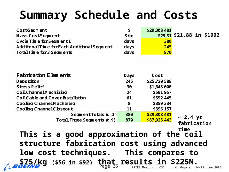
This is a good approximation of the coil structure fabrication cost using advanced low cost techniques. This compares to $75/kg ($56 in $92) that results in $225M.
Cost/Segment $ $29,308,481Mass Cost/Segment $/kg $29.31Cycle Time for Segment 1 days 380Additional Time for Each Additional Segment days 245Total Time for 3 Segments days 870
Fabrication Elements Days CostDeposition 245 $25,720,588Stress Relief 30 $1,648,000Coil Channel Machining 24 $591,957Coil Cable and Cover Installation 61 $592,445Cooling Channel Machining 8 $359,334Cooling Channel Closeout 11 $396,157
Segment Totals (d, $) 380 $29,308,481Total, Three Segments (d,$) 870 $87,925,443
$21.88 in $1992
~ 2.4 yr fabrication time
Related Documents