RESEARCH Are Vauban’s Geometrical Principles Applied in the Petrovaradin Fortress? Marija Obradovic ´ • Slobodan Mis ˇic ´ Published online: 11 September 2014 Ó Kim Williams Books, Turin 2014 Abstract There is a widespread opinion in different sources, ranging from popular to scientific, that the project of the Petrovaradin Fortress was conceived under the influence of the most important European military engineer and innovator of the time, Sebastien de Vauban. By examining the historical context as well as by comparing Vauban’s geometrical methods for determination of the fortification master line (la ligne magistrale) with Austrian plans and the actual state of the Petrovaradin fortress, especially its Wasserstadt part, we have examined how well- founded this claim is. Keywords Fortress design Star-fortress Vauban Geometrical construction Regular polygons Geometrical analysis Master line Petrovaradin Fortress Introduction L’art de fortifier ne consiste pas dans les re `gles et les syste `mes, mais uniquement dans le bon sens et l’expe ´rience (The art of fortifying does not consists in rules and systems, but only in common sense and experience) Sebastien le Prestre de Vauban (1633–1707) Controversial data regarding the origin of the Petrovaradin Fortress design and its authorship have surrounded this aspect of the fortress history for many years, ranging from scientific, popular, unofficial and colloquial accounts to legends and M. Obradovic ´(&) S. Mis ˇic ´ Department of Mathematics, Physics and Descriptive Geometry, Faculty of Civil Engineering, University of Belgrade, Bul. kralja Aleksandra 73, 11000 Belgrade, Serbia e-mail: [email protected] S. Mis ˇic ´ e-mail: [email protected] Nexus Netw J (2014) 16:751–776 DOI 10.1007/s00004-014-0205-9

Are Vauban’s Geometrical Principles Applied in the ... · PDF fileAre Vauban’s Geometrical Principles Applied in the Petrovaradin Fortress? ... [email protected] ... Are...
Mar 05, 2018
Welcome message from author
This document is posted to help you gain knowledge. Please leave a comment to let me know what you think about it! Share it to your friends and learn new things together.
Transcript

RESEARCH
Are Vauban’s Geometrical Principles Appliedin the Petrovaradin Fortress?
Marija Obradovic • Slobodan Misic
Published online: 11 September 2014
� Kim Williams Books, Turin 2014
Abstract There is a widespread opinion in different sources, ranging from popular
to scientific, that the project of the Petrovaradin Fortress was conceived under the
influence of the most important European military engineer and innovator of the
time, Sebastien de Vauban. By examining the historical context as well as by
comparing Vauban’s geometrical methods for determination of the fortification
master line (la ligne magistrale) with Austrian plans and the actual state of the
Petrovaradin fortress, especially its Wasserstadt part, we have examined how well-
founded this claim is.
Keywords Fortress design � Star-fortress � Vauban � Geometrical
construction � Regular polygons � Geometrical analysis � Master line �Petrovaradin Fortress
Introduction
L’art de fortifier ne consiste pas dans les regles et les systemes, mais
uniquement dans le bon sens et l’experience (The art of fortifying does not
consists in rules and systems, but only in common sense and experience)
Sebastien le Prestre de Vauban (1633–1707)
Controversial data regarding the origin of the Petrovaradin Fortress design and its
authorship have surrounded this aspect of the fortress history for many years,
ranging from scientific, popular, unofficial and colloquial accounts to legends and
M. Obradovic (&) � S. Misic
Department of Mathematics, Physics and Descriptive Geometry, Faculty of Civil Engineering,
University of Belgrade, Bul. kralja Aleksandra 73, 11000 Belgrade, Serbia
e-mail: [email protected]
S. Misic
e-mail: [email protected]
Nexus Netw J (2014) 16:751–776
DOI 10.1007/s00004-014-0205-9

myths retold persistently enough to enter even the official sources. There are
numerous copies of the plans of the Petrovaradin fortress (over 200 in the Austrian
State Archive) based on the built state of works, or done for a particular stage in the
reconstruction, but the original conceptual blueprint is unknown. The story of the
Petrovaradin Fortress invariably brings up the name of Sebastien le Prestre de
Vauban (1633–1707) who gained fame by improving fortification systems and
contributed significantly to the development of fortress construction techniques,
which remained dominant and admired until the twentieth century.
Vauban’s stamp on design of the Petrovaradin Fortress is given varying
importance in different sources—from bold claims that the project was his own
(Lukic 1992) (a frequent and persistent datum that can be found in most
brochures on Petrovaradin and Novi Sad), via official historical sources that his
design was developed into detailed plans by several military engineers during
Austrian reign (Markovic 1984; Gajic 2003) to unfounded, though exciting and
compelling accounts in which Austrian engineers (or Prince Eugene of Savoy
himself) ‘stole’ the design from Vauban (Milkovic 2003). However, whether and
to which extent Vauban’s doctrine was known and respected can be determined
by means of comparative analysis of the design of the fortress and Vauban’s
geometrical principles. It was our aim to apply these analyses to confirm or reject
the claim that Vauban is the actual or conceptual author of this piece of military
architecture.
The Petrovaradin Fortress: Position, Function, Significance
‘Gibraltar on the Danube’, as the Petrovaradin Fortress is often called, is the
largest and best preserved building out of 284 fortifications in Serbia
(comprising some forty fortresses and preserved fortified towers and monas-
teries) (Deroko 1964). Ever since the thirteenth century, it was a strategically
important military fortress, which purpose it will serve for the next six
centuries. It is situated on the banks of the Danube, on the rock of
Petrovaradin (Novi Sad, Serbia) from which it radiates down towards the
Pannonian basin. In its current state it is an impressive example of the
traditional European style of fortification planning and construction that was
dominant in seventeenth and eighteenth centuries and was developed under a
resounding influence of the French, Italian and Flemish schools of military
architecture. Due to gradual, evolutionary building interventions over a long
period of time, the fortress acquired its actual form in the year 1780, which
coincides with the end of the reign of Maria Theresa when the last phase of
the construction of the complex of buildings on the right bank of the Danube
was completed. It was placed under state protection in 1948, and declared a
Spatial Cultural-Historical Unit of Great Importance in 1991.
In the second half of the nineteenth century, with the Austro-Hungarian
Compromise (1867) and the weakening of the Turkish Empire, the importance of
this fortification declined, so that its purpose ceased to be strictly military. In the
twentieth century, many military buildings within the fortress became purely
752 M. Obradovic, S. Misic

civilian, housing the Museum of Novi Sad, the Historical Archive, the Academy of
Arts with accompanying studios, the Magistrate building, the Planetarium, as well
as numerous bars and restaurants. The larger half of the northern complex still
serves its military purpose. The Petrovaradin Fortress has recently become popular
as the venue of the world-famous EXIT music festival (since 2000), and it is large
enough to accommodate eleven separate stages and 200,000 people from all over
the world during the four-day event.
The Petrovaradin Fortress Complex
As can be seen from the copies of the Austro-Hungarian plans1 as well as from the
Google Earth� satellite pictures, the ground plan of the fortress resembles a comet,
with three clearly distinguishable units (Fig. 1):
1. the star-fortress, the last part of the fortress to be completed, also known as the
Lower Fortress, or Wasserstadt (Water Town). Wasserstadt comprises one-third
of the complex and is the least familiar to the public, since it has been used by
the Serbian Army for decades;
2. the body (the oldest part of the fortification, the Upper Fortress);
3. the tail, which has been altered in the meantime—the two-pointed bastion
called Hornwerk (Hornwork).
Apart from the main body, the fortress also comprised three parts that no longer
exist today:
4. Inzelschanze, the Isle Fortress, which was submerged due to the change of flow
of the Danube and construction of the Danube-Tisa-Danube canal;
5. Bruckuckschanze, the Bridgehead, on the opposite bank of the Danube;
6. a separate facility comprised of zigzag trenches (Markovic 1984), which
collapsed after the 1726 earthquake, and were lost when Majur was built
(Milkovic 2003).
All parts of the complex are united by the single outer line of defense (envelope)
consisting of interconnected fortification-defense system buildings: counterguards,
ravelins, lunets and caponiers.
Due to its regular geometrical matrix and clearly identifiable principles of
military fortification construction, the Wasserstadt in the north is the most
interesting part for the purposes of this paper in terms of geometrical analysis,
which is why we will focus on this part of the fortress. Hornwerk, the south-
stretching tail of the fortification, was the part adapted to the terrain so that it
aggressively encroaches upon the plain, thus defending the Upper Fortress on the
Rock of Petrovaradin and giving the entire fortress a stable position.
1 The maps are used thanks to the kind permission of the Historical Archive of the City of Novi Sad,
which keeps the digital record of the plans, transferred from the Archives of Vienna (Osterreichisches
Staatsarchiv) in cooperation with the City of Novi Sad, in November 2010.
Are Vauban’s Geometrical Principles Applied 753

The Early History of the Petrovaradin Fortress
Continuity of human settlements on the site of the Petrovaradin Fortress stretches
from the Middle Palaeolithic era (Mihailovic 2009) to the present. In the course of
history, up to the seventeenth century, when the current shape of the Fortress started
to emerge, different cultures occupied the Petrovaradin area, ranging from the Celts
(circa 100 B.C.), through the Romans, who built a fortification named Cusum, the
Huns (fifth century), Byzantium (when Petrovaradin, or Petrikon, as it was named at
the time, grew further in military and strategic importance), Hungary under Bela IV
(eighth century), who allowed Cistercians monks to manage the fortress, to Turkey
(late fourteenth through the fifteenth century), after which the Turkish and
Hungarian rulers alternated. In one of these periods, Hungarian archbishop Petar
Varadi, after whom both the fortress and the locality were named, invested a lot of
effort and in 1501 restored the remains of the former fortification, which was
recaptured in 1526 by the Turkish army under the command of Suleiman the
Fig. 1 Zoning of the parts of the Petrovaradin Fortress: a Austro-Hungarian plan from 1762. Image:reproduced by permission, with authors’ overlay and mapped onto identical zones (right); b the satellitepicture (Google Earth�) mapped onto identical zones. Image: 2014 CNES/Astrium (Google Earth�) withauthors’ overlay
754 M. Obradovic, S. Misic

Magnificent. Petrovaradin remained under Turkish rule until 1688, when the army
of the Austrian Empire seized the fort. This was followed by deconstruction of the
old medieval (Hungarian and Turkish) fortress, while 1692 marked the beginning of
the construction of a large, new fortress, designed according to the most modern
fortification building system of the time. The foundation stone of the modern
Petrovaradin Fortress was laid by the Austrian Duke Croy (Charles Eugen de Croy)
in 1692 (Gavanski 1988). It is, therefore, evident that the construction started in
Vauban’s lifetime, which was most likely enough for certain texts2 to identify him
as the author of the plans.
Construction of the Petrovaradin Fortress 1692–1780
The building of the fortress lasted for 88 years, stopping and starting, and spanned
the reigns of five Austrian emperors: Leopold I, Joseph I, Charles VI, Maria Theresa
and (to some extent) Joseph II. The construction started in the southern side of the
Upper Fortress, where the first of many bastions was built upon the orders from the
Habsburg emperor Leopold I (the Leopold’s Bastion) into which a large amount of
material from the medieval fortress was built (Fig. 2a). The work was interrupted in
1694 because of the Turkish army attack. In the same year, the Austrians built the
triangular Bridgehead on the other side of the Danube, around which the city of
Novi Sad was later built.
After the Karlovac peace treaty in 1699, the Turks finally left the area, but the
Petrovaradin Fortress still kept its strategic importance. In the same year, engineer
colonel Count Mathias Keyserfeld made the first blueprint for the fortress, while the
next was done by the engineer colonel Count Luigi Ferdinando Marsigli
(1659–1730). Engineer colonel Michael Wamberg was in charge of execution and
when he died in 1793, engineer colonel Gisenbir succeeded him and remained in
charge till 1728 (Markovic 1984).
In the relatively calm before 1728 (briefly interrupted by the outbreak of Austro-
Turkish war between 1716 and 1718, when one of the decisive battles was fought on
the very sides of the hill of Petrovaradin under the command of Prince Eugene of
Savoy) the construction of the Upper Fortress was continued along with the
modifications of the master line, ravelins and counterguards. It was in this period
that the Wasserstadt was partially constructed, together with Bruckenschanze (the
triangular trench of the bridgehead on the left bank of the Danube), the
entrenchment of Petrovaradin, quadrilateral fortification, Inselschanze, and finally
Hornwerk (the two-horned fortification facing south, the most endangered point).
Towards the Danube, in front of the Hornwerk, Kronwerk (Crownwork) was built
(Figs. 2b, 3).
The Treaty of Belgrade in 1739 brought a more permanent peace for Austria and
Turkey after many decades. The construction of the Petrovaradin Fortress was
2 Truth be told, these are mainly commercial and promotional texts which flooded the news thus leading
the public to take this information for granted; but historical publications, as well; see for example (Lukic
1992: 37; Milkovic 2003: 25).
Are Vauban’s Geometrical Principles Applied 755

resumed after nearly three-decade-long interruption (from 1726 to 1753). As can be
seen in Fig. 4, many outworks were torn down, so that only the corpus of the
fortress delineated by the master line and the several ravelins and counterguards
remained.
The final construction phase and the completion of the monumental building
started in 1753 and lasted until 1780. Wasserstadt was enlarged to encompass the
area of Podgradje (the Lower Town),3 stretching to what is today the Gate of
Belgrade. Extensive construction work changed not only the appearance of the
Wasserstadt, but of the Upper Fortress, Bruckenschanze and Hornwerk as well,
while the ramparts of Kronwerk were torn down (Fig. 5). Wasserstadt underwent
the greatest alterations, receiving a new geometrical matrix, evolving from the
Fig. 2 The old maps of the Petrovaradin Fortress: a the status of works in 1694. Image: public domain(Wikipedia, http://sr.wikipedia.org/wiki/Lanonera:1694_m.jpg); b the ground floor plan of the Fortress inthe period 1699–1721 with the display of trenches in front of the Hornwerk. Image: reproduced bypermission
3 The part of Petrovaradin which used to be the core of the fortress complex. As an architectural unit, it
has preserved its authentic form and the characteristics of the particular ambience and the spirit of the
time in which it was built.
756 M. Obradovic, S. Misic

initial deltoid shape into a star-like formation based on a pentagonal pattern. The
urban matrix formulated in Wasserstadt at the time, has been preserved until today.
At the end of the eighteenth century, battles for this fortification, as well as for
the others in the north of the Balkan Peninsula, ceased. When underground corridors
and some smaller buildings were finished in 1780, the Fortress acquired its final
appearance, which has been preserved till today.
The Principle of Military Fortification Building in Seventeenth and EighteenthCentury
The need to switch to new form of fortification construction and new geometrical
patterns emerged when it became evident that the previous design was deficient in
relation to new warfare techniques that used gunpowder. The circular shape of
medieval forts proved to be vulnerable to damage caused by cannon fire aimed at
vertical walls. Furthermore, if troops managed to reach the ramparts, they
threatened the fort from the safety of the ‘dead ground’, as the defenders could
not aim from the surrounding parapets due to blind spots (Bevilacqua 2007).
In contrast, the new type of fortification had a pointed form which resulted from
geometrically calculated distribution of a series of arrow-shaped bastions (often
taking the form of a star, Fig. 6), specially designed to cover both each other and the
trench in front. In order to withstand cannon balls, defensive ramparts were made
thicker and lower. Although this facilitated climbing up the walls, the trench itself
Fig. 3 The Petrovaradin Fortress in 1720. Legend: yellow line contour of the complete fortification withthe outworks; shaded pink outworks, which were torn down later; broken red line contours of the fortresswalls, master line; solid red line master lines of satellite fortifications on the left Danube bank. Image:reproduced by permission, with authors overlay
Are Vauban’s Geometrical Principles Applied 757

was widened, so that the attacking infantry was still under fire from several
positions including the side bastions. The exterior side of the trench was usually
characterized by a slight glacis in order to deflect cannon balls aimed at the lower
part of the main wall (curtain). Onto the basic body of the fortress different works
were still being added, such as ravelins, arrow-like triangular fortifications
(detached from the fortress itself), tenailles, which were detached as well, and
positioned just outside the curtain, two-pointed formations without the bastion,
hornworks, three-pointed formations with the bastion, crownworks, even detached
fortresses, added as outworks to protect the main wall from gunfire and provide
additional defense positions (Holmes 2004).
In this way, many various additions to the main corpus of the fortress emerge,
with special purposes and equally special terminology: ravelins, redoubts,
bonnettes, lunettes, tenailles, tenaillons, counterguards, crownworks, hornworks,
curvettes, fausse brayes, scarps, cordons, banquettes, counterscarps (Townshend
2005). Some of these works, present in the Petrovaradin Fortress, are shown on
Fig. 7. These constructions were built from different materials, mostly soil, and
covered in brick, which does not shatter under cannon fire like stone walls do, but
absorbs the impact.
Defense of these fortifications gravitates towards the ‘bastion’, a four-sided
addition to the fortress protruding from the ramparts. On two of its sides, cannons
could fire over the glacis onto specially shaped open zones between the fortress and
Fig. 4 The Petrovaradin Fortress in 1750: yellow line contour of the complete fortification with theoutworks; shaded pink outworks, which were torn down later; broken red line contours of the formermaster line; solid blue line contours of the master line of the newly constructed fortification. Image:reproduced by permission, with authors overlay
758 M. Obradovic, S. Misic

the surrounding area, so that cannons from the sides of the bastion could neutralize
the frontal attack by enfilade. The bastions were placed at the angles of the fort in
such a way that the defenders could cover all the fortification walls stretching to the
next bastion, including the bastion itself. The number and design of the bastions
varies depending on the shape and size of the fortification. The most common shape
of smaller fortifications and separated citadels is that of a pentagram. In larger
fortified towns the military engineer planned the position and shape of each bastion
by using geometrical calculations (De Ville De Ville 1641; Du Fay 1691; Marolois
1627; Pagan 1668).
Between the bastions stretched the curtain, the main fortress wall. Just like the
bastion, it had a thoughtfully designed profile that prevented the attacker from
Fig. 5 The new shape of the master line and the outworks in the plan of Petrovaradin Fortress1760–1762. Yellow line contour of the complete fortification with the outworks; shaded pink outworks,which were torn down later; broken red line contours of the former master line; solid blue line contours ofthe master line of the newly constructed fortification. Image: reproduced by permission, with authorsoverlay
Fig. 6 Comparison of lines of fine in a medieval castle with circular towers and a plan with pointedbastions. Image: authors, after (Duffy 1996: 10)
Are Vauban’s Geometrical Principles Applied 759

damaging the material it was built from. From the attacker’s point of view, only the
ramparts above the glacis were visible. The glacis side facing the fortress ended in a
palisade which protected the covered road, along which the defenders could move,
and then fell steeply into a deep wide entrenchment which could, for purposes of
additional defense, be filled with water (Holmes et al. 2004).
Fig. 7 The terms for particular works on the fortification, drawn according to the 1764 PetrovaradinFortress plan: a detail of the Wasserstadt; b detail of the Hornwerk segment (shown in Fig. 5); c segmentof the cross section of the Petrovaradin Fortress illustrating the terms for particular works on thefortification. The drawing is based on the cross section shown on the 1720 plan of the PetrovaradinFortress. Images: Authors
760 M. Obradovic, S. Misic

Star Fortresses: An Example of Regular Polygonal Construction Pattern
The radial distribution of the bastions according to a regular geometrical pattern
resulted in the star-shaped fortification, star fortress or trace italienne, which
emerged in the middle of the fifteenth century in Italy with the transition to angular
fortification forms, as mentioned. The model of a regular polygon was ancestral
from the Renaissance period and Utopian ‘ideal city’, the project of urban
settlement that was based upon the abstract principles and regular geometrical
schemes. The idea of utopian cities had existed almost as long as cities themselves,
and many of them reflected the aspirations for political reforms and social
reorganization, suggesting by its perfect geometrical form the values they pursued.
Similar concepts can be identified in various epochs, from Plato and his Republic,
whose ideal city ‘‘was one which mirrored the cosmos, on the one hand, and the
individual on the other’’ (London 2013), to St Augustine, Sir Thomas More, Francis
Bacon, Tomasso Campanella, Charles Fourier, James Buckingham, Etienne Cabet
and others (Jones 1960). These ideas were raised to the level of principles by the
famous Renaissance architect and polymath Leon Battista Alberti, who in his
treatise De re aedificatoria developed, starting from Vitruvius’s theories, the rules
of planning and construction of an ideal city based on proportion, firmitas (solidity),
utilitas (functionality) and venustas (beauty).
Using this concept of ideal geometry, the designers of star fortresses developed a
regular polygonal urban matrix of an ‘ideal city’, adding to it the ‘halo’ in the shape
of single (or multiple) star-shaped polygons (most frequently identical, scaled and
rotated). The newly obtained star was not the result of the stellation of the initial
polygons, but rather a complex polygon created by adding equilateral triangles onto
the sides of the basic polygon, which was accompanied by radial distribution of
outworks, appropriate number of counterguards, ravelins, redoubts, etc., designed in
accordance with the rules of defense and needs of such a fortification. The angular
geometry of the bastion fits perfectly into the star-shaped form that enveloped the
central polygonal core of the fortification.
Several examples of such fortifications, with regular polygonal matrices, from
four to ten-sided, are given in Fig. 8.
Star fortresses were a lasting model, widely used all over Europe in the sixteenth,
seventeenth and eighteenth centuries. The largest contributions to improved
construction of these fortresses were made in the seventeenth century by Menno
van Coehoorn, Blaise Francois Pagan and especially Sebastien le Prestre de Vauban,
one of Louis XIV’s military engineers. The star fortress model was predominant
until well into the nineteenth century, when the development of the explosive
grenade changed the nature of fortification defense. However, in contrast to regular
patterns of star fortresses, fortresses whose plans were irregularly shaped were also
built, as the plans had to be adjusted to the conditions of a specific terrain.
Furthermore, most fortresses were not ‘lucky enough’ to be built on ideal, flat
ground, so that even those which contained a star-shaped citadel within the complex
had to be combined with a chain of free-form walls.
The Petrovaradin Fortress, with one part on the rock of Petrovaradin and the
other in the plain, in accordance with le bon sens et l’experience as in the quote
Are Vauban’s Geometrical Principles Applied 761

762 M. Obradovic, S. Misic

from Vauban that opened this paper, is designed and built using a combined system
that unites the regular geometry of the star-shaped polygon of the Wasserstadt with
the free-form plans of the Upper Fortress and the Hornwerk.
The Principles of Vauban’s Military Architecture
Historically speaking, Sebastien Le Prestre de Vauban (1633–1707) is primarily
famous not only as the inventor of skilful and carefully designed siege systems
(Ostwals 2006),4 but also as one of the most prominent fortification designers, who,
thanks to his innovations and the doctrine of construction of effectively defended
fortifications, excelled as one of the most significant military engineers of the period
(Langinis 2003; Lepage 2009). Apart from introducing some new ideas and variations
of the established manner of fortress building, Vauban is considered the first military
engineer to have designed a fortress adjusted to the terrain. Respecting the symmetry
inspired by classical principles of the aesthetics that governed the fortress design of the
time, in the words of Christoper Duffy, ‘‘Vauban’s fortress stretches over a wavy
terrain, encompassing it as though ‘embracing it’’ (Duffy 1985: 82–84).
By skilful application of geometrical principles and geometrical constructions,
Vauban achieved not only the capacity for effective defense in the fortresses he
designed, but a certain artistic quality as well, which most likely was not even
deliberate, so that many historians and biographers of today consider him not only
an architect, but an artist as well. Thus, the famous architect Jean Nouvel noticed
that ‘Vauban’s fortresses were the early form of land-art and morphing’, without
(Vauban) being aware of it (Nouvel 2007).
As a student, excelling at mathematics and technical drawing, Vauban was
considerably influenced by Rene Descartes, which led him to pay special attention
to geometrical principles in fortress design. The procedure which brought him
architectural renown strikes a fine balance between linear and nesting geometry
(Helie 2009). Although Vauban did not invent the star fortress, he used it widely and
b Fig. 8 Examples of military fortifications with regular polygon in their bases. a Saint Martin de Re, 17thCentury Map, (France) after the fortifications of Vauban, 1722, (Public domain) (http://commons.wikimedia.org/wiki/File:Saint_Martin_de_Re_17th_century_map.jpg); b Fortification of Huningue,France, Author: Sebastien Le Prestre de Vauban (1679–1681) (Public domain) http://en.wikipedia.org/wiki/File:Fortification_of_Huningue.jpg); c Cascale Monferrato Map, (Italy) Author: unknown (Publicdomain) (http://commons.wikimedia.org/wiki/File:Casale_Monferrato_map_%28018_009%29.jpg);d Fortification plan of Coevorden, Netherlands, Author: Markus Schweiss (Public domain) (http://upload.wikimedia.org/wikipedia/commons/thumb/6/6a/Coevorden.jpg/240px-Coevorden.jpg); e Plan of Cita-delle Neuf-Brisach, France, Author: Sebastien Le Prestre de Vauban (Public domain) (http://commons.wikimedia.org/wiki/File:Plan_citadelle_Neuf_Brisach.jpg); f 17th century map of the city of Palmanova,Italy, Author: Unknown (Public Domain) (http://commons.wikimedia.org/wiki/File:Palmanova1600.jpg);g Wilhelm Dilich, copper engraving on paper, 1641. (Peribologia Seu Muniendorum Locorum RatioWilhelmi Dilichii) Author: Wilhelm Dilich (Public Domain) (http://commons.wikimedia.org/wiki/File:Fotothek_df_tg_0008838_Architektur_%5E_Geometrie_%5E_Festungsbau_%5E_Hornwerk_%5E_Kronwerk.jpg)
4 These systems introduced circumvallation and contravallation lines, as well as a systematic approach to
deployment of parallel trenches in order to capture the enemy’s fortress.
Are Vauban’s Geometrical Principles Applied 763

developed its form to functional perfection. The improvements he introduced in
fortress design were based on several innovations:
1. application of the star-fortress form, whenever the conditions of the terrain
allowed it;
2. adjustment of the geometry of the fortress to the terrain;
3. a geometrical approach to positioning and shaping of bastions, which
introduced certain changes in the scheme and construction of distances
between the primary points of the master line;
4. remodelling the outworks: placing tenailles in front of the curtain, with ravelins
and redoubts in front of them;
5. principles of construction and positioning of military facilities within the
fortification, among other things suggesting that special purpose facilities
(powder magazines, mills, stockrooms) be placed in the heart of the bastion.
Geometrical Principle of Master Line Modelling According to Vauban’sSystem
As in the work of many other military engineers from the end of sixteenth till the
beginning of eighteenth century, such as Jean Errard (cf. 1554–1610) and Blaise
Francois Pagan (1603–1665), Vauban’s system of fortification design has geomet-
rical principles of master line formation as its starting point. This regulatory line
responds to the outer borders of all the bastion fronts, including all bastions’ sides
and faces, curtains not excluded. It is defined by the geometry of the bastions, where
the face and the side determine the shoulder of the bastion. Between the sides of two
neighbouring bastions stretches the curtain, whose regulation line aligns with the
sides of the inner polygon, on the vertices of which the gorges of the bastion are
situated (Fig. 9a). The master line of regular fortresses must be inscribed in a circle,
which is divided by the number of necessary strongholds (bastions), thus providing
the vertices of the circumscribed regular polygon of the ground plan and
determining the position of the bastions. Vauban defined the rules for determination
of linear and angular parameters for circumscribed polygons from tetragon to
decagon, not excluding the possibility of creating fortresses on even larger bases,
should the need arise (Du Fay 1691).
The radius of the circumcircle drawn around the inner polygon is called the inner
radius (R1, segment OP in Fig. 9b), while the radius of the circumcircle of the outer
polygon is called outer radius (R2, segment OQ in Fig. 9b). The inner radius is part
of the outer radius starting from the centre of the polygon O and ending in the
bastion gorge (P). The capital line (la ligne capitale) is the other portion of the outer
radius, i.e., the extension of the inner radius starting from the bastion gorge (P) and
ending in the vertex of bastion’s interior angle (Q).
According to the seventeenth and eighteenth century engineers, the design of the
master line is of utmost importance when designing fortifications. Dimensions of the
master line elements are dictated by the range of the musket or the arquebus
(Jacquot et al. 2011). The line of curtain defense must stretch from the vertex of the
764 M. Obradovic, S. Misic

bastion shoulder (i.e., vertex A of the circumscribed polygon, Fig. 10) to the vertex
(N) of the side of the opposite bastion. For the purpose of more effective defense,
the shoulder angle can be reduced, so that the line of the bastion face would not
match the line of curtain defense.
Vauban’s system of tracing the master line is based on thoroughly calculated
geometrical construction whose procedure is shown in Fig. 10.
Vauban divides the AB side of the circumscribed polygon of the master line into
eight segments for a square, seven segments for the pentagon and six segments for
the hexagon and larger polygons (Du Fay 1691). Thus divided, one segment of the
side is transferred onto the perpendicular from the center of the polygon side, thus
obtaining segments AC and BC, which present directions of the lines of defense.
The length of the bastion face (AE = BF) is always 2/7 of the side AB. The
Fig. 9 a Elements of masterline; b master line of a regularfortification with hexagonalbase. Image: authors
Are Vauban’s Geometrical Principles Applied 765

intersection of the arc (r = AF = BF) and defense lines gives Vauban in this
construction the end points of bastion sides (EM = FN) and the length of the curtain
MN.
In contrast to Vauban, some authors, such as Errard, Pagan, Louis de
Cormontaigne (1695–1752), Antoine de Ville (1596–1656), Jacques Ozanam
(1640-1717), and Guillaume Le Blond (1704–1781), rely on pre-set dimensions of
the elements and master line angles, depending on the size of the base polygon of
the fortification (Jacquot et al. 2011; Table 1).
We will single out the method of Vauban’s precursor, Pagan, who in Les
Fortifications de Monsieur le Comte de Pagan (1668) defines the length of master
line segments for three selected groups of fortifications. The classification is based
on the length of the side of the initial circumscribed polygon (AB = 200 toises;
AB = 180 toises;AB = 160 toises).5 The construction of master line fragments
according to Pagan’s method is shown in Fig. 11.
The beginning of the construction procedure is the same as Vauban’s, the
segment DC is a perpendicular from the midpoint of the side AB of the
circumscribed polygon of the fortification base. All the other values are obtained by
applying pre-defined values for individual sections of the master line. We should
emphasize that in Les fortifications (1668), Pagan suggested the given values for
fortifications with pentagonal to dodecagonal bases, paying special attention to
square-based fortifications. The suggested values of master line segments are shown
in Table 1.
Does Wasserstadt Geometry Reflect Vauban’s Principles?
In the light of the five geometrical principles mentioned above, which can be
regarded as the stamp of Vauban’s influence, we will analyse one part of the
Petrovaradin fortress, Wasserstadt, to determine whether it incorporates or violates
these rules.
Fig. 10 Construction of the fragment of master line of fortification with regular hexagonal baseaccording to Vauban’s method. Image: authors
5 One toise was exactly 6 pieds (feet) (about 1.949 m) in France until 1812.
766 M. Obradovic, S. Misic

The analysis and reconstruction of the geometrical matrix of the ground plan of
the Wasserstadt (using the 1764 plan) accompanied by comparison of these
measures and proportions with the satellite pictures (Fig. 12), clearly shows a
pentagonal pattern, upon which further modelling of the complex network of
outworks is based, forming several five-pointed star-shaped polygons. It is also
evident that none of these polygons are either finished or perfectly regular, in spite
of the obvious tendency to respect the scheme of the regular polygon. We can see
that two (II6 and III) out of five vertices of the regular interior pentagon are located
exactly in the gorges of the two most protruding bastions, which were most
accurately calculated, while bastions I and IV do not follow the identical principle,
whereas the bastion V is partially immersed into the Upper Town platform.
In order to observe the regularities of these polygons more accurately, we have
determined the axes of symmetry radiating from the point O, which is the centre of
the circumcircle of this regular pentagon, passing the most protruding vertices of the
Fig. 11 Construction of master line fragment according to Pagan’s method by applying lengths fromTable 1. Image: authors
Table 1 Lengths of the master line fragments according to Pagan’s method
1t. = 6p.
= 1.949 m
n = 4 5 B n B 12
AB 200t. 180t. 160t. 200t. 180t. 160t.
CD 27t. 24t. 21t. 30t. 30t. 30t.
AE = BF 60t. 55t. 45t. 60t. 55t. 50t.
CM = CN 38t. 33t. 33t. 37t. 32t. 27t.
MN 73t. and 2p. 63t. and 4p. 63t. and 5p. 70t. and 5p. 60t. and 4p. 50t. and 4p.
EM = FN 22t. 19t. and 1p. 18t. and 3p. 24t. and 2p. 24t. 23t. and 2p.
AN = BM 141t. and 4p. 126t. and 1p. 115t. and 5p. 141t. and 2p. 126t. and 5p. 112t. and 3p.
Angle
ACB
149�60 150�80 150�360 146�360 143�60 138�540
6 The bastions by number are: I—Bastion Benedicti; II—Bastion Francisci; III—Bastion Maria Theresa;
IV—Bastion Joseph; V—Bastion Caroli.
Are Vauban’s Geometrical Principles Applied 767

bastions (I–V). It is noticeable that the vertices of the counterguards are also aligned
along these axes, with certain insignificant aberrations. Similarly, using the most
protruding vertices of the bastions II and III we can form the side of the
circumscribed pentagon, concentric with the previous one, with (slightly declined)
parallel sides. The vertices of bastions I, IV and V respect their positions dictated by
the geometry of the pentagon, with smaller aberrations (i.e., IV and V deviate by 3�,
and 4�, respectively, while I is relatively precisely positioned). Separate schematic
drawings of the above-mentioned polygons, the Wasserstadt’s master line, circum-
circles around pentagon and dimensions of these figures7 are given in Fig. 13.
Fig. 12 Geometrical regularities of star fortress observed in Wasserstadt: a, left according to Austro-Hungarian plan from 1764. Image: reproduced by permission, with authors’ overlay; b, right on thesatellite image of Petrovaradin. Image: CNES/Astrium 2014 (Google Earth�), with authors’ overlay
7 Note: In geometrical drawings certain simplification and idealization of the actual state was made by
ignoring and disregarding lesser imprecisions, to obtain a scheme suitable for analysis and observation.
768 M. Obradovic, S. Misic

The genesis of the star-shaped polygon, which emerges as a halo around the main
ramparts of the fortress (Fig. 14) can be followed in Figs. 15, 16, 17, 18.
By overlapping of obtained star KQLRMSNTPU with the bases of the three
pentagonal-based star-shaped citadels designed by Vauban (The Fortress of Lille,
Fort Tournai and Fortification of Hunungue, Fig. 19), we have found noticeable
aberrations. Since the principle of the master line formation dictated the shape of the
ground plan, we observe differences in the shape of the outer star, as well as in the
radius of the circle k0 (in dark blue) on which the vertices of the star are situated. We
concluded that there is no necessary match, which suggests that this geometrical
principle of outer star formation is not Vauban’s pattern.
Analysis of the Geometrical Calculation of the Fragments of Wasserstadt’sMaster Line
Proceeding with the examination of geometrical congruencies between master line
construction of the Wasserstadt and Vauban’s principles, we made a comparison to
Vauban’s, as well as Pagan’s construction (shown in Figs. 20, 21) to determine
whether Vauban’s construction was the model for the master line between bastions
II and III and the Wasserschtadt, or if some other procedures and influences also
played their part.
When Vauban’s construction is applied, some overlapping between the
constructed and the existing bastion faces are observable, but there is also a
significant deviation in the position of the curtain line. The surface that
demonstrates aberration between the ideal master line according to Vauban and
the actual line in Wasserstadt is shown in blue in Fig. 20.
For Pagan’s construction, the linear dimensions from Table 1 are adjusted to the
actual side length of the circumscribed polygon, which is 333 m (shown in Table 2).
Pagan himself in his Les fortifications recommends proportional scaling of the given
linear dimensions of master line segments, depending on the measure by which the
actual side of the circumscribed polygon deviates from the dimension given in
Table 1.
It was observed that the aberrations (blue surfaces in Fig. 21) of the actual master
line of the Wasserstadt, from the line obtained by construction, are in this case
significantly smaller, which suggests that military engineers who designed the plan
respected the older method of Pagan, or at the very least, that in this segment of the
design of Wasserstadt’s ground plan Vauban’s influence was inessential.
When it comes to the organization of the outworks, Pagan’s influence is
observable once again, especially considering the fact that counterguards, which are
not characteristic of Vauban’s method, are present, while characteristic teneilles and
redoubts are absent. However, in terms of positioning of military facilities within
the master line, echoes of Vauban’s doctrine are noticeable, particularly in
placement of powder magazines within the bastions.
After all the insights from previous sections, Table 3 shows an overview of
principles of Vauban’s method present in the Petrovaradin Fortress in order to
confirm or reject the hypothesis that he was the author of this fortification. Out of
Are Vauban’s Geometrical Principles Applied 769

seven principles we examined, as many as five do not adhere to Vauban’s doctrine.
In short, the result of the research indicates that Vauban, who is known to have
never visited the Petrovaradin Fortress, did not significantly influence the shaping of
its ground plan (which may be a disappointment to many tourist guides who eagerly
associate the famous name to this building).
Fig. 13 Inscribed and circumscribed pentagon in the Wasserstadt’s ground plan with dimensions andaberrations from the ideal geometrical pattern. Image: authors
Fig. 14 Star-shaped polygons in the geometry of Wasserstadt’s plan. Image: reproduced by permission,with authors’ overlay
770 M. Obradovic, S. Misic

Conclusions
Analysing the available sources and comparing the geometry of the Wasserstadt of
Petrovaradin Fortress to the schemes and principles of Vauban’s method, we have
Fig. 15 The initial star AFBGCHDIEJ (in red) is obtained as a complex concave polygon, formed byadding isosceles triangles, approximate to equilateral, onto the pentagon sides. The star I–II–III–IV–V (inpink) is obtained by inscription into the interior pentagon, while its sides are actually lines of defense. Theblue circle (k) passes the midpoints of the sides of the star I–II–III–IV–V. Image: authors
Fig. 16 When we gyrate (rotateby \180�) the starAFBGCHDIEJ, we obtain thestar A0F0B0G0C0H0D0I0E0J0
(broken red line) with interiorvertices F0G0H0I0J0. The starA0F0B0G0C0H0D0I0E0J0 is thenscaled by factor n ¼ K=R1
(where K is the radius of thecircle k, and R1 is the interiorradius) into the starKQLRMSNTPU, so that itsinterior vertices QRSTU belongto the circle k. Image: authors
Are Vauban’s Geometrical Principles Applied 771

concluded that there is not enough evidence to prove that the great French military
architect was the author the project of the Petrovaradin fortress, in facts or in
concept, although some influences of his doctrine are noticeable. The design of the
fortress, created by the military engineers Keyserfeld, Marsigli, Wamberg, and
Gisenbir—all of whom, unfortunately, are less famous than Vauban—is a
compilation of various influences, which were modern at the end of the seventeenth
into eighteenth and throughout the eighteenth century, having proven effective in
the military engineering of Middle Europe. We can say that, as the research has
shown, Blaise Pagan, for example, had an equal or even greater influence on the
Fig. 17 Next, interior verticesQRSTU of the newly obtainedstar are adjusted for the value m,so that they are positionedprecisely on the interiorpentagon sides. The valuem = r2 - K, where r2 is theradius of the incircle of thelarger pentagon (I–II–III–IV–V).Image: authors
Fig. 18 The new starKQLRMSNTPU (in yellow)exactly matches the star that canbe circumscribed around outercounterguards, in ideal draft. Inreality, the outworks located invertices of the starKQLRMSNTPU had to undergocertain modifications due toproximity of the Danube bank,so that the ideal geometricalmatrix in three out of five of thestar-shaped polygon verticeswas violated. Image: authors
772 M. Obradovic, S. Misic
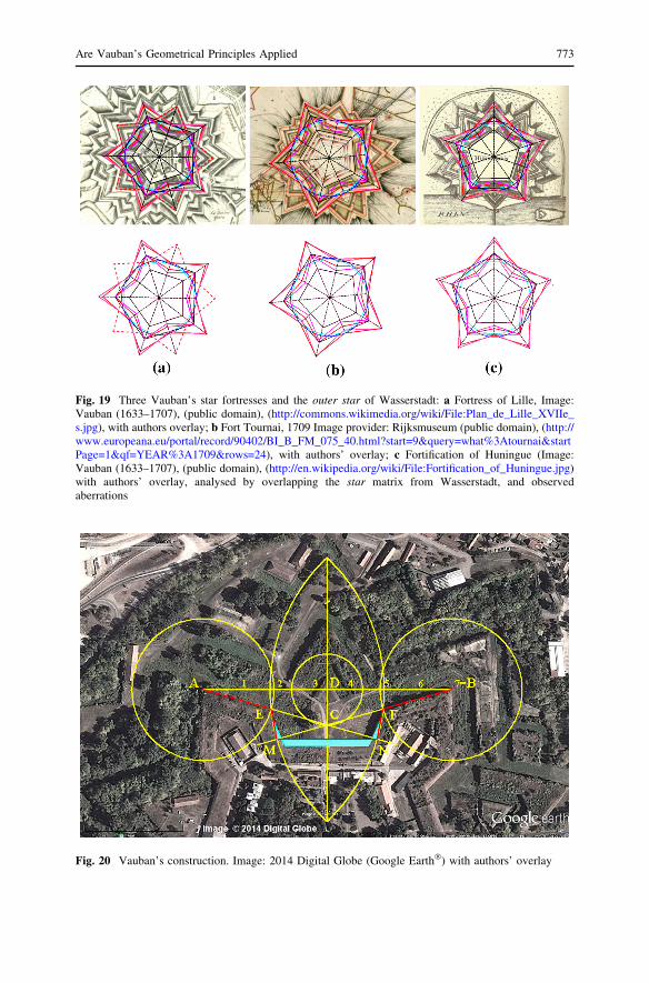
Fig. 19 Three Vauban’s star fortresses and the outer star of Wasserstadt: a Fortress of Lille, Image:Vauban (1633–1707), (public domain), (http://commons.wikimedia.org/wiki/File:Plan_de_Lille_XVIIe_s.jpg), with authors overlay; b Fort Tournai, 1709 Image provider: Rijksmuseum (public domain), (http://www.europeana.eu/portal/record/90402/BI_B_FM_075_40.html?start=9&query=what%3Atournai&startPage=1&qf=YEAR%3A1709&rows=24), with authors’ overlay; c Fortification of Huningue (Image:Vauban (1633–1707), (public domain), (http://en.wikipedia.org/wiki/File:Fortification_of_Huningue.jpg)with authors’ overlay, analysed by overlapping the star matrix from Wasserstadt, and observedaberrations
Fig. 20 Vauban’s construction. Image: 2014 Digital Globe (Google Earth�) with authors’ overlay
Are Vauban’s Geometrical Principles Applied 773

Fig. 21 Pagan’s construction. Image: 2014 Digital Globe (Google Earth�), with authors’ overlay
Table 2 Lengths of the
Wasserstadt’s master line
fragments according to Pagan’s
method
n = 5
AB 333,00 m
CD 58,76 m
AE = BF 102,83 m
CM = CN 57,79 m
MN 107,74 m
EM = FN 46,36 m
AN = BM 233,62 m
Angle ACB 141�
Table 3 The presence of
Vauban’s system characteristics
in the Petrovaradin Fortress
Characteristics of Vauban’s system (?) existent
(-) nonexistent
Coincidences of star-patterns (-)
Adjustment to the terrain (?)
Geometry of master line (-)
Tenailles (-)
Geometry of Ravelins (-)
Redoubts (-)
Works within the master line (?)
774 M. Obradovic, S. Misic

shape and organization of the Petrovaradin Fortress, since the Wasserstadt bastions
are constructed in a manner much closer to his principles. Apart from that, the
influence of the Renaissance ideal city and the need to adjust to the actual terrain,
largely contributed to the form of the ground plan and the overall appearance of the
fortress. Although the fact remains that these two characteristics also figure in
Vauban’s designs, and allowing for the partial influence, it is remarkable that the
outworks so characteristic of his work, are absent. To summarize, it cannot be
claimed that the project was done by, or even modelled upon Marquis Vauban, since
congruencies with his principles and construction doctrine do not prevail. We hope
that this paper has shattered some of the persistent myths and brought one of the
most freely interpreted chapters in the chronicles of the Petrovaradin Fortress closer
to scientific truth.
Acknowledgments The research is supported by Ministry of Science and Education, Republic of
Serbia, under the project No. III 44006, ‘‘The development of new information-communication
technologies, using advanced mathematical methods with applications in medicine, energy, e-governance
and the protection of national heritage.’’
References
Bevilacqua, Marco G. 2007. The Conception of Ramparts in the Sixteenth Century. Nexus Network
Journal 9, 2: 249–261.
Deroko, Aleksandar. 1964. Medieval Castles on the Danube. Belgrade: Turisticka stampa.
De Ville, Antoine. 1641. Les Fortifications du Chevalier Antoine de Ville tholosain, avec L’ataque & la
Defence des Places. Lyon: Chez Philippe Borde.
Du Fay (Abbe). 1691. Maniere de fortifier selon la methode de Monsieur de Vauban avec un traite
preliminaire des Principes de Geometrie (2nd enlarged ed.). Paris: La Veuve de Jean-Baptiste I
Coignard et Jean-Baptiste Coignard Fils.
Duffy, Christopher. 1985. The fortress in the age of Vauban and Frederick the Great 1660–1789.
London: Routledge & Kegan Paul.
Duffy, Christopher. 1996. Fire & Stone: The Science of Fortress Warfare, 1660–1860. London: Castle
Books.
Gajic, Radenko. 2003. Petrovaradinska tvrdava—Gibraltar na Dunavu. Sremski Karlovci: Kulturni
centar Karlovacka umetnicka radionica
Gavanski, Djordje. 1988. Petrovaradinska tvrdjava. Novi Sad: Muzej grada Novog Sada.
Helie, Mathieu. 2009. The Genesis of Complex Geometry, Rediscovering Urban Complexity, Emergent
Urbanism. http://emergenturbanism.com/2009/06/21/the-genesis-of-complex-geometry.
Holmes, Richard, Charles Singleton, and Spencer Jones. 2004. The Oxford Companion to Military
History. Oxford: Oxford University Press.
Jacquot, Kevin, Christine Chevrier, and Gilles Halin. 2011. Study of the Fortification of old scale models
in order to automate their 3D modelling. Digital Aids to Design Creativity-eCAADe 29(2011):
967–976.
Jones, Barclay. 1960. Prolegomena to a study of the aesthetic effect of cities. The Journal of Aesthetics
and Art Criticism 18(4): 419–429.
Langinis, Janis. 2003. Conserving the enlightenment, french military engineering from Vauban to the
revolution. Cambridge: MIT Press.
Lepage, Jean-Denis G. G. 2009. Vauban and the French Military under Louis XIV: An Illustrated History
of Fortifications and Strategies. Jonathan’s Reviews. Jefferson: McFarland &Company Inc.
London, Scott. 2013. The ideal city. http://www.scottlondon.com/articles/idealcity.html.
Lukic, Milos. 1992. Petrovaradin u proslosti. Novi Sad: Istorijski muzej Vojvodine i Institut za istoriju
Markovic, Zivko. 1984. Novi Sad i Petrovaradin. Novi Sad: Muzej grada Novog Sada.
Marolois, Samuel. 1627. Fortification ou Architecture militaire tant offensive que defensive. Amsterdam:
Published by Ian Ianssen.
Are Vauban’s Geometrical Principles Applied 775

Mihailovic D. 2009. Middle Palaeolithic Settlement at Petrovaradin Fortress, Petrovaradin Edition, vol.
II, Novi Sad: The City Museum of Novi Sad.
Milkovic, Veljko. 2003. Petrovaradin i Srem—Misterija proslosti. Novi Sad: Drustvo za popularizaciju
nauke.
Nouvel, Jean. 2007. Preface. In Vauban l’intelligence du territoire, ed. Martin Barros, Nicole Salat, and
Thierry Sarmant. Paris: Chaudun.
Ostwald, Jamel M. 2006. Vauban under siege: engineering efficiency and martial vigor in the war of the
Spanish succession. Leiden: Brill.
Pagan, Blaise Francois de. 1668. Les fortifications de Monsieur le comte de Pagan: avec les theoremes
sur la Fortification. Brussels: Francois Foppens.
Townshend, Charles. 2005. Oxford history of modern war. Oxford: Oxford University Press.
Marija Obradovic associate professor, graduated in Architecture at the University of Belgrade in 1989,
and has been employed in Faculty Civil Engineering at the University of Belgrade from 1991, teaching
descriptive geometry and computational geometry. She took her Ph.D. in 2006 with a thesis: ‘‘Toroidal
Deltahedra with Regular Polygonal Bases’’. She has participated in several Serbian projects dealing with
the development of technology and digitizing of national heritage, including the application of geometry
and visualization. In addition, she authored over fifty scientific papers published in national and
international journals and proceedings of scientific conferences, dealing with various fields of geometry,
especially with polyhedral structures in architecture and engineering. She is a member of International
Society for Geometry and Graphics (ISGG), and the Serbian Society for Geometry and Graphics
(SUGIG), chaired by since June 2014.
Slobodan Misic assistant professor, graduated in architecture from the University of Belgrade in 1993,
and has been employed in the Faculty of Civil Engineering at the University of Belgrade since 1996,
teaching descriptive geometry and computational geometry. He took his Ph.D. in 2013 with a thesis
entitled ‘‘Constructive- geometric Generating of Cupolae with Concave polyhedral Surfaces’’. He is the
author of over twenty scientific papers published in national and international journals and proceedings of
scientific conferences. In his scientific research, he is engaged mostly in general collinear planes,
constructive geometry and polyhedral structures in architecture and engineering. He is a member of the
Serbian Society for Geometry and Graphics (SUGIG).
776 M. Obradovic, S. Misic
Related Documents


![IS 8000-2 (1992): Technical drawings - Geometrical ... · IS 8000-2 (1992): Technical drawings - Geometrical tolerancing, Part 2: Maximum material principles [PGD 24: Drawings] IS](https://static.cupdf.com/doc/110x72/6125804e139b0b418814b06d/is-8000-2-1992-technical-drawings-geometrical-is-8000-2-1992-technical.jpg)


