Welcome message from author
This document is posted to help you gain knowledge. Please leave a comment to let me know what you think about it! Share it to your friends and learn new things together.
Transcript

May 19, 2016
User Manual
Standalone Engine Management System
o m r s 3

CONTENTS CONTENTS
Contents
1 Introduction 121.1 Overview . . . . . . . . . . . . . . . . . . . . . . . . . . . . . . . . . . . . . . . . . . . . 12
1.1.1 Warning labels . . . . . . . . . . . . . . . . . . . . . . . . . . . . . . . . . . . . . 121.1.2 Technical support . . . . . . . . . . . . . . . . . . . . . . . . . . . . . . . . . . . 121.1.3 Copyrights . . . . . . . . . . . . . . . . . . . . . . . . . . . . . . . . . . . . . . . 12
1.2 MS3-Pro components . . . . . . . . . . . . . . . . . . . . . . . . . . . . . . . . . . . . . 131.2.1 MS3-Pro Engine Control Unit . . . . . . . . . . . . . . . . . . . . . . . . . . . . . 131.2.2 Wiring harness . . . . . . . . . . . . . . . . . . . . . . . . . . . . . . . . . . . . . 131.2.3 Tuning cables . . . . . . . . . . . . . . . . . . . . . . . . . . . . . . . . . . . . . . 13
1.3 MS3-Pro accessories . . . . . . . . . . . . . . . . . . . . . . . . . . . . . . . . . . . . . 131.3.1 Sensors . . . . . . . . . . . . . . . . . . . . . . . . . . . . . . . . . . . . . . . . . 131.3.2 QuadSpark . . . . . . . . . . . . . . . . . . . . . . . . . . . . . . . . . . . . . . . 131.3.3 Ignition coils . . . . . . . . . . . . . . . . . . . . . . . . . . . . . . . . . . . . . . 131.3.4 CAN-EGT thermocouple interface . . . . . . . . . . . . . . . . . . . . . . . . . . 141.3.5 MicroSquirt . . . . . . . . . . . . . . . . . . . . . . . . . . . . . . . . . . . . . . . 141.3.6 Part numbers . . . . . . . . . . . . . . . . . . . . . . . . . . . . . . . . . . . . . . 14
1.4 Tools . . . . . . . . . . . . . . . . . . . . . . . . . . . . . . . . . . . . . . . . . . . . . . . 15
2 Installing and registering software 162.1 TunerStudio . . . . . . . . . . . . . . . . . . . . . . . . . . . . . . . . . . . . . . . . . . . 16
2.1.1 Start screen . . . . . . . . . . . . . . . . . . . . . . . . . . . . . . . . . . . . . . . 162.1.2 Creating a project . . . . . . . . . . . . . . . . . . . . . . . . . . . . . . . . . . . 172.1.3 TunerStudio main screen . . . . . . . . . . . . . . . . . . . . . . . . . . . . . . . 20
3 MS3-Pro hardware 223.1 Overview . . . . . . . . . . . . . . . . . . . . . . . . . . . . . . . . . . . . . . . . . . . . 223.2 Inputs . . . . . . . . . . . . . . . . . . . . . . . . . . . . . . . . . . . . . . . . . . . . . . 24
3.2.1 Engine speed . . . . . . . . . . . . . . . . . . . . . . . . . . . . . . . . . . . . . . 243.2.2 Temperature inputs . . . . . . . . . . . . . . . . . . . . . . . . . . . . . . . . . . . 243.2.3 Throttle position . . . . . . . . . . . . . . . . . . . . . . . . . . . . . . . . . . . . 243.2.4 O2 sensor input . . . . . . . . . . . . . . . . . . . . . . . . . . . . . . . . . . . . 243.2.5 MAP sensor input . . . . . . . . . . . . . . . . . . . . . . . . . . . . . . . . . . . 243.2.6 General purpose analog inputs . . . . . . . . . . . . . . . . . . . . . . . . . . . . 243.2.7 Knock input . . . . . . . . . . . . . . . . . . . . . . . . . . . . . . . . . . . . . . . 253.2.8 Digital I/O channels . . . . . . . . . . . . . . . . . . . . . . . . . . . . . . . . . . 25
3.3 Outputs . . . . . . . . . . . . . . . . . . . . . . . . . . . . . . . . . . . . . . . . . . . . . 253.3.1 Injector outputs . . . . . . . . . . . . . . . . . . . . . . . . . . . . . . . . . . . . . 253.3.2 Ignition outputs . . . . . . . . . . . . . . . . . . . . . . . . . . . . . . . . . . . . . 253.3.3 High current outputs . . . . . . . . . . . . . . . . . . . . . . . . . . . . . . . . . . 253.3.4 PWM medium current outputs . . . . . . . . . . . . . . . . . . . . . . . . . . . . . 263.3.5 Tach output . . . . . . . . . . . . . . . . . . . . . . . . . . . . . . . . . . . . . . . 263.3.6 Stepper motor control output . . . . . . . . . . . . . . . . . . . . . . . . . . . . . 26
3.4 Communications lines . . . . . . . . . . . . . . . . . . . . . . . . . . . . . . . . . . . . . 263.4.1 RS232 . . . . . . . . . . . . . . . . . . . . . . . . . . . . . . . . . . . . . . . . . . 263.4.2 USB . . . . . . . . . . . . . . . . . . . . . . . . . . . . . . . . . . . . . . . . . . . 263.4.3 CANbus . . . . . . . . . . . . . . . . . . . . . . . . . . . . . . . . . . . . . . . . . 26
3.5 Maintenance inside the case . . . . . . . . . . . . . . . . . . . . . . . . . . . . . . . . . 273.5.1 Changing the fuses . . . . . . . . . . . . . . . . . . . . . . . . . . . . . . . . . . 273.5.2 Replacing the SD card . . . . . . . . . . . . . . . . . . . . . . . . . . . . . . . . . 283.5.3 Changing the real time clock battery . . . . . . . . . . . . . . . . . . . . . . . . . 28
DIYAutoTune.com MS3-Pro manual version 1.102, firmware 1.4.1, 5/19/2016 Page 2

CONTENTS CONTENTS
3.5.4 Improving the waterproofing . . . . . . . . . . . . . . . . . . . . . . . . . . . . . . 283.5.5 Mounting footprint . . . . . . . . . . . . . . . . . . . . . . . . . . . . . . . . . . . 29
4 Wiring 304.1 ECU pinout . . . . . . . . . . . . . . . . . . . . . . . . . . . . . . . . . . . . . . . . . . . 304.2 Wiring diagram . . . . . . . . . . . . . . . . . . . . . . . . . . . . . . . . . . . . . . . . . 334.3 Engine position sensors . . . . . . . . . . . . . . . . . . . . . . . . . . . . . . . . . . . . 37
4.3.1 Variable reluctor sensors . . . . . . . . . . . . . . . . . . . . . . . . . . . . . . . 374.3.2 Hall effect and optical sensors . . . . . . . . . . . . . . . . . . . . . . . . . . . . 374.3.3 Points triggering and points replacement devices . . . . . . . . . . . . . . . . . . 384.3.4 Fuel only with an MSD box or similar . . . . . . . . . . . . . . . . . . . . . . . . . 38
4.4 Other sensors . . . . . . . . . . . . . . . . . . . . . . . . . . . . . . . . . . . . . . . . . . 384.4.1 Temperature sensors . . . . . . . . . . . . . . . . . . . . . . . . . . . . . . . . . 384.4.2 MAP sensors . . . . . . . . . . . . . . . . . . . . . . . . . . . . . . . . . . . . . . 394.4.3 Throttle position sensor . . . . . . . . . . . . . . . . . . . . . . . . . . . . . . . . 404.4.4 Mass air flow sensors . . . . . . . . . . . . . . . . . . . . . . . . . . . . . . . . . 40
4.4.4.1 Ford 5.0 Mustang 4 pin oval connector MAF . . . . . . . . . . . . . . . 414.4.4.2 Ford 5 pin rectangular connector MAF . . . . . . . . . . . . . . . . . . . 414.4.4.3 Nissan / Infiniti Q45 MAF . . . . . . . . . . . . . . . . . . . . . . . . . . 41
4.4.5 Oxygen sensors . . . . . . . . . . . . . . . . . . . . . . . . . . . . . . . . . . . . 424.4.6 Knock sensors . . . . . . . . . . . . . . . . . . . . . . . . . . . . . . . . . . . . . 434.4.7 Speed and gear sensors . . . . . . . . . . . . . . . . . . . . . . . . . . . . . . . 434.4.8 Generic on/off switches . . . . . . . . . . . . . . . . . . . . . . . . . . . . . . . . 444.4.9 Other sensors . . . . . . . . . . . . . . . . . . . . . . . . . . . . . . . . . . . . . 44
4.5 Fuel injectors . . . . . . . . . . . . . . . . . . . . . . . . . . . . . . . . . . . . . . . . . . 444.6 Ignition outputs . . . . . . . . . . . . . . . . . . . . . . . . . . . . . . . . . . . . . . . . . 44
4.6.1 QuadSpark ignition module . . . . . . . . . . . . . . . . . . . . . . . . . . . . . . 454.6.2 IGN-1A coil with built in ignition module . . . . . . . . . . . . . . . . . . . . . . . 454.6.3 LS series coils . . . . . . . . . . . . . . . . . . . . . . . . . . . . . . . . . . . . . 454.6.4 VW pencil coils . . . . . . . . . . . . . . . . . . . . . . . . . . . . . . . . . . . . . 464.6.5 MSD and other single channel capacitive discharge ignitions . . . . . . . . . . . 464.6.6 Common firing orders . . . . . . . . . . . . . . . . . . . . . . . . . . . . . . . . . 47
4.7 IAC valves . . . . . . . . . . . . . . . . . . . . . . . . . . . . . . . . . . . . . . . . . . . . 484.7.1 Stepper IAC valves . . . . . . . . . . . . . . . . . . . . . . . . . . . . . . . . . . . 484.7.2 PWM IAC valves . . . . . . . . . . . . . . . . . . . . . . . . . . . . . . . . . . . . 504.7.3 On/off IAC valves . . . . . . . . . . . . . . . . . . . . . . . . . . . . . . . . . . . . 514.7.4 Thermal IAC valves . . . . . . . . . . . . . . . . . . . . . . . . . . . . . . . . . . 514.7.5 DC servo IAC valves (currently not supported) . . . . . . . . . . . . . . . . . . . 51
4.8 Fuel pump relay . . . . . . . . . . . . . . . . . . . . . . . . . . . . . . . . . . . . . . . . 514.9 Tach output . . . . . . . . . . . . . . . . . . . . . . . . . . . . . . . . . . . . . . . . . . . 514.10 High current outputs . . . . . . . . . . . . . . . . . . . . . . . . . . . . . . . . . . . . . . 514.11 PWM medium current outputs . . . . . . . . . . . . . . . . . . . . . . . . . . . . . . . . . 51
4.11.1 Solid state relay control . . . . . . . . . . . . . . . . . . . . . . . . . . . . . . . . 524.12 Grounding notes . . . . . . . . . . . . . . . . . . . . . . . . . . . . . . . . . . . . . . . . 524.13 Output comparison chart . . . . . . . . . . . . . . . . . . . . . . . . . . . . . . . . . . . 52
5 Setting up a basic configuration 545.1 Connecting the MS3-Pro to your laptop . . . . . . . . . . . . . . . . . . . . . . . . . . . 545.2 Basic engine constants . . . . . . . . . . . . . . . . . . . . . . . . . . . . . . . . . . . . 565.3 Ignition settings . . . . . . . . . . . . . . . . . . . . . . . . . . . . . . . . . . . . . . . . . 58
5.3.1 Basic Trigger . . . . . . . . . . . . . . . . . . . . . . . . . . . . . . . . . . . . . . 645.3.1.1 Input phasing . . . . . . . . . . . . . . . . . . . . . . . . . . . . . . . . . 65
DIYAutoTune.com MS3-Pro manual version 1.102, firmware 1.4.1, 5/19/2016 Page 3

CONTENTS CONTENTS
5.3.1.2 Ford TFI distributors . . . . . . . . . . . . . . . . . . . . . . . . . . . . . 655.3.1.3 GM HEI . . . . . . . . . . . . . . . . . . . . . . . . . . . . . . . . . . . . 665.3.1.4 MSD distributor based ignitions . . . . . . . . . . . . . . . . . . . . . . 66
5.3.2 Trigger Return . . . . . . . . . . . . . . . . . . . . . . . . . . . . . . . . . . . . . 675.3.3 Fuel only . . . . . . . . . . . . . . . . . . . . . . . . . . . . . . . . . . . . . . . . 675.3.4 Toothed wheel . . . . . . . . . . . . . . . . . . . . . . . . . . . . . . . . . . . . . 67
5.3.4.1 Terminology notes . . . . . . . . . . . . . . . . . . . . . . . . . . . . . . 695.3.4.2 Wheel naming . . . . . . . . . . . . . . . . . . . . . . . . . . . . . . . . 695.3.4.3 Specific settings . . . . . . . . . . . . . . . . . . . . . . . . . . . . . . . 705.3.4.4 Existing . . . . . . . . . . . . . . . . . . . . . . . . . . . . . . . . . . . . 705.3.4.5 Retrofit . . . . . . . . . . . . . . . . . . . . . . . . . . . . . . . . . . . . 705.3.4.6 Missing tooth crank wheel . . . . . . . . . . . . . . . . . . . . . . . . . 71
A note about VR sensors and missing tooth wheels . . . . . . . . . . . . . 735.3.4.7 Missing tooth cam wheel . . . . . . . . . . . . . . . . . . . . . . . . . . 735.3.4.8 Missing tooth crank wheel and single tooth cam wheel . . . . . . . . . . 735.3.4.9 Missing tooth crank wheel and polled (50/50 or half moon) cam wheel . 765.3.4.10 Missing tooth crank wheel and irregular cam wheel . . . . . . . . . . . 795.3.4.11 Nippon Denso CAS . . . . . . . . . . . . . . . . . . . . . . . . . . . . . 815.3.4.12 Non-missing tooth cam wheel with single-tooth cam . . . . . . . . . . . 825.3.4.13 Non-missing tooth cam wheel with two opposite teeth on the cam . . . 855.3.4.14 Non-missing tooth cam wheel with one cam tooth per cylinder . . . . . 855.3.4.15 Non-missing tooth crank wheel with one cam tooth . . . . . . . . . . . . 865.3.4.16 Example wheel decoder settings . . . . . . . . . . . . . . . . . . . . . . 89
BMW inline sixes . . . . . . . . . . . . . . . . . . . . . . . . . . . . . . . . 89Cheverolet LS2, LS3 and other GM 58X V8s . . . . . . . . . . . . . . . . 89Chrysler 318 / 360 Magnum V8 . . . . . . . . . . . . . . . . . . . . . . . . 90Chrysler VVT Hemi . . . . . . . . . . . . . . . . . . . . . . . . . . . . . . . 90Ford 36-1 . . . . . . . . . . . . . . . . . . . . . . . . . . . . . . . . . . . . 90Ford Coyote . . . . . . . . . . . . . . . . . . . . . . . . . . . . . . . . . . . 91Toyota 2JZ-GTE . . . . . . . . . . . . . . . . . . . . . . . . . . . . . . . . 91
5.3.4.17 Other wheel arrangements . . . . . . . . . . . . . . . . . . . . . . . . . 925.3.5 EDIS and EDIS Multispark . . . . . . . . . . . . . . . . . . . . . . . . . . . . . . 92
5.3.5.1 Checking the timing . . . . . . . . . . . . . . . . . . . . . . . . . . . . . 935.3.5.2 Cam sensor and EDIS . . . . . . . . . . . . . . . . . . . . . . . . . . . 94
5.3.6 420A/Neon . . . . . . . . . . . . . . . . . . . . . . . . . . . . . . . . . . . . . . . 945.3.7 36-2+2 . . . . . . . . . . . . . . . . . . . . . . . . . . . . . . . . . . . . . . . . . 945.3.8 36-2-2-2 . . . . . . . . . . . . . . . . . . . . . . . . . . . . . . . . . . . . . . . . . 955.3.9 Subaru 6/7 . . . . . . . . . . . . . . . . . . . . . . . . . . . . . . . . . . . . . . . 955.3.10 Miata 99-05 . . . . . . . . . . . . . . . . . . . . . . . . . . . . . . . . . . . . . . . 955.3.11 6G72 . . . . . . . . . . . . . . . . . . . . . . . . . . . . . . . . . . . . . . . . . . 955.3.12 IAW Weber . . . . . . . . . . . . . . . . . . . . . . . . . . . . . . . . . . . . . . . 965.3.13 CAS 4/1 . . . . . . . . . . . . . . . . . . . . . . . . . . . . . . . . . . . . . . . . . 965.3.14 4G63 . . . . . . . . . . . . . . . . . . . . . . . . . . . . . . . . . . . . . . . . . . 965.3.15 Twin trigger . . . . . . . . . . . . . . . . . . . . . . . . . . . . . . . . . . . . . . . 965.3.16 Chrysler 2.2 / 2.5 . . . . . . . . . . . . . . . . . . . . . . . . . . . . . . . . . . . . 975.3.17 Renix 44-2-2 . . . . . . . . . . . . . . . . . . . . . . . . . . . . . . . . . . . . . . 975.3.18 Suzuki Swift . . . . . . . . . . . . . . . . . . . . . . . . . . . . . . . . . . . . . . . 975.3.19 Suzuki Vitara 2.0 . . . . . . . . . . . . . . . . . . . . . . . . . . . . . . . . . . . . 985.3.20 Daihatsu 3cyl . . . . . . . . . . . . . . . . . . . . . . . . . . . . . . . . . . . . . . 985.3.21 Daihatsu 4cyl . . . . . . . . . . . . . . . . . . . . . . . . . . . . . . . . . . . . . . 985.3.22 VTR1000 . . . . . . . . . . . . . . . . . . . . . . . . . . . . . . . . . . . . . . . . 985.3.23 Rover #1 . . . . . . . . . . . . . . . . . . . . . . . . . . . . . . . . . . . . . . . . 98
DIYAutoTune.com MS3-Pro manual version 1.102, firmware 1.4.1, 5/19/2016 Page 4
CONTENTS CONTENTS
5.3.24 Rover #2 . . . . . . . . . . . . . . . . . . . . . . . . . . . . . . . . . . . . . . . . 985.3.25 Rover #3 . . . . . . . . . . . . . . . . . . . . . . . . . . . . . . . . . . . . . . . . 985.3.26 GM 7X . . . . . . . . . . . . . . . . . . . . . . . . . . . . . . . . . . . . . . . . . . 985.3.27 QR25DE . . . . . . . . . . . . . . . . . . . . . . . . . . . . . . . . . . . . . . . . 985.3.28 Honda RC51 . . . . . . . . . . . . . . . . . . . . . . . . . . . . . . . . . . . . . . 995.3.29 Fiat 1.8 16V . . . . . . . . . . . . . . . . . . . . . . . . . . . . . . . . . . . . . . . 995.3.30 Optispark . . . . . . . . . . . . . . . . . . . . . . . . . . . . . . . . . . . . . . . . 995.3.31 Nissan SR20 . . . . . . . . . . . . . . . . . . . . . . . . . . . . . . . . . . . . . . 1005.3.32 Nissan RB25 . . . . . . . . . . . . . . . . . . . . . . . . . . . . . . . . . . . . . . 1005.3.33 LS1 . . . . . . . . . . . . . . . . . . . . . . . . . . . . . . . . . . . . . . . . . . . 1005.3.34 YZF1000 . . . . . . . . . . . . . . . . . . . . . . . . . . . . . . . . . . . . . . . . 1005.3.35 Honda Acura (V6) . . . . . . . . . . . . . . . . . . . . . . . . . . . . . . . . . . . 1015.3.36 VQ35DE . . . . . . . . . . . . . . . . . . . . . . . . . . . . . . . . . . . . . . . . 1015.3.37 Jeep 2000 . . . . . . . . . . . . . . . . . . . . . . . . . . . . . . . . . . . . . . . 1015.3.38 Jeep 2002 . . . . . . . . . . . . . . . . . . . . . . . . . . . . . . . . . . . . . . . 1015.3.39 Zetec VTC . . . . . . . . . . . . . . . . . . . . . . . . . . . . . . . . . . . . . . . 1025.3.40 Flywheel tri-tach . . . . . . . . . . . . . . . . . . . . . . . . . . . . . . . . . . . . 1025.3.41 2JZ VVTi . . . . . . . . . . . . . . . . . . . . . . . . . . . . . . . . . . . . . . . . 1025.3.42 Honda TSX / D17 . . . . . . . . . . . . . . . . . . . . . . . . . . . . . . . . . . . 1035.3.43 Viper V10 . . . . . . . . . . . . . . . . . . . . . . . . . . . . . . . . . . . . . . . . 1035.3.44 Honda K24A2 . . . . . . . . . . . . . . . . . . . . . . . . . . . . . . . . . . . . . 1035.3.45 HD32-2 . . . . . . . . . . . . . . . . . . . . . . . . . . . . . . . . . . . . . . . . . 1035.3.46 Miata 36-2 . . . . . . . . . . . . . . . . . . . . . . . . . . . . . . . . . . . . . . . 1035.3.47 Daihatsu 12+1 . . . . . . . . . . . . . . . . . . . . . . . . . . . . . . . . . . . . . 1035.3.48 Subaru 36-2-2-2 VVT . . . . . . . . . . . . . . . . . . . . . . . . . . . . . . . . . 103
5.4 Idle valves . . . . . . . . . . . . . . . . . . . . . . . . . . . . . . . . . . . . . . . . . . . . 1035.4.1 On / Off settings . . . . . . . . . . . . . . . . . . . . . . . . . . . . . . . . . . . . 1045.4.2 Stepper valve settings . . . . . . . . . . . . . . . . . . . . . . . . . . . . . . . . . 1045.4.3 PWM idle valve settings . . . . . . . . . . . . . . . . . . . . . . . . . . . . . . . . 105
5.5 Sensor calibration . . . . . . . . . . . . . . . . . . . . . . . . . . . . . . . . . . . . . . . 106
6 Tuning the MS3-Pro 1086.1 Getting started . . . . . . . . . . . . . . . . . . . . . . . . . . . . . . . . . . . . . . . . . 108
6.1.1 Using output test mode . . . . . . . . . . . . . . . . . . . . . . . . . . . . . . . . 1086.1.1.1 Injector test mode . . . . . . . . . . . . . . . . . . . . . . . . . . . . . . 1086.1.1.2 Coil test mode . . . . . . . . . . . . . . . . . . . . . . . . . . . . . . . . 1096.1.1.3 Idle valve testing . . . . . . . . . . . . . . . . . . . . . . . . . . . . . . . 109
Testing a stepper IAC valve . . . . . . . . . . . . . . . . . . . . . . . . . . 110Testing a PWM IAC valve . . . . . . . . . . . . . . . . . . . . . . . . . . . 111
6.1.2 Checking RPM . . . . . . . . . . . . . . . . . . . . . . . . . . . . . . . . . . . . . 1116.1.3 Setting cranking timing . . . . . . . . . . . . . . . . . . . . . . . . . . . . . . . . . 1126.1.4 Starting the engine . . . . . . . . . . . . . . . . . . . . . . . . . . . . . . . . . . . 1126.1.5 Setting running timing . . . . . . . . . . . . . . . . . . . . . . . . . . . . . . . . . 113
6.2 The basics of 3D tuning tables and load types . . . . . . . . . . . . . . . . . . . . . . . . 1146.3 Tuning fuel . . . . . . . . . . . . . . . . . . . . . . . . . . . . . . . . . . . . . . . . . . . 116
6.3.1 Dead time . . . . . . . . . . . . . . . . . . . . . . . . . . . . . . . . . . . . . . . . 1176.3.1.1 Injector settings . . . . . . . . . . . . . . . . . . . . . . . . . . . . . . . 117
6.3.2 Small pulse widths . . . . . . . . . . . . . . . . . . . . . . . . . . . . . . . . . . . 1186.3.3 AFR table . . . . . . . . . . . . . . . . . . . . . . . . . . . . . . . . . . . . . . . . 1196.3.4 VE table . . . . . . . . . . . . . . . . . . . . . . . . . . . . . . . . . . . . . . . . . 120
6.3.4.1 VE table generator . . . . . . . . . . . . . . . . . . . . . . . . . . . . . . 1216.3.5 Basic acceleration enrichment (AE) tuning . . . . . . . . . . . . . . . . . . . . . . 122
DIYAutoTune.com MS3-Pro manual version 1.102, firmware 1.4.1, 5/19/2016 Page 5
CONTENTS CONTENTS
6.3.5.1 Main accel enrich settings menu . . . . . . . . . . . . . . . . . . . . . . 1226.3.5.2 Accelerator pump AE . . . . . . . . . . . . . . . . . . . . . . . . . . . . 1236.3.5.3 Time Based AE . . . . . . . . . . . . . . . . . . . . . . . . . . . . . . . 1246.3.5.4 Getting it dialed in . . . . . . . . . . . . . . . . . . . . . . . . . . . . . . 126
MAP based or TPS based AE? . . . . . . . . . . . . . . . . . . . . . . . . 126Setting the TPSdot/MAPdot Threshold Levels . . . . . . . . . . . . . . . . 126Tuning the tables . . . . . . . . . . . . . . . . . . . . . . . . . . . . . . . . 127
6.3.6 Startup / warmup fueling . . . . . . . . . . . . . . . . . . . . . . . . . . . . . . . . 1286.3.6.1 Cranking / Startup settings . . . . . . . . . . . . . . . . . . . . . . . . . 1286.3.6.2 Priming pulse . . . . . . . . . . . . . . . . . . . . . . . . . . . . . . . . 1296.3.6.3 Afterstart (ASE) percentage . . . . . . . . . . . . . . . . . . . . . . . . 1296.3.6.4 Afterstart (ASE) taper . . . . . . . . . . . . . . . . . . . . . . . . . . . . 1296.3.6.5 Warmup enrichment . . . . . . . . . . . . . . . . . . . . . . . . . . . . . 1296.3.6.6 Putting it all together . . . . . . . . . . . . . . . . . . . . . . . . . . . . . 129
6.4 Tuning spark . . . . . . . . . . . . . . . . . . . . . . . . . . . . . . . . . . . . . . . . . . 1306.5 Getting a good idle . . . . . . . . . . . . . . . . . . . . . . . . . . . . . . . . . . . . . . . 131
6.5.0.7 Correct Fuel . . . . . . . . . . . . . . . . . . . . . . . . . . . . . . . . . 1316.5.0.8 Correct Timing . . . . . . . . . . . . . . . . . . . . . . . . . . . . . . . . 1316.5.0.9 Correct Airflow . . . . . . . . . . . . . . . . . . . . . . . . . . . . . . . . 132
7 Additional items: Beyond basic fuel and ignition control 1337.1 Basic / Load Sections . . . . . . . . . . . . . . . . . . . . . . . . . . . . . . . . . . . . . 133
7.1.1 General Settings . . . . . . . . . . . . . . . . . . . . . . . . . . . . . . . . . . . . 1337.1.1.1 Barometric settings . . . . . . . . . . . . . . . . . . . . . . . . . . . . . 1337.1.1.2 MAP sensor settings . . . . . . . . . . . . . . . . . . . . . . . . . . . . 1347.1.1.3 General Sensor Settings . . . . . . . . . . . . . . . . . . . . . . . . . . 1347.1.1.4 Load Parameters . . . . . . . . . . . . . . . . . . . . . . . . . . . . . . 135
7.1.2 Rev Limiter . . . . . . . . . . . . . . . . . . . . . . . . . . . . . . . . . . . . . . . 1357.1.2.1 Hard rev limit . . . . . . . . . . . . . . . . . . . . . . . . . . . . . . . . . 1367.1.2.2 Coolant temp limiter . . . . . . . . . . . . . . . . . . . . . . . . . . . . . 1367.1.2.3 Spark retard . . . . . . . . . . . . . . . . . . . . . . . . . . . . . . . . . 1367.1.2.4 Spark cut . . . . . . . . . . . . . . . . . . . . . . . . . . . . . . . . . . . 1377.1.2.5 Fuel cut . . . . . . . . . . . . . . . . . . . . . . . . . . . . . . . . . . . . 137
7.1.3 Shift light . . . . . . . . . . . . . . . . . . . . . . . . . . . . . . . . . . . . . . . . 1377.1.4 Tacho Output . . . . . . . . . . . . . . . . . . . . . . . . . . . . . . . . . . . . . . 1387.1.5 Fan control . . . . . . . . . . . . . . . . . . . . . . . . . . . . . . . . . . . . . . . 1397.1.6 Torque converter lockup . . . . . . . . . . . . . . . . . . . . . . . . . . . . . . . . 1407.1.7 Alternator control . . . . . . . . . . . . . . . . . . . . . . . . . . . . . . . . . . . . 1417.1.8 Barometric correction . . . . . . . . . . . . . . . . . . . . . . . . . . . . . . . . . 1437.1.9 MAP sample settings . . . . . . . . . . . . . . . . . . . . . . . . . . . . . . . . . 143
7.1.9.1 Event Average . . . . . . . . . . . . . . . . . . . . . . . . . . . . . . . . 1447.1.9.2 Timed Minimum . . . . . . . . . . . . . . . . . . . . . . . . . . . . . . . 144
7.1.10 ITB load settings . . . . . . . . . . . . . . . . . . . . . . . . . . . . . . . . . . . . 1467.1.10.1 ITB load VE table . . . . . . . . . . . . . . . . . . . . . . . . . . . . . . 1467.1.10.2 ITB load TPS switch point curve . . . . . . . . . . . . . . . . . . . . . . 1477.1.10.3 ITB Load at TPS Switchpoint Curve . . . . . . . . . . . . . . . . . . . . 1477.1.10.4 Putting it all Together - Calculating ITB Load . . . . . . . . . . . . . . . 1477.1.10.5 ITB Load Calculation in Speed-Density Mode . . . . . . . . . . . . . . . 1477.1.10.6 ITB Load Calculation in Alpha-N Mode . . . . . . . . . . . . . . . . . . 1487.1.10.7 Tuning For Idle Air Control . . . . . . . . . . . . . . . . . . . . . . . . . 149
7.1.11 MAF options . . . . . . . . . . . . . . . . . . . . . . . . . . . . . . . . . . . . . . 1497.1.11.1 More about frequency based MAFs . . . . . . . . . . . . . . . . . . . . 151
DIYAutoTune.com MS3-Pro manual version 1.102, firmware 1.4.1, 5/19/2016 Page 6

CONTENTS CONTENTS
7.1.12 MAF flow curve . . . . . . . . . . . . . . . . . . . . . . . . . . . . . . . . . . . . . 1527.1.12.1 MAF Load . . . . . . . . . . . . . . . . . . . . . . . . . . . . . . . . . . 1527.1.12.2 Tuning . . . . . . . . . . . . . . . . . . . . . . . . . . . . . . . . . . . . 1527.1.12.3 Using VE1 as a trim table . . . . . . . . . . . . . . . . . . . . . . . . . . 153
7.1.13 MAF correction table (old) . . . . . . . . . . . . . . . . . . . . . . . . . . . . . . . 1537.1.14 MAF / MAT correction table . . . . . . . . . . . . . . . . . . . . . . . . . . . . . . 1537.1.15 Realtime Display . . . . . . . . . . . . . . . . . . . . . . . . . . . . . . . . . . . . 1547.1.16 Feature List Showing I/O Pins . . . . . . . . . . . . . . . . . . . . . . . . . . . . . 1557.1.17 I/O Pins Showing Useage . . . . . . . . . . . . . . . . . . . . . . . . . . . . . . . 1557.1.18 Expansion I/O Pins List / Usage . . . . . . . . . . . . . . . . . . . . . . . . . . . 1557.1.19 Gauge and setting limits . . . . . . . . . . . . . . . . . . . . . . . . . . . . . . . . 155
7.2 Fuel Settings . . . . . . . . . . . . . . . . . . . . . . . . . . . . . . . . . . . . . . . . . . 1567.2.1 Injector timing table . . . . . . . . . . . . . . . . . . . . . . . . . . . . . . . . . . 1567.2.2 Secondary injector timing table . . . . . . . . . . . . . . . . . . . . . . . . . . . . 1577.2.3 Staged injection . . . . . . . . . . . . . . . . . . . . . . . . . . . . . . . . . . . . 157
7.2.3.1 Tuning Staged Injection . . . . . . . . . . . . . . . . . . . . . . . . . . . 1607.2.3.2 Tuning Table-based Staged Injection . . . . . . . . . . . . . . . . . . . . 1607.2.3.3 Tuning All other Staged Injection Modes . . . . . . . . . . . . . . . . . . 161
7.2.4 Fuel sensor settings (Flex) . . . . . . . . . . . . . . . . . . . . . . . . . . . . . . 1617.2.5 Over Run Fuel Cut . . . . . . . . . . . . . . . . . . . . . . . . . . . . . . . . . . . 1627.2.6 AFR / EGO control . . . . . . . . . . . . . . . . . . . . . . . . . . . . . . . . . . . 164
7.2.6.1 Basic EGO settings . . . . . . . . . . . . . . . . . . . . . . . . . . . . . 1647.2.6.2 EGO ports . . . . . . . . . . . . . . . . . . . . . . . . . . . . . . . . . . 1667.2.6.3 AFR/EGO Sensor Mapping . . . . . . . . . . . . . . . . . . . . . . . . . 1667.2.6.4 Tuning . . . . . . . . . . . . . . . . . . . . . . . . . . . . . . . . . . . . 166
Simple algorithm with narrowband sensor . . . . . . . . . . . . . . . . . . 166Simple Algorithm with Wideband Sensor . . . . . . . . . . . . . . . . . . . 167PID Algorithm with Narrowband Sensor . . . . . . . . . . . . . . . . . . . 167PID Algorithm with Wideband Sensor . . . . . . . . . . . . . . . . . . . . 167
7.2.7 Narrowband EGO targets . . . . . . . . . . . . . . . . . . . . . . . . . . . . . . . 1677.2.8 AFR safety system . . . . . . . . . . . . . . . . . . . . . . . . . . . . . . . . . . . 1677.2.9 Cylinder trim tables . . . . . . . . . . . . . . . . . . . . . . . . . . . . . . . . . . . 1697.2.10 Sequenced Batch Fire . . . . . . . . . . . . . . . . . . . . . . . . . . . . . . . . . 1697.2.11 Fuel pump and pressure . . . . . . . . . . . . . . . . . . . . . . . . . . . . . . . . 1697.2.12 Fuel pressure safety . . . . . . . . . . . . . . . . . . . . . . . . . . . . . . . . . . 172
7.3 Ignition Settings . . . . . . . . . . . . . . . . . . . . . . . . . . . . . . . . . . . . . . . . 1727.3.1 Dwell battery correction . . . . . . . . . . . . . . . . . . . . . . . . . . . . . . . . 1727.3.2 Dwell vs RPM . . . . . . . . . . . . . . . . . . . . . . . . . . . . . . . . . . . . . . 1727.3.3 Dwell Table . . . . . . . . . . . . . . . . . . . . . . . . . . . . . . . . . . . . . . . 1727.3.4 Cold advance . . . . . . . . . . . . . . . . . . . . . . . . . . . . . . . . . . . . . . 1737.3.5 MAT based timing retard . . . . . . . . . . . . . . . . . . . . . . . . . . . . . . . . 1737.3.6 Noise filtering . . . . . . . . . . . . . . . . . . . . . . . . . . . . . . . . . . . . . . 173
7.3.6.1 Examples . . . . . . . . . . . . . . . . . . . . . . . . . . . . . . . . . . . 1767.3.7 Knock sensor settings . . . . . . . . . . . . . . . . . . . . . . . . . . . . . . . . . 177
7.3.7.1 Knock sensor settings . . . . . . . . . . . . . . . . . . . . . . . . . . . . 1797.3.7.2 Detection . . . . . . . . . . . . . . . . . . . . . . . . . . . . . . . . . . . 1807.3.7.3 Retarding . . . . . . . . . . . . . . . . . . . . . . . . . . . . . . . . . . . 1807.3.7.4 Recovery . . . . . . . . . . . . . . . . . . . . . . . . . . . . . . . . . . . 1807.3.7.5 Knock input threshold . . . . . . . . . . . . . . . . . . . . . . . . . . . . 180
7.3.8 Knock sensor parameters . . . . . . . . . . . . . . . . . . . . . . . . . . . . . . . 1817.3.9 Knock window settings . . . . . . . . . . . . . . . . . . . . . . . . . . . . . . . . . 1817.3.10 Knock coolant scaling . . . . . . . . . . . . . . . . . . . . . . . . . . . . . . . . . 182
DIYAutoTune.com MS3-Pro manual version 1.102, firmware 1.4.1, 5/19/2016 Page 7
CONTENTS CONTENTS
7.3.11 Rotary settings . . . . . . . . . . . . . . . . . . . . . . . . . . . . . . . . . . . . . 1827.3.11.1 FC mode . . . . . . . . . . . . . . . . . . . . . . . . . . . . . . . . . . . 1837.3.11.2 FD mode . . . . . . . . . . . . . . . . . . . . . . . . . . . . . . . . . . . 1837.3.11.3 RX8 mode . . . . . . . . . . . . . . . . . . . . . . . . . . . . . . . . . . 1847.3.11.4 3 rotor . . . . . . . . . . . . . . . . . . . . . . . . . . . . . . . . . . . . . 1847.3.11.5 4 rotor . . . . . . . . . . . . . . . . . . . . . . . . . . . . . . . . . . . . . 185
7.3.12 Rotary split table . . . . . . . . . . . . . . . . . . . . . . . . . . . . . . . . . . . . 1857.3.13 Cylinder trim tables . . . . . . . . . . . . . . . . . . . . . . . . . . . . . . . . . . . 186
7.4 Startup / Idle . . . . . . . . . . . . . . . . . . . . . . . . . . . . . . . . . . . . . . . . . . 1867.4.1 Cranking / startup settings . . . . . . . . . . . . . . . . . . . . . . . . . . . . . . . 1877.4.2 Cranking Taper Curve . . . . . . . . . . . . . . . . . . . . . . . . . . . . . . . . . 1887.4.3 Priming Pulse 2 through Warmup Enrichment 2 . . . . . . . . . . . . . . . . . . . 1887.4.4 Idle control . . . . . . . . . . . . . . . . . . . . . . . . . . . . . . . . . . . . . . . 188
7.4.4.1 On/Off Valve . . . . . . . . . . . . . . . . . . . . . . . . . . . . . . . . . 1897.4.4.2 Stepper valve settings . . . . . . . . . . . . . . . . . . . . . . . . . . . . 1897.4.4.3 PWM idle valve settings . . . . . . . . . . . . . . . . . . . . . . . . . . . 190
7.4.5 Idle Cranking Duty / Steps . . . . . . . . . . . . . . . . . . . . . . . . . . . . . . . 1917.4.6 Idle Warmup Duty / Steps . . . . . . . . . . . . . . . . . . . . . . . . . . . . . . . 1917.4.7 Closed loop idle settings . . . . . . . . . . . . . . . . . . . . . . . . . . . . . . . . 191
7.4.7.1 Tuning closed loop idle . . . . . . . . . . . . . . . . . . . . . . . . . . . 1947.4.8 Closed loop idle target curve . . . . . . . . . . . . . . . . . . . . . . . . . . . . . 1977.4.9 Closed loop idle initial values . . . . . . . . . . . . . . . . . . . . . . . . . . . . . 1977.4.10 PWM Idle voltage compensation . . . . . . . . . . . . . . . . . . . . . . . . . . . 1987.4.11 Air conditioning idle up . . . . . . . . . . . . . . . . . . . . . . . . . . . . . . . . . 1987.4.12 Idle advance settings . . . . . . . . . . . . . . . . . . . . . . . . . . . . . . . . . 199
7.4.12.1 Idle advance tuning . . . . . . . . . . . . . . . . . . . . . . . . . . . . . 2007.4.12.2 Tuning Idle Advance Engagement Settings . . . . . . . . . . . . . . . . 2007.4.12.3 Tuning Idle Advance Timing . . . . . . . . . . . . . . . . . . . . . . . . 201
7.4.13 Idle RPM timing correction curve . . . . . . . . . . . . . . . . . . . . . . . . . . . 2017.4.14 Idle VE settings . . . . . . . . . . . . . . . . . . . . . . . . . . . . . . . . . . . . . 201
7.5 Accel Enrich . . . . . . . . . . . . . . . . . . . . . . . . . . . . . . . . . . . . . . . . . . 2027.5.1 TPS WOT curve . . . . . . . . . . . . . . . . . . . . . . . . . . . . . . . . . . . . 2037.5.2 Enhanced acceleration enrichment . . . . . . . . . . . . . . . . . . . . . . . . . . 203
7.5.2.1 Adheres to Walls Coefficient . . . . . . . . . . . . . . . . . . . . . . . . 2047.5.2.2 EAE Sucked-from-walls coefficient . . . . . . . . . . . . . . . . . . . . . 2047.5.2.3 EAE Adhere-to-walls RPM correction . . . . . . . . . . . . . . . . . . . 2057.5.2.4 EAE Sucked-from-walls RPM correction . . . . . . . . . . . . . . . . . . 2057.5.2.5 EAE Adhere-to-walls CLT correction . . . . . . . . . . . . . . . . . . . . 2057.5.2.6 EAE Sucked-from-walls CLT correction . . . . . . . . . . . . . . . . . . 2067.5.2.7 Tuning EAE . . . . . . . . . . . . . . . . . . . . . . . . . . . . . . . . . 206
7.5.3 X-Tau acceleration enrichment . . . . . . . . . . . . . . . . . . . . . . . . . . . . 2077.5.3.1 Puddling Factors . . . . . . . . . . . . . . . . . . . . . . . . . . . . . . . 2077.5.3.2 Time factors . . . . . . . . . . . . . . . . . . . . . . . . . . . . . . . . . 2087.5.3.3 X (Puddling) Temp Correction Factors . . . . . . . . . . . . . . . . . . . 2087.5.3.4 Tau (Time) temp corrections . . . . . . . . . . . . . . . . . . . . . . . . 2097.5.3.5 MAP . . . . . . . . . . . . . . . . . . . . . . . . . . . . . . . . . . . . . 2097.5.3.6 X-Tau tuning tips . . . . . . . . . . . . . . . . . . . . . . . . . . . . . . . 209
7.6 Boost / VVT . . . . . . . . . . . . . . . . . . . . . . . . . . . . . . . . . . . . . . . . . . . 2097.6.1 Boost control settings . . . . . . . . . . . . . . . . . . . . . . . . . . . . . . . . . 210
7.6.1.1 Boost control common settings . . . . . . . . . . . . . . . . . . . . . . . 2107.6.1.2 Closed loop specific settings . . . . . . . . . . . . . . . . . . . . . . . . 2117.6.1.3 Overboost Protection . . . . . . . . . . . . . . . . . . . . . . . . . . . . 212
DIYAutoTune.com MS3-Pro manual version 1.102, firmware 1.4.1, 5/19/2016 Page 8
CONTENTS CONTENTS
7.6.1.4 Other Boost Control Settings . . . . . . . . . . . . . . . . . . . . . . . . 2137.6.2 Boost control duty table . . . . . . . . . . . . . . . . . . . . . . . . . . . . . . . . 2147.6.3 Boost control target table . . . . . . . . . . . . . . . . . . . . . . . . . . . . . . . 2147.6.4 Boost control bias duty table . . . . . . . . . . . . . . . . . . . . . . . . . . . . . 2157.6.5 Boost delay . . . . . . . . . . . . . . . . . . . . . . . . . . . . . . . . . . . . . . . 2157.6.6 Boost control vs speed . . . . . . . . . . . . . . . . . . . . . . . . . . . . . . . . 2167.6.7 Boost 2 control settings . . . . . . . . . . . . . . . . . . . . . . . . . . . . . . . . 2167.6.8 Turbo anti-lag (ALS) . . . . . . . . . . . . . . . . . . . . . . . . . . . . . . . . . . 2177.6.9 Turbo anti-lag tables . . . . . . . . . . . . . . . . . . . . . . . . . . . . . . . . . . 2197.6.10 ALS roving idle fuel cut % . . . . . . . . . . . . . . . . . . . . . . . . . . . . . . . 2207.6.11 VVT settings . . . . . . . . . . . . . . . . . . . . . . . . . . . . . . . . . . . . . . 2207.6.12 VVT intake and exhaust tables . . . . . . . . . . . . . . . . . . . . . . . . . . . . 2237.6.13 VVT on/off table . . . . . . . . . . . . . . . . . . . . . . . . . . . . . . . . . . . . 223
7.7 Table Choices . . . . . . . . . . . . . . . . . . . . . . . . . . . . . . . . . . . . . . . . . . 2247.7.0.1 Example scenarios . . . . . . . . . . . . . . . . . . . . . . . . . . . . . 2257.7.0.2 Fuel blending and switching types . . . . . . . . . . . . . . . . . . . . . 2257.7.0.3 Fuel settings . . . . . . . . . . . . . . . . . . . . . . . . . . . . . . . . . 227
Single algorithm, single table . . . . . . . . . . . . . . . . . . . . . . . . . 227Single algorithm with table switching . . . . . . . . . . . . . . . . . . . . . 227Single algorithm with table blending . . . . . . . . . . . . . . . . . . . . . 228Dual table . . . . . . . . . . . . . . . . . . . . . . . . . . . . . . . . . . . . 228
7.7.0.4 Spark / ignition blending and switching types . . . . . . . . . . . . . . . 228Single table . . . . . . . . . . . . . . . . . . . . . . . . . . . . . . . . . . . 230Single algorithm with table switching . . . . . . . . . . . . . . . . . . . . . 230Single algorithm with table blending . . . . . . . . . . . . . . . . . . . . . 230Combined tables - secondary additive table . . . . . . . . . . . . . . . . . 231Secondary algorithm blended table . . . . . . . . . . . . . . . . . . . . . . 231
7.7.0.5 AFR blending and switching types . . . . . . . . . . . . . . . . . . . . . 2317.7.0.6 Boost table switching . . . . . . . . . . . . . . . . . . . . . . . . . . . . 232
7.7.1 Table Switch / Dual Fuel . . . . . . . . . . . . . . . . . . . . . . . . . . . . . . . . 2337.7.2 Temperature Adjustment . . . . . . . . . . . . . . . . . . . . . . . . . . . . . . . . 2357.7.3 Pressure Adjustment . . . . . . . . . . . . . . . . . . . . . . . . . . . . . . . . . . 2357.7.4 Alt Injector Dead-time 2 . . . . . . . . . . . . . . . . . . . . . . . . . . . . . . . . 2357.7.5 Alt Injector small pulsewidths 2 . . . . . . . . . . . . . . . . . . . . . . . . . . . . 2367.7.6 Blend curve menus . . . . . . . . . . . . . . . . . . . . . . . . . . . . . . . . . . . 236
7.8 Advanced Engine . . . . . . . . . . . . . . . . . . . . . . . . . . . . . . . . . . . . . . . . 2377.8.1 Speed and gear sensors . . . . . . . . . . . . . . . . . . . . . . . . . . . . . . . 237
7.8.1.1 Analogue linear input . . . . . . . . . . . . . . . . . . . . . . . . . . . . 2387.8.1.2 Digital pulse input to MS3-Pro . . . . . . . . . . . . . . . . . . . . . . . 238
Wheel mounted . . . . . . . . . . . . . . . . . . . . . . . . . . . . . . . . . 238Driveline mounted . . . . . . . . . . . . . . . . . . . . . . . . . . . . . . . 238
7.8.1.3 Speed value from a remote CAN device . . . . . . . . . . . . . . . . . . 2387.8.1.4 Pulse data from a remote CAN device . . . . . . . . . . . . . . . . . . . 2387.8.1.5 Menu settings . . . . . . . . . . . . . . . . . . . . . . . . . . . . . . . . 2387.8.1.6 VSS dot smoothing . . . . . . . . . . . . . . . . . . . . . . . . . . . . . 2397.8.1.7 VSS sampling . . . . . . . . . . . . . . . . . . . . . . . . . . . . . . . . 2397.8.1.8 VSS output . . . . . . . . . . . . . . . . . . . . . . . . . . . . . . . . . . 239
7.8.2 Shaft Speed Sensors . . . . . . . . . . . . . . . . . . . . . . . . . . . . . . . . . 2397.8.3 EGT / Thermocouple settings . . . . . . . . . . . . . . . . . . . . . . . . . . . . . 2407.8.4 Generic sensor inputs . . . . . . . . . . . . . . . . . . . . . . . . . . . . . . . . . 241
7.8.4.1 Source . . . . . . . . . . . . . . . . . . . . . . . . . . . . . . . . . . . . 2427.8.4.2 Field Name . . . . . . . . . . . . . . . . . . . . . . . . . . . . . . . . . . 242
DIYAutoTune.com MS3-Pro manual version 1.102, firmware 1.4.1, 5/19/2016 Page 9
CONTENTS CONTENTS
7.8.4.3 Transformation . . . . . . . . . . . . . . . . . . . . . . . . . . . . . . . 2427.8.4.4 0V, 5V value . . . . . . . . . . . . . . . . . . . . . . . . . . . . . . . . . 2437.8.4.5 Lag . . . . . . . . . . . . . . . . . . . . . . . . . . . . . . . . . . . . . . 2437.8.4.6 CLT/MAT temp units . . . . . . . . . . . . . . . . . . . . . . . . . . . . . 2437.8.4.7 Allow Input Sharing . . . . . . . . . . . . . . . . . . . . . . . . . . . . . 243
7.8.5 Accelerometer parameters . . . . . . . . . . . . . . . . . . . . . . . . . . . . . . 2447.8.5.1 Collecting calibration data . . . . . . . . . . . . . . . . . . . . . . . . . 244
7.8.6 Traction control settings . . . . . . . . . . . . . . . . . . . . . . . . . . . . . . . . 2457.8.6.1 Traction control settings . . . . . . . . . . . . . . . . . . . . . . . . . . . 246
7.8.7 Traction control - perfect run VSS . . . . . . . . . . . . . . . . . . . . . . . . . . . 2477.8.8 Traction control - perfect run RPM . . . . . . . . . . . . . . . . . . . . . . . . . . 2477.8.9 Traction control - External % slip input . . . . . . . . . . . . . . . . . . . . . . . . 2487.8.10 Traction control reactions . . . . . . . . . . . . . . . . . . . . . . . . . . . . . . . 2487.8.11 Launch / 2 step / 3 step / T-Brake . . . . . . . . . . . . . . . . . . . . . . . . . . . 249
7.8.11.1 Basic launch control / flat shift settings . . . . . . . . . . . . . . . . . . 2507.8.11.2 Variable launch settings . . . . . . . . . . . . . . . . . . . . . . . . . . . 2517.8.11.3 Transbrake and throttle stop . . . . . . . . . . . . . . . . . . . . . . . . 2527.8.11.4 3 step / burnout limiter . . . . . . . . . . . . . . . . . . . . . . . . . . . . 2537.8.11.5 Line lock staging . . . . . . . . . . . . . . . . . . . . . . . . . . . . . . . 254
7.8.12 Timed retard after launch . . . . . . . . . . . . . . . . . . . . . . . . . . . . . . . 2547.8.13 Speed based launch control . . . . . . . . . . . . . . . . . . . . . . . . . . . . . . 2547.8.14 Sequential shift cut . . . . . . . . . . . . . . . . . . . . . . . . . . . . . . . . . . . 2557.8.15 Nitrous system . . . . . . . . . . . . . . . . . . . . . . . . . . . . . . . . . . . . . 257
7.8.15.1 Wet flow nitrous . . . . . . . . . . . . . . . . . . . . . . . . . . . . . . . 2577.8.15.2 Dry nitrous . . . . . . . . . . . . . . . . . . . . . . . . . . . . . . . . . . 2577.8.15.3 On/Off . . . . . . . . . . . . . . . . . . . . . . . . . . . . . . . . . . . . 2577.8.15.4 Progressive control . . . . . . . . . . . . . . . . . . . . . . . . . . . . . 2577.8.15.5 Multistage and progressive nitrous . . . . . . . . . . . . . . . . . . . . . 2577.8.15.6 Tuning considerations . . . . . . . . . . . . . . . . . . . . . . . . . . . . 2587.8.15.7 Nitrous settings . . . . . . . . . . . . . . . . . . . . . . . . . . . . . . . 258
7.8.16 Nitrous - time based progressive . . . . . . . . . . . . . . . . . . . . . . . . . . . 2617.8.17 Nitrous - RPM based progressive . . . . . . . . . . . . . . . . . . . . . . . . . . . 2627.8.18 Nitrous - VSS based progressive . . . . . . . . . . . . . . . . . . . . . . . . . . . 2627.8.19 Water injection . . . . . . . . . . . . . . . . . . . . . . . . . . . . . . . . . . . . . 2627.8.20 High Power Time Enrichment . . . . . . . . . . . . . . . . . . . . . . . . . . . . . 2637.8.21 Oil Pressure . . . . . . . . . . . . . . . . . . . . . . . . . . . . . . . . . . . . . . 2647.8.22 Pit lane limiter . . . . . . . . . . . . . . . . . . . . . . . . . . . . . . . . . . . . . 2657.8.23 Programmable on/off outputs . . . . . . . . . . . . . . . . . . . . . . . . . . . . . 266
7.8.23.1 Output port pane . . . . . . . . . . . . . . . . . . . . . . . . . . . . . . . 2667.8.23.2 Port settings pane . . . . . . . . . . . . . . . . . . . . . . . . . . . . . . 2677.8.23.3 Conditions . . . . . . . . . . . . . . . . . . . . . . . . . . . . . . . . . . 267
Output channel . . . . . . . . . . . . . . . . . . . . . . . . . . . . . . . . . 267> = < . . . . . . . . . . . . . . . . . . . . . . . . . . . . . . . . . . . . . . 267Threshold . . . . . . . . . . . . . . . . . . . . . . . . . . . . . . . . . . . . 267Hysteresis . . . . . . . . . . . . . . . . . . . . . . . . . . . . . . . . . . . . 267Additional condition . . . . . . . . . . . . . . . . . . . . . . . . . . . . . . 268
7.8.23.4 Loop conditions . . . . . . . . . . . . . . . . . . . . . . . . . . . . . . . 2687.8.24 Generic PWM outputs . . . . . . . . . . . . . . . . . . . . . . . . . . . . . . . . . 2697.8.25 Generic Closed Loop outputs . . . . . . . . . . . . . . . . . . . . . . . . . . . . . 269
7.9 3D Tuning Maps . . . . . . . . . . . . . . . . . . . . . . . . . . . . . . . . . . . . . . . . 2707.10 CAN bus / Testmodes . . . . . . . . . . . . . . . . . . . . . . . . . . . . . . . . . . . . . 271
7.10.1 CAN parameters . . . . . . . . . . . . . . . . . . . . . . . . . . . . . . . . . . . . 271
DIYAutoTune.com MS3-Pro manual version 1.102, firmware 1.4.1, 5/19/2016 Page 10

CONTENTS CONTENTS
7.10.1.1 Base data . . . . . . . . . . . . . . . . . . . . . . . . . . . . . . . . . . 2717.10.1.2 PWM polling . . . . . . . . . . . . . . . . . . . . . . . . . . . . . . . . . 2717.10.1.3 Digital I/O . . . . . . . . . . . . . . . . . . . . . . . . . . . . . . . . . . . 2727.10.1.4 PWM outputs . . . . . . . . . . . . . . . . . . . . . . . . . . . . . . . . . 2727.10.1.5 Analog (ADC) inputs over CAN . . . . . . . . . . . . . . . . . . . . . . . 272
7.10.2 CAN broadcasting . . . . . . . . . . . . . . . . . . . . . . . . . . . . . . . . . . . 2737.10.3 CAN broadcast testing . . . . . . . . . . . . . . . . . . . . . . . . . . . . . . . . . 2737.10.4 CAN realtime data broadcasting . . . . . . . . . . . . . . . . . . . . . . . . . . . 2737.10.5 CAN receiving . . . . . . . . . . . . . . . . . . . . . . . . . . . . . . . . . . . . . 2747.10.6 CAN VSS, gear, EGO . . . . . . . . . . . . . . . . . . . . . . . . . . . . . . . . . 2757.10.7 Real time clock . . . . . . . . . . . . . . . . . . . . . . . . . . . . . . . . . . . . . 2757.10.8 IO Box settings . . . . . . . . . . . . . . . . . . . . . . . . . . . . . . . . . . . . . 2757.10.9 Dash broadcasting . . . . . . . . . . . . . . . . . . . . . . . . . . . . . . . . . . . 2757.10.10Check Engine Light . . . . . . . . . . . . . . . . . . . . . . . . . . . . . . . . . . 276
7.10.10.1Check Engine codes . . . . . . . . . . . . . . . . . . . . . . . . . . . . 2797.10.11Limp Mode . . . . . . . . . . . . . . . . . . . . . . . . . . . . . . . . . . . . . . . 2807.10.12Fallback MAP table . . . . . . . . . . . . . . . . . . . . . . . . . . . . . . . . . . . 2817.10.13Output test mode - Inj / spark . . . . . . . . . . . . . . . . . . . . . . . . . . . . . 282
7.10.13.1Fuel Pump . . . . . . . . . . . . . . . . . . . . . . . . . . . . . . . . . . 2827.10.13.2Coils . . . . . . . . . . . . . . . . . . . . . . . . . . . . . . . . . . . . . 2827.10.13.3Injectors . . . . . . . . . . . . . . . . . . . . . . . . . . . . . . . . . . . 283
7.10.14Output test mode - I/O . . . . . . . . . . . . . . . . . . . . . . . . . . . . . . . . . 2847.10.15Output test mode - idle valve . . . . . . . . . . . . . . . . . . . . . . . . . . . . . 2857.10.16Injector Sequence Testing . . . . . . . . . . . . . . . . . . . . . . . . . . . . . . . 2867.10.17Inj / Spk Disabling Test Mode . . . . . . . . . . . . . . . . . . . . . . . . . . . . . 2877.10.18Special options . . . . . . . . . . . . . . . . . . . . . . . . . . . . . . . . . . . . . 2877.10.19Long term fuel trim . . . . . . . . . . . . . . . . . . . . . . . . . . . . . . . . . . . 288
8 Troubleshooting and Data Logging 2908.1 Resets . . . . . . . . . . . . . . . . . . . . . . . . . . . . . . . . . . . . . . . . . . . . . . 2908.2 Capturing data logs . . . . . . . . . . . . . . . . . . . . . . . . . . . . . . . . . . . . . . 290
8.2.1 Data logging with a laptop . . . . . . . . . . . . . . . . . . . . . . . . . . . . . . . 2908.2.1.1 GPS logging with a laptop . . . . . . . . . . . . . . . . . . . . . . . . . 291
8.2.2 Data logging with the SD card . . . . . . . . . . . . . . . . . . . . . . . . . . . . 2918.2.3 Downloading SD data logs . . . . . . . . . . . . . . . . . . . . . . . . . . . . . . 2938.2.4 SD card error codes . . . . . . . . . . . . . . . . . . . . . . . . . . . . . . . . . . 293
8.3 Data log fields . . . . . . . . . . . . . . . . . . . . . . . . . . . . . . . . . . . . . . . . . 2948.3.1 Understanding data log bit fields . . . . . . . . . . . . . . . . . . . . . . . . . . . 2948.3.2 Complete list of fields . . . . . . . . . . . . . . . . . . . . . . . . . . . . . . . . . 295
8.4 Tooth / trigger logger and troubleshooting RPM issues . . . . . . . . . . . . . . . . . . . 3038.4.1 Lost sync numbers . . . . . . . . . . . . . . . . . . . . . . . . . . . . . . . . . . . 3048.4.2 Using the diagnostic logger . . . . . . . . . . . . . . . . . . . . . . . . . . . . . . 3058.4.3 Tooth logger . . . . . . . . . . . . . . . . . . . . . . . . . . . . . . . . . . . . . . 3068.4.4 Trigger logger . . . . . . . . . . . . . . . . . . . . . . . . . . . . . . . . . . . . . . 3068.4.5 Composite logger . . . . . . . . . . . . . . . . . . . . . . . . . . . . . . . . . . . 3078.4.6 Sync error logger . . . . . . . . . . . . . . . . . . . . . . . . . . . . . . . . . . . . 3078.4.7 Example logs . . . . . . . . . . . . . . . . . . . . . . . . . . . . . . . . . . . . . . 307
8.5 Communication issues . . . . . . . . . . . . . . . . . . . . . . . . . . . . . . . . . . . . . 3108.5.1 USB driver software . . . . . . . . . . . . . . . . . . . . . . . . . . . . . . . . . . 310
8.5.1.1 Windows drivers . . . . . . . . . . . . . . . . . . . . . . . . . . . . . . . 3108.5.1.2 Linux drivers . . . . . . . . . . . . . . . . . . . . . . . . . . . . . . . . . 3128.5.1.3 MacOS drivers . . . . . . . . . . . . . . . . . . . . . . . . . . . . . . . . 312
DIYAutoTune.com MS3-Pro manual version 1.102, firmware 1.4.1, 5/19/2016 Page 11

1 INTRODUCTION
8.5.2 Additional diagnostics . . . . . . . . . . . . . . . . . . . . . . . . . . . . . . . . . 3128.5.2.1 Portcheck . . . . . . . . . . . . . . . . . . . . . . . . . . . . . . . . . . . 3128.5.2.2 Loading firmware . . . . . . . . . . . . . . . . . . . . . . . . . . . . . . 312
8.6 Loading or upgrading firmware . . . . . . . . . . . . . . . . . . . . . . . . . . . . . . . . 3138.6.1 Windows firmware loader . . . . . . . . . . . . . . . . . . . . . . . . . . . . . . . 3138.6.2 Linux firmware loader . . . . . . . . . . . . . . . . . . . . . . . . . . . . . . . . . 315
1 Introduction
1.1 Overview
Congratulations on your purchase of an MS3-Pro! The MS3-Pro is based on the proven MegaSquirt-III sequential ECU, but we have combined parts originally spread across five separate circuit boardsinto a single, compact, weather resistant package. We’ve also made dozens of small tweaks to thedesign to maximize reliability, improve noise resistance, and decrease power consumption.
This manual is based on the 1.4.0 and later firmware. Earlier documentation can be downloadedat DIYAutoTune.com.
1.1.1 Warning labels
Everything comes with warning labels. Lets get these out of the way.All parts are sold for OFF ROAD RACE-ONLY ground-vehicle use only, or vehicles that predate any
federal and state emissions control requirements. Aftermarket EFI/EMS systems are not for sale oruse on pollution controlled vehicles. Alteration of emission related components constitutes tamperingunder the US EPA guidelines and can lead to substantial fines and penalties. Your state/district mayalso have specific rules restricting your tampering with your vehicle’s emissions system. In short, asstated before, our official policy has to be RACE or OFF-ROAD USE-ONLY in ground based vehiclesONLY.
Race parts are inherently dangerous and may cause injury or damage if improperly modified oraltered before use. DIYAutoTune.com will not be held liable for and will not pay you for any injuriesor damage caused by misuse, modification, redesign, or alternation of any of our products. DIYAu-toTune.com will not be held in any way responsible for any incidental or consequential damagesincluding direct or indirect labor, towing, lodging, garage, repair, medical, or legal expense in anyway attributable to the use of any item in our catalog or to the delay or inconvenience caused by thenecessity of replacing or repairing any such item.
1.1.2 Technical support
DIYAutoTune.com’s technical support team can be reached by email at [email protected]. Ifyou are having difficulty with a particular issue, we recommend sending a data log of the problem anda copy of your tune file with the email, as these are often helpful for resolving issues.
DIYAutoTune.com continuously maintains this manual; please use the contact address above ifyou find any errors or sections that need to be cleared up.
1.1.3 Copyrights
This manual contains content copyright 2013-2015 Bruce Bowling, Al Grippo, James Murray, KenCulver, Jerry Hoffmann, and Matt Cramer. You may share this file in its unaltered form or print outcopies for your own personal use. For permission for other uses, contact DIYAutoTune.com supportat the link above.
DIYAutoTune.com MS3-Pro manual version 1.102, firmware 1.4.1, 5/19/2016 Page 12
1.2 MS3-Pro components 1 INTRODUCTION
1.2 MS3-Pro components
1.2.1 MS3-Pro Engine Control Unit
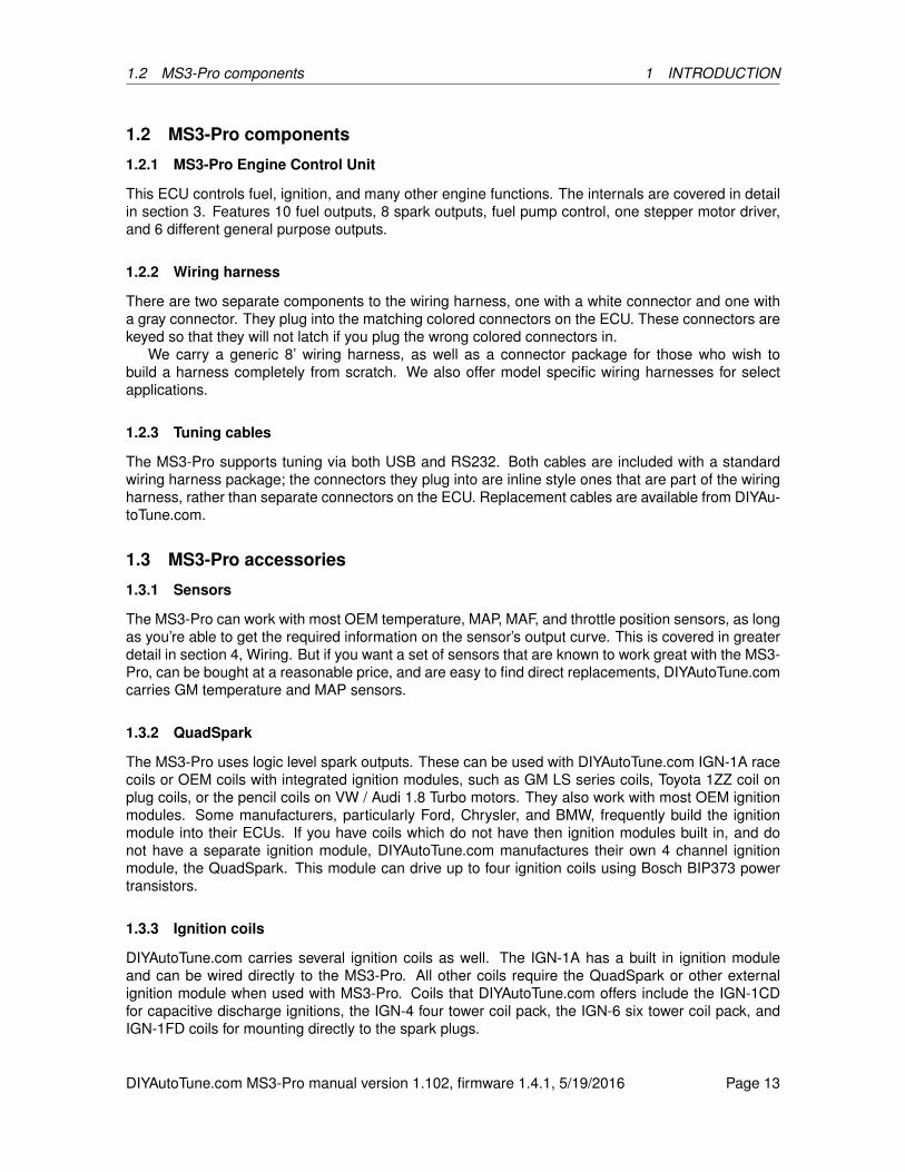
This ECU controls fuel, ignition, and many other engine functions. The internals are covered in detailin section 3. Features 10 fuel outputs, 8 spark outputs, fuel pump control, one stepper motor driver,and 6 different general purpose outputs.
1.2.2 Wiring harness
There are two separate components to the wiring harness, one with a white connector and one witha gray connector. They plug into the matching colored connectors on the ECU. These connectors arekeyed so that they will not latch if you plug the wrong colored connectors in.
We carry a generic 8’ wiring harness, as well as a connector package for those who wish tobuild a harness completely from scratch. We also offer model specific wiring harnesses for selectapplications.
1.2.3 Tuning cables
The MS3-Pro supports tuning via both USB and RS232. Both cables are included with a standardwiring harness package; the connectors they plug into are inline style ones that are part of the wiringharness, rather than separate connectors on the ECU. Replacement cables are available from DIYAu-toTune.com.
1.3 MS3-Pro accessories
1.3.1 Sensors
The MS3-Pro can work with most OEM temperature, MAP, MAF, and throttle position sensors, as longas you’re able to get the required information on the sensor’s output curve. This is covered in greaterdetail in section 4, Wiring. But if you want a set of sensors that are known to work great with the MS3-Pro, can be bought at a reasonable price, and are easy to find direct replacements, DIYAutoTune.comcarries GM temperature and MAP sensors.
1.3.2 QuadSpark
The MS3-Pro uses logic level spark outputs. These can be used with DIYAutoTune.com IGN-1A racecoils or OEM coils with integrated ignition modules, such as GM LS series coils, Toyota 1ZZ coil onplug coils, or the pencil coils on VW / Audi 1.8 Turbo motors. They also work with most OEM ignitionmodules. Some manufacturers, particularly Ford, Chrysler, and BMW, frequently build the ignitionmodule into their ECUs. If you have coils which do not have then ignition modules built in, and donot have a separate ignition module, DIYAutoTune.com manufactures their own 4 channel ignitionmodule, the QuadSpark. This module can drive up to four ignition coils using Bosch BIP373 powertransistors.
1.3.3 Ignition coils
DIYAutoTune.com carries several ignition coils as well. The IGN-1A has a built in ignition moduleand can be wired directly to the MS3-Pro. All other coils require the QuadSpark or other externalignition module when used with MS3-Pro. Coils that DIYAutoTune.com offers include the IGN-1CDfor capacitive discharge ignitions, the IGN-4 four tower coil pack, the IGN-6 six tower coil pack, andIGN-1FD coils for mounting directly to the spark plugs.
DIYAutoTune.com MS3-Pro manual version 1.102, firmware 1.4.1, 5/19/2016 Page 13

1.3 MS3-Pro accessories 1 INTRODUCTION
1.3.4 CAN-EGT thermocouple interface
Thermocouples put out a faint voltage that requires an amplifier circuit to get an accurate reading. TheCAN-EGT includes amplifiers for up to eight of these sensors, which can be used to measure exhaustgas or cylinder head temperature. The CAN-EGT module then transmits the temperature data to theMS3-Pro over a CAN network to avoid the inaccuracies of using a digital to analog conversion circuit.The MS3-Pro can use this both for data logging and for safety shutdown features if the exhaust gastemperatures go too high under load.
The CAN-EGT module can also gather data from the digital output on up to eight separate InnovateMotorsports LC-1, LM-2, or MTX-L wideband controllers and transmit this information to the MS3-Pro.Using this allows the MS3-Pro to run separate wideband O2 correction for all cylinders.
1.3.5 MicroSquirt
The MicroSquirt was originally intended as a fuel and ignition controller for powersports applications,but its CAN network capabilities and easily reprogrammed firmware allow it to be configured for otherfunctions. Current release firmware allows it to be used as a transmission controller for applicationsincluding GM 4L60E and 4L80E transmissions, and as a general purpose I/O expansion module.The CAN bus allows you to view the MicroSquirt data through TunerStudio as if the MS3-Pro andMicroSquirt are a single control unit with a single point of tuning.
Another use for the MicroSquirt is to run the IO Box firmware. This turns the MicroSquirt into anI/O expansion device, adding additional analog inputs as well as on/off or PWM outputs. The MS3-Procan accommodate up to three MicroSquirts running IO Box firmware, daisy chained together.
1.3.6 Part numbers
Replacement partsComponent DIYAutoTune.com part numberECU MS3Pro-ECUCase O-ring seal MS3Pro-Oring8’ wiring harness MS3Pro-Harn8Harness connector package MS3Pro-AMPSEALSTuning cable (USB) MS3TuneCableTuning cable (RS232) MS3Pro-RS232CableBattery BR-1225Internal fuse 0454.500MRSD card SD-8G
Recommended accessoriesComponent DIYAutoTune.com part numberIntake air temperature sensor with connector IATwPiggyCoolant temperature sensor with connector CLTIATwPiggyQuadSpark four channel ignition module QuadSpark3 bar MAP sensor GM3bar-mapPigtail connector for MAP sensor GM3bar_piggy4 way stackable fuse block Fuseblock-4
DIYAutoTune.com MS3-Pro manual version 1.102, firmware 1.4.1, 5/19/2016 Page 14

1.4 Tools 1 INTRODUCTION
1.4 Tools
As a general rule, you’ll want to have the following tools and supplies on hand for a successful MS3-Pro installation:
• Multimeter
• Laptop (the MS3-Pro software supports Windows, Linux, or Mac OS)
• Screwdrivers
• Soldering iron, solder, and heat shrink tubing (if joining wires by soldering) or crimp connectorsand crimp tool
• Wire cutters
• Wire stripping tool
• Timing light
• Wideband O2 sensor and controller (not needed for permanent installation, but useful for tuning)
• Electrical tape
• Vacuum tubing
DIYAutoTune.com MS3-Pro manual version 1.102, firmware 1.4.1, 5/19/2016 Page 15

2 INSTALLING AND REGISTERING SOFTWARE
2 Installing and registering software
The MS3-Pro comes with a software installation USB memory stick that includes the following pro-grams:
• TunerStudio. This is the main program you’ll use to connect to the MS3-Pro. It is used toconfigure the MS3-Pro’s settings, tune the MS3-Pro, record data logs on the laptop, and retrieveinternal data logs.
• MegaLogViewer. This is an analysis program which can play back data logs and display thedata in both line graph and scatter plot format. It can also modify tune files based on informationrecorded in data logs.
• Firmware loading utility. This is used to update firmware or for certain diagnostics.
Depending on your computer’s settings, the software may automatically install when you insert theCD into your computer. If it does not, open the CD drive and double click the Setup.exe file on theCD. Follow the installation prompts, and the software should install in just a couple minutes.
The tuning software can run on most versions of Windows, as well as Linux and Mac OS.Both TunerStudio and MegaLogViewer have registered versions. To unlock the registered ver-
sion, use the serial number code on your MS3-Pro. This appears on a label on the undersideof the box as well as on a tag on the back of the MS3-Pro. You will enter the serial number athttps://www.efianalytics.com/register/registerCoupon.jsp as a “Coupon code provided by dealer” toobtain a registration key.
2.1 TunerStudio
2.1.1 Start screen
Once TunerStudio opens, you will be presented with the start screen as shown below.
DIYAutoTune.com MS3-Pro manual version 1.102, firmware 1.4.1, 5/19/2016 Page 16

2.1 TunerStudio 2 INSTALLING AND REGISTERING SOFTWARE
At this point, you’d normally use the screen to create a project or open one; this will set up Tuner-Studio with the configuration it needs to communicate with your ECU or allow you to view tune filesoffline. You can create or open a new project under the file menu (1), or use this menu to open a newtune for offline viewing. There are also command links to create a new project (2) or open a recentproject (3).
The Help and Support button brings up links to documentaion and support forums for the MS3-Proas well as other systems in the MegaSquirt line.
Note that if you open a tune file from this screen, it will go into a temporary project and TunerStudiowill not connect to the MS3-Pro until you create or open a project for connecting to the MS3-Pro.
2.1.2 Creating a project
Selecting “New Project” from the File menu opens a wizard to create a new project. It will bring up ascreen like the one below. At this point, you will want to have the MS3-Pro powered up (see section 4for wiring details) and connected to the laptop with either the USB or RS232 cable. The MS3-Pro willneed to be powered through the 12 volt supply; it cannot be powered off the laptop.
DIYAutoTune.com MS3-Pro manual version 1.102, firmware 1.4.1, 5/19/2016 Page 17
2.1 TunerStudio 2 INSTALLING AND REGISTERING SOFTWARE
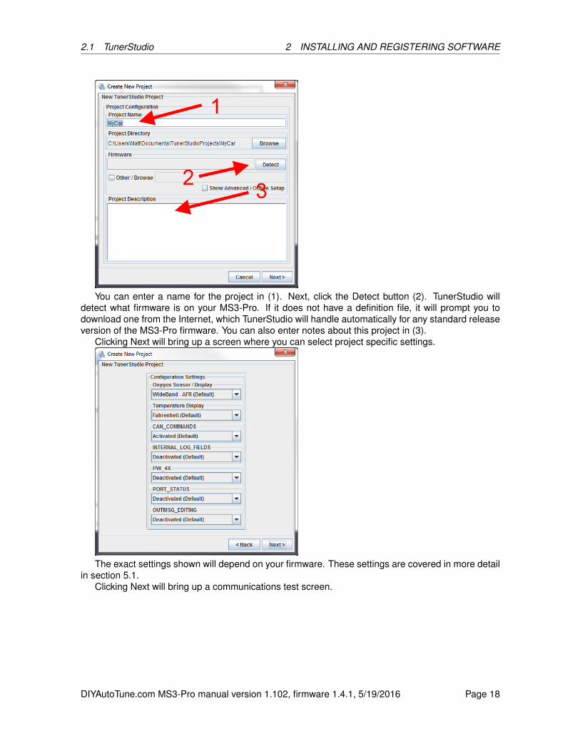
You can enter a name for the project in (1). Next, click the Detect button (2). TunerStudio willdetect what firmware is on your MS3-Pro. If it does not have a definition file, it will prompt you todownload one from the Internet, which TunerStudio will handle automatically for any standard releaseversion of the MS3-Pro firmware. You can also enter notes about this project in (3).
Clicking Next will bring up a screen where you can select project specific settings.
The exact settings shown will depend on your firmware. These settings are covered in more detailin section 5.1.
Clicking Next will bring up a communications test screen.
DIYAutoTune.com MS3-Pro manual version 1.102, firmware 1.4.1, 5/19/2016 Page 18
2.1 TunerStudio 2 INSTALLING AND REGISTERING SOFTWARE
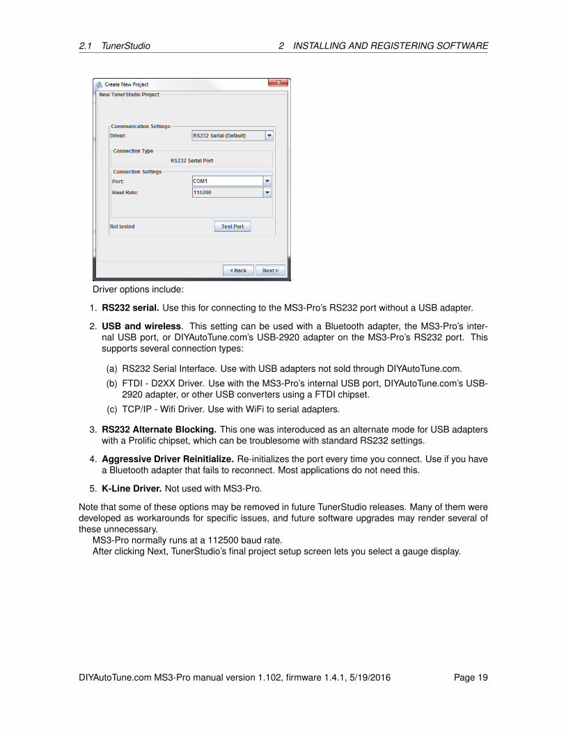
Driver options include:
1. RS232 serial. Use this for connecting to the MS3-Pro’s RS232 port without a USB adapter.
2. USB and wireless. This setting can be used with a Bluetooth adapter, the MS3-Pro’s inter-nal USB port, or DIYAutoTune.com’s USB-2920 adapter on the MS3-Pro’s RS232 port. Thissupports several connection types:
(a) RS232 Serial Interface. Use with USB adapters not sold through DIYAutoTune.com.
(b) FTDI - D2XX Driver. Use with the MS3-Pro’s internal USB port, DIYAutoTune.com’s USB-2920 adapter, or other USB converters using a FTDI chipset.
(c) TCP/IP - Wifi Driver. Use with WiFi to serial adapters.
3. RS232 Alternate Blocking. This one was interoduced as an alternate mode for USB adapterswith a Prolific chipset, which can be troublesome with standard RS232 settings.
4. Aggressive Driver Reinitialize. Re-initializes the port every time you connect. Use if you havea Bluetooth adapter that fails to reconnect. Most applications do not need this.
5. K-Line Driver. Not used with MS3-Pro.
Note that some of these options may be removed in future TunerStudio releases. Many of them weredeveloped as workarounds for specific issues, and future software upgrades may render several ofthese unnecessary.
MS3-Pro normally runs at a 112500 baud rate.After clicking Next, TunerStudio’s final project setup screen lets you select a gauge display.
DIYAutoTune.com MS3-Pro manual version 1.102, firmware 1.4.1, 5/19/2016 Page 19
2.1 TunerStudio 2 INSTALLING AND REGISTERING SOFTWARE
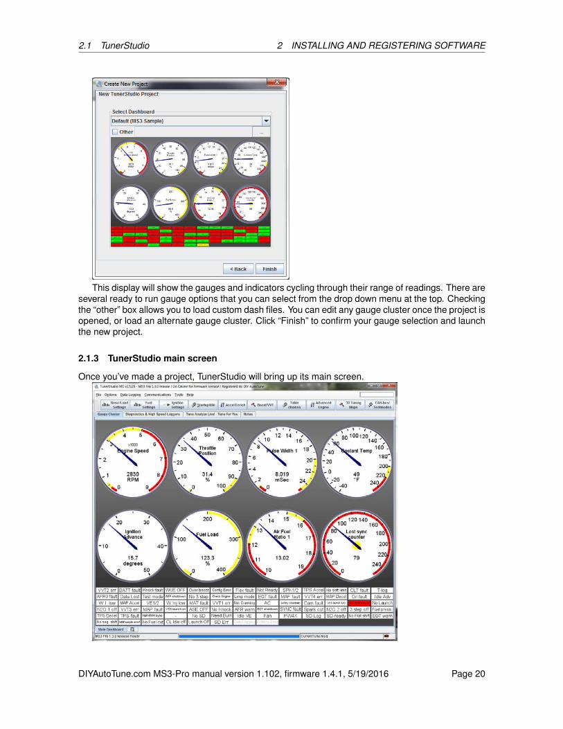
This display will show the gauges and indicators cycling through their range of readings. There areseveral ready to run gauge options that you can select from the drop down menu at the top. Checkingthe “other” box allows you to load custom dash files. You can edit any gauge cluster once the project isopened, or load an alternate gauge cluster. Click “Finish” to confirm your gauge selection and launchthe new project.
2.1.3 TunerStudio main screen
Once you’ve made a project, TunerStudio will bring up its main screen.
DIYAutoTune.com MS3-Pro manual version 1.102, firmware 1.4.1, 5/19/2016 Page 20
2.1 TunerStudio 2 INSTALLING AND REGISTERING SOFTWARE
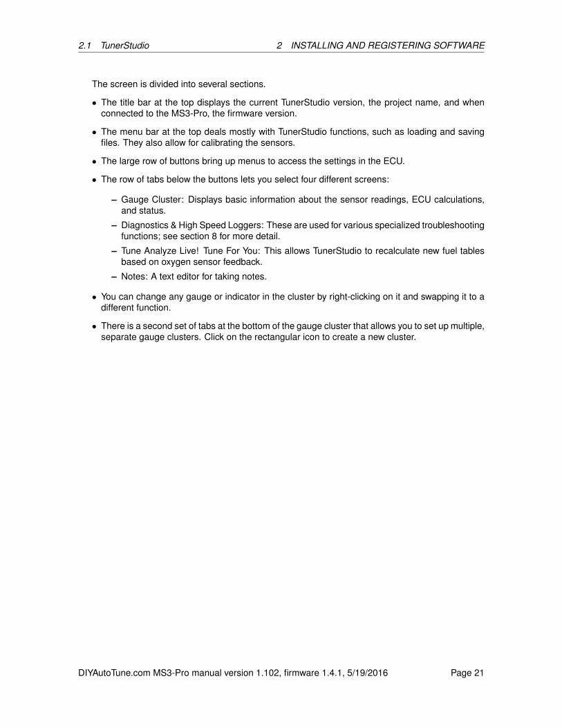
The screen is divided into several sections.
• The title bar at the top displays the current TunerStudio version, the project name, and whenconnected to the MS3-Pro, the firmware version.
• The menu bar at the top deals mostly with TunerStudio functions, such as loading and savingfiles. They also allow for calibrating the sensors.
• The large row of buttons bring up menus to access the settings in the ECU.
• The row of tabs below the buttons lets you select four different screens:
– Gauge Cluster: Displays basic information about the sensor readings, ECU calculations,and status.
– Diagnostics & High Speed Loggers: These are used for various specialized troubleshootingfunctions; see section 8 for more detail.
– Tune Analyze Live! Tune For You: This allows TunerStudio to recalculate new fuel tablesbased on oxygen sensor feedback.
– Notes: A text editor for taking notes.
• You can change any gauge or indicator in the cluster by right-clicking on it and swapping it to adifferent function.
• There is a second set of tabs at the bottom of the gauge cluster that allows you to set up multiple,separate gauge clusters. Click on the rectangular icon to create a new cluster.
DIYAutoTune.com MS3-Pro manual version 1.102, firmware 1.4.1, 5/19/2016 Page 21

3 MS3-PRO HARDWARE
3 MS3-Pro hardware
3.1 Overview
The MS3-Pro is a full standalone ECU with everything you need to run sequential fuel injection on upto 12 cylinders. This ECU is based on the previous MegaSquirt-III design and runs similar code, butwe’ve miniaturized the system to fit into a smaller package, and put it in a waterproof enclosure withhigh current, vibration resistant AMPSEAL connectors. Here are the MS3-Pro’s specifications.
Hardware features:
• Freescale MC9S12X 16 bit, 50 MHz asymmetrical dual core processor
• 10 saturated injector drivers
• 8 logic level ignition outputs
• 3 high current (5 amp) general purpose outputs - 2 can be reconfigured as additional injectordrivers
• 3 medium current (3 amp), high frequency general purpose outputs
• 1 stepper H-bridge driver
• Camshaft and crankshaft differential inputs - supports VR, Hall effect, and optical input
• 12 volt tach output
• Fuel pump output
• 8 analog inputs (5 dedicated sensor inputs, 3 general purpose)
• 5 general purpose on/off or frequency inputs
• 2 digital I/O logic inputs
• 2 knock inputs
• RS232, USB 2.0, and CAN communication
• Onboard SD card for internal data logging
• Internal ECU temperature sensor
• Real time clock
• Temperature range: -30 to +80 degrees C (-40 to +85 without battery for real time clock)
• Minimum supply voltage: 6 volts
• Maximum supply voltage: 22 volts before triggering overvoltage protection circuits
Software features:
• Supports speed density, alpha-N, or MAF based fuel and spark tables
• 1 microsecond injector pulse width resolution
• Tables for nonlinear injector behavior at small pulse widths
• Allows blending multiple load types, including specialized mode for independent throttle bodies
DIYAutoTune.com MS3-Pro manual version 1.102, firmware 1.4.1, 5/19/2016 Page 22

3.1 Overview 3 MS3-PRO HARDWARE
• Supports a wide variety of OEM cam and crank position sensors
• Individual cylinder trim tables for fuel and ignition
• Accelerator pump or model based acceleration enrichment
• Closed or open loop idle speed control
• Closed or open loop boost control with gear or speed based tuning options
• On/off or closed loop continuously variable valve timing control - supports up to 4 channels
• On/off or progressive nitrous control
• Traction control
• Rally anti-lag
• Rotary support - can run up to 4 rotor engines with separate leading and trailing spark tables
• Staged injection
• Table switching
• 16 x 16 fuel and spark tables - can be reconfigured to function as 30 x 16 or 16 x 30 by switchingtables based on RPM or load
• 2 or 3 step rev limiter with no-lift shifting
• Wideband AFR target tables
• Flex fuel sensor input
• Allows repurposing injector or ignition outputs as general purpose outputs, or high current out-puts as injector drivers for 12 cylinder sequential applications
• Real time barometric correction
• A/C and cooling fan control with idle compensation
• Safety shutdown based on AFR or EGT input
• Motorcycle shift cut
• 3 high current general purpose outputs
• 3 high frequency general purpose outputs
The MS3-Pro’s nylon case is somewhat unusual in a world of aluminum cased aftermarket ECUs. Youmay be wondering how it can dissipate heat. Our strategy for heat management is simple: You don’tneed to dissipate heat if you don’t make heat in the first place. The MS3-Pro uses a power supplyoptimized for high efficiency, and if you want to use circuits that generate large amounts of heat likepeak and hold injector drivers, they can be ordered as an external box. The plastic case is the samegrade of nylon used in many OEM ECUs and other underhood components.
Most of how to set these inputs up is covered in the wiring guide, but for those who want moredetails on the circuits used in the MS3-Pro, here they are. (Most users can skip straight to Section 4and start wiring the unit up, but for those who want to know the full details, here they are!)
DIYAutoTune.com MS3-Pro manual version 1.102, firmware 1.4.1, 5/19/2016 Page 23
3.2 Inputs 3 MS3-PRO HARDWARE
3.2 Inputs
3.2.1 Engine speed
The MS3-Pro uses a Maxim MAX9926 adaptive differential conditioner for engine RPM. This circuitcan accept input from variable reluctor, Hall effect, or optical sensors, and the input’s absolute maxi-mum rating is 400 volts. The input circuit cannot be triggered off the negative terminal of an ignitioncoil - this may damage the circuit. For fuel only installations, you will want to use a 12 volt tach signal,like the one off an MSD ignition box.
Some spark modes, discussed in the ignition section of the manual, use the digital I/O channelsas well. These come into play for systems that either use very high frequency signals (such as theNissan or Optispark optical systems), require more than two sensors for engine position (such as theAudi “tri-tach” system), or use more than one channel of variable valve timing.
3.2.2 Temperature inputs
The IAT and CLT inputs are designed to accept input from a negative temperature coefficient thermis-tor. Simply put, this is a sensor that is a type of resistor that changes resistance with temperature,and the resistance goes down as the temperature goes up. The default settings are for the sort ofGM sensors that are something of an industry standard in the EFI world, but you can calibrate it forother sensor types through TunerStudio. These incorporate a 2,490 bias resistor that connects thesensor output to 5 volts. The sensor acts as a resistor to ground, reducing the voltage from 5 volts.The higher the temperature, the more the sensor will pull the voltage down.
A third temperature input monitors ECU internal temperature. This sensor cannot detect individualhot spots, but if you are installing this under the hood or in other applications where you are concernedabout exceeding its internal temperature limit, this will let you log and view how hot the MS3-Pro isgetting.
3.2.3 Throttle position
This input can accept signals in the 0 to 5 volt range and will work with almost any potentiometer typeTPS. If this is not used, you should connect this input to the sensor return.
3.2.4 O2 sensor input
This input is also 0 to 5 volts. It can be used with either narrow band O2 sensors or accept an analogoutput from a wideband O2 sensor controller. It will not interface directly with a wideband O2 sensor,but it is compatible with most external wideband controllers, including Innovate, AEM, Zeitronix, PLX,and 14point7.
The three general purpose analog inputs may also be configured as additional O2 input channelsand work in the same way when set up as O2 inputs.
3.2.5 MAP sensor input
This input works with 0 to 5 volt MAP sensors, and can also be used with 0 to 5 volt mass air flowsensors. The MS3-Pro does support frequency based MAP and MAF sensors, but not on this wire -their signals need to be connected to a Digital I/O port.
3.2.6 General purpose analog inputs
These inputs can accept a 0 to 5 volt signal from a variety of sensors, which can be used for barometriccorrection, O2 correction, an alternate load sensor (such as running a MAP and a MAF sensor at the
DIYAutoTune.com MS3-Pro manual version 1.102, firmware 1.4.1, 5/19/2016 Page 24

3.3 Outputs 3 MS3-PRO HARDWARE
same time), or simply for data logging additional sensors such as oil or fuel pressure.
3.2.7 Knock input
The MS3-Pro employs a Texas Instruments TPIC8101 knock sensor interface chip. This can useeither one or two knock sensors, and incorporates a built in, software adjustable bandpass filter. Theinterface allows you to adjust the triggering threshold as a function of RPM and detect knock only atspecific crank angles so as to filter out noise occurring when the piston is in a position where it can’tpossibly be detonating. The MS3-Pro supports cylinder by cylinder knock detection and can identifywhich cylinder is knocking by crank angle.
3.2.8 Digital I/O channels
There are several channels that support on/off inputs. The Digital Switched In wires can use an on/offswitch to ground. The Digital Switched 12V In line is triggered by 12 volts instead. There are alsothree digital inputs capable of receiving high frequency signals, which can be used for speed inputs,frequency based MAF or MAP sensors, or a number of other functions.
3.3 Outputs
3.3.1 Injector outputs
The injector outputs are limited to 5 amps per channel, with thermal shutdown protection. These candrive one or two high impedance injectors on each output, but will not directly run low impedanceinjectors. We recommend our eight channel Peak and Hold Injector Driver Board for use with lowimpedance injectors. Unused injector outputs may be used for on/off outputs.
3.3.2 Ignition outputs
The MS3-Pro uses 5 volt, logic level ignition outputs with a high side driver circuit. These will drivemost factory ignition modules and coils with built in ignitors. For use with coils that lack built in ignitionmodules, we recommend the QuadSpark external ignition module. Note that these outputs will nottrigger an MSD ignition box or a Ford TFI. The tach output (see below) can be reassigned to functionas a spark output when using these types of external ignition modules. Do not connect the MS3-Proignition outputs directly to the negative terminal of an ignition coil; this can result in damage to theMS3-Pro. Maximum current is 200 mA per ignition output channel, and pushing the output beyondthis amount of current can damage the output channel.
Unused ignition outputs may be used as on/off outputs, although their low current capacity meanswe do not recommend using them for anything other than logic level devices or LED lights. Do notuse these outputs to drive relays directly or use them for anything that needs a ground for triggering.
3.3.3 High current outputs
These are ground switched outputs with a maximum current of 5 amps, just like the injector outputchannels (in fact, it’s the same transistor type). These can be run in an on/off fashion or use pulsewidth modulation. Flyback voltage spikes are clamped at 36 volts to help the valve close rapidly. Theytypically work well with boost control solenoids and nitrous solenoids, which cycle fully off and fullyon.
DIYAutoTune.com MS3-Pro manual version 1.102, firmware 1.4.1, 5/19/2016 Page 25
3.4 Communications lines 3 MS3-PRO HARDWARE
3.3.4 PWM medium current outputs
These are ground switched outputs, maximum current 3 amps. They are optimized for valves whichuse pulse width modulation to hold them in an intermediate position instead of pulsing on and off.Flyback spikes are clamped at battery voltage, which causes the valve to close more slowly. Commonvalves that would use these outputs include idle air control valves and variable valve timing oil controlvalves. They can also be used as an on/off signal. The fuel pump uses a similar circuit, although itdoes not use PWM.
Note: Any device connected to these outputs must be set up so that it is powered off when theECU is shut down. Relays or solenoids connected to these outputs can back feed power into the MS3-Pro if the relay coil or solenoid winding receives power with the key on. Wire any device connected tothese outputs to switched 12 volt power.
3.3.5 Tach output
This output can be used to produce a 12 volt square wave signal. It can also trigger certain ignitionmodules such as an MSD 6AL or a Ford TFI, or be used as a general purpose on/off output. Whenused as an on/off output, it can sink up to 1 amp.
3.3.6 Stepper motor control output
The MS3-Pro has one stepper control output, with a maximum current of 750 mA per channel. Thisone is intended to drive a stepper idle air control valve. However, its outputs can also be used asa tach signal or general purpose on/off outputs. When used as an on/off output, the device can betreated as two separate paired low / high side drivers. The A output of either side is high when itis turned on, while the B output will sink current to drive a relay or solenoid. Turning the output offreverses the pattern if the other output is on. If both outputs are off, all four outputs will be floatingand neither sink nor source current.
3.4 Communications lines
3.4.1 RS232
RS232 is your old fashioned serial connection. This is brought out to a 4 piece Weather Pack con-nector in the harness, which connects to a cable that plugs into a 9 pin serial port on a laptop. RS232is more noise resistant than USB, and if your laptop supports this, we recommend using it. Do notattempt to plug the RS232 connection into any sort of 15 or 25 pin connector - these are usually forVGA displays or joysticks. Some third party devices such as the Racepak data acquisition setup alsouse the RS232 connection.
3.4.2 USB
The MS3-Pro features one USB output channel that allows it to communicate with a laptop.
3.4.3 CANbus
The CANbus wires are a communications network that allow the MS3-Pro to talk to other CAN enabledmodules. Note that not all CAN enabled devices will communicate with the MS3-Pro; CAN is a type ofhardware, and in addition to having the required hardware, the device you are attempting to connectto the MS3-Pro must also be programmed to understand the type of messages the MS3-Pro sends.Devices currently or soon on the market that can be connected to the MS3-Pro include:
DIYAutoTune.com MS3-Pro manual version 1.102, firmware 1.4.1, 5/19/2016 Page 26
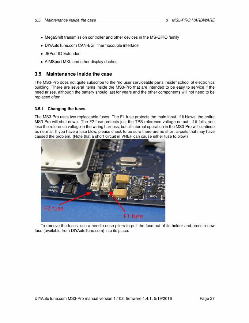
3.5 Maintenance inside the case 3 MS3-PRO HARDWARE
• MegaShift transmission controller and other devices in the MS-GPIO family
• DIYAutoTune.com CAN-EGT thermocouple interface
• JBPerf IO Extender
• AIMSport MXL and other display dashes
3.5 Maintenance inside the case
The MS3-Pro does not quite subscribe to the “no user serviceable parts inside” school of electronicsbuilding. There are several items inside the MS3-Pro that are intended to be easy to service if theneed arises, although the battery should last for years and the other components will not need to bereplaced often.
3.5.1 Changing the fuses
The MS3-Pro uses two replaceable fuses. The F1 fuse protects the main input; if it blows, the entireMS3-Pro will shut down. The F2 fuse protects just the TPS reference voltage output. If it fails, youlose the reference voltage in the wiring harness, but all internal operation in the MS3-Pro will continueas normal. If you have a fuse blow, please check to be sure there are no short circuits that may havecaused the problem. (Note that a short circuit in VREF can cause either fuse to blow.)
To remove the fuses, use a needle nose pliers to pull the fuse out of its holder and press a newfuse (available from DIYAutoTune.com) into its place.
DIYAutoTune.com MS3-Pro manual version 1.102, firmware 1.4.1, 5/19/2016 Page 27
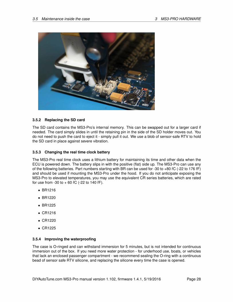
3.5 Maintenance inside the case 3 MS3-PRO HARDWARE
3.5.2 Replacing the SD card
The SD card contains the MS3-Pro’s internal memory. This can be swapped out for a larger card ifneeded. The card simply slides in until the retaining pin in the side of the SD holder moves out. Youdo not need to push the card to eject it - simply pull it out. We use a blob of sensor-safe RTV to holdthe SD card in place against severe vibration.
3.5.3 Changing the real time clock battery
The MS3-Pro real time clock uses a lithium battery for maintaining its time and other data when theECU is powered down. The battery slips in with the positive (flat) side up. The MS3-Pro can use anyof the following batteries. Part numbers starting with BR can be used for -30 to +80 rC (-22 to 176 rF)and should be used if mounting the MS3-Pro under the hood. If you do not anticipate exposing theMS3-Pro to elevated temperatures, you may use the equivalent CR series batteries, which are ratedfor use from -30 to + 60 rC (-22 to 140 rF).
• BR1216
• BR1220
• BR1225
• CR1216
• CR1220
• CR1225
3.5.4 Improving the waterproofing
The case is O-ringed and can withstand immersion for 5 minutes, but is not intended for continuousimmersion out of the box. If you need more water protection - for underhood use, boats, or vehiclesthat lack an enclosed passenger compartment - we recommend sealing the O-ring with a continuousbead of sensor safe RTV silicone, and replacing the silicone every time the case is opened.
DIYAutoTune.com MS3-Pro manual version 1.102, firmware 1.4.1, 5/19/2016 Page 28
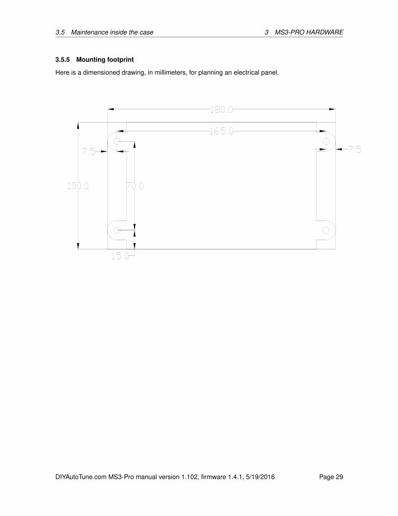
3.5 Maintenance inside the case 3 MS3-PRO HARDWARE
3.5.5 Mounting footprint
Here is a dimensioned drawing, in millimeters, for planning an electrical panel.
DIYAutoTune.com MS3-Pro manual version 1.102, firmware 1.4.1, 5/19/2016 Page 29

4 WIRING
4 Wiring
First, some general advice about wiring.We use automotive grade, high temperature TXL wiring in our harness (it’s rated for up to 125rC),
but you should still do your best to keep it away from heat sources. Also take any potential sources ofmechanical damage into account - flip up headlight mechanisms, the side to side movements of theengine on its mounts, etc.
Usually the biggest source of electrical noise isn’t RFI or other radio noise - it’s poor grounding orhaving noise injected into the power wires by another device. The MS3-Pro needs to be grounded tothe engine block or cylinder head if at all possible; the battery negative terminal is often an acceptablesecond choice. We do not recommend grounding the MS3-Pro to the chassis or sheet metal. Youmay either crimp all ground wires to a single lug, or crimp the ground wires on the gray connector toone lug and the single ground on the white one to a separate lug. The sensors need to be groundedto the sensor return wire, which grounds them to the MS3-Pro. Grounding sensors to the engine orbody will create jitter from ground offsets.
You will also want to make sure the 12 volt power wire is clean. We recommend using one powerwire from the battery for the MS3-Pro EFI main relay, and a separate power wire to power the relay forthe injectors, fuel pump, and ignition system for maximum noise reduction. Fuel pumps and ignitioncoils in particular tend to inject significant amounts of noise into their 12 volt supply wire. Also, puttinga capacitor (the points condenser out of an old fashioned points distributor will work) on the supplyline to the ignition coils can reduce the amount of noise they feed into the 12 volt supply.
You can start off a debate that goes on for hundreds of posts on an Internet forum over whetherit’s better to solder or crimp wires to join them. Either one can work very well if done right, and eitherone can be unreliable if done poorly. It’s our experience that getting a good solder joint is more relianton good technique, which can still be done with cheap tooling, while a good crimp joint is more relianton good tooling. Either way, the joint needs to be sealed (such as with heat shrink tubing) to keepout moisture and contaminants. Heat shrink tubing also provides some measure of protection againstvibration.
We designed the MS3-Pro’s power supply to run on a wide range of supply voltage. It can operateon voltages as low as 6 volts to cover voltage dips during cranking, although if your voltage drops thatfar, we’re not sure your battery is going to crank it over. The MS3-Pro has an input voltage limitingcircuit that clamps input voltage at 22 volts, and feeding it 22 volts for any sustained length of time willblow the F1 input voltage protection fuse.
4.1 ECU pinout
The ECU uses two AMPSEAL connectors, where the pin numbers are molded into the connectorhousing.
DIYAutoTune.com MS3-Pro manual version 1.102, firmware 1.4.1, 5/19/2016 Page 30

4.1 ECU pinout 4 WIRING
White connector pinout
Pin Function Wire color Stripe / shielding1 High current out 1 Light green None2 High current out 2 Light green Dark blue3 Injector out J White Yellow4 Injector out I White Gray5 High current out 3 Light green Red6 CKP+ White Shielded7 Knock In 2 Orange Red8 5V+ VREF out Gray None9 TPS in Light blue Shielded
10 MAT in Orange None11 CLT in Yellow None12 MAP in Light blue Dark green13 Shield ground Connects to shields14 PWM / Idle Out 1 Light green None15 CKP- Black Shielded16 Logic ground * Black None17 RS232 ground ** Black None18 Sensor return Black White19 Analog in 1 Light blue Dark blue20 Analog in 2 Light blue Red21 Analog in 3 Light blue Purple22 RS232 TX ** Black Shielded23 RS232 RX ** White Shielded24 Tach out Light green Purple25 O2 in Pink None26 CMP+ Yellow Shielded27 CMP- Red Shielded28 Fuel pump relay out Purple None29 PWM out 2 Light green Pink30 PWM out 3 Light green Dark green31 Knock in 1 Orange Purple32 Digital switched in 1 Gray Orange33 CAN L Tan Red34 CAN H Tan None35 12V+ switched power in Red None
* Both logic ground and power grounds must be connected to the engine block or cylinder head.Do not leave the logic ground disconnected, as this may result in noise issues or improper operation.
** RS232 connections are brought to their own Weather Pack 4 pin connector and do not go intothe main harness.
DIYAutoTune.com MS3-Pro manual version 1.102, firmware 1.4.1, 5/19/2016 Page 31
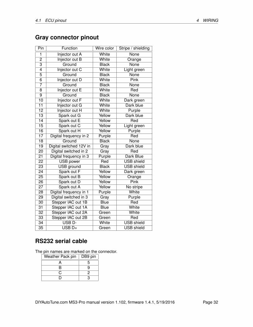
4.1 ECU pinout 4 WIRING
Gray connector pinout
Pin Function Wire color Stripe / shielding1 Injector out A White None2 Injector out B White Orange3 Ground Black None4 Injector out C White Light green5 Ground Black None6 Injector out D White Pink7 Ground Black None8 Injector out E White Red9 Ground Black None
10 Injector out F White Dark green11 Injector out G White Dark blue12 Injector out H White Purple13 Spark out G Yellow Dark blue14 Spark out E Yellow Red15 Spark out C Yellow Light green16 Spark out H Yellow Purple17 Digital frequency in 2 Purple Red18 Ground Black None19 Digital switched 12V in Gray Dark blue20 Digital switched in 2 Gray Red21 Digital frequency in 3 Purple Dark Blue22 USB power Red USB shield23 USB ground Black USB shield24 Spark out F Yellow Dark green25 Spark out B Yellow Orange26 Spark out D Yellow Pink27 Spark out A Yellow No stripe28 Digital frequency in 1 Purple White29 Digital switched in 3 Gray Purple30 Stepper IAC out 1B Blue Red31 Stepper IAC out 1A Blue White32 Stepper IAC out 2A Green White33 Stepper IAC out 2B Green Red34 USB D- White USB shield35 USB D+ Green USB shield
RS232 serial cable
The pin names are marked on the connector.Weather Pack pin DB9 pin
A 5B 9C 2D 3
DIYAutoTune.com MS3-Pro manual version 1.102, firmware 1.4.1, 5/19/2016 Page 32

4.2 Wiring diagram 4 WIRING
4.2 Wiring diagram
These show the basic connections - power, ground, fuel, ignition, idle control, and basic sensors.Other inputs and outputs are covered in their respective sections.
DIYAutoTune.com MS3-Pro manual version 1.102, firmware 1.4.1, 5/19/2016 Page 33
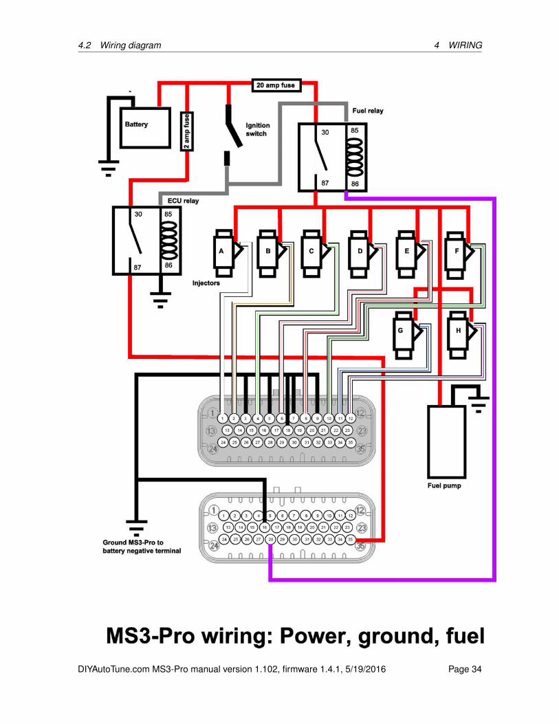
4.2 Wiring diagram 4 WIRING
DIYAutoTune.com MS3-Pro manual version 1.102, firmware 1.4.1, 5/19/2016 Page 34

4.2 Wiring diagram 4 WIRING
DIYAutoTune.com MS3-Pro manual version 1.102, firmware 1.4.1, 5/19/2016 Page 35

4.2 Wiring diagram 4 WIRING
DIYAutoTune.com MS3-Pro manual version 1.102, firmware 1.4.1, 5/19/2016 Page 36

4.3 Engine position sensors 4 WIRING
4.3 Engine position sensors
The MS3’s CKP and CMP inputs use differential signal conditioners that can accept input from VR(variable reluctor, also called a inductive pick-up or magnetic pick-up, although the latter is somewhatconfusing because Hall effect sensors are also magnetic), Hall effect, or optical sensors. We useCKP (short for crankshaft position sensor) to mean the primary trigger. In most spark modes, this isthe signal the ECU relies on for most of its RPM and timing calculations. Although the abbreviationimplies the sensor should be on the crankshaft, in some cases, it’s actually in a distributor or on thecamshaft.
The CMP (camshaft position) signal is a secondary trigger. This is almost always on the camshaftor distributor, although there are one or two setups that put this on the crank. The CMP sensorgenerally provides supplemental information used to interpret the crank sensor readings, and itsaccuracy is usually not as critical. Here are the rules we go by to identify which sensor is the CKPand which is the CMP.
• If one sensor spins at crankshaft speed and the other spins at cam speed, the one that turns atcrank speed is the CKP and the one at cam speed is the CMP.
• On a GM Optispark and most Nissan optical cam sensors, the MS3-Pro normally uses a ringwith one slot per cylinder for primary engine operation. There is a ring of 360 slits that is usedfor cranking and operation at very low RPM. Consequently, the one slot per cylinder sensor isthe CKP and the 360 slot ring is CMP. (Note that these use Digital Frequency In 2 for the CMPsensor, as the regular CMP input is too heavily filtered to correctly handle this signal.)
• On almost all other setups with two sensors reading wheels spinning at cam speed, the sensorthat reads the wheel with the lowest number of teeth is CMP and the one with the most teeth isCKP.
• Specific sensor setups that do not fall into any of these categories are covered in the ignitionset-up section of the manual.
Note that the conditioner circuit will invert the signal. We have left the settings unchanged becausea lot of other MegaSquirt installs use a conditioner that behaves in a similar way. So if you set theignition input capture to “rising edge”, that is the signal at the processor - it will actually be activatedwhen the signal coming in to the MS3-Pro transitions from high to low.
4.3.1 Variable reluctor sensors
Variable reluctor (VR) sensors are similar to a guitar pick-up coil. They have a magnet and a coil ofwire which generates an A/C signal with a voltage that increases with RPM. VR sensors do not havepower wires as they generate their own voltage. On a VR sensor, you will wire their two terminals toboth of the CKP or CMP wires, as appropriate. Don’t worry too much about getting it backwards - youcan set the active edge in software.
The MS3-Pro package includes two 10K resistors sealed in red sealed tubing with yellow wireleads. If you are using a VR sensor on a high tooth count wheel with missing teeth (Ford 36-1 andBosch 60-2 are two common examples) and lose sync as the RPM comes up, install one of the 10Kresistors in parallel with the sensor. This fixes the problem in most cases.
4.3.2 Hall effect and optical sensors
Hall effect and optical sensors are a bit different. These use a switching transistor and are poweredfrom an external source (either 5 or 12 volts; if your sensor can run on either, we recommend using12 volts). Your typical sensor has three pins - the power wire goes to a 12 or 5 volt feed, the ground
DIYAutoTune.com MS3-Pro manual version 1.102, firmware 1.4.1, 5/19/2016 Page 37

4.4 Other sensors 4 WIRING
wire goes to sensor ground, and the signal wire goes to CKP+ or CMP+ as appropriate. Do not useCMP- or CKP- with Hall effect or optical sensors. Leave this wire disconnected and taped off.
Some sensors put out a square wave signal on their own, like the ones sold by DIYAutoTune.com.Others switch from a ground output to a floating (undefined) output. The ones that behave this wayrequire running a 1K resistor from their power terminal to their signal terminal (called a pull-up resistor)to work with MS3-Pro. If you’re not sure which sensor type you have, supply it with power and ground,and check the voltage on its output wire when the sensor is both far away from any metal and touchinga piece of steel (note - do not use stainless steel for this test; some grades of stainless steel aren’tmagnetic.) If the output voltage stays at zero the whole time, you’ll need the pull up resistor; connectthe 1K resistor from the signal wire to the power wire. If it is at zero volts in one state and bounces upto at least 5 volts in the other state, it doesn’t need a pull up resistor. The MS3-Pro package includestwo 1K resistors in blue sealed tubing with blue wire leads.
In some cases where a Hall effect sensor puts out 12 volts and the wiring harness has severenoise issues, tying the CKP- or CMP- wires to the VREF output can reduce noise.
4.3.3 Points triggering and points replacement devices
The MS3-Pro cannot trigger off the negative terminal of an ignition coil directly. However, if youwish to lock out a points distributor mechanism and let the MS3-Pro control the ignition, you can treatthe points output as a Hall sensor with a ground to floating output. You will need to connect a 1Kresistor from a 12 volt source to the points, and also wire the points to the CKP+ wire. Do not use theCKP- wire; tape it out of the way safely.
Using a Pertronix Ignitor or equivalent is similar. With a Pertronix, connect the Ignitor’s red andblack wires with a 1K resistor, and leave the red wire connected to switched 12 volt power. Connectthe black wire to CKP+ and leave CKP- disconnected. Other modules may use different wire colors.
4.3.4 Fuel only with an MSD box or similar
When MSD says that their orange and black wires are the only wires that should be connected tothe coil, they’re not kidding. You do not want to try to get a tach signal from the coil by any means,including external adapter boxes. Instead, use the ignition box’s tach output wire to the CKP+ insteadif you are using a distributor advance mechanism to control timing and just want the MS3-Pro tocontrol fuel. Do not use the CKP- wire or the CMP+ and CMP- wires.
4.4 Other sensors
4.4.1 Temperature sensors
The MS3-Pro is designed to work with the type of sensor called a NTC thermistor. NTC stands fornegative temperature coefficient, and simply means that the resistance goes down as the temperaturegoes up. This is how most automotive temperature sensors are set up, including the GM type sensorsavailable from DIYAutoTune.com. Normal automotive temperature sensors have two terminals. Oneconnects to the coolant temperature sensor or intake air temperature sensor input of the MS3-Pro.The other one connects to the sensor ground wire. These sensors have no polarity and can be wiredeither way.
There are two common variations on automotive temperature sensors. Closed element type sen-sors are resistant to water, oil, and other liquids. We recommend using this type for coolant. Theyare not a good idea to use with air temperature, as they react slowly and are prone to absorbing heatfrom the intake manifold. Open element sensors are better to use for air temperature. We recommendmounting them upstream of the throttle body to avoid absorbing heat from the intake manifold, unlessyou have a plastic intake manifold. If you are using a turbocharger or supercharger, the IAT sensormust be mounted downstream of the compressor and intercooler (if used).
DIYAutoTune.com MS3-Pro manual version 1.102, firmware 1.4.1, 5/19/2016 Page 38
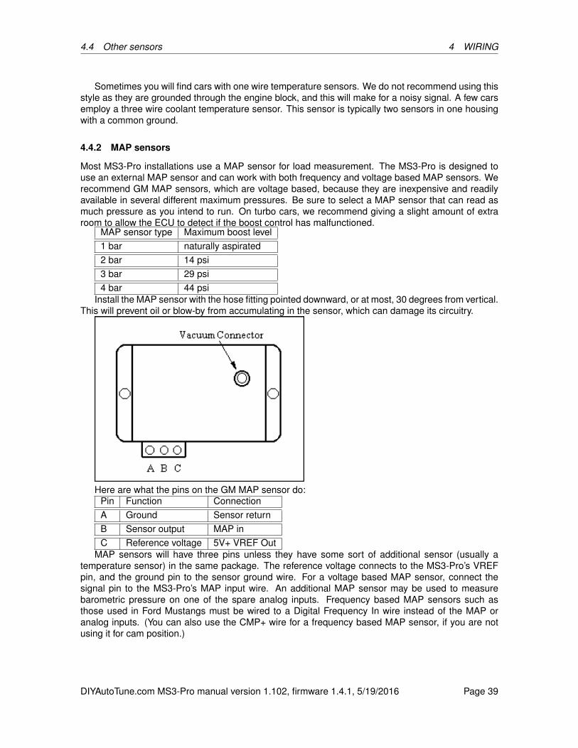
4.4 Other sensors 4 WIRING
Sometimes you will find cars with one wire temperature sensors. We do not recommend using thisstyle as they are grounded through the engine block, and this will make for a noisy signal. A few carsemploy a three wire coolant temperature sensor. This sensor is typically two sensors in one housingwith a common ground.
4.4.2 MAP sensors
Most MS3-Pro installations use a MAP sensor for load measurement. The MS3-Pro is designed touse an external MAP sensor and can work with both frequency and voltage based MAP sensors. Werecommend GM MAP sensors, which are voltage based, because they are inexpensive and readilyavailable in several different maximum pressures. Be sure to select a MAP sensor that can read asmuch pressure as you intend to run. On turbo cars, we recommend giving a slight amount of extraroom to allow the ECU to detect if the boost control has malfunctioned.
MAP sensor type Maximum boost level1 bar naturally aspirated2 bar 14 psi3 bar 29 psi4 bar 44 psi
Install the MAP sensor with the hose fitting pointed downward, or at most, 30 degrees from vertical.This will prevent oil or blow-by from accumulating in the sensor, which can damage its circuitry.
Here are what the pins on the GM MAP sensor do:Pin Function ConnectionA Ground Sensor returnB Sensor output MAP inC Reference voltage 5V+ VREF Out
MAP sensors will have three pins unless they have some sort of additional sensor (usually atemperature sensor) in the same package. The reference voltage connects to the MS3-Pro’s VREFpin, and the ground pin to the sensor ground wire. For a voltage based MAP sensor, connect thesignal pin to the MS3-Pro’s MAP input wire. An additional MAP sensor may be used to measurebarometric pressure on one of the spare analog inputs. Frequency based MAP sensors such asthose used in Ford Mustangs must be wired to a Digital Frequency In wire instead of the MAP oranalog inputs. (You can also use the CMP+ wire for a frequency based MAP sensor, if you are notusing it for cam position.)
DIYAutoTune.com MS3-Pro manual version 1.102, firmware 1.4.1, 5/19/2016 Page 39
4.4 Other sensors 4 WIRING
4.4.3 Throttle position sensor
The throttle position sensors used on most cars are potentiometer or variable resistance types, whichput out a voltage that increases as the throttle opens. The easiest way to check a TPS is to unplug itand put an ohmmeter on its pins. Observe the resistance as the throttle opens and closes. Each pairof pins will behave differently:
The resistance between the VREF and ground pins will remain constant. The resistance betweenthe ground and signal pins will be low with the throttle closed and high with the throttle wide open.The resistance between the VREF and signal pins will be high with the throttle closed and low withthe throttle wide open.
If your sensor behaves like this, it will be pretty straightforward to connect it to the MS3-Pro.If the resistance jumps from infinite (or near infinite) to near zero, you have a switch type throttle
position sensor, or possibly a seriously defective potentiometer type TPS. These do not provide verymuch information that MS3-Pro needs, as it can tell if you are at idle or full throttle by the MAP sensorinformation. You can still use MAP based acceleration enrichment. If the TPS input is not used, thiswire should be connected to sensor ground.
4.4.4 Mass air flow sensors
Mass air flow (MAF) sensors provide a measurement of actual airflow through the intake system of anengine. In its most basic form, the fuel required by the engine (in mass per second) is directly relatedto the air flowing into the engine (in mass per second) so the MAF sensor should give a good basisfor the fuel equation. By comparison, Speed Density uses RPM, MAP, MAT and VE to estimate themass air flow. In practice, like any other sensor input the MAF has its own quirks and can suffer fromreversion effects (particularly on "cammy" engines) where the air flow gets measured twice.
MAF sensors have at least three wires: Ground, power supply, signal.
• The power supply is typically 12V and should be taken from a fused source from the main relay.
• Signal GND should connect to MegaSquirt sensor ground.
• If present, Power GND should connect to the engine block along with the other MegaSquirtpower grounds.
• With a voltage MAF, you may use the MAP signal wire or any of the three extra analog inputwires.
• With a frequency based MAF, you may use any of the Digital Frequency In inputs, or the CMP+wire if you are not using it for cam position.
Here are some of the more commonly seen MAF pinouts.
DIYAutoTune.com MS3-Pro manual version 1.102, firmware 1.4.1, 5/19/2016 Page 40

4.4 Other sensors 4 WIRING
4.4.4.1 Ford 5.0 Mustang 4 pin oval connector MAFPin Function ConnectionA Switched 12 volts 12 volt fused supply from main relayB Ground To engine blockC MAF signal ground MS3-Pro sensor returnD MAF output signal MS3-Pro MAP, Analog In 1, Analog In 2, or Analog In 3
4.4.4.2 Ford 5 pin rectangular connector MAF The rectangular connector MAF sensor has 5pins denoted by A, C, D, and E, with the B pin missing:
Pin Function ConnectionA Switched 12 volts 12 volt fused supply from main relayC Ground To engine blockD MAF signal ground MS3-Pro sensor returnE MAF output signal MS3-Pro MAP, Analog In 1, Analog In 2, or Analog In 3
4.4.4.3 Nissan / Infiniti Q45 MAF This is a popular MAF with many Japanese imports, althoughits huge diameter (90 mm) and ability to handle large air flow volumes (by OEM MAF standards) wouldwork well on many smallblock domestic V8s as well. Note that the picture below uses non-stock wirecolors for clarity.
DIYAutoTune.com MS3-Pro manual version 1.102, firmware 1.4.1, 5/19/2016 Page 41
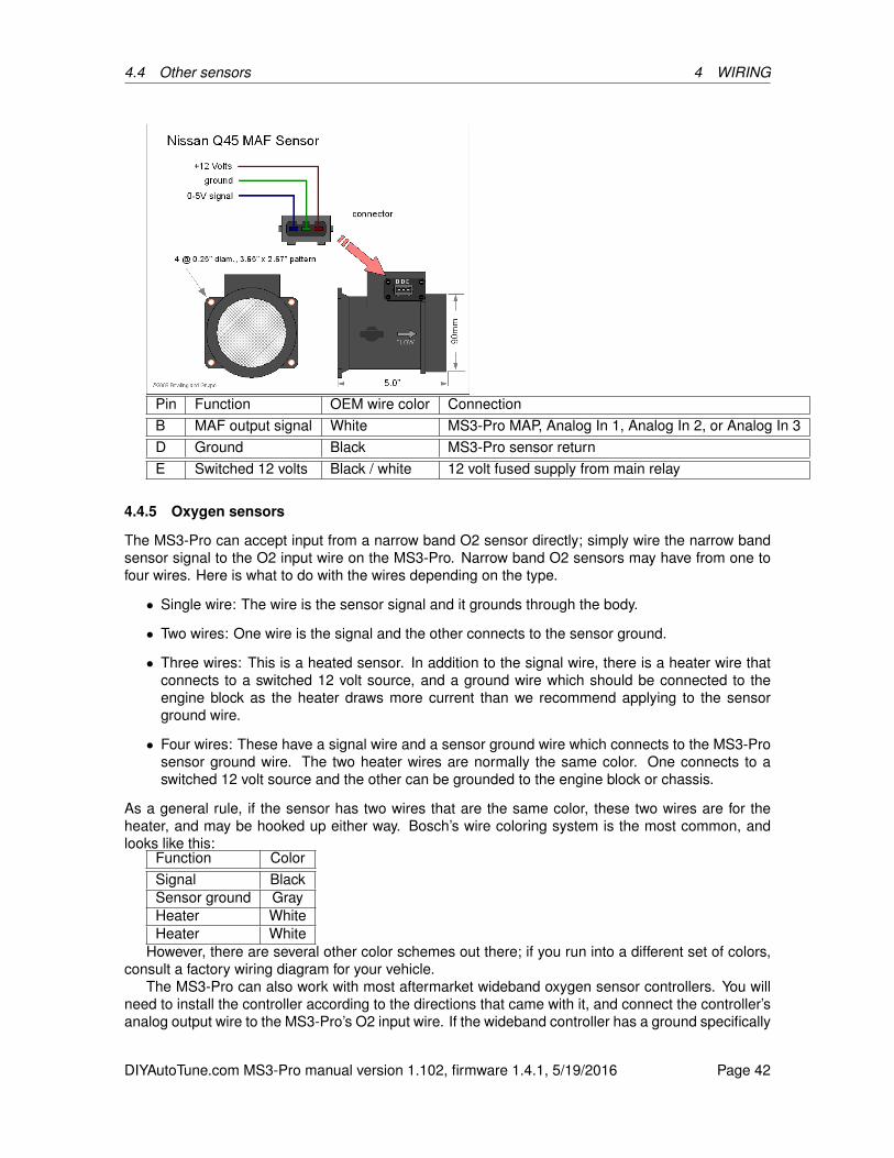
4.4 Other sensors 4 WIRING
Pin Function OEM wire color ConnectionB MAF output signal White MS3-Pro MAP, Analog In 1, Analog In 2, or Analog In 3D Ground Black MS3-Pro sensor returnE Switched 12 volts Black / white 12 volt fused supply from main relay
4.4.5 Oxygen sensors
The MS3-Pro can accept input from a narrow band O2 sensor directly; simply wire the narrow bandsensor signal to the O2 input wire on the MS3-Pro. Narrow band O2 sensors may have from one tofour wires. Here is what to do with the wires depending on the type.
• Single wire: The wire is the sensor signal and it grounds through the body.
• Two wires: One wire is the signal and the other connects to the sensor ground.
• Three wires: This is a heated sensor. In addition to the signal wire, there is a heater wire thatconnects to a switched 12 volt source, and a ground wire which should be connected to theengine block as the heater draws more current than we recommend applying to the sensorground wire.
• Four wires: These have a signal wire and a sensor ground wire which connects to the MS3-Prosensor ground wire. The two heater wires are normally the same color. One connects to aswitched 12 volt source and the other can be grounded to the engine block or chassis.
As a general rule, if the sensor has two wires that are the same color, these two wires are for theheater, and may be hooked up either way. Bosch’s wire coloring system is the most common, andlooks like this:
Function ColorSignal BlackSensor ground GrayHeater WhiteHeater White
However, there are several other color schemes out there; if you run into a different set of colors,consult a factory wiring diagram for your vehicle.
The MS3-Pro can also work with most aftermarket wideband oxygen sensor controllers. You willneed to install the controller according to the directions that came with it, and connect the controller’sanalog output wire to the MS3-Pro’s O2 input wire. If the wideband controller has a ground specifically
DIYAutoTune.com MS3-Pro manual version 1.102, firmware 1.4.1, 5/19/2016 Page 42

4.4 Other sensors 4 WIRING
for its analog output, it connects to the MS3-Pro sensor ground wire. Do not connect any wires labeled“serial output”, “digital output” or similar to the MS3-Pro, or connect any other sort of wideband groundto the MS3-Pro. Here is a list of what wire to use with common wideband controllers.
Controller Analog output Analog groundInnovate LC-1 Brown * N/AInnovate MTX-L Yellow * N/AInnovate LM-2 Lime green* Yellow*AEM UEGO White N/AZeitronix ZT-2, ZT-3 White Brown (ZT-2 only)PLX SM-AFR Gray N/A
*Innovate systems have multiple analog outputs; this is the recommended default.The above list is not intended to be a complete list of what wideband controllers will work with the
MS3-Pro; it will work with many other ones not listed. As long as the wideband has a 0-5 volt analogoutput, and you can obtain the specifications for its output, you can make it work with the MS3-Pro.
Additional narrow band O2 sensors or wideband controllers may be wired to the spare analoginput wires.
4.4.6 Knock sensors
If you have a two wire knock sensor, connect one wire to the knock input wire and the other wire tothe sensor return. Some cars have three wire knock sensors; the third pin is a connection for a shieldon the wire. If you’re only using one knock sensor, connect it to Knock In 1. Knock sensors, like VRsensors, generate their own voltage and do not require a power source.
4.4.7 Speed and gear sensors
The MS3-Pro can use analog or Hall effect speed sensors.Analog speed sensors are rare, but put out 0 volts with the vehicle stopped, increasing to 5 volts
at some top speed. These may be wired to Analog In 1, 2, or 3.Hall effect speed sensors are more common. These get 12 volts from the MS3-Pro’s main relay or
5 volts from VREF, and have a ground wire that connects to the MS3-Pro’s sensor ground. The outputsignal may connect to Digital Frequency In 1, 2, or 3, Digital Switched In 1, 2, or 3, or Digital Switched12V In. No pull up resistor is required if using our tabbed Hall effect sensor; we recommend a pull upwhen using our threaded Hall effect sensor. The MS3-Pro can use two separate speed sensors fordriven and non-driven wheels.
Some bikes are fitted with a Gear Position Sensor. This 0-5V analogue input can be used directlyto determine gear, and can connect to Analog In 1, 2, or 3. The MS3-Pro can also determine the gearyou are in by comparing the engine RPM and wheel speed.
When used with a MegaShift transmission controller, the MS3-Pro can read speed and gear infor-mation through the MegaShift over CAN. No additional sensor wiring is needed, other than the wiresfor the MegaShift.
DIYAutoTune.com MS3-Pro manual version 1.102, firmware 1.4.1, 5/19/2016 Page 43
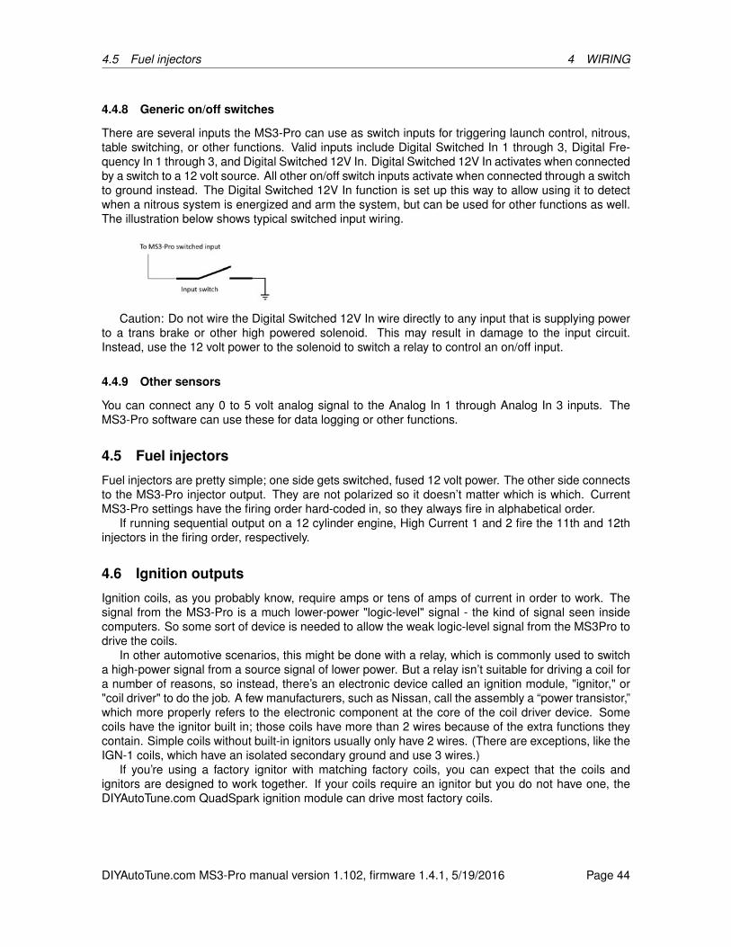
4.5 Fuel injectors 4 WIRING
4.4.8 Generic on/off switches
There are several inputs the MS3-Pro can use as switch inputs for triggering launch control, nitrous,table switching, or other functions. Valid inputs include Digital Switched In 1 through 3, Digital Fre-quency In 1 through 3, and Digital Switched 12V In. Digital Switched 12V In activates when connectedby a switch to a 12 volt source. All other on/off switch inputs activate when connected through a switchto ground instead. The Digital Switched 12V In function is set up this way to allow using it to detectwhen a nitrous system is energized and arm the system, but can be used for other functions as well.The illustration below shows typical switched input wiring.
Caution: Do not wire the Digital Switched 12V In wire directly to any input that is supplying powerto a trans brake or other high powered solenoid. This may result in damage to the input circuit.Instead, use the 12 volt power to the solenoid to switch a relay to control an on/off input.
4.4.9 Other sensors
You can connect any 0 to 5 volt analog signal to the Analog In 1 through Analog In 3 inputs. TheMS3-Pro software can use these for data logging or other functions.
4.5 Fuel injectors
Fuel injectors are pretty simple; one side gets switched, fused 12 volt power. The other side connectsto the MS3-Pro injector output. They are not polarized so it doesn’t matter which is which. CurrentMS3-Pro settings have the firing order hard-coded in, so they always fire in alphabetical order.
If running sequential output on a 12 cylinder engine, High Current 1 and 2 fire the 11th and 12thinjectors in the firing order, respectively.
4.6 Ignition outputs
Ignition coils, as you probably know, require amps or tens of amps of current in order to work. Thesignal from the MS3-Pro is a much lower-power "logic-level" signal - the kind of signal seen insidecomputers. So some sort of device is needed to allow the weak logic-level signal from the MS3Pro todrive the coils.
In other automotive scenarios, this might be done with a relay, which is commonly used to switcha high-power signal from a source signal of lower power. But a relay isn’t suitable for driving a coil fora number of reasons, so instead, there’s an electronic device called an ignition module, "ignitor," or"coil driver" to do the job. A few manufacturers, such as Nissan, call the assembly a “power transistor,”which more properly refers to the electronic component at the core of the coil driver device. Somecoils have the ignitor built in; those coils have more than 2 wires because of the extra functions theycontain. Simple coils without built-in ignitors usually only have 2 wires. (There are exceptions, like theIGN-1 coils, which have an isolated secondary ground and use 3 wires.)
If you’re using a factory ignitor with matching factory coils, you can expect that the coils andignitors are designed to work together. If your coils require an ignitor but you do not have one, theDIYAutoTune.com QuadSpark ignition module can drive most factory coils.
DIYAutoTune.com MS3-Pro manual version 1.102, firmware 1.4.1, 5/19/2016 Page 44
4.6 Ignition outputs 4 WIRING
4.6.1 QuadSpark ignition module
Here are the pins to use on the QuadSpark.Wire color Thickness ConnectionYellow 20 gauge MS3-Pro Spark Out AWhite 16 gauge Spark A to coil negativeOrange 20 gauge MS3-Pro Spark Out BPink 16 gauge Spark B to coil negativeDark green 20 gauge MS3-Pro Spark Out CLight green 16 gauge Spark C to coil negativeBlue 20 gauge MS3-Pro Spark Out DViolet 16 gauge Spark D to coil negativeBlack 4 x 14 gauge Ground to engine block or cylinder head
If using more than four channels of ignition output, you would use a second QuadSpark, wired uplike this:
Wire color Thickness ConnectionYellow 20 gauge MS3-Pro Spark Out EWhite 16 gauge Spark E to coil negativeOrange 20 gauge MS3-Pro Spark Out FPink 16 gauge Spark F to coil negativeDark green 20 gauge MS3-Pro Spark Out GLight green 16 gauge Spark G to coil negativeBlue 20 gauge MS3-Pro Spark Out HViolet 16 gauge Spark H to coil negativeBlack 4 x 14 gauge Ground to engine block or cylinder head
4.6.2 IGN-1A coil with built in ignition module
The IGN-1A is a high powered coil with a built in ignition module, capable of handling engines thatmake over 250 hp per cylinder. These can be used both for coil per plug applications or with adistributor. These use a five wire connector. The connector pins are designated with letters moldedinto the connector:
Connection letter FunctionA Spark out from MS3-ProB ECU ground - connect to sensor returnC Secondary ground - connect to engine block or cylinder headD Power ground - connect to battery negative terminalE 12 volt power
4.6.3 LS series coils
The coils on GM’s LS series engines are a popular choice as they are readily available, inexpensive,powerful, and have a built in ignition module. They can be wired directly to the MS3-Pro. LS1 andLS2 coils use different connector designs, but the connectors are always marked with small letters toindicate the function, and the function is the same on both:
Connection letter FunctionA Power ground - connect to engine block or cylinder headB ECU ground - connect to sensor returnC Spark out from MS3-ProD 12 volt power
DIYAutoTune.com MS3-Pro manual version 1.102, firmware 1.4.1, 5/19/2016 Page 45
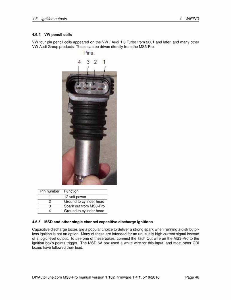
4.6 Ignition outputs 4 WIRING
4.6.4 VW pencil coils
VW four pin pencil coils appeared on the VW / Audi 1.8 Turbo from 2001 and later, and many otherVW-Audi Group products. These can be driven directly from the MS3-Pro.
Pin number Function1 12 volt power2 Ground to cylinder head3 Spark out from MS3-Pro4 Ground to cylinder head
4.6.5 MSD and other single channel capacitive discharge ignitions
Capacitive discharge boxes are a popular choice to deliver a strong spark when running a distributor-less ignition is not an option. Many of these are intended for an unusually high current signal insteadof a logic level output. To use one of these boxes, connect the Tach Out wire on the MS3-Pro to theignition box’s points trigger. The MSD 6A box used a white wire for this input, and most other CDIboxes have followed their lead.
DIYAutoTune.com MS3-Pro manual version 1.102, firmware 1.4.1, 5/19/2016 Page 46

4.6 Ignition outputs 4 WIRING
4.6.6 Common firing orders
DIYAutoTune.com MS3-Pro manual version 1.102, firmware 1.4.1, 5/19/2016 Page 47
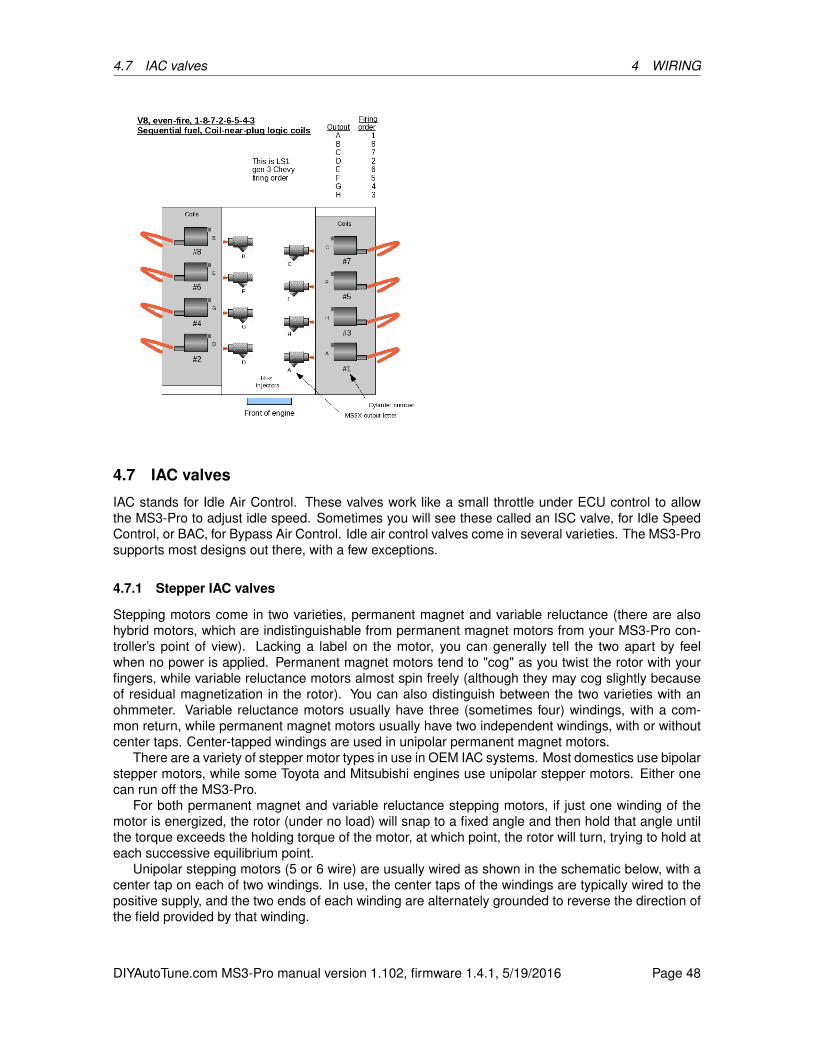
4.7 IAC valves 4 WIRING
4.7 IAC valves
IAC stands for Idle Air Control. These valves work like a small throttle under ECU control to allowthe MS3-Pro to adjust idle speed. Sometimes you will see these called an ISC valve, for Idle SpeedControl, or BAC, for Bypass Air Control. Idle air control valves come in several varieties. The MS3-Prosupports most designs out there, with a few exceptions.
4.7.1 Stepper IAC valves
Stepping motors come in two varieties, permanent magnet and variable reluctance (there are alsohybrid motors, which are indistinguishable from permanent magnet motors from your MS3-Pro con-troller’s point of view). Lacking a label on the motor, you can generally tell the two apart by feelwhen no power is applied. Permanent magnet motors tend to "cog" as you twist the rotor with yourfingers, while variable reluctance motors almost spin freely (although they may cog slightly becauseof residual magnetization in the rotor). You can also distinguish between the two varieties with anohmmeter. Variable reluctance motors usually have three (sometimes four) windings, with a com-mon return, while permanent magnet motors usually have two independent windings, with or withoutcenter taps. Center-tapped windings are used in unipolar permanent magnet motors.
There are a variety of stepper motor types in use in OEM IAC systems. Most domestics use bipolarstepper motors, while some Toyota and Mitsubishi engines use unipolar stepper motors. Either onecan run off the MS3-Pro.
For both permanent magnet and variable reluctance stepping motors, if just one winding of themotor is energized, the rotor (under no load) will snap to a fixed angle and then hold that angle untilthe torque exceeds the holding torque of the motor, at which point, the rotor will turn, trying to hold ateach successive equilibrium point.
Unipolar stepping motors (5 or 6 wire) are usually wired as shown in the schematic below, with acenter tap on each of two windings. In use, the center taps of the windings are typically wired to thepositive supply, and the two ends of each winding are alternately grounded to reverse the direction ofthe field provided by that winding.
DIYAutoTune.com MS3-Pro manual version 1.102, firmware 1.4.1, 5/19/2016 Page 48

4.7 IAC valves 4 WIRING
Typical bipolar steppers have 4 leads, connected to two isolated coils in the motor. These arethe most common in automotive applications. Bipolar permanent magnet and hybrid motors areconstructed with exactly the same mechanism as is used on unipolar motors, but the two windingsare wired more simply, with no center taps. The leads to both coils are brought out to the harness with4 wires. If you energize one coil the rotor will rotate to a position aligned with that coil. If you energizethe second coil the rotor will rotate a little bit to be aligned between the two coils. If you turn off thefirst coil the rotor will rotate a little more to line up directly with the second coil. If you energize thefirst coil again with the opposite polarity of the first time the rotor will rotate a little more, and so on.The MS3-Pro controller applies pulses in a particular sequence to the four wires to produce rotation.Each pulse results in specific amount of rotation of the motor . The motor can be made to spin eitherdirection by changing the polarity of the pulses.
On GM IAC steppers, the one coil usually has blue wires leading to it, the other coil has greenwires. The schematic below shows how such a motor is wired.
The picture below shows most of the common GM and Chrysler IAC valve pinouts and how theywire to the MS3-Pro. The illustration is looking into the IAC valve itself, not the wiring on the harnessside.
DIYAutoTune.com MS3-Pro manual version 1.102, firmware 1.4.1, 5/19/2016 Page 49
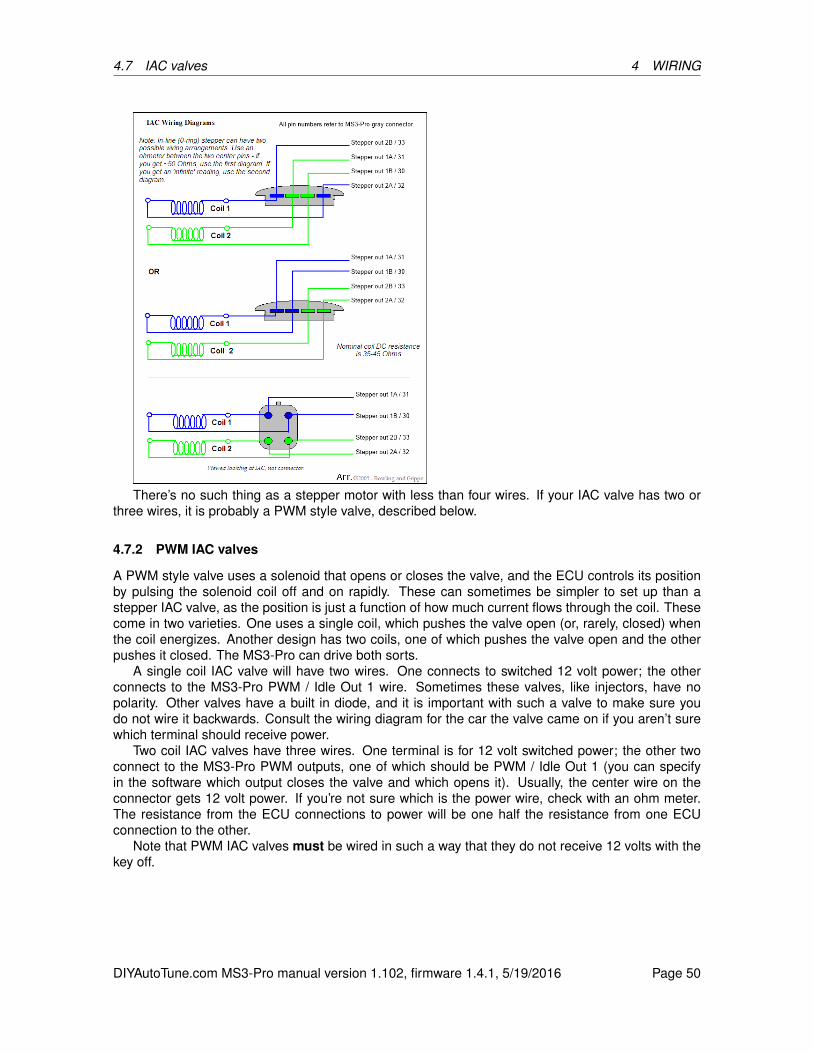
4.7 IAC valves 4 WIRING
There’s no such thing as a stepper motor with less than four wires. If your IAC valve has two orthree wires, it is probably a PWM style valve, described below.
4.7.2 PWM IAC valves
A PWM style valve uses a solenoid that opens or closes the valve, and the ECU controls its positionby pulsing the solenoid coil off and on rapidly. These can sometimes be simpler to set up than astepper IAC valve, as the position is just a function of how much current flows through the coil. Thesecome in two varieties. One uses a single coil, which pushes the valve open (or, rarely, closed) whenthe coil energizes. Another design has two coils, one of which pushes the valve open and the otherpushes it closed. The MS3-Pro can drive both sorts.
A single coil IAC valve will have two wires. One connects to switched 12 volt power; the otherconnects to the MS3-Pro PWM / Idle Out 1 wire. Sometimes these valves, like injectors, have nopolarity. Other valves have a built in diode, and it is important with such a valve to make sure youdo not wire it backwards. Consult the wiring diagram for the car the valve came on if you aren’t surewhich terminal should receive power.
Two coil IAC valves have three wires. One terminal is for 12 volt switched power; the other twoconnect to the MS3-Pro PWM outputs, one of which should be PWM / Idle Out 1 (you can specifyin the software which output closes the valve and which opens it). Usually, the center wire on theconnector gets 12 volt power. If you’re not sure which is the power wire, check with an ohm meter.The resistance from the ECU connections to power will be one half the resistance from one ECUconnection to the other.
Note that PWM IAC valves must be wired in such a way that they do not receive 12 volts with thekey off.
DIYAutoTune.com MS3-Pro manual version 1.102, firmware 1.4.1, 5/19/2016 Page 50

4.8 Fuel pump relay 4 WIRING
4.7.3 On/off IAC valves
Rare but supported. The MS3-Pro’s PWM / Idle Out 1 can drive an on/off idle solenoid directly if thesolenoid draws 3 amps or less.
4.7.4 Thermal IAC valves
These valves were used on some early Bosch L-Jetronic systems and are not controlled by the ECU.They use a thermal element that warms up and reduces idle speed as they heat up. If you have sucha valve, power it from the fuel pump relay.
4.7.5 DC servo IAC valves (currently not supported)
This design incorporates a two wire DC servo with a three wire position sensor. We’ve only seenthem on a few Ford and Mitsubishi throttle body injected engines from the 1980s. The MS3-Pro doesnot currently support this idle valve type.
4.8 Fuel pump relay
The MS3-Pro fuel pump relay output is a low side driver that supplies ground, not power. It can onlyhandle a maximum of 3 amps, so you will need to use this to turn on a relay to provide the fuel pumpwith enough power. We recommend supplying the fuel pump relay with a separate source of 12 voltpower from the ECU main relay to minimize electrical noise. Do not wire a fuel pump directly to theMS3-Pro. Also, do not wire the fuel pump relay coil in such a way that it receives 12 volts with the keyoff, as this power can backfeed into the MS3-Pro and cause it to stay powered up when the ignition isturned off.
4.9 Tach output
The tach output supplies a 0 to 12 volt square wave that is compatible with many factory tachometersand nearly all aftermarket units. Just wire its output to the tach signal wire.
4.10 High current outputs
The MS3-Pro’s three high current outputs can be used to control devices that draw up to 5 amps.These outputs are what are known as low side drivers; they provide a switched connection to ground.The other side receives 12 volts, ideally only when the ignition key is on. Recommended uses besideson/off output include nitrous control and running boost control solenoids, which pulse open and shut.
Note that any unused injector outputs can be used for the same on/off or low frequency functionsas the high current outputs; they have the same maximum current and basic design.
4.11 PWM medium current outputs
These outputs are low side drivers like the high current outputs, but can operate at a higher frequencyand have a maximum current of 3 amps. Devices connected to these outputs absolutely must notreceive power when the key is off, as the circuit used to clamp high frequency voltage spikes canfeed power back into the MS3-Pro’s power supply and prevent the ECU from turning on. Maximumfrequency is 1021 Hz. The high frequency outputs work best with valves that can stay in the middleof their travel, like variable valve timing control valves and idle air control valves.
DIYAutoTune.com MS3-Pro manual version 1.102, firmware 1.4.1, 5/19/2016 Page 51
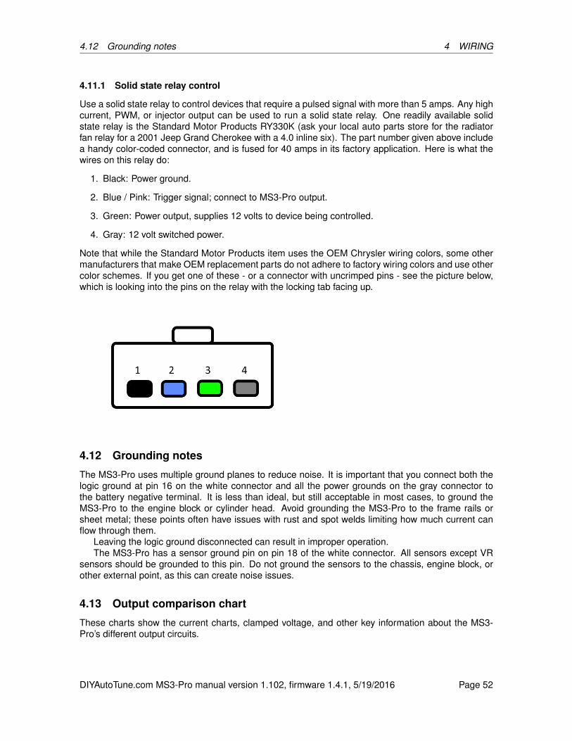
4.12 Grounding notes 4 WIRING
4.11.1 Solid state relay control
Use a solid state relay to control devices that require a pulsed signal with more than 5 amps. Any highcurrent, PWM, or injector output can be used to run a solid state relay. One readily available solidstate relay is the Standard Motor Products RY330K (ask your local auto parts store for the radiatorfan relay for a 2001 Jeep Grand Cherokee with a 4.0 inline six). The part number given above includea handy color-coded connector, and is fused for 40 amps in its factory application. Here is what thewires on this relay do:
1. Black: Power ground.
2. Blue / Pink: Trigger signal; connect to MS3-Pro output.
3. Green: Power output, supplies 12 volts to device being controlled.
4. Gray: 12 volt switched power.
Note that while the Standard Motor Products item uses the OEM Chrysler wiring colors, some othermanufacturers that make OEM replacement parts do not adhere to factory wiring colors and use othercolor schemes. If you get one of these - or a connector with uncrimped pins - see the picture below,which is looking into the pins on the relay with the locking tab facing up.
4.12 Grounding notes
The MS3-Pro uses multiple ground planes to reduce noise. It is important that you connect both thelogic ground at pin 16 on the white connector and all the power grounds on the gray connector tothe battery negative terminal. It is less than ideal, but still acceptable in most cases, to ground theMS3-Pro to the engine block or cylinder head. Avoid grounding the MS3-Pro to the frame rails orsheet metal; these points often have issues with rust and spot welds limiting how much current canflow through them.
Leaving the logic ground disconnected can result in improper operation.The MS3-Pro has a sensor ground pin on pin 18 of the white connector. All sensors except VR
sensors should be grounded to this pin. Do not ground the sensors to the chassis, engine block, orother external point, as this can create noise issues.
4.13 Output comparison chart
These charts show the current charts, clamped voltage, and other key information about the MS3-Pro’s different output circuits.
DIYAutoTune.com MS3-Pro manual version 1.102, firmware 1.4.1, 5/19/2016 Page 52

4.13 Output comparison chart 4 WIRING
Name Output type Max rated current Clamping voltageInjector Low side 5 A 36 V
High current Low side 5 A 36 VSpark 5V high side 100 mA* N/APWM Low side 3 A 12 VTach Low side w / 12 V pull up 1 A 12 V
Stepper H-bridge 400 mA peak 12 V* Do not exceed 250 mA total for all spark outputs at one time.
DIYAutoTune.com MS3-Pro manual version 1.102, firmware 1.4.1, 5/19/2016 Page 53
5 SETTING UP A BASIC CONFIGURATION
5 Setting up a basic configuration
5.1 Connecting the MS3-Pro to your laptop
1. Power up the MS3-Pro and plug it in to your laptop with either the provided serial or USB cable.The MS3-Pro is not powered through the serial cable; it will need to be connected to a goodpower and ground source to communicate.
2. Open TunerStudio. TunerStudio will check for available updates; if there is one, accept it and letit install.
3. From the File menu, select "New Project".
4. You may enter a name to keep track of the project and a detailed description in the ProjectDescription field.
5. Click the “Detect” button. TunerStudio should automatically detect that you have an MS3-Proand what port it is using.
6. Clicking the Next button will bring up a menu of project settings.
7. Here are what the project settings do:
• Oxygen Sensor/Display - selects the default gauges for oxygen or lambda sensor (theAFR/EGO settings must also be used to configure the firmware)
• Temperature Display - preferred temperature units
• CAN_COMMANDS - normally Deactivated. Only Activate this where you are connectingto the MS3 over a CAN network instead of directly with USB or serial.
• Internal Log Fields - normally Deactivated. Allows developers to log special fields intoSDcard logs
• PW_4X - normally Deactivated. Used in conjunction with the advanced firmware settingto enable four times the injector pulsewidth on large industrial engines that use injectorssized for operating below 2000 RPM.
• Port Status - allows displaying the status of input and output ports directly as indicators,and recording port status in data logs. Useful for troubleshooting, but can slow down datalogging rates.
• OutMSG Editing - Enables a system for sending CAN data to other CAN devices. Onlyneeded if the documentation for a CAN device you are using requires this.
8. When you are done with the project settings, click Next. This will bring up a page of communi-cations settings.
9. The final screen for project setup is to select a dashboard view. It is safe to accept the defaultand Finish. TunerStudio allows advanced users to create their own custom dashboard layouts.
10. At this point, you’re ready to start setting up the MS3-Pro to run your engine.
The first rule of tuning is that you do not want to tune from a blank file. You can either connect to theMS3-Pro and retrieve the tune on it (this is done automatically) or open an existing tune file, but becareful if you see this message:
DIYAutoTune.com MS3-Pro manual version 1.102, firmware 1.4.1, 5/19/2016 Page 54

5.1 Connecting the MS3-Pro to your laptop 5 SETTING UP A BASIC CONFIGURATION
This means that you have no tune loaded. This is OK if you are just having a look, but do not tryto start a tune like this. TunerStudio will default to a table full of zeroed out values - or in some cases,the numbers will be set to their lowest possible value. It’s not worth chasing down all the nonsensevalues to turn this “blank file” into a real tune. Start with either the tune in the ECU or one of thesample tunes provided in the software package.
We recommend that you do not have the ignition coils hooked up while doing a basic setup on theMS3-Pro. During the setup stage, you will define what type of ignition hardware that you are using, butif the ignition you have doesn’t work with the default settings, you may overheat your ignition moduleand damage it before you are done with your setup.
DIYAutoTune.com MS3-Pro manual version 1.102, firmware 1.4.1, 5/19/2016 Page 55

5.2 Basic engine constants 5 SETTING UP A BASIC CONFIGURATION
5.2 Basic engine constants
First, we’ll go over the basic settings you need to go through for starting the engine. The followingare the most essential settings. We’ll come back and go over the other menu items later. The firststop is under the Basic / Load Settings menu. Select Engine and Sequential Settings. Here iswhat the settings do.
• Required Fuel: This is your base pulse width. It is the amount of pulse width the engine wouldtheoretically need at 100 kPa and 100% volumetric efficiency. While you can enter it directly,we recommend using the calculator that the “Required Fuel...” button pulls up. Here, you willenter the engine displacement, number of cylinders, injector fuel rate, and air/fuel ratio. Usuallythe air/fuel ratio should be stoichiometric for the fuel used, such as 14.7 for gasoline or 9.85for E85 ethanol blends. Note that you will want to run this after entering the injector size anddisplacement numbers, below.
• Control Algorithm - This setting controls the method with which engine load is calculated.Engine load represents how hard the engine has to work and can be based on many factorssuch as manifold pressure, throttle position, air mass, or combinations of these. Note that thissetting only sets the control algorithm for fuel injection and related settings; it does not set thecontrol algorithm for ignition and related settings. You may use different algorithms for differenttables. The following settings may be selected.
– Speed Density - Use the MAP (Manifold Absolute Pressure) sensor to determine load. Inthis case, the vertical axis of any fuel table lookups is in kilopascals (kPa). The maximumvalue reported by the MAP sensor (in non-turbo applications) will be the same as thebarometric pressure.
– Percent Baro - This setting is similar to the Speed Density setting in that the MAP sensoris used to determine load. However, instead of directly using the manifold pressure, themanifold pressure is divided by barometric pressure to give a percentage of barometricpressure. This setting can be useful for those who regularly drive at high altitudes. Itensures that regardless of barometric pressure, all table lookups operate over 0-100%.For example, if barometric pressure is 80 kPa, and the engine is operating at 50 kPa, theactual value used for table lookups is 50kPa/80kPa or 62.5%.
– Alpha-N - Use the throttle position to determine load on the engine. Be sure to calibratethe throttle range using Tools -> Calibrate TPS before using this setting.
DIYAutoTune.com MS3-Pro manual version 1.102, firmware 1.4.1, 5/19/2016 Page 56
5.2 Basic engine constants 5 SETTING UP A BASIC CONFIGURATION
– MAF - Use the MAF sensor and related calculations to directly determine the amount offuel to inject. In this mode, the VE table is not used to determine the amount of fuel toinject.
– ITB - This mode was created specifically for naturally aspirated engines running with in-dependent throttle bodies. It combines alpha-n (at high engine loads) with speed density(at low engine loads), using the load calculation that makes the most sense at each RPM.For example, most ITB setups do not have good vacuum at idle or low RPM, and slightlytouching the throttle makes them lose all vacuum, but at higher RPM start to respond morelike a traditional single throttle body engine. This mode allows the use of speed densityat low engine loads and switches to alpha-n at high loads, with an adjustable switchpointcurve over RPM.
• Squirts Per Engine Cycle - Only used when running batch fired injection. Determines thenumber of times per engine cycle (two revolutions on a four-stroke engine) injectors are squirtedwhen in a batch injection mode. This setting has no effect when injecting sequentially.
• Injector Staging - This setting is used only in batch injection modes. It determines whether thetwo injection channels are squirted at the same time, or in an alternating fashion.
• Engine Stroke / Rotary - Specify whether the engine is a four or two stroke piston engine, ora Wankel rotary engine. The rotary mode allows for trailing spark outputs on Mazda and otherdual plug rotary designs.
• Number of Cylinders / Rotors - Sets the number of cylinders for the engine. The MS3-Pro canrun sequential injection on up to 12 cylinders.
• Engine Type - Determines whether the engine is an even-fire engine or odd-fire engine. Aneven fire engine is an engine where the crankshaft moves an equal number of degrees betweeneach cylinder’s top dead center (TDC). An odd fire engine may have a different number ofdegrees between TDC on some cylinders when compared with others. You are only likely tosee odd fire settings on certain V6 models, “crossplane” inline fours and split crank paralleltwins (found on some motorcycle engines), and V type engines having less than 6 cylinders.Normal V8, inline four, and inline six engines are all even fire.
• Engine Size and Injector Size are used for MAF fueling and the Required Fuel calculator.
• Main fuel outputs - This should be set to “Injector A, B...” Fuel for all normal MS3-Pro installs.This is included to allow you to check tune files imported from standard MS3s. It can be set touse only injector I and J, but this is mostly to maintain compatability with MS3 V3.0 / V3.57 tunefiles.
• Sequential On - The injector sequencing may be set to three different modes.
– Off - Use batch injection. The channels are divided into two groups, and all injectors in agroup are squirted simultaneously. This mode would typically be used if your engine hasan ignition input like a HEI distributor that provides for no cylinder identification.
– Semi-Sequential - Injects once every rotation, firing injectors in pairs. The injectors aretimed, so you can set the angle at which they fire. Injectors should be wired in the samemanner they would be wired for fully sequential injection.
– Fully Sequential - Use fully sequential injection. In this mode, outputs A-H are squirted insequence, so care must be taken to use the correct wiring for the engine’s firing order. Forexample, for a four cylinder engine with firing order 1-3-4-2, the following wiring should beused:
∗ Output A - Cylinder 1
DIYAutoTune.com MS3-Pro manual version 1.102, firmware 1.4.1, 5/19/2016 Page 57

5.3 Ignition settings 5 SETTING UP A BASIC CONFIGURATION
∗ Output B - Cylinder 3∗ Output C - Cylinder 4∗ Output D - Cylinder 2
• Angle Specifies - The MS3-Pro has a tunable injector timing table, and this setting determineshow the MS3-Pro interprets that table.
– End of Squirt - The angle specified in the injector timing table specifies the angle of theend of each squirt. This should be used by most people for most engines.
– Beginning of Squirt - The angle specified in the injector timing table specifies the angle ofthe beginning of each squirt.
– Middle of Squirt - You can also use the injector table to specify the mid-point of the injectionevent if you find this easier to tune.
• Injector Trim - Turning this on allows adjusting the injectors separately using injector trim tables.
• Firing order - The firing order should be set to the firing order that your engine uses. It doesnot affect the order in which the outputs are triggered. Instead it is used to associate an injectortrim table with a particular physical output so that when injector trim is applied, it is applied tothe correct cylinder. It is also used if closed-loop EGO is being done per-cylinder.
5.3 Ignition settings
Next, proceed to the Ignition Settings menu and select Ignition Options / Wheel Decoder to setup how the MS3-Pro gets its RPM input and controls the ignition.
Here are what the settings under this menu do. We’ll go over setting these up, then the nextsubsection will cover the settings for specific engine modes.
• Spark mode - this sets the type of tach input pattern decoder to be used. Four of these modesare generic, while the remainder of these are model specific ignitions. Here are the four genericmodes. The chart below shows what the model specific modes cover.
DIYAutoTune.com MS3-Pro manual version 1.102, firmware 1.4.1, 5/19/2016 Page 58
5.3 Ignition settings 5 SETTING UP A BASIC CONFIGURATION
– Fuel Only: The ECU is not controlling ignition, and receives a tach signal of one pulse forevery ignition event.
– Basic Trigger: A simple distributor trigger setup where the ECU controls the ignition, butreceives one pulse per ignition event. Common examples include Ford TFI, GM computercontrolled HEI, and MSD’s “flying magnet” crank trigger.
– Trigger Return: Similar to Basic Trigger, but there is a Hall effect or optical distributor wherethe leading edge of the signal is used to calculate timing when the engine is running, andthe trailing edge is used for cranking timing. Common in VW and other European Halleffect distributors.
– Toothed Wheel: This is a user defined trigger wheel configuration. There are two basictypes: “Dual Wheel” mode has one trigger wheel with equally spaced teeth and a one toothsync signal, while “Missing tooth” mode has a wheel where most of the teeth are equallyspaced, but there is a gap of the width of one or two teeth. This wheel may or may notbe paired with a second sensor for cam sync use. Ford, Bosch, and Nippon Denso OEMsystems often use this mode. So do the common aftermarket dual sync type distributors.
Note that some modes in the chart below can be run without a cam sensor, but if the cam sensor isomitted, the engine will not be able to run sequential injection or coil on plug.
DIYAutoTune.com MS3-Pro manual version 1.102, firmware 1.4.1, 5/19/2016 Page 59
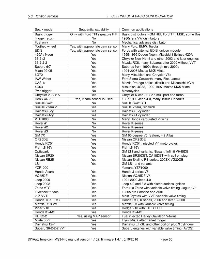
5.3 Ignition settings 5 SETTING UP A BASIC CONFIGURATION
Spark mode Sequential capability Common applicationsBasic trigger Only with Ford TFI signature PIP Basic distributors - GM HEI, Ford TFI, MSD, some BoschTrigger return No 1980s era VW distributorsFuel only No Mechanical advance distributorToothed wheel Yes, with appropriate cam sensor Many Ford, BMW, ToyotaEDIS Yes, with appropriate cam sensor Fords with external EDIS ignition module420A / Neon Yes 1995-1999 Dodge Neon, Mitsubishi Eclipse 420A36-2+2 Yes Chrysler New Hemi and other 2003 and later engines36-2-2-2 Yes Mazda RX8, many Subarus after 2000 without VVTSubaru 6/7 Yes Subarus from 1990s through mid 2000sMiata 99-05 Yes 1994-2005 Mazda MX5 Miata6G72 Yes Many Mitsubishi and Chrysler V6sIAW Weber Yes Ford Sierra Cosworth, many Fiat, LanciaCAS 4/1 Yes Mazda Protege optical distributor, Mitsubishi 4G914G63 Yes Mitsubishi 4G63, 1990-1997 Mazda MX5 MiataTwin trigger No MotorcyclesChrysler 2.2 / 2.5 Yes Chrysler K-car 2.2 / 2.5 multiport and turboRenix 44-2-2 Yes, if cam sensor is used 1987-1990 Jeep 4.0, many 1980s RenaultsSuzuki Swift No Suzuki Swift GTISuzuki Vitara 2.0 Yes Suzuki Vitara, SidekickDaihatsu 3cyl Yes Daihatsu 3 cylinderDaihatsu 4cyl Yes Daihatsu 4 cylinderVTR1000 No Many Honda carbureted V-twinsRover #1 No Rover K-seriesRover #2 No Rover K-seriesRover #3 No Rover K-seriesGM 7X Yes GM 60 degree V6, Saturn, 4.2 AtlasQR25DE Yes Nissan QR25DEHonda RC51 Yes Honda RC51, injected V-4 motorcyclesFiat 1.8 16V Yes Fiat 1.8 16VOptispark Yes GM LT1 and variants, Nissan / Infiniti VH45DENissan SR20 Yes Nissan SR20DET, CA18DET with coil on plugNissan RB25 Yes Nissan Skyline RB series, 300ZX VG30DELS1 Yes GM LS1 and variantsYZF1000 Yamaha YZF1000Honda Acura Yes Honda J series V6VQ35DE Yes Nissan VQ35DE V6Jeep 2000 Yes 1991-2000 Jeep 4.0Jeep 2002 Yes Jeep 4.0 and 3.8 with distributorless ignitionZetec VTC Yes Ford 2.0 Zetec with variable valve timing, Jaguar V8Flywheel tri-tach Yes 1980s era Porsche and Audi2JZ VVTi Yes Most Toyotas with VVTi variable valve timingHonda TSX / D17 Yes Honda D17, K series, 2006 and later S2000Mazda6 2.3 VVT Yes Mazda 2.3 with variable valve timingViper V10 Yes Dodge V10 with JTEC ECUHonda K24A2 Yes Honda K24A2HD 32-2 Yes, using MAP sensor Fuel injected Harley-Davidson V-twinsMiata 36-2 Yes Flyin’ Miata aftermarket triggerDaihatsu 12+1 Yes Daihatsu EF-SE and other coil on plug 3 cylindersSubaru 36-2-2-2 VVT Yes Subaru engines with variable valve timing (AVCS)
DIYAutoTune.com MS3-Pro manual version 1.102, firmware 1.4.1, 5/19/2016 Page 60

5.3 Ignition settings 5 SETTING UP A BASIC CONFIGURATION
• Trigger Angle/Offset - There are three different ways this setting is used:
– In Basic Trigger and Trigger Return, it specifies the engine angle BTDC that each triggerpulse is received.
– In Toothed Wheel, it should always be set to zero - use tooth#1 angle instead.
– In other modes, this setting can make a +/- 20 degree adjustment to the preset timingalignment.
• Angle between main and return - This is only used in CAS 4/1 mode and specifies the angularlength of each tooth.
• Oddfire first angle - For oddfire engines this specifies the angle the engine must rotate fromspark A output to spark B output.
• GM HEI/DIS, TFI, C3I options - Some distributor and related setups have a couple of extratricks that they use:
– Off: No additional spark outputs or cylinder identifications are used:
– GM Bypass on Spark B: On a computer controlled GM HEI or many GM distributorlessignitions, this setting enables the "bypass" output on spark B. The bypass output allowsthe module to control the timing during cranking. The ECU applies voltage to the bypasswire after startup to take control of timing.
– Buick C3I: This uses a distributorless ignition which behaves like a GM HEI, but also in-cludes a cam sync signal. Used with Toothed Wheel mode instead of Basic Trigger toenable the cam sensor.
– TFI Non-Signature: Used with Ford TFI distributors where all trigger vanes are the samelength.
– TFI Signature PIP: This allows you use the cylinder identification feature on Ford SignaturePIP distributor, where one vane is shorter than the others. Signature PIP mode is usedwith "Basic Trigger" and allows the MegaSquirt to use these distributors for sequential fuel.
• Oddfire phasing - Most oddfire engines, such as the Chevy V6, use alternate long/short anglesbetween cylinders. Yamaha Vmax and a couple other V-twins use a paired long/long/short/shortpattern. You can also define a custom pattern with four separate odd fire angles, for engineswhere the odd fire sequence is really odd.
• Skip Pulses - This tells the code how many input pulses it should ignored before attempting tomatch the input pattern. The default value of 3 is suitable for most applications. Increasing thisnumber can filter out RPM spikes right at the start of cranking, but setting this value too high willdelay startup. This setting is only used for startup and is ignored after the engine is running.
• Ignition Input Capture - Determines if the active edge is when the voltage on the RPM inputrises or falls. This must be matched to your tach input. If it is set incorrectly you can experiencetiming drift with rpms or misdetection of missing teeth on a missing tooth wheel. The toothlogger can be used to confirm polarity is correct. Note that for compatibility across severaldifferent products in the MegaSquirt family, this name refers to the signal at the processor, notthe signal coming into the ECU. The MS3-Pro’s input conditioner will invert the signal. So if youwere using a Hall effect sensor where the voltage dropped from 12 to 0 volts, the MS3-Pro willsee this as a rising edge instead of a falling one. If using the Digital Frequency In pins for caminput, the signal on the Digital Frequency In pins is not inverted.
DIYAutoTune.com MS3-Pro manual version 1.102, firmware 1.4.1, 5/19/2016 Page 61
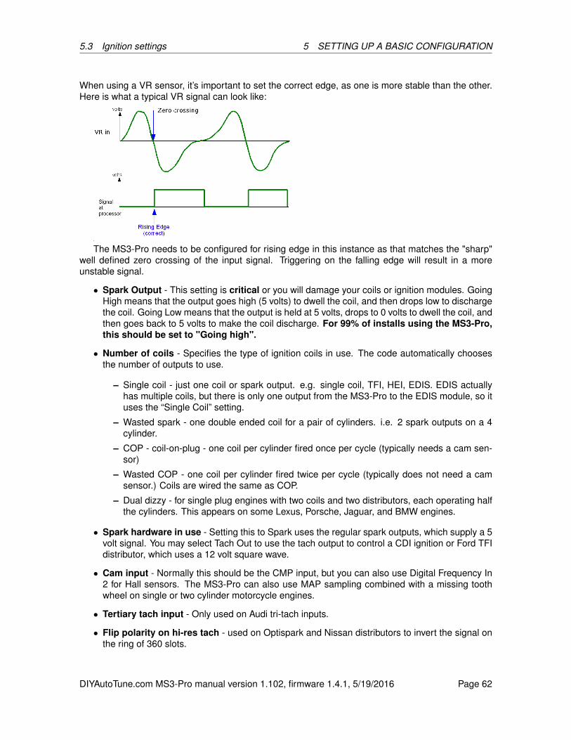
5.3 Ignition settings 5 SETTING UP A BASIC CONFIGURATION
When using a VR sensor, it’s important to set the correct edge, as one is more stable than the other.Here is what a typical VR signal can look like:
The MS3-Pro needs to be configured for rising edge in this instance as that matches the "sharp"well defined zero crossing of the input signal. Triggering on the falling edge will result in a moreunstable signal.
• Spark Output - This setting is critical or you will damage your coils or ignition modules. GoingHigh means that the output goes high (5 volts) to dwell the coil, and then drops low to dischargethe coil. Going Low means that the output is held at 5 volts, drops to 0 volts to dwell the coil, andthen goes back to 5 volts to make the coil discharge. For 99% of installs using the MS3-Pro,this should be set to "Going high".
• Number of coils - Specifies the type of ignition coils in use. The code automatically choosesthe number of outputs to use.
– Single coil - just one coil or spark output. e.g. single coil, TFI, HEI, EDIS. EDIS actuallyhas multiple coils, but there is only one output from the MS3-Pro to the EDIS module, so ituses the “Single Coil” setting.
– Wasted spark - one double ended coil for a pair of cylinders. i.e. 2 spark outputs on a 4cylinder.
– COP - coil-on-plug - one coil per cylinder fired once per cycle (typically needs a cam sen-sor)
– Wasted COP - one coil per cylinder fired twice per cycle (typically does not need a camsensor.) Coils are wired the same as COP.
– Dual dizzy - for single plug engines with two coils and two distributors, each operating halfthe cylinders. This appears on some Lexus, Porsche, Jaguar, and BMW engines.
• Spark hardware in use - Setting this to Spark uses the regular spark outputs, which supply a 5volt signal. You may select Tach Out to use the tach output to control a CDI ignition or Ford TFIdistributor, which uses a 12 volt square wave.
• Cam input - Normally this should be the CMP input, but you can also use Digital Frequency In2 for Hall sensors. The MS3-Pro can also use MAP sampling combined with a missing toothwheel on single or two cylinder motorcycle engines.
• Tertiary tach input - Only used on Audi tri-tach inputs.
• Flip polarity on hi-res tach - used on Optispark and Nissan distributors to invert the signal onthe ring of 360 slots.
DIYAutoTune.com MS3-Pro manual version 1.102, firmware 1.4.1, 5/19/2016 Page 62
5.3 Ignition settings 5 SETTING UP A BASIC CONFIGURATION
The remaining settings on the left hand side are for Toothed Wheel mode, which will be covered inthe specific ignition settings section. Here is what the settings on the right hand side do.
• Fixed advance - When set to "Fixed Advance", the spark timing is locked to the value set below.This is used for confirming timing with a strobe timing light during setup. For normal operation,this must be set to "Use table" so that the spark advance table is used.
• Use Prediction - Normally set to "1st Deriv Prediction". Alters the way the internal spark timingcalculation functions. With no prediction, spark retard may be observed during engine acceler-ation. With 1st Deriv, this is automatically compensated for.
• Timing for Fixed Advance - only applies when "Fixed Timing" is set above. Timing is thenlocked to this specified value.
• Cranking dwell - specifies the base coil dwell time during cranking before battery correction isapplied.
• Cranking advance - The MS3-Pro uses a fixed timing angle while cranking, specified here.
• Toyota Multiplex - Used for Toyota DLI distributorless ignitions. Known applications include the7M-GTE and Japanese market 4A-GZE. This uses the primary spark output as a timing signal,and secondary spark outputs to specify which coil is active.
• Dwell type - Can be "Standard Dwell", "Fixed Duty", "Time after Spark", "Charge at Trigger" toaccommodate different ignition types.
– Standard Dwell - this is the setting to use for most installs. i.e. regular coils that are firedby a module or with internal drivers or logic-level COPs. This is also used with GM-HEI7and GM-DIS.
– Fixed Duty - locks the spark output to a constant duty cycle instead of controlling dwell.This is typically used for ignition modules that control the dwell directly, including Ford’s"Push Start" TFI modules, Bosch "smart" ignition modules, or MSD and other capacitivedischarge boxes.
– Time After Spark - only intended for Saab Tri-Ionic DI cassettes that require a backwardsdwell signal.
– Charge at trigger - This is a highly specialized mode intended for driving a CDI thyristordirectly. Do not use with multi-tooth wheels. Do not use with direct coil control or COP typeignitions as the dwell varies with rpm and advance. Do not use if you are not certain whata thyristor is.
• Use dwell vs rpm curve - For Saab Tri-ionic and time-after-spark, the dwell can be varied withrpm.
• Use Dwell Table - Enables a 3D table of dwell as a function of RPM and load. This lets yourun a low dwell under vacuum and increase dwell only under boost, to reduce heat load on thecoils.
• Nominal dwell - The base dwell time before battery voltage correction. (With the standardcorrection curve, this time is applied at 14V.) Typical values are 3-4 ms.
• Spark duration - The time required for the spark to complete, typically in the order of 1 mil-lisecond. Note that in older single-coil systems with many cylinders, the dwell time can beconstrained at higher rpms as there isn’t enough time between cylinders for the desired dwelland spark. The dwell time is automatically reduced in this case (this is the reason for stock HEIignition being weak above 5000rpm on V8s.) With wasted-spark or COP, there is far greatertime between ignition events and this dwell-reduction rarely occurs.
DIYAutoTune.com MS3-Pro manual version 1.102, firmware 1.4.1, 5/19/2016 Page 63
5.3 Ignition settings 5 SETTING UP A BASIC CONFIGURATION
• Dwell time - the backwards dwell time for Time-After-Spark
• Dwell duty - for fixed duty, this specifies the percentage duty cycle of the output signal.
• Spark Hardware Latency - all electronic devices take a finite time to propagate signals andswitch. This setting allows for that slight delay. If you notice a slight retarding of ignition timingwith rpm while strobing with fixed timing, you can enter a small number in here to remedy it.
• Middle LED indicator - not used on MS3-Pro.
• Spark Trim - enables the adjustment of timing per individual cylinder. This requires a suitabletrigger wheel capable of cylinder identification; modes like Basic Trigger do not allow this.
Now, for the settings for specific ignition modes. Note that many of the model specific modes arenamed after one common application of the settings, but there are often other engines that will usethe same settings. For example, the “4G63” mode is not just used on the Mitsubishi 4G63, but alsoon other Mitsubishi engines and Mazda Miatas.
5.3.1 Basic Trigger
The distributor is the traditional method of timing spark and distributing the high-tension spark voltageto individual spark plugs. Originally, this used a set of breaker points, a condenser and a singleignition coil. Most distributors feature mechanical and vacuum advance systems to match spark timingsomewhere close to optimal for different operating conditions. Later systems were "breakerless" andreplaced the high-maintenance points with VR, hall or optical sensors, but there is still just one toothfor each cylinder. When combined with OEM fuel injection systems, the distributor may be "locked"in that there is no advance mechanism and the timing is controlled by the computer. Any enginepredating fuel injection will have the tach pickup within the distributor. With most distributors there isno cylinder identification so it is not possible to run sequential fuel; Ford Signature PIP TFI distributors,which used one short vane and the others a different length, are the exception.
This mode also covers arrangements with a single crank wheel with one tooth for every two cylin-ders, where there is no cam sensor used. This looks exactly the same to the ECU - other than thatthe signal is more accurate.
Ford TFI and GM computer controlled are specialized versions of the distributor system and willbe covered in their own sections. “Basic Trigger” does not cover “dual sync” distributors, which havetwo pickups and use “Toothed Wheel” mode, or setups which have a distributor but use a morecomplicated trigger pattern than the basic “one tooth, one cylinder.” There are covered in their ownsections.
Examples of ignitions that use “Basic Trigger” include:
• Ford TFI
• GM HEI (both original and computer controlled)
• Chrysler Lean Burn
• MSD distributors and Flying Magnet
In all cases, you’d wire the Crankshaft Position In wire to the distributor pick-up, and Spark A Out toan ignition module.
DIYAutoTune.com MS3-Pro manual version 1.102, firmware 1.4.1, 5/19/2016 Page 64

5.3 Ignition settings 5 SETTING UP A BASIC CONFIGURATION
5.3.1.1 Input phasing In most cases you will be controlling timing with the MegaSquirt, for thisyou need a trigger that does not vary angle with rpm or load. This is called a "locked distributor".
Early distributors such as points, original HEI, Duraspark etc, all have advance mechanisms builtin. Similar distributors can be converted for use with MegaSquirt -
• Remove ignition module (if present)
• Connect pickup sensor (VR, hall, opto, points) to MegaSquirt.
• Remove and weld up mechanical advance mechanism.
• Remove vacuum canister.
• Use remnants of vacuum advance mechanism to achieve correct input:output phasing. Youmay be able to set the rotor output phasing FIRST and then rotate the baseplate to achieve thecorrect input phasing.
Later engines may feature a distributor in conjunction with computer controlled timing - usually thesedistributor are "locked" from the factory and should already have good input and output phasing. (e.g.Ford TFI, GM computer controlled, Bosch hall effect.) Align as per the factory manuals and determinehow it is phased before you modify anything!
The crank angle at which the tach input triggers is of importance and needs to be configured inthe MegaSquirt. For best spark control, there are some optimal and some disallowed crank angles. Atypical engine will have an operating advance range of approximately 10-50r BTDC timing (dependingon engine type.) The trigger must not happen during this range of angles. It can be really helpful toinstall timing tape on your crank pulley or temporarily mark on a range of angles.
For best accuracy at high revs or during transients, aim for the trigger to align at 60-90r BTDC.This also allows a full range of timing and including retarded timing should you need it for boostedconditions. This range of trigger angle is preferred for new installs. For slightly better starting, butnot quite such good running accuracy, aim for a trigger ~10r BTDC or your desired cranking advance.This is the typical trigger angle for TFI and computer controlled HEI. You cannot retard timing laterthan the trigger angle. e.g. 9r BTDC and lower are not possible with a 10r BTDC trigger angle.
The VR sensor input presents a simple pulse as the reluctor passes the sensor, this gives a timingposition easily identified by eye. Rotate the engine to 60r BTDC (or 10r BTDC if chosen) and thenalign the distributor so the reluctor aligns with the center of the sensor.
5.3.1.2 Ford TFI distributors Ford’s TFI module was used throughout the 1980s and into the1990s on many millions of vehicles in two main mounting positions - “distributor mount” and “remotemount”. There are also two electrical versions: "Push Start" and "Computer Controlled Dwell" : doc-umentation claims that these can be distinguished by color, but that appears unreliable. Checkingthe wiring on pin4 is likely best. The wiring of the modules is largely the same, just the distributormount connects directly to a 3 wire hall sensor in the distributor. In most installations you do not needto concern yourself with that as only the “PIP” and “SPOUT” connections are of interest. The otherconnections should be left stock.
DIYAutoTune.com MS3-Pro manual version 1.102, firmware 1.4.1, 5/19/2016 Page 65
5.3 Ignition settings 5 SETTING UP A BASIC CONFIGURATION
The white wire on the CKP input connects to the PIP signal, and the Tach Out wire (NOT Spark AOut) connects to PIP. Be sure “Spark hardware in use” is set to Tacho.
The module described mainly here is the "Push Start" type that uses a 12V start signal. Whilesome documentation claims that all “PS” type modules are gray, we’ve seen them in black as well. Amore reliable indicator is that pin 4 will be connected to a 12 volt source when cranking. 50% dwellduty should be used. On the "CCD" type, pin 4 runs as a diagnostic signal to the original ECU. Thesemodules need normal dwell control instead of a fixed duty. We recommend starting with 3.0 ms dwelland adjusting to match the coil used. Other wiring should be the same.
"Base Timing" on the distributor (with computer control "SPOUT" disconnected) is around 10BTDC.This is the number you should use as your initial Trigger Offset, and adjust as needed to obtain correcttiming. As these distributors were designed for ECU control, the rotor arm phasing should already becorrect.
The “Signature PIP” versions of the TFI distributor have a shorter vane used to identify the #1cylinder. These appeared on factory sequential injected engines. These are still set up as basictrigger, but you will set “TFI Signature PIP” under Ford TFI Options.
Set “Ignition Input Capture” to “Falling Edge” and Spark Output to “Going High”.
5.3.1.3 GM HEI The original "High Energy Ignition" (HEI) distributors used the 4 pin module fromthe early 1970s (as shown in the photo at the top of the page.) That module is fine in the breakerlessdistributor as designed, but is not suitable for computer timing control. The later 7 and 8 pin modulesand corresponding distributors are designed for computer control and should be an easy swap ontoearlier engines - not only are those modules intended for computer control, but their distributors arealready locked-out so no modifications are required. HEI7/8 uses three control wires to/from theMS3-Pro.
• The ’Ref’ signal from the module to the MS3-Pro gives rpm and engine position information. Itconnects to the white wire on the CKP In line.
• The ’Est’ signal from MS3-Pro to the module controls the advance when running. It connects toSpark A Out.
• The ’Bypass’ signal from MS3-Pro to the module allows the module to beneficially control itsown advance during cranking. Once the engine has been running for more than 5 seconds, theMS3-Pro takes control of timing. It connects to Spark B Out.
To enable the bypass, set GM HEI / DIS options to “GM Bypass on SpkB”. Set Ignition Input Captureto “Rising Edge” and Spark Output to “Going High”. Set trigger angle 10 and adjust as needed.
5.3.1.4 MSD distributor based ignitions Most MSD distributors use a two wire sensor that MSDcalls a magnetic pickup. This is called a VR sensor throughout the MS3-Pro documentation, as thereare other sensors (such as Hall effect sensors) that are also magnetic, but put out very differentsignals. MSD Flying Magnet pick-ups also fall into this category.
MSD ignition boxes require a grounded signal to trigger, and the regular MS3-Pro spark outputsare designed to provide voltage instead of grounds. The tach output, on the other hand, will provideground, so it is used to trigger the MSD box. For an MSD 6AL or similar box, connect the MSD whitewire to the MS3-Pro tach output pin.
• Ignition Input Capture depends on the sensor and how it is wired up. Set to whichever edgegives the most stable signal across the RPM range. These signasl typically have one good edgeand one bad edge.
• Spark output needs to be set to Going High.
• Spark Hardware In Use needs to be set to Tacho Out.
DIYAutoTune.com MS3-Pro manual version 1.102, firmware 1.4.1, 5/19/2016 Page 66
5.3 Ignition settings 5 SETTING UP A BASIC CONFIGURATION
MSD boxes can be run on standard dwell or fixed duty. The MSD box is effectively in control of thedwell in this application.
5.3.2 Trigger Return
Trigger Return is a special case of Basic Trigger which can be used if you have a Hall effect distributoror optical distributor where all the slots, shutters, or vanes are equally sized. The purpose of the"Trigger Return" mode is to have accurate cranking timing as well as accurate running timing. Itachieves this by using the signal from both edges of a vane/slot. One edge is used for the timingcalculations during running and will typically pass the sensor at 55r BTDC or more. The other edgeis used for cranking timing and must pass the sensor at the desired cranking advance angle e.g. 10rBTDC.
Examples of ignitions that use Trigger Return include:
• Many ’80s era water cooled VWs
• Volvos with Bosch LH2.2 ignition
5.3.3 Fuel only
When the MS3-Pro is not controlling ignition, you will need to send it a tach signal on the CKP Inwhite wire. The MS3-Pro cannot trigger off the negative terminal of the coil. Examples of acceptablesignals that you CAN use to trigger the MS3-Pro include:
• Electronic distributor pickups
• The tach output terminal of an MSD or other capacitive discharge ignition box
5.3.4 Toothed wheel
The Trigger Wheel mode is designed to support most combinations of regular missing tooth wheelswith or without a cam signal. Other ignition modes are used to support irregular or OEM specificwheel patterns.
The table below lists all of the valid combinations for trigger wheel. However, some of the modeswill rarely be used. The most common are:
• 36-1 on crank with no cam sensor - many Fords
• 36-1 on crank plus single tooth cam sensor - same
• 60-2 on crank with no cam sensor - many vehicles with early Bosch Motronic engine manage-ment: BMW, VW, Audi, Volvo, Vauxhall, Opel, Peugeot etc.
• 60-2 on crank plus single tooth cam sensor - Bosch Motronic systems with sequential injectionor distributorless ignition
• 24 tooth on cam - many Japanese originated vehicles use the Nippon Denso 24 tooth CAS withdiffering numbers of 2nd trigger teeth and sensors.
Note - this table is for four-stroke piston engines. Two stroke or rotaries only need 360 degrees ofinformation for full sequential and COP. Commonly used modes have detailed sections on how to setthem up. Unusual modes are not documented in detail at this time.
For initial setup and determining tooth#1 angle on uncommon setups, having timing marks or tapeon your crank pulley/damper covering the full 360 degrees will be greatly helpful. Speed shops selltiming tape for a variety of damper diameters. If your engine has no timing marks, you do need to
DIYAutoTune.com MS3-Pro manual version 1.102, firmware 1.4.1, 5/19/2016 Page 67

5.3 Ignition settings 5 SETTING UP A BASIC CONFIGURATION
add them. Just guessing at timing is a great way to damage an engine. Running excessive timingunder load will almost always cause severe engine damage, e.g. broken pistons. It is essentialthat timing is confirmed with a timing-light on EVERY install.
Trigger wheels Sequential level SettingsMainwheel
Secondarywheel
Distributoronly
Semi se-quential
Full se-quential
Triggerwheel ar-
rangement
Mainwheelspeed
2ndtrigger
active onMissingtooth on
crank
None Y Y N Singlewheel with
missingtooth
Crank n/a
Missingtooth on
cam
None Y Y Y Singlewheel with
missingtooth
Cam n/a
Missingtooth on
crank
Single toothon cam
Y Y Y Dual wheelwith
missingtooth
Crank n/a
Nonmissingtooth on
crank
Single toothon crank
Y Y N Dual wheel Crank Crank
Nonmissingtooth on
crank
Single toothon cam
Y Y Y Dual wheel Crank Cam
Nonmissingtooth on
crank
Cam wheelwith tooth
per cylinder
Y N N Dual wheel Crank EveryCylinder
Nonmissingtooth on
cam
Single toothon cam
Y Y Y Dual wheel Cam Cam
Nonmissingtooth on
cam
Single toothon crank or
twooppositeteeth on
cam
Y Y N Dual wheel Cam Crank
Nonmissingtooth on
cam
Cam wheelwith tooth
per cylinder
Y N N Dual wheel Cam EveryCylinder
Distributor only: Can only use a distributor and batch fire fueling.Semi-sequential: Supports wasted spark or wasted-COP ignition and semi-sequential fueling.Full sequential: Supports sequential COP and sequential fueling.
DIYAutoTune.com MS3-Pro manual version 1.102, firmware 1.4.1, 5/19/2016 Page 68
5.3 Ignition settings 5 SETTING UP A BASIC CONFIGURATION
5.3.4.1 Terminology notes
• Missing tooth - This is a regular wheel with a group of "missing" teeth e.g. 12-1, 36-1, 36-2,60-2
• on crank - the wheel is rotating at crank speed, normally directly attached to the crank pulleyor flywheel
• on cam - the wheel is rotating at camshaft or distributor speed
• Single coil - a single coil and distributor
• Wasted spark - double ended coils (or a pair of coils) that fire twice per cycle
• Wasted-COP - a single coil per cylinder, but firing twice per cycle. Each coil is controlled by aseparate wire. Useful for testing out a dual wheel arrangement when you are uncertain of thecam phase.
• COP - a single coil per cylinder that fires once per cycle
• Batch/bank fire - groups of injector fired at once, not timed to a specific cylinder event
• Semi-sequential - injectors fired twice per cycle timed to cylinder events
• Sequential - each injector fires once per engine cycle timed to a specific cylinder event
5.3.4.2 Wheel naming There does not appear to be universal agreement on the way to namewheels among manufacturers. In the MegaSquirt world, we use a standard where a minus signindicates missing teeth, a slash indicates a separate wheel, and a plus indicates a tooth added to thesame wheel. Here are some examples of how this naming convention works.
• 36-1. This means a single wheel with place for 36 teeth and a single tooth omitted. i.e. 35 teethat 10 (360/36) degree spacing.
• 36-2. This means a single wheel with place for 36 teeth and a two adjacent tooth omitted. i.e.34 teeth at 10 (360/36) degree spacing.
• 36-1-1. This means a single wheel with place for 36 teeth and a two non-adjacent single toothomitted. This type of wheel is not supported by this generic wheel decoder. It is supported by amodel specific decoder.
• 36-2-2-2. This means a single wheel with place for 36 teeth and a three sets of double missingteeth. This type of wheel is not supported by this generic wheel decoder. It is supported as36-2-2-2 with the specific OEM pattern required.
• 24/1. This means 24 teeth (non-missing) on one wheel and a single tooth on a second wheel.
• 36-1/1. This means a one 36-1 wheel and a single tooth on a second wheel.
• 3+1. This means one wheel with 3 equally spaced teeth and an additional tooth to indicate sync.Not supported by the generic wheel decoder.
DIYAutoTune.com MS3-Pro manual version 1.102, firmware 1.4.1, 5/19/2016 Page 69

5.3 Ignition settings 5 SETTING UP A BASIC CONFIGURATION
5.3.4.3 Specific settings This covers just the settings used in Toothed Wheel mode; settings thatare common to all wheel decoders are covered under “Ignition Settings.”
• Spark Mode - set to "Toothed Wheel"
• Trigger Angle/Offset - always zero in Toothed Wheel mode. You’ll use the Tooth #1 Angle in-stead.
• Trigger wheel arrangement - see table above for correct settings
• Trigger wheel teeth - the number of effective teeth, counting the missing teeth as if they existed.i.e. a 36-1 wheel has 35 physical teeth, but enter 36, as you’re including the teeth that wouldpopulate the gap as well.
• Missing Teeth - the number of missing teeth. Common are 1 for 36-1, or 2 for 60-2 or 36-2
• Tooth #1 angle - definition depends on whether main wheel is missing or non-missing type. Seesections below.
• Main wheel speed - indicates whether the main wheel rotate at crankshaft speed or camshaft(distributor) speed.
• Second trigger active on - Like ignition input capture above, specifies which voltage level isconsidered "active"
• Level for phase 1 - only applies in "Poll level" mode. See Dual+Missing section.
• Check at tooth # - Determines which tooth on the crank trigger is used for polling. See Dual+Missingsection.
• and every rotation of - how often are second trigger input pulses received. See Dual Wheelsection
There are two main categories of install - Existing and Retrofit.
5.3.4.4 Existing In this cases where you are fitting MegaSquirt to an engine already fitted with atrigger wheel, your main task is to wire up the sensor(s), determine the tooth #1 angle and wire upyour coil(s). It should not normally be necessary to alter the engine.
5.3.4.5 Retrofit If you have an engine that did not originally come equipped with a trigger wheel(e.g. a distributor based, pre-EFI engine) then you have to mount a wheel and sensor and set thephasing correctly. For a typical car engine - go for a 36-1 wheel on the crank for non-sequential. ora 36-1 wheel on the crank and a 50/50 cam tooth with gear-tooth hall sensor for full sequential 60-2works great on most engines too, but is not advised for very high rpms. For very high revving engines(such as motorcycle engines) due to the number of teeth per second, 36-1, 24-1 or 12-1 are preferred.
While the code can cope with any sensor/tooth phasing, during cranking the rpms vary up anddown greatly as the engine rotates. It is desirable to place the missing tooth such that it passes thesensor when the engine is somewhat stable. The OEMs have found that certain tooth #1 angles workwell and it is worth following their lead.
It is suggested to align your wheel and sensor to arrive at the following tooth #1 angles. (See laterfor explanation of tooth #1.)
• 4 cylinders ~90-120r
• 6 cylinders ~50r
• 8 cylinders ~40r
DIYAutoTune.com MS3-Pro manual version 1.102, firmware 1.4.1, 5/19/2016 Page 70
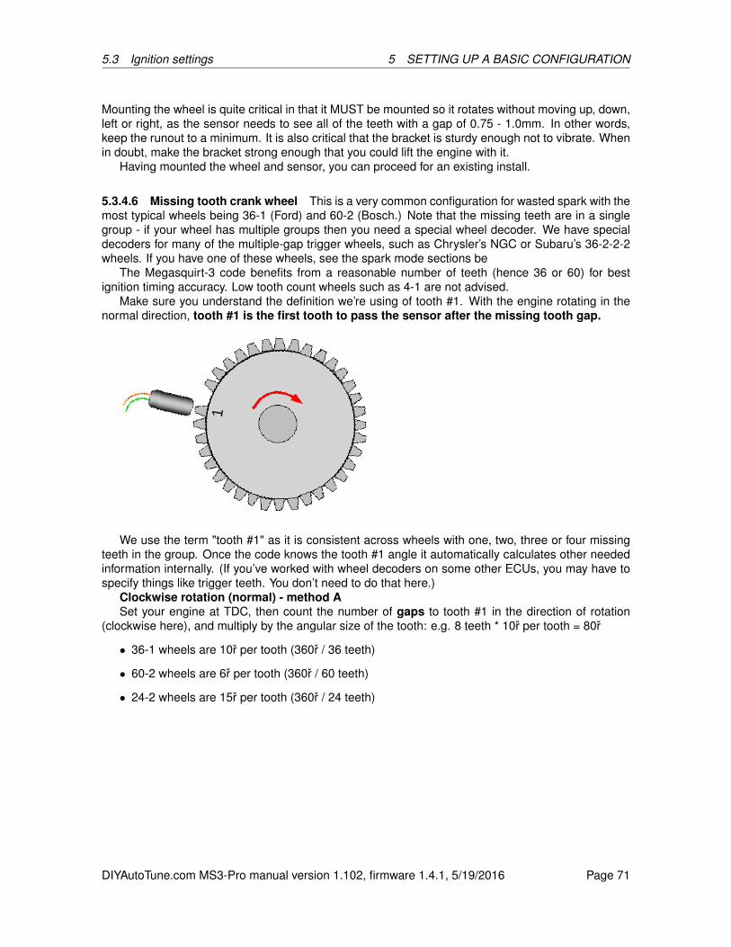
5.3 Ignition settings 5 SETTING UP A BASIC CONFIGURATION
Mounting the wheel is quite critical in that it MUST be mounted so it rotates without moving up, down,left or right, as the sensor needs to see all of the teeth with a gap of 0.75 - 1.0mm. In other words,keep the runout to a minimum. It is also critical that the bracket is sturdy enough not to vibrate. Whenin doubt, make the bracket strong enough that you could lift the engine with it.
Having mounted the wheel and sensor, you can proceed for an existing install.
5.3.4.6 Missing tooth crank wheel This is a very common configuration for wasted spark with themost typical wheels being 36-1 (Ford) and 60-2 (Bosch.) Note that the missing teeth are in a singlegroup - if your wheel has multiple groups then you need a special wheel decoder. We have specialdecoders for many of the multiple-gap trigger wheels, such as Chrysler’s NGC or Subaru’s 36-2-2-2wheels. If you have one of these wheels, see the spark mode sections be
The Megasquirt-3 code benefits from a reasonable number of teeth (hence 36 or 60) for bestignition timing accuracy. Low tooth count wheels such as 4-1 are not advised.
Make sure you understand the definition we’re using of tooth #1. With the engine rotating in thenormal direction, tooth #1 is the first tooth to pass the sensor after the missing tooth gap.
We use the term "tooth #1" as it is consistent across wheels with one, two, three or four missingteeth in the group. Once the code knows the tooth #1 angle it automatically calculates other neededinformation internally. (If you’ve worked with wheel decoders on some other ECUs, you may have tospecify things like trigger teeth. You don’t need to do that here.)
Clockwise rotation (normal) - method ASet your engine at TDC, then count the number of gaps to tooth #1 in the direction of rotation
(clockwise here), and multiply by the angular size of the tooth: e.g. 8 teeth * 10r per tooth = 80r
• 36-1 wheels are 10r per tooth (360r / 36 teeth)
• 60-2 wheels are 6r per tooth (360r / 60 teeth)
• 24-2 wheels are 15r per tooth (360r / 24 teeth)
DIYAutoTune.com MS3-Pro manual version 1.102, firmware 1.4.1, 5/19/2016 Page 71

5.3 Ignition settings 5 SETTING UP A BASIC CONFIGURATION
Clockwise rotation (normal) - method BA different way of looking at the same phasing. Turn your engine so that tooth #1 aligns with the
sensor. Read off the tooth#1 angle from timing marks/tape on the crank pulley.
Critical settings include:
• Spark Mode = Toothed Wheel
• Trigger Angle / Offset = 0
• Trigger wheel arrangement = Single wheel with missing tooth
• Trigger wheel teeth = number of teeth including missing teeth
• Missing teeth = set according to your trigger wheel
• Tooth #1 Angle (deg BTDC) = set as above
• Main wheel speed = Crank wheel
Typical settings:
• Ford 4 cylinder = 36-1, 80r tooth #1
• Ford 6 cylinder = 36-1, 50r tooth #1
• Ford 8 cylinder = 36-1, 40r tooth #1
• Bosch 4 cylinder (Peugeot, Vauxhall) = 60-2, 114r tooth #1
• Bosch 6 cylinder (many BMWs) = 60-2, 89r tooth #1
DIYAutoTune.com MS3-Pro manual version 1.102, firmware 1.4.1, 5/19/2016 Page 72
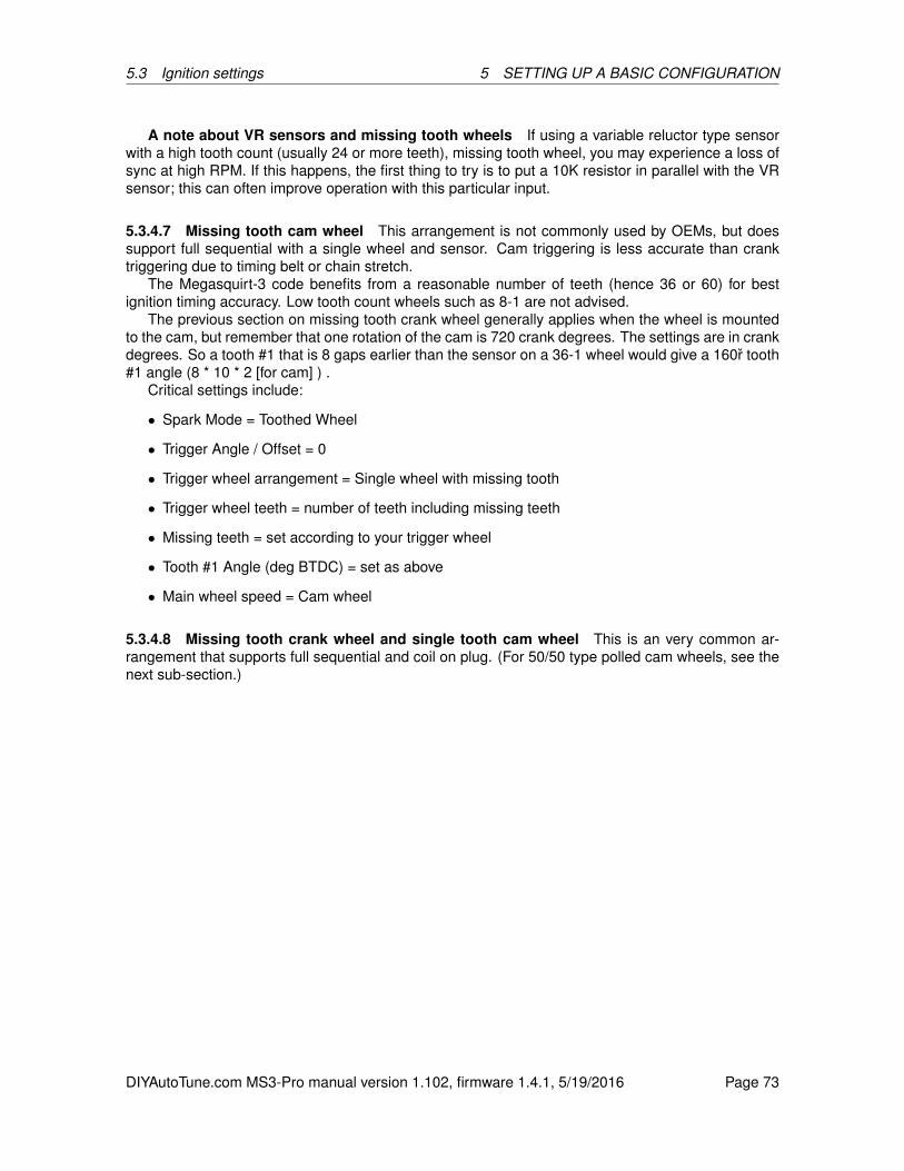
5.3 Ignition settings 5 SETTING UP A BASIC CONFIGURATION
A note about VR sensors and missing tooth wheels If using a variable reluctor type sensorwith a high tooth count (usually 24 or more teeth), missing tooth wheel, you may experience a loss ofsync at high RPM. If this happens, the first thing to try is to put a 10K resistor in parallel with the VRsensor; this can often improve operation with this particular input.
5.3.4.7 Missing tooth cam wheel This arrangement is not commonly used by OEMs, but doessupport full sequential with a single wheel and sensor. Cam triggering is less accurate than cranktriggering due to timing belt or chain stretch.
The Megasquirt-3 code benefits from a reasonable number of teeth (hence 36 or 60) for bestignition timing accuracy. Low tooth count wheels such as 8-1 are not advised.
The previous section on missing tooth crank wheel generally applies when the wheel is mountedto the cam, but remember that one rotation of the cam is 720 crank degrees. The settings are in crankdegrees. So a tooth #1 that is 8 gaps earlier than the sensor on a 36-1 wheel would give a 160r tooth#1 angle (8 * 10 * 2 [for cam] ) .
Critical settings include:
• Spark Mode = Toothed Wheel
• Trigger Angle / Offset = 0
• Trigger wheel arrangement = Single wheel with missing tooth
• Trigger wheel teeth = number of teeth including missing teeth
• Missing teeth = set according to your trigger wheel
• Tooth #1 Angle (deg BTDC) = set as above
• Main wheel speed = Cam wheel
5.3.4.8 Missing tooth crank wheel and single tooth cam wheel This is an very common ar-rangement that supports full sequential and coil on plug. (For 50/50 type polled cam wheels, see thenext sub-section.)
DIYAutoTune.com MS3-Pro manual version 1.102, firmware 1.4.1, 5/19/2016 Page 73
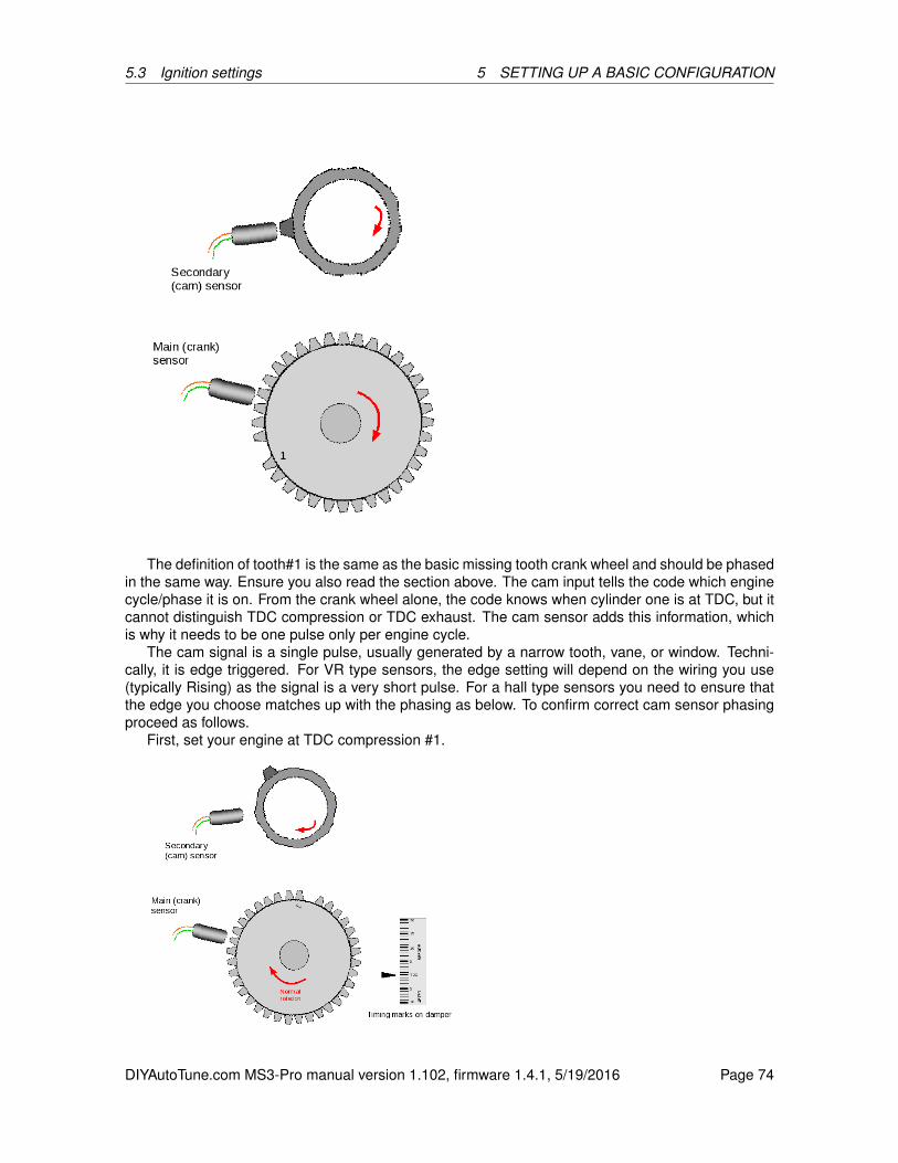
5.3 Ignition settings 5 SETTING UP A BASIC CONFIGURATION
The definition of tooth#1 is the same as the basic missing tooth crank wheel and should be phasedin the same way. Ensure you also read the section above. The cam input tells the code which enginecycle/phase it is on. From the crank wheel alone, the code knows when cylinder one is at TDC, but itcannot distinguish TDC compression or TDC exhaust. The cam sensor adds this information, whichis why it needs to be one pulse only per engine cycle.
The cam signal is a single pulse, usually generated by a narrow tooth, vane, or window. Techni-cally, it is edge triggered. For VR type sensors, the edge setting will depend on the wiring you use(typically Rising) as the signal is a very short pulse. For a hall type sensors you need to ensure thatthe edge you choose matches up with the phasing as below. To confirm correct cam sensor phasingproceed as follows.
First, set your engine at TDC compression #1.
DIYAutoTune.com MS3-Pro manual version 1.102, firmware 1.4.1, 5/19/2016 Page 74
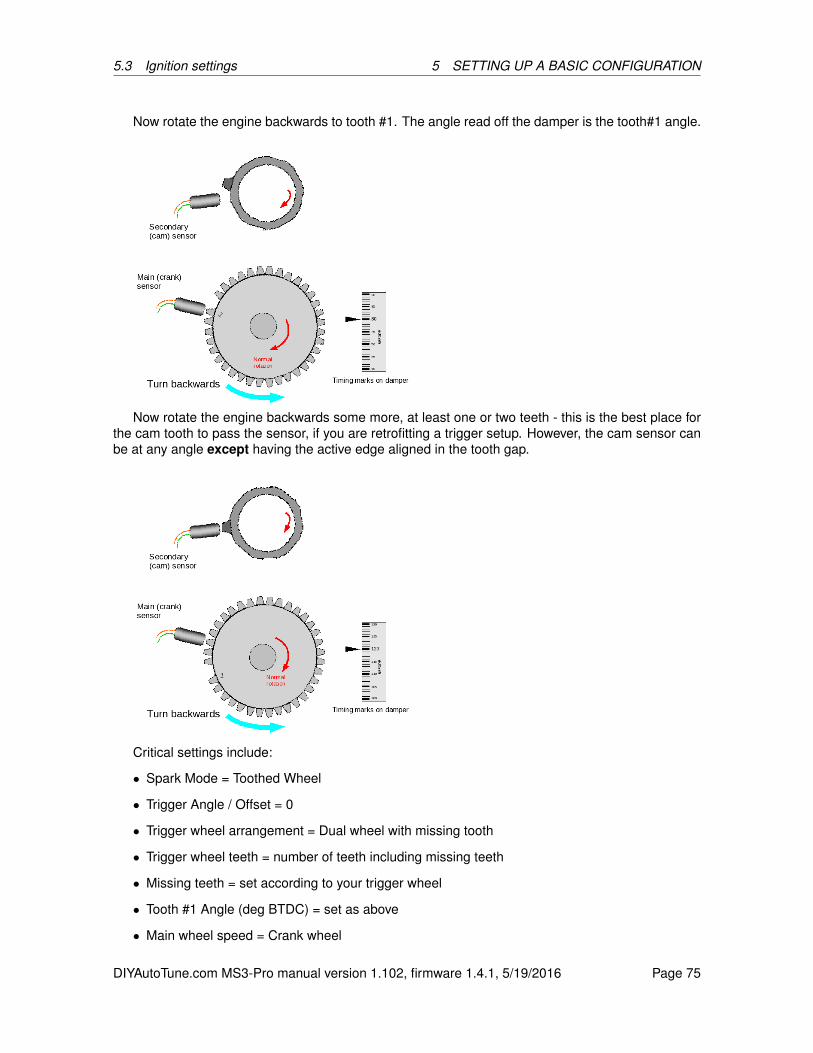
5.3 Ignition settings 5 SETTING UP A BASIC CONFIGURATION
Now rotate the engine backwards to tooth #1. The angle read off the damper is the tooth#1 angle.
Now rotate the engine backwards some more, at least one or two teeth - this is the best place forthe cam tooth to pass the sensor, if you are retrofitting a trigger setup. However, the cam sensor canbe at any angle except having the active edge aligned in the tooth gap.
Critical settings include:
• Spark Mode = Toothed Wheel
• Trigger Angle / Offset = 0
• Trigger wheel arrangement = Dual wheel with missing tooth
• Trigger wheel teeth = number of teeth including missing teeth
• Missing teeth = set according to your trigger wheel
• Tooth #1 Angle (deg BTDC) = set as above
• Main wheel speed = Crank wheel
DIYAutoTune.com MS3-Pro manual version 1.102, firmware 1.4.1, 5/19/2016 Page 75

5.3 Ignition settings 5 SETTING UP A BASIC CONFIGURATION
• Second trigger active on = Set as above
The “and every rotation of” setting is grayed out as this mode only allows the second trigger to be onthe cam wheel.
This wheel decoder mode has a limp home feature: If the camshaft position sensor works OKduring startup, but the MS3-Pro subsequently loses the cam wheel, it will “remember” what phase thecylinders are on, and keep running as if nothing happened.
5.3.4.9 Missing tooth crank wheel and polled (50/50 or half moon) cam wheel This is an fairlycommon arrangement that supports full sequential and coil on plug. Here, a missing tooth wheel isused on the crank in the common way, and a hall-effect or gear tooth sensor is used on the cam with along tooth or window or vane. The MS3 first checks for a missing tooth in the crank wheel sensor, thenchecks the voltage coming from the cam signal to determine if the cylinder is on the compression orexhaust stroke, without waiting for the cam sensor to reach an edge. This gives you the ability to havefull sequential, but the engine syncs up as fast as a regular missing tooth crank wheel without thecam sensor. Different OEM implementations exist - some engines use a 50/50 cam pattern, Vauxhallred-top engines use a window in the distributor rotor that spans the missing tooth region. As far asthe code is concerned, these are equivalent because it only “looks at” (polls) the cam just after themissing tooth.
While this code normally checks at the missing teeth, the “Check at Tooth #” setting allows for itto delay this checking and look for a pulse on a later tooth. By default, this is set to tooth zero for themissing tooth. Some engines use multiple teeth on the cam wheel, with one tooth present on onerotation of the crank but not the next but no cam teeth over the missing tooth on the crank wheel.In this case, you can set “Check at Tooth #” to a crank tooth that lines up with a cam tooth on onerotation but not on the next rotation.
The definition of tooth #1 is the same as the basic missing tooth crank wheel and should bephased in the same way. The cam input tells the code which engine cycle/phase it is on. From
DIYAutoTune.com MS3-Pro manual version 1.102, firmware 1.4.1, 5/19/2016 Page 76
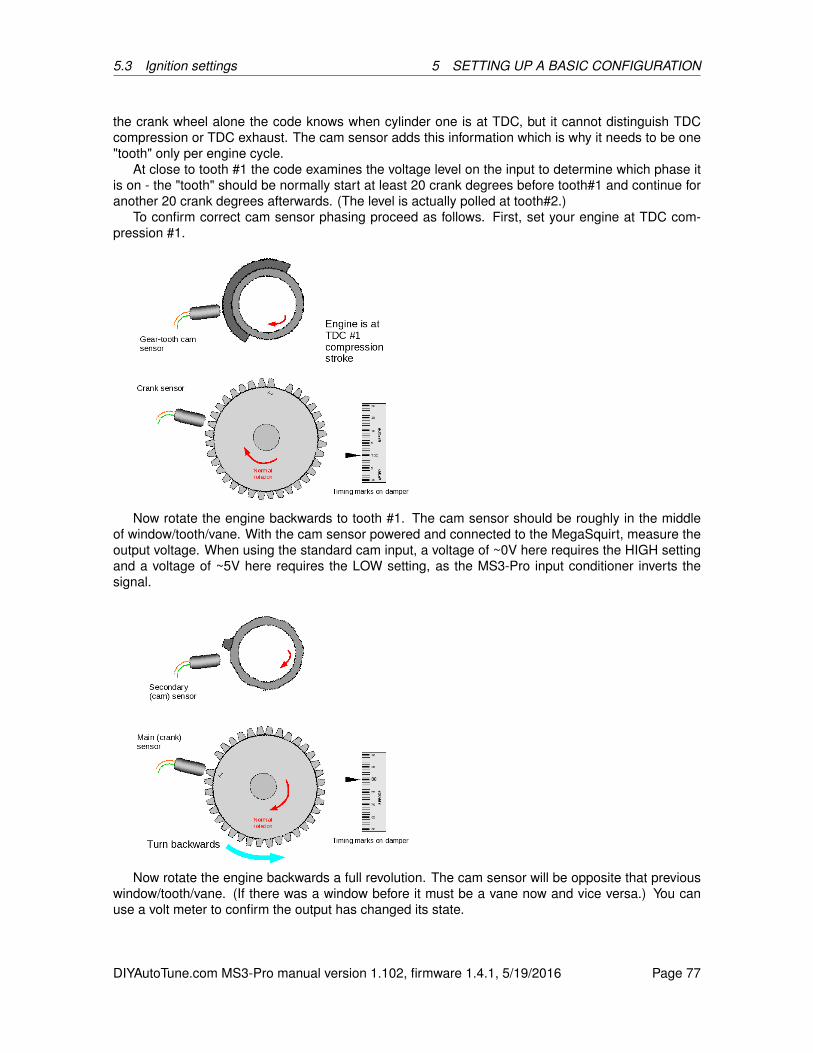
5.3 Ignition settings 5 SETTING UP A BASIC CONFIGURATION
the crank wheel alone the code knows when cylinder one is at TDC, but it cannot distinguish TDCcompression or TDC exhaust. The cam sensor adds this information which is why it needs to be one"tooth" only per engine cycle.
At close to tooth #1 the code examines the voltage level on the input to determine which phase itis on - the "tooth" should be normally start at least 20 crank degrees before tooth#1 and continue foranother 20 crank degrees afterwards. (The level is actually polled at tooth#2.)
To confirm correct cam sensor phasing proceed as follows. First, set your engine at TDC com-pression #1.
Now rotate the engine backwards to tooth #1. The cam sensor should be roughly in the middleof window/tooth/vane. With the cam sensor powered and connected to the MegaSquirt, measure theoutput voltage. When using the standard cam input, a voltage of ~0V here requires the HIGH settingand a voltage of ~5V here requires the LOW setting, as the MS3-Pro input conditioner inverts thesignal.
Now rotate the engine backwards a full revolution. The cam sensor will be opposite that previouswindow/tooth/vane. (If there was a window before it must be a vane now and vice versa.) You canuse a volt meter to confirm the output has changed its state.
DIYAutoTune.com MS3-Pro manual version 1.102, firmware 1.4.1, 5/19/2016 Page 77
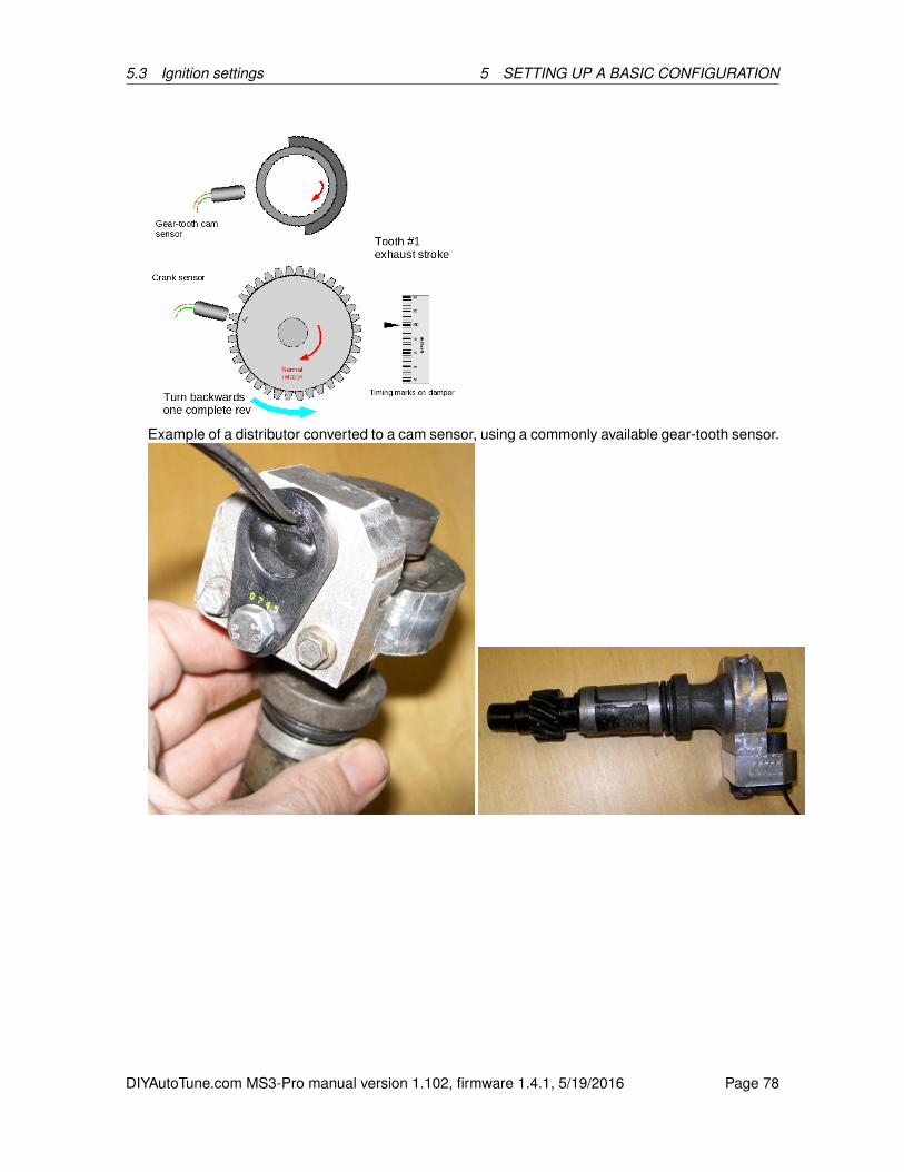
5.3 Ignition settings 5 SETTING UP A BASIC CONFIGURATION
Example of a distributor converted to a cam sensor, using a commonly available gear-tooth sensor.
DIYAutoTune.com MS3-Pro manual version 1.102, firmware 1.4.1, 5/19/2016 Page 78
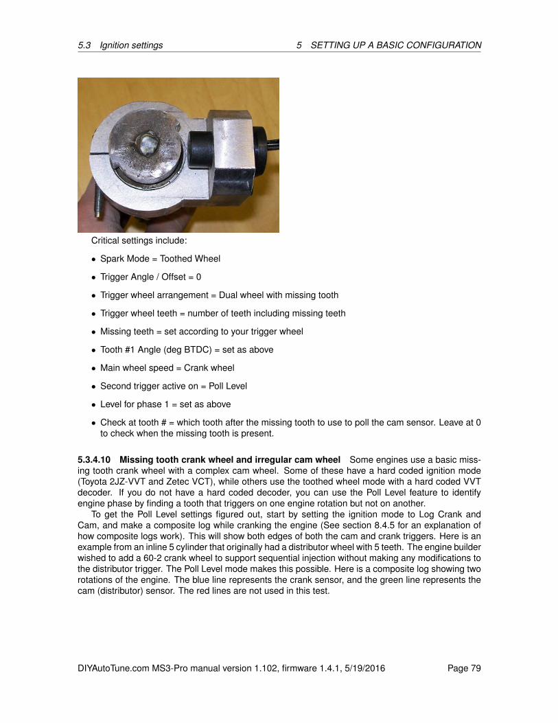
5.3 Ignition settings 5 SETTING UP A BASIC CONFIGURATION
Critical settings include:
• Spark Mode = Toothed Wheel
• Trigger Angle / Offset = 0
• Trigger wheel arrangement = Dual wheel with missing tooth
• Trigger wheel teeth = number of teeth including missing teeth
• Missing teeth = set according to your trigger wheel
• Tooth #1 Angle (deg BTDC) = set as above
• Main wheel speed = Crank wheel
• Second trigger active on = Poll Level
• Level for phase 1 = set as above
• Check at tooth # = which tooth after the missing tooth to use to poll the cam sensor. Leave at 0to check when the missing tooth is present.
5.3.4.10 Missing tooth crank wheel and irregular cam wheel Some engines use a basic miss-ing tooth crank wheel with a complex cam wheel. Some of these have a hard coded ignition mode(Toyota 2JZ-VVT and Zetec VCT), while others use the toothed wheel mode with a hard coded VVTdecoder. If you do not have a hard coded decoder, you can use the Poll Level feature to identifyengine phase by finding a tooth that triggers on one engine rotation but not on another.
To get the Poll Level settings figured out, start by setting the ignition mode to Log Crank andCam, and make a composite log while cranking the engine (See section 8.4.5 for an explanation ofhow composite logs work). This will show both edges of both the cam and crank triggers. Here is anexample from an inline 5 cylinder that originally had a distributor wheel with 5 teeth. The engine builderwished to add a 60-2 crank wheel to support sequential injection without making any modifications tothe distributor trigger. The Poll Level mode makes this possible. Here is a composite log showing tworotations of the engine. The blue line represents the crank sensor, and the green line represents thecam (distributor) sensor. The red lines are not used in this test.
DIYAutoTune.com MS3-Pro manual version 1.102, firmware 1.4.1, 5/19/2016 Page 79

5.3 Ignition settings 5 SETTING UP A BASIC CONFIGURATION
The first step is to identify the missing teeth, marked with red arrows in the image below. Thenext step is to find a tooth in the green line that triggers on one cylinder rotation but does not triggeron the rotation before it. The wider the tooth, the better, as it will span more crank degrees. In thisexample, we’ll try to poll on the first cam pulse to arrive after the missing tooth (marked with a greenarrow). Notice that the cam sensor signal is high for the entire length of this tooth, but low for theentire duration of the tooth on the rotation before it.
Next, we’ll zoom in on that arrow and count how many crank teeth after the missing tooth thereare to the center of the tooth that we’re using for the cam sync.
DIYAutoTune.com MS3-Pro manual version 1.102, firmware 1.4.1, 5/19/2016 Page 80
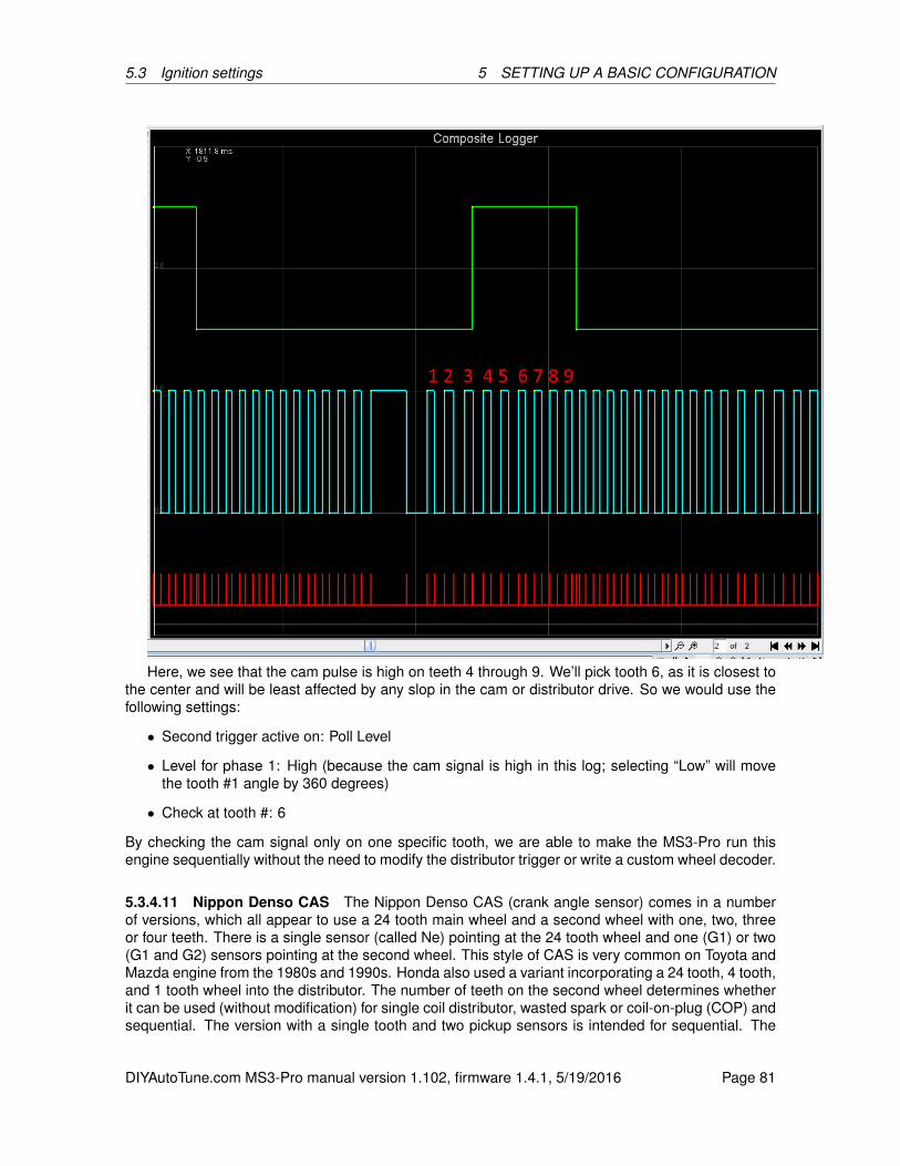
5.3 Ignition settings 5 SETTING UP A BASIC CONFIGURATION
Here, we see that the cam pulse is high on teeth 4 through 9. We’ll pick tooth 6, as it is closest tothe center and will be least affected by any slop in the cam or distributor drive. So we would use thefollowing settings:
• Second trigger active on: Poll Level
• Level for phase 1: High (because the cam signal is high in this log; selecting “Low” will movethe tooth #1 angle by 360 degrees)
• Check at tooth #: 6
By checking the cam signal only on one specific tooth, we are able to make the MS3-Pro run thisengine sequentially without the need to modify the distributor trigger or write a custom wheel decoder.
5.3.4.11 Nippon Denso CAS The Nippon Denso CAS (crank angle sensor) comes in a numberof versions, which all appear to use a 24 tooth main wheel and a second wheel with one, two, threeor four teeth. There is a single sensor (called Ne) pointing at the 24 tooth wheel and one (G1) or two(G1 and G2) sensors pointing at the second wheel. This style of CAS is very common on Toyota andMazda engine from the 1980s and 1990s. Honda also used a variant incorporating a 24 tooth, 4 tooth,and 1 tooth wheel into the distributor. The number of teeth on the second wheel determines whetherit can be used (without modification) for single coil distributor, wasted spark or coil-on-plug (COP) andsequential. The version with a single tooth and two pickup sensors is intended for sequential. The
DIYAutoTune.com MS3-Pro manual version 1.102, firmware 1.4.1, 5/19/2016 Page 81
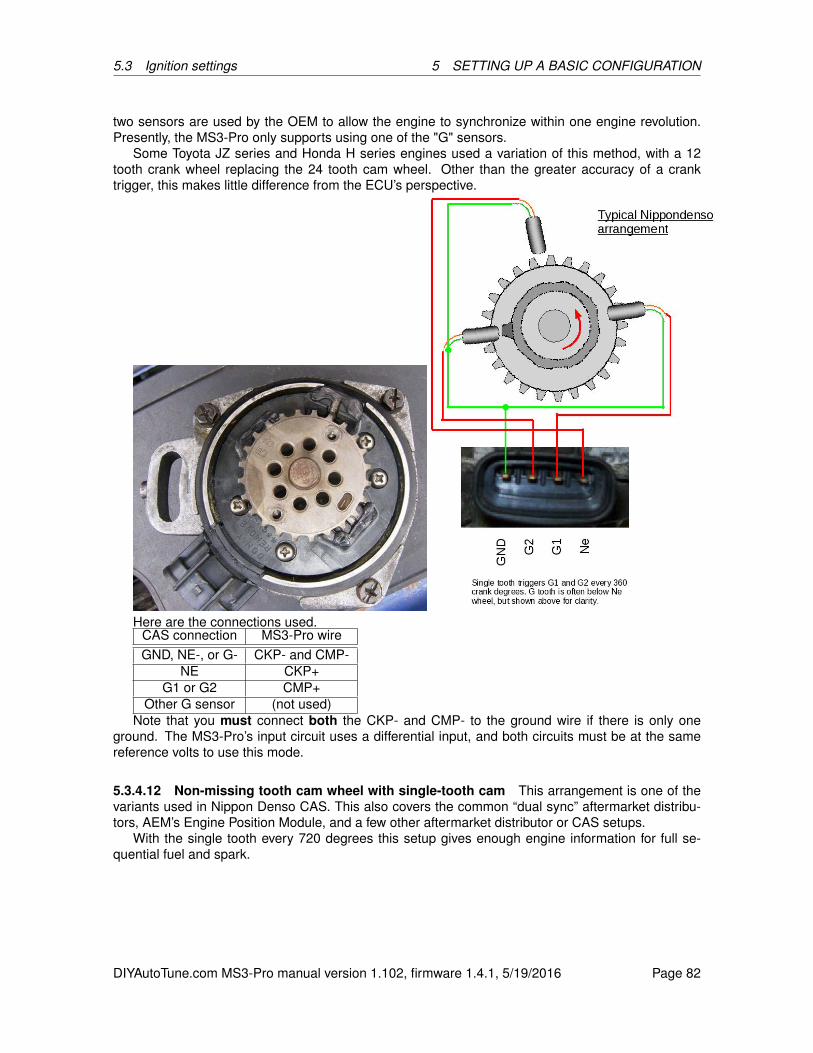
5.3 Ignition settings 5 SETTING UP A BASIC CONFIGURATION
two sensors are used by the OEM to allow the engine to synchronize within one engine revolution.Presently, the MS3-Pro only supports using one of the "G" sensors.
Some Toyota JZ series and Honda H series engines used a variation of this method, with a 12tooth crank wheel replacing the 24 tooth cam wheel. Other than the greater accuracy of a cranktrigger, this makes little difference from the ECU’s perspective.
Here are the connections used.CAS connection MS3-Pro wireGND, NE-, or G- CKP- and CMP-
NE CKP+G1 or G2 CMP+
Other G sensor (not used)Note that you must connect both the CKP- and CMP- to the ground wire if there is only one
ground. The MS3-Pro’s input circuit uses a differential input, and both circuits must be at the samereference volts to use this mode.
5.3.4.12 Non-missing tooth cam wheel with single-tooth cam This arrangement is one of thevariants used in Nippon Denso CAS. This also covers the common “dual sync” aftermarket distribu-tors, AEM’s Engine Position Module, and a few other aftermarket distributor or CAS setups.
With the single tooth every 720 degrees this setup gives enough engine information for full se-quential fuel and spark.
DIYAutoTune.com MS3-Pro manual version 1.102, firmware 1.4.1, 5/19/2016 Page 82
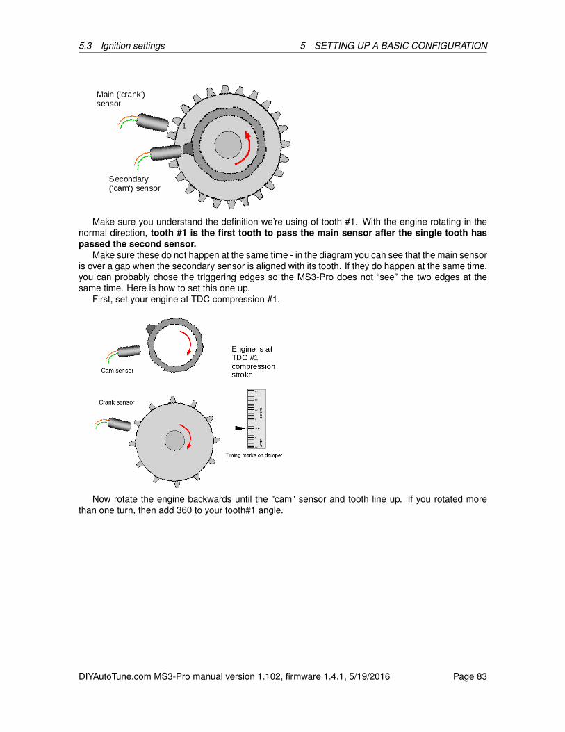
5.3 Ignition settings 5 SETTING UP A BASIC CONFIGURATION
Make sure you understand the definition we’re using of tooth #1. With the engine rotating in thenormal direction, tooth #1 is the first tooth to pass the main sensor after the single tooth haspassed the second sensor.
Make sure these do not happen at the same time - in the diagram you can see that the main sensoris over a gap when the secondary sensor is aligned with its tooth. If they do happen at the same time,you can probably chose the triggering edges so the MS3-Pro does not “see” the two edges at thesame time. Here is how to set this one up.
First, set your engine at TDC compression #1.
Now rotate the engine backwards until the "cam" sensor and tooth line up. If you rotated morethan one turn, then add 360 to your tooth#1 angle.
DIYAutoTune.com MS3-Pro manual version 1.102, firmware 1.4.1, 5/19/2016 Page 83
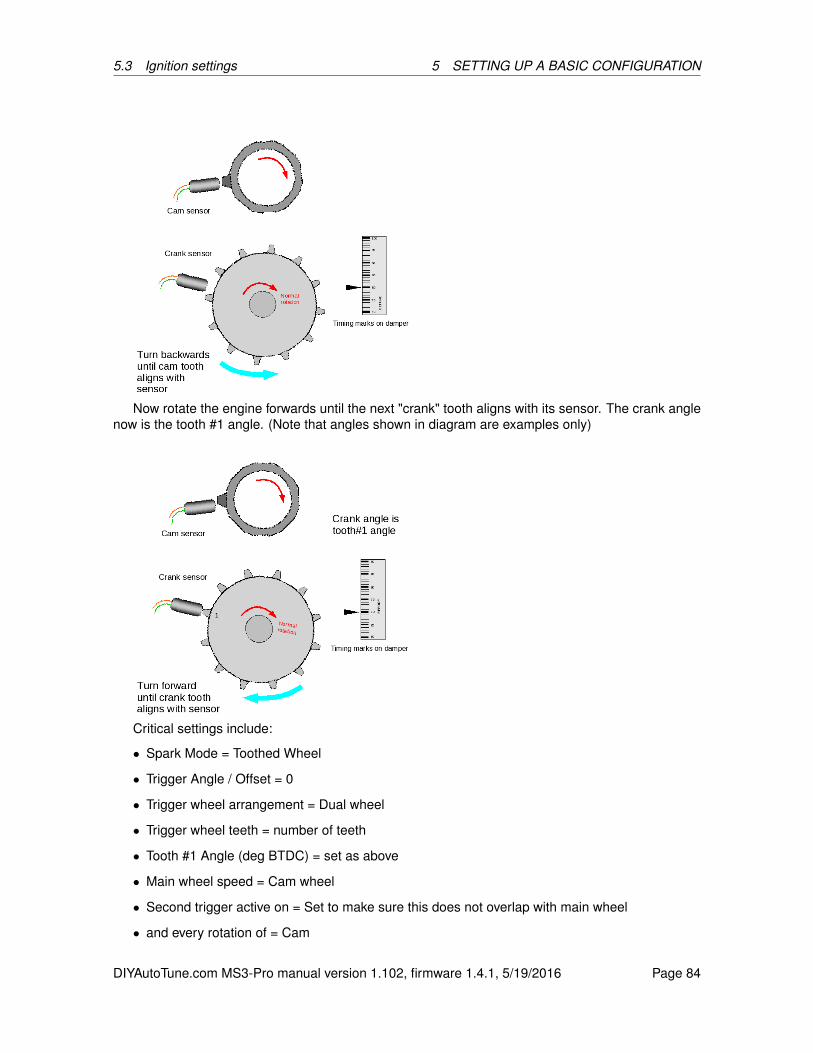
5.3 Ignition settings 5 SETTING UP A BASIC CONFIGURATION
Now rotate the engine forwards until the next "crank" tooth aligns with its sensor. The crank anglenow is the tooth #1 angle. (Note that angles shown in diagram are examples only)
Critical settings include:
• Spark Mode = Toothed Wheel
• Trigger Angle / Offset = 0
• Trigger wheel arrangement = Dual wheel
• Trigger wheel teeth = number of teeth
• Tooth #1 Angle (deg BTDC) = set as above
• Main wheel speed = Cam wheel
• Second trigger active on = Set to make sure this does not overlap with main wheel
• and every rotation of = Cam
DIYAutoTune.com MS3-Pro manual version 1.102, firmware 1.4.1, 5/19/2016 Page 84
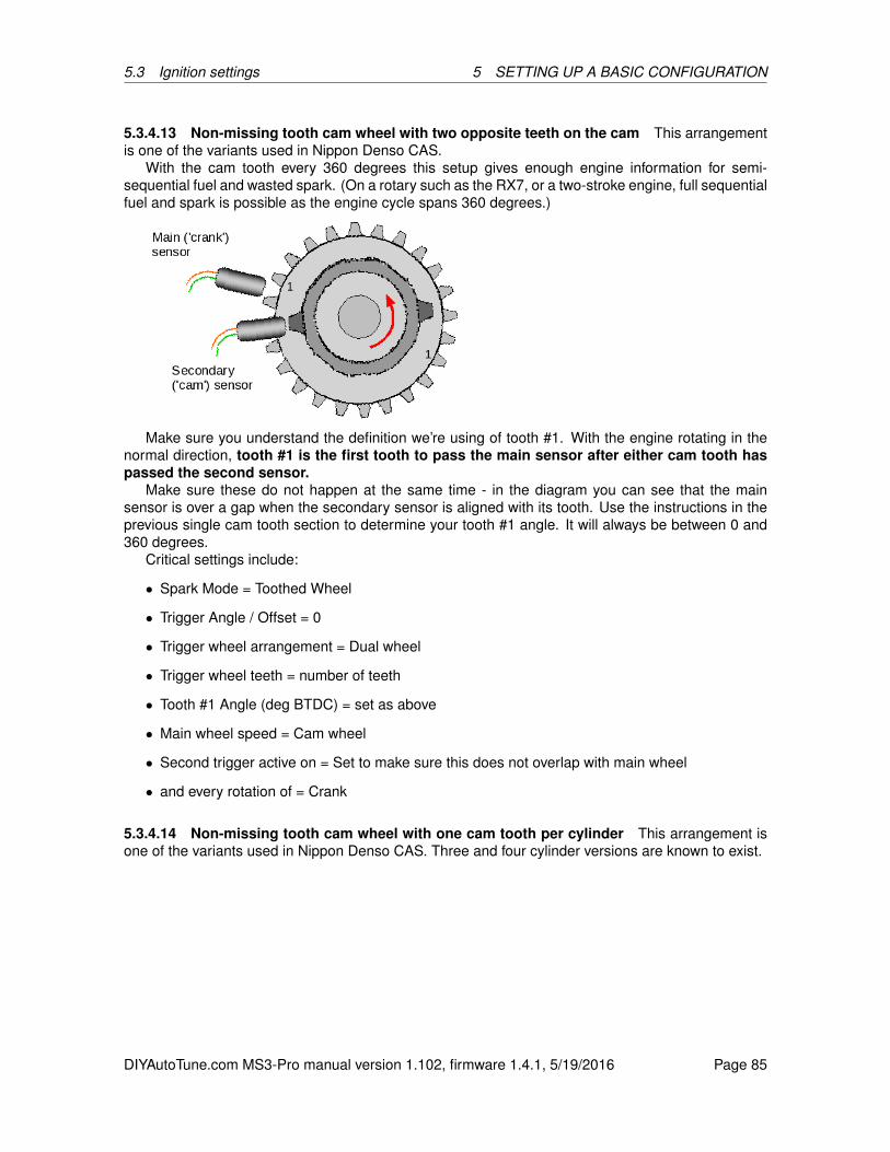
5.3 Ignition settings 5 SETTING UP A BASIC CONFIGURATION
5.3.4.13 Non-missing tooth cam wheel with two opposite teeth on the cam This arrangementis one of the variants used in Nippon Denso CAS.
With the cam tooth every 360 degrees this setup gives enough engine information for semi-sequential fuel and wasted spark. (On a rotary such as the RX7, or a two-stroke engine, full sequentialfuel and spark is possible as the engine cycle spans 360 degrees.)
Make sure you understand the definition we’re using of tooth #1. With the engine rotating in thenormal direction, tooth #1 is the first tooth to pass the main sensor after either cam tooth haspassed the second sensor.
Make sure these do not happen at the same time - in the diagram you can see that the mainsensor is over a gap when the secondary sensor is aligned with its tooth. Use the instructions in theprevious single cam tooth section to determine your tooth #1 angle. It will always be between 0 and360 degrees.
Critical settings include:
• Spark Mode = Toothed Wheel
• Trigger Angle / Offset = 0
• Trigger wheel arrangement = Dual wheel
• Trigger wheel teeth = number of teeth
• Tooth #1 Angle (deg BTDC) = set as above
• Main wheel speed = Cam wheel
• Second trigger active on = Set to make sure this does not overlap with main wheel
• and every rotation of = Crank
5.3.4.14 Non-missing tooth cam wheel with one cam tooth per cylinder This arrangement isone of the variants used in Nippon Denso CAS. Three and four cylinder versions are known to exist.
DIYAutoTune.com MS3-Pro manual version 1.102, firmware 1.4.1, 5/19/2016 Page 85

5.3 Ignition settings 5 SETTING UP A BASIC CONFIGURATION
As there is one tooth per cylinder, there is only enough information to run a distributor and untimedinjection. It is not strictly necessary to use both Ne and G wheels. Using both will give you theimproved timing accuracy from the "every-tooth" wheel decoder system, but it is possible to use the"G" input only and configure as "Basic Trigger" instead. Timing will not be as accurate though.
Make sure you understand the definition we’re using of tooth #1. With the engine rotating in thenormal direction, tooth #1 is the first tooth to pass the main sensor after any cam tooth haspassed the second sensor.
Make sure these do not happen at the same time - in the diagram you can see that the mainsensor is over a gap when the secondary sensor is aligned with its tooth. Use the instructions in theprevious single cam tooth section to determine your tooth#1 angle. It will always be between 0 and360 degrees.
Critical settings include:
• Spark Mode = Toothed Wheel
• Trigger Angle / Offset = 0
• Trigger wheel arrangement = Dual wheel
• Trigger wheel teeth = number of teeth
• Tooth #1 Angle (deg BTDC) = set as above
• Main wheel speed = Cam wheel
• Second trigger active on = Set to make sure this does not overlap with main wheel
• and every rotation of = Every cylinder
5.3.4.15 Non-missing tooth crank wheel with one cam tooth This arrangement appears on afew OEM applications, including the Chrysler 318 and 360 Magnum, the Mazda KLDE, and someToyota JZ engines. Also, it could be used to extend a simple distributor crank trigger to support se-quential. Generally Megasquirt-3 benefits from many crank teeth to improve ignition timing accuracy.However, with this wheel arrangement, you need to beware of trying to use too many teeth on thecrank as there is a risk of the trigger inputs overlapping as the cam belt or chain stretches. If thisoverlap occurs, it will cause sync-loss as the cam tooth moves from being seen "before" to "after" acrank tooth or vice versa. As a general rule, this mode does not work well with more than 12 teeth onthe crank wheel.
DIYAutoTune.com MS3-Pro manual version 1.102, firmware 1.4.1, 5/19/2016 Page 86
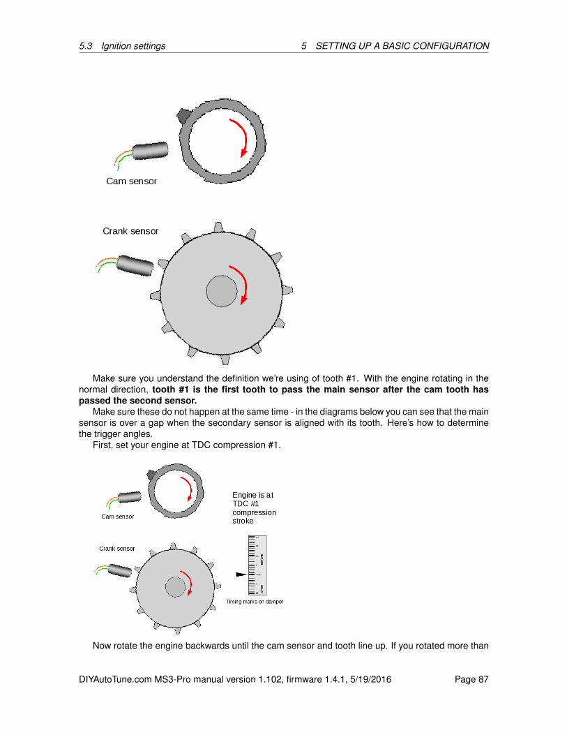
5.3 Ignition settings 5 SETTING UP A BASIC CONFIGURATION
Make sure you understand the definition we’re using of tooth #1. With the engine rotating in thenormal direction, tooth #1 is the first tooth to pass the main sensor after the cam tooth haspassed the second sensor.
Make sure these do not happen at the same time - in the diagrams below you can see that the mainsensor is over a gap when the secondary sensor is aligned with its tooth. Here’s how to determinethe trigger angles.
First, set your engine at TDC compression #1.
Now rotate the engine backwards until the cam sensor and tooth line up. If you rotated more than
DIYAutoTune.com MS3-Pro manual version 1.102, firmware 1.4.1, 5/19/2016 Page 87
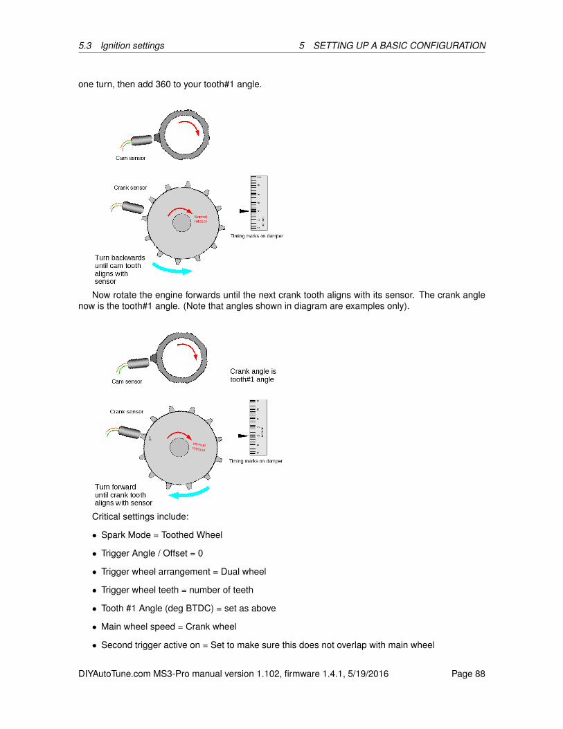
5.3 Ignition settings 5 SETTING UP A BASIC CONFIGURATION
one turn, then add 360 to your tooth#1 angle.
Now rotate the engine forwards until the next crank tooth aligns with its sensor. The crank anglenow is the tooth#1 angle. (Note that angles shown in diagram are examples only).
Critical settings include:
• Spark Mode = Toothed Wheel
• Trigger Angle / Offset = 0
• Trigger wheel arrangement = Dual wheel
• Trigger wheel teeth = number of teeth
• Tooth #1 Angle (deg BTDC) = set as above
• Main wheel speed = Crank wheel
• Second trigger active on = Set to make sure this does not overlap with main wheel
DIYAutoTune.com MS3-Pro manual version 1.102, firmware 1.4.1, 5/19/2016 Page 88
5.3 Ignition settings 5 SETTING UP A BASIC CONFIGURATION
• and every rotation of = Cam
5.3.4.16 Example wheel decoder settings Here are settings from engines that use the ToothedWheel mode. You will want to confirm these with a timing light, as trigger wheel tolerances may vary.Some of these are quite specific, while others are general starting points.
BMW inline sixes These typically use a 60-2 crank trigger starting with the Motronic 1.1 systemsin the mid to late ’80s, with later models adding a one tooth cam sensor. Most use a tooth #1 anglein the 90 to 100 degree range (450 to 460 degrees with certain cam sensor versions), but there are afew exceptions. Check with a timing light to be sure.
Note that models with a VR sensor typically need a 10K resistor between the CKP+ and CKP-wires.
Buick C3IThe Grand National (and the later front wheel drive 3800) used a distributorless ignition with a
module that partially decoded the trigger wheel. Although there is an 18 tooth wheel on the crank, itconnects to the factory ignition module. The MS3-Pro will use the 6X signal from the ignition moduleplus the 1X cam signal for timing control and sequential injection. You will use spark output A forthe EST signal and spark output B for the Bypass signal. This includes the complete ignition modulesettings as well as the wheel decoder settings.
• HEI / GMDIS, TFI, C3I Options: Buick C3I
• Ignition input capture: Rising Edge
• Spark output: Going High
• Number of coils: Single Coil
• Trigger wheel arrangement: Dual wheel
• Trigger wheel teeth: 6
• Tooth #1 angle: 70
• Main wheel speed: Crank wheel
• Second trigger active on: Rising Edge
• And every rotation of: Cam
• Dwell type: Standard dwell
• Nominal dwell: 3.0 (adjust as needed to match coils)
Cheverolet LS2, LS3 and other GM 58X V8s These use a 60-2 crank trigger with a 4 tooth camwheel. The sensors run at 5 volts and use a 1K pull up resistor.
• Ignition input capture: Rising Edge
• Trigger wheel arrangement: Dual wheel with missing teeth
• Trigger wheel teeth: 60
• Missing teeth: 2
• Tooth #1 angle: 70
DIYAutoTune.com MS3-Pro manual version 1.102, firmware 1.4.1, 5/19/2016 Page 89

5.3 Ignition settings 5 SETTING UP A BASIC CONFIGURATION
• Main wheel speed: Crank wheel
• Second trigger active on: Poll Level
• Level for phase 1: High
• Check at tooth #: 1
Chrysler 318 / 360 Magnum V8 These engines used an eight tooth flywheel trigger and a onetooth trigger in the distributor. This can be used to trigger a distributorless ignition as well, as long asyou keep the distributor body, sensor, and trigger wheel.
• Ignition input capture: Falling Edge
• Trigger wheel arrangement: Dual wheel
• Trigger wheel teeth: 8
• Tooth #1 angle: 142
• Main wheel speed: Crank wheel
• Second trigger active on: Falling edge
• And every rotation of: Cam
Chrysler VVT Hemi These used a 60-2 crank wheel with the same tone wheel used on theearlier (NGC) motors on the cam.
• Ignition input capture: Rising Edge
• Trigger wheel arrangement: Dual wheel with missing teeth
• Trigger wheel teeth: 60
• Missing teeth: 2
• Tooth #1 angle: 693
• Main wheel speed: Crank wheel
• Second trigger active on: Falling edge
To complete the cam wheel settings, you will need to set the cam decoder to “Hemi VVT” under theVVT Settings menu.
Ford 36-1 This pattern shows up in many four, six, and eight cylinder engines. Note that for VVTengines other than the Coyote, use the Zetec VCT pattern instead of Toothed Wheel. Many of theseinstalls require a 10K resistor across CKP+ and CKP- to avoid losing sync at high RPM.
• Ignition input capture will depend on the crank sensor wiring.
• Trigger wheel arrangement: Dual wheel with missing teeth
• Trigger wheel teeth: 36
• Missing teeth: 1
DIYAutoTune.com MS3-Pro manual version 1.102, firmware 1.4.1, 5/19/2016 Page 90

5.3 Ignition settings 5 SETTING UP A BASIC CONFIGURATION
• Tooth #1 angle depends on the number of cylinders and the cam sensor. If the tooth #1 angle isset to the version, the engine will be able to run in wasted spark or wasted-COP mode, but notwith sequential coil on plug.
Cylinders Possible Tooth # 1 angles4 80 or 4406 50 or 4108 40 or 400
• Main wheel speed: Crank wheel
Some of these used Hall effect cam sensors and others used VR type ones, but engines without VVTall used a single tooth cam sensor. You may need to adjust the second trigger settings depending onthe sensor type.
Ford Coyote This one also uses a 36-1 crank wheel, but you set up the cam trigger under theVVT settings instead of directly. As with other Ford 36-1 wheels, you may need to use the 10K resistoracross CKP+ and CKP- to avoid loss of sync at high RPM.
• Ignition input capture will depend on the crank sensor wiring.
• Trigger wheel arrangement: Dual wheel with missing teeth
• Trigger wheel teeth: 36
• Missing teeth: 1
• Tooth #1 angle: 400
• Main wheel speed: Crank wheel
• Second trigger active on: Rising edge
To complete the cam wheel settings, you will need to set the cam decoder to “Ford Coyote” under theVVT Settings menu.
Toyota 2JZ-GTE This is for the US market turbo motor that does not have VVT. These engineshave a 12 tooth crank wheel called an NE sensor plus two one tooth cam sensors called G sensors.These settings use the “G1” sensor; for the “G2” sensor, add 360 degrees to the Tooth #1 Angle. Thelater VVT motors use the hard coded 2JZ-VVT spark mode. Pre-VVT versions of the non turbo motoroften used a 24 tooth cam wheel in place of the 12 tooth crank wheel, but the settings are similar. Theactive edge settings assume you have the grounded (common) wires connected to CKP- and CMP-.Reverse wiring the sensors will reverse which edges are active.
• Ignition input capture: Falling Edge
• Trigger wheel arrangement: Dual wheel
• Trigger wheel teeth: 12
• Tooth #1 angle: 16
• Main wheel speed: Crank wheel
• Second trigger active on: Rising edge
• And every rotation of: Cam
DIYAutoTune.com MS3-Pro manual version 1.102, firmware 1.4.1, 5/19/2016 Page 91
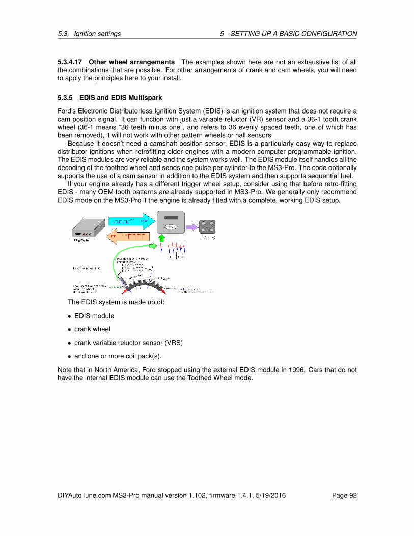
5.3 Ignition settings 5 SETTING UP A BASIC CONFIGURATION
5.3.4.17 Other wheel arrangements The examples shown here are not an exhaustive list of allthe combinations that are possible. For other arrangements of crank and cam wheels, you will needto apply the principles here to your install.
5.3.5 EDIS and EDIS Multispark
Ford’s Electronic Distributorless Ignition System (EDIS) is an ignition system that does not require acam position signal. It can function with just a variable reluctor (VR) sensor and a 36-1 tooth crankwheel (36-1 means “36 teeth minus one”, and refers to 36 evenly spaced teeth, one of which hasbeen removed), it will not work with other pattern wheels or hall sensors.
Because it doesn’t need a camshaft position sensor, EDIS is a particularly easy way to replacedistributor ignitions when retrofitting older engines with a modern computer programmable ignition.The EDIS modules are very reliable and the system works well. The EDIS module itself handles all thedecoding of the toothed wheel and sends one pulse per cylinder to the MS3-Pro. The code optionallysupports the use of a cam sensor in addition to the EDIS system and then supports sequential fuel.
If your engine already has a different trigger wheel setup, consider using that before retro-fittingEDIS - many OEM tooth patterns are already supported in MS3-Pro. We generally only recommendEDIS mode on the MS3-Pro if the engine is already fitted with a complete, working EDIS setup.
The EDIS system is made up of:
• EDIS module
• crank wheel
• crank variable reluctor sensor (VRS)
• and one or more coil pack(s).
Note that in North America, Ford stopped using the external EDIS module in 1996. Cars that do nothave the internal EDIS module can use the Toothed Wheel mode.
DIYAutoTune.com MS3-Pro manual version 1.102, firmware 1.4.1, 5/19/2016 Page 92
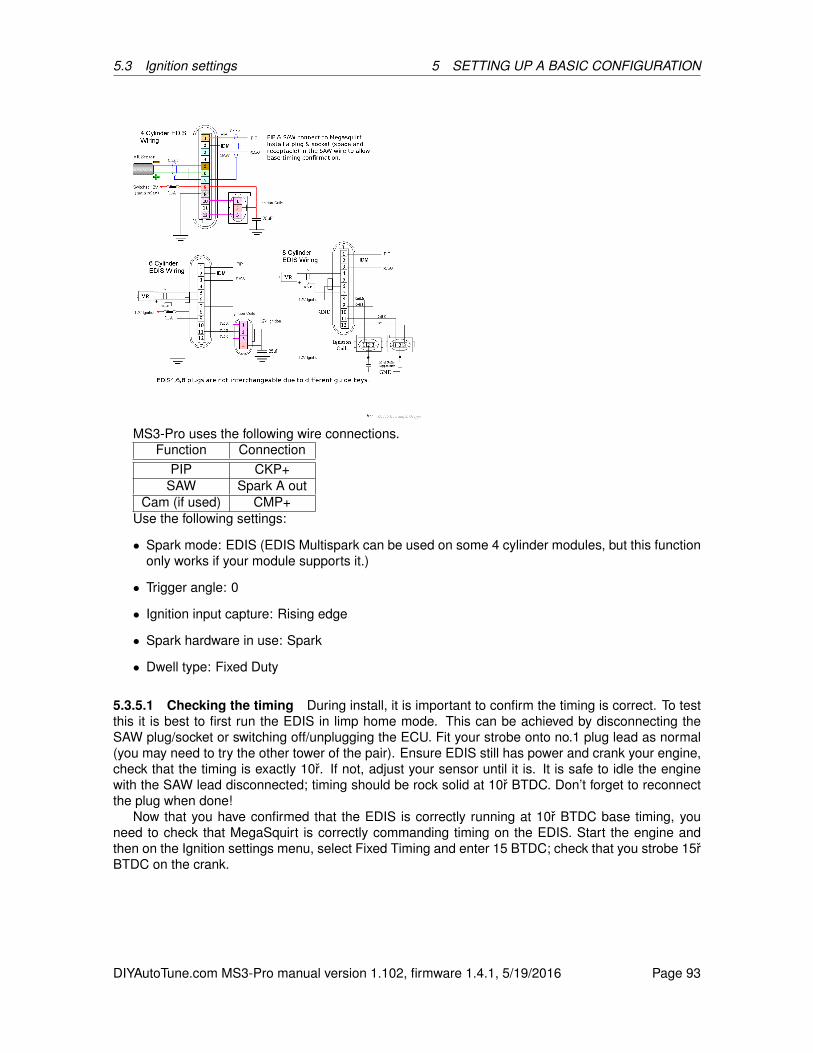
5.3 Ignition settings 5 SETTING UP A BASIC CONFIGURATION
MS3-Pro uses the following wire connections.Function Connection
PIP CKP+SAW Spark A out
Cam (if used) CMP+Use the following settings:
• Spark mode: EDIS (EDIS Multispark can be used on some 4 cylinder modules, but this functiononly works if your module supports it.)
• Trigger angle: 0
• Ignition input capture: Rising edge
• Spark hardware in use: Spark
• Dwell type: Fixed Duty
5.3.5.1 Checking the timing During install, it is important to confirm the timing is correct. To testthis it is best to first run the EDIS in limp home mode. This can be achieved by disconnecting theSAW plug/socket or switching off/unplugging the ECU. Fit your strobe onto no.1 plug lead as normal(you may need to try the other tower of the pair). Ensure EDIS still has power and crank your engine,check that the timing is exactly 10r. If not, adjust your sensor until it is. It is safe to idle the enginewith the SAW lead disconnected; timing should be rock solid at 10r BTDC. Don’t forget to reconnectthe plug when done!
Now that you have confirmed that the EDIS is correctly running at 10r BTDC base timing, youneed to check that MegaSquirt is correctly commanding timing on the EDIS. Start the engine andthen on the Ignition settings menu, select Fixed Timing and enter 15 BTDC; check that you strobe 15rBTDC on the crank.
DIYAutoTune.com MS3-Pro manual version 1.102, firmware 1.4.1, 5/19/2016 Page 93

5.3 Ignition settings 5 SETTING UP A BASIC CONFIGURATION
When done, reset Fixed Advance to “Use table.”
5.3.5.2 Cam sensor and EDIS The EDIS module itself does not need a cam sensor as it alwaysruns in wasted spark, firing each coil pair every crank revolution. However for sequential fuel it isnecessary to use a cam sensor in addition so the MS3-Pro knows what phase the engine is on. Mostoriginal cam sensors are 2 wire VR type, so only require a ground and the signal connecting to theMS3-Pro. The code works the same whether a hall or VR sensor is used.
5.3.6 420A/Neon
Known applications include:
• First generation Chrysler / Dodge / Plymouth Neon (both DOHC and SOHC)
• Second generation Diamond Star cars (Mitsubishi Eclipse / Eagle Talon) with 420A
• 2001-2002 Chrysler PT Cruiser
• Many four cylinder “Cloud Cars” (Stratus, Breeze, Cirrus)
This mode uses an irregular crank wheel that can support wasted spark without a cam sensor. It alsoallows sequential injection if the cam sensor is used. Both sensors require pull-up resistors from thesensor power wire to the signal wire. Ignition input capture should be set to Rising Edge.
Factory ignition coils on these motors require an external ignition module such as the QuadSpark.
5.3.7 36-2+2
Known applications include:
• 5.7 and 6.1 Hemi without VVT
• Second generation Neon and SRT-4
• Most other Chryslers from 2003 and later
This mode uses a crank trigger (which Chrysler calls a “tone ring”) with 36 base teeth and two sepa-rate gaps 180 degrees apart. The number of teeth on the camshaft position sensor change with thenumber of cylinders; the MS3-Pro will select the cam wheel based on the general setup informationentered. The camshaft position sensor must be used if sequential injection or ignition is used, but the
DIYAutoTune.com MS3-Pro manual version 1.102, firmware 1.4.1, 5/19/2016 Page 94

5.3 Ignition settings 5 SETTING UP A BASIC CONFIGURATION
crank wheel can run the engine in semi-sequential and wasted spark. Both sensors require pull-upresistors. Ignition input capture should be set to Rising Edge.
Factory ignition coils on these motors require an external ignition module such as the QuadSpark.VVT Hemi models used a 60-2 wheel that uses Toothed Wheel mode.
5.3.8 36-2-2-2
Known applications include:
• Many Subarus built after 2000 without variable valve timing (AVCS)
• Mazda RX8
• Mazda MX5 from 2005 and later
This mode uses a VR sensor and a crankshaft trigger wheel with two gaps on one side and one gapon the other. This mode can support sequential injection if cam input is used. Ignition input capturewill depend on the way the sensor is wired.
Note that Subarus with variable valve timing (AVCS) used a different cam pattern. For this mode,see Subaru 36-2-2-2 VVT mode.
5.3.9 Subaru 6/7
Known applications include:
• Many Subarus from the 1990s through mid 2000s
This mode uses a 6 tooth crankshaft trigger and a 7 tooth camshaft trigger, both with VR sensors.You must use both sensors with this spark mode. Sequential injection is supported. Because of thenature of the VR sensors, it can trigger off either edge, depending on the wiring. Ignition input captureshould be tried both ways and set to which one gives you the most stable signal.
5.3.10 Miata 99-05
Known applications include:
• Mazda MX5 Miata from 1999 to 2005
This mode requires using both cam and crankshaft position sensors. This code allows for both se-quential injection and control of the variable valve timing found on 2001-2005 engines. Ignition inputcapture should be set to Rising Edge.
5.3.11 6G72
Known applications include:
• Mitsubishi 3000GT
• Mitsubishi Galant V6
• Some other Mitsubishi and Chrysler V6 models
This spark mode comes in two variations. One used an optical trigger with six slots for the CKP signaland four slots for the CMP signal. Another variation used Hall effect sensors with a three tooth cranktrigger and a four tooth cam trigger. Both require pull-up resistors, and from the ECU’s perspective,they look alike, as in both cases the ECU will “see” three pulses on the CKP wire for every crankrevolution.
Ignition input capture needs to be set to Rising Edge. This mode supports full sequential operation.
DIYAutoTune.com MS3-Pro manual version 1.102, firmware 1.4.1, 5/19/2016 Page 95

5.3 Ignition settings 5 SETTING UP A BASIC CONFIGURATION
5.3.12 IAW Weber
Known applications include:
• Ford Sierra Cosworth
• Some Fiat and Lancia applications
This application uses a four tooth crank trigger with a VR sensor and a two tooth cam trigger witha Hall effect or VR sensor, depending on the year. Ignition input capture needs to be set to FallingEdge. This mode supports full sequential operation.
5.3.13 CAS 4/1
Known applications include:
• Mitsubishi 4G91
• Mazda Protege and 323 with optical distributor
This mode uses a Hall effect or optical sensor spinning at cam speed, with both sensors requiringa pull up. There are four teeth on the CKP signal and one on the CMP signal. You will need to setthe “Angle between main and return” parameter to the distance between edges of the optical sensor.Note that if you are not able to get a stable signal off both edges, you should instead use ToothedWheel mode. Full sequential operation is supported.
5.3.14 4G63
Known applications include:
• Mitsubishi 4G63 with distributorless ignition, as used in Eclipse, Galant VR4, and Lancer Evo-lution
• 1990-1997 Mazda MX5 Miata
This spark mode comes in several variations. One used an optical trigger or Hall effect sensor withfour slots for the CKP signal and two unequal length slots for the CMP signal. Another variation usedHall effect sensors with a two tooth crank trigger and a two tooth cam trigger. All require pull-upresistors, and from the ECU’s perspective, they look alike, as in both cases the ECU will “see” twopulses on the CKP wire for every crank revolution.
Ignition input capture needs to be set to Rising Edge. This mode supports full sequential operation.Caution: Early Miatas used a version of this CAS where the timing is 360 (crank) degrees off
normal. On these cars, you will need to swap cylinders A-B with cylinders C-D in the wiring.
5.3.15 Twin trigger
Twin trigger is a specific ignition mode designed for use on a range of motorcycle engines that usea crank or cam mounted reluctor and two discrete pickup sensors. Each sensor triggers a separateignition coil.
DIYAutoTune.com MS3-Pro manual version 1.102, firmware 1.4.1, 5/19/2016 Page 96
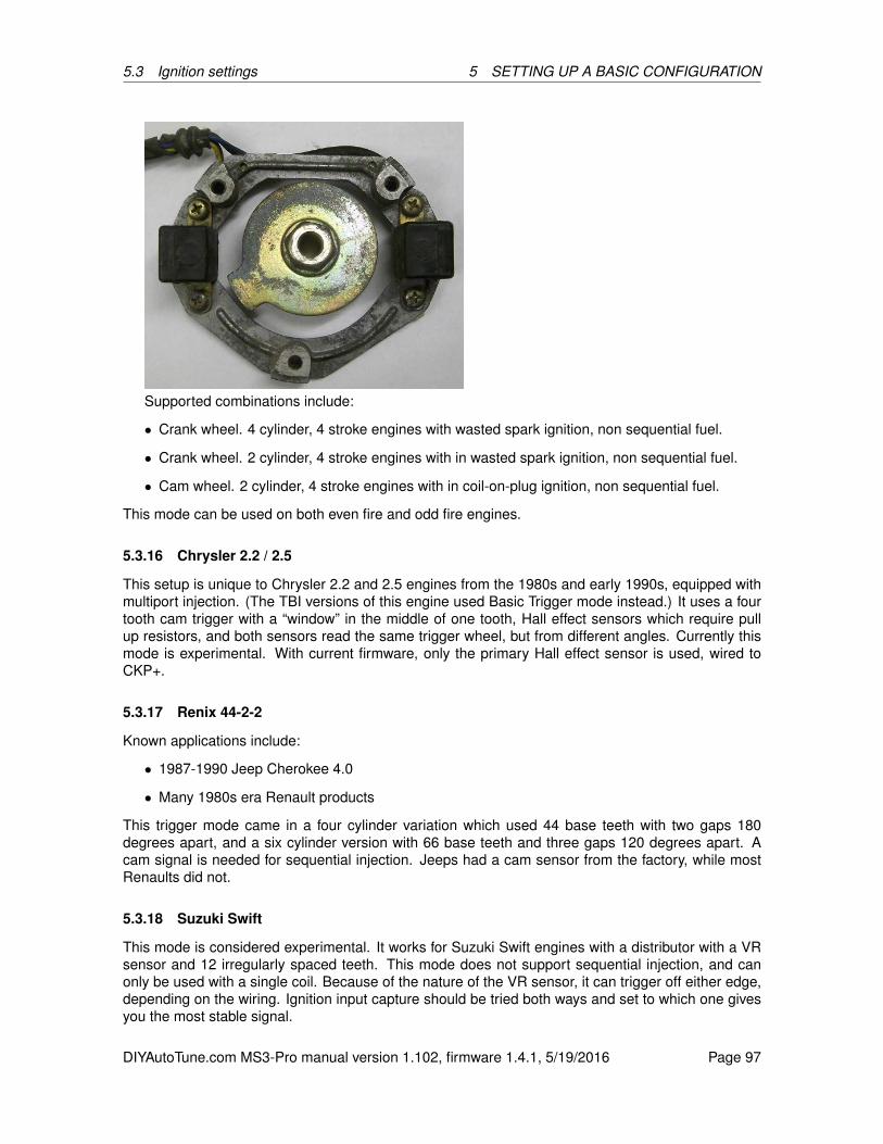
5.3 Ignition settings 5 SETTING UP A BASIC CONFIGURATION
Supported combinations include:
• Crank wheel. 4 cylinder, 4 stroke engines with wasted spark ignition, non sequential fuel.
• Crank wheel. 2 cylinder, 4 stroke engines with in wasted spark ignition, non sequential fuel.
• Cam wheel. 2 cylinder, 4 stroke engines with in coil-on-plug ignition, non sequential fuel.
This mode can be used on both even fire and odd fire engines.
5.3.16 Chrysler 2.2 / 2.5
This setup is unique to Chrysler 2.2 and 2.5 engines from the 1980s and early 1990s, equipped withmultiport injection. (The TBI versions of this engine used Basic Trigger mode instead.) It uses a fourtooth cam trigger with a “window” in the middle of one tooth, Hall effect sensors which require pullup resistors, and both sensors read the same trigger wheel, but from different angles. Currently thismode is experimental. With current firmware, only the primary Hall effect sensor is used, wired toCKP+.
5.3.17 Renix 44-2-2
Known applications include:
• 1987-1990 Jeep Cherokee 4.0
• Many 1980s era Renault products
This trigger mode came in a four cylinder variation which used 44 base teeth with two gaps 180degrees apart, and a six cylinder version with 66 base teeth and three gaps 120 degrees apart. Acam signal is needed for sequential injection. Jeeps had a cam sensor from the factory, while mostRenaults did not.
5.3.18 Suzuki Swift
This mode is considered experimental. It works for Suzuki Swift engines with a distributor with a VRsensor and 12 irregularly spaced teeth. This mode does not support sequential injection, and canonly be used with a single coil. Because of the nature of the VR sensor, it can trigger off either edge,depending on the wiring. Ignition input capture should be tried both ways and set to which one givesyou the most stable signal.
DIYAutoTune.com MS3-Pro manual version 1.102, firmware 1.4.1, 5/19/2016 Page 97
5.3 Ignition settings 5 SETTING UP A BASIC CONFIGURATION
5.3.19 Suzuki Vitara 2.0
This mode is considered experimental. It works for a later modification of Suzuki’s irregularly spacedteeth that has 11 teeth instead of 12. Supports sequential injection. Because of the nature of the VRsensor, it can trigger off either edge, depending on the wiring. Ignition input capture should be triedboth ways and set to which one gives you the most stable signal.
5.3.20 Daihatsu 3cyl
This mode is considered experimental. The Daihatsu three cylinder version has 3 equally spacedteeth in a distributor with a fourth tooth adjacent to one of the teeth and a VR sensor. Supportssequential injection.
5.3.21 Daihatsu 4cyl
This mode is considered experimental. The Daihatsu four cylinder version has 4 equally spaced teethin a distributor with a fifth tooth adjacent to one of the teeth and a VR sensor. Supports sequentialinjection.
5.3.22 VTR1000
This ignition appears on some Honda V-twin motorcycles. It uses a 12-3 crank trigger with a VRsensor and no cam sensor. Sequential injection is not supported.
5.3.23 Rover #1
This mode is used on Rover K-series engines with a crank trigger wheel with 36 base teeth and twoone tooth gaps, 180 degrees apart. This only allows a single coil and batch fire injection. Cam inputis not supported.
5.3.24 Rover #2
This mode is used on Rover K-series engines with a crank trigger wheel with 36 base teeth and fourone tooth gaps. This only allows a single coil or wasted spark ignition and batch fire or semi-sequentialinjection. Cam input is not supported.
5.3.25 Rover #3
Similar to Rover #2, but the gaps are two teeth wide and positioned differently. As with Rover #2,supports wasted spark and semi-sequential injection, but does not support cam input.
5.3.26 GM 7X
This appears on several GM four and six cylinder engines with distributorless ignitions. GM refers tothe crank wheel in their internal documentation as a 7X trigger wheel. It has six equally spaced teethand a seventh tooth for cylinder identification. Cam input is supported for sequential injection.
5.3.27 QR25DE
Used on the Nissan QR25DE and some other Nissan four cylinders with crank triggering. Supportsfully sequential injection.
DIYAutoTune.com MS3-Pro manual version 1.102, firmware 1.4.1, 5/19/2016 Page 98
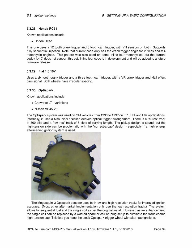
5.3 Ignition settings 5 SETTING UP A BASIC CONFIGURATION
5.3.28 Honda RC51
Known applications include:
• Honda RC51
This one uses a 12 tooth crank trigger and 3 tooth cam trigger, with VR sensors on both. Supportsfully sequential injection. Note that current code only has the crank trigger angle for V-twins and V-4motorcycle engines. This pattern was also used on some inline four motorcycles, but the currentcode (1.4.0) does not support this yet. Inline four code is in development and will be added to a futurefirmware release.
5.3.29 Fiat 1.8 16V
Uses a six tooth crank trigger and a three tooth cam trigger, with a VR crank trigger and Hall effectcam signal. Both wheels have irregular spacing.
5.3.30 Optispark
Known applications include:
• Chevrolet LT1 variations
• Nissan VH45 V8
The Optispark system was used on GM vehicles from 1993 to 1997 on LT1, LT4 and L99 applications.Internally, it uses a Mitsubishi / Nissan derived optical trigger arrangement. There is a "hi-res" trackof 360 slits and a "low-res" track of 8 slots of varying length. The pickup design is sound, but thehigh-tension side can be problematic with the "correct-a-cap" design - especially if a high energyaftermarket ignition system is used.
The Megasquirt-3 Optispark decoder uses both low and high resolution tracks for improved ignitionaccuracy. (Most other aftermarket implementation only use the low resolution track.) The systemallows for sequential fuel and the single coil as per the original install. However, as an enhancement,the single coil can be replaced by a wasted-spark or coil-on-plug setup to eliminate the troublesomehigh-tension cap. This lets you keep the stock Optispark trigger wheel with alternate ignitions.
DIYAutoTune.com MS3-Pro manual version 1.102, firmware 1.4.1, 5/19/2016 Page 99
5.3 Ignition settings 5 SETTING UP A BASIC CONFIGURATION
The Optispark requires a fused 12V supply. This can be tapped into the same 12V supply as theMegaSquirt. The Ground connection should be run to the sensor ground at the MegaSquirt. Thehigh and low resolution tach signals each require a 5 volt "pull up" resistor to operate correctly. Theconnector is marked with letters that can be used to identify the functions.
Optispark pin Function ConnectionA Low resolution signal CKP+B High resolution signal Digital frequency in 2C 12 volt power Shares powerD Ground Sensor ground
The low resolution signal runs to CKP. Because of the high frequency of the high resolution signal,it needs to be connected to the Digital Frequency In or Digital Frequency In 2 input instead of theCMP signal. You will need to specify which frequency input is used in the Ignition Options / WheelDecoder menu. Ignition input capture needs to be set to Falling Edge, and the Spark Output needs tobe set to Going High if using the stock ignition module.
5.3.31 Nissan SR20
This mode is used for the RWD version of the SR20DET with coil on plug ignition. These enginesuse an optical CAS with four unequally sized slots and a row of 360 slots. It wires up exactly like theOptispark and uses the same settings.
5.3.32 Nissan RB25
Known applications include:
• Nissan Skyline RB25DET, RB26DETT, RB20DET
• Nissan VG30DE and VG30DETT
This mode works for Nissan engines that used six unequally sized slots; it does not work for earlierVG30E applications which used a distributor and one long slot with five short ones. It wires up exactlylike the Optispark and uses the same settings.
5.3.33 LS1
This mode is used on the Chevrolet LS1 and related LSx V8 engines with the 24X wheel. The CKPinput wires to the 24X sensor and the CMP input wires to the 1X sensor. Both are Hall effect sensors,but do not require pull ups. This spark mode looks like it might be the “dual wheel” mode, but if youlook closely at the crank trigger, you’ll see that the edges of the crank wheel are different lengths.The MS3-Pro can use these different lengths to sync faster and avoid the sorts of problems causedby timing chain stretch causing the cam sensor to trigger on different teeth.
Ignition Input Capture needs to be set to Rising Edge for MS3-Pro, and spark output needs to beset to Going High.
For LS2 and other engines in the Gen IV family with a 58X crank wheel, see the examples underToothed Wheel.
5.3.34 YZF1000
This is used on Yamaha motorcycle engines with 7 small holes and 1 long recess in the crank trigger.There is no cam sensor in this mode, so current firmware only supports wasted spark and semi-sequential fuel. Known applications include the following Yamahas:
• YZF1000 / Thunderace
DIYAutoTune.com MS3-Pro manual version 1.102, firmware 1.4.1, 5/19/2016 Page 100
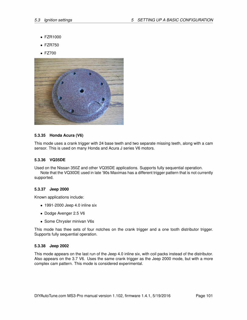
5.3 Ignition settings 5 SETTING UP A BASIC CONFIGURATION
• FZR1000
• FZR750
• FZ700
5.3.35 Honda Acura (V6)
This mode uses a crank trigger with 24 base teeth and two separate missing teeth, along with a camsensor. This is used on many Honda and Acura J series V6 motors.
5.3.36 VQ35DE
Used on the Nissan 350Z and other VQ35DE applications. Supports fully sequential operation.Note that the VQ30DE used in late ’90s Maximas has a different trigger pattern that is not currently
supported.
5.3.37 Jeep 2000
Known applications include:
• 1991-2000 Jeep 4.0 inline six
• Dodge Avenger 2.5 V6
• Some Chrysler minivan V6s
This mode has thee sets of four notches on the crank trigger and a one tooth distributor trigger.Supports fully sequential operation.
5.3.38 Jeep 2002
This mode appears on the last run of the Jeep 4.0 inline six, with coil packs instead of the distributor.Also appears on the 3.7 V6. Uses the same crank trigger as the Jeep 2000 mode, but with a morecomplex cam pattern. This mode is considered experimental.
DIYAutoTune.com MS3-Pro manual version 1.102, firmware 1.4.1, 5/19/2016 Page 101
5.3 Ignition settings 5 SETTING UP A BASIC CONFIGURATION
5.3.39 Zetec VTC
Used on Ford Zetec and other four cylinder engines with variable valve timing. It also supports JaguarV8s with variable valve timing. Features a 36-1 crank trigger like many other Fords, but a five toothcam wheel instead of a one tooth. Uses VR sensors on both, and supports full sequential operationand variable valve timing. Because of the nature of the VR sensor, it can trigger off either edge,depending on the wiring. Ignition input capture should be tried both ways and set to which one givesyou the most stable signal.
Note - the Ti-VCT system used on the Coyote motors is considered a subset of Toothed Wheelwith a special cam decoder instead of Zetec VCT mode. See the Coyote example under ToothedWheel.
5.3.40 Flywheel tri-tach
Known applications include:
• Early 1980s Porsche 911
• Porsche 944 Turbo (951)
• 1986 and earlier BMW 325e
• E30 chassis BMW M3 with S14 motor
• Many 1980s and early 1990s Audis
This application uses a VR sensor that counts flywheel teeth, with a second flywheel sensor thatreads a single post and, in most implementations, a cam sensor. Note that the number of teeth ishard coded for a specific number of cylinders. With a cam sensor, this will support full sequential.Current ones available include:
Number of teeth Number of cylinders135 5135 6136 8132 4130 4
For wiring, connect the CKP wires to the flywheel tooth sensor, the reference (1 tooth) flywheelsensor to the “cam” input, and the cam sensor to the pin selected as tertiary tach input. For mostapplications, the flywheel sensors are both VR type with a Hall effect cam sensor, so you will useCMP for the reference sensor and Digital Frequency In 2 for the cam sensor.
This mode is also considered experimental at this point.
5.3.41 2JZ VVTi
Used on the Lexus IS300 and many 2000 and later Toyota six cylinder engines with VVTi. This uses a36-2 crank trigger and a three tooth cam trigger, with VR sensors. Supports sequential injection andvariable valve timing. Because of the nature of the VR sensor, it can trigger off either edge, dependingon the wiring. Ignition input capture should be tried both ways and set to which one gives you themost stable signal.
This mode now also supports VVTi applications with a 36-2 crank trigger in four, eight, and twelvecylinder variations. Twelve cylinder mode is considered experimental.
DIYAutoTune.com MS3-Pro manual version 1.102, firmware 1.4.1, 5/19/2016 Page 102
5.4 Idle valves 5 SETTING UP A BASIC CONFIGURATION
5.3.42 Honda TSX / D17
Uses a 12 tooth crank sensor with one tooth added for a total of 13 real teeth, combined with a camsensor. This allowed Honda to add continuously variable valve timing. Uses VR sensors.
5.3.43 Viper V10
Used for Vipers and V10 Rams with JTEC ECU. This one has a crank trigger with five groups of twoteeth. A cam sensor is also required, with a one tooth trigger wheel. Both are Hall effect and requirepull ups. Supports sequential injection, but as the MS3-Pro has only eight ignition outputs, you willneed to run wasted spark ignition. Factory Chrysler coils require external ignition modules such asthe QuadSpark. Gen 1 mode is used for the 1995 and earlier, which had three teeth on the camtrigger, while the others use regular Viper V10 mode and have a one tooth cam trigger.
5.3.44 Honda K24A2
This mode uses the same pattern as the TSX / D17 mode but with a different position for the addedtooth on the crank pulley.
5.3.45 HD32-2
Used for Harley-Davidson engines that use a 32-2 crank wheel and a MAP sensor instead of a camsensor. Cam sensor needs to be set to MAP. The front cylinder is considered the #1 cylinder.
5.3.46 Miata 36-2
This mode is specifically written for ’99-’05 Mazda Miatas running the Flyin’ Miata crank trigger andthe stock ’99-’05 cam sensor. Supports full sequential ignition and VVT. Ignition input capture needsto be set to Rising Edge.
5.3.47 Daihatsu 12+1
The Daihatsu EF-SE and other three cylinder engines with coil on plug ignition used a trigger wheelturning at cam speed with 12 equally spaced teeth and one additonal tooth for cylinder identification.This single sensor is a VR type and wires to the CKP inputs. Because of the nature of the VR sensors,it can trigger off either edge, depending on the wiring. Ignition input capture should be tried both waysand set to which one gives you the most stable signal.
5.3.48 Subaru 36-2-2-2 VVT
Subarus with variable valve timing (often called AVCS in Subaru’s documentation) changed their camtrigger pattern, requiring a different wheel decoder from Subarus with a 36-2-2-2 crank pattern andfixed cam position. These engines have a second cam sensor that can be wired to any unused digitalfrequency input. Settings are otherwise the same as for 36-2-2-2 mode.
5.4 Idle valves
The idle valve can be selected under Startup / Idle and chose Idle Control. The first option allowsyou to select your type of idle valve:
• None - The engine can run without an idle control valve if the throttle is adjusted to preventstalling.
DIYAutoTune.com MS3-Pro manual version 1.102, firmware 1.4.1, 5/19/2016 Page 103

5.4 Idle valves 5 SETTING UP A BASIC CONFIGURATION
• On / Off Valve - A solenoid that only opens and closes for a very basic open loop operation.
• PWM valve (2 or 3 wire) - Uses a pulse width modulated solenoid where changing the dutycycle changes the valve position. 2 wire valves use a single solenoid and a return spring, while3 wire valves use two solenoids in a push-pull configuration. Common applications include Ford,Mazda, Honda, some Toyotas, and most European cars that do not use drive by wire.
• Stepper valve (4 or 6 wire) - These valves use four separate coils to rotate a shaft, and havefrom 4 to 5 wires. Often used in GM, Chrysler, Mitsubishi, and Toyota vehicles.
The next box allows you to chose between open loop and closed loop.
• Open loop (warmup) - The valve opening amount is set as a function of coolant temperature,starting at an open value with the engine cold and closing the valve as it warms up.
• Closed loop - The ECU moves the valve as needed to target a specified idle speed.
We recommend only selecting a closed loop idle mode after getting the engine running well in anopen loop mode. Open loop commands how to open the valve as a function of temperature, whileclosed loop targets a specific idle speed.
Once you have selected a mode, you will need to set up the individual IAC modes. Settings notused are grayed out.
5.4.1 On / Off settings
• Fast Idle Temperature - the solenoid opens below this temperature and closes above it.
• Hysteresis - If the temperature drops below the opening temperature, it needs to drop by thisadditional amount before re-opening the valve. This prevents the valve from rapidly flickering onand off if the temperature is almost exactly at the opening temperature.
• Output port - Select which output you wish to use to control the solenoid.
5.4.2 Stepper valve settings
• Time Step Size - This is the number of milliseconds the firmware will wait between each step.If a valve does not move reliably, this setting should be increased.
– If the valve is perfectly dialed in, this will match the time it takes the coil move the motorthrough a single step. If this value is too low, the step is not completed, and the valve doesnot move. If the step is too high, the valve will move more slowly than it can - but it will stillwork, so it is better to set this too high than too low. Your best bet is to set this for 10 ms,then decrease until the valve no longer moves. Then add 0.5 to 1.0 ms.
DIYAutoTune.com MS3-Pro manual version 1.102, firmware 1.4.1, 5/19/2016 Page 104
5.4 Idle valves 5 SETTING UP A BASIC CONFIGURATION
• Initial Time Step Size - When moving more than one step, using a larger time for the first stepcan help overcome stiction in the valve. Setting this larger than the Time Step Size can improvereliability.
• Minimum # of steps to move - This is the minimum number of steps the controlling piece ofcode has to command before the code that moves the valve will actually try to move the valve.We’ve found some stepper valves, particularly used ones on older cars, may stick if commandedto move fewer than 5 to 8 steps.
• Homing Steps - This is the number of steps the valve will move (in the closing direction) onpower on so that the rest of the code can rely on the start position being accurate. After re-tracting to the Start Value, the IAC valve will then move to the number specified in the CrankingSteps.
• Homing Direction - Specifies if the valve opens or closes during the homing time.
• Wide Open Steps - If the valve is set to home in the opening direction, this sets the number ofsteps between closed and wide open. The number of homing steps should be larger than thisto ensure reliable operation. Not used if the homing direction is set to closed.
• Crank-to-Run Taper Time - This is the amount of time the IAC valve uses to transition afterstarting from its crank position to its running position. Not used in closed loop control.
• Power Between Steps - Determines what to do when the valve is not moving.
– Moving only: Turns off current to the idle valve. This can reduce current consumption andmake the valve run cooler, but can result in unreliable operation for some valves. Usuallythis should only be used for valves that do not freewheel if you try spinning the pintle byhand.
– Hold current: Applies a 50% current to keep the valve in place. Something of an intermedi-ate position between the other two options. Should be used with any valve that spins freelyif you attempt to turn it by hand. If you run into problems with the stepper valve drifting,switch to “always on” instead.
– Always on: Applies full power to the last coil to move to prevent the valve from turning. Thiscan make the valve and the drive circuit run hotter but locks the valve in position.
The amount to move the valve is specified in additional menus. Also, see section 6.1.1.3, Idle ValveTesting, for troubleshooting common problems with a stepper IAC valve.
5.4.3 PWM idle valve settings
• Crank-to-Run Taper Time - This is the amount of time the IAC valve uses to transition afterstarting from its crank position to its running position.
• Valve Mode - Normal mode is off at 0% duty cycle, inverted mode is off at 100% duty cycle. Asthe name implies, most valves use normal mode. If you’ve found you accidentally wired up a 3wire IAC valve backwards, just flip this setting.
• Output Port - Allows you to pick which output wires are used. In 3 wire mode, this is for the coilthat opens the valve.
• 3 wire mode - Used with 3 wire rotary IAC valves, common in Denso and Bosch applications.Set to Off for a 2 wire valve. For a 3 wire valve, this specifies the connection used for the coilthat closes the valves.
DIYAutoTune.com MS3-Pro manual version 1.102, firmware 1.4.1, 5/19/2016 Page 105

5.5 Sensor calibration 5 SETTING UP A BASIC CONFIGURATION
• Valve Frequency Selection - Select a frequency from the list. Different valves operate best ondifferent frequencies.
The PWM idle control uses two additional menus, PWM Idle Cranking Duty and Idle PWM DutyTable. These specify the IAC position in cranking and running as a function of temperature. A thirdmenu, PWM Idle Voltage Compensation, lets you specify an amount of duty cycle to be added to orsubtracted from the duty cycle as a function of battery voltage.
5.5 Sensor calibration
The MS3-Pro uses internal calibration tables to convert the resistance/voltage from the input sensorsinto a real world number. It is necessary to setup this calibration so the inputs read correctly. Thebuilt-in calibrations for coolant temperature (CLT) and air temperature (MAT) are for GM sensors, so ifyou have GM sensors you are safe to leave these alone. All installs should set the calibration for theAFR (air fuel ratio) table that is used for the oxygen sensor (lambda sensor) whether narrowband orwideband. Here’s how to change the sensor calibrations.
1. Unlock the calibrations (This lock/unlock is to ensure the calibration isn’t changed by accident.)
2. Open the Set Thermistor Tables dialogue, then set the CLT calibration (if needed) Pick thesensor type. The bias resistor value is hardwired at 2490. For a custom sensor, enter threemeasured temperature and resistance pairs. (Don’t guess, measure.) For greatest accuracythe bias resistor should be close to the sensor resistance at a "warm" temperature. Write tocontroller.
3. Set the MAT calibration in the same way (if needed.) The bias resistor is 2490 ohms. Write tocontroller. Close the dialogue.
4. Calibrate the AFR table. Either pick a preset or look up the voltage/AFR pairs from your con-troller manual. Write to controller. Note! You should also set your Project Properties for narrow-band/wideband and configure the settings on the “EGO control” page.
5. Re-lock the calibrations and Burn.
6. Calibrate TPS. With the throttle closed, "Get Current" on the closed throttle. Then fully open thethrottle and "Get Current" on the open throttle. Close.
7. Calibrate the MAP/Baro. Typically chose from one of the preset values.
8. It is not usually needed to calibrate the battery voltage. Do not alter these values from thedefaults unless you have confirmed the actual voltage reading is inaccurate.
You’ll also want to set up a couple basics on how the MS3-Pro uses the oxygen sensor. Go to FuelSettings and select AFR / EGO Control. This will bring up the screen below.
DIYAutoTune.com MS3-Pro manual version 1.102, firmware 1.4.1, 5/19/2016 Page 106

5.5 Sensor calibration 5 SETTING UP A BASIC CONFIGURATION
At this point, you’ll just want to set up a couple basic parameters. When first tuning, it helps tohave the O2 sensor correction off, so you’ll set Algorithm to “No Correction”. At the top of the middlecolumn, specify if you have a wide band or narrow band sensor, and enter your number of sensors(note that setting the EGO sensor type to Disabled will not just disable correction; it will disable allO2 input logging as well). The MS3-Pro can read up to four sensors over its analog inputs, and evenmore over the CAN bus with appropriate expansion modules.
If you have more than one O2 sensor, you will need to set what port (input) is being used. Selectwhich analog input is associated with what sensor with the drop down boxes in the middle. The tab atthe far right lets you pair each injector channel with a specific O2 sensor. The MS3-Pro can use anyO2 sensor to correct for any injector channel.
Once you’re done calibrating the sensors, check them from the main dash. To change any gaugesRight-Click on them and pick a different gauge. The ones we need here are under the Sensor Inputscategories. Check each of the following with the key on and engine off:
• Coolant temp - is it reasonable?
• Manifold air temp - is it reasonable and within a few degrees of CLT (for a cold engine)?
• Throttle - is it close to 0% with no throttle and close to 100% with full throttle
• Fuel load - if you are running speed density, this should be close to 100kPa at sea level, downto say 80kPa at high elevations.
• Air:Fuel ratio - this won’t read anything sensible with the engine off.
• Engine speed - should be zero. (Note! If RPM ever reads anything like 65000 rpm, it means youhave made an error in your configuration settings. Normally this will appear as an error whenyou first connect. In the unlikely case that it does not, open up Communications, MiniTerminaland turn the MegaSquirt off then back on again. You’ll get a message explaining what is wrong.Close MiniTerminal and fix the faulty settings. Then turn the MegaSquirt off then back on again.)
• Fuel pump - the fuel pump output on the MegaSquirt is ground switching for a relay. When theMegaSquirt is first turned on it will run for a couple of seconds. As soon as tach input pulsesare seen the pump will turn on again. If the engine stalls, the pump is turned off.
DIYAutoTune.com MS3-Pro manual version 1.102, firmware 1.4.1, 5/19/2016 Page 107
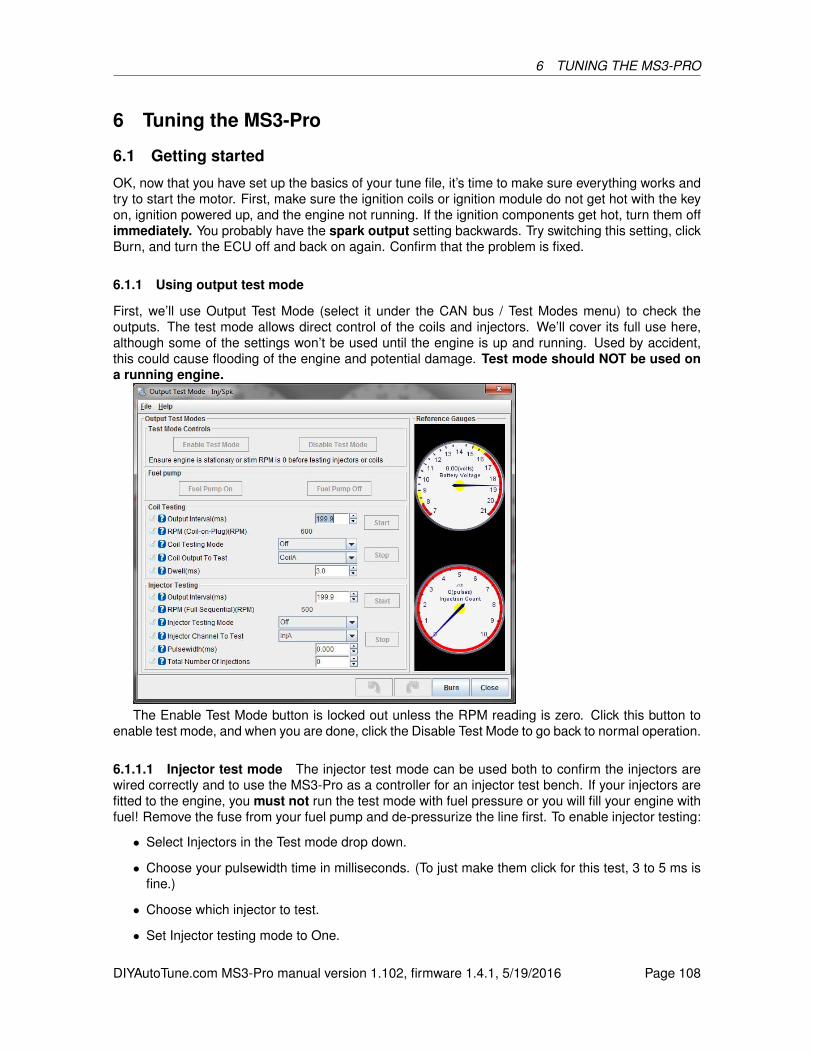
6 TUNING THE MS3-PRO
6 Tuning the MS3-Pro
6.1 Getting started
OK, now that you have set up the basics of your tune file, it’s time to make sure everything works andtry to start the motor. First, make sure the ignition coils or ignition module do not get hot with the keyon, ignition powered up, and the engine not running. If the ignition components get hot, turn them offimmediately. You probably have the spark output setting backwards. Try switching this setting, clickBurn, and turn the ECU off and back on again. Confirm that the problem is fixed.
6.1.1 Using output test mode
First, we’ll use Output Test Mode (select it under the CAN bus / Test Modes menu) to check theoutputs. The test mode allows direct control of the coils and injectors. We’ll cover its full use here,although some of the settings won’t be used until the engine is up and running. Used by accident,this could cause flooding of the engine and potential damage. Test mode should NOT be used ona running engine.
The Enable Test Mode button is locked out unless the RPM reading is zero. Click this button toenable test mode, and when you are done, click the Disable Test Mode to go back to normal operation.
6.1.1.1 Injector test mode The injector test mode can be used both to confirm the injectors arewired correctly and to use the MS3-Pro as a controller for an injector test bench. If your injectors arefitted to the engine, you must not run the test mode with fuel pressure or you will fill your engine withfuel! Remove the fuse from your fuel pump and de-pressurize the line first. To enable injector testing:
• Select Injectors in the Test mode drop down.
• Choose your pulsewidth time in milliseconds. (To just make them click for this test, 3 to 5 ms isfine.)
• Choose which injector to test.
• Set Injector testing mode to One.
DIYAutoTune.com MS3-Pro manual version 1.102, firmware 1.4.1, 5/19/2016 Page 108

6.1 Getting started 6 TUNING THE MS3-PRO
• If your injectors are powered via the fuel pump relay as is recommended, set the fuel pump toOn.
• For functional testing, set the total number of injections to 65535 (the maximum) or for flowtesting use your chosen number. (When performing repeated tests at the same number, youneed to enter 0, TAB out, then enter the number you want and TAB out again.)
The injector testing mode called Sequence runs the injector in sequence up to the chosen injector.So if you have six injectors and selected Injector D and Sequence, then the test mode will repeatedlyfire Injector A, then Injector B, then Injector C, then Injector D in turn, but will not fire injectors E andF. Set the chosen injector to the last one, and you can use this to confirm the injectors are followingthe right firing order.
The Output Interval determines how long to go between each test firing of the injectors. If youwant the injectors to fire every 100 ms, you would enter 100. The screen shows the rpm this approxi-mates to in full sequential.
Testing the fuel pump is straightforward; just buttons under Fuel Pump to turn it off and on. You willnotice that "Ready" lights up on the TunerStudio dash when the fuel pump is enabled. If you get noactivity, try starting again. However, if Ready lights up but the pump doesn’t run, you need to checkyou fuel pump relay and pump wiring. If this is a new fuel system, make sure that the fuel systemdoesn’t leak and that it holds pressure. Note that some aftermarket fuel pressure regulators, includingmost from Aeromotive, will hold pressure for only about 30 seconds or so after shutdown even if thefuel system has no leaks. Most OEM fuel pressure regulators will hold pressure much longer.
6.1.1.2 Coil test mode The coil test mode is useful to confirm you have the coils wired correctlyand to check dwell settings. (Do be careful as ignition coils put out a potential lethal voltage. Typically30,000V or more.) To enable coil testing:
• Select coils in the Test mode drop down.
• Choose your dwell time in milliseconds. Start low. e.g. 2.0ms.
• Choose which coil to test
• Set Coil testing mode to One
• If your coils are powered via the fuel pump relay as is recommended, set the fuel pump to On.
The Sequence mode and Output Interval work the same for coils as for the injectors. For example, a4 cylinder wasted spark engine at 6000rpm will fire a coil every 5ms, so each coil is fired every 10ms.Note that the test mode does not allow dwell periods to overlap in the sequence mode, unlike normaloperation where the dwell periods overlap as required. (This is why traditional V8 distributor sparkwas weak at high revs - there was not enough time to charge the single coil between sparks.)
6.1.1.3 Idle valve testing The idle valve has a separate test mode, also under the CAN bus /Testmodes menu. The idle valve test mode can be used with the engine running or stationary, unlikethe regular Output Test Mode. Note that with a PWM idle valve or a five or six wire stepper valve, youmay need to run a temporary fused 12V supply to the valve if you normally take power from the fuelpump relay and are testing with the engine off.
DIYAutoTune.com MS3-Pro manual version 1.102, firmware 1.4.1, 5/19/2016 Page 109

6.1 Getting started 6 TUNING THE MS3-PRO
• Idle Valve Homing Steps - This only applies to stepper idle valves. This setting determines howmany steps the motor should move during homing to ensure it has reached the home position.The number needs to be large enough to close the valve from any unknown starting position.(This is because there is no position feedback on most automotive stepper IAC valves.)
• Idle Valve Step - the desired valve position if using a stepper IAC valve. Larger numbers shouldgive a more open valve and higher rpm.
• PWM idle duty% - the desired valve position if using a PWM IAC valve. Larger numbers shouldgive a more open valve and higher rpm.
(Note that some Bosch rotary PWM valves valves feature a failsafe mode so that zero flow is at amidpoint, such as 20% duty,; above that the valve operates as expected where more duty gives moreairflow. Below this specific point is a failsafe mode that allows airflow even if there is no control signal.This is readily observed during test mode.)
There are three control buttons:
• Enable Test - Home Position - for stepper idle valves, this moves the valve through the numberof homing steps back to the home position. (If it doesn’t get all the way back to the stop, increasethe number of homing steps.) The valve will move to the run position shortly afterwards.
• Enable Test - Run Position - enable test mode where the steps or duty setting controls thevalve position
• Enable Test - In/Out Cycle - Cycles the valve continuously between the homing and run posi-tions.
• Stop Testing - disable test mode and allow normal idle control to operate.
Testing a stepper IAC valve First, click the Enable Test - Home Position button, and verify thatthe valve closes completely. The valve will move back to the run position on its own; if you are doingthis test yourself and want to make sure the valve is closed, set the run position to zero. Steppervalves can be a bit more complicated to troubleshoot than PWM valves. Here are some commonproblems and what to do if you encounter them.
• Problem: Valve vibrates when commanded to move, but does not actually turn.
DIYAutoTune.com MS3-Pro manual version 1.102, firmware 1.4.1, 5/19/2016 Page 110

6.1 Getting started 6 TUNING THE MS3-PRO
– One coil is wired backwards; swap wire 1A for 1B, or 2A for 2B.
• Problem: Valve moves, but in opposite direction of intended.
– Both coils are wired backwards for the way your tune is configured. With the currentfirmware, you can simply change the homing direction in the software. 1.2.4 and ear-lier code does not allow this. If you encounter this problem on older firmware, you canreverse the wiring. Switch wires 1A for 1B, and 2A for 2B.
• Problem: Valve does not move at all on initial power up.
– One possibility is incorrect wiring. Make sure 1A and 1B are on one coil, and 2A and 2Bare on the opposite coil.
– The other usual problem is the time step size is set too small. Try increasing it and see ifthe valve moves.
• Problem: Idle speed is not consistent from one start to another at the same temperature.
– Usually, this is caused by the homing steps being set too low. Increase this value until thevalve retracts fully.
– If the valve sometimes retracts fully, but not always, this may mean the steps are smallenough that they do not always successfully move the motor. Try increasing the time stepsize.
• Problem: The valve retracts normally, but then appears to stop working at some point duringoperation.
– Try increasing the time step size and/or minimum number of steps to move. Some oldervalves can have problems with stiction. Increasing the time step size will send a longerpulse, while increasing the minimum number of steps to move will send more pulses thatcan un-stick a stubborn valve.
• Problem: Idle speed hunts while the number of steps displayed is constant.
– It’s easy to assume the IAC valve is responsible here. After all, it’s supposed to control theidle speed, and the idle speed is behaving wrong. However, this is likely to be an issuewith the ignition timing or fueling instead.
Testing a PWM IAC valve PWM valves do not need a homing routine, as the PWM outputdirectly controls their position. As noted above, be sure your valve has power when testing. The"PWM idle duty" box allows entry of 0-100% duty output. This could be used to confirm operation ofthe valve as well as determining what duty cycle gives what RPM with the engine running.
6.1.2 Checking RPM
Next, we’ll disconnect the injectors and check to be sure the RPM input is working and your timingis correct. Pull the fuses to the injectors, or disconnect the connectors on the injectors, and crankthe engine. With TunerStudio connected and running, turn the key on and crank the engine. If allis well you see "Synced" and a stable engine speed (rpm) number. If the pattern is noisy, incorrector missing you might see "Synced" then "Not-synced" and/or rpms jumping up and down. The toothlogger (see section 8.3) should also be used to confirm that the pattern is stable if you do not have asteady RPM. Keep working on the crank/cam sensor inputs until you have stable rpm with no loss ofsync.
DIYAutoTune.com MS3-Pro manual version 1.102, firmware 1.4.1, 5/19/2016 Page 111

6.1 Getting started 6 TUNING THE MS3-PRO
While cranking, take a look at the fuel load (MAP sensor) reading in TunerStudio, if you are runningspeed density. You should expect to see it drop slightly as the engine pulls some vacuum. If it staysstuck on atmospheric pressure (near 100 kPa) then your map hose might be connected incorrectly.
6.1.3 Setting cranking timing
Having confirmed that the coils work as expected and with the fuel pump still disconnected, hook upa timing light to plug lead #1. Yes, this is really needed - correct timing is very important. If you arerunning wasted spark you need to ensure your strobe is compatible. "Dumb" timing lights are fine;some dial-back lights can be awkward. Use a "2-stroke" setting for wasted-spark or wasted-COP ifyou have a dial-back light. With a coil-on-plug pencil type coil you will need to remove the coil fromthe engine and install a short length of regular spark plug wire from the COP to the spark plug, andpossibly ground the COP if it was bolted on. Connect your timing light over this temporary plug lead.
If there are no timing marks on your engine, you will need to add some sort of marks. You canestablish TDC with a piston stop and add timing marks with either paint or timing tape.
Crank the engine and confirm that #1 timing is somewhere close to the Cranking Advance numberset in TunerStudio (this is set in section 5.3). If the timing doesn’t match and you’re in Fuel Only mode,you’ll need to adjust whatever is controlling the timing. Otherwise, you’ll need to adjust the Tooth #1Angle setting (if running Toothed Wheel) or Trigger Angle / Offset (if running any other spark modebesides Fuel Only). If the timing is too far advanced, increase this number. If the timing is retarded,decrease this number. If adjustments of more than 10 degrees are required, making the change, clickBurn, turn the key off and restart the engine. Very large changes don’t take effect until you turn theMS3-Pro off and back on again.
6.1.4 Starting the engine
Now that you’ve confirmed sensor inputs, coil and injector outputs, have good rpm and cranking timingis close you are ready to start the engine. Ensure the fuel pump is connected (since we disconnectedit in previous tests), battery is charged, and all hoses are secure. We recommend starting a data logas well. While the engine will usually start if you’ve gone through all the previous steps for settingup MS3-Pro, sometimes you’ll need a couple more tweaks, and the data log can be very valuable if itcomes to that. Go to the Data Logging menu, select Start Logging, and enter a name for your datalog. The log starts when you click Save, and stops when you either close TunerStudio or go to theData Logging menu and select Stop.
Now, hit the starter, and hope the moment for the big payoff has arrived.It is common to need to give the engine a little throttle to keep it alive on the first start. If all sounds
well, then keep the engine running and warm it up. Check for oil pressure, coolant temperature etc. Ifanything sounds wrong - stop and investigate.
Take your time! If things aren’t working out, then take a breather and come back another day.Come to the www.msextra.com forum and ask for help. When posting, please include full detailsof your install: engine type, make, model, ignition setup. The forum is global and we might not befamiliar with your engine, so just quoting an engine code is not sufficient. Don’t use the forum to ventyour frustration, keep it calm...
If the engine kicks back, your timing is too advanced. Disconnect the injectors again and checkwith a timing light. This can damage the starter motor if you ignore it.
If your engine does not spark, in spite of having a functioning fuel and ignition system and timingthat appears to be correct, here are several things we recommend checking that commonly will causea no start condition.
• If you are running full sequential fuel and / or coil on plug ignition, try changing these settingsto semi-sequential fuel and wasted-COP ignition. This will rule out the possibility that the camsensor hasn’t been set up correctly, and you’re firing on the exhaust stroke instead of the intake
DIYAutoTune.com MS3-Pro manual version 1.102, firmware 1.4.1, 5/19/2016 Page 112
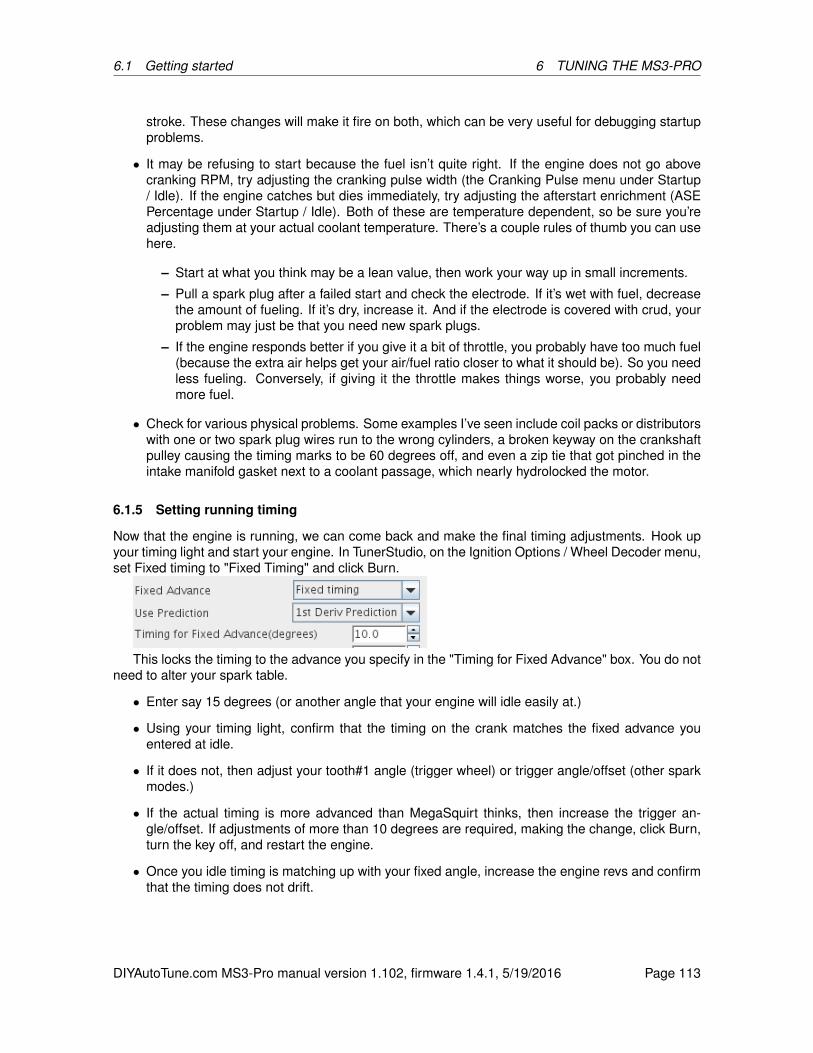
6.1 Getting started 6 TUNING THE MS3-PRO
stroke. These changes will make it fire on both, which can be very useful for debugging startupproblems.
• It may be refusing to start because the fuel isn’t quite right. If the engine does not go abovecranking RPM, try adjusting the cranking pulse width (the Cranking Pulse menu under Startup/ Idle). If the engine catches but dies immediately, try adjusting the afterstart enrichment (ASEPercentage under Startup / Idle). Both of these are temperature dependent, so be sure you’readjusting them at your actual coolant temperature. There’s a couple rules of thumb you can usehere.
– Start at what you think may be a lean value, then work your way up in small increments.
– Pull a spark plug after a failed start and check the electrode. If it’s wet with fuel, decreasethe amount of fueling. If it’s dry, increase it. And if the electrode is covered with crud, yourproblem may just be that you need new spark plugs.
– If the engine responds better if you give it a bit of throttle, you probably have too much fuel(because the extra air helps get your air/fuel ratio closer to what it should be). So you needless fueling. Conversely, if giving it the throttle makes things worse, you probably needmore fuel.
• Check for various physical problems. Some examples I’ve seen include coil packs or distributorswith one or two spark plug wires run to the wrong cylinders, a broken keyway on the crankshaftpulley causing the timing marks to be 60 degrees off, and even a zip tie that got pinched in theintake manifold gasket next to a coolant passage, which nearly hydrolocked the motor.
6.1.5 Setting running timing
Now that the engine is running, we can come back and make the final timing adjustments. Hook upyour timing light and start your engine. In TunerStudio, on the Ignition Options / Wheel Decoder menu,set Fixed timing to "Fixed Timing" and click Burn.
This locks the timing to the advance you specify in the "Timing for Fixed Advance" box. You do notneed to alter your spark table.
• Enter say 15 degrees (or another angle that your engine will idle easily at.)
• Using your timing light, confirm that the timing on the crank matches the fixed advance youentered at idle.
• If it does not, then adjust your tooth#1 angle (trigger wheel) or trigger angle/offset (other sparkmodes.)
• If the actual timing is more advanced than MegaSquirt thinks, then increase the trigger an-gle/offset. If adjustments of more than 10 degrees are required, making the change, click Burn,turn the key off, and restart the engine.
• Once you idle timing is matching up with your fixed angle, increase the engine revs and confirmthat the timing does not drift.
DIYAutoTune.com MS3-Pro manual version 1.102, firmware 1.4.1, 5/19/2016 Page 113
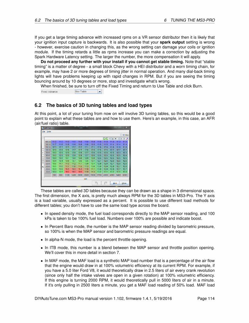
6.2 The basics of 3D tuning tables and load types 6 TUNING THE MS3-PRO
If you get a large timing advance with increased rpms on a VR sensor distributor then it is likely thatyour ignition input capture is backwards. It is also possible that your spark output setting is wrong- however, exercise caution in changing this, as the wrong setting can damage your coils or ignitionmodule. If the timing retards a little as rpms increase you can make a correction by adjusting theSpark Hardware Latency setting. The larger the number, the more compensation it will apply.
Do not proceed any further with your install if you cannot get stable timing. Note that “stabletiming” is a matter of degree - a small block Chevy with a HEI distributor and a worn timing chain, forexample, may have 2 or more degrees of timing jitter in normal operation. And many dial-back timinglights will have problems keeping up with rapid changes in RPM. But if you are seeing the timingbouncing around by 10 degrees or more, stop and investigate what’s wrong.
When finished, be sure to turn off the Fixed Timing and return to Use Table and click Burn.
6.2 The basics of 3D tuning tables and load types
At this point, a lot of your tuning from now on will involve 3D tuning tables, so this would be a goodpoint to explain what these tables are and how to use them. Here’s an example, in this case, an AFR(air/fuel ratio) table.
These tables are called 3D tables because they can be drawn as a shape in 3 dimensional space.The first dimension, the X axis, is pretty much always RPM for the 3D tables in MS3-Pro. The Y axisis a load variable, usually expressed as a percent. It is possible to use different load methods fordifferent tables; you don’t have to use the same load type across the board.
• In speed density mode, the fuel load corresponds directly to the MAP sensor reading, and 100kPa is taken to be 100% fuel load. Numbers over 100% are possible and indicate boost.
• In Percent Baro mode, the number is the MAP sensor reading divided by barometric pressure,so 100% is when the MAP sensor and barometric pressure readings are equal.
• In alpha-N mode, the load is the percent throttle opening.
• In ITB mode, this number is a blend between the MAP sensor and throttle position opening.We’ll cover this in more detail in section 7.
• In MAF mode, the MAF load is a synthetic MAP load number that is a percentage of the air flowthat the engine would draw in at 100% volumetric efficiency at its current RPM. For example, ifyou have a 5.0 liter Ford V8, it would theoretically draw in 2.5 liters of air every crank revolution(since only half the intake valves are open in a given rotation) at 100% volumetric efficiency.If this engine is turning 2000 RPM, it would theoretically pull in 5000 liters of air in a minute.If it’s only pulling in 2500 liters a minute, you get a MAF load reading of 50% load. MAF load
DIYAutoTune.com MS3-Pro manual version 1.102, firmware 1.4.1, 5/19/2016 Page 114
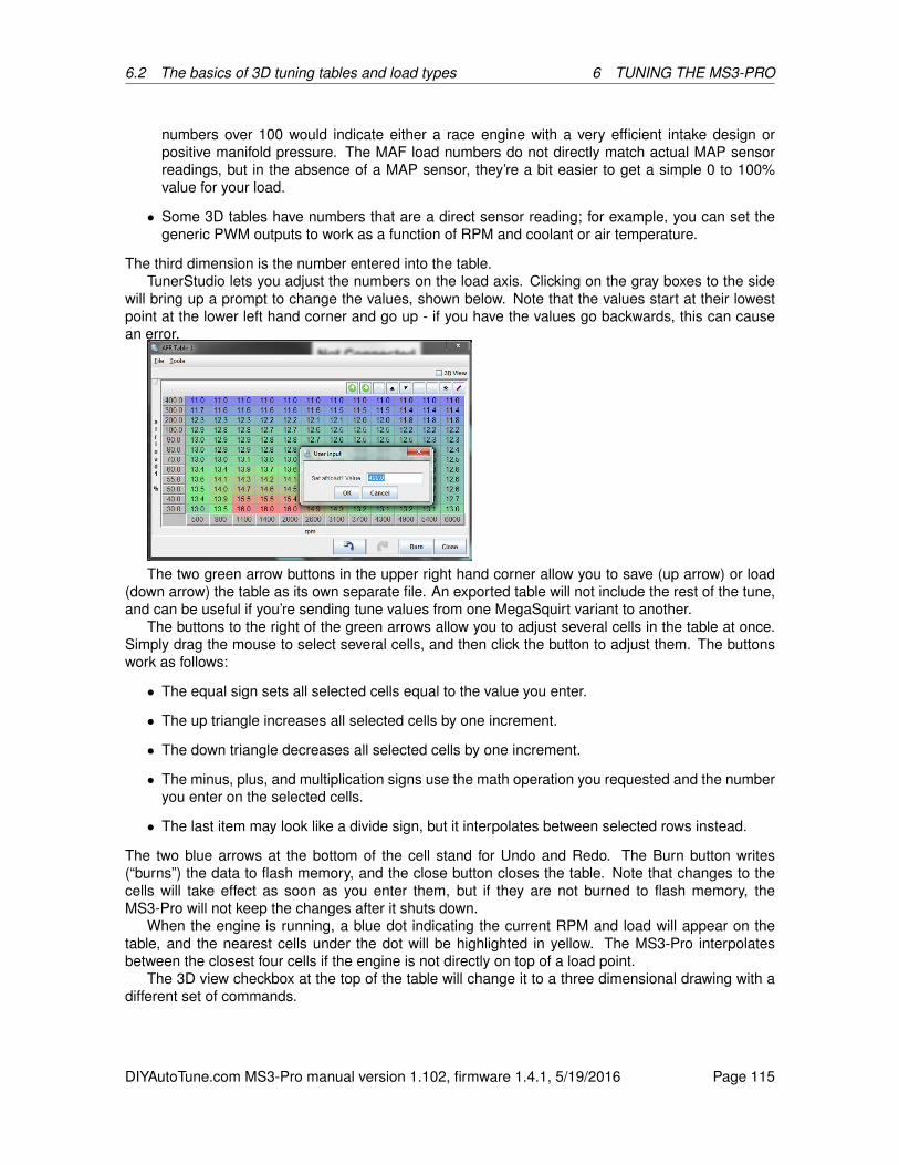
6.2 The basics of 3D tuning tables and load types 6 TUNING THE MS3-PRO
numbers over 100 would indicate either a race engine with a very efficient intake design orpositive manifold pressure. The MAF load numbers do not directly match actual MAP sensorreadings, but in the absence of a MAP sensor, they’re a bit easier to get a simple 0 to 100%value for your load.
• Some 3D tables have numbers that are a direct sensor reading; for example, you can set thegeneric PWM outputs to work as a function of RPM and coolant or air temperature.
The third dimension is the number entered into the table.TunerStudio lets you adjust the numbers on the load axis. Clicking on the gray boxes to the side
will bring up a prompt to change the values, shown below. Note that the values start at their lowestpoint at the lower left hand corner and go up - if you have the values go backwards, this can causean error.
The two green arrow buttons in the upper right hand corner allow you to save (up arrow) or load(down arrow) the table as its own separate file. An exported table will not include the rest of the tune,and can be useful if you’re sending tune values from one MegaSquirt variant to another.
The buttons to the right of the green arrows allow you to adjust several cells in the table at once.Simply drag the mouse to select several cells, and then click the button to adjust them. The buttonswork as follows:
• The equal sign sets all selected cells equal to the value you enter.
• The up triangle increases all selected cells by one increment.
• The down triangle decreases all selected cells by one increment.
• The minus, plus, and multiplication signs use the math operation you requested and the numberyou enter on the selected cells.
• The last item may look like a divide sign, but it interpolates between selected rows instead.
The two blue arrows at the bottom of the cell stand for Undo and Redo. The Burn button writes(“burns”) the data to flash memory, and the close button closes the table. Note that changes to thecells will take effect as soon as you enter them, but if they are not burned to flash memory, theMS3-Pro will not keep the changes after it shuts down.
When the engine is running, a blue dot indicating the current RPM and load will appear on thetable, and the nearest cells under the dot will be highlighted in yellow. The MS3-Pro interpolatesbetween the closest four cells if the engine is not directly on top of a load point.
The 3D view checkbox at the top of the table will change it to a three dimensional drawing with adifferent set of commands.
DIYAutoTune.com MS3-Pro manual version 1.102, firmware 1.4.1, 5/19/2016 Page 115

6.3 Tuning fuel 6 TUNING THE MS3-PRO
You can rotate the drawing with the mouse to get a better view, or press Z to toggle a flat overheadview. When the engine is running, a blue dot will appear showing what RPM and load point the engineis currently running at. The red dot shows which cell you are currently adjusting. Use the arrow keysto move the dot around the map, and shift-up arrow or shift-down arrow to move the map value up ordown. Checking Follow Mode will cause the red adjusting dot to follow the blue dot around the table.
Many of the tuning maps can also be viewed under the 3D Tuning Maps menu. This brings upboth a 3D table and a bank of gauges to let you monitor the status of the engine while the table isactive.
You may change the gauge style to “Histogram” to change them to a line graph, or right click anygauge to swap it to a different gauge style if you want to see different variables.
6.3 Tuning fuel
Once you have the engine up and running, it’s time to start tuning. There are three tools to usefor tuning when the engine is in a steady state: the VE table, the AFR table, and the settings thatdefine the injector behavior (Dead time and small pulse widths). We’ll cover the last two first as theyare applied across the board, so you will want these pinned down before you start tuning the wholetable. After these are dialed in, you can come back and dial in the acceleration enrichment and otherenrichments applied to the fueling.
DIYAutoTune.com MS3-Pro manual version 1.102, firmware 1.4.1, 5/19/2016 Page 116

6.3 Tuning fuel 6 TUNING THE MS3-PRO
6.3.1 Dead time
The dead time (or offset) of an injector is effectively the portion of the pulsewidth when no fuel isinjected, this is because the injector is an electro-mechanical valve and takes a measurable timeto open and close. (Note that documentation for some earlier MS variants referred to this as just"opening time".)
Setting the dead time correctly is an important setup step. If it is incorrectly set, you will find tuninglight-load or idle very tricky and features such as air-temperature correction will malfunction. In worstcases your engine will be untuneable - especially if you have very large injectors.
The MS3-Pro dead time system is found on the Fuel Settings -> Injector Dead-time. It allowsfor individual or grouped setting of these dead times. This will match up with the "Main fuel outputssetting" on the engine and sequential settings page.
There are three main areas on this page:
• The injector settings on the left side.
• The voltage correction curves on the right side. These allow fine tuning the battery voltagecorrection of the dead time.
6.3.1.1 Injector settings As previously mentioned, the injector outputs directly support high-impedanceinjectors. Low impedance injectors may be used through an external peak-and-hold box or resistorpack.
The first setting Same/Individual allows either one dead-time across all injectors, or if you havephysically determined the precise dead time for each injector individually, you can use the Individualsetting. Normally, use Same. The table below allows entry of the dead times - in milliseconds atnominal 13.2 volts. You can choose one of the four battery voltage correction curves. (If in doubt, pickno.1 and leave the curve alone.)
Typical dead times at 13.2 volts:
• High impedance injectors - dead time = 0.8-1.0 ms
• Low impedance injectors with resistors - dead time = 0.8-0.9 ms
• Low impedance injectors with external peak/hold - dead time = 0.6-0.8 ms
LPG injectors may require larger dead times.
DIYAutoTune.com MS3-Pro manual version 1.102, firmware 1.4.1, 5/19/2016 Page 117

6.3 Tuning fuel 6 TUNING THE MS3-PRO
We’ll cover measuring injector dead time in more detail in the Advanced section.
6.3.2 Small pulse widths
At most pulsewidths (say above 2ms), injectors behave in a linear manner, where 10% increase ineffective pulsewidth gives a 10% increase in fuel flow. The MS3-Pro normally relies on this linearbehavior for fuel calculations. However, at small pulsewidths, injectors behave non-linearly. This tableallows for you to correct for this. You may specify up to four separate curves if you determine that yourinjectors do not all work the same.
The Injector Small Pulsewidths feature allows the user to make a correction and make the non-linear region more linear in nature. Unless you have calibration data for your injectors measured onyour MegaSquirt, this feature should be left turned off. The X-axis of the curve is the MegaSquirtpulsewidth (before deadtime is applied) and the Y-axis is the required injector pulsewidth (beforedeadtime) that the injector needs to approximate linearity. Most injectors observed exhibit an "S"shaped non-linear region. Nothing happens for the first few 0.1ms after dead time, so a curve thateffectively adds on PW to the very low values will help linearize this somewhat. The non-linear regionalso frequently shows a "lump" which will make linearization tricky. See the dead time measurementsection for real measured data.
Here are some example curves based on data from real injectors. Note that no allowance is madefor the "lump" which will distort the results. The injectors were linear by 1.2ms (plus dead time) so thecurve is arranged from 0-1.2ms.
DIYAutoTune.com MS3-Pro manual version 1.102, firmware 1.4.1, 5/19/2016 Page 118

6.3 Tuning fuel 6 TUNING THE MS3-PRO
Ensure that the start and end points match. In this example, the curve starts at 0.000, 0.000 andends at 1.200, 1.200.
However, the best approach is to avoid operating injectors in this non-linear region altogether. Sizeinjectors appropriately and use a second set of staged injectors if a large dynamic range is needed.
6.3.3 AFR table
The AFR table can be used in three different ways.
• In MAF mode, it is your primary fuel table.
• In all other fuel modes, it can be used purely for closed loop O2 correction with a wideband O2sensor.
• If you set “Incorporate AFR Target” under the General Settings menu to “include AFRtarget,” itwill scale the pulse widths based on the numbers entered.
We recommend using the “Incorporate AFR Target” option on most installs. This allows the VE tableto closer reflect actual volumetric efficiency, and allows you to specify the air/fuel ratio by directlyadjusting this table.
We took a brief look at this table in section 6.2. Now, let’s take a look at how you use this particulartable.
You’ll enter the AFR you want at each RPM and load point (see section 6.2 if you need a refresheron the load points.). Most sequential fire engines will run best at 14.7:1 at idle. At cruising RPM andlow load, you can run 14.7:1 or sometimes leaner depending on the engine. Most naturally aspiratedengines tend to run best at 13.2 to 13.5 at full throttle, while engines running forced induction mayneed to run as rich as the mid 11’s under boost. The Tools menu in the upper left hand corner letsyou bring up an AFR table generator.
DIYAutoTune.com MS3-Pro manual version 1.102, firmware 1.4.1, 5/19/2016 Page 119

6.3 Tuning fuel 6 TUNING THE MS3-PRO
In this menu, you can enter information about the engine at left. The “X and Y Axis” option givesyou the option of retaining the current load and RPM bins, or generating new ones based on the dataentered. First, click Generate to create the table, then the Apply button to activate the new table orCancel to close the generator and not use the generated table.
If you are running MAF mode, this is your main fuel tuning table. If you do not hit the actual AFRtargets, you will need to adjust the MAF flow curve under the Basic / Load Settings menu.
If you set “Incorporate AFR Target” under the General Settings menu to “include AFRtarget,” thistable is used to scale the fueling. A table entry of 14.7:1 will mean no fuel scaling. Numbers less thanthat will increase the fuel, and numbers higher will decrease the fuel. When using this mode, you’lltune your VE table to hit your AFR targets, then adjusting the AFR target table will directly adjust thefuel to the desired AFR number.
6.3.4 VE table
The VE table is your primary tuning table unless running in MAF mode (and in MAF mode, it can beused as a corrective trim table). At its simplest, bigger numbers equal more fuel.
In any mode that uses this table, the numbers in the VE table are a percentage. The fuelingequation takes the base pulse width from Required Fuel, scales it by the percentage in the VE table,and then applies any other corrections, enrichments, and the like, such as air density correctionand warmup enrichment. If you have the tuning set to incorporate the AFR target, theoretically, theVE table will match the engine’s actual volumetric efficiency. Don’t be alarmed if you need to enternumbers above 100, particularly in boost. The maximum number is 255.
If you are running in MAF mode with the VE table enabled as a trim table, start by adjusting allcells to 100. The table will apply a percent trim to the fueling calculated from the MAF sensor curveand AFR table.
We recommend first setting up an appropriate AFR table, then adjust the numbers in the VE table(upwards to add fuel, downwards to take it away) until your actual air/fuel ratio hits the target table.
Before starting to tune the VE Table, it is recommended that you turn the Acceleration Enrichment(AE) off so you can see whats happening to the mixture as a direct result of the table rather thanhaving fuel added from Accel Enrichment. See the next section on how to switch this off. You mayfind that youll need to be light on the throttle, as the AE is needed to fill "holes" that occur when thethrottle opens quickly. Remember to tune the AE when you have a tuned VE Table.
DIYAutoTune.com MS3-Pro manual version 1.102, firmware 1.4.1, 5/19/2016 Page 120
6.3 Tuning fuel 6 TUNING THE MS3-PRO
Another item to turn off during tuning is the Overrun settings as the PW may drop to 0.0mS causinglean spots. You’ll find this by going to the Basic / Load Settings menu and selecting General Settings.Overrun fuel cut is in the lower right corner. The default tune has this turned off.
Tuning the VE table involves richening (by increasing the VE) or leaning (be decreasing VE) ateach point in the VE table. Most of your driving will occur in a diagonal strip of the VE table, from lowrpm, low kPa (i.e. idle) to high rpm, high kPa (i.e. WOT). You can adjust these values using the O2sensor, data logs, VE Analyze Live in TunerStudio, and/or the seat of your pants. Low rpm and lowkPa (say less than half of the max rpm and max kPa) might be able to use stoichiometric or leaner.Richer mixtures would be used at high rpm and high kPa.
However, the low rpm/high kPa and high rpm/low kPa are not seen as often driving your vehicle.Basically, if the engine never runs in certain parts of the MAP, then the numbers there should notmatter. However, since you may not be able to guess where you will run under every possible set ofconditions, you put estimated VE numbers that make sense into the little used areas.
From this frequently used diagonal strip of the VE table, you will be able to see how much the VErises from one rpm bin to the next, and use these differences to estimate the low rpm, very high kPanumbers and the high rpm, very low kPa numbers. Since you rarely (if ever) run in these parts of thetable, the actual numbers will not make much difference, but they will be there "just in case". You arelooking to create a smooth VE map wherever possible.
It is a good idea to set either the second or third row of kPa bins in the VE Table to the idle MAPvalue. So, for example, if you idle at 35 kPa, set the first to say 20 kPa or even a little lower (this canbe used for fuel saving during over run). The second can then either be 35 kPa or a value between 20and 35, with the next row being 35. The reason is it is always easier to tune idle if the point of idle ison a cross hatch; then there’s only really 2 points that influence it rather than 4. The engine may notalways idle at the same MAP value when under load, but it’s worth trying to set this up for unloadedidle. Most of the time, an engine will idle best if you flatten out the cells above and below where itidles; it’s rare for an engine to need large changes in VE at idle.
6.3.4.1 VE table generator Clicking on the Tools menu under the VE table will bring up the VEtable generator tool. This can create an approximate starting VE table based on the engine’s size,induction type, and estimated torque curve. This table can be a good starting point, but will requiresome fine tuning to dial in. Note that entering a peak power and a peak torque that are only a fewhundred RPM apart can result in a table with almost no useful data below the peak torque. The VEtable generator works for fairly typical engines, but its algorithm does not work very well for an enginethat peaky.
DIYAutoTune.com MS3-Pro manual version 1.102, firmware 1.4.1, 5/19/2016 Page 121

6.3 Tuning fuel 6 TUNING THE MS3-PRO
6.3.5 Basic acceleration enrichment (AE) tuning
MS3-Pro has two options for basic acceleration enrichment, plus model based acceleration enrich-ment that we’ll discuss later. One is the time based accel enrichment setup that users of previousMegaSquirt variations will recognize. The other one behaves similar to an accelerator pump on acarburetor. We recommend using the accelerator pump style in most cases, but we will cover bothstyles if you prefer the “classic” MegaSquirt setup.
Both use variables called TPSdot and MAPdot. The “dot” is a calculus notation that indicates rateof change with respect to time. Don’t worry, you don’t need to know calculus to tune this. The amountis expressed as a percent of change over time. With TPSdot, it is percent opening versus time; aTPSdot rate of 100 %/sec would be opening from closed to wide open throttle in one second, or theequivalent speed, such as going from 25% to 75% throttle in 1/2 second. The MAPdot is measuredin kPa per second. MS3-Pro can use either one, or a combination of the two, to trigger accelerationenrichment.
6.3.5.1 Main accel enrich settings menu This menu allows for several changes that affect bothAE modes.
DIYAutoTune.com MS3-Pro manual version 1.102, firmware 1.4.1, 5/19/2016 Page 122

6.3 Tuning fuel 6 TUNING THE MS3-PRO
• Use Time-based or Accel-pump Accel: This lets you select which of the two methods belowwill be used.
• Wall-wetting AE (EAE, X-Tau): Enables model based acceleration enrichment, discussed insection 7.
• TPSdot uses %WOT: This allows you to specify a curve that defines the upper limit of throt-tle position as a function of RPM. Moving the throttle beyond this point does not allow in anyadditional air, and therefor triggers no additional acceleration enrichment.
• X-Tau MAPdot Thresholds: The X-Tau acceleration enrichment, when enabled, will alwaystrigger when the MAP readings increase. However, you can prevent this from automaticallytriggering when the MAP sensor decreases by specifying a minimum amount of MAPdot in kPaper second to trigger X-Tau.
– Start Transition - A MAP decrease at a rate slower than this will not trigger X-Tau fuel cuts.
– Finish Transition - When the MAP sensor reading drops faster than this, full X-Tau drivenfuel cuts are in effect. Between the start and finish values, the MS3-Pro will ramp in thisfeature.
6.3.5.2 Accelerator pump AE The accelerator pump AE uses one curve each for MAPdot andTPSdot driven acceleration enrichment. The enrichment starts as soon as the MAP or TPS readingchanges, and stops when the reading stops changing. The % number is a multiplier which multipliesby Required Fuel to scale the pulse width up (or down; you can set negative multipliers when the MAPdecreases or the throttle closes and pull fuel at this point) for acceleration enrichment. The curve letsyou add a greater amount of pulse width at faster throttle openings or MAP rises. Zero on the curvemeans no enrichment is added at that point.
Underneath the curves, you have a line graph that appears when the engine is running. It tracksthe air/fuel ratio, MAPdot, and TPSdot measurements to help you tune the acceleration enrichment.
Besides the curves, you have the following settings.
DIYAutoTune.com MS3-Pro manual version 1.102, firmware 1.4.1, 5/19/2016 Page 123

6.3 Tuning fuel 6 TUNING THE MS3-PRO
• Accel enrichment TPS <-> MAPdot blend %: This percentage determines what percentageof the acceleration enrichment comes from the TPS and what percentage comes from the MAPsensor. 100% is entirely TPS driven, and 0% is entirely MAP driven. In between, the percentagewill scale the MAP driven pulse width adder down and the TPS driven pulse width adder up.
• Accel MAPdot threshold: The minimum MAPDot level needed to trigger MAP driven accelera-tion enrichment. Increasing this number will decrease false triggering from a noisy MAP signal,but too much will mean you miss triggering acceleration enrichment at lower amounts of tip in.
• Accel TPSdot threshold: The minimum TPS rate of change needed to trigger TPS drivenacceleration enrichment. As with MAPdot threshold, this has similar trade-offs between settingit too sensitive and not sensitive enough.
• Cold Accel multiplier %: This is applied whenever warmup enrichment is active. The MS3-Proapplies the full amount of multiplier when coolant temperature is at -40 degrees. It tapers off ina linear fashion to zero when you reach the point on the warmup enrichment curve where WUEequals 100% and there is no enrichment.
• Accel Enrich Down-Scaling with RPM: The acceleration enrichment will begin tapering off ina linear fashion once you reach the “Full Accel Below” RPM, and stop entirely once the RPMexceeds the “Zero Accel Above” RPM.
6.3.5.3 Time Based AE This is tuned under the Time Based Accel menu.
The two curves are the primary tuning tools. They set the percentage of pulse width to add as afunction of the rate of change of MAP and TPS readings. The adder % is a percentage of the mainRequired Fuel number. Under these charts, you can set a percentage to blend MAP and TPS driven
DIYAutoTune.com MS3-Pro manual version 1.102, firmware 1.4.1, 5/19/2016 Page 124

6.3 Tuning fuel 6 TUNING THE MS3-PRO
acceleration enrichment. 100% is entirely TPS driven, and 0% is entirely MAP driven. In between, thepercentage will scale the MAP driven pulse width adder down and the TPS driven pulse width adderup.
Unlike accelerator pump AE, which stops when the throttle position or MAP sensor stops moving,this mode will activate the acceleration enrichment for a defined time when the threshold rate ofchange occurs.
Below that, you have a line graph that appears when the engine is running. It tracks the air/fuelratio, MAPdot, and TPSdot measurements to help you tune the acceleration enrichment.
Here are what the settings do.
• Accel MAPdot threshold: The minimum MAPDot level needed to trigger MAP driven accelera-tion enrichment. Increasing this number will decrease false triggering from a noisy MAP signal,but too much will mean you miss triggering acceleration enrichment at lower amounts of tip in.
• End pulse width: The amount of pulse width at the end of the acceleration event, as a percent-age of Required Fuel.
• Time or Ignition Events: Allows you to specify the pulse width in either time or the number ofignition events.
• Accel duration (events): If using ignition events, the number of ignition events where you willreceive full acceleration enrichment pulse width.
• Accel taper (events): If using ignition events, the acceleration enrichment will taper off to thespecified end pulse width amount over this number of ignition events after the accel duration iscomplete.
• Accel time: The amount of time the full pulse width adder is applied, in seconds, when set totime mode.
• Accel taper time: The amount of time after the accel time over which the pulse width addertapers off to the end pulse width number, if set to time mode. After this time, the amount ofadded pulse width drops back to zero.
• Accel TPSdot threshold: The minimum TPS rate of change needed to trigger TPS drivenacceleration enrichment. As with MAPdot threshold, this has similar trade-offs between settingit too sensitive and not sensitive enough.
• Decel Fuel Amount: A multiplier that is applied whenever the TPSdot or MAPdot threshold iscrossed down instead of up. 0% would trigger a total fuel cut, while 100% means no changewould be applied. The firmware will allow using values over 100% to add fuel in this situation,although this is usually not a desirable effect. We recommend starting with 100% for a manualtransmission or 90% for an automatic transmission.
• Cold Accel Adder: This is applied whenever warmup enrichment is active, and is added to thestandard PW adder. The MS3-Pro applies the full amount of added pulse width when coolant
DIYAutoTune.com MS3-Pro manual version 1.102, firmware 1.4.1, 5/19/2016 Page 125
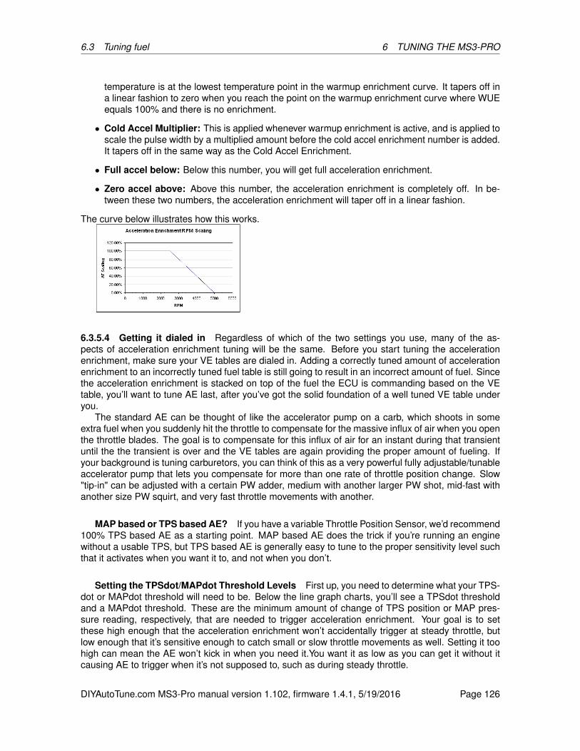
6.3 Tuning fuel 6 TUNING THE MS3-PRO
temperature is at the lowest temperature point in the warmup enrichment curve. It tapers off ina linear fashion to zero when you reach the point on the warmup enrichment curve where WUEequals 100% and there is no enrichment.
• Cold Accel Multiplier: This is applied whenever warmup enrichment is active, and is applied toscale the pulse width by a multiplied amount before the cold accel enrichment number is added.It tapers off in the same way as the Cold Accel Enrichment.
• Full accel below: Below this number, you will get full acceleration enrichment.
• Zero accel above: Above this number, the acceleration enrichment is completely off. In be-tween these two numbers, the acceleration enrichment will taper off in a linear fashion.
The curve below illustrates how this works.
6.3.5.4 Getting it dialed in Regardless of which of the two settings you use, many of the as-pects of acceleration enrichment tuning will be the same. Before you start tuning the accelerationenrichment, make sure your VE tables are dialed in. Adding a correctly tuned amount of accelerationenrichment to an incorrectly tuned fuel table is still going to result in an incorrect amount of fuel. Sincethe acceleration enrichment is stacked on top of the fuel the ECU is commanding based on the VEtable, you’ll want to tune AE last, after you’ve got the solid foundation of a well tuned VE table underyou.
The standard AE can be thought of like the accelerator pump on a carb, which shoots in someextra fuel when you suddenly hit the throttle to compensate for the massive influx of air when you openthe throttle blades. The goal is to compensate for this influx of air for an instant during that transientuntil the the transient is over and the VE tables are again providing the proper amount of fueling. Ifyour background is tuning carburetors, you can think of this as a very powerful fully adjustable/tunableaccelerator pump that lets you compensate for more than one rate of throttle position change. Slow"tip-in" can be adjusted with a certain PW adder, medium with another larger PW shot, mid-fast withanother size PW squirt, and very fast throttle movements with another.
MAP based or TPS based AE? If you have a variable Throttle Position Sensor, we’d recommend100% TPS based AE as a starting point. MAP based AE does the trick if you’re running an enginewithout a usable TPS, but TPS based AE is generally easy to tune to the proper sensitivity level suchthat it activates when you want it to, and not when you don’t.
Setting the TPSdot/MAPdot Threshold Levels First up, you need to determine what your TPS-dot or MAPdot threshold will need to be. Below the line graph charts, you’ll see a TPSdot thresholdand a MAPdot threshold. These are the minimum amount of change of TPS position or MAP pres-sure reading, respectively, that are needed to trigger acceleration enrichment. Your goal is to setthese high enough that the acceleration enrichment won’t accidentally trigger at steady throttle, butlow enough that it’s sensitive enough to catch small or slow throttle movements as well. Setting it toohigh can mean the AE won’t kick in when you need it.You want it as low as you can get it without itcausing AE to trigger when it’s not supposed to, such as during steady throttle.
DIYAutoTune.com MS3-Pro manual version 1.102, firmware 1.4.1, 5/19/2016 Page 126
6.3 Tuning fuel 6 TUNING THE MS3-PRO
Getting this dialed in can be done methodically, or by trial and error. Here’s the methodical method.You’ll need to have a safe way to accelerate from the bottom to the top of a gear, preferably your 1:1ratio gear, and you’ll want to datalog your engine idling, as well as these WOT pulls with your MS3-Proand TunerStudio. Ideally this is done on a dyno. Two to three pulls is better than one, but there’s noneed to get carried away. Then you can stop the datalogging and load this log up into MegaLogViewer.
In MegaLogViewer, on the left using the drop-down boxes that let you select what data you areviewing in your logs, set one of these to TPSdot, and/or MAPdot. You can set another to TPS to showyou what throttle position you were at as well. Additionally, monitoring injector pulsewidth (selectPW in the log to view that data) is helpful too, as you’ll be able to see the commanded injectorpulsewidth including the extra fuel added during an AE event. Lastly, near the bottom right corner ofMegaLogViewer you’ll see four indicators. Accel, Decel, Bit 7, and Bit 8. If either Accel or Bit 7 areactive, that’s a Accel event and AE is adding fuel. If Decel or Bit 8 are active, that’s a Decel event andAE is pulling fuel if configured to do so. (Accel and Decel are used for TPS Driven AE, and Bit7/Bit8are for MAP Driven AE).
Next, look at the datalog section of the car idling. The TPS signal should be rock solid, no move-ment. If it’s jumping around, you have a noise issues on your TPS signal. This can be caused by ECUsensor signal wiring that’s been routed too close to high voltage sources such as ignition coils, plugwires, the distributor, etc. Re-routing those wires away from those high-voltage sources is always agood idea. Additional possibilities for noise to get in the TPS signal could be a bad sensor ground(be sure you’ve grounded it the MS3-Pro sensor return wire), or a faulty TPS sensor. Similarly noiseon the MAP signal could be electrical, but is more likely to actually be real movement in the manifoldpressure, at least at the source you’re grabbing the vacuum signal from, meaning the port on yourintake manifold that’s connected to the MAP sensor.
If you’re seeing AE events at idle, your TPSdot or MAPdot threshold is set too sensitive (too lowof a number). You’ll see the pulse width bounce around when this happens as well; AE is just doingwhat you told it to do.
Now look at the datalog sections for the WOT pulls, step through these in the logs and look for anytime AE activated (Accel or Decel). It shouldn’t be active at all on WOT pulls, because you’re at WideOpen Throttle, you’re not moving the throttle around, so AE is not needed. Again, if you are seeingAE activate during WOT pulls, your threshold is too sensitive.
In either case if you’re triggering AE when you shouldn’t be, you’ll want to increase the thresholdvalue a bit above the highest TPSdot (or MAPdot) value you see it reach in the logs. This is the lowestyou can set your threshold in order to be a sensitive as possible while not triggering at steady statethrottle (or idle, which is also steady state throttle, it’s the steady state of NO throttle).
Note this setting is also the same setting you should use for your lowest (slowest rate of change)TPSdot or MAPdot field in the next section.
Tuning the tables Now that you have these, it’s time to tune the PW adder line graphs. To tunethese, start with the lowest speed throttle change position, and practice “tipping in” at that rate ofspeed. Use the real-time line graph at the bottom of the page to see how fast you’re tipping in. Whenyou’ve gotten use to applying the throttle at the right rate of speed to be close to the TPSDot numberyou’re using in the "slow" setting, watch your wideband o2 sensor readout. You want to be able todetermine what’s happening when you stab the throttle at that rate of speed. Is it going lean or rich?Note that it’s hard to see this on a gauge, as often it will go one then the other really fast. You want thefirst response; if it goes lean then rich you’ll usually see it hit 20:1 or maybe 22:1 for just an instant,and then as it goes back to running purely the table it may go to 13:1 or whatever... you want towatch that initial response, and if the first response is to go lean, then you want to add fuel; if the firstresponse is to go rich, you want to reduce fuel (PW).
A wideband o2 sensor is immensely helpful here, but don’t get too caught up in seeing perfectAFR numbers through the whole transient event. Adjust it until it feels right, snappy and responsivewith no hesitation. The feel is more important than looking for perfect numbers. If you want perfect
DIYAutoTune.com MS3-Pro manual version 1.102, firmware 1.4.1, 5/19/2016 Page 127
6.3 Tuning fuel 6 TUNING THE MS3-PRO
numbers, you may want to try the model based acceleration enrichment. Setup basic AE first asdescribed here. Next you’ll adjust the other set points you’ve setup for faster throttle rate changes.Repeat the process for the medium speed tip in, then the mid-fast, then the fast.
6.3.6 Startup / warmup fueling
On the first couple starts, you’ll want to use whatever combination of fuel and throttle can nurse theengine along until it is warmed up, and dial in the fuel at idle while hot. The reason is that this settingcan affect startup behavior, and you will want to have good, solid values in the VE table (at least atidle) before you can get final values for the startup sequence. Here is the sequence that MS3-Profueling goes through while starting.
1. When the key is on, the MS3-Pro will turn the fuel pump on for 2 seconds and fire one primingpulse to clear air for the lines. (You can disable this feature by setting the priming pulse to zero.)
2. When the engine starts turning, the MS3-Pro will run off the cranking pulse width table in batchfire mode until the RPM rises above the cranking RPM threshold.
3. Once the RPM rises above the cranking threshold, the MS3-Pro transitions to the main fueltable. It will initially multiply the pulse width from this table by the warmup enrichment (WUE)and afterstart enrichment (ASE) combined.
4. The ASE tapers off based on a user defined curve. After the ASE tapers away, the MS3-Pro willrun on the main fuel table multiplied by WUE.
5. When the engine reaches normal operating temperature, as defined by the WUE curve, theengine will run on the main fuel table, and the warmup cycle is over.
Now, let’s have a look at the menus in more detail.
6.3.6.1 Cranking / Startup settings
• Cranking RPM: This is the RPM where the MS3-Pro uses cranking pulse width. You want thisto be high enough that the engine does not exceed this if turning at its “cranking, but doesn’tcatch” speed, but less than the speed it will settle into as soon as the engine has started.
• Flood clear TPS: When the throttle is open above this percentage below cranking RPM, theMS3-Pro will conclude you are trying to clear a flooded engine, and turn off the cranking pulsewidth.
• Cranking fuel pulse rate: The injectors are batch fired during cranking. This parameter lets youinject fuel every ignition event or every other ignition event at double the cranking pulse widthnumber. Usually you would only use the “Alternate events” setting on engines with more thaneight cylinders.
• Priming pulse delay: This allows the MS3-Pro to wait a number of seconds after key on to fire apriming pulse.
• Ignore MAT correction during ASE: This can be used to compensate for MAT sensors thatabsorb heat from the engine. Turning this on will cause the air temperature correction to resetto 100% until the ASE taper is over.
• ASE count units: You can specify the length of the after-start enrichment in engine cycles (everyother crank revolution for a four stroke) or tenths of a second.
DIYAutoTune.com MS3-Pro manual version 1.102, firmware 1.4.1, 5/19/2016 Page 128
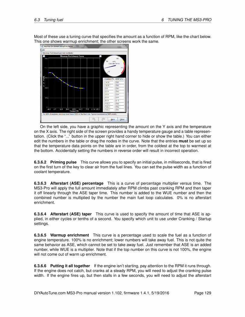
6.3 Tuning fuel 6 TUNING THE MS3-PRO
Most of these use a tuning curve that specifies the amount as a function of RPM, like the chart below.This one shows warmup enrichment; the other screens work the same.
On the left side, you have a graphic representing the amount on the Y axis and the temperatureon the X axis. The right side of the screen provides a handy temperature gauge and a table represen-tation. (Click the “...” button in the upper right hand corner to hide or show the table.) You can eitheredit the numbers in the table or drag the nodes in the curve. Note that the entries must be set up sothat the temperature data points on the table are in order, from the coldest at the top to warmest atthe bottom. Accidentally setting the numbers in reverse order will result in incorrect operation.
6.3.6.2 Priming pulse This curve allows you to specify an initial pulse, in milliseconds, that is firedon the first turn of the key to clear air from the fuel lines. You can set the pulse width as a function ofcoolant temperature.
6.3.6.3 Afterstart (ASE) percentage This is a curve of percentage multiplier versus time. TheMS3-Pro will apply the full amount immediately after RPM climbs past cranking RPM and then taperit off linearly through the ASE taper time. This number is added to the WUE number and then thecombined number is multiplied by the number the main fuel loop calculates. 0% is no afterstartenrichment.
6.3.6.4 Afterstart (ASE) taper This curve is used to specify the amount of time that ASE is ap-plied, in either cycles or tenths of a second. You specify which unit to use under Cranking / Startupsettings.
6.3.6.5 Warmup enrichment This curve is a percentage used to scale the fuel as a function ofengine temperature. 100% is no enrichment; lower numbers will take away fuel. This is not quite thesame behavior as ASE, which cannot be set to take away fuel. Just remember that ASE is an addednumber, while WUE is a multiplier. Note that if the top number on this curve is not 100%, the enginewill not come out of warm up enrichment.
6.3.6.6 Putting it all together If the engine isn’t starting, pay attention to the RPM it runs through.If the engine does not catch, but cranks at a steady RPM, you will need to adjust the cranking pulsewidth. If the engine fires up, but then stalls in a few seconds, you will need to adjust the afterstart
DIYAutoTune.com MS3-Pro manual version 1.102, firmware 1.4.1, 5/19/2016 Page 129
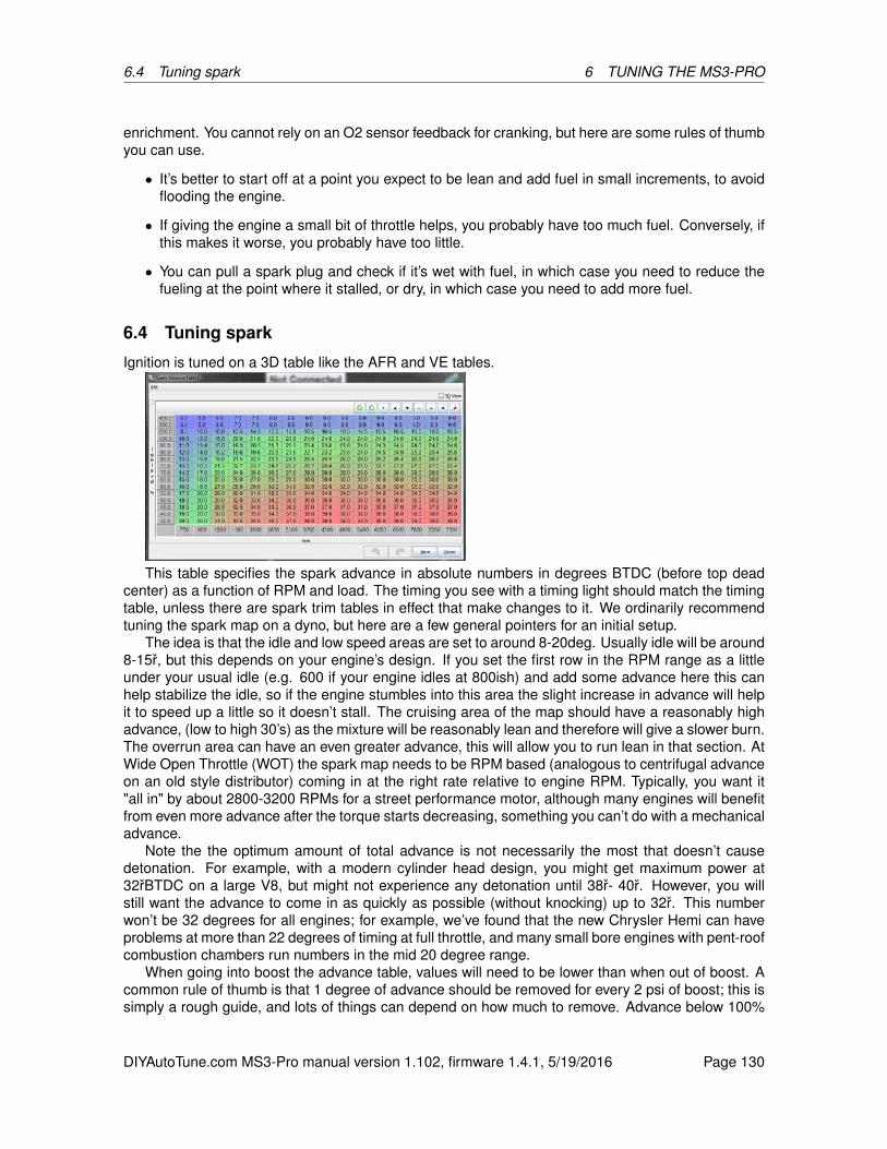
6.4 Tuning spark 6 TUNING THE MS3-PRO
enrichment. You cannot rely on an O2 sensor feedback for cranking, but here are some rules of thumbyou can use.
• It’s better to start off at a point you expect to be lean and add fuel in small increments, to avoidflooding the engine.
• If giving the engine a small bit of throttle helps, you probably have too much fuel. Conversely, ifthis makes it worse, you probably have too little.
• You can pull a spark plug and check if it’s wet with fuel, in which case you need to reduce thefueling at the point where it stalled, or dry, in which case you need to add more fuel.
6.4 Tuning spark
Ignition is tuned on a 3D table like the AFR and VE tables.
This table specifies the spark advance in absolute numbers in degrees BTDC (before top deadcenter) as a function of RPM and load. The timing you see with a timing light should match the timingtable, unless there are spark trim tables in effect that make changes to it. We ordinarily recommendtuning the spark map on a dyno, but here are a few general pointers for an initial setup.
The idea is that the idle and low speed areas are set to around 8-20deg. Usually idle will be around8-15r, but this depends on your engine’s design. If you set the first row in the RPM range as a littleunder your usual idle (e.g. 600 if your engine idles at 800ish) and add some advance here this canhelp stabilize the idle, so if the engine stumbles into this area the slight increase in advance will helpit to speed up a little so it doesn’t stall. The cruising area of the map should have a reasonably highadvance, (low to high 30’s) as the mixture will be reasonably lean and therefore will give a slower burn.The overrun area can have an even greater advance, this will allow you to run lean in that section. AtWide Open Throttle (WOT) the spark map needs to be RPM based (analogous to centrifugal advanceon an old style distributor) coming in at the right rate relative to engine RPM. Typically, you want it"all in" by about 2800-3200 RPMs for a street performance motor, although many engines will benefitfrom even more advance after the torque starts decreasing, something you can’t do with a mechanicaladvance.
Note the the optimum amount of total advance is not necessarily the most that doesn’t causedetonation. For example, with a modern cylinder head design, you might get maximum power at32rBTDC on a large V8, but might not experience any detonation until 38r- 40r. However, you willstill want the advance to come in as quickly as possible (without knocking) up to 32r. This numberwon’t be 32 degrees for all engines; for example, we’ve found that the new Chrysler Hemi can haveproblems at more than 22 degrees of timing at full throttle, and many small bore engines with pent-roofcombustion chambers run numbers in the mid 20 degree range.
When going into boost the advance table, values will need to be lower than when out of boost. Acommon rule of thumb is that 1 degree of advance should be removed for every 2 psi of boost; this issimply a rough guide, and lots of things can depend on how much to remove. Advance below 100%
DIYAutoTune.com MS3-Pro manual version 1.102, firmware 1.4.1, 5/19/2016 Page 130

6.5 Getting a good idle 6 TUNING THE MS3-PRO
load is often simply the flip side of retarding the timing under boost; as cylinder filling decreases, youwill need more timing.
6.5 Getting a good idle
Idle tuning has several components. One is how far the throttle is open - this can be adjusted withthe Idle PWM Duty Table or Idle Steps if you have an IAC valve, which lets you specify the valveopening amount in terms of temperature. If you don’t have an IAC valve, you can use a set screw toadjust the throttle blade angle. There is also closed loop idle tuning, which we will cover later in themanual. Closed loop idle tuning targets a specific idle speed. But first, you need to get a stable idlewithout closed loop tuning. If your idle is already hunting because of a bad tune, putting closed loopon an idle that already has trouble will make it worse. We’ll take some time here to explain how totune your MS3-Pro for a smooth idle.The first key may surprise many novice tuners: The idle controlsettings are not the most important thing to adjust to get a smooth idle.
This may seem counter-intuitive, but consider this: If the engine is idling at constant load with thethrottle held at a constant opening, shouldn’t you have a constant idle speed? If your idle surgesor hunts under these conditions, and your idle control valve is staying at one opening value, the idlecontrol settings are not the problem. To get a steady idle, you need three things in place: correct fuel,correct timing, and correct airflow. These problems should be addressed individually.
6.5.0.7 Correct Fuel Engines don’t like to idle lean; a lean air/fuel ratio is one of the biggest causesof a surging idle. On an engine with sequential injection, this is simple enough - get the engine idlingat 14.7:1 for gasoline, and you’re good to go. Batch fire engines, however, have issues at idle withintake pulse reversion sending some of the fuel into an adjacent cylinder. So, if your setup only allowsbatch fire, you’ll need to add a little more fuel so all the cylinders can stay at 14.7:1 or richer. Batchfire engines typically idle best in the mid 13’s, so if you’re leaner than that, put in some more fuel andsee if that stabilizes the idle.
You’ll need to make sure the air/fuel ratio is maintained during cold start. If your idle hunts whenthe engine is cold, but stabilizes when it warms up, try more warm up enrichment.
6.5.0.8 Correct Timing Timing is a very useful tool for controlling your idle speed. Ideally, you’llwant the timing to be set to slightly below the timing that would give it the most power - on most pistonengines, this typically works out to somewhere in the 10 to 18 degree range. Then you can add a rowaround 300 RPM below your target idle speed if you find the idle to be unstable. The timing in this row
DIYAutoTune.com MS3-Pro manual version 1.102, firmware 1.4.1, 5/19/2016 Page 131

6.5 Getting a good idle 6 TUNING THE MS3-PRO
can be bumped up by around 2 to 4 degrees over the idle timing. The 3d view below shows a sparktable set up this way.
Setting up your timing like this has a stabilizing effect on the idle. When the idle speed drops, thetiming advances, increasing power and moving the idle speed back up. The result is an automaticfeedback loop that helps maintain a constant idle speed. Not every engine really needs this. However,you need to look out for timing curves that do the opposite. If you’ve specified less timing below thetarget idle speed than you have at the idle speed, this often makes for an unstable idle as the ECUpulls timing while the idle speed falls. This can make a slight disturbance in idle RPM amplify itselfinto an idle speed that cycles up and down rapidly.
Too much timing can be trouble. If the timing at your regular idle speed already puts you at themost power output, you have nowhere to go but down. Over-advanced timing will hurt power as well- beyond a certain point, adding more timing will not bump up the idle, and taken to extremes, it cando the exact opposite. So you want to "hold back" a little timing at your idle RPM and run less thanthe amount of timing that would give it the most power.
6.5.0.9 Correct Airflow You’ll need to get the right amount of air to maintain a good idle speed.How to do this depends on what sort of IAC (idle air control) valve you have.
No IAC valve at all? Yes, you can run without an IAC valve. Just use your idle speed set screwto adjust it open enough that the engine doesn’t stall on cold starts. Sure, your idle speed with theengine warmed up will be higher than it could be, and you’ll have no way to adjust for stuff like theA/C or electrical loads, but it’ll work.
On/off IAC valves give you two choices: On fast idle, or off it. You’d set the idle speed set screw toyour desired idle speed with the engine warm, and if your on/off valve is big enough, turning it on willkeep the engine from stalling on a cold start. No closed loop control is possible. You can even add asecond on/off IAC valve alongside an existing IAC to kick up the idle when the A/C turns on. Nissanused this on many early ’90s cars, although they paired it with a PWM IAC valve.
PWM IAC valves or stepper motor IAC valves are continuously variable. This lets you adjust theamount of opening time as a function of temperature. There are two ways these can be run. Openloop mode (also called warmup mode) simply tells the valve to open a set amount as a function oftemperature. Closed loop mode tries to maintain a target idle speed. We’ll cover closed loop idletuning and several of the MS3-Pro’s other idle control features, such as increasing the idle speedwhen the A/C or cooling fan come on, under the Additional Items.
DIYAutoTune.com MS3-Pro manual version 1.102, firmware 1.4.1, 5/19/2016 Page 132

7 ADDITIONAL ITEMS: BEYOND BASIC FUEL AND IGNITION CONTROL
7 Additional items: Beyond basic fuel and ignition control
The MS3-Pro will control a lot more than basic fuel and ignition. In this section, we’ll cover what elsethe MS3-Pro can do, one menu screen at a time. We’ll skip the menu screens that were set up insections 5 and 6, and cover the rest here.
7.1 Basic / Load Sections
This section covers many basic aspects of the engine setup as well as very commonly used input andoutput features.
7.1.1 General Settings
7.1.1.1 Barometric settings
• Barometric correction For vehicles that experience altitude variations, this setting enables anautomatic adjustment to fueling. See also the baro correction curve.
– "None" - disables the feature, if adjustment is not required or desired.
– "Initial MAP reading" - takes a reading from the primary MAP sensor at power on and usesthat single value. If your altitude changes greatly during a single journey, you may need tostop and restart to take a fresh reading.
– "Two independent sensors" - uses a second sensor which is sampled in real time to updatethe barometric correction continuously.
• Realtime baro port - when two sensors are enabled, this selects the input port you have thesecond sensor wired to.
DIYAutoTune.com MS3-Pro manual version 1.102, firmware 1.4.1, 5/19/2016 Page 133

7.1 Basic / Load Sections7 ADDITIONAL ITEMS: BEYOND BASIC FUEL AND IGNITION CONTROL
The next two settings are used to limit false readings in case of sensor failure.
• Upper limit - the maximum barometric pressure allowed.
• Lower limit - the minimum barometric pressure allowed.
• Default baro - the typical baro pressure for your region. This is used as a the barometer valueif you have not enabled a sensor.
• Old Baro Calc - Barometric correction has been improved for 1.4.0 and later firmware. If loadinga tune from 1.3.4 firmware or older, turn this on to maintain backward compatability.
7.1.1.2 MAP sensor settings
• MAP sensor type - "Voltage" (by far the most common) or "Frequency" (used on a few Fordor Cosworth engines) are supported. The most common frequency based MAP sensor mostenthusiasts may encounter is the one used on Fox body Mustangs.
• Voltage input port - where the primary MAP sensor is wired (when voltage is selected.)
• Frequency input port - where the primary MAP sensor is wired (when frequency is selected.)
• Low frequency - the frequency corresponding to the minimum pressure, if using a frequencybased MAP sensor.
• High frequency - the frequency corresponding to the maximum pressure, if using a frequencybased MAP sensor.
• 2nd MAP port - enables a secondary voltage MAP sensor and selects where it is wired. If usingtwo MAP sensors, the MS3-Pro compares both MAP sensors and uses the lower one as thereading for the engine.
7.1.1.3 General Sensor Settings The MegaView is an add on display device from the DIY line ofMegaSquirt products. Ones built for the MegaSquirt-II will also work with MS3-Pro.
• MegaView temp units - Choose degC or degF to match your MegaView.
Lag factors force the variables to change more slowly than the actual input value, smoothing themand reducing the effect of noise in the signals. Note that in all cases, 100% is no lag effect at all, andsmaller numbers slow the input response speed. Setting a lag factor to zero will completely paralyzethe input and prevent it from changing at all, normally not a desirable setting. Higher numbers cangive faster throttle response in many cases, but setting them too high can cause problems if you havenoise on the input.
The following inputs can have lag factors applied to them:
• MAP Averaging Lag Factor (also applies to MAF)
• RPM Averaging Lag Factor
• TPS Averaging Lag Factor
• Lambda Averaging Lag Factor
• CLT/MAT/Batt Averaging Lag Factor (these sensors run off a common number)
Auto-zero TPS - if TPS% is showing negative at power on, the current value will be taken as zero.
DIYAutoTune.com MS3-Pro manual version 1.102, firmware 1.4.1, 5/19/2016 Page 134
7.1 Basic / Load Sections7 ADDITIONAL ITEMS: BEYOND BASIC FUEL AND IGNITION CONTROL
7.1.1.4 Load Parameters These critical settings determine the engine behavior and select yourchosen load source. See section 5.2 for an explanation of the load types.
• Primary Fuel load - sets the primary fueling algorithm.
• Secondary Fuel load - enables an optional secondary blended fuel table. Most engines will notneed a secondary fuel load.
• Secondary Fuel - "multiplicative" or "additive" - whether the values in VEtable1 and VEtable2should be multiplied or added together when the secondary fuel table is in use. Selecting “BlendCurve” allows blending between two tables based on a curve (selected under the Table Choicesmenu).
• Multiply MAP - For Speed-Density installs this should normally be set to "Multiply". This numberuses the air density, based on the MAP sensor reading, in the main fueling equation. If this isturned off on a speed density install, the VE table values at low loads can be very small, whileany values under boost will head off to well over 100%. Turning this on will flatten out the tableand make it a bit more manageable. About the only reason to turn this off when running speeddensity is on installs with a highly unstable MAP signal. Turning this on in alpha-N mode willresult in a mode that is something of a hybrid between alpha-N and speed density, as the pulsewidth will be scaled for MAP readings.
• Incorporate AFRTarget - selects whether the target AFR value from the AFR table is used inthe main fueling equation. See the tuning section before changing this setting.
• Stoichiometric AFR - this is used with the previous setting. 14.7 is typically used for gasoline.Many racing fuels may not follow this exact value; if you are changing from one race fuel toanother and know the stoichiometric point for both, this can be used to change the fuelingdirectly.
• Primary Ignition load - sets the load value for ignition table lookups.
• Secondary Ignition load - enables an optional secondary blended ignition table. The blendedfuel and spark tables can be used to effectively enlarge the table size. This table can be additiveor use a blend curve.
• AFR table load - sets the load value for AFR table lookups
• EAE table load - sets the load value for Enhanced Acceleration Enrichment curve lookups.
7.1.2 Rev Limiter
MS3-Pro allows for fuel or spark based rev limiting. You can also allow the rev limit to change as afunction of coolant, so as to set it low before the engine warms up, or even drop the rev limit if youoverheat.
DIYAutoTune.com MS3-Pro manual version 1.102, firmware 1.4.1, 5/19/2016 Page 135

7.1 Basic / Load Sections7 ADDITIONAL ITEMS: BEYOND BASIC FUEL AND IGNITION CONTROL
7.1.2.1 Hard rev limit
• Hard Rev Limit (RPM) - This is the point at which a fuel cut or complete spark cut is applied.The coolant temp limiter, if used, will override this setting.
• Soft Limit Zone / Hysteresis - The RPM needs to fall this far beyond the hard limit before the fuelcut is turned off. If you are using a spark cut or a progressive fuel cut, the cut will start to phasein when you reach this many RPM below the hard cut as well.
7.1.2.2 Coolant temp limiter The curve defines an alternate hard rev limit based on coolant tem-perature. You can use this to limit RPM with the engine cold or to create a shut-off if the engine isoverheating, or both.
• Rev limiter coolant based -
– Normal - The above settings are used independent of coolant.
– CLT Based - the curve is used to select a rev limit based on coolant temperature, so thatlower limits can be applied to a cold engine. When selected, the graph on the right handside of the screen defines the rev limit.
• Rev limit TPS bypass% - above this TPS% the coolant curve is ignored, and it uses the stan-dard rev limiter. This should be set to a high percentage number, so that only in an emergencywhen you really need full throttle on a cold engine can you override the cold limit.
7.1.2.3 Spark retard The MS3-Pro has several different spark retard strategies. You specify thetiming retard in an absolute angle which the MS3-Pro will use as your timing; the timing specified hereis not an amount of timing to pull but the total amount of timing to use. The spark retard begins at thesoft rev limit - the hard limit minus the soft zone number.
• Mode - Select how
– Off - no spark retard rev-limiting is used.
– Progressive Retard - the timing is progressively retarded between the “retard above” thresh-old and hard rev limit. The retard starts just above the "retard above" rpm and reaches themaximum set retard by the "fuel cut" rpm.
DIYAutoTune.com MS3-Pro manual version 1.102, firmware 1.4.1, 5/19/2016 Page 136

7.1 Basic / Load Sections7 ADDITIONAL ITEMS: BEYOND BASIC FUEL AND IGNITION CONTROL
– Fixed angle - when the "retard above" rpm is reached the spark timing is immediatelychanged to the rev limiter timing.
• Maximum retard - the maximum amount of timing retard that will be applied
• Retard to - the fixed spark angle that will be used.
7.1.2.4 Spark cut Where MegaSquirt is directly controlling spark, spark cut can be used as a revlimiter method. This cannot be used with EDIS and will not work as expected with TFI, GMDIS orC3I, as these systems have some level of independent spark control. Be aware that spark cut canbe harsh and should not be used with catalytic convertors due to the damage it causes. Frequently,there will be some level of "popping and banging" and exhaust system damage may occur. Use atyour own risk!
The spark cut algorithm cuts sparks on a "round-robin" basis to prevent individual cylinders loadingup with unburned fuel. The cut begins at the soft limit value and the percent of sparks cut increasesup to the hard limit, where the MS3-Pro shuts off the spark entirely
7.1.2.5 Fuel cut This gives the option of an abrupt, total fuel cut, or cutting fuel to more and morecylinders until a total fuel cut at the hard limit.
• Enable Fuel Cut Limiting - Turns on fuel cut rev limiter.
• Progressive Fuel Cut - If this is turned off, the fuel cut applies abruptly when you reach thehard limit. If this setting is on, the MS3-Pro will shut off fuel to one cylinder at the soft rev limitand ramp this up to cutting all cylinders at the hard limit. This does not rotate between cylinderslike the spark cut - once the cylinder is off, it remains off until the RPM drops enough to turn iton. Note that this cannot be used with throttle body injection or staged injection. Thisonly works with one injector per cylinder.
7.1.3 Shift light
While a programmable on/off output can be set to work as a shift light, the MS3-Pro has a dedicatedfunction for this that allows separate shift settings for each gear. The shift light will need switched 12volt power on one end and the MS3-Pro will supply ground. The light needs to be wired so it does notreceive power with the key off. The stepper outputs are an exception. Stepper Out 1A and StepperOut 2A supply 12 volt power when active.
• Shift light output - Specifies which pin is used for shift light output.
DIYAutoTune.com MS3-Pro manual version 1.102, firmware 1.4.1, 5/19/2016 Page 137
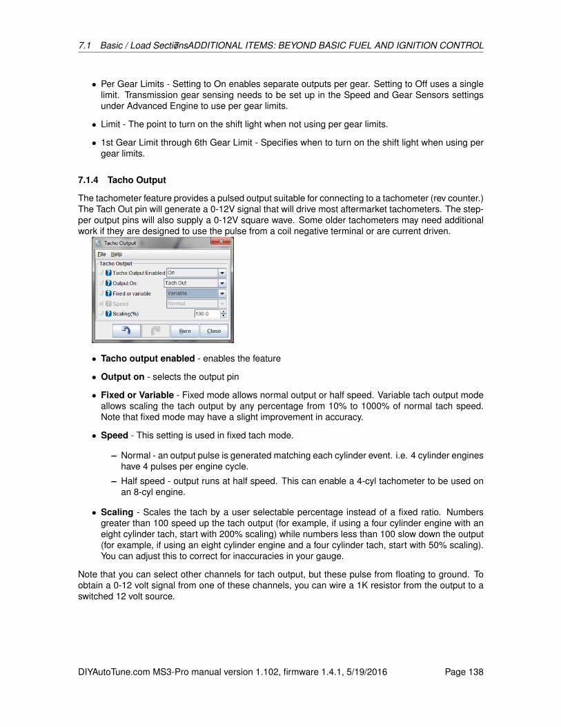
7.1 Basic / Load Sections7 ADDITIONAL ITEMS: BEYOND BASIC FUEL AND IGNITION CONTROL
• Per Gear Limits - Setting to On enables separate outputs per gear. Setting to Off uses a singlelimit. Transmission gear sensing needs to be set up in the Speed and Gear Sensors settingsunder Advanced Engine to use per gear limits.
• Limit - The point to turn on the shift light when not using per gear limits.
• 1st Gear Limit through 6th Gear Limit - Specifies when to turn on the shift light when using pergear limits.
7.1.4 Tacho Output
The tachometer feature provides a pulsed output suitable for connecting to a tachometer (rev counter.)The Tach Out pin will generate a 0-12V signal that will drive most aftermarket tachometers. The step-per output pins will also supply a 0-12V square wave. Some older tachometers may need additionalwork if they are designed to use the pulse from a coil negative terminal or are current driven.
• Tacho output enabled - enables the feature
• Output on - selects the output pin
• Fixed or Variable - Fixed mode allows normal output or half speed. Variable tach output modeallows scaling the tach output by any percentage from 10% to 1000% of normal tach speed.Note that fixed mode may have a slight improvement in accuracy.
• Speed - This setting is used in fixed tach mode.
– Normal - an output pulse is generated matching each cylinder event. i.e. 4 cylinder engineshave 4 pulses per engine cycle.
– Half speed - output runs at half speed. This can enable a 4-cyl tachometer to be used onan 8-cyl engine.
• Scaling - Scales the tach by a user selectable percentage instead of a fixed ratio. Numbersgreater than 100 speed up the tach output (for example, if using a four cylinder engine with aneight cylinder tach, start with 200% scaling) while numbers less than 100 slow down the output(for example, if using an eight cylinder engine and a four cylinder tach, start with 50% scaling).You can adjust this to correct for inaccuracies in your gauge.
Note that you can select other channels for tach output, but these pulse from floating to ground. Toobtain a 0-12 volt signal from one of these channels, you can wire a 1K resistor from the output to aswitched 12 volt source.
DIYAutoTune.com MS3-Pro manual version 1.102, firmware 1.4.1, 5/19/2016 Page 138
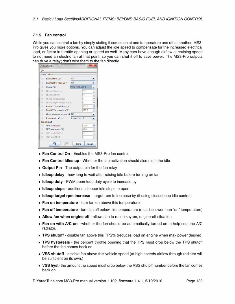
7.1 Basic / Load Sections7 ADDITIONAL ITEMS: BEYOND BASIC FUEL AND IGNITION CONTROL
7.1.5 Fan control
While you can control a fan by simply stating it comes on at one temperature and off at another, MS3-Pro gives you more options. You can adjust the idle speed to compensate for the increased electricalload, or factor in throttle opening or speed as well. Many cars have enough airflow at cruising speedto not need an electric fan at that point, so you can shut it off to save power. The MS3-Pro outputscan drive a relay; don’t wire them to the fan directly.
• Fan Control On - Enables the MS3-Pro fan control
• Fan Control Idles up - Whether the fan activation should also raise the idle
• Output Pin - The output pin for the fan relay
• Idleup delay - how long to wait after raising idle before turning on fan
• Idleup duty - PWM open-loop duty cycle to increase by
• Idleup steps - additional stepper idle steps to open
• Idleup target rpm increase - target rpm to increase by (if using closed loop idle control)
• Fan on temperature - turn fan on above this temperature
• Fan off temperature - turn fan off below this temperature (must be lower than "on" temperature)
• Allow fan when engine off - allows fan to run in key-on, engine-off situation
• Fan on with A/C on - whether the fan should be automatically turned on to help cool the A/Cradiator.
• TPS shutoff - disable fan above this TPS% (reduces load on engine when max power desired)
• TPS hysteresis - the percent throttle opening that the TPS must drop below the TPS shutoffbefore the fan comes back on
• VSS shutoff - disable fan above this vehicle speed (at high speeds airflow through radiator willbe sufficient on its own.)
• VSS hyst- the amount the speed must drop below the VSS shutoff number before the fan comesback on
DIYAutoTune.com MS3-Pro manual version 1.102, firmware 1.4.1, 5/19/2016 Page 139

7.1 Basic / Load Sections7 ADDITIONAL ITEMS: BEYOND BASIC FUEL AND IGNITION CONTROL
7.1.6 Torque converter lockup
MS3-Pro has the ability to control electric lockup on automatic transmissions. This is for part-electrictransmissions (e.g. 700R4, A4LD) but not fully electric (e.g. 4L60E, 4L80E). As a minimum, TPS andMAP are used to set lockup criteria. Optional criteria include an enable switch, brake switch, speedsensor, or gear sensor.
• Output port - output port to connect to lockup solenoid
• Enable input - optional input port for enable switch. For example, some transmissions have aswitch that turns on in fourth gear to enable lockup.
• Brake switch - optional input port for brake light switch. The torque converter unlocks if thisinput is active.
• Minimum TPS - minimum TPS to enable lockup
• Maximum TPS - maximum TPS to enable lockup
• Minimum MAP - minimum MAP to enable lockup
• Maximum MAP - maximum MAP to enable lockup
• Use VSS - optionally allow VSS1 or VSS2 speed input as criteria
• Minimum speed - sets minimum speed for lockup. (Requires VSS input in speed/gear sensors.)
• Use gear value - optionally allows gear number as criteria. (Requires gear to be enable inspeed/gear sensors.)
• Minimum gear - minimum gear to enable lockup
• Activation delay - wait this long after conditions are met before locking up.
The MS3-Pro can drive a 5A solenoid with a high current output, or up to 3A with a PWM output. Ifyou need more current, you will need to use a relay.
Note that these settings are not used if you have added on a MicroSquirt using the MicroSquirttransmission control firmware - the torque converter lock up will be tuned from the MicroSquirt’s menuinstead.
DIYAutoTune.com MS3-Pro manual version 1.102, firmware 1.4.1, 5/19/2016 Page 140
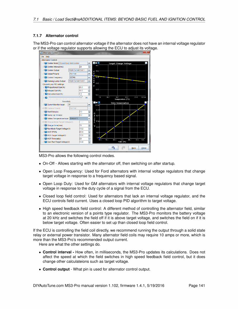
7.1 Basic / Load Sections7 ADDITIONAL ITEMS: BEYOND BASIC FUEL AND IGNITION CONTROL
7.1.7 Alternator control
The MS3-Pro can control alternator voltage if the alternator does not have an internal voltage regulatoror if the voltage regulator supports allowing the ECU to adjust its voltage.
MS3-Pro allows the following control modes.
• On-Off - Allows starting with the alternator off, then switching on after startup.
• Open Loop Frequency: Used for Ford alternators with internal voltage regulators that changetarget voltage in response to a frequency based signal.
• Open Loop Duty: Used for GM alternators with internal voltage regulators that change targetvoltage in response to the duty cycle of a signal from the ECU.
• Closed loop field control: Used for alternators that lack an internal voltage regulator, and theECU controls field current. Uses a closed loop PID algorithm to target voltage.
• High speed feedback field control: A different method of controlling the alternator field, similarto an electronic version of a points type regulator. The MS3-Pro monitors the battery voltageat 20 kHz and switches the field off if it is above target voltage, and switches the field on if it isbelow target voltage. Often easier to set up than closed loop field control.
If the ECU is controlling the field coil directly, we recommend running the output through a solid staterelay or external power transistor. Many alternator field coils may require 10 amps or more, which ismore than the MS3-Pro’s recommended output current.
Here are what the other settings do.
• Control interval - How often, in milliseconds, the MS3-Pro updates its calculations. Does notaffect the speed at which the field switches in high speed feedback field control, but it doeschange other calculateions such as target voltage.
• Control output - What pin is used for alternator control output.
DIYAutoTune.com MS3-Pro manual version 1.102, firmware 1.4.1, 5/19/2016 Page 141

7.1 Basic / Load Sections7 ADDITIONAL ITEMS: BEYOND BASIC FUEL AND IGNITION CONTROL
• Output polarity - If set to normal, turning the output on sends the signal to increase voltage. Ifset to inverted, an on signal decreases voltage.
• Control frequency - What frequency is used to pulse the output in open loop duty or closedloop field control mode.
• Warning lamp output - If this output is enabled, the MS3-Pro will trigger it if the voltage dropsbelow the target voltage minus the warn on voltage difference setting.
• Warn on voltage difference - How far the battery voltage needs to drop below target voltageto trigger the warning lamp output, if used.
• Load monitor input - Allows using a PWM load signal from an alternator, such as the “F”terminal on many GM alternators. Not available in field control modes.
• Capture polarity - Determines if the PWM signal is based on sending voltage or being pulledlow.
• Warn on load - Triggers the warning light output if the load signal goes above this value.
• Closed loop PID settings - When using closed loop field control, allows you to set the sensitivityof the closed loop response. See notes on closed loop idle tuning for how these settings work.
• Current monitor input - Allows using a PWM signal to monitor alternator output current. Thisnumber can be sent to a gauge, but does not affect calculations.
• Capture polarity - Determines if the PWM signal is based on sending voltage or being pulledlow for the current monitor input.
• Startup delay - How many seconds to wait after engine start before turning on the alternator.
• Ramp up time - How many seconds to take the alternator from zero output to charging voltageafter the startup delay is complete.
• Battery temperature input - Allows using a battery temperature sensor to adjust chargingvoltage based on battery temperature. This must first be defined as a generic sensor underAdvanced Engine.
• Charge mode target voltage - If you are not using a battery temperature input, the MS3-Pro willalways target this voltage during the charge time. After the charge time is complete, it switchesto run mode target voltage.
• Charge time - The time, in minutes, to apply the charging voltage.
• Run mode target voltage - The voltage to target after charge time is complete.
• WOT TPS% - Above this TPS reading, the MS3-Pro can drop the target voltage to free up morepower.
• WOT target voltage - The voltage to target above the WOT percentage.
• WOT timeout - After this many seconds at full throttle, target voltage returns to charge voltage(if during the charge time) or run voltage (if the charge time is complete).
• Over-run target voltage - The voltage to target when the overrun fuel cut is active. A highervoltage will create a minor engine braking effect.
• Target charge voltage curve - When you enable battery temperature input, this allows you todefine the charging voltage target as a function of battery temperature.
DIYAutoTune.com MS3-Pro manual version 1.102, firmware 1.4.1, 5/19/2016 Page 142
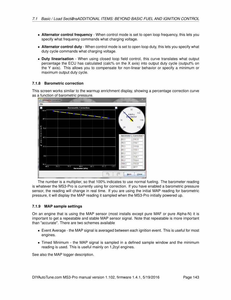
7.1 Basic / Load Sections7 ADDITIONAL ITEMS: BEYOND BASIC FUEL AND IGNITION CONTROL
• Alternator control frequency - When control mode is set to open loop frequency, this lets youspecify what frequency commands what charging voltage.
• Alternator control duty - When control mode is set to open loop duty, this lets you specify whatduty cycle commands what charging voltage.
• Duty linearisation - When using closed loop field control, this curve translates what outputpercentage the ECU has calculated (calc% on the X axis) into output duty cycle (output% onthe Y axis). This allows you to compensate for non-linear behavior or specify a minimum ormaximum output duty cycle.
7.1.8 Barometric correction
This screen works similar to the warmup enrichment display, showing a percentage correction curveas a function of barometric pressure.
The number is a multiplier, so that 100% indicates to use normal fueling. The barometer readingis whatever the MS3-Pro is currently using for correction. If you have enabled a barometric pressuresensor, the reading will change in real time. If you are using the initial MAP reading for barometricpressure, it will display the MAP reading it sampled when the MS3-Pro initially powered up.
7.1.9 MAP sample settings
On an engine that is using the MAP sensor (most installs except pure MAF or pure Alpha-N) it isimportant to get a repeatable and stable MAP sensor signal. Note that repeatable is more importantthan "accurate". There are two schemes available
• Event Average - the MAP signal is averaged between each ignition event. This is useful for mostengines.
• Timed Minimum - the MAP signal is sampled in a defined sample window and the minimumreading is used. This is useful mainly on 1,2cyl engines.
See also the MAP logger description.
DIYAutoTune.com MS3-Pro manual version 1.102, firmware 1.4.1, 5/19/2016 Page 143
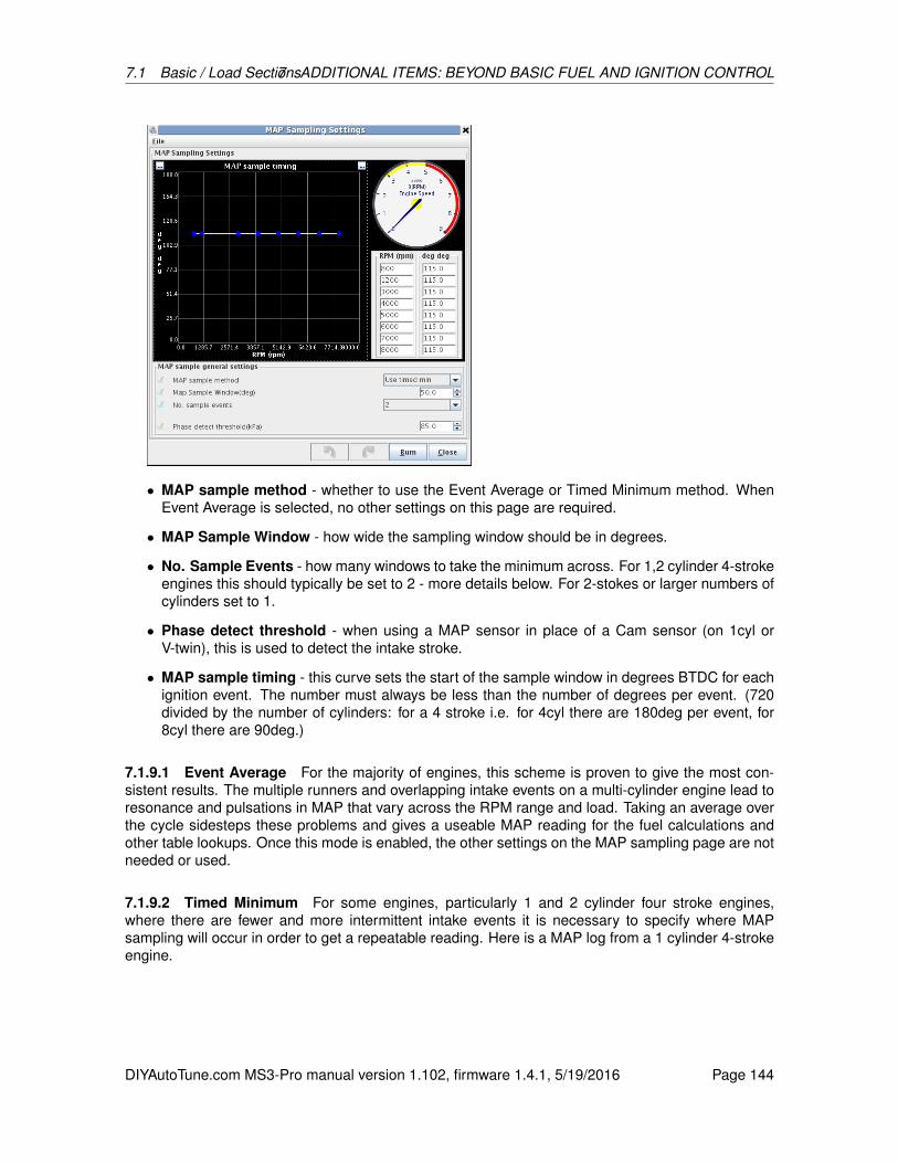
7.1 Basic / Load Sections7 ADDITIONAL ITEMS: BEYOND BASIC FUEL AND IGNITION CONTROL
• MAP sample method - whether to use the Event Average or Timed Minimum method. WhenEvent Average is selected, no other settings on this page are required.
• MAP Sample Window - how wide the sampling window should be in degrees.
• No. Sample Events - how many windows to take the minimum across. For 1,2 cylinder 4-strokeengines this should typically be set to 2 - more details below. For 2-stokes or larger numbers ofcylinders set to 1.
• Phase detect threshold - when using a MAP sensor in place of a Cam sensor (on 1cyl orV-twin), this is used to detect the intake stroke.
• MAP sample timing - this curve sets the start of the sample window in degrees BTDC for eachignition event. The number must always be less than the number of degrees per event. (720divided by the number of cylinders: for a 4 stroke i.e. for 4cyl there are 180deg per event, for8cyl there are 90deg.)
7.1.9.1 Event Average For the majority of engines, this scheme is proven to give the most con-sistent results. The multiple runners and overlapping intake events on a multi-cylinder engine lead toresonance and pulsations in MAP that vary across the RPM range and load. Taking an average overthe cycle sidesteps these problems and gives a useable MAP reading for the fuel calculations andother table lookups. Once this mode is enabled, the other settings on the MAP sampling page are notneeded or used.
7.1.9.2 Timed Minimum For some engines, particularly 1 and 2 cylinder four stroke engines,where there are fewer and more intermittent intake events it is necessary to specify where MAPsampling will occur in order to get a repeatable reading. Here is a MAP log from a 1 cylinder 4-strokeengine.
DIYAutoTune.com MS3-Pro manual version 1.102, firmware 1.4.1, 5/19/2016 Page 144

7.1 Basic / Load Sections7 ADDITIONAL ITEMS: BEYOND BASIC FUEL AND IGNITION CONTROL
Observe the large variation in MAP signal during the 720 degree cycle. It can be seen that oneMAP window falls on the intake stroke (where the MAP reaches a minimum) and the next MAPwindow is on the power stroke (MAP is near atmospheric.) On this engine it was important to set theappropriate MAP sample angle and window width to capture the dip in MAP, and set the number ofevents to 2, since the intake happens every two revolutions.
The ideal MAP sample angle may either be determined by:
• using the MAP logger (registered TunerStudio only) and opening the datalogs created in Mega-LogViewer to ensure the MAP window aligns with the dip in MAP
• by watching the MAP gauge on the TunerStudio dash and adjusting the MAP sample angle in(say) 10 degree steps until the minimum is found.
Note that on most engines the best sample angle will vary with RPM. The Window Width should beset so that it covers the dip repeatably.
The sample data below shows a practical example from the above test engine with a short sampleof the data.
First - with No. Events set to 1.Event no. Min MAP in window MAP used for fueling
1 70 701 98 981 70.5 70.51 98 98
The MS3-Pro is sampling the MAP reading on both the intake stroke and the power stroke; theintake strokes have a low MAP reading, but the pressure on the power stroke is nearly atmospheric.This results in the MAP bouncing around between 70 and 98 resulting in unpredictable tuning. UsingEvent Average would be equally poor.
Now - with No. Events set to 2.Event no. Min MAP in window MAP used for fueling
1 70 702 98 701 70.5 70.52 98 70.5
This gives a more realistic and more repeatable MAP signal and is a good start for tuning - theatmospheric readings of 98kPa on the "dead" windows are ignored.
The Phase detect threshold is in use on this particular engine. It allows 1cyl and certain 2cylengines to run sequential fuel and spark without a cam sensor. The MS3-Pro "looks" at the MAP
DIYAutoTune.com MS3-Pro manual version 1.102, firmware 1.4.1, 5/19/2016 Page 145

7.1 Basic / Load Sections7 ADDITIONAL ITEMS: BEYOND BASIC FUEL AND IGNITION CONTROL
signal during the reading and compares it to the threshold to determine whether this is an intakestroke.
7.1.10 ITB load settings
ITB tuning mode builds on the capabilities of the dual table blended tuning approach but solves one ofthe more significant drawbacks to that tuning mode: it provides the blended Speed-Density/Alpha-Nbehavior of the blended dual tables in just a single table. This single table approach is a significantimprovement as all the automatic tuning tools available through TunerStudio now work correctly withthe single table.
This new tuning mode introduces a new engine load type to MegaSquirt, the ITB load. This loadtype is selected in the tuning configuration the same way that Alpha-N, Speed-Density, or blendedtuning are selected. ITB load is also available for the other tuning settings including AFR, Ignition,and Enhanced Accel Enrichment.
The ITB Load is derived from a combination of MAP and TPS values as well as other ITB-relatedtuning curves that all work together to create a calculated value that is used as the "ITB Load" andapplied to the Y axis of the tuning tables in the same way that MAP is used for Speed-Density tuningor TPS is used for Alpha-N tuning.
7.1.10.1 ITB load VE table ITB Load tuning uses a single VE table to control fuel but this VE tableis partitioned into two regions, one for Speed-Density and one for Alpha-N tuning. There are twotuning curves and a couple of configuration values that must be set up to correctly partition the VEtable for a given engine. The curves and values are:
• % Baro Switchpoint - The MAP value where tuning switches from TPS based to MAP based.Default is 90% and works for most engines.
• Idle TPS Threshold - A minimum TPS value that must be met to allow the switch to TPS basedtuning to occur. This is sometimes useful in idle tuning.
• ITB Load TPS Switchpoint - A TPS curve that defines the TPS value across the RPM rangewhere the MAP value reaches the pre-defined %b baro switch point.
• ITB Load at TPS Switchpoint - A curve that allocates the amount of each VE table column thatwill be allocated to MAP based or TPS based tuning.
The diagram below illustrates how the ITB load VE table is partitioned for dual use. The region ofgreatest MAP change (below %Baro switchpoint) is tuned using Speed-Density based tuning. The
DIYAutoTune.com MS3-Pro manual version 1.102, firmware 1.4.1, 5/19/2016 Page 146

7.1 Basic / Load Sections7 ADDITIONAL ITEMS: BEYOND BASIC FUEL AND IGNITION CONTROL
region of greatest TPS change (above %Baro switchpoint) will be tuned using Alpha-N based tuning.This is exactly the same technique used in the blended tuning, just applied within a single table.
7.1.10.2 ITB load TPS switch point curve This curve defines the TPS value where the MAP loadreaches %Baro switchpoint. This curve will be different for each engine and should be set up usingvalues obtained from log files from your engine. The curve tends to be fairly linear so you only need afew data points to plot the curve. A data point at low, medium, and high RPM from a log file is usuallyenough. A spreadsheet or just graph paper can then be used to establish enough data points to fill inthe table for this curve.
ITB Load tuning requires that the MAP signal be above the %Baro switchpoint and that the TPSvalue be above the value defined on this curve to switch from Speed-Density tuning to Alpha-N tuning.Therefore, you want this curve to be relatively accurate and you may even want to set the values onthe curve a few percent low to ensure that the TPS value has been met when the MAP reaches the%Baro switchpoint.
Besides defining the switch point to Alpha-N tuning, this curve also establishes the lower TPSvalue that will be used to interpret the range of VE bins allocated to Alpha-N tuning in the VE table.
7.1.10.3 ITB Load at TPS Switchpoint Curve This curve is used to allocate the bins on the VEtable to either Speed-Density or Alpha-N tuning. The area of the VE table below the curve will be usedfor Speed-Density tuning and the area above the curve will be used for Alpha-N tuning. The shapeof this curve defines how much of the VE table will be allocated for use between Speed-Density andAlpha-N tuning for each RPM column. You want to allocate the largest portion of the VE table ateach RPM to the tuning mode that has the most non-linear response. The lower RPM region typicallyrequires a little more Speed-Density definition range than the upper RPMs.
7.1.10.4 Putting it all Together - Calculating ITB Load The ITB Load VE table is defined asITB Load vs. RPM. The ITB Load should not be confused with MAP or TPS, it is neither. What theITB Load tuning algorithm does is calculate a load value based on MAP, TPS, and the two ITB Loadcurves. This calculated load value is the Y axis of the ITB Load VE table; it can also be applied to theignition advance and AFR tables as well.
7.1.10.5 ITB Load Calculation in Speed-Density Mode When the throttle position is less thanthe value defined in the ITB load TPS switchpoint curve or the MAP value is less than the %Baroswitchpoint, the tuning algorithm will take the array of cells from the VE table below the ITB load atTPS switchpoint curve and interpret this array within the context of 0% to %Baro switchpoint load.
A couple examples that assume %Baro switchpoint = 90:If you have allocated the region between 0% ITB Load and 60% ITB Load on your VE table for use
in Speed-Density tuning and your %baro is 50% then the VE value for 30% ITB load will be used. In
DIYAutoTune.com MS3-Pro manual version 1.102, firmware 1.4.1, 5/19/2016 Page 147

7.1 Basic / Load Sections7 ADDITIONAL ITEMS: BEYOND BASIC FUEL AND IGNITION CONTROL
this same example, a MAP value of 0kpa would use the 0% ITB load bin and a MAP value of just lessthan %Baro switchpoint would use the VE value just below the 60% ITB Load value on the VE table.
7.1.10.6 ITB Load Calculation in Alpha-N Mode When the throttle position is greater than orequal to the ITB load TPS switchpoint curve and the MAP value is greater than or equal to the %Baroswitchpoint, the tuning algorithm will take the array of cells from the VE table above the ITB load atTPS switchpoint curve and interpret this array within the context of TPS position. The lower TPS valueused for this interpretation is taken from the ITB load TPS switchpoint curve and the upper TPS valueis always 100%.
For example, if you have allocated the region between 60% ITB Load and 100% ITB Load on yourVE table for use in Alpha-N tuning and also assigned a value of 10% TPS on your ITB load TPSswitchpoint curve then a TPS value of 55% would yield an ITB Load value of 80% and the VE bin for
DIYAutoTune.com MS3-Pro manual version 1.102, firmware 1.4.1, 5/19/2016 Page 148
7.1 Basic / Load Sections7 ADDITIONAL ITEMS: BEYOND BASIC FUEL AND IGNITION CONTROL
80% ITB Load would be used. In this same example, a TPS value of 10% would use the 60% ITBLoad bin on the VE table and 100% TPS would use the 100% ITB Load bin.
7.1.10.7 Tuning For Idle Air Control The Idle TPS Threshold % setting defines the minimum TPSvalue required to allow the transition to Alpha-N tuning. This feature allows the fast idle MAP to exceedthe %Baro switchpoint without entering Alpha-N mode. On engines with aggressive cams with higheroverlap, it is possible for the fast idle MAP to exceed the %Baro switchpoint. When this happens, youdo not want to enter Alpha-N mode tuning since the throttle is still reading fully closed. The Idle TPSThreshold % prevents you entering Alpha-N mode and you can use the warm up enrichment curveto compensate for any tuning errors caused by being stuck at the maximum Speed-Density bin whilethe MAP is greater than the %Baro switchpoint.
7.1.11 MAF options
Mass air flow (MAF) sensors provide a measurement of actual airflow through the intake system of anengine. In its most basic form, the fuel required by the engine (in mass per second) is directly relatedto the air flowing into the engine (in mass per second), so the MAF sensor should give a good basisfor the fuel equation. (By comparison, Speed Density uses RPM, MAP, MAT and VE to estimate themass air flow.) In practice, like any other sensor input, the MAF has its own quirks and can suffer fromreversion effects (particularly on "cammy" engines) where the air flow gets measured twice.
The MegaSquirt implementation of MAF consists of the following main elements:
• Engine and injector parameters
• MAF calibration curve
• Optional trim table
Before setting up the MAF options, be sure you have the right parameters set under Engine andSequential Settings. The critical settings to enter here are:
• Engine Stroke
• No. cylinders/rotors
• Number of Injectors
• Engine size
• Injector size each.
Having entered those details, click on the Required Fuel button to calculate the global fuel constant.You may need to re-enter the numbers if the calculator doesn’t pick them up automatically. Make sureyou set the correct units.
DIYAutoTune.com MS3-Pro manual version 1.102, firmware 1.4.1, 5/19/2016 Page 149
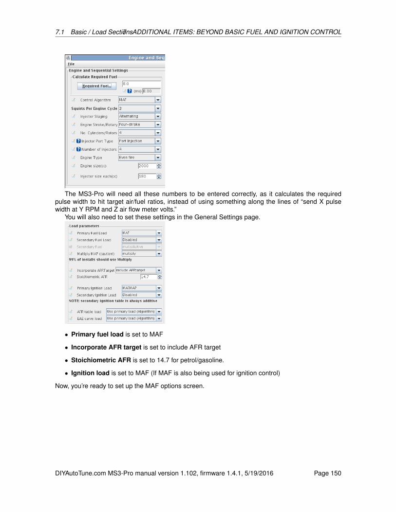
7.1 Basic / Load Sections7 ADDITIONAL ITEMS: BEYOND BASIC FUEL AND IGNITION CONTROL
The MS3-Pro will need all these numbers to be entered correctly, as it calculates the requiredpulse width to hit target air/fuel ratios, instead of using something along the lines of “send X pulsewidth at Y RPM and Z air flow meter volts.”
You will also need to set these settings in the General Settings page.
• Primary fuel load is set to MAF
• Incorporate AFR target is set to include AFR target
• Stoichiometric AFR is set to 14.7 for petrol/gasoline.
• Ignition load is set to MAF (If MAF is also being used for ignition control)
Now, you’re ready to set up the MAF options screen.
DIYAutoTune.com MS3-Pro manual version 1.102, firmware 1.4.1, 5/19/2016 Page 150
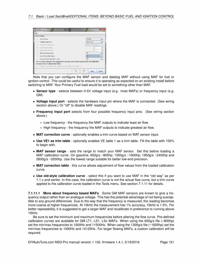
7.1 Basic / Load Sections7 ADDITIONAL ITEMS: BEYOND BASIC FUEL AND IGNITION CONTROL
Note that you can configure the MAF sensor and datalog MAF without using MAF for fuel orignition control. This could be useful to ensure it is operating as expected on an existing install beforeswitching to MAF. Your Primary Fuel load would be set to something other than MAF.
• Sensor type - selects between 0-5V voltage input (e.g. most MAFs) or frequency input (e.g.GM)
• Voltage input port - selects the hardware input pin where the MAF is connected. (See wiringsection above.) Or "off" to disable MAF readings.
• Frequency input port selects from four possible frequency input pins. (See wiring sectionabove.)
– Low frequency - the frequency the MAF outputs to indicate least air flow.– High frequency - the frequency the MAF outputs to indicate greatest air flow.
• MAT correction curve - optionally enables a trim curve based on MAT sensor input.
• Use VE1 as trim table - optionally enables VE table 1 as a trim table. Fill the table with 100%to begin with.
• MAF sensor range - sets the range to match your MAF sensor. Set this before loading aMAF calibration curve. On gasoline, 650g/s ~800hp; 1300g/s ~1600hp; 1950g/s ~2400hp and2600g/s ~3200hp. Use the lowest range suitable for better low-end precision.
• MAT correction table - this curve allows adjustment of flow values from the loaded calibrationcurve.
• Use old-style calibration curve - select this if you want to use MAF in the “old way” as per1.1.x and earlier. In this case, the calibration curve is not the actual flow curve, but a trim curveapplied to the calibration curve loaded in the Tools menu. See section 7.1.11 for details.
7.1.11.1 More about frequency based MAFs Some GM MAF sensors are known to give a fre-quency output rather than an analogue voltage. This has the potential advantage of not being suscep-tible to any ground differences. Due to the way that the frequency is measured, the reading becomesmore coarse at higher frequencies. At 10kHz the measurement has 1% accuracy, 15kHz is 1.5%. Forbetter repeatability, it is suggested to get a larger MAF and recalibrate in preference to running above10kHz.
Be sure to set the minimum and maximum frequencies before altering the flow curve. Pre-definedcalibration curves are available for GM LT1, LS1, LSx MAFs. When using the 650g/s file (~800hp)set the min/max frequencies to 1000Hz and 11500Hz. When using the 1300g/s file (~1600hp) set themin/max frequencies to 1000Hz and 14125Hz. For larger flowing MAFs, a custom calibration will berequired.
DIYAutoTune.com MS3-Pro manual version 1.102, firmware 1.4.1, 5/19/2016 Page 151

7.1 Basic / Load Sections7 ADDITIONAL ITEMS: BEYOND BASIC FUEL AND IGNITION CONTROL
7.1.12 MAF flow curve
This will bring up the MAF calibration curve, showing airflow as grams per second as a function ofvoltage. Ideally you should start with the curve that matches your actual sensor. Some examples areprovided in the software package that may be loaded with File > Load Dialog Settings.
(This one curve replaces the Calibration and Correction Curve that were used in previous firmwarereleases.)
7.1.12.1 MAF Load As shown above, the primary fuel load is MAF because fuel required is directlyrelated to mass air flow. However, ignition, AFR, and other load based tables are not directly relatedin the same way. While it would be possible to use MAF volts as the Y-axis on other tables, it wouldmean that only a very narrow band of the table was used, and tuning would suffer. So instead of that,the code calculates a synthesized load value called MAF Load. This behaves similarly to MAP in aspeed density system and should give a repeatable load value and allow tuning of those tables in theconventional manner. Make sure the axes on the table are set to cover all MAF load values and RPMsif the engine is turbocharged; as a rule of thumb, the highest MAF load will probably be higher thanthe highest K Pa value the engine sees. When live tuning, the active cell will be highlighted.
A MAF only install will need to use MAF Load for spark and AFR table lookups. But, if you havea MAP sensor installed you can choose to set "Speed Density" for spark and/or AFR which will thenuse MAP as the Y-axis in the table. It is also possible to use alpha-N and tune the spark map basedon TPS.
7.1.12.2 Tuning Initially it is suggested to leave the trim table turned off. Ensure you have config-ured the basic engine parameters: number of cylinders, number of injectors, engine size, injector flowand used the ReqFuel calculator to set ReqFuel. As noted above, set primary fuel load to MAF andspark and AFR to use MAF. Configure the AFR table for your chosen target AFR values. Ensure thatthe load and rpm axes cover your expected range; alter them to suit if needed. It is suggested thatEGO correction be set to "No correction" at this time. Having started your engine, your primary tuning
DIYAutoTune.com MS3-Pro manual version 1.102, firmware 1.4.1, 5/19/2016 Page 152
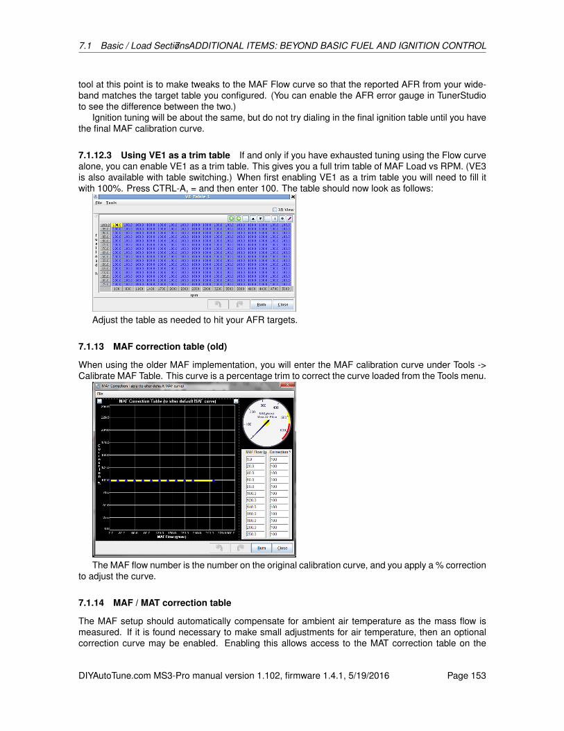
7.1 Basic / Load Sections7 ADDITIONAL ITEMS: BEYOND BASIC FUEL AND IGNITION CONTROL
tool at this point is to make tweaks to the MAF Flow curve so that the reported AFR from your wide-band matches the target table you configured. (You can enable the AFR error gauge in TunerStudioto see the difference between the two.)
Ignition tuning will be about the same, but do not try dialing in the final ignition table until you havethe final MAF calibration curve.
7.1.12.3 Using VE1 as a trim table If and only if you have exhausted tuning using the Flow curvealone, you can enable VE1 as a trim table. This gives you a full trim table of MAF Load vs RPM. (VE3is also available with table switching.) When first enabling VE1 as a trim table you will need to fill itwith 100%. Press CTRL-A, = and then enter 100. The table should now look as follows:
Adjust the table as needed to hit your AFR targets.
7.1.13 MAF correction table (old)
When using the older MAF implementation, you will enter the MAF calibration curve under Tools ->Calibrate MAF Table. This curve is a percentage trim to correct the curve loaded from the Tools menu.
The MAF flow number is the number on the original calibration curve, and you apply a % correctionto adjust the curve.
7.1.14 MAF / MAT correction table
The MAF setup should automatically compensate for ambient air temperature as the mass flow ismeasured. If it is found necessary to make small adjustments for air temperature, then an optionalcorrection curve may be enabled. Enabling this allows access to the MAT correction table on the
DIYAutoTune.com MS3-Pro manual version 1.102, firmware 1.4.1, 5/19/2016 Page 153
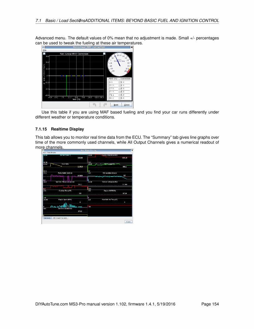
7.1 Basic / Load Sections7 ADDITIONAL ITEMS: BEYOND BASIC FUEL AND IGNITION CONTROL
Advanced menu. The default values of 0% mean that no adjustment is made. Small +/- percentagescan be used to tweak the fueling at these air temperatures.
Use this table if you are using MAF based fueling and you find your car runs differently underdifferent weather or temperature conditions.
7.1.15 Realtime Display
This tab allows you to monitor real time data from the ECU. The “Summary” tab gives line graphs overtime of the more commonly used channels, while All Output Channels gives a numerical readout ofmore channels.
DIYAutoTune.com MS3-Pro manual version 1.102, firmware 1.4.1, 5/19/2016 Page 154

7.1 Basic / Load Sections7 ADDITIONAL ITEMS: BEYOND BASIC FUEL AND IGNITION CONTROL
7.1.16 Feature List Showing I/O Pins
This allows you to display all the pins in use. You can use this to check what wire does whatfunction, or check if you have accidentally assigned one pin to multiple functions. Features not in useare grayed out.
7.1.17 I/O Pins Showing Useage
When TunerStudio is connected to the ECU, this presents the same information in a differentgrouping - it shows each pin and what function (if any) is assigned to it.
7.1.18 Expansion I/O Pins List / Usage
This screen is similar to the I/O Pins Showing Usage screen, but does the same for devices connectedto the MS3-Pro via the CAN connection, such as a CAN-EGT or a MicroSquirt running IO Box ortransmission control code.
7.1.19 Gauge and setting limits
Allows you to specify RPM levels and maximum load values on the gauges, as well as the highestvalues you can enter into the load and VE tables. The other settings are explained below.
DIYAutoTune.com MS3-Pro manual version 1.102, firmware 1.4.1, 5/19/2016 Page 155
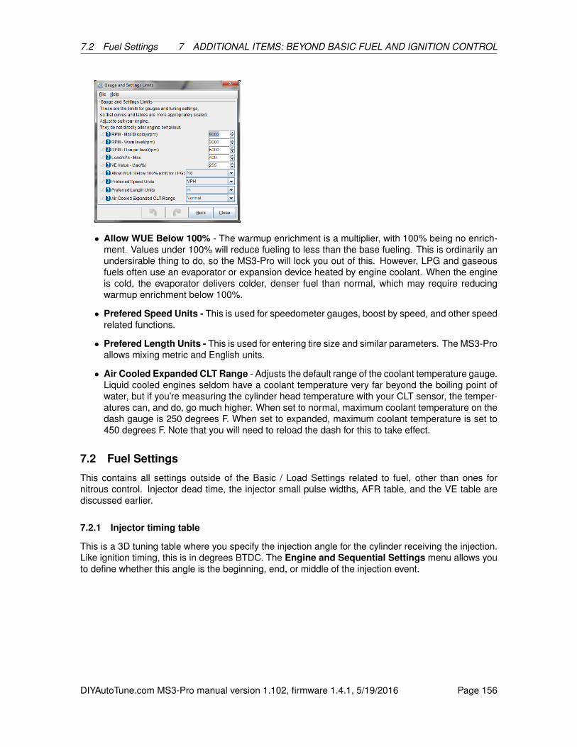
7.2 Fuel Settings 7 ADDITIONAL ITEMS: BEYOND BASIC FUEL AND IGNITION CONTROL
• Allow WUE Below 100% - The warmup enrichment is a multiplier, with 100% being no enrich-ment. Values under 100% will reduce fueling to less than the base fueling. This is ordinarily anundersirable thing to do, so the MS3-Pro will lock you out of this. However, LPG and gaseousfuels often use an evaporator or expansion device heated by engine coolant. When the engineis cold, the evaporator delivers colder, denser fuel than normal, which may require reducingwarmup enrichment below 100%.
• Prefered Speed Units - This is used for speedometer gauges, boost by speed, and other speedrelated functions.
• Prefered Length Units - This is used for entering tire size and similar parameters. The MS3-Proallows mixing metric and English units.
• Air Cooled Expanded CLT Range - Adjusts the default range of the coolant temperature gauge.Liquid cooled engines seldom have a coolant temperature very far beyond the boiling point ofwater, but if you’re measuring the cylinder head temperature with your CLT sensor, the temper-atures can, and do, go much higher. When set to normal, maximum coolant temperature on thedash gauge is 250 degrees F. When set to expanded, maximum coolant temperature is set to450 degrees F. Note that you will need to reload the dash for this to take effect.
7.2 Fuel Settings
This contains all settings outside of the Basic / Load Settings related to fuel, other than ones fornitrous control. Injector dead time, the injector small pulse widths, AFR table, and the VE table arediscussed earlier.
7.2.1 Injector timing table
This is a 3D tuning table where you specify the injection angle for the cylinder receiving the injection.Like ignition timing, this is in degrees BTDC. The Engine and Sequential Settings menu allows youto define whether this angle is the beginning, end, or middle of the injection event.
DIYAutoTune.com MS3-Pro manual version 1.102, firmware 1.4.1, 5/19/2016 Page 156

7.2 Fuel Settings 7 ADDITIONAL ITEMS: BEYOND BASIC FUEL AND IGNITION CONTROL
Injector timing is specified as a function of RPM and fuel load. Most engines run best if the injectiontiming is completed before the valve opens, to allow the fuel to vaporize. So, if you have a cam cardwith an “Intake valve opens” spec, you can use this and the “end of squirt” setting to ensure the fuelinjection finishes before the valve opens. An injector timing value of 360 degrees, when used withtiming set to “end of squirt”, would finish the injection event just at the intake valve is starting to open,as shown in the diagram below.
7.2.2 Secondary injector timing table
This timing table is used if you have enabled a secondary set of injectors, either with the StagedInjection or Dual Fuel menu. While these injectors may need the same timing as the primaries,secondary injectors that fire in an upstream direction or in an air horn often need different timing.
7.2.3 Staged injection
Staged injection allows the use of one set of small injectors for low-load and/or low RPM operationof the engine with the ability to engage a second set of injectors at higher load and RPM when theprimary set of injectors would otherwise reach their maximum operational duty cycle. The MS3-Pro’s staged injection function supports staging equally between the primary injectors and secondaryinjectors during staged operation as well as staging completely to the secondary set of injectors. Youmay either use the standard injector outputs A through H on a four cylinder, or use injectors I and J inbatch fire on engines with more than four cylinders.
If you have enough outputs to use timed injection on the secondary injection, the SecondaryInjection Timing Table is enabled (in addition to the standard injection timing table), so the user mustremember to tune secondary injection timing separately from primary injection timing.
DIYAutoTune.com MS3-Pro manual version 1.102, firmware 1.4.1, 5/19/2016 Page 157
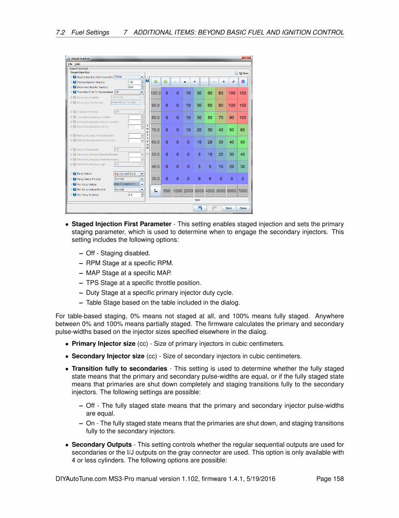
7.2 Fuel Settings 7 ADDITIONAL ITEMS: BEYOND BASIC FUEL AND IGNITION CONTROL
• Staged Injection First Parameter - This setting enables staged injection and sets the primarystaging parameter, which is used to determine when to engage the secondary injectors. Thissetting includes the following options:
– Off - Staging disabled.– RPM Stage at a specific RPM.– MAP Stage at a specific MAP.– TPS Stage at a specific throttle position.– Duty Stage at a specific primary injector duty cycle.– Table Stage based on the table included in the dialog.
For table-based staging, 0% means not staged at all, and 100% means fully staged. Anywherebetween 0% and 100% means partially staged. The firmware calculates the primary and secondarypulse-widths based on the injector sizes specified elsewhere in the dialog.
• Primary Injector size (cc) - Size of primary injectors in cubic centimeters.
• Secondary Injector size (cc) - Size of secondary injectors in cubic centimeters.
• Transition fully to secondaries - This setting is used to determine whether the fully stagedstate means that the primary and secondary pulse-widths are equal, or if the fully staged statemeans that primaries are shut down completely and staging transitions fully to the secondaryinjectors. The following settings are possible:
– Off - The fully staged state means that the primary and secondary injector pulse-widthsare equal.
– On - The fully staged state means that the primaries are shut down, and staging transitionsfully to the secondary injectors.
• Secondary Outputs - This setting controls whether the regular sequential outputs are used forsecondaries or the I/J outputs on the gray connector are used. This option is only available with4 or less cylinders. The following options are possible:
DIYAutoTune.com MS3-Pro manual version 1.102, firmware 1.4.1, 5/19/2016 Page 158

7.2 Fuel Settings 7 ADDITIONAL ITEMS: BEYOND BASIC FUEL AND IGNITION CONTROL
– Use Inj A -H if possible - Use the standard outputs A through H. The second stage is fullysequential with this setting Available on engines with four cylinders or less.
– Use Inj I/J - Use the I and J injector channels in batch fire.
• Secondary V3 Alternate - This setting controls whether the secondaries (when using the I/Joutputs) alternate between injector channel 1 and injector channel 2, or inject simultaneouslyon injector channel 1 and injector channel 2. The following settings are available:
– Alternating (2 squirts) - Alternate between injector channel 1 and injector channel 2. Notethat when in alternating mode, the firmware injects 2 squirts per cycle.
– Simultaneous (1 squirt) - Squirt fuel on injector channel 1 and injector channel 2 simulta-neously. Note that when in simultaneous mode, the firmware injects 1 squirt per cycle.
• Gradual Transition - This setting enables the ability to gradually reduce the pulse width of theprimary injectors and gradually increase the pulse width of the secondary injectors as stagedinjection engages. This setting is most useful when the secondary injectors are located faraway from the primaries on the intake tract. Gradual transition and associated settings are notavailable when using table-based staged injection. The following settings are available:
– On - Gradual staging is enabled. The associated settings will be used to control how quicklythe secondaries are engaged.
– Off - Gradual staging is disabled. When staged injection engages, the pulse width will goimmediately to the fully staged width.
• Transition events (ign events) - This setting is used when gradual staging is enabled to deter-mine how many ignition events it will take to go from no staging to fully staged.
• Primary reduction delay (ign events) - This setting is used to delay the reduction of the primarypulse width by the number of ignition events after the secondaries start coming online. It is onlyenabled when the gradual transition feature is enabled.
• Secondary Enrichment (ms) - This setting is used to inject more fuel on the secondaries thanthe fully staged calculation determines. This is useful when there is a small lean spot just afterstaged injection fully engages. This setting is only available when the gradual transition featureis enabled.
• Primary staging threshold (units) - This setting is used to determine when staged injectionengages when using RPM, MAP, TPS, or Duty. It is not available when using table-basedstaging.
• Primary staging hysteresis - This setting is used to determine when staged injection shuts off.For example, if RPM is selected as the staged injection first parameter, and the primary stagingthreshold is 4100, and the primary staging hysteresis is 300, then staged injection will shut offthe secondaries and return the primaries to their normal pulse width at 3800 rpm. This settingis not available when using table-based staging.
• Second parameter - This setting is used to add a second method for determining when tostage. Note that this setting should not be set the same as the first parameter setting. Thissetting is not available with table-based staging. The following settings are available:
– Off
– RPM
– MAP
DIYAutoTune.com MS3-Pro manual version 1.102, firmware 1.4.1, 5/19/2016 Page 159

7.2 Fuel Settings 7 ADDITIONAL ITEMS: BEYOND BASIC FUEL AND IGNITION CONTROL
– TPS– Duty
• Secondary staging threshold (units) - This setting determines the RPM, MAP, TPS, or Dutyat which the secondary staged parameter allows staged injection to engage. This setting is notavailable unless a second staging parameter is enabled.
• Secondary staging hysteresis (units) - This setting is used with the secondary staging thresh-old setting to determine when staged injection will shut off. This setting is not available unless asecond staging parameter is enabled.
• Secondary staging logic - This setting is used to determine whether both the primary andsecondary staging parameters must be met to engage staged injection, or if only one of theparameters must be met. This setting is not available in table-based staging mode.
• Relay Output - Allows using a relay to power secondary injectors in systems where the primaryand secondary injectors are both wired to the same ECU output pin, with the secondary injectorsreceiving switched power from a relay. This tends to produce a jerky, abrupt transition, and ismainly in place to support plug and play applications where the factory wiring lacks separateoutputs for primary and secondary injectors.
• Relay Output Polarity - If set to normal, turning the output on turns on the secondary injectors.Inverted turns this off to activate the secondary injectors.
• Pre-Relay Output - Allows activating a relay before the secondary injectors are active. This isusually to allow a secondary fuel pump to pressurize the second stage injector rail.
• Pre-Relay Output Polarity - If set to normal, the pre-relay is turned on before turning theinjectors. If set to inverted, the pre-relay output is set to off before turning on the secondaryinjectors.
• Pre-Relay Timer - Specifies the time, in seconds, between turning on the pre-staging relay andthe secondary injector stage.
7.2.3.1 Tuning Staged Injection Our recommendation is that on any setup with secondaries arefurther up the intake tract than the primaries, that you should use table-based staging. It is possible toachieve a much smoother transition to staged injection in all situations when tuning with this method.
7.2.3.2 Tuning Table-based Staged Injection The following tips should be followed when tuningtable-based staged injection:
• RPM and Load transition bins - Make the two RPM bins and two Load bins where staged in-jection first engages close together. Also make the staging percent jump to 10-20% almostimmediately (as shown in the dialog at the beginning of the staged injection section). This isso that a very small amount of time is spent with the secondary injectors at or near the injectoropening time for those injectors. Spending a lot of time near the injector opening time can lead toinconsistent fueling, especially if the secondary injector opening time has not been determinedand the default value is being used.
• Transition to 100% engaged - The transition to 100% engaged should be determined usingexperimentation. In general, the transition should be set so that the primaries stay close totheir maximum duty cycle (80% is recommended) for as long as possible. This ensures thatreduction to the primary pulse-width does not result in a lean situation. The table displayed atthe beginning of the staged injection settings section is a good example of how to tune table-based staging for a smooth transition on a naturally aspirated engine.
DIYAutoTune.com MS3-Pro manual version 1.102, firmware 1.4.1, 5/19/2016 Page 160

7.2 Fuel Settings 7 ADDITIONAL ITEMS: BEYOND BASIC FUEL AND IGNITION CONTROL
7.2.3.3 Tuning All other Staged Injection Modes All staged injection modes that do not use thetable to determine the staging amount can be tuned similarly. The following tips should be used:
• Primary staging parameter - It is usually recommended that the primary staging parameter usedis Duty. This ensures that staged injection engages when the duty cycle of the primary injectorswarrants it instead of trying to guess what RPM or load will cause use of the secondaries to benecessary.
• Secondary staging parameter - It is recommended that this parameter only be used with forcedinduction engines. It should be used to ensure that staging is fully complete before going intoboost so that any lean spots caused by staging are gone.
• Gradual transition - The gradual transition code was introduced to try to solve the same problemsthat table-based staging solves, notably the small lean spot in AFR briefly after staged injectionengages. It should be set to transition over as many ignition events as possible for the smoothesttransition. If doing this still causes a lean spot, the primary reduction delay can be used alongwith the secondary enrichment setting to make sure that slightly more fuel than calculated usingthe normal fuel calculations is injected. If enabling the gradual transition feature still does not getrid of the brief lean spot after staging is engaged, it is recommended that table-based staging isused.
7.2.4 Fuel sensor settings (Flex)
The flex fuel system allows the use of E85 or other ethanol and petroleum blended fuel mixes to beused when a special fuel composition. sensor is fitted. The support is specifically based aroundthe use of a GM flex fuel sensor which outputs a varying frequency signal depending on the fuelcomposition. This information can then be used to add more fuel and advance timing. Ethanol blendsneed more fuel volume than unblended fuel and different advance. The basic system uses a two-pointsystem (low/high) and interpolates between the values. You can also use flex fuel to create a blendcurve, which is explained in the section on blend curves below.
• Flex fuel sensor - this enables or disables the Flex Fuel system
DIYAutoTune.com MS3-Pro manual version 1.102, firmware 1.4.1, 5/19/2016 Page 161

7.2 Fuel Settings 7 ADDITIONAL ITEMS: BEYOND BASIC FUEL AND IGNITION CONTROL
• Sensor port - where the sensor is connected. A GM flex fuel sensor typically has pin A asground, B as 12 volt supply, and C to the MS3-Pro Digital Switched In 1. Note that DigitalSwitched In 1 is currently the only supported port.
• Temperature input - GM’s flex fuel sensors can output a fuel temperature signal based on theirpulse width. You can also specify a separate analog sensor, enabled under Generic Sensors.
• Spark / Fuel settings - These have separate low and high settings to define the range of sensoroutputs.
– Frequency - Specifies the minimum and maximum frequencies the senor will send.
– Ethanol mix - Specifies the percentage ethanol at minimum and maximum frequency.
– Fuel multiplier - Ethanol requires more fuel. This is a percentage multiplier that scales howmuch fuel is added.
– Timing addition - If not using a blended table, this simply adds a fixed amount of timing,interpolated between the low and high points.
• Temp Sense - Allows setting up pulse width based fuel temperature output from a flex fuelsensor.
• Fallback fuel multiplier - If the sensor duty cycle goes out of range, the MS3 will apply thismultiplier to the fuel to avoid a lean condition.
• Fallback timing addition - How much to adjust the timing in the event of a sensor failure.
• Dual fuel mode - The ability to blend tables is enabled under the Table Switch / Dual Fuelscreen.
7.2.5 Over Run Fuel Cut
The MS3-Pro not only allows you to cut off fuel while coasting; it also allows retarding spark timing atthis point, and gradually phasing the fuel cut in and out to make for a smoother transition.
DIYAutoTune.com MS3-Pro manual version 1.102, firmware 1.4.1, 5/19/2016 Page 162

7.2 Fuel Settings 7 ADDITIONAL ITEMS: BEYOND BASIC FUEL AND IGNITION CONTROL
• Over-run fuel cut - Allows turning this feature off or on.
• RPM Greater than - Specifies the maximum RPM for overrun fuel cut to trigger. This needs tobe above idle speed; having the fuel cut engage at the high end of the idle range will make foran abrupt surge / fall behavior when idling.
• And MAP lower than - Specifies the maximum MAP sensor reading for overrun fuel cut.
• And TPS lower than - Specifies the maximum throttle position for overrun fuel cut.
• And CLT greater than - Allows locking out fuel cut on a cold engine.
• After delay - Specifies how many seconds the MS3-Pro will wait after trigger conditions are metbefore engaging fuel cut.
• Progressive fuel cut - Allows cutting cylinders one at a time to smooth the transition.
• Ignition timing transition - Changes the ignition timing during overrun fuel cut.
• Ignition timing during over-run - The absolute timing during overrun fuel cut. Positive numbersare BTDC and negative numbers are ATDC.
• Cut transition time - The amount of time to transition in the spark retard and progressive fuelcut.
• Progressive fuel return - Allows gradually returning fuel. If using this setting, we recommendnot using the fuel adder.
• Ignition timing transition return - Allows gradually transitioning from spark retard to normaltiming.
• Return transition time - The time, in seconds, from re-engaging fuel to returning to full fuel (ifprogressive fuel return is used) and ignition timing (if ignition timing transition return is used).
DIYAutoTune.com MS3-Pro manual version 1.102, firmware 1.4.1, 5/19/2016 Page 163
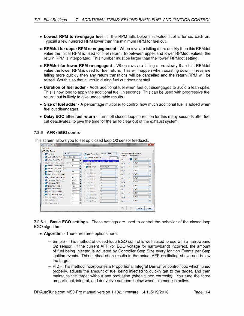
7.2 Fuel Settings 7 ADDITIONAL ITEMS: BEYOND BASIC FUEL AND IGNITION CONTROL
• Lowest RPM to re-engage fuel - If the RPM falls below this value, fuel is turned back on.Typicall a few hundred RPM lower than the minimum RPM for fuel cut.
• RPMdot for upper RPM re-engagement - When revs are falling more quickly than this RPMdotvalue the initial RPM is used for fuel return. In-between upper and lower RPMdot values, thereturn RPM is interpolated. This number must be larger than the ’lower’ RPMdot setting.
• RPMdot for lower RPM re-engagent - When revs are falling more slowly than this RPMdotvalue the lower RPM is used for fuel return. This will happen when coasting down. If revs arefalling more quickly then any return transitions will be cancelled and the return RPM will beraised. Set this so that clutch-in during fuel cut does not stall.
• Duration of fuel adder - Adds additional fuel when fuel cut disengages to avoid a lean spike.This is how long to apply the additional fuel, in seconds. This can be used with progressive fuelreturn, but is likely to give undesirable results.
• Size of fuel adder - A percentage multiplier to control how much additional fuel is added whenfuel cut disengages.
• Delay EGO after fuel return - Turns off closed loop correction for this many seconds after fuelcut deactivates, to give the time for the air to clear out of the exhaust system.
7.2.6 AFR / EGO control
This screen allows you to set up closed loop O2 sensor feedback.
7.2.6.1 Basic EGO settings These settings are used to control the behavior of the closed-loopEGO algorithm.
• Algorithm - There are three options here:
– Simple - This method of closed-loop EGO control is well-suited to use with a narrowbandO2 sensor. If the current AFR (or EGO voltage for narrowband) incorrect, the amountof fuel being injected is adjusted by Controller Step Size every Ignition Events per Stepignition events. This method often results in the actual AFR oscillating above and belowthe target.
– PID - This method incorporates a Proportional Integral Derivative control loop which tunedproperly, adjusts the amount of fuel being injected to quickly get to the target, and thenmaintains the target without any oscillation (when tuned correctly). You tune the threeproportional, integral, and derivative numbers below when this mode is active.
DIYAutoTune.com MS3-Pro manual version 1.102, firmware 1.4.1, 5/19/2016 Page 164

7.2 Fuel Settings 7 ADDITIONAL ITEMS: BEYOND BASIC FUEL AND IGNITION CONTROL
– No correction: The O2 sensor is used for data logging only and is not used for closed loopcontrol.
• Use EGO Delay Table - You can select how often the EGO correction is updated based oneither the number of ignition events or by using a 12 x 12 table that determines how often toupdate the correction as a function of RPM and engine load.
• Ignition Events per Step - While closed-loop EGO is active and the EGO delay table is off,how often the correction is run is determined by this setting. It is the number of ignition eventsper correction.
• Controller Step Size - This setting is only used with the "Simple" EGO algorithm. It controls howlarge each correction "step" is. So if the AFR does not match the desired AFR, and ControllerStep Size is configured to be 1%, each time a correction is made, that correction will be 1%.
• Use Authority Table - Turning this on will allow using a table to determine how the maximumamount of correction that can be applied applied as a function of load and RPM. For example,you might want to give a large amount of control authority while cruising at light throttle, butreduce controller authority to zero under boost to protect against the consequences of a failingoxygen sensor leaning out the engine under load.
• Controller Auth - This setting controls the maximum amount of adjustment performed by theclosed-loop algorithm if not using the authority table.
• Only correct above (AFR) - AFR readings below this level are not used and correction is turnedoff when your receive this reading. Used to turn off EGO correction if the sensor is out of itsaccurate range.
• And correct below (AFR) - This parameter allows setting a maximum AFR for correction incombination with the above setting.
• Active Above Coolant - Below the temperature defined by this setting, closed-loop EGO willnot activate.
• Active above RPM - Below the RPM defined by this setting, closed-loop EGO will not activate.
• Active Below TPS - Above the throttle position defined by this setting, closed-loop EGO will notactivate.
• Active below Load - Above the load defined by this setting, closed-loop EGO will not activate.
• Active Above Load - Below the load defined by this setting, closed-loop EGO will not activate.
• EGO delay after start - The time in seconds after engine-start before closed-loop EGO can beactivated.
• PID parameters - These numbers are used to tune the correction when the algorithm is set toPID.
• EGO Sensor Type - This setting enables EGO control and allows the user to choose betweenusing a wideband sensor or narrowband sensor. The following settings are supported:
– Disabled - No EGO sensor enabled. Note that this will also disable AFR logging. If youwish to log your EGO sensor information, but do not want to use closed loop correction,enable your sensor type and set Controller Auth to zero instead.
– Narrowband - Sensor in use is a narrowband sensor.
– Wideband - Sensor in use is a wideband sensor.
DIYAutoTune.com MS3-Pro manual version 1.102, firmware 1.4.1, 5/19/2016 Page 165
7.2 Fuel Settings 7 ADDITIONAL ITEMS: BEYOND BASIC FUEL AND IGNITION CONTROL
• Number of Sensors - This setting is used to select the number of oxygen sensors in use by theMS3-Pro. Up to 12 sensors can be configured.
7.2.6.2 EGO ports The EGO Ports settings allow the user to select the input port used to read thesignal from the oxygen sensor. The number of EGO ports available depends on the number of sensorsselected. The “Normal EGO” input is reserved for the primary O2 sensor, but you can optionally useone of the three other analog inputs for the primary, or an O2 sensor on a CAN network. The secondand subsequent sensors may not use “Normal EGO”, but may use any spare analog input or a CANdevice.
7.2.6.3 AFR/EGO Sensor Mapping Use this menu to assign which injector channel is associatedwith what O2 sensor input.
7.2.6.4 Tuning
Simple algorithm with narrowband sensor A narrowband sensor is only accurate at exactlystoichiometric mixtures for the fuel being used (14.7:1 for gasoline). At around 0.5 volts, the mixtureis stoichiometric. For leaner mixtures (above 14.7:1 for gasoline, above 1.0 lambda) the voltage dipsslightly below 0.5 volts. For richer mixtures, the voltage goes above 0.5 volts. This behavior meansthat it is not possible to hold an exact mixture when running closed-loop with a narrowband sensor.
Because of this, the best algorithm to use with a narrowband sensor is the "simple" algorithm.The simple algorithm adjusts the mixture richer if the sensor reads lean, and leaner if the sensor
reads rich. It adjusts Controller Step Size percent every Ignition Events per Step. This can lead toa small oscillation in O2-based correction once the AFR reaches close to stoichiometric.
The following steps are recommended when tuning the simple algorithm with a narrowband sen-sor:
1. Ignition Events per Step - When first tuning the engine, this should be set to a fairly low number(4-8) so that if the AFR is very far off, it is corrected quickly. Once the engine is better tuned,this number can be switched to a higher number to gain more stable correction behavior (8-16or more).
2. Controller Step Size - When first tuning the engine, this should be set to 2% so that whencorrecting, the engine reaches stoichiometric quickly. Once the engine is well tuned, this shouldbe reduced to 1% to gain more stable correction.
3. Controller Auth - When first tuning the engine, this should be set to 20% or higher. Care must betaken to watch how the algorithm is correcting. In some situations, it is possible for the sensorto read very lean when really the engine is running very rich. Once the engine is tuned, thisshould be set between 5% and 10%.
4. Engagement Settings - Most of the remaining settings control how and when the closed loopalgorithm is engaged. Engagement with a narrowband sensor should happen when the engineis nearly fully warm, 500-1000 rpm above idle, below 80% throttle, below about 80% load, justabove the lowest load seen when barely pressing the throttle, and at least 30 seconds after theengine starts. These settings are because the sensor must be hot to operate, must not be usedat high load due to the fact that the engine should be operated rich of stoichiometric, and mustnot be used at very low load because the oscillations will cause the engine speed to oscillate.
DIYAutoTune.com MS3-Pro manual version 1.102, firmware 1.4.1, 5/19/2016 Page 166

7.2 Fuel Settings 7 ADDITIONAL ITEMS: BEYOND BASIC FUEL AND IGNITION CONTROL
Simple Algorithm with Wideband Sensor Tuning the simple algorithm with a wideband sensoris essentially the same as tuning it with a narrowband sensor with the caveat that the AFR target tableis used to set the AFR target. It is still recommended that the EGO algorithm not be used at highthrottle position/load due to the fact that the accuracy of the wideband sensor decreases dramaticallywith pressure and temperature changes caused by high load.
PID Algorithm with Narrowband Sensor When using a narrowband sensor with the PID algo-rithm, all the same recommendations for settings given in the section describing the Simple algorithmshould be followed.
Additionally, since it is nearly impossible to keep the narrowband sensor from oscillating, it isrecommended to start by tuning the "I" term until the target is reached with minimal oscillation. Oncethis point is reached. It is recommended that very little (if any) "P" term is used since the "P" part ofthe PID algorithm causes instantaneous reaction, and the response of the sensor is not proportionalto the distance from stoichiometric.
PID Algorithm with Wideband Sensor When using a wideband sensor with the PID algorithm,the same steps as when using a narrowband sensor can be followed for tuning the "I" term.
Additionally, since the response of most wideband controllers and sensors is linear with AFR,a larger "P" term can be used to help correct for fast changes in AFR. Caution must still be usedhowever since there is a significant delay between the amount of fuel being injected changing andMS3 registering an AFR change as a result.
Finally, a small amount of "D" term can be used to help slow response during very fast changes.This helps reduce overshoot of the target.
7.2.7 Narrowband EGO targets
This is a 3D table that behaves like an AFR table, but instead of specifying a target air/fuel ratio, itspecifies what voltage from a narrow band the MS3-Pro should target.
7.2.8 AFR safety system
The "AFR Safety" System is designed to help you protect your engine from unwanted dangerouslean conditions. Typically this will be used for wide open throttle and/or boosted conditions. It onlymakes sense to use this feature with a wideband lambda sensor on an already well tuned engine. Thesystem compares the wideband EGO input against your existing AFR target table and a safety limitdifference table. If this situation persists beyond a time you specify, the engine will be shutdown asa protective measure until you get out of boost, off the throttle and down in revs. NOTE This systemwill only work if configured correctly and will not protect your engine against bad tuning or knock!However, it is likely it would detect a failing fuel pump or regulator. A single faulty injector could easilygo un-noticed with a single wideband reading the average AFR. This shutdown mechanism is sharedwith the EGT over-temperature settings.
DIYAutoTune.com MS3-Pro manual version 1.102, firmware 1.4.1, 5/19/2016 Page 167
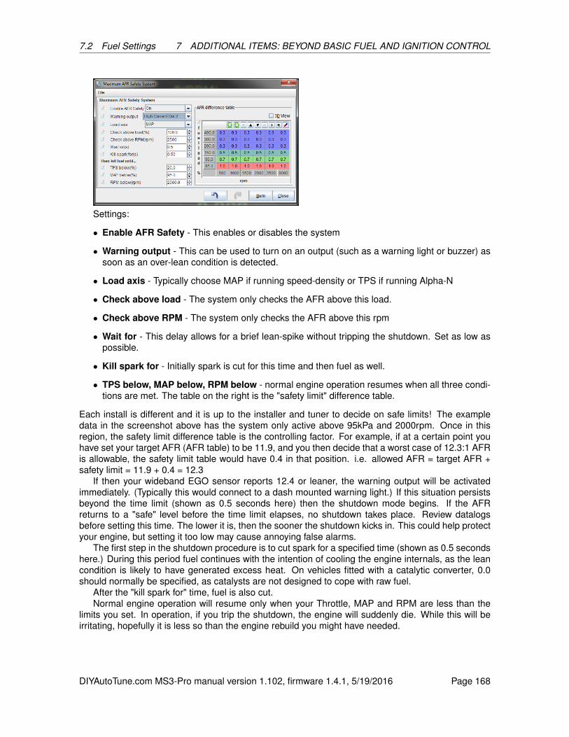
7.2 Fuel Settings 7 ADDITIONAL ITEMS: BEYOND BASIC FUEL AND IGNITION CONTROL
Settings:
• Enable AFR Safety - This enables or disables the system
• Warning output - This can be used to turn on an output (such as a warning light or buzzer) assoon as an over-lean condition is detected.
• Load axis - Typically choose MAP if running speed-density or TPS if running Alpha-N
• Check above load - The system only checks the AFR above this load.
• Check above RPM - The system only checks the AFR above this rpm
• Wait for - This delay allows for a brief lean-spike without tripping the shutdown. Set as low aspossible.
• Kill spark for - Initially spark is cut for this time and then fuel as well.
• TPS below, MAP below, RPM below - normal engine operation resumes when all three condi-tions are met. The table on the right is the "safety limit" difference table.
Each install is different and it is up to the installer and tuner to decide on safe limits! The exampledata in the screenshot above has the system only active above 95kPa and 2000rpm. Once in thisregion, the safety limit difference table is the controlling factor. For example, if at a certain point youhave set your target AFR (AFR table) to be 11.9, and you then decide that a worst case of 12.3:1 AFRis allowable, the safety limit table would have 0.4 in that position. i.e. allowed AFR = target AFR +safety limit = 11.9 + 0.4 = 12.3
If then your wideband EGO sensor reports 12.4 or leaner, the warning output will be activatedimmediately. (Typically this would connect to a dash mounted warning light.) If this situation persistsbeyond the time limit (shown as 0.5 seconds here) then the shutdown mode begins. If the AFRreturns to a "safe" level before the time limit elapses, no shutdown takes place. Review datalogsbefore setting this time. The lower it is, then the sooner the shutdown kicks in. This could help protectyour engine, but setting it too low may cause annoying false alarms.
The first step in the shutdown procedure is to cut spark for a specified time (shown as 0.5 secondshere.) During this period fuel continues with the intention of cooling the engine internals, as the leancondition is likely to have generated excess heat. On vehicles fitted with a catalytic converter, 0.0should normally be specified, as catalysts are not designed to cope with raw fuel.
After the "kill spark for" time, fuel is also cut.Normal engine operation will resume only when your Throttle, MAP and RPM are less than the
limits you set. In operation, if you trip the shutdown, the engine will suddenly die. While this will beirritating, hopefully it is less so than the engine rebuild you might have needed.
DIYAutoTune.com MS3-Pro manual version 1.102, firmware 1.4.1, 5/19/2016 Page 168

7.2 Fuel Settings 7 ADDITIONAL ITEMS: BEYOND BASIC FUEL AND IGNITION CONTROL
7.2.9 Cylinder trim tables
These tables act like miniature VE tables and are added to each individual cylinder.
7.2.10 Sequenced Batch Fire
These settings allow batch firing to be sequenced from a specific trigger number for repeatable phas-ing on each start if you are running batch fire fuel with a sensor input mode that allows for wastedspark or coil on plug. As standard, batch fire sequencing is "random" at the change from crankingmode to run mode. This setting forces the sequence to always start on the same "trigger" on eachstartup. This can help if you are running batch fire injection and you find the engine runs differentlyfrom startup to startup.
On an engine running wasted spark, the trigger numbers start at one and count up to half thenumber of cylinders, with trigger 1 corresponding to the number one cylinder firing event. On anengine running sequential coil on plug with batch fire injectors, the trigger numbers again start at 1for the number one cylinder firing event and count up to the number of cylinders.
7.2.11 Fuel pump and pressure
MS3-Pro can both control fuel pump pressure and correct based on fuel temperature and pressure.
DIYAutoTune.com MS3-Pro manual version 1.102, firmware 1.4.1, 5/19/2016 Page 169
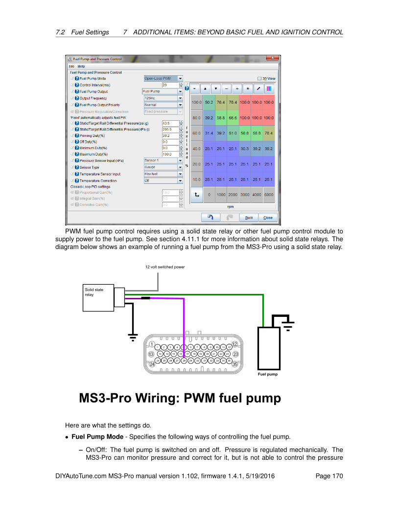
7.2 Fuel Settings 7 ADDITIONAL ITEMS: BEYOND BASIC FUEL AND IGNITION CONTROL
PWM fuel pump control requires using a solid state relay or other fuel pump control module tosupply power to the fuel pump. See section 4.11.1 for more information about solid state relays. Thediagram below shows an example of running a fuel pump from the MS3-Pro using a solid state relay.
Here are what the settings do.
• Fuel Pump Mode - Specifies the following ways of controlling the fuel pump.
– On/Off: The fuel pump is switched on and off. Pressure is regulated mechanically. TheMS3-Pro can monitor pressure and correct for it, but is not able to control the pressure
DIYAutoTune.com MS3-Pro manual version 1.102, firmware 1.4.1, 5/19/2016 Page 170
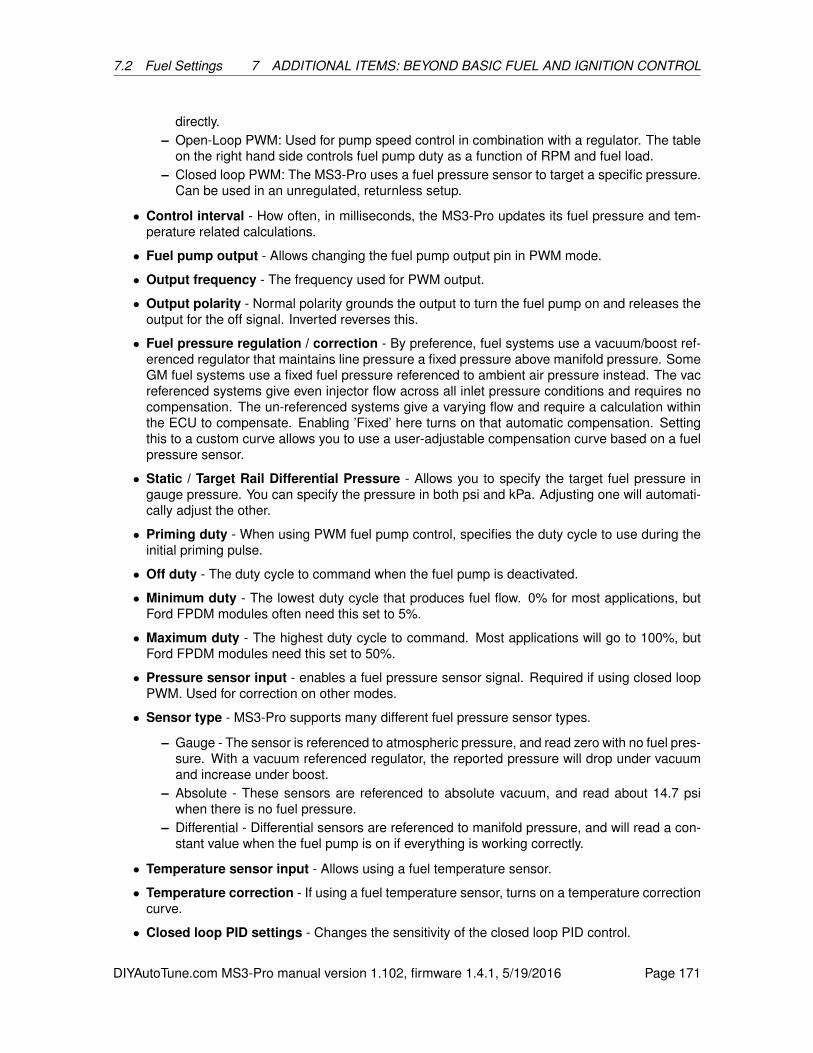
7.2 Fuel Settings 7 ADDITIONAL ITEMS: BEYOND BASIC FUEL AND IGNITION CONTROL
directly.– Open-Loop PWM: Used for pump speed control in combination with a regulator. The table
on the right hand side controls fuel pump duty as a function of RPM and fuel load.– Closed loop PWM: The MS3-Pro uses a fuel pressure sensor to target a specific pressure.
Can be used in an unregulated, returnless setup.
• Control interval - How often, in milliseconds, the MS3-Pro updates its fuel pressure and tem-perature related calculations.
• Fuel pump output - Allows changing the fuel pump output pin in PWM mode.
• Output frequency - The frequency used for PWM output.
• Output polarity - Normal polarity grounds the output to turn the fuel pump on and releases theoutput for the off signal. Inverted reverses this.
• Fuel pressure regulation / correction - By preference, fuel systems use a vacuum/boost ref-erenced regulator that maintains line pressure a fixed pressure above manifold pressure. SomeGM fuel systems use a fixed fuel pressure referenced to ambient air pressure instead. The vacreferenced systems give even injector flow across all inlet pressure conditions and requires nocompensation. The un-referenced systems give a varying flow and require a calculation withinthe ECU to compensate. Enabling ’Fixed’ here turns on that automatic compensation. Settingthis to a custom curve allows you to use a user-adjustable compensation curve based on a fuelpressure sensor.
• Static / Target Rail Differential Pressure - Allows you to specify the target fuel pressure ingauge pressure. You can specify the pressure in both psi and kPa. Adjusting one will automati-cally adjust the other.
• Priming duty - When using PWM fuel pump control, specifies the duty cycle to use during theinitial priming pulse.
• Off duty - The duty cycle to command when the fuel pump is deactivated.
• Minimum duty - The lowest duty cycle that produces fuel flow. 0% for most applications, butFord FPDM modules often need this set to 5%.
• Maximum duty - The highest duty cycle to command. Most applications will go to 100%, butFord FPDM modules need this set to 50%.
• Pressure sensor input - enables a fuel pressure sensor signal. Required if using closed loopPWM. Used for correction on other modes.
• Sensor type - MS3-Pro supports many different fuel pressure sensor types.
– Gauge - The sensor is referenced to atmospheric pressure, and read zero with no fuel pres-sure. With a vacuum referenced regulator, the reported pressure will drop under vacuumand increase under boost.
– Absolute - These sensors are referenced to absolute vacuum, and read about 14.7 psiwhen there is no fuel pressure.
– Differential - Differential sensors are referenced to manifold pressure, and will read a con-stant value when the fuel pump is on if everything is working correctly.
• Temperature sensor input - Allows using a fuel temperature sensor.
• Temperature correction - If using a fuel temperature sensor, turns on a temperature correctioncurve.
• Closed loop PID settings - Changes the sensitivity of the closed loop PID control.
DIYAutoTune.com MS3-Pro manual version 1.102, firmware 1.4.1, 5/19/2016 Page 171

7.3 Ignition Settings 7 ADDITIONAL ITEMS: BEYOND BASIC FUEL AND IGNITION CONTROL
7.2.12 Fuel pressure safety
Fuel pressure safety is a failsafe feature that allows shutting down the engine in the same way asAFR Safety if the fuel pressure goes out of range. You can specify what RPM and load to use whenchecking, as well as the maximum allowable pressure drop and how long this can continue beforetriggering a shutdown.
7.3 Ignition Settings
7.3.1 Dwell battery correction
The dwell battery correction/adjustment curve is a built-in curve to automatically apply greater sparkdwell at lower battery voltages. This is required for inductive ignition systems - more time is requiredto charge the coil with less voltage. The default curve as shown is suitable for most applications. Notethat it is centered on 14.4V with 100% - at this voltage the actual dwell time matches the dwell enteredon the ignition options page.
7.3.2 Dwell vs RPM
The Dwell vs. RPM curve is a feature intended to be used with Saab Tri-ionic ignitions only. Theserequire "Time After Spark " to be enabled. The dwell vs. RPM curve must also be turned on underthe Ignition Options / Wheel Decoder mode, as shown below:
7.3.3 Dwell Table
This table allows you to specify dwell (before battery voltage correction) as a function of RPM andignition load. This allows increasing dwell under boost, then backing it off at low load to reduce theamount of heat put into the ignition system.
DIYAutoTune.com MS3-Pro manual version 1.102, firmware 1.4.1, 5/19/2016 Page 172
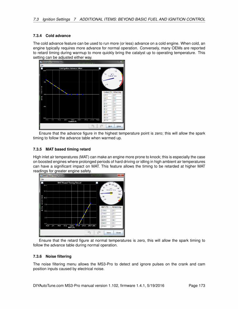
7.3 Ignition Settings 7 ADDITIONAL ITEMS: BEYOND BASIC FUEL AND IGNITION CONTROL
7.3.4 Cold advance
The cold advance feature can be used to run more (or less) advance on a cold engine. When cold, anengine typically requires more advance for normal operation. Conversely, many OEMs are reportedto retard timing during warmup to more quickly bring the catalyst up to operating temperature. Thissetting can be adjusted either way.
Ensure that the advance figure in the highest temperature point is zero; this will allow the sparktiming to follow the advance table when warmed up.
7.3.5 MAT based timing retard
High inlet air temperatures (MAT) can make an engine more prone to knock; this is especially the caseon boosted engines where prolonged periods of hard driving or idling in high ambient air temperaturescan have a significant impact on MAT. This feature allows the timing to be retarded at higher MATreadings for greater engine safety.
Ensure that the retard figure at normal temperatures is zero, this will allow the spark timing tofollow the advance table during normal operation.
7.3.6 Noise filtering
The noise filtering menu allows the MS3-Pro to detect and ignore pulses on the crank and camposition inputs caused by electrical noise.
DIYAutoTune.com MS3-Pro manual version 1.102, firmware 1.4.1, 5/19/2016 Page 173

7.3 Ignition Settings 7 ADDITIONAL ITEMS: BEYOND BASIC FUEL AND IGNITION CONTROL
In the simplest form of a fuel-only controller with a tach signal from the coil negative, the "ringing"of the coil may cause apparent rpm spikes. This will cause additional fuel to be injected on each ofthese noise pulses and show up as a falsely high rpm. It will likely be irritating, but no major problemsare likely.
On an install controlling ignition, it is a different matter. In the simple distributor install with asimple trigger arrangement (1 pulse per ignition event like in a normal distributor), the noise will causea misfire probably on that one event. On a multi-toothed wheel, the noise is likely to cause a loss ofsync with the wheel, and spark will be lost for 360 or even 720 degrees of engine rotation before there-synchronization occurs.
So, the tach input is critical to ECU operation, it is important to reduce or eliminate that noise.Hardware is your first line of defense. Here are some tips on setting up hardware to keep out noise:
• Set the sensor gap to an appropriate level. Most sensors work with a gap about the thicknessof a normal business card.
• Use shielded wire, like in our standard wiring harness. Ground the shield at only one end - ashield grounded at both ends can carry current, and induce noise in the signal.
• Route the signal wire away from any electrical noise sources, such as ignition coils, spark plugwires, and the alternator or starter.
• Ensure that the MS3-Pro has a clean ground to the engine block, cylinder head, or negativebattery terminal.
• VR sensors need to be connected to the positive and negative signal wires. Hall effect or opticalsensors should be grounded to the MS3-Pro sensor ground.
With the hardware well defended against noise, the second line of defense is to set up the ECU toread the sensors correctly and reject noise. The first setting is the ignition input capture is correct,as covered in section 5. For example, the VR signal below has one stable and one unstable edge. Itneeds to be set to triggering on Rising Edge.
Setting to Falling Edge would result in an unstable signal - you’ll see this as timing scatter and theRPM bouncing around. And this is with a fairly clean signal, which the processor would see like thisif triggering on the correct edge:
If the wiring or sensor isn’t perfect, and the signal becomes noisy, the CPU will see a signal likethis instead:
DIYAutoTune.com MS3-Pro manual version 1.102, firmware 1.4.1, 5/19/2016 Page 174
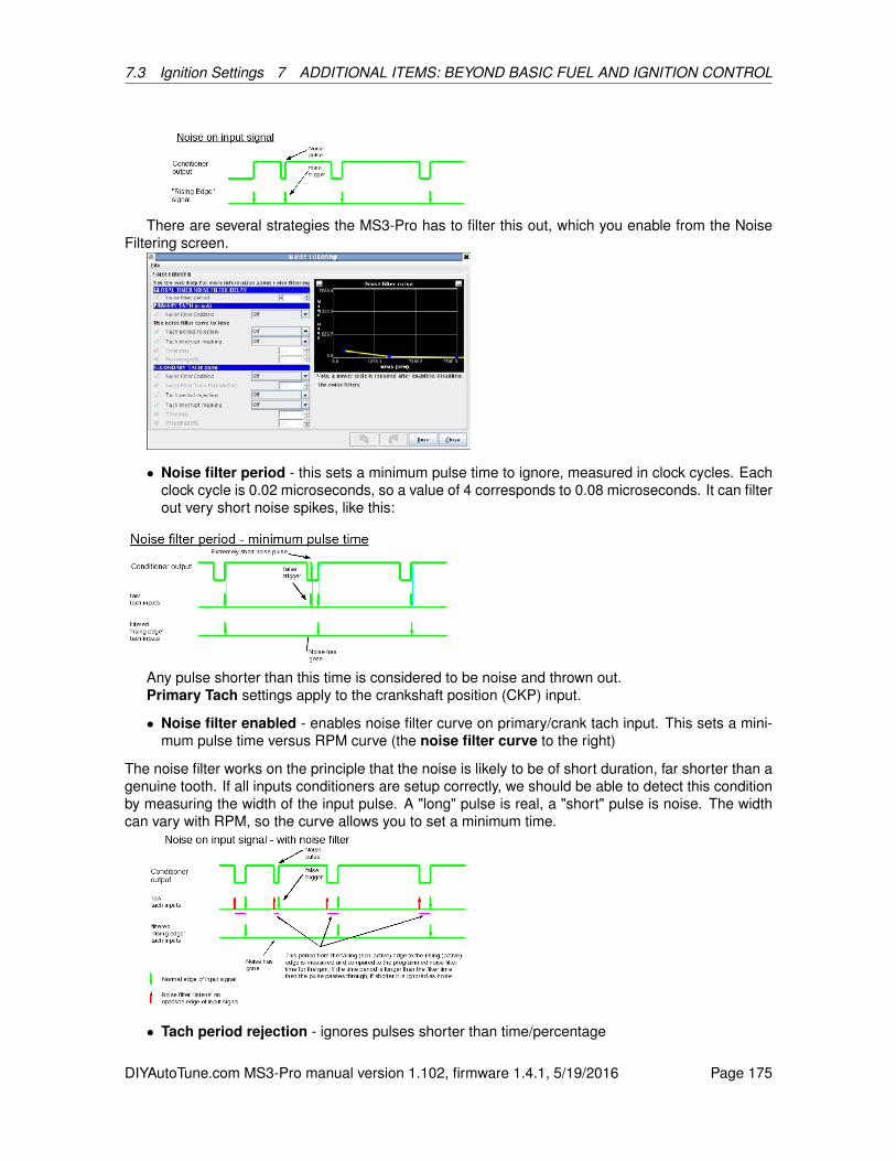
7.3 Ignition Settings 7 ADDITIONAL ITEMS: BEYOND BASIC FUEL AND IGNITION CONTROL
There are several strategies the MS3-Pro has to filter this out, which you enable from the NoiseFiltering screen.
• Noise filter period - this sets a minimum pulse time to ignore, measured in clock cycles. Eachclock cycle is 0.02 microseconds, so a value of 4 corresponds to 0.08 microseconds. It can filterout very short noise spikes, like this:
Any pulse shorter than this time is considered to be noise and thrown out.Primary Tach settings apply to the crankshaft position (CKP) input.
• Noise filter enabled - enables noise filter curve on primary/crank tach input. This sets a mini-mum pulse time versus RPM curve (the noise filter curve to the right)
The noise filter works on the principle that the noise is likely to be of short duration, far shorter than agenuine tooth. If all inputs conditioners are setup correctly, we should be able to detect this conditionby measuring the width of the input pulse. A "long" pulse is real, a "short" pulse is noise. The widthcan vary with RPM, so the curve allows you to set a minimum time.
• Tach period rejection - ignores pulses shorter than time/percentage
DIYAutoTune.com MS3-Pro manual version 1.102, firmware 1.4.1, 5/19/2016 Page 175

7.3 Ignition Settings 7 ADDITIONAL ITEMS: BEYOND BASIC FUEL AND IGNITION CONTROL
This is a different approach: It ignores any pulse that comes in within either a timeframe or percentof the spacing between the tach pulses. This goes off the timing of the pulse, rather than the length.Note that the spacing used is between the smallest teeth, so this method works best on wheelswhere most of the pulses are a similar distance apart. Modes like the Subaru 6/7 have several closelyspaced pulses (at least on the cam wheel), rendering this method less effective.
• Tach interrupt masking - turns off input pin so pulses are not seen at all for time/percentage
This setting is similar to tach period rejection. However, instead of sensing and rejecting pulses inthe rejection time, this setting outright turns off the interrupt - it actively stops the ECU from listeningduring the rejection wheel.
• Time(ms) - time period to ignore for interrupt masking or period rejection.
• Percentage - percentage of "tach interval" to ignore.
Secondary Tach settings apply to the camshaft position (CMP) input.
• Noise filter enabled - enables noise filter time on secondary/cam tach input.
• Noise filter time period - pulses shorter than this are treated as noise. Used instead of thenoise filter curve.
• Tach period rejection - ignores pulses shorter than time/percentage
• Tach interrupt masking - turns off input pin so pulses are not seen at all for time/percentage
• Time(ms) - time period to ignore.
• Percentage - percentage of "tach interval" to ignore.
7.3.6.1 Examples These should be taken as a starting point and will often need install specifictuning.
• Coil negative triggering for a fuel-only install. This requires noise filtering to eliminate theeffects of coil ringing. A typical setting would be to enable crank tach period masking at 2msand 30%.
DIYAutoTune.com MS3-Pro manual version 1.102, firmware 1.4.1, 5/19/2016 Page 176
7.3 Ignition Settings 7 ADDITIONAL ITEMS: BEYOND BASIC FUEL AND IGNITION CONTROL
• Distributor type pickup, such as HEI, TFI, or EDIS (although the last is not a distributor, theMS3-Pro will see a similar signal.). Noise filtering is often useful here. A typical setting wouldbe crank tach period masking with 1ms and 30%.
• Wheel decoder and other more advanced installs. Noise filtering may be useful on someinstalls. Due to the multi-toothed input signal the rejection time periods need to be set farsmaller. e.g. on a V8 with distributor at 6000rpm, the time between tach pulses is 5ms. A 36-1wheel on the same engine gives a pulse every 0.6ms (600us). Using too large a filter time willfilter out the real signal.
7.3.7 Knock sensor settings
Note: While this is a fairly good setup as far as knock sensing goes in a race ECU, gettingOEM like levels of knock protection generally requires grenading a few motors on the dyno toget it dialed in perfectly. This can provide an extra layer of protection, but never use knocksensing as your only spark tuning tool!
Spark knock is the sound of abnormal combustion in an engine. Once combustion in a spark-ignition internal combustion engine is initiated by a spark, the flame front is designed to spreadfrom the spark plug and travel across the combustion chamber rapidly and smoothly. As the flamefront propagates across the chamber, the remaining unburnt air-fuel mixture can ignite spontaneously(auto-ignites) before the flame front arrives, due to the increasing pressure and temperature in thecombustion chamber. When this occurs, there is a sudden jump in the pressure in the cylinder. Thiscauses in the characteristic knocking or pinging sound. It is most common at low-mid rpms and highload, such as ascending a hill in too high a gear.
Prolonged heavy knock is likely to cause severe and permanent engine damage and mustbe avoided.
It is a common misconception that engines make most torque just before knock. In reality, thereisn’t much of a connection between the knock threshold and the timing that makes best torque. Aknock resistant engine may start losing power well before the onset of knock, while a knock limitedengine may have the point where it makes best power past the knock threshold (and not safe to reachwithout higher octane fuel) Ideally, set timing on a dyno to achieve maximum brake torque (MBT)timing. Even with a well tuned engine, factors such as fuel octane, intake air temperature, coolanttemperature, engine age and condition, air/fuel ratios, air density, altitude and humidity and otherscan push the engine from a safe condition to borderline knock or worse. The knock control system isa safety measure designed to retard timing under these conditions and safeguard the engine.
The MS3-Pro contains an internal module that can process one or two knock sensors. It alsoallows input from an external module that gives an on/off, “knock” or “no knock” signal. The knocksensor inputs use dedicated wires intended for connecting directly to a knock sensor. External mod-ules would use the digital input wires instead.
There are two main types of knock sensor. Resonant and wideband sensors. The resonantsensor is tuned to a particular frequency and is only likely to work on an engine with a very similarbore size. (Bore size determines "ping" frequency.) The wideband sensors give a lower voltage outputbut operate over a wider frequency range, and can usually be applied to different engines.
DIYAutoTune.com MS3-Pro manual version 1.102, firmware 1.4.1, 5/19/2016 Page 177
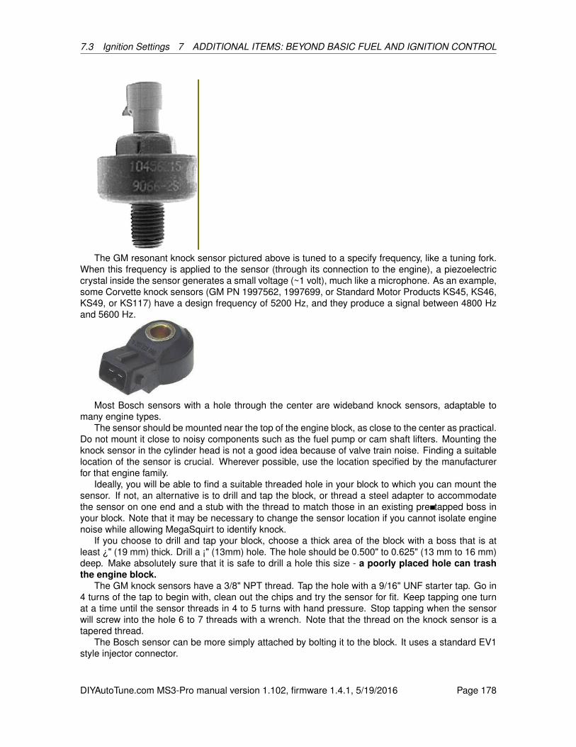
7.3 Ignition Settings 7 ADDITIONAL ITEMS: BEYOND BASIC FUEL AND IGNITION CONTROL
The GM resonant knock sensor pictured above is tuned to a specify frequency, like a tuning fork.When this frequency is applied to the sensor (through its connection to the engine), a piezoelectriccrystal inside the sensor generates a small voltage (~1 volt), much like a microphone. As an example,some Corvette knock sensors (GM PN 1997562, 1997699, or Standard Motor Products KS45, KS46,KS49, or KS117) have a design frequency of 5200 Hz, and they produce a signal between 4800 Hzand 5600 Hz.
Most Bosch sensors with a hole through the center are wideband knock sensors, adaptable tomany engine types.
The sensor should be mounted near the top of the engine block, as close to the center as practical.Do not mount it close to noisy components such as the fuel pump or cam shaft lifters. Mounting theknock sensor in the cylinder head is not a good idea because of valve train noise. Finding a suitablelocation of the sensor is crucial. Wherever possible, use the location specified by the manufacturerfor that engine family.
Ideally, you will be able to find a suitable threaded hole in your block to which you can mount thesensor. If not, an alternative is to drill and tap the block, or thread a steel adapter to accommodatethe sensor on one end and a stub with the thread to match those in an existing pre tapped boss inyour block. Note that it may be necessary to change the sensor location if you cannot isolate enginenoise while allowing MegaSquirt to identify knock.
If you choose to drill and tap your block, choose a thick area of the block with a boss that is atleast ¿" (19 mm) thick. Drill a ¡" (13mm) hole. The hole should be 0.500" to 0.625" (13 mm to 16 mm)deep. Make absolutely sure that it is safe to drill a hole this size - a poorly placed hole can trashthe engine block.
The GM knock sensors have a 3/8" NPT thread. Tap the hole with a 9/16" UNF starter tap. Go in4 turns of the tap to begin with, clean out the chips and try the sensor for fit. Keep tapping one turnat a time until the sensor threads in 4 to 5 turns with hand pressure. Stop tapping when the sensorwill screw into the hole 6 to 7 threads with a wrench. Note that the thread on the knock sensor is atapered thread.
The Bosch sensor can be more simply attached by bolting it to the block. It uses a standard EV1style injector connector.
DIYAutoTune.com MS3-Pro manual version 1.102, firmware 1.4.1, 5/19/2016 Page 178
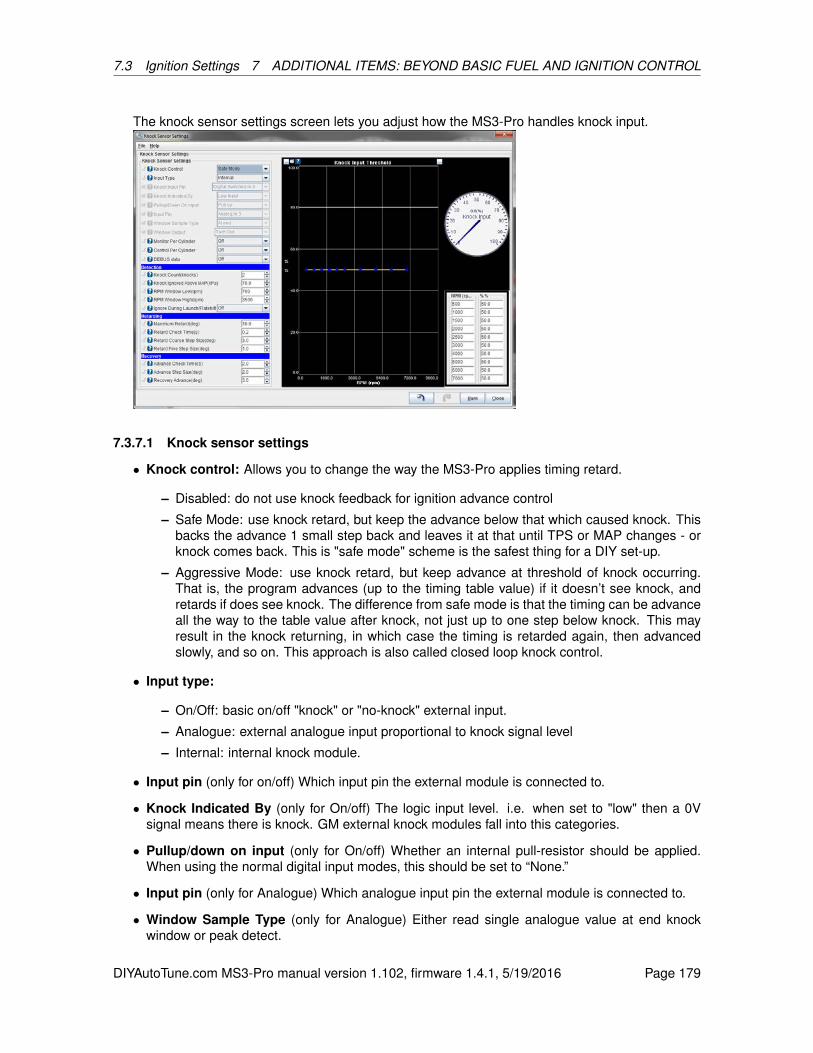
7.3 Ignition Settings 7 ADDITIONAL ITEMS: BEYOND BASIC FUEL AND IGNITION CONTROL
The knock sensor settings screen lets you adjust how the MS3-Pro handles knock input.
7.3.7.1 Knock sensor settings
• Knock control: Allows you to change the way the MS3-Pro applies timing retard.
– Disabled: do not use knock feedback for ignition advance control
– Safe Mode: use knock retard, but keep the advance below that which caused knock. Thisbacks the advance 1 small step back and leaves it at that until TPS or MAP changes - orknock comes back. This is "safe mode" scheme is the safest thing for a DIY set-up.
– Aggressive Mode: use knock retard, but keep advance at threshold of knock occurring.That is, the program advances (up to the timing table value) if it doesn’t see knock, andretards if does see knock. The difference from safe mode is that the timing can be advanceall the way to the table value after knock, not just up to one step below knock. This mayresult in the knock returning, in which case the timing is retarded again, then advancedslowly, and so on. This approach is also called closed loop knock control.
• Input type:
– On/Off: basic on/off "knock" or "no-knock" external input.
– Analogue: external analogue input proportional to knock signal level
– Internal: internal knock module.
• Input pin (only for on/off) Which input pin the external module is connected to.
• Knock Indicated By (only for On/off) The logic input level. i.e. when set to "low" then a 0Vsignal means there is knock. GM external knock modules fall into this categories.
• Pullup/down on input (only for On/off) Whether an internal pull-resistor should be applied.When using the normal digital input modes, this should be set to “None.”
• Input pin (only for Analogue) Which analogue input pin the external module is connected to.
• Window Sample Type (only for Analogue) Either read single analogue value at end knockwindow or peak detect.
DIYAutoTune.com MS3-Pro manual version 1.102, firmware 1.4.1, 5/19/2016 Page 179
7.3 Ignition Settings 7 ADDITIONAL ITEMS: BEYOND BASIC FUEL AND IGNITION CONTROL
• Window Output (only for Analogue) Optional digital output for knock window signal.
• Monitor Per Cylinder Enables using different knock thresholds for each cylinder. This requiressequential fueling and/or coil on plug mode to be enabled.
• Control Per Cylinder This allows knock retard to only be applied to the cylinder that is knocking.If turned off, knock control is applied to all cylinders.
• DEBUG data Adds per-cylinder knock measurements to dataloging.
7.3.7.2 Detection
• Knock Count (knocks): number of knock events detected before control is started
• Knock Ignored above MAP (kPa): no knock retard is implemented above this MAP
• RPM window low (rpm): knock control is implemented above this rpm
• RPM window high (rpm): knock control is implemented below this rpm. This upper limit isdesirable as valve train noise will typically mask out the knock sensor signal at higher rpmswhich could cause false reports of knock.
• Ignore During Launch / Flatshift: Flat shift or launch rev limiting with a spark cut can causeenough noise to cause false knock readings on some engines. This setting disables detectionwhen the launch or flat shift rev limiter is active.
7.3.7.3 Retarding
• Maximum Retard (deg): maximum total retard when knock occurs. This can be useful toprevent timing from being excessively retarded (avoiding potential overheating issues) if thesenor malfunctions or there are other problems with the knock sensing system.
• Retard Check Time (sec): this is the time between knock retard corrections, allows short timestep to quickly retard.
• Retard Coarse Step Size (deg): ignition retard step size when 1st knock, make it large toquickly retard the timing and stop knock.
• Retard Fine Step Size (deg): ignition retard step size when knock restarts after it had stopped.
7.3.7.4 Recovery
• Advance Check Time (sec): this is the time between knock advance corrections (I.e., timingreturn to "normal")
• Advance Step Size (deg): ignition advance step size after knock has stopped.
• Recovery Advance (deg)): this is the change in table advance required to restart advance untilknock or reach table value (0 knock retard) process. This only applies in Safe Mode.
7.3.7.5 Knock input threshold For analogue and internal modes, this sets a threshold level. If themeasured knock signal exceeds the threshold, then the control system is started. This allows differentthresholds to be applied to match actual engine behavior. The curve will need to be set empirically byexamining datalogs of knock% when operating the engine under safe conditions.
DIYAutoTune.com MS3-Pro manual version 1.102, firmware 1.4.1, 5/19/2016 Page 180

7.3 Ignition Settings 7 ADDITIONAL ITEMS: BEYOND BASIC FUEL AND IGNITION CONTROL
7.3.8 Knock sensor parameters
This screen is used with the internal knock processing.
• Bandpass frequency - this should be adjusted to suit the resonant frequency of you engine.(Formulae exist on the web for estimating this frequency based on bore diameter.)
• Integrator time constant - internal setting to knock sensor chip. Default is 150us. A largernumber will reduce the output level and creates more filtering.
• Number of sensors - how many knock sensors are connected (1 or 2.)
• Monitor per cylinder - when sequential fuel or spark are in operation the code can deter-mine which cylinder the knock signal applies to. This enables the individual cylinder data to berecorded.
• Gain - compensate for sensor sensitivity and distance between cylinder and sensor.
• Sensor - pick which sensor to use for each cylinder.
Some engines have multiple knock sensors. In this case, you will usually want to pair the cylinder withwhichever sensor is nearest. For example, LS1 style engines use a pair of sensors in the valley whichare positioned to "listen" to four equally spaced cylinders each. i.e. the front sensor corresponds tocylinders 1,2,3,4 and the rear sensor to cylinders 5,6,7,8.
7.3.9 Knock window settings
These are used with both internal and analog knock sensing modes.
DIYAutoTune.com MS3-Pro manual version 1.102, firmware 1.4.1, 5/19/2016 Page 181
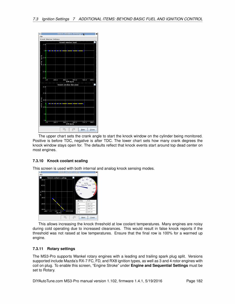
7.3 Ignition Settings 7 ADDITIONAL ITEMS: BEYOND BASIC FUEL AND IGNITION CONTROL
The upper chart sets the crank angle to start the knock window on the cylinder being monitored.Positive is before TDC, negative is after TDC. The lower chart sets how many crank degrees theknock window stays open for. The defaults reflect that knock events start around top dead center onmost engines.
7.3.10 Knock coolant scaling
This screen is used with both internal and analog knock sensing modes.
This allows increasing the knock threshold at low coolant temperatures. Many engines are noisyduring cold operating due to increased clearances. This would result in false knock reports if thethreshold was not raised at low temperatures. Ensure that the final row is 100% for a warmed upengine.
7.3.11 Rotary settings
The MS3-Pro supports Wankel rotary engines with a leading and trailing spark plug split. Versionssupported include Mazda’s RX-7 FC, FD, and RX8 ignition types, as well as 3 and 4 rotor engines withcoil on plug. To enable this screen, “Engine Stroke” under Engine and Sequential Settings must beset to Rotary.
DIYAutoTune.com MS3-Pro manual version 1.102, firmware 1.4.1, 5/19/2016 Page 182

7.3 Ignition Settings 7 ADDITIONAL ITEMS: BEYOND BASIC FUEL AND IGNITION CONTROL
The “Allow negative split” setting lets you fire the trailing spark plugs before the leading (positivesplit numbers have the trailing spark plugs fired after the leading). You can also set a separate dwelltime for the trailing coils. Note that all rotary modes have you set the number of injectors to the numberof primary injectors; a 2 rotor engine would have the number set to 2, even though there are a total offour injectors, two primary and two secondary.
Here are the output modes available.
7.3.11.1 FC mode The second generation RX-7 used a logic level wasted spark coil for the leadingplugs and a coil that had a “coil select” mode for the trailing coil. FC mode requires setting “Numberof coils” to “wasted spark”, and uses this wiring.
Ignition wiring:
• Spark A Leading coil (IGt-L)
• Spark B Trailing coil (IGt-T)
• Spark C Trailing coil select
Fuel wiring:
• Inj A Front rotor primary injector
• Inj B Rear rotor primary injector
• Inj C Front rotor secondary injector
• Inj D Rear rotor secondary injector
7.3.11.2 FD mode The third generation RX-7 retains a wasted spark coil for the leading plugs, butthe trailing plugs are individual logic level coils. As with FC mode, “number of coils” needs to be setto “wasted spark.”
Ignition wiring:
• Spark A Leading coil (IGt-L)
• Spark C Front trailing coil
• Spark D Rear trailing coil
Note that FD mode does not use spark B - this is done to match the RX8 mode. If you ever convertto coil on plug, this means you only have to change one wire instead of three.
Fuel wiring:
• Inj A Front rotor primary injector
• Inj B Rear rotor primary injector
• Inj C Front rotor secondary injector
• Inj D Rear rotor secondary injector
DIYAutoTune.com MS3-Pro manual version 1.102, firmware 1.4.1, 5/19/2016 Page 183
7.3 Ignition Settings 7 ADDITIONAL ITEMS: BEYOND BASIC FUEL AND IGNITION CONTROL
7.3.11.3 RX8 mode The RX8 mode is automatically enabled if you set the number of coils to “coilon plug” and the number of rotors to 2.
Ignition wiring:
• Spark A Front Leading coil
• Spark B Rear Leading coil
• Spark C Front trailing coil
• Spark D Rear trailing coil
Fuel wiring:
• Inj A Front rotor primary injector
• Inj B Rear rotor primary injector
• Inj C Front rotor secondary injector
• Inj D Rear rotor secondary injector
7.3.11.4 3 rotor Using three rotors requires coil on plug ignition to be set.Ignition wiring:
• Spark A Leading coil A
• Spark B Leading coil B
• Spark C Leading coil C
• Spark D Trailing coil A
• Spark E Trailing coil B
• Spark F Trailing coil C
Fuel wiring:
• Inj A Primary injector A
• Inj B Primary injector B
• Inj C Primary injector C
• Inj D Secondary injector A
• Inj E Secondary injector B
• Inj F Secondary injector C
The coils and injectors need to be wired in firing-order sequence. The outputs fire A,B,C,D,A....
DIYAutoTune.com MS3-Pro manual version 1.102, firmware 1.4.1, 5/19/2016 Page 184
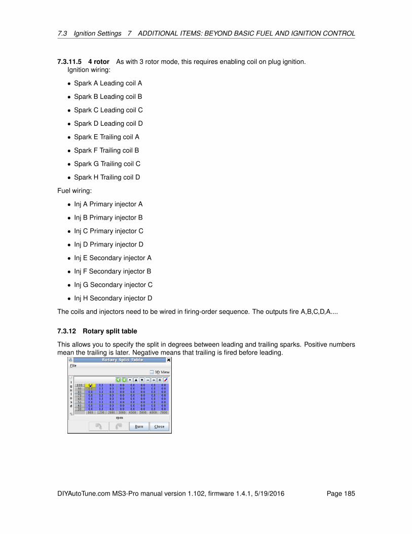
7.3 Ignition Settings 7 ADDITIONAL ITEMS: BEYOND BASIC FUEL AND IGNITION CONTROL
7.3.11.5 4 rotor As with 3 rotor mode, this requires enabling coil on plug ignition.Ignition wiring:
• Spark A Leading coil A
• Spark B Leading coil B
• Spark C Leading coil C
• Spark D Leading coil D
• Spark E Trailing coil A
• Spark F Trailing coil B
• Spark G Trailing coil C
• Spark H Trailing coil D
Fuel wiring:
• Inj A Primary injector A
• Inj B Primary injector B
• Inj C Primary injector C
• Inj D Primary injector D
• Inj E Secondary injector A
• Inj F Secondary injector B
• Inj G Secondary injector C
• Inj H Secondary injector D
The coils and injectors need to be wired in firing-order sequence. The outputs fire A,B,C,D,A....
7.3.12 Rotary split table
This allows you to specify the split in degrees between leading and trailing sparks. Positive numbersmean the trailing is later. Negative means that trailing is fired before leading.
DIYAutoTune.com MS3-Pro manual version 1.102, firmware 1.4.1, 5/19/2016 Page 185
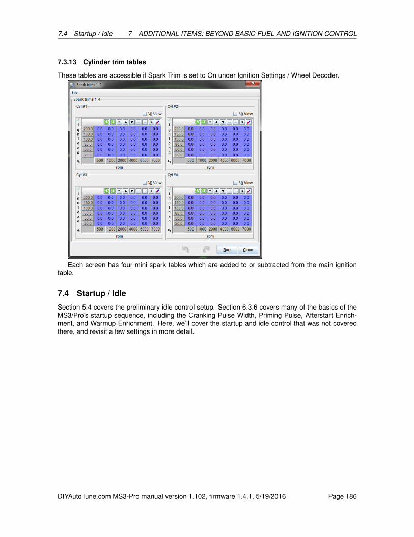
7.4 Startup / Idle 7 ADDITIONAL ITEMS: BEYOND BASIC FUEL AND IGNITION CONTROL
7.3.13 Cylinder trim tables
These tables are accessible if Spark Trim is set to On under Ignition Settings / Wheel Decoder.
Each screen has four mini spark tables which are added to or subtracted from the main ignitiontable.
7.4 Startup / Idle
Section 5.4 covers the preliminary idle control setup. Section 6.3.6 covers many of the basics of theMS3/Pro’s startup sequence, including the Cranking Pulse Width, Priming Pulse, Afterstart Enrich-ment, and Warmup Enrichment. Here, we’ll cover the startup and idle control that was not coveredthere, and revisit a few settings in more detail.
DIYAutoTune.com MS3-Pro manual version 1.102, firmware 1.4.1, 5/19/2016 Page 186

7.4 Startup / Idle 7 ADDITIONAL ITEMS: BEYOND BASIC FUEL AND IGNITION CONTROL
7.4.1 Cranking / startup settings
• Cranking RPM - On the initial start, the MS3-Pro will run in batch fire on the cranking pulsewidth settings until RPM rises above this threshold, or if the RPM falls below this thresholdwithin 5 seconds of starting. Set this value higher than the engine can reach while being justdriven by the starter. The goal with this setting is to set it to a point where it will know the engineis up and running once RPM goes over this value.
• Flood clear TPS - If the throttle position exceeds this value below cranking RPM, the MS3-Prowill shut off the injectors because it will take this as a signal to clear a flooded engine.
• Batch fire during crank - If set to on, the MS3-Pro will fire all injectors every ignition eventduring cranking. If set to off, the MS3-Pro will use sequential injection during cranking as soonas it has established cylinder identification. This setting is grayed out if the engine is set tobatch fire as it will use batch firing on every ignition event in this case. Using batch fire duringcranking can allow more fuel to be injected in cold climates - the maximum cranking pulse widhtis approximately 65 ms, so injecting fuel more often can allow for more fuel during startup.
• Cranking taper curve - This curve allows for the ECU to vary the pulse width while cranking,generally used to allow a large initial fuel shot that tapers off. This can make for easier startupbut is a bit more complex to tune.
• Cranking taper curve units - The taper curve can either use time or ignition events to changehow it adjusts fuel.
• Cranking fuel pulse rate - When using batch fired cranking, you can inject fuel every igni-tion event or every other ignition event. Every other ignition event can give better hot startingbehavior on engines with more than 8 cylinders.
• Blended cranking curves - Allows using a blend curve to blend between two cranking pulsewidth tables. This is most commonly used with flex fuel engines.
• Priming pulse delay - Allows you to delay the priming pulse instead of firing it as soon as thekey is turned on.
DIYAutoTune.com MS3-Pro manual version 1.102, firmware 1.4.1, 5/19/2016 Page 187

7.4 Startup / Idle 7 ADDITIONAL ITEMS: BEYOND BASIC FUEL AND IGNITION CONTROL
• Ignore MAT correction during ASE - This setting allows the MS3-Pro to override the air tem-perature correction while afterstart enrichment is active. If this is turned on, MAT correction willbe set to 100% until the ASE time is complete. This is useful if the IAT sensor is in the intakemanifold and absorbs heat from the manifold.
• ASE count units - You may set the afterstart enrichment to be based on either time or enginecycles.
7.4.2 Cranking Taper Curve
This curve provides a multiplier for the pulse width during cranking, with 100% being to use thecranking pulse width curve unchanged. The curve will repeat itself after reaching the end point. Onsome engines, an initial spike of fuel followed by pulling fuel can lead to better startup performance.
7.4.3 Priming Pulse 2 through Warmup Enrichment 2
These are used in dual fuel mode or a blend curve (see Table Choices) if running on an alternatefuel, as different fuels have different behavior when cold. An extreme case is CNG (compressednatural gas), which has almost no tendency to stick to the intake walls even on the coldest engine.This means an engine running CNG will require very little warmup or afterstart enrichment. E85 oftenrequires different cranking pulses from gasoline as well, both because it has a lower air/fuel ratio andbecause it is more likely to stick to a cold intake manifold.
7.4.4 Idle control
DIYAutoTune.com MS3-Pro manual version 1.102, firmware 1.4.1, 5/19/2016 Page 188

7.4 Startup / Idle 7 ADDITIONAL ITEMS: BEYOND BASIC FUEL AND IGNITION CONTROL
The MS3-Pro firmware has several methods for controlling idle speed, besides the “not run anysort of ECU control, and just use a set screw to hold the throttle open” method. They were introducedin section 5.4, but we will cover them again in more detail.
The current firmware allows you to specify the valve type separately from open vs closed loopoperation.
• Idle valve type
– None: The MS3-Pro does not control idle speed.
– On/Off Valve: The valve is a two wire solenoid that can only turn on or off with no in betweenpositions.
– PWM valve: A solenoid type valve where the amount of opening is controlled by the outputduty cycle.
– Stepper valve: This uses a rotating motor to move a pintle. The motor takes a discrete stepevery time one of the wires is pulsed.
• Algorithm
– Open-loop (warmup): The MS3-Pro commands how far to open the valve as a function ofcoolant temperature. Note that on/off valves are always open loop, so this setting is grayedout when an on/off valve is selected.
– Closed-loop: The MS3-Pro adjusts the idle valve opening to match an RPM target.
The different valve types use different settings, described in detail below.
7.4.4.1 On/Off Valve
• Fast Idle Temperature - The MS3-Pro will energize the on/off valve until the engine reachesthis coolant temperature.
• Hysteresis - The amount of temperature drop below the fast idle temperature needed for theon/off valve to turn back on. This prevents the valve from toggling on and off rapidly when theengine is right at the fast idle temperature.
7.4.4.2 Stepper valve settings
• Time Step Size - This is the number of milliseconds the firmware will wait between each step ifthe idle valve moves more than one step. If a valve does not move reliably, this setting shouldbe increased. Setting this valve too high will make the valve move slowly.
• Initial Time Step Size - This is the number of milliseconds for the first step. It is often set longerthan the other steps to help overcome friction.
• Minimum # of steps to move - This is the minimum number of steps the controlling piece ofcode has to command before the code that moves the valve will actually try to move the valve.We’ve found some stepper valves, particularly used ones on older cars, may stick if commandedto move fewer than 5 to 8 steps.
• Homing steps - This is the number of steps the valve will move (in the homing direction) onboot so that the rest of the code can rely on the start position being accurate. After homing, theIAC valve will then move to the number specified in the Cranking Steps.
• Homing direction - You can set the valve to go through its homing routine by either opening orclosing.
DIYAutoTune.com MS3-Pro manual version 1.102, firmware 1.4.1, 5/19/2016 Page 189
7.4 Startup / Idle 7 ADDITIONAL ITEMS: BEYOND BASIC FUEL AND IGNITION CONTROL
• Wide Open Steps - If the homing direction is set to open, this number defines the amount ofsteps from the closed position to wide open.
• Crank-to-Run Taper Time - This is the amount of time the IAC valve uses to transition afterstarting from its crank position to its running position.
• Power between steps
– Moving only: Power is turned off in between steps. Do not use if the valve freewheels whenunplugged.
– Hold current: Applies partial current in between steps.
– Always on: Leaves the valve at full power between steps. This produces the most heat butwill prevent a 4 wire stepper from moving when not commanded. Use this if the valve spinswith almost no resistance when unplugged.
7.4.4.3 PWM idle valve settings
• Crank-to-Run Taper Time - This is the amount of time the IAC valve uses to transition afterstarting from its crank position to its running position.
• Valve Mode - Normal mode is off at 0% duty cycle, inverted mode is off at 100% duty cycle. Asthe name implies, most valves use normal mode. If you’ve found you accidentally wired up a 3wire IAC valve backwards, just flip this setting.
• Run valve before start - If set to on, the valve is energized with the key on and engine off. Thisallows for slightly faster starting, but some PWM valves may make an objectionable amount ofnoise before starting. Turning this off will prevent the valve from making noise with the engineoff, but may produce a small delay in starting.
• Output Port - Allows you to pick which output wires are used. In 3 wire mode, this is for the coilthat opens the valve.
• 3 wire mode - Used with 3 wire rotary IAC valves, common in Denso and Bosch applications.This may be left off or used to specify the connection used for the coil that closes the valves.
• Valve Frequency Selection - Select a frequency from the list. Different valves operate best ondifferent frequencies.
DIYAutoTune.com MS3-Pro manual version 1.102, firmware 1.4.1, 5/19/2016 Page 190
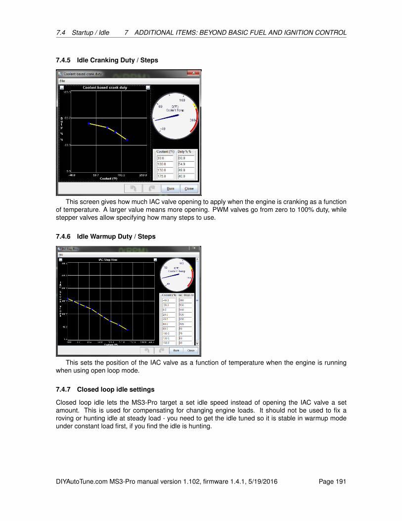
7.4 Startup / Idle 7 ADDITIONAL ITEMS: BEYOND BASIC FUEL AND IGNITION CONTROL
7.4.5 Idle Cranking Duty / Steps
This screen gives how much IAC valve opening to apply when the engine is cranking as a functionof temperature. A larger value means more opening. PWM valves go from zero to 100% duty, whilestepper valves allow specifying how many steps to use.
7.4.6 Idle Warmup Duty / Steps
This sets the position of the IAC valve as a function of temperature when the engine is runningwhen using open loop mode.
7.4.7 Closed loop idle settings
Closed loop idle lets the MS3-Pro target a set idle speed instead of opening the IAC valve a setamount. This is used for compensating for changing engine loads. It should not be used to fix aroving or hunting idle at steady load - you need to get the idle tuned so it is stable in warmup modeunder constant load first, if you find the idle is hunting.
DIYAutoTune.com MS3-Pro manual version 1.102, firmware 1.4.1, 5/19/2016 Page 191
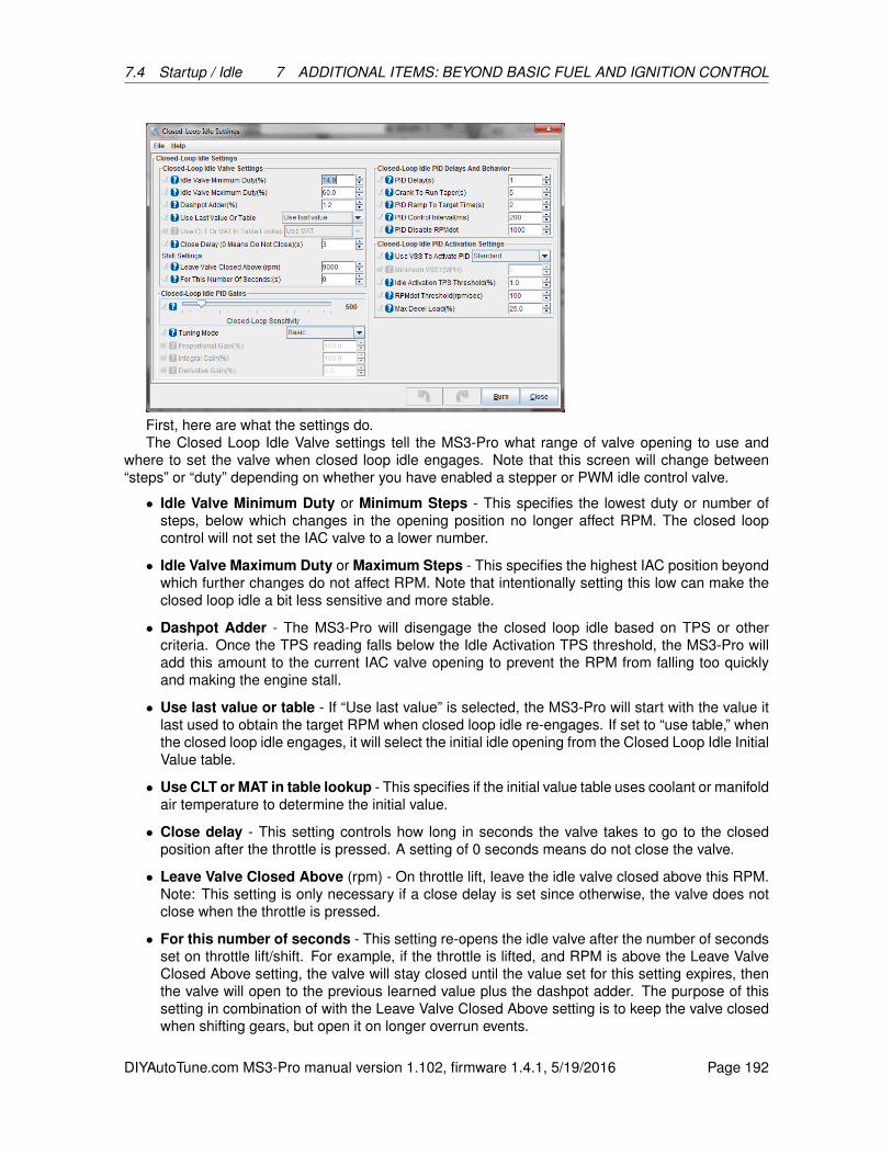
7.4 Startup / Idle 7 ADDITIONAL ITEMS: BEYOND BASIC FUEL AND IGNITION CONTROL
First, here are what the settings do.The Closed Loop Idle Valve settings tell the MS3-Pro what range of valve opening to use and
where to set the valve when closed loop idle engages. Note that this screen will change between“steps” or “duty” depending on whether you have enabled a stepper or PWM idle control valve.
• Idle Valve Minimum Duty or Minimum Steps - This specifies the lowest duty or number ofsteps, below which changes in the opening position no longer affect RPM. The closed loopcontrol will not set the IAC valve to a lower number.
• Idle Valve Maximum Duty or Maximum Steps - This specifies the highest IAC position beyondwhich further changes do not affect RPM. Note that intentionally setting this low can make theclosed loop idle a bit less sensitive and more stable.
• Dashpot Adder - The MS3-Pro will disengage the closed loop idle based on TPS or othercriteria. Once the TPS reading falls below the Idle Activation TPS threshold, the MS3-Pro willadd this amount to the current IAC valve opening to prevent the RPM from falling too quicklyand making the engine stall.
• Use last value or table - If “Use last value” is selected, the MS3-Pro will start with the value itlast used to obtain the target RPM when closed loop idle re-engages. If set to “use table,” whenthe closed loop idle engages, it will select the initial idle opening from the Closed Loop Idle InitialValue table.
• Use CLT or MAT in table lookup - This specifies if the initial value table uses coolant or manifoldair temperature to determine the initial value.
• Close delay - This setting controls how long in seconds the valve takes to go to the closedposition after the throttle is pressed. A setting of 0 seconds means do not close the valve.
• Leave Valve Closed Above (rpm) - On throttle lift, leave the idle valve closed above this RPM.Note: This setting is only necessary if a close delay is set since otherwise, the valve does notclose when the throttle is pressed.
• For this number of seconds - This setting re-opens the idle valve after the number of secondsset on throttle lift/shift. For example, if the throttle is lifted, and RPM is above the Leave ValveClosed Above setting, the valve will stay closed until the value set for this setting expires, thenthe valve will open to the previous learned value plus the dashpot adder. The purpose of thissetting in combination of with the Leave Valve Closed Above setting is to keep the valve closedwhen shifting gears, but open it on longer overrun events.
DIYAutoTune.com MS3-Pro manual version 1.102, firmware 1.4.1, 5/19/2016 Page 192
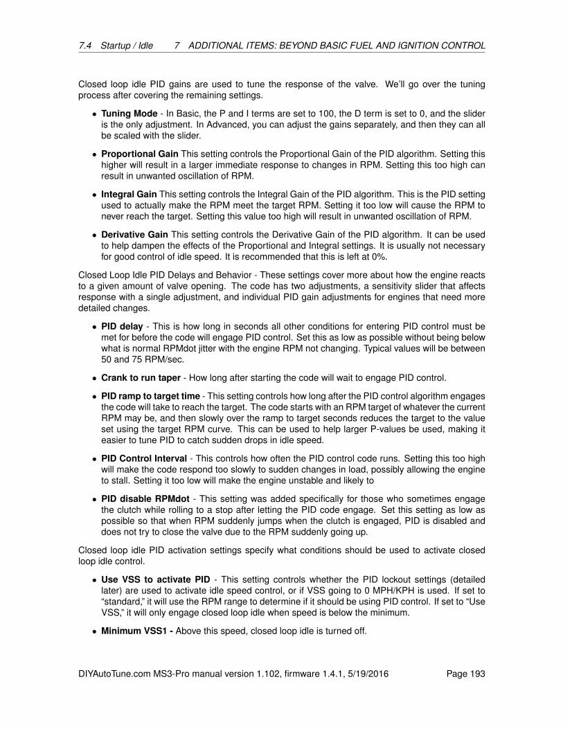
7.4 Startup / Idle 7 ADDITIONAL ITEMS: BEYOND BASIC FUEL AND IGNITION CONTROL
Closed loop idle PID gains are used to tune the response of the valve. We’ll go over the tuningprocess after covering the remaining settings.
• Tuning Mode - In Basic, the P and I terms are set to 100, the D term is set to 0, and the slideris the only adjustment. In Advanced, you can adjust the gains separately, and then they can allbe scaled with the slider.
• Proportional Gain This setting controls the Proportional Gain of the PID algorithm. Setting thishigher will result in a larger immediate response to changes in RPM. Setting this too high canresult in unwanted oscillation of RPM.
• Integral Gain This setting controls the Integral Gain of the PID algorithm. This is the PID settingused to actually make the RPM meet the target RPM. Setting it too low will cause the RPM tonever reach the target. Setting this value too high will result in unwanted oscillation of RPM.
• Derivative Gain This setting controls the Derivative Gain of the PID algorithm. It can be usedto help dampen the effects of the Proportional and Integral settings. It is usually not necessaryfor good control of idle speed. It is recommended that this is left at 0%.
Closed Loop Idle PID Delays and Behavior - These settings cover more about how the engine reactsto a given amount of valve opening. The code has two adjustments, a sensitivity slider that affectsresponse with a single adjustment, and individual PID gain adjustments for engines that need moredetailed changes.
• PID delay - This is how long in seconds all other conditions for entering PID control must bemet for before the code will engage PID control. Set this as low as possible without being belowwhat is normal RPMdot jitter with the engine RPM not changing. Typical values will be between50 and 75 RPM/sec.
• Crank to run taper - How long after starting the code will wait to engage PID control.
• PID ramp to target time - This setting controls how long after the PID control algorithm engagesthe code will take to reach the target. The code starts with an RPM target of whatever the currentRPM may be, and then slowly over the ramp to target seconds reduces the target to the valueset using the target RPM curve. This can be used to help larger P-values be used, making iteasier to tune PID to catch sudden drops in idle speed.
• PID Control Interval - This controls how often the PID control code runs. Setting this too highwill make the code respond too slowly to sudden changes in load, possibly allowing the engineto stall. Setting it too low will make the engine unstable and likely to
• PID disable RPMdot - This setting was added specifically for those who sometimes engagethe clutch while rolling to a stop after letting the PID code engage. Set this setting as low aspossible so that when RPM suddenly jumps when the clutch is engaged, PID is disabled anddoes not try to close the valve due to the RPM suddenly going up.
Closed loop idle PID activation settings specify what conditions should be used to activate closedloop idle control.
• Use VSS to activate PID - This setting controls whether the PID lockout settings (detailedlater) are used to activate idle speed control, or if VSS going to 0 MPH/KPH is used. If set to“standard,” it will use the RPM range to determine if it should be using PID control. If set to “UseVSS,” it will only engage closed loop idle when speed is below the minimum.
• Minimum VSS1 - Above this speed, closed loop idle is turned off.
DIYAutoTune.com MS3-Pro manual version 1.102, firmware 1.4.1, 5/19/2016 Page 193
7.4 Startup / Idle 7 ADDITIONAL ITEMS: BEYOND BASIC FUEL AND IGNITION CONTROL
• Idle Activation TPS threshold - This setting is the throttle position below which the PID algo-rithm is engaged. It is used in conjunction with the RPM adder to determine whether or not toengage PID control of the idle valve. This should be set as low as possible to avoid the idlevalve closing when the throttle is pressed.
• RPMdot threshold - This is a maximum RPM change in RPM per second. Above this rate,the MS3-Pro will expect the car to be in engine braking and not activate closed loop. Set thisas low as possible without being below what is normal RPMdot jitter with the engine RPM notchanging. Typical values will be between 50 and 75 RPM/sec. This may look similar to “PIDDisable RPMdot.” However, this setting is used to allow the MS3-Pro to enter closed loop idle,while PID disable RPMdot is used to deactivate closed loop idle.
• Max decel load - This setting controls the kPa below which the PID lockout detection code isdisabled. This should be set to a kPa just under the lowest kPa that is seen during a fast idle.
7.4.7.1 Tuning closed loop idle Before trying to tune closed loop idle speed control, be sure to trytuning warmup only idle speed control. With warmup only control, a higher step-count or duty shouldyield higher RPM. Make sure that this is the case, and that smooth idle speed can be attained withwarmup only before moving on to closed loop control.
There are two main things to tune when tuning closed-loop idle speed control:
• PID gains
• Conditions for entering PID control
We recommend tuning these in stages. For example, PID cannot be tuned if the code is neverentering the PID loop. Because of this, it is a good idea to start by tuning the conditions for enteringPID control, then come back and tune the PID gains.
These settings include:
• Use VSS to activate PID - This takes the place of the PID lockout settings. Turning this on willmake it so that the PID loop activates after the vehicle speed comes to zero MPH/KPH.
• Idle Activation TPS threshold - Set as low as possible. If the TPS has a bit of noise, set it toaround 1%; otherwise set it to 0.3%-0.5%.
• PID delay - This should be set so that the RPM dropping on throttle lift can come to a restslightly higher than the target RPM, and become stable there. Between three and five secondsnormally works the best.
• Crank to Run Taper - This setting controls how long after starting the code will delay beforeentering PID. Between three and five seconds works well for this setting.
• RPMdot threshold - This is the first of the PID lockout detection settings. Use this setting so thatthe code can tell the difference between decelerating with closed throttle (engine braking) andsitting at one RPM. Set this as low as possible without being below what is normal RPMdot jitterwith the engine RPM not changing. Typical values will be between 50 and 75 RPM/sec.
• Max decel load - This is the second PID lockout detection setting. The code assumes that ifMAP is lower than this setting, the driver must be decelerating, and not "locked out" of the PIDloop. Set this to a value just under the load seen with an idle slightly higher than the currenttarget RPM + the Idle Activation RPM Adder. This can be done by temporarily switching towarmup-only mode or idle test mode, and setting the valve position manually.
DIYAutoTune.com MS3-Pro manual version 1.102, firmware 1.4.1, 5/19/2016 Page 194
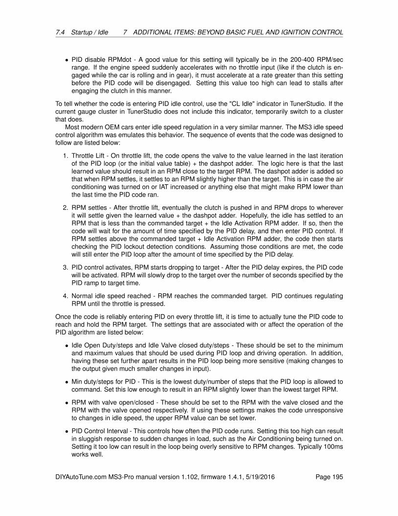
7.4 Startup / Idle 7 ADDITIONAL ITEMS: BEYOND BASIC FUEL AND IGNITION CONTROL
• PID disable RPMdot - A good value for this setting will typically be in the 200-400 RPM/secrange. If the engine speed suddenly accelerates with no throttle input (like if the clutch is en-gaged while the car is rolling and in gear), it must accelerate at a rate greater than this settingbefore the PID code will be disengaged. Setting this value too high can lead to stalls afterengaging the clutch in this manner.
To tell whether the code is entering PID idle control, use the "CL Idle" indicator in TunerStudio. If thecurrent gauge cluster in TunerStudio does not include this indicator, temporarily switch to a clusterthat does.
Most modern OEM cars enter idle speed regulation in a very similar manner. The MS3 idle speedcontrol algorithm was emulates this behavior. The sequence of events that the code was designed tofollow are listed below:
1. Throttle Lift - On throttle lift, the code opens the valve to the value learned in the last iterationof the PID loop (or the initial value table) + the dashpot adder. The logic here is that the lastlearned value should result in an RPM close to the target RPM. The dashpot adder is added sothat when RPM settles, it settles to an RPM slightly higher than the target. This is in case the airconditioning was turned on or IAT increased or anything else that might make RPM lower thanthe last time the PID code ran.
2. RPM settles - After throttle lift, eventually the clutch is pushed in and RPM drops to whereverit will settle given the learned value + the dashpot adder. Hopefully, the idle has settled to anRPM that is less than the commanded target + the Idle Activation RPM adder. If so, then thecode will wait for the amount of time specified by the PID delay, and then enter PID control. IfRPM settles above the commanded target + Idle Activation RPM adder, the code then startschecking the PID lockout detection conditions. Assuming those conditions are met, the codewill still enter the PID loop after the amount of time specified by the PID delay.
3. PID control activates, RPM starts dropping to target - After the PID delay expires, the PID codewill be activated. RPM will slowly drop to the target over the number of seconds specified by thePID ramp to target time.
4. Normal idle speed reached - RPM reaches the commanded target. PID continues regulatingRPM until the throttle is pressed.
Once the code is reliably entering PID on every throttle lift, it is time to actually tune the PID code toreach and hold the RPM target. The settings that are associated with or affect the operation of thePID algorithm are listed below:
• Idle Open Duty/steps and Idle Valve closed duty/steps - These should be set to the minimumand maximum values that should be used during PID loop and driving operation. In addition,having these set further apart results in the PID loop being more sensitive (making changes tothe output given much smaller changes in input).
• Min duty/steps for PID - This is the lowest duty/number of steps that the PID loop is allowed tocommand. Set this low enough to result in an RPM slightly lower than the lowest target RPM.
• RPM with valve open/closed - These should be set to the RPM with the valve closed and theRPM with the valve opened respectively. If using these settings makes the code unresponsiveto changes in idle speed, the upper RPM value can be set lower.
• PID Control Interval - This controls how often the PID code runs. Setting this too high can resultin sluggish response to sudden changes in load, such as the Air Conditioning being turned on.Setting it too low can result in the loop being overly sensitive to RPM changes. Typically 100msworks well.
DIYAutoTune.com MS3-Pro manual version 1.102, firmware 1.4.1, 5/19/2016 Page 195
7.4 Startup / Idle 7 ADDITIONAL ITEMS: BEYOND BASIC FUEL AND IGNITION CONTROL
• PID controller gains - These control the actual response of the code to changes in RPM, as wellas how well the code will reach the target. Tips for tuning these are listed below.
In Basic mode, simply adjust the slider, starting with a low value and increasing it until the engine canreact fast enough to any load placed on it to avoid stalling or an unacceptable RPM dip.
The following basic steps should be used for tuning the PID controller gains in advanced mode:
1. Zero all the gains - Set all the gains to 0%. This is so that the effects of tuning the I-term in thenext step are not confused with the effects of any other setting.
2. Tune the Integral (I) gain - The Integral gain is the only term that controls whether the codeactually reaches its target. Higher values for Integral gain will result in the code being able toget closer to the commanded target; however, a value that is too high will result in oscillation.The easiest way to determine a good value for the I term is to keep increasing it until oscillationoccurs, then slightly lower it. If this value is increased to 200% without reaching a point whereoscillation occurs, then the RPM with valve opened setting can be decreased as far as neces-sary, and the open duty/steps setting and closed duty/steps setting can be made further apartto make the PID loop more sensitive.
3. Tune the Proportional (P) gain - After tuning the I gain so that the RPM reaches the commandedtarget without oscillation, the P gain can be tuned. The best way to tune this is to set it as highas possible without getting any oscillation. After setting this, try turning on the air conditioningor other accessories that normally lower RPM or increase load. When these accessories areturned on, the RPM should dip a bit, then recover (the valve position should increase signifi-cantly). Using longer PID ramp to target times can also make it so that when the PID algorithmengages, a higher P gain can be set without causing oscillation.
4. Tune the Derivative (D) gain - For most users, use of the D gain should not be necessary. Itsubstantially dampens the response of the loop.
Some final tips:
• Idle Fuel Tuning - Before even attempting to tune Closed-loop Idle speed control, tune the areaaround idle so that if RPM goes up or down or load goes up or down, the AFR stays close tothe same value. Changing AFR can affect idle speed, which can then cause the PID code to tryto correct, getting into an unrecoverable oscillation.
• Idle Advance - The idle advance feature can be used to help "catch" the idle in situations whereheavy load is suddenly added while the engine is idling. It is recommended that the advanceis increased with increasing load, and decreased with decreasing load. This way, when the airconditioning or electric fan are turned on, the sudden increase in load causes a correspondingincrease in timing which generates more power. Also, this feature can be used so that on idlewithout load, slightly less than what would normally be considered "optimal" timing can be used.This causes the idle valve to need to open further to keep a particular idle speed. Then whensudden load is added, the timing increases and the valve position does not have to change asmuch to cope with the sudden load increase.
DIYAutoTune.com MS3-Pro manual version 1.102, firmware 1.4.1, 5/19/2016 Page 196

7.4 Startup / Idle 7 ADDITIONAL ITEMS: BEYOND BASIC FUEL AND IGNITION CONTROL
7.4.8 Closed loop idle target curve
This screen is used when running closed loop idle. It lets you specify the target RPM as a functionof coolant temperature.
7.4.9 Closed loop idle initial values
If you are using closed loop idle with the initial value table selected, the MS3-Pro uses this to lookup the initial duty cycle when closed loop idle control engages. The X-axis specifies what target RPM,and the Y-axis is either coolant or air temperature, as determined by the closed loop settings screen.
DIYAutoTune.com MS3-Pro manual version 1.102, firmware 1.4.1, 5/19/2016 Page 197
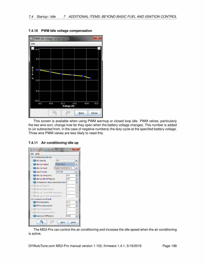
7.4 Startup / Idle 7 ADDITIONAL ITEMS: BEYOND BASIC FUEL AND IGNITION CONTROL
7.4.10 PWM Idle voltage compensation
This screen is available when using PWM warmup or closed loop idle. PWM valves, particularlythe two wire sort, change how far they open when the battery voltage changes. This number is addedto (or subtracted from, in the case of negative numbers) the duty cycle at the specified battery voltage.Three wire PWM valves are less likely to need this.
7.4.11 Air conditioning idle up
The MS3-Pro can control the air conditioning and increase the idle speed when the air conditioningis active.
DIYAutoTune.com MS3-Pro manual version 1.102, firmware 1.4.1, 5/19/2016 Page 198

7.4 Startup / Idle 7 ADDITIONAL ITEMS: BEYOND BASIC FUEL AND IGNITION CONTROL
• A/C idleup on - Allows the MS3-Pro to control the A/C or increase idle speed when the A/C ison.
• Idle-up output - This uses an output pin to activate the A/C compressor and/or condenser fan.
• Idle-up input - This is the input used to tell the MS3-Pro that the air conditioning is on or needsto be turned on.
• Input Polarity
– Normal: The A/C switch grounds the ECU input to trigger the A/C.
– Inverted: The A/C switch sends 12 volts to the ECU to trigger the A/C.
• Idle-up Delay - The amount of time between receiving a signal on the idleup input and increas-ing the idle valve opening.
• Idle-up min RPM - The lowest RPM where the A/C can run. If the RPM falls below this point,the A/C output is turned off.
• Compressor delay since last on - The minimum amount of time between turning the idleupoutput off and turning it back on. Use this to prevent excessively rapid cycling of the compressor.
• Idle-up duty / idle-up steps - The amount to increase the idle valve opening when the A/C ison.
• Idleup target RPM adder - You can either set this to zero to make the MS3-Pro hold a constantRPM when the A/C engages, or use this to increase the RPM to better drive the compressor.This feature requires closed loop idle to be on.
• Idleup CL load allowance - The engine may be under more load when decelerating with theA/C on. This number is added to the PID lockout max decel load when the idleup input is on.
• TPS shutoff - The MS3-Pro turns off the A/C output above this TPS opening value.
• TPS hysteresis - Once the TPS based A/C shutoff has engaged, the TPS needs to fall thisamount below the TPS shutoff value to turn the A/C back on.
• VSS shutoff - Allows you to specify a speed above which the MS3-Pro turns off the A/C.
• VSS hysteresis - Once the VSS based A/C shutoff has engaged, the speed needs to fall thisamount below the VSS shutoff value to turn the A/C back on.
• Maximum RPM - Shuts off the A/C above this RPM to prevent overspinning the compressor.
7.4.12 Idle advance settings
The Idle Advance feature is useful to fine-tune ignition timing at idle. It is particularly useful to helpcatch sudden load increases on the engine at idle by increasing timing when load increases to helpthe engine generate more power, keeping RPM from dropping severely.
DIYAutoTune.com MS3-Pro manual version 1.102, firmware 1.4.1, 5/19/2016 Page 199
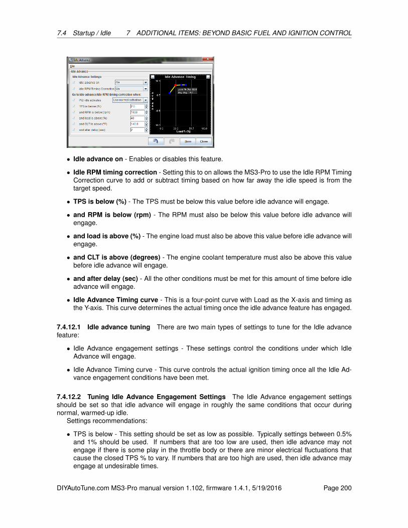
7.4 Startup / Idle 7 ADDITIONAL ITEMS: BEYOND BASIC FUEL AND IGNITION CONTROL
• Idle advance on - Enables or disables this feature.
• Idle RPM timing correction - Setting this to on allows the MS3-Pro to use the Idle RPM TimingCorrection curve to add or subtract timing based on how far away the idle speed is from thetarget speed.
• TPS is below (%) - The TPS must be below this value before idle advance will engage.
• and RPM is below (rpm) - The RPM must also be below this value before idle advance willengage.
• and load is above (%) - The engine load must also be above this value before idle advance willengage.
• and CLT is above (degrees) - The engine coolant temperature must also be above this valuebefore idle advance will engage.
• and after delay (sec) - All the other conditions must be met for this amount of time before idleadvance will engage.
• Idle Advance Timing curve - This is a four-point curve with Load as the X-axis and timing asthe Y-axis. This curve determines the actual timing once the idle advance feature has engaged.
7.4.12.1 Idle advance tuning There are two main types of settings to tune for the Idle advancefeature:
• Idle Advance engagement settings - These settings control the conditions under which IdleAdvance will engage.
• Idle Advance Timing curve - This curve controls the actual ignition timing once all the Idle Ad-vance engagement conditions have been met.
7.4.12.2 Tuning Idle Advance Engagement Settings The Idle Advance engagement settingsshould be set so that idle advance will engage in roughly the same conditions that occur duringnormal, warmed-up idle.
Settings recommendations:
• TPS is below - This setting should be set as low as possible. Typically settings between 0.5%and 1% should be used. If numbers that are too low are used, then idle advance may notengage if there is some play in the throttle body or there are minor electrical fluctuations thatcause the closed TPS % to vary. If numbers that are too high are used, then idle advance mayengage at undesirable times.
DIYAutoTune.com MS3-Pro manual version 1.102, firmware 1.4.1, 5/19/2016 Page 200
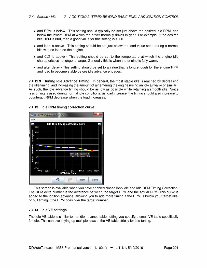
7.4 Startup / Idle 7 ADDITIONAL ITEMS: BEYOND BASIC FUEL AND IGNITION CONTROL
• and RPM is below - This setting should typically be set just above the desired idle RPM, andbelow the lowest RPM at which the driver normally drives in gear. For example, if the desiredidle RPM is 800, then a good value for this setting is 1000.
• and load is above - This setting should be set just below the load value seen during a normalidle with no load on the engine.
• and CLT is above - This setting should be set to the temperature at which the engine idlecharacteristics no longer change. Generally this is when the engine is fully warm.
• and after delay - This setting should be set to a value that is long enough for the engine RPMand load to become stable before idle advance engages.
7.4.12.3 Tuning Idle Advance Timing In general, the most stable idle is reached by decreasingthe idle timing, and increasing the amount of air entering the engine (using an idle air valve or similar).As such, the idle advance timing should be as low as possible while retaining a smooth idle. Sinceless timing is used during normal idle conditions, as load increase, the timing should also increase tocounteract RPM decrease when the load increases.
7.4.13 Idle RPM timing correction curve
This screen is available when you have enabled closed loop idle and Idle RPM Timing Correction.The RPM delta number is the difference between the target RPM and the actual RPM. This curve isadded to the ignition advance, allowing you to add more timing if the RPM is below your target idle,or pull timing if the RPM goes over the target number.
7.4.14 Idle VE settings
The idle VE table is similar to the idle advance table, letting you specify a small VE table specificallyfor idle. This can avoid tying up multiple rows in the VE table strictly for idle tuning.
DIYAutoTune.com MS3-Pro manual version 1.102, firmware 1.4.1, 5/19/2016 Page 201
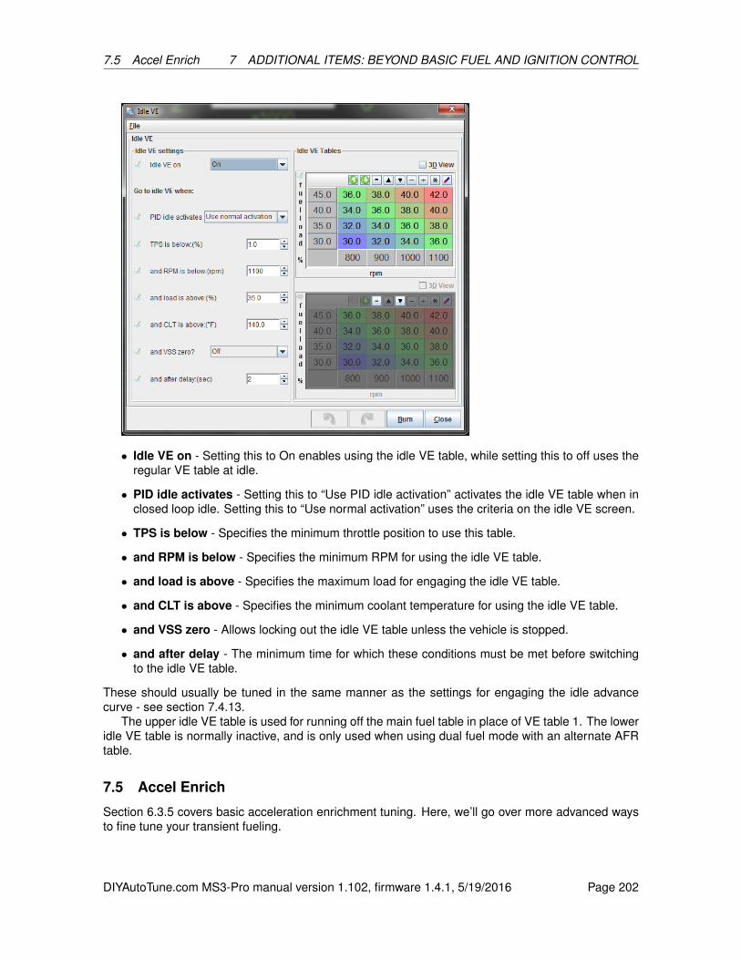
7.5 Accel Enrich 7 ADDITIONAL ITEMS: BEYOND BASIC FUEL AND IGNITION CONTROL
• Idle VE on - Setting this to On enables using the idle VE table, while setting this to off uses theregular VE table at idle.
• PID idle activates - Setting this to “Use PID idle activation” activates the idle VE table when inclosed loop idle. Setting this to “Use normal activation” uses the criteria on the idle VE screen.
• TPS is below - Specifies the minimum throttle position to use this table.
• and RPM is below - Specifies the minimum RPM for using the idle VE table.
• and load is above - Specifies the maximum load for engaging the idle VE table.
• and CLT is above - Specifies the minimum coolant temperature for using the idle VE table.
• and VSS zero - Allows locking out the idle VE table unless the vehicle is stopped.
• and after delay - The minimum time for which these conditions must be met before switchingto the idle VE table.
These should usually be tuned in the same manner as the settings for engaging the idle advancecurve - see section 7.4.13.
The upper idle VE table is used for running off the main fuel table in place of VE table 1. The loweridle VE table is normally inactive, and is only used when using dual fuel mode with an alternate AFRtable.
7.5 Accel Enrich
Section 6.3.5 covers basic acceleration enrichment tuning. Here, we’ll go over more advanced waysto fine tune your transient fueling.
DIYAutoTune.com MS3-Pro manual version 1.102, firmware 1.4.1, 5/19/2016 Page 202

7.5 Accel Enrich 7 ADDITIONAL ITEMS: BEYOND BASIC FUEL AND IGNITION CONTROL
7.5.1 TPS WOT curve
If you have enabled “TPSdot enables %WOT” under Accel Enrich Settings, this curve defines whatis considered wide open throttle for a given RPM. This curve should be set so that beyond this point,additional throttle opening has no effect on the MAP sensor reading or air flow. The accelerationenrichment will not add additional fueling once the throttle moves past the WOT level for your RPM,as the additional throttle will not make the engine need more fuel.
7.5.2 Enhanced acceleration enrichment
Enhanced Acceleration Enrichment (EAE) is a model base acceleration enrichment setup that usesa physics model to determine how much fuel the engine needs under changing load. This is morecomplicated to tune than regular acceleration enrichment, but can produce superior drivability. EAE isapplied on top of regular acceleration enrichment, as the regular acceleration enrichment often reactsfaster, but you’ll want to reduce the amount of regular acceleration enrichment you use when you turnEAE on.
The Enhanced Acceleration Enrichment feature is based on the concept that the fuel injecteddoes not all enter the engine on every injector squirt. Instead, a portion of the fuel collects on the portand/or intake runner walls. The fuel collected there forms a puddle, from which some fuel enters theengine on every intake event.
During steady-state conditions (such as cruise or idle), the amount of fuel entering the puddle,the amount of fuel leaving the puddle, and the amount of each injector squirt going directly into theengine reach a state of equilibrium. However, during throttle opening or throttle closing transientconditions, the amounts of fuel entering the puddle, leaving the puddle, and going directly into theengine change. Until equilibrium is reached again, the amount of injected fuel must change to ensurethat the intended amount of fuel (from the normal fuel equations and VE table lookup) still enters theengine.
The EAE algorithm tracks the various quantities and adjusts the amount of fuel injected accord-ingly, but does so based on several adjustment curves and settings. The following curves are whatyou’ll use to tune it.
DIYAutoTune.com MS3-Pro manual version 1.102, firmware 1.4.1, 5/19/2016 Page 203
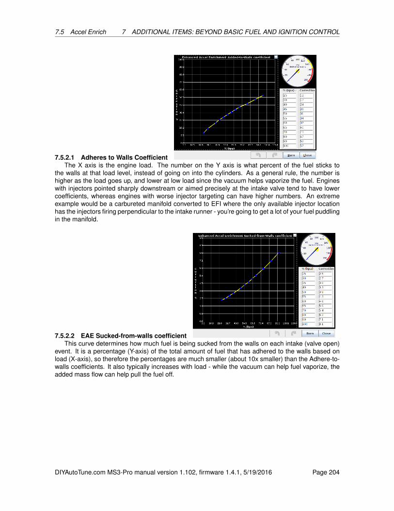
7.5 Accel Enrich 7 ADDITIONAL ITEMS: BEYOND BASIC FUEL AND IGNITION CONTROL
7.5.2.1 Adheres to Walls CoefficientThe X axis is the engine load. The number on the Y axis is what percent of the fuel sticks to
the walls at that load level, instead of going on into the cylinders. As a general rule, the number ishigher as the load goes up, and lower at low load since the vacuum helps vaporize the fuel. Engineswith injectors pointed sharply downstream or aimed precisely at the intake valve tend to have lowercoefficients, whereas engines with worse injector targeting can have higher numbers. An extremeexample would be a carbureted manifold converted to EFI where the only available injector locationhas the injectors firing perpendicular to the intake runner - you’re going to get a lot of your fuel puddlingin the manifold.
7.5.2.2 EAE Sucked-from-walls coefficientThis curve determines how much fuel is being sucked from the walls on each intake (valve open)
event. It is a percentage (Y-axis) of the total amount of fuel that has adhered to the walls based onload (X-axis), so therefore the percentages are much smaller (about 10x smaller) than the Adhere-to-walls coefficients. It also typically increases with load - while the vacuum can help fuel vaporize, theadded mass flow can help pull the fuel off.
DIYAutoTune.com MS3-Pro manual version 1.102, firmware 1.4.1, 5/19/2016 Page 204

7.5 Accel Enrich 7 ADDITIONAL ITEMS: BEYOND BASIC FUEL AND IGNITION CONTROL
7.5.2.3 EAE Adhere-to-walls RPM correctionThis curve modifies the EAE Adhere-to-walls curve. It allows the amount of correction specified
by the EAE Adhere-to-walls curve to be increased or decreased based on RPM. As you may expect,the higher flow rates at higher RPM tend to carry more of the fuel into the cylinders and result in lesson the walls.
7.5.2.4 EAE Sucked-from-walls RPM correctionThis curve modifies the EAE Sucked-from-walls curve. It allows the amount of correction specified
by the EAE Sucked-from-walls curve to be increased or decreased based on RPM. The increasedflow rate at higher RPM tends to pull more fuel off the walls as well as preventing as much of it fromsticking in the first place.
7.5.2.5 EAE Adhere-to-walls CLT correction
DIYAutoTune.com MS3-Pro manual version 1.102, firmware 1.4.1, 5/19/2016 Page 205
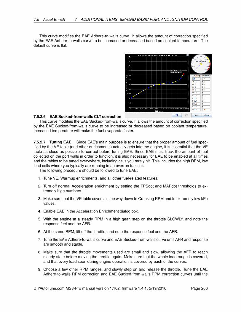
7.5 Accel Enrich 7 ADDITIONAL ITEMS: BEYOND BASIC FUEL AND IGNITION CONTROL
This curve modifies the EAE Adhere-to-walls curve. It allows the amount of correction specifiedby the EAE Adhere-to-walls curve to be increased or decreased based on coolant temperature. Thedefault curve is flat.
7.5.2.6 EAE Sucked-from-walls CLT correctionThis curve modifies the EAE Sucked-from-walls curve. It allows the amount of correction specified
by the EAE Sucked-from-walls curve to be increased or decreased based on coolant temperature.Increased temperature will make the fuel evaporate faster.
7.5.2.7 Tuning EAE Since EAE’s main purpose is to ensure that the proper amount of fuel spec-ified by the VE table (and other enrichments) actually gets into the engine, it is essential that the VEtable as close as possible to correct before tuning EAE. Since EAE must track the amount of fuelcollected on the port walls in order to function, it is also necessary for EAE to be enabled at all timesand the tables to be tuned everywhere, including cells you rarely hit. This includes the high RPM, lowload cells where you typically are running in an overrun fuel cut.
The following procedure should be followed to tune EAE:
1. Tune VE, Warmup enrichments, and all other fuel-related features.
2. Turn off normal Acceleration enrichment by setting the TPSdot and MAPdot thresholds to ex-tremely high numbers.
3. Make sure that the VE table covers all the way down to Cranking RPM and to extremely low kPavalues.
4. Enable EAE in the Acceleration Enrichment dialog box.
5. With the engine at a steady RPM in a high gear, step on the throttle SLOWLY, and note theresponse feel and the AFR.
6. At the same RPM, lift off the throttle, and note the response feel and the AFR.
7. Tune the EAE Adhere-to-walls curve and EAE Sucked-from-walls curve until AFR and responseare smooth and stable.
8. Make sure that the throttle movements used are small and slow, allowing the AFR to reachsteady-state before moving the throttle again. Make sure that the whole load range is covered,and that every load seen during engine operation is covered by each of the curves.
9. Choose a few other RPM ranges, and slowly step on and release the throttle. Tune the EAEAdhere-to-walls RPM correction and EAE Sucked-from-walls RPM correction curves until the
DIYAutoTune.com MS3-Pro manual version 1.102, firmware 1.4.1, 5/19/2016 Page 206
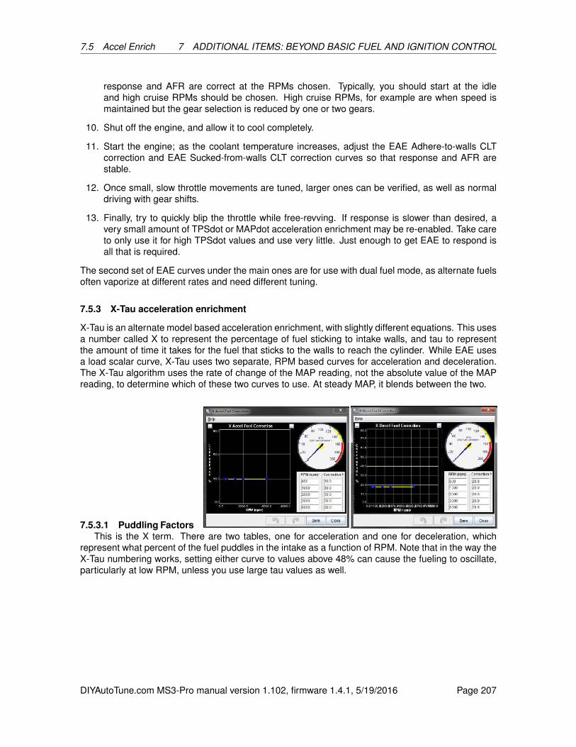
7.5 Accel Enrich 7 ADDITIONAL ITEMS: BEYOND BASIC FUEL AND IGNITION CONTROL
response and AFR are correct at the RPMs chosen. Typically, you should start at the idleand high cruise RPMs should be chosen. High cruise RPMs, for example are when speed ismaintained but the gear selection is reduced by one or two gears.
10. Shut off the engine, and allow it to cool completely.
11. Start the engine; as the coolant temperature increases, adjust the EAE Adhere-to-walls CLTcorrection and EAE Sucked-from-walls CLT correction curves so that response and AFR arestable.
12. Once small, slow throttle movements are tuned, larger ones can be verified, as well as normaldriving with gear shifts.
13. Finally, try to quickly blip the throttle while free-revving. If response is slower than desired, avery small amount of TPSdot or MAPdot acceleration enrichment may be re-enabled. Take careto only use it for high TPSdot values and use very little. Just enough to get EAE to respond isall that is required.
The second set of EAE curves under the main ones are for use with dual fuel mode, as alternate fuelsoften vaporize at different rates and need different tuning.
7.5.3 X-Tau acceleration enrichment
X-Tau is an alternate model based acceleration enrichment, with slightly different equations. This usesa number called X to represent the percentage of fuel sticking to intake walls, and tau to representthe amount of time it takes for the fuel that sticks to the walls to reach the cylinder. While EAE usesa load scalar curve, X-Tau uses two separate, RPM based curves for acceleration and deceleration.The X-Tau algorithm uses the rate of change of the MAP reading, not the absolute value of the MAPreading, to determine which of these two curves to use. At steady MAP, it blends between the two.
7.5.3.1 Puddling FactorsThis is the X term. There are two tables, one for acceleration and one for deceleration, which
represent what percent of the fuel puddles in the intake as a function of RPM. Note that in the way theX-Tau numbering works, setting either curve to values above 48% can cause the fueling to oscillate,particularly at low RPM, unless you use large tau values as well.
DIYAutoTune.com MS3-Pro manual version 1.102, firmware 1.4.1, 5/19/2016 Page 207
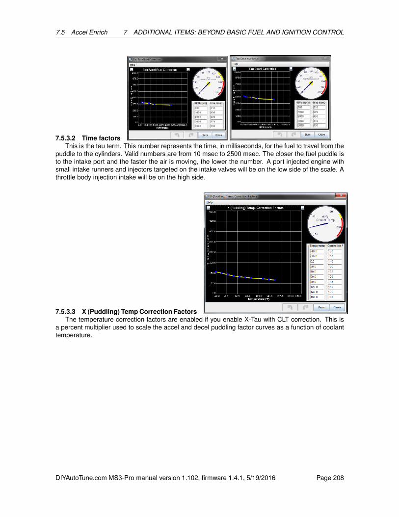
7.5 Accel Enrich 7 ADDITIONAL ITEMS: BEYOND BASIC FUEL AND IGNITION CONTROL
7.5.3.2 Time factorsThis is the tau term. This number represents the time, in milliseconds, for the fuel to travel from the
puddle to the cylinders. Valid numbers are from 10 msec to 2500 msec. The closer the fuel puddle isto the intake port and the faster the air is moving, the lower the number. A port injected engine withsmall intake runners and injectors targeted on the intake valves will be on the low side of the scale. Athrottle body injection intake will be on the high side.
7.5.3.3 X (Puddling) Temp Correction FactorsThe temperature correction factors are enabled if you enable X-Tau with CLT correction. This is
a percent multiplier used to scale the accel and decel puddling factor curves as a function of coolanttemperature.
DIYAutoTune.com MS3-Pro manual version 1.102, firmware 1.4.1, 5/19/2016 Page 208
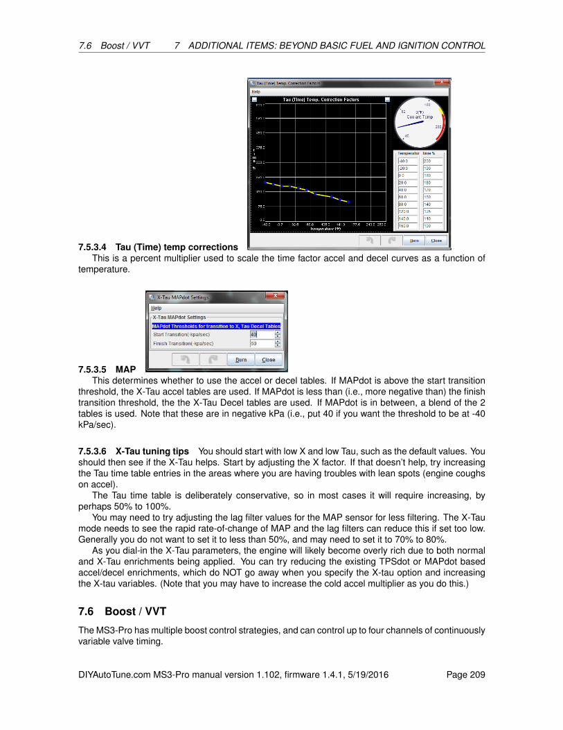
7.6 Boost / VVT 7 ADDITIONAL ITEMS: BEYOND BASIC FUEL AND IGNITION CONTROL
7.5.3.4 Tau (Time) temp correctionsThis is a percent multiplier used to scale the time factor accel and decel curves as a function of
temperature.
7.5.3.5 MAPThis determines whether to use the accel or decel tables. If MAPdot is above the start transition
threshold, the X-Tau accel tables are used. If MAPdot is less than (i.e., more negative than) the finishtransition threshold, the the X-Tau Decel tables are used. If MAPdot is in between, a blend of the 2tables is used. Note that these are in negative kPa (i.e., put 40 if you want the threshold to be at -40kPa/sec).
7.5.3.6 X-Tau tuning tips You should start with low X and low Tau, such as the default values. Youshould then see if the X-Tau helps. Start by adjusting the X factor. If that doesn’t help, try increasingthe Tau time table entries in the areas where you are having troubles with lean spots (engine coughson accel).
The Tau time table is deliberately conservative, so in most cases it will require increasing, byperhaps 50% to 100%.
You may need to try adjusting the lag filter values for the MAP sensor for less filtering. The X-Taumode needs to see the rapid rate-of-change of MAP and the lag filters can reduce this if set too low.Generally you do not want to set it to less than 50%, and may need to set it to 70% to 80%.
As you dial-in the X-Tau parameters, the engine will likely become overly rich due to both normaland X-Tau enrichments being applied. You can try reducing the existing TPSdot or MAPdot basedaccel/decel enrichments, which do NOT go away when you specify the X-tau option and increasingthe X-tau variables. (Note that you may have to increase the cold accel multiplier as you do this.)
7.6 Boost / VVT
The MS3-Pro has multiple boost control strategies, and can control up to four channels of continuouslyvariable valve timing.
DIYAutoTune.com MS3-Pro manual version 1.102, firmware 1.4.1, 5/19/2016 Page 209

7.6 Boost / VVT 7 ADDITIONAL ITEMS: BEYOND BASIC FUEL AND IGNITION CONTROL
7.6.1 Boost control settings
You can wire a boost control solenoid to any unused high current or injector output, as shown below.Boost solenoids normally do not have a polarity; the two wires can be hooked up in either order.
The MS3 Firmware has two algorithms for controlling boost:
• Open-Loop - Solenoid duty comes from an 8x8 duty table of TPS vs RPM.
• Closed-loop - A Proportional-Integral-Derivative (PID) loop controls solenoid duty to match theactual boost to the boost target. Closed loop control starts by using a bias table to look up whatduty cycle to start with for a particular RPM and target boost, and then uses the PID loop toapply a correction factor to hit your target boost. An 8x8 target table of TPS vs RPM or a 6-pointboost vs vehicle speed curve is used to figure out the boost target.
In addition to the algorithm selection, there are several other settings that you will need to set up inorder to use the boost control feature.
7.6.1.1 Boost control common settings This section covers settings that are used by both theopen-loop and closed-loop control algorithms.
• Boost Control Enabled - This controls whether the boost control feature is enabled or disabled.
• Solenoid Frequency Range - This setting controls the frequency range of the valve. Mid rangeallows 12 to 1021 Hz, while Slow allows 11.1 to 78 Hz but allows you to use a wider variety ofpins (such as more unused injector outputs) for boost control.
DIYAutoTune.com MS3-Pro manual version 1.102, firmware 1.4.1, 5/19/2016 Page 210

7.6 Boost / VVT 7 ADDITIONAL ITEMS: BEYOND BASIC FUEL AND IGNITION CONTROL
• Solenoid Frequency - Note that there are two drop down menus depending on whether youare using Mid or Slow mode. This sets how many times to pulse the boost control solenoid offor on. Many boost control solenoids work well from 19.5 to 78 Hz, depending on the valve - wetypically recommend 19.5 to 39 Hz for the boost control solenoid we sell.
• Boost Control Pin - This sets which output pin is used to control the boost control solenoid.
• Output Polarity - This is used to set the polarity of the output. Normal is used when you have aconventionally set up boost control solenoid designed to go to minimum boost if it loses poweras a fail-safe; with this setting, higher duty cycle means higher levels of boost. Inverted meansthat increasing the duty cycle decreases the boost.
• Control Interval - This setting is used to control how often the boost control algorithm runs.
• Closed Duty - This setting controls the lowest allowed reported duty. Normally, this should be0%.
• Open Duty - This setting controls the highest allowed reported duty. Normally, this should be100%.
• Boost Control Lower CLT Threshold - To prevent running maximum boost before the engineis warmed up, the MS3-Pro will run minimum boost until you reach this temperature, at whichpoint the boost control turns on.
• Algorithm - Specifies if you are using open loop or closed loop control.
7.6.1.2 Closed loop specific settings Enabling the closed-loop boost control algorithm enablesthe following additional settings:
• Boost control use initial value table - If this is set to On, the boost control will start with aninitial duty cycle table whenever it moves into a new load cell as a feed-forward mechanism. Ifit is set to off, the boost control will adjust from the previous duty cycle it was running at, andoperate purely from the feedback loop.
• Boost Control Lower Limit Delta - This regulates how close the boost must be to your targetto engage closed loop control. When the boost is more than this amount below your target, thecontroller holds the valve wide open to maximize spool up speed.
• Tuning Mode:
– Setup Mode - PID correction is turned off to allow adjusting the bias tables. Set the biastables so you reach your boost target levels.
– Basic Mode - The PID parameters are all set to 100%, and you only tune with the slider.
– Advanced Mode - All PID parameters are adjustable.
• Closed Loop Sensitivity - Use this setting to tune how agressively the boost controller triesto reach the target boost. Adjust the slider up until the boost oscillates around the target, thenback down until it stops.
• Proportional Gain - Proportional gain affects the strength with which changes in input immedi-ately affect changes in output.
• Integral Gain - The Integral Gain setting affects the response to continued difference betweenthe target boost and the actual boost.
DIYAutoTune.com MS3-Pro manual version 1.102, firmware 1.4.1, 5/19/2016 Page 211

7.6 Boost / VVT 7 ADDITIONAL ITEMS: BEYOND BASIC FUEL AND IGNITION CONTROL
• Derivative Gain - The Derivative Gain setting helps to slow down the response of the Propor-tional and Integral gain settings as the target is reached. This should be used sparingly as itcan also completely dampen the other two Gains.
The first step for tuning Closed-loop boost control is to set the desired targets in the Boost ControlTarget table (section 7.6.3). Typically, lower throttle positions will have lower boost targets. This letsyou modulate the boost with the throttle.
Once you have set the targets, set the tuning mode to Setup Mode. Then adjust the boost controlduty bias table so that you hit your boost targets with the duty cycles used in this table.
Typically, the defaults for the following settings can be used:
• Closed Duty - A closed duty of 0% is the default. This should be tuned to the value that startsto open the wastegate, but typically 0% works well.
• Open Duty - An open duty value of 100% is the default. This should be tuned to the value thatfully opens the wastegate, but typically 100% works well.
• Boost Control Lower Limit - This setting is used to set the pressure at which PID boost control isengaged. The default for this setting is 100. If a faster rise to target is desired, this setting canbe set to a higher number, but the safest number is 100 since it gives the PID code the mosttime to react to climbing boost.
The next step after setting up the target table and supporting settings is to adjust the slider for bestperformance. If the slider on its own does not give the results you hope for, you can go to advancedmode and tune the PID gains:
1. Set Integral and Differential Gains to 0% - This will let you focus on tuning the proportional gain.
2. Set Proportional gain to 100% and slowly lower - While tuning Proportional gain, higher numbersmean slower boost climb and lower final boost. For safety, start with a very high gain (100%should be sufficient). Find the RPM that typically spools quickly, and fully and quickly depressthe accelerator. Note how much boost is reached. If boost overshoots the target dramatically,increase the Proportional gain. Otherwise, reduce the Proportional gain and try again. Do thisuntil boost reaches the target with a small amount of overshoot.
3. Tune the Integral Gain - The next step after the target is reached consistently is to tune theIntegral gain. Starting from the RPM used to tune the Proportional gain, fully depress theaccelerator and watch the boost as the engine climbs through the RPM range. As the engineaccelerates through the rev range, the boost will probably creep away from the target. Keepincreasing the Integral gain until the controller adequately maintains the target with minimaloscillation. It may be necessary to increase the Proportional gain a bit after tuning the Integralgain since the two gains tend to counteract each other.
4. Tune the Derivative Gain - Increase the Derivative gain until the overshoot is minimized. Caremust be taken when increasing the Derivative gain as too much Derivative gain can over-dampen the effects of the Proportional and Integral gains.
7.6.1.3 Overboost Protection Overboost protection works similarly to a rev limiter, except that itcan stop engine operation when boost exceeds a user-set limit. In addition, use of the overboost pro-tection feature is required when using the closed-loop boost control algorithm. The following settingsaffect the operation of overboost protection:
• Overboost Protection - Activates overboost protection and lets you specify what action to takewhen boost exceeds the maximum boost number.
– None - Disables overboost protection.
DIYAutoTune.com MS3-Pro manual version 1.102, firmware 1.4.1, 5/19/2016 Page 212
7.6 Boost / VVT 7 ADDITIONAL ITEMS: BEYOND BASIC FUEL AND IGNITION CONTROL
– Fuel Cut - Stops the engine by cutting fuel.
– Spark Cut - Stops the engine by cutting spark.
– Both - Stops the engine using both fuel and spark cut.
• Maximum Boost - The maximum boost (in kPa) at which the engine should be operated.
• Hysteresis - The amount boost must drop by (in kPa) after hitting the maximum boost beforefuel or spark are restored.
• Overboost switching - Allows you to use an input to raise or lower the point at which overboostprotection engages. For example, you might want one setting for pump gas and another for racegas, and can use a switch to let the MS3-Pro know which you are running.
• Alt Maximum Boost - The boost level to allow when the overboost switch is active.
Setting this ups very similar to setting up a rev-limiter. Choose from Fuel Cut or Spark cut or Both.Do not use spark cut mode if the engine still has a catalytic converter. Spark cut can cause backfiresthat melt or break the catalyst.
The maximum boost should be set up higher than the maximum target boost will be in the closed-loop boost target table. Hysteresis should be set so that MAP jitter does not cause it to alternaterapidly between on and off. Remember, overboost protection is not telling the MS3-Pro “I wouldprefer my boost level stays below this setting;” it is more like, “Shut down my engine at once if theboost gets this high!” And the MS3-Pro will react with that same level of urgency.
7.6.1.4 Other Boost Control Settings The following settings remain:
• Boost Table Switching - This option when enabled allows a switch input to be configured whichswitches between two different boost duty or target tables. You can also allow it to switch tablesbased on gear by selecting “Gear-based”.
• Boost Table Switching Gear - If boost table swithcing is set to gear based, the MS3-Pro willswitch to the second boost table when you shift into this gear and above.
• Boost Timed From Launch - If launch control is enabled, this setting allows a specific boostduty or target to be used for a set amount of time after launch.
• Specific Launch Duty/Target - If launch control is enabled, this setting controls what target(closed-loop) or duty (open-loop) is used for boost control.
• Launch Boost Duty - This is the duty used by Specific Launch Duty/Target, if using open loopboost control.
• Launch boost target - This is the boost target used by Specific Launch Duty/Target, if usingclosed loop boost control.
• Boost by speed / gear - this item enables the use of the boost vs speed curve. You may set itto use one of two speed sensors if enabled.
• Above TPS % - This setting is used in conjunction with the Boost vs Speed function. Belowthis TPS setting, the normal boost tables are used. Above this TPS setting, the boost vs speedcurve is used.
• Per Gear Targets - Specifies the boost target in each gear if boost by gear is active.
DIYAutoTune.com MS3-Pro manual version 1.102, firmware 1.4.1, 5/19/2016 Page 213
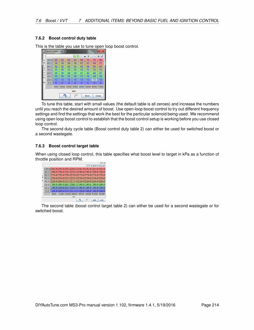
7.6 Boost / VVT 7 ADDITIONAL ITEMS: BEYOND BASIC FUEL AND IGNITION CONTROL
7.6.2 Boost control duty table
This is the table you use to tune open loop boost control.
To tune this table, start with small values (the default table is all zeroes) and increase the numbersuntil you reach the desired amount of boost. Use open-loop boost control to try out different frequencysettings and find the settings that work the best for the particular solenoid being used. We recommendusing open loop boost control to establish that the boost control setup is working before you use closedloop control.
The second duty cycle table (Boost control duty table 2) can either be used for switched boost ora second wastegate.
7.6.3 Boost control target table
When using closed loop control, this table specifies what boost level to target in kPa as a function ofthrottle position and RPM.
The second table (boost control target table 2) can either be used for a second wastegate or forswitched boost.
DIYAutoTune.com MS3-Pro manual version 1.102, firmware 1.4.1, 5/19/2016 Page 214

7.6 Boost / VVT 7 ADDITIONAL ITEMS: BEYOND BASIC FUEL AND IGNITION CONTROL
7.6.4 Boost control bias duty table
This is a feed-forward table. The MS3-Pro first looks to the closed loop target table to see whatboost target to use, then goes to this table to look up what duty cycle to start with at what RPM andtarget boost level. The X axis is the engine RPM, while the Y axis is the target boost level. As withthe other tables, the second table (boost control initial duty table 2) can either be used for a secondwastegate or for switched boost.
7.6.5 Boost delay
This screen is active if you enable “Boost timed from launch” and launch control.
This specifies how long to go from no boost (if the initial value is not used) or the specified initialvalue (if used) to full boost after you release the launch control switch. This is a percentage of theregular boost, so it should end at 100% boost.
DIYAutoTune.com MS3-Pro manual version 1.102, firmware 1.4.1, 5/19/2016 Page 215
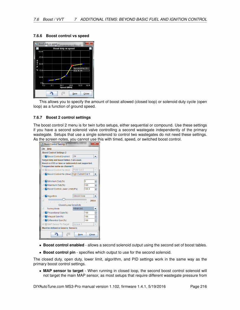
7.6 Boost / VVT 7 ADDITIONAL ITEMS: BEYOND BASIC FUEL AND IGNITION CONTROL
7.6.6 Boost control vs speed
This allows you to specify the amount of boost allowed (closed loop) or solenoid duty cycle (openloop) as a function of ground speed.
7.6.7 Boost 2 control settings
The boost control 2 menu is for twin turbo setups, either sequential or compound. Use these settingsif you have a second solenoid valve controlling a second wastegate independently of the primarywastegate. Setups that use a single solenoid to control two wastegates do not need these settings.As the screen notes, you cannot use this with timed, speed, or switched boost control.
• Boost control enabled - allows a second solenoid output using the second set of boost tables.
• Boost control pin - specifies which output to use for the second solenoid.
The closed duty, open duty, lower limit, algorithm, and PID settings work in the same way as theprimary boost control settings.
• MAP sensor to target - When running in closed loop, the second boost control solenoid willnot target the main MAP sensor, as most setups that require different wastegate pressure from
DIYAutoTune.com MS3-Pro manual version 1.102, firmware 1.4.1, 5/19/2016 Page 216
7.6 Boost / VVT 7 ADDITIONAL ITEMS: BEYOND BASIC FUEL AND IGNITION CONTROL
side to side also require different compressor outlet pressures. You will need to define what thesecond MAP sensor is on the Generic Sensor Inputs screen in the Advanced Engine menu.
7.6.8 Turbo anti-lag (ALS)
Anti-lag is a combination of features you can use to keep the turbo spooled while shifting, beyondthe basic flat shift rev limiter. The MS3-Pro has several strategies it can use to dump extra fuel intothe exhaust and increase exhaust gas temperatures under these conditions. This increase in exhausttemperature will shorten turbo life and possibly result in increased wear and tear on other parts of theexhaust system as well.
All anti-lag variations require an input switch to arm the system. When active, the anti-lag systemwill add fuel and retard timing to a number specified by the ALS tables. You can also allow theMS3-Pro to use the following additional strategies when the anti-lag is active:
• Use a cyclic fuel cut
• Use a cyclic spark cut to dump unburned fuel into the exhaust
• Activate a solenoid or additional injector output to send fuel or air into the exhaust manifolddirectly
• Open the idle valve a set amount
• Open a solenoid to let additional air into the intake manifold
Note - use extreme caution if using any system that dumps fuel directly into the exhaust! Thistype of anti-lag can turn “danger to manifold” from an ironic “The Fast and the Furious” reference intoa very real hazard.
As many anti-lag systems also have the throttle or idle control valve open by a large amount, theMS3-Pro can also use a rotational idle fuel cut to reduce idle speed on engines using anti-lag. Therotational idle engages when anti-lag is off.
Anti-lag is only used when you release the throttle to shift; see the Launch Control section for howto set up the MS3-Pro for no lift shifting.
Since anti-lag creates so much heat, the MS3-Pro has several settings to limit the anti-lag system’suse to limit heat buildup.
DIYAutoTune.com MS3-Pro manual version 1.102, firmware 1.4.1, 5/19/2016 Page 217
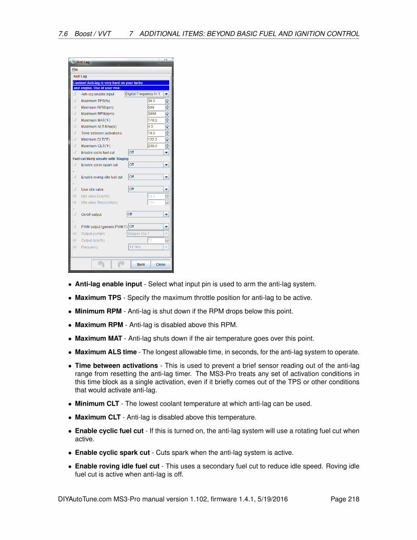
7.6 Boost / VVT 7 ADDITIONAL ITEMS: BEYOND BASIC FUEL AND IGNITION CONTROL
• Anti-lag enable input - Select what input pin is used to arm the anti-lag system.
• Maximum TPS - Specify the maximum throttle position for anti-lag to be active.
• Minimum RPM - Anti-lag is shut down if the RPM drops below this point.
• Maximum RPM - Anti-lag is disabled above this RPM.
• Maximum MAT - Anti-lag shuts down if the air temperature goes over this point.
• Maximum ALS time - The longest allowable time, in seconds, for the anti-lag system to operate.
• Time between activations - This is used to prevent a brief sensor reading out of the anti-lagrange from resetting the anti-lag timer. The MS3-Pro treats any set of activation conditions inthis time block as a single activation, even if it briefly comes out of the TPS or other conditionsthat would activate anti-lag.
• Minimum CLT - The lowest coolant temperature at which anti-lag can be used.
• Maximum CLT - Anti-lag is disabled above this temperature.
• Enable cyclic fuel cut - If this is turned on, the anti-lag system will use a rotating fuel cut whenactive.
• Enable cyclic spark cut - Cuts spark when the anti-lag system is active.
• Enable roving idle fuel cut - This uses a secondary fuel cut to reduce idle speed. Roving idlefuel cut is active when anti-lag is off.
DIYAutoTune.com MS3-Pro manual version 1.102, firmware 1.4.1, 5/19/2016 Page 218
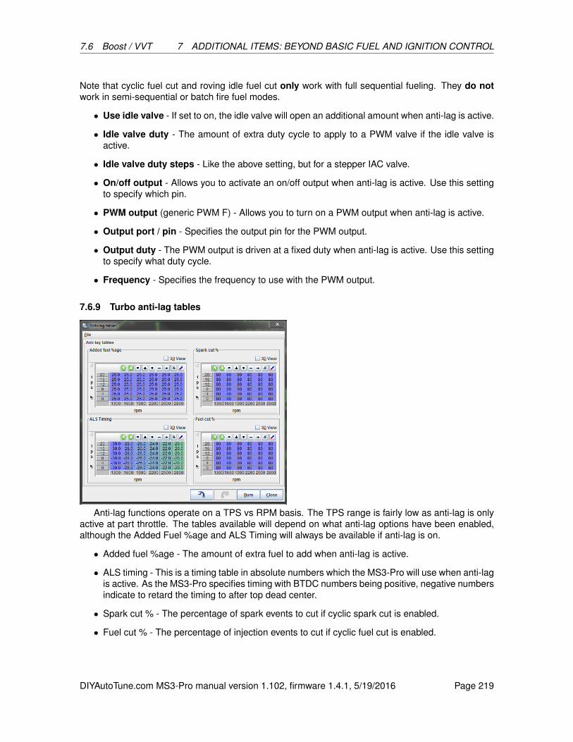
7.6 Boost / VVT 7 ADDITIONAL ITEMS: BEYOND BASIC FUEL AND IGNITION CONTROL
Note that cyclic fuel cut and roving idle fuel cut only work with full sequential fueling. They do notwork in semi-sequential or batch fire fuel modes.
• Use idle valve - If set to on, the idle valve will open an additional amount when anti-lag is active.
• Idle valve duty - The amount of extra duty cycle to apply to a PWM valve if the idle valve isactive.
• Idle valve duty steps - Like the above setting, but for a stepper IAC valve.
• On/off output - Allows you to activate an on/off output when anti-lag is active. Use this settingto specify which pin.
• PWM output (generic PWM F) - Allows you to turn on a PWM output when anti-lag is active.
• Output port / pin - Specifies the output pin for the PWM output.
• Output duty - The PWM output is driven at a fixed duty when anti-lag is active. Use this settingto specify what duty cycle.
• Frequency - Specifies the frequency to use with the PWM output.
7.6.9 Turbo anti-lag tables
Anti-lag functions operate on a TPS vs RPM basis. The TPS range is fairly low as anti-lag is onlyactive at part throttle. The tables available will depend on what anti-lag options have been enabled,although the Added Fuel %age and ALS Timing will always be available if anti-lag is on.
• Added fuel %age - The amount of extra fuel to add when anti-lag is active.
• ALS timing - This is a timing table in absolute numbers which the MS3-Pro will use when anti-lagis active. As the MS3-Pro specifies timing with BTDC numbers being positive, negative numbersindicate to retard the timing to after top dead center.
• Spark cut % - The percentage of spark events to cut if cyclic spark cut is enabled.
• Fuel cut % - The percentage of injection events to cut if cyclic fuel cut is enabled.
DIYAutoTune.com MS3-Pro manual version 1.102, firmware 1.4.1, 5/19/2016 Page 219
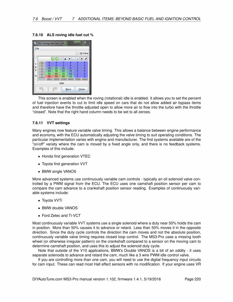
7.6 Boost / VVT 7 ADDITIONAL ITEMS: BEYOND BASIC FUEL AND IGNITION CONTROL
7.6.10 ALS roving idle fuel cut %
This screen is enabled when the roving (rotational) idle is enabled. It allows you to set the percentof fuel injection events to cut to limit idle speed on cars that do not allow added air bypass itemsand therefore have the throttle adjusted open to allow more air to flow into the turbo with the throttle“closed”. Note that the right hand column needs to be set to all zeroes.
7.6.11 VVT settings
Many engines now feature variable valve timing. This allows a balance between engine performanceand economy, with the ECU automatically adjusting the valve timing to suit operating conditions. Theparticular implementation varies with engine and manufacturer. The first systems available are of the"on/off" variety where the cam is moved by a fixed angle only, and there is no feedback systems.Examples of this include:
• Honda first generation VTEC
• Toyota first generation VVT
• BMW single VANOS
More advanced systems use continuously variable cam controls - typically an oil solenoid valve con-trolled by a PWM signal from the ECU. The ECU uses one camshaft position sensor per cam tocompare the cam advance to a crankshaft position sensor reading. Examples of continuously vari-able systems include:
• Toyota VVTi
• BMW double VANOS
• Ford Zetec and Ti-VCT
Most continuously variable VVT systems use a single solenoid where a duty near 50% holds the camin position. More than 50% causes it to advance or retard. Less than 50% moves it in the oppositedirection. Since the duty cycle controls the direction the cam moves and not the absolute position,continuously variable valve timing requires closed loop control. The MS3-Pro uses a missing toothwheel (or otherwise irregular pattern) on the crankshaft compared to a sensor on the moving cam todetermine camshaft position, and uses this to adjust the solenoid duty cycle.
Note that outside of the V10 applications, BMW’s Double VANOS is a bit of an oddity - it usesseparate solenoids to advance and retard the cam, much like a 3 wire PWM idle control valve.
If you are controlling more than one cam, you will need to use the digital frequency input circuitsfor cam input. These can read most Hall effect sensors with no modification. If your engine uses VR
DIYAutoTune.com MS3-Pro manual version 1.102, firmware 1.4.1, 5/19/2016 Page 220

7.6 Boost / VVT 7 ADDITIONAL ITEMS: BEYOND BASIC FUEL AND IGNITION CONTROL
type camshaft position sensors, you will need external VR conditioner circuits to read the additionalsensors.
If you find you have run out of PWM outputs, you can use the high current outputs to control a VVToil control valve. However, these outputs will cause a valve to close faster, making it harder to “park”the valve in an intermediate position. You can enable the same slow closing as on PWM outputsby connecting a 1N4001 diode across the VVT valve, with the banded end connected to the 12 voltsupply.
• No. VVTs - the number of VVT actuators to be controlled
• Cam Decoder - Standard mode works with either cam teeth that are all equally spaced, or ahard coded spark mode. Nonstandard cam decoders work with engines that use Toothed Wheelmode with an unusual cam wheel. Currently supported modes include BMW V10s, the BMWS54’s double VANOS setup, Chrysler VVT Hemi engines, Ford Coyote V8, and Ford Duratec 4cylinder. BMW and Chrysler modes use a 60-2 crank trigger, while Ford modes use a 36-1.
• Frequency - the PWM output frequency. Adjust to suit your solenoids.
• On/Off or PID - the mode of operation. Full variable systems should use PID.
• Adjust inj. timing based on - whether the Injector Timing for sequential injection should beadjusted as the cams are moved.
• Commanded vs Actual - If the injection timing adjustment is on, this specifies whether thecommanded or actual timing is used to make the adjustment.
• Inj. Timing Adjustment - for on/off mode, this specifies the Injector Timing adjustment whenVVT is on.
• Test output - during initial setup the test mode is used to confirm solenoid operation and learnthe cam range of movement. The output specifies which cam should be altered.
• Test duty - the PWM duty cycle to be applied to the chosen VVT output under test.
• Control Interval - Synced to Cam adjusts the duty cycle each time the MS3-Pro updates itsdata on the cam position, which usually gives the best response. Timed mode adjusts the dutycycle once per specified timed interval.
DIYAutoTune.com MS3-Pro manual version 1.102, firmware 1.4.1, 5/19/2016 Page 221
7.6 Boost / VVT 7 ADDITIONAL ITEMS: BEYOND BASIC FUEL AND IGNITION CONTROL
• Control Interval Time - the time interval in milliseconds for adjustments in timed mode.
• Range Check Measured Angles - Checks to see if the measured range is within the minimumto maximum settings. If the cam moves out of range, this triggers a cam fault.
• Tooth Filter - Applies the cam noise filtering settings to the VVT decoder.
• Minimum VVT Duty - The lowest duty cycle to use for the solenoid.
• Maximum VVT Duty - The highest duty cycle to use for the solenoid.
PID Parameters - these are used to adjust the closed loop feedback. There are separate settings forintake and exhaust.
• Use hold duty - Specifies whether to default to a set value when no cam change is commanded.
• Hold/neutral duty - the duty at which the cam stays still.
• Proportional gain - Proportional gain affects the strength with which changes in input immedi-ately affect changes in output.
• Integral gain - The Integral Gain setting affects the response to continued difference betweenthe target cam angle and the actual angle.
• Difference gain - The Derivative Gain setting helps to slow down the response of the Propor-tional and Integral gain settings as the target is reached. Usually smaller than the other twonumbers.
• Table is Advance / Retard - Controls whether the table reads the degrees advanced from theminimum advance, or degrees retarded from minimum retard. Intake cams always use advance,while exhaust cam tables may use a retard table instead.
Cam Settings - allow you to specify each cam’s output, function, and range of movement.
• Input - the position sensor input for this cam. (Cam 1 always uses the main cam sensor inputset in Ignition Settings.)
• Polarity - The capture polarity of the cam input. (Cam 1 typically follows the main settings.)
• No. teeth - How many capture teeth on the cam wheel.
– Note: If you are using a wheel that can be described as a set of equally spaced teeth withone or more teeth missing, set this to the number of base teeth used. If no pulse is seenduring the expected cam range where there should be a cam teeth, the MS3-Pro simply“throws out” the reading. For example, if you have a cam trigger with teeth at 0, 60, 120,and 240 degrees, sett the number of teeth to 6. The MS3-Pro will look for a tooth every 60degrees, and simply will not update the cam position at the 180 and 300 degree points.
• Output - where the PWM solenoid valve is connected.
• Minimum - the minimum absolute angle from the cam sensor. See setting up. This is the angleof the signal from the sensor - not necessarily the actual cam center angle.
• Maximum - the maximum absolute angle from the cam sensor.
• Int./Exh. - specifies if the cam is an intake or exhaust cam. This determines the PID parameters,direction and target table to be used.
DIYAutoTune.com MS3-Pro manual version 1.102, firmware 1.4.1, 5/19/2016 Page 222

7.6 Boost / VVT 7 ADDITIONAL ITEMS: BEYOND BASIC FUEL AND IGNITION CONTROL
• Tooth 1 - only used by BMW V10 at present. Look for the cam tooth edge after this crank toothno.
• Tooth 2 - same again, but for second crank revolution.
• More duty means - whether more PWM duty on the solenoid causes the cam to advance orretard.
Note that on dual solenoid applications, such as the BMW S54 mode, the Cam 1 solenoid is used toadvance the main cam and the Cam 3 solenoid is used to retard the same cam. Cam 2 advances thesecondary (usually exhaust) cam, while Cam 4 retards this cam.
The most basic setup is to make the wiring connections for inputs and outputs. Most engines willrun safely with VVT inactive; ensure this is the case on your engine. Having completed the wiring,set the basic configuration reflecting the wiring choices you made, the control type and the number ofteeth on the cam wheels. Leave the min/max cam angles as zero for now.
On your TunerStudio dashboard, enable the gauges VVT_angle (1,2,3,4 as required). Start theengine and observe the VVT angle gauges. Use the test mode for each VVT with 0 and 100% duty andobserve the swing of the cam angles. You will hear the engine tone change as the cam angle changes.It is important that the VVT angles you observe are stable and vary evenly. With continuously variablecam timing, the VVT angle will normally swing from fully retarded to fully advanced (and vice versa)quite quickly with any duty beyond the hold/neutral duty, so it will be unlikely that you will be ableto catch the cam at anything other than the limits of its travel. Double check that the cam min/maxangles are presently set to zero.
For each cam, record the minimum and maximum angles you observe while varying the test duty.Enter these into the min/max fields. Note that the maximum MUST be larger than the minimum. (Inthe instance where the angles cross 720 degrees, add 720 to the maximum angle. e.g. if minimumwas 700 and maximum was 40 degrees, enter 700 and 760.) At this stage you should also be able todetermine if more duty is retarding or advancing each cam.
Having configured the inputs and outputs, proceed with PID tuning. Take datalogs and observethe VVT actual angle compared to the target angle. We recommend tuning in much the same way asboost control. Start with the I and D terms zeroed out, dial in the P term first, followed by the I. If youhave problems with the cam overshooting its targets, gradually increase the D term until it damps outthe overshoots.
Once the cam control is working, you may dial in the VVT activation tables. These are usually bestto dial in on a dyno.
7.6.12 VVT intake and exhaust tables
The intake and exhaust VVT tables show the cam position as determined by the angle of the camsensor signal relative to the crankshaft position sensor. Usually, this one requires dyno tuning todetermine what settings perform best.
7.6.13 VVT on/off table
For on/off mode, no feedback of cam position is used and most settings on the VVT settings screenare unused and grayed out. The output value, frequency and injector timing adjustment are setthrough the main settings screen. In place of the angle target table, an on/off table is used. In thistable, set 100 for cells where VVT should be active and 0 for cell where it should be inactive. Do notuse other values.
DIYAutoTune.com MS3-Pro manual version 1.102, firmware 1.4.1, 5/19/2016 Page 223
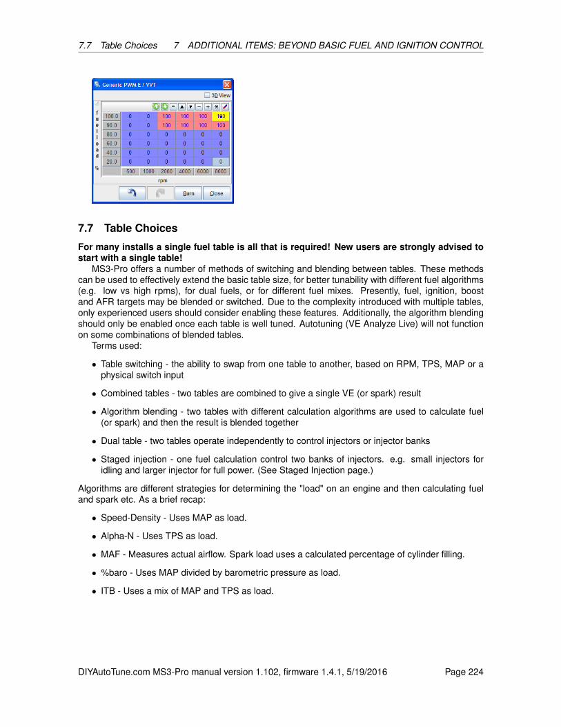
7.7 Table Choices 7 ADDITIONAL ITEMS: BEYOND BASIC FUEL AND IGNITION CONTROL
7.7 Table Choices
For many installs a single fuel table is all that is required! New users are strongly advised tostart with a single table!
MS3-Pro offers a number of methods of switching and blending between tables. These methodscan be used to effectively extend the basic table size, for better tunability with different fuel algorithms(e.g. low vs high rpms), for dual fuels, or for different fuel mixes. Presently, fuel, ignition, boostand AFR targets may be blended or switched. Due to the complexity introduced with multiple tables,only experienced users should consider enabling these features. Additionally, the algorithm blendingshould only be enabled once each table is well tuned. Autotuning (VE Analyze Live) will not functionon some combinations of blended tables.
Terms used:
• Table switching - the ability to swap from one table to another, based on RPM, TPS, MAP or aphysical switch input
• Combined tables - two tables are combined to give a single VE (or spark) result
• Algorithm blending - two tables with different calculation algorithms are used to calculate fuel(or spark) and then the result is blended together
• Dual table - two tables operate independently to control injectors or injector banks
• Staged injection - one fuel calculation control two banks of injectors. e.g. small injectors foridling and larger injector for full power. (See Staged Injection page.)
Algorithms are different strategies for determining the "load" on an engine and then calculating fueland spark etc. As a brief recap:
• Speed-Density - Uses MAP as load.
• Alpha-N - Uses TPS as load.
• MAF - Measures actual airflow. Spark load uses a calculated percentage of cylinder filling.
• %baro - Uses MAP divided by barometric pressure as load.
• ITB - Uses a mix of MAP and TPS as load.
DIYAutoTune.com MS3-Pro manual version 1.102, firmware 1.4.1, 5/19/2016 Page 224
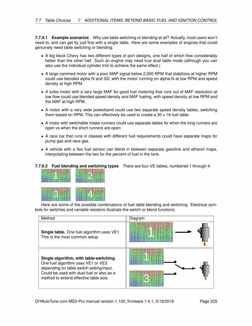
7.7 Table Choices 7 ADDITIONAL ITEMS: BEYOND BASIC FUEL AND IGNITION CONTROL
7.7.0.1 Example scenarios Why use table switching or blending at all? Actually, most users won’tneed to, and can get by just fine with a single table. Here are some examples of engines that couldgenuinely need table switching or blending.
• A big block Chevy has two different types of port designs, one half of which flow considerablybetter than the other half. Such an engine may need true dual table mode (although you canalso use the individual cylinder trim to achieve the same effect.)
• A large cammed motor with a poor MAP signal below 2,000 RPM that stabilizes at higher RPMcould use blended alpha N and SD, with the motor running on alpha-N at low RPM and speeddensity at high RPM.
• A turbo motor with a very large MAF for good fuel metering that runs out of MAF resolution atlow flow could use blended speed density and MAF fueling, with speed density at low RPM andthe MAF at high RPM.
• A motor with a very wide powerband could use two separate speed density tables, switchingthem based on RPM. This can effectively be used to create a 30 x 16 fuel table.
• A motor with switchable intake runners could use separate tables for when the long runners areopen vs when the short runners are open.
• A race car that runs in classes with different fuel requirements could have separate maps forpump gas and race gas.
• A vehicle with a flex fuel sensor can blend in between separate gasoline and ethanol maps,interpolating between the two for the percent of fuel in the tank.
7.7.0.2 Fuel blending and switching types There are four VE tables, numbered 1 through 4.
Here are some of the possible combinations of fuel table blending and switching. Electrical sym-bols for switches and variable resistors illustrate the switch or blend functions.
Method Diagram
Single table. One fuel algorithm uses VE1.This is the most common setup.
Single algorithm, with table-switching.One fuel algorithm uses VE1 or VE3depending on table switch setting/input.Could be used with dual-fuel or also as amethod to extend effective table size.
DIYAutoTune.com MS3-Pro manual version 1.102, firmware 1.4.1, 5/19/2016 Page 225

7.7 Table Choices 7 ADDITIONAL ITEMS: BEYOND BASIC FUEL AND IGNITION CONTROL
Single algorithm with table-blending. Onefuel algorithm uses a proportion of VE1 orVE3 depending on the blend input and curve(3).The tables could be blended based onethanol percentage in the fuel from a flex-fuelsensor.
Combined tables - secondary additivetable. Fuel is calculated by adding thelookup from VE1 and VE2.VE2 can be used a tweak to VE1 to add a4th dimension to the fuel table e.g. includinga throttle component in a speed-density tune.0% in the secondary table means no change,2% means add 2%Combined tables - secondarymultiplicitive table. Fuel is calculated bymultiplying the lookup from VE1 and VE2.VE2 can be used a tweak to VE1 to add a4th dimension to the fuel table e.g. includinga throttle component in a speed-density tune.100% in the secondary table means nochange, 102% means add 2% etc.Secondary algorithm blended table. Fuelis calculated from VE1 using the primary fuelalgorithm and also from VE2 using thesecondary fuel algorithm and then the resultis blended.This could be used to have a blend betweena Speed-Density in VE1 and MAF tune inVE2. The blend curve (1) allows you to alterwhere each algorithm is in use. Each tableshould be tuned individually i.e. set the curveto 0% and tune VE1, then set to 100% andtune VE2, afterwards enable blending.Two way blend.Fuel is calculated from VE1and VE3 using the primary fuel algorithm.These are blended. Then VE2 and VE4 arecalculated using the secondary fuelalgorithm and blended. The VE1/3 result isthen blended with the VE2/4 result.This could be considered for E85 (VE3/4) vsregular gasoline (VE1/2) where algorithmblending is also used between left and right,such as a blend of Speed Density and MAF.This is incompatible with ’Dual Table’ as thatuses VE3/4 for the second bank.Two way blending is complex ! Do not enableit without fully tuning each individual table.
DIYAutoTune.com MS3-Pro manual version 1.102, firmware 1.4.1, 5/19/2016 Page 226

7.7 Table Choices 7 ADDITIONAL ITEMS: BEYOND BASIC FUEL AND IGNITION CONTROL
Dual table. Fuel for injector bank 1 iscalculated from VE1 and fuel for injectorbank 2 is calculated from VE3.This could be used where an engine hasradically different fuel requirements betweenbanks (or cylinders in a V twin.) or as part ofa dual-fuel install where the second bank isused for LPG or methanol etc.Injector staging. Fuel is calculated fromVE1 and the staging parameters determinethe split between primary and secondaryinjectors.This is typically used on engines with a largedynamic range so that small injectors may beused at low loads for good tunability withadditional (staged) large injectors comingonline at full power. This concept is usedfrom the factory on Mazda rotary engines.More variations. There are many morecombinations possible to include doubleblending, switching between blended tablesetc.
These are partially set in the Basic / Load Settings and partially set in the Table Choices menu.
7.7.0.3 Fuel settings
Single algorithm, single tableBy far the most common install is to use a single Speed-Density fuel table. This really
should be your starting point before considering other load methods and certainly before multiple-table configurations are enabled.
Multiply MAP controls whether MAP is included in the calculation for VE1 (and VE3). For regularSpeed-Density this should almost always be enabled. For "Pure" Alpha-N, leave it disabled. For"Hybrid" Alpha-N, enable it. For MAF, it is ignored.
Single algorithm with table switching
DIYAutoTune.com MS3-Pro manual version 1.102, firmware 1.4.1, 5/19/2016 Page 227
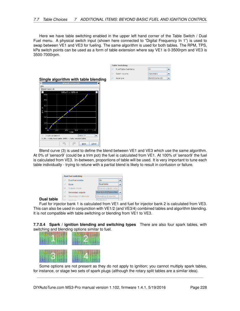
7.7 Table Choices 7 ADDITIONAL ITEMS: BEYOND BASIC FUEL AND IGNITION CONTROL
Here we have table switching enabled in the upper left hand corner of the Table Switch / DualFuel menu. A physical switch input (shown here connected to “Digital Frequency In 1”) is used toswap between VE1 and VE3 for fueling. The same algorithm is used for both tables. The RPM, TPS,kPa switch points can be used as a form of table extension where say VE1 is 0-3500rpm and VE3 is3500-7000rpm.
Single algorithm with table blending
Blend curve (3) is used to define the blend between VE1 and VE3 which use the same algorithm.At 0% of ’sensor9’ (could be a trim pot) the fuel is calculated from VE1. At 100% of ’sensor9’ the fuelis calculated from VE3. In-between, proportions of table will be used. It is very important to tune eachtable individually - trying to retune with a partial blend is likely to result in confusion or failure.
Dual tableFuel for injector bank 1 is calculated from VE1 and fuel for injector bank 2 is calculated from VE3.
This can also be used in conjunction with VE1/2 (and VE3/4) combined tables and algorithm blending.It is not compatible with table switching or blending from VE1 to VE3.
7.7.0.4 Spark / ignition blending and switching types There are also four spark tables, withswitching and blending options similar to fuel.
Some options are not present as they do not apply to ignition; you cannot multiply spark tables,for instance, or stage two sets of spark plugs (although the rotary split tables are a similar idea).
DIYAutoTune.com MS3-Pro manual version 1.102, firmware 1.4.1, 5/19/2016 Page 228

7.7 Table Choices 7 ADDITIONAL ITEMS: BEYOND BASIC FUEL AND IGNITION CONTROL
Method Diagram
Single table. One ignition algorithm usesSpk1.This is the most common setup.
Single algorithm with table-switching.One ignition algorithm uses Spk1 or Spk3depending on table switch setting/input.Could be used with dual-fuel or also as amethod to extend effective table size.
Single algorithm with table-blending. Oneignition algorithm uses a proportion of Spk1or Spk3 depending on the blend input andcurve (2).The tables could be blended based onethanol percentage in the fuel from a flex-fuelsensor.
Combined tables - secondary additivetable. Ignition is calculated by adding thelookup from Spk1 and Spk2.Spk2 can be used a tweak to Spk1 to add a4th dimension to the fuel table e.g. includinga throttle component in a speed-density tune.Secondary algorithm blended table.Ignition is calculated from Spk1 using theprimary ignition algorithm and also fromSpk2 using the secondary ignition algorithmand then the result is blended.This could be used to have a blend betweena Speed-Density in Spk1 and MAF tune inSpk3. The blend curve (2) allows you to alterwhere each algorithm is in use. Each tableshould be tuned individually i.e. set the curveto 0% and tune Spk1, then set to 100% andtune Spk2, afterwards enable blending.
DIYAutoTune.com MS3-Pro manual version 1.102, firmware 1.4.1, 5/19/2016 Page 229

7.7 Table Choices 7 ADDITIONAL ITEMS: BEYOND BASIC FUEL AND IGNITION CONTROL
Two way blend.Ignition is calculated fromSpk1 and Spk3 using the primary ignitionalgorithm. These are blended. Then Spk2and Spk4 are calculated using the secondaryignition algorithm and blended. The Spk1/3result is then blended with the Spk2/4 result.This could be considered for high-octane(Spk3/4) vs low octane (Spk1/2) wherealgorithm blending is also used between leftand right.
Single tableBy far the most common install is to use a single Speed-Density ignition table. This really
should be your starting point before considering other load methods and certainly before multiple-table configurations are enabled.
Single algorithm with table switchingIn the above screen shot, the MS3-Pro is set to switch the spark tables at 5000 RPM. You can also
set the switching to kPa or throttle position, or use a physical switch.
Single algorithm with table blending
DIYAutoTune.com MS3-Pro manual version 1.102, firmware 1.4.1, 5/19/2016 Page 230
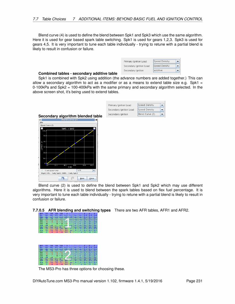
7.7 Table Choices 7 ADDITIONAL ITEMS: BEYOND BASIC FUEL AND IGNITION CONTROL
Blend curve (4) is used to define the blend between Spk1 and Spk3 which use the same algorithm.Here it is used for gear based spark table switching. Spk1 is used for gears 1,2,3. Spk3 is used forgears 4,5. It is very important to tune each table individually - trying to retune with a partial blend islikely to result in confusion or failure.
Combined tables - secondary additive tableSpk1 is combined with Spk2 using addition (the advance numbers are added together.) This can
allow a secondary algorithm to act as a modifier or as a means to extend table size e.g. Spk1 =0-100kPa and Spk2 = 100-400kPa with the same primary and secondary algorithm selected. In theabove screen shot, it’s being used to extend tables.
Secondary algorithm blended table
Blend curve (2) is used to define the blend between Spk1 and Spk2 which may use differentalgorithms. Here it is used to blend between the spark tables based on flex fuel percentage. It isvery important to tune each table individually - trying to retune with a partial blend is likely to result inconfusion or failure.
7.7.0.5 AFR blending and switching types There are two AFR tables, AFR1 and AFR2.
The MS3-Pro has three options for choosing these.
DIYAutoTune.com MS3-Pro manual version 1.102, firmware 1.4.1, 5/19/2016 Page 231
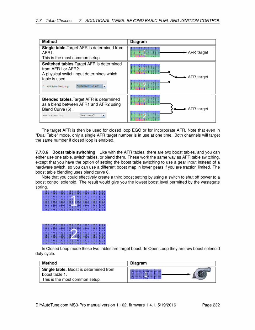
7.7 Table Choices 7 ADDITIONAL ITEMS: BEYOND BASIC FUEL AND IGNITION CONTROL
Method DiagramSingle table.Target AFR is determined fromAFR1.This is the most common setup.Switched tables.Target AFR is determinedfrom AFR1 or AFR2.A physical switch input determines whichtable is used.
Blended tables.Target AFR is determinedas a blend between AFR1 and AFR2 usingBlend Curve (5) .
The target AFR is then be used for closed loop EGO or for Incorporate AFR. Note that even in"Dual Table" mode, only a single AFR target number is in use at one time. Both channels will targetthe same number if closed loop is enabled.
7.7.0.6 Boost table switching Like with the AFR tables, there are two boost tables, and you caneither use one table, switch tables, or blend them. These work the same way as AFR table switching,except that you have the option of setting the boost table switching to use a gear input instead of ahardware switch, so you can use a different boost map in lower gears if you are traction limited. Theboost table blending uses blend curve 6.
Note that you could effectively create a third boost setting by using a switch to shut off power to aboost control solenoid. The result would give you the lowest boost level permitted by the wastegatespring.
In Closed Loop mode these two tables are target boost. In Open Loop they are raw boost solenoidduty cycle.
Method DiagramSingle table. Boost is determined fromboost table 1.This is the most common setup.
DIYAutoTune.com MS3-Pro manual version 1.102, firmware 1.4.1, 5/19/2016 Page 232
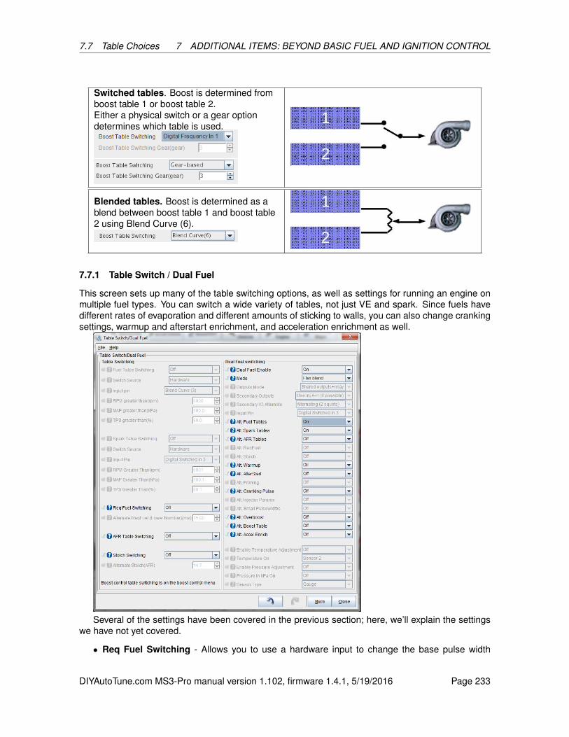
7.7 Table Choices 7 ADDITIONAL ITEMS: BEYOND BASIC FUEL AND IGNITION CONTROL
Switched tables. Boost is determined fromboost table 1 or boost table 2.Either a physical switch or a gear optiondetermines which table is used.
Blended tables. Boost is determined as ablend between boost table 1 and boost table2 using Blend Curve (6).
7.7.1 Table Switch / Dual Fuel
This screen sets up many of the table switching options, as well as settings for running an engine onmultiple fuel types. You can switch a wide variety of tables, not just VE and spark. Since fuels havedifferent rates of evaporation and different amounts of sticking to walls, you can also change crankingsettings, warmup and afterstart enrichment, and acceleration enrichment as well.
Several of the settings have been covered in the previous section; here, we’ll explain the settingswe have not yet covered.
• Req Fuel Switching - Allows you to use a hardware input to change the base pulse width
DIYAutoTune.com MS3-Pro manual version 1.102, firmware 1.4.1, 5/19/2016 Page 233
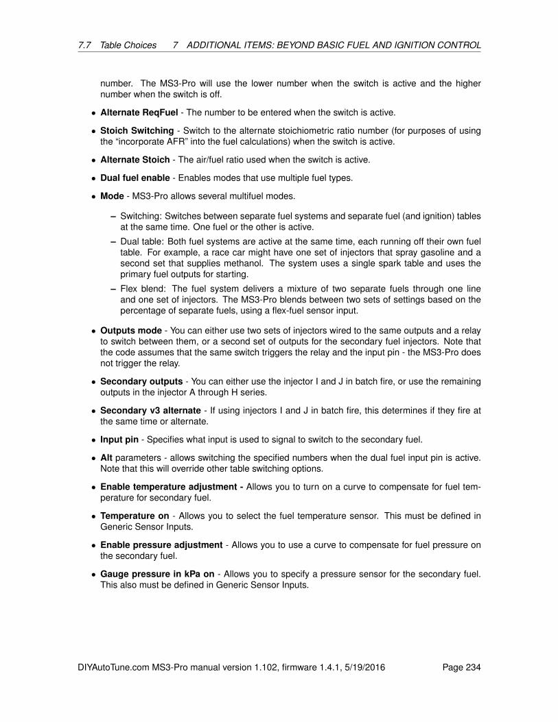
7.7 Table Choices 7 ADDITIONAL ITEMS: BEYOND BASIC FUEL AND IGNITION CONTROL
number. The MS3-Pro will use the lower number when the switch is active and the highernumber when the switch is off.
• Alternate ReqFuel - The number to be entered when the switch is active.
• Stoich Switching - Switch to the alternate stoichiometric ratio number (for purposes of usingthe “incorporate AFR” into the fuel calculations) when the switch is active.
• Alternate Stoich - The air/fuel ratio used when the switch is active.
• Dual fuel enable - Enables modes that use multiple fuel types.
• Mode - MS3-Pro allows several multifuel modes.
– Switching: Switches between separate fuel systems and separate fuel (and ignition) tablesat the same time. One fuel or the other is active.
– Dual table: Both fuel systems are active at the same time, each running off their own fueltable. For example, a race car might have one set of injectors that spray gasoline and asecond set that supplies methanol. The system uses a single spark table and uses theprimary fuel outputs for starting.
– Flex blend: The fuel system delivers a mixture of two separate fuels through one lineand one set of injectors. The MS3-Pro blends between two sets of settings based on thepercentage of separate fuels, using a flex-fuel sensor input.
• Outputs mode - You can either use two sets of injectors wired to the same outputs and a relayto switch between them, or a second set of outputs for the secondary fuel injectors. Note thatthe code assumes that the same switch triggers the relay and the input pin - the MS3-Pro doesnot trigger the relay.
• Secondary outputs - You can either use the injector I and J in batch fire, or use the remainingoutputs in the injector A through H series.
• Secondary v3 alternate - If using injectors I and J in batch fire, this determines if they fire atthe same time or alternate.
• Input pin - Specifies what input is used to signal to switch to the secondary fuel.
• Alt parameters - allows switching the specified numbers when the dual fuel input pin is active.Note that this will override other table switching options.
• Enable temperature adjustment - Allows you to turn on a curve to compensate for fuel tem-perature for secondary fuel.
• Temperature on - Allows you to select the fuel temperature sensor. This must be defined inGeneric Sensor Inputs.
• Enable pressure adjustment - Allows you to use a curve to compensate for fuel pressure onthe secondary fuel.
• Gauge pressure in kPa on - Allows you to specify a pressure sensor for the secondary fuel.This also must be defined in Generic Sensor Inputs.
DIYAutoTune.com MS3-Pro manual version 1.102, firmware 1.4.1, 5/19/2016 Page 234
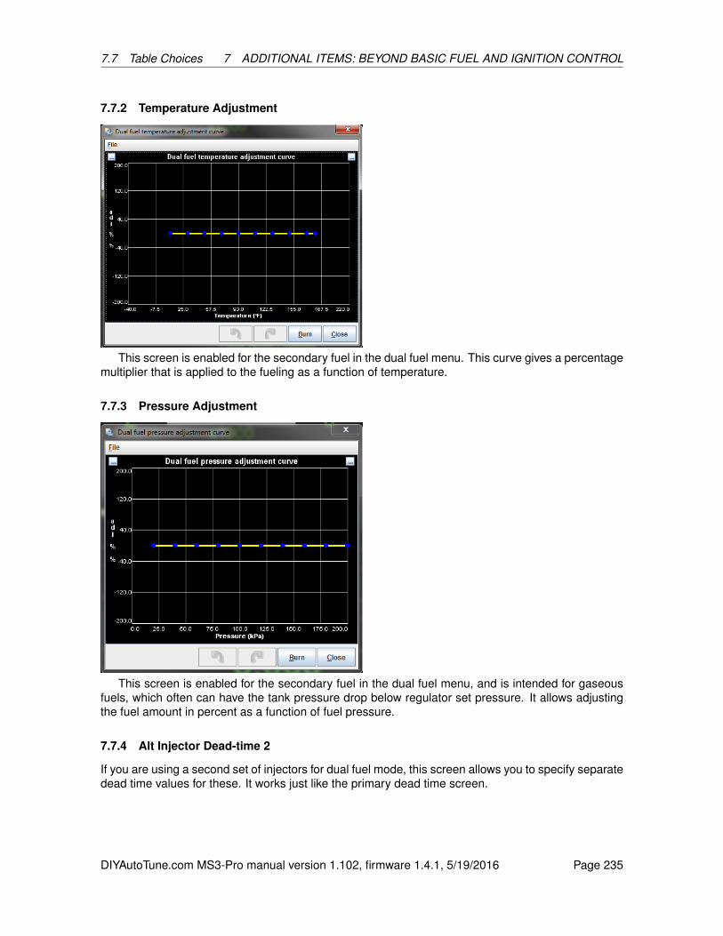
7.7 Table Choices 7 ADDITIONAL ITEMS: BEYOND BASIC FUEL AND IGNITION CONTROL
7.7.2 Temperature Adjustment
This screen is enabled for the secondary fuel in the dual fuel menu. This curve gives a percentagemultiplier that is applied to the fueling as a function of temperature.
7.7.3 Pressure Adjustment
This screen is enabled for the secondary fuel in the dual fuel menu, and is intended for gaseousfuels, which often can have the tank pressure drop below regulator set pressure. It allows adjustingthe fuel amount in percent as a function of fuel pressure.
7.7.4 Alt Injector Dead-time 2
If you are using a second set of injectors for dual fuel mode, this screen allows you to specify separatedead time values for these. It works just like the primary dead time screen.
DIYAutoTune.com MS3-Pro manual version 1.102, firmware 1.4.1, 5/19/2016 Page 235
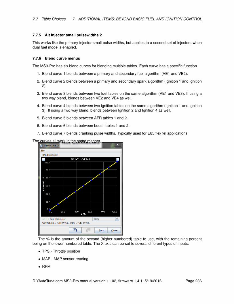
7.7 Table Choices 7 ADDITIONAL ITEMS: BEYOND BASIC FUEL AND IGNITION CONTROL
7.7.5 Alt Injector small pulsewidths 2
This works like the primary injector small pulse widths, but applies to a second set of injectors whendual fuel mode is enabled.
7.7.6 Blend curve menus
The MS3-Pro has six blend curves for blending multiple tables. Each curve has a specific function.
1. Blend curve 1 blends between a primary and secondary fuel algorithm (VE1 and VE2).
2. Blend curve 2 blends between a primary and secondary spark algorithm (Ignition 1 and Ignition2).
3. Blend curve 3 blends between two fuel tables on the same algorithm (VE1 and VE3). If using atwo way blend, blends between VE2 and VE4 as well.
4. Blend curve 4 blends between two ignition tables on the same algorithm (Ignition 1 and Ignition3). If using a two way blend, blends between Ignition 2 and Ignition 4 as well.
5. Blend curve 5 blends between AFR tables 1 and 2.
6. Blend curve 6 blends between boost tables 1 and 2.
7. Blend curve 7 blends cranking pulse widths. Typically used for E85 flex fel applications.
The curves all work in the same manner.
The % is the amount of the second (higher numbered) table to use, with the remaining percentbeing on the lower numbered table. The X axis can be set to several different types of inputs:
• TPS - Throttle position
• MAP - MAP sensor reading
• RPM
DIYAutoTune.com MS3-Pro manual version 1.102, firmware 1.4.1, 5/19/2016 Page 236

7.8 Advanced Engine 7 ADDITIONAL ITEMS: BEYOND BASIC FUEL AND IGNITION CONTROL
• MAF load
• Flex% (percent ethanol in fuel, as measured by a flex fuel sensor)
• VSS1 - driven wheel speed
• Gear - transmission gear position
• RPM * Load / 100
• Generic sensor inputs
7.8 Advanced Engine
7.8.1 Speed and gear sensors
The vehicle speed sensors (VSS) allow one or two wheel speeds to be monitored. The MS3-Proallows one or two speed sensors, with the second one being used to measure wheel slip for tractioncontrol. The inputs read from either a wheel/axle mounted pickup or a perhaps pickup that is part ofthe transmission. The input can be magnetic (with suitable interface) or more directly a hall type input.This input is converted to a linear speed (mph or kph). The shaft speed inputs work in a similar wayto the vehicle speed but calculates to rpms. It could be used as gearbox input shaft speed to monitorconvertor or clutch slip. The VSS output feature provides a pulsed output in proportion to the VSS fordriving a digital speedometer. The gear detection calculates the current gear selected in the gearboxby a number of methods.
You can use the Project Properties screen to set the units, both mph vs kph and meters vs inches,in the Settings tab under Project Properties, or you can change them with the settings in the lowercorner of this table.
There are four options for speed input.
1. Analogue linear input where 0V = zero speed and 5V = max speed.
DIYAutoTune.com MS3-Pro manual version 1.102, firmware 1.4.1, 5/19/2016 Page 237
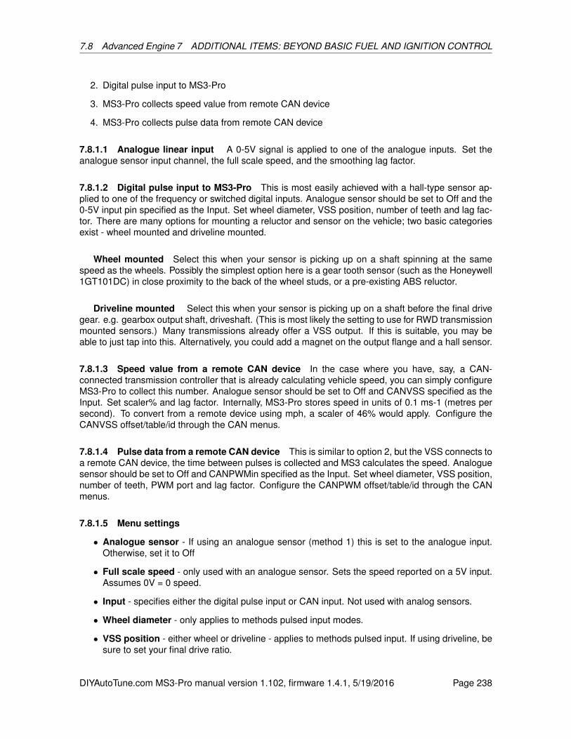
7.8 Advanced Engine 7 ADDITIONAL ITEMS: BEYOND BASIC FUEL AND IGNITION CONTROL
2. Digital pulse input to MS3-Pro
3. MS3-Pro collects speed value from remote CAN device
4. MS3-Pro collects pulse data from remote CAN device
7.8.1.1 Analogue linear input A 0-5V signal is applied to one of the analogue inputs. Set theanalogue sensor input channel, the full scale speed, and the smoothing lag factor.
7.8.1.2 Digital pulse input to MS3-Pro This is most easily achieved with a hall-type sensor ap-plied to one of the frequency or switched digital inputs. Analogue sensor should be set to Off and the0-5V input pin specified as the Input. Set wheel diameter, VSS position, number of teeth and lag fac-tor. There are many options for mounting a reluctor and sensor on the vehicle; two basic categoriesexist - wheel mounted and driveline mounted.
Wheel mounted Select this when your sensor is picking up on a shaft spinning at the samespeed as the wheels. Possibly the simplest option here is a gear tooth sensor (such as the Honeywell1GT101DC) in close proximity to the back of the wheel studs, or a pre-existing ABS reluctor.
Driveline mounted Select this when your sensor is picking up on a shaft before the final drivegear. e.g. gearbox output shaft, driveshaft. (This is most likely the setting to use for RWD transmissionmounted sensors.) Many transmissions already offer a VSS output. If this is suitable, you may beable to just tap into this. Alternatively, you could add a magnet on the output flange and a hall sensor.
7.8.1.3 Speed value from a remote CAN device In the case where you have, say, a CAN-connected transmission controller that is already calculating vehicle speed, you can simply configureMS3-Pro to collect this number. Analogue sensor should be set to Off and CANVSS specified as theInput. Set scaler% and lag factor. Internally, MS3-Pro stores speed in units of 0.1 ms-1 (metres persecond). To convert from a remote device using mph, a scaler of 46% would apply. Configure theCANVSS offset/table/id through the CAN menus.
7.8.1.4 Pulse data from a remote CAN device This is similar to option 2, but the VSS connects toa remote CAN device, the time between pulses is collected and MS3 calculates the speed. Analoguesensor should be set to Off and CANPWMin specified as the Input. Set wheel diameter, VSS position,number of teeth, PWM port and lag factor. Configure the CANPWM offset/table/id through the CANmenus.
7.8.1.5 Menu settings
• Analogue sensor - If using an analogue sensor (method 1) this is set to the analogue input.Otherwise, set it to Off
• Full scale speed - only used with an analogue sensor. Sets the speed reported on a 5V input.Assumes 0V = 0 speed.
• Input - specifies either the digital pulse input or CAN input. Not used with analog sensors.
• Wheel diameter - only applies to methods pulsed input modes.
• VSS position - either wheel or driveline - applies to methods pulsed input. If using driveline, besure to set your final drive ratio.
DIYAutoTune.com MS3-Pro manual version 1.102, firmware 1.4.1, 5/19/2016 Page 238

7.8 Advanced Engine 7 ADDITIONAL ITEMS: BEYOND BASIC FUEL AND IGNITION CONTROL
• Speed sensor #teeth - how many teeth the reluctor has - used with pulsed input
• PWM port - the CAN PWM "port" being used - only used with pulsed input over CAN.
• Scaler - applies a scaling to the CAN collected speed value, for units conversion. Applies ifusing CAN.
• Smoothing lag factor - Smoothing on the speed value. Lower numbers mean more delay andsmoothing. Sensible range is 15-100.
7.8.1.6 VSS dot smoothing These settings control how the VSSdot (acceleration) calculation isperformed. The lower the sample interval, the more responsive the calculation but the noisier it willbe. Experimentation will be required to get the best settings for your application. Calculating launchacceleration is particularly difficult to get right. Very low tooth counts and wheel speed collected viaCAN will be the most difficult due to the low data rate and the communication delays.
7.8.1.7 VSS sampling The MS3-Pro calculates vehicle speed by counting the number of pulsesin a sample interval time, separate from (and shorter than) the VSSdot sample interval. Normally50ms is ok and gives excellent smoothing. Hard accelerating vehicles will need to lower this numberfor improved zero-speed response.
7.8.1.8 VSS output This allows the MS3-Pro to provide a scaled output based on speed sensor#1 to control a speedometer.
• VSS output - specifies which output channel to use.
• VSSout units - valid units are as follows:
– Time
– Pulses per mile
– Pulses per kilometer
• Scale - If “pulses per mile” or “pulses per kilometer” is selected, this is how many pulses to putout per unit of distance. If “time” is selected, the time between output pulses is calculated astime factor / speed in meters per second.
7.8.2 Shaft Speed Sensors
These use digital pulsed inputs to determine speed of other components in the car for data logging.For example, you can log the converter output shaft speed in an automatic transmission. Currently,shaft speeds are just recorded and displayed, but not used for any other calculations.
DIYAutoTune.com MS3-Pro manual version 1.102, firmware 1.4.1, 5/19/2016 Page 239

7.8 Advanced Engine 7 ADDITIONAL ITEMS: BEYOND BASIC FUEL AND IGNITION CONTROL
High speed input mode allows more precision, but is not available on all inputs. If it is available onyour input, it is best to turn this on.
This mode allows fractional teeth in case the sensor is driven by a gear or other mechanism thatresults in a non-integer number of outputs per shaft revolution.
7.8.3 EGT / Thermocouple settings
The EGT system in MS3-Pro allows inputs from EGT sensors to be datalogged by serial or SDcard.It optionally allows the engine to be shut down if EGT exceeds a set temperature. If an EGT probe isfitted to each exhaust port, it can be used in conjunction with per-cylinder fuel trim to balance cylindersto account for air flow and injector flow differences. EGT is used extensively in piston driven aircraftand much useful information can be found from aircraft literature and then applied to your non-aeroengine. (EGT differences between cylinders can be significant at idle. Evidence shows that V8s oftenrun cold on the four corner cylinders and hot on the inner four. One engine required over 10% fueltrim to balance these air-flow differences.)
To use the EGT system an EGT probe (usually a K-type thermocouple) is installed in the exhaustmanifold. When installing an EGT per cylinder, it is typical to install ~50mm from the head.
The thermocouple output is a small voltage that the MS3-Pro will not read directly. There are twoways you can connect a thermocouple to the MS3-Pro:
• An amplified that converts the signal to a 0-5 volt reading which you can connect to an MS3-Proanalog input
• A CAN enabled thermocouple interface like the CAN-EGT input module that transmits the dataover the CAN bus
DIYAutoTune.com MS3-Pro manual version 1.102, firmware 1.4.1, 5/19/2016 Page 240
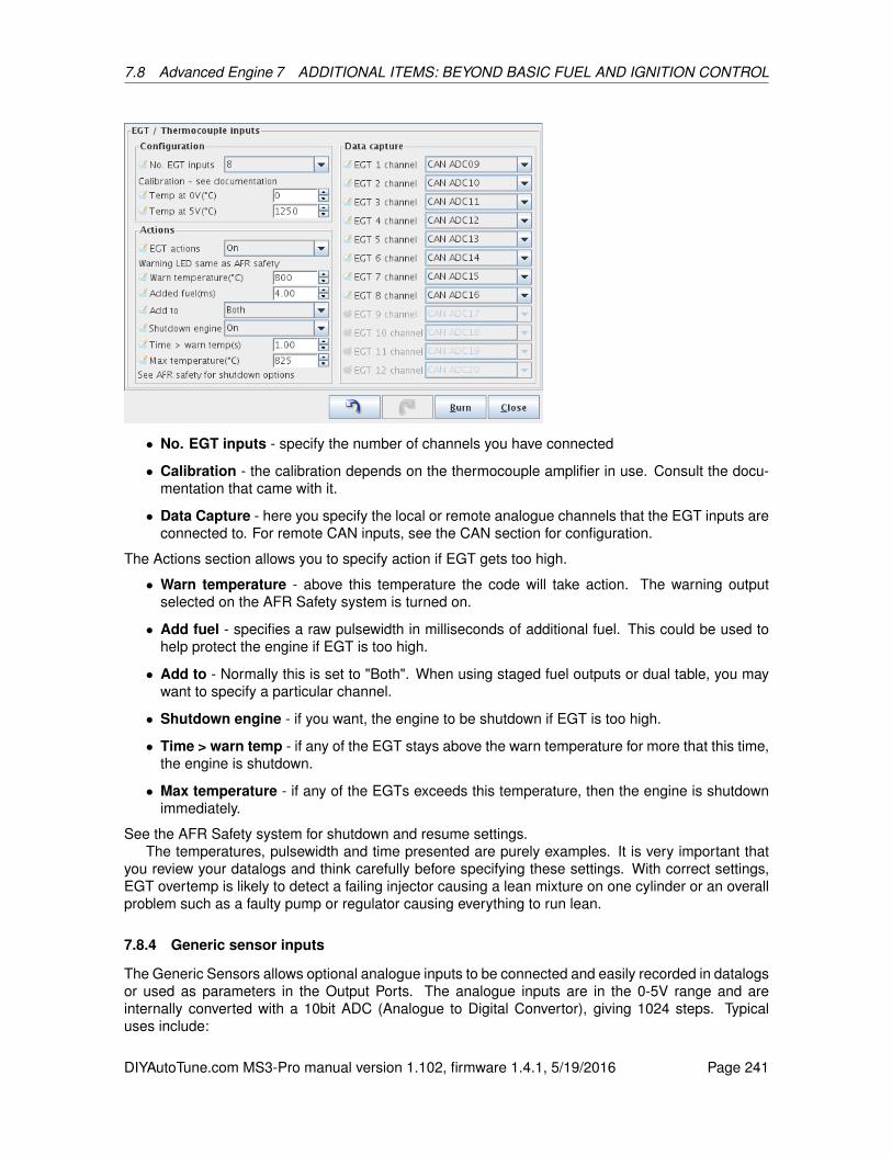
7.8 Advanced Engine 7 ADDITIONAL ITEMS: BEYOND BASIC FUEL AND IGNITION CONTROL
• No. EGT inputs - specify the number of channels you have connected
• Calibration - the calibration depends on the thermocouple amplifier in use. Consult the docu-mentation that came with it.
• Data Capture - here you specify the local or remote analogue channels that the EGT inputs areconnected to. For remote CAN inputs, see the CAN section for configuration.
The Actions section allows you to specify action if EGT gets too high.
• Warn temperature - above this temperature the code will take action. The warning outputselected on the AFR Safety system is turned on.
• Add fuel - specifies a raw pulsewidth in milliseconds of additional fuel. This could be used tohelp protect the engine if EGT is too high.
• Add to - Normally this is set to "Both". When using staged fuel outputs or dual table, you maywant to specify a particular channel.
• Shutdown engine - if you want, the engine to be shutdown if EGT is too high.
• Time > warn temp - if any of the EGT stays above the warn temperature for more that this time,the engine is shutdown.
• Max temperature - if any of the EGTs exceeds this temperature, then the engine is shutdownimmediately.
See the AFR Safety system for shutdown and resume settings.The temperatures, pulsewidth and time presented are purely examples. It is very important that
you review your datalogs and think carefully before specifying these settings. With correct settings,EGT overtemp is likely to detect a failing injector causing a lean mixture on one cylinder or an overallproblem such as a faulty pump or regulator causing everything to run lean.
7.8.4 Generic sensor inputs
The Generic Sensors allows optional analogue inputs to be connected and easily recorded in datalogsor used as parameters in the Output Ports. The analogue inputs are in the 0-5V range and areinternally converted with a 10bit ADC (Analogue to Digital Convertor), giving 1024 steps. Typicaluses include:
DIYAutoTune.com MS3-Pro manual version 1.102, firmware 1.4.1, 5/19/2016 Page 241
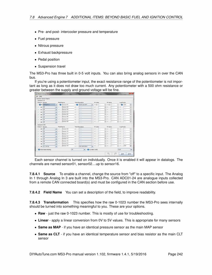
7.8 Advanced Engine 7 ADDITIONAL ITEMS: BEYOND BASIC FUEL AND IGNITION CONTROL
• Pre- and post- intercooler pressure and temperature
• Fuel pressure
• Nitrous pressure
• Exhaust backpressure
• Pedal position
• Suspension travel
The MS3-Pro has three built in 0-5 volt inputs. You can also bring analog sensors in over the CANbus.
If you’re using a potentiometer input, the exact resistance range of the potentiometer is not impor-tant as long as it does not draw too much current. Any potentiometer with a 500 ohm resistance orgreater between the supply and ground voltage will be fine.
Each sensor channel is turned on individually. Once it is enabled it will appear in datalogs. Thechannels are named sensor01, sensor02....up to sensor16.
7.8.4.1 Source To enable a channel, change the source from "off" to a specific input. The AnalogIn 1 through Analog In 3 are built into the MS3-Pro. CAN ADC01-24 are analogue inputs collectedfrom a remote CAN connected board(s) and must be configured in the CAN section before use.
7.8.4.2 Field Name You can set a description of the field, to improve readability.
7.8.4.3 Transformation This specifies how the raw 0-1023 number the MS3-Pro sees internallyshould be turned into something meaningful to you. These are your options.
• Raw - just the raw 0-1023 number. This is mostly of use for troubleshooting.
• Linear - apply a linear conversion from 0V to 5V values. This is appropriate for many sensors
• Same as MAP - if you have an identical pressure sensor as the main MAP sensor
• Same as CLT - if you have an identical temperature sensor and bias resistor as the main CLTsensor
DIYAutoTune.com MS3-Pro manual version 1.102, firmware 1.4.1, 5/19/2016 Page 242

7.8 Advanced Engine 7 ADDITIONAL ITEMS: BEYOND BASIC FUEL AND IGNITION CONTROL
• Same as MAT - if you have an identical temperature sensor and bias resistor as the main MATsensor
• Same as EGO - if you have an identical EGO calibration as the main EGO sensor
• Same as MAF - if you have an identical Mass Air Flow sensor as the main MAF sensor calibra-tion
• GM calibration - if you have a GM temperature sensor and standard (2490 ohm) bias resistor
7.8.4.4 0V, 5V value These are only used with the Linear transformation.
• 0V value - specifies the number you want to see when 0V is applied
• 5V value - specifies the number you want to see when 5V is applied
Many sensors specify output at other voltages, e.g. some data sheets advise pressure at 0.5V and4.5V. This needs to be converted to the 0V and 5V values using a calculator.
Take the following numbers:“A” = low voltage“B” = high voltage“C” = low pressure“D” = high pressureCalculate E = (D - C) / (B - A)0V value = C - (E * A)5V value = (E * 5) + 0V valueLet’s work these out with an example sensor: Honeywell’s 2000 psi sensor, part number MLH02KPSB06A.This sensor has a linear (ratiometric) output voltage range of 0.5V to 4.5V from zero to full pres-
sure. It is a 2000psi gauge sensor that would be suitable for measuring nitrous line pressure 0.5V is0psi 4.5V is 2000psi
Calculate the 0V and 5V values as above. Take A = 0.5V, B = 4.5V, C = 0psi, D = 2000psiE = (D - C) / (B - A) = (2000 - 0) / (4.5 - 0.5) = 2000 / 4 = 5000V value = C - (E * A) = 0 - (500 * 0.5) = 0 - 250 = -250 (yes, this is negative) 5V value = (E * 5) +
0V value = (500 * 5) - 250 = 2500 - 250 = 2250For this particular sensor, you would enter -250 in the 0V box and 2250 in the 5V box. Those
values are never actually reached, but this gives the correct calibration.
7.8.4.5 Lag The smoothing factor to apply. This uses the same number system as lags elsewhere.100% means no smoothing and lower numbers give increased smoothing and lag to the input. 15%is a sensible lower limit.
7.8.4.6 CLT/MAT temp units Specify the temperature unit system you want.
7.8.4.7 Allow Input Sharing Normally each input can only be used by one feature. This settingallows inputs to be shared between generic sensors and other features. (Obviously you can still onlyconnect one sensor to each input!) For example, you may want to enable a sensor as an EGT input,but also have TunerStudio display the raw voltage from the sensor.
DIYAutoTune.com MS3-Pro manual version 1.102, firmware 1.4.1, 5/19/2016 Page 243
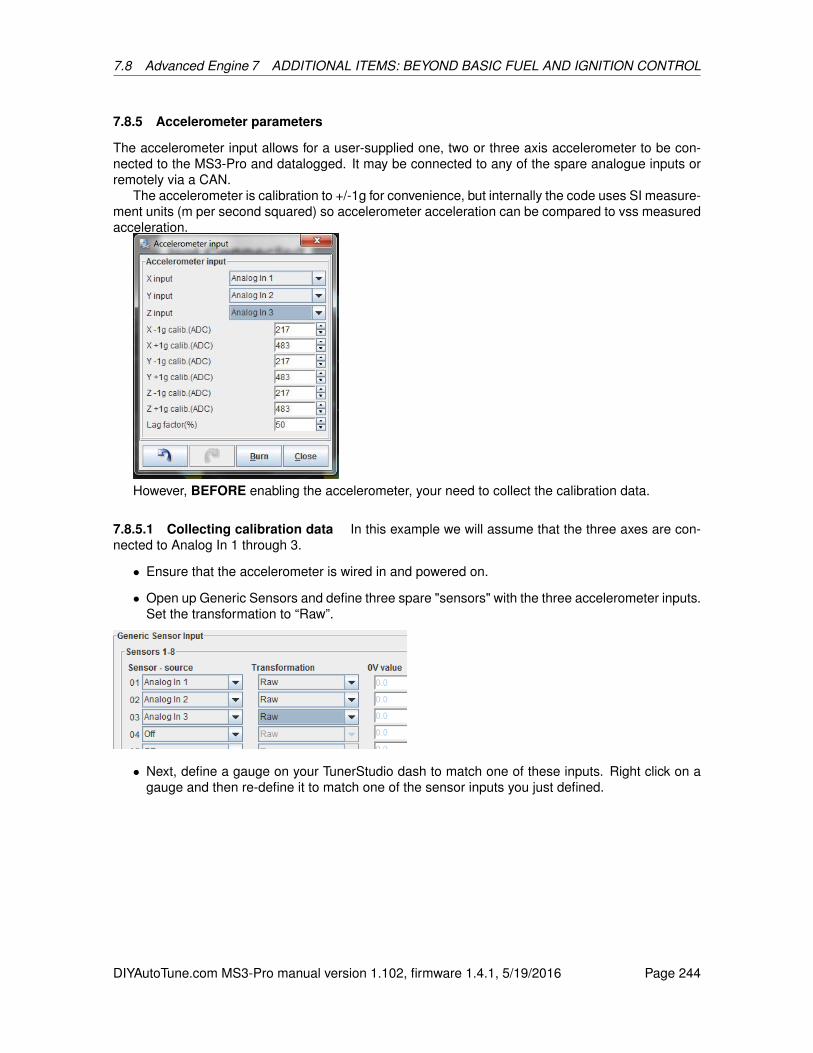
7.8 Advanced Engine 7 ADDITIONAL ITEMS: BEYOND BASIC FUEL AND IGNITION CONTROL
7.8.5 Accelerometer parameters
The accelerometer input allows for a user-supplied one, two or three axis accelerometer to be con-nected to the MS3-Pro and datalogged. It may be connected to any of the spare analogue inputs orremotely via a CAN.
The accelerometer is calibration to +/-1g for convenience, but internally the code uses SI measure-ment units (m per second squared) so accelerometer acceleration can be compared to vss measuredacceleration.
However, BEFORE enabling the accelerometer, your need to collect the calibration data.
7.8.5.1 Collecting calibration data In this example we will assume that the three axes are con-nected to Analog In 1 through 3.
• Ensure that the accelerometer is wired in and powered on.
• Open up Generic Sensors and define three spare "sensors" with the three accelerometer inputs.Set the transformation to “Raw”.
• Next, define a gauge on your TunerStudio dash to match one of these inputs. Right click on agauge and then re-define it to match one of the sensor inputs you just defined.
DIYAutoTune.com MS3-Pro manual version 1.102, firmware 1.4.1, 5/19/2016 Page 244
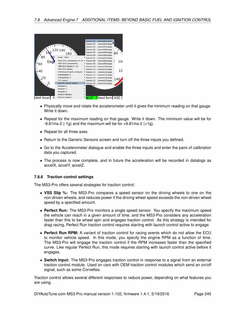
7.8 Advanced Engine 7 ADDITIONAL ITEMS: BEYOND BASIC FUEL AND IGNITION CONTROL
• Physically move and rotate the accelerometer until it gives the minimum reading on that gauge.Write it down.
• Repeat for the maximum reading on that gauge. Write it down. The minimum value will be for-9.81ms-2 (-1g) and the maximum will be for +9.81ms-2 (+1g).
• Repeat for all three axes.
• Return to the Generic Sensors screen and turn off the three inputs you defined.
• Go to the Accelerometer dialogue and enable the three inputs and enter the pairs of calibrationdata you captured.
• The process is now complete, and in future the acceleration will be recorded in datalogs asaccelX, accelY, accelZ.
7.8.6 Traction control settings
The MS3-Pro offers several strategies for traction control:
• VSS Slip %: The MS3-Pro compares a speed sensor on the driving wheels to one on thenon-driven wheels, and reduces power if the driving wheel speed exceeds the non-driven wheelspeed by a specified amount.
• Perfect Run: The MS3-Pro monitors a single speed sensor. You specify the maximum speedthe vehicle can reach in a given amount of time, and the MS3-Pro considers any accelerationfaster than this to be wheel spin and engages traction control. As this strategy is intended fordrag racing, Perfect Run traction control requires starting with launch control active to engage.
• Perfect Run RPM: A variant of traction control for racing events which do not allow the ECUto monitor vehicle speed. In this mode, you specify the engine RPM as a function of time.The MS3-Pro will engage the traction control if the RPM increases faster than the specifiedcurve. Like regular Perfect Run, this mode requires starting with launch control active before itengages.
• Switch Input: The MS3-Pro engages traction control in response to a signal from an externaltraction control module. Used on cars with OEM traction control modules which send an on/offsignal, such as some Corvettes.
Traction control allows several different responses to reduce power, depending on what features youare using.
DIYAutoTune.com MS3-Pro manual version 1.102, firmware 1.4.1, 5/19/2016 Page 245

7.8 Advanced Engine 7 ADDITIONAL ITEMS: BEYOND BASIC FUEL AND IGNITION CONTROL
• Retarding the spark timing.
• Using a rolling spark cut.
• Adding fuel.
• Reducing or shutting off a nitrous oxide injection system.
• Reducing boost on a turbocharged motor.
7.8.6.1 Traction control settings
• Traction control - Allows turning traction control off or on.
• Method - Specifies what method is used to determine when to apply traction control.
• Enable input - If set to “off,” traction control is active full time (for switched input or VSS %slip)or active any time the launch control system is used (for Perfect Run). This can specify an inputpin used to arm traction control.
• Minimum TPS - Specifies the minimum throttle position below which traction control is notapplied.
• Minimum MAP - Specifies the minimum MAP reading below which traction control is not ap-plied. (Not used for Perfect Run)
• Minimum VSS - Traction control is not used below this speed. (Not used for Perfect Run)
• Slip % setting - If set to “Fixed value,” you specify the maximum percent the drive wheel speedcan exceed the non driven wheel speed with the Slip Threshold % setting. “Adjustable” allowsyou to use an external dial to change the slip threshold.
• Slip threshold - The maximum amount of wheel slip permitted in VSS % slip mode.
• Nitrous control - Current firmware only supports on/off. In on/off mode, nitrous is left on if theNitrous Cut curve is less than 40%, and cut if nitrous cut % is over 60%.
• Add fuel to - If using added fuel, specifies if this is applied to the first stage (Bank 1), secondaryinjectors if used (Bank 2), or both.
DIYAutoTune.com MS3-Pro manual version 1.102, firmware 1.4.1, 5/19/2016 Page 246

7.8 Advanced Engine 7 ADDITIONAL ITEMS: BEYOND BASIC FUEL AND IGNITION CONTROL
7.8.7 Traction control - perfect run VSS
This screen lets you specify the maximum speed for the traction control to allow as a function ofthe time after launch control deactivates. After passing the top time point, the traction control turnsoff.
7.8.8 Traction control - perfect run RPM
This works in the same manner as the perfect run VSS screen, except you specify the maximumengine RPM to allow as a function of time. This provides a slew control function instead of true tractioncontrol, to meet various sanctioning body rules.
DIYAutoTune.com MS3-Pro manual version 1.102, firmware 1.4.1, 5/19/2016 Page 247

7.8 Advanced Engine 7 ADDITIONAL ITEMS: BEYOND BASIC FUEL AND IGNITION CONTROL
7.8.9 Traction control - External % slip input
Allows you to specify the maximum slip percent to allow as function of the amount of input froman external adjustment knob.
7.8.10 Traction control reactions
This screen lets you specify what actions to take if traction control is active. The MS3-Pro can be
DIYAutoTune.com MS3-Pro manual version 1.102, firmware 1.4.1, 5/19/2016 Page 248

7.8 Advanced Engine 7 ADDITIONAL ITEMS: BEYOND BASIC FUEL AND IGNITION CONTROL
set to take more action the longer the traction control is active. The slip number is different based onthe method used.
• For VSS% slip, it is the percent by which the driving wheel speed exceeds the non-driven wheelspeed.
• For perfect run, it is the percentage difference in acceleration or time vs the target.
• For switched mode, off is 0% slip and on is 100% slip.
With on/off nitrous cut, we recommend setting the nitrous cut at 0 for leaving the nitrous off, and 100%to cut off the nitrous.
7.8.11 Launch / 2 step / 3 step / T-Brake
The MS3-Pro launch control system is a 2-step limiter, typically used in drag racing applications forconsistent hard launches and/or to build boost with a turbocharged engine. The flat shift settingsallow full throttle shifts on a clutched vehicle. A switch on the clutch triggers the flat-shift rev limiting(for bikes, see also the sequential shift cut, which may be more suitable.) It is important to install theclutch switch with adjustability, as the exact height has an effect on how well flat-shifting works. Flatshift is unlikely to be useful when running an automatic transmission. The 3-step is typically used asa burnout limiter and will often be linked to a line-lock.
A typical drag racing scenario would go like this: You pull forward into the burnout box, stand onthe brakes and flick on the line-lock. This also enables the 3-step. You now do your burnout and the3-step limits are applied. After your burnout, you pull into stage, depress the clutch (activating thelaunch switch) and then push the throttle to the floor. The launch settings will hold the engine close toyour chosen rpm. When you change gear, keep the throttle planted, and only use the clutch. Now theflat shift settings come into play, and the revs will be limited to those settings. After changing gear andlifting your foot off the clutch, the limiter is disabled. Be sure to also set the normal rev limiter shouldyou miss shift.
DIYAutoTune.com MS3-Pro manual version 1.102, firmware 1.4.1, 5/19/2016 Page 249

7.8 Advanced Engine 7 ADDITIONAL ITEMS: BEYOND BASIC FUEL AND IGNITION CONTROL
7.8.11.1 Basic launch control / flat shift settings
• Launch control option
– Off - all of launch if turned off
– Launch - launch only, no flat shift
– Launch/flatshift - launch and flat shift
• Input on - where the launch input switch is connected
• Launch hard limit - when the launch conditions are met, above this rpm the hard limiter meth-ods are used
• Soft Limit Zone - When the RPM is this far below the launch hard limit, the MS3-Pro will applyspark retard, and if spark cut is used, it will begin to phase in a partial spark cut.
• Soft Limit Retard To - This is the timing (in absolute degrees BTDC) that the MS3-Pro willcommand while in the soft limit zone.
• Launch retard above - when the launch conditions are met, the timing is retarded above thisrpm
• Retard to - the absolute timing to retard to. For example, if you enter 5 in here, the timing willbe 5 BTDC, -3 means 3 ATDC. Using ATDC timing can be useful for building boost, but bewareof the potentially harmful heat it generates in the turbo too.
• Launch fuel add/remove - Allows fueling to be changed while the launch limiter is on.
• Fuel addition - the raw millisecond pulsewidth change to make (+/-)
• Enable launch when TPS above - launch is only active when the throttle is open a certainpercentage. Most users can safely set this to a very low number. Setting it too high can causelaunch not to activate as expected.
• Limiter method
– None - Launch control itself is not activated. However, this will allow you to use timedfeatures that activate after a launch, such as timed boost control or perfect run tractioncontrol.
– Spark cut - drop sparks; this is the most common limiter used. (Will not work with EDISignition or some other semi-autonomous ignition controls.)
– Fuel cut - cuts fuel. Seen by many as risky due to the possibility of partly fueling, but if yourignition goes into a limp home mode if you try to cut it off, this may be your only option.
– Spark and fuel - both
• Disable launch when VSS above - If you have set up a speed input, this allows you to lock outthe launch control when the vehicle is in motion.
• Limiter settings - Basic automatically sets the spark limit behavior. Advanced allows you tofine tune this setting.
• Spark limiter type - In advanced mode, you can fine tune the spark cut behavior.
– Random progressive: Applies a random spark cut that cuts more sparks in between thesoft zone and hard limit.
DIYAutoTune.com MS3-Pro manual version 1.102, firmware 1.4.1, 5/19/2016 Page 250
7.8 Advanced Engine 7 ADDITIONAL ITEMS: BEYOND BASIC FUEL AND IGNITION CONTROL
– Random ramped: Random cut that ramps up across the spark cut zone.
– Fixed 5/7: Repeats a pattern of 5 sparks cut and 2 sparks fired.
– Fixed 4/5: Repeats a pattern of 4 sparks cut and 1 spark fired. Do not use on 5 cylinderengines!
• Spark cut zone - The range of RPM below the hard limit to apply a spark cut.
• Cut zone timing - The absolute timing to run when in the spark cut zone.
Flat shift settings:
• Disable Flat-Shift when VSS Below - Prevents flat-shift from activating at low speeds, such asjust after launch.
• Flat shift arming rpm - this rpm set point is used to differentiate between a flat shift and launchcondition. Typically as you are preparing to start a launch you will be at lower rpms, while forflat shift you operate the clutch near your rev limit. So set the flat shift arming rpm to say 3/4or your max rpms. i.e. consider what rpms are you doing when you press the clutch and makesure the code will always know if you want the launch limits or flat shift limits.
• Flat shift hard limit - The maximum RPM to use when flat shift is active. Uses the same softlimit zone as launch control.
• Soft Limit Retard To - This is the timing (in absolute degrees BTDC) that the MS3-Pro willcommand while in the soft limit zone during a flat shift.
• Cut fuel above - this is intended to be used during flat shifting. During the up-shift as the revsare falling, the fuel is cut off until the revs have fallen below this set point. This reduces the rawfuel in the exhaust system that can otherwise produce a loud backfire.
• Timed retard after launch - Allows you to set a spark retard that is active immediately afterlaunch. The MS3-Pro will then use a time based curve to put the timing back in. Use this toreduce power if you have wheelspin, but are running in a racing series that doesn’t allow tractioncontrol.
7.8.11.2 Variable launch settings The variable launch mode allows you to adjust your launchcontrol RPM limit with a 0-5 volt input, allowing you to adjust your launch control for changing trackconditions.
• Variable launch input
– Off - disables the feature and uses the single limits
– One of the analogue inputs - indicates what input pin is being used for the variable launch
• minimum setting - With a 0V input, the launch hard limit is set to this rpm.
• maximum setting - With a 5V input, the launch hard limit is set to this rpm
• soft limit lower by - The soft launch limit is this many rpm below the variable hard limit.1000rpm is typical.
DIYAutoTune.com MS3-Pro manual version 1.102, firmware 1.4.1, 5/19/2016 Page 251

7.8 Advanced Engine 7 ADDITIONAL ITEMS: BEYOND BASIC FUEL AND IGNITION CONTROL
7.8.11.3 Transbrake and throttle stop The MS3-Pro can control many timed delay functions forbracket or drag racing. The trans brake control applies the trans brake when you press the transbrake input button. When you release the button, the trans brake will remain on for the delay time,then release. Launch control is enabled while the trans brake is on, and releases at the same timeas the transbrake. The throttle stop output switches on after launch, stays on for a set time, thenreleases.
• Transbrake button input - Specify what input pin is used for the transbrake switch
• Transbrake output - Specify what output pin is used for the transbrake control.
• Delay - The time, in seconds, between releasing the transbrake input and releasing the trans-brake.
• Turbo Staging Button - Press this button, and the MS3-Pro will pulse the trans brake off andon, allowing the car to creep forward while building boost.
• Release Time - How long to release trans-brake for on each move step. This should be set longenough to move the car a little without gaining any speed.
• On Time - How long the trans-brake should be re-activated for between each step. This shouldbe set long enough to fully grab again.
• Main # Moves - How many moves (trans-brake release steps) on the first press of the button.Each subsequent press of the button gives a single move.
• Throttle stop output - Specify what output pin is used for a throttle stop.
• On delay after launch - The time, in seconds, between releasing launch control and the throttlestop turning on.
• Keep on for - The time, in seconds, to keep the throttle stop active.
If using the trans brake without the staging feature, you can drive it with a conventional relay. A solidstate relay will give more precise release timing, and you will also need a solid state relay if using theturbo staging button feature in order to pulse the trans brake off and on rapidly enough.
The wiring example on the next page shows Digital Switched In 3 as the trans brake button, DigitalSwitched In 2 as the staging button, and High Current Out 1 as the solenoid control output. This isjust one example. You can use any unused digital switched or frequency input for the button inputs(note that Digital Switched 12V In needs to be wired to 12 volt switched power and not ground) andany unused high current, PWM, or injector output for the solenoid control.
DIYAutoTune.com MS3-Pro manual version 1.102, firmware 1.4.1, 5/19/2016 Page 252
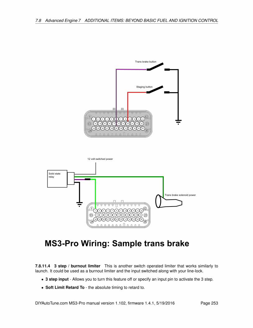
7.8 Advanced Engine 7 ADDITIONAL ITEMS: BEYOND BASIC FUEL AND IGNITION CONTROL
7.8.11.4 3 step / burnout limiter This is another switch operated limiter that works similarly tolaunch. It could be used as a burnout limiter and the input switched along with your line-lock.
• 3 step input - Allows you to turn this feature off or specify an input pin to activate the 3 step.
• Soft Limit Retard To - the absolute timing to retard to.
DIYAutoTune.com MS3-Pro manual version 1.102, firmware 1.4.1, 5/19/2016 Page 253
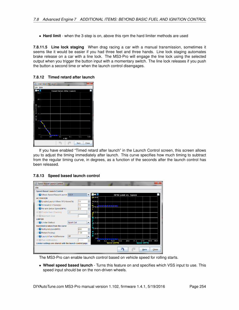
7.8 Advanced Engine 7 ADDITIONAL ITEMS: BEYOND BASIC FUEL AND IGNITION CONTROL
• Hard limit - when the 3-step is on, above this rpm the hard limiter methods are used
7.8.11.5 Line lock staging When drag racing a car with a manual transmission, sometimes itseems like it would be easier if you had three feet and three hands. Line lock staging automatesbrake release on a car with a line lock. The MS3-Pro will engage the line lock using the selectedoutput when you trigger the button input with a momentary switch. The line lock releases if you pushthe button a second time or when the launch control disengages.
7.8.12 Timed retard after launch
If you have enabled “Timed retard after launch” in the Launch Control screen, this screen allowsyou to adjust the timing immediately after launch. This curve specifies how much timing to subtractfrom the regular timing curve, in degrees, as a function of the seconds after the launch control hasbeen released.
7.8.13 Speed based launch control
The MS3-Pro can enable launch control based on vehicle speed for rolling starts.
• Wheel speed based launch - Turns this feature on and specifies which VSS input to use. Thisspeed input should be on the non-driven wheels.
DIYAutoTune.com MS3-Pro manual version 1.102, firmware 1.4.1, 5/19/2016 Page 254

7.8 Advanced Engine 7 ADDITIONAL ITEMS: BEYOND BASIC FUEL AND IGNITION CONTROL
• Enable launch when TPS above - Specifies the minimum throttle position to use this feature.
• Timeout - Once you have been moving for this number of seconds, VSS based launch controlis locked out until next stop. Set to zero to make it permanently active (no timeout.)
• Re-arm below speed - Below this speed the wheel speed launch is re-armed. Typically set toa very low number.
• Enable gear checking - Allows speed based launch control to only engage in certain gears.
• Maximum gear - If gear checking is enabled, this is the highest gear you can use this setting.
• Limiter method - Allows using a fuel and/or spark cut for speed based launch. The RPM limitand amount of spark retard is taken from the curve at the right.
• Retard to - The absolute timing to use when at the rev limit. Below the rev limit, the MS3-Prouses the green curve for timing retard.
• Launch fuel add / remove - Allows adding pulse width (specified by Fuel Addition) when onthe launch limiter. Entering a negative value in Fuel Addition removes fuel.
7.8.14 Sequential shift cut
Another drag racing feature, this one is intended for use with air shifters and sequentially shiftedtransmissions. The MS3-Pro can cut the ignition during shifting and also control the air shifter solenoidvalve. Note that automatic shift control and gear based delays require setting up the gear input underSpeed and Gear Sensors. The shifting will happen in this sequence:
1. As soon as the button is pressed or automatic shift is required, the air shifter solenoid is turnedon.
2. The MS3-Pro pauses for a time defined by the shift cut delay before cutting spark.
3. The MS3-Pro waits for the specified spark cut time plus any gear based delay, if applied. Duringthis point, the solenoid turns off before the ignition resumes.
4. The ignition resumes firing.
5. The MS3-Pro starts the re-shift hold off timer. The MS3-Pro will not shift again until this timerruns out.
DIYAutoTune.com MS3-Pro manual version 1.102, firmware 1.4.1, 5/19/2016 Page 255

7.8 Advanced Engine 7 ADDITIONAL ITEMS: BEYOND BASIC FUEL AND IGNITION CONTROL
• Shifter Spark cut system - Toggles this feature off or on.
• Mode
– Button - The shift cut is activated by an external button.
– Auto - The MS3-Pro controls the shifting using preset RPM points. Pressing the button willforce an upshift.
• Button input - Select the channel for the switch to activate the shift cut. Usually, this button isin the shifter mechanism itself.
• Solenoid output - Select the output pin for an air shift solenoid.
• RPM > (RPM) - The shift cut will only operate above this RPM.
• And TPS > (%) - The minimum TPS reading to activate the shift cut.
• Delay before spark cut - The time, in seconds, between the input shift and cutting the spark.This is to allow the solenoid to start moving.
• Spark cut time (base) - The amount of time, in seconds, for the spark cut to be applied.
• Gear based delay - Turning this on allows you to add an extra amount of spark cut time in oneor more gears.
• Additional delay settings - These add a small number of extra spark cut for the specified shift
• Solenoid delay - the time to allow the solenoid to deactivate before re-applying spark
• Re-shift hold off time - Disables the shift cut for the specified time after shifting, to avoidaccidentally triggering.
DIYAutoTune.com MS3-Pro manual version 1.102, firmware 1.4.1, 5/19/2016 Page 256
7.8 Advanced Engine 7 ADDITIONAL ITEMS: BEYOND BASIC FUEL AND IGNITION CONTROL
• Shift RPM - These five points let you specify the RPM for each shift if running in automaticmode.
7.8.15 Nitrous system
Nitrous oxide injection is primarily used in racing applications where nitrous oxide and additional fuelare injected into the intake to give a horsepower boost. This is particularly popular in drag racing.Used correctly, nitrous can give perhaps 100% additional power. Used incorrectly, it can melt pistonsand destroy engines in seconds. The nitrous system within MegaSquirt allows control over the nitrousand optional fuel solenoid to enable the nitrous injection when desired and also retard the ignitiontiming. The system supports two stages of control with on/off or progressive.
There are two main categories of nitrous systems - wet and dry. You can further subdivide thisinto on/off, progressive, and multistage nitrous systems.
7.8.15.1 Wet flow nitrous A wet system injects fuel into the manifold ahead of the injectors. Thiscan result in fuel distribution problems and mixture varying between cylinders. The simplest exampleof a wet system is a "plate" system that installs under the throttle body (or carb) above the intakemanifold and delivers nitrous and fuel through spray bars. Other variations exist which use singleor multiple nozzles. A standalone wet nitrous system has the advantage that when used with thesuppliers suggested jetting it will typically install and work. More hardware, less tuning.
7.8.15.2 Dry nitrous With a dry system, the fuel injectors supply additional fuel when the nitrousis active. Systems designed to work with OEM engine management sometimes do this by increasingfuel pressure, which does not give accurate fuel increase across the rev range, but with MS3-Pro, wecan directly increase the injector pulse width instead. The nitrous enters through a nozzle typicallylocated upstream of the throttle body.
In a port-injection system, a dry nitrous system minimizes the fuel distribution problems. A drysystem can also have fewer system components, as it uses the existing fuel system components.However, because the fuel and nitrous can be controlled independently, the software settings arecritical to getting the mixture correct. Less hardware, more tuning.
7.8.15.3 On/Off With On/Off control, the nitrous/fuel solenoids are either on or off. This is thestandard operating mode.
7.8.15.4 Progressive control The Progressive system allows you to pulse you solenoids withoutput duty varying with rpm or time during drag pass. It is more complicated to setup than the On/Offsystem.
7.8.15.5 Multistage and progressive nitrous Note! - you are advised to always start with asimple system using small jets. Big hits with multiple stages or progressive are significantly moredifficult to install and tune correctly.
With a single on/off stage using fixed jetting, the flow of nitrous (and fuel) is approximately constantunder all conditions. This means that if you are getting a claimed 100hp at 3000rpm when you activatethe system, by 6000rpm the engine is turning twice as fast and each intake event will only receivehalf the nitrous/fuel, so you will get half the torque benefit. One answer might be to use two stagesbased on rpm. The first stage is still jetted at 100hp, but at 4500rpm you bring in a second stageof say 25hp. This will make up for some of the "lost" torque. Another approach would be a singlestage progressive system using "200hp" jets. You could start at ~50% duty at 3000rpm and ramp upto 100% duty at 6000rpm. This could keep a similar torque gain across the rev range.
DIYAutoTune.com MS3-Pro manual version 1.102, firmware 1.4.1, 5/19/2016 Page 257

7.8 Advanced Engine 7 ADDITIONAL ITEMS: BEYOND BASIC FUEL AND IGNITION CONTROL
7.8.15.6 Tuning considerations In general, applying up to 50% extra hp to your engine with a kitmanufacturer’s jetting and suggested retard works well and will not cause problems to your engine.However, it is very important to take plug readings and check for any signs of leanness or detonation.As mentioned already, it is quite easy to destroy your engine with nitrous given the wrong combination.
Easy mistakes to make with bad consequences:
• Mixed up fuel/nitrous jets.
• Fuel pressure too low (mismatched to fuel jet size)
• Incorrect dry fuel pulsewidth
• Insufficient timing retard
• Too hot a spark plug
• Faulty fuel solenoid or wiring
• Blocked fuel lines or jets
• System activated at too low an rpm
7.8.15.7 Nitrous settings
• Nitrous Control - Turns the system on or off
• Enable N2O when above - sets the minimum RPM to enable nitrous.
• And Coolant Temp above - sets the minimum coolant temperature to enable nitrous.
• And TPS > - sets the minimum throttle position to enable nitrous (Typically, nitrous should onlybe enabled on a warmed up engine at wide open throttle at an RPM point where the engine ismaking at least as much horsepower as the nitrous shot provides.)
• Max RPM - sets the maximum RPM to enable nitrous. You will want this off before the rev limiterengages.
• Enrich which bank - Set to "Both" for most installs. If "dual table" or Staging are in use it selectswhich injector bank receives any additional fuel pulsewidth.
DIYAutoTune.com MS3-Pro manual version 1.102, firmware 1.4.1, 5/19/2016 Page 258
7.8 Advanced Engine 7 ADDITIONAL ITEMS: BEYOND BASIC FUEL AND IGNITION CONTROL
• On/Off vs Progressive mode - Selects between On/Off or Progressive control mode.
• Time-based or RPM-based - For progressive, chooses between time or RPM as control factor.
• Solenoid frequency - For progressive, selects nitrous solenoid frequency.
• Fuel solenoid frequency - Allows specifing a separate frequency for the fuel solenoid.
• AFR safety uses AFR2 targets - Allows optional AFR safety system to use alternate AFRtargets when nitrous is active.
Stage 1 settings:
• Stage 1 output - nitrous - Selects output pin to use for stage 1 nitrous solenoid
• Stage 1 output - fuel - Selects output pin to use for stage 1 fuel solenoid (These will normallybe the same for an on/off system, but may be different for progressive.)
• Enable input on: - Selects the input pin to use to enable the nitrous system. We recommendusing the digital 12 volt input pin for nitrous. If you’re using a conventional arming switch, thisallows you to wire the input to the nitrous solenoid power source.
• Additional Fuel PW @ N2O min rpm - In on/off mode with a dry system the fuel PW to add atthe min rpm.
• Additional Fuel PW @ N2O max rpm - In on/off mode with a dry system the fuel PW to addat the max rpm. (In between these two rpm points, the MegaSquirt calculates the requiredpulsewidth using linear interpolation.)
• Retard Ignition by - In on/off mode sets a fixed ignition retard.
• Nitrous delay after launch - Sets a minimum time after launch control before nitrous can acti-vate.
• Nitrous delay after flat shift - Likewise for flat shift.
• Allow nitrous during launch - Allows turning nitrous stage 1 on while launch control is activatedto use nitrous to build boost on a turbo car.
• Max MAP during launch - The nitrous system will turn off if MAP goes over this value andlaunch is active.
Stage 2 settings:
• Stage 2 output - nitrous - Selects output pin to use for stage 2 nitrous solenoid
• Stage 2 output - fuel - Selects output pin to use for stage 2 fuel solenoid
• Enable stage 2 above - In on/off mode, sets the activation rpm for stage 2.
• Max rpm - In on/off mode, sets the maximum rpm for stage 2.
• Delay after stage 1 - Sets a minimum time delay after stage 1 activates before stage 2 canactivate. (To prevent a massive hit.)
• Retard Ignition by - In on/off mode sets a fixed ignition retard for stage 2.
• Additional Fuel PW @ N2O min rpm - In on/off mode with a dry system the fuel PW to add atthe min rpm.
DIYAutoTune.com MS3-Pro manual version 1.102, firmware 1.4.1, 5/19/2016 Page 259

7.8 Advanced Engine 7 ADDITIONAL ITEMS: BEYOND BASIC FUEL AND IGNITION CONTROL
• Additional Fuel PW @ N2O max rpm - In on/off mode with a dry system the fuel PW to add atthe max rpm.
The progressive feature adds another level of control and complexity. The solenoid duty, added fueland timing retard for one or two stages can be plotted out against rpm or time giving you fine controlover nitrous operation. You’ll need to experiment to determine the best duty cycles. The way mostsolenoids work, 50% duty is rarely equal to 50% flow. You will likely find that fuel and nitrous solenoidsvary in behavior too (due to different coils and liquid pressures, among other factors.)
As always, experimentation and careful testing, datalogging and refinement will be required tomake the most of this feature.
Progressive nitrous control will require using solid state relays to control the solenoids (see section4.11.1 for more information on solid state relays). The diagram below shows a nitrous system armedwith a button connected to Digital Switched In 1, using High Current Out 1 for the first stage and HighCurrent Out 2 for the second stage.
DIYAutoTune.com MS3-Pro manual version 1.102, firmware 1.4.1, 5/19/2016 Page 260

7.8 Advanced Engine 7 ADDITIONAL ITEMS: BEYOND BASIC FUEL AND IGNITION CONTROL
7.8.16 Nitrous - time based progressive
This requires the use of the MegaSquirt launch control system and the time is measured from therelease of launch. This is only really of use in drag racing. This allows you to specify the amount ofnitrous duty cycle, fuel (in raw pulse width numbers), and timing retard (in degrees) for both stages ofa progressive nitrous system.
DIYAutoTune.com MS3-Pro manual version 1.102, firmware 1.4.1, 5/19/2016 Page 261
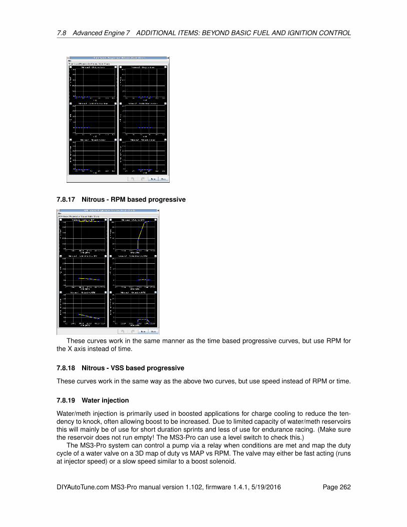
7.8 Advanced Engine 7 ADDITIONAL ITEMS: BEYOND BASIC FUEL AND IGNITION CONTROL
7.8.17 Nitrous - RPM based progressive
These curves work in the same manner as the time based progressive curves, but use RPM forthe X axis instead of time.
7.8.18 Nitrous - VSS based progressive
These curves work in the same way as the above two curves, but use speed instead of RPM or time.
7.8.19 Water injection
Water/meth injection is primarily used in boosted applications for charge cooling to reduce the ten-dency to knock, often allowing boost to be increased. Due to limited capacity of water/meth reservoirsthis will mainly be of use for short duration sprints and less of use for endurance racing. (Make surethe reservoir does not run empty! The MS3-Pro can use a level switch to check this.)
The MS3-Pro system can control a pump via a relay when conditions are met and map the dutycycle of a water valve on a 3D map of duty vs MAP vs RPM. The valve may either be fast acting (runsat injector speed) or a slow speed similar to a boost solenoid.
DIYAutoTune.com MS3-Pro manual version 1.102, firmware 1.4.1, 5/19/2016 Page 262
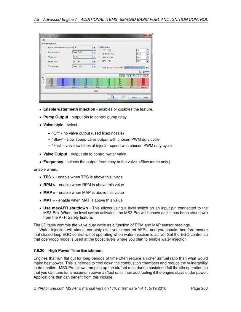
7.8 Advanced Engine 7 ADDITIONAL ITEMS: BEYOND BASIC FUEL AND IGNITION CONTROL
• Enable water/meth injection - enables or disables the feature.
• Pump Output - output pin to control pump relay.
• Valve style - select
– "Off" - no valve output (used fixed nozzle)
– "Slow" - slow speed valve output with chosen PWM duty cycle
– "Fast" - valve switches at injector speed with chosen PWM duty cycle
• Valve Output - output pin to control water valve.
• Frequency - selects the output frequency to the valve. (Slow mode only.)
Enable when...
• TPS > - enable when TPS is above this %age
• RPM > - enable when RPM is above this value
• MAP > - enable when MAP is above this value
• MAT > - enable when MAT is above this value
• Use maxAFR shutdown - This allows using a level switch on an input pin connected to theMS3-Pro. When the level switch activates, the MS3-Pro will behave as if it has been shut downfrom the AFR Safety feature.
The 3D table controls the valve duty cycle as a function of RPM and MAP sensor readings.Water injection will almost certainly alter your reported AFRs, and you should therefore ensure
that closed-loop EGO control is not operating when water injection is active. Set the EGO control sothat open-loop mode is used at the boost levels where you plan to enable water injection.
7.8.20 High Power Time Enrichment
Engines that run flat out for long periods of time often require a richer air/fuel ratio than what wouldmake best power. This is needed to cool down the combustion chambers and reduce the vulnerabilityto detonation. MS3-Pro allows ramping up the air/fuel ratio during sustained full throttle operation sothat you can tune for a maximum power air/fuel ratio, then add fueling if the engine stays under power.Applications that can benefit from this include:
DIYAutoTune.com MS3-Pro manual version 1.102, firmware 1.4.1, 5/19/2016 Page 263

7.8 Advanced Engine 7 ADDITIONAL ITEMS: BEYOND BASIC FUEL AND IGNITION CONTROL
• Road race vehicles
• Boats
• Air cooled engines
To use this feature, you will need to turn on Incorporate AFR Target under Basic / Load Settings ->General Settings.
You can specify the minimum load and RPM to apply this feature. Once the engine is running inthis range and this feature is active, it will adjust the air/fuel ratio as a function of time until the enginedrops below the active load or RPM range. The curve specifies AFR decrease (richer) vs. time. Itis normal for the first row to be 0, 0. The second row typically specifies when the enrichment shouldbegin. e.g. 7, 0. This means that there is no change from 0-7 seconds as both are set to a 0 decreasein AFR. The third row onwards specify the richening.
7.8.21 Oil Pressure
The MS3-Pro can monitor oil pressure and trigger a smart warning light. This feature can also beused to trigger the check engine light. Setting the minimum pressure to more than zero on startup willensure that the oil pressure warning light turns on when you turn the key on, so you can make sureit is working. The light will come on if the oil pressure goes above the maximum pressure vs RPMcurve or below the minimum pressure curve. You will need to define the input sensor under GenericSensors.
DIYAutoTune.com MS3-Pro manual version 1.102, firmware 1.4.1, 5/19/2016 Page 264

7.8 Advanced Engine 7 ADDITIONAL ITEMS: BEYOND BASIC FUEL AND IGNITION CONTROL
7.8.22 Pit lane limiter
This allows you to apply a speed limiter in the pit lane of a road course as long as an input switch isactivated.
• Pit limiter enable - Toggles this feature on or off.
• Input - Specifies what switch to use to the speed limiter.
• Mode - Fixed mode uses a single speed. Holding mode will hold your speed limit at the speedwhen the switch is activated.
DIYAutoTune.com MS3-Pro manual version 1.102, firmware 1.4.1, 5/19/2016 Page 265

7.8 Advanced Engine 7 ADDITIONAL ITEMS: BEYOND BASIC FUEL AND IGNITION CONTROL
• Use VSS or RPM target - In holding mode, this allows you to use either the vehicle speedsensor or RPM to determine speed. Fixed mode always uses VSS.
• Speed - The maximum speed in fixed mode.
• Speed control range - Control range of speed to apply limiters across. 5mph recommendedas a starting point. Setting the range too small will cause oscillation.
• RPM control range - Control range of RPM to apply limiters across. Setting the range too smallwill cause oscillation.
• Tracking sensitivity - Adjust tracking sensitivity to adjust limiter window. Initially the 0% fuel/sparkcut is applied at the limit and full cut is applied at the limit+range. If the speed is above the limit,the lower limiting point is lowered slowly.
• Spark retard mode - Allows using spark retard while the speed limiter is activated.
• Maximum retard - The most spark retard allowed, in degrees from the regular timing table.
• Enable spark cut limiting - Allows using a spark cut as pit speed rev limiter.
• Enable fuel cut limiting - Allows using a fuel cut as pit speed rev limiter.
• Progressive fuel cut - Ramps in the fuel cut instead of appying it all at once. Requires sequen-tial injection to be enabled.
7.8.23 Programmable on/off outputs
This screen is for setting up generic on/off outputs for features like shift lights, variable intake controlsolenoids, and other items that don’t need complicated control settings.
Note that if you’re using one of these outputs for another function, you don’t want to enable it here.For example, if you’re using PWM / Idle Out 1 for idle control, don’t enable it here. Enabling it here willtell the MS3-Pro that you’re trying to use PWM / Idle Out 1 as some sort of on/off output at the sametime, and the MS3-Pro will report a configuration error.
7.8.23.1 Output port pane In the left hand pane, ports currently configured through this systemare shown with a green bulb. To configure a port, click on the name to highlight it and then view oralter the settings in the right hand pane.
DIYAutoTune.com MS3-Pro manual version 1.102, firmware 1.4.1, 5/19/2016 Page 266

7.8 Advanced Engine 7 ADDITIONAL ITEMS: BEYOND BASIC FUEL AND IGNITION CONTROL
7.8.23.2 Port settings pane
• Enabled This enables or disables the selected port. (Toggles green bulb on/off) Do not try toconfigure a port already used for another feature.
• Power On Value Whether the output should be on or off when MS3-Pro first starts. Ensure thatthis matches up with the conditions the MS3-Pro is likely to see on startup.
• Trigger Value The output state when your conditions are met. Typical settings would have thepower on value as Off and the trigger value as On.
7.8.23.3 Conditions This pane is where you specify the logic that activates the output.
Output channel This is a list of MegaSquirt variables - much the same as the various gaugesyou can select in TunerStudio.
> = < This “logical operator” forms part of the equation.
• > is greater than
• = is equals. Usually, you don’t want to use the = sign here. This will turn on the output onlywhen the variable is exactly equal to the threshold number, with zero difference. There are afew variables, such as SD card error conditions, where this can be useful. Most of the time, avariable won’t hit your threshold right on the nose, and the output will stay unactivated.
• < is less than
Threshold The value compared against.
Hysteresis It is very common for a value to hover around the threshold, which would cause theoutput to turn on and off rapidly. This setting helps to prevent that by creating a dead band below thethreshold before the output turns back off again.
• & is a bitwise AND function. This is normally used with Status, CELStatus, or Port fields. Boththe Threshold and Hysteresis values work completely differently when using this mode. Thisoutput is triggered when the result of performing a bitwise AND function between the parameterand the threshold is equal to the hysteresis value.
For example, suppose you want a value to activate when launch control is armed, but not active.Looking at the Status2 field, we see we have the following bits in the field.
128 64 32 16 8 4 2 1Closed
loop idleOverboostprotection
Spark cut Flat shiftactive
Launchcontrolactive
Launchcontrolarmed
Nitrousstage 2active
Nitrousstage 1active
We see launch control active has a value of 8, and launch control armed has a value of 4. So tolook at both these bits, we add these values together and set the “threshold” (bitmask) to 12. Thebitmask “trims down” the Status2 field like this:
128 64 32 16 8 4 2 1Blocked by
bitmaskBlocked by
bitmaskBlocked by
bitmaskBlocked by
bitmaskLaunchcontrolactive
Launchcontrolarmed
Blocked bybitmask
Blocked bybitmask
DIYAutoTune.com MS3-Pro manual version 1.102, firmware 1.4.1, 5/19/2016 Page 267
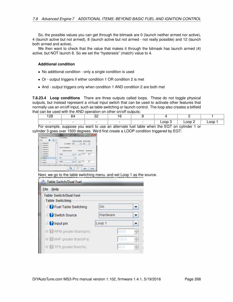
7.8 Advanced Engine 7 ADDITIONAL ITEMS: BEYOND BASIC FUEL AND IGNITION CONTROL
So, the possible values you can get through the bitmask are 0 (launch neither armed nor active),4 (launch active but not armed), 8 (launch active but not armed - not really possible) and 12 (launchboth armed and active).
We then want to check that the value that makes it through the bitmask has launch armed (4)active, but NOT launch 8. So we set the “hysteresis” (match) value to 4.
Additional condition
• No additional condition - only a single condition is used
• Or - output triggers if either condition 1 OR condition 2 is met
• And - output triggers only when condition 1 AND condition 2 are both met
7.8.23.4 Loop conditions There are three outputs called loops. These do not toggle physicaloutputs, but instead represent a virtual input switch that can be used to activate other features thatnormally use an on/off input, such as table switching or launch control. The loop also creates a bitfieldthat can be used with the AND operation on other on/off outputs:
128 64 32 16 8 4 2 1- - - - - Loop 3 Loop 2 Loop 1
For example, suppose you want to use an alternate fuel table when the EGT on cylinder 1 orcylinder 3 goes over 1500 degrees. We’d first create a LOOP condition triggered by EGT:
Next, we go to the table switching menu, and set Loop 1 as the source.
DIYAutoTune.com MS3-Pro manual version 1.102, firmware 1.4.1, 5/19/2016 Page 268
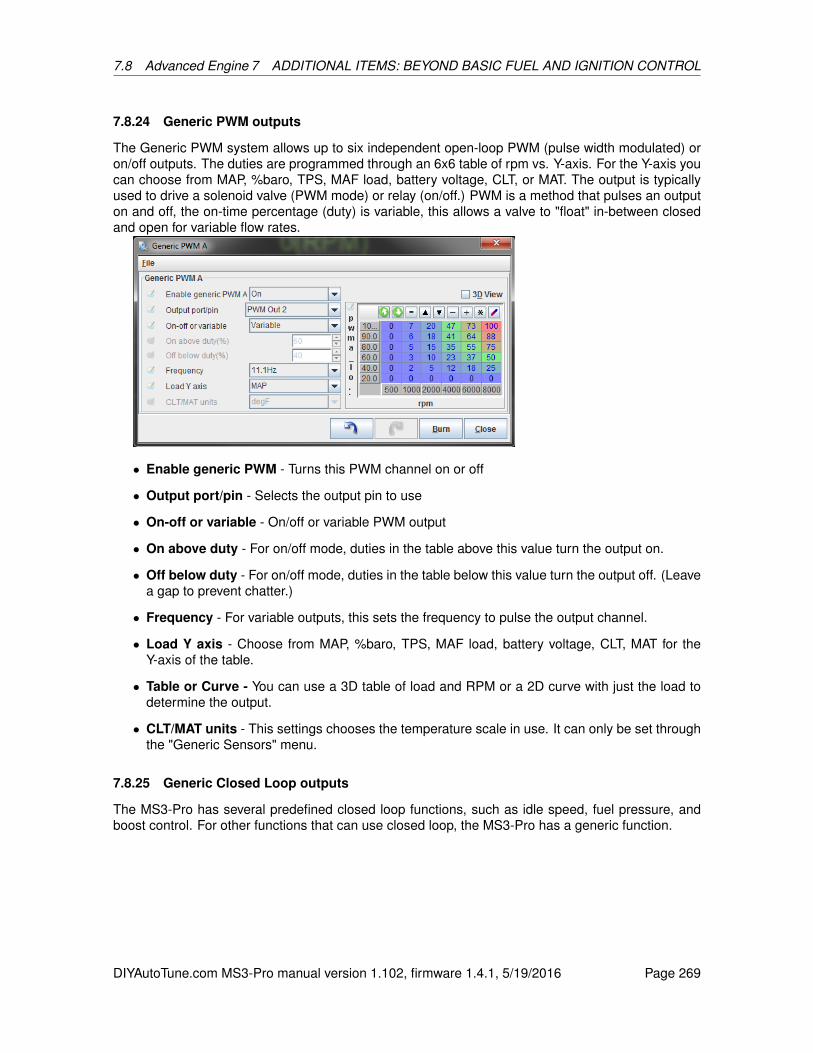
7.8 Advanced Engine 7 ADDITIONAL ITEMS: BEYOND BASIC FUEL AND IGNITION CONTROL
7.8.24 Generic PWM outputs
The Generic PWM system allows up to six independent open-loop PWM (pulse width modulated) oron/off outputs. The duties are programmed through an 6x6 table of rpm vs. Y-axis. For the Y-axis youcan choose from MAP, %baro, TPS, MAF load, battery voltage, CLT, or MAT. The output is typicallyused to drive a solenoid valve (PWM mode) or relay (on/off.) PWM is a method that pulses an outputon and off, the on-time percentage (duty) is variable, this allows a valve to "float" in-between closedand open for variable flow rates.
• Enable generic PWM - Turns this PWM channel on or off
• Output port/pin - Selects the output pin to use
• On-off or variable - On/off or variable PWM output
• On above duty - For on/off mode, duties in the table above this value turn the output on.
• Off below duty - For on/off mode, duties in the table below this value turn the output off. (Leavea gap to prevent chatter.)
• Frequency - For variable outputs, this sets the frequency to pulse the output channel.
• Load Y axis - Choose from MAP, %baro, TPS, MAF load, battery voltage, CLT, MAT for theY-axis of the table.
• Table or Curve - You can use a 3D table of load and RPM or a 2D curve with just the load todetermine the output.
• CLT/MAT units - This settings chooses the temperature scale in use. It can only be set throughthe "Generic Sensors" menu.
7.8.25 Generic Closed Loop outputs
The MS3-Pro has several predefined closed loop functions, such as idle speed, fuel pressure, andboost control. For other functions that can use closed loop, the MS3-Pro has a generic function.
DIYAutoTune.com MS3-Pro manual version 1.102, firmware 1.4.1, 5/19/2016 Page 269
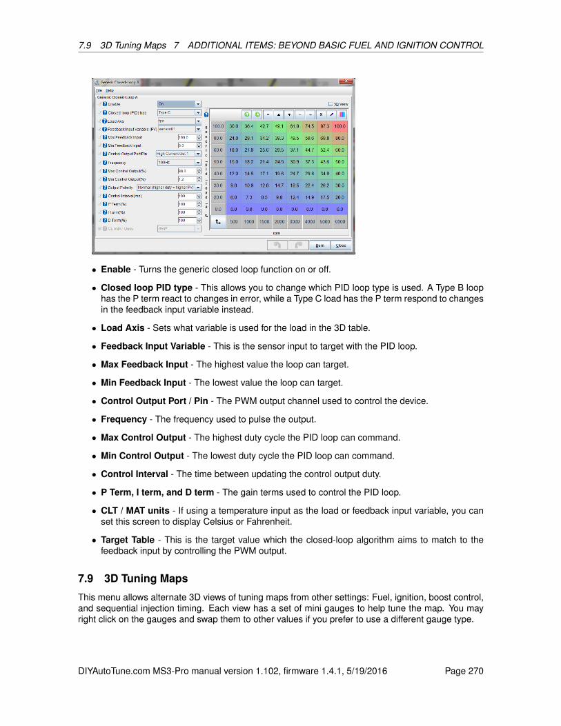
7.9 3D Tuning Maps 7 ADDITIONAL ITEMS: BEYOND BASIC FUEL AND IGNITION CONTROL
• Enable - Turns the generic closed loop function on or off.
• Closed loop PID type - This allows you to change which PID loop type is used. A Type B loophas the P term react to changes in error, while a Type C load has the P term respond to changesin the feedback input variable instead.
• Load Axis - Sets what variable is used for the load in the 3D table.
• Feedback Input Variable - This is the sensor input to target with the PID loop.
• Max Feedback Input - The highest value the loop can target.
• Min Feedback Input - The lowest value the loop can target.
• Control Output Port / Pin - The PWM output channel used to control the device.
• Frequency - The frequency used to pulse the output.
• Max Control Output - The highest duty cycle the PID loop can command.
• Min Control Output - The lowest duty cycle the PID loop can command.
• Control Interval - The time between updating the control output duty.
• P Term, I term, and D term - The gain terms used to control the PID loop.
• CLT / MAT units - If using a temperature input as the load or feedback input variable, you canset this screen to display Celsius or Fahrenheit.
• Target Table - This is the target value which the closed-loop algorithm aims to match to thefeedback input by controlling the PWM output.
7.9 3D Tuning Maps
This menu allows alternate 3D views of tuning maps from other settings: Fuel, ignition, boost control,and sequential injection timing. Each view has a set of mini gauges to help tune the map. You mayright click on the gauges and swap them to other values if you prefer to use a different gauge type.
DIYAutoTune.com MS3-Pro manual version 1.102, firmware 1.4.1, 5/19/2016 Page 270
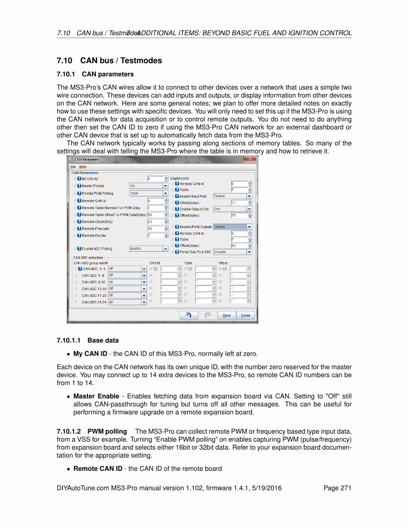
7.10 CAN bus / Testmodes7 ADDITIONAL ITEMS: BEYOND BASIC FUEL AND IGNITION CONTROL
7.10 CAN bus / Testmodes
7.10.1 CAN parameters
The MS3-Pro’s CAN wires allow it to connect to other devices over a network that uses a simple twowire connection. These devices can add inputs and outputs, or display information from other deviceson the CAN network. Here are some general notes; we plan to offer more detailed notes on exactlyhow to use these settings with specific devices. You will only need to set this up if the MS3-Pro is usingthe CAN network for data acquisition or to control remote outputs. You do not need to do anythingother then set the CAN ID to zero if using the MS3-Pro CAN network for an external dashboard orother CAN device that is set up to automatically fetch data from the MS3-Pro.
The CAN network typically works by passing along sections of memory tables. So many of thesettings will deal with telling the MS3-Pro where the table is in memory and how to retrieve it.
7.10.1.1 Base data
• My CAN ID - the CAN ID of this MS3-Pro, normally left at zero.
Each device on the CAN network has its own unique ID, with the number zero reserved for the masterdevice. You may connect up to 14 extra devices to the MS3-Pro, so remote CAN ID numbers can befrom 1 to 14.
• Master Enable - Enables fetching data from expansion board via CAN. Setting to "Off" stillallows CAN-passthrough for tuning but turns off all other messages. This can be useful forperforming a firmware upgrade on a remote expansion board.
7.10.1.2 PWM polling The MS3-Pro can collect remote PWM or frequency based type input data,from a VSS for example. Turning “Enable PWM polling” on enables capturing PWM (pulse/frequency)from expansion board and selects either 16bit or 32bit data. Refer to your expansion board documen-tation for the appropriate setting.
• Remote CAN ID - the CAN ID of the remote board
DIYAutoTune.com MS3-Pro manual version 1.102, firmware 1.4.1, 5/19/2016 Page 271
7.10 CAN bus / Testmodes7 ADDITIONAL ITEMS: BEYOND BASIC FUEL AND IGNITION CONTROL
• Enable PWM polling - enable or disable this feature
• Remote table number for PWM data - varies by application
• Remote table offset for PWM data - varies by application.
• Remote clock - The clock on the remote device
• Remote prescale - If used a prescale divider
• Remote divider - If used a clock divider
7.10.1.3 Digital I/O This allows the MS3 to use up to eight remote on/off inputs (CANIN1-8) andup to sixteen remote on/off outputs (CANOUT1-16). CANIN1 is bit 0 from the remote input port andCANIN8 is bit7. CANOUT1 is bit 0 from the first remote output port and CANOUT8 is bit7. CANOUT9is bit 0 from the second remote output port and CANIN16 is bit7.
• Remote CAN Id - the remote CANid to fetch from
• Table - the remote table number
• Enable input port - enable remote input port
• Offset - the offset number in the remote table
• Enable output port - enable remote output port
• Offset - the offset number in the remote table
7.10.1.4 PWM outputs MS3-Pro can command PWM outputs on remote CAN devices. You willneed to refer to your CAN device’s documentation for the appropriate settings to use.
• Enable PWM outputs - Enables sending PWM/pulsed outputs to expansion board.
• Remote CAN ID - Enables sending PWM/pulsed outputs to expansion board.
• Table - Enables sending PWM/pulsed outputs to expansion board.
• Offset - Data offset on the expansion board used for PWM outputs.
• Forde duty to 0-255 - Normally, PWM duty cycles read on a 0-100% scale. However, someremote devices require an 8 bit, 0 to 255 scale. This setting enables the 8 bit scaling.
7.10.1.5 Analog (ADC) inputs over CAN This allows additional analogue inputs to be capturedfrom remote CAN devices and used with most MS3 features. The code allows up to 24 remote CANADCs. The dropdown menus (e.g. EGT) allow you to select either a local ADC or a remote CANADC.Before attempting to use the chosen CANADC, you need to enable it on this CAN settings menu. Dueto data sizes, the CANADCs are configured in groups of four. The exact table and offset numbers arespecific to the configuration of the remote device.
• Enable ADC polling - enable or disable the feature
• CAN ADC 1-4 - enable or disable this group.
• CAN Id - the remote CANid to fetch from
• Table - the remote table number
• Offset - the offset number in the remote table
DIYAutoTune.com MS3-Pro manual version 1.102, firmware 1.4.1, 5/19/2016 Page 272
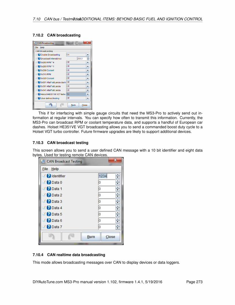
7.10 CAN bus / Testmodes7 ADDITIONAL ITEMS: BEYOND BASIC FUEL AND IGNITION CONTROL
7.10.2 CAN broadcasting
This if for interfacing with simple gauge circuits that need the MS3-Pro to actively send out in-formation at regular intervals. You can specify how often to transmit this information. Currently, theMS3-Pro can broadcast RPM or coolant temperature data, and supports a handful of European cardashes. Holset HE351VE VGT broadcasting allows you to send a commanded boost duty cycle to aHolset VGT turbo controller. Future firmware upgrades are likely to support additional devices.
7.10.3 CAN broadcast testing
This screen allows you to send a user defined CAN message with a 10 bit identifier and eight databytes. Used for testing remote CAN devices.
7.10.4 CAN realtime data broadcasting
This mode allows broadcasting messages over CAN to display devices or data loggers.
DIYAutoTune.com MS3-Pro manual version 1.102, firmware 1.4.1, 5/19/2016 Page 273
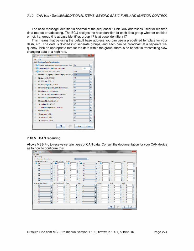
7.10 CAN bus / Testmodes7 ADDITIONAL ITEMS: BEYOND BASIC FUEL AND IGNITION CONTROL
The base message identifier in decimal of the sequential 11-bit CAN addresses used for realtimedata (outpc) broadcasting. The ECU assigns the next identifier for each data group whether enabledor not. i.e. group 0 is at base identifier, group 17 is at base identifier+17
This means that by using the default base address you can use a predefined template for yourdash, etc. The data is divided into separate groups, and each can be broadcast at a separate fre-quency. Pick an appropriate rate for the data within the group; there is no benefit in transmitting slowchanging data at a high rate.
7.10.5 CAN receiving
Allows MS3-Pro to receive certain types of CAN data. Consult the documentation for your CAN deviceas to how to configure this.
DIYAutoTune.com MS3-Pro manual version 1.102, firmware 1.4.1, 5/19/2016 Page 274
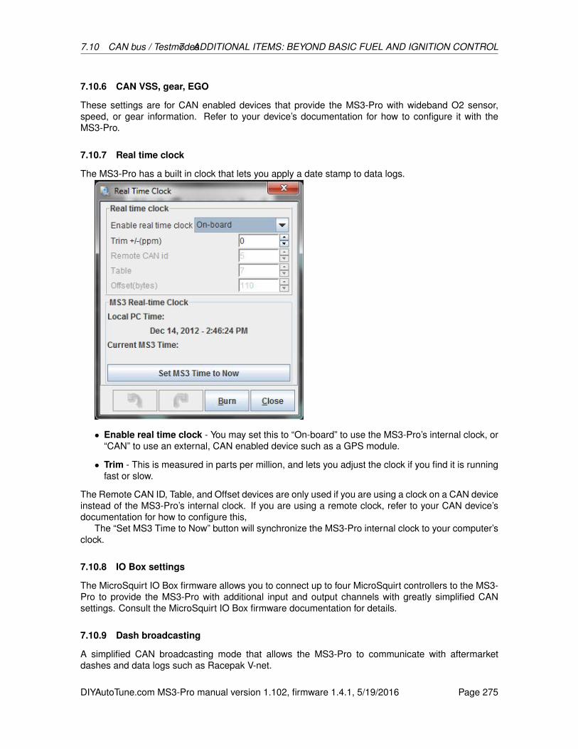
7.10 CAN bus / Testmodes7 ADDITIONAL ITEMS: BEYOND BASIC FUEL AND IGNITION CONTROL
7.10.6 CAN VSS, gear, EGO
These settings are for CAN enabled devices that provide the MS3-Pro with wideband O2 sensor,speed, or gear information. Refer to your device’s documentation for how to configure it with theMS3-Pro.
7.10.7 Real time clock
The MS3-Pro has a built in clock that lets you apply a date stamp to data logs.
• Enable real time clock - You may set this to “On-board” to use the MS3-Pro’s internal clock, or“CAN” to use an external, CAN enabled device such as a GPS module.
• Trim - This is measured in parts per million, and lets you adjust the clock if you find it is runningfast or slow.
The Remote CAN ID, Table, and Offset devices are only used if you are using a clock on a CAN deviceinstead of the MS3-Pro’s internal clock. If you are using a remote clock, refer to your CAN device’sdocumentation for how to configure this,
The “Set MS3 Time to Now” button will synchronize the MS3-Pro internal clock to your computer’sclock.
7.10.8 IO Box settings
The MicroSquirt IO Box firmware allows you to connect up to four MicroSquirt controllers to the MS3-Pro to provide the MS3-Pro with additional input and output channels with greatly simplified CANsettings. Consult the MicroSquirt IO Box firmware documentation for details.
7.10.9 Dash broadcasting
A simplified CAN broadcasting mode that allows the MS3-Pro to communicate with aftermarketdashes and data logs such as Racepak V-net.
DIYAutoTune.com MS3-Pro manual version 1.102, firmware 1.4.1, 5/19/2016 Page 275
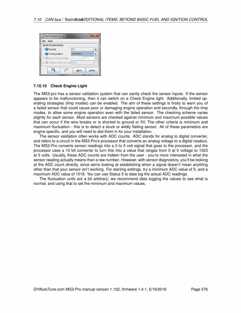
7.10 CAN bus / Testmodes7 ADDITIONAL ITEMS: BEYOND BASIC FUEL AND IGNITION CONTROL
7.10.10 Check Engine Light
The MS3-pro has a sensor validation system that can sanity check the sensor inputs. If the sensorappears to be malfunctioning, then it can switch on a Check Engine light. Additionally, limited op-erating strategies (limp modes) can be enabled. The aim of these settings is firstly to warn you ofa failed sensor that could cause poor or damaging engine operation and secondly, through the limpmodes, to allow some engine operation even with the failed sensor. The checking scheme variesslightly for each sensor. Most sensors are checked against minimum and maximum possible valuesthat can occur if the wire breaks or is shorted to ground or 5V. The other criteria is minimum andmaximum fluctuation - this is to detect a stuck or wildly flailing sensor. All of these parameters areengine specific, and you will need to dial them in for your installation.
The sensor validation often works with ADC counts. ADC stands for analog to digital converter,and refers to a circuit in the MS3-Pro’s processor that converts an analog voltage to a digital readout.The MS3-Pro converts sensor readings into a 0 to 5 volt signal that goes to the processor, and theprocessor uses a 10 bit converter to turn this into a value that ranges from 0 at 0 voltage to 1023at 5 volts. Usually, these ADC counts are hidden from the user - you’re more interested in what thesensor reading actually means than a raw number. However, with sensor diagnostics, you’ll be lookingat the ADC count directly, since we’re looking at establishing when a signal doesn’t mean anythingother than that your sensor isn’t working. For starting settings, try a minimum ADC value of 5, and amaximum ADC value of 1018. You can use Status 5 to data log the actual ADC readings.
The fluctuation units are a bit arbitrary; we recommend data logging the values to see what isnormal, and using that to set the minimum and maximum values.
DIYAutoTune.com MS3-Pro manual version 1.102, firmware 1.4.1, 5/19/2016 Page 276

7.10 CAN bus / Testmodes7 ADDITIONAL ITEMS: BEYOND BASIC FUEL AND IGNITION CONTROL
• Sensor checking - Enables or disables this system
• Light output - Selects an optional output for the Check Engine Light. Recommended. Notethat this can share a channel with the AFR Safety warning light.
• CEL Solid / Flash Codes - You can have the Check Engine light stay on, or transmit flashcodes.
• Light When Not Running - Specify if the Check Engine light should be off or on when theengine RPM is at zero.
• Ignore fluctuations for first - The number of seconds that sensor fluctuations are ignored afterstartup. This is to allow conditions to settle down and avoid false alarms.
• MAP sensor check - Enable or disable checking of the MAP sensor input.
• Minimum ADC - minimum valid ADC reading for the MAP sensor
• Maximum ADC - maximum valid ADC reading for the MAP sensor
• Minimum Fluctuation - minimum fluctuation during smooth running
• Maximum Fluctuation - maximum fluctuation during operation
The minimum fluctuation setting is likely the most useful setting here, as it can be used to detecta failed or "stuck" sensor, or if a hose fell off. A correctly operating MAP sensor will not produce aperfectly flat value on a running engine.
• MAT sensor check - Enable or disable checking of the MAT sensor input.
• Minimum ADC - minimum valid ADC reading for the MAT sensor
DIYAutoTune.com MS3-Pro manual version 1.102, firmware 1.4.1, 5/19/2016 Page 277
7.10 CAN bus / Testmodes7 ADDITIONAL ITEMS: BEYOND BASIC FUEL AND IGNITION CONTROL
• Maximum ADC - maximum valid ADC reading for the MAT sensor
• Maximum Fluctuation - maximum fluctuation during operation
• CLT sensor check - Enable or disable checking of the CLT sensor input.
• Minimum ADC - minimum valid ADC reading for the CLT sensor
• Maximum ADC - maximum valid ADC reading for the CLT sensor
• Maximum Fluctuation - maximum fluctuation during operation
The CLT sensor should be smooth in operation; the max fluctuations can be used to detect a fault.You’re likely to see a lower maximum fluctuation value here than on most other sensors. Not only doyou have a sensor with a fairly large thermal mass, but the coolant and engine block aren’t going tochange temperature very quickly.
• TPS sensor check - Enable or disable checking of the TPS sensor input.
• Minimum ADC - minimum valid ADC reading for the TPS sensor
• Maximum ADC - maximum valid ADC reading for the TPS sensor
• Maximum Fluctuation - maximum fluctuation during operation
For the TPS, the minimum and maximum ADC values are the more likely ones to detect a fault. Youcan view the ADC counts at closed and wide open throttle under the Tools menu when you selectCalibrate TPS. A good starting point is a minimum ADC that is 10 counts below the closed throttlecalibration and a maximum ADC 10 counts above the full throttle calibration.
• Battery check - Enable or disable checking of the battery voltage input.
• Minimum voltage - minimum acceptable voltage reading
• Maximum voltage - maximum acceptable voltage reading
• Maximum Fluctuation - maximum fluctuation during operation
This can be used to warn of charging system faults or ground issues causing excessive voltage noise.
• EGO1 sensor check - Enable or disable checking of the EGO1 sensor input.
• Minimum ADC - minimum valid ADC reading for the EGO1 input
• Maximum ADC - maximum valid ADC reading for the EGO1 input
• Minimum Fluctuation - minimum fluctuation during smooth running
• Maximum Fluctuation - maximum fluctuation during operation
The fluctuation settings are key to detecting a failed O2 sensor. Many wideband controllers will get"stuck" if the sensor fails, although appearing to show a valid AFR reading. Combined with closed-loop EGO or autotuning, this can be troublesome without this detection scheme. Other controllersallow an “out of range” voltage output - match the min/max ADC readings to capture this.
• Sync-loss check - Enable or disable checking of sync losses to troubleshoot crank or camsensors.
• No. sync losses allowed - how many recorded losses of tach-in synchronization are allowedbefore setting the CEL. (During normal operation, you may see one or two sync-losses duringstartup. Beyond that, there is a problem with your RPM input wiring or configuration.)
DIYAutoTune.com MS3-Pro manual version 1.102, firmware 1.4.1, 5/19/2016 Page 278

7.10 CAN bus / Testmodes7 ADDITIONAL ITEMS: BEYOND BASIC FUEL AND IGNITION CONTROL
• EGT sensor check - Enable or disable checking of the EGT sensor inputs.
• Minimum EGT - minimum valid EGT while engine is running
• Maximum EGT - maximum valid EGT while engine is running
• Minimum Fluctuation - minimum fluctuation during smooth running
• Maximum Fluctuation - maximum fluctuation during operation ()
The exhaust gas temperatures are not checked immediately after startup, so the minimum tempera-ture can be set to 200C to detect a dead cylinder or faulty sensor. The maximum will depend on yourengine. N/A could be around 900C, boosted perhaps 1000C.
• Flex sensor check - Enable or disable checking of the Flex sensor input. (An error conditionwill be triggered if the frequency on the flex input is outside of the set range.)
• status5 input - Specifies which sensor details are logged in status5 in the data log fields.
• status5 shows - If set the fluctuation, the value of status5 is the fluctuation number the codecalculates and compares to the minimum or maximum for each chosen sensor. e.g. Set thisto MAP and then enable ’status5’ on your dash or view in a datalog. Allow the engine to idleand observe the lowest number. You can then set the MAP minimum fluctuation to some valueLOWER than this number. If the MAP input becomes too stable (e.g. the hose falls off), thenthe alarm will be raised. If set to ADC counts, this shows the raw analog to digital conversionreading of the sensor.
7.10.10.1 Check Engine codes The Check Engine light can be set to flash codes. These codesalso show up as CELStatus in the data logs. The codes are as follows:
• 2: MAP sensor fault
• 3: MAT sensor fault
• 4: CLT sensor fault
• 5: TPS fault
• 6: Battery voltage fault
• 7: O2 sensor fault
• 8: Loss of sync (crank or cam sensor)
• 9: EGT sensor fault
• 10: Flex fuel sensor fault
• 11: MAF sensor fault
• 12: Knock sensor fault
• 13: Cam sensor fault, engine still has sync but is running in semi-sequential
• 14: Oil pressure out of range
• 15: Fuel pressure sensor out of range
• 16: EGT safety shutdown triggered
• 17: AFR safety shutdown triggered
DIYAutoTune.com MS3-Pro manual version 1.102, firmware 1.4.1, 5/19/2016 Page 279
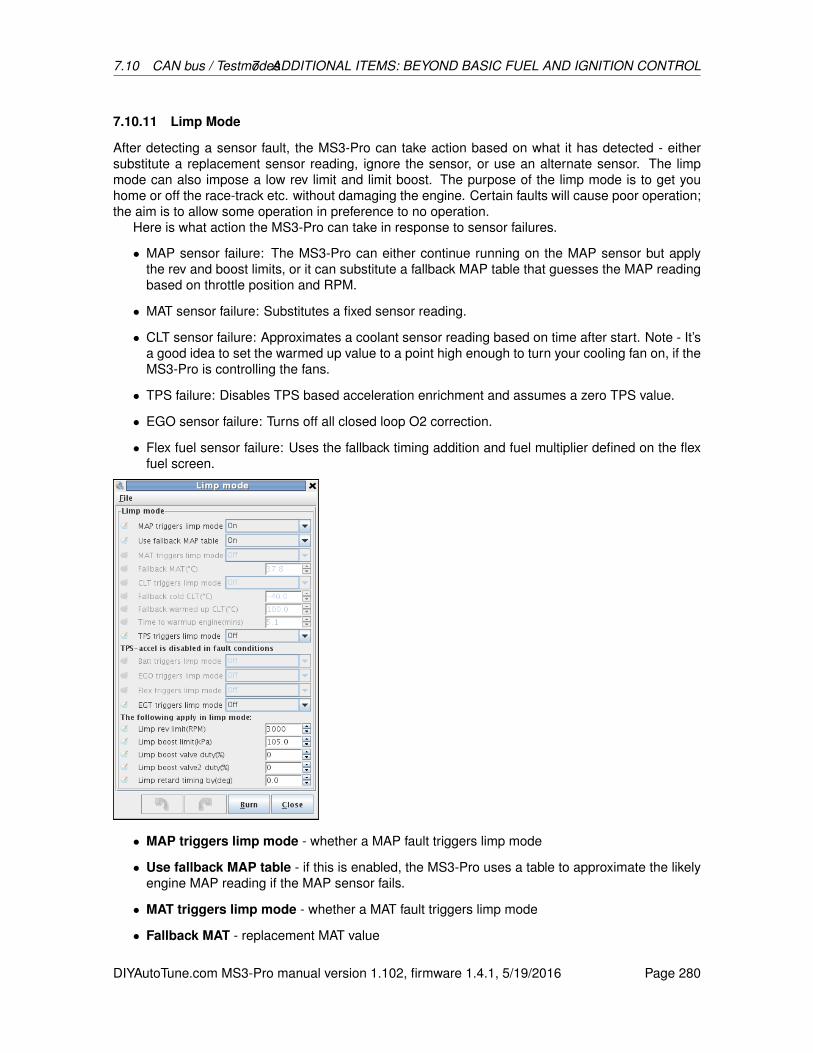
7.10 CAN bus / Testmodes7 ADDITIONAL ITEMS: BEYOND BASIC FUEL AND IGNITION CONTROL
7.10.11 Limp Mode
After detecting a sensor fault, the MS3-Pro can take action based on what it has detected - eithersubstitute a replacement sensor reading, ignore the sensor, or use an alternate sensor. The limpmode can also impose a low rev limit and limit boost. The purpose of the limp mode is to get youhome or off the race-track etc. without damaging the engine. Certain faults will cause poor operation;the aim is to allow some operation in preference to no operation.
Here is what action the MS3-Pro can take in response to sensor failures.
• MAP sensor failure: The MS3-Pro can either continue running on the MAP sensor but applythe rev and boost limits, or it can substitute a fallback MAP table that guesses the MAP readingbased on throttle position and RPM.
• MAT sensor failure: Substitutes a fixed sensor reading.
• CLT sensor failure: Approximates a coolant sensor reading based on time after start. Note - It’sa good idea to set the warmed up value to a point high enough to turn your cooling fan on, if theMS3-Pro is controlling the fans.
• TPS failure: Disables TPS based acceleration enrichment and assumes a zero TPS value.
• EGO sensor failure: Turns off all closed loop O2 correction.
• Flex fuel sensor failure: Uses the fallback timing addition and fuel multiplier defined on the flexfuel screen.
• MAP triggers limp mode - whether a MAP fault triggers limp mode
• Use fallback MAP table - if this is enabled, the MS3-Pro uses a table to approximate the likelyengine MAP reading if the MAP sensor fails.
• MAT triggers limp mode - whether a MAT fault triggers limp mode
• Fallback MAT - replacement MAT value
DIYAutoTune.com MS3-Pro manual version 1.102, firmware 1.4.1, 5/19/2016 Page 280

7.10 CAN bus / Testmodes7 ADDITIONAL ITEMS: BEYOND BASIC FUEL AND IGNITION CONTROL
• CLT triggers limp mode - whether a CLT fault triggers limp mode
• Fallback cold CLT - replacement initial CLT value
• Fallback warmed up CLT - replacement final CLT value
• Time to warmup engine - time taken to blend from cold to warm value (simulating a warmupcycle)
• TPS triggers limp mode - whether a TPS fault triggers limp mode. TPS based acceleration isdisabled if TPS is faulty.
• Batt triggers limp mode - whether an out of range battery voltage reading triggers limp mode
• EGO triggers limp mode - whether an EGO fault triggers limp mode
• Flex triggers limp mode - whether a Flex fault triggers limp mode EGT triggers limp mode -whether an EGT fault triggers limp mode
The settings below are applied when any sensor triggers the limp mode.
• Limp rev limit - the hard fuel cut rev limiter when in limp mode
• Limp boost limit - the boost limit when in limp mode. Typically, this will be no boost to preventengine damage in unknown conditions.
• Limp boost valve duty - forces boost valve1 to a set duty in limp mode.
• Limp boost valve2 duty - forces boost valve2 to a set duty in limp mode.
• Limp retard timing by - retards timing by the set amount in limp mode.
7.10.12 Fallback MAP table
In the event of a MAP sensor failure, the MS3-Pro can use a synthesized MAP value based onTPS and Rpm. This will be less accurate than the real MAP reading, but the aim is to allow somedriveability in the absence of a real sensor reading before the root cause failure is fixed.
The initial vales for this table can be derived from datalogs comparing MAP, RPM, TPS whiledriving. You can use MegaLogViewer’s scatter plot feature to see what MAP reading is common forthe throttle position and RPM range in a data log; the shape of the scatter plot will be close to thetable required.
To test and tune this table, unhook the MAP hose and wait until “Limp Mode” engages. Then thistable will be operative and you can tune.
DIYAutoTune.com MS3-Pro manual version 1.102, firmware 1.4.1, 5/19/2016 Page 281
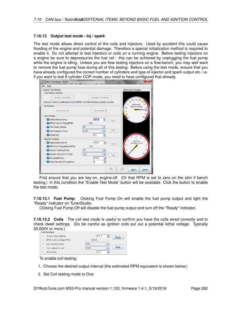
7.10 CAN bus / Testmodes7 ADDITIONAL ITEMS: BEYOND BASIC FUEL AND IGNITION CONTROL
7.10.13 Output test mode - Inj / spark
The test mode allows direct control of the coils and injectors. Used by accident this could causeflooding of the engine and potential damage. Therefore a special initialization method is required toenable it. Do not attempt to test injectors or coils on a running engine. Before testing injectors ona engine be sure to depressurize the fuel rail - this can be achieved by unplugging the fuel pumpwhile the engine is idling. Unless you are flow testing injectors on a flow-bench, you may well wantto remove the fuel pump fuse during all of this testing. Before using the test mode, ensure that youhave already configured the correct number of cylinders and type of injector and spark output etc. i.e.if you want to test 8 cylinder COP mode, you need to have configured that already.
First ensure that you are key-on, engine-off. (Or that RPM is set to zero on the stim if benchtesting.) In this condition the “Enable Test Mode” button will be available. Click the button to enablethe test mode.
7.10.13.1 Fuel Pump Clicking Fuel Pump On will enable the fuel pump output and light the"Ready" indicator on TunerStudio.
Clicking Fuel Pump Off will disable the fuel pump output and turn off the "Ready" indicator.
7.10.13.2 Coils The coil test mode is useful to confirm you have the coils wired correctly and tocheck dwell settings. (Do be careful as ignition coils put out a potential lethal voltage. Typically30,000V or more.)
To enable coil testing:
1. Choose the desired output interval (the estimated RPM equivalent is shown below.)
2. Set Coil testing mode to One
DIYAutoTune.com MS3-Pro manual version 1.102, firmware 1.4.1, 5/19/2016 Page 282

7.10 CAN bus / Testmodes7 ADDITIONAL ITEMS: BEYOND BASIC FUEL AND IGNITION CONTROL
3. Choose which coil to test e.g. Coil A
4. Choose your dwell time in milliseconds. Start low. e.g. 2.5ms.
5. If your coils are powered via the fuel pump relay as is recommended, set the fuel pump to On.
6. With valid settings entered, the Start button should be active - click it.
7. When finished, click Stop.
If the coils get hot or your coil fuses pop, then you almost certainly have a basic settings mistake withoutput polarity. Turn off power immediately and re-visit those settings.
The Coil testing mode called Sequence runs the coils in sequence up to the chosen coil. So if youhave four coils and selected Coil D and Sequence then the test mode will repeatedly fire Coil A, thenCoil B, then Coil C, then Coil D in turn. Note that the test mode does not allow dwell periods to overlapin the sequence mode, unlike normal operation where the dwell periods overlap as required. (This iswhy traditional V8 distributor spark was weak at high revs - there was not enough time to charge thesingle coil between sparks.)
7.10.13.3 Injectors The coil test mode is useful to confirm you have the injectors wired correctlyand to experiment with opening times, PWM settings or to measure flow rate if you have an injectortest bench setup. (Using flammable liquids while testing is hazardous and can lead to serious fires.Non-flammable injector test liquid is available.)
If your injectors are fitted to the engine you MUST NOT run the test mode with fuel pressure,or you will fill your engine with fuel! Remove the fuse from your fuel pump and depressurizethe line first.
When semi-sequential is enabled, the injectors will fire in pairs. To test individually, temporarily setSequential to Off.
To enable injector testing:
1. Choose the desired output interval (the estimated RPM equivalent is shown below.)
2. Set Injector testing mode to One
3. Choose which injector to test e.g. Injector A
4. Choose your pulsewidth time in milliseconds.
5. If your injectors are powered via the fuel pump relay as is recommended, set the fuel pump toOn.
6. For functional testing, set the total number of injections to 65535 (the maximum), or for flowtesting use your chosen number.
7. With valid settings entered, the Start button should be active - click it.
8. The number of injections gauge will count down and stop at zero.
9. To stop testing sooner, click Stop.
When you have finished using the test mode, close the test mode window and power off the MS3-Pro.If you disconnected you fuel pump, reconnect it now.
DIYAutoTune.com MS3-Pro manual version 1.102, firmware 1.4.1, 5/19/2016 Page 283
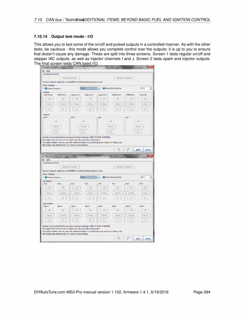
7.10 CAN bus / Testmodes7 ADDITIONAL ITEMS: BEYOND BASIC FUEL AND IGNITION CONTROL
7.10.14 Output test mode - I/O
This allows you to test some of the on/off and pulsed outputs in a controlled manner. As with the othertests, be cautious - this mode allows you complete control over the outputs; it is up to you to ensurethat doesn’t cause any damage. These are split into three screens. Screen 1 tests regular on/off andstepper IAC outputs, as well as injector channels I and J. Screen 2 tests spark and injector outputs.The final screen tests CAN baed I/O.
DIYAutoTune.com MS3-Pro manual version 1.102, firmware 1.4.1, 5/19/2016 Page 284

7.10 CAN bus / Testmodes7 ADDITIONAL ITEMS: BEYOND BASIC FUEL AND IGNITION CONTROL
First ensure that you are key-on, engine-off. In this condition, the “Enable Test Mode” button willbe available. Click the button to enable the test mode. For each of the outputs you can select thefollowing:
• Off - turns the selected output off.
• On - turns the selected output on.
• Pulsed - pulses the output at the selected frequency and duty. (Not available on the fuel pump.)
Except for the Tach channel and stepper IAC outputs, all of these outputs are ground switched, soyou will not be able to see their status with a volt meter. Use a small test lamp or test LED connectedbetween 12V and the output, if you are not using them with a solenoid or the actual device you will bedriving.
7.10.15 Output test mode - idle valve
The idle valve test mode can be used with the engine running or stationary. Note that with a PWMidle valve you may need to run a temporary fused 12V supply to the valve if you normally take powerfrom the fuel pump relay and are testing with the engine off. You need to have enabled idle controlbefore this is available.
DIYAutoTune.com MS3-Pro manual version 1.102, firmware 1.4.1, 5/19/2016 Page 285
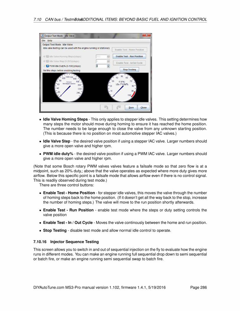
7.10 CAN bus / Testmodes7 ADDITIONAL ITEMS: BEYOND BASIC FUEL AND IGNITION CONTROL
• Idle Valve Homing Steps - This only applies to stepper idle valves. This setting determines howmany steps the motor should move during homing to ensure it has reached the home position.The number needs to be large enough to close the valve from any unknown starting position.(This is because there is no position on most automotive stepper IAC valves.)
• Idle Valve Step - the desired valve position if using a stepper IAC valve. Larger numbers shouldgive a more open valve and higher rpm.
• PWM idle duty% - the desired valve position if using a PWM IAC valve. Larger numbers shouldgive a more open valve and higher rpm.
(Note that some Bosch rotary PWM valves valves feature a failsafe mode so that zero flow is at amidpoint, such as 20% duty,; above that the valve operates as expected where more duty gives moreairflow. Below this specific point is a failsafe mode that allows airflow even if there is no control signal.This is readily observed during test mode.)
There are three control buttons:
• Enable Test - Home Position - for stepper idle valves, this moves the valve through the numberof homing steps back to the home position. (If it doesn’t get all the way back to the stop, increasethe number of homing steps.) The valve will move to the run position shortly afterwards.
• Enable Test - Run Position - enable test mode where the steps or duty setting controls thevalve position
• Enable Test - In / Out Cycle - Moves the valve continously between the home and run position.
• Stop Testing - disable test mode and allow normal idle control to operate.
7.10.16 Injector Sequence Testing
This screen allows you to switch in and out of sequential injection on the fly to evaluate how the engineruns in different modes. You can make an engine running full sequential drop down to semi sequentialor batch fire, or make an engine running semi sequential swap to batch fire.
DIYAutoTune.com MS3-Pro manual version 1.102, firmware 1.4.1, 5/19/2016 Page 286
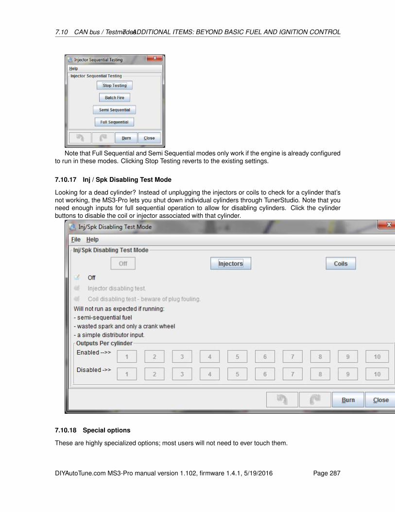
7.10 CAN bus / Testmodes7 ADDITIONAL ITEMS: BEYOND BASIC FUEL AND IGNITION CONTROL
Note that Full Sequential and Semi Sequential modes only work if the engine is already configuredto run in these modes. Clicking Stop Testing reverts to the existing settings.
7.10.17 Inj / Spk Disabling Test Mode
Looking for a dead cylinder? Instead of unplugging the injectors or coils to check for a cylinder that’snot working, the MS3-Pro lets you shut down individual cylinders through TunerStudio. Note that youneed enough inputs for full sequential operation to allow for disabling cylinders. Click the cylinderbuttons to disable the coil or injector associated with that cylinder.
7.10.18 Special options
These are highly specialized options; most users will not need to ever touch them.
DIYAutoTune.com MS3-Pro manual version 1.102, firmware 1.4.1, 5/19/2016 Page 287
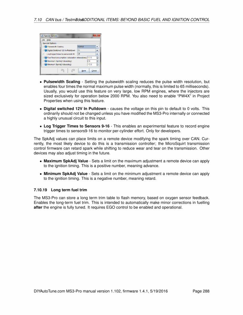
7.10 CAN bus / Testmodes7 ADDITIONAL ITEMS: BEYOND BASIC FUEL AND IGNITION CONTROL
• Pulsewidth Scaling - Setting the pulsewidth scaling reduces the pulse width resolution, butenables four times the normal maximum pulse width (normally, this is limited to 65 milliseconds).Usually, you would use this feature on very large, low RPM engines, where the injectors aresized exclusively for operation below 2000 RPM. You also need to enable “PW4X” in ProjectProperties when using this feature.
• Digital switched 12V In Pulldown - causes the voltage on this pin to default to 0 volts. Thisordinarily should not be changed unless you have modified the MS3-Pro internally or connecteda highly unusual circuit to this input.
• Log Trigger Times to Sensors 9-16 - This enables an experimental feature to record enginetrigger times to sensors9-16 to monitor per-cylinder effort. Only for developers.
The SpkAdj values can place limits on a remote device modifying the spark timing over CAN. Cur-rently, the most likely device to do this is a transmission controller; the MicroSquirt transmissioncontrol firmware can retard spark while shifting to reduce wear and tear on the transmission. Otherdevices may also adjust timing in the future.
• Maximum SpkAdj Value - Sets a limit on the maximum adjustment a remote device can applyto the ignition timing. This is a positive number, meaning advance.
• Minimum SpkAdj Value - Sets a limit on the minimum adjustment a remote device can applyto the ignition timing. This is a negative number, meaning retard.
7.10.19 Long term fuel trim
The MS3-Pro can store a long term trim table to flash memory, based on oxygen sensor feedback.Enables the long-term fuel trim. This is intended to automatically make minor corrections in fuellingafter the engine is fully tuned. It requires EGO control to be enabled and operational.
DIYAutoTune.com MS3-Pro manual version 1.102, firmware 1.4.1, 5/19/2016 Page 288

7.10 CAN bus / Testmodes7 ADDITIONAL ITEMS: BEYOND BASIC FUEL AND IGNITION CONTROL
• Enable experimental long term trim - Turns on the ability to store and write long term fuel trimtables.
• Sample interval - How often, in seconds, the code checks the amount of EGO correction beingapplied.
• Correction softness - Controls how aggressively the trim is applied. Larger numbers mean asofter amount of correction.
• Write method - Allows you to select writing the trim table to flash based on timed updates ortriggered with an external button.
• Burn button - If using button input, specifies which input triggers writing the long term trim table.
• Burn interval - Minimum time, in minutes, before updating the long term trim to flash.
• LED output - Turns on an output when the amount of trim change exceeds the total changethreshold, to let you know the ECU needs the trim to be burned to flash.
• Total change before burning - In timed write mode, the MS3-Pro will automatically burn thetrim table to flash if it changes by this large a percentage. In button mode, this will turn on theLED indicator.
• Display current % change in sensor 15 - Allows using the Sensor 15 generic sensor to readthe percent of change to long term trim.
• Read Table 1 to RAM - This takes the saved table #1 and copies it to the working RAM area.
• Read Table 2 to RAM - This takes the saved table #2 and copies it to the working RAM area.
• Burn Table to Flash - This takes the saved table #1 and copies it to the working RAM area.
• Zero Tables - This resets the working table and two saved tables to zero trim. It should be usedafter tuning the VE table.
DIYAutoTune.com MS3-Pro manual version 1.102, firmware 1.4.1, 5/19/2016 Page 289
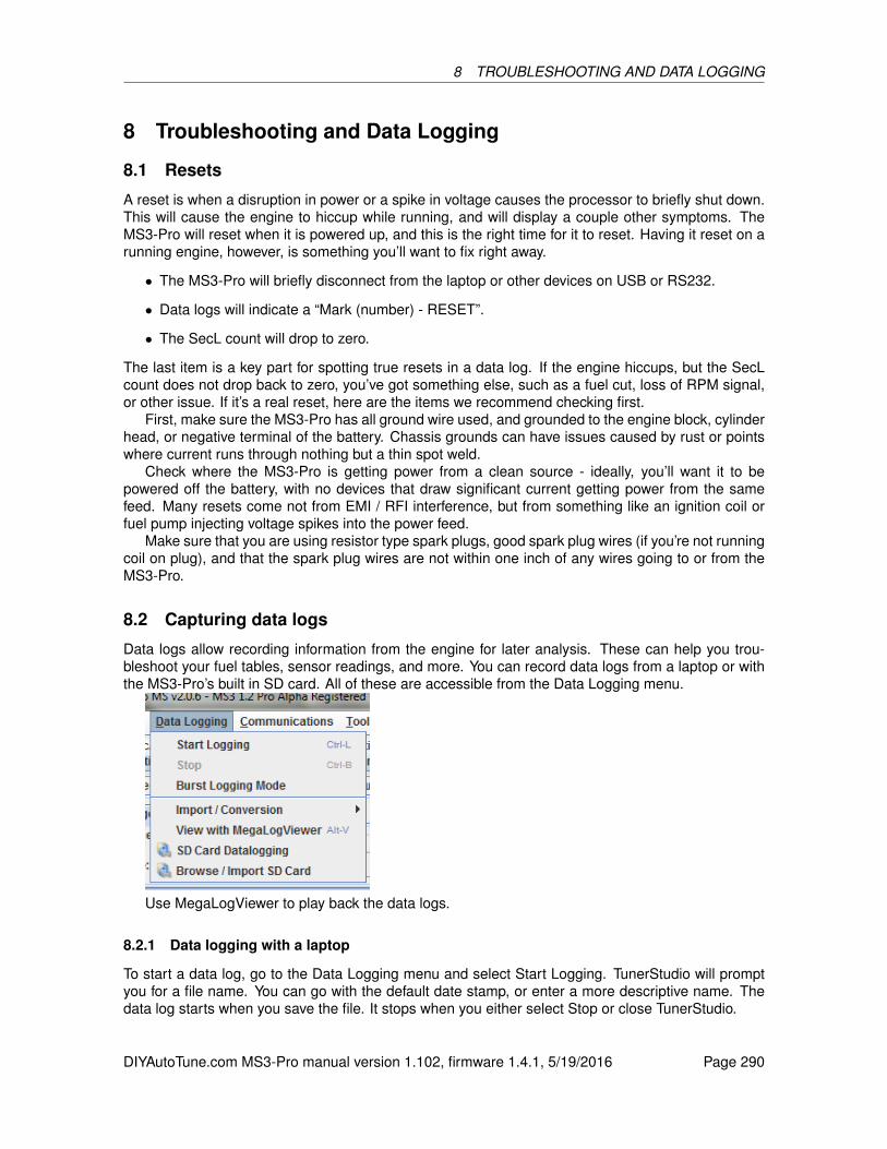
8 TROUBLESHOOTING AND DATA LOGGING
8 Troubleshooting and Data Logging
8.1 Resets
A reset is when a disruption in power or a spike in voltage causes the processor to briefly shut down.This will cause the engine to hiccup while running, and will display a couple other symptoms. TheMS3-Pro will reset when it is powered up, and this is the right time for it to reset. Having it reset on arunning engine, however, is something you’ll want to fix right away.
• The MS3-Pro will briefly disconnect from the laptop or other devices on USB or RS232.
• Data logs will indicate a “Mark (number) - RESET”.
• The SecL count will drop to zero.
The last item is a key part for spotting true resets in a data log. If the engine hiccups, but the SecLcount does not drop back to zero, you’ve got something else, such as a fuel cut, loss of RPM signal,or other issue. If it’s a real reset, here are the items we recommend checking first.
First, make sure the MS3-Pro has all ground wire used, and grounded to the engine block, cylinderhead, or negative terminal of the battery. Chassis grounds can have issues caused by rust or pointswhere current runs through nothing but a thin spot weld.
Check where the MS3-Pro is getting power from a clean source - ideally, you’ll want it to bepowered off the battery, with no devices that draw significant current getting power from the samefeed. Many resets come not from EMI / RFI interference, but from something like an ignition coil orfuel pump injecting voltage spikes into the power feed.
Make sure that you are using resistor type spark plugs, good spark plug wires (if you’re not runningcoil on plug), and that the spark plug wires are not within one inch of any wires going to or from theMS3-Pro.
8.2 Capturing data logs
Data logs allow recording information from the engine for later analysis. These can help you trou-bleshoot your fuel tables, sensor readings, and more. You can record data logs from a laptop or withthe MS3-Pro’s built in SD card. All of these are accessible from the Data Logging menu.
Use MegaLogViewer to play back the data logs.
8.2.1 Data logging with a laptop
To start a data log, go to the Data Logging menu and select Start Logging. TunerStudio will promptyou for a file name. You can go with the default date stamp, or enter a more descriptive name. Thedata log starts when you save the file. It stops when you either select Stop or close TunerStudio.
DIYAutoTune.com MS3-Pro manual version 1.102, firmware 1.4.1, 5/19/2016 Page 290
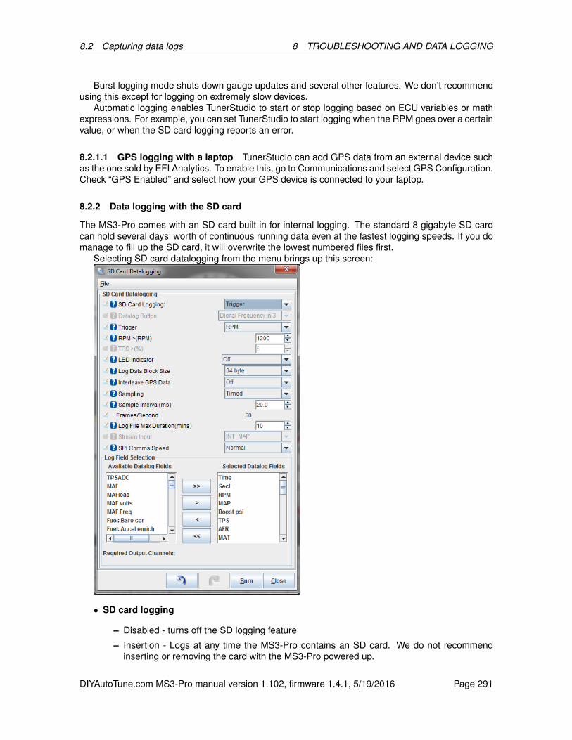
8.2 Capturing data logs 8 TROUBLESHOOTING AND DATA LOGGING
Burst logging mode shuts down gauge updates and several other features. We don’t recommendusing this except for logging on extremely slow devices.
Automatic logging enables TunerStudio to start or stop logging based on ECU variables or mathexpressions. For example, you can set TunerStudio to start logging when the RPM goes over a certainvalue, or when the SD card logging reports an error.
8.2.1.1 GPS logging with a laptop TunerStudio can add GPS data from an external device suchas the one sold by EFI Analytics. To enable this, go to Communications and select GPS Configuration.Check “GPS Enabled” and select how your GPS device is connected to your laptop.
8.2.2 Data logging with the SD card
The MS3-Pro comes with an SD card built in for internal logging. The standard 8 gigabyte SD cardcan hold several days’ worth of continuous running data even at the fastest logging speeds. If you domanage to fill up the SD card, it will overwrite the lowest numbered files first.
Selecting SD card datalogging from the menu brings up this screen:
• SD card logging
– Disabled - turns off the SD logging feature
– Insertion - Logs at any time the MS3-Pro contains an SD card. We do not recommendinserting or removing the card with the MS3-Pro powered up.
DIYAutoTune.com MS3-Pro manual version 1.102, firmware 1.4.1, 5/19/2016 Page 291
8.2 Capturing data logs 8 TROUBLESHOOTING AND DATA LOGGING
– Button - logging is controlled by a push button
– Trigger - Logging is triggered by RPM or throttle position.
• Datalog button - selects the input pin used for the button if used.
• Trigger - Specify whether the log is to be triggered by RPM or throttle position.
• LED indicator - selects the output used for the optional LED indicator. This output is on whenSD card data logging is active.
• Log data block size
– 64 byte is the most common setting
– 64 byte + stream allows the simultaneous recording of data and a 8kHz mono sound input.This could be used as a commentary during a datalog such as position on a racetrack ornotable incidents in the log. Presently the tuning software does not support extracting thisaudio data.
• Interleave GPS Data - Enables the recording of interleaved GPS data. Requires a CAN con-nected GPS module.
• Sampling
– Timed - a data sample is taken at predefined time interval - this is the most common option
– every tooth, every cycle - for special logging and at low engine speeds, these options takea data sample at these events
• Sample interval - how often to take a data sample. 3ms is the fastest supported, but many cardswill only sustain 5ms before you start getting small gaps in the logs. See the utilities section forspeed testing. The frames per second that this sample interval works out to is displayed belowthis setting.
• Log file max duration - how long each datalog should be. The files are always created full sizeand fill up the allocated space during logging. If the log file is filled, a new file is started. If youturn off the power to the MS3-Pro (which is safe to do during a log) the log will be there and willshow full size. When the log file is extracted, the unused part of the allocated file will be ignored.(Note, it is impossible for the MS3-Pro to set the file length or otherwise "clean up" the log file inthis case because there is no power and the processor is off !) A result of this is that all log fileson the SD card will appear the same size.
• Stream input - where the 0-5V audio input is connected, if using the stream option.
• SPI Comms Speed - Allows you to adjust the speed if you have swapped the SD card for onethat does not run at normal logging speed.
Log field selectionThe field selector allows you to choose which data fields you want to log. Because of the compact
datalog format, only 64 bytes are available total, so you need to pick the data that you find mostcritical. To add a field, highlight it on the left and then click on > to move it to the right. To remove afield, highlight it on the right and then click on < to move it to the left.
Button usageWhen Megasquirt-3 powers up it will create an empty datalog file ready for logging. Press and
hold the button for over half a second to start a log. A quick press of the button will end the log. Whenextracting the log files you will likely find a blank log file on the card after your real logs, this is normal.
LED flash codes
DIYAutoTune.com MS3-Pro manual version 1.102, firmware 1.4.1, 5/19/2016 Page 292

8.2 Capturing data logs 8 TROUBLESHOOTING AND DATA LOGGING
• Off - SD logging not active
• On (solid) - Ready but not logging
• Fast flashing - Initializing card
• Slow flashing - Logging
• Pause, sequence of flashes - error code (See Error codes section)
8.2.3 Downloading SD data logs
The Browse / Import SD Card option on the Data Logging menu brings up the following screen.
The screen shot above shows the menu without a MS3-Pro connected. If you have data logs onthe SD card, they will appear in the list at the right hand side. Click the green “down arrow” button tosave the selected logs to your computer. The middle button will reload the list of files, and the red Xwill delete the selected files.
8.2.4 SD card error codes
You can view SD card error codes by right-clicking on a gauge and swapping it to an “SD error” gauge.Some error codes are not used.
DIYAutoTune.com MS3-Pro manual version 1.102, firmware 1.4.1, 5/19/2016 Page 293

8.3 Data log fields 8 TROUBLESHOOTING AND DATA LOGGING
Error number Error name Notes0 No error SD logger is working correctly.1 Sending clock error Possible card fault. Try replacing SD card.2 Idle error Possible card fault. Try replacing SD card.3 Init error Possible card fault. Try replacing SD card.4 Set block size Possible card fault. Try replacing SD card.5 Request CSD The SD card being used is an unsupported type.6 Error reading MBR Erase files and reformat SD card.7 MBR end marker not found Erase files and reformat SD card.8 No partition 1 defined Erase files and reformat SD card.9 Error reading partition boot sector Possible card fault. Try replacing SD card.
10 Error reading directory Possible card fault. Try replacing SD card.12 Error reading file allocation table (FAT) Possible card fault. Try replacing SD card.13 Error reading FAT continuation sector Possible card fault. Try replacing SD card.14 Error writing FAT Possible card fault. Try replacing SD card.15 Error reading directory Possible card fault. Try replacing SD card.16 Error writing directory Possible card fault. Try replacing SD card.17 Error writing log sector Possible card fault. Try replacing SD card.18 Unsupported FAT type (not FAT16) Erase files and reformat SD card.20 SDHC detection error Try reformatting SD card.21 VCA check pattern failed22 VCA voltage rejected23 Operation Condition Register (OCR) error 1 Possible hardware fault. Try replacing SD card.24 OCR2 Possible hardware fault. Try replacing SD card.25 OCR3 Possible hardware fault. Try replacing SD card.26 OCR4 Possible hardware fault. Try replacing SD card.28 Error processing CSD Try reducing data logging speed.29 Write failed Possible card fault. Try replacing SD card.30 Directory full Full SD card - delete data logs.31 Can’t find space in FAT Full SD card - delete data logs.32 Looks like VBR but not valid Erase files and reformat SD card.
8.3 Data log fields
The data log fields represent not only the main sensor inputs but also a large number of the MS3-Pro’sinternal calculations. Here is a complete list of what data you can view.
8.3.1 Understanding data log bit fields
Several of the data log fields are a bit code. To decypher a bit field, you need to determine whatcombination of numbers adds up to the final number. Do this by taking the first code number that issmaller than the value displayed, subtract that, and repeat the process until you’ve used up all thenumbers. For example, suppose you have a CEL Status code of 15. Here’s what you would do.
• The highest number on the chart that is less than 15 is 8. TPS fault. So we have a TPS faultpresent.
• Subtract 8 from 15, giving us 7. We’ll need to see what codes make up the 7.
• The next lowest value is 4. CLT sensor fault. So there is also a CLT sensor fault.
• Subtracting 4 from 7 gives us 3. So we have more codes to find.
DIYAutoTune.com MS3-Pro manual version 1.102, firmware 1.4.1, 5/19/2016 Page 294
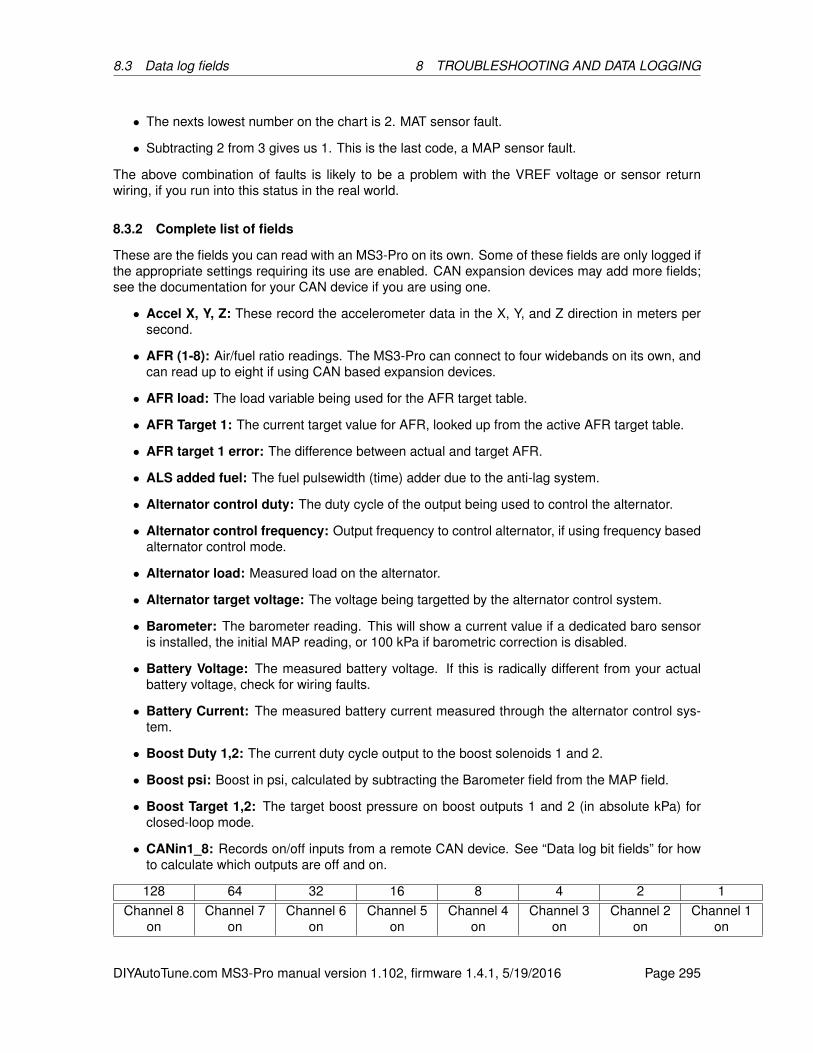
8.3 Data log fields 8 TROUBLESHOOTING AND DATA LOGGING
• The nexts lowest number on the chart is 2. MAT sensor fault.
• Subtracting 2 from 3 gives us 1. This is the last code, a MAP sensor fault.
The above combination of faults is likely to be a problem with the VREF voltage or sensor returnwiring, if you run into this status in the real world.
8.3.2 Complete list of fields
These are the fields you can read with an MS3-Pro on its own. Some of these fields are only logged ifthe appropriate settings requiring its use are enabled. CAN expansion devices may add more fields;see the documentation for your CAN device if you are using one.
• Accel X, Y, Z: These record the accelerometer data in the X, Y, and Z direction in meters persecond.
• AFR (1-8): Air/fuel ratio readings. The MS3-Pro can connect to four widebands on its own, andcan read up to eight if using CAN based expansion devices.
• AFR load: The load variable being used for the AFR target table.
• AFR Target 1: The current target value for AFR, looked up from the active AFR target table.
• AFR target 1 error: The difference between actual and target AFR.
• ALS added fuel: The fuel pulsewidth (time) adder due to the anti-lag system.
• Alternator control duty: The duty cycle of the output being used to control the alternator.
• Alternator control frequency: Output frequency to control alternator, if using frequency basedalternator control mode.
• Alternator load: Measured load on the alternator.
• Alternator target voltage: The voltage being targetted by the alternator control system.
• Barometer: The barometer reading. This will show a current value if a dedicated baro sensoris installed, the initial MAP reading, or 100 kPa if barometric correction is disabled.
• Battery Voltage: The measured battery voltage. If this is radically different from your actualbattery voltage, check for wiring faults.
• Battery Current: The measured battery current measured through the alternator control sys-tem.
• Boost Duty 1,2: The current duty cycle output to the boost solenoids 1 and 2.
• Boost psi: Boost in psi, calculated by subtracting the Barometer field from the MAP field.
• Boost Target 1,2: The target boost pressure on boost outputs 1 and 2 (in absolute kPa) forclosed-loop mode.
• CANin1_8: Records on/off inputs from a remote CAN device. See “Data log bit fields” for howto calculate which outputs are off and on.
128 64 32 16 8 4 2 1Channel 8
onChannel 7
onChannel 6
onChannel 5
onChannel 4
onChannel 3
onChannel 2
onChannel 1
on
DIYAutoTune.com MS3-Pro manual version 1.102, firmware 1.4.1, 5/19/2016 Page 295
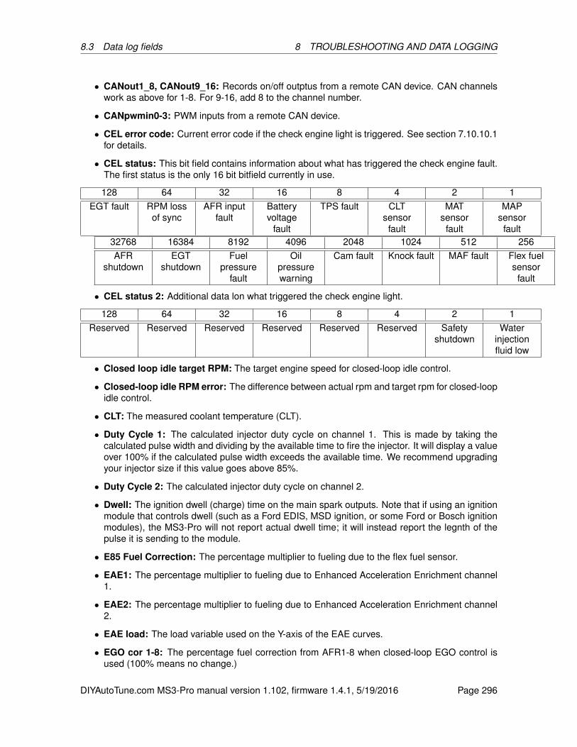
8.3 Data log fields 8 TROUBLESHOOTING AND DATA LOGGING
• CANout1_8, CANout9_16: Records on/off outptus from a remote CAN device. CAN channelswork as above for 1-8. For 9-16, add 8 to the channel number.
• CANpwmin0-3: PWM inputs from a remote CAN device.
• CEL error code: Current error code if the check engine light is triggered. See section 7.10.10.1for details.
• CEL status: This bit field contains information about what has triggered the check engine fault.The first status is the only 16 bit bitfield currently in use.
128 64 32 16 8 4 2 1EGT fault RPM loss
of syncAFR input
faultBatteryvoltage
fault
TPS fault CLTsensor
fault
MATsensor
fault
MAPsensor
fault32768 16384 8192 4096 2048 1024 512 256AFR
shutdownEGT
shutdownFuel
pressurefault
Oilpressurewarning
Cam fault Knock fault MAF fault Flex fuelsensor
fault
• CEL status 2: Additional data lon what triggered the check engine light.
128 64 32 16 8 4 2 1Reserved Reserved Reserved Reserved Reserved Reserved Safety
shutdownWater
injectionfluid low
• Closed loop idle target RPM: The target engine speed for closed-loop idle control.
• Closed-loop idle RPM error: The difference between actual rpm and target rpm for closed-loopidle control.
• CLT: The measured coolant temperature (CLT).
• Duty Cycle 1: The calculated injector duty cycle on channel 1. This is made by taking thecalculated pulse width and dividing by the available time to fire the injector. It will display a valueover 100% if the calculated pulse width exceeds the available time. We recommend upgradingyour injector size if this value goes above 85%.
• Duty Cycle 2: The calculated injector duty cycle on channel 2.
• Dwell: The ignition dwell (charge) time on the main spark outputs. Note that if using an ignitionmodule that controls dwell (such as a Ford EDIS, MSD ignition, or some Ford or Bosch ignitionmodules), the MS3-Pro will not report actual dwell time; it will instead report the legnth of thepulse it is sending to the module.
• E85 Fuel Correction: The percentage multiplier to fueling due to the flex fuel sensor.
• EAE1: The percentage multiplier to fueling due to Enhanced Acceleration Enrichment channel1.
• EAE2: The percentage multiplier to fueling due to Enhanced Acceleration Enrichment channel2.
• EAE load: The load variable used on the Y-axis of the EAE curves.
• EGO cor 1-8: The percentage fuel correction from AFR1-8 when closed-loop EGO control isused (100% means no change.)
DIYAutoTune.com MS3-Pro manual version 1.102, firmware 1.4.1, 5/19/2016 Page 296
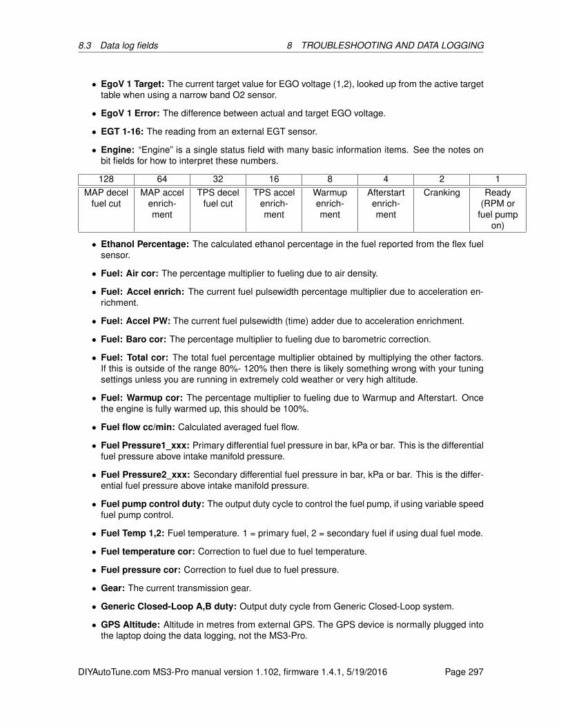
8.3 Data log fields 8 TROUBLESHOOTING AND DATA LOGGING
• EgoV 1 Target: The current target value for EGO voltage (1,2), looked up from the active targettable when using a narrow band O2 sensor.
• EgoV 1 Error: The difference between actual and target EGO voltage.
• EGT 1-16: The reading from an external EGT sensor.
• Engine: “Engine” is a single status field with many basic information items. See the notes onbit fields for how to interpret these numbers.
128 64 32 16 8 4 2 1MAP decel
fuel cutMAP accel
enrich-ment
TPS decelfuel cut
TPS accelenrich-ment
Warmupenrich-ment
Afterstartenrich-ment
Cranking Ready(RPM or
fuel pumpon)
• Ethanol Percentage: The calculated ethanol percentage in the fuel reported from the flex fuelsensor.
• Fuel: Air cor: The percentage multiplier to fueling due to air density.
• Fuel: Accel enrich: The current fuel pulsewidth percentage multiplier due to acceleration en-richment.
• Fuel: Accel PW: The current fuel pulsewidth (time) adder due to acceleration enrichment.
• Fuel: Baro cor: The percentage multiplier to fueling due to barometric correction.
• Fuel: Total cor: The total fuel percentage multiplier obtained by multiplying the other factors.If this is outside of the range 80%- 120% then there is likely something wrong with your tuningsettings unless you are running in extremely cold weather or very high altitude.
• Fuel: Warmup cor: The percentage multiplier to fueling due to Warmup and Afterstart. Oncethe engine is fully warmed up, this should be 100%.
• Fuel flow cc/min: Calculated averaged fuel flow.
• Fuel Pressure1_xxx: Primary differential fuel pressure in bar, kPa or bar. This is the differentialfuel pressure above intake manifold pressure.
• Fuel Pressure2_xxx: Secondary differential fuel pressure in bar, kPa or bar. This is the differ-ential fuel pressure above intake manifold pressure.
• Fuel pump control duty: The output duty cycle to control the fuel pump, if using variable speedfuel pump control.
• Fuel Temp 1,2: Fuel temperature. 1 = primary fuel, 2 = secondary fuel if using dual fuel mode.
• Fuel temperature cor: Correction to fuel due to fuel temperature.
• Fuel pressure cor: Correction to fuel due to fuel pressure.
• Gear: The current transmission gear.
• Generic Closed-Loop A,B duty: Output duty cycle from Generic Closed-Loop system.
• GPS Altitude: Altitude in metres from external GPS. The GPS device is normally plugged intothe laptop doing the data logging, not the MS3-Pro.
DIYAutoTune.com MS3-Pro manual version 1.102, firmware 1.4.1, 5/19/2016 Page 297
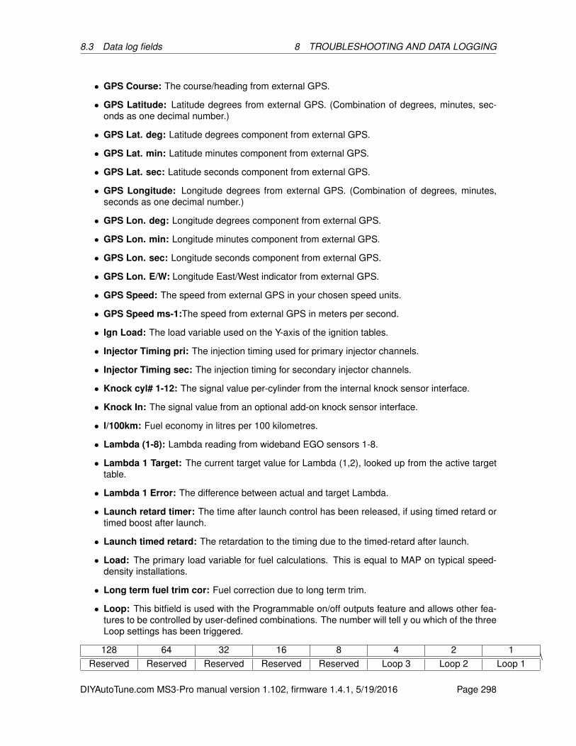
8.3 Data log fields 8 TROUBLESHOOTING AND DATA LOGGING
• GPS Course: The course/heading from external GPS.
• GPS Latitude: Latitude degrees from external GPS. (Combination of degrees, minutes, sec-onds as one decimal number.)
• GPS Lat. deg: Latitude degrees component from external GPS.
• GPS Lat. min: Latitude minutes component from external GPS.
• GPS Lat. sec: Latitude seconds component from external GPS.
• GPS Longitude: Longitude degrees from external GPS. (Combination of degrees, minutes,seconds as one decimal number.)
• GPS Lon. deg: Longitude degrees component from external GPS.
• GPS Lon. min: Longitude minutes component from external GPS.
• GPS Lon. sec: Longitude seconds component from external GPS.
• GPS Lon. E/W: Longitude East/West indicator from external GPS.
• GPS Speed: The speed from external GPS in your chosen speed units.
• GPS Speed ms-1:The speed from external GPS in meters per second.
• Ign Load: The load variable used on the Y-axis of the ignition tables.
• Injector Timing pri: The injection timing used for primary injector channels.
• Injector Timing sec: The injection timing for secondary injector channels.
• Knock cyl# 1-12: The signal value per-cylinder from the internal knock sensor interface.
• Knock In: The signal value from an optional add-on knock sensor interface.
• l/100km: Fuel economy in litres per 100 kilometres.
• Lambda (1-8): Lambda reading from wideband EGO sensors 1-8.
• Lambda 1 Target: The current target value for Lambda (1,2), looked up from the active targettable.
• Lambda 1 Error: The difference between actual and target Lambda.
• Launch retard timer: The time after launch control has been released, if using timed retard ortimed boost after launch.
• Launch timed retard: The retardation to the timing due to the timed-retard after launch.
• Load: The primary load variable for fuel calculations. This is equal to MAP on typical speed-density installations.
• Long term fuel trim cor: Fuel correction due to long term trim.
• Loop: This bitfield is used with the Programmable on/off outputs feature and allows other fea-tures to be controlled by user-defined combinations. The number will tell y ou which of the threeLoop settings has been triggered.
128 64 32 16 8 4 2 1Reserved Reserved Reserved Reserved Reserved Loop 3 Loop 2 Loop 1
\
DIYAutoTune.com MS3-Pro manual version 1.102, firmware 1.4.1, 5/19/2016 Page 298
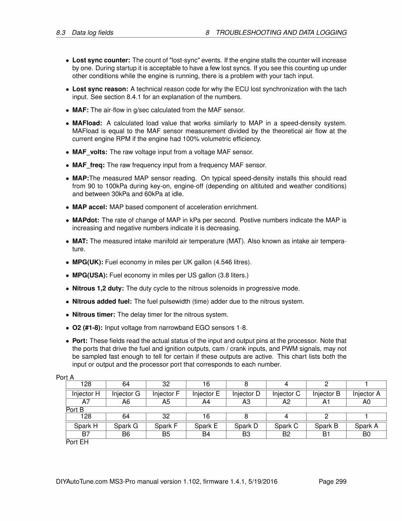
8.3 Data log fields 8 TROUBLESHOOTING AND DATA LOGGING
• Lost sync counter: The count of "lost-sync" events. If the engine stalls the counter will increaseby one. During startup it is acceptable to have a few lost syncs. If you see this counting up underother conditions while the engine is running, there is a problem with your tach input.
• Lost sync reason: A technical reason code for why the ECU lost synchronization with the tachinput. See section 8.4.1 for an explanation of the numbers.
• MAF: The air-flow in g/sec calculated from the MAF sensor.
• MAFload: A calculated load value that works similarly to MAP in a speed-density system.MAFload is equal to the MAF sensor measurement divided by the theoretical air flow at thecurrent engine RPM if the engine had 100% volumetric efficiency.
• MAF_volts: The raw voltage input from a voltage MAF sensor.
• MAF_freq: The raw frequency input from a frequency MAF sensor.
• MAP:The measured MAP sensor reading. On typical speed-density installs this should readfrom 90 to 100kPa during key-on, engine-off (depending on altituted and weather conditions)and between 30kPa and 60kPa at idle.
• MAP accel: MAP based component of acceleration enrichment.
• MAPdot: The rate of change of MAP in kPa per second. Postive numbers indicate the MAP isincreasing and negative numbers indicate it is decreasing.
• MAT: The measured intake manifold air temperature (MAT). Also known as intake air tempera-ture.
• MPG(UK): Fuel economy in miles per UK gallon (4.546 litres).
• MPG(USA): Fuel economy in miles per US gallon (3.8 liters.)
• Nitrous 1,2 duty: The duty cycle to the nitrous solenoids in progressive mode.
• Nitrous added fuel: The fuel pulsewidth (time) adder due to the nitrous system.
• Nitrous timer: The delay timer for the nitrous system.
• O2 (#1-8): Input voltage from narrowband EGO sensors 1-8.
• Port: These fields read the actual status of the input and output pins at the processor. Note thatthe ports that drive the fuel and ignition outputs, cam / crank inputs, and PWM signals, may notbe sampled fast enough to tell for certain if these outputs are active. This chart lists both theinput or output and the processor port that corresponds to each number.
Port A128 64 32 16 8 4 2 1
Injector H Injector G Injector F Injector E Injector D Injector C Injector B Injector AA7 A6 A5 A4 A3 A2 A1 A0
Port B128 64 32 16 8 4 2 1
Spark H Spark G Spark F Spark E Spark D Spark C Spark B Spark AB7 B6 B5 B4 B3 B2 B1 B0
Port EH
DIYAutoTune.com MS3-Pro manual version 1.102, firmware 1.4.1, 5/19/2016 Page 299
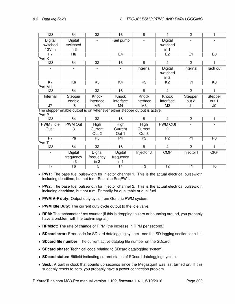
8.3 Data log fields 8 TROUBLESHOOTING AND DATA LOGGING
128 64 32 16 8 4 2 1Digital
switched12V in
Digitalswitched
in 3
- Fuel pump - Digitalswitched
in 1
- -
H7 H6 E4 E2 E1 E0Port K
128 64 32 16 8 4 2 1- - - - Internal Digital
switchedin 2
Internal Tach out
K7 K6 K5 K4 K3 K2 K1 K0Port MJ
128 64 32 16 8 4 2 1Internal Stepper
enableKnock
interfaceKnock
interfaceKnock
interfaceKnock
interfaceStepper
out 2Stepper
out 1J7 J6 M5 M4 M3 M2 J1 J0
The stepper enable output is on whenever either stepper output is active.Port P
128 64 32 16 8 4 2 1PWM / Idle
Out 1PWM Out
3High
CurrentOut 2
HighCurrentOut 1
HighCurrentOut 3
PWM OUt2
- -
P7 P6 P5 P4 P3 P2 P1 P0Port T
128 64 32 16 8 4 2 1- Digital
frequencyin 3
Digitalfrequency
in 2
Digitalfrequency
in 1
Injector J CMP Injector I CKP
T7 T6 T5 T4 T3 T2 T1 T0
• PW1: The base fuel pulsewidth for injector channel 1. This is the actual electrical pulsewidthincluding deadtime, but not trim. See also SeqPW1.
• PW2: The base fuel pulsewidth for injector channel 2. This is the actual electrical pulsewidthincluding deadtime, but not trim. Primarily for dual table or dual fuel.
• PWM A-F duty: Output duty cycle from Generic PWM system.
• PWM Idle Duty: The current duty cycle output to the idle valve.
• RPM: The tachometer / rev counter (if this is dropping to zero or bouncing around, you probablyhave a problem with the tach-in signal.)
• RPMdot: The rate of change of RPM (the increase in RPM per second.)
• SDcard error: Error code for SDcard datalogging system - see the SD logging section for a list.
• SDcard file number: The current active datalog file number on the SDcard.
• SDcard phase: Technical code relating to SDcard datalogging system.
• SDcard status: Bitfield indicating current status of SDcard datalogging system.
• SecL: A built in clock that counts up seconds since the Megasquirt was last turned on. If thissuddenly resets to zero, you probably have a power connection problem.
DIYAutoTune.com MS3-Pro manual version 1.102, firmware 1.4.1, 5/19/2016 Page 300

8.3 Data log fields 8 TROUBLESHOOTING AND DATA LOGGING
• Secondary Ign Load: Like Ign Load but used for the secondary lookup table.
• Secondary Load: Like Load but used for the secondary fuel lookup table.
• Sensor01-16: The reading from a sensor converted into your chosen units through the GenericSensors system. You can also give the sensors a name of your choice which will then be usedin the datalog.
• Seq PW1-8: The base fuel pulsewidth for the injector on cyl#1. This is the actual output elec-trical pulsewidth including deadtime, all corrections and trim. (The "Firing Order" setting is usedto determine which cylinder is which as the injectors always fire in the same order. A,B,C...)
• SPK: 3-step Timing: The spark timing/advance taken from the 3-step system.
• SPK: ALS Timing: The spark timing/advance taken from the anti-lag system.
• SPK: Base Spark Advance: The spark timing/advance looked up from the ignition table beforeother adjustments are made.
• SPK: CEL retard: The retardation to the timing due to check engine light and limp mode.
• SPK: Cold advance: The advancement to the timing due to the cold advance curve.
• SPK: External Advance: The external advancement to the timing, e.g., from a transmissioncontroller.
• SPK: Flex Advance: The advancement to the timing due to flex fuel.
• SPK: Fuel cut retard: The retardation to the timing due to over-run fuel cut.
• SPK: Idle Correction Advance: The advancement to the timing due to idle correction.
• SPK: Knock Retard: The retardation to the timing due to knock control.
• SPK: Launch Timing: The spark timing/advance taken from the launch (2-step) system.
• SPK: Launch VSS Retard: The retardation to the timing due to the speed based launch system.
• SPK: MAT Retard: The retardation to the timing due to the MAT retard curve.
• SPK: Nitrous Retard: The retardation to the timing due to the nitrous system.
• SPK: Revlim Retard: The retardation to the timing due to the rev limiter.
• SPK: Spark Advance: The overall ignition advance.This should match the actual timing yousee with a timing light - if not, check the spark settings.
• SPK: Spark Table 1: The looked up spark advance from ignition table 1.
• SPK: Spark Table 2: The looked up spark advance from ignition table 2.
• SPK: Spark Table 3: The looked up spark advance from ignition table 3.
• SPK: Spark Table 4: The looked up spark advance from ignition table 4.
• SPK: Traction retard: The retardation to the timing due to traction control.
• Shaft rpm 1,2: Shaft speed in RPM.
• Status codes: These describe which features are currently active. See “Data log bit fields” forhow to see which bits are active.
DIYAutoTune.com MS3-Pro manual version 1.102, firmware 1.4.1, 5/19/2016 Page 301

8.3 Data log fields 8 TROUBLESHOOTING AND DATA LOGGING
Status 1128 64 32 16 8 4 2 1
Full RPMsync
Sparktable
switching
Fuel tableswitching
Sync latch RPM sync Configerror
Lost data Need toburn
settingsStatus 2
128 64 32 16 8 4 2 1Closed
loop idleOverboostprotection
Spark cut Flat shiftactive
Launchcontrolactive
Launchcontrolarmed
Nitrousstage 2active
Nitrousstage 1active
Status 3128 64 32 16 8 4 2 1
Launch on Sequentialshift cut
Soft revlimit
3 steparmed
Test modeactive
3 stepactive
T log Fuel cut
Status 4 and 5 are development fields. You can set the Check Engine functionality to use Status5 to record sensor ADC counts or input fluctuation levels.
Status 6128 64 32 16 8 4 2 1MAP
sampleerror
Fan on Idleadvance
mode
Idle VEtablemode
AFRshutdown
AFRwarning
EGTshutdown
EGTwarning
Status 7128 64 32 16 8 4 2 1Limphomemode
Checkengine
light
A/C on Knockdetected
VVT4 error VVT3 error VVT2 error VVT1 error
Status 8128 64 32 16 8 4 2 1
Reserved Reserved VSSbasedlaunch
VSSlaunchlockout
PW 4Xmode
enabled
Waterinjection
low
Sparkdisable
test mode
Injectordisable
test mode
• Stepper Idle position: The current stepper valve position (0 means fully closed.)
• Time: TunerStudio maintains a time since it was started and records this is the datalog. Thetime is shown at the bottom of the graph area. This can be helpful if discussing a data log withsomeone online; you can note what the time reading was when a problem occurs.
• Timing err: A calculation of how accurately the position of the next tach tooth was predicted. Asthe data log sampling rate is very low compared to the frequency of the tach input, this numbertends to bounce around and is not nearly as useful as a tooth or composite log for analyzingRPM input problems.
• Total accel: Combination of TPS and MAP based components of acceleration enrichment.
• TPS: The 0-100% throttle (pedal) position (check the calibration settings if you do not get 0-100%)
• TPS accel: TPS based component of acceleration enrichment.
• TPSADC: The raw ADC input of the throttle (pedal) position.
• TPSdot: The rate of change of TPS, in percent throttle opening per second.
• VE1,2 The looked up VE value for channel 1,2. Blend tables are factored in.
DIYAutoTune.com MS3-Pro manual version 1.102, firmware 1.4.1, 5/19/2016 Page 302

8.4 Tooth / trigger logger and troubleshooting RPM issues8 TROUBLESHOOTING AND DATA LOGGING
• VSS1-4: Vehicle (wheel) speed sensor inputs in your chosen speed units.
• VSS1-4 ms-1: Vehicle (wheel) speed sensor inputs in meters per second.
• VSS1dot, VSS2dot: The rate of change of VSS (acceleration) measured in meters per secondsquared.
• VVT angle 1,2,3,4: The current relative angle of VVT cam 1,2,3,4
• VVT duty 1,2,3,4: The solenoid output duty cycle for VVT cam 1,2,3,4
• VVT target 1,2,3,4: The target angle of VVT cam 1,2,3,4
• WallFuel1: The calculated fuel puddle volume on the intake port walls, channel 1. Wall fuelnumbers are used for model based acceleration enrichment.
• WallFuel2: The calculated fuel puddle volume on the intake port walls, channel 2.
• Water Duty: The duty cycle to the water injection solenoid (or pump).
8.4 Tooth / trigger logger and troubleshooting RPM issues
Certain conditions such as electrical noise can cause the MS3-Pro to lose sync with the engineposition. This is called a sync loss event or a sync error. Common symptoms of this include:
• Feels like a misfire or a false rev limiter
• RPM in datalog suddenly drops to zero
• RPM in datalog suddenly spikes up
• "Lost sync count" increments while "SecL" counts up normally. (NB. If SecL suddenly drops tozero this is a "reset"; see section 8.1.)
Taking and reviewing a datalog is a required step for troubleshooting this. This datalog extract below(viewed in Megalogviewer) shows the rpm (yellow trace) dropping to zero and at the same time the"Lost sync count" increases. The "Lost sync reason" shows reason code 2.
DIYAutoTune.com MS3-Pro manual version 1.102, firmware 1.4.1, 5/19/2016 Page 303

8.4 Tooth / trigger logger and troubleshooting RPM issues8 TROUBLESHOOTING AND DATA LOGGING
8.4.1 Lost sync numbers
The MS3-Pro can report several different lost sync reasons in the data logs. Most of these simplyshow that there’s a problem and don’t particularly pinpoint where it is, but some are more specificthan others. In particular, if you get Lost Sync Reason 11 or 17 in a specific RPM band, try changingthe ignition input capture and /or second trigger active edge. Lost sync reason 2 with a VR sensoroften means you will need a resistor across the CKP sensor.
0 no problem1 init error2 missing tooth at wrong time3 too many teeth before missing tooth (last)4 too few teeth before missing tooth (last)5 1st tooth failed test6 nonsense input (last)7 nonsense input (mid)8 too many teeth before missing tooth (mid)9 too few teeth before missing tooth (mid)10 too many teeth before end of sequence11 too few teeth before second trigger12 too many sync errors13 dizzy wrong edge14 trigger return vane size15 and 16 - EDIS SAW signal error17 second trigger not found when expected20 subaru 6/7 tooth 6 error21 subaru 6/7 tooth 3 error22 Rover #2 missing tooth error23 420A long tooth not found24 420A cam phase wrong25, 26, and 27 pattern does not otherwise match 420A28 Pattern does not match 36-1+129 36-2-2-2 semi sync failed30 36-2-2-2 tooth 14 error31 Miata 99-00 - 2 cams not seen32 Miata 99-00 - 0 cams seen33 6G72 - tooth 2 error34 6G72 - tooth 4 error35 Pattern does not match Weber-Marelli36 CAS 4/1 error37, 38, and 39 Pattern does not match 4G6340 and 41 Twin trigger error42 Pattern does not match Chrysler 2.2/2.543 Pattern does not match Renix44 Pattern does not match Suzuki Swift45 and 46 Pattern does not match Vitara47 Pattern does not match Daihatsu 348 Pattern does not match Daihatsu 449 Pattern does not match VTR100050 Pattern does not match Rover #351 Pattern does not match GM 7X52 36-2-2-2 tooth 30 error53 rc51 semi error
DIYAutoTune.com MS3-Pro manual version 1.102, firmware 1.4.1, 5/19/2016 Page 304
8.4 Tooth / trigger logger and troubleshooting RPM issues8 TROUBLESHOOTING AND DATA LOGGING
54 rc51 re-sync error tooth 655 rc51 re-sync error tooth 1656 rc51 re-sync error tooth 1857 fiat 1.8 tooth 058 fiat 1.8 tooth 359 fiat 1.8 tooth 660 fiat 1.8 tooth 961 36-1+1 first62 36-1+1 second63 QR25DE semi failed64 QR25DE lost running sync65 CAS360 running66 NGC8 semi failed67 LS1 semi failed68 LS1 resync failed69 YZF1000 resync failedHaving identified that you have a sync loss problem, you need to attempt to eliminate it. Check for
any basic problems:
• Loose sensor
• Loose cabling
• Sensor wires running close to spark plug wires or coils
• Slop in timing belt
• VR sensor wired backwards
• Fouled plugs causing misfire
• Non-resistor plugs
• Excessively rich mixture causing misfire
• Excessively lean mixture causing misfire
Having ruled out all those possible causes, you should enable some noise filtering. See the noisefiltering settings, section 7.3.5.
8.4.2 Using the diagnostic logger
The tooth / trigger logger, accessible under TunerStudio’s Diagnostic tab, lets you visualize crank andcam signals. It does not give you a voltage reading directly, but it will show you the state of the crankor cam signal, either on or off, as it reaches the MS3-Pro’s processor. Use this to troubleshoot issueswith the MS3-Pro’s RPM input. There are several different modes. They work in a similar way:
The Logger Type setting selects which log type to use.The Start, Stop, and Clear buttons work as youd expect.The Open Log button lets you pull up previous logs.To capture a log to a file, first click the Capture Log to File button. You will be prompted to save a
file. After you save the file, you may then start the log and collect data.
DIYAutoTune.com MS3-Pro manual version 1.102, firmware 1.4.1, 5/19/2016 Page 305
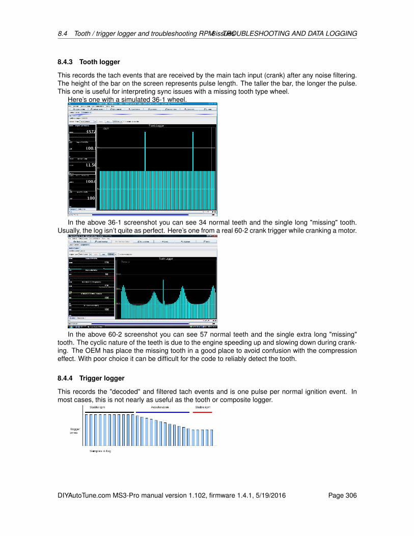
8.4 Tooth / trigger logger and troubleshooting RPM issues8 TROUBLESHOOTING AND DATA LOGGING
8.4.3 Tooth logger
This records the tach events that are received by the main tach input (crank) after any noise filtering.The height of the bar on the screen represents pulse length. The taller the bar, the longer the pulse.This one is useful for interpreting sync issues with a missing tooth type wheel.
Here’s one with a simulated 36-1 wheel.
In the above 36-1 screenshot you can see 34 normal teeth and the single long "missing" tooth.Usually, the log isn’t quite as perfect. Here’s one from a real 60-2 crank trigger while cranking a motor.
In the above 60-2 screenshot you can see 57 normal teeth and the single extra long "missing"tooth. The cyclic nature of the teeth is due to the engine speeding up and slowing down during crank-ing. The OEM has place the missing tooth in a good place to avoid confusion with the compressioneffect. With poor choice it can be difficult for the code to reliably detect the tooth.
8.4.4 Trigger logger
This records the "decoded" and filtered tach events and is one pulse per normal ignition event. Inmost cases, this is not nearly as useful as the tooth or composite logger.
DIYAutoTune.com MS3-Pro manual version 1.102, firmware 1.4.1, 5/19/2016 Page 306

8.4 Tooth / trigger logger and troubleshooting RPM issues8 TROUBLESHOOTING AND DATA LOGGING
8.4.5 Composite logger
The basic tooth logger records enough information to analyze a typical missing tooth wheel on thecrank. However, if the engine uses both cam and crank sensors, then a new logging method isrequired. This third composite logger records both crank and cam signals and under some circum-stances it will record both edges of the input signal. It could be used as a crude two channel oscillo-scope. The composite logger shows three signals.
• The green line at the top represents the cam signal.
• The blue line in the middle represents the crank signal.
• The red line at the bottom represents error pulses that do not fit the expected pattern.
This log shows Subaru 6/7. This is a single edged signal, so the visualization can only show apoint/line.
This log shows an example double edged signal with some noise.
Here is a screen shot of a simulated signal with a 24 tooth crank wheel and a 1 tooth cam wheel.The crank signal is single edged and the cam signal is double edged.
8.4.6 Sync error logger
This is a variant of the composite logger. During normal engine operation it will show nothing atall, but if a sync-loss event occurs (due to noise) it shows the tooth pattern that led up to the lossof synchronization. This allows you to pinpoint the problem without searching for the needle in thehaystack as would be the case trawling through large composite logs. To use this logger, it is usuallyuseful to capture to a log file. Tick the "Capture to log file" box and save the file name. Then startthe sync error logger and drive or ride around. (You can datalog at the same time.) When you havefinished, Stop the logger and un-tick the "Capture to log file".
8.4.7 Example logs
Here are some examples of how these logs look in the real world.
DIYAutoTune.com MS3-Pro manual version 1.102, firmware 1.4.1, 5/19/2016 Page 307
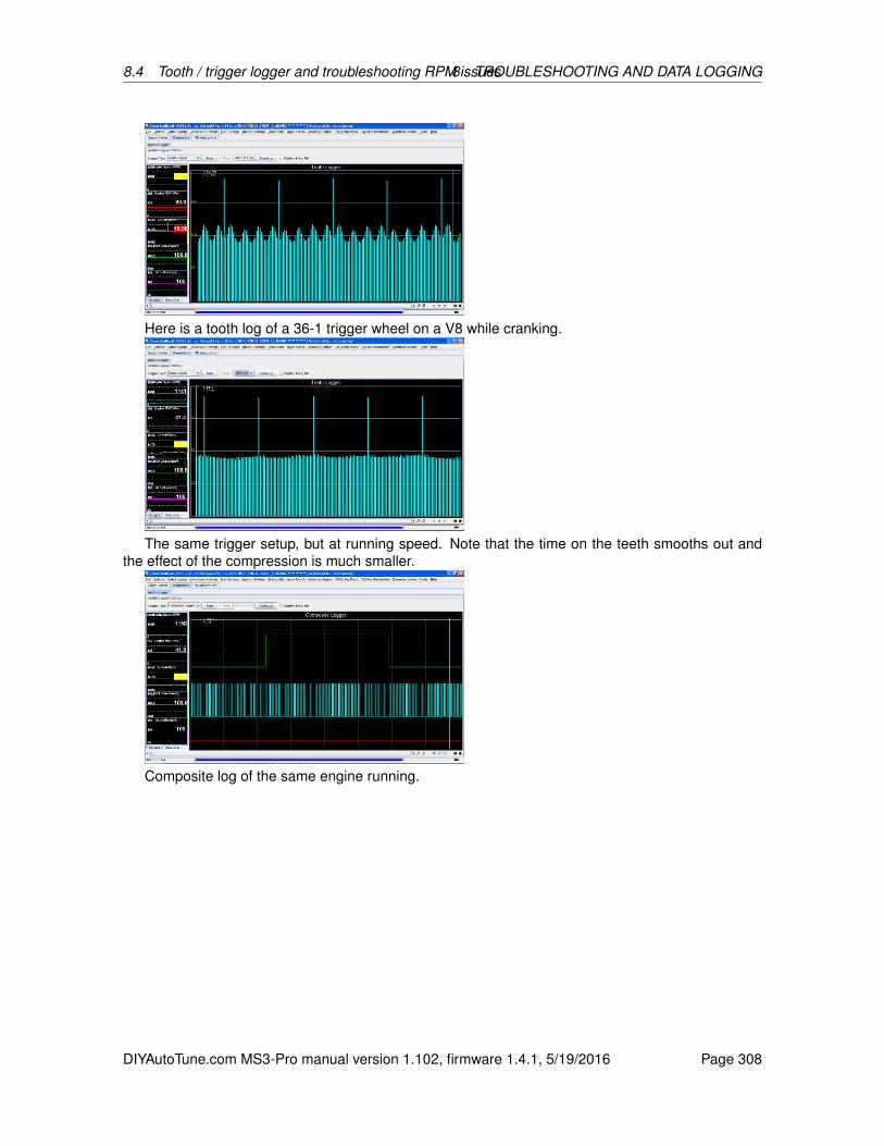
8.4 Tooth / trigger logger and troubleshooting RPM issues8 TROUBLESHOOTING AND DATA LOGGING
Here is a tooth log of a 36-1 trigger wheel on a V8 while cranking.
The same trigger setup, but at running speed. Note that the time on the teeth smooths out andthe effect of the compression is much smaller.
Composite log of the same engine running.
DIYAutoTune.com MS3-Pro manual version 1.102, firmware 1.4.1, 5/19/2016 Page 308

8.4 Tooth / trigger logger and troubleshooting RPM issues8 TROUBLESHOOTING AND DATA LOGGING
The above picture shows a 60-2 crank wheel during cranking. Note that the missing tooth is threetimes the height of the other tooth marks, instead of twice the height as on a 36-1.
Tooth log of 60-2 showing incorrect VR sensor wiring. Two somewhat long teeth instead of onevery long tooth. In this situation the engine might get sync some of the time. Test it by change inputcapture polarity to Falling, if that helps then swap VR sensor wires and return input capture setting toRising.
Composite log of a Nippon Denso ignition with a 24 tooth cam wheel (on the crank input channel)and a 1 tooth cam wheel.
DIYAutoTune.com MS3-Pro manual version 1.102, firmware 1.4.1, 5/19/2016 Page 309

8.5 Communication issues 8 TROUBLESHOOTING AND DATA LOGGING
Noise issues on the same ignition type. More noise filtering can reduce this problem.
8.5 Communication issues
If the internal fuse F1 is blown, the MS3-Pro will not communicate - see section 3.5.1 for how toreplace the fuse. A good way to check if this may be an issue without opening the case is to check ifyou have 5 volts on the VREF wire with the MS3-Pro powered up. If either internal fuse is blown, youwill see 0 volts on this wire.
Most other reported user problems are actually a computer setup problem, so follow these stepsto get your settings right. The MS3-Pro package comes with a serial (RS232) and a USB cable; youmay use either one to connect, but not (currently) both at one time. If your tuning computer has abuilt in RS232 port, that should “just work.” The USB port will work correctly with most versions ofWindows, but sometimes you will need to set up driver software. Note that the MS3-Pro cannot bepowered through the laptop; it needs to have 12 volt power through its wiring harness before it willcommunicate. The USB connection will still show up on a computer, but it will not be able to send orreceive data to or from the MS3-Pro.
8.5.1 USB driver software
The MS3-Pro USB connection uses an FTDI chipset with a Virtual COM Port (VCP) driver.
8.5.1.1 Windows drivers You may download the driver from this page on the FTDI website:FTDI virtual COM port driversHaving downloaded the driver, you should run it and the drivers should be installed. Then insert
the USB cable and when Windows asks for a driver, you should be able to follow the automatic installprocess. Having installed the drivers, proceed with Device manager. There are several ways to dothis, and you may have a preferred way. If you don’t know how to do this, here are directions forgetting into the Device Manager for XP and Vista / Windows 7.
On Windows XP, right-click My Computer and select Manage. This will bring up the ComputerManagement screen. Select the Device Manager from the list at the left.
For Vista or Windows 7, click the Start button and go to the Control Panel. From there, clickSystem and Maintenance, then click on the Device Manager from there. You may need to enter apassword.
DIYAutoTune.com MS3-Pro manual version 1.102, firmware 1.4.1, 5/19/2016 Page 310
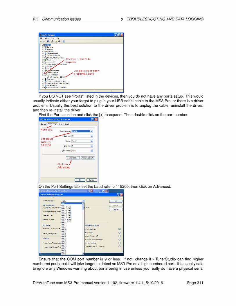
8.5 Communication issues 8 TROUBLESHOOTING AND DATA LOGGING
If you DO NOT see "Ports" listed in the devices, then you do not have any ports setup. This wouldusually indicate either your forgot to plug in your USB-serial cable to the MS3-Pro, or there is a driverproblem. Usually the best solution to the driver problem is to unplug the cable, uninstall the driver,and then re-install the driver.
Find the Ports section and click the [+] to expand. Then double-click on the port number.
On the Port Settings tab, set the baud rate to 115200, then click on Advanced.
Ensure that the COM port number is 9 or less. If not, change it - TunerStudio can find highernumbered ports, but it will take longer to detect an MS3-Pro on a high numbered port. It is usually safeto ignore any Windows warning about ports being in use unless you really do have a physical serial
DIYAutoTune.com MS3-Pro manual version 1.102, firmware 1.4.1, 5/19/2016 Page 311

8.5 Communication issues 8 TROUBLESHOOTING AND DATA LOGGING
port or built-in modem. The port number you select here is the one you need to use in TunerStudio.
While on this page reduce the Latency Timer. 1 is normally OK. The default value gives very slowserial.
Now [OK] all windows to close them and then close the Device Manager.
8.5.1.2 Linux drivers USB serial adapters are typically used as /dev/ttyUSB0. All recent Linuxkernels include support for the built-in FT232RL USB-serial adapter. You might want to use the lsusbcommand to check that the adapter has been recognized. dmesg can be used to see what portnumber has been assigned.
8.5.1.3 MacOS drivers Install the latest MacOS driver from the link below:FTDI virtual COM port driversThen plug in the cable and power on the MS3. Either use Autodetect in TunerStudio or check the
/dev directory for a port such as /dev/cu.usbserial-XXXXX .
8.5.2 Additional diagnostics
8.5.2.1 Portcheck The Port Check program is a small file, portcheck.exe, included for Windows.Port Check scans the available COM ports and sends them commands that will cause a MS3-Pro orother ECU to display its signature. The example below shows it detecting an MS2 on COM port 1.
Note that to run Port Check, you will want any other programs that use the serial connection,like TunerStudio, closed. Sometimes it will report ’“S”ing “S”’ on a port at both speeds. This usuallyhappens if it’s trying to check a mouse port or other port that sends back any character it receivesinstead of sending new information.
8.5.2.2 Loading firmware One other way to test an MS3-Pro that is not communicating and doesnot pass the port check program is to try reloading firmware. It is possible to corrupt the firmware
DIYAutoTune.com MS3-Pro manual version 1.102, firmware 1.4.1, 5/19/2016 Page 312

8.6 Loading or upgrading firmware 8 TROUBLESHOOTING AND DATA LOGGING
in such a way that it does not respond to normal communications, but still responds to a commandto load firmware. In such a case, loading firmware can reset the MS3-Pro’s settings. If the MS3-Prohas power and ground, and is putting out a 5 volt signal on VREF, but does not respond to othercommunications tests, try this.
8.6 Loading or upgrading firmware
MS3-Pros ship with the latest firmware on them, but we anticipate upgraded firmware being available.The firmware can also be reloaded if it has somehow been accidentally erased. The MS3-Pro mustbe powered up when loading firmware, and you need to close any other programs that could useserial communication, such as TunerStudio, Palm HotSync, or modem software. The firmware loaderinstalls with the CD.
8.6.1 Windows firmware loader
The download utility is text based. Browse to the directory where you extracted the zip and double-click on ms3loader_win32.exe Example:
The firmware loading program will launch. Follow the onscreen prompts. Note that when it promptsyou for the file to load, you will want to use the file named ms3pro.s19.
DIYAutoTune.com MS3-Pro manual version 1.102, firmware 1.4.1, 5/19/2016 Page 313
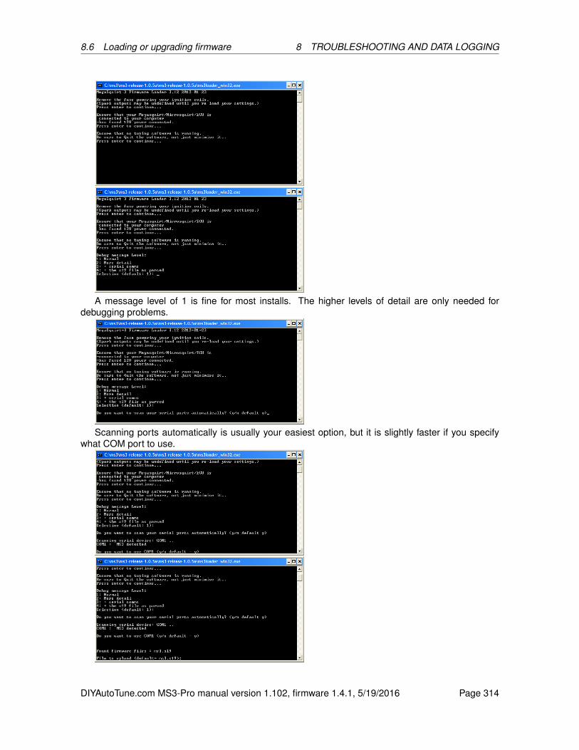
8.6 Loading or upgrading firmware 8 TROUBLESHOOTING AND DATA LOGGING
A message level of 1 is fine for most installs. The higher levels of detail are only needed fordebugging problems.
Scanning ports automatically is usually your easiest option, but it is slightly faster if you specifywhat COM port to use.
DIYAutoTune.com MS3-Pro manual version 1.102, firmware 1.4.1, 5/19/2016 Page 314

8.6 Loading or upgrading firmware 8 TROUBLESHOOTING AND DATA LOGGING
At this point, specify a file name of ms3pro.s19 and press Enter.
Preserving these settings can take somewhat longer. After this, the loader will give you a summaryof your requests before loading firmware:
Once you confirm this, it will load the firmware.
If this takes long than ~45 seconds then you likely need to adjust the port settings of your USB-serial adapter to reduce the latency setting.
8.6.2 Linux firmware loader
It is assumed you’ll be using the command line here.
1. Create a directory for MS3. e.g. mkdir ms3
2. A 32bit compiled command-line firmware loader for Linux is included in firmware zip.
3. Fetch the latest s19 and ini files in a zip from the Code file area and save into the ms3 directory.Extract the zip.
4. cd to the correct directory and key in the following: ./ms3loader_linux32bit
The program runs the same as the windows version, so see above for an example of typical output.Typically, you only need to check you serial comm port. You can usually just press Enter on the otherselection. When loading code for the first time be sure to answer "Y" to the First time loading question.If this takes long than ~45 seconds then you likely need to adjust the port settings of your USB-serialadapter to reduce the latency setting. For the FTDI built in device, try the following.
DIYAutoTune.com MS3-Pro manual version 1.102, firmware 1.4.1, 5/19/2016 Page 315

8.6 Loading or upgrading firmware 8 TROUBLESHOOTING AND DATA LOGGING
echo 1 > /sys/bus/usb-serial/devices/ttyUSB0/latencyIf you get a permissions problem trying to run the file, you likely need to make it executable (e.g.
chmod a+x ms3loader_linux32bit or through your graphical interface.)
DIYAutoTune.com MS3-Pro manual version 1.102, firmware 1.4.1, 5/19/2016 Page 316
Related Documents