LabVIEW Function and VI Reference Manual LabVIEW Function and VI Reference Manual VI Reference Overview May 1997 EditionPart Number 321526A-01 © Copyright 1997 National Instruments Corporation. All rights reserved.

Welcome message from author
This document is posted to help you gain knowledge. Please leave a comment to let me know what you think about it! Share it to your friends and learn new things together.
Transcript

LabVIEW Function and VI
Reference ManualLabVIEW Function and VI Reference Manual
VI Reference Overview
May 1997 EditionPart Number 321526A-01
© Copyright 1997 National Instruments Corporation. All rights reserved.

186,
6, 0,
[email protected]: [email protected] Site: ftp.natinst.comWeb Address: http://www.natinst.com
BBS United States: (512) 794-5422BBS United Kingdom: 01635 551422BBS France: 01 48 65 15 59
(512) 418-1111
Tel: (512) 795-8248Fax: (512) 794-5678
Australia 02 9874 4100, Austria 0662 45 79 90 0, Belgium 02 757 00 20, Canada (Ontario) 905 785 0085, Canada (Québec) 514 694 8521, Denmark 45 76 26 00, Finland 09 527 2321, France 01 48 14 24 24, Germany 089 741 31 30, Hong Kong 2645 3Israel 03 5734815, Italy 06 5729961, Japan 03 5472 2970, Korea 02 596 7456, Mexico 5 520 2635, Netherlands 31 348 43 34 66, Norway 32 84 84 00, Singapore 226588Spain 91 640 0085, Sweden 08 730 49 70, Switzerland 056 200 51 51, Taiwan 02 377 120U.K. 01635 523545
National Instruments Corporate Headquarters
6504 Bridge Point Parkway Austin, TX 78730-5039 Tel: (512) 794-0100
Internet Support
Bulletin Board Support
Fax-on-Demand Support
Telephone Support (U.S.)
International Offices

Important Information
ng denced at do nty free.
tside pping
y serves n. The ble for
ction uments vided he
ties, or
nical, ,
ability on the g itional s injury uments ed to
WarrantyThe media on which you receive National Instruments software are warranted not to fail to execute programmiinstructions, due to defects in materials and workmanship, for a period of 90 days from date of shipment, as eviby receipts or other documentation. National Instruments will, at its option, repair or replace software media thnot execute programming instructions if National Instruments receives notice of such defects during the warraperiod. National Instruments does not warrant that the operation of the software shall be uninterrupted or error
A Return Material Authorization (RMA) number must be obtained from the factory and clearly marked on the ouof the package before any equipment will be accepted for warranty work. National Instruments will pay the shicosts of returning to the owner parts which are covered by warranty.
National Instruments believes that the information in this manual is accurate. The document has been carefullreviewed for technical accuracy. In the event that technical or typographical errors exist, National Instruments rethe right to make changes to subsequent editions of this document without prior notice to holders of this editioreader should consult National Instruments if errors are suspected. In no event shall National Instruments be liaany damages arising out of or related to this document or the information contained in it.
EXCEPT AS SPECIFIED HEREIN, NATIONAL INSTRUMENTS MAKES NO WARRANTIES, EXPRESS OR IMPLIED, AND SPECIFICALLY DISCLAIMS ANY WARRANTY OF MERCHANTABILITY OR FITNESS FOR A PARTICULAR PURPOSE. CUSTOMER’ S RIGHT TO RECOVER DAMAGES CAUSED BY FAULT OR NEGLIGENCE ON THE PART OF NATIONAL INSTRUMENTS SHALL BE LIMITED TO THE AMOUNT THERETOFORE PAID BY THE CUSTOMER. NATIONAL INSTRUMENTS WILL NOT BE LIABLE FOR DAMAGES RESULTING FROM LOSS OF DATA, PROFITS, USE OF PRODUCTS, OR INCIDENTAL OR CONSEQUENTIAL DAMAGES, EVEN IF ADVISED OF THE POSSIBILITY THEREOF. This limitation of the liability of National Instruments will apply regardless of the form of action, whether in contract or tort, including negligence. Any aagainst National Instruments must be brought within one year after the cause of action accrues. National Instrshall not be liable for any delay in performance due to causes beyond its reasonable control. The warranty proherein does not cover damages, defects, malfunctions, or service failures caused by owner’s failure to follow tNational Instruments installation, operation, or maintenance instructions; owner’s modification of the product; owner’s abuse, misuse, or negligent acts; and power failure or surges, fire, flood, accident, actions of third parother events outside reasonable control.
CopyrightUnder the copyright laws, this publication may not be reproduced or transmitted in any form, electronic or mechaincluding photocopying, recording, storing in an information retrieval system, or translating, in whole or in partwithout the prior written consent of National Instruments Corporation.
TrademarksLabVIEW®, National Instruments™, natinst.com™, and NI-DAQ® are trademarks of National Instruments Corporation.
Product and company names listed are trademarks or trade names of their respective companies.
WARNING REGARDING MEDICAL AND CLINICAL USE OF NATIONAL INSTRUMENTS PRODUCTSNational Instruments products are not designed with components and testing intended to ensure a level of relisuitable for use in treatment and diagnosis of humans. Applications of National Instruments products involvingmedical or clinical treatment can create a potential for accidental injury caused by product failure, or by errors part of the user or application designer. Any use or application of National Instruments products for or involvinmedical or clinical treatment must be performed by properly trained and qualified medical personnel, and all tradmedical safeguards, equipment, and procedures that are appropriate in the particular situation to prevent seriouor death should always continue to be used when National Instruments products are being used. National Instrproducts are NOT intended to be a substitute for any form of established process, procedure, or equipment usmonitor or safeguard human health and safety in medical or clinical treatment.
© National Instruments Corporation v LabVIEW Function an
Contents
xxiii.xxiv.xxv.xxvi.xxvi
.1-11-21-2
1-31-31-3-3
1-41-4-4-41-41-51-51-5-5-6
1-6-61-7
About This ManualOrganization of the Product User Manual .......................................................................Conventions Used in This Manual..................................................................................Related Documentation...................................................................................................Related Online Documentation.......................................................................................Customer Communication ..............................................................................................
Chapter 1Introduction to the LabVIEW Functions and VIs
Locating the G Functions and VIs ..................................................................................Function and VI Overviews.............................................................................................
Structures...........................................................................................................Numeric Functions ............................................................................................Boolean Functions.............................................................................................String Functions.................................................................................................Array Functions .................................................................................................1Cluster Functions...............................................................................................Comparison Functions.......................................................................................Time and Dialog Functions ...............................................................................1File I/O Functions..............................................................................................1Advanced Functions ..........................................................................................DAQ ..................................................................................................................Instrument I/O ...................................................................................................Communication .................................................................................................Analysis VIs ......................................................................................................1Select A VI... .....................................................................................................1Tutorial ..............................................................................................................Instrument Driver Library .................................................................................1User Library.......................................................................................................
d VI Reference Manual

Contents
2-22-22-2-2-3
-52-5
. 3-2
4-2-3-3-4-44-44-94-144-184-204-22
5-15-2
-1-2
Section One: G Functions and VIs
Chapter 2G Function and VI Reference Overview
G Functions Overview.....................................................................................................Introduction to Polymorphism.........................................................................................
Polymorphism ...................................................................................................Unit Polymorphism........................................................................................... 2Numeric Conversion ......................................................................................... 2Overflow and Underflow .................................................................................. 2Wire Styles........................................................................................................
Chapter 3Structures
Structures Overview .......................................................................................................
Chapter 4Numeric Functions
Polymorphism for Numeric Functions ............................................................................Polymorphism for Trig Functions..................................................................... 4Polymorphism for Logarithmic Functions........................................................ 4Polymorphism for Conversion Functions ......................................................... 4Polymorphism for Complex Functions ............................................................. 4
Arithmetic Function Descriptions ...................................................................................Conversion Functions Descriptions.................................................................................Trigonometric Functions Descriptions ............................................................................Logarithmic Functions Descriptions ...............................................................................Complex Function Descriptions ......................................................................................Additional Numeric Constants Descriptions ...................................................................
Chapter 5Boolean Functions
Polymorphism for Boolean Functions.............................................................................Boolean Function Descriptions .......................................................................................
Chapter 6String Functions
Overview of Polymorphism for String Functions ........................................................... 6Polymorphism for String Functions.................................................................. 6
LabVIEW Function and VI Reference Manual vi © National Instruments Corporation

Contents
2-2.6-26-6-156-19.6-21
7-27-37-3
8-28-28-38-3
9-19-29-29-29-29-49-5.9-6
10-10-20-20-410-60-8
Polymorphism for Additional String to Number Functions..............................6-Polymorphism for String Conversion Functions...............................................6
Format Strings Overview................................................................................................String Function Descriptions ...........................................................................................Additional String To Number Function Descriptions......................................................6String Conversion Function Descriptions........................................................................String Fixed Constants....................................................................................................
Chapter 7Array Functions
Array Function Overview ................................................................................................Polymorphism for Array Functions .................................................................................Array Function Descriptions............................................................................................
Chapter 8Cluster Functions
Cluster Function Overview..............................................................................................Polymorphism for Cluster Functions...............................................................................
Setting the Order of Cluster Elements............................................................... Cluster Function Descriptions ........................................................................................
Chapter 9Comparison Functions
Comparison Function Overview......................................................................................Compare Boolean ..............................................................................................Compare Strings ................................................................................................Compare Clusters ..............................................................................................Compare Modes.................................................................................................Character Comparison.......................................................................................
Polymorphism for Comparison Functions.......................................................................Comparison Function Descriptions ................................................................................
Chapter 10Time, Dialog, and Error Functions
Time, Dialog, and Error Functions Overview .................................................................Timing Functions...............................................................................................1Error Handling Overview..................................................................................1
Error I/O and the Error State Cluster ..................................................1Time and Dialog Function Descriptions..........................................................................Error Handling VI Descriptions.......................................................................................1
© National Instruments Corporation vii LabVIEW Function and VI Reference Manual

Contents
1-21-2-2
11-311-51-511-51-6
11-1311-14. 11-21
12-212-512-8
. 12-912-102-11
3-213-33-43-5-53-63-613-63-73-7-83-83-8
Chapter 11File Functions
File I/O VI and Function Overview................................................................................. 1High-Level VIs ................................................................................................. 1Low-Level File VIs and File Functions ............................................................ 11Byte Stream and Datalog Files..........................................................................Flow-Through Parameters.................................................................................Error I/O in File I/O Functions ......................................................................... 1Permissions .......................................................................................................
File I/O Function and VI Descriptions ............................................................................ 1Binary File VI Descriptions.............................................................................................Advanced File Function Descriptions .............................................................................File Constants Descriptions............................................................................................
Chapter 12Advanced Functions
Advanced Function Descriptions ....................................................................................Data Manipulation Function Descriptions.......................................................................Help Function Descriptions.............................................................................................Occurrence Function Descriptions .................................................................................Memory VI Descriptions.................................................................................................VI Control VI Descriptions ............................................................................................. 1
Section Two: Data Acquisition VIs
Chapter 13Introduction to the LabVIEW Data Acquisition VIs
Finding Help Online for the DAQ VIs ............................................................................ 1The Analog Input VIs......................................................................................................
Easy Analog Input VIs...................................................................................... 1Intermediate Analog Input VIs ......................................................................... 1Analog Input Utility VIs ................................................................................... 13Advanced Analog Input VIs ............................................................................. 1Locating Analog Input VI Examples ................................................................ 1
Analog Output VIs ..........................................................................................................Easy Analog Output VIs ................................................................................... 1Intermediate Analog Output VIs....................................................................... 1Analog Output Utility VIs................................................................................. 13Advanced Analog Output VIs........................................................................... 1Locating Analog Output VI Examples.............................................................. 1
LabVIEW Function and VI Reference Manual viii © National Instruments Corporation
Contents
13-3-93-103-10-10
13-113-12
13-123-13
13-1313-13
14-1
5-2
6-2
17-1
18-1
Digital Function VIs ........................................................................................................9Easy Digital I/O VIs ..........................................................................................1Intermediate Digital I/O VIs..............................................................................1Advanced Digital I/O VIs..................................................................................1Locating Digital I/O VI Examples ....................................................................13
Counter VIs......................................................................................................................13-11Easy Counter VIs...............................................................................................Intermediate Analog Input VIs..........................................................................1Advanced Counter VIs ......................................................................................Locating Counter VI Examples.........................................................................1
Calibration and Configuration VIs ..................................................................................Signal Conditioning VIs ..................................................................................................
Chapter 14Easy Analog Input VIs
Easy Analog Input VI Descriptions .................................................................................
Chapter 15Intermediate Analog Input VIs
Handling Errors................................................................................................................15-1Intermediate Analog Input VI Descriptions.....................................................................1
Chapter 16Analog Input Utility VIs
Handling Errors................................................................................................................16-1Analog Input Utility VI Descriptions ..............................................................................1
Chapter 17Advanced Analog Input VIs
Advanced Analog Input VI Descriptions.........................................................................
Chapter 18Easy Analog Output VIs
Easy Analog Output VI Descriptions ..............................................................................
© National Instruments Corporation ix LabVIEW Function and VI Reference Manual

Contents
119-2
20-2
21-1
22-1
23-2
4-14-3
25-2
226-2
Chapter 19Intermediate Analog Output VIs
Handling Errors ...............................................................................................................9-1Analog Output VI Descriptions.......................................................................................
Chapter 20Analog Output Utility VIs
Handling Errors ...............................................................................................................0-1Analog Output Utility VI Descriptions ........................................................................... 2
Chapter 21Advanced Analog Output VIs
Advanced Analog Output VI Descriptions......................................................................
Chapter 22Easy Digital I/O VIs
Easy Digital I/O Descriptions..........................................................................................
Chapter 23Intermediate Digital I/O VIs
Handling Errors ...............................................................................................................3-2Intermediate Digital I/O VI Descriptions ........................................................................ 2
Chapter 24Advanced Digital I/O VIs
Digital Port VI Descriptions............................................................................................ 2Digital Group VI Descriptions ........................................................................................ 2
Chapter 25Easy Counter VIs
Easy Counter VI Descriptions .........................................................................................
Chapter 26Intermediate Counter VIs
Handling Errors ...............................................................................................................6-1Intermediate Counter VI Descriptions.............................................................................
LabVIEW Function and VI Reference Manual x © National Instruments Corporation
Contents
27-2
8-228-16
9-2
30-20-330-30-430-40-430-50-6-6
-6-6-7-7-77-8
30-80-9-90-9
Chapter 27Advanced Counter VIs
Advanced Counter VI Descriptions.................................................................................
Chapter 28Calibration and Configuration VIs
Calibration and Configuration VI Descriptions...............................................................2Channel Configuration VIs..............................................................................................
Chapter 29Signal Conditioning VIs
Signal Conditioning VI Descriptions...............................................................................2
Section Three: Instrument I/O Functions and VIs
Chapter 30Introduction to LabVIEW Instrument Driver VIs
Instrument Drivers Overview ..........................................................................................Instrument Driver Distribution..........................................................................3
CD-ROM Instrument Driver Distribution...........................................30-Instrument Driver Template VIs .......................................................................3
Introduction to VISA Library ..........................................................................................3Introduction to GPIB .......................................................................................................
History of the GPIB...........................................................................................3The IEEE 488.2 Standard ..................................................................................Compatible GPIB Hardware..............................................................................3
LabVIEW for Windows 95 and Windows 95-Japanese .....................30LabVIEW for Windows NT................................................................30LabVIEW for Windows 3.1 ................................................................30LabVIEW for Mac OS ........................................................................30LabVIEW for HP-UX .........................................................................30LabVIEW for Sun (Solaris) ................................................................30LabVIEW for Concurrent PowerMAX...............................................30-
LabVIEW Traditional GPIB Functions.............................................................30GPIB 488.2 Functions .......................................................................................
Single-Device Functions .....................................................................3Multiple-Device Functions .................................................................30Bus Management Functions................................................................3
© National Instruments Corporation xi LabVIEW Function and VI Reference Manual
Contents
-90-10
30-10
1-131-231-21-2
31-331-31-3-41-51-8
-81-9-10
. 32-12-1-22-42-6-8-102-112-122-122-13
32-1432-162-172-182-202-21
32-212-22
2-22
Low-Level Functions.......................................................................... 30General Functions............................................................................... 3
Serial Port VI Overview ..................................................................................................
Chapter 31LabVIEW Instrument Driver Models
LabVIEW Instrument Driver External Interface Model ................................................. 3Functional Body................................................................................................Interactive Developer Interface.........................................................................Programmatic Developer Interface ................................................................... 3I/O Interface ......................................................................................................Subroutine Interface..........................................................................................
LabVIEW Instrument Driver Internal Design Model ..................................................... 3Instrument Driver Application VIs ................................................................... 31Instrument Driver Component VIs ................................................................... 3Error Reporting ................................................................................................. 3Additional VIs Distributed with the Instrument Driver .................................... 31
The Getting Started VI ....................................................................... 3The VI Tree VI ................................................................................... 31
Chapter 32LabVIEW Instrument Driver Development
Development Procedure .................................................................................................Designing the Instrument Driver Structure....................................................... 3
Instrument Driver Structure and VI Hierarchy................................... 32Guidelines and Recommendations ..................................................... 3Design Example.................................................................................. 3
Modifying the Instrument Driver Templates .................................................... 32Adding Instrument Driver Component VI VIs ................................................. 32Modifying the Menu Files to Create Function Sub-Palettes............................. 3
Tips for Developing a LabVIEW Instrument Driver ...................................................... 3Loop Termination Conditions........................................................................... 3Assembling Command Strings.......................................................................... 3Data Dependency ..............................................................................................Guidelines .........................................................................................................
Front Panel.......................................................................................... 3Required Front Panel Controls ........................................................... 3Block Diagram.................................................................................... 3Icon ..................................................................................................... 3Connector Pane...................................................................................
Error Reporting ................................................................................................. 3Online Help Information................................................................................... 3
LabVIEW Function and VI Reference Manual xii © National Instruments Corporation
Contents
2-222-232-242-24
3-13-2
4-234-3.34-7.34-8.34-1134-134-14
.35-135-235-335-7.35.35-
.36-16-2
6-436-66-836-10
VI Descriptions ...................................................................................3Control and Indicator Descriptions .....................................................3
Application VIs .................................................................................................3LabVIEW Instrument Driver Standards Checklist ..........................................................3
Chapter 33Instrument Driver Template VIs
Introduction to Instrument Driver Template VIs.............................................................3Instrument Driver Template VI Descriptions ..................................................................3
Chapter 34VISA Library Reference
Operations........................................................................................................................34-2VISA Library Reference Parameters.................................................................3
VISA Operation Descriptions..........................................................................................Event Handling Functions ..............................................................................................High Level Register Access Functions...........................................................................Low Level Register Access Functions............................................................................VISA Attribute Node .......................................................................................................VISA Attribute Node Descriptions..................................................................................3
Chapter 35Traditional GPIB Functions
Traditional GPIB Function Parameters...........................................................................Traditional GPIB Function Behavior...............................................................................Traditional GPIB Function Descriptions .........................................................................GPIB Device and Controller Functions ...........................................................................Device Functions ............................................................................................................-7Controller Functions .......................................................................................................9
Chapter 36GPIB 488.2 Functions
GPIB 488.2 Common Function Parameters ...................................................................GPIB 488.2 Function Descriptions (Single-Device Functions).......................................3GPIB 488.2 Multiple-Device Function Descriptions ......................................................3GPIB 488.2 Bus Management Function Descriptions.....................................................GPIB 488.2 Low-Level I/O Function Descriptions.........................................................3GPIB 488.2 General Function Descriptions ....................................................................
© National Instruments Corporation xiii LabVIEW Function and VI Reference Manual

Contents
. 37-137-137-27-337-337-3
38-238-3
38-338-438-5
. 38
39-139-4
40-240-8
41-241-4
Chapter 37Serial Port VIs
Common Serial Port VI Parameters ...............................................................................Port Number......................................................................................................Handshaking Modes..........................................................................................Software Handshaking–XON/XOFF ................................................................ 3Error Codes .......................................................................................................
Serial Port VI Descriptions..............................................................................................
Section Four: Analysis VIs
Chapter 38Introduction to Analysis in LabVIEW
The Importance of Data Analysis....................................................................................Full Development System ...............................................................................................Analysis VI Overview .....................................................................................................Analysis VI Organization ................................................................................................Notation and Naming Conventions .................................................................................Sampling Signals ............................................................................................................-8
Chapter 39Analysis Signal Generation VIs
Normalized Frequency ....................................................................................................Signal Generation VI Descriptions..................................................................................
Chapter 40Analysis Digital Signal Processing VIs
The Fast Fourier Transform (FFT) ..................................................................................Signal Processing VI Descriptions ..................................................................................
Chapter 41Analysis Measurement VIs
Introduction to Measurement VIs....................................................................................Measurement VI Descriptions.........................................................................................
LabVIEW Function and VI Reference Manual xiv © National Instruments Corporation

Contents
2-1.42-32-52-742-842-92-1042-11.42-122-13-142-142-152-152-15
.42-
43-13-243-5
44-14-3
45-1
Chapter 42Analysis Filter VIs
Introduction to Digital Filtering Functions......................................................................4Infinite Impulse Response Filters ...................................................................................
Cascade Form IIR Filtering...............................................................................4Butterworth Filters.............................................................................................4Chebyshev Filters ..............................................................................................Chebyshev II or Inverse Chebyshev Filters.......................................................Elliptic (or Cauer) Filters...................................................................................4Bessel Filters .....................................................................................................
Finite Impulse Response Filters......................................................................................Designing FIR Filters by Windowing ...............................................................4Designing Optimum FIR Filters using the Parks-McClellan Algorithm...........42Designing Narrowband FIR Filters ...................................................................4Windowed FIR Filters .......................................................................................4Optimum FIR Filters .........................................................................................4FIR Narrowband Filters.....................................................................................4
Nonlinear Filters .............................................................................................................42-16Filter VI Descriptions ......................................................................................................16
Chapter 43Analysis Window VIs
Introduction to Smoothing Windows...............................................................................Windows for Spectral Analysis versus Windows for Coefficient Design.......................4Window VI Descriptions .................................................................................................
Chapter 44Analysis Curve-Fitting VIs
Introduction to Curve Fitting ...........................................................................................Curve Fitting VI Descriptions..........................................................................................4
Chapter 45Analysis Probability and Statistics VIs
Probability and Statistics VI Descriptions .......................................................................
© National Instruments Corporation xv LabVIEW Function and VI Reference Manual
Contents
6-2. 46-346-46-5. 46-6446-6
7-1
8-1
9-349-449-549-59-69-7
49-849-9
49-109-109-109-10-119-1149-119-11
Chapter 46Analysis Linear Algebra VIs
Basic Matrix Manipulations Functions ........................................................................... 4Common Matrices ..........................................................................................................Matrix Factorization ........................................................................................................4Solving Linear Equations and Matrix Inverses ...............................................................Eigenvalues and Eigenvectors........................................................................................Matrix Analysis ...............................................................................................................6-6Linear Algebra VI Descriptions ......................................................................................
Chapter 47Analysis Array Operation VIs
Array Operation VI Descriptions .................................................................................... 4
Chapter 48Analysis Additional Numerical Method VIs
Additional Numerical Method VI Descriptions .............................................................. 4
Section Five: Communication VIs and Functions
Chapter 49Introduction to LabVIEW Communication VIs and Functions
LabVIEW Communication VIs and Functions Overview............................................... 4Introduction to Communication Protocols ......................................................................File Sharing vs Communication Protocols ......................................................................Client/Server Model ........................................................................................................
A General Model for a Client ........................................................................... 4A General Model for a Server........................................................................... 4
TCP/IP (all platforms) .....................................................................................................Internet Addresses.............................................................................................
Setup ................................................................................................................................ 49-10Setup for Your System......................................................................................
UNIX .................................................................................................. 4Macintosh ........................................................................................... 4Windows 3.x ....................................................................................... 4Windows 95 and Windows NT .......................................................... 49
LabVIEW and TCP/IP ...................................................................................... 4TCP versus UDP ...............................................................................................TCP Client Example ......................................................................................... 4
LabVIEW Function and VI Reference Manual xvi © National Instruments Corporation
Contents
49-1249-129-1349-1349-149-159-1649-1849-199-229-2349-239-249-24-24
9-25-26.49-27.49-2749-2849-299-30
.5050-2
50-4
.5151-251-2
Timeouts and Errors ..........................................................................................TCP Server Example .........................................................................................TCP Server with Multiple Connections ............................................................4
DDE (Windows Only) .....................................................................................................Services, Topics, and Data Items ......................................................................Examples of Client Communication with Excel ...............................................4LabVIEW VIs as DDE Servers .........................................................................4Requesting Data versus Advising Data .............................................................Synchronization of Data ....................................................................................Networked DDE ................................................................................................4
OLE Automation (Windows Only)..................................................................................4AppleEvents (Macintosh Only) .......................................................................................
Client Server Model ..........................................................................................4AppleEvent Client Examples ............................................................................4
Launching Other Applications ............................................................49Sending Events to Other Applications ................................................4Dynamically Loading and Running a VI ............................................49
PPC (Macintosh Only)....................................................................................................Ports, Target IDs, and Sessions ........................................................................PPC Client Example..........................................................................................PPC Server Example .........................................................................................PPC Server with Multiple Connections.............................................................4
Chapter 50TCP VIs
Internet Protocol (IP) ......................................................................................................-1Transmission Control Protocol (TCP) .............................................................................Using TCP........................................................................................................................50-2TCP Errors .......................................................................................................................50-4TCP VI Descriptions........................................................................................................
Chapter 51UDP VIs
UDP Overview................................................................................................................-1Using UDP.........................................................................................................
UDP VI Descriptions .......................................................................................................
© National Instruments Corporation xvii LabVIEW Function and VI Reference Manual
Contents
52-52-252-32-42-7
52-9
53-23-23-3
.54-34-3-34-44-554-554-74-9. 54-4-1054-114-1554-184-2054-214-2154-214-21-23-24
4-25
Chapter 52DDE VIs
DDE Overview ................................................................................................................1Using DDE as a Client ......................................................................................Using DDE as a Server .....................................................................................Using NetDDE .................................................................................................. 5
DDE Client VI Descriptions............................................................................................ 5DDE Server VI Descriptions ...........................................................................................
Chapter 53OLE Automation VIs
OLE Automation Concepts .............................................................................................Using LabVIEW to Implement OLE Automation........................................................... 5OLE Automation VI Descriptions................................................................................... 5
Chapter 54AppleEvent VIs
AppleEvents ...................................................................................................................54-2Sending AppleEvents........................................................................................General AppleEvent VI Behavior ..................................................................... 5
The User Identity Dialog Box ............................................................ 54Target ID............................................................................................. 5Send Options....................................................................................... 5
Targeting VI Descriptions ...............................................................................................AppleEvent VI Descriptions............................................................................................LabVIEW Specific AppleEvent VIs ............................................................................... 5Advanced Topics ............................................................................................................10
Constructing and Sending Other AppleEvents ................................................. 5Creating AppleEvent Parameters ......................................................................
Low-Level AppleEvent VIs ............................................................................................ 5Object Support VI Example ............................................................................................Sending AppleEvents to LabVIEW from Other Applications ........................................ 5
Required AppleEvents ......................................................................................LabVIEW Specific AppleEvents ...................................................................... 5Replies to AppleEvents.....................................................................................
Event: Run VI ..................................................................................... 5Event: Abort VI .................................................................................. 54Event: VI Active? ............................................................................... 54Event: Close VI .................................................................................. 5
LabVIEW Function and VI Reference Manual xviii © National Instruments Corporation
Contents
.55-
..55-2
.55-3
-1-41-51-71-8
82-122-1332-152-162-162-20
Chapter 55Program to Program Communication VIs
Introduction to PPC ........................................................................................................1General PPC Behavior ...................................................................................................PPC VI Descriptions.......................................................................................................
Appendix ADAQ Hardware Capabilities
Appendix BMultiline Interface Messages
Appendix COperation of the GPIB
Appendix DReferences
Appendix ECustomer Communication
Index
FiguresFigure 31-1. General Model of Instrument Drivers in LabVIEW ...............................31Figure 31-2. LabVIEW Instrument Driver Internal Design Model .............................31Figure 31-3. Tek VX4790 Example VI........................................................................3Figure 31-4. VIs in Tek VX4790 Example Diagram...................................................3Figure 31-5. Tek VX4790 Config Std Wave Diagram ................................................3
Figure 32-1. LabVIEW Instrument Driver VIs for the Tektronix VX4790.................32-Figure 32-2. Incorrect Mechanism for Escaping from While Loop.............................3Figure 32-3. Correct Mechanism for Escaping from While Loop ...............................3Figure 32-4. Range Test VI (Front Panel and Block Diagram) ...................................Figure 32-5. Simple Trigger VI with Programmatic Range Testing ...........................3Figure 32-6. Simple Trigger VI without Programmatic Range Testing ......................3Figure 32-7. Simple Trigger VI Front Panel (See Figure 32-8 for Diagram) .............3
© National Instruments Corporation xix LabVIEW Function and VI Reference Manual
Contents
2-2039-339-4
55-3-5
C-6C-7
. 6-36-46-76-86-96-116-126-13
9-9
0-2
7-2
-47-67-77-97-127-147-17
7-18
7-19
7-20
7-214-224-77-2
Figure 32-8. Simple Trigger Block Diagram............................................................... 3Figure 39-1. Front Panel Example...............................................................................Figure 39-2. Block Diagram example .........................................................................
Figure 55-1. PPC VI Execution Order (Used by permission of Apple Computer, Inc.)Figure 55-2. GPIB Connector Showing Signal Assignment ....................................... CFigure 55-3. Linear Configuration...............................................................................Figure 55-4. Star Configuration...................................................................................
TablesTable 6-1. Special Escape Codes ............................................................................Table 6-2. String Syntax...........................................................................................Table 6-3. Possible Format Into String Errors .........................................................Table 6-4. Format Specifiers ....................................................................................Table 6-5. Special Characters for Match Pattern .....................................................Table 6-6. Strings for the Match Pattern Examples .................................................Table 6-7. Scan From String Errors .........................................................................Table 6-8. Scan from String Examples ....................................................................
Table 9-1. Lexical Class Number Descriptions........................................................
Table 10-1. Order of 32-bit Integers in TIming Functions......................................... 1
Table 17-1. AI Buffer Config VI Device-Specific Settings and Ranges ................... 1Table 17-2. Device-Specific Settings and Ranges for Controls in the
AI Clock Config VI ................................................................................ 17Table 17-3. Device-Specific Settings and Ranges for the AI Control VI .................. 1Table 17-4. Device-Specific Settings and Ranges for the AI Group Config VI ........ 1Table 17-5. AI Hardware Config Channel Configuration.......................................... 1Table 17-6. Device-Specific Settings and Ranges for the AI Hardware Config VI... 1Table 17-7. Device-Specific Settings and Ranges for the AI SingleScan VI ............ 1Table 17-8. Restrictions for Analog Triggering on E Series Devices........................ 1Table 17-9. Digital Trigger Sources for Devices with Fixed Digital
Trigger Sources....................................................................................... 1Table 17-10. Device-Specific Settings and Ranges for the AI Trigger
Config VI—Part 1................................................................................... 1Table 17-11. Device-Specific Settings and Ranges for the AI Trigger
Config VI—Part 2................................................................................... 1Table 17-12. Device-Specific Settings and Ranges for the AI Trigger
Config VI—Part 4................................................................................... 1Table 24-1. Physical Port Widths of Digital Ports ..................................................... 2Table 24-2. Device specific parameters and legal ranges for devices........................Table 27-1. Counter Chips and Their Available DAQ Devices................................. 2
LabVIEW Function and VI Reference Manual xx © National Instruments Corporation

Contents
7-3.27-10
28-728-8
2-32-7
35-4
2-5
54-13
24-5
-8-8
A-9
-10
-11
-12
-12
-14
-16-17-18-18
-19-19
Table 27-2. Valid Counter Numbers for CTR Group Config Devices.......................2Table 27-3. Adjacent Counters. .................................................................................
Table 28-1. Channel to Index VI Parameter Examples ..............................................Table 28-2. Channel to Index VI Parameter Examples for Sun .................................
Table 32-1. Instrument Driver Organization Example ...............................................3Table 32-2. Command Summary from Tektronix VX4790 .......................................3
Table 35-1. Command String Functions.....................................................................
Table 52-1. Values to Add in Place of Default...........................................................5
Table 54-1. AppleEvent Descriptor String Formats ...................................................
Table A-1. Analog Input Configuration Programmability—MIO and AI Devices...A-2Table A-2. Analog Input Characteristics—MIO and AI Devices (Part 1) ................A-Table A-3. Analog Input Characteristics—MIO and AI Devices (Part 2) ................A-Table A-4. Analog Output Characteristics—MIO and AI Devices...........................ATable A-5. Digital I/O Hardware Capabilities—MIO and AI Devices .....................A-7Table A-6. Counter Characteristics—MIO and AI Devices......................................ATable A-7. Counter Usage for Analog Input and Output—MIO and AI Devices.....ATable A-8. Analog Input Configuration Programmability—Lab and 1200 Series
and Portable Devices ...............................................................................Table A-9. Analog Input Characteristics—Lab and 1200 Series and Portable
Devices (Part 1) .......................................................................................ATable A-10. Analog Input Characteristics—Lab and 1200 Series and Portable
Devices (Part 2)A-10Table A-11. Analog Output Characteristics—Lab and 1200 Series and
Portable Devices......................................................................................ATable A-12. Counter Usage for Analog Input and Output—Lab Series and
Portable Devices......................................................................................ATable A-13. Digital I/O Hardware Capabilities—Lab and 1200 Series and
Portable Devices......................................................................................ATable A-14. Analog Output and Digital Output Characteristics—54XX Series
Devices ....................................................................................................ATable A-15. Counter/Timer Characteristics -- Lab and 1200 Series and
Portable Devices......................................................................................ATable A-16. Analog Input Characteristics—SCXI Modules (Part 1)..........................ATable A-17. Analog Output Characteristics—SCXI Modules ....................................ATable A-18. Relay Characteristics—SCXI Modules...................................................ATable A-19. Digital Input and Output Characteristics—SCXI Modules.....................ATable A-20. Terminal Block Selection Guide—SCXI Modules .................................A
© National Instruments Corporation xxi LabVIEW Function and VI Reference Manual
Contents
-20-20-21
-222224-25-26A-26A-26
Table A-21. Analog Input Configuration Programmability........................................ ATable A-22. Analog Input Configuration Programmability........................................ ATable A-23. Analog Output Characteristics--Analog Output Only Devices .............. ATable A-24. Analog Input Configuration Programmability—Dynamic Signal
Acquisition Devices ................................................................................ ATable A-25. Analog Input Characteristics—Dynamic Signal Acquisition Devices ... A-Table A-26. Digital Hardware Capabilities—Digital I/O Devices ............................. A-Table A-27. Counter/Timer Characteristics—Timing Only Devices ......................... ATable A-28. Analog input configuration programmability ......................................... ATable A-29. Analog input characteristics....................................................................Table A-30. Analog input characteristics, part 2 ........................................................
LabVIEW Function and VI Reference Manual xxii © National Instruments Corporation
© National Instruments Corporation xxiii LabVIEW Function and
AboutThis
Manual
to
in
e
n
ise
The LabVIEW Function and VI Reference Manual contains descriptions of all virtual instruments (VIs) available for LabVIEW, including thefollowing:
• G functions and VIs
• VIs that support the devices for data acquisition
• VIs for GPIB, VXIbus, and serial port I/O operation
• digital signal processing, filtering, and numerical and statistical VIs
• networking and interapplication communications VIs
This manual is a supplement to the LabVIEW User Manual and assumes that you are familiar with that material. You should also know how operate LabVIEW, and your computer and operating system.
This manual provides an overview of each function and VI availableLabVIEW. However, for more specific information regarding each function and VI (e.g. for specific parameter information), refer to thLabVIEW Online Reference, which you can access by selecting Online Reference from the LabVIEW Help menu, or Help, which you access by selecting Show Help from the LabVIEW Help menu.
Organization of the Product User ManualThis manual covers five subject areas G Functions, Data AcquisitioVIs, Instrument I/O VIs, Analysis VIs, and Communications VIs. Chapter 1 introduces the LabVIEW Functions and VIs, which comprthe sections in this manual.
• Section 1, G Functions and VIs, includes Chapters 2 through 12, which describe the functions unique to the G programming language.
• Section 2, Data Acquisition VIs, includes Chapters 13 through 29, which describe the Data Acquisition (DAQ) VIs.
VI Reference Manual
About This Manual
0 s.
49
x:
l
ple, sis r
ets
• Section 3, Instrument I/O Functions and VIs, includes Chapters 3through 37, which describe the Instrument I/O VIs and function
• Section 4, Analysis VIs, includes Chapters 38 through 48, which describe the Analysis VIs.
• Section 5, Communications VI and Functions, includes Chaptersthrough 55, which describe the Communication VIs.
In addition, this manual includes the following appendices and inde
• Appendix A, DAQ Hardware Capabilities, includes tables that summarize the analog and digital I/O capabilities of National Instruments data acquisition devices.
• Appendix B, Multiline Interface Messages, lists commands that IEEE 488 defines.
• Appendix C, Operation of the GPIB, describes basic concepts youneed to understand to operate the GPIB.
• Appendix D, References, lists the reference material used to produce the Analysis VIs described in this manual.
• Appendix E, Customer Communication, contains forms to help you gather the information necessary to help us solve your technicaproblems and a form you can use to comment on the product documentation.
• The Index contains an alphabetical list of VIs described in this manual, including the page where you can find each one.
Conventions Used in This ManualThe following conventions are used in this manual:
<> Angle brackets enclose the name of a key on the keyboard (for exam<option>). Angle brackets containing numbers separated by an elliprepresent a range of values associated with a bit or signal name (foexample, DBIO<3…0>).
[ ] Square brackets enclose optional items (for example, [response ]).
- A hyphen between two or more key names enclosed in angle brackdenotes that you should simultaneously press the named keys–for example, <Control-Alt-Delete>.
» The » symbol leads you through nested menu items and dialog boxoptions to a final action. The sequence File»Page Setup»Options» Substitute Fonts directs you to pull down the File menu, select the
LabVIEW Function and VI Reference Manual xxiv © National Instruments Corporation
About This Manual
ialog bs,
izes
o a
r
k vice and
drive
PageSetup item, select Options, and finally select the Substitute Fonts options from the last dialog box.
♦ The ♦ symbol indicates that the text following it applies only to a specific product, a specific operating system, or a specific softwareversion.
bold Bold text denotes the names of menus, menu items, parameters, dbox, dialog box buttons or options, icons, windows, Windows 95 taor LEDs.
bold italic Bold italic text denotes a note, caution, or warning.
bol d Bold text in this font denotes the messages and responses that themonospace computer automatically prints to the screen. This font also emphas
lines of code that are different from the other examples.
CTRL Key names are in all capital letters.
italic Italic text denotes emphasis, a cross reference, or an introduction tkey concept. This font also denotes text from which you supply theappropriate word or value, as in Windows 3.x.
italic Italic text in this font denotes that you must supply the appropriatemonospace words or values in the place of these items.
monospace Text in this font denotes text or characters that should literally entefrom the keyboard, sections of code, programming examples, and syntax examples. This font is also used for the proper names of disdrives, paths, directories, programs, subprograms, subroutines, denames, functions, operations, variables, filenames and extensions,for statements and comments taken from programs.
paths Paths in this manual are denoted using backslashes (\) to separate names, directories, folders, and files.
The Glossary lists abbreviations, acronyms, metric prefixes, mnemonics, symbols, and terms.
Related DocumentationYou might find the following documents helpful as you read this manual:
• LabVIEW User Manual
• LabVIEW Error Codes
• LabVIEW Getting Started Card
• LabVIEW QuickStart Guide
© National Instruments Corporation xxv LabVIEW Function and VI Reference Manual

About This Manual
cts our ake
• LabVIEW Release Notes
• LabVIEW Upgrade Notes
• G Quick Reference Card
Related Online DocumentationThe following related documents are available through the LabVIEWOnline Reference, which you access by selecting Help»OnlineReference.
• Communications Common Questions
• LabVIEW Glossary
Customer CommunicationNational Instruments wants to receive your comments on our produand manuals. We are interested in the applications you develop withproducts, and we want to help if you have problems with them. To mit easy for you to contact us, this manual contains comment and configuration forms for you to complete. These forms are in Appendix E, Customer Communication, at the end of this manual.
LabVIEW Function and VI Reference Manual xxvi © National Instruments Corporation

© National Instruments Corporation 1-1 LabVIEW Function and
Chapter
1
Introduction to the LabVIEW Functions and VIsual
hey
nels ine
This chapter contains basic information about the functions and virtinstruments (VIs) that are available with LabVIEW.
LabVIEW includes collections of VIs that work with your G programming language, data acquisition (DAQ) hardware devices, instrument input and output devices, analysis instruments, and communication devices.
Locating the G Functions and VIsYou can find the G functions and VIs on the Functions palette. To access the Functions palette, access a block diagram in LabVIEW. When you put your cursor over each of the icons in the Functions palette, LabVIEW displays the name of the icon palette.
Functions are elementary nodes in the G programming language. Tare analogous to operators or library functions in conventional languages. Functions are not VIs and therefore do not have front paor block diagrams. When compiled, functions generate inline machcode.
You select functions from the Functions palette, in the block diagram.When the block diagram window is active, select Windows»Show Functions Palette. You also can access the
VI Reference Manual

Chapter 1 Introduction to the LabVIEW Functions and VIs
Functions palette by popping up on the area in the block diagram window where you want to place the function.
Many Function palette chapters include information about function examples.
The paths for these examples for LabVIEW begin with examples\ .
Function and VI OverviewsThe following functions and VIs are available.
StructuresG Structures include While Loop, For Loop, Case and Sequence structures. This palette also contains the global and local variable nodes.
LabVIEW Function and VI Reference Manual 1-2 © National Instruments Corporation
Chapter 1 Introduction to the LabVIEW Functions and VIs
is
m To
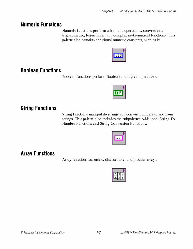
Numeric FunctionsNumeric functions perform arithmetic operations, conversions, trigonometric, logarithmic, and complex mathematical functions. Thpalette also contains additional numeric constants, such as Pi.
Boolean FunctionsBoolean functions perform Boolean and logical operations.
String FunctionsString functions manipulate strings and convert numbers to and frostrings. This palette also includes the subpalettes Additional StringNumber Functions and String Conversion Functions.
Array FunctionsArray functions assemble, disassemble, and process arrays.
© National Instruments Corporation 1-3 LabVIEW Function and VI Reference Manual

Chapter 1 Introduction to the LabVIEW Functions and VIs
n a
o on) e
s hat
nd
ry. he
Cluster FunctionsUse Cluster functions to assemble, access, and change elements icluster.
Comparison FunctionsComparison functions compare data (greater than, less than, and sand operations that are based on a comparison, such as finding thminimum and maximum ranges for two values.
Time and Dialog FunctionsTime and Dialog functions can be used to manipulate time functionand display dialog boxes. This palette also includes the functions tperform error handling.
File I/O FunctionsFile I/O functions manipulate files and directories. This palette alsocontains the subpalettes Advanced File Functions, Binary File VIs, aFile Constants.
Advanced FunctionsAdvanced functions are functions that do not fit into any other categoThe Code Interface Node is an example of an advanced function. T
LabVIEW Function and VI Reference Manual 1-4 © National Instruments Corporation
Chapter 1 Introduction to the LabVIEW Functions and VIs
VI s.
ell
,
E,
l
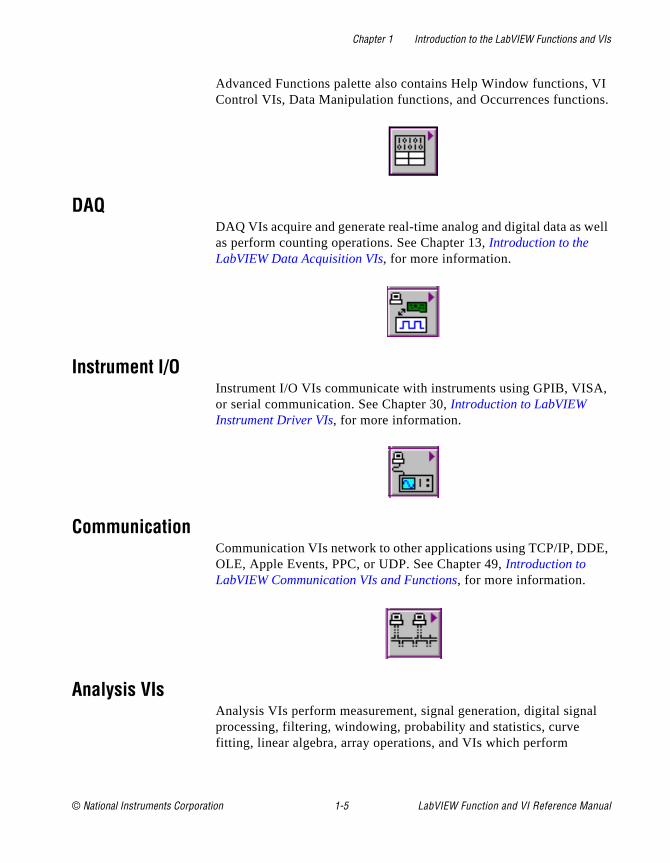
Advanced Functions palette also contains Help Window functions, Control VIs, Data Manipulation functions, and Occurrences function
DAQDAQ VIs acquire and generate real-time analog and digital data as was perform counting operations. See Chapter 13, Introduction to the LabVIEW Data Acquisition VIs, for more information.
Instrument I/OInstrument I/O VIs communicate with instruments using GPIB, VISAor serial communication. See Chapter 30, Introduction to LabVIEW Instrument Driver VIs, for more information.
CommunicationCommunication VIs network to other applications using TCP/IP, DDOLE, Apple Events, PPC, or UDP. See Chapter 49, Introduction to LabVIEW Communication VIs and Functions, for more information.
Analysis VIsAnalysis VIs perform measurement, signal generation, digital signaprocessing, filtering, windowing, probability and statistics, curve fitting, linear algebra, array operations, and VIs which perform
© National Instruments Corporation 1-5 LabVIEW Function and VI Reference Manual

Chapter 1 Introduction to the LabVIEW Functions and VIs
am.
e
C ute
additional numerical methods. See Chapter 38, Introduction to Analysis in LabVIEW, for more information.
Select A VI...When you select Functions»Select a VI..., LabVIEW displays a file dialog box. From there, you can select any VI and place it on a diagr
TutorialSelecting Functions»Tutorial accesses the Tutorial VIs. You call thesVIs while working through the LabVIEW Tutorial Manual.
Instrument Driver LibraryInstrument drivers are a set of VIs for GPIB, VISA, Serial, and CAMAinstruments. National Instruments, as well as other vendors, distribthese instrument drivers. Any drivers you place in the instr.lib appear in the palette.
LabVIEW Function and VI Reference Manual 1-6 © National Instruments Corporation

Chapter 1 Introduction to the LabVIEW Functions and VIs
sed
User LibraryThis palette automatically includes any VIs in your user.lib directory, making it more convenient to gain access to commonly usub-VIs you have written.
© National Instruments Corporation 1-7 LabVIEW Function and VI Reference Manual
© National Instruments Corporation 2-1 LabVIEW Function and
Chapter
2
G Function and VI Reference Overviewich
hey
nels ine
the
This chapter introduces the G Functions and VIs, descriptions of whcomprise Chapter 3 through Chapter 12.
Functions are elementary nodes in the G programming language. Tare analogous to operators or library functions in conventional languages. Functions are not VIs and therefore do not have front paor block diagrams. When compiled, functions generate inline machcode.
VIs are “virtual instruments,” so called because they model the appearance functions of a physical instrument.
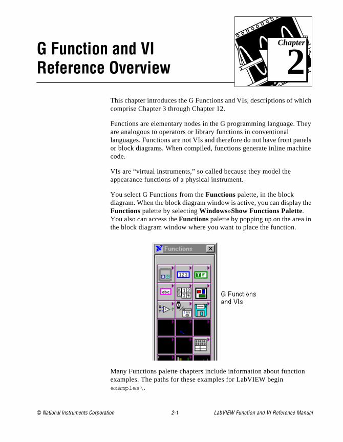
You select G Functions from the Functions palette, in the block diagram. When the block diagram window is active, you can display Functions palette by selecting Windows»Show Functions Palette. You also can access the Functions palette by popping up on the area inthe block diagram window where you want to place the function.
Many Functions palette chapters include information about functionexamples. The paths for these examples for LabVIEW begin examples\ .
VI Reference Manual
Chapter 2 G Function and VI Reference Overview
Is pt ept
f ers not rs,
ype. s.
e of rm.
it. ass
unit
G Functions OverviewFor brief descriptions of each of the 10 G Function and VI palettes available refer to Chapter 1, Introduction to LabVIEW Functions and VIs.
Introduction to PolymorphismThe following sections provide some general information about Polymorphism in G functions.
PolymorphismPolymorphism is the ability of a function to adjust to input data of different types or representations. Most functions are polymorphic. Vare not polymorphic. All functions that take numeric input can acceany numeric representation (except some functions that do not acccomplex numbers).
Functions are polymorphic to varying degrees; none, some, or all otheir inputs may be polymorphic. Some function inputs accept numbor Boolean values. Some accept numbers or strings. Some acceptonly scalar numbers but also arrays of numbers, clusters of numbearrays of clusters of numbers, and so on. Some accept only one-dimensional arrays although the array elements may be of any tSome functions accept all types of data, including complex number
Unit PolymorphismIf you want to create a VI that computes the root, mean square valua waveform, you have to define the unit associated with the wavefoYou would need a separate VI for voltage waveforms, current waveforms, temperature waveforms, and so on. LabVIEW has polymorphic unit capability so that one VI can perform the same calculation, regardless of the units received by the inputs.
You create a polymorphic unit by entering $x, where x is a number (for example, $1). You can think of this as a placeholder for the actual unWhen LabVIEW calls the VI, the program substitutes the units you pin for all occurrences of $x in that VI.
LabVIEW treats a polymorphic unit as a unique unit. You cannot convert a polymorphic unit to any other unit, and polymorphic unitspropagate throughout the diagram, just as other units do. When the
LabVIEW Function and VI Reference Manual 2-2 © National Instruments Corporation

Chapter 2 G Function and VI Reference Overview
, r,
ts u
ict
nt the ions
n, sion
connects to an indicator that also has the abbreviation $1, the units match and the VI can then compile.
You can use $1 in combinations just like any other unit. For exampleif the input is multiplied by 3 seconds and then wired to an indicatothe indicator must be $1 s units. If the indicator has different units, theblock diagram shows a bad wire. If you need to use more than onepolymorphic unit, you can use the abbreviations $2, $3, and so on.
A call to a subVI containing polymorphic units computes output unibased on the units received by its inputs. For example, suppose yocreate a VI that has two inputs with the polymorphic units $1 and $2 that creates an output in the form $1 $2 / s . If a call to the VI receives inputs with the unit m/s to the $1 input and kg to the $2 input, LabVIEW computes the output unit as kg m / s^2 .
Suppose a different VI has two inputs of $1 and $1/s , and computes an output of $1^2 . If a call to this VI receives inputs of m/s to the $1 input and m/s^2 to the $1/s input, LabVIEW computes the output unit as m^2 / s^2 . If this VI receives inputs of m to the $1 input and kg to the $1/s input, however, LabVIEW declares one of the inputs as a unit confland computes (if possible) the output from the other input.
A polymorphic VI can have a polymorphic subVI because LabVIEWkeeps the respective units distinct.
Numeric ConversionYou can convert any numeric representation to any other numeric representation. When you wire two or more numeric inputs of differerepresentations to a function, the function usually returns output in larger or wider format. The functions coerce the smaller representatto the widest representation before execution.
Some functions, such as Divide, Sine, and Cosine, always producefloating-point output. If you wire integers to their inputs, these functions convert the integers to double-precision, floating-point numbers before performing the calculation.
For floating-point, scalar quantities, it is usually best to use double-precision, floating-point numbers. Single-precision, floating-point numbers save little memory, little or no time, and overflow much more easily. You should only use extended-precisiofloating-point numbers when necessary. The performance and preciof extended-precision arithmetic varies among the platforms.
© National Instruments Corporation 2-3 LabVIEW Function and VI Reference Manual
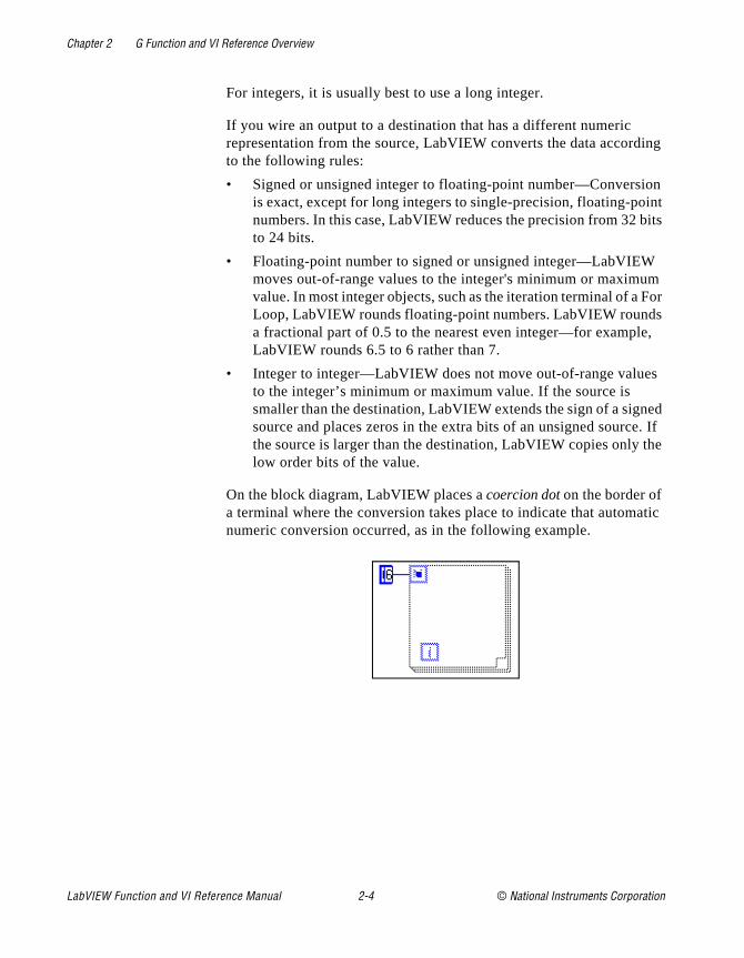
Chapter 2 G Function and VI Reference Overview
ing
on int its
m For s ,
s
ed . If
the
atic
For integers, it is usually best to use a long integer.
If you wire an output to a destination that has a different numeric representation from the source, LabVIEW converts the data accordto the following rules:
• Signed or unsigned integer to floating-point number—Conversiis exact, except for long integers to single-precision, floating-ponumbers. In this case, LabVIEW reduces the precision from 32 bto 24 bits.
• Floating-point number to signed or unsigned integer—LabVIEWmoves out-of-range values to the integer's minimum or maximuvalue. In most integer objects, such as the iteration terminal of a Loop, LabVIEW rounds floating-point numbers. LabVIEW rounda fractional part of 0.5 to the nearest even integer—for exampleLabVIEW rounds 6.5 to 6 rather than 7.
• Integer to integer—LabVIEW does not move out-of-range valueto the integer’s minimum or maximum value. If the source is smaller than the destination, LabVIEW extends the sign of a signsource and places zeros in the extra bits of an unsigned sourcethe source is larger than the destination, LabVIEW copies only low order bits of the value.
On the block diagram, LabVIEW places a coercion dot on the border of a terminal where the conversion takes place to indicate that automnumeric conversion occurred, as in the following example.
LabVIEW Function and VI Reference Manual 2-4 © National Instruments Corporation
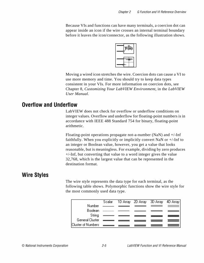
Chapter 2 G Function and VI Reference Overview
can ary s.
I to
in
ces
r
Because VIs and functions can have many terminals, a coercion dotappear inside an icon if the wire crosses an internal terminal boundbefore it leaves the icon/connector, as the following illustration show
Moving a wired icon stretches the wire. Coercion dots can cause a Vuse more memory and time. You should try to keep data types consistent in your VIs. For more information on coercion dots, see Chapter 8, Customizing Your LabVIEW Environment, in the LabVIEW User Manual.
Overflow and UnderflowLabVIEW does not check for overflow or underflow conditions on integer values. Overflow and underflow for floating-point numbers isaccordance with IEEE 488 Standard 754 for binary, floating-point arithmetic.
Floating-point operations propagate not-a-number (NaN) and +/-Inffaithfully. When you explicitly or implicitly convert NaN or +/-Inf to an integer or Boolean value, however, you get a value that looks reasonable, but is meaningless. For example, dividing by zero produ+/-Inf, but converting that value to a word integer gives the value 32,768, which is the largest value that can be represented in the destination format.
Wire StylesThe wire style represents the data type for each terminal, as the following table shows. Polymorphic functions show the wire style fothe most commonly used data type.
© National Instruments Corporation 2-5 LabVIEW Function and VI Reference Manual
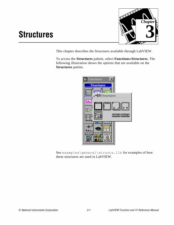
© National Instruments Corporation 3-1 LabVIEW Function and
Chapter
3
StructuresThis chapter describes the Structures available through LabVIEW.
To access the Structures palette, select Functions»Structures. The following illustration shows the options that are available on the Structures palette.
See examples\general\structs.llb for examples of how these structures are used in LabVIEW.
VI Reference Manual
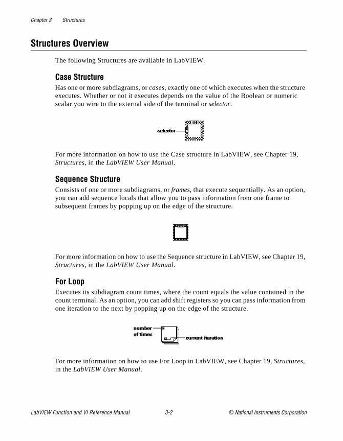
Chapter 3 Structures
re ric
9,
,
er 19,
in the from
Structures Overview
The following Structures are available in LabVIEW.
Case StructureHas one or more subdiagrams, or cases, exactly one of which executes when the structuexecutes. Whether or not it executes depends on the value of the Boolean or numescalar you wire to the external side of the terminal or selector.
For more information on how to use the Case structure in LabVIEW, see Chapter 1Structures, in the LabVIEW User Manual.
Sequence StructureConsists of one or more subdiagrams, or frames, that execute sequentially. As an optionyou can add sequence locals that allow you to pass information from one frame tosubsequent frames by popping up on the edge of the structure.
For more information on how to use the Sequence structure in LabVIEW, see ChaptStructures, in the LabVIEW User Manual.
For LoopExecutes its subdiagram count times, where the count equals the value contained count terminal. As an option, you can add shift registers so you can pass informationone iteration to the next by popping up on the edge of the structure.
For more information on how to use For Loop in LabVIEW, see Chapter 19, Structures, in the LabVIEW User Manual.
LabVIEW Function and VI Reference Manual 3-2 © National Instruments Corporation
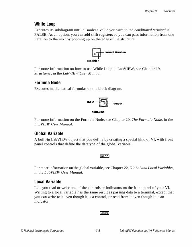
Chapter 3 Structures
one
t
I. t that
While LoopExecutes its subdiagram until a Boolean value you wire to the conditional terminal is FALSE. As an option, you can add shift registers so you can pass information fromiteration to the next by popping up on the edge of the structure.
For more information on how to use While Loop in LabVIEW, see Chapter 19, Structures, in the LabVIEW User Manual.
Formula NodeExecutes mathematical formulas on the block diagram.
For more information on the Formula Node, see Chapter 20, The Formula Node, in the LabVIEW User Manual.
Global VariableA built-in LabVIEW object that you define by creating a special kind of VI, with fronpanel controls that define the datatype of the global variable.
For more information on the global variable, see Chapter 22, Global and Local Variables, in the LabVIEW User Manual.
Local VariableLets you read or write one of the controls or indicators on the front panel of your VWriting to a local variable has the same result as passing data to a terminal, excepyou can write to it even though it is a control, or read from it even though it is an indicator.
© National Instruments Corporation 3-3 LabVIEW Function and VI Reference Manual

Chapter 3 Structures
For more information on the local variable, see Chapter 22, Global and Local Variables, in the LabVIEW User Manual.
LabVIEW Function and VI Reference Manual 3-4 © National Instruments Corporation
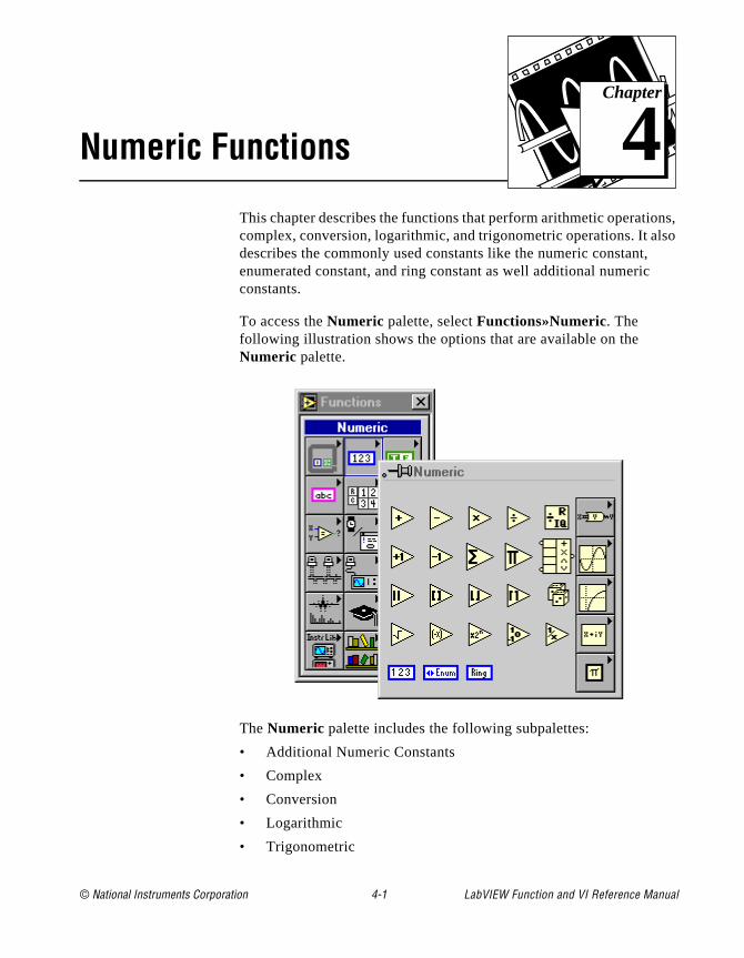
© National Instruments Corporation 4-1 LabVIEW Function and
Chapter
4
Numeric Functionsns, lso
This chapter describes the functions that perform arithmetic operatiocomplex, conversion, logarithmic, and trigonometric operations. It adescribes the commonly used constants like the numeric constant,enumerated constant, and ring constant as well additional numericconstants.
To access the Numeric palette, select Functions»Numeric. The following illustration shows the options that are available on the Numeric palette.
The Numeric palette includes the following subpalettes:
• Additional Numeric Constants
• Complex
• Conversion
• Logarithmic
• Trigonometric
VI Reference Manual

Chapter 4 Numeric Functions
me
ers on.
,
n
as
or
nts
ity. of nput.
e
For examples of some of the arithmetic functions, see examples\general\structs.llb .
Polymorphism for Numeric FunctionsThe arithmetic functions accept numeric input data. With some exceptions noted in the function descriptions, the output has the sanumeric representation as the input, or if the inputs have different representations, the output is the wider of the inputs.
The arithmetic functions work on numbers, arrays of numbers, clustof numbers, arrays of clusters of numbers, complex numbers, and soA formal and recursive definition of the allowable input type is as follows:
Numeric type = numeric scalar || array [numeric type] || cluster [numeric types]
The numeric scalars can be a floating-point, integer or complexnumber. G does not allow you to use arrays of arrays.
Arrays can have any number of dimensions of any size. Clusters cahave any number of elements. For functions with one input, the functions operate on each element of the structure.
For functions with two inputs, you can use the following input combinations:
• Similar—both inputs have the same structure, and the output hthe same structure as the inputs.
• One scalar—one input is a numeric scalar, the other is an arraycluster, and the output is an array or cluster.
• Array of—one input is a numeric array, the other is the numerictype itself, and the output is an array.
For similar inputs, G performs the function on the respective elemeof the structures. For example, G can add two arrays element-by-element. Both arrays must have the same dimensionalYou can add arrays with differing numbers of elements; the output such an addition has the same number of elements as the smallest iClusters also must have the same number of elements, and the respective elements must have the same structure.
Note: You cannot use the multiply function to do matrix multiplication. If you use the multiply function with two matrices, G takes the first number in th
LabVIEW Function and VI Reference Manual 4-2 © National Instruments Corporation
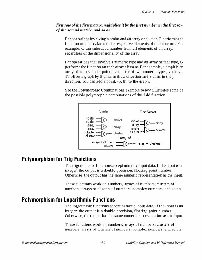
Chapter 4 Numeric Functions
the For
, G is an
of
an
nput.
on.
an
nput.
on.
first row of the first matrix, multiplies it by the first number in the first row of the second matrix, and so on.
For operations involving a scalar and an array or cluster, G performsfunction on the scalar and the respective elements of the structure.example, G can subtract a number from all elements of an array, regardless of the dimensionality of the array.
For operations that involve a numeric type and an array of that typeperforms the function on each array element. For example, a graph array of points, and a point is a cluster of two numeric types, x and y. To offset a graph by 5 units in the x direction and 8 units in the y direction, you can add a point, (5, 8), to the graph.
See the Polymorphic Combinations example below illustrates somethe possible polymorphic combinations of the Add function.
Polymorphism for Trig FunctionsThe trigonometric functions accept numeric input data. If the input isinteger, the output is a double-precision, floating-point number. Otherwise, the output has the same numeric representation as the i
These functions work on numbers, arrays of numbers, clusters of numbers, arrays of clusters of numbers, complex numbers, and so
Polymorphism for Logarithmic FunctionsThe logarithmic functions accept numeric input data. If the input is integer, the output is a double-precision, floating-point number. Otherwise, the output has the same numeric representation as the i
These functions work on numbers, arrays of numbers, clusters of numbers, arrays of clusters of numbers, complex numbers, and so
© National Instruments Corporation 4-3 LabVIEW Function and VI Reference Manual
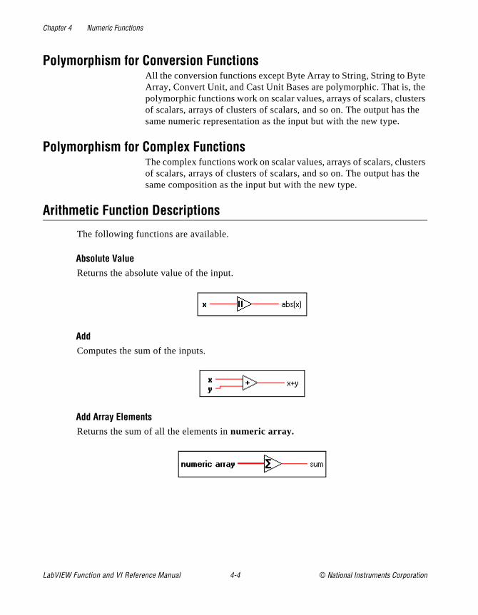
Chapter 4 Numeric Functions
te the ters the
ters the
Polymorphism for Conversion FunctionsAll the conversion functions except Byte Array to String, String to ByArray, Convert Unit, and Cast Unit Bases are polymorphic. That is, polymorphic functions work on scalar values, arrays of scalars, clusof scalars, arrays of clusters of scalars, and so on. The output has same numeric representation as the input but with the new type.
Polymorphism for Complex FunctionsThe complex functions work on scalar values, arrays of scalars, clusof scalars, arrays of clusters of scalars, and so on. The output has same composition as the input but with the new type.
Arithmetic Function Descriptions
The following functions are available.
Absolute ValueReturns the absolute value of the input.
AddComputes the sum of the inputs.
Add Array ElementsReturns the sum of all the elements in numeric array.
LabVIEW Function and VI Reference Manual 4-4 © National Instruments Corporation
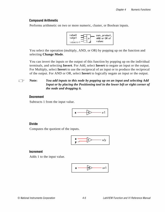
Chapter 4 Numeric Functions
ual . cal
d
Compound ArithmeticPerforms arithmetic on two or more numeric, cluster, or Boolean inputs.
You select the operation (multiply, AND, or OR) by popping up on the function andselecting Change Mode.
You can invert the inputs or the output of this function by popping up on the individterminals, and selecting Invert . For Add, select Invert to negate an input or the outputFor Multiply, select Invert to use the reciprocal of an input or to produce the reciproof the output. For AND or OR, select Invert to logically negate an input or the output.
Note: You add inputs to this node by popping up on an input and selecting AdInput or by placing the Positioning tool in the lower left or right corner ofthe node and dragging it.
DecrementSubtracts 1 from the input value.
DivideComputes the quotient of the inputs.
IncrementAdds 1 to the input value.
© National Instruments Corporation 4-5 LabVIEW Function and VI Reference Manual

Chapter 4 Numeric Functions
er
ot
MultiplyReturns the product of the inputs.
Multiply Array ElementsReturns the product of all the elements in numeric array.
NegateNegates the input value.
Quotient & RemainderComputes the integer quotient and the remainder of the inputs.
With integer input values for y of zero, the quotient is zero and the remainder is the dividend x. For floating point inputs, if y is zero, the quotient is infinity and the remainddefaults to NaN.
Random Number (0–1)Produces a double-precision floating-point number between 0 and 1 exclusive, or nincluding 0 and 1. The distribution is uniform.
LabVIEW Function and VI Reference Manual 4-6 © National Instruments Corporation

Chapter 4 Numeric Functions
sult
ult is
two .
ReciprocalDivides 1 by the input value.
Round To +InfinityRounds the input to the next highest integer. For example, if the input is 3.1, the reis 4. If the input is –3.1, the result is –3.
Round To –InfinityRounds the input to the next lowest integer. For example, if the input is 3.8, the res3. If the input is –3.8, the result is –4.
Round To NearestRounds the input to the nearest integer. If the value of the input is midway betweenintegers (for example, 1.5 or 2.5), the function returns the nearest even integer (2)
Scale By Power Of 2Multiplies one input (x) by 2 raised to the power of the other input (n). If n is floating-point, this function rounds n prior to scaling x (0.5 rounds to 0; 0.51 rounds to 1). If x is an integer, this function is the equivalent of an arithmetic shift.
© National Instruments Corporation 4-7 LabVIEW Function and VI Reference Manual
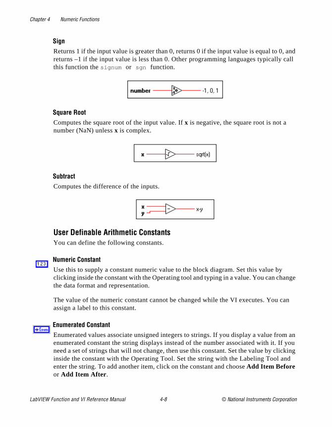
Chapter 4 Numeric Functions
, and call
ange
can
m an f you icking nd
SignReturns 1 if the input value is greater than 0, returns 0 if the input value is equal to 0returns –1 if the input value is less than 0. Other programming languages typicallythis function the signum or sgn function.
Square RootComputes the square root of the input value. If x is negative, the square root is not a number (NaN) unless x is complex.
SubtractComputes the difference of the inputs.
User Definable Arithmetic ConstantsYou can define the following constants.
Numeric ConstantUse this to supply a constant numeric value to the block diagram. Set this value byclicking inside the constant with the Operating tool and typing in a value. You can chthe data format and representation.
The value of the numeric constant cannot be changed while the VI executes. You assign a label to this constant.
Enumerated ConstantEnumerated values associate unsigned integers to strings. If you display a value froenumerated constant the string displays instead of the number associated with it. Ineed a set of strings that will not change, then use this constant. Set the value by clinside the constant with the Operating Tool. Set the string with the Labeling Tool aenter the string. To add another item, click on the constant and choose Add Item Before or Add Item After .
LabVIEW Function and VI Reference Manual 4-8 © National Instruments Corporation
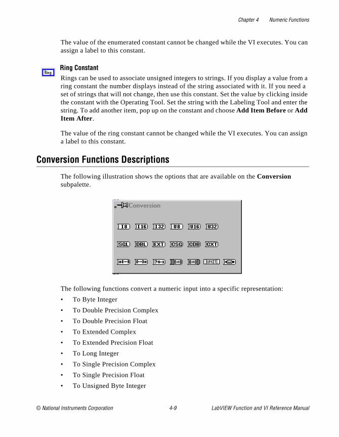
Chapter 4 Numeric Functions
u can
rom a ed a nside r the
ssign
The value of the enumerated constant cannot be changed while the VI executes. Yoassign a label to this constant.
Ring ConstantRings can be used to associate unsigned integers to strings. If you display a value fring constant the number displays instead of the string associated with it. If you neset of strings that will not change, then use this constant. Set the value by clicking ithe constant with the Operating Tool. Set the string with the Labeling Tool and entestring. To add another item, pop up on the constant and choose Add Item Before or Add Item After .
The value of the ring constant cannot be changed while the VI executes. You can aa label to this constant.
Conversion Functions Descriptions
The following illustration shows the options that are available on the Conversion subpalette.
The following functions convert a numeric input into a specific representation:
• To Byte Integer
• To Double Precision Complex
• To Double Precision Float
• To Extended Complex
• To Extended Precision Float
• To Long Integer
• To Single Precision Complex
• To Single Precision Float
• To Unsigned Byte Integer
© National Instruments Corporation 4-9 LabVIEW Function and VI Reference Manual

Chapter 4 Numeric Functions
utput result e for copy r to r with
en
least
and
ers of
• To Unsigned Word Integer
• To Unsigned Long Integer
• To Word Integer
When these functions convert a floating-point number to an integer, they round the oto the nearest integer, or the nearest even integer if the fractional part is 0.5. If the is out of range for the integer, these functions return the minimum or maximum valuthe integer type. When these functions convert an integer to a smaller integer, theythe least significant bits without checking for overflow. When they convert an integea larger integer, they extend the sign of a signed integer and pad an unsigned integezeros.
Use caution when you convert numbers to smaller representations, particularly whconverting integers, because the G conversion routines do not check for overflow.
Boolean Array To NumberConverts Boolean array to an unsigned long integer by interpreting it as the two’s complement representation of an integer with the 0th element of the array being thesignificant bit.
Boolean To (0,1) Converts a Boolean value to a word integer— 0 and 1 for the input values FALSE TRUE, respectively.
Boolean can be a scalar, an array, or a cluster of Boolean values, an array of clustBoolean values, and so on. See the Polymorphism for Boolean Functions section in Chapter 5, Boolean Functions.
Byte Array To StringConverts an array of unsigned bytes into a string.
LabVIEW Function and VI Reference Manual 4-10 © National Instruments Corporation
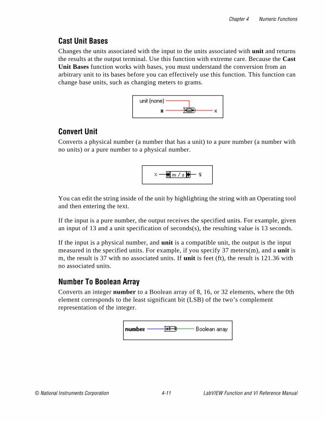
Chapter 4 Numeric Functions
can
r with
tool
given nds.
th
Cast Unit BasesChanges the units associated with the input to the units associated with unit and returns the results at the output terminal. Use this function with extreme care. Because theCast Unit Bases function works with bases, you must understand the conversion from anarbitrary unit to its bases before you can effectively use this function. This functionchange base units, such as changing meters to grams.
Convert UnitConverts a physical number (a number that has a unit) to a pure number (a numbeno units) or a pure number to a physical number.
You can edit the string inside of the unit by highlighting the string with an Operating and then entering the text.
If the input is a pure number, the output receives the specified units. For example, an input of 13 and a unit specification of seconds(s), the resulting value is 13 seco
If the input is a physical number, and unit is a compatible unit, the output is the input measured in the specified units. For example, if you specify 37 meters(m), and a unit is m, the result is 37 with no associated units. If unit is feet (ft), the result is 121.36 with no associated units.
Number To Boolean Array Converts an integer number to a Boolean array of 8, 16, or 32 elements, where the 0element corresponds to the least significant bit (LSB) of the two’s complement representation of the integer.
© National Instruments Corporation 4-11 LabVIEW Function and VI Reference Manual
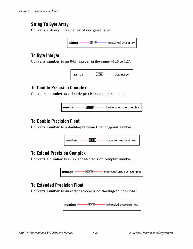
Chapter 4 Numeric Functions
String To Byte ArrayConverts a string into an array of unsigned bytes.
To Byte IntegerConverts number to an 8-bit integer in the range –128 to 127.
To Double Precision ComplexConverts a number to a double-precision complex number.
To Double Precision FloatConverts number to a double-precision floating-point number.
To Extend Precision ComplexConverts a number to an extended-precision complex number.
To Extended Precision FloatConverts number to an extended-precision floating-point number.
LabVIEW Function and VI Reference Manual 4-12 © National Instruments Corporation
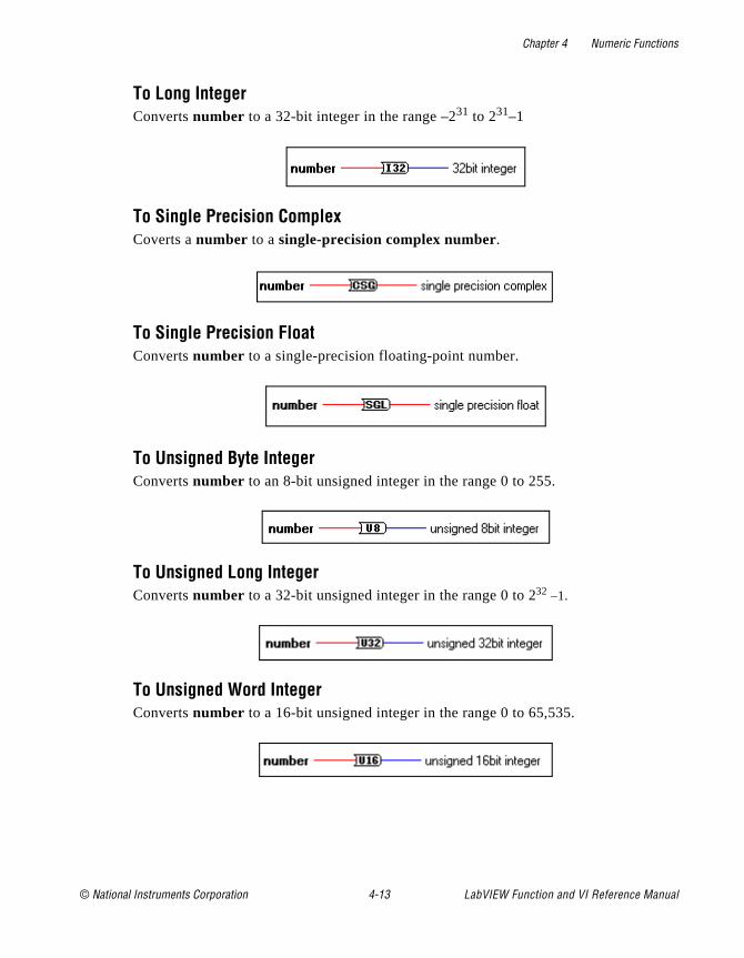
Chapter 4 Numeric Functions
To Long IntegerConverts number to a 32-bit integer in the range –231 to 231–1
To Single Precision ComplexCoverts a number to a single-precision complex number.
To Single Precision FloatConverts number to a single-precision floating-point number.
To Unsigned Byte IntegerConverts number to an 8-bit unsigned integer in the range 0 to 255.
To Unsigned Long IntegerConverts number to a 32-bit unsigned integer in the range 0 to 232 –1.
To Unsigned Word IntegerConverts number to a 16-bit unsigned integer in the range 0 to 65,535.
© National Instruments Corporation 4-13 LabVIEW Function and VI Reference Manual

Chapter 4 Numeric Functions
t.
To Word IntegerConverts number to a 16-bit integer in the range –32,768 to 32,767.
Trigonometric Functions Descriptions
The following illustration shows the options for the Trigonometric subpalette.
CosecantComputes the cosecant of x, where x is in radians. Cosecant is the reciprocal of sine.
CosineComputes the cosine of x, where x is in radians.
CotangentComputes the cotangent of x, where x is in radians. Cotangent is the reciprocal of tangen
LabVIEW Function and VI Reference Manual 4-14 © National Instruments Corporation

Chapter 4 Numeric Functions
er
,
Hyperbolic CosineComputes the hyperbolic cosine of x, where x is in radians.
Hyperbolic SineComputes the hyperbolic sine of x, where x is in radians.
Hyperbolic TangentComputes the hyperbolic tangent of x, where x is in radians.
Inverse CosineComputes the arccosine of x in radians. If x is not complex and is less than –1 or greatthan +1, the result is NaN.
Inverse Hyperbolic CosineComputes the hyperbolic argcosine of x in radians. If x is not complex and is less than 1the result is NaN.
© National Instruments Corporation 4-15 LabVIEW Function and VI Reference Manual

Chapter 4 Numeric Functions
r
or nction
Inverse Hyperbolic SineComputes the hyperbolic argsine of x in radians.
Inverse Hyperbolic TangentComputes the hyperbolic argtangent of x in radians. If x is not complex and is less than–1 or greater than 1, the result is NaN.
Inverse SineComputes the arcsine of x in radians. If x is not complex and is less than –1 or greatethan +1, the result is NaN.
Inverse TangentComputes the arctangent of x in radians (which can be between –Π/2 and Π/2).
Inverse Tangent (2 Input)Computes the arctangent of y/x in radians. This function can compute the arctangent fangles in any of the four quadrants of the x,y plane, whereas the Inverse Tangent fucomputes the arctangent in only two quadrants.
LabVIEW Function and VI Reference Manual 4-16 © National Instruments Corporation

Chapter 4 Numeric Functions
SecantComputes the secant of x, where x is in radians.
SincComputes the sine of x divided by x, where x is in radians.
SineComputes the sine of x, where x is in radians.
Sine & CosineComputes both the sine and cosine of x, where x is in radians. Use this function only when you need both results.
TangentComputes the tangent of x, where x is in radians.
© National Instruments Corporation 4-17 LabVIEW Function and VI Reference Manual
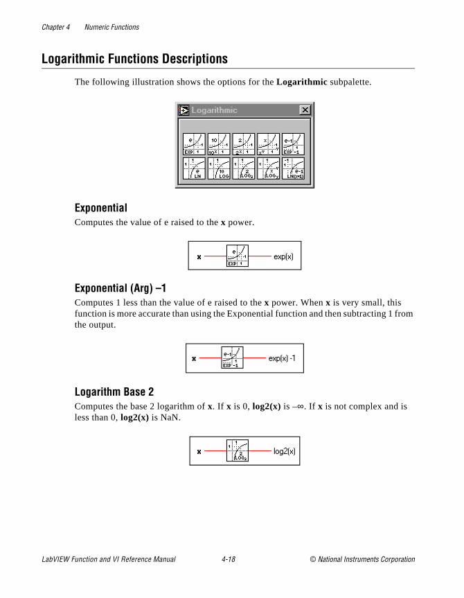
Chapter 4 Numeric Functions
from
Logarithmic Functions Descriptions
The following illustration shows the options for the Logarithmic subpalette.
ExponentialComputes the value of e raised to the x power.
Exponential (Arg) –1Computes 1 less than the value of e raised to the x power. When x is very small, this function is more accurate than using the Exponential function and then subtracting 1the output.
Logarithm Base 2Computes the base 2 logarithm of x. If x is 0, log2(x) is –∞. If x is not complex and is less than 0, log2(x) is NaN.
LabVIEW Function and VI Reference Manual 4-18 © National Instruments Corporation
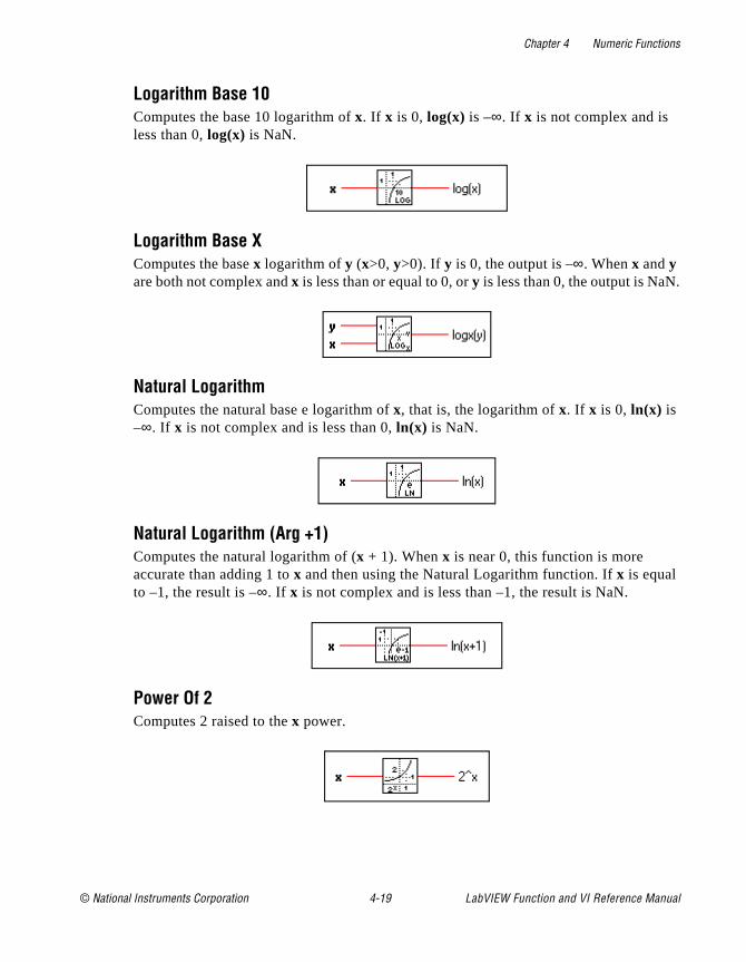
Chapter 4 Numeric Functions
.
Logarithm Base 10Computes the base 10 logarithm of x. If x is 0, log(x) is –∞. If x is not complex and is less than 0, log(x) is NaN.
Logarithm Base XComputes the base x logarithm of y (x>0, y>0). If y is 0, the output is –∞. When x and y are both not complex and x is less than or equal to 0, or y is less than 0, the output is NaN
Natural LogarithmComputes the natural base e logarithm of x, that is, the logarithm of x. If x is 0, ln(x) is –∞. If x is not complex and is less than 0, ln(x) is NaN.
Natural Logarithm (Arg +1)Computes the natural logarithm of (x + 1). When x is near 0, this function is more accurate than adding 1 to x and then using the Natural Logarithm function. If x is equal to –1, the result is –∞. If x is not complex and is less than –1, the result is NaN.
Power Of 2Computes 2 raised to the x power.
© National Instruments Corporation 4-19 LabVIEW Function and VI Reference Manual

Chapter 4 Numeric Functions
ss
from lar
Power Of 10Computes 10 raised to the x power.
Power Of XComputes x raised to the y power. If x is not complex, it must be greater than zero unley is an integer value. Otherwise, the result is NaN. If y is zero, x^y is 1 for all values of x, including zero.
Complex Function Descriptions
The following illustration displays the options available on the Complex subpalette.
The functions Polar To Complex and Re/Im To Complex create complex numbers two values given in rectangular or polar notation, and the functions Complex To Poand Complex To Re/Im break a complex number into its rectangular or polar components.
Complex ConjugateProduces the complex conjugate of x + iy.
LabVIEW Function and VI Reference Manual 4-20 © National Instruments Corporation
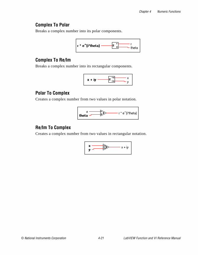
Chapter 4 Numeric Functions
Complex To PolarBreaks a complex number into its polar components.
Complex To Re/ImBreaks a complex number into its rectangular components.
Polar To ComplexCreates a complex number from two values in polar notation.
Re/Im To ComplexCreates a complex number from two values in rectangular notation.
© National Instruments Corporation 4-21 LabVIEW Function and VI Reference Manual
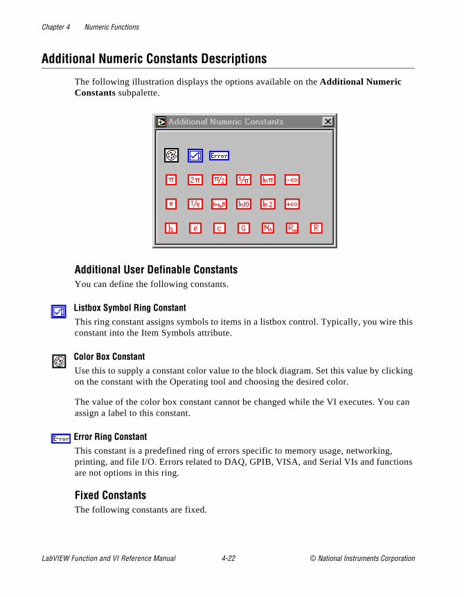
Chapter 4 Numeric Functions
this
king
can
ns
Additional Numeric Constants Descriptions
The following illustration displays the options available on the Additional Numeric Constants subpalette.
Additional User Definable ConstantsYou can define the following constants.
Listbox Symbol Ring ConstantThis ring constant assigns symbols to items in a listbox control. Typically, you wire constant into the Item Symbols attribute.
Color Box ConstantUse this to supply a constant color value to the block diagram. Set this value by clicon the constant with the Operating tool and choosing the desired color.
The value of the color box constant cannot be changed while the VI executes. Youassign a label to this constant.
Error Ring ConstantThis constant is a predefined ring of errors specific to memory usage, networking, printing, and file I/O. Errors related to DAQ, GPIB, VISA, and Serial VIs and functioare not options in this ring.
Fixed ConstantsThe following constants are fixed.
LabVIEW Function and VI Reference Manual 4-22 © National Instruments Corporation

Chapter 4 Numeric Functions
Avogadro Constant (1/mol)Returns the value 6.0220e23.
Base 10 Logarithm of eReturns the value 0.43429448190325183.
Elementary Charge (c)Returns the value 1.6021892e–19.
Gravitational Constant (Nm2/kg2)Returns the value 6.6720e–11.
Molar Gas Constant (J/mol K)Returns the value 8.31441.
eReturns the value 2.7182818284590452e+0.
Natural Logarithm of PiReturns the value 1.14472988584940020.
Natural Logarithm of 2Returns the value 0.69314718055994531.
Natural Logarithm of 10Returns the value 2.30234095236904570.
Negative InfinityReturns the value –∞.
PiReturns the value 3.14159265358979320.
Pi divided by 2Returns the value 1.57079632679489660.
Pi multiplied by 2Returns the value 6.28318530717958650.
© National Instruments Corporation 4-23 LabVIEW Function and VI Reference Manual
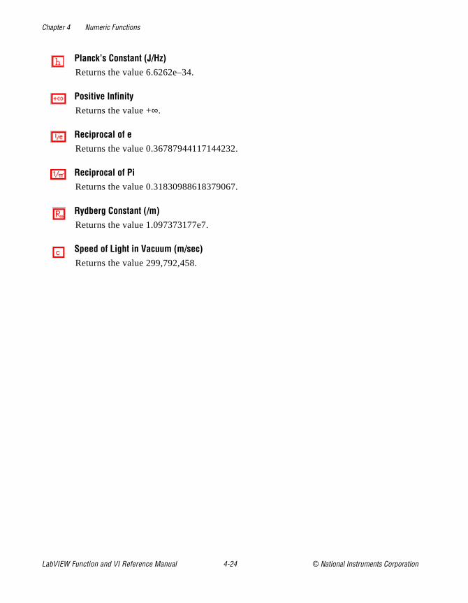
Chapter 4 Numeric Functions
Planck’s Constant (J/Hz)Returns the value 6.6262e–34.
Positive InfinityReturns the value +∞.
Reciprocal of eReturns the value 0.36787944117144232.
Reciprocal of PiReturns the value 0.31830988618379067.
Rydberg Constant (/m)Returns the value 1.097373177e7.
Speed of Light in Vacuum (m/sec)Returns the value 299,792,458.
LabVIEW Function and VI Reference Manual 4-24 © National Instruments Corporation

© National Instruments Corporation 5-1 LabVIEW Function and
Chapter
5
Boolean Functionss.
he
is
, s or
This chapter describes the functions that perform logical operation
The following illustration shows the Boolean palette, which you accessby selecting Functions»Boolean.
For examples of some of the Boolean functions, seeexamples\general\structs.llb .
Polymorphism for Boolean FunctionsThe logical functions take either Boolean or numeric input data. If tinput is numeric, G performs a bit-wise operation. If the input is an integer, the output has the same representation. If the input is a floating-point number, G rounds it to a long integer, and the outputlong integer.
The logical functions work on arrays of numbers or Boolean valuesclusters of numbers or Boolean values, arrays of clusters of number
VI Reference Manual

Chapter 5 Boolean Functions
nly the
Boolean values, and so on. A formal and recursive definition of theallowable input type is as follows.
Logical type = Boolean scalar || numeric scalar || array [logical type] || cluster [logical types]
except that complex numbers and arrays of arrays are not allowed.
Logical functions with two inputs can have the same input combinations as the arithmetic functions. However, the logical functions have the further restriction that the base operations can obe between two Boolean values or two numbers. For example, youcannot have an AND between a Boolean value and a number. Seeexample below for an illustration of some combinations of Booleanvalues for the AND function.
Boolean Function Descriptions
The following Boolean functions are available.
AndComputes the logical AND of the inputs.
Note: This function performs bit-wise operations on numeric inputs.
LabVIEW Function and VI Reference Manual 5-2 © National Instruments Corporation
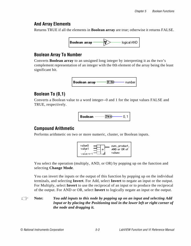
Chapter 5 Boolean Functions
.
least
d
ual . cal
d
And Array ElementsReturns TRUE if all the elements in Boolean array are true; otherwise it returns FALSE
Boolean Array To NumberConverts Boolean array to an unsigned long integer by interpreting it as the two’s complement representation of an integer with the 0th element of the array being thesignificant bit.
Boolean To (0,1) Converts a Boolean value to a word integer--0 and 1 for the input values FALSE anTRUE, respectively.
Compound ArithmeticPerforms arithmetic on two or more numeric, cluster, or Boolean inputs.
You select the operation (multiply, AND, or OR) by popping up on the function andselecting Change Mode.
You can invert the inputs or the output of this function by popping up on the individterminals, and selecting Invert . For Add, select Invert to negate an input or the outputFor Multiply, select Invert to use the reciprocal of an input or to produce the reciproof the output. For AND or OR, select Invert to logically negate an input or the output.
Note: You add inputs to this node by popping up on an input and selecting AdInput or by placing the Positioning tool in the lower left or right corner ofthe node and dragging it.
© National Instruments Corporation 5-3 LabVIEW Function and VI Reference Manual
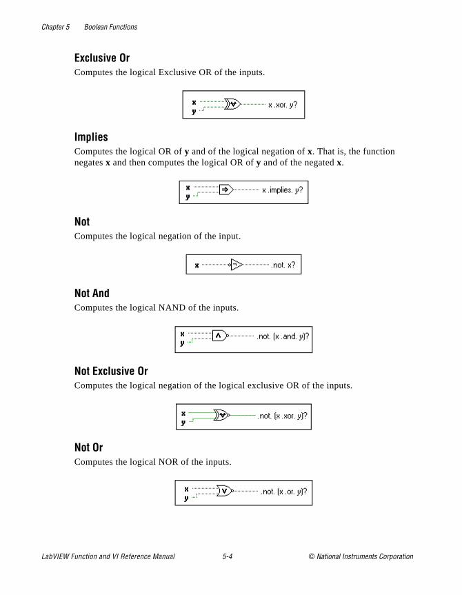
Chapter 5 Boolean Functions
Exclusive OrComputes the logical Exclusive OR of the inputs.
ImpliesComputes the logical OR of y and of the logical negation of x. That is, the function negates x and then computes the logical OR of y and of the negated x.
NotComputes the logical negation of the input.
Not AndComputes the logical NAND of the inputs.
Not Exclusive OrComputes the logical negation of the logical exclusive OR of the inputs.
Not OrComputes the logical NOR of the inputs.
LabVIEW Function and VI Reference Manual 5-4 © National Instruments Corporation
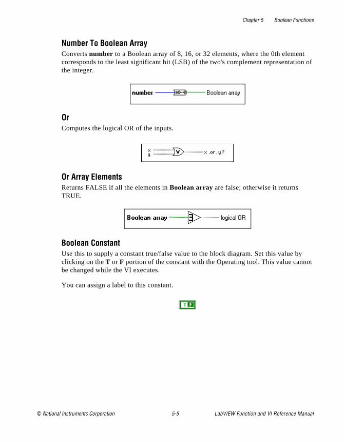
Chapter 5 Boolean Functions
t n of
y ot
Number To Boolean Array Converts number to a Boolean array of 8, 16, or 32 elements, where the 0th elemencorresponds to the least significant bit (LSB) of the two's complement representatiothe integer.
OrComputes the logical OR of the inputs.
Or Array ElementsReturns FALSE if all the elements in Boolean array are false; otherwise it returns TRUE.
Boolean ConstantUse this to supply a constant true/false value to the block diagram. Set this value bclicking on the T or F portion of the constant with the Operating tool. This value cannbe changed while the VI executes.
You can assign a label to this constant.
© National Instruments Corporation 5-5 LabVIEW Function and VI Reference Manual

© National Instruments Corporation 6-1 LabVIEW Function and
Chapter
6
String Functionsvert
This chapter describes the string functions, including those that constrings to numbers and numbers to strings.The following illustration shows the String palette, which you access by selecting Functions»String.
Overview of Polymorphism for String FunctionsThis section provides descriptions of polymorphism for String functions, Additional String to Number functions, and String Conversion functions.
VI Reference Manual
Chapter 6 String Functions
d of CII
ch
o sters om uce
e
hat ,
e
for ing tput the f yable t
Polymorphism for String FunctionsString Length, To Upper Case, To Lower Case, Reverse String, anRotate String accept strings, clusters, arrays of strings, and arraysclusters. To Upper Case and To Lower Case also accept numbers,clusters of numbers, and arrays of numbers, interpreting them as AScodes for characters (refer to the Appendix B, Multiline Interface Messages, later in this manual, for the numbers that correspond to eacharacter). Width and precision inputs must be scalar.
Polymorphism for Additional String to Number FunctionsTo Decimal, To Hex, To Octal, To Engineering, To Fractional, and TExponential accept clusters and arrays of numbers and produce cluand arrays of strings. From Decimal, From Hex, From Octal, and FrExponential/Fract/Sci accept clusters and arrays of strings and prodclusters and arrays of numbers. Width and precision inputs must bscalar.
Polymorphism for String Conversion FunctionsThe Path To String and String To Path functions are polymorphic. Tis, they work on scalar values, arrays of scalars, clusters of scalarsarrays of clusters of scalars, and so on. The output has the same composition as the input but with the new type.
Format Strings OverviewMany G functions accept a format string input, which controls the behavior of the function. A format string is composed of one or morformat specifiers, which determine what action to take to process agiven parameter. The Format Into String and Scan From String functions can use multiple format specifiers in the format string, oneeach resizable input or output to the function. Characters in the strthat are not part of the format specifier are copied verbatim to the oustring (in the case of Format Into String) or are matched exactly in input string (in the case of Scan From String), with the exception ospecial escape codes. You can use these codes to insert nondisplacharacters, the backslash, and percent characters within any formastring. These codes are similar to those used in the C programminglanguage.
LabVIEW Function and VI Reference Manual 6-2 © National Instruments Corporation
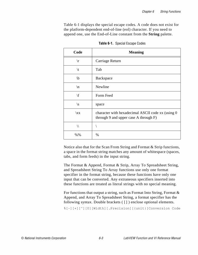
Chapter 6 String Functions
t for
ns, ces,
g,
e o g.
t & he
Table 6-1 displays the special escape codes. A code does not existhe platform-dependent end-of-line (eol) character. If you need to append one, use the End-of-Line constant from the String palette.
Notice also that for the Scan From String and Format & Strip functioa space in the format string matches any amount of whitespace (spatabs, and form feeds) in the input string.
The Format & Append, Format & Strip, Array To Spreadsheet Strinand Spreadsheet String To Array functions use only one format specifier in the format string, because these functions have only oninput that can be converted. Any extraneous specifiers inserted intthese functions are treated as literal strings with no special meanin
For functions that output a string, such as Format Into String, FormaAppend, and Array To Spreadsheet String, a format specifier has tfollowing syntax. Double brackets ( [ ] ) enclose optional elements.
%[–][+][^][0][Width][.Precision][unit]Conversion Code
Table 6-1. Special Escape Codes
Code Meaning
\r Carriage Return
\t Tab
\b Backspace
\n Newline
\f Form Feed
\s space
\xx character with hexadecimal ASCII code xx (using 0through 9 and upper case A through F)
\\ \
%% %
© National Instruments Corporation 6-3 LabVIEW Function and VI Reference Manual
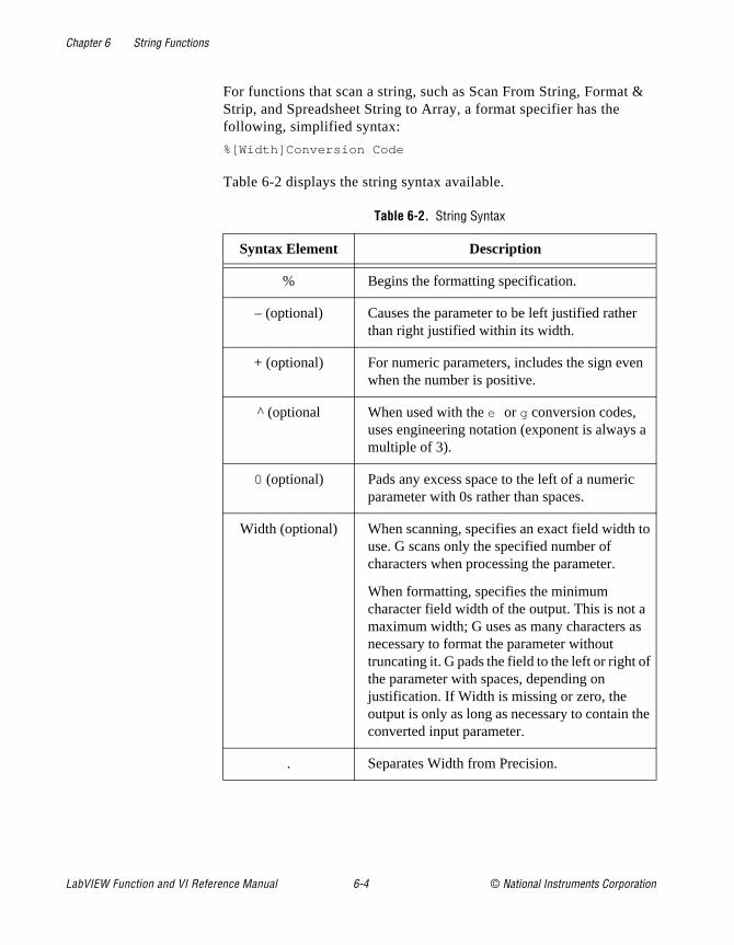
Chapter 6 String Functions
&
a
o
e
For functions that scan a string, such as Scan From String, FormatStrip, and Spreadsheet String to Array, a format specifier has the following, simplified syntax:
%[Width]Conversion Code
Table 6-2 displays the string syntax available.
Table 6-2. String Syntax
Syntax Element Description
% Begins the formatting specification.
– (optional) Causes the parameter to be left justified rather than right justified within its width.
+ (optional) For numeric parameters, includes the sign evenwhen the number is positive.
^ (optional When used with the e or g conversion codes, uses engineering notation (exponent is always multiple of 3).
0 (optional) Pads any excess space to the left of a numericparameter with 0s rather than spaces.
Width (optional) When scanning, specifies an exact field width tuse. G scans only the specified number of characters when processing the parameter.
When formatting, specifies the minimum character field width of the output. This is not amaximum width; G uses as many characters asnecessary to format the parameter without truncating it. G pads the field to the left or right ofthe parameter with spaces, depending on justification. If Width is missing or zero, the output is only as long as necessary to contain thconverted input parameter.
. Separates Width from Precision.
LabVIEW Function and VI Reference Manual 6-4 © National Instruments Corporation
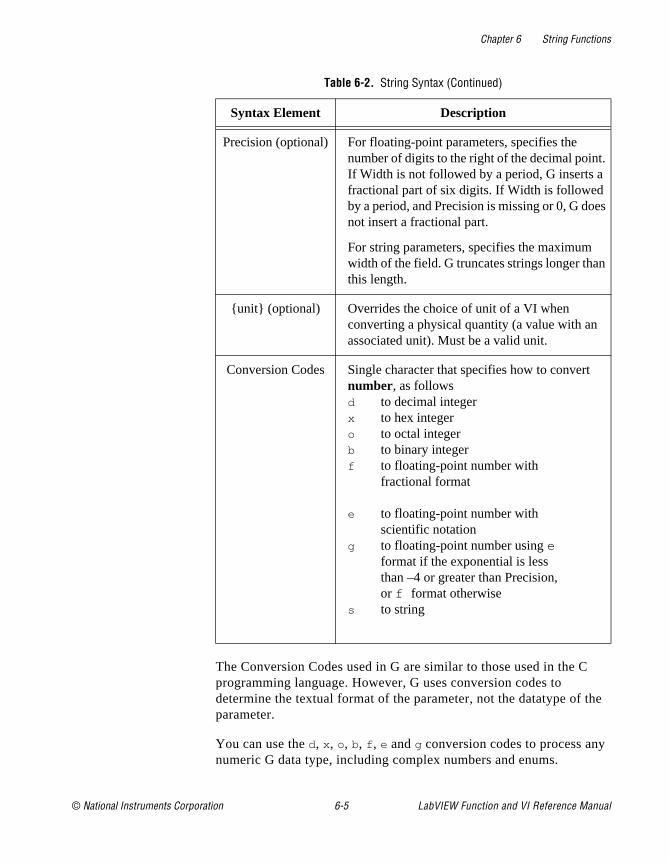
Chapter 6 String Functions
he
.
s
The Conversion Codes used in G are similar to those used in the Cprogramming language. However, G uses conversion codes to determine the textual format of the parameter, not the datatype of tparameter.
You can use the d, x , o, b, f , e and g conversion codes to process anynumeric G data type, including complex numbers and enums.
Precision (optional) For floating-point parameters, specifies the number of digits to the right of the decimal pointIf Width is not followed by a period, G inserts a fractional part of six digits. If Width is followed by a period, and Precision is missing or 0, G doenot insert a fractional part.
For string parameters, specifies the maximum width of the field. G truncates strings longer thanthis length.
unit (optional) Overrides the choice of unit of a VI when converting a physical quantity (a value with an associated unit). Must be a valid unit.
Conversion Codes Single character that specifies how to convert number, as followsd to decimal integerx to hex integero to octal integerb to binary integerf to floating-point number with
fractional format
e to floating-point number with scientific notation
g to floating-point number using e format if the exponential is less than –4 or greater than Precision, or f format otherwise
s to string
Table 6-2. String Syntax (Continued)
Syntax Element Description
© National Instruments Corporation 6-5 LabVIEW Function and VI Reference Manual

Chapter 6 String Functions
both
ers
ith
ines d.
d
ent s are
put
For complex numbers, you can use the format specifier to process the real and imaginary parts as a single parameter.
You can use the s conversion code to process string or path parametor enums.
Notice that you can use either a numeric or string conversion code wan enum, depending on whether you want the numeric value or symbolic (string) value of the enum.
For compatibility with C, G treats a u conversion code (unsigned integer) the same as a d, and ignores an l or L preceding the conversioncode. However, in G it is the datatype of the parameter that determthe size of an integer and whether the integer is signed or unsigne
For examples of format string usage, see the Format Into String anScan From String function descriptions later in this chapter.
String Function Descriptions
The following string functions are available.
Array To Spreadsheet StringConverts an array of any dimension to spreadsheet string. spreadsheet string is a table in string form, containing delimiter-separated column elements, a platform-dependEOL character separating rows, and, for arrays of three or more dimensions, pageseparated.
Concatenate StringsConcatenates input strings and one-dimensional arrays of strings into a single, outstring. For array inputs, this function concatenates each element of the array.
LabVIEW Function and VI Reference Manual 6-6 © National Instruments Corporation
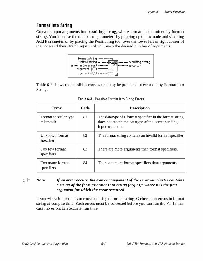
Chapter 6 String Functions
cting of
Into
s
mat this
g
r.
Format Into StringConverts input arguments into resulting string, whose format is determined by format string. You increase the number of parameters by popping up on the node and seleAdd Parameter or by placing the Positioning tool over the lower left or right corner the node and then stretching it until you reach the desired number of arguments.
Table 6-3 shows the possible errors which may be produced in error out by FormatString.
Note: If an error occurs, the source component of the error out cluster containa string of the form “Format Into String (arg n),” where n is the first argument for which the error occurred.
If you wire a block diagram constant string to format string, G checks for errors in forstring at compile time. Such errors must be corrected before you can run the VI. Incase, no errors can occur at run time.
Table 6-3. Possible Format Into String Errors
Error Code Description
Format specifier type mismatch
81 The datatype of a format specifier in the format strindoes not match the datatype of the corresponding input argument.
Unknown format specifier
82 The format string contains an invalid format specifie
Too few format specifiers
83 There are more arguments than format specifiers.
Too many format specifiers
84 There are more format specifiers than arguments.
© National Instruments Corporation 6-7 LabVIEW Function and VI Reference Manual
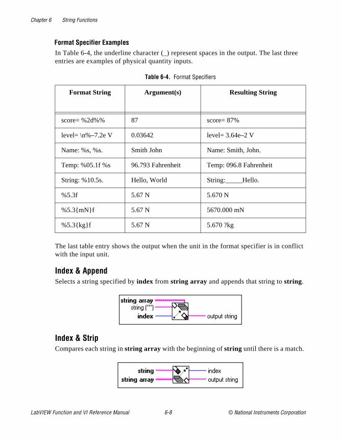
Chapter 6 String Functions
ree
flict
Format Specifier ExamplesIn Table 6-4, the underline character (_) represent spaces in the output. The last thentries are examples of physical quantity inputs.
The last table entry shows the output when the unit in the format specifier is in conwith the input unit.
Index & AppendSelects a string specified by index from string array and appends that string to string.
Index & StripCompares each string in string array with the beginning of string until there is a match.
Table 6-4. Format Specifiers
Format String Argument(s) Resulting String
score= %2d%% 87 score= 87%
level= \n%–7.2e V 0.03642 level= 3.64e–2 V
Name: %s, %s. Smith John Name: Smith, John.
Temp: %05.1f %s 96.793 Fahrenheit Temp: 096.8 Fahrenheit
String: %10.5s. Hello, World String:_____Hello.
%5.3f 5.67 N 5.670 N
%5.3mNf 5.67 N 5670.000 mN
%5.3kgf 5.67 N 5.670 ?kg
LabVIEW Function and VI Reference Manual 6-8 © National Instruments Corporation
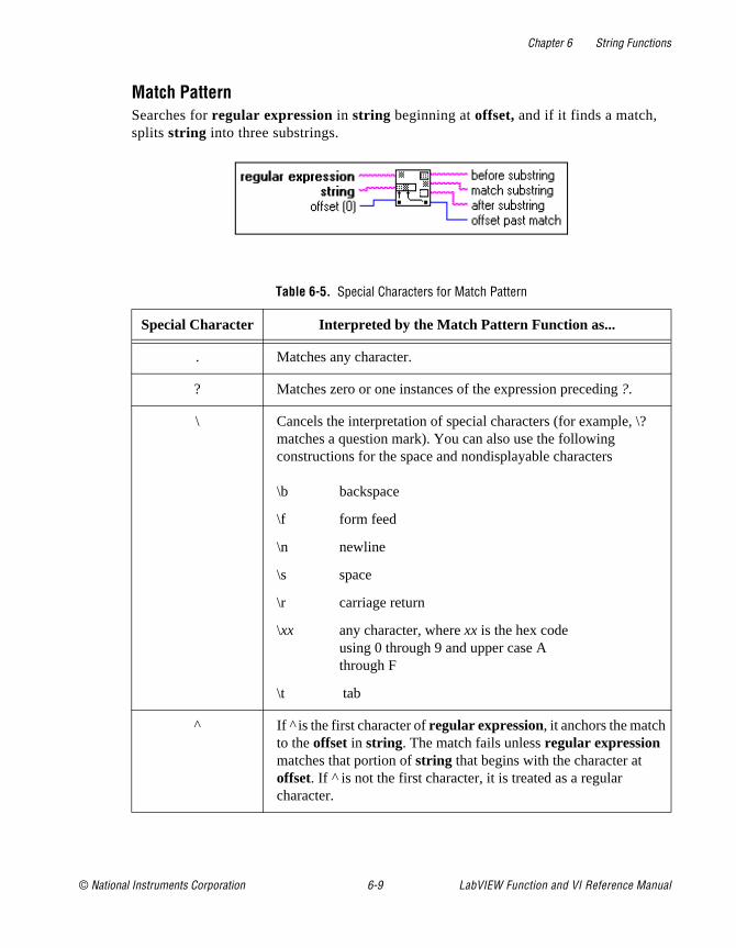
Chapter 6 String Functions
Match Pattern Searches for regular expression in string beginning at offset, and if it finds a match, splits string into three substrings.
Table 6-5. Special Characters for Match Pattern
Special Character Interpreted by the Match Pattern Function as...
. Matches any character.
? Matches zero or one instances of the expression preceding ?.
\ Cancels the interpretation of special characters (for example, \?matches a question mark). You can also use the following constructions for the space and nondisplayable characters
\b backspace
\f form feed
\n newline
\s space
\r carriage return
\xx any character, where xx is the hex codeusing 0 through 9 and upper case Athrough F
\t tab
^ If is the first character of regular expression, it anchors the match to the offset in string. The match fails unless regular expression matches that portion of string that begins with the character at offset. If is not the first character, it is treated as a regular character.
© National Instruments Corporation 6-9 LabVIEW Function and VI Reference Manual
Chapter 6 String Functions
e
e or
he
9.
and l
Table 6-6 shows examples of the Strings for the Match Pattern functions.
[ ] Encloses alternates. For example, [abc] matches a, b, or c. Thefollowing character has special significance when used within thbrackets in the following manner.
– (dash)Indicates a range when used between digits, or lowercasuppercase letters (for example, [0–5],[a–g], or [L–Q])
The following characters have significance only when they are tfirst character within the brackets.
~ Excludes the set of characters, including nondisplayable characters. [~0–9] matches any character other than 0 through
^ Excludes the set with respect to all the displayable characters (the space characters). [^0–9] gives the space characters and aldisplayable characters except 0 through 9.
+ Matches the longest number of instances of the expression preceding + ; there must be at least one instance to constitute a match.
* Matches the longest number of instances of the expression preceding * in regular expression, including zero instances.
$ If $ is the last character of regular expression, it anchors the match to the last element of string. The match fails unless regular expression matches up to and including the last character in thestring. If $ is not last, it is treated as a regular character.
Table 6-6. Strings for the Match Pattern Examples
Characters to Be Matched Regular Expression
VOLTS VOLTS
All uppercase and lowercase versions of volts, that is, VOLTS, Volts, volts, and so on
[Vv][Oo][Ll][Tt][Ss]
Table 6-5. Special Characters for Match Pattern (Continued)
Special Character Interpreted by the Match Pattern Function as...
LabVIEW Function and VI Reference Manual 6-10 © National Instruments Corporation
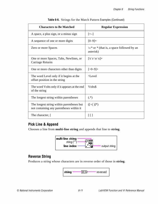
Chapter 6 String Functions
Pick Line & AppendChooses a line from multi-line string and appends that line to string.
Reverse StringProduces a string whose characters are in reverse order of those in string.
A space, a plus sign, or a minus sign [+–]
A sequence of one or more digits [0–9]+
Zero or more Spaces \s* or * (that is, a space followed by an asterisk)
One or more Spaces, Tabs, Newlines, or Carriage Returns
[\t \r \n \s]+
One or more characters other than digits [~0–9]+
The word Level only if it begins at the offset position in the string
^Level
The word Volts only if it appears at the end of the string
Volts$
The longest string within parentheses (.*)
The longest string within parentheses but not containing any parentheses within it
([~( )]*)
The character, [ [ [ ]
Table 6-6. Strings for the Match Pattern Examples (Continued)
Characters to Be Matched Regular Expression
© National Instruments Corporation 6-11 LabVIEW Function and VI Reference Manual
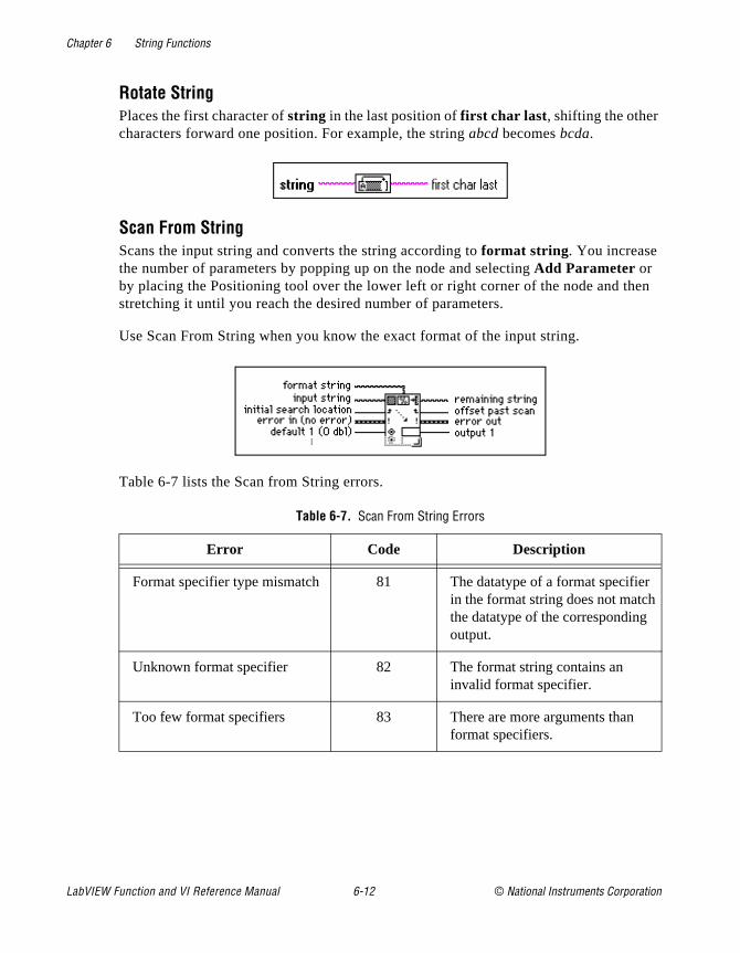
Chapter 6 String Functions
en
Rotate StringPlaces the first character of string in the last position of first char last, shifting the other characters forward one position. For example, the string abcd becomes bcda.
Scan From StringScans the input string and converts the string according to format string . You increase the number of parameters by popping up on the node and selecting Add Parameter or by placing the Positioning tool over the lower left or right corner of the node and thstretching it until you reach the desired number of parameters.
Use Scan From String when you know the exact format of the input string.
Table 6-7 lists the Scan from String errors.
Table 6-7. Scan From String Errors
Error Code Description
Format specifier type mismatch 81 The datatype of a format specifier in the format string does not matchthe datatype of the corresponding output.
Unknown format specifier 82 The format string contains an invalid format specifier.
Too few format specifiers 83 There are more arguments than format specifiers.
LabVIEW Function and VI Reference Manual 6-12 © National Instruments Corporation

Chapter 6 String Functions
mat this
Note: If an error occurs, the source component of the error out cluster contains a string of the form “Scan From String (arg n),” where n is the first argument for which the error occurred.
If you wire a block diagram constant string to format string, G checks for errors in forstring at compile time. You must correct these errors before you can run the VI. In case, only Scan failed can occur at run time.
Table 6-8 lists Scan From String examples.
Too many format specifiers 84 There are more format specifiers than arguments.
Scan failed 85 Scan From String was unable to convert the input string into the datatype indicated by the format specifier.
Table 6-8. Scan from String Examples
Input String Format String Default(s) Output(s)Remaining
String
abc xyz12.3+56i 7200
%s %s%f%2d
abcxyz12.3+56i72
00
Q+1.27E–3 tail Q%f t 1.27E–3 ail
0123456789 %3d%3d 12345
6789
X:9.860 Z:3.450 X:%fY:%f 100 (I32)100.0 (DBL)
10100.0
Z: 3450
set49.4.2 set%d 49 .4.2
Table 6-7. Scan From String Errors (Continued)
Error Code Description
© National Instruments Corporation 6-13 LabVIEW Function and VI Reference Manual
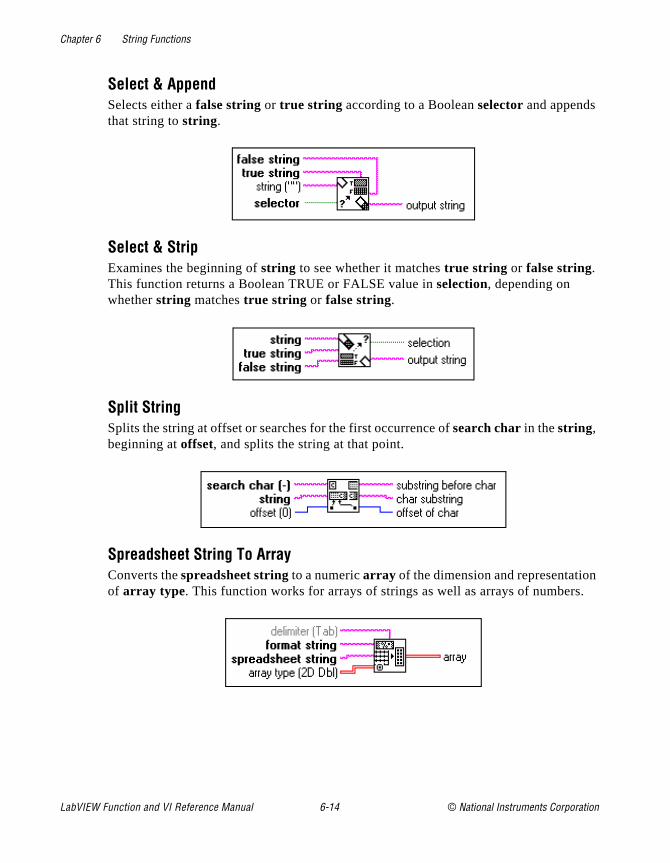
Chapter 6 String Functions
n .
Select & AppendSelects either a false string or true string according to a Boolean selector and appends that string to string.
Select & StripExamines the beginning of string to see whether it matches true string or false string. This function returns a Boolean TRUE or FALSE value in selection, depending on whether string matches true string or false string.
Split StringSplits the string at offset or searches for the first occurrence of search char in the string, beginning at offset, and splits the string at that point.
Spreadsheet String To ArrayConverts the spreadsheet string to a numeric array of the dimension and representatioof array type. This function works for arrays of strings as well as arrays of numbers
LabVIEW Function and VI Reference Manual 6-14 © National Instruments Corporation

Chapter 6 String Functions
s
s
String LengthReturns in length the number of characters (bytes) in string.
String SubsetReturns the substring of the original string beginning at offset and containing length number of characters.
To Lower CaseConverts all alphabetic characters in string to lowercase characters. This function doenot affect nonalphabetic characters.
To Upper CaseConverts all alphabetic characters in string to uppercase characters. This function doenot affect nonalphabetic characters.
Additional String To Number Function Descriptions
For general information about Additional String to Number functions, see Polymorphism for Additional String to Number Functions, earlier in this chapter.
© National Instruments Corporation 6-15 LabVIEW Function and VI Reference Manual

Chapter 6 String Functions
f
The following illustration displays the options available on the Additional String to Number Functions subpalette.
Format & AppendConverts number into a regular string according to the format specified in format string, and appends this to string.
Note: The Format Into String function has the same functionality as Format &Append but can use multiple inputs, so that you can convert informationsimultaneously. You should consider using Format Into String instead othis function: in many cases, this can simplify your block diagram.
Format & StripLooks for format string at the beginning of string, formats any number in this string portion according to the conversion codes in format string , and returns the converted number in number and the remainder of string after the match in output string .
LabVIEW Function and VI Reference Manual 6-16 © National Instruments Corporation
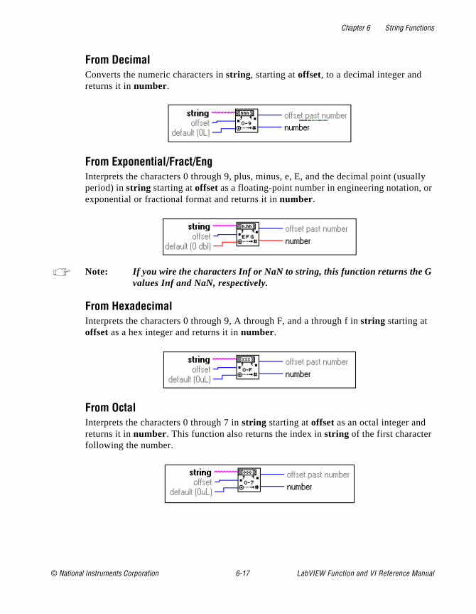
Chapter 6 String Functions
ally r
From DecimalConverts the numeric characters in string, starting at offset, to a decimal integer and returns it in number.
From Exponential/Fract/EngInterprets the characters 0 through 9, plus, minus, e, E, and the decimal point (usuperiod) in string starting at offset as a floating-point number in engineering notation, oexponential or fractional format and returns it in number.
Note: If you wire the characters Inf or NaN to string, this function returns the Gvalues Inf and NaN, respectively.
From HexadecimalInterprets the characters 0 through 9, A through F, and a through f in string starting at offset as a hex integer and returns it in number.
From OctalInterprets the characters 0 through 7 in string starting at offset as an octal integer and returns it in number. This function also returns the index in string of the first character following the number.
© National Instruments Corporation 6-17 LabVIEW Function and VI Reference Manual

Chapter 6 String Functions
nt is
To DecimalConverts number to a string of decimal digits width characters wide, or wider if necessary.
To EngineeringConverts number to an engineering format, floating-point string width characters wide, or wider if necessary. Engineering format is similar to E format, except the exponea multiple of three (–3, 0, 3, 6).
To ExponentialConverts number to an E-format (exponential notation), floating-point string width characters wide, or wider if necessary.
To FractionalConverts number to an F-format (fractional notation), floating-point string width characters wide, or wider if necessary.
LabVIEW Function and VI Reference Manual 6-18 © National Instruments Corporation

Chapter 6 String Functions
.
rray strings.
To HexadecimalConverts number to a string of hexadecimal digits width characters wide, or wider if necessary.
To OctalConverts number to a string of octal digits width characters wide, or wider if necessary
String Conversion Function Descriptions
For general information about String Conversion functions, see Overview of Polymorphism for String Functions earlier in this chapter.
The following illustration shows the String Conversion subpalette.
Array Of Strings To Path accepts one-dimensional (1D) arrays of strings, Path To AOf Strings accepts paths, Path To String accepts paths, and String To Path accepts
Array Of Strings To PathConverts an array of strings into a relative or absolute path.
© National Instruments Corporation 6-19 LabVIEW Function and VI Reference Manual
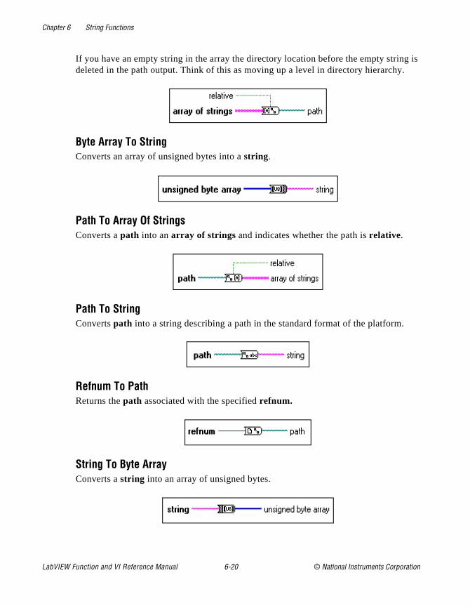
Chapter 6 String Functions
g is .
If you have an empty string in the array the directory location before the empty strindeleted in the path output. Think of this as moving up a level in directory hierarchy
Byte Array To StringConverts an array of unsigned bytes into a string.
Path To Array Of StringsConverts a path into an array of strings and indicates whether the path is relative.
Path To StringConverts path into a string describing a path in the standard format of the platform.
Refnum To PathReturns the path associated with the specified refnum.
String To Byte ArrayConverts a string into an array of unsigned bytes.
LabVIEW Function and VI Reference Manual 6-20 © National Instruments Corporation

Chapter 6 String Functions
, to a
king e the he layed
ssign
For ue
String To PathConverts a string, describing a path in the standard format for the current platformpath.
String Fixed Constants
The following String Fixed Constants are available.
String ConstantUse this to supply a constant ASCII value to the block diagram. Set this value by clicinside the constant with the Operating tool and typing in the value. You can changdisplay mode so you can see non-displayable characters or the hex equivalent to tcharacters. You can also set the constant in password display mode so “*” are dispwhen you type in characters.
The value of the string constant cannot be changed while the VI executes. You can aa label to this constant.
Carriage ReturnConsists of a constant string containing the ASCII CR value.
Empty StringConsists of a constant string that is empty. Length is zero.
End of LineConsists of a constant string containing the platform-dependent, end of line value.Windows, the value is CRLF; for Macintosh, the value is CR; and on UNIX, the valis LF.
Line FeedConsists of a constant string containing the ASCII LF value.
TabConsists of a constant string containing the ASCII HT (horizontal tab) value.
© National Instruments Corporation 6-21 LabVIEW Function and VI Reference Manual
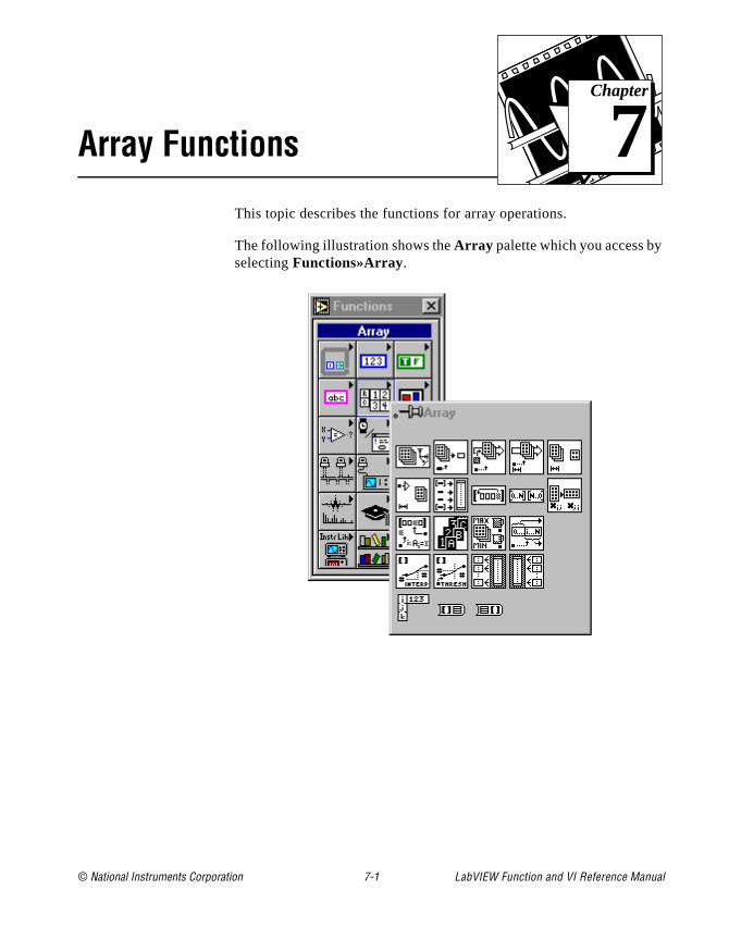
© National Instruments Corporation 7-1 LabVIEW Function and
Chapter
7
Array FunctionsThis topic describes the functions for array operations.
The following illustration shows the Array palette which you access byselecting Functions»Array.
VI Reference Manual

Chapter 7 Array Functions
w
ect
hen m by
) or
The
is
Some of the array functions are also available from the Array Tools palette of most terminal or wire pop-up menus. The illustration beloshows the pop-up menu.
If you select the functions from this palette, they appear with the corrnumber of terminals to wire to the object on which you popped up.
For examples of array functions, see examples\general\arrays.llb .
Array Function OverviewSome of the array functions have a variable number of terminals. Wyou drop a new function of this kind, it appears on the block diagrawith only one or two terminals. You can add and remove terminals using the pop-up menu Add Element Input or Add Array Input and Remove Input commands (the actual names depend on the functionby resizing the node vertically from any corner. If you want to add terminals by popping up, you must place your cursor on the input terminals to access the pop-up menu.
You can shrink the node if doing so does not delete wired terminals. Add Element Input or Add Array Input command inserts a terminaldirectly after the one on which you popped up. The Remove Input command removes the terminal on which you popped up, even if it
LabVIEW Function and VI Reference Manual 7-2 © National Instruments Corporation
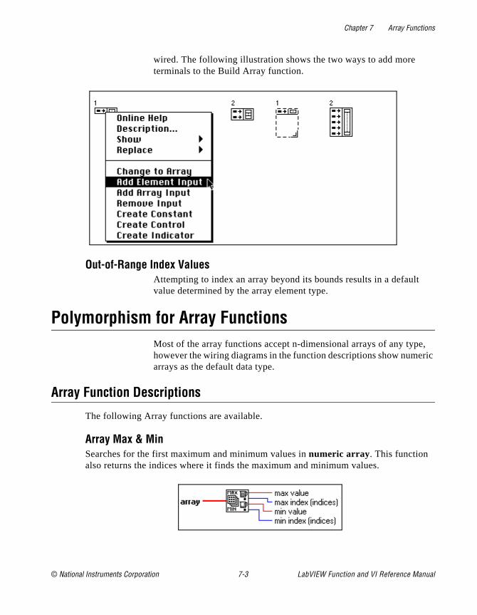
Chapter 7 Array Functions
, ric
wired. The following illustration shows the two ways to add more terminals to the Build Array function.
Out-of-Range Index ValuesAttempting to index an array beyond its bounds results in a defaultvalue determined by the array element type.
Polymorphism for Array FunctionsMost of the array functions accept n-dimensional arrays of any typehowever the wiring diagrams in the function descriptions show numearrays as the default data type.
Array Function Descriptions
The following Array functions are available.
Array Max & MinSearches for the first maximum and minimum values in numeric array . This function also returns the indices where it finds the maximum and minimum values.
© National Instruments Corporation 7-3 LabVIEW Function and VI Reference Manual
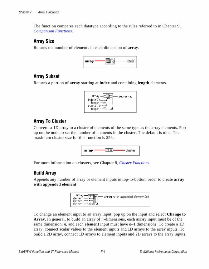
Chapter 7 Array Functions
9,
s. Pop e
s. To puts.
The function compares each datatype according to the rules referred to in ChapterComparison Functions.
Array SizeReturns the number of elements in each dimension of array .
Array SubsetReturns a portion of array starting at index and containing length elements.
Array To ClusterConverts a 1D array to a cluster of elements of the same type as the array elementup on the node to set the number of elements in the cluster. The default is nine. Thmaximum cluster size for this function is 256.
For more information on clusters, see Chapter 8, Cluster Functions.
Build ArrayAppends any number of array or element inputs in top-to-bottom order to create array with appended element.
To change an element input to an array input, pop up on the input and select Change to Array . In general, to build an array of n-dimensions, each array input must be of the same dimension, n, and each element input must have n–1 dimensions. To create a 1D array, connect scalar values to the element inputs and 1D arrays to the array inputbuild a 2D array, connect 1D arrays to element inputs and 2D arrays to the array in
LabVIEW Function and VI Reference Manual 7-4 © National Instruments Corporation

Chapter 7 Array Functions
same
Cluster To Array Converts a cluster of identically typed components to a 1D array of elements of the type.
For more information on clusters, see Chapter 8, Cluster Functions.
Decimate 1D ArrayDivides the elements of array into the output arrays.
Index ArrayReturns the element of array at index. If array is multidimensional, you must add additional index terminals for each dimension of the array .
In addition to extracting an element of the array, you can slice out a higher dimensional component by disabling one or more of the index terminals.
Initialize ArrayCreates an n-dimensional array in which every element is initialized to the value of element.
© National Instruments Corporation 7-5 LabVIEW Function and VI Reference Manual
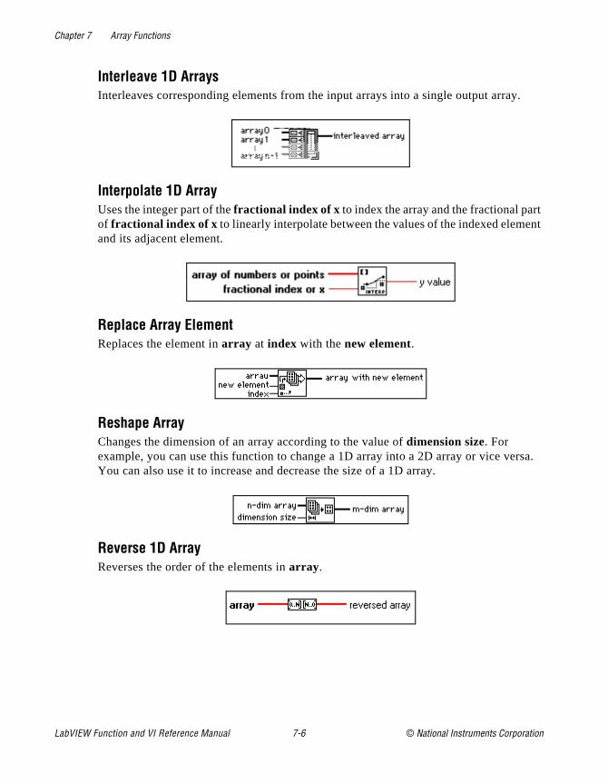
Chapter 7 Array Functions
.
t ent
rsa.
Interleave 1D ArraysInterleaves corresponding elements from the input arrays into a single output array
Interpolate 1D ArrayUses the integer part of the fractional index of x to index the array and the fractional parof fractional index of x to linearly interpolate between the values of the indexed elemand its adjacent element.
Replace Array ElementReplaces the element in array at index with the new element.
Reshape ArrayChanges the dimension of an array according to the value of dimension size. For example, you can use this function to change a 1D array into a 2D array or vice veYou can also use it to increase and decrease the size of a 1D array.
Reverse 1D ArrayReverses the order of the elements in array .
LabVIEW Function and VI Reference Manual 7-6 © National Instruments Corporation
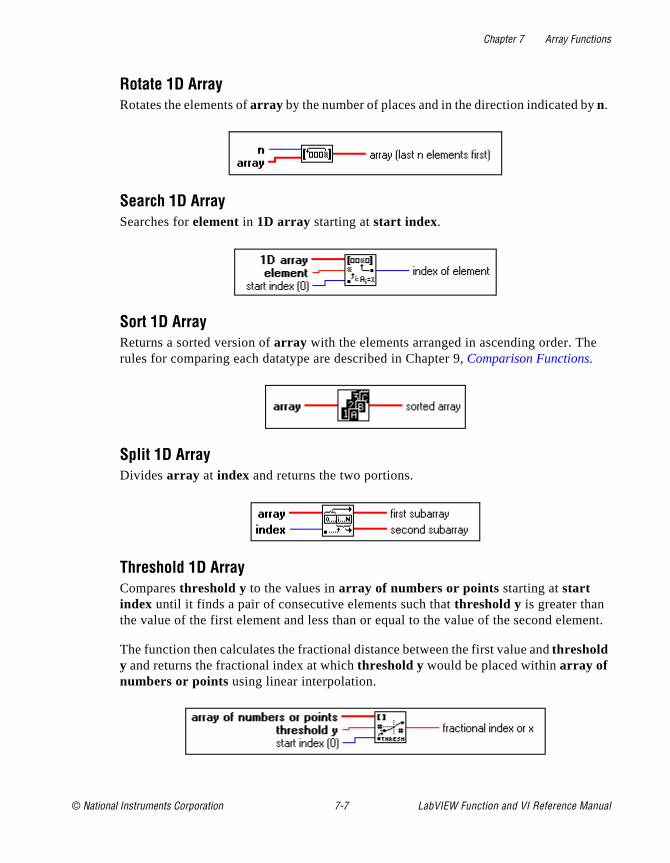
Chapter 7 Array Functions
ent.
Rotate 1D ArrayRotates the elements of array by the number of places and in the direction indicated byn.
Search 1D ArraySearches for element in 1D array starting at start index.
Sort 1D ArrayReturns a sorted version of array with the elements arranged in ascending order. Therules for comparing each datatype are described in Chapter 9, Comparison Functions.
Split 1D ArrayDivides array at index and returns the two portions.
Threshold 1D ArrayCompares threshold y to the values in array of numbers or points starting at start index until it finds a pair of consecutive elements such that threshold y is greater than the value of the first element and less than or equal to the value of the second elem
The function then calculates the fractional distance between the first value and threshold y and returns the fractional index at which threshold y would be placed within array of numbers or points using linear interpolation.
© National Instruments Corporation 7-7 LabVIEW Function and VI Reference Manual
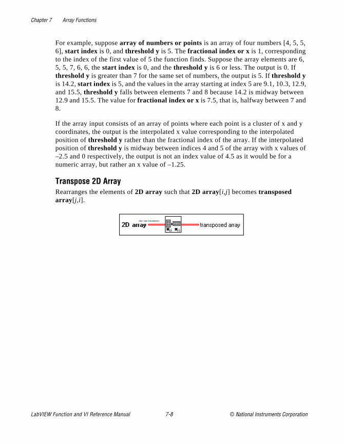
Chapter 7 Array Functions
re 6,
2.9, en
d y d d of
For example, suppose array of numbers or points is an array of four numbers [4, 5, 5,6], start index is 0, and threshold y is 5. The fractional index or x is 1, corresponding to the index of the first value of 5 the function finds. Suppose the array elements a5, 5, 7, 6, 6, the start index is 0, and the threshold y is 6 or less. The output is 0. If threshold y is greater than 7 for the same set of numbers, the output is 5. If threshold y is 14.2, start index is 5, and the values in the array starting at index 5 are 9.1, 10.3, 1and 15.5, threshold y falls between elements 7 and 8 because 14.2 is midway betwe12.9 and 15.5. The value for fractional index or x is 7.5, that is, halfway between 7 and8.
If the array input consists of an array of points where each point is a cluster of x ancoordinates, the output is the interpolated x value corresponding to the interpolateposition of threshold y rather than the fractional index of the array. If the interpolateposition of threshold y is midway between indices 4 and 5 of the array with x values–2.5 and 0 respectively, the output is not an index value of 4.5 as it would be for anumeric array, but rather an x value of –1.25.
Transpose 2D ArrayRearranges the elements of 2D array such that 2D array[ i,j] becomes transposed array [ j,i].
LabVIEW Function and VI Reference Manual 7-8 © National Instruments Corporation

© National Instruments Corporation 8-1 LabVIEW Function and
Chapter
8
Cluster Functionsect
This chapter describes the functions for cluster operations.
The following illustration shows the Cluster palette, which you accessby selecting Functions»Cluster.
Some of the cluster functions are also available from the Cluster Tools palette of most terminal or wire pop-up menus. The following illustration shows the pop-up menu.
If you select the functions from this palette, they appear with the corrnumber of terminals to wire to the object on which you popped up.
VI Reference Manual

Chapter 8 Cluster Functions
nt put
The u
to
eir
Cluster Function OverviewSome of the cluster functions have a variable number of terminals.When you drop a new function of this kind, it appears on the block diagram with only one or two terminals. You can add and remove terminals by using the pop-up menu Add Input or Remove Input options or by resizing the node using the Positioning tool. If you wato add terminals by popping up, you must place your cursor on the interminal to access the pop-up menu.
You can shrink the node if doing so does not delete wired terminals. Add Input option inserts a terminal directly after the one on which yopopped up. The Remove Input option removes the terminal on whichyou popped up, even if it is wired.
The following illustration shows the two ways to add more terminalsthe Bundle function.
Polymorphism for Cluster FunctionsThe Bundle and Unbundle functions do not show the datatype for thindividual input or output terminals until you wire objects to these terminals. When you wire them, these terminals look similar to the datatypes of the corresponding front panel control or indicator terminals.
LabVIEW Function and VI Reference Manual 8-2 © National Instruments Corporation
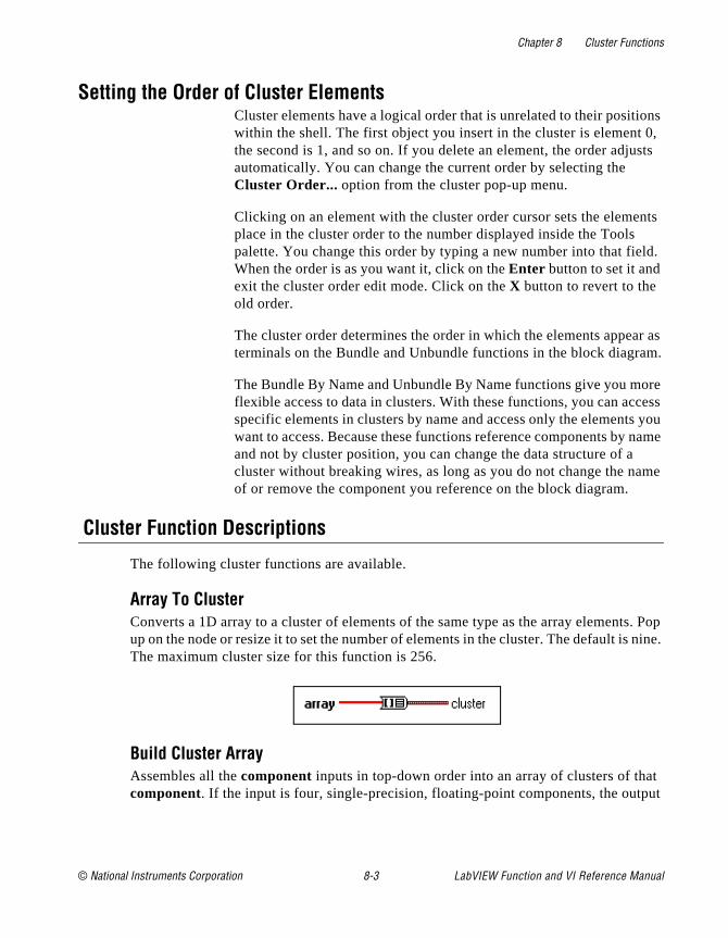
Chapter 8 Cluster Functions
ons 0, sts
nts
ld.
r as m.
re cess you name me
s. Pop nine.
ut
Setting the Order of Cluster ElementsCluster elements have a logical order that is unrelated to their positiwithin the shell. The first object you insert in the cluster is element the second is 1, and so on. If you delete an element, the order adjuautomatically. You can change the current order by selecting the Cluster Order... option from the cluster pop-up menu.
Clicking on an element with the cluster order cursor sets the elemeplace in the cluster order to the number displayed inside the Tools palette. You change this order by typing a new number into that fieWhen the order is as you want it, click on the Enter button to set it and exit the cluster order edit mode. Click on the X button to revert to the old order.
The cluster order determines the order in which the elements appeaterminals on the Bundle and Unbundle functions in the block diagra
The Bundle By Name and Unbundle By Name functions give you moflexible access to data in clusters. With these functions, you can acspecific elements in clusters by name and access only the elementswant to access. Because these functions reference components by and not by cluster position, you can change the data structure of acluster without breaking wires, as long as you do not change the naof or remove the component you reference on the block diagram.
Cluster Function Descriptions
The following cluster functions are available.
Array To ClusterConverts a 1D array to a cluster of elements of the same type as the array elementup on the node or resize it to set the number of elements in the cluster. The default isThe maximum cluster size for this function is 256.
Build Cluster ArrayAssembles all the component inputs in top-down order into an array of clusters of that component. If the input is four, single-precision, floating-point components, the outp
© National Instruments Corporation 8-3 LabVIEW Function and VI Reference Manual
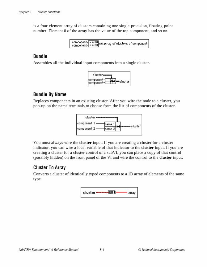
Chapter 8 Cluster Functions
ou .
rol
same
is a four-element array of clusters containing one single-precision, floating-point number. Element 0 of the array has the value of the top component, and so on.
BundleAssembles all the individual input components into a single cluster.
Bundle By NameReplaces components in an existing cluster. After you wire the node to a cluster, ypop-up on the name terminals to choose from the list of components of the cluster
You must always wire the cluster input. If you are creating a cluster for a cluster indicator, you can wire a local variable of that indicator to the cluster input. If you are creating a cluster for a cluster control of a subVI, you can place a copy of that cont(possibly hidden) on the front panel of the VI and wire the control to the cluster input.
Cluster To Array Converts a cluster of identically typed components to a 1D array of elements of the type.
LabVIEW Function and VI Reference Manual 8-4 © National Instruments Corporation
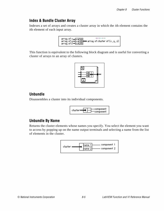
Chapter 8 Cluster Functions
g a
want he list
Index & Bundle Cluster ArrayIndexes a set of arrays and creates a cluster array in which the ith element contains the ith element of each input array.
This function is equivalent to the following block diagram and is useful for convertincluster of arrays to an array of clusters.
UnbundleDisassembles a cluster into its individual components.
Unbundle By NameReturns the cluster elements whose names you specify. You select the element youto access by popping up on the name output terminals and selecting a name from tof elements in the cluster.
© National Instruments Corporation 8-5 LabVIEW Function and VI Reference Manual

© National Instruments Corporation 9-1 LabVIEW Function and
Chapter
9
Comparison FunctionsThis chapter describes the functions that perform comparisons or conditional tests.
The following illustration shows the Comparison palette, which you access by selecting Functions»Comparison.
For examples of comparison functions, see examples\general\struct.llb .
Comparison Function OverviewThis section introduces the Comparison functions.
VI Reference Manual
Chapter 9 Comparison Functions
ater
lent
e t the f Thus,
uts ame f
le,
pare s, of .
Compare BooleanFor the Compare Boolean functions, the Boolean value TRUE is grethan the Boolean value FALSE.
Compare StringsThese functions compare strings according to the numerical equivaof the ASCII characters. Thus, a (with a decimal value of 97) is greaterthan A (65), which is greater than the numeral 0 (48), which is greater than the space character (32). These functions compare characters onby one from the beginning of the string until an inequality occurs, awhich time the comparison ends. For example, LabVIEW evaluatesstrings abcd and abef until it finds c , which is greater than the value oe. The presence of a character is greater than the absence of one. the string abcd is greater than abc because the first string is longer.Most of the comparison functions test one input or compare two inpand return a Boolean value. The functions convert numbers to the srepresentation before comparing them. Comparisons with a value oNaN (not a number) return a value that indicates inequality.
The functions that test the category of a string character (for exampthe Decimal Digit? and Printable? functions) evaluate only the first character of the string.
Compare ClustersThe comparison functions compare clusters the same way they comstrings, one element at a time starting with the 0th element until aninequality occurs. Clusters must have the same number of elementthe same type, and in the same order if you want to compare them
Compare ModesSome of the comparison functions have two modes for comparing arrays or clusters. In the Compare Aggregates mode, if you compare two arrays or clusters, the function returns a single value. In the Compare Elements mode, the function compares the elements
LabVIEW Function and VI Reference Manual 9-2 © National Instruments Corporation
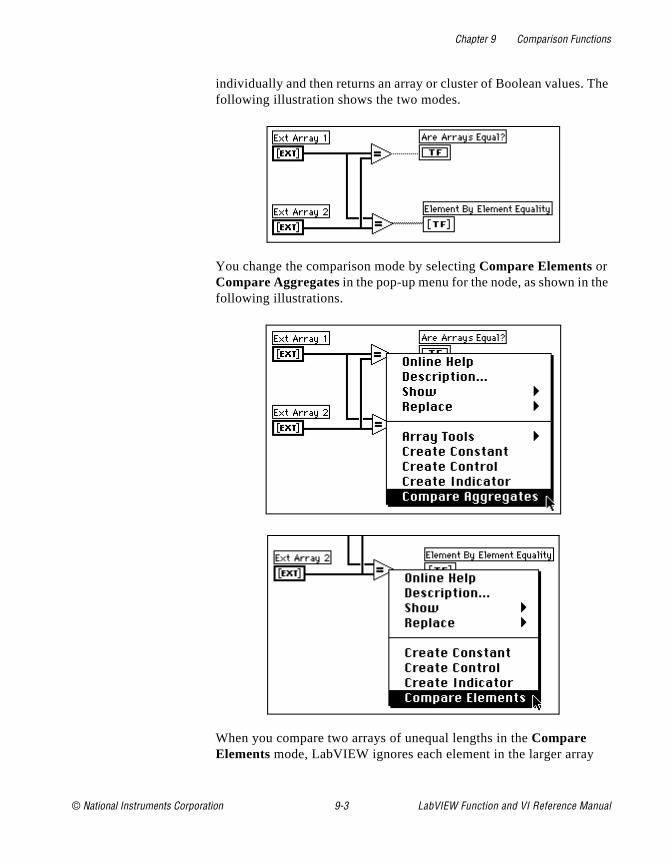
Chapter 9 Comparison Functions
he
e
individually and then returns an array or cluster of Boolean values. Tfollowing illustration shows the two modes.
You change the comparison mode by selecting Compare Elements or Compare Aggregates in the pop-up menu for the node, as shown in thfollowing illustrations.
When you compare two arrays of unequal lengths in the Compare Elements mode, LabVIEW ignores each element in the larger array
© National Instruments Corporation 9-3 LabVIEW Function and VI Reference Manual

Chapter 9 Comparison Functions
ller
e to ical r two qual. ray
ers
h ray,
al
n
whose index is greater than the index of the last element in the smaarray.
When you use the Compare Aggregates mode to compare two arrays,the following occurs: (1) LabVIEW searches for the first set of corresponding elements in the two inputs that differ, and uses thosdetermine the results of the comparison. (2) If all elements are identexcept that one has more elements, LabVIEW considers the longearray to be greater than the shorter array. (3) If no elements of the arrays differ, and the arrays have the same length, the arrays are eThus, LabVIEW considers the array [1,2,3] to be greater than the ar[1,2] and returns a single Boolean value in the Compare Aggregates mode.
When comparing clusters using the Compare Aggregates mode, LabVIEW goes by cluster order instead of array order. The two clustLabVIEW compares are always the same length.
In the Compare Elements mode, LabVIEW returns a Boolean for eacof the first two elements and ignores the last element of the larger aras in the preceding example.
Arrays must have the same dimension size (for example, both two-dimensional), and for the comparison between multidimensionarrays to make sense, each dimension must have the same size.
The comparison functions that do not have the Compare Aggregates or Compare Elements modes compare arrays in the same manner as strings—one element at a time starting with the 0th element until ainequality occurs.
Character Comparison You can use the functions that compare characters to determine a character’s type. The following functions are character comparisonfunctions.
• Decimal Digit?
• Hex Digit?
• Lexical Class
• Octal Digit?
• Printable?
• White Space?
LabVIEW Function and VI Reference Manual 9-4 © National Instruments Corporation
Chapter 9 Comparison Functions
ut
pe,
pare
lues
pes ts
d ings s,
ters ean
, but
If the input is a string, the functions test the first character. If the inpis an empty string, the result is FALSE. If the input is a number, thefunctions interpret it as a code for an ASCII character.
See Appendix B, Multiline Interface Messages, for the numbers that correspond to each character.
Polymorphism for Comparison FunctionsThe functions Equal?, Not Equal?, and Select take inputs of any tyas long as the inputs are the same type.
The functions Greater or Equal?, Less or Equal?, Less?, Greater?,Max & Min, and In Range? take inputs of any type except complex,path, or refnum, as long as the inputs are the same type. You can compare numbers, strings, Booleans, arrays of strings, clusters of numbers, clusters of strings, and so on. You cannot, however, coma number to a string or a string to a Boolean, and so on.
The functions that compare values to zero accept numeric scalars,clusters, and arrays of numbers. These functions output Boolean vain the same data structure as the input.
The Not A Number/Path/Refnum function accepts the same input tyas functions that compare values to zero. This function also acceppaths and refnums. Not A Number/Path/Refnum outputs Boolean values in corresponding structures. See Chapter 30, Introduction to LabVIEW Instrument Driver VIs, and Chapter 11, File Functions, for more information on these functions.
The functions Decimal Digit?, Hex Digit?, Octal Digit?, Printable?, anWhite Space? accept a scalar string or number input, clusters of stror non-complex numbers, arrays of strings or non-complex numberand so on. The output consists of Boolean values in the same datastructure as the input.
The function Empty String/Path? accepts a path, a scalar string, clusof strings, arrays of strings, and so on. The output consists of Boolvalues in the same data structure as the input.
You can use the Equal?, Not Equal?, Not A Number/Path/Refnum?Empty String/Path?, and Select functions with paths and refnums, no other comparison functions accept paths or refnums as inputs.
© National Instruments Corporation 9-5 LabVIEW Function and VI Reference Manual
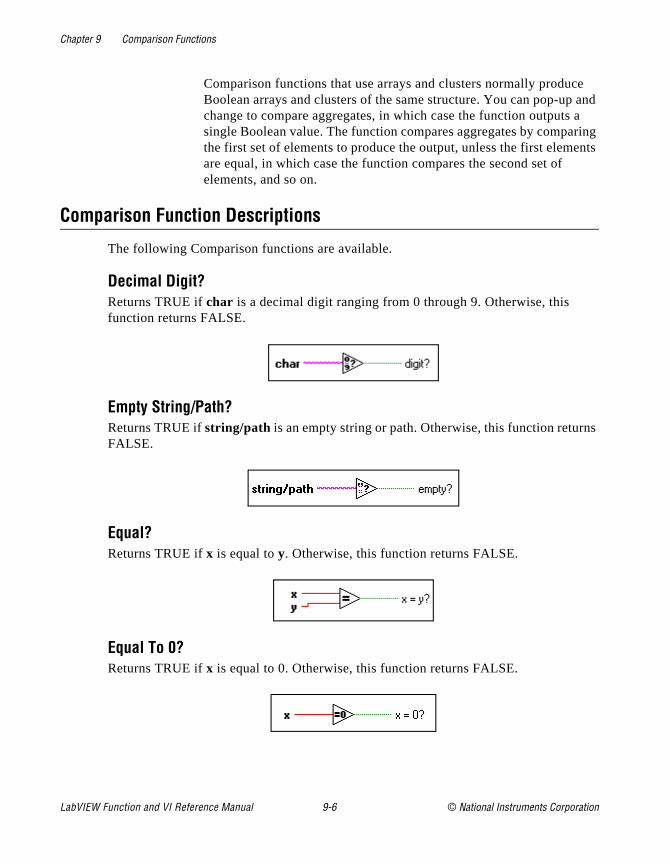
Chapter 9 Comparison Functions
e and a ring ents
ns
Comparison functions that use arrays and clusters normally producBoolean arrays and clusters of the same structure. You can pop-upchange to compare aggregates, in which case the function outputssingle Boolean value. The function compares aggregates by compathe first set of elements to produce the output, unless the first elemare equal, in which case the function compares the second set of elements, and so on.
Comparison Function Descriptions
The following Comparison functions are available.
Decimal Digit?Returns TRUE if char is a decimal digit ranging from 0 through 9. Otherwise, this function returns FALSE.
Empty String/Path?Returns TRUE if string/path is an empty string or path. Otherwise, this function returFALSE.
Equal?Returns TRUE if x is equal to y. Otherwise, this function returns FALSE.
Equal To 0?Returns TRUE if x is equal to 0. Otherwise, this function returns FALSE.
LabVIEW Function and VI Reference Manual 9-6 © National Instruments Corporation

Chapter 9 Comparison Functions
.
SE.
gh
Greater?Returns TRUE if x is greater than y. Otherwise, this function returns FALSE.
Greater Or Equal?Returns TRUE if x is greater than or equal to y. Otherwise, this function returns FALSE
Greater Or Equal To 0?Returns TRUE if x is greater than or equal to 0. Otherwise, this function returns FAL
Greater Than 0?Returns TRUE if x is greater than 0. Otherwise, this function returns FALSE.
Hex Digit?Returns TRUE if char is a hex digit ranging from 0 through 9, A through F, or a throuf. Otherwise, this function returns FALSE.
n Range?Returns TRUE if x is greater than or equal to lo and less than hi. Otherwise, this function returns FALSE.
© National Instruments Corporation 9-7 LabVIEW Function and VI Reference Manual

Chapter 9 Comparison Functions
a
.
Note: This function always operates in the Compare Aggregates mode. To produce a Boolean array as an output, you must execute this function inloop structure.
Less?Returns TRUE if x is less than y. Otherwise, this function returns FALSE.
Less Or Equal?Returns TRUE if x is less than or equal to y. Otherwise, this function returns FALSE.
Less Or Equal To 0?Returns TRUE if x is less than or equal to 0. Otherwise, this function returns FALSE
Less Than 0?Returns TRUE if x is less than 0. Otherwise, this function returns FALSE.
LabVIEW Function and VI Reference Manual 9-8 © National Instruments Corporation
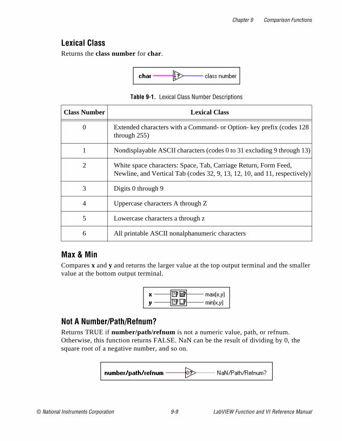
Chapter 9 Comparison Functions
ller
28
13)
ely)
Lexical ClassReturns the class number for char.
Max & MinCompares x and y and returns the larger value at the top output terminal and the smavalue at the bottom output terminal.
Not A Number/Path/Refnum?Returns TRUE if number/path/refnum is not a numeric value, path, or refnum. Otherwise, this function returns FALSE. NaN can be the result of dividing by 0, thesquare root of a negative number, and so on.
Table 9-1. Lexical Class Number Descriptions
Class Number Lexical Class
0 Extended characters with a Command- or Option- key prefix (codes 1through 255)
1 Nondisplayable ASCII characters (codes 0 to 31 excluding 9 through
2 White space characters: Space, Tab, Carriage Return, Form Feed, Newline, and Vertical Tab (codes 32, 9, 13, 12, 10, and 11, respectiv
3 Digits 0 through 9
4 Uppercase characters A through Z
5 Lowercase characters a through z
6 All printable ASCII nonalphanumeric characters
© National Instruments Corporation 9-9 LabVIEW Function and VI Reference Manual
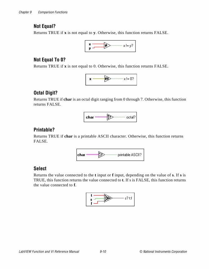
Chapter 9 Comparison Functions
n
s
Not Equal?Returns TRUE if x is not equal to y. Otherwise, this function returns FALSE.
Not Equal To 0?Returns TRUE if x is not equal to 0. Otherwise, this function returns FALSE.
Octal Digit?Returns TRUE if char is an octal digit ranging from 0 through 7. Otherwise, this functioreturns FALSE.
Printable?Returns TRUE if char is a printable ASCII character. Otherwise, this function returnFALSE.
SelectReturns the value connected to the t input or f input, depending on the value of s. If s is TRUE, this function returns the value connected to t. If s is FALSE, this function returns the value connected to f.
LabVIEW Function and VI Reference Manual 9-10 © National Instruments Corporation

Chapter 9 Comparison Functions
iage
White Space?Returns TRUE if char is a white space character, such as space, Tab, Newline, CarrReturn, Form Feed, or Vertical Tab. Otherwise, the function returns FALSE.
© National Instruments Corporation 9-11 LabVIEW Function and VI Reference Manual
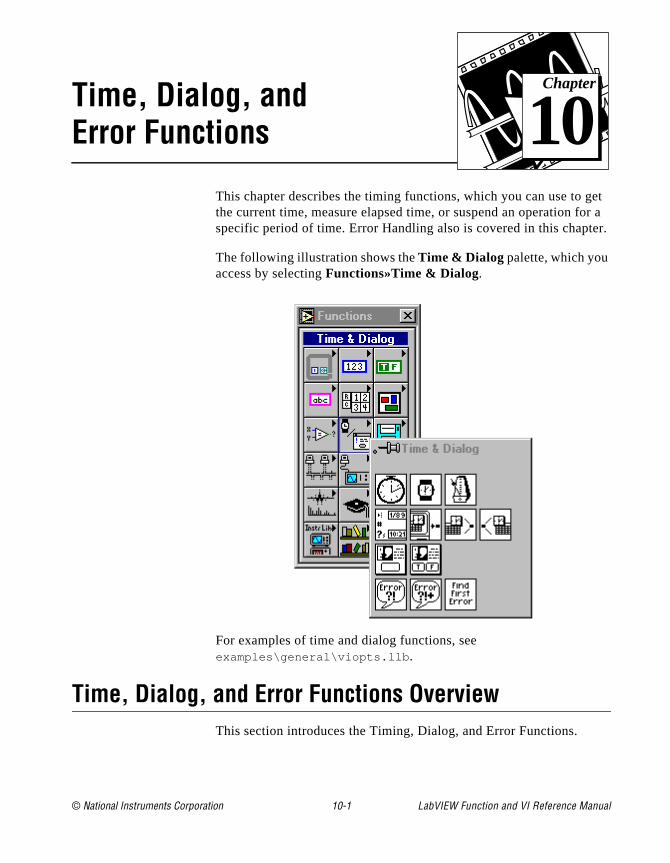
© National Instruments Corporation 10-1 LabVIEW Function and
Chapter
10
Time, Dialog, and Error Functionset r a
er.
This chapter describes the timing functions, which you can use to gthe current time, measure elapsed time, or suspend an operation fospecific period of time. Error Handling also is covered in this chapt
The following illustration shows the Time & Dialog palette, which you access by selecting Functions»Time & Dialog.
For examples of time and dialog functions, see examples\general\viopts.llb .
Time, Dialog, and Error Functions OverviewThis section introduces the Timing, Dialog, and Error Functions.
VI Reference Manual

Chapter 10 Time, Dialog, and Error Functions
ns
that
m., e.
ity ow
Timing FunctionsThe Date/Time To Seconds and the Seconds To Date/Time functiohave a parameter called date time rec, which is a cluster that consistsof signed 32-bit integers in the following order.
The Wait (ms) and Wait Until Next ms Multiple functions make asynchronous system calls, but the nodes themselves function synchronously. That is, they do not complete execution until the specified time has elapsed. The functions use asynchronous calls soother nodes can execute while the timing nodes wait.
Note: National Instruments can only guarantee correct time values across all platforms for the range 2082844800 to 4230328447 seconds or 12:00 a.Jan. 1, 1970, Universal Time to 3:14 a.m., Jan. 19, 2038, Universal Tim
Error Handling OverviewEvery time you design a program, you should consider the possibilthat something can go wrong and, if it does, you should consider hyour program should manage the problem. LabVIEW automatically
Table 10-1. Order of 32-bit Integers in TIming Functions
Time Value and Range
0 (second) 0 to 59
1 (minute) 0 to 59
2 (hour) 0 to 23
3 (day of month) 1 to 31 as output from the function;1 to 366 as input
4 (month) 1 to 12
5 (year) 1904 to 2040
6 (day of week) 1 to 7 (Sunday to Saturday)
7 (day of year) 1 to 366
8 (DST) 0 to 1 (0 for Standard Time, 1 for Daylight Savings Time)
LabVIEW Function and VI Reference Manual 10-2 © National Instruments Corporation
Chapter 10 Time, Dialog, and Error Functions
r, re to e
ses ors
am.
cks. rk.
y be lly
ur ram rors hat
rror
ns
notifies you with a dialog box only when a few run-time errors occumostly for file dialog operations. It does not report all errors. If it weto report all errors, you would lose the flexibility to determine what do when an error occurs and how and when to inform the user of therror in your program.
Rigorous error checking, especially for I/O operations (file, serial, GPIB, data acquisition, and communication), is invaluable in all phaof a project. This section describes three I/O situations in which errcan occur.
The first error can occur when you have initialized your communications incorrectly or have written improper data to your external device. This type of problem usually occurs during programdevelopment and disappears once you finish debugging your progrHowever, you can spend a lot of time tracking down a simple programming mistake because you have not incorporated error cheWithout error checks, all you know is that your program does not woYou do not know why the error occurred or where it is.
The second type of error can occur because your external device mapowered off, broken down, or otherwise unable to do what it normadoes. This type of problem can occur at any time, but if you have incorporated error checking, your program notifies you immediatelywhen such operational failures occur.
The third kind of error can occur when you upgrade LabVIEW or yooperating system software, and you notice a bug in either a G progor a system program. This type of error means you should check erthat you may have felt safe ignoring, such as those from functions tclose files or clear DAQ operations. The bottom line is, check all I/Ooperations for errors.
It may feel easier to ignore error checking when you have to add ehandling code to test and report errors. The VIs described here aredesigned to make it easier for you to create programs with error checking and handling.
G functions and library VIs return errors in one of two ways—with numeric error codes or with an error state cluster. Typically, functiooutput error codes while VIs incorporate the error cluster, usually within a framework called error input/output or error I/O.
© National Instruments Corporation 10-3 LabVIEW Function and VI Reference Manual

Chapter 10 Time, Dialog, and Error Functions
ata
the rror, e, rror des,
AQ
ID ns.
ther he
Error I/O and the Error State ClusterThe concept of error I/O is natural to the G dataflow architecture. If dinformation can flow from one node to another, so can error state information. Each node that needs to know about errors tests the incoming error state and responds appropriately. If no error exists,node executes normally. If an error does exist, the node detects an eskips execution, and then passes its error state out to the next nodwhich responds in the same way. In this fashion, notice of the first ethat occurs in a sequence of operations is passed through all the nowith each node responding to the error. At the end of the flow, yourprogram reports the error to the user.
Error I/O has an additional benefit—you can use it to control the execution order of independent operations. While you can use the DtaskID to control the order of DAQ operations for one group, you cannot use it to control the order for multiple groups. The DAQ taskdoes not work with other types of I/O operations such as file operatio
The following diagram from the File Utility VI, Read Characters
From File , shows how error I/O is implemented in a simple VI.
The operation starts at Open File+.vi . If it opens the file successfully, Read File+ (string).vi reads the file and Close File+.vi closes the file. If you pass in an invalid path, Open
File+.vi detects the error and passes the error state through the otwo VIs to the General Error Handler, which reports it. Notice that t
LabVIEW Function and VI Reference Manual 10-4 © National Instruments Corporation
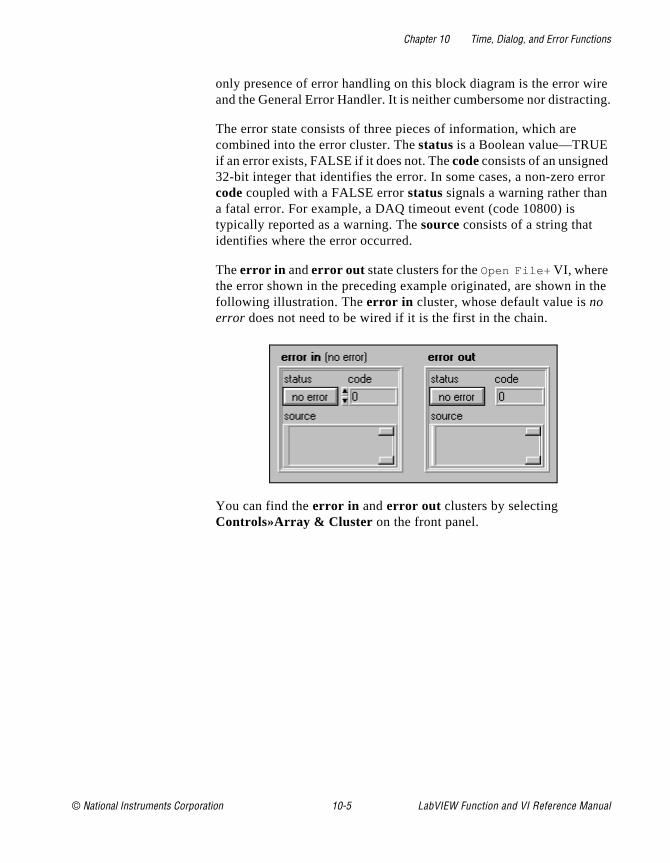
Chapter 10 Time, Dialog, and Error Functions
ire ting.
rror
the
only presence of error handling on this block diagram is the error wand the General Error Handler. It is neither cumbersome nor distrac
The error state consists of three pieces of information, which are combined into the error cluster. The status is a Boolean value—TRUE if an error exists, FALSE if it does not. The code consists of an unsigned32-bit integer that identifies the error. In some cases, a non-zero ecode coupled with a FALSE error status signals a warning rather thana fatal error. For example, a DAQ timeout event (code 10800) is typically reported as a warning. The source consists of a string that identifies where the error occurred.
The error in and error out state clusters for the Open File+ VI, where the error shown in the preceding example originated, are shown infollowing illustration. The error in cluster, whose default value is no error does not need to be wired if it is the first in the chain.
You can find the error in and error out clusters by selecting Controls»Array & Cluster on the front panel.
© National Instruments Corporation 10-5 LabVIEW Function and VI Reference Manual

Chapter 10 Time, Dialog, and Error Functions
It
VI, at
ndard
,
nores value. day to
The following illustration shows the message you receive from the General Error Handler if you pass in an invalid path.
General Error Handler is one of the three error handling utility VIs. contains a database of error codes and descriptions, from which it creates messages like the previous one. The Simple Error Handlerperforms the same basic operation but has fewer options. The thirdFind First Error, creates the error I/O cluster from functions or VIs thoutput only scalar error codes.
Time and Dialog Function Descriptions
The following Time and Dialog functions are available.
Date/Time To SecondsConverts a cluster of nine, signed 32-bit integers assumed to specify the local time(second, minute, hour, day, month, year, day of the week, day of the year, and Staor Daylight Savings Time) in the configured time zone for your computer into a time-zone-independent number of seconds that have elapsed since 12:00 a.m., FridayJanuary 1, 1904, Universal Time.
If the year and month integers are out of range, the results are unpredictable. G igthe day of the week and day of the year integers. The other five integers can be any Thus, you can specify Julian dates by setting the month to January and the current the day of the year. For example, use January 150 for the 150th day of the year.
LabVIEW Function and VI Reference Manual 10-6 © National Instruments Corporation

Chapter 10 Time, Dialog, and Error Functions
t have
that and
er of mber vings
ro) is
Get Date/Time In SecondsReturns a time-zone-independent number that contains the number of seconds thaelapsed since 12:00 a.m., Friday, January 1, 1904, Universal Time.
Get Date/Time StringConverts a time-zone-independent number assumed to be the number of secondshave elapsed since 12:00 a.m., Friday, January 1, 1904, Universal Time, to a datetime string in the configured time zone for your computer.
One Button Dialog BoxDisplays a dialog box that contains a message and a single button. The button name is the name displayed on the dialog box button.
Seconds To Date/TimeConverts a time-zone-independent number assumed to be the number of seconds that have elapsed since 12:00 a.m., Friday, January 1, 1904, Universal Time, to a clustnine, signed 32-bit integers that specify (second, minute, hour, day of the month, nuof month (1–12), year, day of the week, day of the year, and Standard or Daylight SaTime) in the configured time zone for your computer.
Tick Count (ms)Returns the value of the millisecond timer. The base reference time (millisecond zeundefined; that is, you cannot convert millisecond timer value to a real-world time or
© National Instruments Corporation 10-7 LabVIEW Function and VI Reference Manual

Chapter 10 Time, Dialog, and Error Functions
he
cond
all t the
date. Be careful when you use this function in comparisons, because the value of tmillisecond timer wraps from 232–1 to 0.
Two Button Dialog BoxDisplays a dialog box that contains a message and two buttons. T button name and F button name are the names displayed on the buttons of the dialog box.
Wait (ms)Waits the specified number of milliseconds and then returns the value of the millisetimer.
Wait Until Next ms MultipleWaits until the value of the millisecond timer becomes a multiple of the specified millisecond multiple . You can use this function to synchronize activities. You can cthis function in a loop to control the loop execution rate. However, it is possible thafirst loop period may be short.
Error Handling VI Descriptions
The following Error Handling VIs are available.
LabVIEW Function and VI Reference Manual 10-8 © National Instruments Corporation
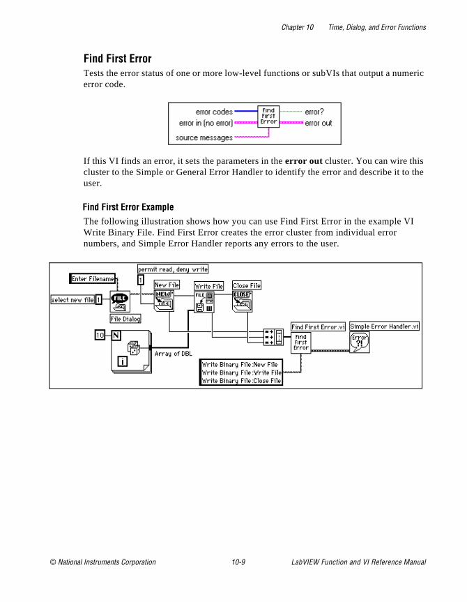
Chapter 10 Time, Dialog, and Error Functions
eric
the
I
Find First ErrorTests the error status of one or more low-level functions or subVIs that output a numerror code.
If this VI finds an error, it sets the parameters in the error out cluster. You can wire this cluster to the Simple or General Error Handler to identify the error and describe it touser.
Find First Error ExampleThe following illustration shows how you can use Find First Error in the example VWrite Binary File. Find First Error creates the error cluster from individual error numbers, and Simple Error Handler reports any errors to the user.
© National Instruments Corporation 10-9 LabVIEW Function and VI Reference Manual

Chapter 10 Time, Dialog, and Error Functions
n of
ality
General Error HandlerDetermines whether an error has occurred. If an error occurred, this VI creates a description of the error and optionally displays a dialog box.
Simple Error HandlerDetermines whether an error occurred. If it finds an error, this VI creates a descriptiothe error and optionally displays a dialog box.
Simple Error Handler calls General Error Handler and has the same basic functionas General Error Handler, but with fewer options.
LabVIEW Function and VI Reference Manual 10-10 © National Instruments Corporation

© National Instruments Corporation 11-1 LabVIEW Function and
Chapter
11
File Functionsd el
This topic describes the low-level functions that manipulate files andirectories. This topic also describes file constants and the high-levfile VIs.
You access these functions, constants, and VIs by selecting Functions»File I/O.
The File I/O palette includes the following subpalettes:
• Advanced File Functions
• Binary File VIs
• File Constants
For examples of File functions and VIs, see examples\file .
VI Reference Manual

Chapter 11 File Functions
e
es
yte
o eate
tion
se
vel
ad
File I/O VI and Function OverviewThis section introduces the high-level and low-level File VIs, and thFile functions.
High-Level VIsYou can use the high-level File VIs to write or read the following typof data:
• Strings to text files
• One-dimensional (1D) or two-dimensional (2D) arrays of single-precision numbers to spreadsheet text files.
• 1D or 2D arrays of single-precision or signed word integers to bstream files.
The high-level File VIs described here call the low-level functions tperform complete, easy-to-use file operations. These VIs open or cra file, write or read to it, and close it. If an error occurs, these VIs display a dialog box that describes the problem and gives you the opto halt execution or to continue.
The high-level File VIs are located on the top row of the palette andconsist of the following VIs:
• Write Characters to File
• Write to Spreadsheet File
• Read Characters from File
• Read from Spreadsheet File
• Read Lines from File
• Binary File VIs—located in the subpalette.
Low-Level File VIs and File FunctionsThe low-level File functions perform one file operation at a time. TheVIs and functions perform error detection in addition to their other functions. The most commonly used low-level file functions and VIsare located on the second row of the palette. The remaining low-lefunctions are located in the Advanced File Functions subpalette.
The principal low-level file operations involve a three-step process.First, you create or open a file. Then you write data to the file or redata from the file. Finally, you close the file. Other file operations
LabVIEW Function and VI Reference Manual 11-2 © National Instruments Corporation

Chapter 11 File Functions
ng
nt
of es a es,
u in of
a ch r n of
ng , or
een t is the
is
nit ous
include creating directories; moving, copying, or deleting files; flushifiles; listing directory contents; changing file characteristics; and manipulating paths.
When creating or opening a file, you must specify its location. Differecomputers describe the location of files in different ways, but most computer systems use a hierarchical system to specify the locationfiles. In a hierarchical file system, the computer system superimposhierarchy on the storage media. You can store files inside directoriwhich can contain other directories.
When you specify a file or directory in a hierarchical file system, yomust indicate the name of the file or directory, as well as its locationthe hierarchy. In addition, some file systems support the connectionmultiple discrete media, called volumes. For example, Windows systems support multiple drives connected to a system; for most ofthese systems, you must include the name of the volume to createcomplete specification for the location of a file. On other systems, suas UNIX, you do not need to specify the storage media locations fofiles because the operating system hides the physical implementatiothe file system from you.
The method of identifying the target of a file function varies dependion whether the target is an open file. If the target is not an open fileif it is a directory, you specify a target using the path of the target. The path describes the volume containing the target, the directories betwthe top-level and the target, and the name of the target. If the targean open file, you use a file refnum to identify the file that G is supposedto manipulate. The file refnum is an identifier that G associates with file when you open it. When you close the file, the file manager dissociates the file refnum from the file. In other words, the refnumobsolete once the file is closed.
See, Strings and File I/O, Chapter 6 of the Tutorial Manual, and Path Controls and Refnum in that section for more information on path specification in G and for file function examples.
Byte Stream and Datalog FilesG can make and access two types of files—byte stream and datalog files.
A byte stream file, as the name implies, is a file whose fundamental uis a byte. A byte stream file can contain anything from a homogene
© National Instruments Corporation 11-3 LabVIEW Function and VI Reference Manual
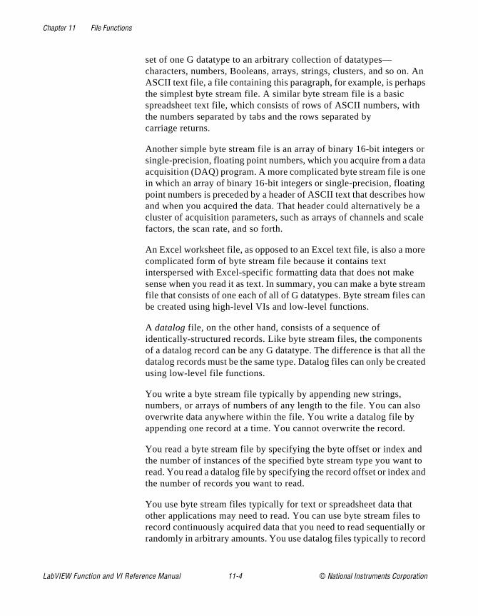
Chapter 11 File Functions
. An ps
h
or ata ne g
how e a cale
ore
ream can
ts l the ated
so
nd t to and
t to
ly or rd
set of one G datatype to an arbitrary collection of datatypes—characters, numbers, Booleans, arrays, strings, clusters, and so onASCII text file, a file containing this paragraph, for example, is perhathe simplest byte stream file. A similar byte stream file is a basic spreadsheet text file, which consists of rows of ASCII numbers, witthe numbers separated by tabs and the rows separated by carriage returns.
Another simple byte stream file is an array of binary 16-bit integerssingle-precision, floating point numbers, which you acquire from a dacquisition (DAQ) program. A more complicated byte stream file is oin which an array of binary 16-bit integers or single-precision, floatinpoint numbers is preceded by a header of ASCII text that describes and when you acquired the data. That header could alternatively bcluster of acquisition parameters, such as arrays of channels and sfactors, the scan rate, and so forth.
An Excel worksheet file, as opposed to an Excel text file, is also a mcomplicated form of byte stream file because it contains text interspersed with Excel-specific formatting data that does not makesense when you read it as text. In summary, you can make a byte stfile that consists of one each of all of G datatypes. Byte stream files be created using high-level VIs and low-level functions.
A datalog file, on the other hand, consists of a sequence of identically-structured records. Like byte stream files, the componenof a datalog record can be any G datatype. The difference is that aldatalog records must be the same type. Datalog files can only be creusing low-level file functions.
You write a byte stream file typically by appending new strings, numbers, or arrays of numbers of any length to the file. You can aloverwrite data anywhere within the file. You write a datalog file by appending one record at a time. You cannot overwrite the record.
You read a byte stream file by specifying the byte offset or index athe number of instances of the specified byte stream type you wanread. You read a datalog file by specifying the record offset or index the number of records you want to read.
You use byte stream files typically for text or spreadsheet data thaother applications may need to read. You can use byte stream filesrecord continuously acquired data that you need to read sequentialrandomly in arbitrary amounts. You use datalog files typically to reco
LabVIEW Function and VI Reference Manual 11-4 © National Instruments Corporation
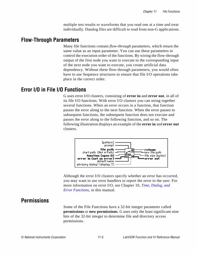
Chapter 11 File Functions
reat s.
to h
put
ten take
to nd
ed, For
multiple test results or waveforms that you read one at a time and tindividually. Datalog files are difficult to read from non-G application
Flow-Through ParametersMany file functions contain flow-through parameters, which return thesame value as an input parameter. You can use these parameters control the execution order of the functions. By wiring the flow-througoutput of the first node you want to execute to the corresponding inof the next node you want to execute, you create artificial data dependency. Without these flow-through parameters, you would ofhave to use Sequence structures to ensure that file I/O operations place in the correct order.
Error I/O in File I/O FunctionsG uses error I/O clusters, consisting of error in and error out , in all of its file I/O functions. With error I/O clusters you can string togetherseveral functions. When an error occurs in a function, that functionpasses the error along to the next function. When the error passessubsequent functions, the subsequent function does not execute apasses the error along to the following function, and so on. The following illustration displays an example of the error in and error out clusters.
Although the error I/O clusters specify whether an error has occurryou may want to use error handlers to report the error to the user. more information on error I/O, see Chapter 10, Time, Dialog, and Error Functions, in this manual.
PermissionsSome of the File Functions have a 32-bit integer parameter called permissions or new permissions. G uses only the least significant ninebits of the 32-bit integer to determine file and directory access permissions.
© National Instruments Corporation 11-5 LabVIEW Function and VI Reference Manual

Chapter 11 File Functions
7 le
n a e bit e
f
(Windows) G ignores the permissions for directories. For files, only bit(the UNIX user write permission bit) is used. If this bit is clear, the fiis read-only. Otherwise, you can write to the file.
(Macintosh) G uses all 9 bits of permissions for directories. The bits which control read, write, and execute permissions, respectively, oUNIX system are used to control See Files, Make Changes, and SeFolders access rights, respectively, on the Macintosh. For files, only7 (the UNIX user write permission bit) is used. If this bit is clear, thfile is locked. Otherwise, the file is not locked.
(UNIX) The nine bits of permissions correspond exactly to nine UNIXpermission bits governing read, write, and execute permissions forusers, groups, and others. The following illustration shows the permission bits on a UNIX system.
File I/O Function and VI Descriptions
The following functions and VIs are available from the File I/O palette.
Build PathCreates a new path by appending a name (or relative path) to an existing path.
Close FileWrites all buffers of the file identified by refnum to disk, updates the directory entry othe file, closes the file, and voids refnum for subsequent file operations.
LabVIEW Function and VI Reference Manual 11-6 © National Instruments Corporation
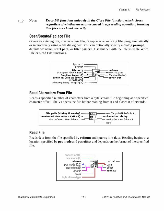
Chapter 11 File Functions
g
cally
cified ds.
d
Note: Error I/O functions uniquely in the Close File function, which closes regardless of whether an error occurred in a preceding operation, insurinthat files are closed correctly.
Open/Create/Replace FileOpens an existing file, creates a new file, or replaces an existing file, programmatior interactively using a file dialog box. You can optionally specify a dialog prompt , default file name, start path, or filter pattern. Use this VI with the intermediate Write File or Read File functions.
Read Characters From FileReads a specified number of characters from a byte stream file beginning at a specharacter offset. The VI opens the file before reading from it and closes it afterwar
Read FileReads data from the file specified by refnum and returns it in data. Reading begins at a location specified by pos mode and pos offset and depends on the format of the specifiefile.
© National Instruments Corporation 11-7 LabVIEW Function and VI Reference Manual

Chapter 11 File Functions
yte
ng of
, n
hole
ile.
ge
e
ads urn d on
to rs
Reading Byte Stream FilesIf refnum is a byte stream file refnum, the Read File function reads data from the bstream file specified by refnum. You can wire either line mode or byte stream type when you read byte stream files, but you cannot wire both. If you do not wire byte stream type, Read File assumes the data that begins at the designated byte offset is a stricharacters. If you wire byte stream type, the function interprets data starting at the designated byte offset to be count instances of that type. Following the read operationthe function sets the file mark to the byte following the last byte read. If the functioencounters end of file before reading all of the requested data, it returns as many winstances of the designated byte stream type as it finds.
Reading CharactersTo read characters from a byte stream file (typically a text file) do not wire the byte stream type. The following paragraphs describe the manner in which the line mode, count, convert eol, and data parameters function when reading from a byte stream f
line mode, in conjunction with count, determines when the read stops.
If line mode is TRUE, and if you do not wire count or count equals 0, Read File readsuntil it encounters an end of line marker—a carriage return, a line feed, or a carriareturn followed by a line feed, or it encounters end of file. If line mode is TRUE, and count is greater than 0, Read File reads until it encounters an end of line marker, itencounters end of file, or it reads count characters.
If line mode is FALSE, Read File reads count characters. In this case, if you do not wircount, it defaults to 0. line mode defaults to FALSE.
convert eol (F) determines whether the function converts the end of line markers it reinto G end of line markers. The system-specific end of line marker is a carriage retfollowed by a line feed on Windows, a carriage return on Macintosh, and a line feeUNIX. The G end of line marker is a line feed.
If convert eol is TRUE, the function converts all end of line markers it encounters inline feeds. If convert eol is FALSE, the function does not convert the end of line markeit reads. convert eol defaults to FALSE.
data is the string of characters read from the file.
Reading Binary DataTo read binary data from a byte stream file, wire the type of the data to byte stream type. In this case, count, and data function in the manner described in the following paragraphs, and you do not have to wire line mode or convert eol.
LabVIEW Function and VI Reference Manual 11-8 © National Instruments Corporation

Chapter 11 File Functions
, umes f they
atch
D in
if the ree, ion .
ber
ray ing ner is oint with
alog d
ord
byte stream type can be any datatype. Read File interprets the data starting at the designated byte offset to be count instances of that type. If the type is variable-lengththat is, an array, a string, or a cluster containing an array or string, the function assthat each instance of the type contains the length or dimensions of that instance. Ido not, the function misinterprets the data. If G determines that the data does not mthe type, it sets the value of data to the default value for its type and returns an error.
count is the number of instances of the byte stream type to read. If count is unwired, the function returns a single instance of the byte stream type.
If you wire count, it can be a scalar number, in which case the function returns a 1-array of instances of the byte stream type. Or it can be a cluster of N scalar numbers, which case the function returns an N-dimension array of instances of the byte stream type.
If the wired count is a scalar number and the byte stream type is something other than an array, the function returns that number of instances in a 1D array. For example, type is a single-precision, floating point number, the function returns an array of thsingle-precision, floating point numbers. However, if the type is an array, the functreturns the instances in a cluster array, because G does not have arrays of arraysTherefore, if the type is an array of single-precision, floating point numbers and count is 3, the function returns a cluster array of three, single-precision, floating point numarrays.
If the wired count is a cluster of N numbers, the function returns an N-dimension arof instances of the type. The size of each dimension is the value of the correspondnumber according to its cluster order. The number of instances returned in this manthe product of the N numbers. Thus, you can return 20, single-precision, floating pnumbers as a 2D array of two columns and ten rows by wiring a two-element clusterelement 0 = 2 and element 1 = 10 to count.
data contains the data read from the file. Refer to the previous description of count for an explanation of the structures data can have.
Reading Datalog FilesIf refnum is a datalog file refnum, the Read File function reads records from the datfile specified by refnum. If the data in the file does not match the datatype associatewith the datalog file, this function returns an error.
The number of records read can be less than specified by count if this function encounters the end of the file. The function sets the file mark to the record following the last recread. (You should never encounter a partial record; if you do, the file is corrupt.)
© National Instruments Corporation 11-9 LabVIEW Function and VI Reference Manual

Chapter 11 File Functions
ire le is one ay of the
rray turns
an type
ion
and int
ray
o
ent
ding d in ta.
Do not wire convert eol, line mode, and byte stream type. They do not pertain to datalog files. The count and data parameters function in the following manner.
count is the number of records to read and may be wired or unwired. If you do not wcount, the function returns a single record of the datalog type specified when the ficreated or opened. For example, if the type is a 16-bit integer, the function returns16-bit integer. If the type is an array of 16-bit integers, the functions returns one arr16-bit integers. (Your records typically consist of clusters of diverse elements, but rules for simple types used in these examples apply to those as well.)
If you wire count, it can be a scalar number, in which case the function returns a 1D aof records. Or it can be a cluster of N scalar numbers, in which case the function rean N-dimension array of records.
If the wired count is a scalar number, and the datalog type is something other than array, the function returns that number of records in a 1D array. For example, if theis a single-precision, floating-point number and count is 3, the array contains three, single-precision, floating-point numbers. However, if the type is an array, the functreturns the records in a cluster array (because G does not have arrays of arrays). Therefore, if the datalog type is an array of single-precision, floating-point numberscount is 3, the function returns a cluster array of three, single-precision, floating-ponumber arrays.
If the wired count is a cluster of N numbers, the function returns an N-dimension arof records. The size of each dimension is the value of the corresponding number according to its cluster order. The number of records returned in this manner is theproduct of the N numbers. Therefore, you can return 20 records as a 2D array of twcolumns and ten rows by wiring a two-element cluster with element 0 = 2 and elem1 = 10 to count.
Read From Spreadsheet FileReads a specified number of lines or rows from a numeric text file beginning at a specified character offset and converts the data to a 2D, single-precision array of numbers. Optionally, you can transpose the array. The VI opens the file before reafrom it and closes it afterwards. You can use this VI to read a spreadsheet file savetext format. This VI calls the Spreadsheet String to Array function to convert the da
LabVIEW Function and VI Reference Manual 11-10 © National Instruments Corporation
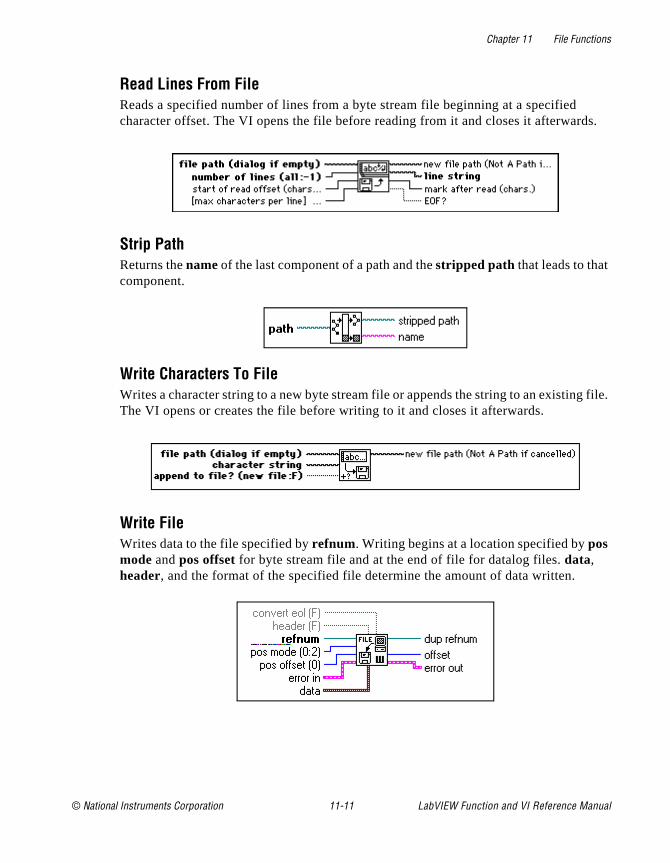
Chapter 11 File Functions
ds.
g file.
Read Lines From FileReads a specified number of lines from a byte stream file beginning at a specified character offset. The VI opens the file before reading from it and closes it afterwar
Strip PathReturns the name of the last component of a path and the stripped path that leads to that component.
Write Characters To FileWrites a character string to a new byte stream file or appends the string to an existinThe VI opens or creates the file before writing to it and closes it afterwards.
Write FileWrites data to the file specified by refnum. Writing begins at a location specified by pos mode and pos offset for byte stream file and at the end of file for datalog files. data, header, and the format of the specified file determine the amount of data written.
© National Instruments Corporation 11-11 LabVIEW Function and VI Reference Manual

Chapter 11 File Functions
e the
You a iage
he
cord
or the ach
rites n nd sheet ata.
Writing Byte Stream FilesIf refnum is a byte stream file refnum, the Write File function writes to a location specified by pos mode and pos offset in the byte stream file specified by refnum. If the top-level datatype of data is of variable length (that is, a string or an array), Write Filcan write a header to the file that specifies the size of the data. G sets the file mark tobyte following the last byte written. convert eol determines whether the function converts the end-of-line markers it writes into system-specific end-of-line markers. can wire convert eol only if data is a string. The system-specific end-of-line marker iscarriage return followed by a line feed on Windows, a line feed on UNIX, and a carrreturn on Macintosh. If header is true, G ignores convert eol.
Writing Datalog FilesIf refnum is a datalog file refnum, the Write File function writes data as records to tdatalog file specified by refnum. Writing always starts at the end of the datalog file (datalog files are append-only). G sets the file mark to the record following the last rewritten. The convert eol, header, pos mode, and pos offset parameters do not apply withdatalog files, and you cannot wire them. The data parameter functions in the following manner for datalog files.
data must be either a datatype that matches the datatype specified when you opencreate the file, or an array of such datatypes. In the former case, this function writesdata as a single record in the datalog file. Representation of numeric data is coerced torepresentation of the datatype if necessary. In the latter case, this function writes eelement of data as a separate record in the datalog file in row-major order.
Write To Spreadsheet FileConverts a 2D or 1D array of single-precision (SGL) numbers to a text string and wthe string to a new byte stream file or appends the string to an existing file. You caoptionally transpose the data. This VI opens or creates the file before writing to it acloses it afterwards. You can use this VI to create a text file readable by most spreadapplications. This VI calls the Array to Spreadsheet String function to convert the d
LabVIEW Function and VI Reference Manual 11-12 © National Instruments Corporation

Chapter 11 File Functions
. The I to
with
use ith
ends oses
Binary File VI Descriptions
The following VIs are available on the Binary File VIs subpalette.
Read From I16 FileReads a 2D or 1D array of data from a byte stream file of signed, word integers (I16)VI opens the file before reading from it and closes it afterwards. You can use this Vread unscaled or binary data acquired from data acquisition VIs and written to a fileWrite To I16 File.
Read From SGL FileReads a 2D or 1D array of data from a byte stream file of single-precision numbers(SGL). The VI opens the file before reading from it and closes it afterwards. You canthis VI to read scaled data acquired from data acquisition VIs and written to a file wWrite To SGL File.
Write To I16 FileWrites a 2D or 1D array of signed word integers (I16) to a new byte stream file or appthe data to an existing file. The VI opens or creates the file before writing to it and cl
© National Instruments Corporation 11-13 LabVIEW Function and VI Reference Manual

Chapter 11 File Functions
ition
e or to it ition
it afterwards. You can use this VI to write unscaled or binary data from data acquisVIs.
Write To SGL FileWrites a 2D or 1D array of single-precision numbers (SGL) to a new byte stream filappends the data to an existing file. The VI opens or creates the file before writingand closes it afterwards. You can use this VI to write scaled data from data acquisVIs without changing the representation.
Advanced File Function Descriptions
The following functions are available on the Advanced File Functions subpalette.
LabVIEW Function and VI Reference Manual 11-14 © National Instruments Corporation
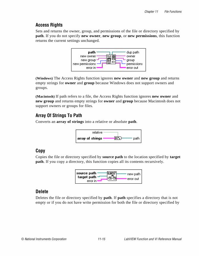
Chapter 11 File Functions
d by
t
by
Access RightsSets and returns the owner, group, and permissions of the file or directory specifiepath. If you do not specify new owner, new group, or new permissions, this function returns the current settings unchanged.
(Windows) The Access Rights function ignores new owner and new group and returns empty strings for owner and group because Windows does not support owners and groups.
(Macintosh) If path refers to a file, the Access Rights function ignores new owner and new group and returns empty strings for owner and group because Macintosh does nosupport owners or groups for files.
Array Of Strings To PathConverts an array of strings into a relative or absolute path.
CopyCopies the file or directory specified by source path to the location specified by target path. If you copy a directory, this function copies all its contents recursively.
DeleteDeletes the file or directory specified by path. If path specifies a directory that is not empty or if you do not have write permission for both the file or directory specified
© National Instruments Corporation 11-15 LabVIEW Function and VI Reference Manual
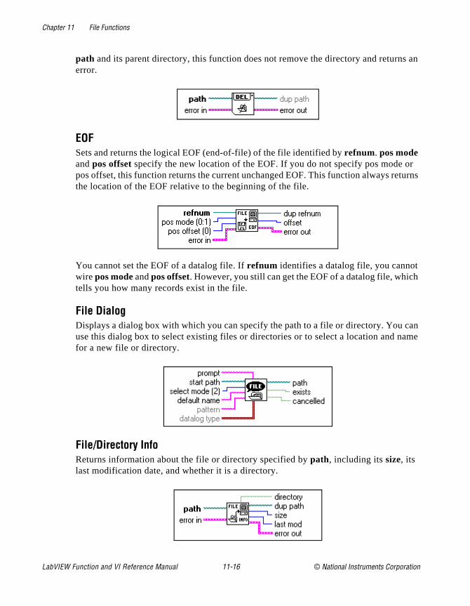
Chapter 11 File Functions
s an
r turns
h
can ame
path and its parent directory, this function does not remove the directory and returnerror.
EOFSets and returns the logical EOF (end-of-file) of the file identified by refnum. pos mode and pos offset specify the new location of the EOF. If you do not specify pos mode opos offset, this function returns the current unchanged EOF. This function always rethe location of the EOF relative to the beginning of the file.
You cannot set the EOF of a datalog file. If refnum identifies a datalog file, you cannotwire pos mode and pos offset. However, you still can get the EOF of a datalog file, whictells you how many records exist in the file.
File Dialog Displays a dialog box with which you can specify the path to a file or directory. You use this dialog box to select existing files or directories or to select a location and nfor a new file or directory.
File/Directory InfoReturns information about the file or directory specified by path, including its size, its last modification date, and whether it is a directory.
LabVIEW Function and VI Reference Manual 11-16 © National Instruments Corporation
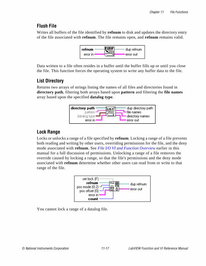
Chapter 11 File Functions
y
se .
deny
e de t
Flush FileWrites all buffers of the file identified by refnum to disk and updates the directory entrof the file associated with refnum. The file remains open, and refnum remains valid.
Data written to a file often resides in a buffer until the buffer fills up or until you clothe file. This function forces the operating system to write any buffer data to the file
List DirectoryReturns two arrays of strings listing the names of all files and directories found in directory path , filtering both arrays based upon pattern and filtering the file names array based upon the specified datalog type.
Lock RangeLocks or unlocks a range of a file specified by refnum. Locking a range of a file preventsboth reading and writing by other users, overriding permissions for the file, and the mode associated with refnum. See File I/O VI and Function Overview earlier in this manual for a full discussion of permissions. Unlocking a range of a file removes thoverride caused by locking a range, so that the file's permissions and the deny moassociated with refnum determine whether other users can read from or write to tharange of the file.
You cannot lock a range of a datalog file.
© National Instruments Corporation 11-17 LabVIEW Function and VI Reference Manual

Chapter 11 File Functions
of
MoveMoves the file or directory specified by source path to the location specified by target path.
New DirectoryProgrammatically creates the directory specified by directory path . If a file or directory already exists at the specified location, this function returns an error instead of overwriting the existing file or directory.
New FileCreates the file specified by file path and opens it for reading and writing (regardless permissions).
Open FileOpens the file specified by file path for reading and/or writing.
LabVIEW Function and VI Reference Manual 11-18 © National Instruments Corporation
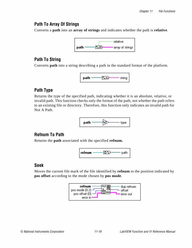
Chapter 11 File Functions
, or fers
for
Path To Array Of StringsConverts a path into an array of strings and indicates whether the path is relative.
Path To StringConverts path into a string describing a path in the standard format of the platform.
Path TypeReturns the type of the specified path, indicating whether it is an absolute, relativeinvalid path. This function checks only the format of the path, not whether the path reto an existing file or directory. Therefore, this function only indicates an invalid pathNot A Path.
Refnum To PathReturns the path associated with the specified refnum.
SeekMoves the current file mark of the file identified by refnum to the position indicated by pos offset according to the mode chosen by pos mode.
© National Instruments Corporation 11-19 LabVIEW Function and VI Reference Manual
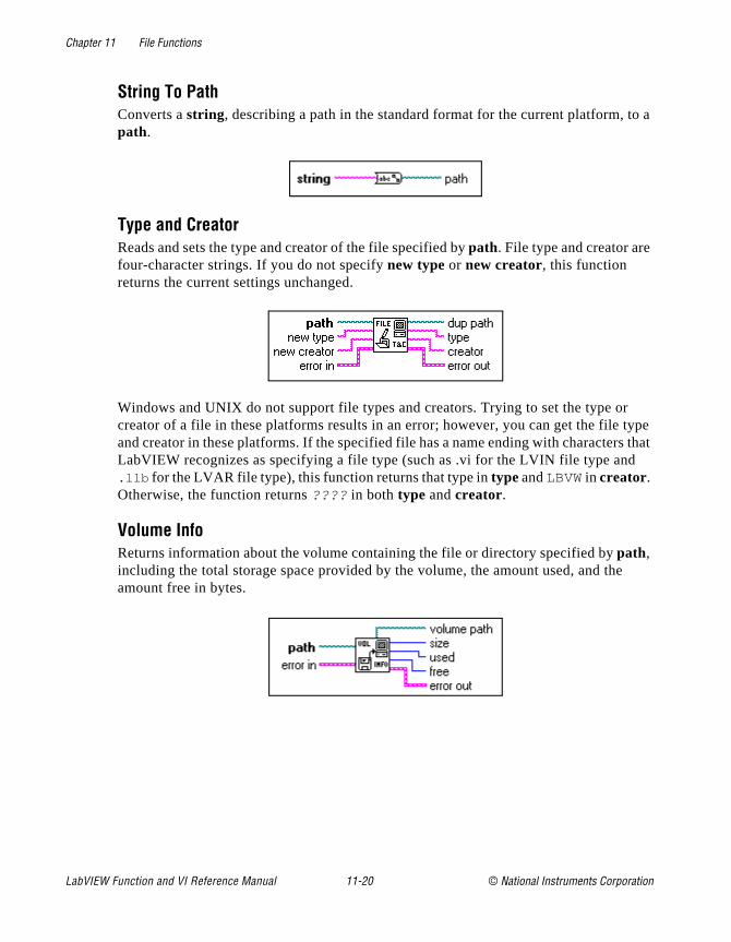
Chapter 11 File Functions
o a
type s that
e
String To PathConverts a string, describing a path in the standard format for the current platform, tpath.
Type and CreatorReads and sets the type and creator of the file specified by path. File type and creator arefour-character strings. If you do not specify new type or new creator, this function returns the current settings unchanged.
Windows and UNIX do not support file types and creators. Trying to set the type orcreator of a file in these platforms results in an error; however, you can get the file and creator in these platforms. If the specified file has a name ending with characterLabVIEW recognizes as specifying a file type (such as .vi for the LVIN file type and.llb for the LVAR file type), this function returns that type in type and LBVW in creator. Otherwise, the function returns ???? in both type and creator.
Volume InfoReturns information about the volume containing the file or directory specified by path, including the total storage space provided by the volume, the amount used, and thamount free in bytes.
LabVIEW Function and VI Reference Manual 11-20 © National Instruments Corporation

Chapter 11 File Functions
I is n
VI
ich
File Constants Descriptions
The following constants are the options available on the File Constants subpalette.
Current VI's Path ConstantReturns the path to the file containing the VI in which this function appears. If the Vincorporated into an application (using the Application Builder libraries), the functioreturns the path to the VI in the application file, and treats the application file as a library.
Default Directory ConstantReturns the path to your default directory. The default directory is the directory whthe file dialog displays initially. The G Preferences dialog box, under Paths, defines this directory.
Empty Path Returns an empty path.
© National Instruments Corporation 11-21 LabVIEW Function and VI Reference Manual
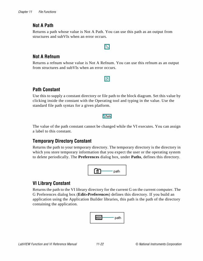
Chapter 11 File Functions
tput
e by
ssign
ry in stem
The
ory
Not A PathReturns a path whose value is Not A Path. You can use this path as an output fromstructures and subVIs when an error occurs.
Not A RefnumReturns a refnum whose value is Not A Refnum. You can use this refnum as an oufrom structures and subVIs when an error occurs.
Path ConstantUse this to supply a constant directory or file path to the block diagram. Set this valuclicking inside the constant with the Operating tool and typing in the value. Use thestandard file path syntax for a given platform.
The value of the path constant cannot be changed while the VI executes. You can aa label to this constant.
Temporary Directory ConstantReturns the path to your temporary directory. The temporary directory is the directowhich you store temporary information that you expect the user or the operating syto delete periodically. The Preferences dialog box, under Paths, defines this directory.
VI Library ConstantReturns the path to the VI library directory for the current G on the current computer.G Preferences dialog box (Edit»Preferences) defines this directory. If you build an application using the Application Builder libraries, this path is the path of the directcontaining the application.
LabVIEW Function and VI Reference Manual 11-22 © National Instruments Corporation
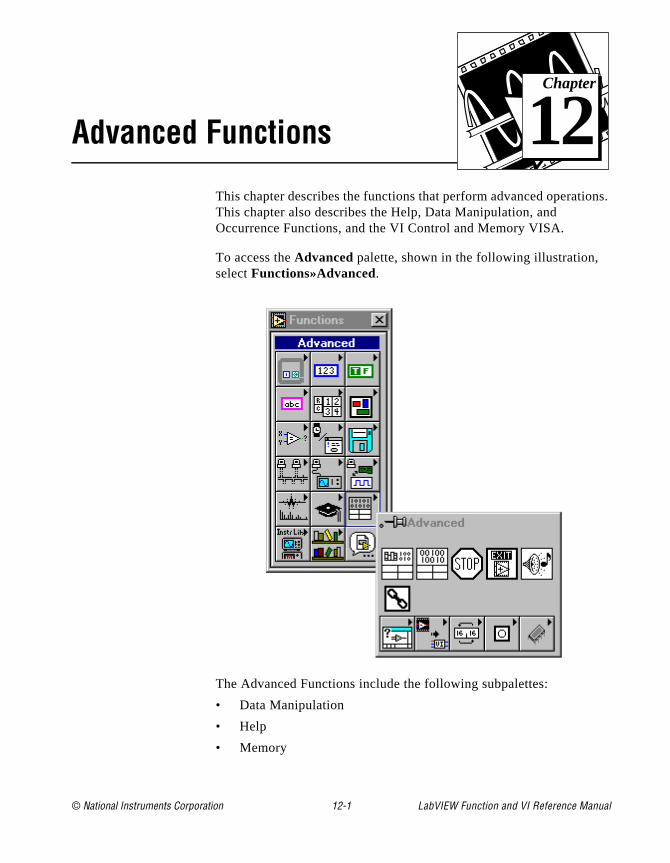
© National Instruments Corporation 12-1 LabVIEW Function and
Chapter
12
Advanced Functionsons.
This chapter describes the functions that perform advanced operatiThis chapter also describes the Help, Data Manipulation, and Occurrence Functions, and the VI Control and Memory VISA.To access the Advanced palette, shown in the following illustration, select Functions»Advanced.
The Advanced Functions include the following subpalettes:
• Data Manipulation
• Help
• Memory
VI Reference Manual

Chapter 12 Advanced Functions
Hertz, ing
sible
nd
• Occurrences
• VI Controls
Advanced Function Descriptions
The following Advanced Functions are available.
BeepCauses the system to issue an audible tone. You can specify the tone frequency in the duration in milliseconds, and the intensity as a value from 0 to 255, with 255 bethe loudest. Although this VI appears on all platforms, the frequency, duration, andintensity parameters work only on the Macintosh.
Call ChainReturns the chain of callers from this VI to the top-level VI as an array of strings.
Code Interface NodeWith a Code Interface Node (CIN), you can call code written in a conventional programming language, such as C, directly from a block diagram. CINs make it posfor you to use algorithms written in another language or to access platform-specificfeatures or hardware that G does not directly support.
Code Interface Nodes are resizable and show datatypes for the connected inputs aoutputs, similar to the Bundle function. The following illustration shows the CIN function.
LabVIEW Function and VI Reference Manual 12-2 © National Instruments Corporation

Chapter 12 Advanced Functions
f
the ing
a L)
tly. r the
ld be
a
left is turn onds iring tion
me,
LabVIEW’s interface to external code is very powerful. You can pass any number oparameters to or from external code, and each parameter can be of any arbitrary Gdatatype. LabVIEW provides several libraries of routines that make working with Gdatatypes easier. These routines support memory allocation, file manipulation, anddatatype conversion.
If you convert a VI that contains a CIN to another platform, you need to recompile code for the new platform, because CINs use code compiled in another programmlanguage. You can write source code for a CIN so that it is machine-independent, requiring only a recompile to convert it to another platform.
For examples of CINs, see examples\cins .
For more information on the Code Interface Node see the Code Interface Reference Manual.
Call Library FunctionWith the Call Library Function node, you can call standard libraries without writing Code Interface Node (CIN). Under Windows, you can call a dynamic link library (DLfunction directly. In Macintosh and UNIX, you can call a shared library function direcOn the Macintosh 68K, you must have the CFM-68K system extension installed foCall Library Function node to operate.
This node supports a large number of datatypes and calling conventions. You shouable to use it to call functions from most standard and custom-made libraries.
The Call Library Function node, shown in the following illustration, looks similar to Code Interface Node.
The Call Library Function consists of paired input/output terminals with input on the and output on the right. You can use one or both. The return value for the functionreturned in the right terminal of the top pair of terminals of the node. If there is no revalue, then this pair of terminals is unused. Each additional pair of terminals correspto a parameter in the functions parameter list. You pass a value to the function by wto the left terminal of a terminal pair. You read the value of a parameter after the funccall by wiring from the right terminal of a terminal pair.
If you select Configure... from the pop-up menu of the node, you see a Call Library Function dialog box from which you can specify the library name or path, function na
© National Instruments Corporation 12-3 LabVIEW Function and VI Reference Manual
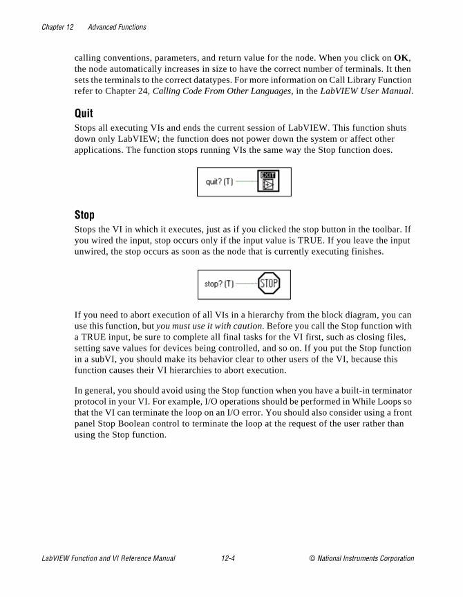
Chapter 12 Advanced Functions
then ction
uts
r. If put
can s,
ction is
ator s so front han
calling conventions, parameters, and return value for the node. When you click on OK , the node automatically increases in size to have the correct number of terminals. Itsets the terminals to the correct datatypes. For more information on Call Library Funrefer to Chapter 24, Calling Code From Other Languages, in the LabVIEW User Manual.
QuitStops all executing VIs and ends the current session of LabVIEW. This function shdown only LabVIEW; the function does not power down the system or affect other applications. The function stops running VIs the same way the Stop function does.
Stop Stops the VI in which it executes, just as if you clicked the stop button in the toolbayou wired the input, stop occurs only if the input value is TRUE. If you leave the inunwired, the stop occurs as soon as the node that is currently executing finishes.
If you need to abort execution of all VIs in a hierarchy from the block diagram, you use this function, but you must use it with caution. Before you call the Stop function witha TRUE input, be sure to complete all final tasks for the VI first, such as closing filesetting save values for devices being controlled, and so on. If you put the Stop funin a subVI, you should make its behavior clear to other users of the VI, because thfunction causes their VI hierarchies to abort execution.
In general, you should avoid using the Stop function when you have a built-in terminprotocol in your VI. For example, I/O operations should be performed in While Loopthat the VI can terminate the loop on an I/O error. You should also consider using a panel Stop Boolean control to terminate the loop at the request of the user rather tusing the Stop function.
LabVIEW Function and VI Reference Manual 12-4 © National Instruments Corporation
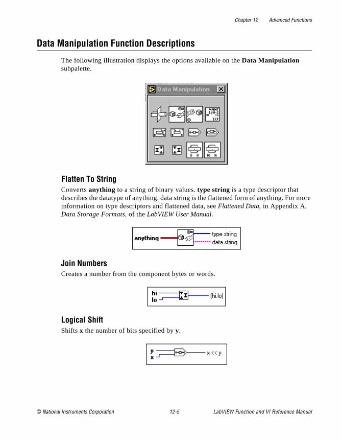
Chapter 12 Advanced Functions
more
Data Manipulation Function Descriptions
The following illustration displays the options available on the Data Manipulation subpalette.
Flatten To StringConverts anything to a string of binary values. type string is a type descriptor that describes the datatype of anything. data string is the flattened form of anything. For information on type descriptors and flattened data, see Flattened Data, in Appendix A, Data Storage Formats, of the LabVIEW User Manual.
Join NumbersCreates a number from the component bytes or words.
Logical ShiftShifts x the number of bits specified by y.
© National Instruments Corporation 12-5 LabVIEW Function and VI Reference Manual
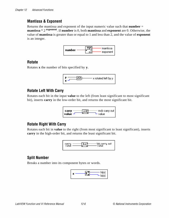
Chapter 12 Advanced Functions
ts
Mantissa & ExponentReturns the mantissa and exponent of the input numeric value such that number = mantissa * 2 exponent. If number is 0, both mantissa and exponent are 0. Otherwise, the value of mantissa is greater than or equal to 1 and less than 2, and the value of exponent is an integer.
RotateRotates x the number of bits specified by y.
Rotate Left With CarryRotates each bit in the input value to the left (from least significant to most significantbit), inserts carry in the low-order bit, and returns the most significant bit.
Rotate Right With CarryRotates each bit in value to the right (from most significant to least significant), insercarry in the high-order bit, and returns the least significant bit.
Split NumberBreaks a number into its component bytes or words.
LabVIEW Function and VI Reference Manual 12-6 © National Instruments Corporation
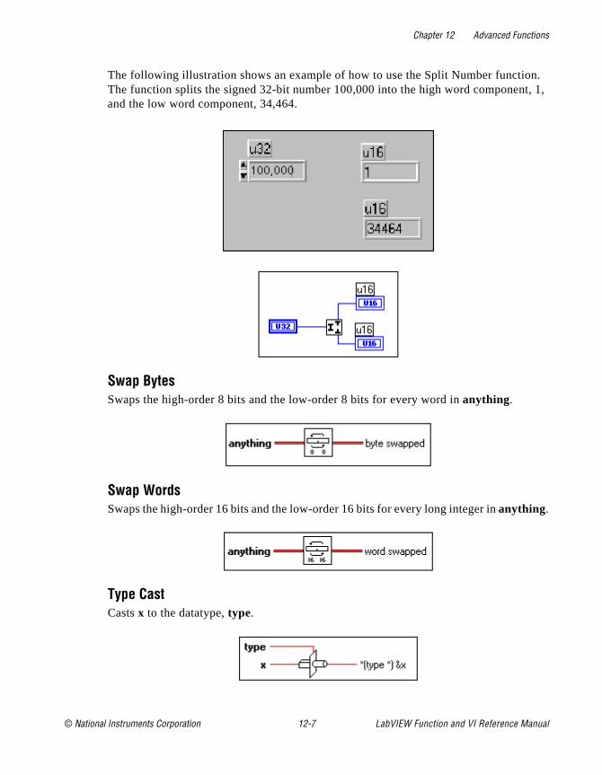
Chapter 12 Advanced Functions
n. t, 1,
The following illustration shows an example of how to use the Split Number functioThe function splits the signed 32-bit number 100,000 into the high word componenand the low word component, 34,464.
Swap BytesSwaps the high-order 8 bits and the low-order 8 bits for every word in anything.
Swap WordsSwaps the high-order 16 bits and the low-order 16 bits for every long integer in anything.
Type CastCasts x to the datatype, type.
© National Instruments Corporation 12-7 LabVIEW Function and VI Reference Manual
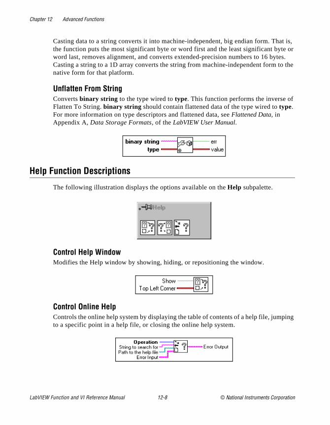
Chapter 12 Advanced Functions
t is, e or es. o the
ping
Casting data to a string converts it into machine-independent, big endian form. Thathe function puts the most significant byte or word first and the least significant bytword last, removes alignment, and converts extended-precision numbers to 16 bytCasting a string to a 1D array converts the string from machine-independent form tnative form for that platform.
Unflatten From StringConverts binary string to the type wired to type. This function performs the inverse ofFlatten To String. binary string should contain flattened data of the type wired to type. For more information on type descriptors and flattened data, see Flattened Data, in Appendix A, Data Storage Formats, of the LabVIEW User Manual.
Help Function Descriptions
The following illustration displays the options available on the Help subpalette.
Control Help WindowModifies the Help window by showing, hiding, or repositioning the window.
Control Online HelpControls the online help system by displaying the table of contents of a help file, jumto a specific point in a help file, or closing the online help system.
LabVIEW Function and VI Reference Manual 12-8 © National Instruments Corporation
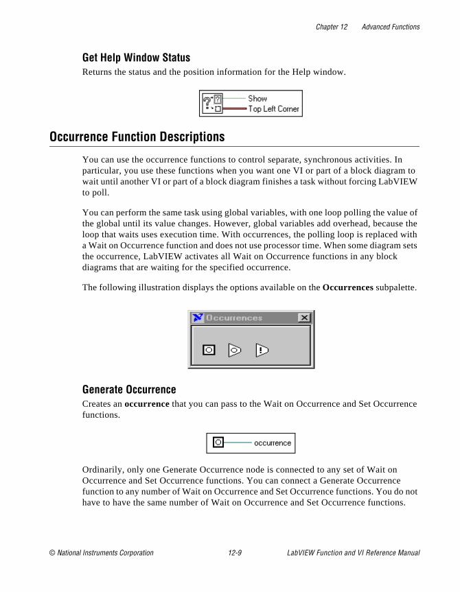
Chapter 12 Advanced Functions
In to
W
e of se the with m sets
nce
ce o not ns.
Get Help Window StatusReturns the status and the position information for the Help window.
Occurrence Function Descriptions
You can use the occurrence functions to control separate, synchronous activities. particular, you use these functions when you want one VI or part of a block diagramwait until another VI or part of a block diagram finishes a task without forcing LabVIEto poll.
You can perform the same task using global variables, with one loop polling the valuthe global until its value changes. However, global variables add overhead, becauloop that waits uses execution time. With occurrences, the polling loop is replaceda Wait on Occurrence function and does not use processor time. When some diagrathe occurrence, LabVIEW activates all Wait on Occurrence functions in any block diagrams that are waiting for the specified occurrence.
The following illustration displays the options available on the Occurrences subpalette.
Generate OccurrenceCreates an occurrence that you can pass to the Wait on Occurrence and Set Occurrefunctions.
Ordinarily, only one Generate Occurrence node is connected to any set of Wait onOccurrence and Set Occurrence functions. You can connect a Generate Occurrenfunction to any number of Wait on Occurrence and Set Occurrence functions. You dhave to have the same number of Wait on Occurrence and Set Occurrence functio
© National Instruments Corporation 12-9 LabVIEW Function and VI Reference Manual

Chapter 12 Advanced Functions
e stant. de
on ram
ot
Each Generate Occurrence function on a block diagram represents a single, uniquoccurrence. In this way, you can think of the Generate Occurrence function as a conWhen a VI is running, every time a Generate Occurrence function executes, the noproduces the same value. For example, if you place a Generate Occurrence functiinside of a loop, the value produced by Generate Occurrence is the same for everyiteration of the loop. If you place a Generate Occurrence function on the block diagof a reentrant VI, Generate Occurrence produces a different value for each caller.
Set OccurrenceTriggers the specified occurrence. All block diagrams that are waiting for this occurrence stop waiting.
Wait On OccurrenceWaits for the Set Occurrence function to set or trigger the given occurrence.
Memory VI Descriptions
The following illustration displays the options available on the Memory subpalette.
In Port (Windows 3.1 and Windows 95)Reads a byte or word integer from a specific register address. Because this VI is navailable on all platforms, VIs using this subVI are not portable.
LabVIEW Function and VI Reference Manual 12-10 © National Instruments Corporation
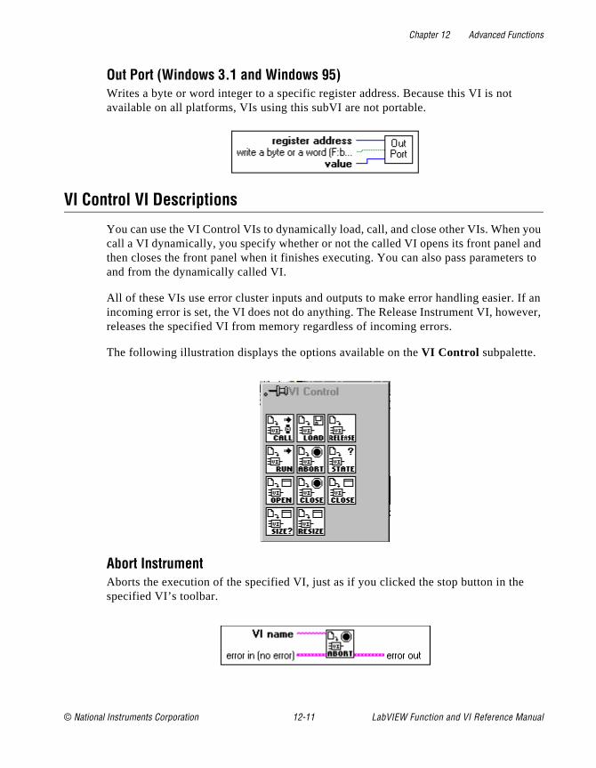
Chapter 12 Advanced Functions
you and rs to
If an ever,
Out Port (Windows 3.1 and Windows 95)Writes a byte or word integer to a specific register address. Because this VI is not available on all platforms, VIs using this subVI are not portable.
VI Control VI Descriptions
You can use the VI Control VIs to dynamically load, call, and close other VIs. When call a VI dynamically, you specify whether or not the called VI opens its front panel then closes the front panel when it finishes executing. You can also pass parameteand from the dynamically called VI.
All of these VIs use error cluster inputs and outputs to make error handling easier. incoming error is set, the VI does not do anything. The Release Instrument VI, howreleases the specified VI from memory regardless of incoming errors.
The following illustration displays the options available on the VI Control subpalette.
Abort InstrumentAborts the execution of the specified VI, just as if you clicked the stop button in thespecified VI’s toolbar.
© National Instruments Corporation 12-11 LabVIEW Function and VI Reference Manual
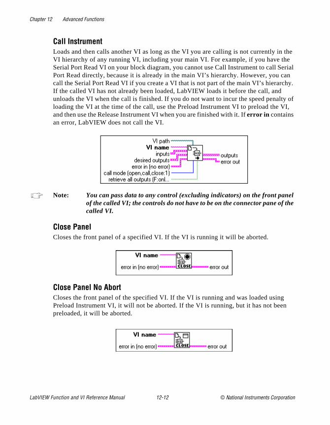
Chapter 12 Advanced Functions
the e erial an hy. ty of I,
el he
Call InstrumentLoads and then calls another VI as long as the VI you are calling is not currently inVI hierarchy of any running VI, including your main VI. For example, if you have thSerial Port Read VI on your block diagram, you cannot use Call Instrument to call SPort Read directly, because it is already in the main VI’s hierarchy. However, you ccall the Serial Port Read VI if you create a VI that is not part of the main VI’s hierarcIf the called VI has not already been loaded, LabVIEW loads it before the call, andunloads the VI when the call is finished. If you do not want to incur the speed penalloading the VI at the time of the call, use the Preload Instrument VI to preload the Vand then use the Release Instrument VI when you are finished with it. If error in contains an error, LabVIEW does not call the VI.
Note: You can pass data to any control (excluding indicators) on the front panof the called VI; the controls do not have to be on the connector pane of tcalled VI.
Close PanelCloses the front panel of a specified VI. If the VI is running it will be aborted.
Close Panel No AbortCloses the front panel of the specified VI. If the VI is running and was loaded usingPreload Instrument VI, it will not be aborted. If the VI is running, but it has not beenpreloaded, it will be aborted.
LabVIEW Function and VI Reference Manual 12-12 © National Instruments Corporation
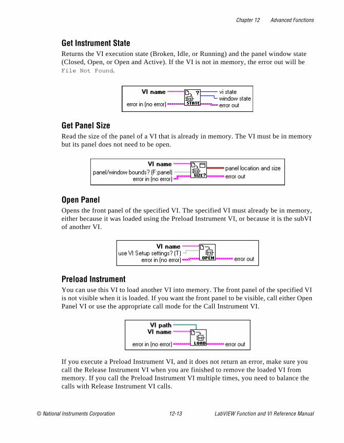
Chapter 12 Advanced Functions
te
ory
ory, ubVI
VI pen
you
the
Get Instrument StateReturns the VI execution state (Broken, Idle, or Running) and the panel window sta(Closed, Open, or Open and Active). If the VI is not in memory, the error out will beFile Not Found .
Get Panel SizeRead the size of the panel of a VI that is already in memory. The VI must be in membut its panel does not need to be open.
Open PanelOpens the front panel of the specified VI. The specified VI must already be in memeither because it was loaded using the Preload Instrument VI, or because it is the sof another VI.
Preload InstrumentYou can use this VI to load another VI into memory. The front panel of the specifiedis not visible when it is loaded. If you want the front panel to be visible, call either OPanel VI or use the appropriate call mode for the Call Instrument VI.
If you execute a Preload Instrument VI, and it does not return an error, make sure call the Release Instrument VI when you are finished to remove the loaded VI frommemory. If you call the Preload Instrument VI multiple times, you need to balance calls with Release Instrument VI calls.
© National Instruments Corporation 12-13 LabVIEW Function and VI Reference Manual
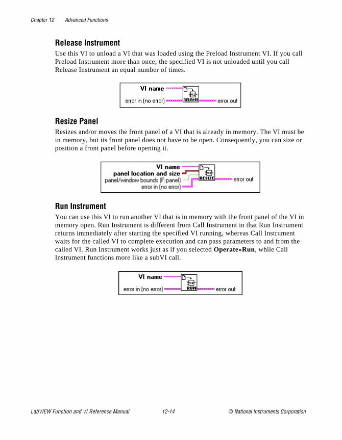
Chapter 12 Advanced Functions
call
st be ze or
I in ent t the
Release InstrumentUse this VI to unload a VI that was loaded using the Preload Instrument VI. If you Preload Instrument more than once; the specified VI is not unloaded until you call Release Instrument an equal number of times.
Resize PanelResizes and/or moves the front panel of a VI that is already in memory. The VI muin memory, but its front panel does not have to be open. Consequently, you can siposition a front panel before opening it.
Run InstrumentYou can use this VI to run another VI that is in memory with the front panel of the Vmemory open. Run Instrument is different from Call Instrument in that Run Instrumreturns immediately after starting the specified VI running, whereas Call Instrumenwaits for the called VI to complete execution and can pass parameters to and fromcalled VI. Run Instrument works just as if you selected Operate»Run, while Call Instrument functions more like a subVI call.
LabVIEW Function and VI Reference Manual 12-14 © National Instruments Corporation
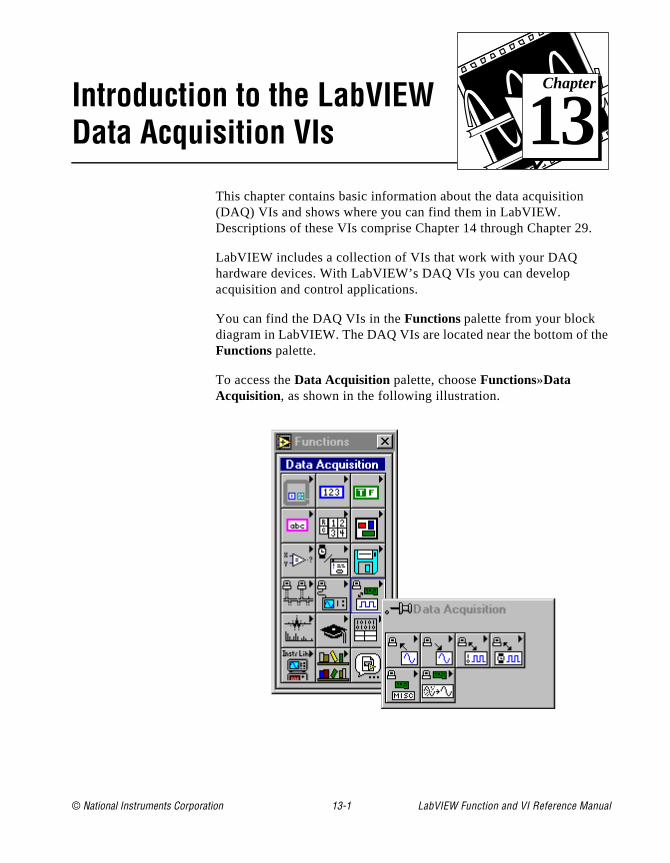
© National Instruments Corporation 13-1 LabVIEW Function and
Chapter
13
Introduction to the LabVIEW Data Acquisition VIs.
he
This chapter contains basic information about the data acquisition (DAQ) VIs and shows where you can find them in LabVIEW. Descriptions of these VIs comprise Chapter 14 through Chapter 29
LabVIEW includes a collection of VIs that work with your DAQ hardware devices. With LabVIEW’s DAQ VIs you can develop acquisition and control applications.
You can find the DAQ VIs in the Functions palette from your block diagram in LabVIEW. The DAQ VIs are located near the bottom of tFunctions palette.
To access the Data Acquisition palette, choose Functions»Data Acquisition, as shown in the following illustration.
VI Reference Manual
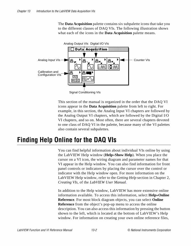
Chapter 13 Introduction to the LabVIEW Data Acquisition VIs
ou
I
by
oted tes
g
at t r
e
tton ,
The Data Acquisition palette contains six subpalette icons that take yto the different classes of DAQ VIs. The following illustration showswhat each of the icons in the Data Acquisition palette means.
This section of the manual is organized in the order that the DAQ Vicons appear in the Data Acquisition palette from left to right. For example, in this section, the Analog Input VI chapters are followed the Analog Output VI chapters, which are followed by the Digital I/OVI chapters, and so on. Most often, there are several chapters devto one class of DAQ VI in the palette, because many of the VI paletalso contain several subpalettes.
Finding Help Online for the DAQ VIsYou can find helpful information about individual VIs online by usinthe LabVIEW Help window (Help»Show Help). When you place the cursor on a VI icon, the wiring diagram and parameter names for thVI appear in the Help window. You can also find information for fronpanel controls or indicators by placing the cursor over the control oindicator with the Help window open. For more information on the LabVIEW Help window, refer to the Getting Help section in Chapter 2, Creating VIs, of the LabVIEW User Manual.
In addition to the Help window, LabVIEW has more extensive onlininformation available. To access this information, select Help»Online Reference. For most block diagram objects, you can select Online Reference from the object’s pop-up menu to access the online description. You can also access this information by pressing the bushown to the left, which is located at the bottom of LabVIEW’s Helpwindow. For information on creating your own online reference files
Analog Input VIs
Analog Output VIs Digital I/O VIs
Counter VIs
Signal Conditioning VIs
Calibration andConfiguration VIs
LabVIEW Function and VI Reference Manual 13-2 © National Instruments Corporation

Chapter 13 Introduction to the LabVIEW Data Acquisition VIs
I
see the Creating Your Own Help Files section in Chapter 25, Managing Your Applications of the LabVIEW User Manual.
Note: Use only the inputs that you need on each VI. LabVIEW sets all unwiredinputs to their default values. Many of the DAQ function inputs are optional and do not appear in the Simple Diagram Help window. These inputs typically specify rarely-used options. If an input is required, your Vwiring remains “broken” until a value is wired to the input. Required inputs appear in bold in the Help window, recommended inputs appear inplain text, and optional inputs are in gray text. The default values for inputs appear in parentheses beside the input name in the Help window.
Note: Some DAQ VIs use an enumerated data type as a control or indicator terminal. If you connect a numeric value to an enumerated indicator, LabVIEW converts the number to the closest enumeration item. If you connect an enumerated control to a number value, the value is the enumeration index. To wire an enumerated control to an enumerated indicator, the enumerated items must match exactly, or you will get a broken wire.
The Analog Input VIsThese VIs perform analog input operations.
The Analog Input VIs can be found by choosing Functions»Data Acquisition»Analog Input. When you click on the
© National Instruments Corporation 13-3 LabVIEW Function and VI Reference Manual

Chapter 13 Introduction to the LabVIEW Data Acquisition VIs
. n
Analog Input icon in the Data Acquisition palette, the Analog Input palette pops up, as shown in the following illustration.
There are four classes of Analog Input VIs found in the Analog Input palette. The Easy Analog Input VIs, Intermediate Analog Input VIs,Analog Input Utility VIs, and Advanced Analog Input VIs. The following illustrates these VI classes.
Easy Analog Input VIsThe Easy Analog Input VIs perform simple analog input operationsYou can run these VIs from the front panel or use them as subVIs ibasic applications.
Easy Analog Input VIs
IntermediateAnalog Input VIs
Advanced Analog Input VIs
Analog Input Utility VIs
LabVIEW Function and VI Reference Manual 13-4 © National Instruments Corporation

Chapter 13 Introduction to the LabVIEW Data Acquisition VIs
like
top
r
I
d
el
You can use each VI alone to perform a basic analog operation. Unintermediate- and advanced-level VIs, Easy Analog Input VIs automatically alert you to errors with a dialog box that asks you to sthe execution of the VI or to ignore the error.
The Easy Analog Input VIs are actually composed of Intermediate Analog Input VIs, which are in turn composed of Advanced AnalogInput VIs. The Easy Analog Input VIs provide a basic, convenient interface with only the most commonly used inputs and outputs. Fomore complex applications, you should use the intermediate- or advanced-level VIs for more functionality and performance.
Refer to Chapter 14, Easy Analog Input VIs, for specific VI information.
Intermediate Analog Input VIsYou can find intermediate-level Analog Input VIs in two different places in the Analog Input palette. You can find the Intermediate Analog Input VIs in the second row of the Analog Input palette. The other intermediate-level VIs are in the Analog Input Utilities palette, which will be discussed later. The Intermediate Analog Input VIs—AConfig, AI Start, AI Read, AI Single Scan, and AI Clear—are in turnbuilt from the fundamental building block layer, called the AdvanceAnalog Input VIs. These VIs offer almost as much power as the advanced-level VIs, and they conveniently group the advanced-levVIs into a tidy, logical sequence.
Refer to Chapter 15, Intermediate Analog Input VIs, for specific VI information.
Analog Input Utility VIsYou can access the Analog Input Utilities palette by choosing the Analog Input Utility icon from the Analog Input palette. The Analog Input Utility VIs—AI Read One Scan, AI Waveform Scan, and AI Continuous Scan—are single-VI solutions to common analog inputproblems. These VIs are convenient, but they lack flexibility. Thesethree VIs are built from the Intermediate Analog Input VIs in the Analog Input palette.
Refer to Chapter 16, Analog Input Utility VIs, for specific VI information.
Analog InputUtility Icon
© National Instruments Corporation 13-5 LabVIEW Function and VI Reference Manual
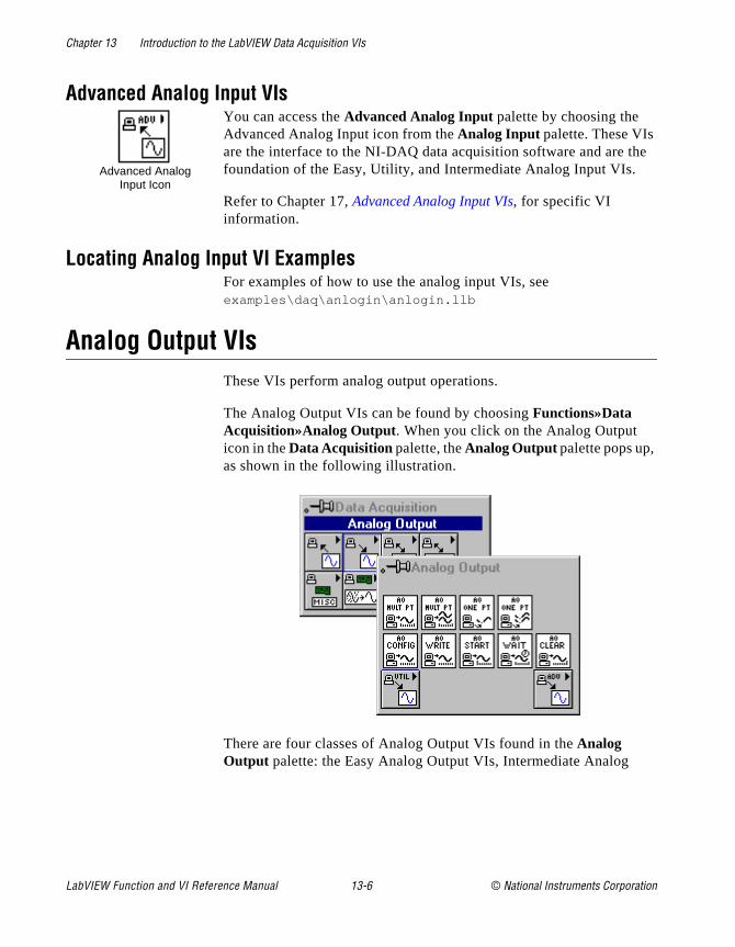
Chapter 13 Introduction to the LabVIEW Data Acquisition VIs
he
Advanced Analog Input VIsYou can access the Advanced Analog Input palette by choosing the Advanced Analog Input icon from the Analog Input palette. These VIs are the interface to the NI-DAQ data acquisition software and are tfoundation of the Easy, Utility, and Intermediate Analog Input VIs.
Refer to Chapter 17, Advanced Analog Input VIs, for specific VI information.
Locating Analog Input VI ExamplesFor examples of how to use the analog input VIs, see examples\daq\anlogin\anlogin.llb
Analog Output VIsThese VIs perform analog output operations.
The Analog Output VIs can be found by choosing Functions»Data Acquisition»Analog Output. When you click on the Analog Output icon in the Data Acquisition palette, the Analog Output palette pops up, as shown in the following illustration.
There are four classes of Analog Output VIs found in the Analog Output palette: the Easy Analog Output VIs, Intermediate Analog
Advanced AnalogInput Icon
LabVIEW Function and VI Reference Manual 13-6 © National Instruments Corporation

Chapter 13 Introduction to the LabVIEW Data Acquisition VIs
ns. in
og ks
g nt r
Output VIs, Analog Output Utility VIs, and the Advanced Analog Output VIs. The following illustrates these VI classes.
Easy Analog Output VIsThe Easy Analog Output VIs perform simple analog output operatioYou can run these VIs from the front panel or use them as subVIs basic applications.
You can use each VI by itself to perform a basic analog output operation. Unlike intermediate- and advanced-level VIs, Easy AnalOutput VIs automatically alert you to errors with a dialog box that asyou to stop the execution of the VI or to ignore the error.
The Easy Analog Output VIs are actually composed of IntermediateAnalog Output VIs, which are in turn composed of Advanced AnaloOutput VIs. The Easy Analog Output VIs provide a basic, convenieinterface with only the most commonly used inputs and outputs. Fomore complex applications, you should use the intermediate- or advanced-level VIs for more functionality and performance.
Refer to Chapter 18, Easy Analog Output VIs, for specific VI information.
Intermediate Analog Output VIsYou can find intermediate-level Analog Output VIs in two different places in the Analog Output palette. You can find the Intermediate Analog Output VIs in the second row of the Analog Output palette. The other intermediate-level VIs are in the Analog Output Utilities palette,
Easy Analog Output VIs
IntermediateAnalog Output VIs
Advanced Analog Output VIs
Analog Output Utility VIs
© National Instruments Corporation 13-7 LabVIEW Function and VI Reference Manual
Chapter 13 Introduction to the LabVIEW Data Acquisition VIs
d
el
g . in
of
r to
s in
which will be discussed later. The Intermediate Analog Output VIs—AO Config, AO Write, AO Start, AO Wait, and AO Clear—are in turnbuilt from the fundamental building block layer, called the AdvanceAnalog Output VIs. These VIs offer almost as much power as the advanced-level VIs, and they conveniently group the advanced-levVIs into a tidy, logical sequence.
Refer to Chapter 19, Intermediate Analog Output VIs, for specific VI information.
Analog Output Utility VIsYou can access the Analog Output Utilities palette by choosing the Analog Output Utility icon from the Analog Output palette. The Analog Output Utility VIs—AI Read One Scan, AI Waveform Scan, and AI Continuous Scan—are single-VI solutions to common analooutput problems. These VIs are convenient, but they lack flexibilityThese three VIs are built from the Intermediate Analog Output VIs the Analog Output palette.
Refer to Chapter 20, Analog Output Utility VIs, for specific VI information.
Advanced Analog Output VIsYou can access the Advanced Analog Output palette by choosing the Advanced Analog Output icon from the Analog Output palette. These VIs are the interface to the NI-DAQ software and are the foundationthe Easy, Utility, and Intermediate Analog Output VIs.
Because all these VIs rely on the advanced-level VIs, you can refeChapter 21, Advanced Analog Output VIs, for additional information on the inputs and outputs and how they work.
Locating Analog Output VI ExamplesFor examples of how to use the analog output VIs, see the exampleexamples\daq\anlogout\anlogout.llb .
Analog OutputUtility Icon
Advanced AnalogOutput Icon
LabVIEW Function and VI Reference Manual 13-8 © National Instruments Corporation

Chapter 13 Introduction to the LabVIEW Data Acquisition VIs
.
Digital Function VIsThese VIs perform digital operations.
The Digital I/O VIs can be found by choosing Functions»Data Acquisition»Digital I/O . When you click on the Digital I/O icon in theData Acquisition palette, the Digital I/O palette pops up, as shown in the following illustration.
There are three classes of Digital I/O VIs found in the Digital I/O palette. The Easy Digital I/O VIs, Intermediate Digital I/O VIs, and Advanced Digital I/O VIs. The following illustrates these VI classes
Easy Digital I/O VIsThe Easy Digital I/O VIs perform simple digital operations. You canrun these VIs from the front panel or use them as subVIs in basic applications.
Easy Digital I/O VIs
IntermediateDigital I/O VIs
Advanced Digital I/O VIs
© National Instruments Corporation 13-9 LabVIEW Function and VI Reference Manual
Chapter 13 Introduction to the LabVIEW Data Acquisition VIs
top
tal e he
for
rd
the el
r to
You can use each VI by itself to perform a basic digital operation. Unlike intermediate- and advanced-level VIs, Easy Digital I/O VIs automatically alert you to errors with a dialog box that asks you to sthe execution of the VI or to ignore the error.
The Easy Digital I/O VIs are actually composed of Intermediate DigiI/O VIs, which are in turn composed of Advanced Digital I/O VIs. ThEasy Digital I/O VIs provide a basic, convenient interface with only tmost commonly used inputs and outputs. For more complex applications, you should use the intermediate- or advanced-level VIsmore functionality and performance.
Refer to Chapter 22, Easy Digital I/O VIs, for specific VI information.
Intermediate Digital I/O VIsYou can find intermediate-level Digital I/O VIs in the second and thirows of the Digital I/O palette. The Intermediate Digital I/O VIs are inturn built from the fundamental building block layer, called the Advanced Digital I/O VIs. These VIs offer almost as much power as advanced-level VIs, and they conveniently group the advanced-levVIs into a tidy, logical sequence.
Refer to Chapter 23, Intermediate Digital I/O VIs, for specific VI information.
Advanced Digital I/O VIsYou can access the Advanced Digital I/O palette by choosing the Advanced Digital I/O icon from the Digital I/O palette. These VIs are the interface to the NI-DAQ software and are the foundation of the Easy, Utility, and Intermediate Digital I/O VIs.
Because all these VIs rely on the advanced-level VIs, you can refeChapter 24, Advanced Digital I/O VIs, for additional information on the inputs and outputs and how they work.
Locating Digital I/O VI ExamplesFor examples of how to use the Digital I/O VIs, see the examples inexamples\daq\digital\digital.llb .
LabVIEW Function and VI Reference Manual 13-10 © National Instruments Corporation
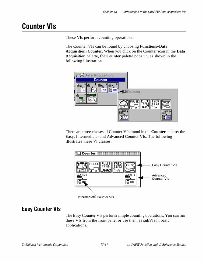
Chapter 13 Introduction to the LabVIEW Data Acquisition VIs
run
Counter VIsThese VIs perform counting operations.
The Counter VIs can be found by choosing Functions»Data Acquisition»Counter. When you click on the Counter icon in the Data Acquisition palette, the Counter palette pops up, as shown in the following illustration.
There are three classes of Counter VIs found in the Counter palette: the Easy, Intermediate, and Advanced Counter VIs. The following illustrates these VI classes.
Easy Counter VIsThe Easy Counter VIs perform simple counting operations. You can these VIs from the front panel or use them as subVIs in basic applications.
Easy Counter VIs
Advanced Counter VIs
Intermediate Counter VIs
© National Instruments Corporation 13-11 LabVIEW Function and VI Reference Manual
Chapter 13 Introduction to the LabVIEW Data Acquisition VIs
.
top
ter sy st you
t
ts.
he . and
y
r to
You can use each VI by itself to perform a basic counting operationUnlike intermediate- and advanced-level VIs, Easy Counter VIs automatically alert you to errors with a dialog box that asks you to sthe execution of the VI or to ignore the error.
The Easy Counter VIs are actually composed of Intermediate CounVIs, which are in turn composed of Advanced Counter VIs. The EaCounter VIs provide a basic, convenient interface with only the mocommonly used inputs and outputs. For more complex applications, should use the intermediate- or advanced-level VIs for more functionality and performance.
Note: An important basic data acquisition concept is to use only the inputs thayou need on each VI. Leave the rest of the inputs unwired, and LabVIEWsets them to their default values. In the Help window, the most important terminals are labeled in bold, and the least commonly used are in brackeValues given in parentheses are default values.
Refer to Chapter 25, Easy Counter VIs, for specific VI information.
Intermediate Counter Input VIsYou can find the Intermediate Counter VIs in the second row of the Counter palette. The Intermediate Counter VIs are in turn built from tfundamental building block layer, called the Advanced Counter VIsThese VIs offer almost as much power as the advanced-level VIs, they conveniently group the advanced-level VIs into a tidy, logical sequence.
Refer to Chapter 26, Intermediate Counter VIs, for specific VI information.
Advanced Counter VIsYou can access the Advanced Counter palette by choosing the Advanced Counter icon from the Counter palette. These VIs are the interface to the NI-DAQ software and are the foundation of the Easand Intermediate Counter VIs.
Because all these VIs rely on the advanced-level VIs, you can refeChapter 27, Advanced Counter VIs, for additional information on the inputs and outputs and how they work.
Intermediate Counter VI Icon
Ad d
LabVIEW Function and VI Reference Manual 13-12 © National Instruments Corporation
Chapter 13 Introduction to the LabVIEW Data Acquisition VIs
ary
n
o
Locating Counter VI ExamplesFor examples of how to use the Counter VIs, open the example librby opening examples\daq\counter\counter.llb .
Calibration and Configuration VIsThese VIs calibrate specific devices and set and return configuratioinformation.
See Chapter 28, Calibration and Configuration VIs, for information on locating these VIs and examples.
Signal Conditioning VIsThese VIs convert analog input voltages read from resistance temperature detectors (RTDs), strain gauges, or thermocouples intunits of strain or temperature.
See Chapter 29, Signal Conditioning VIs, for information on locating these VIs and examples.
© National Instruments Corporation 13-13 LabVIEW Function and VI Reference Manual
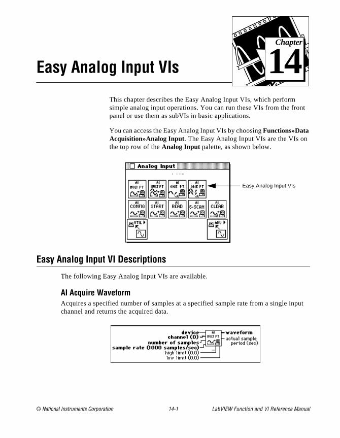
© National Instruments Corporation 14-1 LabVIEW Function and
Chapter
14
Easy Analog Input VIsnt
put
This chapter describes the Easy Analog Input VIs, which perform simple analog input operations. You can run these VIs from the fropanel or use them as subVIs in basic applications.
You can access the Easy Analog Input VIs by choosing Functions»Data Acquisition»Analog Input . The Easy Analog Input VIs are the VIs onthe top row of the Analog Input palette, as shown below.
Easy Analog Input VI Descriptions
The following Easy Analog Input VIs are available.
AI Acquire WaveformAcquires a specified number of samples at a specified sample rate from a single inchannel and returns the acquired data.
Easy Analog Input VIs
VI Reference Manual
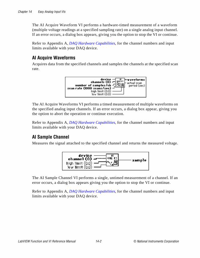
Chapter 14 Easy Analog Input VIs
rm nnel. nue.
d scan
on you
oltage.
If an
The AI Acquire Waveform VI performs a hardware-timed measurement of a wavefo(multiple voltage readings at a specified sampling rate) on a single analog input chaIf an error occurs, a dialog box appears, giving you the option to stop the VI or conti
Refer to Appendix A, DAQ Hardware Capabilities, for the channel numbers and input limits available with your DAQ device.
AI Acquire WaveformsAcquires data from the specified channels and samples the channels at the specifierate.
The AI Acquire Waveforms VI performs a timed measurement of multiple waveformsthe specified analog input channels. If an error occurs, a dialog box appear, givingthe option to abort the operation or continue execution.
Refer to Appendix A, DAQ Hardware Capabilities, for the channel numbers and input limits available with your DAQ device.
AI Sample ChannelMeasures the signal attached to the specified channel and returns the measured v
The AI Sample Channel VI performs a single, untimed measurement of a channel.error occurs, a dialog box appears giving you the option to stop the VI or continue.
Refer to Appendix A, DAQ Hardware Capabilities, for the channel numbers and input limits available with your DAQ device.
LabVIEW Function and VI Reference Manual 14-2 © National Instruments Corporation

Chapter 14 Easy Analog Input VIs
nalog p the
AI Sample ChannelsPerforms a single voltage reading from each of the specified channels.
The AI Sample Channels VI measures a single voltage from each of the specified ainput channels. If an error occurs, a dialog box appears, giving you the option to stoVI or continue.
Refer to Appendix A, DAQ Hardware Capabilities, for the channel numbers and input limits available with your DAQ device.
© National Instruments Corporation 14-3 LabVIEW Function and VI Reference Manual
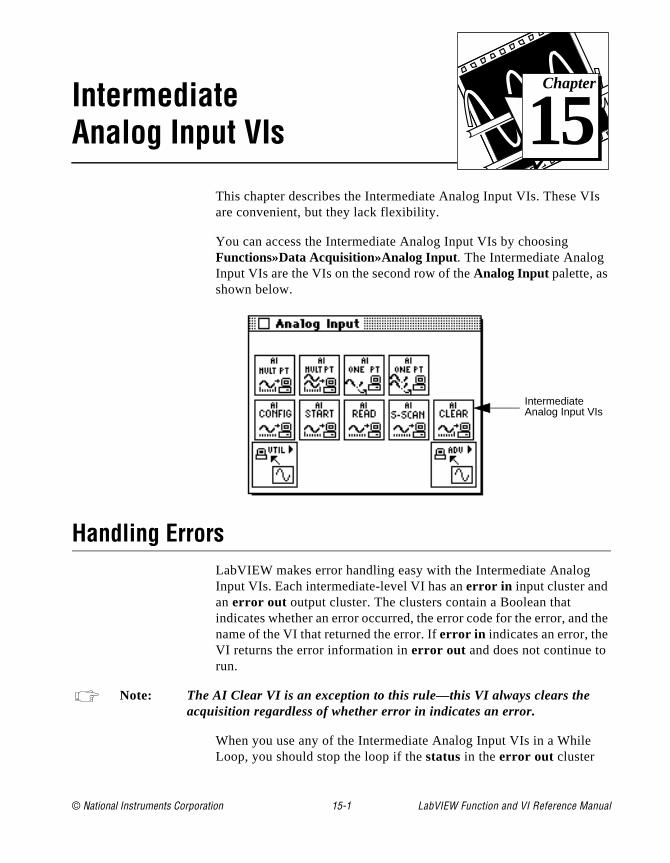
© National Instruments Corporation 15-1 LabVIEW Function and
Chapter
15
Intermediate Analog Input VIsIs
the
This chapter describes the Intermediate Analog Input VIs. These Vare convenient, but they lack flexibility.
You can access the Intermediate Analog Input VIs by choosing Functions»Data Acquisition»Analog Input. The Intermediate Analog Input VIs are the VIs on the second row of the Analog Input palette, as shown below.
Handling ErrorsLabVIEW makes error handling easy with the Intermediate Analog Input VIs. Each intermediate-level VI has an error in input cluster and an error out output cluster. The clusters contain a Boolean that indicates whether an error occurred, the error code for the error, andname of the VI that returned the error. If error in indicates an error, the VI returns the error information in error out and does not continue to run.
Note: The AI Clear VI is an exception to this rule—this VI always clears the acquisition regardless of whether error in indicates an error.
When you use any of the Intermediate Analog Input VIs in a While Loop, you should stop the loop if the status in the error out cluster
IntermediateAnalog Input VIs
VI Reference Manual
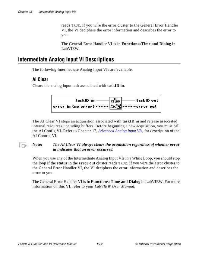
Chapter 15 Intermediate Analog Input VIs
r
call
stop
the
reads TRUE. If you wire the error cluster to the General Error HandleVI, the VI deciphers the error information and describes the error toyou.
The General Error Handler VI is in Functions»Time and Dialog in LabVIEW.
Intermediate Analog Input VI Descriptions
The following Intermediate Analog Input VIs are available.
AI ClearClears the analog input task associated with taskID in .
The AI Clear VI stops an acquisition associated with taskID in and release associated internal resources, including buffers. Before beginning a new acquisition, you mustthe AI Config VI. Refer to Chapter 17, Advanced Analog Input VIs, for description of the AI Control VI.
Note: The AI Clear VI always clears the acquisition regardless of whether error in indicates that an error occurred.
When you use any of the Intermediate Analog Input VIs in a While Loop, you should the loop if the status in the error out cluster reads TRUE. If you wire the error cluster to the General Error Handler VI, the VI deciphers the error information and describeserror to you.
The General Error Handler VI is in Functions»Time and Dialog in LabVIEW. For more information on this VI, refer to your LabVIEW User Manual.
LabVIEW Function and VI Reference Manual 15-2 © National Instruments Corporation

Chapter 15 Intermediate Analog Input VIs
ures
ut
AI ConfigConfigures an analog input operation for a specified set of channels. This VI configthe hardware and allocates a buffer for a buffered analog input operation.
You can allocate more than one buffer only with the following devices.
• (Macintosh) NB-A2000, NB-A2100, and NB-A2150
• (Windows) EISA-A2000, AT-A2150, and AT-DSP2200
Refer to Appendix A, DAQ Hardware Capabilities, for the channel ranges, input limits, and scanning order you can use with your National Instruments DAQ device.
AI ReadReads data from a buffered data acquisition.
The AI Read VI calls the AI Buffer Read VI to read data from a buffered analog inpacquisition.
© National Instruments Corporation 15-3 LabVIEW Function and VI Reference Manual

Chapter 15 Intermediate Analog Input VIs
an ed. of
e
ked
r
he
AI Single Scan Returns one scan of data from a previously configured group of channels.
If you have already started an acquisition with the AI Start VI, this VI reads one scfrom the acquisition buffer data, or the onboard FIFO if the acquisition is not bufferIf you have not started an acquisition, this VI starts an acquisition, retrieves a scandata, and then terminates the acquisition. The group configuration determines the channels the VI samples.
If you do not call the AI Start VI, this VI initiates a single scan using the fastest safchannel clock rate. You can alter the channel clock rate with the AI Config VI.
If you run the AI Start VI, a clock signal initiates the scans.
You must use the AI Start VI to set the clock source to external, for externally-clocconversions.
If clock sources are internal and you do not allocate memory, a timed nonbuffered acquisition begins when you run the AI Start VI. You use this type of acquisition fosynchronizing analog inputs and outputs in a point-to-point control application. Thefollowing devices do not support timed, nonbuffered acquisitions.
• (Macintosh) NB-A2000, NB-A2100, and NB-A2150
• (Windows) AT-DSP2200, EISA-A2000, and AT-A2150
Note: LabVIEW restarts the device in the event of a FIFO overflow during a timed, nonbuffered acquisition.
When you set opcode to 1 for a nonbuffered acquisition, the VI reads one scan from tFIFO and returns the data. If opcode is 2, the VI reads the FIFO until it is empty and returns the last scan read.
LabVIEW Function and VI Reference Manual 15-4 © National Instruments Corporation
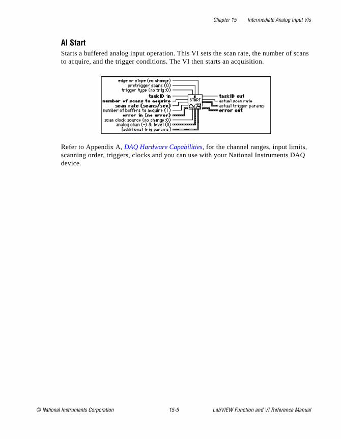
Chapter 15 Intermediate Analog Input VIs
scans
AQ
AI StartStarts a buffered analog input operation. This VI sets the scan rate, the number of to acquire, and the trigger conditions. The VI then starts an acquisition.
Refer to Appendix A, DAQ Hardware Capabilities, for the channel ranges, input limits, scanning order, triggers, clocks and you can use with your National Instruments Ddevice.
© National Instruments Corporation 15-5 LabVIEW Function and VI Reference Manual

© National Instruments Corporation 16-1 LabVIEW Function and
Chapter
16
Analog Input Utility VIsw
is
the
This chapter describes the Analog Input Utility VIs. These VIs—AI Read One Scan, AI Waveform Scan, and AI Continuous Scan—aresingle-VI solutions to common analog input problems. The Analog Input Utility VIs are intermediate-level VIs, so they rely on the advanced-level VIs. You can refer to Chapter 17, Advanced Analog Input VIs, for additional information on the inputs and outputs and hothey work.
You can access the Analog Input Utilities palette by choosing Functions»Data Acquisition»Analog Input»Analog Input Utilities . The icon that you must select to access the Analog Input Utility VIson the bottom row of the Analog Input palette, as shown below.
Handling ErrorsLabVIEW makes error handling easy with the intermediate-level Analog Input Utility VIs. Each intermediate-level VI has an error in input cluster and an error out output cluster. The clusters contain a Boolean that indicates whether an error occurred, the error code forerror, and the name of the VI that returned the error. If error in indicates an error, the VI returns the error information in error out and does not continue to run.
Analog Input Utility VIs
VI Reference Manual

Chapter 16 Analog Input Utility VIs
u
data in all.
as op
data each ified es.
AI
the does
When you use any of the Analog Input Utility VIs in a While Loop, yoshould stop the loop if the status in the error out cluster reads TRUE. If you wire the error cluster to the General Error Handler VI, the VI deciphers the error information and describes the error to you.
The General Error Handler VI is in Functions»Time and Dialog in LabVIEW. For more information on this VI, refer to your LabVIEW User Manual.
Analog Input Utility VI Descriptions
The following VIs are available through the Analog Input Utility subpalette.
AI Continuous ScanMakes continuous, time-sampled measurements of a group of channels, stores the a circular buffer, and returns a specified number of scan measurements on each c
The AI Continuous Scan VI scans a group of channels indefinitely,you might do in data logging applications. Place the VI in a While Loand wire the loop’s iteration terminal to the VI iteration input.
Also wire the condition that terminates the loop to the clear acquisition input, inverting the signal if necessary so that it reads TRUE on the last iteration. On iteration 0, the VI calls the AI Config VI to configure the channel group and hardware and allocates abuffer; the VI calls the AI Start VI to set the scan rate and start the acquisition. On iteration, the VI calls the AI Read VI to retrieve the number of measurements specby number of scans to read, scales them, and returns the data as an array of voltagOn the last iteration (when clear acquisition is TRUE) or if an error occurs, the VI calls the AI Clear VI to clear any acquisition in progress. You should not need to call theContinuous Scan VI outside of a loop, but if you do, you can leave the iteration and clear acquisition inputs unwired.
When calling the AI Continuous Scan VI in a loop to read portions of the data fromongoing acquisition, you must read the data fast enough so that newly acquired data
iterationterminal
LabVIEW Function and VI Reference Manual 16-2 © National Instruments Corporation
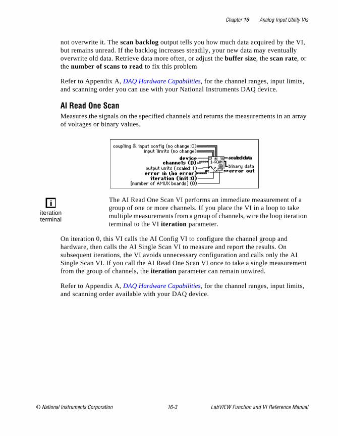
Chapter 16 Analog Input Utility VIs
, lly
n array
a tion
I ment
not overwrite it. The scan backlog output tells you how much data acquired by the VIbut remains unread. If the backlog increases steadily, your new data may eventuaoverwrite old data. Retrieve data more often, or adjust the buffer size, the scan rate, or the number of scans to read to fix this problem
Refer to Appendix A, DAQ Hardware Capabilities, for the channel ranges, input limits, and scanning order you can use with your National Instruments DAQ device.
AI Read One ScanMeasures the signals on the specified channels and returns the measurements in aof voltages or binary values.
The AI Read One Scan VI performs an immediate measurement ofgroup of one or more channels. If you place the VI in a loop to takemultiple measurements from a group of channels, wire the loop iteraterminal to the VI iteration parameter.
On iteration 0, this VI calls the AI Config VI to configure the channel group and hardware, then calls the AI Single Scan VI to measure and report the results. On subsequent iterations, the VI avoids unnecessary configuration and calls only the ASingle Scan VI. If you call the AI Read One Scan VI once to take a single measurefrom the group of channels, the iteration parameter can remain unwired.
Refer to Appendix A, DAQ Hardware Capabilities, for the channel ranges, input limits, and scanning order available with your DAQ device.
iterationterminal
© National Instruments Corporation 16-3 LabVIEW Function and VI Reference Manual
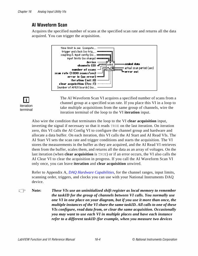
Chapter 16 Analog Input Utility VIs
e data
m a to e
d The VI rieves n the I
AQ
er e e
ly
AI Waveform ScanAcquires the specified number of scans at the specified scan rate and returns all thacquired. You can trigger the acquisition.
The AI Waveform Scan VI acquires a specified number of scans frochannel group at a specified scan rate. If you place this VI in a looptake multiple acquisitions from the same group of channels, wire thiteration terminal of the loop to the VI iteration input.
Also wire the condition that terminates the loop to the VI clear acquisition input, inverting the signal if necessary so that it reads TRUE on the last iteration. On iteration zero, this VI calls the AI Config VI to configure the channel group and hardware anallocate a data buffer. On each iteration, this VI calls the AI Start and AI Read VIs. AI Start VI sets the scan rate and trigger conditions and starts the acquisition. Thestores the measurements in the buffer as they are acquired, and the AI Read VI retthem from the buffer, scales them, and returns all the data as an array of voltages. Olast iteration (when clear acquisition is TRUE) or if an error occurs, the VI also calls theAI Clear VI to clear the acquisition in progress. If you call the AI Waveform Scan Vonly once, you can leave iteration and clear acquisition unwired.
Refer to Appendix A, DAQ Hardware Capabilities, for the channel ranges, input limits, scanning order, triggers, and clocks you can use with your National Instruments Ddevice.
Note: These VIs use an uninitialized shift register as local memory to remembthe taskID for the group of channels between VI calls. You normally useone VI in one place on your diagram, but if you use it more than once, thmultiple instances of the VI share the same taskID. All calls to one of thesVIs configure, read data from, or clear the same acquisition. Occasionalyou may want to use each VI in multiple places and have each instancerefer to a different taskID (for example, when you measure two devices
iterationterminal
LabVIEW Function and VI Reference Manual 16-4 © National Instruments Corporation

Chapter 16 Analog Input Utility VIs
simultaneously). Save a copy of the VI with a new name (for example, AI Waveform Scan R) and make your new VI reentrant.
Note: For all Analog Input Utility VIs, if your program iterates more than 231 - 1
times, do not wire the iteration input to the loop iteration terminal. Instead, set iteration to 0 on the first loop, then to any positive value on all other iterations. The VI reconfigures and restarts if iteration ≤0.
© National Instruments Corporation 16-5 LabVIEW Function and VI Reference Manual

© National Instruments Corporation 17-1 LabVIEW Function and
Chapter
17
Advanced Analog Input VIsog re
Is.
VIs
VI fig
This chapter contains reference descriptions of the Advanced AnalInput VIs. These VIs are the interface to the NI-DAQ software and athe foundation of the Easy, Utility and Intermediate Analog Input V
You can access the Advanced Analog Input palette by choosing Functions»Data Acquisition»Analog Input»Advanced Analog Input. The icon that you must select to access the Advanced Analog Inputis on the bottom row of the Analog Input palette, as shown below.
Advanced Analog Input VI Descriptions
The following Advanced Analog Input VIs are available.
AI Buffer ConfigAllocates memory for LabVIEW to store analog input data until the AI Buffer Read can deliver it to you. LabVIEW refers to the buffer(s) allocated by the AI Buffer ConVI as internal buffers because you do not have direct access to them.
AdvancedAnalog Input VIs
VI Reference Manual

Chapter 17 Advanced Analog Input VIs
re
w at are
Note: (Macintosh) If you are using an NB-A2000 with an NB-DMA2800, buffer size and total scans to acquire are both multiples of 32, and your computerhas block-mode memory, the driver will automatically use block-mode DMA transfers.
Note: When you run the AI Control VI with control code set to 4 (clear), the VI performs the equivalent of running the AI Buffer Config VI with allocation mode set to 1. That is, both VIs deallocate the internal analog input data buffers. However, acquisitions that use DSP or expansion card memory aan exception. The AI Control VI does not deallocate DSP memory whenclearing an acquisition. You must explicitly call the AI Buffer Config VI to deallocate DSP acquisition buffers.
Table 17-1 lists default settings and ranges for the AI Buffer Config VI. The first rogives the values for most devices, and the other rows give the values for devices thexceptions to the rule.
Table 17-1. AI Buffer Config VI Device-Specific Settings and Ranges
DeviceScans per Buffer Number of Buffers Allocation Mode
DefaultSetting Range
DefaultSetting Range
DefaultSetting Range
Most devices 100 0, n≥3 1 0, 1 2 1, 2
Lab-NBLab-LC
100 n≥3 1 0, 1 2 1, 2
AT-DSP2200 100 n≥0 1 n≥0 2 1≤n≤4
NB-A2000EISA-A2000NB-A2100NB-A2150AT-A2150
100 n≥0 1 n≥0 2 1, 2
5102 devices 100 n≥3 1 1 2 1, 2
LabVIEW Function and VI Reference Manual 17-2 © National Instruments Corporation

Chapter 17 Advanced Analog Input VIs
+,
ecause
nel is
can
AI Buffer ReadReturns analog input data from the internal data buffer(s).
Note: When the VI reads from the trigger mark, it does not return data until theacquisition completes for the buffer containing the trigger.
AI Clock ConfigSets the channel and scan clock rates.
Refer to Appendix A, DAQ Hardware Capabilities, for the clocks available with your DAQ device.
For devices that have only a channel clock (Lab-LC, Lab-NB, NB-MIO-16, Lab-PCPCI-1200, PC-LPM-16, DAQCard-500, DAQCard-700, and DAQCard-1200), you cannot set independent channel and scan clock rates. Setting one resets the other bthe channel rate equals scan rate/number of channels to scan.
For devices that have no channel clock (NB-A2000, NB-A2100, NB-A2150, EISA-A2000, AT-A2150, and AT-DSP2200), setting the channel clock produces anerror.
If you specify a value of 0 for the scan clock rate, interval scanning turns off, and chanscanning (or round-robin scanning) proceeds at the channel clock rate. This optionmeaningful only for devices with independent channel and scan clocks.
The clock rate is the rate at which LabVIEW samples data or acquires scans. You express the clock rate three ways—with clock frequency, with clock period, or with timebase source, timebase signal, and timebase divisor. The VI searches these
© National Instruments Corporation 17-3 LabVIEW Function and VI Reference Manual
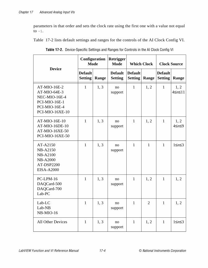
Chapter 17 Advanced Analog Input VIs
equal
VI.
parameters in that order and sets the clock rate using the first one with a value notto –1.
Table 17-2 lists default settings and ranges for the controls of the AI Clock Config
Table 17-2. Device-Specific Settings and Ranges for Controls in the AI Clock Config VI
Device
ConfigurationMode
RetriggerMode Which Clock Clock Source
DefaultSetting Range
DefaultSetting
DefaultSetting Range
DefaultSetting Range
AT-MIO-16E-2AT-MIO-64E-3NEC-MIO-16E-4PCI-MIO-16E-1PCI-MIO-16E-4PCI-MIO-16XE-10
1 1, 3 no support
1 1, 2 1 1, 24≤n≤11
AT-MIO-16E-10AT-MIO-16DE-10AT-MIO-16XE-50PCI-MIO-16XE-50
1 1, 3 no support
1 1, 2 1 1, 24≤n≤9
AT-A2150NB-A2150NB-A2100NB-A2000AT-DSP2200EISA-A2000
1 1, 3 no support
1 1 1 1≤n≤3
PC-LPM-16DAQCard-500DAQCard-700Lab-PC
1 1, 3 no support
1 1, 2 1 1, 2
Lab-LCLab-NBNB-MIO-16
1 1, 3 no support
1 2 1 1, 2
All Other Devices 1 1, 3 no support
1 1, 2 1 1≤n≤3
LabVIEW Function and VI Reference Manual 17-4 © National Instruments Corporation
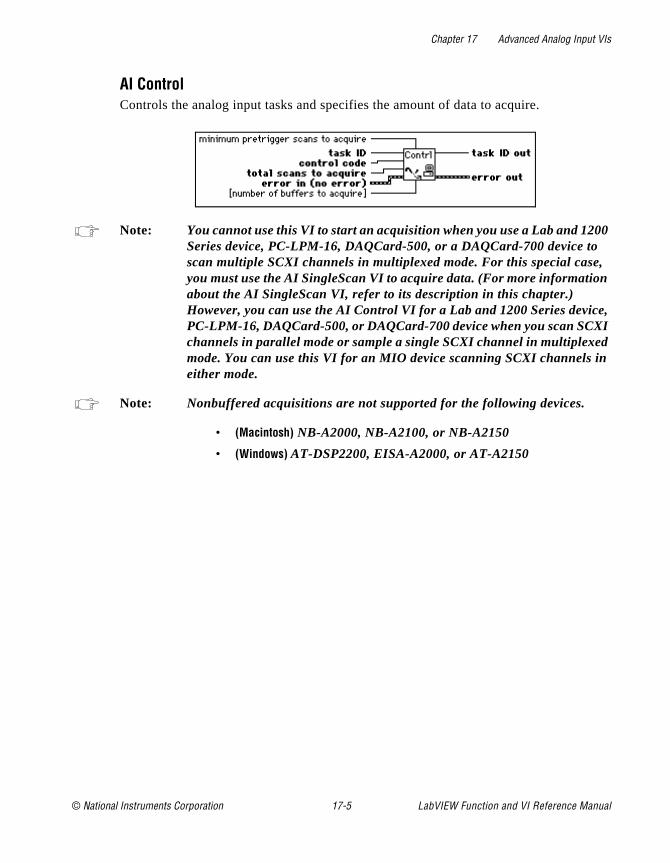
Chapter 17 Advanced Analog Input VIs
0 ,
e, I
d n
AI ControlControls the analog input tasks and specifies the amount of data to acquire.
Note: You cannot use this VI to start an acquisition when you use a Lab and 120Series device, PC-LPM-16, DAQCard-500, or a DAQCard-700 device toscan multiple SCXI channels in multiplexed mode. For this special caseyou must use the AI SingleScan VI to acquire data. (For more informationabout the AI SingleScan VI, refer to its description in this chapter.) However, you can use the AI Control VI for a Lab and 1200 Series devicPC-LPM-16, DAQCard-500, or DAQCard-700 device when you scan SCXchannels in parallel mode or sample a single SCXI channel in multiplexemode. You can use this VI for an MIO device scanning SCXI channels ieither mode.
Note: Nonbuffered acquisitions are not supported for the following devices.
• (Macintosh) NB-A2000, NB-A2100, or NB-A2150
• (Windows) AT-DSP2200, EISA-A2000, or AT-A2150
© National Instruments Corporation 17-5 LabVIEW Function and VI Reference Manual
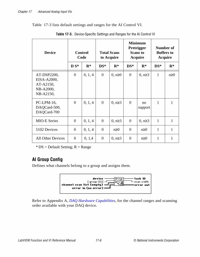
Chapter 17 Advanced Analog Input VIs
g
Table 17-3 lists default settings and ranges for the AI Control VI.
AI Group ConfigDefines what channels belong to a group and assigns them.
Refer to Appendix A, DAQ Hardware Capabilities, for the channel ranges and scanninorder available with your DAQ device.
Table 17-3. Device-Specific Settings and Ranges for the AI Control VI
Device Control Code
Total Scansto Acquire
MinimumPretriggerScans toAcquire
Number ofBuffers toAcquire
D S* R* DS* R* DS* R* DS* R*
AT-DSP2200, EISA-A2000, AT-A2150, NB-A2000, NB-A2150,
0 0, 1, 4 0 0, n≥0 0 0, n≥3 1 n≥0
PC-LPM-16, DAQCard-500, DAQCard-700
0 0, 1, 4 0 0, n≥3 0 no support
1 1
MIO-E Series 0 0, 1, 4 0 0, n≥3 0 0, n≥3 1 1
5102 Devices 0 0, 1, 4 0 n≥0 0 n≥0 1 1
All Other Devices 0 0, 1,4 0 0, n≥3 0 n≥0 1 1
* DS = Default Setting; R = Range
LabVIEW Function and VI Reference Manual 17-6 © National Instruments Corporation

Chapter 17 Advanced Analog Input VIs
of vices
g
e
Table 17-4 lists default settings and ranges for the AI Group Config VI. The first rowthe table gives the values for most devices, and the other rows give the values for dethat are exceptions to the rule.
Note: The Lab-LC, Lab-NB, Lab-PC+, PCI-1200, PC-LPM-16, DAQCard-500, DAQCard-700, and DAQCard-1200 must scan channel lists containing multiple channels from channel n (n ≥ 0) to channel 0 in sequential order, including all channels between n and 0. The NB-A2000, NB-A2150, EISA-A2000, and AT-A2150 allow only the following scan lists: (0), (1), (2), (3), (0, 1), (2, 3), and (0, 1, 2, 3). The NB-A2100 allows the followinscan lists: (0), (1), (0, 1), and (1, 0).
The channel scan list range shown above is for single-ended mode. Pleasrefer to Appendix A, DAQ Hardware Capabilities, to determine the valid range for channels in differential mode.
Table 17-4. Device-Specific Settings and Ranges for the AI Group Config VI
DeviceGroup Channel Scan List
DefaultSetting Range Default Setting Range
Most Windows Devices 0 0≤n≤15 all channels 0≤n≤15
Most Macintosh Devices 0 0≤n≤15 all channels 0≤n≤15
AT-MIO-64F-5AT-MIO-64E-3
0 0≤n≤15 all channels 0≤n≤63
AT-A2150, EISA-A2000 0 0≤n≤15 all channels 0≤n≤3
AT-DSP2200 0 0≤n≤15 all channels 0, 1
Lab-PC+, PCI-1200, DAQCard-1200
0 0≤n≤15 all channels 0≤n≤7
Lab-LC, Lab-NB 0 0≤n≤15 all channels 0≤n≤7
NB-A2000, NB-A2150 0 0≤n≤15 all channels 0≤n≤3
NB-A2100 0 0≤n≤15 all channels 0, 1
5102 Devices 0 0≤n≤15 all channels 0, 1
© National Instruments Corporation 17-7 LabVIEW Function and VI Reference Manual

Chapter 17 Advanced Analog Input VIs
rder, trary. r of
The
p.
ake h
nnels.
sted d in
1 of
SCXI modules in multiplexed mode must scan channels in ascending consecutive ostarting from any channel on the module. The module order you specify can be arbiSCXI modules in parallel mode must follow the DAQ device restrictions on the ordechannel scan lists. Refer to the Channel, Port, and Counter Addressing section of Chapter 3, Basic LabVIEW Data Acquisition Concepts, in the LabVIEW Data Acquisition Basics Manual for information about SCXI channel string syntax.
AI Hardware ConfigConfigures either the upper and lower input limits or the range, polarity, and gain. AI Hardware Config VI also configures the coupling, input mode, and number of AMUX-64T devices. The configuration utility determines the default settings for theparameters of this VI.
You can use this VI to retrieve the current settings by wiring taskID only or by wiring both taskID and channel list. If channel list is empty, the VI configures channels on aper group basis. This means that the configuration applies to all the channels in thegroup. When you specify one or more channels in channel list, the VI configures channels on a per channel basis. This means that the configuration applies only to thechannels you specify. This VI always returns the current settings for the entire grou
When the configuration is on a per channel basis, channel list can contain one or more channels. The channels in channel list must belong to the group named by taskID. You specify channels the same way you specify them for the AI Group Config VI. If you tmultiple samples of a channel within a scan and you want to change the hardwareconfiguration for that channel at each sample, you must supply the settings for eacinstance of the channel within the scan. If an element of channel list specifies more than one channel, the corresponding element of the other arrays applies to all those cha
The VI applies the values contained in the configuration arrays (upper input limits, lower input limits , coupling, range, polarity , gain, and mode) to the channels in the group (if you configured on a per group basis) or the channels in channel list (if you configured on a per channel basis) in the following way. The VI applies the values lifirst in the arrays (at index 0) to the first channel in the group or the channel(s) listeindex 0 of channel list. The VI applies the values listed second in the configuration arrays (at index 1) to the second channel in the group or channel(s) listed in indexchannel list. The VI continues to apply the values in this fashion until the arrays are
LabVIEW Function and VI Reference Manual 17-8 © National Instruments Corporation
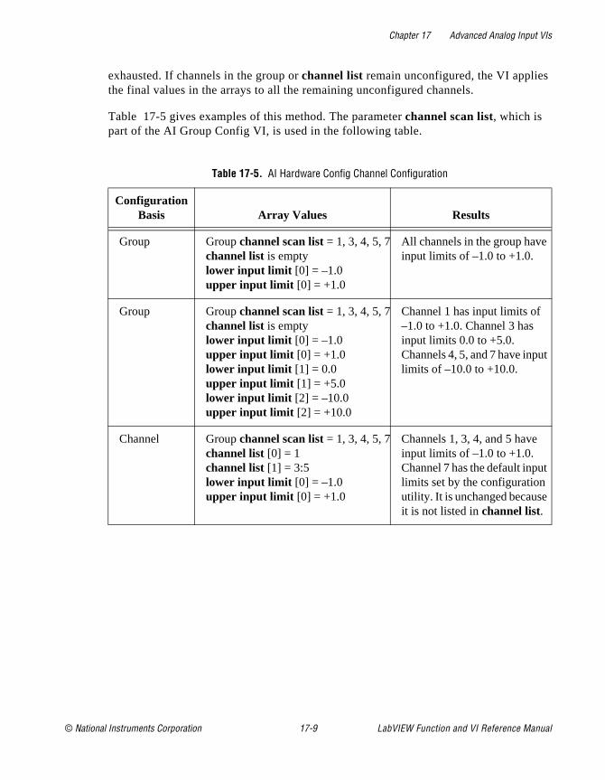
Chapter 17 Advanced Analog Input VIs
exhausted. If channels in the group or channel list remain unconfigured, the VI appliesthe final values in the arrays to all the remaining unconfigured channels.
Table 17-5 gives examples of this method. The parameter channel scan list, which is part of the AI Group Config VI, is used in the following table.
Table 17-5. AI Hardware Config Channel Configuration
ConfigurationBasis Array Values Results
Group Group channel scan list = 1, 3, 4, 5, 7channel list is emptylower input limit [0] = –1.0upper input limit [0] = +1.0
All channels in the group have input limits of –1.0 to +1.0.
Group Group channel scan list = 1, 3, 4, 5, 7channel list is emptylower input limit [0] = –1.0upper input limit [0] = +1.0lower input limit [1] = 0.0upper input limit [1] = +5.0lower input limit [2] = –10.0upper input limit [2] = +10.0
Channel 1 has input limits of –1.0 to +1.0. Channel 3 has input limits 0.0 to +5.0. Channels 4, 5, and 7 have inputlimits of –10.0 to +10.0.
Channel Group channel scan list = 1, 3, 4, 5, 7channel list [0] = 1channel list [1] = 3:5lower input limit [0] = –1.0upper input limit [0] = +1.0
Channels 1, 3, 4, and 5 have input limits of –1.0 to +1.0. Channel 7 has the default inputlimits set by the configuration utility. It is unchanged becauseit is not listed in channel list.
© National Instruments Corporation 17-9 LabVIEW Function and VI Reference Manual

Chapter 17 Advanced Analog Input VIs
ses
rray.
d
The range, polarity , and gain determine the lower and upper input limits. When you wire valid input limit arrays (that is, arrays of lengths greater than zero) the VI choosuitable input ranges, polarities, and gains to achieve these input limits . The VI ignores the range, polarity , and gain arrays.
If you do not wire the input limit arrays, the VI checks range, polarity , and gain. Where the VI finds an array, it sets the corresponding input property to the values in the aWhere the VI does not find an array, it leaves the corresponding input property unchanged.
For some devices and SCXI modules, onboard jumpers set range, polarity , and/or gain. LabVIEW does not alter the settings of jumpered parameters when you specify input limits . If LabVIEW cannot achieve the desired input limits using the current jumpered settings, it returns a warning.
To override the current jumper values, you must call the AI Hardware Config VI anspecify range, polarity , and/or gain explicitly. The configuration utility determines theinitial setting for these parameters (the default value is the factory jumper setting).
If a pair of input limits values are both 0, the VI does not change the input limits .
Channel Group channel scan list = 1, 3, 4, 5, 7channel list [0] = 1channel list [1] = 3:5lower input limit [0] = –1.0upper input limit [0] = +1.0lower input limit [1] = 0.0upper input limit [1] = +5.0
Channel 1 has input limits of –1.0 to +1.0. Channels 3, 4, and 5 have input limits of 0.0 to +5.0. Channel 7 has the default input limits set by the configuration utility.
Group Group channel scan list = 0, 1, 0, 1channel list is emptylower input limit [0] = –1.0upper input limit [0] = +1.0lower input limit [1] = –1.0upper input limit [1] = +1.0lower input limit [2] = –10.0upper input limit [2] = +10.0lower input limit [3] = –10.0upper input limit [3] = +10.0
Channels 0 and 1 have input limits of –1.0 to +1.0 the first time they are sampled and input limits of –10.0 to +10.0 the second time they are sampled.
Table 17-5. AI Hardware Config Channel Configuration (Continued)
ConfigurationBasis Array Values Results
LabVIEW Function and VI Reference Manual 17-10 © National Instruments Corporation

Chapter 17 Advanced Analog Input VIs
and nels e
nd e
gain
f three
Q
ice evice
le.
lly,
VI. his lues to the
SCXI channel hardware configurations are actually a combination of SCXI moduleDAQ device settings and require special considerations. The way you specify chanindicates whether LabVIEW alters the SCXI module settings and/or the DAQ devicsettings. The input limits parameter always applies to the entire acquisition path.
When you configure on a per group basis, LabVIEW may alter both SCXI module aDAQ device settings. In this case, gain applies to the entire path and is the product of thSCXI channel gain and acquisition device channel gain. LabVIEW sets the highestneeded on the SCXI module, then adds DAQ device gain if necessary.
When configuration is on a per channel basis, you can specify the channels in one oways. The first way is to specify the entire path, as in the following example.
OB0!SC1!MD1!CH0:7
(Windows) Also, you can specify the path using channel names configured in the DAChannel Wizard, as in the following example.
temperature
If you use either of these methods, LabVIEW can alter both SCXI and DAQ devicesettings, and gain applies to the product of the SCXI channel gain and the DAQ devgain. LabVIEW sets the highest gain needed on the SCXI module, then adds DAQ dgain if necessary.
The second method is to specify the SCXI channel only, as in the following examp
SC1!MD1!CH0:7
This specification indicates that LabVIEW should alter SCXI settings only. Additionagain applies only to the SCXI channel.
The third way is to specify the acquisition device channel only, as in the following example.
OB0
In this case, LabVIEW alters only DAQ device settings. The gain parameter applies to the onboard channel only.
Refer to Appendix A, DAQ Hardware Capabilities, for the channel ranges, input limits, and scanning order available with your DAQ device.
Tables 17-6 through 17-9 list default settings and ranges for the AI Hardware ConfigA tilde (~) indicates that the parameter is configurable on a per group basis only. Tmeans you cannot configure it by channel. The first row of these tables give the vafor most devices, and the other rows give the values for devices that are exceptions
© National Instruments Corporation 17-11 LabVIEW Function and VI Reference Manual
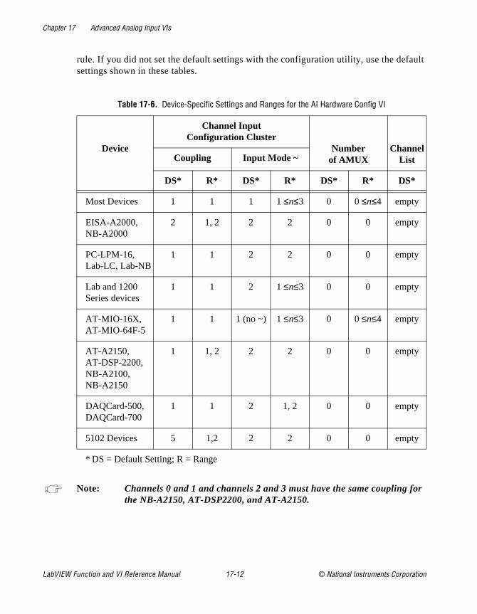
Chapter 17 Advanced Analog Input VIs
ault
or
rule. If you did not set the default settings with the configuration utility, use the defsettings shown in these tables.
Note: Channels 0 and 1 and channels 2 and 3 must have the same coupling fthe NB-A2150, AT-DSP2200, and AT-A2150.
Table 17-6. Device-Specific Settings and Ranges for the AI Hardware Config VI
Device
Channel InputConfiguration Cluster
Number of AMUX
Channel ListCoupling Input Mode ~
DS* R* DS* R* DS* R* DS*
Most Devices 1 1 1 1 ≤n≤3 0 0 ≤n≤4 empty
EISA-A2000, NB-A2000
2 1, 2 2 2 0 0 empty
PC-LPM-16, Lab-LC, Lab-NB
1 1 2 2 0 0 empty
Lab and 1200 Series devices
1 1 2 1 ≤n≤3 0 0 empty
AT-MIO-16X, AT-MIO-64F-5
1 1 1 (no ~) 1 ≤n≤3 0 0 ≤n≤4 empty
AT-A2150, AT-DSP-2200, NB-A2100, NB-A2150
1 1, 2 2 2 0 0 empty
DAQCard-500, DAQCard-700
1 1 2 1, 2 0 0 empty
5102 Devices 5 1,2 2 2 0 0 empty
* DS = Default Setting; R = Range
LabVIEW Function and VI Reference Manual 17-12 © National Instruments Corporation
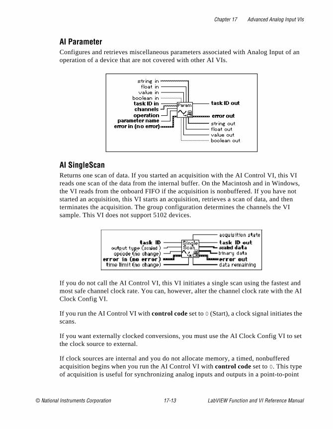
Chapter 17 Advanced Analog Input VIs
f an
I ws,
ot en I
nd e AI
set
int
AI ParameterConfigures and retrieves miscellaneous parameters associated with Analog Input ooperation of a device that are not covered with other AI VIs.
AI SingleScan Returns one scan of data. If you started an acquisition with the AI Control VI, this Vreads one scan of the data from the internal buffer. On the Macintosh and in Windothe VI reads from the onboard FIFO if the acquisition is nonbuffered. If you have nstarted an acquisition, this VI starts an acquisition, retrieves a scan of data, and thterminates the acquisition. The group configuration determines the channels the Vsample. This VI does not support 5102 devices.
If you do not call the AI Control VI, this VI initiates a single scan using the fastest amost safe channel clock rate. You can, however, alter the channel clock rate with thClock Config VI.
If you run the AI Control VI with control code set to 0 (Start), a clock signal initiates thescans.
If you want externally clocked conversions, you must use the AI Clock Config VI to the clock source to external.
If clock sources are internal and you do not allocate memory, a timed, nonbufferedacquisition begins when you run the AI Control VI with control code set to 0. This type of acquisition is useful for synchronizing analog inputs and outputs in a point-to-po
© National Instruments Corporation 17-13 LabVIEW Function and VI Reference Manual
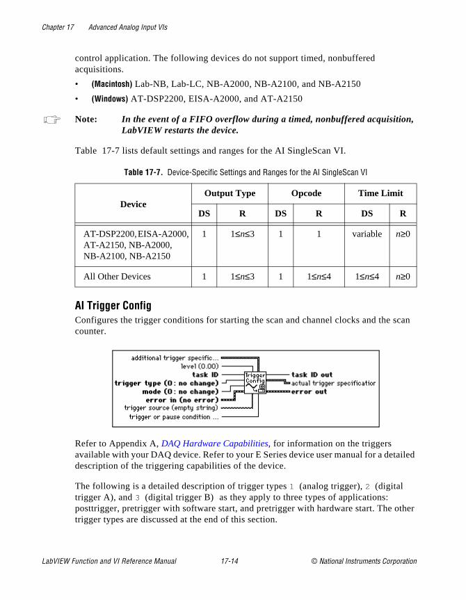
Chapter 17 Advanced Analog Input VIs
scan
ailed
ther
control application. The following devices do not support timed, nonbuffered acquisitions.
• (Macintosh) Lab-NB, Lab-LC, NB-A2000, NB-A2100, and NB-A2150
• (Windows) AT-DSP2200, EISA-A2000, and AT-A2150
Note: In the event of a FIFO overflow during a timed, nonbuffered acquisition,LabVIEW restarts the device.
Table 17-7 lists default settings and ranges for the AI SingleScan VI.
AI Trigger ConfigConfigures the trigger conditions for starting the scan and channel clocks and the counter.
Refer to Appendix A, DAQ Hardware Capabilities, for information on the triggers available with your DAQ device. Refer to your E Series device user manual for a detdescription of the triggering capabilities of the device.
The following is a detailed description of trigger types 1 (analog trigger), 2 (digital trigger A), and 3 (digital trigger B) as they apply to three types of applications: posttrigger, pretrigger with software start, and pretrigger with hardware start. The otrigger types are discussed at the end of this section.
Table 17-7. Device-Specific Settings and Ranges for the AI SingleScan VI
DeviceOutput Type Opcode Time Limit
DS R DS R DS R
AT-DSP2200, EISA-A2000, AT-A2150, NB-A2000, NB-A2100, NB-A2150
1 1≤n≤3 1 1 variable n≥0
All Other Devices 1 1≤n≤3 1 1≤n≤4 1≤n≤4 n≥0
LabVIEW Function and VI Reference Manual 17-14 © National Instruments Corporation
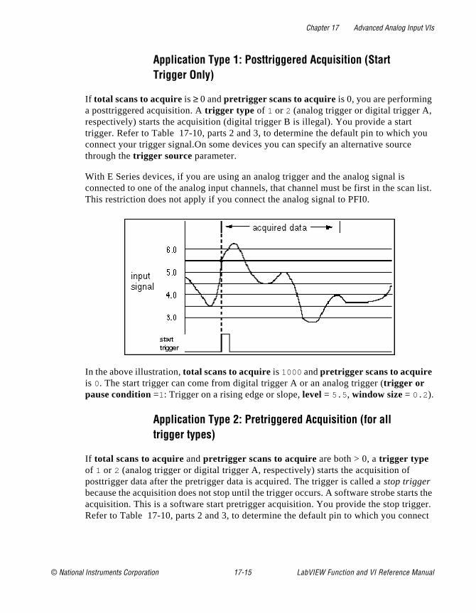
Chapter 17 Advanced Analog Input VIs
you
n list.
rts the ger. nect
Application Type 1: Posttriggered Acquisition (Start Trigger Only)
If total scans to acquire is ≥ 0 and pretrigger scans to acquire is 0, you are performing a posttriggered acquisition. A trigger type of 1 or 2 (analog trigger or digital trigger A, respectively) starts the acquisition (digital trigger B is illegal). You provide a start trigger. Refer to Table 17-10, parts 2 and 3, to determine the default pin to which connect your trigger signal.On some devices you can specify an alternative sourcethrough the trigger source parameter.
With E Series devices, if you are using an analog trigger and the analog signal is connected to one of the analog input channels, that channel must be first in the scaThis restriction does not apply if you connect the analog signal to PFI0.
In the above illustration, total scans to acquire is 1000 and pretrigger scans to acquire is 0. The start trigger can come from digital trigger A or an analog trigger (trigger or pause condition =1: Trigger on a rising edge or slope, level = 5.5 , window size = 0.2 ).
Application Type 2: Pretriggered Acquisition (for all trigger types)
If total scans to acquire and pretrigger scans to acquire are both > 0, a trigger type of 1 or 2 (analog trigger or digital trigger A, respectively) starts the acquisition of posttrigger data after the pretrigger data is acquired. The trigger is called a stop trigger because the acquisition does not stop until the trigger occurs. A software strobe staacquisition. This is a software start pretrigger acquisition. You provide the stop trigRefer to Table 17-10, parts 2 and 3, to determine the default pin to which you con
© National Instruments Corporation 17-15 LabVIEW Function and VI Reference Manual

Chapter 17 Advanced Analog Input VIs
h the
scan t the
ger
t call nal gered
your trigger signal. On some devices, you can specify an alternative source througtrigger source parameter.
In the above illustration, total scans to acquire is 1000 and pretrigger scans to acquire is 900 . The stop trigger can come from digital trigger A or an analog trigger (trigger or pause condition = 1: Trigger on rising edge or slope, level = 3.7 , window size = 0.5 ).
With E Series devices, if you are using an analog trigger and the analog signal is connected to an analog input channel, that channel must be the only channel in thelist (no multiple channel scan allowed). This restriction does not apply if you connecanalog signal to PFI0.
Application Type 3: Pretriggered Acquisition (Start and Stop Trigger)
Application Type 3 is used infrequently. Unless you plan to provide both a start trigand a stop trigger, skip this section.
On MIO devices, you can enable both the start trigger and the stop trigger. (You musthe AI Trigger Config VI twice to do this.) In this case, a digital or analog trigger sigstarts the acquisition rather than a software strobe. This is a hardware start pretrigacquisition. You provide both the start trigger (as described in Application Type 1) and the stop trigger (as described in Application Type 2). Refer to Table 17-10, parts 2 and 3, to
LabVIEW Function and VI Reference Manual 17-16 © National Instruments Corporation
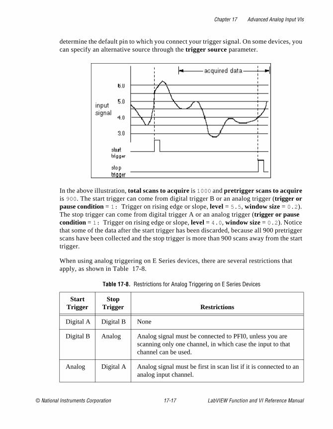
Chapter 17 Advanced Analog Input VIs
, you
trigger e start
at
n
determine the default pin to which you connect your trigger signal. On some devicescan specify an alternative source through the trigger source parameter.
In the above illustration, total scans to acquire is 1000 and pretrigger scans to acquire is 900 . The start trigger can come from digital trigger B or an analog trigger (trigger or pause condition = 1: Trigger on rising edge or slope, level = 5.5 , window size = 0.2 ). The stop trigger can come from digital trigger A or an analog trigger (trigger or pause condition = 1: Trigger on rising edge or slope, level = 4.0 , window size = 0.2 ). Notice that some of the data after the start trigger has been discarded, because all 900 prescans have been collected and the stop trigger is more than 900 scans away from thtrigger.
When using analog triggering on E Series devices, there are several restrictions thapply, as shown in Table 17-8.
Table 17-8. Restrictions for Analog Triggering on E Series Devices
StartTrigger
StopTrigger Restrictions
Digital A Digital B None
Digital B Analog Analog signal must be connected to PFI0, unless you are scanning only one channel, in which case the input to that channel can be used.
Analog Digital A Analog signal must be first in scan list if it is connected to aanalog input channel.
© National Instruments Corporation 17-17 LabVIEW Function and VI Reference Manual
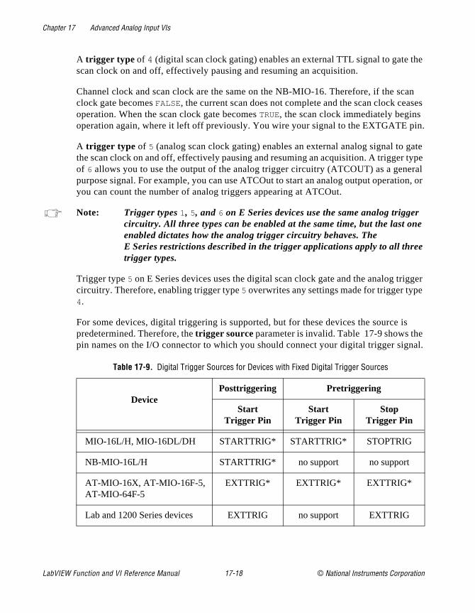
Chapter 17 Advanced Analog Input VIs
the
an ases in.
gate type eral on, or
r ne
e
igger e
is e nal.
A trigger type of 4 (digital scan clock gating) enables an external TTL signal to gate scan clock on and off, effectively pausing and resuming an acquisition.
Channel clock and scan clock are the same on the NB-MIO-16. Therefore, if the scclock gate becomes FALSE, the current scan does not complete and the scan clock ceoperation. When the scan clock gate becomes TRUE, the scan clock immediately beginsoperation again, where it left off previously. You wire your signal to the EXTGATE p
A trigger type of 5 (analog scan clock gating) enables an external analog signal to the scan clock on and off, effectively pausing and resuming an acquisition. A triggerof 6 allows you to use the output of the analog trigger circuitry (ATCOUT) as a genpurpose signal. For example, you can use ATCOut to start an analog output operatiyou can count the number of analog triggers appearing at ATCOut.
Note: Trigger types 1, 5, and 6 on E Series devices use the same analog triggecircuitry. All three types can be enabled at the same time, but the last oenabled dictates how the analog trigger circuitry behaves. The E Series restrictions described in the trigger applications apply to all thretrigger types.
Trigger type 5 on E Series devices uses the digital scan clock gate and the analog trcircuitry. Therefore, enabling trigger type 5 overwrites any settings made for trigger typ4.
For some devices, digital triggering is supported, but for these devices the source predetermined. Therefore, the trigger source parameter is invalid. Table 17-9 shows thpin names on the I/O connector to which you should connect your digital trigger sig
Table 17-9. Digital Trigger Sources for Devices with Fixed Digital Trigger Sources
DevicePosttriggering Pretriggering
StartTrigger Pin
StartTrigger Pin
StopTrigger Pin
MIO-16L/H, MIO-16DL/DH STARTTRIG* STARTTRIG* STOPTRIG
NB-MIO-16L/H STARTTRIG* no support no support
AT-MIO-16X, AT-MIO-16F-5, AT-MIO-64F-5
EXTTRIG* EXTTRIG* EXTTRIG*
Lab and 1200 Series devices EXTTRIG no support EXTTRIG
LabVIEW Function and VI Reference Manual 17-18 © National Instruments Corporation

Chapter 17 Advanced Analog Input VIs
first lues
ore
Table 17-10 lists the default settings and ranges for the AI Trigger Config VI. The row of each table gives the values for most devices, and the other rows give the vafor devices that are exceptions to the rule.
PC-LPM-16, DAQCard-500, DAQCard-700
no support no support no support
AT-DSP2200, EISA-A2000, AT-A2150, NB-A2000, NB-A2100, NB-A2150
EXTTRIG* no support EXTTRIG*
* On the AT-MIO-16X, AT-MIO-16F-5, and AT-MIO-64F-5, the same pin is used for both the start trigger and the stop trigger. Refer to your hardware user manual for mdetails
Table 17-10. Device-Specific Settings and Ranges for the AI Trigger Config VI—Part 1
DeviceTrigger
Type Mode
Trigger orPause
Condition Level
DS* R* DS* R* DS* R* DS* R*
Most Devices 2 2, 3 1 1≤n≤ 3 no support no support
AT-MIO-16E-10, AT-MIO-16DE-10,AT-MIO-16XE-50,PCI-MIO-16XE-50
2 2≤n≤4 1 1≤n≤ 3 1 1, 2, 7, 8
no support
AT-MIO-16E-2, AT-MIO-64E-3, NEC-MIO-16E-4
2 1≤n≤6 1 1≤n ≤3 1 1≤n≤8 0 –10≤n≤10
Lab and 1200 Series devices
2 2 1 1≤n≤ 3 no support
no support
Table 17-9. Digital Trigger Sources for Devices with Fixed Digital Trigger Sources (Continued)
DevicePosttriggering Pretriggering
StartTrigger Pin
StartTrigger Pin
StopTrigger Pin
© National Instruments Corporation 17-19 LabVIEW Function and VI Reference Manual
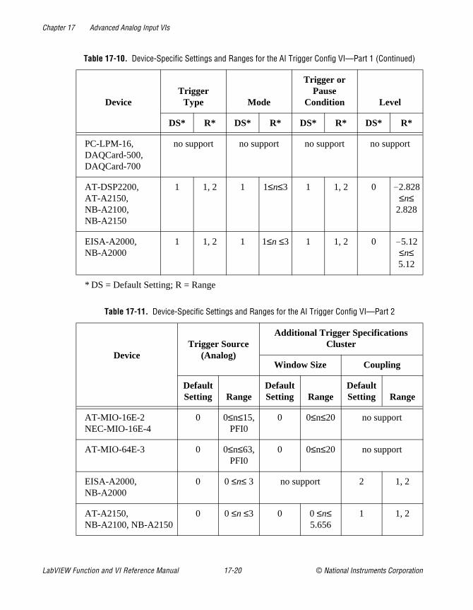
Chapter 17 Advanced Analog Input VIs
PC-LPM-16, DAQCard-500, DAQCard-700
no support no support no support no support
AT-DSP2200, AT-A2150, NB-A2100, NB-A2150
1 1, 2 1 1≤n≤3 1 1, 2 0 –2.828≤n≤
2.828
EISA-A2000, NB-A2000
1 1, 2 1 1≤n ≤3 1 1, 2 0 –5.12≤n≤5.12
* DS = Default Setting; R = Range
Table 17-11. Device-Specific Settings and Ranges for the AI Trigger Config VI—Part 2
DeviceTrigger Source
(Analog)
Additional Trigger SpecificationsCluster
Window Size Coupling
DefaultSetting Range
DefaultSetting Range
DefaultSetting Range
AT-MIO-16E-2NEC-MIO-16E-4
0 0≤n≤15,PFI0
0 0≤n≤20 no support
AT-MIO-64E-3 0 0≤n≤63,PFI0
0 0≤n≤20 no support
EISA-A2000, NB-A2000
0 0 ≤n≤ 3 no support 2 1, 2
AT-A2150, NB-A2100, NB-A2150
0 0 ≤n ≤3 0 0 ≤n≤ 5.656
1 1, 2
Table 17-10. Device-Specific Settings and Ranges for the AI Trigger Config VI—Part 1 (Continued)
DeviceTrigger
Type Mode
Trigger orPause
Condition Level
DS* R* DS* R* DS* R* DS* R*
LabVIEW Function and VI Reference Manual 17-20 © National Instruments Corporation
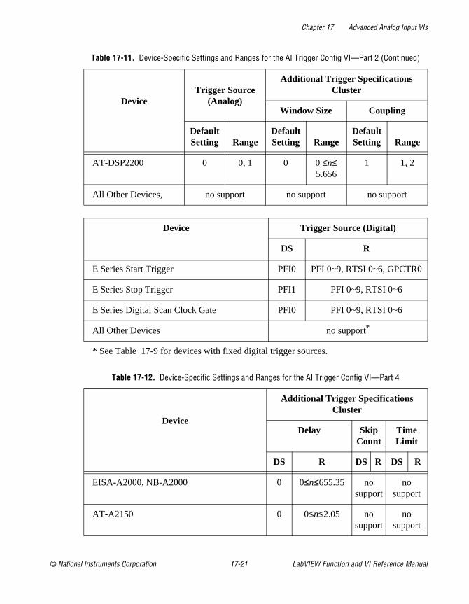
Chapter 17 Advanced Analog Input VIs
AT-DSP2200 0 0, 1 0 0 ≤n≤ 5.656
1 1, 2
All Other Devices, no support no support no support
Device Trigger Source (Digital)
DS R
E Series Start Trigger PFI0 PFI 0~9, RTSI 0~6, GPCTR0
E Series Stop Trigger PFI1 PFI 0~9, RTSI 0~6
E Series Digital Scan Clock Gate PFI0 PFI 0~9, RTSI 0~6
All Other Devices no support*
* See Table 17-9 for devices with fixed digital trigger sources.
Table 17-12. Device-Specific Settings and Ranges for the AI Trigger Config VI—Part 4
Device
Additional Trigger Specifications Cluster
Delay Skip Count
Time Limit
DS R DS R DS R
EISA-A2000, NB-A2000 0 0≤n≤655.35 no support
no support
AT-A2150 0 0≤n≤2.05 no support
no support
Table 17-11. Device-Specific Settings and Ranges for the AI Trigger Config VI—Part 2 (Continued)
DeviceTrigger Source
(Analog)
Additional Trigger SpecificationsCluster
Window Size Coupling
DefaultSetting Range
DefaultSetting Range
DefaultSetting Range
© National Instruments Corporation 17-21 LabVIEW Function and VI Reference Manual
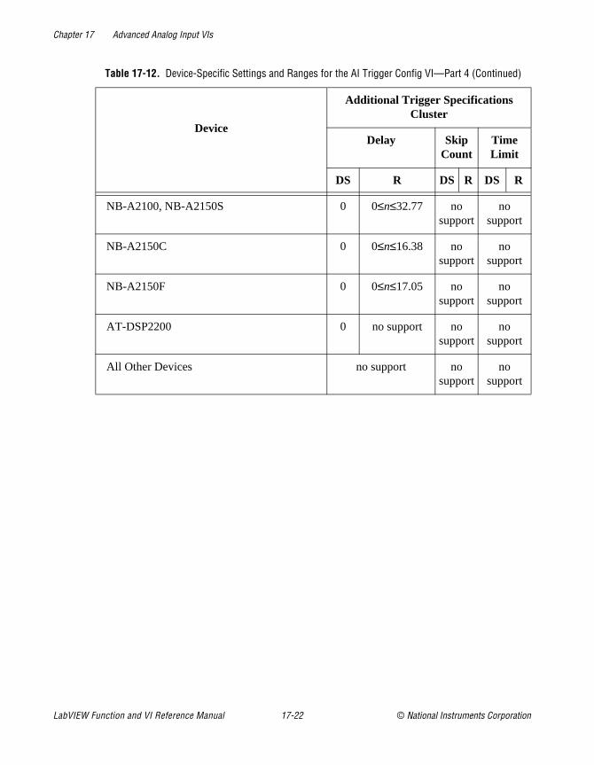
Chapter 17 Advanced Analog Input VIs
NB-A2100, NB-A2150S 0 0≤n≤32.77 no support
no support
NB-A2150C 0 0≤n≤16.38 no support
no support
NB-A2150F 0 0≤n≤17.05 no support
no support
AT-DSP2200 0 no support no support
no support
All Other Devices no support no support
no support
Table 17-12. Device-Specific Settings and Ranges for the AI Trigger Config VI—Part 4 (Continued)
Device
Additional Trigger Specifications Cluster
Delay Skip Count
Time Limit
DS R DS R DS R
LabVIEW Function and VI Reference Manual 17-22 © National Instruments Corporation
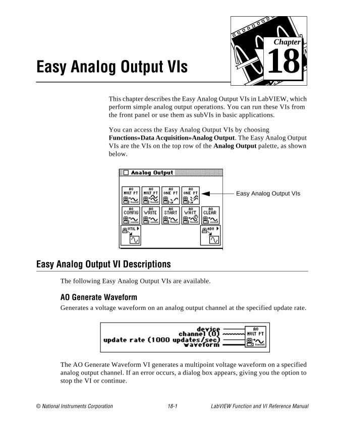
© National Instruments Corporation 18-1 LabVIEW Function and
Chapter
18
Easy Analog Output VIsch m
e rate.
ified on to
This chapter describes the Easy Analog Output VIs in LabVIEW, whiperform simple analog output operations. You can run these VIs frothe front panel or use them as subVIs in basic applications.
You can access the Easy Analog Output VIs by choosing Functions»Data Acquisition»Analog Output. The Easy Analog Output VIs are the VIs on the top row of the Analog Output palette, as shown below.
Easy Analog Output VI Descriptions
The following Easy Analog Output VIs are available.
AO Generate WaveformGenerates a voltage waveform on an analog output channel at the specified updat
The AO Generate Waveform VI generates a multipoint voltage waveform on a specanalog output channel. If an error occurs, a dialog box appears, giving you the optistop the VI or continue.
Easy Analog Output VIs
VI Reference Manual

Chapter 18 Easy Analog Output VIs
the
nue.
e
error
ltage I or
e
AO Generate WaveformsGenerates multiple voltage waveforms on the specified analog output channels at specified update rate.
If an error occurs, a dialog box appears, giving you the option to stop the VI or conti
Refer to Appendix A, DAQ Hardware Capabilities, for the channel numbers you can uswith your DAQ device.
AO Update ChannelWrites a specified voltage value to an analog output channel.
The AO Update Channel VI writes a single update to an analog output channel. If anoccurs, a dialog box appears, giving you the option to stop the VI or continue.
Refer to Appendix A, DAQ Hardware Capabilities, for the channel numbers and outputlimits available with your DAQ device.
AO Update ChannelsWrites voltage values to each of the specified analog output channels.
The AO Update Channels VI updates multiple analog output channels with single vovalues. If an error occurs, a dialog box appears, giving you the option to stop the Vcontinue.
Refer to Appendix A, DAQ Hardware Capabilities, for the channel numbers you can uswith your DAQ device.
LabVIEW Function and VI Reference Manual 18-2 © National Instruments Corporation
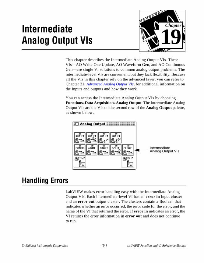
© National Instruments Corporation 19-1 LabVIEW Function and
Chapter
19
Intermediate Analog Output VIss he se to
the
This chapter describes the Intermediate Analog Output VIs. These VIs—AO Write One Update, AO Waveform Gen, and AO ContinuouGen—are single VI solutions to common analog output problems. Tintermediate-level VIs are convenient, but they lack flexibility. Becauall the VIs in this chapter rely on the advanced layer, you can referChapter 21, Advanced Analog Output VIs, for additional information on the inputs and outputs and how they work.
You can access the Intermediate Analog Output VIs by choosing Functions»Data Acquisition»Analog Output. The Intermediate Analog Output VIs are the VIs on the second row of the Analog Output palette, as shown below.
Handling ErrorsLabVIEW makes error handling easy with the Intermediate Analog Output VIs. Each intermediate-level VI has an error in input cluster and an error out output cluster. The clusters contain a Boolean thatindicates whether an error occurred, the error code for the error, andname of the VI that returned the error. If error in indicates an error, the VI returns the error information in error out and does not continue to run.
IntermediateAnalog Output VIs
VI Reference Manual

Chapter 19 Intermediate Analog Output VIs
e
r
ut
Note: The AO Clear VI is an exception to this rule—this VI always clears the acquisition regardless of whether error in indicates an error.
When you use any of the Intermediate Analog Output VIs in a WhilLoop, you should stop the loop if the status in the error out cluster reads TRUE. If you wire the error cluster to the General Error HandleVI, the VI deciphers the error information and describes the error toyou.
The General Error Handler VI is in Functions»Time and Dialog in LabVIEW. For more information on this VI, refer to your LabVIEW User Manual.
Analog Output VI Descriptions
The following Analog Output VIs are available.
AO ClearClears the analog output task associated with taskID in .
The AO Clear VI always clears the generation regardless of whether error in indicates an error.
AO ConfigConfigures the channel list and output limits, and allocates a buffer for analog outpoperation.
Refer to Appendix A, DAQ Hardware Capabilities, for the channel ranges and output limits available with your DAQ device.
LabVIEW Function and VI Reference Manual 19-2 © National Instruments Corporation
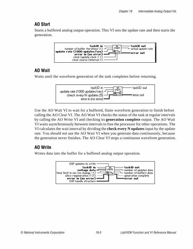
Chapter 19 Intermediate Analog Output VIs
rts the
re vals
. The
ause ation.
AO StartStarts a buffered analog output operation. This VI sets the update rate and then stageneration.
AO WaitWaits until the waveform generation of the task completes before returning.
Use the AO Wait VI to wait for a buffered, finite waveform generation to finish befocalling the AO Clear VI. The AO Wait VI checks the status of the task at regular interby calling the AO Write VI and checking its generation complete output. The AO Wait VI waits asynchronously between intervals to free the processor for other operationsVI calculates the wait interval by dividing the check every N updates input by the update rate. You should not use the AO Wait VI when you generate data continuously, becthe generation never finishes. The AO Clear VI stops a continuous waveform gener
AO WriteWrites data into the buffer for a buffered analog output operation.
© National Instruments Corporation 19-3 LabVIEW Function and VI Reference Manual
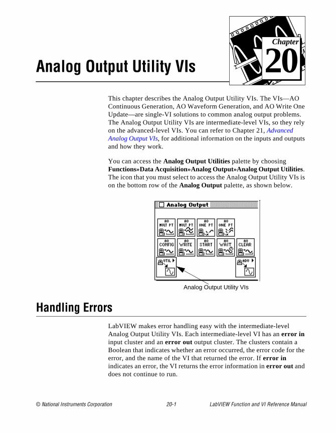
© National Instruments Corporation 20-1 LabVIEW Function and
Chapter
20
Analog Output Utility VIsne s. ly
s
is
the
This chapter describes the Analog Output Utility VIs. The VIs—AO Continuous Generation, AO Waveform Generation, and AO Write OUpdate—are single-VI solutions to common analog output problemThe Analog Output Utility VIs are intermediate-level VIs, so they reon the advanced-level VIs. You can refer to Chapter 21, Advanced Analog Output VIs, for additional information on the inputs and outputand how they work.
You can access the Analog Output Utilities palette by choosing Functions»Data Acquisition»Analog Output»Analog Output Utilities. The icon that you must select to access the Analog Output Utility VIson the bottom row of the Analog Output palette, as shown below.
Handling ErrorsLabVIEW makes error handling easy with the intermediate-level Analog Output Utility VIs. Each intermediate-level VI has an error in input cluster and an error out output cluster. The clusters contain a Boolean that indicates whether an error occurred, the error code forerror, and the name of the VI that returned the error. If error in indicates an error, the VI returns the error information in error out and does not continue to run.
Analog Output Utility VIs
VI Reference Manual
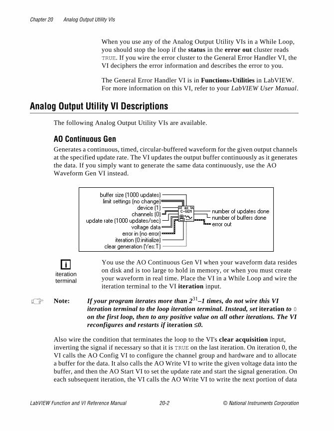
Chapter 20 Analog Output Utility VIs
,
e
nels erates
es e e
I
ate
the n. On ata
When you use any of the Analog Output Utility VIs in a While Loopyou should stop the loop if the status in the error out cluster reads TRUE. If you wire the error cluster to the General Error Handler VI, thVI deciphers the error information and describes the error to you.
The General Error Handler VI is in Functions»Utilities in LabVIEW. For more information on this VI, refer to your LabVIEW User Manual.
Analog Output Utility VI Descriptions
The following Analog Output Utility VIs are available.
AO Continuous GenGenerates a continuous, timed, circular-buffered waveform for the given output chanat the specified update rate. The VI updates the output buffer continuously as it genthe data. If you simply want to generate the same data continuously, use the AO Waveform Gen VI instead.
You use the AO Continuous Gen VI when your waveform data residon disk and is too large to hold in memory, or when you must creatyour waveform in real time. Place the VI in a While Loop and wire thiteration terminal to the VI iteration input.
Note: If your program iterates more than 231–1 times, do not wire this VI iteration terminal to the loop iteration terminal. Instead, set iteration to 0 on the first loop, then to any positive value on all other iterations. The Vreconfigures and restarts if iteration ≤0.
Also wire the condition that terminates the loop to the VI's clear acquisition input, inverting the signal if necessary so that it is TRUE on the last iteration. On iteration 0, theVI calls the AO Config VI to configure the channel group and hardware and to alloca buffer for the data. It also calls the AO Write VI to write the given voltage data intobuffer, and then the AO Start VI to set the update rate and start the signal generatioeach subsequent iteration, the VI calls the AO Write VI to write the next portion of d
iterationterminal
LabVIEW Function and VI Reference Manual 20-2 © National Instruments Corporation

Chapter 20 Analog Output Utility VIs
ion Gen
u do ,
t
then
its
ou ll
). n
put e VI
into the buffer at the current write position. On the last iteration (when clear generation is TRUE) or if an error occurs, the VI also calls the AO Clear VI to clear any generatin progress. Although it is not normally necessary, you can call the AO Continuous VI outside of a loop (that is, to call it only once). But if you do, leave the iteration and clear generation inputs unwired.
The first call to the AO Write VI sets allow regeneration to TRUE, so that the same datacan be generated more than once. If you change allow regeneration to FALSE, you must write new data fast enough that new data is always available to be generated. If yonot fill the buffer fast enough, you get a regeneration error. To correct this problemdecrease the update rate, increase the buffer size, increase the amount of data writteneach time, or write data more often.
(Windows) If you set allow regeneration to FALSE, and your device has an analog outpuFIFO, your buffer size must be at least twice as big as your FIFO.
If an error occurs, the VI calls the AO Clear VI to clear any generation in progress, passes the unmodified error information to error out . If an error occurs inside the AO Continuous Gen VI, the AO Clear VI clears any generation in progress and passeserror information out.
Refer to Appendix A, DAQ Hardware Capabilities, for the channel ranges and output limits available with your DAQ device.
Note: The AO Continuous Gen VI uses an uninitialized shift register as local memory to remember the taskID of the output operation between calls. Ynormally use this VI in one place on a diagram, but if you use it in morethan one place, the multiple instances of the VI share the same taskID. Acalls to this VI configure, write data, or clear the same generation. Occasionally, you may want to use this VI in multiple places on the diagram but have each instance refer to a different taskID (for example,when you want to generate waveforms with two devices simultaneouslySave a copy of this VI with a new name (for example, AO Continuous GeR) and make your new VI reentrant.
AO Waveform GenGenerates a timed, simple-buffered or circular-buffered waveform for the given outchannels at the specified update rate. Unless you perform indefinite generation, threturns control to the LabVIEW diagram only when the generation completes.
© National Instruments Corporation 20-3 LabVIEW Function and VI Reference Manual
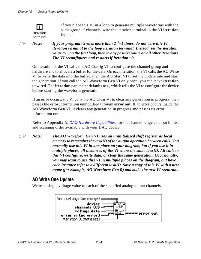
Chapter 20 Analog Output Utility VIs
e
.
rite start
then
,
ou
o , w t.
If you place this VI in a loop to generate multiple waveforms with thsame group of channels, wire the iteration terminal to the VI iteration input.
Note: If your program iterates more than 231–1 times, do not wire this VI iteration terminal to the loop iteration terminal. Instead, set the iterationvalue to 0 on the first loop, then to any positive value on all other iterationsThe VI reconfigures and restarts if iteration ≤0.
On iteration 0, the VI calls the AO Config VI to configure the channel group and hardware and to allocate a buffer for the data. On each iteration, the VI calls the AO WVI to write the data into the buffer, then the AO Start VI to set the update rate and the generation. If you call the AO Waveform Gen VI only once, you can leave iteration unwired. The iteration parameter defaults to 0, which tells the VI to configure the devicebefore starting the waveform generation.
If an error occurs, the VI calls the AO Clear VI to clear any generation in progress, passes the error information unmodified through error out . If an error occurs inside theAO Waveform Gen VI, it clears any generation in progress and passes its error information out.
Refer to Appendix A, DAQ Hardware Capabilities, for the channel ranges, output limitsand scanning order available with your DAQ device.
Note: The AO Waveform Gen VI uses an uninitialized shift register as local memory to remember the taskID of the output operation between calls. Ynormally use this VI in one place on your diagram, but if you use it in multiple places, all instances of the VI share the same taskID. All calls tthis VI configure, write data, or clear the same generation. Occasionallyyou may want to use this VI in multiple places on the diagram, but haveeach instance refer to a different taskID. Save a copy of this VI with a nename (for example, AO Waveform Gen R) and make the new VI reentran
AO Write One UpdateWrites a single voltage value to each of the specified analog output channels.
iterationterminal
LabVIEW Function and VI Reference Manual 20-4 © National Instruments Corporation
Chapter 20 Analog Output Utility VIs
te ite ion
.
nels. ry
lue
,
l
e
ave )
The AO Write One Update VI performs an immediate, untimed updaof a group of one or more channels. If you place the VI in a loop to wrmore than one value to the same group of channels, wire the iteratterminal to the VI iteration input.
Note: If your program iterates more than 231–1 times, do not wire this VI iteration terminal to the loop iteration terminal. Instead, set the iterationvalue to 0 on the first loop, then to any positive value on all other iterationsThe VI reconfigures and restarts if iteration ≤0.
On iteration 0, the VI calls the AO Config VI to configure the channel group and hardware, then calls the AO Single Update VI to write the voltage to the output chanOn future iterations, the VI calls only the AO Single Update VI, avoiding unnecessaconfiguration. If you call the AO Write One Update VI only once to write a single vato each channel, leave the iteration input unwired. Its default value of 0 tells the VI to perform the configuration before writing any data.
Refer to Appendix A, DAQ Hardware Capabilities, for the channel ranges, output limitsand scanning order available with your DAQ device.
Note: The AO Write One Update VI uses an uninitialized shift register as locamemory to remember the taskID for the group of channels when callingbetween VIs. Usually, this VI appears in one place on your diagram. However, if you use it in more than one place, the multiple instances of thVI share the same taskID. All calls to this VI configure or write data to thesame group. If you want to use this VI in more than one place on your diagram, and want each instance to refer to a different taskID (for example, to write data with two devices at the same time), you should sa copy of this VI with a new name (for example, AO Write One Update Rand make your new VI reentrant.
iterationterminal
© National Instruments Corporation 20-5 LabVIEW Function and VI Reference Manual

© National Instruments Corporation 21-1 LabVIEW Function and
Chapter
21
Advanced Analog Output VIsog are Is.
log
AO
This chapter contains reference descriptions of the Advanced AnalOutput VIs. These VIs are the interface to the NI-DAQ software and the foundation of the Easy, Utility and Intermediate Analog Output V
You can access the Advanced Analog Output palette by choosing Functions»Data Acquisition»Analog Output»Advanced Analog Output . The icon that you must select to access the Advanced AnaOutput VIs is on the bottom row of the Analog Output palette, as shown below.
Advanced Analog Output VI Descriptions
The following Advanced Analog Output VIs are available.
AO Buffer ConfigAllocates memory for an analog output buffer. If you are using interrupts, you can allocate a series of analog output buffers and assign them to a group by calling theBuffer Config VI multiple times. Each buffer can have its own size. If you are usingDMA, you may allocate only one buffer.
Note: (Macintosh) If you are using the NB-A2100 with the NB-DMA2800, the AOBuffer Write VI restricts the amount of data that can be put into the VI toone-half of the buffer size specified in the AO Buffer Config VI.
AdvancedAnalog Output VIs
VI Reference Manual
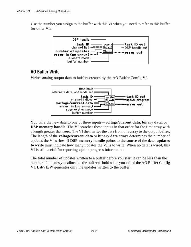
Chapter 21 Advanced Analog Output VIs
uffer
ith uffer. f
this
the nfig
Use the number you assign to the buffer with this VI when you need to refer to this bfor other VIs.
AO Buffer WriteWrites analog output data to buffers created by the AO Buffer Config VI.
You wire the new data to one of three inputs—voltage/current data, binary data, or DSP memory handle. The VI searches these inputs in that order for the first array wa length greater than zero. The VI then writes the data from this array to the output bThe length of the voltage/current data or binary data arrays determines the number oupdates the VI writes. If DSP memory handle points to the source of the data, updates to write must indicate how many updates the VI is to write. When no data is wired, VI is still useful for reporting update progress information.
The total number of updates written to a buffer before you start it can be less than number of updates you allocated the buffer to hold when you called the AO Buffer CoVI. LabVIEW generates only the updates written to the buffer.
LabVIEW Function and VI Reference Manual 21-2 © National Instruments Corporation
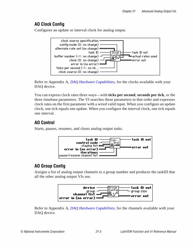
Chapter 21 Advanced Analog Output VIs
presses date uals
D that
AO Clock ConfigConfigures an update or interval clock for analog output.
Refer to Appendix A, DAQ Hardware Capabilities, for the clocks available with your DAQ device.
You can express clock rates three ways—with ticks per second, seconds per tick, or the three timebase parameters. The VI searches these parameters in that order and exclock rates on the first parameter with a wired valid input. When you configure an upclock, one tick equals one update. When you configure the interval clock, one tick eqone interval.
AO ControlStarts, pauses, resumes, and clears analog output tasks.
AO Group ConfigAssigns a list of analog output channels to a group number and produces the taskIall the other analog output VIs use.
Refer to Appendix A, DAQ Hardware Capabilities, for the channels available with yourDAQ device.
© National Instruments Corporation 21-3 LabVIEW Function and VI Reference Manual

Chapter 21 Advanced Analog Output VIs
the
AO Hardware ConfigConfigures the reference voltage level, output polarity, and the unit of measure fordata of a given channel (volts or milliamperes). This VI always returns the current settings for all the channels in the group.
Refer to Appendix A, DAQ Hardware Capabilities, for the channel ranges, and output limits available with your DAQ device.
AO ParameterSets miscellaneous parameters associated with the Analog Output operation of thedevices that are not covered with other Analog Output VIs.
AO Single UpdatePerforms an immediate update of the channels in the group.
LabVIEW Function and VI Reference Manual 21-4 © National Instruments Corporation
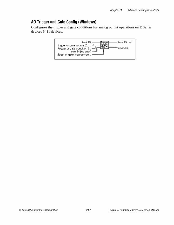
Chapter 21 Advanced Analog Output VIs
s
AO Trigger and Gate Config (Windows)Configures the trigger and gate conditions for analog output operations on E Seriedevices 5411 devices.
© National Instruments Corporation 21-5 LabVIEW Function and VI Reference Manual
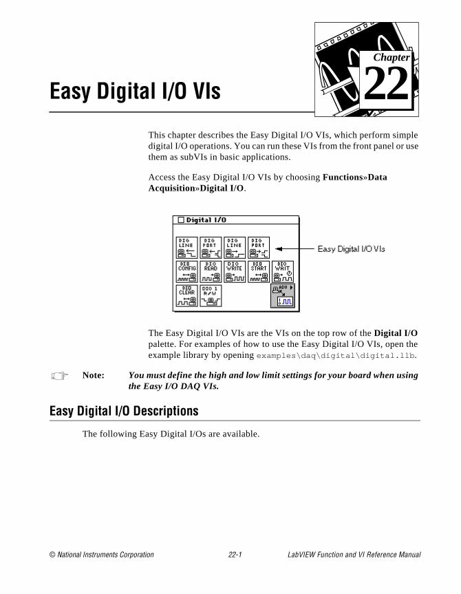
© National Instruments Corporation 22-1 LabVIEW Function and
Chapter
22
Easy Digital I/O VIsle se
the
g
This chapter describes the Easy Digital I/O VIs, which perform simpdigital I/O operations. You can run these VIs from the front panel or uthem as subVIs in basic applications.
Access the Easy Digital I/O VIs by choosing Functions»Data Acquisition»Digital I/O .
The Easy Digital I/O VIs are the VIs on the top row of the Digital I/O palette. For examples of how to use the Easy Digital I/O VIs, open example library by opening examples\daq\digital\digital.llb .
Note: You must define the high and low limit settings for your board when usinthe Easy I/O DAQ VIs.
Easy Digital I/O Descriptions
The following Easy Digital I/Os are available.
VI Reference Manual

Chapter 22 Easy Digital I/O VIs
inue.
et r r
ts.
inue.
et ct e
Read from Digital Line Reads the logical state of a digital line on a port that you configure.
If an error occurs, a dialog box appears, giving you the option to stop the VI or cont
Note: When you call this VI on a digital I/O port that is part of an 8255 PPI whenyour iteration terminal is left at 0, the 8255 PPI goes through a configuration phase, where all the ports within the same PPI chip get resto logic low, regardless of the data direction. The data direction on otheports, however, is maintained. To avoid this effect, connect a value othethan 0 to the iteration terminal once you have configured the desired por
Read from Digital Port Reads a digital port that you configure.
If an error occurs, a dialog box appears, giving you the option to stop the VI or cont
Note: When you call this VI on a digital I/O port that is part of an 8255 PPI whenyour iteration terminal is left at 0, the 8255 PPI goes through a configuration phase, where all the ports within the same PPI chip get resto logic low, regardless of the data direction. To avoid this effect, connea value other than 0 to the iteration terminal once you have configured thdesired ports.
LabVIEW Function and VI Reference Manual 22-2 © National Instruments Corporation

Chapter 22 Easy Digital I/O VIs
cify.
inue.
et r r
ts.
inue.
et r r
ts.
Write to Digital Line Sets the output logic state of a digital line to high or low on a digital port that you spe
If an error occurs, a dialog box appears, giving you the option to stop the VI or cont
Note: When you call this VI on a digital I/O port that is part of an 8255 PPI whenyour iteration terminal is left at 0, the 8255 PPI goes through a configuration phase, where all the ports within the same PPI chip get resto logic low, regardless of the data direction. The data direction on otheports, however, is maintained. To avoid this effect, connect a value othethan 0 to the iteration terminal once you have configured the desired por
Write to Digital Port Outputs a decimal pattern to a digital port that you specify.
If an error occurs, a dialog box appears, giving you the option to stop the VI or cont
Note: When you call this VI on a digital I/O port that is part of an 8255 PPI whenyour iteration terminal is left at 0, the 8255 PPI goes through a configuration phase, where all the ports within the same PPI chip get resto logic low, regardless of the data direction. The data direction on otheports, however, is maintained. To avoid this effect, connect a value othethan 0 to the iteration terminal once you have configured the desired por
© National Instruments Corporation 22-3 LabVIEW Function and VI Reference Manual

© National Instruments Corporation 23-1 LabVIEW Function and
Chapter
23
Intermediate Digital I/O VIsare
r
ust the
This chapter describes the Intermediate Digital I/O VIs. These VIs single VI solutions to common digital problems.
For example, the DIO Single Read/Write VI is a single VI solution fonon-buffered reads and writes to the ports in your group. The DIO Single Read/Write VI works with any device with digital ports.
You combine the other VIs—DIO Config, DIO Start, DIO Read, DIOWrite, DIO Wait, and DIO Clear—to build more demanding applications using buffered digital reads and writes. Your device msupport handshaking to use this group of VIs, with the exception of DIO Single Read/Write VI.
All the VIs described in this chapter are built from the fundamental building block layer, the advanced-level VIs.
You can access the Intermediate Digital I/O VIs by choosing Functions»Data Acquisition»Digital I/O . The Intermediate Digital I/O VIs are the VIs on the second and third rows of the Digital palette, as shown below.
IntermediateDigital I/O VIs
VI Reference Manual
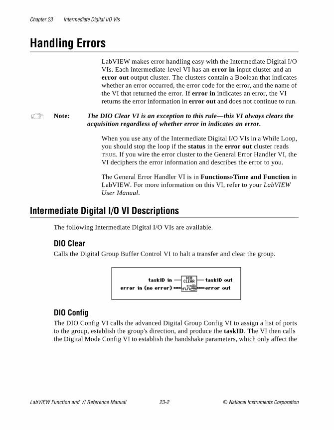
Chapter 23 Intermediate Digital I/O VIs
O
tes e of
p,
e
rts
t the
Handling ErrorsLabVIEW makes error handling easy with the Intermediate Digital I/VIs. Each intermediate-level VI has an error in input cluster and an error out output cluster. The clusters contain a Boolean that indicawhether an error occurred, the error code for the error, and the namthe VI that returned the error. If error in indicates an error, the VI returns the error information in error out and does not continue to run.
Note: The DIO Clear VI is an exception to this rule—this VI always clears the acquisition regardless of whether error in indicates an error.
When you use any of the Intermediate Digital I/O VIs in a While Looyou should stop the loop if the status in the error out cluster reads TRUE. If you wire the error cluster to the General Error Handler VI, thVI deciphers the error information and describes the error to you.
The General Error Handler VI is in Functions»Time and Function in LabVIEW. For more information on this VI, refer to your LabVIEW User Manual.
Intermediate Digital I/O VI Descriptions
The following Intermediate Digital I/O VIs are available.
DIO Clear Calls the Digital Group Buffer Control VI to halt a transfer and clear the group.
DIO ConfigThe DIO Config VI calls the advanced Digital Group Config VI to assign a list of poto the group, establish the group's direction, and produce the taskID. The VI then calls the Digital Mode Config VI to establish the handshake parameters, which only affec
LabVIEW Function and VI Reference Manual 23-2 © National Instruments Corporation
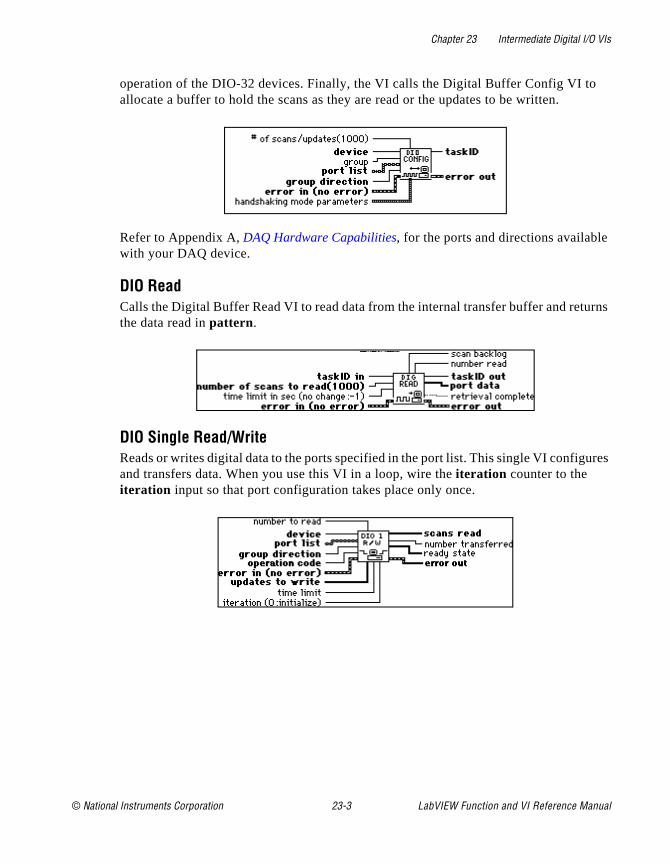
Chapter 23 Intermediate Digital I/O VIs
rns
ures
operation of the DIO-32 devices. Finally, the VI calls the Digital Buffer Config VI toallocate a buffer to hold the scans as they are read or the updates to be written.
Refer to Appendix A, DAQ Hardware Capabilities, for the ports and directions availablewith your DAQ device.
DIO Read Calls the Digital Buffer Read VI to read data from the internal transfer buffer and retuthe data read in pattern.
DIO Single Read/WriteReads or writes digital data to the ports specified in the port list. This single VI configand transfers data. When you use this VI in a loop, wire the iteration counter to the iteration input so that port configuration takes place only once.
© National Instruments Corporation 23-3 LabVIEW Function and VI Reference Manual

Chapter 23 Intermediate Digital I/O VIs
et e data
For ffer
en
he
DIO Start Starts a buffered digital I/O operation. This VI calls the Digital Clock Config VI to sthe clock rate if the internal clock produces the handshake signals, and then starts thtransfer by calling the Digital Buffer Control VI.
DIO WaitWaits until the digital buffered input or output operation completes before returning.input, the VI detects completion when the acquisition state returned by the Digital BuRead VI finishes with or without backlog. For output, the VI detects completion whthe generation complete indicator of the DIO Write VI is TRUE.
Refer to Appendix A, DAQ Hardware Capabilities, for the handshake modes available with your DAQ device.
DIO WriteCalls the Digital Buffer Write VI to write to the internal transfer buffer.
(Macintosh) You must fill the buffer with data before you use the DIO Start VI to begin tdigital output operation. You can call the DIO Write VI after the transfer begins to retrieve status information.
LabVIEW Function and VI Reference Manual 23-4 © National Instruments Corporation
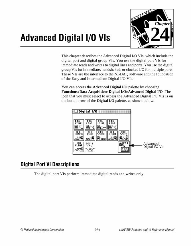
© National Instruments Corporation 24-1 LabVIEW Function and
Chapter
24
Advanced Digital I/O VIshe
ital ts. ion
on
This chapter describes the Advanced Digital I/O VIs, which include tdigital port and digital group VIs. You use the digital port VIs for immediate reads and writes to digital lines and ports. You use the diggroup VIs for immediate, handshaked, or clocked I/O for multiple porThese VIs are the interface to the NI-DAQ software and the foundatof the Easy and Intermediate Digital I/O VIs.
You can access the Advanced Digital I/O palette by choosing Functions»Data Acquisition»Digital I/O»Advanced Digital I/O. The icon that you must select to access the Advanced Digital I/O VIs isthe bottom row of the Digital I/O palette, as shown below.
Digital Port VI Descriptions
The digital port VIs perform immediate digital reads and writes only.
AdvancedDigital I/O VIs
VI Reference Manual
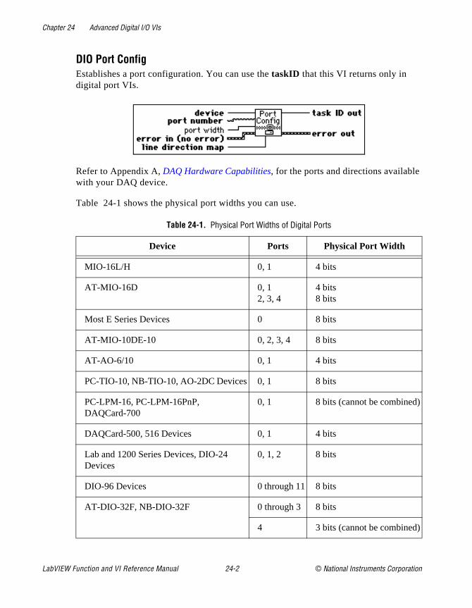
Chapter 24 Advanced Digital I/O VIs
DIO Port ConfigEstablishes a port configuration. You can use the taskID that this VI returns only in digital port VIs.
Refer to Appendix A, DAQ Hardware Capabilities, for the ports and directions availablewith your DAQ device.
Table 24-1 shows the physical port widths you can use.
Table 24-1. Physical Port Widths of Digital Ports
Device Ports Physical Port Width
MIO-16L/H 0, 1 4 bits
AT-MIO-16D 0, 12, 3, 4
4 bits8 bits
Most E Series Devices 0 8 bits
AT-MIO-10DE-10 0, 2, 3, 4 8 bits
AT-AO-6/10 0, 1 4 bits
PC-TIO-10, NB-TIO-10, AO-2DC Devices 0, 1 8 bits
PC-LPM-16, PC-LPM-16PnP, DAQCard-700
0, 1 8 bits (cannot be combined)
DAQCard-500, 516 Devices 0, 1 4 bits
Lab and 1200 Series Devices, DIO-24 Devices
0, 1, 2 8 bits
DIO-96 Devices 0 through 11 8 bits
AT-DIO-32F, NB-DIO-32F 0 through 3 8 bits
4 3 bits (cannot be combined)
LabVIEW Function and VI Reference Manual 24-2 © National Instruments Corporation
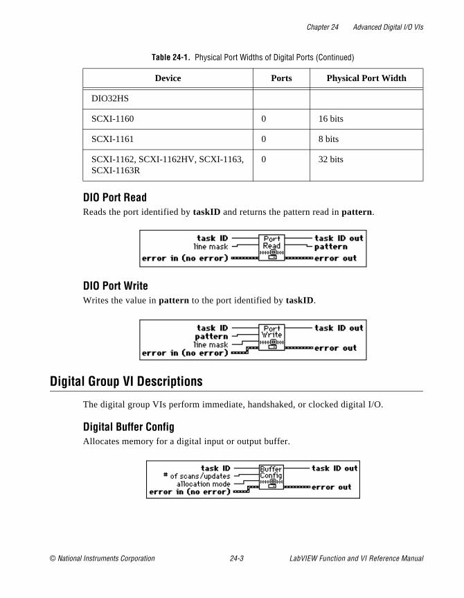
Chapter 24 Advanced Digital I/O VIs
DIO Port ReadReads the port identified by taskID and returns the pattern read in pattern.
DIO Port WriteWrites the value in pattern to the port identified by taskID.
Digital Group VI Descriptions
The digital group VIs perform immediate, handshaked, or clocked digital I/O.
Digital Buffer ConfigAllocates memory for a digital input or output buffer.
DIO32HS
SCXI-1160 0 16 bits
SCXI-1161 0 8 bits
SCXI-1162, SCXI-1162HV, SCXI-1163, SCXI-1163R
0 32 bits
Table 24-1. Physical Port Widths of Digital Ports (Continued)
Device Ports Physical Port Width
© National Instruments Corporation 24-3 LabVIEW Function and VI Reference Manual
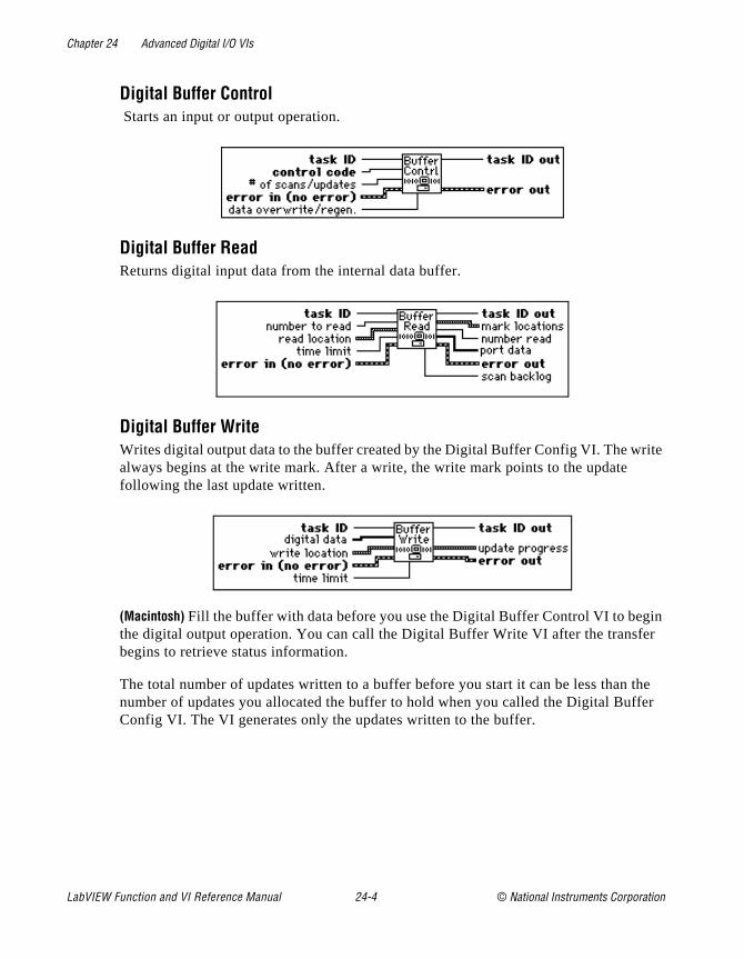
Chapter 24 Advanced Digital I/O VIs
ite
in r
the fer
Digital Buffer Control Starts an input or output operation.
Digital Buffer ReadReturns digital input data from the internal data buffer.
Digital Buffer WriteWrites digital output data to the buffer created by the Digital Buffer Config VI. The wralways begins at the write mark. After a write, the write mark points to the update following the last update written.
(Macintosh) Fill the buffer with data before you use the Digital Buffer Control VI to begthe digital output operation. You can call the Digital Buffer Write VI after the transfebegins to retrieve status information.
The total number of updates written to a buffer before you start it can be less than number of updates you allocated the buffer to hold when you called the Digital BufConfig VI. The VI generates only the updates written to the buffer.
LabVIEW Function and VI Reference Manual 24-4 © National Instruments Corporation

Chapter 24 Advanced Digital I/O VIs
clock
cify a
dates
e
Digital Clock ConfigConfigures a DIO-32 device to produce handshake signals based on the output of afor timed digital I/O.
Refer to Appendix A, DAQ Hardware Capabilities, for the clocks available with your DAQ device.
The following example illustrates how to use the three timebase parameters to speclock rate. Assume these parameters have the following settings:
timebase source: 1timebase signal: 1,000,000.0 Hztimebase divisor: 25
In this case, the ticks per second rate is 1,000,000.0 divided by 25, so LabVIEW upthe digital group 40,000 times per second.
Digital Group ConfigDefines a digital input or output group. You can use the taskID this VI returns only in the digital group VIs.
Refer to Appendix A, DAQ Hardware Capabilities, for the ports and directions availablewith your DAQ device.
Note: The same port cannot belong to two different groups. If you configure agroup to use a specified port, that port must be one that is not already defined in another group or you will get an error.
MIO devices (except for the AT-MIO-16D and the AT-MIO-16DE-10), as well as thNB-TIO-10, LPM devices, DAQCard-500, 516 devices, DAQCard-700, PC-TIO-10,AO-2DC devices, PC-OPDIO-16, and AT-AO-6/10, do not allow handshaking. Thedigital port VIs are more appropriate for these devices. The AT-MIO-16D and
© National Instruments Corporation 24-5 LabVIEW Function and VI Reference Manual
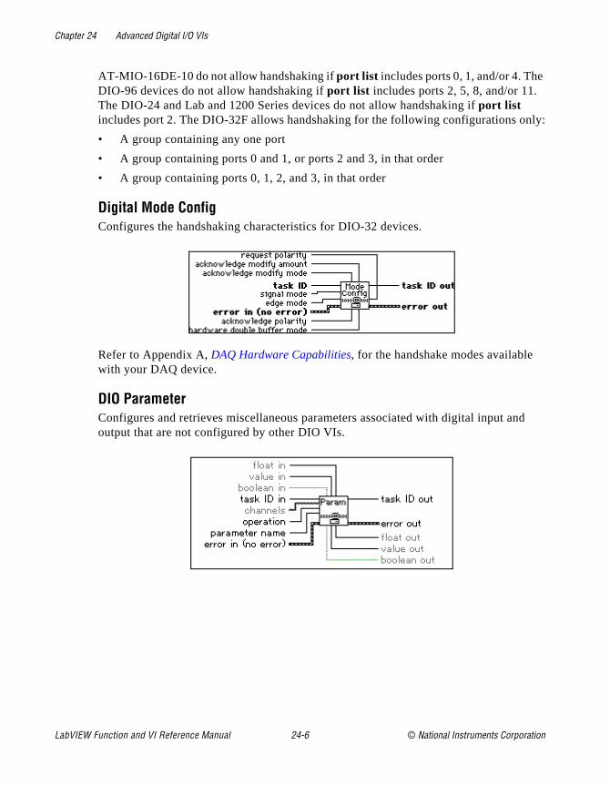
Chapter 24 Advanced Digital I/O VIs
nly:
d
AT-MIO-16DE-10 do not allow handshaking if port list includes ports 0, 1, and/or 4. TheDIO-96 devices do not allow handshaking if port list includes ports 2, 5, 8, and/or 11. The DIO-24 and Lab and 1200 Series devices do not allow handshaking if port list includes port 2. The DIO-32F allows handshaking for the following configurations o
• A group containing any one port
• A group containing ports 0 and 1, or ports 2 and 3, in that order
• A group containing ports 0, 1, 2, and 3, in that order
Digital Mode ConfigConfigures the handshaking characteristics for DIO-32 devices.
Refer to Appendix A, DAQ Hardware Capabilities, for the handshake modes available with your DAQ device.
DIO ParameterConfigures and retrieves miscellaneous parameters associated with digital input anoutput that are not configured by other DIO VIs.
LabVIEW Function and VI Reference Manual 24-6 © National Instruments Corporation

Chapter 24 Advanced Digital I/O VIs
tion
ock).
Table 24-2 lists device specific parameters and legal ranges for devices.
Digital Single ReadReads the ports that belong to the group identified by taskID and returns the patterns read.
Digital Single WriteWrites the data in pattern array to the ports that belong to the group identified by taskID.
Digital Trigger ConfigConfigures the trigger condition for starting and/or stopping a digital pattern generaoperation. This VI is only valid when the Digital Clock Config VI has its handshake source parameter set to 1 or 4 (internal or external pattern generation w/ external cl
Table 24-2. Device specific parameters and legal ranges for devices
DeviceParameter
Name SupportSettingPossible
Input/outputyou should
useLegalValues
DefaultValue
VXI-DIO-128
0: Input Port Logic Threshold
per input port
yes channels, float in, float out
N/A N/A
© National Instruments Corporation 24-7 LabVIEW Function and VI Reference Manual

© National Instruments Corporation 25-1 LabVIEW Function and
Chapter
25
Easy Counter VIsrun
w
on
nd
ed. d to
+1
The Easy Counter VIs perform simple counting operations. You can these VIs from the front panel or use them as subVIs in basic applications.
You can access the Easy Counter VIs by choosing Functions»Data Acquisition»Counter. The Easy Counter VIs are the VIs on the top roof the Counter palette.
This chapter describes the high-level VIs for programming countersthe MIO, TIO, and other devices with the Am9513 or DAQ-STC counter/timer chips. These VIs call the Intermediate Counter VIs togenerate a single delayed TTL pulse, a finite or continuous train ofpulses, and to measure the frequency, pulse width, or period of a TTL signal.
Note: These VIs do not work with Lab and 1200 Series devices, DAQCards, aother devices that have the 8253 chip. Use the intermediate-level ICTRControl for those devices. Refer to Chapter 26, Intermediate Counter VIs for more information on the ICTR Control VI.
Some of these VIs use other counters in addition to the one specifiIn this case, a logically adjacent counter is chosen, which is referreas counter+1 when it is the adjacent, logically higher counter and counter–1 when it is the adjacent, logically lower counter.
For a device with the Am9513 chip, if the counter is 1, then counteris counter 2 and counter–1 is counter 5.
VI Reference Manual

Chapter 25 Easy Counter VIs
le
nal .
ant to base
and se 1), ternal to ser with lse
See the Adjacent Counters VI described in Chapter 26, Intermediate Counter VIs, for more information.
For examples of how to use the Easy Counter VIs, open the examplibrary by opening examples\daq\counter\counter.llb .
Easy Counter VI Descriptions
The following Easy Counter VIs are available.
Count Events or TimeConfigures one or two counters to count external events or elapsed time. An exterevent is a high or low signal transition on the specified SOURCE pin of the counter
To count events, set the event source/timebase to 0.0 and connect the signal you wcount to the SOURCE pin of the counter. To count time, set this control to the timefrequency you want to use.
Generate Delayed PulseConfigures and starts a counter to generate a single pulse with the specified delaypulse width on the counter’s OUT pin. A single pulse consists of a delay phase (phafollowed by a pulse phase (phase 2), and than a return to the phase 1 level. If an intimebase is chosen, the VI selects the highest resolution timebase for the counter achieve the desired characteristics. If an external timebase signal is chosen, the uindicates the delay and width as cycles of that signal. Execute the Counter Start VIthis VI’s taskID to generate another pulse. You can optionally gate or trigger the puwith a signal on the counter’s GATE pin.
LabVIEW Function and VI Reference Manual 25-2 © National Instruments Corporation

Chapter 25 Easy Counter VIs
er's an Each se
se to rt VI
pulse.
the
e h the
y this VI r
Generate Pulse TrainConfigures the specified counter to generate a continuous pulse train on the countOUT pin, or to generate a finite-length pulse train using the specified counter and adjacent counter. The signal has the prescribed frequency, duty cycle, and polarity.cycle of the pulse train consist of a delay phase (phase 1) followed by a pulse pha(phase 2).
This VI uses only the specified counter to generates a continuous pulse. For a finite-length pulse, the VI also uses counter–1 to generate a minimum-delayed pulgate counter. To generate another pulse train, execute the intermediate Counter Stawith the taskIDs supplied by this VI. To stop a continuous pulse train, execute the intermediate Counter Stop VI or execute this counter again to generate one, short You must externally wire counter–1’s OUT pin to counter's GATE pin for a finite-length pulse train. You can optionally gate or trigger the start of the train with a signal on counter–1’s GATE pin.
Note: A pulse train consists of a series of delayed pulses, where phase 1 or thfirst phase of each pulse is the inactive state of the output (low for a higpulse) and the phase 2 of the second phase is the pulse itself. Refer to following illustration of a high polarity pulse train.
Measure FrequencyMeasures the frequency of a TTL signal on the specified counter’s SOURCE pin bcounting positive edges of the signal during a specified period of time. In addition toconnection, you must wire the counter’s GATE pin to the OUT pin of counter–1. Thisis useful for relatively high frequency signals, when many cycles of the signal occuduring the timing period. Use the Measure Pulse Width or Period VI for relatively low frequency signals. Keep in mind that period(s) = 1/frequency (Hz).
© National Instruments Corporation 25-3 LabVIEW Function and VI Reference Manual
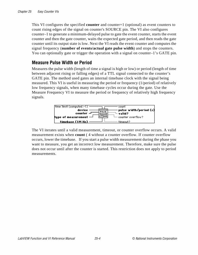
Chapter 25 Easy Counter VIs
o event
he gate s the
pin.
time s vely ncy
alid
e you pulse eriod
This VI configures the specified counter and counter+1 (optional) as event counters tcount rising edges of the signal on counter's SOURCE pin. The VI also configurescounter–1 to generate a minimum-delayed pulse to gate the event counter, starts thecounter and then the gate counter, waits the expected gate period, and then reads tcounter until its output state is low. Next the VI reads the event counter and computesignal frequency (number of events/actual gate pulse width) and stops the counters. You can optionally gate or trigger the operation with a signal on counter–1’s GATE
Measure Pulse Width or PeriodMeasures the pulse width (length of time a signal is high or low) or period (length of between adjacent rising or falling edges) of a TTL signal connected to the counter’GATE pin. The method used gates an internal timebase clock with the signal beingmeasured. This VI is useful in measuring the period or frequency (1/period) of relatilow frequency signals, when many timebase cycles occur during the gate. Use theMeasure Frequency VI to measure the period or frequency of relatively high frequesignals.
The VI iterates until a valid measurement, timeout, or counter overflow occurs. A vmeasurement exists when count ( 4 without a counter overflow. If counter overflow occurs, lower the timebase. If you start a pulse width measurement during the phaswant to measure, you get an incorrect low measurement. Therefore, make sure thedoes not occur until after the counter is started. This restriction does not apply to pmeasurements.
LabVIEW Function and VI Reference Manual 25-4 © National Instruments Corporation
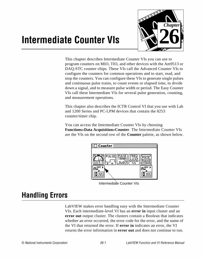
© National Instruments Corporation 26-1 LabVIEW Function and
Chapter
26
Intermediate Counter VIsor to nd lses ide nter ng,
ab
tes e of
This chapter describes Intermediate Counter VIs you can use to program counters on MIO, TIO, and other devices with the Am9513DAQ-STC counter chips. These VIs call the Advanced Counter VIsconfigure the counters for common operations and to start, read, astop the counters. You can configure these VIs to generate single puand continuous pulse trains, to count events or elapsed time, to divdown a signal, and to measure pulse width or period. The Easy CouVIs call these Intermediate VIs for several pulse generation, countiand measurement operations.
This chapter also describes the ICTR Control VI that you use with Land 1200 Series and PC-LPM devices that contain the 8253 counter/timer chip.
You can access the Intermediate Counter VIs by choosing Functions»Data Acquisition»Counter. The Intermediate Counter VIs are the VIs on the second row of the Counter palette, as shown below.
Handling ErrorsLabVIEW makes error handling easy with the Intermediate CounterVIs. Each intermediate-level VI has an error in input cluster and an error out output cluster. The clusters contain a Boolean that indicawhether an error occurred, the error code for the error, and the namthe VI that returned the error. If error in indicates an error, the VI returns the error information in error out and does not continue to run.
Intermediate Counter VIs
VI Reference Manual
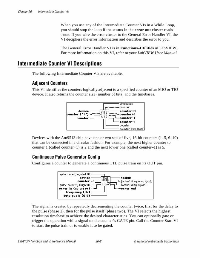
Chapter 26 Intermediate Counter VIs
,
e
IO
–10) o
ay to t or t VI
When you use any of the Intermediate Counter VIs in a While Loopyou should stop the loop if the status in the error out cluster reads TRUE. If you wire the error cluster to the General Error Handler VI, thVI deciphers the error information and describes the error to you.
The General Error Handler VI is in Functions»Utilities in LabVIEW. For more information on this VI, refer to your LabVIEW User Manual.
Intermediate Counter VI Descriptions
The following Intermediate Counter VIs are available.
Adjacent CountersThis VI identifies the counters logically adjacent to a specified counter of an MIO or Tdevice. It also returns the counter size (number of bits) and the timebases.
Devices with the Am9513 chip have one or two sets of five, 16-bit counters (1–5, 6that can be connected in a circular fashion. For example, the next higher counter tcounter 1 (called counter+1) is 2 and the next lower one (called counter–1) is 5.
Continuous Pulse Generator ConfigConfigures a counter to generate a continuous TTL pulse train on its OUT pin.
The signal is created by repeatedly decrementing the counter twice, first for the delthe pulse (phase 1), then for the pulse itself (phase two). The VI selects the highesresolution timebase to achieve the desired characteristics. You can optionally gatetrigger the operation with a signal on the counter’s GATE pin. Call the Counter Starto start the pulse train or to enable it to be gated.
LabVIEW Function and VI Reference Manual 26-2 © National Instruments Corporation

Chapter 26 Intermediate Counter VIs
3
ulse n, the
lay and a
Counter ReadReads the counter or counters identified by taskID.
The VI is designed to read one counter or two concatenated counters of an Am951counter chip or to read one counter of a DAQ-STC counter chip.
Counter StartStarts the counters identified by taskID.
Counter StopStops a count operation immediately or conditionally on an input error.
Delayed Pulse Generator ConfigConfigures a counter to generate a single, delayed TTL pulse on its OUT pin.
The signal is created by decrementing the counter twice, first for the delay to the p(called phase 1), then for the pulse itself (phase 2). If an internal timebase is choseVI selects the highest resolution timebase for the counter to achieve the desired characteristics. If an external timebase signal is chosen, the user designates the dewidth as cycles of that signal. You can optionally gate or trigger the operation with
© National Instruments Corporation 26-3 LabVIEW Function and VI Reference Manual

Chapter 26 Intermediate Counter VIs
able
ncy
ace of nals.
er’s
but n
the
signal on the counter’s GATE pin. Call the Counter Start VI to start the pulse or enit to be gated.
Down Counter or Divider ConfigConfigures the specified counter to count down or divide a signal on the counter’s SOURCE pin or on an internal timebase signal using a count value called the timebase divisor. The result is that the signal on the counter’s OUT pin is equal to the frequeof the input signal/timebase divisor.
You can use this VI to generate finite pulse trains by enabling a continuous pulse generator until the desired number of pulses has occurred. You can also use it in plthe Continuous Pulse Generator Config VI to generate a train of strobe or trigger sig
Event or Time Counter ConfigConfigures one or two counters to count edges in the signal on the specified countSOURCE pin or the number of cycles of a specified internal timebase signal.
When the internal timebase is used, this VI works like the Tick Count (ms) functionuses a hardware counter on the DAQ device with programmable resolution. You caoptionally gate or trigger the operation with a signal on the counter’s GATE pin. CallCounter Start VI to start the operation or enable it to be gated.
LabVIEW Function and VI Reference Manual 26-4 © National Instruments Corporation
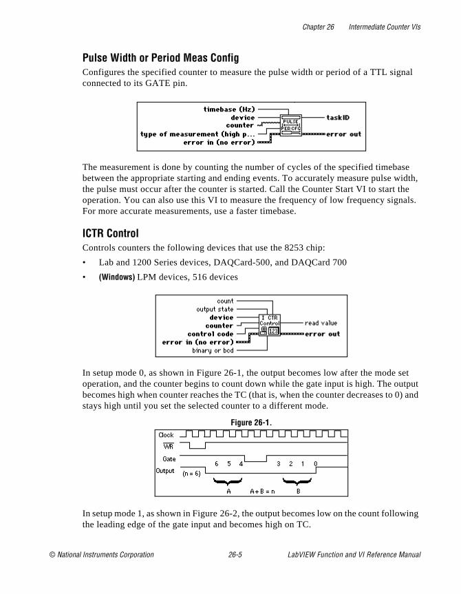
Chapter 26 Intermediate Counter VIs
nal
ase width, the nals.
set utput 0) and
wing
Pulse Width or Period Meas ConfigConfigures the specified counter to measure the pulse width or period of a TTL sigconnected to its GATE pin.
The measurement is done by counting the number of cycles of the specified timebbetween the appropriate starting and ending events. To accurately measure pulse the pulse must occur after the counter is started. Call the Counter Start VI to start operation. You can also use this VI to measure the frequency of low frequency sigFor more accurate measurements, use a faster timebase.
ICTR ControlControls counters the following devices that use the 8253 chip:
• Lab and 1200 Series devices, DAQCard-500, and DAQCard 700
• (Windows) LPM devices, 516 devices
In setup mode 0, as shown in Figure 26-1, the output becomes low after the modeoperation, and the counter begins to count down while the gate input is high. The obecomes high when counter reaches the TC (that is, when the counter decreases tostays high until you set the selected counter to a different mode.
Figure 26-1.
In setup mode 1, as shown in Figure 26-2, the output becomes low on the count follothe leading edge of the gate input and becomes high on TC.
© National Instruments Corporation 26-5 LabVIEW Function and VI Reference Manual
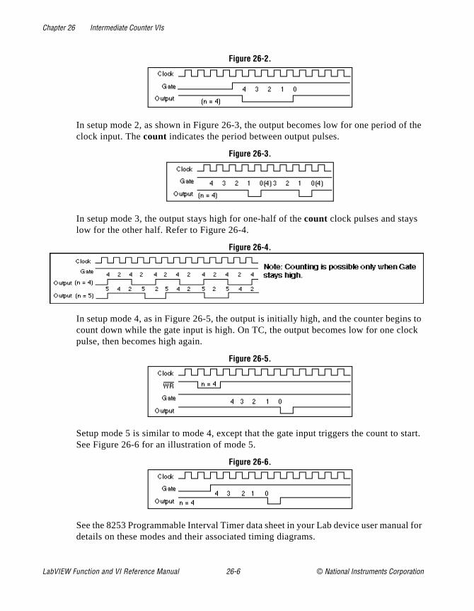
Chapter 26 Intermediate Counter VIs
f the
ns to ock
start.
al for
Figure 26-2.
In setup mode 2, as shown in Figure 26-3, the output becomes low for one period oclock input. The count indicates the period between output pulses.
Figure 26-3.
In setup mode 3, the output stays high for one-half of the count clock pulses and stays low for the other half. Refer to Figure 26-4.
Figure 26-4.
In setup mode 4, as in Figure 26-5, the output is initially high, and the counter begicount down while the gate input is high. On TC, the output becomes low for one clpulse, then becomes high again.
Figure 26-5.
Setup mode 5 is similar to mode 4, except that the gate input triggers the count to See Figure 26-6 for an illustration of mode 5.
Figure 26-6.
See the 8253 Programmable Interval Timer data sheet in your Lab device user manudetails on these modes and their associated timing diagrams.
LabVIEW Function and VI Reference Manual 26-6 © National Instruments Corporation
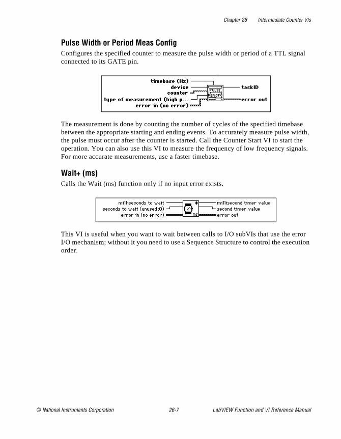
Chapter 26 Intermediate Counter VIs
nal
ase width, the nals.
ror ution
Pulse Width or Period Meas ConfigConfigures the specified counter to measure the pulse width or period of a TTL sigconnected to its GATE pin.
The measurement is done by counting the number of cycles of the specified timebbetween the appropriate starting and ending events. To accurately measure pulse the pulse must occur after the counter is started. Call the Counter Start VI to start operation. You can also use this VI to measure the frequency of low frequency sigFor more accurate measurements, use a faster timebase.
Wait+ (ms)Calls the Wait (ms) function only if no input error exists.
This VI is useful when you want to wait between calls to I/O subVIs that use the erI/O mechanism; without it you need to use a Sequence Structure to control the execorder.
© National Instruments Corporation 26-7 LabVIEW Function and VI Reference Manual
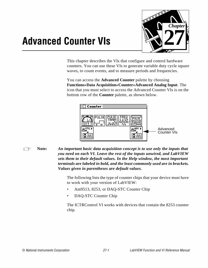
© National Instruments Corporation 27-1 LabVIEW Function and
Chapter
27
Advanced Counter VIsuare
the
t
t ts.
ve
er
This chapter describes the VIs that configure and control hardwarecounters. You can use these VIs to generate variable duty cycle sqwaves, to count events, and to measure periods and frequencies.
You can access the Advanced Counter palette by choosing Functions»Data Acquisition»Counter»Advanced Analog Input. The icon that you must select to access the Advanced Counter VIs is onbottom row of the Counter palette, as shown below.
Note: An important basic data acquisition concept is to use only the inputs thayou need on each VI. Leave the rest of the inputs unwired, and LabVIEWsets them to their default values. In the Help window, the most importanterminals are labeled in bold, and the least commonly used are in brackeValues given in parentheses are default values.
The following lists the type of counter chips that your device must hato work with your version of LabVIEW:
• Am9513, 8253, or DAQ-STC Counter Chip
• DAQ-STC Counter Chip
The ICTRControl VI works with devices that contain the 8253 countchip.
Advanced Counter VIs
VI Reference Manual
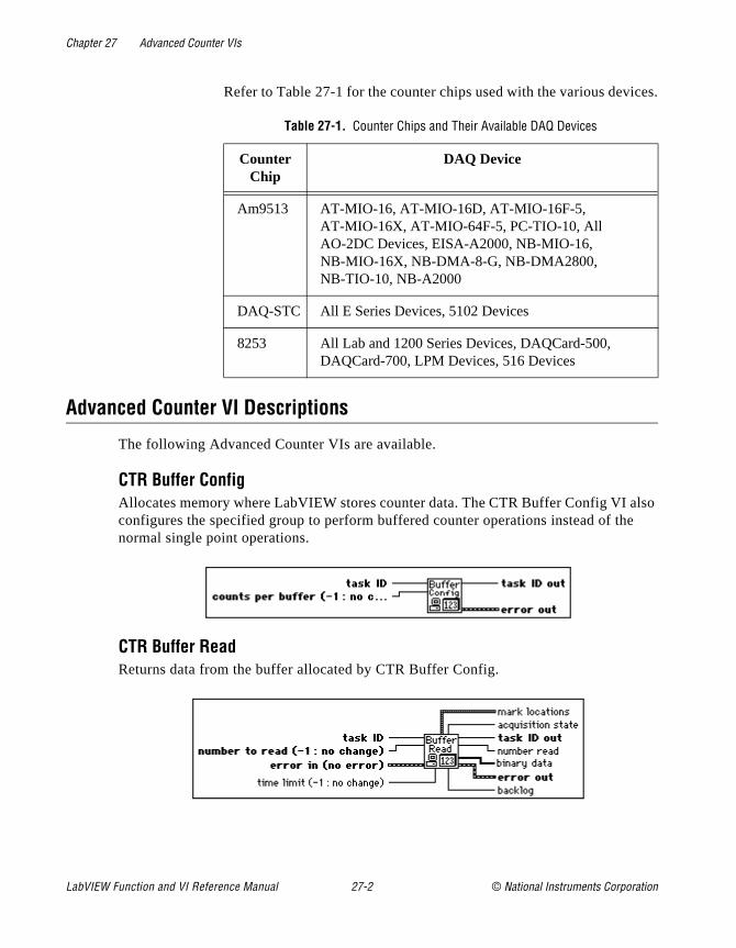
Chapter 27 Advanced Counter VIs
ces.
lso e
Refer to Table 27-1 for the counter chips used with the various devi
Advanced Counter VI Descriptions
The following Advanced Counter VIs are available.
CTR Buffer ConfigAllocates memory where LabVIEW stores counter data. The CTR Buffer Config VI aconfigures the specified group to perform buffered counter operations instead of thnormal single point operations.
CTR Buffer ReadReturns data from the buffer allocated by CTR Buffer Config.
Table 27-1. Counter Chips and Their Available DAQ Devices
Counter Chip
DAQ Device
Am9513 AT-MIO-16, AT-MIO-16D, AT-MIO-16F-5, AT-MIO-16X, AT-MIO-64F-5, PC-TIO-10, All AO-2DC Devices, EISA-A2000, NB-MIO-16, NB-MIO-16X, NB-DMA-8-G, NB-DMA2800, NB-TIO-10, NB-A2000
DAQ-STC All E Series Devices, 5102 Devices
8253 All Lab and 1200 Series Devices, DAQCard-500, DAQCard-700, LPM Devices, 516 Devices
LabVIEW Function and VI Reference Manual 27-2 © National Instruments Corporation
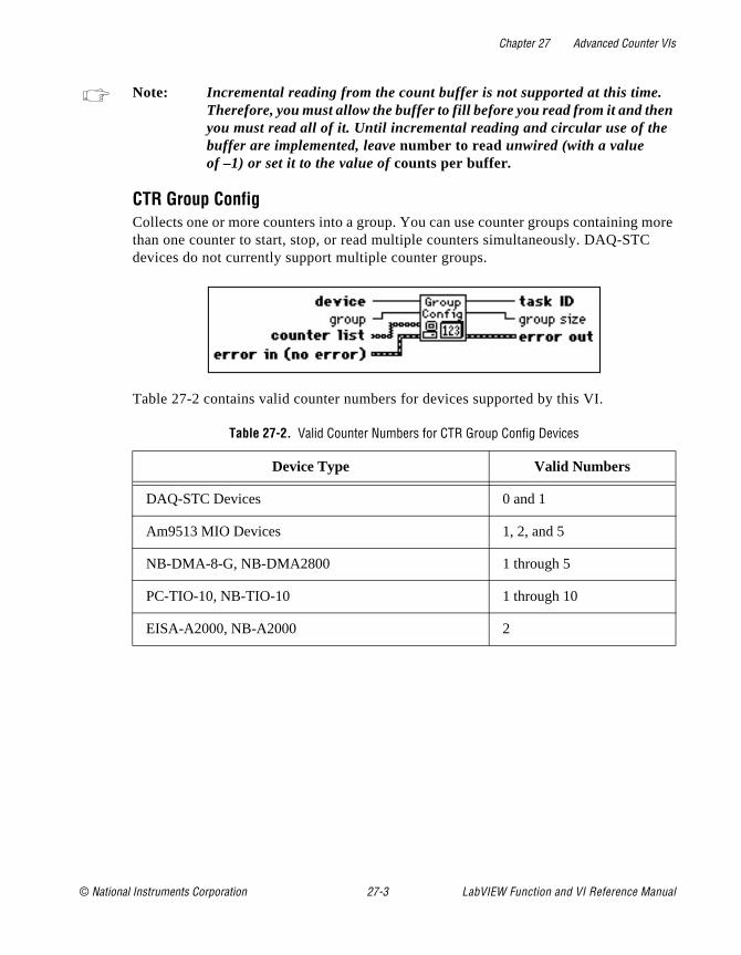
Chapter 27 Advanced Counter VIs
more
Note: Incremental reading from the count buffer is not supported at this time. Therefore, you must allow the buffer to fill before you read from it and thenyou must read all of it. Until incremental reading and circular use of the buffer are implemented, leave number to read unwired (with a valueof –1) or set it to the value of counts per buffer.
CTR Group ConfigCollects one or more counters into a group. You can use counter groups containingthan one counter to start, stop, or read multiple counters simultaneously. DAQ-STCdevices do not currently support multiple counter groups.
Table 27-2 contains valid counter numbers for devices supported by this VI.
Table 27-2. Valid Counter Numbers for CTR Group Config Devices
Device Type Valid Numbers
DAQ-STC Devices 0 and 1
Am9513 MIO Devices 1, 2, and 5
NB-DMA-8-G, NB-DMA2800 1 through 5
PC-TIO-10, NB-TIO-10 1 through 10
EISA-A2000, NB-A2000 2
© National Instruments Corporation 27-3 LabVIEW Function and VI Reference Manual
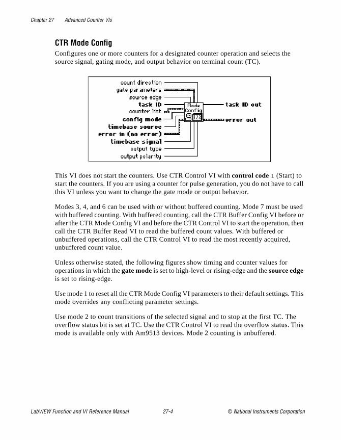
Chapter 27 Advanced Counter VIs
e
to call
used or hen
This
he This
CTR Mode ConfigConfigures one or more counters for a designated counter operation and selects thsource signal, gating mode, and output behavior on terminal count (TC).
This VI does not start the counters. Use CTR Control VI with control code 1 (Start) to start the counters. If you are using a counter for pulse generation, you do not have this VI unless you want to change the gate mode or output behavior.
Modes 3, 4, and 6 can be used with or without buffered counting. Mode 7 must be with buffered counting. With buffered counting, call the CTR Buffer Config VI beforeafter the CTR Mode Config VI and before the CTR Control VI to start the operation, tcall the CTR Buffer Read VI to read the buffered count values. With buffered or unbuffered operations, call the CTR Control VI to read the most recently acquired,unbuffered count value.
Unless otherwise stated, the following figures show timing and counter values for operations in which the gate mode is set to high-level or rising-edge and the source edge is set to rising-edge.
Use mode 1 to reset all the CTR Mode Config VI parameters to their default settings.mode overrides any conflicting parameter settings.
Use mode 2 to count transitions of the selected signal and to stop at the first TC. Toverflow status bit is set at TC. Use the CTR Control VI to read the overflow status. mode is available only with Am9513 devices. Mode 2 counting is unbuffered.
LabVIEW Function and VI Reference Manual 27-4 © National Instruments Corporation
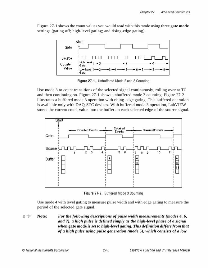
Chapter 27 Advanced Counter VIs
TC -2 tion
signal.
re the
, l
Figure 27-1 shows the count values you would read with this mode using three gate mode settings (gating off; high-level gating; and rising-edge gating).
Figure 27-1. Unbuffered Mode 2 and 3 Counting
Use mode 3 to count transitions of the selected signal continuously, rolling over at and then continuing on. Figure 27-1 shows unbuffered mode 3 counting. Figure 27illustrates a buffered mode 3 operation with rising-edge gating. This buffered operais available only with DAQ-STC devices. With buffered mode 3 operation, LabVIEWstores the current count value into the buffer on each selected edge of the source
Figure 27-2. Buffered Mode 3 Counting
Use mode 4 with level gating to measure pulse width and with edge gating to measuperiod of the selected gate signal.
Note: For the following descriptions of pulse width measurements (modes 4, 6and 7), a high pulse is defined simply as the high-level phase of a signawhen gate mode is set to high-level gating. This definition differs from thatof a high pulse using pulse generation (mode 5), which consists of a low
© National Instruments Corporation 27-5 LabVIEW Function and VI Reference Manual

Chapter 27 Advanced Counter VIs
t any lse
EW ly , a
ode cify
only each e.
gins
level delay phase followed by a high level pulse phase. (Low pulses aresimilarly defined by switching the words high and low.)
To measure pulse width, set the gate mode to high or low level. Figure 27-3 shows unbuffered mode 4 pulse width measurements. You can start an Am9513 counter atime, and it will measure pulses until you stop it. If you start it in the middle of the puyou want to measure (for example, during a high pulse for high-level gating), LabVIreturns a short count for that measurement. You must start a DAQ-STC counter onwhen the signal is in the opposite polarity from the selected gate level (for examplelow-level phase for high-level gating). Otherwise, the VI returns error number –10890. With unbuffered counting, the DAQ-STC stops counting after one measurement. M5 configures the counter for pulse generation. Use the CTR Pulse Config VI to spethe pulse you want to generate.
Figure 27-3. Unbuffered Mode 4 High Pulse Width Measurement
Figure 27-4 shows the buffered mode 4 pulse width measurement, which is availablewith DAQ-STC devices. The measured value is stored into the buffer at the end of pulse. See mode 6 for another way to measure pulse width with a DAQ-STC devic
Figure 27-4. Buffered Mode 4 Rising-Edge Pulse Width Measurement
To measure period, set the gate mode to rising or falling edge. Figure 27-5 shows unbuffered mode 4 pulse width measurement.
You may start either an Am9513 or a DAQ-STC counter at any time. The counter becounting at the start of the next period. The Am9513 counter measures periods
LabVIEW Function and VI Reference Manual 27-6 © National Instruments Corporation
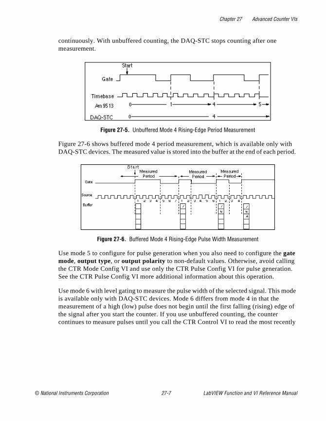
Chapter 27 Advanced Counter VIs
ith eriod.
n.
mode
of
ently
continuously. With unbuffered counting, the DAQ-STC stops counting after one measurement.
Figure 27-5. Unbuffered Mode 4 Rising-Edge Period Measurement
Figure 27-6 shows buffered mode 4 period measurement, which is available only wDAQ-STC devices. The measured value is stored into the buffer at the end of each p
Figure 27-6. Buffered Mode 4 Rising-Edge Pulse Width Measurement
Use mode 5 to configure for pulse generation when you also need to configure thegate mode, output type, or output polarity to non-default values. Otherwise, avoid callingthe CTR Mode Config VI and use only the CTR Pulse Config VI for pulse generatioSee the CTR Pulse Config VI more additional information about this operation.
Use mode 6 with level gating to measure the pulse width of the selected signal. This is available only with DAQ-STC devices. Mode 6 differs from mode 4 in that the measurement of a high (low) pulse does not begin until the first falling (rising) edgethe signal after you start the counter. If you use unbuffered counting, the counter continues to measure pulses until you call the CTR Control VI to read the most rec
© National Instruments Corporation 27-7 LabVIEW Function and VI Reference Manual
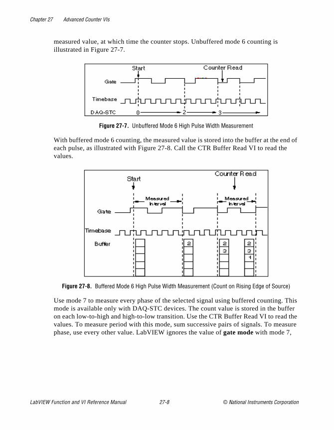
Chapter 27 Advanced Counter VIs
nd of
. This ffer the asure
measured value, at which time the counter stops. Unbuffered mode 6 counting is illustrated in Figure 27-7.
Figure 27-7. Unbuffered Mode 6 High Pulse Width Measurement
With buffered mode 6 counting, the measured value is stored into the buffer at the eeach pulse, as illustrated with Figure 27-8. Call the CTR Buffer Read VI to read thevalues.
Figure 27-8. Buffered Mode 6 High Pulse Width Measurement (Count on Rising Edge of Source)
Use mode 7 to measure every phase of the selected signal using buffered countingmode is available only with DAQ-STC devices. The count value is stored in the buon each low-to-high and high-to-low transition. Use the CTR Buffer Read VI to readvalues. To measure period with this mode, sum successive pairs of signals. To mephase, use every other value. LabVIEW ignores the value of gate mode with mode 7,
LabVIEW Function and VI Reference Manual 27-8 © National Instruments Corporation

Chapter 27 Advanced Counter VIs
alling
the
which means that you cannot tell whether the first measurement starts at a rising or fedge.
Figure 27-9. Buffered Mode 7 Semi-Period Measurement
Table 27-3 shows the legal values and default settings for timebase signal. A value of -1 tells LabVIEW to use the default settings. When the table says counter, it refers tocounter being configured. If there are multiple counters, LabVIEW configures eachcounter successively.
© National Instruments Corporation 27-9 LabVIEW Function and VI Reference Manual

Chapter 27 Advanced Counter VIs
ter.
does .
Refer to Table 27-3 to determine what is the next higher or lower consecutive coun
CTR Pulse ConfigSpecifies the parameters for pulse generation. This VI configures the counters butnot start them. Use the CTR Control VI with control code 1 (Start) to produce the pulse
Table 27-3. Adjacent Counters.
DeviceType
NextLower
Counter Counter
NextHigher
Counter
Am9513
5 1 2
1 2 3
2 3 4
3 4 5
4 5 1
10 6 7
6 7 8
7 8 9
8 9 10
9 10 6
DAQ-STC1 0 1
0 1 0
LabVIEW Function and VI Reference Manual 27-10 © National Instruments Corporation
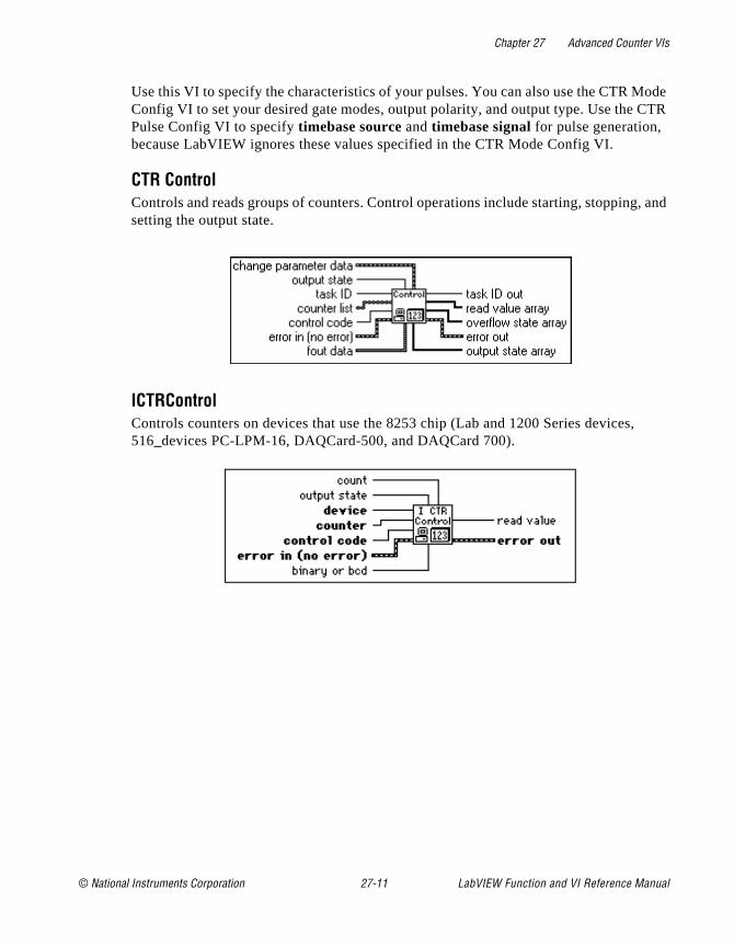
Chapter 27 Advanced Counter VIs
ode CTR
, and
,
Use this VI to specify the characteristics of your pulses. You can also use the CTR MConfig VI to set your desired gate modes, output polarity, and output type. Use the Pulse Config VI to specify timebase source and timebase signal for pulse generation, because LabVIEW ignores these values specified in the CTR Mode Config VI.
CTR ControlControls and reads groups of counters. Control operations include starting, stoppingsetting the output state.
ICTRControlControls counters on devices that use the 8253 chip (Lab and 1200 Series devices516_devices PC-LPM-16, DAQCard-500, and DAQCard 700).
© National Instruments Corporation 27-11 LabVIEW Function and VI Reference Manual
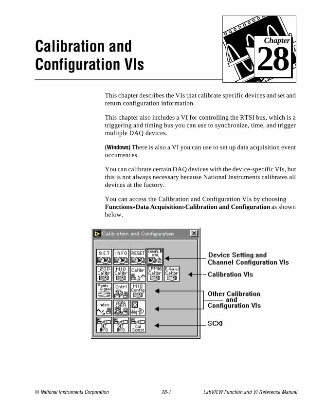
© National Instruments Corporation 28-1 LabVIEW Function and
Chapter
28
Calibration and Configuration VIst and
a ger
ent
ut s all
This chapter describes the VIs that calibrate specific devices and sereturn configuration information.
This chapter also includes a VI for controlling the RTSI bus, which istriggering and timing bus you can use to synchronize, time, and trigmultiple DAQ devices.
(Windows) There is also a VI you can use to set up data acquisition evoccurrences.
You can calibrate certain DAQ devices with the device-specific VIs, bthis is not always necessary because National Instruments calibratedevices at the factory.
You can access the Calibration and Configuration VIs by choosingFunctions»Data Acquisition»Calibration and Configuration as shown below.
VI Reference Manual
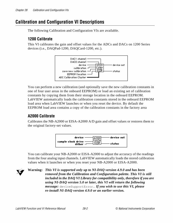
Chapter 28 Calibration and Configuration VIs
s
ts in on
OM
m to
ings tion
Calibration and Configuration VI Descriptions
The following Calibration and Configuration VIs are available.
1200 CalibrateThis VI calibrates the gain and offset values for the ADCs and DACs on 1200 Seriedevices (i.e., DAQPad-1200, DAQCard-1200, etc.).
You can perform a new calibration (and optionally save the new calibration constanone of four user areas in the onboard EEPROM) or load an existing set of calibraticonstants by copying them from their storage location in the onboard EEPROM. LabVIEW automatically loads the calibration constants stored in the onboard EEPRload area when LabVIEW launches or when you reset the device. By default the EEPROM load area contains a copy of the calibration constants in the factory area
A2000 CalibrateCalibrates the NB-A2000 or EISA-A2000 A/D gain and offset values or restores thethe original factory-set values.
You can calibrate your NB-A2000 or EISA-A2000 to adjust the accuracy of the readfrom the four analog input channels. LabVIEW automatically loads the stored calibravalues when it launches or when you reset your NB-A2000 or EISA-A2000.
Warning: This VI is supported only up to NI-DAQ version 4.9.0 and has been removed from the Calibration and Configuration palette. This VI is still included in the DAQ VI Library for compatibility only, therefore if you are using NI-DAQ version 5.0 or later, this VI will return the following message: deviceSupportError . If you wish to use this VI, please re-install NI-DAQ version 4.9.0 or an earlier version.
LabVIEW Function and VI Reference Manual 28-2 © National Instruments Corporation
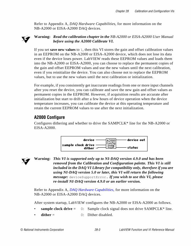
Chapter 28 Calibration and Configuration VIs
l
es ata them of
ion,
nnels es as er and
s.
Refer to Appendix A, DAQ Hardware Capabilities, for more information on the NB-A2000 or EISA-A2000 DAQ devices.
Warning: Read the calibration chapter in the NB-A2000 or EISA-A2000 User Manua before using the A2000 Calibrate VI.
If you set save new values to 1, then this VI stores the gain and offset calibration valuin an EEPROM on the NB-A2000 or EISA-A2000 device, which does not lose its deven if the device loses power. LabVIEW reads these EEPROM values and loads into the NB-A2000 or EISA-A2000, you can choose to replace the permanent copiesthe gain and offset EEPROM values and use the new values until the next calibrateven if you reinitialize the device. You can also choose not to replace the EEPROMvalues, but to use the new values until the next calibration or initialization.
For example, if you consistently get inaccurate readings from one or more input chaafter you reset the device, you can calibrate and save the new gain and offset valupermanent copies in the EEPROM. However, if acquisition results are accurate aftinitialization but start to drift after a few hours of device operation when the devicetemperature increases, you can calibrate the device at this operating temperature retain the current EEPROM values to use after the next initialization.
A2000 ConfigureConfigures dithering and whether to drive the SAMPCLK* line for the NB-A2000 orEISA-A2000.
Warning: This VI is supported only up to NI-DAQ version 4.9.0 and has been removed from the Calibration and Configuration palette. This VI is still included in the DAQ VI Library for compatibility only, therefore if you are using NI-DAQ version 5.0 or later, this VI will return the following message: deviceSupportError . If you wish to use this VI, please re-install NI-DAQ version 4.9.0 or an earlier version.
Refer to Appendix A, DAQ Hardware Capabilities, for more information on the NB-A2000 or EISA-A2000 DAQ devices.
After system startup, LabVIEW configures the NB-A2000 or EISA-A2000 as follow
• sample clock drive = 0: Sample clock signal does not drive SAMPCLK* line.
• dither = 0: Dither disabled.
© National Instruments Corporation 28-3 LabVIEW Function and VI Reference Manual
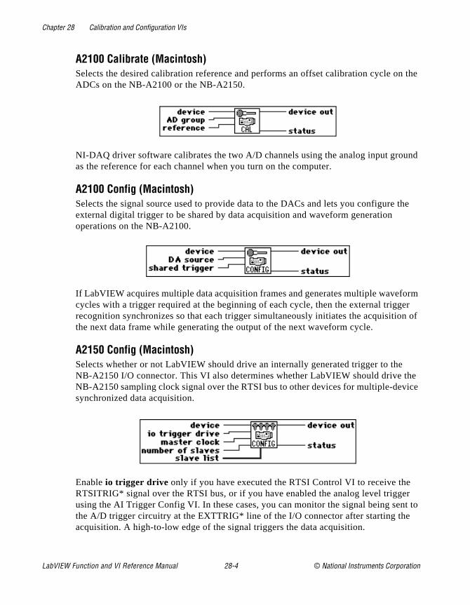
Chapter 28 Calibration and Configuration VIs
n the
und
the
orm er n of
he ice
er nt to
A2100 Calibrate (Macintosh)Selects the desired calibration reference and performs an offset calibration cycle oADCs on the NB-A2100 or the NB-A2150.
NI-DAQ driver software calibrates the two A/D channels using the analog input groas the reference for each channel when you turn on the computer.
A2100 Config (Macintosh)Selects the signal source used to provide data to the DACs and lets you configureexternal digital trigger to be shared by data acquisition and waveform generation operations on the NB-A2100.
If LabVIEW acquires multiple data acquisition frames and generates multiple wavefcycles with a trigger required at the beginning of each cycle, then the external triggrecognition synchronizes so that each trigger simultaneously initiates the acquisitiothe next data frame while generating the output of the next waveform cycle.
A2150 Config (Macintosh)Selects whether or not LabVIEW should drive an internally generated trigger to theNB-A2150 I/O connector. This VI also determines whether LabVIEW should drive tNB-A2150 sampling clock signal over the RTSI bus to other devices for multiple-devsynchronized data acquisition.
Enable io trigger drive only if you have executed the RTSI Control VI to receive theRTSITRIG* signal over the RTSI bus, or if you have enabled the analog level triggusing the AI Trigger Config VI. In these cases, you can monitor the signal being sethe A/D trigger circuitry at the EXTTRIG* line of the I/O connector after starting theacquisition. A high-to-low edge of the signal triggers the data acquisition.
LabVIEW Function and VI Reference Manual 28-4 © National Instruments Corporation
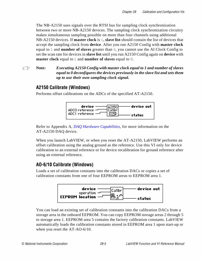
Chapter 28 Calibration and Configuration VIs
itry al t
s em
an vice after
a ugh 5 IEW
up or
The NB-A2150 uses signals over the RTSI bus for sampling clock synchronization between two or more NB-A2150 devices. The sampling clock synchronization circumakes simultaneous sampling possible on more than four channels using additionNB-A2150 devices. If master clock is 1, slave list should contain the list of devices thaaccept the sampling clock from device. After you run A2150 Config with master clock equal to 1 and number of slaves greater than 0, you cannot use the AI Clock Config toset the scan rate for devices in slave list until you run A2150 Config again on device with master clock equal to 1 and number of slaves equal to 0.
Note: Executing A2150 Config with master clock equal to 1 and number of slaveequal to 0 deconfigures the devices previously in the slave list and sets thup to use their own sampling clock signal.
A2150 Calibrate (Windows)Performs offset calibrations on the ADCs of the specified AT-A2150.
Refer to Appendix A, DAQ Hardware Capabilities, for more information on the AT-A2150 DAQ device.
When you launch LabVIEW, or when you reset the AT-A2150, LabVIEW performs offset calibration using the analog ground as the reference. Use this VI only for decalibration to an external reference or for device recalibration for ground reference using an external reference.
AO-6/10 Calibrate (Windows)Loads a set of calibration constants into the calibration DACs or copies a set of calibration constants from one of four EEPROM areas to EEPROM area 1.
You can load an existing set of calibration constants into the calibration DACs fromstorage area in the onboard EEPROM. You can copy EEPROM storage areas 2 throto storage area 1. EEPROM area 5 contains the factory calibration constants. LabVautomatically loads the calibration constants stored in EEPROM area 1 upon start-when you reset the AT-AO-6/10.
© National Instruments Corporation 28-5 LabVIEW Function and VI Reference Manual
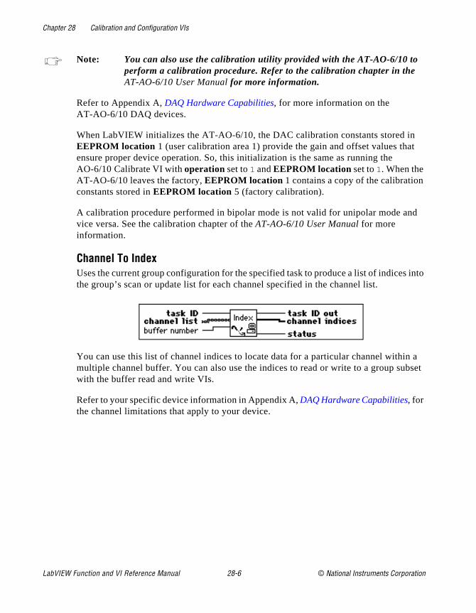
Chapter 28 Calibration and Configuration VIs
t
d
into
n a bset
Note: You can also use the calibration utility provided with the AT-AO-6/10 to perform a calibration procedure. Refer to the calibration chapter in the AT-AO-6/10 User Manual for more information.
Refer to Appendix A, DAQ Hardware Capabilities, for more information on the AT-AO-6/10 DAQ devices.
When LabVIEW initializes the AT-AO-6/10, the DAC calibration constants stored inEEPROM location 1 (user calibration area 1) provide the gain and offset values thaensure proper device operation. So, this initialization is the same as running the AO-6/10 Calibrate VI with operation set to 1 and EEPROM location set to 1. When the AT-AO-6/10 leaves the factory, EEPROM location 1 contains a copy of the calibrationconstants stored in EEPROM location 5 (factory calibration).
A calibration procedure performed in bipolar mode is not valid for unipolar mode anvice versa. See the calibration chapter of the AT-AO-6/10 User Manual for more information.
Channel To IndexUses the current group configuration for the specified task to produce a list of indicesthe group’s scan or update list for each channel specified in the channel list.
You can use this list of channel indices to locate data for a particular channel withimultiple channel buffer. You can also use the indices to read or write to a group suwith the buffer read and write VIs.
Refer to your specific device information in Appendix A, DAQ Hardware Capabilities, for the channel limitations that apply to your device.
LabVIEW Function and VI Reference Manual 28-6 © National Instruments Corporation
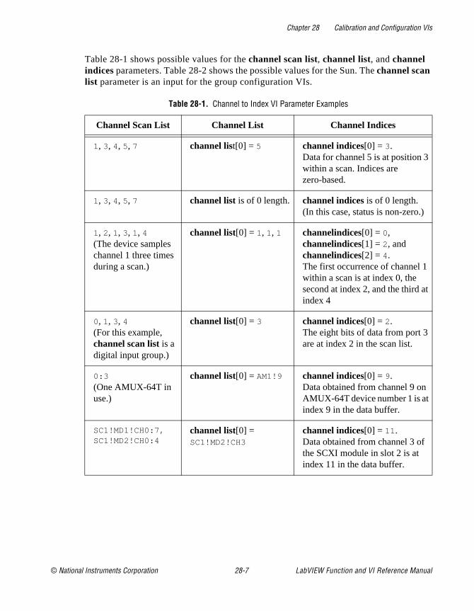
Chapter 28 Calibration and Configuration VIs
Table 28-1 shows possible values for the channel scan list, channel list, and channel indices parameters. Table 28-2 shows the possible values for the Sun. The channel scan list parameter is an input for the group configuration VIs.
Table 28-1. Channel to Index VI Parameter Examples
Channel Scan List Channel List Channel Indices
1, 3, 4, 5, 7 channel list[0] = 5 channel indices[0] = 3. Data for channel 5 is at position 3within a scan. Indices are zero-based.
1, 3, 4, 5, 7 channel list is of 0 length. channel indices is of 0 length. (In this case, status is non-zero.)
1, 2, 1, 3, 1, 4 (The device samples channel 1 three times during a scan.)
channel list[0] = 1, 1, 1 channelindices[0] = 0, channelindices[1] = 2, and channelindices[2] = 4. The first occurrence of channel 1 within a scan is at index 0, the second at index 2, and the third atindex 4
0, 1, 3, 4(For this example, channel scan list is a digital input group.)
channel list[0] = 3 channel indices[0] = 2. The eight bits of data from port 3 are at index 2 in the scan list.
0:3
(One AMUX-64T in use.)
channel list[0] = AM1!9 channel indices[0] = 9. Data obtained from channel 9 on AMUX-64T device number 1 is at index 9 in the data buffer.
SC1!MD1!CH0:7,SC1!MD2!CH0:4
channel list[0] = SC1!MD2!CH3
channel indices[0] = 11.Data obtained from channel 3 of the SCXI module in slot 2 is at index 11 in the data buffer.
© National Instruments Corporation 28-7 LabVIEW Function and VI Reference Manual
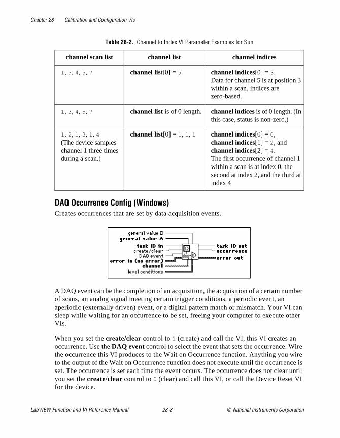
Chapter 28 Calibration and Configuration VIs
ber
can ther
ire wire ce is
ar until I
t
DAQ Occurrence Config (Windows)Creates occurrences that are set by data acquisition events.
A DAQ event can be the completion of an acquisition, the acquisition of a certain numof scans, an analog signal meeting certain trigger conditions, a periodic event, an aperiodic (externally driven) event, or a digital pattern match or mismatch. Your VI sleep while waiting for an occurrence to be set, freeing your computer to execute oVIs.
When you set the create/clear control to 1 (create) and call the VI, this VI creates an occurrence. Use the DAQ event control to select the event that sets the occurrence. Wthe occurrence this VI produces to the Wait on Occurrence function. Anything you to the output of the Wait on Occurrence function does not execute until the occurrenset. The occurrence is set each time the event occurs. The occurrence does not cleyou set the create/clear control to 0 (clear) and call this VI, or call the Device Reset Vfor the device.
Table 28-2. Channel to Index VI Parameter Examples for Sun
channel scan list channel list channel indices
1, 3, 4, 5, 7 channel list[0] = 5 channel indices[0] = 3. Data for channel 5 is at position 3within a scan. Indices are zero-based.
1, 3, 4, 5, 7 channel list is of 0 length. channel indices is of 0 length. (In this case, status is non-zero.)
1, 2, 1, 3, 1, 4 (The device samples channel 1 three times during a scan.)
channel list[0] = 1, 1, 1 channel indices[0] = 0, channel indices[1] = 2, and channel indices[2] = 4. The first occurrence of channel 1 within a scan is at index 0, the second at index 2, and the third aindex 4
LabVIEW Function and VI Reference Manual 28-8 © National Instruments Corporation

Chapter 28 Calibration and Configuration VIs
e if
that eding
f
ion ll
t ce.
nges.
LabVIEW returns a Not a Refnum file I/O constant along with a non-zero status codit cannot create the occurrence.
For each computer platform, LabVIEW limits the number of occurrences per secondyou can set. Although this limit depends on the speed of your computer, avoid exce500 occurrences per second.
For some of the events, you must perform your operation using interrupts instead oDMA. Refer to the description of the DAQ event control in this section for more information.
Device ResetResets either an entire device or the particular function identified by taskID.
Resetting a taskID function has the same result as calling the control VI for that functwith control code set to clear. When you reset the entire device, LabVIEW clears atasks and changes all device settings to their default values.
DSP2200 Calibrate (Windows)Performs offset calibrations on the analog input and/or analog output of the AT-DSP2200.
Refer to Appendix A, DAQ Hardware Capabilities, for more information on the AT-DSP2200 DAQ device.
When you launch LabVIEW or reset the AT-DSP2200, LabVIEW performs an offsecalibration on both the analog input and output using analog ground as the referen
You can use this VI to calibrate the analog input using an external reference or to recalibrate the AT-DSP2200 to compensate for configuration or environmental cha
© National Instruments Corporation 28-9 LabVIEW Function and VI Reference Manual

Chapter 28 Calibration and Configuration VIs
orms
rom
a as
nnel ce gers, sion
Cs
in
tants
e
DSP2200 Configure (Windows)Specifies data translation and demultiplexing operations that the AT-DSP2200 perfon analog input and output data.
Refer to Appendix A, DAQ Hardware Capabilities, for more information on the AT-DSP2200 DAQ device.
Because software running locally on the AT&T WE DSP32C DSP chip reads data fthe ADCs and writes data to the DACs, you can manipulate the data during these transfers. When you write analog input data to DSP memory, you can write the datunscaled 16-bit integers, unscaled 32C floating-point numbers, or scaled 32C floating-point voltages. You can use the demux option only when you write analog inputdata to DSP memory. When you enable demux, the device writes data from channel 0 consecutively into DSP memory, beginning at the start of each buffer, and writes cha1 data consecutively beginning at the half-way point of each buffer. When the deviwrites analog input data to PC memory, it can write the data as unscaled 16-bit inteunscaled IEEE single-precision floating-point numbers, or scaled IEEE single-precivoltages.
The analog output translations in the opposite directions from the analog input translations. If aotranslate is 0, the source data must be in a format suitable for the DA(16-bit integer DAC values). If aotranslate is 1 or 3, the source data are DAC values in32C format in DSP memory or in IEEE single-precision format in PC memory. If aotranslate is 2 or 4, the source data are voltages in 32C format in DSP memory orIEEE single-precision format in PC memory.
E-Series Calibrate (Windows)Use this VI to calibrate your E Series device and to select a set of calibration consto be used by LabVIEW.
Warning: Read the calibration chapter in your device user manual before using thE-Series Calibrate VI.
LabVIEW Function and VI Reference Manual 28-10 © National Instruments Corporation

Chapter 28 Calibration and Configuration VIs
ing ers,
n
on and table
f you
er. oad that rea
if
t
line.
each ive
t
Your device contains calibration D/A converters (calDACs) that are used for fine-tunthe analog circuitry. The calDACs must be programmed (loaded) with certain numbcalled calibration constants. Those constants are stored in non-volatile memory (EEPROM) on your device or are maintained by LabVIEW. To achieve specificatioaccuracy, you should perform an internal calibration of your device just before a measurement session, but after your computer and the device have been powered allowed to warm up for at least 15 minutes. Frequent calibration produces the most sand repeatable measurement performance. The device is not harmed in any way irecalibrate it as often as you like.
Two sets of calibration constants can reside in two areas inside the EEPROM, calledload areas. One set of constants is programmed at the factory, the other is left for the usOne load area in the EEPROM corresponds to one set of constants. The load areaLabVIEW uses for loading calDACs with calibration constants is called the default lareas. When you get the device from the factory, the default load area is the area contains the calibration constants obtained by calibrating the device in the factory.LabVIEW automatically loads the relevant calibration constants stored in the load athe first time you call a VI that requires them.
Note: Calibration of your E Series device takes some time. Do not be alarmedthe VI takes several seconds to execute.
Warning: When you run this VI with the operation set to self calibrate or external calibrate, LabVIEW will abort any ongoing operations the device is performing and set all configurations to their defaults. Therefore, you should run this VI before any other DAQ VIs or when no other operationsare running.
12-bit E Series Devices
• Connect the positive output of your reference voltage source to the analog inpuchannel 8.
• Connect the negative output of your reference voltage source to the AISENSE
• Connect DAC0 line (analog output channel 0) with analog input channel 0.
• If your reference voltage source and your computer are floating with respect to other, connect the AISENSE line with the AIGND line as well as with the negatoutput of your reference voltage source.
16-bit E Series Devices
• Connect the positive output of your reference voltage source to the analog inpuchannel 0.
© National Instruments Corporation 28-11 LabVIEW Function and VI Reference Manual
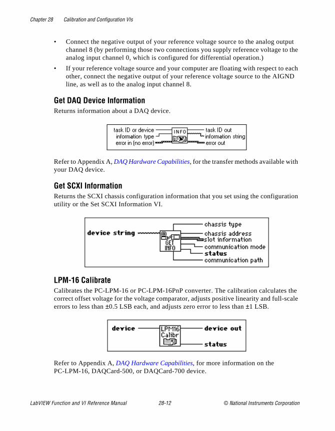
Chapter 28 Calibration and Configuration VIs
tput o the
each ND
tion
the cale
• Connect the negative output of your reference voltage source to the analog ouchannel 8 (by performing those two connections you supply reference voltage tanalog input channel 0, which is configured for differential operation.)
• If your reference voltage source and your computer are floating with respect to other, connect the negative output of your reference voltage source to the AIGline, as well as to the analog input channel 8.
Get DAQ Device InformationReturns information about a DAQ device.
Refer to Appendix A, DAQ Hardware Capabilities, for the transfer methods available withyour DAQ device.
Get SCXI InformationReturns the SCXI chassis configuration information that you set using the configurautility or the Set SCXI Information VI.
LPM-16 Calibrate Calibrates the PC-LPM-16 or PC-LPM-16PnP converter. The calibration calculatescorrect offset voltage for the voltage comparator, adjusts positive linearity and full-serrors to less than ±0.5 LSB each, and adjusts zero error to less than ±1 LSB.
Refer to Appendix A, DAQ Hardware Capabilities, for more information on the PC-LPM-16, DAQCard-500, or DAQCard-700 device.
LabVIEW Function and VI Reference Manual 28-12 © National Instruments Corporation
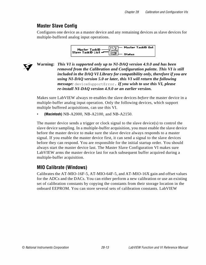
Chapter 28 Calibration and Configuration VIs
ces for
the vice
ter es ld a
es sting the
Master Slave ConfigConfigures one device as a master device and any remaining devices as slave devimultiple-buffered analog input operations.
Warning: This VI is supported only up to NI-DAQ version 4.9.0 and has been removed from the Calibration and Configuration palette. This VI is still included in the DAQ VI Library for compatibility only, therefore if you are using NI-DAQ version 5.0 or later, this VI will return the following message: deviceSupportError . If you wish to use this VI, please re-install NI-DAQ version 4.9.0 or an earlier version.
Makes sure LabVIEW always re-enables the slave devices before the master device in a multiple-buffer analog input operation. Only the following devices, which support multiple buffered acquisitions, can use this VI.
• (Macintosh) NB-A2000, NB-A2100, and NB-A2150.
The master device sends a trigger or clock signal to the slave device(s) to control slave device sampling. In a multiple-buffer acquisition, you must enable the slave debefore the master device to make sure the slave device always responds to a massignal. If you enable the master device first, it can send a signal to the slave devicbefore they can respond. You are responsible for the initial startup order. You shoualways start the master device last. The Master Slave Configuration VI makes sureLabVIEW arms the master device last for each subsequent buffer acquired during multiple-buffer acquisition.
MIO Calibrate (Windows)Calibrates the AT-MIO-16F-5, AT-MIO-64F-5, and AT-MIO-16X gain and offset valufor the ADCs and the DACs. You can either perform a new calibration or use an exiset of calibration constants by copying the constants from their storage location in onboard EEPROM. You can store several sets of calibration constants. LabVIEW
© National Instruments Corporation 28-13 LabVIEW Function and VI Reference Manual
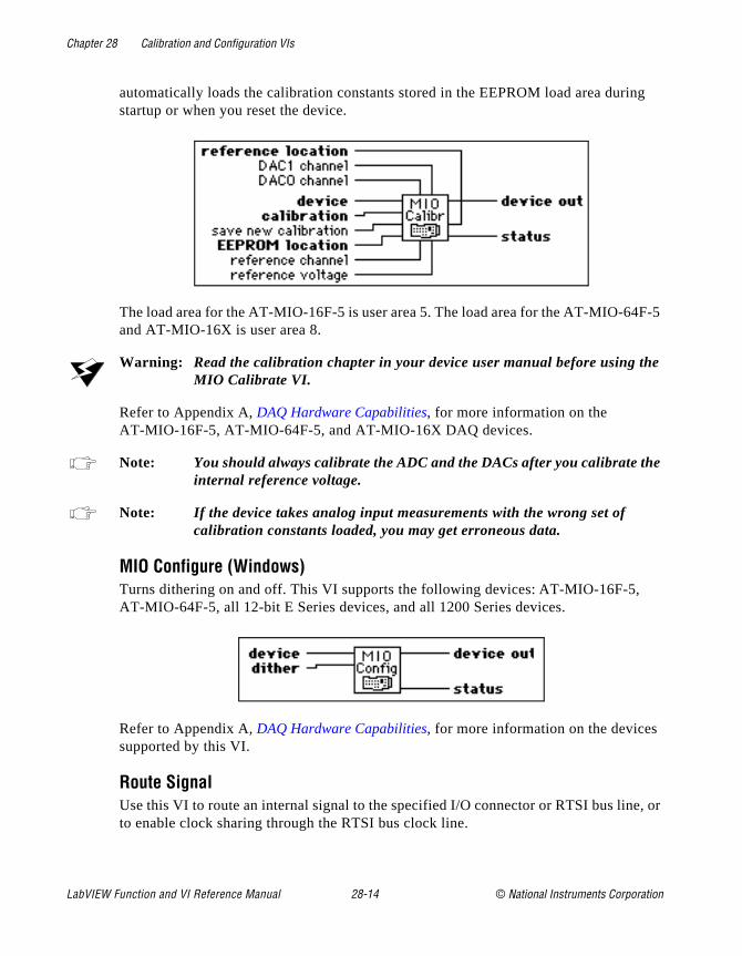
Chapter 28 Calibration and Configuration VIs
ng
F-5
e
e
e, or
automatically loads the calibration constants stored in the EEPROM load area duristartup or when you reset the device.
The load area for the AT-MIO-16F-5 is user area 5. The load area for the AT-MIO-64and AT-MIO-16X is user area 8.
Warning: Read the calibration chapter in your device user manual before using thMIO Calibrate VI.
Refer to Appendix A, DAQ Hardware Capabilities, for more information on the AT-MIO-16F-5, AT-MIO-64F-5, and AT-MIO-16X DAQ devices.
Note: You should always calibrate the ADC and the DACs after you calibrate thinternal reference voltage.
Note: If the device takes analog input measurements with the wrong set of calibration constants loaded, you may get erroneous data.
MIO Configure (Windows)Turns dithering on and off. This VI supports the following devices: AT-MIO-16F-5, AT-MIO-64F-5, all 12-bit E Series devices, and all 1200 Series devices.
Refer to Appendix A, DAQ Hardware Capabilities, for more information on the devicessupported by this VI.
Route SignalUse this VI to route an internal signal to the specified I/O connector or RTSI bus linto enable clock sharing through the RTSI bus clock line.
LabVIEW Function and VI Reference Manual 28-14 © National Instruments Corporation
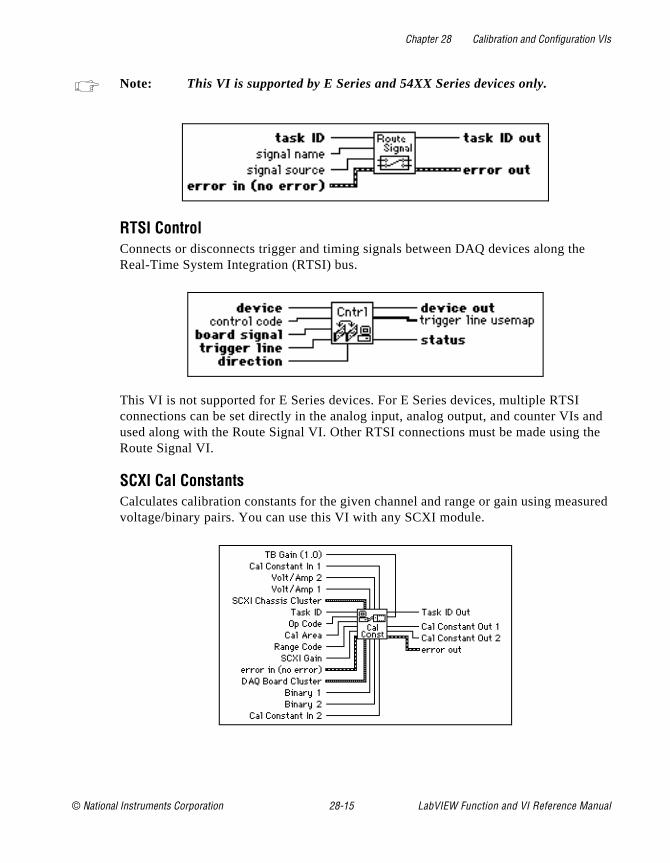
Chapter 28 Calibration and Configuration VIs
e
and the
sured
Note: This VI is supported by E Series and 54XX Series devices only.
RTSI ControlConnects or disconnects trigger and timing signals between DAQ devices along thReal-Time System Integration (RTSI) bus.
This VI is not supported for E Series devices. For E Series devices, multiple RTSI connections can be set directly in the analog input, analog output, and counter VIsused along with the Route Signal VI. Other RTSI connections must be made usingRoute Signal VI.
SCXI Cal ConstantsCalculates calibration constants for the given channel and range or gain using meavoltage/binary pairs. You can use this VI with any SCXI module.
© National Instruments Corporation 28-15 LabVIEW Function and VI Reference Manual

Chapter 28 Calibration and Configuration VIs
u on
Set DAQ Device InformationSets the data transfer mode for different types of operations.
Refer to Appendix A, DAQ Hardware Capabilities, for the transfer methods available withyour DAQ device.
Set SCXI InformationSets the SCXI chassis configuration information.
Use this VI to override the configuration already set with the configuration utility Yocan use this VI instead of using the configuration utility to enter the chassis configuratiinformation. If you do not use this VI, the first VI that accesses an SCXI chassis automatically tries to load information from the configuration file.
Channel Configuration VIs
The following illustration shows the Channel Configurations VIs palette.
LabVIEW Function and VI Reference Manual 28-16 © National Instruments Corporation
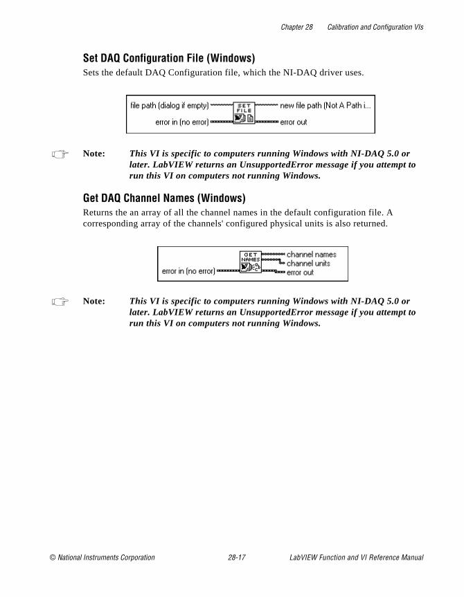
Chapter 28 Calibration and Configuration VIs
Set DAQ Configuration File (Windows)Sets the default DAQ Configuration file, which the NI-DAQ driver uses.
Note: This VI is specific to computers running Windows with NI-DAQ 5.0 or later. LabVIEW returns an UnsupportedError message if you attempt torun this VI on computers not running Windows.
Get DAQ Channel Names (Windows)Returns the an array of all the channel names in the default configuration file. A corresponding array of the channels' configured physical units is also returned.
Note: This VI is specific to computers running Windows with NI-DAQ 5.0 or later. LabVIEW returns an UnsupportedError message if you attempt torun this VI on computers not running Windows.
© National Instruments Corporation 28-17 LabVIEW Function and VI Reference Manual
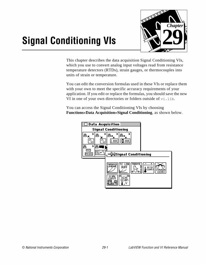
© National Instruments Corporation 29-1 LabVIEW Function and
Chapter
29
Signal Conditioning VIs, e o
em
ew
This chapter describes the data acquisition Signal Conditioning VIswhich you use to convert analog input voltages read from resistanctemperature detectors (RTDs), strain gauges, or thermocouples intunits of strain or temperature.
You can edit the conversion formulas used in these VIs or replace thwith your own to meet the specific accuracy requirements of your application. If you edit or replace the formulas, you should save the nVI in one of your own directories or folders outside of vi.lib .
You can access the Signal Conditioning VIs by choosing Functions»Data Acquisition»Signal Conditioning, as shown below.
VI Reference Manual
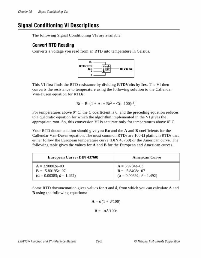
Chapter 29 Signal Conditioning VIs
r
es
The
Signal Conditioning VI Descriptions
The following Signal Conditioning VIs are available.
Convert RTD Reading Converts a voltage you read from an RTD into temperature in Celsius.
This VI first finds the RTD resistance by dividing RTDVolts by Iex. The VI then converts the resistance to temperature using the following solution to the CallendaVan-Dusen equation for RTDs:
Rt = Ro[1 + At + Bt2 + C(t–100)t3]
For temperatures above 0° C, the C coefficient is 0, and the preceding equation reducto a quadratic equation for which the algorithm implemented in the VI gives the appropriate root. So, this conversion VI is accurate only for temperatures above 0° C.
Your RTD documentation should give you Ro and the A and B coefficients for the Callendar Van-Dusen equation. The most common RTDs are 100-Ω platinum RTDs that either follow the European temperature curve (DIN 43760) or the American curve. following table gives the values for A and B for the European and American curves.
Some RTD documentation gives values for α and ∂, from which you can calculate A and B using the following equations:
A = α(1 + ∂/100)
B = –α∂/1002
European Curve (DIN 43760) American Curve
A = 3.90802e–03B = –5.80195e–07(α = 0.00385; ∂ = 1.492)
A = 3.9784e–03B = –5.8408e–07(α = 0.00392; ∂ = 1.492)
LabVIEW Function and VI Reference Manual 29-2 © National Instruments Corporation
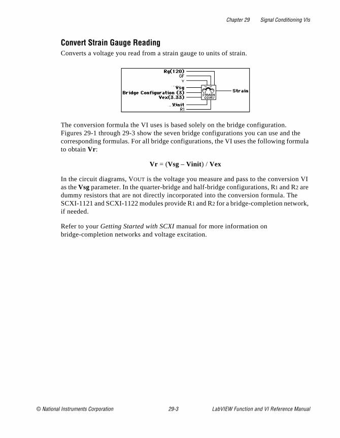
Chapter 29 Signal Conditioning VIs
he ula
VI
Convert Strain Gauge Reading Converts a voltage you read from a strain gauge to units of strain.
The conversion formula the VI uses is based solely on the bridge configuration. Figures 29-1 through 29-3 show the seven bridge configurations you can use and tcorresponding formulas. For all bridge configurations, the VI uses the following formto obtain Vr :
Vr = (Vsg – Vinit ) / Vex
In the circuit diagrams, VOUT is the voltage you measure and pass to the conversionas the Vsg parameter. In the quarter-bridge and half-bridge configurations, R1 and R2 are dummy resistors that are not directly incorporated into the conversion formula. TheSCXI-1121 and SCXI-1122 modules provide R1 and R2 for a bridge-completion network, if needed.
Refer to your Getting Started with SCXI manual for more information on bridge-completion networks and voltage excitation.
© National Instruments Corporation 29-3 LabVIEW Function and VI Reference Manual
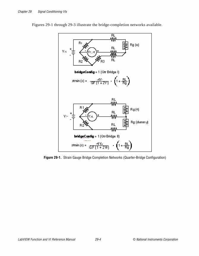
Chapter 29 Signal Conditioning VIs
Figures 29-1 through 29-3 illustrate the bridge-completion networks available.
Figure 29-1. Strain Gauge Bridge Completion Networks (Quarter-Bridge Configuration)
LabVIEW Function and VI Reference Manual 29-4 © National Instruments Corporation
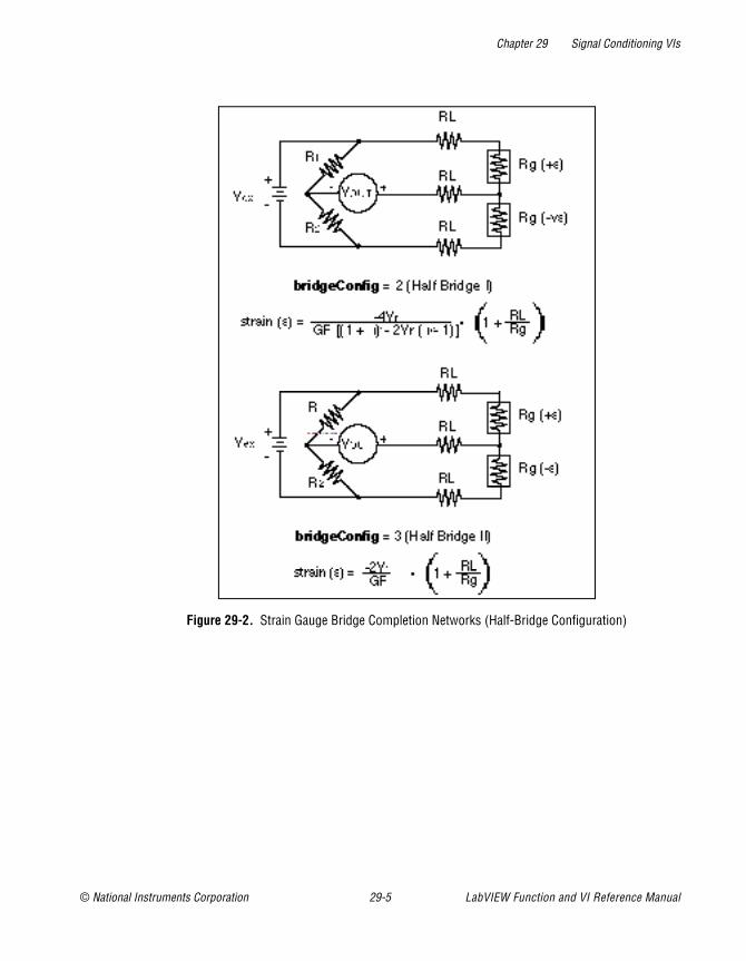
Chapter 29 Signal Conditioning VIs
Figure 29-2. Strain Gauge Bridge Completion Networks (Half-Bridge Configuration)
© National Instruments Corporation 29-5 LabVIEW Function and VI Reference Manual

Chapter 29 Signal Conditioning VIs
Figure 29-3. Strain Gauge Bridge Completion Networks (Full-Bridge Configuration)
LabVIEW Function and VI Reference Manual 29-6 © National Instruments Corporation

Chapter 29 Signal Conditioning VIs
s. is is l
urce.
Convert Thermistor ReadingConverts a thermistor voltage into temperature. This VI has two different modes ofoperation for voltage-excited and current-excited thermistors.
This VI has two modes of operation for use with different types of thermistor circuitFigure 29-4 shows how the thermistor can be connected to a voltage reference. Ththe setup used in the SCXI-1303, SCXI-1322, SCXI-1327, and SCXI-1328 terminablocks, which use an onboard thermistor for cold-junction compensation.
Figure 29-4. Circuit Diagram of a Thermistor in a Voltage Divider
Figure 29-5 shows a circuit where the thermistor is excited by a constant current soAn example of this setup would be the use of the DAQPad-MIO-16XE-50, which
© National Instruments Corporation 29-7 LabVIEW Function and VI Reference Manual
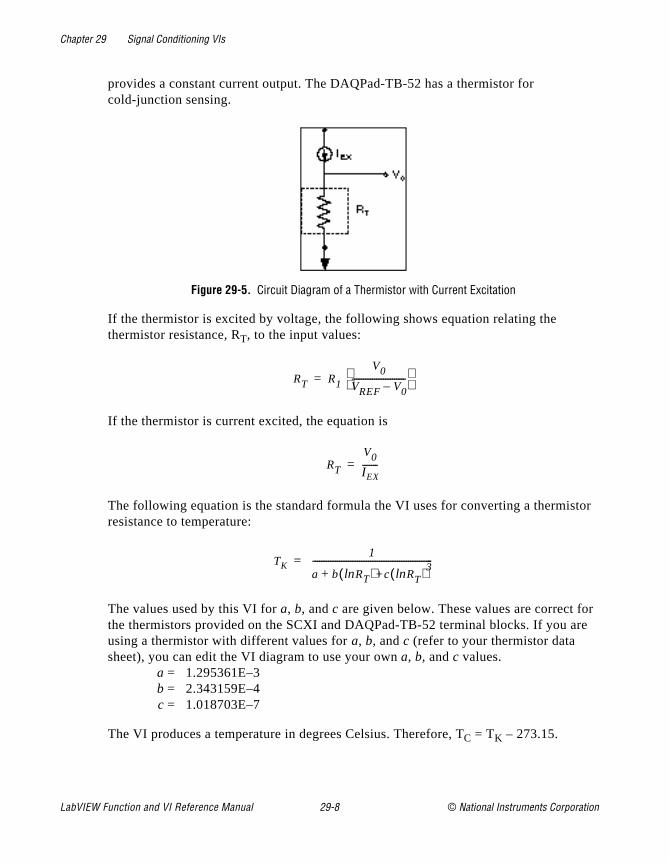
Chapter 29 Signal Conditioning VIs
tor
r re
provides a constant current output. The DAQPad-TB-52 has a thermistor for cold-junction sensing.
Figure 29-5. Circuit Diagram of a Thermistor with Current Excitation
If the thermistor is excited by voltage, the following shows equation relating the thermistor resistance, RT, to the input values:
If the thermistor is current excited, the equation is
The following equation is the standard formula the VI uses for converting a thermisresistance to temperature:
The values used by this VI for a, b, and c are given below. These values are correct fothe thermistors provided on the SCXI and DAQPad-TB-52 terminal blocks. If you ausing a thermistor with different values for a, b, and c (refer to your thermistor data sheet), you can edit the VI diagram to use your own a, b, and c values.
a = 1.295361E–3b = 2.343159E–4c = 1.018703E–7
The VI produces a temperature in degrees Celsius. Therefore, TC = TK – 273.15.
RT R1
V0
VREF V0–------------------------
=
RT
V0
IEX-------=
TK1
a b lnRT( )+c lnRT( )3+
------------------------------------------------------=
LabVIEW Function and VI Reference Manual 29-8 © National Instruments Corporation

Chapter 29 Signal Conditioning VIs
e in
elsius.
deal
et
g, or .
he 100, d the ype
ry
Convert Thermocouple Buffer Converts a voltage buffer read from a thermocouple into a temperature buffer valudegrees Celsius.
Convert Thermocouple ReadingConverts a voltage read from a thermocouple into a temperature value in degrees C
Scaling Constant TunerAdjusts the scaling constants, which LabVIEW uses to account for offset and non-igain, to convert analog input binary data to voltage data.
To use this VI correctly, you must first take two analog input readings—a zero offsreading and a known-voltage reading.
The default binary offset for each channel in the group is 0. To determine the actual binary offset for a channel path, ground the channel inputs and take a binary readintake multiple binary readings and average them to get fractional LSBs of the offset
If you use SCXI, ground the inputs of the SCXI channels to measure the offset of tentire signal path, including both the SCXI module and the DAQ device. The SCXI-1SCXI-1122, and SCXI-1141 modules have an internal switch you can use to grounamplifier inputs without actually wiring the terminals to ground. To use this feature, tthe special SCXI string CALGND in your SCXI channel string as described in the Amplifier Offset section of Chapter 19, Common SCXI Applications, in the LabVIEW Data Acquisition Basics Manual. Use intermediate or advanced analog input VIs to get binadata instead of voltage data.
© National Instruments Corporation 29-9 LabVIEW Function and VI Reference Manual

Chapter 29 Signal Conditioning VIs
en it alues ry ary urate e
e nge ode ain
ld re
e
he
dware
ply
lues
Note: If your device supports dithering, you should enable dither on your DAQdevice when you take multiple readings and average them.
LabVIEW assumes the DAQ devices gain settings and SCXI modules are ideal whscales binary readings to voltage, unless you use this VI to determine actual gain vfor the channels. Apply a known precision voltage to each channel and take a binareading, or take multiple readings from each channel and compute an average binreading for each channel. Your precision voltage should be about ten times as accas the resolution of your DAQ device to produce meaningful results. When you wirbinary readings, precision voltages, and binary offsets to this VI, LabVIEW determines the actual gain using the following formula:
In this formula, the voltage resolution value expressed in volts per LSB and is a valuthat varies depending on the DAQ device type, the polarity setting, and the input rasetting. For example, the voltage resolution for a PCI-MIO-16E-1 device in bipolar mwith an input range of +5 to –5 V is 2.44 mV. The VI returns an array of the actual gvalues that the VI stores for each channel.
Note: When you take readings to determine the offset and actual gain, you shouuse the same input limits settings and clock rates that you use to measuyour input signals.
LabVIEW uses the following equation to scale binary readings to voltage:
When you run the AI Group Config VI, it sets the attributes of all the channels in thgroup to their defaults, including the binary offset and gain values.
You can wire channel list if you want to adjust the scaling constants for a subset of tchannels in the group. If you leave channel list unwired, the VI adjusts the scaling constants for all channels in the group. The VI uses the same method as the AI HarConfig VI to apply values in the binary offsets, precision voltages, and binary readings input arrays That is, if you wired channel list first (at index 0) of the input arrays apto the channels listed at index 0 of channel list if you wired channel list, or to the channels listed at index 0 of channel list. If you leave channel list unwired, the first values of the input arrays apply to the first channel in the group. The VI applies the vaof each input array to channel list channels or the group in this manner until the VI
actual gainvoltage resolution * binary reading binary offset–( )
precision voltage-----------------------------------------------------------------------------------------------------------------------------=
voltagevoltage resolution * binary reading binary offset–( )
gain-----------------------------------------------------------------------------------------------------------------------------=
LabVIEW Function and VI Reference Manual 29-10 © National Instruments Corporation
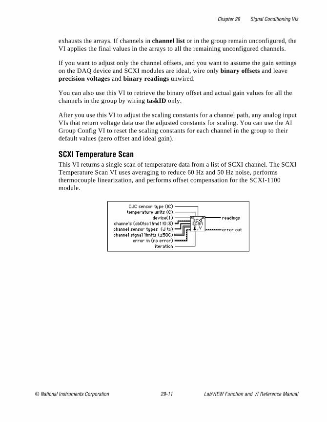
Chapter 29 Signal Conditioning VIs
.
ttings
the
input e AI ir
CXI
exhausts the arrays. If channels in channel list or in the group remain unconfigured, theVI applies the final values in the arrays to all the remaining unconfigured channels
If you want to adjust only the channel offsets, and you want to assume the gain seon the DAQ device and SCXI modules are ideal, wire only binary offsets and leave precision voltages and binary readings unwired.
You can also use this VI to retrieve the binary offset and actual gain values for all channels in the group by wiring taskID only.
After you use this VI to adjust the scaling constants for a channel path, any analog VIs that return voltage data use the adjusted constants for scaling. You can use thGroup Config VI to reset the scaling constants for each channel in the group to thedefault values (zero offset and ideal gain).
SCXI Temperature ScanThis VI returns a single scan of temperature data from a list of SCXI channel. The STemperature Scan VI uses averaging to reduce 60 Hz and 50 Hz noise, performs thermocouple linearization, and performs offset compensation for the SCXI-1100 module.
© National Instruments Corporation 29-11 LabVIEW Function and VI Reference Manual
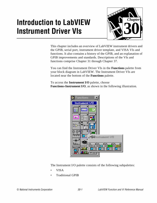
© National Instruments Corporation 30-1 LabVIEW Function and
Chapter
30
Introduction to LabVIEW Instrument Driver VIsnd of
This chapter includes an overview of LabVIEW instrument drivers athe GPIB, serial port, instrument driver template, and VISA VIs andfunctions. It also contains a history of the GPIB, and an explanationGPIB improvements and standards. Descriptions of the VIs and functions comprise Chapter 31 through Chapter 37.
You can find the Instrument Driver VIs in the Functions palette from your block diagram in LabVIEW. The Instrument Driver VIs are located near the bottom of the Functions palette.
To access the Instrument I/O palette, choose Functions»Instrument I/O , as shown in the following illustration.
The Instrument I/O palette consists of the following subpalettes:
• VISA
• Traditional GPIB
VI Reference Manual

Chapter 30 Introduction to LabVIEW Instrument Driver VIs
g
at t r
e
he nt.
or d
as ur ot
er
• GPIB 488.2
• Serial
You can find helpful information about individual VIs online by usinthe LabVIEW Help window (Help»Show Help). When you place the cursor on a VI icon, the wiring diagram and parameter names for thVI appear in the Help window. You can also find information for fronpanel controls or indicators by placing the cursor over the control oindicator with the Help window open. For more information on the LabVIEW Help window, refer to the Getting Help section in Chapter 2, Creating VIs, of the LabVIEW User Manual.
In addition to the Help window, LabVIEW has more extensive onlininformation available. To access this information, select Help»Online Reference. For most block diagram objects, you can select Online Reference from the object’s pop-up menu to access the online description. For information on creating your own online reference files, see the Creating Your Own Help Files section in Chapter 25, Managing Your Applications of the LabVIEW User Manual.
Instrument Drivers OverviewA LabVIEW instrument driver is a set of VIs that control a programmable instrument. Each VI corresponds to a programmaticoperation such as configuring, reading from, writing to, or triggeringthe instrument. LabVIEW instrument drivers simplify instrument control and reduce test program development time by eliminating tneed to learn the low-level programming protocol for each instrume
The LabVIEW instrument driver library contains instrument drivers fa variety of programmable instrumentation, including GPIB, VXI, anserial. If a driver for your instrument is in the library, you can use it is to control your instrument. Instrument drivers are distributed withtheir block diagram source code, so you can customize them for yospecific application. If a driver for your particular instrument does nexist, you can:
• Try using a driver for a similar instrument. Often similar instruments from the same manufacturer have similar if not identical instrument drivers.
• Modify the Instrument Driver Template VIs to create a new drivfor your instrument.
LabVIEW Function and VI Reference Manual 30-2 © National Instruments Corporation
Chapter 30 Introduction to LabVIEW Instrument Driver VIs
ou files
l
one
l le, u
t for
nt
wn ent ds
• Use either the GPIB, VXI, Serial, or VISA I/O libraries providedwith LabVIEW to send commands directly to your instrument.
Instrument Driver DistributionLabVIEW instrument drivers are distributed in a variety of media including electronic via bulletin board and internet and CD-ROM.
You can download the latest versions of the LabVIEW instrument drivers from one of the National Instruments bulletin boards and, if yhave internet access, you can download the latest instrument driver from the National Instrument File Transfer Protocol site. See the Bulletin Board Support and FTP Support sections of Appendix E, Customer Communication.
CD-ROM Instrument Driver DistributionThe entire library of LabVIEW instrument drivers is available on CD-ROM. The instrument driver CD-ROM is available from NationaInstruments at no charge.
You can retrieve the latest instrument driver list on a touch-tone phby calling the National Instruments automated fax system, Fax-on-Demand, at (512) 418-1111 or by calling National Instruments.
Instrument Driver Template VIsThe LabVIEW instrument driver templates are the foundation for alLabVIEW instrument driver development. The templates have a simpflexible structure and a common set of instrument driver VIs that yocan use for driver development. The VIs establish a standard formaall LabVIEW drivers and each has instructions for modifying it for aparticular instrument.
The LabVIEW instrument driver templates are predefined instrumedriver VIs that perform common operations such as initialization, self-test, reset, error query, and so on. Instead of developing your oVIs to accomplish these tasks, you should use the LabVIEW instrumdriver template VIs, which already conform to the LabVIEW standarfor instrument drivers.
Chapter 33, Instrument Driver Template VIs, provides more information on the Instrument Driver Template VIs.
© National Instruments Corporation 30-3 LabVIEW Function and VI Reference Manual

Chapter 30 Introduction to LabVIEW Instrument Driver VIs
es
in he uch
in PIB
ate.
r
rd 87.
,
Introduction to VISA LibraryVISA (Virtual Instrument Software Architecture) is a single interfacelibrary for controlling VXI, GPIB, RS-232, and other types of instruments. The VISA Library provides a standard set of I/O routinused by all LabVIEW instrument drivers. Using the VISA functions,you can construct a single instrument driver VI which controls a particular instrument model across different I/O interfaces.
An instrument descriptor string is passed to the VISA Open functionorder to select which kind of I/O will be used to communicate with tinstrument. Once the session with the instrument is open, functions sas VISA Read and VISA Write perform the instrument I/O activities a generic manner such that the program is not tied to any specific Gor VXI functions. Such an instrument driver is considered to be interface independent and can be used as is in different systems.
Instrument drivers which use the VISA functions perform activities specific to the instrument, not to the communication interface. Thiscreates more opportunities for using the instrument driver in many diverse situations.
For more information on VISA functions, see Chapter 34, VISA Library Reference.
Introduction to GPIBThe General Purpose Interface Bus (GPIB) is a link, or interface system, through which interconnected electronic devices communic
History of the GPIBHewlett-Packard designed the GPIB (originally called the HP-IB) tointerconnect and control its line of programmable instruments. TheGPIB was soon applied to other applications such as intercomputecommunication and peripheral control because of its 1 Mbytes/s maximum data transfer rates. It was later accepted as IEEE Standa488-1975 and has since evolved into ANSI/IEEE Standard 488.2-19The versatility of the system prompted the name General Purpose Interface Bus. For a basic description of the GPIB, see Appendix COperation of the GPIB.
LabVIEW Function and VI Reference Manual 30-4 © National Instruments Corporation
Chapter 30 Introduction to LabVIEW Instrument Driver VIs
sive,
t rors and
ain
ach
n
s the ility ive es
tly B
s.
National Instruments brought the GPIB to users of non-Hewlett-Packard computers and devices, specializing in both high-performance, high-speed hardware interfaces and comprehenfull-function software. The GPIB functions for LabVIEW follow the IEEE 488.2 specification.
The IEEE 488.2 StandardThe ANSI/IEEE Standard 488.2-1987 expanded on the earlier IEEE 488.1 standard to describe exactly how the Controller shouldmanage the GPIB, including the standard messages that compliandevices should understand, the mechanisms for reporting device erand other status information, and the various protocols that discoverconfigure compliant devices connected to the bus.
The original standard, renamed IEEE 488.1, addressed only the hardware specifications of the GPIB cable and basic protocols. Its mshortcoming was that it left the interpretation of the standard as it applied to GPIB devices up to the instrument manufacturers. Thus, eGPIB instrument had a unique command set. To integrate each instrument into a particular GPIB system, programmers had to learprogramming particulars for each device, a time-consuming and frustrating process. IEEE 488.2 specifically states how compliant devices must communicate. This standard, along with Standard Commands for Programmable Instruments (SCPI), which defines specific function-dependent command sets, makes instrument programming more uniform.
The IEEE 488.2 standard also addresses Controller issues, such acapabilities a compatible Controller must have. For example, the abto monitor any of the bus lines at any time is crucial for detecting actdevices (Talkers and Listeners) on the GPIB. IEEE 488.2 also definthe bus commands and protocols a Controller must use. The new standard also lists minimum functionality requirements, which direcinfluence the style of the NI-488.2 software in general and the GPI488.2 functions for LabVIEW in particular. Appendix C, Operation of the GPIB, for more information on Talkers, Listeners, and Controller
© National Instruments Corporation 30-5 LabVIEW Function and VI Reference Manual
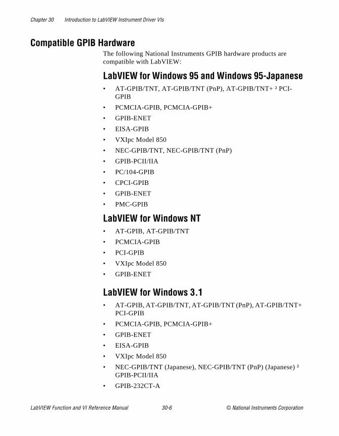
Chapter 30 Introduction to LabVIEW Instrument Driver VIs
) ²
Compatible GPIB HardwareThe following National Instruments GPIB hardware products are compatible with LabVIEW:
LabVIEW for Windows 95 and Windows 95-Japanese• AT-GPIB/TNT, AT-GPIB/TNT (PnP), AT-GPIB/TNT+ ² PCI-
GPIB
• PCMCIA-GPIB, PCMCIA-GPIB+
• GPIB-ENET
• EISA-GPIB
• VXIpc Model 850
• NEC-GPIB/TNT, NEC-GPIB/TNT (PnP)
• GPIB-PCII/IIA
• PC/104-GPIB
• CPCI-GPIB
• GPIB-ENET
• PMC-GPIB
LabVIEW for Windows NT• AT-GPIB, AT-GPIB/TNT
• PCMCIA-GPIB
• PCI-GPIB
• VXIpc Model 850
• GPIB-ENET
LabVIEW for Windows 3.1• AT-GPIB, AT-GPIB/TNT, AT-GPIB/TNT (PnP), AT-GPIB/TNT+
PCI-GPIB
• PCMCIA-GPIB, PCMCIA-GPIB+
• GPIB-ENET
• EISA-GPIB
• VXIpc Model 850
• NEC-GPIB/TNT (Japanese), NEC-GPIB/TNT (PnP) (JapaneseGPIB-PCII/IIA
• GPIB-232CT-A
LabVIEW Function and VI Reference Manual 30-6 © National Instruments Corporation
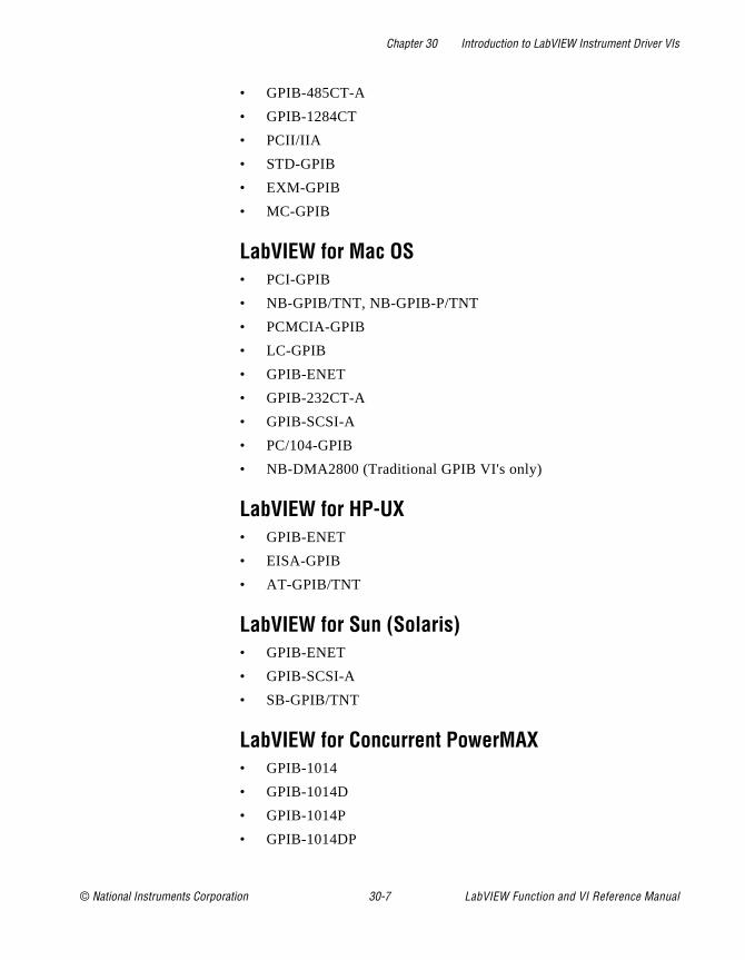
Chapter 30 Introduction to LabVIEW Instrument Driver VIs
• GPIB-485CT-A
• GPIB-1284CT
• PCII/IIA
• STD-GPIB
• EXM-GPIB
• MC-GPIB
LabVIEW for Mac OS• PCI-GPIB
• NB-GPIB/TNT, NB-GPIB-P/TNT
• PCMCIA-GPIB
• LC-GPIB
• GPIB-ENET
• GPIB-232CT-A
• GPIB-SCSI-A
• PC/104-GPIB
• NB-DMA2800 (Traditional GPIB VI's only)
LabVIEW for HP-UX• GPIB-ENET
• EISA-GPIB
• AT-GPIB/TNT
LabVIEW for Sun (Solaris)• GPIB-ENET
• GPIB-SCSI-A
• SB-GPIB/TNT
LabVIEW for Concurrent PowerMAX• GPIB-1014
• GPIB-1014D
• GPIB-1014P
• GPIB-1014DP
© National Instruments Corporation 30-7 LabVIEW Function and VI Reference Manual
Chapter 30 Introduction to LabVIEW Instrument Driver VIs
ds
8 r than
e
ior rent
e
ill
he
f a
on. rror
an
st
LabVIEW Traditional GPIB FunctionsThe traditional GPIB functions are compatible with all the GPIB boarlisted in the Compatible GPIB Hardware section of this chapter.
These traditional GPIB functions are compatible with both IEEE 48and IEEE 488.2 devices and are suffcient for most applications. Fomore complex applications, such as using several devices and moreone GPIB interface, you can use the GPIB IEE 488.2 functions.
For more information on the LabVIEW Traditional GPIB functions, seChapter 35, Traditional GPIB Functions.
GPIB 488.2 FunctionsUsing GPIB 488.2 functions together with IEEE 488.2-compatible devices improves the predictability of instrument and software behavand lessens programming differences between instruments of diffemanufacturers.
The latest revisions of many National Instruments GPIB boards arefully compatible with the IEEE 488.2 specification for Controllers. ThLabVIEW package also contains functions that make use of IEEE 488.2. By using these functions, your programming interface wstrictly adhere to the IEEE 488.2 standard for command and data sequences.
The GPIB 488.2 functions contain the same basic functionality as ttraditional GPIB functions, and include the following enhancementsand additions:
• You specify the GPIB device address with an integer instead ostring. Further, you specify the bus number with an additional numeric control, which makes dealing with multiple GPIB interfaces easier.
• You can determine the GPIB status, error, and/or byte count immediately from the connector pane of each GPIB 488.2 functiYou no longer need to use the GPIB Status Function to obtain eand other information.
• The FindLstn Function implements the IEEE 488.2 Find All Listeners protocol. You can use this function at the beginning ofapplication to determine which devices are present on the bus without knowing their addresses.
• The GPIB Misc Function is still available, but it is no longer necessary in most cases. IEEE 488.2 specifies routines for mo
LabVIEW Function and VI Reference Manual 30-8 © National Instruments Corporation

Chapter 30 Introduction to LabVIEW Instrument Driver VIs
r
e
se 8.2 al
s
ns s an
,
6,
am l
GPIB application needs, which are implemented as functions. However, you can mix the GPIB Misc Function, as well as otheGPIB functions, with the GPIB 488.2 functions if you need to.
• There are GPIB 488.2 functions with low-level as well as high-level functionality, to suit any GPIB application. You can usthe low-level functions in Non-Controller situations or when youneed additional flexibility.
• Although you must use an IEEE 488.2-compatible Controller to uthese functions, they can control both IEEE 488.1 and IEEE 48devices. The GPIB 488.2 functions are divided into five functioncategories: single-device, multiple-device, bus management, low-level, and general.
Single-Device FunctionsThe single-device functions perform GPIB I/O and control operationwith a single GPIB device. In general, each function accepts a single-device address as one of its inputs.
For more information on Single-Device Functions, see Chapter 36,GPIB 488.2 Functions.
Multiple-Device FunctionsThe multiple-device functions perform GPIB I/O and control operatiowith several GPIB devices at once. In general, each function acceptarray of addresses as one of its inputs.
For more information on Multiple Device Functions, see Chapter 36GPIB 488.2 Functions.
Bus Management FunctionsThe bus management functions perform system-wide functions or report system-wide status.
For more information on Bus Management functions, see Chapter 3GPIB 488.2 Functions.
Low-Level FunctionsThe low-level functions let you create a more specific, detailed progrthan higher-level functions. You use low-level functions for unusuasituations or for situations requiring additional flexibility.
© National Instruments Corporation 30-9 LabVIEW Function and VI Reference Manual
Chapter 30 Introduction to LabVIEW Instrument Driver VIs
g
For more information on Low-Level functions, see Chapter 36,GPIB 488.2 Functions.
General FunctionsThe general functions are useful for special situations. The followintable lists the general functions:
For more information on General functions, see Chapter 36,GPIB 488.2 Functions.
Serial Port VI OverviewThe serial port VIs configure the serial port of your computer and conduct I/O using that port.
For more information on serial port functions, see Chapter 37,Serial Port VIs.
LabVIEW Function and VI Reference Manual 30-10 © National Instruments Corporation
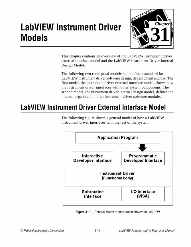
© National Instruments Corporation 31-1 LabVIEW Function and
Chapter
31
LabVIEW Instrument Driver Modelsr al
he ow
the
This chapter contains an overview of the LabVIEW instrument driveexternal interface model and the LabVIEW Instrument Driver InternDesign Model.
The following two conceptual models help define a standard for LabVIEW instrument driver software design, development and use. Tfirst model, the instrument driver external interface model, shows hthe instrument driver interfaces with other system components. Thesecond model, the instrument driver internal design model, definesinternal organization of an instrument driver software module.
LabVIEW Instrument Driver External Interface ModelThe following figure shows a general model of how a LabVIEW instrument driver interfaces with the rest of the system.
Figure 31-1. General Model of Instrument Drivers in LabVIEW
VI Reference Manual

Chapter 31 LabVIEW Instrument Driver Models
r
en nal
at ck
res.
e
is the
ith
VI
ce ng
mble g a
to
Functional BodyThe functional body is the actual code for the instrument driver. Refeto the LabVIEW Instrument Driver Internal Design Model section of this chapter, for more information.
The most successful instrument driver products historically have bedeveloped by using a standard programming language for the functiobody. This is the approach LabVIEW instrument drivers take. The advantages include greater developer control over the driver, morerobust drivers, and increased functionality. LabVIEW instrument drivers are written using the standard LabVIEW graphical programming environment.
The functional body of a LabVIEW instrument driver is a set of VIs thcontrol a specific instrument. The source code for these VIs are blodiagrams consisting of executable icons connected by data flow wiBecause the functional body is developed with the standard tools provided in LabVIEW, users can view instrument driver source codeasily and optimize it for their application.
Interactive Developer InterfaceThe interactive developer interface of a LabVIEW instrument driverthe front panel. It is analogous to a physical instrument panel and isinteractive user interface of the VI. On the panel, controls and indicators graphically represent the inputs and outputs of the VI. Wthe LabVIEW front panel, users can operate individual instrument driver VIs interactively and verify communication.
Programmatic Developer InterfaceThe icon/connector is the programmatic interface of the LabVIEW instrument driver VI. It consists of a graphical representation of the(icon) and a definition of the input and output terminals for the VI (connector). When you call or execute a VI from another VI, you plaa copy of the subVI icon/connector in the block diagram of the calliVI. Information passes between the two VIs through the connector terminals. There are several benefits to this approach. You can assetest systems easily using LabVIEW instrument drivers by combininfew instrument driver VIs, each using multiple parameters. The instrument driver interface in the user program is modular and easyidentify, and you can recall the VI front panels during debugging tounderstand how the program uses the instrument driver.
LabVIEW Function and VI Reference Manual 31-2 © National Instruments Corporation
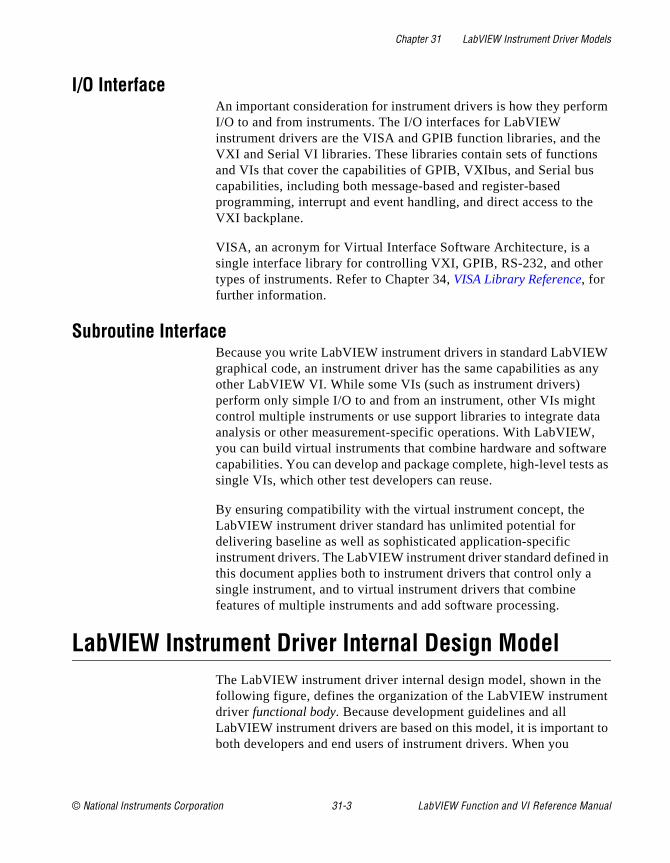
Chapter 31 LabVIEW Instrument Driver Models
m
e
e
r
W ny
ta , are ts as
in
e t
to
I/O InterfaceAn important consideration for instrument drivers is how they perforI/O to and from instruments. The I/O interfaces for LabVIEW instrument drivers are the VISA and GPIB function libraries, and thVXI and Serial VI libraries. These libraries contain sets of functionsand VIs that cover the capabilities of GPIB, VXIbus, and Serial buscapabilities, including both message-based and register-based programming, interrupt and event handling, and direct access to thVXI backplane.
VISA, an acronym for Virtual Interface Software Architecture, is a single interface library for controlling VXI, GPIB, RS-232, and othetypes of instruments. Refer to Chapter 34, VISA Library Reference, for further information.
Subroutine InterfaceBecause you write LabVIEW instrument drivers in standard LabVIEgraphical code, an instrument driver has the same capabilities as aother LabVIEW VI. While some VIs (such as instrument drivers) perform only simple I/O to and from an instrument, other VIs mightcontrol multiple instruments or use support libraries to integrate daanalysis or other measurement-specific operations. With LabVIEWyou can build virtual instruments that combine hardware and softwcapabilities. You can develop and package complete, high-level tessingle VIs, which other test developers can reuse.
By ensuring compatibility with the virtual instrument concept, the LabVIEW instrument driver standard has unlimited potential for delivering baseline as well as sophisticated application-specific instrument drivers. The LabVIEW instrument driver standard definedthis document applies both to instrument drivers that control only asingle instrument, and to virtual instrument drivers that combine features of multiple instruments and add software processing.
LabVIEW Instrument Driver Internal Design ModelThe LabVIEW instrument driver internal design model, shown in thfollowing figure, defines the organization of the LabVIEW instrumendriver functional body. Because development guidelines and all LabVIEW instrument drivers are based on this model, it is importantboth developers and end users of instrument drivers. When you
© National Instruments Corporation 31-3 LabVIEW Function and VI Reference Manual
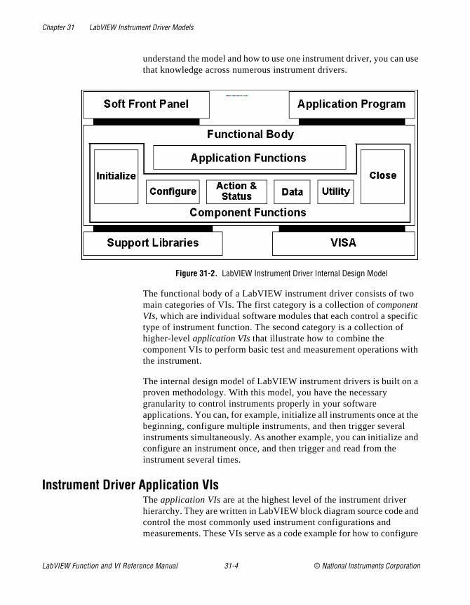
Chapter 31 LabVIEW Instrument Driver Models
use
ific
with
a
the and
nd
igure
understand the model and how to use one instrument driver, you canthat knowledge across numerous instrument drivers.
Figure 31-2. LabVIEW Instrument Driver Internal Design Model
The functional body of a LabVIEW instrument driver consists of twomain categories of VIs. The first category is a collection of component VIs, which are individual software modules that each control a spectype of instrument function. The second category is a collection of higher-level application VIs that illustrate how to combine the component VIs to perform basic test and measurement operations the instrument.
The internal design model of LabVIEW instrument drivers is built onproven methodology. With this model, you have the necessary granularity to control instruments properly in your software applications. You can, for example, initialize all instruments once at beginning, configure multiple instruments, and then trigger severalinstruments simultaneously. As another example, you can initialize configure an instrument once, and then trigger and read from the instrument several times.
Instrument Driver Application VIsThe application VIs are at the highest level of the instrument driver hierarchy. They are written in LabVIEW block diagram source code acontrol the most commonly used instrument configurations and measurements. These VIs serve as a code example for how to conf
LabVIEW Function and VI Reference Manual 31-4 © National Instruments Corporation

Chapter 31 LabVIEW Instrument Driver Models
ake ons
tion ver. ver
r
:
h
the instrument for a common operation, trigger the instrument, and tmeasurements. Because the application VIs are standard VIs, with icand connector panes, you can call them from any high-level applicawhen you want a single, measurement-oriented interface to the driFor many developers, the application VIs are the only instrument driVIs needed for instrument control. The Tek VX4790 Example VI, shown in the following figure, demonstrates an application VI front panel.
Figure 31-3. Tek VX4790 Example VI
The application VIs are built from a low-level set of instrument drivecomponent VIs.
Instrument Driver Component VIsLabVIEW instrument drivers have component VIs, which are a modular set of VIs that contain all of the instrument configuration and measurement capabilities. The component VIs fit into six categoriesinitialize, configuration, action/status, data, utility, and close.
All LabVIEW instrument drivers should have an initialize VI. It is the first instrument driver VI called, and establishes communication wit
© National Instruments Corporation 31-5 LabVIEW Function and VI Reference Manual

Chapter 31 LabVIEW Instrument Driver Models
o ther
ay nt.
ents
ons. ng a e
. f tual
Is
and .
he ity
m
ates
se
the instrument. Additionally, it can perform any necessary actions tplace the instrument either in its default power on state or in some ospecific state.
The configuration VIs are a collection of software routines that configure the instrument to perform the desired operation. There mbe numerous configuration VIs, depending on the particular instrumeAfter these VIs are called, the instrument is ready to take measuremor stimulate a system.
The action/status category contains two types of VIs. Action VIs cause the instrument to initiate or terminate test and measurement operatiThese operations can include arming the trigger system or generatistimulus. These VIs are different from the configuration VIs becausthey do not change the instrument settings, but only order the instrument to carry out an action based on its current configurationStatus VIs obtain the current status of the instrument or the status opending operations. The specific routines in this category and the acoperations they perform are left up to you.
Data VIs transfer data to or from the instrument. Examples include Vfor reading a measured value or waveform from a measurement instrument, VIs for downloading waveforms or digital patterns to a source instrument, and so on. The specific routines in this categorythe actual operations performed by those routines are left up to you
Utility VIs can perform a variety of operations that are auxiliary to tmost often used instrument driver VIs. These VIs include the majorof the instrument driver template VIs such as reset, self-test, revision query, error query, and error message and may include other custoinstrument driver VIs, such as calibration or storing and recalling setups.
All LabVIEW instrument drivers should include a close VI. The close VI terminates the software connection to the instrument and deallocsystem resources.
Each of these categories, with the exception of the initialize and cloVIs, consists of several modular VIs. Most of the critical work in developing an instrument driver lies in the initial design and organization of the instrument driver component VIs. The specific routines in each category are further categorized as either template VIs or developer-specified VIs.
LabVIEW Function and VI Reference Manual 31-6 © National Instruments Corporation
Chapter 31 LabVIEW Instrument Driver Models
tes ize, or
f
s
the
The template VIs are instrument driver VIs that you can use as templaor examples. These VIs perform common operations such as initialclose, reset, self-test, and revision query. The template VIs containmodification instructions for their use in a specific instrument driver fa particular instrument. For more information, refer to Chapter 33, Instrument Driver Template VIs.
The remainder of instrument driver VIs are known as developer-specified VIs, and the actual operations performed by thoseroutines are left up you. Although all instruments will have configuration VIs, some instruments can have a different number oconfiguration VIs depending on the unique capabilities of the instrument.
Figure 31-4 shows how the Tek VX4790 Example application VI diagram uses the instrument driver component VIs:
Figure 31-4. VIs in Tek VX4790 Example Diagram
The block diagram of the instrument driver component VIs uses standard LabVIEW VIs, as well as VISA VIs to build command stringand send them to the instrument. In the following figure, the Tek VX4790 Config Std Wave component VI block diagram assembles command string and wires it into the VISA Write function. This function
© National Instruments Corporation 31-7 LabVIEW Function and VI Reference Manual

Chapter 31 LabVIEW Instrument Driver Models
and ic
ent
ly. er nt
ed
ing
performs the necessary I/O, checks for errors, and updates the appropriate error indicators.
Figure 31-5. Tek VX4790 Config Std Wave Diagram
Error ReportingLabVIEW instrument drivers use error clusters to report all errors. Inside the cluster, a Boolean error indicator, a numeric error code, an error source string indicator report if there is an error, the speciferror condition, and the source (name) of the VI in which the error occurred. Additional comments may also be included. Each instrumdriver VI has an error in and an error out terminal defined on its connector pane in the lower left and lower right terminals respectiveBy wiring the error out cluster of one VI to the error in cluster of anothVI, you can pass error information all the way through your instrumedriver and out to your full application.
Another benefit of error input/output is that data dependency is addto VIs that are not otherwise data dependent.
Additional VIs Distributed with the Instrument DriverIn addition to the VIs described by the internal model, include a GettStarted VI and a VI Tree VI with your instrument driver files.
LabVIEW Function and VI Reference Manual 31-8 © National Instruments Corporation
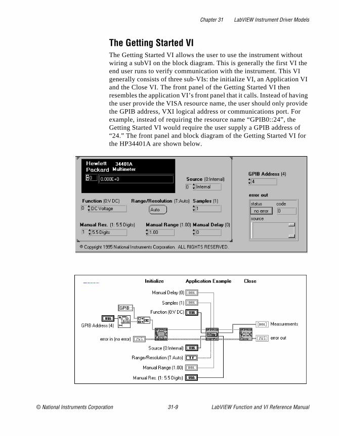
Chapter 31 LabVIEW Instrument Driver Models
t e
I
ing ide
r
f r
The Getting Started VIThe Getting Started VI allows the user to use the instrument withouwiring a subVI on the block diagram. This is generally the first VI thend user runs to verify communication with the instrument. This VI generally consists of three sub-VIs: the initialize VI, an Application Vand the Close VI. The front panel of the Getting Started VI then resembles the application VI’s front panel that it calls. Instead of havthe user provide the VISA resource name, the user should only provthe GPIB address, VXI logical address or communications port. Foexample, instead of requiring the resource name “GPIB0::24”, the Getting Started VI would require the user supply a GPIB address o“24.” The front panel and block diagram of the Getting Started VI fothe HP34401A are shown below.
© National Instruments Corporation 31-9 LabVIEW Function and VI Reference Manual

Chapter 31 LabVIEW Instrument Driver Models
at s oes e
ee
The VI Tree VIIn order for customers to view the entire instrument driver hierarchyonce, a VI Tree VI is required. This VI is a non-executable VI that idesigned to show the functional structure of the VI. If an end user dnot install the palette menu files for the instrument, the VI Tree is thonly resource to understanding the structure. An example of a VI trVI is shown below.
LabVIEW Function and VI Reference Manual 31-10 © National Instruments Corporation
© National Instruments Corporation 32-1 LabVIEW Function and
Chapter
32
LabVIEW Instrument Driver Developmentd , ll
a
Is.
d no by r
ses, e VI
re, ply. d
is ion ion
This chapter describes the procedure for developing a LabVIEW instrument driver. The ideal LabVIEW instrument driver has full function control of the instrument. Rather than mandate the requirefunctionality of all instrument types, such as DMMs, counter/timersand so on, this chapter focuses on the architectural guidelines of adrivers. With this information, driver developers can implement functionality unique to a particular instrument, and still organize, package and use all drivers in the same way.
Development ProcedureThe best way to develop a LabVIEW Instrument Driver is to follow three-step process. In step one, you design the instrument driver structure. In step two, you modify the instrument driver templates VIn step three, you add developer defined VIs.
Designing the Instrument Driver StructureThe ideal instrument driver does what the user needs—no more anless. No particular type of driver design is perfect for everyone, butcarefully studying the instrument and grouping controls into modulaVIs, you can satisfy most users.
When the number of programmable controls in an instrument increaso does the need for modular instrument driver design since a singlcannot access all features. However, when an instrument driver contains hundreds of VIs, each controlling a single instrument featumore instrument rules regarding command order and interaction apModular design simplifies the tasks of controlling the instrument anmodifying VIs to meet special requirements.
Ideally, you should devise the overall structure of your instrument driver before you build the individual VIs. A useful instrument driver more than a series of VIs; it is a tool to help users develop applicatprograms. You should design an instrument driver with the applicatand end user in mind.
VI Reference Manual
Chapter 32 LabVIEW Instrument Driver Development
n 3,
ne is
ps
n
a
ion he or
th
e of
You must create some instrument driver VIs that control unique instrument features. However, you can use template VIs for commooperations. For more information about template VIs see Chapter 3Instrument Driver Template VIs.
Instrument Driver Structure and VI HierarchyWhen you develop a LabVIEW instrument driver, it is important to clearly define the structure and VI hierarchy of the driver. First, defithe primary VIs and develop a modular VI hierarchy. This hierarchythe design document for a LabVIEW instrument driver.
Useful instrument drivers come from an in-depth knowledge of the instrument operation and use in test applications. The following steoutline one approach to developing the structure for the LabVIEW instrument drivers:
1. Familiarize yourself with the instrument operation. Read the operating manual thoroughly. Typically the foundation of the driver hierarchy is in the instrument programming manual. Learhow to use the instrument interactively before you attempt anyprogramming.
2. Use the instrument in an actual test set-up to get practical experience. (The operating manual may explain how to set up simple test.)
3. Study the programming section of the manual. Skim the instructset to see which controls and functions are available and how tfeatures are organized. Decide which features are best suited fprogrammatic use.
4. Examine instrument drivers for similar instruments. Often instruments from the same family have the same programmingcommand set and you can easily modify their corresponding instrument drivers.
5. Determine which LabVIEW template VIs are suitable for use wiyour instrument.
6. Develop a structure for the driver by looking for controls that arused together to perform a single task or function. The sectionsa well organized manual often correspond to the functional groupings of an instrument driver.
LabVIEW Function and VI Reference Manual 32-2 © National Instruments Corporation

Chapter 32 LabVIEW Instrument Driver Development
nd
ed
st,
d ur
EE ent
n e
Instrument Driver VI OrganizationAfter you have developed your Instrument Driver structure, you candevelop a VI hierarchy to organize the VIs that will be necessary tocreate the driver.
The VI organization of an instrument driver defines the hierarchy aoverall relationship of the instrument driver component VIs.
You define the majority of instrument driver VIs and design them toaccess the unique capabilities of a particular instrument. However,many operations common to all types of instrumentation are performby the template instrument driver VIs: initialize, close, reset, self-terevision query, error query, and error message.
The template VIs for LabVIEW instrument drivers include prewrittenVIs to perform these common instrument operations. The commanstrings are based on the VISA functions. To include these VIs in yoinstrument driver, modify the command strings as required for yourinstrument. If the instrument is IEEE 488.2 compliant, little or no modifications are needed. If you are developing a driver for a non-IE488.2 compliant or a register-based device, you will develop equivalVIs for your instrument.
A class is a group of VIs that perform similar operations. Common classes of VIs are configuration, action/status, data, and utility.
The following table shows an example instrument driver organizatiofor an oscilloscope. At the highest level of the hierarchy, you see thtemplate VIs, initialize and close and the typical classes of VIs.
Table 32-1. Instrument Driver Organization Example
VI Hierarchy Type
Initialize VI (Template)
Application VIs• Autosetup and Read Waveform• Rise-Time/Fall-Time Measurement
(Developer Defined) (Developer Defined)
© National Instruments Corporation 32-3 LabVIEW Function and VI Reference Manual

Chapter 32 LabVIEW Instrument Driver Development
he
any rm
ch
ent.
Guidelines and Recommendations• Design an instrument driver VI front panel that contains all the
controls required to perform the VI task.
For example, a configure measurement VI would contain only tnecessary controls to configure the instrument to take the measurement. It would not take the measurement or configure other features. Other VIs included in the instrument driver perfothese tasks.
• Design a modular instrument driver that contains a set of VIs, eaperforming a logical task or function such as configuring the instrument or taking a measurement.
A modular instrument driver is flexible and easy to use. For example, consider a digital multimeter driver design that uses asingle VI to both configure the instrument and read a measurem
Configuration VIs• Configure Vertical• Configure Horizontal• Configure Trigger• Configure Acquisition Mode• Autosetup
(Developer Defined)(Developer Defined)(Developer Defined(Developer Defined)(Developer Defined)
Action VIs• Acquire Data (Developer Defined)
Data VIs• Read Waveform• Voltmeter Measurement• Counter/Timer Measurement
(Developer Defined)(Developer Defined)(Developer Defined)
Utilities VIs• Reset• Self-Test• Revision Query• Error Query• Error Message
(Template)(Template)(Template)(Template)(Template)
Close VI (Template)
Table 32-1. Instrument Driver Organization Example (Continued)
VI Hierarchy Type
LabVIEW Function and VI Reference Manual 32-4 © National Instruments Corporation
Chapter 32 LabVIEW Instrument Driver Development
ing ild
take
e , an
h as ce
ser
se rs
the
rs
in d
des
be l
f an
t
The user cannot read multiple measurements without reconfigurthe meter each time the VI executes. A better approach is to butwo VIs: one to configure the instrument, and one to read a measurement. Then the user can configure the meter once andmultiple measurements.
• Concentrate on the correct level of granularity of driver VIs andhow these VIs will be used in a system.
An instrument driver with a few very high-level VIs may not givthe user enough control of the instrument operation. Converselyinstrument driver with many low-level VIs is difficult for users unfamiliar with instrument rules regarding command order and interaction. For example, when using a measurement device sucan oscilloscope, the user typically configures the instrument onand takes many measurements. In this case, you should write high-level configuration VIs for the device. On the other hand, when using a stimulus device such as a pulse generator, the umay want to vary individual parameters of the pulse to test the boundary conditions of his system, or perform frequency respontests. In this case, you should write lower-level VIs, so that usecan access individual instrument capabilities instead of reconfiguring each time they want to change one component ofoutput.
• Consider the relationship of the driver with other instrument drivein the system.
Typically, test designers want to initialize all of the instruments a system at once, then configure them, take measurements, anfinally close them at the end of the test. Good driver design inclulogical division of operations.
• Create an instrument driver design (both in appearance and functional structure) that is similar to other instruments of the same type.
Instrument drivers across a family of similar instruments shouldconsistent in appearance, structure, and style. For example, aloscilloscope drivers should resemble each other, as should all multimeters, scanners, and sources. If possible, modify a copy oexisting driver of a similar instrument.
• Design an instrument driver that optimizes the programming capability of the instrument.
You can sometimes exclude documented functions that are nowell-suited for programmatic use.
© National Instruments Corporation 32-5 LabVIEW Function and VI Reference Manual
Chapter 32 LabVIEW Instrument Driver Development
em
el
se an
ne
a
e lop
her
• Design each VI to be independent of other VIs.
If two or more VIs must always be used together, consolidate thinto one VI.
• Minimize redundant parameters.
For example, the parameters for each channel of a multi-channoscilloscope are similar or identical. Rather than duplicate the programming controls for each channel, you can include a VI control for selecting which channel to configure. The user can uthis VI to change the settings for an individual channel, rather thconfiguring every channel each time the VI is called.
Design ExampleDeciding which parameters to include in an instrument driver VI is oof the greatest challenges facing the instrument driver developer. Fortunately, organizational information is often available in the instrument’s manuals. In particular, the programming section of themanual may group the commands into sections such as configuringmeasurement, triggering, reading measurements, and so on. Thesgroupings can serve as a model for a driver hierarchy. Begin to devea structure for the driver by looking for controls that are used togetto perform a single task or function. A modular driver will contain individual VIs for each of the control groups.
LabVIEW Function and VI Reference Manual 32-6 © National Instruments Corporation

Chapter 32 LabVIEW Instrument Driver Development
l
n it
The following table shows how the command summary from the Tektronix VX4790 Arbitrary Waveform Generator Operating Manua relates to developer specified instrument driver VIs.
While the instrument manual can provide a great deal of informatioabout how to structure the instrument driver, you should not rely onexclusively. Your knowledge of the instrument and how it is used should be the ultimate guide. The preceding table shows manual
Table 32-2. Command Summary from Tektronix VX4790
Instrument Manual Section Instrument Driver VI
Setup Commands• External clock input enable• External trigger source• Sync pulse control• Isolation relay control
TKVX4790 Setup
Pre-Programmed Waveform Commands• Sine wave• Square wave• Triangle wave• Sawtooth wave
TKVX4790 Config Std. Waveform
Frequency Commands• Frequency• Period• Divide• Low-Pass filters
TKVX4790 Config Sample Frequency
Voltage/Attenuator Commands• Voltage control• Attenuator enable• Attenuation level
TKVX4790 Config Volt/Atten.
Arbitrary Waveform Commands• Sample voltage• Breakpoint/Last commands
TKVX4790 Download Arb. Waveform
Trigger Commands• Start location• Breakpoint/last commands
TKVX4790 Run/Stop
© National Instruments Corporation 32-7 LabVIEW Function and VI Reference Manual
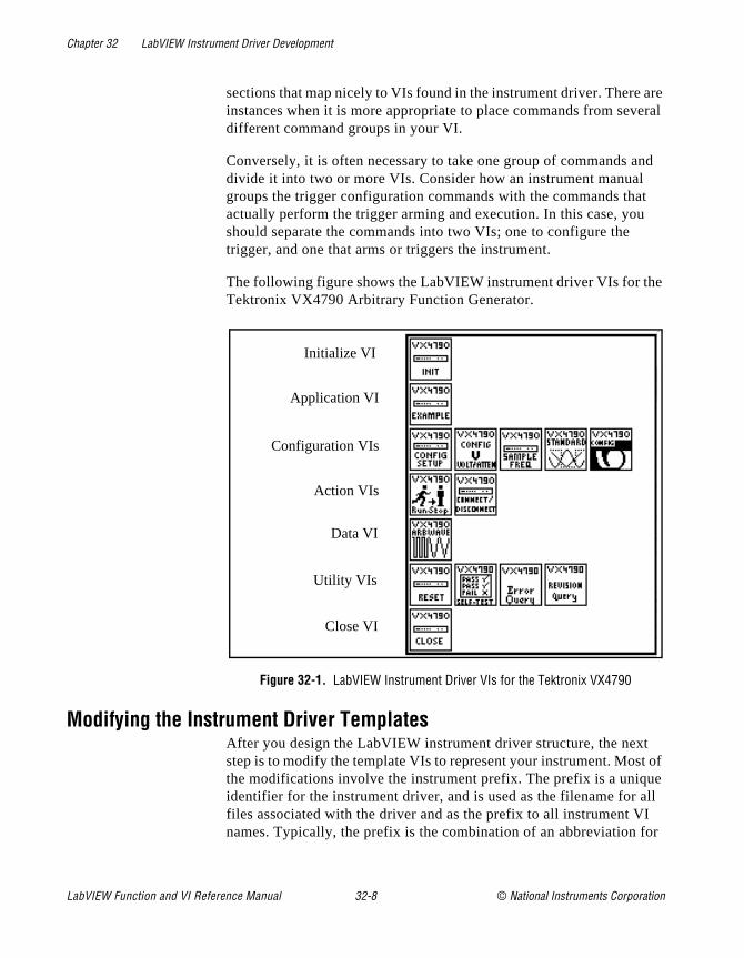
Chapter 32 LabVIEW Instrument Driver Development
are eral
nd
t
e
t of e ll
I or
sections that map nicely to VIs found in the instrument driver. There instances when it is more appropriate to place commands from sevdifferent command groups in your VI.
Conversely, it is often necessary to take one group of commands adivide it into two or more VIs. Consider how an instrument manual groups the trigger configuration commands with the commands thaactually perform the trigger arming and execution. In this case, youshould separate the commands into two VIs; one to configure the trigger, and one that arms or triggers the instrument.
The following figure shows the LabVIEW instrument driver VIs for thTektronix VX4790 Arbitrary Function Generator.
Figure 32-1. LabVIEW Instrument Driver VIs for the Tektronix VX4790
Modifying the Instrument Driver TemplatesAfter you design the LabVIEW instrument driver structure, the nextstep is to modify the template VIs to represent your instrument. Mosthe modifications involve the instrument prefix. The prefix is a uniquidentifier for the instrument driver, and is used as the filename for afiles associated with the driver and as the prefix to all instrument Vnames. Typically, the prefix is the combination of an abbreviation f
Application VI
Configuration VIs
Initialize VI
Action VIs
Close VI
Data VI
Utility VIs
LabVIEW Function and VI Reference Manual 32-8 © National Instruments Corporation
Chapter 32 LabVIEW Instrument Driver Development
the
r
on:
ing t VIs. he
rk
nd
e
the instrument vendor name and the model number. For example, instrument prefix for the Tektronix VX4790 instrument driver is tkvx4790 . As a default, the template instrument drivers use PREFIX as the instrument prefix.
Use the following procedure for modifying the LabVIEW instrumentdriver template:
1. Open the PREFIX Initialize template in the file CoreDrv.llb .
2. Save the VI into a new VI library file by using the prefix for youinstrument as the filename of the.llb file. Save the VI replacing PREFIX in the VI name with the prefix for your instrument.
3. Follow the instructions in the Modification Instructions string control on the initialize panel to modify the VI for your particular instrument.
4. Edit all Show VI Info... and control and indicator descriptions.
5. Edit the icon. Create an icon for each of the color modes of the icBlack and White, 16-Color, and 256-Color.
6. Delete the Modification Instructions string control after you have completed the modifications.
7. Resize the front panel and save the VI.
8. Repeat steps 1 through 7 for PREFIX Close VI and the remaintemplate VIs that your instrument uses. All LabVIEW instrumendrivers should have initialize, close, reset, revision query, errormessage, self test and error query and error message (multiple)If the instrument does not support some of the utility functions, tVI should return a “not supported” warning.
After completing this procedure, you have a base-level driver that implements all template instrument driver VIs and is a good framewofrom which you can create the rest of your driver.
In addition to CoreDrv.llb , there is one more instrument driver template library, CoreDr_U.llb . This library can contain support VIsthat the instrument driver uses internally, but which you do not intethe end user to call. Two examples of support files, PREFIX Utility Clean Up Initialize and PREFIX Utility Default Instrument Setup, arincluded in the CoreDr_U.llb file. If you intend the instrument driver to use these files, you should rename and modify them like those inCoreDrv.llb .
© National Instruments Corporation 32-9 LabVIEW Function and VI Reference Manual
Chapter 32 LabVIEW Instrument Driver Development
he e ent. the
e
on:
rn
rry
nd
ode.
Adding Instrument Driver Component VI VIsThe final step in developing a LabVIEW instrument driver is to add tdeveloper defined component VIs that define the functionality of thinstrument driver and access the unique capabilities of your instrumThe VIs that you create will be added to the source code along withtemplate VIs in the file prefix.llb .
You can use the following procedure to add your new VIs:
1. Open either the PREFIX Message-Based or PREFIX
Register-Based templates VI in CoreDrv.llb . Use the PREFIX
Message-Based template VI for message-based operations. Usthe PREFIX Register-Based template VI for register-based operations.
2. Edit the VI front panel. Create the controls and indicators for the VI.
3. Edit all control and indicator Help information. Edit the Show VI Info... description.
4. Edit the icon. Create an icon for each of the color modes of the icBlack and White, 16-Color, and 256-Color.
5. Edit the connector pane. Select an appropriate connector patteand wire all controls and indicators to the terminals.
6. Edit the block diagram. Program all operations necessary to caout the functionality of the instrument driver VI.
7. Save the VI.
8. Test the instrument driver VI.
9. Repeat these steps for every instrument driver component VI aapplication VI that you define for your instrument.
10. Edit the instrument driver .llb by selecting File»Edit VI Library... from the menu. Edit the Functions and Controls names. Edit the arrangement of icons in the Functions and Controls palettes.
Editing the block diagram source code is the most difficult step in adding a component VI to the instrument driver. Defining a block diagram structure makes it easier to edit the block diagram source cYou can divide this process into the following steps:
1. Place the appropriate I/O routines in the block diagram.
2. Wire the error in cluster terminal to the first I/O VI error input connector. Then wire the error out connector of that VI to the error
LabVIEW Function and VI Reference Manual 32-10 © National Instruments Corporation

Chapter 32 LabVIEW Instrument Driver Development
/O
sed
t
the as
r in
to
h ate
d
in connector of the next VI. Continue this process for all of the IVIs. Then wire the error out connector of the last VI to the error out terminal of the icon.
3. Wire the VISA session to every I/O VI.
4. Use the LabVIEW string VIs to assemble a command string baon the VI inputs.
5. Wire the command string to the VISAWrite function.
6. Use the VISA Read function to read the response if an instrumenresponse is generated.
7. Use the string VIs to parse the response and wire it to the appropriate indicator terminals.
Modifying the Menu Files to Create Function Sub-PalettesAfter you complete all the required VIs, component VIs, ApplicationVIs and the Getting Started VI, organize them into subpalettes thatend user can access. This involves editing the template menu filesfollows:
1. Copy the CoreDrv directory to another directory and rename thenew directory PREFIX. This directory should be a subdirectory ofInstr.lib .
2. Relaunch LabVIEW so that the new template subpalettes appeathe function palette under instrument drivers.
3. Select Edit Controls and Function Palettes. . . from the File menu in LabVIEW.
4. Edit the instrument driver’s palette icon and change the name PREFIX.
5. Access the instrument driver’s subpalette window to view the hierarchy of the driver. For each subpalette, insert the VIs whiccorrespond to that category. You will need to replace the templfiles with the completed version.
6. Save your changes. Your menu files will now contain the addecomponent VIs.
© National Instruments Corporation 32-11 LabVIEW Function and VI Reference Manual
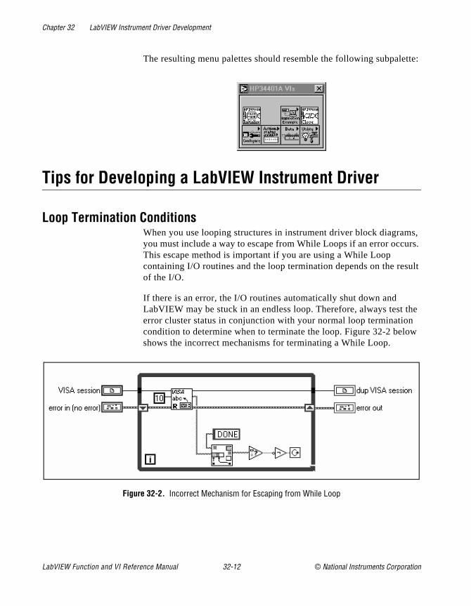
Chapter 32 LabVIEW Instrument Driver Development
tte:
s, rs.
sult
the w
The resulting menu palettes should resemble the following subpale
Tips for Developing a LabVIEW Instrument Driver
Loop Termination ConditionsWhen you use looping structures in instrument driver block diagramyou must include a way to escape from While Loops if an error occuThis escape method is important if you are using a While Loop containing I/O routines and the loop termination depends on the reof the I/O.
If there is an error, the I/O routines automatically shut down and LabVIEW may be stuck in an endless loop. Therefore, always test error cluster status in conjunction with your normal loop terminationcondition to determine when to terminate the loop. Figure 32-2 beloshows the incorrect mechanisms for terminating a While Loop.
Figure 32-2. Incorrect Mechanism for Escaping from While Loop
LabVIEW Function and VI Reference Manual 32-12 © National Instruments Corporation

Chapter 32 LabVIEW Instrument Driver Development
ck of t
gs e is
Figure 32-3 below shows the correct mechanisms for terminating aWhile Loop
Figure 32-3. Correct Mechanism for Escaping from While Loop
Assembling Command StringsAfter you develop your front panel, the next step is to create the blodiagram which performs the function required by the VI. Each typefront panel control has a corresponding block diagram string VI thasimplifies the task of building command strings.
You can use Pick Line & Append to choose from a selection of strinand concatenate it to another string in a single step. This procedureasier than using a Case structure and Concatenate Strings.
You can use Format & Append to format and concatenate simple numeric values. This procedure is easier than using one of the To
Use this block diagram... rather than this one...
© National Instruments Corporation 32-13 LabVIEW Function and VI Reference Manual

Chapter 32 LabVIEW Instrument Driver Development
sier
m r.
or
er. rol
Decimal or To Exponential type conversion VIs in conjunction with Concatenate Strings.
By using Select & Append you can select a string constant and concatenate it to another string in a single step. This procedure is eathan using Select and Concatenate Strings.
Data DependencyCarefully consider the control flow when you build your diagrams. LabVIEW does not necessarily execute in a left-to-right, top-to-bottofashion. Data dependency automatically determines execution ordeAdd artificial data dependency wherever appropriate (see the LabVIEW User Manual for more information). By using the clusters to chain I/OVIs together, you can define the execution order without using CaseSequence structures, as illustrated in Figure 31-3, in Chapter 31, LabVIEW Instrument Driver Models. Sequence structures, which hide parts of the diagram, are also effective at controlling execution ordWhichever method you use, make sure that you clearly define contflow so that the correct branch of the diagram executes first
Use this block diagram... rather than this one...
Use this block diagram... rather than this one...
LabVIEW Function and VI Reference Manual 32-14 © National Instruments Corporation
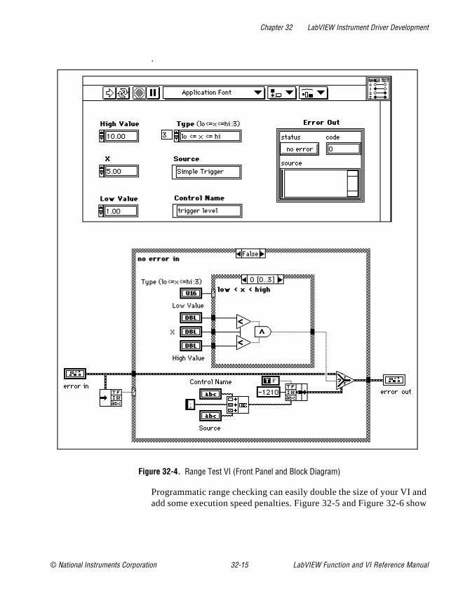
Chapter 32 LabVIEW Instrument Driver Development
and how
.
Figure 32-4. Range Test VI (Front Panel and Block Diagram)
Programmatic range checking can easily double the size of your VI add some execution speed penalties. Figure 32-5 and Figure 32-6 s
© National Instruments Corporation 32-15 LabVIEW Function and VI Reference Manual
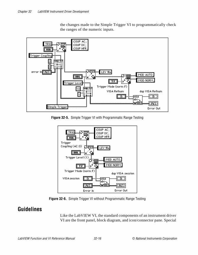
Chapter 32 LabVIEW Instrument Driver Development
ck
er cial
the changes made to the Simple Trigger VI to programmatically chethe ranges of the numeric inputs.
Figure 32-5. Simple Trigger VI with Programmatic Range Testing
Figure 32-6. Simple Trigger VI without Programmatic Range Testing
GuidelinesLike the LabVIEW VI, the standard components of an instrument drivVI are the front panel, block diagram, and icon/connector pane. Spe
LabVIEW Function and VI Reference Manual 32-16 © National Instruments Corporation
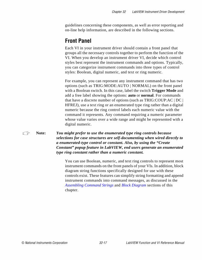
Chapter 32 LabVIEW Instrument Driver Development
and
the l ally, l
two l
C | gital e ter ith a
to
d
ost ck
end e
guidelines concerning these components, as well as error reportingon-line help information, are described in the following sections.
Front PanelEach VI in your instrument driver should contain a front panel that groups all the necessary controls together to perform the function ofVI. When you develop an instrument driver VI, decide which controstyles best represent the instrument commands and options. Typicyou can categorize instrument commands into three types of controstyles: Boolean, digital numeric, and text or ring numeric.
For example, you can represent any instrument command that hasoptions (such as TRIG:MODE:AUTO | NORMAL) on the front panewith a Boolean switch. In this case, label the switch Trigger Mode and add a free label showing the options: auto or normal. For commands that have a discrete number of options (such as TRIG:COUP:AC | DHFREJ), use a text ring or an enumerated type ring rather than a dinumeric because the ring control labels each numeric value with thcommand it represents. Any command requiring a numeric paramewhose value varies over a wide range and might be represented wdigital numeric.
Note: You might prefer to use the enumerated type ring controls because selections for case structures are self-documenting when wired directly a enumerated-type control or constant. Also, by using the “Create Constant” popup feature in LabVIEW, end users generate an enumeratetype ring constant rather than a numeric constant.
You can use Boolean, numeric, and text ring controls to represent minstrument commands on the front panels of your VIs. In addition, blodiagram string functions specifically designed for use with these controls exist. These features can simplify string formatting and appinstrument commands into command messages, as discussed in thAssembling Command Strings and Block Diagram sections of this chapter.
© National Instruments Corporation 32-17 LabVIEW Function and VI Reference Manual

Chapter 32 LabVIEW Instrument Driver Development
ont
the
s.
for
r
06ch32.fm Page 18 Tuesday, May 13, 1997 9:00 AM
Required Front Panel ControlsIn addition to the controls required to operate the instrument, your frpanel must also have the following controls.
VISA session (except for the initialize VI) input is a unique identifier reference to a device I/O session. It identifies the device with which VI communicates and all configuration information necessary to perform the I/O.
dup VISA session output is a unique identifier reference to a device I/O session. It identifies the device with which the VI communicatesand all configuration information necessary to perform the I/O.
error in describes error conditions that occur before this VI executeThe default input of this cluster is no error .
error out is a cluster containing error information. If error in indicates an error, the status, code, and source elements of error out have the same values as the corresponding elements of error in . If error in does not indicate an error, error out describes the error encountered by theVI. Refer to the LabVIEW Error Codes manual for a description of the possible error codes.
To gain consistency with other LabVIEW instrument drivers, place the VISA session control and dup VISA session indicator in the upper left and upper right corners of the front panel, and the error out cluster in the lower right corner. Place the error in cluster outside the panel’s visible window because it has no interactive use and is only neededprogrammatic use.
Control GuidelinesWhen placing controls on your front panels, use the following style guidelines to ensure uniformity with other LabVIEW Instrument DriveVI front panels:
LabVIEW Function and VI Reference Manual 32-18 © National Instruments Corporation
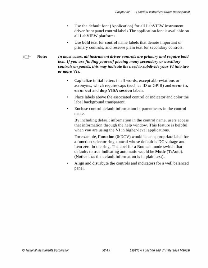
Chapter 32 LabVIEW Instrument Driver Development
on
d
o
the
l
ss l
ed
• Use the default font (Application) for all LabVIEW instrument driver front panel control labels.The application font is available all LabVIEW platforms.
• Use bold text for control name labels that denote important or primary controls, and reserve plain text for secondary controls.
Note: In most cases, all instrument driver controls are primary and require boltext. If you are finding yourself placing many secondary or auxiliary controls on panels, this may indicate the need to subdivide your VI into twor more VIs.
• Capitalize initial letters in all words, except abbreviations or acronyms, which require caps (such as ID or GPIB) and error in, error out and dup VISA session labels.
• Place labels above the associated control or indicator and colorlabel background transparent.
• Enclose control default information in parentheses in the controname.
By including default information in the control name, users accethat information through the help window. This feature is helpfuwhen you are using the VI in higher-level applications.
For example, Function (0:DCV) would be an appropriate label fora function selector ring control whose default is DC voltage anditem zero in the ring. The abel for a Boolean mode switch that defaults to true indicating automatic would be Mode (T:Auto). (Notice that the default information is in plain text).
• Align and distribute the controls and indicators for a well balancpanel.
© National Instruments Corporation 32-19 LabVIEW Function and VI Reference Manual
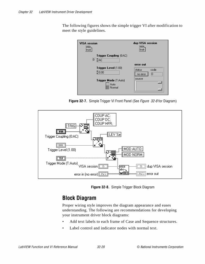
Chapter 32 LabVIEW Instrument Driver Development
o
s.
The following figures shows the simple trigger VI after modification tmeet the style guidelines.
Figure 32-7. Simple Trigger VI Front Panel (See Figure 32-8 for Diagram)
Figure 32-8. Simple Trigger Block Diagram
Block DiagramProper wiring style improves the diagram appearance and eases understanding. The following are recommendations for developingyour instrument driver block diagrams:
• Add text labels to each frame of Case and Sequence structure
• Label control and indicator nodes with normal text.
LabVIEW Function and VI Reference Manual 32-20 © National Instruments Corporation
Chapter 32 LabVIEW Instrument Driver Development
not
als ts
m.
a C n
use
r
es:
e
r
als
ed
• Use bold text to make your free label comments stand out.
• Leave room for labels and wires. Do not crowd the diagram. Do cover wires with loops, cases, labels, or other diagram objects.
• Reduce the number of bends in the wires by aligning data terminwhenever possible. You can use the cursor keys to move objecone pixel width at a time. Use the Align and Distribute options in the Edit menu to add symmetry and straight lines to your diagra
• Label long wires and complex operations to increase understandability.
IconWhen you use an instrument driver VI programmatically, the icon graphically represents the function (much like the function name of library call). Use meaningful icons for every VI. Include text in the icothat identifies the instrument model controlled by the VI. If you are unable to create an icon to express the function of the VI, you can text only.
You can borrow icons from similar VIs in other instrument drivers. These sample icons are available in the file insticon.llb .
Connector PaneWhen you use an instrument driver programmatically, the connectopane defines how to pass parameters to and from the VI. Use the following rules when creating your instrument driver connector pan
• Place the VISA session input and dup VISA session output in the upper left and upper right terminals of the LabVIEW instrumentdriver connector pane.
• Place the error in and error out clusters in the lower left and lowerright terminals of the LabVIEW instrument driver connector pan respectively.
• Place inputs on the left and outputs on the right of the connectopane whenever possible. This promotes a left-to-right data flowwhen the VI is used in a block diagram.
Note: It is acceptable to choose a connector pane pattern that has extra terminin case you make unforeseen control or indicator additions to your instrument driver VIs in the future. This procedure prevents you from having to change the pattern and replace all instances of calls to a modifiVI.
© National Instruments Corporation 32-21 LabVIEW Function and VI Reference Manual

Chapter 32 LabVIEW Instrument Driver Development
e
Error ReportingRefer to the document, LabVIEW Error Codes, for a list of error codes reserved for LabVIEW instrument drivers.
Online Help InformationLabVIEW has two types of help mechanisms available to users: VI Descriptions and Control Descriptions. You should implement both VI Descriptions and Control Descriptions for all LabVIEW instrument driver VIs and controls that you develop.
VI DescriptionsUsers can access VI Description help from the description box of thinformation window by selecting Windows»Show VI Info..., as shown in the following figure.
This dialog box should contain the following information:
LabVIEW Function and VI Reference Manual 32-22 © National Instruments Corporation

Chapter 32 LabVIEW Instrument Driver Development
by
• A general description of the instrument driver VI
• Control usage rules
• VI interaction with other instrument driver VIs
• Important information concerning the use of the VI
Control and Indicator DescriptionsControl and indicator help is the information most frequently viewed the user. You can obtain control or indicator help by selecting Data Operations»Description... from the control or indicator pop-up menu,as shown in the following figure.
The control and indicator help information should contain the following:
• Name of the parameter
• Brief description of the parameter
• Valid range
• Default value
• Interaction with other controls
Be sure to include information showing index numbers and corresponding settings for all ring and slide controls, and settings corresponding to True/False positions on Boolean controls.
© National Instruments Corporation 32-23 LabVIEW Function and VI Reference Manual
Chapter 32 LabVIEW Instrument Driver Development
nd a
he
as
nt
.
.
s , t to
Application VIs The application VIs demonstrate a common use of the instrument ashow how the component VIs are used programmatically to performtask. For example, an oscilloscope application VI would configure tvertical and horizontal amplifiers, trigger the instrument, acquire a waveform, and report errors. Consider the following points when developing application VIs for your instrument driver:
• Concentrate on building simple, quality examples that can servegeneral models for users. It is not necessary to make your application VIs perform every function found in your instrumentdriver.
• Build the instrument driver top-level examples from the instrumedriver component VIs, and perform common test- and measurement-oriented operations for this particular instrument
• Do not use the instrument driver application VIs to call the initialize or close instrument driver VIs, because doing so will make the application VIs less useful to higher level applications
LabVIEW Instrument Driver Standards ChecklistAll LabVIEW instrument drivers should conform to recommendationfor programming style, error handling, front panels, block diagramsand online help described in this section. Use the following checklisverify that your instrument driver complies with library standards:
I. Files and Documents you submit:
A. Prefix.zip containing the instrument driver files.
1) Prefix.llb , your main instrument driver library. (e.g.,hp16500b.llb , fl45.llb )
2) Palette menu files. (dir.mnu , acstat.mnu , data.mnu , applic.mnu , util.mnu . config.mnu )
3) (optional/recommended) Prefix_u.llb . (e.g., hp1650_u.llb , fl45_u.llb ).
4) (optional) Prefix.txt .
B. Manufacturer’s instrument manual or manual set.
C. A completed checklist.
LabVIEW Function and VI Reference Manual 32-24 © National Instruments Corporation
Chapter 32 LabVIEW Instrument Driver Development
:
o nd
ft ork
st
y /or
if
ose e
.g., be
II. General Issues:
A. The instrument driver must use VISA for all instrument I/O
B. All VIs are designed for programmatic use, so there are npop-up VIs or dialog boxes, and no interactive inputs. All controls aindicators are wired to the connector pane.
C. All VIs are multi-instance, so there are no uninitialized shiregisters, and no global storage VIs unless specifically designed to wwith multiple instruments simultaneously.
D. All VIs are fully documented including Show VI Info and control descriptions.
E. Driver follows the instrument internal and external driver model: The driver must include the following VIs: Initialize, Close, Getting Started, Application and VI Tree. In addition, all other VIs mube grouped into the following categories: Configure, Action/Status,Data, Utility, or support.
F. All VIs use the error I/O clusters, error in and error out .
G. The instrument driver contains the following required Utilitfunctions: Revision Query, Self Test, Reset, Error Query (single andmultiple), and Error Message.
H. The required utility VIs return a VISA NSUP warning code the instrument does not support the requested operation.
I. The instrument driver uses VISA session, dup VISA session, error in , and error out to channel data flow, and force data dependency. Do not use sequences or case structures for this purpbecause they slow execution speed and make it harder to debug thdriver.
III. Prefix.llb :
A. Prefix.llb contains all the instrument driver VIs that youwant the end user to access directly.
B. All VIs are saved with meaningful names including instrument prefix and description, and include only alpha-numeric characters (no special characters). Use Initial Capital Letter form (eFluke 45 Read Measurement). VIs that are of the same type should
© National Instruments Corporation 32-25 LabVIEW Function and VI Reference Manual
Chapter 32 LabVIEW Instrument Driver Development
am ess. ted,
se
s.
I
he
nd
named so that they start with a common name. For example, all configuration VIs should start with “Prefix Config.”
C. The VI Tree is contained in prefix.llb and is named Prefix VI Tree.vi . The front panel of the VI contains a message instructing the users to “See the diagram for the VI Tree”. The diagrcontains all of the driver's VIs that are designed for the user to accThese VIs are arranged by functional grouping, such as Getting StarApplication, Initialize, Configuration, Action/Status, Data, Utility, and Close.
D. All instrument drivers have at least one Application VI. TheVIs are programmatic examples that demonstrate how to use the instrument driver component VIs to perform a common task or task
E. All instrument drivers must have a Getting Started VI. This Vcalls the Initialize VI, one or more application VIs, followed by the Close VI.
F. Getting Started, Application and VI Tree VIs are given top-level status in the VI library.
IV. Prefix_U.llb (Recommended/Optional):
A. Prefix_U.llb contains all the support VIs the end user should not access directly, but are used by the instrument driver.
V. Palette Menu Files:
A. The function menu palettes are well organized and follow tformat of the instrument driver template.
B. Palette Menu files include dir.mnu , applic.mnu , config.mnu , acstat.mnu , data.mnu , and util.mnu .
VI. VI Front Panels
A. Contains VISA session, dup VISA session, error in and error out controls/indicators.
B. Front panel Show VI Info description is complete, informative, and contains any additional information that helps the euser successfully operate the instrument driver.
LabVIEW Function and VI Reference Manual 32-26 © National Instruments Corporation

Chapter 32 LabVIEW Instrument Driver Development
ent
,
is
sed.
f d ult
are
s,
tab
C. Show VI Info for the Revision Query VI includes the following:
1) The Instrument Driver Revision Number
2) The Firmware Revision of the Instrument used when creating the instrument
3) The date the driver will be released on the next InstrumDriver CD (month/year)
4) The instrument manufacturer's name
5) The instrument model number
6) The instrument type (Digital Multi-Meter, OscilloscopeFunction Generator, etc.)
7) The instrument driver developer’s name
D. (optional/recommended). The same information that is included in the revision query VI is included in the Show VI Info documentation of the VI Tree VI.
E. VI History is updated with comments as needed.
F. Controls and Indicators
1) All control and indicator descriptions are complete. Thincludes valid ranges, default values and items within a ring control.
2) Labels are placed at the upper left of controls and thebackground color of labels is transparent. Size to Text feature u
3) Default Application Font is used and the initial letters ocontrol names are capitalized. Use bold for primary controls anplain text for secondary controls. Use plain text to indicate defavalues.
4) Proper defaults are set for each control. Default values included in the control name.
5) Proper data type and display format is used.
6) Enumerated text rings used instead of regular test ringwhenever possible.
G. Align and distribute the controls for an appealing panel layout. Do not overlap controls. Set Panel Order so that users can through the controls in a logical sequence.
© National Instruments Corporation 32-27 LabVIEW Function and VI Reference Manual
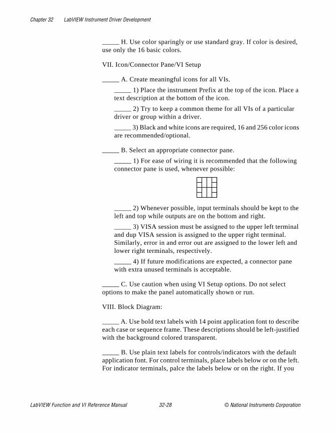
Chapter 32 LabVIEW Instrument Driver Development
d,
e a
ns
g
he
al
d
e tified
lt ft.
H. Use color sparingly or use standard gray. If color is desireuse only the 16 basic colors.
VII. Icon/Connector Pane/VI Setup
A. Create meaningful icons for all VIs.
1) Place the instrument Prefix at the top of the icon. Plactext description at the bottom of the icon.
2) Try to keep a common theme for all VIs of a particulardriver or group within a driver.
3) Black and white icons are required, 16 and 256 color icoare recommended/optional.
B. Select an appropriate connector pane.
1) For ease of wiring it is recommended that the followinconnector pane is used, whenever possible:
2) Whenever possible, input terminals should be kept to tleft and top while outputs are on the bottom and right.
3) VISA session must be assigned to the upper left terminand dup VISA session is assigned to the upper right terminal. Similarly, error in and error out are assigned to the lower left anlower right terminals, respectively.
4) If future modifications are expected, a connector panewith extra unused terminals is acceptable.
C. Use caution when using VI Setup options. Do not select options to make the panel automatically shown or run.
VIII. Block Diagram:
A. Use bold text labels with 14 point application font to describeach case or sequence frame. These descriptions should be left-juswith the background colored transparent.
B. Use plain text labels for controls/indicators with the defauapplication font. For control terminals, place labels below or on the leFor indicator terminals, palce the labels below or on the right. If you
LabVIEW Function and VI Reference Manual 32-28 © National Instruments Corporation
Chapter 32 LabVIEW Instrument Driver Development
t.
in
SA es to
in
ror
tion
er ns ng.
place labels to the left of the terminal, make them right justified, otherwise use left-justification. Make label backgrounds transparen
C. Do not crowd the diagram. Do not cover wires with labels,objects, or structures.
D. When possible, try to wire the VIs the way that they appearthe LabVIEW Help Window.
E. Try to lay out the diagram with a left-right, top-down data flow.
F. For functions and VIs that are chained together using the VIsessions and error clusters, try to align the wires between sequencbe on the same horizontal level.
G. Try to align and distribute terminals, VIs and functions withyour block diagram to give it a well-balanced look. Eliminate unnecessary bends in the wires.
H. Use proper error I/O wiring techniques. Use the correct ercodes for error reporting.
I. Save diagrams with the first or most important frames and cases visible. Place bold-text descriptive free labels in each case and frame.
J. Avoid using sequence structures because they slow execuof your VI and make it harder to understand the diagram.
K. Avoid using the Concatenate Strings function when anothstring function is more appropriate. Use other string handling functiosuch as Pick Line & Append, Select & Append and Format into Stri
© National Instruments Corporation 32-29 LabVIEW Function and VI Reference Manual
© National Instruments Corporation 33-1 LabVIEW Function and
Chapter
33
Instrument Driver Template VIsVIs
l le, u
d g
Is:
This chapter describes the Instrument Driver Template VIs. These are located in examples\instr\insttmpl.llb .
Introduction to Instrument Driver Template VIsThe LabVIEW instrument driver templates are the foundation for alLabVIEW instrument driver development. The templates have a simpflexible structure and a common set of instrument driver VIs that yocan use for driver development. The templates establish a standarformat for all LabVIEW drivers and each has instructions for modifyinit for a particular instrument. The LabVIEW instrument driver templates contain the following 11 predefined template component V
• PREFIX Initialize
• PREFIX Initialize (VXI, Reg-based)
• PREFIX Close
• PREFIX Reset
• PREFIX Self Test
• PREFIX Error Query
• PREFIX Error Query (Multiple)
• PREFIX Error Message
• PREFIX Revision Query
• PREFIX Message-Based Template
• PREFIX Register-Based Template
The templates contain the following support VIs:
• PREFIX Revision Query
• PREFIX Message-Based Template
They also contain the following VI Example Tree:
• PREFIX Message-Based Template
VI Reference Manual
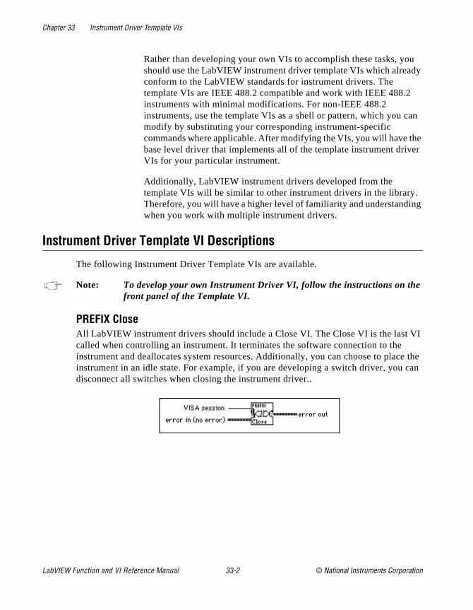
Chapter 33 Instrument Driver Template VIs
u dy
an
he er
. ng
I e the
can
Rather than developing your own VIs to accomplish these tasks, yoshould use the LabVIEW instrument driver template VIs which alreaconform to the LabVIEW standards for instrument drivers. The template VIs are IEEE 488.2 compatible and work with IEEE 488.2instruments with minimal modifications. For non-IEEE 488.2 instruments, use the template VIs as a shell or pattern, which you cmodify by substituting your corresponding instrument-specific commands where applicable. After modifying the VIs, you will have tbase level driver that implements all of the template instrument drivVIs for your particular instrument.
Additionally, LabVIEW instrument drivers developed from the template VIs will be similar to other instrument drivers in the libraryTherefore, you will have a higher level of familiarity and understandiwhen you work with multiple instrument drivers.
Instrument Driver Template VI Descriptions
The following Instrument Driver Template VIs are available.
Note: To develop your own Instrument Driver VI, follow the instructions on thefront panel of the Template VI.
PREFIX CloseAll LabVIEW instrument drivers should include a Close VI. The Close VI is the last Vcalled when controlling an instrument. It terminates the software connection to theinstrument and deallocates system resources. Additionally, you can choose to placinstrument in an idle state. For example, if you are developing a switch driver, youdisconnect all switches when closing the instrument driver..
LabVIEW Function and VI Reference Manual 33-2 © National Instruments Corporation

Chapter 33 Instrument Driver Template VIs
our IEW
he tus
ng.
It
g or
nput, r
PREFIX Error MessageThe PREFIX Error Message VI is a template for creating an Error Message VI for yparticular instrument. It translates the error status information returned from a LabVinstrument driver VI to a user-readable string.
PREFIX Error Query, Error Query (Multiple) and Error MessageIf an instrument has error query capability, the LabVIEW instrument driver has Error Query and Error Message VIs. The Error Query VI queries the instrument and returns tinstrument-specific error information. The Error Message VI translates the error stainformation returned from a LabVIEW instrument driver VI into a user-readable stri
PREFIX Initialize and PREFIX Initialize (VXI, Reg-based)The Initialize VI is the first VI called when you are accessing an instrument driver. configures the communications interface, manages handles, and sends a default command to the instrument. Typically, the default setup configures the instrument operation for the rest of the driver (including turning headers on or off, or using lonshort form for queries). After successful operation, the Initialize VI returns a VISA session that addresses the instrument in all subsequent instrument driver VIs. TheInitialize VI is a template for message-based instruments while Initialize (VXI, Reg-based) is for register-based instruments.
The VI has an instrument descriptor string as an input. Based on the syntax of this ithe VI configures the I/O interface and generates an instrument handle for all othe
© National Instruments Corporation 33-3 LabVIEW Function and VI Reference Manual
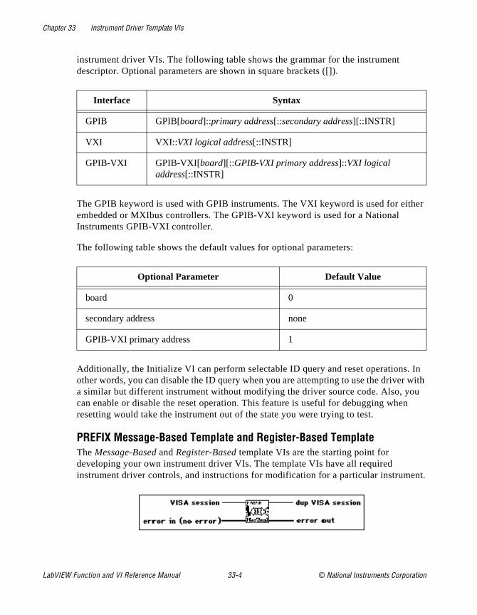
Chapter 33 Instrument Driver Template VIs
her
In with u n
ent.
instrument driver VIs. The following table shows the grammar for the instrument descriptor. Optional parameters are shown in square brackets ([]).
The GPIB keyword is used with GPIB instruments. The VXI keyword is used for eitembedded or MXIbus controllers. The GPIB-VXI keyword is used for a National Instruments GPIB-VXI controller.
The following table shows the default values for optional parameters:
Additionally, the Initialize VI can perform selectable ID query and reset operations.other words, you can disable the ID query when you are attempting to use the drivera similar but different instrument without modifying the driver source code. Also, yocan enable or disable the reset operation. This feature is useful for debugging wheresetting would take the instrument out of the state you were trying to test.
PREFIX Message-Based Template and Register-Based TemplateThe Message-Based and Register-Based template VIs are the starting point for developing your own instrument driver VIs. The template VIs have all required instrument driver controls, and instructions for modification for a particular instrum
Interface Syntax
GPIB GPIB[board]::primary address[::secondary address][::INSTR]
VXI VXI:: VXI logical address[::INSTR]
GPIB-VXI GPIB-VXI[board][::GPIB-VXI primary address]::VXI logical address[::INSTR]
Optional Parameter Default Value
board 0
secondary address none
GPIB-VXI primary address 1
LabVIEW Function and VI Reference Manual 33-4 © National Instruments Corporation
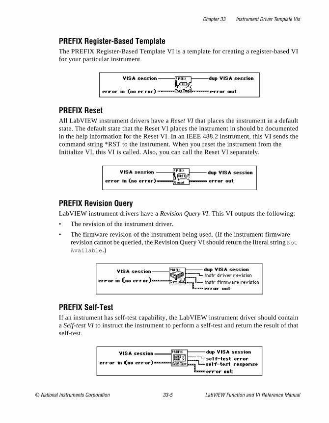
Chapter 33 Instrument Driver Template VIs
d VI
t ented the
that
PREFIX Register-Based TemplateThe PREFIX Register-Based Template VI is a template for creating a register-basefor your particular instrument.
PREFIX ResetAll LabVIEW instrument drivers have a Reset VI that places the instrument in a defaulstate. The default state that the Reset VI places the instrument in should be documin the help information for the Reset VI. In an IEEE 488.2 instrument, this VI sendscommand string *RST to the instrument. When you reset the instrument from the Initialize VI, this VI is called. Also, you can call the Reset VI separately.
PREFIX Revision QueryLabVIEW instrument drivers have a Revision Query VI. This VI outputs the following:
• The revision of the instrument driver.
• The firmware revision of the instrument being used. (If the instrument firmwarerevision cannot be queried, the Revision Query VI should return the literal string Not
Available .)
PREFIX Self-TestIf an instrument has self-test capability, the LabVIEW instrument driver should contain a Self-test VI to instruct the instrument to perform a self-test and return the result of self-test.
© National Instruments Corporation 33-5 LabVIEW Function and VI Reference Manual
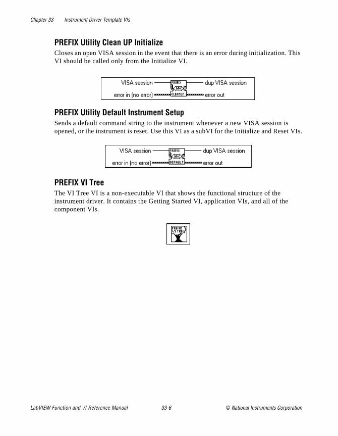
Chapter 33 Instrument Driver Template VIs
This
s t VIs.
PREFIX Utility Clean UP InitializeCloses an open VISA session in the event that there is an error during initialization.VI should be called only from the Initialize VI.
PREFIX Utility Default Instrument SetupSends a default command string to the instrument whenever a new VISA session iopened, or the instrument is reset. Use this VI as a subVI for the Initialize and Rese
PREFIX VI TreeThe VI Tree VI is a non-executable VI that shows the functional structure of the instrument driver. It contains the Getting Started VI, application VIs, and all of the component VIs.
LabVIEW Function and VI Reference Manual 33-6 © National Instruments Corporation

© National Instruments Corporation 34-1 LabVIEW Function and
Chapter
34
VISA Library ReferenceThis chapter contains descriptions of the VISA Library Reference operations and attributes.
The following figure shows the VISA palette, which you access by selecting Functions»Instrument I/O »VISA :
The Visa palette includes the following subpalettes:
• Event Handling Functions
• High-Level Event Access
• Low-Level Registry Access
VI Reference Manual
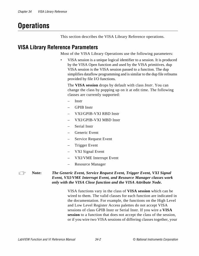
Chapter 34 VISA Library Reference
ed
s
in el
on, ur
OperationsThis section describes the VISA Library Reference operations.
VISA Library Reference ParametersMost of the VISA Library Operations use the following parameters:
• VISA session is a unique logical identifier to a session. It is producby the VISA Open function and used by the VISA primitives. dup VISA session is the VISA session passed to a function. The dup simplifies dataflow programming and is similar to the dup file refnumprovided by file I/O functions.
The VISA session drops by default with class Instr. You can change the class by popping up on it at edit time. The followingclasses are currently supported:
– Instr
– GPIB Instr
– VXI/GPIB-VXI RBD Instr
– VXI/GPIB-VXI MBD Instr
– Serial Instr
– Generic Event
– Service Request Event
– Trigger Event
– VXI Signal Event
– VXI/VME Interrupt Event
– Resource Manager
Note: The Generic Event, Service Request Event, Trigger Event, VXI Signal Event, VXI/VME Interrupt Event, and Resource Manager classes work only with the VISA Close function and the VISA Attribute Node.
VISA functions vary in the class of VISA session which can be wired to them. The valid classes for each function are indicatedthe documentation. For example, the functions on the High Levand Low Level Register Access palettes do not accept VISA sessions of class GPIB Instr or Serial Instr. If you wire a VISA session to a function that does not accept the class of the sessior if you wire two VISA sessions of differing classes together, yo
LabVIEW Function and VI Reference Manual 34-2 © National Instruments Corporation
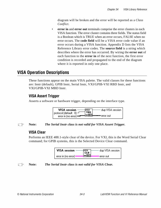
Chapter 34 VISA Library Reference
ld o
tions
lear
diagram will be broken and the error will be reported as a Class Conflict.
• error in and error out terminals comprise the error clusters in eachVISA function. The error cluster contains three fields. The status fieis a Boolean which is TRUE when an error occurs, FALSE when nerror occurs. The code field will be a VISA error code value if an error occurs during a VISA function. Appendix D lists the VISA Reference Library error codes. The source field is a string which describes where the error has occurred. By wiring the error out of each function to the error in of the next function, the first error condition is recorded and propagated to the end of the diagramwhere it is reported in only one place.
VISA Operation Descriptions
These functions appear on the main VISA palette. The valid classes for these funcare: Instr (default), GPIB Instr, Serial Instr, VXI/GPIB-VXI RBD Instr, and VXI/GPIB-VXI MBD Instr.
VISA Assert TriggerAsserts a software or hardware trigger, depending on the interface type.
Note: The Serial Instr class is not valid for VISA Assert Trigger.
VISA ClearPerforms an IEEE 488.1-style clear of the device. For VXI, this is the Word Serial Ccommand; for GPIB systems, this is the Selected Device Clear command.
Note: The Serial Instr class is not valid for VISA Clear.
© National Instruments Corporation 34-3 LabVIEW Function and VI Reference Manual
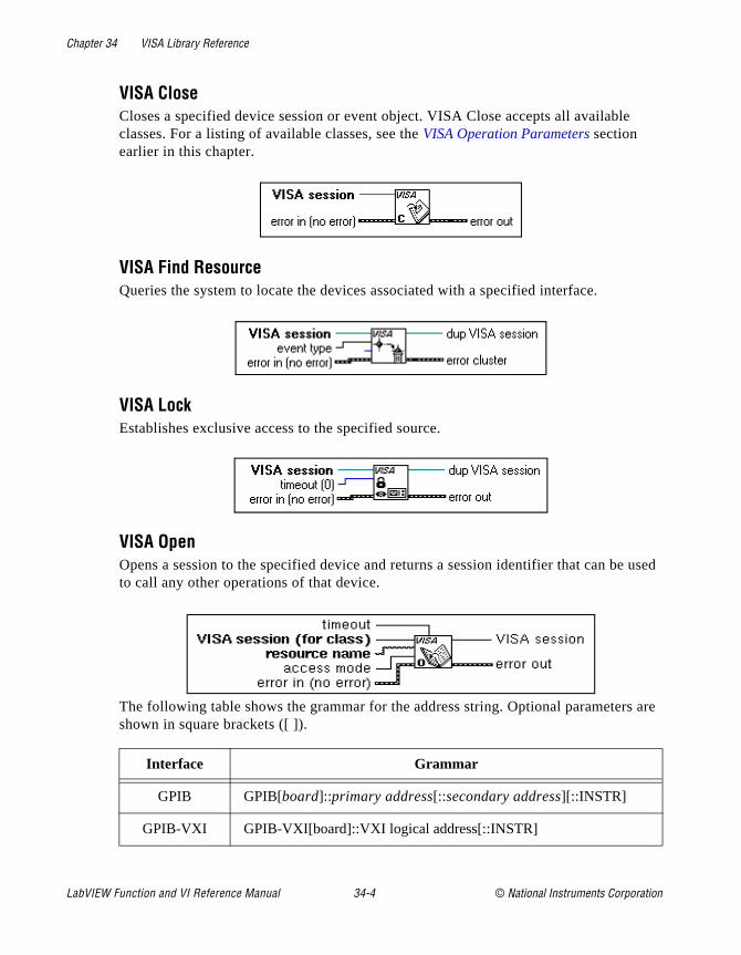
Chapter 34 VISA Library Reference
e used
s are
VISA CloseCloses a specified device session or event object. VISA Close accepts all availableclasses. For a listing of available classes, see the VISA Operation Parameters section earlier in this chapter.
VISA Find ResourceQueries the system to locate the devices associated with a specified interface.
VISA LockEstablishes exclusive access to the specified source.
VISA OpenOpens a session to the specified device and returns a session identifier that can bto call any other operations of that device.
The following table shows the grammar for the address string. Optional parametershown in square brackets ([ ]).
Interface Grammar
GPIB GPIB[board]::primary address[::secondary address][::INSTR]
GPIB-VXI GPIB-VXI[board]::VXI logical address[::INSTR]
LabVIEW Function and VI Reference Manual 34-4 © National Instruments Corporation
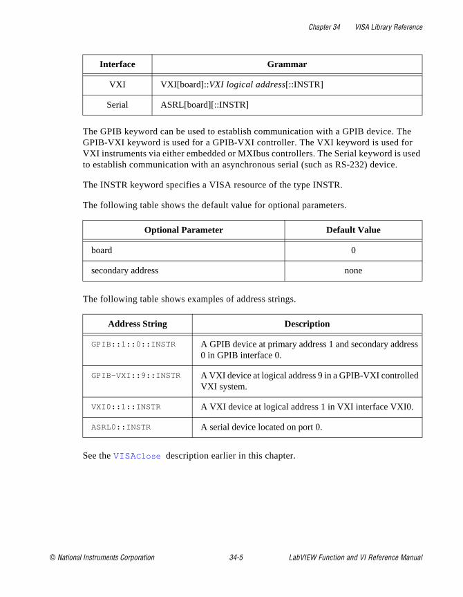
Chapter 34 VISA Library Reference
he
sed
ss
The GPIB keyword can be used to establish communication with a GPIB device. TGPIB-VXI keyword is used for a GPIB-VXI controller. The VXI keyword is used for VXI instruments via either embedded or MXIbus controllers. The Serial keyword is uto establish communication with an asynchronous serial (such as RS-232) device.
The INSTR keyword specifies a VISA resource of the type INSTR.
The following table shows the default value for optional parameters.
The following table shows examples of address strings.
See the VISA Close description earlier in this chapter.
VXI VXI[board]::VXI logical address[::INSTR]
Serial ASRL[board][::INSTR]
Optional Parameter Default Value
board 0
secondary address none
Address String Description
GPIB::1::0::INSTR A GPIB device at primary address 1 and secondary addre0 in GPIB interface 0.
GPIB-VXI::9::INSTR A VXI device at logical address 9 in a GPIB-VXI controlledVXI system.
VXI0::1::INSTR A VXI device at logical address 1 in VXI interface VXI0.
ASRL0::INSTR A serial device located on port 0.
Interface Grammar
© National Instruments Corporation 34-5 LabVIEW Function and VI Reference Manual
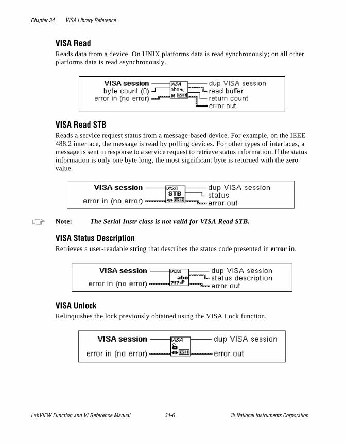
Chapter 34 VISA Library Reference
ther
e IEEE es, a status
VISA ReadReads data from a device. On UNIX platforms data is read synchronously; on all oplatforms data is read asynchronously.
VISA Read STBReads a service request status from a message-based device. For example, on th488.2 interface, the message is read by polling devices. For other types of interfacmessage is sent in response to a service request to retrieve status information. If theinformation is only one byte long, the most significant byte is returned with the zerovalue.
Note: The Serial Instr class is not valid for VISA Read STB.
VISA Status DescriptionRetrieves a user-readable string that describes the status code presented in error in .
VISA UnlockRelinquishes the lock previously obtained using the VISA Lock function.
LabVIEW Function and VI Reference Manual 34-6 © National Instruments Corporation

Chapter 34 VISA Library Reference
ther
or tr,
rd
VISA WriteWrites data to the device. On UNIX platforms data is written synchronously; on all oplatforms data is written asynchronously.
Event Handling Functions
The following section describes the VISA Event Handling functions. Valid classes fthese functions are: Instr (default), GPIB Instr, Serial Instr, VXI/GPIB-VXI RBD Insand VXI/GPIB-VXI MBD Instr.
You access the VISA Event Handling functions through the VISA palette, which you access by selecting Functions»Instrument I/O »VISA.
VISA Disable EventDisables servicing of an event. This operation prevents new event occurrences from beingqueued. However, event occurrences already queued are not lost; use VISA DiscaEvents if you want to discard queued events.
© National Instruments Corporation 34-7 LabVIEW Function and VI Reference Manual
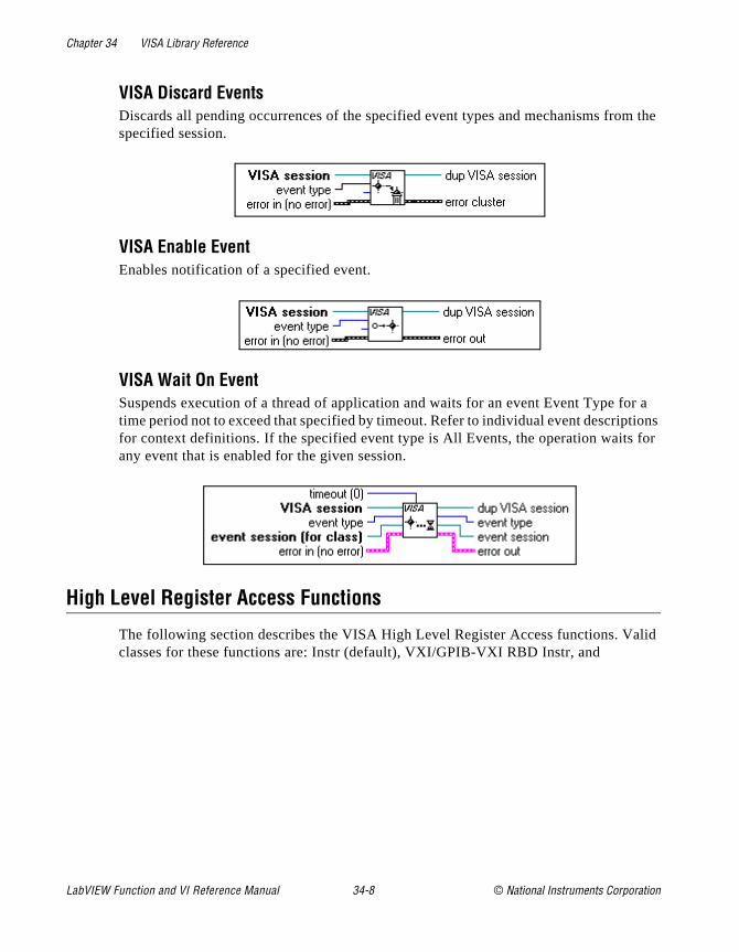
Chapter 34 VISA Library Reference
m the
or a tions for
lid
VISA Discard EventsDiscards all pending occurrences of the specified event types and mechanisms frospecified session.
VISA Enable EventEnables notification of a specified event.
VISA Wait On EventSuspends execution of a thread of application and waits for an event Event Type ftime period not to exceed that specified by timeout. Refer to individual event descripfor context definitions. If the specified event type is All Events, the operation waits any event that is enabled for the given session.
High Level Register Access Functions
The following section describes the VISA High Level Register Access functions. Vaclasses for these functions are: Instr (default), VXI/GPIB-VXI RBD Instr, and
LabVIEW Function and VI Reference Manual 34-8 © National Instruments Corporation
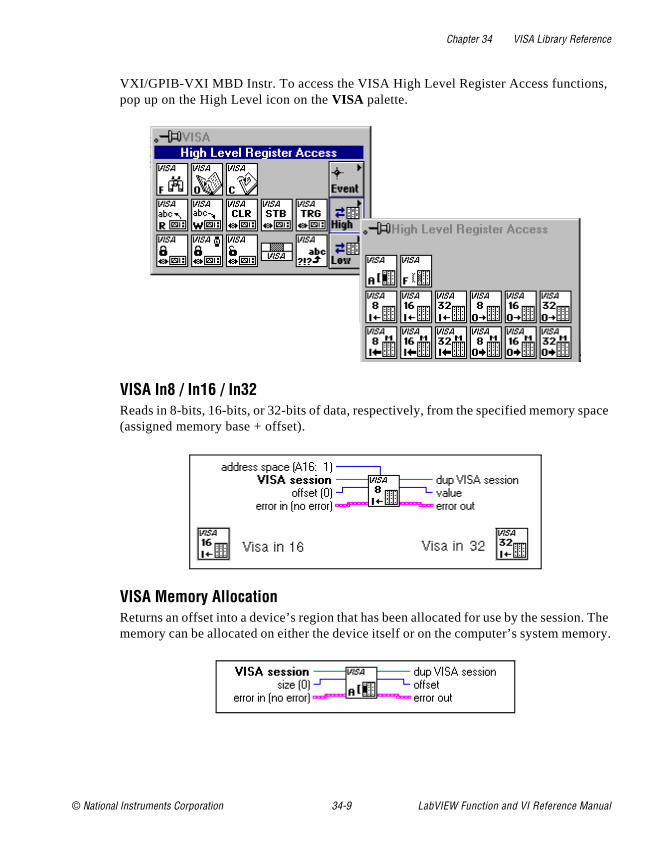
Chapter 34 VISA Library Reference
s,
pace
n. The mory.
VXI/GPIB-VXI MBD Instr. To access the VISA High Level Register Access functionpop up on the High Level icon on the VISA palette.
VISA In8 / In16 / In32Reads in 8-bits, 16-bits, or 32-bits of data, respectively, from the specified memory s(assigned memory base + offset).
VISA Memory AllocationReturns an offset into a device’s region that has been allocated for use by the sessiomemory can be allocated on either the device itself or on the computer’s system me
© National Instruments Corporation 34-9 LabVIEW Function and VI Reference Manual
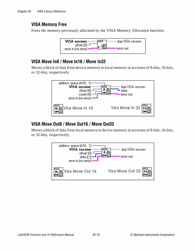
Chapter 34 VISA Library Reference
-bits,
-bits,
VISA Memory FreeFrees the memory previously allocated by the VISA Memory Allocation function.
VISA Move In8 / Move In16 / Move In32Moves a block of data from device memory to local memory in accesses of 8-bits, 16or 32-bits, respectively.
VISA Move Out8 / Move Out16 / Move Out32Moves a block of data from local memory to device memory in accesses of 8-bits, 16or 32-bits, respectively.
LabVIEW Function and VI Reference Manual 34-10 © National Instruments Corporation
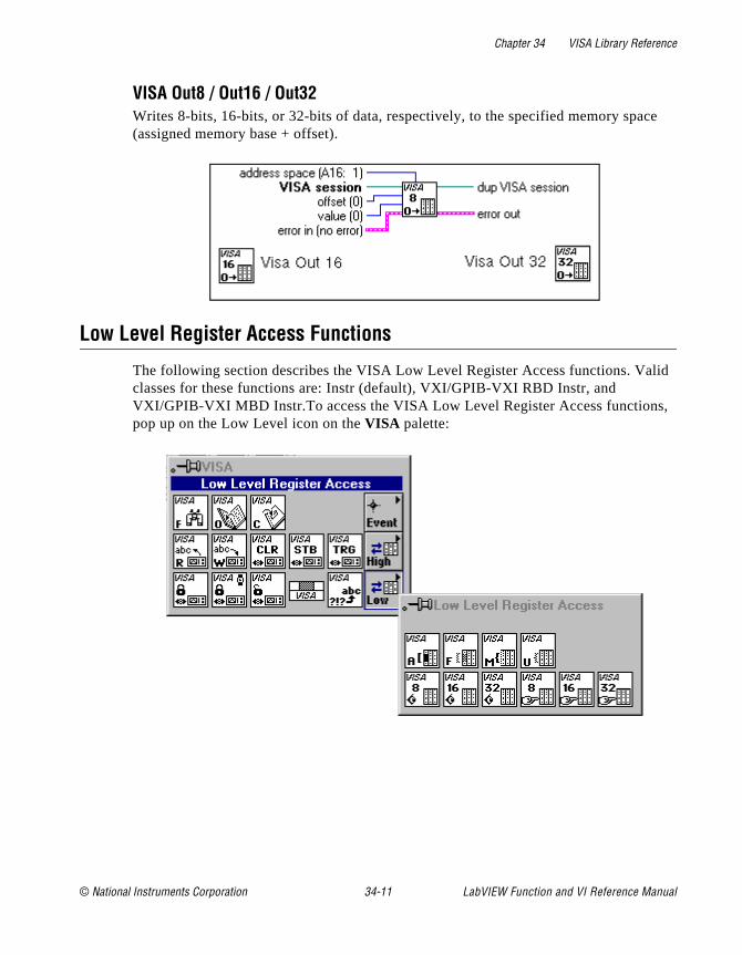
Chapter 34 VISA Library Reference
ce
lid
,
VISA Out8 / Out16 / Out32Writes 8-bits, 16-bits, or 32-bits of data, respectively, to the specified memory spa(assigned memory base + offset).
Low Level Register Access Functions
The following section describes the VISA Low Level Register Access functions. Vaclasses for these functions are: Instr (default), VXI/GPIB-VXI RBD Instr, and VXI/GPIB-VXI MBD Instr.To access the VISA Low Level Register Access functionspop up on the Low Level icon on the VISA palette:
© National Instruments Corporation 34-11 LabVIEW Function and VI Reference Manual
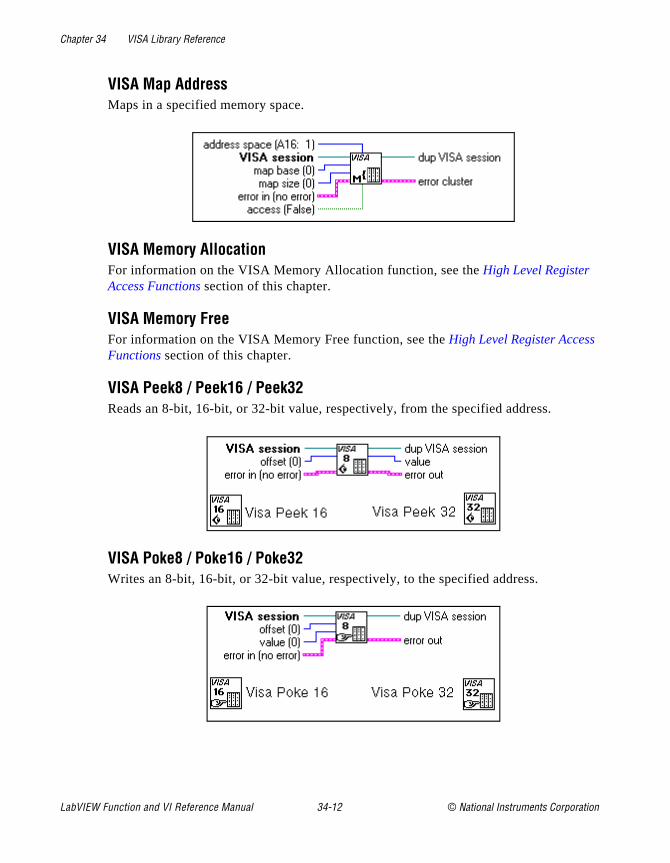
Chapter 34 VISA Library Reference
VISA Map AddressMaps in a specified memory space.
VISA Memory AllocationFor information on the VISA Memory Allocation function, see the High Level Register Access Functions section of this chapter.
VISA Memory FreeFor information on the VISA Memory Free function, see the High Level Register AccessFunctions section of this chapter.
VISA Peek8 / Peek16 / Peek32Reads an 8-bit, 16-bit, or 32-bit value, respectively, from the specified address.
VISA Poke8 / Poke16 / Poke32Writes an 8-bit, 16-bit, or 32-bit value, respectively, to the specified address.
LabVIEW Function and VI Reference Manual 34-12 © National Instruments Corporation

Chapter 34 VISA Library Reference
te le; r, or
w
e ute
e ss .
VISA Unmap AddressUnmaps memory space previously mapped by VISA Map Address.
VISA Attribute Node
This section describes the VISA Library attributes. The VISA AttribuNode gets and/or sets the indicated attributes. The node is growabevaluation starts from the top and proceeds downward until an errountil the final evaluation, occurs.
To access the attribute node, select Functions»Instrument I/O »VISA . Then select the Attribute Node icon located on the bottom roof the VISA palette.
The VISA Attribute Node only displays attributes for the class of thsession that is wired to it. You can change the class of a VISA AttribNode as long as you have not wired it to a VISA session. Once a VISA session is wired to a VISA Attribute Node, it adapts to the class of thsession and any displayed attributes which are not valid for that clabecome invalid (this is indicated by turning the attribute item black)
© National Instruments Corporation 34-13 LabVIEW Function and VI Reference Manual
Chapter 34 VISA Library Reference
d
ill be
the hile
ord
block
VISA Attribute Node Descriptions
Each attribute description includes the attribute’s range of values, default value, anaccess privilege. Local applies the current session only. Global refers to all sessions to the same VISA resource.
Fast Data Channel ModeSpecifies which FDC mode to use (either normal or stream mode).
Fast Data Channel NumberDetermines which fast data channel (FDC) will be used to transfer the buffer.
Fast Data Channel PairsSpecifies use of a channel pair for transferring data; (otherwise, only one channel wused).
Fast Data Channel Signal EnableLets the servant send a signal when control of the FDC channel is passed back to commander. This action frees the commander from having to poll the FDC header wengaging in an FDC transfer.
GPIB Primary AddressSpecifies the primary address of the GPIB device used by the given session.
GPIB Secondary AddressSpecifies the secondary address of the GPIB device used by the given session.
IO ProtocolSpecifies which protocol to use. In VXI systems you can choose between normal wserial or fast data channel (FDC). In GPIB, you can choose between normal and high-speed (HS488) data transfers.
Immediate ServantDetermines if the VXI device is an immediate servant of the local controller.
Increment Destination CountSpecifies the number of elements by which to increment the destination address onmove operations.
LabVIEW Function and VI Reference Manual 34-14 © National Instruments Corporation
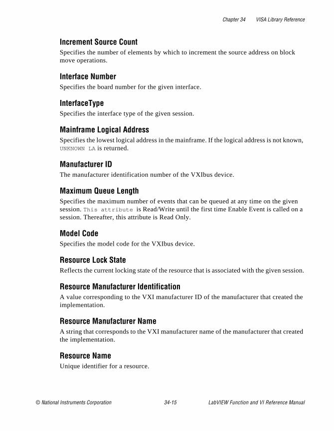
Chapter 34 VISA Library Reference
ck
own,
iven a
ssion.
the
ated
Increment Source CountSpecifies the number of elements by which to increment the source address on blomove operations.
Interface NumberSpecifies the board number for the given interface.
InterfaceTypeSpecifies the interface type of the given session.
Mainframe Logical AddressSpecifies the lowest logical address in the mainframe. If the logical address is not knUNKNOWN LA is returned.
Manufacturer IDThe manufacturer identification number of the VXIbus device.
Maximum Queue LengthSpecifies the maximum number of events that can be queued at any time on the gsession. This attribute is Read/Write until the first time Enable Event is called onsession. Thereafter, this attribute is Read Only.
Model CodeSpecifies the model code for the VXIbus device.
Resource Lock StateReflects the current locking state of the resource that is associated with the given se
Resource Manufacturer IdentificationA value corresponding to the VXI manufacturer ID of the manufacturer that createdimplementation.
Resource Manufacturer NameA string that corresponds to the VXI manufacturer name of the manufacturer that crethe implementation.
Resource NameUnique identifier for a resource.
© National Instruments Corporation 34-15 LabVIEW Function and VI Reference Manual
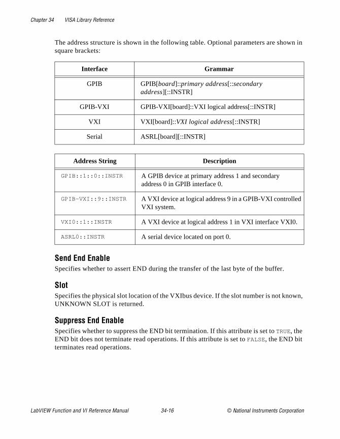
Chapter 34 VISA Library Reference
wn in
wn,
The address structure is shown in the following table. Optional parameters are shosquare brackets:
Send End EnableSpecifies whether to assert END during the transfer of the last byte of the buffer.
SlotSpecifies the physical slot location of the VXIbus device. If the slot number is not knoUNKNOWN SLOT is returned.
Suppress End EnableSpecifies whether to suppress the END bit termination. If this attribute is set to TRUE, the END bit does not terminate read operations. If this attribute is set to FALSE, the END bit terminates read operations.
Interface Grammar
GPIB GPIB[board]::primary address[::secondary address][::INSTR]
GPIB-VXI GPIB-VXI[board]::VXI logical address[::INSTR]
VXI VXI[board]::VXI logical address[::INSTR]
Serial ASRL[board][::INSTR]
Address String Description
GPIB::1::0::INSTR A GPIB device at primary address 1 and secondary address 0 in GPIB interface 0.
GPIB-VXI::9::INSTR A VXI device at logical address 9 in a GPIB-VXI controlledVXI system.
VXI0::1::INSTR A VXI device at logical address 1 in VXI interface VXI0.
ASRL0::INSTR A serial device located on port 0.
LabVIEW Function and VI Reference Manual 34-16 © National Instruments Corporation
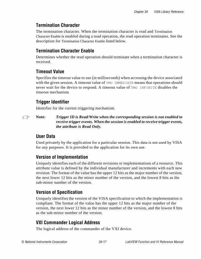
Chapter 34 VISA Library Reference
e the
cter is
ciated
to nts,
ISA
This new rsion, the
is e bits
Termination CharacterThe termination character. When the termination character is read and Termination Character Enable is enabled during a read operation, the read operation terminates. Sedescription for Termination Character Enable listed below.
Termination Character EnableDetermines whether the read operation should terminate when a termination charareceived.
Timeout ValueSpecifies the timeout value to use (in milliseconds) when accessing the device assowith the given session. A timeout value of TMO IMMEDIATE means that operations shouldnever wait for the device to respond. A timeout value of TMO INFINITE disables the timeout mechanism.
Trigger IdentifierIdentifier for the current triggering mechanism.
Note: Trigger ID is Read/Write when the corresponding session is not enabledreceive trigger events. When the session is enabled to receive trigger evethe attribute is Read Only.
User DataUsed privately by the application for a particular session. This data is not used by Vfor any purposes. It is provided to the application for its own use.
Version of ImplementationUniquely identifies each of the different revisions or implementations of a resource. attribute value is defined by the individual manufacturer and increments with each revision. The format of the value has the upper 12 bits as the major number of the vethe next lower 12 bits as the minor number of the version, and the lowest 8 bits assub-minor number of the version.
Version of SpecificationUniquely identifies the version of the VISA specification to which the implementationcompliant. The format of the value has the upper 12 bits as the major number of thversion, the next lower 12 bits as the minor number of the version, and the lowest 8as the sub-minor number of the version.
VXI Commander Logical AddressThe logical address of the commander of the VXI device.
© National Instruments Corporation 34-17 LabVIEW Function and VI Reference Manual

Chapter 34 VISA Library Reference
nly,
ase
VXI Logical AddressSpecifies the logical address of the VXI device used by the given session.
VXI Memory Address SpaceSpecifies the VXIbus address space used by the device. The three types are A16 oA16/A24, or A16/A32 memory address space.
VXI Memory Base AddressSpecifies the base address of the device in VXIbus memory address space. This baddress is applicable to A24 or A32 address space.
VXI Memory SizeSpecifies the size of memory requested by the device in VXIbus address space.
Window AccessSpecifies the modes in which the current window may be accessed.
Window Base AddressSpecifies the base address of the interface bus to which this window is mapped.
Window SizeSpecifies the size of the region mapped to this window.
LabVIEW Function and VI Reference Manual 34-18 © National Instruments Corporation

© National Instruments Corporation 35-1 LabVIEW Function and
Chapter
35
Traditional GPIB Functionss:
h
This chapter describes the Traditional GPIB functions.
The following figure shows the Traditional GPIB Functions palette which you access by selecting Functions»Instrument I/O »GPIB.
For examples of how to use the Traditional GPIB functions, see examples\instr\smplgpib.llb .
Traditional GPIB Function ParametersMost of the Traditional GPIB functions use the following parameter
• address string contains the address of the GPIB device with whicthe function communicates. You can input both the primary and
VI Reference Manual
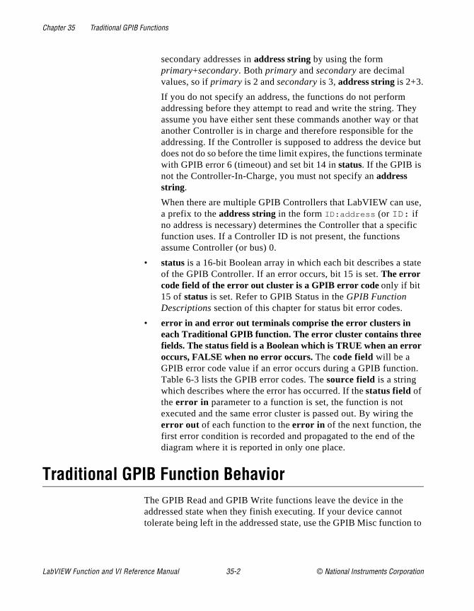
Chapter 35 Traditional GPIB Functions
ey that e but ate
e,
ific
ate
.
e
e
n to
secondary addresses in address string by using the form primary+secondary. Both primary and secondary are decimal values, so if primary is 2 and secondary is 3, address string is 2+3.
If you do not specify an address, the functions do not perform addressing before they attempt to read and write the string. Thassume you have either sent these commands another way or another Controller is in charge and therefore responsible for thaddressing. If the Controller is supposed to address the devicedoes not do so before the time limit expires, the functions terminwith GPIB error 6 (timeout) and set bit 14 in status. If the GPIB is not the Controller-In-Charge, you must not specify an address string.
When there are multiple GPIB Controllers that LabVIEW can usa prefix to the address string in the form ID:address (or ID: if no address is necessary) determines the Controller that a specfunction uses. If a Controller ID is not present, the functions assume Controller (or bus) 0.
• status is a 16-bit Boolean array in which each bit describes a stof the GPIB Controller. If an error occurs, bit 15 is set. The error code field of the error out cluster is a GPIB error code only if bit 15 of status is set. Refer to GPIB Status in the GPIB Function Descriptions section of this chapter for status bit error codes.
• error in and error out terminals comprise the error clusters in each Traditional GPIB function. The error cluster contains three fields. The status field is a Boolean which is TRUE when an error occurs, FALSE when no error occurs. The code field will be a GPIB error code value if an error occurs during a GPIB functionTable 6-3 lists the GPIB error codes. The source field is a string which describes where the error has occurred. If the status field of the error in parameter to a function is set, the function is not executed and the same error cluster is passed out. By wiring therror out of each function to the error in of the next function, the first error condition is recorded and propagated to the end of thdiagram where it is reported in only one place.
Traditional GPIB Function BehaviorThe GPIB Read and GPIB Write functions leave the device in the addressed state when they finish executing. If your device cannot tolerate being left in the addressed state, use the GPIB Misc functio
LabVIEW Function and VI Reference Manual 35-2 © National Instruments Corporation
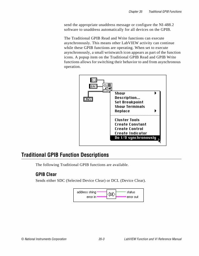
Chapter 35 Traditional GPIB Functions
tion us
send the appropriate unaddress message or configure the NI-488.2software to unaddress automatically for all devices on the GPIB.
The Traditional GPIB Read and Write functions can execute asynchronously. This means other LabVIEW activity can continue while these GPIB functions are operating. When set to execute asynchronously, a small wristwatch icon appears as part of the funcicons. A popup item on the Traditional GPIB Read and GPIB Writefunctions allows for switching their behavior to and from asynchronooperation.
Traditional GPIB Function Descriptions
The following Traditional GPIB functions are available.
GPIB ClearSends either SDC (Selected Device Clear) or DCL (Device Clear).
© National Instruments Corporation 35-3 LabVIEW Function and VI Reference Manual
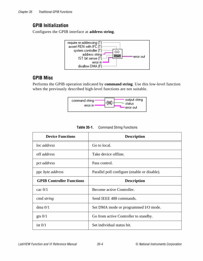
Chapter 35 Traditional GPIB Functions
GPIB InitializationConfigures the GPIB interface at address string.
GPIB MiscPerforms the GPIB operation indicated by command string. Use this low-level function when the previously described high-level functions are not suitable.
Table 35-1. Command String Functions
Device Functions Description
loc address Go to local.
off address Take device offline.
pct address Pass control.
ppc byte address Parallel poll configure (enable or disable).
GPIB Controller Functions Description
cac 0/1 Become active Controller.
cmd string Send IEEE 488 commands.
dma 0/1 Set DMA mode or programmed I/O mode.
gts 0/1 Go from active Controller to standby.
ist 0/1 Set individual status bit.
LabVIEW Function and VI Reference Manual 35-4 © National Instruments Corporation
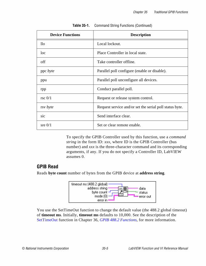
Chapter 35 Traditional GPIB Functions
ing
out)
.
To specify the GPIB Controller used by this function, use a command string in the form ID: xxx, where ID is the GPIB Controller (bus number) and xxx is the three-character command and its correspondarguments, if any. If you do not specify a Controller ID, LabVIEW assumes 0.
GPIB ReadReads byte count number of bytes from the GPIB device at address string.
You use the SetTimeOut function to change the default value (the 488.2 global timeof timeout ms. Initially, timeout ms defaults to 10,000. See the description of the SetTimeOut function in Chapter 36, GPIB 488.2 Functions, for more information.
llo Local lockout.
loc Place Controller in local state.
off Take controller offline.
ppc byte Parallel poll configure (enable or disable).
ppu Parallel poll unconfigure all devices.
rpp Conduct parallel poll.
rsc 0/1 Request or release system control.
rsv byte Request service and/or set the serial poll status byte
sic Send interface clear.
sre 0/1 Set or clear remote enable.
Table 35-1. Command String Functions (Continued)
Device Functions Description
© National Instruments Corporation 35-5 LabVIEW Function and VI Reference Manual
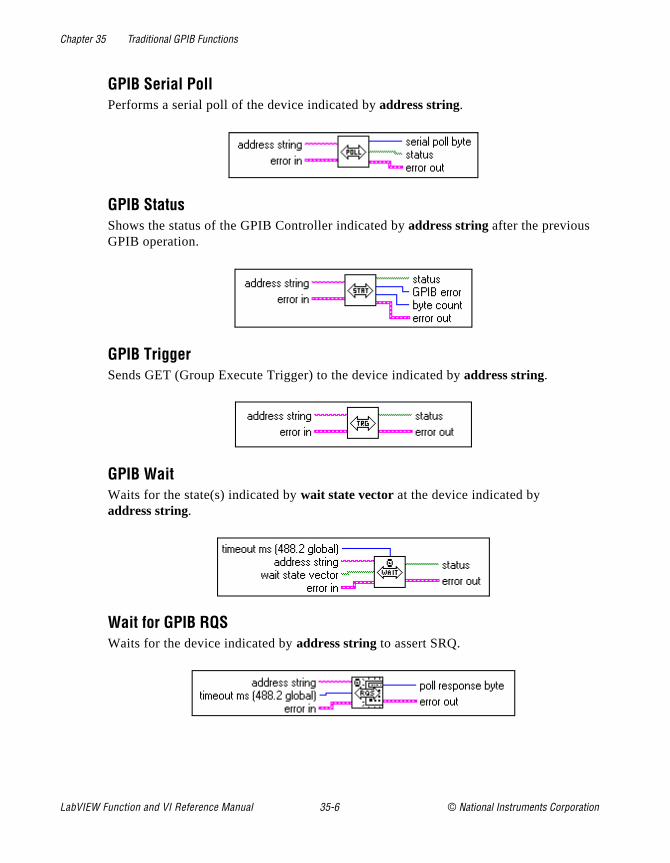
Chapter 35 Traditional GPIB Functions
GPIB Serial PollPerforms a serial poll of the device indicated by address string.
GPIB StatusShows the status of the GPIB Controller indicated by address string after the previous GPIB operation.
GPIB TriggerSends GET (Group Execute Trigger) to the device indicated by address string.
GPIB WaitWaits for the state(s) indicated by wait state vector at the device indicated by address string.
Wait for GPIB RQSWaits for the device indicated by address string to assert SRQ.
LabVIEW Function and VI Reference Manual 35-6 © National Instruments Corporation
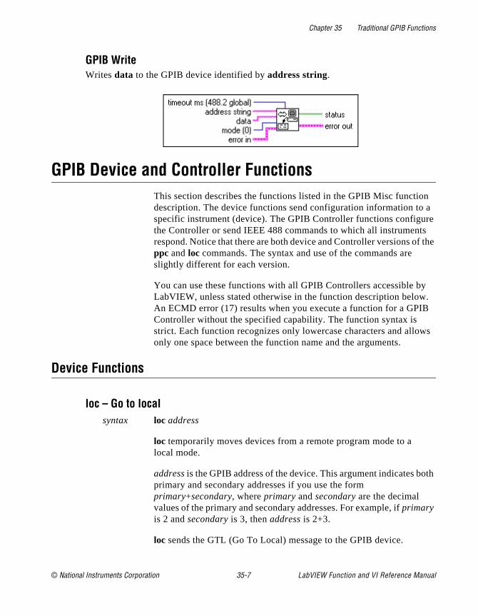
Chapter 35 Traditional GPIB Functions
n a re s f the
y .
B
ws
oth
GPIB WriteWrites data to the GPIB device identified by address string.
GPIB Device and Controller FunctionsThis section describes the functions listed in the GPIB Misc functiodescription. The device functions send configuration information tospecific instrument (device). The GPIB Controller functions configuthe Controller or send IEEE 488 commands to which all instrumentrespond. Notice that there are both device and Controller versions oppc and loc commands. The syntax and use of the commands are slightly different for each version.
You can use these functions with all GPIB Controllers accessible bLabVIEW, unless stated otherwise in the function description belowAn ECMD error (17) results when you execute a function for a GPIController without the specified capability. The function syntax is strict. Each function recognizes only lowercase characters and alloonly one space between the function name and the arguments.
Device Functions
loc – Go to localsyntax loc address
loc temporarily moves devices from a remote program mode to a local mode.
address is the GPIB address of the device. This argument indicates bprimary and secondary addresses if you use the form primary+secondary, where primary and secondary are the decimal values of the primary and secondary addresses. For example, if primary is 2 and secondary is 3, then address is 2+3.
loc sends the GTL (Go To Local) message to the GPIB device.
© National Instruments Corporation 35-7 LabVIEW Function and VI Reference Manual
Chapter 35 Traditional GPIB Functions
nly ing
oth
dle
oth
om a ice
off – Take device offlinesyntax off address
off takes the device at the specified GPIB address offline. This is oneeded when sharing a device with another application which is usthe NI 488 GPIB Library.
address is the GPIB address of the device. This argument indicates bprimary and secondary addresses if you use the form primary+secondary, where primary and secondary are the decimal values of the primary and secondary addresses. For example, if primary is 2 and secondary is 3, then address is 2+3.
pct – Pass control syntax pct address
pct passes Controller-in-Charge (CIC) authority to the device at thespecified address. The GPIB Controller automatically goes into an istate. The function assumes that the device to which pct passes control has Controller capability.
address is the GPIB address of the device. This argument indicates bprimary and secondary addresses if you use the form primary+secondary, where primary and secondary are the decimal values of the primary and secondary addresses. For example, if primary is 2 and secondary is 3, then address is 2+3.
pct sends the following command sequence:
1. Talk address of the device
2. Secondary address of the device, if applicable
3. Take Control (TCT)
ppc – Parallel poll configuresyntax ppc byte address
ppc enables the instrument to respond to parallel polls.
byte is 0 or a valid parallel poll enable (PPE) command. If byte is 0, the parallel poll disable (PPD) byte 0x70 is sent to disable the device frresponding to a parallel poll. Each of the 16 PPE messages selectsGPIB data line (DIO1 through DIO8) and sense (1 or 0) that the devmust use when it responds to the Identify (IDY) message during a
LabVIEW Function and VI Reference Manual 35-8 © National Instruments Corporation
Chapter 35 Traditional GPIB Functions
oth
n
tion trol out
in
al and
parallel poll. The device compares the ist sense and drives the indicatedDIO line TRUE or FALSE.
address is the GPIB address of the device. This argument indicates bprimary and secondary addresses if you use the form primary+secondary, where primary and secondary are the decimal values of the primary and secondary addresses. For example, if primary is 2 and secondary is 3, then address is 2+3.
Controller Functions
cac – Become active Controllersyntax cac 0 (take control synchronously)
cac 1 (take control immediately)
cac takes control either synchronously or immediately (and in somecases asynchronously). You generally do not need to use the cac function because other functions, such as cmd and rpp , take control automatically.
If you try to take control synchronously when a data handshake is iprogress, the function postpones the take control action until the handshake is complete. If a handshake is not in progress, the funcexecutes the take control action immediately. Synchronous take conis not guaranteed if a read or write operation completes with a timeor other error.
You should take control asynchronously when it is impossible to gacontrol synchronously (for example, after a timeout error).
The ECIC error results if the GPIB Controller is not CIC.
cmd – Send IEEE 488 commandssyntax cmd string
cmd sends GPIB command messages. These command messagesinclude device talk and listen addresses, secondary addresses, seriparallel poll configuration messages, and device clear and trigger messages.
© National Instruments Corporation 35-9 LabVIEW Function and VI Reference Manual
Chapter 35 Traditional GPIB Functions
.
string e
te
the ady
ding
to
You do not use cmd to transmit programming instructions to devicesThe GPIB Read and GPIB Write functions transmit programming instructions and other device-dependent information.
string contains the command bytes the Controller sends. ASCII characters represent these bytes in cmd string. If you must send nondisplayable characters, you can enable backslash codes on the control or string constant or you can use a format function to list thcommands in hexadecimal.
dma – Set DMA mode or programmed I/O modesyntax dma 0 (use programmed I/O)
dma 1 (use DMA)
dma indicates whether data transfers use DMA.
Some GPIB boards do not have DMA capability. If you try to execudma 1, the function returns GPIB error 11 to indicate no capability.
gts – Go from active Controller to standbysyntax gts 0 (no shadow handshaking)
gts 1 (shadow handshaking)
Description:
gts sets the GPIB Controller to the Controller Standby state and unasserts the ATN signal if it is the active Controller. Normally, theGPIB Controller is involved in the data transfer. gts permits GPIB devices to transfer data without involving the GPIB Controller.
If shadow handshaking is active, the GPIB Controller participates in GPIB transfer as a Listener, but does not accept any data. When itdetects the END message, the GPIB Controller asserts the Not ReFor Data (NRFD) to create a handshake holdoff state.
If shadow handshaking is not active, the GPIB Controller performs neither shadow handshaking nor a handshake holdoff.
If you activate the shadow handshake option, the GPIB Controller participates in a data handshake as a Listener without actually reathe data. It monitors the transfer for the END message and stops subsequent transfers. This mechanism allows the GPIB Controller
LabVIEW Function and VI Reference Manual 35-10 © National Instruments Corporation
Chapter 35 Traditional GPIB Functions
e
in he e,
by
if
its
take control synchronously on subsequent operations such as cmd or rpp .
After sending the gts command, you should always wait for END beforyou initiate another GPIB command. You can do this with the GPIBWait function.
The ECIC error results if the GPIB Controller is not CIC.
ist – Set individual status bitsyntax ist 0 (individual status bit is cleared)
ist 1 (individual status bit is set)
ist sets the sense of the individual status (ist) bit.
You use ist when the GPIB Controller is not the CIC but participates a parallel poll conducted by a device that is the active Controller. TCIC conducts a parallel poll by asserting the EOI and ATN signals,which send the Identify (IDY) message. While this message is activeach device that you configured to participate in the poll responds asserting a predetermined GPIB data line either TRUE or FALSE, depending on the value of its local ist bit. For example, you can assignthe GPIB Controller to drive the DIO3 data line TRUE if ist is 1 and FALSE if ist is 0. Conversely, you can assign it to drive DIO3 TRUE ist is 0 and FALSE if ist is 1.
The Parallel Poll Enable (PPE) message in effect for each device determines the relationship among the value of ist, the line that is driven, and the sense at which the line is driven. The Controller is capable of receiving this message either locally via ppc or remotely via a command from the CIC. Once the PPE message executes, ist changes the sense at which the GPIB Controller drives the line during the parallel poll, and the GPIB Controller can convey a one-bit, device-dependent message to the Controller.
llo – Local lockoutsyntax llo
llo places all devices in local lockout state. This action usually inhibrecognition of inputs from the front panel of the device.
llo sends the Local Lockout (LLO) command.
© National Instruments Corporation 35-11 LabVIEW Function and VI Reference Manual
Chapter 35 Traditional GPIB Functions
ent.
e .
y
IB ust el alue
if
loc – Place Controller in local statesyntax loc
loc places the GPIB Controller in a local state by sending the local message Return To Local (RTL) if it is not locked in remote mode (indicated by the LOK bit of status). You use loc to simulate a front panel RTL switch when you use a computer to simulate an instrum
off – Take controller offlinesyntax off
off takes the controller offline. This is only needed when sharing thcontroller with another application which is using the NI 488 Library
ppc – Parallel poll configure (enable and disable)syntax ppc byte
ppc configures the GPIB Controller to participate in a parallel poll bsetting its Local Poll Enable (LPE) message to the value of byte. If the value of byte is 0, the GPIB Controller unconfigures itself.
Each of the 16 Parallel Poll Enable (PPE) messages selects the GPdata line (DIO1 through DIO8) and sense (1 or 0) that the device muse when responding to the Identify (IDY) message during a parallpoll. The device interprets the assigned message and the current vof the individual status (ist) bit to determine if the selected line is drivenTRUE or FALSE. For example, if PPE=0x64, DIO5 is driven TRUE ist is 0 and FALSE if ist is 1. If PPE=0x68, DIO1 PPE message is in effect. You must know which PPE and PPD messages are sent anddetermine what the responses indicate.
ppu – Parallel poll unconfigure syntax ppu
ppu disables all devices from responding to parallel polls.
ppu sends the Parallel Poll Unconfigure (PPU) command.
rpp – Conduct parallel pollsyntax rpp
LabVIEW Function and VI Reference Manual 35-12 © National Instruments Corporation
Chapter 35 Traditional GPIB Functions
.
the
st
ant the
yte
ec if s
ion.
rpp conducts a parallel poll of previously configured devices by asserting the ATN and EOI signals, which sends the IDY message
rpp places the parallel poll response in the output string as ASCII characters.
rsc – Release or request system controlsyntax rsc 0 (release system control)
rsc 1 (request system control)
rsc releases or requests the capability of the GPIB Controller to sendInterface Clear (IFC) and Remote Enable (REN) messages to GPIBdevices using the sic and sre functions. For the GPIB Controller to respond to IFC sent by another Controller, the GPIB Controller munot be the System Controller.
In most applications, the GPIB Controller is always the System Controller. You use rsc only if the computer is not the System Controller for the duration of the program execution.
rsv – Request service and/or set the serial poll status bytesyntax rsv byte
rsv sets the serial poll status byte of the GPIB Controller to byte. If the 0x40 bit is set in byte, the GPIB Controller also requests service fromthe Controller by asserting the GPIB SRQ line. For instance, if you wto assert the GPIB SRQ line, send the ASCII character @, in which0x40 bit is set.
You use rsv to request service from the Controller using the ServiceRequest (SRQ) signal and to provide a system-dependent status bwhen the Controller serial polls the GPIB port.
sic – Send interface clearsyntax sic
sic causes the Controller to assert the IFC signal for at least 100 msthe Controller has System Controller authority. This action initializethe GPIB and makes the Controller port CIC. You generally use sic when you want a device to become CIC or to clear a bus fault condit
© National Instruments Corporation 35-13 LabVIEW Function and VI Reference Manual
Chapter 35 Traditional GPIB Functions
es
. ese
hen does
The IFC signal resets only the GPIB functions of bus devices; it donot reset internal device functions. The Device Clear (DCL) and Selected Device Clear (SDC) commands reset the device functionsConsult the instrument documentation to determine the effect of thmessages.
sre – Unassert or assert remote enablesyntax sre 0 (unassert Remote Enable)
sre 1 (assert Remote Enable)
sre unasserts or asserts the GPIB REN line. Devices monitor REN wthey select between local and remote modes of operation. A device not actually enter remote mode until it receives its listen address.
The ESAC error occurs if the Controller is not System Controller.
LabVIEW Function and VI Reference Manual 35-14 © National Instruments Corporation
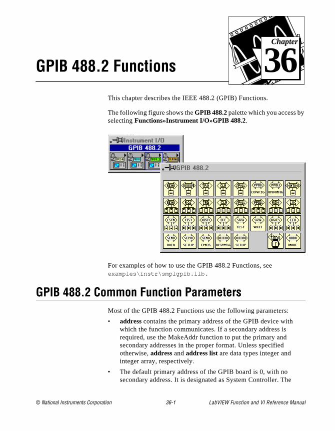
© National Instruments Corporation 36-1 LabVIEW Function and
Chapter
36
GPIB 488.2 FunctionsThis chapter describes the IEEE 488.2 (GPIB) Functions.
The following figure shows the GPIB 488.2 palette which you access byselecting Functions»Instrument I/O»GPIB 488.2.
For examples of how to use the GPIB 488.2 Functions, see examples\instr\smplgpib.llb .
GPIB 488.2 Common Function ParametersMost of the GPIB 488.2 Functions use the following parameters:
• address contains the primary address of the GPIB device with which the function communicates. If a secondary address is required, use the MakeAddr function to put the primary and secondary addresses in the proper format. Unless specified otherwise, address and address list are data types integer and integer array, respectively.
• The default primary address of the GPIB board is 0, with no secondary address. It is designated as System Controller. The
VI Reference Manual

Chapter 36 GPIB 488.2 Functions
nt nd the
e
B.
the 5. n
B uts.
ral
default timeout value for the functions is 10 seconds. If you wato change any of these parameters, use the configuration utilityincluded with your GPIB board. You can also use the GPIB Init aSetTimeOut functions to set the primary address and to changedefault timeout value at run time, but these functions affect theinterface only when you use it with LabVIEW. For more information, see the documentation supplied with your hardwarinterface.
• bus refers to the GPIB bus number. If you have only one GPIB interface in your computer, the default bus number is 0. For additional GPIB interfaces, see the software installation instructions included with your GPIB board.
• byte count refers to the number of bytes that pass over the GPI
• status is a Boolean array in which each bit describes a state of GPIB Controller. If an error occurs, the GPIB functions set bit 1GPIB error is valid only if bit 15 of status is set. See the status bitand GPIB error tables in the GPIB Status function description iChapter 35, Traditional GPIB Functions.
• error in ; error out . See the GPIB Traditional Function Parameters section of Chapter 35, Traditional GPIB Functions.
GPIB 488.2 Function Descriptions (Single-Device Functions)
Single-device functions perform GPIB I/O and control operations with a single GPIdevice. In general, each function accepts a single-device address as one of its inp
DevClearClears a single device. To send the Selected Device Clear (SDC) message to seveGPIB devices, use the DevClearList function.
LabVIEW Function and VI Reference Manual 36-2 © National Instruments Corporation
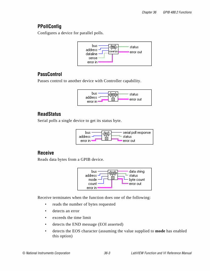
Chapter 36 GPIB 488.2 Functions
PPollConfigConfigures a device for parallel polls.
PassControlPasses control to another device with Controller capability.
ReadStatusSerial polls a single device to get its status byte.
ReceiveReads data bytes from a GPIB device.
Receive terminates when the function does one of the following:
• reads the number of bytes requested
• detects an error
• exceeds the time limit
• detects the END message (EOI asserted)
• detects the EOS character (assuming the value supplied to mode has enabled this option)
© National Instruments Corporation 36-3 LabVIEW Function and VI Reference Manual
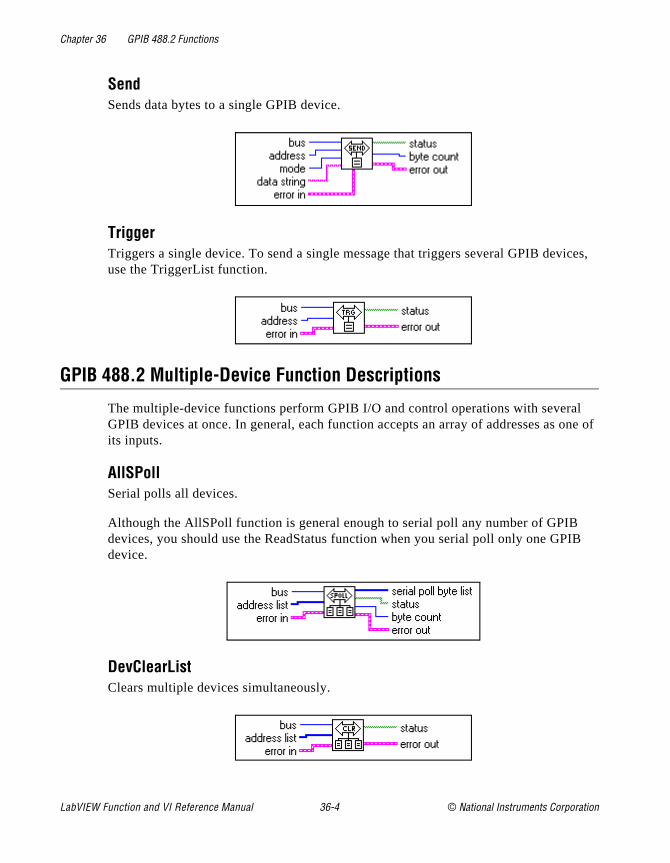
Chapter 36 GPIB 488.2 Functions
ices,
l one of
IB
SendSends data bytes to a single GPIB device.
TriggerTriggers a single device. To send a single message that triggers several GPIB devuse the TriggerList function.
GPIB 488.2 Multiple-Device Function Descriptions
The multiple-device functions perform GPIB I/O and control operations with severaGPIB devices at once. In general, each function accepts an array of addresses as its inputs.
AllSPollSerial polls all devices.
Although the AllSPoll function is general enough to serial poll any number of GPIBdevices, you should use the ReadStatus function when you serial poll only one GPdevice.
DevClearListClears multiple devices simultaneously.
LabVIEW Function and VI Reference Manual 36-4 © National Instruments Corporation
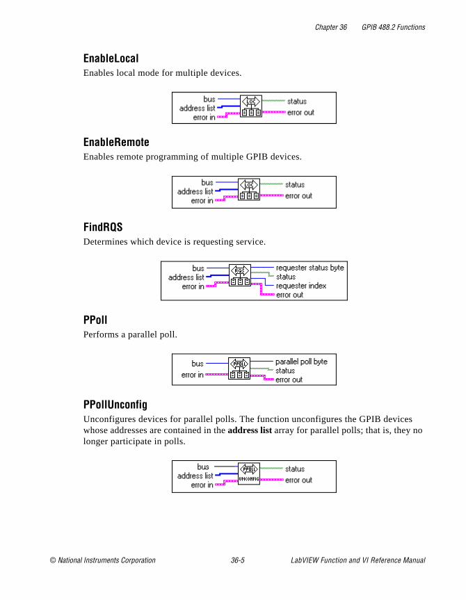
Chapter 36 GPIB 488.2 Functions
s
EnableLocalEnables local mode for multiple devices.
EnableRemoteEnables remote programming of multiple GPIB devices.
FindRQSDetermines which device is requesting service.
PPollPerforms a parallel poll.
PPollUnconfigUnconfigures devices for parallel polls. The function unconfigures the GPIB devicewhose addresses are contained in the address list array for parallel polls; that is, they nolonger participate in polls.
© National Instruments Corporation 36-5 LabVIEW Function and VI Reference Manual

Chapter 36 GPIB 488.2 Functions
that
ide
ce of en. heir
n. ,
SendListSends data bytes to multiple GPIB devices. This function is similar to Send, exceptSendList sends data to multiple Listeners with only one transmission.
TriggerListTriggers multiple devices simultaneously.
GPIB 488.2 Bus Management Function Descriptions
The bus management functions perform system-wide functions or report system-wstatus.
FindLstnFinds all Listeners on the GPIB. You normally use this function to detect the presendevices at particular addresses because most GPIB devices have the ability to listWhen you detect them, you can usually interrogate the devices with to determine tidentity.
ResetSysPerforms bus initialization, message exchange initialization, and device initializatioFirst, the function asserts Remote Enable (REN), followed by Interface Clear (IFC)unaddressing all devices and making the GPIB board (the System Controller) the Controller-in-Charge.
LabVIEW Function and VI Reference Manual 36-6 © National Instruments Corporation
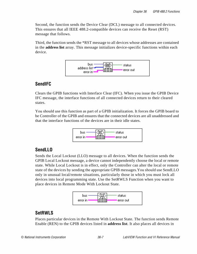
Chapter 36 GPIB 488.2 Functions
ces.
tained ch
vice d
d to ed and
he mote ote ndLLO ll to
mote
Second, the function sends the Device Clear (DCL) message to all connected deviThis ensures that all IEEE 488.2-compatible devices can receive the Reset (RST) message that follows.
Third, the function sends the *RST message to all devices whose addresses are conin the address list array. This message initializes device-specific functions within eadevice.
SendIFC
Clears the GPIB functions with Interface Clear (IFC). When you issue the GPIB DeIFC message, the interface functions of all connected devices return to their clearestates.
You should use this function as part of a GPIB initialization. It forces the GPIB boarbe Controller of the GPIB and ensures that the connected devices are all unaddressthat the interface functions of the devices are in their idle states.
SendLLOSends the Local Lockout (LLO) message to all devices. When the function sends tGPIB Local Lockout message, a device cannot independently choose the local or restate. While Local Lockout is in effect, only the Controller can alter the local or remstate of the devices by sending the appropriate GPIB messages.You should use Seonly in unusual local/remote situations, particularly those in which you must lock adevices into local programming state. Use the SetRWLS Function when you want place devices in Remote Mode With Lockout State.
SetRWLSPlaces particular devices in the Remote With Lockout State. The function sends ReEnable (REN) to the GPIB devices listed in address list. It also places all devices in
© National Instruments Corporation 36-7 LabVIEW Function and VI Reference Manual
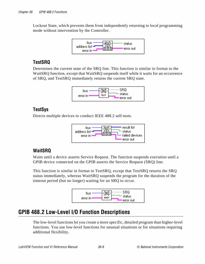
Chapter 36 GPIB 488.2 Functions
ing
e nce
til a
e
level ing
Lockout State, which prevents them from independently returning to local programmmode without intervention by the Controller.
TestSRQDetermines the current state of the SRQ line. This function is similar in format to thWaitSRQ function, except that WaitSRQ suspends itself while it waits for an occurreof SRQ, and TestSRQ immediately returns the current SRQ state.
TestSysDirects multiple devices to conduct IEEE 488.2 self-tests.
WaitSRQWaits until a device asserts Service Request. The function suspends execution unGPIB device connected on the GPIB asserts the Service Request (SRQ) line.
This function is similar in format to TestSRQ, except that TestSRQ returns the SRQstatus immediately, whereas WaitSRQ suspends the program for the duration of thtimeout period (but no longer) waiting for an SRQ to occur.
GPIB 488.2 Low-Level I/O Function Descriptions
The low-level functions let you create a more specific, detailed program than higher-functions. You use low-level functions for unusual situations or for situations requiradditional flexibility.
LabVIEW Function and VI Reference Manual 36-8 © National Instruments Corporation
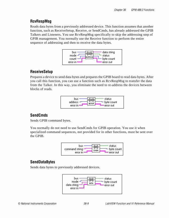
Chapter 36 GPIB 488.2 Functions
nother e GPIB ep of
s. After data een
over
RcvRespMsgReads data bytes from a previously addressed device. This function assumes that afunction, such as ReceiveSetup, Receive, or SendCmds, has already addressed thTalkers and Listeners. You use RcvRespMsg specifically to skip the addressing stGPIB management. You normally use the Receive function to perform the entire sequence of addressing and then to receive the data bytes.
ReceiveSetupPrepares a device to send data bytes and prepares the GPIB board to read data byteyou call this function, you can use a function such as RcvRespMsg to transfer the from the Talker. In this way, you eliminate the need to re-address the devices betwblocks of reads.
SendCmdsSends GPIB command bytes.
You normally do not need to use SendCmds for GPIB operation. You use it when specialized command sequences, not provided for in other functions, must be sentthe GPIB.
SendDataBytesSends data bytes to previously addressed devices.
© National Instruments Corporation 36-9 LabVIEW Function and VI Reference Manual
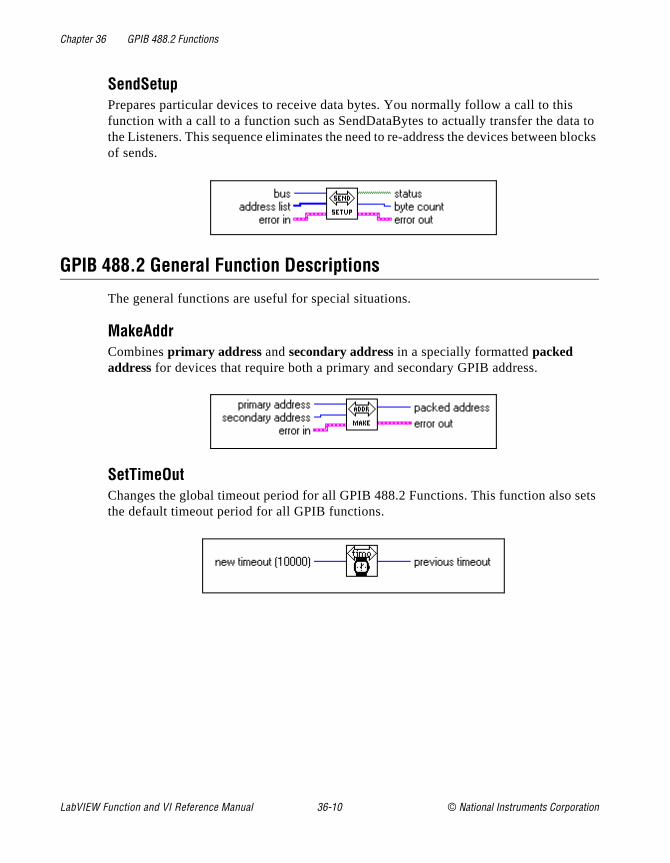
Chapter 36 GPIB 488.2 Functions
ta to blocks
sets
SendSetupPrepares particular devices to receive data bytes. You normally follow a call to thisfunction with a call to a function such as SendDataBytes to actually transfer the dathe Listeners. This sequence eliminates the need to re-address the devices betweenof sends.
GPIB 488.2 General Function Descriptions
The general functions are useful for special situations.
MakeAddrCombines primary address and secondary address in a specially formatted packed address for devices that require both a primary and secondary GPIB address.
SetTimeOutChanges the global timeout period for all GPIB 488.2 Functions. This function alsothe default timeout period for all GPIB functions.
LabVIEW Function and VI Reference Manual 36-10 © National Instruments Corporation
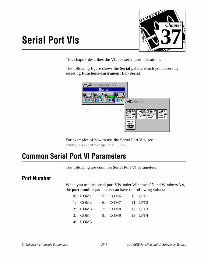
© National Instruments Corporation 37-1 LabVIEW Function and
Chapter
37
Serial Port VIs.x,
This chapter describes the VIs for serial port operations.
The following figure shows the Serial palette which you access by selecting Functions»Instrument I/O»Serial.
For examples of how to use the Serial Port VIs, see examples\instr\smplserl.llb .
Common Serial Port VI ParametersThe following are common Serial Port VI parameters.
Port NumberWhen you use the serial port VIs under Windows 95 and Windows 3the port number parameter can have the following values:
0: COM1 5: COM6 10: LPT1
1: COM2 6: COM7 11: LPT2
2: COM3 7: COM8 12: LPT3
3: COM4 8: COM9 13: LPT4
4: COM5
VI Reference Manual
Chapter 37 Serial Port VIs
T,
s
e
ses
h
r
t a til
When you use the serial port VIs under Windows 95 or Windows Nthe port number parameter is 0 for COM1, 1 for COM2, and so on.
On a Sun SPARCstation under Solaris 1 and on Concurrent PowerMAX, the port number parameter for the serial port VIs is 0 for/dev/ttya , 1 for /dev/ttyb , and so on. Under Solaris 2, port 0 referto /dev/cua/a , 1 to /dev/cua/b , and so on. Under HP-UX port number 0 refers to /dev/tty00 , 1 to /dev/tty01 , and so on.
On the Macintosh, port 0 is the modem, using the drivers .ain and .aout . Port 1 is the printer, using the drivers.bin and .bout . To get more ports on a Macintosh, you must install other boards, with the accompanying drivers.
Because other vendor’s serial port boards can have arbitrary devicnames, LabVIEW has developed an easy interface to keep the numbering of ports simple. In LabVIEW for Sun, HP-UX, and Concurrent PowerMAX, a configuration option exists to tell LabVIEWhow to address the serial ports. LabVIEW supports any board that ustandard UNIX devices. Some manufacturers suggest using cua rather than tty device nodes with their boards. LabVIEW can address bottypes of nodes.
The file .labviewrc contains the LabVIEW configuration options. Toset the devices the serial port VIs use, set the configuration option labview.serialDevices to the list of devices you intend to use. Foexample, the default is:
labview.serialDevices:/dev/ttya:/dev/ttyb:/dev/ttyc:...
:/dev/ttyz .
Note: This requires that any third party serial board installation include a method of creating a standard /dev file (node) and that the user knows thename of that file.
Handshaking ModesA common problem in serial communications is ensuring that both sender and receiver keep up with data transmission. The serial pordriver can buffer incoming/outgoing information, but that buffer is offinite size. When it becomes full, the computer ignores new data unyou have read enough data out of the buffer to make room for newinformation.
LabVIEW Function and VI Reference Manual 37-2 © National Instruments Corporation

Chapter 37 Serial Port VIs
heir ntil
e lt,
id ll, r te he u FF be and
to rror
ific. .
Handshaking helps prevent this buffer from overflowing. With handshaking, the sender and the receiver notify each other when tbuffers fill up. The sender can then stop sending new information uthe other end of the serial communication is ready for new data.
You can perform two kinds of handshaking in LabVIEW—software handshaking and hardware handshaking. You can turn both of thesforms of handshaking on or off using the Serial Port Init VI. By defauthe VIs do not use handshaking.
Software Handshaking–XON/XOFFXON/XOFF is a software handshaking protocol you can use to avooverflowing serial port buffers. When the receive buffer is nearly futhe receiver sends XOFF (<control-S> [decimal 19]) to tell the othedevice to stop sending data. When the receive buffer is sufficientlyempty, the receiver sends XON (<control-Q> [decimal 17]) to indicathat transmission can begin again. When you enable XON/XOFF, tdevices always interpret <control-Q> and <control-S> as XON andXOFF characters, never as data. When you disable XON/XOFF, yocan send <control-Q> and <control-S> as data. Do not use XON/XOwith binary data transfers because <control-Q> or <control-S> mayembedded in the data, and the devices will interpret them as XON XOFF instead of as data.
Error CodesYou can connect the error code parameter to one of the error handlerVIs. These VIs can describe the error and give you options on howproceed when an error occurs. For more information on using the ehandler VIs, refer to the Error Handling Overview section in Chapter 10, Time, Dialog and Error Functions.
Some error codes returned by the serial port VIs are platform-specPlease refer to your system documentation for a list of error codes
Serial Port VI Descriptions
The following Serial Port VIs are available.
© National Instruments Corporation 37-3 LabVIEW Function and VI Reference Manual
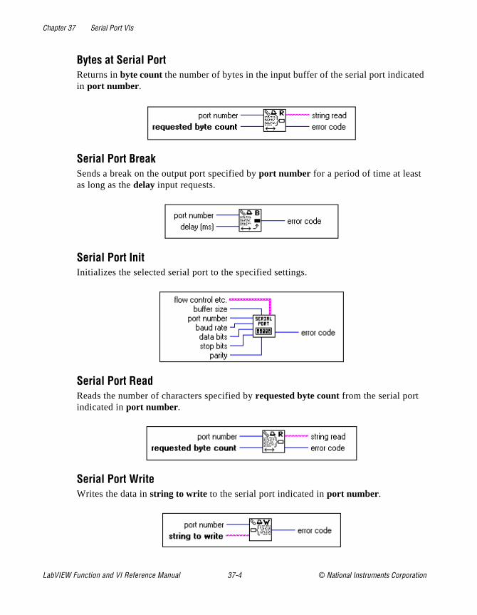
Chapter 37 Serial Port VIs
ed
Bytes at Serial PortReturns in byte count the number of bytes in the input buffer of the serial port indicatin port number.
Serial Port BreakSends a break on the output port specified by port number for a period of time at least as long as the delay input requests.
Serial Port InitInitializes the selected serial port to the specified settings.
Serial Port ReadReads the number of characters specified by requested byte count from the serial port indicated in port number.
Serial Port WriteWrites the data in string to write to the serial port indicated in port number.
LabVIEW Function and VI Reference Manual 37-4 © National Instruments Corporation
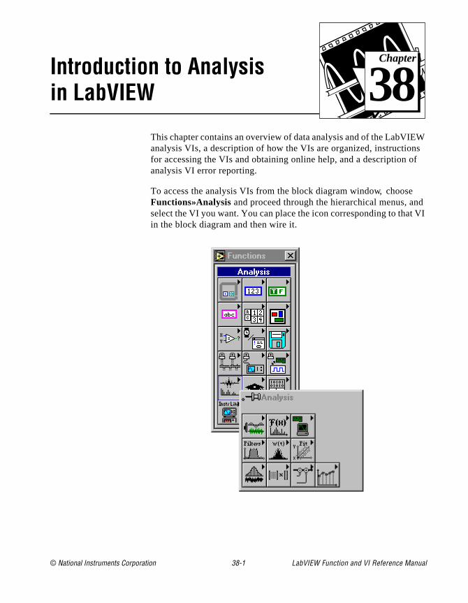
© National Instruments Corporation 38-1 LabVIEW Function and
Chapter
38
Introduction to Analysis in LabVIEWEW s f
d
t VI
This chapter contains an overview of data analysis and of the LabVIanalysis VIs, a description of how the VIs are organized, instructionfor accessing the VIs and obtaining online help, and a description oanalysis VI error reporting.
To access the analysis VIs from the block diagram window, chooseFunctions»Analysis and proceed through the hierarchical menus, anselect the VI you want. You can place the icon corresponding to thain the block diagram and then wire it.
VI Reference Manual
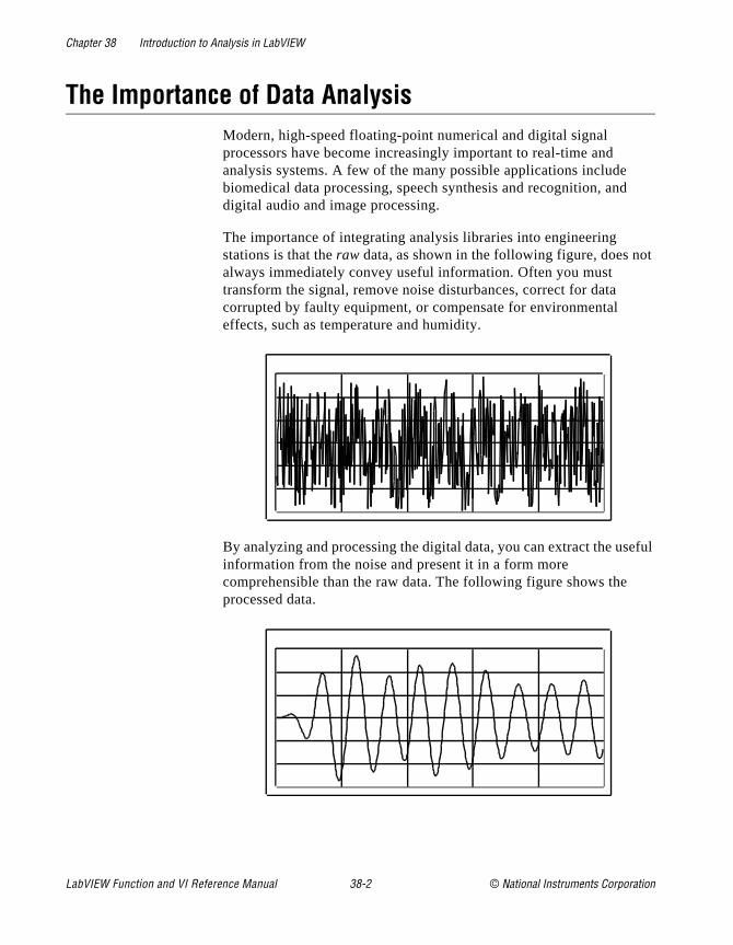
Chapter 38 Introduction to Analysis in LabVIEW
t
eful
The Importance of Data AnalysisModern, high-speed floating-point numerical and digital signal processors have become increasingly important to real-time and analysis systems. A few of the many possible applications include biomedical data processing, speech synthesis and recognition, anddigital audio and image processing.
The importance of integrating analysis libraries into engineering stations is that the raw data, as shown in the following figure, does noalways immediately convey useful information. Often you must transform the signal, remove noise disturbances, correct for data corrupted by faulty equipment, or compensate for environmental effects, such as temperature and humidity.
By analyzing and processing the digital data, you can extract the usinformation from the noise and present it in a form more comprehensible than the raw data. The following figure shows the processed data.
LabVIEW Function and VI Reference Manual 38-2 © National Instruments Corporation
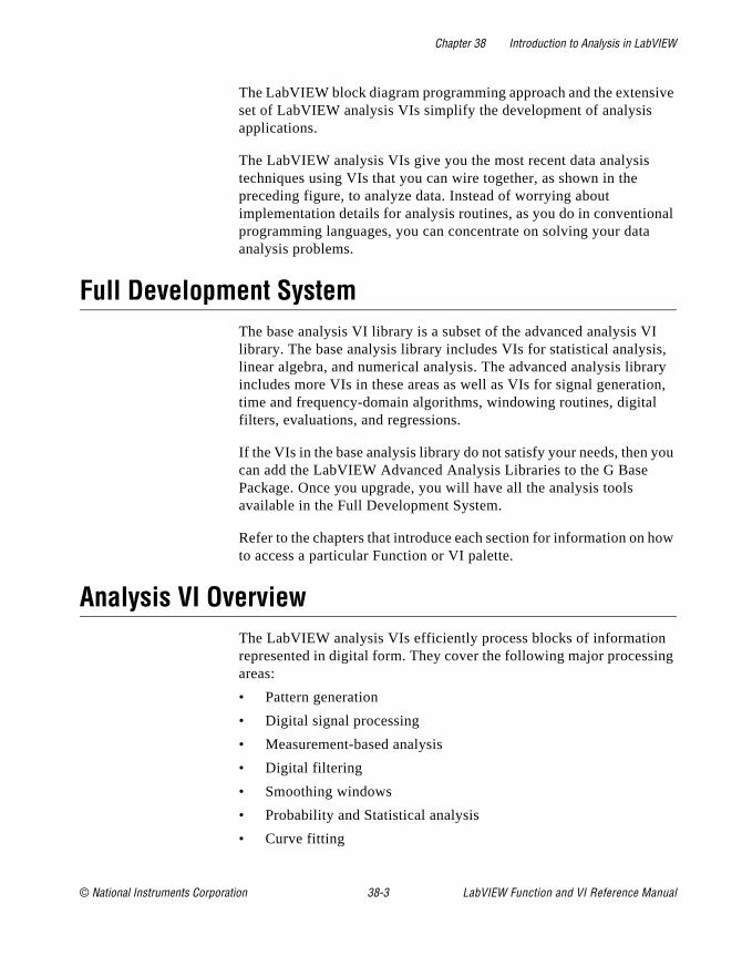
Chapter 38 Introduction to Analysis in LabVIEW
ive
nal
I s, ry n,
you
ow
ng
The LabVIEW block diagram programming approach and the extensset of LabVIEW analysis VIs simplify the development of analysis applications.
The LabVIEW analysis VIs give you the most recent data analysis techniques using VIs that you can wire together, as shown in the preceding figure, to analyze data. Instead of worrying about implementation details for analysis routines, as you do in conventioprogramming languages, you can concentrate on solving your dataanalysis problems.
Full Development SystemThe base analysis VI library is a subset of the advanced analysis Vlibrary. The base analysis library includes VIs for statistical analysilinear algebra, and numerical analysis. The advanced analysis libraincludes more VIs in these areas as well as VIs for signal generatiotime and frequency-domain algorithms, windowing routines, digital filters, evaluations, and regressions.
If the VIs in the base analysis library do not satisfy your needs, then can add the LabVIEW Advanced Analysis Libraries to the G Base Package. Once you upgrade, you will have all the analysis tools available in the Full Development System.
Refer to the chapters that introduce each section for information on hto access a particular Function or VI palette.
Analysis VI OverviewThe LabVIEW analysis VIs efficiently process blocks of informationrepresented in digital form. They cover the following major processiareas:
• Pattern generation
• Digital signal processing
• Measurement-based analysis
• Digital filtering
• Smoothing windows
• Probability and Statistical analysis
• Curve fitting
© National Instruments Corporation 38-3 LabVIEW Function and VI Reference Manual

Chapter 38 Introduction to Analysis in LabVIEW
of the sis
the that can is
r
ted re
.
:
d
in
nd
d
• Linear algebra
• Numerical analysis
The analysis VIs perform numerical operations using the central processing unit (CPU) and a floating-point coprocessor (FPU). Manythe VIs take advantage of the concurrent processing capabilities ofCPU and the FPU, thereby minimizing execution time of data analytasks.
The analysis VIs use in-place data processing algorithms. That is, algorithms allocate minimal data space and process the data withinspace. In-place processing minimizes memory requirements, so youprocess larger data blocks. The only memory limitation for these VIsthe amount of RAM available in your computer. Refer to your LabVIEW User Manual for instructions on configuring the memory allocation foLabVIEW.
The analysis VIs are powerful enough for experts to build sophisticaanalysis applications quickly and efficiently. At the same time, they asimple enough for novices to analyze data without being expert programmers in DSP, digital filters, statistics, or numerical analysis
Analysis VI OrganizationAfter installation, the ten analysis VI libraries appear in the Functions palette. These libraries cover the following major processing areas
• Signal Generation contains VIs that generate digital patterns anwaveforms.
• Digital Signal Processing contains VIs that perform frequency domain transformations, frequency domain analysis, time domaanalysis, and other transforms such as the Hartley and Hilbert transforms.
• Measurement contains VIs that perform measurement-oriented functions such as single-sided spectrums, scaled windowing, apeak power and frequency estimation.
• Filters contains VIs that perform IIR, FIR, and nonlinear, digitalfiltering functions.
• Windows contains VIs that perform data windowing.
• Probability and Statistics contains VIs that perform descriptive statistics functions, such as identifying the mean or the standar
LabVIEW Function and VI Reference Manual 38-4 © National Instruments Corporation
Chapter 38 Introduction to Analysis in LabVIEW
ns
d
r
k
g
tion
ew rge d
ple,
deviation of a set of data, as well as inferential statistics functiofor probability and analysis of variance (ANOVA).
• Curve Fitting contains VIs that perform curve fitting functions aninterpolations.
• Linear Algebra contains VIs that perform algebraic functions foreal and complex vectors and matrices.
• Array Operations contains VIs that perform common, one- andtwo-dimensional numerical array operations, such as linear evaluation and scaling.
• Additional Numerical Methods contains VIs that use numerical methods to perform root-finding, numerical integration, and peadetection.
You can reorganize the folders and the VIs to suit your needs and applications. You can also rebuild the original structure by removinthe VIs from your hard disk and then reinstalling them from the distribution disks.
Notation and Naming ConventionsTo help you identify the type of parameters and operations, this secof the manual uses the following notation and naming conventions unless otherwise specified in a VI description. Although there are a fscalar functions and operations, most of the analysis VIs process lablocks of data in the form of one-dimensional arrays (or vectors) antwo-dimensional arrays (or matrices).
Normal lower case letters represent scalars or constants. For exam
a,
π,
b = 1.234.
Capital letters represent arrays. For example,
X,
A,
Y = a X + b.
In general, X and Y denote 1D arrays, and A, B, and C represent matrices.
© National Instruments Corporation 38-5 LabVIEW Function and VI Reference Manual
Chapter 38 Introduction to Analysis in LabVIEW
ing
g
ex
d
by
Array indexes in LabVIEW are zero-based. The index of the first element in the array, regardless of its dimension, is zero. The followsequence of numbers represents a 1D array X containing n elements.
The following scalar quantity represents the ith element of the sequenceX.
The first element in the sequence is x0 and the last element in the
sequence is xn-1, for a total of n elements.
The following sequence of numbers represents a 2D array containinn rows and m columns.
The total number of elements in the 2D array is the product of n and m. The first index corresponds to the row number, and the second indcorresponds to the column number. The following scalar quantity represents the element located on the ith row and the jth column.
ai j ,0 ≤ i < n and 0 ≤ j < m
The first element in A is a0 0
and the last element is an-1 m-1.
Unless otherwise specified, this manual uses the following simplifiearray operation notations.
Setting the elements of an array to a scalar constant is represented
X = a,
which corresponds to the sequence
X = a, a, a, …, a
X x0 x1 x2 ... xn 1–, , , , =
xi 0 i n<≤,
A
a00 a01 a02 ... a0m 1–
a10 a11 a12 ... a1m 1–
a20 a21 a22 ... a2m 1–
: : : : :
an 10– an 11– an 2– ... an 1m– 1–
=
LabVIEW Function and VI Reference Manual 38-6 © National Instruments Corporation
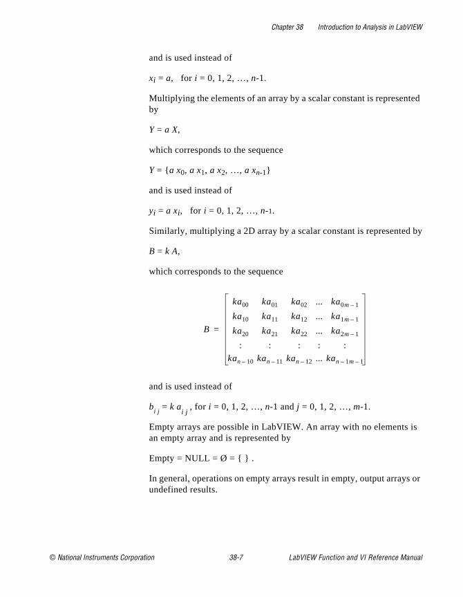
Chapter 38 Introduction to Analysis in LabVIEW
ted
by
is
s or
and is used instead of
xi = a, for i = 0, 1, 2, …, n-1.
Multiplying the elements of an array by a scalar constant is represenby
Y = a X,
which corresponds to the sequence
Y = a x0, a x1, a x2, …, a xn-1
and is used instead of
yi = a xi, for i = 0, 1, 2, …, n-1.
Similarly, multiplying a 2D array by a scalar constant is represented
B = k A,
which corresponds to the sequence
and is used instead of
bi j
= k ai j
, for i = 0, 1, 2, …, n-1 and j = 0, 1, 2, …, m-1.
Empty arrays are possible in LabVIEW. An array with no elements an empty array and is represented by
Empty = NULL = Ø = .
In general, operations on empty arrays result in empty, output arrayundefined results.
B
ka00 ka01 ka02 ... ka0m 1–
ka10 ka11 ka12 ... ka1m 1–
ka20 ka21 ka22 ... ka2m 1–
: : : : :
kan 10– kan 11– kan 12– ... kan 1m– 1–
=
© National Instruments Corporation 38-7 LabVIEW Function and VI Reference Manual

Chapter 38 Introduction to Analysis in LabVIEW
alog ief ion ated
the
Sampling SignalsTo use digital signal processing techniques, you must convert an ansignal into its digital representation. This section includes only a brdiscussion of the notation that represents a digital signal. This sectdoes not discuss the mathematical background or problems associwith sampling techniques.
Consider an analog signal x(t) and the sampling interval ∆t. The signal x(t) can be represented by the discrete sequence of samples
x(0), x(∆t), x(2∆t), x(3∆t), …, x(k∆t), … .
Because ∆t establishes only the sampling rate and has no bearing onactual sampled (digitized) value, the sample at
t = i∆t, for i = 0, 1, 2, …
corresponds to the i th element in the sequence.
Thus,
xi = x(i∆t)
and x(t) can be represented by the sequence X whose values are
X = x0, x1, x2, x3, …, xk, … .
If n samples are obtained from the signal x(t), then the sequence
X = x0, x1, x2, x3, …, xn-1
is the digital representation or the sampled version of x(t).
LabVIEW Function and VI Reference Manual 38-8 © National Instruments Corporation

© National Instruments Corporation 39-1 LabVIEW Function and
Chapter
39
Analysis Signal Generation VIsys
in . you
.
ples
(ple.
This chapter describes the VIs that generate one-dimensional arrawith specific waveform patterns.
You can combine these VIs with the arithmetic functions discussedChapter 4, Numeric Functions, to generate more elaborate waveformsFor example, if you want to generate an amplitude modulated pulse,multiply a pulse pattern by a sinusoidal pattern.
To access the Signal Analysis palette, select Function»Analysis»Signal Generation. The following illustration shows the options that are available on the Signal Analysis palette
For examples of how to use the signal generation VIs, see the examlocated in examples\analysis\sigxmpl.llb .
Normalized FrequencySome of the Signal Generation VIs use an input frequency controlf) that is assumed to use normalized frequency units of cycles per samIts reciprocal (1/f) gives you the number of times that the signal is sampled in one cycle. This frequency ranges from 0 to 1.0, which
VI Reference Manual

Chapter 39 Analysis Signal Generation VIs
is 1.1
y of
to zed
ert s
corresponds to a real frequency range of 0 to the sampling rate. Thfrequency also wraps around 1.0, so that a normalized frequency ofis equivalent to 0.1.
For example, if a signal is sampled at the Nyquist rate (fs/2), it is sampled twice per cycle. This corresponds to a normalized frequenc1/2 samples/cycle that is less than or equal to 0.5 cycles/sample.
If you use some of these VIs, you must convert your frequency unitsthe normalized units of cycles/sample. You must use these normaliunits with the following VIs:
• Sine Wave
• Square Wave
• Sawtooth Wave
• Triangle Wave
• Arbitrary Wave
• Chirp Pattern
If you are used to working in frequency units of cycles, you can convcycles to cycles/sample by dividing cycles by the number of samplegenerated. The following illustration shows an example of the SineWave VI generating two cycles of a sine wave.
LabVIEW Function and VI Reference Manual 39-2 © National Instruments Corporation
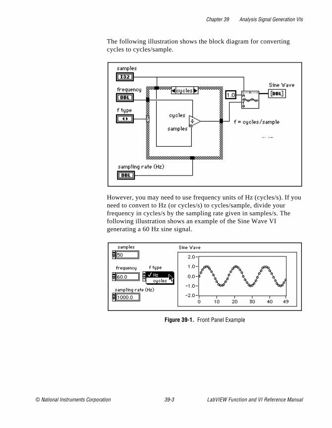
Chapter 39 Analysis Signal Generation VIs
ou
The following illustration shows the block diagram for converting cycles to cycles/sample.
However, you may need to use frequency units of Hz (cycles/s). If yneed to convert to Hz (or cycles/s) to cycles/sample, divide your frequency in cycles/s by the sampling rate given in samples/s. Thefollowing illustration shows an example of the Sine Wave VI generating a 60 Hz sine signal.
Figure 39-1. Front Panel Example
© National Instruments Corporation 39-3 LabVIEW Function and VI Reference Manual
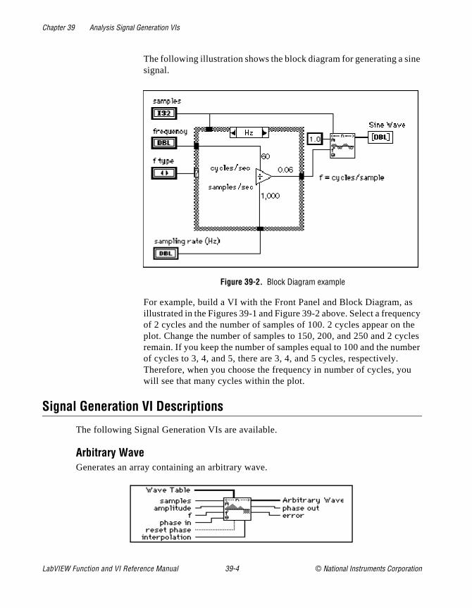
Chapter 39 Analysis Signal Generation VIs
ne
s ncy
the cles ber
u
The following illustration shows the block diagram for generating a sisignal.
Figure 39-2. Block Diagram example
For example, build a VI with the Front Panel and Block Diagram, aillustrated in the Figures 39-1 and Figure 39-2 above. Select a frequeof 2 cycles and the number of samples of 100. 2 cycles appear on plot. Change the number of samples to 150, 200, and 250 and 2 cyremain. If you keep the number of samples equal to 100 and the numof cycles to 3, 4, and 5, there are 3, 4, and 5 cycles, respectively. Therefore, when you choose the frequency in number of cycles, yowill see that many cycles within the plot.
Signal Generation VI Descriptions
The following Signal Generation VIs are available.
Arbitrary WaveGenerates an array containing an arbitrary wave.
LabVIEW Function and VI Reference Manual 39-4 © National Instruments Corporation
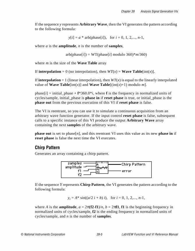
Chapter 39 Analysis Signal Generation VIs
g
e
If the sequence y represents Arbitrary Wave , then the VI generates the pattern accordinto the following formula:
y[ i] = a * arb(phase[i]), for i = 0, 1, 2,..., n-1,
where a is the amplitude, n is the number of samples,
arb(phase[i]) = WT(phase[i] modulo 360)*m/360)
where m is the size of the Wave Table array
If interpolation = 0 (no interpolation), then WT(x) = Wave Table[int(x)].
If interpolation = 1 (linear interpolation), then WT(x) is equal to the linearly interpolatedvalue of Wave Table[int(x)] and Wave Table[(int(x)+1) modulo m].
phase[i] = initial_phase + f*360.0*i, where f is the frequency in normalized units of cycles/sample, initial_phase is phase in if reset phase is true, or initial_phase is the phase out from the previous execution of this VI if reset phase is false.
The VI is reentrant, so you can use it to simulate a continuous acquisition from an arbitrary wave function generator. If the input control reset phase is false, subsequent calls to a specific instance of this VI produce the output Arbitrary Wave array containing the next samples of the arbitrary wave.
phase out is set to phase[n], and this reentrant VI uses this value as its new phase in if reset phase is false the next time the VI executes.
Chirp Pattern Generates an array containing a chirp pattern.
If the sequence Y represents Chirp Pattern , the VI generates the pattern according to thfollowing formula:
yi = A* sin((a/2 i + b) i), for i = 0, 1, 2,..., n-1,
where A is the amplitude, a = 2π(f2-f1)/n, b = 2πf1, f1 is the beginning frequency in normalized units of cycles/sample, f2 is the ending frequency in normalized units of cycles/sample, and n is the number of samples.
© National Instruments Corporation 39-5 LabVIEW Function and VI Reference Manual
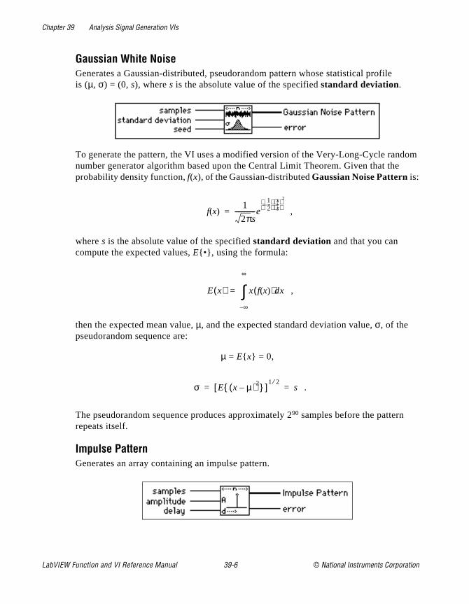
Chapter 39 Analysis Signal Generation VIs
dom
Gaussian White NoiseGenerates a Gaussian-distributed, pseudorandom pattern whose statistical profile is (µ, σ) = (0, s), where s is the absolute value of the specified standard deviation.
To generate the pattern, the VI uses a modified version of the Very-Long-Cycle rannumber generator algorithm based upon the Central Limit Theorem. Given that theprobability density function, f(x), of the Gaussian-distributed Gaussian Noise Pattern is:
,
where s is the absolute value of the specified standard deviation and that you can compute the expected values, E•, using the formula:
,
then the expected mean value, µ, and the expected standard deviation value, σ, of the pseudorandom sequence are:
µ = E x = 0,
.
The pseudorandom sequence produces approximately 290 samples before the pattern repeats itself.
Impulse PatternGenerates an array containing an impulse pattern.
f x( )1
2πs-------------e
12---–
xs--
2
=
E x( ) x f x( )( )dx
∞–
∞
∫=
σ E x µ–( )2 [ ]1 2⁄
s= =
LabVIEW Function and VI Reference Manual 39-6 © National Instruments Corporation

Chapter 39 Analysis Signal Generation VIs
rn
l
the
er
record st for
y
If the Impulse Pattern is represented by the sequence X, the VI generates the patteaccording to the following formula:
where a is the amplitude, d is the delay, and n is the number of samples.
Periodic Random NoiseGenerates an array containing periodic random noise (PRN).
The output array contains all frequencies which can be represented with an integranumber of cycles in the requested number of samples. Each frequency-domain component has a magnitude of spectral amplitude and random phase.
You can think of the output array of PRN as a summation of sinusoidal signals withsame amplitudes but with random phases. The unit of spectral amplitude is the same as the output Periodic Random Noise, and is a linear measure of amplitude, similar to othsignal generation VIs.
The VI generates the same periodic random sequence for a given positive seed value. The VI does not reseed the random phase generator if seed is negative.
The output sequence is bounded by an amplitude of .
You can use PRN to compute the frequency response of a linear system in one time instead of averaging the frequency response over several time records, as you munonperiodic random noise sources.
You do not need to window PRN before performing spectral analysis; PRN is self-windowing and, therefore, has no spectral leakage because PRN contains onlintegral-cycle sinusoids.
xi
a if i d for i = 0, 1, 2, . . ., n-1=
0 elsewhere
=
spectral amplitude *samples
2--------------------
© National Instruments Corporation 39-7 LabVIEW Function and VI Reference Manual

Chapter 39 Analysis Signal Generation VIs
e
e
Pulse PatternGenerates an array containing a pulse pattern.
If the sequence X represents Pulse Pattern, the VI generates the pattern according to thfollowing formula:
where a is the amplitude, d is the delay, w is the width , and n is the number of samples.
Ramp PatternGenerates an array containing a ramp pattern.
If the sequence X represents Ramp Pattern, the VI generates the pattern according to thformula:
for i = 0, 1, 2,…, n-1,
where , xn-1 is the end, x0 is the start, and n is the number of samples.
The does not impose conditions on the relationship between start and end. Therefore, it can generate ramp-up and ramp-down patterns.
xi
a if d i d w+( )< for i = 0, 1, 2, . . ., n-1.≤
0.0 elsewhere
=
xi x0 i x∆+=
x∆xn 1– x0–
n 1–----------------------=
LabVIEW Function and VI Reference Manual 39-8 © National Instruments Corporation

Chapter 39 Analysis Signal Generation VIs
o
tooth
Sawtooth WaveGenerates an array containing a sawtooth wave.
If the sequence Y represents Sawtooth Wave, the VI generates the pattern according tthe following formula:
y[ i] = a * sawtooth(phase[i]), for i = 0, 1, 2,..., n-1,
where a is the amplitude, n is the number of samples,
p = phase[i] modulo 360.0, phase[i] = initial_phase + f*360.0*i, f is the frequency in normalized units of cycles/sample; initial_phase is phase in if reset phase is true; or initial_phase is the phase out from the previous execution of this instance of the VI ifreset phase is false.
The VI is reentrant, so you can use it to simulate a continuous acquisition from a sawwave function generator. If the input control reset phase is false, subsequent calls to aspecific instance of the VI produce the output Sawtooth Wave array containing the next samples of a sawtooth wave.
phase out is set to phase[n], and, if reset phase is false, the next time the VI executes this reentrant VI uses this value as its new phase in.
Sinc PatternGenerates an array containing a sinc pattern.
sawtooth phasei[ ]( )
p180.0------------- 0 p 180<≤
p180.0------------- 2.0 180 p 360<≤–
=
© National Instruments Corporation 39-9 LabVIEW Function and VI Reference Manual

Chapter 39 Analysis Signal Generation VIs
e
e
hus, to the
g
If the sequence Y represents Sinc Pattern, the VI generates the pattern according to thfollowing formula:
, for i = 0, 1, 2,…, n-1,
where , a is the amplitude, ∆t is the sampling interval delta t, d is
the delay, and n is the number of samples.
The main lobe of the sinc function, sinc(x), is the part of the sinc curve bounded by thregion -1≤ x ≤ 1.
When |x| = 1, the sinc(x) = 0.0, and the peak value of the sinc function occurs when x = 0. Using l'Hôpital's Rule, you can show that sinc(0) = 1 and is its peak value. Tthe main lobe is the region of the sinc curve encompassed by the first set of zeros left and the right of the sinc value.
Sine PatternGenerates an array containing a sinusoidal pattern.
If the sequence Y represents Sinusoidal Pattern, the VI generates the pattern accordinto the following formula:
for i = 0, 1, 2,…, n-1,
where
, a is the amplitude, k is the number of cycles in the pattern,
is the initial phase (degrees), and n is the number of samples.
Sine WaveGenerates an array containing a sine wave.
LabVIEW Function and VI Reference Manual 39-10 © National Instruments Corporation
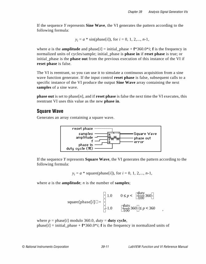
Chapter 39 Analysis Signal Generation VIs
ine
s
e
If the sequence Y represents Sine Wave, the VI generates the pattern according to thefollowing formula:
yi = a * sin(phase[i]), for i = 0, 1, 2,..., n-1,
where a is the amplitude and phase[i] = initial_phase + f*360.0*i; f is the frequency in normalized units of cycles/sample; initial_phase is phase in if reset phase is true; or initial_phase is the phase out from the previous execution of this instance of the VI ifreset phase is false.
The VI is reentrant, so you can use it to simulate a continuous acquisition from a swave function generator. If the input control reset phase is false, subsequent calls to aspecific instance of the VI produce the output Sine Wave array containing the next samples of a sine wave.
phase out is set to phase[n], and if reset phase is false the next time the VI executes, thireentrant VI uses this value as the new phase in.
Square WaveGenerates an array containing a square wave.
If the sequence Y represents Square Wave, the VI generates the pattern according to thfollowing formula:
yi = a * square(phase[i]), for i = 0, 1, 2,..., n-1,
where a is the amplitude; n is the number of samples;
,
where p = phase[i] modulo 360.0, duty = duty cycle, phase[i] = initial_phase + f*360.0*i; f is the frequency in normalized units of
square phasei[ ]( )1.0 0 p <≤
duty100----------360
1.0duty100----------360
p 360<≤–
=
© National Instruments Corporation 39-11 LabVIEW Function and VI Reference Manual
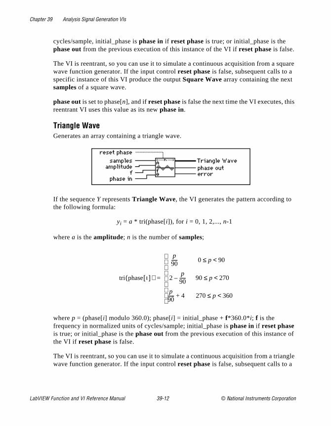
Chapter 39 Analysis Signal Generation VIs
uare
s
f
ngle
cycles/sample, initial_phase is phase in if reset phase is true; or initial_phase is the phase out from the previous execution of this instance of the VI if reset phase is false.
The VI is reentrant, so you can use it to simulate a continuous acquisition from a sqwave function generator. If the input control reset phase is false, subsequent calls to aspecific instance of this VI produce the output Square Wave array containing the next samples of a square wave.
phase out is set to phase[n], and if reset phase is false the next time the VI executes, thireentrant VI uses this value as its new phase in.
Triangle WaveGenerates an array containing a triangle wave.
If the sequence Y represents Triangle Wave, the VI generates the pattern according tothe following formula:
yi = a * tri(phase[i]), for i = 0, 1, 2,..., n-1
where a is the amplitude; n is the number of samples;
where p = (phase[i] modulo 360.0); phase[i] = initial_phase + f*360.0*i; f is the frequency in normalized units of cycles/sample; initial_phase is phase in if reset phase is true; or initial_phase is the phase out from the previous execution of this instance othe VI if reset phase is false.
The VI is reentrant, so you can use it to simulate a continuous acquisition from a triawave function generator. If the input control reset phase is false, subsequent calls to a
tri phaseι[ ]( )
p90------ 0 p 90<≤
2p90------ 90 p 270<≤–
p90------ 4 270 p 360<≤+
=
LabVIEW Function and VI Reference Manual 39-12 © National Instruments Corporation
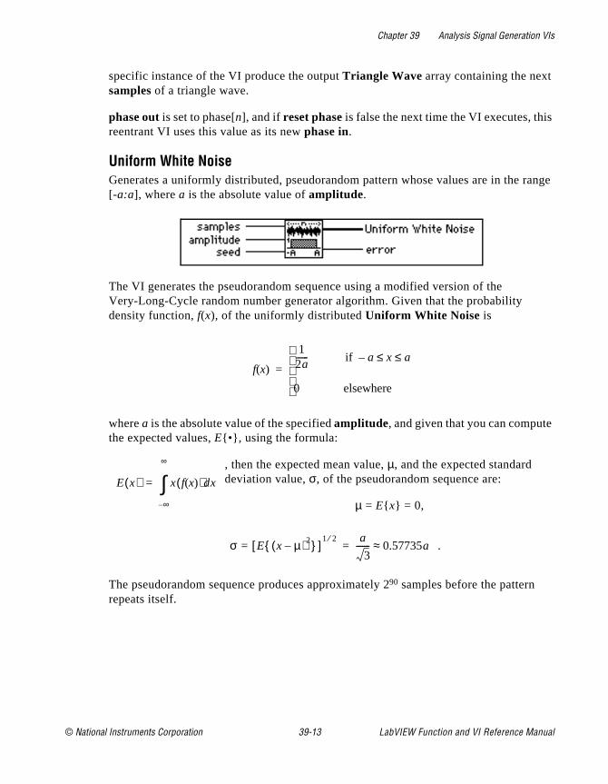
Chapter 39 Analysis Signal Generation VIs
s
range
specific instance of the VI produce the output Triangle Wave array containing the next samples of a triangle wave.
phase out is set to phase[n], and if reset phase is false the next time the VI executes, thireentrant VI uses this value as its new phase in.
Uniform White NoiseGenerates a uniformly distributed, pseudorandom pattern whose values are in the [-a:a], where a is the absolute value of amplitude.
The VI generates the pseudorandom sequence using a modified version of the Very-Long-Cycle random number generator algorithm. Given that the probability density function, f(x), of the uniformly distributed Uniform White Noise is
where a is the absolute value of the specified amplitude, and given that you can computethe expected values, E•, using the formula:
, then the expected mean value, µ, and the expected standard deviation value, σ, of the pseudorandom sequence are:
µ = E x = 0,
.
The pseudorandom sequence produces approximately 290 samples before the pattern repeats itself.
f x( )
12a------ if a x a≤ ≤–
0 elsewhere
=
E x( ) x f x( )( )dx
∞–
∞
∫=
σ E x µ–( )2 [ ]1 2⁄
=a
3------- 0.57735a≈=
© National Instruments Corporation 39-13 LabVIEW Function and VI Reference Manual
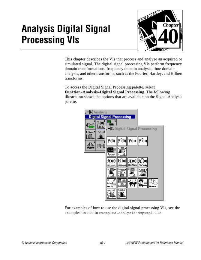
© National Instruments Corporation 40-1 LabVIEW Function and
Chapter
40
Analysis Digital Signal Processing VIsd or cy
bert
sis
he
This chapter describes the VIs that process and analyze an acquiresimulated signal. The digital signal processing VIs perform frequendomain transformations, frequency domain analysis, time domain analysis, and other transforms, such as the Fourier, Hartley, and Hiltransforms.
To access the Digital Signal Processing palette, select Function»Analysis»Digital Signal Processing. The following illustration shows the options that are available on the Signal Analypalette.
For examples of how to use the digital signal processing VIs, see texamples located in examples\analysis\dspxmpl.llb .
VI Reference Manual
Chapter 40 Analysis Digital Signal Processing VIs
and s a
d
ons,
e
The Fast Fourier Transform (FFT)The Fourier transform establishes the relationship between a signalits representation in the frequency domain. The Fourier transform ipowerful analysis tool for spectral analysis, applied mechanics, acoustics, medical imaging, numerical analysis, instrumentation, antelecommunications.
The definition of the Fourier transform of a signal x(t) is
, (40-1)
and the inverse Fourier transform of a signal X(f) is
. (40-2)
A notation often used to indicate that the signals x(t) and X(f) are a Fourier transform pair and are related via the Fourier transform is:
x(t) ⇔ X(f). (40-3)
To derive the discrete representation of the Fourier transform equatiequations (40-1) and (40-2), sample the Fourier transform pair in equation (40-3) using the following sampling relationships:
where ∆t is the sampling interval, ∆f is the frequency resolution, is the sampling frequency, and n is the number of samples in both the timand frequency domain.
Thus, the discrete transform pair
xi ⇔ Xk (40-4)
is obtained and the discrete Fourier transform is given by
X f( ) F x t ( ) x t( )e j2πft–td
∞–
∞
∫= =
x t( ) F 1– X f( ) X f( )ej2πfttd
∞–
∞
∫= =
t∆ 1fs---= f∆
fs
n---=
fs
LabVIEW Function and VI Reference Manual 40-2 © National Instruments Corporation

Chapter 40 Analysis Digital Signal Processing VIs
ply
al 8), te.
st
ss
(40-5)
and the inverse by
. (40-6)
Xk in equation (40-5) represents an amplitude spectral density. Multithe right-hand side of equation (40-5) by the frequency resolution ∆f to arrive at the amplitude spectrum. This amplitude spectrum is the finform of the DFT and inverse DFT, given by equations (40-7) and (40-respectively. Notice that the DFT is independent of the sampling ra
for k = 0, 1, 2, …, n-1 (40-7)
for i = 0, 1, 2, …, n-1. (40-8)
Direct implementation of the DFT requires approximately n2 complex operations, and until recently, it was a time-consuming process. However, when the size of the sequence is
n = 2m for m = 1, 2, 3,…,
you can implement the computation of the DFT with approximatelyn log2(n) operations. DSP literature refers to these algorithms as faFourier transforms (FFTs).
Note: The advantages of the FFT include its speed and memory efficiency because the VI performs the transform in place. The size of the input sequence, however, must be a power of 2. The DFT can efficiently proceany size sequence, but the DFT is slower than the FFT and uses more memory, because it must store intermediate results during processing.
Xk xiej2π ik n⁄–
t∆
i 0=
n 1–
∑=
xi Xkej2π ik n⁄ f∆
i 0=
n 1–
∑=
Xk xiej2π ik n⁄–
i 0=
n 1–
∑=
xi1n--- Xke
j2π ik n⁄
k 0=
n 1–
∑=
© National Instruments Corporation 40-3 LabVIEW Function and VI Reference Manual
Chapter 40 Analysis Digital Signal Processing VIs
ize
on
as
rier
orm ce
Furthermore, with the aid of the FFT, you can find the DFT of any ssequence in approximately 3nlog2(n) operations where n is the next power of 2 that accommodates intermediate results. You can find amore detailed explanation of FFT theory in most introductory texts DSP.
The algorithm implemented in the LabVIEW analysis VIs is known the split-radix algorithm. This algorithm has a form similar to the radix-4 algorithms with the efficiency of radix-8 algorithms. The split-radix algorithm requires the least number of multiplications among the radix-2, radix-4, and mixed-radix algorithms.
This manual uses the following notation to denote the discrete Foutransform of a sequence x:
X = F x,
and
x = F-1 X
to denote the discrete inverse Fourier transform. The Fourier transfalways results in a complex output sequence, and the input sequencan be either real or complex. Unless otherwise specified, two real sequences represent the complex sequences. If X is a complex sequence,then:
XRe = ReX
represents the real part of the complex sequence X,
XIm = ImX
represents the imaginary part of the complex sequence X, and
X = XRe + j XIm = ReX + j Im X.
If the i/p signal is real, the FT is symmetric.
If the i/p signal is complex, the FT is not symmetric.
LabVIEW Function and VI Reference Manual 40-4 © National Instruments Corporation
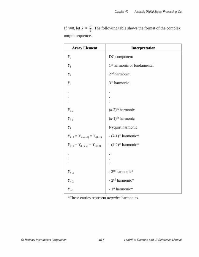
Chapter 40 Analysis Digital Signal Processing VIs
x
If n=8, let . The following table shows the format of the compleoutput sequence.
Array Element Interpretation
Y0 DC component
Y1 1st harmonic or fundamental
Y2 2nd harmonic
Y3 3rd harmonic
.
.
.
.
.
.
Yk-2 (k-2)th harmonic
Yk-1 (k-1)th harmonic
Yk Nyquist harmonic
Yk+1 = Yn-(k-1) = Y-(k-1) - (k-1)th harmonic*
Yk+2 = Yn-(k-2) = Y-(k-2) - (k-2)th harmonic*
.
.
.
.
.
.
Yn-3 - 3rd harmonic*
Yn-2 - 2nd harmonic*
Yn-1 - 1st harmonic*
*These entries represent negative harmonics.
kn2---=
© National Instruments Corporation 40-5 LabVIEW Function and VI Reference Manual
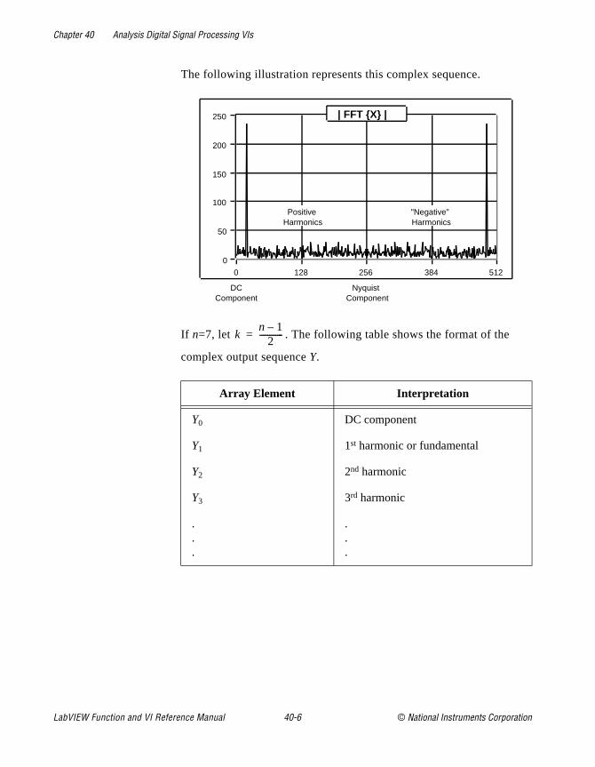
Chapter 40 Analysis Digital Signal Processing VIs
The following illustration represents this complex sequence.
If n=7, let . The following table shows the format of the
complex output sequenceY.
Array Element Interpretation
Y0 DC component
Y1 1st harmonic or fundamental
Y2 2nd harmonic
Y3 3rd harmonic
.
.
.
.
.
.
128 256 3840 512
50
100
150
200
0
250 | FFT X |
DC Component
Nyquist Component
Positive Harmonics
"Negative" Harmonics
kn 1–
2------------=
LabVIEW Function and VI Reference Manual 40-6 © National Instruments Corporation
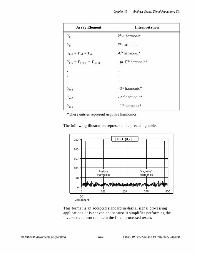
Chapter 40 Analysis Digital Signal Processing VIs
The following illustration represents the preceding table.
This format is an accepted standard in digital signal processing applications. It is convenient because it simplifies performing the inverse transform to obtain the final, processed result.
Yk-1 kth-1 harmonic
Yk kth harmonic
Yk+1 = Yn-k = Y-k -kth harmonic*
Yk+2 = Yn-(k-1) = Y-(k-1) - (k-1)th harmonic*
.
.
.
.
.
.
Yn-3 - 3rd harmonic*
Yn-2 - 2nd harmonic*
Yn-1 - 1st harmonic*
*These entries represent negative harmonics.
Array Element Interpretation
125 250 3750 500
50
100
150
200
0
250 | FFT X |
DC Component
Positive Harmonics
"Negative" Harmonics
© National Instruments Corporation 40-7 LabVIEW Function and VI Reference Manual
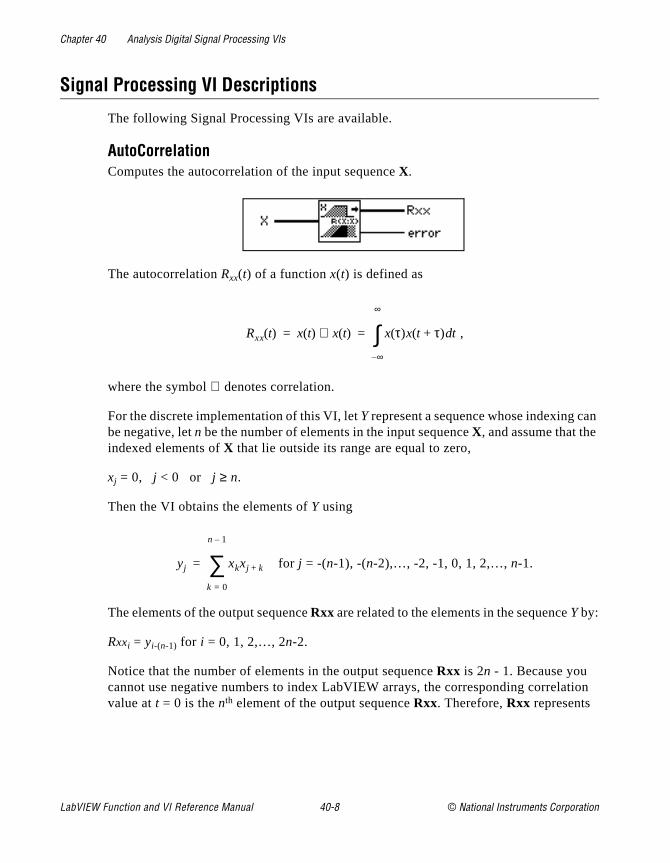
Chapter 40 Analysis Digital Signal Processing VIs
an
tion
Signal Processing VI Descriptions
The following Signal Processing VIs are available.
AutoCorrelationComputes the autocorrelation of the input sequence X.
The autocorrelation Rxx(t) of a function x(t) is defined as
,
where the symbol ⊗ denotes correlation.
For the discrete implementation of this VI, let Y represent a sequence whose indexing cbe negative, let n be the number of elements in the input sequence X, and assume that theindexed elements of X that lie outside its range are equal to zero,
xj = 0, j < 0 or j ≥ n.
Then the VI obtains the elements of Y using
for j = -(n-1), -(n-2),…, -2, -1, 0, 1, 2,…, n-1.
The elements of the output sequence Rxx are related to the elements in the sequence Y by:
Rxxi = yi-(n-1) for i = 0, 1, 2,…, 2n-2.
Notice that the number of elements in the output sequence Rxx is 2n - 1. Because you cannot use negative numbers to index LabVIEW arrays, the corresponding correlavalue at t = 0 is the nth element of the output sequence Rxx. Therefore, Rxx represents
Rxx t( ) x t( ) x t( )⊗ x τ( )x t τ+( ) td
∞–
∞
∫= =
yj xkxj k+
k 0=
n 1–
∑=
LabVIEW Function and VI Reference Manual 40-8 © National Instruments Corporation
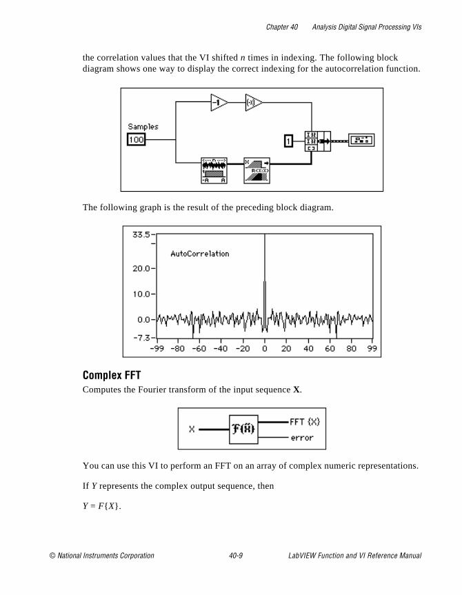
Chapter 40 Analysis Digital Signal Processing VIs
tion.
ions.
the correlation values that the VI shifted n times in indexing. The following block diagram shows one way to display the correct indexing for the autocorrelation func
The following graph is the result of the preceding block diagram.
Complex FFTComputes the Fourier transform of the input sequence X.
You can use this VI to perform an FFT on an array of complex numeric representat
If Y represents the complex output sequence, then
Y = F X.
© National Instruments Corporation 40-9 LabVIEW Function and VI Reference Manual
Chapter 40 Analysis Digital Signal Processing VIs
urier take
lying
y
e
You also can use this VI to perform the following operations when X has one of the complex LabVIEW data types.
• The FFT of a complex-valued sequence X
• The DFT of a complex-valued sequence X
This VI first analyzes the input data, and based on this analysis, it calculates the Fotransform of the data by executing one of the preceding options. All these routinesadvantage of the concurrent processing capabilities of the CPU and FPU.
When the number of samples in the input sequence X is a valid power of 2,
n = 2m for m = 1, 2, 3,…, 23,
where n is the number of samples, the VI computes the fast Fourier transform by appthe split-radix algorithm. The largest complex FFT the VI can compute is223 = 8,388,608 (8M).
When the number of samples in the input sequence X is not a valid power of 2,
n ≠ 2m for m = 1, 2, 3,…, 23,
where n is the number of samples, the VI computes the discrete Fourier transform bapplying the chirp-z algorithm. The largest complex DFT that can be computed is 222-1 = 4,194,303 (4M - 1).
Note: Because the VI performs the transform in place, advantages of the FFTinclude speed and memory efficiency. The size of the input sequence, however, must be a power of 2. The DFT can efficiently process any sizsequence, but the DFT is slower than the FFT and uses more memory, because it must store intermediate results during processing.
Let Y be the complex output sequence and n be the number of samples in it. Using equation (40-7), you can show that
Yn-i = Y-i
which means you can interpret the (n-i)th element of Y as the -i th element of the sequence,if it could be physically realized, which represents the negative i th harmonic.
LabVIEW Function and VI Reference Manual 40-10 © National Instruments Corporation
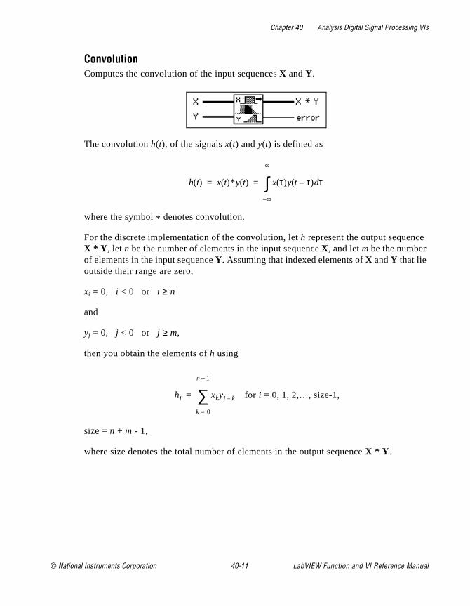
Chapter 40 Analysis Digital Signal Processing VIs
ConvolutionComputes the convolution of the input sequences X and Y.
The convolution h(t), of the signals x(t) and y(t) is defined as
where the symbol * denotes convolution.
For the discrete implementation of the convolution, let h represent the output sequenceX * Y , let n be the number of elements in the input sequence X, and let m be the number of elements in the input sequence Y. Assuming that indexed elements of X and Y that lie outside their range are zero,
xi = 0, i < 0 or i ≥ n
and
yj = 0, j < 0 or j ≥ m,
then you obtain the elements of h using
for i = 0, 1, 2,…, size-1,
size = n + m - 1,
where size denotes the total number of elements in the output sequence X * Y .
h t( ) x t( )* y t( ) x τ( )y t τ–( ) τd
∞–
∞
∫= =
hi xkyi k–
k 0=
n 1–
∑=
© National Instruments Corporation 40-11 LabVIEW Function and VI Reference Manual
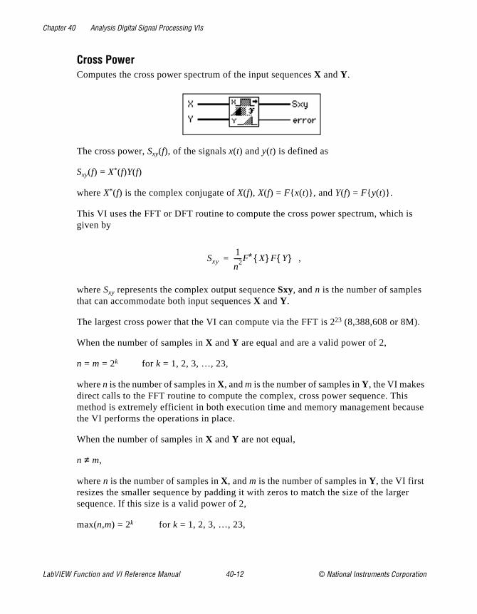
Chapter 40 Analysis Digital Signal Processing VIs
is
s ause
er
Cross PowerComputes the cross power spectrum of the input sequences X and Y.
The cross power, Sxy(f), of the signals x(t) and y(t) is defined as
Sxy(f) = X* (f)Y(f)
where X* (f) is the complex conjugate of X(f), X(f) = F x(t), and Y(f) = F y(t).
This VI uses the FFT or DFT routine to compute the cross power spectrum, which given by
,
where Sxy represents the complex output sequence Sxy, and n is the number of samples that can accommodate both input sequences X and Y.
The largest cross power that the VI can compute via the FFT is 223 (8,388,608 or 8M).
When the number of samples in X and Y are equal and are a valid power of 2,
n = m = 2k for k = 1, 2, 3, …, 23,
where n is the number of samples in X, and m is the number of samples in Y, the VI makes direct calls to the FFT routine to compute the complex, cross power sequence. Thimethod is extremely efficient in both execution time and memory management becthe VI performs the operations in place.
When the number of samples in X and Y are not equal,
n ≠ m,
where n is the number of samples in X, and m is the number of samples in Y, the VI first resizes the smaller sequence by padding it with zeros to match the size of the largsequence. If this size is a valid power of 2,
max(n,m) = 2k for k = 1, 2, 3, …, 23,
Sxy1
n2-----F∗ X F Y =
LabVIEW Function and VI Reference Manual 40-12 © National Instruments Corporation
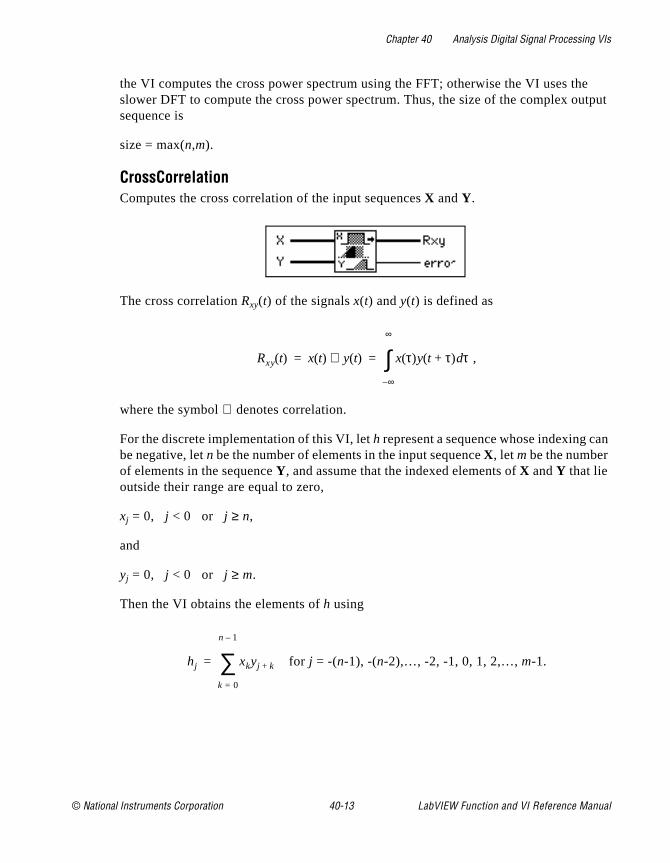
Chapter 40 Analysis Digital Signal Processing VIs
e utput
an
the VI computes the cross power spectrum using the FFT; otherwise the VI uses thslower DFT to compute the cross power spectrum. Thus, the size of the complex osequence is
size = max(n,m).
CrossCorrelationComputes the cross correlation of the input sequences X and Y.
The cross correlation Rxy(t) of the signals x(t) and y(t) is defined as
,
where the symbol ⊗ denotes correlation.
For the discrete implementation of this VI, let h represent a sequence whose indexing cbe negative, let n be the number of elements in the input sequence X, let m be the number of elements in the sequence Y, and assume that the indexed elements of X and Y that lie outside their range are equal to zero,
xj = 0, j < 0 or j ≥ n,
and
yj = 0, j < 0 or j ≥ m.
Then the VI obtains the elements of h using
for j = -(n-1), -(n-2),…, -2, -1, 0, 1, 2,…, m-1.
Rxy t( ) x t( ) y t( )⊗ x τ( )y t τ+( ) τd
∞–
∞
∫= =
hj xkyj k+
k 0=
n 1–
∑=
© National Instruments Corporation 40-13 LabVIEW Function and VI Reference Manual
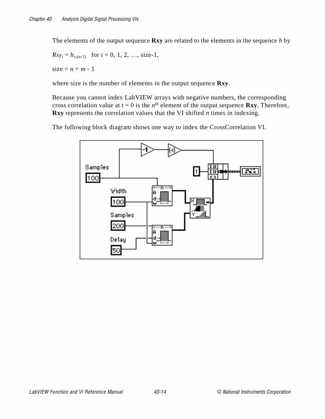
Chapter 40 Analysis Digital Signal Processing VIs
ing
The elements of the output sequence Rxy are related to the elements in the sequence h by
Rxyi = hi-(n-1) for i = 0, 1, 2, …, size-1,
size = n + m - 1
where size is the number of elements in the output sequence Rxy.
Because you cannot index LabVIEW arrays with negative numbers, the correspondcross correlation value at t = 0 is the nth element of the output sequence Rxy. Therefore, Rxy represents the correlation values that the VI shifted n times in indexing.
The following block diagram shows one way to index the CrossCorrelation VI.
LabVIEW Function and VI Reference Manual 40-14 © National Instruments Corporation

Chapter 40 Analysis Digital Signal Processing VIs
The following graph is the result of the preceding block diagram.
DecimateDecimates the input sequence X by the decimating factor and the averaging binary control.
If Y represents the output sequence Decimated Array, the VI obtains the elements of thesequence Y using
for i = 0, 1, 2,..., size-1
,
where n is the number of elements in X, m is the decimating factor, ave is the averaging option, and size is the number of elements in the output sequence Decimated Array.
yi
xim if ave is false
1m---- x im k+( ) if ave is true
k 0=
m 1–
∑
=
size truncnm----
=
© National Instruments Corporation 40-15 LabVIEW Function and VI Reference Manual

Chapter 40 Analysis Digital Signal Processing VIs
ng
s
t
DeconvolutionComputes the deconvolution of the input sequences X * Y and Y.
The VI can use Fourier identities to realize the convolution operation because
x(t) * y(t) ⇔ X(f) Y(f)
is a Fourier transform pair, where the symbol * denotes convolution, and the deconvolution is the inverse of the convolution operation. If h(t) is the signal resulting from the deconvolution of the signals x(t) and y(t), the VI obtains h(t) using the equation
,
where X(f) is the Fourier transform of x(t), and Y(f) is the Fourier transform of y(t).
The VI performs the discrete implementation of the deconvolution using the followisteps:
1. Compute the Fourier transform of the input sequence X * Y .
2. Compute the Fourier transform of the input sequence Y.
3. Divide the Fourier transform of X * Y by the Fourier transform of Y. Call the new sequenceH.
4. Compute the inverse Fourier transform of H to obtain the deconvoluted sequence X.
Note: The deconvolution operation is a numerically unstable operation, and it inot always possible to solve the system numerically. Computing the deconvolution via FFTs is perhaps the most stable generic algorithm norequiring sophisticated DSP techniques. However, it is not free of errors(for example, when there are zeros in the Fourier transform of the inputsequence Y).
h t( ) F 1– X f( )Y f( )---------
=
LabVIEW Function and VI Reference Manual 40-16 © National Instruments Corporation
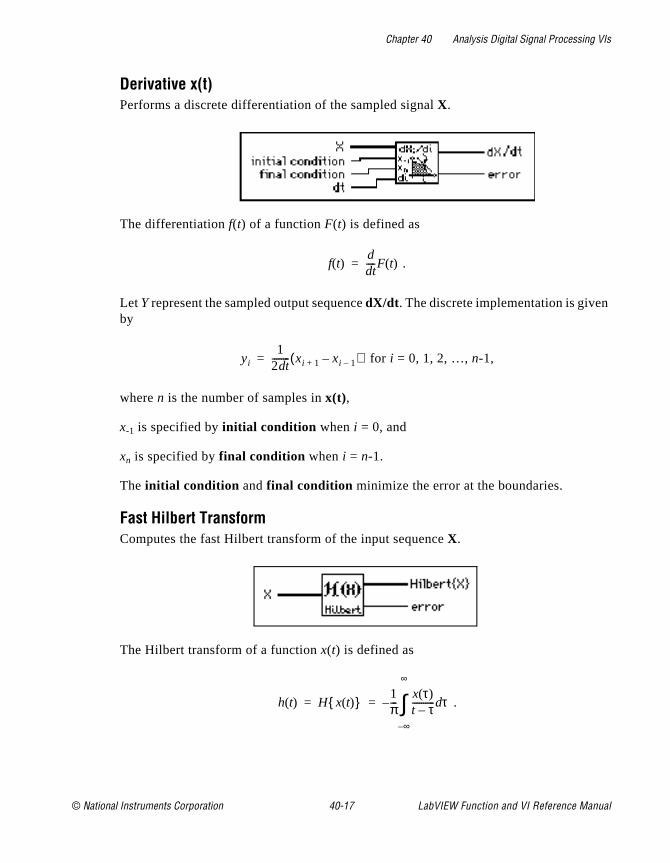
Chapter 40 Analysis Digital Signal Processing VIs
Derivative x(t)Performs a discrete differentiation of the sampled signal X.
The differentiation f(t) of a function F(t) is defined as
.
Let Y represent the sampled output sequence dX/dt . The discrete implementation is givenby
for i = 0, 1, 2, …, n-1,
where n is the number of samples in x(t),
x-1 is specified by initial condition when i = 0, and
xn is specified by final condition when i = n-1.
The initial condition and final condition minimize the error at the boundaries.
Fast Hilbert TransformComputes the fast Hilbert transform of the input sequence X.
The Hilbert transform of a function x(t) is defined as
.
f t( )dtd
----F t( )=
yi1
2 td-------- xi 1+ xi 1––( )=
h t( ) H x t( ) 1π---
x τ( )t τ–---------- τd
∞–
∞
∫–= =
© National Instruments Corporation 40-17 LabVIEW Function and VI Reference Manual
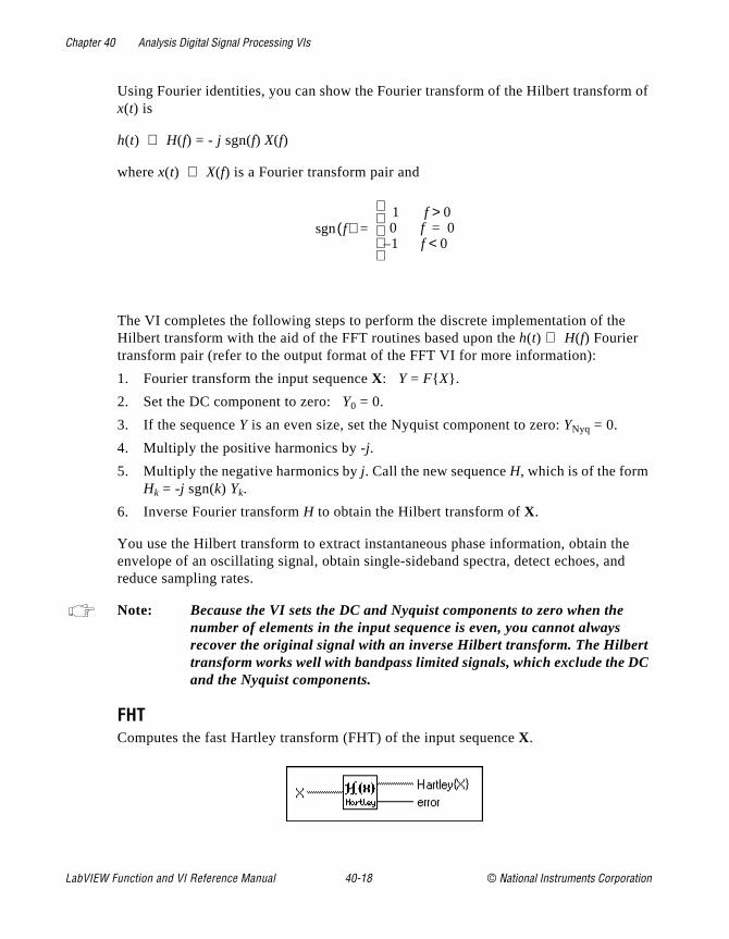
Chapter 40 Analysis Digital Signal Processing VIs
of
e nd
C
Using Fourier identities, you can show the Fourier transform of the Hilbert transformx(t) is
h(t) ⇔ H(f) = - j sgn(f) X(f)
where x(t) ⇔ X(f) is a Fourier transform pair and
The VI completes the following steps to perform the discrete implementation of theHilbert transform with the aid of the FFT routines based upon the h(t) ⇔ H(f) Fourier transform pair (refer to the output format of the FFT VI for more information):
1. Fourier transform the input sequence X: Y = F X.
2. Set the DC component to zero: Y0 = 0.
3. If the sequence Y is an even size, set the Nyquist component to zero: YNyq = 0.
4. Multiply the positive harmonics by -j.
5. Multiply the negative harmonics by j. Call the new sequence H, which is of the form Hk = -j sgn(k) Yk.
6. Inverse Fourier transform H to obtain the Hilbert transform of X.
You use the Hilbert transform to extract instantaneous phase information, obtain thenvelope of an oscillating signal, obtain single-sideband spectra, detect echoes, areduce sampling rates.
Note: Because the VI sets the DC and Nyquist components to zero when the number of elements in the input sequence is even, you cannot always recover the original signal with an inverse Hilbert transform. The Hilberttransform works well with bandpass limited signals, which exclude the Dand the Nyquist components.
FHTComputes the fast Hartley transform (FHT) of the input sequence X.
f( )sgn1 f 0>0 f 0=1 f 0<–
=
LabVIEW Function and VI Reference Manual 40-18 © National Instruments Corporation
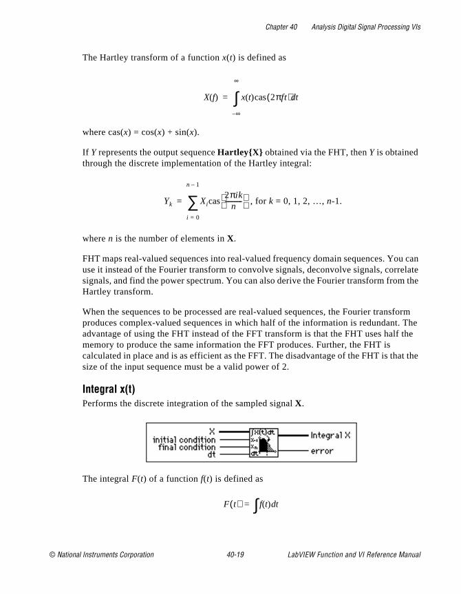
Chapter 40 Analysis Digital Signal Processing VIs
ou can elate the
sform The the
at the
The Hartley transform of a function x(t) is defined as
where cas(x) = cos(x) + sin(x).
If Y represents the output sequence HartleyX obtained via the FHT, then Y is obtained through the discrete implementation of the Hartley integral:
, for k = 0, 1, 2, …, n-1.
where n is the number of elements in X.
FHT maps real-valued sequences into real-valued frequency domain sequences. Yuse it instead of the Fourier transform to convolve signals, deconvolve signals, corrsignals, and find the power spectrum. You can also derive the Fourier transform fromHartley transform.
When the sequences to be processed are real-valued sequences, the Fourier tranproduces complex-valued sequences in which half of the information is redundant.advantage of using the FHT instead of the FFT transform is that the FHT uses halfmemory to produce the same information the FFT produces. Further, the FHT is calculated in place and is as efficient as the FFT. The disadvantage of the FHT is thsize of the input sequence must be a valid power of 2.
Integral x(t)Performs the discrete integration of the sampled signal X.
The integral F(t) of a function f(t) is defined as
X f( ) x t( )cas 2πft( ) td
∞–
∞
∫=
Yk Xicas2πik
n-----------
i 0=
n 1–
∑=
F t( ) f t( ) td∫=
© National Instruments Corporation 40-19 LabVIEW Function and VI Reference Manual
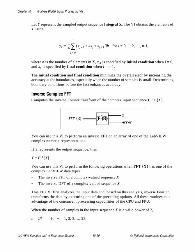
Chapter 40 Analysis Digital Signal Processing VIs
ining
ier ake
Let Y represent the sampled output sequence Integral X . The VI obtains the elements ofY using
for i = 0, 1, 2, …, n-1,
where n is the number of elements in X, x-1 is specified by initial condition when i = 0, and xn is specified by final condition when i = n-1.
The initial condition and final condition minimize the overall error by increasing the accuracy at the boundaries, especially when the number of samples is small. Determboundary conditions before the fact enhances accuracy.
Inverse Complex FFTComputes the inverse Fourier transform of the complex input sequence FFT X .
You can use this VI to perform an inverse FFT on an array of one of the LabVIEW complex numeric representations.
If Y represents the output sequence, then
Y = F-1 X.
You can use this VI to perform the following operations when FFT X has one of the complex LabVIEW data types:
• The inverse FFT of a complex-valued sequence X
• The inverse DFT of a complex-valued sequence X
This FFT VI first analyzes the input data and, based on this analysis, inverse Fourtransforms the data by executing one of the preceding options. All these routines tadvantage of the concurrent processing capabilities of the CPU and FPU.
When the number of samples in the input sequence X is a valid power of 2,
n = 2m for m = 1, 2, 3,…, 23,
yi16--- xj 1– 4xj xj 1++ +( ) td
j 0=
i
∑=
LabVIEW Function and VI Reference Manual 40-20 © National Instruments Corporation

Chapter 40 Analysis Digital Signal Processing VIs
I can
e an
e
where n is the number of samples, the VI computes the inverse FFT by applying thesplit-radix algorithm. The longest sequence with an inverse complex FFT that the Vcompute is 223=8,388,608 (8M).
When the number of samples in the input sequence X is not a valid power of 2,
n ≠ 2m for m = 1, 2, 3, …, 23,
where n is the number of samples, the VI computes the inverse DFT by applying thchirp-z algorithm. The longest sequence with an inverse complex DFT that the VI ccompute is 222-1 (4,194,303 or 4M - 1).
Note: Because the VI performs the transform in place, advantages of the FFTinclude speed and memory efficiency. The size of the input sequence, however, must be a power of 2. The DFT can efficiently process any sizsequence, but the DFT is slower than the FFT and uses more memory, because it must store intermediate results during processing.
Inverse Fast Hilbert TransformComputes the inverse fast Hilbert transform of the input sequence X.
The inverse Hilbert transform of a function h(t) is defined as
.
Using the definition of the Hilbert transform
,
you obtain the inverse Hilbert transform by negating the forward Hilbert transform
x(t) = H-1 h(t) = - H h(t).
h t( ) H 1– h t( ) 1π---
h τ( )t τ–---------- τd
∞–
∞
∫= =
h t( ) H x t( ) 1π---
x τ( )t τ–---------- τd
∞–
∞
∫–= =
© National Instruments Corporation 40-21 LabVIEW Function and VI Reference Manual
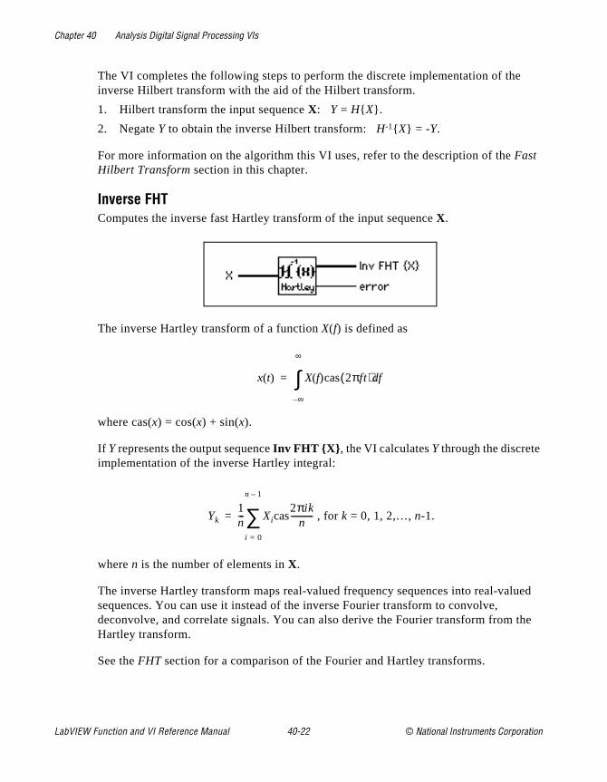
Chapter 40 Analysis Digital Signal Processing VIs
ued
the
The VI completes the following steps to perform the discrete implementation of theinverse Hilbert transform with the aid of the Hilbert transform.
1. Hilbert transform the input sequence X: Y = H X.
2. Negate Y to obtain the inverse Hilbert transform: H-1 X = -Y.
For more information on the algorithm this VI uses, refer to the description of the Fast Hilbert Transform section in this chapter.
Inverse FHTComputes the inverse fast Hartley transform of the input sequence X.
The inverse Hartley transform of a function X(f) is defined as
where cas(x) = cos(x) + sin(x).
If Y represents the output sequence Inv FHT X , the VI calculates Y through the discrete implementation of the inverse Hartley integral:
, for k = 0, 1, 2,…, n-1.
where n is the number of elements in X.
The inverse Hartley transform maps real-valued frequency sequences into real-valsequences. You can use it instead of the inverse Fourier transform to convolve, deconvolve, and correlate signals. You can also derive the Fourier transform from Hartley transform.
See the FHT section for a comparison of the Fourier and Hartley transforms.
x t( ) X f( )cas 2πft( ) fd
∞–
∞
∫=
Yk1n--- Xicas
2πikn
-----------
i 0=
n 1–
∑=
LabVIEW Function and VI Reference Manual 40-22 © National Instruments Corporation
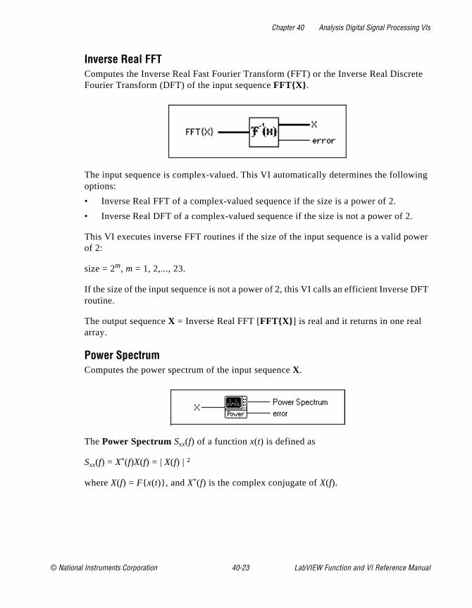
Chapter 40 Analysis Digital Signal Processing VIs
rete
ing
.
ower
DFT
Inverse Real FFTComputes the Inverse Real Fast Fourier Transform (FFT) or the Inverse Real DiscFourier Transform (DFT) of the input sequence FFTX .
The input sequence is complex-valued. This VI automatically determines the followoptions:
• Inverse Real FFT of a complex-valued sequence if the size is a power of 2.
• Inverse Real DFT of a complex-valued sequence if the size is not a power of 2
This VI executes inverse FFT routines if the size of the input sequence is a valid pof 2:
size = 2m, m = 1, 2,..., 23.
If the size of the input sequence is not a power of 2, this VI calls an efficient Inverse routine.
The output sequence X = Inverse Real FFT [FFTX ] is real and it returns in one real array.
Power SpectrumComputes the power spectrum of the input sequence X.
The Power Spectrum Sxx(f) of a function x(t) is defined as
Sxx(f) = X*(f)X(f) = | X(f) | 2
where X(f) = F x(t), and X*(f) is the complex conjugate of X(f).
© National Instruments Corporation 40-23 LabVIEW Function and VI Reference Manual
Chapter 40 Analysis Digital Signal Processing VIs
en by
and pute
of a . The
the ence trum
This VI uses the FFT and DFT routines to compute the power spectrum, which is giv
,
where Sxx represents the output sequence Power Spectrum, and n is the number of samples in the input sequence X.
When the number of samples, n, in the input sequence X is a valid power of 2,
n = 2m for m = 1, 2, 3, …, 23,
this VI computes the FFT of a real-valued sequence using the split-radix algorithmefficiently scales the magnitude square. The largest power spectrum the VI can comusing the FFT is 223 (8,388,608 or 8M).
When the number of samples in the input sequence X is not a valid power of 2,
n ≠ 2m for m = 1, 2, 3,…, 23,
where n is the number of samples, this VI computes the discrete Fourier transform real-valued sequence using the chirp-z algorithm and scales the magnitude squarelargest power spectrum the VI can compute using the fast DFT is 222-1 (4,194,303 or 4M - 1).
The FFT computation of the power spectrum is time and memory efficient becausetransform is real and done in the same space. However, the size of the input sequmust be exactly a power of 2. The DFT version efficiently computes the power specof any size sequence. The DFT version is slower than the FFT version, uses morememory, and is not as efficient in scaling.
Let Y be the Fourier transform of the input sequence X and let n be the number of samplesin it. Using equation (40-7), you can show that
.
You can interpret the power in the (n-i)th element of Y as the power in the -i th element of the sequence, which represents the power in the negative i th harmonic. You can find the total power for the ith harmonic (DC and Nyquist component not included) using
.
Sxx1
n2----- F X 2=
Yn i–2
Y i–2=
Power ini th harmonic 2Yi2 Yi
2 Yn i–2, 0 i
n2---< <+= =
LabVIEW Function and VI Reference Manual 40-24 © National Instruments Corporation

Chapter 40 Analysis Digital Signal Processing VIs
ely.
The total power in the DC and Nyquist components are and , respectiv
If n is even, let . The following table shows the format of the output sequenceSxx
corresponding to the power spectrum.
The following illustration represents the preceding table information.
Array Element Interpretation
Sxx0 Power in DC component
Sxx1 = Sxx(n-1) Power in 1st harmonic or fundamental
Sxx2 = Sxx(n-2) Power in 2nd harmonic
Sxx3 = Sxx(n-3) Power in 3rd harmonic
.
.
.
.
.
.
Sxxk-2 = Sxxn-(k-2) Power in (k-2)th harmonic
Sxxk-1 = Sxxn-(k-1) Power in (k-1)th harmonic
Sxxk Power in Nyquist harmonic
Y02 Yn 2⁄
2
kn2---=
128 256 3840 512
0.05
0.10
0.15
0.20
0.00
0.25 Power Spectrum
Nyquist Component
DC Component
Positive Harmonics
"Negative" Harmonics
© National Instruments Corporation 40-25 LabVIEW Function and VI Reference Manual
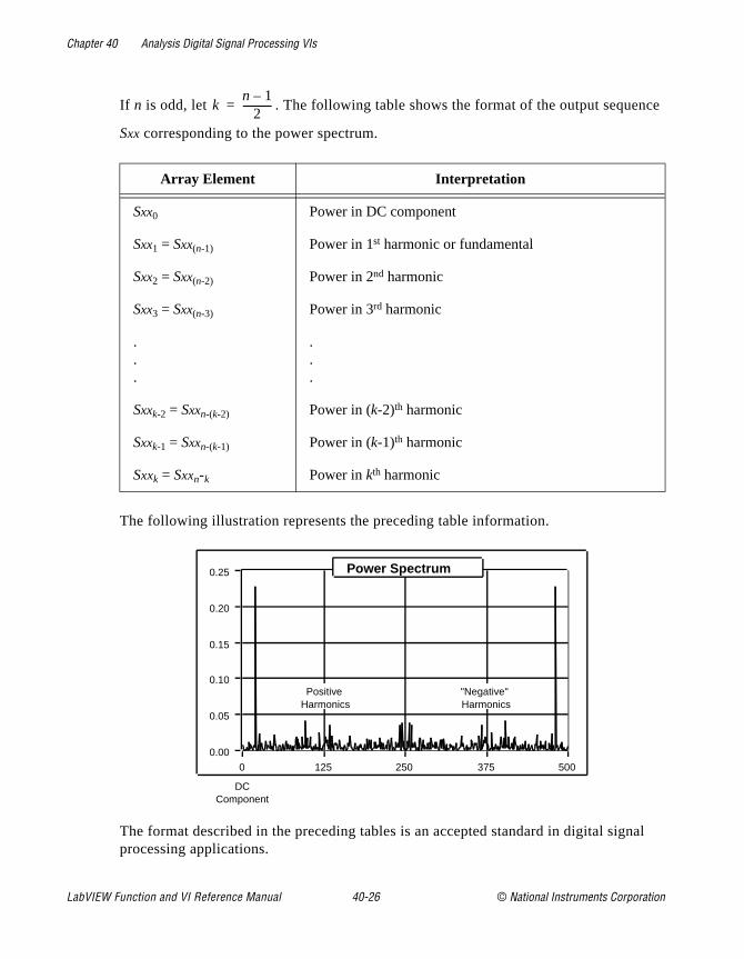
Chapter 40 Analysis Digital Signal Processing VIs
ce
nal
If n is odd, let . The following table shows the format of the output sequen
Sxx corresponding to the power spectrum.
The following illustration represents the preceding table information.
The format described in the preceding tables is an accepted standard in digital sigprocessing applications.
Array Element Interpretation
Sxx0 Power in DC component
Sxx1 = Sxx(n-1) Power in 1st harmonic or fundamental
Sxx2 = Sxx(n-2) Power in 2nd harmonic
Sxx3 = Sxx(n-3) Power in 3rd harmonic
.
.
.
.
.
.
Sxxk-2 = Sxxn-(k-2) Power in (k-2)th harmonic
Sxxk-1 = Sxxn-(k-1) Power in (k-1)th harmonic
Sxxk = Sxxn-k Power in kth harmonic
kn 1–
2------------=
125 250 3750 500
0.05
0.10
0.15
0.20
0.00
0.25 Power Spectrum
DC Component
Positive Harmonics
"Negative" Harmonics
LabVIEW Function and VI Reference Manual 40-26 © National Instruments Corporation

Chapter 40 Analysis Digital Signal Processing VIs
form
ower
ent
d
Real FFTComputes the Real Fast Fourier Transform (FFT) or the Real Discrete Fourier Trans(DFT) of the input sequence X.
The input sequence is real-valued. The Real FFT VI automatically determines the options, which are the following:
• FFT of a real-valued sequence
• DFT of a real-valued sequence
The Real FFT VI executes FFT routines if the size of the input sequence is a valid pof 2:
size = 2m, m = 1, 2,..., 23.
If the size of the input sequence is not a power of 2, the Real FFT VI calls an efficiReal DFT routine.
The output sequence Y = Real FFT[X] is complex and returns in one complex array:
Y = YRe + jYIm
Unwrap PhaseUnwraps the Phase array by eliminating discontinuities whose absolute values exceeΠ.
Y[i] = Clip X[i]Clips the elements of Input Array to within the bounds specified by upper limit and lower limit .
© National Instruments Corporation 40-27 LabVIEW Function and VI Reference Manual

Chapter 40 Analysis Digital Signal Processing VIs
ot
w
Let the sequence Y represent the output sequence Clipped Array ; then the elements of Y are related to the elements of Input Array by
for i = 0, 1, 2,…, n-1,
where n is the number of elements in Input Array , a is the upper limit , and b is the lower limit .
Y[i] = X[i-n]Shifts the elements in the Input Array by the specified number of shifts.
Let the sequence Y represent the output sequence Shifted Array ; then the elements of Y are related to the elements of X by
where n is the number of elements in Input Array .
Note: This VI does not rotate the elements in the array. The VI disposes of theelements of the input sequence shifted outside the range, and you cannrecover them by shifting the array in the opposite direction.
Zero PadderResizes the input sequence Input Array to the next higher valid power of 2, sets the netrailing elements of the sequence to zero, and leaves the first n elements unchanged, where n is the number of samples in the input sequence.
yi
a xi a>
xi b xi a≤ ≤
b xi b<
=
yi
xi shifts– if 0 i shifts n for i = 0, 1, 2, . . ., n-1 ,<–≤
0 elsewhere
=
LabVIEW Function and VI Reference Manual 40-28 © National Instruments Corporation

Chapter 40 Analysis Digital Signal Processing VIs
you
mely
This VI is useful when the size of the acquired data buffers is not a power of 2, andwant to take advantage of fast processing algorithms in the analysis VIs. These algorithms include Fourier transforms, power spectrum, and FHTs, which are extreefficient for buffer sizes that are a power of 2.
© National Instruments Corporation 40-29 LabVIEW Function and VI Reference Manual

© National Instruments Corporation 41-1 LabVIEW Function and
Chapter
41
Analysis Measurement VIsd to for
es
This chapter describes the measurement VIs, which are streamlineperform DFT-based and FFT-based analysis with signal acquisitionfrequency measurement applications as seen in typical frequency measurement instruments, such as dynamic signal analyzers.
To access the Analysis Measurement palette, select Function»Analysis»Measurement. The following illustration shows the options that are available on the Measurement palette.
For examples of how to use the measurement VIs, see the examplusing data acquisition located in examples\analysis\measure\daqmeas.llb (Windows and Macintosh) and using simulated signals in examples\analysis\measure\measxmpl.llb .
VI Reference Manual
Chapter 41 Analysis Measurement VIs
on. as
n.
es t the
ing hen lass
uld am.
and
Introduction to Measurement VIsSeveral measurement VIs perform commonly used time domain to frequency-domain transformations such as amplitude and phase spectrum, signal power spectrum, network transfer function, and soOther measurement VIs interact with VIs that perform such functionsscaled time domain windowing and power and frequency estimatio
You can use the measurement VIs for the following applications:
• Spectrum analysis applications
– Amplitude and phase spectrum
– Power spectrum
– Scaled time domain window
– Power and frequency estimate
– Harmonic analysis and total harmonic distortion (THD) measurements
• Network (frequency response) and dual channel analysis applications
– Transfer function
– Impulse response function
– Network functions (including coherence)
– Cross power spectrum
The DFT, FFT, and power spectrum are useful for measuring the frequency content of stationary or transient signals. The FFT providthe average frequency content of the signal over the entire time thasignal was acquired. For this reason, you use the FFT mostly for stationary signal analysis (when the signal is not significantly changin frequency content over the time that the signal is acquired), or wyou want only the average energy at each frequency line. A large cof measurement problems fall in this category. For measuring frequency information that changes during the acquisition, you shouse joint time-frequency analysis VIs, such as the Gabor Spectrogr
The measurement VIs are built on top of the signal processing VIs have the following characteristics, which model the behavior of traditional, benchtop frequency analysis instruments.
• Real-world, time-domain signal input is assumed.
LabVIEW Function and VI Reference Manual 41-2 © National Instruments Corporation
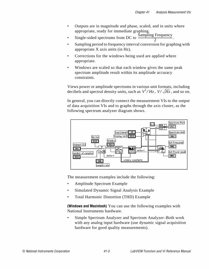
Chapter 41 Analysis Measurement VIs
e
ith
ng on.
tput e
• Outputs are in magnitude and phase, scaled, and in units wherappropriate, ready for immediate graphing.
• Single-sided spectrums from DC to .
• Sampling period to frequency interval conversion for graphing wappropriate X axis units (in Hz).
• Corrections for the windows being used are applied where appropriate.
• Windows are scaled so that each window gives the same peakspectrum amplitude result within its amplitude accuracy constraints.
Views power or amplitude spectrums in various unit formats, includidecibels and spectral density units, such as , , and so
In general, you can directly connect the measurement VIs to the ouof data acquisition VIs and to graphs through the axis cluster, as thfollowing spectrum analyzer diagram shows.
The measurement examples include the following:
• Amplitude Spectrum Example
• Simulated Dynamic Signal Analysis Example
• Total Harmonic Distortion (THD) Example
(Windows and Macintosh) You can use the following examples with National Instruments hardware.
• Simple Spectrum Analyzer and Spectrum Analyzer–Both work with any analog input hardware (use dynamic signal acquisitionhardware for good quality measurements).
Sampling Frequency2
-------------------------------------------------
V2 Hz⁄ V Hz⁄
© National Instruments Corporation 41-3 LabVIEW Function and VI Reference Manual
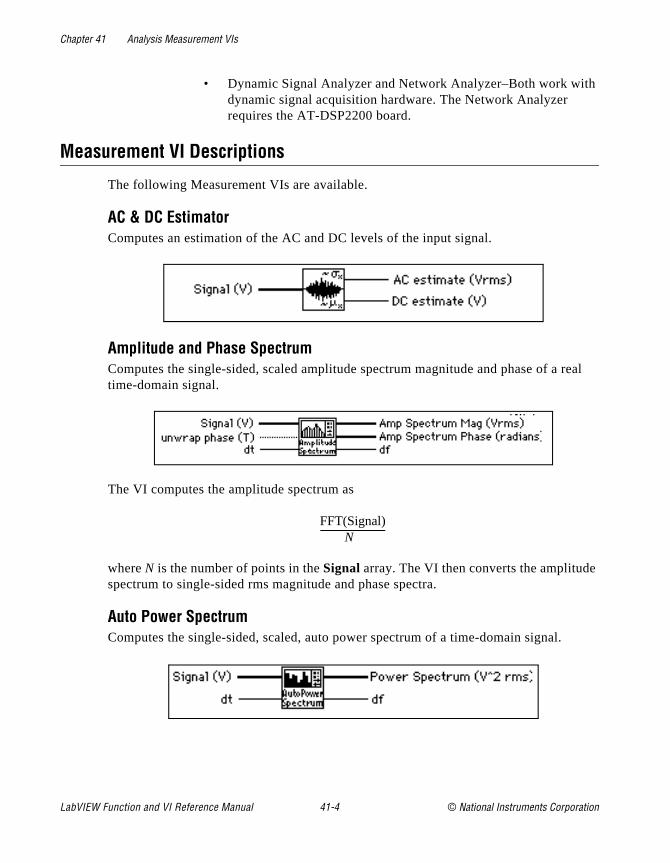
Chapter 41 Analysis Measurement VIs
h
real
• Dynamic Signal Analyzer and Network Analyzer–Both work witdynamic signal acquisition hardware. The Network Analyzer requires the AT-DSP2200 board.
Measurement VI Descriptions
The following Measurement VIs are available.
AC & DC EstimatorComputes an estimation of the AC and DC levels of the input signal.
Amplitude and Phase SpectrumComputes the single-sided, scaled amplitude spectrum magnitude and phase of a time-domain signal.
The VI computes the amplitude spectrum as
where N is the number of points in the Signal array. The VI then converts the amplitudespectrum to single-sided rms magnitude and phase spectra.
Auto Power SpectrumComputes the single-sided, scaled, auto power spectrum of a time-domain signal.
FFT(Signal)N
-----------------------------
LabVIEW Function and VI Reference Manual 41-4 © National Instruments Corporation

Chapter 41 Analysis Measurement VIs
lt.
The d the
nt in n
e
ower
This VI computes the power spectrum as
where N is the number of points in the Signal array and * denotes complex conjugate.The VI then converts the power spectrum into a single-sided power spectrum resu
Cross Power SpectrumComputes the single-sided, scaled, cross power spectrum of two real-time signals.cross power spectrum gives the product of the amplitude of the signals X and Y andifference between their phases (phase of Y minus phase of X).
This VI computes the cross power spectrum as
where N is the number of points in Signal X or Signal Y arrays. The VI then converts thecross power spectrum to single-sided magnitude and phase spectra.
Harmonic AnalyzerFinds the fundamental and harmonic components (amplitude and frequency) presethe input Auto Power Spectrum, and computes the percent of total harmonic distortio(%THD) and the total harmonic distortion plus noise (%THD + Noise).
You must pass the windowed, auto power spectrum of your signal to this VI for it tofunction correctly. You should pass your time-domain signal through the scaled timdomain window and then through the Auto Power Spectrum, connecting the Auto PSpectrum output to this VI.
FFT*(Signal) x FFT(Signal)N2--------------------------------------------------------------------
FFT*(Signal X) x FFT(Signal Y)N2--------------------------------------------------------------------------------
© National Instruments Corporation 41-5 LabVIEW Function and VI Reference Manual
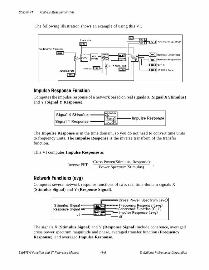
Chapter 41 Analysis Measurement VIs
its
The following illustration shows an example of using this VI.
Impulse Response FunctionComputes the impulse response of a network based on real signals X (Signal X Stimulus) and Y (Signal Y Response).
The Impulse Response is in the time domain, so you do not need to convert time unto frequency units. The Impulse Response is the inverse transform of the transfer function.
This VI computes Impulse Response as
.
Network Functions (avg)Computes several network response functions of two, real time-domain signals X (Stimulus Signal) and Y (Response Signal).
The signals X (Stimulus Signal) and Y (Response Signal) include coherence, averagedcross power spectrum magnitude and phase, averaged transfer function (Frequency Response), and averaged Impulse Response.
Inverse FFTCross Power(Stimulus, Response)
Power Spectrum(Stimulus)---------------------------------------------------------------------------------
LabVIEW Function and VI Reference Manual 41-6 © National Instruments Corporation

Chapter 41 Analysis Measurement VIs
y
rages
ly se
m of a
at lie
e
You usually compute these functions on the stimulus and response signals from a network under test. The coherence function shows the frequency content of the Response Signal Y due to Stimulus Signal X and measures the validity of the network frequencresponse measurement.
You can use this VI to measure the coherence between any two signals. The VI avemultiple stimulus and response signals to get valid coherence measurements. Cross Power Spectrum and Impulse Response are the rms averaged versions of the similarnamed VIs. Frequency Response is the rms averaged version of the frequency responoutputs of the Transfer Function VI.
Peak DetectorFor information on this VI, see Chapter 48, Analysis Additional Numerical Method VIs, in this manual.
Power & Frequency EstimateComputes the estimated power and frequency around a peak in the power spectrutime-domain signal.
With this VI, you can achieve good frequency estimates for measured frequencies thbetween frequency lines on the spectrum. The VI makes corrections for the windowfunction you use.
Pulse ParametersAnalyzes the input sequence X for a pulse pattern and determines the best set of pulsparameters that describes the pulse.
© National Instruments Corporation 41-7 LabVIEW Function and VI Reference Manual
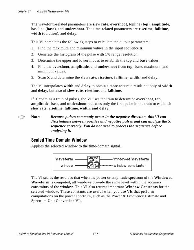
Chapter 41 Analysis Measurement VIs
h
d
The waveform-related parameters are slew rate, overshoot, topline (top), amplitude, baseline (base), and undershoot. The time-related parameters are risetime, falltime , width (duration), and delay.
This VI completes the following steps to calculate the output parameters:
1. Find the maximum and minimum values in the input sequence X.
2. Generate the histogram of the pulse with 1% range resolution.
3. Determine the upper and lower modes to establish the top and base values.
4. Find the overshoot, amplitude, and undershoot from top, base, maximum, and minimum values.
5. Scan X and determine the slew rate, risetime, falltime , width , and delay.
The VI interpolates width and delay to obtain a more accurate result not only of width and delay, but also of slew rate, risetime, and falltime .
If X contains a train of pulses, the VI uses the train to determine overshoot, top, amplitude, base, and undershoot, but uses only the first pulse in the train to establisslew rate, risetime, falltime , width , and delay.
Note: Because pulses commonly occur in the negative direction, this VI can discriminate between positive and negative pulses and can analyze theX sequence correctly. You do not need to process the sequence before analyzing it.
Scaled Time Domain WindowApplies the selected window to the time-domain signal.
The VI scales the result so that when the power or amplitude spectrum of the Windowed Waveform is computed, all windows provide the same level within the accuracy constraints of the window. This VI also returns important Window Constants for the selected window. These constants are useful when you use VIs that perform computations on the power spectrum, such as the Power & Frequency Estimate anSpectrum Unit Conversion VIs.
LabVIEW Function and VI Reference Manual 41-8 © National Instruments Corporation

Chapter 41 Analysis Measurement VIs
te
h
Spectrum Unit ConversionConverts either the power, amplitude, or gain (amplitude ratio) spectrum to alternaformats including Log (decibel and dbm) and spectral density.
Threshold Peak DetectorFor information on the this VI, see Chapter 48, Analysis Additional Numerical Method VIs, of this manual.
Transfer FunctionComputes the transfer function (also known as the frequency response) from the time-domain Stimulus Signal and Response Signal from a network under test.
This VI computes the transfer function of a system based on the real signals X (Stimulus Signal) and Y (Response Signal). The output is the amplitude gain of the network, whicis unitless.
The VI computer frequency response is:
.Cross Power(Stimulus, Response)
Power Spectrum(Stimulus)---------------------------------------------------------------------------------
© National Instruments Corporation 41-9 LabVIEW Function and VI Reference Manual
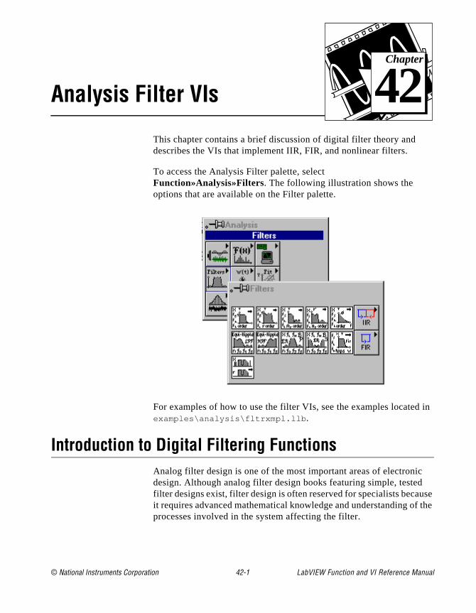
© National Instruments Corporation 42-1 LabVIEW Function and
Chapter
42
Analysis Filter VIsin
use f the
This chapter contains a brief discussion of digital filter theory and describes the VIs that implement IIR, FIR, and nonlinear filters.
To access the Analysis Filter palette, select Function»Analysis»Filters. The following illustration shows the options that are available on the Filter palette.
For examples of how to use the filter VIs, see the examples locatedexamples\analysis\fltrxmpl.llb .
Introduction to Digital Filtering FunctionsAnalog filter design is one of the most important areas of electronicdesign. Although analog filter design books featuring simple, testedfilter designs exist, filter design is often reserved for specialists becait requires advanced mathematical knowledge and understanding oprocesses involved in the system affecting the filter.
VI Reference Manual

Chapter 42 Analysis Filter VIs
at
n
s
n
a the
time ncy me
.
Modern sampling and digital signal processing tools have made it possible to replace analog filters with digital filters in applications threquire flexibility and programmability. These applications include audio, telecommunications, geophysics, and medical monitoring.
Digital filters have the following advantages over their analog counterparts:
• They are software programmable.
• They are stable and predictable.
• They do not drift with temperature or humidity or require precisiocomponents.
• They have a superior performance-to-cost ratio.
You can use digital filters in LabVIEW to control parameters such afilter order, cutoff frequencies, amount of ripple, and stopband attenuation.
The digital filter VIs described in this section follow the virtual instrument philosophy. The VIs handle all the design issues, computations, memory management, and actual data filtering internally, and are transparent to the user. You do not have to be aexpert in digital filters or digital filter theory to process the data.
The following discussion of sampling theory is intended to give youbetter understanding of the filter parameters and how they relate toinput parameters.
The sampling theorem states that you can reconstruct a continuous-signal from discrete, equally spaced samples if the sampling frequeis at least twice that of the highest frequency in the time signal. Assuyou can sample the time signal of interest at ∆t equally spaced intervals without losing information. The ∆t parameter is the sampling interval
You can obtain the sampling rate or sampling frequency fs from the sampling interval
,
which means that, according to the sampling theorem, the highest frequency that the digital system can process is
fs1t∆-----=
LabVIEW Function and VI Reference Manual 42-2 © National Instruments Corporation
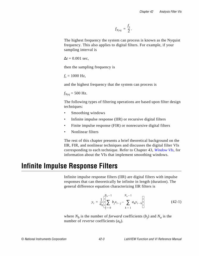
Chapter 42 Analysis Filter VIs
uist
gn
the Is
.
The highest frequency the system can process is known as the Nyqfrequency. This also applies to digital filters. For example, if your sampling interval is
∆t = 0.001 sec,
then the sampling frequency is
fs = 1000 Hz,
and the highest frequency that the system can process is
fNyq = 500 Hz.
The following types of filtering operations are based upon filter desitechniques:
• Smoothing windows
• Infinite impulse response (IIR) or recursive digital filters
• Finite impulse response (FIR) or nonrecursive digital filters
• Nonlinear filters
The rest of this chapter presents a brief theoretical background on IIR, FIR, and nonlinear techniques and discusses the digital filter Vcorresponding to each technique. Refer to Chapter 43, Window VIs, for information about the VIs that implement smoothing windows.
Infinite Impulse Response FiltersInfinite impulse response filters (IIR) are digital filters with impulse responses that can theoretically be infinite in length (duration). Thegeneral difference equation characterizing IIR filters is
(42-1)
where Nb is the number of forward coefficients (bj) and Na is the number of reverse coefficients (ak).
fNyq
fs
2---=
yi1a0----- bjxi j–
j 0=
Nb 1–
∑ akyi k–
k 1=
Na 1–
∑–
=
© National Instruments Corporation 42-3 LabVIEW Function and VI Reference Manual
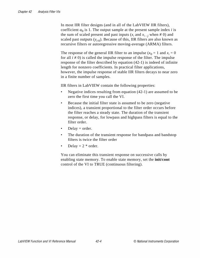
Chapter 42 Analysis Filter VIs
s
ite
ero
be
e
the
top
In most IIR filter designs (and in all of the LabVIEW IIR filters), coefficient a0 is 1. The output sample at the present sample index i is the sum of scaled present and past inputs (xi and xi - j when ≠ 0) and scaled past outputs (yi-k). Because of this, IIR filters are also known arecursive filters or autoregressive moving-average (ARMA) filters.
The response of the general IIR filter to an impulse (x0 = 1 and xi = 0 for all i ≠ 0) is called the impulse response of the filter. The impulseresponse of the filter described by equation (42-1) is indeed of infinlength for nonzero coefficients. In practical filter applications, however, the impulse response of stable IIR filters decays to near zin a finite number of samples.
IIR filters in LabVIEW contain the following properties:
• Negative indices resulting from equation (42-1) are assumed tozero the first time you call the VI.
• Because the initial filter state is assumed to be zero (negative indices), a transient proportional to the filter order occurs beforthe filter reaches a steady state. The duration of the transient response, or delay, for lowpass and highpass filters is equal tofilter order.
• Delay = order.
• The duration of the transient response for bandpass and bandsfilters is twice the filter order
• Delay = 2 * order.
You can eliminate this transient response on successive calls by enabling state memory. To enable state memory, set the init/cont control of the VI to TRUE (continuous filtering).
LabVIEW Function and VI Reference Manual 42-4 © National Instruments Corporation
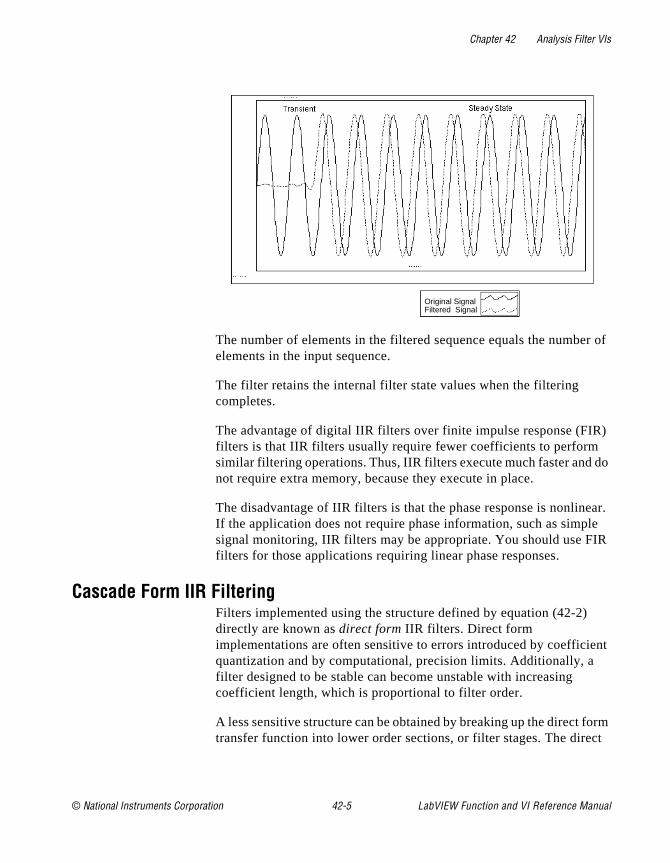
Chapter 42 Analysis Filter VIs
r of
) do
ear. le IR
ent
orm ct
The number of elements in the filtered sequence equals the numbeelements in the input sequence.
The filter retains the internal filter state values when the filtering completes.
The advantage of digital IIR filters over finite impulse response (FIRfilters is that IIR filters usually require fewer coefficients to performsimilar filtering operations. Thus, IIR filters execute much faster andnot require extra memory, because they execute in place.
The disadvantage of IIR filters is that the phase response is nonlinIf the application does not require phase information, such as simpsignal monitoring, IIR filters may be appropriate. You should use Ffilters for those applications requiring linear phase responses.
Cascade Form IIR FilteringFilters implemented using the structure defined by equation (42-2) directly are known as direct form IIR filters. Direct form implementations are often sensitive to errors introduced by coefficiquantization and by computational, precision limits. Additionally, a filter designed to be stable can become unstable with increasing coefficient length, which is proportional to filter order.
A less sensitive structure can be obtained by breaking up the direct ftransfer function into lower order sections, or filter stages. The dire
Original Signal Filtered Signal
© National Instruments Corporation 42-5 LabVIEW Function and VI Reference Manual
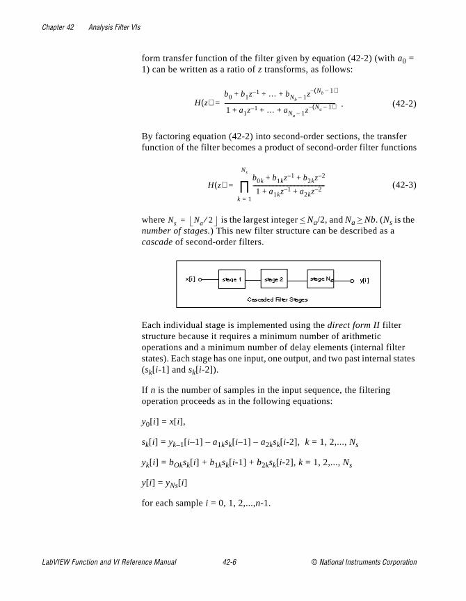
Chapter 42 Analysis Filter VIs
r ns
r tates
form transfer function of the filter given by equation (42-2) (with a0 = 1) can be written as a ratio of z transforms, as follows:
. (42-2)
By factoring equation (42-2) into second-order sections, the transfefunction of the filter becomes a product of second-order filter functio
(42-3)
where is the largest integer < Na/2, and Na > Nb. (Ns is the number of stages.) This new filter structure can be described as a cascade of second-order filters.
Each individual stage is implemented using the direct form II filter structure because it requires a minimum number of arithmetic operations and a minimum number of delay elements (internal filtestates). Each stage has one input, one output, and two past internal s(sk[ i-1] and sk[ i-2]).
If n is the number of samples in the input sequence, the filtering operation proceeds as in the following equations:
y0[ i] = x[ i],
sk[ i] = yk–1[ i–1] – a1ksk[ i–1] – a2ksk[ i-2], k = 1, 2,..., Ns
yk[ i] = bOksk[ i] + b1ksk[ i-1] + b2ksk[ i-2], k = 1, 2,..., Ns
y[ i] = yNs[ i]
for each sample i = 0, 1, 2,...,n-1.
H z( )b0 b1z 1– … bNb 1– z Nb 1–( )–+ + +
1 a1z 1– … aNa 1– z Na 1–( )–+ + +--------------------------------------------------------------------------------=
H z( )b0k b1kz 1– b2kz
2–+ +
1 a1kz 1– a2kz 2–+ +----------------------------------------------------
k 1=
Ns
∏=
Ns Na 2⁄=
LabVIEW Function and VI Reference Manual 42-6 © National Instruments Corporation
Chapter 42 Analysis Filter VIs
ng
.
rom e of
alf
rth lly
For filters with a single cutoff frequency (lowpass and highpass), second-order filter stages can be designed directly. The overall IIRlowpass or highpass filter contains cascaded second-order filters.
For filters with two cutoff frequencies (bandpass and bandstop), fourth-order filter stages are a more natural form. The overall IIR bandpass or bandstop filter is cascaded fourth-order filters. The filtering operation for fourth-order stages proceeds as in the followiequations:
y0[ i] = x[ i],
sk[ i] = yk–1[ i–1] – a1ksk[ i–1] – a2ksk[ i-2] – a3ksk[ i–3] – a4ksk[ i–4],
k = 1, 2,..., Ns
yk[ i] = b0ksk[ i] + b1ksk[ i-1] + b2ksk[ i-2] + b3ksk[ i-3] + b4ksk[ i-4],
k = 1, 2,..., Ns
y[ i] = yNs[ i].
Notice that in the case of fourth-order filter stages,
Butterworth FiltersA smooth response at all frequencies a nd a monotonic decrease fthe specified cutoff frequencies characterize the frequency responsButterworth filters. Butterworth filters are maximally flat—the ideal response of unity in the passband and zero in the stopband. The hpower frequency or the 3-dB down frequency corresponds to the specified cutoff frequencies.
The following illustration shows the response of a lowpass Butterwofilter. The advantage of Butterworth filters is a smooth, monotonicadecreasing frequency response. After you set the cutoff frequency,LabVIEW sets the steepness of the transition proportional to the filter
Ns Na 1+( ) 4⁄=
© National Instruments Corporation 42-7 LabVIEW Function and VI Reference Manual
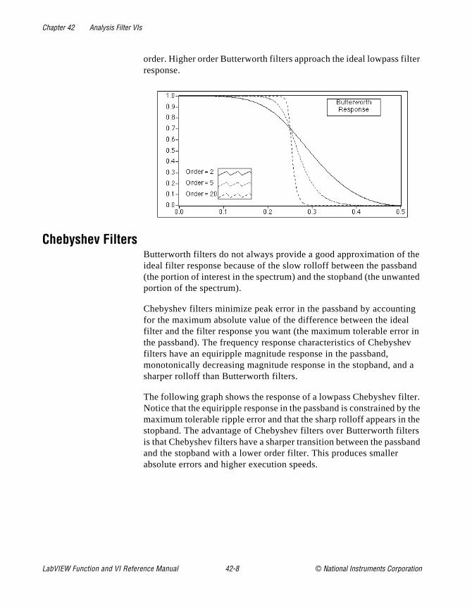
Chapter 42 Analysis Filter VIs
ter
he nd ted
ng l in ev
d a
lter. y the the ers band
order. Higher order Butterworth filters approach the ideal lowpass filresponse.
Chebyshev FiltersButterworth filters do not always provide a good approximation of tideal filter response because of the slow rolloff between the passba(the portion of interest in the spectrum) and the stopband (the unwanportion of the spectrum).
Chebyshev filters minimize peak error in the passband by accountifor the maximum absolute value of the difference between the ideafilter and the filter response you want (the maximum tolerable errorthe passband). The frequency response characteristics of Chebyshfilters have an equiripple magnitude response in the passband, monotonically decreasing magnitude response in the stopband, ansharper rolloff than Butterworth filters.
The following graph shows the response of a lowpass Chebyshev fiNotice that the equiripple response in the passband is constrained bmaximum tolerable ripple error and that the sharp rolloff appears in stopband. The advantage of Chebyshev filters over Butterworth filtis that Chebyshev filters have a sharper transition between the passand the stopband with a lower order filter. This produces smaller absolute errors and higher execution speeds.
LabVIEW Function and VI Reference Manual 42-8 © National Instruments Corporation
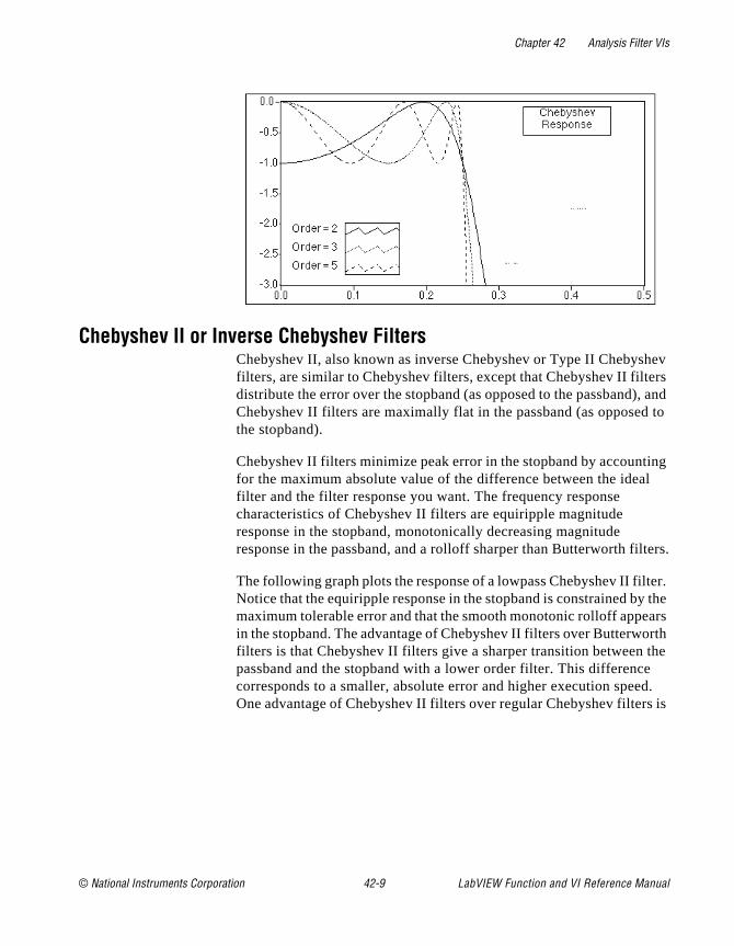
Chapter 42 Analysis Filter VIs
hev rs , and to
ing l
ters.
ter. the ars rth
the d.
s is
Chebyshev II or Inverse Chebyshev FiltersChebyshev II, also known as inverse Chebyshev or Type II Chebysfilters, are similar to Chebyshev filters, except that Chebyshev II filtedistribute the error over the stopband (as opposed to the passband)Chebyshev II filters are maximally flat in the passband (as opposedthe stopband).
Chebyshev II filters minimize peak error in the stopband by accountfor the maximum absolute value of the difference between the ideafilter and the filter response you want. The frequency response characteristics of Chebyshev II filters are equiripple magnitude response in the stopband, monotonically decreasing magnitude response in the passband, and a rolloff sharper than Butterworth fil
The following graph plots the response of a lowpass Chebyshev II filNotice that the equiripple response in the stopband is constrained bymaximum tolerable error and that the smooth monotonic rolloff appein the stopband. The advantage of Chebyshev II filters over Butterwofilters is that Chebyshev II filters give a sharper transition between passband and the stopband with a lower order filter. This differencecorresponds to a smaller, absolute error and higher execution speeOne advantage of Chebyshev II filters over regular Chebyshev filter
© National Instruments Corporation 42-9 LabVIEW Function and VI Reference Manual
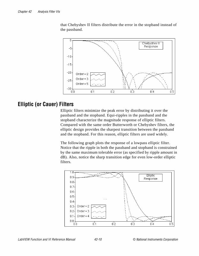
Chapter 42 Analysis Filter VIs
of
e nd
ined t in ic
that Chebyshev II filters distribute the error in the stopband insteadthe passband.
Elliptic (or Cauer) FiltersElliptic filters minimize the peak error by distributing it over the passband and the stopband. Equi-ripples in the passband and the stopband characterize the magnitude response of elliptic filters. Compared with the same order Butterworth or Chebyshev filters, thelliptic design provides the sharpest transition between the passbaand the stopband. For this reason, elliptic filters are used widely.
The following graph plots the response of a lowpass elliptic filter. Notice that the ripple in both the passband and stopband is constraby the same maximum tolerable error (as specified by ripple amoundB). Also, notice the sharp transition edge for even low-order elliptfilters.
LabVIEW Function and VI Reference Manual 42-10 © National Instruments Corporation
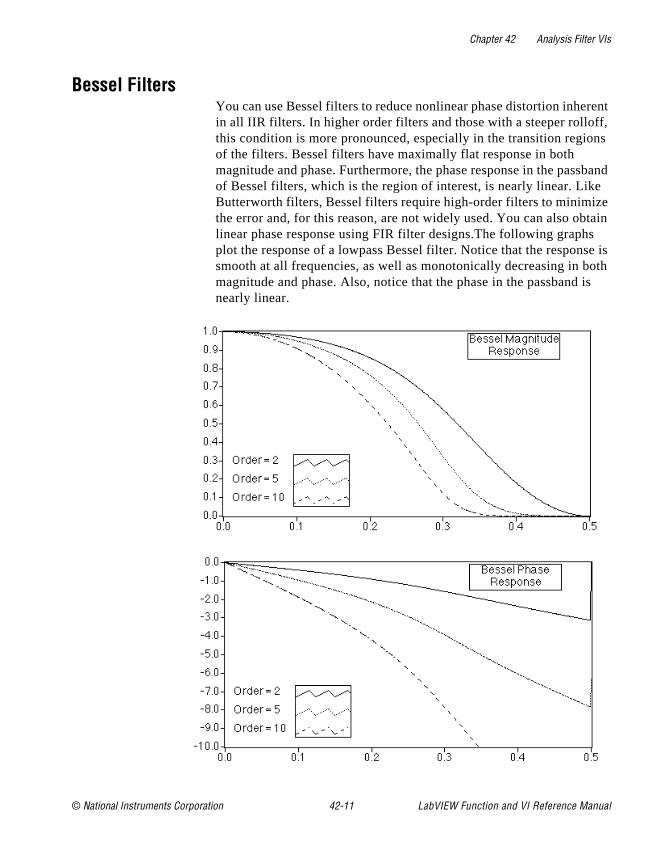
Chapter 42 Analysis Filter VIs
rent f, ns
sband e e tain s e is oth is
Bessel FiltersYou can use Bessel filters to reduce nonlinear phase distortion inhein all IIR filters. In higher order filters and those with a steeper rollofthis condition is more pronounced, especially in the transition regioof the filters. Bessel filters have maximally flat response in both magnitude and phase. Furthermore, the phase response in the pasof Bessel filters, which is the region of interest, is nearly linear. LikButterworth filters, Bessel filters require high-order filters to minimizthe error and, for this reason, are not widely used. You can also oblinear phase response using FIR filter designs.The following graphplot the response of a lowpass Bessel filter. Notice that the responssmooth at all frequencies, as well as monotonically decreasing in bmagnitude and phase. Also, notice that the phase in the passbandnearly linear.
© National Instruments Corporation 42-11 LabVIEW Function and VI Reference Manual

Chapter 42 Analysis Filter VIs
u
,
of
Finite Impulse Response FiltersFinite impulse response (FIR) filters are digital filters, which have afinite impulse response. FIR filters are also known as nonrecursivefilters, convolution filters, or moving-average (MA) filters because yocan express the output of an FIR filter as a finite convolution
where x represents the input sequence to be filtered, y represents the output filtered sequence, and h represents the FIR filter coefficients.
The following list gives the most important characteristics of FIR filters:
• They can achieve linear phase because of filter coefficient symmetry in the realization.
• They are always stable.
• You can perform the filtering function using the convolution andas such, generally associate a delay with the output sequence
,
where n is the number of FIR filter coefficients.
The following graphs plot a typical magnitude and phase responseFIR filters versus normalized frequency.
yi hkxi k–
k 0=
n 1–
∑=
delayn 1–
2------------=
0.10 0.20 0.30 0.400.00 0.50
0.20
0.40
0.60
0.80
1.00
0.00
1.20 Magnitude (dB)
f (Hz)
Magnitude (dB)
LabVIEW Function and VI Reference Manual 42-12 © National Instruments Corporation

Chapter 42 Analysis Filter VIs
ities
rder
cy
t nd
etry l non
the
the ish tage
nd
The discontinuities in the phase response arise from the discontinuintroduced when you compute the magnitude response using the absolute value. Notice that the discontinuities in phase are on the oof pi. The phase, however, is clearly linear. See Appendix D, References, for material that can give you more information on this topic.
You design FIR filters by approximating a specified, desired frequenresponse of a discrete-time system. The most common techniquesapproximate the desired magnitude response while maintaining a linear-phase response.
Designing FIR Filters by WindowingThe simplest method for designing linear-phase FIR filters is the window design method. To design a FIR filter by windowing, you starwith an ideal frequency response, calculate its impulse response, athen truncate the impulse response to produce a finite number of coefficients. To meet the linear-phase constraint, by maintain symmabout the center point of the coefficients. The truncation of the ideaimpulse response results in the effect known as the Gibbs phenome– oscillatory behavior near abrupt transitions (cutoff frequencies) in FIR filter frequency response.
You can reduce the effects of the Gibbs phenomenon by smoothingtruncation of the ideal impulse response using a smoothing windowfunction. By tapering the FIR coefficients at each end, you can diminthe height of the side lobes in the frequency response. The disadvanto this method, however, is that the main lobe widens, resulting in awider transition region at the cutoff frequencies. The selection of awindow function, then, is similar to the choice between Chebyshev a
0.10 0.20 0.30 0.400.00 0.50
-10.0
-8.0
-6.0
-4.0
-2.0
-12.0
0.0 Phase (radians)
f (Hz)
Phase (radians)
© National Instruments Corporation 42-13 LabVIEW Function and VI Reference Manual

Chapter 42 Analysis Filter VIs
ls
not
t the n
h
um
ry
uch
e and
an lan , f ee
r in
Butterworth IIR filters in that it is a trade-off between side lobe levenear the cutoff frequencies and width of the transition region.
Designing FIR filters by windowing is simple and computationally inexpensive. It is therefore the fastest way to design FIR filters. It is necessarily, however, the best FIR filter design method.
Designing Optimum FIR Filters using the Parks-McClellan AlgorithmThe Parks-McClellan algorithm offers an optimum FIR filter design technique that attempts to design the best filter possible for a givennumber of coefficients. Such a design reduces the adverse effects acutoff frequencies. It also offers more control over the approximatioerrors in different frequency bands—control that is not possible witthe window method.
Using the Parks-McClellan algorithm to design FIR filters is computationally expensive. This method, however, produces optimFIR filters by applying time-consuming iterative techniques.
Designing Narrowband FIR FiltersWhen you use conventional techniques to design FIR filters with especially narrow bandwidths, the resulting filter lengths may be velong. FIR filters with long filter lengths often require lengthy designand implementation times, and are more susceptible to numerical inaccuracy. In some cases, conventional filter design techniques, sas the Parks-McClellan algorithm, may fail the design altogether.
You can use a very efficient algorithm, called the Interpolated FinitImpulse Response (IFIR) filter design technique, to design narrowbFIR filters. Using this technique produces narrowband filters that require far fewer coefficients (and therefore fewer computations) ththose filters designed by the direct application of the Parks-McClelalgorithm. LabVIEW also uses this technique to produce widebandlowpass (cutoff frequency near Nyquist) and highpass filters (cutoffrequency near zero). For more information about IFIR filter design, sMultirate Systems and Filter Banks by P.P. Vaidyanathan, or the papeon interpolated finite impulse response filters by Neuvo, et al., listedAppendix D, References, of this manual.
LabVIEW Function and VI Reference Manual 42-14 © National Instruments Corporation
Chapter 42 Analysis Filter VIs
ter
d you ith g
, op.
ep
r d pass
Windowed FIR FiltersYou use the filter type parameter of the FIR VIs to select the type ofwindowed FIR filter you want: lowpass, highpass, bandpass, or bandstop. The following list gives the two related FIR VIs:
• FIR Windowed Coefficients—Generates the windowed (or unwindowed) coefficients.
• FIR Windowed Filters—Filters the input using windowed (or unwindowed) coefficients.
Optimum FIR FiltersYou can use the Parks-McClellan algorithm to design optimum, linear-phase, FIR filter coefficients in the sense that the resulting filoptimally matches the filter specifications for a given number of coefficients. The Parks-McClellan VI takes as input an array of bandescriptions, each containing information describing the response want for the given band. The VI outputs the FIR coefficients along wcomputed ripple, which is a measure of the deviation of the resultinfilter from the ideal filter specifications.
Four VIs use the Parks-McClellan VI to implement filters whose stopband and passband ripple level are equal: Equiripple LowPassEquiripple HighPass, Equiripple BandPass, and Equiripple BandSt
FIR Narrowband FiltersYou can design narrowband FIR filters using the FIR Narrowband Coefficients VI, and then implement the filtering using the FIR Narrowband Filter VI. The design and implementation are separateoperations because many narrowband filters require lengthy designtimes, while the actual filtering process is very fast and efficient. Kethis in mind when creating your narrowband filtering diagrams.
The parameters required for narrowband filter specification are filtetype, sampling rate, passband and stopband frequencies, passbanripple (linear scale), and stopband attenuation (decibels). For bandand bandstop filters, passband and stopband frequencies refer to bandwidths, and you must specify an additional center frequency parameter. You can also design wideband lowpass filters (cutoff frequency near Nyquist) and wideband highpass filters (cutoff frequency near zero) using the narrowband filter VIs.
© National Instruments Corporation 42-15 LabVIEW Function and VI Reference Manual

Chapter 42 Analysis Filter VIs
ey
use e
re
ve t
The following illustration shows how to use the FIR Narrowband Coefficients VI and the FIR Narrowband Filter VI to estimate the response of a narrowband filter to an impulse.
Nonlinear FiltersSmoothing windows, IIR filters, and FIR filters are linear because thsatisfy the superposition and proportionality principles
L ax(t) + by(t) = aL x(t) + bL y(t),
where a and b are constants, x(t) and y(t) are signals, L• is a linear filtering operation, and their inputs and outputs are related via the convolution operation.
A nonlinear filter does not meet the preceding conditions and you cannot obtain its output signals via the convolution operation, becaa set of coefficients cannot characterize the impulse response of thfilter. Nonlinear filters provide specific filtering characteristics that adifficult to obtain using linear techniques. The median filter is a nonlinear filter that combines lowpass filter characteristics (to remohigh-frequency noise) and high-frequency characteristics (to detecedges).
Filter VI Descriptions
The following Filter VIs are available.
LabVIEW Function and VI Reference Manual 42-16 © National Instruments Corporation
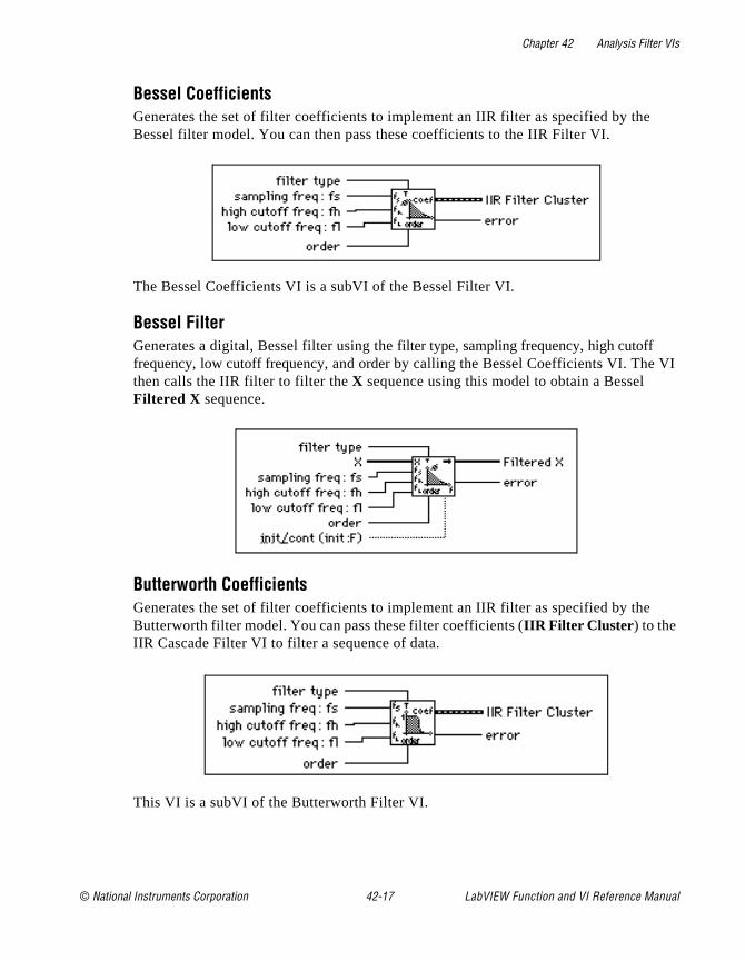
Chapter 42 Analysis Filter VIs
f VI
Bessel CoefficientsGenerates the set of filter coefficients to implement an IIR filter as specified by theBessel filter model. You can then pass these coefficients to the IIR Filter VI.
The Bessel Coefficients VI is a subVI of the Bessel Filter VI.
Bessel FilterGenerates a digital, Bessel filter using the filter type, sampling frequency, high cutoffrequency, low cutoff frequency, and order by calling the Bessel Coefficients VI. Thethen calls the IIR filter to filter the X sequence using this model to obtain a Bessel Filtered X sequence.
Butterworth CoefficientsGenerates the set of filter coefficients to implement an IIR filter as specified by theButterworth filter model. You can pass these filter coefficients (IIR Filter Cluster ) to the IIR Cascade Filter VI to filter a sequence of data.
This VI is a subVI of the Butterworth Filter VI.
© National Instruments Corporation 42-17 LabVIEW Function and VI Reference Manual
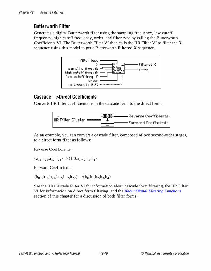
Chapter 42 Analysis Filter VIs
tages,
lter
Butterworth FilterGenerates a digital Butterworth filter using the sampling frequency, low cutoff frequency, high cutoff frequency, order, and filter type by calling the Butterworth Coefficients VI. The Butterworth Filter VI then calls the IIR Filter VI to filter the X sequence using this model to get a Butterworth Filtered X sequence.
Cascade—>Direct CoefficientsConverts IIR filter coefficients from the cascade form to the direct form.
As an example, you can convert a cascade filter, composed of two second-order sto a direct form filter as follows:
Reverse Coefficients:
a11,a21,a12,a22 ->1.0,a1,a2,a3,a4
Forward Coefficients:
b01,b11,b21,b02,b12,b22 ->b 0,b1,b2,b3,b4
See the IIR Cascade Filter VI for information about cascade form filtering, the IIR FiVI for information on direct form filtering, and the About Digital Filtering Functions section of this chapter for a discussion of both filter forms.
LabVIEW Function and VI Reference Manual 42-18 © National Instruments Corporation
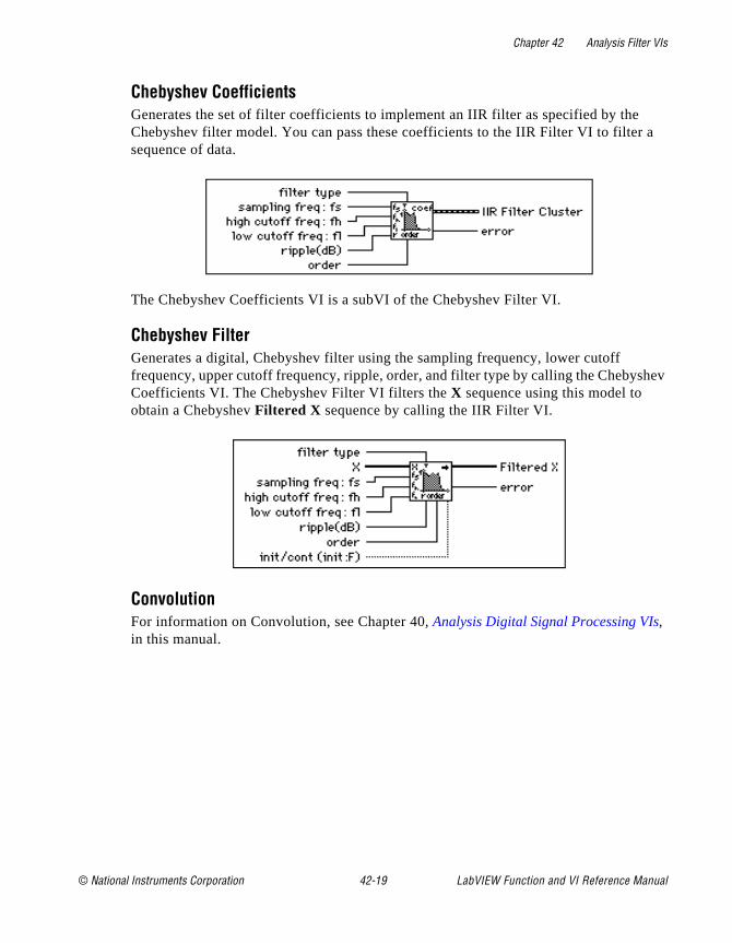
Chapter 42 Analysis Filter VIs
a
hev
Chebyshev CoefficientsGenerates the set of filter coefficients to implement an IIR filter as specified by theChebyshev filter model. You can pass these coefficients to the IIR Filter VI to filtersequence of data.
The Chebyshev Coefficients VI is a subVI of the Chebyshev Filter VI.
Chebyshev FilterGenerates a digital, Chebyshev filter using the sampling frequency, lower cutoff frequency, upper cutoff frequency, ripple, order, and filter type by calling the ChebysCoefficients VI. The Chebyshev Filter VI filters the X sequence using this model to obtain a Chebyshev Filtered X sequence by calling the IIR Filter VI.
ConvolutionFor information on Convolution, see Chapter 40, Analysis Digital Signal Processing VIs, in this manual.
© National Instruments Corporation 42-19 LabVIEW Function and VI Reference Manual
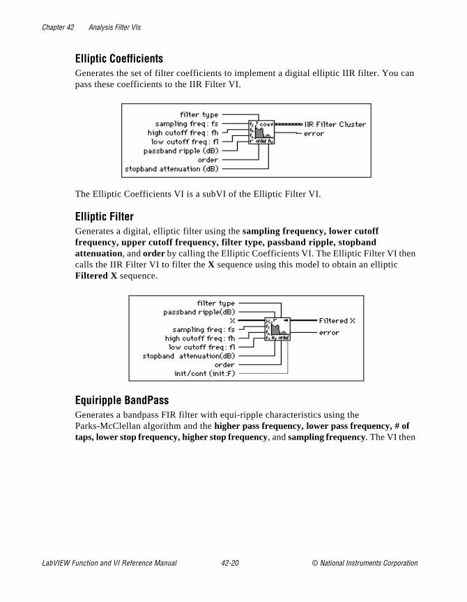
Chapter 42 Analysis Filter VIs
an
Elliptic CoefficientsGenerates the set of filter coefficients to implement a digital elliptic IIR filter. You cpass these coefficients to the IIR Filter VI.
The Elliptic Coefficients VI is a subVI of the Elliptic Filter VI.
Elliptic FilterGenerates a digital, elliptic filter using the sampling frequency, lower cutoff frequency, upper cutoff frequency, filter type, passband ripple, stopband attenuation, and order by calling the Elliptic Coefficients VI. The Elliptic Filter VI thencalls the IIR Filter VI to filter the X sequence using this model to obtain an elliptic Filtered X sequence.
Equiripple BandPassGenerates a bandpass FIR filter with equi-ripple characteristics using the Parks-McClellan algorithm and the higher pass frequency, lower pass frequency, # of taps, lower stop frequency, higher stop frequency, and sampling frequency. The VI then
LabVIEW Function and VI Reference Manual 42-20 © National Instruments Corporation
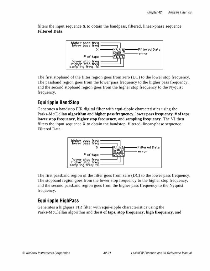
Chapter 42 Analysis Filter VIs
cy. ency, t
ncy, ist
filters the input sequence X to obtain the bandpass, filtered, linear-phase sequence Filtered Data.
The first stopband of the filter region goes from zero (DC) to the lower stop frequenThe passband region goes from the lower pass frequency to the higher pass frequand the second stopband region goes from the higher stop frequency to the Nyquisfrequency.
Equiripple BandStopGenerates a bandstop FIR digital filter with equi-ripple characteristics using the Parks-McClellan algorithm and higher pass frequency, lower pass frequency, # of taps, lower stop frequency, higher stop frequency, and sampling frequency. The VI then filters the input sequence X to obtain the bandstop, filtered, linear-phase sequenceFiltered Data.
The first passband region of the filter goes from zero (DC) to the lower pass frequency. The stopband region goes from the lower stop frequency to the higher stop frequeand the second passband region goes from the higher pass frequency to the Nyqufrequency.
Equiripple HighPassGenerates a highpass FIR filter with equi-ripple characteristics using the Parks-McClellan algorithm and the # of taps, stop frequency, high frequency, and
© National Instruments Corporation 42-21 LabVIEW Function and VI Reference Manual
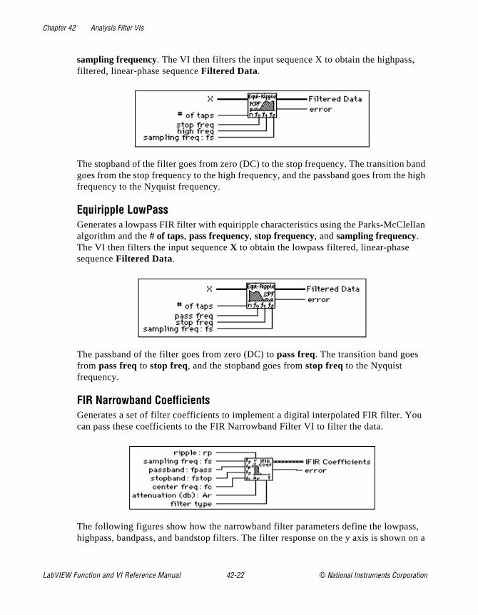
Chapter 42 Analysis Filter VIs
,
band e high
llan
ou
ss, n on a
sampling frequency. The VI then filters the input sequence X to obtain the highpassfiltered, linear-phase sequence Filtered Data.
The stopband of the filter goes from zero (DC) to the stop frequency. The transition goes from the stop frequency to the high frequency, and the passband goes from thfrequency to the Nyquist frequency.
Equiripple LowPassGenerates a lowpass FIR filter with equiripple characteristics using the Parks-McClealgorithm and the # of taps, pass frequency, stop frequency, and sampling frequency. The VI then filters the input sequence X to obtain the lowpass filtered, linear-phase sequence Filtered Data.
The passband of the filter goes from zero (DC) to pass freq. The transition band goes from pass freq to stop freq, and the stopband goes from stop freq to the Nyquist frequency.
FIR Narrowband CoefficientsGenerates a set of filter coefficients to implement a digital interpolated FIR filter. Ycan pass these coefficients to the FIR Narrowband Filter VI to filter the data.
The following figures show how the narrowband filter parameters define the lowpahighpass, bandpass, and bandstop filters. The filter response on the y axis is show
LabVIEW Function and VI Reference Manual 42-22 © National Instruments Corporation
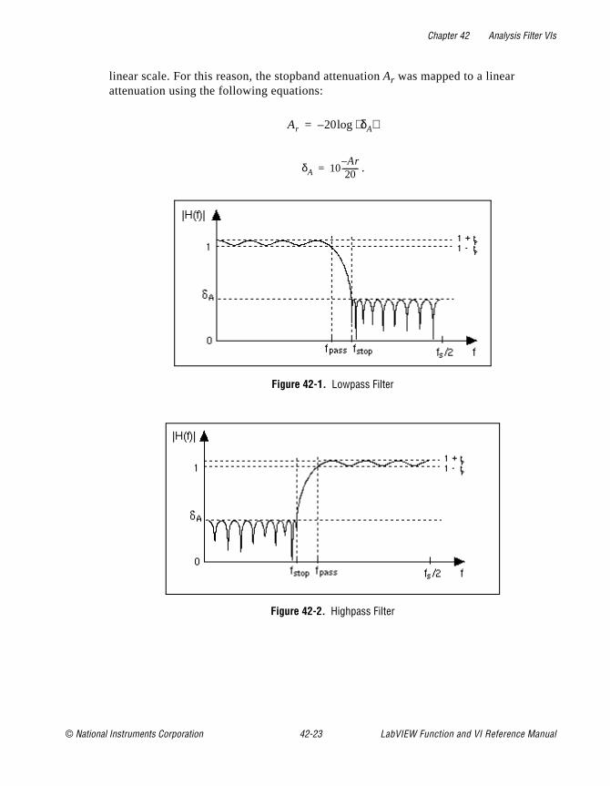
Chapter 42 Analysis Filter VIs
linear scale. For this reason, the stopband attenuation Ar was mapped to a linear attenuation using the following equations:
.
Figure 42-1. Lowpass Filter
Figure 42-2. Highpass Filter
Ar 20 δA⟨ ⟩log–=
δA 10Ar–20
---------=
© National Instruments Corporation 42-23 LabVIEW Function and VI Reference Manual
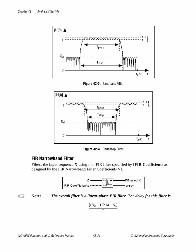
Chapter 42 Analysis Filter VIs
Figure 42-3. Bandpass Filter
Figure 42-4. Bandstop Filter
FIR Narrowband FilterFilters the input sequence X using the IFIR filter specified by IFIR Coefficients as designed by the FIR Narrowband Filter Coefficients VI.
Note: The overall filter is a linear-phase FIR filter. The delay for this filter is
NG 1–( ) M NI+•[ ]
2-------------------------------------------------
LabVIEW Function and VI Reference Manual 42-24 © National Instruments Corporation
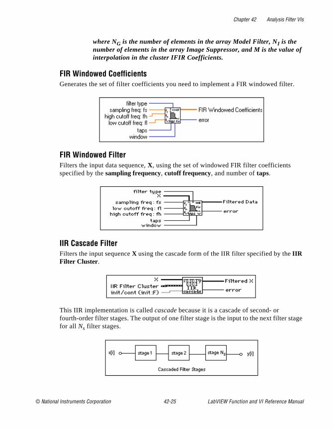
Chapter 42 Analysis Filter VIs
of
r.
tage
where NG is the number of elements in the array Model Filter, NI is the number of elements in the array Image Suppressor, and M is the value interpolation in the cluster IFIR Coefficients.
FIR Windowed CoefficientsGenerates the set of filter coefficients you need to implement a FIR windowed filte
FIR Windowed FilterFilters the input data sequence, X, using the set of windowed FIR filter coefficients specified by the sampling frequency, cutoff frequency, and number of taps.
IIR Cascade FilterFilters the input sequence X using the cascade form of the IIR filter specified by the IIR Filter Cluster .
This IIR implementation is called cascade because it is a cascade of second- or fourth-order filter stages. The output of one filter stage is the input to the next filter sfor all Ns filter stages.
© National Instruments Corporation 42-25 LabVIEW Function and VI Reference Manual

Chapter 42 Analysis Filter VIs
s and
in the
Second-Order FilteringEach second-order stage (stage number k = 1,2,...Ns) has two reverse coefficients (a1k,a2k), and three forward coefficients (b0k,b1k,b2k). The total number of reverse coefficients is 2Ns and the total number of forward coefficients is 3Ns. The Reverse Coefficients and the Forward Coefficients array contain the coefficients for one stage followed by the coefficients for the next stage, and so on. For example, an IIR filtercomposed of two second-order stages must have a total of four reverse coefficientsix forward coefficients, as follows:
Reverse Coefficients = a11, a21,a12, a22
Forward Coefficients = b01, b11, b21, b02, b12, b22
Fourth-Order FilteringFor fourth order cascade stages, the filtering is implemented in the same manner assecond-order stages, but each stage must have four reverse coefficients (a1k...a4k) and five forward coefficients (b0k...b4k).
IIR Cascade Filter with Integrated CircuitFilters the input sequence, X, using the cascade form of the IIR filter specified by the IIR Filter Cluster .
IIR FilterFilters the input sequence X using the direct form IIR filter specified by Reverse Coefficients and Forward Coefficients.
If y represents the output sequence Filtered X , the VI obtains the elements of y using
,yi1a0----- bjxi j–
j 0=
n 1–
∑ akyi k–
k 1=
m 1–
∑–
=
LabVIEW Function and VI Reference Manual 42-26 © National Instruments Corporation
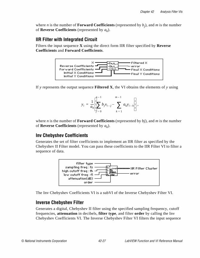
Chapter 42 Analysis Filter VIs
r a
off
nce
where n is the number of Forward Coefficients (represented by bj), and m is the number of Reverse Coefficients (represented by ak).
IIR Filter with Integrated CircuitFilters the input sequence X using the direct form IIR filter specified by Reverse Coefficients and Forward Coefficients.
If y represents the output sequence Filtered X , the VI obtains the elements of y using
,
where n is the number of Forward Coefficients (represented by bj), and m is the number of Reverse Coefficients (represented by ak).
Inv Chebyshev CoefficientsGenerates the set of filter coefficients to implement an IIR filter as specified by theChebyshev II Filter model. You can pass these coefficients to the IIR Filter VI to filtesequence of data.
The Inv Chebyshev Coefficients VI is a subVI of the Inverse Chebyshev Filter VI.
Inverse Chebyshev FilterGenerates a digital, Chebyshev II filter using the specified sampling frequency, cutfrequencies, attenuation in decibels, filter type , and filter order by calling the Inv Chebyshev Coefficients VI. The Inverse Chebyshev Filter VI filters the input seque
yi1a0----- bjxi j–
j 0=
n 1–
∑ akyi k–
k 1=
m 1–
∑–
=
© National Instruments Corporation 42-27 LabVIEW Function and VI Reference Manual

Chapter 42 Analysis Filter VIs
s
ber
X using this model to obtain a Chebyshev II Filtered X sequence by calling the IIR Filter VI.
Median FilterApplies a median filter of rank to the input sequence X.
If Y represents the output sequence Filtered Data, and if Ji represents a subset of the input sequence X centered about the i th element of X
Ji = xi-r , xi-r+1, …, xi-1, xi, xi+1, …, xi+r -1, xi+r ,
and if the indexed elements outside the range of X equal zero, the VI obtains the elementof y using
yi = Median(Ji) for i = 0, 1, 2,…, n-1,
where n is the number of elements in the input sequence X, and r is the filter rank .
Parks-McClellanGenerates a set of linear-phase FIR multiband digital filter coefficients using the numof taps, sampling frequency, Band Parameters, and filter type .
Note: This VI finds the coefficients using iterative techniques based upon an error criterion. Although you specify valid filter parameters, the algorithmmay fail to converge.
LabVIEW Function and VI Reference Manual 42-28 © National Instruments Corporation
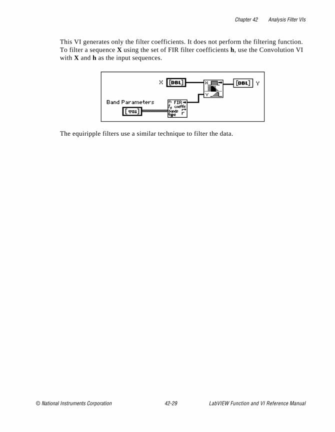
Chapter 42 Analysis Filter VIs
n.
This VI generates only the filter coefficients. It does not perform the filtering functioTo filter a sequence X using the set of FIR filter coefficients h, use the Convolution VI with X and h as the input sequences.The equiripple filters use a similar technique to filter the data.
© National Instruments Corporation 42-29 LabVIEW Function and VI Reference Manual
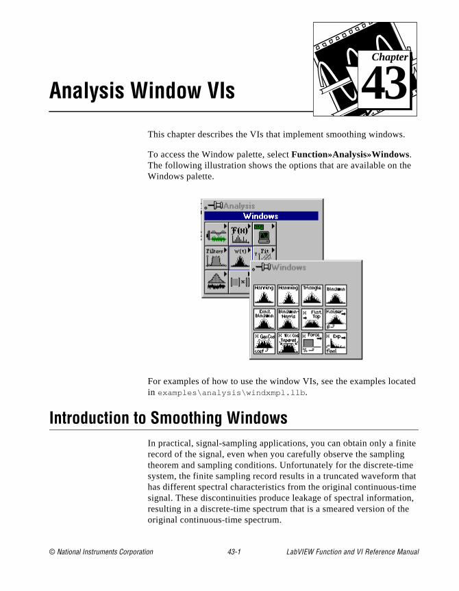
© National Instruments Corporation 43-1 LabVIEW Function and
Chapter
43
Analysis Window VIse
ted
ite e hat me n, e
This chapter describes the VIs that implement smoothing windows.
To access the Window palette, select Function»Analysis»Windows. The following illustration shows the options that are available on thWindows palette.
For examples of how to use the window VIs, see the examples locain examples\analysis\windxmpl.llb .
Introduction to Smoothing WindowsIn practical, signal-sampling applications, you can obtain only a finrecord of the signal, even when you carefully observe the samplingtheorem and sampling conditions. Unfortunately for the discrete-timsystem, the finite sampling record results in a truncated waveform thas different spectral characteristics from the original continuous-tisignal. These discontinuities produce leakage of spectral informatioresulting in a discrete-time spectrum that is a smeared version of thoriginal continuous-time spectrum.
VI Reference Manual
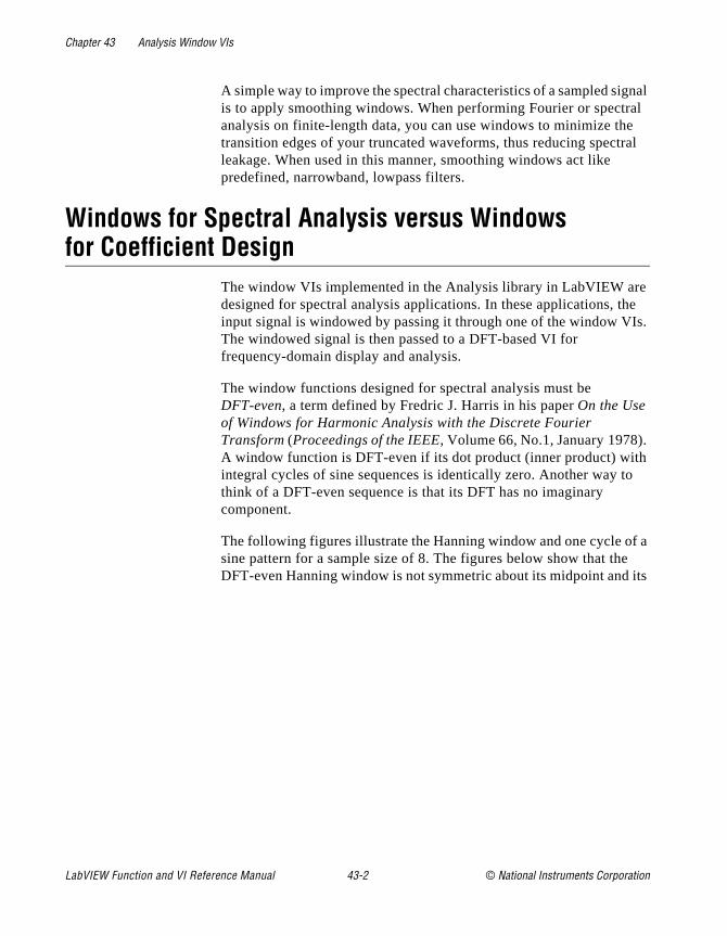
Chapter 43 Analysis Window VIs
nal al al
e he Is.
h o
f a
its
A simple way to improve the spectral characteristics of a sampled sigis to apply smoothing windows. When performing Fourier or spectranalysis on finite-length data, you can use windows to minimize thetransition edges of your truncated waveforms, thus reducing spectrleakage. When used in this manner, smoothing windows act like predefined, narrowband, lowpass filters.
Windows for Spectral Analysis versus Windows for Coefficient Design
The window VIs implemented in the Analysis library in LabVIEW ardesigned for spectral analysis applications. In these applications, tinput signal is windowed by passing it through one of the window VThe windowed signal is then passed to a DFT-based VI for frequency-domain display and analysis.
The window functions designed for spectral analysis must be DFT-even, a term defined by Fredric J. Harris in his paper On the Use of Windows for Harmonic Analysis with the Discrete Fourier Transform (Proceedings of the IEEE, Volume 66, No.1, January 1978).A window function is DFT-even if its dot product (inner product) witintegral cycles of sine sequences is identically zero. Another way tthink of a DFT-even sequence is that its DFT has no imaginary component.
The following figures illustrate the Hanning window and one cycle osine pattern for a sample size of 8. The figures below show that theDFT-even Hanning window is not symmetric about its midpoint and
LabVIEW Function and VI Reference Manual 43-2 © National Instruments Corporation

Chapter 43 Analysis Window VIs
of
l.
last point is not equal to its first point, much like one complete cyclea sine pattern.
Finally, the DFT considers input sequences to be periodic—that thesignal being analyzed is actually a concatenation of the input signaThe following illustration shows three such cycles of the previous
© National Instruments Corporation 43-3 LabVIEW Function and VI Reference Manual
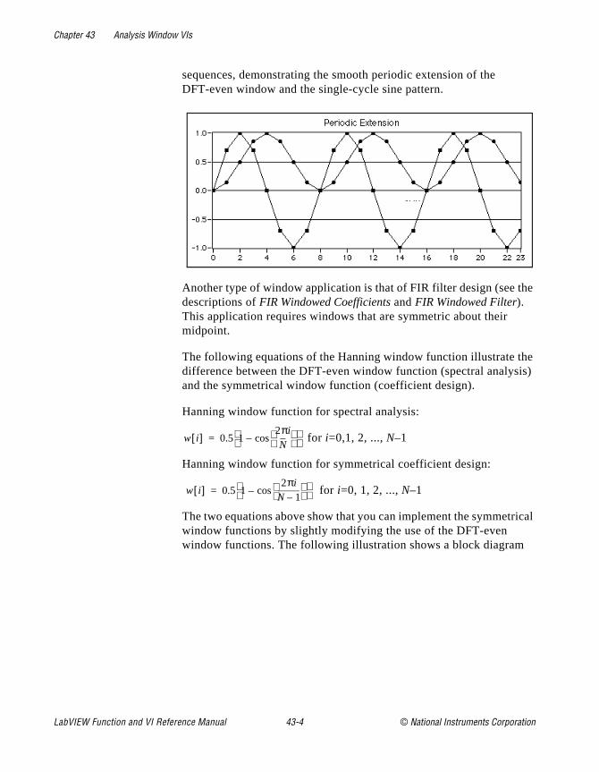
Chapter 43 Analysis Window VIs
he
e is)
ical
sequences, demonstrating the smooth periodic extension of the DFT-even window and the single-cycle sine pattern.
Another type of window application is that of FIR filter design (see tdescriptions of FIR Windowed Coefficients and FIR Windowed Filter). This application requires windows that are symmetric about their midpoint.
The following equations of the Hanning window function illustrate thdifference between the DFT-even window function (spectral analysand the symmetrical window function (coefficient design).
Hanning window function for spectral analysis:
for i=0,1, 2, ..., N–1
Hanning window function for symmetrical coefficient design:
for i=0, 1, 2, ..., N–1
The two equations above show that you can implement the symmetrwindow functions by slightly modifying the use of the DFT-even window functions. The following illustration shows a block diagram
w i[ ] 0.5 12πiN
cos–
=
w i[ ] 0.5 12πi
N 1–
cos–
=
LabVIEW Function and VI Reference Manual 43-4 © National Instruments Corporation
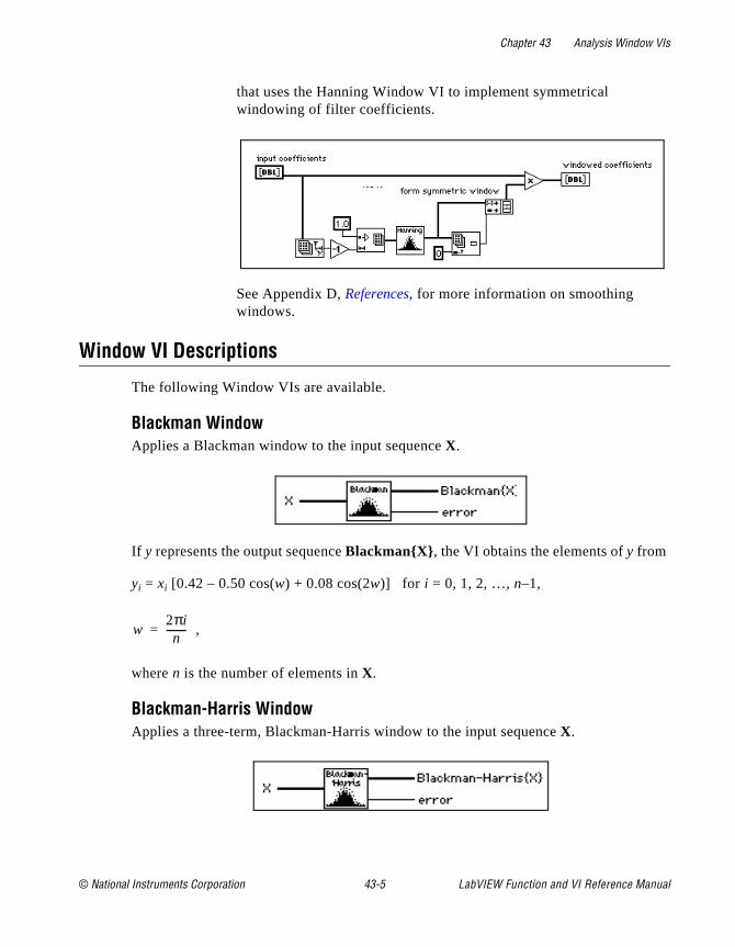
Chapter 43 Analysis Window VIs
that uses the Hanning Window VI to implement symmetrical windowing of filter coefficients.
See Appendix D, References, for more information on smoothing windows.
Window VI Descriptions
The following Window VIs are available.
Blackman WindowApplies a Blackman window to the input sequence X.
If y represents the output sequence BlackmanX , the VI obtains the elements of y from
yi = xi [0.42 – 0.50 cos(w) + 0.08 cos(2w)] for i = 0, 1, 2, …, n–1,
,
where n is the number of elements in X.
Blackman-Harris WindowApplies a three-term, Blackman-Harris window to the input sequence X.
w2πin
--------=
© National Instruments Corporation 43-5 LabVIEW Function and VI Reference Manual
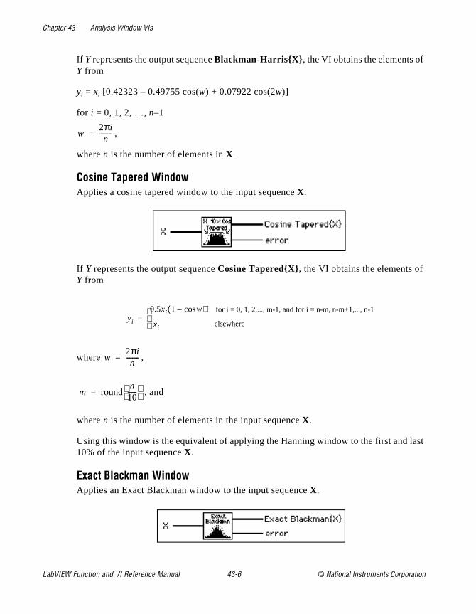
Chapter 43 Analysis Window VIs
last
If Y represents the output sequence Blackman-HarrisX , the VI obtains the elements ofY from
yi = xi [0.42323 – 0.49755 cos(w) + 0.07922 cos(2w)]
for i = 0, 1, 2, …, n–1
,
where n is the number of elements in X.
Cosine Tapered WindowApplies a cosine tapered window to the input sequence X.
If Y represents the output sequence Cosine TaperedX, the VI obtains the elements ofY from
where ,
, and
where n is the number of elements in the input sequence X.
Using this window is the equivalent of applying the Hanning window to the first and 10% of the input sequence X.
Exact Blackman WindowApplies an Exact Blackman window to the input sequence X.
w2πin
--------=
yi
0.5xi 1 wcos–( )
xi for i = 0, 1, 2,..., m-1, and for i = n-m, n-m+1,..., n-1
elsewhere=
w2πin
--------=
m roundn10------
=
LabVIEW Function and VI Reference Manual 43-6 © National Instruments Corporation
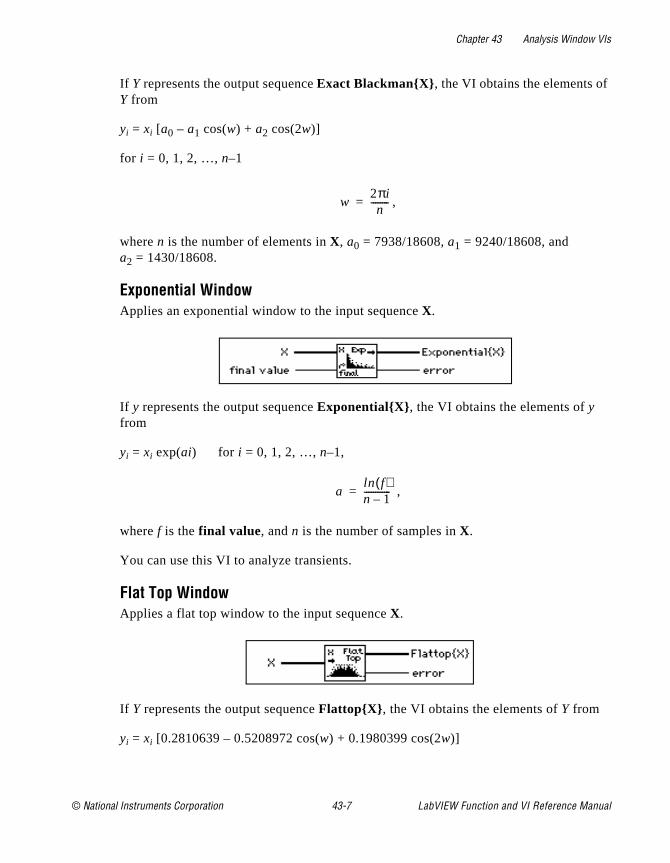
Chapter 43 Analysis Window VIs
If Y represents the output sequence Exact BlackmanX , the VI obtains the elements ofY fromyi = xi [a0 – a1 cos(w) + a2 cos(2w)]
for i = 0, 1, 2, …, n–1
,
where n is the number of elements in X, a0 = 7938/18608, a1 = 9240/18608, and a2 = 1430/18608.
Exponential WindowApplies an exponential window to the input sequence X.
If y represents the output sequence ExponentialX , the VI obtains the elements of y from
yi = xi exp(ai) for i = 0, 1, 2, …, n–1,
,
where f is the final value, and n is the number of samples in X.
You can use this VI to analyze transients.
Flat Top WindowApplies a flat top window to the input sequence X.
If Y represents the output sequence FlattopX , the VI obtains the elements of Y from
yi = xi [0.2810639 – 0.5208972 cos(w) + 0.1980399 cos(2w)]
w2πin
--------=
aln f( )n 1–------------=
© National Instruments Corporation 43-7 LabVIEW Function and VI Reference Manual
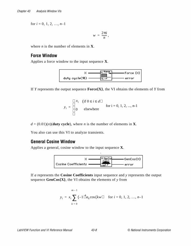
Chapter 43 Analysis Window VIs
for i = 0, 1, 2, …, n–1
,
where n is the number of elements in X.
Force WindowApplies a force window to the input sequence X.
If Y represents the output sequence ForceX, the VI obtains the elements of Y from
d = (0.01)(n)(duty cycle), where n is the number of elements in X.
You also can use this VI to analyze transients.
General Cosine WindowApplies a general, cosine window to the input sequence X.
.
If a represents the Cosine Coefficients input sequence and y represents the output sequence GenCosX, the VI obtains the elements of y from
for i = 0, 1, 2, …, n–1
w2πin
--------=
yi
xi if 0 i d≤ ≤( )for i = 0, 1, 2, ..., n-1
0 elsewhere
=
yi xi 1–( )kak kw( )cos
k 0=
m 1–
∑=
LabVIEW Function and VI Reference Manual 43-8 © National Instruments Corporation
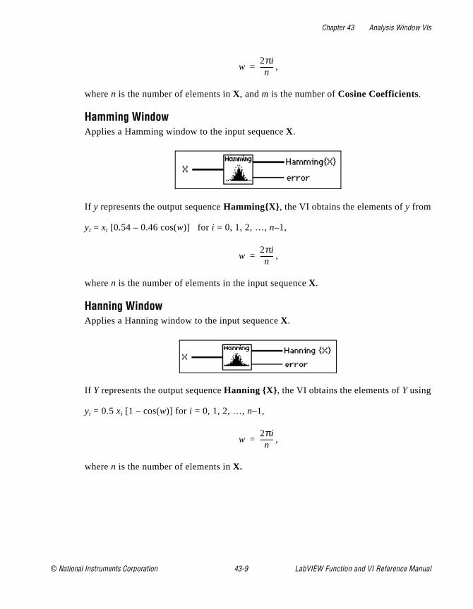
Chapter 43 Analysis Window VIs
,
where n is the number of elements in X, and m is the number of Cosine Coefficients.
Hamming WindowApplies a Hamming window to the input sequence X.
If y represents the output sequence HammingX , the VI obtains the elements of y from
yi = xi [0.54 – 0.46 cos(w)] for i = 0, 1, 2, …, n–1,
,
where n is the number of elements in the input sequence X.
Hanning WindowApplies a Hanning window to the input sequence X.
If Y represents the output sequence Hanning X , the VI obtains the elements of Y using
yi = 0.5 xi [1 – cos(w)] for i = 0, 1, 2, …, n–1,
,
where n is the number of elements in X.
w2πin
--------=
w2πin
--------=
w2πin
--------=
© National Instruments Corporation 43-9 LabVIEW Function and VI Reference Manual

Chapter 43 Analysis Window VIs
Kaiser-Bessel WindowApplies a Kaiser-Bessel window to the input sequence X(t) .
If y represents the output sequence, Kaiser-BesselX(t), the VI obtains the elements ofy from
for i = 0, 1, 2, … n – 1
,
,
where n is the number of elements in X(t) , and Io(•) is the zero-order modified Bessel function.
Triangle WindowApplies a triangular window to the input sequence X.
Note: The triangle smoothing window is also known as the Bartlett smoothingwindow.
If y represents the output sequence TriangleX , the VI obtains the elements of y from
yi = xi tri(w) for i = 0, 1, 2, …, n–1,
,
where tri(w) = 1 – |w|, and n is the number of elements in X.
yi xi
Io β 1.0 a2–( )Io β( )------------------------------------=
ai k–
k----------=
kn 1–
2------------=
w2i n–
n--------------=
LabVIEW Function and VI Reference Manual 43-10 © National Instruments Corporation

© National Instruments Corporation 44-1 LabVIEW Function and
Chapter
44
Analysis Curve-Fitting VIsr
ated
lar most
This chapter describes the VIs that perform curve fitting analysis oregression.
To access the Curve-Fitting palette, choose Functions»Analysis»Curve Fitting , as shown in the following illustration.
For examples of how to use the regression VIs, see the examples locin examples\analysis\regressn.llb .
Introduction to Curve FittingCurve fitting analysis is a technique for extracting a set of curve parameters or coefficients from the data set to obtain a functional description of the data set. The algorithm that fits a curve to a particudata set is known as the Least Squares Method and is discussed inintroductory textbooks in probability and statistics. The error is defined as
e(a) = [f(x,a) – y(x)]2, (44-1)
VI Reference Manual

Chapter 44 Analysis Curve-Fitting VIs
for e of
es our
et
of ts,
the ean ates
mula
where e(a) is the error, y(x) is the observed data set, f(x,a) is the functional description of the data set, and a is the set of curve coefficients which best describes the curve.
For example, let a = a0, a1. Then the functional description of a line is
f(x,a) = a0 + a1 x.
The least squares algorithm finds a by solving the system
(44-2)
To solve this system, you set up and solve the Jacobian system generated by expanding equation (44-2). After you solve the systema, you can obtain an estimate of the observed data set for any valux using the functional description f(x, a).
In LabVIEW, the curve fitting VIs automatically set up and solve theJacobian system and return the set of coefficients that best describyour data set. You can concentrate on the functional description of ydata and not worry about solving the system in equation (44-2).
Two input sequences, Y Values and X Values, represent the data s y(x). A sample or point in the data set is
(xi, yi),
where xi is the i th element of the sequence X Values, and yi is the ith element of the sequence Y Values.
In general, for each predefined type of curve fit, there are two typesVIs, unless otherwise specified. One type returns only the coefficienso that you can further manipulate the data. The other type returnscoefficients, the corresponding expected or fitted curve, and the msquared error (MSE). Because it is a discrete system, the VI calculthe MSE, which is a relative measure of the residuals between the expected curve values and the actual observed values, using the for
(44-3)
∂∂a------e a( ) 0=
MSE1n--- fi yi–( )2
i 0=
n 1–
∑=
LabVIEW Function and VI Reference Manual 44-2 © National Instruments Corporation
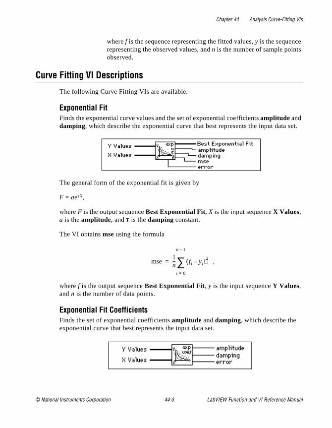
Chapter 44 Analysis Curve-Fitting VIs
set.
where f is the sequence representing the fitted values, y is the sequence representing the observed values, and n is the number of sample pointsobserved.
Curve Fitting VI Descriptions
The following Curve Fitting VIs are available.
Exponential FitFinds the exponential curve values and the set of exponential coefficients amplitude and damping, which describe the exponential curve that best represents the input data
The general form of the exponential fit is given by
F = aeτX,
where F is the output sequence Best Exponential Fit, X is the input sequence X Values, a is the amplitude, and τ is the damping constant.
The VI obtains mse using the formula
,
where f is the output sequence Best Exponential Fit, y is the input sequence Y Values, and n is the number of data points.
Exponential Fit CoefficientsFinds the set of exponential coefficients amplitude and damping, which describe the exponential curve that best represents the input data set.
mse1n--- fi yi–( )2
i 0=
n 1–
∑=
© National Instruments Corporation 44-3 LabVIEW Function and VI Reference Manual
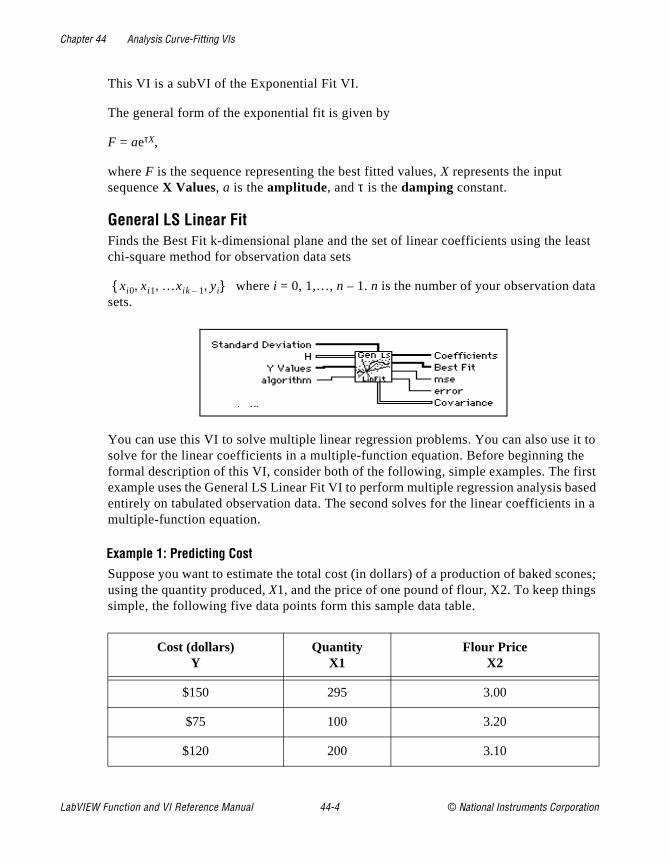
Chapter 44 Analysis Curve-Fitting VIs
east
it to e irst ased in a
ones; s
This VI is a subVI of the Exponential Fit VI.
The general form of the exponential fit is given by
F = aeτX,
where F is the sequence representing the best fitted values, X represents the input sequence X Values, a is the amplitude, and τ is the damping constant.
General LS Linear FitFinds the Best Fit k-dimensional plane and the set of linear coefficients using the lchi-square method for observation data sets
where i = 0, 1,…, n – 1. n is the number of your observation datasets.
You can use this VI to solve multiple linear regression problems. You can also usesolve for the linear coefficients in a multiple-function equation. Before beginning thformal description of this VI, consider both of the following, simple examples. The fexample uses the General LS Linear Fit VI to perform multiple regression analysis bentirely on tabulated observation data. The second solves for the linear coefficientsmultiple-function equation.
Example 1: Predicting CostSuppose you want to estimate the total cost (in dollars) of a production of baked scusing the quantity produced, X1, and the price of one pound of flour, X2. To keep thingsimple, the following five data points form this sample data table.
Cost (dollars)Y
QuantityX1
Flour Price X2
$150 295 3.00
$75 100 3.20
$120 200 3.10
xi0 xi1 …xik 1– yi,, ,
LabVIEW Function and VI Reference Manual 44-4 © National Instruments Corporation
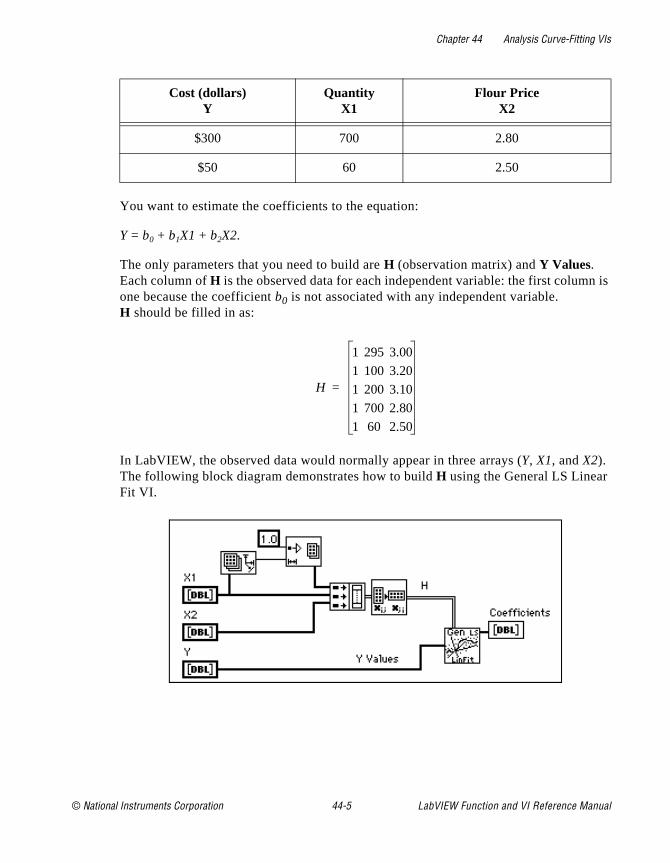
Chapter 44 Analysis Curve-Fitting VIs
n is
You want to estimate the coefficients to the equation:
Y = b0 + b1X1 + b2X2.
The only parameters that you need to build are H (observation matrix) and Y Values. Each column of H is the observed data for each independent variable: the first columone because the coefficient b0 is not associated with any independent variable. H should be filled in as:
In LabVIEW, the observed data would normally appear in three arrays (Y, X1, and X2). The following block diagram demonstrates how to build H using the General LS LinearFit VI.
$300 700 2.80
$50 60 2.50
Cost (dollars)Y
QuantityX1
Flour Price X2
H
1 295 3.00
1 100 3.20
1 200 3.10
1 700 2.80
1 60 2.50
=
© National Instruments Corporation 44-5 LabVIEW Function and VI Reference Manual

Chapter 44 Analysis Curve-Fitting VIs
After running this VI, the following coefficients are obtained.
The resulting equation for the total cost of scone production is therefore:
Y = –20.34 + 0.38X1 + 19.05X2.
Example 2: Linear CombinationsSuppose that you have collected samples from a transducer (Y Values) and you want to solve for the coefficients of the model:
To build H, you set each column to the independent functions evaluated at each x value. Assuming there are 100 x values, H is:
Given that you have the independent X Values and observed Y Values, the following block diagram demonstrates how to build H and use the General LS Linear Fit VI.
y bo b1 ωx( )sin b2 ωx( )cos b3x2
+ + +=
H
1 ωx0( )sin ωx0( )cos x02
1 ωx1( )sin ωx1( )cos x12
1 ωx2( )sin ωx2( )cos x22
… … … …
1 ωx99( )sin ωx99( )cos x992
=
LabVIEW Function and VI Reference Manual 44-6 © National Instruments Corporation
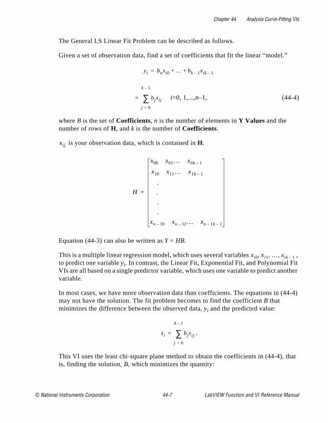
Chapter 44 Analysis Curve-Fitting VIs
, it other
(44-4)
that
The General LS Linear Fit Problem can be described as follows.
Given a set of observation data, find a set of coefficients that fit the linear “model.”
i=0, 1,...,n–1, (44-4)
where B is the set of Coefficients, n is the number of elements in Y Values and the number of rows of H, and k is the number of Coefficients.
is your observation data, which is contained in H.
Equation (44-3) can also be written as Y = HB.
This is a multiple linear regression model, which uses several variables to predict one variable yi. In contrast, the Linear Fit, Exponential Fit, and Polynomial FVIs are all based on a single predictor variable, which uses one variable to predict anvariable.
In most cases, we have more observation data than coefficients. The equations in may not have the solution. The fit problem becomes to find the coefficient B that minimizes the difference between the observed data, yi and the predicted value:
.
This VI uses the least chi-square plane method to obtain the coefficients in (44-4),is, finding the solution, B, which minimizes the quantity:
yi boxi0 … bk 1– xik 1–+ +=
bjxij
j 0=
k 1–
∑=
xij
H
x00 x01… x0k 1–
x10 x11… x1k 1–
.
.
.
.
xn 10– xn 12– … xn 1k– 1–
=
xi0 xi1 … xik 1–, , ,
zi bjxij
j 0=
k 1–
∑=
© National Instruments Corporation 44-7 LabVIEW Function and VI Reference Manual
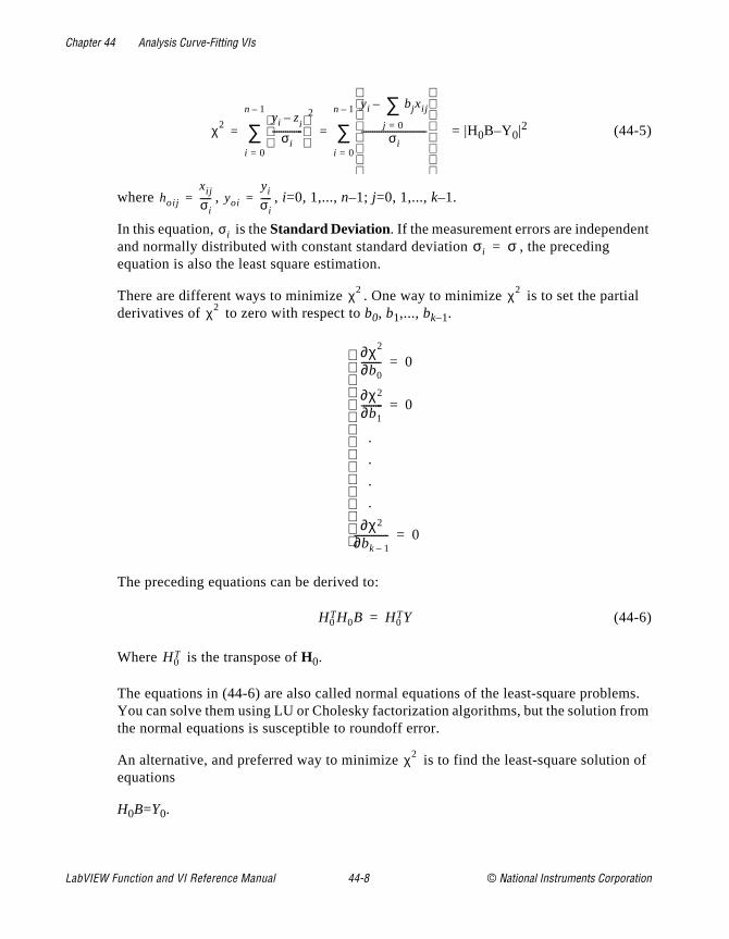
Chapter 44 Analysis Curve-Fitting VIs
nt
ial
ms. rom
n of
= |H0B–Y0|2 (44-5)
where , , i=0, 1,..., n–1; j=0, 1,..., k–1.
In this equation, is the Standard Deviation. If the measurement errors are independeand normally distributed with constant standard deviation , the preceding equation is also the least square estimation.
There are different ways to minimize . One way to minimize is to set the partderivatives of to zero with respect to b0, b1,..., bk–1.
The preceding equations can be derived to:
(44-6)
Where is the transpose of H0.
The equations in (44-6) are also called normal equations of the least-square probleYou can solve them using LU or Cholesky factorization algorithms, but the solution fthe normal equations is susceptible to roundoff error.
An alternative, and preferred way to minimize is to find the least-square solutioequations
H0B=Y0.
χ2yi z–
i
σi--------------
2
i 0=
n 1–
∑yi bjxij
j 0=
∑–
σi------------------------------
i 0=
n 1–
∑= =
hoij
xij
σi-----= yoi
yi
σi-----=
σiσi σ=
χ2 χ2
χ2
∂χ2
∂b0-------- 0=
∂χ2
∂b1--------- 0=
.
.
.
.
∂χ2
∂bk 1–-------------- 0=
H0TH0B H0
TY=
H0T
χ2
LabVIEW Function and VI Reference Manual 44-8 © National Instruments Corporation
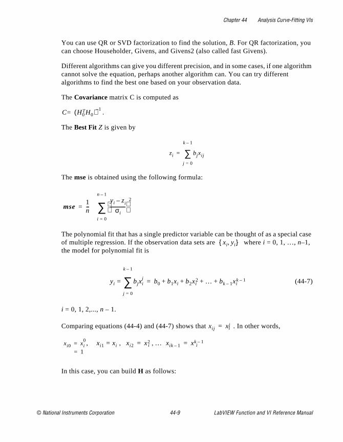
Chapter 44 Analysis Curve-Fitting VIs
ithm
l case
You can use QR or SVD factorization to find the solution, B. For QR factorization, you can choose Householder, Givens, and Givens2 (also called fast Givens).
Different algorithms can give you different precision, and in some cases, if one algorcannot solve the equation, perhaps another algorithm can. You can try different algorithms to find the best one based on your observation data.
The Covariance matrix C is computed as
.
The Best Fit Z is given by
The mse is obtained using the following formula:
The polynomial fit that has a single predictor variable can be thought of as a speciaof multiple regression. If the observation data sets are where i = 0, 1, …, n–1, the model for polynomial fit is
(44-7)
i = 0, 1, 2,..., n – 1.
Comparing equations (44-4) and (44-7) shows that . In other words,
,
In this case, you can build H as follows:
C H0TH0( ) 1–
=
zi bjxij
j 0=
k 1–
∑=
mse1n---
yi z– i
σi-------------
2
i 0=
n 1–
∑=
xi yi,
yi bjxij
j 0=
k 1–
∑= b0 b1xi b2xi2 … bk 1– xi
k 1–+ + + +=
xij xji=
xi0 xi0
=1=
xi1 xi= xi2, x2i … xik 1–, xk 1–
i= =
© National Instruments Corporation 44-9 LabVIEW Function and VI Reference Manual
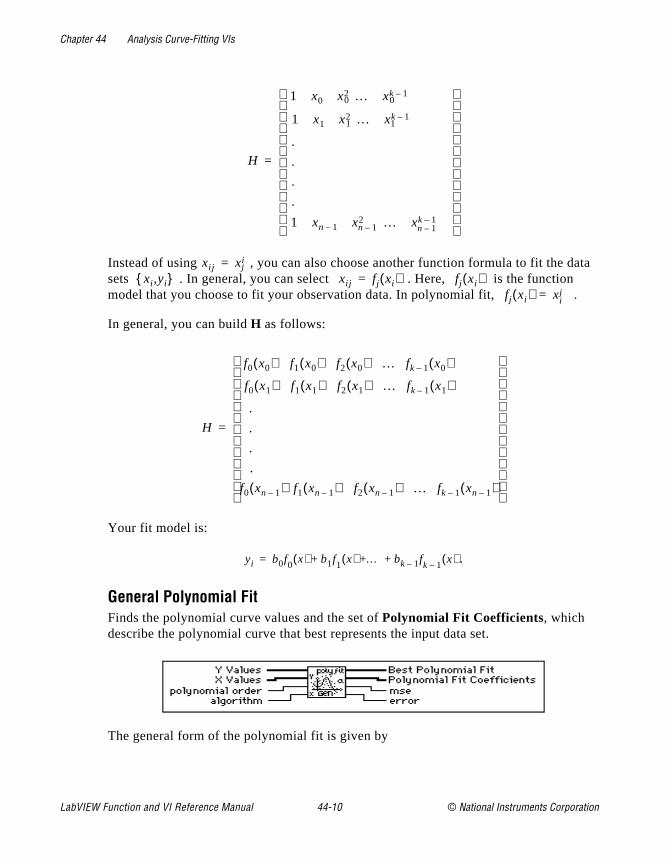
Chapter 44 Analysis Curve-Fitting VIs
ata
Instead of using , you can also choose another function formula to fit the dsets . In general, you can select . Here, is the function model that you choose to fit your observation data. In polynomial fit, .In general, you can build H as follows:
Your fit model is:
.
General Polynomial FitFinds the polynomial curve values and the set of Polynomial Fit Coefficients, which describe the polynomial curve that best represents the input data set.
The general form of the polynomial fit is given by
H
1 x0 x20 … xk 1–
0
1 x1 x21 … xk 1–
1
.
.
.
.
1 xn 1– x2n 1– … xk 1–
n 1–
=
xij xij=
xi ,yi xij fj xi( )= fj xi( )fj xi( ) xj
i=
H
f0 x0( ) f1 x0( ) f2 x0( ) … fk 1– x0( )
f0 x1( ) f1 x1( ) f2 x1( ) … fk 1– x1( )
.
.
.
.
f0 xn 1–( ) f1 xn 1–( ) f2 xn 1–( ) … fk 1– xn 1–( )
=
yi b0f0
x( ) b1f1
x( ) … bk 1– fk 1–
x( )+ + +=
LabVIEW Function and VI Reference Manual 44-10 © National Instruments Corporation
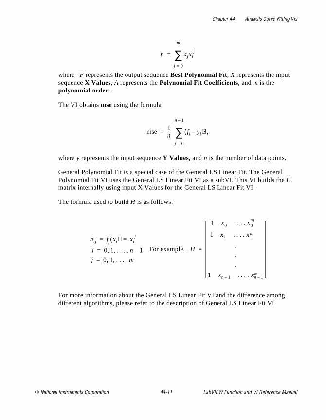
Chapter 44 Analysis Curve-Fitting VIs
where F represents the output sequence Best Polynomial Fit, X represents the input sequence X Values, A represents the Polynomial Fit Coefficients, and m is the polynomial order.
The VI obtains mse using the formula
where y represents the input sequence Y Values, and n is the number of data points.
General Polynomial Fit is a special case of the General LS Linear Fit. The GeneralPolynomial Fit VI uses the General LS Linear Fit VI as a subVI. This VI builds the H matrix internally using input X Values for the General LS Linear Fit VI.
The formula used to build H is as follows:
For example,
For more information about the General LS Linear Fit VI and the difference amongdifferent algorithms, please refer to the description of General LS Linear Fit VI.
fi ajxij
j 0=
m
∑=
mse1n--- fi yi–( )2,
j 0=
n 1–
∑=
hij fj xi( ) xij= =
i 0 1 . . . n 1–, , ,=
j 0 1 . . . m, , ,=
H
1 x0 . . . . x0m
1 x1 . . . . x1m
.
.
.
1 xn 1– . . . . xn 1–m
=
© National Instruments Corporation 44-11 LabVIEW Function and VI Reference Manual
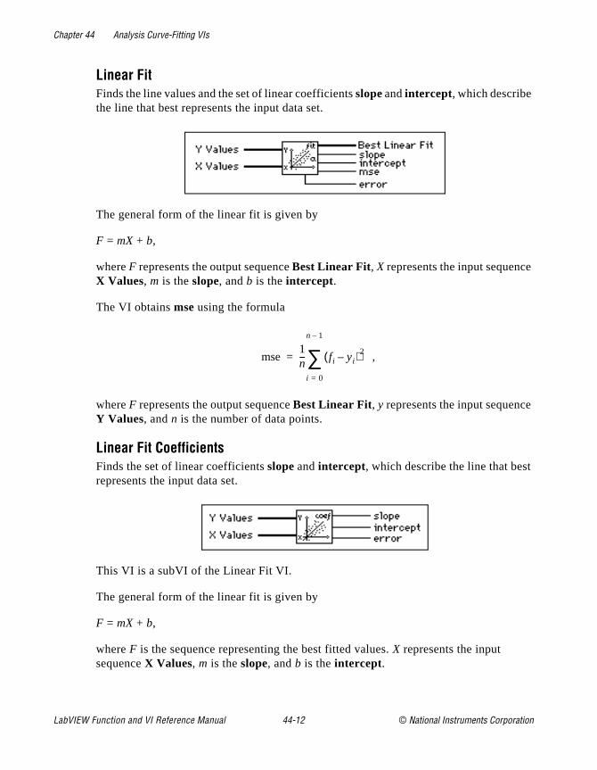
Chapter 44 Analysis Curve-Fitting VIs
e
e
t
Linear FitFinds the line values and the set of linear coefficients slope and intercept, which describe the line that best represents the input data set.
The general form of the linear fit is given by
F = mX + b,
where F represents the output sequence Best Linear Fit, X represents the input sequencX Values, m is the slope, and b is the intercept.
The VI obtains mse using the formula
,
where F represents the output sequence Best Linear Fit, y represents the input sequencY Values, and n is the number of data points.
Linear Fit CoefficientsFinds the set of linear coefficients slope and intercept, which describe the line that besrepresents the input data set.
This VI is a subVI of the Linear Fit VI.
The general form of the linear fit is given by
F = mX + b,
where F is the sequence representing the best fitted values. X represents the input sequence X Values, m is the slope, and b is the intercept.
mse1n--- fi yi–( )2
i 0=
n 1–
∑=
LabVIEW Function and VI Reference Manual 44-12 © National Instruments Corporation
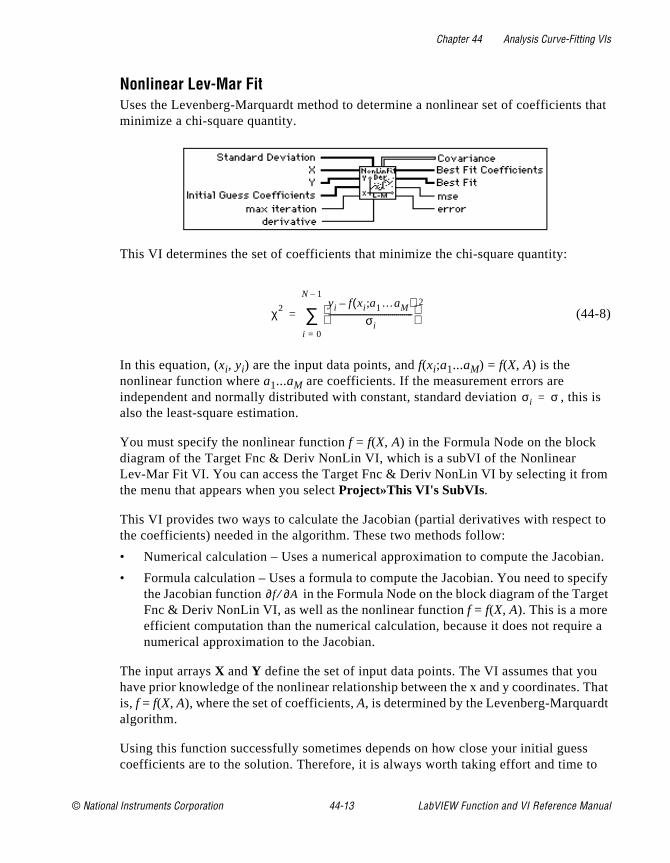
Chapter 44 Analysis Curve-Fitting VIs
that
is
m
t to
ian.
ecify rget
re a
u That t
s to
Nonlinear Lev-Mar FitUses the Levenberg-Marquardt method to determine a nonlinear set of coefficientsminimize a chi-square quantity.
This VI determines the set of coefficients that minimize the chi-square quantity:
(44-8)
In this equation, (xi, yi) are the input data points, and f(xi;a1...aM) = f(X, A) is the nonlinear function where a1...aM are coefficients. If the measurement errors are independent and normally distributed with constant, standard deviation , thisalso the least-square estimation.
You must specify the nonlinear function f = f(X, A) in the Formula Node on the block diagram of the Target Fnc & Deriv NonLin VI, which is a subVI of the Nonlinear Lev-Mar Fit VI. You can access the Target Fnc & Deriv NonLin VI by selecting it frothe menu that appears when you select Project»This VI's SubVIs.
This VI provides two ways to calculate the Jacobian (partial derivatives with respecthe coefficients) needed in the algorithm. These two methods follow:
• Numerical calculation – Uses a numerical approximation to compute the Jacob
• Formula calculation – Uses a formula to compute the Jacobian. You need to spthe Jacobian function in the Formula Node on the block diagram of the TaFnc & Deriv NonLin VI, as well as the nonlinear function f = f(X, A). This is a more efficient computation than the numerical calculation, because it does not requinumerical approximation to the Jacobian.
The input arrays X and Y define the set of input data points. The VI assumes that yohave prior knowledge of the nonlinear relationship between the x and y coordinates.is, f = f(X, A), where the set of coefficients, A, is determined by the Levenberg-Marquardalgorithm.
Using this function successfully sometimes depends on how close your initial guescoefficients are to the solution. Therefore, it is always worth taking effort and time
χ2 yi f xi a1…aM;( )–
σi------------------------------------------
2
i 0=
N 1–
∑=
σi σ=
∂f ∂A⁄
© National Instruments Corporation 44-13 LabVIEW Function and VI Reference Manual

Chapter 44 Analysis Curve-Fitting VIs
fore
obtain good initial guess coefficients to the solution from any available resources beusing the function.
Polynomial InterpolationInterpolates or extrapolates the function f at x, given a set of n points (x
i, y
i), where f(x
i) =
yi, f is any function, and given a number, x. The VI calculates output interpolation value
Pn–1(x), where Pn–1 is the unique polynomial of degree n–1 that passes through the n points (x
i, y
i).
Rational InterpolationInterpolates or extrapolates f at x using a rational function.
The rational function
passes through all the points formed by Y Array and X Array . P and Q are polynomials, and the rational function is unique, given a set of n points (x
i, y
i),
where f(xi) = y
i, f is any function, and given a number x in the range of the x
i values. This
VI calculates the output interpolation value y using . If the number of points
is odd, the degrees of freedom of P and Q are . If the number of points is even, the
degrees of freedom of P are , and the degrees of freedom of Q are , where n is the
total number of points formed by Y Array and X Array .
P xi( )Q xi( )-------------
p0 p1xi … pmxmi+ ++
q0 q1xi … qv+ + xv+-------------------------------------------------------=
yP x( )Q x( )------------=
n 1–2
------------
n2--- 1–
n2---
LabVIEW Function and VI Reference Manual 44-14 © National Instruments Corporation
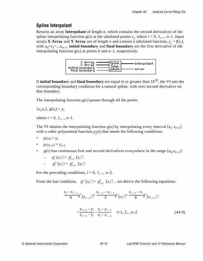
Chapter 44 Analysis Curve-Fitting VIs
on
Spline InterpolantReturns an array Interpolant of length n, which contains the second derivatives of thespline interpolating function g(x) at the tabulated points x
i, where i = 0, 1,..., n–1. Input
arrays X Array and Y Array are of length n and contain a tabulated function, yi = f(x
i),
with x0<x1<...xn–1. initial boundary and final boundary are the first derivative of the interpolating function g(x) at points 0 and n–1, respectively.
If initial boundary and final boundary are equal to or greater than 1030, the VI sets the corresponding boundary condition for a natural spline, with zero second derivativethat boundary.
The interpolating function g(x) passes through all the points
xi,yi, g(xi) = yi
where i = 0, 1,..., n–1.
The VI obtains the interpolating function g(x) by interpolating every interval [xi, xi+1] with a cubic polynomial function p
i(x) that meets the following conditions:
• pi(xi) = yi
• pi(xi+1) = yi+1
• g(x) has continuous first and second derivatives everywhere in the range [x0,xn–1]:
–
–
For the preceding conditions, i = 0, 1,..., n–2.
From the last condition, , we derive the following equations:
i=1, 2,...n–2 (44-9)
p'i
xi( ) p'i+1 xi( )=
p''i xi( ) p''i+1 xi( )=
p''i xi( ) p''i+1 xi( )=
xi xi 1––
6--------------------g'' xi 1–( )
xi 1+ xi 1––
3--------------------------g'' xi( )
xi 1+ xi–
6--------------------g'' xi 1+( )+ +
=yi 1+ yi–
xi 1+ xi–--------------------
yi yi 1––
xi xi 1––--------------------–
© National Instruments Corporation 44-15 LabVIEW Function and VI Reference Manual

Chapter 44 Analysis Curve-Fitting VIs
hen
f
These are n–2 linear equations with n unknowns
i = 0, 1,…, n – 1. This VI computes , from initial boundary and final
boundary using the formula
.
Here
You can derive this formula from the preceding conditions numbered 1–3. This VI t
uses , in equation (44-1) to solve all the , for i = 1, … n–2.
is the output Interpolant . You can use Interpolant as an input to the Spline
Interpolation VI to interpolate y at any value of .
Spline InterpolationPerforms a cubic spline interpolation of f at x, given a tabulated function.
This VI performs cubic spline interpolation using a tabulated function in the form oy
i = f(x
i) for i = 0, 1,..., n–1, and given the second derivatives Interpolant that the VI
obtains from the Spline Interpolant VI. The value of x must be in the range of X values. The points are formed by the input arrays X and Y, and n is the total number of points.
On the interval , the output interpolation value y is defined by
,
and
g'' xi( )
g'' x0( ) g'' xn 1–( )
g' x( )yi 1+ yi–
xi 1+ xi–--------------------
3A2 1–6
------------------ xi 1+ xi–( )g'' xi( )+=
3B2 1–6
------------------+ xi 1+ xi–( )g'' xi 1+( )
Axi 1+ x–
xi 1+ xi–--------------------= B 1 A–
x xi–
xi 1+ xi–--------------------= =
g'' x0( ) g'' xn 1–( ) g'' xi( )
g'' xi( )
x0 x xn 1–≤ ≤
xi xi 1+,[ ]
y Ayi Byi 1 Cy''i Dy''i 1+ + + ++=
LabVIEW Function and VI Reference Manual 44-16 © National Instruments Corporation
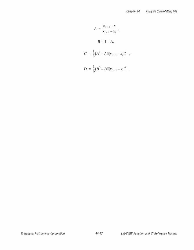
Chapter 44 Analysis Curve-Fitting VIs
,
B = 1 – A,
,
.
Axi 1+ x–
xi 1+ xi–--------------------=
C16--- A3 A–( ) xi 1+ xi–( )2=
D16--- B3 B–( ) xi 1+ xi–( )2=
© National Instruments Corporation 44-17 LabVIEW Function and VI Reference Manual
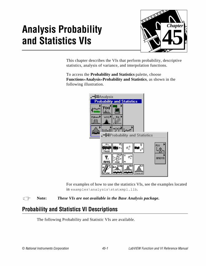
© National Instruments Corporation 45-1 LabVIEW Function and
Chapter
45
Analysis Probability and Statistics VIsated
This chapter describes the VIs that perform probability, descriptivestatistics, analysis of variance, and interpolation functions.
To access the Probability and Statistics palette, choose Functions»Analysis»Probability and Statistics, as shown in the following illustration.
For examples of how to use the statistics VIs, see the examples locin examples\analysis\statxmpl.llb .
Note: These VIs are not available in the Base Analysis package.
Probability and Statistics VI Descriptions
The following Probability and Statistic VIs are available.
VI Reference Manual
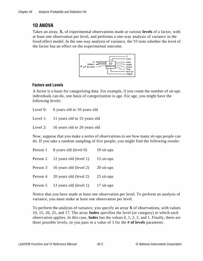
Chapter 45 Analysis Probability and Statistics VIs
the el of
-ups
le can lts:
sis of
re
1D ANOVATakes an array, X, of experimental observations made at various levels of a factor, with at least one observation per level, and performs a one-way analysis of variance in fixed effect model. In the one-way analysis of variance, the VI tests whether the levthe factor has an effect on the experimental outcome.
Factors and LevelsA factor is a basis for categorizing data. For example, if you count the number of sitindividuals can do, one basis of categorization is age. For age, you might have thefollowing levels:
Level 0: 6 years old to 10 years old
Level 1: 11 years old to 15 years old
Level 2: 16 years old to 20 years old
Now, suppose that you make a series of observations to see how many sit-ups peopdo. If you take a random sampling of five people, you might find the following resu
Person 1 8 years old (level 0) 10 sit-ups
Person 2 12 years old (level 1) 15 sit-ups
Person 3 16 years old (level 2) 20 sit-ups
Person 4 20 years old (level 2) 25 sit-ups
Person 5 13 years old (level 1) 17 sit-ups
Notice that you have made at least one observation per level. To perform an analyvariance, you must make at least one observation per level.
To perform the analysis of variance, you specify an array X of observations, with values 10, 15, 20, 25, and 17. The array Index specifies the level (or category) to which eachobservation applies. In this case, Index has the values 0, 1, 2, 2, and 1. Finally, there athree possible levels, so you pass in a value of 3 for the # of levels parameter.
LabVIEW Function and VI Reference Manual 45-2 © National Instruments Corporation

Chapter 45 Analysis Probability and Statistics VIs
and
-ups
ople
2D ANOVATakes an array of experimental observations made at various levels of two factors performs a two-way analysis of variance.
Factors, Levels, and CellsA factor is a basis for categorizing data. For example, if you count the number of sitindividuals can do, one basis of categorization is age. For age, you might have thefollowing levels:
Level 0: 6 years old to 10 years old
Level 1: 11 years old to 15 years old
Another possible factor is weight, with the following levels:
Level 0: less than 50 kg
Level 1: between 50 and 75 kg
Level 2: more than 75 kg
Now, suppose that you made a series of observations to see how many sit-ups pecould do. If you took a random sampling of n people, you might find the following results:
Person 1 8 years old (level 0) 30 kg (level 0) 10 sit-ups
Person 2 12 years old (level 1) 40 kg (level 0) 15 sit-ups
Person 3 15 years old (level 1)7 6 kg (level 2) 20 sit-ups
Person 4 14 years old (level 1) 60 kg (level 1) 25 sit-ups
Person 5 9 years old (level 0) 51 kg (level 1) 17 sit-ups
Person 6 10 years old (level 0) 80 kg (level 2) 4 sit ups
and so on.
© National Instruments Corporation 45-3 LabVIEW Function and VI Reference Manual
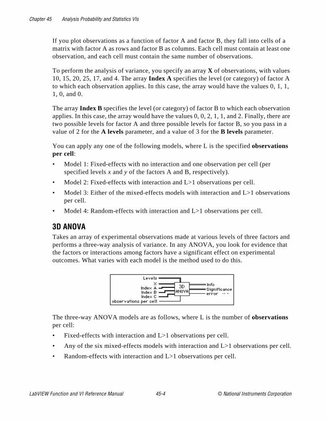
Chapter 45 Analysis Probability and Statistics VIs
a t one
, 1, 1,
ion re are in a
ons
s and at
cell.
If you plot observations as a function of factor A and factor B, they fall into cells ofmatrix with factor A as rows and factor B as columns. Each cell must contain at leasobservation, and each cell must contain the same number of observations.
To perform the analysis of variance, you specify an array X of observations, with values 10, 15, 20, 25, 17, and 4. The array Index A specifies the level (or category) of factor Ato which each observation applies. In this case, the array would have the values 01, 0, and 0.
The array Index B specifies the level (or category) of factor B to which each observatapplies. In this case, the array would have the values 0, 0, 2, 1, 1, and 2. Finally, thetwo possible levels for factor A and three possible levels for factor B, so you pass value of 2 for the A levels parameter, and a value of 3 for the B levels parameter.
You can apply any one of the following models, where L is the specified observations per cell:
• Model 1: Fixed-effects with no interaction and one observation per cell (per specified levels x and y of the factors A and B, respectively).
• Model 2: Fixed-effects with interaction and L>1 observations per cell.
• Model 3: Either of the mixed-effects models with interaction and L>1 observatiper cell.
• Model 4: Random-effects with interaction and L>1 observations per cell.
3D ANOVATakes an array of experimental observations made at various levels of three factorperforms a three-way analysis of variance. In any ANOVA, you look for evidence ththe factors or interactions among factors have a significant effect on experimental outcomes. What varies with each model is the method used to do this.
The three-way ANOVA models are as follows, where L is the number of observations per cell:
• Fixed-effects with interaction and L>1 observations per cell.
• Any of the six mixed-effects models with interaction and L>1 observations per
• Random-effects with interaction and L>1 observations per cell.
LabVIEW Function and VI Reference Manual 45-4 © National Instruments Corporation
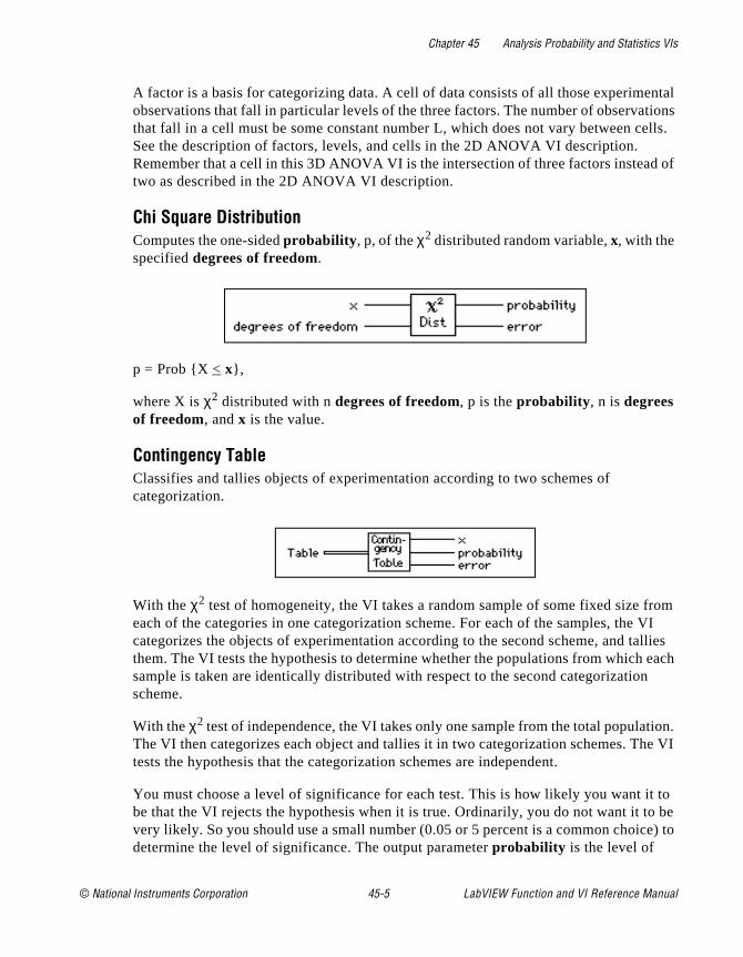
Chapter 45 Analysis Probability and Statistics VIs
ental tions ells.
d of
rom VI llies
each
tion. e VI
t to be e) to
A factor is a basis for categorizing data. A cell of data consists of all those experimobservations that fall in particular levels of the three factors. The number of observathat fall in a cell must be some constant number L, which does not vary between cSee the description of factors, levels, and cells in the 2D ANOVA VI description. Remember that a cell in this 3D ANOVA VI is the intersection of three factors insteatwo as described in the 2D ANOVA VI description.
Chi Square DistributionComputes the one-sided probability , p, of the χ2 distributed random variable, x, with the specified degrees of freedom.
p = Prob X < x,
where X is χ2 distributed with n degrees of freedom, p is the probability , n is degrees of freedom, and x is the value.
Contingency TableClassifies and tallies objects of experimentation according to two schemes of categorization.
With the χ2 test of homogeneity, the VI takes a random sample of some fixed size feach of the categories in one categorization scheme. For each of the samples, thecategorizes the objects of experimentation according to the second scheme, and tathem. The VI tests the hypothesis to determine whether the populations from whichsample is taken are identically distributed with respect to the second categorizationscheme.
With the χ2 test of independence, the VI takes only one sample from the total populaThe VI then categorizes each object and tallies it in two categorization schemes. Thtests the hypothesis that the categorization schemes are independent.
You must choose a level of significance for each test. This is how likely you want ibe that the VI rejects the hypothesis when it is true. Ordinarily, you do not want it tovery likely. So you should use a small number (0.05 or 5 percent is a common choicdetermine the level of significance. The output parameter probability is the level of
© National Instruments Corporation 45-5 LabVIEW Function and VI Reference Manual

Chapter 45 Analysis Probability and Statistics VIs
e
d
significance at which the hypothesis is rejected. Thus, if probability is less than the level of significance, you must reject the hypothesis.
erf(x)Evaluates the error function at the input value.
erfc(x)Evaluates the complementary error function at the input value.
F DistributionComputes the one-sided probability , p, of the F-distributed random variable, F, with thspecified n and m degrees of freedom
p = Prob Fn,m
< x,
where F is F-distributed, p is the probability , n specifies the first degree of freedom, m specifies the second degree of freedom, and x is the value.
General HistogramFinds the discrete histogram of the input sequence X based on the given bin specifications.
The VI obtains the Histogram as follows. The VI establishes all the intervals (also callebins) based on the information in the input array Bins first. The intervals (bins) are:
LabVIEW Function and VI Reference Manual 45-6 © National Instruments Corporation
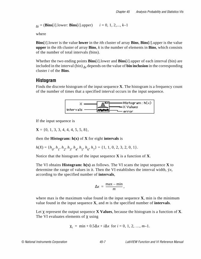
Chapter 45 Analysis Probability and Statistics VIs
t
∆i = (Bins[ i].lower: Bins[ i].upper) i = 0, 1, 2,..., k–1
where
Bins[ i].lower is the value lower in the ith cluster of array Bins, Bins[ i].upper is the value upper in the ith cluster of array Bins, k is the number of elements in Bins, which consists of the number of total intervals (bins).
Whether the two ending points Bins[ i].lower and Bins[ i].upper of each interval (bin) areincluded in the interval (bin) ∆i depends on the value of bin inclusion in the corresponding cluster i of the Bins.
HistogramFinds the discrete histogram of the input sequence X. The histogram is a frequency counof the number of times that a specified interval occurs in the input sequence.
If the input sequence is
X = 0, 1, 3, 3, 4, 4, 4, 5, 5, 8,
then the Histogram: h(x) of X for eight intervals is
h(X) = h0, h
1, h
2, h
3, h
4, h
5, h
6, h
7 = 1, 1, 0, 2, 3, 2, 0, 1.
Notice that the histogram of the input sequence X is a function of X.
The VI obtains Histogram: h(x) as follows. The VI scans the input sequence X to determine the range of values in it. Then the VI establishes the interval width, ýx, according to the specified number of intervals,
,
where max is the maximum value found in the input sequence X, min is the minimum value found in the input sequence X, and m is the specified number of intervals.
Let χ represent the output sequence X Values, because the histogram is a function of X. The VI evaluates elements of χ using
for i = 0, 1, 2, …, m–1.
x∆ max min–m
-------------------------=
χi min 0.5∆x i∆x+ +=
© National Instruments Corporation 45-7 LabVIEW Function and VI Reference Manual
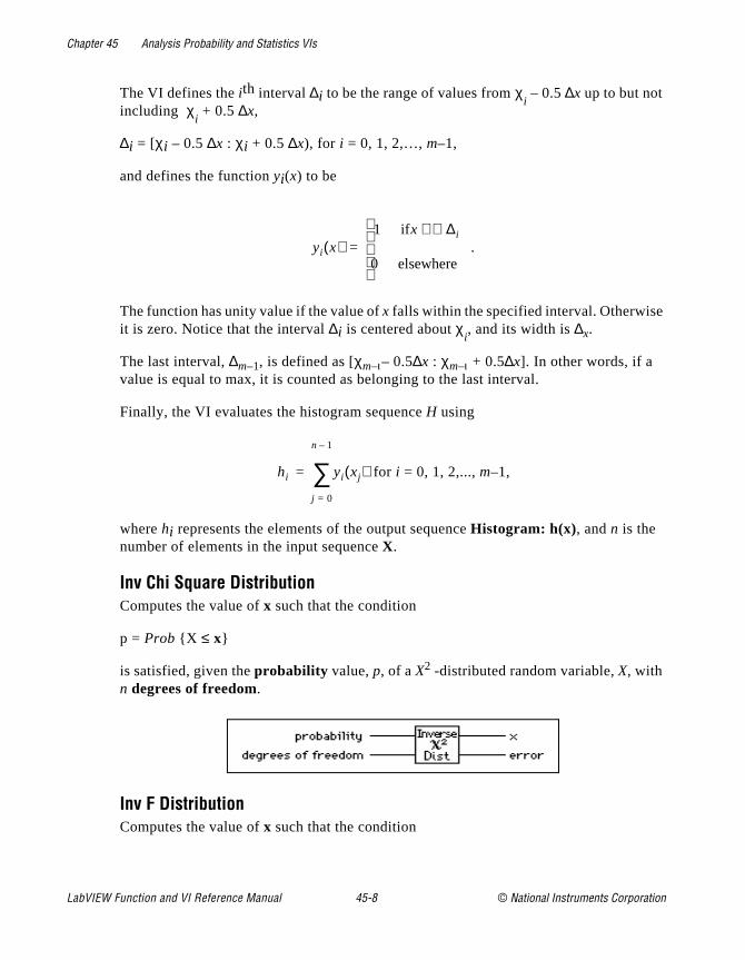
Chapter 45 Analysis Probability and Statistics VIs
The VI defines the ith interval ∆i to be the range of values from χi – 0.5 ∆x up to but not
including χi + 0.5 ∆x,
∆i = [χi – 0.5 ∆x : χi + 0.5 ∆x), for i = 0, 1, 2,…, m–1,
and defines the function yi(x) to be
.
The function has unity value if the value of x falls within the specified interval. Otherwiseit is zero. Notice that the interval ∆i is centered about χ
i, and its width is ∆x.
The last interval, ∆m–1, is defined as [χm–ι– 0.5∆x : χm–ι + 0.5∆x]. In other words, if a value is equal to max, it is counted as belonging to the last interval.
Finally, the VI evaluates the histogram sequence H using
for i = 0, 1, 2,..., m–1,
where hi represents the elements of the output sequence Histogram: h(x), and n is the number of elements in the input sequence X.
Inv Chi Square DistributionComputes the value of x such that the condition
p = Prob X ≤ x
is satisfied, given the probability value, p, of a X2 -distributed random variable, X, with n degrees of freedom.
Inv F DistributionComputes the value of x such that the condition
yi x( )1 ifx ∆i⊇∈
0 elsewhere
=
hi yi xj( )
j 0=
n 1–
∑=
LabVIEW Function and VI Reference Manual 45-8 © National Instruments Corporation
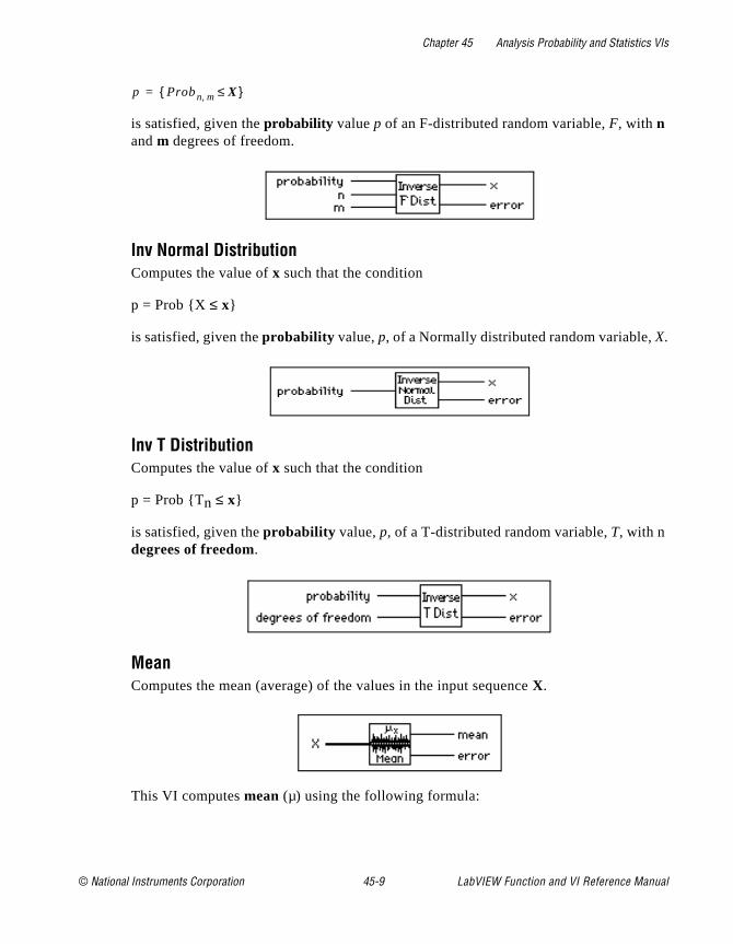
Chapter 45 Analysis Probability and Statistics VIs
is satisfied, given the probability value p of an F-distributed random variable, F, with n and m degrees of freedom.
Inv Normal DistributionComputes the value of x such that the condition
p = Prob X ≤ x
is satisfied, given the probability value, p, of a Normally distributed random variable, X.
Inv T DistributionComputes the value of x such that the condition
p = Prob Tn ≤ x
is satisfied, given the probability value, p, of a T-distributed random variable, T, with n degrees of freedom.
MeanComputes the mean (average) of the values in the input sequence X.
This VI computes mean (µ) using the following formula:
p Prob n m, X ≤=
© National Instruments Corporation 45-9 LabVIEW Function and VI Reference Manual

Chapter 45 Analysis Probability and Statistics VIs
,
where n is the number of elements in X.
MedianFinds the median value of the input sequence X by sorting the values of X and selecting the middle element(s) of the sorted array.
Let n be the number of elements in the input sequence X, and let S be the sorted sequenceof X. The VI finds median using the following identity:
where ,
and .
ModeFinds the mode of the input sequence X.
Moment About MeanComputes the moment about the mean of the input sequence X using the specified order.
Let m be the desired order. The VI computes the mth
-order moment using the formula:
µ1n--- xi
i 0=
n 1–
∑=
mediansi if n is odd
0.5 sk 1– sk+( ) if n is even
=
in 1–
2------------=
kn2---=
LabVIEW Function and VI Reference Manual 45-10 © National Instruments Corporation
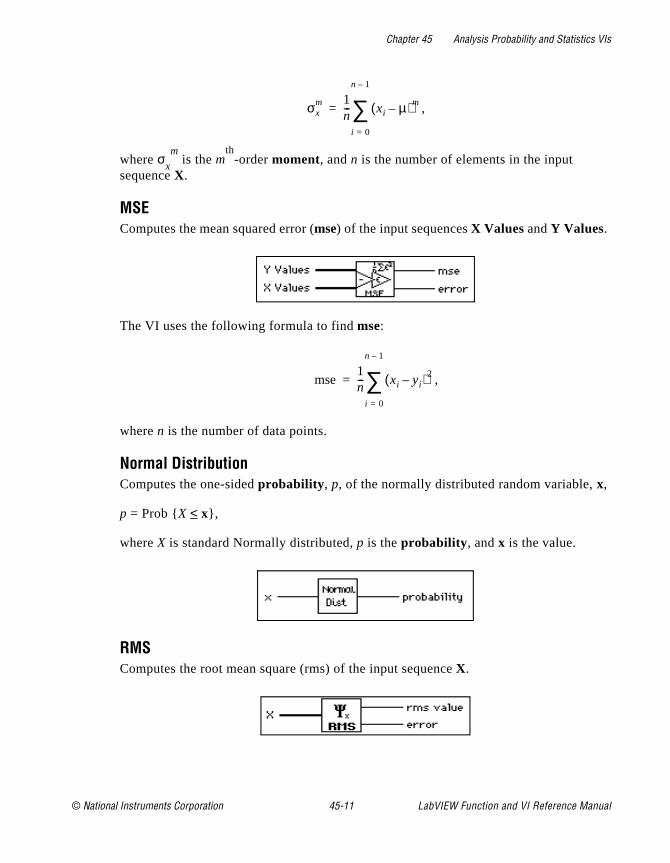
Chapter 45 Analysis Probability and Statistics VIs
,
where σx
m is the m
th-order moment, and n is the number of elements in the input
sequence X.
MSEComputes the mean squared error (mse) of the input sequences X Values and Y Values.
The VI uses the following formula to find mse:
,
where n is the number of data points.
Normal DistributionComputes the one-sided probability , p, of the normally distributed random variable, x,
p = Prob X < x,
where X is standard Normally distributed, p is the probability , and x is the value.
RMSComputes the root mean square (rms) of the input sequence X.
σxm 1
n--- xi µ–( )m
i 0=
n 1–
∑=
mse1n--- xi yi–( )2
i 0=
n 1–
∑=
© National Instruments Corporation 45-11 LabVIEW Function and VI Reference Manual
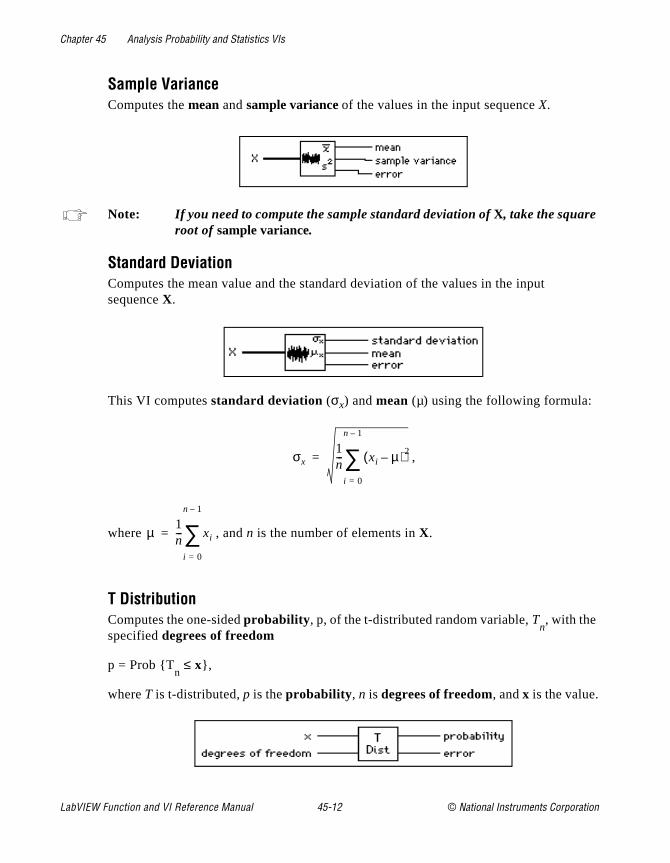
Chapter 45 Analysis Probability and Statistics VIs
Sample VarianceComputes the mean and sample variance of the values in the input sequence X.
Note: If you need to compute the sample standard deviation of X, take the square root of sample variance.
Standard DeviationComputes the mean value and the standard deviation of the values in the input sequence X.
This VI computes standard deviation (σx) and mean (µ) using the following formula:
,
where , and n is the number of elements in X.
T DistributionComputes the one-sided probability , p, of the t-distributed random variable, T
n, with the
specified degrees of freedom
p = Prob Tn ≤ x,
where T is t-distributed, p is the probability , n is degrees of freedom, and x is the value.
σx1n--- xi µ–( )2
i 0=
n 1–
∑=
µ1n--- xi
i 0=
n 1–
∑=
LabVIEW Function and VI Reference Manual 45-12 © National Instruments Corporation
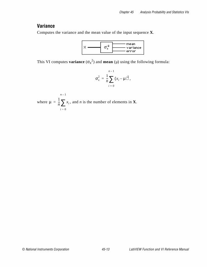
Chapter 45 Analysis Probability and Statistics VIs
VarianceComputes the variance and the mean value of the input sequence X.
This VI computes variance (σx2) and mean (µ) using the following formula:
,
where , and n is the number of elements in X.
σx2 1
n--- xi µ–( )2
i 0=
n 1–
∑=
µ1n--- xi
i 0=
n 1–
∑=
© National Instruments Corporation 45-13 LabVIEW Function and VI Reference Manual
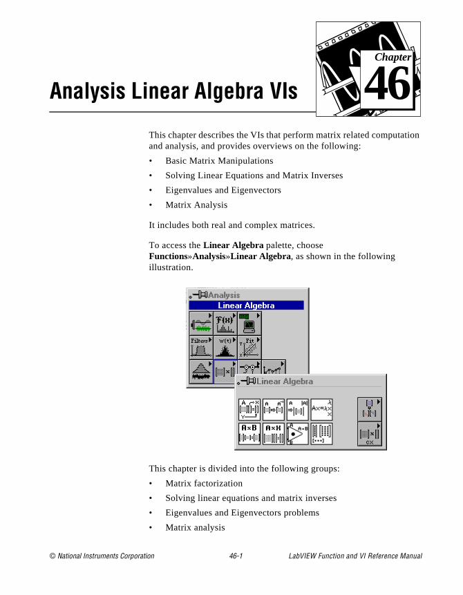
© National Instruments Corporation 46-1 LabVIEW Function and
Chapter
46
Analysis Linear Algebra VIsion
This chapter describes the VIs that perform matrix related computatand analysis, and provides overviews on the following:• Basic Matrix Manipulations
• Solving Linear Equations and Matrix Inverses
• Eigenvalues and Eigenvectors
• Matrix Analysis
It includes both real and complex matrices.
To access the Linear Algebra palette, choose Functions»Analysis»Linear Algebra, as shown in the following illustration.
This chapter is divided into the following groups:
• Matrix factorization
• Solving linear equations and matrix inverses
• Eigenvalues and Eigenvectors problems
• Matrix analysis
VI Reference Manual
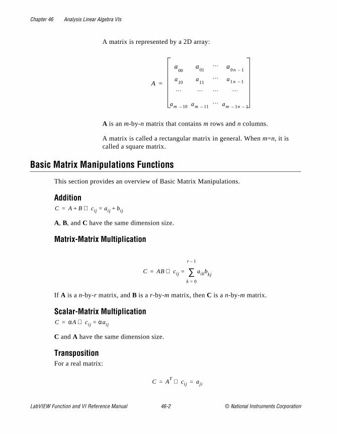
Chapter 46 Analysis Linear Algebra VIs
A matrix is represented by a 2D array:
A is an m-by-n matrix that contains m rows and n columns.
A matrix is called a rectangular matrix in general. When m=n, it is called a square matrix.
Basic Matrix Manipulations Functions
This section provides an overview of Basic Matrix Manipulations.
Addition
A, B, and C have the same dimension size.
Matrix-Matrix Multiplication
If A is a n-by-r matrix, and B is a r-by-m matrix, then C is a n-by-m matrix.
Scalar-Matrix Multiplication
C and A have the same dimension size.
TranspositionFor a real matrix:
A
a00
a01
… a0n 1–
a10
a11
… a1n 1–
… … … …
am 10– am 11–… am 1n– 1–
=
C A B cij aij bij+=⇒+=
C AB cij aikbkj
k 0=
r 1–
∑=⇒=
C αA cij αaij=⇒=
C AT
cij⇒ aji= =
LabVIEW Function and VI Reference Manual 46-2 © National Instruments Corporation
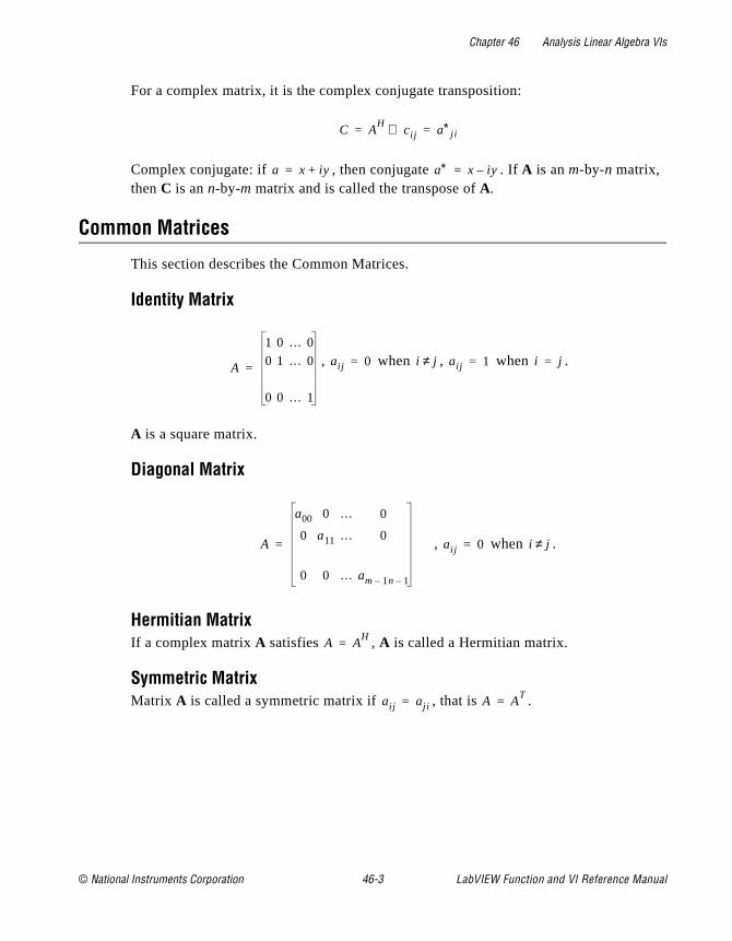
Chapter 46 Analysis Linear Algebra VIs
For a complex matrix, it is the complex conjugate transposition:
Complex conjugate: if , then conjugate . If A is an m-by-n matrix, then C is an n-by-m matrix and is called the transpose of A.
Common Matrices
This section describes the Common Matrices.
Identity Matrix
, when , when .
A is a square matrix.
Diagonal Matrix
, when .
Hermitian MatrixIf a complex matrix A satisfies , A is called a Hermitian matrix.
Symmetric MatrixMatrix A is called a symmetric matrix if , that is .
C AH
cij⇒ a∗j i= =
a x iy+= a∗ x iy–=
A
1 0 … 0
0 1 … 0
0 0 … 1
= aij 0= i j≠ aij 1= i j=
A
a00 0 … 0
0 a11 … 0
0 0 … am 1n 1––
= aij 0= i j≠
A AH
=
aij aji= A AT
=
© National Instruments Corporation 46-3 LabVIEW Function and VI Reference Manual
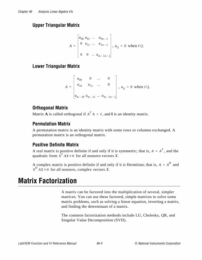
Chapter 46 Analysis Linear Algebra VIs
e
d
e rix,
Upper Triangular Matrix
, when i>j.
Lower Triangular Matrix
, when i<j.
Orthogonal MatrixMatrix A is called orthogonal if , and I is an identity matrix.
Permutation MatrixA permutation matrix is an identity matrix with some rows or columns exchanged. Apermutation matrix is an orthogonal matrix.
Positive Definite MatrixA real matrix is positive definite if and only if it is symmetric; that is, , and thquadratic form for all nonzero vectors X.
A complex matrix is positive definite if and only if it is Hermitian; that is, an for all nonzero, complex vectors X.
Matrix FactorizationA matrix can be factored into the multiplication of several, simpler matrices. You can use these factored, simple matrices to solve sommatrix problems, such as solving a linear equation, inverting a matand finding the determinant of a matrix.
The common factorization methods include LU, Cholesky, QR, andSingular Value Decomposition (SVD).
A
a00 a01 … a0n 1–
0 a11 … a1n 1–
0 0 … am 1n– 1–
= aij 0=
A
a00 0 … 0
a10 a11 … 0
am 10– am 11– … am 1n– 1–
= aij 0=
AT
A I=
A AT
=X
TAX 0>
A AH
=X
HAX 0>
LabVIEW Function and VI Reference Manual 46-4 © National Instruments Corporation

Chapter 46 Analysis Linear Algebra VIs
ne
f
nal
• LU Factorization—Factors a square matrix into two matrices. Ois an upper triangular matrix U, and the other is a lower triangularmatrix L that has ones on the diagonal, so that PA=LU. P is a permutation matrix.
• When a square matrix is positive definite, you can factor it into , if A is a real matrix, and , if A is a complex
matrix, where R is an upper triangular matrix. This is called Cholesky factorization. Cholesky factorization only needs half othe operations of LU factorization.
• QR Factorization–Factors a matrix as the product of an orthogomatrix Q and an upper triangular matrix R: A=QR. QR factorization is useful for both square and rectangular matrices.
• SVD—Decomposes a matrix into the product of three matrices:, where U and V are orthogonal matrices and S is a
diagonal matrix whose diagonal values are called the singular values of A. SVD is useful for solving analysis problems involvingmatrices. In addition to its common uses, you can use SVD for operations such as pseudoinverse, rank, norm, and condition number.
Solving Linear Equations and Matrix InversesTo Solve the linear equation AX=Y, you must find solution X when you know the given values of A and Y. A is a m-by-n matrix, X is a vector with n elements, and Y is a vector with m elements.
Using LU factorization, if m=n and A is a square matrix, A can be factored into triangular matrices L and U, so that A=LU. AX=Y becomes LUX=Y and you can solve Z for LZ=Y where Z=UX. You can then solve for X in UX=Z.
In the Cholesky case, and .
Triangular systems are easy to solve using recursive techniques.
If , the number of equations are different from the number of unknowns and A is not a square matrix, A can be factored into an orthogonal matrix Q and an upper triangular matrix R, so that A=QR. AX=Y becomes QRX=Y and you can solve for X by using .
When m>n, and the system has more equations than unknowns, it iscalled an overdetermined system. The solution that satisfies AX=Y may
A RTR= A R
HR=
A USVT
=
L RT
= U R=
m n≠
RX QTY=
© National Instruments Corporation 46-5 LabVIEW Function and VI Reference Manual
Chapter 46 Analysis Linear Algebra VIs
at
he
tion
lyze
not exist. The solution above finds the least square solution that minimizes .
When m<n, and the system has more unknowns than equations, it iscalled an underdetermined system. It may have infinite solutions thsatisfy AX=Y. The previous solution finds one of these solutions.
Inverting a square matrix A means that you find that satisfies , where I is an identity matrix. is called the inverse of
matrix A. You can solve for by solving n linear equations .
When A is not a square matrix, or when A is singular, does not exist. You can compute the pseudoinverse of A instead. If the m-by-n matrix A+ satisfies the following four Moore-Penrose conditions:AA+A=AA+AA+=A+
AA+ is a Hermitian matrix if A is a complex matrix. AA+ is a symmetric matrix if A is real matrix.A+A is a Hermitian matrix if A is a complex matrix. A+A is a symmetric matrix if A is real matrix.Then, A+ is called the pseudoinverse of matrix A. You can compute for A+ using SVD.
Eigenvalues and EigenvectorsThis Eigenvalue problem is to determine the nontrivial solutions to tequation , where A is an n-by-n matrix, X is a vector with
elements, and is a scalar. The values of that satisfy the equaare called eigenvalues of A, and the corresponding values of X are called the right eigenvectors of A.
Matrix AnalysisMatrix Analysis VIs can compute the matrix determinant, condition number, norm, and rank. Typically, you use these parameters to anaa matrix property.
Linear Algebra VI Descriptions
The following Linear Algebra VIs are available.
AX Y– AX( )i yi–[ ]2∑=
A1–
AA1–
I= A1–
A1–
AA1–
I=
A1–
AX λX=n λ n λ
LabVIEW Function and VI Reference Manual 46-6 © National Instruments Corporation
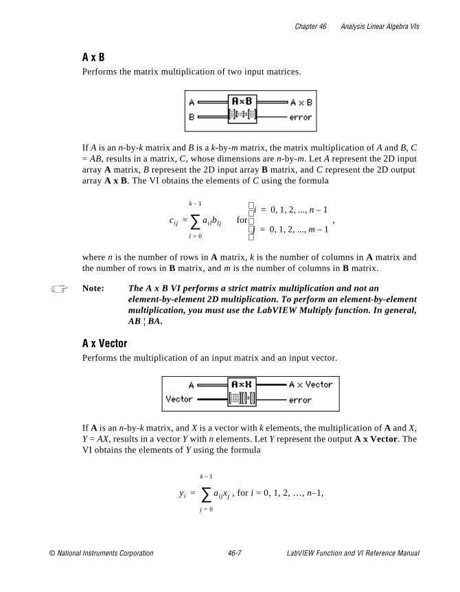
Chapter 46 Analysis Linear Algebra VIs
nt
A x BPerforms the matrix multiplication of two input matrices.
If A is an n-by-k matrix and B is a k-by-m matrix, the matrix multiplication of A and B, C = AB, results in a matrix, C, whose dimensions are n-by-m. Let A represent the 2D input array A matrix, B represent the 2D input array B matrix, and C represent the 2D output array A x B. The VI obtains the elements of C using the formula
,
where n is the number of rows in A matrix, k is the number of columns in A matrix and the number of rows in B matrix, and m is the number of columns in B matrix.
Note: The A x B VI performs a strict matrix multiplication and not an element-by-element 2D multiplication. To perform an element-by-elememultiplication, you must use the LabVIEW Multiply function. In general, AB ¦ BA.
A x VectorPerforms the multiplication of an input matrix and an input vector.
If A is an n-by-k matrix, and X is a vector with k elements, the multiplication of A and X, Y = AX, results in a vector Y with n elements. Let Y represent the output A x Vector. The VI obtains the elements of Y using the formula
, for i = 0, 1, 2, …, n–1,
cij ail blj
l 0=
k 1–
∑ fori 0 1 2 ... n 1–, , , ,=
j 0 1 2 ... m 1–, , , ,=
=
yi aij xj
j 0=
k 1–
∑=
© National Instruments Corporation 46-7 LabVIEW Function and VI Reference Manual
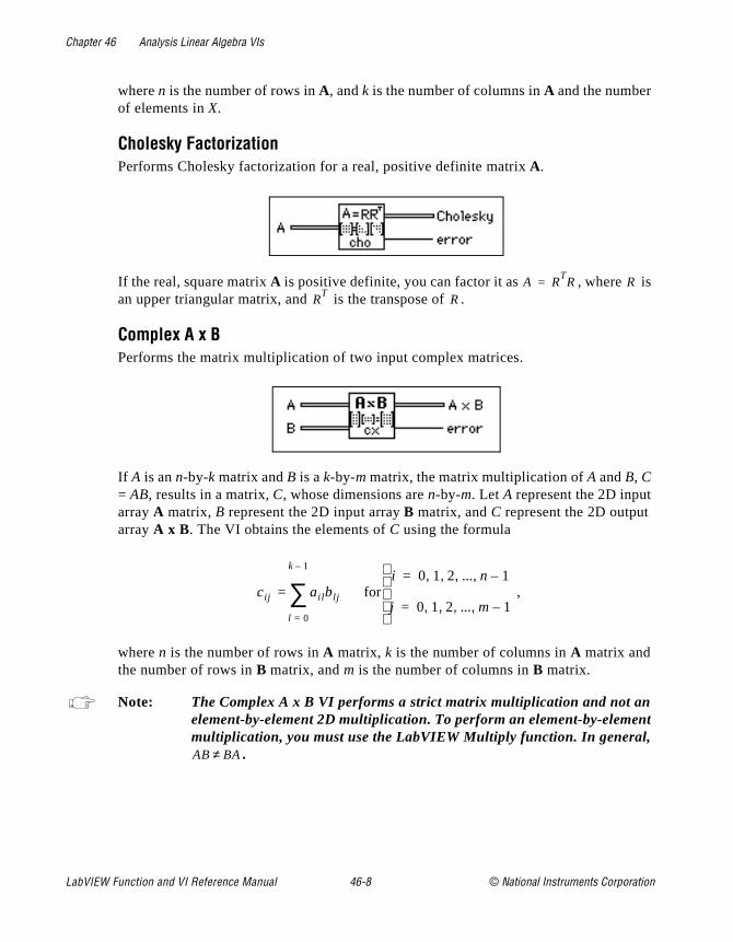
Chapter 46 Analysis Linear Algebra VIs
s
nt
where n is the number of rows in A, and k is the number of columns in A and the number of elements in X.
Cholesky FactorizationPerforms Cholesky factorization for a real, positive definite matrix A.
If the real, square matrix A is positive definite, you can factor it as , where ian upper triangular matrix, and is the transpose of .
Complex A x B Performs the matrix multiplication of two input complex matrices.
If A is an n-by-k matrix and B is a k-by-m matrix, the matrix multiplication of A and B, C = AB, results in a matrix, C, whose dimensions are n-by-m. Let A represent the 2D input array A matrix, B represent the 2D input array B matrix, and C represent the 2D output array A x B. The VI obtains the elements of C using the formula
,
where n is the number of rows in A matrix, k is the number of columns in A matrix and the number of rows in B matrix, and m is the number of columns in B matrix.
Note: The Complex A x B VI performs a strict matrix multiplication and not an element-by-element 2D multiplication. To perform an element-by-elememultiplication, you must use the LabVIEW Multiply function. In general,
.
A RTR= R
RT
R
cij ail blj
l 0=
k 1–
∑ fori 0 1 2 ... n 1–, , , ,=
j 0 1 2 ... m 1–, , , ,=
=
AB BA≠
LabVIEW Function and VI Reference Manual 46-8 © National Instruments Corporation
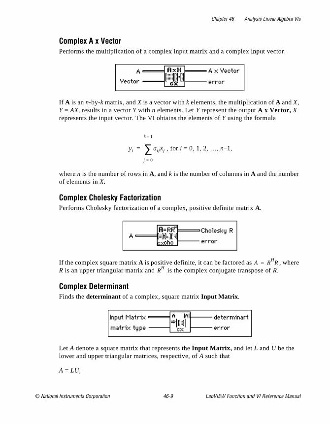
Chapter 46 Analysis Linear Algebra VIs
e
Complex A x Vector Performs the multiplication of a complex input matrix and a complex input vector.
If A is an n-by-k matrix, and X is a vector with k elements, the multiplication of A and X, Y = AX, results in a vector Y with n elements. Let Y represent the output A x Vector, X represents the input vector. The VI obtains the elements of Y using the formula
, for i = 0, 1, 2, …, n–1,
where n is the number of rows in A, and k is the number of columns in A and the number of elements in X.
Complex Cholesky Factorization Performs Cholesky factorization of a complex, positive definite matrix A.
If the complex square matrix A is positive definite, it can be factored as , wherR is an upper triangular matrix and is the complex conjugate transpose of R.
Complex Determinant Finds the determinant of a complex, square matrix Input Matrix .
Let A denote a square matrix that represents the Input Matrix, and let L and U be the lower and upper triangular matrices, respective, of A such that
A = LU,
yi aij xj
j 0=
k 1–
∑=
A RH
R=R
H
© National Instruments Corporation 46-9 LabVIEW Function and VI Reference Manual
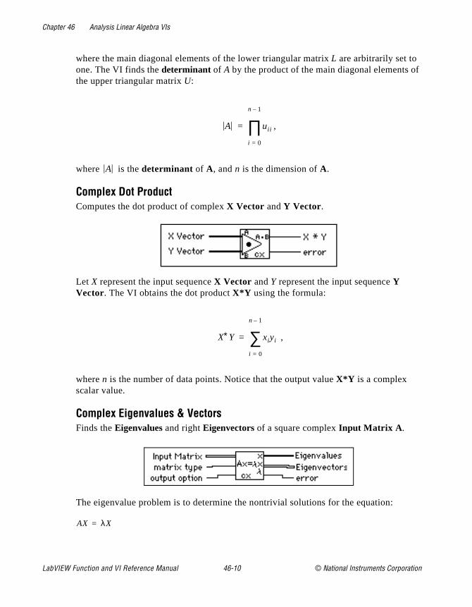
Chapter 46 Analysis Linear Algebra VIs
f
where the main diagonal elements of the lower triangular matrix L are arbitrarily set to one. The VI finds the determinant of A by the product of the main diagonal elements othe upper triangular matrix U:,
where is the determinant of A, and n is the dimension of A.
Complex Dot Product Computes the dot product of complex X Vector and Y Vector.
Let X represent the input sequence X Vector and Y represent the input sequence Y Vector. The VI obtains the dot product X*Y using the formula:
,
where n is the number of data points. Notice that the output value X*Y is a complex scalar value.
Complex Eigenvalues & Vectors Finds the Eigenvalues and right Eigenvectors of a square complex Input Matrix A.
The eigenvalue problem is to determine the nontrivial solutions for the equation:
A uii
i 0=
n 1–
∏=
A
X∗Y xiyi
i 0=
n 1–
∑=
AX λX=
LabVIEW Function and VI Reference Manual 46-10 © National Instruments Corporation
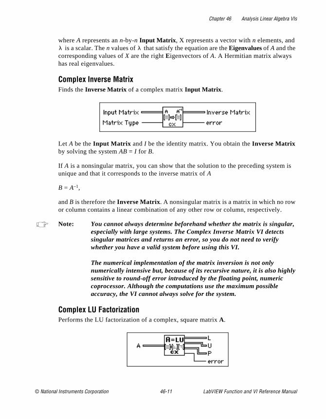
Chapter 46 Analysis Linear Algebra VIs
is
,
ly
where A represents an n-by-n Input Matrix , X represents a vector with n elements, and is a scalar. The n values of that satisfy the equation are the Eigenvalues of A and the
corresponding values of X are the right Eigenvectors of A. A Hermitian matrix always has real eigenvalues.
Complex Inverse MatrixFinds the Inverse Matrix of a complex matrix Input Matrix .
Let A be the Input Matrix and I be the identity matrix. You obtain the Inverse Matrix by solving the system AB = I for B.
If A is a nonsingular matrix, you can show that the solution to the preceding systemunique and that it corresponds to the inverse matrix of A
B = A–1,
and B is therefore the Inverse Matrix . A nonsingular matrix is a matrix in which no rowor column contains a linear combination of any other row or column, respectively.
Note: You cannot always determine beforehand whether the matrix is singularespecially with large systems. The Complex Inverse Matrix VI detects singular matrices and returns an error, so you do not need to verify whether you have a valid system before using this VI.
The numerical implementation of the matrix inversion is not only numerically intensive but, because of its recursive nature, it is also highsensitive to round-off error introduced by the floating point, numeric coprocessor. Although the computations use the maximum possible accuracy, the VI cannot always solve for the system.
Complex LU Factorization Performs the LU factorization of a complex, square matrix A.
λ λ
© National Instruments Corporation 46-11 LabVIEW Function and VI Reference Manual

Chapter 46 Analysis Linear Algebra VIs
r trix
s
of sults
LU factorization factors the square matrix A into two triangular matrices; one is a lowetriangular matrix L with ones on the diagonal, and the other is an upper triangular maU, so that
PA = LU
where P is a permutation matrix, which consists of the identity matrix with some rowexchanged.
Factorization is the key step for inverting a matrix, computing the determinant of a matrix, and solving a linear equation.
Complex Matrix Condition Number Computes the condition number of a complex matrix Input Matrix .
The condition number of a matrix measures the sensitivity of the solution of a systemlinear equations to errors in the data. It gives an indication of the accuracy of the refrom the matrix inversion and linear equation solutions.
Complex Matrix Norm Computes the norm of a complex matrix Input Matrix .
The norm of a matrix is a scalar that gives some measure of the magnitude of the elements of the matrix. Let A represent the Input Matrix , represent the norm of A, where p can be 1,2,f, . Different values of p mean different types of norms that are computed.
A p∞
LabVIEW Function and VI Reference Manual 46-12 © National Instruments Corporation
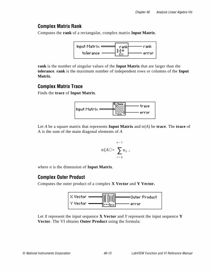
Chapter 46 Analysis Linear Algebra VIs
Complex Matrix RankComputes the rank of a rectangular, complex matrix Input Matrix .
rank is the number of singular values of the Input Matrix that are larger than the tolerance. rank is the maximum number of independent rows or columns of the Input Matrix .
Complex Matrix TraceFinds the trace of Input Matrix .
Let A be a square matrix that represents Input Matrix and tr(A) be trace. The trace of A is the sum of the main diagonal elements of A
,
where n is the dimension of Input Matrix .
Complex Outer Product Computes the outer product of a complex X Vector and Y Vector.
Let X represent the input sequence X Vector and Y represent the input sequence Y Vector. The VI obtains Outer Product using the formula:
tr A( ) aii
i 0=
n 1–
∑=
© National Instruments Corporation 46-13 LabVIEW Function and VI Reference Manual

Chapter 46 Analysis Linear Algebra VIs
e
the
lex
tions
aij = xi yj, for ,
where A represents the 2D output sequence Outer Product, n is the number of elementsin the input sequence X Vector, and m is the number of elements in the input sequencY Vector.
Complex PseudoInverse Matrix Finds the PseudoInverse Matrix of a rectangular, complex matrix Input Matrix .
An SVD algorithm computes PseudoInverse Matrix A+, and treats any singular values less than the tolerance as zeros. For a definition of the PseudoInverse of a matrix, seeSolving Linear Equations and Matrix Inverses section at the beginning of this chapter.
If Input matrix A is square and not singular, A+ is the same as A–1, but using the Complex Inverse Matrix VI to compute A–1 is more efficient than using this VI.
Complex QR Factorization Performs QR factorization for a complex matrix A.
QR factorization is also called orthogonal-triangular factorization. It factors a compmatrix A into two matrices; one is an orthogonal matrix Q, the other is an upper triangularmatrix R, so that A = QR. This VI provides three methods for the factorization: Householder, Givens, and Fast Givens.
You can use QR factorization to solve linear systems that contain less or more equathan unknowns.
i 0 1 2 ... n 1–, , , ,=
j 0 1 2 ... m 1–, , , ,=
LabVIEW Function and VI Reference Manual 46-14 © National Instruments Corporation
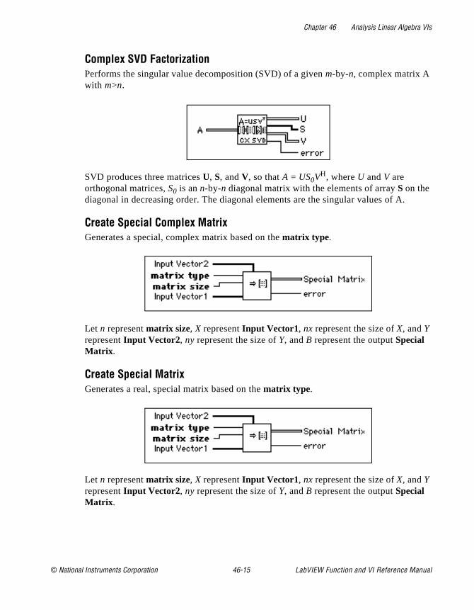
Chapter 46 Analysis Linear Algebra VIs
Complex SVD Factorization Performs the singular value decomposition (SVD) of a given m-by-n, complex matrix A with m>n.
SVD produces three matrices U, S, and V, so that A = US0VH, where U and V are orthogonal matrices, S0 is an n-by-n diagonal matrix with the elements of array S on the diagonal in decreasing order. The diagonal elements are the singular values of A.
Create Special Complex Matrix Generates a special, complex matrix based on the matrix type.
Let n represent matrix size, X represent Input Vector1, nx represent the size of X, and Y represent Input Vector2, ny represent the size of Y, and B represent the output Special Matrix .
Create Special MatrixGenerates a real, special matrix based on the matrix type.
Let n represent matrix size, X represent Input Vector1, nx represent the size of X, and Y represent Input Vector2, ny represent the size of Y, and B represent the output Special Matrix .
© National Instruments Corporation 46-15 LabVIEW Function and VI Reference Manual
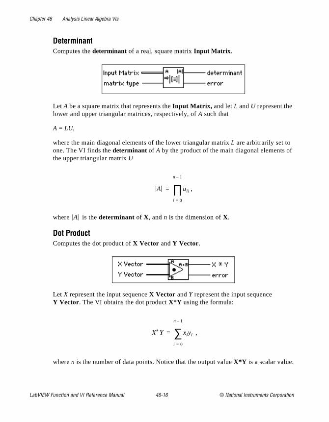
Chapter 46 Analysis Linear Algebra VIs
f
DeterminantComputes the determinant of a real, square matrix Input Matrix .
Let A be a square matrix that represents the Input Matrix, and let L and U represent the lower and upper triangular matrices, respectively, of A such that
A = LU,
where the main diagonal elements of the lower triangular matrix L are arbitrarily set to one. The VI finds the determinant of A by the product of the main diagonal elements othe upper triangular matrix U
,
where is the determinant of X, and n is the dimension of X.
Dot ProductComputes the dot product of X Vector and Y Vector.
Let X represent the input sequence X Vector and Y represent the input sequence Y Vector. The VI obtains the dot product X*Y using the formula:
,
where n is the number of data points. Notice that the output value X*Y is a scalar value.
A uii
i 0=
n 1–
∏=
A
X∗Y xiyi
i 0=
n 1–
∑=
LabVIEW Function and VI Reference Manual 46-16 © National Instruments Corporation
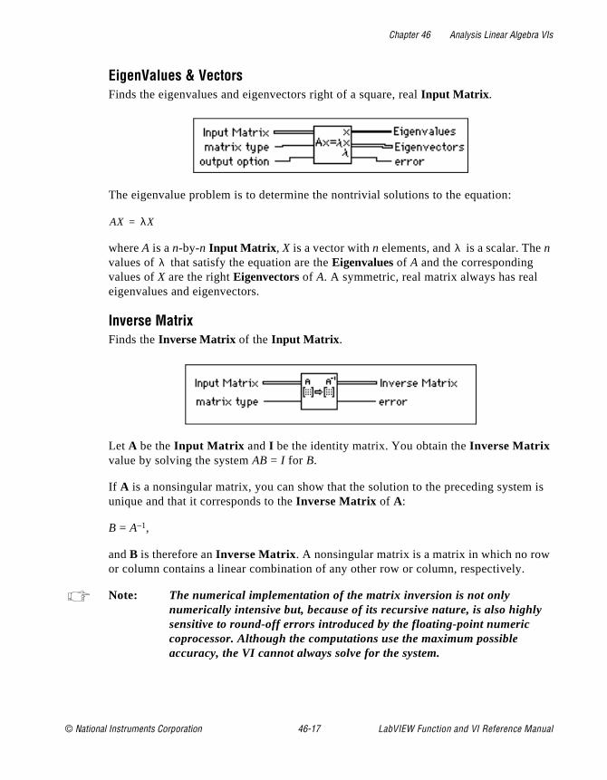
Chapter 46 Analysis Linear Algebra VIs
is
EigenValues & VectorsFinds the eigenvalues and eigenvectors right of a square, real Input Matrix .
The eigenvalue problem is to determine the nontrivial solutions to the equation:
where A is a n-by-n Input Matrix , X is a vector with n elements, and is a scalar. The n values of that satisfy the equation are the Eigenvalues of A and the corresponding values of X are the right Eigenvectors of A. A symmetric, real matrix always has real eigenvalues and eigenvectors.
Inverse MatrixFinds the Inverse Matrix of the Input Matrix .
Let A be the Input Matrix and I be the identity matrix. You obtain the Inverse Matrix value by solving the system AB = I for B.
If A is a nonsingular matrix, you can show that the solution to the preceding systemunique and that it corresponds to the Inverse Matrix of A:
B = A–1,
and B is therefore an Inverse Matrix . A nonsingular matrix is a matrix in which no rowor column contains a linear combination of any other row or column, respectively.
Note: The numerical implementation of the matrix inversion is not only numerically intensive but, because of its recursive nature, is also highlysensitive to round-off errors introduced by the floating-point numeric coprocessor. Although the computations use the maximum possible accuracy, the VI cannot always solve for the system.
AX λX=
λλ
© National Instruments Corporation 46-17 LabVIEW Function and VI Reference Manual
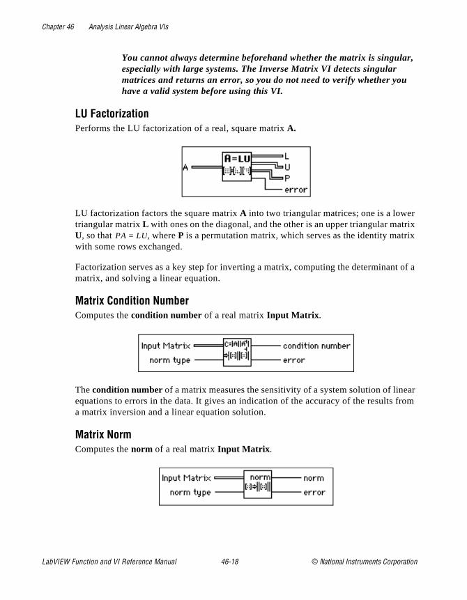
Chapter 46 Analysis Linear Algebra VIs
,
r trix ix
t of a
ar from
You cannot always determine beforehand whether the matrix is singularespecially with large systems. The Inverse Matrix VI detects singular matrices and returns an error, so you do not need to verify whether youhave a valid system before using this VI.
LU FactorizationPerforms the LU factorization of a real, square matrix A.
LU factorization factors the square matrix A into two triangular matrices; one is a lowetriangular matrix L with ones on the diagonal, and the other is an upper triangular maU, so that , where P is a permutation matrix, which serves as the identity matrwith some rows exchanged.
Factorization serves as a key step for inverting a matrix, computing the determinanmatrix, and solving a linear equation.
Matrix Condition NumberComputes the condition number of a real matrix Input Matrix .
The condition number of a matrix measures the sensitivity of a system solution of lineequations to errors in the data. It gives an indication of the accuracy of the results a matrix inversion and a linear equation solution.
Matrix NormComputes the norm of a real matrix Input Matrix .
PA LU=
LabVIEW Function and VI Reference Manual 46-18 © National Instruments Corporation
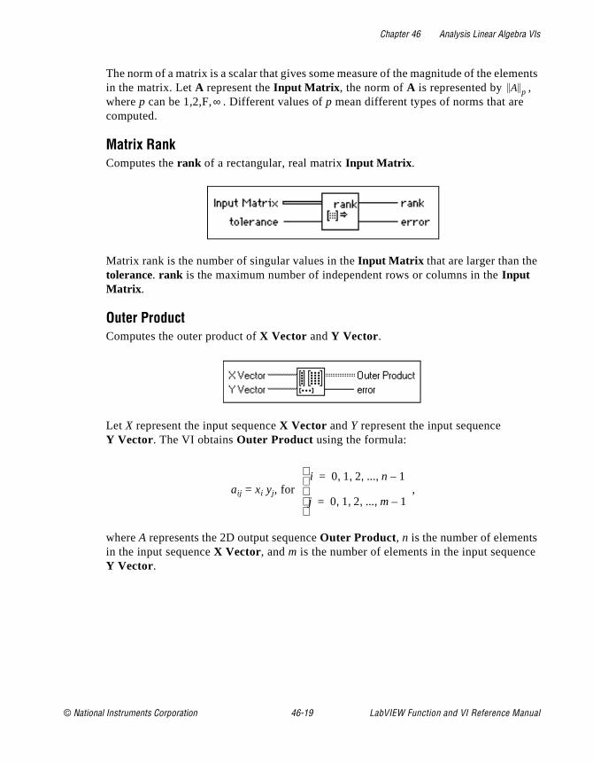
Chapter 46 Analysis Linear Algebra VIs
ments
e
The norm of a matrix is a scalar that gives some measure of the magnitude of the elein the matrix. Let A represent the Input Matrix , the norm of A is represented by , where p can be 1,2,F, . Different values of p mean different types of norms that are computed.
Matrix RankComputes the rank of a rectangular, real matrix Input Matrix .
Matrix rank is the number of singular values in the Input Matrix that are larger than the tolerance. rank is the maximum number of independent rows or columns in the Input Matrix .
Outer ProductComputes the outer product of X Vector and Y Vector.
Let X represent the input sequence X Vector and Y represent the input sequence Y Vector. The VI obtains Outer Product using the formula:
aij = xi yj, for ,
where A represents the 2D output sequence Outer Product, n is the number of elementsin the input sequence X Vector, and m is the number of elements in the input sequencY Vector.
A p∞
i 0 1 2 ... n 1–, , , ,=
j 0 1 2 ... m 1–, , , ,=
© National Instruments Corporation 46-19 LabVIEW Function and VI Reference Manual

Chapter 46 Analysis Linear Algebra VIs
se
trix r
PseudoInverse MatrixFinds the PseudoInverse Matrix of a rectangular, real matrix Input Matrix .
You compute PseudoInverse Matrix A+ by using the SVD algorithm and any singular value less than the tolerance, which are set to zero. For a definition of the PseudoInverof a matrix, see the Solving Linear Equations and Matrix Inverses section at the beginning of this chapter.
If Input matrix A is square and not singular, A+ is the same as A–1, but using the Inverse Matrix VI to compute A–1 is more efficient than using this VI.
Note: This VI is not available with Base packages of LabVIEW.
QR FactorizationPerforms the QR factorization of a real matrix A.
QR factorization is also called orthogonal-triangular factorization. It factors a real maA into two matrices. One is an orthogonal matrix Q, and the other is an upper triangulamatrix R, so that . This VI provides three methods for the factorization: householder, givens, and fast givens.
You can use QR factorization to solve linear systems with more equations than unknowns.
Note: This VI is not available with Base packages of LabVIEW.
Solve Complex Linear Equations Solves a complex, linear system AX=Y.
A QR=
LabVIEW Function and VI Reference Manual 46-20 © National Instruments Corporation
Chapter 46 Analysis Linear Algebra VIs
ined e
ined
f
n you
,
d by
Let A represent the m-by-n Input Matrix , Y represent the set of m elements in the Known Vector, and X represent the set of n elements in the Solution Vector that solves for the system
AX = Y.
When , the system has more equations than unknowns, so it is an overdetermsystem. Since the solution that satisfies AX=Y may not exist, the VI finds the least squarsolution X, which minimizes ||AX–Y||.
When m<n, the system has more unknowns than equations, so it is an underdetermsystem. It might have infinite solutions that satisfy AX=Y. The VI then selects one of these solutions.
When m=n, if A is a nonsingular matrix—no row or column is a linear combination oany other row or column, respectively—then you can solve the system for X by decomposing the Input Matrix A into its lower and upper triangular matrices, L and U, such that
AX = LZ = Y,
and
Z = UX
can be an alternate representation of the original system. Notice that Z is also an n element vector.
Triangular systems are easy to solve using recursive techniques. Consequently, wheobtain the L and U matrices from A, you can find Z from the LZ = Y system and X from the UX = Z system.
When , A can be decomposed to an orthogonal matrix Q, and an upper triangular matrix R, so that A=QR, and the linear system can be represented by QRX=Y. You can then solve RX=QHY.
You can easily solve this triangular system to get X using recursive techniques.
Note: You cannot always determine beforehand whether the matrix is singularespecially with large systems. The Inverse Matrix VI detects singular matrices and returns an error, so you do not need to verify whether youhave a valid system before using this VI.
The numerical implementation of the matrix inversion is numerically intensive and,because of its recursive nature, is also highly sensitive to round-off error introduce
m n>
m n≠
© National Instruments Corporation 46-21 LabVIEW Function and VI Reference Manual
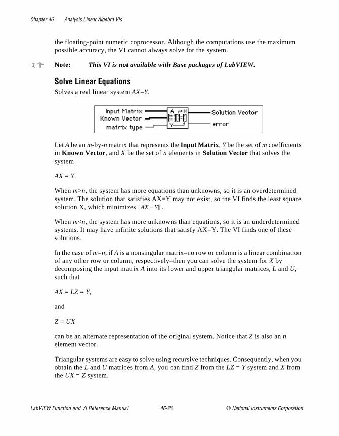
Chapter 46 Analysis Linear Algebra VIs
m
ed uare
ined
n
n you
the floating-point numeric coprocessor. Although the computations use the maximupossible accuracy, the VI cannot always solve for the system.
Note: This VI is not available with Base packages of LabVIEW.
Solve Linear EquationsSolves a real linear system AX=Y.
Let A be an m-by-n matrix that represents the Input Matrix , Y be the set of m coefficients in Known Vector, and X be the set of n elements in Solution Vector that solves the system
AX = Y.
When m>n, the system has more equations than unknowns, so it is an overdeterminsystem. The solution that satisfies AX=Y may not exist, so the VI finds the least sqsolution X, which minimizes .
When m<n, the system has more unknowns than equations, so it is an underdetermsystems. It may have infinite solutions that satisfy AX=Y. The VI finds one of thesesolutions.
In the case of m=n, if A is a nonsingular matrix–no row or column is a linear combinatioof any other row or column, respectively–then you can solve the system for X by decomposing the input matrix A into its lower and upper triangular matrices, L and U, such that
AX = LZ = Y,
and
Z = UX
can be an alternate representation of the original system. Notice that Z is also an n element vector.
Triangular systems are easy to solve using recursive techniques. Consequently, wheobtain the L and U matrices from A, you can find Z from the LZ = Y system and X from the UX = Z system.
AX Y–
LabVIEW Function and VI Reference Manual 46-22 © National Instruments Corporation

Chapter 46 Analysis Linear Algebra VIs
,
d by m
In the case of , A can be decomposed to an orthogonal matrix Q and an upper triangular matrix R, so that A=QR. The linear system can then be represented by QRX=Y. You can then solve RX=QTY.
You can easily solve this triangular system to get x using recursive techniques.
Note: You cannot always determine beforehand whether the matrix is singularespecially with large systems. The Inverse Matrix VI detects singular matrices and returns an error, so you do not need to verify whether youhave a valid system before using this VI.
The numerical implementation of the matrix inversion is numerically intensive and,because of its recursive nature, is also highly sensitive to round-off error introducethe floating-point numeric coprocessor. Although the computations use the maximupossible accuracy, the VI cannot always solve the system.
SVD FactorizationPerforms the singular value decomposition (SVD) of a given m-by-n real matrix A, with m>n.
SVD produces three matrices U,S0, and V so that A = US0VT, where U and VT are orthogonal matrices, S0 is an n-by-n diagonal matrix with the elements of array S on the diagonal in decreasing order.
Test Complex Positive Definite Tests whether the Input Matrix is a Positive Definite matrix.
m n≠
© National Instruments Corporation 46-23 LabVIEW Function and VI Reference Manual
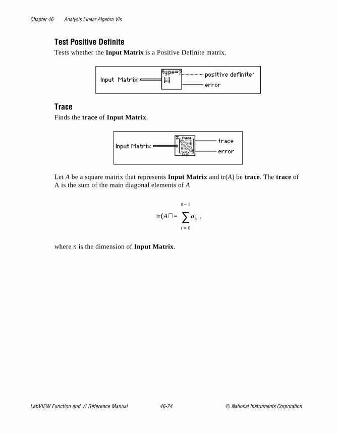
Chapter 46 Analysis Linear Algebra VIs
Test Positive DefiniteTests whether the Input Matrix is a Positive Definite matrix.
TraceFinds the trace of Input Matrix .
Let A be a square matrix that represents Input Matrix and tr(A) be trace. The trace of A is the sum of the main diagonal elements of A
,
where n is the dimension of Input Matrix .
tr A( ) aii
i 0=
n 1–
∑=
LabVIEW Function and VI Reference Manual 46-24 © National Instruments Corporation

© National Instruments Corporation 47-1 LabVIEW Function and
Chapter
47
Analysis Array Operation VIsThis chapter describes the VIs that perform common, one- and two-dimensional numerical array operations.
The following illustration shows the Array Operations palette, which you access by selecting Functions»Analysis»Array Operations.
Array Operation VI Descriptions
The following Array Operation VIs are available.
VI Reference Manual
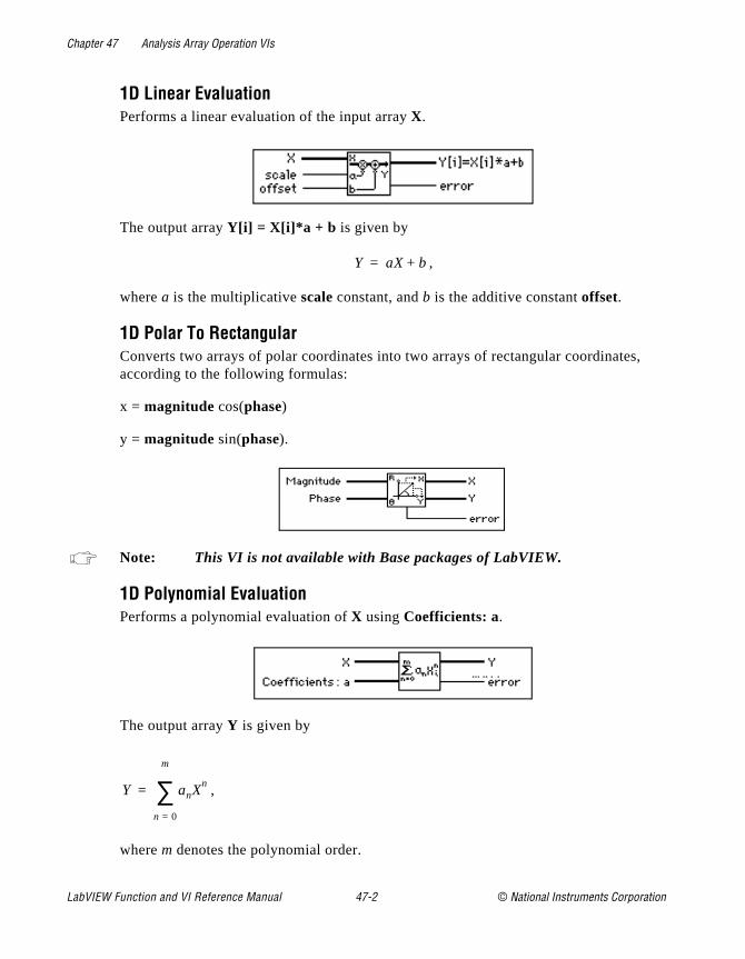
Chapter 47 Analysis Array Operation VIs
,
1D Linear EvaluationPerforms a linear evaluation of the input array X.
The output array Y[i] = X[i]*a + b is given by
,
where a is the multiplicative scale constant, and b is the additive constant offset.
1D Polar To RectangularConverts two arrays of polar coordinates into two arrays of rectangular coordinatesaccording to the following formulas:
x = magnitude cos(phase)
y = magnitude sin(phase).
Note: This VI is not available with Base packages of LabVIEW.
1D Polynomial EvaluationPerforms a polynomial evaluation of X using Coefficients: a.
The output array Y is given by
,
where m denotes the polynomial order.
Y aX b+=
Y anXn
n 0=
m
∑=
LabVIEW Function and VI Reference Manual 47-2 © National Instruments Corporation
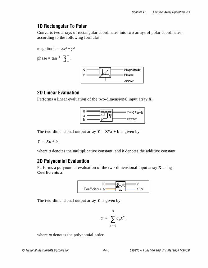
Chapter 47 Analysis Array Operation VIs
,
1D Rectangular To PolarConverts two arrays of rectangular coordinates into two arrays of polar coordinatesaccording to the following formulas:
magnitude =
phase = tan–1 .
2D Linear EvaluationPerforms a linear evaluation of the two-dimensional input array X.
The two-dimensional output array Y = X*a + b is given by
,
where a denotes the multiplicative constant, and b denotes the additive constant.
2D Polynomial EvaluationPerforms a polynomial evaluation of the two-dimensional input array X using Coefficients a.
The two-dimensional output array Y is given by
,
where m denotes the polynomial order.
x2 y2+
yx--
Y Xa b+=
Y anXn
n 0=
m
∑=
© National Instruments Corporation 47-3 LabVIEW Function and VI Reference Manual
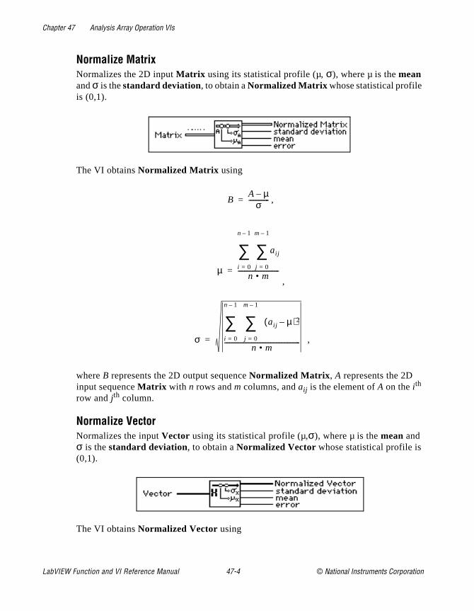
Chapter 47 Analysis Array Operation VIs
Normalize MatrixNormalizes the 2D input Matrix using its statistical profile (µ, σ), where µ is the mean and σ is the standard deviation, to obtain a Normalized Matrix whose statistical profile is (0,1).
The VI obtains Normalized Matrix using
,
,
,
where B represents the 2D output sequence Normalized Matrix , A represents the 2D input sequence Matrix with n rows and m columns, and aij is the element of A on the i th row and j th column.
Normalize VectorNormalizes the input Vector using its statistical profile (µ,σ), where µ is the mean and σ is the standard deviation, to obtain a Normalized Vector whose statistical profile is (0,1).
The VI obtains Normalized Vector using
BA µ–
σ-------------=
µ
aij
j 0=
m 1–
∑i 0=
n 1–
∑n • m
--------------------------=
σ j 0=
m 1–
∑ aij µ–( )2
i 0=
n 1–
∑n • m
------------------------------------------------=
LabVIEW Function and VI Reference Manual 47-4 © National Instruments Corporation
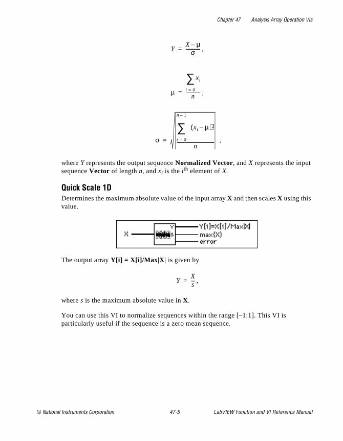
Chapter 47 Analysis Array Operation VIs
,
,
,
where Y represents the output sequence Normalized Vector, and X represents the input sequence Vector of length n, and xi is the i th element of X.
Quick Scale 1DDetermines the maximum absolute value of the input array X and then scales X using this value.
The output array Y[i] = X[i]/Max|X| is given by
,
where s is the maximum absolute value in X.
You can use this VI to normalize sequences within the range [–1:1]. This VI is particularly useful if the sequence is a zero mean sequence.
YX µ–
σ-------------=
µ
xi
i 0=
∑n
-------------=
σ i 0=
n 1–
∑ xi µ–( )2
n---------------------------------=
YXs---=
© National Instruments Corporation 47-5 LabVIEW Function and VI Reference Manual
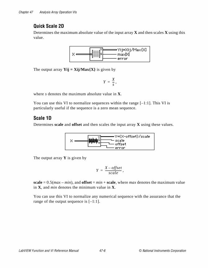
Chapter 47 Analysis Array Operation VIs
the
Quick Scale 2DDetermines the maximum absolute value of the input array X and then scales X using this value.
The output array Yij = Xij/MaxX is given by
,
where s denotes the maximum absolute value in X.
You can use this VI to normalize sequences within the range [–1:1]. This VI is particularly useful if the sequence is a zero mean sequence.
Scale 1DDetermines scale and offset and then scales the input array X using these values.
The output array Y is given by
,
scale = 0.5(max – min), and offset = min + scale, where max denotes the maximum valuein X, and min denotes the minimum value in X.
You can use this VI to normalize any numerical sequence with the assurance that range of the output sequence is [–1:1].
YXs---=
YX offset–
scale------------------------=
LabVIEW Function and VI Reference Manual 47-6 © National Instruments Corporation
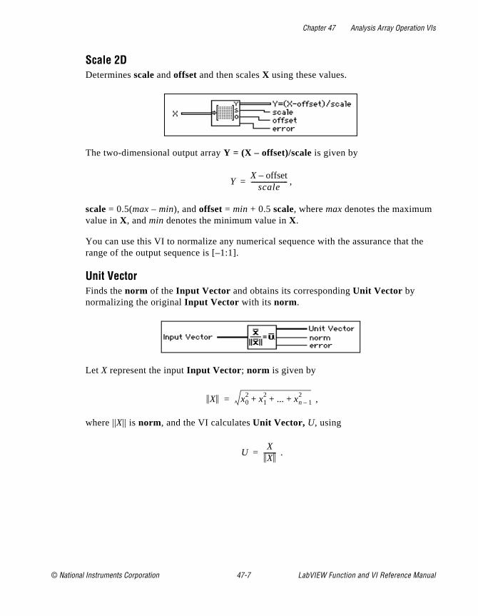
Chapter 47 Analysis Array Operation VIs
the
Scale 2DDetermines scale and offset and then scales X using these values.
The two-dimensional output array Y = (X – offset)/scale is given by
,
scale = 0.5(max – min), and offset = min + 0.5 scale, where max denotes the maximum value in X, and min denotes the minimum value in X.
You can use this VI to normalize any numerical sequence with the assurance that range of the output sequence is [–1:1].
Unit VectorFinds the norm of the Input Vector and obtains its corresponding Unit Vector by normalizing the original Input Vector with its norm.
Let X represent the input Input Vector ; norm is given by
,
where ||X|| is norm, and the VI calculates Unit Vector, U, using
.
YX offset–
scale-----------------------=
X x02 x1
2 ... xn 1–2+ + +=
UXX
--------=
© National Instruments Corporation 47-7 LabVIEW Function and VI Reference Manual
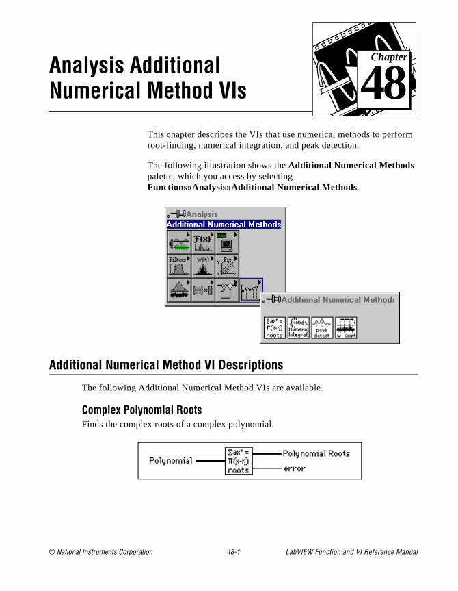
© National Instruments Corporation 48-1 LabVIEW Function and
Chapter
48
Analysis Additional Numerical Method VIsrm
This chapter describes the VIs that use numerical methods to perforoot-finding, numerical integration, and peak detection.The following illustration shows the Additional Numerical Methods palette, which you access by selecting Functions»Analysis»Additional Numerical Methods.
Additional Numerical Method VI Descriptions
The following Additional Numerical Method VIs are available.
Complex Polynomial RootsFinds the complex roots of a complex polynomial.
VI Reference Manual
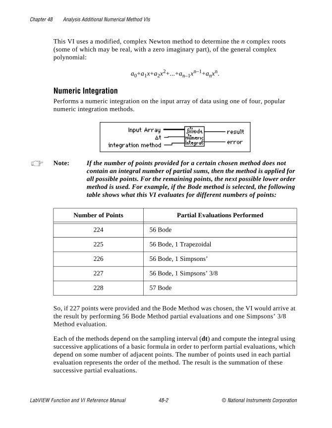
Chapter 48 Analysis Additional Numerical Method VIs
r
r er ng
ve at 8
hich rtial e
This VI uses a modified, complex Newton method to determine the n complex roots (some of which may be real, with a zero imaginary part), of the general complex polynomial:
a0+a1x+a2x2+...+an–1xn–1+anxn.
Numeric IntegrationPerforms a numeric integration on the input array of data using one of four, populanumeric integration methods.
Note: If the number of points provided for a certain chosen method does not contain an integral number of partial sums, then the method is applied foall possible points. For the remaining points, the next possible lower ordmethod is used. For example, if the Bode method is selected, the followitable shows what this VI evaluates for different numbers of points:
So, if 227 points were provided and the Bode Method was chosen, the VI would arrithe result by performing 56 Bode Method partial evaluations and one Simpsons’ 3/Method evaluation.
Each of the methods depend on the sampling interval (dt) and compute the integral usingsuccessive applications of a basic formula in order to perform partial evaluations, wdepend on some number of adjacent points. The number of points used in each paevaluation represents the order of the method. The result is the summation of thessuccessive partial evaluations.
Number of Points Partial Evaluations Performed
224 56 Bode
225 56 Bode, 1 Trapezoidal
226 56 Bode, 1 Simpsons’
227 56 Bode, 1 Simpsons’ 3/8
228 57 Bode
LabVIEW Function and VI Reference Manual 48-2 © National Instruments Corporation
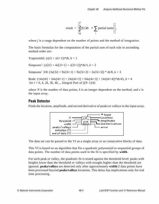
Chapter 48 Analysis Additional Numerical Method VIs
n.
rray.
data.
s of
with re
l
,
where j is a range dependent on the number of points and the method of integratio
The basic formulas for the computation of the partial sum of each rule in ascendingmethod order are:
Trapezoidal: (x[ i] + x[ i+1])*dt, k = 1
Simpsons’: (x[2i] + 4x[2i+1] + x[2i+2])*dt/3, k = 2
Simpsons’ 3/8: (3x[3i] + 9x[3i+1] + 9x[3i+2] + 3x[3i+3]) * dt/8, k = 3
Bode: (14x[4i] + 64x[4i+1] + 24x[4i+2] + 64x[4i+3] + 14x[4i+4])*dt/45, k = 4 for i = 0, k, 2k, 3k, 4k..., Integral Part of [(N–1)/k]
where N is the number of data points, k is an integer dependent on the method, and x is the input array.
Peak DetectorFinds the location, amplitude, and second derivative of peaks or valleys in the input a
The data set can be passed to the VI as a single array or as consecutive blocks of
This VI is based on an algorithm that fits a quadratic polynomial to sequential groupdata points. The number of data points used in the fit is specified by width .
For each peak or valley, the quadratic fit is tested against the threshold level: peaksheights lower than the threshold or valleys with troughs higher than the threshold aignored. peaks/valleys are detected only after approximately width /2 data points have been processed beyond peaks/valleys locations. This delay has implications only for reatime processing.
result f t( )dt
t0
t1
∫ partial sums
j
∑≈
=
© National Instruments Corporation 48-3 LabVIEW Function and VI Reference Manual
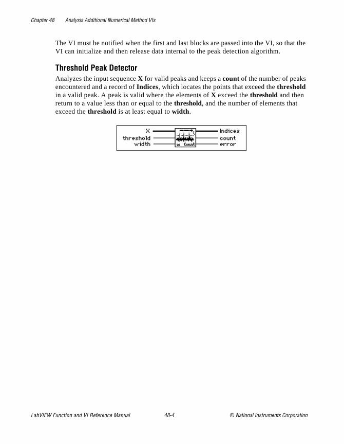
Chapter 48 Analysis Additional Numerical Method VIs
t the
The VI must be notified when the first and last blocks are passed into the VI, so thaVI can initialize and then release data internal to the peak detection algorithm.Threshold Peak DetectorAnalyzes the input sequence X for valid peaks and keeps a count of the number of peaks encountered and a record of Indices, which locates the points that exceed the threshold in a valid peak. A peak is valid where the elements of X exceed the threshold and then return to a value less than or equal to the threshold, and the number of elements that exceed the threshold is at least equal to width .
LabVIEW Function and VI Reference Manual 48-4 © National Instruments Corporation
© National Instruments Corporation 49-1 LabVIEW Function and
Chapter
49
Introduction to LabVIEW Communication VIs and Functionsn
ar
This chapter introduces the way LabVIEW handles networking andinterapplication communications, and introduces the Communicatiofunctions and VIs, descriptions of which comprise Chapter 50 to Chapter 55.
You can find the Communication VIs in the Functions palette from your block diagram in LabVIEW. The Communication VIs are located nethe middle of the Functions palette.
VI Reference Manual

Chapter 49 Introduction to LabVIEW Communication VIs and Functions
To access the Communications palette, select Functions»Communications, as shown in the following illustration.
The Communications palette consists of the following subpalettes:
• TCP
• UDP
• DDE (Windows only)
• OLE (Windows only)
• HiQ
If you have LabVIEW for the Macintosh, the following additional subpalettes are available:
• Apple Event
• Program to Program Communications
LabVIEW Function and VI Reference Manual 49-2 © National Instruments Corporation
Chapter 49 Introduction to LabVIEW Communication VIs and Functions
or r trol
e
or
her
y an
t use
If you have a computer running a UNIX operating system and LabVIEW, the following additional subpalette is available:
• Named Pipes
LabVIEW for Windows and LabVIEW for UNIX also include the System Exec VI.
You can find information about these LabVIEW features online by using the LabVIEW Help window (Help»Show Help). When you place the cursor on a VI icon, the wiring diagram and parameter names fthat VI appear in the Help window. You can also find information fofront panel controls or indicators by placing the cursor over the conor indicator with the Help window open.
In addition to the Help window, LabVIEW has more extensive onlininformation available. To access this information, select Help»Online Reference. For most block diagram objects, you can select Online Reference from the object’s pop-up menu to access the online description.
LabVIEW Communication VIs and Functions OverviewFor the purpose of this discussion, networking refers to communication between multiple processes. The processes can optionally run on separate computers. This communication usually occurs over a hardware network, such as ethernet or LocalTalk.
One main use for networking in software applications is to allow onemore applications to use the services of another application. For example, the application providing services (the server) could be eita data collection application running on a dedicated computer, or adatabase program providing information for other applications.
The purpose of this discussion is to introduce you to the terminologused in networking and communication applications, and to give youoverview of how to program networked applications.
Introduction to Communication ProtocolsFor communication between processes to work, the processes musa common communications language, referred to as a protocol.
© National Instruments Corporation 49-3 LabVIEW Function and VI Reference Manual
Chapter 49 Introduction to LabVIEW Communication VIs and Functions
o ut tes ork
s for
rst
ve
ind
ic
s
s
ta
h d a
e
A communication protocol lets you specify the data that you want tsend or receive and the location of the destination or source, withohaving to worry about how the data gets there. The protocol translayour commands into data that network drivers can accept. The netwdrivers then take care of transferring data across the network as appropriate.
Several networking protocols have emerged as accepted standardcommunications. In general, one protocol is not compatible with a different protocol. Thus, in communication applications, one of the fithings you must do is decide which protocol to use. If you want to communicate with an existing, off the shelf application, then you hato work within the protocols supported by that application.
When you are actually writing the application, you have more flexibility in choosing a protocol. Factors that affect your protocol choice include the type of machines the processes will run on, the kof hardware network you have available, and the complexity of the communication that your application will need.
Several protocols are built into LabVIEW, some of which are specifto a type of computer. LabVIEW uses the following protocols to communicate between computers:
• TCP—Available on all computers
• UDP—Available on all computers
• DDE—Available on the PC, for communication between Windowapplications
• OLE—Available for use with Windows 95 and Windows NT
• AppleEvents—Available on the Macintosh, for sending messagebetween Macintosh applications
• PPC—Available on the Macintosh, for sending and receiving dabetween Macintosh applications
Each protocol is different, especially in the way they refer to the network location of a remote application. They are incompatible witeach other, so if you want to communicate between a Macintosh anPC, you must use a protocol compatible with both, such as TCP.
Other communication options provided by LabVIEW include:
• System Exec VI, which allows you to execute a system level command. There are actually two System Exec VIs, one for uswith all versions of Windows, the other with Sun and HP-UX.
LabVIEW Function and VI Reference Manual 49-4 © National Instruments Corporation
Chapter 49 Introduction to LabVIEW Communication VIs and Functions
d t
nd .
ost
this ote
ns. vices
uter as
ts as
s to nd
• Named Pipes, available on UNIX only
• HiQ®, available on the Macintosh and PC only
File Sharing vs Communication ProtocolsBefore you get too deeply involved in communication protocols, consider whether another approach is more appropriate for your application. For instance, consider an application where a dedicatesystem acquires data and you want the data recorded on a differencomputer.
You could write an application that uses networking protocols to sedata from the acquisition computer to the data repository machine,where a separate application collects the data and stores it on disk
A simpler method is to use the filesharing capabilities available on mnetworked computers. With filesharing, drivers that are part of the operating system let you connect to other machines. The remote machine’s disk storage is treated as an extension of your own diskstorage. Once you connect two systems, filesharing usually makesconnection transparent, so that any application can write to the remdisk as if connected locally.
Filesharing is frequently the simplest method for transferring data between machines.
Client/Server Model The client/server model is a common model for networked applicatioIn the client/server model, one set of processes (clients) request serfrom another set of processes (servers).
For example, in your application you could set up a dedicated compfor acquiring measurements from the real world. The computer actsa server when it provides data to other computers on request. It aca client when it requests another application, such as a database program, to record the data that it acquires.
In LabVIEW, you can use client and server applications with all protocols except Macintosh AppleEvents. You can use AppleEventsend commands to other applications. You cannot set up a comma
© National Instruments Corporation 49-5 LabVIEW Function and VI Reference Manual

Chapter 49 Introduction to LabVIEW Communication VIs and Functions
es
nt
k, and at
the e the
server in LabVIEW using AppleEvents. If you need server capabilition the Macintosh, use either TCP, UDP or PPC.
A General Model for a ClientThe following block diagram shows what a simplified model for a clielooks like in LabVIEW.
In the preceding diagram, LabVIEW first opens a connection to a server. It then sends a command to the server, gets a response baccloses the connection to the server. Finally, it reports any errors thoccurred during the communication process.
For higher performance, you can process multiple commands onceconnection is open. After the commands are executed, you can closconnection.
This basic block diagram structure serves as a model and is used elsewhere in this manual to demonstrate how to implement a givenprotocol in LabVIEW.
LabVIEW Function and VI Reference Manual 49-6 © National Instruments Corporation
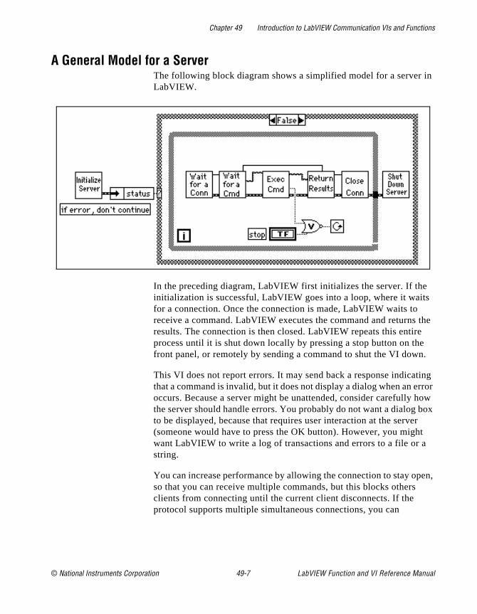
Chapter 49 Introduction to LabVIEW Communication VIs and Functions
in
s
the
e .
ing rror how box r t
en,
A General Model for a ServerThe following block diagram shows a simplified model for a server LabVIEW.
In the preceding diagram, LabVIEW first initializes the server. If theinitialization is successful, LabVIEW goes into a loop, where it waitfor a connection. Once the connection is made, LabVIEW waits to receive a command. LabVIEW executes the command and returnsresults. The connection is then closed. LabVIEW repeats this entireprocess until it is shut down locally by pressing a stop button on thfront panel, or remotely by sending a command to shut the VI down
This VI does not report errors. It may send back a response indicatthat a command is invalid, but it does not display a dialog when an eoccurs. Because a server might be unattended, consider carefully the server should handle errors. You probably do not want a dialog to be displayed, because that requires user interaction at the serve(someone would have to press the OK button). However, you mighwant LabVIEW to write a log of transactions and errors to a file or astring.
You can increase performance by allowing the connection to stay opso that you can receive multiple commands, but this blocks others clients from connecting until the current client disconnects. If the protocol supports multiple simultaneous connections, you can
© National Instruments Corporation 49-7 LabVIEW Function and VI Reference Manual
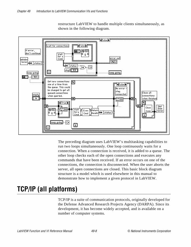
Chapter 49 Introduction to LabVIEW Communication VIs and Functions
The
e the
or its
restructure LabVIEW to handle multiple clients simultaneously, as shown in the following diagram.
The preceding diagram uses LabVIEW’s multitasking capabilities torun two loops simultaneously. One loop continuously waits for a connection. When a connection is received, it is added to a queue.other loop checks each of the open connections and executes any commands that have been received. If an error occurs on one of thconnections, the connection is disconnected. When the user abortsserver, all open connections are closed. This basic block diagram structure is a model which is used elsewhere in this manual to demonstrate how to implement a given protocol in LabVIEW.
TCP/IP (all platforms)TCP/IP is a suite of communication protocols, originally developed fthe Defense Advanced Research Projects Agency (DARPA). Sincedevelopment, it has become widely accepted, and is available on anumber of computer systems.
LabVIEW Function and VI Reference Manual 49-8 © National Instruments Corporation
Chapter 49 Introduction to LabVIEW Communication VIs and Functions
he
the
t
vel
oes you
aks
For ons.
his
ress .
e . For
d to
The name TCP/IP comes from two of the best known protocols of tsuite, the Transmission Control Protocol (TCP) and the Internet Protocol (IP). TCP, IP, and the User Datagram Protocol (UDP) are basic tools for network communication.
TCP/IP enables communication over single networks or multiple interconnected networks, which are known as an internetwork or internet. The individual networks can be separated by great geographical distances. TCP/IP routes data from one network or internet computer to another. Because TCP/IP is available on moscomputers, it can transfer information between diverse systems.
Internet Protocol (IP) transmits data across the network. This low leprotocol takes data of a limited size and sends it as a datagram across the network. IP is rarely used directly by applications, because it dnot guarantee that the data will arrive at the other end. Also, when send several datagrams they sometimes arrive out of order, or aredelivered multiple times, depending on how the network transfer occurs. UDP, which is built on top of IP, has similar problems.
TCP is a higher level protocol that uses IP to transfer data. TCP bredata into components that IP can manage. It also provides error detection and ensures that data arrives in order without duplication.these reasons, TCP is usually the best choice for network applicati
Internet AddressesEach host on an IP network has a unique 32-bit internet address. Taddress identifies the network on the internet to which the host is attached, and the specific computer on that network. You use this address to identify the sender or receiver of data. IP places the addin the datagram headers, so that each datagram is routed correctly
One way of describing this 32-bit address is the IP dotted decimal notation. This divides the 32-bit address into four 8-bit numbers. Thaddress is written as the four integers, separated by decimal pointsexample, the 32-bit address
10000100 00001101 00000010 00011110
is written in dotted decimal notation as
132.13.2.30
Another way of using the 32-bit address is by names that are mappethe IP address. Network drivers usually perform this mapping by
© National Instruments Corporation 49-9 LabVIEW Function and VI Reference Manual

Chapter 49 Introduction to LabVIEW Communication VIs and Functions
or ery ork
is
the .
er. CP
ng tion
e to
f ffer L
consulting a local hosts file that contains name to address mappings, consulting a larger database using the Domain Name System to quother computer systems for the address for a given name. Your netwconfiguration dictates the exact mechanism for this process, whichknown as hostname resolution.
SetupBefore you can use TCP/IP, you need to make sure that you have right setup. This setup varies, depending on the computer you use
Setup for Your System
UNIXTCP/IP support is built-in. Assuming your network is configured properly, no additional setup for LabVIEW is necessary.
MacintoshTCP/IP is built in to Macintosh operating system version 7.5 and latTo use TCP/IP with an earlier system, you need to install the MacTdriver software, available from the Apple Programmer Developer Association (APDA). You can contact APDA at (800) 282-2732 for information on licensing the MacTCP driver. LabVIEW also works with Open Transport.
Windows 3.xTo use TCP/IP, you must install an ethernet board along with its low-level driver. In addition, you must purchase and install TCP/IP software that includes a Windows Sockets (WinSock) DLL conformito standard 1.1. WinSock is a standard interface that enables applicacommunication with a variety of network drivers. Several vendors provide network software that includes the WinSock DLL. Install thethernet board, the board drivers, and the WinSock DLL accordingthe software vendor instructions.
Several vendors supply WinSock drivers that work with a number oboards. You can contact the vendor of your board to inquire if they oa WinSock DLL you can use with the board. Install the WinSock DLaccording to vendor instructions.
LabVIEW Function and VI Reference Manual 49-10 © National Instruments Corporation

Chapter 49 Introduction to LabVIEW Communication VIs and Functions
fy lly f a o
lable
to
se a col n of
the ol.
You
port the . the
National Instruments has tested a number of WinSock DLLs to veriwhich work correctly. These tests showed that many DLLs do not fucomply with the standard, so you may want to try a demo version oDLL before you buy the real version. You can usually obtain a demversion from the manufacturer. Most demo versions are fully functional, but they expire after a certain amount of time.
If you have access to the internet, several of these demos are avaiby anonymous ftp from sunsite.unc.edu . in the directory /pub/micro/pc-stuff/ms-windows/winsock/packages . Refer to your LabVIEW Release Notes for a detailed list of WinSock DLLs tested by National Instruments.
Windows 95 and Windows NTTCP support is built-in to Windows NT. You do not need to use a third-party DLL to communicate using TCP.
LabVIEW and TCP/IPYou can use the TCP/IP suite of protocols with LabVIEW on all platforms. LabVIEW has a set of TCP and UDP VIs that you can usecreate client or server VIs.
TCP versus UDPIf you are writing both the client and server, and your system can uTCP/IP, then TCP is probably the best protocol to use because it isreliable, connection-based protocol. UDP is a connectionless protowith higher performance, but it does not ensure reliable transmissiodata.
TCP Client ExampleThe following discussion is a generalized description of how to use components of the Client block diagram model with the TCP protoc
Use the TCP Open Connection VI to open a connection to a server. must specify the internet address of the server, as well as the port for the server. The address identifies a computer on the network. The is an additional number that identifies a communication channel on computer that the server uses to listen for communication requestsWhen you create a TCP server, you specify the port that you want server to use for communication.
© National Instruments Corporation 49-11 LabVIEW Function and VI Reference Manual
Chapter 49 Introduction to LabVIEW Communication VIs and Functions
the k
e use
e vary.
ized
that he d by
is
ll
rver.
ver. uld
if he
hut
ch
To execute a command on the server, use the TCP Write VI to sendcommand to the server. You then use the TCP Read VI to read bacresults from the server. With the TCP Read VI, you must specify thnumber of characters you want to read. This can be awkward, becathe length of the response may vary. The server can have the samproblem with the command, because the length of a command can
The following are several methods you can use to address varying scommands:
• Precede the command and the result with a fixed size parameterspecifies the size of the command or result. In this case, read tsize parameter, and then read the number of characters specifiethe size. This option is efficient and flexible.
• Make each command and result a fixed size. When a commandsmaller than the size, you can pad it out to the fixed size.
• Follow each command and result with a specific terminating character. To read the data, you then need to read data in smachunks until you get the terminating character.
Use the TCP Close Connection VI to close the connection to the se
Timeouts and ErrorsThe preceding section discussed communication protocol for the serWhen you design a network application consider carefully what shohappen if something fails. For example, if the server crashes, how would each of the client VIs handle it?
One solution is to make sure that each VI has a timeout. This way,something fails to produce results, after a certain amount of time, tclient will continue execution. In continuing, the client can try to reestablish execution, or it can report the error, and if necessary, sthe client application down gracefully.
TCP Server ExampleThe following discussion explains how you can use TCP to fulfill eacomponent of the general server model.
No initialization is necessary with TCP, so this step can be left out.
LabVIEW Function and VI Reference Manual 49-12 © National Instruments Corporation

Chapter 49 Introduction to LabVIEW Communication VIs and Functions
e e e
the irst the
it is next
ent
fter
s f a
ion
One t of
Use the TCP Listen VI to wait for a connection. You must specify thport that will be used for communication. This port must be the samport that the client will attempt to connect. For more information, sethe TCP Client Example section in this chapter.
If a connection is established, read from that port to retrieve a command. As discussed in the TCP Client example, you must decideformat for commands. If commands are preceded by a length field, fread the length field, and then read the amount of data indicated bylength field.
Execution of a command should be protocol independent, becausedone on the local computer. When finished, pass the results to the stage, where they are transmitted to the client.
Use the TCP Write VI to return results. As discussed in the TCP Cliexample, the data must be in a form that the client can accept.
Use the TCP Close Connection VI to close the connection.
This step can be left out with TCP, because everything is finished ayou close the connection.
TCP Server with Multiple ConnectionsTCP handles multiple connections easily. You can use the methoddescribed in the preceding section to implement the components oserver with multiple connections.
DDE (Windows Only)Dynamic Data Exchange (DDE) is a protocol for exchanging data between Windows applications.
In TCP/IP communications, applications open a line of communicatand then transfer raw data. DDE works at a higher level, where applications send messages to each other to exchange information.simple message is to send a command to another application. Mosthe other messages deal with transferring data, where the data is referenced by name.
© National Instruments Corporation 49-13 LabVIEW Function and VI Reference Manual
Chapter 49 Introduction to LabVIEW Communication VIs and Functions
E tion, t the
The ient est e the p ise
elf
ns).
the
and not
of
nd se
ork t
A DDE client initiates a conversation with another application (a DDserver) by sending a connect message. After establishing a connecthe client can send commands to the server and change or requesvalue of data that the server manages.
A client can request data from a server by a request or an advise. client uses a request to ask for the current value of the data. If a clwants to monitor a value over a period of time, the client must requto be advised of changes. By asking to be advised of data value, thclient establishes a link between the client and server through whichserver notifies the client when the data changes. The client can stomonitoring the value of the data by telling the server to stop the advlink.
When the DDE communication for a conversation is complete, the client sends a close conversation message to the server.
DDE is most appropriate for communication with standard off the shapplications such as Microsoft Excel.
With LabVIEW you can create VIs that act as clients to other applications (meaning they request or send data to other applicatioYou can also create VIs that act as servers that provide named information for access by other applications. As a server, LabVIEWdoes not use connection-based communication. Instead, you provide named information to other applications, which can then read or setvalues of that information by name.
Services, Topics, and Data ItemsWith TCP/IP, you identify the process you want to talk to by its computer address and a port number. With DDE, you identify the application you want to talk to by referencing the name of a service a topic. The server decides on arbitrary service and topic names. Agiven server generally uses its application name for the service, butnecessarily. That server can offer several topics that it is willing to communicate. With Excel, for example, the topic might be the namea spreadsheet.
To communicate with a server, first find the names of the service atopic that you want to discuss. Then open a conversation using thetwo names to identify the server.
Unless you are going to send a command to the server, you usually wwith data items that the server is willing to talk about. You can trea
LabVIEW Function and VI Reference Manual 49-14 © National Instruments Corporation
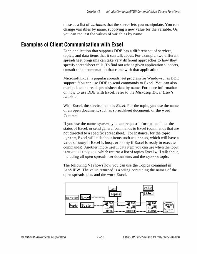
Chapter 49 Introduction to LabVIEW Communication VIs and Functions
n Or,
ent hey rts,
DE lso tion
t are
opic ,
e
these as a list of variables that the server lets you manipulate. You cachange variables by name, supplying a new value for the variable. you can request the values of variables by name.
Examples of Client Communication with ExcelEach application that supports DDE has a different set of services,topics, and data items that it can talk about. For example, two differspreadsheet programs can take very different approaches to how tspecify spreadsheet cells. To find out what a given application suppoconsult the documentation that came with that application.
Microsoft Excel, a popular spreadsheet program for Windows, has Dsupport. You can use DDE to send commands to Excel. You can amanipulate and read spreadsheet data by name. For more informaon how to use DDE with Excel, refer to the Microsoft Excel User’s Guide 2.
With Excel, the service name is Excel. For the topic, you use the nameof an open document, such as spreadsheet document, or the wordSystem .
If you use the name System , you can request information about the status of Excel, or send general commands to Excel (commands thanot directed to a specific spreadsheet). For instance, for the topic System , Excel will talk about items such as Status , which will have a value of Busy if Excel is busy, or Ready if Excel is ready to execute commands). Another, more useful data item you can use when the tis Status is Topics , which returns a list of topics Excel will talk aboutincluding all open spreadsheet documents and the System topic.
The following VI shows how you can use the Topics command in LabVIEW. The value returned is a string containing the names of thopen spreadsheets and the work Excel.
© National Instruments Corporation 49-15 LabVIEW Function and VI Reference Manual

Chapter 49 Introduction to LabVIEW Communication VIs and Functions
pen
ge of ing n
s the
e
an
tion
Another way you can use the System topic with Excel is to instructExcel to open a specific document. To do this, you use the DDE Execute.vi to send an Excel Macro to Excel that instructs Excel to othe document, as shown in the following LabVIEW diagram.
After you open a spreadsheet file, you can send commands to the spreadsheet to read cell values. In this case, your topic is the spreadsheet document name. The item is the name of a cell, a rancells, or a named section of a spreadsheet. For example, in the followdiagram LabVIEW can retrieve the value in the cell at row one columone. It then acquires a sample from the specified channel, and sendresulting sample back to Excel.
LabVIEW VIs as DDE ServersYou can create LabVIEW VIs that act as servers for data items. Thgeneral concept is that a LabVIEW VI indicates that it is willing to provide information regarding a specific service in topic. LabVIEW cuse any name for the service and topic name. It might specify the service name to be the name of the application (LabVIEW), and the topic name to be either the name of the Server VI, or a general classificafor the data it provides, such as Lab Data .
LabVIEW Function and VI Reference Manual 49-16 © National Instruments Corporation
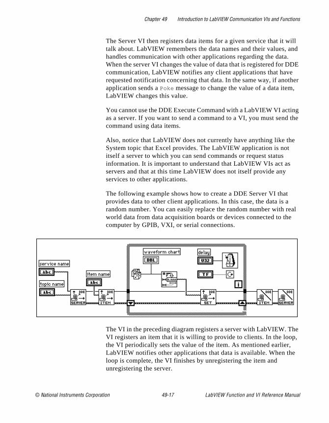
Chapter 49 Introduction to LabVIEW Communication VIs and Functions
ill and DE
ther ,
ng the
eal e
he , e
The Server VI then registers data items for a given service that it wtalk about. LabVIEW remembers the data names and their values, handles communication with other applications regarding the data.When the server VI changes the value of data that is registered for Dcommunication, LabVIEW notifies any client applications that haverequested notification concerning that data. In the same way, if anoapplication sends a Poke message to change the value of a data itemLabVIEW changes this value.
You cannot use the DDE Execute Command with a LabVIEW VI actias a server. If you want to send a command to a VI, you must sendcommand using data items.
Also, notice that LabVIEW does not currently have anything like theSystem topic that Excel provides. The LabVIEW application is not itself a server to which you can send commands or request status information. It is important to understand that LabVIEW VIs act as servers and that at this time LabVIEW does not itself provide any services to other applications.
The following example shows how to create a DDE Server VI that provides data to other client applications. In this case, the data is arandom number. You can easily replace the random number with rworld data from data acquisition boards or devices connected to thcomputer by GPIB, VXI, or serial connections.
The VI in the preceding diagram registers a server with LabVIEW. TVI registers an item that it is willing to provide to clients. In the loopthe VI periodically sets the value of the item. As mentioned earlier,LabVIEW notifies other applications that data is available. When thloop is complete, the VI finishes by unregistering the item and unregistering the server.
© National Instruments Corporation 49-17 LabVIEW Function and VI Reference Manual
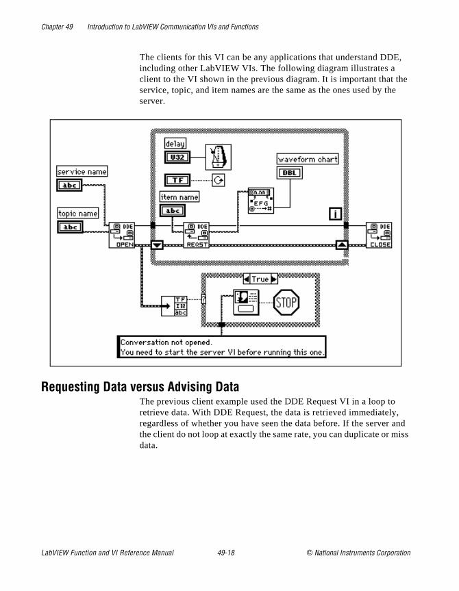
Chapter 49 Introduction to LabVIEW Communication VIs and Functions
,
he he
, and
iss
The clients for this VI can be any applications that understand DDEincluding other LabVIEW VIs. The following diagram illustrates a client to the VI shown in the previous diagram. It is important that tservice, topic, and item names are the same as the ones used by tserver.
Requesting Data versus Advising DataThe previous client example used the DDE Request VI in a loop toretrieve data. With DDE Request, the data is retrieved immediatelyregardless of whether you have seen the data before. If the serverthe client do not loop at exactly the same rate, you can duplicate or mdata.
LabVIEW Function and VI Reference Manual 49-18 © National Instruments Corporation
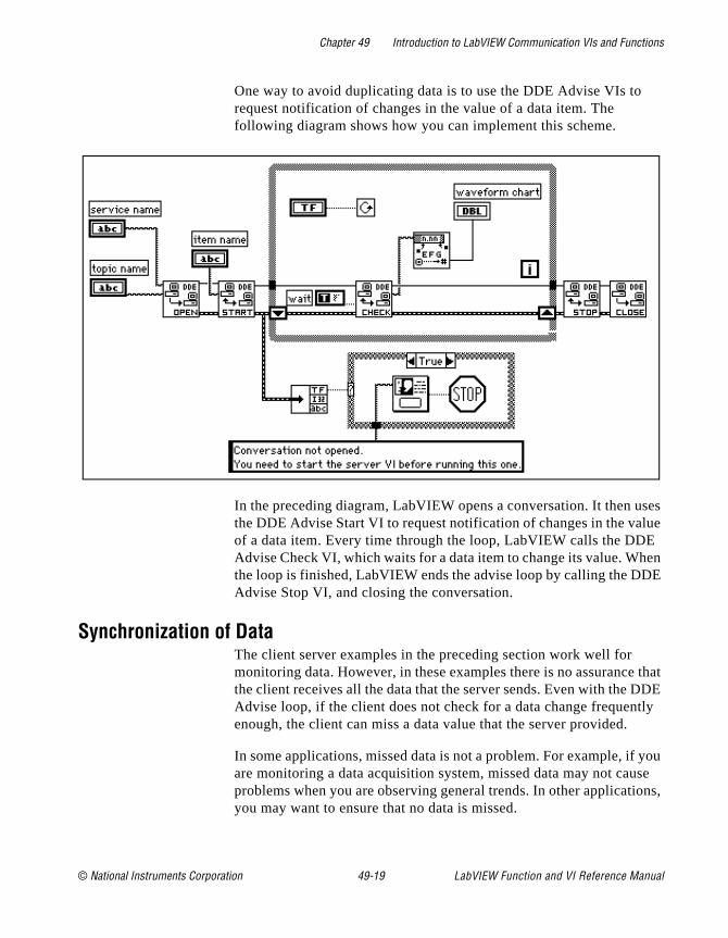
Chapter 49 Introduction to LabVIEW Communication VIs and Functions
ses ue E en E
that DE
tly
you se
ons,
One way to avoid duplicating data is to use the DDE Advise VIs to request notification of changes in the value of a data item. The following diagram shows how you can implement this scheme.
In the preceding diagram, LabVIEW opens a conversation. It then uthe DDE Advise Start VI to request notification of changes in the valof a data item. Every time through the loop, LabVIEW calls the DDAdvise Check VI, which waits for a data item to change its value. Whthe loop is finished, LabVIEW ends the advise loop by calling the DDAdvise Stop VI, and closing the conversation.
Synchronization of DataThe client server examples in the preceding section work well for monitoring data. However, in these examples there is no assurancethe client receives all the data that the server sends. Even with the DAdvise loop, if the client does not check for a data change frequenenough, the client can miss a data value that the server provided.
In some applications, missed data is not a problem. For example, if are monitoring a data acquisition system, missed data may not cauproblems when you are observing general trends. In other applicatiyou may want to ensure that no data is missed.
© National Instruments Corporation 49-19 LabVIEW Function and VI Reference Manual
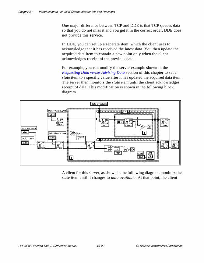
Chapter 49 Introduction to LabVIEW Communication VIs and Functions
ata oes
the
em.
he
One major difference between TCP and DDE is that TCP queues dso that you do not miss it and you get it in the correct order. DDE dnot provide this service.
In DDE, you can set up a separate item, which the client uses to acknowledge that it has received the latest data. You then update acquired data item to contain a new point only when the client acknowledges receipt of the previous data.
For example, you can modify the server example shown in the Requesting Data versus Advising Data section of this chapter to set a state item to a specific value after it has updated the acquired data itThe server then monitors the state item until the client acknowledges receipt of data. This modification is shown in the following block diagram.
A client for this server, as shown in the following diagram, monitors tstate item until it changes to data available. At that point, the client
LabVIEW Function and VI Reference Manual 49-20 © National Instruments Corporation
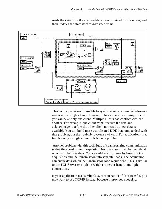
Chapter 49 Introduction to LabVIEW Communication VIs and Functions
and
en a t,
ith at
on at e n ilar
ou
reads the data from the acquired data item provided by the server,then updates the state item to data read value.
This technique makes it possible to synchronize data transfer betweserver and a single client. However, it has some shortcomings. Firsyou can have only one client. Multiple clients can conflict with one another. For example, one client might receive the data and acknowledge it before the other client notices that new data is available.You can build more complicated DDE diagrams to deal wthis problem, but they quickly become awkward. For applications thinvolve only a single client, this is not a problem.
Another problem with this technique of synchronizing communicatiis that the speed of your acquisition becomes controlled by the ratewhich you transfer data. You can address this issue by breaking thacquisition and the transmission into separate loops. The acquisitiocan queue data which the transmission loop would send. This is simto the TCP Server example in which the server handles multiple connections.
If your application needs reliable synchronization of data transfer, ymay want to use TCP/IP instead, because it provides queueing,
© National Instruments Corporation 49-21 LabVIEW Function and VI Reference Manual
Chapter 49 Introduction to LabVIEW Communication VIs and Functions
ons
T. DE.
l
ice t you you m:
nd lso ing
E,
ay The
acknowledgment of data transfer, and support for multiple connectiat the driver level.
Networked DDEYou can use DDE to communicate with applications on the same computer or to communicate over the network with applications ondifferent computers. To use networked DDE, you must be running Windows for Workgroups 3.1 or greater, Windows 95, or Windows NThe standard version of Windows 3.1 does not support networked D
Each computer under Windows for Workgroups has a network computer name. You configure this name using the Network contropanel.
When you communicate over the network, the meaning of the servand topic strings change. The service name changes to indicate thawant to use networked DDE, and includes the name of the computerwant to communicate with. The service name is of the following for
\\ computer-name \ndde$
You can supply any arbitrary name for the topic. You then edit the SYSTEM.INI file to associate this topic name with the actual service atopic that will be used on the remote computer. This configuration aincludes parameters that configure the network connection. Followis an example of what this section would look like:
[DDE Shares]
topicname = appname, realtopic, ,31,,0,,0,0,0
The topicname is the name that your client VI uses for the topic. Appname is the name of the remote application. With networked DDthis must be the same as the service name. Realtopic is the topic to use on the remote computer. The remaining parameters configure the wDDE works. Use the parameters as listed in the preceding example.meaning of these parameters is not documented by Microsoft.
For example, if you want two computers running LabVIEW to communicate using networked DDE, the server needs to use LabVIEW for the service name, and a name, such as labdata , for the topic.
Assuming the server computer name is Lab , the client tries to open a conversation using the \\Lab\ndde$ for the service. For the topic, theclient can use a name of remotelab .
LabVIEW Function and VI Reference Manual 49-22 © National Instruments Corporation

Chapter 49 Introduction to LabVIEW Communication VIs and Functions
he
nd E
g on
nt.
ns h
from
as
iled
For this to work, you must edit the SYSTEM.INI file of the server computer to have the following line in the [DDEShares] section:
remotelab=LabVIEW,labdata,,31,,0,,0,0,0
For Windows NT, launch DDEShare.exe , which is located in the winnt/system 32 directory. Choose Shares»DDE Shares… and then select Add a Share… to register the service name and topic name on tserver.For more information, see the Using NetDDE section of Chapter 52, DDE VIs.
OLE Automation (Windows Only)OLE (Object Linking and Embedding) Automation is a protocol for accessing the functions and methods of one Windows application amaking them available for use by another Windows application. OLAutomation works with Windows 95 and Windows NT only, not Windows 3.x.
If an application exposes objects and provides a method of operatinthose objects, it is called an OLE automation server. Applications that use the methods exposed by another application are OLE automation clients/controllers.
LabVIEW contains VIs that enable it to become an automation clieHelper VIs are provided.
AppleEvents (Macintosh Only)AppleEvents is a Macintosh specific protocol that allows applicatioto communicate with each other. As with DDE, it is a protocol in whicapplications use a message to request actions or return information other applications. An application can send a message to itself, anapplication on the same computer, or an application running on a computer elsewhere on the network.
You can use AppleEvents to send other commands to other applications, such as open or print, or to send data requests, such spreadsheet information.
LabVIEW contains VIs for sending some of commands common tomost applications. The VIs are easy to use, and do not require detaknowledge of how AppleEvents work.
© National Instruments Corporation 49-23 LabVIEW Function and VI Reference Manual
Chapter 49 Introduction to LabVIEW Communication VIs and Functions
has
hat
ust
and ou
n
o ing , you
ing. ion.
These VIs use the low level AESend VI to send AppleEvents. Apple defined a large vocabulary for messages to help standardize AppleEvent communication. You can combine words in this vocabulary to build complex messages. You can use this VI to send arbitrary AppleEvents to other applications. However, creating and sending AppleEvents at this level is complicated and requires detailed understanding of AppleEvents. See Inside Macintosh and the AppleEvent Registry.
Client Server ModelYou cannot use the AppleEvent VIs to create LabVIEW diagrams tbehave as servers. The VIs are used to send messages to other applications. If you need diagram-based server capabilities, you muse TCP or PPC.
LabVIEW itself acts as an AppleEvent server, in that it understands responds to a set of AppleEvents. Specifically, using AppleEvents, ycan instruct LabVIEW to open VIs, print them, run them, and closethem. You can ask LabVIEW whether a given VI is running. You caalso tell LabVIEW to quit.
Using these server capabilities, you can instruct other LabVIEW applications to run VIs, and control LabVIEW remotely. You can alscommand LabVIEW to send messages to itself, instructing the loadof specific VIs. For example, in large applications where memory islimited, you can replace subVI calls with calls to the AESend OpenRun, Close VI to load and run VIs as necessary. Notice that when run a VI this way its front panel opens, just as if you had selected File»Open....
AppleEvent Client Examples
Launching Other ApplicationsTo send a message to an application, that application must be runnYou can use the AESend Finder Open VI to launch another applicatThis VI sends a message to the Finder. The Finder is, in itself, an application that understands a limited number of AppleEvents. The
LabVIEW Function and VI Reference Manual 49-24 © National Instruments Corporation
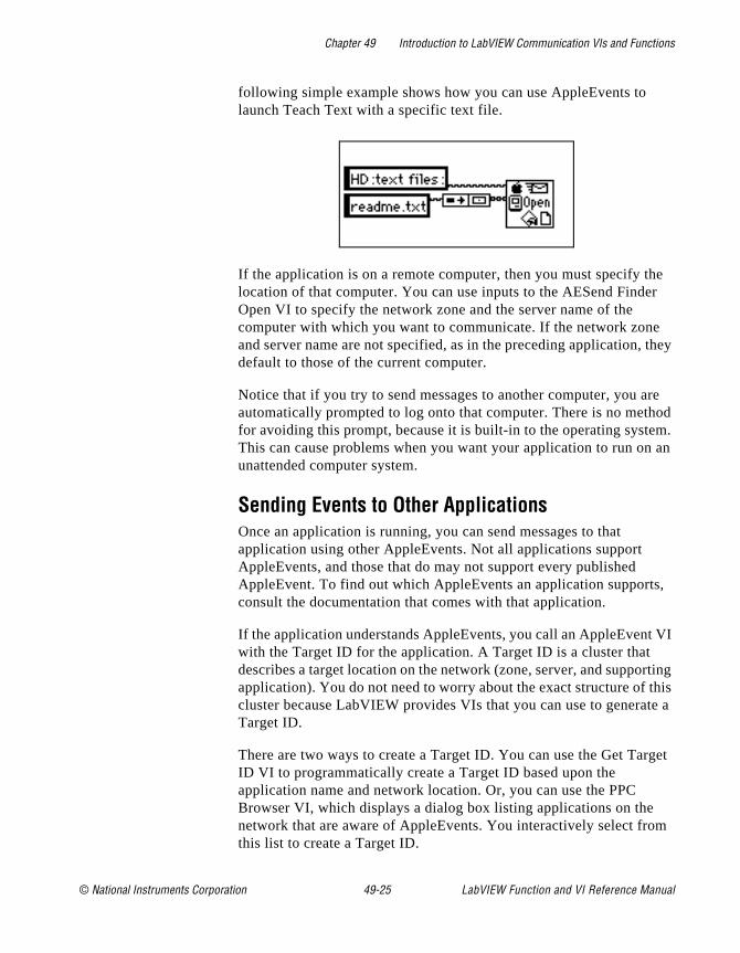
Chapter 49 Introduction to LabVIEW Communication VIs and Functions
e r
they
re od m. an
,
VI
rting his te a
get
m
following simple example shows how you can use AppleEvents to launch Teach Text with a specific text file.
If the application is on a remote computer, then you must specify thlocation of that computer. You can use inputs to the AESend FindeOpen VI to specify the network zone and the server name of the computer with which you want to communicate. If the network zoneand server name are not specified, as in the preceding application, default to those of the current computer.
Notice that if you try to send messages to another computer, you aautomatically prompted to log onto that computer. There is no methfor avoiding this prompt, because it is built-in to the operating systeThis can cause problems when you want your application to run onunattended computer system.
Sending Events to Other ApplicationsOnce an application is running, you can send messages to that application using other AppleEvents. Not all applications support AppleEvents, and those that do may not support every published AppleEvent. To find out which AppleEvents an application supportsconsult the documentation that comes with that application.
If the application understands AppleEvents, you call an AppleEventwith the Target ID for the application. A Target ID is a cluster that describes a target location on the network (zone, server, and suppoapplication). You do not need to worry about the exact structure of tcluster because LabVIEW provides VIs that you can use to generaTarget ID.
There are two ways to create a Target ID. You can use the Get TarID VI to programmatically create a Target ID based upon the application name and network location. Or, you can use the PPC Browser VI, which displays a dialog box listing applications on the network that are aware of AppleEvents. You interactively select frothis list to create a Target ID.
© National Instruments Corporation 49-25 LabVIEW Function and VI Reference Manual

Chapter 49 Introduction to LabVIEW Communication VIs and Functions
ion
VI.
to
VI se a e
se he
You can also use the PPC Browser VI to find out if another applicatuses AppleEvents. If you run the VI and select the computer that isrunning the application, the dialog box will list the application if it isAppleEvent aware.
In the following diagram, LabVIEW interactively selects an AppleEvent aware application on the network and tells it to open adocument. In this case, LabVIEW is telling the application to open a
Dynamically Loading and Running a VIThe AESend Open, Run, Close VI sends messages asking LabVIEWrun a VI. First, it sends the Open Document Message and LabVIEWopens a VI. Then, the Open Run Close VI sends the LabVIEW Runmessage and LabVIEW runs the specified VI. Next, Open Run Closends the VI Active? message, and LabVIEW returns the status of specified VI, until the VI is no longer running. Finally, the VI sends thClose VI message.
Assuming the target LabVIEW is on another computer, you could uthe following diagram to load and run the VI. If you are sending it to tcurrent LabVIEW, you do not need the PPC Browser VI.
LabVIEW Function and VI Reference Manual 49-26 © National Instruments Corporation

Chapter 49 Introduction to LabVIEW Communication VIs and Functions
for
es s
eate
t s
cols
ich d to r g irly
rts ens that
PPC (Macintosh Only)Program to Program Communication (PPC) is a Macintosh protocoltransferring blocks of data between applications. You can use it to create VIs that act as clients or servers. Although supported by all Macintoshes running System 7.x, it is not commonly used by most Macintosh applications. Instead, most Macintosh applications use AppleEvents, a high-level protocol for sending commands betweenapplications, to communicate.
Although PPC is not as commonly supported as AppleEvents, it doprovide some advantages. Because it is at a lower level, it providebetter performance than AppleEvents. Also, in LabVIEW you can create VIs that use PPC to act as clients or servers. You cannot crdiagrams that act as AppleEvent servers.
PPC is similar in structure to TCP, in terms of both server and clienapplications. The PPC method for specifying a remote application idifferent from the TCP method. Other than that, the two protocols provide similar performance and features. Both protocols handle queueing and reliable transmission of data. You can use both protowith multiple open connections.
In deciding between TCP and PPC, the main point to consider is whplatforms you plan to run your VIs on, and with which platforms youwill communicate. If your application is Macintosh only, PPC is a goochoice, because it is built-in to the operating system. TCP is built-inMacintosh operating system version 7.5. To use TCP with an earliesystem you must buy a separate TCP/IP driver from Apple. If buyinthe separate driver is not an issue, then you may want to use TCP,because the TCP interface is simpler than PPC. PPC uses some facomplicated data structures to describe addresses.
If your application must communicate with other platforms or run onother platforms, then you should use TCP/IP.
Ports, Target IDs, and SessionsTo communicate using PPC, both clients and servers must open pothat they use for subsequent communication. The Open Port VI opthe port using a cluster that contains, among other things, the nameyou want to use for the port.
© National Instruments Corporation 49-27 LabVIEW Function and VI Reference Manual
Chapter 49 Introduction to LabVIEW Communication VIs and Functions
ions. of t VIs rate
PC sing
PC
rite ion,
ch
n a of the um,
the ults er a
g
that he
Ports are used to distinguish between different services that an application provides. Each application can have multiple ports opensimultaneously.
Each port can support several simultaneous sessions or conversatTo open a session, a client uses a Target ID indicating the locationthe server. PPC uses the same type of Target ID that the AppleEvenuse. You can use the PPC Browser or the Get Target ID VIs to genethe Target ID for the remote application.
A server waits for clients to attempt to open a session by using the PInform Session VI. The server can accept or reject the session by uthe PPC Accept Session VI.
A client can attempt to open a session with a server by using the PStart Session VI.
After the session is started, you can use the PPC Read and PPC WVIs to transfer data. You can close a session using PPC End Sessand you can close a port using the PPC Close Port VI.
PPC Client ExampleThe following discussion explains how you can use PPC to fulfill eacomponent of the general Client model.
Use the PPC Open Connection and PPC Open Session VIs to opeconnection to a server. This requires that you specify the Target IDthe server, which you can get by using either the PPC Browser VI orGet Target ID VI. The end result is a port refnum and a session refnwhich are used to communicate with the server.
To execute a command on the server, use the PPC Write VI to sendcommand to the server. Next, use the PPC Read VI to read the resfrom the server. With the PPC Read VI, you must specify the numbof characters you want to read. As with TCP, this can be awkward,because the length of the response can vary. The server can havesimilar problem, because the length of a command may vary.
Following are several methods for addressing the problem of varyinsized commands. These methods can also be used with TCP.
• Precede the command and the result with a fixed size parameterspecifies the size of the command or result. In this case, read t
LabVIEW Function and VI Reference Manual 49-28 © National Instruments Corporation

Chapter 49 Introduction to LabVIEW Communication VIs and Functions
d by
is
ll
e the
ch
tion
ou
ssion sion
to
re ld,
it is e
size parameter, and then read the number of characters specifiethe size. This option is efficient and flexible.
• Make each command and result a fixed size. When a commandsmaller than the size, you can pad it out to the fixed size.
• Follow each command and result with a specific terminating character. To read the data, you then need to read data in smachunks until you get the terminating character.
Use the PPC Close Session and PPC Close Connection VIs to closconnection to the server.
PPC Server ExampleThe following discussion explains how you can use PPC to fulfill eacomponent of the general Server.
Use PPC Open Port in the initialization phase to open a communicaport.
Use the PPC Inform Session VI to wait for a connection. With PPC, ycan either automatically accept incoming connections, or you can choose to accept or reject the session by using the PPC Accept SeVI. This process of waiting for a session and then approving the sesallows you to screen connections.
When a connection is established, you can read from that session retrieve a command. As was discussed in the PPC Client Example section, you must decide the format for commands. If commands apreceded by a length field, then you need to first read the length fieand then read that amount of data.
Execution of a command should be protocol independent, becausesomething done on the local computer. When finished, you pass thresults to the next stage, where they are transmitted to the client.
Use the PPC Write VI to return the result. As discussed in the PPC Client Example section, the data must be formatted in a form that theclient can accept.
Use the PPC Close Session VI to close the connection.
© National Instruments Corporation 49-29 LabVIEW Function and VI Reference Manual
Chapter 49 Introduction to LabVIEW Communication VIs and Functions
ose
ods
.
Finally, when the server is finished, Use the PPC Close Port VI to clthe port that you opened in the initialization phase.
PPC Server with Multiple ConnectionsPPC handles multiple sessions and multiple ports easily. The methfor implementing each component of a server, as described in the preceding section, also work for a server with multiple connections
LabVIEW Function and VI Reference Manual 49-30 © National Instruments Corporation

© National Instruments Corporation 50-1 LabVIEW Function and
Chapter
50
TCP VIsl W
ata r cross tion.
l o the se
This chapter discusses Internet Protocol (IP), Transmission ControProtocol (TCP), and internet addresses, and describes the LabVIETCP VIs. Refer to Chapter 49, Introduction to LabVIEW CommunicationVIs and Functions, for an overview of TCP/IP and examples of TCP client/server applications.
The following illustration shows the TCP palette, which you access byselecting Functions»Communication»TCP.
For examples of how to use the TCP VIs, see the examples in examples\comm\tcpex.llb .
Internet Protocol (IP)Internet Protocol (IP) performs the low-level service of packaging dinto components called datagrams. A datagram contains, among othethings, the data and a header indicating the source and destinationaddresses. IP determines the correct path for the datagram to take athe network or internet, and sends the data to the specified destina
The original host may not know the complete path that the data wiltake. Using the header, any host on the network can route the data tdestination, either directly or by forwarding it to another host. Becausome systems have different transfer capabilities, IP can fragment
VI Reference Manual
Chapter 50 TCP VIs
es at nal
e ay
han der he sed st
ion r
ams CP
not
le
on
and and
ltiple
port
datagrams into smaller segments as necessary; when the data arrivthe destination, IP automatically reassembles the data into its origiform.
IP makes a best-effort attempt to deliver data, but cannot guarantedelivery. Also, because IP routes each datagram separately, they marrive out of sequence. In fact, IP may deliver a single packet more tonce if it is duplicated in transmission. IP does not determine the orof packets. Instead, higher-level protocols layered above IP order tpackets and ensure reliable delivery. For this reason, IP is rarely udirectly; instead, TCP and UDP, which are built on top of IP, are mooften used to transfer information.
Transmission Control Protocol (TCP)The Transmission Control Protocol (TCP) ensures reliable transmissacross networks, delivering data in sequence without errors, loss, oduplication. When you pass data to TCP, it attaches additional information and gives the data to IP, which puts the data into datagrand transmits it. This process reverses at the receiving end, with Tchecking the data for errors, ordering the data correctly, and acknowledging successful transmissions. If the sending TCP does receive an acknowledgment, it retransmits the data segment.
Using TCPTCP is a connection-based protocol, which means that sites must establish a connection before transferring data. TCP permits multipsimultaneous connections.
You initiate a connection either by waiting for an incoming connectior by actively seeking a connection with a specified address. In establishing TCP connections, you have to specify both the addressa port at that address. A port is represented by a number between 065535. With UNIX, port numbers less than 1024 are reserved for privileged applications. Different ports at a given address identify different services at that address, and make it easier to manage musimultaneous connections.
You can actively establish a connection with a specific address and using the TCP Open Connection VI. Using this VI, you specify the address and port with which you want to communicate. If the
LabVIEW Function and VI Reference Manual 50-2 © National Instruments Corporation
Chapter 50 TCP VIs
ely
er the e
o for e ID
not
listen u to ple,
he
the tion er
connection is successful, the VI returns a connection ID that uniquidentifies that connection. Use this connection ID to refer to the connection in subsequent VI calls.
You can use two methods to wait for an incoming connection:
• With the first method, you use the TCP Listen VI to create a listenand wait for an accepted TCP connection at a specified port. If connection is successful, the VI returns a connection ID and thaddress and port of the remote TCP.
• With the second method, you use the TCP Create Listener VI tcreate a listener, and then use the Wait on Listener VI to listen and accept new connections. Wait on Listener returns the samlistener ID that was passed to the VI, as well as the connectionfor a connection. When you are finished waiting for new connections, you can use TCP Close to close a listener. You canread from or write to a listener.
The advantage of using the second method is that you can cancel a operation by calling TCP Close. This is useful in the case where yowant to listen for a connection without using a timeout, but you wantcancel the listen when some other condition becomes true (for examwhen the user presses a button).
When a connection is established, you can read and write data to tremote application using the TCP Read and TCP Write VIs.
Finally, use the TCP Close Connection VI to close the connection toremote application. Note that if there is unread data and the conneccloses, that data may be lost. Connected parties should use a highlevel protocol to determine when to close the connection. Once a connection is closed, you may not read or write from it again.
© National Instruments Corporation 50-3 LabVIEW Function and VI Reference Manual
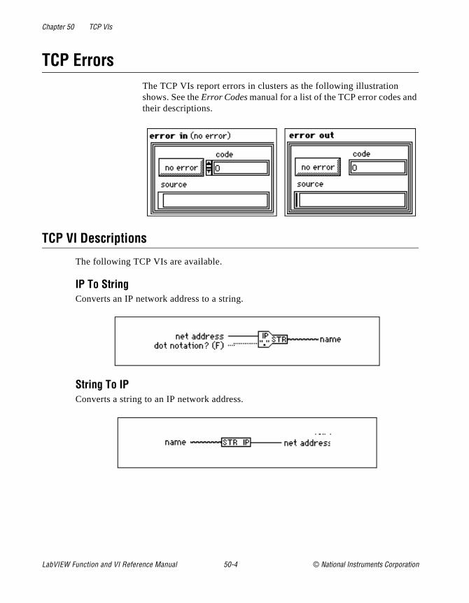
Chapter 50 TCP VIs
d
TCP Errors The TCP VIs report errors in clusters as the following illustration shows. See the Error Codes manual for a list of the TCP error codes antheir descriptions.
TCP VI Descriptions
The following TCP VIs are available.
IP To StringConverts an IP network address to a string.
String To IPConverts a string to an IP network address.
LabVIEW Function and VI Reference Manual 50-4 © National Instruments Corporation
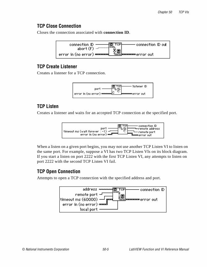
Chapter 50 TCP VIs
n on ram.
on
TCP Close ConnectionCloses the connection associated with connection ID.
TCP Create ListenerCreates a listener for a TCP connection.
TCP ListenCreates a listener and waits for an accepted TCP connection at the specified port.
When a listen on a given port begins, you may not use another TCP Listen VI to listethe same port. For example, suppose a VI has two TCP Listen VIs on its block diagIf you start a listen on port 2222 with the first TCP Listen VI, any attempts to listenport 2222 with the second TCP Listen VI fail.
TCP Open ConnectionAttempts to open a TCP connection with the specified address and port.
© National Instruments Corporation 50-5 LabVIEW Function and VI Reference Manual

Chapter 50 TCP VIs
TCP ReadReceives up to bytes to read bytes from the specified TCP connection, returning the results in data out.
TCP Wait on ListenerWaits for an accepted TCP connection at the specified port.
TCP WriteWrites the string data in to the specified TCP connection.
LabVIEW Function and VI Reference Manual 50-6 © National Instruments Corporation
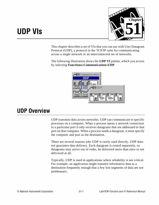
© National Instruments Corporation 51-1 LabVIEW Function and
Chapter
51
UDP VIsram
cific ction that ecify
es o not
l.
not
This chapter describes a set of VIs that you can use with User DatagProtocol (UDP), a protocol in the TCP/IP suite for communicating across a single network or an interconnected set of networks.
The following illustration shows the UDP VI palette, which you accessby selecting Functions»Communication»UDP.
UDP OverviewUDP transmits data across networks. UDP can communicate to speprocesses on a computer. When a process opens a network conneto a particular port it only receives datagrams that are addressed toport on that computer. When a process sends a datagram, it must spthe computer and port as the destination.
There are several reasons why UDP is rarely used directly. UDP donot guarantee data delivery. Each datagram is routed separately, sdatagrams may arrive out of order, be delivered more than once ordelivered at all.
Typically, UDP is used in applications where reliability is not criticaFor example, an application might transmit informative data to a destination frequently enough that a few lost segments of data are problematic.
VI Reference Manual
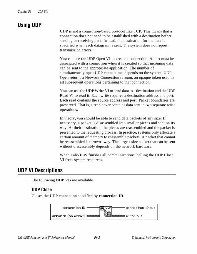
Chapter 51 UDP VIs
a re
be ta
P in
DP ort. s are write
n its et is ate a nnot sent
Using UDPUDP is not a connection-based protocol like TCP. This means thatconnection does not need to be established with a destination befosending or receiving data. Instead, the destination for the data is specified when each datagram is sent. The system does not reporttransmission errors.
You can use the UDP Open VI to create a connection. A port mustassociated with a connection when it is created so that incoming dacan be sent to the appropriate application. The number of simultaneously open UDP connections depends on the system. UDOpen returns a Network Connection refnum, an opaque token usedall subsequent operations pertaining to that connection.
You can use the UDP Write VI to send data to a destination and the URead VI to read it. Each write requires a destination address and pEach read contains the source address and port. Packet boundariepreserved. That is, a read never contains data sent in two separate operations.
In theory, you should be able to send data packets of any size. If necessary, a packet is disassembled into smaller pieces and sent oway. At their destination, the pieces are reassembled and the packpresented to the requesting process. In practice, systems only alloccertain amount of memory to reassemble packets. A packet that cabe reassembled is thrown away. The largest size packet that can bewithout dissassembly depends on the network hardware.
When LabVIEW finishes all communications, calling the UDP CloseVI frees system resources.
UDP VI Descriptions
The following UDP VIs are available.
UDP CloseCloses the UDP connection specified by connection ID.
LabVIEW Function and VI Reference Manual 51-2 © National Instruments Corporation
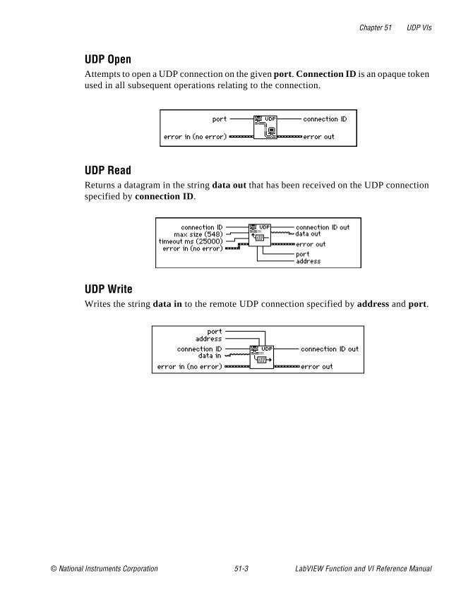
Chapter 51 UDP VIs
n
UDP OpenAttempts to open a UDP connection on the given port . Connection ID is an opaque token used in all subsequent operations relating to the connection.
UDP ReadReturns a datagram in the string data out that has been received on the UDP connectiospecified by connection ID.
UDP WriteWrites the string data in to the remote UDP connection specified by address and port .
© National Instruments Corporation 51-3 LabVIEW Function and VI Reference Manual
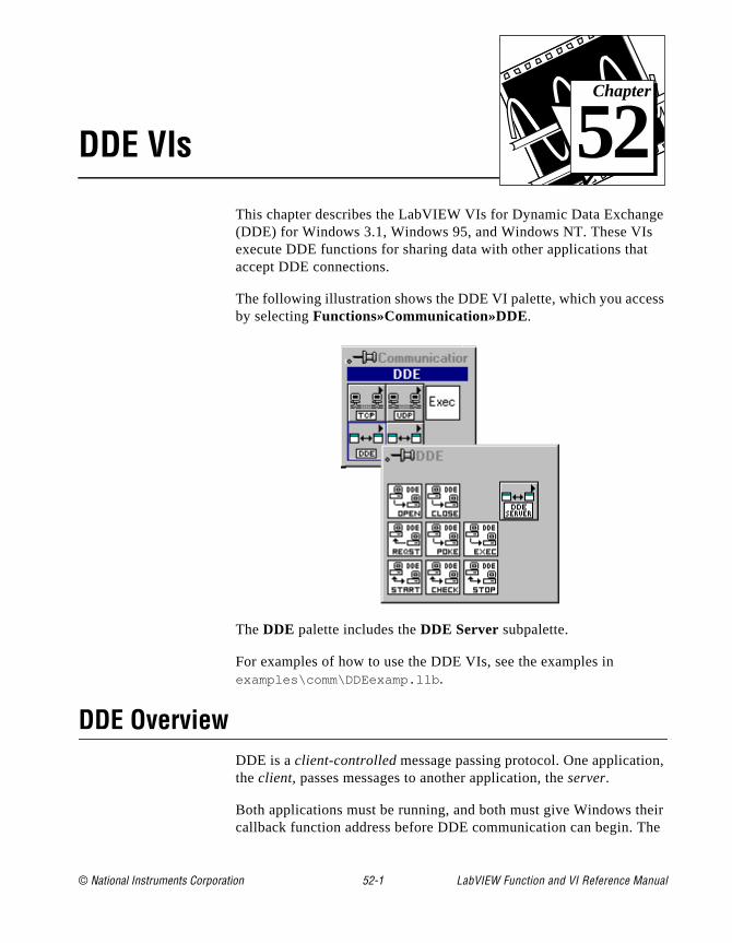
© National Instruments Corporation 52-1 LabVIEW Function and
Chapter
52
DDE VIsge
ss
n,
eir he
This chapter describes the LabVIEW VIs for Dynamic Data Exchan(DDE) for Windows 3.1, Windows 95, and Windows NT. These VIsexecute DDE functions for sharing data with other applications thataccept DDE connections.
The following illustration shows the DDE VI palette, which you acceby selecting Functions»Communication»DDE.
The DDE palette includes the DDE Server subpalette.
For examples of how to use the DDE VIs, see the examples in examples\comm\DDEexamp.llb .
DDE OverviewDDE is a client-controlled message passing protocol. One applicatiothe client, passes messages to another application, the server.
Both applications must be running, and both must give Windows thcallback function address before DDE communication can begin. T
VI Reference Manual
Chapter 52 DDE VIs
the
E n ver.
link ery e
the
ion rom
g the ata E
you in vise
are ns he ges, but
callback function accepts any DDE messages that Windows sends toapplication.
The client initiates a conversation with the server by sending a DDconnect message. After establishing the conversation, the client casend commands or data to the server, or request data from the ser
A client can request data from a server by a request or an advise. A request is a single transfer of data. An advise establishes an activebetween the two applications. The server then informs the client evtime the advise value changes. When the client no longer needs thchanged values, it sends an advise stop message to the server.
When all the DDE communication for the conversation is complete, client sends a close conversation message to the server.
Using DDE as a ClientThe Dynamic Data Exchange VIs give LabVIEW full DDE client capability.
To use DDE, you must first establish a conversation using the DDEOpen Conversation VI. The VI must specify the service and the topic. The service usually corresponds to the name of the server applicatand the topic to the active file. DDE messages then carry data to or fspecific locations in the active file. For more information on how a specific application handles topic names and data item locations, consult the documentation for that application.
When you have established a conversation, you can send data usinDDE Poke VI, send commands using the DDE Execute VI, obtain dwith the DDE Request VI, or initiate an advise protocol with the DDAdvise Start VI.
The DDE Request VI sends a DDE message to the server every timecall it. The server must then check the data requested and return itanother DDE message. If your VI checks the value frequently, an adprotocol might be more efficient than a request.
The DDE Advise Start VI creates a local copy of the data value you interested in. When you call the DDE Advise Check VI, the VI returthis value without sending any DDE messages. At the same time, tserver application sends DDE messages every time the value chanso that the local value is always current. If the value seldom changes
LabVIEW Function and VI Reference Manual 52-2 © National Instruments Corporation

Chapter 52 DDE VIs
ber
er
e ,
ata
ber
ion
Is.
and his
ster ing ith
es
for er s on
VI .
is often needed, an advise can significantly reduce the required numof DDE messages.
Caution: During a conversation, you must pass the conversation refnum to all othDDE VIs involved in that conversation. Windows uses these refnums toidentify the conversation. If you alter the conversation refnum, or do notspecify or wire the conversation refnum, the VI will fail. The same is truefor the advise refnum. If you alter advise refnum, or do not specify or wiradvise refnum for the DDE Advise Check VI or the DDE Advise Stop VIthe VIs will fail and may cause a system failure.
The DDE protocol used by LabVIEW is ASCII based, and the transmission is terminated when a null byte is reached. If the binary dhas a null byte (00) in it, the transmission will end.
To send a number to another application, you must convert that numto a string. In the same way, you must convert numbers received through a request or advise from the string format. Use the conversVIs from Functions»String. See Chapter 6, String Functions, earlier in this manual for further information on how to use string conversion V
Stop all advises and close all conversations using DDE Advise StopDDE Close Conversation after all DDE commands have executed. Treleases the system resources associated with these VIs.
Using DDE as a ServerThe first step to becoming a DDE server is to use the DDE Srv RegiService VI to tell Windows what your service name and topic are goto be. At this point other applications can open DDE conversations wyour service.
You can call the DDE Srv Register Service VI multiple times with different service names to establish multiple services or multiple timwith the same service name but different topic names to establish multiple topics for one service.
After specifying your service and topic names, you can define itemsthat service using the DDE Srv Register Item VI. After this call, othapplications can request or poke the item, as well as initiate advisethat item. LabVIEW fully manages all these transactions.
To change the value of an item, call the DDE Srv Set Item VI. This changes the value and informs all clients that have advises on them
© National Instruments Corporation 52-3 LabVIEW Function and VI Reference Manual

Chapter 52 DDE VIs
the
es
as
er
d.
d
how
s
To monitor whether a client has changed an item with a poke, call DDE Srv Check Item VI. This VI either returns the current value immediately or waits until a client changes the value. If a client pokthe value before DDE Srv Check Item is called with wait for poke true, DDE Srv Check Item returns immediately and reports that the value wpoked.
You call the DDE Srv Unregister Item VI and the DDE Srv UnregistService VI to close down your DDE server when you are finished. LabVIEW automatically disconnects any client conversations connected to your server when DDE Srv Unregister Service is calle
Using NetDDENetDDE is built into Windows for WorkGroups 3.11, Windows 95 anWindows NT. It is also available for Windows 3.1 with an add-on package from WonderWare. If you are using Windows 3.1 with theWonderWare package, consult the WonderWare documentation on to use NetDDE.
If you are using Windows for WorkGroups, Windows 95, or WindowNT, use the following instructions:
SERVER MACHINE
Windows for WorkgroupsAdd the following line to the [DDE Shares] section of the file system.ini on the server (application receiving DDE commands):
lvdemo = service_name,topic_name,,31,,0,,0,0,0
where
lvdemo can be any name.
service_name is typically the name of the application, such as excel.
topic_name is typically the specific file name, such as sheet1.
Enter other commas and numbers as shown.
LabVIEW Function and VI Reference Manual 52-4 © National Instruments Corporation

Chapter 52 DDE VIs
e
re ied
e
Windows 95
Note: NetDDE is not automatically started by Windows 95. You need to run thprogram\WINDOWS\NETDDE.EXE. (This can be added to the startup folder so that it is always started.)
To set up a NetDDE server on Windows 95:
• Run\WINDOWS\REGEDIT.EXE.
• In the tree display, open the folder My Computer\
HKEY_LOCAL_MACHINE\SOFTWARE\Microsoft\
NetDDE\DDE Shares .
• Create a new DDE Share by selecting Edit»New»Key and give it the name lvdemo .
• With the lvdemo key selected, add the required values to the shaas follows. (For future reference, these keys are just being copfrom the CHAT$ share but REDEGIT does not allow you cut, copy, orpaste keys or values.) Use Edit»New to add new values. When youcreate the key, there will a default value named (Default ) and a value of (value not set ). Leave these values alone and add thfollowing:
Table 52-1. Values to Add in Place of Default
Value Type Name Value
Binary Additional item count 00 00 00 00
String Application service_name
String Item service_name
String Password1 service_name
String Password2 service_name
Binary Permissions1 1f 00 00 00
Binary Permissions2 00 00 00 00
String Topic topic_name
© National Instruments Corporation 52-5 LabVIEW Function and VI Reference Manual
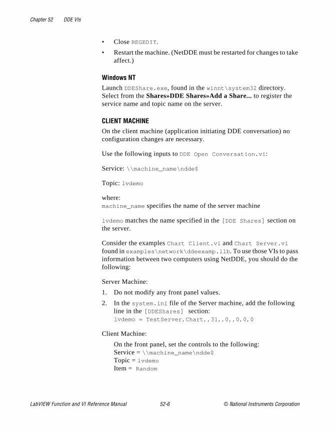
Chapter 52 DDE VIs
take
the
• Close REGEDIT.
• Restart the machine. (NetDDE must be restarted for changes to affect.)
Windows NTLaunch DDEShare.exe , found in the winnt\system32 directory. Select from the Shares»DDE Shares»Add a Share... to register the service name and topic name on the server.
CLIENT MACHINE On the client machine (application initiating DDE conversation) no configuration changes are necessary.
Use the following inputs to DDE Open Conversation.vi :
Service: \\machine_name\ndde$
Topic: lvdemo
where:machine_name specifies the name of the server machine
lvdemo matches the name specified in the [ DDE Shares ] section on the server.
Consider the examples Chart Client.vi and Chart Server.vi found in examples\network\ddeexamp.llb . To use those VIs to passinformation between two computers using NetDDE, you should do following:
Server Machine:
1. Do not modify any front panel values.
2. In the system.ini file of the Server machine, add the following line in the [ DDEShares] section:lvdemo = TestServer,Chart,,31,,0,,0,0,0
Client Machine:
On the front panel, set the controls to the following:Service = \\machine_name\ndde$
Topic = lvdemo
Item = Random
LabVIEW Function and VI Reference Manual 52-6 © National Instruments Corporation
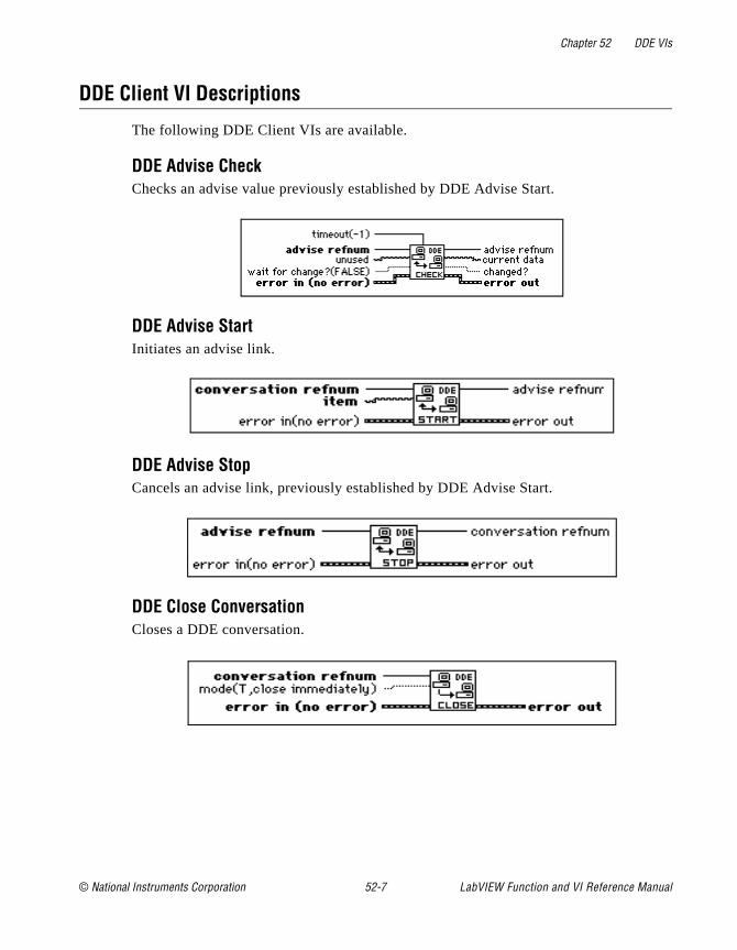
Chapter 52 DDE VIs
DDE Client VI Descriptions
The following DDE Client VIs are available.
DDE Advise CheckChecks an advise value previously established by DDE Advise Start.
DDE Advise StartInitiates an advise link.
DDE Advise StopCancels an advise link, previously established by DDE Advise Start.
DDE Close ConversationCloses a DDE conversation.
© National Instruments Corporation 52-7 LabVIEW Function and VI Reference Manual
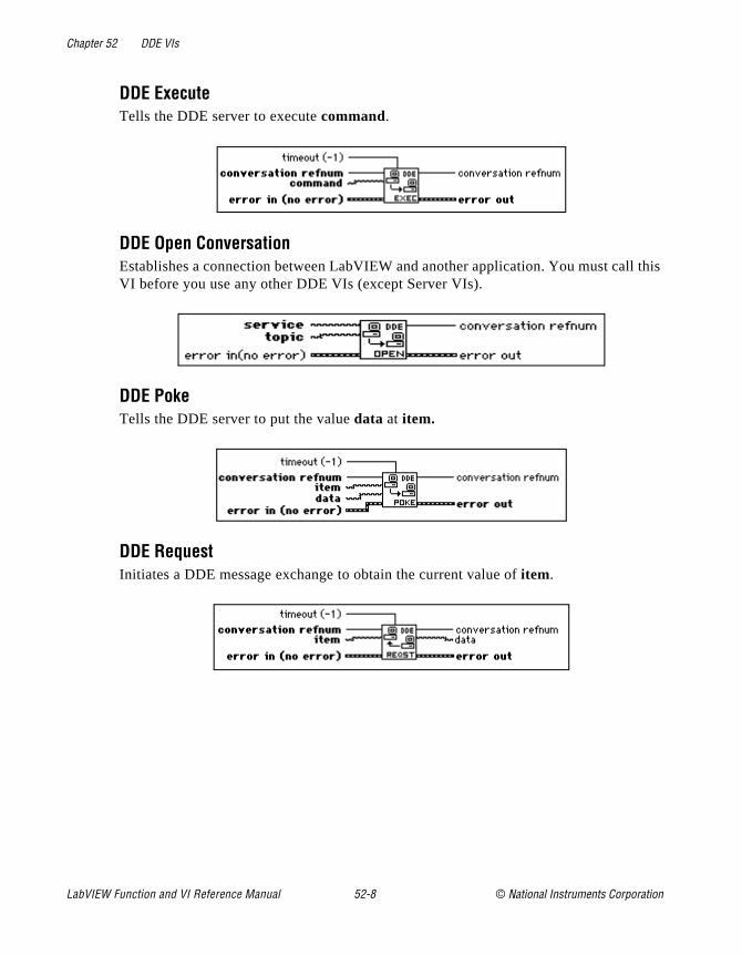
Chapter 52 DDE VIs
l this
DDE ExecuteTells the DDE server to execute command.
DDE Open ConversationEstablishes a connection between LabVIEW and another application. You must calVI before you use any other DDE VIs (except Server VIs).
DDE PokeTells the DDE server to put the value data at item.
DDE RequestInitiates a DDE message exchange to obtain the current value of item.
LabVIEW Function and VI Reference Manual 52-8 © National Instruments Corporation

Chapter 52 DDE VIs
DDE Server VI Descriptions
You access by selecting Functions»Communication»DDE»DDE Server.
DDE Srv Check ItemSets the value of a previously defined DDE Item.
DDE Srv Register ItemEstablishes a DDE item for the service specified by service refnum.
DDE Srv Register ServiceEstablishes a DDE service to which clients can connect.
DDE Srv Set ItemSets the value of a previously defined DDE Item.
© National Instruments Corporation 52-9 LabVIEW Function and VI Reference Manual
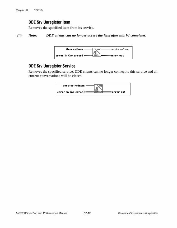
Chapter 52 DDE VIs
nd all
DDE Srv Unregister ItemRemoves the specified item from its service.
Note: DDE clients can no longer access the item after this VI completes.
DDE Srv Unregister ServiceRemoves the specified service. DDE clients can no longer connect to this service acurrent conversations will be closed.
LabVIEW Function and VI Reference Manual 52-10 © National Instruments Corporation
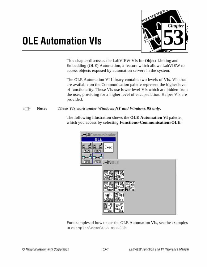
© National Instruments Corporation 53-1 LabVIEW Function and
Chapter
53
OLE Automation VIsvel m re
les
This chapter discusses the LabVIEW VIs for Object Linking and Embedding (OLE) Automation, a feature which allows LabVIEW toaccess objects exposed by automation servers in the system.
The OLE Automation VI Library contains two levels of VIs. VIs thatare available on the Communication palette represent the higher leof functionality. These VIs use lower level VIs which are hidden frothe user, providing for a higher level of encapsulation. Helper VIs aprovided.
Note: These VIs work under Windows NT and Windows 95 only.
The following illustration shows the OLE Automation VI palette, which you access by selecting Functions»Communication»OLE .
For examples of how to use the OLE Automation VIs, see the exampin examples\comm\OLE-xxx.llb .
VI Reference Manual

Chapter 53 OLE Automation VIs
as ese
ing
one s .
on
the t or s nd
ws:
ant
hat pe
OLE Automation ConceptsIn the context of Object Linking and Embedding, objects are defineddata abstractions exported by an application. You can manipulate thobjects by using another Windows application. Linking and Embeddare two of the methods used to access OLE objects.
You can use OLE Automation to make the functions and methods of application available for use by other applications. You then accesthese functions or methods, which are usually grouped into objects
An application supports automation either as a server or a client. Applications that expose objects and provide methods for operatingthose objects are called OLE automation servers. Applications that use the methods exposed by another application are called OLE automation clients/controllers. The OLE VIs enable LabVIEW to become an automation client.
Using LabVIEW to Implement OLE Automation An OLE object exposes both methods and properties. Methods haveability to modify a wide range of values, whereas properties can seget the value of a specific characteristic of the object. Some serverprovide a type library listing all exposed objects and the methods aproperties of each object.
The typical steps in creating a client application using C are as follo
• Get the IDispatch interface of the Object whose methods you wto access.
• Get the DispatchID of the method of that object.
• Invoke the method using the Invoke functions of the IDispatch interface, packing all parameters into the parameter list.
In LabVIEW, do as follows:
• Use the Create Automation Refnum VI to get an Automation refnum which uniquely defines the IDispatch interface.
• Use the Execute Method VI to execute a method belonging to tobject. If there is just one parameter, it can be flattened. The tydescriptors and the flattened string are then passed in as inputparameters. If there are multiple outputs, they are bundled in a
LabVIEW Function and VI Reference Manual 53-2 © National Instruments Corporation

Chapter 53 OLE Automation VIs
ation
cluster. The resultant cluster is then flattened and wired to the correct input of the VI.
The implementation uses DLLs to perform the actual OLE calls. Parameters are passed to these DLLs as flattened data.
OLE Automation VI Descriptions
The following OLE Automation VIs are available.
Create Automation RefnumGiven the object name (registered class name) of an OLE object, returns an AutomRefnum uniquely identifying the instantiation.
Execute MethodExecutes a method.
Get PropertyGets the value of a property.
List Methods or PropertiesLists all the methods or properties of an object.
© National Instruments Corporation 53-3 LabVIEW Function and VI Reference Manual
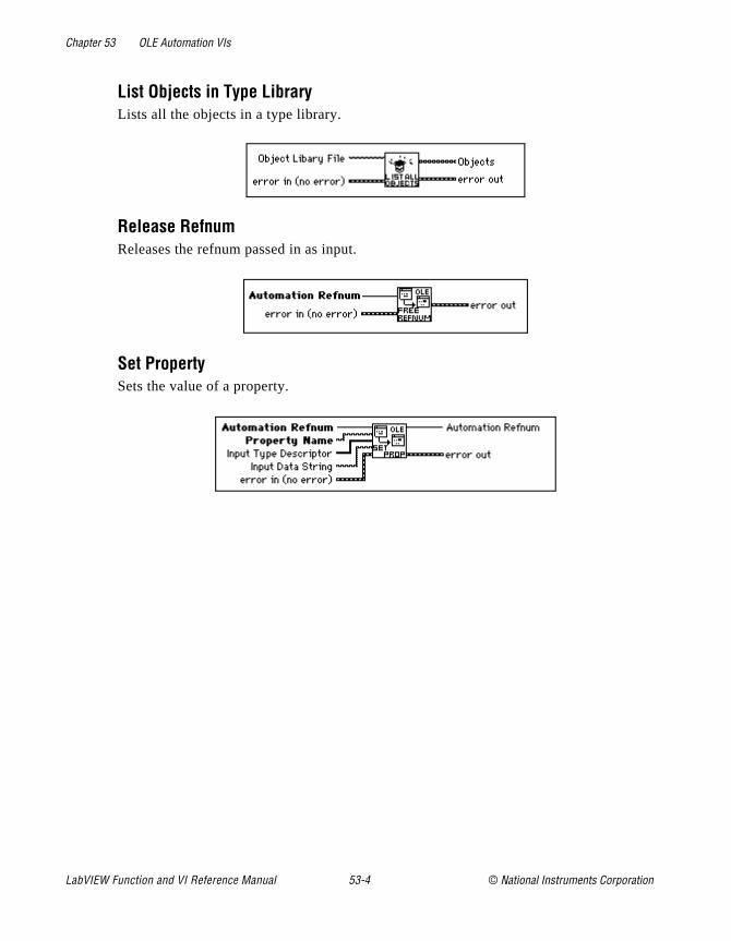
Chapter 53 OLE Automation VIs
List Objects in Type LibraryLists all the objects in a type library.
Release RefnumReleases the refnum passed in as input.
Set PropertySets the value of a property.
LabVIEW Function and VI Reference Manual 53-4 © National Instruments Corporation

© National Instruments Corporation 54-1 LabVIEW Function and
Chapter
54
AppleEvent VIse ch d
ges ons
e
ive s,
you ay
port
This chapter discusses the LabVIEW VIs for interapplication communication (IAC), a feature of Apple Macintosh system softwarversion 7 by which Macintosh applications can communicate with eaother. You can use LabVIEW with two forms of IAC, AppleEvents anprogram-to-program communication (PPC).
AppleEvents are a high-level method of communication in which applications use messages to request other applications to performactions or return information. An application can send these messato itself, other applications on the same machine, or other applicatilocated anywhere on a network. Apple has defined a large vocabulary for messages to help standardize this form of interapplication communication. You can combine words in this vocabulary to form very complex messages. This vocabulary is described in detail in thAppleEvent Registry, a document available from Apple. Most applications written for System 7, including LabVIEW, respond to some subset of AppleEvents.
PPC is a low-level form of IAC by which applications send and receblocks of data. PPC provides higher performance than AppleEventbecause the overhead required to transmit information is lower. However, because PPC does not define what kinds of information can transfer, many applications do not support it. PPC is the best wto send large amounts of information between applications that supPPC. See Chapter 55, Program to Program Communication VIs, for more information about PPC.
VI Reference Manual
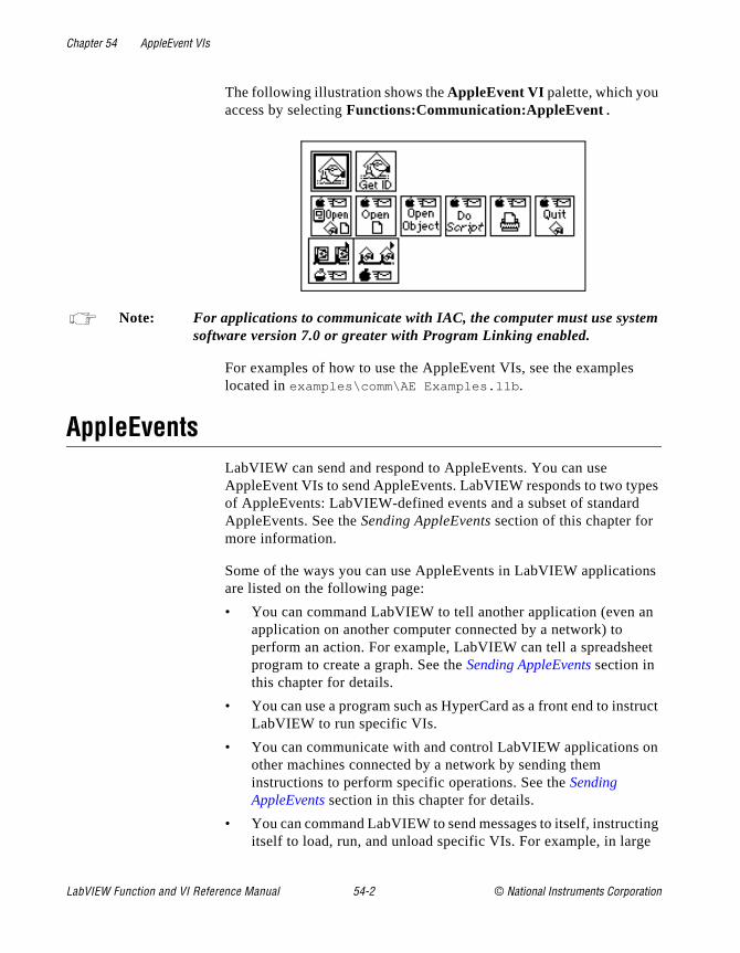
Chapter 54 AppleEvent VIs
m
es
ns
n
et
truct
n
ing e
The following illustration shows the AppleEvent VI palette, which you access by selecting Functions:Communication:AppleEvent.
Note: For applications to communicate with IAC, the computer must use systesoftware version 7.0 or greater with Program Linking enabled.
For examples of how to use the AppleEvent VIs, see the exampleslocated in examples\comm\AE Examples.llb .
AppleEventsLabVIEW can send and respond to AppleEvents. You can use AppleEvent VIs to send AppleEvents. LabVIEW responds to two typof AppleEvents: LabVIEW-defined events and a subset of standardAppleEvents. See the Sending AppleEvents section of this chapter for more information.
Some of the ways you can use AppleEvents in LabVIEW applicatioare listed on the following page:
• You can command LabVIEW to tell another application (even aapplication on another computer connected by a network) to perform an action. For example, LabVIEW can tell a spreadsheprogram to create a graph. See the Sending AppleEvents section in this chapter for details.
• You can use a program such as HyperCard as a front end to insLabVIEW to run specific VIs.
• You can communicate with and control LabVIEW applications oother machines connected by a network by sending them instructions to perform specific operations. See the Sending AppleEvents section in this chapter for details.
• You can command LabVIEW to send messages to itself, instructitself to load, run, and unload specific VIs. For example, in larg
LabVIEW Function and VI Reference Manual 54-2 © National Instruments Corporation
Chapter 54 AppleEvent VIs
s
you ent,
of
t be tion.
the set an , a tem
applications where memory is tight, you can replace subVI callwith a utility VI (the AESend Open, Run, Close VI) and dynamically load, run, and unload the VIs. See the Sending AppleEvents section in this chapter for details.
The following sections describe in detail how LabVIEW sends and receives AppleEvents.
Sending AppleEventsThe Communication subpalette of the Functions palette contains VIs for sending AppleEvents. With these VIs, you can select a target application for an AppleEvent, create AppleEvents, and send the AppleEvents to the target application.
The AppleEvent VIs palette of the Communication subpalette contains VIs that send specific AppleEvent messages. These VIs letsend several standard AppleEvents (Open Document, Print Documand Close Application) and all the LabVIEW custom AppleEvents. These high-level VIs require little understanding of AppleEvent programming details. Their diagrams also serve as good exampleshow to create and send AppleEvents.
You can use the low-level AESend VI if you want to send an AppleEvent for which LabVIEW provides no VI. The AppleEvent VIs palette of the Communication subpalette also contains VIs that can help you create an AppleEvent. However, creating and sending anAppleEvent at this level requires detailed understanding of AppleEvents as described in Inside Macintosh, Volume VI and the AppleEvent Registry.
General AppleEvent VI BehaviorWhen sending an AppleEvent, you must specify the target application for the event. To receive the AppleEvent, the target application musopen. You can use the AESend Finder Open VI to open an applica
The User Identity Dialog BoxBefore you send an AppleEvent to another computer, you must useUsers & Groups control panel utility on the destination computer to up a user name and password for yourself. The first time you sendAppleEvent to an application or Finder on the destination computerdialog box prompts you to enter your name and password. The sys
© National Instruments Corporation 54-3 LabVIEW Function and VI Reference Manual
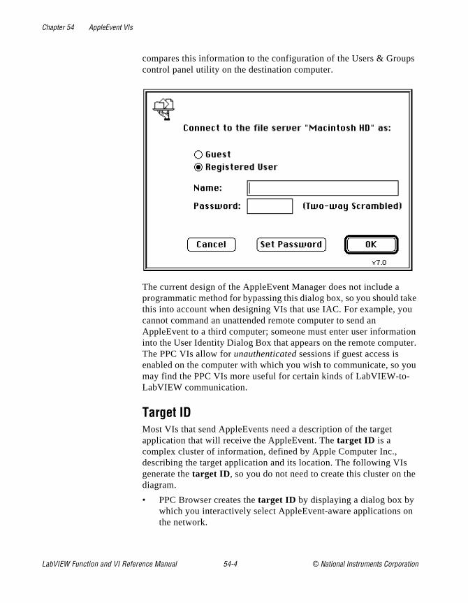
Chapter 54 AppleEvent VIs
ps
ake u
ion ter.
ou
e
n
compares this information to the configuration of the Users & Groucontrol panel utility on the destination computer.
The current design of the AppleEvent Manager does not include a programmatic method for bypassing this dialog box, so you should tthis into account when designing VIs that use IAC. For example, yocannot command an unattended remote computer to send an AppleEvent to a third computer; someone must enter user informatinto the User Identity Dialog Box that appears on the remote compuThe PPC VIs allow for unauthenticated sessions if guest access is enabled on the computer with which you wish to communicate, so ymay find the PPC VIs more useful for certain kinds of LabVIEW-to-LabVIEW communication.
Target IDMost VIs that send AppleEvents need a description of the target application that will receive the AppleEvent. The target ID is a complex cluster of information, defined by Apple Computer Inc., describing the target application and its location. The following VIsgenerate the target ID , so you do not need to create this cluster on thdiagram.
• PPC Browser creates the target ID by displaying a dialog box by which you interactively select AppleEvent-aware applications othe network.
LabVIEW Function and VI Reference Manual 54-4 © National Instruments Corporation
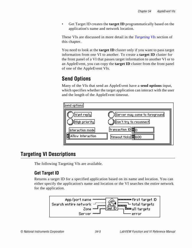
Chapter 54 AppleEvent VIs
t
r to
ser
can work
• Get Target ID creates the target ID programmatically based on theapplication's name and network location.
These VIs are discussed in more detail in the Targeting VIs section of this chapter.
You need to look at the target ID cluster only if you want to pass targeinformation from one VI to another. To create a target ID cluster for the front panel of a VI that passes target information to another VI oan AppleEvent, you can copy the target ID cluster from the front panel of one of the AppleEvent VIs.
Send OptionsMany of the VIs that send an AppleEvent have a send options input, which specifies whether the target application can interact with the uand the length of the AppleEvent timeout.
Targeting VI Descriptions
The following Targeting VIs are available.
Get Target IDReturns a target ID for a specified application based on its name and location. Youeither specify the application's name and location or the VI searches the entire netfor the application.
© National Instruments Corporation 54-5 LabVIEW Function and VI Reference Manual
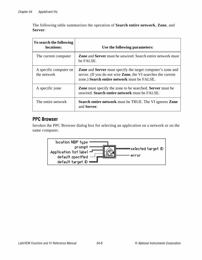
Chapter 54 AppleEvent VIs
the
t
The following table summarizes the operation of Search entire network, Zone, and Server:
PPC BrowserInvokes the PPC Browser dialog box for selecting an application on a network or onsame computer.
To search the following locations: Use the following parameters:
The current computer Zone and Server must be unwired. Search entire network musbe FALSE.
A specific computer on the network
Zone and Server must specify the target computer’s zone andserver. (If you do not wire Zone, the VI searches the current zone.) Search entire network must be FALSE.
A specific zone Zone must specify the zone to be searched. Server must be unwired. Search entire network must be FALSE.
The entire network Search entire network must be TRUE. The VI ignores Zone and Server.
LabVIEW Function and VI Reference Manual 54-6 © National Instruments Corporation

Chapter 54 AppleEvent VIs
, an , and
You can use this standard Macintosh dialog box to select a zone from the networkobject in that zone (in System 7, this is typically the name of a person's computer)an application. The VI then returns the target ID cluster.
AppleEvent VI Descriptions
The following AppleEvent VIs are available.
AESend Do ScriptSends the Do Script AppleEvent to a specified target application.
© National Instruments Corporation 54-7 LabVIEW Function and VI Reference Manual
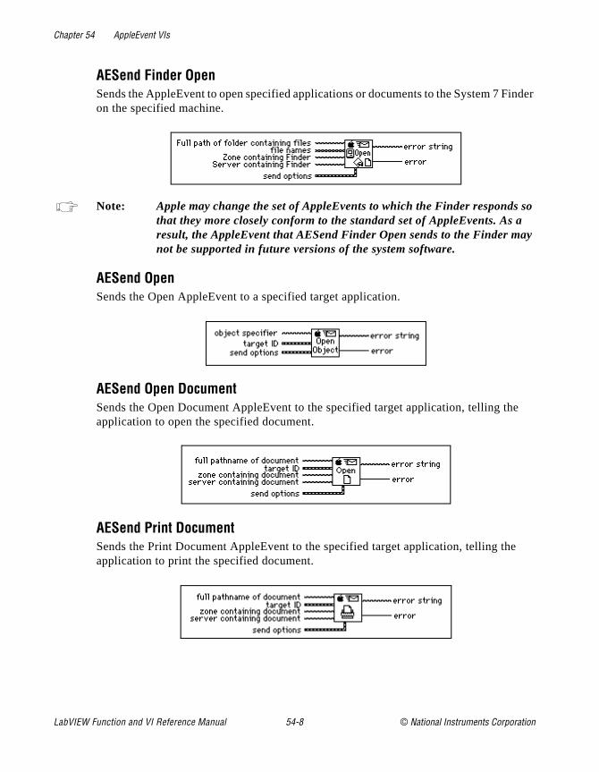
Chapter 54 AppleEvent VIs
inder
so y
e
AESend Finder OpenSends the AppleEvent to open specified applications or documents to the System 7 Fon the specified machine.
Note: Apple may change the set of AppleEvents to which the Finder respondsthat they more closely conform to the standard set of AppleEvents. As aresult, the AppleEvent that AESend Finder Open sends to the Finder manot be supported in future versions of the system software.
AESend OpenSends the Open AppleEvent to a specified target application.
AESend Open DocumentSends the Open Document AppleEvent to the specified target application, telling the application to open the specified document.
AESend Print DocumentSends the Print Document AppleEvent to the specified target application, telling thapplication to print the specified document.
LabVIEW Function and VI Reference Manual 54-8 © National Instruments Corporation
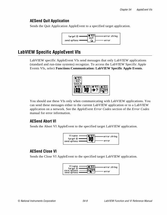
Chapter 54 AppleEvent VIs
e
ou W
AESend Quit ApplicationSends the Quit Application AppleEvent to a specified target application.
LabVIEW Specific AppleEvent VIs
LabVIEW specific AppleEvent VIs send messages that only LabVIEW applications(standard and run-time systems) recognize. To access the LabVIEW Specific ApplEvents VIs, select Functions:Communication: LabVIEW Specific Apple Events.
You should use these VIs only when communicating with LabVIEW applications. Ycan send these messages either to the current LabVIEW application or to a LabVIEapplication on a network. See the AppleEvent Error Codes section of the Error Codes manual for error information.
AESend Abort VISends the Abort VI AppleEvent to the specified target LabVIEW application.
AESend Close VISends the Close VI AppleEvent to the specified target LabVIEW application.
© National Instruments Corporation 54-9 LabVIEW Function and VI Reference Manual
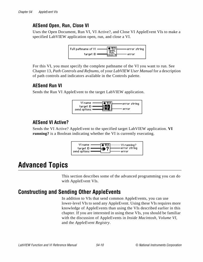
Chapter 54 AppleEvent VIs
e a
n do
ore his iliar
AESend Open, Run, Close VIUses the Open Document, Run VI, VI Active?, and Close VI AppleEvent VIs to makspecified LabVIEW application open, run, and close a VI.
For this VI, you must specify the complete pathname of the VI you want to run. See Chapter 13, Path Controls and Refnums, of your LabVIEW User Manual for a description of path controls and indicators available in the Controls palette.
AESend Run VISends the Run VI AppleEvent to the target LabVIEW application.
AESend VI Active?Sends the VI Active? AppleEvent to the specified target LabVIEW application. VI running? is a Boolean indicating whether the VI is currently executing.
Advanced TopicsThis section describes some of the advanced programming you cawith AppleEvent VIs.
Constructing and Sending Other AppleEventsIn addition to VIs that send common AppleEvents, you can use lower-level VIs to send any AppleEvent. Using these VIs requires mknowledge of AppleEvents than using the VIs described earlier in tchapter. If you are interested in using these VIs, you should be famwith the discussion of AppleEvents in Inside Macintosh, Volume VI, and the AppleEvent Registry.
LabVIEW Function and VI Reference Manual 54-10 © National Instruments Corporation

Chapter 54 AppleEvent VIs
ou he
ID at
vent pen
ode
to r.
n
ient ters ibed
te he
r, it
, a with ter
r eter you
e
sed r
When sending an AppleEvent, you must include several pieces of information. The event class and event ID identify the AppleEvent yare sending. The event class is a four-letter code which identifies tAppleEvent group. For example, an event class of core identifies an AppleEvent as belonging to the set of core AppleEvents. The eventis another four-letter code that identifies the specific AppleEvent thyou wish to send. For example, odoc is the four-letter code for the OpenDocuments AppleEvent, one of the core AppleEvents. To send an AppleEvent using the AESend VI, concatenate the event class and eID together as an eight-character string. For example, to send the ODocuments AppleEvent, pass the AESend VI the eight-character ccoreodoc .
If you are sending the AppleEvent to another application, you havespecify target ID and send options, as described earlier in this chapte
You can also specify an array of parameters if the target applicationeeds additional information to execute the specified AppleEvent. Because the data structure for AppleEvent parameters is inconvenfor use in LabVIEW diagrams, the AESend VI accepts these parameas ASCII strings. These strings must conform to the grammar descrin the next section. You can use this grammar to describe any AppleEvent parameter. The AESend VI interprets this string to creathe appropriate data structure for an AppleEvent, and then sends tevent to the specified target.
Creating AppleEvent ParametersIn many cases, an AppleEvent parameter is a single value; howevecan be quite complex, with a hierarchical structure containing components that in turn can contain other components. In LabVIEWparameter is constructed as a string, which has a simple grammar which you can describe all kinds of data that an AppleEvent paramecan be, including complex structures.
An AppleEvent parameter string begins with a keyword, a four-lettecode describing the parameter's meaning. For example, if the paramis a direct parameter (one of the most common types of parameters)must specify that the keyword is a keyDirectObject by using the four-letter code ---- (four dashes). Other examples of keywords include savo , short for save options, which is used when sending thClose VI AppleEvent to LabVIEW. Documentation detailing an application's supported AppleEvents should indicate the keywords ufor each parameter. See the Sending AppleEvents to LabVIEW from Othe
© National Instruments Corporation 54-11 LabVIEW Function and VI Reference Manual

Chapter 54 AppleEvent VIs
u
ing. VI
g.
pret
e
ich
plex
Applications section of this chapter for a list of the AppleEvents that yocan use with LabVIEW.
Following the keyword, you must specify the parameter data as a strYou can use AppleEvents with many different data types, includingstrings and numbers. When you specify the data string, the AESendconverts it to a desired data type based upon the way the data is formatted and optional directives that can be embedded in the strinEach piece of data has a four-letter type code associated with it, indicating its data type. The target application uses this code to interthe data. For example, if comma-separated items are enclosed in brackets, a list of AE Descriptors is created, and the list has a data typof list ; each of the comma-separated items could in turn be otheritems, including lists.
You can use a number of VIs in the AppleEvents VI palette to create some of the more common parameter strings, including aliases, whare used when referencing files in parameters, and descriptor lists,which are used to specify a list of items as a parameter. You can concatenate or cascade these strings together to create a more comparameter.
LabVIEW Function and VI Reference Manual 54-12 © National Instruments Corporation

Chapter 54 AppleEvent VIs
d
Table 6-1 describes the format of AppleEvent descriptor strings anindicates VIs that can create the descriptor, where appropriate.Table 54-1. AppleEvent Descriptor String Formats
To send data as: Format the string as:Parameter is of
code type: Examples:
VI that can construct
string:
an integer A series of decimal digits, optionally preceded by a minus sign.
long or shor 1234–5678
n/a
enumerated data A four-letter code. If it is too long, it is truncated; if it is too short, it is padded with spaces. If you put single quotes (') around it, it can contain any characters; otherwise, it cannot contain: @ ' : - , ( [ ] ) and cannot begin with a digit.
enum whos'@all'long>='86it'
n/a
© National Instruments Corporation 54-13 LabVIEW Function and VI Reference Manual
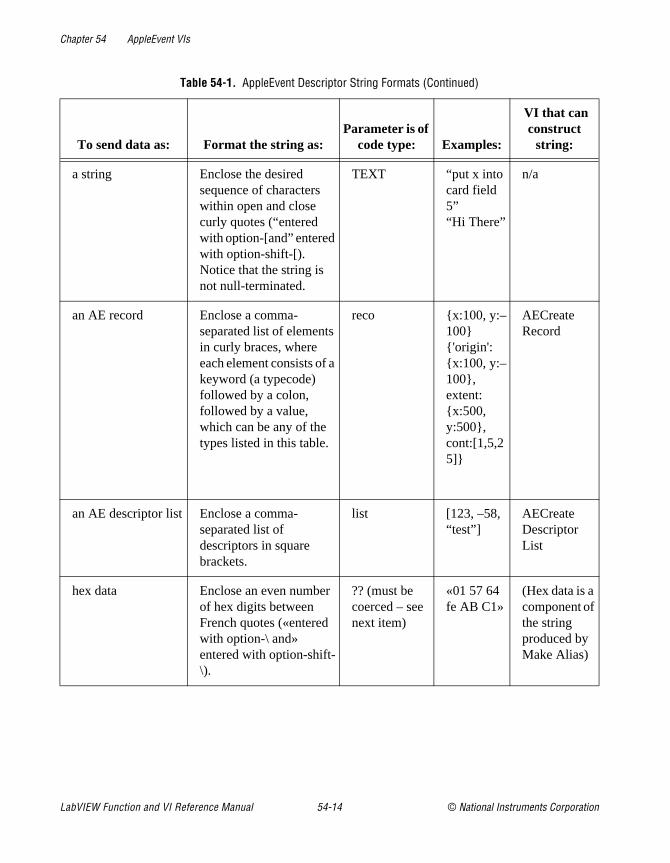
Chapter 54 AppleEvent VIs
a string Enclose the desired sequence of characters within open and close curly quotes (“entered with option-[and” entered with option-shift-[). Notice that the string is not null-terminated.
TEXT “put x into card field 5”“Hi There”
n/a
an AE record Enclose a comma-separated list of elements in curly braces, where each element consists of a keyword (a typecode) followed by a colon, followed by a value, which can be any of the types listed in this table.
reco x:100, y:–100 'origin':x:100, y:–100, extent:x:500, y:500, cont:[1,5,25]
AECreate Record
an AE descriptor list Enclose a comma-separated list of descriptors in square brackets.
list [123, –58, “test”]
AECreate Descriptor List
hex data Enclose an even number of hex digits between French quotes («entered with option-\ and» entered with option-shift-\).
?? (must be coerced – see next item)
«01 57 64 fe AB C1»
(Hex data is a component of the string produced by Make Alias)
Table 54-1. AppleEvent Descriptor String Formats (Continued)
To send data as: Format the string as:Parameter is of
code type: Examples:
VI that can construct
string:
LabVIEW Function and VI Reference Manual 54-14 © National Instruments Corporation

Chapter 54 AppleEvent VIs
he
ents
nts
Low-Level AppleEvent VIs
You can use the VIs in this section to construct AppleEvent parameters and send tAppleEvent. The high-level VIs for sending AppleEvents, described earlier in this chapter, are based on the AESend VI, and are good examples of creating AppleEvand their parameters.
To access the Low Level Apple Events palette, pop up on the Low Level Apple Eveicon.
some other data type Embed data created in one of the types of this table in parentheses and put the desired type code before it. If the data is a numeric, LabVIEW coerces the data to the specified type if possible and returns the errAECoercionFail error code if it cannot. If the data is of a different type, LabVIEW replaces the old typecode with the specified type code.
The specified type code
sing(1234)alis(«hex dump of an alias»)
type(line)rangstar: 5, stop: 6
n/aMake Alias creates a hex dump of a file description.
n/an/a
null data Coerce an empty string to no type.
null ( ) n/a
Table 54-1. AppleEvent Descriptor String Formats (Continued)
To send data as: Format the string as:Parameter is of
code type: Examples:
VI that can construct
string:
© National Instruments Corporation 54-15 LabVIEW Function and VI Reference Manual
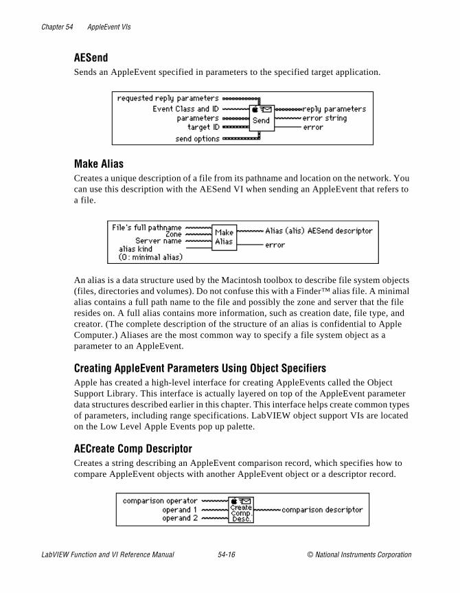
Chapter 54 AppleEvent VIs
. You rs to
jects mal file and le
t ter types ted
to .
AESendSends an AppleEvent specified in parameters to the specified target application.
Make AliasCreates a unique description of a file from its pathname and location on the networkcan use this description with the AESend VI when sending an AppleEvent that refea file.
An alias is a data structure used by the Macintosh toolbox to describe file system ob(files, directories and volumes). Do not confuse this with a Finder™ alias file. A minialias contains a full path name to the file and possibly the zone and server that theresides on. A full alias contains more information, such as creation date, file type, creator. (The complete description of the structure of an alias is confidential to AppComputer.) Aliases are the most common way to specify a file system object as a parameter to an AppleEvent.
Creating AppleEvent Parameters Using Object SpecifiersApple has created a high-level interface for creating AppleEvents called the ObjecSupport Library. This interface is actually layered on top of the AppleEvent paramedata structures described earlier in this chapter. This interface helps create commonof parameters, including range specifications. LabVIEW object support VIs are locaon the Low Level Apple Events pop up palette.
AECreate Comp DescriptorCreates a string describing an AppleEvent comparison record, which specifies howcompare AppleEvent objects with another AppleEvent object or a descriptor record
LabVIEW Function and VI Reference Manual 54-16 © National Instruments Corporation

Chapter 54 AppleEvent VIs
to the lex
e
ms, he nt to
VI.
with
For example, you can use the output comparison descriptor string as an argument AESend VI, or as an argument to AECreate Object Specifier to build a more compdescriptor string. See the Object Support VI Example section of this chapter for an exampleof its use.
AECreate Logical DescriptorCreates a string describing an AppleEvent logical descriptor, which you use with thAESend VI.
AppleEvent logical records describe logical, or Boolean expressions of multiple tersuch as the AND of two AppleEvent comparison records. For example, you can use toutput logical descriptor string as an argument to the AESend VI, or as an argumeAECreate Object Specifier VI to build a more complex descriptor string. See the Object Support VI Example in this chapter for an example of its use.
AECreate Object SpecifierCreates a string describing an AppleEvent object, which you use with the AESend
An object specifier is an AppleEvent record whose type is obj and describes a specific object. It has four elements: the class of the object, the containing object, a code indicating the form of the description, and the description of the object.
AECreate Range DescriptorCreates a string describing an AppleEvent range descriptor record, which you usethe AESend VI.
© National Instruments Corporation 54-17 LabVIEW Function and VI Reference Manual

Chapter 54 AppleEvent VIs
ge end
with for a
d with pes.
VIs. ing the
Range descriptor records are used in object specifiers whose key form is formRan(rang ). They describe a range of objects with two object specifiers: the start and theof the range
AECreate Descriptor ListCreates a string describing a list of AppleEvent descriptors, which you can then usethe AESend VI. You commonly use Descriptor lists when you create the operands logical descriptor
AECreate RecordCreates a string describing an AppleEvent descriptor record, which can then be usethe AESend VI. You can use a record descriptor to bundle descriptors of different tyEach descriptor has its own keyword, or name, and value
Object Support VI Example
The following example creates an AppleEvent parameter using the object support This example creates an AppleEvent parameter to be sent to a word processor, ask
LabVIEW Function and VI Reference Manual 54-18 © National Instruments Corporation
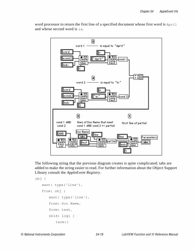
Chapter 54 AppleEvent VIs
e pport
word processor to return the first line of a specified document whose first word is April and whose second word is is .
The following string that the previous diagram creates is quite complicated; tabs aradded to make the string easier to read. For further information about the Object SuLibrary consult the AppleEvent Registry.
obj
want: type(‘line’),
from: obj
want: type('line'),
from: Doc Name,
form: test,
seld: logi
term:[
© National Instruments Corporation 54-19 LabVIEW Function and VI Reference Manual
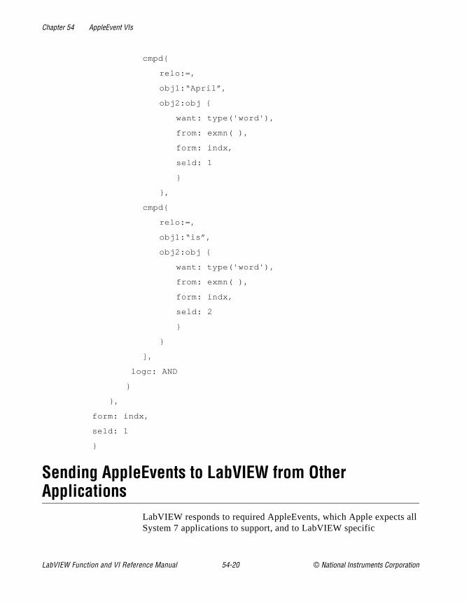
Chapter 54 AppleEvent VIs
all
cmpd
relo:=,
obj1:“April”,
obj2:obj
want: type('word'),
from: exmn( ),
form: indx,
seld: 1
,
cmpd
relo:=,
obj1:“is”,
obj2:obj
want: type('word'),
from: exmn( ),
form: indx,
seld: 2
],
logc: AND
,
form: indx,
seld: 1
Sending AppleEvents to LabVIEW from Other Applications
LabVIEW responds to required AppleEvents, which Apple expects System 7 applications to support, and to LabVIEW specific
LabVIEW Function and VI Reference Manual 54-20 © National Instruments Corporation

Chapter 54 AppleEvent VIs
re
n.
I,
n ed
EW
in
n ply
ply
t,
AppleEvents, designed specifically for LabVIEW. Both categories adescribed in the following sections.
Required AppleEventsLabVIEW responds to the required AppleEvents, which are Open Application, Open Documents, Print Documents, and Quit ApplicatioThese events are described in Inside Macintosh, Volume VI.
LabVIEW Specific AppleEventsLabVIEW also responds to the LabVIEW specific AppleEvents Run VAbort VI, VI Active?, and Close VI. With these events and the OpenDocuments AppleEvent, you can use other applications to programmatically tell LabVIEW to open a VI, run it, and close it wheit is finished. A thorough understanding of AppleEvents, as describin Inside Macintosh, Volume VI, and the AppleEvent Registry is a prerequisite for sending these AppleEvents to LabVIEW from otherapplications. You can send these events between two or more LabVIapplications by using the utility VIs described in the Sending AppleEvents section in Chapter 49, Communication Applications in LabVIEW.
The LabVIEW specific AppleEvents are described in later sections,a format similar to that used in the AppleEvent Registry.
Replies to AppleEventsIf LabVIEW is unable to perform an AppleEvent, the reply will contaian error code. If the error is not a standard AppleEvent error, the rewill also contain a string describing the error. The Error Codes manual summarizes the LabVIEW specific errors that can be returned in a reto an AppleEvent.
Event: Run VI
DescriptionTells LabVIEW to run the specified VI(s). Before executing this eventhe LabVIEW application must be running, and the VI must be open(you can open the VI using the Open Documents AppleEvent).
© National Instruments Corporation 54-21 LabVIEW Function and VI Reference Manual
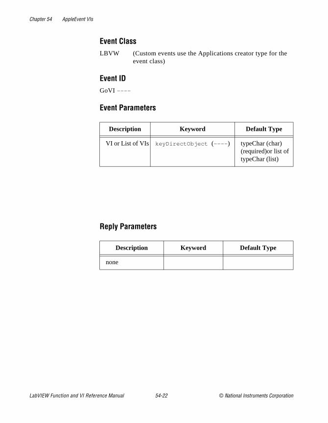
Chapter 54 AppleEvent VIs
Event ClassLBVW (Custom events use the Applications creator type for the
event class)
Event IDGoVI ----
Event Parameters
Reply Parameters
Description Keyword Default Type
VI or List of VIs keyDirectObject (---- ) typeChar (char) (required)or list of typeChar (list)
Description Keyword Default Type
none
LabVIEW Function and VI Reference Manual 54-22 © National Instruments Corporation
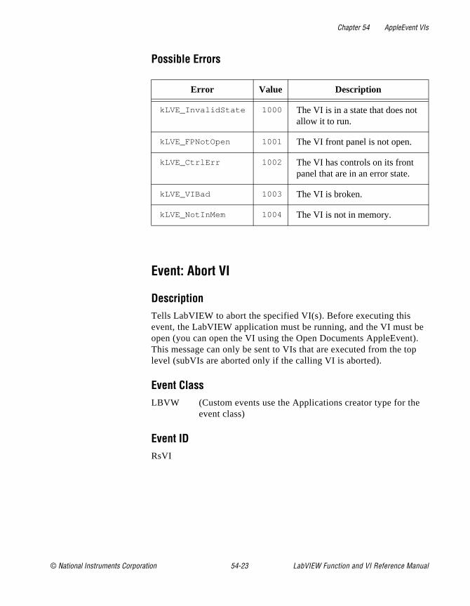
Chapter 54 AppleEvent VIs
e ). p
Possible Errors
Event: Abort VI
DescriptionTells LabVIEW to abort the specified VI(s). Before executing this event, the LabVIEW application must be running, and the VI must bopen (you can open the VI using the Open Documents AppleEventThis message can only be sent to VIs that are executed from the tolevel (subVIs are aborted only if the calling VI is aborted).
Event ClassLBVW (Custom events use the Applications creator type for the
event class)
Event IDRsVI
Error Value Description
kLVE_InvalidState 1000 The VI is in a state that does not allow it to run.
kLVE_FPNotOpen 1001 The VI front panel is not open.
kLVE_CtrlErr 1002 The VI has controls on its front panel that are in an error state.
kLVE_VIBad 1003 The VI is broken.
kLVE_NotInMem 1004 The VI is not in memory.
© National Instruments Corporation 54-23 LabVIEW Function and VI Reference Manual
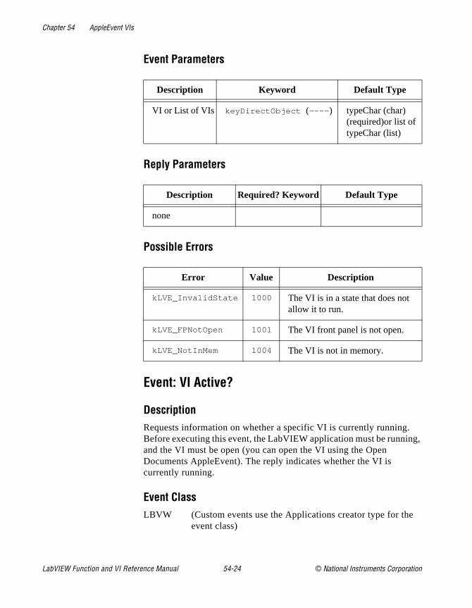
Chapter 54 AppleEvent VIs
ng,
Event Parameters
Reply Parameters
Possible Errors
Event: VI Active?
DescriptionRequests information on whether a specific VI is currently running.Before executing this event, the LabVIEW application must be runniand the VI must be open (you can open the VI using the Open Documents AppleEvent). The reply indicates whether the VI is currently running.
Event ClassLBVW (Custom events use the Applications creator type for the
event class)
Description Keyword Default Type
VI or List of VIs keyDirectObject (---- ) typeChar (char) (required)or list of typeChar (list)
Description Required? Keyword Default Type
none
Error Value Description
kLVE_InvalidState 1000 The VI is in a state that does not allow it to run.
kLVE_FPNotOpen 1001 The VI front panel is not open.
kLVE_NotInMem 1004 The VI is not in memory.
LabVIEW Function and VI Reference Manual 54-24 © National Instruments Corporation
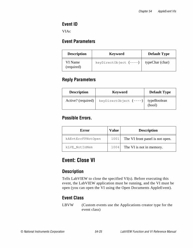
Chapter 54 AppleEvent VIs
e ).
Event IDVIAc
Event Parameters
Reply Parameters
Possible Errors.
Event: Close VI
DescriptionTells LabVIEW to close the specified VI(s). Before executing this event, the LabVIEW application must be running, and the VI must bopen (you can open the VI using the Open Documents AppleEvent
Event ClassLBVW (Custom events use the Applications creator type for the
event class)
Description Keyword Default Type
VI Name (required)
keyDirectObject (---- ) typeChar (char)
Description Keyword Default Type
Active? (required) keyDirectObject (---- ) typeBoolean (bool)
Error Value Description
kAEvtErrFPNotOpen 1001 The VI front panel is not open.
kLVE_NotInMem 1004 The VI is not in memory.
© National Instruments Corporation 54-25 LabVIEW Function and VI Reference Manual

Chapter 54 AppleEvent VIs
Event IDClVI
Event Parameters
Reply Parameters
Possible Errors.
Description Keyword Default Type
VI or List of VIs keyDirectObject (---- ) typeChar (char) (required)or list of typeChar (list)
Save Options (not required)
keyAESaveOptions (savo )
typeEnum (enum) possible values: yes and no
Description Keyword Default Type
none
Error Value Description
kAEvtErrFPNotOpen 1001 The VI front panel is not open.
kLVE_NotInMem 1004 The VI is not in memory.
cancelError 43 The user cancelled the close operation
LabVIEW Function and VI Reference Manual 54-26 © National Instruments Corporation
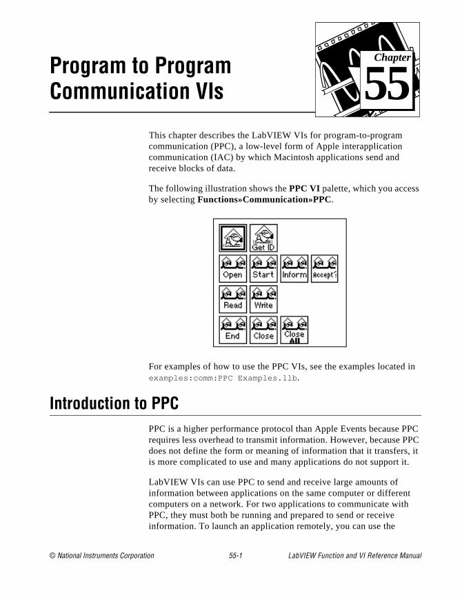
© National Instruments Corporation 55-1 LabVIEW Function and
Chapter
55
Program to Program Communication VIsd in
PPC PC
, it t.
t
This chapter describes the LabVIEW VIs for program-to-program communication (PPC), a low-level form of Apple interapplication communication (IAC) by which Macintosh applications send and receive blocks of data.
The following illustration shows the PPC VI palette, which you accessby selecting Functions»Communication»PPC.
For examples of how to use the PPC VIs, see the examples locateexamples:comm:PPC Examples.llb .
Introduction to PPCPPC is a higher performance protocol than Apple Events because requires less overhead to transmit information. However, because Pdoes not define the form or meaning of information that it transfersis more complicated to use and many applications do not support i
LabVIEW VIs can use PPC to send and receive large amounts of information between applications on the same computer or differencomputers on a network. For two applications to communicate withPPC, they must both be running and prepared to send or receive information. To launch an application remotely, you can use the
VI Reference Manual
Chapter 55 Program to Program Communication VIs
C rver ver sion n
do
PC uent
port
PPC
e ion.
can ide out
r
t its
Read ed
AESend Finder Open VI, which is described in the AppleEvents section of Chapter 49, Communication Applications in LabVIEW.
General PPC BehaviorTo communicate using PPC, each application must open a named port, over which communication sessions are established, as shown in Figure 55-1. The application that requests communication is the client; and the application with which the client communicates is the server. The server application makes its availability known by issuing a PPInform Session operation. The client requests a session with the seapplication, which can either accept or reject the request. If the serapplication accepts the request, then the system establishes a sesand the two applications can send and receive blocks of informatiobetween them. When the applications finish communicating, you should end the session. You may also want to close the port if younot want to establish more sessions with that port.
You use the PPC Open Port VI to open a port for communication. POpen Port returns a port reference number, which you use in subseqoperations relating to that port. You can have multiple ports open simultaneously, as long as they each have a different name. Each can support multiple sessions.
You can initiate a session using the PPC Start Session VI. You passStart Session a target ID (see the General Apple Event VI Behavior section of Chapter 54, Apple Event VIs) and the port reference numberthrough which you want to communicate. If the target application accepts the session, PPC Start Session returns a session referencnumber, which you use in subsequent communication for that sessPPC Start Session also incorporates an authentication (password) mechanism.
To receive session requests, use the PPC Inform Session VI. You configure this VI to accept all requests automatically, or you can decwhether to accept or reject the request based on the information abthe requesting application that this VI returns. You should accept oreject the request using the PPC Accept Session VI immediately, because the other computer waits (hangs) until you accept or rejecattempt to initiate a session, or until an error occurs.
When a session is established, you can use the PPC Write and PPCVIs to communicate with the other application. When you are finish
LabVIEW Function and VI Reference Manual 55-2 © National Instruments Corporation

Chapter 55 Program to Program Communication VIs
ose
with a session, you should execute the PPC End Session VI and clthe port using the PPC Close Port VI.Figure 55-1 illustrates the order in which you use the PPC VIs.
Figure 55-1. PPC VI Execution Order (Used by permission of Apple Computer, Inc.)
PPC VI Descriptions
The following PPC VIs are available.
PPC Accept SessionAccepts or rejects a PPC session request based on the Boolean accept?.
© National Instruments Corporation 55-3 LabVIEW Function and VI Reference Manual
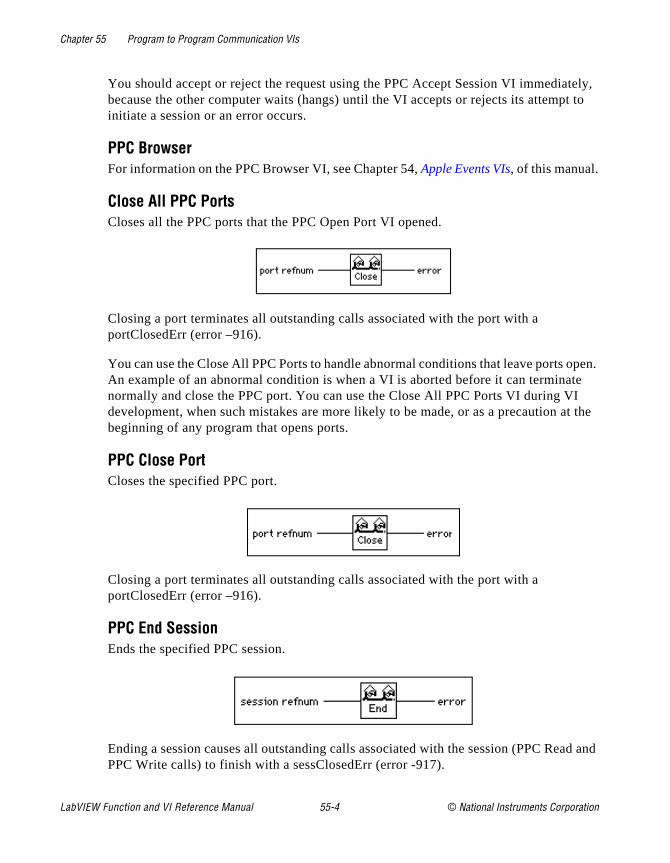
Chapter 55 Program to Program Communication VIs
tely, t to
open. te I t the
ad and
You should accept or reject the request using the PPC Accept Session VI immediabecause the other computer waits (hangs) until the VI accepts or rejects its attempinitiate a session or an error occurs.
PPC BrowserFor information on the PPC Browser VI, see Chapter 54, Apple Events VIs, of this manual.
Close All PPC PortsCloses all the PPC ports that the PPC Open Port VI opened.
Closing a port terminates all outstanding calls associated with the port with a portClosedErr (error –916).
You can use the Close All PPC Ports to handle abnormal conditions that leave portsAn example of an abnormal condition is when a VI is aborted before it can terminanormally and close the PPC port. You can use the Close All PPC Ports VI during Vdevelopment, when such mistakes are more likely to be made, or as a precaution abeginning of any program that opens ports.
PPC Close PortCloses the specified PPC port.
Closing a port terminates all outstanding calls associated with the port with a portClosedErr (error –916).
PPC End SessionEnds the specified PPC session.
Ending a session causes all outstanding calls associated with the session (PPC RePPC Write calls) to finish with a sessClosedErr (error -917).
LabVIEW Function and VI Reference Manual 55-4 © National Instruments Corporation

Chapter 55 Program to Program Communication VIs
Get Target IDFor information on the Get Target ID VI, see Chapter 54, Apple Event VIs, of this manual.
PPC Inform SessionWaits for a PPC session request.
PPC Open PortOpens a port for PPC communication and returns a unique port reference number inport refnum. You can use a single port for multiple sessions.
When opening a port using PPC Open Port, you must specify a portName cluster.
Refer to the LabVIEW online help for more information on this VI.
© National Instruments Corporation 55-5 LabVIEW Function and VI Reference Manual
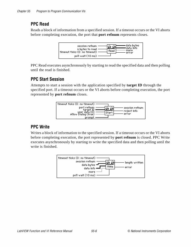
Chapter 55 Program to Program Communication VIs
borts
polling
port
orts
il the
PPC ReadReads a block of information from a specified session. If a timeout occurs or the VI abefore completing execution, the port that port refnum represents closes.
PPC Read executes asynchronously by starting to read the specified data and then until the read is finished.
PPC Start SessionAttempts to start a session with the application specified by target ID through the specified port. If a timeout occurs or the VI aborts before completing execution, therepresented by port refnum closes.
PPC WriteWrites a block of information to the specified session. If a timeout occurs or the VI abbefore completing execution, the port represented by port refnum is closed. PPC Write executes asynchronously by starting to write the specified data and then polling untwrite is finished.
LabVIEW Function and VI Reference Manual 55-6 © National Instruments Corporation
© National Instruments Corporation A-1 LabVIEW Function an
Appendix
A
DAQ Hardware Capabilitiesl
The
a
This appendix contains tables that summarize the analog and digitaI/O capabilities of National Instruments data acquisition (DAQ) devices. The devices in this appendix are grouped into categories. DAQ device categories for these tables include the following.
• MIO and AI Devices
• Lab and 1200 Series and Portable Devices
• 54xx Series Devices
• SCXI Modules
• Dynamic Signal Acquisition Devices
• Analog Output Only Devices
• Digital Only Devices
• Timing Only Devices
• 5102 Devices Hardware Capabilities
Note: (Macintosh) When a NuBus device indicates it supports DMA transfers, DMA device (such as an NB-DMA2800) is also required.
d VI Reference Manual

Appendix A DAQ Hardware Capabilities
re ice. the el” h eter
MIO and AI Device Hardware Capabilities
“By device” means you select the value of a parameter with hardwajumpers, and the selection affects any group of channels on the dev“By group” means you program the selection through software, and selection affects all the channels used at the same time. “By channmeans you program the selection with hardware jumpers or througsoftware on a per channel basis. When a specific value for a paramis shown, that parameter value is fixed.
Table A-1. Analog Input Configuration Programmability—MIO and AI Devices
Device Gain Range Polarity SE/DIFF Coupling
All MIO-E Series DevicesAll AI-E Series Devices
By Channel By Channel By Channel By Channel DC
AT-MIO-16F-5 By Channel By Group By Group By Group DC
AT-MIO-64F-5AT-MIO-16X
By Channel By Channel By Channel By Channel DC
AT-MIO-16/16DNB-MIO-16NB-MIO-16X
By Channel By Device By Device By Device DC
Table A-2. Analog Input Characteristics—MIO and AI Devices (Part 1)
DeviceNumber ofChannels Resolution Gains1
Range (V)1 Input FIFO(words) Scanning2
AT-MIO-16E-1AT-MIO-16E-2AT-MIO-16E-10AT-MIO-16DE-10NEC-MIO-16E-4PCI-MIO-16E-1PCI-MIO-16E-4NEC-AI-16E-4
16SE, 8DI 12 bits 0.5, 1, 2, 5, 10, 20, 50, 100
±5, 0 to 10 512; E-1: 8,192; E-2 and E4: 2,048
Up to 512
AT-MIO-64E-3* 64SE, 32DI 12 bits 0.5, 1, 2, 5, 10, 20, 50, 100
±5, 0 to 10 2,048 Up to 512
PCI-MIO-16XE-10 16SE, 8DI 16 bits 1, 2, 5, 10, 20, 50,100
±10, 0 to 10 512 Up to 512
LabVIEW Function and VI Reference Manual A-2 © National Instruments Corporation
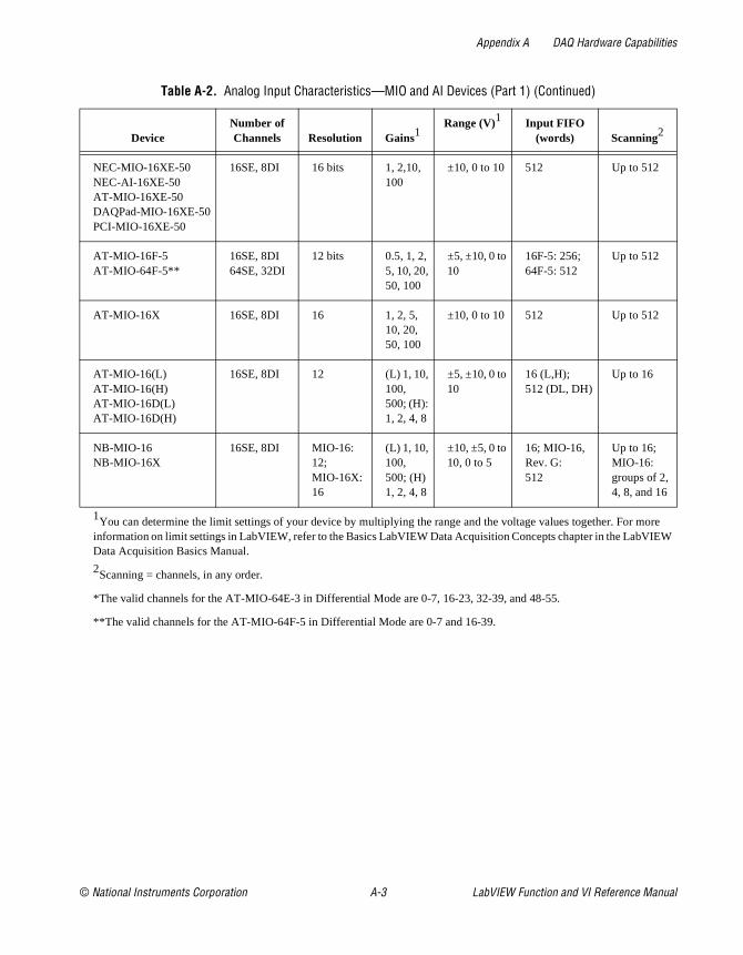
Appendix A DAQ Hardware Capabilities
ore EW
NEC-MIO-16XE-50NEC-AI-16XE-50AT-MIO-16XE-50DAQPad-MIO-16XE-50PCI-MIO-16XE-50
16SE, 8DI 16 bits 1, 2,10, 100
±10, 0 to 10 512 Up to 512
AT-MIO-16F-5AT-MIO-64F-5**
16SE, 8DI64SE, 32DI
12 bits 0.5, 1, 2, 5, 10, 20, 50, 100
±5, ±10, 0 to 10
16F-5: 256; 64F-5: 512
Up to 512
AT-MIO-16X 16SE, 8DI 16 1, 2, 5, 10, 20, 50, 100
±10, 0 to 10 512 Up to 512
AT-MIO-16(L)AT-MIO-16(H)AT-MIO-16D(L)AT-MIO-16D(H)
16SE, 8DI 12 (L) 1, 10, 100, 500; (H): 1, 2, 4, 8
±5, ±10, 0 to 10
16 (L,H); 512 (DL, DH)
Up to 16
NB-MIO-16NB-MIO-16X
16SE, 8DI MIO-16: 12; MIO-16X: 16
(L) 1, 10, 100, 500; (H) 1, 2, 4, 8
±10, ±5, 0 to 10, 0 to 5
16; MIO-16, Rev. G:512
Up to 16; MIO-16: groups of 2, 4, 8, and 16
1You can determine the limit settings of your device by multiplying the range and the voltage values together. For minformation on limit settings in LabVIEW, refer to the Basics LabVIEW Data Acquisition Concepts chapter in the LabVIData Acquisition Basics Manual.
2Scanning = channels, in any order.
*The valid channels for the AT-MIO-64E-3 in Differential Mode are 0-7, 16-23, 32-39, and 48-55.
**The valid channels for the AT-MIO-64F-5 in Differential Mode are 0-7 and 16-39.
Table A-2. Analog Input Characteristics—MIO and AI Devices (Part 1) (Continued)
DeviceNumber ofChannels Resolution Gains1
Range (V)1 Input FIFO(words) Scanning2
© National Instruments Corporation A-3 LabVIEW Function and VI Reference Manual
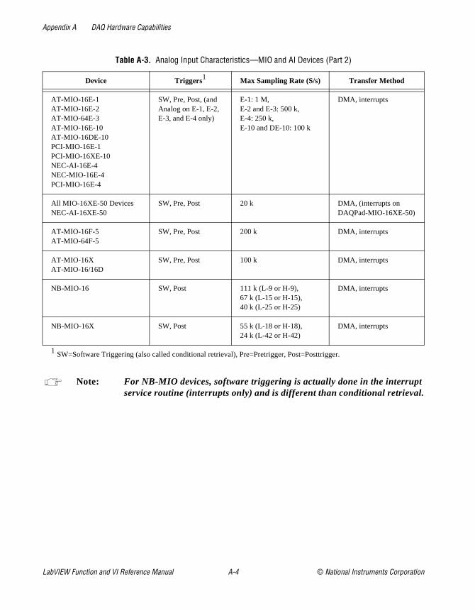
Appendix A DAQ Hardware Capabilities
.
.
Note: For NB-MIO devices, software triggering is actually done in the interruptservice routine (interrupts only) and is different than conditional retrieval
Table A-3. Analog Input Characteristics—MIO and AI Devices (Part 2)
Device Triggers1 Max Sampling Rate (S/s) Transfer Method
AT-MIO-16E-1AT-MIO-16E-2AT-MIO-64E-3AT-MIO-16E-10AT-MIO-16DE-10PCI-MIO-16E-1PCI-MIO-16XE-10NEC-AI-16E-4NEC-MIO-16E-4PCI-MIO-16E-4
SW, Pre, Post, (and Analog on E-1, E-2, E-3, and E-4 only)
E-1: 1 M, E-2 and E-3: 500 k, E-4: 250 k, E-10 and DE-10: 100 k
DMA, interrupts
All MIO-16XE-50 DevicesNEC-AI-16XE-50
SW, Pre, Post 20 k DMA, (interrupts on DAQPad-MIO-16XE-50)
AT-MIO-16F-5AT-MIO-64F-5
SW, Pre, Post 200 k DMA, interrupts
AT-MIO-16XAT-MIO-16/16D
SW, Pre, Post 100 k DMA, interrupts
NB-MIO-16 SW, Post 111 k (L-9 or H-9), 67 k (L-15 or H-15), 40 k (L-25 or H-25)
DMA, interrupts
NB-MIO-16X SW, Post 55 k (L-18 or H-18), 24 k (L-42 or H-42)
DMA, interrupts
1 SW=Software Triggering (also called conditional retrieval), Pre=Pretrigger, Post=Posttrigger.
LabVIEW Function and VI Reference Manual A-4 © National Instruments Corporation

Appendix A DAQ Hardware Capabilities
Table A-4. Analog Output Characteristics—MIO and AI Devices
Device
Cha
nnel
Num
bers
DA
C T
ype
Out
put L
imits
Upd
ate
Clo
cks
Wav
efor
m G
roup
ing
Tra
nsfe
r M
etho
d
All MIO-16E DevicesAT-MIO-16DE-10AT-MIO-64 E-3AT-MIO-16XE-50DAQPad-MIO-16XE-50PCI-MIO-16E-1PCI-MIO-16E-4PCI-MIO-16XE-50
0, 1 12-bit double buffered(E-1, E-2, 64E-3, and E-4: 2 K FIFO)
0 to 10, ±10, ±Vref, 0 to Vref (only ±10 on XE-50 devices)
Update clock 1 or external update.
0, 1, or 0 and 1
DMA, interrupts
PCI-MIO-16XE-10 16-bit ±10,0 to 10
AT-MIO-16F-5AT-MIO-64F-5
0, 1 12-bit double buffered (64F-5: 2 K FIFO)
0 to 10, ±10, ±Vref, 0 to Vref
Update clock 1 is first available of ctr 5, 2, 1 or external update. Default is 5. Timebase signal range is 5,000,000, 1,000,000, 100,000, 10,000, 1,000, and 100.
0, 1, or 0 and 1
DMA, interrupts
AT-MIO-16X 0, 1 16-bit double buffered(2 K FIFO)
±10, 0 to 10, ±Vref, 0 to Vref
Update clock 1 is first available on ctr 5, 2, 1, or external update. Timebase signal range is 5,000,000, 1,000,000, 100,000, 10,000, 1,000, 100.
0, 1, or 0 and 1
DMA, interrupts
© National Instruments Corporation A-5 LabVIEW Function and VI Reference Manual
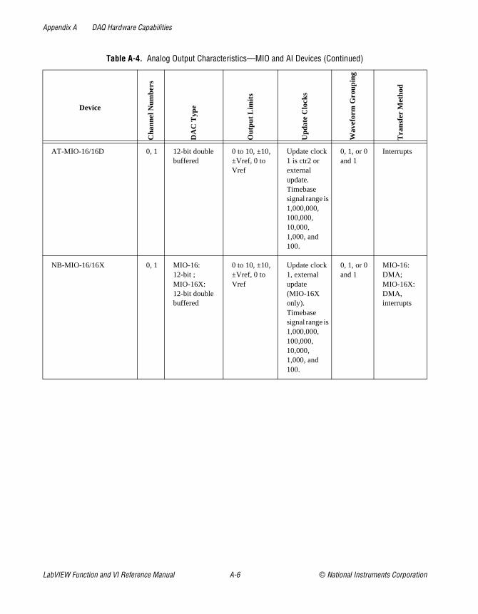
Appendix A DAQ Hardware Capabilities
AT-MIO-16/16D 0, 1 12-bit double buffered
0 to 10, ±10, ±Vref, 0 to Vref
Update clock 1 is ctr2 or external update. Timebase signal range is 1,000,000, 100,000, 10,000, 1,000, and 100.
0, 1, or 0 and 1
Interrupts
NB-MIO-16/16X 0, 1 MIO-16:12-bit ; MIO-16X: 12-bit double buffered
0 to 10, ±10, ±Vref, 0 to Vref
Update clock 1, external update (MIO-16X only). Timebase signal range is 1,000,000, 100,000, 10,000, 1,000, and 100.
0, 1, or 0 and 1
MIO-16:DMA; MIO-16X: DMA, interrupts
Table A-4. Analog Output Characteristics—MIO and AI Devices (Continued)
Device
Cha
nnel
Num
bers
DA
C T
ype
Out
put L
imits
Upd
ate
Clo
cks
Wav
efor
m G
roup
ing
Tra
nsfe
r M
etho
d
LabVIEW Function and VI Reference Manual A-6 © National Instruments Corporation

Appendix A DAQ Hardware Capabilities
Table A-5. Digital I/O Hardware Capabilities—MIO and AI Devices
DevicePort Type
Port Numbers
Handshake Modes Direction
DIO Clocks
Transfer Method
All MIO-16 DevicesAT-MIO-16D1
AT-MIO-64F-5
4-bit ports
0, 1 No handshaking Read or write None Software polling
All MIO-16E DevicesAll NEC-E Series DevicesAT-MIO-64E-3AT-MIO-16DE-101
AT-MIO-16XE-50DAQPad-MIO-16XE-50PCI-MIO-16XE-50
8-bit ports
0 No handshaking Bit-wise direction control
None Software polling
AT-MIO-16D1
AT-MIO-16DE-1018-bit ports
2, 3 Handshaking on or off
Read or write, port 2 may be bi-directional
None Interrupts
8-bit ports
4 No handshaking;Unusable if port 2 or 3 uses handshaking
Read or write None Software polling
1 These devices appear more than once in this table, because they have enhanced digital functionality.
© National Instruments Corporation A-7 LabVIEW Function and VI Reference Manual

Appendix A DAQ Hardware Capabilities
65536,
CXI
Table A-6. Counter Characteristics—MIO and AI Devices
Device
Cou
nter
Chi
p U
sed
# of
Gen
eral
Pur
pose
Cou
nter
s A
vaila
ble
Tim
ebas
es A
vaila
ble
Num
ber
of B
its
Gat
e M
odes
Ava
ilabl
e
Out
-put
s A
vaila
ble
Out
put M
odes
Ava
ilabl
e
Cou
nt D
irect
ion
1
E Series Devices DAQ-STC 2 2 internal: 20 MHz or 100 kHz; external
24 rising-edge, falling-edge, high-level, low-level
2 up or down, can be SW- or HW-controlled
AT-MIO-16F-5AT-MIO-64F-5AT-MIO-16/16DNB-MIO-16/16X
Am-9513 3 5 or 6 internal: 5 MHz (only on CTR2 of 16F-5, 64F-5, and AT-MIO-16X), 1 MHz, 100 kHz, 10 kHz, 1 kHz, 100 Hz; external
16 rising-edge, falling-edge, high-level, low-level
2 TC pulse or TC toggle
Up
1SW = Software; HW = Hardware.
Table A-7. Counter Usage for Analog Input and Output—MIO and AI Devices
Device nameCounter Chip
UsedAI Channel
ClockAI Sample Counter AI Scan Clock AO Update Clock
E Series Devices DAQ-STC The DAQ-STC chip uses dedicated clocks for these purposes.
AT-MIO-16F-5AT-MIO-64F-5AT-MIO-16X
Am9513 Ctr 3 Ctr 4 (& 5)1 Ctr 2 (or 1)2 Ctr 5, 2 or 1
AT-MIO-16/16DNB-MIO-16X
Am9513 Ctr 3 Ctr 4 (& 5)1 Ctr 2 (or 1)2 Ctr 2 (and via DMA for NB-MIO-16X)
NB-MIO-16 Am9513 Ctr 3 Ctr 4 (& 5)1 None (or 1)2 (via DMA)
1 If the total number of samples is less than 65535, only the first counter is used. If the number of samples exceedsthe first counter is used together with the second counter as a 32-bit sample counter.
2 Ctr 2 (or no counter for NB-MIO-16) is used for normal scanning operations, and Ctr 1 is used for AMUX-64T and Shardware scanning.
LabVIEW Function and VI Reference Manual A-8 © National Instruments Corporation
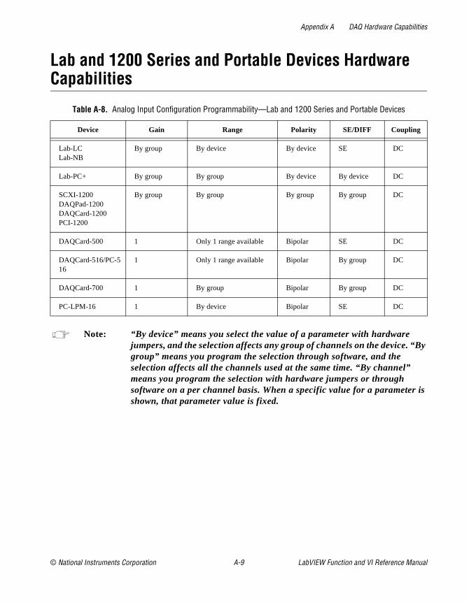
Appendix A DAQ Hardware Capabilities
y
is
Lab and 1200 Series and Portable Devices Hardware Capabilities
Note: “By device” means you select the value of a parameter with hardware jumpers, and the selection affects any group of channels on the device. “Bgroup” means you program the selection through software, and the selection affects all the channels used at the same time. “By channel” means you program the selection with hardware jumpers or through software on a per channel basis. When a specific value for a parametershown, that parameter value is fixed.
Table A-8. Analog Input Configuration Programmability—Lab and 1200 Series and Portable Devices
Device Gain Range Polarity SE/DIFF Coupling
Lab-LCLab-NB
By group By device By device SE DC
Lab-PC+ By group By group By device By device DC
SCXI-1200DAQPad-1200DAQCard-1200PCI-1200
By group By group By group By group DC
DAQCard-500 1 Only 1 range available Bipolar SE DC
DAQCard-516/PC-516
1 Only 1 range available Bipolar By group DC
DAQCard-700 1 By group Bipolar By group DC
PC-LPM-16 1 By device Bipolar SE DC
© National Instruments Corporation A-9 LabVIEW Function and VI Reference Manual

Appendix A DAQ Hardware Capabilities
ore EW
Table A-9. Analog Input Characteristics—Lab and 1200 Series and Portable Devices (Part 1)
DeviceNumber ofChannels
Resolution(bits) Gains1 Range (V)1
Input FIFO(samples)
Lab-LCLab-NB
8SE 12 1, 2, 5, 10, 20, 50, 100 ±5, 0 to 10 16
Lab-PC+SCXI-1200DAQPad-1200DAQCard-1200PCI-1200
8SE, 4DI 12 1, 2, 5, 10 20, 50, 100 ±5, 0 to 10 2,048; Lab-PC: 512
DAQCard-500 8SE 12 1 ±5 16
DAQCard 516PC516
8SE,4DI 16 1 +/-5 512
DAQCard-700 16SE, 8DI 12 1 ±10, ±5, ±2.5 512
PC-LPM-16 16SE 12 1 ±5, ±2.5, 0 to 10, 0 to 5
16
1 You can determine the limit settings of your device by multiplying the range and the voltage values together. For minformation on limit settings in LabVIEW, refer to the Basics LabVIEW Data Acquisition Concepts chapter in the LabVIData Acquisition Basics Manual.
Table A-10. Analog Input Characteristics—Lab and 1200 Series and Portable Devices (Part 2)
Device Scanning Triggers
MaxSamplingRate (S/s)
Transfer Method
Lab-LCLab-NB
Any single channel; for multiple channels, N through 0, where N<=7
Software trigger, pretrigger, and posttrigger with digital trigger
62.5 k Interrupts
Lab-PC+SCXI-1200DAQPad-1200DAQCard-1200
Any single channel; for multiple channels, N through 0, where N<=7.
Software trigger, pretrigger, and posttrigger with digital trigger
100 k; Lab-PC+: 83 k
Interrupts; Lab-PC+: Interrupts, DMA
DAQCard-500 DAQCard 516PC-516
Any single channel; for multiple channels, N through 0, where N<=7
Software trigger only 50 k Interrupts
LabVIEW Function and VI Reference Manual A-10 © National Instruments Corporation

Appendix A DAQ Hardware Capabilities
Note: The DAQCard-516 and PC 516 devices do not have analog output.
DAQCard-700 Any single channel; for multiple channels, N through 0, where N#15
Software trigger only 100 k Interrupts
PC-LPM-16 Any single channel; for multiple channels, N through 0, where N#15
Software trigger only 50 k Interrupts
Table A-11. Analog Output Characteristics—Lab and 1200 Series and Portable Devices
DeviceChannel
#sDACType
OutputLimits
(V) Update ClocksWaveformGrouping
TransferMethods
Lab-NBLab-LC
0, 1 12-bit double-buffered
0 to 10, ±5 Update clock 1 is ctrA2 or external update; timebase is 1 MHz or ctrB0
0, 1, or 0 and 1 Interrupts
Lab-PC+SCXI-1200DAQPad-1200DAQCard-1200PCI-1200
0, 1 12-bit double-buffered
0 to 10, ±5 Update clock 1 is ctrA2 or external update; timebase signal range is 1,000,000, 100,000, 10,000, 1,000, and 100
0, 1, or 0 and 1 Interrupts
Table A-10. Analog Input Characteristics—Lab and 1200 Series and Portable Devices (Part 2) (Continued)
Device Scanning Triggers
MaxSamplingRate (S/s)
Transfer Method
© National Instruments Corporation A-11 LabVIEW Function and VI Reference Manual
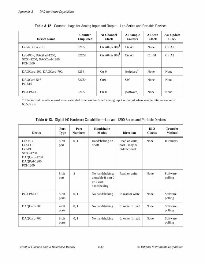
Appendix A DAQ Hardware Capabilities
eds
Table A-12. Counter Usage for Analog Input and Output—Lab Series and Portable Devices
Device NameCounter
Chip UsedAI Channel
ClockAI SampleCounter
AI ScanClock
AO UpdateClock
Lab-NB, Lab-LC 82C53 Ctr A0 (& B0)1 Ctr A1 None Ctr A2
Lab-PC+, DAQPad-1200, SCXI-1200, DAQCard-1200, PCI-1200
82C53 Ctr A0 (& B0)1 Ctr A1 Ctr B1 Ctr A2
DAQCard-500, DAQCard-700, 8254 Ctr 0 (software) None None
DAQCard 516PC-516
82C54 Ctr0 SW None None
PC-LPM-16 82C53 Ctr 0 (software) None None
1 The second counter is used as an extended timebase for timed analog input or output when sample interval exce65.535 ms.
Table A-13. Digital I/O Hardware Capabilities—Lab and 1200 Series and Portable Devices
DevicePortType
PortNumbers
HandshakeModes Direction
DIOClocks
TransferMethod
Lab-NBLab-LCLab-PC+SCXI-1200DAQCard-1200DAQPad-1200PCI-1200
8-bit port
0, 1 Handshaking on or off
Read or write, port 0 may be bidirectional
None Interrupts
8-bit port
2 No handshaking;unusable if port 0 or 1 uses handshaking
Read or write None Software polling
PC-LPM-16 8-bit ports
0, 1 No handshaking 0: read or write None Software polling
DAQCard-500 4-bit ports
0, 1 No handshaking 0: write, 1: read None Software polling
DAQCard-700 8-bit ports
0, 1 No handshaking 0: write, 1: read None Software polling
LabVIEW Function and VI Reference Manual A-12 © National Instruments Corporation
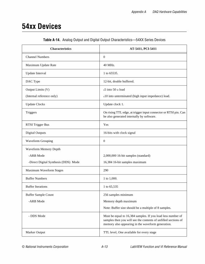
Appendix A DAQ Hardware Capabilities
n
54xx Devices
Table A-14. Analog Output and Digital Output Characteristics—54XX Series Devices
Characteristics AT-5411, PCI-5411
Channel Numbers 0
Maximum Update Rate 40 MHz.
Update Interval 1 to 65535.
DAC Type 12-bit, double buffered.
Output Limits (V)
(Internal reference only)
±5 into 50 Ω load
±10 into unterminated (high input impedance) load.
Update Clocks Update clock 1.
Triggers On rising TTL edge, at trigger input connector or RTSI pin. Cabe also generated internally by software.
RTSI Trigger Bus Yes
Digital Outputs 16-bits with clock signal
Waveform Grouping 0
Waveform Memory Depth
-ARB Mode
-Direct Digital Synthesis (DDS) Mode
2,000,000 16-bit samples (standard)
16,384 16-bit samples maximum
Maximum Waveform Stages 290
Buffer Numbers 1 to 1,000.
Buffer Iterations 1 to 65,535
Buffer Sample Count
-ARB Mode
256 samples minimum
Memory depth maximum
Note: Buffer size should be a multiple of 8 samples.
- DDS Mode Must be equal to 16,384 samples. If you load less number of samples then you will see the contents of unfilled sections of memory also appearing in the waveform generation.
Marker Output TTL level, One available for every stage
© National Instruments Corporation A-13 LabVIEW Function and VI Reference Manual

Appendix A DAQ Hardware Capabilities
r
Note: Refer to your hardware user reference manual for default settings of youdevice.DDS Accumulator Size 32-bit
Maximum Output Frequency 16 MHz
Output Frequency Resolution (DDS Mode only) 9.31 mHz
Output Attenuation (after the DAC) 0 through 74.000 dB (Decibels) in 0.001 dB steps
SYNC Output Duty Cycle (% High) TTL level, 20% to 80%.
PLL Reference Clock 1 MHz, 10 MHz or 20 MHz
Output Enable software switchable to ON or OFF
Output Impedance 50Ω or 75Ω (video), software selectable
Low-Pass Filter 16 MHz, software switchable to ON or OFF
Digital Half-Band Interpolating Filter 80 MSPS, software switchable to ON or OFF
Trigger Operation Modes Single, Continuous, Stepped and Burst
Table A-14. Analog Output and Digital Output Characteristics—54XX Series Devices (Continued)
Characteristics AT-5411, PCI-5411
LabVIEW Function and VI Reference Manual A-14 © National Instruments Corporation

Appendix A DAQ Hardware Capabilities
SCXI Module Hardware Capabilities
Table A-15. Counter/Timer Characteristics -- Lab and 1200 Series and Portable Devices
Device
Cou
nter
Chi
p U
sed
# of
Gen
. Pur
pose
Cou
nter
s A
vaila
ble
Tim
ebas
es A
vaila
ble
Num
ber
of B
its
Gat
e M
odes
Ava
ilabl
e
Out
puts
Ava
ilabl
e
Out
put M
odes
Ava
ilabl
e
Cou
nt D
irect
ion
Lab-NBLab-LCLab-PC+SCXI-1200DAQCard-1200DAQPad-1200PC-LPM-16PCI-1200
8253 3 (2 with SOURCE input at I/O Connector)
Internal: 1 MHz; (PC-LPM-16: only on CTRB0) external
16 high-level or rising-edgedependingon output mode
3 Refer to ICTRControl VI description on modes in Chapter 19, Advanced Counter VIs.
down
DAQCard-500DAQCard 516DAQCard-700 PC-516
8254 3 (2 with SOURCE input at I/O Connector)
Internal: 1 MHz only on CTRB0; external
16 high-level or rising-edgedependingon output mode
3 (2 for DAQCard-500)
Refer to ICTRControl VI description on modes in Chapter 19, Advanced Counter VIs.
down
Table A-16. Analog Input Characteristics—SCXI Modules (Part 1)
ModuleNumber of Channels
Input Voltage
Range (V) Gains1 Filter 1Excitation Channels1 Mode Support
SCXI-1100 32 DI ±10 1, 2, 5, 10, 20, 50, 100, 200, 500, 1,000, 2,000 (SW/M)1
lowpass filter (or no filter) with 10 kHz or 4 Hz cutoff frequency(JS/M)1
— multiplexed
SCXI-1102 32 DI ±10 1, 100 (SW/C)1 1 Hz lowpass on each channel
— multiplexed
© National Instruments Corporation A-15 LabVIEW Function and VI Reference Manual

Appendix A DAQ Hardware Capabilities
odule,
ith the
SCXI-1120SCXI-1121
8 DI(SCXI-1120)4 DI(SCXI-1121)
±5 1, 2, 5, 10, 20, 50, 100, 200, 500, 1,000, and 2,000(JS/C)1
lowpass filter with 10 kHz or 4 Hz cutoff frequency (JS/C)1
SCXI-1121 only: 4 voltage or current excitation JS/C 1 (channels)
multiplexed or parallel
SCXI-1120D 8 DI(SCXI-1120)4 DI(SCXI-1121)
±5 0.5, 1, 2.5, 5, 10, 25, 50, 100, 250, 500, 1,000
4,500, 24,500 Hz
SCXI-1121 only: 4 voltage or current excitation JS/C 1 (channels)
multiplexed or parallel
SCXI-1122 16 DI or 8 DI and 8 excitation SW/M1 channels
±10 0.01, 0.02, 0.05, 0.1, 0.2, 0.5, 1, 2, 5, 10, 20, 50, 100, 200, 500, 1,000, 2,000(SW/M)1
lowpass filter with 4kHz or 4 Hz cutoff frequency
8 voltage or current excitation channels in4-wire scanning mode
multiplexed
SCXI-1140 8 DI, sample and hold
±10 1, 10, 100, 200, 500 (DS/C)1
none — multiplexed or parallel
SCXI-1141 8 DI ±5 1, 2, 5, 10, 20, 50, 100 (SW/C)1
elliptic lowpass filter with 10Hz to 25KHz cutoff frequency2 (SW/M)1 (disabled on a per channel basis)
— multiplexed or parallel
1 DS/C = dip switch-selectable per channel, JS/C = jumper-selectable per channel, JS/M = jumper-selectable per mSW/C = software-selectable per channel, SW/M = software-selectable per module
2 The SCXI-1141 has an automatic filter setting. LabVIEW sets the filter frequency based on the scan rates used wmodule.
Table A-16. Analog Input Characteristics—SCXI Modules (Part 1) (Continued)
ModuleNumber of Channels
Input Voltage
Range (V) Gains1 Filter 1Excitation Channels1 Mode Support
LabVIEW Function and VI Reference Manual A-16 © National Instruments Corporation
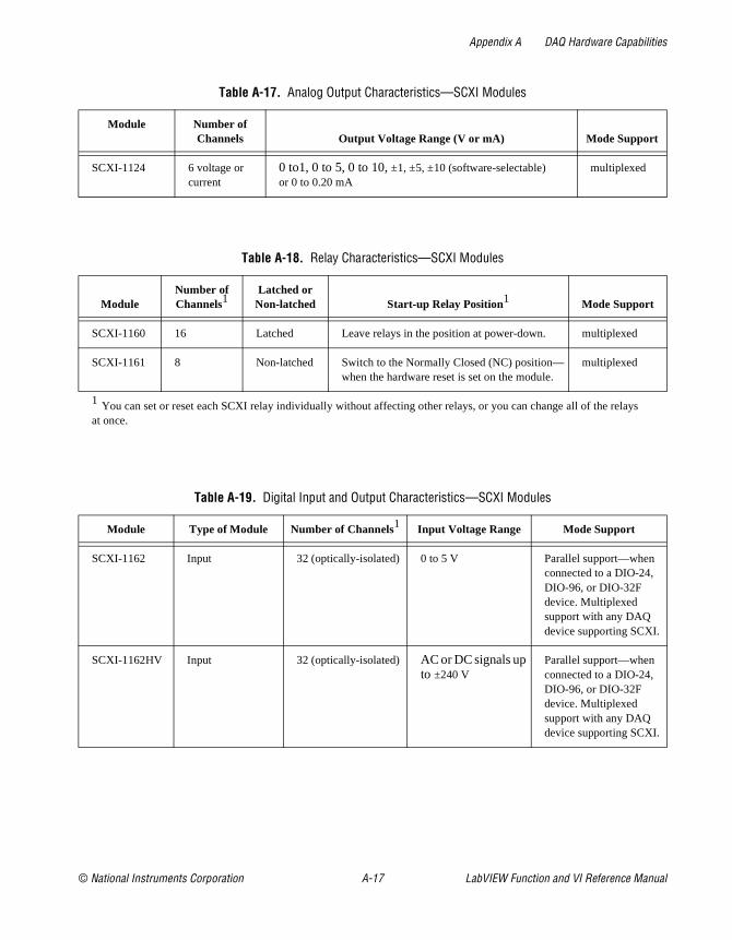
Appendix A DAQ Hardware Capabilities
s
Table A-17. Analog Output Characteristics—SCXI Modules
Module Number of Channels Output Voltage Range (V or mA) Mode Support
SCXI-1124 6 voltage or current
0 to1, 0 to 5, 0 to 10, ±1, ±5, ±10 (software-selectable)or 0 to 0.20 mA
multiplexed
Table A-18. Relay Characteristics—SCXI Modules
ModuleNumber of Channels1
Latched or Non-latched Start-up Relay Position1 Mode Support
SCXI-1160 16 Latched Leave relays in the position at power-down. multiplexed
SCXI-1161 8 Non-latched Switch to the Normally Closed (NC) position—when the hardware reset is set on the module.
multiplexed
1 You can set or reset each SCXI relay individually without affecting other relays, or you can change all of the relayat once.
Table A-19. Digital Input and Output Characteristics—SCXI Modules
Module Type of Module Number of Channels1 Input Voltage Range Mode Support
SCXI-1162 Input 32 (optically-isolated) 0 to 5 V Parallel support—when connected to a DIO-24, DIO-96, or DIO-32F device. Multiplexed support with any DAQ device supporting SCXI.
SCXI-1162HV Input 32 (optically-isolated) AC or DC signals up to ±240 V
Parallel support—when connected to a DIO-24, DIO-96, or DIO-32F device. Multiplexed support with any DAQ device supporting SCXI.
© National Instruments Corporation A-17 LabVIEW Function and VI Reference Manual

Appendix A DAQ Hardware Capabilities
SCXI-1163 Output 32 (optically-isolated) 0 to 5 V Parallel support—when connected to a DIO-24, DIO-96, or DIO-32F device. Multiplexed support with any DAQ device supporting SCXI.
SCXI-1163R* Output 32 (optically-isolated) ±240 V Parallel support—when connected to a DIO-24, DIO-96, or DIO-32F device. Multiplexed support with any DAQ device supporting SCXI.
1 Functionally equivalent to the SCXI-1163, but incorporates solid-state relays in place of digital outputs.
Table A-20. Terminal Block Selection Guide—SCXI Modules
SCXI Module Terminal Blocks Cold-Junction Compensation Sensor (CJC)
SCXI-1100SCXI-1102
SCXI-1303SCXI-1300
ThermistorIC Sensor
SCXI-1120SCXI-1121
SCXI-1320SCXI-13211
SCXI-1327SCXI-1328
IC SensorIC SensorThermistorThermistor
SCXI-1122 SCXI-1322 Thermistor
SCXI-1124 SCXI-1325 —
SCXI-1140 SCXI-1301SCXI-1304
——
SCXI-1141 SCXI-1304 —
SCXI-1160 SCXI-1324 —
SCXI-1161 None–screw terminals located in module.
—
Table A-19. Digital Input and Output Characteristics—SCXI Modules (Continued)
Module Type of Module Number of Channels1 Input Voltage Range Mode Support
LabVIEW Function and VI Reference Manual A-18 © National Instruments Corporation
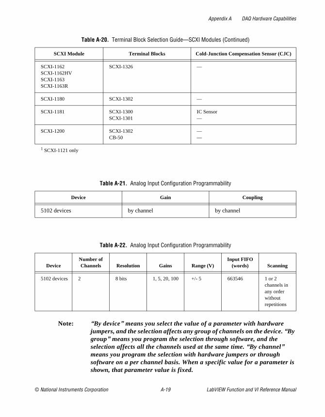
Appendix A DAQ Hardware Capabilities
is
Note: “ By device” means you select the value of a parameter with hardware jumpers, and the selection affects any group of channels on the device. “ By group” means you program the selection through software, and the selection affects all the channels used at the same time. “ By channel” means you program the selection with hardware jumpers or through software on a per channel basis. When a specific value for a parametershown, that parameter value is fixed.
SCXI-1162SCXI-1162HVSCXI-1163SCXI-1163R
SCXI-1326 —
SCXI-1180 SCXI-1302 —
SCXI-1181 SCXI-1300SCXI-1301
IC Sensor—
SCXI-1200 SCXI-1302CB-50
——
1 SCXI-1121 only
Table A-21. Analog Input Configuration Programmability
Device Gain Coupling
5102 devices by channel by channel
Table A-22. Analog Input Configuration Programmability
DeviceNumber of Channels Resolution Gains Range (V)
Input FIFO(words) Scanning
5102 devices 2 8 bits 1, 5, 20, 100 +/- 5 663546 1 or 2 channels in any order without repetitions
Table A-20. Terminal Block Selection Guide—SCXI Modules (Continued)
SCXI Module Terminal Blocks Cold-Junction Compensation Sensor (CJC)
© National Instruments Corporation A-19 LabVIEW Function and VI Reference Manual
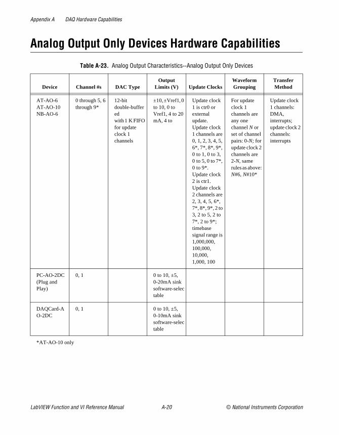
Appendix A DAQ Hardware Capabilities
Analog Output Only Devices Hardware Capabilities
Table A-23. Analog Output Characteristics--Analog Output Only Devices
Device Channel #s DAC TypeOutput
Limits (V) Update ClocksWaveform Grouping
Transfer Method
AT-AO-6AT-AO-10NB-AO-6
0 through 5, 6 through 9*
12-bit double-bufferedwith 1 K FIFO for update clock 1 channels
±10, ±Vref1, 0 to 10, 0 to Vref1, 4 to 20 mA, 4 to
Update clock 1 is ctr0 or external update. Update clock 1 channels are 0, 1, 2, 3, 4, 5, 6*, 7*, 8*, 9*, 0 to 1, 0 to 3, 0 to 5, 0 to 7*, 0 to 9*. Update clock 2 is ctr1. Update clock 2 channels are 2, 3, 4, 5, 6*, 7*, 8*, 9*, 2 to 3, 2 to 5, 2 to 7*, 2 to 9*; timebase signal range is 1,000,000, 100,000, 10,000, 1,000, 100
For update clock 1 channels are any one channel N or set of channel pairs: 0-N; for update clock 2 channels are 2-N, same rules as above: N#6, N#10*
Update clock 1 channels: DMA, interrupts; update clock 2 channels: interrupts
PC-AO-2DC (Plug and Play)
0, 1 0 to 10, ±5, 0-20mA sink software-selectable
DAQCard-AO-2DC
0, 1 0 to 10, ±5, 0-10mA sink software-selectable
*AT-AO-10 only
LabVIEW Function and VI Reference Manual A-20 © National Instruments Corporation

Appendix A DAQ Hardware Capabilities
y
is
Dynamic Signal Acquisition Devices Hardware Capabilities
Note: “By device” means you select the value of a parameter with hardware jumpers, and the selection affects any group of channels on the device. “Bgroup” means you program the selection through software, and the selection affects all the channels used at the same time. “By channel” means you program the selection with hardware jumpers or through software on a per channel basis. When a specific value for a parametershown, that parameter value is fixed.
Table A-24. Analog Input Configuration Programmability—Dynamic Signal Acquisition Devices
Device Gain Range (V) Polarity SE/DIFF Coupling
EISA-A2000NB-A2000
1 ±5 Bipolar SE By channel
NB-A2100AT-DSP2200
1 ±2.828 Bipolar SE By group
NB-A2150AT-A2150
1 ±2.828 Bipolar SE By channel pair 0 and 1, 2 and 3
© National Instruments Corporation A-21 LabVIEW Function and VI Reference Manual

Appendix A DAQ Hardware Capabilities
Table A-25. Analog Input Characteristics—Dynamic Signal Acquisition Devices
Device
Num
ber
of C
hann
els
Res
olut
ion
Ran
ge (
V)
Inpu
t FIF
O(w
ords
)
Trig
gers
Sca
nnin
g
Max
Sam
plin
gR
ate
(S/s
)
Tra
nsfe
rM
etho
d
EISA-A2000NB-A2000
4 SE 12 bits
±5 EISA:512; NB:1,024
Software trigger, pretrigger, and posttrigger with digital or analog triggering and posttrigger delay
0, 1, 2, 3, 0 and 1, 2 and 3, 0 to 3.
1M DMA, interrupts
NB-A2100NB-A2150
2 SE 16 bits
±2.828 32 Software trigger, pretrigger, and posttrigger with digital or analog triggering
A2150:0, 1, 2, 3, 0 and 1, 2 and 3, 0 to 3;A2100:0, 1, 0 and 1
2100:48 k, 2150:24 k, 2150C:48 k, 2150S:51.2 k
DMA, interrupts
AT-A2150 4 SE 16 bits
±2.828 — Software trigger, pretrigger, and posttrigger with digital or analog triggering
0, 1, 2, 3, 0 and 1, 2 and 3, 0 and 3
2150:24 k2150:51.2 k
DMA, interrupts
LabVIEW Function and VI Reference Manual A-22 © National Instruments Corporation

Appendix A DAQ Hardware Capabilities
Digital Only Devices Hardware Capabilities
Table A-26. Digital Hardware Capabilities—Digital I/O Devices
DevicePortType Port #s Handshake Modes Direction DIO Clocks
TransferMethod
AT-DIO-32FNB-DIO-32F
8-bit ports
0, 1, 2, 3
8-bit port Handshaking on or off; extensive handshaking modes
Read or write Two clocks available 16-bit with variable timebase
DMA for each group; dual channel DMA for groups containing port 0
2-bit ports
4 No handshaking Read or write None Software polling
PC-DIO-24NB-DIO-24DAQCard-DIO-24
8-bit port
0, 1 Handshaking on or off
Read or write, port 0 may be bidirectional
None Interrupts
8-bit port
2 No handshaking; unusable if port 0 or 1 uses handshaking
Read or write None Software polling
PC-DIO-96PCI-DIO-96NB-DIO-96
8-bit port
0, 1, 3, 4, 6, 7, 9, 10
Handshaking on or off
Read or write, ports 0, 3, 6, and 9 may be bidirectional
None Interrupts
8-bit port
2, 5, 8, 11
No handshaking; unusable if port A and B of the 8255 chip use handshaking
Read or write None Software polling
PC-OPDIO-16 (Plug and Play)
Opti-cally-isolated8-bit port
0, 1 — Port 0 is output (write); port 1 is input (read)
None Programmed I/O
© National Instruments Corporation A-23 LabVIEW Function and VI Reference Manual
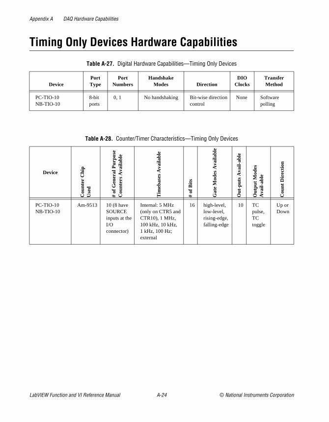
Appendix A DAQ Hardware Capabilities
Timing Only Devices Hardware Capabilities
Table A-27. Digital Hardware Capabilities—Timing Only Devices
DevicePort Type
Port Numbers
HandshakeModes Direction
DIOClocks
TransferMethod
PC-TIO-10NB-TIO-10
8-bit ports
0, 1 No handshaking Bit-wise direction control
None Software polling
Table A-28. Counter/Timer Characteristics—Timing Only Devices
Device
Cou
nter
Chi
pU
sed
# of
Gen
eral
Pur
pose
Cou
nter
s A
vaila
ble
Tim
ebas
es A
vaila
ble
# of
Bits
Gat
e M
odes
Ava
ilabl
e
Out
-put
s A
vail-
able
Out
put M
odes
Ava
il-ab
le
Cou
nt D
irect
ion
PC-TIO-10NB-TIO-10
Am-9513 10 (8 have SOURCE inputs at the I/O connector)
Internal: 5 MHz (only on CTR5 and CTR10), 1 MHz,100 kHz, 10 kHz,1 kHz, 100 Hz; external
16 high-level, low-level, rising-edge, falling-edge
10 TC pulse, TC toggle
Up or Down
LabVIEW Function and VI Reference Manual A-24 © National Instruments Corporation
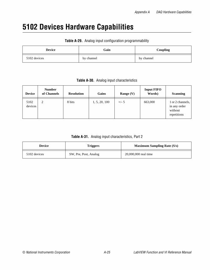
Appendix A DAQ Hardware Capabilities
5102 Devices Hardware Capabilities
Table A-29. Analog input configuration programmability
Device Gain Coupling
5102 devices by channel by channel
Table A-30. Analog input characteristics
DeviceNumber
of Channels Resolution Gains Range (V)Input FIFO
Words) Scanning
5102 devices
2 8 bits 1, 5, 20, 100 +/- 5 663,000 1 or 2 channels, in any order without repetitions
Table A-31. Analog input characteristics, Part 2
Device Triggers Maximum Sampling Rate (S/s)
5102 devices SW, Pre, Post, Analog 20,000,000 real time
© National Instruments Corporation A-25 LabVIEW Function and VI Reference Manual
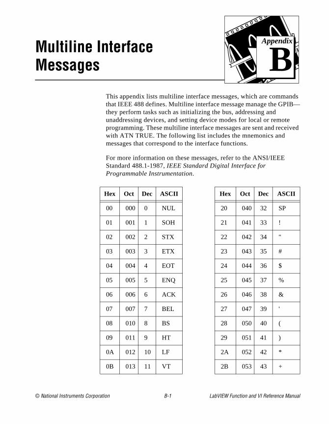
© National Instruments Corporation B-1 LabVIEW Function an
Appendix
B
Multiline Interface Messagesnds B—
e ived
This appendix lists multiline interface messages, which are commathat IEEE 488 defines. Multiline interface message manage the GPIthey perform tasks such as initializing the bus, addressing and unaddressing devices, and setting device modes for local or remotprogramming. These multiline interface messages are sent and recewith ATN TRUE. The following list includes the mnemonics and messages that correspond to the interface functions.
For more information on these messages, refer to the ANSI/IEEE Standard 488.1-1987, IEEE Standard Digital Interface for Programmable Instrumentation.
Hex Oct Dec ASCII Hex Oct Dec ASCII
00 000 0 NUL 20 040 32 SP
01 001 1 SOH 21 041 33 !
02 002 2 STX 22 042 34 "
03 003 3 ETX 23 043 35 #
04 004 4 EOT 24 044 36 $
05 005 5 ENQ 25 045 37 %
06 006 6 ACK 26 046 38 &
07 007 7 BEL 27 047 39 '
08 010 8 BS 28 050 40 (
09 011 9 HT 29 051 41 )
0A 012 10 LF 2A 052 42 *
0B 013 11 VT 2B 053 43 +
d VI Reference Manual
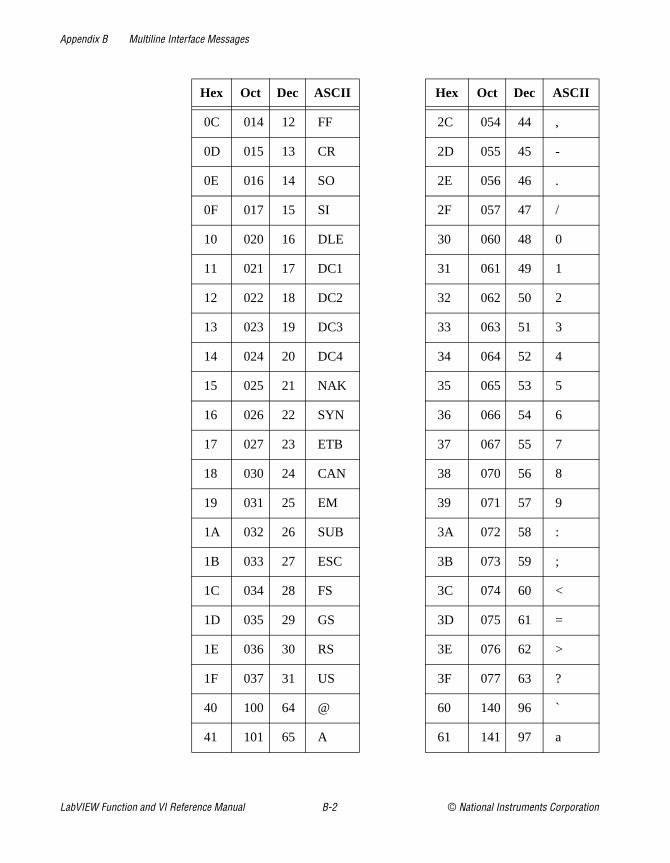
Appendix B Multiline Interface Messages
0C 014 12 FF 2C 054 44 ,
0D 015 13 CR 2D 055 45 -
0E 016 14 SO 2E 056 46 .
0F 017 15 SI 2F 057 47 /
10 020 16 DLE 30 060 48 0
11 021 17 DC1 31 061 49 1
12 022 18 DC2 32 062 50 2
13 023 19 DC3 33 063 51 3
14 024 20 DC4 34 064 52 4
15 025 21 NAK 35 065 53 5
16 026 22 SYN 36 066 54 6
17 027 23 ETB 37 067 55 7
18 030 24 CAN 38 070 56 8
19 031 25 EM 39 071 57 9
1A 032 26 SUB 3A 072 58 :
1B 033 27 ESC 3B 073 59 ;
1C 034 28 FS 3C 074 60 <
1D 035 29 GS 3D 075 61 =
1E 036 30 RS 3E 076 62 >
1F 037 31 US 3F 077 63 ?
40 100 64 @ 60 140 96 `
41 101 65 A 61 141 97 a
Hex Oct Dec ASCII Hex Oct Dec ASCII
LabVIEW Function and VI Reference Manual B-2 © National Instruments Corporation
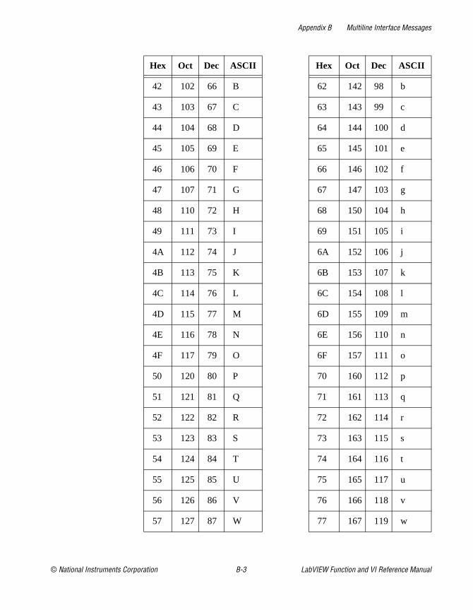
Appendix B Multiline Interface Messages
42 102 66 B 62 142 98 b
43 103 67 C 63 143 99 c
44 104 68 D 64 144 100 d
45 105 69 E 65 145 101 e
46 106 70 F 66 146 102 f
47 107 71 G 67 147 103 g
48 110 72 H 68 150 104 h
49 111 73 I 69 151 105 i
4A 112 74 J 6A 152 106 j
4B 113 75 K 6B 153 107 k
4C 114 76 L 6C 154 108 l
4D 115 77 M 6D 155 109 m
4E 116 78 N 6E 156 110 n
4F 117 79 O 6F 157 111 o
50 120 80 P 70 160 112 p
51 121 81 Q 71 161 113 q
52 122 82 R 72 162 114 r
53 123 83 S 73 163 115 s
54 124 84 T 74 164 116 t
55 125 85 U 75 165 117 u
56 126 86 V 76 166 118 v
57 127 87 W 77 167 119 w
Hex Oct Dec ASCII Hex Oct Dec ASCII
© National Instruments Corporation B-3 LabVIEW Function and VI Reference Manual
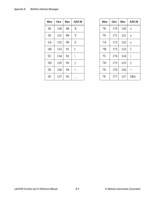
Appendix B Multiline Interface Messages
58 130 88 X 78 170 120 x
59 131 89 Y 79 171 121 y
5A 132 90 Z 7A 172 122 z
5B 133 91 [ 7B 173 123
5C 134 92 \ 7C 174 124 |
5D 135 93 ] 7D 175 125
5E 136 94 ^ 7E 176 126 ~
5F 137 95 _ 7F 177 127 DEL
Hex Oct Dec ASCII Hex Oct Dec ASCII
LabVIEW Function and VI Reference Manual B-4 © National Instruments Corporation

© National Instruments Corporation C-1 LabVIEW Function an
Appendix
C
Operation of the GPIBof
ages.
es.
lled h ces,
cific
al
ller to
er he
This appendix describes basic concepts you need to understand tooperate the GPIB. It also contains a description of the physical andelectrical characteristics of the GPIB and configuration requirementsthe GPIB.
Types of MessagesThe GPIB carries device-dependent messages and interface mess
• Device-dependent messages, often called data or data messages, contain device-specific information such as programming instructions, measurement results, machine status, and data fil
• Interface messages manage the bus itself. They are usually cacommands or command messages. Interface messages perform suctasks as initializing the bus, addressing and unaddressing deviand setting device modes for remote or local programming.
Do not confuse the term command as used here with some device instructions, which can also be called commands. These device-speinstructions are actually data messages.
Talkers, Listeners, and ControllersGPIB devices can be Talkers, Listeners, and/or Controllers. A digitvoltmeter, for example, is a Talker and may be a Listener as well. ATalker sends data messages to one or more Listeners. The Contromanages the flow of information on the GPIB by sending commandsall devices.
The GPIB is like an ordinary computer bus, except that the computhas its circuit cards interconnected via a backplane bus, whereas tGPIB has stand-alone devices interconnected via a cable bus.
The role of the GPIB Controller is similar to the role of the CPU of acomputer, but a better analogy is to the switching center of a city telephone system. The switching center (Controller) monitors the
d VI Reference Manual
Appendix C Operation of the GPIB
es t
can age,
one e
ssed on.
all
n ne .
n or
communications network (GPIB). When the center (Controller) noticthat a party (device) wants to make a call (send a data message), iconnects the caller (Talker) to the receiver (Listener).
The Controller addresses a Talker and a Listener before the Talkersend its message to the Listener. After the Talker transmits the messthe Controller may unaddress both devices.
Some bus configurations do not require a Controller. For example, device may always be a Talker (called a Talk-only device) and thermay be one or more Listen-only devices.
A Controller is necessary when you must change the active or addreTalker or Listener. A computer usually handles the Controller functi
With the GPIB board and its software, your personal computer playsthree roles:
• Controller—to manage the GPIB
• Talker—to send data
• Listener—to receive data
The Controller-In-Charge and System ControllerAlthough there can be multiple Controllers on the GPIB, only one Controller at a time is active or Controller-In-Charge (CIC). You capass active control from the current CIC to an idle Controller. Only odevice on the bus—the System Controller—can make itself the CICThe GPIB board is usually the System Controller.
GPIB Signals and LinesThe interface system consists of 16 signal lines and 8 ground-returshield-drain lines.
The 16 signal lines are divided into three groups:
• Eight data lines
• Three handshake lines
• Five interface management lines
LabVIEW Function and VI Reference Manual C-2 © National Instruments Corporation
Appendix C Operation of the GPIB
and
the
ong and eived
te. rs
ll rive
d ta
ages.
Data LinesThe eight data lines, DIO1 through DIO8, carry both data and commmessages. All commands and most data use the 7-bit ASCII or International Standards Organization (ISO) code set, in which caseeighth bit, DIO8, is unused or is used for parity.
Handshake LinesThree lines asynchronously control the transfer of message bytes amdevices. This process is called a three-wire interlocked handshake,it guarantees that message bytes on the data lines are sent and recwithout transmission error.
NRFD (not ready for data)NRFD indicates whether a device is ready to receive a message byAll devices drive NRFD when they receive commands, and Listenedrive it when they receive data messages.
NDAC (not data accepted)NDAC indicates whether a device has accepted a message byte. Adevices drive NDAC when they receive commands, and Listeners dit when they receive data messages.
DAV (data valid)DAV tells whether the signals on the data lines are stable (valid) anwhether devices can accept them safely. The Controller drives DAVwhen sending commands, and the Talker drives it when sending damessages.
Interface Management LinesFive lines manage the flow of information across the interface.
ATN (attention)The Controller drives ATN true when it uses the data lines to send commands and drives ATN false when a Talker can send data mess
© National Instruments Corporation C-3 LabVIEW Function and VI Reference Manual

Appendix C Operation of the GPIB
ice
rk ll
le her
a
IFC (interface clear)The System Controller drives the IFC line to initialize the bus and become CIC.
REN (remote enable)The System Controller drives the REN line, which places devices inremote or local program mode.
SRQ (service request)Any device can drive the SRQ line to asynchronously request servfrom the Controller.
EOI (end or identify)The EOI line has two purposes. The Talker uses the EOI line to mathe end of a message string. The Controller uses the EOI line to tedevices to respond in a parallel poll.
Physical and Electrical CharacteristicsYou usually connect devices with a cable assembly consisting of ashielded 24-conductor cable which has both a plug and a receptacconnector at each end. With this design, you can link devices in eita linear or a star configuration, or a combination of the two.
The standard connector is the Amphenol or Cinch Series 57 Microribbon or Amp Champ type. You can use an adapter cable withnon-standard cable and/or connector for special interconnection applications.
LabVIEW Function and VI Reference Manual C-4 © National Instruments Corporation
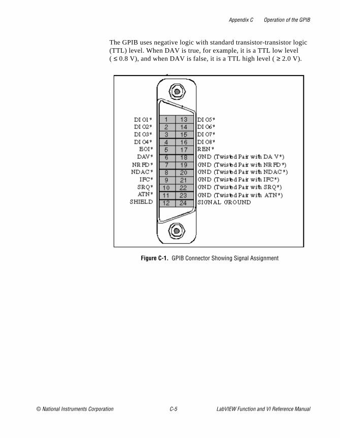
Appendix C Operation of the GPIB
gic
The GPIB uses negative logic with standard transistor-transistor lo(TTL) level. When DAV is true, for example, it is a TTL low level ( ≤ 0.8 V), and when DAV is false, it is a TTL high level ( ≥ 2.0 V).Figure C-1. GPIB Connector Showing Signal Assignment
© National Instruments Corporation C-5 LabVIEW Function and VI Reference Manual

Appendix C Operation of the GPIB
Figure C-2. Linear Configuration
GPIB Cables
Device A
Device C
Device B
LabVIEW Function and VI Reference Manual C-6 © National Instruments Corporation
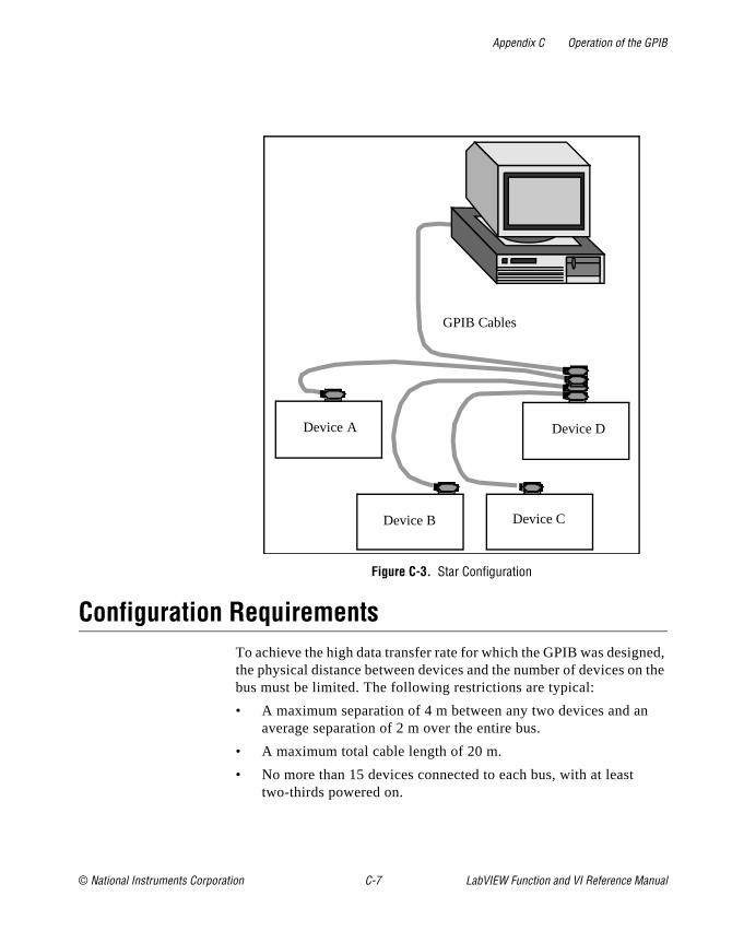
Appendix C Operation of the GPIB
ed, n the
Figure C-3. Star Configuration
Configuration RequirementsTo achieve the high data transfer rate for which the GPIB was designthe physical distance between devices and the number of devices obus must be limited. The following restrictions are typical:
• A maximum separation of 4 m between any two devices and anaverage separation of 2 m over the entire bus.
• A maximum total cable length of 20 m.
• No more than 15 devices connected to each bus, with at least two-thirds powered on.
GPIB Cables
Device A
Device C
Device D
Device B
© National Instruments Corporation C-7 LabVIEW Function and VI Reference Manual

Appendix C Operation of the GPIB
s
Contact National Instruments for bus extenders if your requirementexceed these limits.LabVIEW Function and VI Reference Manual C-8 © National Instruments Corporation
© National Instruments Corporation D-1 LabVIEW Function and
Appendix
D
Referencesysis he
.
is 6
to d
This appendix lists the reference material used to produce the AnalVIs in this manual. These references contain more information on ttheories and algorithms implemented in the analysis library.
1. Baher, H. Analog & Digital Signal Processing. New York: John Wiley & Sons. 1990.
2. Bates, D.M. and Watts, D.G. Nonlinear Regression Analysis and itsApplications. New York: John Wiley & Sons. 1988.
3. Bracewell, R.N. “Numerical Transforms.” Science. Science-24811 May 1990.
4. Burden, R.L. & Faires, J.D. Numerical Analysis. Third Edition. Boston: Prindle, Weber & Schmidt. 1985.
5. Chen, C.H. et al. Signal Processing Handbook. New York: Marcel Decker, Inc. 1988.
6. DeGroot, M. Probability and Statistics 2nd ed. Reading, Massachusetts: Addison-Wesley Publishing Co. 1986.
7. Dowdy, S. and Wearden, S. Statistics for Research 2nd ed. New York: John Wiley & Sons. 1991.
8. Dudewicz, E.J. and Mishra, S.N. Modern Mathematical Statistics New York: John Wiley & Sons, 1988.
9. Duhamel, P. et al. “On Computing the Inverse DFT.” IEEE Transactions on ASSP. ASSP-34 (1986): 1 (February).
10. Dunn, O. and Clark, V. Applied Statistics: Analysis of Variance andRegression 2nd ed. New York: John Wiley & Sons. 1987.
11. Elliot, D.F. Handbook of Digital Signal Processing Engineering Applications. San Diego: Academic Press. 1987.
12. Harris, Fredric J. “On the Use of Windows for Harmonic Analyswith the Discrete Fourier Transform,” Proceedings of the IEEE-6(1978)-1.
13. Maisel, J.E. “Hilbert Transform Works With Fourier Transforms Dramatically Lower Sampling Rates.” Personal Engineering anInstrumentation News. PEIN-7 (1990): 2 (February).
VI Reference Manual
Appendix D References
-32
E
r: s.”
14. Miller, I. and Freund, J.E. Probability and Statistics for Engineers. Englewood Cliffs, N.J.: Prentice-Hall, Inc. 1987.
15. Neter, J. et al. Applied Linear Regression Models. Richard D. Irwin, Inc. 1983.
16. Neuvo, Y., Dong, C.-Y., and Mitra, S.K. “Interpolated Finite Impulse Response Filters,” IEEE Transactions on ASSP. ASSP(1984): 6 (June).
17. O’Neill, M.A. “Faster Than Fast Fourier.” BYTE. (1988) (April).
18. Oppenheim, A.V. & Schafer, R.W. Discrete-Time Signal Processing. Englewood Cliffs, New Jersey: Prentice Hall. 1989.
19. Parks, T.W. and Burrus, C.S. Digital Filter Design. John Wiley & Sons, Inc.: New York. 1987.
20. Pearson, C.E. Numerical Methods in Engineering and Science. New York: Van Nostrand Reinhold Co. 1986.
21. Press, W.H. et al. Numerical Recipes in C: The Art of Scientific Computing. Cambridge: Cambridge University Press. 1988.
22. Rabiner, L.R. & Gold, B. Theory and Application of Digital Signal Processing. Englewood Cliffs, New Jersey: Prentice Hall. 1975.
23. Sorensen, H.V. et al. “On Computing the Split-Radix FFT.” IEETransactions on ASSP. ASSP-34 (1986):1 (February).
24. Sorensen, H.V. et al. “Real-Valued Fast Fourier Transform Algorithms.” IEEE Transactions on ASSP. ASSP-35 (1987): 6 (June).
25. Stoer, J. and Bulirsch, R. Introduction to Numerical Analysis. New York: Springer-Verlag. 1987.
26. Vaidyanathan, P.P. Multirate Systems and Filter Banks. Englewood Cliffs, New Jersey: Prentice Hall. 1993.
27. Wichman, B. and Hill, D. “Building a Random-Number GeneratoA pascal routine for very-long-cycle random-number sequenceBYTE, March 1987, pp. 127-128.
LabVIEW Function and VI Reference Manual D-2 © National Instruments Corporation

© National Instruments Corporation E-1 LabVIEW Function and
Appendix
E
Customer Communicationssary ct orm
o
ms to
e or ese
chnical
n of an also ctions
(512)
For your convenience, this appendix contains forms to help you gather the information neceto help us solve your technical problems and a form you can use to comment on the produdocumentation. When you contact us, we need the information on the Technical Support Fand the configuration form, if your manual contains one, about your system configuration tanswer your questions as quickly as possible.
National Instruments has technical assistance through electronic, fax, and telephone systequickly provide the information you need. Our electronic services include a bulletin board service, an FTP site, a fax-on-demand system, and e-mail support. If you have a hardwarsoftware problem, first try the electronic support systems. If the information available on thsystems does not answer your questions, we offer fax and telephone support through our tesupport centers, which are staffed by applications engineers.
Electronic Services
National Instruments has BBS and FTP sites dedicated for 24-hour support with a collectiofiles and documents to answer most common customer questions. From these sites, you cdownload the latest instrument drivers, updates, and example programs. For recorded instruon how to use the bulletin board and FTP services and for BBS automated information, call795-6990. You can access these services at:
United States: (512) 794-5422Up to 14,400 baud, 8 data bits, 1 stop bit, no parity
United Kingdom: 01635 551422Up to 9,600 baud, 8 data bits, 1 stop bit, no parity
France: 01 48 65 15 59Up to 9,600 baud, 8 data bits, 1 stop bit, no parity
To access our FTP site, log on to our Internet host, ftp.natinst.com , as anonymous and use your Internet address, such as [email protected] , as your password. The support filesand documents are located in the /support directories.
Bulletin Board Support
FTP Support
VI Reference Manual

on a
-mail number
nical
Fax-on-Demand is a 24-hour information retrieval system containing a library of documentswide range of technical information. You can access Fax-on-Demand from a touch-tone telephone at (512) 418-1111.
You can submit technical support questions to the applications engineering team through eat the Internet address listed below. Remember to include your name, address, and phone so we can contact you with solutions and suggestions.
Telephone and Fax SupportNational Instruments has branch offices all over the world. Use the list below to find the techsupport number for your country. If there is no National Instruments office in your country,contact the source from which you purchased your software to obtain support.
Telephone FaxAustralia 02 9874 4100 02 9874 4455Austria 0662 45 79 90 0 0662 45 79 90 19Belgium 02 757 00 20 02 757 03 11Canada (Ontario) 905 785 0085 905 785 0086Canada (Quebec) 514 694 8521 514 694 4399Denmark 45 76 26 00 45 76 26 02Finland 09 527 2321 09 502 2930France 01 48 14 24 24 01 48 14 24 14Germany 089 741 31 30 089 714 60 35Hong Kong 2645 3186 2686 8505Israel 03 5734815 03 5734816Italy 06 5729961 06 57284309Japan 03 5472 2970 03 5472 2977Korea 02 596 7456 02 596 7455Mexico 5 520 2635 5 520 3282Netherlands 31 348 43 34 66 31 348 43 06 73Norway 32 84 84 00 32 84 86 00Singapore 2265886 2265887Spain 91 640 0085 91 640 0533Sweden 08 730 49 70 08 730 43 70Switzerland 056 200 51 51 056 200 51 55Taiwan 02 377 1200 02 737 4644U.K. 01635 523545 01635 523154
Fax-on-Demand Support
E-Mail Support (currently U.S. only)

re, and ting
blem, sary.
____
____
____
____
____
____
____
ter
____
rand
____
____
ision
____
sion
____
____
____
____
____
____
_____
____
____
____
____
____
____
____
Technical Support FormPhotocopy this form and update it each time you make changes to your software or hardwause the completed copy of this form as a reference for your current configuration. Complethis form accurately before contacting National Instruments for technical support helps ourapplications engineers answer your questions more efficiently.
If you are using any National Instruments hardware or software products related to this proinclude the configuration forms from their user manuals. Include additional pages if neces
Name ______________________________________________________________________
Company ___________________________________________________________________
Address ____________________________________________________________________
___________________________________________________________________________
Fax ( ___ )___________________ Phone ( ___ ) ___________________________________
Computer brand ________________ Model ________________ Processor_______________
Operating system (include version number) ________________________________________
Clock speed ______MHz RAM _____MB _____________________________ Display adap
Mouse ___yes ___no Other adapters installed___________________________________
Hard disk capacity _____MB __________________________________________________B
Instruments used _____________________________________________________________
___________________________________________________________________________
National Instruments hardware product model __________________________________ Rev
Configuration _______________________________________________________________
National Instruments software product _________________________________________ Ver
Configuration _______________________________________________________________
The problem is: ______________________________________________________________
___________________________________________________________________________
___________________________________________________________________________
___________________________________________________________________________
___________________________________________________________________________
List any error messages: ______________________________________________________
___________________________________________________________________________
___________________________________________________________________________
The following steps reproduce the problem:________________________________________
___________________________________________________________________________
___________________________________________________________________________
___________________________________________________________________________
___________________________________________________________________________
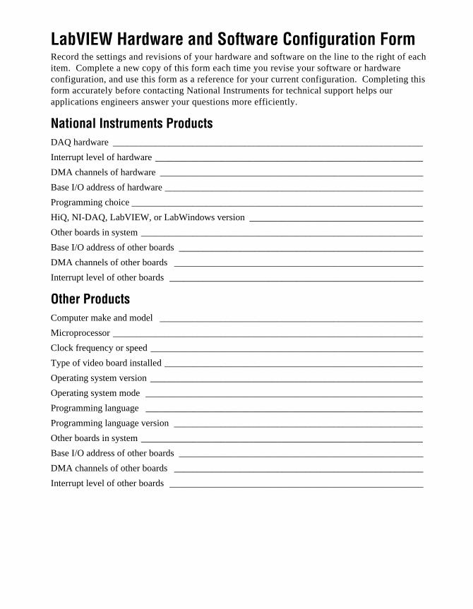
each
this
____
____
____
_____
____
__
____
_____
____
____
____
____
____
____
____
____
____
____
____
_____
____
____
LabVIEW Hardware and Software Configuration FormRecord the settings and revisions of your hardware and software on the line to the right ofitem. Complete a new copy of this form each time you revise your software or hardware configuration, and use this form as a reference for your current configuration. Completingform accurately before contacting National Instruments for technical support helps our applications engineers answer your questions more efficiently.
National Instruments ProductsDAQ hardware ______________________________________________________________
Interrupt level of hardware _____________________________________________________
DMA channels of hardware ____________________________________________________
Base I/O address of hardware __________________________________________________
Programming choice __________________________________________________________
HiQ, NI-DAQ, LabVIEW, or LabWindows version ___________________________________
Other boards in system ________________________________________________________
Base I/O address of other boards _______________________________________________
DMA channels of other boards _________________________________________________
Interrupt level of other boards __________________________________________________
Other ProductsComputer make and model ____________________________________________________
Microprocessor ______________________________________________________________
Clock frequency or speed ______________________________________________________
Type of video board installed ___________________________________________________
Operating system version ______________________________________________________
Operating system mode _______________________________________________________
Programming language _______________________________________________________
Programming language version _________________________________________________
Other boards in system ________________________________________________________
Base I/O address of other boards _______________________________________________
DMA channels of other boards _________________________________________________
Interrupt level of other boards __________________________________________________

____
____
____
____
____
____
____
____
____
____
____
____
____
____
____
____
____
____
____
____
Documentation Comment FormNational Instruments encourages you to comment on the documentation supplied with ourproducts. This information helps us provide quality products to meet your needs.
Title: LabVIEW Function and VI Reference Overview
Edition Date: May 1997
Part Number: 321526A-01
Please comment on the completeness, clarity, and organization of the manual.
___________________________________________________________________________
___________________________________________________________________________
___________________________________________________________________________
___________________________________________________________________________
___________________________________________________________________________
___________________________________________________________________________
___________________________________________________________________________
If you find errors in the manual, please record the page numbers and describe the errors.
___________________________________________________________________________
___________________________________________________________________________
___________________________________________________________________________
___________________________________________________________________________
___________________________________________________________________________
___________________________________________________________________________
___________________________________________________________________________
Thank you for your help.
Name _____________________________________________________________________
Title ______________________________________________________________________
Company ___________________________________________________________________
Address ____________________________________________________________________
___________________________________________________________________________
Phone ( ___ )__________________________ Fax ( ___ ) ____________________________
Mail to: Technical Publications Fax to: Technical PublicationsNational Instruments Corporation National Instruments Corporation6504 Bridge Point Parkway (512) 794-5678Austin, TX 78730-5039

© National Instruments Corporation I-1 LabVIEW Function and
Index
1200 Calibrate, 28-21D ANOVA, 45-21D Linear Evaluation, 47-21D Polar To Rectangular, 47-21D Polynomial Evaluation, 47-21D Rectangular To Polar, 47-32D ANOVA, 45-32D Linear Evaluation, 47-32D Polynomial Evaluation, 47-33D ANOVA, 45-4A x B, 46-7A x Vector, 46-7A2000 Calibrate, 28-2A2000 Configure, 28-3A2100 Calibrate (Macintosh), 28-4A2100 Config (Macintosh), 28-4A2150 Calibrate (Windows), 28-5A2150 Config (Macintosh), 28-4Abort Instrument, 12-11AC & DC Estimator, 41-4Access Rights, 11-15Addition, 46-2Additional User Definable Constants, 4-22Adjacent Counters, 26-2AECreate Comp Descriptor, 54-16AECreate Descriptor List, 54-18AECreate Logical Descriptor, 54-17AECreate Object Specifier, 54-17AECreate Range Descriptor, 54-17AECreate Record, 54-18AESend Abort VI, 54-9AESend Close VI, 54-9AESend Do Script, 54-7AESend Finder Open, 54-8AESend Open Document, 54-8AESend Open, 54-8AESend Open, Run, Close VI, 54-10AESend Print Document, 54-8AESend Quit Application, 54-9AESend Run VI, 54-10AESend VI Active?, 54-10AESend, 54-16AI Acquire Waveform, 14-1
AI Acquire Waveforms, 14-2AI Buffer Config, 17-1AI Buffer Read, 17-3AI Clear, 15-2AI Clock Config, 17-3AI Config, 15-3AI Continuous Scan, 16-2AI Control, 17-5AI Group Config, 17-6AI Hardware Config, 17-8AI Parameter, 17-13AI Read One Scan, 16-3AI Read, 15-3AI Sample Channel, 14-2AI Sample Channels, 14-3AI Single Scan, 15-4AI SingleScan, 17-13AI Start, 15-5AI Trigger Config, 17-14AI Waveform Scan, 16-4AllSPoll, 36-4Amplitude and Phase Spectrum, 41-4And Array Elements, 5-3And, 5-2AO Buffer Config, 21-1AO Buffer Write, 21-2AO Clear, 19-2AO Clock Config, 21-3AO Config, 19-2AO Continuous Gen, 20-2AO Control, 21-3AO Generate Waveform, 18-1AO Generate Waveforms, 18-2AO Group Config, 21-3AO Hardware Config, 21-4AO Parameter, 21-4AO Single Update, 21-4AO Start, 19-3AO Trigger and Gate Config (Windows), 21-5AO Update Channel, 18-2AO Update Channels, 18-2AO Wait, 19-3AO Waveform Gen, 20-3
VI Reference Manual

Index
AO Write One Update, 20-4AO Write, 19-3AO-6/10 Calibrate (Windows), 28-5Arbitrary Wave, 39-4Array Max & Min, 7-3Array Of Strings To Path, 11-15Array Of Strings To Path, 6-19Array Size, 7-4Array Subset, 7-4Array To Cluster, 7-4Array To Cluster, 8-3Array To Spreadsheet String, 6-6Auto Power Spectrum, 41-4AutoCorrelation, 40-8Beep, 12-2Bessel Coefficients, 42-17Bessel Filter, 42-17Blackman Window, 43-5Blackman-Harris Window, 43-5Boolean Array To Number, 4-10Boolean Array To Number, 5-3Boolean Constant, 5-5Boolean To (0,1), 4-10Boolean To (0,1), 5-3Build Array, 7-4Build Cluster Array, 8-3Build Path, 11-6Bundle By Name, 8-4Bundle, 8-4Butterworth Coefficients, 42-17Butterworth Filter, 42-18Byte Array To String, 4-10Byte Array To String, 6-20Bytes at Serial Port, 37-4cac – Become active Controller, 35-9Call Chain, 12-2Call Instrument, 12-12Call Library Function, 12-3Carriage Return, 6-21Cascade—>Direct Coefficients, 42-18Case Structure, 3-2Cast Unit Bases, 4-11Channel To Index, 28-6Chebyshev Coefficients, 42-19Chebyshev Filter, 42-19Chi Square Distribution, 45-5Chirp Pattern, 39-5Cholesky Factorization, 46-8Close All PPC Ports, 55-4Close File, 11-6Close Panel No Abort, 12-12Close Panel, 12-12
Cluster To Array, 7-5Cluster To Array, 8-4cmd – Send IEEE488 commands, 35-9Code Interface Node, 12-2Complex A x B, 46-8Complex A x Vector, 46-9Complex Cholesky Factorization, 46-9Complex Conjugate, 4-20Complex Determinant, 46-9Complex Dot Product, 46-10Complex Eigenvalues & Vectors, 46-10Complex FFT, 40-9Complex Inverse Matrix, 46-11Complex LU Factorization, 46-11Complex Matrix Condition Number, 46-12Complex Matrix Norm, 46-12Complex Matrix Rank, 46-13Complex Matrix Trace, 46-13Complex Outer Product, 46-13Complex Polynomial Roots, 48-1Complex PseudoInverse Matrix, 46-14Complex QR Factorization, 46-14Complex SVD Factorization, 46-15Complex To Polar, 4-21Complex To Re/Im, 4-21Compound Arithmetic, 5-3Concatenate Strings, 6-6Contingency Table, 45-5Continuous Pulse Generator Config, 26-2Control Help Window, 12-8Control Online Help, 12-8Convert RTD Reading, 29-2Convert Strain Gauge Reading, 29-3Convert Thermistor Reading, 29-7Convert Thermocouple Buffer, 29-9Convert Thermocouple Reading, 29-9Convert Unit, 4-11Convolution, 40-11Convolution, 42-19Copy, 11-15Cosecant, 4-14Cosine Tapered Window, 43-6Cosine, 4-14Cotangent, 4-14Count Events or Time, 25-2Counter Read, 26-3Counter Start, 26-3Counter Stop, 26-3Create Automation Refnum, 53-3Create Special Complex Matrix, 46-15Create Special Matrix, 46-15
LabVIEW Function and VI Reference Manual I-2 © National Instruments Corporation
Index
Creating AppleEvent Parameters Using Object Specifiers, 54-16
Cross Power Spectrum, 41-5Cross Power, 40-12CrossCorrelation, 40-13CTR Buffer Config, 27-2CTR Buffer Read, 27-2CTR Control, 27-11CTR Group Config, 27-3CTR Mode Config, 27-4CTR Pulse Config, 27-10Current VI's Path Constant, 11-21DAQ Occurrence Config (Windows), 28-8Date/Time To Seconds, 10-6DDE Advise Check, 52-7DDE Advise Start, 52-7DDE Advise Stop, 52-7DDE Close Conversation, 52-7DDE Execute, 52-8DDE Open Conversation, 52-8DDE Poke, 52-8DDE Request, 52-8DDE Srv Check Item, 52-9DDE Srv Register Item, 52-9DDE Srv Register Service, 52-9DDE Srv Set Item, 52-9DDE Srv Unregister Item, 52-10DDE Srv Unregister Service, 52-10Decimal Digit?, 9-6Decimate 1D Array, 7-5Decimate, 40-15Deconvolution, 40-16Default Directory Constant, 11-21Delayed Pulse Generator Config, 26-3Delete, 11-15Derivative x(t), 40-17Determinant, 46-16DevClear, 36-2DevClearList, 36-4Device Reset, 28-9Diagonal Matrix, 46-3Digital Buffer Config, 24-3Digital Buffer Control, 24-4Digital Buffer Read, 24-4Digital Buffer Write, 24-4Digital Clock Config, 24-5Digital Group Config, 24-5Digital Mode Config, 24-6Digital Single Read, 24-7Digital Single Write, 24-7Digital Trigger Config, 24-7DIO Clear, 23-2
DIO Config, 23-2DIO Parameter, 24-6DIO Port Config, 24-2DIO Port Read, 24-3DIO Port Write, 24-3DIO Read, 23-3DIO Single Read/Write, 23-3DIO Start, 23-4DIO Wait, 23-4DIO Write, 23-4dma – Set DMA mode or programmed I/O mode, 35-10Dot Product, 46-16Down Counter or Divider Config, 26-4DSP2200 Calibrate (Windows), 28-9DSP2200 Configure (Windows), 28-10EigenValues & Vectors, 46-17Elliptic Coefficients, 42-20Elliptic Filter, 42-20Empty Path, 11-21Empty String, 6-21Empty String/Path?, 9-6EnableLocal, 36-5EnableRemote, 36-5End of Line, 6-21EOF, 11-16Equal To 0?, 9-6Equal?, 9-6Equiripple BandPass, 42-20Equiripple BandStop, 42-21Equiripple HighPass, 42-21Equiripple LowPass, 42-22erf(x), 45-6erfc(x), 45-6E-Series Calibrate (Windows), 28-10Event or Time Counter Config, 26-4Exact Blackman Window, 43-6Exclusive Or, 5-4Execute Method, 53-3Exponential (Arg) –1, 4-18Exponential Fit Coefficients, 44-3Exponential Fit, 44-3Exponential Window, 43-7Exponential, 4-18F Distribution, 45-6Fast Data Channel Mode, 34-14Fast Data Channel Number, 34-14Fast Data Channel Pairs, 34-14Fast Data Channel Signal Enable, 34-14Fast Hilbert Transform, 40-17FHT, 40-18File Dialog, 11-16File/Directory Info, 11-16
© National Instruments Corporation I-3 LabVIEW Function and VI Reference Manual

Index
Find First Error, 10-9FindLstn, 36-6FindRQS, 36-5FIR Narrowband Coefficients, 42-22FIR Narrowband Filter, 42-24FIR Windowed Coefficients, 42-25FIR Windowed Filter, 42-25Fixed Constants, 4-22Flat Top Window, 43-7Flatten To String, 12-5Flush File, 11-17For Loop, 3-2Force Window, 43-8Format & Append, 6-16Format & Strip, 6-16Format Into String, 6-7Formula Node, 3-3From Decimal, 6-17From Exponential/Fract/Eng, 6-17From Hexadecimal, 6-17From Octal, 6-17Gaussian White Noise, 39-6General Cosine Window, 43-8General Error Handler, 10-10General Histogram, 45-6General LS Linear Fit, 44-4General Polynomial Fit, 44-10Generate Delayed Pulse, 25-2Generate Occurrence, 12-9Generate Pulse Train, 25-3Get DAQ Channel Names (Windows), 28-17Get DAQ Device Information, 28-12Get Date/Time In Seconds, 10-7Get Date/Time String, 10-7Get Help Window Status, 12-9Get Instrument State, 12-13Get Panel Size, 12-13Get Property, 53-3Get SCXI Information, 28-12Get Target ID, 54-5Get Target ID, 55-5Global Variable, 3-3GPIB Clear, 35-3GPIB Initialization, 35-4GPIB Misc, 35-4GPIB Primary Address, 34-14GPIB Read, 35-5GPIB Secondary Address, 34-14GPIB Serial Poll, 35-6GPIB Status, 35-6GPIB Trigger, 35-6GPIB Wait, 35-6
GPIB Write, 35-7Greater Or Equal To 0?, 9-7Greater Or Equal?, 9-7Greater Than 0?, 9-7Greater?, 9-7gts – Go from active Controller to standby, 35-10Hamming Window, 43-9Hanning Window, 43-9Harmonic Analyzer, 41-5Hermitian Matrix, 46-3Hex Digit?, 9-7Histogram, 45-7Hyperbolic Cosine, 4-15Hyperbolic Sine, 4-15Hyperbolic Tangent, 4-15ICTR Control, 26-5ICTRControl, 27-11Identity Matrix, 46-3IIR Cascade Filter with Integrated Circuit, 42-26IIR Cascade Filter, 42-25IIR Filter with Integrated Circuit, 42-27IIR Filter, 42-26Immediate Servant, 34-14Implies, 5-4Impulse Pattern, 39-6Impulse Response Function, 41-6In Port (Windows 3.1 and Windows 95), 12-10Increment Destination Count, 34-14Increment Source Count, 34-15Index & Append, 6-8Index & Bundle Cluster Array, 8-5Index & Strip, 6-8Index Array, 7-5Initialize Array, 7-5Integral x(t), 40-19Interface Number, 34-15InterfaceType, 34-15Interleave 1D Arrays, 7-6Interpolate 1D Array, 7-6Inv Chebyshev Coefficients, 42-27Inv Chi Square Distribution, 45-8Inv F Distribution, 45-8Inv Normal Distribution, 45-9Inv T Distribution, 45-9Inverse Chebyshev Filter, 42-27Inverse Complex FFT, 40-20Inverse Cosine, 4-15Inverse Fast Hilbert Transform, 40-21Inverse FHT, 40-22Inverse Hyperbolic Cosine, 4-15Inverse Hyperbolic Sine, 4-16Inverse Hyperbolic Tangent, 4-16
LabVIEW Function and VI Reference Manual I-4 © National Instruments Corporation

Index
Inverse Matrix, 46-17Inverse Real FFT, 40-23Inverse Sine, 4-16Inverse Tangent (2 Input), 4-16Inverse Tangent, 4-16IO Protocol, 34-14IP To String, 50-4ist – Set individual status bit, 35-11Join Numbers, 12-5Kaiser-Bessel Window, 43-10Less Or Equal To 0?, 9-8Less Or Equal?, 9-8Less Than 0?, 9-8Less?, 9-8Lexical Class, 9-9Line Feed, 6-21Linear Fit Coefficients, 44-12Linear Fit, 44-12List Directory, 11-17List Methods or Properties, 53-3List Objects in Type Library, 53-4llo – Local lockout, 35-11loc – Go to local, 35-7loc – Place Controller in local state, 35-12Local Variable, 3-3Lock Range, 11-17Logarithm Base 10, 4-19Logarithm Base 2, 4-18Logarithm Base X, 4-19Logical Shift, 12-5Lower Triangular Matrix, 46-4LPM-16 Calibrate, 28-12LU Factorization, 46-18Mainframe Logical Address, 34-15Make Alias, 54-16MakeAddr, 36-10Mantissa & Exponent, 12-6Manufacturer ID, 34-15Master Slave Config, 28-13Match Pattern, 6-9Matrix Condition Number, 46-18Matrix Norm, 46-18Matrix Rank, 46-19Matrix-Matrix Multiplication, 46-2Max & Min, 9-9Maximum Queue Length, 34-15Mean, 45-9Measure Frequency, 25-3Measure Pulse Width or Period, 25-4Median Filter, 42-28Median, 45-10MIO Calibrate (Windows), 28-13
MIO Configure (Windows), 28-14Mode, 45-10Model Code, 34-15Moment About Mean, 45-10Move, 11-18MSE, 45-11n Range?, 9-7Natural Logarithm (Arg +1), 4-19Natural Logarithm, 4-19Network Functions (avg), 41-6New Directory, 11-18New File, 11-18Nonlinear Lev-Mar Fit, 44-13Normal Distribution, 45-11Normalize Matrix, 47-4Normalize Vector, 47-4Not A Number/Path/Refnum?, 9-9Not A Path, 11-22Not A Refnum, 11-22Not And, 5-4Not Equal To 0?, 9-10Not Equal?, 9-10Not Exclusive Or, 5-4Not Or, 5-4Not, 5-4Number To Boolean Array, 4-11Number To Boolean Array, 5-5Numeric Integration, 48-2Octal Digit?, 9-10off – Take controller offline, 35-12off – Take device offline, 35-8One Button Dialog Box, 10-7Open File, 11-18Open Panel, 12-13Open/Create/Replace File, 11-7Or Array Elements, 5-5Or, 5-5Orthogonal Matrix, 46-4Out Port (Windows 3.1 and Windows 95), 12-11Outer Product, 46-19Out-of-Range Index Values, 7-3Parks-McClellan, 42-28PassControl, 36-3Path Constant, 11-22Path To Array Of Strings, 11-19Path To Array Of Strings, 6-20Path To String, 11-19Path To String, 6-20Path Type, 11-19pct – Pass control, 35-8Peak Detector, 41-7Peak Detector, 48-3
© National Instruments Corporation I-5 LabVIEW Function and VI Reference Manual

Index
te,
Periodic Random Noise, 39-7Permutation Matrix, 46-4Pick Line & Append, 6-11Polar To Complex, 4-21Polynomial Interpolation, 44-14Positive Definite Matrix, 46-4Power & Frequency Estimate, 41-7Power Of 10, 4-20Power Of 2, 4-19Power Of X, 4-20Power Spectrum, 40-23ppc – Parallel poll configure (enable and disable), 35-12ppc – Parallel poll configure, 35-8PPC Accept Session, 55-3PPC Browser, 54-6PPC Browser, 55-4PPC Close Port, 55-4PPC End Session, 55-4PPC Inform Session, 55-5PPC Open Port, 55-5PPC Read, 55-6PPC Start Session, 55-6PPC Write, 55-6PPoll, 36-5PPollConfig, 36-3PPollUnconfig, 36-5ppu – Parallel poll unconfigure, 35-12PREFIX Close, 33-2PREFIX Error Message, 33-3PREFIX Error Query, Error Query (Multiple) and Error
Message, 33-3PREFIX Initialize and PREFIX Initialize (VXI,
Reg-based), 33-3PREFIX Message-Based Template and Register-Based
Template, 33-4PREFIX Register-Based Template, 33-5PREFIX Reset, 33-5PREFIX Revision Query, 33-5PREFIX Self-Test, 33-5PREFIX Utility Clean UP Initialize, 33-6PREFIX Utility Default Instrument Setup, 33-6PREFIX VI Tree, 33-6Preload Instrument, 12-13Printable?, 9-10PseudoInverse Matrix, 46-20Pulse Parameters, 41-7Pulse Pattern, 39-8Pulse Width or Period Meas Config, 26-5Pulse Width or Period Meas Config, 26-7QR Factorization, 46-20Quick Scale 1D, 47-5Quick Scale 2D, 47-6
Quit, 12-4Ramp Pattern, 39-8Rational Interpolation, 44-14RcvRespMsg, 36-9Re/Im To Complex, 4-21Read Characters From File, 11-7Read File, 11-7Read from Digital Line, 22-2Read from Digital Port, 22-2Read From I16 File, 11-13Read From SGL File, 11-13Read From Spreadsheet File, 11-10Read Lines From File, 11-11ReadStatus, 36-3Real FFT, 40-27Receive, 36-3ReceiveSetup, 36-9Refnum To Path, 11-19Refnum To Path, 6-20Release Instrument, 12-14Release Refnum, 53-4Replace Array Element, 7-6ResetSys, 36-6Reshape Array, 7-6Resize Panel, 12-14Resource Lock State, 34-15Resource Manufacturer Identification, 34-15Resource Manufacturer Name, 34-15Resource Name, 34-15Reverse 1D Array, 7-6Reverse String, 6-11RMS, 45-11Rotate 1D Array, 7-7Rotate Left With Carry, 12-6Rotate Right With Carry, 12-6Rotate String, 6-12Rotate, 12-6Route Signal, 28-14rpp – Conduct parallel poll, 35-12rsc – Release or request system control, 35-13rsv – Request service and/or set the serial poll status by
35-13RTSI Control, 28-15Run Instrument, 12-14Sample Variance, 45-12Sawtooth Wave, 39-9Scalar-Matrix Multiplication, 46-2Scale 1D, 47-6Scale 2D, 47-7Scaled Time Domain Window, 41-8Scaling Constant Tuner, 29-9Scan From String, 6-12
LabVIEW Function and VI Reference Manual I-6 © National Instruments Corporation

Index
SCXI Cal Constants, 28-15SCXI Temperature Scan, 29-11Search 1D Array, 7-7Secant, 4-17Seconds To Date/Time, 10-7Seek, 11-19Select & Append, 6-14Select & Strip, 6-14Select, 9-10Send End Enable, 34-16Send, 36-4SendCmds, 36-9SendDataBytes, 36-9SendIFC, 36-7SendList, 36-6SendLLO, 36-7SendSetup, 36-10Sequence Structure, 3-2Serial Port Break, 37-4Serial Port Init, 37-4Serial Port Read, 37-4Serial Port Write, 37-4Set DAQ Configuration File (Windows), 28-17Set DAQ Device Information, 28-16Set Occurrence, 12-10Set Property, 53-4Set SCXI Information, 28-16SetRWLS, 36-7SetTimeOut, 36-10sic – Send interface clear, 35-13Simple Error Handler, 10-10Sinc Pattern, 39-9Sinc, 4-17Sine & Cosine, 4-17Sine Pattern, 39-10Sine Wave, 39-10Sine, 4-17Slot, 34-16Solve Complex Linear Equations, 46-20Solve Linear Equations, 46-22Sort 1D Array, 7-7Spectrum Unit Conversion, 41-9Spline Interpolant, 44-15Spline Interpolation, 44-16Split 1D Array, 7-7Split Number, 12-6Split String, 6-14Spreadsheet String To Array, 6-14Square Wave, 39-11sre – Unassert or assert remote enable, 35-14Standard Deviation, 45-12Stop, 12-4
String Constant, 6-21String Length, 6-15String Subset, 6-15String To Byte Array, 4-12String To Byte Array, 6-20String To IP, 50-4String To Path, 11-20String To Path, 6-21Strip Path, 11-11Suppress End Enable, 34-16SVD Factorization, 46-23Swap Bytes, 12-7Swap Words, 12-7Symmetric Matrix, 46-3T Distribution, 45-12Tab, 6-21Tangent, 4-17TCP Close Connection, 50-5TCP Create Listener, 50-5TCP Listen, 50-5TCP Open Connection, 50-5TCP Read, 50-6TCP Wait on Listener, 50-6TCP Write, 50-6Temporary Directory Constant, 11-22Termination Character Enable, 34-17Termination Character, 34-17Test Complex Positive Definite, 46-23Test Positive Definite, 46-24TestSRQ, 36-8TestSys, 36-8Threshold 1D Array, 7-7Threshold Peak Detector, 41-9Threshold Peak Detector, 48-4Tick Count (ms), 10-7Timeout Value, 34-17To Byte Integer, 4-12To Decimal, 6-18To Double Precision Complex, 4-12To Double Precision Float, 4-12To Engineering, 6-18To Exponential, 6-18To Extend Precision Complex, 4-12To Extended Precision Float, 4-12To Fractional, 6-18To Hexadecimal, 6-19To Long Integer, 4-13To Lower Case, 6-15To Octal, 6-19To Single Precision Complex, 4-13To Single Precision Float, 4-13To Unsigned Byte Integer, 4-13
© National Instruments Corporation I-7 LabVIEW Function and VI Reference Manual

Index
To Unsigned Long Integer, 4-13To Unsigned Word Integer, 4-13To Upper Case, 6-15To Word Integer, 4-14Trace, 46-24Transfer Function, 41-9Transpose 2D Array, 7-8Transposition, 46-2Triangle Wave, 39-12Triangle Window, 43-10Trigger Identifier, 34-17Trigger, 36-4TriggerList, 36-6Two Button Dialog Box, 10-8Type and Creator, 11-20Type Cast, 12-7UDP Close, 51-2UDP Open, 51-3UDP Read, 51-3UDP Write, 51-3Unbundle By Name, 8-5Unbundle, 8-5Unflatten From String, 12-8Uniform White Noise, 39-13Unit Vector, 47-7Unwrap Phase, 40-27Upper Triangular Matrix, 46-4User Data, 34-17User Definable Arithmetic Constants, 4-8Variance, 45-13Version of Implementation, 34-17Version of Specification, 34-17VI Library Constant, 11-22VISA Assert Trigger, 34-3VISA Clear, 34-3VISA Close, 34-4VISA Disable Event, 34-7VISA Discard Events, 34-8VISA Enable Event, 34-8VISA Find Resource, 34-4VISA In8 / In16 / In32, 34-9VISA Lock, 34-4VISA Map Address, 34-12VISA Memory Allocation, 34-12VISA Memory Allocation, 34-9VISA Memory Free, 34-10VISA Memory Free, 34-12VISA Move In8 / Move In16 / Move In32, 34-10VISA Move Out8 / Move Out16 / Move Out32, 34-10VISA Open, 34-4VISA Out8 / Out16 / Out32, 34-11VISA Peek8 / Peek16 / Peek32, 34-12
VISA Poke8 / Poke16 / Poke32, 34-12VISA Read STB, 34-6VISA Read, 34-6VISA Status Description, 34-6VISA Unlock, 34-6VISA Unmap Address, 34-13VISA Wait On Event, 34-8VISA Write, 34-7Volume Info, 11-20VXI Commander Logical Address, 34-17VXI Logical Address, 34-18VXI Memory Address Space, 34-18VXI Memory Base Address, 34-18VXI Memory Size, 34-18Wait (ms), 10-8Wait for GPIB RQS, 35-6Wait On Occurrence, 12-10Wait Until Next ms Multiple, 10-8Wait+ (ms), 26-7WaitSRQ, 36-8While Loop, 3-3White Space?, 9-11Window Access, 34-18Window Base Address, 34-18Window Size, 34-18Write Characters To File, 11-11Write File, 11-11Write to Digital Line, 22-3Write to Digital Port, 22-3Write To I16 File, 11-13Write To SGL File, 11-14Write To Spreadsheet File, 11-12Y[i] = Clip X[i], 40-27Y[i] = X[i-n], 40-28Zero Padder, 40-28
LabVIEW Function and VI Reference Manual I-8 © National Instruments Corporation
Related Documents