126 IEEE JOURNAL ON SELECTED AREAS IN COMMUNICATIONS, VOL. 27, NO. 2, FEBRUARY 2009 Architecture to Integrate Multiple PONs with Long Reach DWDM Backhaul Darren P Shea and John E Mitchell, Member, IEEE, Abstract—This paper demonstrates the feasibility of an archi- tecture that consolidates a number of deployed Passive Optical Network (PON) infrastructures into a long-reach, high-split ratio system which further increases equipment sharing between users. The demonstrated system allows the use of uncooled lasers with possible wavelength drift across a CWDM band (20 nm) with optical amplification and narrow optical filtering with no performance degradation. A complete study of potential imple- mentations was performed with experimental results showing that a target performance of 10 -10 could be achieved over 120 km of standard fiber with transmitter wavelengths from 1542 to 1558 nm and DWDM backhaul wavelengths from 1520 to 1535 nm. This gives the potential to support up to 2560 users. Index Terms—PON, Wavelength Conversion, DWDM, XGM I. I NTRODUCTION P ASSIVE optical networks (PON) are a key technology to enable the development of an optical access network. Currently there are many versions of PON technology [1], [2]. First developed by BT in the 1980s [3] the technology was furthered with the development of the Broadband PON to carry broadband data over 20 km to 32 customers at symmetrical data rates of up to 622 Mbit/s [4]. The IEEE has also developed a PON architecture as part of the Ethernet in the First Mile project [5]. Ethernet-PON (EPON) are capable of delivering Ethernet encapsulated data at a rate of 1 Gbit/s symmetrical with commercially available systems demonstrat- ing 64 users over a range of up to 20 km [1]. However, the highest capacity standardised PON architecture is the Gigabit- PON standardised by the ITU-T, which is capable of operating at 2.5 Gbit/s symmetrical data rates, connecting up to 64 customers over 20 km [6], although currently only lower rates (1.25 Gbit/s) in the upstream are commercially available. Tra- ditionally PONs are connected to the core telecoms network through SDH rings which form the metro network. Large cost savings could be made by implementing a combined access/metro optical solution as proposed by the ACTS project PLANET [7]. The SuperPON concept was further refined with the development of a Long Reach Optical Access Network (LROAN) [8]. Both systems enable significant cost savings by implementing large split sizes, long-reach, high-speed optical Manuscript received 15 January 2008; revised 15 August 2008. The work described in this paper was carried out with the support of the BONE-project (Building the Future Optical Network in Europe), a Network of Excellence funded by the European Commission through the 7th ICT-Framework Pro- gramme. D. P. Shea and J. E. Mitchell are with University College London (UCL), Department of Electronic & Electrical Engineering, Torrington Place, London WC1E 7JE, UK (e-mail: [email protected]). Digital Object Identifier 10.1109/JSAC.2009.090204. access networks. PLANET [2], developed in the late 90s, enabled 2048 customers to be connected over 100 km at 2.5 Gbit/s downstream and 311 Mbit/s upstream. LROAN provided similar reach (110 km) at 10Gbit/s symmetrical to 1024 customers. In developing these systems further there is a requirement that DWDM operation be implemented in the backhaul to increase the fiber efficiency. In the simplest implementation, this would require tunable lasers in the customer equipment with accurate wavelength locking or wavelengths supplied from the central office and modulated at the optical network unit (ONU) by a device such as a reflective SOA. Such techniques have been demonstrated recently in the EU project PIEMAN [2]. However, we suggest that significant savings could be made by using a technique that allows uncooled, wavelength variable sources to be used in the customers ONU while still enabling tight optical filtering to limit amplifier noise and support multiple wavelengths in the backhaul. Using a combination of a generalised local access PON and a wavelength converter, it is possible to create an optical access network which presents all of the advantages of PON, long reach access and DWDM. In this paper, we experimentally demonstrate a 20 km Wavelength Converting Optical Access Network (WCOAN) with 100 km DWDM backhaul and 20 km PON distribution section. This enables uncooled lasers with wavelength drift across a CWDM band, to be used in a long-reach optical access network by implementing wavelength conversion prior to the DWDM backhaul. Section II describes the network architecture proposed, based on the concept of consolidating multiple existing PON architectures into a single integrated DWDM backhaul, with section III outlining the experimental set-up. Section IV demonstrates an integrated system of two SOA at the wavelength conversion point, and shows the possibility of consolidating PONs with 32 way splits. Section V extends this proof of concept by considering a system where the gain slope effects of the first SOA stage are reduced and increases the split size to 64 as well as demonstrating operation with two simultaneous channels. In section VI we demonstrate that with the addition of an amplification stage in the backhaul, it is possible to increase the number of ONUs on each PON to 128, thereby enabling a total of 2560 ONUs to be consolidated onto the 20 DWDM channels available. II. ARCHITECTURE A major obstacle for the optical access network is the cost of the ONU installed at the customer premises [1]. Current PONs reduce this burden by using low cost uncooled trans- mitters in the ONU. However, this results in the transmission 0733-8716/08/$25.00 c 2008 IEEE Authorized licensed use limited to: IEEE Xplore. Downloaded on April 16, 2009 at 10:53 from IEEE Xplore. Restrictions apply.

Welcome message from author
This document is posted to help you gain knowledge. Please leave a comment to let me know what you think about it! Share it to your friends and learn new things together.
Transcript

126 IEEE JOURNAL ON SELECTED AREAS IN COMMUNICATIONS, VOL. 27, NO. 2, FEBRUARY 2009
Architecture to Integrate Multiple PONs with LongReach DWDM BackhaulDarren P Shea and John E Mitchell, Member, IEEE,
Abstract—This paper demonstrates the feasibility of an archi-tecture that consolidates a number of deployed Passive OpticalNetwork (PON) infrastructures into a long-reach, high-split ratiosystem which further increases equipment sharing between users.The demonstrated system allows the use of uncooled laserswith possible wavelength drift across a CWDM band (20 nm)with optical amplification and narrow optical filtering with noperformance degradation. A complete study of potential imple-mentations was performed with experimental results showingthat a target performance of 10−10 could be achieved over120 km of standard fiber with transmitter wavelengths from1542 to 1558 nm and DWDM backhaul wavelengths from 1520to 1535 nm. This gives the potential to support up to 2560 users.
Index Terms—PON, Wavelength Conversion, DWDM, XGM
I. INTRODUCTION
PASSIVE optical networks (PON) are a key technologyto enable the development of an optical access network.
Currently there are many versions of PON technology [1],[2]. First developed by BT in the 1980s [3] the technologywas furthered with the development of the Broadband PONto carry broadband data over 20 km to 32 customers atsymmetrical data rates of up to 622 Mbit/s [4]. The IEEE hasalso developed a PON architecture as part of the Ethernet inthe First Mile project [5]. Ethernet-PON (EPON) are capableof delivering Ethernet encapsulated data at a rate of 1 Gbit/ssymmetrical with commercially available systems demonstrat-ing 64 users over a range of up to 20 km [1]. However, thehighest capacity standardised PON architecture is the Gigabit-PON standardised by the ITU-T, which is capable of operatingat 2.5 Gbit/s symmetrical data rates, connecting up to 64customers over 20 km [6], although currently only lower rates(1.25 Gbit/s) in the upstream are commercially available. Tra-ditionally PONs are connected to the core telecoms networkthrough SDH rings which form the metro network. Largecost savings could be made by implementing a combinedaccess/metro optical solution as proposed by the ACTS projectPLANET [7]. The SuperPON concept was further refined withthe development of a Long Reach Optical Access Network(LROAN) [8]. Both systems enable significant cost savings byimplementing large split sizes, long-reach, high-speed optical
Manuscript received 15 January 2008; revised 15 August 2008. The workdescribed in this paper was carried out with the support of the BONE-project(Building the Future Optical Network in Europe), a Network of Excellencefunded by the European Commission through the 7th ICT-Framework Pro-gramme.
D. P. Shea and J. E. Mitchell are with University College London (UCL),Department of Electronic & Electrical Engineering, Torrington Place, LondonWC1E 7JE, UK (e-mail: [email protected]).
Digital Object Identifier 10.1109/JSAC.2009.090204.
access networks. PLANET [2], developed in the late 90s,enabled 2048 customers to be connected over 100 km at2.5 Gbit/s downstream and 311 Mbit/s upstream. LROANprovided similar reach (110 km) at 10Gbit/s symmetrical to1024 customers.
In developing these systems further there is a requirementthat DWDM operation be implemented in the backhaul toincrease the fiber efficiency. In the simplest implementation,this would require tunable lasers in the customer equipmentwith accurate wavelength locking or wavelengths suppliedfrom the central office and modulated at the optical networkunit (ONU) by a device such as a reflective SOA. Suchtechniques have been demonstrated recently in the EU projectPIEMAN [2]. However, we suggest that significant savingscould be made by using a technique that allows uncooled,wavelength variable sources to be used in the customers ONUwhile still enabling tight optical filtering to limit amplifiernoise and support multiple wavelengths in the backhaul. Usinga combination of a generalised local access PON and awavelength converter, it is possible to create an optical accessnetwork which presents all of the advantages of PON, longreach access and DWDM.
In this paper, we experimentally demonstrate a 20 kmWavelength Converting Optical Access Network (WCOAN)with 100 km DWDM backhaul and 20 km PON distributionsection. This enables uncooled lasers with wavelength driftacross a CWDM band, to be used in a long-reach opticalaccess network by implementing wavelength conversion priorto the DWDM backhaul. Section II describes the networkarchitecture proposed, based on the concept of consolidatingmultiple existing PON architectures into a single integratedDWDM backhaul, with section III outlining the experimentalset-up. Section IV demonstrates an integrated system of twoSOA at the wavelength conversion point, and shows thepossibility of consolidating PONs with 32 way splits. SectionV extends this proof of concept by considering a system wherethe gain slope effects of the first SOA stage are reduced andincreases the split size to 64 as well as demonstrating operationwith two simultaneous channels. In section VI we demonstratethat with the addition of an amplification stage in the backhaul,it is possible to increase the number of ONUs on each PON to128, thereby enabling a total of 2560 ONUs to be consolidatedonto the 20 DWDM channels available.
II. ARCHITECTURE
A major obstacle for the optical access network is the costof the ONU installed at the customer premises [1]. CurrentPONs reduce this burden by using low cost uncooled trans-mitters in the ONU. However, this results in the transmission
0733-8716/08/$25.00 c© 2008 IEEE
Authorized licensed use limited to: IEEE Xplore. Downloaded on April 16, 2009 at 10:53 from IEEE Xplore. Restrictions apply.

SHEA and MITCHELL: ARCHITECTURE TO INTEGRATE MULTIPLE PONS WITH LONG REACH DWDM BACKHAUL 127
Fig. 1. Conversion between temperature dependant wavelength and a DWDMwavelength.
wavelength being temperature dependant with a possible driftof ± 10 nm. As no components in either direction of standardPONs (EPON or GPON) are wavelength critical to less than± 10 nm, the performance is unaffected. The inclusion ofwavelength stable sources is currently needed both whenmultiple wavelengths are used to enable DWDM operation inthe backhaul as well as when optical amplification is includedto overcome the large amount of additional loss introducedby incorporating a large split and/or long fiber length, whereoptical filtering is used to reduce the effects of ASE. Hence,in long reach systems, more expensive, cooled transmitters areused to ensure stable wavelengths.
The concept of our proposed system is shown in Figure1. The inclusion of a wavelength converter means that driftof the transmitter wavelength has no effect on system perfor-mance as it is converted to a stable wavelength before thenarrow-band filtering in the optical path. Via the wavelengthconversion process, the network operator has complete controlover the wavelength to which the original wavelength (pumpwavelength) is converted.
The conversion to a stable wavelength has a major advan-tage; a number of PONs can be grouped together over thesame backhaul fiber, the data from each PON being convertedto a separate wavelength. This will reduce the overall costper customer as the utilisation and efficiency of the backhaulfiber is increased allowing the cost to be spread over a largernumber of customers. Therefore, with the incorporation of awavelength converter, a high-split, long-reach optical accessnetwork combining both access and metro networks can becreated from standard PON architectures and the existingmetro backhaul, as illustrated in Figure 2.
A number of wavelength conversion techniques are avail-able. The main techniques used are derived from non-lineareffects, namely: four wave mixing (FWM) [9], [10], crossphase modulation (XPM) [11] and cross gain modulation(XGM) [11]. The simplest technique for all optical wave-length conversion involves XGM. XGM can be performedby using the pump wavelength (which carries the data) tosaturate an SOA along with a counter or co-propagating probe(CW) wavelength. The gain which the probe experiences ismodulated by the pump wavelength causing the inverse of thedata signal to be imposed onto the probe wavelength [11]. Thesimplicity of the XGM conversion is countered by a limitedwavelength conversion range where the extinction ratio of thepump is maintained after transfer to the probe. Extinction ratioconservation can only be achieved when converting to a probewavelength which is shorter than the pump wavelength [11].Therefore, the performance of the system will be reduced if
Fig. 2. Formation of long reach high split combined access and metro net-work from existing standard PONs through the use of wavelength conversion.
the pump is converted to a longer wavelength (e.g. 1550 nmto 1570 nm).
This reduction in extinction ratio can be explained byconsidering the dependence of SOA saturation power onwavelength due to the gain peak shift due to bandfilling.Increasing the signal power causes the SOA signal gain tosaturate due to a reduction in the number of injected carriers.As a result of the decrease in carrier density, the gain peakshifts towards a longer wavelength in accordance with thereverse process of bandfilling [12]. The saturation input powerwill be lower for a longer wavelength due to the increasedgain. Hence, when converting from a shorter to longer wave-length the extinction ratio is reduced as it is more difficultfor a shorter wavelength to saturate the SOA. Secondly, theXGM conversion process always results in positive chirp [13],which in turn results in increased pulse broadening duringpropagation through SSMF. Positive chirp in the convertedsignal (Probe wavelength) is due to phase modulation, whichis caused by changes in refractive index as a direct result ofthe carrier density modulation [14]. Hence, the propagationdistance of the converted signal is limited by the positive chirp.
III. EXPERIMENTAL ARCHITECTURE
The experimental, upstream, dual fiber architecture of thelong reach WCOAN is shown in Figure 3. The focus wason the upstream transmission as it presents the most dif-ficulties due to the cost sensitivity of the ONU. In thedistribution section, a single fiber infrastructure which followsthe GPON standard was represented by a 20 km of fiber(SSMF, α = 0.25 dB/km, Dispersion = 16 ps/nm.km) andan optical attenuator were used to represent the attenuationinherent in the optical splitter. An insertion loss of 3.5 dB per2 way split was assumed with the additional 0.5 dB added toaccount for non-ideal device construction. For example, theinsertion loss equivalent to a 32 way split is 17.5 dB (32 =25; 3.5 x 5 = 17.5 dB). In the experiment the ONU transmitterconsisted of a tunable laser with an external MZ modulatoroperating at 2.5 Gbit/s to simulate the possible wavelengthdrift of an uncooled, directly modulated ONU transmitterwhich would be mandated in a commercial realization. Thetransmitter had an output power of 2 dBm with an extinctionratio of 10 dB which complies with the GPON standard. The
Authorized licensed use limited to: IEEE Xplore. Downloaded on April 16, 2009 at 10:53 from IEEE Xplore. Restrictions apply.

128 IEEE JOURNAL ON SELECTED AREAS IN COMMUNICATIONS, VOL. 27, NO. 2, FEBRUARY 2009
Fig. 3. General experimental architecture of the upstream channel for aWCOAN.
transmitter wavelength was 1550 nm ± 10 nm, following thewavelength plan suggested previously for long reach opticalaccess networks [15]. As in previous systems, a dual fiberbackhaul would be used to avoid any wavelength overlapsbetween the upstream and downstream channels [8]. This mayalso reuse existing fiber pairs; for example those installed toprovide SDH backhaul to current systems. After propagationthrough the PON distribution section the data signal wastransferred to the probe wavelength in the XGM wavelengthconverter. The probe wavelength was supplied by a CWDWDM laser. Exact details of the wavelength converter willbe given in the subsequent sections.
Directly after the wavelength converter was the backhaulsection. The converted signal, at the probe wavelength, waswavelength multiplexed into a 100km SSMF backhaul throughan arrayed wavelength grating (AWG). A second AWG waspositioned immediately after the backhaul fiber to filter eachchannel to the correct Optical Line Terminal (OLT). TheOLT was formed of a 2.5 Gbit/s avalanche photodiode (APD)receiver with sensitivity of -31 dBm at BER=10−9. The AWGshad 20 channels with 100 GHz spacing, allowing DWDM tobe implemented in the backhaul.
IV. INITIAL SYSTEM EXPERIMENT
The first implementation used two SOAs in the wavelengthconversion unit: one acting as a pre-amplifier to boost thepower of the incoming signal to a point where it was possibleto saturate the second SOA, which performed the conversion.The use of two SOAs is ideal as it creates a device that istolerant to bursty data and that could be integrated, if required.
A. Experimental Setup
The first experimental setup to be analysed used the generalarchitecture presented in Figure 3. As the XGM wavelengthconversion process relies on SOA gain saturation, an SOA pre-amplifier stage was required to ensure there was sufficient op-tical signal power to saturate the SOA acting as the wavelengthconverter, as depicted in Figure 4. To improve the performanceof the XGM wavelength conversion process, a CWDM opticalfilter (20 nm, λ = 1550 nm) was used to reduce SOA saturationthrough amplified spontaneous emission (ASE). The probewavelength (1533.47 nm), which the signal was converted
Fig. 4. WCOAN performance against split size. Performance better thanBER=10−10 can be achieved with a split size of 32.
Fig. 5. Wavelength converter for the 32 way split system using an SOApre-amplifier and an SOA to provide the XGM wavelength conversion to thecounter propagating probe wavelength.
to, was supplied by a CW laser, injected into the wavelengthconverter in the counter propagating direction relative to thedata signal (pump wavelength). The signal on the convertedwavelength was then coupled out of the wavelength converterthrough a 2x2 coupler.
B. Experimental Results
To assess the performance, a number of experimental testswere carried out. For each test, the optical carrier was mod-ulated with a continuous, NRZ, 223−1 PRBS with the opticalattenuator set to simulate the splitter loss. Figure 5 showsthe BER performance for each wavelength, as the split sizeincreases. The system performance was then measured byvarying the split size through adjustments of the variableattenuator, which simulates the splitter in each PON.
The results presented in Figure 5 confirmed that it was pos-sible to achieve the GPON target performance of BER=10−10
for individual 32 way splits over 120 km, using 20 channelAWGs. At the input to the XGM wavelength converter, afterthe distribution section consisting of an optical splitter and20 km of SSMF, the 2 dBm ONU transmitter power wasattenuated to -20.5 dBm. To ensure that the best possibleperformance was achieved for all wavelengths, the optimum
Authorized licensed use limited to: IEEE Xplore. Downloaded on April 16, 2009 at 10:53 from IEEE Xplore. Restrictions apply.
SHEA and MITCHELL: ARCHITECTURE TO INTEGRATE MULTIPLE PONS WITH LONG REACH DWDM BACKHAUL 129
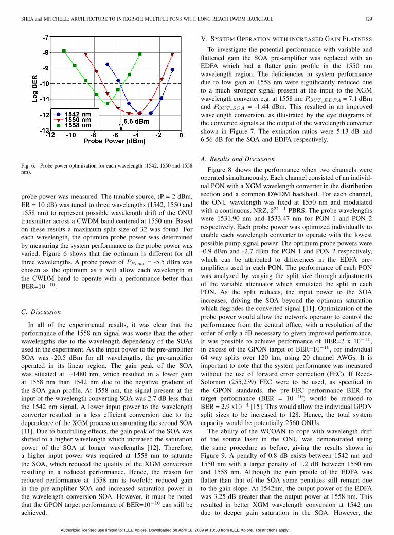
Fig. 6. Probe power optimisation for each wavelength (1542, 1550 and 1558nm).
probe power was measured. The tunable source, (P = 2 dBm,ER = 10 dB) was tuned to three wavelengths (1542, 1550 and1558 nm) to represent possible wavelength drift of the ONUtransmitter across a CWDM band centered at 1550 nm. Basedon these results a maximum split size of 32 was found. Foreach wavelength, the optimum probe power was determinedby measuring the system performance as the probe power wasvaried. Figure 6 shows that the optimum is different for allthree wavelengths. A probe power of PProbe = -5.5 dBm waschosen as the optimum as it will allow each wavelength inthe CWDM band to operate with a performance better thanBER=10−10.
C. Discussion
In all of the experimental results, it was clear that theperformance of the 1558 nm signal was worse than the otherwavelengths due to the wavelength dependency of the SOAsused in the experiment. As the input power to the pre-amplifierSOA was -20.5 dBm for all wavelengths, the pre-amplifieroperated in its linear region. The gain peak of the SOAwas situated at ∼1480 nm, which resulted in a lower gainat 1558 nm than 1542 nm due to the negative gradient ofthe SOA gain profile. At 1558 nm, the signal present at theinput of the wavelength converting SOA was 2.7 dB less thanthe 1542 nm signal. A lower input power to the wavelengthconverter resulted in a less efficient conversion due to thedependence of the XGM process on saturating the second SOA[11]. Due to bandfilling effects, the gain peak of the SOA wasshifted to a higher wavelength which increased the saturationpower of the SOA at longer wavelengths [12]. Therefore,a higher input power was required at 1558 nm to saturatethe SOA, which reduced the quality of the XGM conversionresulting in a reduced performance. Hence, the reason forreduced performance at 1558 nm is twofold; reduced gainin the pre-amplifier SOA and increased saturation power inthe wavelength conversion SOA. However, it must be notedthat the GPON target performance of BER=10−10 can still beachieved.
V. SYSTEM OPERATION WITH INCREASED GAIN FLATNESS
To investigate the potential performance with variable andflattened gain the SOA pre-amplifier was replaced with anEDFA which had a flatter gain profile in the 1550 nmwavelength region. The deficiencies in system performancedue to low gain at 1558 nm were significantly reduced dueto a much stronger signal present at the input to the XGMwavelength converter e.g. at 1558 nm POUT EDFA = 7.1 dBmand POUT SOA = -1.44 dBm. This resulted in an improvedwavelength conversion, as illustrated by the eye diagrams ofthe converted signals at the output of the wavelength convertershown in Figure 7. The extinction ratios were 5.13 dB and6.56 dB for the SOA and EDFA respectively.
A. Results and Discussion
Figure 8 shows the performance when two channels wereoperated simultaneously. Each channel consisted of an individ-ual PON with a XGM wavelength converter in the distributionsection and a common DWDM backhaul. For each channel,the ONU wavelength was fixed at 1550 nm and modulatedwith a continuous, NRZ, 231−1 PBRS. The probe wavelengthswere 1531.90 nm and 1533.47 nm for PON 1 and PON 2respectively. Each probe power was optimized individually toenable each wavelength converter to operate with the lowestpossible pump signal power. The optimum probe powers were-0.9 dBm and -2.7 dBm for PON 1 and PON 2 respectively,which can be attributed to differences in the EDFA pre-amplifiers used in each PON. The performance of each PONwas analyzed by varying the split size through adjustmentsof the variable attenuator which simulated the split in eachPON. As the split reduces, the input power to the SOAincreases, driving the SOA beyond the optimum saturationwhich degrades the converted signal [11]. Optimization of theprobe power would allow the network operator to control theperformance from the central office, with a resolution of theorder of only a dB necessary to given improved performance.It was possible to achieve performance of BER=2 x 10⁻¹¹,in excess of the GPON target of BER=10−10, for individual64 way splits over 120 km, using 20 channel AWGs. It isimportant to note that the system performance was measuredwithout the use of forward error correction (FEC). If Reed-Solomon (255,239) FEC were to be used, as specified inthe GPON standards, the pre-FEC performance BER fortarget performance (BER = 10−10) would be reduced toBER = 2.9 x10⁻⁴ [15]. This would allow the individual GPONsplit sizes to be increased to 128. Hence, the total systemcapacity would be potentially 2560 ONUs.
The ability of the WCOAN to cope with wavelength driftof the source laser in the ONU was demonstrated usingthe same procedure as before, giving the results shown inFigure 9. A penalty of 0.8 dB exists between 1542 nm and1550 nm with a larger penalty of 1.2 dB between 1550 nmand 1558 nm. Although the gain profile of the EDFA wasflatter than that of the SOA some penalties still remain dueto the gain slope. At 1542nm, the output power of the EDFAwas 3.25 dB greater than the output power at 1558 nm. Thisresulted in better XGM wavelength conversion at 1542 nmdue to deeper gain saturation in the SOA. However, the
Authorized licensed use limited to: IEEE Xplore. Downloaded on April 16, 2009 at 10:53 from IEEE Xplore. Restrictions apply.

130 IEEE JOURNAL ON SELECTED AREAS IN COMMUNICATIONS, VOL. 27, NO. 2, FEBRUARY 2009
Fig. 7. Comparison of eye diagrams for the converted signal after thewavelength converter when using an SOA and EDFA pre-amplifier. Both eyesare recorded on a 50µV/div scale.
Fig. 8. Two channels operating simultaneously across WCOAN. Bothchannels achieve better than BER=10−10 with individual 64 way splits givinga potential split of 1280 or 2560 with FEC.
wavelength dependency of the SOA reduces the penalty. At1558 nm, a higher output power (6.6 dBm) was possible thanat 1542 nm (4.2 dBm), due to increased SOA saturation pow-ers at longer wavelengths. The penalty between wavelengthswas therefore reduced as a greater optical signal power waspresent at the receiver; −25.7 dBm @ 1558 nm comparedwith −28.1 dBm @ 1542 nm.
VI. 128 SPLIT WITH AMPLIFIED BACKHAUL
Up to this point, all of the system improvements havebeen made through modifications to the wavelength converter.The network backhaul is another area where performanceenhancements can be achieved. After the wavelength converterthe signal was subject to 35 dB of attenuation in the backhaulsection due to fiber loss (25 dB) and insertion losses in theAWGs (5 dB each). An avalanche photodiode (APD) was usedin the OLT to recover the optical signal. Further improvementsin the receiver sensitivity were made by using an opticalamplifier to overcome the loss in the backhaul and AWG.Typically, the benefits of the avalanche gain within an APD arenegated when pre-amplified by an optical amplifier. However,here it is placed before the AWG to provide gain as the systemis currently limited by noise from the photodiode due to thelong backhaul and AWG loss; improving the sensitivity of thereceiver and hence the system performance.
Fig. 9. Wavelength drift resilience of the WCOAN. A tunable source wasused to simulate wavelength drift in an uncooled ONU laser. A 2 dB penaltywas observed between 1542 nm and 1558 nm.
Fig. 10. 128 way split architecture with optically pre-amplified receiver.
A. Experimental Setup
The modified system architecture is depicted by Figure10, where an SOA is placed after the backhaul fiber. In thisconfiguration the second AWG will also act as an ASE filter atthe receiver. In this particular setup the wavelength converteruses an SOA pre-amplifier as in the system shown in Figure4.
B. Experimental Results
The experimental procedure used to determine whether theperformance of the system with amplified backhaul was thesame as in the previous sections. Initially, the optimum probepower was determined to be -26 dBm when using a backhaulwavelength of 1530.04 nm. Figure 11 shows how the optimumprobe power enabled the system to operate with a performancebetter than BER = 10−10 for a split ratio of 128 across aCWDM band centred at 1550 nm. The performance variationwith wavelength corresponds to the wavelength dependency ofthe SOA identified in Section IV. An increase to 256 way splitPONs would be possible when using an EDFA pre-amplifierin the wavelength converter. However, the benefit of usingtwo SOAs is that both devices can be integrated into the samepackage which creates a much more compact solution.
Authorized licensed use limited to: IEEE Xplore. Downloaded on April 16, 2009 at 10:53 from IEEE Xplore. Restrictions apply.

SHEA and MITCHELL: ARCHITECTURE TO INTEGRATE MULTIPLE PONS WITH LONG REACH DWDM BACKHAUL 131
Fig. 11. Performance of the amplified backhaul system showing that a splitsize of 128 is achievable when the ONU wavelength varies over CWDMchannel centred at 1550 nm.
Fig. 12. Dynamic range of the network measured for distribution wavelengthswhich span a CWDM channel. Shaded areas indicate where the wavelengthconverter is saturated by ones only (left) and ones and zeros (right).
The dynamic range of the system is shown in Figure 12. Thedynamic range of the system defines the range of pump signalpower over which the target performance of BER=10−10 canbe maintained. Out of the three wavelengths used to simulatethe CWDM band centred on 1550 nm, the minimum dynamicrange of 11.6 dB was achieved for 1542 nm wavelength.Due to the wavelength dependency of the SOAs the longerwavelengths have less gain. This enables the shorter 1542 nmwavelength to operate with a larger split size. However, highergain means that the zero level signal will begin to saturate thewavelength converter at lower input power. Saturation of theSOA by the zeros would result in a reduced extinction ratioin the converted signal and hence reduced performance. Forlonger wavelengths, lower gain means that zero saturation ofthe SOA is limited, which leads to a larger dynamic range. At1558 nm, it was not possible to measure the dynamic rangedue to power limitations i.e. it was not possible to achievethe signal power required for the zero level SOA saturation,indicating that it was in excess of 15 dB.
In a deployed system, numerous DWDM probe wavelengthswould be used to carry the data from numerous PON distri-
Fig. 13. Performance penalty measure in terms of the Q factor for variousdegrees of detuning of the optical filter prior to the receiver.
bution sections connected to the common backhaul throughwavelength converters. To ensure that the target BER of 10−10,can be achieved at different backhaul wavelengths, the systemperformance was measured at using probe wavelengths of1520.25 nm and 1535.04 nm which provided 20, 100 GHzspaced channels. Modifications were made to the experimentalset-up to allow tunability of the backhaul wavelengths i.e. theAWGs were replaced with 100 GHz optical filters. Additionalattenuation of 35 dB was included to ensure that the total back-haul attenuation was consistent with the previous experimentalsetup. It was assumed that the best performance would beachieved when the optical filter centre frequency was perfectlyaligned with the backhaul wavelength, as the maximum opticalsignal power would be present at the receiver. However, thiswas not the case. Figure 13 shows that the best systemperformance occurs when the optical filter prior to the receiveris detuned from the centre wavelength by -110 GHz ± 5 GHz(-0.9 nm ± 0.04 nm).
The reason for this can be explained as follows: driving anSOA into saturation induces phase modulation due to carrierdensity changes [16]. In the XGM wavelength conversionprocess different levels of saturation are achieved for ones andzeros in order to modulate the gain of the SOA. This resultsin a frequency difference between the ones and zeros in thesignal frequency spectrum. By detuning the optical filter, itis possible to use the filter to remove the zero componentof the signal [17]. Hence, the extinction ratio of the signalis increased resulting in a performance increase. To takeadvantage of the performance increase the optical filters inthe subsequent results are detuned by -110 GHz.
As in the previous sections, wavelength drift of the ONUtransmitter across a CWDM band centred at 1550 nm, wassimulated by using three test wavelengths, 1542, 1550 and1558 nm. An attenuator placed prior to the receiver wasused to adjust the received optical power in 1 dB steps.The optimum probe powers were determined to be -9 dBmand -7.5 dBm for the 1535.04 nm and 1520.25 nm probewavelengths respectively. The difference between the twooptimum probe powers can be attributed to the wavelengthdependency of the SOA devices used. The peak gain of the
Authorized licensed use limited to: IEEE Xplore. Downloaded on April 16, 2009 at 10:53 from IEEE Xplore. Restrictions apply.
132 IEEE JOURNAL ON SELECTED AREAS IN COMMUNICATIONS, VOL. 27, NO. 2, FEBRUARY 2009
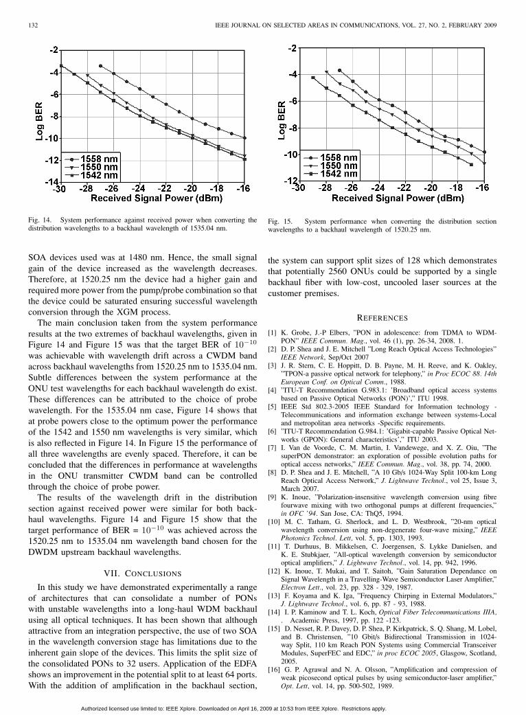
Fig. 14. System performance against received power when converting thedistribution wavelengths to a backhaul wavelength of 1535.04 nm.
SOA devices used was at 1480 nm. Hence, the small signalgain of the device increased as the wavelength decreases.Therefore, at 1520.25 nm the device had a higher gain andrequired more power from the pump/probe combination so thatthe device could be saturated ensuring successful wavelengthconversion through the XGM process.
The main conclusion taken from the system performanceresults at the two extremes of backhaul wavelengths, given inFigure 14 and Figure 15 was that the target BER of 10−10
was achievable with wavelength drift across a CWDM bandacross backhaul wavelengths from 1520.25 nm to 1535.04 nm.Subtle differences between the system performance at theONU test wavelengths for each backhaul wavelength do exist.These differences can be attributed to the choice of probewavelength. For the 1535.04 nm case, Figure 14 shows thatat probe powers close to the optimum power the performanceof the 1542 and 1550 nm wavelengths is very similar, whichis also reflected in Figure 14. In Figure 15 the performance ofall three wavelengths are evenly spaced. Therefore, it can beconcluded that the differences in performance at wavelengthsin the ONU transmitter CWDM band can be controlledthrough the choice of probe power.
The results of the wavelength drift in the distributionsection against received power were similar for both back-haul wavelengths. Figure 14 and Figure 15 show that thetarget performance of BER = 10−10 was achieved across the1520.25 nm to 1535.04 nm wavelength band chosen for theDWDM upstream backhaul wavelengths.
VII. CONCLUSIONS
In this study we have demonstrated experimentally a rangeof architectures that can consolidate a number of PONswith unstable wavelengths into a long-haul WDM backhaulusing all optical techniques. It has been shown that althoughattractive from an integration perspective, the use of two SOAin the wavelength conversion stage has limitations due to theinherent gain slope of the devices. This limits the split size ofthe consolidated PONs to 32 users. Application of the EDFAshows an improvement in the potential split to at least 64 ports.With the addition of amplification in the backhaul section,
Fig. 15. System performance when converting the distribution sectionwavelengths to a backhaul wavelength of 1520.25 nm.
the system can support split sizes of 128 which demonstratesthat potentially 2560 ONUs could be supported by a singlebackhaul fiber with low-cost, uncooled laser sources at thecustomer premises.
REFERENCES
[1] K. Grobe, J.-P Elbers, ”PON in adolescence: from TDMA to WDM-PON” IEEE Commun. Mag., vol. 46 (1), pp. 26-34, 2008. 1.
[2] D. P. Shea and J. E. Mitchell ”Long Reach Optical Access Technologies”IEEE Network, Sep/Oct 2007
[3] J. R. Stern, C. E. Hoppitt, D. B. Payne, M. H. Reeve, and K. Oakley,”TPON-a passive optical network for telephony,” in Proc ECOC 88. 14thEuropean Conf. on Optical Comm., 1988.
[4] ”ITU-T Recommendation G.983.1: ’Broadband optical access systemsbased on Passive Optical Networks (PON)’,” ITU 1998.
[5] IEEE Std 802.3-2005 IEEE Standard for Information technology -Telecommunications and information exchange between systems-Localand metropolitan area networks -Specific requirements.
[6] ”ITU-T Recommendation G.984.1: ’Gigabit-capable Passive Optical Net-works (GPON): General characteristics’,” ITU 2003.
[7] I. Van de Voorde, C. M. Martin, I. Vandewege, and X. Z. Oiu, ”ThesuperPON demonstrator: an exploration of possible evolution paths foroptical access networks,” IEEE Commun. Mag., vol. 38, pp. 74, 2000.
[8] D. P. Shea and J. E. Mitchell, ”A 10 Gb/s 1024-Way Split 100-km LongReach Optical Access Network,” J. Lightwave Technol., vol 25, Issue 3,March 2007.
[9] K. Inoue, ”Polarization-insensitive wavelength conversion using fibrefourwave mixing with two orthogonal pumps at different frequencies,”in OFC ’94. San Jose, CA: ThQ5, 1994.
[10] M. C. Tatham, G. Sherlock, and L. D. Westbrook, ”20-nm opticalwavelength conversion using non-degenerate four-wave mixing,” IEEEPhotonics Technol. Lett, vol. 5, pp. 1303, 1993.
[11] T. Durhuus, B. Mikkelsen, C. Joergensen, S. Lykke Danielsen, andK. E. Stubkjaer, ”All-optical wavelength conversion by semiconductoroptical amplifiers,” J. Lightwave Technol., vol. 14, pp. 942, 1996.
[12] K. Inoue, T. Mukai, and T. Saitoh, ”Gain Saturation Dependance onSignal Wavelength in a Travelling-Wave Semiconductor Laser Amplifier,”Electron Lett., vol. 23, pp. 328 - 329, 1987.
[13] F. Koyama and K. Iga, ”Frequency Chirping in External Modulators,”J. Lightwave Technol., vol. 6, pp. 87 - 93, 1988.
[14] I. P. Kaminow and T. L. Koch, Optical Fiber Telecommunications IIIA,. Academic Press, 1997, pp. 122 -123.
[15] D. Nesset, R. P. Davey, D. P. Shea, P. Kirkpatrick, S. Q. Shang, M. Lobel,and B. Christensen, ”10 Gbit/s Bidirectional Transmission in 1024-way Split, 110 km Reach PON Systems using Commercial TransceiverModules, SuperFEC and EDC,” in proc ECOC 2005, Glasgow, Scotland,2005.
[16] G. P. Agrawal and N. A. Olsson, ”Amplification and compression ofweak picosecond optical pulses by using semiconductor-laser amplifier,”Opt. Lett, vol. 14, pp. 500-502, 1989.
Authorized licensed use limited to: IEEE Xplore. Downloaded on April 16, 2009 at 10:53 from IEEE Xplore. Restrictions apply.

SHEA and MITCHELL: ARCHITECTURE TO INTEGRATE MULTIPLE PONS WITH LONG REACH DWDM BACKHAUL 133
[17] P. V. Mamyshev, ”All-optical data regeneration based on self-phasemodulation effect,” in ECOC 1998., vol. 1, 1998, pp. 475.
Darren P. Shea Darren Shea received his Engi-neering Doctorate (EngD) Degree in Telecommuni-cations from University College London (UCL) in2006. His thesis research, performed in conjunctionwith BT, involved the design and construction ofa 10Gbit/s optical access network which connected1024 customers directly to the core network over adistance of 100 km. Prior to his doctorate studies, hereceived first class honours in electronic engineeringfrom The University of Manchester.
For the duration of his doctorate research, Darrenworked as part of the Optical Networks group at BT, based at Adastral Park,Ipswich, UK. Currently, he is working as a Research Fellow at UCL. Hisresearch interests include optical access, specifically fibre to the home, andburst mode receiver and long haul transmission improvements using opticalfrequency chirping.
John E. Mitchell John E. Mitchell (S96 M00)received the Ph.D. degree in Electronic Engineeringfrom UCL (University College London), UK in2000. Since 2000 he has been a a Lecturer andSenior Lecturer (since 2006) in the Department ofElectronic and Electrical Engineering at UCL.
He has published over 40 papers in the areaof optical communications. His research interestsinclude optical access technologies and the transportof millimetre wave radio signals over optical fibrefor communications, and noise relating to crosstalk
in optical networks. Dr Mitchell is a member of the Institute of Engineeringand Technology (IET) and the IEEE ComSoc
Authorized licensed use limited to: IEEE Xplore. Downloaded on April 16, 2009 at 10:53 from IEEE Xplore. Restrictions apply.
Related Documents