Ready Solutions for Data Analytics Real-Time Data Streaming Architecture Guide February 2019 H17557.1

Welcome message from author
This document is posted to help you gain knowledge. Please leave a comment to let me know what you think about it! Share it to your friends and learn new things together.
Transcript

Ready Solutions for Data AnalyticsReal-Time Data Streaming
Architecture GuideFebruary 2019
H17557.1

ii | Contents
ContentsList of figures..................................................................................................................... iv
List of tables....................................................................................................................... v
Trademarks........................................................................................................................ viNotes, cautions, and warnings......................................................................................... vii
Chapter 1: Executive summary.......................................................................................... 8Introduction...........................................................................................................................................9
Chapter 2: Streaming overview........................................................................................ 10Streaming introduction....................................................................................................................... 11
Publish and subscribe.............................................................................................................11Storage.................................................................................................................................... 11Processing............................................................................................................................... 11
Streaming architecture.......................................................................................................................12Lambda architecture................................................................................................................12Kappa architecture.................................................................................................................. 12
Chapter 3: Cluster architecture.........................................................................................14Architecture overview.........................................................................................................................15Network architecture.......................................................................................................................... 17
Chapter 4: Hardware configurations.................................................................................19Control Center Node..........................................................................................................................20Platform Node.................................................................................................................................... 20KSQL Node........................................................................................................................................21Broker Node.......................................................................................................................................22Broker Node - high performance.......................................................................................................24Network configurations.......................................................................................................................25
Chapter 5: Integration, sizing, and scaling.......................................................................28Integration...........................................................................................................................................29
Integration with external data sources....................................................................................29Integration with Isilon.............................................................................................................. 30
Physical rack integration....................................................................................................................31Sizing and scaling..............................................................................................................................32
Broker and ZooKeeper scaling............................................................................................... 32KSQL and Kafka Connect scaling.......................................................................................... 33
Chapter 6: Testing and performance results.................................................................... 34Overview.............................................................................................................................................35System under test..............................................................................................................................35Performance tests..............................................................................................................................35Results................................................................................................................................................35
Partitioning...............................................................................................................................36
Ready Solutions for Data Analytics | Real-Time Data Streaming | February 2019

Contents | iii
Producer variations................................................................................................................. 36Consumer variations............................................................................................................... 37Producer and consumer variations.........................................................................................38Broker scalability..................................................................................................................... 40Message size variations..........................................................................................................41
Conclusion..........................................................................................................................................41
Appendix A: Tested component versions......................................................................... 42Software versions...............................................................................................................................43Network switch firmware versions..................................................................................................... 43Dell EMC PowerEdge R640 firmware versions............................................................................... 43
Appendix B: Related documentation................................................................................ 44Confluent documentation................................................................................................................... 45Dell EMC documentation................................................................................................................... 45Operating systems documentation.................................................................................................... 45Apache Software Foundation documentation....................................................................................45
Appendix C: References...................................................................................................46About Confluent................................................................................................................................. 47About Dell EMC Customer Solution Centers.................................................................................... 47To learn more.....................................................................................................................................47
Glossary............................................................................................................................48
Index................................................................................................................................. 54
Ready Solutions for Data Analytics | Real-Time Data Streaming | February 2019

iv | List of figures
List of figuresFigure 1: Streaming adoption journey............................................................................... 9
Figure 2: Lambda architecture.........................................................................................12
Figure 3: Kappa architecture........................................................................................... 13
Figure 4: Standard cluster architecture........................................................................... 15
Figure 5: Large cluster architecture.................................................................................16
Figure 6: Network layout..................................................................................................18
Figure 7: Single rack network connections......................................................................26
Figure 8: Client data interfaces........................................................................................29
Figure 9: Hadoop integration example............................................................................ 30
Figure 10: Isilon integration example...............................................................................30
Figure 11: Single rack deployment.................................................................................. 31
Figure 12: Multiple rack deployment................................................................................32
Figure 13: Throughput versus number of producers....................................................... 37
Figure 14: Throughput versus number of consumers......................................................38
Figure 15: Throughput versus number of producers and consumers..............................39
Figure 16: Broker scalability: maximum throughput.........................................................40
Figure 17: Broker scalability: maximum records per second...........................................40
Figure 18: Message size versus throughput....................................................................41
Ready Solutions for Data Analytics | Real-Time Data Streaming | February 2019

List of tables | v
List of tablesTable 1: Node roles and services.................................................................................... 16
Table 2: Node roles and hardware configurations........................................................... 17
Table 3: Hardware configuration – Control Center Node.................................................20
Table 4: Volumes - Control Center Node.........................................................................20
Table 5: Partitions - Control Center Node....................................................................... 20
Table 6: Hardware configurations – Platform Node.........................................................21
Table 7: Volumes - Platform Node...................................................................................21
Table 8: Partitions - Platform Node..................................................................................21
Table 9: Hardware configurations – KSQL Node.............................................................21
Table 10: Volumes - KSQL Node.................................................................................... 22
Table 11: Partitions - KSQL Node....................................................................................22
Table 12: Hardware configurations – Broker Node..........................................................22
Table 13: Volumes - Broker Node................................................................................... 23
Table 14: Partitions - Broker Node.................................................................................. 23
Table 15: Hardware configurations – Broker Node high performance............................. 24
Table 16: Volumes - Broker Node high performance.......................................................24
Table 17: Partitions - Broker Node - high performance................................................... 24
Table 18: Network configurations.....................................................................................27
Table 19: Producer variations test parameters................................................................ 36
Table 20: Consumer variations test parameters.............................................................. 37
Table 21: Producer and consumer variations test parameters........................................ 38
Table 22: Results with 6 producers and 6 consumers.....................................................39
Table 23: Tested software versions................................................................................. 43
Table 24: Tested switch firmware versions...................................................................... 43
Table 25: Dell EMC PowerEdge R640 tested firmware versions.....................................43
Ready Solutions for Data Analytics | Real-Time Data Streaming | February 2019

vi | Trademarks
Trademarks
The information in this publication is provided “as is.” Dell Inc. makes no representations or warranties ofany kind with respect to the information in this publication, and specifically disclaims implied warranties ofmerchantability or fitness for a particular purpose.
Use, copying, and distribution of any software described in this publication requires an applicable softwarelicense.
Copyright © 2019 Dell Inc. or its subsidiaries. All rights reserved. Dell, EMC, Dell EMC and othertrademarks are trademarks of Dell Inc. or its subsidiaries. Other trademarks may be trademarks of theirrespective owners.
Dell believes the information in this document is accurate as of its publication date. The information issubject to change without notice.
Ready Solutions for Data Analytics | Real-Time Data Streaming | February 2019

Notes, cautions, and warnings | vii
Notes, cautions, and warnings
Note: A Note indicates important information that helps you make better use of your system.
CAUTION: A Caution indicates potential damage to hardware or loss of data if instructions are notfollowed.
Warning: A Warning indicates a potential for property damage, personal injury, or death.
This document is for informational purposes only and may contain typographical errors and technicalinaccuracies. The content is provided as is, without express or implied warranties of any kind.
Ready Solutions for Data Analytics | Real-Time Data Streaming | February 2019

8 | Executive summary
Chapter
1Executive summary
Topics:
• Introduction
This Ready Architecture Guide describes recommended Dell EMCinfrastructure for implementing Lambda and Kappa stream processingarchitectures using Apache Kafka and Confluent Enterprise.
Ready Solutions for Data Analytics | Real-Time Data Streaming | February 2019

Executive summary | 9
IntroductionCompanies are modernizing their IT architecture to enable innovation, increase agility, and support thecreation of new digital products and services. These trends are also driving a fundamental shift in how datapowers a company's core business, as companies transition from batch processing to real-time data andevent-driven applications.
The journey to a real-time enterprise starts with a streaming platform for data. A streaming platformcombines the data distribution strength of a publish-subscribe model with a storage layer and a processinglayer. This makes it much easier to create data pipelines and connect them to all of your systems.Deploying a streaming platform can avoid the latency of batch processing, and make data available in realtime to applications that need it.
Apache Kafka is a streaming platform designed to solve these problems in a modern, distributedarchitecture. Originally envisioned as a fast and scalable distributed messaging queue, it has rapidlyexpanded into a full-scale streaming platform.
Confluent Platform improves Apache Kafka by expanding its integration capabilities, adding tools tooptimize and manage Kafka clusters, and methods to ensure the streams are secure. Confluent Platformmakes Kafka easier to build and easier to operate. Confluent Open Source is freely downloadable, whileConfluent Enterprise is available through subscription.
In most customer environments, there is a logical progression in the adoption of streaming data analytics,as shown in Figure 1: Streaming adoption journey on page 9 1. Choosing the correct infrastructure fora streaming platform is critical for success, performance, and scalability. This guide describes Dell EMC'srecommended infrastructure for deploying Kafka and Confluent Enterprise.
Figure 1: Streaming adoption journey
1 Figure courtesy of Confluent, Inc.
Ready Solutions for Data Analytics | Real-Time Data Streaming | February 2019

10 | Streaming overview
Chapter
2Streaming overview
Topics:
• Streaming introduction• Streaming architecture
This chapter provides an overview of stream processing, key Kafkaconcepts, and architectures for stream processing in the context of BigData Analytics.
Ready Solutions for Data Analytics | Real-Time Data Streaming | February 2019

Streaming overview | 11
Streaming introductionApache Kafka is an open source, distributed streaming platform capable of handling trillions of events aday. Confluent Platform improves Kafka with additional open source and commercial features designed toenhance the streaming experience of both operators and developers in production, at massive scale.
This streaming platform provides three core capabilities:
• Publish and subscribe — see Publish and subscribe on page 11• Storage — see Storage on page 11• Processing — see Processing on page 11
Publish and subscribePublish and subscribe describes the way data enters and leaves a streaming platform. The unit of data inKafka is a message. Kafka messages are organized into topics that contained ordered messages. DataProducers publish their messages to a topic, and Consumers subscribe to a topic. A Kafka server is calleda Broker. The Broker receives messages from Producers, and responds to Consumer requests. MultipleBrokers are normally operated as part of a cluster for scalability and redundancy. A topic can be partitionedinto subsets across multiple Brokers, and partitions can also be replicated between Brokers.
The Confluent Platform provides multiple APIs for reading and writing data. The Producer/Consumer APIprovides a low level interface directly to and from the Brokers. The Kafka Connect API and Connectorssupport data integration with other systems, while the Kafka Streams API is optimized for streamprocessing. The RESTful API Proxy API can also be used as an HTTP interface to the cluster.
Brokers, Kafka Connect, and the RESTful API Proxy can all be scaled independently to meet capacity andredundancy requirements.
StorageStorage of messages is provided by the Brokers, and uses local disks. A topic can be partitioned intosubsets across multiple Brokers, and partitions can also be replicated between Brokers for scalability andredundancy. Each topic can be configured with a retention policy, to store messages for some period oftime or until a topic reaches a certain size in bytes. Once these limits are reached, messages are expiredand deleted.
Kafka Connect can be used to transfer topic data to external systems such as:
• Relational and NoSQL databases• Hadoop• Object Stores• Dell EMC Isilon
ProcessingThe Kafka Streams API is a powerful, lightweight library that enables real-time data processing againstApache Kafka. Confluent KSQL is an open source, streaming SQL engine built upon Kafka Streams. Itprovides an easy-to-use, yet powerful, interactive SQL interface for stream processing on Kafka. KSQL isscalable, elastic, fault-tolerant, and it supports a wide range of streaming operations, including:
• Data filtering• Transformations• Aggregations• Joins• Windowing• Sessionization
Ready Solutions for Data Analytics | Real-Time Data Streaming | February 2019

12 | Streaming overview
Streaming architectureThe flexibility of a Kafka-based streaming platform supports many streaming architectures. Commonarchitectural patterns include microservice interfaces for existing or legacy systems, including:
• Fanout to multiple downstream systems optimized for specific use cases• SIEM offload, replacement and augmentation• Transactional and exactly once operations• Real-time alerts at edge interfaces
In the Big Data Analytics space, two implementation patterns have emerged, commonly known as:
• Lambda architecture — see Lambda architecture on page 12• Kappa architecture — see Kappa architecture on page 12
Both of these architectures process data into a serving system, which could be Hadoop HDFS files,HBase, or another NoSQL database. The service system is then interfaced to applications.
Lambda architectureThe Lambda architecture is a stream processing architecture sometimes used to integrate real-time datainto existing batch processing systems. Figure 2: Lambda architecture on page 12 illustrates thisarchitecture.
In the Lambda architecture, there are two distinct processing flows, both writing to a service database:
• One for batch data• One for streaming data
These flows will typically use different processing systems optimized for batch and stream processing. Thespeed table contains recent data, while the batch table contains older data. At regular intervals, usuallybased on the size of the speed table, the recent data is re-processed through the batch system into batchtables, the speed table is emptied, and the cycle is repeated.
Figure 2: Lambda architecture
Kappa architectureThe Kappa architecture is a stream processing architecture that eliminates all batch processing, andreplaces it with streaming. Kappa architecture is sometimes used to replace batch processing; inother instances it is deployed from scratch. Figure 3: Kappa architecture on page 13 illustrates thisarchitecture.
In the Kappa architecture, the same processing flow and system is used for all data, and the data isprocessed directly into the serving database. This architecture requires a high performance streamprocessing platform capable of keeping up with the flow of real-time data.
Ready Solutions for Data Analytics | Real-Time Data Streaming | February 2019

Streaming overview | 13
The Kappa architecture has some advantages over Lambda for stream processing. The primaryadvantage is the use of a single processing flow, which avoids re-processing and maintenance of the sameprocessing logic in two different systems. Another advantage is the ability to quickly implement versioningof processing logic. Whenever logic needs to be changed, a new streaming job can be deployed, writinginto a new table, in parallel with any existing logic.
Figure 3: Kappa architecture
Ready Solutions for Data Analytics | Real-Time Data Streaming | February 2019

14 | Cluster architecture
Chapter
3Cluster architecture
Topics:
• Architecture overview• Network architecture
Kafka is both flexible and scalable, with multiple deploymentoptions that complicate infrastructure selection. This architecture isprovided to assist customers in selecting the correct infrastructure forimplementing Confluent Enterprise in production environments.
Ready Solutions for Data Analytics | Real-Time Data Streaming | February 2019

Cluster architecture | 15
Architecture overviewThe architecture follows the general recommendations in the Apache Kafka and Confluent EnterpriseReference Architecture and can be used to implement small or large clusters, with a clear path to scalingfrom small to large. The architecture also addresses the performance, latency, and reliability requirementsof mission-critical production deployments.
The Confluent Enterprise components are grouped into seven main categories:
1. Confluent Control Center2. Kafka Brokers3. ZooKeeper4. Kafka Connect and Connectors5. Confluent Schema Registry6. Confluent KSQL7. Confluent RESTful API Proxy
This grouping is chosen to allow each category to be scaled independently, based on capacity andperformance requirements. It also simplifies scaling from initial deployments to larger implementations,since some functions can be co-located on physical nodes, and later moved to additional physical nodes.
Figure 4: Standard cluster architecture on page 15 illustrates a typical initial deployment architecture,while Figure 5: Large cluster architecture on page 16 illustrates a scaled implementation where allcomponents have been scaled out. Actual implementations will typically fall somewhere between these twoexamples.
Figure 4: Standard cluster architecture
Ready Solutions for Data Analytics | Real-Time Data Streaming | February 2019
16 | Cluster architecture
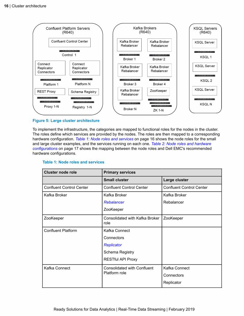
Figure 5: Large cluster architecture
To implement the infrastructure, the categories are mapped to functional roles for the nodes in the cluster.The roles define which services are provided by the nodes. The roles are then mapped to a correspondinghardware configuration. Table 1: Node roles and services on page 16 shows the node roles for the smalland large cluster examples, and the services running on each one. Table 2: Node roles and hardwareconfigurations on page 17 shows the mapping between the node roles and Dell EMC's recommendedhardware configurations.
Table 1: Node roles and services
Cluster node role Primary services
Small cluster Large cluster
Confluent Control Center Confluent Control Center Confluent Control Center
Kafka Broker Kafka Broker
Rebalancer
ZooKeeper
Kafka Broker
Rebalancer
ZooKeeper Consolidated with Kafka Brokerrole
ZooKeeper
Confluent Platform Kafka Connect
Connectors
Replicator
Schema Registry
RESTful API Proxy
Kafka Connect Consolidated with ConfluentPlatform role
Kafka Connect
Connectors
Replicator
Ready Solutions for Data Analytics | Real-Time Data Streaming | February 2019

Cluster architecture | 17
Cluster node role Primary services
Small cluster Large cluster
Confluent Schema Registry Consolidated with ConfluentPlatform role
Schema Registry
Confluent RESTful API Proxy Consolidated with ConfluentPlatform role
RESTful API Proxy
Confluent KSQL KSQL Server KSQL Server
Table 2: Node roles and hardware configurations
Cluster node role Hardware configuration
Confluent Control Center Control Center Node
Kafka Broker Broker Node on page 22
or
Broker Node - high performance on page 24
ZooKeeper Platform Node
Kafka Connect Platform Node
Confluent Schema Registry Platform Node
Confluent RESTful API Proxy Platform Node
Confluent KSQL KSQL Node
Network architectureThe network is an important part of any Confluent Enterprise implementation. The network organizationis shown in Figure 6: Network layout on page 18. The network is flat, and accounts for traffic both inand out of the cluster, and traffic within the cluster. This architecture supports scaling of the individualcomponents and of the cluster as a whole.
Dell EMC recommends 25 GbE technology for best price and performance. The switches are high-performance, non-blocking models, with multi-rate capabilities to support external interfaces. In somedeployments using the RESTful API proxy, a hardware load balancer may be required and can be easilyadded to the implementation.
Ready Solutions for Data Analytics | Real-Time Data Streaming | February 2019

18 | Cluster architecture
Figure 6: Network layout
Ready Solutions for Data Analytics | Real-Time Data Streaming | February 2019

Hardware configurations | 19
Chapter
4Hardware configurations
Topics:
• Control Center Node• Platform Node• KSQL Node• Broker Node• Broker Node - high performance• Network configurations
This chapter describes the Dell EMC recommended server andnetwork configurations for Confluent Enterprise.
Ready Solutions for Data Analytics | Real-Time Data Streaming | February 2019
20 | Hardware configurations
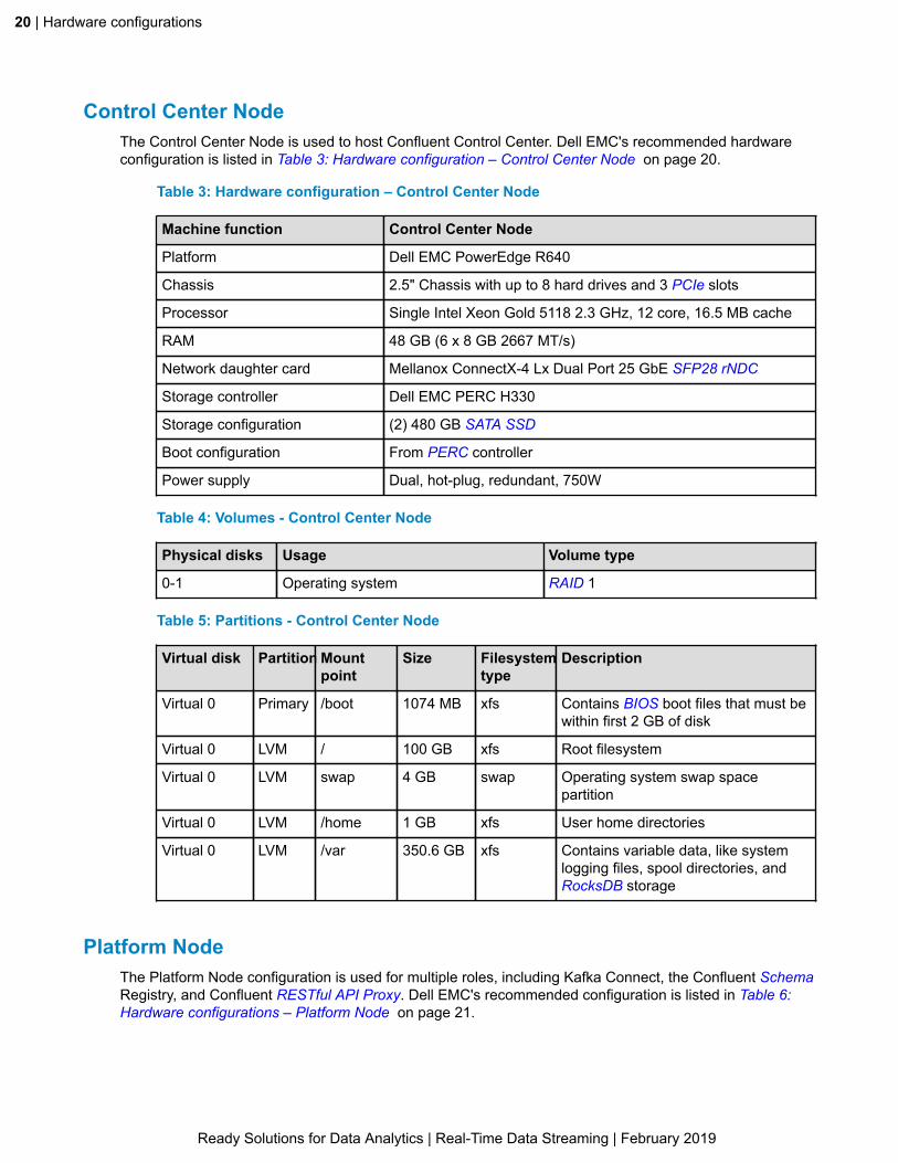
Control Center NodeThe Control Center Node is used to host Confluent Control Center. Dell EMC's recommended hardwareconfiguration is listed in Table 3: Hardware configuration – Control Center Node on page 20.
Table 3: Hardware configuration – Control Center Node
Machine function Control Center Node
Platform Dell EMC PowerEdge R640
Chassis 2.5" Chassis with up to 8 hard drives and 3 PCIe slots
Processor Single Intel Xeon Gold 5118 2.3 GHz, 12 core, 16.5 MB cache
RAM 48 GB (6 x 8 GB 2667 MT/s)
Network daughter card Mellanox ConnectX-4 Lx Dual Port 25 GbE SFP28 rNDC
Storage controller Dell EMC PERC H330
Storage configuration (2) 480 GB SATA SSD
Boot configuration From PERC controller
Power supply Dual, hot-plug, redundant, 750W
Table 4: Volumes - Control Center Node
Physical disks Usage Volume type
0-1 Operating system RAID 1
Table 5: Partitions - Control Center Node
Virtual disk Partition Mountpoint
Size Filesystemtype
Description
Virtual 0 Primary /boot 1074 MB xfs Contains BIOS boot files that must bewithin first 2 GB of disk
Virtual 0 LVM / 100 GB xfs Root filesystem
Virtual 0 LVM swap 4 GB swap Operating system swap spacepartition
Virtual 0 LVM /home 1 GB xfs User home directories
Virtual 0 LVM /var 350.6 GB xfs Contains variable data, like systemlogging files, spool directories, andRocksDB storage
Platform NodeThe Platform Node configuration is used for multiple roles, including Kafka Connect, the Confluent SchemaRegistry, and Confluent RESTful API Proxy. Dell EMC's recommended configuration is listed in Table 6:Hardware configurations – Platform Node on page 21.
Ready Solutions for Data Analytics | Real-Time Data Streaming | February 2019

Hardware configurations | 21
Table 6: Hardware configurations – Platform Node
Machine function Platform Node
Platform Dell EMC PowerEdge R640
Chassis 2.5" Chassis with up to 8 hard drives and 3 PCIe slots
Processor Single Intel Xeon Gold 6126 2.6 GHz, 12 core, 19.25 MB cache
RAM 48 GB - 6 x 8 GB DIMM
Network daughter card Mellanox ConnectX-4 Lx Dual Port 25 GbE SFP28 rNDC
Storage controller Dell EMC PERC H330
Storage configuration (2) 240 GB SATA SSD
Boot configuration From PERC controller
Power supply Dual, hot-plug, redundant, 750W
Table 7: Volumes - Platform Node
Physical disks Usage Volume type
0-1 Operating system RAID 1
Table 8: Partitions - Platform Node
Virtual disk Partition Mountpoint
Size Filesystemtype
Description
Virtual 0 Primary /boot 1074 MB xfs Contains BIOS boot files that must bewithin first 2 GB of disk
Virtual 0 LVM / 50 GB xfs Root filesystem
Virtual 3 LVM swap 4 GB swap Operating system swap spacepartition
Virtual 4 LVM /home 1 GB xfs User home directories
Virtual 5 LVM /var 167.5 GB xfs Contains variable data, like systemlogging files, spool directories, andRocksDB storage
KSQL NodeThe KSQL Node is used to host Confluent KSQL. Dell EMC's recommended configuration is listed in Table9: Hardware configurations – KSQL Node on page 21.
Table 9: Hardware configurations – KSQL Node
Machine function KSQL Node
Platform Dell EMC PowerEdge R640
Chassis 2.5" Chassis with up to 8 hard drives and 3 PCIe slots
Processor Single Intel Xeon Gold 6126 2.6 GHz, 12 core,19.25 MB cache
Ready Solutions for Data Analytics | Real-Time Data Streaming | February 2019

22 | Hardware configurations
Machine function KSQL Node
RAM 48 GB - 6 x 8 GB DIMM
Network daughter card Mellanox ConnectX-4 Lx Dual Port 25 GbE SFP28 rNDC
Boot configuration From PERC controller
Storage controller Dell EMC PERC H330
Storage configuration (2) 480 GB SAS SSD
Boot configuration From PERC controller
Power supply Dual, hot-plug, redundant, 750W
Table 10: Volumes - KSQL Node
Physical disks Usage Volume type
0-1 Operating system RAID 1
Table 11: Partitions - KSQL Node
Virtual disk Partition Mountpoint
Size Filesystemtype
Description
Virtual 1 Primary /boot 1074 MB xfs Contains BIOS boot files that must bewithin first 2 GB of disk
Virtual 2 LVM / 50 GB xfs Root filesystem
Virtual 3 LVM swap 4 GB swap Operating system swap spacepartition
Virtual 4 LVM /home 1 GB xfs User home directories
Virtual 5 LVM /var 390.6 GB xfs Contains variable data, like systemlogging files, spool directories, andRocksDB storage
Broker NodeThe Broker Node is used to host the Kafka Broker, and provides a balance of compute and storage. DellEMC's recommended configuration is listed in Table 12: Hardware configurations – Broker Node on page22
Table 12: Hardware configurations – Broker Node
Machine function Broker Node
Platform Dell EMC PowerEdge R640
Chassis 2.5" Chassis with up to 10 hard drives, 2 x 2.5" SATA/SAS drivesand 1 PCIe slot
Processor Dual Intel Xeon Gold 5118 2.3 GHz, 12 core 16.5 MB cache
RAM 96 GB - 12 x 8 GB
Network daughter card Mellanox ConnectX-4 Lx Dual Port 25 GbE SFP28 rNDC
Ready Solutions for Data Analytics | Real-Time Data Streaming | February 2019

Hardware configurations | 23
Machine function Broker Node
Storage controller Dell EMC PERC H740P
Storage configuration BOSS card + with two 240 GB M.2
(10) 2TB 7.2K NL-SAS
(1) 480 GB SSD (rear bay)
Boot configuration From BOSS controller
Power supply Dual, hot-plug, redundant, 750W
Table 13: Volumes - Broker Node
Physical disks Usage Volume type
0-1 Operating System RAID 1
2-9 Kafka partitions RAID 6 (Refer to note.)
10-11 ZooKeeper data RAID 1
12 ZooKeeper log RAID 1
Note: The Kafka partitions should use a reliable storage layer, either RAID 5, RAID 6, or RAID 10.We recommend RAID 6 for the best performance and reliability with the Dell EMC PERC H740Pstorage controller. RAID 5 provides slightly larger storage capacity but lower redundancy. RAID10 has lower performance than RAID 6 during normal I/O operations and when running with adegraded RAID array.
Table 14: Partitions - Broker Node
Virtual disk Partition Mountpoint
Size Filesystemtype
Description
DellBOSS 1 Primary /boot 1074 MB xfs Contains BIOS boot files that must bewithin first 2 GB of disk
DellBOSS 2 LVM / 50 GB xfs Root filesystem
DellBOSS 3 LVM swap 4 GB swap Operating system swap spacepartition
DellBOSS 4 LVM /home 1 GB xfs User home directories
DellBOSS 5 LVM /var 167.5 GB xfs Contains variable data, like systemlogging files, databases, mail andprinter spool directories, transient andtemporary files
Virtual 0 LVM /kafka 12 TB xfs Kafka Broker data
Virtual 1 LVM /var/zk 2 TB xfs ZooKeeper data
Virtual 2 LVM /var/log/zookeeper
480 GB xfs ZooKeeper log data
Ready Solutions for Data Analytics | Real-Time Data Streaming | February 2019

24 | Hardware configurations
Broker Node - high performanceThe High performance Broker Node is used to host Kafka Brokers. This configuration uses NVMe drivesfor high performance storage. Dell EMC's recommended configuration is listed in Table 15: Hardwareconfigurations – Broker Node high performance on page 24.
Table 15: Hardware configurations – Broker Node high performance
Machine function Broker Node
Platform Dell EMC PowerEdge R640
Chassis 2.5" Chassis with up to 10 hard drives, 8 NVMe drives and 3PCIe slots
Processor Dual Intel Xeon Gold 6126 2.6 GHz, 12 core, 19.25 MB cache
RAM 96 GB - 12 x 8 GB
Network daughter card Mellanox ConnectX-4 Lx Dual Port 25 GbE SFP28 rNDC
Storage controller Dell EMC PERC H330
Storage configuration (2) 240GB SATA SSD
(6) 1.6 TB U.2 NVMe flash
Boot configuration From PERC controller
Power supply Dual, hot-plug, redundant, 750W
Table 16: Volumes - Broker Node high performance
Physical disks Usage Volume type
0-1 Operating system RAID 1
2-7 Kafka partitions No RAID
Table 17: Partitions - Broker Node - high performance
Virtual disk Partition Mountpoint
Size Filesystemtype
Description
Virtual 0 Primary /boot 1074 MB xfs Contains BIOS boot filesthat must be within first 2GB of disk
Virtual 0 LVM / 50 GB xfs Root filesystem
Virtual 0 LVM swap 4 GB swap Operating system swapspace partition
Virtual 0 LVM /home 1 GB xfs User home directories
Virtual 0 LVM /var 167.5 GB xfs Contains variable data,like system logging files,databases, mail and printerspool directories, transientand temporary files
Ready Solutions for Data Analytics | Real-Time Data Streaming | February 2019

Hardware configurations | 25
Virtual disk Partition Mountpoint
Size Filesystemtype
Description
nvme0-
nvme5
nvme0p1-
nvme5p1
/kafka0-
/kafka5
1.6 TB xfs Kafka Broker data
Note: For high performance Broker Nodes, no provision is made for ZooKeeper data. These nodesare intended to be used with dedicated ZooKeeper nodes.
Note: High performance Broker Nodes must be used in JBOD mode since NVMe configurations donot support RAID.
Network configurationsDell EMC recommends the Dell EMC Networking S5148-ON as the rack level switch for deployments.It is a high-density 25/10/1 GbE 1 RU form factor switch with up to 48 ports of native 25 GbE (SFP28)ports, supporting 25 GbE without breakout cables. It also provides six multi-rate 100 GbE ports, supporting10/25/40/50 GbE to simplify integration to existing network infrastructures. This switch uses a high-performance 3.6 Tbps (full-duplex) non-blocking, cut-through switching fabric and delivers line-rateperformance under full load.
Networking requirements will vary somewhat based on the actual deployment scenario. For single rackcluster deployments, a single switch is adequate and will comfortably support 40 nodes, with spareconnections for integration. Figure 7: Single rack network connections on page 26 illustrates a typicalsingle rack scenario.
Ready Solutions for Data Analytics | Real-Time Data Streaming | February 2019

26 | Hardware configurations
Figure 7: Single rack network connections
Multi-rack deployments are often integrated into existing network infrastructure. In multi-rack scenarios,nodes from each function should be distributed across racks to increase resiliency and avoid single pointsof failure.
In some application scenarios using the RESTful API, RESTful API Proxy, and a load balancer usingsession affinity ("sticky" sessions) may be required. In other cases, IP rotation or simple load balancing willbe adequate.
Ready Solutions for Data Analytics | Real-Time Data Streaming | February 2019

Hardware configurations | 27
Dell EMC recommends the Dell EMC Networking S3048-ON for iDRAC or management networkinterfaces.
Table 18: Network configurations
Function Switch model
Top of rack or cluster Dell EMC Networking S5148-ON
Management Dell EMC Networking S3048-ON
Load balancing Hardware load balancer, or IP rotation.
Ready Solutions for Data Analytics | Real-Time Data Streaming | February 2019

28 | Integration, sizing, and scaling
Chapter
5Integration, sizing, and scaling
Topics:
• Integration• Physical rack integration• Sizing and scaling
This chapter describes the aspects of integrating Confluent Enterpriseinto existing environments.
Ready Solutions for Data Analytics | Real-Time Data Streaming | February 2019

Integration, sizing, and scaling | 29
IntegrationFigure 8: Client data interfaces on page 29 illustrates the Confluent Enterprise APIs that can be usedfor external interfaces with the cluster. The architecture supports all of them simultaneously. However, theactual deployment scenario will define which interfaces are used.
Figure 8: Client data interfaces
Integration with external data sourcesAs a data streaming platform, a Confluent Enterprise deployment requires network connectivity to multipledata sources and targets. If Kafka Connect is being used, the external message traffic will be via the nodesrunning Kafka Connect, while traffic using either the Producer/Consumer API or the streams API will be viatheBroker Nodes.
All the cluster nodes are accessible via the Cluster Data network. The Dell EMC Networking S5148-ONhas 25 GbE and 100 GbE ports available for low latency connectivity to the external systems. One or moreports can be used depending on the bandwidth requirements.
Figure 9: Hadoop integration example on page 30 illustrates one possible scenario where streamingdata is being consumed by Spark running under YARN, with the Spark streaming integration using theConsumer API, while stream data is also being written to HDFS using the Kafka Connect HDFS Connector.
Ready Solutions for Data Analytics | Real-Time Data Streaming | February 2019

30 | Integration, sizing, and scaling
Figure 9: Hadoop integration example
Integration with IsilonDell EMC Isilon provides a large, high performance, and reliable storage pool, and can be accessed fromKafka using HDFS or NFS protocols. In some implementations, a large amount of stream data needs tobe stored for extended periods. For these cases, Isilon can be used as an archive tier, to offload data fromBrokers and free up storage. Dell EMC recommends the HDFS interface for this scenario, since it supportsdirect access to the archived data from many analytics tools, while still providing easy access throughKafka.
Figure 10: Isilon integration example on page 30 illustrates this scenario.
Figure 10: Isilon integration example
Ready Solutions for Data Analytics | Real-Time Data Streaming | February 2019

Integration, sizing, and scaling | 31
Physical rack integrationFigure 11: Single rack deployment on page 31 shows the physical rack layout of nodes for a standardinstallation. The node service assignments are described in Table 1: Node roles and services on page16. This installation can be scaled within the single rack to add capacity. Additional Broker Nodes, KSQLNodes, or Platform Nodes can be independently added as needed. The primary limitation of a single rackconfiguration is high availability, since the entire rack is a single fault zone if power or a network switchfails. Redundant power rails and redundant network switches can be used to mitigate this.
Figure 11: Single rack deployment
Confluent Enterprise is rarely deployed as a standalone system; it is typically integrated with existingsystems such as Hadoop. In these deployments, the nodes are usually distributed across existing racks.Figure 12: Multiple rack deployment on page 32 shows an example of a deployment where the nodesare distributed across the racks of a Hadoop installation to provide additional high-availability. The nodeservice assignments are described in Table 1: Node roles and services on page 16. In many instances,there is enough network, power and cooling capacity to add the new nodes without any infrastructurechanges.
Ready Solutions for Data Analytics | Real-Time Data Streaming | February 2019

32 | Integration, sizing, and scaling
Figure 12: Multiple rack deployment
Sizing and scalingAs described in Architecture overview on page 15, a Confluent Enterprise cluster can be scaled to meetperformance and capacity requirements of the workloads.
Broker and ZooKeeper scalingDell EMC recommends a minimum of three Broker Nodes. Each Broker provides approximately 8 TB ofstorage for stream data using a RAID 10 configuration, 14 TB for RAID 5 and 12 TB for RAID 6. Kafkatopics and partitions can be distributed across these nodes. If additional storage is required for moretopics or longer retention, Brokers can be added to the cluster as needed. Brokers can also be added toincrease performance for higher data rates on the Producer or Consumer side. Each additional Brokeradds bandwidth and processing capacity to the cluster in addition to storage. Broker Nodes should bedistributed across racks for High Availability. Very high performance requirements can be met by using theHigh Performance Broker Node configuration.
Dell EMC's recommended configuration for Brokers includes processing capacity and storage space forZooKeeper, and assumes the ZooKeeper ensemble is running on the Broker Nodes. The minimum numberof ZooKeeper servers is three. For larger Kafka clusters, or multiple clusters, ZooKeeper can be hostedon a dedicated set of ZooKeeper nodes using the Platform Node configuration. This approach frees upcapacity on the Broker Nodes, and allows ZooKeeper to be scaled independently of the Brokers. The
Ready Solutions for Data Analytics | Real-Time Data Streaming | February 2019

Integration, sizing, and scaling | 33
ZooKeeper ensemble should be scaled in odd increments to maintain a quorum in the ensemble. Whenusing the High Performance Broker Node ZooKeeper must be hosted on a separate set of machines.
KSQL and Kafka Connect scalingKSQL can be scaled by adding additional KSQL nodes, and can scale independently of ZooKeeper andBroker Nodes.
Kafka Connect can also be scaled independently to meet capacity requirements. Dell EMC'srecommended architecture co-locates the RESTful API Proxy and Schema Registry functions on the KafkaConnect nodes. Either or both of these functions can be split out to independent nodes, and they can alsobe scaled to meet capacity requirements.
Ready Solutions for Data Analytics | Real-Time Data Streaming | February 2019

34 | Testing and performance results
Chapter
6Testing and performance results
Topics:
• Overview• System under test• Performance tests• Results• Conclusion
This chapter presents results based on running Kafka Real-Time DataStreaming workloads on a cluster of Brokers based upon the Real-Time Data Streaming Ready Architecture, as described in Hardwareconfigurations on page 19.
Ready Solutions for Data Analytics | Real-Time Data Streaming | February 2019

Testing and performance results | 35
OverviewThe main objective of performance characterizations was to use Kafka distributed data streams to stressthe resources of the underlying infrastructure, in order to:
• Understand the behavior of the Kafka cluster under load• Identify bottlenecks
Note: These were baseline tests. Apart from optimizing Kafka properties for functionality, no extratuning or tweaking was applied.
System under testThe Broker Node System Under Test (SUT) consisted of Dell EMC PowerEdge R640 servers based uponthis architecture, as described in Table 15: Hardware configurations – Broker Node high performance onpage 24. The Control Center Node, Platform Node, and KSQL Node also used Dell EMC's recommendedconfigurations as described in Hardware configurations on page 19.
The software components used are as described in Tested component versions on page 42. IntelPlatform Analysis Technology (PAT) was used for performance monitoring and analysis.
Performance testsThe performance tests that were executed on the SUT are listed in Results on page 35.
Before the tests, ZooKeeper and Kafka Server properties were appropriately configured for functionality.The Kafka cluster used in these tests consists of Producers that send messages (records) to the clusterof Brokers for storage. The cluster makes these records available to Consumers. The records sent by theProducers are appended to write-ahead logs known as Topics. Consumers subscribe to specified topicsand any changes therein. Essentially, these tests consist of creating partitioned (distributed) topics, witheach partition being serviced by a lead Broker.
For redundancy, other Brokers (followers) are assigned to the partition so that it can be replicated. Areplication factor of 3 was used. Synchronous replication (acks=-1 or all) was used where the leader ofa partition tracks the progress of the follower replicas, and ensures that Kafka does not notify Consumersor Producers about specific records until they are fully acknowledged by replicas. Synchronous replicationensures that messages will not be lost as long as one in-sync replica remains.
Kafka performance classes are used to generate data streams of 50 million, 100-byte records which arewritten to the logs by Brokers, and then subsequently ingested by Consumers. The rate at which theserecords are written and/or consumed was a primary metric in these tests.
The goal of the first test was to find the number of partitions (or range) that results in optimal publication/consumption throughput for the 3-Broker configuration. Subsequent tests involved varying the number ofProducers or Consumers or a combination of the two, and obtaining the resultant Throughput, Latencyand/or Fetch Times. The Intel PAT tool was used to monitor the impact of these data stream variationson the CPU utilization and I/O (disk/network) traffic of the underlying infrastructure. Additional tests wereundertaken to measure throughput gain resulting from Broker scalability.
ResultsThis section describes the details and results of the following performance tests:
• Partitioning on page 36• Producer variations on page 36• Consumer variations on page 37
Ready Solutions for Data Analytics | Real-Time Data Streaming | February 2019

36 | Testing and performance results
• Producer and consumer variations on page 38• Broker scalability on page 40• Message size variations on page 41
PartitioningAs a baseline, the number of Producers on the standard 3-Broker configuration, for one topic, was raisedfrom 1 to 4. At each Producer (1 through 4) iteration test, the number of partitions was raised from 1 to (upto) 900. For every test, the throughput and message latency were noted.
The best throughput was 591.38 MB/s with 11 partitions from the 4-Producer test. The four tests indicatedthat the best throughput was attained between 9 to 20 partitions. For subsequent tests, 15 partitions wereused.
Producer variationsUsing 15 partitions, the number of Producer instances was raised from 1 to 25. The test was conductedwith the parameters shown in Table 19: Producer variations test parameters on page 36.
Table 19: Producer variations test parameters
Parameter Value
Number of partitions 15
Replication factor 3
Minimum in sync replicas 2
Producer ACK All (durable)
Message size 100 Bytes
Number of records 50 million per producer
Compression LZ4
Bufer size 64 MB
Batch 16 KB
Partitioner Default - round robin (no message key)
Figure 13: Throughput versus number of producers on page 37 graphs the throughput performancevariations per the number of Producers.
Ready Solutions for Data Analytics | Real-Time Data Streaming | February 2019

Testing and performance results | 37
Figure 13: Throughput versus number of producers
The best throughput, almost 1.8 GB/s (about 18 million records per second), was observed with 13Producers. Further adding Producer instances resulted in a sharp rise in message latency, which lead toan almost exponential drop in throughput.
As the number of Producer instances increases beyond 13, fewer records per second are processed. Forinstance with 25 Producers, 1.2 billion records are sent but they are processed at a rate of about 4 millionper second.
Consumer variationsSimilar to the Producer variations tests, the number of Consumer instances was raised from 1 to 30. Thetest was conducted with the parameters shown in Table 20: Consumer variations test parameters on page37.
Table 20: Consumer variations test parameters
Parameter Value
Number of partitions 15
Replication factor 3
Minumum in-sync replicas 2
Message size 100 bytes
Consumer offset details Name: __consumer_offsets
Partitions: 50
Replication factor: 3
Figure 14: Throughput versus number of consumers on page 38 graphs the throughput performancevariations per the number of Consumers.
Ready Solutions for Data Analytics | Real-Time Data Streaming | February 2019

38 | Testing and performance results
Figure 14: Throughput versus number of consumers
The best throughput, almost 6.7 GB/s (67 million+ records per second) was attained with 16 Consumerinstances with 800 million messages consumed (50 million message per consumer group). With 30Consumer instances, 1.5 billion messages are read (consumed) but they are processed at a rate of about18 million per second, down from the peak 67 million per second.
Producer and consumer variationsFor these tests, Producer and Consumer instances were deployed simultaneously on the same Brokerinstances. The test was conducted with the parameters shown in Table 21: Producer and consumervariations test parameters on page 38.
Table 21: Producer and consumer variations test parameters
Parameter Value
Number of partitions 15
Replication factor 3
Minumum in-sync replicas 2
Producer ACK All (durable)
Message size 100 bytes
Number of records 50 million per producer
Compression LZ4
Buffer size 64 MB
Batch 16 KB
Partitioner Default - round robin (no message keys)
Ready Solutions for Data Analytics | Real-Time Data Streaming | February 2019

Testing and performance results | 39
Parameter Value
Consumer offsets topic details Name: __consumer_offsets
Partitions: 50
Replication factor: 3
Figure 15: Throughput versus number of producers and consumers on page 39 graphs the throughputperformance variations per the number of Producers and Consumers.
Figure 15: Throughput versus number of producers and consumers
The best throughput was attained when 6 Producers and 6 Consumers (300 million message each), wererun simultaneously, as shown in Table 22: Results with 6 producers and 6 consumers on page 39.
Table 22: Results with 6 producers and 6 consumers
Metric Producers Consumers
Maximum throughput (GB per second) 0.793 2.673
Maximum # records (millions per second) 7.933 26.735
As the number of Producer/Consumer instances were increased, CPU utilization increased. At 24Producers and Consumers, maximum CPU utilization was attained.
Ready Solutions for Data Analytics | Real-Time Data Streaming | February 2019

40 | Testing and performance results
Broker scalabilityThe Producer and Consumer variability tests were repeated using 6 partitions, but initially serviced by asingle Broker. Additional Brokers were then added up to 3.
Figure 16: Broker scalability: maximum throughput on page 40 and Figure 17: Broker scalability:maximum records per second on page 40 show that Broker Consumer scalability (throughput andnumber of records per second) is almost perfectly linear for the first 3 Brokers. Broker scalability forProducers is linear but less steep.
Figure 16: Broker scalability: maximum throughput
Figure 17: Broker scalability: maximum records per second
Bottlenecks and throughput limitations
Throughput limitations were noticed in all tests. Beyond a particular point (number of Producers,Consumers and Partitions) performance drops below the maximum value. By analyzing resource utilizationdata gathered by PAT, these limitations were not caused by hardware bottlenecks. As the number ofProducers and Consumers are raised, CPU Utilization increases. With the Producer/Consumer test,maximum CPU utilization was noticed with 24 Producers/Consumers.
Ready Solutions for Data Analytics | Real-Time Data Streaming | February 2019
Testing and performance results | 41
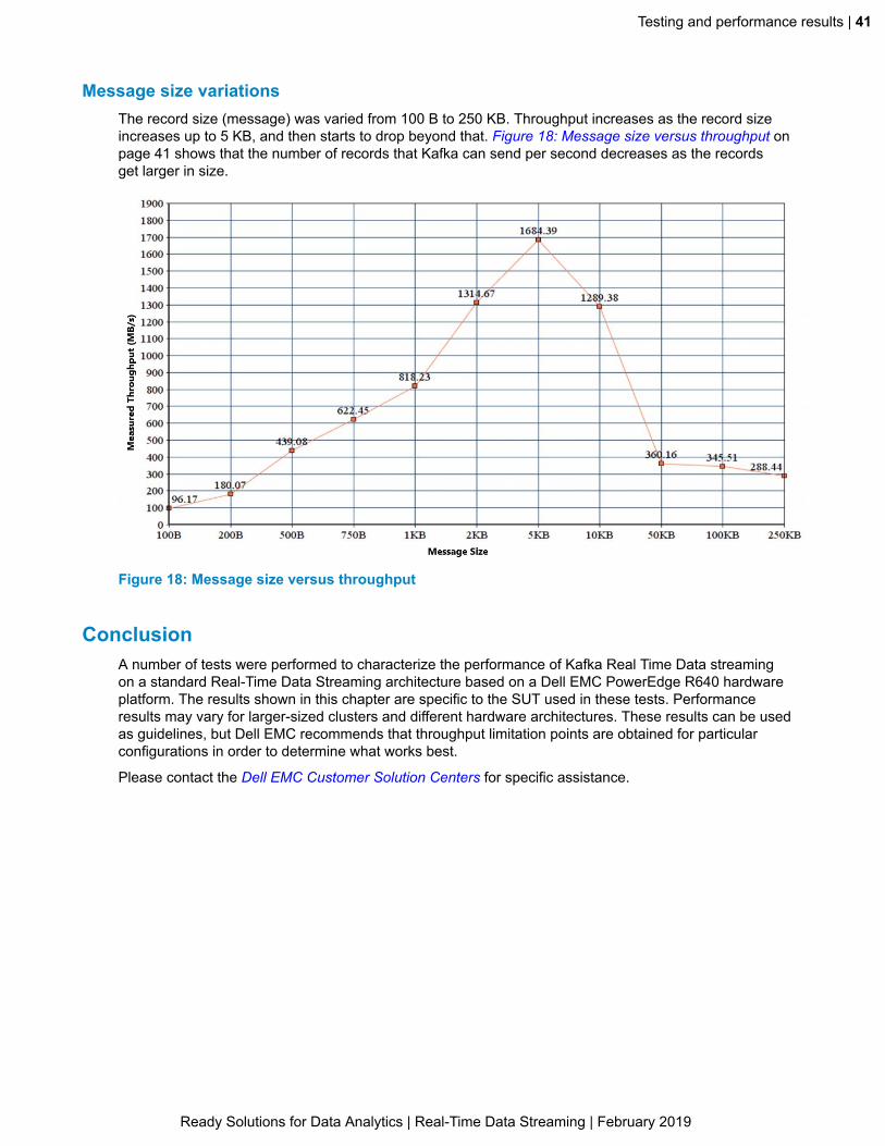
Message size variationsThe record size (message) was varied from 100 B to 250 KB. Throughput increases as the record sizeincreases up to 5 KB, and then starts to drop beyond that. Figure 18: Message size versus throughput onpage 41 shows that the number of records that Kafka can send per second decreases as the recordsget larger in size.
Figure 18: Message size versus throughput
ConclusionA number of tests were performed to characterize the performance of Kafka Real Time Data streamingon a standard Real-Time Data Streaming architecture based on a Dell EMC PowerEdge R640 hardwareplatform. The results shown in this chapter are specific to the SUT used in these tests. Performanceresults may vary for larger-sized clusters and different hardware architectures. These results can be usedas guidelines, but Dell EMC recommends that throughput limitation points are obtained for particularconfigurations in order to determine what works best.
Please contact the Dell EMC Customer Solution Centers for specific assistance.
Ready Solutions for Data Analytics | Real-Time Data Streaming | February 2019

42 | Tested component versions
Appendix
ATested component versions
Topics:
• Software versions• Network switch firmware
versions• Dell EMC PowerEdge R640
firmware versions
This appendix describes the versions of software and firmware usedduring validation of this architecture.
Ready Solutions for Data Analytics | Real-Time Data Streaming | February 2019

Tested component versions | 43
Software versionsTable 23: Tested software versions on page 43 shows the software versions that were tested for thisarchitecture.
Table 23: Tested software versions
Component Version
Operating system RHEL 7.5
Confluent Enterprise 5.0
Network switch firmware versionsTable 24: Tested switch firmware versions on page 43 shows the network switch firmware versions thatwere tested for this architecture.
Table 24: Tested switch firmware versions
Component Version
Dell EMC S5148-ON 9.12(1.0)
Dell EMC S3048-ON 9.11(2.4)
Dell EMC PowerEdge R640 firmware versionsTable 25: Dell EMC PowerEdge R640 tested firmware versions on page 43 shows the Dell EMCPowerEdge R640 firmware versions that were tested for this architecture.
Table 25: Dell EMC PowerEdge R640 tested firmware versions
Component Version
BIOS 1.6.12
iDRAC with LC 3.21.26.22
Mellanox ConnectX-4 LX 25 GbE SFP rNDC 14.21.30.12
Driver for OS deployment 18.10.17
Dell EMC 12 Gb expander firmware for 14Gservers
2.25
Dell EMC PERC H740P 50.5.0.1750
CPLD 1.0.2
Ready Solutions for Data Analytics | Real-Time Data Streaming | February 2019

44 | Related documentation
Appendix
BRelated documentation
Topics:
• Confluent documentation• Dell EMC documentation• Operating systems
documentation• Apache Software Foundation
documentation
This chapter provides references to partner documentation related tothis architecture.
In addition to this architecture guide the partner productsdocumentation provided here will further your understanding of Real-Time Data Streaming.
Ready Solutions for Data Analytics | Real-Time Data Streaming | February 2019

Related documentation | 45
Confluent documentationRelated Confluent documentation includes:
• Confluent Enterprise Reference Architecture• Confluent Platform Documentation
Dell EMC documentationRelated Dell EMC documentation includes:
• Running Kafka with Dell EMC Isilon White Paper• Dell EMC Configuration Guide for the S5148-ON System 9.14.0.0
Operating systems documentationRelated operating systems documentation includes:
• CentOS Documentation• Red Hat Enterprise Linux Server Documentation
Apache Software Foundation documentationRelated Apache Software Foundation documentation includes:
• Apache Hadoop Documentation• Apache Kafka Documentation
Ready Solutions for Data Analytics | Real-Time Data Streaming | February 2019

46 | References
Appendix
CReferences
Topics:
• About Confluent• About Dell EMC Customer
Solution Centers• To learn more
Additional information can be obtained at Big Data Analytics Info Hubfor Ready Solutions.
If you need additional services or implementation help, please contactyour Dell EMC sales representative.
Ready Solutions for Data Analytics | Real-Time Data Streaming | February 2019

References | 47
About ConfluentFounded by the team that built Apache Kafka, Confluent, Inc. builds a streaming platform that enablescompanies to easily access data as real-time streams. Confluent Enterprise improves Apache Kafka byexpanding its integration capabilities, adding tools to optimize and manage Kafka clusters, and methods toensure the streams are secure. Confluent Enterprise makes Kafka easier to build and easier to operate.
About Dell EMC Customer Solution CentersOur global network of dedicated Dell EMC Customer Solution Centers are trusted environments whereworld–class IT experts collaborate with customers and prospects to share best practices; facilitate in–depthdiscussions of effective business strategies using briefings, workshops, or proofs–of–concept (PoCs); andhelp businesses become more successful and competitive.
Dell EMC Customer Solution Centers reduce the risks associated with new technology investments andcan help improve speed of implementation.
To learn moreFor more information on this architecture, visit Big Data and Big Data Analytics Solutions.
Copyright © 2019 Dell Inc. or its subsidiaries. All rights reserved. Trademarks and trade names maybe used in this document to refer to either the entities claiming the marks and names or their products.Specifications are correct at date of publication but are subject to availability or change without noticeat any time. Dell Inc. and its affiliates cannot be responsible for errors or omissions in typography orphotography. Dell Inc.’s Terms and Conditions of Sales and Service apply and are available on request.Dell Inc. service offerings do not affect consumer’s statutory rights.
Dell EMC, the DELL EMC logo, the DELL EMC badge, and PowerEdge are trademarks of Dell Inc.
Ready Solutions for Data Analytics | Real-Time Data Streaming | February 2019

48 | Glossary
Glossary
GlossaryAPI
Application Programming Interface
BDaaSBig Data as a Service
BIOSBasic Input-Output System
BMCBaseboard Management Controller
BMPBare Metal Provisioning
BOSSThe Boot Optimized Storage Solution enables customers to segregate operating system and data onserver-internal storage. This is helpful in the Hyper-Converged Infrastructure and Software DefinedStorage arenas, to separate operating system drives from data drives, and implement hardware RAIDmirroring (RAID1) for OS drives.
ClosA multiple-stage, non-blocking network switch architecture. It reduces the number of required ports within anetwork switch fabric.
CPLDA Complex Programmable Logic Device combines programmable AND/OR arrays, and macrocells.
CPUCentral Processing Unit
DBMSDatabase Management System
DIMMDual In-line Memory Module
ECMPEqual Cost Multi-Path
EDWEnterprise Data Warehouse
EIPTThe Dell EMC Enterprise Infrastructure Planning Tool is a model-driven tool supporting a large number ofproducts and configurations for infrastructure sizing purposes.
EoREnd-of-Row Switch/Router
Ready Solutions for Data Analytics | Real-Time Data Streaming | February 2019

Glossary | 49
ETLExtract, Transform, Load is a process for extracting data from various data sources; transforming the datainto proper structure for storage; and then loading the data into a data store.
FQDDA Fully Qualified Device Descriptor is a method used to describe a particular component within a system orsubsystem, and is used for system management and other purposes.
FQDNA Fully Qualified Domain Name is the portion of an Internet Uniform Resource Locator (URL) that fullyidentifies the server to which an Internet request is addressed. The FQDN includes the second-leveldomain name, such as "dell.com", and any other levels as required.
HAHigh Availability
HadoopHadoop is an open source, distributed framework from the Apache Software Foundation that managesdata processing and storage for clustered Big Data applications.
HBAHost Bus Adapter
HBaseApache HBase is Hadoop's distributed, scalable database.
HDDHard Disk Drive
HDFSHadoop Distributed File System
HTTPHypertext Transfer Protocol is the set of rules for transferring files on the World Wide Web.
HVEHadoop Virtualization Extensions
iDRACIntegrated Dell Remote Access with Lifecycle Controller
IPMIIntelligent Platform Management Interface
JBODJust a Bunch of Disks
KPIKey Performance Indicators are critical progress markers that provide focus on what matters most to anorganization, in terms of strategic and operational improvement, and informed decision making.
KSQLConfluent KSQL is an open source SQL engine that enables processing of real-time streaming dataagainst Apache Kafka.
Ready Solutions for Data Analytics | Real-Time Data Streaming | February 2019

50 | Glossary
LACPLink Aggregation Control Protocol
LAGLink Aggregation Group
LCLifecycle Controller
LFFLarge Form Factor 3.5" industry-standard disk drives
LOMLights-out management enables a system administrator to monitor and manage servers remotely.
MicroservicesThe microservices architecture style structures applications as collections of related services.Microservices enable continuous delivery and deployment of applications.
MTUA maximum transmission unit is the largest size packet or frame, in octets, that can be sent over a packet/frame-based computer network.
NICNetwork Interface Card
NL-SASNear Line Serial Attached SCSI
NoSQLNot Only SQL is an alternative to relational databases. Data is put into tables, and the data schema ismodeled before the database is built.
NTPNetwork Time Protocol
NVMeNon-Volatile Memory Express is a host controller interface and storage protocol that enables high-speeddata transfers between systems and solid-state drives (SSD), over a computer's Peripheral ComponentInterconnect Express (PCIe) bus.
OSOperating System
OS-HCTKA configuration utility with sample scripts and configuration files used to automate the setup andconfiguration of BIOS and RAID settings for Dell EMC servers in OpenStack and Hadoop open sourcesoftware solutions.
PAMPluggable Authentication Modules, a centralized authentication method for Linux systems.
PCIePeripheral Component Interconnect Express is a standard for high-bandwidth connections betweencomputers and peripherals.
Ready Solutions for Data Analytics | Real-Time Data Streaming | February 2019

Glossary | 51
PERCDell EMC PowerEdge RAID Controller is Dell EMC's family of enterprise-class controllers designed forenhanced performance, increased reliability, fault tolerance, and simplified management — providing apowerful, easy-to-manage way to create a robust infrastructure and help maximize server uptime.
ProxyA service that acts as an intermediary between computer networks, often used to provide secure Internetaccess to devices that do not have a routed connection.
RAIDRedundant Array of Inexpensive Disks
RDBMSRelational Database Management System is a database management system (DBMS) that forms the basisfor SQL, and all modern database systems.
RDIMMRegistered Dual In-line Memory Module
RebalancerA Rebalancer redistributes cluster data and indexes among available nodes when one or more nodes havebeen added to, or removed from, a cluster.
RedfishRedfish is a standard API, designed by the Distributed Management Task Force to provide managementfor converged, hybrid IT as well as Software Defined Data Centers.
ReplicatorThe Confluent Replicator enables an operator to reliably replicate topics from one Kafka cluster to another.
RESTREpresentational State Transfer is an architectural style for developing web services, using standard HTTPstatus codes.
RESTful APIA RESTful API uses HTTP requests to GET, PUT, POST, and DELETE data. It is based upon RESTtechnology.
rNDCRack Select Network Daughter Card
RocksDBRocksDB is an embedded, persistent, high-performance database for key-value data.
RPMRed Hat Package Manager
RSTPRapid Spanning Tree Protocol
RTORecovery Time Objectives
RUA Rack Unit measures 1.75 inches, or 44.45 mm, in a 19-inch or 23-inch electronic equipment rack frame.
Ready Solutions for Data Analytics | Real-Time Data Streaming | February 2019

52 | Glossary
SASSerial-attached SCSI is a method for accessing computer peripherals, using a serial (one bit at a time)means of digital data transfer over thin cables.
SATASerial Advanced Technology Attachment is a standard for connecting and transferring data to and fromhard disk drives (HDDs) to computers.
SchemaA schema defines a database's record structure.
SCSISmall Computing System Interface
SFFSmall Form Factor 2.5" industry-standard disk drives
SFP28Small Form-Factor Pluggable 28 is the third generation of the SFP interconnect systems designed for 25Gperformance, as per the IEEE 802.3by specification (25GBASE-CR).
SIEMSecurity Information and Event Management
SLAService Level Agreement
SPScalable Processor
SQLStructured Query Language is a standard programming language used to manage relational databases,and perform operations on their data.
SSDSolid-state Drive (or Solid-state Disk)
TCPTransmission Control Protocol is a standard that defines how to both establish and maintain networkconversations.
TCP Offload EngineA technology used to move the TCP stack processing from the CPU to a dedicated processor.
THPTransparent Huge Pages
ToRTop-of-Rack Switch/Router
UIDA code identifying each user on a Unix and/or Unix-like computer system
VLTVirtual Link Trunking
Ready Solutions for Data Analytics | Real-Time Data Streaming | February 2019

Glossary | 53
VRRPVirtual Router Redundancy Protocol
YARNYet Another Resource Negotiator
ZooKeeperApache ZooKeeper is a high-performance coordination service for distributed applications.
Ready Solutions for Data Analytics | Real-Time Data Streaming | February 2019
54 | Index
Index
AAbout
Confluent 47Dell EMC Customer Solution Centers 47
Apache Software Foundationrelated documentation 45
Architecturecluster 14kappa 12lambda 12network 17overview 15streaming 12
Architecture overview 15
BBottlenecks
performance testing results 40Broker Node
hardware configurations 22scaling 32
Broker Node — high-performancehardware configurations 24
Broker scalabilityperformance testing results 40
CCautions viiCentOS
related documentation 45Cluster
architecture 14Cluster architecture 14Conclusion
performance testing results 41Configurations
hardwareBroker Node 22Broker Node — high-performance 24Control Center Node 20KSQL Node 21networking 25Platform Node 20
Confluentabout 47related documentation
App Workbench 45Consumer variations
performance testing results 37Control Center Node
hardware configurations 20
DDell EMC
related documentation 45Dell EMC Customer Solution Centers
About 47Dell EMC Isilon
integration 30Dell EMC PowerEdge R640 firmware versions tested 43Documentation
Apache Software Foundation 45CentOS 45Confluent 45Dell EMC 45related 44RHEL 45
EExecutive summary 8External data sources
integration 29
GGlossary 48
HHardware configurations
Broker Node 22Broker Node — high-performance 24Control Center Node 20KSQL Node 21networking 25Platform Node 20
IIntegration
Dell EMC Isilon 30external data sources 29physical rack 31
Introductionstreaming 11
KKafka Connect
scaling 33Kappa architecture
streaming 12KSQL
scaling 33KSQL Node
hardware configurations 21
Ready Solutions for Data Analytics | Real-Time Data Streaming | February 2019

Index | 55
LLambda architecture
streaming 12Limitations
throughputperformance testing results 40
MMessage size variations
performance testing results 41
NNetwork architecture 17Network switch firmware versions tested 43Networking
hardware configurations 25Notes viiNotes, cautions, and warnings vii
OOperating systems
CentOSrelated documentation 45
related documentationCentOS 45RHEL 45
RHELrelated documentation 45
Overviewarchitecture 15performance testing results 35streaming 10
PPartitioning
performance testing results 36Performance testing results
bottlenecks 40broker scalability 40conclusion 41consumer variations 37message size variations 41overview 35partitioning 36producer and consumer variations 38producer variations 36system under test 35throughput limitations 40
Physical rackintegration 31
Platform Nodehardware configurations 20
Processingstreaming 11
Producer and consumer variationsperformance testing results 38
Producer variationsperformance testing results 36
Publish and subscribestreaming 11
RRed Hat Enterprise Linux Server, See RHELReferences
about Confluent 47About Dell EMC Customer Solution Centers 47to learn more 47
Related documentationApache Software Foundation 45Confluent 45Dell EMC 45operating systems
CentOS 45RHEL 45
RHELrelated documentation 45
SScaling
Broker Node 32Kafka Connect 33KSQL 33ZooKeeper 32
Serverconfigurations 19
Sizing and scaling 32Software versions tested 43Storage
streaming 11Streaming
architecturekappa 12lambda 12
introduction 11overview 10processing 11publish and subscribe 11storage 11
Streaming architecturekappa 12lambda 12
Streaming introduction 11Streaming overview 10Summary
executive 8System under test
performance testing results 35
TTested versions
Dell EMC PowerEdge R640 firmware 43network switch firmware 43software 43
Throughput limitationsperformance testing results 40
Ready Solutions for Data Analytics | Real-Time Data Streaming | February 2019
56 | Index
To learn more 47Trademarks vi
VVariations
performance testing resultsconsumer 37message size 41producer 36producer and consumer 38
Versions testedDell EMC PowerEdge R640 firmware 43network switch firmware 43software 43
WWarnings vii
ZZooKeeper
scaling 32
Ready Solutions for Data Analytics | Real-Time Data Streaming | February 2019
Related Documents