Design processes

Welcome message from author
This document is posted to help you gain knowledge. Please leave a comment to let me know what you think about it! Share it to your friends and learn new things together.
Transcript

Design processes

This page intentionally left blank

Design processesWhat Architects & Industrial Designers can teach each other about managing the design process
Edited by: Wim Poelman and David Keyson

Edited by: Wim Poelman and David KeysonCommunication and Layout: Matty CruijsbergGraphic design: Janita Han
© 2008 The authors and IOS Press. All rights reserved.
ISBN 978-1-58603-945-5
Published by IOS Press under the imprint Delft University Press
PublisherIOS Press BVNieuwe Hemweg 6b1013 BG AmsterdamThe Netherlandstel: +31-20-688 3355fax: +31-20-687 0019email: [email protected]
LEGAL NOTICEThe publisher is not responsible for the use which might be made of the following information.
PRINTED IN THE NETHERLANDS

1
Preface
Contents
PrefaceProf. dr. C.J.P.M. de Bont ________________________________ 3
1 IntroductionDr. ir. W.A. Poelman ____________________________________ 4
2 Design ProcessesBetween academic and practice viewsDr. ir. H.H. Achten ______________________________________14
3 VisualizationSketching is Alive and Well in this Digital AgeProf. G. Goldschmidt ___________________________________ 28
4 Project Management
Project and risk Management in architecture and industrial designProf. dr. ir. J.W.F. Wamelink and dr. J.L. Heintz _______________ 44
5 Social ComplexitySocial complexity in design collaborationProf. dr. P.G. Badke-Schaub ______________________________60
6 Decision MakingA decision-based design approach ________________________ 68Dr. ir. P.P.J. van Loon, ir. R. Binnekamp and ir. J. Burger
7 Technology Diffusion and DesignThe metabolism of knowledgeDr. ir. W.A. Poelman ____________________________________ 90
8 Closing speechProf. dr. ir. A.C.J.M. Eekhout _____________________________ 108
Appendixes:
1 Chairman’s impressionsProf. dr. ir. T.M. de Jong _________________________________112
2 Program ____________________________________________120

2
3
Introduction
Preface
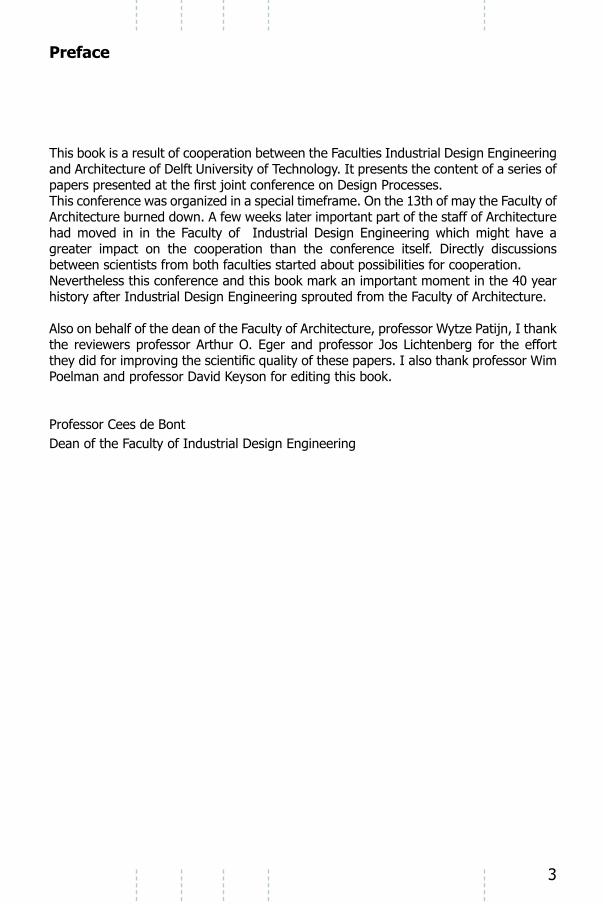
This book is a result of cooperation between the Faculties Industrial Design Engineering and Architecture of Delft University of Technology. It presents the content of a series of
This conference was organized in a special timeframe. On the 13th of may the Faculty of Architecture burned down. A few weeks later important part of the staff of Architecture had moved in in the Faculty of Industrial Design Engineering which might have a greater impact on the cooperation than the conference itself. Directly discussions between scientists from both faculties started about possibilities for cooperation.Nevertheless this conference and this book mark an important moment in the 40 year history after Industrial Design Engineering sprouted from the Faculty of Architecture.
Also on behalf of the dean of the Faculty of Architecture, professor Wytze Patijn, I thank the reviewers professor Arthur O. Eger and professor Jos Lichtenberg for the effort
Poelman and professor David Keyson for editing this book.
Professor Cees de BontDean of the Faculty of Industrial Design Engineering

IDE+ADesign Processes - Wim Poelman and David Keyson (Eds.)
IOS Press, 2008 © 2008 The authors and IOS Press. All rights reserved.
Introduction

5
1 Introduction
BackgroundThis conference has been organized in the context of the cooperation between the faculties Industrial Design Engineering and Architecture of Delft University of Technology.In the second half of the sixties, Professor Joost van den Grinten took the initiative to start an interfaculty for “Technische en Industriële Vormgeving” as a spin-off of the faculty for Architecture, and in cooperation with the faculty for Mechanical Engineering, among others. Some years later the faculty became independent and the name was changed into the faculty of “Industrieel Ontwerpen” or Industrial Design Engineering. As years went by both faculties developed relatively independently which has had drawbacks
knowledge develop themselves more easily in greenhouse-like organizations.However, after nearly forty years the two organizations still have a lot in common with the main communality being their focus and vision on society and the role for leading edge design research. Perhaps more important than what they have in common with each other, is the design research work which is ‘complementary’ between the two faculties. The research subjects within the portfolios of the two faculties differ as does the approach of the design related research in general. Human factors, methodology and sustainability are examples of research subjects for which the approach of the
cooperation. A team, consisting of the two deans and several professors of both faculties started discussing the possibilities of cooperation, a discussion of which the results were presented at a symposium in December 2005.
th of June 2008 with the title “Design Processes”. This title was selected by an organizing committee consisting of Wim Poelman, David Keyson, Petra Badke Schaub, Teake the Jong and Hannah Ottens. The committee was of the opinion that the most striking difference between the disciplines was the attitude against and the practice of methodology in the design process. It was decided that a preliminary investigation would be organized to provide specialist with data from practice preparing their papers.
Preliminary InvestigationFour student assistants were invited to carry out the preliminary research, two from each faculty. Names: Gijs Kappen, Melissa van ter Meij, Maarten Heijmerink and Matty Cruijsberg.
subjects were: design processes in general (invited specialist professor Henri Achten), visualization as a design tool (invited specialist professor Petra Badke Schaub), project management (invited specialist professor Joost Wamelink), social complexity in

6 Introduction - W.A. Poelman
collaboration (invited specialist professor Petra Badke Schaub), decision making (invited specialist professor Peter Paul van Loon) and technology diffusion (invited specialist
Eight projects were selected, four Industrial Design cases and four Architecture cases. Interviews were arranged with the involved companies/designers/architects. The interviews were carried out by two students, one of each faculty.
passed to the specialists. Papers prepared by the specialists were presented to peers, one of the University of Twente (professor Arthur Eger) and one from the University of Eindhoven (professor Jos Lichtenberg).The chairman of the conference professor Teake de Jong of the faculty for Architecture was asked to comment the overall results of the conference. His comments are recorded in chapter “Chairmens Impression“.
The general impression is that specialists were not able to base their paper fully on
The second is that a lot of interesting information came out of the interviews apart
their own point of view. One other aspect might have played a role. For the specialists the conference was a great opportunity to present their own vision. The cases were deployed rather for underpinning their own opinion than for analysis in order to come to new insights.
One of the valuable results of the preliminary research turned out to be the propositions for which the interviewers explicitly asked. They are presented in this introduction. In the Chairmen’s Impressions chapter he will comment these pro-propositions extensively.
The casesThe cases provide several examples of the various characters of design processes.Not all information, resulting from the preliminary research is free for publication, but
provide valuable information.
The Westraven building by CePeZed is a project for the government organization “Rijkswaterstaat” and based on existing building which is stripped completely until only
building in which many new technologies were applied. Eye catching in the project are
get rid of the boring repetition in the façade. Remarkable are furthermore the textile screens in the façade which care for sun shading a well as for wind shielding and sound decrease.
7Introduction - W.A. Poelman
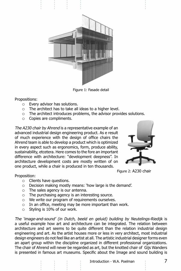
Figure 1: Fasade detail
Propositions:Every advisor has solutions.oThe architect has to take all ideas to a higher level.oThe architect introduces problems, the advisor provides solutions.oCopies are compliments.o
The A230 chair by Ahrend is a representative example of an advanced industrial design engineering product. As e result
Ahrend team is able to develop a product which is optimized in every aspect such as ergonomics, form, produce ability, sustainability, etcetera. Here comes to the fore an important difference with architecture: “development deepness”. In architecture development costs are mostly written of on one product, while a chair is produced in ten thousands. Figure 2: A230 chairProposition:
oDecision making mostly means: ‘how large is the demand’.oThe sales agency is our antenna.oThe purchasing agency is an interesting source.o
oo
Styling is 10% of our work.oThe ‘image-and-sound’ (in Dutch, beeld en geluid) building by Neutelings-Riedijk is a useful example how art and architecture can be integrated. The relation between
engineering and art. As the artist houses more or less in very architect, most industrial design engineers do not feel like an artist at all. The artistic industrial designer forms even an apart group within the discipline organized in different professional organizations. The chair of Ahrend will never be regarded as art, but the knotted chair of Gijs Wanders

8 Introduction - W.A. Poelman
the cooperation with Jaap Drupsteen, a graphical and media designer. In addition to
to the glass facade to realise this remarkable building.
Figure 3: The ‘image-and-sound’ buildingPropositions:
The scale of a project is not relevant for the way of communicating.oSteps are similar to those taught at TUDelft + geographical centered ocommunication.
oAll knowledge in architecture is common knowledge.o
Also the BeerTender by MMID will never be regarded as art, but it is an excellent example of industrial design engineering where the link to marketing is crucial. This project is about a new way of packing, distributing and drinking beer for the home market. Acceptance by the user of this concept is dependant of marketing communication but to a large extent of design. The look of the business to business image of the beer container would not work, not the ergonomics.
Figure 4: The beer container

9Introduction - W.A. Poelman
Propositions:Beertender is produced in very large series.oMy own style isn’t important in this project.oStyle is work method f-d-p (Functionality & technology, Design (look & feel), oProduction & assembly)I cannot recall decisions that explicitly.oBut there have been moments like that during the project. Time, Money and oQuality.
The 1-2-3 House by Martini is an extremely interesting project in the context of the relation between architecture and industrial design engineering. You could say that an architectural product is developed and produced as an industrial designed product. From the interview is learned that there are many constraints introducing this kind of approach in housing industry. Up scaling is necessary to earn back money invested in the manufacturing process, but the market structure is not suitable to apply marketing strategies from industry. The housing market is highly bureaucratic.
Figure 5: Turning the tunnel
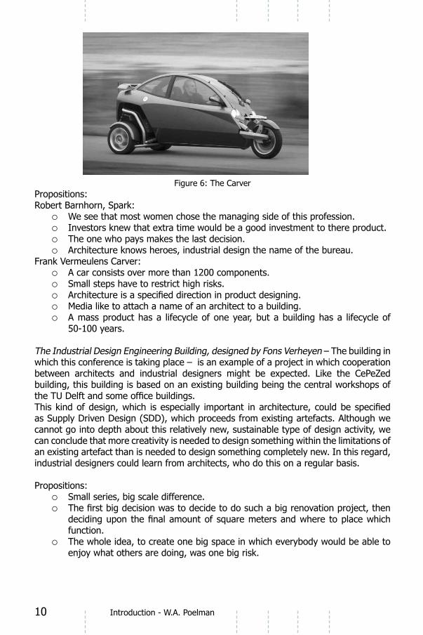
The Carver of Spark Design & Engineering and carver Europe is based upon the invention of a hydraulic canting mechanism, which enables stability of narrow vehicles. The application of the system leads to both a striking driving experience and a striking visual appearance. In fact, a new archetype of a vehicle is created which resembles a cross between a motorcycle and a small car. The success of the design is a result of the collaboration between the engineering company (Carver Europe) and the design company (Spark Engineering). The design problem is comparable with that of the Beertender, introducing new product concepts linked to new human behaviour and new visual appearance. The difference is that Carver does not have a marketing power like the beer companies. Introduction by immense marketing campaigns is not possible, so Carver is dependent on a slow introduction via innovators, trendsetters and trend followers.
10 Introduction - W.A. Poelman
Figure 6: The CarverPropositions:Robert Barnhorn, Spark:
We see that most women chose the managing side of this profession.oInvestors knew that extra time would be a good investment to there product.oThe one who pays makes the last decision.oArchitecture knows heroes, industrial design the name of the bureau. o
Frank Vermeulens Carver: A car consists over more than 1200 components.oSmall steps have to restrict high risks.o
oMedia like to attach a name of an architect to a building.oA mass product has a lifecycle of one year, but a building has a lifecycle of o50-100 years.
The Industrial Design Engineering Building, designed by Fons Verheyen – The building in which this conference is taking place – is an example of a project in which cooperation between architects and industrial designers might be expected. Like the CePeZed building, this building is based on an existing building being the central workshops of
as Supply Driven Design (SDD), which proceeds from existing artefacts. Although we cannot go into depth about this relatively new, sustainable type of design activity, we can conclude that more creativity is needed to design something within the limitations of an existing artefact than is needed to design something completely new. In this regard, industrial designers could learn from architects, who do this on a regular basis.
Propositions:Small series, big scale difference.o
ofunction.The whole idea, to create one big space in which everybody would be able to oenjoy what others are doing, was one big risk.

11Introduction - W.A. Poelman
Figure 7: Interior sketch
is the last project to discuss. The bed was not designed as a synchronous product but as a diachronic script, in which not a special delivery service, but the homecare nurse herself delivers and installs the bed. The physical product was simply a way to enable that script. Because traditional care beds did not
product. Script based design represents a growing trend in the discipline of industrial design
write the script and then the products necessary to realise the script. In architecture this might be more common. The use of a building should be described before it is possible to design a proper building.
Figure 8:
Propositions:Not much attention was given to aesthetics.oUsers played an important role, from the start they were consulted and later othey were involved when prototypes had to be tested.The people involved in the engineering phase are already looking over the oshoulder during the concept development stage.

12 Introduction - W.A. Poelman
From the short description of these cases it will be clear that the diversity is so large
Nevertheless, a lot is learned from the cases in combination with the analysis and
follow in Chapter “Chainman’s impressions.
The subtitleThe subtitle of the conference behind this book reads: “life is a theater. Architects care for the scenery; Industrial designers care for the props; People care for the drama”.
architecture and industrial design engineering. However, the message goes further than that. Most people will agree with the proposition that architects and industrial design engineers should not write the script for human existence. The function of scenery and props designers is to serve the scriptwriter and the actors with objects supporting the play. Imagine a situation in which the behavior of a performer has to change because of the scenery or props. For example, when the actor has to appear on the scene from the ceiling, or is only able to speak after putting of a mask, without discussing it before with the scriptwriter and actors, this would lead to an unacceptable situation. But in real life, this happens all the time. Human behavior is for a large part enshrined by architects and designers and not anymore by people themselves and spiritual fathers who acted as scriptwriters for life and still do in religious communities like the
the script.Nowadays, the script of life is for a large part written by architects and designers. Urban planning decides how we spread our activities geographical. The design of modern residential districts determines for a large part how we communicate with each other.
of means for transport decide how we move ourselves and kitchen designers decide how we cook.
All this has to do with the mechanisms of technology diffusion on which Wim Poelman will elaborate in his paper later.The main subject of this conference however is “Design Processes” and the main issues of the conference were:
the contemporary interrelationship of Industrial Design and Architectureoa confrontation of contemporary design practice in both domains with academic otheory and education

13

IDE+ADesign Processes - Wim Poelman and David Keyson (Eds.)
IOS Press, 2008 © 2008 The authors and IOS Press. All rights reserved.
Design Processes

15
2 Design processes between academic and practice views
Dr. ir. H.H. Achten Assistant Professor, Architectural Modeling Eindhoven University of TechnologyFaculty of Architecture, Building and PlanningDesign Systems Group
AbstractIn order to speak about the commonalities and differences between industrial and
Practice-based descriptions have a long tradition, and are close to everyday reality of
is a more recent development, which aims accurately to provide this framework. We discuss the current understanding of design, its limitations, and some observations related to the cases of the IDE+A Conference.
Keywords: design theory, design method, design research.
1 Do we understand design processes?
Before we begin the general argument in this paper, we must consider an important premise that underlies the motivation of the text. At the IDE+A Conference, architects
then is this: can an architect or industrial designer discuss aspects of design in his or
all, are about bricks, steel, glass, and wood; how to organise the spatial composition of a building or urban environment, how to make structures and installations work together, etc. The industrial designer’s concerns are about plastics, textiles, and various kinds of metals; how to create effective and ergonomic solutions for people; how to set
Both architects and product designers (or designers from any other discipline, for that
designer is assigned or a team is put together, and work on the project continues until its completion (or until its early cancellation). Such projects tend to take a long time, varying from a few months to several years. Throughout this time projects are subject to all kinds of change: in the team, in the norms and laws to which the design must
each project has its own confusing history of contingencies which must be solved for the project to be completed successfully.There is a twofold assumption, therefore, when we talk about design processes: that we can bridge the differences between the design domains, and that we can abstract enough from everyday practice within each design domain to talk about the general aspects of design. If either of these assumptions fails (or we choose not to believe in them) then there is no basis for comparison other than the anecdotal level. Believing

Design processes - H.H. Achten16
in these assumptions, however, does not mean that all our problems are easily solved. Design processes have developed over a very long period of time (one could even claim thousands of years). There is a very close connection between the praxis of design, its body of knowledge, and design methods. For practitioners it is often very hard to separate these views. The conception of the design process as something that can be
tremendous progress has been made in the understanding of design, there is still a lot left to be understood properly.
The perspective that we take in this text, therefore, is academic rather than practice-based, since the academic view provides a transferable set of theoretical concepts by
methods – and sketch the current orthodox view of what design processes are. This view is certainly not unchallenged, and a number of the most notable problems will be
Conference.
Since the notions established in this paper are the result of research on design in all kinds of domains, here we refrain from talking about architects or industrial designers, but use the more generic term ‘designer.’
2 Design process, theory and method
In the description of the design process, two perspectives can be utilised: that of design theory and of design method. Each has a very distinct view of design processes, but it is fair to claim that there is a very strong interdependency between the two.
procedures of design in a rather broad and general sense. Its central concern is how designing both is and might be conducted. This concern therefore includes the study of how designers work and think; the establishment of appropriate structures for the
application to design problems’.
difference between design processes (how designing is) and design methods (how designing might be conducted). In order to describe these aspects, it is necessary to have a theoretical framework for design – this is design theory.It is important to notice that designers and researchers, when talking about design theory, often mean different things. Professional design theory has been around at least since Vitruvius (approximately 1st Century BC; see Vitruvius 1960). Professional design theory is instrumental theory in the sense that very often it instructs or describes how to get things done. Its main subject is the motivation and starting points for design,
experience, and is very much object-oriented – urban environments, buildings, details, and so on. Professional design theory, however, is not the view that we take when we talk about design theory.

17Design processes - H.H. Achten
2.1 The role of design theory
others, for example in an educational setting. Theory helps to distinguish between what is fundamental to the discipline and what is not; which aspects and concepts matter to design, and which aspects and concepts are incidental. This helps the designer maintain an overview of the discipline and guards against ad-hoc actions. A strong theoretical
are, and understands the means by which to achieve them. A too-rigid understanding
balance.
In more recent applications, design theory has also been instrumental in the development of new tools for design – in particular in the development and application of computer
enables new group processes such as collaborative design and twenty-four-hour design teams. Also the more direct use of the form and shape generating capacity of computers
human activities (for example, cooking, sport, arguing, etc.) If so,
2.2 The role of design methods
Design methods concern the actual or desired order of the design decisions that are
informal and can mean anything from a habitual working method to highly structured and controlled processes. Another recurring notion is the ‘personal design method’, which is not communicated with others – it is even claimed to be incommunicable. For a better understanding (and appreciation) of design methods, however, we must clearly
and only if:
3. It is applicable to more than one case.

Design processes - H.H. Achten18
4. Other people can also apply it.5. It has criteria to determine when a step has been concluded.Each aspect of this list has to be present in order for something to be called a design method.
There are a number of reasons to develop and use design methods. Design methods are
occurs in complex design projects, or when the design(er) (team) takes on a problem
structure the process. Finally, because of the explicitness of design methods, they also help in coordinating large design teams or multiple experts involved in projects.
There is a sometimes tenuous relationship between design methods and practice. Most of the designers of the IDE+A Conference cases, when asked whether they followed a method, replied either that they did not, or that when they did, it closely followed what they were taught at university. They also noted that practice will most often lead away from the ‘ideal process’, so there is a perceived lack of applicability. When confronted with new or changed design methods, designers often feel restricted in their freedom (this is probably a stronger sentiment in architecture than in industrial design).
time and effort, which distracts from the job at hand. This is a situation that a skilled designer wants to avoid. This mechanism can also explain why designers often dislike talking about their method. Thinking about the design process in terms of method is a rationalising activity. Design problems, however, as we will see in the next section,
has to state where things are explicitly explainable and where they are not. This again may cause uncertainty or confer a sense of uneasiness. The mark of a skilled designer
effort. Conscious thinking about the act of designing disrupts this because it challenges the hidden skills to become expressed. Again, this is experienced as an intrusive activity. Finally, in the domain of architecture in particular there is a heightened status for star designers. Connected with this status is a tendency to keep the processes or methods shrouded as some kind of mystery or art.
Most design methods have been developed for single designers. In some cases, design teams are considered to be one designer consisting of multiple persons. This may perhaps work for very well-contained design methods that have a limited scope
at higher level goals because of group dynamics and mixed expertise. As much of everyday design takes place in teams or in communication structures with outside
To conclude, if we want to describe design processes, we need a theoretical framework for design. It is basically a descriptive activity with design(ing) as its subject. Based on theoretical considerations, a design theory may lead to a design method, but this is not necessarily so. Design methods, on the other hand, may be the subject of design theory. Design methods are prescriptive and solution-oriented. A design method always
design process.

19Design processes - H.H. Achten
3 The orthodox view of design processes
of distinct periods (see Cross (1984) and Jones (1980) for good accounts of this development). Three research approaches have emerged as dominant in the current view of design processes: rational problem solving, about the structuring of design problems; information processing, about the thought processes of designers; and protocol analysis, about the research methods to study designers. Obviously, there are many other ways to research and investigate design (see for example Oxman et al. (1995), Achten et al. (2001), and Achten et al. (2005) for an overview), but the three mentioned above constitute what we might call the ‘orthodox view’ of design and the study of design.
3.1 The nature of design problems
In the theoretical research on design, a distinction is commonly made between four classes of problems with an increasing degree of complexity and unpredictability: tame problems, well-structured problems, ill-structured problems, and wicked problems (Lawson (1990), Simon (1973)). The general consensus is that design problems are
and Webber (1973):
2. Wicked problems have no stopping rule.3. Solutions to wicked problems are not true-or-false, but good-or-bad.4. There is no immediate and no ultimate test of a solution to a wicked
problem.5. Every solution to a wicked problem is a ‘one-shot operation’; because
there is no opportunity to learn by trial-and-error, every attempt
6. Wicked problems do not have an enumerable (or an exhaustively describable) set of potential solutions, nor is there a well-described set of permissible operations that may be incorporated in the plan.
8. Every wicked problem can be considered to be a symptom of another problem.
9. The existence of a discrepancy representing a wicked problem can be explained in numerous ways. The choice of explanation determines the nature of the problem’s resolution.
10. The planner has no right to be wrong.
degree of rationality can be applied to solve them. Creating a solution will always depend to some degree on a creative insight. The phase where solutions are created is the challenging part where a designer seemingly ‘jumps’ from a problem setting to a solution. A match or mapping is made between two distinct things – a problem and a solution. This is not trivial: just why exactly a given solution matches a problem is still unanswered. Both problems and solutions are complex and they have almost no common elements in their structure. In most cases, problems and solutions are

Design processes - H.H. Achten20
or other verbal statements; and solutions as conglomerations of ordered elements of urban/city environments, buildings, or objects.
3.2 Structure of the design process
Given the characteristics of design problems, it follows that creating a solution is not
therefore, is a lengthy process in time, during which the designer iterates and revises the design many times. Designing is as much about understanding the problem as it is about creating a solution, in particular in the early phase of design. Therefore, not only does the designer utilise information and knowledge that is provided at the outset (brief, site, client, etc.) but he or she also generates a lot of knowledge throughout the design process.
activities and documents that are created and performed in design. The BDC consists of the following (terms in italics denote activities):1. Function statement: a statement about what is needed in the design
problem.2. Analysis: analysis of the function statement or current state of the
design.3. Criteria: a set of criteria to which the design has to conform.4. Synthesis: the creation of a (preliminary) design or solution to a sub-
problem.5. Provisional design: the external representation, by means of sketch,
drawing, text, or model, of the (preliminary) design.6. Simulation: the derivation of the expected behaviour or performance
of the (preliminary) design.7. Expected properties: a prediction of the future behaviour or
performance of the (preliminary) design.8. Evaluation: a judgement of how well the (preliminary) design
performs, based on the criteria formulated earlier, and the expected properties.
9. Value of the design: a value setting of the performance, based on the evaluation and goals set by the designer.
10. Decision: the decision to continue with the design (either through the creation of a new proposal in Synthesis, or restating the problem
next document:
Roozenburg and Eekels note that the actual order of activities and documents in a concrete design project is unpredictable, so they do not claim that this order is indicative for a design project. Rather, they claim that in any given design project, each activity and each document has to be performed or created at least once, but most likely many times over.
The BDC may be considered to be the ‘private’ design cycle for a designer or design team. Throughout the whole design process, additional structuring is created as well – in architecture this is usually a phased process consisting of sketch design, preliminary
that describe the design solution with increasing precision. The purpose of the phased

21Design processes - H.H. Achten
structure is to create secure, consistent descriptions of the design which can form the basis for the next steps in the design process. In that way, the designer avoids unnecessary backtracking.
3.3 Forms of knowledge in design
Designing is knowledge intensive. Much of design is a matter of applying knowledge of previous solutions that inform the basic direction in which the current design solution has to move. Previous solutions can be referred to as precedents (prominent examples), types (generalised knowledge of classes of buildings or products), and analogies (used as metaphors rather than literal examples).
The design process itself starts out with many facts, arising from the brief and from clients’ desires, from the site where a project is to be realised, from particular technologies that will be used (for example the 123 House case in the IDE+A Conference), budget, and so on. Throughout the design process, additional knowledge is generated about the design itself, and the designer searches also for information based on the needs at that point in the design.
Constraints put limits or boundaries on the design or the context of design. Client goals, norms and laws, local regulations, welfare, and so on have to be met in order for a design to be approved.
3.4 Forms of reasoning in the design process
In order to create (preliminary) design solutions, knowledge and information must be processed. This involves several forms of reasoning. Reasoning by example is a major
analogy, the designer takes some element of the example and, based on the perceived structure of the solution, generates a new solution that is suited to the current design problem.
A way of reasoning in design that is a bit more explorative or imaginative is through ‘what-if’ reasoning or by means of scenarios. In these cases, the designer takes the current design and tries to imagine how it will perform. In this way, designers can also use previously experienced episodes with other buildings or urban environments and aim to duplicate them in the current design.
Given the characteristics of wicked problems, it is not possible to determine objectively
designers try to meet the constraints set out in the brief, and those that are imposed by the context of the project. However, this does not mean they have to prove that their design is perfect or the only one possible. Rather, designers try to meet the constraints as much as possible, and aim to reach at least a minimum threshold of performance or
Analytical modes of reasoning are used particularly in the analysis phase of a project, or
plays a role in the design process. Finally, the least well understood form of reasoning is what is generally called ‘visual reasoning’. Designers use external representations such as drawings and sketches a lot, and a considerable amount of generation and

Design processes - H.H. Achten22
judgement is done visually on the basis of such sketches and drawings. All designers of the IDE+A cases strongly indicate that they consider sketching to be a vital skill.
3.5 Psychological view of designers
The reasoning and memory abilities of people is limited. Memory is generally conceived of as consisting of two main functional parts: long-term memory (LTM) and short-term memory (STM) – see Akin (1986) for a good introduction. LTM is where experiences
not directly accessible for conscious processing. In STM memories are accessed from LTM and once there can become the subject of thought processes. STM works relatively fast, but it has a limited capacity to hold information. In general, this is thought of as roughly seven coherent pieces of information, called chunks. How big the chunks can be, or how they are organised, remains unclear. It seems evident, however, that more experienced or skilled designers utilise better or more compressed pieces of information when they are reasoning.
3.6 External representations in the design process
Limited reasoning and memory capacity is an additional factor that structures design processes. One role of representations such as drawings and models is to form an external memory which can store information about the design by similarity. The
stored information.
External representations, in particular those that complete a phase of the design process
legal status, and they are also used to communicate between parties in the design process. A large part of the activity in the design process, therefore, is reserved for the production of accurate and precise drawings and documents.
3.7 Creativity in design processes
Creativity plays an important role in design – it is the mechanism with which a designer is able to come up with a novel solution to a problem. Creativity does not work in isolation; it needs to be embedded in a work context that provides information and the right setting to generate an idea.A common distinction which is made in terms of design solutions are the following three classes of designs (Brown and Chandrasekaran, 1985):1. Routine design: the creation of a solution that falls completely within
the range of previous solutions. The solution is adapted to current needs but does not introduce anything novel. Redesign may also be considered to be routine design.
2. Innovative design: the creation of a solution which has at least one additional feature that has not been seen before in this kind of design solution. Most of the design conforms to existing examples, but one part is pushing the limits. All the architecture design cases in the IDE+A Conference demonstrate this kind of design.
3. Creative design: the creation of a solution that has a highly different structure compared to existing solutions. A creative design does not have a lot of similarities with existing designs.

23Design processes - H.H. Achten
the delineation between the classes is fairly straightforward. A routine design simply is an instance of an already known type or class; an innovative design adds something new but does not change the structure of the type or class; and in creative design an altogether new structure for a type or class is created.
The delineation becomes less clear, however, when we try to apply it from a designer’s perspective. In particular the distinction between innovative and creative design becomes hard to make. Especially if we insist on completely new structures, then most of architectural design simply is not creative – a conclusion with which many will disagree. The difference in ‘innovative’ and ‘creative’, therefore, is more a matter of the degree to which a design is pushing existing limits by means of innovations.
3.8 Design, designers, the design process
Based on the above, we can now summarise the orthodox view as follows. The designer can be conceived of as an information processor (STM, LTM, and cognitive structures) who tries to solve wicked problems. An important design activity is the subdivision and reformulation of the wicked problem into sub-problems in order to make them well-structured. The designer has procedural knowledge in the form of
(architecture, industrial design, machine engineering, etc.) as well as knowledge of previous solutions (cases, precedents, and types).
Because of the limitations of STM and LTM, the designer cannot have an overview of the whole problem (even not when a problem is well-structured, which in design does
External representations such as drawings and models help to maintain an overview
Through the use of phases the designer prevents the possibility that, late in the process, a small change will necessitate a redesign of the whole project (this does not always work). Throughout the design process the designer explores both the solution and the problem. One might claim that only at the end of the design process is the design problem understood. A design problem does not have one single correct solution. Furthermore, it is not possible to determine the degree of correctness. The
4 Challenges to the orthodox view of design processes
The view of design processes sketched above is rather concise, but in broad outlines provides the contours of our current understanding of design processes. As can be seen, there is a strong interdependency between theoretical and methodological notions. Despite the relatively short period of time that design has been an area for
is not the ultimate description of what design is about. Many things are still unknown and there are many challenges to the orthodox view of design processes.
The foundation of the orthodox view of design processes is rational problem solving

Design processes - H.H. Achten24
Table 1 below sets out the differences between the two approaches.
Since rational problem solving has the longer research tradition, it is clear that its
practice, as noted by several researchers (see Dorst (1997), Valkenburg (2000), Reymen (2001)), has a weak theoretical foundation, but strongly appeals to designers. Unless a designer has a very systematic approach to design, the naming-framing-moving-evaluating cycle seems much closer to what designers do. In earlier work (see Achten (2003)), where we investigated the normative stance of three well-known architects through their published works (Peter Eisenman, UN Studio, and Greg Lynn) in order to derive their design methods, we have found some evidence for this. This concerns in particular the decomposition of the problem, which resembles naming-framing more than decomposition. This is so because there is a strong focus on concept formation.
An additional aspect that RPS ignores is the social aspects of design. Designers do not operate in isolation, and most of the time they work in teams. The social aspects of group dynamics such as leadership, dominance, negotiation, and team building are not dealt with (see for example Foley and Macmillan (2005), Valkenburg (2000), Baird et al. (2000), Ball and Ormerod (2000)). Lastly, the idea that the motivation for design, or particular design decisions, is not purely rational or can be stated completely objectively is a problem. Part of the way designers in teams persuade each other is by means of storytelling. Another way to investigate verbal exchanges in design teams is to look at convergence in the use of words, to see whether a more or less consistent group dynamic is developing (Lloyd (2000), Turner and Turner (2003), Dong (2005)).
Although RPS pays due attention to the psychological structure of designers, there is no real differentiation between possible types of designers. In recent work, Lawson and Dorst (2005) have investigated the notion of the level of expertise at which designers
beginner, competent, expert, master, and visionary. Different cognitive structures, sets of competences, and ways of organising the design process are associated with each.
Most of the work summarised here (except for Schön’s work) has begun in the past decade and is still in development. This is only a brief sketch of additional or alternative

25Design processes - H.H. Achten
done justice in this section alone.
5 The IDE+A design cases
The IDE+A design cases include four from architecture, and four from industrial design. From the description of each, it is clear that the complexity of the design team plays an important role in the design process. Given the above outline of the current understanding of design processes, we can immediately see that this aspect is found wanting, as team design is not covered much by current research. Nevertheless, we can make a number of observations about the cases.1. Most of the designers who were interviewed were able to identify the
authorship of the key ideas in a project without a problem. One might expect that due to the size of teams and the complexity of the task, this may be more problematic.
2. In the architectural cases, innovation is much more focused on a single aspect whereas in the industrial design cases, innovation is often spread out over a number of key components.
is a common phenomenon. However, this also means that the design process structure is different from the classical client-meets-architect model. The competition design leads to a proposal by which the architect hopes to win the competition, but it is not the same as the
a real risk of not getting the job. So in this type of process, there
different concerns.4. Because of their length, the structuring of the design process in the
cases is based on the main documents or phases rather than the more detailed design process for the single designer. The ‘ideal design process’ is seen as a point of reference, rather than an attainable goal.
5. Practice is very demanding and problem-oriented. This means that if something does not yield immediate results, designers are not eager
fails to provide productive frameworks for designers. Findings are
threshold for their application.
engineering, chemistry, information technology, and so forth. Since design theory in this
what design is, it is necessary to reference to practice as much as possible.
6 Conclusion

Design processes - H.H. Achten26
in the nature of design, designers, and design products. It has also revealed however, that there is a lot more left to be understood than we currently know. Partly this will always be the case: the study what design is, will never yield what it is to be a designer.
for the design problem at hand, but it helps in creating the basic skills for the designer. Finally, from the view of professional and academic responsibility, we need to understand what we are doing in a systematic, objective, and rigorous way – in order to engage in the creative, unexpected, and joyful way of designing.
ReferencesAchten, H.H. (2003), ‘New Design Methods for Computer Aided Architectural Design Methodology Teaching’; International Journal of Architectural Computing 1(1), pp. 72-91.Achten, H.H., Dorst, K., Stappers, P.J. and de Vries, B. (2005), ‘Design
Research in the Netherlands 2005 – Proceedings of the Symposium held on 19-20 May 2005 Eindhoven University of Technology’; Eindhoven: Faculty of Architecture, Building and Planning.
Achten, H.H., Hennessey, J. and de Vries, B. (2001), ‘Design Research in the Netherlands 2000’, Eindhoven, Faculty of Architecture, Building and Planning.
Akin, O. (1986), ‘Psychology of Architectural Design’, London, Pion.Baird, F., Moore, C.J. and Jagodzinski, A.P. (2000), ‘An Ethnographic Study of
Engineering Design Teams at Rolls-Royce Aerospace’; Design Studies 21(4), pp. 333-355.
Ball, L.J. and Ormerod, Th.C. (2000), ‘Applying Ethnography in the Analysis and Support of Expertise in Engineering Design’; Design Studies 21(4), pp.403-421.
Brown, D. C. and Chandrasekaran, B. (1985), ‘Expert Systems for a Class of Mechanical Design Activity’, in Knowledge Engineering in Computer-Aided Design, ed. by Gero, J.S., Amsterdam, North-Holland, pp. 259-282.
Cross, N. (1984), ‘Developments in Design Methodology’; Chichester, Wiley.Dong, A. (2005), ‘The Latent Semantic Approach to Studying Design Team
Communication’; Design Studies 26(5), pp. 445-461.Dorst, C.H. (1997), ‘Describing Design: A Comparison of Paradigms’; PhD
thesis, Delft: Delft University of Technology.Foley, J. and Macmillan, S. (2005), ‘Patterns of Interaction in Construction
Team Meetings’; CoDesign 1(1), pp. 19-37.Jones, J.C. (1980), ‘Design Methods: Seeds of Human Futures’; London: Wiley
Interscience.
London: Butterworth Architecture.
Computational and Cognitive Models of Creative Design VI., ed. by Gero, J.S. and Maher, M.L., Key Centre University of Sydney, Sydney, pp. 211-230.Lloyd, P. (2000), ‘Storytelling and the Development of Discourse in the
Engineering Design Process’; Design Studies 21(4), pp. 357-373.Oxman, R.M., Bax, M.F.Th. and Achten, H.H. (1995), ‘Design Research in the
Netherlands: A Symposium Convened By the Design Methods Group Information Technology for Architecture, January 1995’; Eindhoven, Faculty of Architecture, Building and Planning.

27Design processes - H.H. Achten
Reymen, I. (2001), ‘Improving Design Processes Through Structured
Eindhoven: Institute for Programming Research and Algorithms.Rittel, W.J. and Webber, M.M. (1973), ‘Planning Problems are Wicked
Problems”, In Cross, N. (1984), “Developments in Design Methodology’; Chichester, Wiley, pp. 135-144.
Roozenburg, N. and Eekels, J. (1995), ‘Product Design: Fundamentals and Methods’, Chichester, Wiley.
Action’; London, Basic Books.Simon, H. (1973). ‘The Structure of Ill-Structured Problems’, In Cross, N.
(1984), “Developments in Design Methodology’; Chichester, Wiley, pp. 145-166.
MIT Press. First Edition 1969.Turner, S. and Turner, P. (2003), ‘Telling Tales: Understanding the Role of
Narrative in the Design of Taxonomic Software’; Design Studies 23(6), pp. 537-547.
thesis, Delft, Industrial Design Engineering.Vitruvius (1960), ‘Vitruvius: The Ten Books on Architecture’, translated by
Morris Hickey Morgan, New York, Dover.

IDE+ADesign Processes - Wim Poelman and David Keyson (Eds.)
IOS Press, 2008 © 2008 The authors and IOS Press. All rights reserved.
Visualization
29
3 Sketching is Alive and Well in this Digital Age
Prof. G. Goldschmidt Professor, The Mary Hill Swope Chair in Architecture & Town PlanningFaculty of Architecture and Town PlanningTechnion – Israel Institute of Technology
AbstractThe different modes of visualisation found in the Delft Interviews are explored with
means of communicating with various project stakeholders. Two main conclusions arise
between architects and industrial designers in the way they produce and use visuals. Second, despite the proliferation of potent digital visualisation means and their willing adaptation by design practitioners, freehand sketching continues to be practised by almost all designers throughout the design process. The extraordinary cognitive advan-tages of sketching are outlined and it is argued that because of those advantages sket-ching will continue to reign in design until other means of visualisation will be capable of emulating its supremacy.
Keywords: DI (Delft Interviews); digital; design; model; sketch; visualisation
IntroductionIn a world such as the one we live in it is only natural for young students, who were born into the digital age, to ask their designer-interviewees: ‘In this digital age is the-
expected answer is ‘no’, but the courteous students ‘allow’ the designers, practicing
Sketching is a mode of visualisation, alongside other modes. All designers in the survey talk about means of visualisation they used in the particular project on which the inter-view focuses but they all generalise to other cases as well. Visualisation, in the evidence
as communication in its roles of information and image recording and description, de-monstration and sharing, explanation and convincing. Apart from freehand sketches (including annotations), visuals include primarily other manual drawings on paper, di-gital two- and three-dimensional drawings, and physical models. Digital drawings can be divided into two distinct types: precise measured drawings, and three-dimensional images and renderings. Sometimes animation and movies are also added to the arsenal of visuals. When and for what purpose is each of these modes of visualisation used,
-
Delft Interviews (DI), and which, perhaps surprisingly for the interviewers, are still in
30 Visualization - G. Goldschmidt
1 Why visualise?
-gners and those for whom the artefacts are designed consider many elements and their properties, as well as the relationships between them (and in the case of architecture, also between them and their surroundings). Function and form must be understood,
complex parameters is not possible without visualisation, especially the representation of shapes and forms. It is possible for individuals to entertain internal representation
using mental imagery only (Athavankar 1997, Athavankar & Mukherjee 2003, Bilda et al. 2006), but imaging has its limitations and in any event it is applicable only to the private musings of individual designers; others are unable to share what is locked inside an individual’s mind. Fish (2004) argues that the capacity for mental imagery develo-ped in humans in prehistoric times for survival purposes as an aid in tasks like hunting; evolution has not caught up with newer human activities, such as design as we know it
(Fish & Scrivener 1990).
Imaging may, though, have to do with preconceived ideas that designers bring with
that preconceived ideas and images existed when they started work on their projects: Pesman (DI.1-Westraven Utrecht) said the image was directly in his head (p. 7); Meer-tens (DI.5-Beertender) said, ‘the design comes to you’ (p. 39); and Spark (DI.8-Carver small car) stated explicitly, ‘the designer always starts with an image of what it has to look like, this image comes to mind from the beginning’ (p.69).
But in practically all cases, more than one person was involved in the project right from the beginning. The team members, whether located in one place or dispersed geogra-phically, had to communicate during meetings and between meetings. This they did using visualisations, which were prepared ahead of time and shown in meetings or sent around, but also produced them in situ, as part and parcel of an ongoing discussion. Participants in design teams range from a small number of in-house designers to colla-borations with partners and consultants from elsewhere, in addition to client represen-tatives. Visualisations help make sure that everyone concerned shares the same mental models of the product’s looks and functioning, materials, manufacturing process or a particular detail thereof that is being discussed. One might say that without visualisati-ons, it is inconceivable that a shared mental model could be achieved in a design team (Goldschmidt 2007). This is the foremost reason for visualising in the design process.
We have mentioned that one of the parties taking part in design meetings is the client. Clients vary greatly in the extent to which they wish, or are able, to get involved in the design process. But in any event they must approve the design, or select from amongst alternatives. Designers must therefore make an effort to convince the client of the virtues of their proposals, sometimes to the point of justifying budget increases. To do so they must show the client the designed entity in the most complete and attractive manner possible, and in a mode the client, who is not necessarily technically adept, can easily understand and appreciate. Digital devices such as graphically potent programs (3D) are often used for this purpose, and so are models. This is the second reason for visualisation in the design process.

31Visualization - G. Goldschmidt
The third, and the least interesting reason for our purposes here, is visualisation for the purpose of construction or manufacturing. The visualisations made for this purpose are technical in nature and today they are almost exclusively produced digitally (2D).
companies. We shall not discuss these visualisations any further in this paper.
2 The digital age
What do we actually mean, in the design context, when we say that ours is a ‘digital
manually, can now be done digitally in most cases, and more manipulations than were
through buildings that do not exist yet, and so on). There are also new possibilities such as digital prototyping which hardly existed a decade ago, mainly useful to industrial designers. Many more new applications are undoubtedly due to make their appearance in the foreseeable future. There are many advantages to digital drafting and modelling, such as speed, accuracy, ease of revision, and ease of sharing with others regardless of where they are stationed. But that is not the whole story, of course: sophisticated algo-rithms permit the expansion of the world of manufactured and built forms, which are less restricted than was hitherto the case. For example, the free form of the roof of the stadium designed by Frei Otto for the 1972 Olympic games in Munich was a painstaking design effort, realised after countless models were built to approximate the curvatures of the membranes, which did not conform to mathematically expressible shapes. Nowa-days digital means can not only easily save the considerable labour invested in building actual models, but also calculate the structure regardless of its irregular geometry and
ability of digital means to cope with completely free forms in architecture.
visualisation mode throughout the design process, and especially in its early, prelimi-nary phase. For experienced sketchers, which include almost every designer (architect
draw’ is an atypical exception (DI.3_Media Museum Hilversum, p. 22)), the production
of generating ideas, testing them and discussing them, in a group or even in private de-liberations with oneself. To date, no digital means are available that come close to emu-
economy, with the possible exception of academic prototypes that were developed with unusual insights (e.g., Do 2002; Shapir et al., 2007). Likewise, both industrial designers and architects continue to produce physical models, with or without the technical assi-stance of digital means. The physical model is still necessary to allow us to get a better feel for scale, texture or the mode of operation of an artefact, be it a small hand-held gadget or a large building; indeed, all DI designers use models at least during the deve-lopment phase of design projects. Digital devices, then, while helpful and in some cases indispensable, are not necessarily the answer to every single aspect of the process of designing. We shall have more to say about sketching in section 5 below.

32 Visualization - G. Goldschmidt
3 Design education and practice
Industrial designers, and to a lesser degree architects, are taught to work systematical-ly, according to well-established methods (Roozenburg & Eekels 1995) that specify all
mechanical engineering design the reliance on strict methodologies is even more strin-gent, with a large body of published research and handbooks to support this claim (e.g., Jänsch et al., 2005). In industrial design brainstorming and other group methods are taught and implemented in practice. However, in ‘real life’ there are many constraints and unexpected situations that force designers to divert from the perfect methods learned at school. Thus the DI car designers state that ‘They [at school] teach you to follow the perfect process, but in reality it doesn’t work that way… an innovative project doesn’t keep to planning, it needs freedom’. (DI.8_Carver small car, pp. 60-61). One of
that there are more iterations, more improvisations, more fresh starts than anticipated,
tools are those best suited for exploration and experimentation, and they usually are not the digital tools.
Despite the drive to use the ‘latest and greatest’ methods which inevitably are largely
In architectural education many studio classes have become paperless, resulting in projects that are detached from real materiality. Students are less occupied with develo-ping rich, complex and sensitive spatial solutions and concentrate instead on the gra-
and communication has become verbal only, related to PowerPoint presentations. With
and pencil, the teacher cannot exemplify how something could or should be done, and is reduced to verbal reactions only to the student’s work in progress. This is a dramatic change in the otherwise still largely apprentice-style design education we practise in the studio, and not a change for the better1.
Luckily, in both architecture and industrial design, in practice as well as in the educatio-
otherwise. It is therefore not surprising that even long before models are built, both stu-
to be in the work environment, to represent or simulate properties of a designed object
mediating role of objects in our lives as knowledge translation agents, among other roles (e.g., Whyte et al. 2007), but in this paper we discuss only visualisations that are
4 Design phases – interlocutors
The different design phases are distinguishable not only by their contents or the spe-
them. It is hardly possible to arrive at a consensual breakdown of the design process
1 The commentary on design education is based on personal knowledge and experience.
33Visualization - G. Goldschmidt
into phases; in the Delft Interviews some designers talk about four phases, others about six, and yet others about a different number of phases. The participants in each phase may also vary according to the design task and the norms and practices of each
-
visualisations, the party with whom he or she (or they) interacts in the normal course of the design process. The three phases/situations are: a) preliminary design; b) de-velopment phase; and c) discussions with clients and users. Table 1 maps the modes of visualisation reported in the DI according to these phases. This mapping cannot be
Nevertheless, it does provide a close enough picture to what we assume is the reality of practice in architecture and industrial design.
sketching is used heavily during the preliminary and development stages, and to some degree in discussions with clients or users. Clients may be involved throughout the pro-cess and discussions with them do not constitute a separate phase, of course. Rather, in this rubric we mean primarily formal and less formal presentations to clients at various points of decision making.
Preliminary designAt the outset the major means of visualisation is sketching. Sketches are made during the search for a solution principle, in most cases following an initial, preconceived idea, by the leading designer(s). Architects make more models than do industrial designers in this phase, sometimes in compensation for the lack of drawings and sketches (DI.3_
to imagine complex spatial relations without models. Architectural sketches and dra-wings, as opposed to product design drawings, tend to be two-dimensional, using the conventions of orthogonal projections which do not describe spaces directly. Architects are trained to imagine spaces on the basis of plans and sections, but a model helps to perceive the space and its proportions, and test the accuracy of the image. Models
-sentations at this stage. It may also be the case that rapid prototyping has become the standard mode of modelling, at least for smaller artefacts; making them is reasonably
a study model.

34 Visualization - G. Goldschmidt
Table 1: Visualisation modes in the Delft Interviews
We note that no digital drawings are produced at this phase. This is not surprising as neither dimensioned drawings nor ‘fancy’ images are needed in this phase, in which the designers communicate primarily among themselves, in search of a viable solution proposal that the designers can defend and which stands a chance of approval by the client. The sketch, at this phase, is a compact ‘laboratory’ in which designers can expe-

35Visualization - G. Goldschmidt
case of failure. This encourages more experimentation with extreme, unusual and po-
-veries in them, including the regrouping of elements, which offers new interpretations. Fish (2004) and Goldschmidt (e.g., 2002) have advanced similar arguments. Whereas this facet of sketching is mostly studied in the context of individual designers working alone, in teams sketching is essential to idea-generation sessions: it does not increase
another (van der Lugt 2005), which is normally a precondition for creativity.
DevelopmentThe development phase is usually carried out by a larger group of people than the one involved in preliminary design. It is also more diverse in terms of expertise – we include in the group, or team, all the consultants, internal or external, who are involved in the
costly and demoralising. A key to good coordination is a high level of understanding and agreement amongst team members regarding the designed entity, which is achieved through face-to-face meetings and conversations which include sharing of documents, also when members are not physically co-located. Naturally, visualisation plays a crucial role in all of these team deliberations. The Delft Interviews show that practically all modes of drawing and physical models are used in this phase (see Table 1), each for the purpose it serves best.
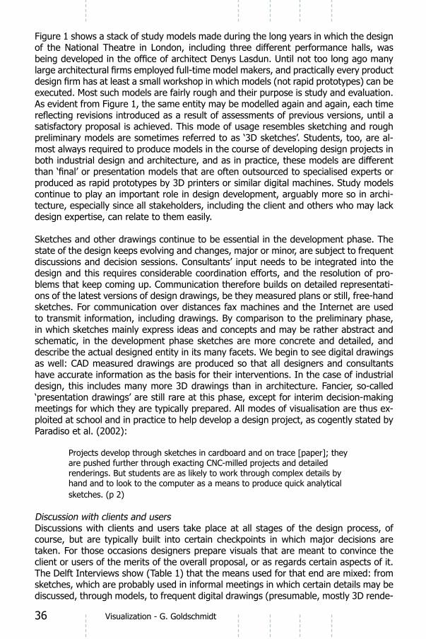
Figure 1: ‘Models in dialogue: Denys Lasdun, National Theatre, London, c. 19652.
2 Photo by Behr Photography.
36 Visualization - G. Goldschmidt
Figure 1 shows a stack of study models made during the long years in which the design of the National Theatre in London, including three different performance halls, was
executed. Most such models are fairly rough and their purpose is study and evaluation. As evident from Figure 1, the same entity may be modelled again and again, each time
satisfactory proposal is achieved. This mode of usage resembles sketching and rough preliminary models are sometimes referred to as ‘3D sketches’. Students, too, are al-
both industrial design and architecture, and as in practice, these models are different
produced as rapid prototypes by 3D printers or similar digital machines. Study models continue to play an important role in design development, arguably more so in archi-tecture, especially since all stakeholders, including the client and others who may lack design expertise, can relate to them easily.
Sketches and other drawings continue to be essential in the development phase. The
discussions and decision sessions. Consultants’ input needs to be integrated into the -
blems that keep coming up. Communication therefore builds on detailed representati-ons of the latest versions of design drawings, be they measured plans or still, free-hand sketches. For communication over distances fax machines and the Internet are used to transmit information, including drawings. By comparison to the preliminary phase, in which sketches mainly express ideas and concepts and may be rather abstract and schematic, in the development phase sketches are more concrete and detailed, and describe the actual designed entity in its many facets. We begin to see digital drawings as well: CAD measured drawings are produced so that all designers and consultants have accurate information as the basis for their interventions. In the case of industrial design, this includes many more 3D drawings than in architecture. Fancier, so-called ‘presentation drawings’ are still rare at this phase, except for interim decision-making meetings for which they are typically prepared. All modes of visualisation are thus ex-ploited at school and in practice to help develop a design project, as cogently stated by Paradiso et al. (2002):
Projects develop through sketches in cardboard and on trace [paper]; they are pushed further through exacting CNC-milled projects and detailed renderings. But students are as likely to work through complex details by
sketches. (p 2)
Discussion with clients and usersDiscussions with clients and users take place at all stages of the design process, of course, but are typically built into certain checkpoints in which major decisions are taken. For those occasions designers prepare visuals that are meant to convince the client or users of the merits of the overall proposal, or as regards certain aspects of it. The Delft Interviews show (Table 1) that the means used for that end are mixed: from sketches, which are probably used in informal meetings in which certain details may be
-

37Visualization - G. Goldschmidt
rings), and even movies. Often, designers refer to ‘presentations’ they prepare, which may indicate the use of tools like PowerPoint in order to show visuals, undoubtedly accompanied by oral explanations.
This ‘mixed media’ panorama is most appropriate, and it applies to all branches of de-sign, architecture and industrial design included. Each mode of visualisation has its own
many more manual drawings were made, of course, but even before drawings were the standard means of visualisation (that is, before paper became readily available and
century), models were made to be presented to patrons in order to secure their appro-val. Figure 2 shows a fresco by Vasari from the mid-16th century, depicting the architect Brunelleschi presenting a model of San Lorenzo to his client, Cosimo de’ Medici, who commanded the church. The model is a fairly accurate representation of the famous Florentine church. Earlier pictures and mosaics bear evidence of the fact that model presentation to patrons was an established practice (for example, a beautiful mosaic at the Kariye Museum in Istanbul, dated c. 1320, depicts Theodore Metochites, donor of the Chora, with a model of the church/monastery).
Figure 2: Fresco by Vasari (1565) showing Brunelleschi presenting the model for the church of San Lorenzo to Cosimo de’ Medici3.
with the production of technical drawings which were made for the masons-builders of
the professional architect, accompanied by his scholarly advisors, presenting plans to the workmen who were building the Rotunda in Rome). Such drawings became standard
3 From: Ettlinger, L.D. (1977). The emergence of the Italian architect. In Kostof, S. (ed.), The architect. University of California Press, Berkeley, pp. 96-123; illustration p. 110.

38 Visualization - G. Goldschmidt
practice following the introduction of orthogonal projections as the mode of delivering information about the geometry of spaces and objects. Perspective drawings were also made from that time, of course, and gradually joined models as formal renderings, but the two co-existed for centuries more as complimentary visualisations rather than rival or competitive modes of expression.
Drawings that are made for clients or users are, as pointed out earlier, a mixed bag, depending on their purpose. The more tools we have at our disposal the more there is
the goals the visualisation is meant to achieve. Whyte et al. (2007) distinguish between
discussions with clients and users. The latter, frozen visuals ‘are characterized by greater certainty’. The authors remark that such visualisations have several functions, including use ‘for tactical and political reasons’ (p. 23). When thus used, the interlocutor is often the client or the users. Figure 3 captures three instances of the usage of visuals in the design process of designing a herbarium. In our terms Figure 3a describes a preliminary design usage of drawings; Figure 3c is taken from the development phase; and Figure
this example, in all three cases the interaction among the concerned parties is entirely dependent on the use of visuals, in this case sketches and drawings.
design work at Edward Cullinan Architects: a) the founder of the practice and an architect wor-king on the project talk about the design concept; b) the ideas are presented and discussed with
the library staff; c) working meeting between the project architects and the engineers4.
The public Designers do more than bring into being the best possible buildings and products; they also take part in the cultural and artistic discourse of their time. For some designers this becomes a major activity and they are interested in making statements through visuali-sations they exhibit and publish, in addition to other modes of representation (oral and written expressions). At times of heated debate designers even publish manifestos and
in architecture, whereas in industrial design it is the products themselves that are made with similar intentions. Figure 4 is an example of a drawing made in James Stirling’s
-keholders in the project, nor is it meant for the builders. Instead, it is a statement about design thinking and representation, made during the early years of Postmodernism and
4 Figure 3 and its caption reproduced from Whyte et al. (2007), p. 22.

39Visualization - G. Goldschmidt
meant for the cultural avant-garde of the time. Stirling chose to present an isolated selected idea, in an unusual view (‘worm-view’ axonometric drawing).
Figure 4: James Stirling and Michael Wilford (1976). Axonometric up-views of major
elements in the Westfalen Museum, Düsseldorf (competition entry, not built)5.
Goldschmidt (2004) distinguished between ‘private’ and ‘public’ representations. The former are those visuals that individuals and teams produce for themselves, as thinking and communication aids; the latter are made in order to advance ideas and concepts vis-à-vis particular interlocutors or the (relevant) public at large, as in Stirling’s case. Other architects and designers produced very different kinds of visuals of the same category;
publicise. The cultural discourse in which design participates, which is an extension of
a cultural context, even if the level of explicit awareness of its grinding wheels, and the attention paid to it, may vary considerably from one designer to another.
5 The robustness of sketching
Sketches are the most dominant mode of visualisation in design practise. Today they are beginning to be produced digitally as well as manually, but sketches on paper are far from obsolete in the design world. In fact design schools have re-discovered the necessity of training students in free-hand drawing, after years of somewhat unrealistic hopes that digital means will happily replace all manual design output. Sketches are not all of a kind; Ferguson (1992) divides them into the thinking sketch, the talking sketch, and the prescriptive sketch. In our terminology this means: sketching as a cognitive aid in the generation of ides; sketching as an agent of communication, and sketching as instruction for execution (e.g., for the construction of manufacturing). In this paper we have largely addressed the talking sketch, which is prevalent in design practice where
5 Source: ‘Landesgalerie Nordrhein-Westfalen in Düsseldorf, James Stirling and Partner with Werner Kreis, Robert Livesey, Russ Bevington, Ueli Schaad’, Lotus International, 1977, Vol. 15, 58-67.

40
-remost a thinking activity – occurs above all in the individual’s mind, and the thinking sketch helps in the conversation the designer holds with him or herself. We have already
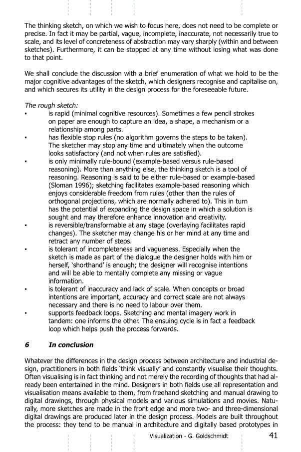
for the robustness of sketching in design practice for over half a millennium now, since paper became the standard medium for visualisations. Figure 5 is a diagram explaining the status of sketching in visualisation as part of the design problem-solving process.
Figure 5: Sketching as a mental facilitator in complex, visually mediated tasks.
41Visualization - G. Goldschmidt
The thinking sketch, on which we wish to focus here, does not need to be complete or precise. In fact it may be partial, vague, incomplete, inaccurate, not necessarily true to scale, and its level of concreteness of abstraction may vary sharply (within and between sketches). Furthermore, it can be stopped at any time without losing what was done to that point.
We shall conclude the discussion with a brief enumeration of what we hold to be the major cognitive advantages of the sketch, which designers recognise and capitalise on, and which secures its utility in the design process for the foreseeable future.
The rough sketch:
on paper are enough to capture an idea, a shape, a mechanism or a relationship among parts.
The sketcher may stop any time and ultimately when the outcome
reasoning). More than anything else, the thinking sketch is a tool of reasoning. Reasoning is said to be either rule-based or example-based (Sloman 1996); sketching facilitates example-based reasoning which enjoys considerable freedom from rules (other than the rules of orthogonal projections, which are normally adhered to). This in turn has the potential of expanding the design space in which a solution is sought and may therefore enhance innovation and creativity.
changes). The sketcher may change his or her mind at any time and retract any number of steps.
sketch is made as part of the dialogue the designer holds with him or herself, ‘shorthand’ is enough; the designer will recognise intentions and will be able to mentally complete any missing or vague information.
intentions are important, accuracy and correct scale are not always necessary and there is no need to labour over them.
tandem: one informs the other. The ensuing cycle is in fact a feedback loop which helps push the process forwards.
6 In conclusion
Whatever the differences in the design process between architecture and industrial de-
Often visualising is in fact thinking and not merely the recording of thoughts that had al-
visualisation means available to them, from freehand sketching and manual drawing to digital drawings, through physical models and various simulations and movies. Natu-rally, more sketches are made in the front edge and more two- and three-dimensional digital drawings are produced later in the design process. Models are built throughout the process: they tend to be manual in architecture and digitally based prototypes in

42 Visualization - G. Goldschmidt
industrial design. In essence, the kinds of visuals that are made in practice are not very different from the ones that have been made for hundreds of years, although we can now produce many of them digitally. A notable exception are the visuals made for display and publication not in the context of regular practise but rather as participants in a cultural discourse, where the norm is to break conventions and present innovative breakthrough concepts. The means utilised are correspondingly often novel.
ends, and the most effective visuals are used for each purpose, i.e. the most conve-nient, most economical and most potent modes of visualisation are selected at any
fact that, at least for the purposes of study and exploration, we have no tool that rates higher. We must therefore conclude that sketching has advantages that to date cannot be emulated by any other mode of visualisation. Sketching will continue to be in good currency as long as it is the state of the art.
Acknowledgment
The writing of this paper was partially supported by a grant to the author from the fund for the promotion of research at the Technion, hereby gratefully acknowledged.
ReferencesAthavankar, U. A. (1997). ‘Mental Imagery as a Design Tool’, Cybernetics and
Systems, Vol. 28, 25-47. Athavankar, U. A. & Mukherjie, A. (2003). ‘Blindfolded Classroom: Getting De
sign Students to Use Mental Images’. In Human Behaviour in Design, edited by Lindemann, U., Springer Verlag, Berlin, pp. 111-120.
the Question’, Design Studies, 27 (5), 587-613.Brereton, M. (2004). ‘Distributed Cognition in Engineering Design: Negotiating
between Abstract and Material Representations’. In Design Representation, edited by Goldschmidt, G. and Porter, W. L., Springer Verlag, London, pp. 83-103.
Do, E. Y-L. (2002). ‘Drawing Marks, Acts and Reacts: Toward a Computational Sketching Interface for Architectural Design’. AIEDAM, Vol. 16, 149-171.
Ferguson, E. S. (1992). Engineering and the Mind’s Eye. The MIT Press, Cambridge, MA.
Fish, J. (2004). ‘Cognitive Catalysis for a Time-lagged Brain’. In Design Representation, edited by Goldschmidt, G. and Porter, W. L., Springer Verlag, London, pp. 151-184.
Fish, J. and Scrivener, S. (1990). ‘Amplifying the Mind’s Eye: Sketching and Visual Cognition’, Leonardo 23, 117-126.
Goldschmidt, G. (2002). ‘Read-Write Acts of Drawing’. In TRACEY (Internet journal dedicated to contemporary drawing issues); issue on Syntax of Mark and Gesture. http://www.lboro.ac.uk/departments/ac/tracey/somag/gabi.html. Loughborough University, UK (accessed April 28, 2008).
Goldschmidt, G. (2004). ‘Design Representation: Private Process, Public Image’. In Design Representation, edited by Goldschmidt, G. and Porter, W. L., Springer Verlag, London, pp. 203-217.

43Visualization - G. Goldschmidt
Goldschmidt, G. (2007). ‘To See Eye to Eye: The Role of Visual Representations in Building Shared Mental Models in Design Teams’, CoDesign 3 (1), 43-50.
Jänsch, J., Nissl, A., Strasser, C. and Bruch, C. (2005). ’The Importance of the Integration of Design Methods in Robust Engineering Design’. In Proceedings of 15th International Conference on Engineering Design -
ICED 2005, edited by Samuel, A. and Lewis, W. Institute of Engineers Australia, Melbourne (CD-ROM).
Paradiso, A., Baxter, E. and Baumberger, M. (eds.) (2002). Foreword. Retrospecta 01-02. New Haven: Yale School of Architecture.
Roozenburg, N.F.M. and Eekels, J. (1995). Product Design: Fundamentals and Methods. Wiley, Chichester.
Shapir, O., Goldschmidt, G. and Yezioro, A. (2007). ‘Conceptual Design: An Operational Prescription for a Computer Support System’. In Computer Graphics, Imaging and Visualisation: New Advances, IEEE & Computer Society, 4th CGIV07 International Conference, Bangkok, edited by Banissi, E., Sarfraz, M. and Dejdumrong, N., pp. 513-521.
Sloman, S. A. (1996). ‘The Empirical Case for Two Systems of Reasoning’. Psychological Bulletin, 119 (1), 3-22.
Suwa, M., Tversky, B., Gero, J. S. and Purcell, T. (2001). ‘Seeing into Sketches: Regrouping Parts Encourages New Interpretations’. In Proceedings of 2nd Conference on Visual and Spatial Reasoning in Design: Computational and Cognitive Approaches, Bellagio, edited by Gero, J.
S., Tversky, B. and Purcell, T., pp. 207-219.van der Lugt, R. (2005). ‘How Sketching Can Affect the Idea Generation
Process in Design Group Meetings’. Design Studies, 26 (2), 101-122. Whyte, J. K., Ewenstein, B., Hales, M. and Tidd, J. (2007). ‘Visual Practices
and the Objects Used in Design’. Building Research & Information, 35 (1), 18-27.
IDE+ADesign Processes - Wim Poelman and David Keyson (Eds.)
IOS Press, 2008 © 2008 The authors and IOS Press. All rights reserved.
Project Management

45
4 Project and risk Management in architecture and industrial design
Prof. dr. ir. J.W.F. (Hans) Wamelink1 and dr. John L. Heintz2
1 Professor, Department of Real Estate and Housing, Faculty of Architecture, Delft University of Technology, 2Assistant Professor, Department of Real Estate and Housing, Faculty of Architecture, Delft University of Technology
AbstractThis paper describes the ways in which factors of project environments determine the application of management concepts, particularly risk management, in industrial design engineering (IDE) and architectural projects. The paper is based on a set of eight design cases prepared for the IDE+A conference. Given the limited number of cases and the constraints imposed by the overall case study design, it was necessary to supplement the insight derived from the cases with a review of generally accepted accounts of the design process in IDE and architecture. By sorting the cases according to the emergent dimensions of internal vs. external project and market- vs. client-driven and comparing the applications of project management concepts in each case, we will
project management concepts are applied than do the disciplinary factors. Indeed, by focusing on the project environment factors we may be in a better position to predict
innovative project organisations.
Keywords: Architectural Design, Industrial Design Engineering, Project Management, Risk Management
IntroductionAlthough designers of all sorts are accustomed to operating under uncertainty, and engage in many activities intended to reduce that uncertainty, they tend not to think of
are sometimes reluctant to speak of risks, and the word ‘risk’ is seldom used in the design literature, the literature does cover most of the issues that are covered by the notion of risk, and has done so for some time. However, which risks are considered
greatly between different design projects. By examining a range of cases across from
and where to best apply different notions of risk and project management in design projects.
We will begin by comparing how project management is applied to IDE and architectural
environment. By sorting the cases along these dimensions and again comparing the

46 Project Management - J.W.F. Wamelink and dr. J.L. Heintz
provide a clearer picture of how and why various project management concepts are applied than do disciplinary factors. Because our focus is on the management of design projects, we begin with a description of projects as seen from the perspective of management.
Project managment
(Robbins & Decenzo, 2004). Robbins and Decenzo attribute the growing popularity of project management to the increasing rates of change in the contemporary world.
projects are not well suited to the standardised operating procedures that guide routine
of projects successfully.
Any project is about causing a “change” in an uncertain situation. – in other words, a project involves developing or making something new. Thus one common characteristic of all projects is discovering the unknown. Inherent to such endeavours are risk and uncertainty. However, the characteristics of risk and uncertainty differ in across projects.
- Civil or chemical engineering and construction projects (buildings, tunnels and bridges)
- Manufacturing projects (automotive, pharmaceuticals, aircraft)1
- Management projects (implementing new IT systems, reorganisation projects)
construction projects incur special risks and problems deriving from their organisations.
organisations are involved in the design and construction of a new building. Furthermore, the design process continues even after construction has been contracted out, as the primary contractor, sub-contractors and suppliers all redesign the various components and details of the building. This may also be the case for some large-scale and complex manufacturing projects (e.g. aircraft), in which a number of organisations collaborate to develop highly complex products. Such internationally oriented projects are prone
complexity, national rivalries, contracts and other factors. Most industrial products, however, are simpler, with the design concentrated within a small group of actors, and
case design engineering and production, are all included within the project; or series produc-tion, in which only design is included in the project.

47Project Management - J.W.F. Wamelink and J.L. Heintz
with the possibility of a global distribution of part sourcing. In most product-design processes, control of both design and production is much held more closely within the design team. Even the simplest product, however, involves unexpected interactions between design intent, user preferences, available technology and production systems.
In the building industry, project management is generally carried out by project
internally by persons bearing titles such as ‘manager of product development’.
These characteristics imply that projects are surrounded by risk and uncertainty. An important aspect of managing these projects is therefore dealing with these risks and uncertainties. Winch (2002) described the project process as the dynamic reduction of uncertainty through time (see Figure 1.). At the inception stages of a project, uncertainty is very high: ‘the asset of the future is little more than an idea and possibly a few sketches’. How high depends upon a number of factors, such as the extent to which standardised components and solutions can be used. It is clear that reducing uncertainty is an important part of managing projects: ’As the project moves through the life cycle, uncertainty is reduced as more information becomes available – ambiguities in design are resolved.‘ (Winch, 2002).
The aim of the project manager , or more in generally the function of project management, is to achieve success in all aspects of the project. Conditions for the successful application of business strategies are also referred to as success factors.
necessary to distinguish between the success factors, which lead to successful projects, and the success criteria, which are used to measure project success (Cooke-Davis, 2002). Thus, although success factors and success criteria commonly address similar issues, we must clearly delineate the differences between cause and effect.
0 Time
Amount ofinformationprocessed
Uncertaintyamount ofinformationrequired
none
noneall
all
inception completion
0 Time
Amount ofinformationprocessed
Uncertaintyamount ofinformationrequired
none
noneall
all
inception completion
Figure 1: The project process as the dynamic reduction of uncertainty (Winch et al., 1998)

48 Project Management - J.W.F. Wamelink and dr. J.L. Heintz
Traditionally, these success criteria have been understood to refer to the three basic
by researchers such as Barnes (Barnes, 1988). Barnes later replaced the concept of
was intended to do (Lock, 2007). Barnes drew these three project objectives as a triangle, to illustrate that the three primary objectives are interrelated. A management decision to place greater emphasis on achieving one or two of these objectives must sometimes be made at the expense of the remaining objectives. Other scientists expanded the model to include additional aspects, such as people (to stress the importance of the management, organization and motivation of the people involved in the project) (Kliem & Ludin, 1992).
Figure 2: triangle of project objectives
A second distinction that must be made is between ‘1) the internal characteristics of project organisation such as time cost and performance goals, and 2) the external characteristics, such as customer satisfaction’ (Shenhar, Dvir et al., 2001; Koutsikouri, Dainty et al., 2006; Meredith and Mantel, 2006). It is conventionally assumed that success, as measured by internal project characteristics, will necessarily lead to customer satisfaction. but the Sydney Opera House, however, is a famous example of the potential for a disconnect between the two. More importantly, building projects
practice of altering recently completed buildings attests.
Key themes in the description of project management in the IDE+A cases
In the section above, several basic aspects of projects and project management were introduced. Although theories of project management are much more mature than
2. To describe the differences concerning project management between the eight selected cases within the IDE+A project, we use the most important concepts from the foregoing section:- Environmental properties of the project, in terms of risks and uncertainty- Important management activities (risk management, estimating, scheduling,
organisation)- Project results, in terms of budget, time and performance
2 Readers interested in more in-depth reading on project management may refer to (Lock, 2007; Winch, 2002; Morris, 1994; Morris, 2001).

49Project Management - J.W.F. Wamelink and J.L. Heintz
Figure 3: Aspects investigated in the cases
As show in Figure 3, risk and uncertainty are determining factors in the description of the project environment. We therefore discuss risk and risk management as it appears in design projects and in the design literature.
In the last decade, risk management has become an important consideration in project management (Lock, 2007). The term has emerged from management studies, and has slowly become accepted in the building industry. However, the term seems still to be novel in IDE, as indicated by its absence from recent books such as Von Stamm (2003), which contains (only a single mention of risk). Older texts .such as Roozenburg
on ‘risk management’ in product design. This does not mean that the concerns of risk management have been ignored. For many of the issues associated with risk are considered to be standard issues in the product design process. Keizer, Vos and Halman have studied perceptions of risk in product product-design processes (Halman, 2002; Keizer et al., 2005). They have found that, when prompted, product design teams identify a large number of risks in their projects. In one study, Keizer et al listed 142
designers are well aware of the risks associated with their projects. It is simply that they consider them to be normal to design practice.

50 Project Management - J.W.F. Wamelink and dr. J.L. Heintz
adapted from Halman (2002).
From their list of perceived risks, Keizer et al derived a shorter list of the 10 most
It is interesting to note that in the case study material, the industrial design engineers provided very little information on risk management in their responses to either the
Thus, it seems as if, while the terminology is not widely accepted in IDE, the issue is fundamental to how industrial designers go about their work. Indeed MMID devotes an extensive section of their website to risk management (MMID 2007). It is possible that
In construction management, the term ‘risk’ is more widely accepted, and researchers in this domain have also indexed perceived risks. Contractors have long been understood to
number perceived risks (El-Sayegh, 2007; Mbachu & Vinasithamby, 2005). Consultants too perceive risks in their work. In their study of Australian building consultants and
market for buildings were not perceived as risks by either consultants or contractors.
One thing emerges clearly in comparing lists of perceived risks in Architecture and IDE. In the construction industry, perceived risks are narrowly focused on project organisation and management issues. In contrast, the risks perceived in IDE span a wide range of issues, including ‘consumer acceptance and marketing’, ‘public acceptance risks’, and ‘commercial viability risks’. These perceived risks could be compared as follows:

51Project Management - J.W.F. Wamelink and J.L. Heintz
Table 2: Comparison of perceived risks in IDE and Architecture; IDE risks after Halman (2002), others supplied by the authors3
The key difference between the two disciplines is the degree to which risks associated with the market or with production are perceived, carried and dealt with by the designers. In architectural projects, the designers carried little or no risk. In IDE projects, the designers were often situated within an organisation carrying the project risk, and be therefore more attentive to these risks and more able to address them.
The cases
Turning now to the cases, we began our analysis of the cases by creating a table in which we could compare a number of salient characteristics of each project. We were looking for patterns, for predictors of project management behaviours.
3 The lists of perceived risks in architecture and construction were compiled by the authors based on traditional project organisations, in which design and construction are carried out by different parties. The distribution of risk perceptions may be different in newer integrat-ed project organisations.

52 Project Management - J.W.F. Wamelink and dr. J.L. Heintz
Table 3: The cases
Organisations
which consisting of a staff of sometimes multidisciplinary designers (some of whom are multidisciplinary) with, normally, no investment in the product and no productive capacity, and 2) large companies whose business is the design, production and
organization external projects, as the design team is external to the producer. The second type of organisation has an in-house design staff, and is responsible for the organization of, if not the actual, production of their products. We refer to the projects in these organisations as internal projects, as the design team is (largely) internal to the producing organisation. In all of the architectural design cases, the design was carried
in one of these cases there is a very close relationship between the designer (Spark Design) and the producer, Eurotool/Carver Engineering. In the other two IDE cases, the
design consultants.
Thus, it is already clear that we cannot say that one organisational form is inherent
architecture cases, this is not a matter of principle. but only of custom. In the case of
company – similar to that of Spark Design and Carver Engineer. The advent of design-build and other integrated contract forms is leading to new organisations where, at least for the term of the project, design and production are more integrated. In Japan,
venture to conclude that the discipline does not determine the organisational form of either the design team or the design project.

53Project Management - J.W.F. Wamelink and J.L. Heintz
Drivers
Further, we notice two types of projects in the cases. One project type is a one-off
type is the development of a product to be marketed to a mass audience. We can call these client-driven and market-driven projects, respectively. Figure 3 shows the cases arrayed in a matrix according to these two project environment dimensions. We will contend that these dimensions give us a much more reliable indication of how project management considerations are typically applied in design projects.
Figure 4: Matrix showing cases grouped according to key environmental factors
Market-driven projects
Figure 5: Cases
The projects in this category are characterised by the fact that the design activities are carried out by and for businesses that will market, produce and distribute the products themselves. The project environment is therefore market oriented. In this category, we have placed, not only all of the IDE examples, but also one of the architectural cases: the 1-2-3 Huis., (although in this case the concept was not developed completely in-house).
Initially, there was a great deal of uncertainty about the production costs for these products. Uncertainties that played a role in this regard include the demand for the product, the price that the market would bear and the manufacturing technologies that
The reaction of anonymous end users was of great importance throughout the entire

54 Project Management - J.W.F. Wamelink and dr. J.L. Heintz
in relation to the desires and needs of the end users.
In market-oriented projects management activity tends to focus on the concept
general, these market-driven projects are also driven by technology driven. This is well illustrated by the case of the 1-2-3 Huis, were the product is not the design of a single house, but a production system that allows customers to order custom-made houses
often responses to social needs. The 1-2-3 Huis was intended to respond to the need for the production of houses to replace the existing post-war stock, which no longer
commodious houses supplied without long waiting periods.
Dealing with these uncertainties and risks is an important part of project management. Characteristic of this is a phased approach to the design process with clear decision moments. Most design processes can be seen as proceeding according to following the
model building and testing, engineering, production start-up, and series production. In some cases you can observe a structured risk analysis sometimes using standard
risks are allayed through extensive testing of prototypes. In this manner, the designers have attempted to match product performance to user expectations, in accordance with the business model driving the product development process.
Remarkably, the designers in this group undertook the management of the entire product development process. Planning, estimating and monitoring seem to be seen as core activities. by the design team. No only the costs of the design projects, but also the costs of production and delivery were carefully analyzed and optimised by the designers. for cases in which the budget for the design of the product proved
projects. For the designers, the primary management goal was to optimise the return on investment for the project as a whole.
Client-driven projects
Characteristic of client-driven projects is the fact that they are based on a brief supplied
brief as well, but in general this leads only to slight changes in the brief. The client’s
be additional design constraints such as typical project management goals as budget and time. The client often contracts the management of the project out to a project
management of the project, and is therefore in general less able to ‘steer’ the design project.
Client-driven projects usually involve a large number of independent parties. Different
complexity and the complexity of the construction phase are increased. The designer is reduced to the status of one of the links in the supply chain to be managed by the project
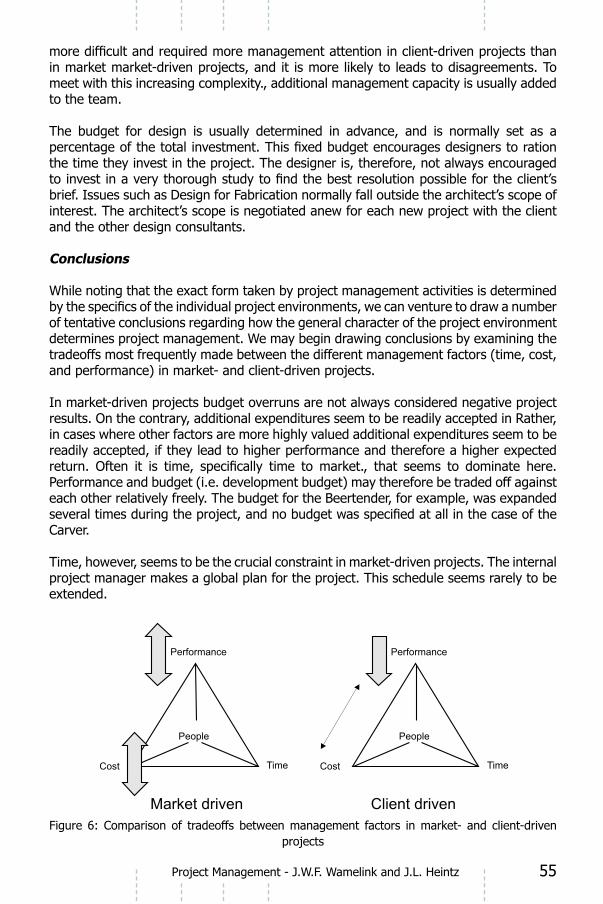
55Project Management - J.W.F. Wamelink and J.L. Heintz
in market market-driven projects, and it is more likely to leads to disagreements. To meet with this increasing complexity., additional management capacity is usually added to the team.
The budget for design is usually determined in advance, and is normally set as a
the time they invest in the project. The designer is, therefore, not always encouraged
brief. Issues such as Design for Fabrication normally fall outside the architect’s scope of interest. The architect’s scope is negotiated anew for each new project with the client and the other design consultants.
Conclusions
While noting that the exact form taken by project management activities is determined
of tentative conclusions regarding how the general character of the project environment determines project management. We may begin drawing conclusions by examining the
and performance) in market- and client-driven projects.
In market-driven projects budget overruns are not always considered negative project results. On the contrary, additional expenditures seem to be readily accepted in Rather, in cases where other factors are more highly valued additional expenditures seem to be readily accepted, if they lead to higher performance and therefore a higher expected
Performance and budget (i.e. development budget) may therefore be traded off against each other relatively freely. The budget for the Beertender, for example, was expanded
Carver.
Time, however, seems to be the crucial constraint in market-driven projects. The internal project manager makes a global plan for the project. This schedule seems rarely to be extended.
Figure 6: Comparison of tradeoffs between management factors in market- and client-driven projects

56 Project Management - J.W.F. Wamelink and dr. J.L. Heintz
In client-oriented projects, project success is more likely to be was measured on the bases of compliance with previously established indicators for time, cost and performance. At the beginning of an architectural project, the client usually provides a relatively detailed brief. Yet it is actually other factors that seem to dominate. Time is generally assumed to be beyond the control of the project team. Delays are accepted as a natural part of the process. The time factor is determined primarily by external factors (i.e. factors external to the design process or the design team), such as building permits, and regulations), and there is little that can be done about them. Thus, although the delivery date may slip because of these factors, such shifts are often not seen as a particularly negative result; rather they are seen as a fact of life. Time only becomes an important management tissue once construction has begun. However, when costs begin to escalate, management intervenes and performance must be reduced to bring costs back into line, as for example, when the sustainability aspects of the IDE building were reduced. This is true not only of production costs, but of the design costs as well. In practice, client-driven projects are budget driven, and the level of performance achievable within the stated budget is accepted, even when this is less that then stated in the original brief.
We can also observe differences in the organisational relationships between design and construction. In client-driven projects we see a separation of design and project management. In architectural projects project management is often performed by an
is often an internal project manager. Thus, in IDE projects the designer is responsible, not only for the design, but also for the management of the project.
tension between the owner of the building (TU Vastgoed) and the users (Faculty of Industrial Design staff). Further, while building design projects often span a period of years, and the organisations to be accommodated continue to evolve throughout the duration of the project. This often leads to changes in the users’ needs and negotiations that lead to deviations from the originally stated brief. On the other hand, the market determines what the expected performance should be, through market research and product testing.
The architectural design process is more complex. There are more parties involved, and many aspects of the design are contracted out to other parties. In some cases, the architect will provide only the concept design, and the working out of that design in
Risk management seems to be important in both market- and client-driven projects. However, the risks receiving the most attention are different. In market-driven projects, the most important risks to be managed are those associated with the market itself – price, and consumer demand. In client-driven projects, the most important risks are internal project risks – the client is concerned with managing the designer, and does not share their concerns for the market (in those cases where the product will eventually be brought to market) with the designer. The designer plays no part in market research,
is on arriving at a previously conceived result rather than maximising performance, production cost, or delivery time.

57Project Management - J.W.F. Wamelink and J.L. Heintz
Risk management varies between internal and external projects as well. In internal projects it is possible for designers to deal with risks associated with production, where as, we can see in the external projects, particularly in the architectural cases, that no account is taken by the designer of production risks.
Thus we see that risk management, while not being named as such, is carried out in a more structured fashion in IDE projects than in architectural projects. In architectural
external consultants or internal to the client organisation. This leads to a sort of conservatism, in which meeting predictable ends is more important than maximising performance. Innovation in architecture is, therefore, exceedingly gradual, and it tends to be focused on aesthetic issues. In this respect it should be noted that the only architectural project where patents were sought was the market-driven 1-2-3 Huis project. The only market-driven project not to seek patents was the A230 Chair, were Arhrend sought alternative means to protect their intellectual property.
From this short study it can be seen that there are many similarities as differences between the ways in which project management as it is applied in IDE and architecture. In summary, we can say that IDE projects are managed to meet product and investment performance expectations, while architectural projects are managed to achieve compliance with briefs.
More interestingly, the distinction between IDE and architecture is not always evident. The categories of market-driven and client-driven projects are more illuminating, as are the
exclusively on internal projects. Indeed, focusing on project-environmental factors may enhance our ability to predict the types of project management approaches that are
References
Barnes, M. (1988). “Construction Project Management.” International Journal of Project Management 6(2): 69-79.
Cooke-Davis, T. (2002) “The ‘real’ success factors on projects.” International Journal of Project Management 20(3): 185-190.
Halman, J. I. M. (2002) “Ontwikkeling van een risicoreferentielijst voor product innovatieprojecten.” Bedrijfskunde 74(5): 35-45.
Keizer, J. A., J.-P. Vos, et al. (2005) “Risks in new product development: devising a reference tool.” R&D Management 35(3): 297-309.
Kliem and Ludin (1992) The People Side of Project Management. Gower, Aldershot.
Koutsikouri, D., A. Dainty, et al. (2006). “Critical success factors for multidisciplinary engineering projects.” 22nd Annual ARCOM Conference, Birmingham, UK, Association of Research in Construction Management.
Lock, D. (2007) Project Management (9th edition). Aldershot, U.K., Gower.

58 Project Management - J.W.F. Wamelink and dr. J.L. Heintz
Mbachu, J. I. C., & Vinasithamby, K. (2005). Sources of risks in construction project development: An exploratory study. Paper presented at the Queensland University of Technology Research Week, Brisbane, Australia.
Meredith, J. R. and S. J. Mantel (2006). Project Management; A managerial approach. New York, Wiley.
MMID. (2007, 20/08/2007). “MMID full service design team (corporate website).” Retrieved 12/05/2008, from www.mmid.nl.
Morris, P.W.G. (1994) The Management of Projects. London, Thomas Telford.Morris, P.W.G. (2001) “Updating the Project Management Bodies of
Knowledge.” Project Management Journal 32 21 –30Robbins, S. P. and D. A. DeCenzo (2004). Fundamentals of management:
essential concepts and applications. Upper Saddle River, N.J., Prentice Hall.
Business Review 57(2): 81-93.Roozenburg, N.F.M. & Eekels, J. (1991) Produktontwerpen, Structuur en
Methoden. Utrecht, Lemma.Shenhar, A. J., D. Dvir, et al. (2001). “Project success: A multidimensional
strategic concept.” Long Range Planning 34(6): 699-725.Stamm, B. von (2003) Managing Innovation, Design & Creativity. Wiley,
Chichester, UK.
gap analysis approach.” Construction Management and Economics 16: 193-207.
Winch, G. (2002) Managing construction projects : an information processing approach. Oxford, Black

59

IDE+ADesign Processes - Wim Poelman and David Keyson (Eds.)
IOS Press, 2008 © 2008 The authors and IOS Press. All rights reserved.
Social Complexity

61
5 Social complexity in design collaboration
Prof. dr. P.G. Badke-SchaubProfessor Design Theory and MethodologyFaculty of Industrial Design EngineeringDelft University of Technology
Abstract-
sign activities by the social context. The eight design projects, which were used as stimulating material, were analysed towards the variables which contributed to the so-cial context. All interviewees discussed collaboration between different stakeholders as one of the main ambiguous issues in the design process. In the paper the challenges of the three problems prevalent in most projects are analysed in further detail: unshared or contradictory goals between different stakeholders involved in the process, the need
concepts are presented and further detailed in how they may provide opportunities of
Keywords: coordination, communication, contradictory goals, team mental models
IntroductionIn the past the designer was a creative genius, a creator and the artist behind the ‘prod-uct’. Today, it’s common to state that design is a social process (e.g. Bucciarelli, 1994) since many design projects are far too complex for individual designers. Technological
-uct development processes within one organisation have changed to concurrent engi-neering processes, often involving several organisations. Thus, the designer is often a member of a multi-disciplinary product development team including disciplines such as marketing and mechanics, software, product control, and more. The same is true for architects, whose work includes collaboration with disciplines such as statics, installation, construction, etc., each of them contributing their particular
coping with these complexities is to integrate the expertise and knowledge of different disciplines. This synergistic effect is especially emphasised in the theoretical framework of social cognition:
Knowledge is commonly socially constructed, through collaborative efforts towards shared objectives or by dialogues and challenges brought about by differences in per-sons’ perspectives. (Pea, 1993, p.48)However, multidisciplinary teams also run the risk of a variety of problems, to name only two aspects of any collaboration in a project team across disciplines and organisa-tions:
same word can indicate different phenomena (for example, the word function) or different words can refer to the same feature;

62 Social complexity - P.G. Badke-Schaub
2007).Considering only these two aspects it becomes obvious that the social context adds ad-
In the following chapter the main challenges which constitute social complexity in de-sign collaboration will be outlined and in the third part (chapter 3) some theoretical analyses explain the aspects which are most important when considering how to cope with these challenges successfully.
1 Challenges
-ment of the task at hand while embedded in a complex social process. The challenges resulting from this situation are of various kinds; the three challenges discussed here are taken from the interviews of four architects and four industrial designers (from 8 different projects) who were involved in the design of well-known Dutch buildings and products (8 different projects). These projects were chosen because they represent design success stories in architecture and product development.
1.1 Unshared and contradictory goals
of people with complementary skills who are committed to a common purpose, per-formance goals, and approach for which they hold themselves mutually accountable’. Furthermore, team members strive for a common goal. However, these characteristics do not hold for teams we see more and more working in the globalised world, such as virtual teams, geographically dispersed teams, etc.. These teams may have a common goal – in the broader sense such as in project teams where each discipline brings in its own, often hidden agenda. For example, one of the architects interviewed describes
company gains the most with a project that is as cheap as possible; in order to save money the construction company does not always stick to the plans. The same problem was also mentioned by another architect: ‘The architect wants to create beautiful things where the building contractor wants the building to be cheap’.Obviously, the need to cope with different and often contradictory goals is not only a part of the task process but also of the social process. The designer has to balance between individual and domain-related goals and project goals, or as Bucciarelli (1994,
negotiate their differences and construct meaning through direct, and preferably face-to-face exchange’. Thus, collaboration can be successful if the interaction focuses on joint objectives.
1.2 Cross-disciplinary communicationThe main contribution to the overall success of a complex design project is communica-tion between the various parties involved, including the user and the client. However, the different individual backgrounds of the parties, visible as an amalgamation of differ-
often refer to, and budget for, the time needed to come to a decision.

63Social complexity - P.G. Badke-Schaub
The main aim of communication is the exchange of information, which in complex projects usually leads to an information overload for the individual professional. Hence, the integration of information is necessary in order to transfer information into knowl-edge. Some projects try to enable this process by using a sophisticated documentation system. The structure of such a system has to be transparent for all parties involved and the vocabularies used need to be understood by all disciplines in the same way. Furthermore, a documentation system should clearly describe the decisions that have been taken and why. The integrated knowledge should be more or less shared by all of the team members.
1.3 Structured proceduresStructured procedures are, in the eyes of many designers, too structured. One designer related that in his company there is a standard procedure for handling a project. This procedure is similar to what he learned at university. ‘They teach you to follow the per-fect process, but in reality it does not work that way. It’s neither preferable nor workable because each project needs its own approach. Every project is one of a kind; we start by asking ourselves what this project needs. And from there we start the project’. Although there are several methods which support project work there is a rather low rate of acceptance by professionals. Contrary to these structured approaches, brain-storming is widely accepted and used in daily work; however this method is not always used as prescribed by the inventor (Osborne, 1953) but more as a tool for unstructured discussions.
2 Essentials of social complexity in design
want to understand and support multi-disciplinary design collaboration: coordination and team mental models.
2.1 Coordination
organised and distributed effectively in terms of team, time and space. As projects

64 Social complexity - P.G. Badke-Schaub
always have to cope with the intersections between disciplines it is necessary to make sure that the individual contributions are in line with the various interconnections. The
is a precondition for precisely aligning individual contributions to the team as well as contributions between teams. The way to coordinate may be different, depending on the use of tools, channels and media (see Figure 2).
As indicated in Figure 2, an important element of coordination determines the team structure by allocating tasks, roles and responsibilities, in which the coordination of
-vides the group with a transparent group structure and a clear allocation of tasks and responsibilities according to the preferences and competencies of the team members
(2001). In this way the team members develop a shared team mental model and may be at the same time a transactive memory.A further major coordination issue is the allocation of time and careful scheduling so that enough time is available to accomplish tasks and for group development. A clear
The coordination of the interaction between different locations becomes more important with increasing globalisation and hence the increasing virtualisation of collaboration. Another important topic with regard to geographically distant collaboration concerns cultural differences and their impact on different aspects of design work.Empirical studies reveal that the more team members coordinate their contributions, in relation to task and process, the better they perform (Gurtner, 2003). Certainly, the need for coordination depends on the complexity of the task, the number of different parties involved and the degree of interconnectivity between the parties; the more in-terdependencies the more coordination is needed.
Groups working together for a longer period of time develop a common history and as

65Social complexity - P.G. Badke-Schaub
their work. However, when collaboration in teams is begun, coordination is communi-cated explicitly and this creates a ‘common ground’ (Clark & Brennan, 1991), which
There is also empirical evidence that teams tend to avoid coordination or postpone the start of coordination activities until it becomes obvious that the current muddling-through strategy is not successful (Hackman, Brousseau & Weiss, 1976). Gersick (1988, 1989) derived from an analysis of project teams that halfway through the project timeline a transition phase occurs, characterised by a sudden change of strategies. Resources can
can be made, which affects the result of the whole project in a negative way.
2.1.1 Regular face-to-face meetings Although all interviewees reported that during the projects information was also shared by computer-mediated communication, all participants underlined the need for regular face-to-face meetings. One designer explained that he does not use the phone or email that much, because he wants to see people and read their body language: ‘The scale of a project is not relevant to the way of communicating. Designing concerns tangible items. It is therefore also important that you see each other face to face and with a drawing or a mock-up’.
meetings support the trust-building process (Tang & Isaacs 1993). Furthermore, the possibility of a shared view of sketches, models and mock-ups is a basic part of most face-to-face meetings in design teams. This ‘tangible aspect’ is mainly stressed by ar-chitects: face-to-face meetings are needed because – especially at the beginning of a
Some of the designers interviewed distinguished between two kinds of meetings; on the one hand, the more structured meetings usually chaired by the project leader, and on the other, unstructured brainstorm sessions. Brainstorming seems to be the method used in all projects and for different purposes, such as to identify various aims.
‘You always have to stay critical about why you are doing something. This goes for the building but also for the management’.
process.
-tured communication and the similarity of mental models. Another interesting result
-
2.2 Team Mental ModelsMental models are internal representations that humans build in order to understand, predict and act in the world (Craik, 1943). There are different assumptions about the patterns of representations; however, researchers agree on two basic types of models (Cooke, Salas, Cannon-Bowers, & Stout, 2000; Klimoski & Mohammed, 1994; Rentsch & Hall, 1994): those concerned with the task and those concerned with the team. The

66 Social complexity - P.G. Badke-Schaub
task mental models encompass all aspects related to the execution of the task, while the team mental model covers all representations related to the team and the team members who are essential to working together. Team mental models are generally
members (Cannon-Bowers, Salas, & Converse, 1993; Klimoski & Mohammed, 1994). It has been shown that teams sharing a common understanding of the task, the team, and the situation perform better (e.g. Lim & Klein, 2006; Mathieu, Heffner, Goodwin, Cannon-Bowers, & Salas, 2005).More precisely, one designer interviewed describes his view of the kind of team-related
team. You have to know who does what. You have to know what you can expect from
-volved’.
from each other.Knowledge about the team includes knowledge about competencies, roles, tasks and responsibilities of the team members: who is responsible for which (sub-)tasks, what
high level of shared team mental models and problem-solving performance but not between shared task mental models and performance, which underlines the relevance of the social context for successful task accomplishment.
3 Conclusions
design. Social complexity relates to the social context that a project team works in and
Interviews with designers responsible for successful Dutch projects in architecture and product development formed the background for the analysis presented here of the impact of social complexity on collaboration in design teams. Although all projects were successful the interviewees also reported some restrictive factors, such as contradicting goals between the different parties involved. Finally, two major theoretical concepts (coordination, team mental models) are discussed which provide further ideas to suc-cessfully dealing with complex design projects in social context.
ReferencesBadke-Schaub, P., Neumann, A., Lauche, K., & Mohammed, S. (2007). Mental models in design teams: A valid approach to performance in design
Bierhals, R., Schuster, I., Kohler, P., Badke-Schaub, P. (2007). Shared mental models - linking team cognition and performance. Co-Design, 3, 75-94.
Bucciarelli, L.L. (1994). Designing Engineers. Boston: MIT Press.Cannon-Bowers, J. A., Salas, E., & Converse, S. (1993). Shared mental models
in expert team decision making. In N. J. Castellan, Jr. (ed.), Individual and group decision making: Current issues (pp. 221-246). Hillsdale,

67Social complexity - P.G. Badke-Schaub
NJ: Lawrence Erlbaum Associates.Clark, H. H., & Brennan, S. E. (1991). Grounding in communication. In L. B. Resnick, J. M. Levine, & S. D. Teasley (eds.), Perspectives on socially shared
cognition (pp. 127-149). Washington, DC, USA: APA Books.Cooke, N. J., Salas, E., Cannon-Bowers, J. A., & Stout, R. J. (2000). Measuring
team knowledge. Human Factors, 42, 151-173.Craik, K. J. W. (1943). The nature of explanation. Cambridge, UK: Cambridge
University Press.Gersick, C.J.G. (1988). Time and transition in work teams: Toward a new
model of group development. Academy of Management Journal, 31, 9-41.
Gersick, C.J.G. (1989). Marking time: predictable transitions in task groups. Academy of Management Journal, 32, 274-309.
Gurtner, A., Tschan, F., Semmer, N.K. & Nägele, C. (2007). Getting groups to
process, team performance, and shared mental models. Organizational Behavior and Human Decision Processes, 102, 127-142.
Hackman, R.J., Brousseau, K.R. & Weiss, J.A. (1976). The interaction of task design and group performance strategies in determining group effectiveness. Organizational Behavior and Human Performance, 16, 350-365.
Katzenbach, J.R. & Smith, D.K. (1993). The Wisdom of Teams: Creating the High-performance Organization. Boston: Harvard Business School.
Klimoski, R., & Mohammed, S. (1994). Team Mental Model - Construct or Metaphor. Journal of Management, 20, 403-437.
Lim, B.-C., & Klein, K. J. (2006). Team mental models and team performance:
accuracy. Journal of Organizational Behavior, 27, 403-418.Mathieu, J. E., Heffner, T. S., Goodwin, G. F., Cannon-Bowers, J. A., & Salas, E.
and normative comparisons. Journal of Organizational Behavior, 26, 37-56.
Mohammed, S., & Dumville, B. C. (2001). Team mental models in a team knowledge framework: Expanding theory and measurement across disciplinary boundaries. Journal of Organizational Behavior, 22, 89-106.
Osborn, A.F. (1953) (rev. 1957, 1963). Applied Imagination: Principles and Procedures of Creative Problem-Solving. New York: Charles Scribner’s Sons.
Pea, R. (1993) Practices of distributed intelligence and designs for education. In G. Salomon (Ed.), Distributed cognitions: Psychological and educational considerations. Cambridge University Press: Cambridge.
task role distribution in work groups. Group Processes and Intergroup Relations, 4, 138-159
multimedia-supported collaboration. Computer Supported Cooperative Work, 1, 163-196.

IDE+ADesign Processes - Wim Poelman and David Keyson (Eds.)
IOS Press, 2008 © 2008 The authors and IOS Press. All rights reserved.
Decision making

69
6 A decision-based design approach
Dr. ir. P.P. van Loon1, ir. R. Binnekamp, ir. J. Burger1Associate professor Design and Decision Systems Faculty of Architecture Delft University of Technology
Introduction
explored for several years now.Over the past decades, design theory research has taken several twists and turns, as computational tools became the standard for how engineers of all disciplines ‘did design’. In an early National Science Foundation Workshop report (Newsome et al., 1989), research was categorised into topical areas focused on the design process that included the computational modelling; the cognitive and social aspects; the representations and environments; the analysis tools including optimisation and the design ‘for’, such as ‘for manufacturing’. At that time, the NSF programme was called ‘Design Theory and Methodology’ and consisted of three components that essentially
the design process. The second, ‘Foundation for Design Environments’, was aimed at advancing the understanding of fundamental generic principles that could be used and understood across engineering domains. The third, ‘Design Processes’, was focused on the how and why of the design process, including early work on life-cycle concepts and concurrent design (Durham, 2006).
the years, from early computer-aided design (CAD) through solid modelling capability. The introduction of virtual reality, computer integration engineering, and collaborative and distributed design processes created demands on the community to focus on how decisions were made, under what conditions and to what purpose. Decision-based design became a major thrust for the research community, with the issues of uncertainty and predictive modelling capability becoming the foci. As with any science, the theories must be put forward, tested for consistency and completeness, and then incorporated (or not) into the framework of the science. This is true, too, for engineering design, if it
During the late 1990s, members of the engineering design research community articulated a growing recognition that decisions are a fundamental construct in engineering design. This position, and its premise that the study of how engineering designers should make choices during the design, represented the foundation of an emerging perspective on design theory called decision-based design (DBD). DBD provides a framework within which the design research community could conceive, articulate, verify and promote
al. (2006):Decision-based design (DBD) is an approach to engineering design that recognizes the substantial role that decisions play in design and in other engineering activities, largely characterized by the ambiguity, uncertainty, risk, and trade-offs. Through the rigorous application of mathematical principles, DBD seeks to improve the degree to which these activities are performed and taught as rational, that is, self-consistent processes.

70
based design for some years. The group’s focus is on a collaborative approach to architecture, urban planning, and project management. It offers concepts and methods to combine technical and social optimisation into one integrated design process (Binnekamp et al., 2006).
IDE+A Case Study Analysis, IDE+A Workgroup TU Delft (2008), pp. 4-5:Introduction - Case 1: Westraven Utrecht - Company: Cepezed
renovated. The building was designed by Jan Lucas (of Lucas & Niemeijer) in 1975. The building stands at a particular spot that is known as the ‘bellybutton’ of the Netherlands. Jan Pesman has looked at the exact middle point of the Netherlands but this was not the correct location. However, the location is characterised by the crossing of waterways and roads such as the Amsterdam-Rhine canal and the A2 highway. This location is therefore very precious to an organisation such as Rijkswaterstaat (the Ministry for Transport, Public Works and Water Management). There was a contest, in
of the working space and that surrounding buildings should have glass windows which could be opened. In order to open the windows they developed a double façade system with a semitransparent fabric in order
Social Complexity in Collaboration - Case 1: Westraven Utrecht - Company: CepezedDescribe the structure, mutual communication and the relationships during the collaboration by those involved in the project.
He was the architect. According to Jan, he is at the top of the food chain. You generate ideas, which you discuss with the design team. These proposals are then taken to the customer (in this case, the Rijksgebouwendienst (Government Buildings Agency)). As the architect, you are president of the design team. This means that you also have a vote about which external advisors take part in the project.
In general, the role of the architect is reduced little by little. Jan Pesman says that architects revolt against this. He sees more and more responsibility being placed in the hands of the construction company. The architect has to make a nice drawing and the construction company executes the plans the way they like it. The danger here is that the construction company aims
and then going to a construction company.
A total of seven parties were involved.
1. The client / user: Rijksmonumentenzorg (Netherlands Department for Conservation) and Rijkswaterstaat.2. The design team: architect (Chair of the design team), Construction company, structural and installation technology3. External advisors or specialists4. Cost management
Only the architect was from Cepezed. All of the other parties involved were from outside the Cepezed organisation.
A decision-based design approach - P.P. van Loon, R. Binnekamp and J. Burger
71A decision-based design approach - P.P. van Loon, R. Binnekamp and J. Burger
Only a few women were involved in this project.
A maximum of 200 people worked on this project. There is the project manager, who represents a group of 30 people who in turn represent the users during the project; there are 15 engineers, 4 people in executive management, and the architect.Were there changes in the number of parties and people that were involved
The number of people did not change, due to the European tender.
Only the architect came from Cepezed. The rest are from outside the organisation.
Yes, this is common.
The architect works in close collaboration with the advisors. This is better for developing ideas.
It is important to have regular meetings in order to develop solutions. In addition, there was a level of technical executive control.
In big projects you have specialised agencies manage the executive functions.
All decisions were recorded in project reports. Because of the complexity
all of the information regarding the project is collected. There are written reports, drawings, and the latest status reports. Jan Pesman also stresses the importance of meetings, saying ‘you need interaction’. In a meeting
e-mail.
Yes, there was.
Because Cepezed had only technical executive control they were not always present at the construction site. But sometimes the construction company will not stick to the plan, in order to save money. So they have to carry out thorough checks of the work.Did the innovative nature of the project (on a international scale) have an
The innovative nature of the project led to more communication between the advisors and the architect. More meetings and more sketches lead to more solutions.
1 Decision making in an architectural design process
tends increasingly to run aground in a ‘combinational explosion’. At such moments, there are too many options, too many opinions and too many alternatives.If designers bring in the expertise of specialists to reduce the size of the solution space,

72
options that lie within their own discipline. When the designers go on to combine these
assessing which combination was important for the whole, and which was the mostly likely to meet the goals of all involved.Many designers attempt to deal with this dilemma of ‘too many combinations at the start’ and ‘too few options after selection’ by setting up a broadly based design team. On such a team, the designers work with specialists, jointly exploring the solution space and determining the best combination of sub-solutions. Unfortunately, this approach often also tends to run aground, when the client and users fail to approve the result
To prevent this kind of rejection, designers often enlist the aid of process experts, asking them to devise a decision-making process for the team. This process sets out what has
sub-design, then the next, etc. This enables the team to work towards a result with some degree of certainty, but also entails the risk that a series of sub-optimum design decisions will lead to a sub-optimum design result.
IDE+A Case Study Analysis, IDE+A Workgroup TU Delft (2008), p. 6:Decision making - Case 1: Westraven Utrecht - Company: Cepezed
The architect makes decisions regarding the design. He is advised by his team of advisors. He takes their advice into account when drawing up the design. Then he takes the design to the client. The client normally follows the advice of the architect.
The client.
The users are the ones who have to use the building. Their wishes and demands have to be represented in the design.Could you give your point of view (related to the project) about these non-
2. The loudest voice is the one the gets heard (others are too modest)3. Power (the boss decides)4. Authority (the dominant person decides)5. ‘Everyone thinks his own owl is a falcon’ (for example, the boss’ son)6. Anxiety (risky decisions are taken)7. Haste (the proposal that looks like it will take the shortest time to complete is chosen)8. ‘Tenderfoot’ (trying to get in the good graces of those making the proposal)9. Fast talking (the best presentation wins)10. Last-best (the last presentation is the one that is best remembered)Types of leadership:1. Laissez-faire (from the French, meaning do what you want to do, I will judge the result)2. Catalytic (stimulating)
A decision-based design approach - P.P. van Loon, R. Binnekamp and J. Burger
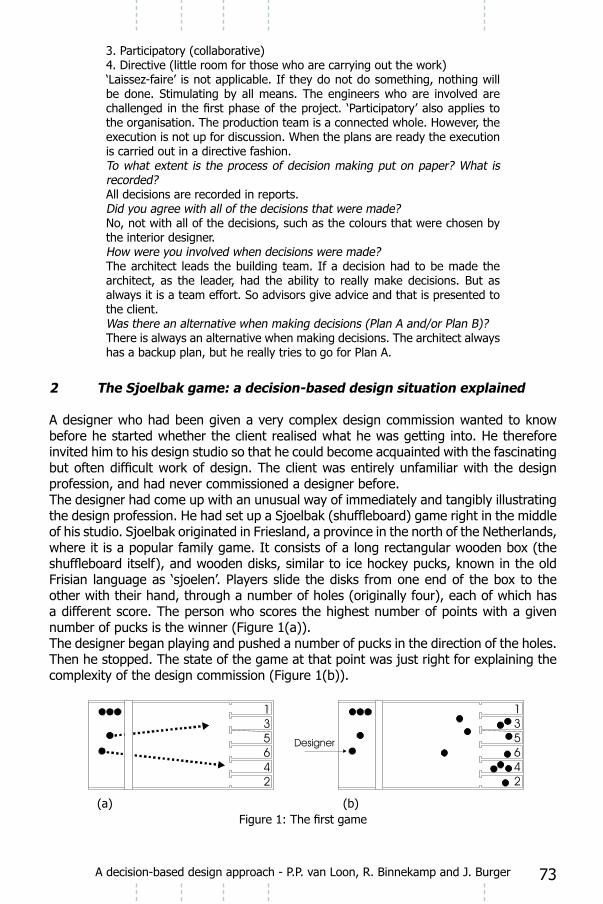
73
3. Participatory (collaborative)4. Directive (little room for those who are carrying out the work)‘Laissez-faire’ is not applicable. If they do not do something, nothing will be done. Stimulating by all means. The engineers who are involved are
the organisation. The production team is a connected whole. However, the execution is not up for discussion. When the plans are ready the execution is carried out in a directive fashion.
All decisions are recorded in reports.
No, not with all of the decisions, such as the colours that were chosen by the interior designer.
The architect leads the building team. If a decision had to be made the architect, as the leader, had the ability to really make decisions. But as always it is a team effort. So advisors give advice and that is presented to the client.
There is always an alternative when making decisions. The architect always has a backup plan, but he really tries to go for Plan A.
2 The Sjoelbak game: a decision-based design situation explained
A designer who had been given a very complex design commission wanted to know before he started whether the client realised what he was getting into. He therefore
profession, and had never commissioned a designer before.The designer had come up with an unusual way of immediately and tangibly illustrating
of his studio. Sjoelbak originated in Friesland, a province in the north of the Netherlands, where it is a popular family game. It consists of a long rectangular wooden box (the
Frisian language as ‘sjoelen’. Players slide the disks from one end of the box to the other with their hand, through a number of holes (originally four), each of which has a different score. The person who scores the highest number of points with a given number of pucks is the winner (Figure 1(a)).The designer began playing and pushed a number of pucks in the direction of the holes. Then he stopped. The state of the game at that point was just right for explaining the complexity of the design commission (Figure 1(b)).
(a) (b)
A decision-based design approach - P.P. van Loon, R. Binnekamp and J. Burger

74
to look at. Because you can’t get all the pucks into the holes at once and because not
The client studied the situation carefully, remembering the game from his youth. ‘Why
Of course the designer had expected him to say this. He called two experts from his
had prepared beforehand so that three people could play simultaneously. The experts were told to send the pucks in a certain direction by pushing the sides of the board in (Figure 2(a)).The designer now pushed a number of pucks towards the holes, while the experts pushed the sides so that the pucks landed in their preferred holes. After a few more pucks had been played, the game nicely illustrated how reducing the number of holes
(a) (b)Figure 2: The second game
‘If we don’t use all the holes,’ explained the designer, ‘there are fewer possible
experts did a great job helping to reduce the number of holes that were in play. But
The client looked desperate. ‘Listen, you’re well known as a good and, above all, clever
Of course the designer had hoped the client would say this. To illustrate his planned
They all, including the client, stood around the board. It had been adjusted so that the direction of the pucks would be affected in a variety of ways. The players at the sides of the board could steer the pucks by pushing or pulling at the sides, which were hinged (Figure 3(a)).After the designer had pushed a number of pucks towards the holes, between the now
approach the design commission (Figure 3(b)).
A decision-based design approach - P.P. van Loon, R. Binnekamp and J. Burger

75
(a) (b)
Figure 3: The third game
‘Look,’ he said, ‘now everyone has affected the outcome, but we don’t know who had what effect. We do know however that everyone had to take everyone else into account.
outcome was not known at the outset. No one was able to steer the pucks entirely as he wanted. If we play the game like this a few times, we’ll get better at it, and be able
group preferences. And we can also arrange to leave open the possibility of pushing the pucks into certain holes at a later stage’.The client now fully realised what he had embarked upon. He was particularly pleased with the idea that he could involve people other than professional designers directly in the process.
3 Decision-based design by means of the combination of sub-solutions
The design situation illustrated above by the Sjoelbak game is known as ‘design by means of the combination of sub-solutions’. This method was developed in the late 1960s and early 1970s in the framework of what was known at the time as ‘systematic design’ or
step-by-step combination of sub-solutions into one design were developed. Initially
been successfully applied in practice by many designers they came to be used by design
time, problems were sometimes encountered by the last two applications. There were
could not simply be applied to design teams and design organisations, especially not in complex and large-scale projects, such as large buildings, residential areas, cities,
due to the impossibility of bringing together the large number of parties involved, all with their own design goals and design ideas, and of incorporating the ideas into one
large numbers of sub-solutions. Systematic design emanated largely from classic conceptions of rational and modern design. While the systems approach, which originated in the thirties, had a strong
decision theory and management science also helped shape the combination method, albeit to a lesser degree.
A decision-based design approach - P.P. van Loon, R. Binnekamp and J. Burger

76
Figure 4: Approaches to methodical design
The classic conception developed in the 1950s when the search for new design methods was underway. Designers and design theorists had seen that commissions were becoming more complex and that existing design methods were proving to be
beginning to ask why these products had been designed in a particular way. People wanted to discuss the effectiveness and the effects of new products before they were made. The designer’s personal vision was no longer enough. People wanted a rational
(1975) and Tzonis (1982) wrote a great deal about this. A whole school emerged around what is now known as ‘systematic design’. Even today there is interest in these views and they are widely propagated in the framework of developments in computer-aided design and the role of information systems in design processes, including those used for complex design commissions. Designers are slowly beginning to realise that
classic conceptions of design. As Mitchell (1990 p. 13) put it: ‘We must embrace the possibilities of design that have ambiguous and unstable structural descriptions’. He goes on to say that we can no longer use only the ‘stable, universal design rules’ of the 1950s and 1960s, on which computer-aided design is still often based.
form-function dichotomy and goal orientation. In the 1950s, when new design methods were being developed, there was a shift from ontological thinking to functional thinking. It was felt that ‘meanings are not immutable and exclusive entities that reside within things and can be discovered by the creative force of an exploring subject, but are,
must determine form. The design process must begin with an analysis of functions and then move to a synthesis of appropriate forms (sub-solutions). The systems approach provided a conceptual framework on the basis of which all manner of systematic and
cultural norms and values into design, which had dominated thinking on design until then, faded into the background. The systems approach placed the goal orientation of design activities in the foreground. From then on all design considerations and goals
put into effect.
A decision-based design approach - P.P. van Loon, R. Binnekamp and J. Burger

77
4 A general phase model for the combination of sub-solutions
The literature contains many general phase models for the division of the design process based on the method of combining sub-solutions. Roozenburg and Eekels
Jones (1970) and Hamel (1990) do the same for architectural design. McLoughlin
regional planning.
would concur that these models all have the same structure, which is simply presented in a different manner in each case. Figure 5 shows this structure in a form which is suitable for our purposes. This general phase model shows that the cycle of formulating and combining sub-solutions (the divergence-convergence cycle) may take place many times during a design process. In Figure 5 it takes place twice: from the outset, up to and including
Figure 5: The general phase model of the combination process
The general model does not show who determines the division of the search space and
include its decision-making environment.
IDE+A Case Study Analysis, IDE+A Workgroup TU Delft (2008), p. 11:Interview with Fons Verheijen and Krijn TabbersFons did not have time to do the whole interview. Therefore he contacted Krijn, who worked on the project daily, to do the interview. Before the interview Fons did have time to give us his view of the differences between architecture and industrial design in the approaches to design. He is a teacher at TU Delft’s Faculty of Architecture but has also tutored to a few students in Industrial Design.
architecture.
and cons, and then you have your answer)
A decision-based design approach - P.P. van Loon, R. Binnekamp and J. Burger

78
rules you have to obey, everything can change
project, what the materials can permit and what the project’s preconditions are. This is what you learn to cope with at the Faculty of Architecture.
are companies that only do concepts. But according to Fons it
actually make what is in your mind.Two big differences are:
have to learn to cope with this.
moment in time
(In architecture this is much more necessary than in industrial design)
with protocols.
them. These secret clients are society and the general well-being. Unasked, architects take all of society into account, and this can
if you want to do something different.
5 Decision making in the combination process
Decision making in a design process that is based on the combination of sub-solutions will be geared mainly to determining and restricting the number of sub-solutions and combinations of sub-solutions. After all, this largely determines the progress and duration of a combination process. The more sub-solutions there are, the more combinations will be possible. Many combinations means that many evaluations and choices have to be made. The number can be limited on the basis of the methods that the designers themselves use to ensure that their combination process has a workable structure, both for themselves and for each other. These methods provide a number of bases for managing the process: the order of the combination process; the allocation of tasks and decisions; the structure of the search space; and the laying out of the search path and the combination strategy.As described above, the combination process begins with a number of parallel individual combination processes, in which the designers draw up their own plans and make their own syntheses. This will present few decision-making problems, irrespective of how these individual processes are carried out. At the outset, each designer has the opportunity to work independently of the others, in terms of both content and method.
A decision-based design approach - P.P. van Loon, R. Binnekamp and J. Burger

79
plans, each designer will want to know what the others’ alternatives are, in order to select those of his own plans that give him the best chance of achieving his own goals,
function well in terms of the designer’s own goals could, in combination with the others’ plans, create an overall situation in which these goals are achieved only partially, if at all.In practice, people will often hold a brainstorming session at this point, at which everyone puts ideas forward freely and, in so doing, gains an idea of all the proposals. It is assumed that the participants will have this freedom. If not, a decision-making problem that is typical of the combination process will arise: each designer will wait for the others to reveal their ideas before he is prepared to reveal his. In such a situation, one designer or group of designers will probably take the initiative and propose an overall plan which will include their own sub-solutions, and those that the other designers were supposed to have produced, in an attempt to gain a lead on the others. The party taking the initiative will formulate an overall plan that is favourable for them, but which includes elements that actually belong to the decision area of others. If, at such a moment, there is still confusion as to the allocation of the decision areas, the process can run aground. Everyone talks about and decides on everything. If certain parts of the plan drawn up by the break-away party taking the initiative seem to be
there will be little he can do about it. In such a situation, the designer has been known to call on his own organisation or department to block the implementation of the plan (on a hierarchic basis).The rules that must be applied to ensure that the combination process runs smoothly are similar to the rules of a game. In a game, the rules (the combination rules) are
resources of their own, but no rules, it is impossible for the players to devise a strategy. With rules but no resources of their own, each player can use any resources.For design in general, rules and individual resources are even more important than in a game because there is feedback during the design process. A series of ‘moves’ might
to the end, but is partially repeated along the way. But which moves may be reversed,
We may conclude from the above that it is possible to control the combination process only if we know in advance what each designer’s decision area is, and what the combination rules are.This does not preclude everyone proposing sub-solutions on any aspect, but certain individuals are authorised to decide whether sub-solutions for certain aspects may be
shifts in decision areas and changes to the combination rules. These will be subjected to negotiation and decision making.
6 Management of the combination process
Management can be described on the basis of its two main components, coordination and control. Coordination is the linking of the activities and decisions of different individuals. This allows a particular piece of work to be carried out as a complete entity. Coordination is normally based on the allocation of responsibilities within the work process; control is steering the process in the desired direction. This mainly entails correcting any mistakes.
A decision-based design approach - P.P. van Loon, R. Binnekamp and J. Burger

80
Generally speaking, a process will have been managed properly only if the results are consistent with the values and characteristics determined beforehand. Management ensures that the process is steered towards those results. Representing this as a simple control model, we can say that the management body determines the interventions that are necessary to the process and its support to obtain an output with those particular values and characteristics. This is represented in Figure 6.
Figure 6: Management of a process (after In ‘t Veld, 1989 p. 47)
Since, at the outset, the outcome of the design process is at best vague, management
by step. Moreover, since it is not entirely known at the outset how the design process will be structured, management will also have to focus on setting it up and altering it during the process: changes in the phasing, reallocation of the tasks that have to be
performed, links between the phases, etc.The design literature, and particularly the literature on decision theory, mentions a number of ways of achieving an effective structure for the design-decision process and a good design-decision result. I shall simply set out the general framework for the structuring of the design-decision process, using the model Herbert Simon has devised for a decision-making process (in: Davis and Olsen, 1985 p. 199). His model is simple and, partly as a result of its simplicity, has become very well known. According to this model, a decision-making process can be structured around three process phases (Figure 7): intelligence, the phase during which problems and possibilities are investigated; design, the phase during which problems and possibilities are analysed, and feasible solutions are generated; and choice, the phase during which options are selected from the various possibilities, and the chosen option is put forward for implementation.
Figure 7: Process phases in a decision-making process (after H.Simon)
A decision-based design approach - P.P. van Loon, R. Binnekamp and J. Burger

81
Each phase can be further divided, using the principle of phased decision-making (Wijnen et al., 1993 p. 13). In other words, the process in each phase can be divided into a number of logical parts, and there will be a moment of decision between activities (see Figure 8).
Figure 8: Phased decision-making (Wijnen et al., 1988 p. 13)
If phased decision-making is incorporated into Simon’s decision-making model, the result is as depicted in Figure 9. The diagram now includes intelligence activities and decisions, design activities and decisions, and choice activities and decisions.
Figure 9: Decision-making process with phased decision making
7 A case study: Stedelijk Museum Amsterdam
of those resources in architectural space. Traditionally this was the architect’s problem to solve; in modern practice the owner/principal as well as a whole range of technical
Increasingly, the prospective users themselves (as distinct from management or developers) also demand – and receive – a voice in these negotiations. This has led to a dramatic increase in the complexity of design processes, in which the design object can sometimes be forgotten.
building design management, operations research, and measurement theory. It enables a number of stakeholders from different disciplines to optimise and steer the design together, each from their own perspective, by indicating preferences and restrictions on function-location combinations, in an iterative search for a better design.This new tool, the Architectural Design/Decision Room, builds on an earlier tool which was successfully used in the design negotiations around the renovation and expansion of one of Amsterdam’s major museums, the Stedelijk Museum. The Architectural Design/Decision Room also shares many ideas and technologies with the Urban Decision Room,
a number of limitations faced by any preference-based system due to the nature of ‘preference’ and the current state of knowledge of measurement theory on this issue.
A decision-based design approach - P.P. van Loon, R. Binnekamp and J. Burger
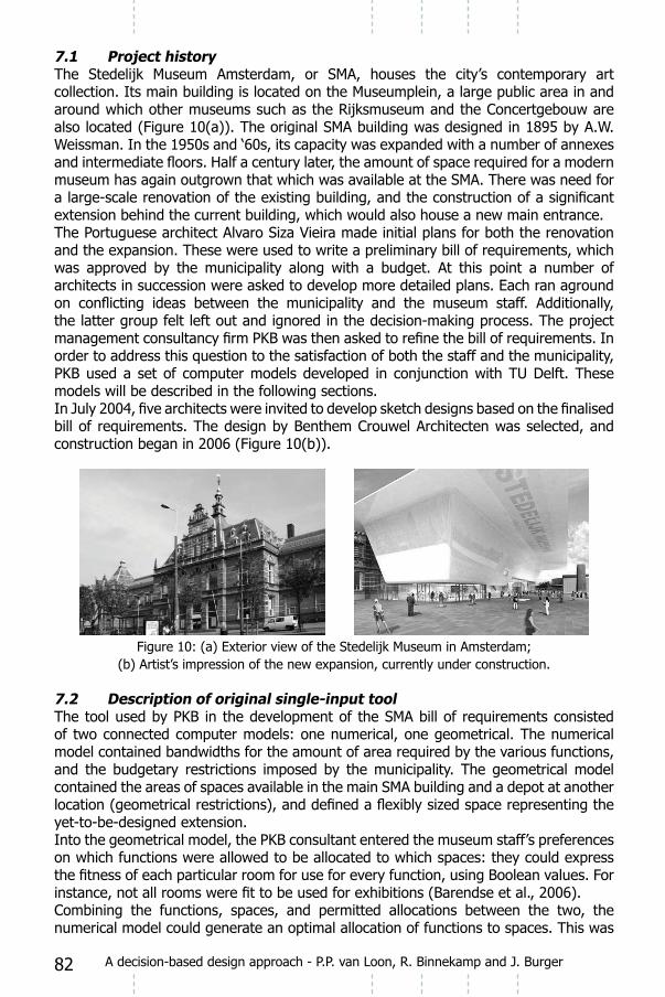
82
7.1 Project historyThe Stedelijk Museum Amsterdam, or SMA, houses the city’s contemporary art collection. Its main building is located on the Museumplein, a large public area in and around which other museums such as the Rijksmuseum and the Concertgebouw are also located (Figure 10(a)). The original SMA building was designed in 1895 by A.W. Weissman. In the 1950s and ‘60s, its capacity was expanded with a number of annexes
museum has again outgrown that which was available at the SMA. There was need for
extension behind the current building, which would also house a new main entrance.The Portuguese architect Alvaro Siza Vieira made initial plans for both the renovation
was approved by the municipality along with a budget. At this point a number of architects in succession were asked to develop more detailed plans. Each ran aground
the latter group felt left out and ignored in the decision-making process. The project
PKB used a set of computer models developed in conjunction with TU Delft. These models will be described in the following sections.
construction began in 2006 (Figure 10(b)).
Figure 10: (a) Exterior view of the Stedelijk Museum in Amsterdam; (b) Artist’s impression of the new expansion, currently under construction.
7.2 Description of original single-input tool
of two connected computer models: one numerical, one geometrical. The numerical
and the budgetary restrictions imposed by the municipality. The geometrical model contained the areas of spaces available in the main SMA building and a depot at another
yet-to-be-designed extension.Into the geometrical model, the PKB consultant entered the museum staff’s preferences on which functions were allowed to be allocated to which spaces: they could express
Combining the functions, spaces, and permitted allocations between the two, the numerical model could generate an optimal allocation of functions to spaces. This was
A decision-based design approach - P.P. van Loon, R. Binnekamp and J. Burger

83
output back to the geometrical model, by colour-coding the different spaces according to their allocated function, so that the SMA staff could view the results. In other words,
rise to changed preferences for permitted allocations, which could be applied to the
A detailed mathematical description of this numerical model was given in an earlier paper (Van Loon et al., 2006). In brief, for allocable functions f, available spaces s, allocation preferences p, and resulting allocations a, with the indices i, j identifying the individual functions and spaces respectively, the function of the numerical model can be given as:
given all fi, sj, pij, maximise (1)
Figure 11: Visualisation of functions allocated to spaces in the original SMA tool.
7.3 Description of multi-stakeholder toolA disadvantage of the tool used by PKB as described above is that it has only a single set of preference inputs. In other words, all the various stakeholders involved in a decision must agree on the allowed allocations to be entered into a model for a given allocation run (Figure 12(a)). In the discussion round following the presentation of
participants must also negotiate on the next set of preferences to be used (Figure
negotiation becomes clouded.
Figure 12: (a) A single set of preferences are used for all stakeholders; (b) The discussion
results.
A decision-based design approach - P.P. van Loon, R. Binnekamp and J. Burger

84
There is a second reason why a single-input tool is less desirable than it could be. An important factor in structuring a decision-making process following the open approach described in earlier sections is the issue of the ownership of constraints throughout the whole process. A decision-support model must accept individual constraints from all the parties involved, and maintain the independence of those constraints. In the context of an allocation model such as the one we are dealing with here, the various stakeholders must be able to enter their own preferences for each of the possible function-space combinations independently of the others (Figure 13).
Figure 13: (a) An independent set of preferences is used for each stakeholder;
The ability to accept multiple sets of preference inputs can be added to the model
can be extended by adding a set of users to the input variables, which then allows the function-to-space preference to receive an additional index k representing the user whose preference it is. Ultimately, of course, the numerical model must optimise to some aggregate or combined resulting form of these multiple preference sets; the
(1), which then functions as before.For functions f, spaces s, users u, preferences p, and allocations a, the function of the numerical model can be given as:
given all fi, sj, uk, pijk, pij (2)then given all fi, sj, pij, maximise aij (1)
of preference values and operations involving preference will be looked at further in section 9.
i j
A decision-based design approach - P.P. van Loon, R. Binnekamp and J. Burger

85
Figure 14: Visualisation of functions allocated to spaces in the new tool.
8 The measurement and addition of stakeholder preferences
In models where there is only a single set of preference inputs, or where the various
models), there is no need for any form of preference addition, as the constraints can be applied independently. As soon as more than one stakeholder is able to express a preference regarding the same thing – here the allocation of a particular function to a particular space – these distinct preferences clearly have to be combined, somehow, at
this can be necessary in the constraints of the model or in the construction of the objective function.
8.1 Boolean and tri-valued veto preferencesIn the models we have constructed to date, the stakeholders’ preferences have been implemented in a very limited way, namely as Boolean values allowing or disallowing a particular function to be allocated to a particular space. The number 1 or TRUE means that a function may be allocated, the number 0 or FALSE means that it may not. These preferences effectively act as ‘veto criteria’, and as such are part of the model constraints. They can be implemented as follows:
ij: aij < sJ x pij (3)
Expressed in words: the area of function i allocated to space j must be less than the area of space j multiplied by either 0 or 1, i.e. either less than 0 or less than the area of space j.If Boolean preferences are to be combined, there are two simple implementations: a) each constraint is treated independently, so that every stakeholder must assign TRUE for a function to be allocable; b) all constraints are evaluated, and if any one stakeholder assigns TRUE, the resulting value is also TRUE. There are more complex
For completeness, it is of course also possible to implement a Boolean veto preference as may/must instead of may not/may. This is not often used, however. Alternatively, one can easily extend the Boolean veto system to a tri-valued system, may not/may/must. This has been implemented in a limited way in our urban planning models, with
We will now introduce an alternative extensible notation for preference values, which is
j ija
A decision-based design approach - P.P. van Loon, R. Binnekamp and J. Burger
A

86
also usable for tri-valued or higher systems. Its nomenclature is based on the meaning of the preference rather than the accident of the corresponding method of implementation, as with the Boolean notation above. After the terms used in the previous paragraph, the negative veto preference will be labelled N for may not; the positive veto preference will be labelled M for must; the neutral may or ‘allowed’ preference will be labelled 0 (zero).Using the new preference notation we can construct a combination table for two stakeholders using a tri-valued veto system {N, 0, M} (Table 1). May not and must both overrule may, being veto criteria; may not
needs to be discussed prior to the next run. Either the problem is truly intractable, in which case infeasible is the correct outcome; or one or both stakeholders can be
the organisational or contractual arrangements are such that one party can overrule the others, transparently within the process. These rules hold when the system is expanded for three or more stakeholders.
N O M
M
O
N
C M M
N O
N
Table 1: Combination table for {N, 0, M} (tri-valued veto system) and two stakeholders. These rules can be expanded for an arbitrary number of stakeholders.
8.2 Multi-valued relative preferences
veto approach described above is too restrictive to express their preferences as they would wish. They want to be able to indicate relative values: ‘I don’t particularly mind allocation x, but I would much prefer allocation y. I don’t really like allocation z, but can live with it if it’s absolutely necessary’. An important change needs to be made to the numerical model to support this. The model must no longer simply maximise the total allocated area, but the objective function must maximise the stakeholders’ preferences for the allocated areas.An individual stakeholder can express relative preferences on an ordinal scale. An
in marketing surveys comes to mind, or grading on a scale of one to ten. However, due to the ordinal nature of these scales, there is no information on how much better
perform further comparative mathematical operations on these preferences, and they are unable to be used as a measure for optimisation. (Strictly speaking, mathematical
hence meaningless.)Preferences expressed on an interval scale can be worked with. In urban planning models where a rent-based bidding system is used as part of the allocation (maximising
A decision-based design approach - P.P. van Loon, R. Binnekamp and J. Burger

87
return), we have observed participants use different rent values as a mechanism to introduce relative preferences implicitly. This can be implemented in the objective function as follows:
given all fi, sj, pij, maximise aij x pij (4)
It should be noted that preference itself cannot be measured on an interval scale (Barzilai, 2005). There is no ‘unit’ of preference, nor an ‘absolute zero’ of preference
the participants used a separate scale measured in rent-euros to approximate their preferences. Though they are using the same scale, each participant’s mapping of preferences to euros is different, and it is not possible to determine how far the resulting group optimum deviates from the ‘true’ group optimum.Preferences for three or more alternatives can be expressed on a relative, proportional scale. In recent years there has been considerable debate on preference in the
implementation in the objective function. Research is ongoing in both these areas.
8.3 Implementing a limited veto and relative preference systemThe {N, 0, M} veto system described in section 9.1 can be extended to include a two-valued relative system, allowing the implementation of a limited mixed system {N, 0, 1, M}. While 0 still represents may or ‘allowed’, 1 (one) represents preferred.Clearly this is a purely ordinal scale, with all the limitations that entails. Nonetheless, due to the nature of zero and one, the problem of measuring the difference between the two categories disappears: only the area allocated in the category preferred, 1, is counted. The problem of different participants’ different interpretations of the verbal label ‘preferred’ still remains; the participants need to be very aware of this if they opt to try this system.
say that the relevant allocation is ‘twice as preferred’ and so should have a value of two, but in ordinal categories this is meaningless, and any non-veto operation involving preferred maps back to preferred (Table 2). These rules are again extensible to three or more stakeholders.
N 0 1
M
1
0
N
C M M
N 1 ?
N 0
N
M
M
N 0 1
M
1
0
N
C M M
N 1 1
N 0
N
M
M
Table 2: Combination table for {N, 0, 1, M} and two stakeholders.(a) The problem of 1 1 anything (except veto values) always maps back to 1.
i j
A decision-based design approach - P.P. van Loon, R. Binnekamp and J. Burger

88
9 Conclusion
The use of both numerical and geometrical models greatly reduced the time it normally
made the staff of the Stedelijk Museum feel their wishes were taken seriously and not swept under the carpet. In contrast to traditional approaches, PKB could provide
imposed by the municipality and the geometrical restrictions imposed by the existing buildings. In the traditional approach some rules of thumb would be used to establish
which often give rise to unpleasant surprises later on in terms of overruns in time and money.The design process for construction projects has become increasingly complex in recent
ways. Ideas from management theory and operations research, and mathematical models which make these ideas operational, can aid in bringing the design process to a successful conclusion. This paper has shown how a preference-based single-input
stakeholder use directly. This new tool is currently being developed, using the SMA case as experimental subject.It has been observed that stakeholders wish to extend the range within which they can express their preferences. However, a number of strict and severe limitations on the ability to measure preferences for this purpose have been shown, stemming from the current state of knowledge in measurement theory.
ReferencesBarendse, P., Binnekamp, R., Graaf, R.P. de, (2006), ‘Integrating linear
programming optimisation and geometric modelling’, in: Aouad, G., et al. (eds.), 3rd International SCRI Symposium, proceedings, University of Salford, Manchester, pp. 295-304.
Barzilai, J., (2005), ‘Measurement and Preference Function Modelling’, Int. Trans. in Operational Res., Vol. 12, pp. 173-183.
Binnekamp, R., Gunsteren, L.A. van, Loon, P.P. van, (2006), Open Design, a Stakeholder-oriented Approach in Architecture, Urban Planning, and Project Management, Research in Design Series, Vol. 1, IOS Press, Amsterdam.
Chadwick, G., (1971), A Systems View of Planning, towards a Theory of the Urban and Regional Planning Process, Pergamon Press, Oxford.
Chen, W., Lewis, K.E., Schmidt, L.C., (2006), ‘The Open Workshop on Decision Based Design’, in: Lewis, K.E., Chen, W., Schmidt, L.C., Decision
Making in Engineering Design, ASME Press, New York.Davis, G. B., and Olson, M. H., (1985), Management Information Systems,
McGraw-Hill Books, New York.Durham, D.R., (2006), ‘The Need for Design Theory Research’, in: Lewis, K.E.,
Chen, W., Schmidt, L.C., Decision Making in Engineering Design, ASME Press, New York.
Faludi, A., (1973), Planning Theory, Pergamon, Oxford.
Spectrum, Utrecht.
A decision-based design approach - P.P. van Loon, R. Binnekamp and J. Burger

89
Hamel, R., (1990), Over het Denken van de Architect, een Cognitief Psychologische Beschrijving van het Ontwerpproces bij Architecten, AHA Books, Amsterdam.
Jones, J. C., (1970), Design Methods, J. Wiley, London.Loon, P.P. van, Burger, J., Graaf, R.P. de, (2006), ‘Optimum architectural group
‘06; proceedings of the joint CIB, Tensinet, IASS international conference on adaptability in design and construction, Eindhoven University of Technology, Eindhoven, pp. 12-103-12-107.
McLoughlin, J. B., (1969), Urban and Regional Planning, a Systems Approach, Faber, London.Mitchell, W. J., (1990), The Logic of Architecture, Design, Computation and
Cognition, MIT Press, Cambridge Mass.Newsome, S.L., Spillers, W.R., Finger, S., (eds.), (1989), Design Theory ‘88,
Springer-Verlag, New York.Roozenburg, N. F. M., and Eekels, J., (1991), Produktontwerpen, Structuur en
Methoden, Uitgever Lemma, Utrecht.Tzonis, A., (1982), Het Architectonisch Denken, Socialistische Uitgeverij,
Nijmegen.Veld, J. i. t., (1988), Analyse van Organisatie Problemen, een Toepassing van
Denken in Systemen en Processen, Stenfert Kroese, Leiden.Wijnen, G., Renes, W., and Storm, P., (1993), Projectmatig Werken, Spectrum,
Utrecht.
A decision-based design approach - P.P. van Loon, R. Binnekamp and J. Burger
IDE+ADesign Processes - Wim Poelman and David Keyson (Eds.)
IOS Press, 2008 © 2008 The authors and IOS Press. All rights reserved.
Technology Diffusion and Design

91
7 The metabolism of knowledge
Dr. ir. W.A. Poelman Associate Professor Product DevelopmentFaculty of ArchitectureDelft University of Technology
Introduction
Discussing the subject of Technology Diffusion and Design can take place on different
level and the responsibility connected to society. The second level is the role design plays on the micro-level in the context of design processes. Of course the emphasis will lie in this paper on the second level, but in the context of the subtitle, some attention will be paid to the macro-level.Referring to this subtitle of the conference “Life is a theater”, a conclusion in the introduction reads: “Nowadays, the script of life is for a large part written by architects and designers. Urban planning prescribes how we spread our activities geographical. The design of modern residential districts determine for a large part how we communicate
foodstuffs. Designers of means for transport decide how we move ourselves and kitchen designers decide how we cook.”
Of course these conclusions are too easy. We cannot just claim that the designers of television sets and programs decide for us that we spend our evenings before the television set and not around the table playing family games. However, we cannot deny
Research on this phenomenon, carried out as “Constructive Technology Assessment” is
and designers participate actively in this discussion, and of course they do already.
Important in the introduction of new technology applications is the phenomenon: “what is may become ought”. Let us discuss some examples. Twenty years ago we would not even think about listening to music in trains with a headphone and a portable audio device. However, it was already possible. In museums you could hire such devices years ago for guiding purposes. The headphone culture started however when Sony introduced the existing functionality in a new coat for the purpose of listening to music in public spaces. After that it became part of the script of life. “If Sony says so you can do it”.The same thing happened with MacDonald’s Drive Inns. It was not ought to eat in a car and for many people it still isn’t. However, when a brand as McDonald suggests that it is acceptable, many people will accept a visit to a Drive Inn as an alternative for the script of having lunch, which used to be a social event.
Coming back to television and the design of residential districts. Could you blame
Could you blame the designers of the Bijlmer for social problems originating from
but they have to keep in mind that they play a minor role in a process on a higher level

92 Technology Diffusion and Design - W.A. Poelman
which acts like a train which is not easy to control. New technology becomes available in a spectacular tempo as a result of research
products, either driven by their own ambition or by the ambition of clients who want to earn money or score in another sense with innovative products such as buildings. Probably this mechanism determines our future more than a mechanism in which values of life are the starting point for concrete wishes which are translated in products
Many writers have thought about the destination of this train and it could be heaven or it could be hell. Aldous Huxley wrote his book “Brave New World” in 1932 and every part of it is subject of discussion nowadays: mood drugs, biotechnology, consumer-society, birth control, etcetera. (see www.huxley.net)
Figure 1: Cover of Brave New World Figure 2: Cover of Nineteen Eighty Four
The story is the same with James Orwell’s “Nineteen eighty four”: technology enables
In brave new world the necessary technological means to keep people happy are all applied, effectively leading to a society which we would not want. The same we
Warner Brothers, and claimed by Sophia Steward to be based on her book The Third
directed by Steven Spielberg, loosely based on the Philip K. Dick short story of the
from technological developments. Of course there are many other examples like 2001 Space Odyssey of Stanley Kubrick (1968), Alphaville of Jean Luc Godard and ExistenZ of David Kronenburg.

93Technology Diffusion and Design - W.A. Poelman
Figure 3 Poster of The matrix
technology or are designers just “prostituting themselves for industry” as professor Jan Jacobs, former director education of the School for Industrial Design Engineering of Delft University of Technology claimed once supposed during a conference.Within the disciplines of industrial design engineering and architecture there is a lot of organized discussion about their societal role. However, there is not enough discussion about the way they are embedded in the overall process of technology development and
on their position in society, architects can build on a long history, industrial designers can not. Architects are consulted regarding social issues, industrial designers hardly.
general from their ability to imagine a non existing future. Design is nothing else than ‘creating a non existing future’. A world in which a certain product does not exist is per
constraint in market investigation.
industrial designers are not often employed for this purpose. Of course there are examples like an industrial design agency which received an assignment to visualize possible means for military defense in the future. However, many design engineers see it as a risky affair. When Leonardo da Vinci would have worked at Delft University now,
that are not possible to produce yet.
1 Technology diffusion and design processes
who were interviewed in the eight cases acknowledged the matter of knowledge diffusion, but they did not discuss what knowledge diffusion involves. The designers apparently regarded technology diffusion itself as innovation, through the application of technology from third parties. We should nevertheless take a more fundamental look

94 Technology Diffusion and Design - W.A. Poelman
“the implementation of new or existing knowledge within new Design is limited to industrial and architectural design.
1.1 The casesThe cases provide several examples of the various characters of knowledge diffusion. We consider each one separately.
The Westraven building by CePeZed provides an example of the diffusion of technology from technical-textiles applications to facades. In addition, it involves the diffusion of
Figure 4: Westraven
The A230 chair by Ahrend apparently involves no direct example of technology diffusion, although the development of the hinges seems to be
(e.g. Ahrend) and a manufacturer of garbage-management devices (e.g. Bammens). He inevitably transfers technological knowledge from one application to the other.
Figure 5: A230 Chair
The ‘image-and-sound’ (in Dutch, beeld en geluid) building by Neutelings-Riedijk offers a clear example of technology diffusion between branches. They collaborated closely with

95Technology Diffusion and Design - W.A. Poelman
Jaap Drupsteen, a graphical and media designer. In addition to technology borrowed
realise this remarkable building.
Figure 6: Beeld en Geluid gebouw
from the professional market to the consumer market. This type of knowledge transfer occurs on a regular basis. Examples include do-it-yourself tools, kitchen devices and audio devices. Direct translations are seldom possible, however, because of the fact that business structures differ. In the example of the BeerTender, professional maintenance services cannot be utilised and ergonomics must be adapted to inexperienced beer drafters. One of the most important differences is that the time span until a container is
the development of a new system.
Figure 7: Beertender container
The 1-2-3 House by Martini is an interesting example of a different situation. This case illustrates a match between knowledge about prefabricated buildings (from the concrete industry) and industrial manufacturing systems.

96 Technology Diffusion and Design - W.A. Poelman
Figure 8: 123 huis 1
In this case, concrete, integrated building elements are handled in the same way as objects in the car industry are handled. Building elements are manipulated by robots for logistic purposes and ergonomic comfort. One interesting aspect is that magnets are applied to keep cables and other inserts in position during the moulding process. The integration of functions allows the use of
industry and other industries. Transport costs limit the geographical expansion, and thus the room for investment, of products like the 1-2-3 House.
Figure 9: 123 huis 2
The next case involves Carver, which can be regarded as a clear example of knowledge diffusion between pure, advanced mechanical engineering and industrial design. The product is based upon the invention of a hydraulic canting mechanism, which enables stability of narrow vehicles. The application of the system, however, inevitably leads to both a striking driving experience and a striking visual appearance. In fact, a new archetype of a vehicle is created which resembles a cross between a motorcycle and a small car. The success of the design is a result of the collaboration between the engineering company (Carver Europe) and the design company (Spark Engineering).

97Technology Diffusion and Design - W.A. Poelman
Figure 10: Carver
The building in which this conference is taking place – the Industrial Design Engineering Building, designed by Fons Verheyen – is an example of a project in which cooperation between architects and industrial designers might be expected. In reference to a new technology, Verheyen mentions that ‘the fencing is done without balusters’. Although this is an obvious example of technology diffusion, it can also demonstrate the diffusion of modern building technology to a project aimed at giving an existing building a complete new function.
“Supply Driven Design” (SDD), which proceeds from existing artefacts. Although we cannot go into depth about this relatively new, sustainable type of design activity, we can conclude that more creativity is needed to design something within the limitations of an existing artefact than is needed to design something completely new. In this regard, industrial designers could learn from architects, who do this on a regular basis.
Figure 11: IDE building
from different applications in one product. The reason for this combination is open to speculation. One option is that it was due to a different approach to the design process, which proceeded from the design of goals instead of from the design of means. The
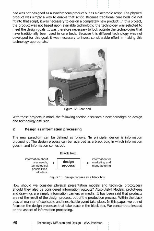
98 Technology Diffusion and Design - W.A. Poelman
bed was not designed as a synchronous product but as a diachronic script. The physical product was simply a way to enable that script. Because traditional care beds did not
the product was not based upon available technology; the technology was selected to meet the design goals. It was therefore necessary to look outside the technologies that have traditionally been used in care beds. Because this diffused technology was not developed for this goal, it was necessary to invest considerable effort in making this technology appropriate.
Figure 12: Care bed
With these projects in mind, the following section discusses a new paradigm on design and technology diffusion.
2 Design as information processing
processing’. The design process can be regarded as a black box, in which information goes in and information comes out.
Black box
designprocess
information aboutuser needs,
technologicalpossibilities,
etcetera.
information formarketing andmanufacturing
Figure 13: Design process as a black box
and drawings are simply information carriers or media. It has been said that products are not the result of the design process, but of the production process. Within the black box, all manner of explicable and inexplicable event take place. In this paper, we do not focus on the design processes that take place in the black box. We concentrate instead on the aspect of information processing.

99Technology Diffusion and Design - W.A. Poelman
could also be a building). As claimed by Kotler (2002), ‘A physical product is just a means to create functions’1. People do not need the physical product; they need the functions that products enable. The physical aspects are generally a necessary evil. The physical aspects occupy space, need maintenance and pollute our world.
disappeared as a physical means for storing and transporting pictures. Consider also communication cables, which have largely been replaced by wireless technology.
2.1 Supply of and demand for information
In the context of this paper, we organise design information into two categories: supply and demand. Starting with the last one, demand information is linked to the ‘design of goals’, which precedes the ‘design of means’. In current times, more products (including buildings) are failing because of defects in the design of goals than because of defects in the design of mean. Although possibilities continue to expand in a technical sense, it
functionalities
functionalities
functionalities
functionalities
functionalities
functionalities
functionalities
functionalities
potentialities
potentialities
potentialities
potentialities
potentialities
potentialities
potentialities
potentialities
properties
properties
technology
objectivefunctions
objectivefunctions
product todesign
Strategic
product plan
Operational
product plan
associationprocess
Figure 14: Product development and the diffusion of technology
In general, goals can be described in terms of objective and subjective functions,2 each of which is realised through functionalities. In this context, functionalities should be interpreted as indivisible functions, such as ‘keeps warm’ or ‘changes colour’. Product functions can generally be described by arranging a large number of functionalities in a tree structure. The design of goals can be described using descriptions of functionalities
On the supply side, technology can enable ‘potentialities’. Although potentialities can
functionalities. The number of potentialities increases at the speed of technological
1 We assume that Kotler included the realization of emotional values in his concept of functions
2 We will not elaborate on these concepts in this context. See Poelman 2005.

100 Technology Diffusion and Design - W.A. Poelman
development. New and interesting potentialities are discovered every day. Although examples can be found in nanotechnology or other disciplines, they occur in nature as well.We could regard the design process as a process of association between the demand side (as expressed in functionalities) and the supply side (as expressed in potentialities). Because it is impossible to make associations with unknown information, we can conclude that designers should have as many potentialities in their minds as possible.
It is important to note that technical background information is not necessary. In the design stage, it is important to know only ‘what might be possible’. It is not necessary to know ‘how it is possible’. More commonly stated, ‘It is enough to have heard the bell
The lack of emphasis on technical explanations is not a matter of which designers and architects should be ashamed, and most of the good ones are not. Nonetheless, even as
from their suppliers (see the glass facade of Neutelings/Riedijk/Drupsteen). Suppliers start by saying that something is impossible, as the costs of doing it differently are
parties. This can result in a better product, ensuring that the supplier then has more to offer.
2.3 Towards a new paradigm for the knowledge-diffusion process
Assuming that designers are able to develop sound designs of goals, and assuming that they have enough knowledge about potentialities at their disposal, the process of matching potentialities and functionalities is the key activity for designers. Although industrial designers should be trained for this task, ‘traditional’ design methodology unfortunately does not provide solutions for such training.
The process of associating functionalities and potentialities involves more than simply a designer sitting and thinking. It is a complex process involving many media, people and organisations. It cannot be explained by traditional organisation models. Many sub-processes can be distinguished that usually have nothing to do with the design process itself. Analysis of these processes has led to an attempt to use the metaphor of an organism rather than an organisation to describe the general process. The difference can be explained as follows. An organisation is created to enable a process and often more than one process. In contrast, an organism is not created but evolved, and it is dedicated to
In nature, even in one-celled creatures, we can observe processes taking place in an
an organism can be seen as two sides of the same coin. The process is the diachronic organisation of activities. The organism is the synchronic, functional organisation that

101Technology Diffusion and Design - W.A. Poelman
Figure 15: Relation between method and organization
out the design process. Every interviewee in this preliminary research expressed in their own words that the situation is much more complex. Many efforts have been made to describe the external design organisation in traditional schemes (Poelman 2005). In general, but cover only part of the situation.
Let us analyse the process of knowledge diffusion. Assuming that some kind of organism is carrying out this process, we considered the possibility of using metaphors from other domains to describe the organism. This exercise resulted in the knowledge metabolism model.
Figure 16: Model of knowledge metabolism for development projects

102 Technology Diffusion and Design - W.A. Poelman
DesignProcesses
In this model, a set of mechanisms can be distinguished, which can be projected onto the eight cases. Before presenting this projection, we must explain the one-celled organism that represents a design project (not a design company).
Each project has a strategic level (1), a tactical level (2) and an operational level (3). 1. The strategic level represents ‘know-what’. It is the planning level, which can be compared to DNA. When something is wrong with the DNA of the project, it will fail or lead to an unexpected outcome. Such outcomes are sometimes better than expected. After all, evolution is partly based upon imperfections in copying genes. Naturalis in Leiden has probably become more successful because the planning changed from city centre to the outskirts.
tactical or ‘know-how’ level (second level). At this level, skills are developed that can be compared to the proteins in a biological cell. As before, the biological organism represents the project as a whole and not the design company. Skills represent both the skills within the design company and those of every involved party. One important skill of the design company, however, is to involve the right parties. This proved a crucial aspect in nearly every case. According to Neutelings-Riedijk, ‘We do not have preferred supplier. Companies involved in creating a building can be compared to a travelling circus. One moment, they are all there with their knees in the Dutch clay; the next moment, they are all gone, back to where they came from’. 3. The real work of design takes place at the third level: the operational or ‘know-where’
operational level, output information is produced and packaged in such media as texts, drawings, models or computer simulations.
‘organism’. This process is freely derived from research done by Hargadon (1997) in IDEO, an international design agency. Hargadon discovered that, as soon as knowledge
application and recording. The interpretation in this model is as follows:
the actual transfer of knowledge Generalisation: potentialitiesAssociation:
analysis)Application: the integration of knowledge in industrial product designRecording: preparation of information for later use, in which the
breaking down the process into ‘leads’, ‘follow-up’ and ‘transfer’. This breakdown is borrowed from the discipline of direct marketing. Because it is impossible provide the
that particular prospects might be interested (e.g. they returned a reply card. After prospects have shown interest in the product, it is necessary to follow up in order to learn whether they are truly interested. The third phase, the transfer of the order, is of course the most important.

103Technology Diffusion and Design - W.A. Poelman
all of the information in the world in a given project. Leads (or potentialities) are
not be successful. Designers should be skilled in motivating suppliers to provide more information and invest in the project.
In the third step, knowledge transfer, learning and engineering capabilities become important. While any of the cases could be used to illustrate these steps, let us consider the media building of Neutelings-Riedijk. One (external) party in the project team was Jaap Drupsteen, an expert in exploiting the potentialities of new technology. He knew
This lead was followed up with visits to companies who could accomplish this. The
Drupsteen competed with economic goals of the glass producer. Drupsteen is skilled in translating potentialities (the tricks that we know) into visually spectacular effects. With respect to recording, according to Neutelings-Riedijk, all knowledge is common knowledge in architecture.
As mentioned above, having leads is an important selection criterion for knowledge
‘constraints’. Constraints operate in both positive and negative ways. One negative function is that they can prevent useful knowledge from coming through. A positive effect of constraints is that they can serve a pre-selection function. Knowledge that triggers no interest will not be processed and will thus be prevented from entering.
a former CEO of a chemical company, Prof. Johannes Eekels advised using piping as a
Valve:the project, as with an embargo on speaking with certain companies. Such valves can
between governmental parties and companies. Intellectual property (IP) considerations form another common reason for blocking knowledge transfer.
Narrowing: of the project, as illustrated by a lack of capacity. There is no time for reading. The stacks of information that we wish to consume increase throughout the course of our careers.
Semi-permeable membrane: A semi-permeable membrane is a mechanism that selectively prevents knowledge from coming through, as in the case of marketing
people tend to defend their own areas of specialisation.
One-way valve: A one-way valve is a mechanism lets knowledge through in only one direction (e.g. from source to recipient); no information is provided to information sources about information needs. Students should be told about the importance of a ‘win-win’ situation. One receives information only when one provides information. In order to understand the kind of information that is of interest to a particular contact, it is essential to be interested in the activities and opinions of that contact.
Filter:

104 Technology Diffusion and Design - W.A. Poelman
mechanism is widely familiar. Faced with the choice between a two-page article and a
that we often do not manage to read the more profound materials.
Labyrinth:
person). A familiar example involves magazine issues that arrive on an employee’s desk half a year after publication.
Leakage: that do not function properly). Because knowledge is a crucial asset of a company, the leakage of knowledge is a severe crime, and guilty parties should be punished. Jan Pesman (CePeZed) states, ‘All knowledge that is gained is stored in the project and for use in future projects. This knowledge increases the toolbox. Every project is a learning process, and the key moments from this process can be reused at any moment – even
Compatibility: Compatibility is a mechanism that prevents information from diffusing (e.g. the extent to which the source and the recipient of the knowledge are able to communicate). This is probably the most interesting constraint in this world of polarisation. Every discipline has its own language, culture and set of ontologies. Although this is often perceived in a negative light, the successful development of disciplines depends upon these aspects.
The successful diffusion of multi-disciplinary knowledge can be stimulated by paying more attention to the interface between disciplines –the designer. Designers should
than one jargon and feel empathy with professionals from other disciplines.
With regard to the organism in Figure 16, two concepts have yet to be discussed:
knowledge diffusion within a project. A project is not a closed entity; it develops itself in a cosmonomy, as represented in Figure 3.
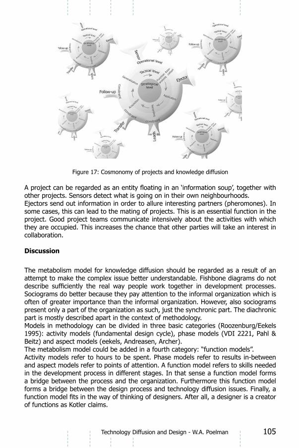
105Technology Diffusion and Design - W.A. Poelman
Figure 17: Cosmonomy of projects and knowledge diffusion
other projects. Sensors detect what is going on in their own neighbourhoods. Ejectors send out information in order to allure interesting partners (pheromones). In some cases, this can lead to the mating of projects. This is an essential function in the project. Good project teams communicate intensively about the activities with which they are occupied. This increases the chance that other parties will take an interest in collaboration.
Discussion
The metabolism model for knowledge diffusion should be regarded as a result of an attempt to make the complex issue better understandable. Fishbone diagrams do not
Sociograms do better because they pay attention to the informal organization which is often of greater importance than the informal organization. However, also sociograms present only a part of the organization as such, just the synchronic part. The diachronic part is mostly described apart in the context of methodology.Models in methodology can be divided in three basic categories (Roozenburg/Eekels 1995): activity models (fundamental design cycle), phase models (VDI 2221, Pahl & Beitz) and aspect models (eekels, Andreasen, Archer).The metabolism model could be added in a fourth category: “function models”. Activity models refer to hours to be spent. Phase models refer to results in-between and aspect models refer to points of attention. A function model refers to skills needed in the development process in different stages. In that sense a function model forms a bridge between the process and the organization. Furthermore this function model forms a bridge between the design process and technology diffusion issues. Finally, a
of functions as Kotler claims.

106 Technology Diffusion and Design - W.A. Poelman
With respect to the relation between architecture and industrial design engineering we
the two disciplines. Industrial designers and architects meet each other more and more in the cosmonomy of development projects such as the creation of new buildings, transport facilities and the composition of public space. Knowledge of the two disciplines has, since the 40 years of existence of the faculty of industrial design engineering become more and more complementary. It is time for intensifying knowledge diffusion between the two disciplines.
ReferencesPoelman, W.A. (2005,) Technology Diffusion in Product Design, thesis, Chair
Design for Sustainability, Delft University of Technology, DelftKotler, Ph. (2002), Marketing Management.Analysis Planning & Control, 11th
edition, Prentice Hall International, London Hargadon, Andrew & Sutton, Robert I. (1997). “Technology Brokering and
Innovation in a Product Development Firm”. Administrative Science Quarterly, vol. 42, December, p 716-749.
Payens, Ruud. (1996). Het Zesde Zintuig, Stichting Innovatiecentrum Noord & Oost Gelderland, Apeldoorn.
Roozenburg, N.F.M. & Eekels, J. (1995), Industrial Product Design: Fundamentals and Methods, Wiley , New York

107
IDE+ADesign Processes - Wim Poelman and David Keyson (Eds.)
IOS Press, 2008 © 2008 The authors and IOS Press. All rights reserved.
Closing Speech

109
8 Closing Speech 6 June 2008 IDE+A symposium “Design Processes”
Prof. dr. ir. A.C.J.M. Eekhout on behalf of the dean of the faculty of architecture.
The literal meaning of this is to make the invisible preparation process, which precedes the production of new building and industrial products and components, visible and understandable by a textual and visual description.
making the invisible visible also means to partly unravel the mysterious, the unknown and the unsaid and pass it on to architects, building technologists, industrial designers and to students as a new knowledge and insight. The mysterious brings along some uncertainty about objectives. Mysteries are challenging, they are a motivation to go and do research and therefore, as far as I am concerned, they never need to be solved completely. When one mystery is solved, new mysteries will have to appear, new challenges, ever further on the way to the future. Yet, in the meantime knowledge grows, the skill, the insight and hopefully also the vision on the specialism of product design and development. Dutch Design and Dutch Architecture are internationally appreciated for its powerful
Dutch architects and industrial designers often have to ‘dance on the rope’. Solid
Architecture.
This Conference Design Processes is dedicated to the methodology and processes of designing, developments and research of building and industrial products, systems and components, as well as to the applications of industrial products in buildings. Therefore, it is of importance to product designers and building product developers,who are mainly concerned with developing products and components at the side of producers, as well as to materializing architects and component designers who, at the
building concept as a whole and in parts.
and Industrial Design Engineering, but also for professionals and students in the
Design Methodology
Design Methodology has a long and thorough history at industrial design Engineering, thanks to the books of Norbert Roozenburg and the late Johannes Eekels. In architecture the situation is more varied. There is a lot of talk on designing in the architectural world, but there seems to be little openness and uniformity when it comes to the process of designing and what design methods are being used.
even conceptual design possibilities are being carefully explored.

110
But the systematics and methodology of design have to go through a renaissance before the full fruits of the computer in the conceptual designing process can be gathered. In my observation design methodologies in architectonical designing are only reluctantly used and there is hardly any systematical and methodical account for the originating process of the design. Indeed, the bridge between the non-cognitive intuitive design process and the ultra-systematic computer as a potential design medium, is missing. So then the computer
It facilitates the drawing, but not the thinking. And, therefore, it cannot be inserted as a full valued reciprocal design medium which is stimulating from self-esteem. To make considerations explicit, as is done with methodical designing, does not just advance insight and clarity in one’s own activities. In practice it stimulates the communication between the ever growing group of professionals which has to co-operate in a building
Design PhasesMethodologists speak of a of conceptual design because of the 3-D concept with its degree of abstraction, leaving many liberties to choose materials and sub-systems the architect has at his disposal.Compared to designers in related technical specialisms (like ship- and aeroplane designers) the architect has an enormous freedom, through the given freedom of choosing structural systems, constructions, structures, building components with their
building. Seldom we realize how jealous other designers could be of him in this respect. In order to make a whole new design concept of his building, the architect has (almost too) many possibilities at his disposal.
The second phase of the process is the materialization design concerns choice of materials, structural schemes and structural composition up to details. The second
situation, the (‘poor’) aircraft designer knows only one or a few degrees of liberty of designing every part of the aeroplane because of the high functional and safety demands. We call this parameter designing: the degree of freedom is only one variation on one single parameter.The leap from the conceptual design to the materialized design mainly takes place in the mind of the designer: sometimes it will be intuitive, often routinely and sometimes methodical. The execution of an intuitive and non-argumented choice and its perfection can, nevertheless, very well be done methodically.
process and the development of materialized and technical building components have become of fundamental importance for the design process of the building. Like the product designer, who usually operates at the side of the producer, a good project architect also knows how far he can go as a consumer of building products in the market and how far he can develop new one-off components to be specially ordered. He should have insight in the iterative development processes for building products, systems and components. The interchangeable relation between technical components and architecture is indispensable for the materialization of the architectonic conceptual design in an inspiring manner.
Closing Speech - A.C.J.M. Eekhout

111
This conference is the fruit of joining hands between the faculties of Industrial Design Engineering and Architecture. Although they started their relationship as a mother and an unwilling daughter, they now seem more like “sisters under the skin”Rudyard Kipling. In the months after the Fire of Architecture the faculty of Industrial Design Engineering is hosting a number of staff, researchers and students from Architecture, for which they are extremely thankful. Hopefully also this regrettable cause will contribute to the
Closing Speech - A.C.J.M. Eekhout

IDE+ADesign Processes - Wim Poelman and David Keyson (Eds.)
IOS Press, 2008 © 2008 The authors and IOS Press. All rights reserved.
Appendix 1
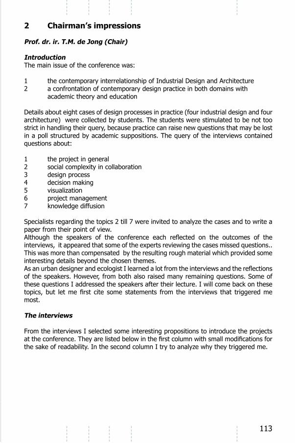
113
2 Chairman’s impressions
Prof. dr. ir. T.M. de Jong (Chair)
IntroductionThe main issue of the conference was:
1 the contemporary interrelationship of Industrial Design and Architecture2 a confrontation of contemporary design practice in both domains with
academic theory and education
Details about eight cases of design processes in practice (four industrial design and four architecture) were collected by students. The students were stimulated to be not too
1 the project in general2 social complexity in collaboration3 design process 4 decision making5 visualization6 project management7 knowledge diffusion
Specialists regarding the topics 2 till 7 were invited to analyze the cases and to write a paper from their point of view.
This was more than compensated by the resulting rough material which provided some interesting details beyond the chosen themes.
most.
The interviews
From the interviews I selected some interesting propositions to introduce the projects
the sake of readability. In the second column I try to analyze why they triggered me.
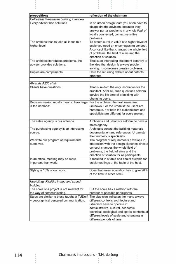
114 Chairman’s impressions - T.M. de Jong

115Chairman’s impressions - T.M. de Jong

116 Chairman’s impressions - T.M. de Jong

117
These propositions already raise many subjects discussed in the conference
Scale (frame and grain)
The larger scale of architecture and urbanism causes may other differences from product design:1. a prominent role of gravity: vertical structures with horizontal
governmental, cultural, economic, technical, ecological and spatial context;
3. small series, many external parties, different by context;4. boundaries of prefabrication by transport possibilities;5. many solutions for the same overall problem: to climatize,
separate or combine activities;6. changing scale changes terms and legend units of the drawing;7. upscaling in space and time affects the composition of the team;8. upscaling decreases decision making based on the size of the
demand and pay-back time.
Shortly after my chairmanship I designed a device to keep straight for scanning from above the pages of differently sized books (see Fig. 1). As an urbanist with a task to teach technical ecology, I wanted to understand the difference of designing at the largest scale form product design by doing:1. In this product gravity plays a role, but not a prominent one
planes, but the vertical structures are mobile.
economic, technical, ecological and spatial contexts.3. There were no external parties, but if it had to be produced in
large series much effort still would have to be done and more parties would have to be involved.
4. There are no boundaries of prefabrication.
Chairman’s impressions - T.M. de Jong

118
5. The problem has a limited number of solutions.6. The character of the legend units are in the range of architecture,
categories and other ways of thinking.7. There was no team, but see 3.8. There was no decision making based on the size of the demand
and pay-back time, but see 3.
Figure 1: A device to keep the pages of differently sized books straight for scanning from above, designed by an ecological urbanist.
I will not summarise the contributions of the speakers here, but I will make some
Social complexity in collaboration
The integration of a group compared to its integration in a larger context is proportional to the time budget they spend internally and exernally. If management askes for many external contacts, the result is sprawl of effort increasing internal entropy.
Design process
A short term goal is a long term means. A goal is a design. So, design cannot be ‘goal directed’. ‘Design directed design’ does not say much. Engineering is design driven research to solve problems risen by design. So, design also raises problems to be solved by engineering. Engineering is the problem solving activity.Design creates improbable possibilities. So, it changes desirable futures, changing the
Solving one problem creates new problems. Reaching one aim creates new goals.
does not solve
Chairman’s impressions - T.M. de Jong

119
Decision making
Visualisation
Schetching is another language.
Project management
Internal integration causes external disintegration and the reverse at any level of scale.Lack of time causes specialisation. Specialisation saves time, integration saves space.
Knowledge diffusion
Discussion
Chairman’s impressions - T.M. de Jong

IDE+ADesign Processes - Wim Poelman and David Keyson (Eds.)
IOS Press, 2008 © 2008 The authors and IOS Press. All rights reserved.
Appendix 2

121
Program
10.00- 10.10 Introduction
Prof. dr. C.J.P.M. de Bont
Dean of the Faculty of Industrial Design Engineering, TU Delft
10.10- 10.30 Explanation Cases
Prof. dr. ir. T.M. de Jong (Chair)
Professor, Chair of Environmental Planning and Ecology
Faculty of Architecture, TU Delft
10.30- 11.00 Design Processes
Dr.ir. H.H. Achten
Assistant Professor, Architectural Modeling
Faculty of Architecture, TU Eindhoven
11.00- 11.30 Coffee/Tea
11.30- 12.00 Visualization
Prof. G. Goldschmidt
Professor,The Mary Hill Swope Chair in Architecture & Town Planning
Faculty of Architecture and Town Planning, Israel Institute of Technology
12.00- 12.30 Project Management
Prof. dr. ir. J.W.F. Wamelink
Professor Design- and Construction
Faculty of Architecture, TU Delft
12.30- 13.30 Lunch

122
13.30- 14.00 Social Complexity in Collaboration
Prof. dr. P.G. Badke-Schaub
Professor Design Theory and Methodology
Faculty of Industrial Design Engineering, TU Delft
14.00- 14.30 Decision Making
Dr. ir. P.P.J. van Loon
Associate professor Design and Decision Systems
Faculty of Architecture, TU Delft
14.30- 15.00 Tea/Coffee
15.00- 15.30 Technology Diffusion
Dr. ir. W.A. Poelman
Associate Professor Product Development
Faculty of Architecture, TU Delft
15.30- 16.00 General Discussion
Prof. dr. ir. T.M. de Jong (Chair)
16.00- 16.10 Afterword
Prof. ir. W. Patijn
Dean faculty of Architecture, TU Delft

This page intentionally left blank

This page intentionally left blank
Related Documents