Arch. Min. Sci., Vol. 60 (2015), No 1, p. 107–121 Electronic version (in color) of this paper is available: http://mining.archives.pl DOI 10.1515/amsc-2015-0008 KRZYSZTOF POLAK*, KAROLINA KAZNOWSKA-OPALA*, KATARZYNA PAWLECKA*, KAZIMIERZ RÓŻKOWSKI*, JERZY KLICH* THE ASSESSMENT OF SUSCEPTIBILITY ON DRAINAGE IN AN AQUIFER ON THE BASIS OF PUMPING TESTS IN A LIGNITE MINE OCENA PODATNOŚCI OŚRODKA WODONOŚNEGO NA ODWODNIENIE NA PODSTAWIE PRÓBNYCH POMPOWAŃ W KOPALNI WĘGLA BRUNATNEGO Drainage of the rock mass is a key component affecting the safety of mining operations and is as- sociated with the removal of the overburden, dumping and excavation of useful minerals. The primary method of drainage in lignite coal mines are bored wells. The efficiency of drainage of rock mass depends on their accurate positioning and quality of workmanship. The paper presents the current state of knowledge concerning the distribution of the components of drawdown (1) in pumping well (Walton, 1955; Bruin & Hudson, 1961; Kruseman & de Ridder, 1991; Avci, 1992; Atkinson, 1994; Helweg, 1994; Kawecki, 1995; Singh, 2002; Dufresne, 2011) and their dependence on the hydrogeological parameters of the drained aquifer (Fig. 2). The results of pumping tests conducted in drainage wells operating in lignite mines are also presented. The subject of analysis was the geohydraulic resistance coefficient B, describing the resistance of the aquifer under laminar flow. This coefficient also takes the hydrogeological parameters into account which determines the dynamics and range of influence of drainage (12, 13). The value of the parameter and its spatial variability can be used for planning, designing and evaluating the effectiveness of wells drainage In view of the results of the pumping tests, classification of aquifer susceptibility to drainage was proposed, which can be used to support decision-making in the scope of expansion of the drainage system, the necessary timing and dynamics of pumping water. The classification is preliminary and is the starting point for the development of methods to rationalize functioning costs of the drainage systems. Keywords: drainage, bored wells, laminar flow, turbulent flow, hydraulic resistance, the aquifer, pore structure, the fractured -karst structure Zadaniem studni odwadniających jest obniżenie zwierciadła wody podziemnej możliwie w jak najkrótszym czasie. W zależności od przeznaczenia studni oraz wymagań technicznych ich czas „życia” jest zróżnicowany. Studnie zlokalizowane w obrębie wyrobiska, tj. studnie nadkładowe i podłożowe (pomocnicze), mają z założenia względnie krótki czas pracy, gdyż są likwidowane wraz z postępem robót górniczych odkrywkowych. Studnie w barierach zewnętrznych oraz wewnętrznych utrzymywane są niekiedy przez kilkadziesiąt lat. * AGH UNIVERSITY OF SCIENCE AND TECHNOLOGY, FACULTY OF MINING AND GEOENGINEERING, AL. A. MICKIE- WICZA 30, 30-059 KRAKOW, POLAND Unauthenticated Download Date | 6/15/15 9:55 AM

Welcome message from author
This document is posted to help you gain knowledge. Please leave a comment to let me know what you think about it! Share it to your friends and learn new things together.
Transcript
Arch. Min. Sci., Vol. 60 (2015), No 1, p. 107–121Electronic version (in color) of this paper is available: http://mining.archives.pl
DOI 10.1515/amsc-2015-0008
KRZYSZTOF POLAK*, KAROLINA KAZNOWSKA-OPALA*, KATARZYNA PAWLECKA*, KAZIMIERZ RÓŻKOWSKI*, JERZY KLICH*
THE ASSESSMENT OF SUSCEPTIBILITY ON DRAINAGE IN AN AQUIFER ON THE BASIS OF PUMPING TESTS IN A LIGNITE MINE
OCENA PODATNOŚCI OŚRODKA WODONOŚNEGO NA ODWODNIENIE NA PODSTAWIE PRÓBNYCH POMPOWAŃ W KOPALNI WĘGLA BRUNATNEGO
Drainage of the rock mass is a key component affecting the safety of mining operations and is as-sociated with the removal of the overburden, dumping and excavation of useful minerals. The primary method of drainage in lignite coal mines are bored wells. The efficiency of drainage of rock mass depends on their accurate positioning and quality of workmanship.
The paper presents the current state of knowledge concerning the distribution of the components of drawdown (1) in pumping well (Walton, 1955; Bruin & Hudson, 1961; Kruseman & de Ridder, 1991; Avci, 1992; Atkinson, 1994; Helweg, 1994; Kawecki, 1995; Singh, 2002; Dufresne, 2011) and their dependence on the hydrogeological parameters of the drained aquifer (Fig. 2).
The results of pumping tests conducted in drainage wells operating in lignite mines are also presented. The subject of analysis was the geohydraulic resistance coefficient B, describing the resistance of the aquifer under laminar flow. This coefficient also takes the hydrogeological parameters into account which determines the dynamics and range of influence of drainage (12, 13). The value of the parameter and its spatial variability can be used for planning, designing and evaluating the effectiveness of wells drainage
In view of the results of the pumping tests, classification of aquifer susceptibility to drainage was proposed, which can be used to support decision-making in the scope of expansion of the drainage system, the necessary timing and dynamics of pumping water. The classification is preliminary and is the starting point for the development of methods to rationalize functioning costs of the drainage systems.
Keywords: drainage, bored wells, laminar flow, turbulent flow, hydraulic resistance, the aquifer, pore structure, the fractured -karst structure
Zadaniem studni odwadniających jest obniżenie zwierciadła wody podziemnej możliwie w jak najkrótszym czasie. W zależności od przeznaczenia studni oraz wymagań technicznych ich czas „życia” jest zróżnicowany. Studnie zlokalizowane w obrębie wyrobiska, tj. studnie nadkładowe i podłożowe (pomocnicze), mają z założenia względnie krótki czas pracy, gdyż są likwidowane wraz z postępem robót górniczych odkrywkowych. Studnie w barierach zewnętrznych oraz wewnętrznych utrzymywane są niekiedy przez kilkadziesiąt lat.
* AGH UNIVERSITY OF SCIENCE AND TECHNOLOGY, FACULTY OF MINING AND GEOENGINEERING, AL. A. MICKIE-WICZA 30, 30-059 KRAKOW, POLAND
UnauthenticatedDownload Date | 6/15/15 9:55 AM
108
Z upływem czasu w pompowanych otworach obserwuje się przyrost depresji roboczego zwierciadła wody oraz spadek wydajności. Mniejsza wydajność studni spowodowana jest zmniejszoną wydajnością war-stwy wodonośnej wskutek słabnącej przewodności hydraulicznej, co wynika z obniżenia zwierciadła wody, a także w wyniku zmian w dopływie wody spowodowanych procesami starzenia otworów studziennych.
Za niekorzystne zmiany parametrów eksploatacyjnych studni odpowiedzialne są m.in. procesy fizyczne i chemiczne zachodzące w bezpośrednim sąsiedztwie studni np. procesy korozji, powstawania powłok zabezpieczeniowych oraz powłok śluzowych, ochry, wytrącania się osadów związków chemicznych oraz kolmatacji. Kolmatacja jest zjawiskiem złożonym, wywołanym przez procesy mechaniczne, fizyczne, chemiczne i biologiczne, który towarzyszy przepływowi przez ośrodki porowe i szczelinowe.
Straty ciśnienia wynikające z przepływu wody w warstwie wodonośnej, czyli kształtowane przez własności hydrogeologiczne warstwy wodonośnej są określane mianem depresji rzeczywistej, która uwi-dacznia się pomiędzy poziomem piezometrycznym i depresją w strefie przyotworowej. Straty te oznaczane są jako BQ, gdzie: B oznacza oporność hydrauliczną ośrodka wodonośnego przy przepływie laminarnym.
Z kolei straty ciśnienia wywołane przepływem wody przez filtr turbulencją przepływu wody w strefie otworowej i przyotworowej określane są mianem zeskoku hydraulicznego CQn, gdzie C oznacza oporność hydrauliczną strefy przyotworowej, natomiast n – wykładnik potęgowy charakteryzujący rodzaj przepływu.
Określenie własności filtracyjnych warstwy wodonośnej wyrażanych przez przewodność hydrau-liczną T oraz współczynnik zasobności sprężystej S, pozwala na wyznaczenie najbardziej korzystnych warunków eksploatacji studni. Wspomniane parametry hydrogeologiczne są składowymi równania opisu-jącego hydrauliczną oporność ośrodka wodonośnego (12). Uogólniając, parametr B, może być kryterium wykorzystanym przy planowaniu i projektowaniu systemu odwodnienia studziennego, a także bieżącej oceny skuteczności współpracy systemu. Na rysunku 3. przedstawiono ideowo metodykę oznaczania tego parametru, za pomocą testu próbnego pompowania.
Dotychczas interpretacja wyników próbnych pompowań koncentrowała się na ocenie technicznych warunków pracy otworów studziennych. W tym celu wykorzystywano współczynnik C występujący we wzorze Jacoba, który stanowił kryterium odbioru studni od wykonawcy. Zdaniem autorów niniejszej pracy wyniki próbnych pompowań należy interpretować w szerszym ujęciu, zwracając uwagę na para-metr B, opisujący oporność hydrauliczną przy przepływie laminarnym wody w ośrodku wodonośnym. Analiza rozkładu przestrzennego zmian tego parametru pozwala na racjonalizację systemu odwodnienia studziennego w tym ocenę niezbędnych wyprzedzeń w zakresie wykonawstwa studni.
W praktyce, ocenę geohydraulicznych warunków prowadzonego odwodnienia przeprowadzono przy wykorzystaniu zmodyfikowanej metody próbnych pompowań wielostopniowych opracowanych przez Klicha (1997). W pracy niniejszej przedstawiono wyniki próbnych pompowań w 27 studniach pracujących w kopalni odkrywkowej węgla brunatnego.
Na rysunkach 5-9 przedstawiono wyniki oceny parametru B dla podstawowych kompleksów wodono-śnych, dla których wykonano próbne pompowania badawcze. Podział wykresów wynika z przeznaczenia studni, co odpowiada podziałowi przedstawionemu na rysunku 4.
Uzyskane wyniki pozwalają na sformułowanie wstępnych uogólnień. W tabeli 1. zaproponowano wstępną klasyfikację podatności ośrodka wodonośnego na prowadzone odwodnienie. Klasyfikacja może być wykorzystana do celów planowania, projektowania oraz bieżącej oceny skuteczności odwadniania studziennego.
Wyniki oceny parametru B wskazują na zmienne warunki hydrogeologiczne w badanych komplek-sach wodonośnych. W utworach wodonośnych o strukturze porowej oporność hydrauliczna B wykazuje stosunkowo małą zmienność (Rys. 7 i 8). Natomiast dużą zmienność własności wykazują utwory szczelino -wo-krasowego kompleksu mezozoicznego. Odwodnienie prowadzone przez system studzienny może zatem charakteryzować się zmienną efektywnością w poszczególnych rejonach kopalni odkrywkowej (Rys. 5 i 6).
Słowa kluczowe: odwadnianie, studnie wiercone, przepływ laminarny, przepływ turbulentny, oporność hydrauliczna, ośrodek wodonośny, struktura porowa, struktura szczelinowo-krasowa
1. Introduction
The task of drainage wells is to decreasing the water table in the shortest possible time. Their “life” time is varied depending on the purpose of the well and its technical requirements. Wells located in proximity of the excavation, i.e. overburden and substrate (secondary) wells are
UnauthenticatedDownload Date | 6/15/15 9:55 AM
109
assumed to have relatively short operating time. Wells with fixed internal and external barriers sometimes work for several dozen years.
Over time an increase has been noted in the drawdown of the working water table as well as a decrease in performance of the pumped boreholes. The lower productivity of wells is caused by the reduced capacity of the aquifer as a result of the decreasing of hydraulic conductivity due to declining of the water table, as well as the result of changes in water supply due to the aging process of wells . The appearance of hydraulic flow losses through the filter is directly linked to a reduction in the efficiency of the wells. Growth of inlet velocity occurs in the cone of depression in situations whereby well productivity is not reduced together with the lowering of the water level.
Physical and chemical processes occurring in the immediate vicinity of the wells, e.g. cor-rosion processes, the formation of protective and mucous coating, ocher, precipitation chemicals and sludge clogging are all responsible for the unfavorable changes in operating parameters of the wells. Clogging is a complex phenomenon caused by mechanical, physical, chemical and biological processes, which accompanies flow through the porous and fractured medium. Loss of aquifer particle concentration, and the increase of these particles in porous of gravel pack, leads to a reduction of porous space, which in turn leads to a decrease in the productivity and reduces the permeability of the well (Trzaska & Broda, 2000; Houben & Treskatis, 2003; Trzaska et al., 2005). The work of Motyka and Wilk (1986) attempts to determine the turbulence zone within a radius around the pump hole, which can accelerate clogging.
Clogging in the filter zone of well affects the increase of head loss. Head loss is a naturally occurring phenomenon in each hydrogeological borehole. Reducing the permeability at the filtration zone in time causes an increase in energy losses when pumping liquid and rise a water flow velocity resulting in further acceleration of mechanical clogging. Research suggests that the amount of clogging is a function of flow velocity (De Zwart et al., 2008).
In the case of drainage wells, whose task is to drain the water out of the rock mass, an increase in head loss causes the required water level in the aquifer to be attained by forcing the generation of so-called apparent drawdown in the well. Therefore apparent drawdown is the sum of drawdown in the aquifer and head loss at the filter zone (1).
Clogging processes are more dynamic in mining wells due to the extreme conditions of their work. It causes, that maintaining the actual drawdown in the aquifer reflects to increase the apparent drawdown inside the well. Reducing the head loss can be done by stable work of wells during whole time of operation, which allows for gradual and stable lowering of the water table at the aquifer. Such conditions can only be achieved by maintaining adequate head loss on the filter, i.e. during a laminar flow of water in the aquifer.
In order to prolong the “life” of the well while maintaining the best possible operational effectiveness and to reduce the energy consumption of pumping, wells should not work under turbulent flow conditions in the aquifer (13). This causes a movement of lifting the rock particles and their deposition on the filter resulting in, as previously mentioned, reduced filter permeability. However it must be recognized that such conditions are acceptable for wells:
• working within the structures of fractured-karst and tectonic zones,• being in the last period of operation, whose time of “life” is relatively short (e.g. over-
burden wells).
Drainage wells are constructed most frequently in the cone of depression, where water table is declining. It may cause deterioration of the well quality as any leaking drilling fluid during the boring of wells will affect the clogging at the damage zone.
UnauthenticatedDownload Date | 6/15/15 9:55 AM
110
The natural process is increased the resistance of damage zone expressed as parameter C in consequence of wells ageing and declining of water table.
In a system of drainage, wells operate in groups. Inflow to the individual wells is subject to conditions of wells interacting with each other. Interference of wells causes, that confined conditions change into unconfined. Consequence of this processes is declining the aeration zone. With the increase of drawdown there is a resultant change of hydrogeological parameters which usually increases hydraulic friction and reduces unit outflow q.
Pressure losses resulting from the water flow in the aquifer, shaped by the hydrogeological characteristics of the aquifer, are called real drawdown, which emerges between the piezometric level and drawdown at the filter zone. These losses are referred as BQ, whereby B is the hydraulic resistance of the aquifer under laminar flow.
In turn, the pressure losses caused by the flow of water through the filter is referred as head loss CQn, whereby C represents the hydraulic resistance at the filter zone, and the n – exponent characterizing the type of flow.
2. Components of depression
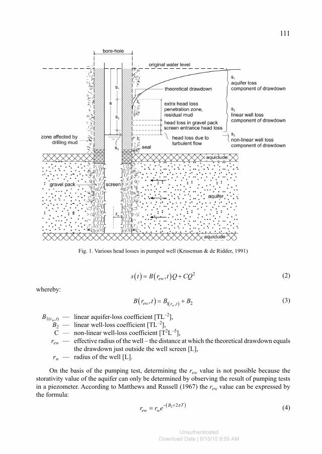
The value of total drawdown in the well (Fig. 1) after time t of pumping covers drawdown in the aquifer as well as the drawdown caused by the flow of water through the gravel pack and well filter, that is head loss. Assuming that the aquifer is homogeneous, isotropic and confined in an infinite range, the flow of water through the layer is determined and the pumping rate Q is constant, lowering the water table in the well s(t) can be described by the equation (Atkinson, 1994; Helweg, 1994; Avci, 1992; Kawecki, 1995; Williams, 1985):
1 2 3s t s s s (1)
where: s(t) — total drawdown measured in the well [L], s1 — laminar loss in the aquifer [L], s2 — laminar loss in the damage zone [L], s3 — turbulent loss in the filter zone and well losses [L], t — pumping time [T].
Equation (1) s1 expresses the drawdown in the aquifer caused by a laminar water flow, s2 expresses drawdown at the damage zone, in which the flow is generally in the laminar system, and s3 represents the drawdown caused by the turbulent flow by the filter zone.
In accordance with Jacob’s assumption, flow in the near filtration zone is turbulent regardless of pumping efficiency, that is why the exponents in formula (2) takes the value n = 2. However, according to Rorobaugh’s assumptions, this zone has a variable size expanding centrally with the increase of outflow. Larger outflow conditioning the turbulent flow zone causes proportional resistance to the power of outflow n > 2.
In detailing the equation entry (1) according to Jacob’s assumptions to form (2) it shows that the size of the drawdown in the aquifer comprises a drawdown caused by the laminar flow through the aquifer and the damage zone as well as drawdown caused by turbulent flow by the filter zone and the well screen (Kruseman & de Ridder, 1991; Kawecki, 1995; Dufresne, 2011):
UnauthenticatedDownload Date | 6/15/15 9:55 AM
111
2,ews t B r t Q CQ (2)
whereby:
21 ,,wew r tB r t B B (3)
B1(rw,t) — linear aquifer-loss coefficient [TL–2], B2 — linear well-loss coefficient [TL–2], C — non-linear well-loss coefficient [T2L–5], rew — effective radius of the well – the distance at which the theoretical drawdown equals
the drawdown just outside the well screen [L], rw — radius of the well [L].
On the basis of the pumping test, determining the rew value is not possible because the storativity value of the aquifer can only be determined by observing the result of pumping tests in a piezometer. According to Matthews and Russell (1967) the rew value can be expressed by the formula:
2 2B T
ew wr r e (4)
Fig. 1. Various head losses in pumped well (Kruseman & de Ridder, 1991)
UnauthenticatedDownload Date | 6/15/15 9:55 AM
112
For unsteady flow conditions, the total drawdown in the well after pumping time t can be expressed by the equation (Singh, 2002; Walton, 1955):
a ws t s t s t (5)
where the sa value can be expressed by the Theis formula (1935) as:
1as t Q W u (6)
and:
11
4 T
(7)
2u
t
(8)
2
2 4ewr ST
(9)
u
u
eW u duu
(10)
while the head loss sw can be described by the formula:
3 3, n
ws t Q t C (11)
In accordance with the above, the value of factor B can be expressed by the equation (Avci, 1992):
2
1 2.25ln4 ew
TtB tT r S
(12)
whereby: T — transmissivity [L2T –1] S — storage capacity
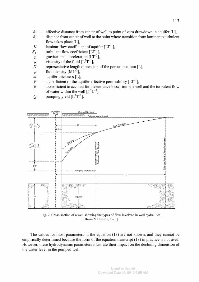
According to Bruin and Hudson (1961) the theoretical drawdown in the water well after predetermined pumping time t taking into account all the parameters affecting the size can be expressed by the formula (Fig. 2):
22
21 1ln i
t w t
RQ Qs t EQR r R
(13)
whereby:
β = Kμ2g (14)
α = D2ρ (15)
δ = 2πmP (16)
γ = K1D2g (17)
UnauthenticatedDownload Date | 6/15/15 9:55 AM
113
Ri — effective distance from center of well to point of zero drawdown in aquifer [L], Rt — distance from center of well to the point where transition from laminar to turbulent
flow takes place [L], K — laminar flow coefficient of aquifer [LT–1], K1 — turbulent flow coefficient [LT–1], g — gravitational acceleration [LT–2], μ — viscosity of the fluid [L2T–1], D — representative length dimension of the porous medium [L], ρ — fluid density [ML-3], m — aquifer thickness [L], P — a coefficient of the aquifer effective permeability [LT–1], E — a coefficient to account for the entrance losses into the well and the turbulent flow
of water within the well [T2L–5], Q — pumping yield [L3T–1].
Fig. 2. Cross-section of a well showing the types of flow involved in well hydraulics (Bruin & Hudson, 1961)
The values for most parameters in the equation (13) are not known, and they cannot be empirically determined because the form of the equation transcript (13) in practice is not used. However, these hydrodynamic parameters illustrate their impact on the declining dimension of the water level in the pumped well.
UnauthenticatedDownload Date | 6/15/15 9:55 AM
114
According to equation (2) and (13), and assuming (14)-(17) coefficient B depends on:
ln i
t
RB
R
(18)
whereas C:
2
1 1
tC E
r R
(19)
Values B and C in equation (2) are fixed parameters, wherein the simplifying assumption is that, as is apparent from equation (13) the size of R is determined by the pumping discharge rate Q. Therefore, to compensate for the variation of parameter Rt, Rorabaugh proposed input to equation (2) exponent n, greater than 2. In practice, the value of parameter B becomes steady after a sufficient pumping period with performance Q.
3. Coefficient B
Determining the filtration properties of aquifer expressed by the transmissivity T and hy-draulic properties i.e. coefficient of permeability K and storativity S allows for the determination of the most favourable conditions for the operation of the wells, since parameter B expresses, among other, the degree of interaction of the well, and its value is greater, the higher the interfer-ence between the wells.
The low value of the parameter means that the well works in the aquifer with significant hydraulic conductivity T, and cone of depression is not deep and has a large range horizontally. Such wells are characterized by a significant inflow, and for the purpose of inducing the water table declining, the time factor is important. In the case of small increments of drawdown of the water table vertically, it is necessary to increase overall efficiency, which may mean the neces-sity to bore further wells.
In the case of small increases the drawdown of the water table (verified in piezometers), the high value of parameter B represents a small range of well influence. The lack of progress in drainage requires density of well nets.
From the above considerations it appears that parameter B, which expresses the hydraulic resistance of the aquifer, can be the criterion used in planning and designing a drainage system, as well as ongoing assessment of the effectiveness of system interaction.
3.1. Measurement Method
The evaluation of geo-hydraulic conditions of drainage was performed using a modified test method of multi-stage pumping developed by Klich (1997).
Multistage pumping is conducted in unsteady flow conditions, when there is no possibility of measuring the observation holes. Such pumping is brief which shortens the period of study to about a few hours. Multistage pumping is carried out from a minimum to maximum capac-ity of a pump motor built-in the well. Efficiency should be differentiated by leaps and bounds as the number of degrees of trial pumping affect the significance of the results of calculations. Interpretation of the results of multistage pumping using the Klich method does not allow for
UnauthenticatedDownload Date | 6/15/15 9:55 AM
115
the assessment of hydrogeological parameters, but determines the value of hydrogeological parameter B and hydraulic parameter C.
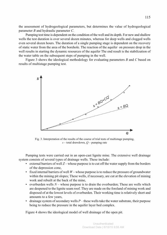
Pumping test time is dependent on the condition of the well and its depth. For new and shallow wells the test duration is over several dozen minutes, whereas for deep wells and clogged wells even several dozen hours. The duration of a single pumping stage is dependent on the recovery of static water from the area of the borehole. The reaction of the aquifer on pressure drop in the well results in starting the dynamic resources of the aquifer The end result is the stabilization of the water table on the subsequent steps of pumping in the well.
Figure 3 shows the ideological methodology for evaluating parameters B and C based on results of multistage pumping test.
Fig. 3. Interpretation of the results of the course of trial tests of multistage pumping, s – total drawdown, Q – pumping rate
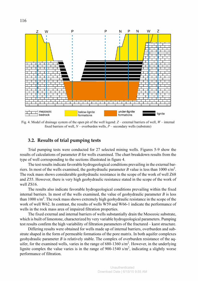
Pumping tests were carried out in an open-cast lignite mine. The extensive well drainage system consists of several types of drainage wells. These include:
• external barriers of well Z – whose purpose is to cut off the water supply from the borders of the depression cone,
• fixed internal barriers of well W – whose purpose is to reduce the pressure of groundwater within the mining pit slopes; These wells, if necessary, are cut at the elevation of mining work and rebuilt at the back of the mine,
• overburden wells N – whose purpose is to drain the overburden; These are wells which are deepened to the lignite seam roof. They are made on the foreland of mining work and disposed of at the lowest levels of overburden. Their working time is relatively short and amounts to a few years,
• drainage system of secondary wells P – these wells take the water substrate, their purpose being to reduce the pressure in the aquifer layer bed complex.
Figure 4 shows the ideological model of well drainage of the open pit.
UnauthenticatedDownload Date | 6/15/15 9:55 AM
116
3.2. Results of trial pumping tests
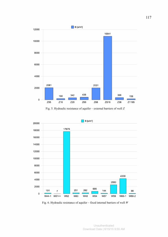
Trial pumping tests were conducted for 27 selected mining wells. Figures 5-9 show the results of calculations of parameter B for wells examined. The chart breakdown results from the type of well corresponding to the sections illustrated in figure 4.
The test results indicate favorable hydrogeological conditions prevailing in the external bar-riers. In most of the wells examined, the geohydraulic parameter B value is less than 1000 s/m2. The rock mass shows considerable geohydraulic resistance in the scope of the work of well Z68 and Z55. However, there is very high geohydraulic resistance stated in the scope of the work of well ZS16.
The results also indicate favorable hydrogeological conditions prevailing within the fixed internal barriers. In most of the wells examined, the value of geohydraulic parameter B is less than 1000 s/m2. The rock mass shows extremely high geohydraulic resistance in the scope of the work of well W62. In contrast, the results of wells W59 and W66-1 indicate the performance of wells in the rock mass area of impaired filtration properties.
The fixed external and internal barriers of wells substantially drain the Mesozoic substrate, which is built of limestone, characterized by very variable hydrogeological parameters. Pumping test results confirm the high variability of filtration parameters of the fractured – karst structure.
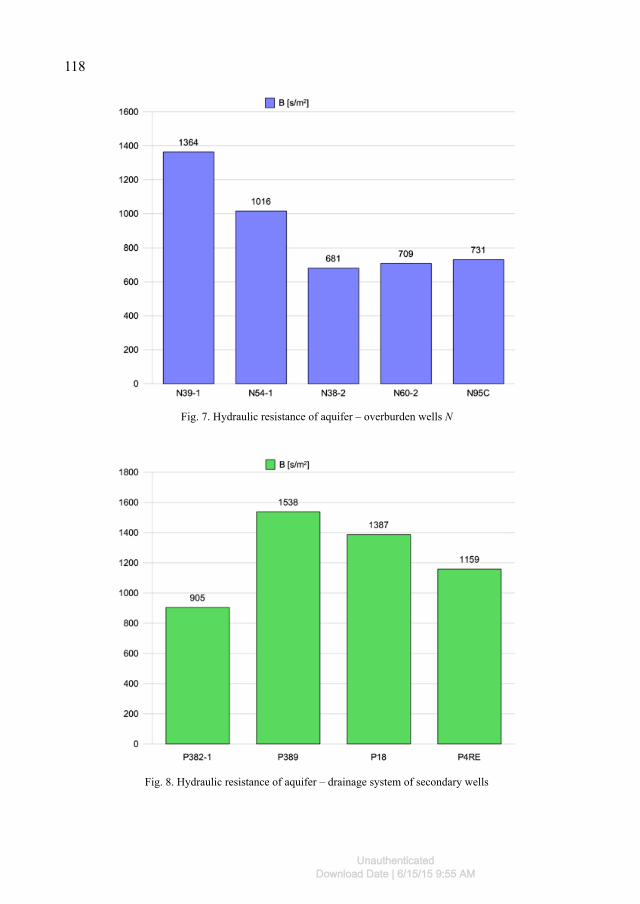
Differing results were obtained for wells made up of internal barriers, overburden and sub-strate shaped in the form of permeable formations of the pore matrix. In both aquifer complexes geohydraulic parameter B is relatively stable. The complex of overburden resistance of the aq-uifer, for the examined wells, varies in the range of 680-1360 s/m2. However, in the underlying lignite complex the value varies is in the range of 900-1540 s/m2, indicating a slightly worse performance of filtration.
Fig. 4. Model of drainage system of the open pit of the well legend: Z – external barriers of well, W – internal fixed barriers of well, N – overburden wells, P – secondary wells (substrate)
UnauthenticatedDownload Date | 6/15/15 9:55 AM
117
Fig. 5. Hydraulic resistance of aquifer – external barriers of well Z
Fig. 6. Hydraulic resistance of aquifer – fixed internal barriers of well W
UnauthenticatedDownload Date | 6/15/15 9:55 AM
118
Fig. 8. Hydraulic resistance of aquifer – drainage system of secondary wells
Fig. 7. Hydraulic resistance of aquifer – overburden wells N
UnauthenticatedDownload Date | 6/15/15 9:55 AM
119
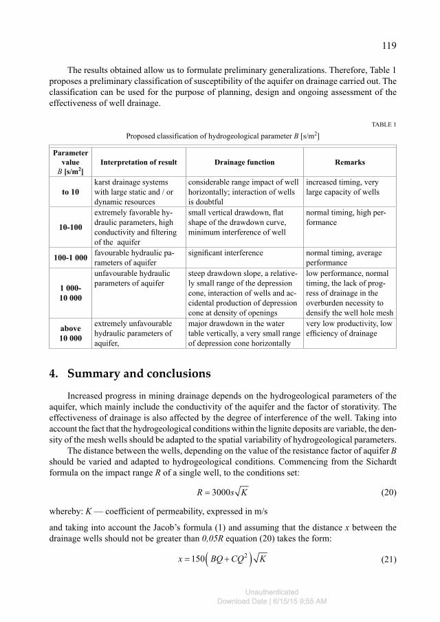
The results obtained allow us to formulate preliminary generalizations. Therefore, Table 1 proposes a preliminary classification of susceptibility of the aquifer on drainage carried out. The classification can be used for the purpose of planning, design and ongoing assessment of the effectiveness of well drainage.
TABLE 1
Proposed classification of hydrogeological parameter B [s/m2]
Parameter value
B [s/m2]Interpretation of result Drainage function Remarks
to 10karst drainage systems with large static and / or dynamic resources
considerable range impact of well horizontally; interaction of wells is doubtful
increased timing, very large capacity of wells
10-100
extremely favorable hy-draulic parameters, high conductivity and fi ltering of the aquifer
small vertical drawdown, fl at shape of the drawdown curve, minimum interference of well
normal timing, high per-formance
100-1 000 favourable hydraulic pa-rameters of aquifer
signifi cant interference normal timing, average performance
1 000-10 000
unfavourable hydraulic parameters of aquifer
steep drawdown slope, a relative-ly small range of the depression cone, interaction of wells and ac-cidental production of depression cone at density of openings
low performance, normal timing, the lack of prog-ress of drainage in the overburden necessity to densify the well hole mesh
above10 000
extremely unfavourable hydraulic parameters of aquifer,
major drawdown in the water table vertically, a very small range of depression cone horizontally
very low productivity, low effi ciency of drainage
4. Summary and conclusions
Increased progress in mining drainage depends on the hydrogeological parameters of the aquifer, which mainly include the conductivity of the aquifer and the factor of storativity. The effectiveness of drainage is also affected by the degree of interference of the well. Taking into account the fact that the hydrogeological conditions within the lignite deposits are variable, the den-sity of the mesh wells should be adapted to the spatial variability of hydrogeological parameters.
The distance between the wells, depending on the value of the resistance factor of aquifer B should be varied and adapted to hydrogeological conditions. Commencing from the Sichardt formula on the impact range R of a single well, to the conditions set:
3000R s K (20)
whereby: K — coefficient of permeability, expressed in m/s
and taking into account the Jacob’s formula (1) and assuming that the distance x between the drainage wells should not be greater than 0,05R equation (20) takes the form:
2150 x BQ CQ K (21)
UnauthenticatedDownload Date | 6/15/15 9:55 AM
120
Assuming the above assumption is right and taking into account the results of pumping tests, the distances determined for each group of wells amounted to:
• external barriers – 150 m• fixed internal barriers – 100 m• overburden barriers – 100 m• secondary substrate wells – 200 m.
Up to now, the interpretation of results of pumping tests focused on assessing the technical working conditions of wells. For this purpose, factor C was used occurring in Jacob’s formula, which was the criterion for accepting the wells from the contractor. According to the authors of this paper pumping test results should be interpreted in a broader sense, paying attention to parameter B, describing the hydraulic resistance of the laminar flow of water in the aquifer. This parameter takes into account the hydrogeological parameters of aquifer. Analysis of spatial distribution of changes in this parameter allows for rationalization of the well drainage system including an assessment of the necessary timing in the construction of the well.
The present work presents the results of pumping tests in 27 wells working in an open pit lignite mine. Evaluation results of parameter B indicate variable hydrological conditions in vari-ous aquifer complexes. In the aquifer formation with pore structure B, hydraulic resistance shows a relatively small variation. The results show that stable hydrogeological conditions within underly-ing and overlying lignite complexes give empowerment to execute the well in regular grid boring.
The results indicate significant Mesozoic aquifer formation. However, there are local distur-bance conditions which manifest themselves in cases of an increase in the value of parameter B. Thus, the rock mass in the scope of operation of some wells has significant hydraulic resistance. It can be concluded therefore that the work of these wells is not justified from the point of view of the effectiveness of drainage. It seems that their possible exclusion does not increase the security risks of mining.
Given the results, it is clear that performance assessment of wells within the Mesozoic should be preceded by a detailed understanding of the hydrogeological conditions, in particular through the use of pilot drilling.
Given the test results from 27 wells, a classification of rock mass susceptibility to drainage was proposed. This classification is preliminary and should be further elaborated in terms of identifying the conditions on the basis of trial test results of multistage pumping.
Acknowledgements
The authors wish to thank PGE Górnictwo i Erergetyka Konwencjolnalna SA, for their sup-port given during the field tests.
References
Atkinson L.C., Gale J.E., Dudgeon C.R., 1994. New Insight into the Step-Drawdown Test in Fractured-Rock Aquifers. Applied Hydrogeology, Vol. 2, No. 1, p. 9-18.
Avci C.B., 1992. Parameter Estimation for Step-Drawdown Tests. Ground Water, Vol. 30, No. 3, p. 338-342.Bruin J., Hudson Jr., H.E., 1961. Selected Methods for Pumping Test Analysis. Illinois State Water Survey W.C. Acker-
mann, Urbana.
UnauthenticatedDownload Date | 6/15/15 9:55 AM
121
De Zwart A.H., Currie P.K., de Boer J., Vafaie Naeini A., Schotting R.J., 2008. Experimental and Theoretical Investi-gation of Clogging Processes Near Production Wells Using X Ray Tomography. Society of Petroleum Engineers. doi:10.2118/116411-MS.
Dufresne D.P., 2011. Developing Better Regional Groundwater Flow Models with Effective Use of Step-Drawdown Test Results. Florida Water Resources Journal, Vol. 63, No. 2, p. 36-40.
Helweg O.J., 1994. A General Solution to the Step-Drawdown Test. Ground Water, Vol. 32, No. 3, p. 363-366.Houben G., Treskatis Ch., 2003. Regenerirrung und Sanierung von Brunnen. Oldenbourg Industrieverlag GmbH, Munchen.Kawecki M.W., 1995. Meaningful Interpretation of Step-Drawdown Tests. Graund Water, Vol. 33, No. 1, p. 23-32.Klich J., Motyka J., Hajdo S., Marek A., Sobczyński E., 1997. Metoda oceny i doboru parametrów technologicznych
studni odwadniających i ujęć wodnych. Załącznik do raportu końcowego z realizacji projektu badawczego KBN – Nr 9S 601 021 06, Poltegor-Instytut Wrocław / AGH Kraków.
Kruseman G.P., de Ridder N.A., 1991. Analysis and Evaluation of Pumping Test Data. Second Etition. International Institute for Land Reclamation and Improvement, Publication 47, Wageningeg, The Netherlands.
Motyka J., Wilk Z., 1986. Zastępczy promień strefy nieliniowej filtracji wokół studni zgłębionej w skałach szczelinowo-krasowych. Archiwum Górnictwa, Vol. 31, No. 2, p. 90-94.
Matthews C.S., Russel D.G., 1967. Pressure buildup and flow tests tests in well. Soc. Petrol. Engrs. of Am. Inst. Min. Met. Enger., Monograph.
Pazdro Z., 1983. Hydrogeologia Ogólna. Wydawnictwa Geologiczne, Warszawa.Singh S.K., 2002. Well Loss Estimation: Variable Pumping Replacing Step Drawdown Test. Journal of Hydraulic Engi-
neering, Vol. 128, No. 3, p. 343-348.Trzaska A., Broda K., 2000. Possibility of Determining Colmatage Parameters and Functions Basing on the Theory of
Colmatage and Experiment. Arch. Min. Sci., Vol. 45, No 4, p. 527-542.Trzaska A., Broda K., Filipek W., Sobowska K., 2005. The Phenomenon of Colmatage and its Effect on the Environment.
Arch. Min. Sci., Vol. 50, Special Issue, p. 43-56.Walton W.C., 1955. Ground-Water Hydraulics as an Aid to Geologic Interpretation. The Ohio Journal of Science,
Vol. 55, No. 13, p. 13-20.Williams D.E., 1985. Modern techniques in well design. Journal American Water Works Association, Allocating Water
Supplies, Vol. 77, No. 9, p. 68-74.
Received: 10 June 2014
UnauthenticatedDownload Date | 6/15/15 9:55 AM
Related Documents


