Ārahi Hoahoa Te Pūtahi o Ōtautahi

Welcome message from author
This document is posted to help you gain knowledge. Please leave a comment to let me know what you think about it! Share it to your friends and learn new things together.
Transcript

Ārahi Hoahoa
Te Pūtahi o Ōtautahi

PAGE 2 | STREETS & SPACES DESIGN GUIDE
Published in [December 2015] by
Canterbury Earthquake Recovery Authority (CERA)Private Bag 4999Christchurch 8140
[email protected] 7464 2372www.cera.govt.nz
ISBNs[978-0-908343-18-8] (print)[978-0-908343-19-5] (online)
Crown Copyright © This work is licensed under the Creative Commons Attribution 3.0 New Zealand licence.

STREETS & SPACES DESIGN GUIDE | PAGE 3
Foreword 4
Purpose 5
How to use this document 6
01. Technical guidance design criteriaStrategic guidance 12
Materials and street furniture selection and set-out criteria 13
Street cross-sections 14
02. Street treatmentsOverview 19
S / Streetscape set-out 20
T / Surface treatments 42
P / Footpath elements and standard details 48
PK / Kerbs 61
PD / Drains 66
03. VegetationOverview 70
VS / Vegetation selection 71
VT / Tree pits 82
VR / Rain gardens - Under Development
04. Street furnitureOverview 91
FS / Seating elements 92
FE / Standalone elements 94
FC / Cycling elements 99
FL / Lighting Elements - Under Development
FW / Wayfinding Elements - Under Development
05. ReferencesTechnical notes index 104
List of figures 106
Photography 107
Further references 109
Contents

PAGE 4 | STREETS & SPACES DESIGN GUIDE
This Technical Guidance book provides the suite of materials, street elements and standard details for streets and public space projects in central Christchurch.
The Technical Guidance book is not intended to replace but rather to complement Christchurch City Council Construction Standard Specifications (CSS) and Infrastructure Design Standards (IDS).
The Technical Guidance book should be read in conjunction with the Strategic Guidance book of the Christchurch Central Streets & Spaces Design Guide.
The Strategic Guidance book provides a design framework to guide the reconstruction of the central city streets and public spaces. It focuses on supporting the delivery of the Christchurch Central Recovery Plan, its anchor projects and transport chapter, An Accessible City.
The Strategic Guidance book is available at:
http://ccdu.govt.nz/the-plan/design-guides
Figure 1 Streets & Spaces Design Guide application area
The CSS can be accessed at:
http://www.ccc.govt.nz/consents-and-licences/construction-requirements/construction-standard-specifications/
The IDS can be accessed at:
http://www.ccc.govt.nz/consents-and-licences/construction-requirements/infrastructure-design-standards/
Foreword
Application area
Legend

STREETS & SPACES DESIGN GUIDE | PAGE 5
This Technical Guidance book has been developed to help realise design, functional, economic and operational benefits for the central city by:
Supporting the delivery of the vision and objectives of the Christchurch Central Streets & Spaces Design Guide.
For example:
• a defined materials and street elements palette will contribute to a city of distinctive identity with a strong sense of place
• the use of similar designs in similar situations will make the city easier to navigate, especially for those with special mobility needs
• a unified design approach will result in a cohesive and well-integrated network of streets and public spaces in the long term, even if projects are built in stages.
Ensuring public realm projects maximise value from infrastructure investment and ongoing asset management efficiencies.
For example:
• a defined palette of materials and street elements will enable economies of scale, making its supply less costly
• a unified design approach will facilitate efficient management and maintenance protocols. As a result, public spaces can be well maintained without unreasonable expense
• a defined suite of materials and street furniture can be pre-tested and proved to perform under demanding conditions, contributing to fit-for-purpose projects
• with a selected suite of materials and street furniture, suitable pieces will be available when replacements are required. In this way the integrity of designs can be effectively preserved.
Scope
The Streets & Spaces Design Guide has been prepared for the area bounded by Park Terrace and Rolleston, Bealey, Fitzgerald, Moorhouse and Hagley avenues. The Streets & Spaces Design Guide does not include Hagley Park. The area to which this Design Guide applies is referred to as the central city or central Christchurch.
While the Streets & Spaces Design Guide focuses specifically on the central city, it has been prepared with regard to the context of greater Christchurch and the values of Ngāi Tahu.
Who is this document for?
This Technical Guidance book has been developed to guide consultant teams, design professionals and anyone involved in designing or delivering public realm projects in central Christchurch.
The technical guidance in this book is applicable in particular to public realm projects that are or will be owned by Christchurch City Council or the Crown.
Purpose

PAGE 6 | STREETS & SPACES DESIGN GUIDE
The Streets & Spaces Design Guide is set out in two books: Strategic Guidance and Technical Guidance.
This Technical Guidance book has five chapters:
Chapter 1 sets out the strategic and technical design criteria that should inform the design of public realm projects in the central city.
Chapter 2 provides the suite of surfacing treatments, their application and standard details.
Chapter 3 outlines the suite of planting elements, their application and standard details.
Chapter 4 provides the suite of street furniture elements and their application.
Chapter 5 includes an index of all the technical notes included in this guide, as well as references to other relevant technical documents.
The Technical Guidance should be read in conjunction with Christchurch City Council (CCC) Construction Standard Specifications (CSS) and Infrastructure Design Standards (IDS) and any other applicable legislation.
This Strategic Guidance book provides the vision, design principles and criteria, along with general concepts that should guide the design of the public realm projects for the central city. The Strategic Guidance book has seven chapters.
Chapter 1 provides the vision and design principles for the central city’s public realm network. It also outlines the value, components and general structure of this network.
Chapter 2 identifies strategic matters that have informed the development of the guidance and concepts set out in the Strategic Guidance book.
Chapter 3 outlines the design criteria that should inform the design of public realm projects in the central city.
Chapter 4 identifies and provides an overview of the gathering places in the central city and how they relate to the anchor projects.
Chapter 5 explains and illustrates plans and design concepts for the central city street network and how they contribute to the implementation of Accessible City.
Chapter 6 describes the public realm component of the anchor projects and identifies important relationships with other anchor projects, gathering places and the street network.
Chapter 7 briefly outlines key aspects for the implementation of public realm projects in the central city.
To make both books as easy as possible to navigate, cross-references to specific topics and interdependencies are included throughout the document.
For example, there is a three-step process to apply the guidance in both books to the individual projects.
1. Understand the strategic approach outlined in Chapter 2 and review the design criteria in Chapter 3 of the Strategic Guidance book. Use these criteria to guide the design process.
2. Identify the public space typology for gathering places in Chapter 4 or the relevant street hierarchy in Chapter 5 of the Strategic Guidance book. Apply relevant design considerations and standards to the design.
3. Use this Technical Guidance book, to select materials, construction details and street furniture.
How to use this document

STREETS & SPACES DESIGN GUIDE | PAGE 7
Figure 2 Strategic Guidance book provides the vision, design principles and criteria, along with general concepts that should guide the design of the public realm projects for the central city
Figure 3 Technical Guidance book provides the suite of materials, street furniture and standard details to be used in public realm projects in the central city
Ārahi Hoahoa
Te Pūtahi o Ōtautahi

PAGE 8 | STREETS & SPACES DESIGN GUIDE
The information in this book has been prepared in the form of technical notes.
A prefix identifying each technical note is located on the top right or left corner of each page, as shown in Figure 4.
The initial characters in the prefix indicate the type of information provided as follows:
‘S’ for the set-out of specific areas within a central city streetscape, such as footpaths and crossings
‘T’ for surface materials and treatments
‘PX’ for elements and standard details that make up the central city footpath palette, where ‘X’ changes depending on the element or detail
‘V’ for vegetation selection and related elements
‘F’ for street furniture elements
When the element or detail illustrated in the technical note has been selected from an existing document or standard, the reference is provided at the end of the text columns as shown in Figure 5.
A list of all the technical notes included in each group is provided at the beginning of Chapter 2 to 4.
An index of all technical notes in the Technical Guidance book is provided in Chapter 5.
How to use this document

STREETS & SPACES DESIGN GUIDE | PAGE 9
COMMENTARY
STA
ND
ARD
PA
GE
Figure 4 Reference elements in a standard page of the Technical Guidance book
CHAPTER & PAGE NUMBER
REFERENCE
IMAGE
PREFIX
PLANS

“Whatever good things we build end up building us.”
Jim Rohn

TECHNICAL GUIDANCE DESIGN CRITERIA

Strategic guidanceThe design of streets and gathering places in the central city should be informed by the design criteria set out in Chapter 3 of the Strategic Guidance book.
Figure 5 Example of a Design Criteria page in the Strategic Guidance book
The design criteria identify key design considerations that will assist in making the vision for the streets and public spaces of central Christchurch a reality.
The Strategic Guidance book is available at http://ccdu.govt.nz/the-plan/design-guides
PAGE 12 | STREETS & SPACES DESIGN GUIDE | DESIGN CRITERIA | CHAPTER 01

The selection of materials and street furniture for the central city was based on elements that are fit for purpose, attractive, offer value for money and are cost-effective to maintain.
Materials and street furniture selection and set-out criteria
Provide logical and simple layouts
Consider the wider context and work towards a long-term plan
Favour simplicity rather than complexity in the choice and combination of materials, street elements, colour palettes and details. Use simple forms and layouts. Avoid visual clutter.
Use elements from the suite of materials, colours, finishes and details provided in the Technical Guidance book.
Select a palette of materials, street furniture and planting material that is visually cohesive and contributes to the intended character of the place.
Select street furniture elements that have consistent style, materials and colour range.
Non-standard elements and special areas
Non-standard streetscape elements may be used in special areas, for example, areas of heritage significance or areas where standard street furniture elements do not fit visually or physically.
While new ‘feature’ areas may use variations of design elements, they should provide considered transitions with existing areas and maintain continuity of movement patterns.
For special areas, use long-lasting robust treatments and details. Take into account ease and cost of ongoing maintenance and replacement of materials and street furniture.
CHAPTER 01 | DESIGN CRITERIA | STREETS & SPACES DESIGN GUIDE | PAGE 13

Street cross-sections
Figure 6 Example of a concept cross-section in Chapter 5 of the Strategic Guidance book
Figure 49 Tuam Street, west of High Street
Build
ing
line
sout
h
Foot
path
Build
ing
line
nort
h
Foot
path
Sepa
rate
d cy
cle
lane
Buff e
r
Park
ing
Park
ing
SOUTH NORTH
3.00 3.25 3.25 3.002.30 2.30
20.10
2.001.00
Bus
and
vehi
cle
lane
Bus
and
vehi
cle
lane
STREETS | STREETS & SPACES DESIGN GUIDE | PAGE 117
STREETS
The Strategic Guidance book of the Streets & Spaces Design Guide provides the next level of detail on how the design of the street network supports Accessible City and the wider objectives of the Recovery Plan.
Chapter 5 provides concept cross-sections for groups of streets in the central city that have a similar role or function. The cross-sections illustrate the spatial allocation for each of the streetscape zones according to each street role.
PAGE 14 | STREETS & SPACES DESIGN GUIDE | DESIGN CRITERIA | CHAPTER 01

Most of the street cross-sections in the central city will have three main spatial components or zones: the footpath, an amenity zone and the carriageway, as illustrated in Figure 8.
These zones have been defined to enable the vision for the central city street network outlined in An Accessible City, the transport chapter of the Central Central Recovery Plan.
The rationale behind the streetscape zones is explained in Chapter 2 of the Strategic Guidance book of the Streets & Spaces Design Guide.
Detailed information on Accessible City is provided at http://ccdu.govt.nz/the-plan
The Strategic Guidance book is available at http://ccdu.govt.nz/the-plan/design-guides
Figure 7. Example of a concept section showing streetscape zones (not to scale)
Build
ing
edge
Build
ing
edge
Foot
path
Amen
ity z
one
Amen
ity z
one
Foot
path
Carr
iage
way
CarriagewayAmenity zone
Footpath Amenity zone
Footpath
CHAPTER 01 | DESIGN CRITERIA | STREETS & SPACES DESIGN GUIDE | PAGE 15

“A street is a spatial entity and not the residue between buildings.”
Anonymous

STREET TREATMENTS

PAGE 18 | STREETS & SPACES DESIGN GUIDE | STREETS TREATMENTS | CHAPTER 02

OverviewThis chapter includes the following technical notes.
ID Content Page
S STREETSCAPE SET-OUT 20
S.1.1 Footpath 20
S.2.1 Build‑outs 21
S.3.1 On‑street car park 22
S.4.1 Separated cycle lane – narrow median separator 23
S.4.2 Separated cycle lane – wide median separator 24
S.4.3 Separated cycle lane – concrete nib separator 25
S.4.4 Separated cycle lane – Copenhagen style 26
S.4.5 Separated cycle lane – Bus stop crossing 27
S.5.1 Mid‑block pedestrian crossing – raised platform
with footpath build‑out 28
S.5.2 Mid‑block pedestrian crossing – central island 29
S.5.3 Mid‑block pedestrian crossing – across cycle lane 30
S.6.1 Vehicle crossing – access way 31
S.7.0 Intersections – design principles 32
S.7.1 Intersection – pedestrian crossings 34
S.7.2 Intersection – Barnes dance crossing 35
S.7.3 Intersection – advanced stop boxes 36
S.7.4 Intersection – separated bicycle lane approach
and hook turn box 37
S.7.5 Intersection – left turn vehicle approach 38
S.8.1 Pedestrian ramp – two kerb crossing 39
S.8.2 Pedestrian ramp – Barnes dance crossing 40
S.8.3 Pedestrian ramp – perpendicular to kerb crossing 41
T SURFACING TREATMENTS 42
T.1.1 Bluestone palette – footpaths 44
T.1.2 Bluestone palette – special areas 45
T.2.1 Concrete paving palete – footpaths 46
T.3.1 Asphalt– footpaths 47
ID Content Page
P FOOTPATH ELEMENTS AND STANDARD DETAILS 48
PB.1.1 Paver units – bluestone 48
PC.1.2 Paver units – concrete 49
PI.1.1 TGSIs 50
PCd.1.1 Paver cutting details – parallel edge 52
PCd.1.2 Paver cutting details – edge greater than 30° 54
PCd.1.3 Paver cutting details – edge less than 30° 55
PCd.2.1 Paver cutting details – fire hydrant and water meter covers 56
PCd.2.2 Paver cutting details – valve and toby box covers 57
PCd.2.3 Paver cutting details – service cover 58
PCd.2.4 Service cover installation – best practice 59
PCd.3.1 Paver cutting details – standalone elements 60
PK KERBS 61
PK.1.1.1 Standard kerb
PK.1.1.2 Dropped kerb
PK.1.1.3 Stormwater kerb
PK.1.1.4 Concrete nib kerb
PK.1.1.5 Reinforced wide kerb 62
PK.1.1.6 Reinforced narrow kerb
PK.1.1.7 Mountable kerb
PK.1.1.8 Passive irrigation kerb
PKd.2.1.1 Stormwater discharge – parallel to carriageway 63
PKd.2.1.2 Stormwater discharge – corner of tree pit or rain garden 64
PKd.2.1.3 Stormwater discharge – kerb 65
PD DRAINS 66
PD.1.1.1 Grate drain
PD.1.1.2 Slot drain
PD.1.1.3 Interpath channel
CHAPTER 02 | STREETS TREATMENTS | STREETS & SPACES DESIGN GUIDE | PAGE 19

FootpathNew footpaths in the central city should integrate three distinct zones.
Make-up stripThis zone runs against building edges to make up for variation in building shapes and setbacks. The make‑up strip should define a straight edge for the circulation zone.
Circulation zoneThe circulation zone provides a continuous and unobstructed route for pedestrian movement.
When using pavers in the circulation zone, only full‑size pavers should be used. Any excess area should be integrated into the make‑up strip.
The make‑up strip and circulation zone should be kept clear of temporary or permanent objects such as street furniture or sandwich boards. This requirement is of particular importance for people with visual impairments or special mobility needs.
Facilities stripThe facilities strip corresponds to the area between the back of the kerb and the circulation zone. This area is where street furniture, trees, signs, above‑ground utilities and any other permanent structures should be located.
Care should be taken in organising the various elements to avoid cluttering the streetscape.
Whenever possible a positive footpath cross fall towards the kerb line should be provided.
The preferred palette of materials for each of the footpath zones is described in the surfacing treatments notes in this chapter.
Pavement set out from back of kerb
Carr
iage
way
or a
men
ity z
one
Kerb
Faci
litie
s st
rip
Circ
ulat
ion
zone
Edge of facilities strip to form straight line
along length of pavement
400mm min ‑ footpaths less than 3.5m. 800mm min ‑ footpaths greater than 3.5m
Edge of make‑up strip to form
straight line along length of
pavement
Build
ing
edge
Mak
e‑up
stri
p
variesvaries
PAGE 20 | STREETS & SPACES DESIGN GUIDE | STREETS | CHAPTER 02
S.1.1

Build-outs
Build‑outs provide an extension to the footpath to accommodate stationary activities and street furniture, trees and other fixed structures. Build-out areas enable street activity while maintaining the footpath’s circulation zone clear of obstacles. Build‑outs can also be used to shorten the walking distance between footpaths at crossing points.
When designing build‑out areas:
• ensure the selection and placement of street elements create a flexible, well-organised, and uncluttered space
• limit the placement of street furniture to build‑out areas that are within pedestrian priority areas or close to bus stops and intersections
• all street furniture should leave a clearance of minimum 700mm to the front of kerb
• ensure kerb angles and radii define spaces that are easy to maintain.
The preferred palette of materials for built‑out areas is described in the surfacing treatments notes in this chapter.
Build
ing
edge
Build
‑out
s
Foot
path
Carr
iage
way
varies 2m min
PK.1.1.1
Passive tree pit VT.1.2
CHAPTER 02 | STREETS | STREETS & SPACES DESIGN GUIDE | PAGE 21
S.2.1

On-street car park
On‑street car parking is one of the functions that can be accommodated within the streetscape’s amenity zone.
New streetscape works in the central city should integrate street trees in between on‑street car parking spaces wherever possible. Where existing footpaths are in good condition, new tree pits should be flush with the carriageway to avoid relocating existing kerbs and drains or re‑grading footpaths. Tree pits that are flush with the carriageway provide the opportunity for passive irrigation (refer VT.1.1).
PK.1.1.1
PK.1.1.6
Build
ing
edge
Foot
path
Park
ing
Park
ing
Carr
iage
way
Kerb
varies 2.3 perf / 2m min
Passive tree pit VT.1.1
PAGE 22 | STREETS & SPACES DESIGN GUIDE | STREETS | CHAPTER 02
S.3.1

Narrow medians are the most common way in the central city to separate cycle lanes from on‑street car parking or traffic. They allow passengers from parked cars to step out of the car safely without intruding in the cycle lane space.
At some intersections, the narrow median transitions to a concrete nib separator (refer PK.1.1.4) to allow space for vehicle turning lanes.
Narrow medians should be paved. Placing intermittent gaps along the median is required to facilitate drainage.
Use of green surface treatment for the cycle lane should be limited to movement conflict points.
Ensure cycle‑related elements such as hand rails and cycle parking are provided along key cycle routes and destinations.
References
Detailed information on the central city cycle network is provided in Accessible City, the Strategic Guidance book of the Streets & Spaces Design Guide, Chapter 5 and the Christchurch Cycle Design Guidelines.
http://ccdu.govt.nz/the‑plan/design‑guides
www.ccc.govt.nz/transport/cycling/cycleways/new‑cycleways/developing‑the‑major‑cycle‑routes/
Separated cycle lanenarrow median separator
Build
ing
edge
Kerb
varies 2m varies800mm min
Foot
path
Park
ing
Unid
irect
iona
l cyc
le la
ne
Carr
iage
way
Unit paving infill (PC.1.2.4)
PK.1.1.7
Passive tree pit VT.1.3
PK.1.1.6
PK.1.1.6
PK.1.1.3Drainage gap
CHAPTER 02 | STREETS | STREETS & SPACES DESIGN GUIDE | PAGE 23
S.4.1

Wide medians are the preferred cycle lane separator where there is enough space in the road reserve.
In most cases there is no on‑street car parking adjacent to a wide median. In long blocks, the wide median may transition to a narrow median (refer S.4.1) to allow space for on‑street carparking.
Wide medians should be planted with trees and/or low planting. Tree pits should be integrated into the median and be flush with the carriageway to allow for passive irrigation (refer VT.1.4).
Use of green surface treatment for separated cycle lanes is not needed and should be limited to movement conflict points.
Ensure cycle‑related elements such as hand rails and cycle parking are provided along key cycle routes and destinations.
References
Detailed information on the central city cycle network is provided in Accessible City, the Strategic Guidance book of the Streets & Spaces Design Guide, Chapter 5 and the Christchurch Cycle Design Guidelines.
http://ccdu.govt.nz/the‑plan/design‑guides
http://www.ccc.govt.nz/transport/cycling/cycleways/new‑cycleways/developing‑the‑major‑cycle‑routes/
Separated cycle lanewide median separator
Unid
irect
iona
l cyc
le la
ne
Carr
iage
way
Foot
path
varies 2m varies
Build
ing
edge
Unit paving infill (PC.1.2.4) or planted infill
PK.1.1.6
PK.1.1.7
Passive tree pit LT.1.1.4
PAGE 24 | STREETS & SPACES DESIGN GUIDE | STREETS | CHAPTER 02
S.4.2

The concrete nib separator is generally used at intersections to allow space for vehicle turning lanes. In long blocks, concrete nib separators should only be used when available space is too constrained to use a median strip to separate the cycle lane from traffic.
In long stretches, gaps should be limited to the minimum required to facilitate effective drainage.
Use of green surface treatment for the cycle lane should be limited to movement conflict points.
References
Detailed information on the central city cycle network is provided in Accessible City, the Strategic Guidance book of the Streets & Spaces Design Guide, Chapter 5 and the Christchurch Cycle Design Guidelines.
http://ccdu.govt.nz/the‑plan/design‑guides
http://www.ccc.govt.nz/transport/cycling/cycleways/new‑cycleways/developing‑the‑major‑cycle‑routes/
Separated cycle laneconcrete nib separator
Foot
path
Unid
irect
iona
l cyc
le la
ne
Carr
iage
way
varies 1.8m min 300mm min
Build
ing
edge
PK.1.1.4
Drainage gap
Kerb
CHAPTER 02 | STREETS | STREETS & SPACES DESIGN GUIDE | PAGE 25
S.4.3

The Copenhagen style cycle lane is the preferred approach where available space in the road corridor is too constrained to use a median strip to separate the cycle lane from traffic. This type of cycle lane can only be used when there is no adjacent on‑street car parking along the entire cycle lane.
When introducing a new cycle lane into an existing carriageway, care should be taken to maintain drainage service levels.
Use of green surface treatment for the cycle lane should be limited to movement conflict points.
References
Detailed information on the central city cycle network is provided in Accessible City, the Strategic Guidance book of the Streets & Spaces Design Guide, Chapter 5 and the Christchurch Cycle Design Guidelines.
http://ccdu.govt.nz/the‑plan/design‑guides
http://www.ccc.govt.nz/transport/cycling/cycleways/new‑cycleways/developing‑the‑major‑cycle‑routes/
Separated cycle laneCopenhagen style
varies variesUn
idire
ctio
nal c
ycle
lane
Carr
iage
way
Foot
path
Build
ing
edge
PK.1.1.6
PK.1.1.6
Asphalt
PAGE 26 | STREETS & SPACES DESIGN GUIDE | STREETS | CHAPTER 02
S.4.4

Bus stops along separated cycle lanes pose as major pedestrian ‑ cyclist conflict points. Careful design is needed to mitigate any potenial risks.
When designing bus stops along separated cycle lanes:
• Appropriate signage and marking should be provided for cyclists to warn them of the bus stop and to yield to passengers crossing the cycleway
• Full height kerbs are required where passengers board and alight the bus
• Consider if any other cycle calming is required
• There should be no sign poles or obstacles in the cycleway
• Bus stops should be marked in accordance with the CCC Bus Stop Design Guide
References
Detailed information on the central city cycle network is provided in Accessible City, the Strategic Guidance book of the Streets & Spaces Design Guide, Chapter 5 and the Christchurch Cycle Design Guidelines.
http://ccdu.govt.nz/the‑plan/design‑guides
http://www.ccc.govt.nz/transport/cycling/cycleways/new‑cycleways/developing‑the‑major‑cycle‑routes/
Separated cycle laneBus stop crossing
Image to be inserted when built
Foot
path
Carr
iage
way
Bus
stop
varies varies varies
Build
ing
edge
Separated cycle lane S.4.1
Kerb
Raised table
Narrow median seperatorS.4.1
PI.1.1.1
Unid
irect
iona
l cyc
le la
ne
CHAPTER 02 | STREETS | STREETS & SPACES DESIGN GUIDE | PAGE 27
S.4.5

Mid-block pedestrian crossing raised platform with footpath build-out
Image to be inserted when built
Raised platforms treatments are an option for high‑demand pedestrian crossings in slow speed zones, where traffic and pedestrian volumes allow for it.
References
All pedestrian platforms should be designed in accordance with the New Zealand Transport Agency (NZTA) Pedestrian Planning and Design Guide, the Road and Traffic Standard (RTS) 14 (Guidelines for facilities for blind and vision‑impaired pedestrians) and the CCC Construction Standard Specifications.
http://www.nzta.govt.nz/resources/pedestrian‑planning‑guide/
http://www.ccc.govt.nz/consents‑and‑licences/construction‑requirements/construction-standard-specifications/
Materials–raised table Concrete unit pavers
Dimension Refer technical note PC.1.2.5
Finish PC.1.2.5 Natural
Pattern PC.1.2.5 45° Herringbone
Colour To approved sample
Jointing 2–3mm wide, stabilised polymer river sand
Bedding, sub-base, base course As per engineer’s specification
Build
ing
edge
Build
ing
edge
Raised table
Build
‑out
Build
‑out
Circ
ulat
ion
zone
Circ
ulat
ion
zone
Carr
iage
way
Carr
iage
way
5m n
om1.
5m n
om
PC.1.2.5
1.5m
nom
PAGE 28 | STREETS & SPACES DESIGN GUIDE | STREETS | CHAPTER 02
S.5.1

Mid-block pedestrian crossing central island
Central islands provide a mid‑point refuge for mid-block crossings in traffic priority streets.
References
Central island crossings should be designed in accordance with the CCC Construction Standard Specifications and NZTA Pedestrian Planning and Design Guide and the RTS 14 (Guidelines for facilities for blind and vision‑impaired pedestrians).
http://www.nzta.govt.nz/resources/pedestrian‑planning‑guide/
http://www.ccc.govt.nz/consents‑and‑licences/construction‑requirements/construction-standard-specifications/
Materials – infillConcrete unit pavers
Dimension
Refer technical note PC.1
Finish
PC.1.2.4, PC.1.2.5 Bush hammered 70%, Honed 30%
Pattern
PC.1.2.4, PC.1.2.5 90° Herringbone
Colour
PC.1.2.4, PC.1.2.5 Blacksands
PI.1.1.1 Safety yellow
Jointing
2‑3mm wide, stabilised polymer river sand
Bedding, sub-base, base course As per engineer’s specification
Carr
iage
way
Carr
iage
way
PC.1.2.4
Refer to CCC SD635
PI.1.1.1
CHAPTER 02 | STREETS | STREETS & SPACES DESIGN GUIDE | PAGE 29
S.5.2

Mid-block pedestrian crossing across cycle lane
This is the standard layout for mid‑block pedestrian crossings along key cycling routes.
Materials – Infill Concrete unit pavers
Dimension Refer technical note PC.1
Finish PC.1.2.4, PC.1.2.5 Bush hammered 70%, Honed 30%
PatternPC.1.2.4, PC.1.2.5 90° Herringbone
ColourPC.1.2.4, PC.1.2.5 BlacksandsPI.1.1.1 Safety yellow
Jointing 2–3mm wide, stabilised polymer river sand
Bedding, sub-base, base course As per engineer’s specification
Foot
path
varie
s
Cycl
e la
ne
Carr
iage
way
1.8m min varies
PC.1.2.4
PK.1.2.7
PI.1.1.1PK..1.1.6
PAGE 30 | STREETS & SPACES DESIGN GUIDE | STREETS | CHAPTER 02
S.5.3

This crossing is for use within the central city to create a safe vehicle crossing point over bluestone, concrete unit pavers or asphalt footpaths.
Footpaths, kerbs and channel levels remain consistent with the existing street, providing a flush pedestrian crossing.
References
Kerb crossings should be designed in accordance with CCC Construction Standard Specifications and the Christchurch City Plan, Volume 3, Part 13, Development standards.
http://www.ccc.govt.nz/consents‑and‑licences/construction‑requirements/construction-standard-specifications/
https://cityplan.ccc.govt.nz/pages/plan/book.aspx
Vehicle crossing access way
Carr
iage
way
Build
ing
edge
1000mm min
2/3 ‘width’
varies
1/3 ‘width’
varie
sva
ries
Vehi
cle
cutd
own
Line
of c
hang
e of
gra
de v
arie
s
Fall
Fall
Fall
Footpath
Side property line
Footpath
Asphalt paving
45 deg
Laneway / driveway
PK.1.1.1
PK.1.1.2
CHAPTER 02 | STREETS | STREETS & SPACES DESIGN GUIDE | PAGE 31
S.6.1

Intersection functionality is closely linked to the wider network capacity, road use hierarchy and traffic volumes.
• Analyse intersections as part of a network, not in isolation.
• Promote consistency with nearby intersections.
Context: Network
In the context of the central city, this is particularly challenging due to the many users and needs to be catered for within existing – often limited – space.
Intersection design should focus only on creating a space in which users are mutually aware of one another and visible and predictable in their actions, rather than on just reducing conflict.
Their design should aim to provide enhanced conditions for:
• movement
• safety and accessibility for all (universal design)
• urban amenity.
The variety of road classifications, road user priorities and street cross‑sections applied in the central city generates a wide range of intersection arrangements. They need to be resolved on a case‑by‑case basis to respond well to their immediate context and the wider network. The technical notes in this Technical Guidance book provide guidance on elements within an intersection rather than on specific intersection layout.
Intersections are where all elements of the movement network come together. They need careful design to ensure they function safely for everyone using them.
Intersections design principles
PAGE 32 | STREETS & SPACES DESIGN GUIDE | STREETS | CHAPTER 02
S.7.0

Space: Compact geometry
Compact intersections improve safety for all. They reduce pedestrian exposure, increase visibility for all users and slow traffic near conflict points.
• Design for the speed at which drivers should go, not for the existing operating speed.
• Limit the addition of dedicated turn lanes and pockets and remove slip lanes where possible.
• Use small corner radii. Corner radii influence vehicle turning speeds and pedestrian crossing distances.
• Design space to facilitate eye contact between users.
Traffic signal timing influences delay, compliance, safety and travel mode choice. This system is a key tool to shape the flow and safety of all travel modes.
• Integrate signal timing to reinforce the intended road use hierarchy and speeds defined in Accessible City.
• Adjust timing according to the different levels of activity through the day.
Time: Signal phasing Quality: Urban amenity
Intersections are a constant element of the city’s public realm. Intersections that provide a consistently good experience for all users will contribute to a positive experience of the city as a whole.
• Use likely pedestrian behaviours and desire lines to inform the design.
• Convert any excess space into usable and attractive public space.
CHAPTER 02 | STREETS | STREETS & SPACES DESIGN GUIDE | PAGE 33

Poor practice example
Best practice example
Align crossings as closely as possible with the pedestrian path of travel.
While considering large vehicles’ tracking paths, promote tight corner radii, kerb extensions and/or medians to keep crossing distances as short as possible.
Design the crossing to be wide enough for two groups of people to pass each other comfortably.
Intersection pedestrian crossings
PAGE 34 | STREETS & SPACES DESIGN GUIDE | STREETS | CHAPTER 02
S.7.1

Barnes dance crossings can be used at pedestrian priority intersections, or where there are high numbers of pedestrians needing to cross. In a barnes dance crossing, traffic signals are set to simultaneously stop traffic in all directions, allowing pedestrians to walk either straight or diagonally across the intersection. Accordingly, pedestrian ramps should be designed to suit these movements (refer S.8.2).
Use tight corner radii, kerb extensions and/or medians to keep crossing distances as short as possible.
Intersection barnes dance crossing
CHAPTER 02 | STREETS | STREETS & SPACES DESIGN GUIDE | PAGE 35
S.7.2

Intersection advanced stop boxes
The advanced stop box provides a designated area for cyclists at the head of a traffic lane at a signalised intersection. It provides cyclists with a safe and visible way to get ahead of queuing traffic during the red signal phase.
In the central city, advanced stop boxes should be provided for all on‑street bike lanes.
References
All cycleway markings and signage should be designed in accordance with NZTA guidelines.
http://www.nzta.govt.nz/resources/motsam/part‑2
PAGE 36 | STREETS & SPACES DESIGN GUIDE | STREETS | CHAPTER 02
S.7.3

This is the preferred detail for the approach of separated bicycle lanes at intersections.
Cycle hook turn boxes provide cyclists with a safe way to make right turns at signalised intersections.
Hook turn boxes are subject to traffic signal phasing.
Reference
All cycleway markings and signage should be designed in accordance with NZTA guidelines.
http://www.nzta.govt.nz/resources/motsam/part‑2
Intersection separated bicycle lane approach and hook turn box
CHAPTER 02 | STREETS | STREETS & SPACES DESIGN GUIDE | PAGE 37
S.7.4

Intersection left turn vehicle approach
This detail applies to the approach of on‑road cycle lanes to an intersection. It aims to reduce conflict between cyclists and vehicles turning left.
Reference
All cycleway markings and signage should be designed in accordance with NZTA guidelines.
http://www.nzta.govt.nz/resources/motsam/part‑2
PAGE 38 | STREETS & SPACES DESIGN GUIDE | STREETS | CHAPTER 02
S.7.5

This access ramp detail is for typical street corners in the central city.
Ramps should generally have a gradient no steeper than 1:12. A shallower gradient of 1:20 is preferred, with 1:8 being the absolute maximum.
Minimise the need for tactile ground surface indicators (TGSIs) by using simple and direct lines of travel to intersections and crossings. Use the minimum appropriate quantity of TGSIs at the crossing point.
Warning TGSIs should be installed at a minimum of 600mm deep and to the full width of the kerb ramp, but should not cover the entire face of the kerb ramp.
In corner situations where the footpath pavement in one street differs from the pavement in the other, extend the use of the higher‑quality material around the corner and make a transition at the side of the ramp.
References
All pedestrian ramps should be designed in accordance with NZTA Pedestrian Planning and Design Guide, the RTS 14 (Guidelines for facilities for blind and vision‑ impaired pedestrians) and the CCC Construction Standard Specifications.
http://www.nzta.govt.nz/resources/pedestrian‑planning‑guide/
http://www.ccc.govt.nz/consents‑and‑licences/construction‑requirements/construction-standard-specifications/
Pedestrian ramp two kerb crossing
Carr
iage
way
Carriageway
300min‑1,000mm maxBuild
ing
edge
Pede
stria
n cu
tdow
nPI.1.1.1
Fall
Fall
Fall
Fall
Fall
Fall
Pedestrian cutdown
Footpath
CHAPTER 02 | STREETS | STREETS & SPACES DESIGN GUIDE | PAGE 39
S.8.1

Carr
iage
way
Carriageway
Ramps in a Barnes dance crossing (S.7.2) should generally have a gradient no steeper than 1:12. A shallower gradient of 1:20 is preferred, with 1:8 being the absolute maximum.
Minimise the need for TGSIs by using simple and direct lines of travel to intersections and crossings. Use the minimum appropriate quantity of TGSIs at the crossing point.
Warning TGSIs should be installed at a minimum of 600mm deep and to the full width of the kerb ramp, but should not cover the entire face of the kerb ramp.
For the general layout of a Barnes dance crossing, refer to technical note S7.2.
References
All pedestrian ramps should be designed in accordance with NZTA Pedestrian Planning and Design Guide, the RTS 14 (Guidelines for facilities for blind and vision‑impaired pedestrians) and the CCC Construction Standard Specifications.
http://www.nzta.govt.nz/resources/pedestrian‑planning‑guide/
http://www.ccc.govt.nz/consents‑and‑licences/construction‑requirements/construction-standard-specifications/
Pedestrian ramp Barnes dance crossing
Build
ing
edge
Pede
strian
cutdo
wn
Fall
Fall
Footpath
PI.1.1.1
300min ‑1,000mm max
PAGE 40 | STREETS & SPACES DESIGN GUIDE | STREETS | CHAPTER 02
S.8.2

Carr
iage
way
This access ramp detail is typically used for mid‑block crossings in the central city.
Ramps should generally have a gradient no steeper than 1:12. A shallower gradient of 1:20 is preferred, with 1:8 being the absolute maximum.
Ramps’ side haunchings should have an abrupt change of gradient steeper than 1:8 but no steeper than 1:6.
Minimise the need for TGSIs by using simple and direct lines of travel to intersections and crossings. Use the minimum appropriate quantity of TGSIs at the crossing point.
Warning TGSIs should be installed at a minimum of 600mm deep and to the full width of the kerb ramp, but should not cover the entire face of the kerb ramp.
References
All pedestrian ramps should be designed in accordance with NZTA Pedestrian Planning and Design Guide, the RTS 14 (Guidelines for facilities for blind and vision‑impaired pedestrians) and the CCC Construction Standard Specifications.
http://www.nzta.govt.nz/resources/pedestrian‑planning‑guide/
http://www.ccc.govt.nz/consents‑and‑licences/construction‑requirements/construction-standard-specifications/
Pedestrian ramp perpendicular to kerb crossing
Footpath
Footpath
Build
ing
edge
Pede
stria
n cu
tdow
n
PI.1.1.1PI.1.2.1
Fall
Fall
300min‑1,000mm max
CHAPTER 02 | STREETS | STREETS & SPACES DESIGN GUIDE | PAGE 41
S.8.3

PiazzaEuropean in design, and versatile in size.
Piazza Colour: Blacksands (special Made To Order mix)Finish: Bush Hammered
2 PaveWare®
Surfacing treatmentsThe surface treatments explained in this section apply to footpaths and gathering places in the central city.
They are of three types.
Type 1
It consists of a sawn basalt (bluestone) paver palette (refer T.1.1).
This is the preferred treatment for public realm areas of particular civic significance such as the city’s main civic axis, squares, the city promenade, the area in front of civic buildings and pedestrian priority intersections.
Type 2
It consists of a concrete paver palette (refer T.2.1).
This is the preferred treatment for public realm areas that will accommodate high pedestrian foot traffic, generally the inner zone. This treatment can also be used in areas of special character outside the inner zone.
Type 3
It consists of asphaltic concrete.
This is the preferred treatment for public realm areas in the central city not covered in the Type 1 and Type 2 treatment areas described above (refer T.3.1).
The plan on the opposite page identifies the locations and types of preferred pavement treatments for the central city street network.
Carriageways
The standard surface for carriageways in the central city is asphaltic concrete. Any other pavement materials will be assessed and approved on a case‑by‑case basis.
PAGE 42 | STREETS & SPACES DESIGN GUIDE | STREETS | CHAPTER 02

Figure 8 Proposed footpath surface treatments
Hagley Ave.
Fitz
gera
ld A
ve
Park Tce
Ant
igua
St
Lincoln Rd
Selw
yn S
t
Victoria St
Moorhouse Ave
Dea
ns A
ve
Barb
adoe
s St
Mad
ras
St
Dur
ham
St
Mon
trea
l St
Man
ches
ter S
t
Colo
mbo
St
Barb
adoe
s St
Mad
ras
St
Dur
ham
St
Mon
trea
l St
Man
ches
ter S
t
Colo
mbo
St
Bealey Ave
Worcester St
Hereford St
Kilmore St
Salisbury St
Gloucester St
Armagh St
Tuam St
St Asaph St
Lichfield St
Cashel St
High St
Type 2
Type 1
Type 3
Maximum 30km/h speed zone
Legend
CHAPTER 02 | STREETS | STREETS & SPACES DESIGN GUIDE | PAGE 43

Bluestone palettefootpaths
Carr
iage
way
/ p
arki
ng
Build
ing
edge
Build
ing
edge
Kerb
Faci
litie
s st
ripFa
cilit
ies
strip
Faci
litie
s st
rip
Circ
ulat
ion
zone
Circ
ulat
ion
zone
Mak
e‑up
stri
pM
ake‑
up s
trip
PB.1.1.1
PB.1.1.1
PB.1.1.3
PB.1.1.3
PB.1.1.3
PB.1.1.3
varies varies
Kerb
Build
‑out
varies varies varies
This is the preferred treatment for streets of particular civic significance such as the city’s main civic axis, and sections of the city promenade along the Ōtākaro/Avon River (refer Figure 9).
MaterialsSawn basalt (bluestone) pavers Dimensions
Refer technical notes PB.1.1.1, PB.1.1.2, PB.1.1.3
Finish
PB.1.1.1, PB.1.1.2 Brushed
Pattern
PB.1.1.1 Stretcher bond
Colour
To approved sample
Jointing
Butt joint. Minimum 150mm between parallel joints
Bedding
As per manufacturer’s specification
Sub-base
125mm reinforced concrete slab
Base course As per engineer’s specification
Reference
All paved surfaces should be designed in accordance with New Zealand Standards for slip resistance in outdoor spaces.
http://www.standards.co.nz/
PB.1.1.1PB.1.1.3
Carr
iage
way
/
park
ing
400mm min ‑ footpaths less than 3.5m. 800mm min ‑ footpaths greater than 3.5m
PAGE 44 | STREETS & SPACES DESIGN GUIDE | STREETS | CHAPTER 02
T.1.1

Bluestone palette special areas
Civic or public building
PB.1.1.1
PC.1.2
PC.1.2
Building edge
Building edge
Carriageway
Carr
iage
way
PB.1.1.1
This is the preferred treatment for public realm areas of particular civic significance such as squares, the area in front of civic buildings and pedestrian priority intersections.
MaterialsSawn basalt (bluestone) pavers
Dimensions
Refer technical notes PB.1.1.1
Finish
PB.1.1.1 Brushed
Pattern
PB.1.1.1 Stretcher bond
Colour
To approved sample
Jointing
Butt joint. Min 150mm between parallel joints
Bedding
As per manufacturer’s specification
Sub-base
125mm reinforced concrete slab
Base course
As per engineer’s specification
Reference
All paved surfaces should be designed in accordance with New Zealand Standards for slip resistance in outdoor spaces.
http://www.standards.co.nz/
CHAPTER 02 | STREETS | STREETS & SPACES DESIGN GUIDE | PAGE 45
T.1.2

PiazzaEuropean in design, and versatile in size.
Piazza Colour: Blacksands (special Made To Order mix)Finish: Bush Hammered
2 PaveWare®
Concrete paving palettefootpaths
varies varies
This is the preferred treatment for public realm areas that will accommodate high pedestrian foot traffic, generally the inner zone. This treatment can also be used in areas of special character outside the inner zone (refer Figure 9).
Materials Concrete unit pavers
Dimensions
Refer technical notes PC.1.2.1/ PC.1.2.2/ PC.1.2.3/ PC.1.2.4/ PC.1.2.5
Finish
PC.1.2.1/ PC.1.2.2/ PC.1.2.3 Honed
PB.1.2.4/ PC.1.2.5 Bush hammered 70%, Honed 30%
Pattern
PC.1.2.1/ PC.1.2.2/ PC.1.2.3
90° Herringbone
Colour
PC.1.2.1/ PC.1.2.2/ PC.1.2.3 Graphite
PB.1.2.4/ PC.1.2.5 Blacksands
Jointing
2–3mm wide stabilised polymer jointing sand
Base course
As per engineer’s specification
Reference
All paved surfaces to be designed in accordance with New Zealand Standards for slip resistance in outdoor spaces.
http://www.standards.co.nz/
PC.1.2.1PC.1.2.4
Carr
iage
way
/ p
arki
ng
Build
ing
edge
Kerb
Faci
litie
s st
ripFa
cilit
ies
strip
Circ
ulat
ion
zone
Mak
e‑up
stri
p
PC.1.2.1PC.1.2.4 PC.1.2.4
varies varies varies
Carr
iage
way
/
park
ing
Build
ing
edge
Faci
litie
s st
rip
Circ
ulat
ion
zone
Mak
e‑up
stri
p
PC.1.2.1PC.1.2.4 PC.1.2.4
Kerb
Build
‑out
400mm min ‑ footpaths less than 3.5m. 800mm min ‑ footpaths greater than 3.5m
PAGE 46 | STREETS & SPACES DESIGN GUIDE | STREETS | CHAPTER 02
T.2.1

Asphaltic concrete
Asphaltfootpaths
This is the preferred treatment for public realm areas in the central city not covered in the Type 1 and Type 2 pavement treatment areas (refer Figure 9).
Asphalt finishes should be consistent in appearance and be level and flush with existing pavement surfaces.
Where sections of asphalt are to be excavated for underground service repairs or installation, existing paving should be cut in complete sections to avoid patched surfaces.
Materials
Asphaltic concrete Dimensions 20mm thickFinish AC5Base course
As per engineer’s specification
References
Footpaths should be designed in accordance with CCC Construction Standard Specifications and CCC Infrastructure Design Standards.
http://www.ccc.govt.nz/consents‑and‑licences/construction‑requirements/construction-standard-specifications/
http://www.ccc.govt.nz/consents‑and‑licences/construction‑requirements/infrastructure‑design‑standards/
varies
varies varies
Carr
iage
way
/ p
arki
ngCa
rria
gew
ay /
pa
rkin
g
Build
ing
edge
Kerb
Circ
ulat
ion
zone
Asphaltic concrete
Asphaltic concrete
Build
ing
edge
Circ
ulat
ion
zone
Kerb
Build
‑out
CHAPTER 02 | STREETS | STREETS & SPACES DESIGN GUIDE | PAGE 47
T.3.1

Paver unitsbluestone
PB.1.1.1 Flagstone
PB.1.1.2 Set
PB.1.1.3 Cutting block
Finish Brushed
Colour To approved sample
Location Footpath’s circulation zone and special areas (refer T.1.1.1 and T.1.1.2)
Finish Brushed
Colour To approved sample
Location Footpath’s make‑up and amenity strips (refer T.1.1.1)
Finish Brushed
Colour To approved sample
Location Cut blocks within the footpath’s make‑up and amenity strips. Refer to PCd technical notes for paver cutting details
Note
All 40mm pavers require solid substrate (ie, concrete or asphaltic concrete) and consider loading for mechanical sweepers and at vehicle entrances.
PAGE 48 | STREETS & SPACES DESIGN GUIDE | STREETS | CHAPTER 02
PB.1.1
700max‑300min 300
40
40
40
100
200
100
100

Paver unitsconcrete
PC.1.2.1 Paver unit
PC.1.2.2 Small cutting unit
PC.1.2.5 Cutting set
PC.1.2.3 Large cutting unit
PC.1.2.4 Set
Finish Honed
Colour Graphite
Location Footpath’s circulation zone (refer T.1.2.1)
Finish Honed
Colour Graphite
Location Footpath’s circulation zone. Refer PCd technical notes for paver cutting details
Finish Honed
Colour Graphite
Location Footpath’s circulation zone. Refer PCd technical notes for paver cutting details
Finish Honed or bush hammered
Colour Blacksands
Location Footpath’s make‑up and amenity strips (refer T.1.2.4)
Finish Honed or bush hammered
Colour Blacksands
Location Footpath’s make‑up and amenity strips. Refer PCd technical notes for paver cutting details
CHAPTER 02 | STREETS | STREETS & SPACES DESIGN GUIDE | PAGE 49
PC.1.2
400 197
197
400 400
100
100
200
200
197
8080
80
8080

PI.1.1.1 Warning TGSIs – paver
Warning TGSIs
PI.1.2.1 Directional TGSIs – paver
Materials Precast concrete
Colour Safety yellow
Location Pedestrian crossings
Tactile ground surface indicators (TGSIs) should be considered early in the design process to ensure they are an integral part of any pavement design.
When using TGSIs:
• minimise the need for TGSIs by using simple and direct lines of travel to intersections and crossings. Use the minimum appropriate quantity of TGSIs
• arrange TGSIs so that it is not possible to bypass them and inadvertently enter the roadway without warning
• provide consistency in the use of TGSIs within a given area
• install warning TGSIs at a minimum of 600mm deep, covering the full width of the kerb ramp, but not covering the entire face of the kerb ramp
• avoid using TGSIs for decorative reasons.
References
All TGSIs to be placed in accordance with NZTA Pedestrian Planning and Design Guide and the RTS 14 (Guidelines for facilities for blind and vision‑impaired pedestrians).
http://www.nzta.govt.nz/resources/pedestrian‑planning‑guide/
Materials Concrete paver unit
Colour Safety yellow
Location Pedestrian crossings
PAGE 50 | STREETS & SPACES DESIGN GUIDE | STREETS | CHAPTER 02
PI.1.1

CHAPTER 02 | STREETS | STREETS & SPACES DESIGN GUIDE | PAGE 51

Min 150
Min 150
Min
145
Min
100
Max
450
RW RW RW
RW RW
OSOS OS
RW
PCd.1.1.1 Bluestone reduced width paver stretcher bond pattern
Paver cutting detailsparallel edge
PCd.1.1.2 Bluestone oversized paver stretcher bond pattern
PCd.1.1.3 Concrete reduced width paver 90° herringbone pattern
LEGEND
Reduced width paver
Oversized paver
Cut paver
PB.1.1.1
PB.1.1.1
PC.1.2.1
PAGE 52 | STREETS & SPACES DESIGN GUIDE | STREETS | CHAPTER 02
PCd.1.1

Max
300
Min
50
OS OS
PCd.1.1.4 Concrete oversized paver 90° herringbone pattern
PCd.1.1.5 Bluestone or concrete cut set
Paver cutting detailsparallel edge
PC.1.2.3PC.1.2.1
PC.1.2.2
PC.1.2.1
PB.1.1.2/PB.1.1.3
PC.1.2.4/PC.1.2.5
LEGEND
Oversized paver
Cut paver
CHAPTER 02 | STREETS | STREETS & SPACES DESIGN GUIDE | PAGE 53
PCd.1.1

Paver cutting detailsedge greater than 30°
PCd.1.2.1 Bluestone paver stretcher bond pattern
PCd.1.2.2 Concrete paver 90° herringbone pattern
PCd.1.2.3 Bluestone or concrete sets
LEGEND
Oversized paver
Cut paver
PB.1.1.1
Greater than 30°
Min 60
PC.1.2.2
PC.1.2.1Min 60
PB.1.1.2/PC.1.2.4
PB.1.1.3/PC.1.2.5
Greater than 30°
Min 50
OS
OS
OS
PAGE 54 | STREETS & SPACES DESIGN GUIDE | STREETS | CHAPTER 02
PCd.1.2

Paver cutting detailsedge less than 30°
PCd.1.3.1 Bluestone paver stretcher bond pattern
PCd.1.3.2 Concrete paver 90° herringbone pattern
PCd.1.3.3 Bluestone or concrete sets
PB.1.1.1
PC.1.2.2
PC.1.2.1
PB.1.1.2/PC.1.2.4
PB.1.1.3/PC.1.2.5
LEGEND
Oversized paver
Cut paver
Less than 30°
Less than 30°
Less than 30°
Min
60
Min
60
Min
50
Min
150
OS
OSOS
OSOS
CHAPTER 02 | STREETS | STREETS & SPACES DESIGN GUIDE | PAGE 55
PCd.1.3

Paver cutting detailsfire hydrant and water meter covers
PCd.2.1.1 Within a circulation zone
PCd.2.1.2 Within make-up or amenity strips
PCd.2.1.3 Across two pavement zones
Align cover edge with paving joint
PC.1.2.1
PC.1.2.2
Align cover edge with paving joint
PB.1.1.3/PC.1.2.5
PB.1.1.2/PC.1.2.4
Align cover edge with paving joint
Build
ing
edge
PC.1.2.2
PC.1.2.5
PC.1.2.4
PC.1.2.1
These details apply to paved areas that need to integrate fire hydrant or water meter service covers.
LEGEND
Reduced width paver
Oversized paver
Cut paver
PAGE 56 | STREETS & SPACES DESIGN GUIDE | STREETS | CHAPTER 02
PCd.2.1

Paver cutting detailsvalve and toby box covers
PCd.2.2.1 Within a circulation zone
PCd.2.2.2 Within make-up or amenity strips
These details apply to paved areas that need to integrate valve and toby box covers.
LEGEND
Oversized paver
Cut paver
Align cover edge with paving joint
PC.1.2.1
PC.1.2.2
PC.1.2.2
Build
ing
edge
Align cover edge with paving joint
PB.1.1.3/PC.1.2.5
PB.1.1.2/PC.1.2.4
CHAPTER 02 | STREETS | STREETS & SPACES DESIGN GUIDE | PAGE 57
PCd.2.2

Paver cutting detailsservice cover
PCd.2.3.1 Within a circulation zone concrete pavers
PCd.2.3.2 Across two pavement zones
Align cover edge with paving joint
PC.1.2.2
PC.1.2.1PC.1.2.4
PC.1.2.5
Align cover edge with paving joint
PC.1.2.2
PC.1.2.2
PC.1.2.1
These details apply to paved areas that need to integrate service covers.
LEGEND
Reduced width paver
Oversized paver
Cut paver
PAGE 58 | STREETS & SPACES DESIGN GUIDE | STREETS | CHAPTER 02
PCd.2.3

Service covers should be aligned with the geometry of the footpath, including kerb lines, paving bond and cut lines. Attention given to the detailing around covers can considerably improve the safety and appearance of the footpath.
Footpath paving should neatly abut the edge of the cover frame to avoid the need for unsightly mortar infill. Where the structure of the cover is such that this cannot be achieved with a rigid surfacing material, the below‑ ground masonry should be lowered and replaced with a deep frame to give increased depth. This allows close laying of the footpath material, and the retention of the shallow infill cover.
Paved infill service chamber covers should be orientated where possible to align the edge of the cover with that of the paving bond to ensure a neat appearance and avoid small cut paving units or mortar joints.
Reference
Refer to technical note PCd.2.3.
Poor practice example
Section (not to scale)
Best practice example
Service cover installationbest practice
Paved infill service cover. Edge of cover orientated to align with paving bond
Chamber/manhole structure
CHAPTER 02 | STREETS | STREETS & SPACES DESIGN GUIDE | PAGE 59
PCd.2.4

Paver cutting detailsstandalone elements
PCd.3.3.1 Bin
PCd.3.3.2 Light pole
Kerb
Element located centrally to joints
Element located centrally to joints
PB.1.1.2/PC.1.2.4
PB.1.1.2/PC.1.2.4
These details apply to paved areas that need to integrate standalone elements such as street furniture and poles.
As a general principle, standalone elements should align centrally to paver joints.
LEGEND
Cut paver
700mm (450mm low seed environments)
PAGE 60 | STREETS & SPACES DESIGN GUIDE | STREETS | CHAPTER 02
PCd.3.1

Kerbs
PK.1.1.1 Standard kerb
PK.1.1.2 Dropped kerb
PK.1.1.3 Stormwater kerb
PK.1.1.4 Concrete nib kerb
Refer to CCC SD 611 for reinforcing details
Refer to CCC SD 601 for reinforcing details
Reference
CCC SD 601
http://www.ccc.govt.nz/consents‑and‑licences/construction‑requirements/construction-standard-specifications/
Material 20MPa concrete
Finish U3 NZS 3114
Colour Natural
Reference n/a
Application Cycle lane separator, refer S.4.3
Material 20MPa concrete
Finish U3 NZS 3114
Colour Natural
Reference n/a
Application Stormwater channel cycle lane median
Reference
CCC SD 611
http://www.ccc.govt.nz/consents‑and‑licences/construction‑requirements/construction-standard-specifications/
CHAPTER 02 | STREETS | STREETS & SPACES DESIGN GUIDE | PAGE 61
PK.1.1

PK.1.1.5 Reinforced wide kerb
PK.1.1.6 Reinforced narrow kerb
PK.1.1.7 Mountable kerb
PK.1.1.8 Passive irrigation kerb
Kerbs
Material 20MPa concrete
Finish U3 NZS 3114
Colour Natural
Reference n/a
Application Beside rain gardens within footpaths
Material 20MPa concrete
Finish U3 NZS 3114
Colour Natural
Reference n/a
Application Edge of medians and rain gardens with negative stormwater flows
Material 20MPa concrete
Finish U3 NZS 3114
Colour Natural
Reference n/a
Application Cycle lane
Material 20MPa concrete
Finish U3 NZS 3114
Colour Natural
Reference n/a
Application Passive irrigation tree pit
PAGE 62 | STREETS & SPACES DESIGN GUIDE | STREETS | CHAPTER 02
PK.1.1

Elevation (not to scale)
Plan view (not to scale)
Section (not to scale)
Stormwater discharge parallel to carriageway
Material 20MPa concrete
Finish U3 NZS 3114
Colour Natural
Reference n/a
Application Tree pits and rain gardens flush with footpath
Rain garden 50mm below kerb opening
Rain garden or stromwater tree pit
PK.1.1.5
Kerb opening
Kerb opening
PK.1.1.5
CHAPTER 02 | STREETS | STREETS & SPACES DESIGN GUIDE | PAGE 63
PKd.2.1.1

Section (not to scale)
Elevation (not to scale)
Plan view (not to scale)
Stormwater discharge corner of tree pit or rain garden
Material 20MPa concrete
Finish U3 NZS 3114
Colour Natural
Reference n/a
Application Tree pits and rain gardens integrated with on‑street car parking
Rain garden 50mm below kerb opening
Rain garden or stromwater tree pit
PK.1.1.5
Kerb openingPK.1.1.1
Kerb openingPK.1.1.5
PK.1.1.1Footpath
varies
varies
Foot
path
PK.1.1.5
PAGE 64 | STREETS & SPACES DESIGN GUIDE | STREETS | CHAPTER 02
PKd.2.1.2

Stormwater discharge front of kerb
Elevation (not to scale)
Plan view (not to scale)
Material 20MPa concrete
Finish U3 NZS 3114
Colour Natural
Reference n/a
Application New or retrofitted rain garden within carriageway
Foot
path
Rain garden or stormwater tree pit
Rain garden or stormwater tree pit
Existing service location
PK.1.1.1
PK.1.1.1 Footpath
If kerb is existing, kerb fender to be milled and made tidy with epoxy mortar
If kerb is existing, kerb fender to be milled and made tidy with epoxy mortar
CHAPTER 02 | STREETS | STREETS & SPACES DESIGN GUIDE | PAGE 65
PKd.2.1.3

Slot drain
Interpath channel
Grate drain
Drains are used generally when it is not possible to provide a positive cross fall towards the kerb line. This may be encountered in the following situations:
• the floor level of the building and top of the kerb level are very similar
• the width of the footpath prevents the provision of a sufficiently steep gradient for water flow
• the provision of a kerb extension into the carriageway requires a back fall on the paving towards the original kerb line.
The slot drain is the preferred drain type for bluestone paved areas.
Reference
Inter path channel should be designed in accordance with CCC Construction Standard Specifications.
http://www.ccc.govt.nz/consents‑and‑licences/construction‑requirements/construction-standard-specifications/
Drains
PD.1.1.1 Grate drain
PD.1.1.2 Slot drain
PD.1.1.3 Interpath channel
Refer to paving details
Refer to paving details
100mm (internal width) open grate drainage channel. Class D cast iron grating with heel guard
100mm (internal width) open grate drainage channel. Class D cast iron grating with heel guard
Adjacent surface
180mm thick concrete slab with reinforcing bars
180mm thick concrete slab with reinforcing bars
Refer to SD601
PAGE 66 | STREETS & SPACES DESIGN GUIDE | STREETS | CHAPTER 02
PD.1.1

CHAPTER 02 | STREETS | STREETS & SPACES DESIGN GUIDE | PAGE 67

“The best time to plant a tree was 20 years ago. The second best time is now.”
Ancient proverb

VEGETATION

Overview
This chapter includes thetechnical notes listed below.
ID Content Page
VS VEGETATION SELECTION 70
VS.1.1 Tree species 70
VS.1.2 Low planting – base species 74
VS.1.3 Low planting –
complementary species 76
Tree species
Figure 10 and Table 1 illustrate the tree species selected for the central city street network. These species have been selected to strengthen the hierarchy and purpose of each street.
The selection is consistent with the objectives and criteria of the Draft Christchurch City Council Tree Policy. In addition, these species generally are:
• frost and wind hardy
• tolerant of city soils and pollution
• drought tolerant
• of high visual impact, with attractive foliage and/or bark
• fast growing
• not prone to structural issues, such as falling branches or fragile trunks
• effective at mitigating transport-related greenhouse gases and urban heating.
Establishment of tree species is dependent on site-specific water table depth and therefore the success of species may vary if conditions are inadequate.
ID Content Page
VT TREE PITS 82
VT.1.1 Tree pit – parking bay 82
VT.1.2 Tree pit – build-out 83
VT.1.3 Tree pit – narrow
median extension 84
VT.1.4 Tree pit – median 85
VT.1.5 Tree pit – footpath 86
ID Content Page
VR RAIN GARDENS - UNDER DEVELOPMENT
PAGE 70 | STREETS & SPACES DESIGN GUIDE | VEGETATION | CHAPTER 03

Figure 10 Proposed street trees
AXIS STREETS
Colombo Street, Quercus palustris ‘Pin oak’
Worcester Street, Tilia platyphyllos ‘Broad-leaved lime’
NORTH–SOUTH STREETS
Cambridge Terrace and Montreal, Durham, Madras, Barbadoes and Manchester streets, Liriodendron tulipifera ‘Tulip tree’
EAST–WEST CENTRAL STREETS (Inner zone)
Armagh, Gloucester, Hereford and Cashel streets, Corylus colurna ‘Turkish hazel’
EAST–WEST STREETS
Tuam, St Asaph, Salisbury, Kilmore and Lichfield streets,Tilia platyphyllos ‘Broad-leaved lime’
ŌTĀKARO/AVON RIVER PROMENADE
Oxford Terrace, Acer rubrum ‘Red maple’ and Sophora microphylla ‘Kōwhai’
NORTH GATEWAY
Victoria Street, Acer platanoides ‘Norway maple’
SOUTH GATEWAY
High Street, Quercus robur fastigiata ‘Upright English oak’
PEDESTRIAN MALL
Cashel Street, Acer rubrum columnare ‘Upright red maple’
METRO SPORTS FACILITY
Antigua Street, Liriodendron tulipifera fastigiata ‘Upright tulip tree’
HAGLEY PARK EDGE
Park Terrace, Quercus robur ‘English oak’ Rolleston Avenue, various existing trees Hagley Avenue, Prunus x yedoensis ‘Cherry’
Legend
Hagley Ave
Fitz
gera
ld A
ve
Park Tce
Ant
igua
St
Lincoln Rd
Selw
yn S
t
Victoria St
Moorhouse Ave
Dea
ns A
ve
Barb
adoe
s St
Mad
ras
St
Dur
ham
St
Mon
trea
l St
Man
ches
ter S
t
Colo
mbo
St
Barb
adoe
s St
Mad
ras
St
Dur
ham
St
Mon
trea
l St
Man
ches
ter S
t
Colo
mbo
St
Bealey Ave
Worcester St
Hereford St
Kilmore St
Salisbury St
Gloucester St
Armagh St
Tuam St
St Asaph St
Lichfield St
Cashel St
High St
CHAPTER 03 | VEGETATION | STREETS & SPACES DESIGN GUIDE | PAGE 71

Tree speciesAS
SOCI
ATED
STR
EET
NO
TES
HEI
GH
T
SPR
EAD
GR
OWTH
RAT
E
FLOW
ER/S
EASO
N
RES
ILIE
NCE
/
RO
BU
STN
ESS
CON
SIST
ENCY
IN F
OR
M
SOIL
CO
ND
ITIO
NS
Common name: Norway maple Botanical name: Acer platanoides
Victoria Street Broadly spreading tree. Deeply divided leaves with lobes overlapping. Orange and red in autumn
10–15m 5–10m Fast No Hardy Good Moist
Common name: Red maple Botanical name: Acer rubrum
Ōtākaro/Avon River Promenade and Cashel Mall
Broadly columnar tree noted for its bright-red autumn colour
20–25m 5–10m Fast Clusters of small red flowers
Hardy Good Moist – wet
Common name: Turkish hazel Botanical name: Corylus colurna
Hereford, Gloucester, Armagh and Cashel streets
Columnar crown broadening as tree ages, forming a beautiful pyramidal shape
10–15m 5–10m Slow Long yellow catkins in spring, clusters of edible nuts and good yellow autumn foliage
Very hardy. Extremely tolerant of exposure and paved areas
Good Moist
Common name: Upright tulip tree Botanical name: Liriodendron tulipifera fastigiata
Antigua Street Lime-coloured leaves turn a golden yellow in autumn
10–15m 5–10m Fast Yellowish-green flowers with orange markings
Hardy Mixed Free draining
Common name: Tulip tree Botanical name: Liriodendron tulipifera
Cambridge Terrace and Durham, Montreal, Madras, Barbadoes and Manchester streets
Pyramidal crown. Leaves turn bright yellow in autumn
25–30m 10–15m
Fast Tulip-shaped greenish, fragrant flowers
Very hardy. Tolerates pollution
Good Moist
Table 1 Central city tree species
PAGE 72 | STREETS & SPACES DESIGN GUIDE | VEGETATION | CHAPTER 03
VS.1.1

Table 1 Central city tree species (continued)
ASSO
CIAT
ED S
TREE
T
NO
TES
HEI
GH
T
SPR
EAD
GR
OWTH
RAT
E
FLOW
ER/S
EASO
N
RES
ILIE
NCE
/
RO
BU
STN
ESS
CON
SIST
ENCY
IN F
OR
M
SOIL
CO
ND
ITIO
NS
Common name: Pin oak Botanical name: Quercus palustris
Colombo Street Handsome, glossy, green leaves turn scarlet, yellow and red-bronze in autumn
15–20m 10–15m Medium No Very hardy. Withstands drought once established
Good Well drained – moist
Common name: English oak Botanical name: Quercus robur
Park Terrace Broad spreading deciduous tree. Leaves dark green, turning red/brown in autumn
25–30m 10–15m Medium Catkin flowers appear in spring,followed by acorns in autumn
Hardy Good Moist
Common Name: Upright English oak Botanical Name: Quercus robur fastigiata
High Street Columnar form. Can hold its brown leaves over winter
20–25m 3–5m Medium No Very hardy Good Moist
Common name: Kōwhai Botanical name: Sophora microphylla
Oxford Terrace Small leguminous tree with attractive fern-like foliage. Tangled juvenile stage
5–10m 3–5m Medium Flowers profusely in early summer
Hardy Mixed Well drained
Common name: Broad-leaved lime Botanical name: Tilia platyphyllos
Worcester Boulevard, Tuam, St Asaph, Lichfield, Salisbury and Kilmore streets
Broadly columnar 15–20m 5–10m Medium – fast
Small, fragrant flowers
Hardy Good Well drained – moist
CHAPTER 03 | VEGETATION | STREETS & SPACES DESIGN GUIDE | PAGE 73
VS.1.1

Low planting base species
The preferred species for low planting areas in the central city are listed in Table 2.
These plants have been selected for their relevance to the Canterbury landscape, proven performance in garden and rain garden environments and minimum maintenance requirements.
When using low planting in the central city, at least 85% of the planting mix should be formed by species listed in Table 2.
The reason for this planting ratio is twofold: to create a consistent look and enable economies of scale in the sourcing and maintenance of planter beds.
Table 2 Central city low planting, base species
NO
TES
HEI
GH
T
SPR
EAD
HAR
DY
SHAD
E/SU
N
FLOW
ER/S
EASO
N
MAI
NTE
NAN
CE
HIG
H/L
OW R
AIN
FALL
(CH
CH)
SOIL
CO
ND
ITIO
NS
MAH
ING
A K
AI
Common name: Dianella Botanical name: Dianella revoluta 'Little Rev'
Upright structure. Flowers bloom a violet blue around spring and summer
400m
m
400m
m Hardy. Tolerates cold conditions and drought
Sun / semi-shade
Yes – spring – summer
Low Low Dry
Common name: Mikoikoi, New Zealand iris Botanical name: Libertia grandiflora
Spiked, flax-like plant with white flowers above the foliage in spring and bright-yellow seed pods
500m
m
500m
m Very hardy Sun / semi-shade
Yes – spring
Low Low Moist
Common name: Mikoikoi, New Zealand iris Botanical name: Libertia ixioides
Flax-like plant with white flowers in spring and bright-yellow seed pods. Plant will spread through creeping ribosomes
400m
m
400m
m Hardy Sun / shade Yes – spring
Low Low Moist – dry
PAGE 74 | STREETS & SPACES DESIGN GUIDE | VEGETATION | CHAPTER 03
VS.1.2

Table 2 Central city low planting, base species (continued)
NO
TES
HEI
GH
T
SPR
EAD
HAR
DY
SHAD
E/SU
N
FLOW
ER/S
EASO
N
MAI
NTE
NAN
CE
HIG
H/L
OW R
AIN
FALL
(CH
CH)
SOIL
CO
ND
ITIO
NS
MAH
ING
A K
AI
Common name: Pānakenake Botanical name: Lobelia angulata
Groundcover with vigorous growth, bright-green leaves and white flowers and red fruit
100m
m
2,00
0mm Very
hardySun / shade Yes –
spring / autumn
Low Low – high
Damp – dry
Food
Common name: Pinātoro, New Zealand Daphne Botanical name: Pimelea prostrata
A low-growing groundcover with tight, blue- grey foliage. Tiny white flowers from spring to autumn
100m
m
1.00
0m Very hardy
Sun Yes – spring / autumn
Low Low Dry
CHAPTER 03 | VEGETATION | STREETS & SPACES DESIGN GUIDE | PAGE 75
VS.1.2

Low planting complementary species
Complementary species are generally used to add colour, variety or singularity to a certain area.
When using low planting in the central city, a maximum 15% of the planting mix can be selected from the plant species listed in Table 3.
The remaining 85% of a planter bed should be formed by the base species provided in technical note VS.1.2.
Table 3 Central city low planting, complementary species
NO
TES
HEI
GH
T
SPR
EAD
HAR
DY
SHAD
E/SU
N
FLOW
ER/S
EASO
N
MAI
NTE
NAN
CE
HIG
H/L
OW R
AIN
FALL
(C
HCH
)
SOIL
CO
ND
ITIO
NS
MAH
ING
A K
AI
Common name: Oioi, jointed wire rush Botanical name: Apodasmia similis
Fast growing–spread-ing from rhizome but is slow spreading. Fine grey-green leaves forming a large dense erect clump
1,00
0mm
1,00
0mm Hardy Sun No Low High Dry – moist Craft
Common name: Rengarenga, NZ rock lily Botanical name: Arthropodium cirratum
A clump-forming plant with grey-green glaucous foliage 50
0mm
500m
m Best protected from frost
Sun/ shade Yes – late spring
Low Low Moist – dry
Common name: Astelia, Kakaha Botanical name: Astelia fragrans
Attractive broad green flax-like leaves, stiffly arched and the ribs are often reddish. Has scented flowers in spring and orange berries in summer
1,50
0mm
1,50
0mm Hardy.
Best in semi-shade. Prefers shelter
Semi-shade/ shade
Yes – spring
Low Low Dry – moist Craft
PAGE 76 | STREETS & SPACES DESIGN GUIDE | VEGETATION | CHAPTER 03
VS.1.3

Table 3 Central city low planting, complementary species (continued)
NO
TES
HEI
GH
T
SPR
EAD
HAR
DY
SHAD
E/SU
N
FLOW
ER/S
EASO
N
MAI
NTE
NAN
CE
HIG
H/L
OW R
AIN
FALL
(C
HCH
)
SOIL
CO
ND
ITIO
NS
MAH
ING
A K
AI
Common name: Mountain kiokio Botanical name: Blechnum montanum
A hardy fern that grows in cold, wet conditions. It forms clumps by a creeping rhizome
300m
m
500m
m Hardy Sun– semi - shade
Pink - orange new fronds
Low Low Needs humus to hold the moisture
Common name: Kiokio Botanical name: Blechnum novae zelandiae
An attractive fern that will grow in deep shade or in a more open site. The new growth has red tones when in sun
1,00
0mm
1,00
0mm Very
hardySun – shade
Pink -orange new fronds
Low High Needs humus to hold the moisture
Food, traditions
Common name: Mini toetoe Botanical name: Chionochloa flavicans
Strong-growing tussock. Flowering stems which turn from a greenish colour to a tawny colour in summer
800m
m
800m
m Hardy Sun Yes – summer
Low Low Dry – moist
CHAPTER 03 | VEGETATION | STREETS & SPACES DESIGN GUIDE | PAGE 77
VS.1.3

Low planting complementary species (continued)
Table 3 Central city low planting, complementary species (continued)
NO
TES
HEI
GH
T
SPR
EAD
HAR
DY
SHAD
E/SU
N
FLOW
ER/S
EASO
N
MAI
NTE
NAN
CE
HIG
H/L
OW R
AIN
FALL
(C
HCH
)
SOIL
CO
ND
ITIO
NS
MAH
ING
A K
AI
Common name: Tūrutu Botanical name: Dianella nigra
Green, flax-like plant. Effective when planted in groups. Best when planted in semi-shade
500m
m
300m
m Hardy in dry semi-shade
Sun – semi-shade
Yes – summer
Low Low Moist – dry
Common name: Puniu, prickly shield fern Botanical name: Polystichum vestitum
Dark, leathery foliage. Can develop a small trunk. Tolerates wind if soils stay moist
1,00
0mm
1,00
0mm Prefers cooler
conditions. Can handle dry
Sun – shade No Low Low Needs humus to hold the moisture
Food
Common name: Wild iris Botanical name: Dietes grandiflora
Clump-forming, sword- like foliage. Does well in hot, dry conditions 80
0mm
600m
m Very hardy, frost and drought tolerant
Sun - semi-shade
Yes – summer
Low Low Dry – moist
PAGE 78 | STREETS & SPACES DESIGN GUIDE | VEGETATION | CHAPTER 03
VS.1.3

Table 3 Central city low planting, complementary species (continued)
NO
TES
HEI
GH
T
SPR
EAD
HAR
DY
SHAD
E/SU
N
FLOW
ER/S
EASO
N
MAI
NTE
NAN
CE
HIG
H/L
OW R
AIN
FALL
(C
HCH
)
SOIL
CO
ND
ITIO
NS
MAH
ING
A K
AI
Common name: Waiū-atua, native spurge Botanical name: Euphorbia glauca
Evergreen shrub with attractive vivid blue-grey foliage on tall stems
600m
m
500m
m Very hardy Sun Yes – summer
Low Low Dry – sandy
Common name: Knobby club rush Botanical name: Ficinia nodosa
Fast-growing, clump-forming rush. Dark-green stems and brown flower heads. Needs full sun
900m
m
700m
m Very hardy. Tolerates exposure
Sun Yes – late spring
Low Low Dry – damp
Craft
Common name: Wand flower Botanical name: Gaura lindheimeri ‘Whirling Butterflies’
Flowers bloom for the entire summer and autumn. Requires good drainage
800m
m
8,00
0mm Semi-hardy,
tolerant to heat and drought
Sun – semi-shade
Yes – summer –autumn
Some – cut to desired shape once established
Low Dry
CHAPTER 03 | VEGETATION | STREETS & SPACES DESIGN GUIDE | PAGE 79
VS.1.3

Low planting complementary species (continued)
NO
TES
HEI
GH
T
SPR
EAD
HAR
DY
SHAD
E/SU
N
FLOW
ER/S
EASO
N
MAI
NTE
NAN
CE
HIG
H/L
OW R
AIN
FALL
(C
HCH
)
SOIL
CO
ND
ITIO
NS
MAH
ING
A K
AI
Common name: Hebe Botanical name: Hebe 'Emerald Gem'
Compact shrub forming oval domes of bright-green tightly packed foliage. Clusters of white flowers in spring
500m
m
500m
m Very hardy Sun– semi-shade
Yes – late spring -summer
Low Low Dry
Common name: Hebe Botanical name: Hebe 'Wiri Mist'
Grey-green foliage and a flat-topped habit. White flowers in late spring – early summer 60
0mm
8,00
0mm Very hardy Sun–
semi-shadeYes – late spring -summer. Can flower again in autumn
Low Low Dry – moist
Common name: Black brass button Botanical name: Leptinella squalida 'Platt's Black'
A carpeting perennial. Easy to grow 50
mm
300m
m Hardy Sun– semi-shade
Yes – summer Low Low Moist
Common name: Lilyturf, Monkey grass Botanical name: Liriope muscari
A clump-forming evergreen with dark-green, strap-like leaves. Spikes of purple-blue flowers in summer
350m
m
350m
m Very hardy Sun–shade Yes – summer Low Low – med
Dry – moist
Common name: Hounds tongue fern Botanical name: Microsorum pustulatum
Fern with distinctive thick, glossy bright-green leaves
300m
m
1,00
0mm Hardy. Best in
semi-shadeShade – semi-shade
No Low Low Needs humus to hold the moisture
Food
Table 3 Central city low planting, complementary species (continued)
PAGE 80 | STREETS & SPACES DESIGN GUIDE | VEGETATION | CHAPTER 03
VS.1.3

NO
TES
HEI
GH
T
SPR
EAD
HAR
DY
SHAD
E/SU
N
FLOW
ER/S
EASO
N
MAI
NTE
NAN
CE
HIG
H/L
OW R
AIN
FALL
(C
HCH
)
SOIL
CO
ND
ITIO
NS
MAH
ING
A K
AI
Common name: Chatham Island Forget-me-not Botanical name: Myosotidium hortensia
Large glossy-green, deeply veined leaves and blue flowers in late spring. Prefers a sheltered site
500m
m
5,00
0mm Semi-hardy,
shelter from frost
Sun– shade Yes – late spring Low High Moist
Common name: NZ mountain flax, Wharariki Botanical name: Phormium cookianum 'Emerald Green'
Erect green foliage. A yellow flower stalk blooms up to 2m in height. Attracts tui when in flower
1,00
0mm
1,00
0mm Very
HardySun – semi-shade
Yes – spring Low Low Dry Craft, traditions, food, medicine, building
Common name: Marlborough rock daisy Botanical name: Pachystegia insignis
Silver-grey foliage. White daisy-like flowers in summer. Needs good drainage and prefers poor soils
600m
m
600m
m Hardy, tolerates dry soil
Sun Yes – summer Low Low Dry–sandy
Table 3 Central city low planting, complementary species (continued)
CHAPTER 03 | VEGETATION | STREETS & SPACES DESIGN GUIDE | PAGE 81
VS.1.3

65mm ø porous pipe irrigation/aeration system
150mm thick concrete surround. Depth varies dependent on service protection requirements
Tree pitparking bay
60°
PK.1.1.1
PK.1.1.1
PK.1.1.6
PK.1.1.6
Foot
path
Carriageway
Carr
iage
way
80mm of resin bound aggregate (50mm below kerb)
100mm of structural soil
350 x 80 x 6mm HDG steel tree ring
Footpath
PKd.2.1.2
1.0 x 150mm thick 17.5MPa concrete surround. Depth varies
Terrafelt photodegradable 150gsm weedmat
Plan view (not to scale)
Section A-A (not to scale)
Extent of structural soil around tree pit
This is the standard detail for tree pits located between parking bays.
This tree pit is flush with the carriageway, which enables passive irrigation of the pit.
Reference
S.3.1 On-street car park
2,100
400
2,25
0
3,82
0
1,20
0
PAGE 82 | STREETS & SPACES DESIGN GUIDE | VEGETATION | CHAPTER 03
VT.1.1

65mm ø porous pipe irrigation/aeration system
150mm thick concrete surround. Depth varies dependent on service protection requirements
PK.1.1.5
80mm layer of resin bound aggregate
Carriageway
100mm of structural soil
Footpath
1.0 x 150mm thick concrete surround. Depth varies
Terrafelt photodegradable 150gsm weedmat
Amenity zone150mm flush concrete nib
Plan view (not to scale)
Section A-A (not to scale)
Carr
iage
way
Foot
path
60°
PKd.2.1.2Extent of structural soil around tree pit
PK.1.1.1
PK.1.1.5
PKd.2.1.1
This is the standard detail for tree pits located at the end of build-out areas.
Reference
S.2.1 Build-outs
Tree pitbuild-out
2,250
400
400
2,86
0
1,91
6
CHAPTER 03 | VEGETATION | STREETS & SPACES DESIGN GUIDE | PAGE 83
VT.1.2

65mm ø porous pipe irrigation/aeration system
150mm thick concrete surround. Depth varies dependent on service protection requirements
60°
PK.1.1.6PC.1.2.4PK.1.1.7
PK.1.1.6
PK.1.1.6
PK.1.1.3
PC.1.2.4
PK.1.1.6
Carriageway
80mm of resin bound aggregate (50mm below kerb)
100mm of structural soil
350 x 80 x 6mm HDG steel tree ring
Cycle lane
PKd.2.1.2
1.0 x 150mm thick 17.5MPa concrete surround. Depth varies
Terrafelt photodegradable 150gsm weedmat
Cycl
e la
ne
Carr
iage
way
Plan view (not to scale)
Section A-A (not to scale)
Extent of structural soil around tree pit
This is the standard detail for tree pits located adjacent to the narrow medians between on-street car parks and a separated cycle lane.
Reference
S.4.1 Separated cycle lane – narrow median separator
Tree pit narrow median extension
2,100
400
1,92
0
4,34
5
1,21
0
PAGE 84 | STREETS & SPACES DESIGN GUIDE | VEGETATION | CHAPTER 03
VT.1.3

This is the standard detail for tree pits located within wide medians between the carriage way and a separated cycle lane.
Reference
S.4.2 Separated cycle lane – wide median separator
Plan view (not to scale)
Section A-A (not to scale)
PC.1.2.4
PK.1.1.6
PK.1.1.7
Carr
iage
way
Cycl
e la
ne
65mm ø porous pipe irrigation/aeration system
PK.1.1.7
PK.1.1.7Median
80mm of resin bound aggregate (50mm below kerb)
100mm of structural soil
350 x 80 x 6mm HDG steel tree ring
Median
150mm thick concrete surround. Depth varies dependent on service protection requirements
Terrafelt photodegradable 150gsm weedmat
Tree pit median
Varies
1,76
0
CHAPTER 03 | VEGETATION | STREETS & SPACES DESIGN GUIDE | PAGE 85
VT.1.4

Plan view (not to scale)
Section A-A (not to scale)
Extent of structural soil around tree pit
Carriageway
Foot
path
2,000
1,200
1,2004,00
0
This is the standard detail for tree pits located within footpath areas.
Reference
S.1.1 Footpath
65mm dia porous pipe irrigation/aeration system
6mm steel edgePC.1.2
PK.1.1.8
PK.1.1.1
PK.1.1.8
Carriageway
50mm washed greywacke rounds (20–40mm)
1.0 x 150mm thick 17.5MPa concrete surround. Depth varies
Terrafelt photodegradable 150gsm weedmat
Tree pit footpath
Faci
litie
s st
ripFa
cilit
ies
strip
PAGE 86 | STREETS & SPACES DESIGN GUIDE | VEGETATION | CHAPTER 03
VT.1.5

Varie
s
CHAPTER 03 | VEGETATION | STREETS & SPACES DESIGN GUIDE | PAGE 87

“My interest is in the future, because I am going to spend the rest of my life there.”Charles Kettering

STREETFURNITURE

PAGE 90 | STREETS & SPACES DESIGN GUIDE | STREET FURNITURE | CHAPTER 04

Overview
This chapter includes the following technical notes.
ID Content Page
FS SEATING ELEMENTS 92
FS.1.1 Timber seat with backrest 92
FS.1.2 Timber bench 93
FE STANDALONE ELEMENTS 94
FE.2.1 litter / recycling bin 94 FE.2.2 Bollard 95
FE.2.3 Drinking fountain 96
FE.2.4 Tree grate 97
FE.2.5 Utility cabinets 98
ID Content Page
FC CYCLING ELEMENTS 99
FC.3.1 Cycle stand 99
FC.3.2 Cycle stub pole and hold rail 100
FC.3.3 Cycle repair and pump station 101
FL LIGHTING ELEMENTS - UNDER DEVELOPMENT
FW WAYFINDING ELEMENTS - UNDER DEVELOPMENT
CHAPTER 04 | STREET FURNITURE | STREETS & SPACES DESIGN GUIDE | PAGE 91
The suppliers identified in each technical note have been selected through the CERA procurement process, or through standing agreements between CCC and the selected supplier.

Timber seatwith backrest
Seats with backrest should be provided along key pedestrian routes, in places where people are likely to sit for extended periods.
Seats should be positioned to take advantage of summer shade, winter sun and any interesting views or activities.
Locating this type of seat along key pedestrian routes provides an incentive to less-able people to walk, as they can stop and rest along the way.
In narrow footpaths, seats should be located within built-out areas in order to maintain a clear circulation zone (refer S.2.1 Build-outs).
Seats should be generally orientated to face away from the kerb with a 700mm setback from the face of the kerb.
Materials Mild steel frame. Galvanised, powder- coated Dulux, 2887182K, NZ Bright Silver Kinetic, Eucalyptus saligna slats, penetrating oil finish
Product E_01_CCC
Supplier Walkspace
Front elevation (not to scale)
Plan view (not to scale)
PAGE 92 | STREETS & SPACES DESIGN GUIDE | STREET FURNITURE | CHAPTER 04
FS.1.1
Leg fixed to concrete foundation as per manufacturer’s specification
Mild steel frame. Galvanised, powder-coated Dulux 2887182K NZ Bright Silver Kinetic
Mild steel frame. Galvanised, powder-coated Dulux, 2887182K, NZ Bright Silver Kinetic
Eucalyptus saligna slats
Eucalyptus saligna slats
512
1,800
1,800
440

Timber bench
Benches provide flexibility for seating arrangements. They should be positioned to take advantage of summer shade, winter sun and any interesting views or activities.
In narrow footpaths, benches should be located within built-out areas in order to maintain a clear circulation zone (refer S.2.1 Build-outs).
Benches should provide a 700mm clearance from the face of the kerb.
Materials Mild steel frame. Galvanised, powder- coated Dulux, 2887182K, NZ Bright Silver Kinetic, Eucalyptus saligna slats, penetrating oil finish
Product E_02_CCC
Supplier Walkspace
Front elevation (not to scale)
Plan view (not to scale)
1,800
1,800
430
600
Eucalyptus saligna slatsMild steel frame. Galvanised, powder-coated Dulux, 2887182K, NZ Bright Silver Kinetic
Leg fixed to concrete foundation as per manufacturer’s specification
Mild steel frame. Galvanised, powder-coated Dulux, 2887182K, NZ Bright Silver Kinetic
Eucalyptus saligna slats
CHAPTER 04 | STREET FURNITURE | STREETS & SPACES DESIGN GUIDE | PAGE 93
FS.1.2

Litter / recycling bin
Bins should be placed at regular intervals along footpaths and public spaces with high pedestrian traffic, at intersections and at mid-block pedestrian crossings.
General principles for placing bins include:
• locate bins to be convenient to seating areas, especially where people are likely to sit and consume food and drinks
• when redesigning existing streets, keep bins in their existing location if feasible
• avoid aligning bins with doorways to buildings
• avoid placing bins within the footpath’s circulation zone (refer S.1.1 Footpath)
• consider the location and amount of bins in relation to the overall appearance of the street. Take care to not over-provide bins in any given area, such that they clutter the footpath or detract from the amenity.
Materials Extruded aluminium with SS frame
Product TWIN Bin CCC
Supplier FEL Group
Walkspace
HUB Street Equipment
Plan view (not to scale)
Side elevation (not to scale)
PAGE 94 | STREETS & SPACES DESIGN GUIDE | STREET FURNITURE | CHAPTER 04
FE.2.1
540
775
135
250 437
470ø
S/S 316 Linish chute
Ash tray receptacle
UV stable recycling diaphragm
Etched colour backfill lid graphic (colour to match cladding)
Aluminium extrusion - 6005 grade, T5, Clear Anodised finish2 pot, etch & back fill graphic. Colour PMS 032 (litter), PMS 108 (recycling)
235 M/S Pedestal
Attach to concrete foundation as per manufacturer’s specification

Bollard
Bollards are generally used instead of kerbs to restrict vehicle access without impeding pedestrian and bicycle access or affecting existing drainage levels.
Bollards must incorporate a reflective panel to ensure visibility for vehicular traffic.
When placing bollards in rows, the clearance between bollards should be a minimum of 1.2m and a maximum of 1.7m.
If using a mix of removable and fixed bollards, all bollards should be the same style.
Materials Linished 316 stainless steel
Product B2.a / B2.b
Supplier Maxwood Manufacturing
Section (not to scale)
Section (not to scale)
Image to be inserted when built
CHAPTER 04 | STREET FURNITURE | STREETS & SPACES DESIGN GUIDE | PAGE 95
FE.2.2
114
300
500
500
125
575
750
Reflective panel
Reflective panel
1,00
0
Stainless steel self-righting bollard
Stainless steel self- righting bollard
Base plate to sit above finished paving level
Base plate to sit above finished paving level
25MPa concrete footing
25MPa concrete footing
Bollard sleeve
75mm drainage gravel
125mm dry mix concrete
125mm dry mix concrete

Drinking fountains should be located along pedestrian and cycle priority routes and other civic spaces.
Fountains should be placed consistently in similar types of locations so people can find them easily. Appropriate sites for drinking fountains include near tram and bus stops and entrances to civic and public buildings.
When drinking fountains are installed along pedestrian walkways, they should not encroach into the path of travel.
Fountains should be installed perpendicular to the kerb.
Ensure provision is made to connect the fountain’s overflow drainage.
The drinking fountain pictured is accessible from a wheelchair.
Materials Bead blast cast aluminium
Product CERA - DF4 Arqua Fountain
Supplier A.E. TIlley
Side elevation (not to scale)
Plan view (not to scale)
Drinking fountain
PAGE 96 | STREETS & SPACES DESIGN GUIDE | STREET FURNITURE | CHAPTER 04
FE.2.345
0
Push button and valve
770
260
Ground level
Sump
Water supply
1,02
014
5
240

The tree grate is used to increase the extent of walkable areas while protecting trees and allowing water to flow into tree pits.
Tree grates are often used as a component of passive irrigation tree pits.
Materials Bead blast cast aluminium
Product CERA – GR2 Silva Square Grate
Supplier A.E. Tilley
Plan view (not to scale)
Front elevation (not to scale)
Tree grate
CHAPTER 04 | STREET FURNITURE | STREETS & SPACES DESIGN GUIDE | PAGE 97
FE.2.4
1,212
1,21
2
1,190
1,19
040
Stainless steel frame
Square cast aluminium grate. Bead blast finish
Grate flush with
pavement

Utility cabinets should be placed to avoid obstruction to pedestrians and to minimise their visual impact on the streetscape.
Cabinets should not mask pedestrians from approaching vehicles or obstruct access to and use of street furniture items.
The preferred location for utility cabinets is within built-out areas parallel to the kerb, allowing at least 700mm separation from the front of the kerb.
When locating utility cabinets against buildings or property boundaries cannot be avoided, they should be placed as close as possible to the property boundary and not obstruct doorways, access ways or shop windows. Do not locate utility cabinets in corner areas.
Utility cabinets
Plan view against building edge (not to scale)
Build
ing
edge
Circ
ulat
ion
zone
Amen
ity s
trip
Mak
e-up
stri
p
Kerb
PAGE 98 | STREETS & SPACES DESIGN GUIDE | STREET FURNITURE | CHAPTER 04
FE.2.5
Plan view in build-out (not to scale)
Carr
iage
way
/
park
ing
Build
ing
edge
Circ
ulat
ionz
one
Mak
e-up
strp
Kerb
Build
-out
700 min

Cycle stand
Side elevation (not to scale)
Plan view (not to scale)
Cycle stands should be located along cycling routes and at cycle destinations and other public attractions.
Cycle stands can be used singly or in groups of two or more. They can be placed perpendicular, parallel or at an angle to the kerb as long as minimum clearances and setbacks are maintained.
When using a perpendicular or at an angled configuration, stands should be set parallel to each other, spaced 1,000mm apart and kept at least 2,000mm clear of other street furniture.
Cycle stands should provide a clearance of a minimum of 500mm from the kerb, site boundary or building edge.
Install cycle stands in visible locations and place them so that more can be added in the future if demand increases.
Materials Linished 316 stainless steel
Product CCC standard cycle stand
Supplier Falcon Hammersley
CHAPTER 04 | STREET FURNITURE | STREETS & SPACES DESIGN GUIDE | PAGE 99
FC.3.1
25MPa concrete footing continuous between stands or 600mm wide
150ø x 5mm linished 316 SS cover plate2 M16 masonry anchors (100mm min embedment) through 160 x 80 x 10mm thick welded baseplate into concrete footing
1,050
1,050
50.8mm OD 1.5mm WT linished 316 SS hand rail tube
150ø x 5mm linished 316 SS cover plate fixed to ground plain with epoxyCore drill hole in pavers
Tangent point in transition in tube to occur below finished paving level
2 M16 masonry anchors 100mm min embedment into footing25MPa concrete footing1,220
780220 220
772
100
250
747 R500

Cycle stub pole and hold rail
Cycle stub poles and hold rails should be included where cycle paths stop and intersect with other modes of transport. Stub poles should be used at signalised crossings; pedestrian-style call-boxes should be installed with support rails. Rails should be used at non-signalised crossings. Designs are to be reviewed by Christchurch City Council.
Reference
Hold rails should be designed in accordance with the CCC Construction Standard Specifications.
http://www.ccc.govt.nz/consents-and-licences/construction-requirements/construction-standard-specifications/
Stub pole and hold rail – side elevation (not to scale)
Hold rail – side elevation (not to scale)
900
300 250
100mm MS HD Galv pipe with end cap
40mm MS HD Galv pipe with end cap
25MPa concrete footing
Refer to CCC SD635
Detail C
Cycle call-box with call accept
950
1,33
060
0
R150
PAGE 100 | STREETS & SPACES DESIGN GUIDE | STREET FURNITURE | CHAPTER 04
FC.3.2
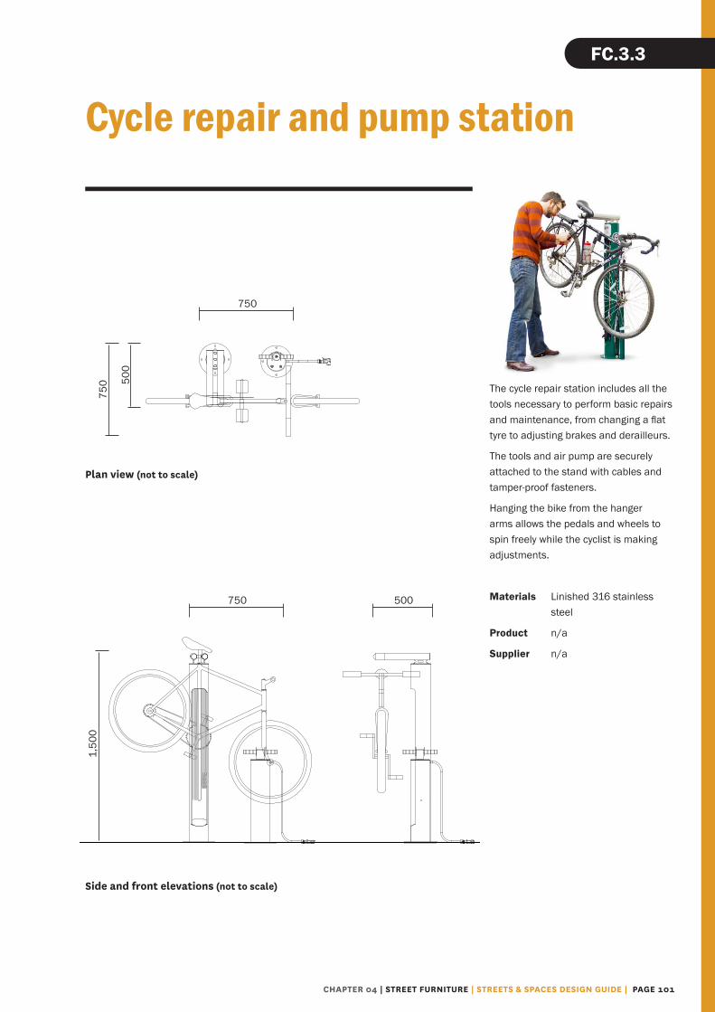
Cycle repair and pump station
The cycle repair station includes all the tools necessary to perform basic repairs and maintenance, from changing a flat tyre to adjusting brakes and derailleurs.
The tools and air pump are securely attached to the stand with cables and tamper-proof fasteners.
Hanging the bike from the hanger arms allows the pedals and wheels to spin freely while the cyclist is making adjustments.
Materials Linished 316 stainless steel
Product n/a
Supplier n/a
Side and front elevations (not to scale)
Plan view (not to scale)
CHAPTER 04 | STREET FURNITURE | STREETS & SPACES DESIGN GUIDE | PAGE 101
FC.3.3
750
750
1,50
0
500
750 50
0

“All truly great thoughts are conceived by walking.”Friedrich Nietzsche

REFERENCES

Technical notes index
ID Content Page
S STREET TREATMENTS 17
S.1.1 Footpath 20
S.2.1 Build‑outs 21
S.3.1 On‑street car park 22
S.4.1 Separated cycle lane – narrow median separator 23
S.4.2 Separated cycle lane – wide median separator 24
S.4.3 Separated cycle lane – concrete nib separator 25
S.4.4 Separated cycle lane – Copenhagen style 26
S.4.5 Separated cycle lane – Bus stop crossing 27
S.5.1 Midblock pedestrian crossing – raised platform
with footpath build‑out 28
S.5.2 Mid‑block pedestrian crossing – central island 29
S.5.3 Mid‑block pedestrian crossing – across cycle lane 30
S.6.1 Vehicle crossing – access way 31
S.7.0 Intersections – design principles 32
S.7.1 Intersection – pedestrian crossings 34
S.7.2 Intersection – Barnes dance crossing 35
S.7.3 Intersection – advanced stop boxes 36
S.7.4 Intersection – separated bicycle lane approach
and hook turn box 37
S.7.5 Intersection – left turn vehicle approach 38
S.8.1 Pedestrian ramp – two kerb crossing 39
S.8.2 Pedestrian ramp – Barnes dance crossing 40
S.8.3 Pedestrian ramp – perpendicular to kerb crossing 41
T SURFACING TREATMENTS 42
T.1.1 Bluestone palette – footpaths 44
T.1.2 Bluestone palette – special areas 45
T.2.1 Concrete paving palette – footpaths 46
T.3.1 Asphalt 47
ID Content Page
P FOOTPATH ELEMENTS AND STANDARD DETAILS 48
PB.1.1 Paver units – bluestone 48
PC.1.2 Paver units – concrete 49
PI.1.1 TGSIs 50
PCd.1.1 Paver cutting details – parallel edge 52
PCd.1.2 Paver cutting details – edge greater than 30° 54
PCd.1.3 Paver cutting details – edge less than 30° 55
PCd.2.1 Paver cutting details – fire hydrant and water meter covers 56
PCd.2.2 Paver cutting details – valve and toby box covers 57
PCd.2.3 Paver cutting details – service cover 58
PCd.2.4 Service cover installation – best practice 59
PCd.3.1 Paver cutting details – standalone elements 60
PK KERBS 61
PK.1.1.1 Standard kerb 61
PK.1.1.2 Dropped kerb 61
PK.1.1.3 Stormwater kerb 61
PK.1.1.4 Concrete nib kerb 61
PK.1.1.5 Reinforced wide kerb 62
PK.1.1.6 Reinforced narrow kerb 62
PK.1.1.7 Mountable kerb 62
PK.1.1.8 Passive irrigation kerb 62
PKd.2.1.1 Stormwater discharge – paralle to carriageway 63
PKd.2.1.2 Stormwater discharge – corner of tree pit or rain garden 64
PKd.2.1.3 Stormwater discharge – front of kerb 65
PD DRAINS 66
PD.1.1.1 Grate drain 66
PD.1.1.2 Slot drain 66
PD.1.1.3 Interpath channel 66
PAGE 104 | STREETS & SPACES DESIGN GUIDE | REFERENCES | CHAPTER 05

ID Content Page
VS VEGETATION SELECTION 69
VS.1.1 Tree species 70
VS.1.2 Low planting – base species 74
VS.1.3 Low planting –
complementary species 76
VT TREE PITS 82
VT.1.1 Tree pit – parking bay 82
VT.1.2 Tree pit – build‑out 83
VT.1.3 Tree pit – narrow
median extension 84
VT.1.4 Tree pit – median 85
VT.1.5 Tree pit – footpath 86
VR RAIN GARDENS ‑ Under Development
ID Content Page
FS SEATING ELEMENTS 92
FS.1.2 Timber seat with backrest 92
FS.1.4 Timber bench 93
FE STANDALONE ELEMENTS 94
FE.2.1 Litter / recycling Bin 94
FE.2.2 Bollard 95
FE.2.3 Drinking fountain 96
FE.2.4 Tree grate 97
FE.2.5 Utility cabinets 98
FC CYCLING ELEMENTS 99
FC.3.1 Cycle stand 99
FC.3.2 Cycle stub and hold rail 100
FC.3.3 Cycle repair station and pump station 101
FL LIGHTING ELEMENTS ‑ Under Development
FW WAYFINDING ELEMENTS ‑ Under Development
CHAPTER 05 | REFERENCES | STREETS & SPACES DESIGN GUIDE | PAGE 105

List of figures and tables
Figure 1 Streets & Spaces Design Guide application area 4
Figure 2 Graphic reference to the Strategic Guidance book 7
Figure 3 Graphic reference to the Technical Guidance book 7
Figure 4 Reference elements in a standard page of the Technical Guidance book 9
Figure 5 Example of a Design Criteria page in the Strategic Guidance book 12
Figure 6 Example of a concept cross section in Chapter 5 of the Strategic Guidance book 14
Figure 7 Example of a concept cross section showing streetscape zones 15
Figure 8 Proposed footpath surface treatments 43
Table 1 Proposed street trees 71
Table 2 Central city low planting, base species 74
Figure 3 Central city low planting, complementary species 76
PAGE 106 | STREETS & SPACES DESIGN GUIDE | REFERENCES | CHAPTER 05

Cover Central city, Christchurch (New Zealand) Melizza Morales‑Hoyos, 2015
Page 10 Civic Way, Rouse Hill, Sydney (Australia) Melizza Morales‑Hoyos, 2014
Page 13 Top to bottom RMIT, Melbourne (Australia)
Melizza Morales‑Hoyos, 2014 Christchurch City Council Civic Offices plaza
(New Zealand) Melizza Morales‑Hoyos
Page 16 Melbourne (Australia) Melizza Morales‑Hoyos, 2014
Page 18 Central city, Christchurch (New Zealand) Cameron McLean, 2009
Page 21 Central city, Christchurch (New Zealand) Cameron McLean, 2015
Page 22 Central city, Christchurch (New Zealand) Cameron McLean, 2015
Page 23 Central city, Christchurch (New Zealand) Cameron McLean, 2015
Page 24 Central city, Christchurch (New Zealand) Cameron McLean, 2015
Page 25 Central city, Christchurch (New Zealand) Cameron McLean, 2015
Page 26 Central city, Christchurch (New Zealand) Cameron McLean, 2015
Page 29 Central city, Christchurch (New Zealand) Cameron McLean, 2015
Page 30 Central city, Christchurch (New Zealand) Cameron McLean, 2015
Page 31 Central city, Christchurch (New Zealand) Cameron McLean, 2015
Page 34 Central city, Christchurch (New Zealand) Melizza Morales‑Hoyos, 2015
Page 35 Central city, Christchurch (New Zealand) Melizza Morales‑Hoyos, 2015
Page 35 Central city, Christchurch (New Zealand) Melizza Morales‑Hoyos, 2015
Page 36 Central city, Christchurch (New Zealand) Cameron McLean, 2015
Page 37 Central city, Christchurch (New Zealand) Melizza Morales‑Hoyos, 2015
Page 38 Central city, Christchurch (New Zealand) CERA, 2015
All photographs are credited as below. Many thanks to those that provided images on a voluntary basis.
Photography
Page 39 Central city, Christchurch (New Zealand) Cameron McLean, 2015
Page 40 Central city, Christchurch (New Zealand) Melizza Morales‑Hoyos, 2015
Page 41 Central city, Christchurch (New Zealand) Cameron McLean, 2015
Page 42 Central city, Christchurch (New Zealand) Cameron McLean, 2015
Page 44 Central city, Christchurch (New Zealand) Cameron McLean, 2015
Page 45 Central city, Christchurch (New Zealand) Cameron McLean, 2015
Page 46 Central city, Christchurch (New Zealand) Cameron McLean, 2015
Page 47 Central city, Christchurch (New Zealand) Cameron McLean, 2015
Page 50 Central city, Christchurch (New Zealand) Cameron McLean, 2015
Page 51 Central city, Christchurch (New Zealand) Melizza Morales‑Hoyos, 2015
Page 59 Central city, Christchurch (New Zealand) Cameron McLean, 2015
Page 66 Central city, Christchurch (New Zealand) Cameron McLean, 2015
Page 63 Central city, Christchurch (New Zealand) Cameron McLean, 2015
Page64 Central city, Christchurch (New Zealand) Cameron McLean, 2015
Page 65 Central city, Christchurch (New Zealand) Cameron McLean, 2015
Page 66 Central city, Christchurch (New Zealand) Cameron McLean, 2015
Page 67 Central city, Christchurch (New Zealand) Melizza Morales‑Hoyos, 2015
Page 68 Melbourne (Australia) Melizza Morales‑Hoyos, 2014
Page 72 Norway maple. http://plants.makeitgreen.ca/Content/Images/Photos/A247‑18.jpg
Red maple. www.wunderground.com/wximage/ronbweather/18?gallery=
Turkish hazel. www.plantoregon.com/images/products/CoryluscolurnaTREE.jpg
Upright tulip tree. www.lappen.de/en/assortment/?tx_sksimplegallery_pi1%5Bid%5D=8&tx_sksimplegallery_pi1%5Bsingle%5D=136&cHash=629993dbce
Tulip tree. www.whatgrowsthere.com/grow/wp‑content/uploads/2011/06/Liriodendron‑tulipifera‑11.jpg
CHAPTER 05 | REFERENCES | STREETS & SPACES DESIGN GUIDE | PAGE 107

Page 80 Hebe ‘Emerald Gem’. www.greenleafnurseries.co.nz/index.php?route=product/product&product_id=217
Hebe ‘Wiri Mist’. www.pukeraunursery.co.nz/product/hebe‑wiri‑mist
Black brass button. www.gardenworldimages.com/Details.aspx?ID=191191&TypeID=1
Lilyturf, monkey grass. www.flickr.com/photos/fayncbikerjaa/10477894955
Hounds tongue fern. www.flickr.com/photos/mollivan_jon/8013470000
Page 81 Chatham Island forget-me-not. https://commons.wikimedia.org/wiki/File:Myosotidium_hortensia_(8749109473).jpg
NZ mountain flax, wharariki. Cameron McLean, 2009
Marlborough rock daisy. https://commons.wikimedia.org/wiki/File:Marguerite_Prachystegia_insginis_daizea.JPG
Page 82 Central city, Christchurch (New Zealand) Cameron McLean, 2015
Page 83 Central city, Christchurch (New Zealand) Cameron McLean, 2015
Page 84 Central city, Christchurch (New Zealand) Cameron McLean, 2015
Page 85 Central city, Christchurch (New Zealand) Cameron McLean, 2015
Page 86 Central city, Christchurch (New Zealand) Cameron McLean, 2015
Page 87 Central city, Christchurch (New Zealand) Melizza Morales‑Hoyos, 2015
Page 88 Melbourne (Australia) Melizza Morales‑Hoyos, 2014
Page 90 Christchurch City Council Civic Offices plaza (New Zealand) Melizza Morales‑Hoyos
Page 92 Timber seat (model render). ww.walkspace.co.nz/#!
Page 93 Timber bench (model render). www.walkspace.co.nz/#!
Page 94 Litter / recycling Bin. Melizza Morales‑Hoyos, 2015
Page 95 Bollard. Cameron McLean, 2015
Page 97 Tree great. Cameron McLean, 2015
Page 98 Utility cabinets. Cameron McLean, 2015
Page 99 Cycle stand. Cameron McLean, 2015
Page 100 Cycle stub pole. Cameron McLean, 2015
Page 101 Cycle repair and pump station. www.dero.com
Page 102 Central city, Christchurch (New Zealand) CERA, 2015
Photography (continued)
Page 73 Pin oak and Broad-leaved lime. CERA, 2014
English oak. http://s0.geograph.org.uk/geophotos/04/03/89/4038950_17e2bd23.jpg
Upright English oak. http://upload.wikimedia.org/wikipedia/en/thumb/4/4b/
Quercus_robur_%E2%80%98Fastigiata%E2%80%99.JPG/768px‑
Kōwhai. http://static.panoramio.com/photos/large/7495396.jpg
Page 74 Dianella. https://commons.wikimedia.org/wiki/File:Dianella_(5067572460).jpg
Mikoikoi, New Zealand Iris (Libertia graniflora). www.theguardian.com/lifeandstyle/gallery/2013/jul/03/new‑zealand‑plants‑uk‑gardens#img‑5 Mikoikoi, New Zealand Iris (Libertia ixioides). www.gardeningsolutionz.co.nz/plant‑catalogue/libertia‑ixiodes/Libertia‑Ixiodes‑2.JPG/image_view_fullscreen
Page 75 Panakenake. https://commons.wikimedia.org/wiki/File:Pratia_pedunculata_1.JPG
Pinātoro, New Zealand daphne. https://commons.wikimedia.org/wiki/File:Pimelea_prostrata_cushion.JPG
Page 76 Oioi, jointed wire rush. https://en.wikipedia.org/wiki/Apodasmia_(plant)#/media/File:Apodasmia_chilensis.jpg
Rengarenga, NZ rock lily. https://commons.wikimedia.org/wiki/File:Arthropodium_cirratum.jpg
Astelia, kakaha. https://en.wikipedia.org/wiki/Astelia#/media/File:Astelia_hemichrysa‑DenisBarthelEdit.JPG
Page 77 Mountain kiokio. http://naturewatch.org.nz/observations/1253602
Kiokio. https://www.flickr.com/photos/84829097@N04/8242400374/
Mini toetoe. https://en.wikipedia.org/wiki/Chionochloa#/media/File:Chionochloa-flavicans.jpg
Page 78 Tūrutu. www.phytotrend.it/foto23.htm
Oikopiko, tuoke, prickly shield fern. https://commons.wikimedia.org/wiki/File:Prickly‑Shield‑Fern‑closeup.jpg
Wild iris. https://commons.wikimedia.org/wiki/File:Dietes_grandiflora_Flower_BotGardBln0806b.JPG
Page 79 Waiu-atua, native spurge. https://commons.wikimedia.org/wiki/File:Euphorbia_glauca.jpg
Knobby club rush. https://commons.wikimedia.org/wiki/File:Ficinia_nodosa_(3394706440).jpg
Wand flower. https://commons.wikimedia.org/wiki/File:Gaura_lindheimeri_A.jpg
PAGE 108 | STREETS & SPACES DESIGN GUIDE | REFERENCES | CHAPTER 05

Further references
Topic Title Author Link
General NZS 3910:2003 New Zealand Standards http://www.standards.co.nz/
NZS 3915:2005 New Zealand Standards http://www.standards.co.nz/
City-wide strategies & plans
Christchurch Central Recovery Plan, Canterbury Earthquake Recovery Authority
Christchurch Central Development Unit
http://ccdu.govt.nz/the‑plan
Christchurch Transport Strategic Plan (June 2012–2042)
Christchurch City Council http://www.ccc.govt.nz/the‑council/plans‑strategies‑policies‑and‑bylaws/strategies/transport‑strategic‑plan‑2012/
An Accessible City Christchurch Central Development Unit
http://ccdu.govt.nz/the‑plan/accessible‑city
Streets & Spaces Design Guide Christchurch Central Development Unit
http://ccdu.govt.nz/the‑plan/design‑guides
Central City Street Tree and Gardens Master Plan
Christchurch City Council
http://resources.ccc.govt.nz/files/CentralCityDecember2011/CentralCityStreetTreesAndGardensMasterPlan.pdf
Christchurch Cycle Design Guidelines (2013)
Christchurch City Council http://www.ccc.govt.nz/transport/cycling/cycleways/new‑cycleways/developing‑the‑major‑cycle‑routes/
Waterways and Wetlands Drainage Guides
Christchurch City Council http://www.ccc.govt.nz/environment/water/policy‑and‑strategy/waterways‑wetlands‑and‑drainage‑guide/
Lanes Design Guide Christchurch City Council http://resources.ccc.govt.nz/files/lanesdesignguide-programmes.pdf
CHAPTER 05 | REFERENCES | STREETS & SPACES DESIGN GUIDE | PAGE 109

Topic Title Author Link
Street Streets & Spaces Design Guide Christchurch Central Development Unit
http://ccdu.govt.nz/the‑plan/design‑guides
Infrastructure Design Standards (IDS)
Christchurch City Council
http://www.ccc.govt.nz/consents‑and‑licences/construction‑requirements/infrastructure‑design‑standards/
Construction Standard Specifications (CSS)
Christchurch City Council
http://www.ccc.govt.nz/consents‑and‑licences/construc‑
tion-requirements/construction-standard-specifications/
Manual of Traffic Signs and Markings (MOTSAM)
NZTA http://www.nzta.govt.nz/resources/motsam/part‑2
Road and Traffic Guidelines (RTS 18, RTS 14)
NZTA http://www.nzta.govt.nz/resources/road-traffic-standards/rts.html
Auckland Transport Code of Practice: Street Amenities
Auckland Transport https://at.govt.nz/about‑us/auckland‑transport‑code‑of‑practice
Austroads: Guide to Road Design
Austroads https://www.onlinepublications.austroads.com.au/
Pedestrian Pedestrian Planning and Design Guide
NZTA http://www.nzta.govt.nz/resources/pedestrian‑planning‑guide/
Guide to Road Design Part 6A: Pedestrian and Cyclist Paths
Austroads https://www.onlinepublications.austroads.com.au/
Barrier Free Built Environments Barrier Free NZ Trust http://www.barrierfreenz.org.nz/
RTS 14: Guidelines for facilities for vision impaired‑pedestrians
Land Transport NZ http://www.nzta.govt.nz/resources/pedestrian‑planning‑guide/
Cycle Cycle Network and Route Planning Guide
Land Transport NZ http://www.nzta.govt.nz/resources/cycle‑network‑and‑route‑planning
Manual of Traffic Signs and Markings (MOTSAM)
NZTA http://www.nzta.govt.nz/resources/motsam/part‑2/
Auckland Transport Code of Practice: Cycling Infrastructure Design
Auckland Transport https://at.govt.nz/about‑us/auckland‑transport‑code‑of‑practice
New Zealand supplement to Austroads Guide to Traffic Engineering Practice Part 14 Bicycles
NZTA http://www.nzta.govt.nz/resources/nz‑supplement‑austroads‑gtep‑part‑14‑bicycles
Public transport
Guidelines for Public Transport Infrastruture and Facilities ‑ interim consultation draft
NZTA http://www.nzta.govt.nz/about‑us/consultations/guidelines‑for‑public‑transport‑infrastructure‑and‑facilities‑interim‑consultation‑draft/
Further references (continued)
PAGE 110 | STREETS & SPACES DESIGN GUIDE | REFERENCES | CHAPTER 05

Topic Title Author Link
Shared space
Shared Space (Guidelines) Local Transport Note 1/11
UK Department for Transport
https://www.gov.uk/government/publications/shared‑space
An Evaluation of Shared Space in Fort Street Auckland
Auckland Council http://www.aucklandcouncil.govt.nz/en/planspoliciesprojects/councilprojects/sharedspaces/Pages/home.aspx
Emergency services
Fire Appliance Access Requirements
NZ Fire Service http://www.fire.org.nz/
Freight Keeping Freight on the Move, An Onsite design guide for Handling Freight
Environment Canterbury http://ecan.govt.nz/publications/Pages/default.aspx
Environment Landscape and Ecology Values within Stormwater Management
Auckland Council http://www.aucklandcity.govt.nz/council/documents/technicalpublications/TR2009083.pdf
Green Infrastructure International Review
Auckland University https://cdn.auckland.ac.nz/assets/creative/schools‑programmes‑centres/transforming%20cities/Greening_Cities_Report.pdf
How to put nature into our neighbourhoods – application of Low Impact Urban Design and Development (LIUDD) principles, with a biodiversity focus, for New Zealand developers and homeowners
Landcare Research Science Series No. 35, Manaaki Whenua Press, Lincoln
http://www.mwpress.co.nz/science‑series/how‑to‑put‑nature‑into‑our‑neighbourhoodss
Further references (continued)
CHAPTER 05 | REFERENCES | STREETS & SPACES DESIGN GUIDE | PAGE 111
Related Documents


