Page 1 ARAHAN TEKNIK (JALAN) 1/85 MANUAL ON DESIGN GUIDELINES Of LONGITUDINAL TRAFFIC BARRIER PREFACE This manual updates the Arahan Teknik (Jalan) 1/85 published in 1985 with few minor changes.This issue omits the Chapter on Specification and Bill of Quantities which was included in the earlier publication and the guardrail specification is now incorporated into the Standard Specifications for Road Works. Departmental policy on guardrail installation has been included in this issue. This Arahan Teknik will be continually updated from time to time and in this respect any feedback from users will be most welcomed. Any comments should be sent to Cawangan Jalan,Ibu pejabat JKR, Kuala Lumpur.

Arahan Teknik(Jalan) 1(85)-Barrier & Guard Rail
Nov 30, 2015
Manual on Design Guidelines of Longitudinal Traffic Barrier
Welcome message from author
This document is posted to help you gain knowledge. Please leave a comment to let me know what you think about it! Share it to your friends and learn new things together.
Transcript

Page 1
ARAHAN TEKNIK (JALAN) 1/85
MANUAL ON DESIGN GUIDELINES OfLONGITUDINAL TRAFFIC BARRIER
PREFACE
This manual updates the Arahan Teknik (Jalan) 1/85 published in 1985 with few minor changes.This issue omits the Chapter on Specification and Bill of Quantities which was included in the earlier publication and the guardrail specification is now incorporated into the Standard Specifications for Road Works. Departmental policy on guardrailinstallation has been included in this issue.
This Arahan Teknik will be continually updated from time to time and in this respect any feedback from users will be most welcomed. Any comments should be sent to Cawangan Jalan,Ibu pejabat JKR, Kuala Lumpur.

Page 2
ARAHAN TEKNIK (JALAN) 1/85
Cawangan Jalan, Ibu Pejabat JKR, K.L
PART I - GENERAL
1.1 INTRODUCTION
There is a need to provide highway designengineers with a choice of safe and effectiveguardrail and medium barrier systems. Theapplication of traffic barriers should result insafer highways. However, guardrails havesometimes been misused, perhaps due to amisconception of their function. Guardrails arenot installed to protect roadside objects orprevent accident occurance, but to protect vehicle occupants from possible serious injury.Therefore, if a guardrail is to be installed, theengineer must be satisfied that the severity ofhitting the barrier must be less than the severityof hitting the hazard or leaving the highway.
It is recognised that traffic barriers are hazards in themselves, and therefore theirapplication should be examined carefully.Emphasis is placed on reducing the number ofsuch installations to only those that can befirmly justified.
The purpose of this document is to give someintroduction on the several types of traffic barrier systems available, some designguidelines on corrugated steel beam highwayguardrail mounted on timber/steel posts andNew Jersey barrier.The considerations outlined are concerned primarily with the selection and installation ofnew traffic barriers, but may also be used forreview of existing installations. Sound application of these considerations will facili-tate the provision of appropriate traffic barriersto ensure roadsides incorporate a consistent andeconomic degree of safety.
Types of barrier not described may bedeveloped, or be found in use in othercountries. However, they should not be adoptedwithin Malaysia without careful identificationof critical design features, investigation of performance records or preliminary testing.
1.2 DEFINITION
i. Traffic barriers are highway appurtenances that provide a relative degree of protection to vehicle occupants from hazardous roadside features and from errant vehicles encroaching across a median.
ii.Traffic barriers are classified into two basic groups according to functions:
(a) LongitudinalLongitudinal traffic barriers perform by redirecting errant vehicles away from the roadside hazard.
(b) Crash CushionCrash cushion barriers function primarily by decelerating errantvehicles to a stop, thus greatly reducing severity of a head-on impact with fixed objects that exist in off-ramp gore areas.(This document only covers Longitudinal traffic barriers.)
1.3 FUNCTION OF HIGHWAYTRAFFIC BARRIER
The primary function of highway traffic barrier is to safely redirect errant vehicles andthus reduce the severity of run-off road accidents and number of highway fatalities, andto minimise personal injuries. Highway trafficbarrier installations on shoulders preventvehicles access to steep embankments or fixedobjects, whereas median barriers are usedbetween the roadways of divided highways toprevent "across the median" collisions withopposing traffic.
Barrier installations are therefore warranted(or justified) only at highway locations wherethe consequence of an errant vehicle leavingthe roadway is judged to be more hazardousthan the impact with the barrier installation.This relative accident severity determination is
FOR INTERNAL USE ONLY

Page 3
ARAHAN TEKNIK (JALAN) 1/85
Cawangan Jalan, Ibu Pejabat JKR, K.L
valid regardless of whether one or one thousand vehicles leave the highway at a point.
Hence accident frequency is not a principalfactor in determining barrier warrants.However,accident frequency factors do assist in establishing a preferred order of construction oftwo or more warranted installations.
However, it is noted that the installation ofhighway barrier itself forms a road hazard asthe system is usually an elongated target whichis located closer to the roadway than the objectitself. For this reason,the highway designershould make every effort to design withoutguardrail. This can be done by
a) providing wide shoulders, verges and medians;
b) providing adequate clearances tostructures;
c) flattening embankment slopes with firm even surfaces;
d) clearing the roadside of fixed objects.
It may be necessary to consider theprovision of safety barriers where the abovemeasures cannot be applied or areconsidered impracticable.
1.4 TYPES OF HIGHWAY TRAFFIC BARRIER
The traffic barrier systems, generallytailored for specific highway requirements at agiven site, are commonly classified accordingto lateral stiffness into thefollowing three categories.
i. Rigid Barriers which are normally used where lateral deflections are notpermitted,such as locations at narrow medians.As hese systems must be essentially unyielding, they are almost exclusively constructed of massivesections of concrete.
ii. Semi-rigid Barriers which are used where small to moderate lateral deflection is acceptable. It can be classified into two groups:
(a) strong beam/strong post and(b) strong beam/weak post.
The strong beam/weak post concept,is that the posts near the point of impact arepurposely designed to break away so that the force of impact is distributed by beam action to a relatively larger number of posts. Attributes of this system are (1) barrier performance is independent of impact point at or between posts and of soil properties, and (2) vehicle snagging on a post is virtually eliminated.
iii. Flexible Barriers which relies on large dynamic deflections to redirect errantvehicles gradually. This system either weak beam/strong post or weak beam/weak post types generally consists of posts connected by steel cables.
The flexible barrier system is the multiple wire rope beam mounted via offset brackets to post. Tests have shown that vehicles become pocketed or snagged.
Some examples of each type of barriersystem are as shown in Figures 1.1, 1.2 and1.3. The most common barrier system in usedis the semi-rigid barriers of strong beam/strongpost, a balanced design, consisting of a corrugated steel beam mounted on varioustypes of posts.
FOR INTERNAL USE ONLY

Page 4
ARAHAN TEKNIK (JALAN) 1/85
Cawangan Jalan, Ibu Pejabat JKR, K.L
FOR INTERNAL USE ONLY

Page 5
ARAHAN TEKNIK (JALAN) 1/85
Cawangan Jalan, Ibu Pejabat JKR, K.L
FOR INTERNAL USE ONLY

Page 6
ARAHAN TEKNIK (JALAN) 1/85
Cawangan Jalan, Ibu Pejabat JKR, K.L
PART 2 . - DESIGN GUIDELINES
2.1 DESIGN PROCEDURE
For any new barrier installation, therecommended design procedure is asfollows:
i. Establish "point of need" or "length of need" by warranting consideration as in sub-section 2.2.
ii. Based on the unobstructed space available for system deflection, select a barriersystem as in sub-section 2.3. For bridge rail selection, the system must bestructurally compatible with the bridge.
iii.Determine design particulars for the selected system, such as terminaltreatments and adjustments for highway curvature.
iv.Make installation layout drawings. Note that for guardrails and median barriers,installations should be extended to areasonable distance upstream beyond the warranted area to prevent vehicle access to a warranting feature. A method for establishing this necessary extension is presented in sub-section 2.4.
v.Make a field review, near the completion of highway construction, before setting the final installation limits. Short gaps between installations should be avoided.
2.2 WARRANTS CONSIDERATION
Traffic barrier warrants are decision criteriathat identify sites along highway needing trafficbarrier installations. These warrants are delin-eated in terms of geometry and location ofroadside features; and for the case of medianbarriers traffic volume is also a decision factor.Warranting criteria presented below have beendeveloped from analysis of run-off-the-roadaccident statistics and are applicable tohighways in general.
2.2.1 Determination of need
Traffic barriers should be considered under thefollowing conditions:
i. Roadways on high embankment and embankment with steep side slopes,
ii. On highways with roadside obstacles and hazards such as structures and appurtenances,
iii. Divided highways with narrow medians, carrying large volume of traffic,
iv. Other conditions such as sharp horizontal curves, pedestrian protection and severe accident experience.
The three principal features are (A) slopesembankment, (B) roadside obstacles, and (C)opposing traffic which are discussed in moredetail in the following. Other factors aredependent on site conditions, traffic character-istics and accident experiences which are considered individually.
(A) Slopes Embankment
Height and slope of roadway embankmentsare basic factors in determining traffic barrier needs for embankment. For low, flatembankments, out of control vehicles can "rideout" a slope with a hazard less than that associated with striking a barrier. For high,steep embankments, the hazard of being redirected by a guardrail is less than that of thevehicle being permitted access to the slope.Adividing line between these extremes is asshown in Figure 2.1. This curve is independentof accident frequency and embankment slopematerial.
FOR INTERNAL USE ONLY

Page 7
ARAHAN TEKNIK (JALAN) 1/85
Cawangan Jalan, Ibu Pejabat JKR, K.L
(B) Roadside Obstacles
For warranting purposes, a 10m zone adjacent to the travelled way is recommended as the minimum for being clearof roadside obstacles. If the 10m zone cannotbe cleared of roadside obstacles such as bridgepiers or permanent buildings, due to practicalor economic reasons, a traffic barrier may bewarranted.
Examples of roadside hazards that warrant traffic barriers are:
(a) rough rock cuts,
(b) large boulders,
(c) permanent bodies of water with depth > 0.6 m (2 ft),
(d) line of large trees ( butt dia > 150 mm (6 in)),
(e) bridge piers and abutment at underpasses,
(f) retaining walls and culvert headwalls,
(g) culvert end or wingwalls forming abrupt drops greater than about 1.0 m in height.
(h) gap between twin bridges,
(i) narrowing of roadway (loss of shoulder) over structure,
(j) street lighting poles,
(k) railway tracks.
As most of these hazards extend a considerable length along the roadway, the probabilityof errant vehicles striking the hazards is higher.Where feasible, these roadside obstacles thatwarrant the traffic barrier should be movedfrom the 10 m wide zone adjacent to theroadway. If this is not possible,traffic barriersare to be installed.When guardrails are used onembankments along shoulders they should beplaced at a minimum distance of 1.5 metresbeyond the edge of the road pavement.
FOR INTERNAL USE ONLY
Page 8
ARAHAN TEKNIK (JALAN) 1/85
Cawangan Jalan, Ibu Pejabat JKR, K.L
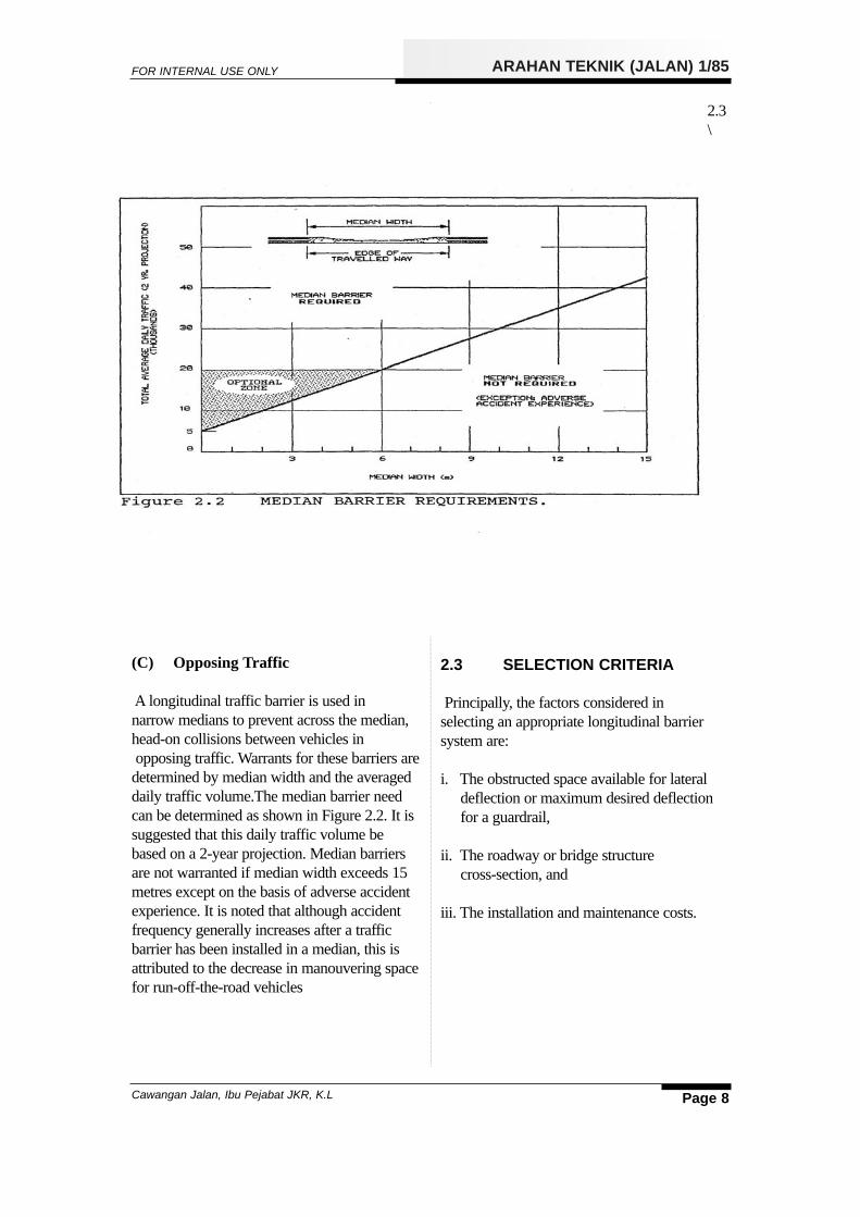
(C) Opposing Traffic
A longitudinal traffic barrier is used in narrow medians to prevent across the median,head-on collisions between vehicles inopposing traffic. Warrants for these barriers aredetermined by median width and the averageddaily traffic volume.The median barrier needcan be determined as shown in Figure 2.2. It issuggested that this daily traffic volume bebased on a 2-year projection. Median barriersare not warranted if median width exceeds 15metres except on the basis of adverse accidentexperience. It is noted that although accidentfrequency generally increases after a trafficbarrier has been installed in a median, this isattributed to the decrease in manouvering spacefor run-off-the-road vehicles
2.3\
2.3 SELECTION CRITERIA
Principally, the factors considered in selecting an appropriate longitudinal barriersystem are:
i. The obstructed space available for lateral deflection or maximum desired deflection for a guardrail,
ii. The roadway or bridge structurecross-section, and
iii. The installation and maintenance costs.
FOR INTERNAL USE ONLY

Page 9
ARAHAN TEKNIK (JALAN) 1/85
Cawangan Jalan, Ibu Pejabat JKR, K.L
2.3.1 Deflection
The major factor in selecting a traffic barriersystem is matching dynamic lateral deflectioncharacteristics of a system to the space available at the highway site. For the systemsto perform in a similar manner in actual service, minimum unobstructed distancesbehind guardrails and median barriers must beequal to or greater than this deflection.Summaries of basic characteristics ofguardrails, bridge rails and median barriers
systems are presented in Figures 2.3, 2.4 and2.5 respectively. Deflection, an important system characteristic, is the maximum lateraldeflection that a system experiences duringimpact and redirection of a selected vehicle.Deflections of systems vary from 0 to 3.6metres (12 ft) for guardrails and medianbarriers and from 0 to 0.6 metre (2 ft) forbridge rails.
FOR INTERNAL USE ONLY

Page 10
ARAHAN TEKNIK (JALAN) 1/85
Cawangan Jalan, Ibu Pejabat JKR, K.L
Rigid barriers requires the least amount of lateral space, because of their minimal deflection under impact, whereas semi-rigidbarriers, which suffer greater deflections underimpact require more lateral space.
The most economical barrier, corrugated sheetsteel guardrail, requires the greatest lateralspace of the types commonly used.
FOR INTERNAL USE ONLY

Page 11
ARAHAN TEKNIK (JALAN) 1/85
Cawangan Jalan, Ibu Pejabat JKR, K.L
2.3.2 Roadway and Bridge Cross-section
Roadway and bridge cross-section can significantly affect traffic barrier performance.Kerbs, sloped shoulders and stepped medianscan cause errant vehicles to vault a barrier or tostrike it so that the vehicle overturns. Optimumbarrier system performance is provided by alevel surface in front of the barrier. Preferably,face of barrier should be aligned above the faceof kerb; if however kerbs must be in front ofthe barrier, they should be of the low, mountable type to avoid dynamic jump byvehicles.
2.3.3 Installation and Maintenance Costs
Although cost of installation generallyincreases as system rigidity increases, cost ofrepair and maintenance generally decreases.However, cost of vehicle damage is higher formore rigid system. If two or more guardrailsystems satisfy lateral deflection requirements,final system selection can be made on the basisof:
Figure 2.6 shows the clearance required to minimise any potential for vehicles to vault theguardrail after hitting the kerb. Where barriersare installed on superelevated sections of highway, the vertical axis of the barrier shouldbe inclined in order to remain perpendicular tothe pavement surface. This is particularlyimportant for slope-face.This is particularlyimportant for slope-face concrete barriers.
(1) local preference,
(2) availability and cost of materials,
(3) ease of installation,
(4) interaction of the barrier or supports with any subsurface rock, services, or drainage structures or with surface drainage paths, and
(5) ease and frequency of maintenance and repair including effects on trafficoperations.
FOR INTERNAL USE ONLY

Page 12
ARAHAN TEKNIK (JALAN) 1/85
Cawangan Jalan, Ibu Pejabat JKR, K.L
2.4 INSTALLATION LENGTH
Installation should be extended upstream fromthe warranted limits to prevent vehicle accessbehind the protective system. It is not necessaryto extend the installation downstream past thehazard on highways with one way traffic. Forhighways with two way undivided traffic, theinstallation should extend downstream.
A method to establish the length-of-need of theinstallation is based on a 100 metres encroachment distance. The length-of-need iscalculated by: L=(1-A)x100mwhere
L=Lenght-of-needA=Distance of barrier from the edge of
pavamentB=Distance of objet from the edge
pavament
FOR INTERNAL USE ONLY

Page 13
ARAHAN TEKNIK (JALAN) 1/85
Cawangan Jalan, Ibu Pejabat JKR, K.L
The length of need of a median barrier willinclude the full length of road along which thebarrier is required to prevent cross-medianvehicle movement, as well as any lengthrequired to shield other hazards.
Short sections of guardrail' should be avoidedas they are ineffective and often introduce newhazards instead. An isolated length of guardrailon an embankment should not be less than 30metres. For high speed facilities, a minimum of75 metres is desirable. Short length of guardrailis only useful as a warning of the presence ofobstruction or hazard but is inadequate as aphysical protection.
2.5 TERMINAL SECTIONS
Regardless of the type of barrier systememployed, a typical installation is composed ofthree components:
(a) upstream terminal section,(b) center section of "length-of-need",and(c) downstream terminal section.
To prevent an errant vehicle from striking thewarranting feature, the installation must beextended a considerable distance upstream.Furthermore, terminal sections must be addedto both ends to anchor the system in order thatredirecting force can develop in the rail.
There are three general types of guardrail terminal treatments:
i. flares,ii. ramps, andiii. straight extensions. 2.5.1 Flared
2.51 Flared Terminals
Flared terminals swing away from the pavement edge either in a straight or parabolicmanner as shown in Figure 2.8. Height of railwith respect to local grade is held constant. Aminimum offset of 1.2 metres (4 ft) should beprovided but where space permits 2.5 metres to3 metres should be used. The flare should begradual to flatten the angle of impact by vehicles leaving the road. As a guide, thelength of flare, should not be less than tentimes the offset
2.5.2 Ramped Terminals
Ramped terminals provide a guardrail slope tothe beam from effective rail height to gradelevel as shown in Figure 2.9.The beam may betwisted 90 within the ramp section and is generally anchored at-grade to a concrete footing.
FOR INTERNAL USE ONLY

Page 14
ARAHAN TEKNIK (JALAN) 1/85
Cawangan Jalan, Ibu Pejabat JKR, K.L
FOR INTERNAL USE ONLY

Page 15
ARAHAN TEKNIK (JALAN) 1/85
Cawangan Jalan, Ibu Pejabat JKR, K.L
FOR INTERNAL USE ONLY

Page 16
ARAHAN TEKNIK (JALAN) 1/85
Cawangan Jalan, Ibu Pejabat JKR, K.L
FOR INTERNAL USE ONLY

Page 17
ARAHAN TEKNIK (JALAN) 1/85
Cawangan Jalan, Ibu Pejabat JKR, K.L
2.5.3 Straight Extensions
Straight extensions are additional lengths ofthe typical guardrail system, generally with astandard end-wing added to the beam used, asshown in Figure 2.10.
2.5.4 Terminals Treatment
Guardrail end treatment is an important safetyconsideration and an improper designed endtreatment present a hazard to traffic. Guardrailends must be strengthened to prevent excessivedeflection and the possibility of the rail endpenetrating the vehicle occupant compartment.It should be noted that the ramps tends tolaunch an errant vehicle and the flare increasesthe angle of impingement. To remove this danger, the approach ends must be anchored tothe ground to give the needed stability toadjoining sections and should be flared wellaway from the travelled way to prevent vehicles from striking the anchored ends with aresulting over-ride or roll-over. If the approachends are not flared back, then they should beblended into the approach environment.
On approaches to structures, the guardrailmust be securely attached to the structure inorder to give maximum protection and todevelop full strength of the rail in tension andprovide a relatively smooth configuration onthe traffic side.
2.6 STANDARD GUARDRAILSYSTEMS ADOPTED
The above design guidelines give a variety ofchoices of different types of traffic barrier.However, for economic consideration and easeof maintenance, standard systems are adoptedas follows:
i. Rigid guardrail adopts the New Jersey design as shown in Figure 2.11.
ii. Semirigid guardrail follows the existing practice of corrugated sheet steel beam guardrail mounted on blocked-out steel posts. In rural areas, timber posts of either Chengal or Berlian can be used.
iii. For terminal sections, flared terminal treatment is used. In case where space is not available, ramped terminal can be used. Straight extension terminal is used only where terminal is pointing away from one directional traffic flow. Return section terminal is used at narrow median installation.
FOR INTERNAL USE ONLY

Page 18
ARAHAN TEKNIK (JALAN) 1/85
Cawangan Jalan, Ibu Pejabat JKR, K.L
2.7DEPARTMENTAL POLICY
i. For all new semi-rigid guardrail installations,corrugated sheet steel beam guardrails mounted on steel posts are to be used. Timber posts may be used on rural roads of R3 standard and below. The timber posts shall be of heavy hardwood only of either Chengal or Bilian.
ii. In the replacement of damaged existing corrugated sheet steel beam guardrails that are mounted on timber posts the following guidelines shall be used to ensure uniformity and consistency:
a) where the damaged timber posts are more than five years old, then all the timber posts in the section shall be replaced with steeposts.
b) Where the damaged timber posts are less han 5 years old, then the damaged timber posts can be replaced with new timber posts but of either Chengal or Bilian only.
iii. If any deviation from the above guidelines is considered necessary for specific reasons, Pengarah Cawangan Jalan, Ibu pejabat JKR should be consulted for installation on Federal roads and the State Pengarah JKR for installations on State roads.
PART 3 - COMMON TYPES OFTRAFFIC BARRIER
3.1 CORRUGATED SHEET STEELBEAM GUARDRAIL
The corrugated sheet steel beam guardrailcommonly used consists of sheet steel beam ofW-shape cross-section attached to block-outs orspacers supported on posts. Generally, theblock-outs and posts are constructed of steel ortimber.The corrugated sheet steel beam guardrail is
classified as being 'semi-rigid' because itdeflects substantially but not excessively underthe U.S. standard structural adequacy crashtest; i.e. it undergoes a dynamic deflection of0.8 - 0.9 m and a permanent deflection of 0.5 - 0.6 m when hit at an angle of 25 degreesby a 2 tonne vehicle travelling at up to 100km/hr. It follows that this type of guardrail canrequire extensive repair after a severe impact,and this may have safety, cost and road capacity implications.
Under substantial impact the guardrail has been designed to behave as follows:
a) The W-beam first bends and then flattens out forming a wide tension band to contain the impacting vehicle.
b) The posts are initially restrained by passive pressure in the soil, resulting in local failure of the soil at the ground line and for a short distance below.
c) Wooden posts rotate, with their point of rotation some distance below the ground. Steel posts partially rotate, but also bend near the ground line.
d) Deflection of the posts and block-outs causes the line of action of the restraining force, acting on the side of the vehicle,initially to rise, before ultimately dropping, thus minimising the risk of vehicle vaulting or rollover; the block-outs also lessen the risk of vehiclewheels snagging on the posts.
FOR INTERNAL USE ONLY

Page 19
ARAHAN TEKNIK (JALAN) 1/85
Cawangan Jalan, Ibu Pejabat JKR, K.L
e) The posts eventually yield and the rail tears away from the bolt heads and restrains the vehicle by tension.
The guardrail deflection lessens the rate ofchange of momentum of the impacting vehicleand its occupants which can significantlyreduce vehicle damage and personal injury.
Sometimes, however, a stiffer barrier isrequired, capable of giving more restraint toheavy vehicles, or of limiting deflections onimpact; narrow medians on roads with restricted cross-section. Corrugated sheet steelbeam guardrail may not be appropriate in suchsituations.
3.2 NEW JERSEY CONCRETEBARRIER
The New Jersey barrier is considered to be a'rigid' barrier as it is designed not to deflectsignificantly under impact. A vehicle, hittingthe barrier at a low angle, first strikes the lowersloping face of the barrier, rides up the slope,and then is redirected along the travelled wayby the upper, nearly vertical, face. Energy isabsorbed on lifting the vehicle and by deformation of the vehicle's suspension andbody.
Generally, it is desirable that this type ofbarrier be located within about 1.0 to 3.0meters of the adjacent edge of the traffic lane tominimise the potential for large angle impacts,while maintaining adequate lateral clearancefor normal traffic movements.
This barrier is narrower than a double-sidedcorrugated sheet steel beam guardrail, and hasthe ability to withstand more severe impacts,making it better suited for use in confined situ-ations. Sometimes this barrier can be madewider to support lighting posts, or other engineering services.
This barrier can be constructed either in-situ orof 6 metres long precast units and sits on thebase course material and restrained by a minimum of 50 mm thick layer of wearingcourse on both sides.
GLOSSARY
Barrier -See 'Traffic barrier'
Crash cushion.A safety barrier or terminal designed primarilyto resist and-on impacts,and consistinggenerally of a partly confined bundle ofexpendable,crushable,elements to absorb theenergy of an impacting vehicle.
Errant vehicle.A vehicle that enters a roadside during agenerally unplanned manoeuvre, e.g. becausethe driver lost control or swerved to avoidanother vehicle or obstacle.
Guardrail.A semi-rigid safety barrier, generallyconsistingof steel rails supported on steel ortimber posts, designed primarily to resist lateralimpacts.
Hazard.See Roadside hazard.
Length of need.The total length of a longitudinal barrier needed to prevent errant vehicles colliding"with roadside hazards. The length is measured'parallel' to the road and should allow for bothdirections of travel.
Rigid barrier.A safety barrier, generally constructed of con-crete, which undergoes no perceptibledeflection or deformation under normal vehicular impact.
FOR INTERNAL USE ONLY

Page 20
ARAHAN TEKNIK (JALAN) 1/85
Cawangan Jalan, Ibu Pejabat JKR, K.L
Roadside.A strip of land abutting the traffic lanes including shoulders.Roadside hazard.A road-side feature of such magnitude that vehicularcollision with the feature would be likely tocause substantial damage to a vehicle, or injuryto its occupants.
Terminal.The end section of a length of barrier.
Traffic barrier.An above-ground structure which preventserrant vehicles colliding with roadside hazardsby redirecting or arresting the vehicles in sucha manner as to minimise injury to occupants ordamage to vehicles.
Vehicle Encroachment.The movement by an errant vehicle into theroadside.
FOR INTERNAL USE ONLY
Related Documents