AQUOS 2006 UPDATE LC26/32D40U and LC37/45D40U

Welcome message from author
This document is posted to help you gain knowledge. Please leave a comment to let me know what you think about it! Share it to your friends and learn new things together.
Transcript

AQUOS 2006 UPDATE
LC26/32D40U and LC37/45D40U

Objectives
Upon completion of this course, you will learn
• How to disassemble the unit
• Theory of operation
• How to Use the service menu
• The functions and operations for each PCB
• Board level PWB troubleshooting and isolating a defective LCD panel
• The required adjustments after a PCB has been replaced
• How to perform software updates
The PWB’s of the Aquos Liquid Crystal Television employ Lead-Free Solder. The LF symbol indicates lead-free solder and is ink stamped on the side of the PWB. The alpha character following the LF indicates the type of lead-free solder used. In this case, it is a compound utilizing a combination of tin, silver, and copper.
Special Service and
Warranty Notes
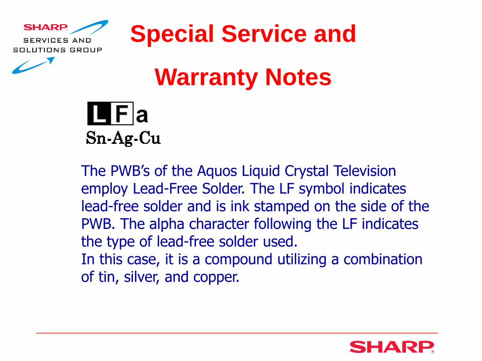
Unit Specifications

Unit Specifications

Unit Disassembly
The back cabinet assembly can be removed with the stand affixed to the TV
Remove 19 screws
Note the 1 short plastic and 2 machine screws
Short plastic screw
Machine screws

Unit Disassembly
Back cabinet assembly removed
As you can see, the set is still supported with the original stand
Your access is very limited, however, you can check for poor connections, etc.
Unit Disassembly
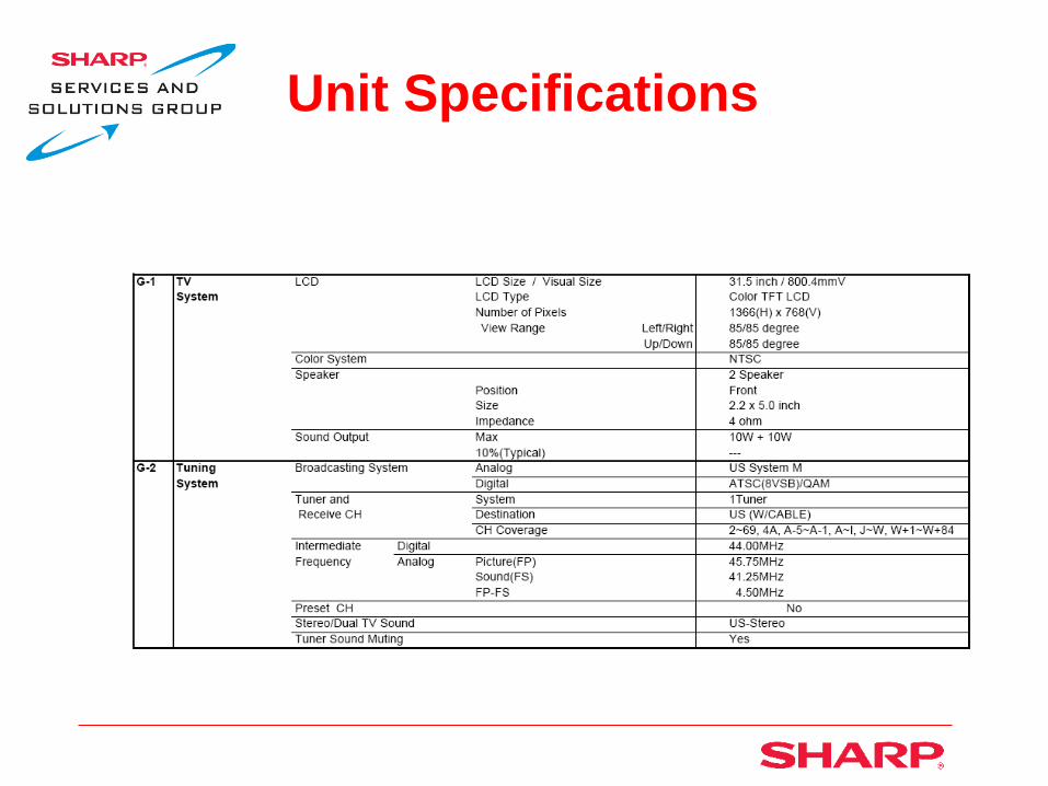
You will need to remove the stand and back angles in order to have full access to the PCB’s
Stand
Back angle 1
Back angle 2

Unit Disassembly
Remove 4 hex screws and pull out stand
Stand

Unit Disassembly
Remove 4 screws and lift off back angle 2
Back angle 2

Unit Disassembly
Remove 4 screws from the bottom of back angle 1
Back angle 1

Unit Disassembly
Remove 3 screws from the top of back angle 1
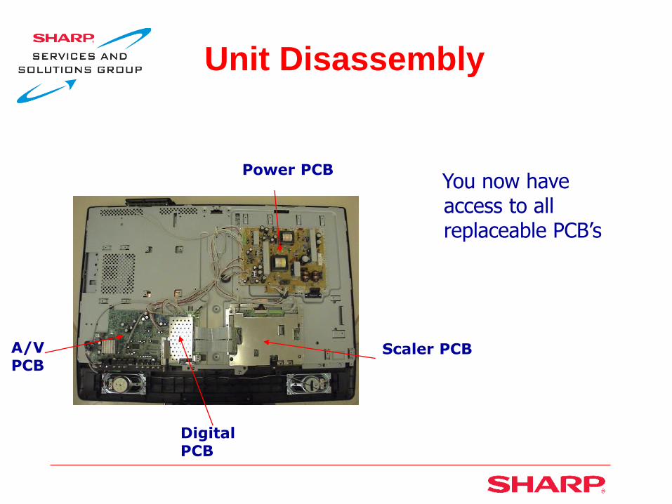
Unit Disassembly
You now have access to all replaceable PCB’s
Digital PCB
Power PCB
A/V PCB
Scaler PCB

Unit Disassembly
LCD Removal
Remocon
Disconnect remocon cable.
Disconnect speaker wires from R&L speakers.
R speaker and wires shown
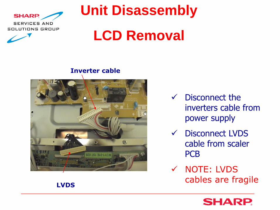
Unit Disassembly
LCD Removal
Inverter cable
Disconnect the inverters cable from power supply
Disconnect LVDS cable from scaler PCB
NOTE: LVDS cables are fragile
LVDS

Unit Disassembly
LCD Removal
Remove 5 screw from the bottom
Remove 1 screw from right side
Remove 2 screws from top
Removing front cabinet
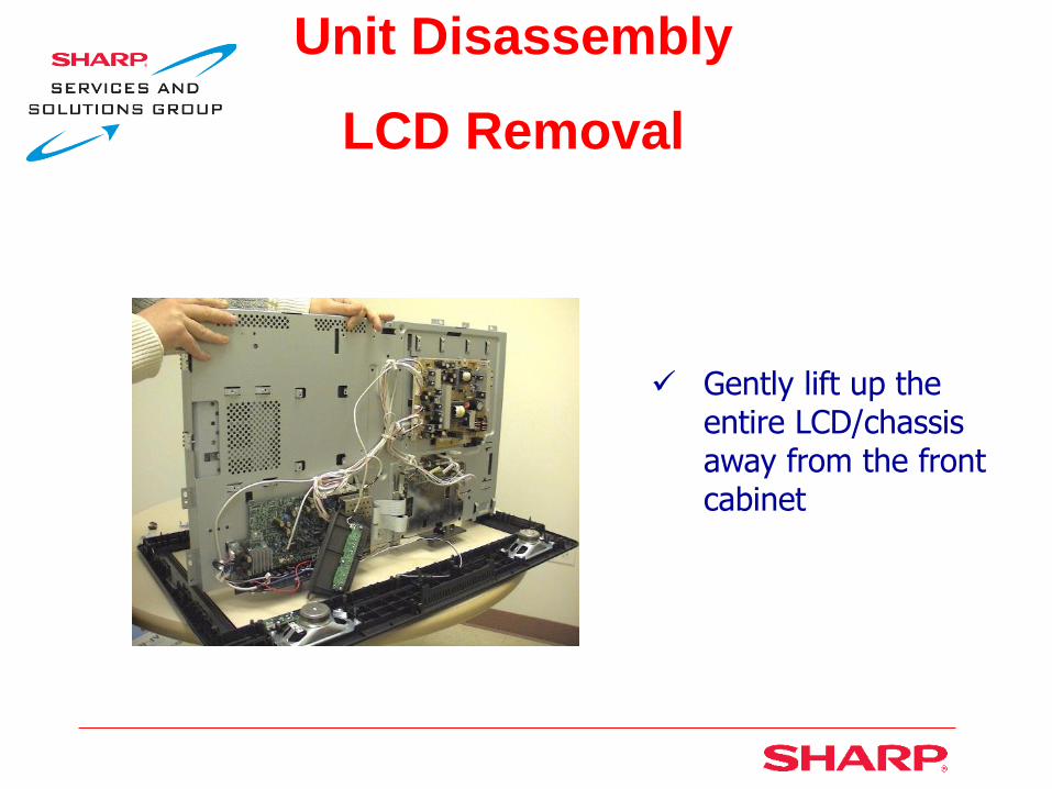
Unit Disassembly
LCD Removal
Gently lift up the entire LCD/chassis away from the front cabinet
Unit Disassembly
LCD Removal
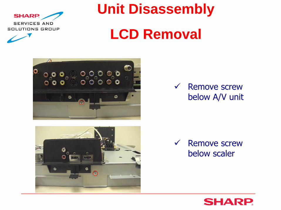
Remove screw below A/V unit
Remove screw below scaler
Unit Disassembly
LCD Removal
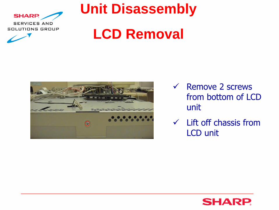
Remove 2 screws from bottom of LCD unit
Lift off chassis from LCD unit

Unit Disassembly
LCD Removal
LCD panel rear view
LCD panel front view
Replaceable PCB’s
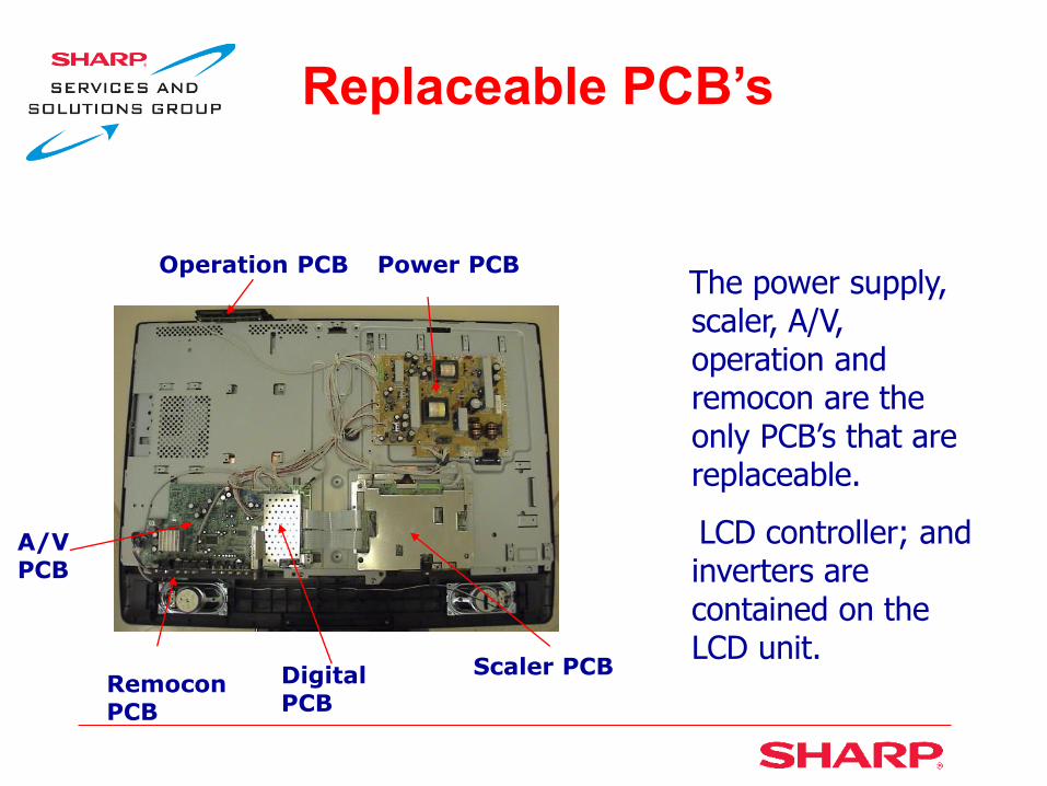
The power supply, scaler, A/V, operation and remocon are the only PCB’s that are replaceable.
LCD controller; and inverters are contained on the LCD unit.
Digital PCB
Power PCB
A/V PCB
Scaler PCB
Operation PCB
Remocon PCB

Power Supply
PCB Removal
Disconnect the 6 power supply cables
Remove 2 screws and lift off AC inlet holder
Remove 7 screws and lift off power supply PCB
AC inlet holder

Scaler PCB Removal
Remove 5 screws and lift out jack plate-2

Scaler PCB Removal
Disconnect 4 cables and 2 FPC’s
Remove 6 screws from metal shield
Remove 7 screws and lift off scaler PCB
LVDS to LCD panel “cable
and wires are fragile”
FPC
A/V-Digital PCB Removal
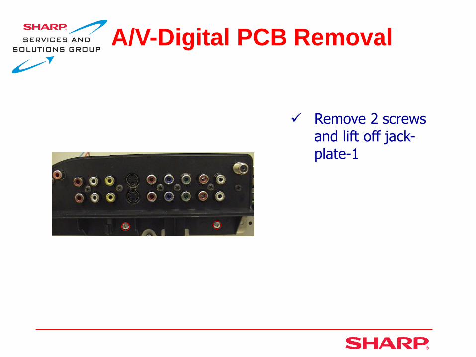
Remove 2 screws and lift off jack-plate-1

A/V-Digital PCB Removal
Disconnect 10 cables and 2 FPC’s
Remove 7 screws and lift off A/V PCB
Digital PCB Removal
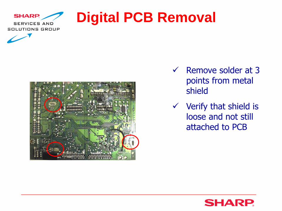
Remove solder at 3 points from metal shield
Verify that shield is loose and not still attached to PCB

Digital PCB Removal
Gently wiggle loose digital PCB and lift from A/V PCB
Digital PCB removed

Operation PCB Removal
Remove 2 screws and lift out button plate
Disconnect 1 cable
Remove 3 screws
and lift off operation PCB
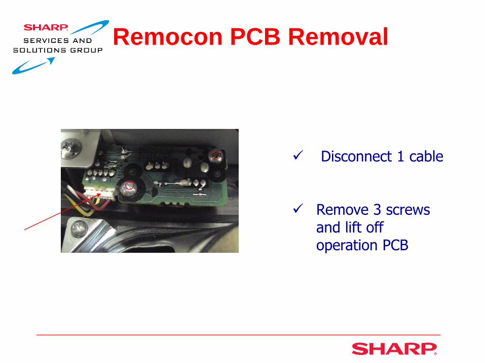
Remocon PCB Removal
Disconnect 1 cable
Remove 3 screws and lift off operation PCB
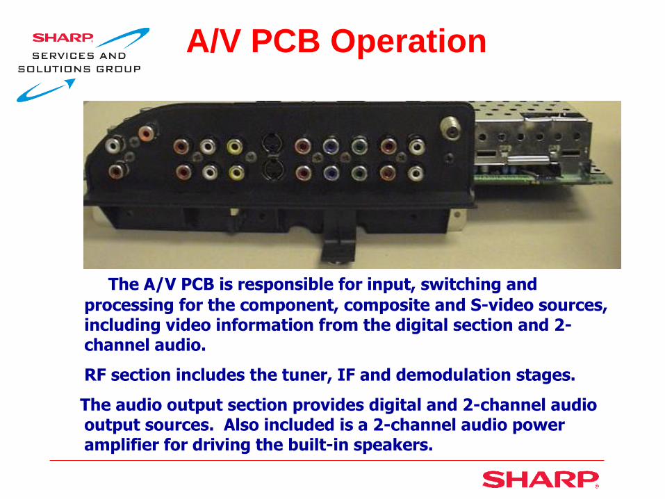
A/V PCB Operation
The A/V PCB is responsible for input, switching and
processing for the component, composite and S-video sources, including video information from the digital section and 2-channel audio.
RF section includes the tuner, IF and demodulation stages.
The audio output section provides digital and 2-channel audio output sources. Also included is a 2-channel audio power amplifier for driving the built-in speakers.

A/V PCB Operation
The digital PCB sits piggy back on the A/V PCB and
provides ATSC and Qam demodulation.
All the processed video outputs the A/V PCB and is applied to the Scaler PCB for picture formatting and LVDS processing.

Scaler PCB Operation
The scaler PCB is
responsible for HDMI input, video scaling, LVDS drive and main system control operation.
All signal passes through the scaler for picture formatting. The LVDS section converts the signal into RGB 24 bit for LCD drive.
The microprocessor controls all functions of the set including OSD.
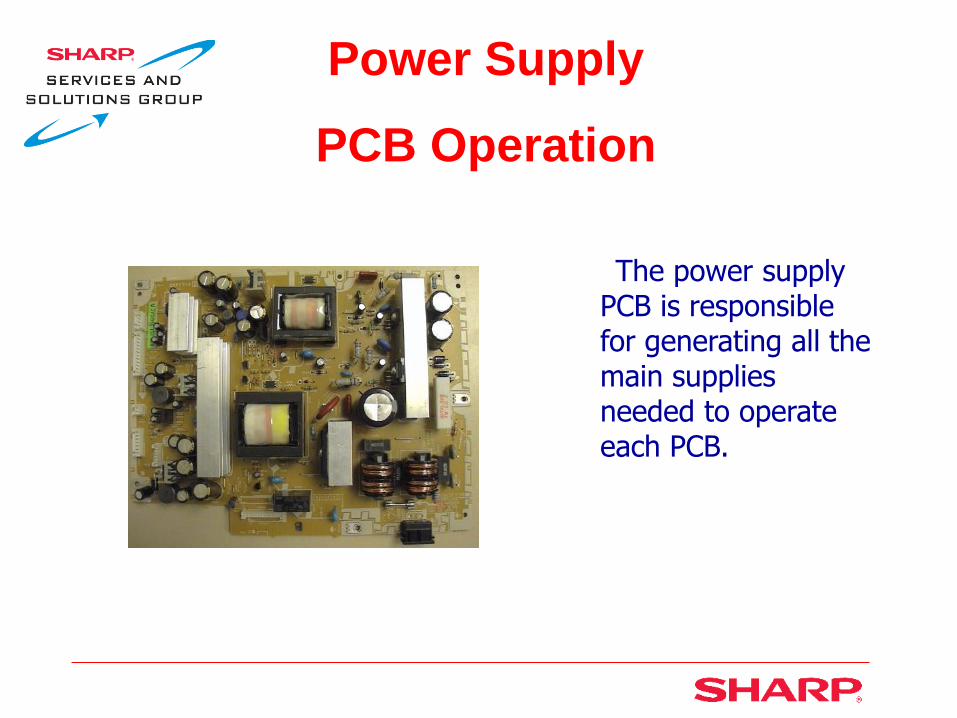
Power Supply
PCB Operation
The power supply PCB is responsible for generating all the main supplies needed to operate each PCB.

Signal Flow Block
AV Unit
LCD
Contro
ller
LCD
Panel
HDMI
Vid
eo
sw
itch
Tuner/Y,Pb,Pr/RGB/Svideo
RGB=24bit
2x LCD panel drive
LCD Panel Unit
Scaler
TDMS
LVDS
HDMI

Signal Flow Block

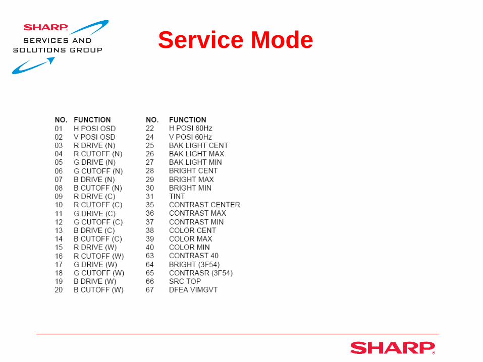
Service Mode
Service Mode

Service Mode
Adjustments
The white balance should be confirmed after replacing the LCD panel or A/V, Digital or Scaler PCB. Perform white balance adjustment if only if required.
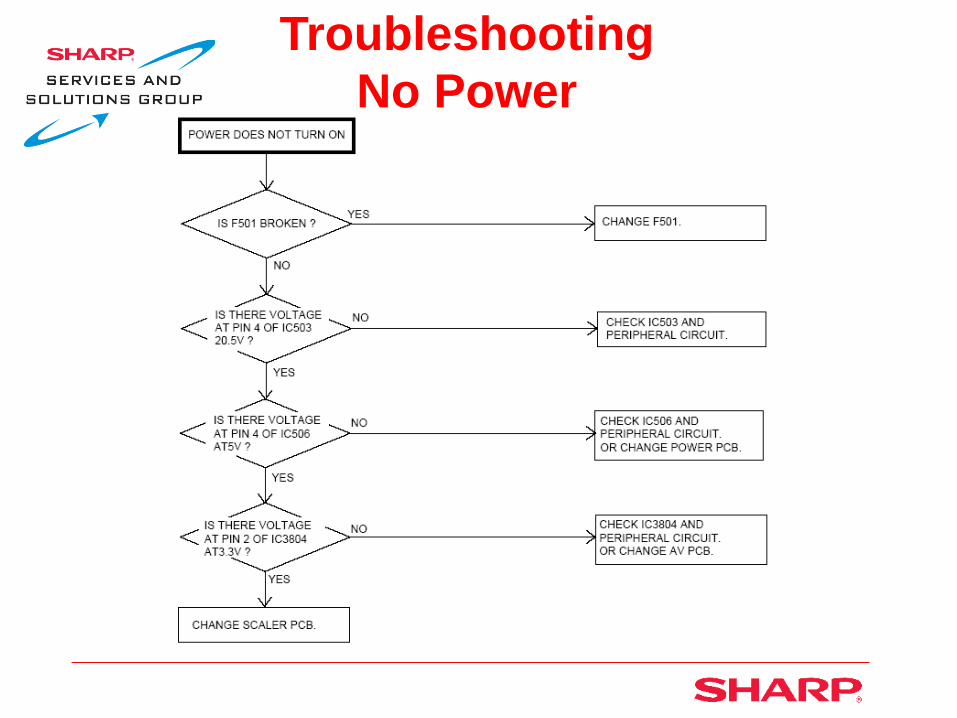
Troubleshooting
No Power

Troubleshooting
No Picture, 1

Troubleshooting
No Picture, 2
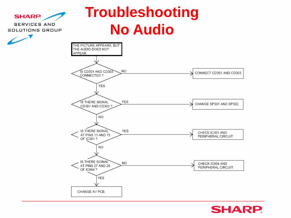
Troubleshooting
No Audio

Troubleshooting
“Please Wait” Error Message
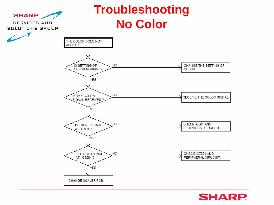
Troubleshooting
No Color

Troubleshooting
No OSD

How to Upgrade Software
LC26/32D40U End

LC37/45D40U


Unit Disassembly
The back cabinet assembly can be removed with the stand affixed to the TV
Remove 16 screws
Note the 6 machine screws (White)
Unit Disassembly
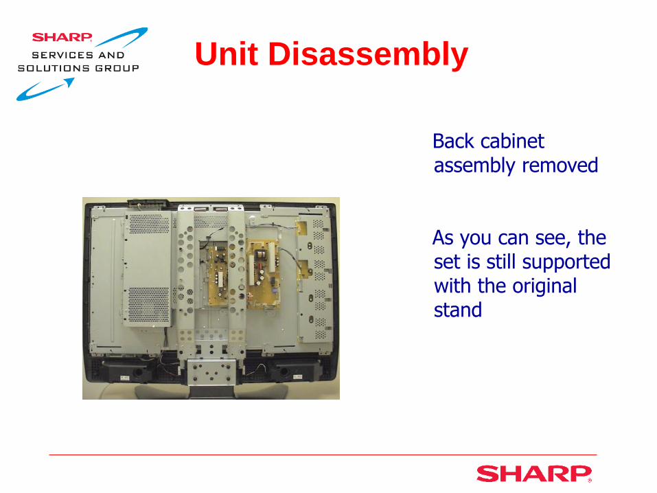
Back cabinet assembly removed
As you can see, the set is still supported with the original stand

Unit Disassembly
Remove 3 screws from each angle
Lift off angles
Center angle right and left

Unit Disassembly
With the center angles removed, you now have access to the various PCB’s
Note: Inverter and LCD controller PCB’s is part of the LCD panel unit, therefore, not replaceable individually
Main unit
IF unit LED unit
Key unit LCD controller unit
Power supply unit
Inverter unit

Unit Disassembly
You will need to remove the main shield in order to access the main and IF units
Remove 7 screws and lift off main shield
Release the 2 wire ties
Wire ties
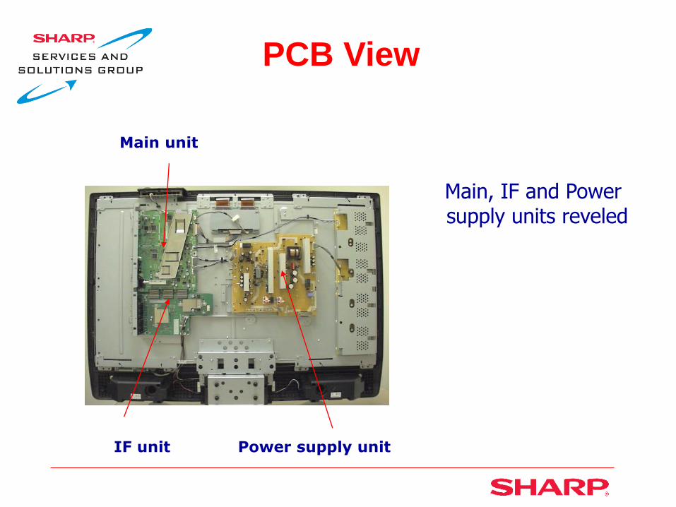
PCB View
Main, IF and Power supply units reveled
Main unit
IF unit Power supply unit
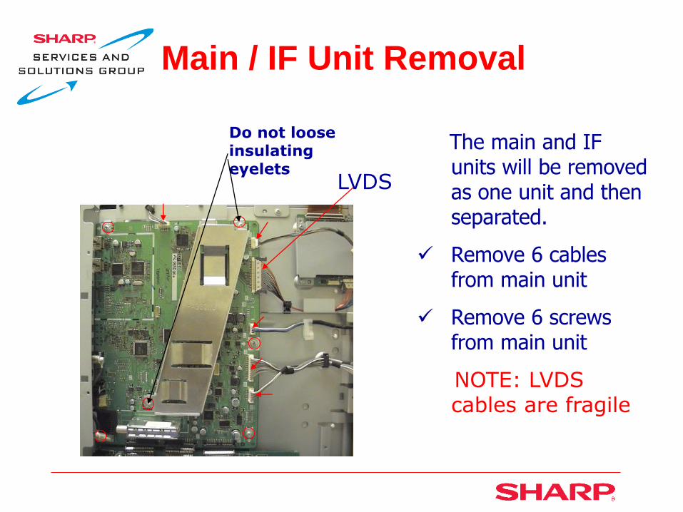
Main / IF Unit Removal
The main and IF units will be removed as one unit and then separated.
Remove 6 cables from main unit
Remove 6 screws from main unit
NOTE: LVDS cables are fragile
Do not loose insulating eyelets
LVDS

Main / IF Unit Removal
Remove 2 cables from IF unit
Remove 6 screws from IF unit
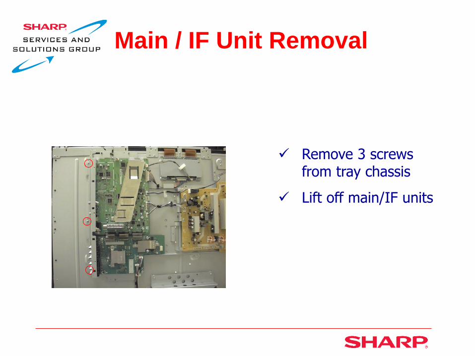
Main / IF Unit Removal
Remove 3 screws from tray chassis
Lift off main/IF units

Main / IF Unit Removal
Remove 3 screws from jack angle
Pull out main unit
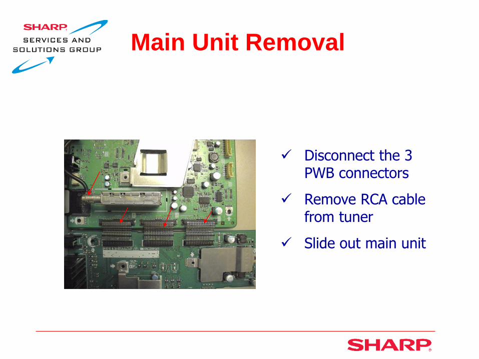
Main Unit Removal
Disconnect the 3 PWB connectors
Remove RCA cable from tuner
Slide out main unit
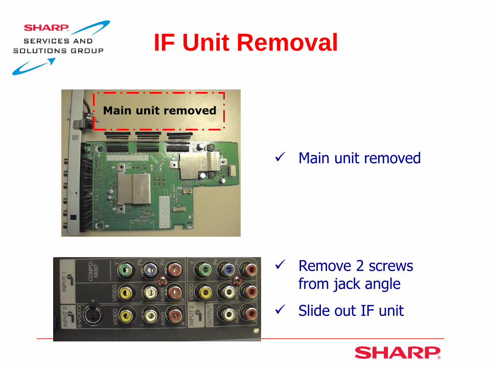
IF Unit Removal
Main unit removed
Remove 2 screws from jack angle
Slide out IF unit
Main unit removed

Power Supply Unit
Removal
Disconnect 3 cables
Remove 3 screws
Lift off power supply unit

LED Unit Removal
Disconnect 1 cable
Remove 2 screws and lift off LED unit

Key Unit Removal
The key unit is
loose once the rear cabinet ass’y is removed
Disconnect 1 cable
Remove 3 screws
and lift off LED unit

Main Unit Operation
The main unit is responsible for:
analog, cable and digital tuning (ATSC/QAM)
analog and digital audio processing
optical digital out
HDMI inputs and processing
CPU & EPROM
LVDS drive signaling
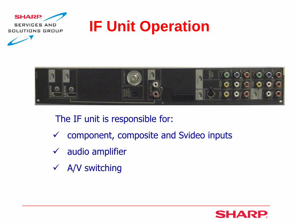
IF Unit Operation
The IF unit is responsible for:
component, composite and Svideo inputs
audio amplifier
A/V switching

Power Supply Unit
Operation
The power supply PCB is responsible for generating all the main supplies needed to operate each PCB.
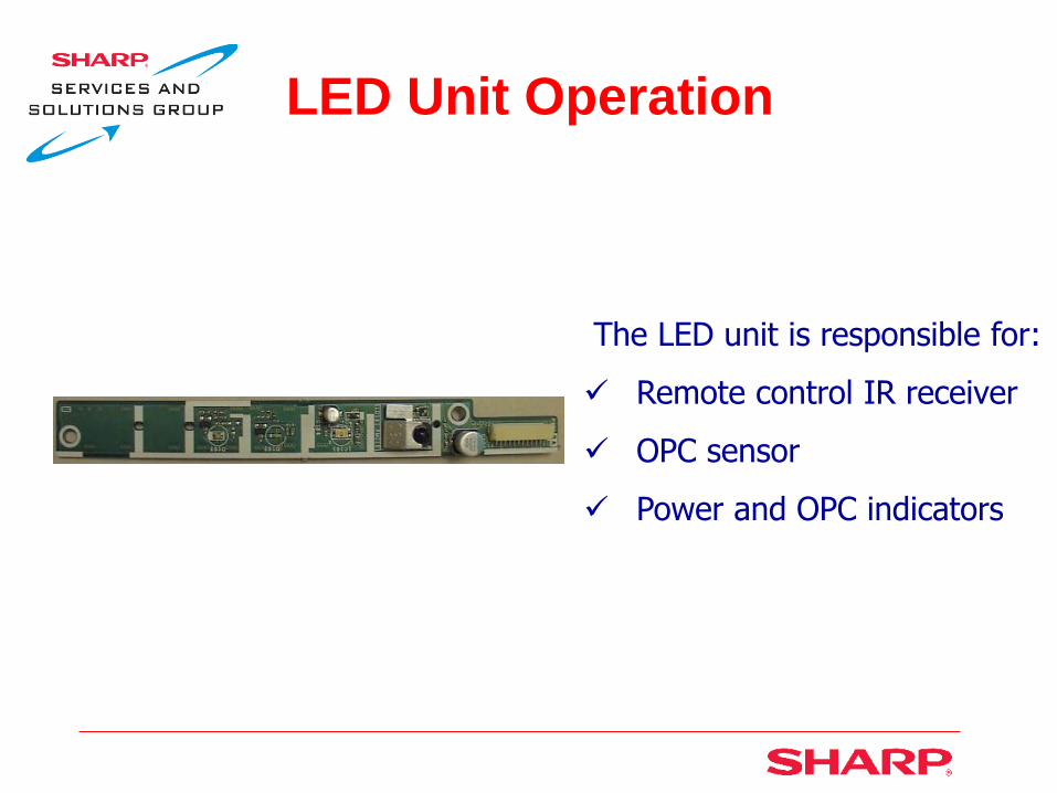
LED Unit Operation
The LED unit is responsible for:
Remote control IR receiver
OPC sensor
Power and OPC indicators
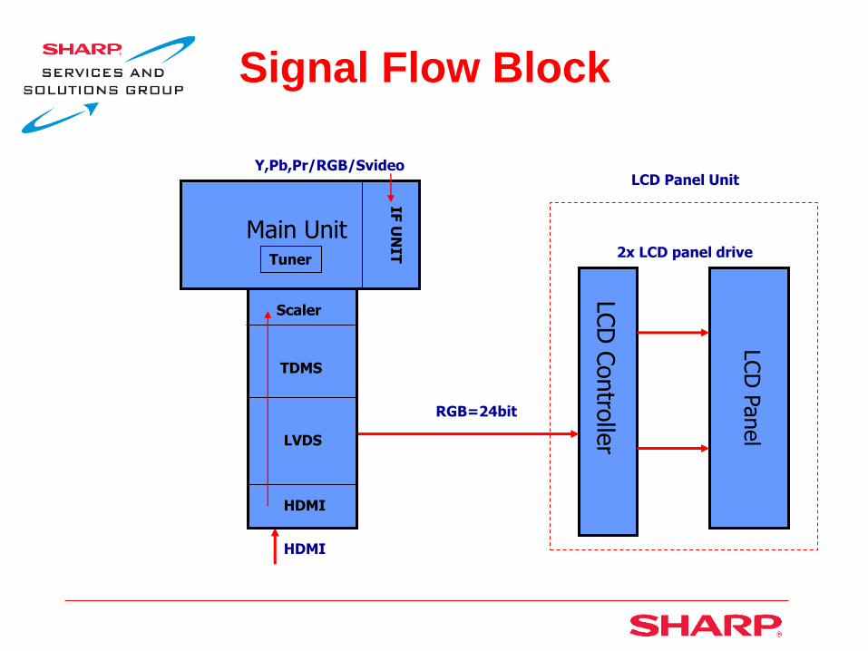
Signal Flow Block
Main Unit
LCD
Contro
ller
LCD
Panel
HDMI
IF U
NIT
Y,Pb,Pr/RGB/Svideo
RGB=24bit
2x LCD panel drive
LCD Panel Unit
Scaler
TDMS
LVDS
HDMI
Tuner

LCD Removal
Remove 4 hex screws
Pull out stand
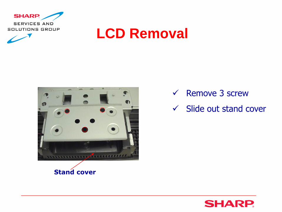
LCD Removal
Remove 3 screw
Slide out stand cover
Stand cover

LCD Removal
Remove 4 screws
Lift off stand fix angle
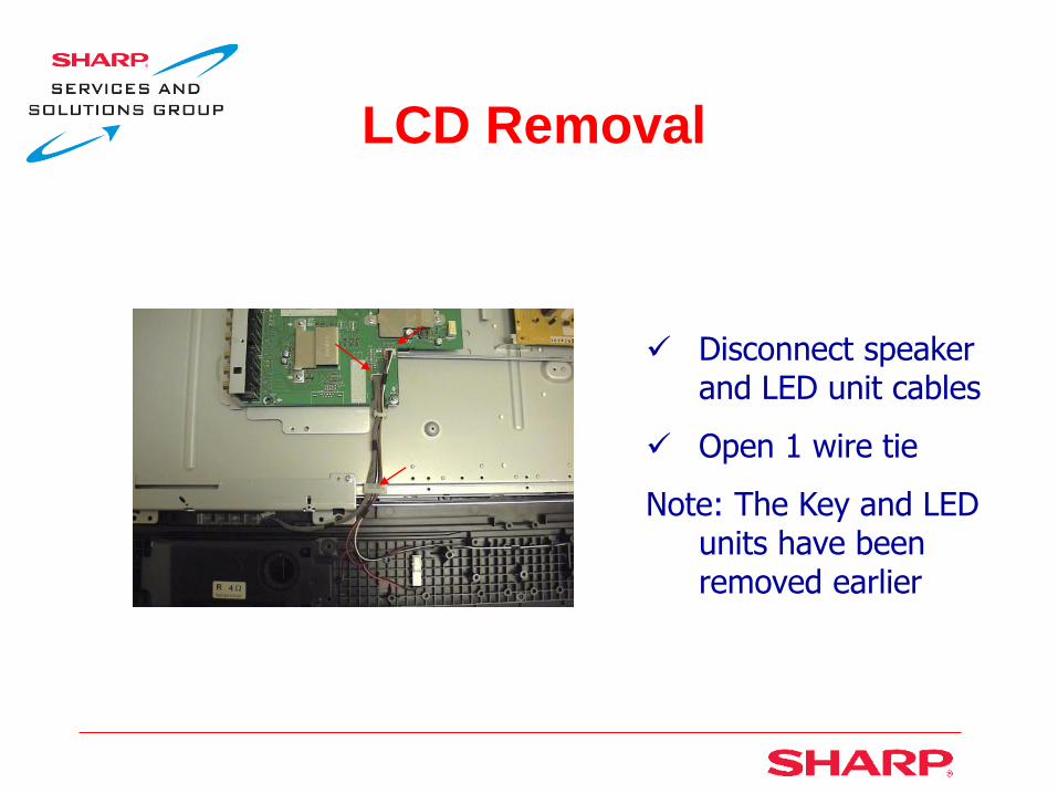
LCD Removal
Disconnect speaker and LED unit cables
Open 1 wire tie
Note: The Key and LED units have been removed earlier

LCD Removal
Remove 2 screws from front cabinet ass’y (bottom)

LCD Removal
Remove 2 screws from front cabinet ass’y (top)

LCD Removal
Lift off LCD unit from front cabinet Ass’y
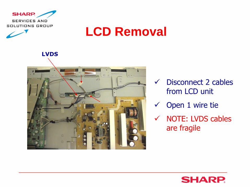
LCD Removal
Disconnect 2 cables from LCD unit
Open 1 wire tie
NOTE: LVDS cables are fragile
LVDS

LCD Removal
Disconnect 2 cables from inverter unit

LCD Removal
Remove 3 screws from tray Ass’y (right side)

LCD Removal
Remove 2 screws from tray Ass’y (left side)

LCD Removal
Lift off tray Ass’y

LCD Removal
Remove rug angles from the top/bottom left and right sides of LCD unit
Remove 2 screws
Lift off rug angle
Rug angle
LCD Removal
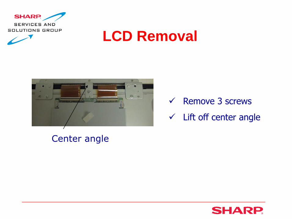
Remove 3 screws
Lift off center angle
Center angle

Troubleshooting Codes

Error Standby Cause
The “Standby Cause” indicator is on page 1/26 of the service menu. This display indicates why the unit may have gone into standby mode. Check the “Standby Cause” display to determine why the unit may have shutdown intermittently or shut down after a specific period of time.
See standby error causes on next slide

Standby Cause Error’s

Industry Initialization
These first 3 steps will bring you to the service menu
1) Press and continue to hold the VOL & INPUT buttons while plugging in AC power.
2) 2) Continue to hold the VOL & INPUT buttons until <K> appears on the top left side of the Display.
Industry Initialization
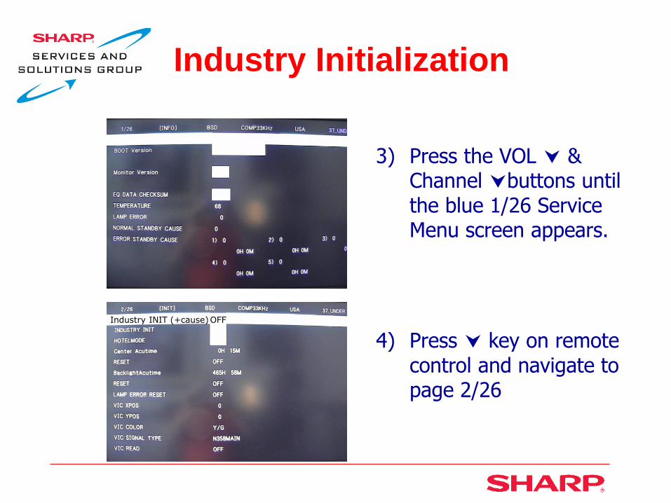
3) Press the VOL &
Channel buttons until the blue 1/26 Service Menu screen appears.
4) Press key on remote control and navigate to page 2/26
Industry INIT (+cause) OFF
Industry Initialization
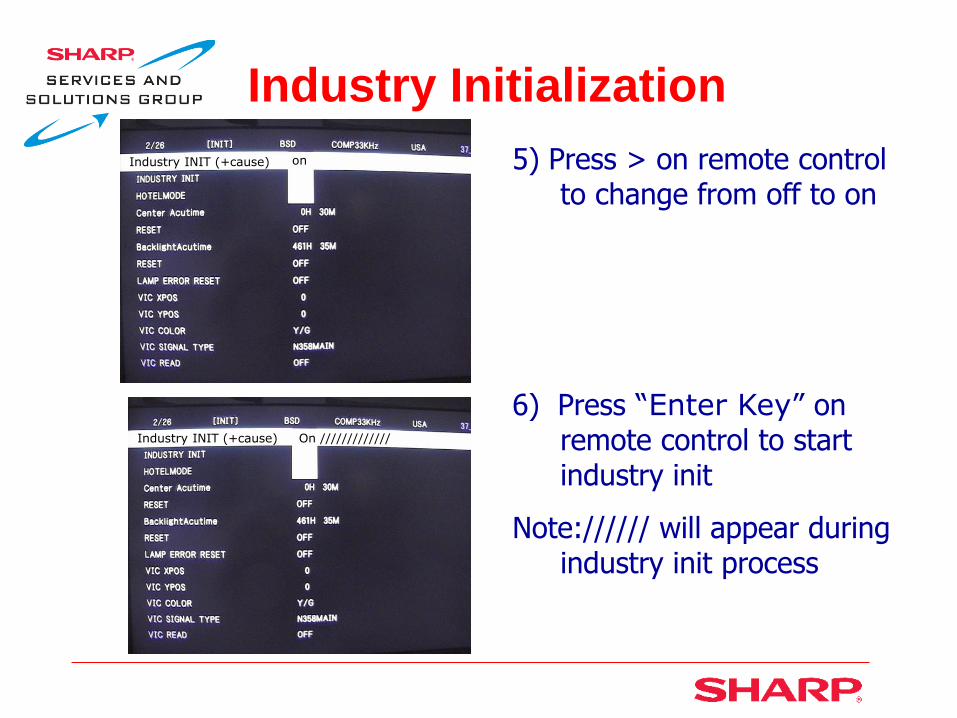
5) Press > on remote control to change from off to on
6) Press “Enter Key” on remote control to start industry init
Note:////// will appear during industry init process
Industry INIT (+cause) on
Industry INIT (+cause) On /////////////
Industry Initialization
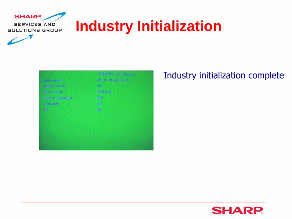
Industry initialization complete

Lamp Error Reset
Use and channel keys on remote control to navigate you to the 2/26 page
1) Press the channel on remote control to select Lamp Error Reset
2) Press > on remote control to change from off to on
3) Press “Enter Key” on remote control to reset lamps
Lamp Error reset ON
Industry INIT (+cause) OFF

Exiting Service Menu
All changes are stored automatically when inputted.
Disconnect AC power to exit the service menu

How to Upgrade Software Note: This upgrade procedure is similar to previous Aquos
models using the SD card update process

This concludes the AQUOS
2006 UPDATE
Related Documents