AUTOMATIC POSITION REPORTING SYSTEM APRS PROTOCOL REFERENCE Protocol Version 1.0 Authors The APRS Working Group Document Version Approved Version 1.0.1 Filename aprs101.pdf Date of Issue 29 August 2000 Copyright ©2000 APRS Working Group All rights reserved Technical Editor Ian Wade, G3NRW

Welcome message from author
This document is posted to help you gain knowledge. Please leave a comment to let me know what you think about it! Share it to your friends and learn new things together.
Transcript
AUTOMATIC POSITIONREPORTING SYSTEM
APRS PROTOCOLREFERENCE
Protocol Version 1.0
Authors The APRS Working Group
Document Version Approved Version 1.0.1
Filename aprs101.pdf
Date of Issue 29 August 2000
Copyright ©2000 APRS Working GroupAll rights reserved
Technical Editor Ian Wade, G3NRW
APRS Protocol ReferenceProtocol Version 1.0
by the APRS Working Group
Edited by Ian Wade
Published byTucson Amateur Packet Radio Corp8987–309 East Tanque Verde Road, #337TucsonAZ 85749-9399United States of America
http://www.tapr.org
ISBN 0-9644707-6-4
TAPR Publication Number: 99-4
Copyright ©2000 APRS Working GroupAll rights reserved
APRS® is a registered trademark of Bob Bruninga.
WinAPRS™, MacAPRS™, X-APRS™, PalmAPRS™ and APRS/CE™are trademarks using the APRS® name, licensed from Bob Bruninga.
This document may be copied for non-commercial purposes only, and mustinclude the above copyright statement and trademark statements in full.
FOREWORD
This APRS Protocol Reference document represents the coming-of-age of WB4APR’s baby.Starting with a simple concept — a way to track the location of moving objects via packet radio— programs using the APRS protocol have grown into perhaps the most popular packet radioapplication in use today. It’s also become one of the most complex; from the simple idea grew,and still grows, a tactical communications system of tremendous capability. Like many hamprojects, the APRS protocol was designed as it was being implemented, and many of itsintricacies have never been documented.
Until now. This specification defines the APRS on-air protocol with a precision and clarity thatmake it a model for future efforts. The work done by members of the APRS Working Group, aswell as Technical Editor Ian Wade, G3NRW, should be recognized as a tremendous contributionto the packet radio art. With this document available, there is now no excuse for any developer toimproperly implement the APRS protocol.
As an APRS Working Group member whose role was mainly that of observer, I was fascinatedwith the interplay among the APRS authors and the Technical Editor as the specification tookform. Putting onto paper details that previously existed only in the minds of the authors exposedambiguities, unconsidered consequences, and even errors in what the authors thought they knew.The discussion that followed each draft, and the questions Ian posed as he tried to wring out theuncertainties, gave everyone a better understanding of the protocol. I am sure that this process hasalready contributed to better interoperability among existing APRS applications.
Everyone who has watched the specification develop, from the initial mention in April 1999 untilrelease of this Version 1.0 document in August 2000, knows that the process took much longerthan was hoped. At the same time, they saw the draft transformed from a skeleton into a heftybook of over 110 pages. With the specification now in hand, I think we can all say the wait wasworth it. Congratulations to the APRS Working Group and, in particular, to G3NRW, for a majorcontribution to the literature of packet radio.
John Ackermann, N8UR
TAPR Vice President and APRS Working Group Administrative Chair
August 2000

Table of Contents i
APRS Protocol Reference — APRS Protocol Version 1.0 Document Version 1.0.1: 29 August 2000
APRS PROTOCOL REFERENCE
TABLE OF CONTENTS
PREAMBLE........................................................................................................................... 1APRS Working Group ...............................................................................................................1Acknowledgements ...................................................................................................................1Document Version Number .......................................................................................................1Release History.........................................................................................................................2Document Conventions .............................................................................................................2Feedback ..................................................................................................................................2
AUTHORS’ FOREWORD ...................................................................................................... 3Disclaimer .................................................................................................................................3
THE STRUCTURE OF THIS SPECIFICATION ..................................................................... 5
1 INTRODUCTION TO APRS............................................................................................... 7What is APRS? .........................................................................................................................7APRS Features .........................................................................................................................8
2 THE APRS DESIGN PHILOSOPHY.................................................................................. 9Net Cycle Time..........................................................................................................................9Packet Timing .........................................................................................................................10Generic Digipeating.................................................................................................................11Communicating Map Views Unambiguously............................................................................11
3 APRS AND AX.25............................................................................................................ 12Protocols .................................................................................................................................12The AX.25 Frame....................................................................................................................12
4 APRS DATA IN THE AX.25 DESTINATION AND SOURCE ADDRESS FIELDS........... 13The AX.25 Destination Address Field......................................................................................13Generic APRS Destination Addresses ....................................................................................13Generic APRS Address with Symbol.......................................................................................14APRS Software Version Number.............................................................................................14Mic-E Encoded Data ...............................................................................................................15Maidenhead Grid Locator in Destination Address....................................................................15Alternate Nets .........................................................................................................................15Generic APRS Digipeater Path ...............................................................................................15The AX.25 Source Address SSID to specify Symbols .............................................................16
5 APRS DATA IN THE AX.25 INFORMATION FIELD ....................................................... 17Generic Data Format...............................................................................................................17APRS Data Type Identifier ......................................................................................................17APRS Data and Data Extension..............................................................................................18Comment Field........................................................................................................................20Base-91 Notation ....................................................................................................................20APRS Data Units.....................................................................................................................21
ii Table of Contents
Document Version 1.0.1: 29 August 2000 APRS Protocol Reference — APRS Protocol Version 1.0
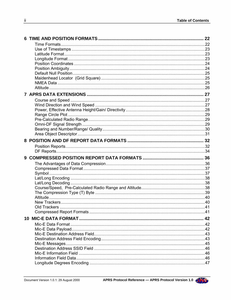
6 TIME AND POSITION FORMATS ................................................................................... 22Time Formats..........................................................................................................................22Use of Timestamps .................................................................................................................23Latitude Format .......................................................................................................................23Longitude Format ....................................................................................................................23Position Coordinates ...............................................................................................................24Position Ambiguity...................................................................................................................24Default Null Position ................................................................................................................25Maidenhead Locator (Grid Square) ........................................................................................25NMEA Data .............................................................................................................................25Altitude ....................................................................................................................................26
7 APRS DATA EXTENSIONS ............................................................................................ 27Course and Speed ..................................................................................................................27Wind Direction and Wind Speed .............................................................................................27Power, Effective Antenna Height/Gain/ Directivity ...................................................................28Range Circle Plot ....................................................................................................................29Pre-Calculated Radio Range...................................................................................................29Omni-DF Signal Strength ........................................................................................................29Bearing and Number/Range/ Quality.......................................................................................30Area Object Descriptor ............................................................................................................31
8 POSITION AND DF REPORT DATA FORMATS ............................................................ 32Position Reports......................................................................................................................32DF Reports..............................................................................................................................34
9 COMPRESSED POSITION REPORT DATA FORMATS ................................................ 36The Advantages of Data Compression....................................................................................36Compressed Data Format .......................................................................................................37Symbol ....................................................................................................................................37Lat/Long Encoding ..................................................................................................................38Lat/Long Decoding ..................................................................................................................38Course/Speed, Pre-Calculated Radio Range and Altitude......................................................38The Compression Type (T) Byte .............................................................................................39Altitude ....................................................................................................................................40New Trackers..........................................................................................................................40Old Trackers ...........................................................................................................................41Compressed Report Formats ..................................................................................................41
10 MIC-E DATA FORMAT .................................................................................................. 42Mic-E Data Format ..................................................................................................................42Mic-E Data Payload.................................................................................................................42Mic-E Destination Address Field..............................................................................................43Destination Address Field Encoding........................................................................................43Mic-E Messages......................................................................................................................45Destination Address SSID Field ..............................................................................................46Mic-E Information Field ...........................................................................................................46Information Field Data.............................................................................................................46Longitude Degrees Encoding ..................................................................................................47
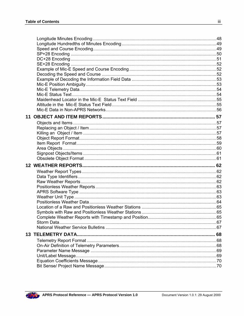
Table of Contents iii
APRS Protocol Reference — APRS Protocol Version 1.0 Document Version 1.0.1: 29 August 2000
Longitude Minutes Encoding ...................................................................................................48Longitude Hundredths of Minutes Encoding............................................................................49Speed and Course Encoding...................................................................................................49SP+28 Encoding .....................................................................................................................50DC+28 Encoding .....................................................................................................................51SE+28 Encoding .....................................................................................................................52Example of Mic-E Speed and Course Encoding......................................................................52Decoding the Speed and Course ............................................................................................52Example of Decoding the Information Field Data ....................................................................53Mic-E Position Ambiguity.........................................................................................................53Mic-E Telemetry Data..............................................................................................................54Mic-E Status Text ....................................................................................................................54Maidenhead Locator in the Mic-E Status Text Field ...............................................................55Altitude in the Mic-E Status Text Field....................................................................................55Mic-E Data in Non-APRS Networks.........................................................................................56
11 OBJECT AND ITEM REPORTS.................................................................................... 57Objects and Items ...................................................................................................................57Replacing an Object / Item......................................................................................................57Killing an Object / Item ...........................................................................................................57Object Report Format..............................................................................................................58Item Report Format ................................................................................................................59Area Objects ...........................................................................................................................60Signpost Objects/Items ...........................................................................................................61Obsolete Object Format ..........................................................................................................61
12 WEATHER REPORTS................................................................................................... 62Weather Report Types ............................................................................................................62Data Type Identifiers ...............................................................................................................62Raw Weather Reports.............................................................................................................62Positionless Weather Reports .................................................................................................63APRS Software Type ..............................................................................................................63Weather Unit Type ..................................................................................................................63Positionless Weather Data......................................................................................................64Location of a Raw and Positionless Weather Stations ............................................................65Symbols with Raw and Positionless Weather Stations ............................................................65Complete Weather Reports with Timestamp and Position.......................................................65Storm Data..............................................................................................................................67National Weather Service Bulletins .........................................................................................67
13 TELEMETRY DATA....................................................................................................... 68Telemetry Report Format ........................................................................................................68On-Air Definition of Telemetry Parameters..............................................................................68Parameter Name Message .....................................................................................................69Unit/Label Message.................................................................................................................69Equation Coefficients Message...............................................................................................70Bit Sense/ Project Name Message..........................................................................................70
iv Table of Contents
Document Version 1.0.1: 29 August 2000 APRS Protocol Reference — APRS Protocol Version 1.0
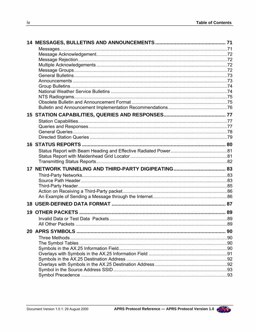
14 MESSAGES, BULLETINS AND ANNOUNCEMENTS .................................................. 71Messages................................................................................................................................71Message Acknowledgement....................................................................................................72Message Rejection..................................................................................................................72Multiple Acknowledgements ....................................................................................................72Message Groups.....................................................................................................................72General Bulletins.....................................................................................................................73Announcements ......................................................................................................................73Group Bulletins........................................................................................................................74National Weather Service Bulletins .........................................................................................74NTS Radiograms.....................................................................................................................75Obsolete Bulletin and Announcement Format .........................................................................75Bulletin and Announcement Implementation Recommendations.............................................76
15 STATION CAPABILITIES, QUERIES AND RESPONSES............................................ 77Station Capabilities..................................................................................................................77Queries and Responses..........................................................................................................77General Queries......................................................................................................................78Directed Station Queries .........................................................................................................79
16 STATUS REPORTS ...................................................................................................... 80Status Report with Beam Heading and Effective Radiated Power ...........................................81Status Report with Maidenhead Grid Locator ..........................................................................81Transmitting Status Reports....................................................................................................82
17 NETWORK TUNNELING AND THIRD-PARTY DIGIPEATING..................................... 83Third-Party Networks...............................................................................................................83Source Path Header................................................................................................................83Third-Party Header..................................................................................................................85Action on Receiving a Third-Party packet................................................................................86An Example of Sending a Message through the Internet.........................................................86
18 USER-DEFINED DATA FORMAT ................................................................................. 87
19 OTHER PACKETS ........................................................................................................ 89Invalid Data or Test Data Packets ..........................................................................................89All Other Packets ....................................................................................................................89
20 APRS SYMBOLS .......................................................................................................... 90Three Methods ........................................................................................................................90The Symbol Tables .................................................................................................................90Symbols in the AX.25 Information Field...................................................................................90Overlays with Symbols in the AX.25 Information Field ............................................................91Symbols in the AX.25 Destination Address .............................................................................92Overlays with Symbols in the AX.25 Destination Address .......................................................92Symbol in the Source Address SSID.......................................................................................93Symbol Precedence ................................................................................................................93
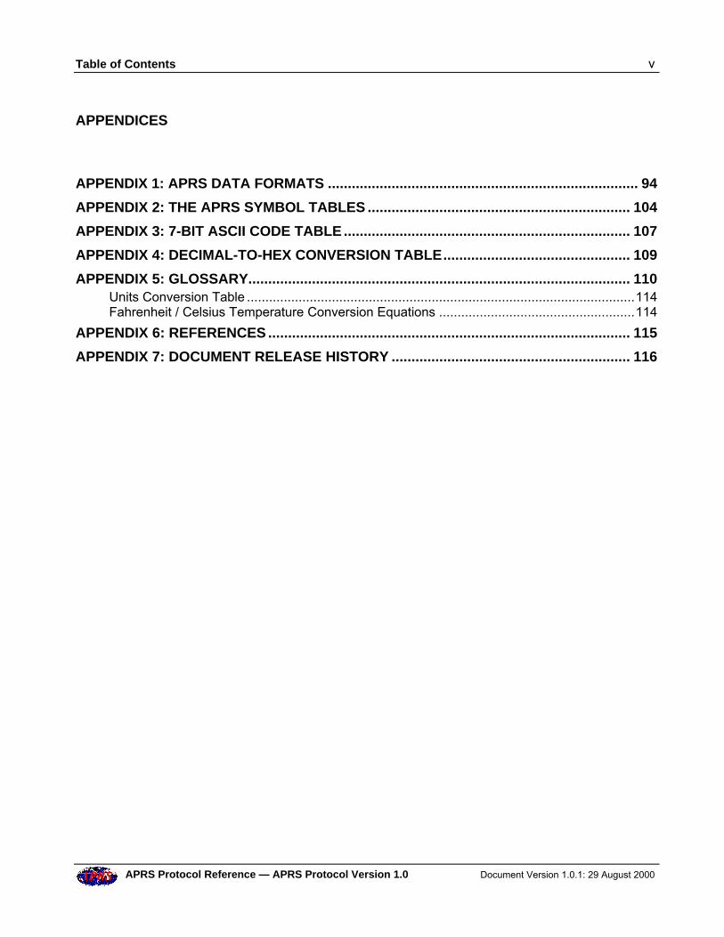
Table of Contents v
APRS Protocol Reference — APRS Protocol Version 1.0 Document Version 1.0.1: 29 August 2000
APPENDICES
APPENDIX 1: APRS DATA FORMATS .............................................................................. 94
APPENDIX 2: THE APRS SYMBOL TABLES .................................................................. 104
APPENDIX 3: 7-BIT ASCII CODE TABLE........................................................................ 107
APPENDIX 4: DECIMAL-TO-HEX CONVERSION TABLE............................................... 109
APPENDIX 5: GLOSSARY................................................................................................ 110Units Conversion Table .........................................................................................................114Fahrenheit / Celsius Temperature Conversion Equations .....................................................114
APPENDIX 6: REFERENCES ........................................................................................... 115
APPENDIX 7: DOCUMENT RELEASE HISTORY ............................................................ 116

Preamble 1
APRS Protocol Reference — APRS Protocol Version 1.0 Document Version 1.0.1: 29 August 2000
PREAMBLE
APRS WorkingGroup
The APRS Working Group is an unincorporated association whose membersundertake to further the use and enhance the value of the APRS protocols by(a) publishing and maintaining a formal APRS Protocol Specification; (b)publishing validation tests and other tools to enable compliance with theSpecification; (c) supporting an APRS Certification program; and (d) generallyworking to improve the capabilities of APRS within the amateur radiocommunity.
Although the Working Group may receive support from TAPR and otherorganizations, it is an independent body and is not affiliated with anyorganization. The Group has no budget, collects no dues, and owns no assets.
The current members of the APRS Working Group are:
John Ackermann, N8UR Administrative Chair & TAPR RepresentativeBob Bruninga, WB4APR Technical Chair, founder of APRSBrent Hildebrand, KH2Z Author of APRS+SAStan Horzepa, WA1LOU SecretaryMike Musick, N0QBF Author of pocketAPRSKeith Sproul, WU2Z Co-Author of WinAPRS/MacAPRS/X-APRSMark Sproul, KB2ICI Co-Author of WinAPRS/MacAPRS/X-APRS
Acknowledgements This document is the result of contributions from many people. It includesmuch of the material produced by individual members of the WorkingGroup.
In addition, the paper on the Mic-E data format by Alan Crosswell, N2YGK,and Ron Parsons, W5RKN was a useful starting point for explaining thecomplications of this format.
DocumentVersion Number
Except for the very first public draft release of the APRS Protocol Reference,the document version number is a 3-part number “P.p.D” (for an approveddocument release) or a 4-part number “P.p.Dd” (for a draft release):
Document Version Number
APRS ProtocolVersion
MajorRelease
MinorRelease
DocumentRelease
Draft
P. p. D d
2 Preamble
Document Version 1.0.1: 29 August 2000 APRS Protocol Reference — APRS Protocol Version 1.0
Thus, for example:
• Document version number “1.2.3” refers to document release 3 coveringAPRS Protocol Version 1.2.
• Document version number “1.2.3c” is draft “c” of that document.
Release History The release history for this document is listed in Appendix 7.
DocumentConventions
This document uses the following conventions:
• Courier font ASCII characters in APRS data.
• V ASCII space character.
• … (ellipsis) zero or more characters.
• /$ Symbol from Primary Symbol Table.
• \$ Symbol from Alternate Symbol Table.
• 0x hexadecimal (e.g. 0x1d).
• All callsigns are assumed to have SSID –0 unless otherwise specified.
• Yellow marker (appears as light gray background in hard copy).Marks text of interest — especially useful for highlighting singleliteral ASCII characters (e.g. ") where they appear in APRS data.
• Shaded areas in packet format diagrams are optional fields.
Feedback Please address your feedback or other comments regarding this document tothe TAPR aprsspec mail list.
To join the list, start at http://www.tapr.org and then follow the path SpecialInterest Groups Ü APRS Specification Ü Join APRS Spec Discussion List.
Authors’ Foreword 3
APRS Protocol Reference — APRS Protocol Version 1.0 Document Version 1.0.1: 29 August 2000
AUTHORS’ FOREWORD
This reference document describes what is known as APRS Protocol Version1.0, and is essentially a description of how APRS operates today.
It is intended primarily for the programmer who wishes to develop APRS-compliant applications, but will also be of interest to the ordinary user whowants to know more about what goes on “under the hood”.
It is not intended, however, to be a dry-as-dust, pedantic, RFC-styleprogramming specification, to be read and understood only by the Mr Spocksof this world. We have included many items of general information which,although strictly not part of the formal protocol description, provide a usefulbackground on how APRS is actually used on the air, and how it isimplemented in APRS software. We hope this will put APRS intoperspective, will make the document more readable, and will not offend thepurists too much.
It is important to realize how APRS originated, and to understand the designphilosophy behind it. In particular, we feel strongly that APRS is, and shouldremain, a light-weight tactical system — almost anyone should be able to useit in temporary situations (such as emergencies or mobile work or weatherwatching) with the minimum of training and equipment.
This document is the result of inputs from many people, and collated andmassaged by the APRS Working Group. Our sincere thanks go to everyonewho has contributed in putting it together and getting it onto the street. If youdiscover any errors or omissions or misleading statements, please let us know— the best way to do this is via the TAPR aprsspec mailing list atwww.tapr.org.
Finally, users throughout the world are continually coming up with new ideasand suggestions for extending and improving APRS. We welcome them.Again, the best way to discuss these is via the aprsspec list.
The APRS Working Group
August 2000
Disclaimer Like any navigation system, APRS is not infallible. No one should relyblindly on APRS for navigation, or in life-and-death situations. Similarly,this specification is not infallible.
The members of the APRS Working Group have done their best to define theAPRS protocol, but this protocol description may contain errors, or theremay be omissions. It is very likely that not all APRS implementations willfully or correctly implement this specification, either today or in the future.
4 Authors’ Foreword
Document Version 1.0.1: 29 August 2000 APRS Protocol Reference — APRS Protocol Version 1.0
We urge anyone using or writing a program that implements thisspecification to exercise caution and good judgement. The APRS WorkingGroup and the specification’s Editor disclaim all liability for injury topersons or property that may result from the use of this specification orsoftware implementing it.
The Structure of this Specification 5
APRS Protocol Reference — APRS Protocol Version 1.0 Document Version 1.0.1: 29 August 2000
THE STRUCTURE OF THIS SPECIFICATION
This specification describes the overall requirements for developing softwarethat complies with APRS Protocol Version 1.0. The information flow startswith the standard AX.25 UI-frame, and progresses downwards into more andmore detail as the use of each field in the frame is explored.
A key feature of the specification is the inclusion of dozens of detailedexamples of typical APRS packets and related math computations.
Here is an outline of the chapters:
Introduction to APRS — A brief background to APRS and a summary of itsmain features.
The APRS Design Philosophy — The fundamentals of APRS, highlightingits use as a real-time tactical communications tool, the timing of APRStransmissions and the use of generic digipeating.
APRS and AX.25 — A brief refresher on the structure of the AX.25UI-frame, with particular reference to the special ways in which APRS usesthe Destination and Source Address fields and the Information field.
APRS Data in the AX.25 Destination and Source Address Fields —Details of generic APRS callsigns and callsigns that specify display symbolsand APRS software version numbers. Also a summary of how Mic-Eencoded data is stored in the Destination Address field, and how the SourceAddress SSID can specify a display icon.
APRS Data in the AX.25 Information Field — Details of the principalconstituents of APRS data that are stored in the Information field. Containsthe APRS Data Type Identifiers table, and a summary of all the differenttypes of data that the Information field can hold.
Time and Position Formats — Information on formats for timestamps,latitude, longitude, position ambiguity, Maidenhead locators, NMEA dataand altitude.
APRS Data Extensions — Details of optional data extensions for stationcourse/speed, wind speed/direction, power/height/gain, pre-calculated radiorange, DF signal strength and Area Object descriptor.
Position and DF Report Data Formats — Full details of these reportformats.
Compressed Position Report Data Formats — Full details of how stationposition and APRS data extensions are compressed into very short packets.
Mic-E Data Format —Mic-E encoding of station lat/long position, altitude,course, speed, Mic-E message code, telemetry data and APRS digipeater pathinto the AX.25 Destination Address and Information fields.
6 The Structure of this Specification
Document Version 1.0.1: 29 August 2000 APRS Protocol Reference — APRS Protocol Version 1.0
Object and Item Reports — Full information on how to set up APRSObjects and Items, and details of the encoding of Area Objects (circles, lines,ellipses etc).
Weather Reports — Full format details for weather reports from stand-alone (positionless) weather stations and for reports containing positioninformation. Also details of storm data format.
Telemetry Data — A description of the MIM/KPC-3+ telemetry dataformat, with supporting information on how to tailor the interpretation of theraw data to individual circumstances.
Messages, Bulletins and Announcements — Full format information.
Station Capabilities, Queries and Responses — Details of the ten differenttypes of query and expected responses.
Status Reports — The format of general status messages, plus the specialcases of using a status report to contain meteor scatter beam heading/powerand Maidenhead locator.
Network Tunneling — The use of the Source Path Header to allowtunneling of APRS packets through third-party networks that do notunderstand AX.25 addresses, and the use of the third-party Data TypeIdentifier.
User-Defined Data Format — APRS allows users to define their own dataformats for special purposes. This chapter describes how to do this.
Other Packets — A general statement on how APRS is to handle any otherpacket types that are not covered by this specification.
APRS Symbols —How to specify APRS symbols and symbol overlays, inposition reports and in generic GPS destination callsigns.
APRS Data Formats — An appendix containing all the APRS data formatscollected together for easy reference.
The APRS Symbol Tables —A complete listing of all the symbols in thePrimary and Alternate Symbol Tables.
ASCII Code Table — The full ASCII code, including decimal and hexcodes for each character (the decimal code is needed for compressed lat/longand altitude computations), together with the hex codes for bit-shifted ASCIIcharacters in AX.25 addresses (useful for Mic-E decoding and general on-airpacket monitoring).
Glossary — A handy one-stop reference for the many APRS-specific termsused in this specification.
References — Pointers to other documents that are relevant to thisspecification.
Chapter 1: Introduction to APRS 7
APRS Protocol Reference — APRS Protocol Version 1.0 Document Version 1.0.1: 29 August 2000
1 INTRODUCTION TO APRS
What is APRS? APRS is short for Automatic Position Reporting System, which was designedby Bob Bruninga, WB4APR, and introduced by him at the 1992 TAPR/ARRL Digital Communications Conference.
Fundamentally, APRS is a packet communications protocol fordisseminating live data to everyone on a network in real time. Its most visualfeature is the combination of packet radio with the Global PositioningSystem (GPS) satellite network, enabling radio amateurs to automaticallydisplay the positions of radio stations and other objects on maps on a PC.Other features not directly related to position reporting are supported, such asweather station reporting, direction finding and messaging.
APRS is different from regular packet in several ways:
• It provides maps and other data displays, for vehicle/personnel locationand weather reporting in real time.
• It performs all communications using a one-to-many protocol, so thateveryone is updated immediately.
• It uses generic digipeating, with well-known callsign aliases, so that priorknowledge of network topology is not required.
• It supports intelligent digipeating, with callsign substitution to reducenetwork flooding.
• Using AX.25 UI-frames, it supports two-way messaging and distributionof bulletins and announcements, leading to fast dissemination of textinformation.
• It supports communications with the Kenwood TH-D7 and TM-D700radios, which have built-in TNC and APRS firmware.
Conventional packet radio is really only useful for passing bulk messagetraffic from point to point, and has traditionally been difficult to apply toreal-time events where information has a very short lifetime. APRS turnspacket radio into a real-time tactical communications and display system foremergencies and public service applications.
APRS provides universal connectivity to all stations, but avoids thecomplexity, time delays and limitations of a connected network. It permitsany number of stations to exchange data just like voice users would on avoice net. Any station that has information to contribute simply sends it, andall stations receive it and log it.
APRS recognizes that one of the greatest real-time needs at any special eventor emergency is the tracking of key assets. Where is the marathon leader?Where are the emergency vehicles? What’s the weather at various points inthe county? Where are the power lines down? Where is the head of the
8 Chapter 1: Introduction to APRS
Document Version 1.0.1: 29 August 2000 APRS Protocol Reference — APRS Protocol Version 1.0
parade? Where is the mobile ATV camera? Where is the storm?
To address these questions, APRS provides a fully featured automaticvehicle location and status reporting system. It can be used over any two-wayradio system including amateur radio, marine band, and cellular phone. Thereis even an international live APRS tracking network on the Internet.
APRSFeatures
APRS runs on most platforms, including DOS, Windows 3.x, Windows95/98, MacOS, Linux and Palm. Most implementations on these platformssupport the main features of APRS:
• Maps — APRS station positions can be plotted in real-time on maps,with coverage from a few hundred yards to worldwide. Stations reportinga course and speed are dead-reckoned to their present position. Overlaydatabases of the locations of APRS digipeaters, US National WeatherService sites and even amateur radio stores are available. It is possible tozoom in to any point on the globe.
• Weather Station Reporting — APRS supports the automatic display ofremote weather station information on the screen.
• DX Cluster Reporting — APRS an ideal tool for the DX cluster user.Small numbers of APRS stations connected to DX clusters can relay DXstation information to many other stations in the local area, reducingoverall packet load on the clusters.
• Internet Access — The Internet can be used transparently to cross-linklocal radio nets anywhere on the globe. It is possible to telnet intoInternet APRS servers and see hundreds of stations from all over theworld live. Everyone connected can feed their locally heard packets intothe APRS server system and everyone everywhere can see them.
• Messages — Messages are two-way messages with acknowledgement.All incoming messages alert the user on arrival and are held on themessage screen until killed.
• Bulletins and Announcements —Bulletins and announcements areaddressed to everyone. Bulletins are sent a few times an hour for a fewhours, and announcements less frequently but possibly over a few days.
• Fixed Station Tracking — In addition to automatically tracking mobileGPS/LORAN-equipped stations, APRS also tracks from manual reportsor grid squares.
• Objects — Any user can place an APRS Object on his own map, andwithin seconds that object appears on all other station displays. This isparticularly useful for tracking assets or people that are not equippedwith trackers. Only one packet operator needs to know where things are(e.g. by monitoring voice traffic), and as he maintains the positions andmovements of assets on his screen, all other stations running APRS willdisplay the same information.
Chapter 2: APRS Design Philosophy 9
APRS Protocol Reference — APRS Protocol Version 1.0 Document Version 1.0.1: 29 August 2000
2 THE APRS DESIGN PHILOSOPHY
Net Cycle Time It is important to note that APRS is primarily a real-time, tacticalcommunications tool, to help the flow of information for things like specialevents, emergencies, Skywarn, the Emergency Operations Center and justplain in-the-field use under stress. But like the real world, for 99% of thetime it is operating routinely, waiting for the unlikely serious event tohappen.
Anything which is done to enhance APRS must not undermine its ability tooperate in local areas under stress. Here are the details of that philosophy:
1. APRS uses the concept of a “net cycle time”. This is the time withinwhich a user should be able to hear (at least once) all APRS stationswithin range, to obtain a more or less complete picture of APRS activity.The net cycle time will vary according to local conditions and with thenumber of digipeaters through which APRS data travels.
2. The objective is to have a net cycle time of 10 minutes for local use. Thismeans that within 10 minutes of arrival on the scene, it is possible tocaptured the entire tactical picture.
3. All stations, even fixed stations, should beacon their position at the netcycle time rate. In a stress situation, stations are coming and going all thetime. The position reports show not only where stations are withoutasking, but also that they are still active.
4. It is not reasonable to assume that all APRS users responding to a stressevent understand the ramifications of APRS and the statistics of thechannel — user settings cannot be relied on to avoid killing a stressednet. Thus, to try to anticipate when the channel is under stress, APRSautomatically adjusts its net cycle time according to the number ofdigipeaters in the UNPROTO path:
• Direct operation (no digipeaters): 10 minutes (probably anevent).
• Via one digipeater hop: 10 minutes (probably an event).
• Via two digipeater hops: 20 minutes.
• Via three or more digipeater hops: 30 minutes.
5. Since almost all home stations set their paths to three or moredigipeaters, the default net cycle time for routine daily operation is 30minutes. This should be a universal standard that everyone can bank on— if you routinely turn on your radio and APRS and do nothing else,then in 30 minutes you should have virtually the total picture of allAPRS stations within range.
6. Since knowing where the digipeaters are located is fundamental to APRS
10 Chapter 2: APRS Design Philosophy
Document Version 1.0.1: 29 August 2000 APRS Protocol Reference — APRS Protocol Version 1.0
connectivity, digipeaters should use multiple beacon commands totransmit position reports at different rates over different paths; i.e. every10 minutes for sending position reports locally, and every 30 minutes forsending them via three digipeaters (plus others rates and distances asneeded).
7. If the net cycle time is too long, users will be tempted to send queries forAPRS stations. This will increase the traffic on the channelunnecessarily. Thus the recommended extremes for net cycle time are 10and 30 minutes — this gives network designers the fundamentalassumptions for channel loading necessary for good engineering design.
Packet Timing Since APRS packets are error-free, but are not guaranteed delivery, APRStransmits information redundantly. To assure rapid delivery of new orchanging data, and to preserve channel capacity by reducing interferencefrom old data, APRS should transmit new information more frequently thanold information.
There are several algorithms in use to achieve this:
• Decay Algorithm — Transmit a new packet once and n seconds later.Double the value of n for each new transmission. When n reaches the netcycle time, continue at that rate. Other factors besides “doubling” may beappropriate, such as for new message lines.
• Fixed Rate — Transmit a new packet once and n seconds later. Transmitit x times and stop.
• Message-on-Heard — Transmit a new packet according to eitheralgorithm above. If the packet is still valid, and has not beenacknowledged, and the net cycle time has been reached, then therecipient is probably not available. However, if a packet is thensubsequently heard from the recipient, try once again to transmit thepacket.
• Time-Out — This term is used to describe a time period beyond which itis reasonable to assume that a station no longer exists or is off the air ifno packets have been heard from it. A period of 2 hours is suggested asthe nominal default timeout. This time-out is not used in any transmittingalgorithms, but is useful in some programs to decide when to ceasedisplaying stations as “active”. Note that on HF, signals come and go, sodecisions about activity may need to be more flexible.
Chapter 2: APRS Design Philosophy 11
APRS Protocol Reference — APRS Protocol Version 1.0 Document Version 1.0.1: 29 August 2000
Generic Digipeating The power of APRS in the field derives from the use of generic digipeating,in that packets are propagated without a priori knowledge of the network.There are six powerful techniques which have evolved since APRS wasintroduced in 1992:
1. RELAY — Every VHF APRS TNC is assumed to have an alias ofRELAY, so that anyone can use it as a digipeater at any time.
2. ECHO — HF stations use the alias of ECHO as an alternative toRELAY. (However, bearing in mind the nature of HF propagation, thishas the potential of causing interference over a wide area, and shouldonly be used sparingly by mobile stations).
3. WIDE — Every high-site digipeater is assumed to have an alias of WIDEfor longer distance communications.
4. TRACE — Every high-site digipeater that is using callsign substitutionis assumed to have the alias of TRACE. These digipeaters self-identifypackets they digipeat by inserting their own call in place of RELAY,WIDE or TRACE.
5. WIDEn-N — A digipeater that supports WIDEn-N digipeating willdigipeat any WIDEn-N packet that is “new” and will subtract 1 from theSSID until the SSID reaches –0. The digipeater keeps a copy or achecksum of the packet and will not digipeat that packet again within(typically) 28 seconds. This considerably reduces the number ofsuperfluous digipeats in areas with many digipeaters in radio range ofeach other.
6. GATE — This generic callsign is used by HF-to-VHF Gatewaydigipeaters. Any packet heard on HF via GATE will be digipeated locallyon VHF. This permits local networks to keep an eye on the national andinternational picture.
CommunicatingMap Views
Unambiguously
APRS is a tactical geographical system. To maximize its operationaleffectiveness and minimize confusion between operators of differentsystems, users need to have an unambiguous way to communicate to othersthe “location” and “size” (or area of coverage) of any map view.
The APRS convention is by reference to a center and range which specifythe geographical center and approximate radius of a circle that will fit in themap view independent of aspect ratio. The radius of the circle (in nauticalmiles, statute miles or km) is known as the “range scale”. This conventiongives all users a simple common basis for describing any specific map viewto others over any communications medium or program.
12 Chapter 3: APRS and AX.25
Document Version 1.0.1: 29 August 2000 APRS Protocol Reference — APRS Protocol Version 1.0
3 APRS AND AX.25
Protocols At the link level, APRS uses the AX.25 protocol, as defined in AmateurPacket-Radio Link-Layer Protocol (see Appendix 6 for details), utilizingUnnumbered Information (UI) frames exclusively. This means that APRSruns in connectionless mode, whereby AX.25 frames are transmitted withoutexpecting any response, and reception at the other end is not guaranteed.
At a higher level, APRS supports a messaging protocol that allows users tosend short messages (one line of text) to nominated stations, and expects toreceive acknowledgements from those stations.
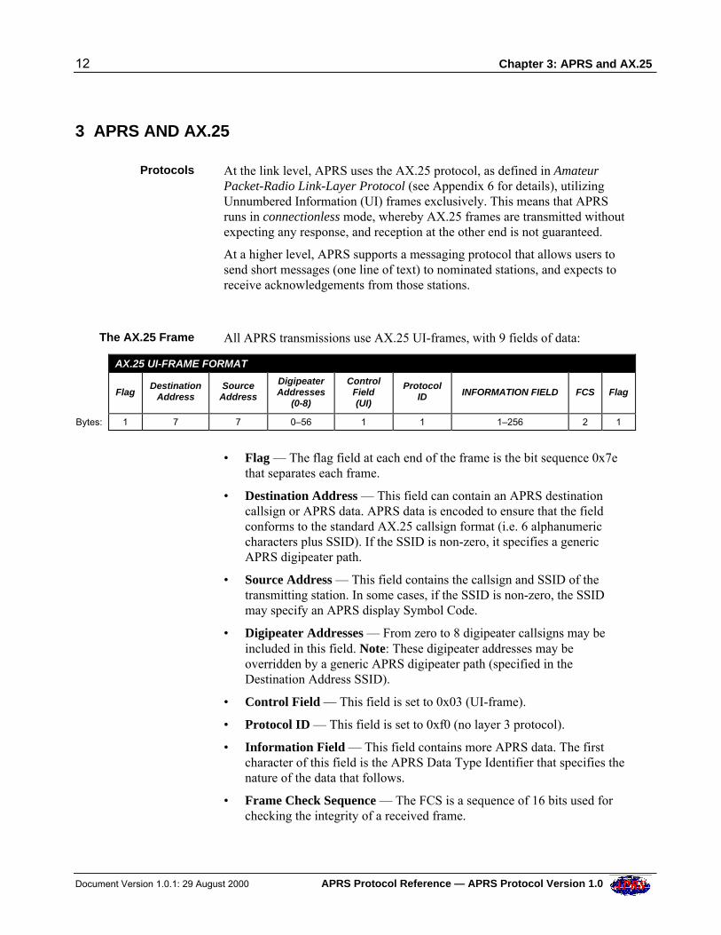
The AX.25 Frame All APRS transmissions use AX.25 UI-frames, with 9 fields of data:
AX.25 UI-FRAME FORMAT
FlagDestination
AddressSource
Address
DigipeaterAddresses
(0-8)
ControlField(UI)
ProtocolID INFORMATION FIELD FCS Flag
Bytes: 1 7 7 0–56 1 1 1–256 2 1
• Flag — The flag field at each end of the frame is the bit sequence 0x7ethat separates each frame.
• Destination Address — This field can contain an APRS destinationcallsign or APRS data. APRS data is encoded to ensure that the fieldconforms to the standard AX.25 callsign format (i.e. 6 alphanumericcharacters plus SSID). If the SSID is non-zero, it specifies a genericAPRS digipeater path.
• Source Address — This field contains the callsign and SSID of thetransmitting station. In some cases, if the SSID is non-zero, the SSIDmay specify an APRS display Symbol Code.
• Digipeater Addresses — From zero to 8 digipeater callsigns may beincluded in this field. Note: These digipeater addresses may beoverridden by a generic APRS digipeater path (specified in theDestination Address SSID).
• Control Field — This field is set to 0x03 (UI-frame).
• Protocol ID — This field is set to 0xf0 (no layer 3 protocol).
• Information Field — This field contains more APRS data. The firstcharacter of this field is the APRS Data Type Identifier that specifies thenature of the data that follows.
• Frame Check Sequence — The FCS is a sequence of 16 bits used forchecking the integrity of a received frame.
Chapter 4: APRS Data in the AX.25 Destination and Source Address Fields 13
APRS Protocol Reference — APRS Protocol Version 1.0 Document Version 1.0.1: 29 August 2000
4 APRS DATA IN THE AX.25 DESTINATION AND SOURCE ADDRESS FIELDS
The AX.25Destination
Address Field
The AX.25 Destination Address field can contain 6 different types of APRSinformation:
• A generic APRS address.
• A generic APRS address with a symbol.
• An APRS software version number.
• Mic-E encoded data.
• A Maidenhead Grid Locator (obsolete).
• An Alternate Net (ALTNET) address.
In all of these cases, the Destination Address SSID may specify a genericAPRS digipeater path.
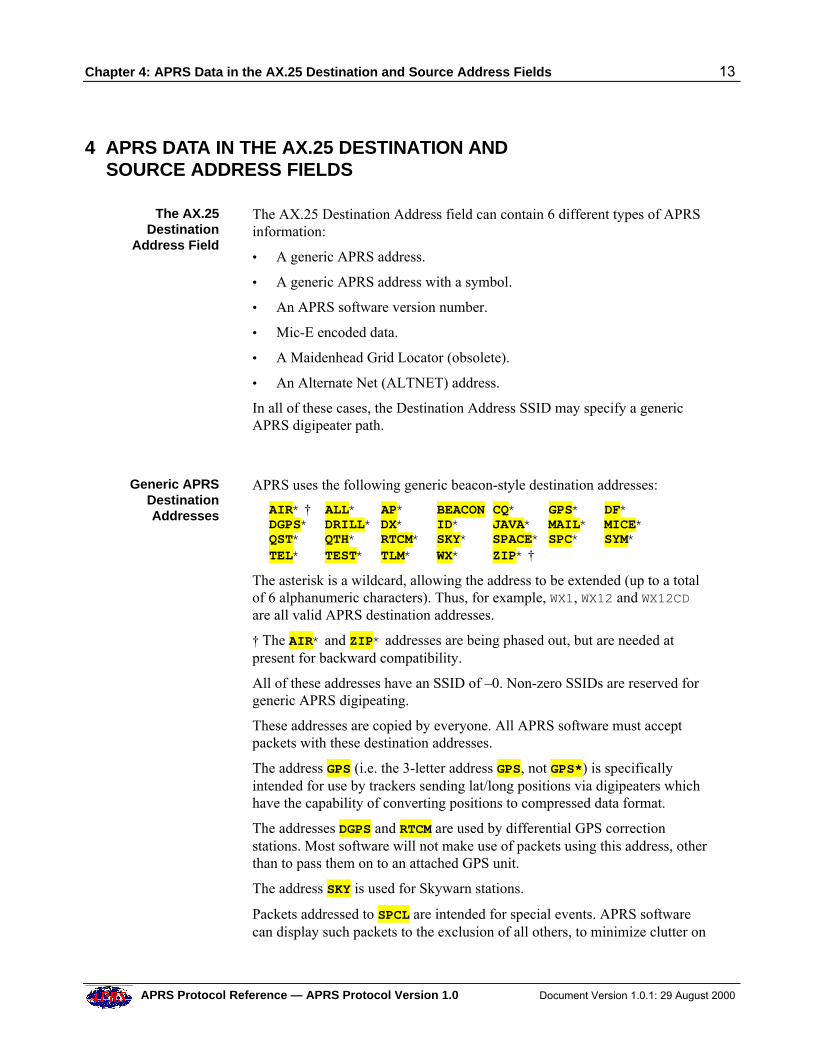
Generic APRSDestinationAddresses
APRS uses the following generic beacon-style destination addresses:
AIR* † ALL* AP* BEACON CQ* GPS* DF*DGPS* DRILL* DX* ID* JAVA* MAIL* MICE*QST* QTH* RTCM* SKY* SPACE* SPC* SYM*TEL* TEST* TLM* WX* ZIP* †
The asterisk is a wildcard, allowing the address to be extended (up to a totalof 6 alphanumeric characters). Thus, for example, WX1, WX12 and WX12CDare all valid APRS destination addresses.
† The AIR* and ZIP* addresses are being phased out, but are needed atpresent for backward compatibility.
All of these addresses have an SSID of –0. Non-zero SSIDs are reserved forgeneric APRS digipeating.
These addresses are copied by everyone. All APRS software must acceptpackets with these destination addresses.
The address GPS (i.e. the 3-letter address GPS, not GPS*) is specificallyintended for use by trackers sending lat/long positions via digipeaters whichhave the capability of converting positions to compressed data format.
The addresses DGPS and RTCM are used by differential GPS correctionstations. Most software will not make use of packets using this address, otherthan to pass them on to an attached GPS unit.
The address SKY is used for Skywarn stations.
Packets addressed to SPCL are intended for special events. APRS softwarecan display such packets to the exclusion of all others, to minimize clutter on
14 Chapter 4: APRS Data in the AX.25 Destination and Source Address Fields
Document Version 1.0.1: 29 August 2000 APRS Protocol Reference — APRS Protocol Version 1.0
the screen from other stations not involved in the special event.
The addresses TEL and TLM is used for telemetry stations.
Generic APRSAddress with
Symbol
APRS uses several of the above-listed generic addresses in a special way, tospecify not only an address but also a display symbol. These specialaddresses are GPSxyz, GPSCnn, GPSEnn, SPCxyz and SYMxyz, and areintended for use where it is not possible to include the symbol in the AX.25Information field.
The GPS addresses above are for general use.
The SPC addresses are intended for special events.
The SYM addresses are reserved for future use.
The characters xy and nn refer to entries in the APRS Symbol Tables. Thecharacter z specifies a symbol overlay. See Chapter 20: APRS Symbols andAppendix 2 for more information.
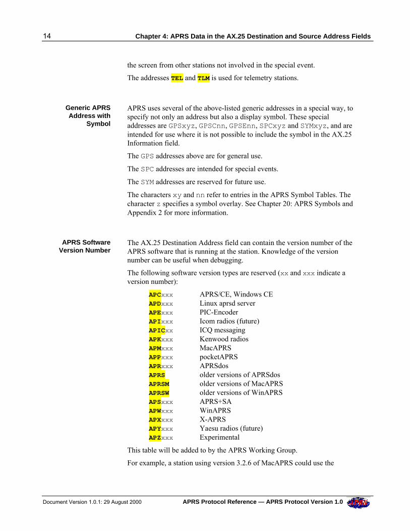
APRS SoftwareVersion Number
The AX.25 Destination Address field can contain the version number of theAPRS software that is running at the station. Knowledge of the versionnumber can be useful when debugging.
The following software version types are reserved (xx and xxx indicate aversion number):
APCxxx APRS/CE, Windows CEAPDxxx Linux aprsd serverAPExxx PIC-EncoderAPIxxx Icom radios (future)APICxx ICQ messagingAPKxxx Kenwood radiosAPMxxx MacAPRSAPPxxx pocketAPRSAPRxxx APRSdosAPRS older versions of APRSdosAPRSM older versions of MacAPRSAPRSW older versions of WinAPRSAPSxxx APRS+SAAPWxxx WinAPRSAPXxxx X-APRSAPYxxx Yaesu radios (future)APZxxx Experimental
This table will be added to by the APRS Working Group.
For example, a station using version 3.2.6 of MacAPRS could use the
Chapter 4: APRS Data in the AX.25 Destination and Source Address Fields 15
APRS Protocol Reference — APRS Protocol Version 1.0 Document Version 1.0.1: 29 August 2000
destination callsign APM326.
The Experimental destination is designated for temporary use only while aproduct is being developed, before a special APRS Software Version addressis assigned to it.
Mic-E EncodedData
Another alternative use of the AX.25 Destination Address field is to containMic-E encoded data. This data includes:
• The latitude of the station.
• A West/East Indicator and a Longitude Offset Indicator (used inlongitude computations).
• A Message Code.
• The APRS digipeater path.
This data is used with associated data in the AX.25 Information field toprovide a complete Position Report and other information about the station(see Chapter 10: Mic-E Data Format).
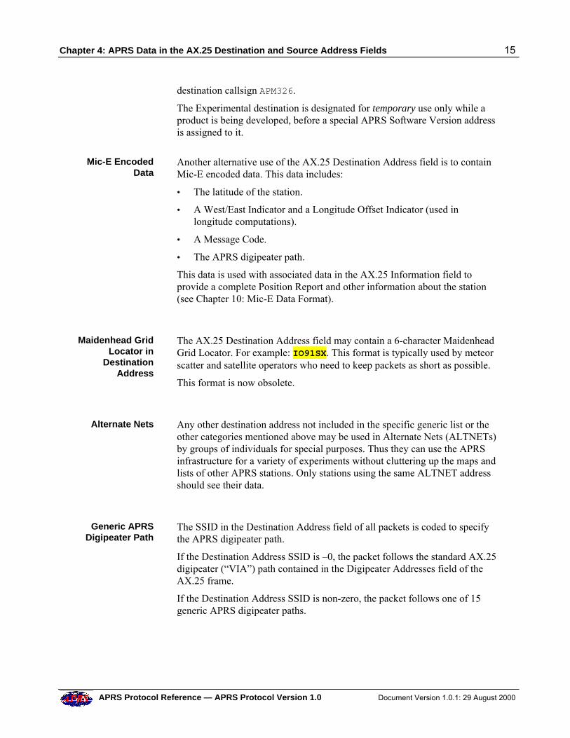
Maidenhead GridLocator in
DestinationAddress
The AX.25 Destination Address field may contain a 6-character MaidenheadGrid Locator. For example: IO91SX. This format is typically used by meteorscatter and satellite operators who need to keep packets as short as possible.
This format is now obsolete.
Alternate Nets Any other destination address not included in the specific generic list or theother categories mentioned above may be used in Alternate Nets (ALTNETs)by groups of individuals for special purposes. Thus they can use the APRSinfrastructure for a variety of experiments without cluttering up the maps andlists of other APRS stations. Only stations using the same ALTNET addressshould see their data.
Generic APRSDigipeater Path
The SSID in the Destination Address field of all packets is coded to specifythe APRS digipeater path.
If the Destination Address SSID is –0, the packet follows the standard AX.25digipeater (“VIA”) path contained in the Digipeater Addresses field of theAX.25 frame.
If the Destination Address SSID is non-zero, the packet follows one of 15generic APRS digipeater paths.
16 Chapter 4: APRS Data in the AX.25 Destination and Source Address Fields
Document Version 1.0.1: 29 August 2000 APRS Protocol Reference — APRS Protocol Version 1.0
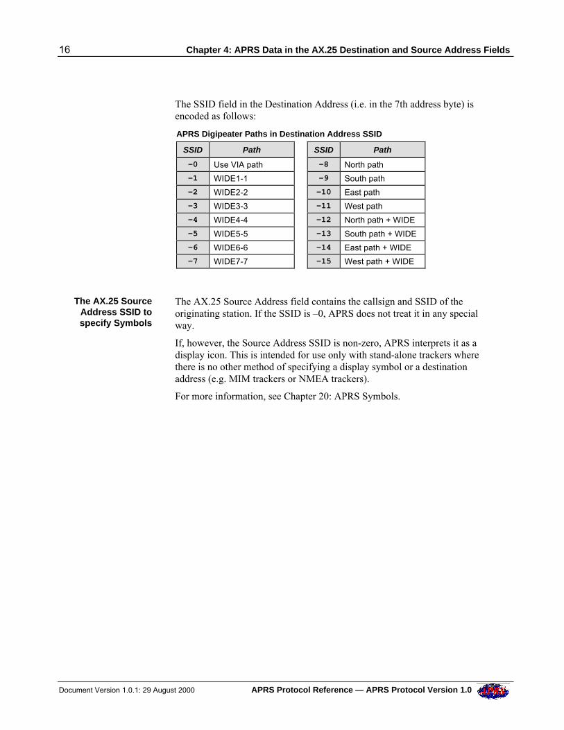
The SSID field in the Destination Address (i.e. in the 7th address byte) isencoded as follows:
APRS Digipeater Paths in Destination Address SSID
SSID Path SSID Path
-0 Use VIA path -8 North path
-1 WIDE1-1 -9 South path
-2 WIDE2-2 -10 East path
-3 WIDE3-3 -11 West path
-4 WIDE4-4 -12 North path + WIDE
-5 WIDE5-5 -13 South path + WIDE
-6 WIDE6-6 -14 East path + WIDE
-7 WIDE7-7 -15 West path + WIDE
The AX.25 SourceAddress SSID tospecify Symbols
The AX.25 Source Address field contains the callsign and SSID of theoriginating station. If the SSID is –0, APRS does not treat it in any specialway.
If, however, the Source Address SSID is non-zero, APRS interprets it as adisplay icon. This is intended for use only with stand-alone trackers wherethere is no other method of specifying a display symbol or a destinationaddress (e.g. MIM trackers or NMEA trackers).
For more information, see Chapter 20: APRS Symbols.
Chapter 5: APRS Data in the AX.25 Information Field 17
APRS Protocol Reference — APRS Protocol Version 1.0 Document Version 1.0.1: 29 August 2000
5 APRS DATA IN THE AX.25 INFORMATION FIELD
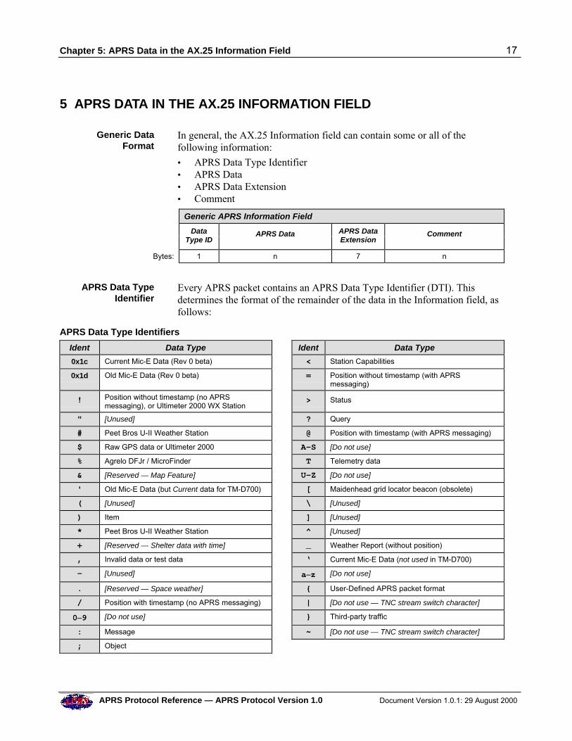
Generic DataFormat
In general, the AX.25 Information field can contain some or all of thefollowing information:
• APRS Data Type Identifier• APRS Data• APRS Data Extension• Comment
Generic APRS Information Field
Data
Type ID APRS Data APRS Data
Extension Comment
Bytes: 1 n 7 n
APRS Data TypeIdentifier
Every APRS packet contains an APRS Data Type Identifier (DTI). Thisdetermines the format of the remainder of the data in the Information field, asfollows:
APRS Data Type Identifiers
Ident Data Type Ident Data Type
0x1c Current Mic-E Data (Rev 0 beta) < Station Capabilities
0x1d Old Mic-E Data (Rev 0 beta) = Position without timestamp (with APRSmessaging)
! Position without timestamp (no APRSmessaging), or Ultimeter 2000 WX Station
> Status
" [Unused] ? Query
# Peet Bros U-II Weather Station @ Position with timestamp (with APRS messaging)
$ Raw GPS data or Ultimeter 2000 A–S [Do not use]
% Agrelo DFJr / MicroFinder T Telemetry data
& [Reserved — Map Feature] U–Z [Do not use]
' Old Mic-E Data (but Current data for TM-D700) [ Maidenhead grid locator beacon (obsolete)
( [Unused] \ [Unused]
) Item ] [Unused]
* Peet Bros U-II Weather Station ̂ [Unused]
+ [Reserved — Shelter data with time] _ Weather Report (without position)
, Invalid data or test data ‘ Current Mic-E Data (not used in TM-D700)
- [Unused] a–z [Do not use]
. [Reserved — Space weather] { User-Defined APRS packet format
/ Position with timestamp (no APRS messaging) | [Do not use — TNC stream switch character]
0–9 [Do not use] } Third-party traffic
: Message ~ [Do not use — TNC stream switch character]
; Object
18 Chapter 5: APRS Data in the AX.25 Information Field
Document Version 1.0.1: 29 August 2000 APRS Protocol Reference — APRS Protocol Version 1.0
Note: There is one exception to the requirement for the Data Type Identifierto be the first character in the Information field — this is the Position withoutTimestamp (indicated by the ! DTI). The ! character may occur anywhereup to and including the 40th character position in the Information field. Thisvariability is required to support X1J TNC digipeaters which have a string ofunmodifiable text at the beginning of the field.
Note: The Kenwood TM-D700 radio uses the ' DTI for current Mic-E data.The radio does not use the ‘ DTI.
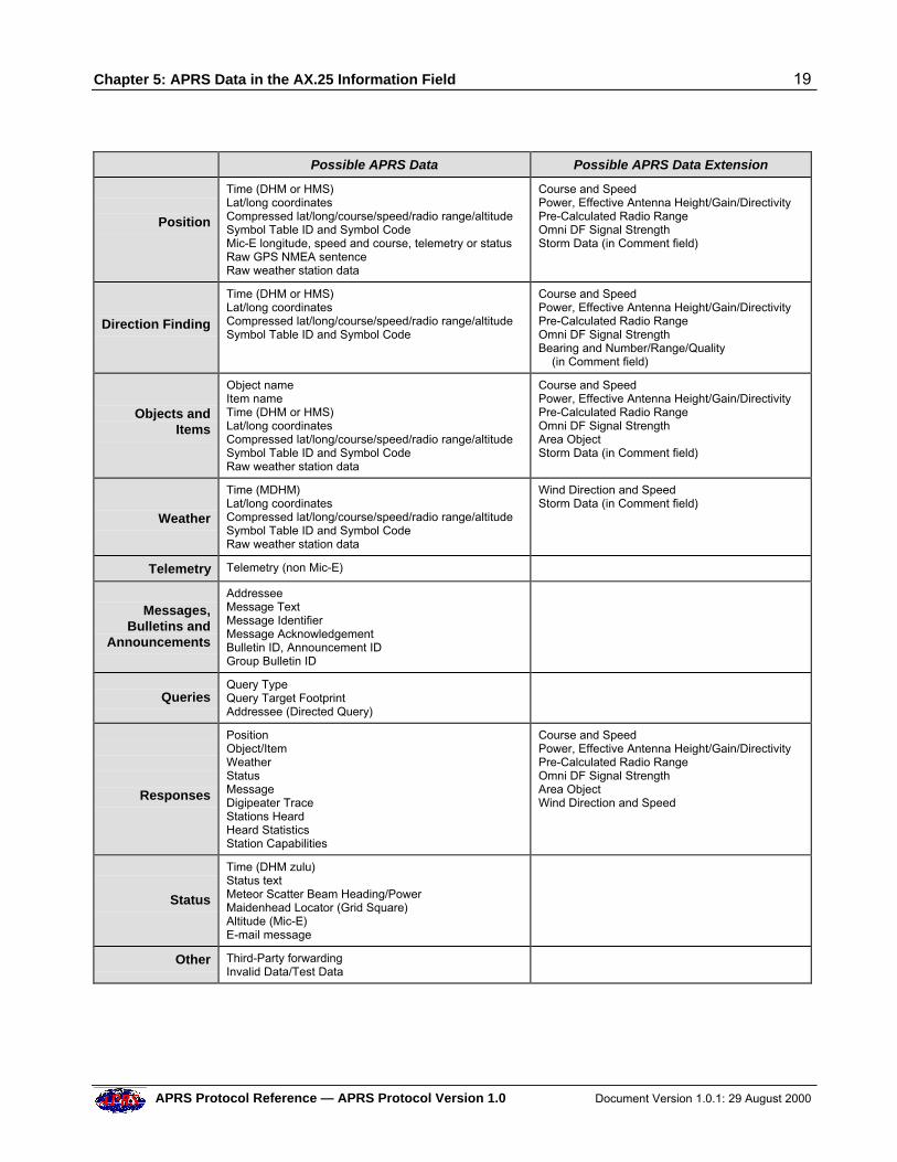
APRS Data andData Extension
There are 10 main types of APRS Data:
• Position
• Direction Finding
• Objects and Items
• Weather
• Telemetry
• Messages, Bulletins and Announcements
• Queries
• Responses
• Status
• Other
Some of this data may also have an APRS Data Extension that providesadditional information.
The APRS Data and optional Data Extension follow the Data Type Identifier.
The table on the next page shows a complete list of all the different possibletypes of APRS Data and APRS Data Extension.
Chapter 5: APRS Data in the AX.25 Information Field 19
APRS Protocol Reference — APRS Protocol Version 1.0 Document Version 1.0.1: 29 August 2000
Possible APRS Data Possible APRS Data Extension
Position
Time (DHM or HMS)Lat/long coordinatesCompressed lat/long/course/speed/radio range/altitudeSymbol Table ID and Symbol CodeMic-E longitude, speed and course, telemetry or statusRaw GPS NMEA sentenceRaw weather station data
Course and SpeedPower, Effective Antenna Height/Gain/DirectivityPre-Calculated Radio RangeOmni DF Signal StrengthStorm Data (in Comment field)
Direction Finding
Time (DHM or HMS)Lat/long coordinatesCompressed lat/long/course/speed/radio range/altitudeSymbol Table ID and Symbol Code
Course and SpeedPower, Effective Antenna Height/Gain/DirectivityPre-Calculated Radio RangeOmni DF Signal StrengthBearing and Number/Range/Quality (in Comment field)
Objects andItems
Object nameItem nameTime (DHM or HMS)Lat/long coordinatesCompressed lat/long/course/speed/radio range/altitudeSymbol Table ID and Symbol CodeRaw weather station data
Course and SpeedPower, Effective Antenna Height/Gain/DirectivityPre-Calculated Radio RangeOmni DF Signal StrengthArea ObjectStorm Data (in Comment field)
Weather
Time (MDHM)Lat/long coordinatesCompressed lat/long/course/speed/radio range/altitudeSymbol Table ID and Symbol CodeRaw weather station data
Wind Direction and SpeedStorm Data (in Comment field)
Telemetry Telemetry (non Mic-E)
Messages,
Bulletins andAnnouncements
AddresseeMessage TextMessage IdentifierMessage AcknowledgementBulletin ID, Announcement IDGroup Bulletin ID
Queries
Query TypeQuery Target FootprintAddressee (Directed Query)
Responses
PositionObject/ItemWeatherStatusMessage Digipeater TraceStations HeardHeard StatisticsStation Capabilities
Course and SpeedPower, Effective Antenna Height/Gain/DirectivityPre-Calculated Radio RangeOmni DF Signal StrengthArea ObjectWind Direction and Speed
Status
Time (DHM zulu)Status textMeteor Scatter Beam Heading/PowerMaidenhead Locator (Grid Square)Altitude (Mic-E)E-mail message
Other Third-Party forwardingInvalid Data/Test Data
20 Chapter 5: APRS Data in the AX.25 Information Field
Document Version 1.0.1: 29 August 2000 APRS Protocol Reference — APRS Protocol Version 1.0
Comment Field In general, any APRS packet can contain a plain text comment (such as abeacon message) in the Information field, immediately following the APRSData or APRS Data Extension.
There is no separator between the APRS data and the comment unlessotherwise stated.
The comment may contain any printable ASCII characters (except | and ~,which are reserved for TNC channel switching).
The maximum length of the comment field depends on the report — detailsare included in the description of each report.
In special cases, the Comment field can also contain further APRS data:
• Altitude in comment text (see Chapter 6: Time and Position Formats), orin Mic-E status text (see Chapter 10: Mic-E Data Format).
• Maidenhead Locator (grid square), in a Mic-E status text field (seeChapter 10: Mic-E Data Format) or in a Status Report (see Chapter 16:Status Reports).
• Bearing and Number/Range/Quality parameters (/BRG/NRQ), in DFreports (see Chapter 7: APRS Data Extensions).
• Area Object Line Widths (see Chapter 11: Object and Item Reports).
• Signpost Objects (see Chapter 11: Object and Item Reports).
• Weather and Storm Data (see Chapter 12: Weather Reports).
• Beam Heading and Power, in Status Reports (see Chapter 16: StatusReports).
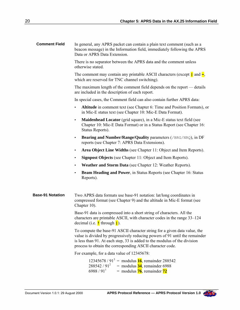
Base-91 Notation Two APRS data formats use base-91 notation: lat/long coordinates incompressed format (see Chapter 9) and the altitude in Mic-E format (seeChapter 10).
Base-91 data is compressed into a short string of characters. All thecharacters are printable ASCII, with character codes in the range 33–124decimal (i.e. ! through |).
To compute the base-91 ASCII character string for a given data value, thevalue is divided by progressively reducing powers of 91 until the remainderis less than 91. At each step, 33 is added to the modulus of the divisionprocess to obtain the corresponding ASCII character code.
For example, for a data value of 12345678:
12345678 / 913 = modulus 16, remainder 288542288542 / 912 = modulus 34, remainder 69886988 / 911 = modulus 76, remainder 72
Chapter 5: APRS Data in the AX.25 Information Field 21
APRS Protocol Reference — APRS Protocol Version 1.0 Document Version 1.0.1: 29 August 2000
The four ASCII character codes are thus 49 (i.e. 16+33), 67 (i.e. 34+33), 109(i.e. 76+33) and 105 (i.e. 72+33), corresponding to the ASCII string 1Cmi.
APRS Data Units For historical reasons there is some lack of consistency between units of datain APRS packets — some speeds are in knots, others in miles per hour; somealtitudes are in feet, others in meters, and so on. It is emphasized that thisspecification describes the units of data as they are transmitted on-air. It isthe responsibility of APRS applications to convert the on-air units to moresuitable units if required.
The default GPS earth datum is World Geodetic System (WGS) 1984.
22 Chapter 6: Time and Position Formats
Document Version 1.0.1: 29 August 2000 APRS Protocol Reference — APRS Protocol Version 1.0
6 TIME AND POSITION FORMATS
Time Formats APRS timestamps are expressed in three different ways:
• Day/Hours/Minutes format
• Hours/Minutes/Seconds format
• Month/Day/Hours/Minutes format
In all three formats, the 24-hour clock is used.
Day/Hours/Minutes (DHM) format is a fixed 7-character field, consisting ofa 6-digit day/time group followed by a single time indicator character (z or/). The day/time group consists of a two-digit day-of-the-month (01–31) anda four-digit time in hours and minutes.
Times can be expressed in zulu (UTC/GMT) or local time. For example:
092345z is 2345 hours zulu time on the 9th day of the month.092345/ is 2345 hours local time on the 9th day of the month.
It is recommended that future APRS implementations only transmit zuluformat on the air.
Note: The time in Status Reports may only be in zulu format.
Hours/Minutes/Seconds (HMS) format is a fixed 7-character field,consisting of a 6-digit time in hours, minutes and seconds, followed by the htime-indicator character. For example:
234517h is 23 hours 45 minutes and 17 seconds zulu.
Note: This format may not be used in Status Reports.
Month/Day/Hours/Minutes (MDHM) format is a fixed 8-character field,consisting of the month (01–12) and day-of-the-month (01–31), followed bythe time in hours and minutes zulu. For example:
10092345 is 23 hours 45 minutes zulu on October 9th.
This format is only used in reports from stand-alone “positionless” weatherstations (i.e. reports that do not contain station position information).
Chapter 6: Time and Position Formats 23
APRS Protocol Reference — APRS Protocol Version 1.0 Document Version 1.0.1: 29 August 2000
Use of Timestamps When a station transmits a report without a timestamp, an APRS receivingstation can make an internal record of the time it was received, if required.This record is the receiving station’s notion of the time the report wascreated.
On the other hand, when a station transmits a report with a timestamp, thattimestamp represents the transmitting station’s notion of the time the reportwas created.
In other words, reports sent without a timestamp can be regarded as real-time,“current” reports (and the receiving station has to record the time they werereceived), whereas reports sent with a timestamp may or may not be real-time, and may possibly be (very) “old”.
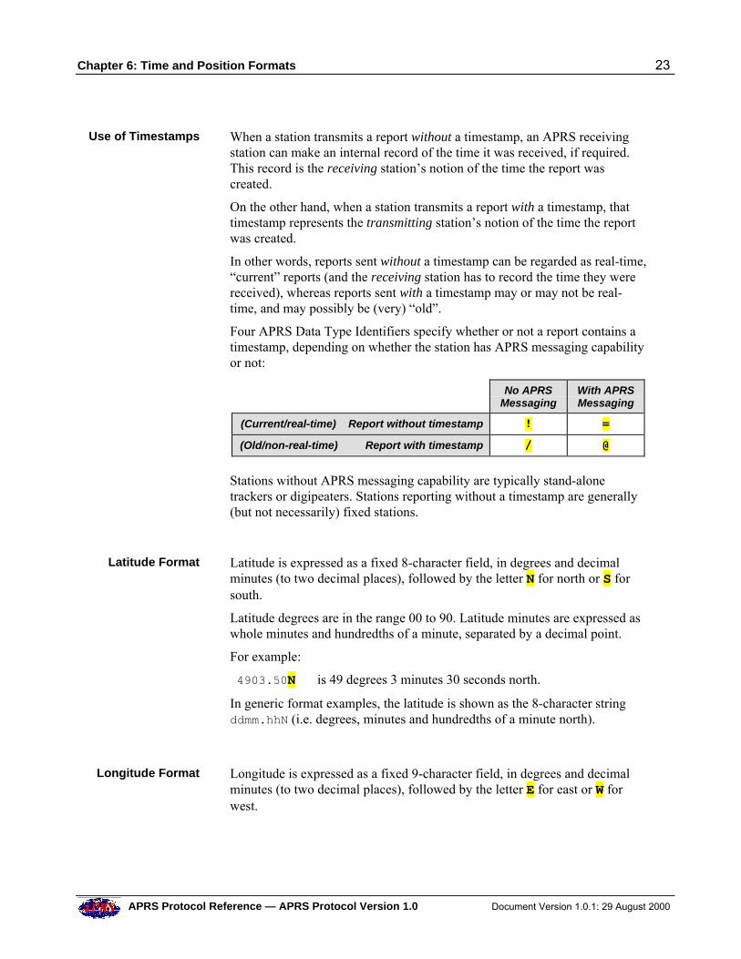
Four APRS Data Type Identifiers specify whether or not a report contains atimestamp, depending on whether the station has APRS messaging capabilityor not:
No APRS
Messaging With APRSMessaging
(Current/real-time) Report without timestamp ! =
(Old/non-real-time) Report with timestamp / @
Stations without APRS messaging capability are typically stand-alonetrackers or digipeaters. Stations reporting without a timestamp are generally(but not necessarily) fixed stations.
Latitude Format Latitude is expressed as a fixed 8-character field, in degrees and decimalminutes (to two decimal places), followed by the letter N for north or S forsouth.
Latitude degrees are in the range 00 to 90. Latitude minutes are expressed aswhole minutes and hundredths of a minute, separated by a decimal point.
For example:
4903.50N is 49 degrees 3 minutes 30 seconds north.
In generic format examples, the latitude is shown as the 8-character stringddmm.hhN (i.e. degrees, minutes and hundredths of a minute north).
Longitude Format Longitude is expressed as a fixed 9-character field, in degrees and decimalminutes (to two decimal places), followed by the letter E for east or W forwest.
24 Chapter 6: Time and Position Formats
Document Version 1.0.1: 29 August 2000 APRS Protocol Reference — APRS Protocol Version 1.0
Longitude degrees are in the range 000 to 180. Longitude minutes areexpressed as whole minutes and hundredths of a minute, separated by adecimal point.
For example:
07201.75W is 72 degrees 1 minute 45 seconds west.
In generic format examples, the longitude is shown as the 9-character stringdddmm.hhW (i.e. degrees, minutes and hundredths of a minute west).
PositionCoordinates
Position coordinates are a combination of latitude and longitude, separatedby a display Symbol Table Identifier, and followed by a Symbol Code. Forexample:
4903.50N/07201.75W-
The / character between latitude and longitude is the Symbol TableIdentifier (in this case indicating use of the Primary Symbol Table), and the –character at the end is the Symbol Code from that table (in this case,indicating a “house” icon).
A description of display symbols is included in Chapter 20: APRS Symbols.The full Symbol Table listing is in Appendix 2.
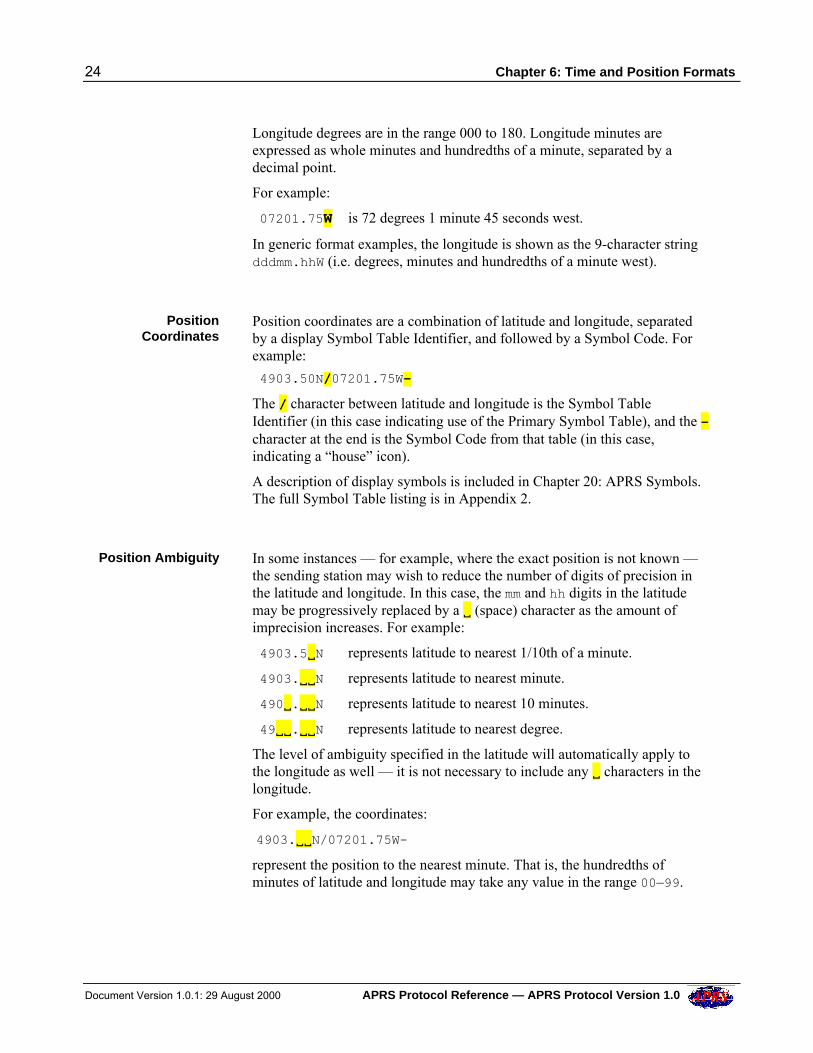
Position Ambiguity In some instances — for example, where the exact position is not known —the sending station may wish to reduce the number of digits of precision inthe latitude and longitude. In this case, the mm and hh digits in the latitudemay be progressively replaced by a V (space) character as the amount ofimprecision increases. For example:
4903.5VN represents latitude to nearest 1/10th of a minute.
4903.VVN represents latitude to nearest minute.
490V.VVN represents latitude to nearest 10 minutes.
49VV.VVN represents latitude to nearest degree.
The level of ambiguity specified in the latitude will automatically apply tothe longitude as well — it is not necessary to include any V characters in thelongitude.
For example, the coordinates:
4903.VVN/07201.75W-
represent the position to the nearest minute. That is, the hundredths ofminutes of latitude and longitude may take any value in the range 00–99.
Chapter 6: Time and Position Formats 25
APRS Protocol Reference — APRS Protocol Version 1.0 Document Version 1.0.1: 29 August 2000
Thus the station may be located anywhere inside a bounding box having thefollowing corner coordinates:
North West corner: 49 deg 3.99 mins N, 72 deg 1.99 mins W North East corner: 49 deg 3.99 mins N, 72 deg 1.00 mins W South East corner: 49 deg 3.00 mins N, 72 deg 1.00 mins W South West corner: 49 deg 3.00 mins N, 72 deg 1.99 mins W
Default NullPosition
Where a station does not have any specific position information to transmit(for example, a Mic-E unit without a GPS receiver connected to it), thestation must transmit a default null position in the location field.
The null position corresponds to 0° 0' 0" north, 0° 0' 0" west.
The null position should be include the \. symbol (unknown/indeterminateposition). For example, a Position Report for a station with unknown positionwill contain the coordinates …0000.00N\00000.00W.…
MaidenheadLocator
(Grid Square)
An alternative method of expressing a station’s location is to provide aMaidenhead locator (grid square). There are four ways of doing this:
• In a Status Report — e.g. IO91SX/-(/- represents the symbol for a “house”).
• In Mic-E Status Text — e.g. IO91SX/G(/G indicates a “grid square”).
• In the Destination Address — e.g. IO91SX. (obsolete).
• In AX.25 beacon text, with the [ APRS Data Type Identifier — e.g.[IO91SX] (obsolete).
Grid squares may be in 6-character form (as above) or in the shortened4-character form (e.g. IO91).
NMEA Data APRS recognizes raw ASCII data strings conforming to the NMEA 0183Version 2.0 specification, originating from navigation equipment such asGPS and LORAN receivers. It is recommended that APRS stations interpretat least the following NMEA Received Sentence types:
GGA Global Positioning System Fix Data GLL Geographic Position, Latitude/Longitude Data RMC Recommended Minimum Specific GPS/Transit Data VTG Velocity and Track Data WPT Way Point Location
26 Chapter 6: Time and Position Formats
Document Version 1.0.1: 29 August 2000 APRS Protocol Reference — APRS Protocol Version 1.0
Altitude Altitude may be expressed in two ways:
• In the comment text.
• In Mic-E format.
Altitude in Comment Text — The comment may contain an altitude value,in the form /A=aaaaaa, where aaaaaa is the altitude in feet. For example:/A=001234. The altitude may appear anywhere in the comment.
Altitude in Mic-E format — The optional Mic-E status field can containaltitude data. See Chapter 10: Mic-E Data Format.
Chapter 7: APRS Data Extensions 27
APRS Protocol Reference — APRS Protocol Version 1.0 Document Version 1.0.1: 29 August 2000
7 APRS DATA EXTENSIONS
A fixed-length 7-byte field may follow APRS position data. This field is anAPRS Data Extension. The extension may be one of the following:
• CSE/SPD Course and Speed (this may be followed by a further 8 bytescontaining DF bearing and Number/Range/Qualityparameters)
• DIR/SPD Wind Direction and Wind Speed
• PHGphgd Station Power and Effective Antenna Height/Gain/ Directivity
• RNGrrrr Pre-Calculated Radio Range
• DFSshgd DF Signal Strength and Effective Antenna Height/Gain
• Tyy/Cxx Area Object Descriptor
Course and Speed The 7-byte CSE/SPD Data Extension can be used to represent the course andspeed of a vehicle or APRS Object.
The course is expressed in degrees (001-360), clockwise from due north. Thespeed is expressed in knots. A slash / character separates the two.
For example:
088/036 represents a course 88 degrees, traveling at 36 knots.
If the course and speed are unknown or not relevant, they can be set to000/000 or .../... or VVVVVV/VVVVVV.
Note: In the special case of DF reports, a course of 000 means that the DFstation is fixed. If the course is non-zero, the station is mobile.
Wind Directionand Wind Speed
The 7-byte DIR/SPD Data Extension can be used to represent the winddirection and sustained one-minute wind speed in a Weather Report.
The wind direction is expressed in degrees (001-360), clockwise from duenorth. The speed is expressed in knots. A slash / character separates the two.
For example:
220/004 represents a wind direction of 220 degrees and a speed of 4 knots.
If the wind direction and speed are unknown or not relevant, they can be setto 000/000 or .../... or VVVVVV/VVVVVV.
28 Chapter 7: APRS Data Extensions
Document Version 1.0.1: 29 August 2000 APRS Protocol Reference — APRS Protocol Version 1.0
Power,Effective Antenna
Height/Gain/Directivity
The 7-byte PHGphgd Data Extension specifies the transmitter power,effective antenna height-above-average-terrain, antenna gain and antennadirectivity. APRS uses this information to plot radio range circles aroundstations.
The 7 characters of this Data Extension are encoded as follows:
Characters 1–3: PHG (fixed)Character 4: p Power codeCharacter 5: h Height codeCharacter 6: g Antenna gain codeCharacter 7: d Directivity code
The PHG codes are listed in the table below:
PHG Codes
phgd Code: 0 1 2 3 4 5 6 7 8 9 Units
Power 0 1 4 9 16 25 36 49 64 81 watts
Height 10 20 40 80 160 320 640 1280 2560 5120 feet
Gain 0 1 2 3 4 5 6 7 8 9 dB
Directivity omni 45NE
90E
135SE
180S
225SW
270W
315NW
360N
deg
The height code represents the effective height of the antenna above averagelocal terrain, not above ground or sea level — this is to provide a roughindication of the antenna’s effectiveness in the local area .
The height code may in fact be any ASCII character 0–9 and above. This isso that larger heights for balloons, aircraft or satellites may be specified.
For example: : is the height code for 10240 feet (approximately 1.9 miles). ; is the height code for 20480 feet (approximately 3.9 miles), and so on.
The Directivity code offsets the PHG circle by one third in the indicateddirection. This means a front-to-back ratio of 2 to 1. Most often this is usedto indicate a favored direction or a null, even if an omni antenna is at the site.
An example of the PHG Data Extension:
PHG5132 means a power of 25 watts,an antenna height of 20 feet above the average local terrain,an antenna gain of 3 dB,and maximum gain due east.
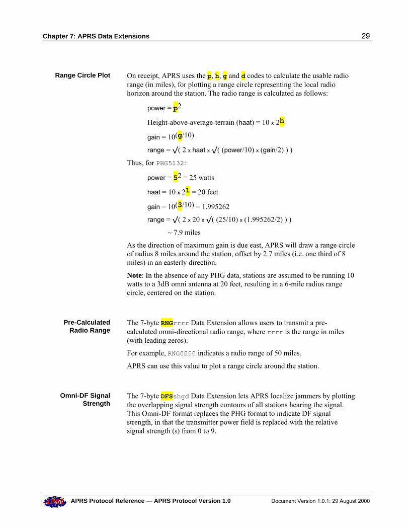
Chapter 7: APRS Data Extensions 29
APRS Protocol Reference — APRS Protocol Version 1.0 Document Version 1.0.1: 29 August 2000
Range Circle Plot On receipt, APRS uses the p, h, g and d codes to calculate the usable radiorange (in miles), for plotting a range circle representing the local radiohorizon around the station. The radio range is calculated as follows:
power = p2
Height-above-average-terrain (haat) = 10 x 2h
gain = 10(g/10)
range = –( 2 x haat x –( (power/10) x (gain/2) ) )
Thus, for PHG5132:
power = 52 = 25 watts
haat = 10 x 21 = 20 feet
gain = 10(3/10) = 1.995262
range = –( 2 x 20 x –( (25/10) x (1.995262/2) ) )
~ 7.9 miles
As the direction of maximum gain is due east, APRS will draw a range circleof radius 8 miles around the station, offset by 2.7 miles (i.e. one third of 8miles) in an easterly direction.
Note: In the absence of any PHG data, stations are assumed to be running 10watts to a 3dB omni antenna at 20 feet, resulting in a 6-mile radius rangecircle, centered on the station.
Pre-CalculatedRadio Range
The 7-byte RNGrrrr Data Extension allows users to transmit a pre-calculated omni-directional radio range, where rrrr is the range in miles(with leading zeros).
For example, RNG0050 indicates a radio range of 50 miles.
APRS can use this value to plot a range circle around the station.
Omni-DF SignalStrength
The 7-byte DFSshgd Data Extension lets APRS localize jammers by plottingthe overlapping signal strength contours of all stations hearing the signal.This Omni-DF format replaces the PHG format to indicate DF signalstrength, in that the transmitter power field is replaced with the relativesignal strength (s) from 0 to 9.
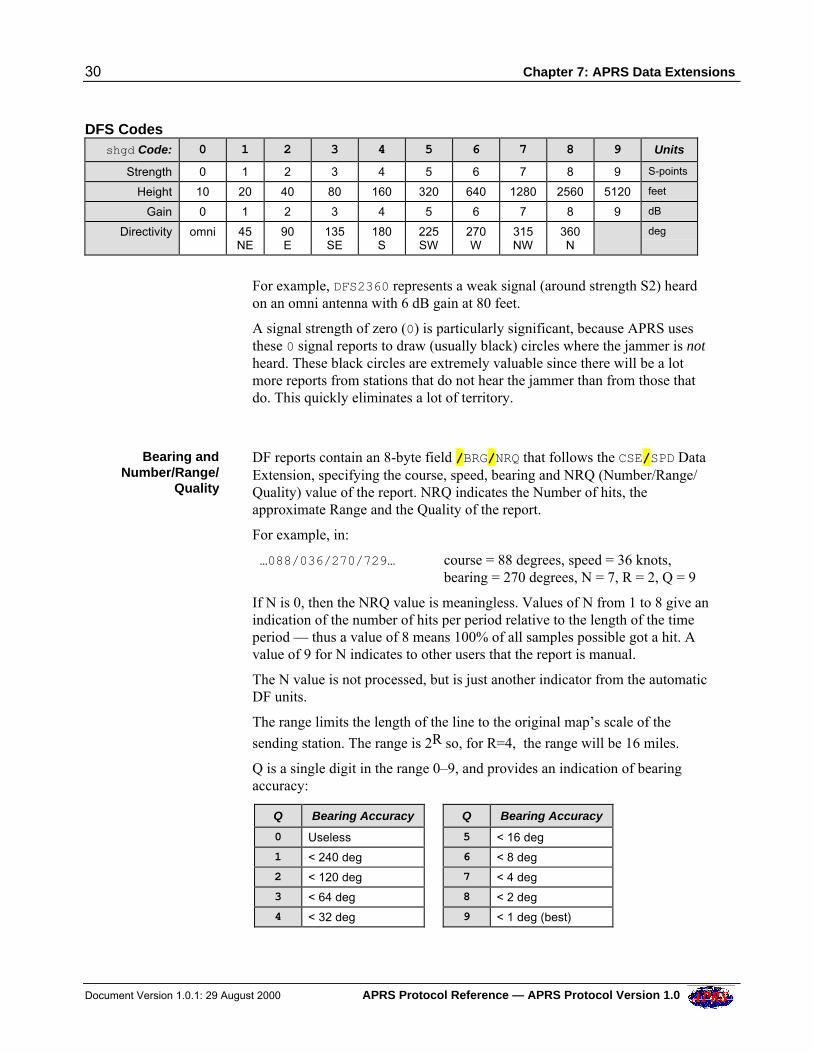
30 Chapter 7: APRS Data Extensions
Document Version 1.0.1: 29 August 2000 APRS Protocol Reference — APRS Protocol Version 1.0
DFS Codes shgd Code: 0 1 2 3 4 5 6 7 8 9 Units
Strength 0 1 2 3 4 5 6 7 8 9 S-points
Height 10 20 40 80 160 320 640 1280 2560 5120 feet
Gain 0 1 2 3 4 5 6 7 8 9 dB
Directivity omni 45NE
90E
135SE
180S
225SW
270W
315NW
360N
deg
For example, DFS2360 represents a weak signal (around strength S2) heardon an omni antenna with 6 dB gain at 80 feet.
A signal strength of zero (0) is particularly significant, because APRS usesthese 0 signal reports to draw (usually black) circles where the jammer is notheard. These black circles are extremely valuable since there will be a lotmore reports from stations that do not hear the jammer than from those thatdo. This quickly eliminates a lot of territory.
Bearing andNumber/Range/
Quality
DF reports contain an 8-byte field /BRG/NRQ that follows the CSE/SPD DataExtension, specifying the course, speed, bearing and NRQ (Number/Range/Quality) value of the report. NRQ indicates the Number of hits, theapproximate Range and the Quality of the report.
For example, in:
…088/036/270/729… course = 88 degrees, speed = 36 knots,bearing = 270 degrees, N = 7, R = 2, Q = 9
If N is 0, then the NRQ value is meaningless. Values of N from 1 to 8 give anindication of the number of hits per period relative to the length of the timeperiod — thus a value of 8 means 100% of all samples possible got a hit. Avalue of 9 for N indicates to other users that the report is manual.
The N value is not processed, but is just another indicator from the automaticDF units.
The range limits the length of the line to the original map’s scale of the
sending station. The range is 2R so, for R=4, the range will be 16 miles.
Q is a single digit in the range 0–9, and provides an indication of bearingaccuracy:
Q Bearing Accuracy Q Bearing Accuracy
0 Useless 5 < 16 deg
1 < 240 deg 6 < 8 deg
2 < 120 deg 7 < 4 deg
3 < 64 deg 8 < 2 deg
4 < 32 deg 9 < 1 deg (best)
Chapter 7: APRS Data Extensions 31
APRS Protocol Reference — APRS Protocol Version 1.0 Document Version 1.0.1: 29 August 2000
If the course and speed parameters are not appropriate, they should have thevalue 000/000 or .../... or VVVVVV/VVVVVV.
Area ObjectDescriptor
The 7-byte Tyy/Cxx Data Extension is an Area Object Descriptor. The Tparameter specifies the type of object (square, circle, triangle, etc) and the/C parameter specifies its fill color.
Area Objects are described in Chapter 11: Object and Item Reports.
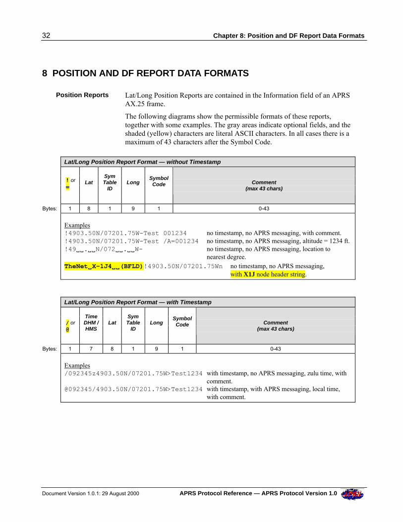
32 Chapter 8: Position and DF Report Data Formats
Document Version 1.0.1: 29 August 2000 APRS Protocol Reference — APRS Protocol Version 1.0
8 POSITION AND DF REPORT DATA FORMATS
Position Reports Lat/Long Position Reports are contained in the Information field of an APRSAX.25 frame.
The following diagrams show the permissible formats of these reports,together with some examples. The gray areas indicate optional fields, and theshaded (yellow) characters are literal ASCII characters. In all cases there is amaximum of 43 characters after the Symbol Code.
Lat/Long Position Report Format — without Timestamp
! or =
Lat
SymTable
ID
Long
SymbolCode
Comment
(max 43 chars)
Bytes: 1 8 1 9 1 0-43
Examples!4903.50N/07201.75W-Test 001234 no timestamp, no APRS messaging, with comment.!4903.50N/07201.75W-Test /A=001234 no timestamp, no APRS messaging, altitude = 1234 ft.!49VV.VVN/072VV.VVW- no timestamp, no APRS messaging, location to
nearest degree. TheNetVVX-1J4VVVV(BFLD)!4903.50N/07201.75Wn no timestamp, no APRS messaging,
with X1J node header string.
Lat/Long Position Report Format — with Timestamp
/ or @
TimeDHM /HMS
Lat
SymTable
ID
Long
SymbolCode
Comment
(max 43 chars)
Bytes: 1 7 8 1 9 1 0-43
Examples/092345z4903.50N/07201.75W>Test1234 with timestamp, no APRS messaging, zulu time, with
comment.@092345/4903.50N/07201.75W>Test1234 with timestamp, with APRS messaging, local time,
with comment.
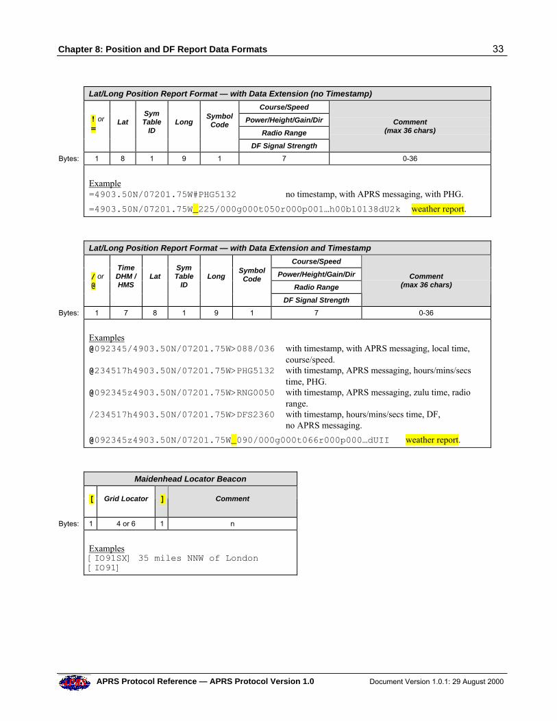
Chapter 8: Position and DF Report Data Formats 33
APRS Protocol Reference — APRS Protocol Version 1.0 Document Version 1.0.1: 29 August 2000
Lat/Long Position Report Format — with Data Extension (no Timestamp)
Course/Speed
Power/Height/Gain/Dir
Radio Range
! or =
Lat
SymTable
ID
Long
SymbolCode
DF Signal Strength
Comment
(max 36 chars)
Bytes: 1 8 1 9 1 7 0-36
Example=4903.50N/07201.75W#PHG5132 no timestamp, with APRS messaging, with PHG.
=4903.50N/07201.75W_225/000g000t050r000p001…h00b10138dU2k weather report.
Lat/Long Position Report Format — with Data Extension and Timestamp
Course/Speed
Power/Height/Gain/Dir
Radio Range
/ or @
TimeDHM /HMS
Lat
SymTable
ID
Long
SymbolCode
DF Signal Strength
Comment
(max 36 chars)
Bytes: 1 7 8 1 9 1 7 0-36
Examples@092345/4903.50N/07201.75W>088/036 with timestamp, with APRS messaging, local time,
course/[email protected]/07201.75W>PHG5132 with timestamp, APRS messaging, hours/mins/secs
time, [email protected]/07201.75W>RNG0050 with timestamp, APRS messaging, zulu time, radio
range./234517h4903.50N/07201.75W>DFS2360 with timestamp, hours/mins/secs time, DF,
no APRS messaging.
@092345z4903.50N/07201.75W_090/000g000t066r000p000…dUII weather report.
Maidenhead Locator Beacon
[ Grid Locator
] Comment
Bytes: 1 4 or 6 1 n
Examples[IO91SX] 35 miles NNW of London[IO91]
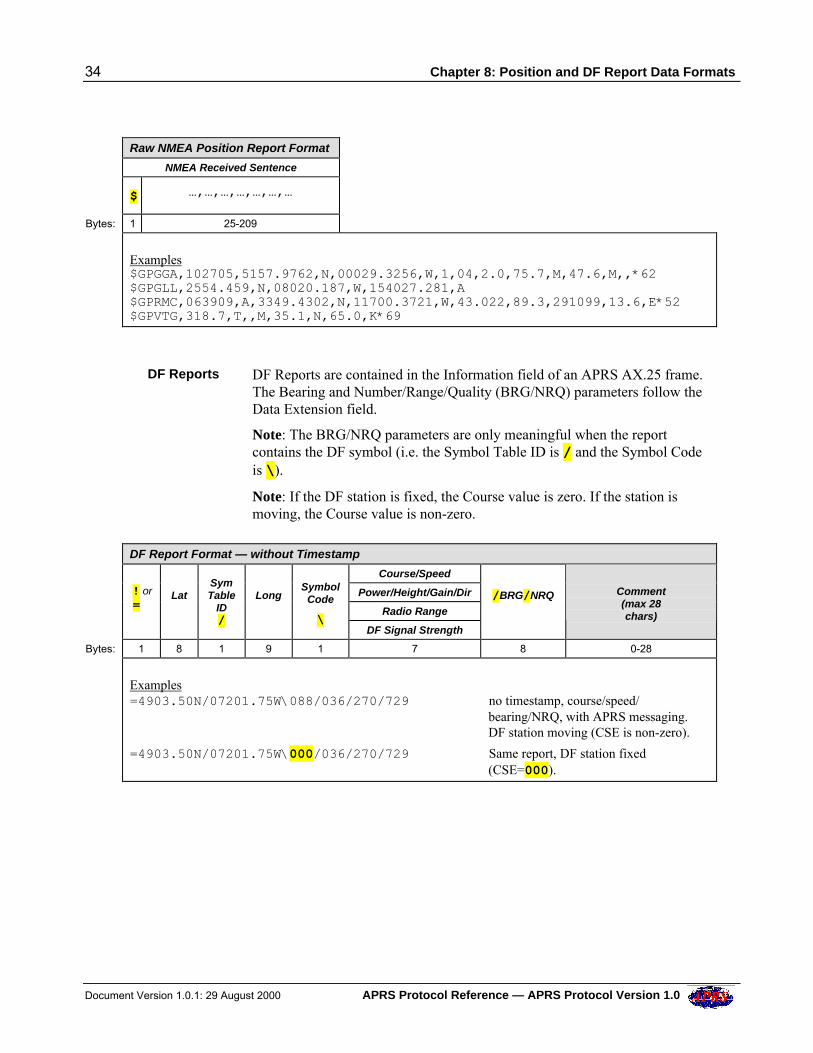
34 Chapter 8: Position and DF Report Data Formats
Document Version 1.0.1: 29 August 2000 APRS Protocol Reference — APRS Protocol Version 1.0
Raw NMEA Position Report Format
NMEA Received Sentence
$ …,…,…,…,…,…,…
Bytes: 1 25-209
Examples$GPGGA,102705,5157.9762,N,00029.3256,W,1,04,2.0,75.7,M,47.6,M,,*62$GPGLL,2554.459,N,08020.187,W,154027.281,A$GPRMC,063909,A,3349.4302,N,11700.3721,W,43.022,89.3,291099,13.6,E*52$GPVTG,318.7,T,,M,35.1,N,65.0,K*69
DF Reports DF Reports are contained in the Information field of an APRS AX.25 frame.The Bearing and Number/Range/Quality (BRG/NRQ) parameters follow theData Extension field.
Note: The BRG/NRQ parameters are only meaningful when the reportcontains the DF symbol (i.e. the Symbol Table ID is / and the Symbol Codeis \).
Note: If the DF station is fixed, the Course value is zero. If the station ismoving, the Course value is non-zero.
DF Report Format — without Timestamp
Course/Speed
Power/Height/Gain/Dir
Radio Range
! or =
Lat
SymTable
ID/
Long
SymbolCode
\ DF Signal Strength
/BRG/NRQ
Comment(max 28chars)
Bytes: 1 8 1 9 1 7 8 0-28
Examples=4903.50N/07201.75W\088/036/270/729 no timestamp, course/speed/
bearing/NRQ, with APRS messaging. DF station moving (CSE is non-zero).
=4903.50N/07201.75W\000/036/270/729 Same report, DF station fixed (CSE=000).
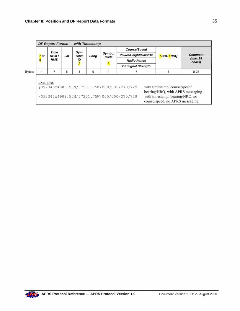
Chapter 8: Position and DF Report Data Formats 35
APRS Protocol Reference — APRS Protocol Version 1.0 Document Version 1.0.1: 29 August 2000
DF Report Format — with Timestamp
Course/Speed
Power/Height/Gain/Dir
Radio Range
/ or @
TimeDHM /HMS
Lat
SymTable
ID/
Long
SymbolCode
\ DF Signal Strength
/BRG/NRQ
Comment(max 28chars)
Bytes: 1 7 8 1 9 1 7 8 0-28
[email protected]/07201.75W\088/036/270/729 with timestamp, course/speed/
bearing/NRQ, with APRS messaging./092345z4903.50N/07201.75W\000/000/270/729 with timestamp, bearing/NRQ, no course/speed, no APRS messaging.
36 Chapter 9: Compressed Position Report Data Formats
Document Version 1.0.1: 29 August 2000 APRS Protocol Reference — APRS Protocol Version 1.0
9 COMPRESSED POSITION REPORT DATA FORMATS
In compressed data format, the Information field contains the station’slatitude and longitude, together with course and speed or pre-calculated radiorange or altitude.
This information is compressed to minimize the length of the transmittedpacket (and therefore improve its chances of being received correctly underless than ideal conditions).
The Information field also contains a display Symbol Code, and there mayoptionally be a plain text comment (uncompressed) as well.
The Advantages ofData Compression
Compressed data format may be used in place of the numeric lat/longcoordinates already described, such as in the !, /, @ and = formats.
Data compression has several important benefits:
• Fully backwards compatible with all existing formats.
• Fully supports any comment string.
• Speed is accurate to +/-1 mph up to about 40 mph and within 3% at 600mph.
• Altitude in feet is accurate to +/- 0.4% from 1 foot to 3000 miles.
• Consistent one-algorithm processing of compressed latitude andlongitude.
• Improved position to 1 foot worldwide.
• Pre-calculated radio range, compressed to one byte.
• Potential 50% compression of every position format on the air.
• Potential 40% reduction of raw GPS NMEA data length.
• Additional 7-byte reduction for NEMA GGA altitudes.
• Support for TNC compression at the NMEA source (from the GPSreceiver).
• Digipeater compression of old NMEA trackers on the fly.
• Usage is optional in all cases.
The only minor disadvantages are that the course only resolves to +/- 2degrees, and this format does not support PHG.
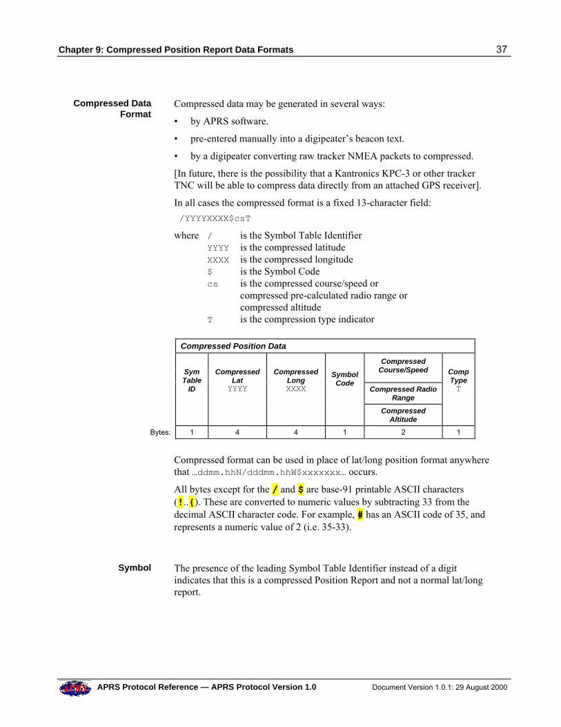
Chapter 9: Compressed Position Report Data Formats 37
APRS Protocol Reference — APRS Protocol Version 1.0 Document Version 1.0.1: 29 August 2000
Compressed DataFormat
Compressed data may be generated in several ways:
• by APRS software.
• pre-entered manually into a digipeater’s beacon text.
• by a digipeater converting raw tracker NMEA packets to compressed.
[In future, there is the possibility that a Kantronics KPC-3 or other trackerTNC will be able to compress data directly from an attached GPS receiver].
In all cases the compressed format is a fixed 13-character field:
/YYYYXXXX$csT
where / is the Symbol Table IdentifierYYYY is the compressed latitudeXXXX is the compressed longitude$ is the Symbol Codecs is the compressed course/speed or
compressed pre-calculated radio range orcompressed altitude
T is the compression type indicator
Compressed Position Data
CompressedCourse/Speed
Compressed RadioRange
SymTable
ID
Compressed
LatYYYY
Compressed
LongXXXX
Symbol
Code
CompressedAltitude
CompTypeT
Bytes: 1 4 4 1 2 1
Compressed format can be used in place of lat/long position format anywherethat …ddmm.hhN/dddmm.hhW$xxxxxxx… occurs.
All bytes except for the / and $ are base-91 printable ASCII characters(!..{). These are converted to numeric values by subtracting 33 from thedecimal ASCII character code. For example, # has an ASCII code of 35, andrepresents a numeric value of 2 (i.e. 35-33).
Symbol The presence of the leading Symbol Table Identifier instead of a digitindicates that this is a compressed Position Report and not a normal lat/longreport.
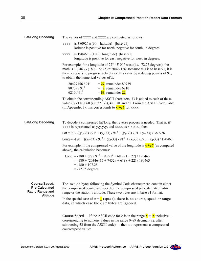
38 Chapter 9: Compressed Position Report Data Formats
Document Version 1.0.1: 29 August 2000 APRS Protocol Reference — APRS Protocol Version 1.0
Lat/Long Encoding The values of YYYY and XXXX are computed as follows:
YYYY is 380926 x (90 – latitude) [base 91]latitude is positive for north, negative for south, in degrees.
XXXX is 190463 x (180 + longitude) [base 91]longitude is positive for east, negative for west, in degrees.
For example, for a longitude of 72° 45' 00" west (i.e. -72.75 degrees), themath is 190463 x (180 – 72.75) = 20427156. Because this is to base 91, it isthen necessary to progressively divide this value by reducing powers of 91,to obtain the numerical values of X:
20427156 / 913 = 27, remainder 8073980739 / 912 = 9, remainder 62106210 / 911 = 68, remainder 22
To obtain the corresponding ASCII characters, 33 is added to each of thesevalues, yielding 60 (i.e. 27+33), 42, 101 and 55. From the ASCII Code Table(in Appendix 3), this corresponds to <*e7 for XXXX.
Lat/Long Decoding To decode a compressed lat/long, the reverse process is needed. That is, ifYYYY is represented as y1y2y3y4 and XXXX as x1x2x3x4, then:
Lat = 90 - ((y1-33) x 913 + (y2-33) x 912 + (y3-33) x 91 + y4-33) / 380926
Long = -180 + ((x1-33) x 913 + (x2-33) x 912 + (x3-33) x 91 + x4-33) / 190463
For example, if the compressed value of the longitude is <*e7 (as computedabove), the calculation becomes:
Long = -180 + (27 x 913 + 9 x 912 + 68 x 91 + 22) / 190463= -180 + (20346417 + 74529 + 6188 + 22) / 190463= -180 + 107.25= -72.75 degrees
Course/Speed,Pre-Calculated
Radio Range andAltitude
The two cs bytes following the Symbol Code character can contain eitherthe compressed course and speed or the compressed pre-calculated radiorange or the station’s altitude. These two bytes are in base 91 format.
In the special case of c = VV (space), there is no course, speed or rangedata, in which case the csT bytes are ignored.
Course/Speed — If the ASCII code for c is in the range ! to z inclusive —corresponding to numeric values in the range 0–89 decimal (i.e. aftersubtracting 33 from the ASCII code) — then cs represents a compressedcourse/speed value:
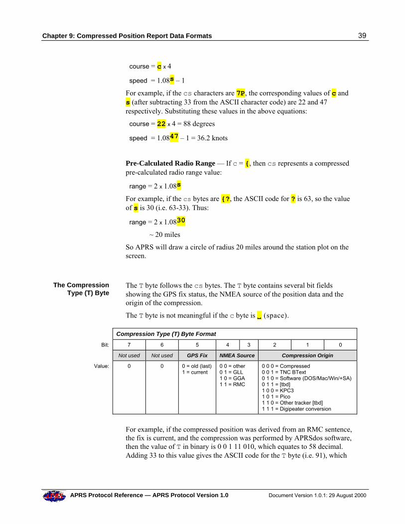
Chapter 9: Compressed Position Report Data Formats 39
APRS Protocol Reference — APRS Protocol Version 1.0 Document Version 1.0.1: 29 August 2000
course = c x 4
speed = 1.08s – 1
For example, if the cs characters are 7P, the corresponding values of c ands (after subtracting 33 from the ASCII character code) are 22 and 47respectively. Substituting these values in the above equations:
course = 22 x 4 = 88 degrees
speed = 1.0847 – 1 = 36.2 knots
Pre-Calculated Radio Range — If c = {, then cs represents a compressedpre-calculated radio range value:
range = 2 x 1.08s
For example, if the cs bytes are {?, the ASCII code for ? is 63, so the valueof s is 30 (i.e. 63-33). Thus:
range = 2 x 1.0830
~ 20 miles
So APRS will draw a circle of radius 20 miles around the station plot on thescreen.
The CompressionType (T) Byte
The T byte follows the cs bytes. The T byte contains several bit fieldsshowing the GPS fix status, the NMEA source of the position data and theorigin of the compression.
The T byte is not meaningful if the c byte is VV (space).
Compression Type (T) Byte Format
Bit: 7 6 5 4 3 2 1 0
Not used Not used GPS Fix NMEA Source Compression Origin
Value: 0 0 0 = old (last)1 = current
0 0 = other0 1 = GLL1 0 = GGA1 1 = RMC
0 0 0 = Compressed0 0 1 = TNC BText0 1 0 = Software (DOS/Mac/Win/+SA)0 1 1 = [tbd]1 0 0 = KPC31 0 1 = Pico1 1 0 = Other tracker [tbd]1 1 1 = Digipeater conversion
For example, if the compressed position was derived from an RMC sentence,the fix is current, and the compression was performed by APRSdos software,then the value of T in binary is 0 0 1 11 010, which equates to 58 decimal.Adding 33 to this value gives the ASCII code for the T byte (i.e. 91), which
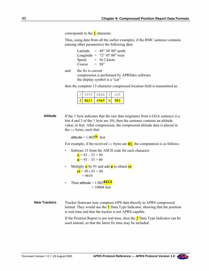
40 Chapter 9: Compressed Position Report Data Formats
Document Version 1.0.1: 29 August 2000 APRS Protocol Reference — APRS Protocol Version 1.0
corresponds to the [ character.
Thus, using data from all the earlier examples, if the RMC sentence contains(among other parameters) the following data:
Latitude = 49° 30' 00" north Longitude = 72° 45' 00" west Speed = 36.2 knots
Course = 88°
and: the fix is currentcompression is performed by APRSdos softwarethe display symbol is a “car”
then the complete 13-character compressed location field is transmitted as:
/ YYYY XXXX $ csT
/ 5L!! <*e7 > 7P[
Altitude If the T byte indicates that the raw data originates from a GGA sentence (i.e.bits 4 and 3 of the T byte are 10), then the sentence contains an altitudevalue, in feet. After compression, the compressed altitude data is placed inthe cs bytes, such that:
altitude = 1.002cs feet
For example, if the received cs bytes are S], the computation is as follows:
• Subtract 33 from the ASCII code for each character:c = 83 – 33 = 50s = 93 – 33 = 60
• Multiply c by 91 and add s to obtain cs:cs = 50 x 91 + 60 = 4610
• Then altitude = 1.0024610
= 10004 feet
New Trackers Tracker firmware may compress GPS data directly to APRS compressedformat. They would use the ! Data Type Indicator, showing that the positionis real-time and that the tracker is not APRS-capable.
If the Position Report is not real-time, then the / Data Type Indicator can beused instead, so that the latest fix time may be included.
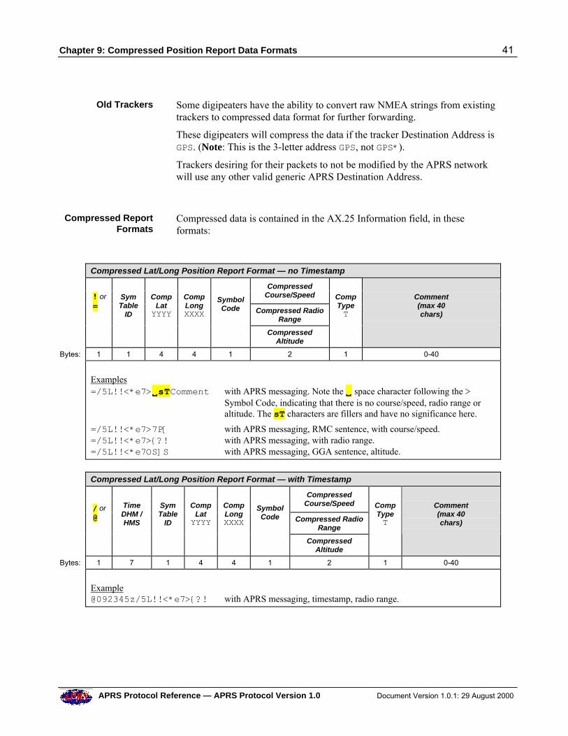
Chapter 9: Compressed Position Report Data Formats 41
APRS Protocol Reference — APRS Protocol Version 1.0 Document Version 1.0.1: 29 August 2000
Old Trackers Some digipeaters have the ability to convert raw NMEA strings from existingtrackers to compressed data format for further forwarding.
These digipeaters will compress the data if the tracker Destination Address isGPS. (Note: This is the 3-letter address GPS, not GPS*).
Trackers desiring for their packets to not be modified by the APRS networkwill use any other valid generic APRS Destination Address.
Compressed ReportFormats
Compressed data is contained in the AX.25 Information field, in theseformats:
Compressed Lat/Long Position Report Format — no Timestamp
Compressed
Course/Speed
Compressed RadioRange
! or =
SymTable
ID
Comp
LatYYYY
CompLongXXXX
SymbolCode
CompressedAltitude
CompTypeT
Comment(max 40chars)
Bytes: 1 1 4 4 1 2 1 0-40
Examples=/5L!!<*e7>VVsTComment with APRS messaging. Note the VV space character following the >
Symbol Code, indicating that there is no course/speed, radio range oraltitude. The sT characters are fillers and have no significance here.
=/5L!!<*e7>7P[ with APRS messaging, RMC sentence, with course/speed.=/5L!!<*e7>{?! with APRS messaging, with radio range.=/5L!!<*e7OS]S with APRS messaging, GGA sentence, altitude.
Compressed Lat/Long Position Report Format — with Timestamp
Compressed
Course/Speed
Compressed RadioRange
/ or @
TimeDHM /HMS
SymTable
ID
Comp
LatYYYY
CompLongXXXX
SymbolCode
CompressedAltitude
CompTypeT
Comment(max 40chars)
Bytes: 1 7 1 4 4 1 2 1 0-40
Example@092345z/5L!!<*e7>{?! with APRS messaging, timestamp, radio range.
42 Chapter 10: Mic-E Data Format
Document Version 1.0.1: 29 August 2000 APRS Protocol Reference — APRS Protocol Version 1.0
10 MIC-E DATA FORMAT
Mic-E Data Format In Mic-E data format, the station’s position, course, speed and displaysymbol, together with an APRS digipeater path and Mic-E Message Code,are packed into the AX.25 Destination Address and Information fields.
The Information field can also optionally contain either Mic-E telemetry dataor Mic-E status. The Mic-E Status can contain the station’s Maidenheadlocator and altitude.
Mic-E packets can be very short. At the minimum, with no callsigns in theDigipeater Addresses field and no optional telemetry data or Mic-E statustext, a complete Mic-E packet is just 25 bytes long (excluding FCS andflags).
Mic-E data format is not only used in the Microphone Encoder unit; it is alsoused in the PIC Encoder and in the Kenwood TH-D7 and TM-D700 radios.
Mic-E Data Payload The Mic-E data format allows a large amount of data to be carried in a veryshort packet. The data is split between the Destination Address field and theInformation field of a standard AX.25 UI-frame.
Destination Address Field — The 7-byte Destination Address field containsthe following encoded information:
• The 6 latitude digits.
• A 3-bit Mic-E message identifier, specifying one of 7 Standard Mic-EMessage Codes or one of 7 Custom Message Codes or an EmergencyMessage Code.
• The North/South and West/East Indicators.
• The Longitude Offset Indicator.
• The generic APRS digipeater path code.
Although the destination address appears to be quite unconventional, it isstill a valid AX.25 address, consisting only of printable 7-bit ASCII values(shifted one bit left) — see the Amateur Packet-Radio Link-Layer Protocolspecification for full details of the format of standard AX.25 addresses.
Information Field — This field contains the following data:
• The encoded longitude.
• The encoded course and speed.
• The display Symbol Code and Symbol Table Identifier.
• An optional field, containing either Mic-E telemetry data or a Mic-Estatus text string. The status string can contain plain text, Maidenhead
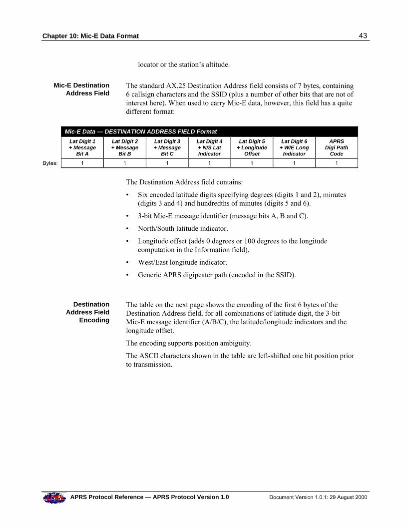
Chapter 10: Mic-E Data Format 43
APRS Protocol Reference — APRS Protocol Version 1.0 Document Version 1.0.1: 29 August 2000
locator or the station’s altitude.
Mic-E DestinationAddress Field
The standard AX.25 Destination Address field consists of 7 bytes, containing6 callsign characters and the SSID (plus a number of other bits that are not ofinterest here). When used to carry Mic-E data, however, this field has a quitedifferent format:
Mic-E Data — DESTINATION ADDRESS FIELD Format
Lat Digit 1+ Message
Bit A
Lat Digit 2+ Message
Bit B
Lat Digit 3+ Message
Bit C
Lat Digit 4+ N/S LatIndicator
Lat Digit 5+ Longitude
Offset
Lat Digit 6+ W/E Long
Indicator
APRSDigi Path
Code
Bytes: 1 1 1 1 1 1 1
The Destination Address field contains:
• Six encoded latitude digits specifying degrees (digits 1 and 2), minutes(digits 3 and 4) and hundredths of minutes (digits 5 and 6).
• 3-bit Mic-E message identifier (message bits A, B and C).
• North/South latitude indicator.
• Longitude offset (adds 0 degrees or 100 degrees to the longitudecomputation in the Information field).
• West/East longitude indicator.
• Generic APRS digipeater path (encoded in the SSID).
DestinationAddress Field
Encoding
The table on the next page shows the encoding of the first 6 bytes of theDestination Address field, for all combinations of latitude digit, the 3-bitMic-E message identifier (A/B/C), the latitude/longitude indicators and thelongitude offset.
The encoding supports position ambiguity.
The ASCII characters shown in the table are left-shifted one bit position priorto transmission.
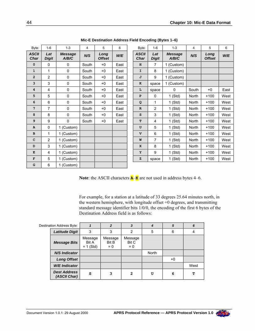
44 Chapter 10: Mic-E Data Format
Document Version 1.0.1: 29 August 2000 APRS Protocol Reference — APRS Protocol Version 1.0
Mic-E Destination Address Field Encoding (Bytes 1–6)
Byte: 1-6 1-3 4 5 6 Byte: 1-6 1-3 4 5 6
ASCIIChar
LatDigit
MessageA/B/C
N/S LongOffset
W/E ASCIIChar
LatDigit
MessageA/B/C
N/S LongOffset
W/E
0 0 0 South +0 East H 7 1 (Custom)
1 1 0 South +0 East I 8 1 (Custom)
2 2 0 South +0 East J 9 1 (Custom)
3 3 0 South +0 East K space 1 (Custom)
4 4 0 South +0 East L space 0 South +0 East
5 5 0 South +0 East P 0 1 (Std) North +100 West
6 6 0 South +0 East Q 1 1 (Std) North +100 West
7 7 0 South +0 East R 2 1 (Std) North +100 West
8 8 0 South +0 East S 3 1 (Std) North +100 West
9 9 0 South +0 East T 4 1 (Std) North +100 West
A 0 1 (Custom) U 5 1 (Std) North +100 West
B 1 1 (Custom) V 6 1 (Std) North +100 West
C 2 1 (Custom) W 7 1 (Std) North +100 West
D 3 1 (Custom) X 8 1 (Std) North +100 West
E 4 1 (Custom) Y 9 1 (Std) North +100 West
F 5 1 (Custom) Z space 1 (Std) North +100 West
G 6 1 (Custom)
Note: the ASCII characters A–K are not used in address bytes 4–6.
For example, for a station at a latitude of 33 degrees 25.64 minutes north, inthe western hemisphere, with longitude offset +0 degrees, and transmittingstandard message identifier bits 1/0/0, the encoding of the first 6 bytes of theDestination Address field is as follows:
Destination Address Byte: 1 2 3 4 5 6
Latitude Digit 3 3 2 5 6 4
Message Bits
MessageBit A
= 1 (Std)
MessageBit B= 0
MessageBit C= 0
N/S Indicator North
Long Offset +0
W/E Indicator West
Dest Address(ASCII Char)
S 3 2 U 6 T
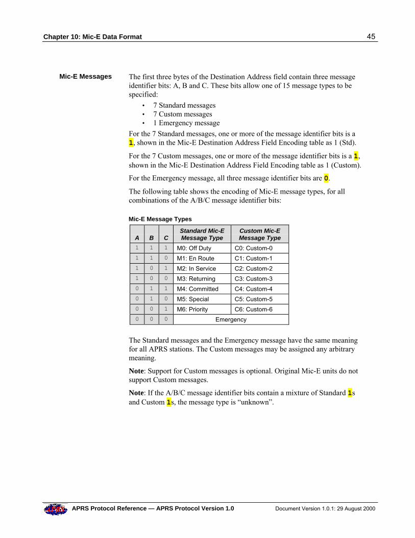
Chapter 10: Mic-E Data Format 45
APRS Protocol Reference — APRS Protocol Version 1.0 Document Version 1.0.1: 29 August 2000
Mic-E Messages The first three bytes of the Destination Address field contain three messageidentifier bits: A, B and C. These bits allow one of 15 message types to bespecified:
• 7 Standard messages• 7 Custom messages• 1 Emergency message
For the 7 Standard messages, one or more of the message identifier bits is a1, shown in the Mic-E Destination Address Field Encoding table as 1 (Std).
For the 7 Custom messages, one or more of the message identifier bits is a 1,shown in the Mic-E Destination Address Field Encoding table as 1 (Custom).
For the Emergency message, all three message identifier bits are 0.
The following table shows the encoding of Mic-E message types, for allcombinations of the A/B/C message identifier bits:
Mic-E Message Types
A
B
C
Standard Mic-EMessage Type
Custom Mic-EMessage Type
1 1 1 M0: Off Duty C0: Custom-0
1 1 0 M1: En Route C1: Custom-1
1 0 1 M2: In Service C2: Custom-2
1 0 0 M3: Returning C3: Custom-3
0 1 1 M4: Committed C4: Custom-4
0 1 0 M5: Special C5: Custom-5
0 0 1 M6: Priority C6: Custom-6
0 0 0 Emergency
The Standard messages and the Emergency message have the same meaningfor all APRS stations. The Custom messages may be assigned any arbitrarymeaning.
Note: Support for Custom messages is optional. Original Mic-E units do notsupport Custom messages.
Note: If the A/B/C message identifier bits contain a mixture of Standard 1sand Custom 1s, the message type is “unknown”.
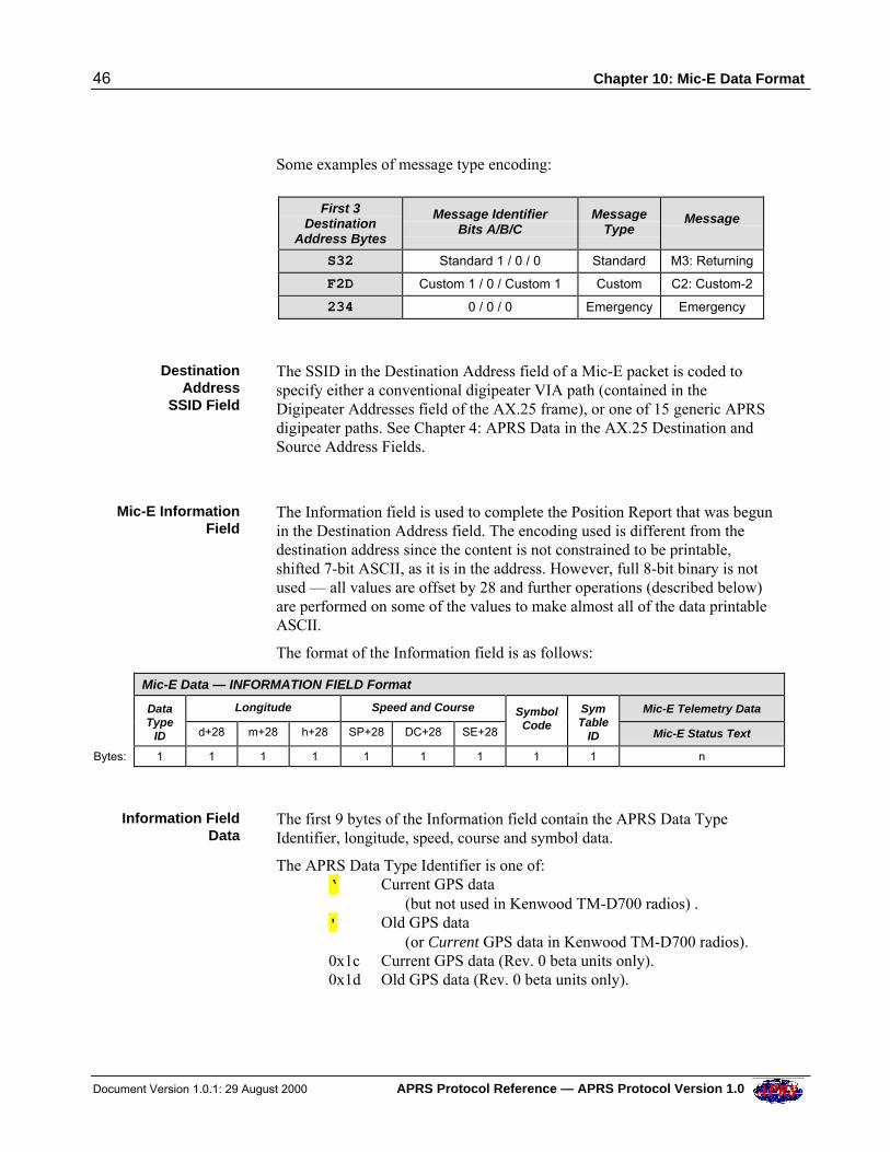
46 Chapter 10: Mic-E Data Format
Document Version 1.0.1: 29 August 2000 APRS Protocol Reference — APRS Protocol Version 1.0
Some examples of message type encoding:
First 3
DestinationAddress Bytes
Message IdentifierBits A/B/C
MessageType
Message
S32 Standard 1 / 0 / 0 Standard M3: Returning
F2D Custom 1 / 0 / Custom 1 Custom C2: Custom-2
234 0 / 0 / 0 Emergency Emergency
DestinationAddress
SSID Field
The SSID in the Destination Address field of a Mic-E packet is coded tospecify either a conventional digipeater VIA path (contained in theDigipeater Addresses field of the AX.25 frame), or one of 15 generic APRSdigipeater paths. See Chapter 4: APRS Data in the AX.25 Destination andSource Address Fields.
Mic-E InformationField
The Information field is used to complete the Position Report that was begunin the Destination Address field. The encoding used is different from thedestination address since the content is not constrained to be printable,shifted 7-bit ASCII, as it is in the address. However, full 8-bit binary is notused — all values are offset by 28 and further operations (described below)are performed on some of the values to make almost all of the data printableASCII.
The format of the Information field is as follows:
Mic-E Data — INFORMATION FIELD Format
Longitude Speed and Course Mic-E Telemetry Data
DataType
ID d+28 m+28 h+28 SP+28 DC+28 SE+28
SymbolCode
SymTable
ID Mic-E Status Text
Bytes: 1 1 1 1 1 1 1 1 1 n
Information FieldData
The first 9 bytes of the Information field contain the APRS Data TypeIdentifier, longitude, speed, course and symbol data.
The APRS Data Type Identifier is one of:‘ Current GPS data
(but not used in Kenwood TM-D700 radios) .' Old GPS data
(or Current GPS data in Kenwood TM-D700 radios).0x1c Current GPS data (Rev. 0 beta units only).0x1d Old GPS data (Rev. 0 beta units only).
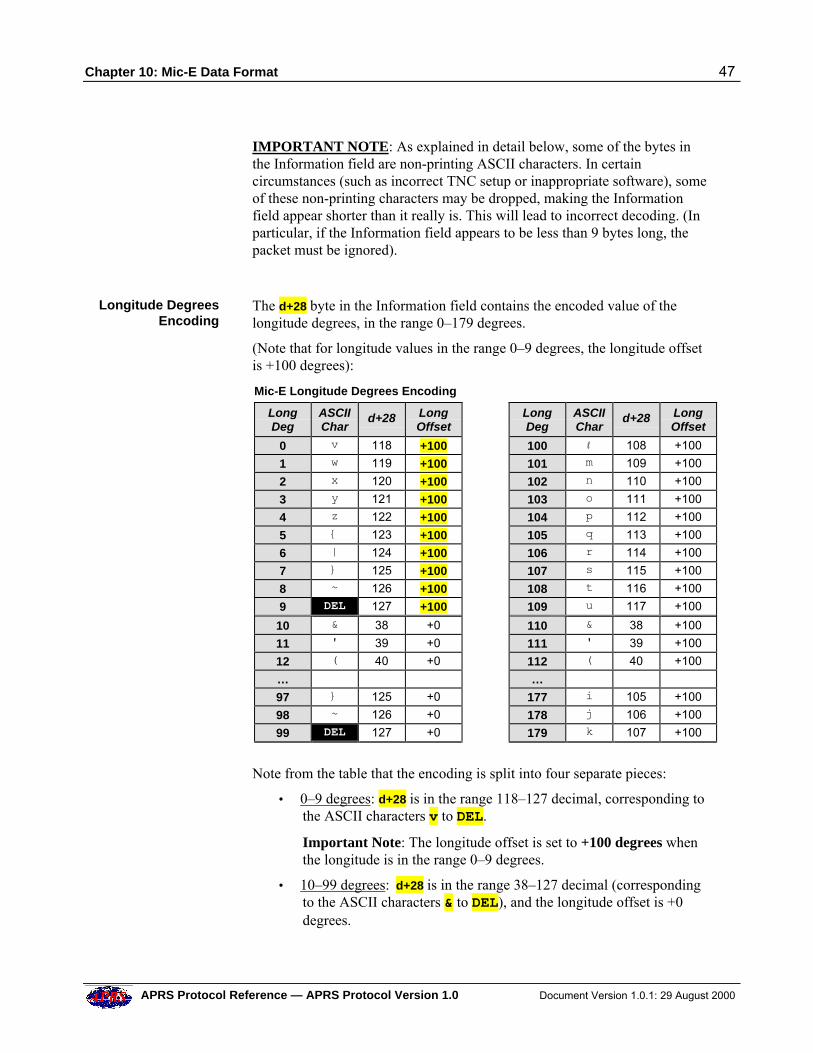
Chapter 10: Mic-E Data Format 47
APRS Protocol Reference — APRS Protocol Version 1.0 Document Version 1.0.1: 29 August 2000
IMPORTANT NOTE: As explained in detail below, some of the bytes inthe Information field are non-printing ASCII characters. In certaincircumstances (such as incorrect TNC setup or inappropriate software), someof these non-printing characters may be dropped, making the Informationfield appear shorter than it really is. This will lead to incorrect decoding. (Inparticular, if the Information field appears to be less than 9 bytes long, thepacket must be ignored).
Longitude DegreesEncoding
The d+28 byte in the Information field contains the encoded value of thelongitude degrees, in the range 0–179 degrees.
(Note that for longitude values in the range 0–9 degrees, the longitude offsetis +100 degrees):
Mic-E Longitude Degrees Encoding
LongDeg
ASCIIChar
d+28 LongOffset
LongDeg
ASCIIChar
d+28 LongOffset
0 v 118 +100 100 l 108 +100
1 w 119 +100 101 m 109 +100
2 x 120 +100 102 n 110 +100
3 y 121 +100 103 o 111 +100
4 z 122 +100 104 p 112 +100
5 { 123 +100 105 q 113 +100
6 | 124 +100 106 r 114 +100
7 } 125 +100 107 s 115 +100
8 ~ 126 +100 108 t 116 +100
9 DEL 127 +100 109 u 117 +100
10 & 38 +0 110 & 38 +100
11 ' 39 +0 111 ' 39 +100
12 ( 40 +0 112 ( 40 +100
… … 97 } 125 +0 177 i 105 +100
98 ~ 126 +0 178 j 106 +100
99 DEL 127 +0 179 k 107 +100
Note from the table that the encoding is split into four separate pieces:
• 0–9 degrees: d+28 is in the range 118–127 decimal, corresponding tothe ASCII characters v to DEL.
Important Note: The longitude offset is set to +100 degrees whenthe longitude is in the range 0–9 degrees.
• 10–99 degrees: d+28 is in the range 38–127 decimal (correspondingto the ASCII characters & to DEL), and the longitude offset is +0degrees.
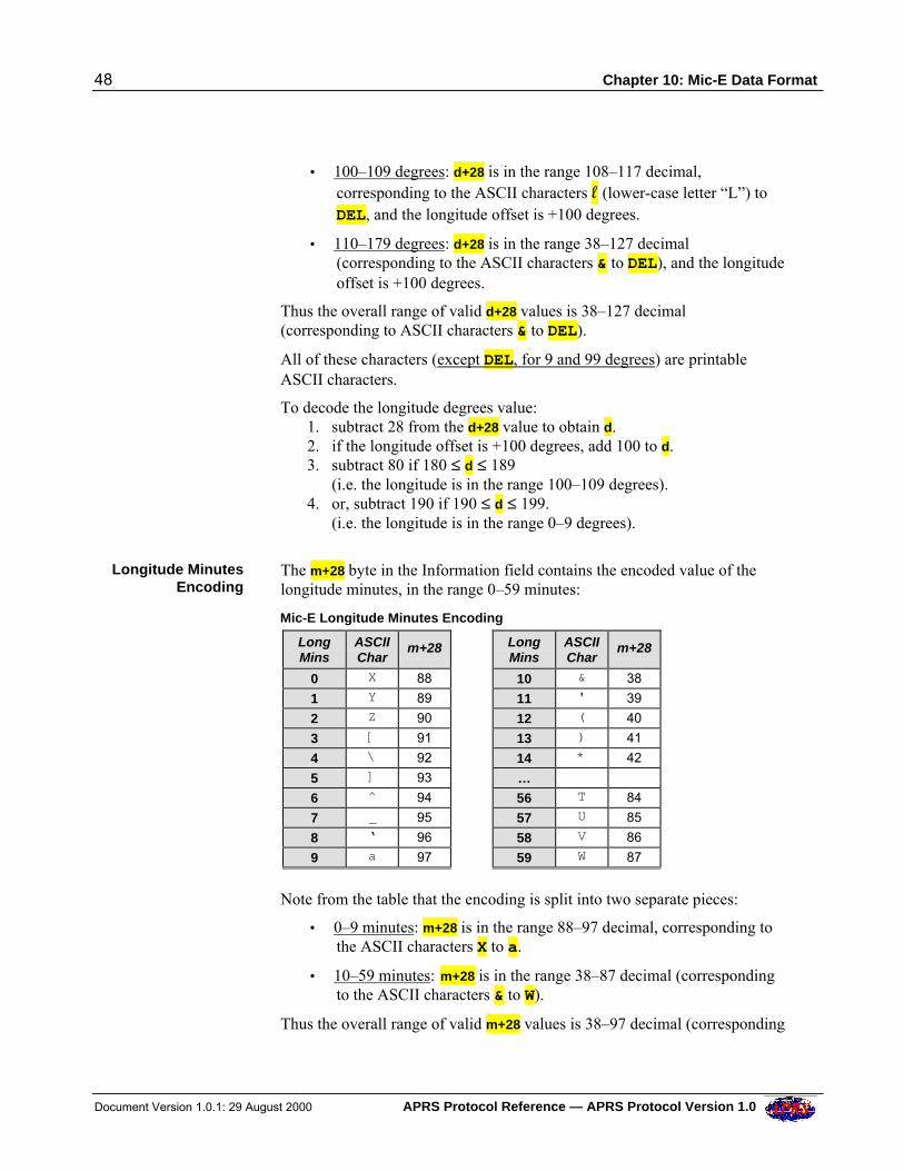
48 Chapter 10: Mic-E Data Format
Document Version 1.0.1: 29 August 2000 APRS Protocol Reference — APRS Protocol Version 1.0
• 100–109 degrees: d+28 is in the range 108–117 decimal,corresponding to the ASCII characters ll (lower-case letter “L”) toDEL, and the longitude offset is +100 degrees.
• 110–179 degrees: d+28 is in the range 38–127 decimal(corresponding to the ASCII characters & to DEL), and the longitudeoffset is +100 degrees.
Thus the overall range of valid d+28 values is 38–127 decimal(corresponding to ASCII characters & to DEL).
All of these characters (except DEL, for 9 and 99 degrees) are printableASCII characters.
To decode the longitude degrees value:1. subtract 28 from the d+28 value to obtain d.2. if the longitude offset is +100 degrees, add 100 to d.3. subtract 80 if 180 ˜ d ˜ 189 (i.e. the longitude is in the range 100–109 degrees).4. or, subtract 190 if 190 ˜ d ˜ 199. (i.e. the longitude is in the range 0–9 degrees).
Longitude MinutesEncoding
The m+28 byte in the Information field contains the encoded value of thelongitude minutes, in the range 0–59 minutes:
Mic-E Longitude Minutes Encoding
LongMins
ASCIIChar
m+28 LongMins
ASCIIChar
m+28
0 X 88 10 & 38
1 Y 89 11 ' 39
2 Z 90 12 ( 40
3 [ 91 13 ) 41
4 \ 92 14 * 42
5 ] 93 … 6 ̂ 94 56 T 84
7 _ 95 57 U 85
8 ‘ 96 58 V 86
9 a 97 59 W 87
Note from the table that the encoding is split into two separate pieces:
• 0–9 minutes: m+28 is in the range 88–97 decimal, corresponding tothe ASCII characters X to a.
• 10–59 minutes: m+28 is in the range 38–87 decimal (correspondingto the ASCII characters & to W).
Thus the overall range of valid m+28 values is 38–97 decimal (corresponding
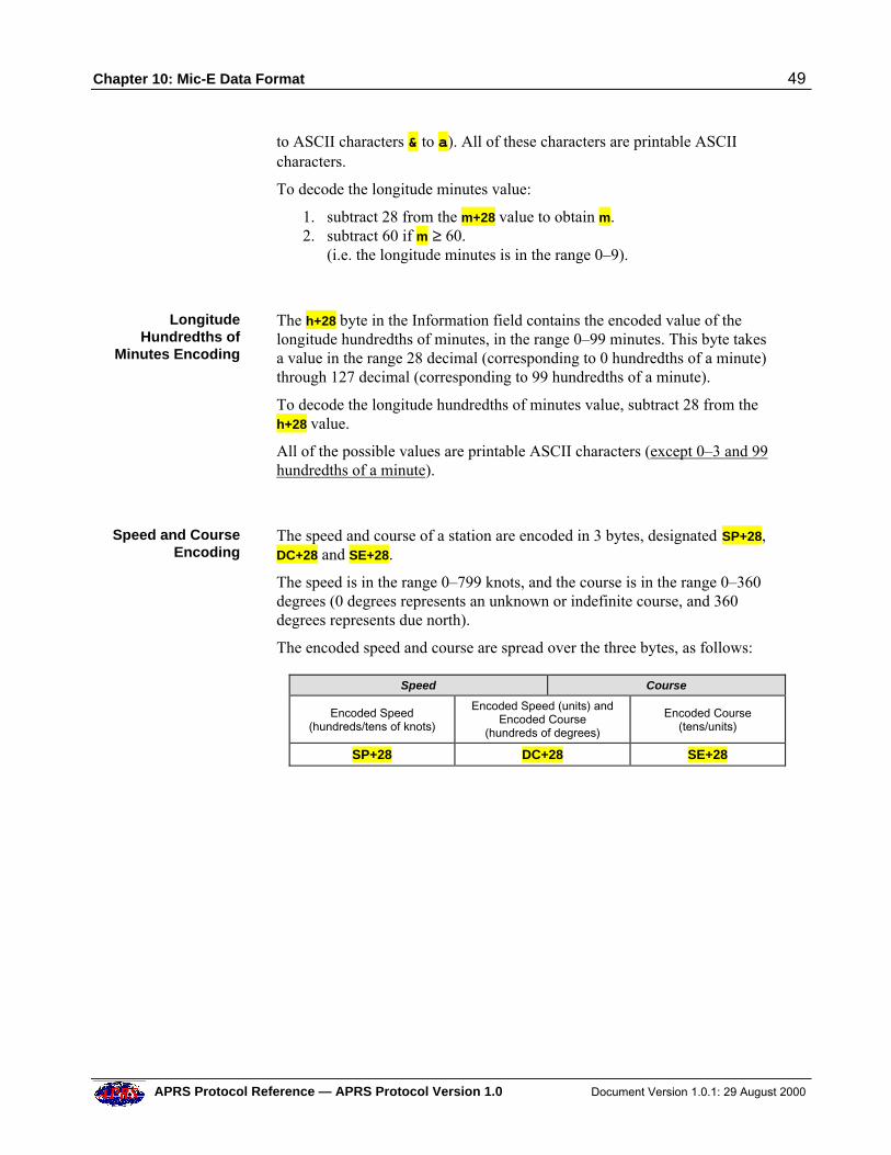
Chapter 10: Mic-E Data Format 49
APRS Protocol Reference — APRS Protocol Version 1.0 Document Version 1.0.1: 29 August 2000
to ASCII characters & to a). All of these characters are printable ASCIIcharacters.
To decode the longitude minutes value:
1. subtract 28 from the m+28 value to obtain m.2. subtract 60 if m ™ 60. (i.e. the longitude minutes is in the range 0–9).
LongitudeHundredths of
Minutes Encoding
The h+28 byte in the Information field contains the encoded value of thelongitude hundredths of minutes, in the range 0–99 minutes. This byte takesa value in the range 28 decimal (corresponding to 0 hundredths of a minute)through 127 decimal (corresponding to 99 hundredths of a minute).
To decode the longitude hundredths of minutes value, subtract 28 from theh+28 value.
All of the possible values are printable ASCII characters (except 0–3 and 99hundredths of a minute).
Speed and CourseEncoding
The speed and course of a station are encoded in 3 bytes, designated SP+28,DC+28 and SE+28.
The speed is in the range 0–799 knots, and the course is in the range 0–360degrees (0 degrees represents an unknown or indefinite course, and 360degrees represents due north). The encoded speed and course are spread over the three bytes, as follows:
Speed Course
Encoded Speed(hundreds/tens of knots)
Encoded Speed (units) andEncoded Course
(hundreds of degrees)
Encoded Course(tens/units)
SP+28 DC+28 SE+28
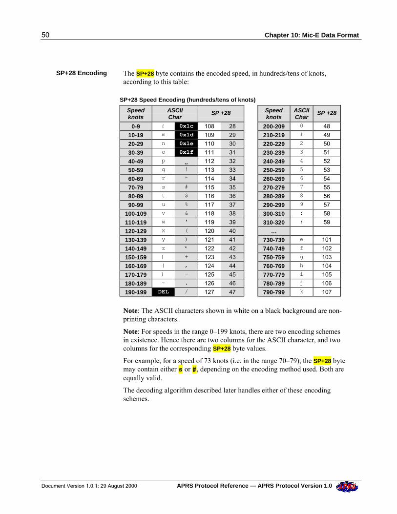
50 Chapter 10: Mic-E Data Format
Document Version 1.0.1: 29 August 2000 APRS Protocol Reference — APRS Protocol Version 1.0
SP+28 Encoding The SP+28 byte contains the encoded speed, in hundreds/tens of knots,according to this table:
SP+28 Speed Encoding (hundreds/tens of knots)
Speedknots
ASCIIChar
SP +28 Speedknots
ASCIIChar
SP +28
0-9 l 0x1c 108 28 200-209 0 48
10-19 m 0x1d 109 29 210-219 1 49
20-29 n 0x1e 110 30 220-229 2 50
30-39 o 0x1f 111 31 230-239 3 51
40-49 p V 112 32 240-249 4 52
50-59 q ! 113 33 250-259 5 53
60-69 r " 114 34 260-269 6 54
70-79 s # 115 35 270-279 7 55
80-89 t $ 116 36 280-289 8 56
90-99 u % 117 37 290-299 9 57
100-109 v & 118 38 300-310 : 58
110-119 w ' 119 39 310-320 ; 59
120-129 x ( 120 40 … 130-139 y ) 121 41 730-739 e 101
140-149 z * 122 42 740-749 f 102
150-159 { + 123 43 750-759 g 103
160-169 | , 124 44 760-769 h 104
170-179 } - 125 45 770-779 i 105
180-189 ~ . 126 46 780-789 j 106
190-199 DEL / 127 47 790-799 k 107
Note: The ASCII characters shown in white on a black background are non-printing characters.
Note: For speeds in the range 0–199 knots, there are two encoding schemesin existence. Hence there are two columns for the ASCII character, and twocolumns for the corresponding SP+28 byte values.
For example, for a speed of 73 knots (i.e. in the range 70–79), the SP+28 bytemay contain either s or #, depending on the encoding method used. Both areequally valid.
The decoding algorithm described later handles either of these encodingschemes.
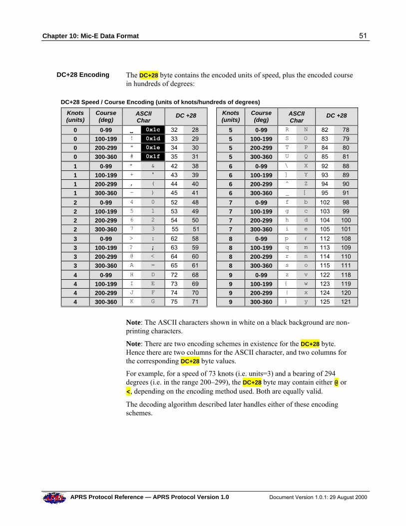
Chapter 10: Mic-E Data Format 51
APRS Protocol Reference — APRS Protocol Version 1.0 Document Version 1.0.1: 29 August 2000
DC+28 Encoding The DC+28 byte contains the encoded units of speed, plus the encoded coursein hundreds of degrees:
DC+28 Speed / Course Encoding (units of knots/hundreds of degrees)
Knots(units)
Course(deg)
ASCIIChar
DC +28 Knots(units)
Course(deg)
ASCIIChar
DC +28
0 0-99 VV 0x1c 32 28 5 0-99 R N 82 78
0 100-199 ! 0x1d 33 29 5 100-199 S O 83 79
0 200-299 " 0x1e 34 30 5 200-299 T P 84 80
0 300-360 # 0x1f 35 31 5 300-360 U Q 85 81
1 0-99 * & 42 38 6 0-99 \ X 92 88
1 100-199 + ' 43 39 6 100-199 ] Y 93 89
1 200-299 , ( 44 40 6 200-299 ̂ Z 94 90
1 300-360 - ) 45 41 6 300-360 _ [ 95 91
2 0-99 4 0 52 48 7 0-99 f b 102 98
2 100-199 5 1 53 49 7 100-199 g c 103 99
2 200-299 6 2 54 50 7 200-299 h d 104 100
2 300-360 7 3 55 51 7 300-360 i e 105 101
3 0-99 > : 62 58 8 0-99 p l 112 108
3 100-199 ? ; 63 59 8 100-199 q m 113 109
3 200-299 @ < 64 60 8 200-299 r n 114 110
3 300-360 A = 65 61 8 300-360 s o 115 111
4 0-99 H D 72 68 9 0-99 z v 122 118
4 100-199 I E 73 69 9 100-199 { w 123 119
4 200-299 J F 74 70 9 200-299 | x 124 120
4 300-360 K G 75 71 9 300-360 } y 125 121
Note: The ASCII characters shown in white on a black background are non-printing characters.
Note: There are two encoding schemes in existence for the DC+28 byte.Hence there are two columns for the ASCII character, and two columns forthe corresponding DC+28 byte values.
For example, for a speed of 73 knots (i.e. units=3) and a bearing of 294degrees (i.e. in the range 200–299), the DC+28 byte may contain either @ or<, depending on the encoding method used. Both are equally valid.
The decoding algorithm described later handles either of these encodingschemes.
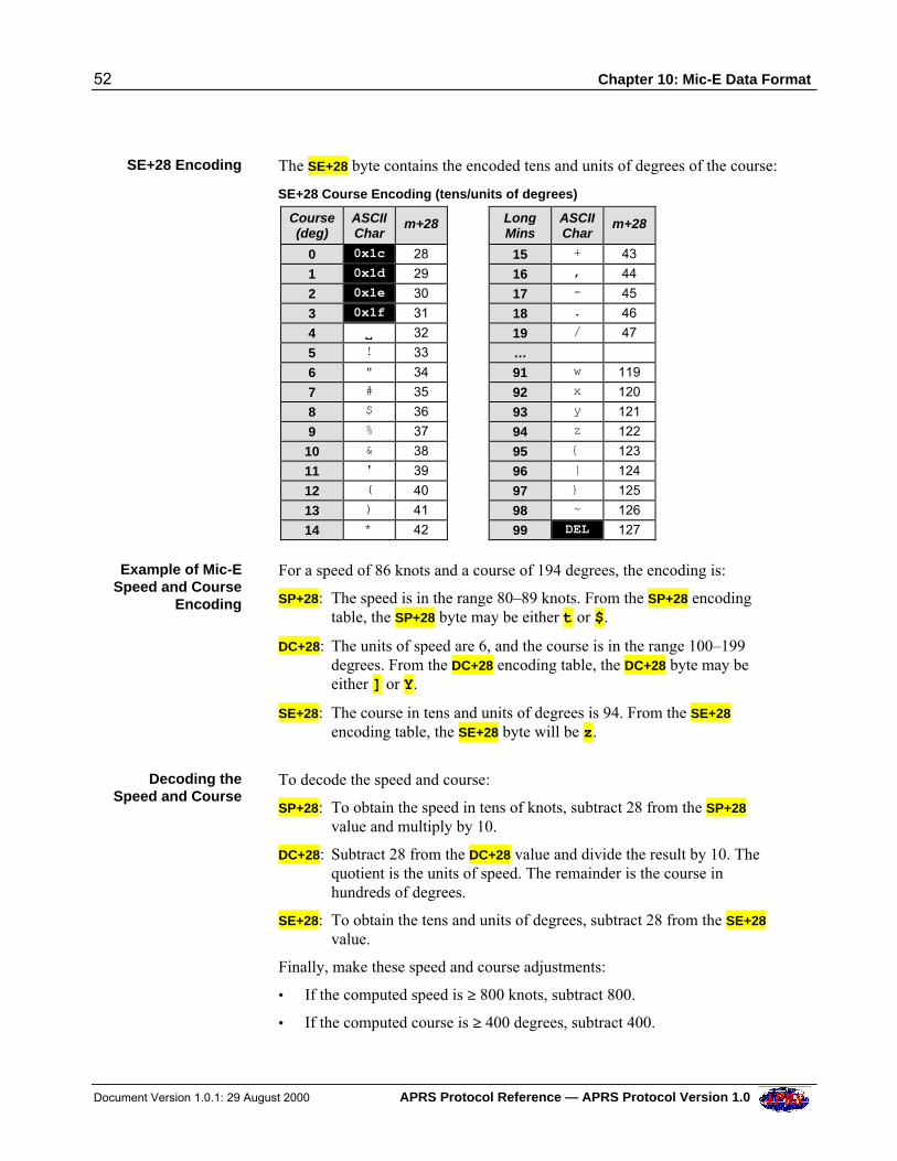
52 Chapter 10: Mic-E Data Format
Document Version 1.0.1: 29 August 2000 APRS Protocol Reference — APRS Protocol Version 1.0
SE+28 Encoding The SE+28 byte contains the encoded tens and units of degrees of the course:
SE+28 Course Encoding (tens/units of degrees)
Course(deg)
ASCIIChar
m+28 LongMins
ASCIIChar
m+28
0 0x1c 28 15 + 43
1 0x1d 29 16 , 44
2 0x1e 30 17 - 45
3 0x1f 31 18 . 46
4 VV 32 19 / 47
5 ! 33 … 6 " 34 91 w 119
7 # 35 92 x 120
8 $ 36 93 y 121
9 % 37 94 z 122
10 & 38 95 { 123
11 ' 39 96 | 124
12 ( 40 97 } 125
13 ) 41 98 ~ 126
14 * 42 99 DEL 127
Example of Mic-ESpeed and Course
Encoding
For a speed of 86 knots and a course of 194 degrees, the encoding is:
SP+28: The speed is in the range 80–89 knots. From the SP+28 encodingtable, the SP+28 byte may be either t or $.
DC+28: The units of speed are 6, and the course is in the range 100–199degrees. From the DC+28 encoding table, the DC+28 byte may beeither ] or Y.
SE+28: The course in tens and units of degrees is 94. From the SE+28
encoding table, the SE+28 byte will be z.
Decoding theSpeed and Course
To decode the speed and course:
SP+28: To obtain the speed in tens of knots, subtract 28 from the SP+28
value and multiply by 10.
DC+28: Subtract 28 from the DC+28 value and divide the result by 10. Thequotient is the units of speed. The remainder is the course inhundreds of degrees.
SE+28: To obtain the tens and units of degrees, subtract 28 from the SE+28
value.
Finally, make these speed and course adjustments:
• If the computed speed is ™ 800 knots, subtract 800.
• If the computed course is ™ 400 degrees, subtract 400.
Chapter 10: Mic-E Data Format 53
APRS Protocol Reference — APRS Protocol Version 1.0 Document Version 1.0.1: 29 August 2000
Example ofDecoding the
Information FieldData
If the first 9 bytes of the Information field contain ‘(_fn"Oj/, and thedestination address specifies that the station is in the western hemispherewith a longitude offset of +100 degrees, then the data is decoded as follows:
• ‘ is the APRS Data Type Identifier for a Mic-E packet containing currentGPS data.
• ( is the d+28 byte. The ( character has the value 40 decimal. Subtracting28 gives 12. The longitude offset (in the destination address) is +100degrees, so the longitude is 100 + 12 = 112 degrees.
• _ is the m+28 byte. The _ character has the value 95 decimal. Subtracting28 gives 67. This is ™ 60, so subtracting 60 gives a value of 7 minuteslongitude.
• f is the h+28 byte. The f character has the value 102 decimal.Subtracting 28 gives 74 hundredths of a minute.
Thus the longitude is 112 degrees 7.74 minutes west.
The speed and course are calculated as follows:
• n is the SP+28 byte. The n character has the value 110 decimal. Aftersubtracting 28, the result is 82. As this is ™ 80, a further 80 is subtracted,leaving a result of 2 tens of knots.
• " is the DC+28 byte. The " character has the value 34 decimal.Subtracting 28 gives 6. Dividing this by 10 gives a quotient of 0 (units ofspeed). Adding the first part of the speed, multiplied by 10 (i.e. 20) to thequotient (0) gives a final computed speed of 20 knots.The remainder from the division is 6. Subtracting 4 gives the course inhundreds of degrees; i.e. 2.
• O (upper-case letter “O”) is the SE+28 byte. The O character has the value79 decimal. Subtracting 28 gives 51. Adding this to the remaindercalculated above, multiplied by 100 (i.e. 200), gives the final value of251 degrees for the course.
The last two characters (j/) represent the jeep symbol from the PrimarySymbol Table.
Mic-E PositionAmbiguity
As mentioned in Chapter 6 (Time and Position Formats), a station mayreduce the precision of its position by introducing position ambiguity. This isalso possible in Mic-E data format.
The position ambiguity is specified for the latitude (in the destinationaddress). The same degree of ambiguity will then also apply to the longitude.
For example, if the destination address is T4SQZZ, the last two digits of the
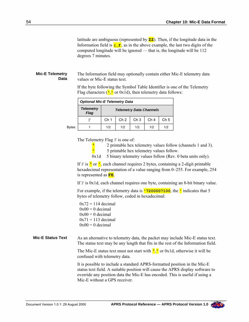
54 Chapter 10: Mic-E Data Format
Document Version 1.0.1: 29 August 2000 APRS Protocol Reference — APRS Protocol Version 1.0
latitude are ambiguous (represented by ZZ). Then, if the longitude data in theInformation field is (_f , as in the above example, the last two digits of thecomputed longitude will be ignored — that is, the longitude will be 112degrees 7 minutes.
Mic-E TelemetryData
The Information field may optionally contain either Mic-E telemetry datavalues or Mic-E status text.
If the byte following the Symbol Table Identifier is one of the TelemetryFlag characters (‘,' or 0x1d), then telemetry data follows:
Optional Mic-E Telemetry Data
TelemetryFlag
Telemetry Data Channels
F Ch 1 Ch 2 Ch 3 Ch 4 Ch 5
Bytes: 1 1/2 1/2 1/2 1/2 1/2
The Telemetry Flag F is one of:‘ 2 printable hex telemetry values follow (channels 1 and 3).' 5 printable hex telemetry values follow.0x1d 5 binary telemetry values follow (Rev. 0 beta units only).
If F is ‘ or ', each channel requires 2 bytes, containing a 2-digit printablehexadecimal representation of a value ranging from 0–255. For example, 254is represented as FE.
If F is 0x1d, each channel requires one byte, containing an 8-bit binary value.
For example, if the telemetry data is '7200007100, the ' indicates that 5bytes of telemetry follow, coded in hexadecimal:
0x72 = 114 decimal 0x00 = 0 decimal 0x00 = 0 decimal 0x71 = 113 decimal 0x00 = 0 decimal
Mic-E Status Text As an alternative to telemetry data, the packet may include Mic-E status text.The status text may be any length that fits in the rest of the Information field.
The Mic-E status text must not start with ‘,' or 0x1d, otherwise it will beconfused with telemetry data.
It is possible to include a standard APRS-formatted position in the Mic-Estatus text field. A suitable position will cause the APRS display software tooverride any position data the Mic-E has encoded. This is useful if using aMic-E without a GPS receiver.
Chapter 10: Mic-E Data Format 55
APRS Protocol Reference — APRS Protocol Version 1.0 Document Version 1.0.1: 29 August 2000
Note: The Kenwood radios automatically insert a special type code at thefront of the status text string (i.e. in the 10th character of the Informationfield):
Kenwood TH-D7: > Kenwood TM-D700: ]
These characters should not be confused with the APRS Data Type Identifierthat appears at the start of reports.
It is envisaged that other Mic-E-compatible devices will be allocated theirown type codes in future.
Note: When Kenwood radios receive the status, they can only display a smallnumber of text characters:
Kenwood TH-D7: 20 characters Kenwood TM-D700: 28 characters
Note: The Kenwood TM-D700 radio uses the ' (apostrophe) instead of the ‘(grave) APRS Data Type Identifier to represent current GPS data. Asuggested way of detecting this situation is to examine the first and 10thcharacters of the Information field; if they are ' and ] respectively, then thepacket is almost certainly from a TM-D700.
MaidenheadLocator in the Mic-E
Status Text Field
The Mic-E status text field can contain a Maidenhead locator.
If the locator is followed by a plain text comment, the first character of thetext must be a space. For example:
IO91SX/GVVHelloVworld (from a Mic-E or PIC-E) >IO91SX/GVVHelloVworld (from a Kenwood TH-D7) ]IO91SX/GVVHelloVworld (from a Kenwood TM-D700)
(/G is the grid locator symbol).
Altitude in theMic-E Status Text
Field
The Mic-E status text field can contain the station’s altitude. The altitude isexpressed in the form xxx}, where xxx is in meters relative to 10km belowmean sea level (the deepest ocean), to base 91.
For example, to compute the xxx characters for an altitude of 200 feet:
200 feet = 61 meters = 10061 meters relative to the datum 10061 / 912 = 1, remainder 1780 1780 / 91 = 19, remainder 51
Adding 33 to each of the highlighted values gives 34, 52 and 84 for theASCII codes of xxx.
56 Chapter 10: Mic-E Data Format
Document Version 1.0.1: 29 August 2000 APRS Protocol Reference — APRS Protocol Version 1.0
Thus the 4-character altitude string is "4T}
Some examples:
"4T} >"4T} ]"4T}
Mic-E Data inNon-APRSNetworks
Some parts of the Mic-E AX.25 Information field may contain binary data(i.e. non-printable ASCII characters). If such a packet is constrained to theAPRS network, this should not cause any difficulties.
If, however, the packet is to be forwarded via a network that does not reliablypreserve binary data (e.g. the Internet), then it is necessary to convert the datato a format that will preserve it.
Further, if the packet subsequently re-emerges back onto the APRS network,it will then be necessary to re-convert the data back to its original format.
Chapter 11: Object and Item Reports 57
APRS Protocol Reference — APRS Protocol Version 1.0 Document Version 1.0.1: 29 August 2000
11 OBJECT AND ITEM REPORTS
Objects and Items Any APRS station can manually report the position of an APRS entity (e.g.another station or a weather phenomenon). This is intended for situationswhere the entity is not capable of reporting its own position.
APRS provides two types of report to support this:
• Object Reports
• Item Reports
Object Reports specify an Object’s position, can have an optional timestamp,and can include course/speed information or other Extended Data. ObjectReports are intended primarily for plotting the positions of moving objects(e.g. spacecraft, storms, marathon runners without trackers).
Item Reports specify an Item’s position, but cannot have a timestamp. WhileItem reports may also include course/speed or other Extended Data, they arereally intended for inanimate things that are occasionally posted on a map(e.g. marathon checkpoints or first-aid posts). Otherwise they are handled inthe same way as Object Reports.
Objects are distinguished from each other by having different Object names.Similarly, Items are distinguished from each other by having different Itemnames.
Implementation Recommendation: When an APRS Object/Item is displayedon the screen, the callsign of the station sending the report should beassociated with the Object/Item.
Replacing anObject / Item
A fundamental precept of APRS is that any station may take over thereporting responsibility for an APRS Object or Item, by simply transmitting anew report with the same Object/Item name.
The replacement report may specify the existing location or a new location.
The original station will cease transmitting an Object/Item Report when itsees an incoming report with the same name from another station.
Killing anObject / Item
To kill an Object/Item, a station transmits a new Object/Item Report, with a“kill” character following the Object/Item name.
Implementation Recommendation: When an Object/Item is killed it should beremoved from display on the screen. However, the data associated with theObject/Item should be retained internally in case it is needed later.
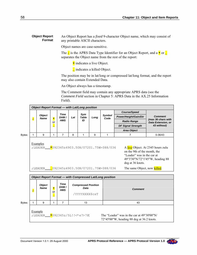
58 Chapter 11: Object and Item Reports
Document Version 1.0.1: 29 August 2000 APRS Protocol Reference — APRS Protocol Version 1.0
Object ReportFormat
An Object Report has a fixed 9-character Object name, which may consist ofany printable ASCII characters.
Object names are case-sensitive.
The ; is the APRS Data Type Identifier for an Object Report, and a * or _separates the Object name from the rest of the report:
* indicates a live Object.
_ indicates a killed Object.
The position may be in lat/long or compressed lat/long format, and the reportmay also contain Extended Data.
An Object always has a timestamp.
The Comment field may contain any appropriate APRS data (see theComment Field section in Chapter 5: APRS Data in the AX.25 InformationField).
Object Report Format — with Lat/Long position
Course/Speed
Power/Height/Gain/Dir
Radio Range
DF Signal Strength
;
ObjectName
*or_
TimeDHM /HMS
Lat
SymTable
ID
Long
SymbolCode
Area Object
Comment
(max 36 chars withData Extension, or
43 without)
Bytes: 1 9 1 7 8 1 9 1 7 0-36/43
Examples;LEADERVVV*092345z4903.50N/07201.75W>088/036 A live Object. At 2345 hours zulu
on the 9th of the month, the“Leader” was in the car at49°3'30"N/72°1'45"W, heading 88deg at 36 knots.
;LEADERVVV_092345z4903.50N/07201.75W>088/036 The same Object, now killed.
Object Report Format — with Compressed Lat/Long position
;
ObjectName
*or_
TimeDHM /HMS
Compressed PositionData
/YYYYXXXX$csT
Comment
Bytes: 1 9 1 7 13 43
Example;LEADERVVV*092345z/5L!!<*e7>7P[ The “Leader” was in the car at 49°30'00"N/
72°45'00"W, heading 88 deg at 36.2 knots.
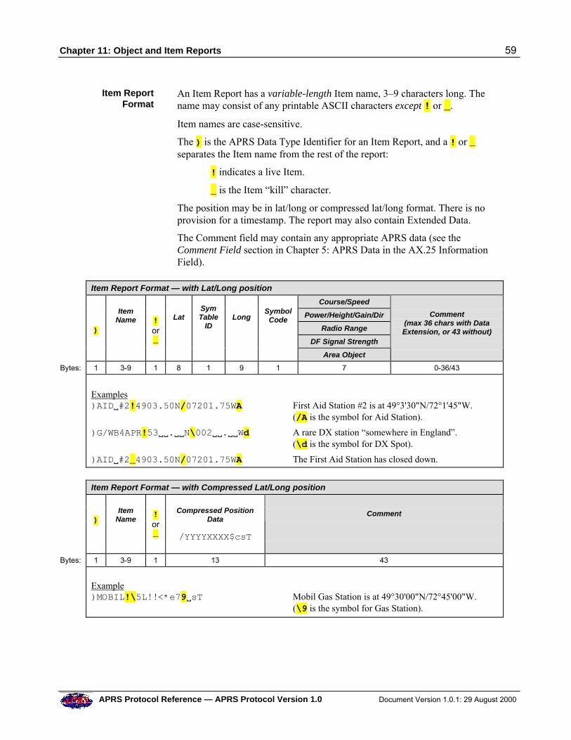
Chapter 11: Object and Item Reports 59
APRS Protocol Reference — APRS Protocol Version 1.0 Document Version 1.0.1: 29 August 2000
Item ReportFormat
An Item Report has a variable-length Item name, 3–9 characters long. Thename may consist of any printable ASCII characters except ! or _.
Item names are case-sensitive.
The ) is the APRS Data Type Identifier for an Item Report, and a ! or _separates the Item name from the rest of the report:
! indicates a live Item.
_ is the Item “kill” character.
The position may be in lat/long or compressed lat/long format. There is noprovision for a timestamp. The report may also contain Extended Data.
The Comment field may contain any appropriate APRS data (see theComment Field section in Chapter 5: APRS Data in the AX.25 InformationField).
Item Report Format — with Lat/Long position
Course/Speed
Power/Height/Gain/Dir
Radio Range
DF Signal Strength
)
ItemName
!or_
Lat
SymTable
ID
Long
SymbolCode
Area Object
Comment
(max 36 chars with DataExtension, or 43 without)
Bytes: 1 3-9 1 8 1 9 1 7 0-36/43
Examples)AIDV#2!4903.50N/07201.75WA First Aid Station #2 is at 49°3'30"N/72°1'45"W.
(/A is the symbol for Aid Station).
)G/WB4APR!53VV.VVN\002VV.VVWd A rare DX station “somewhere in England”.(\d is the symbol for DX Spot).
)AIDV#2_4903.50N/07201.75WA The First Aid Station has closed down.
Item Report Format — with Compressed Lat/Long position
)
ItemName
!or_
Compressed PositionData
/YYYYXXXX$csT
Comment
Bytes: 1 3-9 1 13 43
Example)MOBIL!\5L!!<*e79VsT Mobil Gas Station is at 49°30'00"N/72°45'00"W.
(\9 is the symbol for Gas Station).
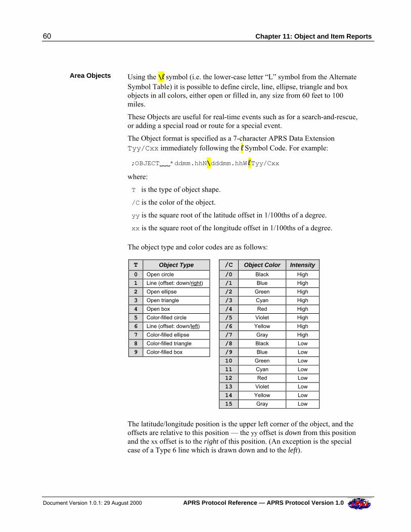
60 Chapter 11: Object and Item Reports
Document Version 1.0.1: 29 August 2000 APRS Protocol Reference — APRS Protocol Version 1.0
Area Objects Using the \ll symbol (i.e. the lower-case letter “L” symbol from the AlternateSymbol Table) it is possible to define circle, line, ellipse, triangle and boxobjects in all colors, either open or filled in, any size from 60 feet to 100miles.
These Objects are useful for real-time events such as for a search-and-rescue,or adding a special road or route for a special event.
The Object format is specified as a 7-character APRS Data ExtensionTyy/Cxx immediately following the ll Symbol Code. For example:
;OBJECTVVV*ddmm.hhN\dddmm.hhW ll Tyy/Cxx
where:
T is the type of object shape.
/C is the color of the object.
yy is the square root of the latitude offset in 1/100ths of a degree.
xx is the square root of the longitude offset in 1/100ths of a degree.
The object type and color codes are as follows:
T Object Type /C Object Color Intensity
0 Open circle /0 Black High
1 Line (offset: down/right) /1 Blue High
2 Open ellipse /2 Green High
3 Open triangle /3 Cyan High
4 Open box /4 Red High
5 Color-filled circle /5 Violet High
6 Line (offset: down/left) /6 Yellow High
7 Color-filled ellipse /7 Gray High
8 Color-filled triangle /8 Black Low
9 Color-filled box /9 Blue Low
10 Green Low
11 Cyan Low
12 Red Low
13 Violet Low
14 Yellow Low
15 Gray Low
The latitude/longitude position is the upper left corner of the object, and theoffsets are relative to this position — the yy offset is down from this positionand the xx offset is to the right of this position. (An exception is the specialcase of a Type 6 line which is drawn down and to the left).
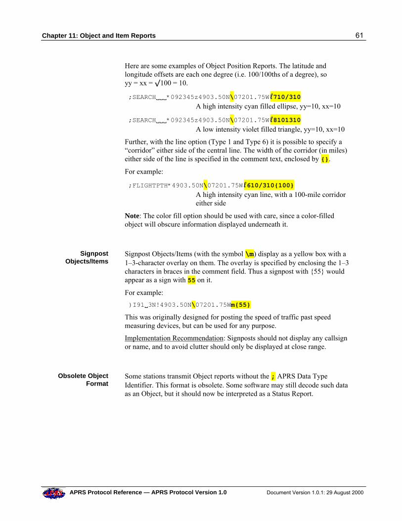
Chapter 11: Object and Item Reports 61
APRS Protocol Reference — APRS Protocol Version 1.0 Document Version 1.0.1: 29 August 2000
Here are some examples of Object Position Reports. The latitude andlongitude offsets are each one degree (i.e. 100/100ths of a degree), soyy = xx = –100 = 10.
;SEARCHVVV*092345z4903.50N\07201.75W ll 710/310A high intensity cyan filled ellipse, yy=10, xx=10
;SEARCHVVV*092345z4903.50N\07201.75W ll 8101310A low intensity violet filled triangle, yy=10, xx=10
Further, with the line option (Type 1 and Type 6) it is possible to specify a“corridor” either side of the central line. The width of the corridor (in miles)either side of the line is specified in the comment text, enclosed by {}.
For example:
;FLIGHTPTH*4903.50N\07201.75W ll 610/310{100}A high intensity cyan line, with a 100-mile corridoreither side
Note: The color fill option should be used with care, since a color-filledobject will obscure information displayed underneath it.
SignpostObjects/Items
Signpost Objects/Items (with the symbol \m) display as a yellow box with a1–3-character overlay on them. The overlay is specified by enclosing the 1–3characters in braces in the comment field. Thus a signpost with {55} wouldappear as a sign with 55 on it.
For example:
)I91V3N!4903.50N\07201.75Wm{55}
This was originally designed for posting the speed of traffic past speedmeasuring devices, but can be used for any purpose.
Implementation Recommendation: Signposts should not display any callsignor name, and to avoid clutter should only be displayed at close range.
Obsolete ObjectFormat
Some stations transmit Object reports without the ; APRS Data TypeIdentifier. This format is obsolete. Some software may still decode such dataas an Object, but it should now be interpreted as a Status Report.
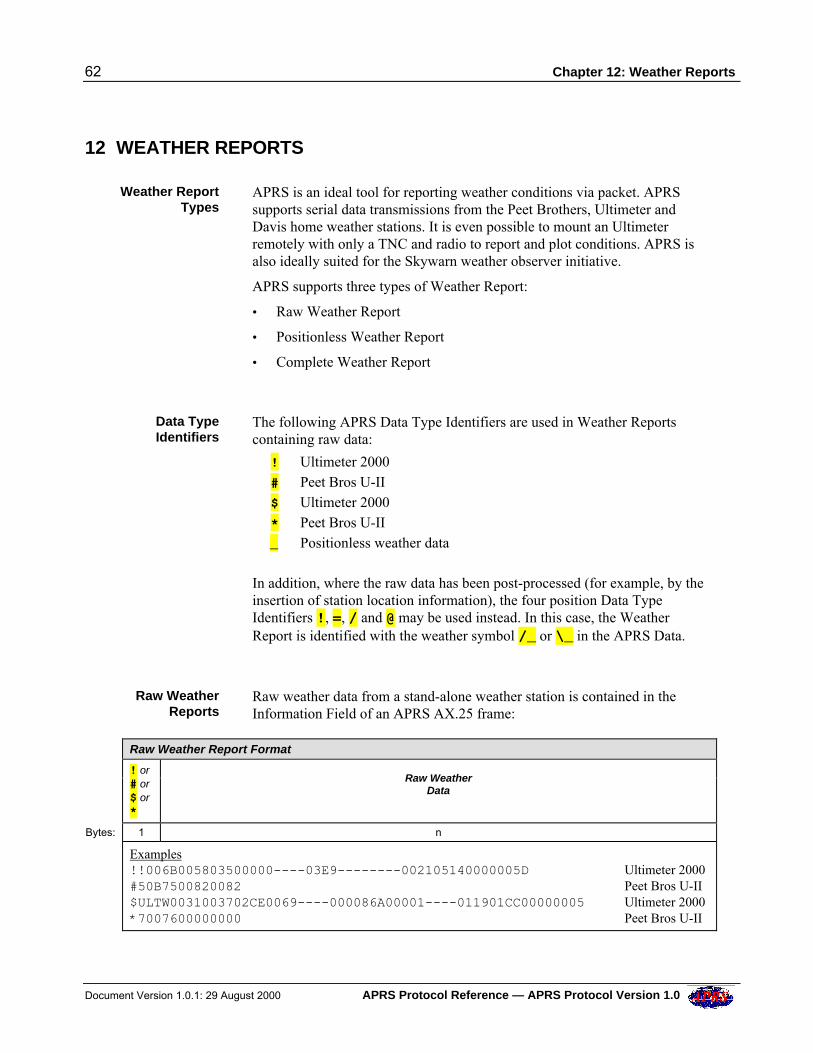
62 Chapter 12: Weather Reports
Document Version 1.0.1: 29 August 2000 APRS Protocol Reference — APRS Protocol Version 1.0
12 WEATHER REPORTS
Weather ReportTypes
APRS is an ideal tool for reporting weather conditions via packet. APRSsupports serial data transmissions from the Peet Brothers, Ultimeter andDavis home weather stations. It is even possible to mount an Ultimeterremotely with only a TNC and radio to report and plot conditions. APRS isalso ideally suited for the Skywarn weather observer initiative.
APRS supports three types of Weather Report:
• Raw Weather Report
• Positionless Weather Report
• Complete Weather Report
Data TypeIdentifiers
The following APRS Data Type Identifiers are used in Weather Reportscontaining raw data:
! Ultimeter 2000 # Peet Bros U-II $ Ultimeter 2000 * Peet Bros U-II _ Positionless weather data
In addition, where the raw data has been post-processed (for example, by theinsertion of station location information), the four position Data TypeIdentifiers !, =, / and @ may be used instead. In this case, the WeatherReport is identified with the weather symbol /_ or \_ in the APRS Data.
Raw WeatherReports
Raw weather data from a stand-alone weather station is contained in theInformation Field of an APRS AX.25 frame:
Raw Weather Report Format
! or# or$ or*
Raw WeatherData
Bytes: 1 n
Examples!!006B005803500000----03E9--------002105140000005D Ultimeter 2000#50B7500820082 Peet Bros U-II$ULTW0031003702CE0069----000086A00001----011901CC00000005 Ultimeter 2000*7007600000000 Peet Bros U-II
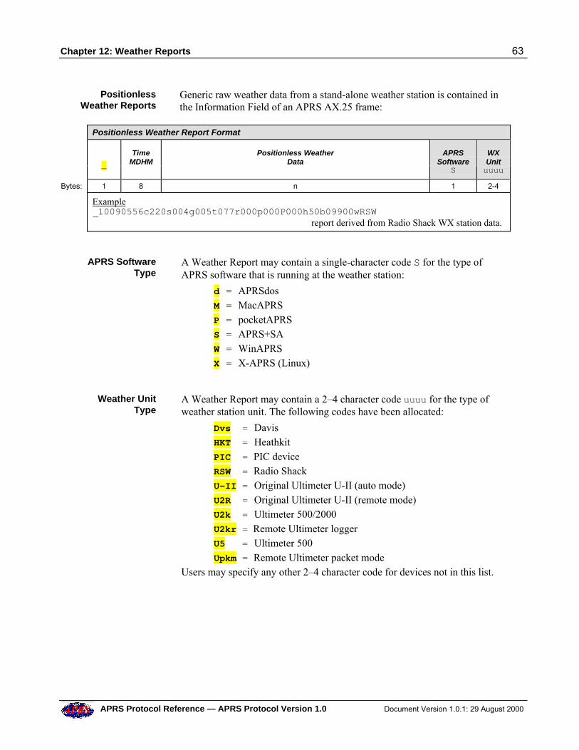
Chapter 12: Weather Reports 63
APRS Protocol Reference — APRS Protocol Version 1.0 Document Version 1.0.1: 29 August 2000
PositionlessWeather Reports
Generic raw weather data from a stand-alone weather station is contained inthe Information Field of an APRS AX.25 frame:
Positionless Weather Report Format
_
TimeMDHM
Positionless WeatherData
APRSSoftware
S
WXUnituuuu
Bytes: 1 8 n 1 2-4
Example_10090556c220s004g005t077r000p000P000h50b09900wRSW report derived from Radio Shack WX station data.
APRS SoftwareType
A Weather Report may contain a single-character code S for the type ofAPRS software that is running at the weather station:
d = APRSdos M = MacAPRS P = pocketAPRS S = APRS+SA W = WinAPRS X = X-APRS (Linux)
Weather UnitType
A Weather Report may contain a 2–4 character code uuuu for the type ofweather station unit. The following codes have been allocated:
Dvs = Davis HKT = Heathkit PIC = PIC device RSW = Radio Shack U-II = Original Ultimeter U-II (auto mode) U2R = Original Ultimeter U-II (remote mode) U2k = Ultimeter 500/2000 U2kr = Remote Ultimeter logger U5 = Ultimeter 500 Upkm = Remote Ultimeter packet mode Users may specify any other 2–4 character code for devices not in this list.
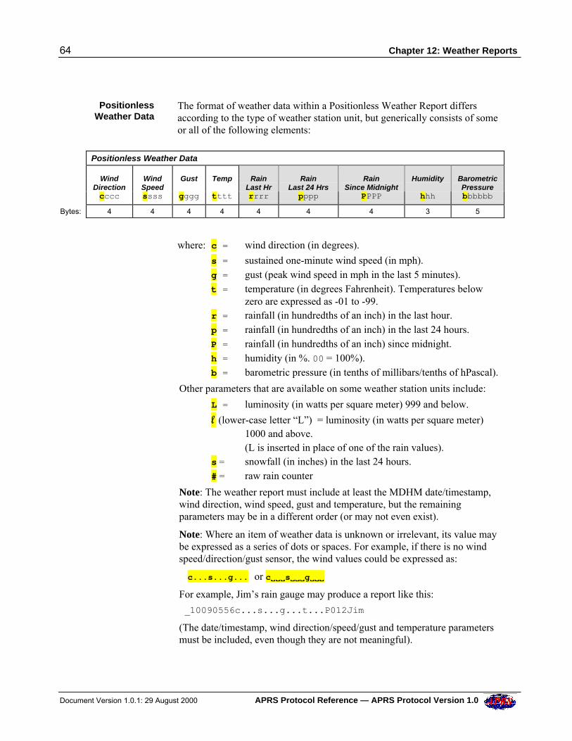
64 Chapter 12: Weather Reports
Document Version 1.0.1: 29 August 2000 APRS Protocol Reference — APRS Protocol Version 1.0
PositionlessWeather Data
The format of weather data within a Positionless Weather Report differsaccording to the type of weather station unit, but generically consists of someor all of the following elements:
Positionless Weather Data
WindDirectioncccc
WindSpeedssss
Gust
gggg
Temp
tttt
RainLast Hrrrrr
RainLast 24 Hrspppp
RainSince Midnight
PPPP
Humidity
hhh
BarometricPressurebbbbbb
Bytes: 4 4 4 4 4 4 4 3 5
where: c = wind direction (in degrees).
s = sustained one-minute wind speed (in mph). g = gust (peak wind speed in mph in the last 5 minutes). t = temperature (in degrees Fahrenheit). Temperatures below
zero are expressed as -01 to -99. r = rainfall (in hundredths of an inch) in the last hour. p = rainfall (in hundredths of an inch) in the last 24 hours. P = rainfall (in hundredths of an inch) since midnight. h = humidity (in %. 00 = 100%). b = barometric pressure (in tenths of millibars/tenths of hPascal).
Other parameters that are available on some weather station units include:
L = luminosity (in watts per square meter) 999 and below.
ll (lower-case letter “L”) = luminosity (in watts per square meter)1000 and above.
(L is inserted in place of one of the rain values). s = snowfall (in inches) in the last 24 hours. # = raw rain counter
Note: The weather report must include at least the MDHM date/timestamp,wind direction, wind speed, gust and temperature, but the remainingparameters may be in a different order (or may not even exist).
Note: Where an item of weather data is unknown or irrelevant, its value maybe expressed as a series of dots or spaces. For example, if there is no windspeed/direction/gust sensor, the wind values could be expressed as:
c...s...g... or cVVVVVVsVVVVVVgVVVVVV
For example, Jim’s rain gauge may produce a report like this:
_10090556c...s...g...t...P012Jim
(The date/timestamp, wind direction/speed/gust and temperature parametersmust be included, even though they are not meaningful).
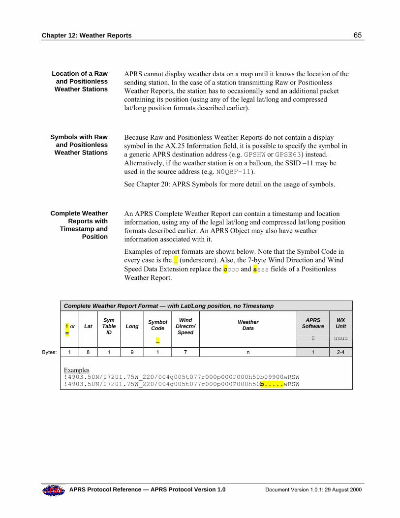
Chapter 12: Weather Reports 65
APRS Protocol Reference — APRS Protocol Version 1.0 Document Version 1.0.1: 29 August 2000
Location of a Rawand PositionlessWeather Stations
APRS cannot display weather data on a map until it knows the location of thesending station. In the case of a station transmitting Raw or PositionlessWeather Reports, the station has to occasionally send an additional packetcontaining its position (using any of the legal lat/long and compressedlat/long position formats described earlier).
Symbols with Rawand PositionlessWeather Stations
Because Raw and Positionless Weather Reports do not contain a displaysymbol in the AX.25 Information field, it is possible to specify the symbol ina generic APRS destination address (e.g. GPSHW or GPSE63) instead.Alternatively, if the weather station is on a balloon, the SSID –11 may beused in the source address (e.g. N0QBF-11).
See Chapter 20: APRS Symbols for more detail on the usage of symbols.
Complete WeatherReports with
Timestamp andPosition
An APRS Complete Weather Report can contain a timestamp and locationinformation, using any of the legal lat/long and compressed lat/long positionformats described earlier. An APRS Object may also have weatherinformation associated with it.
Examples of report formats are shown below. Note that the Symbol Code inevery case is the _ (underscore). Also, the 7-byte Wind Direction and WindSpeed Data Extension replace the cccc and ssss fields of a PositionlessWeather Report.
Complete Weather Report Format — with Lat/Long position, no Timestamp
! or =
Lat
SymTable
ID
Long
SymbolCode
_
WindDirectn/Speed
WeatherData
APRSSoftware
S
WXUnit
uuuu
Bytes: 1 8 1 9 1 7 n 1 2-4
Examples!4903.50N/07201.75W_220/004g005t077r000p000P000h50b09900wRSW!4903.50N/07201.75W_220/004g005t077r000p000P000h50b.....wRSW
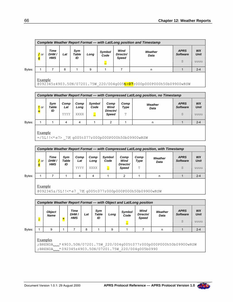
66 Chapter 12: Weather Reports
Document Version 1.0.1: 29 August 2000 APRS Protocol Reference — APRS Protocol Version 1.0
Complete Weather Report Format — with Lat/Long position and Timestamp
/ or @
TimeDHM /HMS
Lat
SymTable
ID
Long
SymbolCode
_
WindDirectn/Speed
WeatherData
APRSSoftware
S
WXUnit
uuuu
Bytes: 1 7 8 1 9 1 7 n 1 2-4
[email protected]/07201.75W_220/004g005t-07r000p000P000h50b09900wRSW
Complete Weather Report Format — with Compressed Lat/Long position, no Timestamp
! or =
SymTable
ID
CompLat
YYYY
CompLong
XXXX
SymbolCode
_
CompWind
Directn/Speed
CompType
T
WeatherData
APRSSoftware
S
WXUnit
uuuu
Bytes: 1 1 4 4 1 2 1 n 1 2-4
Example=/5L!!<*e7> _7P[g005t077r000p000P000h50b09900wRSW
Complete Weather Report Format — with Compressed Lat/Long position, with Timestamp
/ or @
TimeDHM /HMS
SymTable
ID
CompLat
YYYY
CompLong
XXXX
SymbolCode
_
CompWind
Directn/Speed
CompType
T
WeatherData
APRSSoftware
S
WXUnit
uuuu
Bytes: 1 7 1 4 4 1 2 1 n 1 2-4
Example@092345z/5L!!<*e7 _7P[g005t077r000p000P000h50b09900wRSW
Complete Weather Report Format — with Object and Lat/Long position
;
ObjectName
*
TimeDHM /HMS
Lat
SymTable
ID
Long
SymbolCode
_
WindDirectn/Speed
WeatherData
APRSSoftware
S
WXUnit
uuuu
Bytes: 1 9 1 7 8 1 9 1 7 n 1 2-4
Examples;BRENDAVVV*4903.50N/07201.75W_220/004g005t077r000p000P000h50b09900wRSW;BRENDAVVV*092345z4903.50N/07201.75W_220/004g005b0990
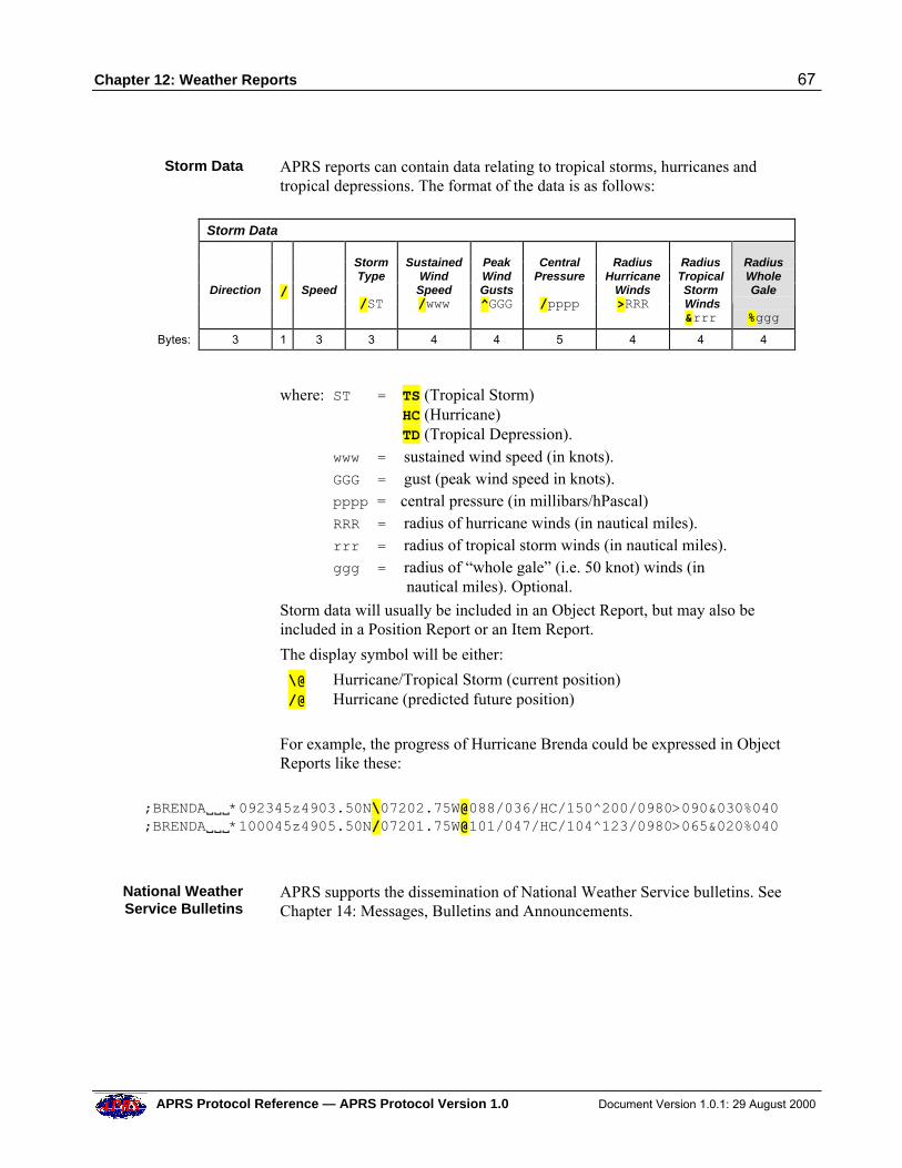
Chapter 12: Weather Reports 67
APRS Protocol Reference — APRS Protocol Version 1.0 Document Version 1.0.1: 29 August 2000
Storm Data APRS reports can contain data relating to tropical storms, hurricanes andtropical depressions. The format of the data is as follows:
Storm Data
Direction
/
Speed
StormType
/ST
SustainedWindSpeed/www
PeakWindGusts^GGG
CentralPressure
/pppp
RadiusHurricane
Winds>RRR
RadiusTropicalStorm Winds&rrr
RadiusWholeGale
%ggg
Bytes: 3 1 3 3 4 4 5 4 4 4
where: ST = TS (Tropical Storm) HC (Hurricane) TD (Tropical Depression).
www = sustained wind speed (in knots). GGG = gust (peak wind speed in knots). pppp = central pressure (in millibars/hPascal) RRR = radius of hurricane winds (in nautical miles). rrr = radius of tropical storm winds (in nautical miles). ggg = radius of “whole gale” (i.e. 50 knot) winds (in
nautical miles). Optional.
Storm data will usually be included in an Object Report, but may also beincluded in a Position Report or an Item Report.
The display symbol will be either:
\@ Hurricane/Tropical Storm (current position) /@ Hurricane (predicted future position)
For example, the progress of Hurricane Brenda could be expressed in ObjectReports like these:
;BRENDAVVV*092345z4903.50N\07202.75W@088/036/HC/150^200/0980>090&030%040;BRENDAVVV*100045z4905.50N/07201.75W@101/047/HC/104^123/0980>065&020%040
National WeatherService Bulletins
APRS supports the dissemination of National Weather Service bulletins. SeeChapter 14: Messages, Bulletins and Announcements.
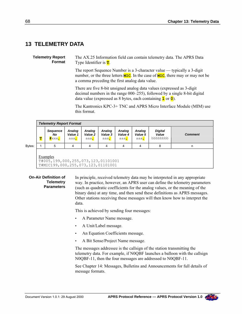
68 Chapter 13: Telemetry Data
Document Version 1.0.1: 29 August 2000 APRS Protocol Reference — APRS Protocol Version 1.0
13 TELEMETRY DATA
Telemetry ReportFormat
The AX.25 Information field can contain telemetry data. The APRS DataType Identifier is T.
The report Sequence Number is a 3-character value — typically a 3-digitnumber, or the three letters MIC. In the case of MIC, there may or may not bea comma preceding the first analog data value.
There are five 8-bit unsigned analog data values (expressed as 3-digitdecimal numbers in the range 000–255), followed by a single 8-bit digitaldata value (expressed as 8 bytes, each containing 1 or 0).
The Kantronics KPC-3+ TNC and APRS Micro Interface Module (MIM) usethis format.
Telemetry Report Format
T
SequenceNo
#xxx,
AnalogValue 1aaa,
AnalogValue 2aaa,
AnalogValue 3aaa,
AnalogValue 4aaa,
AnalogValue 5aaa,
DigitalValue
bbbbbbbb Comment
Bytes: 1 5 4 4 4 4 4 8 n
ExamplesT#005,199,000,255,073,123,01101001T#MIC199,000,255,073,123,01101001
On-Air Definition ofTelemetry
Parameters
In principle, received telemetry data may be interpreted in any appropriateway. In practice, however, an APRS user can define the telemetry parameters(such as quadratic coefficients for the analog values, or the meaning of thebinary data) at any time, and then send these definitions as APRS messages.Other stations receiving these messages will then know how to interpret thedata.
This is achieved by sending four messages:
• A Parameter Name message.
• A Unit/Label message.
• An Equation Coefficients message.
• A Bit Sense/Project Name message.
The messages addressee is the callsign of the station transmitting thetelemetry data. For example, if N0QBF launches a balloon with the callsignN0QBF-11, then the four messages are addressed to N0QBF-11.
See Chapter 14: Messages, Bulletins and Announcements for full details ofmessage formats.
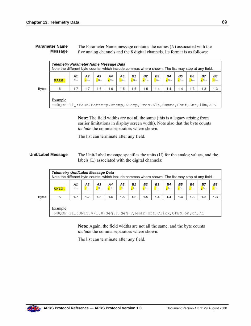
Chapter 13: Telemetry Data 69
APRS Protocol Reference — APRS Protocol Version 1.0 Document Version 1.0.1: 29 August 2000
Parameter NameMessage
The Parameter Name message contains the names (N) associated with thefive analog channels and the 8 digital channels. Its format is as follows:
Telemetry Parameter Name Message Data
Note the different byte counts, which include commas where shown. The list may stop at any field.
PARM.
A1N…
A2,N…
A3,N…
A4,N…
A5,N…
B1,N…
B2,N…
B3,N…
B4,N…
B5,N…
B6,N…
B7,N…
B8,N…
Bytes: 5 1-7 1-7 1-6 1-6 1-5 1-6 1-5 1-4 1-4 1-4 1-3 1-3 1-3
Example:N0QBF-11V:PARM.Battery,Btemp,ATemp,Pres,Alt,Camra,Chut,Sun,10m,ATV
Note: The field widths are not all the same (this is a legacy arising fromearlier limitations in display screen width). Note also that the byte countsinclude the comma separators where shown.
The list can terminate after any field.
Unit/Label Message The Unit/Label message specifies the units (U) for the analog values, and thelabels (L) associated with the digital channels:
Telemetry Unit/Label Message Data
Note the different byte counts, which include commas where shown. The list may stop at any field.
UNIT.
A1U…
A2,U…
A3,U…
A4,U…
A5,U…
B1,L…
B2,L…
B3,L…
B4,L…
B5,L…
B6,L…
B7,L…
B8,L…
Bytes: 5 1-7 1-7 1-6 1-6 1-5 1-6 1-5 1-4 1-4 1-4 1-3 1-3 1-3
Example:N0QBF-11V:UNIT.v/100,deg.F,deg.F,Mbar,Kft,Click,OPEN,on,on,hi
Note: Again, the field widths are not all the same, and the byte countsinclude the comma separators where shown.
The list can terminate after any field.
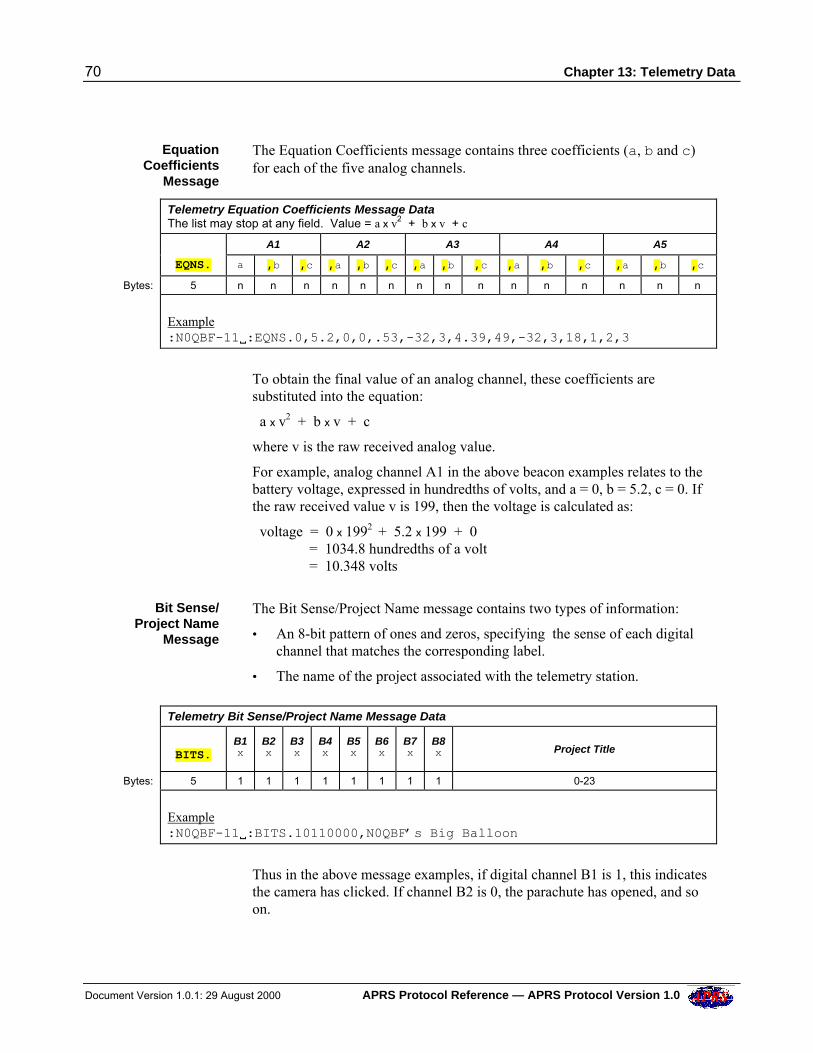
70 Chapter 13: Telemetry Data
Document Version 1.0.1: 29 August 2000 APRS Protocol Reference — APRS Protocol Version 1.0
EquationCoefficients
Message
The Equation Coefficients message contains three coefficients (a, b and c)for each of the five analog channels.
Telemetry Equation Coefficients Message Data
The list may stop at any field. Value = a x v2 + b x v + c
A1 A2 A3 A4 A5
EQNS. a ,b ,c ,a ,b ,c ,a ,b ,c ,a ,b ,c ,a ,b ,c
Bytes: 5 n n n n n n n n n n n n n n n
Example:N0QBF-11V:EQNS.0,5.2,0,0,.53,-32,3,4.39,49,-32,3,18,1,2,3
To obtain the final value of an analog channel, these coefficients aresubstituted into the equation:
a x v2 + b x v + c
where v is the raw received analog value.
For example, analog channel A1 in the above beacon examples relates to thebattery voltage, expressed in hundredths of volts, and a = 0, b = 5.2, c = 0. Ifthe raw received value v is 199, then the voltage is calculated as:
voltage = 0 x 1992 + 5.2 x 199 + 0 = 1034.8 hundredths of a volt = 10.348 volts
Bit Sense/Project Name
Message
The Bit Sense/Project Name message contains two types of information:
• An 8-bit pattern of ones and zeros, specifying the sense of each digitalchannel that matches the corresponding label.
• The name of the project associated with the telemetry station.
Telemetry Bit Sense/Project Name Message Data
BITS.
B1x
B2x
B3x
B4x
B5x
B6x
B7x
B8x Project Title
Bytes: 5 1 1 1 1 1 1 1 1 0-23
Example:N0QBF-11V:BITS.10110000,N0QBF’s Big Balloon
Thus in the above message examples, if digital channel B1 is 1, this indicatesthe camera has clicked. If channel B2 is 0, the parachute has opened, and soon.
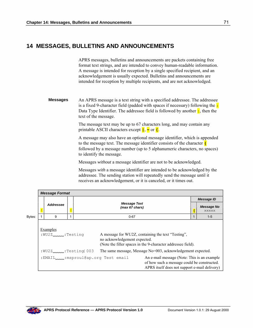
Chapter 14: Messages, Bulletins and Announcements 71
APRS Protocol Reference — APRS Protocol Version 1.0 Document Version 1.0.1: 29 August 2000
14 MESSAGES, BULLETINS AND ANNOUNCEMENTS
APRS messages, bulletins and announcements are packets containing freeformat text strings, and are intended to convey human-readable information.A message is intended for reception by a single specified recipient, and anacknowledgement is usually expected. Bulletins and announcements areintended for reception by multiple recipients, and are not acknowledged.
Messages An APRS message is a text string with a specified addressee. The addresseeis a fixed 9-character field (padded with spaces if necessary) following the :Data Type Identifier. The addressee field is followed by another :, then thetext of the message.
The message text may be up to 67 characters long, and may contain anyprintable ASCII characters except |, ~ or {.
A message may also have an optional message identifier, which is appendedto the message text. The message identifier consists of the character {followed by a message number (up to 5 alphanumeric characters, no spaces)to identify the message.
Messages without a message identifier are not to be acknowledged.
Messages with a message identifier are intended to be acknowledged by theaddressee. The sending station will repeatedly send the message until itreceives an acknowledgement, or it is canceled, or it times out.
Message Format
Message ID
:
Addressee
:
Message Text(max 67 chars)
{ Message Noxxxxx
Bytes: 1 9 1 0-67 1 1-5
Examples:WU2ZVVVVV:Testing A message for WU2Z, containing the text “Testing”,
no acknowledgement expected.(Note the filler spaces in the 9-character addressee field).
:WU2ZVVVVV:Testing{003 The same message, Message No=003, acknowledgement expected.
:EMAILVVVV:[email protected] Test email An e-mail message (Note: This is an exampleof how such a message could be constructed.APRS itself does not support e-mail delivery)
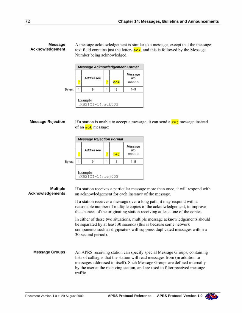
72 Chapter 14: Messages, Bulletins and Announcements
Document Version 1.0.1: 29 August 2000 APRS Protocol Reference — APRS Protocol Version 1.0
MessageAcknowledgement
A message acknowledgement is similar to a message, except that the messagetext field contains just the letters ack, and this is followed by the MessageNumber being acknowledged.
Message Acknowledgement Format
:
Addressee
:
ack
MessageNo
xxxxx
Bytes: 1 9 1 3 1–5
Example:KB2ICI-14:ack003
Message Rejection If a station is unable to accept a message, it can send a rej message insteadof an ack message:
Message Rejection Format
:
Addressee
:
rej
MessageNo
xxxxx
Bytes: 1 9 1 3 1–5
Example:KB2ICI-14:rej003
MultipleAcknowledgements
If a station receives a particular message more than once, it will respond withan acknowledgement for each instance of the message.
If a station receives a message over a long path, it may respond with areasonable number of multiple copies of the acknowledgement, to improvethe chances of the originating station receiving at least one of the copies.
In either of these two situations, multiple message acknowledgements shouldbe separated by at least 30 seconds (this is because some networkcomponents such as digipeaters will suppress duplicated messages within a30-second period).
Message Groups An APRS receiving station can specify special Message Groups, containinglists of callsigns that the station will read messages from (in addition tomessages addressed to itself). Such Message Groups are defined internallyby the user at the receiving station, and are used to filter received messagetraffic.
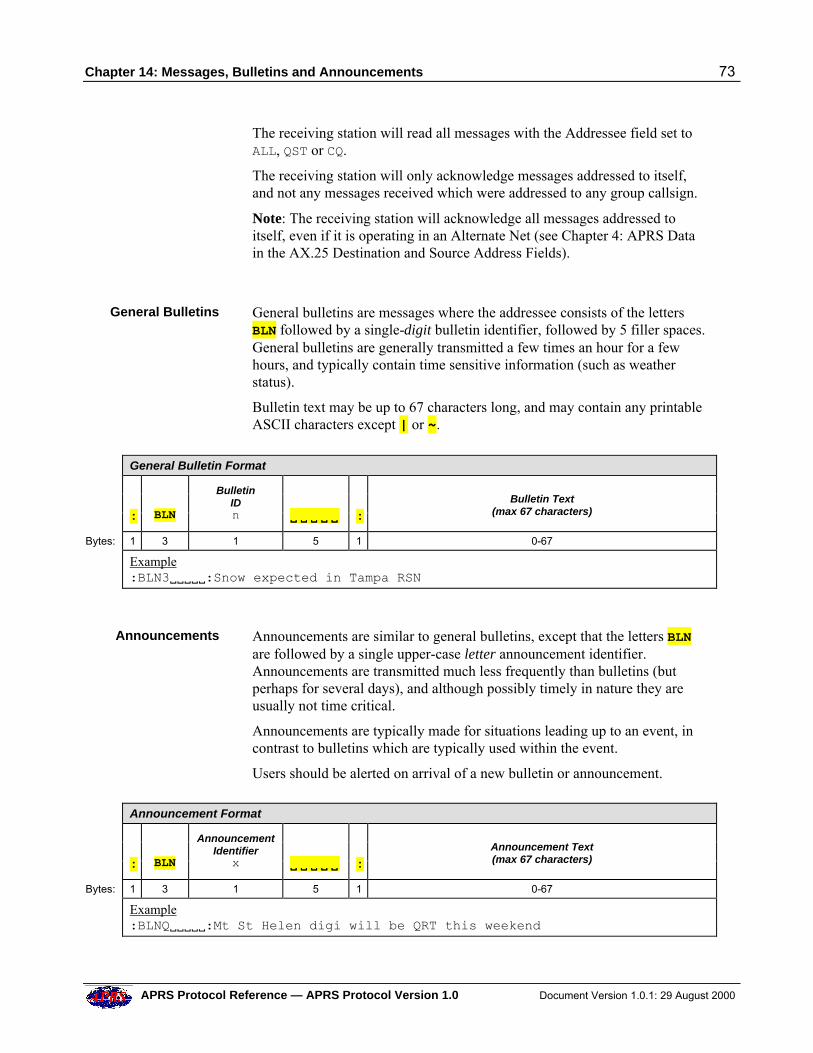
Chapter 14: Messages, Bulletins and Announcements 73
APRS Protocol Reference — APRS Protocol Version 1.0 Document Version 1.0.1: 29 August 2000
The receiving station will read all messages with the Addressee field set toALL, QST or CQ.
The receiving station will only acknowledge messages addressed to itself,and not any messages received which were addressed to any group callsign.
Note: The receiving station will acknowledge all messages addressed toitself, even if it is operating in an Alternate Net (see Chapter 4: APRS Datain the AX.25 Destination and Source Address Fields).
General Bulletins General bulletins are messages where the addressee consists of the lettersBLN followed by a single-digit bulletin identifier, followed by 5 filler spaces.General bulletins are generally transmitted a few times an hour for a fewhours, and typically contain time sensitive information (such as weatherstatus).
Bulletin text may be up to 67 characters long, and may contain any printableASCII characters except | or ~.
General Bulletin Format
:
BLN
BulletinIDn V V V VV V V V VV
:
Bulletin Text
(max 67 characters)
Bytes: 1 3 1 5 1 0-67
Example:BLN3VVVVV:Snow expected in Tampa RSN
Announcements Announcements are similar to general bulletins, except that the letters BLNare followed by a single upper-case letter announcement identifier.Announcements are transmitted much less frequently than bulletins (butperhaps for several days), and although possibly timely in nature they areusually not time critical.
Announcements are typically made for situations leading up to an event, incontrast to bulletins which are typically used within the event.
Users should be alerted on arrival of a new bulletin or announcement.
Announcement Format
:
BLN
AnnouncementIdentifier
x V V V VV V V V VV
:
Announcement Text(max 67 characters)
Bytes: 1 3 1 5 1 0-67
Example:BLNQVVVVV:Mt St Helen digi will be QRT this weekend
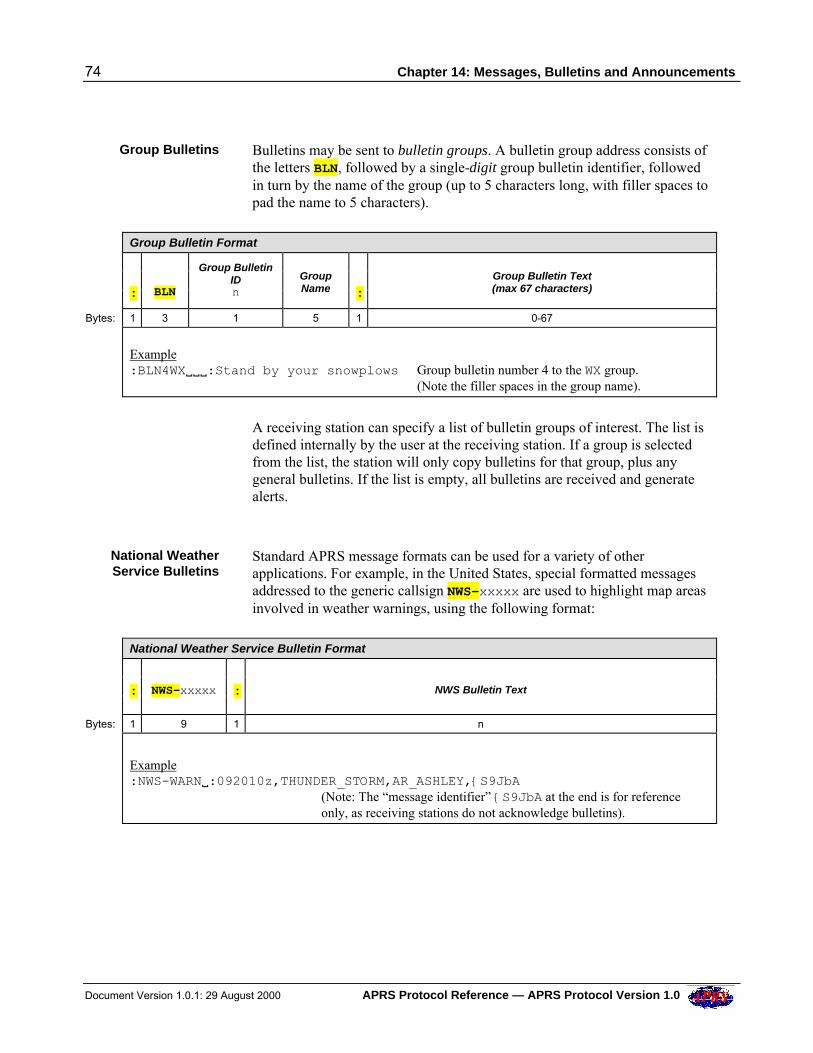
74 Chapter 14: Messages, Bulletins and Announcements
Document Version 1.0.1: 29 August 2000 APRS Protocol Reference — APRS Protocol Version 1.0
Group Bulletins Bulletins may be sent to bulletin groups. A bulletin group address consists ofthe letters BLN, followed by a single-digit group bulletin identifier, followedin turn by the name of the group (up to 5 characters long, with filler spaces topad the name to 5 characters).
Group Bulletin Format
:
BLN
Group BulletinIDn
GroupName
:
Group Bulletin Text(max 67 characters)
Bytes: 1 3 1 5 1 0-67
Example:BLN4WXVVV:Stand by your snowplows Group bulletin number 4 to the WX group.
(Note the filler spaces in the group name).
A receiving station can specify a list of bulletin groups of interest. The list isdefined internally by the user at the receiving station. If a group is selectedfrom the list, the station will only copy bulletins for that group, plus anygeneral bulletins. If the list is empty, all bulletins are received and generatealerts.
National WeatherService Bulletins
Standard APRS message formats can be used for a variety of otherapplications. For example, in the United States, special formatted messagesaddressed to the generic callsign NWS-xxxxx are used to highlight map areasinvolved in weather warnings, using the following format:
National Weather Service Bulletin Format
:
NWS-xxxxx
:
NWS Bulletin Text
Bytes: 1 9 1 n
Example:NWS-WARNV:092010z,THUNDER_STORM,AR_ASHLEY,{S9JbA
(Note: The “message identifier” {S9JbA at the end is for referenceonly, as receiving stations do not acknowledge bulletins).
Chapter 14: Messages, Bulletins and Announcements 75
APRS Protocol Reference — APRS Protocol Version 1.0 Document Version 1.0.1: 29 August 2000
NTS Radiograms APRS can be used to transport NTS radiograms. This uses the existingAPRS message format for backwards compatibility, by adding a 3-characterNTS format identifier Nx\ at the start of the APRS Message Text, asfollows:
N#\number\precedence\handling\originator\check\place\time\dateNA\address_line1\address_line2\address_line3\address_line4NP\phone numberN1\line 1 of NTS message textN2\line 2 of NTS message textN3\line 3 of NTS message textN4\line 4 of NTS message textN5\line 5 of NTS message textN6\line 6 of NTS message textNS\Signature blockNR\Received from\date_time\sent_to\date_time
All of these fields comes from the ARRL NTS Radiogram form and aredescribed in the NTS handbook.
Each message line is addressed to the same station.
The N#\, NA\ and NR\ lines are multiple fields combined for APRStransmission efficiency. The backslash separator is used so that conventionalforward slashes may be embedded in messages. (The backslash does not existin the RTTY or CW alphabets, so it therefore cannot appear in an NTSradiogram).
Each line may be up 67 characters long, including the 3-character NTSformat identifier. Lines in excess of 67 characters will be truncated.
There is a maximum of 6 lines of NTS message text.
Note: The N#\, NA\, NS\ and NR\ fields are required. The others areoptional.
Serialization of each line is handled by the normal APRS Message ID{xxxxx.
An APRS application is not required to understand or generate thesemessages. The information can be read and understood in the normalmessage display.
Obsolete Bulletinand Announcement
Format
Some stations transmit bulletins and announcements without the : APRSData Type Identifier. This format is obsolete. Some software may stilldecode such data as a bulletin or announcement, but it should now beinterpreted as a Status Report.
76 Chapter 14: Messages, Bulletins and Announcements
Document Version 1.0.1: 29 August 2000 APRS Protocol Reference — APRS Protocol Version 1.0
Bulletin andAnnouncementImplementation
Recommendations
Bulletins and announcements are seen as a way for all participants in anevent/emergency/net to see all common information posted to the group. Inthis sense they are visualized as a mountain-top billboard or a bulletin boardon the wall of an Emergency Operations Control Center.
Information that everyone must see is to be posted there. Information isadded and removed. Space is limited. Only so much information can beposted before it becomes too busy for anyone to see everything. Thus thingsare supposed to be posted, updated, and cleared to keep the big billboarduncluttered and current with what everyone needs to know at the presenttime. It should not be cluttered with obsolete information.
This can be implemented in an APRS display system as a “Bulletin Screen”.Everyone has this screen, and anyone can post or update lines on this screen.At any instant, everyone in the network sees exactly the same screen.Everything is arranged and displayed in exactly the same way. Thus,everyone, everywhere is looking at the same mountain-top billboard orbulletin board. There is no ambiguity as to who sees what information, inwhat order at what time.
To make this work, a number of issues should be considered:
• Sorting: Bulletins/Announcements are almost always multi-line, andmay arrive out of sequence. They must be sorted before presentation onthe Bulletin Screen, and re-sorted if necessary when each new linearrives. This includes sorting by originating callsign and Bulletin/Announcement ID.
• Replacement: Stations sending bulletins/announcements can send newlines to replace lines sent earlier, re-using the original Bulletin/Announcement IDs. (Note: It is only necessary to re-send replacementlines. It is not necessary to re-send the whole bulletin/announcement).Receipt of a new line with the same Bulletin/Announcement ID as onealready received from the same station should result in the existing linebeing overwritten (replaced).
• Clearing: A user should be able to clear any or all of the bulletins/announcements from the Bulletin Screen once he has read them. Anybulletins/announcements that are still valid will re-appear in due coursebecause of the way they are redundantly re-transmitted.
• Alerts: On receipt of any new or replacement line for the BulletinScreen, an alarm should be sounded and re-sounded periodically until theuser acknowledges it. Thus, this vital information is “pushed” to theoperator. There is no excuse for not being aware of the current bulletin/announcement state — this is important in the hurried and crisis-ladenscenario of an APRS event.
• Logging: Old bulletins/announcements should be logged in sequentialAPRS log files in case they are subsequently needed.
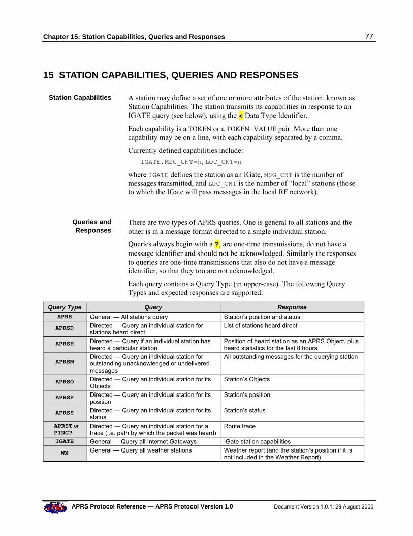
Chapter 15: Station Capabilities, Queries and Responses 77
APRS Protocol Reference — APRS Protocol Version 1.0 Document Version 1.0.1: 29 August 2000
15 STATION CAPABILITIES, QUERIES AND RESPONSES
Station Capabilities A station may define a set of one or more attributes of the station, known asStation Capabilities. The station transmits its capabilities in response to anIGATE query (see below), using the < Data Type Identifier.
Each capability is a TOKEN or a TOKEN=VALUE pair. More than onecapability may be on a line, with each capability separated by a comma.
Currently defined capabilities include:
IGATE,MSG_CNT=n,LOC_CNT=n
where IGATE defines the station as an IGate, MSG_CNT is the number ofmessages transmitted, and LOC_CNT is the number of “local” stations (thoseto which the IGate will pass messages in the local RF network).
Queries andResponses
There are two types of APRS queries. One is general to all stations and theother is in a message format directed to a single individual station.
Queries always begin with a ?, are one-time transmissions, do not have amessage identifier and should not be acknowledged. Similarly the responsesto queries are one-time transmissions that also do not have a messageidentifier, so that they too are not acknowledged.
Each query contains a Query Type (in upper-case). The following QueryTypes and expected responses are supported:
Query Type Query Response
APRS General — All stations query Station’s position and status
APRSD Directed — Query an individual station forstations heard direct
List of stations heard direct
APRSH Directed — Query if an individual station hasheard a particular station
Position of heard station as an APRS Object, plusheard statistics for the last 8 hours
APRSM Directed — Query an individual station foroutstanding unacknowledged or undeliveredmessages
All outstanding messages for the querying station
APRSO Directed — Query an individual station for itsObjects
Station’s Objects
APRSP Directed — Query an individual station for itsposition
Station’s position
APRSS Directed — Query an individual station for itsstatus
Station’s status
APRST or PING?
Directed — Query an individual station for atrace (i.e. path by which the packet was heard)
Route trace
IGATE General — Query all Internet Gateways IGate station capabilities
WX General — Query all weather stations Weather report (and the station’s position if it isnot included in the Weather Report)
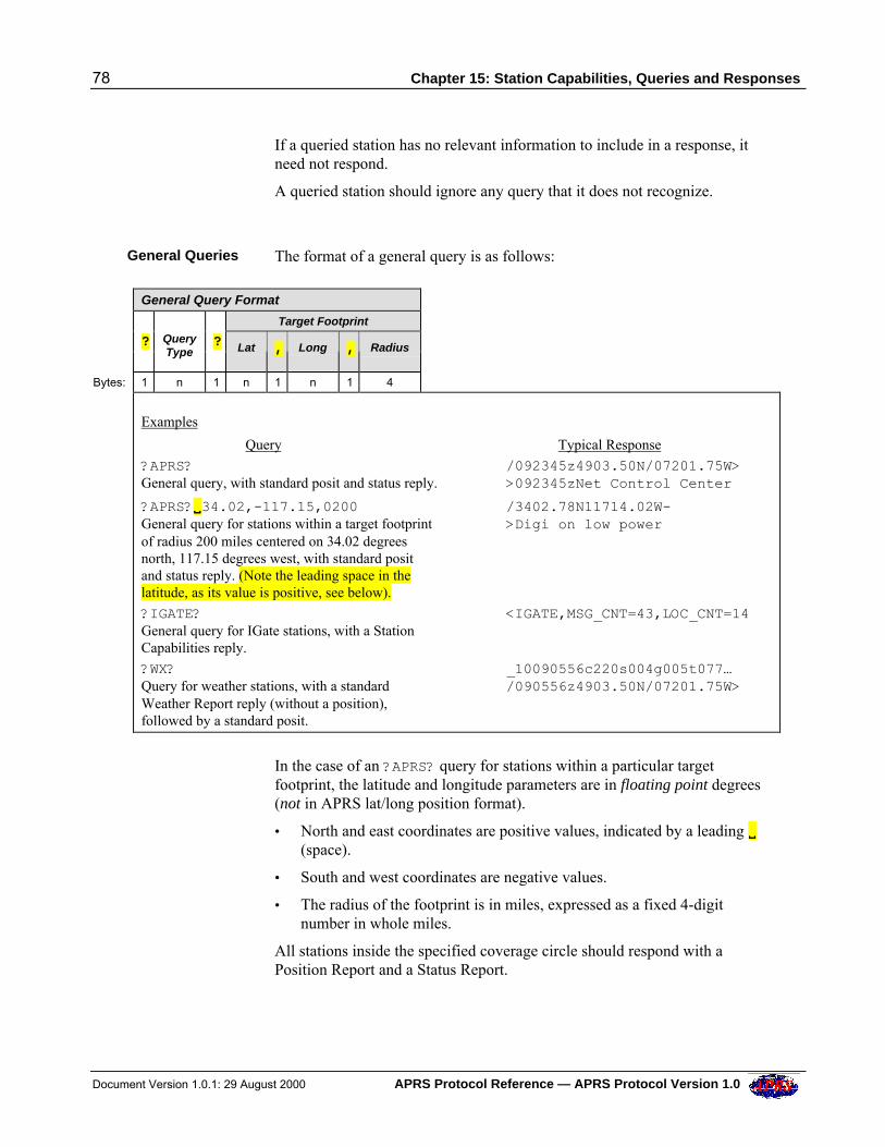
78 Chapter 15: Station Capabilities, Queries and Responses
Document Version 1.0.1: 29 August 2000 APRS Protocol Reference — APRS Protocol Version 1.0
If a queried station has no relevant information to include in a response, itneed not respond.
A queried station should ignore any query that it does not recognize.
General Queries The format of a general query is as follows:
General Query Format
Target Footprint
? Query
Type
? Lat , Long , Radius
Bytes: 1 n 1 n 1 n 1 4
Examples
Query Typical Response
?APRS? /092345z4903.50N/07201.75W>General query, with standard posit and status reply. >092345zNet Control Center
?APRS?VV34.02,-117.15,0200 /3402.78N11714.02W-General query for stations within a target footprint >Digi on low powerof radius 200 miles centered on 34.02 degreesnorth, 117.15 degrees west, with standard positand status reply. (Note the leading space in thelatitude, as its value is positive, see below).
?IGATE? <IGATE,MSG_CNT=43,LOC_CNT=14General query for IGate stations, with a StationCapabilities reply.
?WX? _10090556c220s004g005t077…Query for weather stations, with a standard /090556z4903.50N/07201.75W>Weather Report reply (without a position),followed by a standard posit.
In the case of an ?APRS? query for stations within a particular targetfootprint, the latitude and longitude parameters are in floating point degrees(not in APRS lat/long position format).
• North and east coordinates are positive values, indicated by a leading VV(space).
• South and west coordinates are negative values.
• The radius of the footprint is in miles, expressed as a fixed 4-digitnumber in whole miles.
All stations inside the specified coverage circle should respond with aPosition Report and a Status Report.
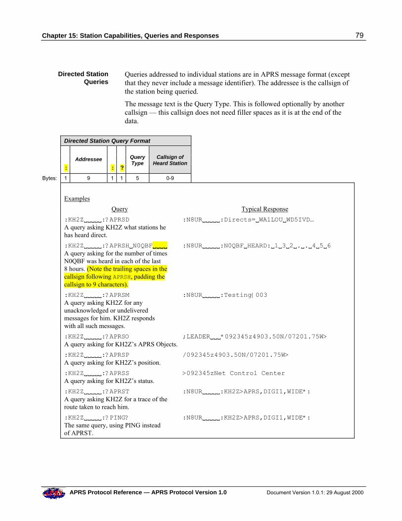
Chapter 15: Station Capabilities, Queries and Responses 79
APRS Protocol Reference — APRS Protocol Version 1.0 Document Version 1.0.1: 29 August 2000
Directed StationQueries
Queries addressed to individual stations are in APRS message format (exceptthat they never include a message identifier). The addressee is the callsign ofthe station being queried.
The message text is the Query Type. This is followed optionally by anothercallsign — this callsign does not need filler spaces as it is at the end of thedata.
Directed Station Query Format
:
Addressee
:
?
QueryType
Callsign ofHeard Station
Bytes: 1 9 1 1 5 0-9
Examples
Query Typical Response
:KH2ZVVVVV:?APRSD :N8URVVVVV:Directs=VWA1LOUVWD5IVD…A query asking KH2Z what stations hehas heard direct.
:KH2ZVVVVV:?APRSHVN0QBFVVVVVVVV :N8URVVVVV:N0QBFVHEARD:V1V3V2V.V.V4V5V6A query asking for the number of timesN0QBF was heard in each of the last8 hours. (Note the trailing spaces in thecallsign following APRSH, padding thecallsign to 9 characters).
:KH2ZVVVVV:?APRSM :N8URVVVVV:Testing{003A query asking KH2Z for anyunacknowledged or undeliveredmessages for him. KH2Z respondswith all such messages.
:KH2ZVVVVV:?APRSO ;LEADERVVV*092345z4903.50N/07201.75W>A query asking for KH2Z’s APRS Objects.
:KH2ZVVVVV:?APRSP /092345z4903.50N/07201.75W>A query asking for KH2Z’s position.
:KH2ZVVVVV:?APRSS >092345zNet Control CenterA query asking for KH2Z’s status.
:KH2ZVVVVV:?APRST :N8URVVVVV:KH2Z>APRS,DIGI1,WIDE*:A query asking KH2Z for a trace of theroute taken to reach him.
:KH2ZVVVVV:?PING? :N8URVVVVV:KH2Z>APRS,DIGI1,WIDE*:The same query, using PING insteadof APRST.
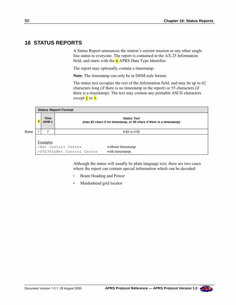
80 Chapter 16: Status Reports
Document Version 1.0.1: 29 August 2000 APRS Protocol Reference — APRS Protocol Version 1.0
16 STATUS REPORTS A Status Report announces the station’s current mission or any other single
line status to everyone. The report is contained in the AX.25 Informationfield, and starts with the > APRS Data Type Identifier.
The report may optionally contain a timestamp.
Note: The timestamp can only be in DHM zulu format.
The status text occupies the rest of the Information field, and may be up to 62characters long (if there is no timestamp in the report) or 55 characters (ifthere is a timestamp). The text may contain any printable ASCII charactersexcept | or ~.
Status Report Format
>
TimeDHM z
Status Text
(max 62 chars if no timestamp, or 55 chars if there is a timestamp)
Bytes: 1 7 0-62 or 0-55
Examples>Net Control Center without timestamp.>092345zNet Control Center with timestamp.
Although the status will usually be plain language text, there are two caseswhere the report can contain special information which can be decoded:
• Beam Heading and Power
• Maidenhead grid locator
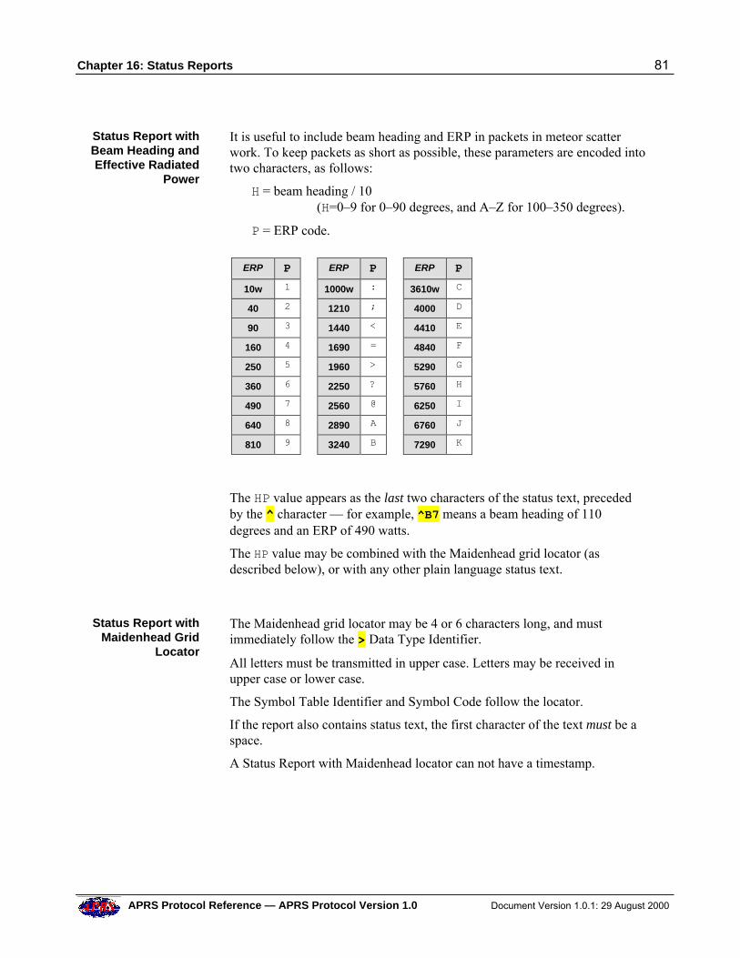
Chapter 16: Status Reports 81
APRS Protocol Reference — APRS Protocol Version 1.0 Document Version 1.0.1: 29 August 2000
Status Report withBeam Heading andEffective Radiated
Power
It is useful to include beam heading and ERP in packets in meteor scatterwork. To keep packets as short as possible, these parameters are encoded intotwo characters, as follows:
H = beam heading / 10(H=0–9 for 0–90 degrees, and A–Z for 100–350 degrees).
P = ERP code.
ERP P ERP P ERP P
10w 1 1000w : 3610w C
40 2 1210 ; 4000 D
90 3 1440 < 4410 E
160 4 1690 = 4840 F
250 5 1960 > 5290 G
360 6 2250 ? 5760 H
490 7 2560 @ 6250 I
640 8 2890 A 6760 J
810 9 3240 B 7290 K
The HP value appears as the last two characters of the status text, precededby the ^ character — for example, ^B7 means a beam heading of 110degrees and an ERP of 490 watts.
The HP value may be combined with the Maidenhead grid locator (asdescribed below), or with any other plain language status text.
Status Report withMaidenhead Grid
Locator
The Maidenhead grid locator may be 4 or 6 characters long, and mustimmediately follow the > Data Type Identifier.
All letters must be transmitted in upper case. Letters may be received inupper case or lower case.
The Symbol Table Identifier and Symbol Code follow the locator.
If the report also contains status text, the first character of the text must be aspace.
A Status Report with Maidenhead locator can not have a timestamp.
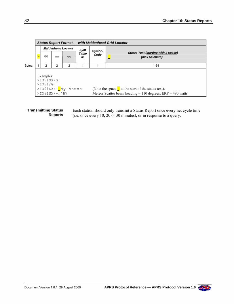
82 Chapter 16: Status Reports
Document Version 1.0.1: 29 August 2000 APRS Protocol Reference — APRS Protocol Version 1.0
Status Report Format — with Maidenhead Grid Locator
Maidenhead Locator
> GG nn gg
SymTable
ID
SymbolCode
Status Text (starting with a space)VV (max 54 chars)
Bytes: 1 2 2 2 1 1 1-54
Examples>IO91SX/G>IO91/G>IO91SX/-VVMy house (Note the space VV at the start of the status text).>IO91SX/-V^B7 Meteor Scatter beam heading = 110 degrees, ERP = 490 watts.
Transmitting StatusReports
Each station should only transmit a Status Report once every net cycle time(i.e. once every 10, 20 or 30 minutes), or in response to a query.
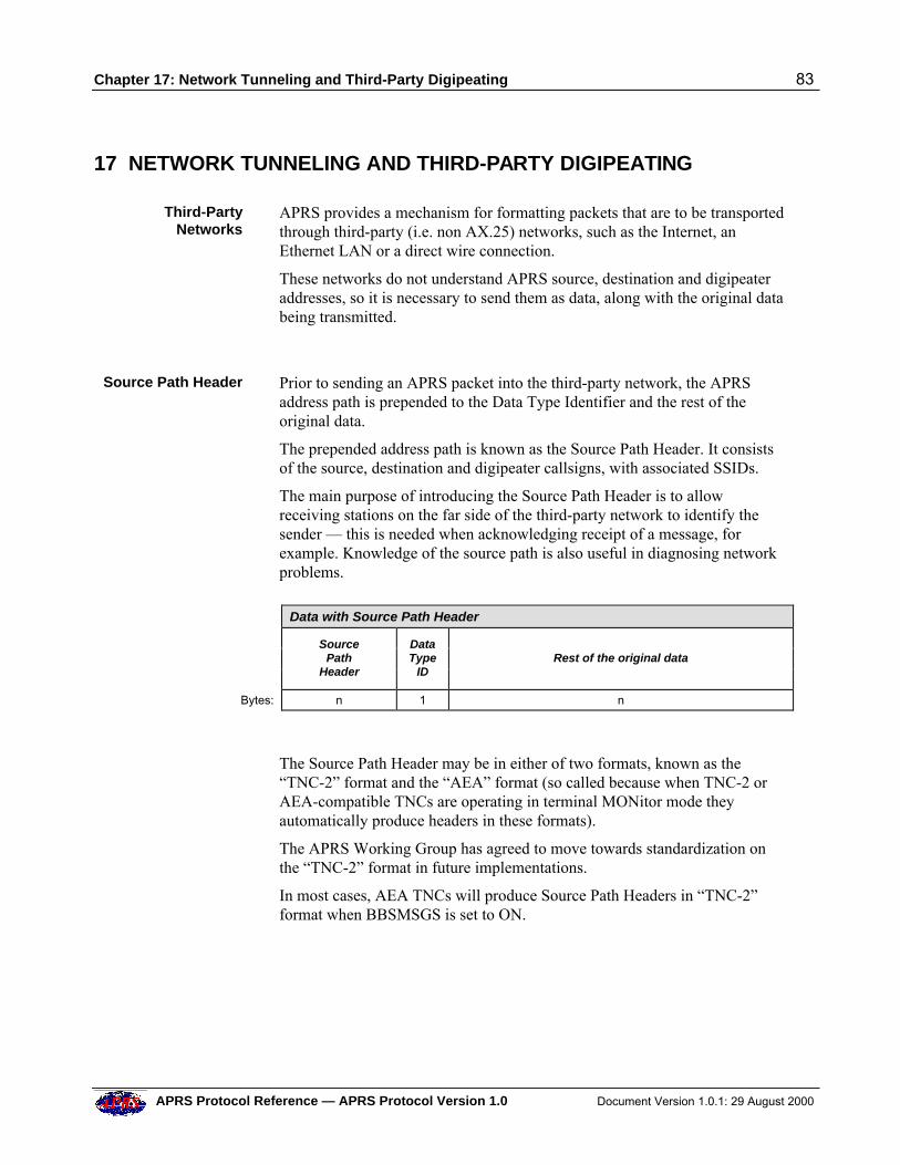
Chapter 17: Network Tunneling and Third-Party Digipeating 83
APRS Protocol Reference — APRS Protocol Version 1.0 Document Version 1.0.1: 29 August 2000
17 NETWORK TUNNELING AND THIRD-PARTY DIGIPEATING
Third-PartyNetworks
APRS provides a mechanism for formatting packets that are to be transportedthrough third-party (i.e. non AX.25) networks, such as the Internet, anEthernet LAN or a direct wire connection.
These networks do not understand APRS source, destination and digipeateraddresses, so it is necessary to send them as data, along with the original databeing transmitted.
Source Path Header Prior to sending an APRS packet into the third-party network, the APRSaddress path is prepended to the Data Type Identifier and the rest of theoriginal data.
The prepended address path is known as the Source Path Header. It consistsof the source, destination and digipeater callsigns, with associated SSIDs.
The main purpose of introducing the Source Path Header is to allowreceiving stations on the far side of the third-party network to identify thesender — this is needed when acknowledging receipt of a message, forexample. Knowledge of the source path is also useful in diagnosing networkproblems.
Data with Source Path Header
SourcePath
Header
DataType
ID
Rest of the original data
Bytes: n 1 n
The Source Path Header may be in either of two formats, known as the“TNC-2” format and the “AEA” format (so called because when TNC-2 orAEA-compatible TNCs are operating in terminal MONitor mode theyautomatically produce headers in these formats).
The APRS Working Group has agreed to move towards standardization onthe “TNC-2” format in future implementations.
In most cases, AEA TNCs will produce Source Path Headers in “TNC-2”format when BBSMSGS is set to ON.
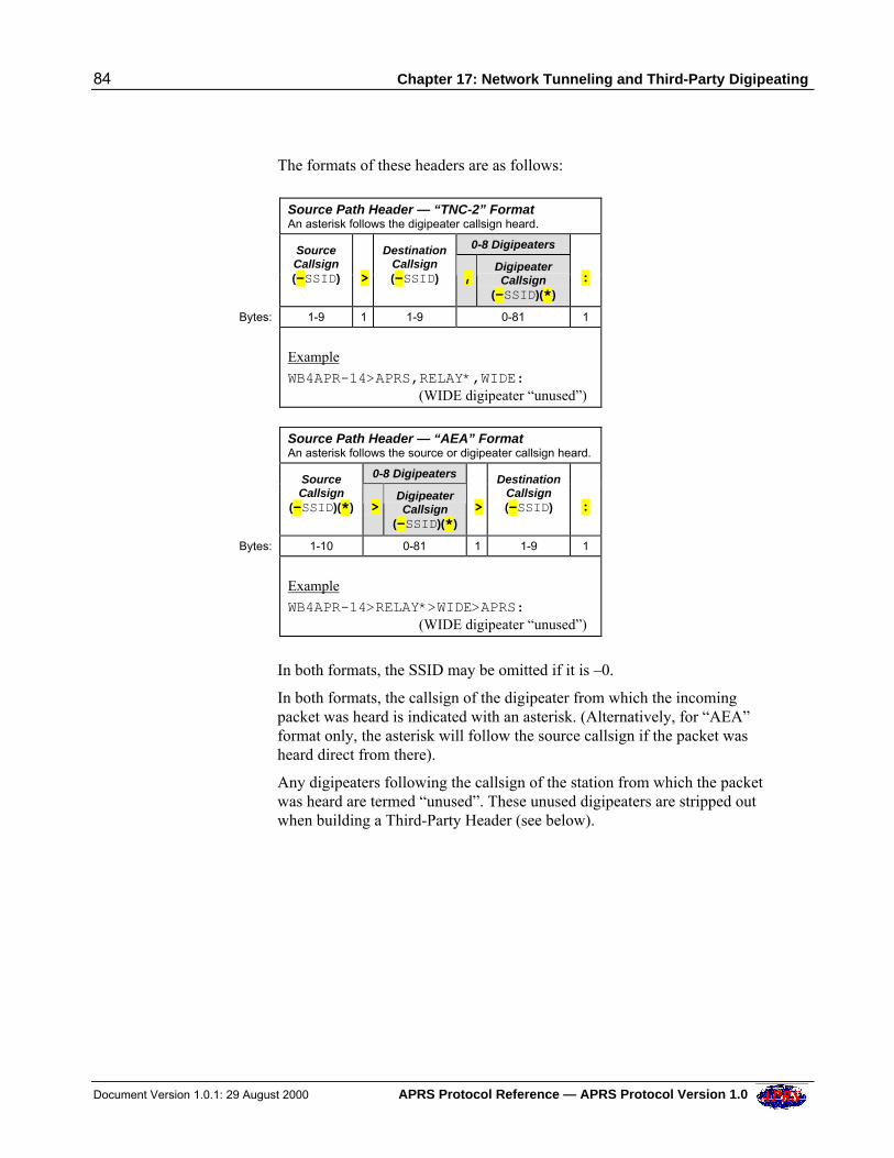
84 Chapter 17: Network Tunneling and Third-Party Digipeating
Document Version 1.0.1: 29 August 2000 APRS Protocol Reference — APRS Protocol Version 1.0
The formats of these headers are as follows:
Source Path Header — “TNC-2” Format
An asterisk follows the digipeater callsign heard.
0-8 Digipeaters
SourceCallsign(-SSID)
>
DestinationCallsign(-SSID) ,
DigipeaterCallsign
(-SSID)(*)
:
Bytes: 1-9 1 1-9 0-81 1
Example
WB4APR-14>APRS,RELAY*,WIDE: (WIDE digipeater “unused”)
Source Path Header — “AEA” Format
An asterisk follows the source or digipeater callsign heard.
0-8 Digipeaters
SourceCallsign
(-SSID)(*) > DigipeaterCallsign
(-SSID)(*)
>
DestinationCallsign(-SSID)
:
Bytes: 1-10 0-81 1 1-9 1
Example
WB4APR-14>RELAY*>WIDE>APRS: (WIDE digipeater “unused”)
In both formats, the SSID may be omitted if it is –0.
In both formats, the callsign of the digipeater from which the incomingpacket was heard is indicated with an asterisk. (Alternatively, for “AEA”format only, the asterisk will follow the source callsign if the packet washeard direct from there).
Any digipeaters following the callsign of the station from which the packetwas heard are termed “unused”. These unused digipeaters are stripped outwhen building a Third-Party Header (see below).
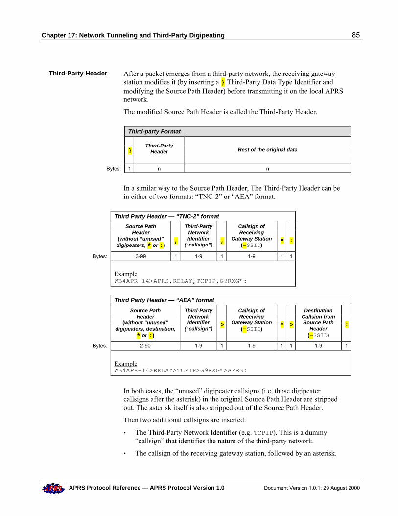
Chapter 17: Network Tunneling and Third-Party Digipeating 85
APRS Protocol Reference — APRS Protocol Version 1.0 Document Version 1.0.1: 29 August 2000
Third-Party Header After a packet emerges from a third-party network, the receiving gatewaystation modifies it (by inserting a } Third-Party Data Type Identifier andmodifying the Source Path Header) before transmitting it on the local APRSnetwork.
The modified Source Path Header is called the Third-Party Header.
Third-party Format
}
Third-PartyHeader
Rest of the original data
Bytes: 1 n n
In a similar way to the Source Path Header, The Third-Party Header can bein either of two formats: “TNC-2” or “AEA” format.
Third Party Header — “TNC-2” format
Source PathHeader
(without “unused”digipeaters, * or :)
,
Third-PartyNetworkIdentifier
(“callsign”)
,
Callsign ofReceiving
Gateway Station(-SSID)
*
:
Bytes: 3-99 1 1-9 1 1-9 1 1
ExampleWB4APR-14>APRS,RELAY,TCPIP,G9RXG*:
Third Party Header — “AEA” format
Source PathHeader
(without “unused”digipeaters, destination,
* or :)
Third-PartyNetworkIdentifier
(“callsign”)
>
Callsign ofReceiving
Gateway Station(-SSID)
*
>
DestinationCallsign fromSource Path
Header(-SSID)
:
Bytes: 2-90 1-9 1 1-9 1 1 1-9 1
ExampleWB4APR-14>RELAY>TCPIP>G9RXG*>APRS:
In both cases, the “unused” digipeater callsigns (i.e. those digipeatercallsigns after the asterisk) in the original Source Path Header are strippedout. The asterisk itself is also stripped out of the Source Path Header.
Then two additional callsigns are inserted:
• The Third-Party Network Identifier (e.g. TCPIP). This is a dummy“callsign” that identifies the nature of the third-party network.
• The callsign of the receiving gateway station, followed by an asterisk.
86 Chapter 17: Network Tunneling and Third-Party Digipeating
Document Version 1.0.1: 29 August 2000 APRS Protocol Reference — APRS Protocol Version 1.0
Action onReceiving a Third-
Party packet
When another station receives a third-party packet, it can extract the callsignof the original sending station from the Third-Party Header, if it is needed toacknowledge receipt of a message.
The other addresses in the Third-Party Header may be useful for networkdiagnostic purposes.
An Example ofSending a Messagethrough the Internet
The Scenario:
• WB4APR-14 wants to send a message via the Internet to G3NRW.
• The nearest Internet gateway to WB4APR-14 is K4HG, reachable via aRELAY,WIDE path.
• The nearest Internet gateway to G3NRW is G9RXG.
The Process:
• In the normal way, WB4APR-14 builds a message packet that contains: :G3NRWVVVVVVVV:Hi Ian{001
• WB4APR-14 transmits the packet via his UNPROTO path RELAY,WIDE.
• The Internet gateway K4HG happens to receive this packet from the RELAYdigipeater in the path.
• K4HG builds a new packet that contains the source path and the originalmessage: WB4APR-14>APRS,RELAY*,WIDE::G3NRWVVVVVVVV:Hi Ian{001
• K4HG sends this packet (using telnet) to an APRServer on the Internet.
• All Internet gateways throughout the world that are connected to theAPRServe network (including G9RXG) receive the packet.
• G9RXG converts the packet into a Third-Party packet: }WB4APR-14>APRS,RELAY,TCPIP,G9RXG*::G3NRWVVVVVVVV:Hi Ian{001
Note that the WIDE digipeater was stripped out of the header because it wasunused.
• G9RXG transmits the packet over the local APRS network.
• G3NRW receives the packet, strips out the Third-Party Header, and discoversthat the packet contains a message for him. From the header, G3NRW thenestablishes that the acknowledgement is to go back to WB4APR-14.
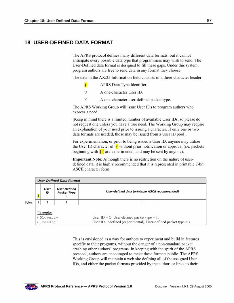
Chapter 18: User-Defined Data Format 87
APRS Protocol Reference — APRS Protocol Version 1.0 Document Version 1.0.1: 29 August 2000
18 USER-DEFINED DATA FORMAT
The APRS protocol defines many different data formats, but it cannotanticipate every possible data type that programmers may wish to send. TheUser-Defined data format is designed to fill these gaps. Under this system,program authors are free to send data in any format they choose.
The data in the AX.25 Information field consists of a three-character header:
{ APRS Data Type Identifier.
U A one-character User ID.
X A one-character user-defined packet type.
The APRS Working Group will issue User IDs to program authors whoexpress a need.
[Keep in mind there is a limited number of available User IDs, so please donot request one unless you have a true need. The Working Group may requirean explanation of your need prior to issuing a character. If only one or twodata formats are needed, those may be issued from a User ID pool].
For experimentation, or prior to being issued a User ID, anyone may utilizethe User ID character of { without prior notification or approval (i.e. packetsbeginning with {{ are experimental, and may be sent by anyone).
Important Note: Although there is no restriction on the nature of user-defined data, it is highly recommended that it is represented in printable 7-bitASCII character form.
User-Defined Data Format
{
UserIDU
User-DefinedPacket Type
X
User-defined data (printable ASCII recommended)
Bytes: 1 1 1 n
Examples{Q1qwerty User ID = Q, User-defined packet type = 1.{{zasdfg User ID undefined (experimental), User-defined packet type = z.
This is envisioned as a way for authors to experiment and build in featuresspecific to their programs, without the danger of a non-standard packetcrashing other authors’ programs. In keeping with the spirit of the APRSprotocol, authors are encouraged to make these formats public. The APRSWorking Group will maintain a web site defining all of the assigned UserIDs, and either the packet formats provided by the author, or links to their
88 Chapter 18: User-Defined data Format
Document Version 1.0.1: 29 August 2000 APRS Protocol Reference — APRS Protocol Version 1.0
own web sites which define their formats.
Generally, all formats using this method will be considered optional. Noprogram is required to decode any of these packets, and must ignore any itdoes not decode. However, it is possible that in the future some of theseformats may prove to be of sufficient utility and interest to the entire APRScommunity that they will be specifically included in future versions of theAPRS protocol.
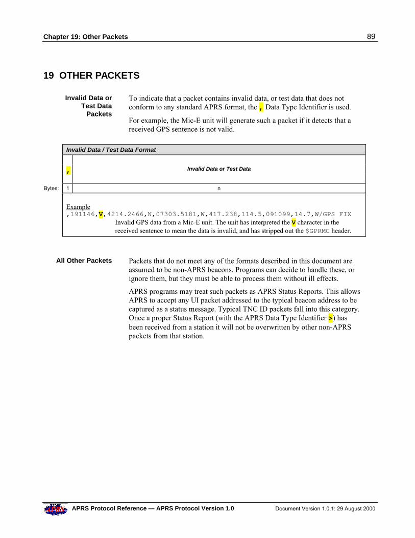
Chapter 19: Other Packets 89
APRS Protocol Reference — APRS Protocol Version 1.0 Document Version 1.0.1: 29 August 2000
19 OTHER PACKETS
Invalid Data orTest Data
Packets
To indicate that a packet contains invalid data, or test data that does notconform to any standard APRS format, the , Data Type Identifier is used.
For example, the Mic-E unit will generate such a packet if it detects that areceived GPS sentence is not valid.
Invalid Data / Test Data Format
,
Invalid Data or Test Data
Bytes: 1 n
Example,191146,V,4214.2466,N,07303.5181,W,417.238,114.5,091099,14.7,W/GPS FIX
Invalid GPS data from a Mic-E unit. The unit has interpreted the V character in thereceived sentence to mean the data is invalid, and has stripped out the $GPRMC header.
All Other Packets Packets that do not meet any of the formats described in this document areassumed to be non-APRS beacons. Programs can decide to handle these, orignore them, but they must be able to process them without ill effects.
APRS programs may treat such packets as APRS Status Reports. This allowsAPRS to accept any UI packet addressed to the typical beacon address to becaptured as a status message. Typical TNC ID packets fall into this category.Once a proper Status Report (with the APRS Data Type Identifier >) hasbeen received from a station it will not be overwritten by other non-APRSpackets from that station.
90 Chapter 20: APRS Symbols
Document Version 1.0.1: 29 August 2000 APRS Protocol Reference — APRS Protocol Version 1.0
20 APRS SYMBOLS
Three Methods There are three methods of specifying an APRS symbol (display icon):
• In the AX.25 Information field.
• In the AX.25 Destination Address.
• In the SSID of the AX.25 Source Address.
The preferred method is to include the symbol in the Information field.However, where this is not possible (for example, in stand-alone trackerswith no means of introducing the symbol into the Information field), either ofthe other two methods may be used instead.
The Symbol Tables There are two APRS Symbol Tables:
• Primary Symbol Table
• Alternate Symbol Table
See Appendix 2 for a full listing of these tables.
The essential difference between the Primary and Alternate Symbol Tables isthat some of the symbols in the Alternate Symbol Table can be overlaid withan alphanumeric character. For example, a “car” icon in the AlternateSymbol Table could be overlaid with the digit “3”, to indicate it is car #3.
Symbols capable of taking an overlay are marked as [with overlay].
None of the symbols in the Primary Symbol Table can be overlaid.
In the tables, each symbol is coded in three ways:
• /$ or \$ — for symbols in the Information field.
• GPSxyz — for generic Destination addresses containing symbols.
• GPSCnn or GPSEnn — another form of generic Destination addressescontaining systems.
In addition, 15 of the symbols in the Primary Symbol Table have anassociated SSID (e.g. a small aircraft has SSID -7). The SSID is intended foruse in the AX.25 Source Address of stand-alone trackers which have no othermeans of specifying the symbol.
Symbols in theAX.25 Information
Field
A symbol in the AX.25 Information field is a combination of a one-characterSymbol Table Identifier and a one-character Symbol Code.
For example, in the Position Report:
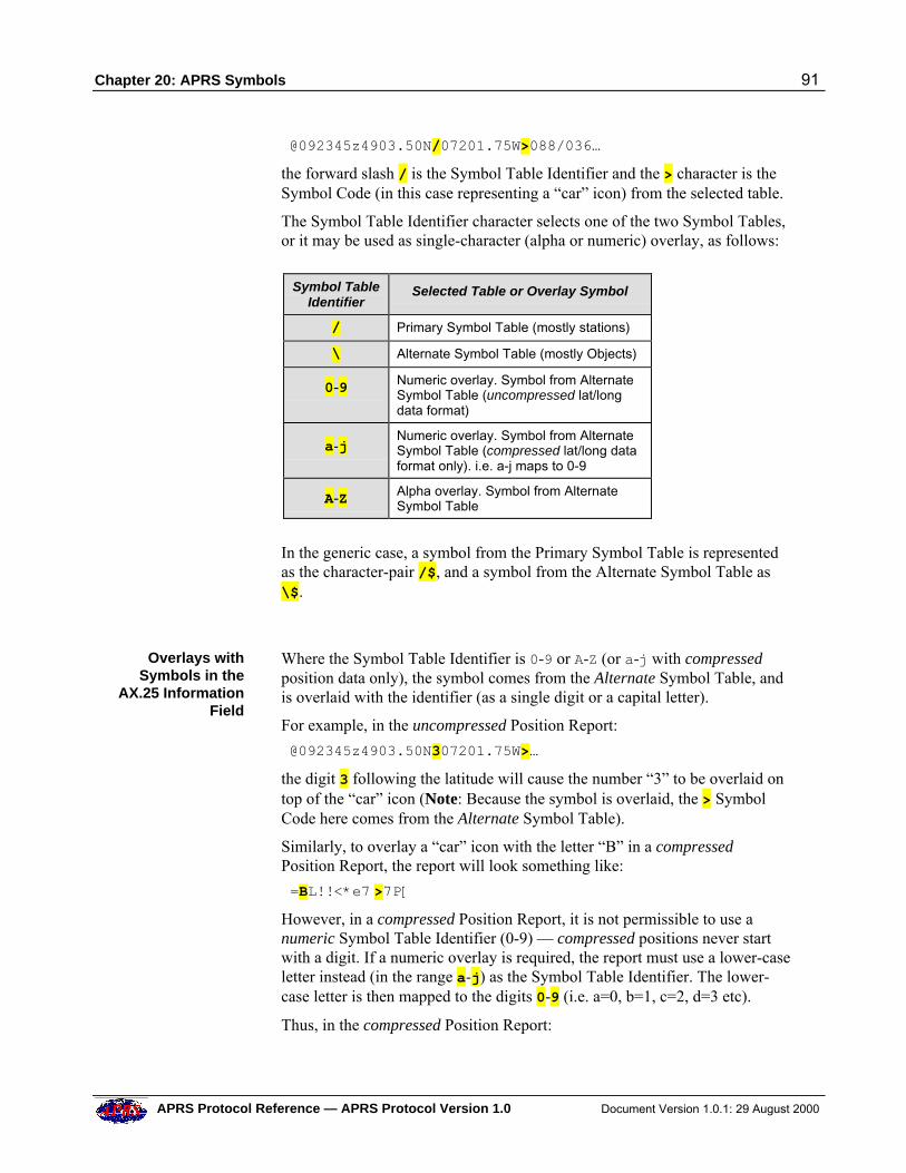
Chapter 20: APRS Symbols 91
APRS Protocol Reference — APRS Protocol Version 1.0 Document Version 1.0.1: 29 August 2000
@092345z4903.50N/07201.75W>088/036…
the forward slash / is the Symbol Table Identifier and the > character is theSymbol Code (in this case representing a “car” icon) from the selected table.
The Symbol Table Identifier character selects one of the two Symbol Tables,or it may be used as single-character (alpha or numeric) overlay, as follows:
Symbol TableIdentifier
Selected Table or Overlay Symbol
/ Primary Symbol Table (mostly stations)
\ Alternate Symbol Table (mostly Objects)
0-9 Numeric overlay. Symbol from AlternateSymbol Table (uncompressed lat/longdata format)
a-j
Numeric overlay. Symbol from AlternateSymbol Table (compressed lat/long dataformat only). i.e. a-j maps to 0-9
A-Z Alpha overlay. Symbol from AlternateSymbol Table
In the generic case, a symbol from the Primary Symbol Table is representedas the character-pair /$, and a symbol from the Alternate Symbol Table as\$.
Overlays withSymbols in the
AX.25 InformationField
Where the Symbol Table Identifier is 0-9 or A-Z (or a-j with compressedposition data only), the symbol comes from the Alternate Symbol Table, andis overlaid with the identifier (as a single digit or a capital letter).
For example, in the uncompressed Position Report:
@092345z4903.50N307201.75W>…
the digit 3 following the latitude will cause the number “3” to be overlaid ontop of the “car” icon (Note: Because the symbol is overlaid, the > SymbolCode here comes from the Alternate Symbol Table).
Similarly, to overlay a “car” icon with the letter “B” in a compressedPosition Report, the report will look something like:
=BL!!<*e7 >7P[
However, in a compressed Position Report, it is not permissible to use anumeric Symbol Table Identifier (0-9) — compressed positions never startwith a digit. If a numeric overlay is required, the report must use a lower-caseletter instead (in the range a-j) as the Symbol Table Identifier. The lower-case letter is then mapped to the digits 0-9 (i.e. a=0, b=1, c=2, d=3 etc).
Thus, in the compressed Position Report:
92 Chapter 20: APRS Symbols
Document Version 1.0.1: 29 August 2000 APRS Protocol Reference — APRS Protocol Version 1.0
=d5L!!<*e7 >7P[
the letter d maps to overlay character “3”.
As noted above, not all symbols from the Alternate Symbol Table may beoverlaid in this way — those that can be overlaid are marked as [with overlay]
in Appendix 2. This means that they are capable of taking an overlay, butthey do not necessarily need to have one. Thus, for example, the followingreport uses the car symbol from the Alternate Symbol Table, but does notdisplay an overlay:
@092345z4903.50N\07201.75W>…
Symbols in theAX.25 Destination
Address
Where it is not possible to include a symbol in the Information field, thesymbol may be specified in the AX.25 Destination Address instead, using thefollowing generic destination addresses: GPSxyz, GPSCnn, GPSEnn,SPCxyz and SYMxyz.
The characters xy and nn refer to entries in the APRS Symbol Tables. Forexample, from the Primary Symbol Table, a tracker could use the DestinationAddress GPSMVVV or GPS30 to specify a “car” icon.
The character z specifies the overlay character (where permitted), or is a VV(space) — the space is a filler character, as all AX.25 addresses must beexactly 6 characters long.
The GPS/SPC/SYMxyV and GPSCnn/GPSEnn addresses can be usedinterchangeably. Thus, for example, GPSBMV , SPCBMV , SYMBMV andGPSC12 all specify a “Boy Scouts” icon (from the Primary Symbol Table),and GPSOMV , SPCOMV , SYMOMV and GPSE12 all specify a “Girl Scouts”icon (from the Alternate Symbol Table).
Overlays withSymbols in the
AX.25 DestinationAddress
If the z character in a GPSxyz, SPCxyz or SYMxyz address is not a space,it specifies an alphanumeric overlay character, in the range 0-9 or A-Z.
Overlays can only be used with symbols from the Alternate Symbol Tablemarked with the legend [with overlay].
For example, if the “car” icon is to be overlaid with a digit “3”, theDestination Address will be GPSNV3.
However, even if the address is overlay-capable, it is not actually necessaryto specify an overlay; e.g. GPSNVVV.
GPSCnn and GPSEnn symbols can not have overlays.
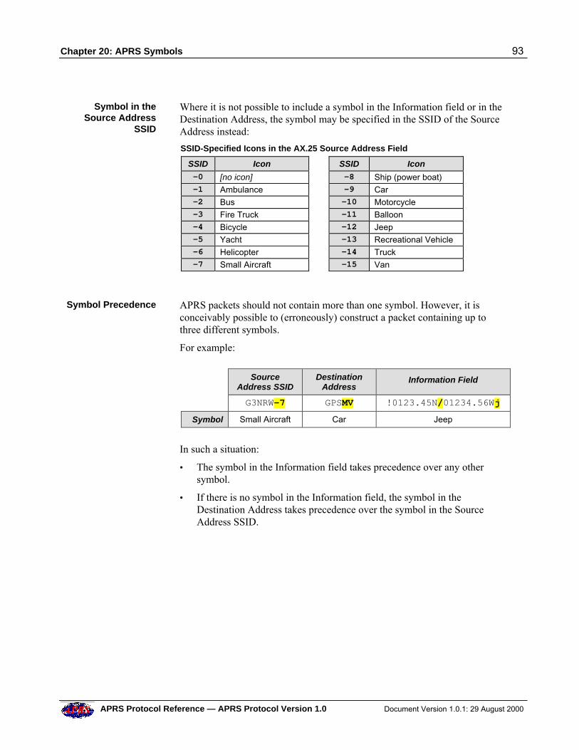
Chapter 20: APRS Symbols 93
APRS Protocol Reference — APRS Protocol Version 1.0 Document Version 1.0.1: 29 August 2000
Symbol in theSource Address
SSID
Where it is not possible to include a symbol in the Information field or in theDestination Address, the symbol may be specified in the SSID of the SourceAddress instead:
SSID-Specified Icons in the AX.25 Source Address Field
SSID Icon SSID Icon
-0 [no icon] -8 Ship (power boat) -1 Ambulance -9 Car -2 Bus -10 Motorcycle -3 Fire Truck -11 Balloon -4 Bicycle -12 Jeep -5 Yacht -13 Recreational Vehicle -6 Helicopter -14 Truck -7 Small Aircraft -15 Van
Symbol Precedence APRS packets should not contain more than one symbol. However, it isconceivably possible to (erroneously) construct a packet containing up tothree different symbols.
For example:
SourceAddress SSID
DestinationAddress
Information Field
G3NRW-7 GPSMV !0123.45N/01234.56Wj
Symbol Small Aircraft Car Jeep
In such a situation:
• The symbol in the Information field takes precedence over any othersymbol.
• If there is no symbol in the Information field, the symbol in theDestination Address takes precedence over the symbol in the SourceAddress SSID.
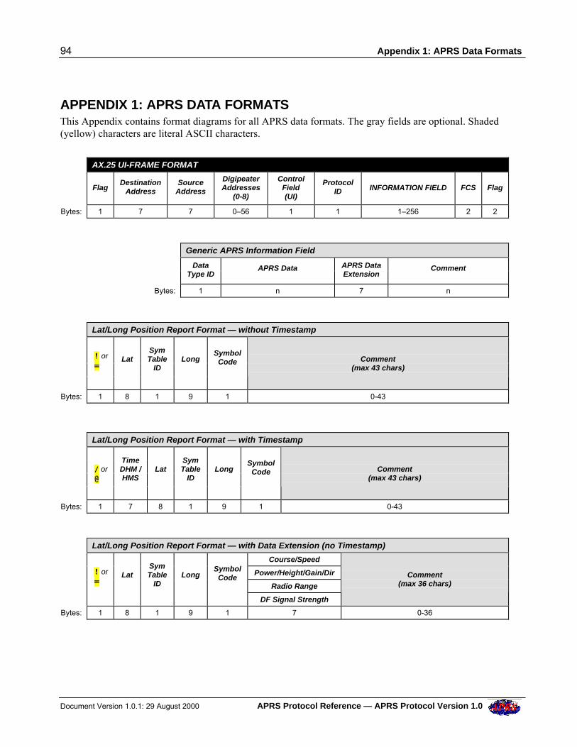
94 Appendix 1: APRS Data Formats
Document Version 1.0.1: 29 August 2000 APRS Protocol Reference — APRS Protocol Version 1.0
APPENDIX 1: APRS DATA FORMATS This Appendix contains format diagrams for all APRS data formats. The gray fields are optional. Shaded(yellow) characters are literal ASCII characters.
AX.25 UI-FRAME FORMAT
FlagDestination
AddressSource
Address
DigipeaterAddresses
(0-8)
ControlField(UI)
ProtocolID INFORMATION FIELD FCS Flag
Bytes: 1 7 7 0–56 1 1 1–256 2 2
Generic APRS Information Field
Data
Type ID APRS Data APRS Data
Extension Comment
Bytes: 1 n 7 n
Lat/Long Position Report Format — without Timestamp
! or =
Lat
SymTable
ID
Long
SymbolCode
Comment
(max 43 chars)
Bytes: 1 8 1 9 1 0-43
Lat/Long Position Report Format — with Timestamp
/ or @
TimeDHM /HMS
Lat
SymTable
ID
Long
SymbolCode
Comment
(max 43 chars)
Bytes: 1 7 8 1 9 1 0-43
Lat/Long Position Report Format — with Data Extension (no Timestamp)
Course/Speed
Power/Height/Gain/Dir
Radio Range
! or =
Lat
SymTable
ID
Long
SymbolCode
DF Signal Strength
Comment
(max 36 chars)
Bytes: 1 8 1 9 1 7 0-36
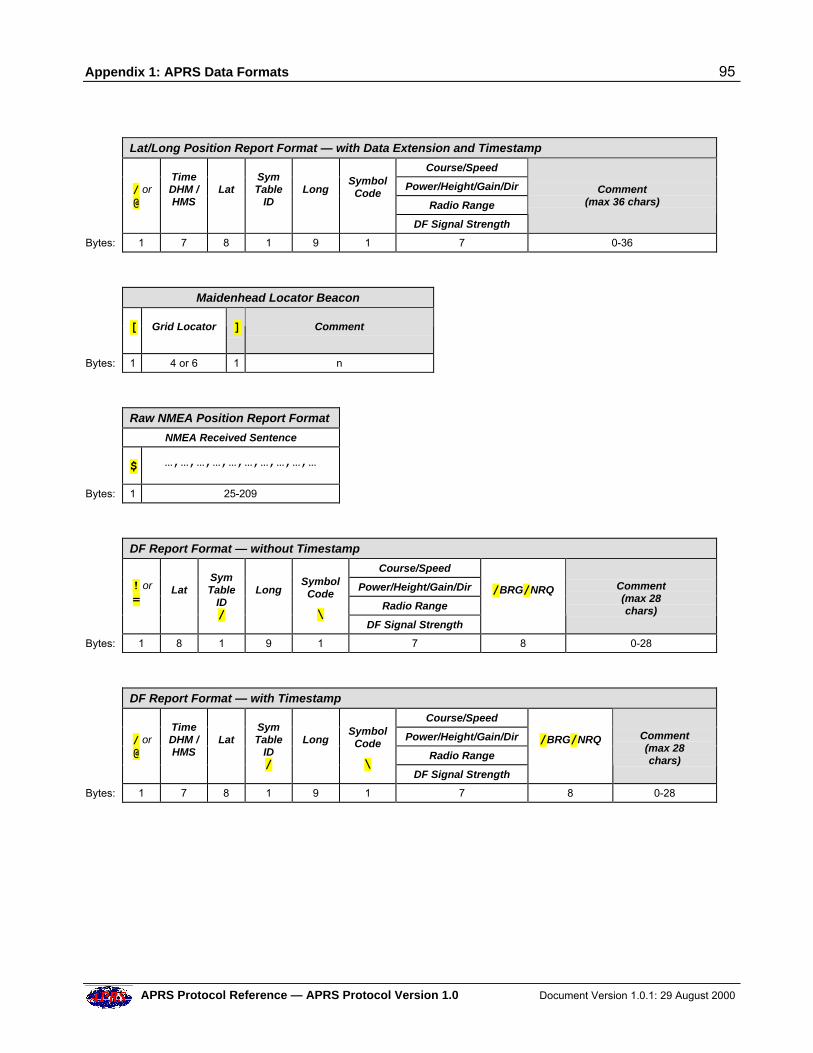
Appendix 1: APRS Data Formats 95
APRS Protocol Reference — APRS Protocol Version 1.0 Document Version 1.0.1: 29 August 2000
Lat/Long Position Report Format — with Data Extension and Timestamp
Course/Speed
Power/Height/Gain/Dir
Radio Range
/ or @
TimeDHM /HMS
Lat
SymTable
ID
Long
SymbolCode
DF Signal Strength
Comment
(max 36 chars)
Bytes: 1 7 8 1 9 1 7 0-36
Maidenhead Locator Beacon
[ Grid Locator
] Comment
Bytes: 1 4 or 6 1 n
Raw NMEA Position Report Format
NMEA Received Sentence
$ …,…,…,…,…,…,…,…,…,…
Bytes: 1 25-209
DF Report Format — without Timestamp
Course/Speed
Power/Height/Gain/Dir
Radio Range
! or =
Lat
SymTable
ID/
Long
SymbolCode
\ DF Signal Strength
/BRG/NRQ
Comment(max 28chars)
Bytes: 1 8 1 9 1 7 8 0-28
DF Report Format — with Timestamp
Course/Speed
Power/Height/Gain/Dir
Radio Range
/ or @
TimeDHM /HMS
Lat
SymTable
ID/
Long
SymbolCode
\ DF Signal Strength
/BRG/NRQ
Comment(max 28chars)
Bytes: 1 7 8 1 9 1 7 8 0-28
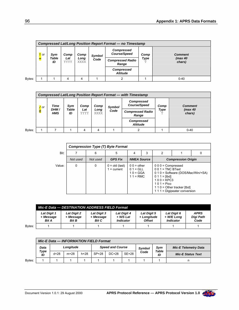
96 Appendix 1: APRS Data Formats
Document Version 1.0.1: 29 August 2000 APRS Protocol Reference — APRS Protocol Version 1.0
Compressed Lat/Long Position Report Format — no Timestamp
Compressed
Course/Speed
Compressed RadioRange
! or =
SymTable
ID
Comp
LatYYYY
CompLongXXXX
SymbolCode
CompressedAltitude
CompTypeT
Comment(max 40chars)
Bytes: 1 1 4 4 1 2 1 0-40
Compressed Lat/Long Position Report Format — with Timestamp
Compressed
Course/Speed
Compressed RadioRange
/ or @
TimeDHM /HMS
SymTable
ID
Comp
LatYYYY
CompLongXXXX
SymbolCode
CompressedAltitude
CompTypeT
Comment(max 40chars)
Bytes: 1 7 1 4 4 1 2 1 0-40
Compression Type (T) Byte Format
Bit: 7 6 5 4 3 2 1 0
Not used Not used GPS Fix NMEA Source Compression Origin
Value: 0 0 0 = old (last)1 = current
0 0 = other0 1 = GLL1 0 = GGA1 1 = RMC
0 0 0 = Compressed0 0 1 = TNC BText0 1 0 = Software (DOS/Mac/Win/+SA)0 1 1 = [tbd]1 0 0 = KPC31 0 1 = Pico1 1 0 = Other tracker [tbd]1 1 1 = Digipeater conversion
Mic-E Data — DESTINATION ADDRESS FIELD Format
Lat Digit 1+ Message
Bit A
Lat Digit 2+ Message
Bit B
Lat Digit 3+ Message
Bit C
Lat Digit 4+ N/S LatIndicator
Lat Digit 5+ Longitude
Offset
Lat Digit 6+ W/E Long
Indicator
APRSDigi Path
Code
Bytes: 1 1 1 1 1 1 1
Mic-E Data — INFORMATION FIELD Format
Longitude Speed and Course Mic-E Telemetry Data
DataType
ID d+28 m+28 h+28 SP+28 DC+28 SE+28
SymbolCode
SymTable
ID Mic-E Status Text
Bytes: 1 1 1 1 1 1 1 1 1 n
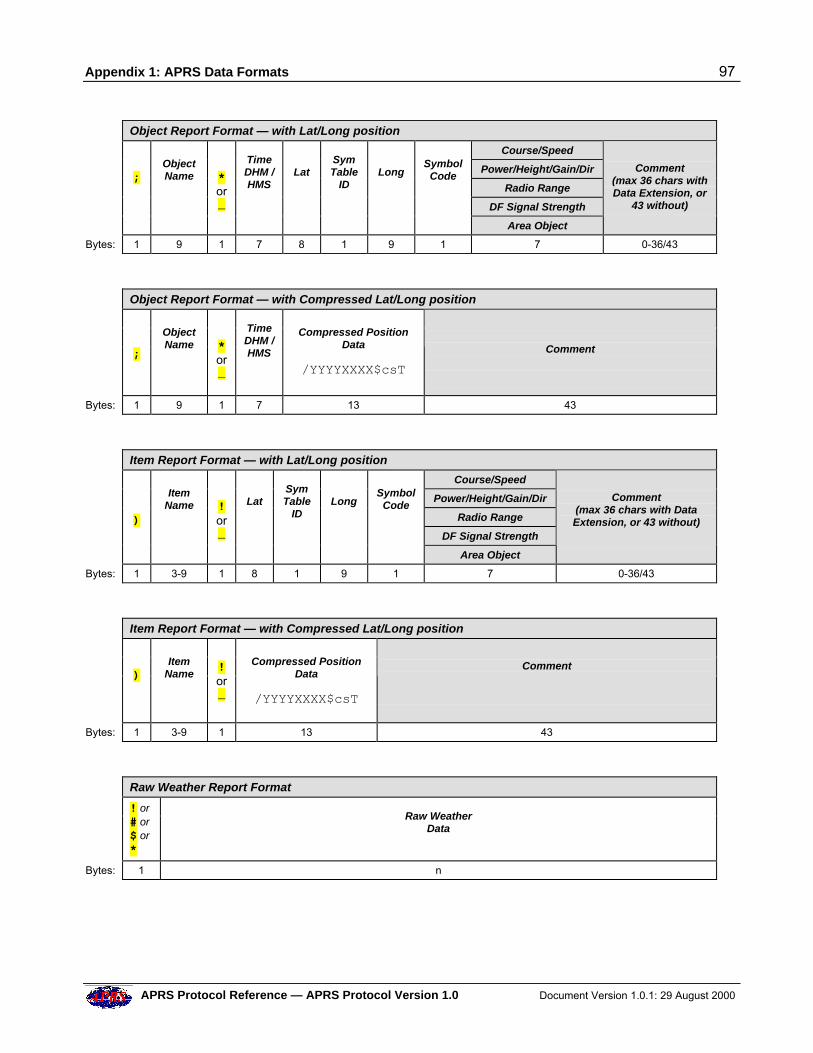
Appendix 1: APRS Data Formats 97
APRS Protocol Reference — APRS Protocol Version 1.0 Document Version 1.0.1: 29 August 2000
Object Report Format — with Lat/Long position
Course/Speed
Power/Height/Gain/Dir
Radio Range
DF Signal Strength
;
ObjectName
*or_
TimeDHM /HMS
Lat
SymTable
ID
Long
SymbolCode
Area Object
Comment
(max 36 chars withData Extension, or
43 without)
Bytes: 1 9 1 7 8 1 9 1 7 0-36/43
Object Report Format — with Compressed Lat/Long position
;
ObjectName
*or_
TimeDHM /HMS
Compressed PositionData
/YYYYXXXX$csT
Comment
Bytes: 1 9 1 7 13 43
Item Report Format — with Lat/Long position
Course/Speed
Power/Height/Gain/Dir
Radio Range
DF Signal Strength
)
ItemName
!or_
Lat
SymTable
ID
Long
SymbolCode
Area Object
Comment
(max 36 chars with DataExtension, or 43 without)
Bytes: 1 3-9 1 8 1 9 1 7 0-36/43
Item Report Format — with Compressed Lat/Long position
)
ItemName
!or_
Compressed PositionData
/YYYYXXXX$csT
Comment
Bytes: 1 3-9 1 13 43
Raw Weather Report Format
! or# or$ or*
Raw WeatherData
Bytes: 1 n
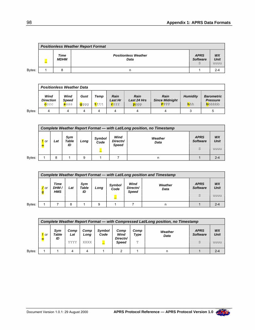
98 Appendix 1: APRS Data Formats
Document Version 1.0.1: 29 August 2000 APRS Protocol Reference — APRS Protocol Version 1.0
Positionless Weather Report Format
_
TimeMDHM
Positionless WeatherData
APRSSoftware
S
WXUnituuuu
Bytes: 1 8 n 1 2-4
Positionless Weather Data
WindDirectioncccc
WindSpeedssss
Gust
gggg
Temp
tttt
RainLast Hrrrrr
RainLast 24 Hrspppp
RainSince Midnight
PPPP
Humidity
hhh
BarometricPressurebbbbbb
Bytes: 4 4 4 4 4 4 4 3 5
Complete Weather Report Format — with Lat/Long position, no Timestamp
! or =
Lat
SymTable
ID
Long
SymbolCode
_
WindDirectn/Speed
WeatherData
APRSSoftware
S
WXUnit
uuuu
Bytes: 1 8 1 9 1 7 n 1 2-4
Complete Weather Report Format — with Lat/Long position and Timestamp
/ or @
TimeDHM /HMS
Lat
SymTable
ID
Long
SymbolCode
_
WindDirectn/Speed
WeatherData
APRSSoftware
S
WXUnit
uuuu
Bytes: 1 7 8 1 9 1 7 n 1 2-4
Complete Weather Report Format — with Compressed Lat/Long position, no Timestamp
! or =
SymTable
ID
CompLat
YYYY
CompLong
XXXX
SymbolCode
_
CompWind
Directn/Speed
CompType
T
WeatherData
APRSSoftware
S
WXUnit
uuuu
Bytes: 1 1 4 4 1 2 1 n 1 2-4
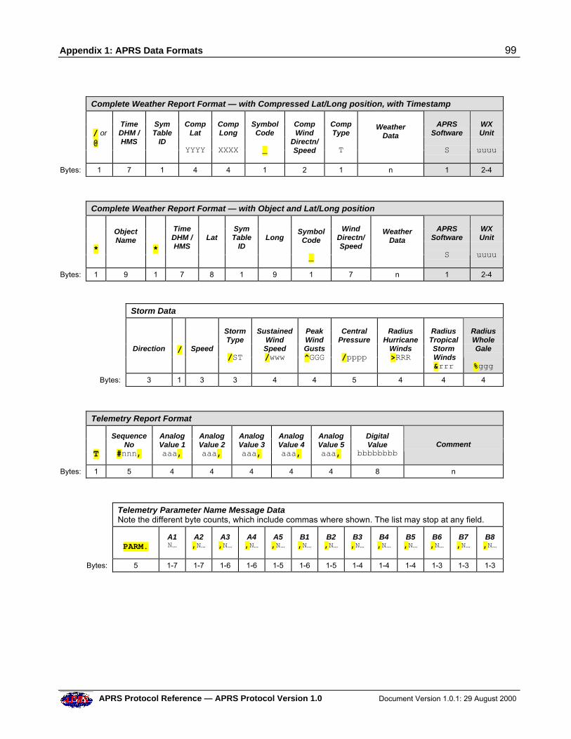
Appendix 1: APRS Data Formats 99
APRS Protocol Reference — APRS Protocol Version 1.0 Document Version 1.0.1: 29 August 2000
Complete Weather Report Format — with Compressed Lat/Long position, with Timestamp
/ or @
TimeDHM /HMS
SymTable
ID
CompLat
YYYY
CompLong
XXXX
SymbolCode
_
CompWind
Directn/Speed
CompType
T
WeatherData
APRSSoftware
S
WXUnit
uuuu
Bytes: 1 7 1 4 4 1 2 1 n 1 2-4
Complete Weather Report Format — with Object and Lat/Long position
*
ObjectName
*
TimeDHM /HMS
Lat
SymTable
ID
Long
SymbolCode
_
WindDirectn/Speed
WeatherData
APRSSoftware
S
WXUnit
uuuu
Bytes: 1 9 1 7 8 1 9 1 7 n 1 2-4
Storm Data
Direction
/
Speed
StormType
/ST
SustainedWindSpeed/www
PeakWindGusts^GGG
CentralPressure
/pppp
RadiusHurricane
Winds>RRR
RadiusTropicalStorm Winds&rrr
RadiusWholeGale
%ggg
Bytes: 3 1 3 3 4 4 5 4 4 4
Telemetry Report Format
T
SequenceNo
#nnn,
AnalogValue 1aaa,
AnalogValue 2aaa,
AnalogValue 3aaa,
AnalogValue 4aaa,
AnalogValue 5aaa,
DigitalValue
bbbbbbbb Comment
Bytes: 1 5 4 4 4 4 4 8 n
Telemetry Parameter Name Message DataNote the different byte counts, which include commas where shown. The list may stop at any field.
PARM.
A1N…
A2,N…
A3,N…
A4,N…
A5,N…
B1,N…
B2,N…
B3,N…
B4,N…
B5,N…
B6,N…
B7,N…
B8,N…
Bytes: 5 1-7 1-7 1-6 1-6 1-5 1-6 1-5 1-4 1-4 1-4 1-3 1-3 1-3
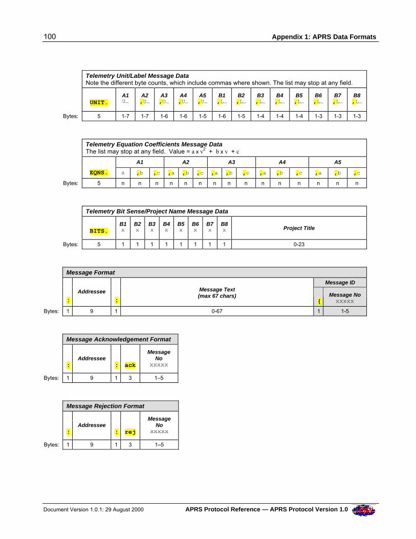
100 Appendix 1: APRS Data Formats
Document Version 1.0.1: 29 August 2000 APRS Protocol Reference — APRS Protocol Version 1.0
Telemetry Unit/Label Message Data
Note the different byte counts, which include commas where shown. The list may stop at any field.
UNIT.
A1U…
A2,U…
A3,U…
A4,U…
A5,U…
B1,L…
B2,L…
B3,L…
B4,L…
B5,L…
B6,L…
B7,L…
B8,L…
Bytes: 5 1-7 1-7 1-6 1-6 1-5 1-6 1-5 1-4 1-4 1-4 1-3 1-3 1-3
Telemetry Equation Coefficients Message DataThe list may stop at any field. Value = a x v2 + b x v + c
A1 A2 A3 A4 A5
EQNS. a ,b ,c ,a ,b ,c ,a ,b ,c ,a ,b ,c ,a ,b ,c
Bytes: 5 n n n n n n n n n n n n n n n
Telemetry Bit Sense/Project Name Message Data
BITS.
B1x
B2x
B3x
B4x
B5x
B6x
B7x
B8x Project Title
Bytes: 5 1 1 1 1 1 1 1 1 0-23
Message Format
Message ID
:
Addressee
:
Message Text(max 67 chars)
{ Message Noxxxxx
Bytes: 1 9 1 0-67 1 1-5
Message Acknowledgement Format
:
Addressee
:
ack
MessageNo
xxxxx
Bytes: 1 9 1 3 1–5
Message Rejection Format
:
Addressee
:
rej
MessageNo
xxxxx
Bytes: 1 9 1 3 1–5
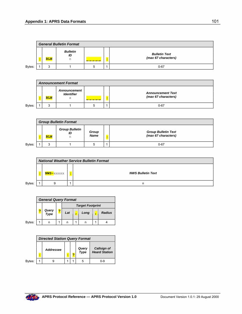
Appendix 1: APRS Data Formats 101
APRS Protocol Reference — APRS Protocol Version 1.0 Document Version 1.0.1: 29 August 2000
General Bulletin Format
:
BLN
BulletinIDn V V V VV V V V VV
:
Bulletin Text
(max 67 characters)
Bytes: 1 3 1 5 1 0-67
Announcement Format
:
BLN
AnnouncementIdentifier
x V V V VV V V V VV
:
Announcement Text(max 67 characters)
Bytes: 1 3 1 5 1 0-67
Group Bulletin Format
:
BLN
Group BulletinIDn
GroupName
:
Group Bulletin Text(max 67 characters)
Bytes: 1 3 1 5 1 0-67
National Weather Service Bulletin Format
:
NWS-xxxxx
:
NWS Bulletin Text
Bytes: 1 9 1 n
General Query Format
Target Footprint
? Query
Type
? Lat , Long , Radius
Bytes: 1 n 1 n 1 n 1 4
Directed Station Query Format
:
Addressee
:
?
QueryType
Callsign ofHeard Station
Bytes: 1 9 1 1 5 0-9
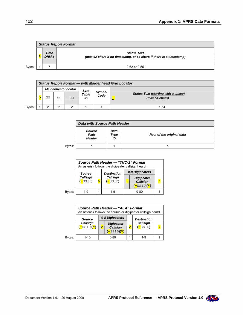
102 Appendix 1: APRS Data Formats
Document Version 1.0.1: 29 August 2000 APRS Protocol Reference — APRS Protocol Version 1.0
Status Report Format
>
TimeDHM z
Status Text
(max 62 chars if no timestamp, or 55 chars if there is a timestamp)
Bytes: 1 7 0-62 or 0-55
Status Report Format — with Maidenhead Grid Locator
Maidenhead Locator
> GG nn gg
SymTable
ID
SymbolCode
Status Text (starting with a space)VV (max 54 chars)
Bytes: 1 2 2 2 1 1 1-54
Data with Source Path Header
SourcePath
Header
DataType
ID
Rest of the original data
Bytes: n 1 n
Source Path Header — “TNC-2” FormatAn asterisk follows the digipeater callsign heard.
0-8 Digipeaters
SourceCallsign(-SSID)
>
DestinationCallsign(-SSID) ,
DigipeaterCallsign
(-SSID)(*)
:
Bytes: 1-9 1 1-9 0-80 1
Source Path Header — “AEA” FormatAn asterisk follows the source or digipeater callsign heard.
0-8 Digipeaters
SourceCallsign
(-SSID)(*) > DigipeaterCallsign
(-SSID)(*)
>
DestinationCallsign(-SSID)
:
Bytes: 1-10 0-80 1 1-9 1
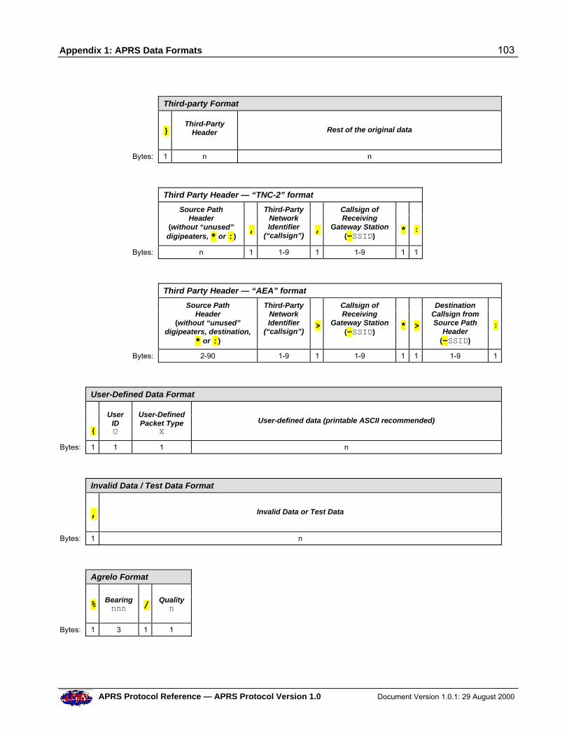
Appendix 1: APRS Data Formats 103
APRS Protocol Reference — APRS Protocol Version 1.0 Document Version 1.0.1: 29 August 2000
Third-party Format
}
Third-PartyHeader
Rest of the original data
Bytes: 1 n n
Third Party Header — “TNC-2” format
Source PathHeader
(without “unused”digipeaters, * or :)
,
Third-PartyNetworkIdentifier
(“callsign”)
,
Callsign ofReceiving
Gateway Station(-SSID)
*
:
Bytes: n 1 1-9 1 1-9 1 1
Third Party Header — “AEA” format
Source PathHeader
(without “unused”digipeaters, destination,
* or :)
Third-PartyNetworkIdentifier
(“callsign”)
>
Callsign ofReceiving
Gateway Station(-SSID)
*
>
DestinationCallsign fromSource Path
Header(-SSID)
:
Bytes: 2-90 1-9 1 1-9 1 1 1-9 1
User-Defined Data Format
{
UserIDU
User-DefinedPacket Type
X
User-defined data (printable ASCII recommended)
Bytes: 1 1 1 n
Invalid Data / Test Data Format
,
Invalid Data or Test Data
Bytes: 1 n
Agrelo Format
% Bearing
nnn
/ Quality
n
Bytes: 1 3 1 1
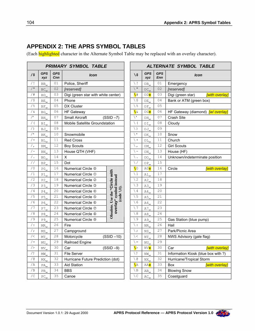
104 Appendix 2: APRS Symbol Tables
Document Version 1.0.1: 29 August 2000 APRS Protocol Reference — APRS Protocol Version 1.0
APPENDIX 2: THE APRS SYMBOL TABLES (Each highlighted character in the Alternate Symbol Table may be replaced with an overlay character).
PRIMARY SYMBOL TABLE ALTERNATE SYMBOL TABLE
/$ GPSxyz
GPSCnn
Icon \$ GPSxyz
GPSEnn
Icon
/! BBV 01 Police, Sheriff \! OBV 01 Emergency /" BCV 02 [reserved] \" OCV 02 [reserved] /# BDV 03 Digi (green star with white center) \# ODz 03 Digi (green star) [with overlay] /$ BEV 04 Phone \$ OEV 04 Bank or ATM (green box) /% BFV 05 DX Cluster \% OFV 05 /& BGV 06 HF Gateway \& OGz 06 HF Gateway (diamond) [w/ overlay] /’ BHV 07 Small Aircraft (SSID –7) \’ OHV 07 Crash Site /( BIV 08 Mobile Satellite Groundstation \( OIV 08 Cloudy /) BJV 09 \) OJV 09 /* BKV 10 Snowmobile \* OKV 10 Snow /+ BLV 11 Red Cross \+ OLV 11 Church /, BMV 12 Boy Scouts \, OMV 12 Girl Scouts /- BNV 13 House QTH (VHF) \- ONV 13 House (HF) /. BOV 14 X \. OOV 14 Unknown/indeterminate position // BPV 15 Dot \/ OPV 15 /0 P0V 16 Numerical Circle � \0 A0z 16 Circle [with overlay] /1 P1V 17 Numerical Circle � \1 A1V 17 /2 P2V 18 Numerical Circle � \2 A2V 18 /3 P3V 19 Numerical Circle � \3 A3V 19 /4 P4V 20 Numerical Circle � \4 A4V 20 /5 P5V 21 Numerical Circle � \5 A5V 21 /6 P6V 22 Numerical Circle � \6 A6V 22 /7 P7V 23 Numerical Circle � \7 A7V 23 /8 P8V 24 Numerical Circle � \8 A8V 24 /9 P9V 25 Numerical Circle � O
bsol
ete.
Use
the
“C
ircl
e w
ith
ove
rlay
” sy
mbo
l ins
tead
(co
de \0
).
\9 A9V 25 Gas Station (blue pump) /: MRV 26 Fire \: NRV 26 Hail /; MSV 27 Campground \; NSV 27 Park/Picnic Area /< MTV 28 Motorcycle (SSID –10) \< NTV 28 NWS Advisory (gale flag) /= MUV 29 Railroad Engine \= NUV 29 /> MVV 30 Car (SSID –9) \> NVz 30 Car [with overlay] /? MWV 31 File Server \? NWV 31 Information Kiosk (blue box with ?) /@ MXV 32 Hurricane Future Prediction (dot) \@ NXV 32 Hurricane/Tropical Storm /A PAV 33 Aid Station \A AAz 33 Box [with overlay] /B PBV 34 BBS \B ABV 34 Blowing Snow /C PCV 35 Canoe \C ACV 35 Coastguard
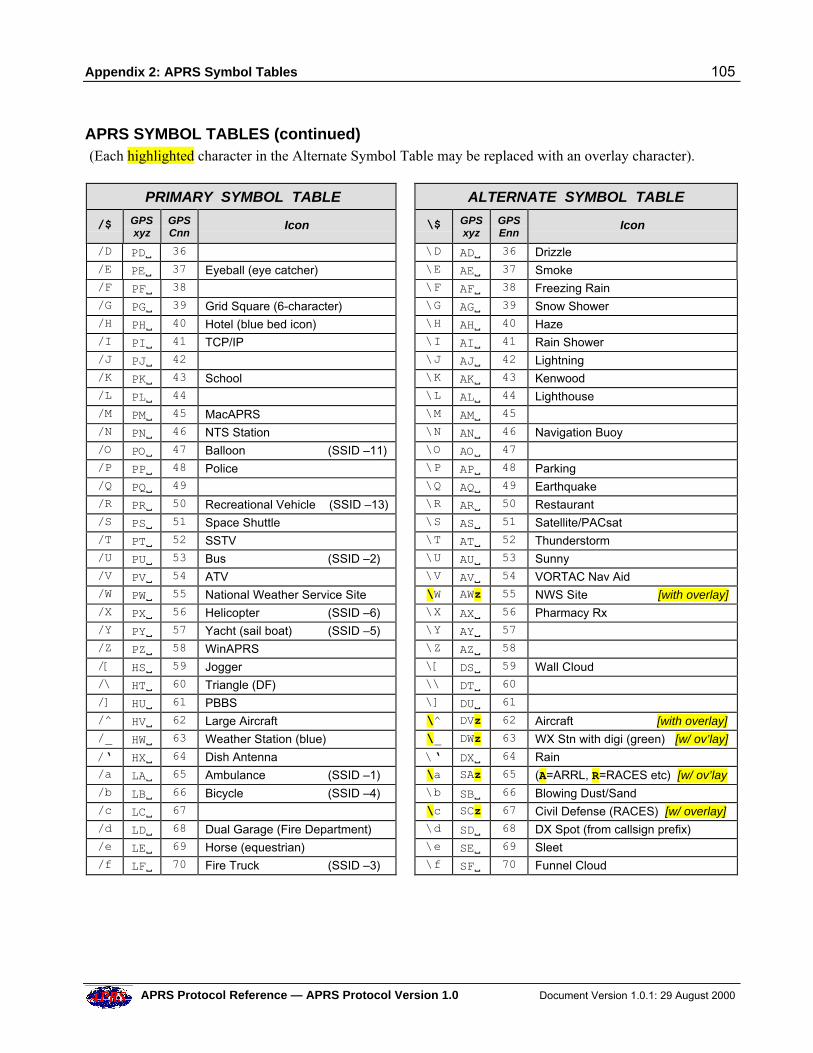
Appendix 2: APRS Symbol Tables 105
APRS Protocol Reference — APRS Protocol Version 1.0 Document Version 1.0.1: 29 August 2000
APRS SYMBOL TABLES (continued) (Each highlighted character in the Alternate Symbol Table may be replaced with an overlay character).
PRIMARY SYMBOL TABLE ALTERNATE SYMBOL TABLE
/$ GPSxyz
GPSCnn
Icon \$ GPSxyz
GPSEnn
Icon
/D PDV 36 \D ADV 36 Drizzle /E PEV 37 Eyeball (eye catcher) \E AEV 37 Smoke /F PFV 38 \F AFV 38 Freezing Rain /G PGV 39 Grid Square (6-character) \G AGV 39 Snow Shower /H PHV 40 Hotel (blue bed icon) \H AHV 40 Haze /I PIV 41 TCP/IP \I AIV 41 Rain Shower /J PJV 42 \J AJV 42 Lightning /K PKV 43 School \K AKV 43 Kenwood /L PLV 44 \L ALV 44 Lighthouse /M PMV 45 MacAPRS \M AMV 45 /N PNV 46 NTS Station \N ANV 46 Navigation Buoy /O POV 47 Balloon (SSID –11) \O AOV 47 /P PPV 48 Police \P APV 48 Parking /Q PQV 49 \Q AQV 49 Earthquake /R PRV 50 Recreational Vehicle (SSID –13) \R ARV 50 Restaurant /S PSV 51 Space Shuttle \S ASV 51 Satellite/PACsat /T PTV 52 SSTV \T ATV 52 Thunderstorm /U PUV 53 Bus (SSID –2) \U AUV 53 Sunny /V PVV 54 ATV \V AVV 54 VORTAC Nav Aid /W PWV 55 National Weather Service Site \W AWz 55 NWS Site [with overlay] /X PXV 56 Helicopter (SSID –6) \X AXV 56 Pharmacy Rx /Y PYV 57 Yacht (sail boat) (SSID –5) \Y AYV 57 /Z PZV 58 WinAPRS \Z AZV 58 /[ HSV 59 Jogger \[ DSV 59 Wall Cloud /\ HTV 60 Triangle (DF) \\ DTV 60 /] HUV 61 PBBS \] DUV 61 /^ HVV 62 Large Aircraft \^ DVz 62 Aircraft [with overlay] /_ HWV 63 Weather Station (blue) \_ DWz 63 WX Stn with digi (green) [w/ ov’lay]
/‘ HXV 64 Dish Antenna \‘ DXV 64 Rain /a LAV 65 Ambulance (SSID –1) \a SAz 65 (A=ARRL, R=RACES etc) [w/ ov’lay /b LBV 66 Bicycle (SSID –4) \b SBV 66 Blowing Dust/Sand /c LCV 67 \c SCz 67 Civil Defense (RACES) [w/ overlay] /d LDV 68 Dual Garage (Fire Department) \d SDV 68 DX Spot (from callsign prefix) /e LEV 69 Horse (equestrian) \e SEV 69 Sleet /f LFV 70 Fire Truck (SSID –3) \f SFV 70 Funnel Cloud
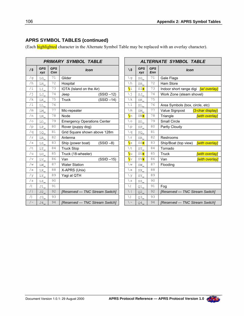
106 Appendix 2: APRS Symbol Tables
Document Version 1.0.1: 29 August 2000 APRS Protocol Reference — APRS Protocol Version 1.0
APRS SYMBOL TABLES (continued) (Each highlighted character in the Alternate Symbol Table may be replaced with an overlay character).
PRIMARY SYMBOL TABLE ALTERNATE SYMBOL TABLE
/$ GPSxyz
GPSCnn
Icon \$ GPSxyz
GPSEnn
Icon
/g LGV 71 Glider \g SGV 71 Gale Flags /h LHV 72 Hospital \h SHV 72 Ham Store /i LIV 73 IOTA (Island on the Air) \i SIz 73 Indoor short range digi [w/ overlay] /j LJV 74 Jeep (SSID –12) \j SJV 74 Work Zone (steam shovel) /k LKV 75 Truck (SSID –14) \k SKV 75 /l LLV 76 \l SLV 76 Area Symbols (box, circle, etc) /m LMV 77 Mic-repeater \m SMV 77 Value Signpost {3-char display} /n LNV 78 Node \n SNz 78 Triangle [with overlay] /o LOV 79 Emergency Operations Center \o SOV 79 Small Circle /p LPV 80 Rover (puppy dog) \p SPV 80 Partly Cloudy /q LQV 81 Grid Square shown above 128m \q SQV 81 /r LRV 82 Antenna \r SRV 82 Restrooms /s LSV 83 Ship (power boat) (SSID –8) \s SSz 83 Ship/Boat (top view) [with overlay] /t LTV 84 Truck Stop \t STV 84 Tornado /u LUV 85 Truck (18-wheeler) \u SUz 85 Truck [with overlay] /v LVV 86 Van (SSID –15) \v SVz 86 Van [with overlay] /w LWV 87 Water Station \w SWV 87 Flooding /x LXV 88 X-APRS (Unix) \x SXV 88 /y LYV 89 Yagi at QTH \y SYV 89 /z LZV 90 \z SZV 90 /{ J1V 91 \{ Q1V 91 Fog /| J2V 92 [Reserved — TNC Stream Switch] \| Q2V 92 [Reserved — TNC Stream Switch] /} J3V 93 \} Q3V 93 /~ J4V 94 [Reserved — TNC Stream Switch] \~ Q4V 94 [Reserved — TNC Stream Switch]
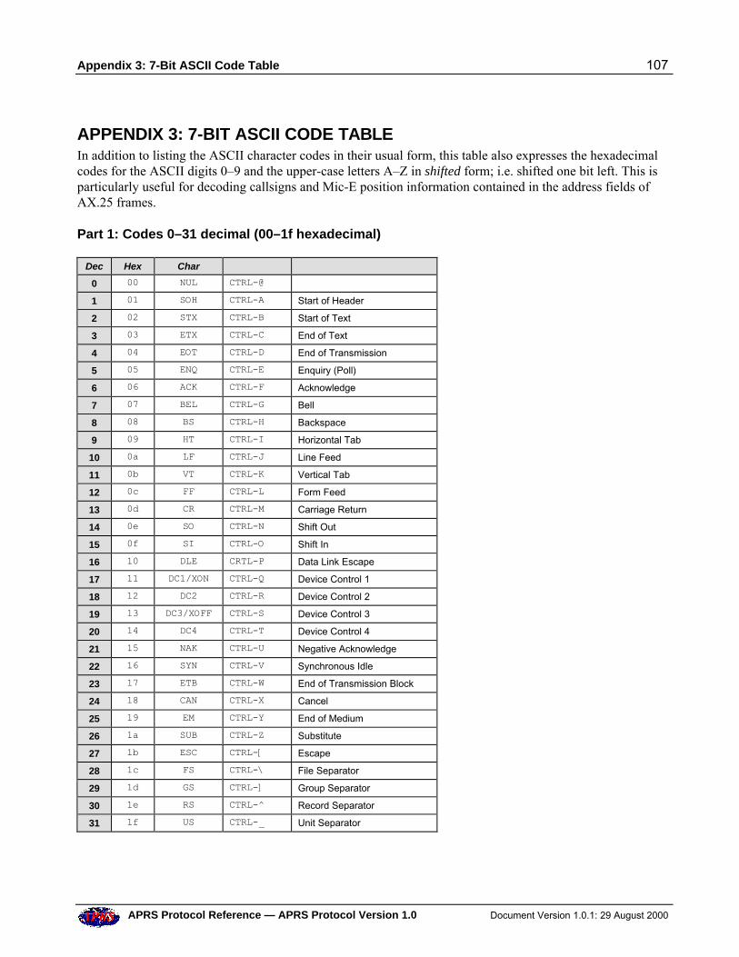
Appendix 3: 7-Bit ASCII Code Table 107
APRS Protocol Reference — APRS Protocol Version 1.0 Document Version 1.0.1: 29 August 2000
APPENDIX 3: 7-BIT ASCII CODE TABLEIn addition to listing the ASCII character codes in their usual form, this table also expresses the hexadecimalcodes for the ASCII digits 0–9 and the upper-case letters A–Z in shifted form; i.e. shifted one bit left. This isparticularly useful for decoding callsigns and Mic-E position information contained in the address fields ofAX.25 frames.
Part 1: Codes 0–31 decimal (00–1f hexadecimal)
Dec Hex Char
0 00 NUL CTRL-@
1 01 SOH CTRL-A Start of Header
2 02 STX CTRL-B Start of Text
3 03 ETX CTRL-C End of Text
4 04 EOT CTRL-D End of Transmission
5 05 ENQ CTRL-E Enquiry (Poll)
6 06 ACK CTRL-F Acknowledge
7 07 BEL CTRL-G Bell
8 08 BS CTRL-H Backspace
9 09 HT CTRL-I Horizontal Tab
10 0a LF CTRL-J Line Feed
11 0b VT CTRL-K Vertical Tab
12 0c FF CTRL-L Form Feed
13 0d CR CTRL-M Carriage Return
14 0e SO CTRL-N Shift Out
15 0f SI CTRL-O Shift In
16 10 DLE CRTL-P Data Link Escape
17 11 DC1/XON CTRL-Q Device Control 1
18 12 DC2 CTRL-R Device Control 2
19 13 DC3/XOFF CTRL-S Device Control 3
20 14 DC4 CTRL-T Device Control 4
21 15 NAK CTRL-U Negative Acknowledge
22 16 SYN CTRL-V Synchronous Idle
23 17 ETB CTRL-W End of Transmission Block
24 18 CAN CTRL-X Cancel
25 19 EM CTRL-Y End of Medium
26 1a SUB CTRL-Z Substitute
27 1b ESC CTRL-[ Escape
28 1c FS CTRL-\ File Separator
29 1d GS CTRL-] Group Separator
30 1e RS CTRL-^ Record Separator
31 1f US CTRL-_ Unit Separator
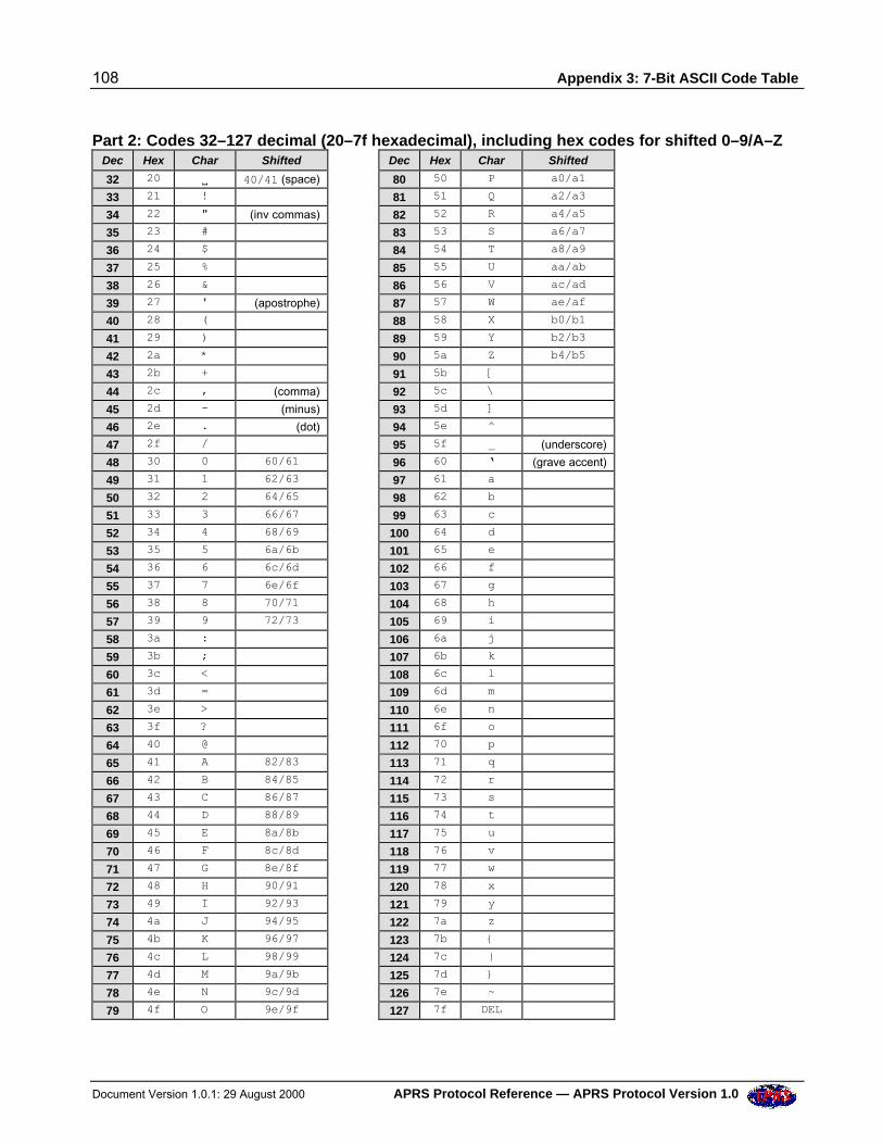
108 Appendix 3: 7-Bit ASCII Code Table
Document Version 1.0.1: 29 August 2000 APRS Protocol Reference — APRS Protocol Version 1.0
Part 2: Codes 32–127 decimal (20–7f hexadecimal), including hex codes for shifted 0–9/A–ZDec Hex Char Shifted Dec Hex Char Shifted
32 20 V 40/41 (space) 80 50 P a0/a1
33 21 ! 81 51 Q a2/a3
34 22 " (inv commas) 82 52 R a4/a5
35 23 # 83 53 S a6/a7
36 24 $ 84 54 T a8/a9
37 25 % 85 55 U aa/ab
38 26 & 86 56 V ac/ad
39 27 ' (apostrophe) 87 57 W ae/af
40 28 ( 88 58 X b0/b1
41 29 ) 89 59 Y b2/b3
42 2a * 90 5a Z b4/b5
43 2b + 91 5b [
44 2c , (comma) 92 5c \
45 2d - (minus) 93 5d ]
46 2e . (dot) 94 5e ^
47 2f / 95 5f _ (underscore)
48 30 0 60/61 96 60 ‘ (grave accent)
49 31 1 62/63 97 61 a
50 32 2 64/65 98 62 b
51 33 3 66/67 99 63 c
52 34 4 68/69 100 64 d
53 35 5 6a/6b 101 65 e
54 36 6 6c/6d 102 66 f
55 37 7 6e/6f 103 67 g
56 38 8 70/71 104 68 h
57 39 9 72/73 105 69 i
58 3a : 106 6a j
59 3b ; 107 6b k
60 3c < 108 6c l
61 3d = 109 6d m
62 3e > 110 6e n
63 3f ? 111 6f o
64 40 @ 112 70 p
65 41 A 82/83 113 71 q
66 42 B 84/85 114 72 r
67 43 C 86/87 115 73 s
68 44 D 88/89 116 74 t
69 45 E 8a/8b 117 75 u
70 46 F 8c/8d 118 76 v
71 47 G 8e/8f 119 77 w
72 48 H 90/91 120 78 x
73 49 I 92/93 121 79 y
74 4a J 94/95 122 7a z
75 4b K 96/97 123 7b {
76 4c L 98/99 124 7c |
77 4d M 9a/9b 125 7d }
78 4e N 9c/9d 126 7e ~
79 4f O 9e/9f 127 7f DEL
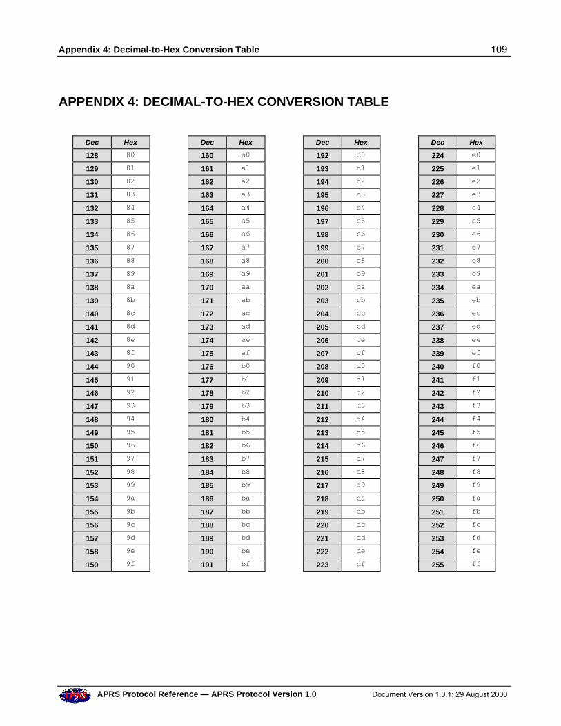
Appendix 4: Decimal-to-Hex Conversion Table 109
APRS Protocol Reference — APRS Protocol Version 1.0 Document Version 1.0.1: 29 August 2000
APPENDIX 4: DECIMAL-TO-HEX CONVERSION TABLE
Dec Hex Dec Hex Dec Hex Dec Hex
128 80 160 a0 192 c0 224 e0
129 81 161 a1 193 c1 225 e1
130 82 162 a2 194 c2 226 e2
131 83 163 a3 195 c3 227 e3
132 84 164 a4 196 c4 228 e4
133 85 165 a5 197 c5 229 e5
134 86 166 a6 198 c6 230 e6
135 87 167 a7 199 c7 231 e7
136 88 168 a8 200 c8 232 e8
137 89 169 a9 201 c9 233 e9
138 8a 170 aa 202 ca 234 ea
139 8b 171 ab 203 cb 235 eb
140 8c 172 ac 204 cc 236 ec
141 8d 173 ad 205 cd 237 ed
142 8e 174 ae 206 ce 238 ee
143 8f 175 af 207 cf 239 ef
144 90 176 b0 208 d0 240 f0
145 91 177 b1 209 d1 241 f1
146 92 178 b2 210 d2 242 f2
147 93 179 b3 211 d3 243 f3
148 94 180 b4 212 d4 244 f4
149 95 181 b5 213 d5 245 f5
150 96 182 b6 214 d6 246 f6
151 97 183 b7 215 d7 247 f7
152 98 184 b8 216 d8 248 f8
153 99 185 b9 217 d9 249 f9
154 9a 186 ba 218 da 250 fa
155 9b 187 bb 219 db 251 fb
156 9c 188 bc 220 dc 252 fc
157 9d 189 bd 221 dd 253 fd
158 9e 190 be 222 de 254 fe
159 9f 191 bf 223 df 255 ff
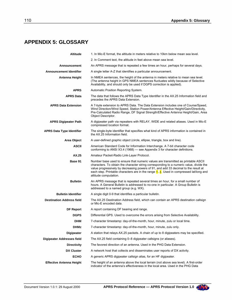
110 Appendix 5: Glossary
Document Version 1.0.1: 29 August 2000 APRS Protocol Reference — APRS Protocol Version 1.0
APPENDIX 5: GLOSSARY
Altitude 1. In Mic-E format, the altitude in meters relative to 10km below mean sea level.
2. In Comment text, the altitude in feet above mean sea level.
Announcement An APRS message that is repeated a few times an hour, perhaps for several days.
Announcement Identifier A single letter A-Z that identifies a particular announcement.
Antenna Height In NMEA sentences, the height of the antenna in meters relative to mean sea level.(The antenna height in GPS NMEA sentences fluctuates wildly because of SelectiveAvailability, and should only be used if DGPS correction is applied).
APRS Automatic Position Reporting System.
APRS Data The data that follows the APRS Data Type Identifier in the AX.25 Information field andprecedes the APRS Data Extension.
APRS Data Extension A 7-byte extension to APRS Data. The Data Extension includes one of Course/Speed,Wind Direction/Wind Speed, Station Power/Antenna Effective Height/Gain/Directivity,Pre-Calculated Radio Range, DF Signal Strength/Effective Antenna Height/Gain, AreaObject Descriptor.
APRS Digipeater Path A digipeater path via repeaters with RELAY, WIDE and related aliases. Used in Mic-Ecompressed location format.
APRS Data Type Identifier The single-byte identifier that specifies what kind of APRS information is contained inthe AX.25 Information field.
Area Object A user-defined graphic object (circle, ellipse, triangle, box and line).
ASCII American Standard Code for Information Interchange. A 7-bit character codeconforming to ANSI X3.4 (1968) — see Appendix 3 for character definitions.
AX.25 Amateur Packet-Radio Link-Layer Protocol.
Base 91 Number base used to ensure that numeric values are transmitted as printable ASCIIcharacters. To obtain the character string corresponding to a numeric value, divide thevalue progressively by decreasing powers of 91, and add 33 decimal to the result ateach step. Printable characters are in the range !..{. Used in compressed lat/long andaltitude computation.
Bulletin An APRS message that is repeated several times an hour, for a small number ofhours. A General Bulletin is addressed to no-one in particular. A Group Bulletin isaddressed to a named group (e.g. WX).
Bulletin Identifier A single digit 0-9 that identifies a particular bulletin.
Destination Address field The AX.25 Destination Address field, which can contain an APRS destination callsignor Mic-E encoded data.
DF Report A report containing DF bearing and range.
DGPS Differential GPS. Used to overcome the errors arising from Selective Availability.
DHM 7-character timestamp: day-of-the-month, hour, minute, zulu or local time.
DHMz 7-character timestamp: day-of-the-month, hour, minute, zulu only.
Digipeater A station that relays AX.25 packets. A chain of up to 8 digipeaters may be specified.
Digipeater Addresses field The AX.25 field containing 0–8 digipeater callsigns (or aliases).
Directivity The favored direction of an antenna. Used in the PHG Data Extension.
DX Cluster A network host that collects and disseminates user reports of DX activity.
ECHO A generic APRS digipeater callsign alias, for an HF digipeater.
Effective Antenna Height The height of an antenna above the local terrain (not above sea level). A first-orderindicator of the antenna’s effectiveness in the local area. Used in the PHG Data
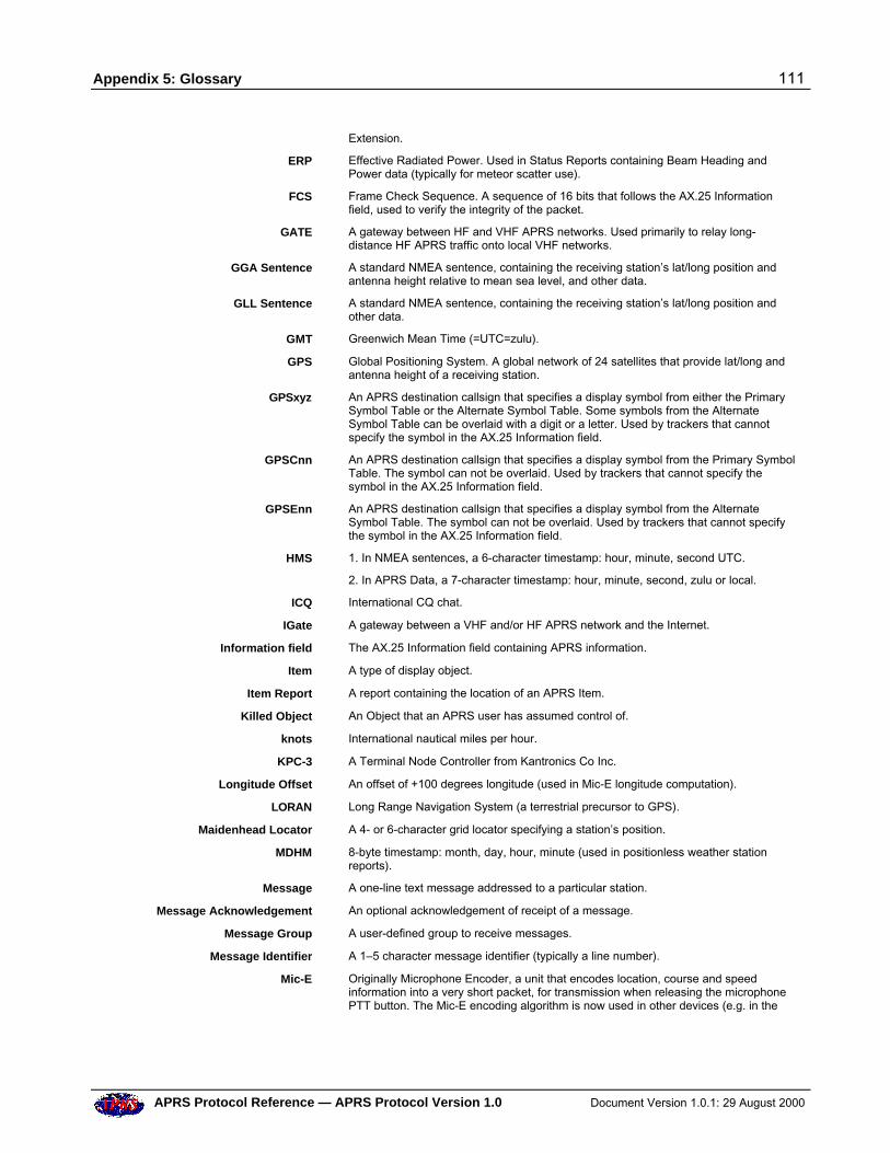
Appendix 5: Glossary 111
APRS Protocol Reference — APRS Protocol Version 1.0 Document Version 1.0.1: 29 August 2000
Extension.
ERP Effective Radiated Power. Used in Status Reports containing Beam Heading andPower data (typically for meteor scatter use).
FCS Frame Check Sequence. A sequence of 16 bits that follows the AX.25 Informationfield, used to verify the integrity of the packet.
GATE A gateway between HF and VHF APRS networks. Used primarily to relay long-distance HF APRS traffic onto local VHF networks.
GGA Sentence A standard NMEA sentence, containing the receiving station’s lat/long position andantenna height relative to mean sea level, and other data.
GLL Sentence A standard NMEA sentence, containing the receiving station’s lat/long position andother data.
GMT Greenwich Mean Time (=UTC=zulu).
GPS Global Positioning System. A global network of 24 satellites that provide lat/long andantenna height of a receiving station.
GPSxyz An APRS destination callsign that specifies a display symbol from either the PrimarySymbol Table or the Alternate Symbol Table. Some symbols from the AlternateSymbol Table can be overlaid with a digit or a letter. Used by trackers that cannotspecify the symbol in the AX.25 Information field.
GPSCnn An APRS destination callsign that specifies a display symbol from the Primary SymbolTable. The symbol can not be overlaid. Used by trackers that cannot specify thesymbol in the AX.25 Information field.
GPSEnn An APRS destination callsign that specifies a display symbol from the AlternateSymbol Table. The symbol can not be overlaid. Used by trackers that cannot specifythe symbol in the AX.25 Information field.
HMS 1. In NMEA sentences, a 6-character timestamp: hour, minute, second UTC.
2. In APRS Data, a 7-character timestamp: hour, minute, second, zulu or local.
ICQ International CQ chat.
IGate A gateway between a VHF and/or HF APRS network and the Internet.
Information field The AX.25 Information field containing APRS information.
Item A type of display object.
Item Report A report containing the location of an APRS Item.
Killed Object An Object that an APRS user has assumed control of.
knots International nautical miles per hour.
KPC-3 A Terminal Node Controller from Kantronics Co Inc.
Longitude Offset An offset of +100 degrees longitude (used in Mic-E longitude computation).
LORAN Long Range Navigation System (a terrestrial precursor to GPS).
Maidenhead Locator A 4- or 6-character grid locator specifying a station’s position.
MDHM 8-byte timestamp: month, day, hour, minute (used in positionless weather stationreports).
Message A one-line text message addressed to a particular station.
Message Acknowledgement An optional acknowledgement of receipt of a message.
Message Group A user-defined group to receive messages.
Message Identifier A 1–5 character message identifier (typically a line number).
Mic-E Originally Microphone Encoder, a unit that encodes location, course and speedinformation into a very short packet, for transmission when releasing the microphonePTT button. The Mic-E encoding algorithm is now used in other devices (e.g. in the
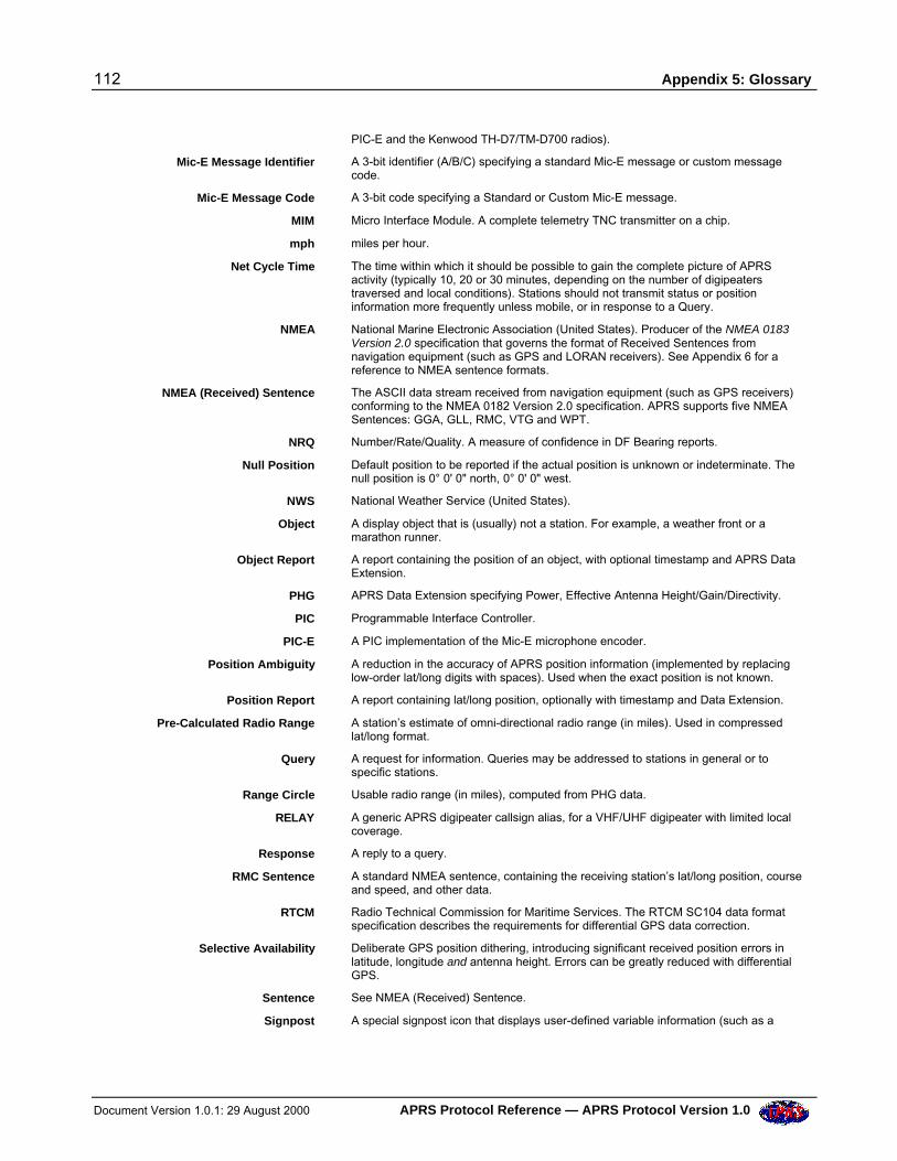
112 Appendix 5: Glossary
Document Version 1.0.1: 29 August 2000 APRS Protocol Reference — APRS Protocol Version 1.0
PIC-E and the Kenwood TH-D7/TM-D700 radios).
Mic-E Message Identifier A 3-bit identifier (A/B/C) specifying a standard Mic-E message or custom messagecode.
Mic-E Message Code A 3-bit code specifying a Standard or Custom Mic-E message.
MIM Micro Interface Module. A complete telemetry TNC transmitter on a chip.
mph miles per hour.
Net Cycle Time The time within which it should be possible to gain the complete picture of APRSactivity (typically 10, 20 or 30 minutes, depending on the number of digipeaterstraversed and local conditions). Stations should not transmit status or positioninformation more frequently unless mobile, or in response to a Query.
NMEA National Marine Electronic Association (United States). Producer of the NMEA 0183Version 2.0 specification that governs the format of Received Sentences fromnavigation equipment (such as GPS and LORAN receivers). See Appendix 6 for areference to NMEA sentence formats.
NMEA (Received) Sentence The ASCII data stream received from navigation equipment (such as GPS receivers)conforming to the NMEA 0182 Version 2.0 specification. APRS supports five NMEASentences: GGA, GLL, RMC, VTG and WPT.
NRQ Number/Rate/Quality. A measure of confidence in DF Bearing reports.
Null Position Default position to be reported if the actual position is unknown or indeterminate. Thenull position is 0° 0' 0" north, 0° 0' 0" west.
NWS National Weather Service (United States).
Object A display object that is (usually) not a station. For example, a weather front or amarathon runner.
Object Report A report containing the position of an object, with optional timestamp and APRS DataExtension.
PHG APRS Data Extension specifying Power, Effective Antenna Height/Gain/Directivity.
PIC Programmable Interface Controller.
PIC-E A PIC implementation of the Mic-E microphone encoder.
Position Ambiguity A reduction in the accuracy of APRS position information (implemented by replacinglow-order lat/long digits with spaces). Used when the exact position is not known.
Position Report A report containing lat/long position, optionally with timestamp and Data Extension.
Pre-Calculated Radio Range A station’s estimate of omni-directional radio range (in miles). Used in compressedlat/long format.
Query A request for information. Queries may be addressed to stations in general or tospecific stations.
Range Circle Usable radio range (in miles), computed from PHG data.
RELAY A generic APRS digipeater callsign alias, for a VHF/UHF digipeater with limited localcoverage.
Response A reply to a query.
RMC Sentence A standard NMEA sentence, containing the receiving station’s lat/long position, courseand speed, and other data.
RTCM Radio Technical Commission for Maritime Services. The RTCM SC104 data formatspecification describes the requirements for differential GPS data correction.
Selective Availability Deliberate GPS position dithering, introducing significant received position errors inlatitude, longitude and antenna height. Errors can be greatly reduced with differentialGPS.
Sentence See NMEA (Received) Sentence.
Signpost A special signpost icon that displays user-defined variable information (such as a
Appendix 5: Glossary 113
APRS Protocol Reference — APRS Protocol Version 1.0 Document Version 1.0.1: 29 August 2000
speed limit or mileage) as an overlay.
Skywarn A weather spotter initiative coordinated by the United States National WeatherService.
Source Address Field The AX.25 Source Address field, containing the callsign of the originating station. Anon-zero SSID specifies a display symbol.
Source Path Header The digipeater path followed prior to a packet entering a Third-Party Network.
SPCL A generic APRS destination callsign used for special stations.
SSID Secondary Station Identifier. A number in the range 0-15, as an adjunct to an AX.25address. If the SSID in a source address is non-zero, it specifies a display symbol.(This is used when the station is unable to specify the symbol in the AX.25 DestinationAddress field or Information field).
Station Capabilities A list of station characteristics that is sent in reply to a query.
Status Report A report containing station status information (and optionally a Maidenhead locator).
Switch Stream Character A character normally used for switching TNC channels.
Symbol A display icon. Consists of a Symbol Table Identifier/Symbol Code pair. Generically,/$ represents a symbol from the Primary Symbol Table, and \$ represents a symbolfrom the Alternate Symbol Table.
Symbol Code A code for a symbol within a Symbol Table.
Symbol Table Identifier An ASCII code specifying the Primary Symbol Table (/) or Alternate Symbol Table (\).The Symbol Table Identifier is also implicit in GPSCnn and GPSEnn destinationcallsigns.
Target Footprint A target area for queries. The querying station asks for responses from stations withina specified number of miles of a lat/long position.
TH-D7 A combined VHF/UHF handheld radio and APRS-compatible TNC from Kenwood.
TM-D700 A combined VHF/UHF mobile radio and APRS-compatible TNC from Kenwood.
Third Party Network A non-APRS network that does not understand AX.25 addresses (e.g. the Internet).
Third-Party Header A Path Header with the Third-Party Network Identifier and the callsign of the receivinggateway inserted.
TNC Terminal Node Controller. A combined AX.25 packet assembler/disassembler andmodem.
Trace An APRS query that asks for the route taken by a packet to a specified station.
TRACE A generic digipeater callsign alias, for digipeaters that performs callsign substitution.These digipeaters self-identify packets they digipeat, by inserting their own callsign inplace of RELAY,WIDE or TRACE.
Tracker A unit comprising a GPS receiver (to obtain the current geographical position) and aradio transmitter (to transmit the position to other stations).
Tunneling Passing APRS AX.25 traffic through a third-party network that does not understandAX.25 addressing. The AX.25 addresses are carried as data (in the Source PathHeader) through the tunneled network.
UI-Frame AX.25 Unnumbered Information frame. APRS uses only UI-frames — that is, itoperates entirely in connectionless (UNPROTO) mode.
UNPROTO Path The digipeater path to the destination callsign.
UTC Coordinated Universal Time (=zulu=GMT).
VTG Received Sentence A standard NMEA sentence, containing the receiving station’s course and speed.
WIDE A generic APRS digipeater callsign alias, for a digipeater with wide area coverage.
WIDEn-N A generic APRS digipeater callsign alias, for a digipeater with wide area coverage(N=0-7). As a packet passes through a digipeater, the value of N is decremented by 1until it reaches zero. The digipeater keeps a record of each packet (or its FCS) as it
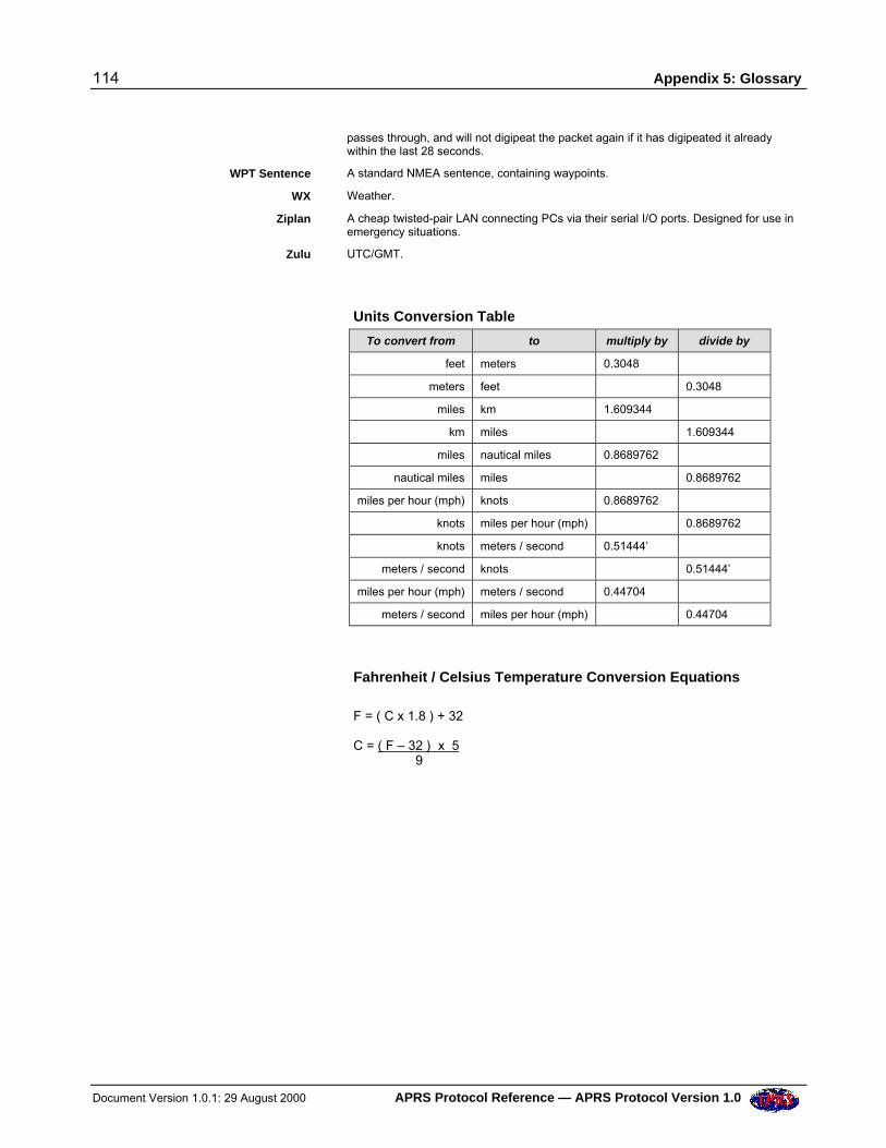
114 Appendix 5: Glossary
Document Version 1.0.1: 29 August 2000 APRS Protocol Reference — APRS Protocol Version 1.0
passes through, and will not digipeat the packet again if it has digipeated it alreadywithin the last 28 seconds.
WPT Sentence A standard NMEA sentence, containing waypoints.
WX Weather.
Ziplan A cheap twisted-pair LAN connecting PCs via their serial I/O ports. Designed for use inemergency situations.
Zulu UTC/GMT.
Units Conversion Table
To convert from to multiply by divide by
feet meters 0.3048
meters feet 0.3048
miles km 1.609344
km miles 1.609344
miles nautical miles 0.8689762
nautical miles miles 0.8689762
miles per hour (mph) knots 0.8689762
knots miles per hour (mph) 0.8689762
knots meters / second 0.51444’
meters / second knots 0.51444’
miles per hour (mph) meters / second 0.44704
meters / second miles per hour (mph) 0.44704
Fahrenheit / Celsius Temperature Conversion Equations
F = ( C x 1.8 ) + 32
C = ( F – 32 ) x 5 9
Appendix 6: References 115
APRS Protocol Reference — APRS Protocol Version 1.0 Document Version 1.0.1: 29 August 2000
APPENDIX 6: REFERENCES
AX.25 Amateur Packet-Radio Link-Layer Protocol Version 2.0, October 1984, athttp://www.tapr.org/tapr/html/ax25.html
NMEA 0183 ASCII Interface Specification, at http://www.nmea.org/0183.htm
NMEA Sentence Formats, in the Garmin GPS25 Technical Reference Manual, athttp://www.garmin.com/manuals/spec25.pdf
Maidenhead Locator, in the IARU Region 1 VHF Manager’s Manual, athttp://www.scit.wlv.ac.uk/vhfc/iaru.r1.vhfm.4e/index.html
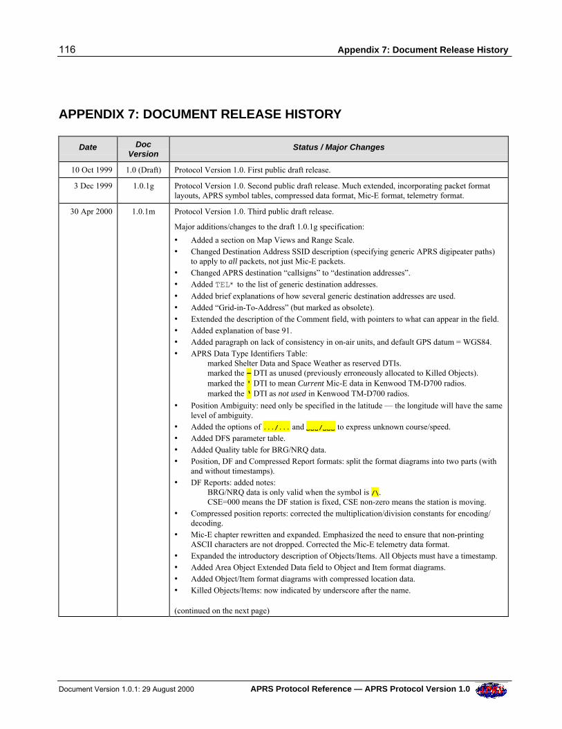
116 Appendix 7: Document Release History
Document Version 1.0.1: 29 August 2000 APRS Protocol Reference — APRS Protocol Version 1.0
APPENDIX 7: DOCUMENT RELEASE HISTORY
Date DocVersion
Status / Major Changes
10 Oct 1999 1.0 (Draft) Protocol Version 1.0. First public draft release.
3 Dec 1999 1.0.1g Protocol Version 1.0. Second public draft release. Much extended, incorporating packet formatlayouts, APRS symbol tables, compressed data format, Mic-E format, telemetry format.
30 Apr 2000 1.0.1m Protocol Version 1.0. Third public draft release.
Major additions/changes to the draft 1.0.1g specification:
• Added a section on Map Views and Range Scale.• Changed Destination Address SSID description (specifying generic APRS digipeater paths)
to apply to all packets, not just Mic-E packets.• Changed APRS destination “callsigns” to “destination addresses”.• Added TEL* to the list of generic destination addresses.
• Added brief explanations of how several generic destination addresses are used.• Added “Grid-in-To-Address” (but marked as obsolete).• Extended the description of the Comment field, with pointers to what can appear in the field.• Added explanation of base 91.• Added paragraph on lack of consistency in on-air units, and default GPS datum = WGS84.• APRS Data Type Identifiers Table:
marked Shelter Data and Space Weather as reserved DTIs.marked the - DTI as unused (previously erroneously allocated to Killed Objects).marked the ' DTI to mean Current Mic-E data in Kenwood TM-D700 radios.marked the ‘ DTI as not used in Kenwood TM-D700 radios.
• Position Ambiguity: need only be specified in the latitude — the longitude will have the samelevel of ambiguity.
• Added the options of .../... and VVVVVV/VVVVVV to express unknown course/speed.• Added DFS parameter table.• Added Quality table for BRG/NRQ data.• Position, DF and Compressed Report formats: split the format diagrams into two parts (with
and without timestamps).• DF Reports: added notes:
BRG/NRQ data is only valid when the symbol is /\.CSE=000 means the DF station is fixed, CSE non-zero means the station is moving.
• Compressed position reports: corrected the multiplication/division constants for encoding/decoding.
• Mic-E chapter rewritten and expanded. Emphasized the need to ensure that non-printingASCII characters are not dropped. Corrected the Mic-E telemetry data format.
• Expanded the introductory description of Objects/Items. All Objects must have a timestamp.• Added Area Object Extended Data field to Object and Item format diagrams.• Added Object/Item format diagrams with compressed location data.• Killed Objects/Items: now indicated by underscore after the name.
(continued on the next page)
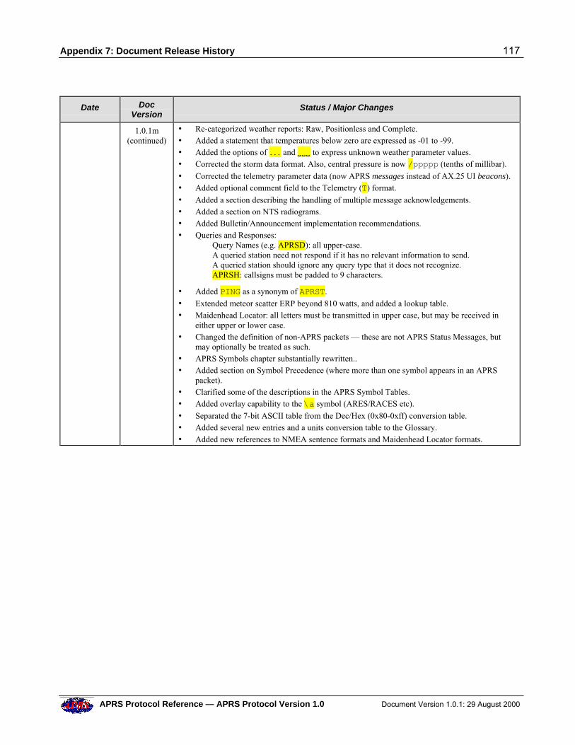
Appendix 7: Document Release History 117
APRS Protocol Reference — APRS Protocol Version 1.0 Document Version 1.0.1: 29 August 2000
Date DocVersion
Status / Major Changes
1.0.1m(continued)
• Re-categorized weather reports: Raw, Positionless and Complete.• Added a statement that temperatures below zero are expressed as -01 to -99.• Added the options of ... and VVVVVV to express unknown weather parameter values.• Corrected the storm data format. Also, central pressure is now /ppppp (tenths of millibar).
• Corrected the telemetry parameter data (now APRS messages instead of AX.25 UI beacons).• Added optional comment field to the Telemetry (T) format.
• Added a section describing the handling of multiple message acknowledgements.• Added a section on NTS radiograms.• Added Bulletin/Announcement implementation recommendations.• Queries and Responses:
Query Names (e.g. APRSD): all upper-case.A queried station need not respond if it has no relevant information to send.A queried station should ignore any query type that it does not recognize.APRSH: callsigns must be padded to 9 characters.
• Added PING as a synonym of APRST.
• Extended meteor scatter ERP beyond 810 watts, and added a lookup table.• Maidenhead Locator: all letters must be transmitted in upper case, but may be received in
either upper or lower case.• Changed the definition of non-APRS packets — these are not APRS Status Messages, but
may optionally be treated as such.• APRS Symbols chapter substantially rewritten..• Added section on Symbol Precedence (where more than one symbol appears in an APRS
packet).• Clarified some of the descriptions in the APRS Symbol Tables.• Added overlay capability to the \a symbol (ARES/RACES etc).
• Separated the 7-bit ASCII table from the Dec/Hex (0x80-0xff) conversion table.• Added several new entries and a units conversion table to the Glossary.• Added new references to NMEA sentence formats and Maidenhead Locator formats.
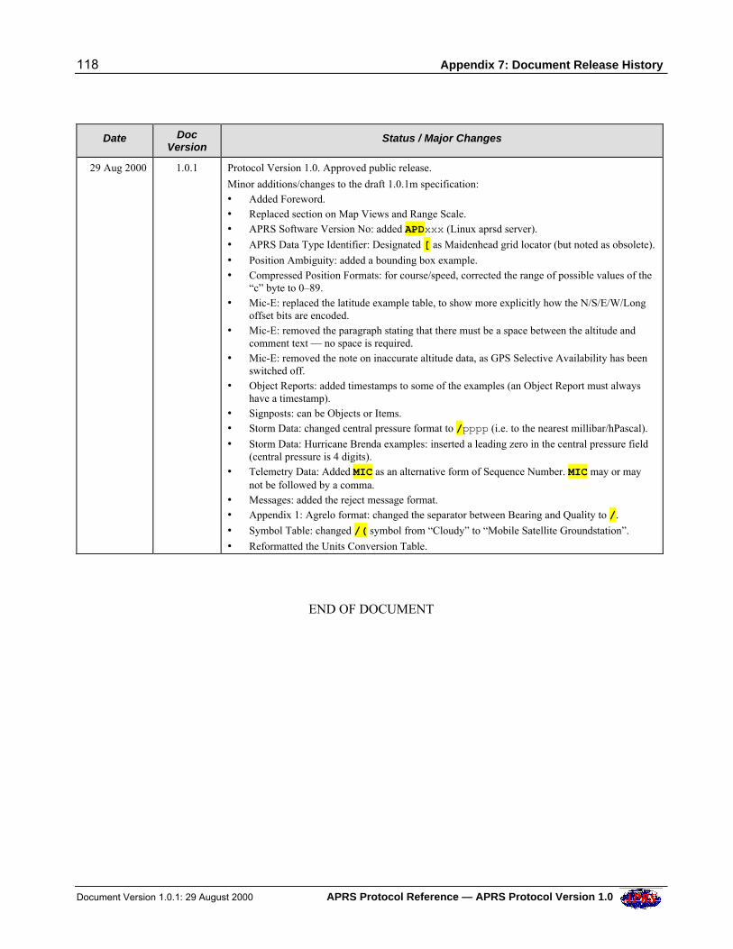
118 Appendix 7: Document Release History
Document Version 1.0.1: 29 August 2000 APRS Protocol Reference — APRS Protocol Version 1.0
Date DocVersion
Status / Major Changes
29 Aug 2000 1.0.1 Protocol Version 1.0. Approved public release.
Minor additions/changes to the draft 1.0.1m specification:• Added Foreword.• Replaced section on Map Views and Range Scale.• APRS Software Version No: added APDxxx (Linux aprsd server).
• APRS Data Type Identifier: Designated [ as Maidenhead grid locator (but noted as obsolete).
• Position Ambiguity: added a bounding box example.• Compressed Position Formats: for course/speed, corrected the range of possible values of the
“c” byte to 0–89.• Mic-E: replaced the latitude example table, to show more explicitly how the N/S/E/W/Long
offset bits are encoded.• Mic-E: removed the paragraph stating that there must be a space between the altitude and
comment text — no space is required.• Mic-E: removed the note on inaccurate altitude data, as GPS Selective Availability has been
switched off.• Object Reports: added timestamps to some of the examples (an Object Report must always
have a timestamp).• Signposts: can be Objects or Items.• Storm Data: changed central pressure format to /pppp (i.e. to the nearest millibar/hPascal).
• Storm Data: Hurricane Brenda examples: inserted a leading zero in the central pressure field(central pressure is 4 digits).
• Telemetry Data: Added MIC as an alternative form of Sequence Number. MIC may or maynot be followed by a comma.
• Messages: added the reject message format.• Appendix 1: Agrelo format: changed the separator between Bearing and Quality to /.
• Symbol Table: changed /( symbol from “Cloudy” to “Mobile Satellite Groundstation”.
• Reformatted the Units Conversion Table.
END OF DOCUMENT
Related Documents