April 10, 2002 A. R. Raffray, et al., Dynamic Chamber Armor Behavior in IFE and MFE 1 Dynamic Chamber Armor Behavior in IFE and MFE A. R. Raffray 1 , G. Federici 2 , A. Hassanein 3 , D. Haynes 4 1 University of California, San Diego, 458 EBU-II, La Jolla, CA 92093- 0417, USA 2 ITER Garching Joint Work Site, Boltzmannstr. 2, 85748 Garching, Germany. 3 Argonne National Laboratory, 9700 South Cass Avenue, Argonne, IL 60439, USA 4 Fusion Technol. Inst., Univ. of Wisconsin, 1500 Eng. Dr., Madison, WI 53706-1687, USA ISFNT-6 San Diego April 10, 2002

April 10, 2002 A. R. Raffray, et al., Dynamic Chamber Armor Behavior in IFE and MFE 1 Dynamic Chamber Armor Behavior in IFE and MFE A. R. Raffray 1, G.
Dec 21, 2015
Welcome message from author
This document is posted to help you gain knowledge. Please leave a comment to let me know what you think about it! Share it to your friends and learn new things together.
Transcript

April 10, 2002 A. R. Raffray, et al., Dynamic Chamber Armor Behavior in IFE and MFE
1
Dynamic Chamber Armor Behavior in IFE and MFE
A. R. Raffray1, G. Federici2, A. Hassanein3, D. Haynes4
1University of California, San Diego, 458 EBU-II, La Jolla, CA 92093-0417, USA2ITER Garching Joint Work Site, Boltzmannstr. 2, 85748 Garching, Germany.
3Argonne National Laboratory, 9700 South Cass Avenue, Argonne, IL 60439, USA4Fusion Technol. Inst., Univ. of Wisconsin, 1500 Eng. Dr., Madison, WI 53706-1687, USA
ISFNT-6
San DiegoApril 10, 2002

April 10, 2002 A. R. Raffray, et al., Dynamic Chamber Armor Behavior in IFE and MFE
2
Outline
• Chamber armor operating conditions– MFE and IFE– Comparison
• Candidate armor materials– Focus on dry walls for this presentation– Properties and characteristics
• Example analysis for dry walls– IFE– MFE
• Critical issues and required R&D – Synergy
• Concluding Remarks

April 10, 2002 A. R. Raffray, et al., Dynamic Chamber Armor Behavior in IFE and MFE
3
IFE Operating Conditions
• Cyclic with repetition rate of ~1-10 Hz • Target injection (direct drive or indirect drive)
• Driver firing (laser or heavy ion beam)
• Microexplosion
• Large fluxes of photons, neutrons, fast ions, debris ions toward the wall
- possible attenuation by chamber gas
Target micro-explosion
Chamber wall
X-rays Fast & debris ions Neutrons
Energy partition for two example targets
NRL DirectDrive Target(MJ)
HI IndirectDrive Target(MJ)
X-rays 2.14 (1%) 115 (25%)
Neutrons 109 (71%) 316 (69%)
Gammas 0.005 (0.003%) 0.36 (0.1%)
Burn ProductFast Ions
18.1 (12%) 8.43 (2%)
Debris IonsKinetic Energy
24.9 (16%) 18.1 (4%)
ResidualThermal Energy
0.013 0.57
Total 154 458
April 10, 2002 A. R. Raffray, et al., Dynamic Chamber Armor Behavior in IFE and MFE
4
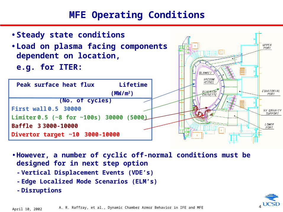
• Steady state conditions
• Load on plasma facing components dependent on location,
e.g. for ITER:
MFE Operating Conditions
• However, a number of cyclic off-normal conditions must be designed for in next step option- Vertical Displacement Events (VDE’s)
- Edge Localized Mode Scenarios (ELM’s)
- Disruptions
Peak surface heat flux Lifetime
(MW/m2) (No. of cycles)
First wall 0.5 30000
Limiter 0.5 (~8 for ~100s) 30000 (5000)
Baffle 3 3000-10000
Divertor target ~10 3000-10000

April 10, 2002 A. R. Raffray, et al., Dynamic Chamber Armor Behavior in IFE and MFE
5
Comparison of IFE and MFE Operating Conditions for ITER Divertor and NRL Direct Drive Target Spectra as Example Cases
• Although base operating conditions of IFE and MFE are fundamentally different, there is an interesting commonality between IFE operating conditions and MFE off-normal operating conditions, in particular ELM’s
- Frequency and energy density are within about one
order of magnitude
ITER Type-I
ELM’s
ITER VDE’s ITER
Disruption
thermal
quench
Typical IFE
Operation
(154 MJ DD
NRL target)
Energy 10-12 MJ ~ 50 MJ/m2 100-350 MJ ~ 0.1 MJ/m2
Affected
area 5-10 m2† A few m2† ~10 m2†
Chamber wall
(R~5-10 m)
Location Surface (near
divertor strike
points)
Surface/bulk Surface (near
divertor strike
points)
bulk (~μm’s)
Time ≥200 µs ~ 0.3 s ~ 1 ms ~ 1-3 μs
Max.
Temperature
Melting/
sublimation
Melting/
sublimation
Melting/
sublimation
~ 2000-3000°C
(for d ry wal )l
Frequency F ewHz ~ 1 per 100
cycles
~ 1 per 10
cycles
~ 10 Hz
Base
Temperature
≥ 500°C ~ 200°C 200-1000°C ~ >700°C
Particle
fluxes ~1023 m-2s-1
† large uncertainties exist
~1024 m-2s-1(peak under normal operation)

April 10, 2002 A. R. Raffray, et al., Dynamic Chamber Armor Behavior in IFE and MFE
6
Candidate Chamber Armor Materials Must Have High Temperature Capability and Good Thermal Properties
• Carbon and refractory metals (e.g. tungsten) considered for both IFE and MFE
- Reasonably high thermal conductivity at high temperature (~100-200 W/m-K)
- Sublimation temperature of carbon ~ 3370°C
- Melting point of tungsten ~3410°C
• In addition, IFE considers possibility of an engineered surface to provide better accommodation of high energy deposition- e.g. ESLI carbon fiber carpet showed good
performance under ion beam testing at SNL (~5 J/cm2 with no visible damage)
• Beryllium considered for moderately loaded first wall of ITER- However, not compatible with commercial reactor operation because of its low
melting point (1283°C) and high sputtering yield
• Example analysis results for IFE and MFE showed for C and W armor
April 10, 2002 A. R. Raffray, et al., Dynamic Chamber Armor Behavior in IFE and MFE
7
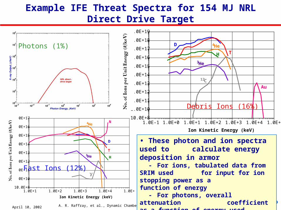
Example IFE Threat Spectra for 154 MJ NRL Direct Drive Target
10.0E+8
1.0E+10
1.0E+11
1.0E+12
1.0E+13
1.0E+14
1.0E+15
1.0E+16
1.0E+17
1.0E+18
1.0E+19
1.0E-1 1.0E+0 1.0E+1 1.0E+2 1.0E+3 1.0E+4 1.0E+5
4HeD
TH
Au
Ion Kinetic Energy (keV)
3He
12C
10.0E+8
1.0E+10
1.0E+11
1.0E+12
1.0E+13
1.0E+14
1.0E+15
1.0E+16
1.0E+17
1.0E+1 1.0E+2 1.0E+3 1.0E+4 1.0E+5
4He
D
T
H
N
Ion Kinetic Energy (keV)
3He
γ
Photons (1%)
Debris Ions (16%)
Fast Ions (12%)
• These photon and ion spectra used to calculate energy deposition in armor- For ions, tabulated data from SRIM used
for input for ion stopping power as a function of energy
- For photons, overall attenuation coefficient as a function of energy used

April 10, 2002 A. R. Raffray, et al., Dynamic Chamber Armor Behavior in IFE and MFE
8
Spatial and Temporal Profiles of Volumetric Energy Deposition in C and W for Direct Drive Target Spectra
10.0x10³
1.0x10⁵
1.0x10⁶
1.0x10⁷
1.0x10⁸
1.0x10⁹
1.0x10¹⁰
1.0x10¹¹
1.0x10¹²
1.0x10¹³
1.0x10¹⁴
1.0x10⁻⁷ 1.0x10⁻⁶ 1.0x10⁻⁵ 1.0x10⁻⁴
4HeD
T
P
Au
Time (s)
3He
12C
1x10⁶
1x10⁷
1x10⁸
1x10⁹
1x10¹⁰
1x10¹¹
1x10⁻⁸ 1x10⁻⁷ 1x10⁻⁶ 1x10⁻⁵ 1x10⁻⁴ 1x10⁻³ 1x10⁻²
Debris ions,W
Fast ions, C
Photons, W
Photons, C
Fast ions, W
Penetration depth (m)
Energy Deposition as a Function of PenetrationDepth for 154 MJ NRL DD Target
Debris ions, CC density = 2000 kg/m3
W density = 19,350 kg/m3
Energy Deposition as a Function of Penetration Depth for 154 MJ NRL DD Target
Ion Power Deposition as a Function of Time for 154 MJ NRL DD Target
Chamber Radius = 6 m
• Penetration range in armor dependent on ion energy level- Debris ions (~20-400 kev) deposit most of their energies within 1’s μm- Fast ions (~1-14 Mev) within 10’s μm
• Important to consider time of flight effects- Photons in sub ns- Fast ions between ~0.2-0.8 μs- Debris ions between ~ 1-3 μs- Much lower maximum temperature than for instantaneous energy deposition case
April 10, 2002 A. R. Raffray, et al., Dynamic Chamber Armor Behavior in IFE and MFE
9
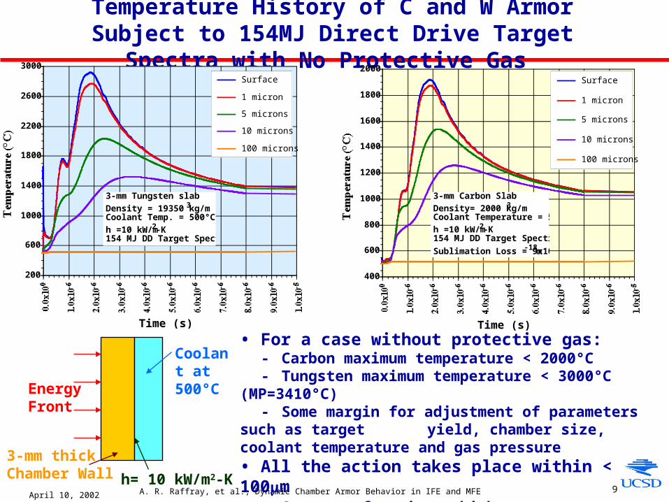
Temperature History of C and W Armor Subject to 154MJ Direct Drive Target Spectra with No Protective Gas
• For a case without protective gas:- Carbon maximum temperature < 2000°C- Tungsten maximum temperature < 3000°C (MP=3410°C)- Some margin for adjustment of parameters such as target
yield, chamber size, coolant temperature and gas pressure• All the action takes place within < 100μm
- Separate functions: high energy accommodation in thin armor, structural function in chamber wall behind
200
600
1000
1400
1800
2200
2600
3000
Surface
1 micron
5 microns
10 microns
100 microns
Time (s)
3-mm Tungsten slab
Density = 19350 kg/m3
Coolant Temp. = 500°C
h =10 kW/m2-K154 MJ DD Target Spectra
400
600
800
1000
1200
1400
1600
1800
2000Surface
1 micron
5 microns
10 microns
100 microns
Time (s)
3-mm Carbon Slab
Density= 2000 kg/m3
Coolant Temperature = 500°C
h =10 kW/m2-K154 MJ DD Target Spectra
Sublimation Loss = 9x10-18 m
Coolant at 500°C
3-mm thick Chamber Wall
EnergyFront
h= 10 kW/m2-K
April 10, 2002 A. R. Raffray, et al., Dynamic Chamber Armor Behavior in IFE and MFE
10
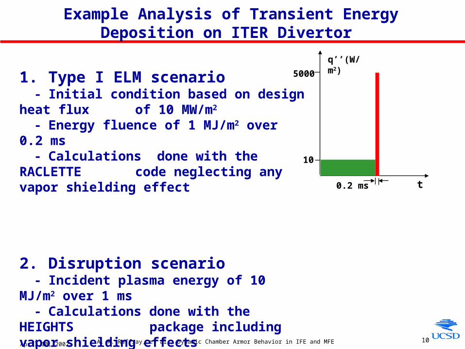
Example Analysis of Transient Energy Deposition on ITER Divertor
1. Type I ELM scenario - Initial condition based on design heat flux
of 10 MW/m2 - Energy fluence of 1 MJ/m2 over 0.2 ms - Calculations done with the RACLETTE
code neglecting any vapor shielding effect
2. Disruption scenario- Incident plasma energy of 10 MJ/m2 over 1 ms - Calculations done with the HEIGHTS
package including vapor shielding effects
t
q’’(W/m2)
0.2 ms
10
5000

April 10, 2002 A. R. Raffray, et al., Dynamic Chamber Armor Behavior in IFE and MFE
11
Example Temperature History of C and W Armor Subject to Transient ELM Scenario in ITER
• Maximum surface temperature is ~4200˚C for CFC and ~6000˚C for W• Temperature drops to the initial value in about 10 ms ( no temperature ratcheting effect for
ELM frequencies of ~ 1-2 Hz)• Sublimated CFC thickness is ~5 μm (this limits the number of ELMs with such energy
densities that can be tolerated in ITER)• Evaporated thickness in the case of W is lower (~1 μm per event) • However, the melt layer thickness is ~ 70 μm • Key lifetime issue for W would be the stability of the melt layer and the corresponding
fractional loss of melted material
April 10, 2002 A. R. Raffray, et al., Dynamic Chamber Armor Behavior in IFE and MFE
12
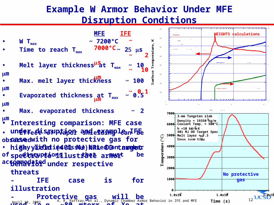
Example W Armor Behavior Under MFE Disruption Conditions
• Interesting comparison: MFE case under disruption and example IFE case with no protective gas for high yield (401 MJ)NRL DD target spectra to illustrate armor behavior under respective threats- IFE case is for illustration- Protective gas will be used (e.g. ~80 mtorr of Xe at RT) to spread out over time energy deposition on armor
0
1000
2000
3000
4000
5000
6000
7000
8000
0.1
1
10
100
1000
10
0
10
1
10
2
10
3
Surface Temperature, K
Time, μ s
10 /MJ m
2
1 ms
(Vaporization Thickness μ )m
Tungsten
(Melted Thickness μ )m
T
s
= 5 , B T α = 2
0
HEIGHTS calculations
• W Tmax ~ 7200°C • Time to reach Tmax ~ 25 μs • Melt layer thickness at Tmax ~ 10 μm• Max. melt layer thickness ~ 100 μm • Evaporated thickness at Tmax ~ 0.5 μm• Max. evaporated thickness ~ 2 μm
• Effect of vapor shielding can be observed• Key lifetime issue based on number of disruptions that must be accommodated
0
1000
2000
3000
4000
5000
6000
7000
1.0x10⁻⁷ 1.0x10⁻⁶ 1.0x10⁻⁵
3-mm Tungsten slab
Density = 19350 kg/m3
Coolant Temp. = 500°C
h =10 kW/m2-K401 MJ DD Target SpectraMelt layer = 7.3 μm
. Evap loss = 0.08 μm
Time (s)
No protective gas
MFE IFE~
7000°C~ 2 μs~ 10
μm
~ 0.1 μm

April 10, 2002 A. R. Raffray, et al., Dynamic Chamber Armor Behavior in IFE and MFE
13
Other Erosion Processes are of Concern in Particular for Carbon
Chemical SputteringRadiation Enhanced Sublimation
- Increases with temperature
Physical sputtering- Not temperature-dependent - Peaks with ion energies of ~ 1 kev
(from J. Roth, et al., “Erosion of Graphite due to Particle Impact,” Nuclear Fusion, 1991)
Plots illustrating relative importance of C erosion mechanisms for example IFE case
(154 MJ NRL DD target spectra)
- RES and chemical sputtering lower than sublimation for this case but quite significant also
- Physical sputtering is less important than other mechanisms
- Increased erosion with debris ions as compared to fast ionsRchamber = 6.5 m
CFC-2002U
April 10, 2002 A. R. Raffray, et al., Dynamic Chamber Armor Behavior in IFE and MFE
14
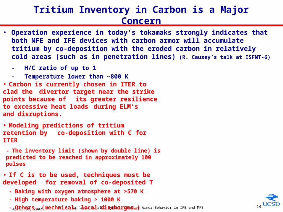
Tritium Inventory in Carbon is a Major Concern
• Operation experience in today’s tokamaks strongly indicates that both MFE and IFE devices with carbon armor will accumulate tritium by co-deposition with the eroded carbon in relatively cold areas (such as in penetration lines) (R. Causey’s talk at ISFNT-6)
- H/C ratio of up to 1
- Temperature lower than ~800 K
• Carbon is currently chosen in ITER to clad the divertor target near the strike points because of
its greater resilience to excessive heat loads during ELM’s and disruptions.
• Modeling predictions of tritium retention by co-deposition with C for ITER
- The inventory limit (shown by double line) is predicted to be reached in approximately 100
pulses
• If C is to be used, techniques must be developed for removal of co-deposited T
- Baking with oxygen atmosphere at >570 K
- High temperature baking > 1000 K
- Others, (mechnical, local discharges…)
April 10, 2002 A. R. Raffray, et al., Dynamic Chamber Armor Behavior in IFE and MFE
15
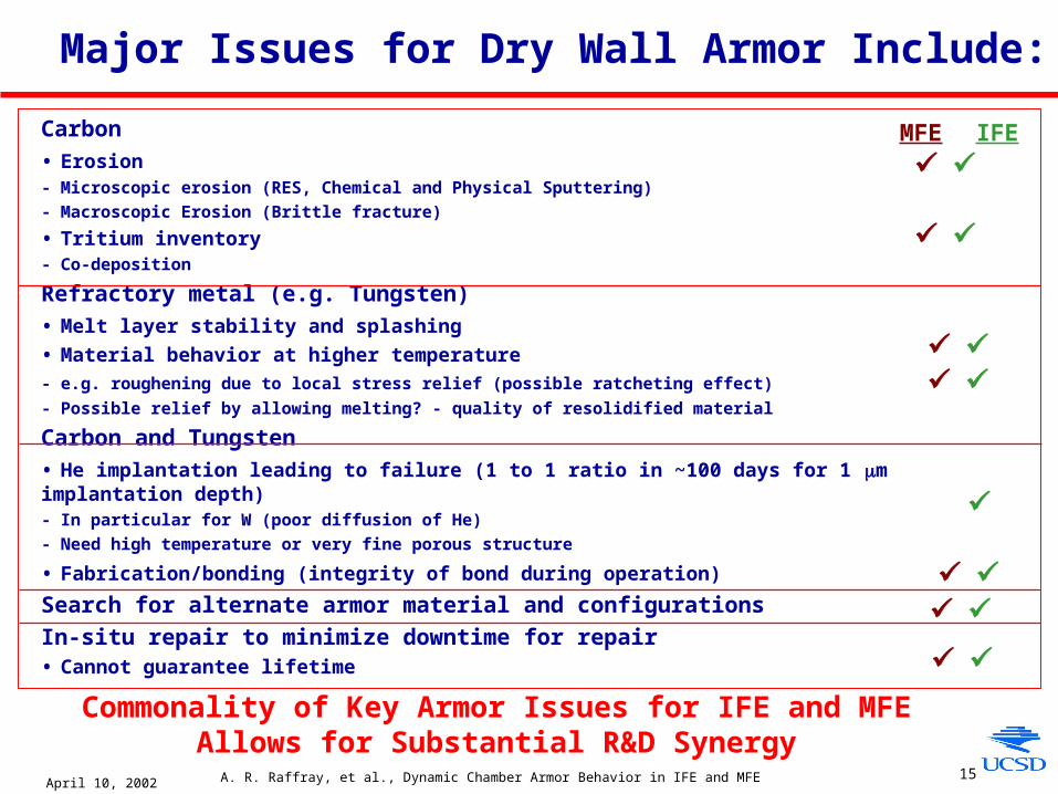
Major Issues for Dry Wall Armor Include:
Commonality of Key Armor Issues for IFE and MFE Allows for Substantial R&D Synergy
Carbon
• Erosion- Microscopic erosion (RES, Chemical and Physical Sputtering)
- Macroscopic Erosion (Brittle fracture)
• Tritium inventory - Co-deposition
Refractory metal (e.g. Tungsten)
• Melt layer stability and splashing
• Material behavior at higher temperature
- e.g. roughening due to local stress relief (possible ratcheting effect)
- Possible relief by allowing melting? - quality of resolidified material
Carbon and Tungsten
• He implantation leading to failure (1 to 1 ratio in ~100 days for 1 μm implantation depth)- In particular for W (poor diffusion of He)
- Need high temperature or very fine porous structure
• Fabrication/bonding (integrity of bond during operation)
Search for alternate armor material and configurations
In-situ repair to minimize downtime for repair• Cannot guarantee lifetime
MFE IFE
April 10, 2002 A. R. Raffray, et al., Dynamic Chamber Armor Behavior in IFE and MFE
16
Concluding Remarks
• Challenging conditions for chamber wall armor in both IFE and MFE
- Overlap between IFE conditions and some MFE off-normal events
• Different armor materials and configurations are being developed - Similarity between MFE and IFE materials
• Some key issues remain and are being addressed by ongoing R&D effort- Many common issues between MFE and IFE chamber armor
• Very beneficial to:
- develop and pursue healthy interaction between IFE and MFE chamber communities
- make the most of synergy between MFE and IFE Chamber Armor R&D
Related Documents