KEPCO & KHNP Style Guide APR1400-E-J-NR-12005-NP, Rev.0 KEPCO & KHNP Style Guide Technical Report September 2013 Copyright ⓒ 2013 Korea Electric Power Corporation & Korea Hydro & Nuclear Power Co., Ltd All Rights Reserved Non-Proprietary

Welcome message from author
This document is posted to help you gain knowledge. Please leave a comment to let me know what you think about it! Share it to your friends and learn new things together.
Transcript
KEPCO & KHNP Style Guide APR1400-E-J-NR-12005-NP, Rev.0
KEPCO & KHNP
Style Guide
Technical Report
September 2013
Copyright 2013
Korea Electric Power Corporation & Korea Hydro & Nuclear Power Co., Ltd
All Rights Reserved
Non-Proprietary
KEPCO & KHNP Style Guide APR1400-E-J-NR-12005-NP, Rev.0 _________________________________________________________________________________________________________
KEPCO & KHNP i
Revision History
Revision Page (Section) Description
0 All Issue for Standard
This document was prepared for the design certification application to the U.S. Nuclear Regulatory Commission and contains technological information that constitutes intellectual property. Copying, using, or distributing the information in this document in whole or in part is permitted only by the U.S. Nuclear Regulatory Commission and its contractors for the purpose of reviewing design certification application materials. Other uses are strictly prohibited without the written permission of Korea Electric Power Corporation and Korea Hydro & Nuclear Power Co., Ltd.
KEPCO & KHNP Style Guide APR1400-E-J-NR-12005-NP, Rev.0 _________________________________________________________________________________________________________
KEPCO & KHNP ii
ABSTRACT
Style guide is a document that contains guidelines that have been tailored so they describe the implementation of human factors engineering guidance to a specific design, such as for a specific plant control room.
KEPCO & KHNP Style Guide APR1400-E-J-NR-12005-NP, Rev.0 _________________________________________________________________________________________________________
KEPCO & KHNP iii
TABLE OF CONTENTS
1.0 INTRODUCTION 1-1
1.1 Scope .............................................................................................................. 1-1 1.2 Purpose ........................................................................................................... 1-1
2.0 INFORMATION DISPLAYS 2-1
2.1 General Guidelines ......................................................................................... 2-1 2.2 Display Network .............................................................................................. 2-9 2.3 Display Format ................................................................................................ 2-9 2.4 Display Element .............................................................................................. 2-46 2.5 Display Coding ................................................................................................ 2-54 2.6 Display Pages ................................................................................................. 2-62 2.7 Controls ........................................................................................................... 2-63
3.0 INTERACTION 3-1
3.1 General Interaction Guidelines ....................................................................... 3-1 3.2 Managing Display and Data ............................................................................ 3-6 3.3 System Response ........................................................................................... 3-12 3.4 System Security .............................................................................................. 3-16
4.0 DISPLAY AND CONTROL DEVICES 4-1
4.1 Display Device ................................................................................................ 4-1 4.2 Control Devices .............................................................................................. 4-7
5.0 HSI SYSTEMS 5-1
5.1 Soft Control for Information FPD and ESCM .................................................. 5-1 5.2 CBPs (Computer-Based Procedures) ............................................................ 5-8 5.3 Alarm System ................................................................................................. 5-15 5.4 Communication System .................................................................................. 5-28
6.0 WORKSTATION AND WORKPLACE DESIGN 6-1
6.1 Console Design .............................................................................................. 6-1 6.2 Environment Design ....................................................................................... 6-7 6.3 Local Control Panel ........................................................................................ 6-11
7.0 MAINTAINABILITY OF DIGITAL SYSTEM 7-1
7.1 General Maintainability Guidelines ................................................................. 7-1 7.2 Instrument Cabinets and Racks...................................................................... 7-4 7.3 Equipment Packaging ..................................................................................... 7-4 7.4 Fuses and Circuit Breakers ............................................................................ 7-9
KEPCO & KHNP Style Guide APR1400-E-J-NR-12005-NP, Rev.0 _________________________________________________________________________________________________________
KEPCO & KHNP iv
TABLE OF CONTENTS (Cont'd)
7.5 Labeling and Marking ..................................................................................... 7-10 7.6 Adjustment Controls ....................................................................................... 7-11 7.7 Test Points and Service Points ....................................................................... 7-13 7.8 Test Equipment ............................................................................................... 7-14
8.0 REFERENCES 8-1
APPENDIX A A-1
Part 1 (Standard Abbreviation List) A-Part 1-1 Part 2 (Physical Units and Abbreviation) A-Part 2-1 Part 3 (Table of System Mnemonics) A-Part 3-1
APPENDIX B (Glossary) B-1 APPENDIX C (The Main Symbols for Video Display Unit) C-1 APPENDIX D (Labeling and Demarcation) D-1
LIST OF TABLES Table 3.3.5 Maximum and preferred system response times for User Command 3-15
KEPCO & KHNP Style Guide APR1400-E-J-NR-12005-NP, Rev.0 _________________________________________________________________________________________________________
KEPCO & KHNP v
List of Acronyms
ANSI American National Standards Institute ARP alarm response procedure ANSI American National Standard Institute CBP computer-based procedure EO electrical operator EOF emergency operating facility ESCM ESF-CCS soft control module FPD flat panel display HFE human factors engineering HSI human-system interface HSIS human-system interface system HVAC heating ventilation and air-conditioning I&C instrumentation and control IHA important human action LCS local control station LOS line of sight LCPs local control panels LDP large display panel MCR main control room RCS reactor coolant system RO reactor operator RSR remote shutdown room SDCV spatially dedicated, continuously visible SPDS safety parameter display system SS shift supervisor STA shift technical advisor TO turbine operator TSC technical support center VDU visual display units
KEPCO & KHNP Style Guide APR1400-E-J-NR-12005-NP, Rev.0 _________________________________________________________________________________________________________
KEPCO & KHNP 1-1
1.0 INTRODUCTION
This human factors engineering (HFE) Guideline has been developed to take an advantage of
the human-system interface (HSI) design of the control room in Nuclear Power Plants. The HFE
guideline provides design guidance to assure that the HSI design is sufficient and consistent,
thus contributing to operational safety.
1.1 Scope
The HFE Guideline contains the design guidance of the APR1400 HSI systems including local
control stations (LCSs) associated with important human actions (IHAs), as well as
environmental conditions in the following areas:
1) Main control room (MCR),
2) Remote shutdown room (RSR),
3) Technical support center (TSC), and
4) Emergency operating facility (EOF)
1.2 Purpose
The purpose of this document is to provide APR1400 HSI designers with design guidance
regarding how the human factors principles may be best of benefit in developing the designs of
individual HSI resources. Each HSI designer should be cognizant of the incorporation for all
related HFE principles in the design of each HSI resource or control facility. Also, this document
is applicable to the related design and engineering work.
KEPCO & KHNP Style Guide APR1400-E-J-NR-12005-NP, Rev.0 _________________________________________________________________________________________________________
KEPCO & KHNP 2-1
2.0 INFORMATION DISPLAYS
2.1 General Guidelines
2.1.1 General Display Guidelines
a) Display Screen Partitioning for HSI Functions - A standard display screen organization
should be evident for the location of various HSI functions (such as a data display zone,
control zone, or message zone) from one display to another.
b) Display Conventions - Consistent interface design conventions should be evident for all
display features (such as labels).
c) Numeral and Letter Styles - Numeral and letter styles should be simple and consistent.
d) Distinctive HSI Functional Organization and Display Elements - The HSI functional zones
and display features should be visually distinctive from one another, especially for on-
screen command and control elements (which should be visibly distinct from all other
screen structures).
e) Display Title - Every display page should begin with a title or header at the top, briefly
describing the contents or purpose of the display.
f) Hierarchy of Titles - Where displays have several levels of titles (and/or labels), the
system should provide visual cues to aid users in distinguishing among the levels in the
hierarchy.
g) Display Simplicity - Displays should present the simplest information consistent with their
function: information irrelevant to the task should not be displayed, and extraneous text
and graphics should not be present.
h) Appropriate Display Format - The display presentation format, e.g., table, graph, or
flowchart, should be consistent with tasks that the user will be performing with the
displayed information.
i) Indication of Transformations Needed - If it is necessary to multiply or divide the displayed
KEPCO & KHNP Style Guide APR1400-E-J-NR-12005-NP, Rev.0 _________________________________________________________________________________________________________
KEPCO & KHNP 2-2
readings by powers of 10 to determine quantitative value, the operation required and
result derived must be clearly indicated appropriate Display Format.
j) Display Information Consistent with Control Requirements - Displays should be consistent
in word choice, format, and basic style with requirements for data and control entry.
k) Normal Value Reference Index - Displays should contain reference(s) to the values of
normal operating condition(s).
l) Critical Value Reference Index - A reference index should be included in a display when
the user must compare displayed information with some critical value. Limit marks
should be used for each critical plant parameter displayed.
m) Highlighting Text Displays - When critical text merits emphasis to set it apart from other
text, that text should be highlighted by bolding/brightening or color coding or by some
auxiliary annotation.
n) Graphic Display Enhancement with Numeric Values - When precise reading of a graphic
display is required, the display should be annotated with actual data values to supplement
their graphic representation.
o) Freeze Feedback - If a display has a freeze capability, the display should have an
obvious reminder that it is in the freeze mode.
p) Dictionary of Display Element Definitions - The user should have access to a dictionary
that contains definitions for all display element conventions through an on-line help or off-
line.
q) Labeling Scrollable and Multi-page Displays - General labels and row/column labels
should remain along the top (or bottom) and left (or right) edges of the display.
r) Data Overlays - Displayed information which temporarily overlays and obscures other
display data should not erase the overlaid data.
s) Physical Overlays - Overlays should not distract or interfere with the observation or
interpretation of displayed information.
KEPCO & KHNP Style Guide APR1400-E-J-NR-12005-NP, Rev.0 _________________________________________________________________________________________________________
KEPCO & KHNP 2-3
t) Hardcopy of VDU Displays - Users should be able to obtain a hardcopy of any VDU
display without altering the display content.
u) Representation of Individual Parameters - Each relevant process parameter should be
represented by a perceptually distinct element within the display.
v) Correspondence Mapping - There should be an explicit mapping between the
characteristics and functions of the system to be represented and the features of the
display representation, i.e., changes in the appearance of the display form should have a
one-to-one relation with the plant states it represents. These changes should result from
explicit rules relating the physical form of the display and its meaning to the plant state
represented.
w) Coherence Mapping - The characteristics and features of the display used to represent
the process should be readily perceived and interpreted by the operator.
x) Salience Levels - The salience of graphic features should reflect the importance of the
information.
y) Display of Goal Status - The information system should provide for global situation
awareness (i.e., an overview of the status of all the operator's goals at all times) as well
as supplying details about the current specific goal.
z) Analytical Redundancy - Analytical redundancy should be considered to help ensure the
appropriateness of displayed values.
aa) Failure Recognition - Information system failure should be indicated.
bb) Navigational Links to Related Information - Navigational links to and from high-level and
lower-levels of information and to reference and supporting information should be
provided when needed for operator's tasks.
cc) Correspondence Between Screen and Document - When users will transfer data from
hard copy documents, the screen layout should correspond to the hard copy in the order
and grouping of data items. For this case, it is desirable that the displayed form look as
KEPCO & KHNP Style Guide APR1400-E-J-NR-12005-NP, Rev.0 _________________________________________________________________________________________________________
KEPCO & KHNP 2-4
much like the source document as possible.
dd) Display Failure Indications - Displays should be designed so that a loss of power or signal
to the display or display circuitry is readily distinguished from the range of possible
readings for the displayed parameter.
ee) Labels of Graphic Objects - The label for a specific graphic object (e.g., an icon) should
be placed in close proximity to the graphical object.
2.1.2 General Information Guidelines
a) Redundancy - Redundancy in the presentation of information items should be limited to
cases where needed for backup or to avoid excessive operator movement. But, if
redundancy gain effects are certain, the redundancy should be used. When the same
message is expressed more than once, it will be more likely to be interpreted correctly
(Redundancy gain). Specially, this will be particularly true if the same message is
presented in alternative physical forms (e.g., tone and voice, voice and print, print and
picture, color and shape) (Use multiple resources).
b) Grouping of Information in a Display - Information on a display should be grouped
according to principles obvious to the user, e.g., by task, system, function, or sequence,
based upon the user's requirements in performance of the ongoing task.
c) Demarcation of Groups - When information is grouped on a display, the groups should be
made visually distinct by such means as color coding or separation using blanks or
demarcation lines.
d) Display Information in Directly Usable Form - Information should be displayed to users in
directly usable form consistent with the task requirements. For this, integral and configural
display formats should be considered.
e) Appropriate Use of Integral Displays - Integral Formats should be used to communicate
high-level, status-at-a-glance information where users may not need information on
individual parameters to interpret the display.
f) Appropriate Use of Configural Displays - Configural formats should be used when
KEPCO & KHNP Style Guide APR1400-E-J-NR-12005-NP, Rev.0 _________________________________________________________________________________________________________
KEPCO & KHNP 2-5
operators must rapidly transition between high-level functional information and specific
parameter values.
1) Representation of Emergent Features: The display elements should be organized so
that the emergent features that arise from their interaction correspond to meaningful
information about the process or system, e.g., when the aspect of the system
represented by the emergent is disturbed, the disturbance is visible in the emergent
feature.
2) Levels of Emerging Features: The emergent features or patterns within the display
should be nested (from global to local) in a way that reflects the hierarchical structure
of the process.
3) Salience of Emerging Features: Each emergent feature should be clearly
distinguishable for other emergent features and from information on individual
parameters.
4) Reference Aids for configural displays: A perceptually distinct reference aid should be
provided in a configural display to support operators in recognizing abnormalities in
emergent features.
5) Representation of Individual Parameters: Each relevant process parameter should be
represented by a perceptually distinct element within the display.
6) Use of Lower-Level Information: The display should support the user in performing
tasks requiring lower-level information.
7) Complexity: The emergent features and their interactions should not be so complex as
to be susceptible to misinterpretation.
g) Display Information Consistent with User Conventions - Information should be displayed
consistently according to standards and conventions familiar to users.
h) Range of Conditions Displayed - The display system should correctly display information
about the plant's safety status including severe accident symptoms.
i) Actual System/Equipment Status - Indications of the actual status of plant systems and
equipment, as opposed to demand status, should be provided when required by the task.
j) Rapid Recognition of Safety Status Change - User comprehension of a change in the
safety status from critical safety function displays should be achieved in a matter of
seconds.
KEPCO & KHNP Style Guide APR1400-E-J-NR-12005-NP, Rev.0 _________________________________________________________________________________________________________
KEPCO & KHNP 2-6
k) Display of Parameters and Variables Important to Safety - Plant parameters and variables
important to safety should be displayed in a way that is convenient and readily accessible
to control room operators.
l) Critical Safety Function Display Visibility - Critical safety function displays should be
readable from the consoles of users needing access to these displays.
m) Critical Parameter Monitoring Support - The system should assist the user in monitoring
critical parameters, especially parameters that change very rapidly or very slowly, by
alerting the user when values are out of range.
n) Display Enhancement with Time Data - When task performance requires or implies the
need to assess currency of information within a display, the information should be
annotated with time information.
o) Freezing Rapidly Changing Information - When the display is changing so rapidly that the
information is difficult to read, the user should have the capability of viewing the
information in a supplemental display.
p) Readability Conditions - Important display elements and codes should be identifiable and
readable from the maximum viewing distance and under minimal ambient lighting
conditions.
q) Information Display Density - Display packing density should not exceed 50 %. Density
should be minimized for displays of critical information. Displays consisting largely of
alphanumeric generally should not exceed 25 % density. Displays composed largely of
graphics may be more dense. When a display contains too much information for
presentation in a single frame, and cannot be refined to accommodate the desired data, it
should be organized into separate screens, multi-paged screens, or scrolled/paged lists.
However, such steps should not be performed if they cause otherwise unitary tasks to
require extensive screen switching.
r) Actual Equipment Responses - Indication devices for remotely instrumented equipment
should present actual status/response of the physical plant equipment wherever practical.
If this is not practical, indication of ordered action or control power status should be
KEPCO & KHNP Style Guide APR1400-E-J-NR-12005-NP, Rev.0 _________________________________________________________________________________________________________
KEPCO & KHNP 2-7
labeled to denote the specific nature of the indication.
2.1.3 General Coding Guidelines
A. Coding Display Items Requiring Rapid Discrimination - Coding should be provided when
a user must distinguish rapidly among different categories of displayed data.
B. Meaningful Codes - Meaningful or familiar codes should be used, rather than arbitrary
codes.
C. Consistent Coding Across Displays - Consistent meanings should be assigned to codes,
from one display to another.
D. Readability of Coded Information - Coding should not interfere with the readability of
displayed information.
E. Coding and Transmission Time - Coding should not increase transmission time.
F. Distinctive Coding of Critical Information - Distinctive means of coding/highlighting should
be used when a user's attention must be directed to changes in the state of the system,
critical or off-normal data, and hazardous conditions.
G. Display Background Color - A single non-distracting background color should be used that
has a hue/contrast which allows the data (foreground) to be easily visible and which does
not distort or interfere with the coding aspects of the display.
2.1.4 General Information Format Guidelines
a) Simple - A simpler format tends to be easier to use. Thus, uninformative aspects of format
should be avoided. For example, unnecessary dividing lines or uninformative words add
"visual noise" to a presentation (rather than useful information or "visual signal"). They
compete with the informative items for the attention and processing capacity of the
operator. Similarly, redundant information should be limited to where it is 1) required for
backup, 2) useful in a specific context, or 3) desirable to avoid operator movement (in
either physical or virtual workspace).
KEPCO & KHNP Style Guide APR1400-E-J-NR-12005-NP, Rev.0 _________________________________________________________________________________________________________
KEPCO & KHNP 2-8
b) Meaningful - A format should be inherently meaningful. This means more than simply
providing information; it implies that the information can be readily understood.
c) Unambiguous - An item is ambiguous if its intended meaning is uncertain or obscured. In
coding, this can occur if the encoding/decoding rules are not crisply specified and applied.
In messages, this occurs if there is insufficient information in a presentation, e.g.,
combining "high water temperature" and "low oil pressure" into a single "engine trouble"
light in an automobile's dashboard. Note that a prerequisite to designing unambiguous
indications is to know how the information element is actually used. An engine trouble
light is more appropriate if the driver's response is expected to be "stop the motor and
have the car taken to a mechanic" and not "stop the motor, let the motor cool off, check
the fluid level, check belts and pump..." etc.
d) Consistent - Meanings and relationships should be consistent among similar elements in
similar contexts. If they are not, then users must learn and remember the separate cases,
and keep them organized by an additional layer of unnecessary detail. This is mentally
laborious and error-prone.
e) Compatible - Where relationships cannot be entirely consistent between contexts, they
still should be compatible (i.e., should not conflict) with one another. For example, VDU
screens may use the color red to denote active components, while red may also be
applied to the color coding of equipment danger tags and placards. Because the two
contexts of use are separate, no conflict is identified, Compatibility between the motion of
a control and associated display is particularly important: the design of these two
components and their relationships can tolerate some inconsistency, but they must never
be incompatible.
f) Readable - Visual information needs to be readable. This requires that characters and
symbols are legible, and that the symbols are combined into terms and messages by
well-known or easily learned rules.
g) Salient - The relative salience between items should correspond to their relative
informativeness or significance. Items must be relatively noticeable, so that they can
compete effectively with their surrounds for the user's attention. For example, an alarm
must be intrusive to perform its function, while component label needs only to be
noticeably located and readably sized. Since excess salience can produce distraction and
KEPCO & KHNP Style Guide APR1400-E-J-NR-12005-NP, Rev.0 _________________________________________________________________________________________________________
KEPCO & KHNP 2-9
possibly stress, it is no more desirable than inadequate salience. In addition, if everything
is emphasized, then nothing stands out. Note that selecting an appropriate salience level
for an item requires some knowledge of the item's surrounds.
h) Cognizance of Users, Tasks, and Working Environment - Displays should be consistent
with the knowledge and abilities of the various users (operators and maintainers), their
tasks (goals, problems, procedures, equipment), and the working environment (normal
and emergency conditions, other external restraints, etc.).
2.2 Display Network
a) Hierarchical Structure - Information should be organized like inverted tree in which the
lower branches provide increasingly specific categories related to the more general
categories contained in the higher branches and trunk. Hierarchical structure should be
described in term of depth and breath. Hierarchical structure should represent functional
or physical relationships.
b) Relational Structure - Relation display network structures should have multiple links
between nodes, which are based on a variety of relationships.
c) Sequential Structure - A sequential display network structures should organize display
pages in a series, representing dependant relationships.
2.3 Display Format
2.3.1 Continuous Text Displays
a) Standard Text Format - A standard text display format should be used from one display to
another.
b) Consistency Between VDU-Based Text and Printed Text - VDU displays of textual data,
messages, or instructions should generally follow design conventions for printed text.
c) Sentences Begin with Main Topic - The main topic of each sentence should be located
near the beginning of the sentence.
KEPCO & KHNP Style Guide APR1400-E-J-NR-12005-NP, Rev.0 _________________________________________________________________________________________________________
KEPCO & KHNP 2-10
d) Clarity of Wording - Text displays should employ simplicity and clarity of wording.
e) Distinct Wording - Distinct words rather than contractions or combined forms should be
used, especially in phrases involving negation
f) Concise Wording - The text should be worded concisely to aid comprehension.
g) Affirmative Sentences - Affirmative statements rather than negative statements should be
used.
h) Active Voice - Sentences should be composed in the active rather than the passive voice.
i) Temporal Sequence - When a sentence describes a sequence of events, it should be
phrased with a corresponding word order.
j) Minimum Number of Displayed Lines - When a user must read continuous text on line, at
least four lines of text should be displayed at one time.
k) Line Length - Continuous text should be displayed in wide columns, containing at least 50
characters per line.
l) Minimal Hyphenation - In display of textual material, words should be kept intact, with
minimal breaking by hyphenation between lines.
m) Conventional Punctuation - Conventional punctuation should be used in textual display.
n) Inter-Line Spacing - The minimum space between lines should be one-half character
height.
o) Combining Text with Other Data - Text should be formatted in a few wide lines rather than
in narrow columns of many short lines, when it is combined with graphics or other data in
a single display, thus limiting the available space.
p) Placing Figures Near Their Citations - When tables and/or graphics are combined with
text, each figure should be placed near its first citation in the text, preferably in the same
display frame.
KEPCO & KHNP Style Guide APR1400-E-J-NR-12005-NP, Rev.0 _________________________________________________________________________________________________________
KEPCO & KHNP 2-11
q) Underlining for Emphasis - When a line is placed under an item to mark or emphasize it,
the line should not impair the legibility of the item, e.g., by obscuring the descenders.
r) Font Coding - Within a text file or table, the use of a different font style should be
preferred over the use of a different size for highlighting information.
s) Attention Symbols in Alphanumeric Displays - When a special symbol, such as an
asterisk, is used to draw attention to a selected item in alphanumeric displays, the symbol
should be separated from the beginning of the word by a space.
t) Hardcopy for Lengthy Text Displays - When a user must read lengthy textual material,
that text should be available in printed form.
u) Spacing between Paragraphs - Displayed paragraphs of text should be separated by at
least one blank line.
2.3.2 Table and List
a) Logical Organization - Information should be organized in some recognizable logical
order to facilitate scanning and assimilation.
b) Table Layout by Row and Column - A table should be constructed so that row and column
labels represent the information a user has prior to consulting the table.
c) Row and Column Labels - Each row and column should be uniquely and informatively
labeled and should be visually distinct from data entries.
d) Labeling Units of Measurement - Labels should include the unit of measure for the data in
the table; units of measurement should be part of row or column labels.
e) Consistent Spacing within Tables - Consistent column and row spacing should be
maintained within a table, and from one table to another. Similarly, spacing between rows
should be consistent within a table and between related tables.
f) Row Separation - in dense tables with many rows, a blank line, dots, or some other
KEPCO & KHNP Style Guide APR1400-E-J-NR-12005-NP, Rev.0 _________________________________________________________________________________________________________
KEPCO & KHNP 2-12
distinctive feature (to aid horizontal scanning) should be inserted after a group of rows at
regular intervals.
g) Consistent Character Appearance - The font and size of alphanumeric characters should
be consistent within a table and between related tables.
h) Justification of Alphabetic Data - Columns of alphabetic data should be displayed with left
justification to permit rapid scanning.
i) Justification of Numeric Data - Columns of numeric data should be justified with respect
to a fixed decimal point; if there is no decimal point, then numbers should be right-justified.
j) Arabic Numerals for Numbered List Items - Arabic rather than Roman numerals should be
used when listed items are numbered.
k) Numbered Items Start with "1" - Item numbers should begin with one rather than zero.
l) Repeated Elements in Hierarchic Numbering - Complete numbers should be displayed for
hierarchic lists with compound numbers, i.e., repeated elements should not be omitted.
m) Single-Column List Format - Lists should be formatted so that each item starts on a new
line.
n) Marking Multi-line Items in a List - When a single item in a list continues for more than
one line, items should be marked in some way so that the continuation of an item is
obvious.
o) Hierarchic Structure for Long Lists - for a long list, extending more than one displayed
page, a hierarchic structure should be used to permit its logical partitioning into related
shorter lists.
p) Vertical Ordering in Multiple Columns - If a list is displayed in multiple columns, the items
should be ordered vertically within each column rather than horizontally within rows and
across columns.
q) Annotating Display of Continued Data - When lists or tables are of variable length and
KEPCO & KHNP Style Guide APR1400-E-J-NR-12005-NP, Rev.0 _________________________________________________________________________________________________________
KEPCO & KHNP 2-13
may extend beyond the limits of one display page, the user should be informed when
data are continued on another page and when data are concluded on the present page.
r) Continuous Numbering in Multi-page Lists - When a list of numbered items exceeds one
display page, the items should be numbered continuously in relation to the first item on
the first page.
s) Vertical List Extension Beyond One Page - Where lists extend over more than one display
page, the last line of one page should be the first line on the succeeding page.
2.3.3 Data Form and Fields
2.3.3.1 Data Forms
a) Consistent Format Across Displays - The ordering and layout of corresponding data fields
across displays should be consistent from one display to another.
b) Consistency of VDU and Hardcopy Formats - The format of a VDU data form should be
similar to that of commonly used hardcopy source documents.
c) Form Compatible for Data Entry and Display - When forms are used for data entry as well
as for data display, the formats of these forms should be compatible.
d) Protected Labels - Field labels should be protected from keyed entry by having the cursor
skip over them automatically when a user is spacing or tabbing.
e) Distinguishing Blanks from Nulls - Blanks (keyed spaces) should be distinguished from
nulls (no entry at all) in the display of data forms, where it can aid task performance.
f) Headings and Label Indentation - When headings are located on the line above related
screen fields, the labels should be indented a minimum of five spaces from the start of the
heading.
g) Heading Proximity to Subordinate Labels - When headings are placed adjacent to the
related fields, they should be located to the left of the topmost row of related fields. The
column of labels should be separated from the longest heading by a minimum of three
KEPCO & KHNP Style Guide APR1400-E-J-NR-12005-NP, Rev.0 _________________________________________________________________________________________________________
KEPCO & KHNP 2-14
blank spaces.
h) Data Form Entry Error - Data entered that does not match the predefined format of the
data form should be highlighted and signaled to the user.
2.3.3.2 Data Fields
a) Comparing Data Fields - Data fields to be compared on a character-by-character basis
should be positioned one above the other.
b) Visually Distinct Labels and Data Entry Areas - Clear visual definition of data fields should
be provided so that the data are distinct from labels and other display features.
c) Separation of Fields Label and Data Entry Area - The label and the data entry area
should be separated by at least one character space.
d) Data Field Separation - At least three character spaces should appear between the
longest data field in one column and the rightmost label in an adjacent column.
e) Justification: Data Field Labels of Equal Length - When label sizes are relatively equal,
both labels and data fields should be left justified. One space should be left between the
longest label and the data field column.
f) Justification: Data Field Labels of Unequal Length - When label sizes vary greatly, labels
should be right justified and the data fields should be left justified. One character space
should be left between each label and the data field.
g) Highlight Active Data Entry Field - The current field to be entered should be highlighted.
h) Data Entry Cues - If appropriate, labels should be used to help cue the user as to the
expected data entry.
i) Labeling Groups Data Fields - A field group heading should be centered above the labels
to which it applies.
j) Data Field Group Separation - At least five character spaces should appear between
KEPCO & KHNP Style Guide APR1400-E-J-NR-12005-NP, Rev.0 _________________________________________________________________________________________________________
KEPCO & KHNP 2-15
groups of data fields.
2.3.4 Graphs
2.3.4.1 General Graph Guidelines
a) Orientation and Origin - If data are limited as positive number, the graph's origin should
be in the lower left of the display. If the data range both positive and negative, the origin
should appear in an intermediate position, dividing the axis in proportion to the anticipated
ranging.
b) Interpreting Graphs - Graphs should convey enough information to allow the user to
interpret the data without referring to additional sources.
c) Legend Ordering - If a legend must be displayed, the codes in the legend should be
ordered to match the spatial order of their corresponding curves in the graph itself.
d) Old data Renewal - Old data points should be removed after some fixed period of time.
2.3.4.2 Scatter Plot and Trend Graph
a) Trending Time Intervals - Trend displays should be capable of showing data collected
during time intervals of different lengths.
b) Multiple Trend Lines - When the user must compare data represented by separate curves,
the curves should be displayed in one combined graph.
c) Grouping Scatter plots to Show Multiple Relations - When relations among several
variables must be examined, an ordered group (matrix) of scatter plots should be
displayed, each showing the relation between just two variables.
2.3.4.3 Flowcharts
a) Logical Ordering of Decision Options - The available decision options should be displayed
in logical order.
KEPCO & KHNP Style Guide APR1400-E-J-NR-12005-NP, Rev.0 _________________________________________________________________________________________________________
KEPCO & KHNP 2-16
b) Single Decision At Each Step - Only a single decision should be required at each step.
c) Consistent Ordering of Decision Options - When a flowchart is designed so that a user
must make decisions at various steps, the available options should be displayed in some
consistent order from step to step.
d) Availability of Supplemental Information - While flowcharts should display only the data
immediately required by the user, more detailed data should be available with a single
action.
e) Conventional Path Orientation - Flowcharts should be designed so that the path of the
logical sequence is consistent with familiar orientation conventions.
f) Flowchart Symbol Set - There should be a standard set of flowchart symbols.
g) Consistency - Words and phrases used for the same purpose should be consistent
throughout a flowchart, an application, and related applications.
h) Highlighting - Paths or portions of a flowchart that deserve particular attention should be
highlighted.
2.3.4.4 Bar Charts and Histograms
a) General Bar Graphs - Bar graphs should be used for comparing a single measure across
multiple entities, or for comparing samples of a variable at discrete intervals.
b) Labeling Single Bars - Each bar on the display should have a unique identification label.
c) Labeling Paired Bars - When bars are displayed in pairs, they should be labeled as a unit,
with individual distinguishing labels for each bar.
d) Consistent Orientation of Bars - in a related series of bar charts, a consistent orientation
of the bars (vertical or horizontal) should be adopted.
e) Highlighting - If one bar represents data of particular significance, then that bar should be
highlighted.
KEPCO & KHNP Style Guide APR1400-E-J-NR-12005-NP, Rev.0 _________________________________________________________________________________________________________
KEPCO & KHNP 2-17
f) Zero Reference on Deviation Bar Charts - The zero reference should be the center of the
deviation bar chart.
g) Normal Range on Deviation Bar Charts - on a deviation bar chart, the range of normal
conditions for positive or negative deviations should represent no more than 10 percent of
the total range.
h) Indication of Magnitude for Deviation Bar Charts - The magnitude of each variable should
be displayed when a deviation bar display is used as a primary display format for safety
function parameters.
i) Bar Spacing - When data must be compared, bars should be adjacent to one another and
spaced such that a direct visual comparison can be made without eye movement.
2.3.4.5 Segmented Curve Graphs
a) Depicting Bands in Segmented Curve Graphs - All segments in a segmented curve graph
should be related to the total value.
b) Ordering Data in Segmented Curve Graphs - The data categories in a segmented curve
graph should be ordered so that the least variable curves are displayed at the bottom and
the most variable at the top.
c) Labeling Curves - When multiple curves are included in a single graph, each curve should
be identified directly by an adjacent label, rather than by a separate legend.
d) Coding to Distinguish Curves - Coding should be used when multiple functions are
displayed in a single graph.
e) Display of Projected Values - Curves representing planned, projected, or extrapolated
data should be distinctive from curves representing actual data.
f) Curve Averaging - Combining several individual curves into a single average curve should
only be done when users do not need to know the pattern of individual curves or when
curves differ on the basis of minor irregularities.
KEPCO & KHNP Style Guide APR1400-E-J-NR-12005-NP, Rev.0 _________________________________________________________________________________________________________
KEPCO & KHNP 2-18
2.3.4.6 Linear Profile Chart
a) Coding Linear Profile Charts - The area below the profile line should be shaded to provide
a more distinguishable profile.
b) Labeling Linear Profile Charts - Labels should be provided along the bottom to identify
each parameter.
2.3.5 Diagrams and Mimics
2.3.5.1 Diagrams
a) Large Diagrams -When a diagram is too large to view all at once, it should be presented
in separate sections, with an overview that indicates the separate sections have
consistent notation throughout the diagram provide an easy means for users to move
among the sections.
b) Highlighting Portions of Diagrams - When portions of a diagram require special attention,
those portions should be highlighted.
c) Component Identification - System components represented on mimic lines should be
identified.
d) Line Points of Origin - All flow path origin points should be labeled or end at labeled
components.
e) Line Termination Points - All flow path line destination or terminal points should be labeled
or end at labeled components.
f) Directional Arrowheads - Flow directions should be clearly indicated by distinctive
arrowheads.
g) Line Coding - Flow lines should be coded (e.g., by color and/or width) to indicate
important information.
KEPCO & KHNP Style Guide APR1400-E-J-NR-12005-NP, Rev.0 _________________________________________________________________________________________________________
KEPCO & KHNP 2-19
h) Overlapping Lines - Overlapping of flow path lines should be avoided.
i) Symbol-Data Integration - Where symbols are used to represent equipment components
and process flow or signal paths, numerical data should be presented reflecting inputs
and outputs associated with equipment.
2.3.5.2 Mimics
a) Aids for Evaluation - When users must evaluate information in detail, computer aids for
calculation and visual analysis should be provided.
b) Line Types - Meaningful differences between lines appearing in graphic displays, such as
flow paths, should be depicted by using various line types, e.g., solid, dashed, dotted, and
widths.
c) Conventional Use of Arrows - In flow charts and other graphics displays, arrowheads
should be used in a conventional fashion to indicate directional relations in the sequential
links between various elements.
d) Restricted Use of Borders - Unnecessary borders should not be used in the display.
e) Bordering Single Blocks - A border should be used to improve the readability of a single
block of numbers or letters.
f) Distinctive Borders Around Critical Information - If several labels or messages are
clustered in the same area, distinctive borders should be placed around the critical ones
only.
2.3.6 Menus
2.3.6.1 Menu Structure
a) Indicating Current Position in Menu Structure - When hierarchic menus are used, the user
should have some indication of current position in the menu structure.
b) Distinct Subordinate Menus - If hierarchical branching is used, each subordinate menu
KEPCO & KHNP Style Guide APR1400-E-J-NR-12005-NP, Rev.0 _________________________________________________________________________________________________________
KEPCO & KHNP 2-20
should be visually distinct from each previous super ordinate menu.
c) Control Options Distinct from Menu Branching - The display of hierarchic menus should
be formatted so that options which actually accomplish control entries can be
distinguished from options, which merely branch to other menu frames.
d) Consistent Entry Prompt - When permanent menus are used, there should be one
standard design for the input prompt that is used across all tasks.
e) Menu Color - If menu options are grouped in logical subunits, the same color for menus
should be used within the same group.
f) Explanatory Title for Menu - An explanatory title should be provided for each menu that
reflects the nature of the choice to be made.
g) Function of Menu - Menus should be designed so that the function of the menu is evident
to the user.
h) Non-Selectable Menu Items - When menu items are not selectable, they should be
identified as such to the user.
i) Breadth and Depth of Menu Items - Menus should have breadth from 3 to 8 items and
depth of less than 3.
j) Highlighting When Cursor Passes Over Item - for all types of menus, menu items that are
available to be selected should be highlighted whenever the cursor passes over them and
the selection button is down.
k) Consistent Location for Menus - Menus should be displayed in consistent screen
locations for all modes, transactions, and sequences.
l) Representation of Menu Structure - A visual representation of the menu structure should
be provided.
2.3.6.2 Menu Selection
KEPCO & KHNP Style Guide APR1400-E-J-NR-12005-NP, Rev.0 _________________________________________________________________________________________________________
KEPCO & KHNP 2-21
a) Labeling Grouped Options - If menu options are grouped in logical subunits, each group
should have a descriptive label that is distinctive in format from the option labels
themselves.
b) Hierarchic Menus for Sequential Selection - When menu selection must be made from a
long list, and not all options can be displayed at once, a hierarchic sequence of menu
selections should be provided rather than one long multi-page menu.
c) Visual Representation of Path - Users should be able to access a visual representation of
their paths through a hierarchy of menus.
d) Letter Codes for Menu Selection - If menu selections are made by keyed codes, each
code should be the initial letter or letters of the displayed option label, rather than
assigning arbitrary letter or number codes.
e) Complete Display of Menu Options - A menu should be designed to display all options
appropriate to any particular transaction.
f) Options Display Dependent on Context - Menus should display as selectable only those
options that are actually available in the current context.
g) Large Pointing Area for Option Selection - If menu selection is accomplished by pointing,
the acceptable area for pointing should be as large as consistently possible, including at
least the area of the displayed option label plus a half-character distance around that
label.
2.3.6.3 Menu Option
A. Arrangement of Menu Options
1) Logical Ordering of Menu Options - Menu options should be ordered and grouped
logically.
2) Default Ordering of Menu Options - Where ordering cannot be determined by the
above, alphabetic ordering should be used.
KEPCO & KHNP Style Guide APR1400-E-J-NR-12005-NP, Rev.0 _________________________________________________________________________________________________________
KEPCO & KHNP 2-22
3) No Scrolling Menus or Menu Bars - All menu items should be visible to the user without
scrolling.
4) Single-Column List Format - When multiple menu options are displayed in a list, each
option should be displayed on a new line, i.e., format the list as a single column.
5) Fixed Menu Order - The order of options on menus should be fixed.
B. Wording and Coding Menu Options
1) Worded as Commands - The wording of menu options should consistently represent
commands to the computer, rather than questions to the user.
2) Terminology - The wording of options should use terminology familiar to the user but
should distinguish each option from every other option in the menu.
3) Consistent with Command Language - When menu selection is used in conjunction
with command language interaction, the wording of menu options should be consistent
with the command language.
4) Terse Wording - Options should be tersely worded, preferably a single word.
C. Option Organization
1) Visual Grouping of Menu Options - If meaningful categories cannot be developed for
menu options then visual groups should be created for long menus.
2) Sequencing of Options within Groups - When users must step through a sequence of
menus to make a selection, the hierarchic menu structure should be designed to
minimize the number of steps required.
3) Explicit Option Display - When control entries for any particular transaction will be
selected from a small set of options, those options should be displayed in a menu
added to the working display, rather than requiring a user to remember them or to
access a separate menu display.
4) Consistent Display of Menu Options - When menus are provided in different displays,
KEPCO & KHNP Style Guide APR1400-E-J-NR-12005-NP, Rev.0 _________________________________________________________________________________________________________
KEPCO & KHNP 2-23
they should be designed so that option lists are consistent in wording and ordering.
5) Menus Distinct from Other Displayed Information - If menu options are included in a
display that is intended also for data review and/or data entry, the menu options should
be distinct from other displayed information.
2.3.6.4 Menu Types
A. System Menu
1) System Menu - Each system should provide a system menu that includes options to
end a session, print selections, review system status, define user preferences, manage
alerts, change a password, access peripherals, and perform file management.
2) Organization of a System-Level Menu - The options of a system-level menu should be
grouped, labeled, and ordered in terms of their logical function, frequency of use, and
criticality.
3) Availability of System-Level Menu Options - Appropriate system-level menu options
should always be available.
B. Hierarchical Menus
1) Top-Level Menu - A user should be able to return easily to the top-level menu in a
hierarchical menu structure at any time.
2) Return to Next Higher Level - A user should be able to return to the next higher-level
menu from anywhere in a hierarchical menu structure with one simple control action.
3) Lower-Level Menus - The options contained in a menu below the top level should be
logically related to each other.
4) Menu Titles as Options - Designers should use a subset of menu titles in the pull-down
menu as the option items in the hierarchical menu.
5) Organizing and Labeling Hierarchical Menus - Hierarchical menus should be organized
KEPCO & KHNP Style Guide APR1400-E-J-NR-12005-NP, Rev.0 _________________________________________________________________________________________________________
KEPCO & KHNP 2-24
and labeled to guide the user within the hierarchical structure.
6) Consistent Design and Use - The display format and selection logic of hierarchic
menus should be consistent at every level.
7) Minimum Number of Levels - A hierarchical menu structure should minimize the
number of selections required to reach the desired option. This implies the use of
broad, shallow structures as opposed to narrow, deep ones.
8) Indicating Current Position in Menu Structure - An indication of the user's current
position in a hierarchical menu structure should be provided.
9) Hierarchical Menus in Graphical User Interfaces - Hierarchical menus designed in a
GUI should be as simple as possible avoiding complex graphical structures.
C. Pull-Down Menus
1) When to Use - Pull-down menus should be used rather than pop-up menus if the
position of the cursor on the screen is not important for information or option retrieval.
2) Consistent Location - Pull-down menus should always appear immediately below the
option whose selection leads to their appearance.
3) Menu Width - The menu should be wide enough to accommodate the longest option
and its keyboard accelerator, if present.
4) Titles - The title of a pull-down menu should be the option on the menu bar with which
the pull-down menu is associated.
5) Unique Title - The title of a pull-down menu should be unique in the menu bar and, to
the extent possible, describe or identify the options in the pull-down menu.
6) Outlining - Pull-down menus should be outlined with a border or drop shadow.
7) Cascading Pull-Down - When a pull-down option leads to a second-level, cascading
pull-down, the option label should be followed with a right-pointing arrow.
KEPCO & KHNP Style Guide APR1400-E-J-NR-12005-NP, Rev.0 _________________________________________________________________________________________________________
KEPCO & KHNP 2-25
8) Separators to Divide Groups of Options - Separators should offset choice groups.
9) Number of Options - The number of options in a pull down menu should not be more
than 10 or less than 3.
10) Presentation of Options - The options in a pull-down menu should be displayed one
option per line.
11) Types of Pull-Down Menu Options - The options in a pull-down menu should be one of
five types: commands, names of windows or forms that will be displayed, names of
other menus, sets of exclusive options, or sets of nonexclusive options.
Execution of Commands - Command options should be executed as soon as the
user selects them.
Names of Windows or Forms that will be displayed - When names of windows or
forms that will be displayed are used as options in pull down menus, they should
be identified by a special symbol, for example, an ellipsis (...).
Names of Other Menus - When names of other menus are used as options in a
pull-down menu, they should be identified by a special symbol, for example, an
arrow or triangle that points to the location where the menu will appear.
Sets of Exclusive Options - Sets of exclusive options should be identified by special
symbol, for example, a filled circle for the selected option and an open circle for the
unselected options.
Sets of Nonexclusive Options - Sets of nonexclusive options should be identified by
special symbols, for example, a marked square for the selected option(s), if any,
and an open square for the unselected option(s), if any.
12) Distinguishing Unavailable Options - When a pull down menu contains options that are
temporarily unavailable, the unavailable options should be displayed but clearly
distinguishable from available options.
13) Option Selection - A user should be able to select an option on a pull-down menu by
moving the pointer onto the desired item and selecting it.
14) Exclusive Option Selection - When only one option in a menu can be selected, a
selection indicator should move to the chosen item and remain until another item is
KEPCO & KHNP Style Guide APR1400-E-J-NR-12005-NP, Rev.0 _________________________________________________________________________________________________________
KEPCO & KHNP 2-26
selected with the indicated menu item remaining in effect until another item is chosen.
15) Options Requiring More User Information - When menu items on a pull-down menu
require additional user information before the transaction can be completed, the
designer should follow each such item with ellipses (…).
D. Cascading Menus
1) When to Use - Cascaded menus should be considered when the menu bar is crowded
and the grouping of options is obvious to the user.
2) Cascading Menus - Cascading menus should follow the same guidelines as
hierarchical menus.
3) Cascade Indicator - Every cascaded menu item that leads to cascading menus should
be marked with a cascade indicator after the menu item name.
4) Number of Levels - Because cascaded menus require the user to remember where
options are located or buried (the original menu may be partially hidden by the new
cascaded menu), the number of levels should be limited to one.
E. Pop-Up Menus
1) Pop-Up Menus - Pop-up menus should follow the guidelines for standard pull-down
menus, except they do not have a title.
2) Attribute Lists - Pop-up menus should not be used for accumulating attribute lists such
as text style choices.
3) Actions - Pop-up menus should not be used as a means of providing more commands;
therefore, they should not contain actions (verbs).
4) Distinguishing the Pop-Up Menu - The pop-up menu should be made distinct from the
screen background by giving it a contrasting yet complementary background or by
giving it a solid-line border.
KEPCO & KHNP Style Guide APR1400-E-J-NR-12005-NP, Rev.0 _________________________________________________________________________________________________________
KEPCO & KHNP 2-27
5) Pop-Up Menu Location - A pop-up menu should be placed near the pointer used to
select it and near the object or higher-level menu that is being manipulated.
6) Selecting an Option Using a Pointing Device - A user should be able to select an option
on a pop-up menu by moving the pointer onto the desired option and clicking the
appropriate button.
7) Selection Highlighting - When an option in a pop-up menu remains on display after it
has been selected, it should remain highlighted.
8) Pop-Up Menus Leading To Cascading Menus - When an option in a pop-up menu
leads to a cascading menu, a right pointing triangle should be placed after the option
label.
9) Options Leading to Cascading Menus - Selected options that lead to a cascading
menu should remain highlighted and serve as the title for the cascading menu.
F. Toggled Menus
1) Toggled Menu Options - Toggled menu options should be used for two and only two
opposite commands that are accessed frequently.
2) Naming Toggled Menu Options - Toggled menu options should begin with verbs that
clearly state the outcome of selecting that menu item.
G. Graphic Menus
1) Pointing - When user input involves frequent pointing on a display surface, the
interface should be designed so that other actions (e.g., display control) are also
accomplished by pointing, in order to minimize shifts from one entry device to another.
2) Highlighting The Selected Item - Selection of an icon, menu, or application-specific
capability from a function area should be acknowledged by highlighting the selected
item.
3) "Opening" An Icon - A user should be able to "open" an icon with a simple, explicit
KEPCO & KHNP Style Guide APR1400-E-J-NR-12005-NP, Rev.0 _________________________________________________________________________________________________________
KEPCO & KHNP 2-28
action.
4) Size of Icons - Icons on the screen that are displayed for selection should be separated
by a minimum of 5 millimeters on a side and separated by at least 3 millimeters.
5) Text Selection Area - When functions are represented by text labels, a large area for
pointing should be provided, including the area of the displayed label, plus a half-
character distance around the label.
2.3.6.5 Menu Bar
a) Systematic Organization of Items on Menu Bar - The categories listed across the menu
bar should be organized systematically.
b) Category Labels on Menu Bar - Category labels on menu bars should be centered in the
vertical dimension. Horizontally, category labels on the menu bar should be separated by
enough space to be distinguishable as separate items, i.e., by at least two standard
character widths.
c) Height of Menu Bar - The height of a menu bar should be sufficient to contain standard
text characters that serve as menu category labels, as well as space above and below
the text characters.
2.3.6.6 Function Keys for Menu
a) Logical Pairing of Double-Keyed Functions - If double (control/shift) keying is used, the
functions paired on one key should be logically related.
b) Consistent Logic for Double Keying - If double (control/shift) keying is used, the logical
relation between shifted and unshifted functions should be consistent from one key to
another.
c) Labeling Multifunction Keys - If a key is used for more than one function, the function
currently available should always be indicated to the user.
d) Easy Return to Base-Level Functions - If the functions assigned to a set of keys change
KEPCO & KHNP Style Guide APR1400-E-J-NR-12005-NP, Rev.0 _________________________________________________________________________________________________________
KEPCO & KHNP 2-29
as a result of user selection, the user should be provided with an easy means to return to
the initial, base-level functions.
e) Feedback for Function Key Activation - When function key activation does not result in
any immediately observable natural response, users should be provided with some other
form of computer acknowledgment.
f) Indicating Active Function Keys - If some function keys are active and some are not, the
current subset of active keys should be indicated in some noticeable way, such as by
brighter illumination.
2.3.7 Windows
2.3.7.1 General Windows Guidelines
a) Window Selection and Display - User should be able to select separate data windows that
will share a single display screen.
b) Window Demarcation - Windows should be visually separated from each other and from
their background, preferably by borders or similar demarcation.
c) Window Position - It should not be possible to position windows in such a way that menu
bars, access to the command area, or caution and warning messages are obscured.
d) Alerting User to Information Availability - The system should alert the user to critical
information that becomes available in an inactive or non-displayed window.
2.3.7.2 Window Components
A. Title Bar and Title
1) See 2.1.1 General Display Guidelines
B. Border
1) Window Identification - Windows should be identified by a label consistently located at
KEPCO & KHNP Style Guide APR1400-E-J-NR-12005-NP, Rev.0 _________________________________________________________________________________________________________
KEPCO & KHNP 2-30
the top of the window's border.
2) Multi-Modal Window Designation - If windows are capable of different modes, the
system should provide immediate and unambiguous feedback concerning which mode
is active.
C. Scroll-Bar
1) Directional Preference for Scrolling - When there is a choice, vertical (top-to-bottom)
scrolling should be used instead of horizontal (left to right) scrolling.
2) Scroll-Bars on Active Windows - Scroll-bars should be displayed in full contrast for the
active window only (the window that displays the user's current input.
3) Vertical Scroll-Bar Size - A vertical scroll-bar should be the height of the scrollable
portion of the window.
4) Horizontal Scroll-Bar size - A horizontal scroll-bar should be at least one-half the width
of the scrollable portion of the window.
5) Changing Scroll-Bar Components - Scroll-bar components should change when the
window size or information position changes reflecting the present status.
6) Arrows to Indicate Direction of Scrolling - Directional arrows should be provided in
small boxes distinct from the scroll area to indicate the direction that scrolling may be
performed.
7) Subdued Directional Arrows - The appropriate directional arrow should be subdued or
grayed out if no information is currently available through scrolling in a particular
direction.
8) Scroll Area or Container - The scroll-bar should be contained a filled-in bar, which
contrasts with the window and the screen body background.
9) Scroll-Bar Entire-Entity Indicator - A scroll-bar should contain a vertical or horizontal
line or area along which the scroll box can move, the length of which represents the
KEPCO & KHNP Style Guide APR1400-E-J-NR-12005-NP, Rev.0 _________________________________________________________________________________________________________
KEPCO & KHNP 2-31
entire entity.
10) Scroll Box - A scroll-bar should contain a movable symbol such as a box or rectangle
that contrasts with the scroll area.
11) Scroll Box Position - The scroll box should indicate by its spatial position the relative
location in the file of the information being viewed.
12) Scroll Box Size - The size of the scroll box should indicate proportionately the amount
of the document displayed in the window relative to the percentage of available
information in the file being viewed.
13) Indicating Selected Scroll Box - When the scroll box has been selected, it should be
indicated to the user in some visually distinctive way.
14) Scroll Box Operations - Users should be able to drag the scroll box continuously along
its line or area using a pointing device.
15) Stepping Through Units Using a Scroll-Bar - A scrollbar should contain two symbols
that allow a user to step forward or backward through the entire entity a unit at a time
(e.g., one page at a time).
D. Control Bar
1) Position - Fixed control bars should located at a fixed position within the application
window, and movable control bars should be placed in a supplemental window or a
dialog box, able to be moved to a position selected by the user.
2) Display of Control Bars - Users should be allowed to specify which control bars, if any,
they wish to display.
3) Location Relative to Window - A window should never conceal the movable control bar
with which it is associated.
4) Movable Control Bar Components - A small title bar and control menu box should be
provided for each movable control bar.
KEPCO & KHNP Style Guide APR1400-E-J-NR-12005-NP, Rev.0 _________________________________________________________________________________________________________
KEPCO & KHNP 2-32
5) Display of Control Bar - Users should be provided with a means to control whether or
not to display the control bar.
E. Push Buttons
1) Same Buttons in Different Windows - When the same buttons are used for different
windows, they should be placed consistently in the same location.
2) Consistent Order - Push button order should be consistent throughout an application.
3) Button Order - Buttons should be ordered from left to right (or top to bottom for vertical
rows) according to frequency of use, sequence of use, or with positive actions at the
left or top and negative or canceling actions at the right or bottom.
4) Grouping Related Buttons - Related push buttons should be placed together.
5) Visibility of Buttons - When push buttons are required for system interaction, they
should always be visible on a primary display.
F. Action Icons
1) Action Icons - When a window includes action icons, they should be arranged along
the left margin of the window.
2) Action Icons Bound to Window - When a window includes action icons, a user should
not be able to move the icons outside the window.
2.3.7.3 Window Types
A. Primary and Secondary Windows
1) Primary Windows - A primary window should contain a title bar, a border, window
controls, and a working area or client area.
2) Application Primary Window - Every application should initially display a primary
KEPCO & KHNP Style Guide APR1400-E-J-NR-12005-NP, Rev.0 _________________________________________________________________________________________________________
KEPCO & KHNP 2-33
window.
3) When to Display a Primary Window - Applications should display a primary window as
soon as the application starts, without leaving the screen blank.
4) Multiple Primary Window Capability - As necessary for performance of the intended
user tasks, an application should be capable of having multiple primary windows open
at the same time.
5) Independence of Primary Windows - Primary windows should be independent of one
another in the application.
6) Secondary Windows - A secondary window should contain a title bar, a working area,
and any of the other window components appropriate to the application.
7) When to Use - A secondary window should be used to temporarily add data (e.g., help
screens, menus, or other features) to a display as a means to control or display
divergent information or to segregate and control separate operations.
8) Secondary Window Constraints - A secondary window should be associated with a
particular primary or other secondary window.
9) Calling Up Other Secondary Windows - A secondary window should be able to call up
additional secondary windows to further the interaction.
10) Placement of Secondary Windows - When present, a secondary window should
appear within the borders of and on top of (superimposed on) a portion of its "parent"
window.
11) Closing a Secondary Window - Closing a secondary window should not affect the
parent window.
12) Removing Secondary Windows - A secondary window should be removed when its
parent window is removed.
13) Number of Secondary Windows - The number of secondary windows should be limited
KEPCO & KHNP Style Guide APR1400-E-J-NR-12005-NP, Rev.0 _________________________________________________________________________________________________________
KEPCO & KHNP 2-34
to avoid creating navigation problems for the user.
14) Secondary Windows Covering Primary Window - Secondary windows should not cover
any part of the primary window that a user needs to see or use to do his or her task.
15) Modeless Secondary Windows - Modeless secondary windows should provide dialogs
that do not require immediate attention and commands that do not need to be done
before moving on.
16) Modal Secondary Windows - Designers should only use modal secondary windows for
serious problems for which an explicit response is required of the user before
continuing.
17) Moving Modal Secondary Windows - Modal secondary windows should not be
movable.
B. Application Windows
1) Switching Windows - The user should be able to use either the mouse or the keyboard
to switch from one application window to another and from one secondary window to
another within the same application.
2) Location of Title in Window Title Bar - The window title should appear left or centered in
the window title bar, except the window title is placed on the fixed frame.
3) Capitalization of Title - The window title should be in mixed-case letters.
C. Data Entry Windows
1) Data-Entry Window Elements - A data-entry window should contain a title that
describes the purpose or contents of the window, a set of labeled fields, vertical or
horizontal scroll-bars or both if the contents do not fit in the window's working area, and
controls appropriate to the task.
2) Data Window Organization - The organization of a data entry window should be
consistent with the task it represents.
KEPCO & KHNP Style Guide APR1400-E-J-NR-12005-NP, Rev.0 _________________________________________________________________________________________________________
KEPCO & KHNP 2-35
3) Multi-Page Data Entry Windows - Every effort should be made to minimize the number
of pages in data entry windows, particularly if the user is expected to change pages
frequently while entering data. When the contents of a set of data-entry fields do not fit
the window working area, a. the window should provide users the ability to page, scroll,
or both, through the entire set; and b. if the fields are arranged in rows, columns, or
both, the labels of the rows or columns should remain in place when the rows or
columns scroll or page.
4) Push Buttons in Data-Entry Windows - When a data entry window contains push
buttons, the buttons should be placed in a row at the bottom of the working area,
visually separated from the data fields.
5) Controls for Data-Entry Windows - A data entry window should contain the controls
appropriate to the task.
6) Saving Entered Data - When a user has finished making entries in a data-entry window,
he or she should be able to save the entries by taking an explicit action such as
selecting a Save menu option or activating an Apply or OK push.
2.3.7.4 Message Windows
A. Request Message Window
1) Request Message Window Use - A request message window should be used when it is
necessary to request information from a user before processing can proceed.
2) Request Message Window Components - A request message window should contain a
title, a question symbol, a message indicating the information required and all of the
following push buttons that apply in the order in which they are listed: OK, Apply, Reset,
Cancel, and Help.
B. Information Message Window
1) Information Message Window Use - An information message window should be used
to convey non-critical information that requires acknowledgement.
KEPCO & KHNP Style Guide APR1400-E-J-NR-12005-NP, Rev.0 _________________________________________________________________________________________________________
KEPCO & KHNP 2-36
2) Information Message Windows - Information message windows should be modal and
require acknowledgement.
3) Information Message Window Components - An information message window should
contain an information symbol, a message, and the following push buttons below the
message in the order listed: OK and Help.
4) Information Message Window Behavior - Information message windows should not
appear to the user to interrupt processing by the application.
C. Confirmation Message Window
1) Confirmation Message Window Use - Confirmation message windows should be used
to request clarification of a previous user action.
2) Requiring User Response - The application should suspend processing until the user
responds to a confirmation message window.
3) Confirmation Message Window Components - Confirmation message windows should
contain a question symbol, a message, and one of the following sets of push buttons
below the message in the order listed: Yes, No, and Help or Yes, No, Cancel, and
Help.
D. Warning Message Window
1) Warning Message Window Use - Critical messages warning users of destructive
consequences of actions should be displayed in warning message windows.
2) Suspending Processing - When a warning message window appears, processing
should be suspended until a user responds to the message.
3) Warning Message Window Contents - Warning message windows should contain a
warning symbol, a message, and one of the following sets of push buttons below the
message in the order listed: Yes, No, and Help or OK, Cancel, and Help.
KEPCO & KHNP Style Guide APR1400-E-J-NR-12005-NP, Rev.0 _________________________________________________________________________________________________________
KEPCO & KHNP 2-37
4) Accompanying Audible Warning Signals - Warning messages should be accompanied
by an audible signal.
5) Caution and Warning Window Priority - Caution and warning windows should be front
most on the display.
E. Dialog Boxes
1) Modeless Dialog Boxes -Modeless dialog boxes should be used for getting user input
and for making changes to a document.
2) Modal Dialog Boxes - Modal dialog boxes should be used to make the user give
necessary information before carrying out the current operation.
3) Movable Modal Dialog Boxes - Movable modal dialog boxes should be used when
input is needed from the user and for making changes to a document while allowing
the user to switch to another application.
4) Dialog Boxes (Control Windows) - Sets of controls that perform similar or related
functions should be grouped and presented together in a dialog box (also called a
control window).
5) Format - A dialog box should have a border and a title that clearly indicates the function
of the set of controls.
6) Unavailable Controls - When a control is temporarily unavailable, it should be
displayed at reduced intensity.
7) Push Buttons for Control Functions - Each function of a dialog box should have a push
button.
8) Size of Control Windows - Control windows should be smaller than application
windows.
9) Visibility of Control Windows - Control windows (dialog boxes), when activated, should
KEPCO & KHNP Style Guide APR1400-E-J-NR-12005-NP, Rev.0 _________________________________________________________________________________________________________
KEPCO & KHNP 2-38
be visible on a primary display.
10) Dialogs Covering Underlying Information - When covering underlying information is a
problem, the application should use movable dialog boxes.
11) Movable Dialog Box Format - A movable dialog box should contain a title bar consisting
of a control menu and a title.
12) Fixed Dialog Box Format - A dialog box that is immovable should not contain a title bar.
13) Use of Fixed vs. Movable Dialog Boxes - An application should primarily use movable
dialog boxes; the user can reposition these to view obscured data.
14) Alert Box Use - Alert boxes (a type of modal dialog box) should be used for
communicating error conditions or preventing any other activity until the user responds
to the error condition.
15) Indication of Alert Severity - An icon should be provided within the alert box that
indicates the degree of severity of the alert message.
F. Error Dialog Box
1) Error Dialog Box Components - An error message window should contain an error
symbol, a message, and the following push buttons below the message in the order
listed: OK, Cancel, and Help.
2) Error Dialog Box Modality - Error windows should be modal, requiring user
acknowledgement in order to continue.
3) Use of an Error Dialog Box - When an error is detected in a system that uses windows,
a dialog box should appear that specifies the error.
4) Placement of Error Dialog Box - An error dialog box should not be placed in front of the
error.
5) Error Acknowledgement - After the user acknowledges the error, the dialog box should
KEPCO & KHNP Style Guide APR1400-E-J-NR-12005-NP, Rev.0 _________________________________________________________________________________________________________
KEPCO & KHNP 2-39
disappear and the actual field that contains the error should be highlighted.
2.3.7.5 Window States
A. Open Window
1) Input from System - An open window should be capable of receiving input from the
system.
2) Visibility - An open window should be completely visible on the screen at the time it is
opened and when it is active.
3) Default Window Size - The size and shape of the initial presentation of a window
should be consistent with its contents (amount of information, number of menus, and
data fields).
4) Number of Allowable Open Windows - An upper limit on the number of windows
allowed to be open at one time should be defined to ensure that system response time
is not compromised.
B. Closed Windows
1) When a primary window is closed, it and any of its secondary windows should be
removed from the screen.
C. Active Windows
1) Indicates Active Window - If several windows are displayed at once, the window(s) in
which action can be taken should be indicated.
2) Window Activates Upon Opening - The action that opens a window should
automatically make that window active.
3) Obscuring The Active Window - A temporary window object should not obscure critical
control information and command entry interfaces of the active window.
KEPCO & KHNP Style Guide APR1400-E-J-NR-12005-NP, Rev.0 _________________________________________________________________________________________________________
KEPCO & KHNP 2-40
4) Active Windows Priority - Under normal operating conditions, active windows should be
front most on the display.
5) Distinguishing Active Windows - An active window should be distinguishable from
inactive windows.
6) Overlapping Windows - When windows are allowed to overlap, the active window
should be in front of and not overlapped by other windows.
7) Making A Window Active - When a window is made active, all other windows should be
made inactive, although there may still be operations (e.g., background processing)
occurring in the inactive windows.
8) Default Window Size - The size and shape of the initial presentation of a window
should be consistent with its contents (amount of information, number of menus, and
data fields).
9) Activating A Previously Opened Window - The user should be able to put a window in
the interactive state by performing any of a set of simple actions in that window or
related to that window.
D. Input Focus
1) One Input Focus - Regardless of the number of windows open in an application, only
one window at a time (the active window) should be able to receive input from a
pointing device or the keyboard.
2) User Assignable Input Focus - Users should be able to assign input focus to any open
window of the current application either with a pointing device or from the keyboard.
3) Assigning Input Focus with a Pointing Device - Users should be able to assign input
focus to any window that is wholly or partially visible by moving the pointer onto any
visible portion (and clicking the appropriate button where explicit input focus is
necessary).
4) Window with Input Focus - When any portion of a window was obscured by another
KEPCO & KHNP Style Guide APR1400-E-J-NR-12005-NP, Rev.0 _________________________________________________________________________________________________________
KEPCO & KHNP 2-41
window, upon activation, the window with input focus should be made wholly visible.
5) Moving Input Focus Using the Keyboard - Users should be able to press a single key
or specific key combination to move the input focus forward or backward through the
open windows one window at a time in the order in which they were opened.
6) Single Object Focus - Only one object in the window having input focus should be able
to receive input from a pointing device or the keyboard.
7) Indicating the Object having Input Focus - When an object has input focus, that object
should be indicated with a location cursor or highlighting.
8) Location of Input Focus in a Window - When a window first appears, the location
cursor or highlighting should be placed on the object that users are most likely to select,
for example, a text field or a default push button.
9) Windows Regaining Input Focus - When a window has lost and then regained input
focus, the location cursor or highlighting should be placed on the object that last had
input focus in the window.
10) Assigning Input Focus to an Object - Users should be able to assign input focus to an
object within a window using either the pointing device or the keyboard.
2.3.7.6 Window Operation
A. Minimizing Windows
1) Minimize Window - When a user minimizes an open window, the window should be
replaced by the window's icon.
2) Uniqueness of Icons Representing Minimized Windows - Any window that can be
minimized should have a unique icon or label that serves as an identifier of the window
it represents.
3) Processes Occurring in Minimized Windows - Any processing occurring in a window
should continue after the window is minimized.
KEPCO & KHNP Style Guide APR1400-E-J-NR-12005-NP, Rev.0 _________________________________________________________________________________________________________
KEPCO & KHNP 2-42
4) Minimize Operation - Where applicable, the application should provide a minimize
operation that changes a window into an icon button at the bottom of the screen.
5) Minimizing a Window Using a Pointing Device - When a window can be minimized, a
user should be able to minimize the window by moving the pointer onto the Minimize
control in the title bar and clicking the appropriate button or by selecting Minimize from
the window menu or control menu.
6) Minimized Window Menu - A minimized window should have a menu that contains the
same options as its window system menu with the exceptions of the Resize and
Minimize options.(When a window menu includes Resize and Minimize options, these
options should appear on the menu as unavailable.)
7) Selecting Options from a Minimized Window Menu - A user should select a minimized
window menu item using standard option selection methods.
8) Removing Minimized Window Menu - A user should be able to remove a minimized
window menu by moving the pointer off the menu and clicking the appropriate button.
9) Location of Minimized Windows - Unless specified otherwise by the application, the
icons representing minimized windows should be placed in the lower left corner of the
screen, arrayed in a row from left to right in the order in which they are created.
B. Maximizing Windows
1) Maximizing a Window - When the user clicks on the maximize button, the application
should enlarge the window to its largest size or to encompass the entire display screen,
which ever is smaller.
2) Maximize Button on Maximized Windows - When a window is maximized, the
Maximize button should assume a Restore function and the button should take on the
Restore icon and function.
3) Maximize - When the window can be resized, the application should provide a
Maximize operation that enlarges a window to its maximum size.
KEPCO & KHNP Style Guide APR1400-E-J-NR-12005-NP, Rev.0 _________________________________________________________________________________________________________
KEPCO & KHNP 2-43
C. Restoring Windows
1) The Restore Function - A click on the Restore button should change the window and
any associated secondary windows to the size and location where they had been prior
to last being maximized or minimized.
2) Status of Restored Window - A restored window should have active status.
3) Restoring the Window - A user should be able to restore a window and any secondary
windows that were displayed when the window was minimized. This was done by
moving the pointer and clicking on the icon (or button) representing the minimized
window or displaying the menu of the minimized window and selecting Restore.
4) Equivalence of Input Device - It should be possible to restore a minimized window by
either using the pointing device.
5) Restoring Window to Default Size - Where applicable, the application should provide a
Restore operation that enables a user to restore a minimized or maximized window to
its default size.
6) Restore Option on Full Sized Windows - The restore option should be unavailable
when the window is its default size.
D. Closing Windows
1) Users should be able to close a window with a single action.
E. Moving Windows
1) Easy Shifting Among Windows - If several windows are open, several easy means
should be provided for a user to shift among them.
2) Movable Windows - Windows movement capability should be provided such that the
user can move windows to different areas of the display.
KEPCO & KHNP Style Guide APR1400-E-J-NR-12005-NP, Rev.0 _________________________________________________________________________________________________________
KEPCO & KHNP 2-44
3) Smooth Window Movement - Movement of a window should appear to be smooth and
continuous to the user.
F. Resizing Windows
1) Resize - Where applicable, the application should provide a Resize operation that
enables a user to change the size of a window.
2) Moved or Resized Windows - When a window has been moved or resized or both and
is then closed and reopened during an application session, it should reappear in the
size and location it had when it was closed.
3) Default Location for Moved or Resized Windows - When a window has been moved or
resized in the current session, it should appear in its default location at the next
application session, as much as possible.
4) Obscuring Critical Information - Critical information should not be obscured during
window resizing.
5) Resizing a Window Using a Pointing Device - When a pointing device is available, a
user should be able to resize a resizable window by (1) moving the pointer onto the
window's border, (2) pressing and holding the appropriate button on the pointing device,
(3) dragging the border to the desired position, and (4) releasing the button resulting in
the window being displayed in its new size.
6) Changing Window Using a Pointer - When dragging the border of a window, the
window itself or an outline of the window should move with the pointer, indicating the
changing size of the window, while leaving the window displayed in its original position.
7) Resizing in One Direction - Resizing a window by placing the pointer onto an edge of
the window (top, bottom, or sides) should permit changing its size in one direction only.
8) Resizing in Two Directions - Resizing a window by placing the pointer onto a corner
should permit changing the size of a window in two directions at once.
KEPCO & KHNP Style Guide APR1400-E-J-NR-12005-NP, Rev.0 _________________________________________________________________________________________________________
KEPCO & KHNP 2-45
9) Standard Sizing Buttons - Standard buttons should be provided by which the user may
control the size of the window (from minimum through variable to maximum).
10) Reformatting of Text, Graphics and Icons - Upon resizing of a window, text, graphics,
or icon layouts should reformat so that they remain visible.
11) Only Borders Affected - When a user resizes a window, only the border(s) affected
should move, not the objects within the borders.
12) Proportional Image Size Change - When the size of a window changes but the content
remains the same, the image size should change proportionately as the window size
changes.
13) Scroll Bars - When a window becomes too small to display its objects, vertical or
horizontal scroll-bars or both should be added.
2.3.8 Label
a) Group Labels - Each individual aspect of a display (e.g., data group, field, or message)
should contain a distinct, unique, and descriptive label.
b) Meaningfulness - Labels should be meaningful words or accepted technical terms.
c) Label Format - Label formats should be consistent across and within displays.
d) Consistent Wording Labels - Labels should be worded consistently, so that the same item
is given the same label whenever it appears.
e) Distinctive Labels - Labels should be uniquely and consistently highlighted, capitalized, or
otherwise emphasized to differentiate them from other screen structures and data.
f) Label Separation - Labels should be separated from one another by at least two standard
character spaces.
g) Normal Orientation for Labels - The annotation of graphic displays, including labels for the
axes of graphs, should be displayed in a normal orientation for reading text.
KEPCO & KHNP Style Guide APR1400-E-J-NR-12005-NP, Rev.0 _________________________________________________________________________________________________________
KEPCO & KHNP 2-46
h) Label Content for User Options - When presenting a list of user options, labels should
reflect the question or decision being posed to the user.
i) Abbreviation in Labeling - a shortened form of a word or phrase shouldn't be used in
labeling but the limited text field. The general practice of abbreviations and acronyms is
described in Section 2.4.1.3 (refer to Part 1 to Appendix A for standard abbreviations).
2.4 Display Element
2.4.1 Alphanumeric Data
a) Font Style - A clearly legible font should be utilized.
b) Use of Capitals - Capitalization should only be used for: headlines, key phrases or
acronyms, short items to draw the user's attention to important text (e.g., field labels or a
window title), the first letter in a sentence, or a single character in each word in a title or
label.
c) Mixed Case - Mixed case should be used for continuous text, messages, menu
descriptions, button descriptions, or screen identification.
d) Consistent Style - Varying sizes or styles of fonts should not be used for any reason other
than coding (for example, text as labels, text as data, text as command input).
e) Consistent Fonts - Selected fonts should be used in a consistent fashion throughout the
interface, and upper and lower case should be provided with full descenders.
f) Distinguishability of Characters - Fonts used should enable positive absolute
discrimination (i.e., discrimination without relative comparisons) of similar characters such
as:
I and 1 ; O and 0 ; S and 5 ; U and V ; Y and 7 ; D and 0 ; Z and 2 ; g and 9 ;
I and L ; O and Q ; T and Y ; X and K ; Y and 4 ; D and O ; T and 7 ; UV and W
2.4.1.1 Characters
KEPCO & KHNP Style Guide APR1400-E-J-NR-12005-NP, Rev.0 _________________________________________________________________________________________________________
KEPCO & KHNP 2-47
a) VDU Viewing Distance - The viewing distance should be 13-30 inches (33 to 80 cm), with
18-24 inches (46-61 cm) preferred.
b) Character Height (Information FPD) - The character height and numerals should be at
least 12 minutes of arc from the longest anticipated viewing distance. To calculate the
minimum character height needed to meet this guidance for a given viewing distance, the
formula is :
0.003491 x Reading Distance = Minimum Character Height (@ 12 min. of arc)
c) Character Height (LDP) - The character height and numerals should be at least 11
minutes of arc from the longest anticipated viewing distance. To calculate the minimum
character height needed to meet this guidance for a given viewing distance, the formula
is :
0.003199 x Reading Distance = Minimum Character Height (@ 11 min. of arc)
d) Character Height-to-Width Ratio - For fixed (as opposed to proportionally spaced)
presentations, the height-to-width ratio should be between 1:0.7 to 1:0.9.
e) Stroke Width - Stroke width should be 1/6 to 1/12 of character height for standard
applications of text and print.
f) Inter-Character Spacing - Horizontal separation between characters or symbols should be
between 10 and 65 percent of character or symbol height.
g) Inter-Word Spacing - Consistent spacing between the words of displayed text should be
maintained, with left justification of lines and ragged right margins. A minimum of one
character width (capital N for proportional spacing) should be used between words.
h) Inter-Line Spacing - A minimum of two stroke widths or 15 percent of character height,
whichever is greater, should be used for spacing between lines of text.
i) Inter-Paragraphs Spacing - Displayed paragraphs of text should be separated by at least
one blank line.
KEPCO & KHNP Style Guide APR1400-E-J-NR-12005-NP, Rev.0 _________________________________________________________________________________________________________
KEPCO & KHNP 2-48
2.4.1.2 Numeric Data
a) Number System - Numeric data should be displayed in the decimal, rather than binary,
octal, hexadecimal, or other number system.
b) Numeric Coding - The number of characters used in numeric codes should not be more
than six.
c) Numerical Precision - Numbers should be specified at the appropriate precision.
d) Spelled Numbers - Numbers that are spelled out should be consistently spelled under the
same conditions.
e) Leading Zeros - Leading zeros in numeric entries for whole numbers should be
suppressed. For example, 28 should be displayed rather than 0028. A leading zero
should be provided if the number is a decimal with no preceding integer (i.e., 0.43 rather
than .43).
f) Maintaining Significant Digits - A number should be displayed at the number of significant
digits required by users to perform their tasks.
g) Display Range - Numeric displays should accommodate the variable's full range.
h) Rate of Display Change - Digital displays should change slowly enough to be readable.
2.4.1.3 Abbreviations and Acronyms
a) Approved Abbreviations List - Acronyms and abbreviations should be combined and
maintained on a single list in Appendix A, Part 1. The approved Abbreviations List will
support consistent development of meaningful terms for use by operators, maintainers,
designers, engineers, technicians, and other O&M domains.
b) Management of The Approved Abbreviations List - The Approved Abbreviations List
should be controlled and updated as necessary to incorporate new terms. The list
management process should avoid extraneous terms that will not be used in plant
labeling, procedures, tech specs, or other O&M domains.
KEPCO & KHNP Style Guide APR1400-E-J-NR-12005-NP, Rev.0 _________________________________________________________________________________________________________
KEPCO & KHNP 2-49
c) Avoiding Abbreviations - Abbreviations should be avoided (except when terms are
commonly referred to by their initialisms, e.g., SPDS).
d) Abbreviation Rule - When defining abbreviations which are not common to the user
population, a simple rule should be used that users understand and recognize. And the
abbreviation rule should be employed consistently. Generally, truncated abbreviations, in
which the first letters of the word are presented (e.g., reinforcement is abbreviated by
reinf), are processed better than contracted abbreviations, in which letters within the word
are deleted (e.g., rnfnt).
e) Distinctive Abbreviations - Abbreviations should be distinctive so that abbreviations for
different words are distinguishable.
f) Punctuation of Abbreviation - Abbreviations and acronyms should not include punctuation.
g) Easily Remembered Arbitrary Codes - When arbitrary codes must be remembered by the
user, characters should be grouped in blocks of three to five characters, separated by a
minimum of one blank space or other separating character such as a hyphen or slash.
h) Avoid O and I in Arbitrary Codes - The use of the letters O and I in a non-meaningful code
should be avoided since they are easily confused with the numbers 0 (zero) and 1 (one),
respectively.
i) Combining Letters and Numbers in Arbitrary Codes - When codes combine both letters
and numbers, letters should be grouped together and numbers grouped together rather
than interspersing letters with numbers.
j) Abbreviations in Text Displays - when two words or more in text displays are abbreviated,
standard abbreviations should be used in Part 1 to Appendix A. When a word is
abbreviated, its first letter should be an uppercase and the rest be lower-cases (refer to
Part 1 to Appendix A for standard abbreviations).
2.4.2 Icons and Symbols
a) Symbol Size - Icons and symbols should be large enough for the user to perceive the
KEPCO & KHNP Style Guide APR1400-E-J-NR-12005-NP, Rev.0 _________________________________________________________________________________________________________
KEPCO & KHNP 2-50
representation and discriminate it from other icons and symbols. When a displayed
symbol of complex shape is to be distinguished from another symbol shape that is also
complex, the symbol should subtend not less than 20 minutes of arc at the required
viewing distance.
b) Graphical Symbols - Shapes codes and pictorial analogs should be used to provide
visually direct representation of components and systems. Graphical symbols should be
highly legible, and either be based on established conventions (e.g., P&IDs), or be easily
learned. Representative symbols used in APR1400 are presented in Appendix C.
c) Appropriate Use of Icons - The primary use of icons in graphic displays should be to
represent actual objects or actions.
d) Iconic Representation - Icons should be designed to look like the objects, processes, or
operations they represent, by use of literal, functional, or operational representations.
e) Simple Design - Icons should be simple, closed figures when possible.
f) Use of Abstract Symbology - Abstract symbols should conform to user conventions or to
common electrical and mechanical symbol conventions when user conventions do not
exist.
g) Distinguishability - Each icon and symbol should represent a single object or action, and
should be easily discriminable from all other icons and symbols.
h) Orientation - Icons and symbols should always be oriented "vertical" or "horizontal".
i) No Alternating Words and Symbols - Words and symbols should not be used alternately.
j) Highlighting - An icon or symbol should be highlighted when the user has selected it.
k) Special Symbols - When special symbols are used to signal critical conditions, they
should be used for only that purpose.
l) Interpretation - A symbols and icons should give the clear meaning of the object in the
context to the viewer.
KEPCO & KHNP Style Guide APR1400-E-J-NR-12005-NP, Rev.0 _________________________________________________________________________________________________________
KEPCO & KHNP 2-51
2.4.3 Scale
a) Scale Zone Banding - Zone banding with color or graphics to denote normal, abnormal, or
other categorical operating ranges of a parameter should, if applied, be conspicuous,
distinct, and not interfere with the quantitative reading of the display. Zone banding should
not be used unless parameter zones can be reliably and usefully defined, and where
relevant mode dependencies in the interpretation and display of the parameter can be
accommodated.
b) Linear/Nonlinear Scaling - A linear scale should be used for displayed data, in preference
to logarithmic or other non-linear methods of scaling, unless it can be demonstrated that
non-linear scaling will facilitate user interpretation of the information.
c) Logarithmic or other nonlinear scales should be reserved for devices that require at least
three orders of magnitude of precise range, and for which nonlinear scaling is deemed
conventional or appropriate (e.g., source range reactor power).
d) Engineering Units - Engineering units should be provided on all applicable parameter
displays unless percentage scaling is specified (graphical displays may specify dual
scales). Engineering units on displays should conform to and be maintained on the
APR1400 Engineering Units list. Control of the list should strive to maximize the mutual
consistency of the entries, within the constraints of customer requirements and operating
conventions.
e) Orientation of Scales - Numbers on a scale should increase clockwise, left to right, or
bottom to top.
f) Scale Intervals - Nine should be the maximum number of tick marks between numbers.
g) Axis Labels - Axes should be clearly labeled with a description of what parameter is
represented by the axis.
h) Identification of Units of Measurement - The units of measurement represented by the
scale should be included in the axis label.
i) Scaling Conventions - Conventional scaling practice should be followed, in which the
KEPCO & KHNP Style Guide APR1400-E-J-NR-12005-NP, Rev.0 _________________________________________________________________________________________________________
KEPCO & KHNP 2-52
horizontal X-axis is used to plot time or the postulated cause of an event, and the vertical
Y-axis is used to plot a caused.
j) Scales Consistent with Function - The scales should be consistent with the intended
functional use of the data.
k) Numeric Scales Start At Zero - When users must compare aggregate quantities within a
display, or within a series of displays, scaling of numeric data should begin with zero.
l) Single Scale on Each Axis - Only a single scale should be shown on each axis, rather
than including different scales for different curves in the graph.
m) Scaling Against A Reference Index - If different variables on a single graph require
different scales, they should be scaled against a common baseline index, rather than
showing multiple scales.
n) Indication of Scale - When a graphic display has been expanded from its normal
coverage, some scale indicator of the expansion factor should be provided.
o) Manual Rescaling - Users should be able to manually change the scale for the purpose of
maintaining an undistorted display for different operating conditions.
p) Indication of Automatic Rescaling - If the system is designed to automatically change
scale, an alert should be given to the user that the change is being made.
q) Aids for Scale Interpolation - If interpolation must be made or where accuracy of reading
graphic data is required, computer aids should be provided for exact interpolation.
r) Numbering Grids - Graphs should be constructed so that the numbered grids are bolder
than unnumbered grids.
s) Restricted Use of Three-Dimensional Scaling - Unless required, use of three-dimensional
scales (i.e., where a Z-axis is added to the display) should be avoided.
2.4.4 Cursor
KEPCO & KHNP Style Guide APR1400-E-J-NR-12005-NP, Rev.0 _________________________________________________________________________________________________________
KEPCO & KHNP 2-53
2.4.4.1 Appearance
a) Distinctive Cursor - Cursors should have distinctive visual features (shape, blink, or other
means of highlighting).
b) Display of Cursor - The cursor should not move beyond the display boundaries or
disappear from sight.
c) Stable Cursor - The displayed cursor should be stable.
d) Initial Cursor Placement - On the initial appearance of a data entry display, the cursor
should appear automatically at some consistent and useful location.
2.4.4.2 Controls
a) Cursor Control - The user should be able to adjust the sensitivity of the cursor movement
to be compatible with the required task and user skills.
b) Compatible Control of Cursor Movement - Control actions for cursor positioning should be
compatible with movements of the displayed cursor, in terms of control function and
labeling.
c) Easy Cursor Positioning - Users should be provided with an easy, accurate means of
positioning a displayed cursor to point at different display elements and/or display
locations.
2.4.4.3 Movement
a) Responsive Cursor Control - For arbitrary position designation, moving a cursor from one
position to another, the cursor control should permit both fast movement and accurate
placement.
b) Explicit Activation - Users should be required to take a separate, explicit action, distinct
from cursor positioning, for the actual entry (enabling, activation) of a designated function.
2.4.4.4 Pointing Cursors
KEPCO & KHNP Style Guide APR1400-E-J-NR-12005-NP, Rev.0 _________________________________________________________________________________________________________
KEPCO & KHNP 2-54
a) Pointing Cursor Visibility - The pointing cursor should be visible to the user at all times
and may obscure characters unless it interferes with performance within an application.
b) Pointing Cursor Blink - The pointing cursor should not blink.
c) Pointing Cursor: Image Quality - Pointing cursors should maintain image quality
throughout an entire range of motion within the display. The position of the pointing cursor
should be clearly visible during movement from one screen position to another. Flicker
should be minimized.
d) Pointing Cursor Design - to the greatest degree possible, pointing cursors should be
completely graphic and should not contain a label.
e) Pointing Cursor: Movement - The movement of the pointing cursor should appear to the
user to be smooth and continuous, with smooth and continuous movement of the cursor
control device. The pointing cursor should not move in the absence of any input from
the user.
2.5 Display Coding
2.5.1 Color Coding
2.5.1.1 General Color Coding Guidelines
a) Redundant Coding Dimensions - Color should not be the only dimension used to encode
and display a set of distinctions. One or more redundant dimensions (e.g., shape, fill,
intensity, blink, etc.) should be used in combination with color.
b) Use of Color - Where color is used for coding, it should be employed conservatively and
consistently.
c) Color Coding to Draw Attention - Brighter and/or more saturated colors should be used
when it is necessary to draw a user's attention to critical data.
d) Color Contrast - The color of the control should contrast with the panel background.
KEPCO & KHNP Style Guide APR1400-E-J-NR-12005-NP, Rev.0 _________________________________________________________________________________________________________
KEPCO & KHNP 2-55
e) Chromostereopsis - Simultaneous presentation of both pure red and pure blue on a dark
background should be avoided.
f) Color Coding for Discrete Data Categories
1) One Meaning Per Color - Each color should represent only one category of displayed
data, if possible.
2) Retain Meaning of Colors - When the user community has previously established
meanings for various colors, the designer should retain those meanings. Thus, a color
should not signify a different condition than it signified in the previous system.
3) Color Coding for Discrete Data Categories - When a user must distinguish rapidly
among several discrete categories of data, a unique color should be used to display
the data in each category.
g) Unplanned Patterns from Color Coding - Color coding should not create unplanned or
obvious new patterns on the screen.
2.5.1.2 Color Assignments
a) Control and Information Displays - The following color set will be used in the context of
control and indication display Other color schemes not specified in this guideline may be
used provided that it can be demonstrated by the supplier so that the standards of
USNRC NUREG-0700, Rev.2 are met:
Grey (R128, G128, B128)
VDU and LDP background, pop-up menu, alarm list window background, grid line
Dark Grey (R95, G91, B82)
Selector and controller label background, parameter value background, uncontrollable and
non-instrumented equipment, board and dynamic data background, display page
background, Recessing Effect Color by Selecting
Light Grey (R204, G204, B204)
Button background, display page title, date and time, CEA drop status indication,
background color
KEPCO & KHNP Style Guide APR1400-E-J-NR-12005-NP, Rev.0 _________________________________________________________________________________________________________
KEPCO & KHNP 2-56
White (R255, G255, B255)
Dynamic data (e.g., process parameter values), rectangle-shaped line color of selectable
touch target, selected mode indication, trend line (flow)
Black (R0, B0, G0)
Label, process line, graphical line, trend background, indicator background in uncontrollable
equipment
Spring Green (R0, G215, B145)
Component Status: off / Inactive / De-energized / Flow Preventive (e.g., Valve Closed,
Breaker Open, Pump off, etc.)
Orange (R255, G135, B0)
Upper and lower limit range of indicator, neutral position of soft control, medium temperature
for core, trend line (pressure), mode condition, trouble/disable, ESFAS Condition, Manual
Permissive
Dark Red (R255, G0, B0)
Component Status: on / Active / Energized / Flow Permissive (e.g., Valve Open, Breaker
Shut, Pump on, etc.), medium value of indicator, high temperature for core, tagged, trend
line (temperature)
Yellow (R252, G227, B112)
Alarm
Med blue (R50, G110, B200)
Soft control switch frame, electrical signal link, measuring point indication, bar for level,
trend line
Med Gray (R166, G166, B166)
Tag No. in uncontrollable component
Royal Blue (R64, G105, B225)
Scan off
KEPCO & KHNP Style Guide APR1400-E-J-NR-12005-NP, Rev.0 _________________________________________________________________________________________________________
KEPCO & KHNP 2-57
Cyan (R0, G255, B255)
Trend line (level)
Steel grey (R142, G162, B171)
Soft control background, display handling menu background
Light Brown (R107, G56, B56)
Demarcations (e.g., uncontrollable area, grouping)
b) Personnel Safety and Physical Hazards - The following specifications are general. They
are not incompatible with applicable OSHA standards in 10 CFR 1910 Sections144,
"Safety Color Code for Marking Physical Hazards" and the color assignments in 2.5.1.2.
Spring Green Safe; Go
Amber and Orange Caution; Attention
Dark Red Danger; Stop; Fire Hazard, Fire Safety
Radiation Hazard
2.5.1.3 Color Selection
a) Red-Green Combination - Whenever possible, red and green colors should not be used
in combination.
b) Pure Red - Dominant wavelengths above 650 nanometers in displays should be avoided.
c) Pure Blue - Pure blue on a dark background should be avoided for text, for thin lines, or
for high-resolution information.
2.5.2 Highlighting
2.5.2.1 General Highlighting Guidelines
a) Easily Recognizable Highlighting - Highlighting should be easily recognizable and used to
attract the user's attention to special conditions, items important to decision-making or
KEPCO & KHNP Style Guide APR1400-E-J-NR-12005-NP, Rev.0 _________________________________________________________________________________________________________
KEPCO & KHNP 2-58
action requirements, or as a means to provide feedback.
b) Minimal Highlighting - Highlighting of information should be minimized.
c) Consistency - A particular highlighting method should be used consistently.
d) Removing Highlighting - If highlighting is used to emphasize important display items, it
should be removed when it no longer has meaning.
2.5.2.2 Brightness
a) Appropriate Use of Brightness Coding - Coding by differences in brightness should be
used for applications that require discrimination between only two categories of displayed
items on the VDUs.
b) Significance of Brightness Levels - High brightness levels should be used to signify
information of primary importance, and lower levels should be used to signify information
of secondary interest.
c) Brightness Coding Intensities - Brightness intensity coding should be employed only to
differentiate between an item of information and adjacent information. No more than two
levels of brightness should be used.
d) Brightness inversion - When a capability for brightness inversion is available, it may be
used for highlighting critical items that require user attention.
2.5.2.3 Flashing
a) Appropriate Use of Flash Coding - Flashing should be used when a displayed item
implies a need for attention or action, but not in displays requiring attention to detail or
reading of text. No more than 2 flash rates should be used. Where one rate is used, the
rate should be 3 - 5 flashes per second. Where two rates are used, the second rate
should be not greater than 2 per second.
b) Flash Coding for Text - When a user must read a displayed item that is flash coded, an
extra symbol such as an asterisk or arrow to mark the item should be used, and the
KEPCO & KHNP Style Guide APR1400-E-J-NR-12005-NP, Rev.0 _________________________________________________________________________________________________________
KEPCO & KHNP 2-59
marker symbol should flash rather than the item itself.
c) Small Area - Only a small area of the screen should flash at any time.
d) Long-Persistence Phosphor Displays - Flashing should not be used with long-persistence
phosphor displays.
e) Flash Rate for Critical Information - When two rates are used, the higher rate should
apply to the more critical information.
2.5.3 Auditory Coding
a) Appropriate Use of Auditory Signal - Auditory signals should be provided to alert the
operator to situations that require attention, such as an incorrect input action by the
operator or a failure of the HSI to process an input from the operator.
b) Dedicated Use - Systems used to transmit non-verbal auditory signals should be used
only for that purpose.
c) Localization - Auditory signals should provide localization cues that direct operators to
those control room consoles where operator attention is required.
d) Selection - Auditory signals should be selected to avoid interference with other auditory
sources, including verbal communication.
e) Signal Priority Distinction - Caution signals should be readily distinguishable from warning
signals and used to indicate conditions requiring awareness, but not necessarily
immediate action.
f) Association with Visual Warnings - Auditory alerts, as well as caution and warning sounds,
should accompany visual displays.
g) Unique Signal-Event Association - Once a particular auditory signal code is established
for a given operating situation, the same signal should not be designated for some other
display.
KEPCO & KHNP Style Guide APR1400-E-J-NR-12005-NP, Rev.0 _________________________________________________________________________________________________________
KEPCO & KHNP 2-60
h) Total Number of Simple Signals - If the audio signal varies on one dimension only (such
as frequency), the number of signals to be identified should not exceed four.
i) Use with Several Visual Displays - One audio signal may be used in conjunction with
several visual displays, provided that immediate discrimination is not critical to personnel
safety or system performance.
j) Confusable Signals - Audio warning signals that might be confused with routine signals or
with other sounds in the operating environment should not be used.
k) Signal Compatible with Environment - The intensity, duration, and source location of the
signal should be compatible with the acoustical environment of the intended receiver as
well as with the requirements of other personnel in the signal area.
l) Indicating Who Is to Respond - When the signal must indicate which user (of a group of
users) is to respond, a simple repetition code should be used.
m) Direction of Sound - Sound sources (speakers or buzzers) should direct sound toward the
center of the primary operating area.
n) Audibility - Auditory alert and warning signals should be audible in all parts of the control
room.
o) Signal Intensity - The intensity of auditory signals should be set to unmistakably alert and
get an operator's attention. Auditory signal intensities should not exceed 90 dB(A), except
for evacuation signals, which may be up to 115 dB(A).
p) Masking - Audio warning signals should not interfere with any other critical functions or
warning signals, or mask any other critical audio signals.
q) Failure of Auditory Signals - The audio display device and circuit should be designed to
preclude warning signal failure in the event of system or equipment failure and vice versa.
r) Distinctive Coding - Coding methods should be distinct and unambiguous, and should not
conflict with other auditory signals.
KEPCO & KHNP Style Guide APR1400-E-J-NR-12005-NP, Rev.0 _________________________________________________________________________________________________________
KEPCO & KHNP 2-61
s) Not Contradictory - Similar auditory signals must not be contradictory in meaning with one
another.
t) Pulse Coding - Auditory signals may be pulse coded by repetition rate. Repetition rates
should be sufficiently separated to ensure operator discrimination.
u) Coding by Intensity - Coding by intensity is not recommended.
v) Testing - It should be possible to test the auditory signal system.
w) Frequency Change Coding - If modulation of the frequency (Hz) of a signal denotes
information, center frequencies should be between 500 and 1000 Hz.
x) Discrete Frequency Coding - If discrete-frequency codes are used for audible signal
coding, frequencies should be broad band and widely spaced within the 200 to 5000 Hz
range (preferably between 500 and 3000 Hz).
2.5.4 Size, Shape, and Pattern
a) Simple Pattern Codes - When patterns are used to code displayed areas, simple rather
than elaborate patterns should be used.
b) Pattern Coding of Extreme Values - Pattern density should vary with the value of the
coded variable so that the least dense pattern is associated with one extreme and the
most dense pattern with the other extreme.
c) Limited Use of Size Coding - Size coding should be used only for applications where
displays are not crowded.
d) Size Coding Proportional to Data Value - When the symbol size is to be proportional to
the data value, the scaled parameter should be the symbol area rather than a linear
dimension such as diameter.
e) Establishing Standards for Shape Coding - When shape coding is used, codes should be
based on conventional meanings.
KEPCO & KHNP Style Guide APR1400-E-J-NR-12005-NP, Rev.0 _________________________________________________________________________________________________________
KEPCO & KHNP 2-62
f) Clearly Discriminable Shapes - Shapes used in coding for data groups should be clearly
discriminable.
2.5.5 Axes, Lines, Curves and Areas
a) Consistent Scaling - When operators must compare graphical data across displays, the
scales should be the same on each.
b) Grid Lines - If the operator must use a graph to precisely extract point values, then scale
graduation on axes should be extended to form a two-dimensional grid. Grid lines should
be unobtrusive (i.e., low intensity) and should not obscure data elements. Grid lines
should be displayed or suppressed at the option of the operator.
c) Labeling of Axes - The horizontal (X) axis should be used to plot time or the causal
variable; the vertical (Y) axis should be used to plot the monitored parameter (the
dependent variable).
d) Consistent Line Coding - Line coding should be used consistently across graphs.
e) Target Area Definition - The target area, preferred combination of X- and Y-axis values,
should be graphically defined, except embedded trend or mimic trend.
2.6 Display Pages
a) Multi-Page - When a form is too large to fit in the available screen area, it should be
broken into pages, and each page should be labeled with its number and the total number
(e.g., Page 1 of 3).
b) Consistent Orientation - A consistent orientation for display framing should be used.
c) Panning with Free Cursor Movement - in applications where a user moves a cursor freely
about a page of displayed data, panning should be adopted rather than scrolling as the
conceptual basis of display framing.
d) Paging Controls - Users should be allowed to move easily from one page to another for
displays which are partitioned into separately displayable pages.
KEPCO & KHNP Style Guide APR1400-E-J-NR-12005-NP, Rev.0 _________________________________________________________________________________________________________
KEPCO & KHNP 2-63
e) Evident Direction of Paging - The direction that a user must page (toward the top or
bottom, left or right) should be evident to the user before s(he) begins to page.
f) Paging in One or Multiple Page Increments - Users should be able to page in one page or
multiple page increments.
g) Discrete Paging - When moving over multiple pages, the movement should be discrete
with no display of intermediate pages between the starting page and the selected page.
h) Indicate Absolute and Relative Positions of User - Scrolling/paging structures should
indicate both the absolute and relative positions of the user in the data file.
i) Navigational Cues - During navigation, displays should support users' comprehension of
the relationships between successive views or destinations. The system should provide
visual cues to indicate the operator's present location in the screen hierarchy. Specifically,
titles should include the screen page name, high-level functional group (e.g., RCS (PRI)).
j) Minimal Navigation Path Distance - Short navigation paths should be provided between
display pages that will be used one after the other.
2.7 Controls
2.7.1 Push Buttons
a) Consistent Appearance - The size and shape of the push button should be coded
according to the purpose of the push button. The same usage of the push button should
have the same size and shape.
b) Minimum Push Button Size - The size should accommodate the largest label.
c) Labels - A push button should have either a text or graphic label.
d) Consistent Labels - Push button labels should be consistent throughout an application
and related applications.
KEPCO & KHNP Style Guide APR1400-E-J-NR-12005-NP, Rev.0 _________________________________________________________________________________________________________
KEPCO & KHNP 2-64
e) Text Label Length - Push button labels should be short and unambiguous.
f) Push Button Label - The push button label should describe the results of pressing the
button and reflect the action that will be taken by the application rather than the user.
g) Activating a Push Button - A user should be able to activate a push button by moving the
pointer onto the button and pressing the appropriate pointer button.
h) Activated Push Buttons - The push button should be highlighted while the pointer button
is depressed.
i) Activating Controls Using Push Buttons - The control should be activated when the
pointer button is released, and the push button is reverted to its normal appearance.
j) Activating Buttons Using the Keyboard - A user should be able to activate a push button
using the keyboard.
k) Information Prior to Push Button Action - When the user must supply additional
information before the system can carry out a push button action, the designer should
provide ellipses (…) after the push button caption to indicate that a dialog box (or control
window) will be presented.
2.7.2 Radio Buttons
a) When to Use - Radio buttons should be used if it is required that one and only one of a
set of mutually exclusive options be selected.
b) Number of Radio Buttons - An individual radio button should always be part of a mutually
exclusive group of two or more radio buttons.
c) Selecting a Radio Button Inactivates Other Radio Buttons - A radio button that is active
should cause all of the other radio buttons in its group to be inactive.
d) Selecting a Radio Button Using a Pointing Device - A user should be able to select a radio
button using a pointing device by moving the pointer onto the radio button and clicking the
appropriate device button.
KEPCO & KHNP Style Guide APR1400-E-J-NR-12005-NP, Rev.0 _________________________________________________________________________________________________________
KEPCO & KHNP 2-65
e) Selecting a Radio Button Using the Keyboard - A user should be able to select a radio
button using the keyboard by moving a location cursor to the desired button (e.g., using
the arrow keys) and pressing the Enter key.
f) Exclusive Selection - Selecting one radio button item should deselect any other radio
button in its group previously selected.
g) Identifying a Set of Radio Buttons - A box should be drawn around a group of radio
buttons to visually separate the group from other interface features.
h) Selected Button Highlighted - Selecting a button that is already highlighted should not
change its state.
i) Radio Button Labels - Labels should be provided for each set of radio buttons.
j) Labeling Individual Radio Buttons - Radio buttons and labels should be left justified in the
columnar format.
k) Labeling Single Panels of Radio Buttons - When a screen or window contains only one
panel of radio buttons, the screen or window title should serve as the panel label.
l) Selection Area - The selection target area for radio buttons should include the radio
button and its label.
m) Moving a Cursor to an Option - Moving the cursor to an option should highlight the label
by reverse video, reverse color, or a dashed box around the label.
n) Sets of Radio Buttons - Radio button sets should contain from two to seven items, but the
user should always have at least two radio buttons in each set.
o) Unavailable Options - When a particular option is not available, it should be displayed as
subdued or grayed-out in relation to the brightness of the available options.
2.7.3 Check Boxes
KEPCO & KHNP Style Guide APR1400-E-J-NR-12005-NP, Rev.0 _________________________________________________________________________________________________________
KEPCO & KHNP 2-66
a) When to Use - Check boxes should be provided if a user must be able to select any
number including none of a set of options.
b) Effect of Activating a Check Box - A check box that is activated should not change the
status of any other choice in the group.
c) Selecting Check Boxes - Users should be able to toggle selected and unselected states
on a check box using either a pointing device or the keyboard.
d) Check Box States - Check boxes should have two states, selected and unselected.
e) Labeling Check Boxes - Labels should be provided for each set of check boxes.
f) Consistent Labeling - Label style and orientation for check boxes should remain
consistent for groups of check boxes within an application and across related applications.
g) Arrangement of Check Boxes - Check boxes should be arranged in logical order so that
the most frequently used boxes are at the top or at the left, depending on how the boxes
are oriented.
h) Alignment of Check Boxes - Check boxes should have a columnar orientation with the
boxes aligned to the left.
i) Alignment of Check Boxes When Space Is Limited - When there is limited space, a
horizontal orientation should be used with adequate separation (three character spaces)
between each box.
j) Check Box Height and Width - When grouping check boxes, the boxes should be equal in
height and width.
2.7.4 List Boxes
a) When to Use - List boxes should be used when choices are displayed for the user.
b) Long Lists in List Boxes - Long lists in list boxes should be accompanied by scrolling
capability.
KEPCO & KHNP Style Guide APR1400-E-J-NR-12005-NP, Rev.0 _________________________________________________________________________________________________________
KEPCO & KHNP 2-67
c) Inactive List Boxes -The label and list items for an inactive list box should be dimmed.
d) Standard Single-Selection List Boxes - Standard list boxes should always remain the
same size.
e) List Box Height - The list box should be high enough to accommodate three to eight list
items if possible within the height of a dialog box.
f) List Box Width - A list box should be a few spaces wider than the average width of the
items in the list.
g) Items Too Wide for List Box - When an item is too wide for the list in a list box, a
horizontal scroll-bar should be placed at the bottom of the list.
h) Drop-Down List Box - A drop-down list box should have a fixed width.
i) Drop-Down List Height when Closed - A drop-down list should be only tall enough to show
one item when closed.
j) Drop-Down List when Open - The height of an opened drop-down list should be enough
to accommodate three to eight items.
k) Drop-Down List with more than Eight Items - Dropdown lists containing nine or more
items should have a vertical scroll-bar.
l) Extended-Selection List Boxes - Extended-selection lists should be used when the user
might select more than one list entry at a time from a list in which related items are
contiguous.
m) Multiple-Selection List Boxes - Multiple-selection lists should be used when users might
select several entries at a time from a list in which related items are not contiguous.
n) Text Boxes - The user should be able to accept, edit, delete, or replace the current text in
a text box.
KEPCO & KHNP Style Guide APR1400-E-J-NR-12005-NP, Rev.0 _________________________________________________________________________________________________________
KEPCO & KHNP 2-68
o) Entering Characters in the Text Box - The system should allow the user to enter
characters in a text box by pressing character keys.
p) Multi-Line Text Boxes - Data in a multi-line text box that are too wide to fit on a single line
should wrap to the following line.
2.7.5 Combo Boxes
a) Combo Boxes - Combo boxes should be used when the user needs to be able to either
select one of the displayed responses or enter a new response.
b) Typing Options into Combo Boxes - A combo box should allow the user to enter a
response if the desired option is not displayed in the list.
c) Scroll-Bar on Combo Box List - The scroll-bar should only be used on a combo box list if
the list is expected to display more entries than can be shown at one time.
d) Ordering Items In Combo Boxes - List entries should be organized in alphabetical order
unless an application requires a different organization.
e) Moving the Selection in the List - A user should be able to move up and down the list of a
combo box with input focus by using the up and down arrow keys.
f) Moving Left and Right in an Edit Field - The user should be able to move the cursor left or
right in the edit field of the combo box by using the left or right arrow keys.
g) Drop-Down Combo Boxes - Drop-down combo boxes should be used instead of standard
combo boxes when the space is limited.
h) Width of Drop-Down Combo Box - The list segment of an open drop-down combo box
should extend to the right border of the down arrow button.
2.7.6 Spin Boxes
a) Spin Box Options - A spin box should be used for a limited set of discrete, ordered options
and to display values that consist of several subcomponents.
KEPCO & KHNP Style Guide APR1400-E-J-NR-12005-NP, Rev.0 _________________________________________________________________________________________________________
KEPCO & KHNP 2-69
b) Entering Values into Spin Boxes - The spin box should allow the user to enter a new
value into the text box that is not available presently as one of the options.
c) Increasing and Decreasing Spin Box Values - The user should be able to increase the
value in a spin box by clicking the UP ARROW key or decrease the value by clicking the
DOWN ARROW key.
d) Arrows on a Spin Box - Spin box arrows should operate like scroll-bar arrows for a
concealed descending list.
KEPCO & KHNP Style Guide APR1400-E-J-NR-12005-NP, Rev.0 _________________________________________________________________________________________________________
KEPCO & KHNP 3-1
3.0 INTERACTION
3.1 General Interaction Guidelines
3.1.1 General Organization Guidelines
a) Readily Usable Form - Data presented to the user should be in a readily usable and
readable form, such that the user does not have to transpose, computer, interpolate or
translate into other units, number bases or meaningful language. for example, reactor
startup rate is displayed, and operators are not required to evaluate it from reactor power
readings; likewise, reactor heat-up rate should be explicitly displayed, rather than
evaluated by operators from the temperature readings.
b) Data Grouped by Function - Sets of data that are associated with specific questions or
related to particular functions may be grouped together to signify those functional
relationships.
c) Tabular Data - Tabular data should be displayed in rows and columns. If the data has
order, the order should be retained and made evident. If the table has objects with
attributes, the objects should be assigned to rows, the attributes to columns.
d) Spatial Demarcation - Empty screen areas, lines, and spaces should be the primary
means of organizing and separating data. Critical information should have extra space
used to demarcate its position, if possible. If empty space is not effective for the
application, then straight, simple lines with minimal bends should be used for demarcation.
e) Integral and Configural Dimensions - When several information is closely related and
needed to be integrated in some tasks, the information can be displayed using integral or
configural dimensions. "Integral relationship" is defined by a strong interaction among
dimensions such that the unique perceptual identities of individual dimensions are lost
(e.g., box, triangle instead of lines). In a "configural relationship", each dimension
maintains its unique perceptual identity, but new emergent properties are also created as
a consequence of the interaction between them (e.g., symmetry, closure, and vertices).
f) Recurring Data Fields - Data fields that appear in multiple locations within a system
KEPCO & KHNP Style Guide APR1400-E-J-NR-12005-NP, Rev.0 _________________________________________________________________________________________________________
KEPCO & KHNP 3-2
should have consistent names, and should have consistent relative position within similar
displays.
g) Selection of Dialogue Types - The selection of dialogue types should be based on
anticipated task requirements, user skills, and anticipated system response time.
h) Minimal User Actions - User input actions should be simple, particularly for real-time tasks
requiring fast user response.
i) Control by Simultaneous Users - When several users must interact with the system
simultaneously, control entries by one user should not interfere with those of another.
3.1.2 General User Interface Guidelines
a) Consistent Procedures - Procedures for entering commands or information should be
consistent in form and consequences.
b) Consistent Wording of Commands - All terms employed in the user-system interface, and
their abbreviations, should be consistent in meaning from one transaction to another, and
from one task to another.
c) Wording Consistent with User Guidance - The wording and required format of information
or command entry functions should be consistently reflected in the wording of user
guidance, including all labels, messages, and instructional material.
d) Minimal Demands on The User - Entry of information or commands should not require the
user to remember special codes or sequences or to perform translations or conversions.
e) Unnecessary Entry of Information - A user should not be required to re-enter information
already available to the system.
f) Logical Transaction Sequences - An information entry sequence should be designed so
that its organization reflects the user's view of the task, and should provide all control
options that may be required.
g) Control by Explicit User Action - Users should be allowed to control the processing of
KEPCO & KHNP Style Guide APR1400-E-J-NR-12005-NP, Rev.0 _________________________________________________________________________________________________________
KEPCO & KHNP 3-3
information or commands by explicit action.
h) Compatibility with User Expectations - The results of any entry should be compatible with
user expectations, so that the system changes in a "natural" way in response to user
actions.
i) General List of Options - A general list of basic options should be provided and always be
available to serve as a "home base" or consistent starting point for user input.
j) Displaying Option Codes - When users must select options by code entry, the code
associated with each option should be displayed in a consistent and distinctive manner.
k) Organization and Labeling of Listed Options - The general options list should show
control entry options grouped, labeled, and ordered in terms of their logical function,
frequency, and criticality of use, following the general guidelines for menu design.
l) Indicating Appropriate Control Options - Users should be provided with a list of the control
options that are specifically appropriate for any transaction.
m) Only Available Options offered - Only control options that are actually available for the
current transaction should be offered to users.
n) Provide Further Available Action - Transactions should never leave the user without
further available action and should provide next steps or alternatives.
o) Prompting Command Entries - Users should be provided with whatever information may
be needed to guide command entries at any point in a sequence of transactions, by
incorporating prompts in a display and/or by providing prompts in response to requests
for HELP.
p) Highlighting Selected Data - When a user is performing an operation on some selected
display item, that item should be highlighted.
q) Distinctive Interrupt Options - If different kinds of user interrupt are provided, each
interrupt function should be designed as a separate control option with a distinct name.
KEPCO & KHNP Style Guide APR1400-E-J-NR-12005-NP, Rev.0 _________________________________________________________________________________________________________
KEPCO & KHNP 3-4
r) User Transaction Interrupts - User interrupts and aborts should not modify or remove
stored or entered data.
s) User Control of Entry - Users should be allowed to control the pace and sequence of their
entry of information or commands.
t) User-Specified Transaction Timing - When appropriate to task requirements, users should
be allowed to specify the timing of transactions.
u) Indicating Pause/Suspend Status - If PAUSE or SUSPEND options are provided, some
indication of the status should be displayed whenever such an option is selected by a
user.
v) Consistent Continue Option - At any step in a defined transaction sequence, if there is
only a single appropriate next step, then a consistent control option to continue to the
next transaction should be provided.
w) Data Manipulation - The user should be able to manipulate information without concern
for internal storage and retrieval mechanisms of the system.
x) Offer Information Feedback - For every user action, there should be system feedback.
y) Design Dialogs to Yield Closure - Sequences of actions should be organized into groups
with a beginning, middle, and end. The information feedback at the completion of a group
of actions gives operators the satisfaction of accomplishment, a sense of relief, the signal
to drop contingency plans and options from their minds, and an indication that the way is
clear to prepare for the next group of actions.
z) Support Internal Locus of Control - System should give experienced operators the sense
that they are in charge of the system and that the system responds to their actions.
Surprising system actions, tedious sequences of data entries, inability or difficulty in
obtaining necessary information, and inability to produce the action desired all build
anxiety and dissatisfaction.
3.1.3 General User Input Guidelines
KEPCO & KHNP Style Guide APR1400-E-J-NR-12005-NP, Rev.0 _________________________________________________________________________________________________________
KEPCO & KHNP 3-5
a) Feedback for User Entries - The computer should acknowledge every entry immediately.
b) Periodic Feedback - When system functioning requires the user to stand-by, periodic
feedback should be provided to indicate normal system operation.
c) Interrupt to End Control Lockout - In situations where control lockout does occur, an
auxiliary means of control entry should be provided, such as a special function key, to
abort a transaction causing extended lockout.
d) Entry via Primary Display - When data entry is a significant part of a user's task, entered
data should appear on the user's primary display.
e) Entry of Corrections - The same explicit ENTER action should be required for entry of
corrections as used for the original entry.
f) Editing Capabilities During Text Entry - Users should be able to perform simple editing
during text entry without having to invoke a separate edit mode.
g) Entries Distinct from Text - If entries are made by keying onto the display, such as by
keyed menu selections or commands, they should be distinguishable from displayed text.
h) Optional Versus Required Entry - Optional versus required data entries within fields on
input forms should be distinct.
i) Distinctive Display of Control Information - All displays should be designed so that
features relevant to user entries are distinctive in position and/or format.
j) Consistent Display of Context Information - Information displayed to provide context for
user entries should be distinctive in location and format, and consistently displayed from
one transaction to the next.
k) Record of Prior Entries - Users should be permitted to request a summary of prior entries
to help determine present status, and should be allowed to review any parameters that
are currently operative.
l) Single Method for Input - Input transactions and associated displays should be designed
KEPCO & KHNP Style Guide APR1400-E-J-NR-12005-NP, Rev.0 _________________________________________________________________________________________________________
KEPCO & KHNP 3-6
so that a user can stay with one method of entry, and not have to shift to another.
m) Justification of Entries - Unless otherwise required by processing or display requirements,
alphabetic input should be left justified, and numeric input should be right justified for
integer data or decimal point justified for decimal data.
n) Automatic Justification of Entries - Automatic justification of tabular data entries should be
provided.
o) Maintaining Significant Zeros - When a user must enter numeric values that will later be
displayed, all significant zeros should be maintained.
p) Significance of Numeric Values - Numeric values should be displayed to the level of
significance required of the data, regardless of the value of individual input data.
q) Overwriting Characters - Data entry by overwriting a set of characters within a field should
be avoided.
r) Consistency of Data-Entry Transactions - Similar sequences of actions should be used
under all conditions; similar delimiters, abbreviations, and so on should be used.
s) Minimal Input Actions by User - Redundant data entry should be avoided. When the same
information is required in two places, the system should copy the information for the user.
t) Minimal Memory Load on Users - When doing data entry, users should not be required to
remember lengthy lists of codes and complex syntactic command strings.
u) Compatibility of Data Entry with Data Display - The format of data-entry information
should be linked closely to the format of displayed information.
3.2 Managing Display and Data
3.2.1 Display Selection and Navigation
a) Initial Cursor Position - When a form first appears, the cursor should be placed
automatically in the first position of the first field, where practical.
KEPCO & KHNP Style Guide APR1400-E-J-NR-12005-NP, Rev.0 _________________________________________________________________________________________________________
KEPCO & KHNP 3-7
b) Navigation with A Pointer - When fields may not necessarily be traversed in a set order, a
pointing device in addition to keyboard should also be available for selecting fields.
c) Easy Cursor Movement - The system should provide one or more easy ways to move the
cursor among fields.
d) Movement with Keyboard - When the primary means of entering data in fields is the
keyboard, the cursor movement methods should include keyboard keys such as the Tab
key(s) and the arrow keys.
e) Movement with Pointing Device - When a pointing device is available, a user should be
able to move the cursor to any field by moving the pointer into the field and clicking the
appropriate button.
f) Multiple Devices - When both a keyboard and pointing device is available, cursor
movement should be allowed using either device.
g) No Automatic Movement - The cursor should not be moved automatically among fields
with movement occurring only upon explicit user action, such as pressing the Tab key.
3.2.2 Orientation Features
a) Organization of the Display Network - The organization of the display network should
reflect an obvious logic based on task requirements and be readily understood by users.
b) Cues to Display Network Structure - The display system should provide information to
support the user in understanding the display network structure.
c) Overview of Display Network - A display should be provided to show an overview of the
structure of an information space, such as a display network or a large display page.
d) Perceptual Landmarks - Easily discernable features should appear in successive views
and provide a frame of reference for establishing relationships across views.
e) Location Cues - Cues should be provided to help the user retain a sense of location
KEPCO & KHNP Style Guide APR1400-E-J-NR-12005-NP, Rev.0 _________________________________________________________________________________________________________
KEPCO & KHNP 3-8
within the information structure.
f) Directional Cues - Directional cues should be provided.
g) Display Page Titles - Display page title and identifying information should be used to
communicate the position of a display in a larger information space.
h) Display Overlap - There should be physical or functional overlaps between displays that
prevent the displays from appearing as disjointed views.
i) Understanding Successive Views - A hypertext information system should show how a
destination node is related to the point of departure.
3.2.3 Retrieval Features
a) Flexibility in Display System Interaction -The display network should provide more than
one way to access displays.
b) Minimal Navigation Path Distance - Short navigation paths should be provided between
display pages that will be used one after the other.
c) Short Navigational Distances in Hierarchies - Navigation distances should be kept short.
d) Relatedness of Successive Views - During navigation, displays should support users'
comprehension of the relationships between successive views or destinations.
e) Time to Complete Navigation - The time required to complete a display navigation action
should be minimized.
f) Detection of Navigation Targets - Navigation targets should be easily detectable.
g) Support for 'Top-Down' Strategies for Navigating Hierarchies - Use of top-down navigation
strategies should be supported.
h) Support for 'Bottom-Up' Strategies for Navigating Hierarchies - The display system should
support users in identifying reversal points.
KEPCO & KHNP Style Guide APR1400-E-J-NR-12005-NP, Rev.0 _________________________________________________________________________________________________________
KEPCO & KHNP 3-9
3.2.4 Display Update, Freeze and Data Quality
a) Readability of Changing Data - Changing data values that must be read should be
displayed in a fixed position and updated no more than once per second. If users need
only to monitor general trends in changing data values, and do not need to take exact
readings, faster update rates may be acceptable.
b) Visual Integration of Changing Graphics - When a user must visually integrate changing
patterns on a graphic display, the data should be updated at a rate appropriate to human
perceptual abilities for that kind of data change.
c) Labeling Display Freeze - When a display is "frozen," the display should be appropriately
labeled to remind users of its "frozen" status.
d) Signaling Changes to Frozen Data - When a display being updated in real-time has been
frozen, the user should be advised if some significant, but not displayed, change should
be detected in the computer processing of new data.
e) Initial Erasure to Replace Changed Data - When the computer generates a display to
update changed data, the old items should be erased before adding new data items to
the display.
f) Data Sampling Rate - The sampling rate for each critical plant variable should result in no
meaningful loss of information in the data presented.
g) Time Delay - The time delay from when the sensor signal is sampled to when it is
displayed should be consistent with the user's task performance requirements.
h) Accuracy - Each variable should be displayed with an accuracy sufficient for the users to
perform their tasks.
i) Display Heartbeat Symbols
1) Representation of Display Feature - A display feature should be provided to indicate to
the user that the system is operating properly (or that a system failure has occurred).
KEPCO & KHNP Style Guide APR1400-E-J-NR-12005-NP, Rev.0 _________________________________________________________________________________________________________
KEPCO & KHNP 3-10
2) Location - The Display Heartbeat symbols should appear consistent, and in a similar
location on similar screens.
3.2.5 Display Suppression
a) Temporary Suppression of Displayed Data - The user should be able to temporarily
suppress standard data displays.
b) Labeling Display Suppression - A data display that has been suppressed should be
annotated with an appropriate label to remind users that data have been suppressed.
c) Resuming Display of Suppressed Data - Data that has been suppressed from a display
should be able to be quickly restored to its complete, originally generated form.
3.2.6 Display Control
a) Display Control - Users should be able to specify the information to be displayed and
select the format in which it is presented.
b) Display of Control Options - Screen control locations and control options should be clearly
and appropriately indicated.
c) Easy Paging - When requested data exceeds the capacity of a single display frame,
users should be given some easy means to move back and forth over displayed material
by paging .
d) Show Changing Scale - When a display is expanded from its normal coverage, a scale
indicator of the expansion factor should be provided.
e) Return to Normal Display Coverage - If a user is allowed to pan over an extended display,
or zoom for display expansion, an easy means for the user to return to normal display
coverage should be provided.
3.2.7 Prevention, Detection and Correction of Errors
3.2.7.1 General Prevention, Detection and Correction of Errors Guidelines
KEPCO & KHNP Style Guide APR1400-E-J-NR-12005-NP, Rev.0 _________________________________________________________________________________________________________
KEPCO & KHNP 3-11
a) Automatic Data Validation - Automatic data validation should be provided to check any
item whose entry and/or correct format or content is required for subsequent data
processing.
b) Data Verification by User Review - When verification of prior data entries is required,
users should be allowed to review and confirm the data, rather than re-entering the data.
c) Timely Validation of Sequential Transactions - in a repetitive data entry task, the data for
one transaction should be validated, and the user should be allowed to correct errors
before beginning another transaction.
d) Non-Disruptive Error Message - If data validation detects a probable error, an error
message should be displayed to the user at the completion of data entry.
e) Deferral of Required Data Entry - If a user wishes to defer entry of a required data item,
the user should be required to enter a special symbol in the data field to indicate that the
item has been temporarily omitted rather than ignored.
f) Reminder of Deferred Entry - If a user has deferred entry of required data but then
requests processing of entries, that omission should be signaled to the user, and
immediate entry (or perhaps further deferral) of missing items should be allowed.
g) User Validation - The user should be able to obtain a paper copy (screen dump) of the
contents of alphanumeric or graphic displays.
3.2.7.2 Correcting Information and Command of Errors
a) Immediate Error Correction - When the system detects an error in a user input, the user
should be allowed to make an immediate correction.
b) Replacing Erroneous Commands - If a user makes a command entry error, after the error
message has been displayed, the user should be allowed to enter a new command.
3.2.7.3 Confirming Entries
KEPCO & KHNP Style Guide APR1400-E-J-NR-12005-NP, Rev.0 _________________________________________________________________________________________________________
KEPCO & KHNP 3-12
a) User Confirmation of Destructive Entries - When a control entry will cause any extensive
change in stored information, procedures, and/or system operation, and particularly if that
change cannot be easily reversed, the user should be notified and confirmation of the
action should be required before implementing it.
b) Informing Users of Potential Information Loss - for conditions which may require special
user attention to protect against information loss, an explicit alert and/or advisory
message should be provided to prompt appropriate user action.
c) Preventing Data Loss At LOG-off - When a user requests LOG-off, pending transactions
should be checked and if any pending transaction will not be completed, or if data will be
lost, an advisory message requesting user confirmation should be displayed.
3.2.7.4 Protecting Data
a) Protection from Computer Failure - Automatic measures should be provided to minimize
data loss from computer failure.
b) Protection from Interrupts - When a proposed user action will interrupt a current
transaction sequence, automatic means to prevent data loss should be provided.
c) Protection from Data Change - When information must not be changed, users should not
be permitted to change controlled items.
d) Explicit Action to Select Destructive Modes - Users should take explicit action to select
any operational mode that might result in data loss.
e) Protection from Interference by Other Users - Data should be protected from inadvertent
loss caused by the actions of other users.
f) Segregating Real from Simulated Data - When simulated data and system functions are
displayed or provided (perhaps for user training), real data should be protected and real
system use should be clearly distinguished from simulated operations.
3.3 System Response
KEPCO & KHNP Style Guide APR1400-E-J-NR-12005-NP, Rev.0 _________________________________________________________________________________________________________
KEPCO & KHNP 3-13
The system response should be generated by OS (Operating System).
3.3.1 General System Response Guidelines
a) System Message Generation - System message should be generated by an operating
system.
b) Standard Display Location - System messages should appear in standard locations.
c) Consistent Format for System Messages - Consistent grammatical construction should be
used in system messages.
d) Familiar Wording - System messages should use familiar terminology and choose user-
centered phrasing, and use a positive tone: avoid condemnation.
e) Concise Wording of System Messages - System messages should be concise and clearly
worded.
f) Speaking Directly to Operators - Wording for system messages should be directed at the
operator.
g) Only Necessary Information Displayed - No extraneous information should be displayed.
But, the information should be as specific and precise as possible. Thus, the information
is constructive: Indicate what the user needs to do.
h) Anthropomorphism - Presenting the system as a person should be avoided. Do not use
"I" when the computer responds to human actions. Use "you" to guide users, or just state
facts.
3.3.2 Advisory Message
a) Distinctive and Consistent Advisory Messages - Advisory messages should be distinctive.
b) Redundant Display - Important information should be presented through both visual and
auditory means.
KEPCO & KHNP Style Guide APR1400-E-J-NR-12005-NP, Rev.0 _________________________________________________________________________________________________________
KEPCO & KHNP 3-14
c) Informing Operators of Potential Data Loss - Protection against data loss should be
provided.
d) Time-Consuming Processes - Users should be informed when a command will be time-
consuming to process.
3.3.3 Error Message
a) Informative Error Messages - When the computer detects an entry error, an error
message should be displayed stating the error and possible subsequent operations.
b) Task-Oriented Error Messages - Wording for error messages should be appropriate to the
task.
c) Neutral Wording for Error Messages - Error messages should use neutral wording.
d) Non-Disruptive Error Messages - The computer should display an error message only
after completion of an entry.
e) Invalid Action - Where an entry is invalid or inoperative at the time of selection, no action
should result except a display of an advisory message indicating the error and the
appropriate functions, options, or commands.
f) Advisory Error Messages - Where data or control entry is made from a small set of
alternatives, error messages should indicate the correct alternatives, where practical (e.g.,
logon and setpoint input errors).
g) Displaying Erroneous Entries - When an entry error has been detected, the erroneous
entry should remain displayed until the error has been corrected.
h) Cautionary Messages - When a data or command entry error is suspected but cannot be
determined (in terms of system error logic), a cautionary message asking for confirmation
should be displayed.
i) Error Message Placement - Error messages should be presented at the point of the error
or in a consistent area of the display.
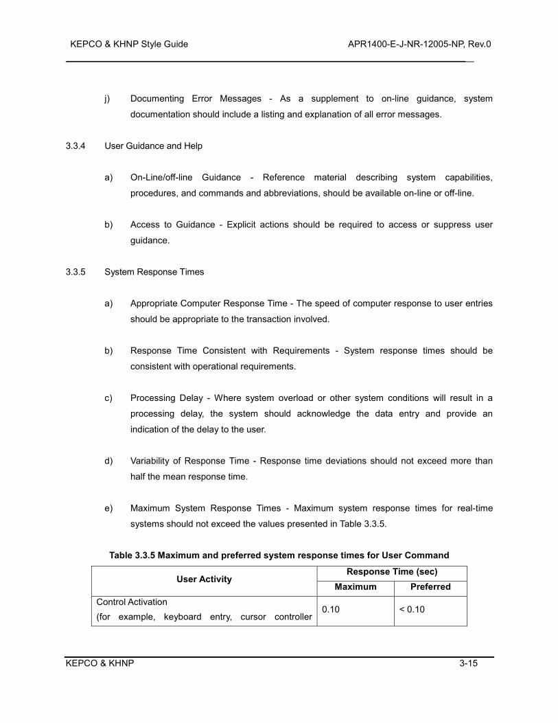
KEPCO & KHNP Style Guide APR1400-E-J-NR-12005-NP, Rev.0 _________________________________________________________________________________________________________
KEPCO & KHNP 3-15
j) Documenting Error Messages - As a supplement to on-line guidance, system
documentation should include a listing and explanation of all error messages.
3.3.4 User Guidance and Help
a) On-Line/off-line Guidance - Reference material describing system capabilities,
procedures, and commands and abbreviations, should be available on-line or off-line.
b) Access to Guidance - Explicit actions should be required to access or suppress user
guidance.
3.3.5 System Response Times
a) Appropriate Computer Response Time - The speed of computer response to user entries
should be appropriate to the transaction involved.
b) Response Time Consistent with Requirements - System response times should be
consistent with operational requirements.
c) Processing Delay - Where system overload or other system conditions will result in a
processing delay, the system should acknowledge the data entry and provide an
indication of the delay to the user.
d) Variability of Response Time - Response time deviations should not exceed more than
half the mean response time.
e) Maximum System Response Times - Maximum system response times for real-time
systems should not exceed the values presented in Table 3.3.5.
Table 3.3.5 Maximum and preferred system response times for User Command
User Activity Response Time (sec)
Maximum Preferred Control Activation (for example, keyboard entry, cursor controller
0.10 < 0.10
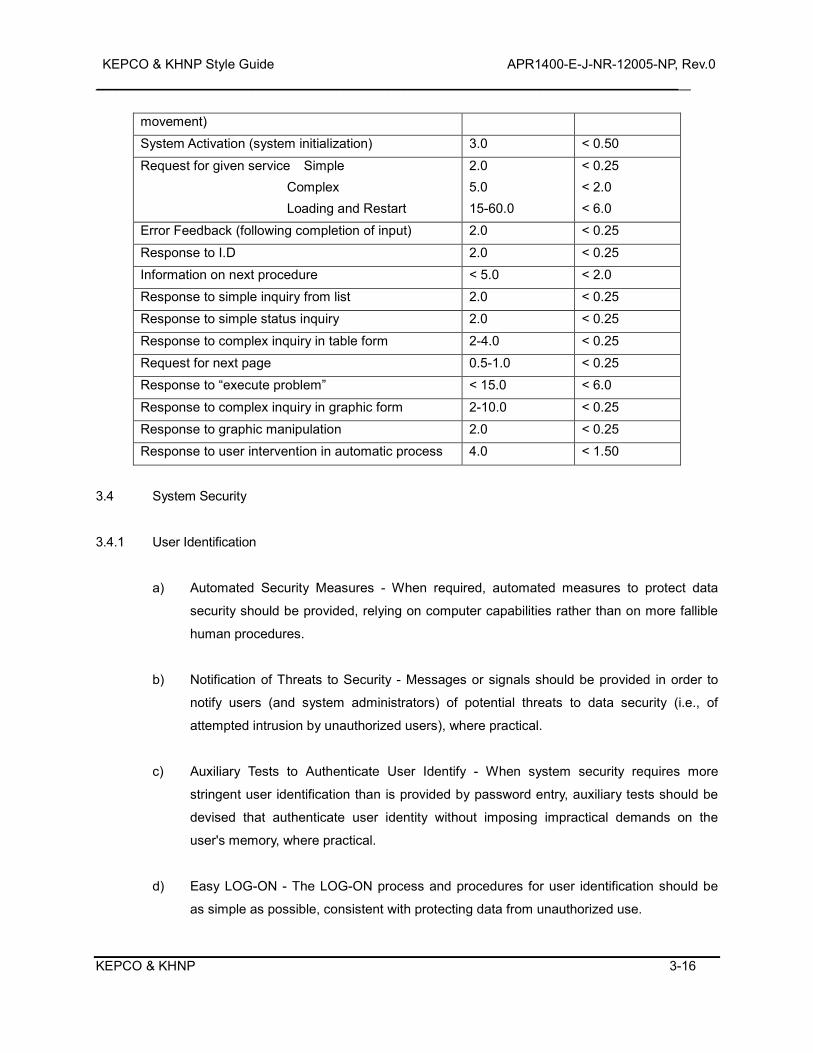
KEPCO & KHNP Style Guide APR1400-E-J-NR-12005-NP, Rev.0 _________________________________________________________________________________________________________
KEPCO & KHNP 3-16
movement) System Activation (system initialization) 3.0 < 0.50
Request for given service Simple Complex Loading and Restart
2.0 5.0 15-60.0
< 0.25 < 2.0 < 6.0
Error Feedback (following completion of input) 2.0 < 0.25
Response to I.D 2.0 < 0.25 Information on next procedure < 5.0 < 2.0 Response to simple inquiry from list 2.0 < 0.25 Response to simple status inquiry 2.0 < 0.25
Response to complex inquiry in table form 2-4.0 < 0.25 Request for next page 0.5-1.0 < 0.25 Response to “execute problem” < 15.0 < 6.0
Response to complex inquiry in graphic form 2-10.0 < 0.25 Response to graphic manipulation 2.0 < 0.25 Response to user intervention in automatic process 4.0 < 1.50
3.4 System Security
3.4.1 User Identification
a) Automated Security Measures - When required, automated measures to protect data
security should be provided, relying on computer capabilities rather than on more fallible
human procedures.
b) Notification of Threats to Security - Messages or signals should be provided in order to
notify users (and system administrators) of potential threats to data security (i.e., of
attempted intrusion by unauthorized users), where practical.
c) Auxiliary Tests to Authenticate User Identify - When system security requires more
stringent user identification than is provided by password entry, auxiliary tests should be
devised that authenticate user identity without imposing impractical demands on the
user's memory, where practical.
d) Easy LOG-ON - The LOG-ON process and procedures for user identification should be
as simple as possible, consistent with protecting data from unauthorized use.
KEPCO & KHNP Style Guide APR1400-E-J-NR-12005-NP, Rev.0 _________________________________________________________________________________________________________
KEPCO & KHNP 3-17
e) Private Entry of Passwords - When a password must be entered by a user, password
entry should not be displayed.
f) User Choice of Passwords - When passwords are required, users should be allowed to
choose their own passwords and to change their passwords as needed.
g) Limiting Unsuccessful Log - ON Attempts - A maximum limit on the number and rate of
unsuccessful LOG-ON attempts should be imposed, where practical.
h) Continuous Recognition of User Identity - Once a user's identity has been authenticated,
any authorized data access/change privileges are for that user should continue
throughout a work session.
i) Single Authorization for Data Entry/Change - User authorization for data entry/change
should be established at initial LOG-ON.
j) Log-on - When users must log-on to a system, log-on should be a separate procedure
that is completed before a user may select any operational options.
k) Log-on Frame - The log-on frame should appear as soon as possible on the display with
no additional user involvement.
l) Log-on Delays - Log-on delays should be accompanied by an advisory message to tell
the user its current status and when the system will become available.
m) Immediate Start of Productive Work - after completing the sign-on process, the user
should be able to start productive work immediately.
n) Log-off - If there are pending actions and the user requests a log-off, the system should
inform the user that these actions will be lost and allow the user to cancel either the
pending actions or the log-off.
i. Saving Open Files in Automatic Log-off - Where possible, in the event of automatic log-off,
open files should be saved to some defined file name.
KEPCO & KHNP Style Guide APR1400-E-J-NR-12005-NP, Rev.0 _________________________________________________________________________________________________________
KEPCO & KHNP 3-18
3.4.2 Information Access
b) Encryption - When sensitive data may be exposed to unauthorized access, a capability
for encrypting those data should be provided.
c) Ensuring Reversible Encryption - Encrypted data should be protected from any change
that might prevent successful reversal of their encryption.
d) Display Suppression for Security - When confidential information is displayed at a work
station that might be viewed by casual onlookers, the user should be provided with some
rapid means of temporarily suppressing a current display if its privacy is threatened, and
then resuming work later.
e) Protecting Printed Data - As required for security, procedures to control access to printed
data should be established, rather than simply prohibiting the printing of sensitive data.
f) Protecting Display Formats - Display formatting features, such as field labels and
delimiters, should be protected from accidental change by users.
g) Protecting Displayed Data - When protection of displayed data is essential, computer
control over the display should be maintained.
h) Automatic Records of Data Access - When records of data access are necessary, the
records should be maintained automatically.
KEPCO & KHNP Style Guide APR1400-E-J-NR-12005-NP, Rev.0 _________________________________________________________________________________________________________
KEPCO & KHNP 4-1
4.0 DISPLAY AND CONTROL DEVICES
4.1 Display Device
4.1.1 Information FPD
a) VDU Resolution - The display should have adequate resolution; i.e., users can
discriminate all display elements and codes from maximum viewing distance.
b) Geometric stability - The display should be free of "jitter".
c) Image Continuity - The display should maintain the illusion of a continuous image, i.e.,
users should not be able to resolve scan lines or matrix spots.
d) VDU Image Linearity - The display should be free of geometric distortion.
e) Luminance Uniformity - All luminances that are supposed to be the same should appear
the same.
f) VDU Controls - Frequently used controls should be easily visible and accessible to the
VDU user from the normal working position.
g) VDU Luminance Control - A control to vary the VDU luminance from 10 percent of
minimum ambient luminance to full luminance should be provided.
h) Refresh Rate - To avoid visible flicker, the refresh rate of VDU screens should be at least
55 Hz, and should be at least 70 Hz (100 Hz for dark characters on light background).
i) Luminance - The minimum level of luminous intensity (see Definitions) for characters on a
VDU screen should be 70 cd/m2 (20 fL), and the preferred display luminance should be
80 to 160 cd/m2 (47 fL). VDUs should provide a brightness adjustment to the user, but
should limit minimum brightness to a visible level.
4.1.2 LDP (Large Display Panel)
a) Provision - A Large Display Panel (LDP) comprised of single or multiple screens should
KEPCO & KHNP Style Guide APR1400-E-J-NR-12005-NP, Rev.0 _________________________________________________________________________________________________________
KEPCO & KHNP 4-2
be provided in the control room to support operators in performing rapid assessment of
plant status and in maintaining awareness of the big picture.
b) Dedicated Display - The LDP should include both fixed (dedicated) and variable display
regions. The LDP design should preclude information in dedicated regions from being
obscured, modified or deleted during LDP use.
c) Variable Display Region - The management of variable display region is performed by the
reactor operator (RO), turbine operator (TO), electrical Operator (EO), and shift
supervisor (SS). The selected display from operation console should be projected in the
variable display.
d) Alarm Indications - The LDP should allow operators to verify either the existence or
absence of the dedicated alarm conditions that are displayed on the LDP. Alarm
acknowledgment, including the LDP, should be integrated across display systems.
e) Printout - Hard copy of the current indications on the LDP should be available on demand.
f) Visibility - The LDP should provide unimpaired visibility from all consoles.
g) Readability - The LDP should be designed for readability from the RO, TO, EO, SS, and
shift technical advisor (STA) consoles.
h) Timing Issues - The LDP data should be updated promptly so that agreement with other
general display systems is maintained. Relevant timing issues should be considered,
including rate of display update, display heartbeat, and system response time.
i) LDP Maintenance - Choice of LDP technology and installation of hardware should
consider impact of maintenance and repair requirements on continuous LDP availability.
j) Control of Critical Information Display - Control of large-screen group display systems
should be such that critical information cannot be modified or deleted inadvertently or
arbitrarily.
k) Projected Display Luminance Ratio - The luminance ratio provided by the projection
system should be adequate for the type of material being projected.
KEPCO & KHNP Style Guide APR1400-E-J-NR-12005-NP, Rev.0 _________________________________________________________________________________________________________
KEPCO & KHNP 4-3
l) Minimize Keystone Effects - If projected displays are used, projector and screen should
be arranged so as to minimize "keystone effect," i.e., distortion of projected data
proportions due to non-perpendicularity between projector and screen.
m) Minimum Viewing Distance - The display should not be closer to any observer than half
the display width or height, whichever is greater.
n) Interruption of View - Large screen displays should be located relative to critical
observers so that the view is not obscured by other people.
o) Consistent Representation - LDP representation should be consistent to other display's
one (VDU display, Soft Control) in the symbol, the state indicator, the spatial layout, and
so on.
p) Resolution - Users should be able to resolve all important display detail at the maximum
viewing position.
q) Projected Display Luminance Ratio - The luminance ratio provided by the projection
system should be adequate for the type of material being projected. The contrast ratio is
defined as image or subject luminance divided by the non-image or background
luminance. Under optimal ambient lighting conditions, the contrast ratio for optically
projected displays should be 500:1. Minimum contrast ratios are as follows:
1) For viewing charts, printed text, and other line-work via slides or opaque projectors, the
minimum contrast ratio is 5:1.
2) For projections that are limited in shadows and detail, such as animation and
photographs with limited luminance range, the minimum contrast ratio is 25:1.
3) For images that show a full range of colors (or grays in black-and-white photographs),
the minimum contrast ratio is 100:1.
r) Projected Display Image Luminance - Image luminance and light distribution should be
uniform. The luminance of the screen center at maximum viewing angle should be at
least half its maximum luminance.
4.1.3 Conventional Display Devices
KEPCO & KHNP Style Guide APR1400-E-J-NR-12005-NP, Rev.0 _________________________________________________________________________________________________________
KEPCO & KHNP 4-4
4.1.3.1 Light Indicators
a) Precautions to Assure Availability - Dual-bulb (including LED) assemblies should be used.
b) Precautions to Assure Unambiguous Sensing by Operators - Lights should not appear to
be glowing when in fact they are off, or vice versa.
c) Precautions to Avoid Misinterpretation - System/equipment status should be inferred by
illuminated indicators, and never by the absence of illumination.
d) Identification of Meaning - Where meaning is not apparent, labeling must be provided
close to the light indicator showing the message intended by its glowing.
e) Light Intensity - The illuminated indicator should be at least 10 percent greater in light
intensity than the surrounding panel as measured by a spot photometer.
f) Visibility Factors - When using legend light indicators, make sure contrast and
ambient/transilluminated conditions are considered.
g) Legend Design - General legend design should be consistent throughout the control room.
h) Distinguishability from Legend Pushbuttons - Illuminated legend indicators should be
readily distinguishable from legend pushbuttons by form, size, or other factors.
i) Color Coding - The color of the legend background under transillumination should
conform to the general color code established for the control room.
4.1.3.2 Meters and Gauges
a) Display Range Coding - Zones indicating operating ranges should be color coded by
edge lines or wedges for circular scales.
b) Location of Zero - When check-reading positive and negative values on rotary meters
(circular displays), the zero or null position should be at 12 o'clock or 9 o'clock.
KEPCO & KHNP Style Guide APR1400-E-J-NR-12005-NP, Rev.0 _________________________________________________________________________________________________________
KEPCO & KHNP 4-5
c) Number of Tick Marks - Scales should not be cluttered with more marks than necessary
for precision.
d) Distinctiveness - Zone markings should be conspicuous and distinctively different for
different zones.
e) Consistency - to facilitate reading of meters and prevent misreading, the orientation of
scale markings should be consistent.
f) Moving-Scale Meters Versus Fixed - Scale Moving-Pointer Types - Moving-scale fixed-
pointer meters should be avoided in favor of the more effective fixed-scale moving-
pointer types.
g) Pointer Characteristics
1) Tip Style - The pointer tip should be simple, and mounted to minimize parallax.
2) Pointer Visibility - Pointer/background contrast and pointer size should be adequate to
permit rapid recognition of pointer position.
h) Numeral Orientation - The individual numerals on any scale should be vertically oriented
with respect to the reader.
i) Numeric Readouts
1) Orientation - Multi-digit numbers formed by several elements (e.g., drums and LED
arrays) should be read horizontally from left to right.
2) Grouping of Numerals - If more than four digits are required, they should be grouped
and the groupings separated as appropriate by commas, by a decimal point, or by
additional space.
3) Display of Changing Values - Numerals should not follow each other faster than one
per second when the operator is expected to read the numerals consecutively.
4.1.3.3 Printers
a) Placement of Printers - in principle, printers should be located within the primary
operating area because they must be verified and attended by the operator.
KEPCO & KHNP Style Guide APR1400-E-J-NR-12005-NP, Rev.0 _________________________________________________________________________________________________________
KEPCO & KHNP 4-6
b) Legibility - Print output should be free from character line misregistration, character tilt,
smear, or glare.
c) Contrast - A minimum contrast ratio of 4:1 should be provided between the printed
material and the background on which it is printed.
d) Illumination - The printer should be provided with internal illumination if the printed matter
is not legible in the planned operational ambient illumination.
e) Visibility - When used for real-time applications, the printed matter should not be hidden,
masked or obscured in a manner that impairs direct reading.
f) User Annotation Capability - When used in real-time applications, printing devices should
be mounted so that the users may write on or mark the printed matter (e.g., paper or
metalized paper) while still in the printer.
g) Take-Up Provision - A take-up device should be provided for printed material.
h) Indication of Supply of Materials - A positive indication should be provided of the
remaining supply of printing materials (e.g., paper, toner, and ribbons).
i) Quality of Expendable Materials - Pens, inks, and paper should be of a quality to provide
clear, distinct, and reliable marking.
j) Availability of Expendable Material - Paper, ink, and other operator-maintained
expendables should be provided and accessible in the control room.
k) Ease of Routine Replenishment - Printer design should permit quick and easy
replenishment of paper, toner, ribbons, or ink.
l) Smudging/Smearing - The hardcopy should be resistant to smudging or smearing when
handled by users.
m) Job Aids - Graphic overlays should be provided where these may be critical to proper
interpretation of graphic data as it is being generated.
KEPCO & KHNP Style Guide APR1400-E-J-NR-12005-NP, Rev.0 _________________________________________________________________________________________________________
KEPCO & KHNP 4-7
4.2 Control Devices
4.2.1 General Control Devices Guidelines
a) Appropriate Use of Input Devices - Input and control devices provided for interacting with
the HSI should be appropriate for the user's task requirements.
b) Input Device Stability - Input and control devices should be stable during normal usage,
i.e., they should not slip or rock, unless such actions are a part of the controller operation.
c) Location - Controls should be operable from the location where the operator is most likely
to need to interact with the system.
d) Speed - Controls should provide rapid positioning of cursors or selection of choices.
e) Accuracy - Device or method accuracy should be commensurate with the functions to be
served.
f) Displacement - Control design should allow the operator freedom of movement to perform
other duties.
g) Range and Precision - Control should provide the sufficient range and precision required
by the task.
h) Economy - Each control or input device should be necessary, use minimal space, and be
the simplest effective control for the task concerned.
i) Human Suitability - Controls and input devices should be suitable for operator use in a
control room environment.
j) Compatibility with Emergency Gear - If used while wearing protective equipment (e.g.,
oxygen masks and protective gloves), controls and input devices should be easy to
identify and activate, or use.
k) Control Activation - Controls and input devices should require distinct or sustained effort
for activation.
KEPCO & KHNP Style Guide APR1400-E-J-NR-12005-NP, Rev.0 _________________________________________________________________________________________________________
KEPCO & KHNP 4-8
l) Sequential Activation - When a strict sequential activation is necessary, controls should
be provided with locks to prevent the controls from passing through a position.
m) Population Stereotypes - to minimize operator error, control movements should conform
to population stereotypes.
n) Consistency - The coding system should be uniform throughout the control room.
o) Size Coding Uniformity - Controls used for performing the same function on different
items of equipment should be the same size.
p) Shape Coding - When possible, controls should be differentiated by shape.
q) Color Coding Contrast - The color of the control should contrast with the panel
background.
r) Location Coding by Function - Controls should be located so as to be easily related to
functions and functional groupings.
s) Location Coding Across Panels - Controls with similar functions should be in the same
location from panel to panel.
t) Feedback - Visual or auditory feedback should be provided to indicate that the system
has received a control input.
u) Display & Control Compatibility - Control device movement and display response should
conform to the user population stereotypes.
1) The control location should be close to (and, in fact, closest to) the entity being
controlled, or the display of that entity.
2) The direction of movement of a control should be congruent with the direction both of
movement of the feedback indicator and of the system movement itself.
3) The User Population Stereotypes.
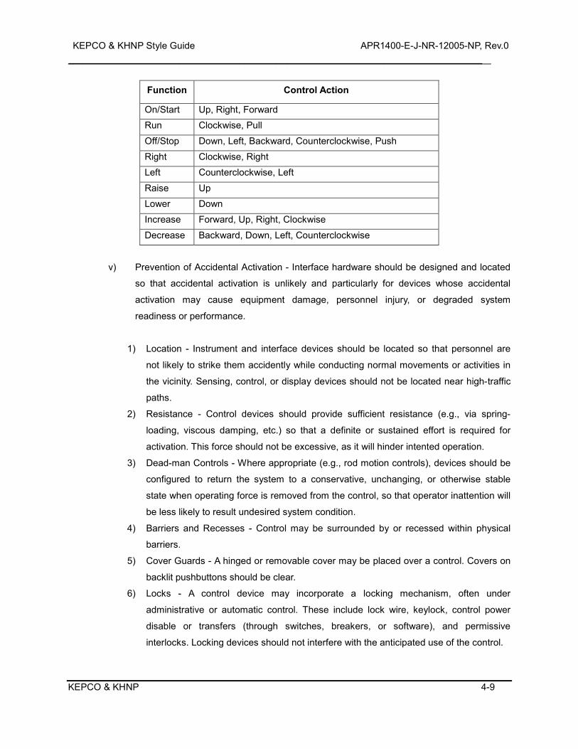
KEPCO & KHNP Style Guide APR1400-E-J-NR-12005-NP, Rev.0 _________________________________________________________________________________________________________
KEPCO & KHNP 4-9
Function Control Action
On/Start Up, Right, Forward Run Clockwise, Pull
Off/Stop Down, Left, Backward, Counterclockwise, Push Right Clockwise, Right Left Counterclockwise, Left
Raise Up Lower Down Increase Forward, Up, Right, Clockwise
Decrease Backward, Down, Left, Counterclockwise
v) Prevention of Accidental Activation - Interface hardware should be designed and located
so that accidental activation is unlikely and particularly for devices whose accidental
activation may cause equipment damage, personnel injury, or degraded system
readiness or performance.
1) Location - Instrument and interface devices should be located so that personnel are
not likely to strike them accidently while conducting normal movements or activities in
the vicinity. Sensing, control, or display devices should not be located near high-traffic
paths.
2) Resistance - Control devices should provide sufficient resistance (e.g., via spring-
loading, viscous damping, etc.) so that a definite or sustained effort is required for
activation. This force should not be excessive, as it will hinder intented operation.
3) Dead-man Controls - Where appropriate (e.g., rod motion controls), devices should be
configured to return the system to a conservative, unchanging, or otherwise stable
state when operating force is removed from the control, so that operator inattention will
be less likely to result undesired system condition.
4) Barriers and Recesses - Control may be surrounded by or recessed within physical
barriers.
5) Cover Guards - A hinged or removable cover may be placed over a control. Covers on
backlit pushbuttons should be clear.
6) Locks - A control device may incorporate a locking mechanism, often under
administrative or automatic control. These include lock wire, keylock, control power
disable or transfers (through switches, breakers, or software), and permissive
interlocks. Locking devices should not interfere with the anticipated use of the control.
KEPCO & KHNP Style Guide APR1400-E-J-NR-12005-NP, Rev.0 _________________________________________________________________________________________________________
KEPCO & KHNP 4-10
4.2.2 Input Device
4.2.2.1 Keyboards
A. Numeric Keypads
Numeric keypads should be organized and oriented as shown in Figure 3.3 in NUREG-0700
in all applications (either hardware or software). The unoccupied spaces to the left and right
of the 0 can be used for additional features (e.g., decimal point, exponents, etc.).
B. Alphanumeric Keyboards
1) General Keyboard Layout - An ANSI standard (QWERTY) layout should be used for
the typing keyboard.
2) Numeric Keypad - When users must enter numeric data, keyboards should be
equipped with a numeric keypad.
3) Numeric Keypad Layout - Keypads used for numeric entry should be consistently
designed.
4) Cursor Control Capability - Horizontal and vertical cursor control keys should be
provided for text processing applications.
5) Cursor Key Layout - Cursor control keys should be arranged in a two-dimensional
layout so that their orientation is compatible with the cursor motion they produce.
6) Overlays - Mechanical overlays, such as coverings over the keyboard, should be not
used.
7) Keyboard Surfaces - A matte finish should be used for keyboard surfaces.
8) Keyboard Slope Adjustment - The slope of the keyboard should be adjustable by the
operator.
KEPCO & KHNP Style Guide APR1400-E-J-NR-12005-NP, Rev.0 _________________________________________________________________________________________________________
KEPCO & KHNP 4-11
9) Standard Keyboard Placement - The operator should be able to reposition the
standard keyboard on the worksurface.
10) Keytop Symbol Marking - Key symbols should be etched (to resist wear) and colored
with high contrast lettering.
11) Keying Feedback - The actuation of a key should be accompanied by tactile or auditory
feedback or both.
12) Repeat Capability - A repeat capability for alphanumeric, symbol character, and cursor
keys should be provided.
13) Multiple-Key Rollover - Multiple-key (N-key) rollover capability should be provided for
the reduction of keying errors.
14) Keystroke Commands - When it is necessary to distinguish command entries from text
input, a specially designated key should be one of the keys used for keystroke
commands.
15) Simultaneous Keystrokes - Keystroke commands should require the user to press both
keys simultaneously, not in close temporal sequence.
16) Inadvertent Operation - Keys with major or fatal effects should be located so that
inadvertent operation is unlikely.
17) Alternate Key Definitions - When the keyboard is redefined, a display of the alternate
characters and their locations should be available to the operator.
18) Destructive Key Functions - Destructive keys/keyboard functions (e.g., DELETE,
BACKSPACE, ESCAPE, QUIT, RESET etc.) should be least accessible, and located
away from frequently used keys (e.g., DELETE should not be adjacent to RETURN).
19) Cursor Movement Keys - Cursor movement keys, if used, should be arranged to be
spatially compatible with the direction of actual cursor movement
C. Function Keys
KEPCO & KHNP Style Guide APR1400-E-J-NR-12005-NP, Rev.0 _________________________________________________________________________________________________________
KEPCO & KHNP 4-12
1) Availability - Fixed function keys should be available to control functions that are often
utilized and continuously available.
2) Inactive Function Keys - Unneeded function keys, either fixed or programmable, should
be disabled so that no other action occurs upon their depression except an advisory
message.
3) Inactive Keys - Non-active fixed function keys should not be present on the keyboard.
4) Grouping - Fixed function keys should be logically grouped and placed in distinctive
locations on the keyboard.
5) Function Labels - Key assignments should be displayed at all times, preferably through
direct marking.
6) Consistency - Fixed function keys should be used consistently throughout the system.
7) Actuation - Fixed function keys should require only a single actuation to accomplish
their function.
8) Repeat for Special Functions - Function keys (except for the delete key) should not
repeat upon prolonged depression.
9) Status Display - When the effect of a function key varies, the status of the key should
be displayed.
10) Easy Return to Initial Functions - Where the functions assigned to a set of function
keys change as a result of user selection, the user should be given an easy means to
return to the initial functions.
11) Reprogrammable or Inactive Default Functions - When keys with labeled default
functions are reprogrammed or turned off, a visual indication should alert the user that
the standard function is not currently accessible via that key.
12) Shifted Characters - Shift keys should be not required to operate variable function keys.
KEPCO & KHNP Style Guide APR1400-E-J-NR-12005-NP, Rev.0 _________________________________________________________________________________________________________
KEPCO & KHNP 4-13
13) Function Keys for Interim Command Entries - Function Keys should be provided for
interim command entries, i.e., for actions taken before the completion of a transaction.
14) Distinctive Labeling of Function Keys - Each function key should be labeled
informatively to designate the function it performs.
15) Distinctive Location - Function Keys should be grouped in distinctive locations on the
keyboard to facilitate their learning and use.
16) Consistent Assignment of Function Keys - A function assigned to a particular key in a
given task context should be assigned to the same key in other contexts.
17) Single Keying for Frequent Functions - Keys controlling frequently used functions
should permit single key action and should not require double (control/shift) keying.
18) Consistent Functions in different Operational Modes - When a function key performs
different operational modes, equivalent or similar functions should be assigned to the
same keys.
19) User definition of Macro Commands - Users should be allowed to assign a single to a
defined series of control entries, and then to use that named "macro" for subsequent
command entry.
20) Limiting User-Definition of Macros and Programmable Keys - The use of user definable
macros and programmable function keys should be limited.
4.2.2.2 Trackballs and Mice
a) Dynamic Characteristics - The controller should be able to produce any combination of x
and y axis output values.
b) Positive Centering - If there is a "home position," the capability for an automatic return to
that point should be provided.
c) Single Monitor/Single Controller Cursor Travel Limits - In a single monitor/single controller
KEPCO & KHNP Style Guide APR1400-E-J-NR-12005-NP, Rev.0 _________________________________________________________________________________________________________
KEPCO & KHNP 4-14
environment, movement of the controller should drive the follower to the edge of the
screen only and not off the screen.
d) Separation of Selectable Screen Items - Selectable screen items or regions should be
separated from each other by a sufficient distance to minimize inadvertent activation of
adjacent items or regions.
e) Selectable Tracking Speed - The controller tracking speed (control-display ratio) should
be user selectable from a predefined list of alternatives; there should be a moderate
default speed.
f) Selectable Inter-Click Interval - If multiple clicks are required on a selection button, the
user should be able to select the inter-click interval from a predefined list of alternatives.
There should be a moderate default setting.
g) Limb Support for Trackballs and Mice - When trackballs and mice are used to make
precise or continuous adjustments, hand, wrist, or arm supports should be provided.
h) Mouse Shape - The mouse should have no sharp edges but should be shaped roughly as
a rectangular solid.
i) Use of Mouse by Either Hand - The controller should be operable with either the left or
right hand.
4.2.2.3 ESCM (Engineered Safety Features - Component Control System Soft Control Module)
a) Shape - Touch targets should be rectangular, with the height less than or equal to the
width.
b) Appropriate Use of Touch-Screens - Touch screens are not recommended if the task
requires holding arm up to the screen for long periods of time.
c) Feedback - Two forms of feedback should be provided: (1) feedback concerning the
position of the follower, and (2) feedback that the pointer has actuated and the input has
been received by the system.
KEPCO & KHNP Style Guide APR1400-E-J-NR-12005-NP, Rev.0 _________________________________________________________________________________________________________
KEPCO & KHNP 4-15
d) ESCM Resolution - See 4.1.1 Information FPD a).
e) Follower Visibility - for touch screens and light pens, the follower should be visible on
screen while the pointer is touching the screen.
f) Serial Command Response - The system should accept only one command at a time.
g) Feedback for Multiple Consoles - Discriminable audible beeps (used to supply feedback)
should be used when more than one touch screen, light pen, or graphics tablet is
employed.
h) Neutral Tint of Touch Overlays - Touch screen overlays should have a neutral tint to avoid
alteration of color codes.
i) Touch Screen Luminance Transmission - Touch screen displays should have sufficient
luminance transmission to allow the display with touch screen installed to be clearly
readable in the intended environment.
j) Dimensions and Separation of Touch Zones - To allow for finger size and parallax
inaccuracy, the dimensions of response areas of touch screens should be a maximum
height and width of 40 mm (1.5 inch) and a minimum height and width of 15 mm (0.6
inch), with a maximum separation distance of 6 mm (0.25 inch) and minimum of 3 mm
(0.1 inch).
4.2.3 Conventional Control Device
4.2.3.1 Pushbuttons
a) Dimension and Orientation - The legend switch dimensions should conform to user
dimensions. Orientation should conform to the user population stereotype.
b) Position - Pushbuttons in a row or matrix should be positioned in a logical order, or in an
order related to the procedural sequence.
c) Pushbutton Surface - The surface of a pushbutton should offer slip resistance or be
concave.
KEPCO & KHNP Style Guide APR1400-E-J-NR-12005-NP, Rev.0 _________________________________________________________________________________________________________
KEPCO & KHNP 4-16
d) Discriminability - Legend pushbuttons should be readily distinguishable from legend lights.
e) Barriers - Barriers should be used when legend pushbuttons are contiguous.
4.2.3.2 Rotary Controls
A. General
1) Direction of Activation - Rotary control settings should increase in value with a
clockwise rotation.
2) Rotary Control Shape Coding - Shape coding should be employed if rotary controls
used for widely different functions are placed on the same panel.
3) Coding Specifications - Shape-coded rotary controls should be visually and tactually
identifiable.
4) Rotating Knob Shape Options - Rotating knob controls for different types of control
actions should be distinguishable by sight and touch and not easily confused with each
other.
5) Rotary Action Control - Rotary action controls should be used in situations where linear
or pushbutton controls would be subject to inadvertent activation and fixed protective
structures are impractical or inappropriate.
B. Rotary Selector Controls
1) Selection - Rotary selector controls should be used when three or more detented
positions are required, and may also be used for two-detented position operation.
2) Positioning - Detents should be provided at each control position to ensure proper
positioning of a discrete rotary control.
3) Readability - Rotary controls should have a moving pointer and fixed position settings
to maximize readability.
KEPCO & KHNP Style Guide APR1400-E-J-NR-12005-NP, Rev.0 _________________________________________________________________________________________________________
KEPCO & KHNP 4-17
4) Position Indication - Position indication should be provided.
5) Momentary Contact Rotary Selector Controls - Knobs for spring-loaded momentary
contact rotary selector controls should be large enough to be easily held against the
spring torque, without fatigue, for as long as necessary to accomplish the control action.
C. Rocker Switches
1) Orientation - Rocker switches should ordinarily be oriented vertically.
2) Indication of Activation - Activation should be indicated by a snap feel, an audible click
or an integral light.
3) Resistance - Control resistance should gradually increase, then drop to zero when the
control snaps into position.
4) Inadvertent Activation - If it controls a critical function, the switch should be protected
by channel guards or other means to prevent inadvertent activation.
KEPCO & KHNP Style Guide APR1400-E-J-NR-12005-NP, Rev.0 _________________________________________________________________________________________________________
KEPCO & KHNP 5-1
5.0 HSI SYSTEMS
5.1 Soft Control for Information FPD and ESCM
5.1.1 General Soft Control Design Guidelines
a) Coordinating Soft Control Use Among Operators - If a soft control can be accessed from
more than one location in the HSI, protective measures should ensure its coordinated use
among multiple operators.
b) Operation with Protective Clothing - Soft controls should be designed to accommodate
any protective clothing that operators may be required to wear.
c) Availability - Soft control access should be available from Information FPD, ESCM, and
Computer-Based Procedures (CBPs) displays at the associated console.
d) Format Chaining - Soft control access from Information FPD, ESCM, and CBPs displays
uses format chaining. Chaining should leave a highlight trail on the Information FPD or
CBPs display indicating 1) the selected component, and 2) the selected functional group,
as appropriate for the chain link.
e) Adequate Display Space - Adequate display space should be provided so that short-term
monitoring and control tasks do not interfere with longer-term tasks.
f) No Activation When Display is Inoperable - Operators should not be able to activate a soft
control if its display is not working.
g) Representing Relationships between Control Components - The display capabilities of
soft controls should allow operators to quickly assess the status of individual control
components and their relationships with other components.
h) Making Options Distinct - The user interface should be designed so that operators can, at
a glance, distinguish options by such characteristics as context, visually distinct formats,
and separation.
i) Depicted as Unavailable - Components within a functional group outside the confirmed
KEPCO & KHNP Style Guide APR1400-E-J-NR-12005-NP, Rev.0 _________________________________________________________________________________________________________
KEPCO & KHNP 5-2
channel should be depicted as unavailable.
j) Soft control Codes & Conventions - Soft control display codes & conventions should be
same as related Information FPD, ESCM, and CBPs display. For example, graphical
depiction of components on the soft control should be similar in shape, orientation etc. to
the VDU image of the larger system.
5.1.2 Selection Display and Input for Soft Control
5.1.2.1 Selection Display
a) Visually Distinct Selection Displays - Displays used for selecting components and
variables should be visually distinct to support choice of the correct display.
b) Visually Distinct Components - The representation of components and variables within
selection displays should be visually distinct to support their correct selection.
c) Identification of Loops on Multiple-Loop Controllers - The loops of multiple-loop controls
should be distinctly marked to prevent the selection or use of the wrong loop.
5.1.2.2 Input Fields
a) Cues for Matching Input Fields to Selection Displays - An operator looking at the input
field for providing a control input should be able to determine which plant component or
variable is being controlled.
b) Labeling of Input Fields - The input field should be labeled with sufficient information to
uniquely identify its corresponding component.
c) Coordination of Soft Controls with Process Displays - Displays should be readily
accessible from the input field so the operator can readily verify that the control actions
have had the intended effect on plant systems and processes.
5.1.2.3 Input Formats
a) Appropriate Use of Discrete-Adjustment Interfaces - Discrete-adjustment interfaces
KEPCO & KHNP Style Guide APR1400-E-J-NR-12005-NP, Rev.0 _________________________________________________________________________________________________________
KEPCO & KHNP 5-3
should be used for selecting among a set of individual settings or values.
b) Labeling Selection Options in Discrete-Adjustment Interfaces - The selection options in
discrete input formats should be clearly labeled.
c) Feedback for Discrete-Adjustment Interface with Multiple Settings - Discrete-adjustment
interfaces should indicate which setting was selected.
d) Feedback for Discrete-Adjustment Interface with Continuous Operation - If a discrete-
adjustment interface has continuous operation, it should provide continuous feedback on
the current state.
e) Appropriate Use of Continuous-Adjustment Interfaces - Continuous-adjustment interfaces
should be used when precise adjustments along a continuum are needed or when many
discrete settings are present.
f) Appropriate Use of Soft Sliders - A soft slider should be considered as an input device
when the range of possible values and the ratio of a value to that range need to be
displayed.
g) Indicating the Range of Values on Soft Sliders - The range of values should be indicated
on horizontal sliders with the low value on the left and the high value on the right, and on
vertical sliders with the low value on the bottom and the high value on the top.
h) Displaying the Digital Value on Soft Sliders - The numerical value to which a soft slider is
set should be presented in digits on the soft slider.
i) Dimensions of Soft Sliders - The physical dimensions of the soft slider should allow the
operator to read the current and target positions and position the slider with the required
precision, accuracy, and response time.
j) Depicting Critical Ranges on Soft Sliders - When part of the range of values depicted by a
soft slider represents critical information, such as alarm limits, those values should be
coded to facilitate recognition.
k) Appropriate Use of Arrow Buttons - A set of arrow buttons should be considered as the
KEPCO & KHNP Style Guide APR1400-E-J-NR-12005-NP, Rev.0 _________________________________________________________________________________________________________
KEPCO & KHNP 5-4
input device when it is desirable to incrementally increase or decrease a variable from its
previous value.
l) Indicating Current Value for Arrow Buttons - Arrow buttons should have a display
indicating the current value of the variable being controlled.
m) Uniform Changes in Values Via Arrow Buttons - Each press of an arrow button should
change the current value uniformly.
n) Feedback Regarding Arrow Button Actuation - Arrow buttons should provide salient
feedback when they are actuated.
o) Apparent Operation of Arrow Buttons - Labeling and other coding should be used when
the operation of the arrow buttons is not apparent.
p) Reference Values for Continuous Variable Inputs - Reference values should be provided
to help the operator judge the appropriateness of values when entering continuous
variable inputs.
5.1.3 Interaction Methods
5.1.3.1 General Interaction Methods Guidelines
a) Minimizing Soft Control Modes - The excessive use of modes in soft controls should be
avoided.
b) Distinctive Indication of Soft Control Modes - When multiple modes exist, they should be
distinctively marked so the operator can determine the current mode at a glance.
c) Coordination of Destructive and Safety-Significant Commands Across Modes - A
command that produces a benign action in one mode should not cause a different action
with serious negative consequences in another mode.
d) Unique Commands for Destructive and Safety-Significant Commands - Unique
commands associated with actions that have important consequences should not be
easily confused with other commands used in the same or different modes.
KEPCO & KHNP Style Guide APR1400-E-J-NR-12005-NP, Rev.0 _________________________________________________________________________________________________________
KEPCO & KHNP 5-5
e) Discrimination of Interface Management Actions and Process Control Actions - The
design of the user interface should clearly distinguish between interface management
actions and process control actions.
f) Reducing the Likelihood of Unintended Actuation - for actions that can have significant
negative consequences, the user interface should be designed to reduce the likelihood of
unintended actuation by requiring deliberate action for their execution.
g) Feedback for Selected Actions Before Execution - The HSI should give the operator
feedback indicating the action that was selected and allow the action to be canceled
before it is executed.
h) Use of Error-Mitigation Approaches - Error-mitigation approaches should not be the sole
means for achieving error tolerance, but should be used in conjunction with other means
for error prevention and system-assisted error detection.
i) Undo Features - If undo features are provided they should be consistently available.
5.1.3.2 Sequential Actions
a) Indicating the Status of Sequential Actions - HSI system should support operators in
rapidly assessing the status of sequential actions in progress.
b) Drawing Attention to Points Where Similar Sequences Diverge - The design of the HSI
should draw the operator's attention to points where operational sequences that have
multiple steps in common begin to diverge from each other.
c) Operator Interruption of Transaction Sequences - The HSI should allow the operator to
interrupt or terminate a current transaction sequence.
d) Interrupted Sequence Prompt - The HSI should support the operator in maintaining
awareness or recalling tasks that were interrupted or suspended by giving a reminder.
e) Resumption of Interrupted Sequences - A minimum number of actions should be required
for the operator to resume a control-action sequence that was temporarily suspended.
KEPCO & KHNP Style Guide APR1400-E-J-NR-12005-NP, Rev.0 _________________________________________________________________________________________________________
KEPCO & KHNP 5-6
5.1.3.3 Verification and Confirmation Steps
a) Separate Action for Verification Steps - Verification steps should be separate from input
actions.
b) Confirmation of Goals - When feasible, confirmation steps should draw operator attention
to the goal of the action, not just to the action.
5.1.3.4 Interlocks, Lockouts, and Lockins
a) Use of Interlocks, Lockouts, and Lockins - Interlocks, lockouts, and lockins should be
provided to restrict personnel actions that may affect plant safety.
b) Operator Override of Interlocks, Lockouts, and Lockins - The design of interlocks,
lockouts, and lockins should not limit the operators' authority unless there is a clear safety
reason.
c) Visibility of Interlocks, Lockouts, and Lockins - Interlocks, lockouts, and lockins should be
designed to indicate which actions are being blocked and what conditions activated the
block.
d) Automatic Logging of the Activation of Interlocks, Lockouts, and Lockins - The activation
of an interlock, lockout, or lockin should be automatically logged.
e) No Automatic Actuation of Blocked Actions - An interlock, lockout, or lockin should not
initiate an action that was previously blocked merely because the status of the triggering
condition has changed.
5.1.3.5 Error Detection and Correction
a) Warning Message Content - Warning messages should draw operators' attention to the
goal of the action, not just to the action.
b) Automatic, Self-Correct Features for Interface Management Action - Automatic, self-
correcting features should only be used for interface management actions, such as
KEPCO & KHNP Style Guide APR1400-E-J-NR-12005-NP, Rev.0 _________________________________________________________________________________________________________
KEPCO & KHNP 5-7
retrieving displays.
c) Undo Capabilities for Self-Correct Features - Automatic, self-correcting features should
only be used if they include good "Undo" capabilities, so that inappropriate changes made
by the system can be reversed by the user.
d) User of Inspection and Transfer Steps - Inspection and transfer steps should be
considered if inputs are complex, or if incorrect inputs can seriously affect safety.
5.1.3.6 Selecting Plant Variables or Components
a) Identification of Plant Variables and Components - The HSI should support the
identification of plant variables and components based on recognition rather than relying
strictly upon recall.
b) Simple Input Actions for Selection - The operator should be able to select a component or
variable from a display by using simple input actions.
c) Minimize Action-Sequence Errors for Selecting Plant Variables - If a sequence of actions
is required to select a component or variable, the HSI should be designed to prevent
misordered action-sequence errors.
d) Minimize the Number of Retrieval Steps for Controls that are Used Together - When a
group of controls must be used together, their retrieval should require a minimal number
of actions.
5.1.3.7 Control Inputs
a) Automatic Reset of Multi-Variable Controls - If an input device controls more than one
variable, the operator should not have to reset the device to match the value of the new
variable before executing a control action.
b) Numerical Input Values - The HSI should provide feedback to support the operator in
verifying the correctness of numerical values entered.
5.1.3.8 Handing stored Data
KEPCO & KHNP Style Guide APR1400-E-J-NR-12005-NP, Rev.0 _________________________________________________________________________________________________________
KEPCO & KHNP 5-8
a) Minimize the Use of Irreversible Actions - The design of the HSI should minimize the use
of irreversible actions for handling stored data.
b) Deferring Execution of Operations that are Destructive to Stored Information - Whenever
practical, irreversible operations that destroy stored information should be deferred and
require a separate action for their execution rather than being carried out immediately.
5.1.3.9 System Response
a) Actuation Feedback - Soft controls should provide feedback about their operating state
after activation.
b) Operator Notification of Automatic Mode Changes - Systems that can change mode
automatically should provide feedback to make the operator aware of the current mode.
c) Delaying System Response - Where appropriate, systems that are sensitive to incorrect
inputs should be designed to limit the rate at which these inputs can affect the process.
5.2 CBPs (Computer-Based Procedures)
5.2.1 Representation of Procedures
5.2.1.1 Identification of Procedures
a) Procedure Title and Identification Information - Each procedure should contain identifying
information including title, procedure number, revision number, date, and organizational
approval.
b) High-Level Goals - Each procedure should state its high-level goals and applicability,
including its procedure category, e.g., emergency or abnormal.
5.2.1.2 Basic Steps of Procedures
a) Concise Steps - Procedure steps should be concise.
KEPCO & KHNP Style Guide APR1400-E-J-NR-12005-NP, Rev.0 _________________________________________________________________________________________________________
KEPCO & KHNP 5-9
b) Short Sentences - Procedure steps should be written as short sentences.
c) Active Voice - Procedure steps should be written in active voice.
d) Positive Commands - Procedure steps should be written as positive commands.
e) Simple Wording - Short, simple words from standard Korean should be used.
f) Standard Punctuation - Punctuation should conform to standard Korean usage.
g) Consistent Word References - Words, phrases, and equipment names and numbers
should be used consistently within and among procedures, drawings, other HSIs, and
equipment labels.
h) Abbreviations and Acronyms - Abbreviations and acronyms should be used consistently
and limited to those well known to the users.
i) Units of Measures - Numerical information should include units of measure.
j) Numerical Precision - Numbers should be specified at the appropriate precision.
k) Number Ranges - Ranges of numbers should be specified, rather than error bands.
l) Use Arabic Numerals - Arabic numerals should be used.
m) Spelled Numbers - Numbers that are spelled out should be consistently spelled under the
same conditions.
n) Presentation of Conditional Steps - Conditional steps should be shown in traditional text
formats following the guidance in Appendix A of USNRC NUREG-0899, Rev.0.
o) Specification of Preconditions for Steps - The procedure should specify any conditions
that must be met before an action can be undertaken.
5.2.1.3 Warnings, Cautions, Notes, and Supplementary Information
KEPCO & KHNP Style Guide APR1400-E-J-NR-12005-NP, Rev.0 _________________________________________________________________________________________________________
KEPCO & KHNP 5-10
a) Parallel Display with Procedure Step - The warnings and cautions applicable to a single
step (or to a series of steps) should be displayed when the step(s) is on the screen.
b) Position Before Action Steps - Warnings, cautions, and notes should be presented so that
they will be read before the applicable action steps.
c) Action References - Warnings, cautions, and notes should not include implied or actual
action steps.
d) Distinction from Other Procedure Elements - Warnings, cautions, and notes should be
uniquely presented, so that they are easily distinguished from each other and from other
display elements.
e) Supplementary Information - All supplementary information (such as tables and figures)
required for a procedure step and available to the CBPs should be shown on the screen
concurrently with the step, or on another easily viewed display.
5.2.1.4 Lists of Procedures
a) Appropriate Application of Lists - Groups of three or more related items (e.g., actions,
conditions, components, criteria, and systems) should be presented as a list.
b) Distinction from Other Procedure Elements - Formatting should be used to differentiate
items in a list from other procedure elements.
c) Identification of Precedence - The presence or absence of precedence among items in
lists should be indicated.
d) List Overviews - Overviews should introduce each list.
e) Assuring Users' Attention - The method for assuring that each item in a list has received
the users' attention should be consistent.
5.2.1.5 Organization and Formatting of Procedures
a) Hierarchical, Logical Organization - The procedures should be organized in a hierarchical,
KEPCO & KHNP Style Guide APR1400-E-J-NR-12005-NP, Rev.0 _________________________________________________________________________________________________________
KEPCO & KHNP 5-11
logical, consistent manner.
b) Organization of Procedure Steps - Each procedure should be organized into sections of
related steps.
c) Organization Format of Procedures - The procedure's format should reflect its
organization.
d) Format of Procedures - A consistent format should be used to display procedures.
e) Partitioning Procedures - A consistent approach to partitioning procedures should be used.
f) Organization of Display Screen - Each display screen should locate information and HSI
features consistently.
g) Continuously Presented Procedure Information - The procedure's title and identification
should be continuously presented.
h) Continuously Presented Status of High-Level Goals - The status of high-level procedure
goals should be continuously presented.
5.2.2 Functionality of Procedures
5.2.2.1 Supervision and Control of Procedures
a) Users' Control of Procedure Path - Users should be in control of the sequence of steps
that are followed.
b) Users' Control of Pace of Procedures - Users should be in control of the pace at which
procedure steps are followed.
c) Understandability of Analysis of Procedure Steps - The methods by which CBPs analyze
procedure steps should be consistent with the methods by which users analyze steps in
procedure logic steps, so that the results are understandable.
d) Users' Verification of CBPs Information - The users should be able to verify the system's
KEPCO & KHNP Style Guide APR1400-E-J-NR-12005-NP, Rev.0 _________________________________________________________________________________________________________
KEPCO & KHNP 5-12
assessment of plant status.
e) Users' Override of CBPs - Users should be able to override any CBPs information,
calculation, evaluation, or assessment.
5.2.2.2 Monitoring and Assessment of Procedures
a) Automatic Identification of Procedures - The CBPs should alert users when entry
conditions to a procedure are satisfied.
b) Automatic Monitoring of Plant Parameters and Equipment Status - The CBPs should
automatically provide accurate and valid information on the values of parameters and
status of equipment, when they are available to the system.
c) Frequent Monitoring - The CBPs should frequently monitor procedure-defined parameters.
d) Automatic Calculation of Procedure-Referenced Values - The system should undertake
calculations, such as subcooling margin, that are required when using procedures.
e) Analysis of Step Logic - The CBPs should evaluate the logic of each procedure step and
show the results to the user.
f) Continuous Analysis of Non-Current Step Logic - Steps of continuous applicability, time-
dependent steps, and process-dependent steps should be monitored by the CBPs and
the user should be alerted when conditions in those steps become effective.
g) Coding of Logical Analysis - When procedure's step logic indicates a violation of the step,
the information should be coded to make that step more salient to users.
h) Analysis of Cautions - The conditions described in cautions should be automatically
monitored by the CBPs system, and the user should be alerted when the caution is in
effect.
i) Coding Applicable Cautions - CBPs should use coding to indicate when a caution is in
effect.
KEPCO & KHNP Style Guide APR1400-E-J-NR-12005-NP, Rev.0 _________________________________________________________________________________________________________
KEPCO & KHNP 5-13
j) Users' Acknowledgment of Procedure Analyses - User should make some from of
acknowledgment of procedure steps and recommendations for terminations and
transitions.
k) Identification of User Input Requirements - The CBPs should provide users with clear,
timely indications when they need to input any information not available to it.
l) Adjustable Level of Detail - Users should be able to choose the level of detail with which
procedures are presented.
m) Context-Specific Guidance - Procedure guidance should be context sensitive where
possible.
n) Assessment of High-Level Goal Status - The CBPs should continuously assess and
present the status of higher-level safety goals, such as critical safety functions, and alert
the user to any challenges.
o) Assessment of Conditions Terminating A Procedure - The CBPs should automatically
identify when conditions are met for transitioning or exiting from a procedure.
5.2.2.3 Monitoring Users' Actions
a) Monitoring Users - User responses to procedures should be monitored and recorded by
the CBPs.
b) Alert Users to Deviations in Procedure - Users should be alerted if their input is incorrect,
or when their actions are not consistent with CBPs evaluations.
5.2.2.4 Planning and Implementation
a) Display of Action Status - The status of procedure-related actions should be displayed by
the CBPs.
b) Timing of Procedures - The CBP's timing, such as status update rates, screen changes,
and navigation features, should be consistent with the time demands of the task.
KEPCO & KHNP Style Guide APR1400-E-J-NR-12005-NP, Rev.0 _________________________________________________________________________________________________________
KEPCO & KHNP 5-14
5.2.3 Management and Support of Procedures
5.2.3.1 Path Monitoring of Procedures
a) Monitoring Step Status - There should be an indication of whether or not a step was
completed.
b) Alert User to Incomplete Procedure Steps - Users should be alerted to incomplete
procedure steps.
c) Coding Current Location - The current procedure step(s) should be indicated.
d) Automatic Path Monitoring - The pathway taken through procedures should be stored and
made available to users.
e) Indication of Multiple Active Procedures - The user should be informed when multiple
procedure steps are to be followed concurrently. A list of all currently active procedures
should be available.
5.2.3.2 Procedure Navigation
a) Flexible Navigation - Navigation support should allow users to freely and easily move
between procedure steps, to other parts of the same procedure, and to other procedures.
b) Support Parallel Access to Information - The CBPs should have the ability to access more
than one piece of information at once.
c) Navigational Links to Related Information - Navigational links to cross-referenced
information and to notes, cautions, warnings, reference material, and communication and
help facilities should be provided.
d) Access to Contingency Actions - Users should be able to easily access appropriate
contingency actions.
5.2.3.3 Help
KEPCO & KHNP Style Guide APR1400-E-J-NR-12005-NP, Rev.0 _________________________________________________________________________________________________________
KEPCO & KHNP 5-15
a) Explanation Facilities - CBPs should have facilities to enable the user to determine how
CBPs functions are performed.
b) Help Facilities - Help for performing procedure specified activities should be provided.
c) Note Taking - There should be a way for users to record their notes and comments in the
CBPs.
5.2.4 Backup for CBPs
a) Paper-Based Procedure Availability - Paper-Based Procedure (PBP)s should be available
in the event of CBPs failures.
b) Consistency of PBPs and CBPs - The content and presentation of procedure information
in PBPs and CBPs should be consistent.
c) Support for Transfer to PBPs - Upon transfer to PBPs, a means should be provided to
support the user's determination of currently open procedures, location in the procedures,
completed and not completed steps, and currently monitored steps.
5.2.5 Integration of CBPs with Other HSI Components
The detailed CBPs design should be fully consistent with the rest of the HSI.
5.3 Alarm System
5.3.1 General Alarm System Design Guidelines
a) Alarm Selection - The following criteria should be included in the basis for selecting alarm
conditions: -Monitoring critical safety functions and key parameters, -Preventing
personnel hazards, -Avoiding significant damage to equipment having a safety function, -
Assuring that technical specifications are met, -Monitoring emergency procedure decision
points, and -Monitoring plant conditions appropriate to plant modes ranging from full
power to shutdown.
b) Timely Warning - Alarm set points should be determined to ensure that the operating crew
KEPCO & KHNP Style Guide APR1400-E-J-NR-12005-NP, Rev.0 _________________________________________________________________________________________________________
KEPCO & KHNP 5-16
can monitor and take appropriate action for each category of alarms, e.g., respond to out-
of-tolerance conditions, in a timely manner.
c) Setpoint Determination and Nuisance Alarm Avoidance - The determination of alarm
setpoints should consider the trade-off between the timely alerting of an operator to off-
normal conditions and the creation of nuisance alarms caused by establishing setpoints
so close to the "normal" operating values that occasional excursions of no real
consequence are to be expected.
d) Darkboard Configuration - Candidate alarms and setpoints should be chosen so that no
alarms are active for the normal operating conditions of the plant.
e) Assured Functionality Under High Alarm Conditions - The alarm processing system
should ensure that alarms which require immediate operator action or indicate a threat to
plant critical safety functions are presented in a manner that supports rapid detection and
understanding by the operator under all alarm loading conditions.
f) Alarm Reduction - The number of alarm messages presented to the crew during off-
normal conditions should be reduced by alarm processing techniques (from a no-
processing baseline) to support the crew's ability to detect, understand, and act upon all
alarms that are important to the plant condition within the necessary time.
g) Alarm Signal Validation - Sensor and other input signals should be validated to ensure
that spurious alarms are not presented to plant personnel, due to sensor or processing
system failure.
h) Parameter Stability Processing - The alarm system should incorporate the capability to
apply time filtering and/or time delay to the alarm inputs to allow filtering of noise signals
and to eliminate unneeded momentary alarms.
i) Alarm-Status Separation - Status indications, messages that indicate the status of plant
systems but are not intended to alert the operator to the need to take action, generally
should not be presented via the alarm system display because they increase the
demands on the operators for reading and evaluating alarm system messages.
j) First-Out Processing - as an aid to diagnostic procedures and root cause analysis,
KEPCO & KHNP Style Guide APR1400-E-J-NR-12005-NP, Rev.0 _________________________________________________________________________________________________________
KEPCO & KHNP 5-17
provision should be made for identifying the initiating event associated with automatic
plant trips through the use of first-out alarms.
k) Mode Dependence Processing - If a component's status or parameter value represents a
fault in some plant modes and not others, it should be alarmed only in the appropriate
modes.
l) System Configuration Processing - If a component's status or parameter value represents
a fault in some system configurations and not others, it should be alarmed only in the
appropriate configurations.
m) Logical Consequences Processing - If a single event invariably leads to subsequent
alarmed events that are the direct consequence of this event, only the alarm message
associated with the main event may be presented and the other alarm messages
suppressed, so long as this does not interfere with the operators' use of alarm information.
n) Intelligibility of Processed Alarm Information - Processing methods should not be so
complex that operators have difficulty evaluating the meaning or validity of the resulting
alarm messages.
o) Location of Alarm System Displays and Controls - Alarm displays and controls should be
located in close proximity so that the display can be read while operating the controls.
p) Location of First-Out Alarms - First-out displays should be located at the main console for
the system and/or at a plant overview display visible to the crew.
q) Location for Prompt Response - Alarm displays and controls should be arranged and
located such that the operating crew member(s) who must respond to an alarm can
access the alarm information in sufficient time to respond adequately.
r) Location for Access to Process Controls and Displays - Visual alarm panels should be
located near the controls and displays which are required for corrective or diagnostic
action in response to the alarm.
s) Alarm Prioritization
KEPCO & KHNP Style Guide APR1400-E-J-NR-12005-NP, Rev.0 _________________________________________________________________________________________________________
KEPCO & KHNP 5-18
1) Prioritization Criteria - Alarm messages should be presented to the operators in
prioritized from based on prioritization dimensions that include, for example, urgency
(immediacy of required operator action) and challenges to plant safety.
2) Access to Suppressed Alarms - When alarm suppression is used, the operator should
be able to access the alarm information that is not displayed.
5.3.2 Auditory Alert Subsystem
a) Audio Signal for Alarms - An auditory signal should be used to alert the operator to the
existence of a new alarm, or any other condition of which the operator must be made
immediately aware.
b) Audible Signals for Alarm States - The tones used for incoming alarms should be
separate and distinct from tones used to signify "clearing" alarms.
c) Reset of Auditory Alert - The auditory alert mechanism should automatically reset when it
has been silenced.
d) Interference Among Signals - Audio alarm signals should not conflict with other auditory
codes or signals.
e) Manual Disable/Adjustment of Signal Intensity - Manual disable or adjustment of auditory
signal intensity (loudness) should be avoided.
f) Sound Sources - The number and placement of loudspeakers should be such that
auditory signals are free of distortion and are equally audible at any operator work station
in the primary operating area.
g) Auditory Signal Discriminability - Each audio signal should be unambiguous and easily
distinguishable from every other tone in the control room.
h) Audio Pattern Codes - If sequences of tones are used to represent information, the
patterns should be easily recognizable.
i) Intensity Coding - Coding of auditory signals by intensity (loudness) should not be used.
Auditory signals should capture operator's attention without unduly startling them (i.e.,
KEPCO & KHNP Style Guide APR1400-E-J-NR-12005-NP, Rev.0 _________________________________________________________________________________________________________
KEPCO & KHNP 5-19
alerts should interrupt, not disrupt, attention).
j) Reminder Audible Signals - If the tone associated with an unacknowledged alarm
automatically turns of after an interval of item, a reminder tone should be presented to
alert the user to the continued presence of an unacknowledged alarm.
5.3.3 Visual Display Subsystem
5.3.3.1 General Visual Display Subsystem Design Guidelines
a) Display Functions - The alarm display should support the operator's ability to rapidly
discern:
1) Priority (e.g., urgency for operator action and importance to plant safety),
2) Distinct alarm states: new, acknowledged, and cleared,
3) The first-out alarms for reactor trip,
4) The need to access other displays to verify or clarify the alarm state, and
5) The difference between alarms which can be canceled through ongoing corrective
actions (i.e., by operations personnel) and alarms that require significant maintenance
intervention.
b) Coordination of Alarm Alerting and Informing Functions - When alarm alerts are displayed
separately from detailed alarm information, the design should support the operator in
making rapid transitions between alerts and detailed information.
c) Presentation of Alarm Priority with Detailed Alarm Information - When alarm alerts are
displayed separately from detailed alarm information, the detailed alarm information
display should provide an indication of the priority and status of alarm condition.
d) Use of Spatially-Dedicated, Continuously-Visible Displays - Spatially-dedicated,
continuously-visible (SDCV) alarm displays should be considered for:
1) USNRC Regulatory Guide 1.97 Category 1 parameters,
2) Alarms that require short-term response by the operator,
3) Main alarms used by operators in diagnosing and responding to plant upsets, and
4) Main alarms used by operators to maintain an overview of plant and system status.
KEPCO & KHNP Style Guide APR1400-E-J-NR-12005-NP, Rev.0 _________________________________________________________________________________________________________
KEPCO & KHNP 5-20
e) Alarm Coding Consistency - Coding (e.g., flash-rate and color coding) conventions should
be consistently applied throughout alarm displays (e.g., on tiles and on VDUs).
f) Multi-Unit Alarms - Alarms for any shared systems in multiple-unit plants should be
duplicated in all control rooms.
g) Coding Effectiveness - The coding scheme used by the alarm system should assure rapid
detection and interpretation by the operators under all control room operating conditions.
h) Visual Coding for Alarms - Visual coding should be used to direct operator attention to
alarms and to indicate their status.
i) Redundant Coding Dimensions - Redundant codes (e.g., fast flashing or bright) should be
used for alarms that require rapid operator action.
j) Color Detectability - Low-intensity (e.g., dark red) indications in the periphery of the visual
field should be avoided where color coding is used, since they may not be readily
detected.
k) Spatial Coding - Spatial coding may be used to indicate alarm importance.
l) Suppressed Visual Codes - If the visual coding used to indicate alarm status is
automatically suppressed or delayed during high alarm volume conditions or the
presence of more important alarms, they should be automatically presented after the
more important alarms have been addressed.
5.3.3.2 Display of High-Priority Alarms
a) Importance/Significance - Alarms that have higher importance or greater safety
significance should be given greater priority in their presentation than less important or
significant alarms.
b) Coding of Alarm Priority - A method of coding the visual signals for the various priority
levels should be employed.
KEPCO & KHNP Style Guide APR1400-E-J-NR-12005-NP, Rev.0 _________________________________________________________________________________________________________
KEPCO & KHNP 5-21
5.3.3.3 Display of Alarm Status
a) Indication of Alarm Status - New, acknowledged, and cleared alarm states should have
unique presentations to support the operators' ability to rapidly distinguish them.
b) New Alarms - New alarms should be indicated both by visual (e.g., flashing) and audible
means.
c) Notice of Undisplayed New Alarms - If the operator is not currently viewing the VDU
display where new, unacknowledged alarm messages appear, the alarm system should
notify the operator that a new alarm message is available, the priority of the alarm
message, and the location where the alarm message can be found.
d) Acknowledged Alarms - After the operator has acknowledged an alarm (e.g., pressed the
acknowledge button), the alarm display should change to a visually distinct acknowledged
state and the alerting function (e.g., audible tone) should cease.
e) Clearing Alarms/Ringback - If the operator is required to take action when an alarm clears
(i.e., the parameter returns to the normal range from an abnormal range), the return to
normal conditions should be indicated by visual and audible means.
f) Cleared Alarms That Re-Enter the Abnormal Range - If an alarm has cleared but was not
reset and the variable re-enters the abnormal range, then the condition should be
presented as a new alarm.
5.3.3.4 Display of Shared Alarms
a) Minimize Shared Alarms - Alarms that are triggered by any one of an aggregate of
individual alarms (e.g., 'Pump Trouble') and which require the operators to perform
additional actions to determine the cause should be limited.
b) Access to Shared Alarm Information - The system should allow users to access the
individual alarm information when a shared alarm activates.
c) Shared Alarm Reflash - If a new parameter deviation has occurred before a preceding
alarm has cleared, the shared alarm should return to the new alarm state (e.g., flashing).
KEPCO & KHNP Style Guide APR1400-E-J-NR-12005-NP, Rev.0 _________________________________________________________________________________________________________
KEPCO & KHNP 5-22
5.3.3.5 Alarm Messages
a) Alarm Information Content - The alarm should provide the following information:
1) Alarm title or legend,
2) Plant system or component involved (e.g., reactor coolant pump A),
3) Parameter involved (e.g., temperature, pressure, voltage),
4) Status of parameter (e.g., high, low, or inadequate),
5) Alarm source, i.e., the particular sensor or group of sensors supplying the signal,
6) Alarm priority, and
7) Setpoint and parameter values.
b) Alarm Text/Legend - Alarm text should be clearly understandable, use standard
terminology, and address conditions specifically.
c) Alarm Messages - SDCV Tile Format - The format of messages on alarm tiles or tile-like
displays should be consistent for all alarms.
d) Alarm Source - The content of each message should provide information that identifies
the alarm source.
e) Alarm Priority - Each alarm message should indicate its priority.
f) Setpoint Values - If an alarm condition requires verification before action is taken, the
relevant setpoint limits should be included in the alarm message when alarm information
is presented on VDU or is printed.
g) Parameter Values - Deviant parameter values should be included in the alarm message
where alarm information is presented on VDU or printer displays.
h) Required Immediate Operator Actions - Immediate operator actions should be presented
or made available directly upon operator request when alarm information is presented on
VDU or printer displays.
i) Reference to Procedures - Where alarm information is presented on VDU or printer
KEPCO & KHNP Style Guide APR1400-E-J-NR-12005-NP, Rev.0 _________________________________________________________________________________________________________
KEPCO & KHNP 5-23
displays, references to alarm response procedures should be provided.
5.3.3.6 Organization of Alarms
A. SDCV (Spatially Dedicated, Continuously Visible) Alarm Displays
1) Functional Grouping of Alarms - Alarms within a display should be grouped by function,
system, or other logical organization.
2) Separation of Functional Groups - Alarm functional groups should be visually distinct
from one another.
3) Group Labels - System/functional groups should be clearly delineated and labeled
such that the operating crew can easily determine which systems have alarms that
have not yet cleared and which system is affected by a particular incoming alarm.
4) Logical Arrangement of Alarms - Alarms should be ordered to depict naturally occurring
relationships.
5) Alarm Display Identification Label - Each group of alarm displays should be identified
by a label above the display.
B. Alarm Message Lists
1) Listing by Priority - Lists of alarm messages should be segregated by alarm priority
with highest priority alarms being listed first.
2) Message Listing Options - In addition to priority grouping, operators should have the
capability to group alarm messages according to operationally relevant categories,
such as function, chronological order, and status (unacknowledged,
acknowledged/active, cleared).
3) Message Overflow - Alphanumeric alarm messages that overflow the first page of
alarm messages should be kept on subsequent alarm pages.
5.3.4 Operator Response Subsystem
KEPCO & KHNP Style Guide APR1400-E-J-NR-12005-NP, Rev.0 _________________________________________________________________________________________________________
KEPCO & KHNP 5-24
5.3.4.1 General Alarm Control Design Guidelines
a) Provisions for Control Functions - Separate controls should be provided for silence,
acknowledgment, reset (acknowledging an alarm that has cleared and returning it to
normal).
b) Distinct Coding of Control Functions - Alarm system controls should be distinctively coded
for easy recognition.
c) Consistent Layout of Control Group - Each set of alarm system controls should have the
functions in the same relative locations.
d) Defeating Controls - Alarm system control designs should not allow the operator to defeat
the control.
e) Access to New Undisplayed Alarms - A VDU-based alarm system should provide rapid
access to any new alarm messages that are not shown on the current display.
5.3.4.2 Alarm Control Type
A. Silence Controls
1) Automatic Silencing - Auditory signals should be silenced automatically without manual
operation after a specified period of time.
B. Acknowledge Controls
1) Effect of Acknowledge Function - An alarm acknowledgement function should
terminate the flashing of an alarm and have it continue at steady illumination until the
alarm is cleared.
2) Acknowledgement Locations - Acknowledgement should be possible only from
locations where the alarm message can be read.
3) Acknowledgement of Alarm Messages - Non-SDCV alarms should only be
KEPCO & KHNP Style Guide APR1400-E-J-NR-12005-NP, Rev.0 _________________________________________________________________________________________________________
KEPCO & KHNP 5-25
acknowledged when the alarm message is on the screen.
C. Reset Controls
1) Effect of Reset Function - The reset function should place the alarm system in an
unalarmed state after an alarm has cleared.
2) Appropriate Use of Manual Reset - A manual reset sequence should be used where it
is important to explicitly inform operators of a cleared condition that had once been
deviant.
3) Appropriate Use of Automatic Reset - An automatic reset sequence should be available
where operators have to respond to numerous alarms or where it is essential to quickly
reset the system.
4) Reset Function Location - The reset function should be effective only from locations at
which plant personnel know which alarm that they are resetting.
5.3.4.3 Alarm Response Procedures (ARP)
a) ARP Scope - ARPs should be available for alarm conditions that require an operator
response which affects the plant process control system or plant equipment.
b) ARP Access - Operators should have immediate access to ARPs from the location at
which the alarm message are read.
c) ARP Content - ARPs should contain the following information:
1) The system/functional group to which the alarm belongs,
2) The exact alarm text or legend,
3) The alarm source (i.e., the sensor(s) sensing the signal, including processing or signal
validation logic, and the actuating device(s) for the alarm with a reference to a
schematic diagram on which such devices can be found),
4) Alarm setpoints,
5) Priority,
6) Potential underlying causes for the alarm (e.g., low water level - feed flow deficient in
KEPCO & KHNP Style Guide APR1400-E-J-NR-12005-NP, Rev.0 _________________________________________________________________________________________________________
KEPCO & KHNP 5-26
the long - term),
7) Required immediate operator actions, including actions the operator can take to
confirm the existence of the alarm condition,
8) Actions which occur automatically when the alarm occurs (and which the operator
should verify as having taken place),
9) Follow-up actions, and
10) Pertinent references.
d) Information Consistency with The HSI - Information in ARPs should be consistent with
information on consoles, in the alarm system, in I&C procedures used to calibrate alarm
setpoints, in controlling documents that determine setpoints (e.g., Technical
Specifications and accident analyses), in P&IDs, and in other plant procedures.
e) ARP Format - The ARP format should:
1) Highlight the ARP identifier on each page of the procedure,
2) Highlight important items,
3) Locate information categories in the same position on each page,
4) Consistently present information throughout the ARP, and
5) Minimize the need for operators to page back and forth to obtain the information.
5.3.5 Automatic Features
a) Automated Alarm System Configuration - If the alarm system automatically changes
operational configurations under some alarm situations, then these configuration changes
should be coupled with an alert to the operator and an indication that the configuration
has changed.
b) Operator-Selectable Alarm System Configuration - If the alarm system provides operator-
selectable operational configurations, then these configuration changes should be
coupled with an indication of the present configuration.
c) Acknowledgement of Alarm System Configuration Changes - Operator acknowledgement
(or confirmation) should be required if a significant alarm system configuration change is
to be made either automatically or by operator selection.
KEPCO & KHNP Style Guide APR1400-E-J-NR-12005-NP, Rev.0 _________________________________________________________________________________________________________
KEPCO & KHNP 5-27
d) Operator-Defined Alarms/Setpoints - The alarm system may provide temporary, operator-
defined alarms and operator-defined set points for specific conditions where such alarms
are determined to be of assistance to the operators in selected evolutions (e.g.,
temporary alarms to support increased monitoring of a problem component, or at other
times when the operator wants to know of a parameter trend that is approaching a limit).
e) Interference of Operator-Defined Alarms/Setpoints with Existing Alarms - Operator-
defined alarms and setpoints should not override or interfere with the existing alarms and
setpoints.
f) Control of Operator-Defined Alarms/Setpoints - The alarm system should provide clear
indication of operator defined alarms and setpoints as distinct from the alarm/setpoints
designed into the system.
g) Automatic Mode-Defined Setpoints - If an alarm system provides automatic adjustment of
setpoints for different plant modes or conditions, it should be evaluated whether operator
acknowledgement/confirmation of the significant changes is necessary.
5.3.6 Reliability, Test, Maintenance, and Failure Indication
5.3.6.1 Reliability
a) Design for Reliability - The alarm system should be designed so that no single failure will
result in the loss of a large number of alarms.
b) VDU Reliability - Where alarms are presented on a VDU as the primary display, operators
should be able to access the alarms from more than one VDU.
5.3.6.2 Test
a) Testing Capabilities - Test controls should be available to initiate operational test
conditions for all essential aspects of the alarm system (including processing logic,
audible alarms, and visual alarm indications).
b) Testing Requirement - Periodic testing of the alarm system should be required and
controlled by administrative procedure.
KEPCO & KHNP Style Guide APR1400-E-J-NR-12005-NP, Rev.0 _________________________________________________________________________________________________________
KEPCO & KHNP 5-28
5.3.6.3 Maintenance
a) Design for Maintainability - The alarm system should be designed so that maintenance
activities can be performed with minimal interference with the activities of the operators.
b) Tagged-Out Alarms - Tagging out an alarm (taking it out of service) should require
disabling of the associated visual and audio signals.
c) Out-of-Service Alarm Indication - Cues for prompt recognition of an out-of-service alarm
should be designed into the system.
5.3.6.4 Failure Indication
Operators should be given prompt indication of a failure of the alarm system or its major
subcomponents.
5.4 Communication System
5.4.1 General Communication Design Guidelines
a) Accessibility - Communications functions and/or equipment should be accessible from the
user's normal working location.
b) Instructions - Instructions should be provided for use of each communication system,
including suggested alternatives if a system becomes inoperable.
c) Outgoing Emergency Messages - Priority procedures should be established for the
transmission of emergency messages from the control room by any of the communication
systems.
d) Incoming Emergency Messages - Procedures should be established for handling
communications during an emergency, and these procedures must be known by all
operators.
e) Minimal User Actions - Communication procedures should be designed to minimize
KEPCO & KHNP Style Guide APR1400-E-J-NR-12005-NP, Rev.0 _________________________________________________________________________________________________________
KEPCO & KHNP 5-29
required user actions.
f) Communication Flexibility - Users should have flexibility in communications methods.
g) Speech Transmission and Reproduction
1) Signal Processing - If the environment or the speech transmission equipment is such
that the signal-to-noise ratio of the speech is degraded, signal processing techniques
should be used to maintain speech intelligibility.
2) Squelch Control - When communication channels are to be continuously monitored,
each channel should be provided with a signal-activated switching device (squelch
control) to suppress channel noise during no-signal periods.
3) Periodic Maintenance Tests - Periodic tests should be performed on all communication
systems to ensure that messages remain intelligible under changes in ambient noise
levels that may have occurred since the last check.
h) Equipment Configuration
1) Equipment should be comfortable for prolonged use.
2) If not cordless, devices should have cords long enough to prevent restriction of access
to the console's far reaches. Cords should be non-kink or retractable.
3) Communications devices should be located so their cords will not tend to traverse
traffic paths in normal use.
4) Phone and handset storage cradles should be designed or located to prevent their
contents from being easily dislodged.
5) Regular telephone style handsets should be equipped with cradle allowing the handset
to be properly held on the operator's shoulder while keeping both hands free.
6) Multiple commutations devices of similar general type at a station should be visually
and/or audibly distinctive, to reduce confusion during periods of peak loading. Code
assignments should be standardized for the entire facility.
i) Equipment Controls
1) Push-talk keys should be equally usable with either a left-or right-handed grip.
2) Channel gain and ring loudness should be adjustable at receiving stations/devices.
Minimum settings of fixed installation devices should produce audible output levels
KEPCO & KHNP Style Guide APR1400-E-J-NR-12005-NP, Rev.0 _________________________________________________________________________________________________________
KEPCO & KHNP 5-30
under normal ambient noise levels.
j) Noise Testing
1) Noise testing must be performed under conditions matched to actual plant operating
conditions.
2) Periodic maintenance tests and criteria should be specified in all communications
systems detailed design documentation sufficient to ensure that the systems will be
effective under anticipated worst-case conditions.
3) All communications systems and appropriate components (i.e., amplifiers, speakers,
level gains, and other hardware whose usability is impact by noise) should be tested
and adjustable after installation to accommodate the test results.
5.4.2 Speech-Based Communication
5.4.2.1 General Requirements
a) Comfort - Communication equipment to be worn should be designed to preclude
discomfort.
b) Hands-Free Operation - Communication equipment should be designed to permit hands-
free operation.
c) Frequency Response - Microphones and associated amplification equipment should be
designed to respond optimally to that part of the speech spectrum most essential to
speech intelligibility (i.e., 200 to 6,100 Hz).
d) Microphone Dynamic Range - The dynamic range of a microphone used with a selected
amplifier should be great enough to admit variations in signal input of at least 50 dB.
e) Microphone Noise Shields - When ambient noise is high (85 dB(A) or greater), the
microphone should be put in a noise shield.
f) Noise-Canceling Microphones - In very loud, low frequency noise environments (100 dB
overall), noise-canceling microphones should be used.
KEPCO & KHNP Style Guide APR1400-E-J-NR-12005-NP, Rev.0 _________________________________________________________________________________________________________
KEPCO & KHNP 5-31
g) Speaker Frequency Range - Loudspeakers, earpieces, and headphone elements should
respond uniformly (plus or minus 5 dB) over the range 100 to 4,800 Hz.
h) Binaural Headsets For High Noise Environments - If listeners will be working in high
ambient noise (85 dB(A) or above), binaural headsets should be provided rather than
monaural headsets.
i) Loudspeakers for Multi-Channel Monitoring - When several channels are to be monitored
simultaneously by means of loudspeakers, the speakers should be mounted at least 10
degrees apart in the horizontal plane frontal quadrant, ranging radially from 45 degrees
left to 45 degrees right of the user's normal forward facing position.
j) Volume Controls - Accessible volume or gain controls should be provided for each
communication receiving channel (e.g., loudspeakers or headphones) with sufficient
electrical power to drive sound pressure level to at least 100 dB overall when using two
earphones.
5.4.2.2 Telephones
a) Handset Size and Shape - The size and shape of handsets should be compatible with
operator's hand size and mouth-ear distance (standard telephone dimensions are
acceptable).
b) Handset Design - Handset earpieces should maintain firm ear contact while the
transmitter is positioned in front of the mouth.
c) Retractable Handset Cords - Cords should be of nonkink or self-retracting type.
d) Handset Cord Length - Cords should be of sufficient length to permit reasonable operator
mobility.
e) Handset Cord Position - Cords should be positioned so as to avoid entangling critical
controls or endangering passing traffic.
f) Handset Cradles - Vertically mounted handset cradles should be designed and located to
prevent the handset from being knocked out of the cradle by passing traffic.
KEPCO & KHNP Style Guide APR1400-E-J-NR-12005-NP, Rev.0 _________________________________________________________________________________________________________
KEPCO & KHNP 5-32
g) Multiple Instruments - Where multiple telephone instruments are located close together
(e.g., on a single desk), they should be coded to indicate circuit or function.
h) Press-to-Talk Button - If a press-to-talk button is used, the button should be convenient to
both left-and right-hand operation.
i) Switching Mechanism - Switching should be designed and/or programmed to minimize
delay in making desired connections under both normal and emergency conditions.
j) Telephone Ringing - The volume of ringing should be adjustable at the individual
telephone instrument.
k) Announcing Use - The transmitter should be compatible with the rest of the announcing
system when used as the microphone input to the announcing system.
l) Hot Lines - Dedicated hot lines should be provided in the control for direct or minimum-
dial connections with the technical support center, emergency facilities and off-site
agencies as required. These phones should be conveniently located for the anticipated
users, but should not occupy central workspace due to their infrequent use.
5.4.2.3 Radio Transceivers
a) Appropriate Use - Walkie-talkies should be used in both emergency and normal
operations for two-way communications beyond the range of installed telephone
connections or as a convenient alternative to the sound-powered telephone.
b) Sound Quality - Walkie-talkies should realize the same quality desired throughout all of
the communications systems within the engineering constraints imposed by radio
frequency spectrum availability and by design for easy portability.
c) Area Coverage - Modulation and a radio frequency should be chosen, as FCC regulations
permit, to provide broad-area walkie-talkie communication to the control room.
d) Portability - to the extent permitted by design for effective electrical/radio frequency
function, walkie-talkies should be small, light, and easy to carry. The microphone should
KEPCO & KHNP Style Guide APR1400-E-J-NR-12005-NP, Rev.0 _________________________________________________________________________________________________________
KEPCO & KHNP 5-33
be integrated into the transceiver package.
e) Party Identification - Procedures should provide for unambiguous identification of the
speaker when there are more than two parties on a channel operating at separate
locations.
f) Battery Replenishment - A supply of fresh replacement batteries should be stowed in an
accessible, well-marked space.
5.4.2.4 Sound-Powered Phones
a) Feedback - Within engineering constraints imposed by sound-powering, the system
should provide in-phase feedback to the user.
b) Switching - When used, patch panels should be conspicuously marked and located in
reasonably accessible places.
5.4.2.5 Announcing Systems
a) Intelligibility and Coverage - The system should provide rapidly intelligible messages to all
areas where personnel subject to a page may be located.
b) Microphone Characteristics - If the powered telephone system is used to provide
microphone input to the announcing system, the telephone system should contain
transmitters of quality compatible with that of the announcing system.
c) Loudspeaker Location - Speakers should be provided in the control room and other areas
where control room personnel operations might be (e.g., restrooms, eating areas, and
locker rooms).
d) Speech Clarity - Since proper speech over an announcing system differs from normal
conversation, operators should be familiarized with the proper way to speak on the
announcing system.
e) Loudspeaker Volume - Speaker volume should be adjusted to ensure that speaker
communications will not prevent detection of auditory alarms.
KEPCO & KHNP Style Guide APR1400-E-J-NR-12005-NP, Rev.0 _________________________________________________________________________________________________________
KEPCO & KHNP 5-34
f) Priority - Control room inputs to the plant announcing system should have priority over
any other input.
5.4.2.6 Emergency Communications
a) Backup Equipment - Provisions should be made to assure complete internal and external
communications capabilities during emergencies.
b) Equipment Usability - Communications equipment should be usable by personnel
wearing protective gear without impediment to their tasks.
c) Voice Communications with Masks - Emergency face masks should be equipped with
diaphragms that are specially designed to transmit speech.
5.4.3 Computer-Based Communication
5.4.3.1 General
a) Interactive Communication - Users should be able to communicate interactively with other
users who are currently using the same system.
b) Interaction with Ongoing Tasks - Users should be able to communicate with each other
without canceling ongoing tasks.
c) Functional Integration - Computer-based communications should be integrated with other
information handling functions within a system.
d) Consistent Procedures - Procedures for sending and receiving messages should be
consistent from one transaction to another.
e) Control by Explicit User Action - Both sending and receiving messages should be
accomplished by explicit user action.
f) Automatic Queuing - The computer should provide automatic queuing of outgoing
messages pending confirmation of transmission, and incoming messages pending their
KEPCO & KHNP Style Guide APR1400-E-J-NR-12005-NP, Rev.0 _________________________________________________________________________________________________________
KEPCO & KHNP 5-35
review and disposition.
g) Interrupt - Users should be able to interrupt message preparation, review, or disposition,
and then resume any of those tasks from the point of interruption.
h) Message Highlighting - Software capabilities should be provided to annotate transmitted
data with appropriate highlighting to emphasize alarm/alert conditions, priority indicators,
or other significant information that could affect message handling.
i) Automatic Record Keeping - A log of data transmissions should be automatically
maintained.
5.4.3.2 Preparing Messages
a) Automatic Message Formatting - When message formats should conform to a defined
standard or structure, prestored formats should be provided to aid users in message
preparation.
b) Message Composition Compatible with Data Entry - Procedures for composing messages
should be compatible with general data entry procedures, especially those for text editing.
c) Variable Message Length - Users should be able to prepare messages of any length.
d) Incorporate Existing Files - Users should be able to incorporate an existing data file in a
message, or to combine several files into a single message for transmission.
e) Message Editing - Users should be able to save and edit messages prior to transmission.
5.4.3.3 Sending Messages
a) Destination Selection - Users should be able to specify the destination(s) to which
messages will be transmitted.
b) Address Directory - Users should be provided with a directory showing all acceptable
forms of message addressing for each destination in the system, and for links to external
systems.
KEPCO & KHNP Style Guide APR1400-E-J-NR-12005-NP, Rev.0 _________________________________________________________________________________________________________
KEPCO & KHNP 5-36
c) Aids for Directory Search - Computer aids should be provided so that a user can search
an address directory by specifying a complete or partial name.
d) Extracting Directory Addresses - Users should be able to extract selected addresses from
a directory or select a distribution list for direct - insertion into a header in order to specify
the destination(s) for a message.
e) Automatic Addressing of Reply - The appropriate address(es) should be provided
automatically for users responding to messages.
f) Assignment of Priority - When messages will have different degrees of urgency, the
sender of a message should be allowed to designate its relative priority.
g) Information about Communication Status - Users should be allowed access to status
information concerning the identity of other system users currently on-line, and the
availability of communication with external systems.
h) Sender Identification - When a message is sent, the computer should show the sender's
address, and the date and time of message creation and/or transmission.
i) Deferring Message for Automatic Transmission - Users should be able to defer the
transmission of prepared messages, to be released by a later action.
j) Automatic Feedback - Automatic feedback for data transmission confirming that
messages have been sent or indicating transmission failures should be provided to permit
effective user participation in message handling.
k) Saving Undelivered Messages - If message transmission is not successful, automatic
storage of undelivered messages should be provided.
l) Message Cancellation - Users should be able to recall any message whose transmission
has been initiated, if it has not yet been received by its addressee(s).
m) User Review of Data Before Transmission - When human judgment may be required to
determine whether data are appropriate for transmission, users (or a system
KEPCO & KHNP Style Guide APR1400-E-J-NR-12005-NP, Rev.0 _________________________________________________________________________________________________________
KEPCO & KHNP 5-37
administrator) should be provided some means to review outgoing messages and confirm
their release before transmission.
n) Saving Transmitted Data Until Receipt is Confirmed - A copy of any transmitted message
should be saved automatically until correct receipt has been confirmed.
5.4.3.4 Receiving Messages
a) Message Notification at Logon - When users log on to a system, they should be notified
of any transmissions received since their last use of the system.
b) Display of Messages - The display of messages from other users should be visually and
spatially distinct from the display of system messages.
c) Nondisruptive Message Notification - Notification of incoming messages should be
nondisruptive.
d) Indicating Priority of Received Messages - Where incoming messages will have different
degrees of urgency, recipients should be notified of message priority and/or other
pertinent information.
e) Filters for Message Notification - Users should be able to specify "filters" based on
message source, type, or content, that will control what notification is provided for
incoming messages.
f) Time-Stamp Messages - Messages should be time-stamped.
g) Indication of Message Size - Some indication of message size should be included at the
beginning of each message.
h) Indication of Message Overflow - The user should be informed when a message has
been truncated, such as when a message exceeds the available space.
i) Message Storage and Retrieval - Messages should be stored in a message queue that is
available to the user.
KEPCO & KHNP Style Guide APR1400-E-J-NR-12005-NP, Rev.0 _________________________________________________________________________________________________________
KEPCO & KHNP 5-38
j) Information about Queued Messages - Users should be able to review summary
information about the type, source, priority, and size of queued incoming messages.
k) User Selection of Messages - The user should be allowed to select any message from an
ordered queue with a simple action.
l) Annotating Received Messages - Users should be able to append notes to a received
message, and ensure that the annotation will be displayed so that it will be distinct from
the message itself.
m) Specifying Device Destination - Users should be able to choose the method of receipt, i.e.,
what device (file, display, printer) will be the local destination. If a specified receiving
device is not operable, such as a printer that is not turned on, the user should be advised.
KEPCO & KHNP Style Guide APR1400-E-J-NR-12005-NP, Rev.0 _________________________________________________________________________________________________________
KEPCO & KHNP 6-1
6.0 WORKSTATION AND WORKPLACE DESIGN
6.1 Console Design
6.1.1 General Console Design Guidelines
a) Availability of Indications and Controls - Control rooms should have all the controls and
displays needed to detect abnormal conditions and bring the facility to a safe condition,
as required by Availability Analysis.
b) Accessibility of Instrumentation and Controls - The operators should not need to leave the
controlling workspace to attend to instrumentation on back panels during operational
sequences which require continuous monitoring or timely control actions. Actions that
must be taken promptly to assure plant safety should be capable of being performed
directly from the control room.
c) Operator Freedom of Movement - Operators should be able to move freely in the control
room without overcoming obstacles such as filing cabinets, storage racks, or
maintenance equipment. Adequate space should be available for the operator to freely
get in and out from console operating positions.
d) Communications - Dimensions and placement of desks, consoles and panels should not
hinder voice communication between the primary operator and any other person in the
primary operating area in not hindered or compromised.
e) Field of View - Operators at desks/consoles in the controlling workspace should have an
unobstructed view of all controls and displays on the consoles and the LDP.
f) Procedure Laydown Space - Procedure laydown space should be assigned for each
console.
g) Dimensions - The guidelines apply to both operation and safety consoles.
6.1.2 Sit-Down Console Design
6.1.2.1 Sit-Down Console Dimension
KEPCO & KHNP Style Guide APR1400-E-J-NR-12005-NP, Rev.0 _________________________________________________________________________________________________________
KEPCO & KHNP 6-2
a) Console Height to See Over - Console height should be no more than approximately 76.3
cm (30 inches) above the seat to accommodate the 5th percentile adult male when the
seated operator must see over the console. Assuming seat height is adjusted to 40.6 cm
(16 inches), maximum console height therefore should be 116.9 cm (46 inches) above the
floor.
b) Seated Clearance - A seated operator should have at least 91 cm (36 inches) separating
a console and any surface or fixed object behind him. The seated operator should also
have at least 76 cm (30 inches) of space for lateral movement.
c) Seat Position - Workstation seat position should not be permanently fixed, so that
operators can adjust their location at the console. See also Section 6.1.2.3, Chairs.
d) Leg and Foot Room - Sufficient leg and foot room should be provided to enable seated
operators to avoid awkward and uncomfortable positions.
e) Writing Space - Writing spaces should be at least 41 cm (16 inches) deep and 61 cm (24
inches) wide. If appropriate space is not provided on the panel for writing, a desk or other
writing surface should be provided in the immediate work area. Writing space should
supplement procedure laydown space.
f) Control Height - All controls on a sit-down console should be within the reach radius of
the 5th percentile male.
g) Benchboard Slope - The benchboard slope, in conjunction with its depth, should be such
that all controls are within the functional reach radius of the 5th percentile male all
displays and markings can be read.
h) Display Height and Orientation - All displays, including alarm indicators, should be within
the upper limit of the visual field (70 degrees above the horizontal line of sight) of the 5th
percentile male, and should be mounted so that the angle from the line of sight to the
display face is 45 degrees or greater.
i) Location of Frequently Monitored Display - Video displays which require frequent or
continuous monitoring, or which may display important (e.g., alarm) information, should
KEPCO & KHNP Style Guide APR1400-E-J-NR-12005-NP, Rev.0 _________________________________________________________________________________________________________
KEPCO & KHNP 6-3
be located not more than 35 degrees to the left or right of the operator's straight-ahead
Line Of Sight (LOS), and not more than 25 degrees above 5th percentile male and 40
degrees below the 95th percentile male horizontal LOS, as measured from the normal
operator workstation.
j) Location of Infrequently Monitored Display - Video displays which do not require frequent
or continuous monitoring, and which will not display important (e.g., alarm) information,
should be located not more than 95 degrees to the left or right of the operator's straight-
ahead LOS, as measured from normal operator work stations which permit full operator
head and eye rotation.
k) VDU Viewing Distance - The viewing distance should be 33-80 cm (13-31 inches), with
46-61 cm (18-24 inches) preferred.
l) Use of Procedures and Other Reference Materials at Consoles - Provision should be
made so that the procedures, manuals, and other reference materials can be consulted
easily while task sequences are performed at the consoles.
6.1.2.2 Desks
a) Working Space - Desks should provide enough clear working space for all materials
required for task performance.
b) Chair Positions - The desk should allow for different chair positions as required, with
adequate knee space.
c) Operator Comfort - The relationships of working surface height and area, knee room, and
chair height should allow operators to work comfortably.
6.1.2.3 Chairs
a) Backrests - Console chairs should have firm back rests, supporting the lumbar and
cervical regions.
b) Mobility - Chairs should pivot so that operator can readily adjust position.
KEPCO & KHNP Style Guide APR1400-E-J-NR-12005-NP, Rev.0 _________________________________________________________________________________________________________
KEPCO & KHNP 6-4
c) Armrests - Console chairs should have armrests.
d) Cushioning - Console chairs should be well cushioned, with remaining resilience when
the seat is occupied.
e) Seat Adjustability - For chairs at sit-down stations, seat height should generally be
adjustable from 38-45 cm (15 to 18 inches).
f) Footrests - An adjustable footrest or heel catch should be provided to support the feet at a
level no more than 18 inches below the seat surface. If a footrest is part of the chair, a
circular design is recommended, diameter 18 inches. The footrest might be provided on
the console base.
6.1.3 Stand-Up Console Design
6.1.3.1 Stand-Up Console Dimension
a) Standing Clearance - A single operator standing between two consoles should have at
least 125cm (50 inches) between the consoles within which to move. Two operators
working between two consoles should have at least 250 cm (96 inches) between the
consoles.
b) Control Height - The highest control on a stand-up console should be within the highest
reach of the 5th percentile male without stretching or using a stool or ladder, while the
lowest controls should be within the lowest reach of the 95th percentile male without
bending or stooping.
c) Benchboard Slope - The benchboard slope, in conjunction with its depth, should result in
all controls being within the reach radius of the 5th percentile male.
d) Control Distance from the Front Edge of the Console - Controls should be set back a
minimum of 7.6 cm (3 inches) from the front edge to protect against accidental activation.
e) Display Height and Orientation - All displays, including alarm indicators, should be within
the upper limit of the visual field (85 degrees above the horizontal line of sight) of the 5th
percentile male, and should be mounted so that the angle from the line of sight to the
KEPCO & KHNP Style Guide APR1400-E-J-NR-12005-NP, Rev.0 _________________________________________________________________________________________________________
KEPCO & KHNP 6-5
display face is 45 degrees or greater .
f) Location of Infrequently Monitored Display - Video displays which do not require frequent
or continuous monitoring, and which will not display important (e.g., alarm) information,
should be located not more than 95 degrees to the left or right of the operator's straight-
ahead LOS, as measured from normal operator workstations which permit full operator
head and eye rotation.
6.1.4 Labeling, Demarcation, and Painting (coating)
Hierarchical labeling employing clearly visible lettering should be used. Labels should conform to
good human factors practices in general, as outlined in USNRC NUREG-0700 (Rev.2). Painting
should enhance system discrimination and minimize glare. Silk-screened lettering may be used
on some panel and console inserts.
6.1.4.1 Hierarchical Labeling
a) To prevent panel clutter and unnecessary repetition, a hierarchical labeling scheme
should be used.
b) System or subsystem name should be presented on an overall label for groups of
controls and indications within these demarcated areas, and the system name should not
be repeated on each individual identifying label.
c) As labels go up the hierarchy, letter height and stroke width should increase.
6.1.4.2 General Labeling and Demarcation
Label colors, letter heights and stroke widths should be designed per Appendix 4U for APR1400.
Demarcation is also discussed in this Appendix D.
6.1.4.3 Label Material
a) Labels should be engraved on a low-glare, non-warping material.
b) Material should be non-flammable and reasonable equivalent consisting of a sandwich
KEPCO & KHNP Style Guide APR1400-E-J-NR-12005-NP, Rev.0 _________________________________________________________________________________________________________
KEPCO & KHNP 6-6
arrangement where the outer layers are the background color and the inner is the letter
color which is engraved down to.
6.1.4.4 Attachment
a) Labels should be attached so as to be solidly anchored under all temperature and wear
conditions and not easily removable.
b) Labels on the panel, console and cabinet should not be attached with screws or other
methods to prevent permanent damage of panel metal, and to prevent label warping.
c) Labels on the panel, console and cabinet should be attached with double sided tape,
covering the entire rear surface of the nameplate. The tape should be Scotch 666 or
equivalent (long lasting). A proven, durable glue or other attachment method which covers
the entire back side of the label may be used provided it is demonstrated to be sturdy and
long-lasting.
6.1.4.5 Placement and Language
a) Labels should be in English and located to facilitate easy reading.
b) Identification labels should be placed above the panel element they describe.
1) Data and information labels for specific components should be below or adjacent right,
with reference to the elements they describe. Other information labels (such as mimic
destinations and sources) may be placed in any appropriate location.
2) Labels should not be mounted on controls if it will cause them to be obscured by the
operator hand.
3) Labels should be placed close to the panel components they describe.
4) Labels should be oriented horizontally and be non-curved.
6.1.4.6 Nomenclature and Style
c) Labels should use plant standard nomenclature and abbreviations.
d) Labels should use consistent nomenclature throughout the MCR, RSR and safety-related
KEPCO & KHNP Style Guide APR1400-E-J-NR-12005-NP, Rev.0 _________________________________________________________________________________________________________
KEPCO & KHNP 6-7
Local Control Panel. Only standardized symbols should be employed.
e) Control direction should be indicated on labels by an arrow, where appropriate.
f) Labels should use sans-serif lettering.
6.1.4.7 Format
a) Labels should use consistent identification format as follows.
line 1 - System or Subsystem Name (if needed) - or Component Name
line 2 - Component (Element) Name and Variable
line 3 - Component Number
b) The engraving should be centered on the label.
6.1.4.8 Panel Paint (coating)
The color of NSSS and BOP cabinets located in the MCR should be distinct from the console
(e.g., Warm Grey (Munsell No 8.4Y 8.3/0.5) is recommended).
6.2 Environment Design
6.2.1 Temperature
The MCR should maintain temperatures of 20-26 °C (68-79 °F) for all seasons. Temperature
difference from the head level to the floor level should not exceed 6 °C (10 °F).
6.2.2 Humidity
Humidity should be maintained at 20 to 60 % relative humidity. Humidity levels should not be
adversely impacted by seasonal/climatic fluctuation. Therefore, humidification may be required
during winter months and dehumidification during warmer months.
6.2.3 Ventilation
The ventilation system should be capable of introducing outdoor air into the MCR at a rate of at
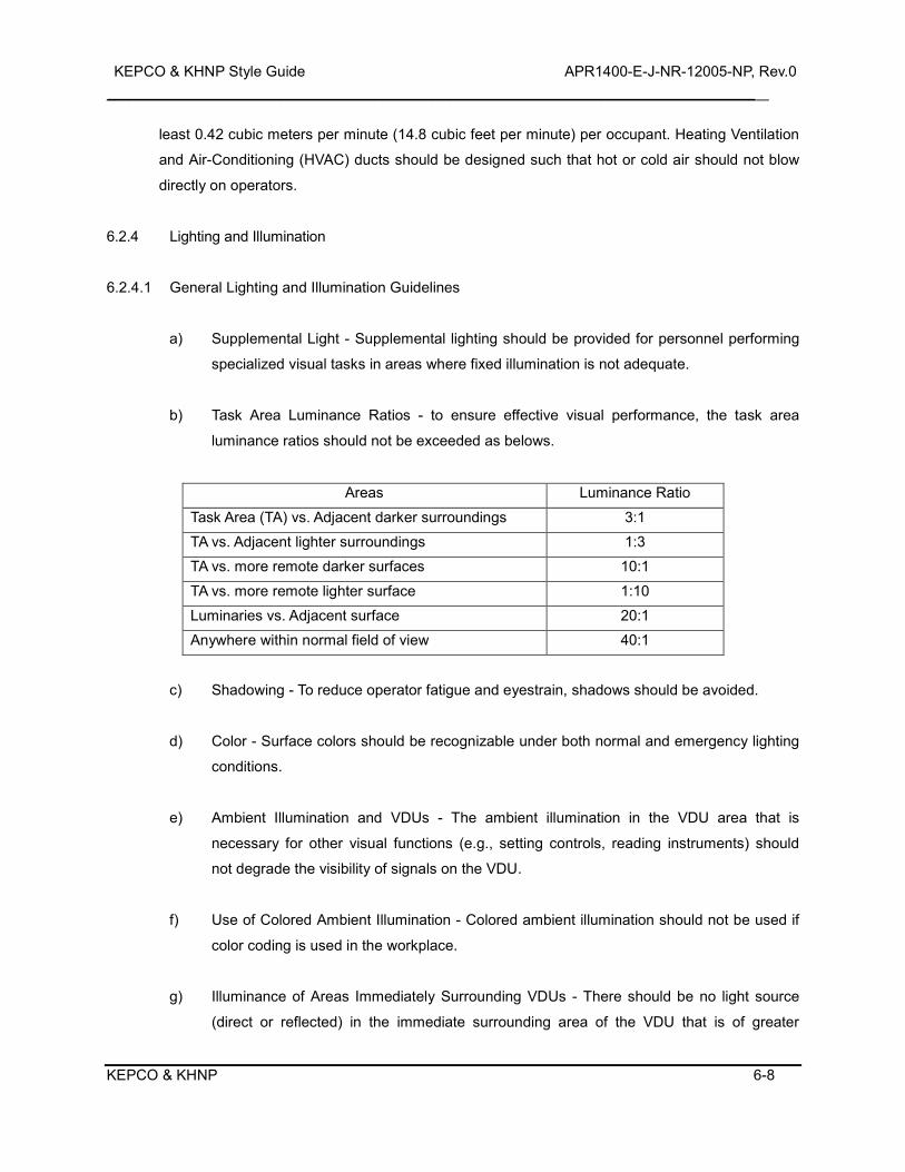
KEPCO & KHNP Style Guide APR1400-E-J-NR-12005-NP, Rev.0 _________________________________________________________________________________________________________
KEPCO & KHNP 6-8
least 0.42 cubic meters per minute (14.8 cubic feet per minute) per occupant. Heating Ventilation
and Air-Conditioning (HVAC) ducts should be designed such that hot or cold air should not blow
directly on operators.
6.2.4 Lighting and Illumination
6.2.4.1 General Lighting and Illumination Guidelines
a) Supplemental Light - Supplemental lighting should be provided for personnel performing
specialized visual tasks in areas where fixed illumination is not adequate.
b) Task Area Luminance Ratios - to ensure effective visual performance, the task area
luminance ratios should not be exceeded as belows.
Areas Luminance Ratio
Task Area (TA) vs. Adjacent darker surroundings 3:1 TA vs. Adjacent lighter surroundings 1:3 TA vs. more remote darker surfaces 10:1
TA vs. more remote lighter surface 1:10 Luminaries vs. Adjacent surface 20:1 Anywhere within normal field of view 40:1
c) Shadowing - To reduce operator fatigue and eyestrain, shadows should be avoided.
d) Color - Surface colors should be recognizable under both normal and emergency lighting
conditions.
e) Ambient Illumination and VDUs - The ambient illumination in the VDU area that is
necessary for other visual functions (e.g., setting controls, reading instruments) should
not degrade the visibility of signals on the VDU.
f) Use of Colored Ambient Illumination - Colored ambient illumination should not be used if
color coding is used in the workplace.
g) Illuminance of Areas Immediately Surrounding VDUs - There should be no light source
(direct or reflected) in the immediate surrounding area of the VDU that is of greater
KEPCO & KHNP Style Guide APR1400-E-J-NR-12005-NP, Rev.0 _________________________________________________________________________________________________________
KEPCO & KHNP 6-9
luminance than the VDU.
6.2.4.2 Task Area Lighting (optimal lighting)
1 foot candle (f/c) is counted as 10 lux (lx).
a) Operation Console - 300 to 1000 lx (700 lx)
b) LDP Area - 50 to 100 lx (100 lx)
c) Safety Console & Auxiliary Panel - 250 to 750 lx (500 lx)
d) Remote Shutdown Room - 300 to 1000 lx (700 lx)
e) Technical Support Center - 700 lx
f) Instrument Shops, Labs, etc. - 700 lx
g) Meeting Room near MCR - 400 to 900 lx (700 lx)
6.2.4.3 Emergency Lighting
a) MCR and RSR ceiling - The ceiling should have a "luminous ceiling" effect achieved
through indirect lighting.
b) Essential (diesel-powered) Lighting - Essential lighting should be provided at designated
egress ways and the MCR, and the RSR during a loss of normal lighting. Essential
lighting levels should always exceed or equal minimum battery pack lighting levels.
c) Emergency lighting - Emergency lighting should provide light to the MCR and RSR at
minimum levels specified below:
1) In the MCR - 100 to 300 lx (200 lx)
2) In the RSR - 100 to 300 lx (200 lx)
6.2.4.4 Reducing Glare and Reflectance
KEPCO & KHNP Style Guide APR1400-E-J-NR-12005-NP, Rev.0 _________________________________________________________________________________________________________
KEPCO & KHNP 6-10
a) Low reflectance flooring should be used.
b) Wall coverings should be low glare.
c) Panel paint should be of a neutral color such as beige and should be formulated for a flat
or semi-gloss finish.
d) VDU screens and other indicator surfaces employing glass or plexiglass transparent
coverings should utilize low glare materials or other glare reduction techniques (e.g.,
hoods, polarized glare filters, screen coatings, etc.).
e) Labels should use low-glare material.
f) Bare metal surfaces (e.g., indicator bezels) should have a non-reflective matte or brushed
finish.
6.2.5 Auditory Environments
6.2.5.1 Noise
A. Noise Levels in Main Control Rooms and Workspaces
1) Background Noise - Background noise should not impair verbal communication
between any two points in the primary operating area.
2) Further Reductions - Where communications between the primary operating area and
other control room locations are necessary, and voice transmission systems are not
provided, further reductions in background noise should be implemented.
3) Noise Distractions - Noise distractions generated either inside or outside the control
room should be minimized.
4) Limit - Nominal background noise levels should be less than 65 dB(A).
5) Reverberation Time and Sound Absorption - The acoustical treatment of the control
room should limit reverberation time of fewer one second or less.
B. Noise Levels in Equipment Spaces
KEPCO & KHNP Style Guide APR1400-E-J-NR-12005-NP, Rev.0 _________________________________________________________________________________________________________
KEPCO & KHNP 6-11
1) Unprotected Continuous Occupancy - Nominal background noise levels should be less
than 80 dB(A). Higher noise levels may require ear protection, limited stay times, or
both.
2) Unprotected Peak Levels - Park impulse or impact noise should not exceed 115 dB(A).
Higher noise levels may require ear protection, limited stay times, or both.
6.3 Local Control Panel
This HFE guideline is applicable to the LCSs associated with IHAs.
KEPCO & KHNP Style Guide APR1400-E-J-NR-12005-NP, Rev.0 _________________________________________________________________________________________________________
KEPCO & KHNP 7-1
7.0 MAINTAINABILITY OF DIGITAL SYSTEM
7.1 General Maintainability Guidelines
7.1.1 Minimizing Maintenance Demands
a) Minimizing Testing and Servicing - Requirements for periodic or repetitive testing and
servicing of components should be avoided where the possibility of human errors may
affect safety.
b) Equipment Independence for Maintenance - Units of equipment should be as
independent as is practical, such that maintenance of one unit has minimal effects on the
other equipment.
c) Minimize Maintenance Time - Equipment should be designed to minimize the time
required for maintenance if having the equipment out of service can affect safety.
d) Ease of Fault Detection - The design of equipment should facilitate rapid, positive fault
detection and isolation of defective items.
e) Equipment Verification - When feasible, equipment should permit verification of
operational status before its installation and without the need for disassembly.
f) Fault Detection Without Disassembly - Equipment should permit fault detection and
isolation without removing components, through the use of BIT, integrated diagnostics, or
standard test equipment.
g) Design for Repair by Module Replacement - To reduce the likelihood of personnel errors
in normal repairs conducted in difficult field environments, the design should support
simple modular replacement in the field, and their repair in the shop.
h) Overall Accessibility - Equipment that is to be maintained should be visually and
physically accessible to the maintainer.
i) Standardized Designs for Construction - Equipment used in assembling equipment, such
as connectors, should be standardized as much as possible.

KEPCO & KHNP Style Guide APR1400-E-J-NR-12005-NP, Rev.0 _________________________________________________________________________________________________________
KEPCO & KHNP 7-2
j) Design Flexibility - Equipment design should provide flexibility to allow future design
modifications to be made without imposing high demands on personnel for installation
and maintenance.
k) Minimize Maintenance Equipment and Tools - Units of equipment should be designed to
minimize the numbers and types of auxiliary equipment and tools required to service
them.
l) Use Common Test Equipment and Tools - Whenever possible, systems and units of
equipment should be designed so they can be maintained with common test equipment
and tools.
m) Need for Special Skills - Equipment should be designed to minimize the need for special
skills on the part of the maintainers.
n) Need for Special Training - Equipment should be designed to minimize the need to
specially train the maintainers.
7.1.2 Continuous Operation and On-Line Maintenance
a) Local Indication of Redundant Equipment Status - If equipment can automatically transfer
operation between redundant units, local personnel who maintain that equipment should
be informed of the transfer and the status of the redundant units.
b) Degraded Operation - Status and fault information should be provided to maintenance
personnel and operators for equipment awaiting maintenance while operating in a
degraded mode.
7.1.3 Supporting the Operator Role in Maintenance
a) Monitoring and Trending Equipment Degradation - To support personnel awareness of
impending equipment failures, monitoring and trending capabilities should be provided
where possible to identify the degradation of equipment.
b) Operator Assistance in Testing and Repair - Where practical, equipment should be
KEPCO & KHNP Style Guide APR1400-E-J-NR-12005-NP, Rev.0 _________________________________________________________________________________________________________
KEPCO & KHNP 7-3
designed to facilitate testing and repairs without requiring the assistance of the on-shift
operator.
c) Operator Indication of Testing or Repair Activities - The operators should be provided with
on indication that testing or repairs are underway.
d) Indication for Equipment That Is Out of Service - Means for indicating the status of
equipment that is out of service should be provided.
7.1.4 Protecting Personnel from Hazards
a) Designing for Safety of Maintainers - Equipment should not present hazards to
maintainers as they follow maintenance procedures.
b) Covering Exposed Parts - Protrusions and corners on equipment that maintainers might
come into contact with should be covered with rubber or other appropriate materials.
c) Energy Dissipation Before Maintenance - Parts that retain hazardous levels of electrical
potential or heat should be equipped with means to dissipate energy before to
maintenance.
d) Protecting Maintainers from Heat and Electrical Shock - Equipment or parts that retain
hazardous levels of heat or electrical potential during maintenance should be located
where maintainers will not touch them during their work, or they should be shielded.
e) Avoidance of Hazards for Adjustment Controls, Test Points, and Service Points -
Adjustment controls and test and service points should be located away from hazards.
7.1.5 Protecting Equipment and Components form Hazards
a) Protecting Equipment from Hazards - Equipment should be protected from potential
exterior hazards resulting from personnel actions.
b) Avoiding Damage to Protruding Parts - Irregular protrusions on a unit of equipment
should be easily removed to prevent damage by personnel during installation and
maintenance.
KEPCO & KHNP Style Guide APR1400-E-J-NR-12005-NP, Rev.0 _________________________________________________________________________________________________________
KEPCO & KHNP 7-4
c) Avoiding Damage When Opening and Closing Equipment - The parts and wiring of a
module should be located and arranged so that personnel do not damage them when the
module or the unit of equipment of which they are part is opened and closed.
d) Avoiding Damage When Maintaining Internal Components - Parts that are susceptible to
damage by personnel should be located or shielded so that they will not be damaged
during maintenance.
7.2 Instrument Cabinets and Racks
a) Instrument Racks - Instrument racks should support maintenance and testing by
providing adequate physical and visual access to their contents.
b) Cabinet Lighting - Cabinets requiring maintenance inside the enclosure should have
permanent lighting.
c) Minimizing Field-Run Wiring - The amount of field-run wiring should be minimized to
avoid errors in identifying and connecting wires.
d) Protective Electrical Grounds for Cabinets - A protective ground should be provided.
7.3 Equipment Packaging
7.3.1 Modularization
a) Modularization - Units of equipment should be divided into as many modules as are
practical and feasible to support personnel performance during maintenance.
b) Physical and Functional Interchangeability - If modules are physically interchangeable,
they should also be functionally interchangeable to avoid errors in installing the wrong
module.
c) Distinguishing Non-interchangeable Modules - The appearance of non-interchangeable
modules should be distinguishable, and the difference should be apparent when the
module is in its installed position.
KEPCO & KHNP Style Guide APR1400-E-J-NR-12005-NP, Rev.0 _________________________________________________________________________________________________________
KEPCO & KHNP 7-5
d) Replacement of Failed Components - Equipment should be designed so that components
that fail frequently can be easily replaced.
e) Maintenance in Installed Location - When possible, modules should be designed so that
they can be maintained in their installed position, without requiring disconnection,
disassembly, or removal of other modules.
f) Unreliable Components - If a module has parts that are significantly less reliable than the
remaining ones, the unreliable parts should be accessible without removing the module.
g) Removal and Testing - Modules should be designed to permit testing when they are
removed from their installed position.
h) Installation and Testing - Each module should allow separate installation and functional
testing before the complete system is integrated.
i) Installation and Calibration - Modules should require little or no calibration immediately
after installation.
j) Interconnectivity - The number of inputs and outputs associated with a module should be
minimized, where possible, to reduce the likelihood of errors in installing connections or
testing multiple inputs and outputs.
k) Modularization Method - The modularization of digital equipment should be based on a
systematic method that can be readily understood by maintenance personnel.
7.3.1.1 Logical Flow Packaging
a) Isolating Module Faults Via Single Input-Output Checks - When logical flow packaging is
used to modularize digital equipment, a module should be designed so that only single
input and output checks are necessary to isolate a fault in it.
b) Indication of Unidirectional Signal Flow - When logical flow packaging is used to
modularize digital equipment, the unidirectional signal flow within a module should be
clearly indicated.
KEPCO & KHNP Style Guide APR1400-E-J-NR-12005-NP, Rev.0 _________________________________________________________________________________________________________
KEPCO & KHNP 7-6
7.3.1.2 Circuit Packaging
a) Locating Parts in A Single Module - When circuit packaging is used to modularize digital
equipment, all parts of a given circuit or group of logically related parts should be located
in a single module to help personnel find and test them.
b) Only One Circuit or Group of Related Parts per Module - When circuit packaging is used
to modularize digital equipment, a module should contain only one circuit or group of
related parts to support testing and diagnosis.
c) Packaging A Circuit as A Single Terminal-Board or Plug-in Module - When circuit
packaging is used to modularize digital equipment, the circuit should be packaged as a
single terminal board or plug-in module, when possible, to support its testing and
installation.
d) Grouping Circuits to Minimize The Crossing of Signals - When circuit packaging is used
to modularize digital equipment, circuit should be grouped to minimize cross-crossing of
signals among modules.
7.3.1.3 Component Packaging
a) Grouping Components with Similar Replacement Schedule - When using component
packaging to modularize digital equipment, similar parts that are likely to require
replacement at approximately the same time should be grouped together.
b) Grouping Components with Similar Servicing Requirements - When component
packaging is used to modularize digital equipment, components requiring the same
maintenance work should be grouped together, e.g., test points or components requiring
a particular cleaning method.
7.3.1.4 Printed Circuit Boards
a) Design for Removal and Replacement - Printed circuit boards should be designed and
mounted for ease of removal and the elimination of errors during replacement.
KEPCO & KHNP Style Guide APR1400-E-J-NR-12005-NP, Rev.0 _________________________________________________________________________________________________________
KEPCO & KHNP 7-7
b) Plug-in Printed Circuit Boards - Plug-in printed circuit boards should be structurally rigid
and easy to remove and replace, providing finger access and gripping aids if necessary.
c) Feedback When Installing Plug-in Printed Circuit Boards - Feedback should be provided
to the maintainer when plug-in printed circuit boards are securely connected.
d) Identification of Printed Circuit Boards and Parts - Printed circuit boards should be
marked to identify the board and the parts mounted on it.
7.3.2 Layout
7.3.2.1 Module Accessibility
a) No Interference from Other Parts - Modules should be laid out so that all parts can be
removed and replaced without interference from or removal of other parts.
b) No Stacking of Parts -To support accessibility, parts that make up a module should be
mounted in an orderly, flat, two-dimensional array and should not be stacked one on top
of another.
c) Consistent Orientation - If a module has more than one part of the same type that must
be inserted in a particular orientation, all such parts should be oriented in the same
direction, where practical.
d) Spacing of Parts - The parts that make up a module should be spaced and oriented so
that required tools can be used without difficulty.
e) Separation of Parts and Wiring on Printed Circuit Boards - To support accessibility for
testing parts on printed circuit boards, all parts should be mounted on one side of the
board and all wiring, including printed circuits, should be located on the other side, where
practical.
f) Spacing of Terminals - Terminals to which wires are to be soldered should be far enough
apart so that work on one terminal does not damage neighboring terminals or nearby
parts.
KEPCO & KHNP Style Guide APR1400-E-J-NR-12005-NP, Rev.0 _________________________________________________________________________________________________________
KEPCO & KHNP 7-8
g) Indicator Lights - If a module has indicator lights, it should be possible to change them
from the front panel, without opening or removing the module.
h) Shutoff Switches - If the module contains emergency shutoff switches, they should be
positioned within easy reach, and they should be located or guarded to prevent
inadvertent operation.
i) Test, Adjustment and Connection Points - Test points, adjustment points, and cable and
line connectors should be located where the maintainer can see them easily and operate
on them without interference.
7.3.2.2 Grouping
a) Grouping Maintenance Display Devices - All maintenance display devices relevant to a
particular task should be grouped together and located where they can easily be seen.
b) Separate Maintenance and Operational Display Devices - If a unit of equipment contains
both maintenance and operational display devices, the two types of devices should be
separated.
c) Separate Maintenance and Operational Displays in a Display Network - If a display
device contains displays for both maintenance and operations personnel, then the
maintenance displays should have a separate location in the display network.
7.3.3 Mounting
a) Support for Hinged Mounting - If a module is mounted on hinges, supports should hold
the module in the "out" or "open" position.
b) Rests and Stands - If a module contains parts that might be damaged when it is moved
into position for maintenance, it should include rests or stands that are integral with the
construction of the module to protect those parts.
c) Preventing Mounting Errors by Physical Design - Modules should be designed so that it is
physically impossible to mount them incorrectly.
KEPCO & KHNP Style Guide APR1400-E-J-NR-12005-NP, Rev.0 _________________________________________________________________________________________________________
KEPCO & KHNP 7-9
d) Controls - Modules should be mounted so that it is unnecessary to disconnect controls
that may be needed for maintenance.
e) Front Access - Replaceable modules should be accessible through the front of the
equipment, rather than the back, if the panel or console is not used by operators.
f) Orientation of Modules within Cases - If a module has a case, the proper orientation of
the module within its case should be obvious, preferably through the physical design of
the case, rather than through labeling.
g) Connectors - Electrical connections between modules should be simple and minimize the
demands for manual dexterity.
h) Standard Connectors - Connectors should be standardized as much as possible.
7.4 Fuses and Circuit Breakers
a) Location of Fuses and Circuit Breakers - Fuses and circuit breakers should be grouped in
a minimum number of centralized, readily accessible locations for removal, replacement,
and resetting.
b) Verification of an Open Circuit - An indication should be given when a fuse or circuit
breaker has opened a circuit.
c) Individual Fused Units - Fuses or circuit breakers should be provided so that each unit of
a system is separately fused and adequately protected from harmful variations in voltages
that personnel may cause.
d) Worker Safety - Fuse installations should be designed so that only the neutral ("cold")
terminal of the fuse can be touched.
e) Safeguarding The Circuit - Fuses should be provided that safeguard the circuit if the
wrong switch or jack position is used.
f) Easily Removed Fuse Holders - Fuse holder cups or caps should be easily removed by
hand.

KEPCO & KHNP Style Guide APR1400-E-J-NR-12005-NP, Rev.0 _________________________________________________________________________________________________________
KEPCO & KHNP 7-10
g) Identifying Fuses and Circuit Breakers - Fuses and circuit breakers should be
permanently labeled or marked.
h) Indicating Fuse Ratings - A fuse's rating should be indicated on the fuse and adjacent to
the fuse holder.
i) Identifying Affected Circuits - The area of equipment served by a fuse or circuit breaker
should be identified.
7.5 Labeling and Marking
a) Standard Labels - Equipment labels should be standardized as much as possible.
b) Information Content of Labels and Markings for Modules - Modules should be labeled or
marked to supply information needed by maintainers.
c) Visibility of Labels and Markings - Labels and markings on parts or in cabinets should be
placed so that the maintainer can see them without having to move or remove anything.
d) Consistent Placement of Labels and Markings - Labels and markings should be
consistently placed in relation to the parts to which they refer.
e) Luminescent Labels - If labels must be read under very low ambient light, they may be
marked in phosphorescent colors.
f) Electrical Parts - Small electrical parts that are attached to mounting boards, such as
resistors and capacitors, should be labeled or marked on the mounting boards.
g) Identification of Parts - Parts should be identified with labels or markings.
h) Identification of Terminals on Terminal Strips or Blocks - The terminals of terminal strips or
blocks should be labeled on the strip or block, or on the chassis, adjacent to the terminals.
i) Identification of Terminals on Parts - When parts have terminals (e.g., transformers,
relays, and capacitors), each terminal should be identified by an adjacent label.
KEPCO & KHNP Style Guide APR1400-E-J-NR-12005-NP, Rev.0 _________________________________________________________________________________________________________
KEPCO & KHNP 7-11
j) Identification of Parts Accessible from Both Sides - Receptacles that are accessible from
both sides of a board or panel should be identified on both sides.
k) Durability of Markings - Markings should be durable enough to last the life of the
equipment.
l) Marking Stacked Parts - If parts or modules are stacked, marking should permit
identification of the individual parts or modules.
m) Marking Enclosed or Shielded Parts, Modules, Test Points, and Service Points - Enclosed
or shielded parts, modules, test points, and service points should be marked both outside
the enclosure or shield, and inside it.
n) Hazard Warnings - If there is any hazard from a part or module, a warning or caution label
should be provided on it, on the case or cover, or both.
o) Labeling Symmetrical Parts - Parts that are symmetrical should be labeled or marked to
indicate their proper orientation for mounting.
p) Insertion Holes - If a module has holes through which parts must be aligned and then
inserted, labels showing the proper orientation of the part should be placed adjacent to
the holes.
q) Auxiliary Information for Parts - Parts to which auxiliary information applies should be
labeled with that information.
7.6 Adjustment Controls
a) Misalignment - Controls and displays should be designed to prevent misalignment that
might be caused by vibration, service use, or accidental contact.
b) Controls and Feedback - Each adjustment control should provide feedback.
c) Simultaneous Access to Controls and Displays - Maintainers should have simultaneous
access to an adjustment control and its associated display or other source of feedback.
KEPCO & KHNP Style Guide APR1400-E-J-NR-12005-NP, Rev.0 _________________________________________________________________________________________________________
KEPCO & KHNP 7-12
d) Differentiating Maintenance Controls from Operational Controls - Maintenance and
operational controls should be clearly differentiated.
e) Location of Maintenance and Operational Controls - The maintenance and operational
controls should not appear on the same panel if maintenance and operation of a unit of
equipment are performed by different sets of people.
f) Independence of Adjustment Controls - Where possible and practical, the adjustment of
one control should be independent of the adjustments of others.
g) Sequential Adjustments - If the adjustment of one control affects the adjustment of
another, the controls should be arranged in sequential order, and labeled or marked to
indicate the order of adjustment.
h) Functionally Related Adjustments - If a single control is used to affect multiple variables,
then the user interface should be designed to prevent mode errors.
i) Degree of Adjustment - Controls should accommodate the degree of adjustment required;
that is, gross adjustment, fine adjustment, or both.
j) Mechanical Stops - Adjustment controls intended to have a limited range of motion should
have mechanical stops.
k) Previous Settings - If a task requires that a maintainer be able to quickly return a control
to its previous setting, the control should have a scale and pointer, or equivalent.
l) Preventing Inadvertent Adjustment - Adjustment controls should be located and mounted
so that they cannot be adjusted inadvertently.
m) Critical or Sensitive Adjustments - Critical or sensitive adjustments should incorporate
features, such as locking devices, to prevent inadvertent or accidental adjustment.
n) Hand or Arm Support - If an adjustment control or the maintainer will be subject to
vibration during adjustment, a suitable hand or arm support should be provided.
KEPCO & KHNP Style Guide APR1400-E-J-NR-12005-NP, Rev.0 _________________________________________________________________________________________________________
KEPCO & KHNP 7-13
7.7 Test Points and Service Points
7.7.1 General Test Points and Service Points Guidelines
a) Ease of Servicing - Equipment should be designed so that it can be serviced in its
installed position to prevent errors associated with disassembling and reassembling it.
b) Appropriate Use of Test Points - Test points should be provided on units of equipment as
required to support personnel in checking, adjusting, and troubleshooting it.
c) Single Adjustment Control Per Test Point - A test point should not have more than one
associated adjustment control.
d) Ground Points - Special grounding points should be provided, as needed, in locations in
which surfaces have poor electrical grounding characteristics.
7.7.2 Location, Arrangement, and Marking
a) Test Points for Units of Equipment - Where possible, each input to and output from a unit
of equipment should have test points to support testing and diagnosis of faults.
b) Tracing Signals - Test points should be provided to permit the systematic tracing of
signals and voltages through a unit of equipment to support fault detection and diagnosis.
c) Test and Service Point Accessibility - All test and service points should be visible and
physically accessible to the maintainer for checking and troubleshooting.
d) Proximity of Controls, Displays, and Test Points - Test points should be located in physical
and visual proximity to the controls and displays used to make the adjustments.
e) Proximity of Controls, Displays, and Service Points - Service points should be located in
physical and visual proximity to the controls used when adjusting them.
f) Test and Service Point Location - Test and service points should be provided, designed,
and located in accordance with their frequency of use and any time-limits on maintenance.
KEPCO & KHNP Style Guide APR1400-E-J-NR-12005-NP, Rev.0 _________________________________________________________________________________________________________
KEPCO & KHNP 7-14
g) Compatibility of Test and Service Points - Test and service points should be designed for
compatibility with checking, troubleshooting, and servicing procedures, and with test and
service equipment.
h) Distinctive Connections - Each type of test or service equipment should have distinctively
different connectors or fittings to minimize the likelihood of error.
i) Distinguishable Marking - Test and service points should be designed and marked so that
they are easily distinguishable from each other.
7.7.3 Accessibility
a) Access Openings for Test Equipment - Access openings necessary to connect test
equipment should accommodate maintainers, equipment, and required tools.
b) Test Probe Guides - Suitable guides for test probes should be provided when test points
are located internally to an enclosure.
7.8 Test Equipment
7.8.1 General Test Equipment Guidelines
a) Built-in Test Capabilities - All test capabilities for a unit of equipment should be built in, to
the extent feasible, to reduce the likelihood of testing errors.
b) Appropriate Use of Alarms - If critical equipment is not regularly monitored, an alarm
should be provided to indicate malfunctions or conditions that would cause personnel
injury or equipment damage.
c) Accuracy of Test Equipment - The accuracy of test equipment should be consistent with
testing requirements.
d) Instructions - Clearly written and easily understandable operating instructions for the test
equipment should be available to the maintainer.
KEPCO & KHNP Style Guide APR1400-E-J-NR-12005-NP, Rev.0 _________________________________________________________________________________________________________
KEPCO & KHNP 7-15
e) Labels - Equipment labels should identify all items the maintainer must be able to
recognize, read, or use.
f) Minimizing Errors - The test equipment should be designed to minimize the occurrence of
errors by the maintainer.
g) Minimizing Hazards - When possible, fail-safe features should be incorporated in test
equipment to minimize dangers to maintainers or equipment.
7.8.2 Automatic Test Equipment
7.8.2.1 General
a) Automated Aids - Fault isolation, inspection, and checkout tasks should be automated to
the extent practical to support personnel performance.
b) On-Line Diagnostics - Computer systems should have on-line diagnostic capabilities, if
the detection and diagnosis of computer faults is required.
7.8.2.2 Test Intervals
a) Continuous on-Line Self-Testing - The capability for continuous on-line self-testing should
be provided when practicable to support prompt detection of faults.
b) Periodic Testing - The capability for periodic functional testing that is manually initiated but
executed automatically should be provided when personnel require control of the test
intervals.
7.8.2.3 Bypasses for Plant and Test Equipment
a) Automatic Bypass - When a test is initiated manually, the correct bypasses required for
testing should be established automatically, and the operators should be aware of all of
them, where practical.
b) Indicators for Test and Bypass Status - Local indication of pass or fail for test and bypass
status should be provided for periodic functional tests.
KEPCO & KHNP Style Guide APR1400-E-J-NR-12005-NP, Rev.0 _________________________________________________________________________________________________________
KEPCO & KHNP 7-16
c) Removal of Automatic Bypass - When a periodic functional test sequence is completed,
all bypasses established to allow the test to be performed should be automatically, to
relieve the operator of this task, where practical.
d) Bypassed Diagnosis Routines - to support the diagnosis of faults, diagnosis routines that
are bypassed during maintenance should be run again before equipment is put back in
service.
7.8.2.4 Failure Indications
a) Loss of Redundancy - If part of a redundant system, unit of equipment, module, or
component becomes inoperable, an alarm signaling the loss of redundancy should be
provided to the user immediately.
b) Overload Indications - Overload indications should be provided for equipment subject to
this condition.
c) Identification of in-Tolerance Ranges - When practical, the ranges for which test values
are within acceptable tolerance limits should be indicated on built-in test equipment.
d) Out-of-Range Indicators - If equipment has failed or is not operating within tolerance limits,
an indication should be provided.
e) Power Failure Indicators - If a power failure occurs, an indication should be given.
f) Open Circuit Indicators - If a fuse or circuit breaker has opened a circuit, there should be
an indication.
g) Power-on Indicator - A power-on indicator that extinguishes with loss of power should be
provided.
7.8.2.5 Display of Test Results
a) Inclusion of Fault Messages - Fault messages should only be shown if they add value to
the maintenance process.
KEPCO & KHNP Style Guide APR1400-E-J-NR-12005-NP, Rev.0 _________________________________________________________________________________________________________
KEPCO & KHNP 7-17
b) Direct Interpretation of Test Results - Messages provided by test equipment should
require a minimum amount of interpretation.
c) Identification of Failure Location - Test features should identify the location of the detected
failure to the lowest replaceable module.
d) Identification of Out-of-Tolerance Signals on Collating Test Equipment - If equipment fails
a test performed by collating test equipment, the test equipment should indicate which
signal(s) are out of tolerance.
7.8.3 Test Equipment Hardware
7.8.3.1 General Test Equipment Hardware Guidelines
a) Requirements for Test Equipment and Bench Mockups - Test equipment and bench
mockups should be treated like any other equipment with respect to the HFE design
requirements for units, covers, cases, cables, connectors, test points, displays, and
controls.
b) Selector Switches - Selector switches should be used rather than many, individual plug-in
connections as long as the effects of switching do not degrade the desired information.
c) Minimizing Test Equipment Accessories - The number and types of test equipment
accessories, such as connectors and test cables, should be minimized.
d) Minimizing Test Equipment Controls, Displays, and Modes -Test equipment should be
simple to operate and have a minimum number of controls, displays, and modes.
e) Reducing The Number and Complexity of Steps - The number and complexity of steps
required to operate the test equipment should be minimized.
f) Individual Operation - Test equipment should be designed for operation by one person, if
practical.
g) Calibration Check - Test equipment should be easily calibrated or equipped with a simple
KEPCO & KHNP Style Guide APR1400-E-J-NR-12005-NP, Rev.0 _________________________________________________________________________________________________________
KEPCO & KHNP 7-18
check to indicate whether or not it is out-of-calibration or malfunctioning.
h) Avoid Temporary Equipment Configurations for Testing - The use of temporary equipment
configurations for periodic, functional testing of equipment should be avoided, where
practical.
7.8.3.2 Portable Test Equipment
a) Portable Diagnostic Tools - Portable diagnostic equipment should be provided to aid in
fault isolation when built-in equipment is not practical.
b) Ease of Connection - Portable test equipment should allow rapid and error-free
connection to the equipment being tested.
c) Calibration Information - If maintenance personnel are required to verify that test
equipment has been calibrated, then this information should be available to them.
7.8.3.3 Built-in Test Panel
a) Test Point Connections - Test points should permit the connection of the appropriate test
equipment, such as voltage meters.
b) Test Point Indication Labeling and Demarcation - Test points should be clearly indicated
on the test panel.
KHNP STYLE GUIDE APR1400-E-J-NR-12005-NP, Rev.0
KEPCO & KHNP 8-1
8.0 REFERENCES
1. Code of Federal Regulations
1) 10 CFR 29, Occupational Health and Safety Administration, Washington, DC: Office of
the Federal Register (1990)
2. USNRC NUREGs
1) NUREG-0700, Human System Interface Design Review Guideline, Appendix A, Rev.2,
USNRC (2002)
2) NUREG-0899, Guidelines for the Preparation of Emergency Operating Procedures,
Washington, DC: Rev.0, USNRC (1982)
3) NUREG/CR-3517, Recommendations to the USNRC on Human Engineering Guidelines
for Nuclear Power Plant Maintainability, Washington, DC: USNRC (1985)
4) NUREG/CR-5908, Advanced Human-System Interface Design Review Guideline.
Washington, DC: USNRC (1994)
5) NUREG/CR-6633, Advanced Information Systems Design : Technical Basis and Human
Factors Review Guidance, Washington, DC : USNRC (2000)
6) NUREG/CR-6634, Computer-Based Procedure Systems : Technical Basis and Human
Factors Review Guidance, Washington, DC : USNRC (2000)
7) NUREG/CR-6635, Soft Controls : Technical Basis and Human Factors Review Guidance,
Washington, DC : USNRC (2000)
8) NUREG/CR-6636, Maintainability of Digital Systems : Technical Basis and Human
Factors Review Guidance, Washington, DC : USNRC (2000)
9) NUREG/CR-6684, Advanced Alarm Systems: Revision of Guidance and Its Technical
Basis, Washington, DC : USNRC (2000)
10) NUREG/CR-6691, The Effects of Alarm Display, Processing, and Availability on Crew
Performance, Washington, DC : USNRC (2000)
3. Industry Standards
1) ANSI/HFS 100-1988, American National Standard for Human Factors Engineering of
Visual Display Terminal Consoles, Santa Monica, CA: Human Factors Society (1988)
2) IEEE 1023-2004, Guide for the application of Human Factors Engineering to Systems,
KHNP STYLE GUIDE APR1400-E-J-NR-12005-NP, Rev.0
KEPCO & KHNP 8-2
Equipment, and Facilities of Nuclear Power Generating Stations (2004)
3) DOT/FAA/CT-01/08, Computer-Human Interface Guidelines : A Revision to Chapter 8 of
the Human Factors Design Guide., Federal Aviation Administration (2001)
4) MIL-STD-1472E, Department of Defense Design Criteria Standard, Human
Engineering (1999)
5) NASA-STD-3000, Man-Systems Integration Standards, Houston, Rev.B, TX: National
Aeronautics and Space Administration (1989)
6) NP-4350, Human Engineering Design Guidelines for Maintainability, Palo Alto, CA:
Electric Power Research Institute (1985)
7) UCRL-15673, Human Factors Design Guidelines for Maintainability of Department of
Energy Nuclear Facilities, Washington, DC: Department of Energy (1985)
8) USE-1000, Space Station Freedom Program Human-computer Interface Guide, Houston,
TX: National Aeronautics and Space Administration (1988)
4. Others
1) Human Performance Engineering: A guide for system designers, Englewood Cliffs, NJ:
Prentice Hall. Bailey, R.W. (1982)
2) Engineering Data Compendium: Human Perception and Performance, Wright-patterson
AFB, OH: Armstrong Aerospace Medical Research Laboratory, Boff, K. R., & Lincoln, J. E.
(1988)
3) Computer Abbreviations: Evidence and a Synthesis Human Factors, 27, 2, 143-156,
Ehernreich (1985)
4) User-Computer Interface in Process Control: A human factors engineering handbook,
Idaho Falls, ID: Idaho National Engineering Laboratory. Gilmore, W. E., Gertman, D. I., &
Blackman, H. S. (1989)
5) Handbook of Human-Computer Interaction. New York, NY: North-Holland, Helander, M.
(Ed.) (1988)
6) The Depth/breadth Tradeoff in the Design of Menu-driven user interfaces, International
Journal of Man- Machine Studies, 20, 201-213. Kiger, J. I. (1984)
7) The Case Against User Interface Consistency. Communications of the ACM, 32, 10, 1164-
1173, Ledgard, H. P. (1989)
8) The Role of Hierarchical Knowledge Representation in decision making and System
Management IEEE Transactions on Systems, Man, and Cybernetics, SMC-15, 2, 234-243.
Rasmussen, J. (1985)
9) Ergonomic Design for People at Work Rochester, NY: Eastman Kodak Company.
KHNP STYLE GUIDE APR1400-E-J-NR-12005-NP, Rev.0
KEPCO & KHNP 8-3
Rodgers, S. H. (Ed.) (1983)
10) Handbook of Human Factors, New York, in NY: Wiley. Salvendy, G. (Ed.) (1982)
11) Human Factors in Engineering and Design, New York, NY: McGraw-Hill. Sanders, M. S.,
& McCormick, E. J. (1987)
12) The Visual Display of Quantitative Information, Chesire, CT: Graphics Press. Tufte, E. R.
(1983)
13) Human Engineering Guide to Equipment Design, Washington, DC: Department of
Defense Van Cott, H. P., & Kinkade, R. G. (Ed.s) (1972)
14) Effects of Key Layout, Visual Feedback, and Encoding Algorithm on Menu Selection with
LED-based Touch Panels (Tech Report HFL-604-02). Beaverton, OR: Tektronix, Weiman,
N., Beaton, R. J., Knox, S. T., & Glasser, P. C. (1985)
15) National Anthropometric Survey of Korea. Korea Research Institute of Standards and
Science (2005)
16) Software-System Safety and Computers Chapter 17, Nancy Leveson, Addison Wesley
Publishing Company, (1995)
17) Control Room Systems Design for Nuclear Power Plants, Section 5, IAEA TECDOC-812,
IAEA, July (1995)
KHNP STYLE GUIDE APR1400-E-J-NR-12005-NP, Rev.0
KEPCO & KHNP A-Part 1-1
APPENDICES
APPENDIX A
This Appendix is divided into the following three Parts:
Part 1: Standard Abbreviation List (except HSI system abbreviation list) which is composed
of standard abbreviations and acronyms for instruments, controls, systems,
emergency procedures, engineering units, engineering documents and procedures,
and other relevant terms pertinent to I&C system.
Part 2: Physical Units and Abbreviations of the Information FPD and/or Qualified Indication
and Alarm System (QIAS).
Part 3: Table of System Mnemonics which contains the approved list of system codes that
are used in the System Functional Descriptions. System abbreviations can be found
in Part 1 of this Appendix.
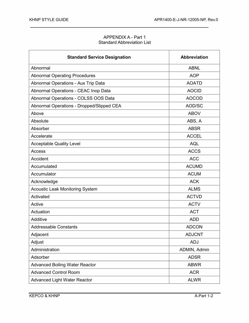
KHNP STYLE GUIDE APR1400-E-J-NR-12005-NP, Rev.0
KEPCO & KHNP A-Part 1-2
APPENDIX A - Part 1 Standard Abbreviation List
Standard Service Designation Abbreviation
Abnormal ABNL
Abnormal Operating Procedures AOP
Abnormal Operations - Aux Trip Data AOATD
Abnormal Operations - CEAC Inop Data AOCID
Abnormal Operations - COLSS OOS Data AOCOD
Abnormal Operations - Dropped/Slipped CEA AOD/SC
Above ABOV
Absolute ABS, A
Absorber ABSR
Accelerate ACCEL
Acceptable Quality Level AQL
Access ACCS
Accident ACC
Accumulated ACUMD
Accumulator ACUM
Acknowledge ACK
Acoustic Leak Monitoring System ALMS
Activated ACTVD
Active ACTV
Actuation ACT
Additive ADD
Addressable Constants ADCON
Adjacent ADJCNT
Adjust ADJ
Administration ADMIN, Admin
Adsorber ADSR
Advanced Boiling Water Reactor ABWR
Advanced Control Room ACR
Advanced Light Water Reactor ALWR
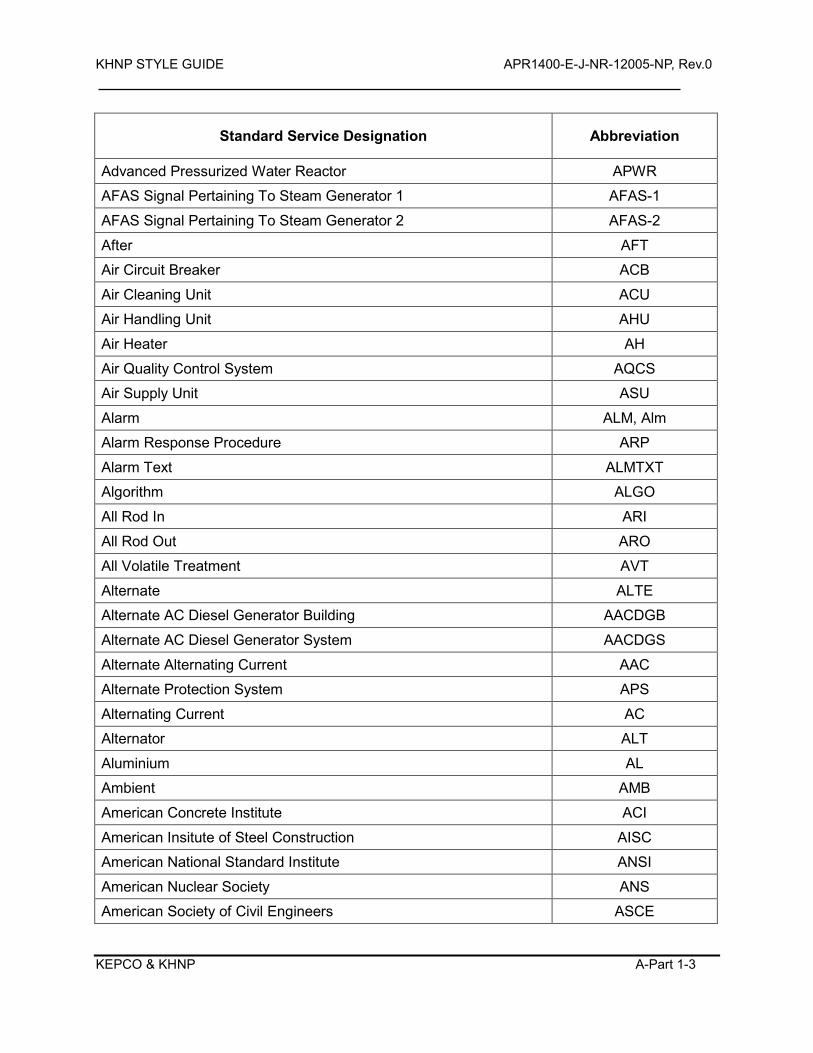
KHNP STYLE GUIDE APR1400-E-J-NR-12005-NP, Rev.0
KEPCO & KHNP A-Part 1-3
Standard Service Designation Abbreviation
Advanced Pressurized Water Reactor APWR
AFAS Signal Pertaining To Steam Generator 1 AFAS-1
AFAS Signal Pertaining To Steam Generator 2 AFAS-2
After AFT
Air Circuit Breaker ACB
Air Cleaning Unit ACU
Air Handling Unit AHU
Air Heater AH
Air Quality Control System AQCS
Air Supply Unit ASU
Alarm ALM, Alm
Alarm Response Procedure ARP
Alarm Text ALMTXT
Algorithm ALGO
All Rod In ARI
All Rod Out ARO
All Volatile Treatment AVT
Alternate ALTE
Alternate AC Diesel Generator Building AACDGB
Alternate AC Diesel Generator System AACDGS
Alternate Alternating Current AAC
Alternate Protection System APS
Alternating Current AC
Alternator ALT
Aluminium AL
Ambient AMB
American Concrete Institute ACI
American Insitute of Steel Construction AISC
American National Standard Institute ANSI
American Nuclear Society ANS
American Society of Civil Engineers ASCE
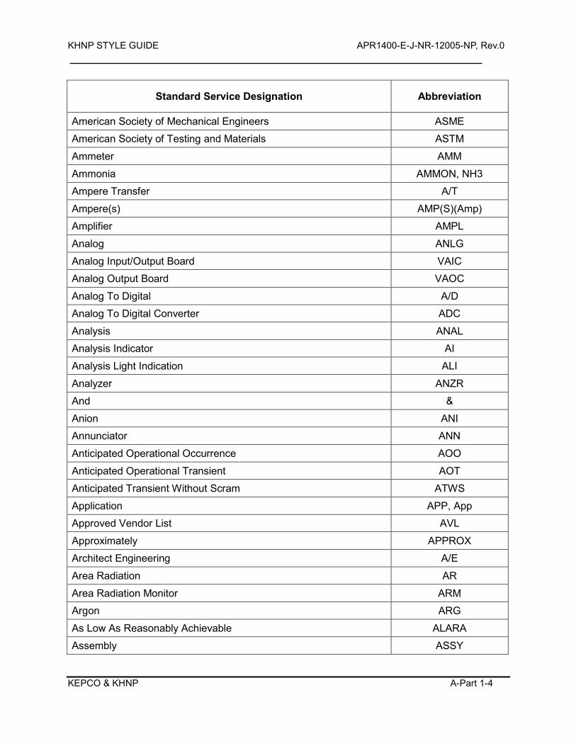
KHNP STYLE GUIDE APR1400-E-J-NR-12005-NP, Rev.0
KEPCO & KHNP A-Part 1-4
Standard Service Designation Abbreviation
American Society of Mechanical Engineers ASME
American Society of Testing and Materials ASTM
Ammeter AMM
Ammonia AMMON, NH3
Ampere Transfer A/T
Ampere(s) AMP(S)(Amp)
Amplifier AMPL
Analog ANLG
Analog Input/Output Board VAIC
Analog Output Board VAOC
Analog To Digital A/D
Analog To Digital Converter ADC
Analysis ANAL
Analysis Indicator AI
Analysis Light Indication ALI
Analyzer ANZR
And &
Anion ANI
Annunciator ANN
Anticipated Operational Occurrence AOO
Anticipated Operational Transient AOT
Anticipated Transient Without Scram ATWS
Application APP, App
Approved Vendor List AVL
Approximately APPROX
Architect Engineering A/E
Area Radiation AR
Area Radiation Monitor ARM
Argon ARG
As Low As Reasonably Achievable ALARA
Assembly ASSY
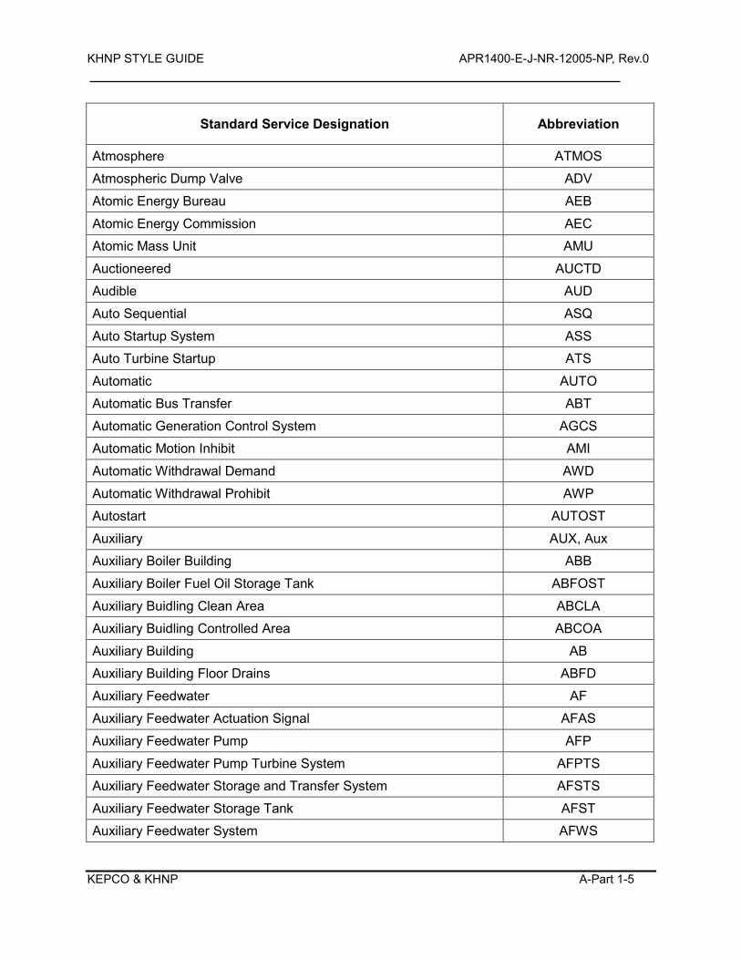
KHNP STYLE GUIDE APR1400-E-J-NR-12005-NP, Rev.0
KEPCO & KHNP A-Part 1-5
Standard Service Designation Abbreviation
Atmosphere ATMOS
Atmospheric Dump Valve ADV
Atomic Energy Bureau AEB
Atomic Energy Commission AEC
Atomic Mass Unit AMU
Auctioneered AUCTD
Audible AUD
Auto Sequential ASQ
Auto Startup System ASS
Auto Turbine Startup ATS
Automatic AUTO
Automatic Bus Transfer ABT
Automatic Generation Control System AGCS
Automatic Motion Inhibit AMI
Automatic Withdrawal Demand AWD
Automatic Withdrawal Prohibit AWP
Autostart AUTOST
Auxiliary AUX, Aux
Auxiliary Boiler Building ABB
Auxiliary Boiler Fuel Oil Storage Tank ABFOST
Auxiliary Buidling Clean Area ABCLA
Auxiliary Buidling Controlled Area ABCOA
Auxiliary Building AB
Auxiliary Building Floor Drains ABFD
Auxiliary Feedwater AF
Auxiliary Feedwater Actuation Signal AFAS
Auxiliary Feedwater Pump AFP
Auxiliary Feedwater Pump Turbine System AFPTS
Auxiliary Feedwater Storage and Transfer System AFSTS
Auxiliary Feedwater Storage Tank AFST
Auxiliary Feedwater System AFWS
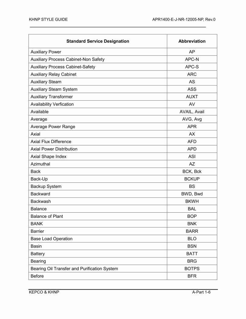
KHNP STYLE GUIDE APR1400-E-J-NR-12005-NP, Rev.0
KEPCO & KHNP A-Part 1-6
Standard Service Designation Abbreviation
Auxiliary Power AP
Auxiliary Process Cabinet-Non Safety APC-N
Auxiliary Process Cabinet-Safety APC-S
Auxiliary Relay Cabinet ARC
Auxiliary Steam AS
Auxiliary Steam System ASS
Auxiliary Transformer AUXT
Availability Verfication AV
Available AVAIL, Avail
Average AVG, Avg
Average Power Range APR
Axial AX
Axial Flux Difference AFD
Axial Power Distribution APD
Axial Shape Index ASI
Azimuthal AZ
Back BCK, Bck
Back-Up BCKUP
Backup System BS
Backward BWD, Bwd
Backwash BKWH
Balance BAL
Balance of Plant BOP
BANK BNK
Barrier BARR
Base Load Operation BLO
Basin BSN
Battery BATT
Bearing BRG
Bearing Oil Transfer and Purification System BOTPS
Before BFR
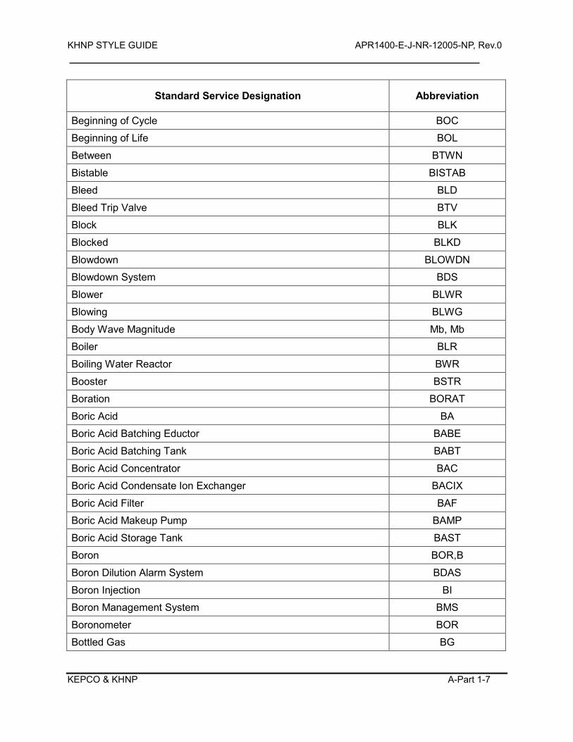
KHNP STYLE GUIDE APR1400-E-J-NR-12005-NP, Rev.0
KEPCO & KHNP A-Part 1-7
Standard Service Designation Abbreviation
Beginning of Cycle BOC
Beginning of Life BOL
Between BTWN
Bistable BISTAB
Bleed BLD
Bleed Trip Valve BTV
Block BLK
Blocked BLKD
Blowdown BLOWDN
Blowdown System BDS
Blower BLWR
Blowing BLWG
Body Wave Magnitude Mb, Mb
Boiler BLR
Boiling Water Reactor BWR
Booster BSTR
Boration BORAT
Boric Acid BA
Boric Acid Batching Eductor BABE
Boric Acid Batching Tank BABT
Boric Acid Concentrator BAC
Boric Acid Condensate Ion Exchanger BACIX
Boric Acid Filter BAF
Boric Acid Makeup Pump BAMP
Boric Acid Storage Tank BAST
Boron BOR,B
Boron Dilution Alarm System BDAS
Boron Injection BI
Boron Management System BMS
Boronometer BOR
Bottled Gas BG
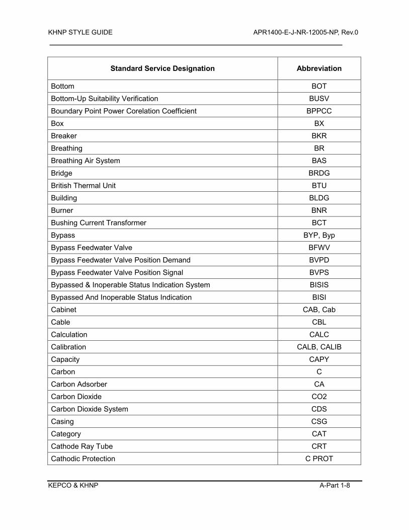
KHNP STYLE GUIDE APR1400-E-J-NR-12005-NP, Rev.0
KEPCO & KHNP A-Part 1-8
Standard Service Designation Abbreviation
Bottom BOT
Bottom-Up Suitability Verification BUSV
Boundary Point Power Corelation Coefficient BPPCC
Box BX
Breaker BKR
Breathing BR
Breathing Air System BAS
Bridge BRDG
British Thermal Unit BTU
Building BLDG
Burner BNR
Bushing Current Transformer BCT
Bypass BYP, Byp
Bypass Feedwater Valve BFWV
Bypass Feedwater Valve Position Demand BVPD
Bypass Feedwater Valve Position Signal BVPS
Bypassed & Inoperable Status Indication System BISIS
Bypassed And Inoperable Status Indication BISI
Cabinet CAB, Cab
Cable CBL
Calculation CALC
Calibration CALB, CALIB
Capacity CAPY
Carbon C
Carbon Adsorber CA
Carbon Dioxide CO2
Carbon Dioxide System CDS
Casing CSG
Category CAT
Cathode Ray Tube CRT
Cathodic Protection C PROT
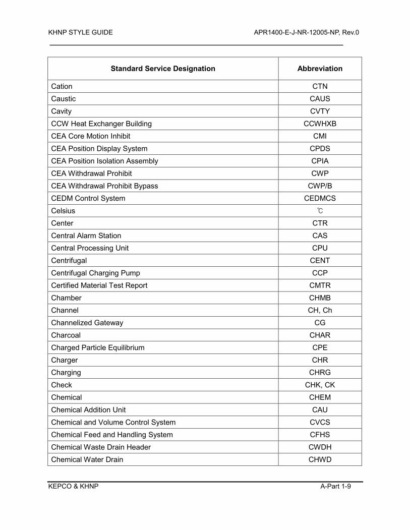
KHNP STYLE GUIDE APR1400-E-J-NR-12005-NP, Rev.0
KEPCO & KHNP A-Part 1-9
Standard Service Designation Abbreviation
Cation CTN
Caustic CAUS
Cavity CVTY
CCW Heat Exchanger Building CCWHXB
CEA Core Motion Inhibit CMI
CEA Position Display System CPDS
CEA Position Isolation Assembly CPIA
CEA Withdrawal Prohibit CWP
CEA Withdrawal Prohibit Bypass CWP/B
CEDM Control System CEDMCS
Celsius
Center CTR
Central Alarm Station CAS
Central Processing Unit CPU
Centrifugal CENT
Centrifugal Charging Pump CCP
Certified Material Test Report CMTR
Chamber CHMB
Channel CH, Ch
Channelized Gateway CG
Charcoal CHAR
Charged Particle Equilibrium CPE
Charger CHR
Charging CHRG
Check CHK, CK
Chemical CHEM
Chemical Addition Unit CAU
Chemical and Volume Control System CVCS
Chemical Feed and Handling System CFHS
Chemical Waste Drain Header CWDH
Chemical Water Drain CHWD
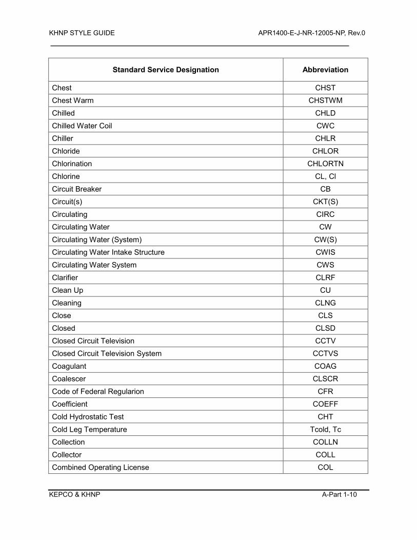
KHNP STYLE GUIDE APR1400-E-J-NR-12005-NP, Rev.0
KEPCO & KHNP A-Part 1-10
Standard Service Designation Abbreviation
Chest CHST
Chest Warm CHSTWM
Chilled CHLD
Chilled Water Coil CWC
Chiller CHLR
Chloride CHLOR
Chlorination CHLORTN
Chlorine CL, Cl
Circuit Breaker CB
Circuit(s) CKT(S)
Circulating CIRC
Circulating Water CW
Circulating Water (System) CW(S)
Circulating Water Intake Structure CWIS
Circulating Water System CWS
Clarifier CLRF
Clean Up CU
Cleaning CLNG
Close CLS
Closed CLSD
Closed Circuit Television CCTV
Closed Circuit Television System CCTVS
Coagulant COAG
Coalescer CLSCR
Code of Federal Regularion CFR
Coefficient COEFF
Cold Hydrostatic Test CHT
Cold Leg Temperature Tcold, Tc
Collection COLLN
Collector COLL
Combined Operating License COL
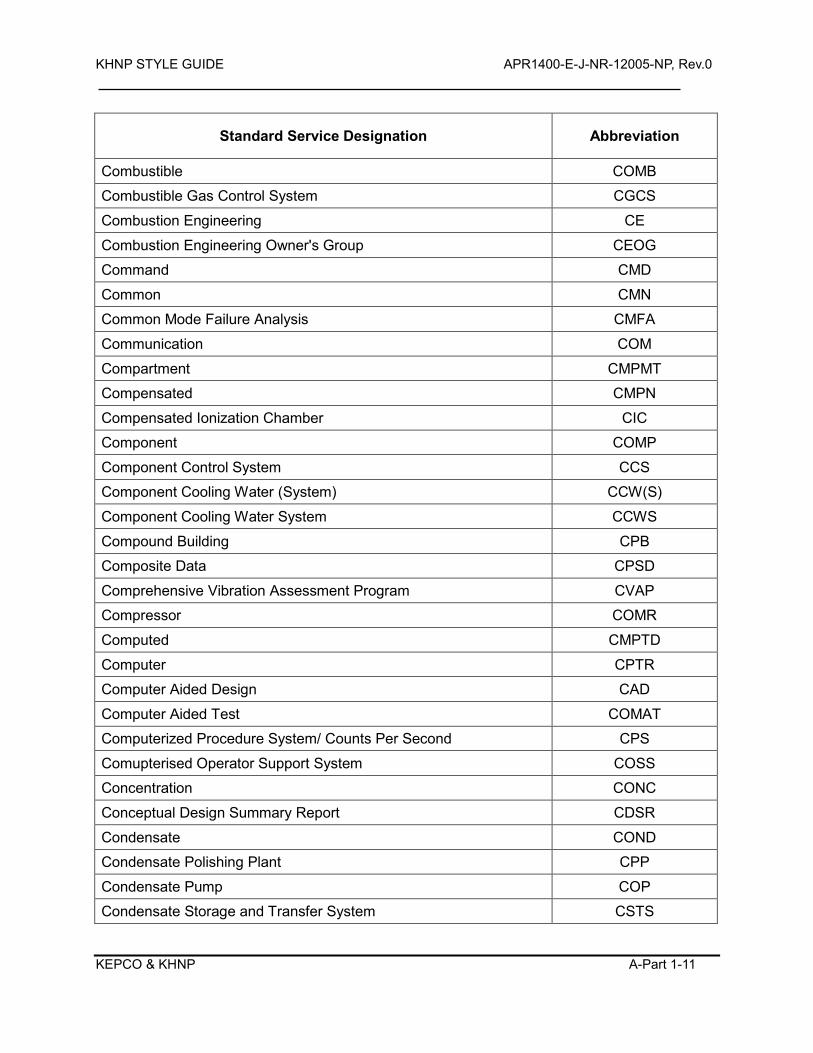
KHNP STYLE GUIDE APR1400-E-J-NR-12005-NP, Rev.0
KEPCO & KHNP A-Part 1-11
Standard Service Designation Abbreviation
Combustible COMB
Combustible Gas Control System CGCS
Combustion Engineering CE
Combustion Engineering Owner's Group CEOG
Command CMD
Common CMN
Common Mode Failure Analysis CMFA
Communication COM
Compartment CMPMT
Compensated CMPN
Compensated Ionization Chamber CIC
Component COMP
Component Control System CCS
Component Cooling Water (System) CCW(S)
Component Cooling Water System CCWS
Compound Building CPB
Composite Data CPSD
Comprehensive Vibration Assessment Program CVAP
Compressor COMR
Computed CMPTD
Computer CPTR
Computer Aided Design CAD
Computer Aided Test COMAT
Computerized Procedure System/ Counts Per Second CPS
Comupterised Operator Support System COSS
Concentration CONC
Conceptual Design Summary Report CDSR
Condensate COND
Condensate Polishing Plant CPP
Condensate Pump COP
Condensate Storage and Transfer System CSTS
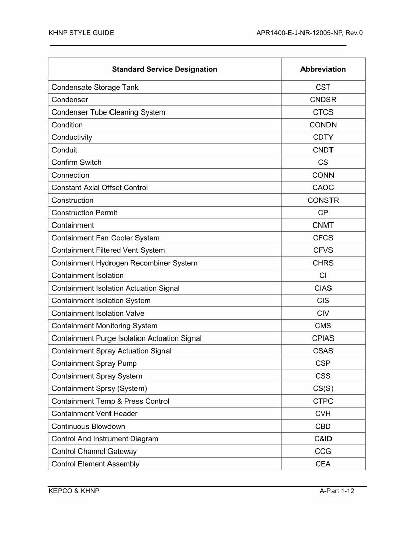
KHNP STYLE GUIDE APR1400-E-J-NR-12005-NP, Rev.0
KEPCO & KHNP A-Part 1-12
Standard Service Designation Abbreviation
Condensate Storage Tank CST
Condenser CNDSR
Condenser Tube Cleaning System CTCS
Condition CONDN
Conductivity CDTY
Conduit CNDT
Confirm Switch CS
Connection CONN
Constant Axial Offset Control CAOC
Construction CONSTR
Construction Permit CP
Containment CNMT
Containment Fan Cooler System CFCS
Containment Filtered Vent System CFVS
Containment Hydrogen Recombiner System CHRS
Containment Isolation CI
Containment Isolation Actuation Signal CIAS
Containment Isolation System CIS
Containment Isolation Valve CIV
Containment Monitoring System CMS
Containment Purge Isolation Actuation Signal CPIAS
Containment Spray Actuation Signal CSAS
Containment Spray Pump CSP
Containment Spray System CSS
Containment Sprsy (System) CS(S)
Containment Temp & Press Control CTPC
Containment Vent Header CVH
Continuous Blowdown CBD
Control And Instrument Diagram C&ID
Control Channel Gateway CCG
Control Element Assembly CEA
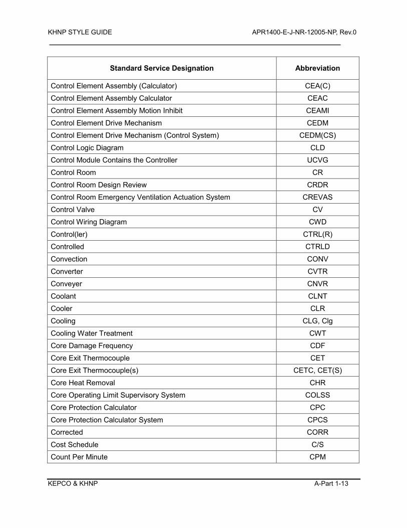
KHNP STYLE GUIDE APR1400-E-J-NR-12005-NP, Rev.0
KEPCO & KHNP A-Part 1-13
Standard Service Designation Abbreviation
Control Element Assembly (Calculator) CEA(C)
Control Element Assembly Calculator CEAC
Control Element Assembly Motion Inhibit CEAMI
Control Element Drive Mechanism CEDM
Control Element Drive Mechanism (Control System) CEDM(CS)
Control Logic Diagram CLD
Control Module Contains the Controller UCVG
Control Room CR
Control Room Design Review CRDR
Control Room Emergency Ventilation Actuation System CREVAS
Control Valve CV
Control Wiring Diagram CWD
Control(ler) CTRL(R)
Controlled CTRLD
Convection CONV
Converter CVTR
Conveyer CNVR
Coolant CLNT
Cooler CLR
Cooling CLG, Clg
Cooling Water Treatment CWT
Core Damage Frequency CDF
Core Exit Thermocouple CET
Core Exit Thermocouple(s) CETC, CET(S)
Core Heat Removal CHR
Core Operating Limit Supervisory System COLSS
Core Protection Calculator CPC
Core Protection Calculator System CPCS
Corrected CORR
Cost Schedule C/S
Count Per Minute CPM
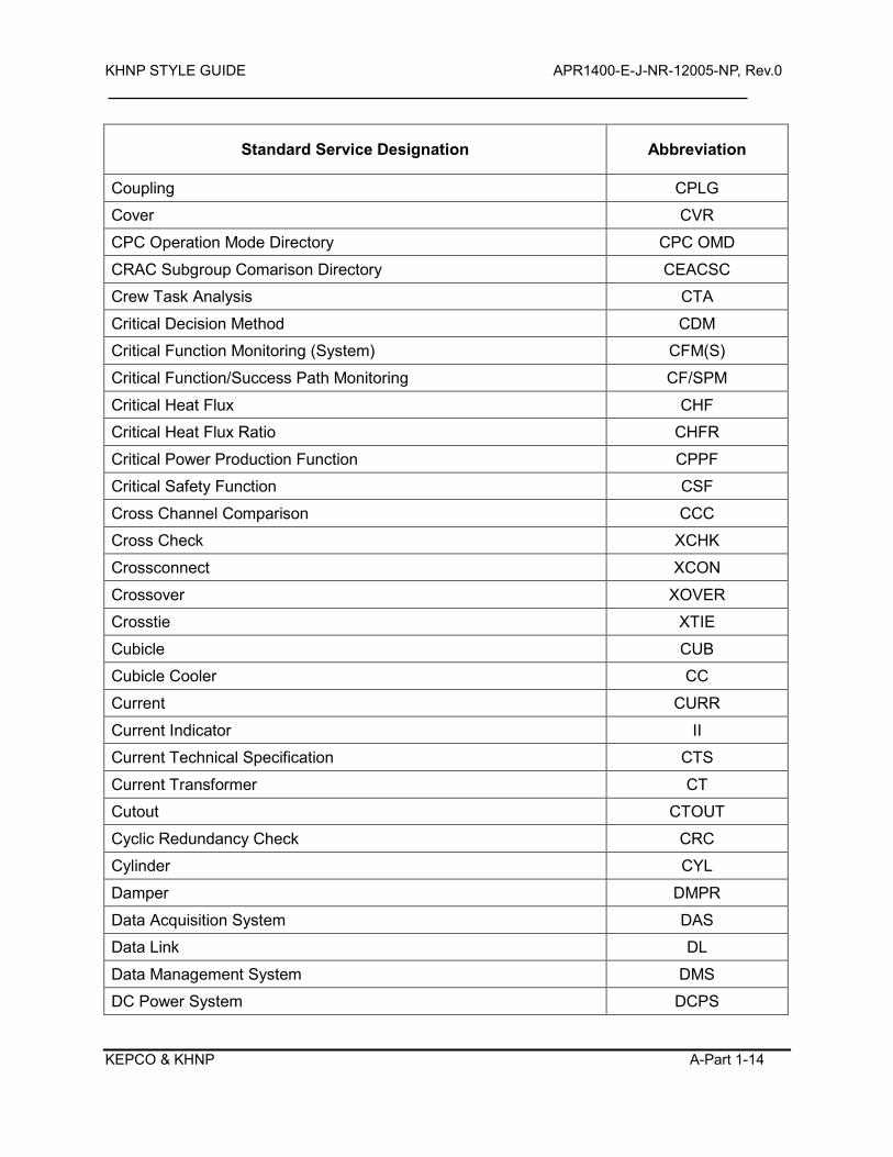
KHNP STYLE GUIDE APR1400-E-J-NR-12005-NP, Rev.0
KEPCO & KHNP A-Part 1-14
Standard Service Designation Abbreviation
Coupling CPLG
Cover CVR
CPC Operation Mode Directory CPC OMD
CRAC Subgroup Comarison Directory CEACSC
Crew Task Analysis CTA
Critical Decision Method CDM
Critical Function Monitoring (System) CFM(S)
Critical Function/Success Path Monitoring CF/SPM
Critical Heat Flux CHF
Critical Heat Flux Ratio CHFR
Critical Power Production Function CPPF
Critical Safety Function CSF
Cross Channel Comparison CCC
Cross Check XCHK
Crossconnect XCON
Crossover XOVER
Crosstie XTIE
Cubicle CUB
Cubicle Cooler CC
Current CURR
Current Indicator II
Current Technical Specification CTS
Current Transformer CT
Cutout CTOUT
Cyclic Redundancy Check CRC
Cylinder CYL
Damper DMPR
Data Acquisition System DAS
Data Link DL
Data Management System DMS
DC Power System DCPS
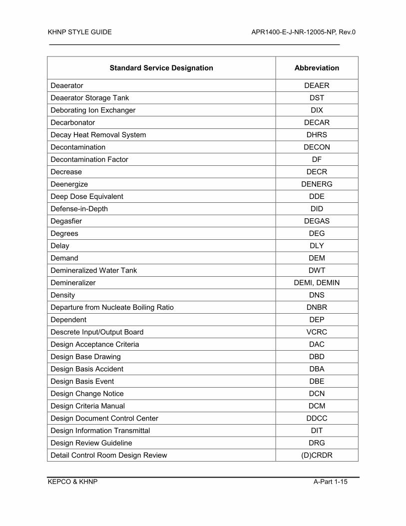
KHNP STYLE GUIDE APR1400-E-J-NR-12005-NP, Rev.0
KEPCO & KHNP A-Part 1-15
Standard Service Designation Abbreviation
Deaerator DEAER
Deaerator Storage Tank DST
Deborating Ion Exchanger DIX
Decarbonator DECAR
Decay Heat Removal System DHRS
Decontamination DECON
Decontamination Factor DF
Decrease DECR
Deenergize DENERG
Deep Dose Equivalent DDE
Defense-in-Depth DID
Degasfier DEGAS
Degrees DEG
Delay DLY
Demand DEM
Demineralized Water Tank DWT
Demineralizer DEMI, DEMIN
Density DNS
Departure from Nucleate Boiling Ratio DNBR
Dependent DEP
Descrete Input/Output Board VCRC
Design Acceptance Criteria DAC
Design Base Drawing DBD
Design Basis Accident DBA
Design Basis Event DBE
Design Change Notice DCN
Design Criteria Manual DCM
Design Document Control Center DDCC
Design Information Transmittal DIT
Design Review Guideline DRG
Detail Control Room Design Review (D)CRDR
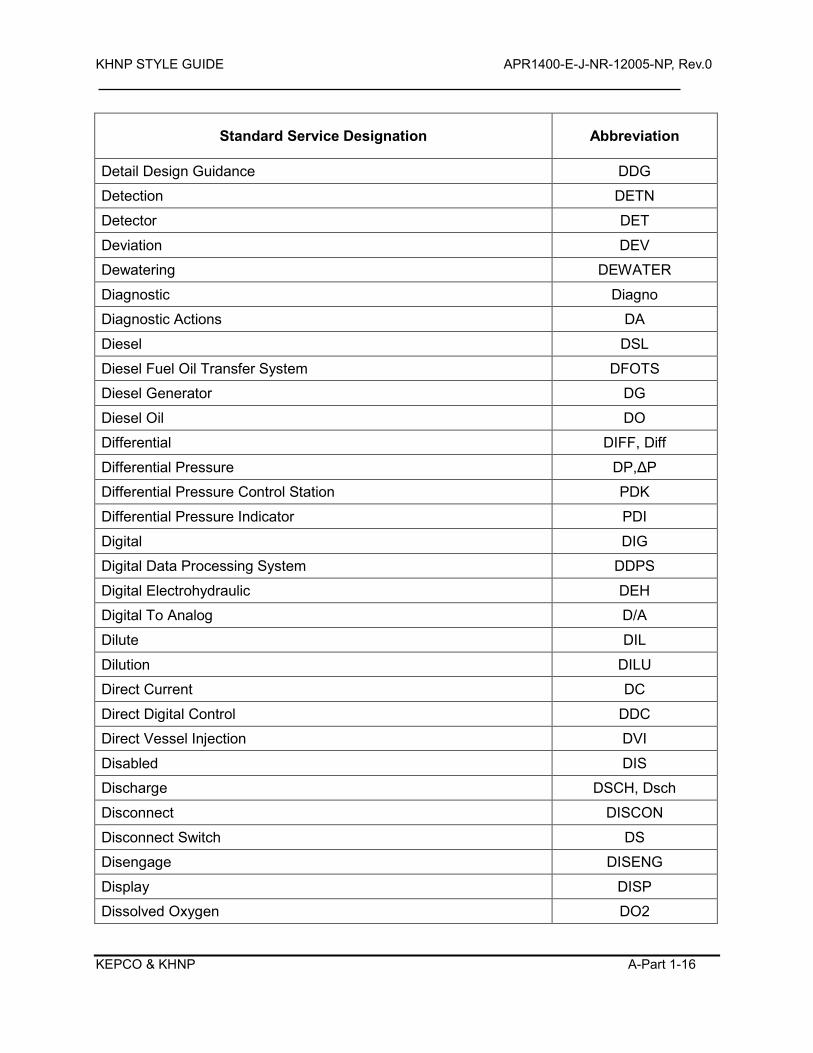
KHNP STYLE GUIDE APR1400-E-J-NR-12005-NP, Rev.0
KEPCO & KHNP A-Part 1-16
Standard Service Designation Abbreviation
Detail Design Guidance DDG
Detection DETN
Detector DET
Deviation DEV
Dewatering DEWATER
Diagnostic Diagno
Diagnostic Actions DA
Diesel DSL
Diesel Fuel Oil Transfer System DFOTS
Diesel Generator DG
Diesel Oil DO
Differential DIFF, Diff
Differential Pressure DP,ΔP
Differential Pressure Control Station PDK
Differential Pressure Indicator PDI
Digital DIG
Digital Data Processing System DDPS
Digital Electrohydraulic DEH
Digital To Analog D/A
Dilute DIL
Dilution DILU
Direct Current DC
Direct Digital Control DDC
Direct Vessel Injection DVI
Disabled DIS
Discharge DSCH, Dsch
Disconnect DISCON
Disconnect Switch DS
Disengage DISENG
Display DISP
Dissolved Oxygen DO2
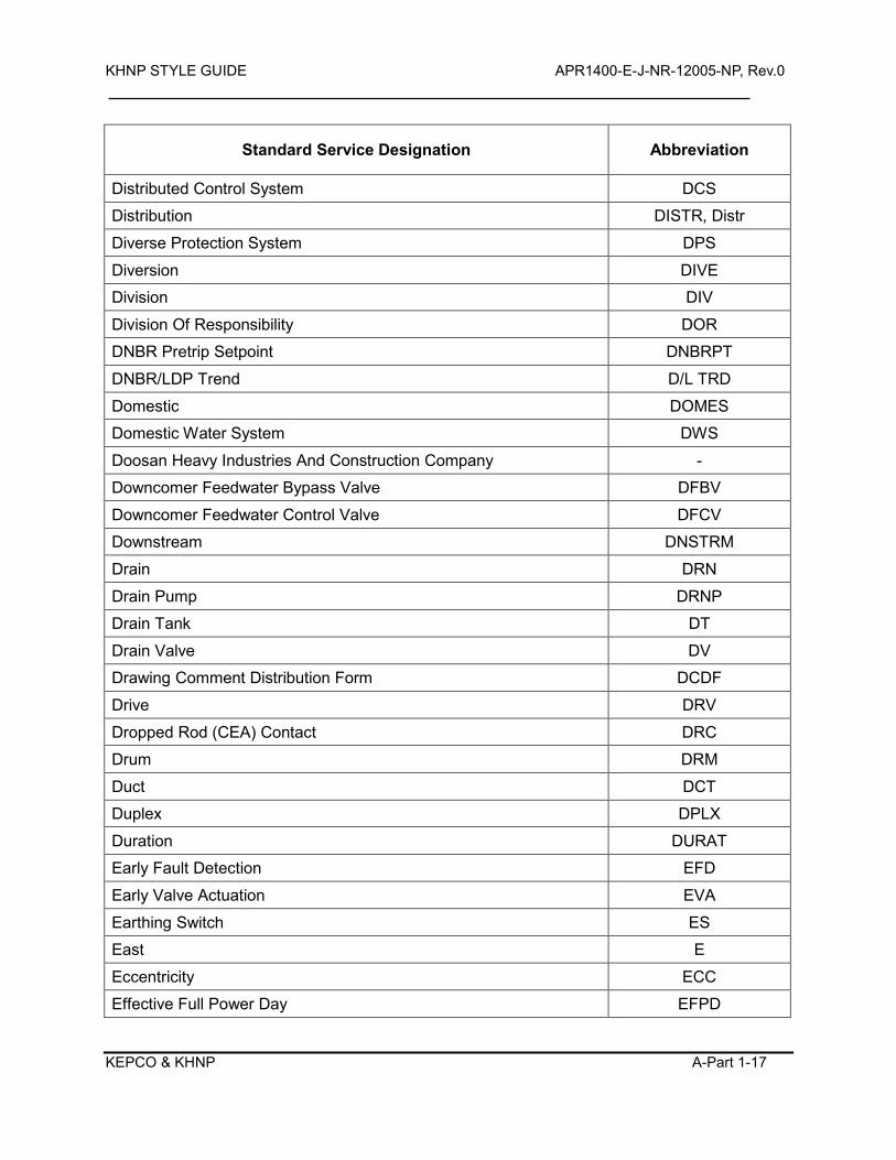
KHNP STYLE GUIDE APR1400-E-J-NR-12005-NP, Rev.0
KEPCO & KHNP A-Part 1-17
Standard Service Designation Abbreviation
Distributed Control System DCS
Distribution DISTR, Distr
Diverse Protection System DPS
Diversion DIVE
Division DIV
Division Of Responsibility DOR
DNBR Pretrip Setpoint DNBRPT
DNBR/LDP Trend D/L TRD
Domestic DOMES
Domestic Water System DWS
Doosan Heavy Industries And Construction Company -
Downcomer Feedwater Bypass Valve DFBV
Downcomer Feedwater Control Valve DFCV
Downstream DNSTRM
Drain DRN
Drain Pump DRNP
Drain Tank DT
Drain Valve DV
Drawing Comment Distribution Form DCDF
Drive DRV
Dropped Rod (CEA) Contact DRC
Drum DRM
Duct DCT
Duplex DPLX
Duration DURAT
Early Fault Detection EFD
Early Valve Actuation EVA
Earthing Switch ES
East E
Eccentricity ECC
Effective Full Power Day EFPD
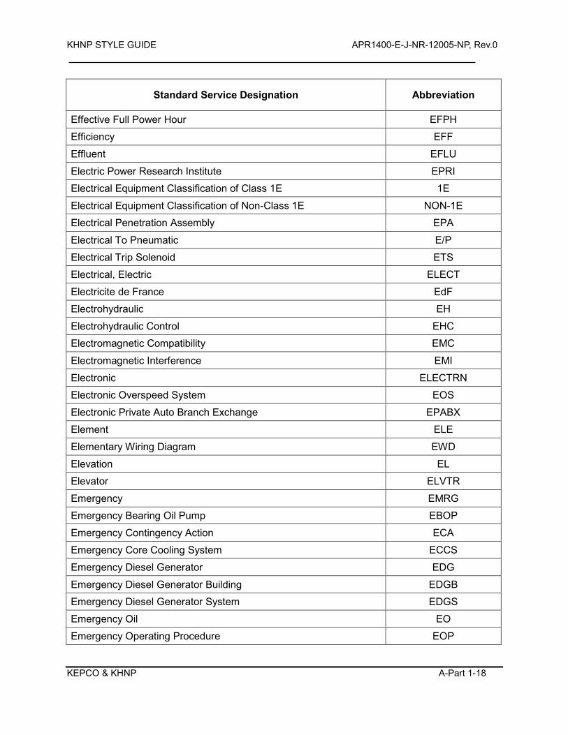
KHNP STYLE GUIDE APR1400-E-J-NR-12005-NP, Rev.0
KEPCO & KHNP A-Part 1-18
Standard Service Designation Abbreviation
Effective Full Power Hour EFPH
Efficiency EFF
Effluent EFLU
Electric Power Research Institute EPRI
Electrical Equipment Classification of Class 1E 1E
Electrical Equipment Classification of Non-Class 1E NON-1E
Electrical Penetration Assembly EPA
Electrical To Pneumatic E/P
Electrical Trip Solenoid ETS
Electrical, Electric ELECT
Electricite de France EdF
Electrohydraulic EH
Electrohydraulic Control EHC
Electromagnetic Compatibility EMC
Electromagnetic Interference EMI
Electronic ELECTRN
Electronic Overspeed System EOS
Electronic Private Auto Branch Exchange EPABX
Element ELE
Elementary Wiring Diagram EWD
Elevation EL
Elevator ELVTR
Emergency EMRG
Emergency Bearing Oil Pump EBOP
Emergency Contingency Action ECA
Emergency Core Cooling System ECCS
Emergency Diesel Generator EDG
Emergency Diesel Generator Building EDGB
Emergency Diesel Generator System EDGS
Emergency Oil EO
Emergency Operating Procedure EOP
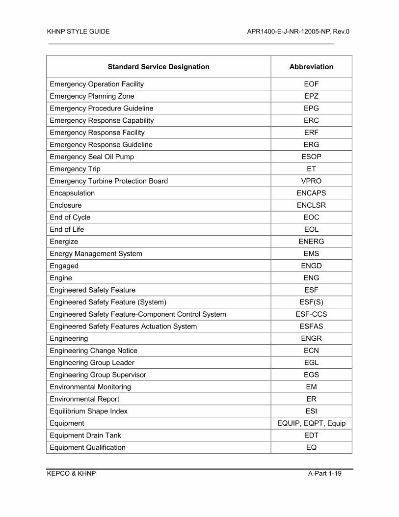
KHNP STYLE GUIDE APR1400-E-J-NR-12005-NP, Rev.0
KEPCO & KHNP A-Part 1-19
Standard Service Designation Abbreviation
Emergency Operation Facility EOF
Emergency Planning Zone EPZ
Emergency Procedure Guideline EPG
Emergency Response Capability ERC
Emergency Response Facility ERF
Emergency Response Guideline ERG
Emergency Seal Oil Pump ESOP
Emergency Trip ET
Emergency Turbine Protection Board VPRO
Encapsulation ENCAPS
Enclosure ENCLSR
End of Cycle EOC
End of Life EOL
Energize ENERG
Energy Management System EMS
Engaged ENGD
Engine ENG
Engineered Safety Feature ESF
Engineered Safety Feature (System) ESF(S)
Engineered Safety Feature-Component Control System ESF-CCS
Engineered Safety Features Actuation System ESFAS
Engineering ENGR
Engineering Change Notice ECN
Engineering Group Leader EGL
Engineering Group Supervisor EGS
Environmental Monitoring EM
Environmental Report ER
Equilibrium Shape Index ESI
Equipment EQUIP, EQPT, Equip
Equipment Drain Tank EDT
Equipment Qualification EQ

KHNP STYLE GUIDE APR1400-E-J-NR-12005-NP, Rev.0
KEPCO & KHNP A-Part 1-20
Standard Service Designation Abbreviation
Equipment Vibration Monitoring System EVMS
Error ERR
ESF Signal Can Be Overriden ESF-2
ESF Signal Cannot Be Overriden ESF-1
ESF-CCS Soft Control Module ESCM
Essential ESSEN, Essen
Essential All Rods Out EARO
Essential Central Chilled Water Makeup Pump ECWMP
Essential Central Chilled Water Pump ECWP
Essential Chilled Water System ECWS
Essential Component Cooling ESCC
Essential Service Water (System) ESW(S)
Essential Service Water System ESWS
Estimated Critical Boron Concentration ECBC
Estimated Critical Position ECP
Estimated Critical Rod Position ECRP
ESW Intake Structure ESWIS
European Utility Requirement EUR
Evacuation EVAC
Evaporator EVAP
EX2100 EX2K
Excess EXCS
Excess Flow Check Valve EFCV
Excess Steam Demand Event ESDE
Exchanger EXCH
Exciter EXC
Exclusion Area Boundary EAB
Excore Neutron Flux Monitoring System ENFMS
Exhaust EXH, Exh
Exhaust Hood EXHD
Exhauster EXHSTR
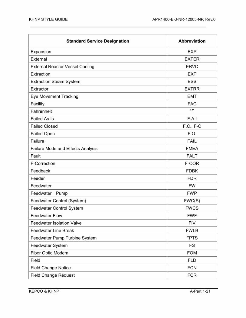
KHNP STYLE GUIDE APR1400-E-J-NR-12005-NP, Rev.0
KEPCO & KHNP A-Part 1-21
Standard Service Designation Abbreviation
Expansion EXP
External EXTER
External Reactor Vessel Cooling ERVC
Extraction EXT
Extraction Steam System ESS
Extractor EXTRR
Eye Movement Tracking EMT
Facility FAC
Fahrenheit
Failed As Is F.A.I
Failed Closed F.C., F-C
Failed Open F.O.
Failure FAIL
Failure Mode and Effects Analysis FMEA
Fault FALT
F-Correction F-COR
Feedback FDBK
Feeder FDR
Feedwater FW
Feedwater Pump FWP
Feedwater Control (System) FWC(S)
Feedwater Control System FWCS
Feedwater Flow FWF
Feedwater Isolation Valve FIV
Feedwater Line Break FWLB
Feedwater Pump Turbine System FPTS
Feedwater System FS
Fiber Optic Modem FOM
Field FLD
Field Change Notice FCN
Field Change Request FCR
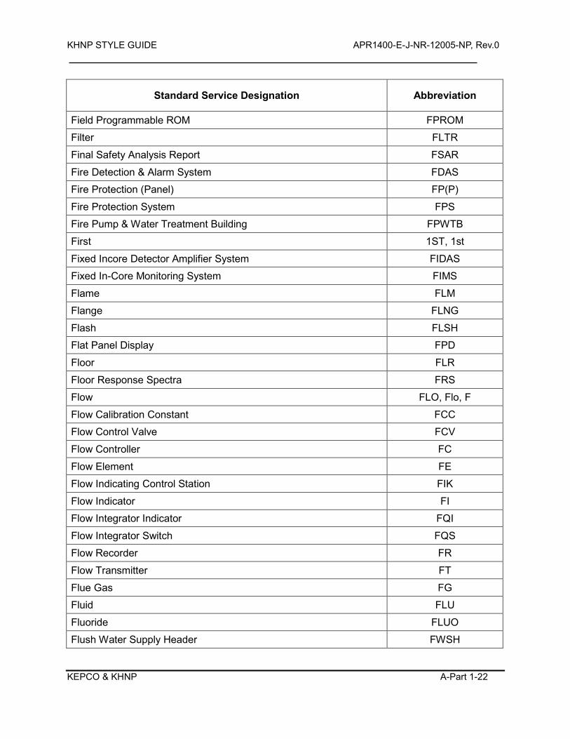
KHNP STYLE GUIDE APR1400-E-J-NR-12005-NP, Rev.0
KEPCO & KHNP A-Part 1-22
Standard Service Designation Abbreviation
Field Programmable ROM FPROM
Filter FLTR
Final Safety Analysis Report FSAR
Fire Detection & Alarm System FDAS
Fire Protection (Panel) FP(P)
Fire Protection System FPS
Fire Pump & Water Treatment Building FPWTB
First 1ST, 1st
Fixed Incore Detector Amplifier System FIDAS
Fixed In-Core Monitoring System FIMS
Flame FLM
Flange FLNG
Flash FLSH
Flat Panel Display FPD
Floor FLR
Floor Response Spectra FRS
Flow FLO, Flo, F
Flow Calibration Constant FCC
Flow Control Valve FCV
Flow Controller FC
Flow Element FE
Flow Indicating Control Station FIK
Flow Indicator FI
Flow Integrator Indicator FQI
Flow Integrator Switch FQS
Flow Recorder FR
Flow Transmitter FT
Flue Gas FG
Fluid FLU
Fluoride FLUO
Flush Water Supply Header FWSH
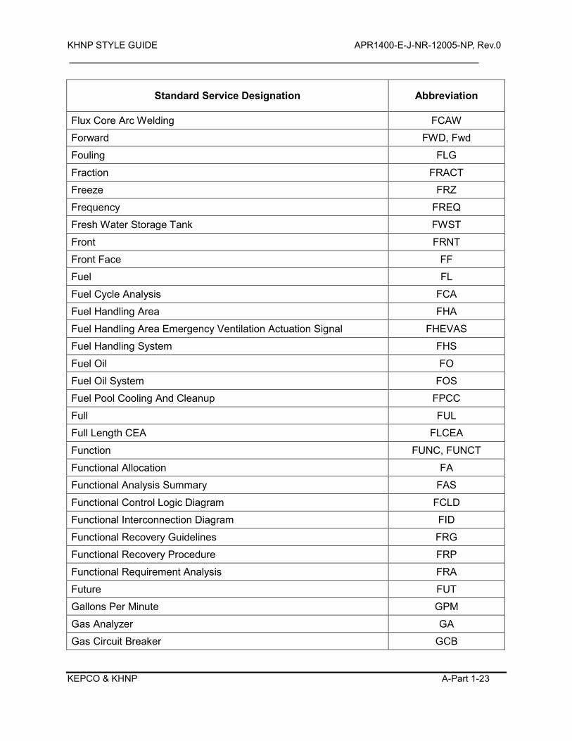
KHNP STYLE GUIDE APR1400-E-J-NR-12005-NP, Rev.0
KEPCO & KHNP A-Part 1-23
Standard Service Designation Abbreviation
Flux Core Arc Welding FCAW
Forward FWD, Fwd
Fouling FLG
Fraction FRACT
Freeze FRZ
Frequency FREQ
Fresh Water Storage Tank FWST
Front FRNT
Front Face FF
Fuel FL
Fuel Cycle Analysis FCA
Fuel Handling Area FHA
Fuel Handling Area Emergency Ventilation Actuation Signal FHEVAS
Fuel Handling System FHS
Fuel Oil FO
Fuel Oil System FOS
Fuel Pool Cooling And Cleanup FPCC
Full FUL
Full Length CEA FLCEA
Function FUNC, FUNCT
Functional Allocation FA
Functional Analysis Summary FAS
Functional Control Logic Diagram FCLD
Functional Interconnection Diagram FID
Functional Recovery Guidelines FRG
Functional Recovery Procedure FRP
Functional Requirement Analysis FRA
Future FUT
Gallons Per Minute GPM
Gas Analyzer GA
Gas Circuit Breaker GCB
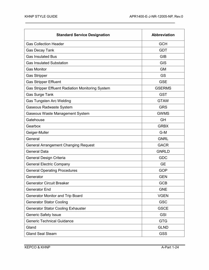
KHNP STYLE GUIDE APR1400-E-J-NR-12005-NP, Rev.0
KEPCO & KHNP A-Part 1-24
Standard Service Designation Abbreviation
Gas Collection Header GCH
Gas Decay Tank GDT
Gas Insulated Bus GIB
Gas Insulated Substation GIS
Gas Monitor GM
Gas Stripper GS
Gas Stripper Effluent GSE
Gas Stripper Effluent Radiation Monitoring System GSERMS
Gas Surge Tank GST
Gas Tungsten Arc Welding GTAW
Gaseous Radwaste System GRS
Gaseous Waste Management System GWMS
Gatehouse GH
Gearbox GRBX
Geiger-Muller G-M
General GNRL
General Arrangement Changing Request GACR
General Data GNRLD
General Design Criteria GDC
General Electric Company GE
General Operating Procedures GOP
Generator GEN
Generator Circuit Breaker GCB
Generator End GNE
Generator Monitor and Trip Board VGEN
Generator Stator Cooling GSC
Generator Stator Cooling Exhauster GSCE
Generic Safety Issue GSI
Generic Technical Guidance GTG
Gland GLND
Gland Seal Steam GSS
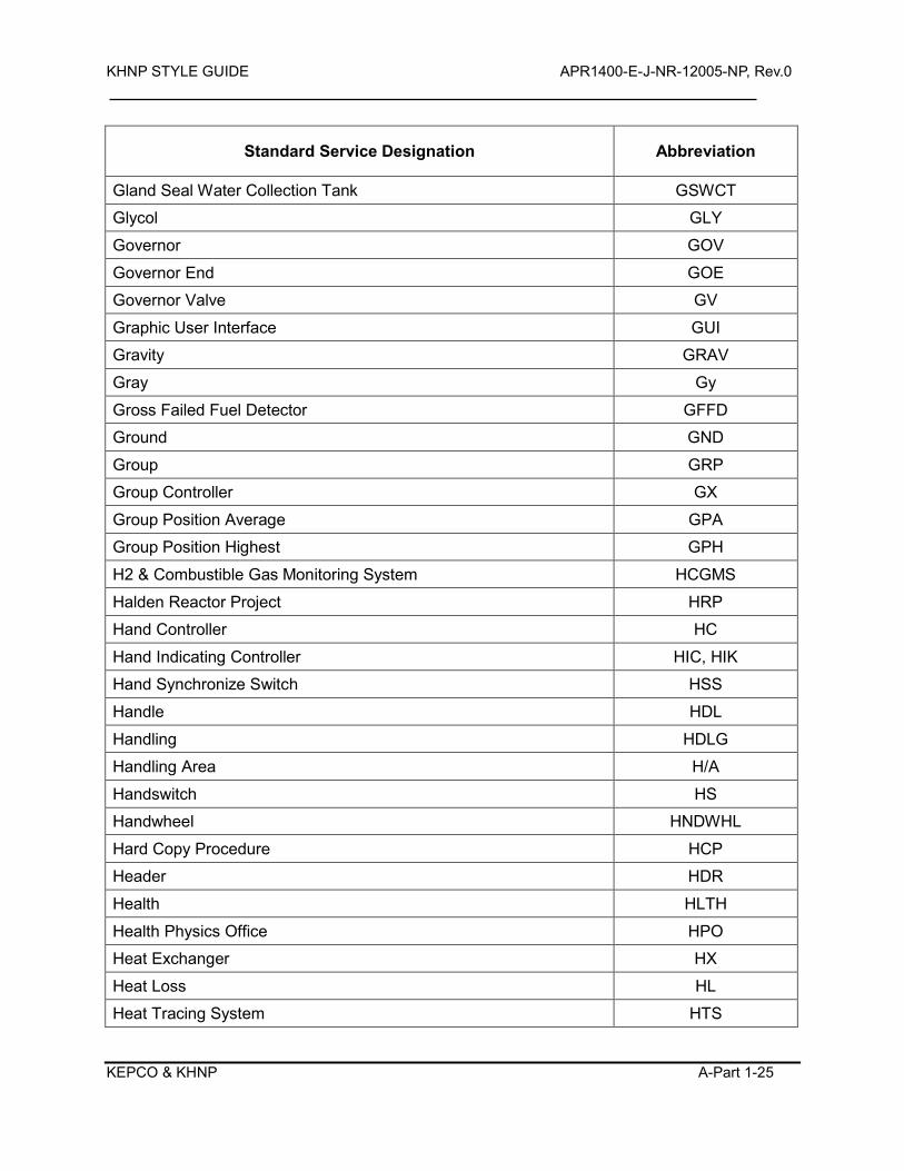
KHNP STYLE GUIDE APR1400-E-J-NR-12005-NP, Rev.0
KEPCO & KHNP A-Part 1-25
Standard Service Designation Abbreviation
Gland Seal Water Collection Tank GSWCT
Glycol GLY
Governor GOV
Governor End GOE
Governor Valve GV
Graphic User Interface GUI
Gravity GRAV
Gray Gy
Gross Failed Fuel Detector GFFD
Ground GND
Group GRP
Group Controller GX
Group Position Average GPA
Group Position Highest GPH
H2 & Combustible Gas Monitoring System HCGMS
Halden Reactor Project HRP
Hand Controller HC
Hand Indicating Controller HIC, HIK
Hand Synchronize Switch HSS
Handle HDL
Handling HDLG
Handling Area H/A
Handswitch HS
Handwheel HNDWHL
Hard Copy Procedure HCP
Header HDR
Health HLTH
Health Physics Office HPO
Heat Exchanger HX
Heat Loss HL
Heat Tracing System HTS
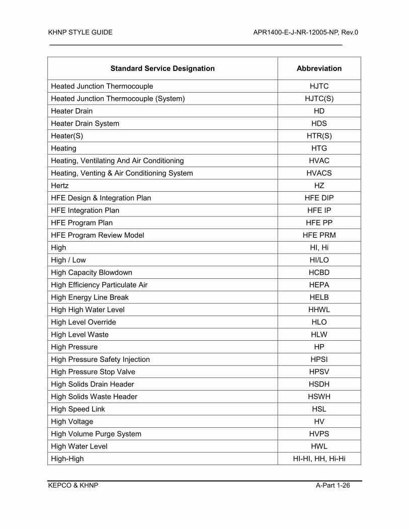
KHNP STYLE GUIDE APR1400-E-J-NR-12005-NP, Rev.0
KEPCO & KHNP A-Part 1-26
Standard Service Designation Abbreviation
Heated Junction Thermocouple HJTC
Heated Junction Thermocouple (System) HJTC(S)
Heater Drain HD
Heater Drain System HDS
Heater(S) HTR(S)
Heating HTG
Heating, Ventilating And Air Conditioning HVAC
Heating, Venting & Air Conditioning System HVACS
Hertz HZ
HFE Design & Integration Plan HFE DIP
HFE Integration Plan HFE IP
HFE Program Plan HFE PP
HFE Program Review Model HFE PRM
High HI, Hi
High / Low HI/LO
High Capacity Blowdown HCBD
High Efficiency Particulate Air HEPA
High Energy Line Break HELB
High High Water Level HHWL
High Level Override HLO
High Level Waste HLW
High Pressure HP
High Pressure Safety Injection HPSI
High Pressure Stop Valve HPSV
High Solids Drain Header HSDH
High Solids Waste Header HSWH
High Speed Link HSL
High Voltage HV
High Volume Purge System HVPS
High Water Level HWL
High-High HI-HI, HH, Hi-Hi
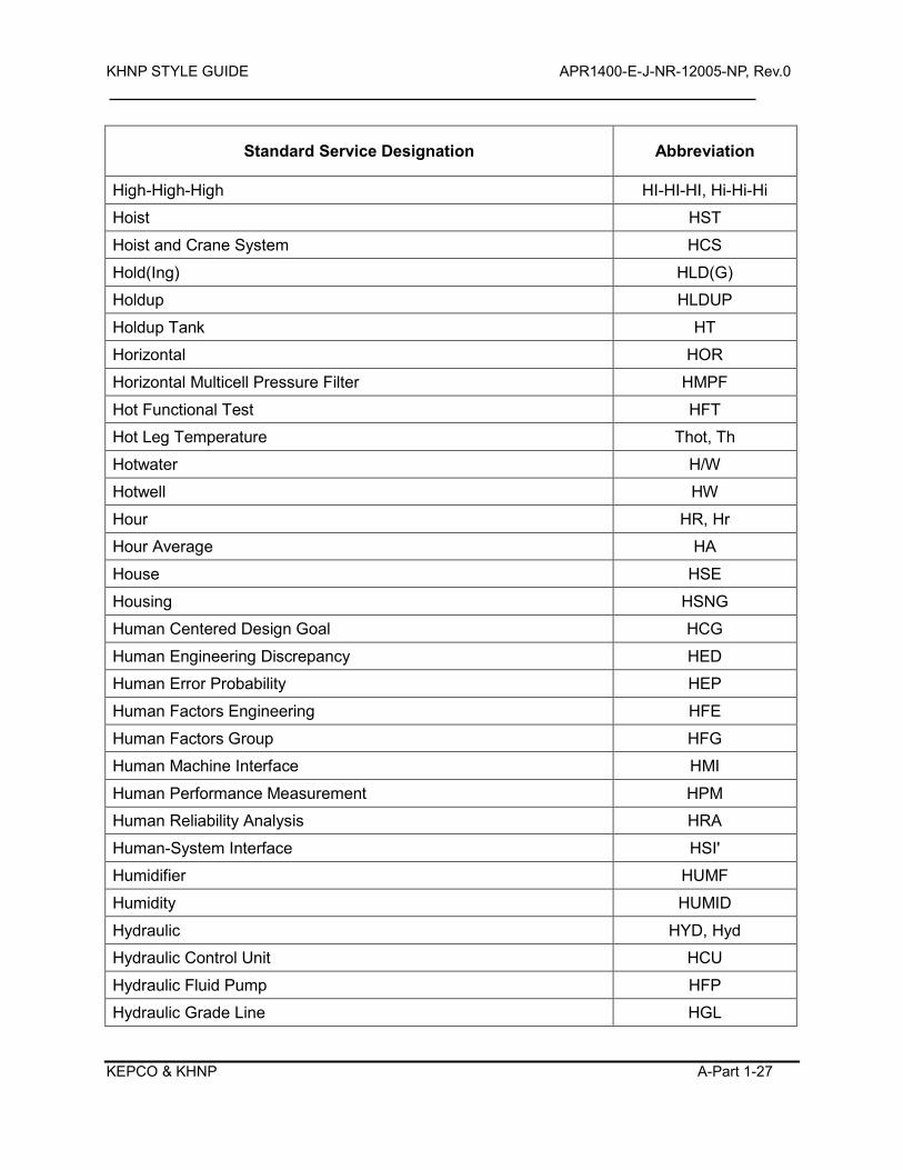
KHNP STYLE GUIDE APR1400-E-J-NR-12005-NP, Rev.0
KEPCO & KHNP A-Part 1-27
Standard Service Designation Abbreviation
High-High-High HI-HI-HI, Hi-Hi-Hi
Hoist HST
Hoist and Crane System HCS
Hold(Ing) HLD(G)
Holdup HLDUP
Holdup Tank HT
Horizontal HOR
Horizontal Multicell Pressure Filter HMPF
Hot Functional Test HFT
Hot Leg Temperature Thot, Th
Hotwater H/W
Hotwell HW
Hour HR, Hr
Hour Average HA
House HSE
Housing HSNG
Human Centered Design Goal HCG
Human Engineering Discrepancy HED
Human Error Probability HEP
Human Factors Engineering HFE
Human Factors Group HFG
Human Machine Interface HMI
Human Performance Measurement HPM
Human Reliability Analysis HRA
Human-System Interface HSI'
Humidifier HUMF
Humidity HUMID
Hydraulic HYD, Hyd
Hydraulic Control Unit HCU
Hydraulic Fluid Pump HFP
Hydraulic Grade Line HGL
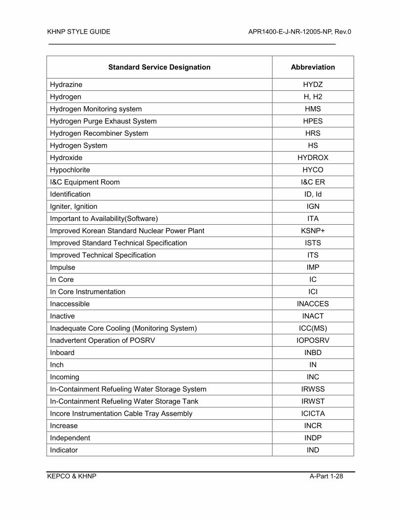
KHNP STYLE GUIDE APR1400-E-J-NR-12005-NP, Rev.0
KEPCO & KHNP A-Part 1-28
Standard Service Designation Abbreviation
Hydrazine HYDZ
Hydrogen H, H2
Hydrogen Monitoring system HMS
Hydrogen Purge Exhaust System HPES
Hydrogen Recombiner System HRS
Hydrogen System HS
Hydroxide HYDROX
Hypochlorite HYCO
I&C Equipment Room I&C ER
Identification ID, Id
Igniter, Ignition IGN
Important to Availability(Software) ITA
Improved Korean Standard Nuclear Power Plant KSNP+
Improved Standard Technical Specification ISTS
Improved Technical Specification ITS
Impulse IMP
In Core IC
In Core Instrumentation ICI
Inaccessible INACCES
Inactive INACT
Inadequate Core Cooling (Monitoring System) ICC(MS)
Inadvertent Operation of POSRV IOPOSRV
Inboard INBD
Inch IN
Incoming INC
In-Containment Refueling Water Storage System IRWSS
In-Containment Refueling Water Storage Tank IRWST
Incore Instrumentation Cable Tray Assembly ICICTA
Increase INCR
Independent INDP
Indicator IND
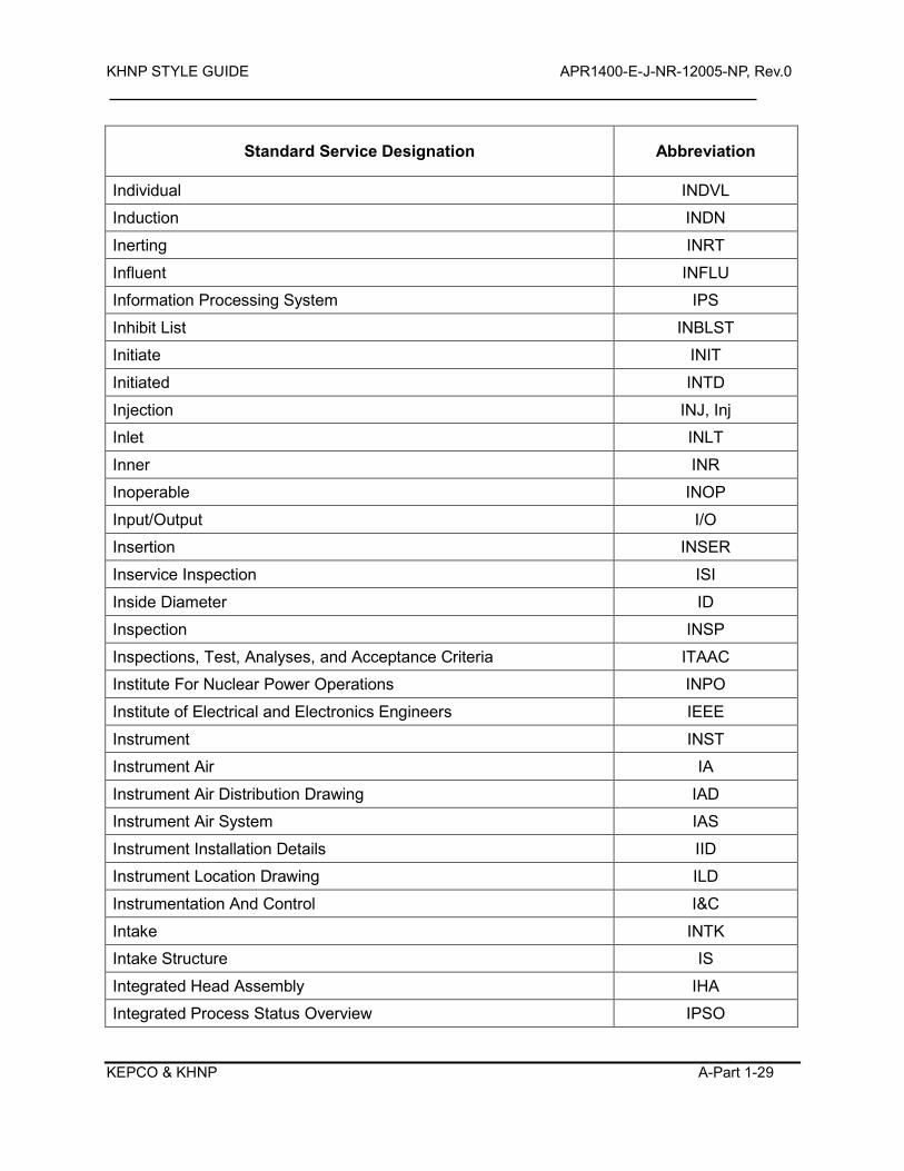
KHNP STYLE GUIDE APR1400-E-J-NR-12005-NP, Rev.0
KEPCO & KHNP A-Part 1-29
Standard Service Designation Abbreviation
Individual INDVL
Induction INDN
Inerting INRT
Influent INFLU
Information Processing System IPS
Inhibit List INBLST
Initiate INIT
Initiated INTD
Injection INJ, Inj
Inlet INLT
Inner INR
Inoperable INOP
Input/Output I/O
Insertion INSER
Inservice Inspection ISI
Inside Diameter ID
Inspection INSP
Inspections, Test, Analyses, and Acceptance Criteria ITAAC
Institute For Nuclear Power Operations INPO
Institute of Electrical and Electronics Engineers IEEE
Instrument INST
Instrument Air IA
Instrument Air Distribution Drawing IAD
Instrument Air System IAS
Instrument Installation Details IID
Instrument Location Drawing ILD
Instrumentation And Control I&C
Intake INTK
Intake Structure IS
Integrated Head Assembly IHA
Integrated Process Status Overview IPSO
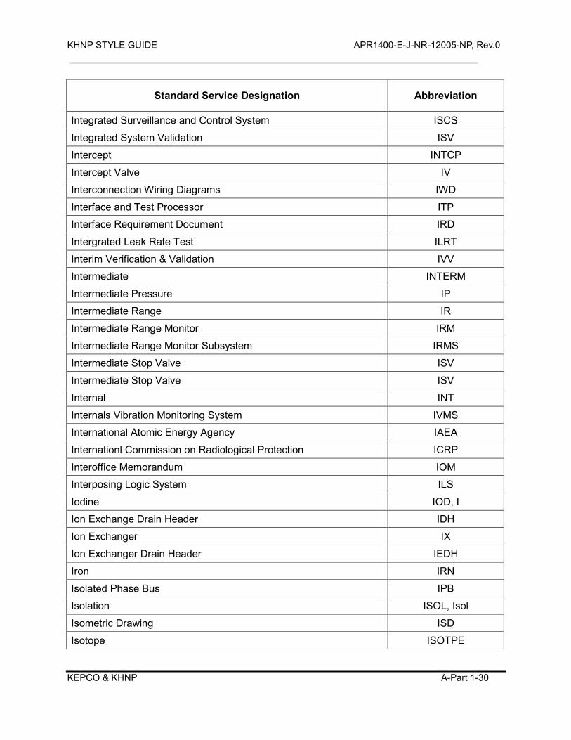
KHNP STYLE GUIDE APR1400-E-J-NR-12005-NP, Rev.0
KEPCO & KHNP A-Part 1-30
Standard Service Designation Abbreviation
Integrated Surveillance and Control System ISCS
Integrated System Validation ISV
Intercept INTCP
Intercept Valve IV
Interconnection Wiring Diagrams IWD
Interface and Test Processor ITP
Interface Requirement Document IRD
Intergrated Leak Rate Test ILRT
Interim Verification & Validation IVV
Intermediate INTERM
Intermediate Pressure IP
Intermediate Range IR
Intermediate Range Monitor IRM
Intermediate Range Monitor Subsystem IRMS
Intermediate Stop Valve ISV
Intermediate Stop Valve ISV
Internal INT
Internals Vibration Monitoring System IVMS
International Atomic Energy Agency IAEA
Internationl Commission on Radiological Protection ICRP
Interoffice Memorandum IOM
Interposing Logic System ILS
Iodine IOD, I
Ion Exchange Drain Header IDH
Ion Exchanger IX
Ion Exchanger Drain Header IEDH
Iron IRN
Isolated Phase Bus IPB
Isolation ISOL, Isol
Isometric Drawing ISD
Isotope ISOTPE
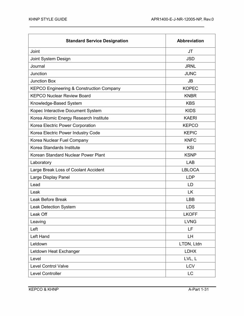
KHNP STYLE GUIDE APR1400-E-J-NR-12005-NP, Rev.0
KEPCO & KHNP A-Part 1-31
Standard Service Designation Abbreviation
Joint JT
Joint System Design JSD
Journal JRNL
Junction JUNC
Junction Box JB
KEPCO Engineering & Construction Company KOPEC
KEPCO Nuclear Review Board KNBR
Knowledge-Based System KBS
Kopec Interactive Document System KIDS
Korea Atomic Energy Research Institute KAERI
Korea Electric Power Corporation KEPCO
Korea Electric Power Industry Code KEPIC
Korea Nuclear Fuel Company KNFC
Korea Standards Institute KSI
Korean Standard Nuclear Power Plant KSNP
Laboratory LAB
Large Break Loss of Coolant Accident LBLOCA
Large Display Panel LDP
Lead LD
Leak LK
Leak Before Break LBB
Leak Detection System LDS
Leak Off LKOFF
Leaving LVNG
Left LF
Left Hand LH
Letdown LTDN, Ltdn
Letdown Heat Exchanger LDHX
Level LVL, L
Level Control Valve LCV
Level Controller LC
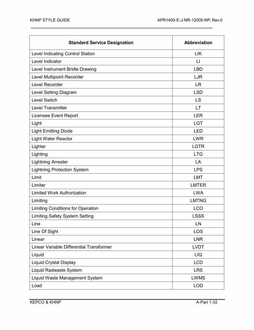
KHNP STYLE GUIDE APR1400-E-J-NR-12005-NP, Rev.0
KEPCO & KHNP A-Part 1-32
Standard Service Designation Abbreviation
Level Indicating Control Station LIK
Level Indicator LI
Level Instrument Bridle Drawing LBD
Level Multipoint Recorder LJR
Level Recorder LR
Level Setting Diagram LSD
Level Switch LS
Level Transmitter LT
Licensee Event Report LER
Light LGT
Light Emitting Diode LED
Light Water Reactor LWR
Lighter LGTR
Lighting LTG
Lightning Arrester LA
Lightning Protection System LPS
Limit LMT
Limiter LMTER
Limited Work Authorization LWA
Limiting LMTNG
Limiting Conditions for Operation LCO
Limiting Safety System Setting LSSS
Line LN
Line Of Sight LOS
Linear LNR
Linear Variable Differential Transformer LVDT
Liquid LIQ
Liquid Crystal Display LCD
Liquid Radwaste System LRS
Liquid Waste Management System LWMS
Load LOD
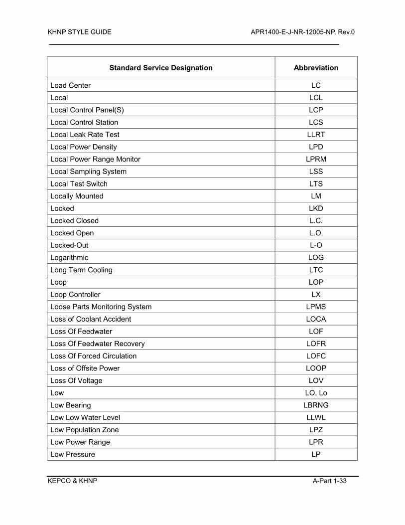
KHNP STYLE GUIDE APR1400-E-J-NR-12005-NP, Rev.0
KEPCO & KHNP A-Part 1-33
Standard Service Designation Abbreviation
Load Center LC
Local LCL
Local Control Panel(S) LCP
Local Control Station LCS
Local Leak Rate Test LLRT
Local Power Density LPD
Local Power Range Monitor LPRM
Local Sampling System LSS
Local Test Switch LTS
Locally Mounted LM
Locked LKD
Locked Closed L.C.
Locked Open L.O.
Locked-Out L-O
Logarithmic LOG
Long Term Cooling LTC
Loop LOP
Loop Controller LX
Loose Parts Monitoring System LPMS
Loss of Coolant Accident LOCA
Loss Of Feedwater LOF
Loss Of Feedwater Recovery LOFR
Loss Of Forced Circulation LOFC
Loss of Offsite Power LOOP
Loss Of Voltage LOV
Low LO, Lo
Low Bearing LBRNG
Low Low Water Level LLWL
Low Population Zone LPZ
Low Power Range LPR
Low Pressure LP
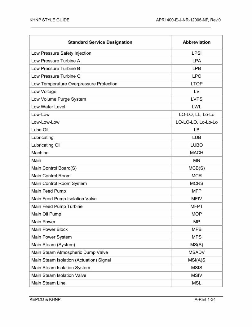
KHNP STYLE GUIDE APR1400-E-J-NR-12005-NP, Rev.0
KEPCO & KHNP A-Part 1-34
Standard Service Designation Abbreviation
Low Pressure Safety Injection LPSI
Low Pressure Turbine A LPA
Low Pressure Turbine B LPB
Low Pressure Turbine C LPC
Low Temperature Overpressure Protection LTOP
Low Voltage LV
Low Volume Purge System LVPS
Low Water Level LWL
Low-Low LO-LO, LL, Lo-Lo
Low-Low-Low LO-LO-LO, Lo-Lo-Lo
Lube Oil LB
Lubricating LUB
Lubricating Oil LUBO
Machine MACH
Main MN
Main Control Board(S) MCB(S)
Main Control Room MCR
Main Control Room System MCRS
Main Feed Pump MFP
Main Feed Pump Isolation Valve MFIV
Main Feed Pump Turbine MFPT
Main Oil Pump MOP
Main Power MP
Main Power Block MPB
Main Power System MPS
Main Steam (System) MS(S)
Main Steam Atmospheric Dump Valve MSADV
Main Steam Isolation (Actuation) Signal MSI(A)S
Main Steam Isolation System MSIS
Main Steam Isolation Valve MSIV
Main Steam Line MSL
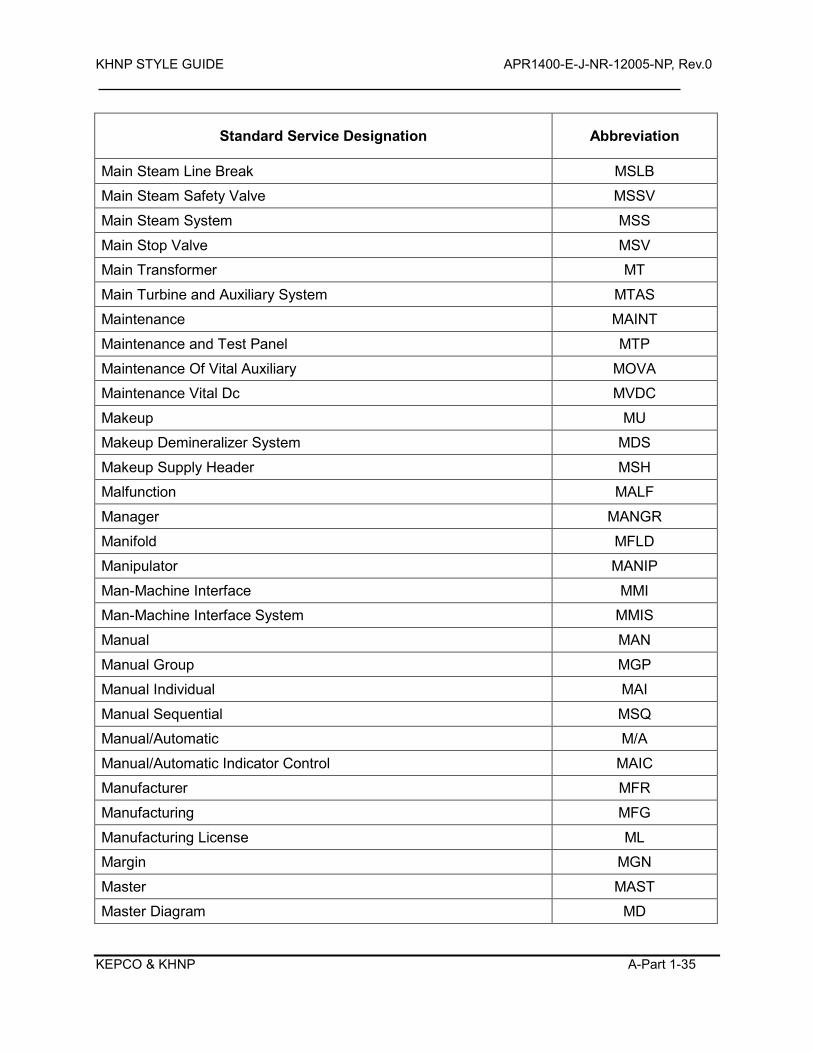
KHNP STYLE GUIDE APR1400-E-J-NR-12005-NP, Rev.0
KEPCO & KHNP A-Part 1-35
Standard Service Designation Abbreviation
Main Steam Line Break MSLB
Main Steam Safety Valve MSSV
Main Steam System MSS
Main Stop Valve MSV
Main Transformer MT
Main Turbine and Auxiliary System MTAS
Maintenance MAINT
Maintenance and Test Panel MTP
Maintenance Of Vital Auxiliary MOVA
Maintenance Vital Dc MVDC
Makeup MU
Makeup Demineralizer System MDS
Makeup Supply Header MSH
Malfunction MALF
Manager MANGR
Manifold MFLD
Manipulator MANIP
Man-Machine Interface MMI
Man-Machine Interface System MMIS
Manual MAN
Manual Group MGP
Manual Individual MAI
Manual Sequential MSQ
Manual/Automatic M/A
Manual/Automatic Indicator Control MAIC
Manufacturer MFR
Manufacturing MFG
Manufacturing License ML
Margin MGN
Master MAST
Master Diagram MD
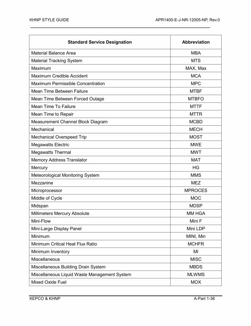
KHNP STYLE GUIDE APR1400-E-J-NR-12005-NP, Rev.0
KEPCO & KHNP A-Part 1-36
Standard Service Designation Abbreviation
Material Balance Area MBA
Material Tracking System MTS
Maximum MAX, Max
Maximum Credible Accident MCA
Maximum Permissible Concentration MPC
Mean Time Between Failure MTBF
Mean Time Between Forced Outage MTBFO
Mean Time To Failure MTTF
Mean Time to Repair MTTR
Measurement Channel Block Diagram MCBD
Mechanical MECH
Mechanical Overspeed Trip MOST
Megawatts Electric MWE
Megawatts Thermal MWT
Memory Address Translator MAT
Mercury HG
Meteorological Monitoring System MMS
Mezzanine MEZ
Microprocessor MPROCES
Middle of Cycle MOC
Midspan MDSP
Millimeters Mercury Absolute MM HGA
Mini-Flow Mini F
Mini-Large Display Panel Mini LDP
Minimum MINI, Min
Minimum Critical Heat Flux Ratio MCHFR
Minimum Inventory MI
Miscellaneous MISC
Miscellaneous Building Drain System MBDS
Miscellaneous Liquid Waste Management System MLWMS
Mixed Oxide Fuel MOX
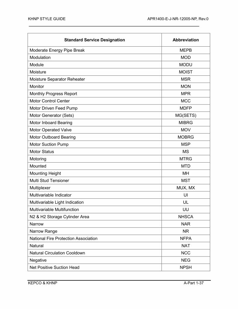
KHNP STYLE GUIDE APR1400-E-J-NR-12005-NP, Rev.0
KEPCO & KHNP A-Part 1-37
Standard Service Designation Abbreviation
Moderate Energy Pipe Break MEPB
Modulation MOD
Module MODU
Moisture MOIST
Moisture Separator Reheater MSR
Monitor MON
Monthly Progress Report MPR
Motor Control Center MCC
Motor Driven Feed Pump MDFP
Motor Generator (Sets) MG(SETS)
Motor Inboard Bearing MIBRG
Motor Operated Valve MOV
Motor Outboard Bearing MOBRG
Motor Suction Pump MSP
Motor Status MS
Motoring MTRG
Mounted MTD
Mounting Height MH
Multi Stud Tensioner MST
Multiplexer MUX, MX
Multivariable Indicator UI
Multivariable Light Indication UL
Multivariable Multifunction UU
N2 & H2 Storage Cylinder Area NHSCA
Narrow NAR
Narrow Range NR
National Fire Protection Association NFPA
Natural NAT
Natural Circulation Cooldown NCC
Negative NEG
Net Positive Suction Head NPSH
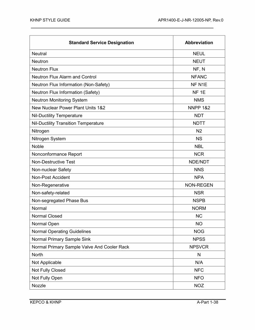
KHNP STYLE GUIDE APR1400-E-J-NR-12005-NP, Rev.0
KEPCO & KHNP A-Part 1-38
Standard Service Designation Abbreviation
Neutral NEUL
Neutron NEUT
Neutron Flux NF, N
Neutron Flux Alarm and Control NFANC
Neutron Flux Information (Non-Safety) NF N1E
Neutron Flux Information (Safety) NF 1E
Neutron Monitoring System NMS
New Nuclear Power Plant Units 1&2 NNPP 1&2
Nil-Ductility Temperature NDT
Nil-Ductility Transition Temperature NDTT
Nitrogen N2
Nitrogen System NS
Noble NBL
Nonconformance Report NCR
Non-Destructive Test NDE/NDT
Non-nuclear Safety NNS
Non-Post Accident NPA
Non-Regenerative NON-REGEN
Non-safety-related NSR
Non-segregated Phase Bus NSPB
Normal NORM
Normal Closed NC
Normal Open NO
Normal Operating Guidelines NOG
Normal Primary Sample Sink NPSS
Normal Primary Sample Valve And Cooler Rack NPSVCR
North N
Not Applicable N/A
Not Fully Closed NFC
Not Fully Open NFO
Nozzle NOZ
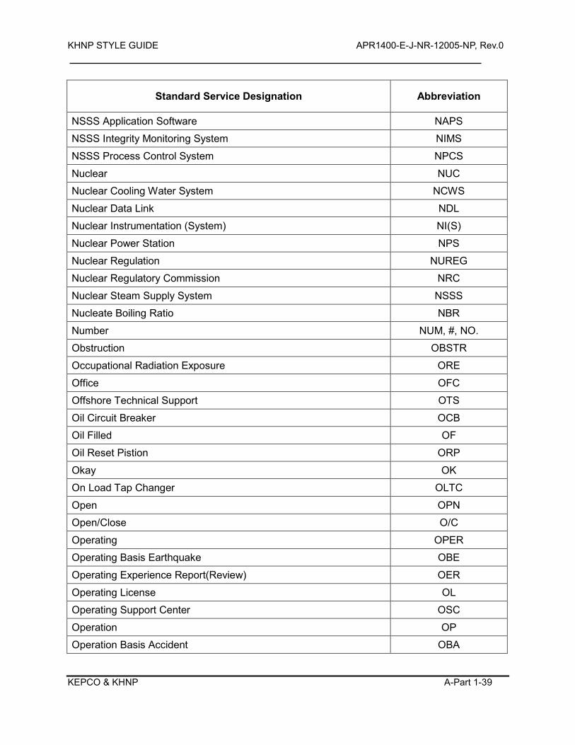
KHNP STYLE GUIDE APR1400-E-J-NR-12005-NP, Rev.0
KEPCO & KHNP A-Part 1-39
Standard Service Designation Abbreviation
NSSS Application Software NAPS
NSSS Integrity Monitoring System NIMS
NSSS Process Control System NPCS
Nuclear NUC
Nuclear Cooling Water System NCWS
Nuclear Data Link NDL
Nuclear Instrumentation (System) NI(S)
Nuclear Power Station NPS
Nuclear Regulation NUREG
Nuclear Regulatory Commission NRC
Nuclear Steam Supply System NSSS
Nucleate Boiling Ratio NBR
Number NUM, #, NO.
Obstruction OBSTR
Occupational Radiation Exposure ORE
Office OFC
Offshore Technical Support OTS
Oil Circuit Breaker OCB
Oil Filled OF
Oil Reset Pistion ORP
Okay OK
On Load Tap Changer OLTC
Open OPN
Open/Close O/C
Operating OPER
Operating Basis Earthquake OBE
Operating Experience Report(Review) OER
Operating License OL
Operating Support Center OSC
Operation OP
Operation Basis Accident OBA
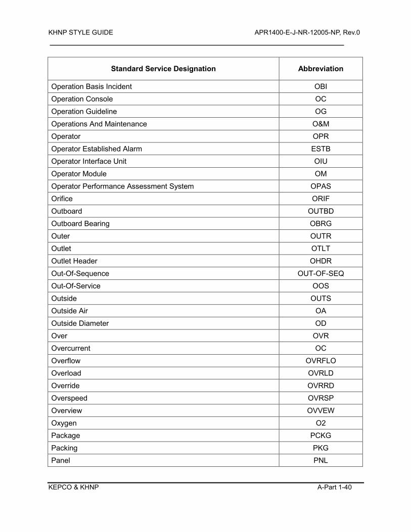
KHNP STYLE GUIDE APR1400-E-J-NR-12005-NP, Rev.0
KEPCO & KHNP A-Part 1-40
Standard Service Designation Abbreviation
Operation Basis Incident OBI
Operation Console OC
Operation Guideline OG
Operations And Maintenance O&M
Operator OPR
Operator Established Alarm ESTB
Operator Interface Unit OIU
Operator Module OM
Operator Performance Assessment System OPAS
Orifice ORIF
Outboard OUTBD
Outboard Bearing OBRG
Outer OUTR
Outlet OTLT
Outlet Header OHDR
Out-Of-Sequence OUT-OF-SEQ
Out-Of-Service OOS
Outside OUTS
Outside Air OA
Outside Diameter OD
Over OVR
Overcurrent OC
Overflow OVRFLO
Overload OVRLD
Override OVRRD
Overspeed OVRSP
Overview OVVEW
Oxygen O2
Package PCKG
Packing PKG
Panel PNL
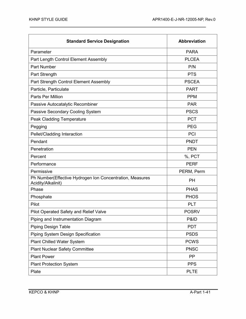
KHNP STYLE GUIDE APR1400-E-J-NR-12005-NP, Rev.0
KEPCO & KHNP A-Part 1-41
Standard Service Designation Abbreviation
Parameter PARA
Part Length Control Element Assembly PLCEA
Part Number P/N
Part Strength PTS
Part Strength Control Element Assembly PSCEA
Particle, Particulate PART
Parts Per Million PPM
Passive Autocatalytic Recombiner PAR
Passive Secondary Cooling System PSCS
Peak Cladding Temperature PCT
Pegging PEG
Pellet/Cladding Interaction PCI
Pendant PNDT
Penetration PEN
Percent %, PCT
Performance PERF
Permissive PERM, Perm Ph Number(Effective Hydrogen Ion Concentration, Measures Acidity/Alkalinit) PH
Phase PHAS
Phosphate PHOS
Pilot PLT
Pilot Operated Safety and Relief Valve POSRV
Piping and Instrumentation Diagram P&ID
Piping Design Table PDT
Piping System Design Specification PSDS
Plant Chilled Water System PCWS
Plant Nuclear Safety Committee PNSC
Plant Power PP
Plant Protection System PPS
Plate PLTE
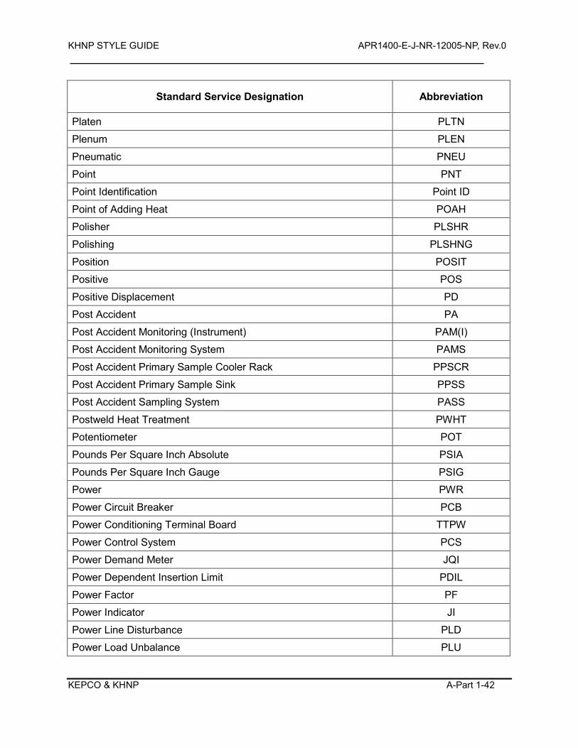
KHNP STYLE GUIDE APR1400-E-J-NR-12005-NP, Rev.0
KEPCO & KHNP A-Part 1-42
Standard Service Designation Abbreviation
Platen PLTN
Plenum PLEN
Pneumatic PNEU
Point PNT
Point Identification Point ID
Point of Adding Heat POAH
Polisher PLSHR
Polishing PLSHNG
Position POSIT
Positive POS
Positive Displacement PD
Post Accident PA
Post Accident Monitoring (Instrument) PAM(I)
Post Accident Monitoring System PAMS
Post Accident Primary Sample Cooler Rack PPSCR
Post Accident Primary Sample Sink PPSS
Post Accident Sampling System PASS
Postweld Heat Treatment PWHT
Potentiometer POT
Pounds Per Square Inch Absolute PSIA
Pounds Per Square Inch Gauge PSIG
Power PWR
Power Circuit Breaker PCB
Power Conditioning Terminal Board TTPW
Power Control System PCS
Power Demand Meter JQI
Power Dependent Insertion Limit PDIL
Power Factor PF
Power Indicator JI
Power Line Disturbance PLD
Power Load Unbalance PLU
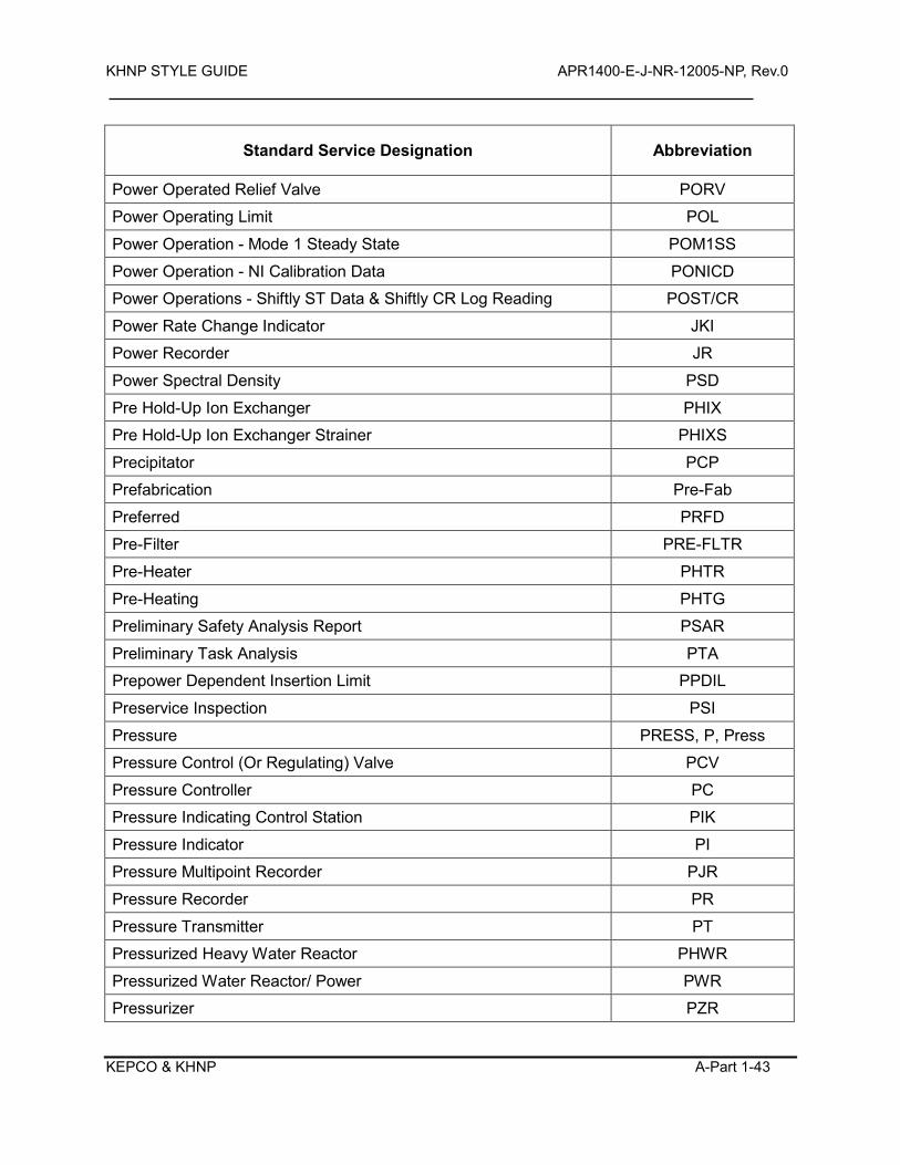
KHNP STYLE GUIDE APR1400-E-J-NR-12005-NP, Rev.0
KEPCO & KHNP A-Part 1-43
Standard Service Designation Abbreviation
Power Operated Relief Valve PORV
Power Operating Limit POL
Power Operation - Mode 1 Steady State POM1SS
Power Operation - NI Calibration Data PONICD
Power Operations - Shiftly ST Data & Shiftly CR Log Reading POST/CR
Power Rate Change Indicator JKI
Power Recorder JR
Power Spectral Density PSD
Pre Hold-Up Ion Exchanger PHIX
Pre Hold-Up Ion Exchanger Strainer PHIXS
Precipitator PCP
Prefabrication Pre-Fab
Preferred PRFD
Pre-Filter PRE-FLTR
Pre-Heater PHTR
Pre-Heating PHTG
Preliminary Safety Analysis Report PSAR
Preliminary Task Analysis PTA
Prepower Dependent Insertion Limit PPDIL
Preservice Inspection PSI
Pressure PRESS, P, Press
Pressure Control (Or Regulating) Valve PCV
Pressure Controller PC
Pressure Indicating Control Station PIK
Pressure Indicator PI
Pressure Multipoint Recorder PJR
Pressure Recorder PR
Pressure Transmitter PT
Pressurized Heavy Water Reactor PHWR
Pressurized Water Reactor/ Power PWR
Pressurizer PZR
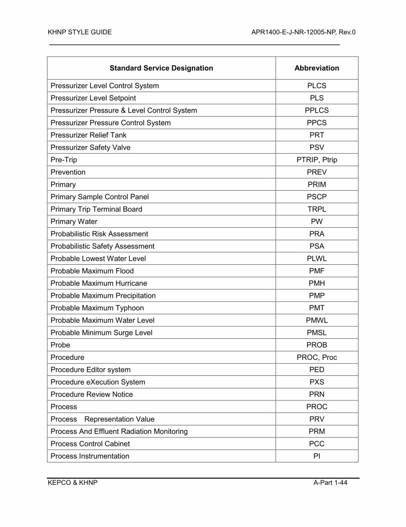
KHNP STYLE GUIDE APR1400-E-J-NR-12005-NP, Rev.0
KEPCO & KHNP A-Part 1-44
Standard Service Designation Abbreviation
Pressurizer Level Control System PLCS
Pressurizer Level Setpoint PLS
Pressurizer Pressure & Level Control System PPLCS
Pressurizer Pressure Control System PPCS
Pressurizer Relief Tank PRT
Pressurizer Safety Valve PSV
Pre-Trip PTRIP, Ptrip
Prevention PREV
Primary PRIM
Primary Sample Control Panel PSCP
Primary Trip Terminal Board TRPL
Primary Water PW
Probabilistic Risk Assessment PRA
Probabilistic Safety Assessment PSA
Probable Lowest Water Level PLWL
Probable Maximum Flood PMF
Probable Maximum Hurricane PMH
Probable Maximum Precipitation PMP
Probable Maximum Typhoon PMT
Probable Maximum Water Level PMWL
Probable Minimum Surge Level PMSL
Probe PROB
Procedure PROC, Proc
Procedure Editor system PED
Procedure eXecution System PXS
Procedure Review Notice PRN
Process PROC
Process Representation Value PRV
Process And Effluent Radiation Monitoring PRM
Process Control Cabinet PCC
Process Instrumentation PI
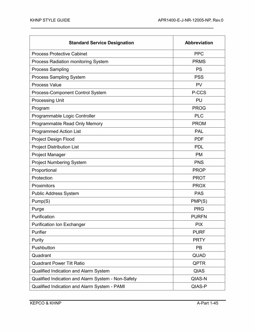
KHNP STYLE GUIDE APR1400-E-J-NR-12005-NP, Rev.0
KEPCO & KHNP A-Part 1-45
Standard Service Designation Abbreviation
Process Protective Cabinet PPC
Process Radiation monitoring System PRMS
Process Sampling PS
Process Sampling System PSS
Process Value PV
Process-Component Control System P-CCS
Processing Unit PU
Program PROG
Programmable Logic Controller PLC
Programmable Read Only Memory PROM
Programmed Action List PAL
Project Design Flood PDF
Project Distribution List PDL
Project Manager PM
Project Numbering System PNS
Proportional PROP
Protection PROT
Proximitors PROX
Public Address System PAS
Pump(S) PMP(S)
Purge PRG
Purification PURFN
Purification Ion Exchanger PIX
Purifier PURF
Purity PRTY
Pushbutton PB
Quadrant QUAD
Quadrant Power Tilt Ratio QPTR
Qualified Indication and Alarm System QIAS
Qualified Indication and Alarm System - Non-Safety QIAS-N
Qualified Indication and Alarm System - PAMI QIAS-P
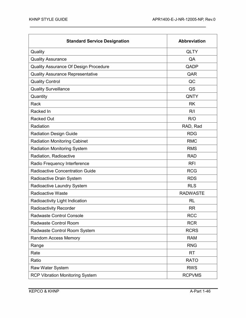
KHNP STYLE GUIDE APR1400-E-J-NR-12005-NP, Rev.0
KEPCO & KHNP A-Part 1-46
Standard Service Designation Abbreviation
Quality QLTY
Quality Assurance QA
Quality Assurance Of Design Procedure QADP
Quality Assurance Representative QAR
Quality Control QC
Quality Surveillance QS
Quantity QNTY
Rack RK
Racked In R/I
Racked Out R/O
Radiation RAD, Rad
Radiation Design Guide RDG
Radiation Monitoring Cabinet RMC
Radiation Monitoring System RMS
Radiation, Radioactive RAD
Radio Frequency Interference RFI
Radioactive Concentration Guide RCG
Radioactive Drain System RDS
Radioactive Laundry System RLS
Radioactive Waste RADWASTE
Radioactivity Light Indication RL
Radioactivity Recorder RR
Radwaste Control Console RCC
Radwaste Control Room RCR
Radwaste Control Room System RCRS
Random Access Memory RAM
Range RNG
Rate RT
Ratio RATO
Raw Water System RWS
RCP Vibration Monitoring System RCPVMS
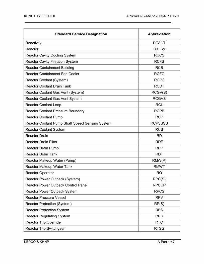
KHNP STYLE GUIDE APR1400-E-J-NR-12005-NP, Rev.0
KEPCO & KHNP A-Part 1-47
Standard Service Designation Abbreviation
Reactivity REACT
Reactor RX, Rx
Reactor Cavity Cooling System RCCS
Reactor Cavity Filtration System RCFS
Reactor Containment Building RCB
Reactor Containment Fan Cooler RCFC
Reactor Coolant (System) RC(S)
Reactor Coolant Drain Tank RCDT
Reactor Coolant Gas Vent (System) RCGV(S)
Reactor Coolant Gas Vent System RCGVS
Reactor Coolant Loop RCL
Reactor Coolant Pressure Boundary RCPB
Reactor Coolant Pump RCP
Reactor Coolant Pump Shaft Speed Sensing System RCPSSSS
Reactor Coolant System RCS
Reactor Drain RD
Reactor Drain Filter RDF
Reactor Drain Pump RDP
Reactor Drain Tank RDT
Reactor Makeup Water (Pump) RMW(P)
Reactor Makeup Water Tank RMWT
Reactor Operator RO
Reactor Power Cutback (System) RPC(S)
Reactor Power Cutback Control Panel RPCCP
Reactor Power Cutback System RPCS
Reactor Pressure Vessel RPV
Reactor Protection (System) RP(S)
Reactor Protection System RPS
Reactor Regulating System RRS
Reactor Trip Override RTO
Reactor Trip Switchgear RTSG
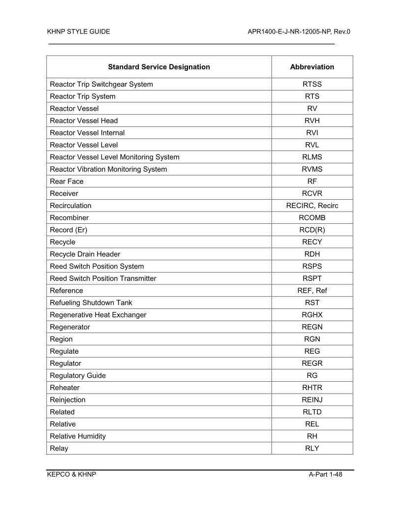
KHNP STYLE GUIDE APR1400-E-J-NR-12005-NP, Rev.0
KEPCO & KHNP A-Part 1-48
Standard Service Designation Abbreviation
Reactor Trip Switchgear System RTSS
Reactor Trip System RTS
Reactor Vessel RV
Reactor Vessel Head RVH
Reactor Vessel Internal RVI
Reactor Vessel Level RVL
Reactor Vessel Level Monitoring System RLMS
Reactor Vibration Monitoring System RVMS
Rear Face RF
Receiver RCVR
Recirculation RECIRC, Recirc
Recombiner RCOMB
Record (Er) RCD(R)
Recycle RECY
Recycle Drain Header RDH
Reed Switch Position System RSPS
Reed Switch Position Transmitter RSPT
Reference REF, Ref
Refueling Shutdown Tank RST
Regenerative Heat Exchanger RGHX
Regenerator REGN
Region RGN
Regulate REG
Regulator REGR
Regulatory Guide RG
Reheater RHTR
Reinjection REINJ
Related RLTD
Relative REL
Relative Humidity RH
Relay RLY
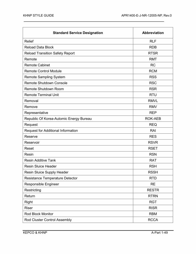
KHNP STYLE GUIDE APR1400-E-J-NR-12005-NP, Rev.0
KEPCO & KHNP A-Part 1-49
Standard Service Designation Abbreviation
Relief RLF
Reload Data Block RDB
Reload Transition Safety Report RTSR
Remote RMT
Remote Cabinet RC
Remote Control Module RCM
Remote Sampling System RSS
Remote Shutdown Console RSC
Remote Shutdown Room RSR
Remote Terminal Unit RTU
Removal RMVL
Remove RMV
Representative REP
Republic Of Korea-Automic Energy Bureau ROK-AEB
Request REQ
Request for Additional Information RAI
Reserve RES
Reservoir RSVR
Reset RSET
Resin RSN
Resin Additive Tank RAT
Resin Sluice Header RSH
Resin Sluice Supply Header RSSH
Resistance Temperature Detector RTD
Responsible Engineer RE
Restricting RESTR
Return RTRN
Right RGT
Riser RISR
Rod Block Monitor RBM
Rod Cluster Control Assembly RCCA
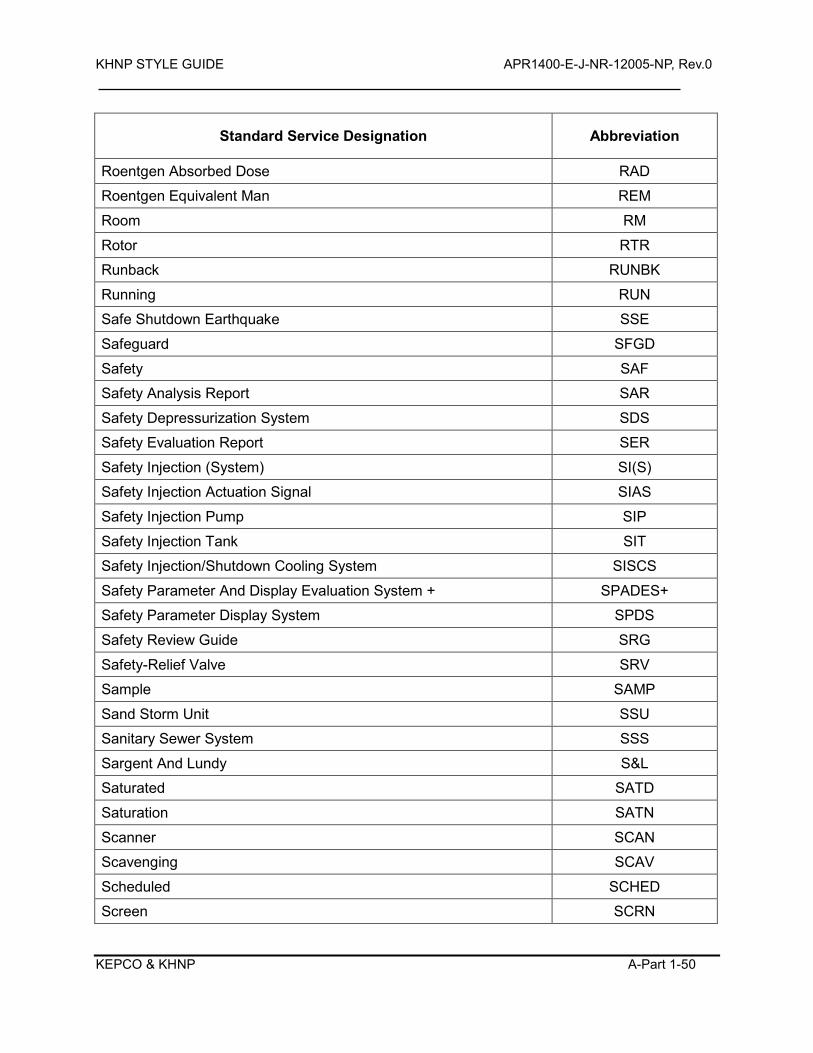
KHNP STYLE GUIDE APR1400-E-J-NR-12005-NP, Rev.0
KEPCO & KHNP A-Part 1-50
Standard Service Designation Abbreviation
Roentgen Absorbed Dose RAD
Roentgen Equivalent Man REM
Room RM
Rotor RTR
Runback RUNBK
Running RUN
Safe Shutdown Earthquake SSE
Safeguard SFGD
Safety SAF
Safety Analysis Report SAR
Safety Depressurization System SDS
Safety Evaluation Report SER
Safety Injection (System) SI(S)
Safety Injection Actuation Signal SIAS
Safety Injection Pump SIP
Safety Injection Tank SIT
Safety Injection/Shutdown Cooling System SISCS
Safety Parameter And Display Evaluation System + SPADES+
Safety Parameter Display System SPDS
Safety Review Guide SRG
Safety-Relief Valve SRV
Sample SAMP
Sand Storm Unit SSU
Sanitary Sewer System SSS
Sargent And Lundy S&L
Saturated SATD
Saturation SATN
Scanner SCAN
Scavenging SCAV
Scheduled SCHED
Screen SCRN
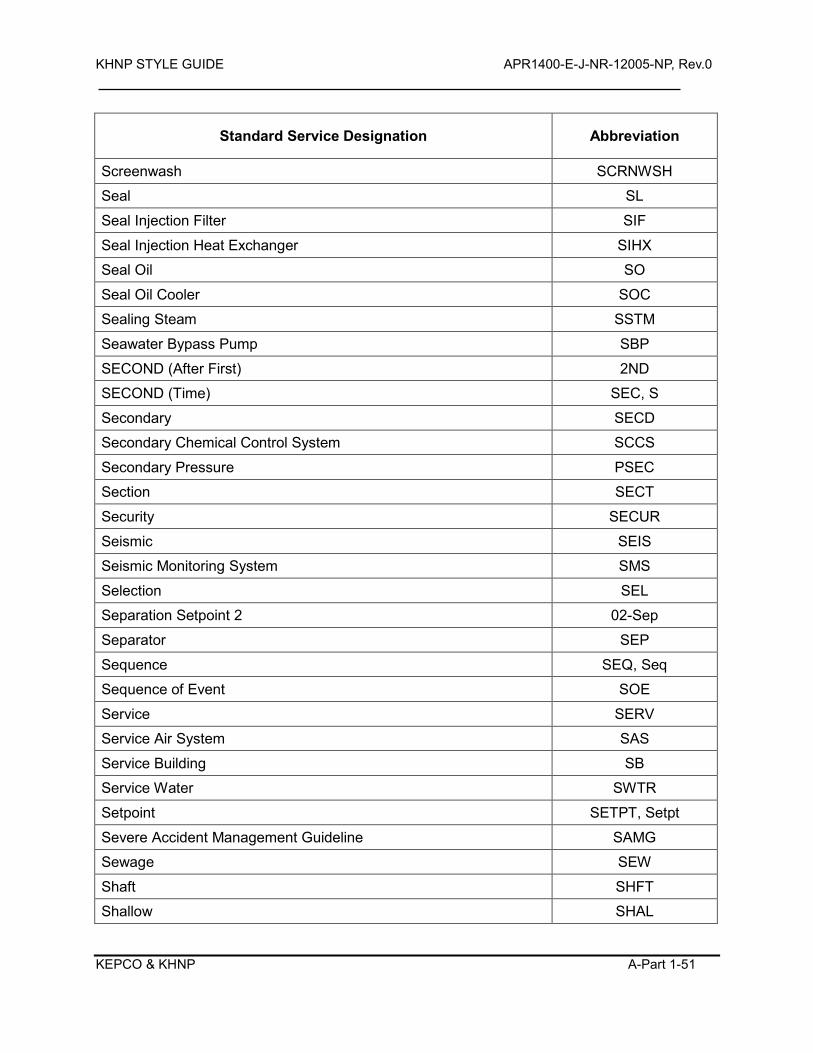
KHNP STYLE GUIDE APR1400-E-J-NR-12005-NP, Rev.0
KEPCO & KHNP A-Part 1-51
Standard Service Designation Abbreviation
Screenwash SCRNWSH
Seal SL
Seal Injection Filter SIF
Seal Injection Heat Exchanger SIHX
Seal Oil SO
Seal Oil Cooler SOC
Sealing Steam SSTM
Seawater Bypass Pump SBP
SECOND (After First) 2ND
SECOND (Time) SEC, S
Secondary SECD
Secondary Chemical Control System SCCS
Secondary Pressure PSEC
Section SECT
Security SECUR
Seismic SEIS
Seismic Monitoring System SMS
Selection SEL
Separation Setpoint 2 02-Sep
Separator SEP
Sequence SEQ, Seq
Sequence of Event SOE
Service SERV
Service Air System SAS
Service Building SB
Service Water SWTR
Setpoint SETPT, Setpt
Severe Accident Management Guideline SAMG
Sewage SEW
Shaft SHFT
Shallow SHAL
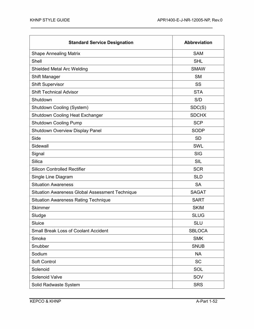
KHNP STYLE GUIDE APR1400-E-J-NR-12005-NP, Rev.0
KEPCO & KHNP A-Part 1-52
Standard Service Designation Abbreviation
Shape Annealing Matrix SAM
Shell SHL
Shielded Metal Arc Welding SMAW
Shift Manager SM
Shift Supervisor SS
Shift Technical Advisor STA
Shutdown S/D
Shutdown Cooling (System) SDC(S)
Shutdown Cooling Heat Exchanger SDCHX
Shutdown Cooling Pump SCP
Shutdown Overview Display Panel SODP
Side SD
Sidewall SWL
Signal SIG
Silica SIL
Silicon Controlled Rectifier SCR
Single Line Diagram SLD
Situation Awareness SA
Situation Awareness Global Assessment Technique SAGAT
Situation Awareness Rating Technique SART
Skimmer SKIM
Sludge SLUG
Sluice SLU
Small Break Loss of Coolant Accident SBLOCA
Smoke SMK
Snubber SNUB
Sodium NA
Soft Control SC
Solenoid SOL
Solenoid Valve SOV
Solid Radwaste System SRS
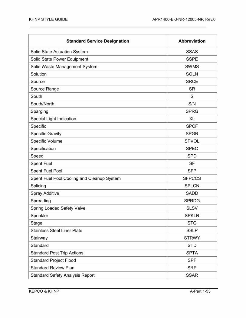
KHNP STYLE GUIDE APR1400-E-J-NR-12005-NP, Rev.0
KEPCO & KHNP A-Part 1-53
Standard Service Designation Abbreviation
Solid State Actuation System SSAS
Solid State Power Equipment SSPE
Solid Waste Management System SWMS
Solution SOLN
Source SRCE
Source Range SR
South S
South/North S/N
Sparging SPRG
Special Light Indication XL
Specific SPCF
Specific Gravity SPGR
Specific Volume SPVOL
Specification SPEC
Speed SPD
Spent Fuel SF
Spent Fuel Pool SFP
Spent Fuel Pool Cooling and Cleanup System SFPCCS
Splicing SPLCN
Spray Additive SADD
Spreading SPRDG
Spring Loaded Safety Valve SLSV
Sprinkler SPKLR
Stage STG
Stainless Steel Liner Plate SSLP
Stairway STRWY
Standard STD
Standard Post Trip Actions SPTA
Standard Project Flood SPF
Standard Review Plan SRP
Standard Safety Analysis Report SSAR
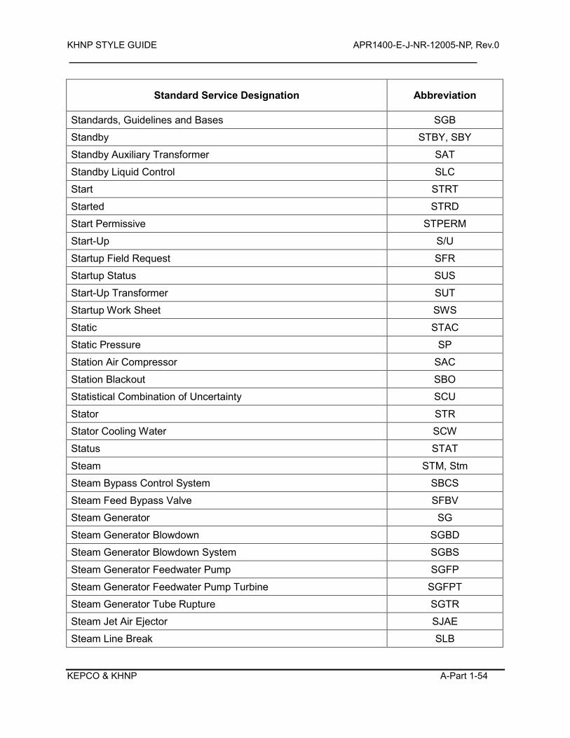
KHNP STYLE GUIDE APR1400-E-J-NR-12005-NP, Rev.0
KEPCO & KHNP A-Part 1-54
Standard Service Designation Abbreviation
Standards, Guidelines and Bases SGB
Standby STBY, SBY
Standby Auxiliary Transformer SAT
Standby Liquid Control SLC
Start STRT
Started STRD
Start Permissive STPERM
Start-Up S/U
Startup Field Request SFR
Startup Status SUS
Start-Up Transformer SUT
Startup Work Sheet SWS
Static STAC
Static Pressure SP
Station Air Compressor SAC
Station Blackout SBO
Statistical Combination of Uncertainty SCU
Stator STR
Stator Cooling Water SCW
Status STAT
Steam STM, Stm
Steam Bypass Control System SBCS
Steam Feed Bypass Valve SFBV
Steam Generator SG
Steam Generator Blowdown SGBD
Steam Generator Blowdown System SGBS
Steam Generator Feedwater Pump SGFP
Steam Generator Feedwater Pump Turbine SGFPT
Steam Generator Tube Rupture SGTR
Steam Jet Air Ejector SJAE
Steam Line Break SLB
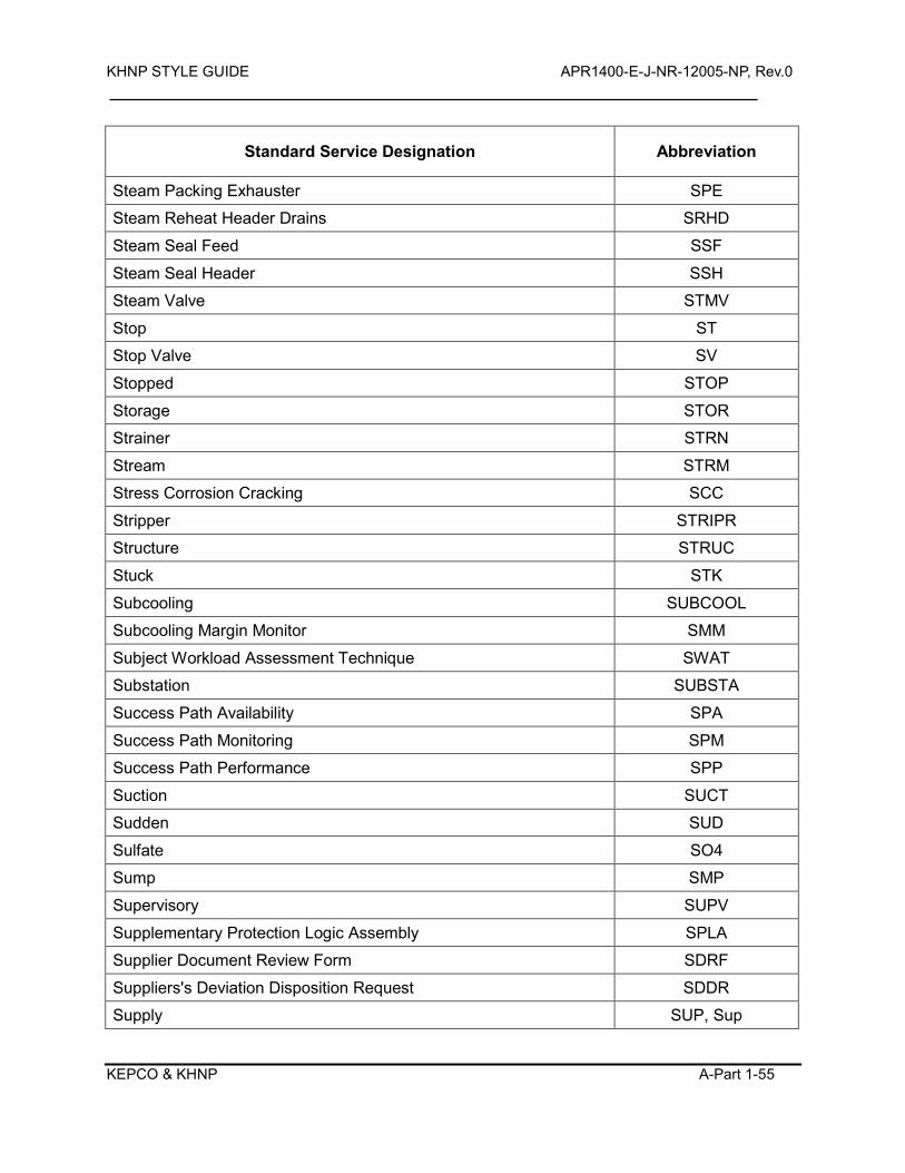
KHNP STYLE GUIDE APR1400-E-J-NR-12005-NP, Rev.0
KEPCO & KHNP A-Part 1-55
Standard Service Designation Abbreviation
Steam Packing Exhauster SPE
Steam Reheat Header Drains SRHD
Steam Seal Feed SSF
Steam Seal Header SSH
Steam Valve STMV
Stop ST
Stop Valve SV
Stopped STOP
Storage STOR
Strainer STRN
Stream STRM
Stress Corrosion Cracking SCC
Stripper STRIPR
Structure STRUC
Stuck STK
Subcooling SUBCOOL
Subcooling Margin Monitor SMM
Subject Workload Assessment Technique SWAT
Substation SUBSTA
Success Path Availability SPA
Success Path Monitoring SPM
Success Path Performance SPP
Suction SUCT
Sudden SUD
Sulfate SO4
Sump SMP
Supervisory SUPV
Supplementary Protection Logic Assembly SPLA
Supplier Document Review Form SDRF
Suppliers's Deviation Disposition Request SDDR
Supply SUP, Sup
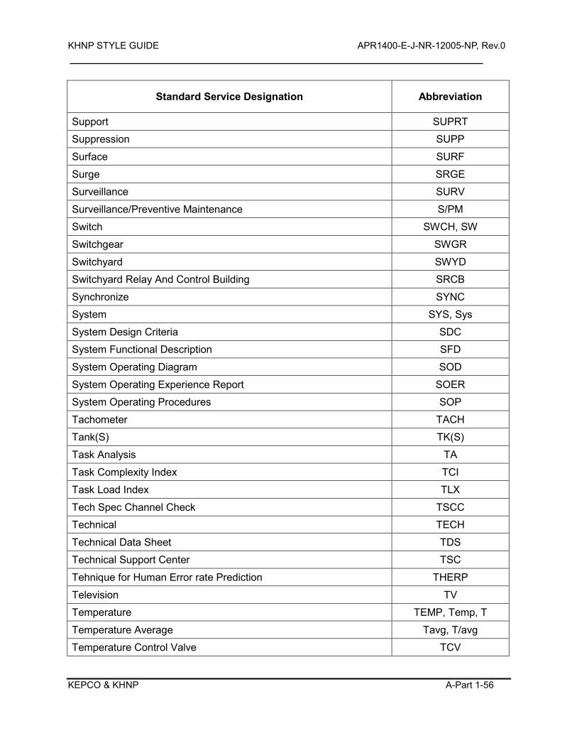
KHNP STYLE GUIDE APR1400-E-J-NR-12005-NP, Rev.0
KEPCO & KHNP A-Part 1-56
Standard Service Designation Abbreviation
Support SUPRT
Suppression SUPP
Surface SURF
Surge SRGE
Surveillance SURV
Surveillance/Preventive Maintenance S/PM
Switch SWCH, SW
Switchgear SWGR
Switchyard SWYD
Switchyard Relay And Control Building SRCB
Synchronize SYNC
System SYS, Sys
System Design Criteria SDC
System Functional Description SFD
System Operating Diagram SOD
System Operating Experience Report SOER
System Operating Procedures SOP
Tachometer TACH
Tank(S) TK(S)
Task Analysis TA
Task Complexity Index TCI
Task Load Index TLX
Tech Spec Channel Check TSCC
Technical TECH
Technical Data Sheet TDS
Technical Support Center TSC
Tehnique for Human Error rate Prediction THERP
Television TV
Temperature TEMP, Temp, T
Temperature Average Tavg, T/avg
Temperature Control Valve TCV
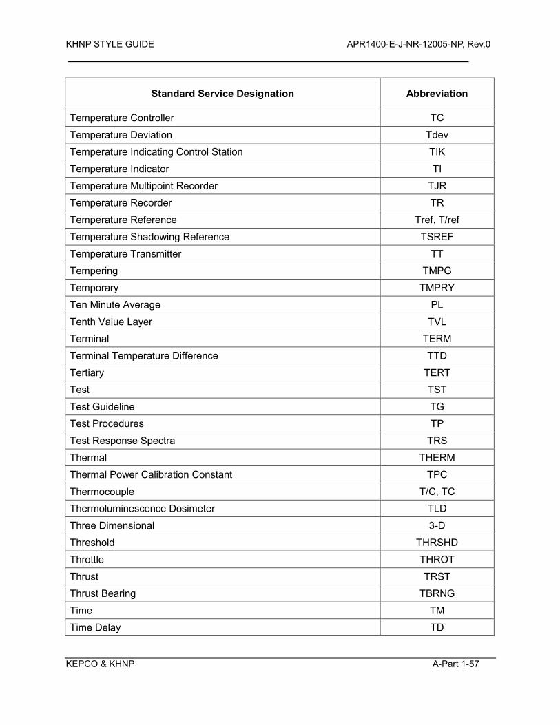
KHNP STYLE GUIDE APR1400-E-J-NR-12005-NP, Rev.0
KEPCO & KHNP A-Part 1-57
Standard Service Designation Abbreviation
Temperature Controller TC
Temperature Deviation Tdev
Temperature Indicating Control Station TIK
Temperature Indicator TI
Temperature Multipoint Recorder TJR
Temperature Recorder TR
Temperature Reference Tref, T/ref
Temperature Shadowing Reference TSREF
Temperature Transmitter TT
Tempering TMPG
Temporary TMPRY
Ten Minute Average PL
Tenth Value Layer TVL
Terminal TERM
Terminal Temperature Difference TTD
Tertiary TERT
Test TST
Test Guideline TG
Test Procedures TP
Test Response Spectra TRS
Thermal THERM
Thermal Power Calibration Constant TPC
Thermocouple T/C, TC
Thermoluminescence Dosimeter TLD
Three Dimensional 3-D
Threshold THRSHD
Throttle THROT
Thrust TRST
Thrust Bearing TBRNG
Time TM
Time Delay TD
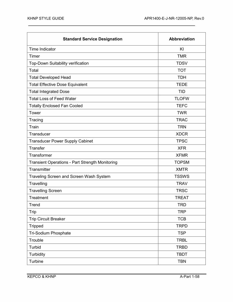
KHNP STYLE GUIDE APR1400-E-J-NR-12005-NP, Rev.0
KEPCO & KHNP A-Part 1-58
Standard Service Designation Abbreviation
Time Indicator KI
Timer TMR
Top-Down Suitability verification TDSV
Total TOT
Total Developed Head TDH
Total Effective Dose Equivalent TEDE
Total Integrated Dose TID
Total Loss of Feed Water TLOFW
Totally Enclosed Fan Cooled TEFC
Tower TWR
Tracing TRAC
Train TRN
Transducer XDCR
Transducer Power Supply Cabinet TPSC
Transfer XFR
Transformer XFMR
Transient Operations - Part Strength Monitoring TOPSM
Transmitter XMTR
Traveling Screen and Screen Wash System TSSWS
Travelling TRAV
Travelling Screen TRSC
Treatment TREAT
Trend TRD
Trip TRP
Trip Circuit Breaker TCB
Tripped TRPD
Tri-Sodium Phosphate TSP
Trouble TRBL
Turbid TRBD
Turbidity TBDT
Turbine TBN
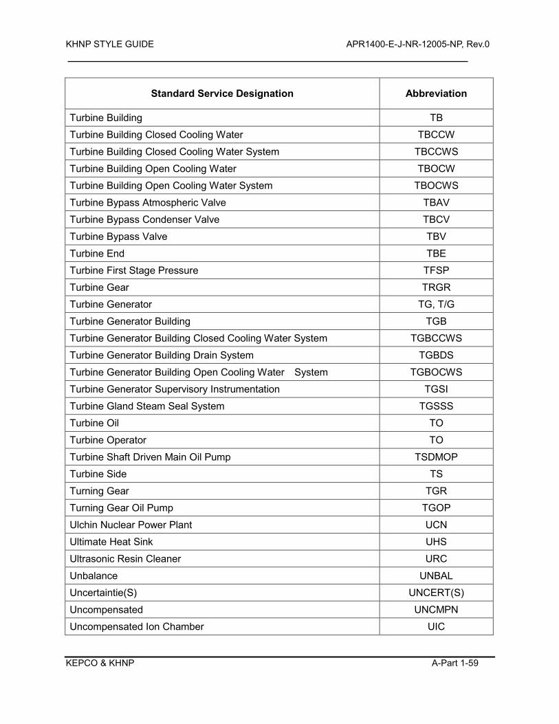
KHNP STYLE GUIDE APR1400-E-J-NR-12005-NP, Rev.0
KEPCO & KHNP A-Part 1-59
Standard Service Designation Abbreviation
Turbine Building TB
Turbine Building Closed Cooling Water TBCCW
Turbine Building Closed Cooling Water System TBCCWS
Turbine Building Open Cooling Water TBOCW
Turbine Building Open Cooling Water System TBOCWS
Turbine Bypass Atmospheric Valve TBAV
Turbine Bypass Condenser Valve TBCV
Turbine Bypass Valve TBV
Turbine End TBE
Turbine First Stage Pressure TFSP
Turbine Gear TRGR
Turbine Generator TG, T/G
Turbine Generator Building TGB
Turbine Generator Building Closed Cooling Water System TGBCCWS
Turbine Generator Building Drain System TGBDS
Turbine Generator Building Open Cooling Water System TGBOCWS
Turbine Generator Supervisory Instrumentation TGSI
Turbine Gland Steam Seal System TGSSS
Turbine Oil TO
Turbine Operator TO
Turbine Shaft Driven Main Oil Pump TSDMOP
Turbine Side TS
Turning Gear TGR
Turning Gear Oil Pump TGOP
Ulchin Nuclear Power Plant UCN
Ultimate Heat Sink UHS
Ultrasonic Resin Cleaner URC
Unbalance UNBAL
Uncertaintie(S) UNCERT(S)
Uncompensated UNCMPN
Uncompensated Ion Chamber UIC
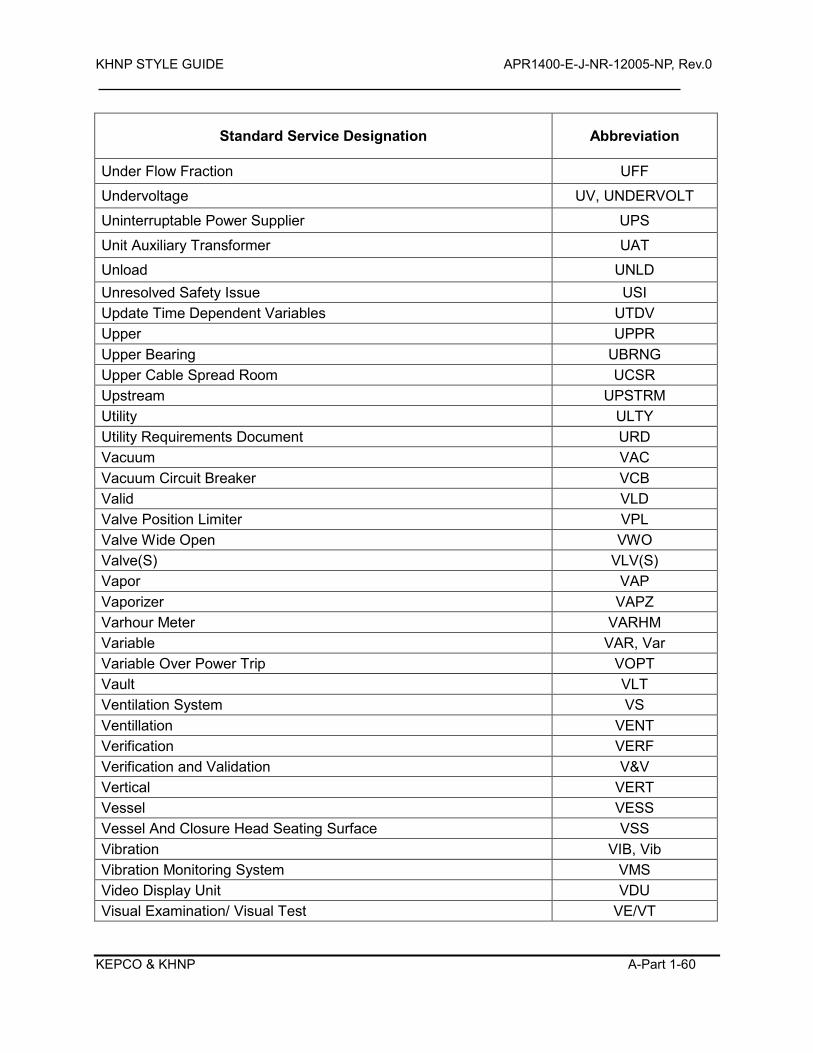
KHNP STYLE GUIDE APR1400-E-J-NR-12005-NP, Rev.0
KEPCO & KHNP A-Part 1-60
Standard Service Designation Abbreviation
Under Flow Fraction UFF
Undervoltage UV, UNDERVOLT
Uninterruptable Power Supplier UPS
Unit Auxiliary Transformer UAT
Unload UNLD Unresolved Safety Issue USI Update Time Dependent Variables UTDV Upper UPPR Upper Bearing UBRNG Upper Cable Spread Room UCSR Upstream UPSTRM Utility ULTY Utility Requirements Document URD Vacuum VAC Vacuum Circuit Breaker VCB Valid VLD Valve Position Limiter VPL Valve Wide Open VWO Valve(S) VLV(S) Vapor VAP Vaporizer VAPZ Varhour Meter VARHM Variable VAR, Var Variable Over Power Trip VOPT Vault VLT Ventilation System VS Ventillation VENT Verification VERF Verification and Validation V&V Vertical VERT Vessel VESS Vessel And Closure Head Seating Surface VSS Vibration VIB, Vib Vibration Monitoring System VMS Video Display Unit VDU Visual Examination/ Visual Test VE/VT
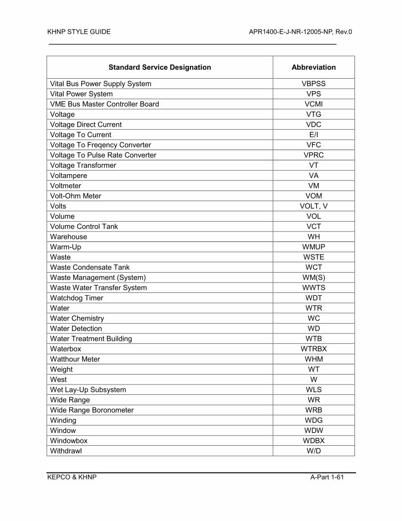
KHNP STYLE GUIDE APR1400-E-J-NR-12005-NP, Rev.0
KEPCO & KHNP A-Part 1-61
Standard Service Designation Abbreviation
Vital Bus Power Supply System VBPSS Vital Power System VPS VME Bus Master Controller Board VCMI Voltage VTG Voltage Direct Current VDC Voltage To Current E/I Voltage To Freqency Converter VFC Voltage To Pulse Rate Converter VPRC Voltage Transformer VT Voltampere VA Voltmeter VM Volt-Ohm Meter VOM Volts VOLT, V Volume VOL Volume Control Tank VCT Warehouse WH Warm-Up WMUP Waste WSTE Waste Condensate Tank WCT Waste Management (System) WM(S) Waste Water Transfer System WWTS Watchdog Timer WDT Water WTR Water Chemistry WC Water Detection WD Water Treatment Building WTB Waterbox WTRBX Watthour Meter WHM Weight WT West W Wet Lay-Up Subsystem WLS Wide Range WR Wide Range Boronometer WRB Winding WDG Window WDW Windowbox WDBX Withdrawl W/D
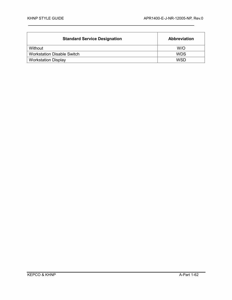
KHNP STYLE GUIDE APR1400-E-J-NR-12005-NP, Rev.0
KEPCO & KHNP A-Part 1-62
Standard Service Designation Abbreviation
Without W/O Workstation Disable Switch WDS Workstation Display WSD
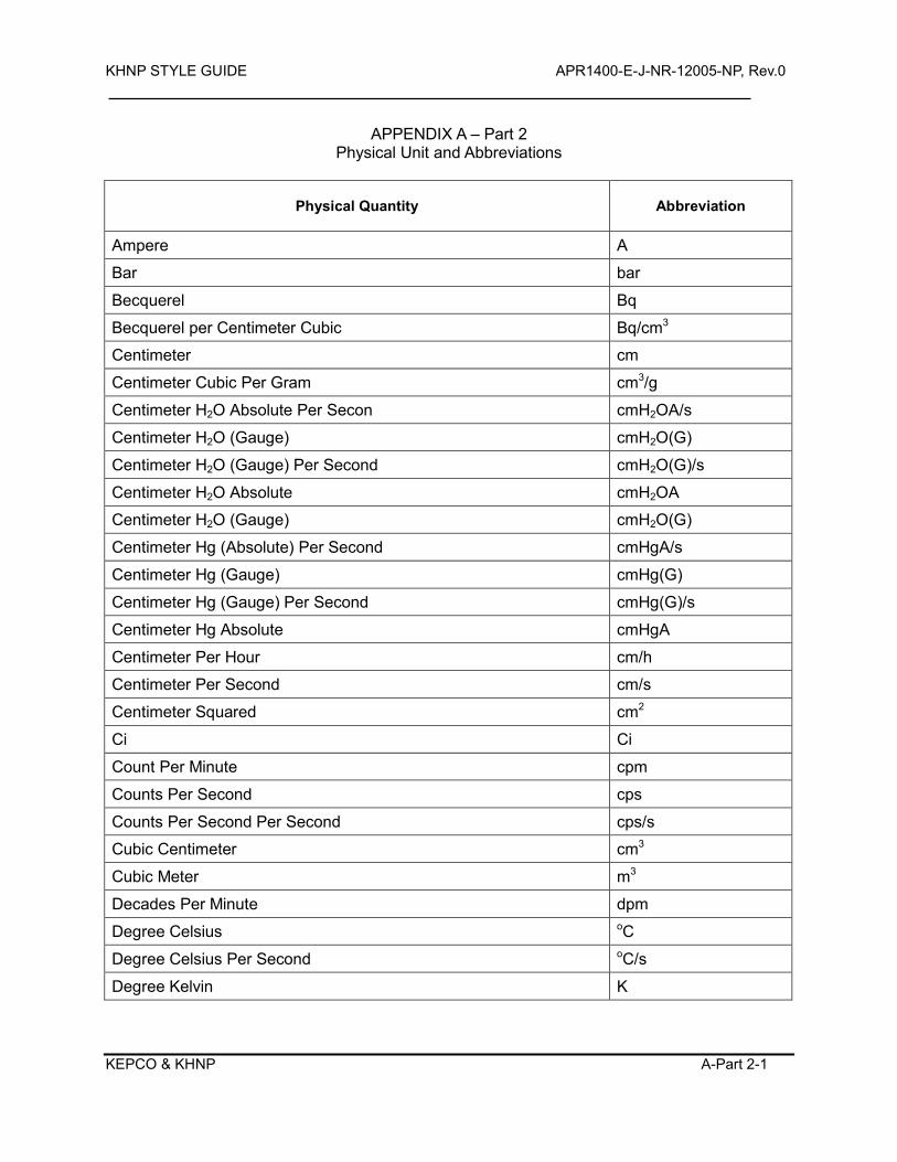
KHNP STYLE GUIDE APR1400-E-J-NR-12005-NP, Rev.0
KEPCO & KHNP A-Part 2-1
APPENDIX A – Part 2 Physical Unit and Abbreviations
Physical Quantity Abbreviation
Ampere A
Bar bar
Becquerel Bq
Becquerel per Centimeter Cubic Bq/cm3
Centimeter cm
Centimeter Cubic Per Gram cm3/g
Centimeter H2O Absolute Per Secon cmH2OA/s
Centimeter H2O (Gauge) cmH2O(G)
Centimeter H2O (Gauge) Per Second cmH2O(G)/s
Centimeter H2O Absolute cmH2OA
Centimeter H2O (Gauge) cmH2O(G)
Centimeter Hg (Absolute) Per Second cmHgA/s
Centimeter Hg (Gauge) cmHg(G)
Centimeter Hg (Gauge) Per Second cmHg(G)/s
Centimeter Hg Absolute cmHgA
Centimeter Per Hour cm/h
Centimeter Per Second cm/s
Centimeter Squared cm2
Ci Ci
Count Per Minute cpm
Counts Per Second cps
Counts Per Second Per Second cps/s
Cubic Centimeter cm3
Cubic Meter m3
Decades Per Minute dpm
Degree Celsius oC
Degree Celsius Per Second oC/s
Degree Kelvin K
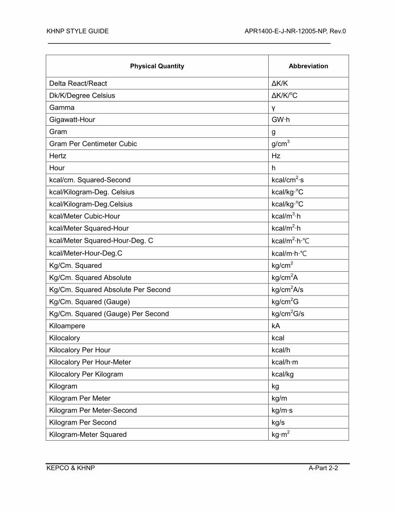
KHNP STYLE GUIDE APR1400-E-J-NR-12005-NP, Rev.0
KEPCO & KHNP A-Part 2-2
Physical Quantity Abbreviation
Delta React/React ΔK/K
Dk/K/Degree Celsius ΔK/K/oC
Gamma γ
Gigawatt-Hour GW·h
Gram g
Gram Per Centimeter Cubic g/cm3
Hertz Hz
Hour h
kcal/cm. Squared-Second kcal/cm2·s
kcal/Kilogram-Deg. Celsius kcal/kg·oC
kcal/Kilogram-Deg.Celsius kcal/kg·oC
kcal/Meter Cubic-Hour kcal/m3·h
kcal/Meter Squared-Hour kcal/m2·h
kcal/Meter Squared-Hour-Deg. C kcal/m2·h·
kcal/Meter-Hour-Deg.C kcal/m·h·
Kg/Cm. Squared kg/cm2
Kg/Cm. Squared Absolute kg/cm2A
Kg/Cm. Squared Absolute Per Second kg/cm2A/s
Kg/Cm. Squared (Gauge) kg/cm2G
Kg/Cm. Squared (Gauge) Per Second kg/cm2G/s
Kiloampere kA
Kilocalory kcal
Kilocalory Per Hour kcal/h
Kilocalory Per Hour-Meter kcal/h·m
Kilocalory Per Kilogram kcal/kg
Kilogram kg
Kilogram Per Meter kg/m
Kilogram Per Meter-Second kg/m·s
Kilogram Per Second kg/s
Kilogram-Meter Squared kg·m2
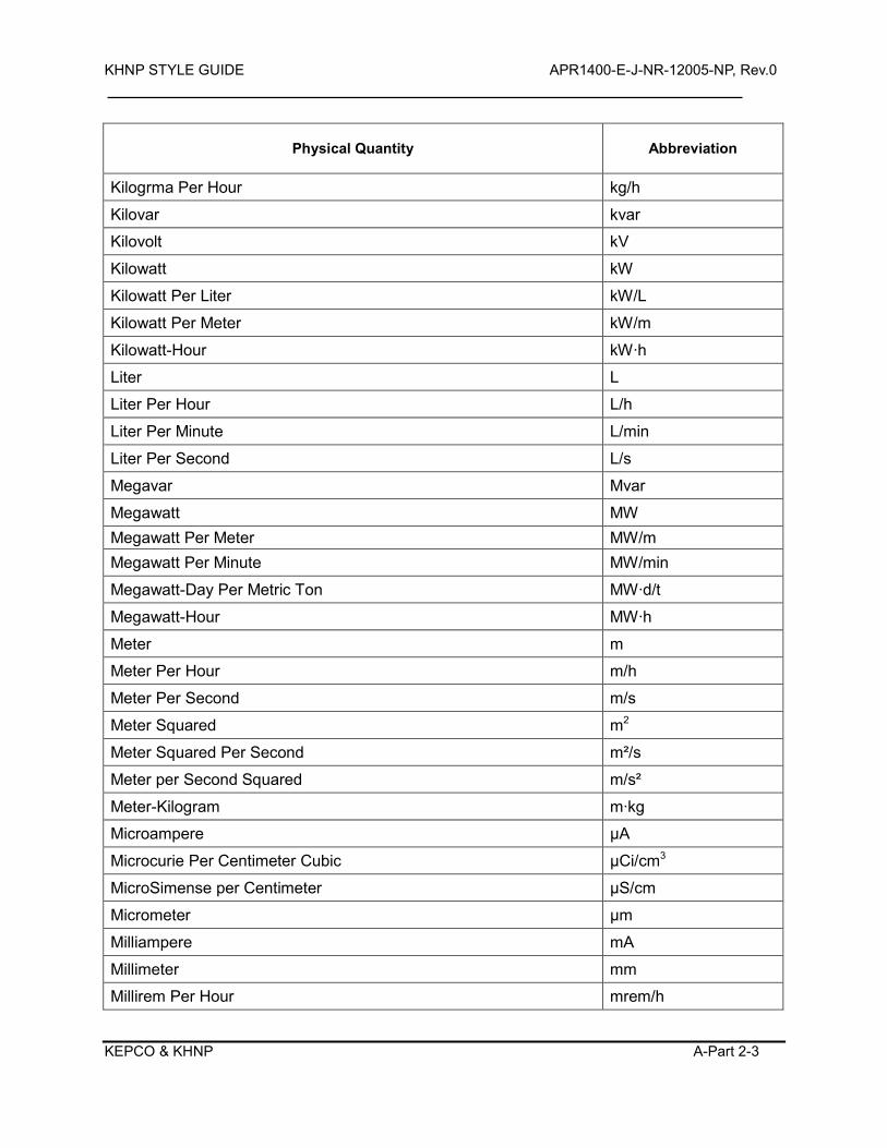
KHNP STYLE GUIDE APR1400-E-J-NR-12005-NP, Rev.0
KEPCO & KHNP A-Part 2-3
Physical Quantity Abbreviation
Kilogrma Per Hour kg/h
Kilovar kvar
Kilovolt kV
Kilowatt kW
Kilowatt Per Liter kW/L
Kilowatt Per Meter kW/m
Kilowatt-Hour kW·h
Liter L
Liter Per Hour L/h
Liter Per Minute L/min
Liter Per Second L/s
Megavar Mvar
Megawatt MW Megawatt Per Meter MW/m Megawatt Per Minute MW/min
Megawatt-Day Per Metric Ton MW·d/t
Megawatt-Hour MW·h
Meter m
Meter Per Hour m/h
Meter Per Second m/s
Meter Squared m2
Meter Squared Per Second m²/s
Meter per Second Squared m/s²
Meter-Kilogram m·kg
Microampere μA
Microcurie Per Centimeter Cubic μCi/cm3
MicroSimense per Centimeter µS/cm
Micrometer μm
Milliampere mA
Millimeter mm
Millirem Per Hour mrem/h
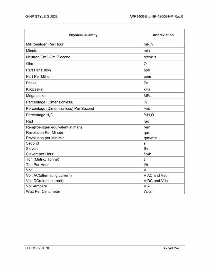
KHNP STYLE GUIDE APR1400-E-J-NR-12005-NP, Rev.0
KEPCO & KHNP A-Part 2-4
Physical Quantity Abbreviation
Milliroentgen Per Hour mR/h
Minute min
Neutron/Cm3-Cm./Second n/cm2·s
Ohm Ω
Part Per Billion ppb
Part Per Million ppm
Paskal Pa
Kilopaskal kPa
Megapaskal MPa
Percentage (Dimensionless) %
Percentage (Dimensionless) Per Second %/s
Percentage H2O %H2O
Rad rad Rem(roentgen equivalent in man) rem Revolution Per Minute rpm Revolution per Min/Min. rpm/min Second s Sievert Sv Sievert per Hour Sv/h Ton (Metric, Tonne) t Ton Per Hour t/h Volt V Volt AC(alternating current) V AC and Vac Volt DC(direct current) V DC and Vdc Volt-Ampere V·A Watt Per Centimeter W/cm
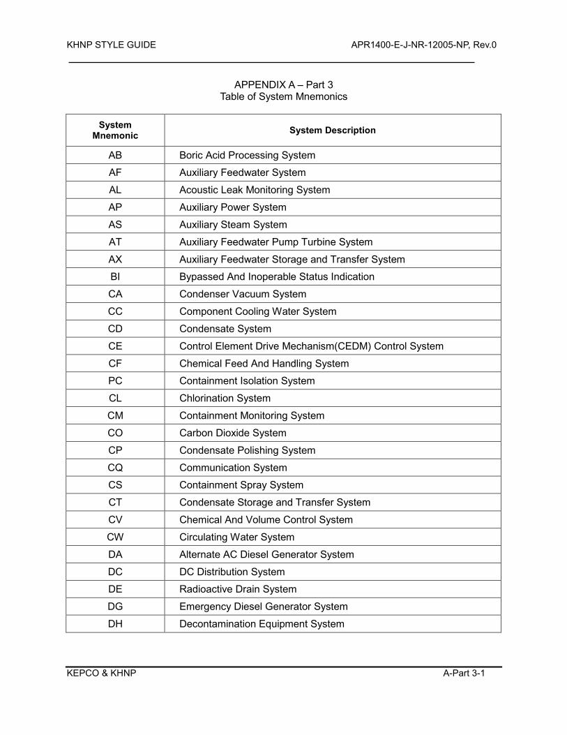
KHNP STYLE GUIDE APR1400-E-J-NR-12005-NP, Rev.0
KEPCO & KHNP A-Part 3-1
APPENDIX A – Part 3 Table of System Mnemonics
System
Mnemonic System Description
AB Boric Acid Processing System
AF Auxiliary Feedwater System
AL Acoustic Leak Monitoring System
AP Auxiliary Power System
AS Auxiliary Steam System
AT Auxiliary Feedwater Pump Turbine System
AX Auxiliary Feedwater Storage and Transfer System
BI Bypassed And Inoperable Status Indication
CA Condenser Vacuum System
CC Component Cooling Water System
CD Condensate System
CE Control Element Drive Mechanism(CEDM) Control System
CF Chemical Feed And Handling System
PC Containment Isolation System
CL Chlorination System
CM Containment Monitoring System
CO Carbon Dioxide System
CP Condensate Polishing System
CQ Communication System
CS Containment Spray System
CT Condensate Storage and Transfer System
CV Chemical And Volume Control System
CW Circulating Water System
DA Alternate AC Diesel Generator System
DC DC Distribution System
DE Radioactive Drain System
DG Emergency Diesel Generator System
DH Decontamination Equipment System
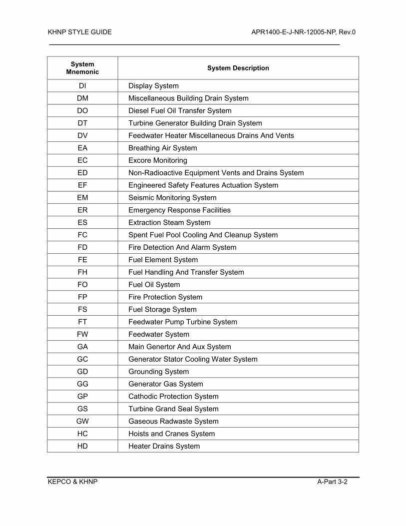
KHNP STYLE GUIDE APR1400-E-J-NR-12005-NP, Rev.0
KEPCO & KHNP A-Part 3-2
System Mnemonic System Description
DI Display System
DM Miscellaneous Building Drain System
DO Diesel Fuel Oil Transfer System
DT Turbine Generator Building Drain System
DV Feedwater Heater Miscellaneous Drains And Vents
EA Breathing Air System
EC Excore Monitoring
ED Non-Radioactive Equipment Vents and Drains System
EF Engineered Safety Features Actuation System
EM Seismic Monitoring System
ER Emergency Response Facilities
ES Extraction Steam System
FC Spent Fuel Pool Cooling And Cleanup System
FD Fire Detection And Alarm System
FE Fuel Element System
FH Fuel Handling And Transfer System
FO Fuel Oil System
FP Fire Protection System
FS Fuel Storage System
FT Feedwater Pump Turbine System
FW Feedwater System
GA Main Genertor And Aux System
GC Generator Stator Cooling Water System
GD Grounding System
GG Generator Gas System
GP Cathodic Protection System
GS Turbine Grand Seal System
GW Gaseous Radwaste System
HC Hoists and Cranes System
HD Heater Drains System
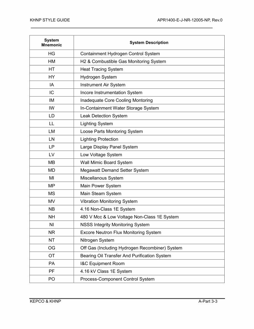
KHNP STYLE GUIDE APR1400-E-J-NR-12005-NP, Rev.0
KEPCO & KHNP A-Part 3-3
System Mnemonic System Description
HG Containment Hydrogen Control System
HM H2 & Combustible Gas Monitoring System
HT Heat Tracing System
HY Hydrogen System
IA Instrument Air System
IC Incore Instrumentation System
IM Inadequate Core Cooling Montoring
IW In-Containment Water Storage System
LD Leak Detection System
LL Lighting System
LM Loose Parts Montoring System
LN Lighting Protection
LP Large Display Panel System
LV Low Voltage System
MB Wall Mimic Board System
MD Megawatt Demand Setter System
MI Miscellanous System
MP Main Power System
MS Main Steam System
MV Vibration Monitoring System
NB 4.16 Non-Class 1E System
NH 480 V Mcc & Low Voltage Non-Class 1E System
NI NSSS Integrity Monitoring System
NR Excore Neutron Flux Monitoring System
NT Nitrogen System
OG Off Gas (Including Hydrogen Recombiner) System
OT Bearing Oil Transfer And Purification System
PA I&C Equipment Room
PF 4.16 kV Class 1E System
PO Process-Component Control System
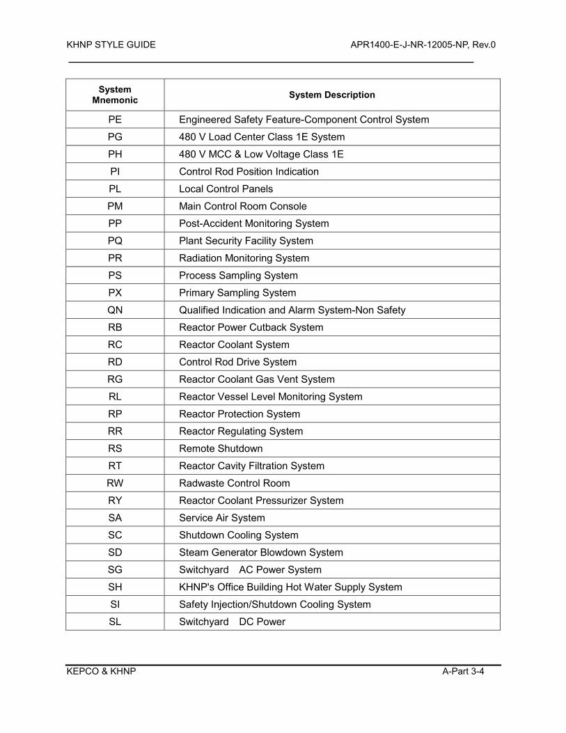
KHNP STYLE GUIDE APR1400-E-J-NR-12005-NP, Rev.0
KEPCO & KHNP A-Part 3-4
System Mnemonic System Description
PE Engineered Safety Feature-Component Control System
PG 480 V Load Center Class 1E System
PH 480 V MCC & Low Voltage Class 1E
PI Control Rod Position Indication
PL Local Control Panels
PM Main Control Room Console
PP Post-Accident Monitoring System
PQ Plant Security Facility System
PR Radiation Monitoring System
PS Process Sampling System
PX Primary Sampling System
QN Qualified Indication and Alarm System-Non Safety
RB Reactor Power Cutback System
RC Reactor Coolant System
RD Control Rod Drive System
RG Reactor Coolant Gas Vent System
RL Reactor Vessel Level Monitoring System
RP Reactor Protection System
RR Reactor Regulating System
RS Remote Shutdown
RT Reactor Cavity Filtration System
RW Radwaste Control Room
RY Reactor Coolant Pressurizer System
SA Service Air System
SC Shutdown Cooling System
SD Steam Generator Blowdown System
SG Switchyard AC Power System
SH KHNP's Office Building Hot Water Supply System
SI Safety Injection/Shutdown Cooling System
SL Switchyard DC Power
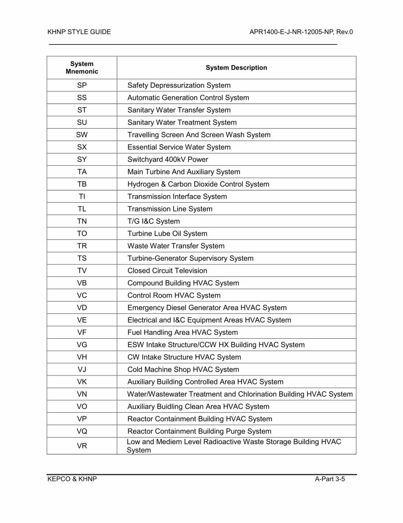
KHNP STYLE GUIDE APR1400-E-J-NR-12005-NP, Rev.0
KEPCO & KHNP A-Part 3-5
System Mnemonic System Description
SP Safety Depressurization System
SS Automatic Generation Control System
ST Sanitary Water Transfer System
SU Sanitary Water Treatment System
SW Travelling Screen And Screen Wash System
SX Essential Service Water System
SY Switchyard 400kV Power
TA Main Turbine And Auxiliary System
TB Hydrogen & Carbon Dioxide Control System
TI Transmission Interface System
TL Transmission Line System
TN T/G I&C System
TO Turbine Lube Oil System
TR Waste Water Transfer System
TS Turbine-Generator Supervisory System
TV Closed Circuit Television
VB Compound Building HVAC System
VC Control Room HVAC System
VD Emergency Diesel Generator Area HVAC System
VE Electrical and I&C Equipment Areas HVAC System
VF Fuel Handling Area HVAC System
VG ESW Intake Structure/CCW HX Building HVAC System
VH CW Intake Structure HVAC System
VJ Cold Machine Shop HVAC System
VK Auxiliary Building Controlled Area HVAC System
VN Water/Wastewater Treatment and Chlorination Building HVAC System
VO Auxiliary Buidling Clean Area HVAC System
VP Reactor Containment Building HVAC System
VQ Reactor Containment Building Purge System
VR Low and Mediem Level Radioactive Waste Storage Building HVAC System
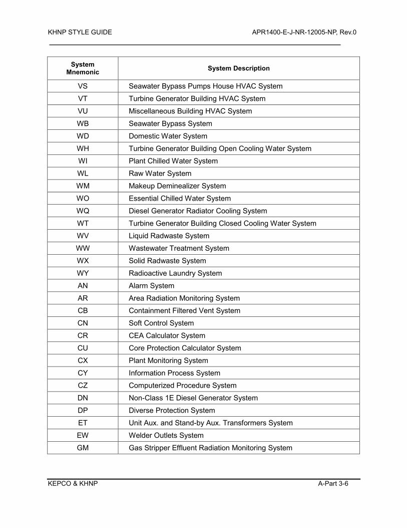
KHNP STYLE GUIDE APR1400-E-J-NR-12005-NP, Rev.0
KEPCO & KHNP A-Part 3-6
System Mnemonic System Description
VS Seawater Bypass Pumps House HVAC System
VT Turbine Generator Building HVAC System
VU Miscellaneous Building HVAC System
WB Seawater Bypass System
WD Domestic Water System
WH Turbine Generator Building Open Cooling Water System
WI Plant Chilled Water System
WL Raw Water System
WM Makeup Deminealizer System
WO Essential Chilled Water System
WQ Diesel Generator Radiator Cooling System
WT Turbine Generator Building Closed Cooling Water System
WV Liquid Radwaste System
WW Wastewater Treatment System
WX Solid Radwaste System
WY Radioactive Laundry System
AN Alarm System
AR Area Radiation Monitoring System
CB Containment Filtered Vent System
CN Soft Control System
CR CEA Calculator System
CU Core Protection Calculator System
CX Plant Monitoring System
CY Information Process System
CZ Computerized Procedure System
DN Non-Class 1E Diesel Generator System
DP Diverse Protection System
ET Unit Aux. and Stand-by Aux. Transformers System
EW Welder Outlets System
GM Gas Stripper Effluent Radiation Monitoring System
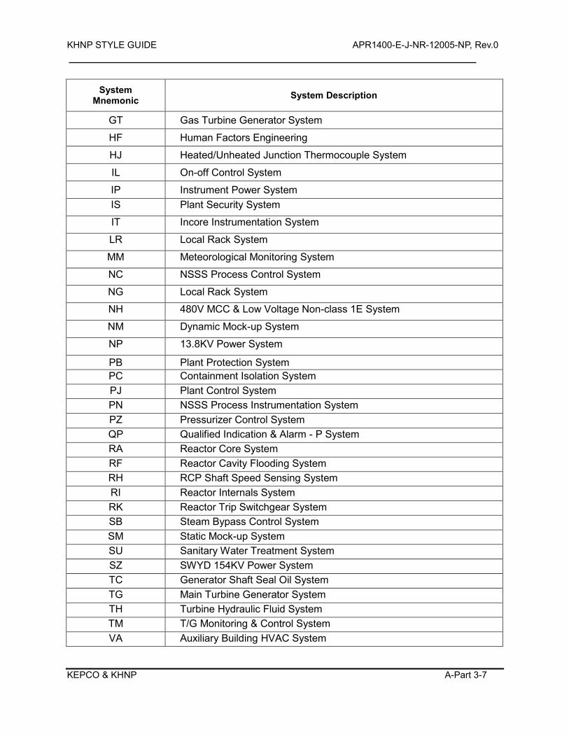
KHNP STYLE GUIDE APR1400-E-J-NR-12005-NP, Rev.0
KEPCO & KHNP A-Part 3-7
System Mnemonic System Description
GT Gas Turbine Generator System
HF Human Factors Engineering
HJ Heated/Unheated Junction Thermocouple System
IL On-off Control System
IP Instrument Power System IS Plant Security System
IT Incore Instrumentation System
LR Local Rack System
MM Meteorological Monitoring System
NC NSSS Process Control System
NG Local Rack System
NH 480V MCC & Low Voltage Non-class 1E System
NM Dynamic Mock-up System
NP 13.8KV Power System
PB Plant Protection System PC Containment Isolation System PJ Plant Control System PN NSSS Process Instrumentation System PZ Pressurizer Control System QP Qualified Indication & Alarm - P System RA Reactor Core System RF Reactor Cavity Flooding System RH RCP Shaft Speed Sensing System RI Reactor Internals System RK Reactor Trip Switchgear System SB Steam Bypass Control System SM Static Mock-up System SU Sanitary Water Treatment System SZ SWYD 154KV Power System TC Generator Shaft Seal Oil System TG Main Turbine Generator System TH Turbine Hydraulic Fluid System TM T/G Monitoring & Control System VA Auxiliary Building HVAC System
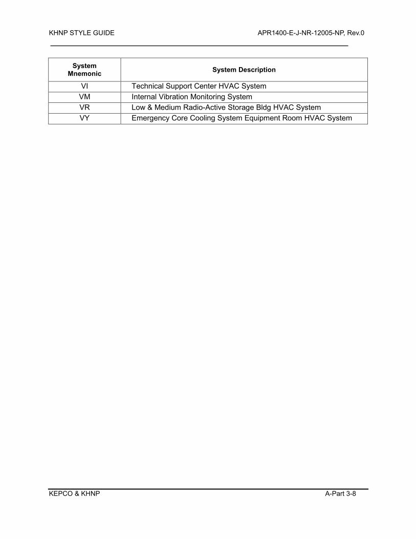
KHNP STYLE GUIDE APR1400-E-J-NR-12005-NP, Rev.0
KEPCO & KHNP A-Part 3-8
System Mnemonic System Description
VI Technical Support Center HVAC System VM Internal Vibration Monitoring System VR Low & Medium Radio-Active Storage Bldg HVAC System VY Emergency Core Cooling System Equipment Room HVAC System
KHNP STYLE GUIDE APR1400-E-J-NR-12005-NP, Rev.0
KEPCO & KHNP B-1
APPENDIX B
GLOSSARY
Abbreviation – A shortened form of a word or phrase used for brevity.
Acronym – A word formed from the initial letter(s) of each of the successive or major parts of a compound
term.
Advanced Alarm System – A primarily digital alarm system employing alarm processing logic and advanced
control (e.g., on-screen controls) and display (e.g., VDU) technology. (This is in contrast to conventional
alarm systems, which are largely based on analog instrument and control technologies.)
Alert – A signal that indicates a condition relating to the effective performance of duties. The condition or
message requires the operator or maintainer to take immediate action.
Alphabetic – Pertaining to a character set that contains letters and other symbols, excluding numbers.
Alphanumeric – Pertaining to a character set that contains letters, digits, and usually other symbols, such as
punctuation marks.
Alphanumeric Code – A set of letters and/or numbers used to identify a group of data (e.g., in a table).
Alphanumeric keyboard – A keyboard used for typing letters or numbers into the computer.
Analytical Redundancy – The calculation of expected parameter values using a model of system
performance.
Anthropometry – A study and measurement of the physical dimensions of the human body
Arrow Buttons – A pair of buttons used to change a value by increments each time they are pressed. Often,
KHNP STYLE GUIDE APR1400-E-J-NR-12005-NP, Rev.0
KEPCO & KHNP B-2
the button that produces an increase is marked with an upward arrow and the button that produces a
decrease is marked with a downward arrow.
Audio – Pertaining to acoustic, mechanical, or electrical frequencies corresponding to normally audible
sound waves.
Auditory – Pertaining to the sense of hearing.
Bar Chart (graph) – A graphic figure in which numeric quantities are represented by the linear extent of
parallel lines (or bars). The length of the line (or bar) is proportional to the numbers represented. Bar charts
are useful for comparing separate entities or showing a variable sampled at intervals.
Binary – (1) Pertaining to a characteristic or property involving a selection, choice, or condition in which there
are two possibilities. (2) Pertaining to the number representation system with two values.
Brightness – Attribute of a visual sensation according to which an area appears to emit more or less light.
Brightness ratio – The ratio of the luminance of two areas or surfaces.
Button – A type of hardware control device or a defined control region on the display screen which, when
selected, causes some action.
Caution Signal – A signal that alerts the operator to an impending condition requiring attention, but not
necessarily immediate action (See warning signal).
Cascading Menu – A type of hierarchical menu in which a submenu is attached to the right side of a menu
item. Cascading menus can be added to drop-down menus, pop-up menus, or even other cascading menus.
Character Set – A set of unique representations called characters; e.g., the 26 letters of the English alphabet,
and the 128 characters of the ASCII alphabet.
Character Width – The horizontal distance between a character's origin (a point on the base line used as a
reference location) and the next character's origin.
KHNP STYLE GUIDE APR1400-E-J-NR-12005-NP, Rev.0
KEPCO & KHNP B-3
Character – A letter, digit, or other symbol that is used as part of the organization, control, or representation
of data.
Circuit Breakers – Devices that protect equipment from excessive electrical current.
Circuit Packaging – A method for organizing equipment into modules in which all parts of a single circuit or
logically related group of parts, and only that circuit or group, are placed in a separate module.
Coding – Use of a system of symbols, shapes, colors or other variable sensory stimuli to represent specific
information. Coding may be used (a) for highlighting (i.e., to attract a user's attention to part of a display), (b)
as a perceptual indicator of a data group, or (c) to symbolize a state or attribute of an object (e.g., to show a
temperature level or for warning purposes).
Cognitive Error – A human error that results from the characteristics of human performance processing such
as errors in diagnosis due to information overload.
Coherence Mapping – A map between the features in the representation and the physical and cognitive
characteristics of the operator (how comprehensible the representation is to the operator).
Color – The aspect of objects or light sources that may be described in terms of hue, lightness (or
brightness), and saturation.
Combo Box – A special type of text box with an attached list of options. Combo boxes allow the user to
either select from the given list or type in an alternative response. These are two types of combo boxes,
standard and drop-down.
Command Language – A type of dialogue in which a user composes entries, possibly with minimal
prompting by the computer.
Computer-Based Procedure Systems – Systems that present plant procedures in computer-based rather
than paper-based formats.
KHNP STYLE GUIDE APR1400-E-J-NR-12005-NP, Rev.0
KEPCO & KHNP B-4
Computerized Operator Support Systems – Systems that use computer technology to support operators or
maintenance personnel in situation assessment and response planning. They can monitor status and provide
recommendations or warnings.
Configural Display – A display in which information dimensions are uniquely represented, but where new
emergent properties are created from interactions between the dimensions. Configural display
representations often use simple graphic forms, such as a polygon.
Contrast – Diversity of adjacent parts in color and intensity.
Contrast Ratio – The measured luminance at one point divided by the measured luminance at another,
equal to Lt/Lb, (Ls-Lb)/Lb, or (1+Ls)/Lb, where
Lt = total luminance, or luminance of the image in the presence of background;
Ls = luminance of the symbol without background (luminance emitted by VDU in the case of VDU displays);
Lb = luminance of background.
Contrast ratio, rather than contrast, is often specified by display manufacturers because it is numerically
larger (by one) than contrast.
Control Entry – User input for sequence control, such as function key activation, menu selection, command
entry.
Darkboard – An alarm display in which the medium is dark (not illuminated) if all monitored plant parameters
are in the normal range. Thus, an illuminated alarm-display device indicates a deviation from normal plant
conditions. This is in contrast to many conventional alarm systems, which employ display devices to indicate
both normal and abnormal changes in the plant's condition.
Data Entry – User input of data for storage in, and/or processing by, the system.
Decibel (dBA) – Sound level in decibels, measured using A-weighting. The use of A-weighting causes the
frequency response of the sound level meter to mimic that of the human ear, i.e., response is maximum at
about 2 kHz, less at very low or very high frequencies. A-weighted measurements correlate well with
KHNP STYLE GUIDE APR1400-E-J-NR-12005-NP, Rev.0
KEPCO & KHNP B-5
measures of speech interference and judgments of loudness.
Demarcation – The technique of enclosing functional or selected groups of controls and displays with a
contrasting line to emphasize their relatedness.
Density – (Screen Density) The amount of the display screen that contains information; often expressed as a
percentage of the total area.
Description Error – An error of execution (slip) that involves performing the wrong set of well-practiced
actions for the situation. Description errors occur when the information that activates or triggers the action is
either ambiguous or undetected.
Diagram – A special form of a picture in which details are only shown if they are necessary to perform a task.
For example, an electrical wiring diagram for a facility would show wiring but not necessarily furniture or
plumbing.
Dialogue – A structured series of interchanges between a user and a computer. A dialogue can be initiated
by a computer (e.g., question and answer) or by a user (e.g., command language).
Dimension – A scale or categorization along which data may vary, taking different values at different times.
Direct Manipulation – The user manipulates symbols in the display by directly interacting with the symbol.
The direct manipulation is generally performed by using a display structure, such as a pointer, and a cursor
control device, such as a mouse.
Display – A specific integrated, organized set of information. A display can be an integration of several
display formats (such as a system mimic which includes bar charts, trend graphs, and data fields).
Display Device – The hardware used to present the display to users. Examples include video display units
and speakers for system messages.
Display Element – A basic component used to make up display formats, such as abbreviations, labels, icons,
KHNP STYLE GUIDE APR1400-E-J-NR-12005-NP, Rev.0
KEPCO & KHNP B-6
symbols, coding, and highlighting.
Display Format – The general class of information presentation. Examples of general classes are
continuous text (such as a procedure display), mimics and piping and instrumentation diagram (P&ID)
displays, trend graphs, and flowcharts.
Display Network – A group of display pages within an information system and their organizational structure.
Display Page – A defined set of information that is intended to be displayed as a single unit. Typical nuclear
power plant display pages may combine several different formats on a single VDU screen, such as putting
bar charts and digital displays in a graphic P&ID format. Display pages typically have a label and designation
within the computer system so they can be assessed by operators as a single "display."
Display Selection – Refers to the specification of data outputs, either by a user or automatically.
Display Structure – Functional or information-presenting aspects of a display that are consistent in
appearance and use across applications, e.g., providing reference to the user's location in an information
system and display of control options available.
Emergent Feature – A high-level, global perceptual feature produced by the interactions among individual
parts or graphical elements of a display (e.g., lines, contours, and shapes).
Fault-Tolerant Digital Control Systems – Digital systems with redundant processors that use fault
diagnostic routines that can detect single faults and isolate the failed equipment. This ensures that the
equipment that is still operational takes over the control function.
Field – An area of the display screen reserved for the display of data or for user entry of a data item. In a
database, a specified area used for a particular category of data, for example, equipment operational status.
Field Label – A displayed word or phrase that identifies the data display or entry field.
Flowchart – A diagram that illustrates sequential relations among elements or events. Flowcharts are often
KHNP STYLE GUIDE APR1400-E-J-NR-12005-NP, Rev.0
KEPCO & KHNP B-7
shown as boxes connected by arrows.
Form – A dialogue technique that presents category labels and requires the user to fill in the blanks. A
formatted output to the user with blank spaces for inserting required or requested information.
Format – The arrangement of data.
Formatting – The process or act of arranging data.
Frequency Modulation – Sinusoidal variation of the frequency of a tone around a center frequency.
Frequency – Rate of signal oscillation in cycles per second (Hz or Hertz).
Function – (1) A software supported capability provided to a user to aid in performing a task. (2) A process
or activity that is required to achieve a desired goal; see, e.g., safety function.
Glare – A consequence of bright light sources in the visual field that cause discomfort and/or a decrease in
visual functioning. The effect is worse the closer the light source is to the line of gaze.
Glare by Reflection – Glare produced by reflections, particularly when reflected images appear in the same
or nearly the same direction as the object viewed.
Gloss – The extent to which light incident on a surface at angle x is reflected from that surface at angle –x
(minus x) relative to a line perpendicular to the surface. A mirror has maximum gloss.
Gloss Instrument – A device that measures reflected light as a function of illumination and angle of view.
The angle for which gloss is measured is typically 60 degrees.
Graph – A display that represents the variation of a variable in comparison with that of one or more other
variables.
Graphic Element – A component part of a graphic display, such as a line, a circle, or a scale.
KHNP STYLE GUIDE APR1400-E-J-NR-12005-NP, Rev.0
KEPCO & KHNP B-8
Graphical Display – A display that provides a pictorial representation of an object or a set of data. Graphical
displays include line, solid object, and perspective drawings; bar, pie, and line charts and graphs; scatterplots;
displayed meters; flowcharts and schematic diagrams.
Graphics – Data specially formatted to show spatial, temporal, or other relations among data sets.
Grid – A network of uniformly spaced horizontal and vertical lines for locating points by means of coordinates.
Highlight – A means of directing the user's attention to a feature of the display. Highlighting methods include
image reversal (reverse video), brightness/boldness contrast, color, underlining, blinking, flashing arrows, and
changes in font. Emphasizing displayed data or format features in some way, e.g., by using underlining, bold,
or inverse video.
Histogram – A type of bar chart used to depict the frequency distribution for a continuous variable. The
variable may be grouped into classes.
Icon – Pictorial, pictographic, or other nonverbal representation of objects or actions.
Identification – A code number or code name that uniquely identifies a record, block, tile, or other unit of
information.
Identifier – A symbol whose purpose is to identify, indicate or name a body of data.
Illuminance – The luminous flux incident on a surface, measured in lumens per square meter (lux) or in
Footcandles (fc).
Illumination – The amount of light falling on a surface.
Instrument Cabinets and Racks – Enclosures that hold modules, components, and parts. They typically
have access doors or removable panels for access to their contents.
KHNP STYLE GUIDE APR1400-E-J-NR-12005-NP, Rev.0
KEPCO & KHNP B-9
Integral Display – A display that depicts the integration of information in such a way that the individual
parameters used to generate the display are not explicitly represented in it.
Interrupt – Stopping an ongoing transaction to redirect the course of the processing. Examples of interrupt
options are BACKUP, CANCEL, RESTART.
Input Field – The area in a display that is used to enter input. For example, a soft control may have an area
in which operators can enter numerical data to adjust control setpoints or commands to execute actions.
Interlock – A feature that requires operator actions to proceed in a specific sequence. For example, action B
must be performed after action A, and action C after action B.
Justification – The act of adjusting, arranging, or shifting digits to the left, right, or center to fit a prescribed
pattern.
Label – Descriptor that is distinguishable from, and helps to identify, displayed screen structures or
components.
Labeling and Marking – The use of labels and demarcations to identify units of equipment, modules,
components, and parts.
Layout – The physical arrangement of the parts and components that make up a module or a unit of
equipment.
Legend – (1) The textual content of a continuously present, spatially dedicated alarm display. (2) An
explanatory list of symbols or highlighting used on a graph, chart, diagram, or map.
Legibility – The quality of a display that allows groups of characters and symbols to be easily discriminated
and recognized.
Lightness – Brightness of an area judged relative to the brightness of similarly illuminated area that appears
to be white or highly transmitting.
KHNP STYLE GUIDE APR1400-E-J-NR-12005-NP, Rev.0
KEPCO & KHNP B-10
Line of Sight – The optical axis extending from the observers eyes to the target viewed.
Lockin – A feature that keeps an ongoing operation active by preventing personnel actions from terminating
it prematurely.
Lockout – A feature that prevents personnel from providing input that may have negative effects. Statically
defined lockouts may restrict operators' inputs to a specific, predefined range or set of values. Context-
sensitive lockouts may restrict input values based on the current situation.
Luminance – The luminous intensity per unit projected area of a given surface as viewed from a given
direction. Measured in candelas per square meter or footlamberts.
Menu – A type of dialogue in which a user selects one item out of a list of displayed alternatives. Selection
may be made by actions such as pointing and clicking and by depressing an adjacent function key.
Menu bar – A specialized function area that displays categories of alternatives of user responses.
Metaphor – Use of concepts and properties which are already familiar to the user and form which the user
can predict function, behavior and organizational structure of the system.
Mimic – A display format combining graphics and alphanumerics used to integrate system components into
functionally oriented diagrams that reflect the components' relationships.
Mistake – An error in intention formation, such as forming one that is not appropriate to the situation.
Mistakes are related to incorrectly assessing the situation or inadequately planning a response.
Mode Error – Performing an operation that is appropriate for one mode when the device is in another mode.
Mode errors occur when the user believes the device is in one mode when it is in another one.
Numeric – Pertaining to numerals or to representation by means of numerals.
KHNP STYLE GUIDE APR1400-E-J-NR-12005-NP, Rev.0
KEPCO & KHNP B-11
Object Display – A type of integral display that uses a geometric object to represent parameter values
graphically, but where the individual information dimensions or data contributing to the object are not
displayed.
Parameter – (1) A power-conversion process variable or quantity that can assume any of a given set of
physically feasible values. Plant parameters are typically measures of the performance of systems and
processes of the plant, e.g., the parameter 'T-hot' is a measure of the temperature of reactor coolant that has
passed through the reactor core. (2) A variable that is measured.
Pie Charts – A circle divided into sections (as pieces of a pie) to represent graphically the relative
proportions of different parts of a whole. A circular chart cut by radii into segments illustrating magnitudes or
frequencies.
Pop-up Menu – A menu whose items are normally "hidden" from the user's view until they are activated or
brought into full view by a complete selection action. Pop-up menus remain visible until the user takes
another action to hide the menu or make a selection.
Prompting – The process or act of assisting by suggestion.
Pull-down Menu – A menu whose items are normally hidden from the users view and accessed by the user
holding the selection button down over the desired menu-bar label.
Radio Buttons – Single, two-state choices, which are mutually exclusive from each other.
Reflash – A method of alarm presentation that can be implemented any time an alarm condition is based on
input from more than one plant parameter. Reflash causes an alarm display to re-enter the new alarm state
when an associated plant parameter reaches its setpoint. The alarm display cannot return to normal until all
related parameters return to their normal ranges.
Reflectance – The ratio of reflected light to incident light.
Ringback – An alarm display feature that provides a distinct cue such as a slow flash or audible tone to
KHNP STYLE GUIDE APR1400-E-J-NR-12005-NP, Rev.0
KEPCO & KHNP B-12
indicate that an alarm condition has cleared, i.e., the monitored parameter(s) has returned to its normal range.
Scale – A graduated series or scheme of rank or order.
Scaling – The positioning of displayed data elements with respect to a defined measurement standard.
Scatterplot – A scaled graph that shows relations among individual data points in a two- dimensional array.
Scrolling Menu – A menu usually containing many options that does not display all of the options at once. It
includes a scroll-bar that permits the sequential display of all options. Scrolling menus are also called list
boxes and scrolling lists.
Slip – An error in carrying out an intention. Slips result from "automatic" human behavior, when schemas, in
the form of subconscious actions that are intended to accomplish the intention, get waylaid en route to
execution. Thus, while one action is intended, another is accomplished. An expert's highly practiced behavior
leads to the lack of focused attention that increases the likelihood of some forms of slips.
Soft Control – A control device that has connections with the control or display system mediated by software
rather than direct physical connections. As a result, the functions of a soft control may be variable and
context-dependent rather than statically defined. Also, the location of a soft control may be virtual (e.g., within
the display system structure) rather than spatially dedicated. Soft controls include devices activated from
display devices (e.g., buttons and sliders on touch screens), multi-function control devices (e.g., knobs,
buttons, keyboard keys, and switches that perform different functions depending upon the current condition of
the plant, the control system, or the human-system interface), and devices activated via voice input.
Spacing – The distance between any two objects.
Spatially Focused, Variable Location, Serial Display – A display where alarms are presented in no fixed
location and according to some logic, such as time or priority. Usually, the same display device can be used
to present many different alarms (in contrast with SDCV display where a given location presents only one
alarm). A scrolling message list is an example of this type of display.
KHNP STYLE GUIDE APR1400-E-J-NR-12005-NP, Rev.0
KEPCO & KHNP B-13
Spatially Dedicated, Continuously Visible (SDCV) Alarm Display – An alarm display that is in a spatially
dedicated position and is always visible whether in an alarmed or cleared state. Conventional alarm tiles are
an example of an SDCV alarm display.
Speech Display – Speech messages (either computer-generated or a recorded human voice) presented
through audio devices, such as speakers and headsets.
Split Bar – The divider placed across the middle of the window that separates the panes.
Split Box – A rectangular indicator located inside the scroll-bar of a split window or immediately above the
scroll-bar of a split-able window.
String – A linear sequence of entities such as characters or physical elements.
Stroke Width – The width of a line comprising a character.
Symbol – A representation of something by reason of relationship, association, or convention.
Table – A rows and columns structure consisting of functional areas that contain data and that may or may
not require input. Tables may be used to present a variety of types of information. A collection of data in a
form suitable for ready reference.
Tear-off Menu – A menu that can be removed from the menu bar and moved to another location on the
screen where it can remain on display. Tear-off menu are also called “tracked” or “pushpin” menus.
Text – The primary display for word processing consists of alphanumeric character strings in linear arrays,
making up words, sentences, and paragraphs. The main body of printed or written matter on a page or in a
message.
Text Box – Edit controls into which the user types information. Most text boxes are one line tall, but message.
Text Entry – Initial entry and subsequent editing of textual data.
KHNP STYLE GUIDE APR1400-E-J-NR-12005-NP, Rev.0
KEPCO & KHNP B-14
Tile – A type of spatially dedicated, continuously visible alarm-display that changes state (i.e., brightness,
color, and/or flash rate) to indicate the presence or absence of an alarm condition, and includes text to
identify the nature of the alarm state.
Transaction – An action by a user followed by a response from the computer. Transaction is used here to
represent the smallest functional unit of user-system interaction.
Variable – A quantity that can assume any of the given set of values.
Video Display Unit – An electronic device for the display of visual information in the form of text and/or
graphics. Typically abbreviated VDU.
Vigilance – The degree to which an operator is alert.
Visual Angle – A measure, in degrees, of the size of the retinal image subtended by a viewed object. It
represents the apparent size of an object based on the relationship between an object's distance from the
viewer and its size (perpendicular to the viewer's line of sight). An object of constant size will subtend a
smaller visual angle as it is moved farther from the viewer. Visual angle is typically defined in terms of
minutes of visual arc.
Warning Signal – A signal that alerts the operator to a condition requiring immediate action (see caution
signal).
Word – A character string or a bit string considered as an entity.
Related Documents