Approved VCS Methodology VM0016 Version 1.0 Sectoral Scope 11 Recovery and Destruction of Ozone-Depleting Substances (ODS) from Products

Welcome message from author
This document is posted to help you gain knowledge. Please leave a comment to let me know what you think about it! Share it to your friends and learn new things together.
Transcript

Approved VCS Methodology VM0016
Version 1.0 Sectoral Scope 11
Recovery and Destruction of Ozone-Depleting Substances
(ODS) from Products

VM0016, Version 1 Sectoral Scope 11
Page 2
Prepared by:
Energy Changes Projekt Entwicklung GmbH
Obere Donaustraße 12/128 1020 Vienna, Austria
www.energy-changes.com
and
USG Umweltservice GmbH Franz-Fritsch-Straße 11/Süd/104
4600 Wels, Austria
VM0016, Version 1 Sectoral Scope 11
Page 3
Table of Contents
1 SOURCE AND APPLICABILITY ........................................................................................................... 4
Source .............................................................................................................................................. 4
Definitions ....................................................................................................................................... 4
Applicability ..................................................................................................................................... 5
2 BASELINE METHODOLOGY .............................................................................................................. 6
Project Boundary ............................................................................................................................. 6
Procedure for the selection of the most plausible baseline scenario ............................................. 7
Additionality .................................................................................................................................... 8
Baseline Emissions .......................................................................................................................... 8
Project Emissions .......................................................................................................................... 12
Leakage Emissions ......................................................................................................................... 15
Emission Reductions ..................................................................................................................... 15
3 MONITORING METHODOLOGY ..................................................................................................... 16
Data and Parameters Monitored .................................................................................................. 20
Data and Parameters not Monitored ............................................................................................ 26
Annex I: ODS (ANNEX I, Groups) and their GWP .................................................................................. 28
Annex II: Code of Good Housekeeping ................................................................................................. 31
Annex III: Technology Screening Process ............................................................................................. 38
Annex IV: ODS Literature and Sources ................................................................................................. 43
Annex V: Amended Annex 2 to the RAL GZ-728 Quality Assurance and Test Specifications……………..44

VM0016, Version 1 Sectoral Scope 11
Page 4
1 Source and Applicability
Source
This baseline and monitoring methodology also refers to the latest approved versions of the following approved baseline and monitoring methodologies, guidelines and tools:
Climate Action Reserve (CAR): U.S. Ozone Depleting Substances Project Protocol, Destruction of U.S. Ozone Depleting Substances Banks
Climate Action Reserve (CAR): Article 5 Ozone Depleting Substances Project Protocol, Destruction of Article 5 Ozone Depleting Substances Banks
CDM Tool for the demonstration and assessment of additionality
CDM Tool to calculate project or leakage CO2 emissions from fossil fuel combustion
CDM Tool to calculate baseline, project and/or leakage emissions from electricity consumption
CDM “Tool to calculate the emission factor for an electricity system”;
RAL Deutsches Institut für Gütesicherung: Quality Assurance and Test Specifications for the Demanufacture of Refrigeration Equipment
Definitions
For the purpose of this methodology the following definitions shall apply: Article 5 Country: means any party to the Montreal Protocol that is a developing country and whose annual calculated level of consumption of the controlled substances in Annex A (of the Montreal Protocol) is less than 0.3 kilograms per capita. Non Article 5 Country: means any party to the Montreal Protocol which is not an Article 5 country. Destruction Facility: is the facility where the destruction of the ODS takes place and which meets the screening criteria for destruction technologies set out in the report, as may be updated from time to time, by the UNEP Technology and Economic Assessment Panel (TEAP) Task Force on Destruction Technologies. UNEP Technology and Economic Assessment Panel (TEAP) Report of the Task Force on Destruction Technologies, UNEP, 2002. Available at: http://ozone.unep.org/teap/Reports/Other_Task_Force/TEAP02V3b.pdf. Ozone-Depleting Substance (ODS) means a family of man-made compounds that includes, but is not limited to, chlorofluorocarbons (CFCs), bromofluorocarbons (halons), methyl chloroform, carbon tetrachloride, methyl bromide, and hydrochlorofluorocarbons (HCFCs). These compounds have been shown to deplete stratospheric ozone, and therefore are typically referred to as ODS. Many Ozone-Depleting Substances also have a Global Warming Potential (GWP) and are therefore Greenhouse Gases (GHG). ODS blowing agent: means a chemical (being an ODS) added to plastics and rubbers that generates inert gases on heating, causing the resin to assume a cellular structure.

VM0016, Version 1 Sectoral Scope 11
Page 5
ODS refrigerant: means a chemical (being an ODS) used in a cooling mechanism, such as an air conditioner or refrigerator, as the heat carrier which changes from gas to liquid and then back to gas in the refrigeration cycle. Product: means any of the following: refrigeration, air conditioning or fire suppression equipment, systems or appliances, or thermal insulation foams. Recovery: means to remove ODS refrigerants and blowing agents in any condition from a system and store it in an external container. Recovery Facility: is the facility where the recovery of ODS refrigerants and blowing agents takes place. Recycle means to extract ODS refrigerants from an appliance and clean it using oil separation and single or multiple passes through filter-driers, which reduce moisture, acidity, and particulate matter. Reclaim means to reprocess used ODS refrigerants or blowing agents, typically by distillation, to specifications similar to that of virgin product specifications. Refrigerator appliance means any appliance whose main purpose is the cooling of foodstuffs and other temperature-sensitive products and which are further defined as following (according to RAL Deutsches Institut für Gütesicherung: Quality Assurance and Test Specifications for the Demanufacture of Refrigeration Equipment):
Domestic fridges: These are refrigerators of a typical domestic design with a storage capacity of up to 180 litres. The appliances may or may not be equipped with a separate deep-freeze compartment. (Type 1 appliances) Domestic fridge-freezers: These are refrigeration appliances of a typical domestic design with a storage capacity ranging from 180 to 350 litres. Generally, these appliances have a separate deep-freeze compartment. (Type 2 appliances) Domestic chest freezers and upright freezers: These are deep-freeze appliances of a typical domestic design with a storage capacity up to 500 litres. (Type 3 appliances)
Applicability
This methodology is applicable to project activities recovering and destroying ODS from products where the baseline scenario is the partial or total atmospheric release of ODS. Project activities can be implemented in Article 5 as well as in Non-Article 5 countries1. Only ODS listed in Annex I of this methodology, and for which the VCS rules (as may be updated from time to time) apply, are eligible. The methodology can be applied to either ODS refrigerants and/or ODS blowing agents. In the case of ODS blowing agents the methodology is only applicable to project activities recovering and destroying ODS blowing agents contained in insulation foam of end of life refrigerator appliances.
1 For the avoidance of doubt: Recovery and destruction activities can take place in separate countries.
VM0016, Version 1 Sectoral Scope 11
Page 6
The ODS blowing agent must be extracted from the foam to a concentrated form prior to destruction. This must be done under negative pressure to ensure that fugitive release of ODS cannot occur. The methodology does not apply to the destruction of stockpiled ODS (accumulated and maintained as
a supply for future use). All ODS must be collected, stored, and transported in cylinders or other hermetically sealed containers.
2 Baseline Methodology
Project Boundary
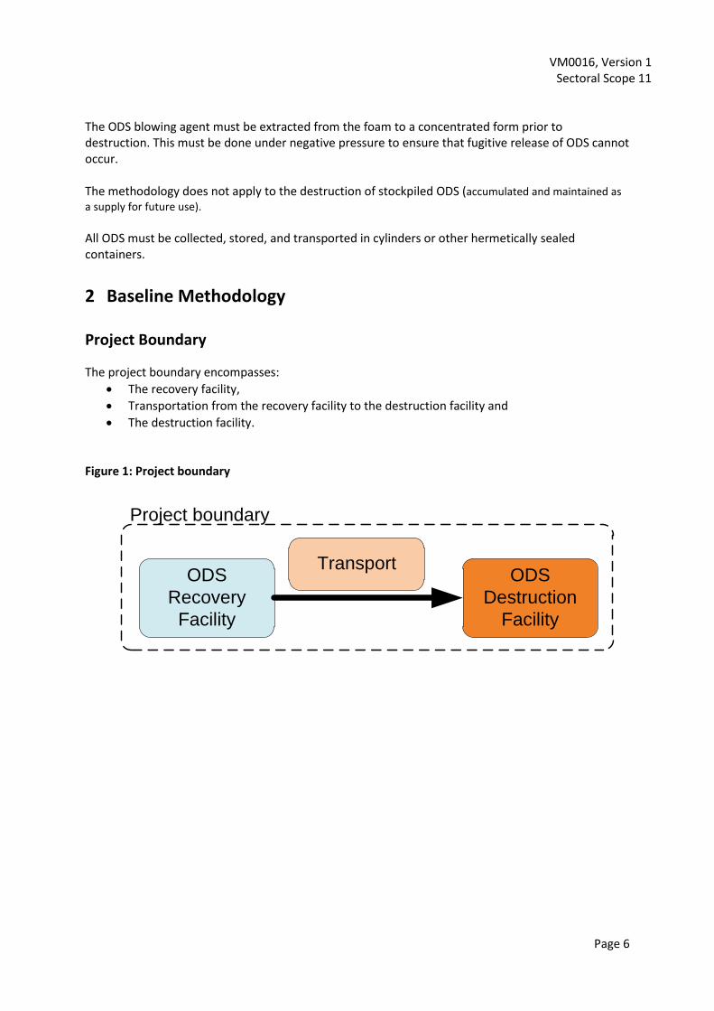
The project boundary encompasses:
The recovery facility,
Transportation from the recovery facility to the destruction facility and
The destruction facility. Figure 1: Project boundary
ODS
Recovery
Facility
TransportODS
Destruction
Facility
Project boundary

VM0016, Version 1 Sectoral Scope 11
Page 7
Table 1: Summary of gases and sources included in the project boundary and justification/explanation where gases and sources are not included
Source Gas Included? Justification / Explanation
Bas
elin
e
Emissions through the release of ODS refrigerants into the atmosphere
n
1i
iODS
Yes Main emission source in the baseline
Emissions through the release of ODS blowing agent into the atmosphere
n
1i
iODS
Yes Main emission source in the baseline
Pro
ject
Act
ivit
y
Emissions through on-site fossil fuel and electricity consumption at the recovery facility
CO2 Yes May be an important emission source
CH4 No Excluded for simplification. This emission source is assumed to be very small
N2O No Excluded for simplification. This emission source is assumed to be very small
Emissions through transportation of ODS from the recovery facility to the destruction facility
CO2 Yes May be an important emission source
CH4 No Excluded for simplification. This emission source is assumed to be very small
N2O No Excluded for simplification. This emission source is assumed to be very small
Emissions associated to the destruction process of ODS
CO2 Yes May be an important emission source
CH4 No Excluded for simplification. This emission source is assumed to be very small
N2O No Excluded for simplification. This emission source is assumed to be very small
n
1i
iODS
Yes May be an important emission source
Procedure for the selection of the most plausible baseline scenario
Project proponents should use Step 1 of the latest version of the “CDM Tool for the demonstration and assessment of additionality”, to identify all realistic and credible baseline alternatives. In doing so, relevant policies and regulations related to the management of ODS banks should be taken into account. Such policies or regulations may include mandatory ODS capture or destruction requirements because of regional or local environmental regulations. In addition, the assessment of alternative scenarios should take into account regional economic and technological circumstances.

VM0016, Version 1 Sectoral Scope 11
Page 8
For ODS refrigerants the realistic and credible alternative(s) may include, inter alia R1 Project activity not performed as emission reduction project R2 Products are disposed of into an incineration facility and thereby ODS refrigerants are
destroyed R3 Atmospheric release of the ODS refrigerant or partial capture and destruction R4 Atmospheric release of the ODS refrigerant or partial capture and reuse in existing products For ODS blowing agents the realistic and credible alternative(s) may include, inter alia BAF1 Project activity not performed as emission reduction project BAF2 The refrigerators containing foams (blowing agents) are disposed of into an incineration
facility and thereby ODS blowing agents are destroyed BAF3 The refrigerators containing foams (blowing agents) are disposed of at a landfill/dump BAF4 Before final disposal, the refrigerators containing foam are shredded. The foams are
subsequently: BAF4.1 disposed of at an incineration facility BAF4.2 disposed of at a landfill/dump BAF4.3 disposed of by open burning BAF4.4 extracted and ODS blowing agents are partly captured and destroyed
The methodology is only applicable for ODS refrigerants if the most plausible baseline scenario for the ODS refrigerant is either R3 or R4 or a combination of both. In respect of ODS blowing agents the methodology is only applicable if the most plausible baseline scenario for ODS blowing agents from foam is either one of BAF4.1, BAF4.2, BAF4.3 or BAF4.4 or any combination of these scenarios.
Additionality
The additionality of project activities shall be demonstrated and assessed using the latest version of the CDM “Tool for the demonstration and assessment of additionality”.
Baseline Emissions
Baseline emissions from existing ODS contained in products are determined with the following equation:
yODS_foam,yODS_refr,yODS, BEBEBE (1)
Where:
yODS,BE means the total quantity of baseline emissions from ODS refrigerants and blowing agents (foam) which would be released into the atmosphere in the absence of the project activity in year y [tCO2e]
yODS_refr,BE means baseline emissions from ODS refrigerants which would be released into the atmosphere in the absence of the project activity in year y [tCO2e]
yODS_foam,BE means baseline emissions from ODS blowing agents contained in insulation foams of refrigeration appliances which would be released into the atmosphere in the absence of the project activity in year y [tCO2e]

VM0016, Version 1 Sectoral Scope 11
Page 9
Baseline emissions from ODS refrigerants are determined as follows:
irefrDRrefryirefrDESTRyirefrRRyirefryirefrDESTRVRrefryirefrDESTR
n
i
GWPEFDRMEFRRMEFVRM ,,,,,,,,,,,,,,,,,,1
yODS_refr, ))()()((BE (2)
refryirefrrefrDRRRVR
,,1
(3)
Where:
yODS_refr,BE means baseline emissions from ODS refrigerants which would be released into the atmosphere in the absence of the project activity in year y [tCO2e]
y,i,refr,DESTRM means the quantity of ODS refrigerant i destroyed by the project activity in year y [tODSi].
refrVR means the rate of ODS refrigerants destroyed which would be vented into the
atmosphere in the baseline [%,0-100%];
VREF means the emission factor for the rate of ODS refrigerants destroyed which
would be vented into the atmosphere [1]
refrDR means the rate of ODS refrigerants destroyed by the project activity which
would also be destroyed in the baseline [%,0-100%]
DREF
means the emission factor for the rate of ODS refrigerants destroyed by the project activity which would also be destroyed in the baseline [0]
i,refrRR means the rate of ODS refrigerants i which would be reused in the baseline [%,0-100%]
irefrRREF
,, means the emission factor for the rate of ODS refrigerant i destroyed which would be reused in the baseline [0-1.0]
i,refrGWP is the Global warming potential of ODS refrigerant type i that converts 1 ton of ODS i to tons of CO2 equivalents. [tCO2e/tODSi]
1
VREF (4)
0DR
EF (5)
tcp
irefrirefrRRLREF )1(1
,,,
(6)
Where
irefrRREF
,, means the emission factor for the rate of ODS refrigerant i destroyed which would be reused in the baseline [0-1.0]
i,refrLR
means the leak rate of ODS refrigerant i destroyed, which would be used as refrigerant for existing equipment in the baseline [%,0-100%]
tcp means the project crediting period [10]
When destruction of the ODS refrigerants by the project activity is mandated by law, statute or other regulatory framework applying in the host country, the baseline shall be the gradually increasing compliance with such law, statute or other regulatory framework, and the baseline GHG emissions shall be calculated as follows:
)1(,_,,_ yyrefrODSayrefrODS CRBEBE (7)

VM0016, Version 1 Sectoral Scope 11
Page 10
Where
yrefrODSBE ,_ means baseline emissions from ODS refrigerants which would be released into the atmosphere in the absence of the project activity in year y [tCO2e]
ayrefrODSBE ,,_ means the adjusted baseline emissions to be used for the calculation of emission reductions in year y [tCO2e]
yCR
means the host country-level compliance rate of the law, statute or other regulatory framework in the year y. Calculation of the compliance rate shall exclude other projects implemented under GHG programs. If the compliance rate exceeds 50%, the project shall receive no further credit [%, 0-100%]
Baseline emissions from ODS blowing agents are determined as follows:
)))((( ,,,,,,,,,,,1
yODS_foam,BE ifoamyifoamDESTRyifoamAPPLIANCEifoamyifoamAPPLIANCE
n
i
GWPMMERM
(8)
Where:
yODS_foam,BE means baseline emissions from ODS blowing agents contained in insulation foams of refrigeration appliances which would be released into the atmosphere in the absence of the project activity in year y [tCO2e]
y,i,foam,DESTRM means the quantity of ODS blowing agent i destroyed by the project activity in year y[tODSi].
yifoamAPPLIANCEM ,,, means the total quantity of ODS blowing agent i contained in the total number of refrigerator appliances from which ODS is recovered in year y [tODSi].
ifoamER , means the rate by which ODS blowing agent i contained in foam of refrigeration appliances would be released into atmosphere based on the disposal practice (baseline) in the respective host country [%,0-100%]
i,foamGWP means the Global warming potential of ODS blowing agent type i that converts 1 ton of ODS i to tons of CO2 equivalents. [tCO2e/tODSi]
yifoamAPPLIANCEyifoamAPPLIANCEyifoamAPPLIANCEyifoamAPPLIANCE MMMM ,,,3,,,,2,,,,1,,,, (9)
Where:
yifoamAPPLIANCEM ,,,1, means the total quantity of ODS blowing agent i contained in the total number of typ 1 refrigerator appliances from which ODS is recovered in year y [tODSi].
yifoamAPPLIANCEM ,,,2, means the total quantity of ODS blowing agent i contained in the total number of typ 2 refrigerator appliances from which ODS is recovered in year y [tODSi].
yifoamAPPLIANCEM ,,,3, means the total quantity of ODS blowing agent i contained in the total number of typ 3 refrigerator appliances from which ODS is recovered in year y [tODSi].
J
yifoamappyifoamAPPLIANCE MM1
,,,1,,,,1, (10)
Where:
yifoamappM ,,,1, means the quantity of ODS blowing agent i contained in one typ 1 refrigerator appliance from which ODS is recovered during year y [tODSi].
J J means the total number of type 1 refrigerator appliances from which ODS blowing agent i is recovered in year y [Number]

VM0016, Version 1 Sectoral Scope 11
Page 11
K
yifoamappyifoamAPPLIANCE MM1
,,,2,,,2, (11)
Where:
yifoamappM ,,,2, means the quantity of ODS blowing agent i contained in one typ 2 refrigerator appliance from which ODS is recovered during year y [tODSi].
K K means the total number of type 2 refrigerator appliances from which ODS blowing agent i is recovered in year y [Number]
L
yifoamappyifoamAPPLIANCE MM1
,,,3,,,,3, (12)
Where:
yifoamappM ,,,1, means the quantity of ODS blowing agent i contained in one typ 3 refrigerator appliance from which ODS is recovered during year y [tODSi].
L J means the total number of type 3 refrigerator appliances of which ODS blowing agent i is recovered in year y [Number]
For baseline scenarios BAF4.1 and BAF4.2 the following default factors shall be used for ifoamER
,
Disposal Practice (Baseline) Applicable default factor
BAF4.1: disposed of at an incineration facility
ODSi ifoamER , Source
CFC-11 0.24 Same as used in CAR U.S. Ozone Depleting Substances Project Protocol Table 5.3 and 5.4 Based on Scheutz, C. et al. (2007a)
CFC-12 0.24
HCFC-22 0.24
HCFC-141b 0.24
BAF4.2: disposed of at a landfill/dump
CFC-11 0.44 Same as used in CAR U.S. Ozone Depleting Substances Project Protocol Table 5.3 and 5.4 Based on Scheutz, C. et al. (2007a/b) Fredenslund, A. et al. (2005)
CFC-12 0.55
HCFC-22 0.75
HCFC-141b 0.5
For BAF4.3 and BAF4.4, ifoamER
, shall be based on host country officially published data, research studies or industry data. When destruction of the ODS blowing agents by the project activity is mandated by law, statute or other regulatory framework applying in the host country, the baseline shall be the gradually increasing compliance with such law, statute or other regulatory framework, and the baseline GHG emissions shall be calculated as follows:
)1(,_,,_ yyfoamODSayfoamODS
CRBEBE (13)

VM0016, Version 1 Sectoral Scope 11
Page 12
Where
yfoamODSBE
,_
means baseline emissions from ODS blowing agents contained in insulation foams of refrigeration appliances which would be released into the atmosphere in the absence of the project activity in year y [tCO2e]
ayfoamODSBE
,,_
means the adjusted baseline emissions to be used for the calculation of emission reductions in year y [tCO2e]
yCR
is the host country-level compliance rate of the law, statute or other regulatory framework in the year y. Calculation of the compliance rate shall exclude other projects implemented under GHG programs. If the compliance rate exceeds 50%, the project shall receive no further credit [%,0-100%]
Project Emissions
Project emissions in year y are:
Emissions that are caused by the project activity due to energy consumption at the ODS recovery facility
Emissions that are caused by the project activity due to ODS transportation
Emissions that are caused by the project activity due to ODS destruction
ynDestructioODSyTransportODSyConsumpEnergyy PEPEPEPE ,_,_, (14)
yPE
means the project emissions during year y [tCO2e]
yConsumpEnergyPE , means the project emissions from energy consumption at the ODS recovery facility during year y [[tCO2e]
yTransportODSPE ,_ means the project emission from ODS transportation during year y [tCO2e]
ynDestructioODSPE ,_ means the project emission from ODS destruction during year y [tCO2e]
Determination of yConsumpEnergyPE , :
yjFCyECyConsumpEnergy PEPEPE ,,,, (15)
Where:
yConsumpEnergyPE , means the project emissions from energy consumption attributable to the ODS recovery facility during year y [tCO2e]
yECPE , means the project emissions from electricity consumption from the grid at the ODS recovery facility during year y [tCO2e]
yjFCPE ,, means the project emissions from fossil fuel consumption attributable to the ODS recovery facility including third party used fossil fuel to generate energy for the ODS recovery facility during year y [tCO2e]
VM0016, Version 1 Sectoral Scope 11
Page 13
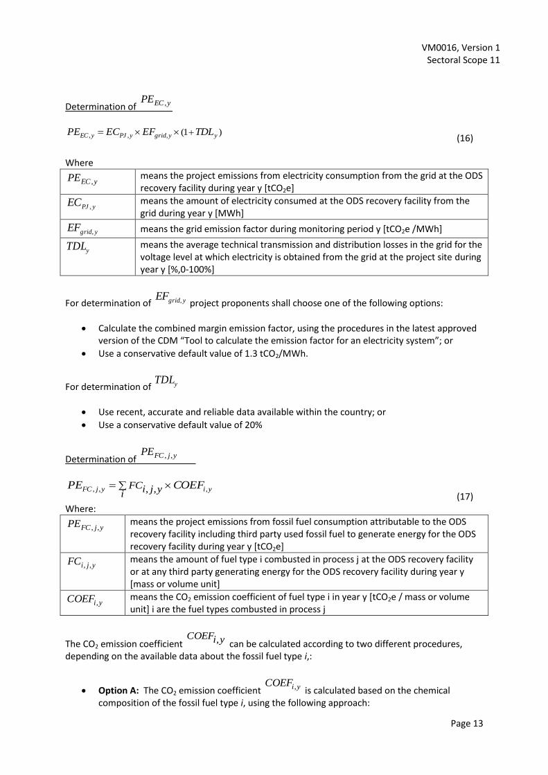
Determination of yECPE ,
)1(,,, yygridyPJyEC TDLEFECPE (16)
Where
yECPE , means the project emissions from electricity consumption from the grid at the ODS recovery facility during year y [tCO2e]
yPJEC , means the amount of electricity consumed at the ODS recovery facility from the grid during year y [MWh]
ygridEF , means the grid emission factor during monitoring period y [tCO2e /MWh]
yTDL
means the average technical transmission and distribution losses in the grid for the voltage level at which electricity is obtained from the grid at the project site during year y [%,0-100%]
For determination of ygridEF , project proponents shall choose one of the following options:
Calculate the combined margin emission factor, using the procedures in the latest approved version of the CDM “Tool to calculate the emission factor for an electricity system”; or
Use a conservative default value of 1.3 tCO2/MWh.
For determination of yTDL
Use recent, accurate and reliable data available within the country; or
Use a conservative default value of 20%
Determination of yjFCPE ,,
yiyjFC COEFPEi
yjiFC ,,, ,, (17)
Where:
yjFCPE ,, means the project emissions from fossil fuel consumption attributable to the ODS recovery facility including third party used fossil fuel to generate energy for the ODS recovery facility during year y [tCO2e]
yjiFC ,, means the amount of fuel type i combusted in process j at the ODS recovery facility or at any third party generating energy for the ODS recovery facility during year y [mass or volume unit]
yiCOEF , means the CO2 emission coefficient of fuel type i in year y [tCO2e / mass or volume unit] i are the fuel types combusted in process j
The CO2 emission coefficient yiCOEF , can be calculated according to two different procedures, depending on the available data about the fossil fuel type i,:
Option A: The CO2 emission coefficient yiCOEF , is calculated based on the chemical composition of the fossil fuel type i, using the following approach:

VM0016, Version 1 Sectoral Scope 11
Page 14
If yjiFC ,, is measured in a mass unit: 12/44,,, yiCwyiCOEF
If yjiFC ,, is measured in a volume unit: 12/44,,,, yiyiCwyiCOEF
Where:
yiCOEF , means the CO2 emission coefficient of fuel type i during year y [tCO2e / mass or volume unit]
yiCw ,, means the weighted average mass fraction of carbon in fuel type i during year y [tC / mass unit of the fuel]
yi,
means the weighted average density of fuel type i during year y (mass unit / volume unit of the fuel)
Option B: The CO2 emission coefficient COEFi,y is calculated based on net calorific value and CO2 emission factor of the fuel type i, as follows:
yiCOEFyiNCVyiCOEF ,,2,, (18)
Where:
yiCOEF , means the CO2 emission coefficient of fuel type i during year y [tCO2e / mass or volume unit]
yiNCV , means the weighted average net calorific value of the fuel type i during year y [GJ/mass or volume unit]
yiCOEF ,,2 means the weighted average CO2 emission factor of fuel type i during year y [tCO2e /GJ]
Where necessary data is available option A should be used.
Determination of yTransportODSPE ,_ and ynDestructioODSPE ,_
For project emissions due to ODS transportation and destruction, project proponents shall apply the default factors provided by the latest version of the CAR Article 5 Ozone Depleting Substances Project Protocol: (Calculating Default Project Emissions from ODS Destruction and Transportation)
ynDestructioTransportODSyifoamDESTRyirefrDESTRynDestructioODSyTransportODS EFMMPEPE ,_,,,,,,,_,_ *)( (19)
Where
yTransportODSPE ,_ means the project emission from ODS transportation during year y [tCO2e]
ynDestructioODSPE ,_ means the project emission from ODS destruction during year y [tCO2e]
y,i,refr,DESTRM
means the quantity of ODS refrigerant i destroyed by the project activity during year y [tODSi]
y,i,foam,DESTRM means the quantity of ODS blowing agent i destroyed by the project activity during year y [tODSi]
ynDestructioTransportODSEF ,_ means the default emission factor aggregating both transportation and destruction emissions [tCO2] (sourced from CAR, as above)

VM0016, Version 1 Sectoral Scope 11
Page 15
Leakage Emissions
Leakage emissions occur where in the baseline ODS refrigerant would have been re-used and in the project scenario must be substituted by other chemicals. Reuse may result in a gradual release of ODS over the project crediting period. When refrigerant ODS are destroyed, continued demand for refrigeration will lead to the production and consumption of other refrigerant chemicals whose production is still legally allowed.
isubstitueisubstitute
n
iyirefrDestrySubstituteODS GWPTLRMLE ,,,,,,_ **
(20)
Where
ySubstituteODSLE ,_ means leakage emissions through ODS substitute i during year y [tCO2e]
y,i,refr,DESTRM
means the quantity of ODS refrigerant i which is sent to destruction by the project activity in year y [tODSi]
isubstituteTLR , means the total leakage of substitute chemical i over the project crediting period [0-1]
isubstitueGWP , means the Global warming potential of substitute chemical i [tonsCO2e/subsitute,i]
tcp
yisubstituteLRTLR )1(1 ;, (21)
Where
isubstituteTLR , means the total leakage of substitute chemical i over the project crediting period [0-1]
yisubstituteLR
;, means the leak rate of substitute chemical i in year y [0-1]
tcp means the project crediting period
For project activities taking place in Article 5 countries, project proponents shall apply a substitute chemical derived from the latest version of the CAR Article 5 Ozone Depleting Substances Project Protocol. Regardless of the substitute chemical applied, however, this methodology applies a total
leakage isubstituteTLR , of 1 of the substitute chemical.
For project activities taking place in Non-Article 5 countries, project proponents shall apply substitute chemicals derived from either official published data, research or industry studies. For instance, in the case of the United States default values provided by the latest version of the CAR U.S. Ozone Depleting Substances Project Protocol may be used. Regardless of the substitute chemical applied, however, a conservative factor of 1 shall be used for yisubstitute
LR;, .
Emission Reductions
Emission reductions are calculated as follows:
yy LEPE yODS_foam,yODS_refr,yODS, BEBEER (22)
VM0016, Version 1 Sectoral Scope 11
Page 16
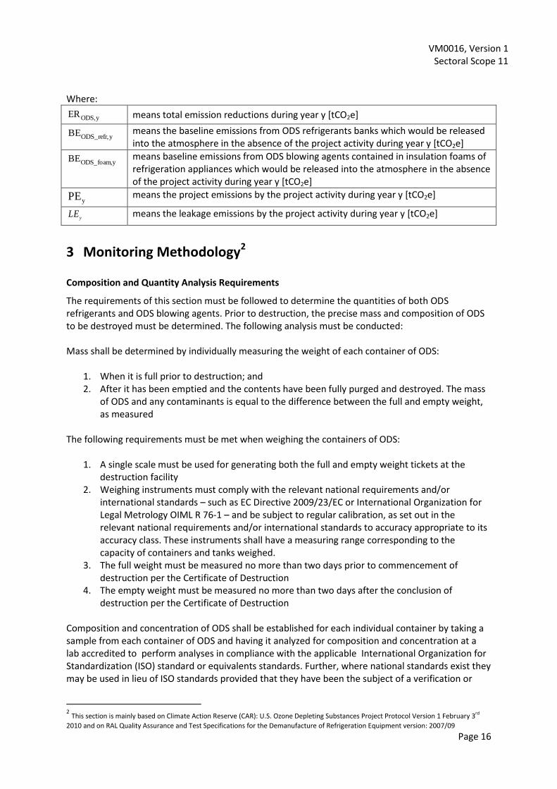
Where:
yODS,ER
means total emission reductions during year y [tCO2e]
yODS_refr,BE
means the baseline emissions from ODS refrigerants banks which would be released into the atmosphere in the absence of the project activity during year y [tCO2e]
yODS_foam,BE means baseline emissions from ODS blowing agents contained in insulation foams of refrigeration appliances which would be released into the atmosphere in the absence of the project activity during year y [tCO2e]
yPE
means the project emissions by the project activity during year y [tCO2e]
yLE means the leakage emissions by the project activity during year y [tCO2e]
3 Monitoring Methodology2 Composition and Quantity Analysis Requirements
The requirements of this section must be followed to determine the quantities of both ODS refrigerants and ODS blowing agents. Prior to destruction, the precise mass and composition of ODS to be destroyed must be determined. The following analysis must be conducted: Mass shall be determined by individually measuring the weight of each container of ODS:
1. When it is full prior to destruction; and 2. After it has been emptied and the contents have been fully purged and destroyed. The mass
of ODS and any contaminants is equal to the difference between the full and empty weight, as measured
The following requirements must be met when weighing the containers of ODS:
1. A single scale must be used for generating both the full and empty weight tickets at the destruction facility
2. Weighing instruments must comply with the relevant national requirements and/or international standards – such as EC Directive 2009/23/EC or International Organization for Legal Metrology OIML R 76-1 – and be subject to regular calibration, as set out in the relevant national requirements and/or international standards to accuracy appropriate to its accuracy class. These instruments shall have a measuring range corresponding to the capacity of containers and tanks weighed.
3. The full weight must be measured no more than two days prior to commencement of destruction per the Certificate of Destruction
4. The empty weight must be measured no more than two days after the conclusion of destruction per the Certificate of Destruction
Composition and concentration of ODS shall be established for each individual container by taking a sample from each container of ODS and having it analyzed for composition and concentration at a lab accredited to perform analyses in compliance with the applicable International Organization for Standardization (ISO) standard or equivalents standards. Further, where national standards exist they may be used in lieu of ISO standards provided that they have been the subject of a verification or
2 This section is mainly based on Climate Action Reserve (CAR): U.S. Ozone Depleting Substances Project Protocol Version 1 February 3rd
2010 and on RAL Quality Assurance and Test Specifications for the Demanufacture of Refrigeration Equipment version: 2007/09

VM0016, Version 1 Sectoral Scope 11
Page 17
validation process addressing their accuracy and representativeness. In the case where no such standards exist, the US Air-Conditioning, Heating and Refrigeration Institute 700-2006 standard shall be applied.
The laboratory performing the composition analysis must not be affiliated with the project proponents. The following requirements must be met for each sample:
1. The sample must be taken while ODS is in the possession of the company that will destroy the ODS
2. Samples must be taken by a technician unaffiliated with the project developer 3. Samples must be taken with a clean, fully evacuated sample bottle that meets applicable U.S.
DOT requirements or an equivalent national (host country) or ISO standard 4. Each sample must be taken in liquid state 5. A minimum sample size of 0.453592 kg (1 pound) must be drawn for each sample 6. Each sample must be individually labeled and tracked according to the container from which
it was taken, and the following information recorded:
Time and date of sample
Name of project developer
Name of technician taking sample
Employer of technician taking sample
Volume of container from which sample was extracted
Ambient air temperature at time of sampling
7. Chain of custody for each sample from the point of sampling lab must be documented by paper bills of lading or electronic, third-party tracking that includes proof of delivery
All project samples shall be analyzed using the International Organization for Standardization (ISO) standard applicable. Further, where national standards exist they may be used in lieu of ISO standards provided that they have been the subject of a verification or validation process addressing their accuracy and representativeness. In the case where no such standards exist, the US Air-Conditioning, Heating and Refrigeration Institute 700-2006 standard shall be applied. The analysis shall provide:
1. Identification of the refrigerant 2. Purity (%) of the ODS mixture by weight using gas chromatography 3. Moisture level in parts per million. The moisture content of each sample must be less than
75% of the saturation point for the ODS based on the temperature recorded at the time the sample was taken.
4. Analysis of high boiling residue, which must be less than 10% by mass 5. Analysis of other ODS in the case of mixtures of ODS, and their percentage by mass
If any of the requirements above are not met, no GHG reductions may be verified for ODS destruction associated with that container. If the container holds non-mixed ODS (defined as greater than 90% composition of a single ODS species) no further information or sampling is required to determine the mass and composition of

VM0016, Version 1 Sectoral Scope 11
Page 18
the ODS. If the container holds mixed ODS, which is defined as less than 90% composition of a single ODS species, the project developer must meet additional requirements as provided below. Composition and Quantity Analysis Requirements for Mixed ODS
If a container holds mixed ODS, its contents must also be processed and measured for composition and concentration according to the requirements of this section. The sampling required under this section may be conducted at the final destruction facility or prior to delivery to the destruction facility. However, the circulation and sampling activities must be conducted by a third-party organization (i.e., not the project developer), and by individuals who have been properly trained for the functions they perform. Circulation and sampling may be conducted at the project proponent’s facility, but all activities must be directed by a properly trained and contracted third-party. The project’s Monitoring Plan must specify the procedures by which mixed ODS are analyzed. The composition and concentration of ODS on a mass basis must be determined using the results of the analysis of this section for each container. The results of the composition analysis in the section above shall be used by verifiers to confirm that the destroyed ODS is in fact the same ODS that is sampled under these requirements. Prior to sampling, the ODS mixture must be circulated in a container that meets all of the following criteria:
1. The container has no solid interior obstructions 2. The container was fully evacuated prior to filling 3. The container must have sampling ports to sample liquid and gas phase ODS 4. The sampling ports must be located in the middle third of the container (i.e., not at one end
or the other) 5. The container and associated equipment can circulate the mixture via a closed loop system
from the bottom to top If the original mixed ODS container does not meet these requirements, the mixed ODS must be transferred into a temporary holding tank or container that meets all of the above criteria. The weight of the contents placed into the temporary container shall be calculated and recorded. During transfer of ODS into and out of the temporary container, ODS shall be recovered to the vacuum levels required by the U.S. EPA for that ODS (see 40 CFR 82.156) or any national (host country) or ISO standard. Once the mixed ODS is in a container or temporary storage unit that meets the criteria above, circulation of mixed ODS must be conducted as follows:
1. Liquid mixture shall be circulated from the liquid port to the vapor port. 2. A volume of the mixture equal to two times the volume in the container shall be circulated 3. Circulation must occur at a rate of at least 113.6l/minute 4. Start and end times shall be recorded
Within 30 minutes of the completion of circulation, a minimum of two samples shall be taken from the bottom liquid port and analyzed according to the procedures above. The mass composition and concentration of the mixed ODS shall be equal to the lesser of the two GWP-weighted concentrations.

VM0016, Version 1 Sectoral Scope 11
Page 19
Determination of Recovery Efficiency of Blowing Agents Contained in Foam of Refrigeration Appliances
An annual test shall be conducted in which at least 1000 refrigeration appliances with ODS containing insulation materials are processed at the recovery facility of the project proponent. Every appliance used in the test shall be intact, i.e. there shall be no damage to the appliance carcass and the doors typical of that appliance type shall still be attached. No other doors, appliance components or other products containing foam insulation shall be processed during the test. Systematically sorting out refrigeration appliances from the mass flow of incoming devices for the purpose of manipulating the quantity of recovered ODS is strictly forbidden. To compile a mass balance analysis, the total weight of all the appliances used in the test shall be determined and recorded. In addition, the weight of all material fractions recovered from the processing plant during the test shall be determined. Polyurethane Ferrous metals Non-ferrous metals Plastics Non-ferrous/plastic fraction Residual waste Process water ODS Other components
The gas cylinders used to store the recovered ODS are weighed when empty (i.e. before processing commences) and again when filled (i.e. after processing has been completed). The dry weight in kilograms of ODS recovered is divided by the number of appliances processed. The result is recorded as the quantity of ODS recovered in grams per appliance. The quantities of ODS blowing agents to be recovered for each appliance type (domestic fridge, domestic fridge-freezers, domestic chest freezers and upright freezers) as specified under the section “Definitions” shall be sourced from official national values. In cases where no such official values are available it shall be determined by RAL RAL Quality Assurance and Test Specifications for the Demanufacture of Refrigeration Equipment The recovery facility must achieve a recovery efficiency of at least 90% otherwise no credits can be generated for the respective monitoring period. The RAL test protocol, attached as a separate excel file (Annex V) to this methodology shall be used for the annual test. Since this methodology requires the extraction of ODS from the foam to a concentrated form prior to destruction the overall Recovery and Destruction Efficiency will be achieved when the destruction facility meets the requirements of UNEP Technology and Economic Assessment Panel (TEAP) Report of the Task Force on Destruction Technologies, UNEP, 2002. A minimum Recovery and Destruction Efficiency (RDE) of 85% shall be achieved otherwise no credits can be generated for the respective monitoring period.

VM0016, Version 1 Sectoral Scope 11
Page 20
Destruction Facility Requirements
Destruction of ODS must occur at a facility that has a valid host country permit for ODS destruction and meets the screening criteria for destruction technologies set out in the report, as may be updated from time to time, by the UNEP Technology and Economic Assessment Panel (TEAP) Task Force on Destruction Technologies. (reproduced in full in Annex III from TEAP Report of the Task Force on Destruction Technologies, Chapter 2 (2002)). Operating parameters of the destruction unit while destroying ODS material shall be monitored and recorded as described in the Code of Good Housekeeping3(as reproduced in full in Annex II) approved by the Montreal Protocol.
Data and Parameters Monitored
Data / Parameter: y,i,refr,DESTRM
Data unit: tODSi
Description: means the quantity of ODS refrigerant i destroyed by the project activity
Source of data: Operation logbook of recovery facility
Identification note for each individual ODS container by a bill of lading
Certificate of Destruction for each individual ODS container (refer to section III of this methodology “Monitoring Methodology”)
Measurement procedures (if any):
Refer to section III of this methodology “Monitoring Methodology”
Monitoring frequency: Each container with ODS sent to destruction
QA/QC procedures: All measurements should be conducted with calibrated measurement equipment according to relevant industry standards (refer to section III of this methodology “Monitoring Methodology”)
Any comment: -
Data / Parameter: y,i,foam,DESTRM
Data unit: tODSi
Description: means the quantity of ODS blowing agent i contained in insulation foams of refrigeration appliances destroyed by the project activity
Source of data: Operation logbook of recovery facility
Identification note for each individual ODS container by a bill of lading
Certificate of Destruction for each individual ODS container (refer to section III of this methodology “Monitoring Methodology”)
Measurement procedures (if any):
Refer to section III of this methodology “Monitoring Methodology”
Monitoring frequency: Each container with ODS sent to destruction
QA/QC procedures: All measurements should be conducted with calibrated measurement equipment according to relevant industry standards (refer to section III of this methodology “Monitoring Methodology”)
Any comment: -
3 TEAP, Code of Good Housekeeping in Handbook for the Montreal Protocol on Substances that Deplete the Ozone Layer -
7th Edition (2006)

VM0016, Version 1 Sectoral Scope 11
Page 21
Data / Parameter: Input flow of appliances (and types) J, K, L into the section of the recovery facility where removal of foams and extraction of ODS blowing agents from foams takes place
Data unit: Number of refrigeration appliances [Number] and mass unit [e.g. kg]
Description: Documentation of all input flows into the section of the recovery facility where removal of foams and extraction of ODS from foams takes place according to appliance types (. type 1 domestic fridges; type 2 domestic fridge-freezers; type 3 domestic chest freezers and upright freezers;) and by weight.
Source of data: Operation logbook of recovery facility
Measurement procedures (if any):
Weight measured by calibrated weighing scales.
Monitoring frequency: Continuous monitoring, recording monthly, once annually: Test of 1000 appliances
QA/QC procedures: All measurements should be conducted with calibrated measurement equipment according to relevant industry standards
Any comment: -
Data / Parameter: Total weight of output fractions from the section of the recovery facility where removal of foams and extraction of ODS blowing agents from foams takes place (test procedure)
Data unit: Mass unit [e.g. kg]
Description: Documentation of output flows (type and weight) The following fractions shall be documented:
Polyurethane
Ferrous metals
Non-ferrous metals
Plastics
Non-ferrous/plastic fraction
Residual waste
Process water
ODS blowing agents
Other components
Source of data: Operation logbook of the recovery facility
Measurement procedures (if any):
Weight measured by calibrated weighing scales.
Monitoring frequency: Continuous monitoring, recording monthly, once annually: Test of 1000 appliances
QA/QC procedures: All measurements should be conducted with calibrated measurement equipment according to relevant industry standards
Any comment: -
Parameter: yODSi
CR,
Data unit: Number
Description: means the host country-level compliance rate of the law, statute or other regulatory framework in the year y in relation to ODSi. Calculation of the

VM0016, Version 1 Sectoral Scope 11
Page 22
compliance rate shall exclude other projects implemented under GHG programs. If the compliance rate exceeds 50%, the project shall receive no further credit.
Source of data: Officially published data, research studies, industry data etc…
Measurement procedures (if any):
-.
Monitoring frequency: Annually
QA/QC procedures: -
Any comment: -
Data / Parameter: yjiFC ,,
Data unit: Mass or volume unit per year (e.g. ton/y or m³/y)
Description: Quantity of fuel type i combusted in process j
Source of data: Onsite measurements
Measurement procedures (if any):
Use either mass or volume meters. In cases where fuel is supplied from small daily tanks, rulers can be used to determine mass or volume of the fuel consumed, with the following conditions: The ruler gauge must be part of the daily tank and calibrated at least once a year and have a book of control for recording the measurements (on a daily basis or per shift); Accessories such as transducers, sonar and piezoelectronic devices are accepted if they are properly calibrated with the ruler gauge and receiving a reasonable maintenance; In case of daily tanks with pre-heaters for heavy oil, the calibration will be made with the system at typical operational conditions.
Monitoring frequency: Continuously
QA/QC procedures: The consistency of metered fuel consumption quantities should be crosschecked by an annual energy balance that is based on purchased quantities and stock changes. Where the purchased fuel invoices can be identified specifically for the project activity, the metered fuel consumption quantities should also be cross-checked with available purchase invoices from the financial records.
Any comment: -
Data / Parameter: yiCw ,,
Data unit: ton C/mass unit of the fuel
Description: Weighted average mass fraction of carbon in fuel type i in year y
Source of data: The following data sources may be used if the relevant conditions apply:
Data source Conditions for using the data source
a) Values provided by the fuel supplier in invoices
Where relevant information is available use option a)
b) Measurements by the project proponents
If a) is not available
Measurement procedures (if any):
Measurements should be undertaken in line with national or international fuel standards.

VM0016, Version 1 Sectoral Scope 11
Page 23
Monitoring frequency: The mass fraction of carbon should be obtained for each fuel delivery, from which weighted average annual values should be calculated.
QA/QC procedures Verify if the values under a) and b) are within the uncertainty range of the IPCC default values as provided in Table 1.2, Vol. 2 of the 2006 IPCC Guidelines. If the values fall below this range collect additional information from the testing laboratory to justify the outcome or conduct additional measurements. The laboratories in b) should have ISO17025 accreditation or justify that they can comply with similar quality standards.
Any comment: Applicable where option A is used
Data / Parameter: yi ,
Data unit: Mass unit/volume unit
Description: Weighted average density of fuel type i in year y
Source of data: The following data sources may be used if the relevant conditions apply:
Data source Conditions for using the data source
a) Values provided by the fuel supplier in invoices
Where relevant information is available use option a)
b) Measurements by the project proponents
If a) is not available
c) Regional or national default values If a) is not available These sources can only be used for liquid fuels and should be based on well documented, reliable sources (such as national energy balances).
Measurement procedures (if any):
Measurements should be undertaken in line with national or international fuel standards.
Monitoring frequency: The density of the fuel should be obtained for each fuel delivery, from which weighted average annual values should be calculated.
QA/QC procedures:
Any comment: Applicable where option A is used and where yjiFC ,, is measured in a volume
unit. Preferably the same data source should be used for yiCw ,, and yi,.
Data / Parameter: yiNCV ,
Data unit: GJ per mass or volume unit (e.g. GJ/m³, GJ/ton)
Description: Weighted average net calorific value of fuel type i in year y
Source of data: The following data sources may be used if the relevant conditions apply:
Data source Conditions for using the data source
a) Values provided by the fuel supplier in invoices
Where relevant information is available use option a)
b) Measurements by the project proponents
If a) is not available
c) Regional or national default values If a) is not available. These sources

VM0016, Version 1 Sectoral Scope 11
Page 24
can only be used for liquid fuels and should be based on well documented, reliable sources (such as national energy balances).
d) IPCC default values at the upper limit of the uncertainty at a 95% confidence interval as provided in Table 1.2 of Chapter 1 of Vol. 2 (Energy) of the 2006 IPCC Guidelines on National GHG Inventories
If a) is not available
Measurement procedures (if any):
For a) and b): Measurements should be undertaken in line with national or international fuel standards
Monitoring frequency: For a) and b): The NCV should be obtained for each fuel delivery, from which weighted average annual values should be calculated For c): Review appropriateness of the values annually For d): Any future revision of the IPCC Guidelines should be taken into account
QA/QC procedures: Verify if the values under a), b) and c) are within the uncertainty range of the IPCC default values as provided in Table 1.2, Vol. 2 of the 2006 IPCC Guidelines. If the values fall below this range collect additional information from the testing laboratory to justify the outcome or conduct additional measurements. The laboratories in a), b) or c) should have ISO17025 accreditation or justify that they can comply with similar quality standards.
Any comment: Applicable where option B of this methodology is used
Data / Parameter: yiCOEF ,,2
Data unit: tCO2/GJ
Description: Weighted average CO2 emission factor of fuel type i in year y
Source of data: The following data sources may be used if the relevant conditions apply:
Data source Conditions for using the data source
a) Values provided by the fuel supplier in invoices
Where relevant information is available use option a).
b) Measurements by the project proponents
If a) is not available
c) Regional or national default values If a) is not available These sources can only be used for liquid fuels and should be based on well documented, reliable sources (such as national energy balances).
d) IPCC default values at the upper limit of the uncertainty at a 95% confidence interval as provided in table 1.4 of Chapter1 of Vol. 2 (Energy) of the 2006 IPCC Guidelines on National GHG Inventories
If a) is not available
Measurement procedures (if any):
For a) and b): Measurements should be undertaken in line with national or international fuel standards.

VM0016, Version 1 Sectoral Scope 11
Page 25
Monitoring frequency: For a) and b): The CO2 emission factor should be obtained for each fuel delivery, from which weighted average annual values should be calculated For c): Review appropriateness of the values per monitoring interval y For d): Any future revision of the IPCC Guidelines should be taken into account
QA/QC procedures:
Any comment: Applicable where option B is used. For a): If the fuel supplier does provide the NCV value and the CO2 emission factor on the invoice and these two values are based on measurements for this specific fuel, this CO2 factor should be used. If another source for the CO2 emission factor is used or no CO2 emission factor is provided, options b), c) or d) should be used
Data / Parameter: yPJEC ,
Data unit: MWh
Description: means the amount of electricity consumed by the project activity from the grid
Source of data: Onsite measurements and recorded by a computer system and/or by printed journals
Measurement procedures (if any):
Directly measured by calibrated electricity meter installed at the project site.
Monitoring frequency: Continuously, aggregated at least annually
QA/QC procedures: Cross check measurement results with invoices for purchased electricity if relevant
Any comment: -
Data / Parameter: ygridEF ,
Data unit: tons CO2/MWh
Description: Emission factor for the grid in year y
Source of data: Choose one of the following options:
Calculate the combined margin emission factor, using the procedures in the latest approved version of the CDM “Tool to calculate the emission factor for an electricity system”;
Use a conservative default value of 1.3 tCO2/MWh.
Measurement procedures (if any):
-
Monitoring frequency: -
QA/QC procedures: If the „Tool to calculate the emission factor for an electricity system” will be used the source and/or the calculation shall be available by printed journals.
Any comment: -
Data / Parameter: yTDL
Data unit: -
Description: Average technical transmission and distribution losses in the grid in year y for the voltage level at which electricity is obtained from the grid at the project site
Source of data: Choose one of the following options: a) Use recent, accurate and reliable data available within the country; b) Use a default value of 20%
VM0016, Version 1 Sectoral Scope 11
Page 26
Measurement procedures (if any): For a) yTDL
should be estimated for the distribution and transmission networks of the electricity grid of the same voltage as the connection where the proposed project activity is connected to. The technical distribution losses should not contain other types of grid losses (e.g. commercial losses/theft). The distribution losses can either be calculated by the project proponents or be based on references from utilities, network operators or other official documentation.
Monitoring frequency: -
QA/QC procedures: In the absence of data from the relevant year, most recent figures should be used, but not older than 5 years.
Any comment: -
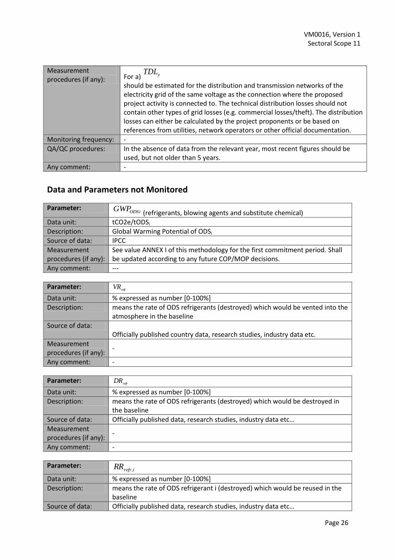
Data and Parameters not Monitored
Parameter: ODSiGWP
(refrigerants, blowing agents and substitute chemical)
Data unit: tCO2e/tODSi
Description: Global Warming Potential of ODSi
Source of data: IPCC
Measurement procedures (if any):
See value ANNEX I of this methodology for the first commitment period. Shall be updated according to any future COP/MOP decisions.
Any comment: ---
Parameter: refr
VR
Data unit: % expressed as number [0-100%]
Description: means the rate of ODS refrigerants (destroyed) which would be vented into the atmosphere in the baseline
Source of data: Officially published country data, research studies, industry data etc.
Measurement procedures (if any):
-
Any comment: -
Parameter: refr
DR
Data unit: % expressed as number [0-100%]
Description: means the rate of ODS refrigerants (destroyed) which would be destroyed in the baseline
Source of data: Officially published data, research studies, industry data etc…
Measurement procedures (if any):
-
Any comment: -
Parameter: irefrRR ,
Data unit: % expressed as number [0-100%]
Description: means the rate of ODS refrigerant i (destroyed) which would be reused in the baseline
Source of data: Officially published data, research studies, industry data etc…

VM0016, Version 1 Sectoral Scope 11
Page 27
Measurement procedures (if any):
-
Any comment: -
Parameter: irefrLR ,
Data unit: % expressed as number [0-100%]
Description: means the leak rate of ODS refrigerant i (destroyed), which would be used as refrigerant for existing equipment in the baseline
Source of data: Officially published data, research studies, industry data etc…
Measurement procedures (if any):
-
Any comment: -
Parameter: i,foamER
Data unit: % expressed as number [0-100%]
Description: means the rate by which ODS blowing agents contained in foam of refrigeration appliances would be released into atmosphere based on the disposal practice (baseline) in the respective host country
Source of data: Depending on baseline scenario (BAF1-4). For BAF4.1-4.2 see scientific sources Annex II to this methodology and/or default values provided by the latest version of the Climate Action Reserve (CAR): U.S. Ozone Depleting Substances Project Protocol. For baseline scenarios BAF4.3 and BAF4.4 officially published data, research studies or industry data shall be used
Measurement procedures (if any):
-
Any comment: -
Parameter: isubstitute
LR,
Data unit: % expressed as number [0-100%]
Description: means the leak rate of substitute chemical i [0-1]
Source of data: For project activities taking place in Article 5 countries leak rate of 1 shall be assumed. For project activities taking place in Non Article 5 countries, officially published data, research studies, industry data etc or 1 shall be used.
Measurement procedures (if any):
-
Any comment: -
Parameter: Substitute chemical i
Data unit:
Description: means the chemical i substituting ODS refrigerant i where in the baseline refrigerant ODS would have been re-used and in the project scenario must be substituted by other chemicals
Source of data: For project activities taking place in Article 5 countries, project proponents shall apply a substitute chemical derived from the latest version of the CAR

VM0016, Version 1 Sectoral Scope 11
Page 28
Article 5 Ozone Depleting Substances Project Protocol. For project activities taking place in Non-Article 5 countries, officially published data, research studies, industry data, etc.
Measurement procedures (if any):
-
Any comment: -
Parameter: yifoamappM ,,,1, , yifoamappM ,,,2, , yifoamappM ,,,3,
Data unit: t ODSi/appliance type 1, 2 and 2
Description: means the amount of blowing agent ODSi contained in foam of refrigeration appliance types 1-3 in host country Type 1 appliances, Domestic fridges: These are refrigerators of a typical domestic design with a storage capacity of up to 180 litres. The appliances may or may not be equipped with a separate deep-freeze compartment. Type 2 appliances, Domestic fridge-freezers: These are refrigeration appliances of a typical domestic design with a storage capacity ranging from 180 to 350 litres. Generally, these appliances have a separate deep-freeze compartment. Type 3 appliances, Domestic chest freezers and upright freezers: These are deep-freeze appliances of a typical domestic design with a storage capacity up to 500 litres.
Source of data: If official national values are available those national values shall be used. In cases where no such official values are available it shall be determined by RAL RAL Quality Assurance and Test Specifications for the Demanufacture of Refrigeration Equipment
Measurement procedures (if any):
-
Any comment: -
Parameter: ynDestructioTransportODSEF ,_
Data unit: tCO2
Description: means the default emission factor aggregating both transportation and destruction emissions
Source of data: provided by the latest version of the CAR Article 5 Ozone Depleting Substances Project Protocol: (Calculating Default Project Emissions from ODS Destruction and Transportation)
Measurement procedures (if any):
-
Any comment: -

VM0016, Version 1 Sectoral Scope 11
Page 29
Annex I: ODS (ANNEX I, Groups) and their GWP
Substance terms and ODP (Ozone-Depleting Potential) values and based on the The Montreal Protocol on Substances that Deplete the Ozone Layer http://unep.org/ozone/pdfs/Montreal-Protocol2000.pdf
GWP (Global warming potential) values based on the IPCC Fourth assessment report 2007 - Working group I report “The physical science basis of climate change” - Chapter 2 “Changes in Atmospheric Constituents and in Radiative Forcing” table 2.14/page 212 http://www.ipcc.ch/pdf/assessment-report/ar4/wg1/ar4-wg1-chapter2.pdf
Annex A: Controlled substances – Group I
Substance ODP Ozone-Depleting Potential
GWP Global warming potential for 100 year Kyoto time horizon
CFCl3 CFC-11 1.0 4750
CF2Cl2 CFC-12 1.0 10900
C2F3Cl3 CFC-113 0.8 6130
C2F4Cl2 CFC-114 1.0 10000
C2F5Cl CFC-115 0.6 7370
Annex B: Controlled substances – Group I
Substance ODP Ozone-Depleting Potential
GWP Global warming potential for 100 year Kyoto time horizon
CF3Cl CFC-13 1.0 14400
C2FCl5 CFC-111 1.0 n.a.
C2F2Cl4 CFC-112 1.0 n.a.
C3FCl7 CFC-211 1.0 n.a.
C3F2Cl6 CFC-212 1.0 n.a.
C3F3Cl5 CFC-213 1.0 n.a.
C3F4Cl4 CFC-214 1.0 n.a.
C3F5Cl3 CFC-215 1.0 n.a.
C3F6Cl2 CFC-216 1.0 n.a.
C3F7Cl CFC-217 1.0 n.a.

VM0016, Version 1 Sectoral Scope 11
Page 30
Annex C: Controlled substances – Group I
Substance ODP Ozone-Depleting Potential
GWP Global warming potential for 100 year Kyoto time horizon
CHFCl2 HCFC-21** 0.04
CHF2Cl HCFC-22** 0.055 1810
CH2FCl HCFC-31 0.02 n.a.
C2HFCl4 HCFC-121 0.01-0.04 n.a.
C2HF2Cl3 HCFC-122 0.02-0.08 n.a.
C2HF3Cl2 HCFC-123 0.02-0.06 n.a.
CHCl2CF3 HCFC-123** 0.02 77
C2HF4Cl HCFC-124 0.02-0.04 n.a.
CHFClCF3 HCFC-124** 0.022 609
C2H2FCl3 HCFC-131 0.007-0.05 n.a.
C2H2F2Cl2 HCFC-132 0.008-0.05 n.a.
C2H2F3Cl HCFC-133 0.02-0.06 n.a.
C2H3FCl2 HCFC-141 0.005-0.07 n.a.
CH3CFCl2 HCFC-141b** 0.11 725
C2H3F2Cl HCFC-142 0.008-0.07 n.a.
CH3CF2Cl HCFC-142b** 0.065 2310
C2H4FCl HCFC-151 0.003-0.005 n.a.
C3HFCl6 HCFC-221 0.015-0.07 n.a.
C3HF2Cl5 HCFC-222 0.01-0.09 n.a.
C3HF3Cl4 HCFC-223 0.01-0.08 n.a.
C3HF4Cl3 HCFC-224 0.01-0.09 n.a.
C3HF5Cl2 HCFC-225 0.02-0.07 n.a.
CF3CF2CHCl2 HCFC-225ca** 0.025 122
CF2ClCF2CHClF HCFC-225cb** 0.033 595
C3HF6Cl HCFC-226 0.02-0.10 n.a.
C3H2FCl5 HCFC-231 0.05-0.09 n.a.
C3H2F2Cl4 HCFC-232 0.008-0.10 n.a.
C3H2F3Cl3 HCFC-233 0.007-0.23 n.a.
C3H2F4Cl2 HCFC-234 0.01-0.28 n.a.
C3H2F5Cl HCFC-235 0.03-0.52 n.a.
C3H3FCl4 HCFC-241 0.004-0.09 n.a.
C3H3F2Cl3 HCFC-242 0.005-0.13 n.a.
C3H3F3Cl2 HCFC-243 0.007-0.12 n.a.
C3H3F4Cl HCFC-244 0.009-0.14 n.a.
C3H4FCl3 HCFC-251 0.001-0.01 n.a.
C3H4F2Cl2 HCFC-252 0.005-0.04 n.a.
C3H4F3Cl HCFC-253 0.003-0.03 n.a.
C3H5FCl2 HCFC-261 0.002-0.02 n.a.
C3H5F2Cl HCFC-262 0.002-0.02 n.a.
C3H6FCl HCFC-271 0.001-0.03 n.a.
** Identifies the most commercially viable substances with ODP values listed against them to be used for the purposes of the Montreal Protocol.

VM0016, Version 1 Sectoral Scope 11
Page 31
Annex II: Code of Good Housekeeping4
To provide additional guidance to facility operators, in May 1992 the Technical Advisory Committee prepared a “Code of Good Housekeeping” as a brief outline of measures that should be considered to ensure that environmental releases of ozone-depleting substances (ODS) through all media are minimized. This Code, updated by the Task Force on Destruction Technologies and amended by the Parties at their Fifteenth Meeting, in 2003, is also intended to provide a framework of practices and measures that should normally be adopted at facilities undertaking the destruction of ODS. Not all measures will be appropriate to all situations and circumstances and, as with any code, nothing specified should be regarded as a barrier to the adoption of better or more effective measures if these can be identified. Pre-delivery
This refers to measures that may be appropriate prior to any delivery of ODS to a facility. The facility operator should generate written guidelines on ODS packaging and containment criteria, together with labelling and transportation requirements. These guidelines should be provided to all suppliers and senders of ODS prior to agreement to accept such substances. The facility operator should seek to visit and inspect the proposed sender’s stocks and arrangements prior to movement of the first consignment. This is to ensure awareness on the part of the sender of proper practices and compliance with standards. Arrival at the facility
This refers to measures that should be taken at the time ODS are received at the facility gate. These include an immediate check of documentation prior to admittance to the facility site, coupled with a preliminary inspection of the general condition of the consignment. Where necessary, special or “fast-track” processing and repackaging facilities may be needed to mitigate risk of leakage or loss of ODS. Arrangements should exist to measure the gross weight of the consignment at the time of delivery. Unloading from delivery vehicle
This refers to measures to be taken at the facility in connection with the unloading of ODS. It is generally assumed that ODS will normally be delivered in some form of container, drum or other vessel that is removed from the delivery vehicle in total. Such containers may be returnable. All unloading activities should be carried out in properly designated areas, to which restricted access of personnel applies. Areas should be free of extraneous activities likely to lead to, or increase the risk of, collision, accidental dropping, spillage, etc. Materials should be placed in designated quarantine areas for subsequent detailed checking and evaluation. Testing and verification
This refers to the arrangements made for detailed checking of the ODS consignments prior to destruction.
4 Reproduced in full from: TEAP, Code of Good Housekeeping in Handbook for the Montreal Protocol on
Substances that Deplete the Ozone Layer - 7th Edition (2006)

VM0016, Version 1 Sectoral Scope 11
Page 32
Detailed checking of delivery documentation should be carried out, along with a complete inventory, to establish that delivery is as advised and appears to comply with expectations. Detailed checks of containers should be made both in respect of accuracy of identification labels, etc, and of physical condition and integrity. Arrangements must be in place to permit repackaging or “fast-track” processing of any items identified as defective. Sampling and analysis of representative quantities of ODS consignments should be carried out to verify material type and characteristics. All sampling and analysis should be conducted using approved procedures and techniques. Storage and stock control
This refers to matters concerning the storage and stock control of ODS. ODS materials should be stored in specially designated areas, subject to the regulations of the relevant local authorities. Arrangements should be put in place as soon as possible to minimize, to the extent practicable, stock emissions prior to destruction. Locations of stock items should be identified through a system of control that should also provide a continuous update of quantities and locations as stock is destroyed and new stock delivered. In regard to storage vessels for concentrated sources of ODS, these arrangements should include a system for regular monitoring and leak detection, as well as arrangements to permit repackaging of leaking stock as soon as possible. Measuring quantities destroyed
It is important to be aware of the quantities of ODS processed through the destruction equipment. Where possible, flow meters or continuously recording weighing equipment for individual containers should be employed. As a minimum, containers should be weighed “full” and “empty” to establish quantities by difference. Residual quantities of ODS in containers that can be sealed and are intended to be returned for further use, may be allowed. Otherwise, containers should be purged of residues or destroyed as part of the process. Facility design
This refers to basic features and requirements of plant, equipment and services deployed in the facility. In general, any destruction facility should be properly designed and constructed in accordance with the best standards of engineering and technology and with particular regard to the need to minimize, if not eliminate, fugitive losses. Particular care should be taken when designing plants to deal with dilute sources such as foams. These may be contained in refrigeration cabinets or may be part of more general demolition waste. The area in which foam is first separated from other substrates should be fully enclosed wherever possible and any significant emissions captured at that stage.

VM0016, Version 1 Sectoral Scope 11
Page 33
Pumps: Magnetic drive, sealers or double mechanical seal pumps should be installed to eliminate environmental releases resulting from seal leakage. Valves: Valves with reduced leakage potential should be used. These include quarter-turn valves or valves with extended packing glands. Tank vents (including loading vents): Filling and breathing discharges from tanks and vessels should be recovered or vented to a destruction process. Piping joints: Screwed connections should not be used and the number of flanged joints should be kept to the minimum that is consistent with safety and the ability to dismantle for maintenance and repair. Drainage systems: Areas of the facility where ODS are stored or handled should be provided with sloped concrete paving and a properly designed collection system. Water that is collected should, if contaminated, be treated prior to authorized discharge. Maintenance
In general, all maintenance work should be performed according to properly planned programmes and should be executed within the framework of a permit system to ensure proper consideration of all aspects of the work. ODS should be purged from all vessels, mechanical units and pipework prior to the opening of these items to the atmosphere. The contaminated purge should be routed to the destruction process or treated to recover the ODS. All flanges, seals, gaskets and other sources of minor losses should be checked routinely to identify developing problems before containment is lost. Leaks should be repaired as soon as possible. Consumable or short-life items, such as flexible hoses and couplings, must be monitored closely and replaced at a frequency that renders the risk of rupture negligible. Quality control and quality assurance
All sampling and analytical work connected with ODS, the process and the monitoring of its overall performance should be subject to quality assessment and quality control measures in line with current recognized practices. This should include at least occasional independent verification and confirmation of data produced by the facility operators. Consideration should also be given to the adoption of quality management systems and environment quality practices covering the entire facility. Training
All personnel concerned with the operation of the facility (with “operation” being interpreted in its widest sense) should have training appropriate to their task. Of particular relevance to the ODS destruction objectives is training in the consequences of unnecessary losses and in the use, handling and maintenance of all equipment in the facility. All training should be carried out by suitably qualified and experienced personnel and the details of such training should be maintained in written records. Refresher training should be conducted at appropriate intervals.

VM0016, Version 1 Sectoral Scope 11
Page 34
Code of transportation
In the interest of protecting the stratospheric ozone layer, it is essential that used ODS and products containing ODS are collected and moved efficiently to facilities practising approved destruction technologies. For transportation purposes, used ODS should receive the same hazard classification as the original substances or products. In practice, this may introduce restrictions on hazardous waste shipment under the Basel Convention on the Control of Transboundary Movements of Hazardous Wastes and their Disposal and this should be consulted separately. In the absence of such specific restrictions, the following proposed code of transportation for ODS from customer to destruction facilities is provided as a guide to help minimize damage caused to the ozone layer as a result of ODS transfers. Additional guidance is contained in the United Nations Transport of Dangerous Goods Model Regulations. It is important to supervise and control all shipments of used ODS and products containing ODS according to national and international requirements to protect the environment and human health. To ensure that ODS and products containing ODS do not constitute an unnecessary risk, they must be properly packaged and labelled. Instructions to be followed in the event of danger or accident must accompany each shipment to protect human beings and the environment from any danger that might arise during the operation. Notification of the following information should be provided at any intermediate stage of the shipment from the place of dispatch until its final destination. When making notification, the notifier should supply the information requested on the consignment note, with particular regard to:
a. The source and composition of the ODS and products containing ODS, including the customer’s identity;
b. Arrangements for routing and for insurance against damage to third parties; c. Measures to be taken to ensure safe transport and, in particular, compliance by the carrier
with the conditions laid down for transport by the States concerned; d. The identity of the consignee, who should possess an authorized centre with adequate
technical capacity for the destruction; e. The existence of a contractual agreement with the consignee concerning the destruction of
ODS and products containing ODS. This code of transportation does not necessarily apply to the disposal of ODS-containing rigid insulation foams. The most appropriate way to dispose of such products may be by direct incineration in municipal waste incinerators or rotary kiln incinerators. Monitoring
The objectives of monitoring should be to provide assurance that input materials are being destroyed with an acceptable efficiency generally consistent with the destruction and removal efficiency (DRE) recommendations listed in annex II to the present report and that the substances resulting from destruction yield environmentally acceptable emission levels consistent with, or better than, those required under national standards or other international protocols or treaties. As there are as yet no International Organization for Standardization (ISO) standards applicable for the sampling and analysis of ODS or the majority of the other pollutants listed in annex IV to the present report, where national standards exist they should be employed. Further, where national standards exist they may be used in lieu of ISO standards provided that they have been the subject of a verification or validation process addressing their accuracy and representativeness.

VM0016, Version 1 Sectoral Scope 11
Page 35
As ISO develops international standards for pollutants listed in annex IV to the present report, the technical bodies charged with developing such standards should take note of the existing national standards including those identified in appendix F to the report of the Technology and Economic Assessment Panel (TEAP) of April 2002 (volume 3, report of the Task Force on Destruction Technologies) and strive to ensure consistency between any new ISO standards and the existing standard test methods, provided that there is no finding that those existing methods are inaccurate or unrepresentative. Where national standards do not exist, the Technical Advisory Committee recommends adoption of the following guidelines for monitoring of destruction processes operating using an approved technology. Recognizing that the Unites States of America Environmental Protection Agency (EPA) methods have been the subject of verification procedures to ensure that they are reasonably accurate and representative, that they cover all of the pollutants of interest (although not all ODS compounds have been the specific subject of verification activities), that they provide a comprehensive level of detail that should lead to replicability of the methods by trained personnel in other jurisdictions and that they are readily available for reference and downloading from the Internet without the payment of a fee, applicable EPA methods as described in appendix F to the 2002 report of TEAP may be employed. In the interest of ensuring a common international basis of comparison for those pollutants or parameters where ISO standards exist (currently particulates, carbon monoxide, carbon dioxide and oxygen), use of those standards is encouraged and jurisdictions are encouraged to adopt them as national standards or acceptable alternatives to existing national standards. The use of EPA or other national standards described in appendix F is also considered acceptable, however. The precedence given to the EPA methods in the present code is based on the relative comprehensiveness of the methods available (both in scope and content), and the relative ease of access to those methods. Measurement of ODS
Operators of destruction facilities should take all necessary precautions concerning the storage and inventory control of ODS-containing material received for destruction. Prior to feeding the ODS to the approved destruction process, the following procedures are recommended:
a. The mass of the ODS-containing material should be determined, where practicable; b. Representative samples should be taken, where appropriate, to verify that the concentration
of ODS matches the description given on the delivery documentation; c. Samples should be analysed by an approved method. If no approved methods are available,
the adoption of United States EPA methods 5030 and 8240 is recommended; d. All records from these mass and ODS-concentration measurements should be documented
and kept in accordance with ISO 9000 or equivalent.
Control systems
Operators should ensure that destruction processes are operated efficiently to ensure complete destruction of ODS to the extent that it is technically feasible for the approved process. This will normally include the use of appropriate measurement devices and sampling techniques to monitor

VM0016, Version 1 Sectoral Scope 11
Page 36
the operating parameters, burn conditions and mass concentrations of the pollutants that are generated by the process. Gaseous emissions from the process need to be monitored and analysed using appropriate instrumentation. This should be supplemented by regular spot checks using manual stack-sampling methods. Other environmental releases, such as liquid effluents and solid residues, require laboratory analysis on a regular basis. The continuous monitoring recommended for ongoing process control, including off-gas cleaning systems, is as follows:
a. Measurement of appropriate reaction and process temperatures; b. Measurement of flue gas temperatures before and after the gas cleaning system; c. Measurement of flue gas concentrations for oxygen and carbon monoxide.
Any additional continuous monitoring requirements are subject to the national regulatory authority that has jurisdiction. The performance of online monitors and instrumentation systems must be periodically checked and validated. When measuring detection limits, error values at the 95 per cent confidence level should not exceed 20 per cent. Approved processes must be equipped with automatic cut-off control systems on the ODS feed system, or be able to go into standby mode whenever:
a. The temperature in the reaction chamber falls below the minimum temperature required to achieve destruction;
b. Other minimum destruction conditions stated in the performance specifications cannot be maintained.
Performance measurements
The approval of technologies recommended by TEAP is based on the destruction capability of the technology in question. It is recognized that the parameters may fluctuate during day-to-day operation from this generic capability. In practice, however, it is not possible to measure against performance criteria on a daily basis. This is particularly the case for situations where ODS only represents a small fraction of the substances being destroyed, thereby requiring specialist equipment to achieve detection of the very low concentrations present in the stack gas. It is therefore not uncommon for validation processes to take place annually at a given facility. With this in mind, TEAP is aware that the measured performance of a facility may not always meet the criteria established for the technology. Nonetheless, TEAP sees no justification for reducing the minimum recommendations for a given technology. Regulators, however, may need to take these practical variations into account when setting minimum standards. The ODS destruction and removal efficiency5 for a facility operating an approved technology should be validated at least once every three years. The validation process should also include an assessment of other relevant stack gas concentrations identified in annex II to decision XV/*…+ and a
5 Destruction and removal efficiency has traditionally been determined by subtracting from the mass of a
chemical fed into a destruction system during a specific period of time the mass of that chemical alone that is released in stack gases and expressing that difference as a percentage of the mass of that chemical fed into the system

VM0016, Version 1 Sectoral Scope 11
Page 37
comparison with maximum levels stipulated in relevant national standards or international protocols/treaties. Determination of the ODS destruction and removal efficiency and other relevant substances identified in annex IV to the present report should also be followed when commissioning a new or rebuilt facility or when any other significant change is made to the destruction procedures in a facility to ensure that all facility characteristics are completely documented and assessed against the approved technology criteria. Tests shall be done with known feed rates of a given ODS compound or with well-known ODS mixtures. In cases where a destruction process incinerates halogen-containing wastes together with ODS, the total halogen load should be calculated and controlled. The number and duration of test runs should be carefully selected to reflect the characteristics of the technology. In summary, the destruction and removal efficiency recommended for concentrated sources means that less than 0.1 gram of total ODS should normally enter the environment from stack-gas emissions when 1,000 grams of ODS are fed into the process. A detailed analysis of stack test results should be made available to verify emissions of halogen acids and polychlorinated dibenzodioxin and dibenzofuran (PCDD/PCDF). In addition, a site-specific test protocol should be prepared and made available for inspection by the appropriate regulatory authorities. The sampling protocol shall report the following data from each test:
a. ODS feed rate; b. Total halogen load in the waste stream; c. Residence time for ODS in the reaction zone; d. Oxygen content in flue gas; e. Gas temperature in the reaction zone; f. Flue gas and effluent flow rate; g. Carbon monoxide in flue gas; h. ODS content in flue gas; i. Effluent volumes and quantities of solid residues discharged; j. ODS concentrations in the effluent and solid residues; k. Concentration of PCDD/PCDF, particulates, HCl, HF and HBr in the flue gases; l. Concentration of PCDD/PCDF in effluent and solids.
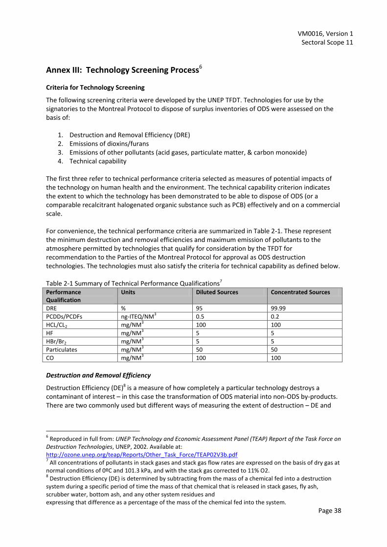
VM0016, Version 1 Sectoral Scope 11
Page 38
Annex III: Technology Screening Process6
Criteria for Technology Screening
The following screening criteria were developed by the UNEP TFDT. Technologies for use by the signatories to the Montreal Protocol to dispose of surplus inventories of ODS were assessed on the basis of:
1. Destruction and Removal Efficiency (DRE) 2. Emissions of dioxins/furans 3. Emissions of other pollutants (acid gases, particulate matter, & carbon monoxide) 4. Technical capability
The first three refer to technical performance criteria selected as measures of potential impacts of the technology on human health and the environment. The technical capability criterion indicates the extent to which the technology has been demonstrated to be able to dispose of ODS (or a comparable recalcitrant halogenated organic substance such as PCB) effectively and on a commercial scale. For convenience, the technical performance criteria are summarized in Table 2-1. These represent the minimum destruction and removal efficiencies and maximum emission of pollutants to the atmosphere permitted by technologies that qualify for consideration by the TFDT for recommendation to the Parties of the Montreal Protocol for approval as ODS destruction technologies. The technologies must also satisfy the criteria for technical capability as defined below. Table 2-1 Summary of Technical Performance Qualifications7 Performance Qualification
Units Diluted Sources Concentrated Sources
DRE % 95 99.99
PCDDs/PCDFs ng-ITEQ/NM3 0.5 0.2
HCL/CL2 mg/NM3 100 100
HF mg/NM3 5 5
HBr/Br2 mg/NM3 5 5
Particulates mg/NM3 50 50
CO mg/NM3 100 100
Destruction and Removal Efficiency
Destruction Efficiency (DE)8 is a measure of how completely a particular technology destroys a contaminant of interest – in this case the transformation of ODS material into non-ODS by-products. There are two commonly used but different ways of measuring the extent of destruction – DE and
6 Reproduced in full from: UNEP Technology and Economic Assessment Panel (TEAP) Report of the Task Force on
Destruction Technologies, UNEP, 2002. Available at: http://ozone.unep.org/teap/Reports/Other_Task_Force/TEAP02V3b.pdf 7 All concentrations of pollutants in stack gases and stack gas flow rates are expressed on the basis of dry gas at
normal conditions of 0ºC and 101.3 kPa, and with the stack gas corrected to 11% O2. 8 Destruction Efficiency (DE) is determined by subtracting from the mass of a chemical fed into a destruction
system during a specific period of time the mass of that chemical that is released in stack gases, fly ash, scrubber water, bottom ash, and any other system residues and expressing that difference as a percentage of the mass of the chemical fed into the system.

VM0016, Version 1 Sectoral Scope 11
Page 39
Destruction and Removal Efficiency (DRE)9. For a more detailed explanation of how DRE is calculated, see section 4.2.1. The terms are sometimes interchanged or used inappropriately. DE is a more comprehensive measure of destruction than DRE, because DE considers the amount of the chemical of interest that escapes destruction by being removed from the process in the stack gases and in all other residue streams. Most references citing performance of ODS destruction processes only provide data for stack emissions and thus, generally, data is only available for DRE and not DE. Because of the relatively volatile nature of ODS and because, with the exception of foams, they are generally introduced as relatively clean fluids, one would not expect a very significant difference between DRE and DE. For these reasons this update of ODS destruction technologies uses DRE as the measure of destruction efficiency. For the purposes of screening destruction technologies, the minimum acceptable DRE is:
95% for foams; and,
99.99% for concentrated sources.
It should be noted that measurements of the products of destruction of CFCs, HCFCs and halons in a plasma destruction process have indicated that interconversion of ODS can occur during the process. For example, under some conditions, the DRE of CFC-12 (CCl2F2) was measured as 99.9998%, but this was accompanied by a conversion of 25% of the input CFC-12 to CFC-13 (CClF3), which has the same ozone-depleting potential. The interconversion is less severe when hydrogen is present in the process, but can nonetheless be significant.10 For this reason, it is important to take into account all types of ODS in the stack gas in defining the DRE. For the reasons described in the previous paragraph, the Task Force recommends that future calculations of DRE use the approach described below11. DRE of an ODS should be determined by subtracting from the number of moles of the ODS fed into a destruction system during a specific period of time, the total number of moles of all types of ODS that are released in stack gases, and expressing that difference as a percentage of the number of moles of the ODS fed into the system.
9 Destruction and Removal Efficiency (DRE) has traditionally been determined by subtracting from the mass of a
chemical fed into a destruction system during a specific period of time the mass of that chemical alone that is released in stack gases, and expressing that difference as a percentage of the mass of that chemical fed into the system. 10
R. T. Deam, A. R. Dayal, T. McAllister, A. E. Mundy, R. J. Western, L. M. Besley, A. J. D. Farmer, E. C. Horrigan, and A. B. Murphy, Interconversion of chlorofluorocarbons in plasmas, J. Chem. Soc.: Chem. Commun. No. 3 (1995) 347-348; A. B. Murphy, A. J. D. Farmer, E. C. Horrigan, and T. McAllister, Plasma destruction of ozone depleting substances, Plasma Chem. Plasma Process. 22 (2002) 371-385. 11
Since different ODS have different ODP, consideration should be given to taking into account the ODP of each type of ODS present in the stack gas in calculating the DRE. An appropriate definition that takes into account the differences in ODP is: DRE of an ODS is determined by subtracting from the number of moles of the ODS fed into a destruction system during a specific period of time, the total number of moles of all types of ODS that are released in stack gases, weighted by their ODP relative to that of the feed ODS, and expressing that difference as a percentage of the number of moles of the ODS fed into the system.
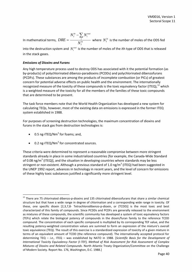
VM0016, Version 1 Sectoral Scope 11
Page 40
In mathematical terms, in
I
i
out
i
in
I
N
NN
DRE
where in
IN is the number of moles of the ODS fed
into the destruction system and out
iN is the number of moles of the ith type of ODS that is released
in the stack gases. Emissions of Dioxins and Furans
Any high temperature process used to destroy ODS has associated with it the potential formation (as by-products) of polychlorinated dibenzo-paradioxins (PCDDs) and polychlorinated dibenzofurans (PCDFs). These substances are among the products of incomplete combustion (or PICs) of greatest concern for potential adverse effects on public health and the environment. The internationally recognized measure of the toxicity of these compounds is the toxic equivalency factor (ITEQ),12 which is a weighted measure of the toxicity for all the members of the families of these toxic compounds that are determined to be present. The task force members note that the World Health Organization has developed a new system for calculating TEQs, however, most of the existing data on emissions is expressed in the former ITEQ system established in 1988. For purposes of screening destruction technologies, the maximum concentration of dioxins and furans in the stack gas from destruction technologies is:
0.5 ng-ITEQ/Nm3 for foams; and,
0.2 ng-ITEQ/Nm3 for concentrated sources. These criteria were determined to represent a reasonable compromise between more stringent standards already in place in some industrialized countries [for example, the Canada-Wide Standard of 0.08 ng/m3 (ITEQ)], and the situation in developing countries where standards may be less stringent or non-existent. Although a previous standard of 1.0 ng/m3 (ITEQ) had been suggested in the UNEP 1992 report, advances in technology in recent years, and the level of concern for emissions of these highly toxic substances justified a significantly more stringent level.
12
There are 75 chlorinated dibenzo-p-dioxins and 135 chlorinated dibenzofurans that share a similar chemical structure but that have a wide range in degree of chlorination and a corresponding wide range in toxicity. Of these, one specific dioxin [2,3,7,8- Tetrachlorodibenzo-p-dioxin, or (TCDD)] is the most toxic and best characterized of this family of compounds. Since PCDDs and PCDFs are generally released to the environment as mixtures of these compounds, the scientific community has developed a system of toxic equivalency factors (TEFs) which relate the biological potency of compounds in the dioxin/furan family to the reference TCDD compound. The concentration of each specific compound is multiplied by its corresponding TEF value, and the resulting potency-weighted concentration values are summed to form an expression of the mixture’s overall toxic equivalence (TEQ). The result of this exercise is a standardized expression of toxicity of a given mixture in terms of an equivalent amount of TCDD (the reference compound). The internationally accepted protocol for determining TEQ – i.e., ITEQ – was established by NATO in 1988. [Scientific Basis for the Development of International Toxicity Equivalency Factor (I-TEF), Method of Risk Assessment for Risk Assessment of Complex Mixtures of Dioxins and Related Compounds. North Atlantic Treaty Organization/Committee on the Challenge of Modern Society. Report No. 176, Washington, D.C. 1988.]

VM0016, Version 1 Sectoral Scope 11
Page 41
Emissions of Acid Gases, Particulate Matter and Carbon Monoxide
Acid gases are generally formed when ODS are destroyed and these must be removed from the stack gases before the gases are released to the atmosphere. The following criteria for acid gases have been set for purposes of screening destruction technologies:
A maximum concentration in stack gases of 100 mg/Nm3 HCl/Cl2
A maximum concentration in stack gases of 5 mg/Nm3 HF; and,
A maximum concentration in stack gases of 5 mg/Nm3 HBr/Br2.
Particulate matter is generally emitted in the stack gases of incinerators for a variety of reasons and can also be emitted in the stack gases of facilities using non-incineration technologies. For the purposes of screening technologies, the criterion for particulate matter is established as:
A maximum concentration of total suspended particulate (TSP) of 50 mg/Nm3. Carbon monoxide (CO) is generally released from incinerators resulting from incomplete combustion and may be released from some ODS destruction facilities because it is one form by which the carbon content of the ODS can exit the process. Carbon monoxide is a good measure of how well the destruction process is being controlled. For the purposes of screening technologies, the following criterion has been established:
A maximum CO concentration in the stack gas of 100 mg/Nm3. These maximum concentrations apply to both foams and concentrated sources. They were set to be achievable by a variety of available technologies while ensuring adequate protection of human health and the environment. Technical Capability
As well as meeting the above performance requirements it is necessary that the destruction technologies have been demonstrated to be technically capable at an appropriate scale of operation. In practical terms, this means that the technology should be demonstrated to achieve the required DRE while satisfying the emissions criteria established above. Demonstration of destruction of ODS is preferred but not necessarily required. Destruction of halogenated compounds that are refractory, i.e., resistant to destruction, is acceptable. For example, demonstrated destruction of polychlorinated biphenyls (PCBs) was often accepted as an adequate surrogate for demonstrated ODS destruction. For this evaluation, an ODS destruction technology is considered technically capable if it meets the following minimum criteria:
It has been demonstrated to have destroyed ODS to the technical performance standards, on at least a pilot scale or demonstration scale (designated in Table 2-2 as “Yes”).
It has been demonstrated to have destroyed a refractory chlorinated organic compound other than an ODS, to the technical performance standards, on at least a pilot scale or demonstration scale (designated in Table 2-2 as “P,” which indicates that the technology is

VM0016, Version 1 Sectoral Scope 11
Page 42
considered to have a high potential for application with ODS, but has not actually been demonstrated with ODS).
The processing capacity of an acceptable pilot plant or demonstration plant must be no less than 1.0 kg/hr of the substance to be destroyed, whether ODS or a suitable surrogate.
These criteria of technical capability will minimize the risk associated with technical performance and ensure that destruction of ODS will be performed in a predictable manner consistent with protecting the environment.

VM0016, Version 1 Sectoral Scope 11
Page 43
Annex IV: ODS Literature and Sources
Scheutz, C. et al. (2007a) Release of fluorocarbons from insulation foam in home appliances during shredding. J of the Air & Waste Mgmt Assn, 57: 1452-1460 Scheutz, C., et al. (2007b) Attenuation of insulation foam released fluorocarbons in landfills. Environ Sci & Tech., 41:7714-7722) Fredenslund, A. et al. (2005) Disposal of Refrigerators-Freezers in the U.S.: State of the Practice. Technical University of Denmark TEAP, Code of Good Housekeeping in Handbook for the Montreal Protocol on Substances that Deplete the Ozone Layer - 7th Edition (2006) UNEP Technology and Economic Assessment Panel (TEAP) Report of the Task Force on Destruction Technologies, UNEP, 2002. Available at: http://ozone.unep.org/teap/Reports/Other_Task_Force/TEAP02V3b.pdf
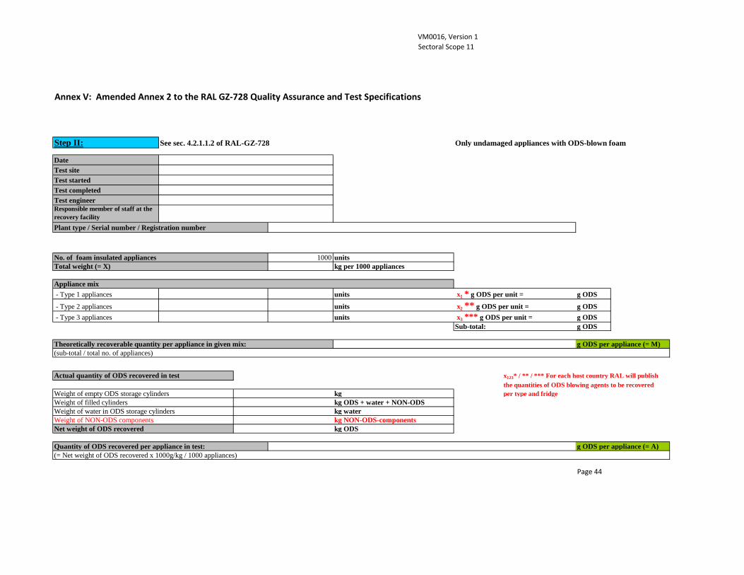
VM0016, Version 1 Sectoral Scope 11
Annex V: Amended Annex 2 to the RAL GZ-728 Quality Assurance and Test Specifications
Step II: See sec. 4.2.1.1.2 of RAL-GZ-728 Only undamaged appliances with ODS-blown foam
DateTest siteTest startedTest completedTest engineerResponsible member of staff at the recovery facility Plant type / Serial number / Registration number
No. of foam insulated appliances 1000 unitsTotal weight (= X) kg per 1000 appliances
Appliance mix - Type 1 appliances units x1 * g ODS per unit = g ODS
- Type 2 appliances units x2 ** g ODS per unit = g ODS - Type 3 appliances units x3 *** g ODS per unit = g ODS
Sub-total: g ODS
Theoretically recoverable quantity per appliance in given mix: g ODS per appliance (= M)(sub-total / total no. of appliances)
Actual quantity of ODS recovered in test x123* / ** / *** For each host country RAL will publishthe quantities of ODS blowing agents to be recovered
Weight of empty ODS storage cylinders kg per type and fridgeWeight of filled cylinders kg ODS + water + NON-ODSWeight of water in ODS storage cylinders kg waterWeight of NON-ODS components kg NON-ODS-componentsNet weight of ODS recovered kg ODS
Quantity of ODS recovered per appliance in test: g ODS per appliance (= A)(= Net weight of ODS recovered x 1000g/kg / 1000 appliances)
Page 44

VM0016, Version 1 Sectoral Scope 11
Weight of output fractions from step II processing
Foam kg (= P)Ferrous metals kgNon-ferrous metals kgPlastics kgNon-ferrous/plastic fraction kgResidual waste kgProcess water kgODS kgOther components kg
Total weight of output fractionskg (= Y)
Ratio Y / X (x 100) = %
Other quantities recorded during step II processing
ODS in exhaust air Conc. of ODS in exhaust air stream mg ODS / m3
ODS mass flow rate g ODS / h
Residual quantity of ODS in waste water mg ODS / l (3 samples => 1 mixed sample => 1 analysis)
Residual foamResidual quantity of foam adhering to ferrous metals % (Sampled every 2 hours => 3 mixed samples => 3 analyses)Residual quantity of foam adhering to non-ferrous metals
% (Sampled every 2 hours => 3 mixed samples => 3 analyses)Residual quantity of foam adhering to plastics % (Sampled every 2 hours => 3 mixed samples => 3 analyses)
Page 45

VM0016, Version 1 Sectoral Scope 11
Residual quantity of foam adhering to the mixed non-ferrous/plastics fraction
% (Sampled every 2 hours => 3 mixed samples => 3 analyses)
Residual foreign material in the foam fraction % foreign material in foam (Sampled every 2 hours => 3 mixed samples => 3 analyses)
Residual ODS in foam % ODS in foam (Sampled every 2 hours => 3 mixed samples => 3 analyses)
(Remark: % = mass percentuage)
Plausibility check for step II processing data
If the value (A) is greater than M g/appliance, the following plausibility analysis is performed to check the results of the plant test.In case of doubt regarding the ODS recovery, the plausibility check provides thevalidation company with an important additional decision-making aid.
A . foam - Output - Fraction
Weight of foam recovered from 1000 appliances 0 kg foam (= P)of which foreign matterial in % 0 % foreign material in foam (=a1)of which foreign matterial in kg 0 = a1 x P/100 kg (= a2)Residual weight of ODS in foam in % 0 % ODS (= b1)Residual weight of ODS in foam in kg =b1 x P/100 0 kg (=b2)Estimated weight of pure foam from 1000 appliances = P – a2 – b2 0 kg foam (= c)
= c · 100 / (100-y**** – c) 0 kg ODS (= d)Total amount of foam in Input (*) = c+d 0 kg foam in Input (=cd)
* = losses via residual foam on material fractions are not included
y**** For each host country RAL will publish the averagecontent of ODS blowing agents in foam in g per kg
Page 46
Estimated weight of ODS originally present in the foam insulation

VM0016, Version 1 Sectoral Scope 11
B. Losses via residual foam on material fractions
Residual foam Losses of foam in kgon Fe fraction in % % kg foamWeight of ferrous metals kgon non-ferrous metals in % % kg foamWeight of non-ferrous metals kgon Plastics fraction in % % kg foamWeight of plastics kgon mixed non-ferrous metals / plastics fraction % kg foamWeight of non-ferrous metals / plastics fraction kgon other materials % kg foamWeight of other materials kg
Total amount of foam losses via material fractions kg foam (=e)
C. Estimated weight of ODS from A. + B. / Process Efficiency
Total amount of foam in Input kg foam (= f)(= cd + e)Calculated amount of total ODS in Input kg ODS (=g)(= y**** % of f)
Estimated ODS (90 % of the calculated ODS Input) kg ODS (=E)(=0,9 x g)
Quantity of ODS recovered per appliance in test: kg ODS (= A)
Process Efficiency (= A / E x 100) % (> 100 %)
Page 47
Related Documents