1 APPROVED MINUTES January 17, 2013 Standards Committee Meeting MEMORANDUM March 01, 2013 TO: Standards Committee FROM: Scott Trammell, Secretary RE: Minutes for the January 17, 2013 Standards Committee Meeting The Standards Committee meeting was called to order by Mr. Miller at 09:04 a.m. on January 17, 2013 in the N955 Bay Window Conference Room. The meeting was adjourned at 10:58 a.m. The following committee members were in attendance: Mark Miller, Chairman Bob Cales, Contract Administration Dave Boruff, Traffic Administration Elizabeth Phillips, Bridge Standards and Policy Greg Pankow, State Engineer Jim Keefer, Fort Wayne District Michael Prather*, Pavement Engineering Michelle Gottschalk, Construction Technical Support Richard Vancleave, Roadway Services Ron Walker, Materials Management * Proxy for Mike Buening Also in attendance were the following: Tony Perkinson, FHWA Matt Beeson, INDOT Greg Richards, INDOT Lana Podorvanova, INDOT Paul Berebitsky, ICA Wendy Chiles, INDOT Prakash Patel, INDOT Dudley Bonte, Rieth-Riley (APAI) Scott Trammell, Secretary Joe Bruno, INDOT Steve Fisher, INDOT Megan M c Elroy, INDOT

Welcome message from author
This document is posted to help you gain knowledge. Please leave a comment to let me know what you think about it! Share it to your friends and learn new things together.
Transcript

1
APPROVED MINUTES January 17, 2013 Standards Committee Meeting
MEMORANDUM March 01, 2013 TO: Standards Committee FROM: Scott Trammell, Secretary RE: Minutes for the January 17, 2013 Standards Committee Meeting The Standards Committee meeting was called to order by Mr. Miller at 09:04 a.m. on January 17, 2013 in the N955 Bay Window Conference Room. The meeting was adjourned at 10:58 a.m. The following committee members were in attendance: Mark Miller, Chairman Bob Cales, Contract Administration Dave Boruff, Traffic Administration Elizabeth Phillips, Bridge Standards and Policy Greg Pankow, State Engineer Jim Keefer, Fort Wayne District Michael Prather*, Pavement Engineering Michelle Gottschalk, Construction Technical Support Richard Vancleave, Roadway Services Ron Walker, Materials Management * Proxy for Mike Buening Also in attendance were the following: Tony Perkinson, FHWA Matt Beeson, INDOT Greg Richards, INDOT Lana Podorvanova, INDOT Paul Berebitsky, ICA Wendy Chiles, INDOT Prakash Patel, INDOT Dudley Bonte, Rieth-Riley (APAI) Scott Trammell, Secretary Joe Bruno, INDOT Steve Fisher, INDOT Megan McElroy, INDOT
(continued)
2
The following agenda items are listed for consideration. A. GENERAL BUSINESS ITEMS OLD BUSINESS (No items were listed for consideration) NEW BUSINESS 1. Approval of the Minutes from the December 20, 2012 meeting. DISCUSSION: Mr. Miller asked for a motion to accept the minutes from the last meeting as presented.
Motion: Mr. Boruff Second: Mr. Cales Ayes: 8 Nays: 0 ACTION: PASSED AS SUBMITTED
2. Submitting Standard Drawing items to the Standards Committee. DISCUSSION: Mr. Miller began by addressing the need for requirements for submitting standard drawing items for consideration by the Standards Committee. The following draft procedure was submitted by Ms. Phillips for consideration. STANDARD DRAWING REVISIONS TO THE STANDARDS COMMITTEE - DRAFT OBJECTIVES
• The approval process for Standard Drawings should be standardized so that all individuals involved know what to expect at each stage of the approval and publication process and are able to plan accordingly.
• The Standards Committee should only give final approval to FINAL DRAFTS of Std Dwgs/RPDs barring changes not typically subject to Standard Committee approval (formatting, editorial-only revisions). “Final Approval” is confirmed by appearance in the Approved Stds Comm. Minutes.
PROCEDURE • When submitting revisions to Standard Drawings to the Standards
Committee, include the following: o the entire series of Standard Drawings, o mark ups – the series as a whole should be reviewed when making
revisions, o final version – drawings should be in their final form and ready
for approval, o consider an effective date for the revisions.
Prior to submission as an agenda item, a QA/QC check is required by the Standard Drawing Administrator to ensure INDOT CAD Standards have been followed. Failure to submit a complete package may result in the rejection of the agenda item. Acceptance or rejection of an agenda item is at the discretion of the Specifications Coordinator.
B. CONCEPTUAL PROPOSAL ITEMS OLD BUSINESS

(continued)
3
(No items were listed for consideration) NEW BUSINESS (No items were listed for consideration) C. STANDARD SPECIFICATIONS, SPECIAL PROVISIONS AND STANDARD DRAWINGS PROPOSED ITEMS OLD BUSINESS Item No. 01 12/20/12 (2012 SS) Mr. Boruff (revised 01/11/13) pg 05 SECTION 805 TRAFFIC SIGNALS SECTION 922 TRAFFIC SIGNALS MATERIALS Recurring Special Provisions: 922-X-XXX CONTROLLER CELLULAR MODEM 805-X-XXX MAGNETOMETERS AND MICROLOOP DETECTORS 805-X-XXX PREFORMED PAVE-OVER LOOPS 805-X-XXX RADIO INTERCONNECTION Standard Drawings: 805-SGCF-04 SIGNAL HANDHOLE 805-SGCF-04A SIGNAL HANDHOLE POLYMER CONCRETE TYPE 805-SGLT-01 LOOP TAGGING SYSTEM ACTION: WITHDRAWN NEW BUSINESS Item No. 01 01/17/13 (2012 SS) Mr. Walker Pg 84 401.05 Volumetric Mix Design 401.09 Acceptance of Mixtures 401.16 Density 401.18(A) Profilograph 402.01 Description 402.07 Mix Criteria 402.13 Spreading and Finishing 402.20 Basis of Payment ACTION: PASSED AS REVISED Item No. 02 01/17/13 (2012 SS) Mr. Walker pg 91 Recurring Special Provision: 402-R-XXX HMA WEDGE AND LEVELING ACTION: WITHDRAWN Item No. 03 01/17/13 (2012 SS) Mr. Vancleave pg 94 910.19 Standard Drawings: 802-TCSS-01 TRI-CHORD SIGN STRUCTURE DRAWING INDEX 802-TCSS-02 TRI-CHORD SIGN STRUCTURE PLAN AND ELEVATION

(continued)
4
802-TCSS-03 TRI-CHORD SIGN STRUCTURE ISOMETRIC VIEWS 802-TCSS-04 TRI-CHORD SIGN STRUCTURE PANEL DIMENSIONS SPANS 36’ THRU 83’ 802-TCSS-05 TRI-CHORD SIGN STRUCTURE PANEL DIMENSIONS SPANS 84’ THRU 130’ 802-TCSS-06 TRI-CHORD SIGN STRUCTURE MEMBER SIZES AND CAMBER 802-TCSS-07 TRI-CHORD SIGN STRUCTURE CONNECTION DETAILS 802-TCSS-08 TRI-CHORD SIGN STRUCTURE CONNECTION AND WELDING DETAILS 802-TCSS-09 TRI-CHORD SIGN STRUCTURE CHORD FLANGE DETAILS 802-TCSS-10 TRI-CHORD SIGN STRUCTURE TOP CAP AND CHORD END PLATE DETAILS 802-TCSS-11 TRI-CHORD SIGN STRUCTURE SIGN ATTACHMENT DETAILS 802-TCSS-12 TRI-CHORD SIGN STRUCTURE BASE PLATE, ANCHOR BOLT, AND I.D. TAG DETAILS 802-TCSS-13 TRI-CHORD SIGN STRUCTURE HANDHOLE DETAILS 802-TCSS-14 TRI-CHORD SIGN STRUCTURE DRILLED SHAFT FOUNDATION 802-TCSS-15 TRI-CHORD SIGN STRUCTURE SPREAD FOUNDATION ACTION: WITHDRAWN cc: Committee Members (11) FHWA (2) ICA (1)

Mr. Boruff Date: 01/17/13
SPECIFICATION, SPECIAL PROVISIONS AND DRAWINGS (OLD BUSINESS ITEM) REVISION TO STANDARD SPECIFICATIONS, SPECIAL PROVISIONS, AND DRAWINGS
5
PROPOSAL TO STANDARDS COMMITTEE
PROBLEM(S) ENCOUNTERED: Sections 805 and 922 of the INDOT Standard Specifications are entirely superseded by RSP 805-T-169 and 922-T-168. These recurring special provisions contain proprietary items that must be extracted before the RSP’s can go into the Standard Specifications. Additionally, there are some outdated ASTM/NEMA/etc references and polymer concrete handholes & signal backplates are not addressed. Standard Drawing 805-SGLT-01 detailing the loop tagging table is not accurate and is redundant after Design Memo 12-13. PROPOSED SOLUTION: Develop recurring special provisions for the proprietary items only and move the remaining portions of the recurring special provisions into section 805 and 922 of the Standard Specifications. Also specifications for signal backplates & polymer concrete handholes have been added and the references to other publications have been updated. Revise Standard Drawing 805-SGCF-04 for concrete handholes and create a version for polymer concrete handholes. Delete Standard Drawing 805-SGLT-01. APPLICABLE STANDARD SPECIFICATIONS: 805, 920, and 922 APPLICABLE STANDARD DRAWINGS: 805-SGLT-01, 805-SGCF-04; 805-SGSC-03, -04 APPLICABLE DESIGN MANUAL SECTION: 77 (Old), 502 (New Draft) APPLICABLE SECTION OF GIFE: N/A APPLICABLE RECURRING SPECIAL PROVISIONS: 805-T-169, 805-T-173, 922-T-168 PAY ITEMS AFFECTED: Signal Cantilever Structures and their foundations, Signal Indication Backplates, Handholes Submitted By: Dave Boruff Title: Manager, Traffic Administration Organization: INDOT Phone Number: (317) 234-7975 Date: 12/26/2012 APPLICABLE SUB-COMMITTEE ENDORSEMENT: Yes, Traffic Standards Subcommittee, Traffic Signal Systems Division.
Item No.01 12/20/12 (2012 SS) (contd.) Mr. Boruff Date: 01/17/13 REVISION TO SPECIFICATIONS, PROVISIONS AND DRAWINGS (OLD BUSINESS ITEM) SECTION 805 – TRAFFIC SIGNALS
6
The Standard Specifications are revised as follows: SECTION 805, DELETE LINES 1 THROUGH 642. SECTION 805, BEGIN LINE 1, INSERT AS FOLLOWS:
SECTION 805 – TRAFFIC SIGNALS 805.01 Description This work shall consist of furnishing miscellaneous materials, not furnished by the Department, and installing traffic signals in accordance with these specifications and in reasonably close conformance with the lines, grades, and locations shown on the plans or as directed.
MATERIALS 805.02 Materials Materials shall be in accordance with the following: Castings for Handhole ............................................................... 910.05(b) Coarse Aggregate, Class E or Higher, Size No. 8 ..................... 904 Concrete, Class A, B, or C ......................................................... 702 Loop Detector Sealant ............................................................... 906.02(a) Reinforced Concrete Pipe .......................................................... 907.02 Traffic Signal Materials and Equipment .................................... 922 Treated Lumber .......................................................................... 911.02 The proposed work shall be examined in order to determine what materials not furnished by the Department are required to complete the contract. The Department will furnish only the materials specified on the Department Furnished Materials special provision. If materials to be furnished by the Contractor are listed, the list is only a guide for estimating purposes. All additional materials required to complete an operating installation as specified shall be furnished. Signal handholes shall be polymer concrete or class III reinforced concrete pipe as shown on the plans. Joint sealant material shall be compatible with the roadway materials. If polyethylene duct loop wire is used, only sealant in accordance with 906.02(a)1 shall be used. Wood poles to be furnished shall be in accordance with the current ANSI specifications and dimensions. They shall be of the length and class specified, be fully treated in accordance with 922.10(b), and dry. Minimum circumference at the top and at a point 6 ft from the butt shall be in accordance with ANSI specifications.
Item No.01 12/20/12 (2012 SS) (contd.) Mr. Boruff Date: 01/17/13 REVISION TO SPECIFICATIONS, PROVISIONS AND DRAWINGS (OLD BUSINESS ITEM) SECTION 805 – TRAFFIC SIGNALS
7
Steel strain poles greater than 24 ft in length shall be in accordance with 922.10(a). The battery cabinet and program timing module for solar powered flashing beacons shall be from the Department’s Approved List of Traffic Signal and ITS Control Equipment.
CONSTRUCTION REQUIREMENTS 805.03 General Requirements The Contractor shall maintain existing traffic signals in operation until the Engineer determines that the progress of the work necessitates their removal. The new installation shall not interfere with the operation of the existing signal. The work shall proceed in such a manner that the signals are not out of service at any 2 adjacent intersections at any time. When the operation of an existing traffic signal must be interrupted before the new signal is placed in operation, the traffic shall be controlled at all times. The work shall be scheduled so that the interruption is limited to a minimum amount of time and at off peak hours. When a new span, catenary, and tether are to be installed on an existing structure, the work shall be done so as not to damage the structure. If an existing structure is damaged, it shall be repaired or replaced as directed with no additional payment. The new span and catenary installation shall not interfere with the operation of the existing traffic signal. Traffic shall be controlled at all times during the changeover when the existing traffic signal is turned off and the new signal is turned on. This changeover shall take place such that the interruption is limited to a minimum amount of time. When directed, temporary stop signs shall be erected at the intersection. When no work is in progress, the intersection shall have at least 2 operating signal faces for each approach. When the new installations are completed, all existing signal equipment and materials including wood poles, steel poles, and cast-iron handhole rings and covers which have not been used in the new installation shall be carefully removed. Regardless of the right to materials found on the project, as set out in other sections of these specifications, items designated in the contract documents, and field identified by the Department, as traffic signal equipment to be salvaged by the Department or local unit of government shall be stored at a secure site until such time as it is transported to the designated location, when designated as a pay item, or salvaged by the Department or local unit of government. The Contractor shall verify that the field identification placed by the Department has not been removed by vandalism or natural causes. If the Contractor has reason to believe field identifications have been removed, it shall contact the Department. The Contractor shall be responsible for all damage or loss of this equipment and shall repair or replace the damaged or lost equipment as directed. All signal equipment removed and not designated to be salvaged shall become the property of the Contractor and shall be disposed of in accordance with 202.

Item No.01 12/20/12 (2012 SS) (contd.) Mr. Boruff Date: 01/17/13 REVISION TO SPECIFICATIONS, PROVISIONS AND DRAWINGS (OLD BUSINESS ITEM) SECTION 805 – TRAFFIC SIGNALS
8
All existing painted signal equipment to be reused, such as pedestals, bases, controller cabinets, signal weatherheads, pipe arms, shall be cleaned and painted with 2 coats of highway yellow enamel. Existing signal heads to be reused shall be painted with 2 coats of black or highway yellow enamel as directed by the Engineer. Aluminum poles and signal support structures shall not be painted. Existing concrete foundations, which have not been used in the new installation, shall be removed to a minimum of 4 in. below the adjacent grade. The openings shall be filled with concrete and the surface finished and broomed, if they are located in sidewalk areas. Otherwise, they shall be filled with acceptable material conforming with the surrounding area. Existing signal handholes to be removed, shall be filled after removing rings and covers, with B borrow with a minimum of 4 in. of concrete on top to bring it up to grade in a sidewalk area. Surfaces shall be finished and broomed. Otherwise, they shall be filled with acceptable material conforming with the surrounding area. The signal controller timings will be provided and the Engineer shall be present when the signal intersection is to be placed in operation. All electrical wiring terminations and splices; controller and cabinet set-up; and testing, review, and turn-on of all operational apparatus at each location shall be done by or in the presence of and under the responsible charge of an employee of the Contractor who holds a Traffic Signal Construction Technician Level II certification which has been granted by the International Municipal Signal Association. Installation inspections, troubleshooting, maintenance and repair of these systems shall be accomplished by or in the presence of and under the responsible charge of an employee of the Contractor who holds a Traffic Signal Construction Technician Level II certification or a Traffic Signal Field Technician Level II certification which has been granted by the International Municipal Signal Association. Supervision of non-electrical, traffic signal related construction work and traffic control shall be done by a person holding, at a minimum, a Work Zone Traffic Safety Specialist certification which has been granted by the International Municipal Signal Association, or an equivalent certification approved by the Department. Before starting work, the Contractor shall provide the names of the Level II Traffic Signal Construction Technicians, the Level II Traffic Signal Field Technicians and Work Zone Traffic Safety Specialists who have been assigned to perform signal related work, and a photocopy of each such person’s certification card. If the Level II Traffic Signal Construction or Field Technicians or Work Zone Traffic Safety Specialists are dismissed from the work, all signal related work requiring such certified personnel on the project site shall cease until the names and photocopies of certification cards for replacement personnel are provided to the Engineer. Electrical work shall be executed in accordance with the requirements of the National Board of Fire Underwriters, the State Fire Marshal, and the power company which will furnish the electric service. The work shall be in accordance with any local

Item No.01 12/20/12 (2012 SS) (contd.) Mr. Boruff Date: 01/17/13 REVISION TO SPECIFICATIONS, PROVISIONS AND DRAWINGS (OLD BUSINESS ITEM) SECTION 805 – TRAFFIC SIGNALS
9
regulations that may apply. The Department will arrange and provide for power service which the power company will bring to the point designated on the plans. Prior to the start of construction, the schedule of activities shall be coordinated with the power company and they shall be contacted again at least 14 days prior to the time the service work is to be completed. The Department will obtain permits from local officials, companies, or individuals for the use of poles, right-of-way, or other property incidental to the installation of traffic signal. Although entering into the contract implies permission and authority to cut into and push under pavement, sidewalks, and alleys, any damage to underground utilities or interruption of such service shall be the responsibility of the Contractor. The Contractor shall be in accordance with local regulations as well as 107.08. Protective devices shall be in accordance with 107.12 and 801. The location of signal heads, controllers, signal poles, signal cantilever structures, detector housing, disconnect hangers, and other installation items will be shown on the plans. However, a change in the location of an item may be ordered during the progress of the work. The work shall be completed as shown on the plans except for those changes specifically authorized in writing. Flashing beacons shall flash at a rate for each beacon of 50 to 60 times per minute with the illuminated period from 1/2 to 2/3 of the total cycle. Second beacons, if specified, shall flash alternately with the exception of intersection control beacons which shall flash simultaneously. 805.04 Pole Installation Working drawings for strain poles or cantilever structures shall be provided in accordance with 105.02. Metal poles shall be erected on concrete foundations and shall be reasonably plumb after installation of signal heads. The handhole side of the pole shall be at right angles to the direction of the signal cantilever arm or span, catenary, and tether. Signal cables shall be brought up inside the poles. Any steel pole, signal cantilever arm, or hardware not galvanized shall be painted with structural steel coating system in accordance with 619.09(a). The surface shall be prepared in accordance with 619.08(a), 619.08(b) and 619.08(d). Paint shall be applied in accordance with 619. All rust, scale, and dirt shall be cleaned from the metal surface so that paint adheres to the surface. The construction of concrete foundations shall be in accordance with 805.13. Wood poles shall be set a minimum of 7 ft in the ground and raked 12 in. 805.05 Placing Signal Heads Signal cantilever arm and span mounted signal heads shall have 17.5 ft minimum and 22.5 ft maximum clearance over the roadway unless there are visual obstructions which require lowering the signal head. A signal head over the roadway shall not have a clearance of less than 15 ft. Such signal heads shall be located over the intersection as

Item No.01 12/20/12 (2012 SS) (contd.) Mr. Boruff Date: 01/17/13 REVISION TO SPECIFICATIONS, PROVISIONS AND DRAWINGS (OLD BUSINESS ITEM) SECTION 805 – TRAFFIC SIGNALS
10
shown on the plans. Such signal heads shall have a uniform clearance, which will be determined. Signal heads not mounted over a paved roadway, on the top or side of a pole, shall not be less than 10 ft nor more than 15 ft above the sidewalk or, if none, above the pavement grade at the center of the roadway. Signal faces shall be directed to the proper approach lane in each direction. Flasher signal faces that supplement signs shall be mounted with the bottom of the housing at not less than 3 ft nor more than 13 ft above the edge of pavement. Flasher signal faces that supplement signs shall be directed towards oncoming traffic. Pedestrian signal faces shall be mounted with the bottom of the housing at not less than 7 ft nor more than 10 ft above the sidewalk. The pedestrian signal shall be in line with the pedestrian’s vision at the appropriate crosswalk being used. Pedestrian push-buttons shall be mounted at a height of 3 1/2 to 4 ft above the sidewalk as shown on the plans. A pedestrian actuated signal sign shall be mounted immediately above the push-button. Signal heads shall be assembled and wired with 1 conductor, type THW, stranded wire. Where splices are made, a 2 ft minimum length of cable or wire in excess of that required for a continuous run shall be provided. Splices shall be twisted together and soldered or approved type connectors used. Each splice shall be completely insulated by wrapping with an approved tape and sealed with an approved electrical coating material. Splices shall be made in such manner that the connections are moisture proof. The cables coming out of the signal weatherhead shall be looped to form a drip loop. The drip loop shall be made so that the cables coming out of the weatherhead loop down below the elevation of the weatherhead to prevent water from following the cable into the weatherhead. If used, the splice indicated above shall be located in the top of the coils of cable forming the drip loop. Overhead 3 section signal heads for through lanes shall have backplates, with the exception of signal heads installed on existing traffic signal cantilever structures. Backplates shall not be cut or altered upon installation. Signal heads shall not be installed until all other work has been completed. If it becomes necessary to mount signal heads for more than 2 h before the lights are to be turned on, the signal heads shall be hooded by placing sacks or similar cover over them so as to conceal them from traffic. Hooded signal heads are not permitted to be in place for more than 5 days. No signal head shall be left over night with the lights out unless it is hooded. Signal heads shall be securely mounted. The polycarbonate signal face shall be used only when securely supported on both ends of the assembly. In a span cable installation, a tether cable would satisfy this requirement. 805.06 Grounding All signal supports, signal controller supports, and entrance switches shall be grounded in accordance with the applicable requirements of 807.12. 805.07 Wire and Cable Installations

Item No.01 12/20/12 (2012 SS) (contd.) Mr. Boruff Date: 01/17/13 REVISION TO SPECIFICATIONS, PROVISIONS AND DRAWINGS (OLD BUSINESS ITEM) SECTION 805 – TRAFFIC SIGNALS
11
All cable runs attached to utility poles shall have code clearance relative to utility cables. They shall be no less than 18 ft above the ground level except over railroad tracks when a minimum of 27 ft clearance shall be maintained. All cable runs shall be installed in continuous lengths without splices between terminals except when necessary at handholes, junction boxes, pole signal bases, and pedestal bases. The type of cable and the number of conductors as well as the gage shall be as shown on plans unless otherwise specified. Cable rings shall be used to support the signal cable on the signal span cable. They shall be spaced 12 in. on center. Cable shall be pulled through the conduit to the terminal panel in the controller cabinet. Caution shall be used to prevent damage to the cable when it is being pulled through conduit. Coded cable conductors shall be used throughout the installation. Cable conductors shall be tagged at all detector housings, handholes, signal pole bases, and controller cabinets. At the ends of each cable, the tag shall be placed between 4 and 8 in. from the end of the wire and on the outer jacket. At all other locations, the tag shall be placed in the middle of the length of cable stored at the location. The tag shall be 1/2 in. wide, thermal printed black on yellow or black on white, polyester or nylon tape with permanent adhesive and shall be water, chemical and scratch resistant. The font shall be arial, size 10. Tags shall be installed flag style around the cable with the backs of the tag ends placed together. Tags shall identify the cables by their use. The following are the uses which shall be indicated by the tags: (a) Power (b) Pedestrian Signal (c) Pedestrian Actuation (d) Signal (e) Detection Loop Identification (f) Interconnect Signal cables shall be tagged to identify the direction of travel. Detector lead-in cables shall be tagged throughout the installation with the corresponding loop tag information. The tagging material and fastening shall be approved prior to proceeding with this work. The color coded wires shall be connected properly. The white wire shall be the common or ground. Wire used for all identical indications of any individual phase shall be color coded and, where possible, shall use red wire to connect red lenses, orange wire to connect yellow lenses, and green wire to connect green lenses. Signal heads shall be

Item No.01 12/20/12 (2012 SS) (contd.) Mr. Boruff Date: 01/17/13 REVISION TO SPECIFICATIONS, PROVISIONS AND DRAWINGS (OLD BUSINESS ITEM) SECTION 805 – TRAFFIC SIGNALS
12
assembled and wired before being installed. The testing of the loops shall be documented in the Loop Testing Table provided by the State. 805.08 Controller Cabinet, Signal Service, and Detector Housing Installation Three document packets shall be prepared in accordance with 922.02(b) for each cabinet. Each packet shall be labeled with the name of the contract number, the intersection, the commission number of the signal, and the date of installation. One paper packet shall be placed in the cabinet, and the remaining 2 packets one paper packet shall be submitted to the Engineer, and one electronic packet shall be submitted to the Electronic Technician Supervisor at INDOT’s Logistical Support Center within 2 days after the signal is turned on. Information in the packets shall include all approved changes to the signal installation. All detector loop lead-in tags and detector rack labels shall reflect all approved changes to the signal installation. Additional detector loop amplifier units and detector racks shall be supplied as directed by the Engineer. Additional detector racks shall include all cables or harnesses including, but not limited to a SDLC cable for each added rack, interface panels and a BIU to provide a complete and functional installation. Additional auxiliary BIU panels shall include all cables or harnesses including, but not limited to a SDLC cable for each additional auxiliary BIU panel, terminal strip on BIU panel and BIU to provide a complete and functional installation. For signal cabinets installed by the Contractor, where no detector loop or lead-in work is included in the contract, the Contractor shall perform detector loop tagging, testing and vehicle simulator testing in accordance with 805.09, only to the extent of documenting the test readings and confirming that all existing detector loops are connected correctly and all detector related equipment in the cabinet is operating correctly. The controller cabinet shall be mounted securely on a pole, pedestal, or concrete foundation. All cabinets on concrete foundations shall be installed with the anchor bolts inside. Controller cabinets on poles or pedestals shall be mounted at a height of 38 in. ± 2 in. Pole mounted controller cabinets shall be fastened with 2 stainless steel bands as shown in the plans. Signal cables and lead-in cable shall be run in conduit from the controller cabinet to the signal support base and to detector housing as indicated on the plans. Galvanized steel elbows shall be used on the detector housing as shown on the plans. The Contractor shall wire the entrance switch and bring service cable up the riser and out the weatherhead and leave 4 ft of cable outside the weatherhead. The utility company, at their option, may bring the service cables to the load side of the entrance switch. Meter bases, if required, shall be obtained from the power company. A minimum of 12 in. and a maximum of 18 in. of loop wire duct will be permitted in the detector housing for each loop lead. Concrete used in the installation of detector
Item No.01 12/20/12 (2012 SS) (contd.) Mr. Boruff Date: 01/17/13 REVISION TO SPECIFICATIONS, PROVISIONS AND DRAWINGS (OLD BUSINESS ITEM) SECTION 805 – TRAFFIC SIGNALS
13
housings shall be in accordance with 506, except 506.05 will not apply. A CMDS in accordance with 502.03 shall be submitted, however, utilization of the Department provided spreadsheet is not required. Where a portion of the road is closed or where there is no vehicular traffic, then class A concrete in accordance with 702 may be used. The concrete shall be placed flush with existing surface and shall be covered with a steel plate during the setting time. 805.09 Loop Wire Detector Installation This work shall consist of placement and testing of loop wire detectors in accordance with the installation details shown on the plans. (a) Layout The number, size, arrangement, and locations of loops shall be as shown on the plans except that loop spacing shall be adjusted to avoid PCCP joints. Loops shall be of a regular octagon shape with sides of 2 1/2 ft in length or a circular shape with a diameter of 6 ft. Loops placed longitudinally adjacent in the same lane shall be spaced 15 ft from the center of one loop to the center of the next loop. Loops shall be arranged so that no loop wire will be bent at an angle less than 120°. Regardless of configuration, the loop installation shall match the intention of the loop tagging table. Prior to installation, loop layout shall be approved in writing by the District Traffic Engineer. The Contractor shall notify the District Traffic Engineer a minimum of 2 business days prior to the date that loop layout approval is required. All roadway centerlines, edge-lines and stop-bars pertinent to loop layout shall be accurately and clearly identified at the time loop layouts are reviewed for approval. An outline shall be painted where the loops are to be placed. The Contractor shall ensure that the final installed location of each loop matches the intention and functionality of the approved layout for loop spacing, lane width and geometry. (b) Installation All loops and lead-in cables shall be tagged according to the plans and 805.07. The slots shall be saw-cut as shown on the plans. A diamond cutting blade shall be used for sawing all loops. All saw-cut loops shall have individual saw cuts to the detector housing. Joints shall be overlapped such that the saw cut at the corner is full depth. Prior to installing roadway loop wire in the roadway saw cuts, the saw cuts shall be cleaned in accordance with the manufacturer’s requirements for the joint sealant to be used. After proper cleaning, the loop wire shall be installed. All loops shall be wired clockwise as viewed from above. Loops shall be wired with 4 turns or as specified then gently tamped with a blunt non-metallic tool. Backer rod 2 to 4 in. in length shall be spaced every 12 in. around the saw cut above the wire and gently tamped to hold the loop wire snug in the bottom of the saw cut. Backer rod shall not be continuous around the saw cut. After installation of the loop wire, the saw cut shall be sealed with a joint sealant material. The sealant shall be poured into the saw cut making a water tight seal. The joint sealant material shall be installed in accordance with the manufacturer’s
Item No.01 12/20/12 (2012 SS) (contd.) Mr. Boruff Date: 01/17/13 REVISION TO SPECIFICATIONS, PROVISIONS AND DRAWINGS (OLD BUSINESS ITEM) SECTION 805 – TRAFFIC SIGNALS
14
recommendations and 906.02. However, the joint configuration shall not apply. A copy of the sealant manufacturer’s written application instructions shall be submitted to the Engineer prior to any sealant operations. If the Contractor elects to use a sealant complying with 906.02(a)2, the sealant material shall be heated in a kettle or melter constructed as a double boiler with the space between the inner and outer shells filled with oil or other heat-transfer medium. This melter shall have a positive temperature control and a mechanical agitator. A backer rod shall be used for both cold applied sealants and hot poured sealants. The sealant material shall fill the saw cut as shown on the plans. All excess joint sealant on the pavement surfaces shall be promptly removed. Loop wire and lead-in cable shall be tagged according to the plans and 805.07. The black lead-in wire shall be spliced to the loop wire which goes back to the field. Such wire shall be tagged as “Out/Loop (No.)”. The white lead-in wire shall be spliced to the loop wire which comes in from the field. Such wire shall be tagged as “In/Loop (No.)”. (c) Splices For each loop cable and lead-in cable entering a handhole, there shall be 6 ft of cable jacket remaining on each wire after the splice is complete. For each loop cable and lead-in cable entering a detector housing, there shall be 2 ft of cable jacket remaining on each wire after the splice is complete. For all loop splices, there shall be a maximum of 1/2 in. of non-jacketed wire measured from the end of each cable jacket to the edge of the splice waterproofing material. The splice of the loop wire and lead-in cable shall be soldered and waterproofed at the detector housing or handhole. Waterproofing shall consist of the use of heat shrink tubing which has an internal coating sealant material. The heat shrink tubing shall not be heated by means of a direct flame tool. (d) Testing and Acceptance All testing and acceptance procedures performed by the Contractor shall be performed in the presence of the Department personnel assigned by the Engineer. The Contractor shall notify the Engineer a minimum of 2 business days prior to the date testing is to be performed. The Contractor shall meter all new loop wire detectors or a new bank of loop wire detectors by means of instruments capable of measuring electrical values for installed loop wires and lead-in cables. The instruments shall measure inductance in microhenries, resistance in ohms, induced AC voltage in volts, and leakage resistance in megohms. All measuring tests shall be performed at the detector housing before the loop wire is spliced to the lead-in cable, and at the cabinet after the loop wire is spliced to the lead-in cable. 1. Electrical Testing a. Megohm Test Before Splice is Made at Detector Housing for Loop Wire
Item No.01 12/20/12 (2012 SS) (contd.) Mr. Boruff Date: 01/17/13 REVISION TO SPECIFICATIONS, PROVISIONS AND DRAWINGS (OLD BUSINESS ITEM) SECTION 805 – TRAFFIC SIGNALS
15
One of the megohm probes shall be connected to ground and the other probe shall be connected to the “in” or “out” loop wire. The remaining loop wire shall be isolated. The test shall then be performed. b. Megohm Test Before Splice is Made at Detector Housing for Lead-in Cable The 2 wires and shield of the lead-in cable at the cabinet shall be isolated and taped. The test shall consist of recording 4 readings taken at the detector housing or handhole as follows: (1) Connect the 1st megohm probe to ground and the 2nd probe to
the shield. Record the reading. (2) Connect the 1st megohm probe to the 1st lead-in wire and the
2nd probe to the shield. Record the reading. (3) Connect the 1st megohm probe to the 2nd lead-in wire and the
2nd probe to the shield. Record the reading. (4) Connect the 1st megohm probe to the 1st lead-in wire and the
2nd probe to the 2nd lead-in wire. Record the reading. The lowest of the 4 readings taken above shall be recorded on the testing document for acceptance. c. Megohm Test After Splice is Completed at Cabinet This test shall be performed after the splice at the detector housing is completed. A water solution of 1 tablespoon of baking soda per pint of water shall be placed in a metal container. The metal container shall be grounded and the splice shall be fully submerged in the solution for 2 min. With the splice submerged, the shield of the lead-in shall be connected to ground at the cabinet. One megohm probe shall then be connected to ground and the other probe connected to one of the lead-in wires and the reading recorded. 2. Delay Amplifier Settings and Vehicle Simulator Test After all detector loop testing is complete, the detector amplifiers shall be installed and settings adjusted for proper operation at the intersection. The frequency setting shall be adjusted using the amplifier’s display so that adjacent loops in the roadway that are connected to different loop amplifiers have a minimum difference of 5 kHz. This operating frequency setting does not apply to loops that are adjacent to each other in the roadway but are connected to the same loop amplifier.

Item No.01 12/20/12 (2012 SS) (contd.) Mr. Boruff Date: 01/17/13 REVISION TO SPECIFICATIONS, PROVISIONS AND DRAWINGS (OLD BUSINESS ITEM) SECTION 805 – TRAFFIC SIGNALS
16
The sensitivity setting shall be adjusted using the amplifier’s display. With an average size front wheel drive vehicle with the front axle centered over the back loop of a series of loops, the sensitivity shall be adjusted in accordance with the manufacturer’s recommendations. The count output shall be enabled for all loops designated as counting loops. The number of loops setting shall be set for loops designated for counting purposes and shall be set to the number of loops connected to that loop amplifier. This test shall be performed by dragging a test vehicle across the loops using a non-conducting string. The test vehicle shall be fabricated with an 8 ft length of No. 6 bare copper wire formed into a 2 1/2 ft diameter circle. The 2 ends shall then be electrically spliced. The test shall be started with all detector amplifiers turned ‘Off’ except for one approach. All amplifiers for that approach shall be turned ‘On’ and adjusted to the proper settings. All traffic for the approach being tested shall be stopped and not allowed to cross any loops during the test procedure for that approach. The simulator shall be dragged slowly across each loop system in the same direction as to simulate a vehicle driving through the loop system. As the simulator crosses each loop an IMSA level II certified Signal Technician shall verify that a call is displayed exclusively on the corresponding loop amplifier, controller detector input and controller phases. After completely verifying the loops on the first approach the amplifiers shall be left ‘On’, and the amplifiers for the next approach to be tested shall be turned ‘On’ and adjusted to the proper settings. The same procedure shall be followed for each remaining approach. With large intersections, as the test proceeds, it may become difficult to verify that the calls are going to the correct detector inputs. In this case, traffic control shall be used to stop vehicles before reaching the loops for as many approaches as needed to accurately complete the testing to the inspector’s approval. Testing may be paused between lanes to allow traffic to clear. 3. Acceptance Criteria The Contractor shall record all test readings, in triplicate, on tabular forms provided by the Department or by copying the 1 included elsewhere herein. The Contractor shall complete, sign, and date the forms before submitting them to the District Traffic Engineer. The District Traffic Engineer will use these forms for recording the Department’s readings on the corresponding space provided. In order for the loop detector installation to be accepted, the electrical values shall be as follows: a. Inductance shall be between 80 and 800 μH. Inductance shall be
determined by means of digital readout meter which drives the field loop system.
b. Resistance shall be less than or equal to 8 ohms.

Item No.01 12/20/12 (2012 SS) (contd.) Mr. Boruff Date: 01/17/13 REVISION TO SPECIFICATIONS, PROVISIONS AND DRAWINGS (OLD BUSINESS ITEM) SECTION 805 – TRAFFIC SIGNALS
17
c. Induced AC voltage shall be less than or equal to 3 V. d. Leakage resistance shall be greater than 100 megohms. Loop wire and/or lead-in cable failing to meet this requirement shall be replaced at no cost to the StateDepartment. 805.10 Other Vehicle Detection Systems When required, the Contractor shall furnish and install an alternative vehicle detection system from the Department’s list of approved Traffic Signal and ITS Control Equipment. 805.11 Steel Conduit Conduit shall be installed to a depth of no less than 2 ft or more than 5 ft below the finished grade unless otherwise specified or approved. Pockets or traps where moisture might accumulate shall be avoided. Conduit shall be placed under existing pavement by approved jacking or drilling methods. Pavement shall not be disturbed without permission. If permission is granted, cuts in pavement areas shall be no greater than 24 in. wide. All cuts in the pavement and sidewalk areas shall be sawed. Sidewalk removal and replacement shall be to the nearest tooled joint. Jacking and drilling pits shall be kept at least 2 ft clear of the edge of any type of pavement or paved shoulder. Excessive use of water that may cause undermining of the pavement shall be avoided. Continuous conduit runs shall not exceed 200 ft in length, unless otherwise indicated on the plans. Expansion fittings as detailed on structure plans shall be installed where conduit crosses an expansion joint in the structure. Where it is deemed inadvisable to install expansion fittings in closely confined areas, the installation of approved flexible tubing may be permitted. Such expansion joints or tubing shall be the same size as the conduit. Any existing underground conduit to be incorporated into a new signal installation shall be cleaned with a mandrel and blown out with compressed air before cable is drawn into pipe. All new conduit runs shall be cleaned and swabbed before cables are installed. All conduit ends shall be capped and shall remain capped until the Contractor is ready to pull cable into the conduit, at which time the caps shall be removed and conduit bushings placed on each end to protect the cable. The inside surface of the conduit shall be kept clean. Conduit to be installed, indicated on the plans for future use of signal cables, shall be left in place with a pull cord on its entire length. Larger size conduit may be used with no additional payment, but when it is used, it shall be for the entire length of the run from outlet to outlet. Conduit runs as shown on the plans are for bidding purposes only and may be changed, with permission, to avoid underground obstructions. A change order may be authorized if the conduit runs can be made on the opposite side of the street to that shown on the plans in order to avoid

Item No.01 12/20/12 (2012 SS) (contd.) Mr. Boruff Date: 01/17/13 REVISION TO SPECIFICATIONS, PROVISIONS AND DRAWINGS (OLD BUSINESS ITEM) SECTION 805 – TRAFFIC SIGNALS
18
obstruction and traffic inconvenience or to avoid unnecessary tearing up of existing pavement. 805.12 PVC, HDPE, and Fiberglass Conduit The method of installing PVC, HDPE and rigid fiberglass conduit underground shall be the same as for steel conduit where applicable except trenches for the conduit in areas with class X material as described in 206.02 shall be backfilled with 2 in. of natural sand before the conduit is placed in the trench. Materials excavated may be used for backfill, if approved. If the Engineer deems it necessary, approved B borrow shall be placed over the conduit to a depth of 12 in. and the remainder of the trench shall be filled with excavated material. Schedule 40 or 80 PVC, Schedule 40 HDPE, or rigid fiberglass conduit may be used for conduit placed in trenches with expansion fittings used every 200 ft unless otherwise indicated on the plans. Schedule 80 PVC HDPE, or steel shall be used for conduit that is jacked or bored. Schedule 80 PVC or rigid fiberglass shall be used for conduit on bridges or other structures. A No. 6 AWG copper or No. 14 AWG aluminum ground wire shall be included in all PVC, HDPE, and rigid fiberglass conduit. 805.13 Foundations Foundations for traffic signal structures, cabinets, and pedestals of the type specified shall be constructed, or existing M foundations shall be modified, as shown on the plans or as directed. Pedestal bases shall be plumb and firmly attached to the anchor bolts either by using leveling nuts or shims if top of the foundation is not level. Grouting shall be used when necessary to fill any gap between pedestal base and foundation. Pipe pedestals shall be screwed tightly into the bases and secured with a stainless steel pin. Power and signal cables shall then be pulled from the base into the cabinet. Curing of concrete shall be in accordance with 702.22. The foundation concrete for traffic signal cantilever structures shall be placed monolithically and shall have no construction joint. Structure bases shall be plumb and attached to the anchor bolts using leveling nuts. A tooled line or other type of permanent marking shall be provided on the top of the foundation to indicate the direction of the conduits. During excavation of the foundation, all material shall be removed to the full depth as shown on the plans, except if class X material is encountered, the work shall be performed in accordance with 206.02(b). 805.14 Final Clean-Up When the installation is completed, all disturbed portions of sidewalk, pavement, shoulders, driveways, sod, etc., shall be cleaned and any excess excavation or other materials shall be disposed. All cutting in the sidewalk and pavement areas shall be done with a saw. Sidewalk removal and replacement shall be to the nearest tool joint. Unless otherwise directed, cuts in pavement areas shall be no greater than 12 in. in width.

Item No.01 12/20/12 (2012 SS) (contd.) Mr. Boruff Date: 01/17/13 REVISION TO SPECIFICATIONS, PROVISIONS AND DRAWINGS (OLD BUSINESS ITEM) SECTION 805 – TRAFFIC SIGNALS
19
805.15 Method of Measurement Traffic signal head; traffic signal head, retrofit; pedestrian signal head; pedestrian push button; controller cabinet foundation; M foundation modified to P-1 foundation; signal pole; signal cantilever structure, single arm; signal cantilever structure, combination arm; signal cantilever structure, single arm, combination arm; signal cantilever structure, dual arm; signal cantilever structure, drilled shaft foundation type; signal cantilever structure, spread footing foundation type; signal support foundation; signal service; disconnect hanger; loop detector delay amplifier; loop detector delay counting amplifier; loop detector rack; signal backplate; signal handhole; signal detector housing; and span catenary and tether; will be measured by the number of units installed. The pay length for a signal cantilever arm or combination arm will be the length shown in the Schedule of Pay Items. Conduit of the type specified will be measured by the linear foot from outside to outside of foundations. Signal cable and signal interconnect cable will be measured by the linear foot. The accepted quantities for payment for electrical signal or loop lead-in cable will be the quantities shown in the Schedule of Pay Items. Such quantities may be corrected if they are in error by more than 25%. Saw cut for roadway loop detector and sealant will be measured by the linear foot for the full depth of slot cut in the pavement as shown on the plans or as directed. If class X material is encountered during foundation excavation, measurement will be made in accordance with 206.10. Traffic signal installation, flasher installation, miscellaneous equipment for traffic signals, and final cleanup in accordance with 805.14 will not be measured for payment. Traffic signal equipment removal will be measured per each installation to be removed. Transportation of salvageable signal equipment will not be measured. 805.16 Basis of Payment Traffic signal installation and flasher installation, all of the type and the location number specified, will be paid for at a contract lump sum price. If specified as pay items, controller and cabinet; traffic signal head; pedestrian signal head; pedestrian push button; controller cabinet foundation; M foundation modified to P-1 foundation; signal pole; signal cantilever structure, single arm; signal cantilever structure, combination arm; signal cantilever structure, single arm, combination arm; signal cantilever structure, dual arm; signal cantilever structure,
Item No.01 12/20/12 (2012 SS) (contd.) Mr. Boruff Date: 01/17/13 REVISION TO SPECIFICATIONS, PROVISIONS AND DRAWINGS (OLD BUSINESS ITEM) SECTION 805 – TRAFFIC SIGNALS
20
drilled shaft foundation type; signal cantilever structure, spread footing foundation type; signal support foundation; signal pedestals; signal service; disconnect hanger; loop detector delay amplifier; loop detector delay counting amplifier; loop detector rack; signal backplate; signal handhole; signal detector housing; span catenary and tether; and span catenary for flasher will be paid for at the contract unit price per each. Signal cable, interconnect cable, electrical signal cable, loop lead-in cable, and saw cut for roadway loop detector and sealant will be paid for at the contract unit price per linear foot. Conduit of the type specified will be paid for at the contract unit price per linear foot. The cost of any backfill, ground wire, or expansion fittings shall be included in the cost of conduit. The removal of existing traffic signal equipment designated to be removed will be paid for at the contract unit price per each for traffic signal equipment, remove for each location removed. When designated as a pay item, the transportation of salvageable signal equipment will be paid for at the contract lump sum price for transportation of salvageable signal equipment. Class X excavation will be paid for in accordance with 206.11. Miscellaneous equipment for traffic signals will be paid for at a contract lump sum price. Payment will be made under: Pay Item Pay Unit Symbol Backplate, Signal ............................................................................................ EACH Conduit ________ ............................................................................................... LFT type Controller and Cabinet, _____. ...................................................................... EACH type Controller Cabinet Foundation, _____ .......................................................... EACH type Disconnect Hanger ......................................................................................... EACH Flasher Installation, ______, Location No. _____ ............................................... LS type Handhole, Signal, _______............................................................................. EACH type Loop Detector Delay Amplifier, ______,_____ Channel ............................... EACH type no. Loop Detector Rack ........................................................................................ EACH Miscellaneous Equipment for Traffic Signals ....................................................... LS Pedestrian Push Button, _____....................................................................... EACH type

Item No.01 12/20/12 (2012 SS) (contd.) Mr. Boruff Date: 01/17/13 REVISION TO SPECIFICATIONS, PROVISIONS AND DRAWINGS (OLD BUSINESS ITEM) SECTION 805 – TRAFFIC SIGNALS
21
Pedestrian Signal Head, _____, ________ ................................................... EACH type lens size Saw Cut for Roadway Loop and Sealant ............................................................ LFT Signal Cable, _____, No. _____ Copper, _____ C/ _____ ................................ LFT type conductors/size Signal Cantilever Structure, Single Arm _______ ft ...................................... EACH length Signal Cantilever Structure, Combination Arm _____ ft ............................... EACH length Signal Cantilever Structure, Single Arm ___ ft, Combination Arm ___ ft ..... EACH length length Signal Cantilever Structure, Dual Arm ___ ft, ___ ft ..................................... EACH length length Signal Cantilever Structure, Drilled Shaft Foundation, ______ .................... EACH type Signal Cantilever Structure, Spread Footing Foundation, _______ .............. EACH type Signal Detector Housing ................................................................................. EACH Signal Pole,______, _____ ft .......................................................................... EACH type length Signal Service.................................................................................................. EACH Signal Support Foundation, _____ in. x _____ in. x _____ in. ...................... EACH Span and Catenary for Flasher....................................................................... EACH Span, Catenary, and Tether ........................................................................... EACH Traffic Signal Equipment, Remove ................................................................. EACH Traffic Signal Head, _____, Section, __________ ......................................... EACH no. lens sizes & colors Traffic Signal Head, _____ Section, Retrofit ................................................. EACH no. Traffic Signal Installation, _____, Location No. _____ ...................................... LS type Transportation of Salvageable Signal Equipment ................................................ LS The cost of the controller and cabinet, conduit, foundations, vehicle detection, pedestrian signals, signal heads, signal poles, signal service, signal cable and all equipment or materials required to complete the installation shall be included in the cost of traffic signal installation. The cost of the controller and cabinet, conduit, foundations, signal heads, signal poles, signal service, signal cable and all equipment or materials required to complete the installation shall be included in the cost of flasher installation. For a solar powered flasher, Tthe cost of the solar panel, battery cabinet, program timing module, signal heads, wiring, and all hardware required to complete the installation shall be included in the cost of flasher installation.

Item No.01 12/20/12 (2012 SS) (contd.) Mr. Boruff Date: 01/17/13 REVISION TO SPECIFICATIONS, PROVISIONS AND DRAWINGS (OLD BUSINESS ITEM) SECTION 805 – TRAFFIC SIGNALS
22
The cost of all wiring, hardware, anchor bolts, and associated equipment required to operate the intersections shall be included in the cost of controller and cabinet, flasher. The cost of the controller assembly, standard loop detector racks, all wiring, hardware, and associated equipment required to operate the intersection shall be included in the cost of controller and cabinet. The cost of concrete, conduits, grounding bushings, ground rod, ground wire, drainage, anchor bolts, and all hardware required to complete the installation shall be included in the cost of controller cabinet foundation. The cost of concrete reinforcing pipe or polymer concrete box, cover and attachment hardware, handhole bottom if required, and aggregate as shown on the plans shall be included in the cost of handhole, signal. The cost of any additionalsupplementary loop detector rack, all wiring, hardware, detector panel, BIU, and associated equipment shall be included in the cost of the loop detector rack. The cost of the push button, pedestrian actuated signal sign, any accessible pedestrian signal components, and all hardware required to complete the installation shall be included in the cost of pedestrian push button. The cost of signal face hook-up wire, pole plates and arms for side mounts, pipe arms, signal brackets, bulbs, weatherhead, and all additional hardware required to assemble a combination of pedestrian signal indications as shown on the plans shall be included in the cost of pedestrian signal head. The cost of the slot cut on the pavement, backer rod, loop sealant, and all testing in accordance with 805.09 shall be included in the cost of saw cut for roadway loop and sealant. The cost of all work and hardware required to properly install overhead or underground signal cable as shown on the plans or as directed shall be included in the cost of signal cable and signal interconnect cable. The cost of all hardware including the metal skirt base plate, where necessary, to complete the installation as shown on the plans shall be included in the cost of signal cantilever structure. The cost of signal pole section 1 and single arm, all hardware including the metal skirt base plate, where necessary, to complete the installation as shown on the plans shall be included in the cost of the signal cantilever structure, single arm.

Item No.01 12/20/12 (2012 SS) (contd.) Mr. Boruff Date: 01/17/13 REVISION TO SPECIFICATIONS, PROVISIONS AND DRAWINGS (OLD BUSINESS ITEM) SECTION 805 – TRAFFIC SIGNALS
23
The cost of signal pole section 2 and combination arm, all hardware including the metal skirt base plate, where necessary, to complete the installation as shown on the plans shall be included in the cost of the signal cantilever structure, combination arm. The cost of signal pole section 1, 2 and single arm, combination arm, all hardware including the metal skirt base plate, where necessary, to complete the installation as shown on the plans shall be included in the cost of the signal cantilever structure, signal arm, combination arm; when structure with single arm and combination arm is required in the same contract. The cost of signal pole and dual arms, all hardware including the metal skirt base plate, where necessary, to complete the installation as shown on the plans shall be included in the cost of the signal cantilever structure, dual arm. The cost of concrete, reinforcing steel, conduits, ground rod, ground wire, grounding bushings, and all hardware required to complete the installation shall be included in the cost of signal cantilever structure, drilled shaft or spread footing foundation. The cost of aluminum casting, enclosure concrete, conduit and elbow, and all hardware required to complete the installation shall be included in the cost of signal detector housing. For a steel signal pole, Tthe cost of the base plate, metal skirt base plate, anchor bolts, handhole and cover grounding lug, 2 in. pipe cable entrance, J hook, and top cover as shown on the plans shall be included in the cost of signal strain pole, steel. For a wood signal pole, Tthe cost of downguys, anchor rods, downguy guards, and hub-eyes as shown on the plans, and all hardware required to complete the installation shall be included in the cost of signal pole, wood. For a signal pedestal, Tthe cost of the pedestal metal base, pedestal pole, pole cap when necessary, anchor bolts, and all hardware required to complete the installation shall be included in the cost of signal pedestalpole. The cost of weatherhead, 1 in. conduit riser, entrance switch, 1 to 2 in. conduit reducer, ground rod, ground wire, and all hardware required to complete the installation, including the meter base when required and supplied by the utility company shall be included in the cost of signal service. The cost of concrete, reinforcing steel, conduits, ground rod, ground wire, grounding bushings, and all hardware required to complete the installation shall be included in the cost of signal support foundation. The cost of steel pole bands or straight eye bolts, span, catenary, and tether of wire rope cables, cable rings, type A support cable, wire rope clips, safety cable, thimble,

Item No.01 12/20/12 (2012 SS) (contd.) Mr. Boruff Date: 01/17/13 REVISION TO SPECIFICATIONS, PROVISIONS AND DRAWINGS (OLD BUSINESS ITEM) SECTION 805 – TRAFFIC SIGNALS
24
service sleeve, and all hardware required to complete the installation as shown on the plans shall be included in the cost of span, catenary, and tether for signal. The cost of signal face hook-up wire, pole plates and arms for side mounts, mid-mast arm mount, pipe arms, signal brackets, visors, louvers, bulbs, span hanger, backplates, balance adjuster, weatherhead, and all additional hardware required to assemble a combination of signal faces as shown on the plans shall be included in the cost of traffic signal head or pedestrian signal head. The cost of removing the existing traffic signal head, replacing the LED indicator if required, replacing the signal head housing, attaching the backplate and then reinstalling shall be included in the cost of traffic signal head, retrofit. The cost to repair or replace damaged or lost salvageable traffic signal equipment shall be at the Contractor’s expense. The cost of excavation, backfill, final cleanup in accordance with 805.14, and necessary incidentals shall be included in the cost of the pay items in this section.
Item No.01 12/20/12 (2012 SS) (contd.) Mr. Boruff Date: 01/17/13 REVISION TO SPECIFICATIONS, PROVISIONS AND DRAWINGS (OLD BUSINESS ITEM) SECTION 922 – TRAFFIC SIGNAL MATERIALS
25
The Standard Specifications are revised as follows: SECTION 922, DELETE LINES 1 THROUGH 1850. SECTION 922, AFTER LINE 1, INSERT AS FOLLOWS:
SECTION 922 – TRAFFIC SIGNAL MATERIALS 922.01 Description All traffic signal materials and equipment shall be in accordance with the NEMA TS2-2003 Standards Publication, and be compatible with the Department’s current inventory of signal equipment, unless specifically outlined in the following specification. 922.02 Traffic Signal Control Equipment Models shall be selected from the Department’s list of approved Traffic Signal and ITS Control Equipment, unless otherwise specified. (a) Model Approval Each model of controller assembly, CA, and all major units, as defined in NEMA TS2-2.1.1, will be tested and evaluated by the Department’s Logistical Support Center, and approved prior to use. The CA, as defined by NEMA TS2-1.1.7, as being a complete electrical unit, shall include major units operational in a TS2 environment. Major units of the CA are defined as controller unit, CU; malfunction management unit, MMU; bus interface unit, BIU; cabinet power supply; load switches; vehicle detector equipment; cellular modems; radio modems, and flasher. The evaluation of a product will be considered when the Department receives the preliminary product evaluation submittal form. The Department will advise the manufacturer or vendor, of the date of delivery at which time a presentation of the product will be required accompanied by the product brochure, the operational manual containing procedures for all features incorporated in the CU’s design, and the maintenance manual containing all schematics, pictorial parts layouts, components parts listings, and documented theory of operation. Certification in accordance with 922.02(d) shall also accompany the preliminary product evaluation form. If a product has TS2 communicative capabilities, then a data analysis interpretation offered in a decimal form expressing frames by an SDLC protocol analyzer shall accompany the initial documentation as well. When accuracy of documentation is validated, the evaluation period may commence. In addition, all computer system software applicable to a manufacturer’s product shall work with the Department’s current operating systems so that upgrades will not be needed to recognize the full potential of the product. Any product under evaluation that has an operational failure occurring during the bench test procedure will be rejected and returned to the submitter. The product will not be considered for future evaluation without a cover letter documenting failures encountered and changes to the design to correct the failures. A presentation by the manufacturer of the product in question and explanation of why the product failed will be required. Resubmittal of the original product will be expected for testing, evaluation, and approval. Furthermore, 2 more rejections of a product submitted for evaluation will be cause to deny approval of that model permanently.
Item No.01 12/20/12 (2012 SS) (contd.) Mr. Boruff Date: 01/17/13 REVISION TO SPECIFICATIONS, PROVISIONS AND DRAWINGS (OLD BUSINESS ITEM) SECTION 922 – TRAFFIC SIGNAL MATERIALS
26
The controller model shall be fully NTCIP 1202 compliant, and be capable of logging time-stamped controller event data at 100 ms resolution. The events collected shall be logged in the Department specified data file format and shall include but are not limited to, start and termination of all phase green, amber, and red, pattern changes, and all detector actuations and terminations. Data log file shall be accessible for standard FTP retrieval directly from the controller model’s internal FTP server via the IP addressable RJ-45 Ethernet port. Continued failures indicative of a trend, repeated random malfunctions, or NEMA non-compliance of an approved product shall be cause to remove that model from the Department’s list of approved Traffic Signal and ITS Control Equipment. If the manufacturer makes any changes to an approved model of major unit and/or controller cabinet terminal/facilities to correct a non-NEMA compliant or safety issue, the Department is to be notified immediately. The manufacturer will be required to correct all existing equipment purchased by the Department either directly, by contract, or through agreement prior to the change being incorporated at the manufacturer’s production level. A design change to an approved model of a CA or any major unit will require a submittal of documented changes. At the discretion of the Department, resubmission of the model for testing, evaluation, and approval may be required. The permanent addition or removal of component parts or wires, printed circuit board modifications, or revisions to memory or processor software, are examples of items that are considered to be design changes. (b) Controller Assemblies or Major Units Furnished and Installed by the Contractor A CA, as defined by NEMA TS2-1.1.7, shall be provided by the Contractor and shall be built to the specifications of the intersection design. Each CA shall be supplied with 3 documentation packets. The documentation shall be provided in both paper hard copy and electronically as specified for each document. Each packet shall consist of: 1. One complete set of wiring and schematic diagrams for all of the CA’s
panels, racks and wiring; the electronic document shall be in .pdf format and have a minimum of 1 indexed page for each paper sheet.
2. A parts list indicating contract number, vendor, category,
manufacturer, model, serial number, software/firmware version as applicable, and inventory number of all major units incorporated in the CA; the electronic document shall be .xls format and the blank worksheet shall be obtained from the Department’s Logistical Support Center.

Item No.01 12/20/12 (2012 SS) (contd.) Mr. Boruff Date: 01/17/13 REVISION TO SPECIFICATIONS, PROVISIONS AND DRAWINGS (OLD BUSINESS ITEM) SECTION 922 – TRAFFIC SIGNAL MATERIALS
27
3. An 11 by 17 in. intersection design plan; the electronic document shall be in .pdf format.
4. A completed Department approved loop tagging table; the electronic
document shall be in .xls format and the blank worksheet shall be obtained from the Department’s Logistical Support Center.
5. Packet number 2 shall also include a paper hard copy and an indexed
and searchable electronic pdf format file of the instructional programming manual identical in nature to that approved for use during the evaluation of each product and shall include a TS2 type 2 to TS2 type 1 adapter harness.
All electronic documents shall be saved to CD (compact disk, CD-R or CD-RW) in the specified format for each document. Each packet shall be labeled with the name of the intersection, the contract number, the commission number and the date of installation. Packet destinations shall be as per 805.08. A 60-day burn-in period of traffic control equipment shall be required prior to acceptance of the contract. The Contractor shall be responsible for all costs associated with vendor or manufacturer warranty service until acceptance of the contract, or acceptance of that portion of the contract where the traffic control equipment is installed. (c) Warranty The manufacturer’s or vendor’s warranty shall be provided for the following components: all major units operating in a TS2 environment, light emitting diode, LED, signal indications, load switches and flashers. Warranty periods shall commence from the date of field placement of the device or on the date of signal turn-on as shown on the IC 636A form if purchased through a contracting agent. (d) Certification of NEMA TS2 Traffic Control Equipment The following certifications shall be furnished. 1. Certification of a Production Run Model A certification representing each model of approved major unit of a CA shall be on file with the Department. A certification of a production run model for a CU will be valid for a maximum period of 5 years from the date of approval or unless a significant change is made in the CU. If a significant change is made, a new certification shall be submitted. A significant change shall be the addition or deletion of any function or feature in the control unit, or any other change as defined in 922.02(a) to the circuitry in the product. 2. Certification of Environmental Testing A certification shall be furnished with each major unit approval request indicating it has been tested and is in accordance with the tests from NEMA TS2-2. The

Item No.01 12/20/12 (2012 SS) (contd.) Mr. Boruff Date: 01/17/13 REVISION TO SPECIFICATIONS, PROVISIONS AND DRAWINGS (OLD BUSINESS ITEM) SECTION 922 – TRAFFIC SIGNAL MATERIALS
28
certification shall specify the model and serial number of the product being tested. A complete log of each test shall be provided to the Department and will be maintained by the Department. The log shall show which, if any, controller component failed during the test, when it failed, and what steps were taken to repair the controller. The log shall include the date of testing, name and title of person conducting the tests, a record of conditions throughout the tests, and a temperature and humidity verses time chart. The maximum report interval of any chart shall be 24 h. The chart shall be from a recording machine used to monitor the status of the environmental chamber during testing. (e) NEMA TS2 Fully Actuated Solid State Controller Unit, CU The following requirements are the minimum for the design and operation of a 16 channel fully actuated solid state CU. The NEMA TS2 configuration will consist of 2 types of CU’s, type A1 and type A2, as defined in NEMA TS2-3.2. The CU shall be in accordance with NEMA TS2 Standards, all provisions contained herein, and the Department’s specifications. Manufacturer specific enhancements are acceptable; however, no function or device shall preclude the interchangeability of a CU with another CU of like NEMA specification within a controller assembly. 1. General Requirements The CU shall be microprocessor based and both versions shall contain a 3-port configuration and shall operate in the NEMA TS2 type A1 environment. The CU shall include provisions for time-of-day programming. The CU shall be capable of a minimum of 50 programmed events and be in accordance with NEMA TS2-3.8. A removable nonvolatile EEPROM module or removable serial, flash-based, non-volatile data module shall be utilized in each CU to maintain all programmed data. A real-time clock shall be either battery-backed or powered by a super capacitor and active during a power outage so as to provide complete time keeping functions and leap year corrections. A switch or other means shall be provided to turn off or disconnect battery power during storage. This shall be accomplished without physical removal of the battery. Batteries within the CU shall be turned off or disconnected during storage and shipment. Programming and maintenance manuals for approved CU’s shall be identical in nature to that approved for use during the evaluation period of the CU. The Department shall be notified of any changes to the manuals. Serial number and model numbers shall be permanently applied on or near the front of circuit boards of the CU and viewable without removing or disconnecting the board. Serial number and model number of the main frame shall be permanently applied externally on top or on the front panel.

Item No.01 12/20/12 (2012 SS) (contd.) Mr. Boruff Date: 01/17/13 REVISION TO SPECIFICATIONS, PROVISIONS AND DRAWINGS (OLD BUSINESS ITEM) SECTION 922 – TRAFFIC SIGNAL MATERIALS
29
2. CU Requirements The requirements set forth herein refer to a type A1 and A2 CU. Where differences occur between types, it will be designated. The CU shall have, as a minimum, the internal diagnostics defined by NEMA TS2-3.9.3. The CU shall monitor and log the status of events as specified in NEMA TS2-3.9.3.1.5 in non-volatile memory and shall be selectable via program entry and be retrievable by the system computer via NEMA port 2 or 3. In addition, the CU shall have the ability to log an MMU fault as it occurs. A minimum of 16 entries shall be stored in non-volatile memory. When capacity is exceeded, the oldest entry will be replaced by the newest. Logged entries shall at minimum contain the date and time denoted in military style with minute resolution, description of the fault as it would appear on the MMU, and the status of each of the channel inputs at the time the fault occurred, clearly denoting the presence of activity on a channel. The CU shall be capable of all inputs and outputs listed by controller type in NEMA TS2-3. Pedestrian timing shall be provided on all phases of a CU. Unless otherwise indicated on the plans, the CU, when delivered, shall be programmed to initialize in phase 2 and phase 6 green, however, tThe CU shall be keyboard programmable to permit initialization in any color and phase. Initialization shall occur after a recognized power interruption, upon MMU reset, or upon return from manual or time-of-day flash. The CU shall be programmable from a closed loop computer system, a laptop computer using the RS232 port, front panel programming, and by downloading from another like CU through the RS232 port. Keystroke buttons shall be clearly marked as to function. All programming buttons and indicators pertinent to the operation of a phase shall be on the front of the CU and shall have programmable phase omitting and phase skipping capabilities. The TS2 type A2 CU shall be in accordance with all applicable requirements for a type A2 CU as defined by NEMA TS2-3 and shall contain a full compliment of connectors. The CU shall have an RJ-45 ethernet port on the front panel and ethernet module that provide 10/100 base T interface in half or full duplex and which supports auto-configuration of the link parameters. 3. Internal Modules All plug-in modules shall be equipped for easy removal or installation without the use of tools and shall be readily accessible for maintenance. All internal module plugs and edge card plugs shall have the corresponding pin connector position labeled with the first and last numbers or the first and last letters.

Item No.01 12/20/12 (2012 SS) (contd.) Mr. Boruff Date: 01/17/13 REVISION TO SPECIFICATIONS, PROVISIONS AND DRAWINGS (OLD BUSINESS ITEM) SECTION 922 – TRAFFIC SIGNAL MATERIALS
30
4. CU Enclosure The enclosure shall be of adequate strength to protect the components during normal handling. The keypad, liquid crystal display and all interface connectors required for the operation and standard field adjustments shall be mounted on the front panel. Fusing shall be on the front panel of the CU and shall provide protection from internal or external overload. The front panel of the controller shall be fastened to the frame such that no special tools shall be required to remove or replace printed circuit board modules nor to gain access through the front panel. All hinges shall have stainless steel pins. 5. Firmware and Software Revisions The Department’s Logistical Support Center shall be notified each time an update or revision of the firmware or software is released, explain the changes, and the benefits of the change. The Department will determine if and to what extent a revision is to be placed into field operation and may fully re-evaluate the CU with the revision. (f) NEMA TS2 Cabinet, Auxiliary Equipment, and Terminal and Facilities, TF, Requirements These standards define the minimum requirements for a TS2 type A1 cabinet, both inside and out. The performance and construction of the cabinet shall be in accordance with the applicable requirements of NEMA TS2 sections 4, 5, 6, and 7. The serial number and model number of the auxiliary equipment shall be permanently applied externally on or near the front of the product. Programming and maintenance manuals for approved products shall be identical in nature to that approved for use during the evaluation period of the product. The Department shall be notified of all changes to the documentation. Manufacturer specific enhancements are acceptable, however no function or device shall preclude the interchangeability of an auxiliary product with another product of like NEMA specification within a controller assembly. 1. Controller Cabinet Requirements The NEMA TS2 type A1 controller cabinet shall be in accordance with the following requirements. a. General The cabinet and the shelves shall be fabricated of aluminum. The cabinet shall be 1/8 in. minimum thickness sheet aluminum or 1/4 in. minimum thickness die-cast aluminum. The cabinet exterior and interior including shelves shall have a sandblasted, roughened, or chemically etched finish that reduces gloss, reflection, and glare. The main cabinet door shall use a Corbin lock No. 2 and each cabinet shall be furnished with 2 No. 2 keys. The lock shall open in a counterclockwise motion only. The door shall be capable of being opened and stopped in at least the following 2 ranges of degree opening as measured from the face of the cabinet door on the hinged side: 80 to

Item No.01 12/20/12 (2012 SS) (contd.) Mr. Boruff Date: 01/17/13 REVISION TO SPECIFICATIONS, PROVISIONS AND DRAWINGS (OLD BUSINESS ITEM) SECTION 922 – TRAFFIC SIGNAL MATERIALS
31
100°, and 170 to 190°. The door shall be hinged on the right side of the cabinet. The main door and the police panel door shall close against a weatherproof and dustproof gasket seal, which shall be permanently bonded to the cabinet. A standard police panel key shall be provided with each cabinet. A rain channel shall be incorporated into the design of the main door panel to prevent liquids from entering the enclosure. A 1 1/2 in. deep drawer shall be provided in the cabinet, mounted directly beneath the controller support shelf. The drawer shall have a hinged top cover and shall be capable of accommodating 1 complete set of cabinet prints and manuals. This drawer shall support 50 lb in weight when fully extended. The drawer shall open and close smoothly. Drawer dimensions shall make maximum use of available depth offered by the controller shelf and be a minimum of 24 in. wide. b. Switches, Auxiliary, and Environmental Feature Requirements The cabinet shall have a police door and a police control panel within the main door. The police panel shall have 3 different switches, 1 switch for field indication cutoff, 1 switch for flashing operation, and 1 switch for Auto and Manual with a manual control jack to accept a ¼”1/4 in. monaural phone plug jack. The switches shall be protected from water when the cabinet door is open. A test switch panel shall be mounted on the inside of the main door. The test switch panel shall include, as a minimum, the following switches. An auto/flash switch shall be installed so that when in the flash position, power shall be maintained to the controller and the intersection shall be placed in flash. A stop time switch shall be installed so that when in the ‘On’ position the controller shall be stop-timed in the current interval. A controller equipment power On/Off switch shall be installed which shall control AC power to the CU, MMU, and cabinet power supply. All switches mounted on the switch panel on the inside of the main door shall have in place a mechanism to prevent accidental activation of the switch. “Locking bat” type switches or side switch guards are acceptable. Switch guards, if used, shall be in place for each switch, shall be made of the same material as the cabinet, and shall permit the operation of the switch without the use of tools. All switch functions shall be permanently and clearly labeled. Hand written labeling will not be permitted. The cabinet shall include all required wiring, connectors and adapters to provide full compatibility and interchangeability with either a TS2 type A1 or type A2 controller. c. Receptacle The cabinet shall contain 1 duplex convenience outlet and a lamp receptacle that is actuated and turns on when the door is open and goes off upon closing of the door and an internal On/Off switch which can override the preceding. The convenience outlet shall be duplex, 3-prong, NEMA type 5-15R grounding outlet in accordance with NEMA WD- 6, with ground-fault circuit interruption as defined by the National Electric Code. These

Item No.01 12/20/12 (2012 SS) (contd.) Mr. Boruff Date: 01/17/13 REVISION TO SPECIFICATIONS, PROVISIONS AND DRAWINGS (OLD BUSINESS ITEM) SECTION 922 – TRAFFIC SIGNAL MATERIALS
32
units shall be protected with a 15-ampere cartridge fuse wired ahead of the multibreakers. An additional outlet shall be provided in each cabinet and shall be a duplex, 3-prong, NEMA type 5-15R grounding outlet wired after the cabinet surge protection. This unit shall be protected with a 10-ampere cartridge fuse. The additional outlet in Mmaster cabinets shall have an additional duplex, 3-prong, NEMA type 5-15R grounding outlet wired after the cabinet surge protection. This outlet shall be powered by the 10-ampere circuit breaker and through a separate power interrupt switch providing separate control of the master CU power supply. d. Fan and Filter The cabinet shall contain a thermostatically controlled ventilating fan and a vent with a commercially classified uniform 1 in. thick filter. The thermostat shall be manually adjustable from 90 to 115°F. The fan shall be mounted internally at the top and toward the front of the cabinet to exhaust out the front top lip of the cabinet. The fan shall be rated at a minimum of 100 cu ft per minute as designated by NEMA TS2-7.9.1. The thermostat shall be located within 6 in. of the fan. The filter size will be according to the provisions for the type of cabinet as stated in NEMA TS2-7.9.2.3 and shall be a replaceable pleated air filter with a minimum efficiency reporting value, MERV, rating of 5 or higher as defined by the ASHRAE 52.2-2007 specification. The cabinet ventilation shall be in accordance with NEMA TS2-7.9. The diameter of circular openings for cabinet ventilation shall not exceed 3/8 in. The short dimension for slotted openings shall not exceed 3/8 in. Each inductive device, including the fan, shall have a separate power surge protection. 2. Load Switch and Flasher Requirements The cabinet shall contain a jack mounted type 3 solid state non-repairable flasher in accordance with NEMA TS2-6.3 electrical and physical dimensions. The pedestrian load switch and the signal load switch shall be an approved unit meeting all electrical and physical dimension requirements in accordance with NEMA TS2-6. The load switch shall not use a printed circuit board to transmit the 115V AC line input or signal buss output. Each load switch shall offer 3 indicators, 1 for each circuit indicating the status of the input to the load switch. The load switch signal outputs shall be brought to a separate terminal strip for hook-up of the signal displays. Load switches inputs shall be capable of being programmed for flash, overlap, vehicular, or pedestrian phases with the use of a standard slotted or phillips screwdriver via the cabinet terminal strip. The load switch input programming of the TS2 type A1 CU shall be accomplished through front panel data entry of a TS2 type A1 or a TS2 type A2 CU. 3. Terminal and Facilities Requirements

Item No.01 12/20/12 (2012 SS) (contd.) Mr. Boruff Date: 01/17/13 REVISION TO SPECIFICATIONS, PROVISIONS AND DRAWINGS (OLD BUSINESS ITEM) SECTION 922 – TRAFFIC SIGNAL MATERIALS
33
a. General Requirements The TF layout shall be in accordance with NEMA TS2-5.2.7. The cabinet shall contain a main TF panel complying with NEMA TS2- 5 standards. The model number of the main panel shall be permanently applied to the front of the panel, where it is easily readable, without removing or disconnecting the panel. Each controller input and output circuit shall terminate on the main TF panel or on a supplementary panel. The phase arrangement of the controller shall coincide with the channel arrangement of the load switches and MMU. All outputs on channels 9 through 12 field connections shall have a 1μF capacitor placed at each output terminal on the front of the TF panel. All TFs within the cabinet shall be readily accessible for field connection without removing the controller or associated equipment and for maintenance in the cabinet. All stranded wiring shall be tinned. A 24 volt relay shall be used on the TF to remove 24V DC from the common side of the load switches, effectively taking the mercury relay out of the circuit when the signal is put in mechanical flash. The TF panel shall be hinged at the bottom and capable of swinging down, to allow accessibility of the wiring and terminals at the rear of the panel. The backpanel shall be attached to the cabinet such that access to the backside of the backpanel, for maintenance purposes, shall be accomplished without the use of special tools or removal of auxiliary panels, shelving, or other cabinet appurtenances. A bracket extending at least half the length of the NEMA load switch shall support all load switches. Terminals shall be consecutively numbered on both sides of the TF panel and shall be in compliance with the appropriate schematic diagrams. All positions for load switches, flasher, and mechanical relays shall have reference designators on both sides of the TF panel. All nomenclature shall be on or adjacent to the component or terminal. All nomenclature shall be machine produced and not handwritten. Cabinet prints shall identify the function of each terminal position. CU and MMU harness cables shall be of sufficient length to allow units to be placed on either shelf or on top of the cabinet while remaining in operational mode. RS485 port 1 communications cable shall also be of sufficient length to allow any port 1 cable to be utilized with any TS2 unit within the CA. The RS485 harness shall be constructed of a high quality shielded communications cable. The TF panel shall contain a resistor/capacitor network circuit which will provide an external restart pulse to initiate the startup sequence upon initialization from flash. Remote flashing shall be provided for all signal circuits. Unless otherwise indicated on the plans, phases 2 and 6 shall be wired to flash yellow. All other phases shall be wired to flash red. Flashing for signal circuits shall be activated on 1 circuit for odd numbered phases and on the other circuit for even numbered phases. b. Power Panel Requirements A transparent plexiglass cover shall be provided over the CA power supply panel. The cover shall leave the switches on the breakers exposed as well as leave access to terminals at the bottom of the panel for wiring purposes. No terminals on the power

Item No.01 12/20/12 (2012 SS) (contd.) Mr. Boruff Date: 01/17/13 REVISION TO SPECIFICATIONS, PROVISIONS AND DRAWINGS (OLD BUSINESS ITEM) SECTION 922 – TRAFFIC SIGNAL MATERIALS
34
panel shall have silicon protectant on them in lieu of the plexiglass cover. The panel shall contain a multi-breaker with one 10 A circuit breaker to provide overload protection to the CU, MMU, BIU, +12/24V DC cabinet power supply, and detection devices. It shall also contain 1 main circuit breaker of 35 or 40 A, to provide over-load protection to the signal and flash buss load. All breakers shall have line and load terminals clearly labeled. The signal bus shall be connected to the incoming AC line through a mercury contact switch or a solid state control device functionally equivalent to the NEMA 5.4.2.3 specified contact switch. The terminals for AC + and − input to the cabinet shall be capable of accepting a No. 6 wire. With the CA 10 A and main 35 or 40 A circuit breakers ‘Off’ (tripped), all units inside the cabinet and the intersection display shall be ‘Off’. With the 10 A breaker ‘On’ and main 35 or 40 A circuit breaker ‘Off’, the signal output shall be ‘Off’ and the major units within the cabinet shall function. With the 10 A breaker ‘Off’ and main 35 or 40 A circuit breaker ‘On’, the intersection shall be in flash mode and all units within the cabinet will be ‘Off’. The cabinet shall contain a 50 kA 8 x 20 μs surge suppressor. The surge suppressor shall be a 120V AC, 15 A, minimum 2-stage parallel/series type device and protect lines: line-neutral, line-ground and neutral-ground, have a maximum continuous operating voltage of 140V AC, maximum clamp voltage of 350 volts and device status indicators of green/good and red/failed. The device shall plug into a NEMA 12 position terminal base wired before and in parallel with the 35 or 40 A main signal buss circuit breaker and in series with the 10 A circuit breaker for the solid state equipment and provide for a tool-free replacement of the device. There shall be a minimum of 2 electrical receptacles on the equipment side of the device for future auxiliary equipment. The surge suppressor shall operate between -30 to 165°F. The dimensions of the unit shall not exceed 4 1/2 in. wide by 7 in. long by 3 1/2 in. deep. All equipment capable of operating at 12 or 24V DC typically powered by an individual receptacle type power supply shall have a power cable permanently wired into the cabinet and the device shall be powered by the cabinet TS2 power supply. 4. MMU Requirements The cabinet shall contain a MMU and shall be in accordance with the standards of NEMA TS2- 4. The MMU shall be wired to monitor each load switch output. 5. BIU Requirements All BIU’s shall be in accordance with NEMA TS2 2008, Section 8. Edge mounted printed circuit boards and rack cards shall not have jumper wire modifications unless the jumper wires are permanently bonded to the PCB over its entire length. BIU’s shall be supplied with each cabinet to allow for maximum phase and function utilization for which the cabinet is designed. 6. Loop Amplifier Units and Rack Requirements

Item No.01 12/20/12 (2012 SS) (contd.) Mr. Boruff Date: 01/17/13 REVISION TO SPECIFICATIONS, PROVISIONS AND DRAWINGS (OLD BUSINESS ITEM) SECTION 922 – TRAFFIC SIGNAL MATERIALS
35
a. General All loop amplifier units shall be in accordance with NEMA TS2-6 and shall follow type C, 2 channel with delay and extend, as stated in NEMA TS2-6.5.2.2.1. All amplifiers shall be selected from the Department’s List of Approved or Prequalified materials for each type of amplifier. In addition, loop amplifiers shall have an LCD display or a RS232 serial data connection and software interface capable of displaying loop status including but not limited to operating frequency and -ΔL/L, diagnostics, and all amplifier settings and operating parameters. Edge mounted printed circuit boards and rack cards shall not have jumper wire modifications unless the jumper wires are permanently bonded to the PCB over its entire length. All detection components including amplifiers, racks, auxiliary BIU, interface panels, lead-ins, and all connecting harnesses shall provide 1 count output channel per lane of each approach within project limits. All loop amplifiers designated for counting shall meet all requirements as above and shall additionally transmit channel 1 and 2 count pulses on the edge connection assigned to channels 3 and 4 respectively. Counting amplifiers shall be configured with count outputs mapped to and recorded in the CU detector logs. The status output of each active counting channel (3 and/or 4) shall be set to logic ground by software configuration within the amplifier or externally by use of jumper card in the adjacent slot. An auxiliary BIU panel may be used strictly for count outputs (channels 3 and/or 4 only); in this configuration, the status outputs for those count output channels may be wired to logic ground on the BIU panel. The status outputs for all standard output channels shall provide accurate status data at all times. All detector input data to the CU shall remain accurate at all times. All M and P-1 cabinets shall incorporate a 16 channel detector rack, configuration No. 2, as per NEMA TS2-5.3.4 and shall allow operation of a 2 channel detector in each slot and the capability of operation of a 2 channel counting amplifier in each even-numbered slot with the respective count outputs in each odd numbered slot. The number of detector racks provided shall be determined by the loop tagging table. All G cabinets shall incorporate an 8 channel detector rack, configuration No. 1, as per NEMA TS2-5.3.4. All detector loop panels and detector racks shall be labeled according to the loop tagging table and as follows. All detection shall be labeled in such a way that the numbering for any loop is consistent throughout the cabinet; the loop terminated as Loop or Detector 17 shall be Detector Channel 17 in the detector rack and Detector Input 17 to the controller.
Item No.01 12/20/12 (2012 SS) (contd.) Mr. Boruff Date: 01/17/13 REVISION TO SPECIFICATIONS, PROVISIONS AND DRAWINGS (OLD BUSINESS ITEM) SECTION 922 – TRAFFIC SIGNAL MATERIALS
36
b. Loop Termination Panel Each loop lead-in panel shall be labeled on the upper left corner with the loop numbers that are terminated on that panel as follows: (1-16), (17-32), (33-48), (49-64). Each loop termination point shall be labeled with the corresponding loop number. Example: For panel 17-32: loops terminated on this panel will start with 17 and end with 32. c. Detector Rack Each detector rack shall be labeled at the bottom of the rack with a continuous label. The label shall be 1 in. wide, thermal printed black on clear, white or matte polyester tape with permanent adhesive, water, chemical and scratch resistant printed with 4 lines of Arial, size 10 font. Below the BIU shall be the BIU number and detector channel numbers that are contained within the rack as follows: (1-16), (17-32), (33-48), (49-64). This area shall also contain the intersection for diamond interchanges controlled from 1 cabinet. Each slot shall be labeled below the module with the corresponding loop tag information; the count output number portion of the information shall be under the first part of the tag information. For each 2-channel module, channel 2’s label shall be below channel 1’s label. 7. Cabinet Power Supply Requirements The TS2 cabinet power supply shall adhere to the guidelines of NEMA TS2-5.3.5. The power supply shall be encased on all sides so that no circuitry is exposed to the user. (g) Cabinets 1. G Cabinet (Size 3) The G cabinet shall be pedestal-mounted or pole-mounted. As per NEMA TS2-5.3, the TS2 type 1 G cabinet, at minimum, shall house an 8-load switch bay (configuration 2) terminal and facilities panel and shall have 1 adjustable shelf located 12 in. below the top of the cabinet. The bottom of the cabinet shall be reinforced to ensure a secure pedestal mounting. The G cabinet shall have dimensions of 25 in. wide, 38 in. high, 18 in. deep with a tolerance of + 4 in. in any or all dimensions. A cabinet slipfitter shall be used to attach the cabinet to the pedestal. The slipfitter shall fit a 4 1/2 in. outside diameter pipe and shall have a minimum of 3 set screws equally spaced around the slipfitter. A vent of adequate size shall be provided. The size of the vent and the filter requirements shall be in accordance with the manufacturer’s recommendations. 2. M Cabinet (Size 5) As per NEMA TS2-5.3, the TS2 type 1 M cabinet, as a minimum, shall house at minimum an 8-load switch bay (configuration 2) terminal and facilities panel and shall have 2 adjustable shelves with the first shelf located 15 in. below the top of the cabinet and the second located 7 in. below the first shelf.

Item No.01 12/20/12 (2012 SS) (contd.) Mr. Boruff Date: 01/17/13 REVISION TO SPECIFICATIONS, PROVISIONS AND DRAWINGS (OLD BUSINESS ITEM) SECTION 922 – TRAFFIC SIGNAL MATERIALS
37
The M cabinet shall be ground-mounted on a concrete foundation at locations and dimensions as shown on the plans. The M cabinet shall have dimensions of 30 in. wide, 48 in. high, and 16 in. deep with a tolerance of ± 2 in. in any or all dimensions. Anchor bolts shall be steel in accordance with ASTM A 36. Diameter of the bolt shall be 1/2 in. or 5/8 in. and the minimum length shall be 15 in. plus 3 in. right angle hook on the unthreaded end. The top 6 in. of the bolt shall be threaded with 13 NC threads on 1/2 in. bolts and 11 NC threads on 5/8 in. bolts. The hexagon nut, the flat washer, and the threaded end of the bolt shall be galvanized in accordance with ASTM A 153 or be mechanically galvanized and in accordance with the coating thickness, adherence, and quality requirements of ASTM A 153, class C. The cabinet shall include 1 loop detector rack. 3. P-1 Cabinet (Size 6) The P-1 cabinet shall be ground mounted on a concrete foundation at locations and dimensions as shown on the plans with anchor bolts in accordance with 922.02(g)2. As per NEMA TS2-5.3, the TS2 type 1 P-1 cabinet, at minimum, shall house a 16-load switch bay (configuration 3) terminal and facilities panel and shall have 2 adjustable shelves with the first shelf located 20 in. below the top of the cabinet and the second located 7 in. below the first shelf a minimum of 30 in. above the bottom of the cabinet, the second shelf having a minimum clear opening of 11 in. located 12 in. above the first shelf. The cabinet shall be 44 in. wide, 52 in. high, and 24 in. deep with a tolerance of ± 3 in. in any or all dimensions. Maximum exterior dimensions shall be 47 in. wide, 63 in. high, and 34 in. deep. The cabinet shall include 2 loop detector racks. 4. R Cabinet (Size 7) The R cabinet shall be ground mounted on a concrete foundation at locations and dimensions as shown on the plans with anchor bolts in accordance with 922.02(g)2. As per NEMA TS2-5.3, the TS2 type 1 R cabinet, at minimum, shall house a 16-load switch bay (configuration 3) terminal and facilities panel and shall have 3 adjustable shelves with the first shelf located a minimum of 30 in. above the bottom of the cabinet, the second shelf having a minimum clear opening of 11 in. located 12 in. above the first shelf and the third shelf having a minimum clear opening of 11 in. located 8 in. above the second shelf. All shelves shall be adjusted so that the second shelf is located 63 in. ±3 in. above the top of the concrete footpad.
Item No.01 12/20/12 (2012 SS) (contd.) Mr. Boruff Date: 01/17/13 REVISION TO SPECIFICATIONS, PROVISIONS AND DRAWINGS (OLD BUSINESS ITEM) SECTION 922 – TRAFFIC SIGNAL MATERIALS
38
The cabinet shall be 44 in. wide, 72 in. high, and 24 in. deep with a tolerance of ± 3 in. in any or all dimensions. Maximum exterior dimensions shall be 47 in. wide, 83 in. high, and 34 in. deep. The cabinet shall include 3 loop detector racks. 5. Flasher - Two Circuit Alternating Flasher Two circuit alternating flasher shall be solid state. a. General The solid state flasher shall periodically interrupt a source of alternating current line power. Solid state shall mean electrical circuits, the active components of which are semi-conductors, to the exclusion of electromechanical devices or tubes. The flasher shall be a type 3 solid state flasher conforming to NEMA TS1-1989. The flasher output circuit carrying the signal load shall consist of opto or photo isolated solid state power relays and shall be hard wired to the flasher connector. Three schematic diagrams and 3 descriptive parts lists shall be furnished with each flasher. Two circuit flashers shall be plug-in design. The flasher design shall not permit the unit to be inserted improperly into the plug-in base. The flasher shall have heavy-duty plugs and jacks capable of handling the rated load current. The rate of flash shall be 50 to 60 flashes per minute. The flasher shall operate between 95V and 135V AC 60 Hz. No degradation of performance shall be experienced in environmental changes from -20 to 165°F and 0 to 90% relative humidity. b. Cabinet Requirements The cabinet shall be weatherproof and fabricated from cast aluminum or aluminum sheeting with a minimum thickness of 1/8 in. The cabinet door shall be the entire front of the cabinet and shall be hinged on the right or left side of the cabinet. A Corbin No. 2 lock and 2 No. 2 keys shall be furnished. The lock shall be located near the center of the door on the side opposite the hinge. Minimum dimensions for the cabinet shall be 12 in. deep, 12 in. wide, and 12 in. high. The maximum dimensions shall be 18 in. deep, 15 in. wide, and 18 in. high. The cabinet shall have 2 pole plates for stainless steel band mounting of the cabinet on a pole with a minimum diameter of 4 in. and a maximum diameter of 18 in. Two blank cover plates shall be provided. Two hub plates for 1 in. diameter conduit shall be provided with gaskets, 8 bolts at 4 bolts per plate, nuts, and washers for attaching the
Item No.01 12/20/12 (2012 SS) (contd.) Mr. Boruff Date: 01/17/13 REVISION TO SPECIFICATIONS, PROVISIONS AND DRAWINGS (OLD BUSINESS ITEM) SECTION 922 – TRAFFIC SIGNAL MATERIALS
39
hub plates to the cabinet. The cabinet shall be drilled for the mounting of the pole plates or hub plates as shown on the plans. It shall have a screened vent in the bottom with a minimum size of 1 3/4 sq in., and a minimum of 1 louvered and screened vent towards the top of the cabinet. The panel in the cabinet shall be capable of being removed and reinstalled with simple hand tools. A 25 ampere radio interference filter and surge arrestor wired ahead of a 15 ampere circuit breaker shall be mounted on the panel. A terminal block capable of the following electrical connections shall be mounted on the panel. Circuit 1 - for connection of field signals (flash circuit 1) Circuit 2 - for connection of field signals (flash circuit 2) Circuit 3 - for connection of field signals (field neutral) AC plus - capable of accepting a No. 6 wire AC minus - capable of accepting a No. 6 wire Ground lug - capable of accepting a No. 6 wire 922.03 Signal Head Components The components shall be in accordance with the Institute of Transportation Engineers for Adjustable Face Vehicular Traffic Control Signal Heads. All new traffic signal and flasher installations that include new indications shall be fitted with LED modules. All LED indications shall be selected from the Department’s list of approved Traffic Signal and ITS Control Equipment. (a) General The signal faces shall be sectional in construction, requiring 1 section for each lens and furnished in the nominal size of 12 in.. Each section of a face shall have a rectangular silhouette when viewed from the front or the rear. (b) Housing, Door, and Visor The top and bottom of each housing shall have an integral locking ring with 72 serrations to permit rotation of the signal housing in 5° increments. Hub openings in the top and bottom of the signal housing shall accommodate standard 1 1/2 in. bracket arms. The thickness of the hub at the top and bottom of the housing shall be a maximum of 1 in. and a minimum of 3/8 in.. The 12 in. door shall have 2 simple locking devices. The door on the hinged side shall be attached with hinge pins. Each lens shall have the standard cap type visor. All screws, latching bolts, locking devices, and hinge pins shall be stainless steel. (c) Signal Indications 1. LED Signal Indications All LED indications shall be selected from the Department’s list of approved Traffic Signal and ITS Control Equipment.

Item No.01 12/20/12 (2012 SS) (contd.) Mr. Boruff Date: 01/17/13 REVISION TO SPECIFICATIONS, PROVISIONS AND DRAWINGS (OLD BUSINESS ITEM) SECTION 922 – TRAFFIC SIGNAL MATERIALS
40
All LED indications shall have a permanent indelible sticker affixed to the back of the module indicating month and year of initial installation. All LED indications provided shall be individually listed on a parts list indicating the contract number, vendor, category, manufacturer, model, serial number, and inventory number. Hard copy and electronic copies shall be provided. The electronic document shall be MS Excel (.xls) format and the blank worksheet shall be obtained from the Department’s Logistical Support Center. 2. Incandescent Signal Indications All new traffic signal and flasher installations that include new indications shall be fitted with LEDs in accordance with 922.03. The minimum design requirements for replacement light bulbs to be used in a traffic signal face shall be in accordance with the Institute of Transportation Engineers standard for traffic signal bulbs. (d) Wiring The field wiring leads shall be terminated with screw spade lug type connectors. The LED module wiring leads shall be terminated with 1/4 in. female type connectors for ease of connection to the terminal block. (e) Section Coupling Any method to connect 2 or more sections together may be used, if the following requirements are met: 1. Two or more sections, when jointed together, shall maintain structural
integrity when loaded in accordance with Institute of Transportation Engineers Standards.
2. The opening between joined sections shall accommodate two 1/2 in.
cables. 3. The maximum length of bolts used to connect sections together shall be
4 in. Nuts, bolts, and lock washers shall be galvanized in accordance with ASTM A 153 or be mechanically galvanized and be in accordance with the coating thickness, adherence, and quality requirements of ASTM A 153, class C. (f) Terminal Block The black One section of the 3-section or 2-section signal head and each 1-section signal head shall be equipped with a 5-position terminal block for termination of field wiring. Each section shall have provisions for two 5-position terminal blocks. Each terminal screw shall have a 1/4 in. corresponding spade tab. The terminal block shall have a minimum spacing between screw connections of 1/2 in.. The height of the

Item No.01 12/20/12 (2012 SS) (contd.) Mr. Boruff Date: 01/17/13 REVISION TO SPECIFICATIONS, PROVISIONS AND DRAWINGS (OLD BUSINESS ITEM) SECTION 922 – TRAFFIC SIGNAL MATERIALS
41
insulating ridge between screw connections shall be a minimum of 19/32 in. from the base of the terminal blocks. (g) Material Requirements 1. Polycarbonate Signal Head The housing, door, and visor of the section shall be made of ultraviolet and heat stabilized polycarbonate. The color shall be permanently molded into the components except the inside surface of the visor shall be painted non-reflecting flat black. The color shall be black in accordance with 909.02(b). 2. Die-Cast Aluminum Signal Head The housing, door, and visor of the section shall be made of a die-cast, corrosion resistant, copper free, non-ferrous metal which shall be in accordance with ASTM B 85. All surfaces of the housing, doors, and visor shall receive a prime coat of zinc chromate paint in accordance with 909.02(a) or shall be anodized with a chromate aluminum oxide coating process. The finish shall be highway black enamel, 2 coats, oven baked and in accordance with 909.02(b). (h) Signal Backplates The traffic signal backplate shall be one piece and made of sheet aluminum. The sheet aluminum shall have a nominal thickness of 0.063 in. and shall be according to ASTM B 209, Alloy 5052. The backplate shall be designed to be attached to a signal face without interfering with the opening and closing of the traffic signal door. It shall be rectangular in shape with round corners and shall be of such dimensions as to give an exposed margin of 5 in. on each side. The surface of the backplate shall be louvered to allow wind to penetrate and reduce wind loading. The louvers shall cover a minimum of 20% of the surface area of the backplate. The backplate shall have a 2 in. wide yellow retroreflective strip applied to the outside perimeter of the backplate. The sheeting shall be Type IV in accordance with 919.01(b) and applied in the orientation for the maximum angularity according to the manufacturer’s recommendations. The aluminum backplates shall receive a prime coat of zinc chromate paint in accordance with 909.02(a) or shall be anodized with a chromate aluminum oxide coating process. The finish shall be nonreflecting flat black. (i) Certification A material certification shall accompany each order certifying that a signal head from a normal production run within the past 12 months, passed the Institute of Transportation Engineers criteria for breaking strength and deflection. Deflection testing is not required in the certification for polycarbonate signal heads.

Item No.01 12/20/12 (2012 SS) (contd.) Mr. Boruff Date: 01/17/13 REVISION TO SPECIFICATIONS, PROVISIONS AND DRAWINGS (OLD BUSINESS ITEM) SECTION 922 – TRAFFIC SIGNAL MATERIALS
42
922.04 Pedestrian Signal Components (a) Pedestrian Signal Head A pedestrian signal shall be 1 section and rectangular in shape. The dimensions of each side may vary from 18 to 19 in., including the visor and the hinges. The signal shall contain 2 figures with 2 different colored messages. The first figure shall transmit an upraised hand symbol message, and the second figure shall transmit a walking person symbol message. All new installations including new pedestrian indications shall use Light Emitting Diodes with countdown displays. All pedestrian LED indications shall be selected from the Department’s list of approved Traffic Signal and ITS Control Equipment. The pedestrian signal shall be in accordance with the standard of the Institute of Transportation Engineers for Pedestrian Traffic Control Signal Indications. 1. Housing, Door, and Visor The housing shall be equipped with mounting device hardware, such as clamshell, and round openings at top and bottom for mounting with brackets made of iron pipe standard, to fit the 1 1/2 in. pipe. The openings shall have a common vertical centerline through the housing to permit 360° rotation after it is mounted. The openings shall have a serrated ring which permits locking of the housing in 5° increments throughout the entire 360° of rotation. The brackets or the clamshell shall serve as the electrical conduit for the pedestrian signal. The housing shall be black and made of die-cast, corrosion resistant, copper free, non-ferrous metal which shall be in accordance with ASTM B 85. The door on the front of the housing may be hinged from any side. The door shall be gasketed to maintain a weather-tight enclosure when secured to the housing. The door and the visor shall be made of the same material as the housing or of polycarbonate. All materials shall be clean, smooth, and free from flaws, cracks, blowholes, or other imperfections. Each signal shall be provided with a visor. The polycarbonate components shall be black in color, impregnated throughout. The metal components shall be painted with enamel in accordance with 909.02(c). 2. Message The upraised hand and walking person symbols shall each be a minimum of 11 in. in height. The width of the upraised hand symbol shall be a minimum of 7 in. The width of the walking person symbol shall be a minimum of 6 in. Message configuration, color, and size shall be in accordance with the standard of the Institute of Traffic Engineers for Pedestrian Traffic Control Signal Indications. Each pedestrian signal shall be completely wired internally, and ready for connection of the field wiring. A suitable terminal block for connection of the internal

Item No.01 12/20/12 (2012 SS) (contd.) Mr. Boruff Date: 01/17/13 REVISION TO SPECIFICATIONS, PROVISIONS AND DRAWINGS (OLD BUSINESS ITEM) SECTION 922 – TRAFFIC SIGNAL MATERIALS
43
wiring and the incoming field wires to the pedestrian signal head shall be provided in the signal housing. The light source shall be designed and constructed so that if an electrical or mechanical failure occurs, the upraised hand and walking person symbols shall also remain dark. (b) Pedestrian Push-Button Pedestrian push-button assemblies shall be ADA compliant, vandal and weather resistant, be pressure activated with minimal movement, and cannot be stuck in a closed or constant call position. A red latching LED and audible tone shall be provided for confirmation of an actuation call. 1. Housing The pedestrian push-button housing shall be constructed of aluminum alloy according to ASTM B 308 6061-T6 and powder coated yellow, and furnished with suitable mounting hardware. 2. Latching LED The normal state of the LED shall be off. When the push button is pressure activated, the LED shall be lighted and remain on until the beginning of the walk phase. The latching relay shall be mounted in the signal cabinet, controlling two pedestrian phases. 3. Actuator The actuator shall be stainless steel with a solid state electronic Piezo switch rated for a minimum of 20 million cycles with no moving plunger or moving electrical contacts. The operating voltage shall be 12-24 VAC/DC. The actuator’s nominal operating force shall be approximately 1 lb (4.45 N). 4. Sign The pedestrian information sign shall be according to the MUTCD. The legend on the sign shall either be all words or a combination of words and symbol to match the pedestrian signal. The sign base shall be sheet aluminum in accordance with 919.01(b). 922.05 Blank 922.06 Disconnect Hanger Junction Box Traffic signal disconnect hanger junction boxes shall consist of a span hanger, a balance adjuster, a disconnect hanger clevis, and a housing with a hinged door with a positive latching device. The span hanger, balance adjuster, and all related hardware shall be galvanized in accordance with ASTM A 153 or be mechanically galvanized and conform to the coating thickness, adherence, and quality requirements of ASTM A 153. The housing shall be made of a die-cast, corrosion resistant, copper free, non-ferrous metal which shall be in accordance with ASTM B 85. The balance adjuster fitting shall be

Item No.01 12/20/12 (2012 SS) (contd.) Mr. Boruff Date: 01/17/13 REVISION TO SPECIFICATIONS, PROVISIONS AND DRAWINGS (OLD BUSINESS ITEM) SECTION 922 – TRAFFIC SIGNAL MATERIALS
44
made of ferrous or non-ferrous metal. When made of ferrous metal it shall be galvanized in accordance with the requirements for the components and related hardware as set out above. The disconnect hanger shall be designed so that the maximum allowable space or play between the span hanger and the eye-bolt of the balance adjuster and between the balance adjuster and the disconnect hanger clevis, at points where they are attached to each other by rivet pins or hex head bolts and nuts with lock washers, shall be 0.062 in.. The span hanger bolt where the eye-bolt or the balance adjuster is attached shall be 5/8 in. diameter. When serrated locking rings are not integrally cast in the components, the component and locking ring shall be designed so that when the locking ring is placed flush against the component, the component and locking ring shall not rotate or slide when torque is applied. The serrated components shall have 72 serrations to permit rotation of the disconnect hanger clevis, hub plate, or signal head in 5° increments. There shall be no thread in contact with a wearing surface. Locking rings shall have a minimum thickness of 3/16 in. and a maximum thickness of 1/4 in. from the base of the ring to the serration peaks. The inside diameter shall be 2 in. and the outside diameter shall be 2 7/8 in. The terminal block shall have an 18-point terminal block permanently engraved or etched with sequential numbers indicating the circuits. The terminal block shall not have a method of connection which allows a screw point to damage wires when the wires are securely connected. Each point of connection shall accommodate a minimum of four No. 14 gauge wires. The disconnect hanger shall have 2 side entrance holes on opposite sides capable of receiving a 1 1/2 in. plastic or rubber insert to reduce water infiltration. It shall be capable of supporting signal faces in the ambient temperature range of -35 to 120°F without failure. The balance adjuster shall have hex head bolts, lock washers, and nuts for securing the main body of the balance adjuster firmly onto and around the eye-bolt to prevent any twisting or turning of the head suspended below it. The span hanger shall have 2 J-bolts, lock washers, and hex head nuts adequate in size to securely fasten the hanger to a messenger cable up to 1/2 in. in diameter. A type C certification in accordance with 916 shall be provided. 922.07 Free Swinging Signal Support Assemblies (a) Clearance
Item No.01 12/20/12 (2012 SS) (contd.) Mr. Boruff Date: 01/17/13 REVISION TO SPECIFICATIONS, PROVISIONS AND DRAWINGS (OLD BUSINESS ITEM) SECTION 922 – TRAFFIC SIGNAL MATERIALS
45
The maximum allowable space or play between the hanger assembly and the eyebolt of the balance adjuster and between the balance adjuster and the weatherhead clevis, at points where they are attached to each other by rivet pins or hex head bolts and nuts with lock washers, shall be 0.062 in.. No bushings or shims will be allowed in this assembly. (b) Balance Adjuster The balance adjuster shall consist of a hex head bolt, a lock washer, and nuts for securing the main body of the balance adjuster onto and around the threads of the eye-bolt to prevent any twisting or turning of the adjuster. (c) Span Hanger The span hanger, balance adjuster, weatherhead, and all related hardware shall be made of a non-corrosive metal or shall be galvanized in accordance with ASTM A 153 or be mechanically galvanized and conform to the coating thickness, adherence, and quality requirements of ASTM A 153. The weatherhead shall have a minimum of 2 1/2 in. of exposed threads. The weatherhead shall have 2 set screws to fasten the nipple to the weatherhead. If the weatherhead and threaded pipe has a slip-in connection, the locking device shall be a double nut assembly. If the weatherhead and threaded pipe has a screw-in connection, the locking device shall be a double set screw assembly. The span hanger shall be furnished with 2 each of J-bolts, lock washers, and hex head nuts. The J-bolt shall be a minimum of 1/4 in. diameter and shall have sufficient threads to be able to secure the hanger to a 1/4 in. or to a 1/2 in. span cable. (d) Tether Bracket The tether bracket shall attach to a 1/8 in. to 1/4 in. messenger cable and prevent the bottom of the head from moving side-to-side on the cable. Where backplates are installed on the signal heads; the tether bracket shall be of the proper length for the backplate so that the cable is mounted below the bottom of the backplate to avoid interference with head alignment and damage to the backplate. (e) Pipe Arm Assemblies The multiple pipe arm assembly shall consist of a span hanger assembly, a balance adjuster, a signal weatherhead, a 2, 3, or 4 way pipe arm, 1 1/2 in. pipe, a lower arm assembly, and all related hardware necessary for a complete assembly. The 2, 3, or 4 way pipe arms shall have a minimum of 2 in. of exposed thread. Each arm of the pipe arm shall be furnished with two 72 serration locking rings. One locking ring shall have a 3 in. outside diameter and one locking ring shall have a 2 3/8 in. outside diameter. ASSEMBLY MAXIMUM ALLOWABLE WEIGHT

Item No.01 12/20/12 (2012 SS) (contd.) Mr. Boruff Date: 01/17/13 REVISION TO SPECIFICATIONS, PROVISIONS AND DRAWINGS (OLD BUSINESS ITEM) SECTION 922 – TRAFFIC SIGNAL MATERIALS
46
2 Way ................................................................................19 lbs 3 Way ................................................................................25 lbs 4 Way ................................................................................28 lbs 922.08 Signal Cantilever Mount Signal Bracket The bracket shall permit the following 4 adjustments: (a) rotational adjustment about bracket axis; (b) vertical adjustment; (c) rotational adjustment about signal cantilever arm; and (d) rotational adjustment right and left from vertical plane The bracket shall be fastened to the supporting arm or structure with stainless steel bands. The bracket shall adjust to fit all sizes of round, octagonal, elliptical, or other shape structure without special tools or equipment. The bracket shall attach to the signal by clamping the signal head both top and bottom and shall be designed to accommodate the specified signal configuration. Each bracket shall be complete with all necessary hardware to attach the traffic signal to the bracket and the bracket to the support. All electrical wiring shall be concealed within the bracket, except that which runs from the bracket to the signal cantilever arm. Upper and lower arms shall be cast from aluminum in accordance with ASTM B 26, alloy 713.0-T5 or 356.0-T6. The vertical support tube shall be extruded from aluminum in accordance with to ASTM B 241, alloy 6063-T6 or 6061-T6, and the strapping to attach the bracket to the arm shall be stainless steel. All steel or malleable iron parts shall be galvanized in accordance with ASTM A 153 or be mechanically galvanized and conform to the coating thickness, adherence, and quality requirements of ASTM A 153, class C. 922.09 Pedestal Poles and Cast Aluminum Pedestal Bases The pedestal base used for mounting pedestrian signal heads or control cabinets shall be in accordance with 922.09(a). The length of the pedestal pole shall be as shown in the plans. (a) Cast Aluminum Pedestal Base A pedestal mounted G cabinet shall have a cast aluminum pedestal base. The cabinet and pedestal base shall be ground mounted on a concrete type A foundation at locations and dimensions as shown on the plans.

Item No.01 12/20/12 (2012 SS) (contd.) Mr. Boruff Date: 01/17/13 REVISION TO SPECIFICATIONS, PROVISIONS AND DRAWINGS (OLD BUSINESS ITEM) SECTION 922 – TRAFFIC SIGNAL MATERIALS
47
The cast aluminum base shall be made of aluminum in accordance with ASTM B 179, alloy ANSI 319.1 or 319.2, or in accordance with ASTM B 26, alloy ANSI 356.0 - T6. The square base shall include an access door and anchor bolts with nuts and washers. The base shall be 13 3/8 in. square and 15 in. in height ± 1/4 in.. The weight shall be 22 lbs ± 5%. The base shall be designed to support a 150 lbs axial load and 11 sq ft of signal head area rigidly mounted. For design purposes, the distance from the bottom of the base to the center of the signal head area is 18 ft. In addition to the dead load, the base shall be designed to withstand wind and ice loads on the specified signal head area and on all surfaces of the support, in accordance with the AASHTO Standard Specification for Structural Supports for Highway Signs, Luminaires and Traffic Signals. Wind speeds used for design shall be based on a 10 year mean recurrence interval and a wind drag coefficient of 1.2 or as shown in the plans. The base shall contain an access door, which is 8 by 8 1/4 in. ± 1/4 in. with a stainless steel hex head bolt for attaching the door. The base shall be attached to a foundation by 4 anchor bolts, with an anchor bolt circle of 12 3/4 in.. Slotted lugs shall be integrally cast into the 4 corners of the base for attachment of the anchor bolts. The anchor bolts shall be steel in accordance to ASTM A 36. The diameter of the anchor bolt shall be 3/4 in. with a minimum length of 18 in. ± ½ in., plus 2 1/2 to 3 in. right angle hook on the unthreaded end. The top 4 in. of the bolt shall be threaded with 10 NC threads. The threads, plus 3 in., shall be coated after fabrication in accordance with ASTM A 153 or be mechanically galvanized and in accordance with the coating thickness, adherence, and quality requirements of ASTM A 153, class C. Each anchor bolt shall be provided with 2 hex head nuts in accordance with ASTM A 325 and 3 washers. Two of the washers shall have a minimum 2 in. and maximum 2 1/8 in. outside diameter and be in accordance to ANSI B 27, type B regular series and one shall be a nominal 3/4 in. series W washer, in accordance with ASTM F 436. The cast aluminum pedestal base shall be in accordance with the dimensions and requirements shown in the plans. The casting shall be true to pattern in form and dimensions; free from pouring faults, sponginess, cracks, and blowholes; and free from other defects in positions affecting the strength and value of the intended use for the casting. The base shall not have sharp unfilleted angles or corners. The surface shall have a workmanlike finish. The door and bolt for the door shall be interchangeable on cast bases from the same manufacturer. (b) Pedestal Pole The top of the base shall accommodate a pole having a 4 1/2 in. outside diameter. The threads inside the top of the base shall be 4 in. national standard pipe threads. The pole shall be either a steel pedestal pole or an aluminum pedestal pole.

Item No.01 12/20/12 (2012 SS) (contd.) Mr. Boruff Date: 01/17/13 REVISION TO SPECIFICATIONS, PROVISIONS AND DRAWINGS (OLD BUSINESS ITEM) SECTION 922 – TRAFFIC SIGNAL MATERIALS
48
A steel pedestal pole shall be a seamless schedule 40 carbon steel pipe in accordance with ASTM A 53, grade B. The pole shall have an outside diameter of 4 1/2 in.. The pole shall weigh approximately 10.8 lbs/ft. The length of the pole shall be as shown on the plans. The pole shall have full depth national standard pipe threads on one end of the pole. The length of threads shall be 2 1/2 in.. The pole shall be galvanized, after threading, in accordance with ASTM A 123. The threads shall be cleaned of all excess galvanizing and protected by a suitable shield. An aluminum pedestal pole shall be in accordance with ASTM B 241 for seamless aluminum alloy, schedule 40, 6061-T6. The outside diameter of the pole shall be 4 1/2 in.. The length of the pole shall be as shown on the plans. The pole shall weigh approximately 3.7 lbs/ft. The pole shall have full depth national standard pipe threads on one end of the pole. The length of threads shall be 2 1/2 in. and protected by a suitable shield. The pole shall have a spun finish. (c) Pole Cap A pole cap shall be supplied for the top of the pole if the pole is used for the mounting of pedestrian signal faces or side mounted signal control cabinets. The pole cap shall be either a cast pole cap of aluminum or a pole cap of spun aluminum. A cast pole cap shall be made of aluminum, in accordance with ASTM B 179, alloy ANSI 319.1 or 319.2. The cap shall fit freely on the 4 1/2 in. outside diameter pole. A set screw using a 3/4 in. No. 12 hex head machine screw shall be supplied to hold the cap on the pole. A standard foundry draft will be allowed on the casting. A pole cap made from spun aluminum shall be in accordance with ASTM B 209, alloy 1100-0. The cap shall fit tightly when placed on the end of the pole. 922.10 Signal Supports All welding shall be in accordance with 711.32. Welds shall generate the full strength of the shaft. Only longitudinal continuous welding will be permitted on the pole shaft. Contacting joint surfaces shall be cleaned before fabrication then sealed by means of welding. Working drawings shall be submitted in accordance with 105.02. (a) Steel Strain Pole The steel strain pole shall be an anchor base type pole and shall include a handhole and a pole top or cap. The poles shall be furnished in lengths specified. The pole shall have a handhole within 18 in. of the base. The pole shall have a top or cap with a set screw that can be removed with small hand tools. The pole material shall be in accordance with ASTM A 595 or A 572 with a minimum yield strength of 50,000 psi. The pole shall be galvanized after fabrication in accordance with ASTM A 123.

Item No.01 12/20/12 (2012 SS) (contd.) Mr. Boruff Date: 01/17/13 REVISION TO SPECIFICATIONS, PROVISIONS AND DRAWINGS (OLD BUSINESS ITEM) SECTION 922 – TRAFFIC SIGNAL MATERIALS
49
All hardware, handhole cover and latching device, band type steel polebands, steel bolts, nuts, and washers shall be galvanized in accordance with ASTM A 153 or be mechanically galvanized and conform to the coating thickness, adherence, and quality requirements of ASTM A 153, class C. All nuts and bolts, except anchor bolts, shall be in accordance with ASTM A 307. If a cast pole top or cap is used it shall be in accordance with ASTM A 126 and shall be galvanized with a minimum coating of 2 oz/sq ft. The polebands shall fit the pole as planned. The wire rope shall not be in contact with any 90° edges or with any threads on the band. The pole band material shall be in accordance with ASTM A 572, grade 50; ASTM A 606; or ASTM A 36 with minimum yield of 50,000 psi. The minimum width of the bands shall be 3 in. and the bands shall be capable of supporting the pole design load. Each half of the band shall be stamped with the corresponding size number. The pipe coupling for the weatherhead and base plate shall be installed prior to galvanizing. The threads shall be cleaned of all excess galvanizing. An internal J-hook shall be installed near the top of the pole for wire support. The steel strain pole shall be capable of supporting a 8,000 lb load applied horizontally 18 in. below the top of the pole with a maximum allowable deflection of 0.16 in. per 100 lb of load. The pole shall be tapered 0.14 in./ft of length. A one piece base plate shall be secured to the base of the pole and shall develop the full strength of the pole. The base plate material shall be in accordance with ASTM A 36, A 572, or A 588. The base plate shall have 4 holes of adequate size to accommodate 2 1/4 in. anchor bolts. The bolt circle shall have a 22 in. diameter and bolt square of 15 1/2 in. Four high strength steel anchor bolts, 2 1/4 in. in diameter and 96 in. long, including the hook, shall be furnished with each pole. Each bolt shall have 2 hex nuts and 2 washers in accordance with ASTM A 307, grade A. The anchor bolt material shall be in accordance with ASTM A 576 or ASTM A 675 with a minimum yield strength of 55,000 psi or ASTM A 36, special quality, modified to 55,000 psi or approved equal. The threaded end of the anchor bolt shall have 12 in. of 4 1/2 NC threads and shall be galvanized the length of the threads, plus 3 in.. The threaded end shall be coated after fabrication in accordance with ASTM A 153 or be mechanically galvanized and be in accordance with the coating thickness, adherence, and quality requirements of ASTM A 153, class C. The unthreaded end of the anchor bolt shall have a standard L bend for a distance of 9 in. from the centerline of the anchor bolt to the end of the L. In lieu of the standard bend a steel plate 4 1/2 sq in. and 1 1/4 in. thick may be welded to the embedded end of the anchor bolt. (b) Wood Strain Pole
Item No.01 12/20/12 (2012 SS) (contd.) Mr. Boruff Date: 01/17/13 REVISION TO SPECIFICATIONS, PROVISIONS AND DRAWINGS (OLD BUSINESS ITEM) SECTION 922 – TRAFFIC SIGNAL MATERIALS
50
Wood strain poles shall be made from southern yellow pine and shall be in accordance with the current ANSI Specifications and Dimensions for Wood Poles No. 05.1. They shall be of the length and class specified. All poles shall be full length pressure treated by the full cell process in accordance with current specifications as set forth in the AWPA Standard UC4B using preservative as outlined in standard P5 and set forth in 911.02(h). Treatment, handling, and storage methods shall be in accordance with the current AWPA Standards. (c) Signal Cantilever Structures 1. General All traffic signal cantilever structures, with or without combination arm, shall be as shown on the plans. There shall be no threads in the wearing surface plane at the point of connection between the clevis clamp and the signal face assembly. The clevis clamp shall have an 11/16 in. diameter bolt hole to receive the signal face assembly. The signal cantilever structure pole, sections 1 and 2, signal arm, and combination arm shall be a round or multi-sided tapered tube, except the upper 4 to 6 ft of a signal pole may be non-tapered. The pole and arms taper rate shall be 0.14 in./ft.. A 1/2 in. 13 NC threaded grounding nut or approved equivalent shall be provided and be accessible through the handhole. The pole cap shall be secured in place with setscrews. The pole shall be provided with a removable pole cap and integral wire support hook for the luminaire electrical cable. The cable shall be attached to the hook by a service drop clamp. The signal cantilever arm and combination arm, if required, shall be attached to the pole as shown on the plans. The arms shall have cable inlets as shown on the plans. All signal heads on the arm shall be attached as shown on the plans and installed parallel to the horizontal plane and centered to the cantilever arm. The cantilever arms shall be used as an enclosed raceway for wiring and shall be free of burs or rough edges. The pole top luminaire for roadway lighting, if required, shall be installed on these structures as shown on the plans. 2. Base Plate A one piece anchor base shall be supplied as shown on the plans. Four removable bolt covers shall be provided with each base and each cover shall attach to the upright portion of the body of the base by means of 1 hex head cap screw. 3. Materials
Item No.01 12/20/12 (2012 SS) (contd.) Mr. Boruff Date: 01/17/13 REVISION TO SPECIFICATIONS, PROVISIONS AND DRAWINGS (OLD BUSINESS ITEM) SECTION 922 – TRAFFIC SIGNAL MATERIALS
51
The signal cantilever pole, arms, base plates, arm flange plates, gusset plates, ring stiffeners, and pole splice plates shall be in accordance with ASTM A 595 or A 572 with a minimum yield strength of 50,000 psi. 4. Hardware Bolts for the pole splice shall be in accordance with ASTM A 490 and shall be galvanized. The contact area for both pole splice plates shall be class B in accordance with AASHTO 10.32.3c with a minimum slip coefficient of 0.5. The surfaces shall be blast cleaned with class B coatings. The arm flange plate connection bolts shall be in accordance with ASTM A 325. All other hardware shall be in accordance with ASTM A 307 and galvanized in accordance with ASTM A 153, or be mechanically galvanized and in accordance with the coating thickness, adherence, and quality requirements of ASTM A 153, class C. A cast pole cap shall be in accordance with ASTM A 126 and shall be galvanized with a minimum coating of 2 oz/sq ft. 5. Anchor Bolts Four steel anchor bolts, each fitted with 2 hex nuts and 2 flat washers, shall be furnished with each pole. The anchor bolt shall be as shown on the plans with a minimum of 15 in. of 7 NC threads on the upper end. The threads, nuts, and washers shall be galvanized in accordance with ASTM A 153 or be mechanically galvanized and conform to the coating thickness, adherence, and quality requirements of ASTM A 153. The steel for the bolt shall be in accordance with ASTM F 1554, with a yield strength of 36,000 psi or 55,000 psi, or approved equal. 6. Finish All steel material shall be fully galvanized. Galvanizing shall take place after all welding is accomplished and holes cut. 7. Working Drawings Working drawings and design calculations shall be submitted in accordance with 105.02. (d) Downguys, Anchors, Rods, and Guards Pole anchors shall be 8 way expanding with a minimum area of 135 sq in. when expanded or a 10 in. diameter screw anchor. They shall have a minimum holding strength of 10,000 lb. They shall be painted and in accordance with ASTM A 575. Anchor rods for expanded anchors shall be 3/4 in. diameter steel and for screw anchors shall be 1 1/4 in. diameter steel, 8 ft long, in accordance with ASTM A 659, and be galvanized in accordance with ASTM A 153. Guy guards shall be made of 18 gauge galvanized steel, polyethylene, polyvinylchloride, or melamine phenolic, and shall be 7 ft long. The steel guy guard shall have a tight gripping, non-scarring hook for quick attachment to the guy wire. The bottom shall have a clamp that fits over the anchor rod and securely grips by tightening the bolt. Steel guy guards shall be in accordance with ASTM A 659. The nonmetallic guy

Item No.01 12/20/12 (2012 SS) (contd.) Mr. Boruff Date: 01/17/13 REVISION TO SPECIFICATIONS, PROVISIONS AND DRAWINGS (OLD BUSINESS ITEM) SECTION 922 – TRAFFIC SIGNAL MATERIALS
52
guard shall be a helical pigtail which shall resist upward movement, a lock strap to secure the lower end, and a guy guard sleeve. Non-metallic guy guards shall be gray or yellow. (e) Support Cable 1. Messenger Cable Messenger cable shall be zinc-coated steel wire strand, contain 7 wires, and have a nominal diameter of 3/8 in.. The cable shall be in accordance with ASTM A 475, Siemens-Martin Grade. 2. Span, Catenary, and Downguy Cable Span, catenary, and downguy cable, shall be aircraft cable for non-aircraft use, and shall be 3/8 in. nominal diameter, made of stainless steel wire, and consist of 7, 19 wire flexible steel strands. The 3/8 in. cable shall have a minimum breaking strength of 12,000 lbs. It shall be in accordance with Military Specifications MIL-W-83420D. 3. Tether and Support Cable Tether and support cable shall be aircraft cable, for non-aircraft, and shall be 3/16 in. nominal diameter, made of stainless steel wire, and consist of 7, 7-wire flexible steel strands. The 3/16 in. cable shall have a minimum breaking strength of 3,700 lbs. It shall be in accordance with Military Specifications MIL-83420D. 4. Cable Hardware a. Messenger Hangers Messenger hangers shall be either a 3-bolt clamp or a 3/8 by 1 3/4 in. steel hanger with a 90° bend extending from the pole 3 3/4 in.. The hanger shall have a curved groove and clamp capable of receiving a 5/16 to 1/2 in. cable. The messenger shall be clamped by two 1/2 in. high carbon steel bolts. The angle hanger shall be mounted with a 5/8 in. through bolt and a 1/2 in. lag screw. The 3-bolt clamp shall be mounted with a 5/8 in. through bolt. The angle hanger shall be in accordance with ASTM A 575. The bolts shall be in accordance with NEMA PH 23. b. Cable Ring Cable rings shall be galvanized steel in accordance with IMSA 51-1. c. Clamps Clamps shall be made of 3/8 in. steel and in accordance with ASTM A 575. Two bolt clamps shall be a minimum of 3 3/4 in. long and 1 1/4 in. wide with two 1/2 in. bolts which shall clamp cable of 1/8 to 1/2 in. diameter.

Item No.01 12/20/12 (2012 SS) (contd.) Mr. Boruff Date: 01/17/13 REVISION TO SPECIFICATIONS, PROVISIONS AND DRAWINGS (OLD BUSINESS ITEM) SECTION 922 – TRAFFIC SIGNAL MATERIALS
53
Three bolt clamps shall be a minimum of 6 in. long and 1 5/8 in. wide with three 5/8 in. bolts which shall clamp cable of 5/16 to 1/2 in. diameter. The bolt heads shall be large enough to provide maximum clamping area and shall have oval shoulders to prevent the bolts from turning while tightening. The bolts shall be in accordance with NEMA PH 23. d. Servi-Sleeves Servi-sleeves shall be 1 1/4 to 2 1/4 in. in length and shall hold the size of the cable specified. The sleeves shall be in accordance with ASTM A 659. e. Straight Eye-Bolts Straight eye-bolts shall be 3/4 in. diameter drop forged steel, a minimum of 14 in. long, and have 6 in. of thread. The steel washers shall be 2 1/4 by 2 1/4 by 3/16 in. in size with a 13/16 in. hole in the center. All parts shall be in accordance with ASTM A 575 and shall be galvanized in accordance with ASTM A 123. f. Hub-Eyes Hub-eyes shall be made of drop forged steel and in accordance with ASTM A 575. They shall receive a 3/4 in. mounting bolt and have a full rounded thimble eye for protection of the guy cable. 922.11 Signal Cable (a) Hook-up Wire Signal hook-up wire shall be stranded 1 conductor wire, type THW 7 strand No. 14 AWG, with a thermoplastic sheath 3/64 in. thick and a 600 volt rating. Insulation shall be color coded, as required, and labeled with gauge, voltage rating, and insulation type. (b) Signal Control Cable Signal control cable shall be in accordance with IMSA 19-1 or 20-1 and shall be stranded No. 14 AWG wire. (c) Service Cable Traffic signal service cable shall be color coded, stranded copper No. 8 AWG wire, 3 conductor cable, type THWN. 922.12 Signal Interconnect (a) Integral Messenger Interconnect Cable Integral aerial interconnect cable shall be figure “8” self-supporting type cable consisting of a messenger cable and 7 conductors No. 14 AWG signal cable in accordance with IMSA 20-3. (b) 6 Pair/19 Telemetry Cable

Item No.01 12/20/12 (2012 SS) (contd.) Mr. Boruff Date: 01/17/13 REVISION TO SPECIFICATIONS, PROVISIONS AND DRAWINGS (OLD BUSINESS ITEM) SECTION 922 – TRAFFIC SIGNAL MATERIALS
54
6 pair telemetry cable shall contain 6 twisted pairs of 19 gauge conductors and shall be in accordance with IMSA 40-2 for underground application and IMSA 40-4, integral messenger, for aerial application. (c) Fiber Optic Interconnect Cable Fiber optic cable shall contain twelve (12) strand multimode, graded index, optic fibers with a minimum of one non-metallic central strength member. The cable shall be gel-free design, loose tube, all dielectric construction, suitable for outdoor use in conduit or on aerial supports. Each length of fiber optic cable in nonmetallic conduit shall include a No. 14 AWG aluminum or No. 6 AWG copper tracer wire.
Each individual fiber shall be 2.5/5 mils (62.5/125 µm) diameter, core/color-coded clad, and each color-coded set of fibers shall be encased in a loose tube buffer with water blocking tape on the outside and fully water blocked inside using craft-friendly, water-swellable yarns. The fiber optic cable shall be constructed with Kevlar braid and outer polyethylene jackets as a minimum. If an inner jacket is used it shall be PVC. Maximum attenuation of the cable shall be 4.0 dB/km nominal, measured at room temperature at 850 nm. The bandwidth shall not be less than 160 MHz/km, also at 850 nm. Each fiber shall be continuous with no factory splices except for joining standard length cables to form longer, continuous jacketed cable to fit installation requirements. The cable shall have standard nylon rip cords. Kevlar rip cords will not be accepted. The cable shall be in accordance with the generic requirements for optical fiber and optical fiber cable per ANSI/ICEA S-104-696 design and test criteria. The exterior of the polyethylene outer cable jacket shall be stenciled so that every 16.6 ft on each reel is marked with a number. The 16.6 ft of each reel shall be marked with a 5, the 32.2 ft marked with a 10, and so on until the end of the reel. The stencil shall be applied to the outer jacket using permanent ink and shall be permanently engraved into the jacket to provide long lasting readability. (d) Radio Interconnect Using Spread Spectrum Radio Modems Spread spectrum radio modems for communications between local controllers and the system master controller shall be on the Department’s list of approved Traffic Signal and ITS Control Equipment. 922.13 Detection Components (a) Loop Detector Lead-in Cable Runs 700 ft and less of loop detector lead-in cable shall be in accordance with IMSA 50-2 and shall be stranded 2 conductor No. 16 AWG, 19 strands of No. 29 wire.
Item No.01 12/20/12 (2012 SS) (contd.) Mr. Boruff Date: 01/17/13 REVISION TO SPECIFICATIONS, PROVISIONS AND DRAWINGS (OLD BUSINESS ITEM) SECTION 922 – TRAFFIC SIGNAL MATERIALS
55
Runs greater than 700 ft shall use 14 AWG wire. The nominal capacitance between conductors shall be 57 pF/ft and 98 pF/ft between one conductor and the other conductor connected to the shield. (b) Roadway Loop Wire Roadway loop wire shall be 14 AWG gauge IMSA 51-7 duct-loop wire with polyvinyl chloride or polyethylene outer jacket of 1/4 in. diameter. (c) Other Vehicle Detection Systems Other vehicle detection systems shall be selected from the Department’s list of approved Traffic Signal and ITS Control Equipment. 922.14 Ground Wire The ground wire shall be copper wire No. 6, AWG soft-drawn, solid copper in accordance with ASTM B 3. 922.15 Splicing Kit Splicing kits shall contain a 2 piece, transparent snap-together mold body and include an epoxy and sealing compound contained in a unipak. It shall be capable of insulating and splicing nonshielded cables rated up to 5 kilovolts and multi-conductor cables rated up to 600 volts. 922.16 Ground Rod and Connections Ground rods shall be 1/2 in. in diameter by 8 ft long with a machined point and chamfered top. They shall be made of steel with a molecularly bonded outer layer of electrolytically applied copper. A single electrode shall have a maximum resistance to ground of 25 ohms. Single electrodes that do not have resistance to ground of 25 ohms or less shall be augmented by additional electrodes, grids, or plates until resistance to ground of 25 ohms or less is achieved. Resistance shall be measured using a 3-point ground tester using the fall of potential method. Data, graphs, resistance in ohms, date of test, make and model of ground tester, and the individual’s initials performing the test shall be recorded and submitted to the District Office. Resistance in ohms shall be tagged at the ground connection. The finished rod shall be cold-drawn and shall have the following minimum physical properties:
PHYSICAL PROPERTY MINIMUM Tensile strength 97,000 psi Yield strength, 0.2% offset 85,000 psi % of elongation 13 psi
The ground rod and wire connection shall be made by a thermo weld process or approved equal. The welding material shall cover and secure the conductor to the rod and shall be porous free.

Item No.01 12/20/12 (2012 SS) (contd.) Mr. Boruff Date: 01/17/13 REVISION TO SPECIFICATIONS, PROVISIONS AND DRAWINGS (OLD BUSINESS ITEM) SECTION 922 – TRAFFIC SIGNAL MATERIALS
56
An acceptable alternate shall be a ground grid connection properly sized and shall consist of a shear head bolt, a “C” shaped body, nest, and wedge. The connector components shall be fabricated from an aluminum-bronze alloy, silicone-bronze alloy, and copper. 922.17 Handholes (a) Concrete Handhole The concrete shall be in accordance with section 702. The bar or welded cage mesh steel reinforcement shall be capable of supporting HS-20-44 loading. Reinforcement shall be provided as shown on the plans or in accordance with the manufacturer’s design. If reinforcement deviates from the plans, provide calculations showing that the modified design supports HS-20-44 loading. The ring and cover for handholes shall be in accordance with 910.05(b). (b) Polymer Concrete Handhole Box and Cover A handhole box of polymer concrete shall be reinforced with a heavy weave fiberglass. The box and cover shall meet or exceed ANSI/SCTE Tier 15 requirements. The handhole shall be stackable. 1. Polymer Concrete Handhole Box The handhole box shall be heavy duty. The inner surface of the handhole shall be smooth and free from cracks and imperfections. 2. Polymer Concrete Handhole Cover The cover shall be marked with logo imprints of “TRAFFIC SIGNAL” and the ANSI/SCTE Tier rating- “TIER XX”. The cover shall be secured with stainless steel, 300 series, 3/8 inch, 16NC hex bolts and washers. The cover shall have a friction coefficient of at least 0.5. 922.18 Entrance Switch The entrance switch shall be a double pole, 50 A, 120V AC circuit breaker in a NEMA type 3R enclosure in accordance with NEMA 250-2008. The minimum dimensions of the enclosure shall be: 5 in. wide, 3 3/4 in. deep and 9 1/4 in. height. A 1 in. rain-tight detachable hub shall be supplied in the top of the enclosure. The enclosure shall have knockouts on the sides, bottom and back with diameters of 7/8 in. to 1 3/4 in.. The enclosure shall contain the circuit breaker, an insulated solid bar for connection of AC neutral, a separate lug for attachment of earthground, have provisions for a padlock, and shall be surface mounted. The enclosure shall be made of galvanized steel with a rust inhibiting treatment and finished in the manufacturer’s standard color of baked enamel.

Item No.01 12/20/12 (2012 SS) (contd.) Mr. Boruff Date: 01/17/13 REVISION TO SPECIFICATIONS, PROVISIONS AND DRAWINGS (OLD BUSINESS ITEM) SECTION 922 – TRAFFIC SIGNAL MATERIALS
57
All wire terminations and breaker to buss-bar contact points inside the enclosure shall be coated with an anti-oxidant to prevent oxidizing and corrosion of components. 922.19 Conduit and Fittings (a) Steel Conduit Steel conduit, couplings, and elbows shall be galvanized rigid steel conduit in accordance with UL 6. The conduit shall be galvanized by the hot dip method on the interior and exterior surfaces. Conduit threads shall be cut after galvanizing. The conduit shall be supplied with a threaded coupling attached to one end and the other threaded end protected by a suitable shield. The various conduit fittings such as bands, bodies, straps, lock nuts, and threadless connectors, shall be in accordance with Federal Specifications A-A-50553 and shall be galvanized if not stainless steel. Conduit straps shall be 2 hole straps with a minimum thickness of 1/8 in.. Conduit lock nuts 3/8 to 1 1/2 in. in size shall be made of steel. Other sizes shall be made of either steel or malleable iron. All conduit lock nuts shall be galvanized. Other nuts shall be either stainless steel or galvanized steel. (b) Polyvinyl Chloride, PVC, Schedule 40 or 80 Conduit Conduit, fittings, and accessories shall be manufactured from polyvinyl chloride meeting ASTM D 1784 and shall comply with all the applicable requirements of NEMA TC2 and UL 651. Each length of pipe shall include a coupling. (c) Fiberglass Conduit Rigid fiberglass conduit and fittings shall be filament wound consisting of E-glass and corrosion resistant epoxy resin manufactured for use at temperatures from -40 to 230° F. Rigid fiberglass conduit shall be pigmented with carbon black for ultraviolet protection and fire resistant per UL 94. All rigid fiberglass conduit shall have tracer wire, be heavy walled, HW, and meet the specifications, labeling and testing of ANSI/NEMA TC9. (d) High Density Polyethylene, HDPE, Schedule 40 or 80 Conduit Conduit, fittings, and accessories shall be smooth wall, Type III, Grade P-33, Category 5, Class C, coilable, high density polyethylene, HDPE. Standard dimension ratio, SDR, 13.5 may be used for Schedule 40 HDPE and SDR 11 may be used for Schedule 80. Conduit and fittings shall meeting the applicable requirements of ASTM D 1248, ASTM D 3350, and ASTM D 3485. ASTM F 2160 and UL 651. The wall thickness and outside diameter dimensions shall be in accordance with ASTM D 1785 for Schedule 40 or 80 material. The Department will allow no more than 3 percent deviation from the minimum wall thickness specified and the wall thickness range shall be within12 percent in accordance with ASTM D 3035.
Item No.01 12/20/12 (2012 SS) (contd.) Mr. Boruff Date: 01/17/13 REVISION TO SPECIFICATIONS, PROVISIONS AND DRAWINGS (OLD BUSINESS ITEM) SECTION 922 – TRAFFIC SIGNAL MATERIALS
58
Schedule 40 HDPE conduit shall be marked in accordance with ASTM D 3485 with the producer code and designation type indicated. Schedule 40 HDPE conduit shall be produced from material with an orange color and ultraviolet stabilization code of C, D, or E in accordance with ASTM D 3350. Schedule 40 HDPE conduit for use above ground shall be black. 922.20 Detector Housing The entire housing casting shall be made from aluminum alloy in accordance with ANSI 320. 922.21 Certification Unless otherwise specified, all materials covered herein shall have a type C certification in accordance with 916.

Item No.01 12/20/12 (2012 SS) (contd.) Mr. Boruff Date: 01/17/13 REVISION TO SPECIAL PROVISIONS (OLD BUSINESS ITEM) PROPOSED NEW 922-X-XXX CONTROLLER CELLULAR MODEM
59
922-X-XXX CONTROLLER CELLULAR MODEM
The Standard Specifications are revised as follows: SECTION 922, BEGIN LINE(TBD, at §922.02(f)7), INSERT AS FOLLOWS: 7. Cabinet Power Supply Requirements The TS2 cabinet power supply shall adhere to the guidelines of NEMA TS2-5.3.5. The power supply shall be encased on all sides so that no circuitry is exposed to the user. 8. Cellular Modems a. Service Provider All data, power and antenna cables and all supplemental hardware shall be provided. The modem shall be compatible with the Department’s current cellular carrier/provider (Verizon as of 07/07) and the traffic control device and closed loop communications software that it is supplied for. b. Modem Hardware Cell modems shall be Airlink GX440 (4G) or similar modem with the following specifications: The cellular modem shall be capable operating in CDMA dual mode (both 800 MHz cellular and 1.9 GHz PCS bands), supporting both circuit switched and 1XRTT packet switched services. The operating voltage range shall include 12V and 24V DC and shall draw less than 250 mA while transmitting and receiving at 12V DC. The modem shall have LED indications for power, signal status/strength, and TX/ RX either separately or combined. The serial interface shall be RS232 with a DB9 (male or female) connector. c. Modem Antenna The RF antenna connection shall be a 50 Ω TNC connector. The antenna shall be a low profile, puck style, flat mount dual band, (800 and 1900 MHz) with low loss RG58 cable and TNC connector. d. Modem Software The modem configuration shall be editable and viewable with MS-Windows provided software or with proprietary software that is included and designed to run on a MS-Windows operating system. The software shall auto-detect connection parameters and display settings when connected. e. Installation Service and activation shall be requested and/or confirmed for each cellular device to be installed prior to installation. The ESN and 10-digit phone number shall be clearly labeled on the exterior of the modem. The cellular modem shall be installed, configured and tested to allow data communication from the central closed loop software to the field master and subsequent secondary controllers, or directly to a secondary controller per the design. All data, power and antenna cables and all supplemental

Item No.01 12/20/12 (2012 SS) (contd.) Mr. Boruff Date: 01/17/13 REVISION TO SPECIAL PROVISIONS (OLD BUSINESS ITEM) PROPOSED NEW 922-X-XXX CONTROLLER CELLULAR MODEM
60
mounting hardware shall be installed. The modem shall be powered by the cabinet power supply from a terminal location on the cabinet back panel or the power distribution panel. A low profile antenna shall be mounted externally and the mounting location includes a watertight seal. The antenna shall have no more than 3 ft excess RG58 cable in the cabinet.

Item No.01 12/20/12 (2012 SS) (contd.) Mr. Boruff Date: 01/17/13 REVISION TO SPECIAL PROVISIONS (OLD BUSINESS ITEM) PROPOSED NEW 805-X-XXX MAGNETOMETERS AND MICROLOOP DETECTORS
61
(Note: statements from RSP 805-T-169 and 922-T-168)
805-X-XXX MAGNETOMETERS AND MICROLOOP DETECTORS
(Adopted xx-xx-xx) Description This work shall consist of furnishing and installing magnetometer or microloop vehicle detection, as specified in the plans. Materials Materials for microloop detectors shall be selected from the Department’s approved materials list. The microloop detectors selected shall be capable of counting vehicles in addition to detecting vehicle presence. Each microloop detector location shall include the following items: 1. Non-invasive probe, lead-in cable and carriers for
microloop detector as shown on the plans; 2. 3-in. diameter schedule 80 PVC conduit containing the
probes, lead-in cable and carriers; 3. Buried service wire encapsulation kit compatible with
microloop detector for all splicing between the lead-in cable and the home run cable;
4. Installation kit, one for each conduit containing probes; 5. All mounting hardware, conduit bushings, wiring,
connectors, grounding wires, ground rods, grounding cables, etc., necessary to complete the microloop detector location installation.
Testing Before installation of magnetometer or microloop probes the Contractor shall confirm the adequacy of the magnetic field intensity, to be sure that the range is suitable for their operation. The Contractor shall demonstrate that the microloop count data recorded in the controller’s detector log is within 5% of count data obtained visually over a 15-minute period for every detector installation. The test shall be performed by the Contractor in the presence of the Engineer. If detector sensitivity or calibration settings are adjusted in order to meet this test, the new settings shall be recorded on the wiring diagram in the cabinet. Installation Arrangement of probes shall be located at maximum distance from metal objects as per manufacturer’s recommendation. Probes shall be installed with their long dimension vertical, and with the cable end at the top. Probes shall be firmly supported, so the lateral and vertical motion is restricted. Probes shall be connected in series. The splice
Item No.01 12/20/12 (2012 SS) (contd.) Mr. Boruff Date: 01/17/13 REVISION TO SPECIAL PROVISIONS (OLD BUSINESS ITEM) PROPOSED NEW 805-X-XXX MAGNETOMETERS AND MICROLOOP DETECTORS
62
shall be soldered by means of hot iron, or pouring or dripping without flames, with rosin core solder and shall be insulated and waterproofed in accordance with the manufacturer’s specifications. Conduit for the microloop detector probes shall be directionally pushed beneath the pavement at the depth and slope determined by the manufacturer to ensure proper carrier and probe installation. The Contractor shall repair any damage to the pavement that occurs during the installation. The microloop detector probe location in each lane shall be per the manufacturer’s recommendation. Method of Measurement Magnetometer detector and microloop detector probe will be measured by the number of units installed. Basis of Payment If specified as pay items, magnetometer detector and microloop detector probe will be paid for at the contract unit price per each. Payment will be made under: Pay Item Pay Unit Symbol Magnetometer Detector ........................................EACH Microloop Detector Probe .....................................EACH The cost of coring the pavement, sealant, and all work necessary for proper installation and operation of the in-pavement sensors shall be included in the cost of magnetometer detector. The cost of the detector unit, lead-in cable, and all work necessary for proper installation shall be included in the cost of magnetometer detector or microloop detector probe. The cost of all hardware and work required to provide and install signal cable from microloop detector probe, including extra-low voltage (home-run), from the handhole adjacent to the detector probe to the controller cabinet shall be included in the cost of signal cable.

Item No.01 12/20/12 (2012 SS) (contd.) Mr. Boruff Date: 01/17/13 REVISION TO SPECIAL PROVISIONS (OLD BUSINESS ITEM) PROPOSED NEW 805-X-XXX PREFORMED PAVE-OVER LOOPS
63
(Note: statements from RSP 805-T-169 and 922-T-168)
805-X-XXX PREFORMED PAVE-OVER LOOPS
(Adopted xx-xx-xx) Description This work shall consist of furnishing and installing preformed pave-over loop vehicle detection, as specified in the plans. Materials Preformed pave-over loops shall be designed for use with HMA, SMA or PCCP as applicable. Preformed pave-over loops shall be selected from the Department’s list of approved Traffic Signal and ITS Control Equipment. All components of preformed pave-over loops designed for HMA paved-over application shall have a minimum temperature rating of 300°F. The size of a preformed pave-over loop shall be 6 ft diameter, 18.9 ft circumference round or 6 ft octagonal, 20 ft perimeter. The loops placed in the same lane shall be spaced 15 ft from the center of one loop to the center of the next loop. Preformed pave-over loops may be constructed as a single loop or as 2, 3 or 4 loops in series. Each individual loop shall be wired with 4 turns of wire unless otherwise specified. Loops constructed in a series shall also be wired in series. Construction Requirements Loop wire shall be installed in accordance with 805.09. Preformed pave-over loops may be installed as a 1, 2, 3 or 4 loop configuration. Pave-over loops shall be secured in place prior to paving. Method of Measurement Preformed pave-over loops will be measured by the number of loops placed. Each loop will be measured only once, regardless of the number of signal cable turns. Signal cable from preformed pave-over loops to handholes, detector housings or from loop to loop will not be measured for payment. Basis of Payment Preformed pave-over loops will be paid for at the contract unit price per each. Payment will be made under: Pay Item Pay Unit Symbol Signal Cable, Preformed Pave-Over Loop .......................EACH The cost of signal cable from preformed pave-over loops to handholes, detector housings or from loop to loop shall be included in the cost of the preformed pave-over loop.
Item No.01 12/20/12 (2012 SS) (contd.) Mr. Boruff Date: 01/17/13 REVISION TO SPECIAL PROVISIONS (OLD BUSINESS ITEM) PROPOSED NEW 805-X-XXX RADIO INTERCONNECTION
64
(Note: statements from RSP 805-T-169 and 922-T-168)
805-X-XXX RADIO INTERCONNECTION
(Adopted xx-xx-xx) Description This work shall consist of furnishing and installing spread spectrum radio equipment for interconnecting traffic signal controllers at signalized intersections. Materials The Contractor shall select radio equipment materials from the Department’s list of approved Traffic Signal and ITS Control Equipment. The Contractor shall furnish 2 copies of the instructions for hardware installation, programming and system commissioning. The spread spectrum radio modems shall provide all the needed features to communicate with NEMA TS2 type 1 and type 2 traffic signal controllers in a coordinated closed loop system. Radio modems shall be capable of both Ethernet and serial data transfer. The radio modems shall be software configurable to be either a master, repeater, repeater/slave, or slave radio. The radio modem shall require no user license from the FCC; operate in the 900 MHz range, and be of frequency hopping spread spectrum, FHSS, technology; support data rates from 1.2 kbps to 115.2 kbps asynchronous; have a receiver sensitivity of at least -110 dBm; have a minimum RF output level of 1 watt; have a minimum of 50 user-selectable hopping patterns and a minimum of 50 RF non-overlapping channels allowing multiple systems to operate in the same line-of-sight path; operate as a transparent RS232, or RS422/RS485, or FSK 1200 baud types of links for use in a point-to-multipoint system; provide an RJ-45 10/100BaseT Ethernet interface; be IP addressable; have an external SMA female type or N-female RP-TNC female antenna connector; and be supplied with power supply for 120V AC operation. The modems shall be rack or shelf mounted in standard NEMA TS2 type 1 or type 2 cabinets. The modems shall have an operation temperature of -40 to 176°F, have a maximum current draw of 500 mA for the transmission of 1 watt of RF output power, while operating on 12V DC. Lighting and transient protection on all data lines and antenna connector, and AC/DC power distribution, shall be provided with the system. The spread spectrum radio modems must include a Windows based, configuration software package, which will include a graphical user interface, GUI, allowing for ease of programming, through pre-written drivers for all Department approved traffic controllers and have the ability to automatically determine, and connect, at their radios baud, stop and parity settings. The configuration software must allow for signal level, RSSI, data integrity, message polling, and spectral analysis testing. The software must also permit all the radios within a system to be configured from a single location. All radio equipment and cables shall be delivered preconfigured and ready for field operation.

Item No.01 12/20/12 (2012 SS) (contd.) Mr. Boruff Date: 01/17/13 REVISION TO SPECIAL PROVISIONS (OLD BUSINESS ITEM) PROPOSED NEW 805-X-XXX RADIO INTERCONNECTION
65
The manufacturer, or vendor, shall supply with each modem, the operational manual containing procedures for all features incorporated in the modem. a. Transient Protection Transient protection shall be installed between the radio modem and the field antenna. The transient protection shall be flange mounted in the cabinet and have a minimum transient current of 40 kA for 8 x 20 μs pulse, an insertion loss or < 0.1 dB, have an operating frequency in the 900 MHz range, allow throughput energy to be < 220 μJ for 6 kV /3 kA @ 8/20 μs waveform, have throughput voltage≤ 144 Vpk, and turn –on voltage shall be ± 600 volts. The unit impedance shall be 50 Ω. b. Antennas The antenna for the radio modem at the system master/local controllers shall be capable of providing a transmission range adequate for communication with all radio modems or repeaters in the system and must be configured as a single omni, single-yagi, or dual-yagi (2 single-yagi antennas on differing alignments) for each radio as described below. (1) Omni Antennas All omni antennas shall be capable of producing between 6 dBd and 10 dBd (8.15 dBi and 12.15 dBi) of gain while operating in, and covering the entire 902-930 MHz frequency range. The voltage standing wave ratio, VSWR, of the omni antenna shall be 1.5:1 or less when the antenna coax feed impedance is 50 Ω. Omni antennas shall be fabricated of fiberglass, brass, copper, and/or aluminum and shall be rated for wind velocities of at least 100 mph. The minimum length of the omni antenna shall be 60 in. and it shall be designed and fabricated with a fiberglass radome with a minimum diameter of 2 in. to prevent ice from collecting directly on the driven element. All omni antennas shall have a cableless N-female connector directly affixed and sealed to the antenna body. All hardware and fastenings devices shall be fabricated from stainless steel. (2) Yagi / Dual-Yagi Antennas All yagi antennas shall be capable of producing between 10 dBd and 13 dBd (12.15 dBi and 15.15 dBi) of gain while operating in, and covering the entire 902-930 MHz frequency range. The voltage standing wave ratio,VSWR, of the omni antenna shall be 1.5:1 or less when the antenna coax feed impedance is 50 Ω. The front to back ratio must be at least 20 dB for each yagi antenna. Yagi-directional antennas shall be fabricated of either anodized or powder coated 6061/T6 aluminum rod and seamless drawn pipe and shall be rated for wind velocities of at least 100 mph. All yagi antennas shall have a cableless N-female connector directly affixed and sealed to the antenna body. The yagi antenna shall be designed and fabricated so that polarization changes (vertical to horizontal) can be made on the antenna mount without adjusting the mast. Single yagis shall be connected by a low loss N-female “T” splitter/coupler and LMR-400 cable to form dual-yagi systems. All hardware and fastenings devices shall be fabricated from stainless steel. c. Antennas Cable and Hardware

Item No.01 12/20/12 (2012 SS) (contd.) Mr. Boruff Date: 01/17/13 REVISION TO SPECIAL PROVISIONS (OLD BUSINESS ITEM) PROPOSED NEW 805-X-XXX RADIO INTERCONNECTION
66
The coaxial cable used as the transient protection to antenna lead shall have no greater than 3.8 dB loss per 100 ft of length and shall be LMR-400. All LMR-400 connections are to be stripped, deburred, and crimped using the ST-400-EZ LMR-400 stripping tool, DBT-01 LMR-400 deburring tool, and a 0.429 in. hex crimp die for solderless LMR-400 connections respectively. All connections shall be completely sealed by heat shrinking double walled, adhesive lined shrink tubing for weather proofing and strain relief. Cables shall be included to interface the radio equipment to the transient protection. The antenna mounting hardware shall securely attach the antenna to the strain pole/cantilever arm. The coaxial cable fitting on the antenna shall not support the weight of the coaxial cable run to the base of the strain pole/cantilever arm. d. Data Cables Cables shall be included to interface the radio equipment to the system master, co-located secondary controller, remote secondary controllers and any communication interface panels as needed. Cables shall include strain relief back shells designed to mate and lock with the telemetry connector on the system master and local controllers. All radio equipment and cables shall be delivered preconfigured and ready for field operation. All miscellaneous equipment necessary to complete the installation shall be as specified by the radio modem manufacturer. Construction Requirements To receive maximum signal strength, the radio antennas shall be positioned by adjusting the antenna direction while monitoring signal strength through the telemetry radio. The radio antenna mounts shall be securely fastened to the poles. Coaxial cable shall be installed inside metal poles and conduits. External cable on poles shall not exceed 3 ft unless approved by the Engineer. Approved external cable runs exceeding 3 ft shall be secured using manufacturer specified hangers at a maximum spacing of 3 ft. Cable terminations shall be in accordance with the manufacturer’s recommendations. Connectors outside of cabinets shall be sealed in accordance with the manufacturer’s recommendations. The Contractor shall deburr any holes made in metal poles and install grommets for protection. Drip loops shall be provided between the antenna connector and the metal pole entrance or first pole clamp. Cable bends shall be in accordance with the manufacturer’s specified bending radius. Testing Test of the radio interconnection system shall be performed after the installation is complete. Notice of the testing shall be provided to the district traffic office at least 2 work days prior to the test. The Contractor shall adjust the radio antennas to optimize the communication signal for the system. The strength of the communication signal shall be determined using computer software provided by the radio interconnection system manufacturer. The test shall be conducted with complete foliage on deciduous trees in the vicinity or on a date
Item No.01 12/20/12 (2012 SS) (contd.) Mr. Boruff Date: 01/17/13 REVISION TO SPECIAL PROVISIONS (OLD BUSINESS ITEM) PROPOSED NEW 805-X-XXX RADIO INTERCONNECTION
67
approved by the Engineer. The test results shall include the signal strength, site polling results using long message polling, and noise levels. The test results shall be above the minimum guidelines set by the radio interconnect system manufacturer. Method of Measurement Radio antenna; radio interconnect; radio splitter; will be measured by the number of units installed Radio, interconnection system testing will not be measured for payment. Basis of Payment Radio, interconnection system testing will be paid for at the contract lump sum price. If specified as pay items, radio antenna; radio interconnect; radio splitter; will be paid for at the contract unit price per each. Payment will be made under: Pay Item Pay Unit Symbol Radio Antenna ....................................... EACH Radio, Interconnect .................................. EACH Radio, Interconnection System Testing ......................... LS Radio Splitter .............................................. EACH

Item No.01 12/20/12 (2012 SS) (contd.) Mr. Boruff Date: 01/17/13 REVISION TO SPECIAL PROVISIONS (OLD BUSINESS ITEM) PROPOSED NEW 805-X-XXX RADIO INTERCONNECTION
68
THIS PAGE LEFT INTENTIONALLY BLANK
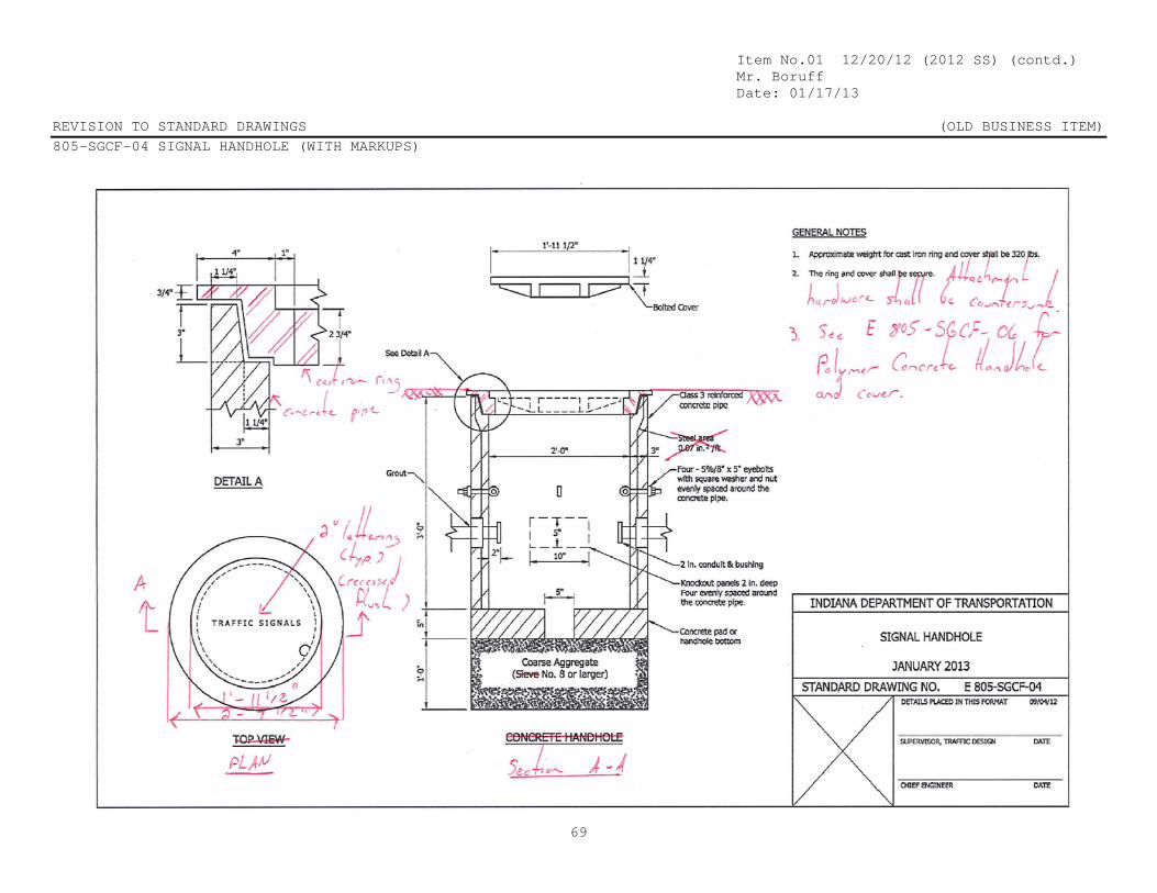
Item No.01 12/20/12 (2012 SS) (contd.) Mr. Boruff Date: 01/17/13 REVISION TO STANDARD DRAWINGS (OLD BUSINESS ITEM) 805-SGCF-04 SIGNAL HANDHOLE (WITH MARKUPS)
69

Item No.01 12/20/12 (2012 SS) (contd.) Mr. Boruff Date: 01/17/13 REVISION TO SPECIAL PROVISIONS (OLD BUSINESS ITEM) 805-SGCF-04 SIGNAL HANDHOLE (REVISED DRAFT)
70

Item No.01 12/20/12 (2012 SS) (contd.) Mr. Boruff Date: 01/17/13 REVISION TO STANDARD DRAWINGS (OLD BUSINESS ITEM) PROPOSED NEW 805-SGCF-04A SIGNAL HANDHOLE POLYMER CONCRETE TYPE
71

Item No.01 12/20/12 (2012 SS) (contd.) Mr. Boruff Date: 01/17/13 REVISION TO STANDARD DRAWINGS (OLD BUSINESS ITEM) EXISTING 805-SGLT-01 LOOP TAGGING SYSTEM (PROPOSED TO DELETE)
72
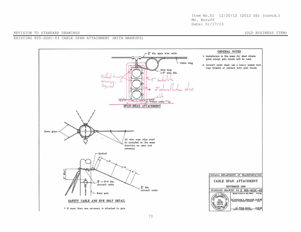
Item No.01 12/20/12 (2012 SS) (contd.) Mr. Boruff Date: 01/17/13 REVISION TO STANDARD DRAWINGS (OLD BUSINESS ITEM) EXISTING 805-SGSC-03 CABLE SPAN ATTACHMENT (WITH MARKUPS)
73
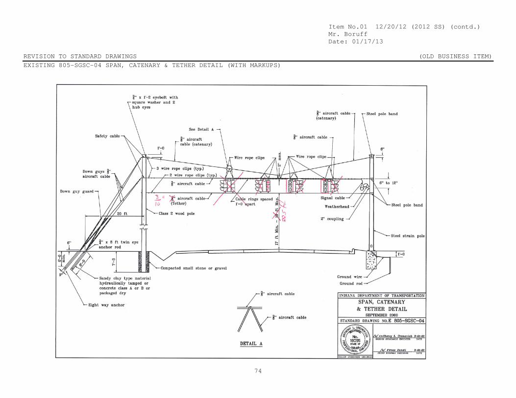
Item No.01 12/20/12 (2012 SS) (contd.) Mr. Boruff Date: 01/17/13 REVISION TO STANDARD DRAWINGS (OLD BUSINESS ITEM) EXISTING 805-SGSC-04 SPAN, CATENARY & TETHER DETAIL (WITH MARKUPS)
74
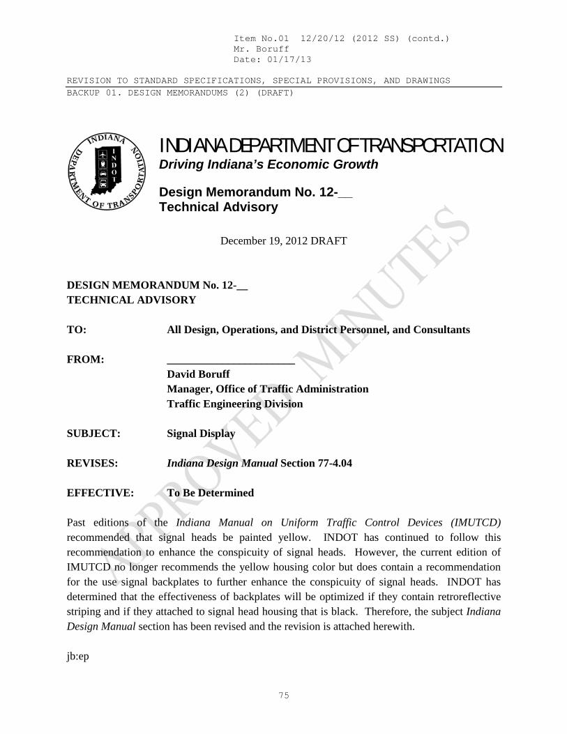
Item No.01 12/20/12 (2012 SS) (contd.) Mr. Boruff Date: 01/17/13 REVISION TO STANDARD SPECIFICATIONS, SPECIAL PROVISIONS, AND DRAWINGS BACKUP 01. DESIGN MEMORANDUMS (2) (DRAFT)
75
X
INDIANA DEPARTMENT OF TRANSPORTATION Driving Indiana’s Economic Growth Design Memorandum No. 12-__ Technical Advisory
December 19, 2012 DRAFT
DESIGN MEMORANDUM No. 12-__ TECHNICAL ADVISORY TO: All Design, Operations, and District Personnel, and Consultants FROM: _______________________ David Boruff Manager, Office of Traffic Administration Traffic Engineering Division SUBJECT: Signal Display REVISES: Indiana Design Manual Section 77-4.04 EFFECTIVE: To Be Determined Past editions of the Indiana Manual on Uniform Traffic Control Devices (IMUTCD) recommended that signal heads be painted yellow. INDOT has continued to follow this recommendation to enhance the conspicuity of signal heads. However, the current edition of IMUTCD no longer recommends the yellow housing color but does contain a recommendation for the use signal backplates to further enhance the conspicuity of signal heads. INDOT has determined that the effectiveness of backplates will be optimized if they contain retroreflective striping and if they attached to signal head housing that is black. Therefore, the subject Indiana Design Manual section has been revised and the revision is attached herewith. jb:ep

Item No.01 12/20/12 (2012 SS) (contd.) Mr. Boruff Date: 01/17/13 REVISION TO STANDARD SPECIFICATIONS, SPECIAL PROVISIONS, AND DRAWINGS BACKUP 01. DESIGN MEMORANDUMS (2) (DRAFT)
76
77-4.04 Signal Display The traffic-signal display consists of parts including the signal head, signal face, optical unit, visors, etc. The criteria set forth in the MUTCD Part IV, the INDOT Standard Specifications, and ITE’s Equipment and Material Standards of the Institute of Transportation Engineers should be followed in determining appropriate signal-display arrangements and equipment. The following provides additional guidance for the selection of the signal display equipment. 1. Signal-Head Housing. This areis made of polycarbonate (plastic). For new traffic
signal installations on the state highway system, the signal head housing should have a black color. For traffic signal modernization projects on the state highway system, the existing yellow signal heads may be reused if this is approved by the District Traffic Engineer.
2 Signal Faces. Section 77-5.01 provides INDOT’s preferred signal-face
arrangements for use on a State highway. The signal lenses should be placed in a vertical line rather than horizontally except where overhead obstructions may limit visibility. Where protected left turns are followed by permissive left turns, the five-section signal head is the recommended arrangement choice. The MUTCD Part IV provides additional information on the arrangement of signal heads.
3. Lens Size. INDOT’s preferred practice is to use only 12-in. diameter lenses.
INDOT specifications require the use of plastic lenses in its signal displays. 4. Signal Illumination. Only Light-Emitting Diodes (LED) should be used. 5. Visors. A visor should be used with each lens. A visor is used to direct the signal
indication to the appropriate approaching traffic and to reduce sun phantom. A tunnel visor provides a complete circle around the lens. A cutaway visor is a partial visor, with the bottom cut away. A partial visor reduces water and snow accumulation and does not let birds build nests within the visor. The decision on which visor type should be used is determined on a site-by-site basis. For a Department installation, partial visors are normally used. Visors are made of the same material as the housing.

Item No.01 12/20/12 (2012 SS) (contd.) Mr. Boruff Date: 01/17/13 REVISION TO STANDARD SPECIFICATIONS, SPECIAL PROVISIONS, AND DRAWINGS BACKUP 01. DESIGN MEMORANDUMS (2) (DRAFT)
77
6. Louvers. Louvers are sometimes used to direct the signal indication to a specific lane. Louvers are used where several signal heads may cause confusion for the approaching driver. One example of this problem is where an intersection has its approaches at angles less than 90 deg and the signal indications can be seen from both approaches. The decision on whether to use louvers depends on site conditions and will be determined for each site.
7. Optically-Programmable Signal. Like louvers, an optically-programmable signal
is designed to direct the signal indication to specific approach lanes and for specific distances. An advantage is that they can be narrowly aligned so that motorists from other approaches cannot see the indications. Applications include closely-spaced intersections or an intersection where the approaches have acute angles. An optically-programmable signal requires rigid mountings to keep the indicator properly directed. The cost is higher than for louvers but the improved visibility often makes it a better choice. The decision on whether to use an optically-programmable signal depends on site conditions and will be determined for each site.
8. Backplate. A signal indication loses some of its contrast value if viewed against a
bright sky or other intensive background lighting such as advertising lighting. A backplate placed around a signal assembly enhance the signal’s visibility and have been shown to provide a benefit in reducing crashes. However, a backplate adds weight to the signal head and can increase the effect of wind loading on the signal. The decision on whether to use a backplate depends on site conditions and will be determined for each site. A backplate should be used on overhead 3 section signal heads for through lanes and on other signal heads as determined by the District Traffic Engineer. Use on other signal heads should be identified in the plans.
By Standard Specification backplates will include a 2 in. yellow retroreflective strip around the perimeter of the backplate to enhance the conspicuity of the signal head at night. For non-INDOT projects where the reflectorized surface is not desired the plans or special provisions should so indicate.

Item No.01 12/20/12 (2012 SS) (contd.) Mr. Boruff Date: 01/17/13 REVISION TO STANDARD SPECIFICATIONS, SPECIAL PROVISIONS, AND DRAWINGS BACKUP 01. DESIGN MEMORANDUMS (2) (DRAFT)
78
X
INDIANA DEPARTMENT OF TRANSPORTATION Driving Indiana’s Economic Growth Design Memorandum No. 12-__ Technical Advisory
December 19, 2012 DRAFT
DESIGN MEMORANDUM No. 12-__ TECHNICAL ADVISORY TO: All Design, Operations, and District Personnel, and Consultants FROM: _______________________ David Boruff Manager, Office of Traffic Administration Traffic Engineering Division SUBJECT: Signal Electrical System REVISES: Indiana Design Manual Section 77-5.05 EFFECTIVE: To Be Determined Significant cost savings can be achieved on a traffic signal project depending on the electrical system design. An estimate of the service connection charge from the local utility company that is included in the Contract Information Book can avoid expensive change orders later on. Polymer concrete handholes are also less expensive than concrete handholes and are appropriate for locations that are protected from heavy vehicles. Also, HDPE has now been added as an acceptable material for non-metallic conduit.Therefore, the subject Indiana Design Manual section has been revised and the revision is attached herewith. Please note that sections 805.02, 805.16 and 922.17 of the INDOT Standard Specifications are being revised and Standard Drawing to allow the use of polymer concrete handholes.

Item No.01 12/20/12 (2012 SS) (contd.) Mr. Boruff Date: 01/17/13 REVISION TO STANDARD SPECIFICATIONS, SPECIAL PROVISIONS, AND DRAWINGS BACKUP 01. DESIGN MEMORANDUMS (2) (DRAFT)
79
77-5.05 Electrical System The electrical system consists of electrical cables or wires, connectors, conduit, handholes, etc. Electrical connections between the power supply, controller cabinet, detectors, and signal poles are carried in conduit. The following should be considered in developing the traffic-signal wiring plan. 1. Service Connections. Service connections from the local utility lines should go
directly to the service disconnect and then to the controller cabinet. The lines should be as short as practical. The service disconnect should be located as close to the controller cabinet as practical. These installations will be placed underground in separate conduits from other signal wires. Easy access to a shut-off device in the controller is required to turn the power supply off while performing system maintenance.
The designer should contact the local utility company and obtain an estimate for the service connection cost. The estimate should be included in the Contract Information Book.
2. Electric Cables. All electric cables and connections must satisfy national, State,
and local electrical codes, in addition to the NEMA criteria, except for the green wire, which is used for the green indication or interconnect function and not for the system ground. The number of conductor cables should be kept to a minimum, usually only 3 or 4 combinations, to reduce inventory requirements. A 7- or greater-conductor cable is used between the controller cabinet and the disconnect hangers or cantilever base. A 5-conductor cable is used between the disconnect hanger or cantilever base and 3-section signal indication. A 7-conductor cable is used between the disconnect hanger or cantilever base and 5-section signal indication. A 5-conductor cable is used between the controller cabinet and the pedestrian-signal indication. A 5-conductor cable is used between the controller cabinet and each pair of pedestrian push buttons located in the same corner of the intersection. Connections to flashers use only a 3-conductor cable. The INDOT Standard Drawings illustrate the correct procedures for wiring and splicing cables.
3. Cable Runs. All cable runs should be continuous between the following:
a. controller cabinet to base of cantilever structure or pedestal; b. controller cabinet to disconnect hangers;

Item No.01 12/20/12 (2012 SS) (contd.) Mr. Boruff Date: 01/17/13 REVISION TO STANDARD SPECIFICATIONS, SPECIAL PROVISIONS, AND DRAWINGS BACKUP 01. DESIGN MEMORANDUMS (2) (DRAFT)
80
c. controller cabinet to service disconnect; d. disconnect hanger to signal indications; e. base of cantilever structure to signal indications; and f. controller cabinet to detector housing.
4. Handhole. A handhole should be located adjacent to the controller cabinet, each
signal pole, and each detector location. Reinforced concrete pipe and polymer concrete may be used as the material for the handhole, depending on the location. A concrete handhole should be used for a location that will be exposed to motor vehicles, such as in the shoulder or an auxiliary lane, or immediately adjacent to the unprotected edge of pavement. A polymer concrete handhole should be used for a location that will not be exposed to motor vehicles, such as on sidewalk, behind guardrail or non-mountable curb, or as directed by the District Traffic or District Maintenance Offices.
The INDOT Standard Drawings provide additional handhole and wiring details.
The maximum spacing between handholes in the same conduit run is 250 200 ft. 5. Underground Conduit. Underground conduit is used to connect the controller
cabinet, traffic signals, and loop detectors together. Conduits run underneath the pavement and between the handholes, using a 2-in. diameter conduit. For a run with additional cables, the conduit size may need to be increased. The NEC should be checked to determine the appropriate conduit size for the number of electric cables that can be contained within the conduit. The INDOT Standard Drawings provide additional placement details of underground conduit.
The designer should indicate which material type should be used. The conduit type should be determined based on the guidelines as follows:
a. PVC Schedule 40 or 80, HDPE Schedule 40, or rigid fiberglass should be used conduit to be placed in a trench.
b. PVCHDPE Schedule 80 should be used for conduit to be jacked or bored,
e.g., underneath pavement. c. Galvanized steel may be used as requested or confirmed by the district
traffic engineer for a signal-modernization project to match the existing conduit or for new signal construction.

Item No.01 12/20/12 (2012 SS) (contd.) Mr. Boruff Date: 01/17/13 REVISION TO STANDARD SPECIFICATIONS, SPECIAL PROVISIONS, AND DRAWINGS BACKUP 01. DESIGN MEMORANDUMS (2) (DRAFT)
81
As the practice of using PVC or rigid fiberglass conduit becomes more prevalent, the need for the designer to indicate the conduit type may not be necessary, as contractors will gain experience in using the material type that is appropriate for the application.
6. Grounding. Each metal pole, cantilever structure, controller cabinet, etc., should
be grounded. The INDOT Standard Drawings illustrate the correct methods for grounding these devices.
7. Detector Housing. A detector housing should be a cast-aluminum box encased in
concrete. A detector housing is used to splice the wires from the loops to the lead-in cable to the detector amplifier. The INDOT Standard Drawings provide additional information on detector housings, including wiring details.
8. Disconnect Hangers. Disconnect hangers are used for a cable-span-mounted
signal to provide a junction box between the signal heads and the controller. 9. Loop Tagging. Each loop-detector cable should be tagged in the controller cabinet
to indicate which loop detector wire belongs to which loop detector. Each should be labeled according to street, direction, lane, and distance from the stop line, and if the loop is a count loop.
10. Interconnect Cable. A 7-conductor signal wire is used for hard-wiring
interconnected signals. For a closed-loop system, the hard-wired connection should use a telecommunication cable consisting of either a fiberoptic cable or a 6-pair twisted cable.

Item No.01 12/20/12 (2012 SS) (contd.) Mr. Boruff Date: 01/17/13 COMMENTS AND ACTION SECTION 805 TRAFFIC SIGNALS SECTION 922 TRAFFIC SIGNALS MATERIALS 922-X-XXX CONTROLLER CELLULAR MODEM 805-X-XXX MAGNETOMETERS AND MICROLOOP DETECTORS 805-X-XXX PREFORMED PAVE-OVER LOOPS 805-X-XXX RADIO INTERCONNECTION 805-SGCF-04 SIGNAL HANDHOLE 805-SGCF-04A SIGNAL HANDHOLE POLYMER CONCRETE TYPE 805-SGLT-01 LOOP TAGGING SYSTEM
82
DISCUSSION: This item was introduced and presented by Mr. Boruff who directed the committee’s attention to their revised proposal, which was sent out as an addendum to the originally submitted agenda items. Mr. Boruff and Mr. Bruno submitted the amended item for consideration and explained that the item was presented at last month’s meeting and was withdrawn in order to address the committee’s concerns. Further revisions were presented and the committee reviewed and discussed those proposed amended revisions. Mr. Boruff stated that there are still more revisions to be incorporated. There was some discussion related to the drawings for the hand-holes, concerning how they will be installed and where they can be located. Mr. Boruff stated that these issues can be addressed in a construction memo and a design memo, both of which will also need to be revised. Mr. Miller suggested withdrawing this item until next month’s meeting to allow time for all revisions and corrections to be incorporated. This item was subsequently withdrawn. Mr. Boruff will revise the language related to the acceptable hand-hole locations and construction requirements.
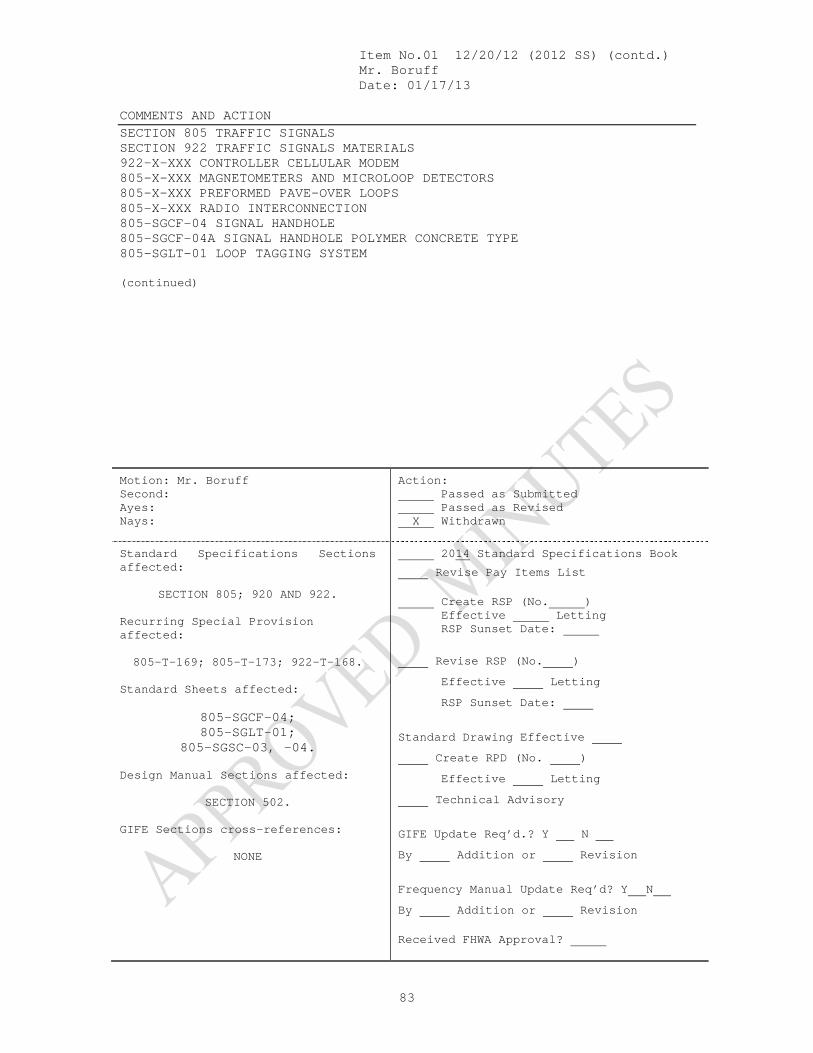
Item No.01 12/20/12 (2012 SS) (contd.) Mr. Boruff Date: 01/17/13 COMMENTS AND ACTION SECTION 805 TRAFFIC SIGNALS SECTION 922 TRAFFIC SIGNALS MATERIALS 922-X-XXX CONTROLLER CELLULAR MODEM 805-X-XXX MAGNETOMETERS AND MICROLOOP DETECTORS 805-X-XXX PREFORMED PAVE-OVER LOOPS 805-X-XXX RADIO INTERCONNECTION 805-SGCF-04 SIGNAL HANDHOLE 805-SGCF-04A SIGNAL HANDHOLE POLYMER CONCRETE TYPE 805-SGLT-01 LOOP TAGGING SYSTEM
83
(continued)
Motion: Mr. Boruff Second: Ayes: Nays:
Action: Passed as Submitted Passed as Revised X Withdrawn
Standard Specifications Sections affected:
SECTION 805; 920 AND 922.
Recurring Special Provision affected: 805-T-169; 805-T-173; 922-T-168.
Standard Sheets affected:
805-SGCF-04; 805-SGLT-01;
805-SGSC-03, -04. Design Manual Sections affected:
SECTION 502. GIFE Sections cross-references:
NONE
2014 Standard Specifications Book
Revise Pay Items List Create RSP (No. ) Effective Letting RSP Sunset Date:
Revise RSP (No. ) Effective Letting RSP Sunset Date:
Standard Drawing Effective Create RPD (No. ) Effective Letting Technical Advisory
GIFE Update Req’d.? Y N By Addition or Revision
Frequency Manual Update Req’d? Y N By Addition or Revision Received FHWA Approval?

Mr. Walker Date: 01/17/13
SPECIFICATION, SPECIAL PROVISIONS AND DRAWINGS REVISION TO STANDARD SPECIFICATIONS
84
PROPOSAL TO STANDARDS COMMITTEE
PROBLEM(S) ENCOUNTERED: 1. Acceptance of QC/QA HMA mixtures with small quantities is a problem because proper quality control techniques cannot be utilized when producing very small quantities of hot mix asphalt and achieving the smoothness requirements is also difficult. 2. AASHTO T 209 requires AASHTO R 47 for reducing HMA samples to the testing size. Our procedure (ITM 587) is different than AASHTO R 47. 3. HMA (402) is being used as mainline pavement. The 402 section is intended for miscellaneous mixtures or locations that cannot be plate sampled and is not intended for mainline pavement mixtures. PROPOSED SOLUTION: 1. Accept QC/QA HMA dense graded mixtures less than 300 tons by a Type D Certification, and accept density by the standard rolling train. 2. Change the requirement that QC/QA mixtures will not be sampled in the first 300 tons of the DMF/JMF to the first 300 tons of the mixture pay item. 3. Reference ITM 587 for the procedure to reduce HMA samples to the proper testing size. 4. Exempt surface mixtures less than or equal to a sublot from profilograph requirements. 5. Remove pay items for HMA Surface, HMA Intermediate, and HMA Base from 402. 6. Remove Wedge and Level from 402 and replace with a Recurring Special Provision. 7 Various other editorial changes are being made. APPLICABLE STANDARD SPECIFICATIONS: 401.05, 401.09, 401.16, 401.18, 402.01, 402.07, 402.13, 402.20 APPLICABLE STANDARD DRAWINGS: APPLICABLE DESIGN MANUAL SECTION: APPLICABLE SECTION OF GIFE:

Mr. Walker Date: 01/17/13
SPECIFICATION, SPECIAL PROVISIONS AND DRAWINGS REVISION TO STANDARD SPECIFICATIONS
85
(CONTINUED) APPLICABLE RECURRING SPECIAL PROVISIONS: PAY ITEMS AFFECTED: Submitted By: Ron Walker Title: Manager, Office of Materials Management Organization: INDOT Phone Number: 317-610-7251 x 204 Date: 12-21-12 APPLICABLE SUB-COMMITTEE ENDORSEMENT: These specification revisions are recommended by the INDOT/APAI Technical Committee.

Item No.01 01/17/13 (2012 SS) (contd.) Mr. Walker Date: 01/17/13 REVISION TO STANDARD SPECIFICATIONS SECTION 401 – QUALITY CONTROL/QUALITY ASSURANCE, QC/QA, HOT MIX ASPHALT, HMA, PAVEMENT 401.05 VOLUMETRIC MIX DESIGN 401.09 ACCEPTANCE OF MIXTURES 401.16 DENSITY 401.18(a) PROFILOGRAPH
86
The Standard Specifications are revised as follows: SECTION 401, BEGIN LINE 67, DELETE AND INSERT AS FOLLOWS:
Open Graded, Mixture Designation – Control Point (Percent Passing) OG19.0 OG25.0
Sieve Size 37.5 mm 100.0 25.0 mm 100.0 70.0 – 98.0 19.0 mm 70.0 – 98.0 50.0 – 85.0 12.5 mm 40.0 – 68.0 28.0 – 62.0 9.5 mm 20.0 – 52.0 15.0 – 50.0 4.75 mm 10.0 – 30.0 67.0 – 30.0 2.36 mm 15.0 ± 8.07.0 – 23.0 15.0 ± 8.07.0 – 23.0 1.18 mm 2.0 – 18.0 2.0 – 18.0 600 µm 1.0 – 13.0 1.0 – 13.0 300 µm 0.0 – 10.0 0.0 – 10.0 150 µm 0.0 – 9.0 0.0 – 9.0 75 µm 0.0 – 8.0 0.0 – 8.0
% of Binder > 3.0 > 3.0 SECTION 401, BEGIN LINE 198, DELETE AND INSERT AS FOLLOWS: 401.09 Acceptance of Mixture Acceptance of mixtures for binder content, VMA at Ndes, and air voids at Ndes for each lot will be based on tests performed by the Engineer for dense graded mixtures with original contract pay item quantities greater than or equal to 300 t. Acceptance of mixtures for binder content and air voids at Ndes will be based on a type D certification in accordance with 402.09 for dense graded mixtures with original contract pay item quantities less than 300 t. Acceptance of mixtures for binder content and air voids at Ndes for each lot will be based on tests performed by the Engineer for open graded mixtures. The Engineer will randomly select the location(s) within each sublot for sampling in accordance with ITM 802. The 1st 300 t (300 Mg) of the 1st sublot of the 1st lot for each DMF/JMF each mixture pay item will not be sampled. An acceptance sample will consist of 2 plate samples with the 1st being at the random location and the 2nd 2 ft (0.6 m) ahead station. A backup sample consisting of 2 plate samples shall be located 2 ft (0.6 m) towards the center of the mat from the acceptance sampleobtained in accordance with ITM 802 and ITM 580. The Engineer will take immediate possession of the samples.

Item No.01 01/17/13 (2012 SS) (contd.) Mr. Walker Date: 01/17/13 REVISION TO STANDARD SPECIFICATIONS SECTION 401 – QUALITY CONTROL/QUALITY ASSURANCE, QC/QA, HOT MIX ASPHALT, HMA, PAVEMENT 401.05 VOLUMETRIC MIX DESIGN 401.09 ACCEPTANCE OF MIXTURES 401.16 DENSITY 401.18(a) PROFILOGRAPH
87
Samples from each location shall be obtained from each sublot from the pavement in accordance with ITM 580. The Engineer will take immediate possession of the samples. Acceptance samples will be reduced to the appropriate size for testing in accordance with ITM 587. The binder content will be determined in accordance with ITM 586 or ITM 571 as directed by the Engineer. The maximum specific gravity will be mass determined in water in accordance with AASHTO T 209. The air voids will be determined in accordance with AASHTO PP 28R 35 based on the average bulk specific gravity from 2 gyratory specimens and the MSG for the sublot. The VMA will be determined in accordance with AASHTO PP 28R 35 based on the average bulk specific gravity from 2 gyratory specimens, the percent aggregate in the mixture from the sublot and the BSG of the aggregate blend from the DMF/JMF as applicable. The gyratory pills will be prepared in accordance with AASHTO T 312. SECTION 401, BEGIN LINE 244, INSERT AS FOLLOWS: Pay factors for dense graded mixtures with original contract pay item quantities greater than or equal to 300 t and less than 1 lot and open graded mixtures will be determined in accordance with 401.19(b). SECTION 401, BEGIN LINE 394, INSERT AS FOLLOWS: Compaction of mixtures with original contract pay item quantities less than 300 t shall be in accordance with 402.15. SECTION 401, AFTER LINE 465, INSERT AND DELETE AS FOLLOWS: If the original contract pay item quantity for a surface mixture is less than or equal to 1 sublot, the item will be exempt from profilograph operation and the smoothness will be accepted in accordance with 401.18(b). If the posted speed limit for an entire smoothness section is less than or equal to 45 mph (70 km/h), the section will be exempt from profilograph operation and the smoothness within the section will be accepted by a 16 ft (4.9 m) straightedgein accordance with 401.18(b).

Item No.01 01/17/13 (2012 SS) (contd.) Mr. Walker Date: 01/17/13 REVISION TO STANDARD SPECIFICATIONS SECTION 402 – HOT MIX ASPHALT, HMA, PAVEMENT 402.01 DESCRIPTION 402.07 MIX CRITERIA 402.13 SPREADING AND FINISHING 402.20 BASIS OF PAYMENT
88
The Standard Specifications are revised as follows: SECTION 402, BEGIN LINE 3, DELETE AND INSERT AS FOLLOWS: 402.01 Description This work shall consist of 1 or more courses of HMA base, intermediate, or surface mixtures, and miscellaneous courses for rumble strips, and wedge and leveling mixtures constructed on prepared foundations in accordance with 105.03. SECTION 402, BEGIN LINE 85, DELETE AND INSERT AS FOLLOWS: (b) Composition Limits for HMA Wedge and Leveling Mixtures The mixture shall consist of surface or intermediate mixtures in accordance with 402.04. Aggregate requirements of 904.03(d) do not apply when the wedge and leveling mixture is covered by a surface or intermediate mixture. (cb) Composition Limits for Temporary HMA Mixtures Temporary HMA mixtures shall be the type specified in accordance with 402.04. A MAF in accordance with 402.05 will not apply. (dc) Composition Limits for HMA Curbing Mixtures The mixture shall be HMA surface type A in accordance with 402 except 402.05 shall not apply and RAP shall not be used. The binder content shall be 7.0% and the gradations shall meet the following. SECTION 402, BEGIN LINE 265, INSERT AND DELETE AS FOLLOWS: The finished thickness of each course shall be at least 2 times but not more than 4 times the maximum particle size as shown on the DMF or JMF. The finished thickness of wedge and level mixtures shall be at least 1.5 times but not more than 6 times the maximum particle size as shown on the DMF or JMF. Feathering may be less than the minimum thickness requirements. SECTION 402, BEGIN LINE 416, DELETE AS FOLLOWS: Pay Item Pay Unit Symbol HMA Surface, Type * ......................................................................... TON HMA Intermediate, Type * ................................................................. TON HMA Base, Type * ............................................................................. TON HMA Rumble Strips .................................................................................... LFT HMA for Temporary Pavement, Type * ............................................. TON HMA Wedge and Level, Type * ......................................................... TON * Mixture type
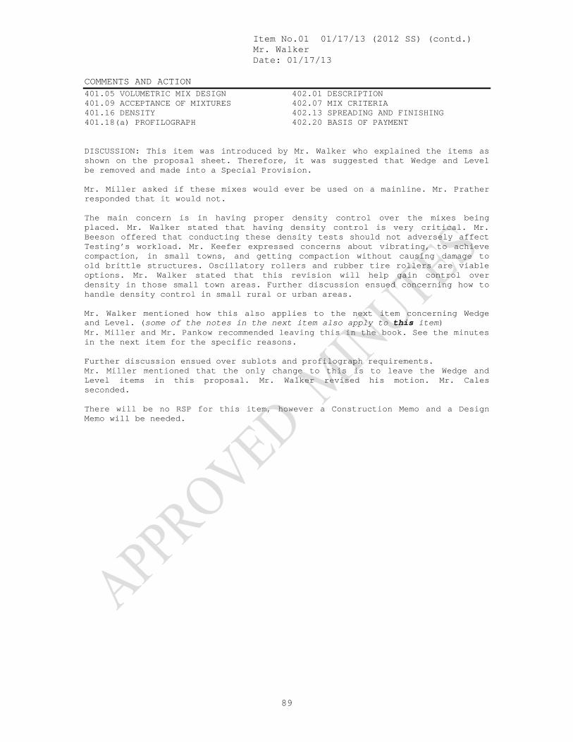
Item No.01 01/17/13 (2012 SS) (contd.) Mr. Walker Date: 01/17/13 COMMENTS AND ACTION 401.05 VOLUMETRIC MIX DESIGN 401.09 ACCEPTANCE OF MIXTURES 401.16 DENSITY 401.18(a) PROFILOGRAPH
402.01 DESCRIPTION 402.07 MIX CRITERIA 402.13 SPREADING AND FINISHING 402.20 BASIS OF PAYMENT
89
DISCUSSION: This item was introduced by Mr. Walker who explained the items as shown on the proposal sheet. Therefore, it was suggested that Wedge and Level be removed and made into a Special Provision. Mr. Miller asked if these mixes would ever be used on a mainline. Mr. Prather responded that it would not. The main concern is in having proper density control over the mixes being placed. Mr. Walker stated that having density control is very critical. Mr. Beeson offered that conducting these density tests should not adversely affect Testing’s workload. Mr. Keefer expressed concerns about vibrating, to achieve compaction, in small towns, and getting compaction without causing damage to old brittle structures. Oscillatory rollers and rubber tire rollers are viable options. Mr. Walker stated that this revision will help gain control over density in those small town areas. Further discussion ensued concerning how to handle density control in small rural or urban areas. Mr. Walker mentioned how this also applies to the next item concerning Wedge and Level. (some of the notes in the next item also apply to this item) Mr. Miller and Mr. Pankow recommended leaving this in the book. See the minutes in the next item for the specific reasons. Further discussion ensued over sublots and profilograph requirements. Mr. Miller mentioned that the only change to this is to leave the Wedge and Level items in this proposal. Mr. Walker revised his motion. Mr. Cales seconded. There will be no RSP for this item, however a Construction Memo and a Design Memo will be needed.
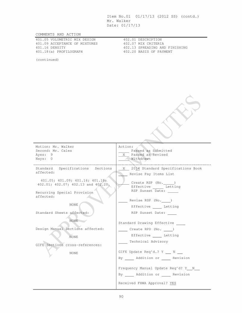
Item No.01 01/17/13 (2012 SS) (contd.) Mr. Walker Date: 01/17/13 COMMENTS AND ACTION 401.05 VOLUMETRIC MIX DESIGN 401.09 ACCEPTANCE OF MIXTURES 401.16 DENSITY 401.18(a) PROFILOGRAPH
402.01 DESCRIPTION 402.07 MIX CRITERIA 402.13 SPREADING AND FINISHING 402.20 BASIS OF PAYMENT
90
(continued)
Motion: Mr. Walker Second: Mr. Cales Ayes: 9 Nays: 0
Action: Passed as Submitted X Passed as Revised Withdrawn
Standard Specifications Sections affected:
401.05; 401.09; 401.16; 401.18;
402.01; 402.07; 402.13 and 402.20. Recurring Special Provision affected:
NONE Standard Sheets affected:
NONE Design Manual Sections affected:
NONE GIFE Sections cross-references:
NONE
X 2014 Standard Specifications Book
Revise Pay Items List Create RSP (No. ) Effective Letting RSP Sunset Date:
Revise RSP (No. ) Effective Letting RSP Sunset Date:
Standard Drawing Effective Create RPD (No. ) Effective Letting Technical Advisory
GIFE Update Req’d.? Y N By Addition or Revision
Frequency Manual Update Req’d? Y N By Addition or Revision Received FHWA Approval? YES

Mr. Walker Date: 01/17/13
SPECIFICATION, SPECIAL PROVISIONS AND DRAWINGS REVISION TO SPECIAL PROVISIONS
91
PROPOSAL TO STANDARDS COMMITTEE
PROBLEM(S) ENCOUNTERED: HMA Wedge and Leveling is not being used for the proper applications of this type of mixture and needs to be controlled by Pavement Design through a Recurring Special Provision. PROPOSED SOLUTION: Make a Recurring Special Provision for HMA Wedge and Leveling Mixture APPLICABLE STANDARD SPECIFICATIONS: 402.07, 402.13, 402.20 APPLICABLE STANDARD DRAWINGS: APPLICABLE DESIGN MANUAL SECTION: APPLICABLE SECTION OF GIFE: APPLICABLE RECURRING SPECIAL PROVISIONS: PAY ITEMS AFFECTED: Submitted By: Ronald Walker Title: Manager, Office of Materials Management Organization: INDOT Phone Number: 317-610-7251 x 204 Date: 12-21-12 APPLICABLE SUB-COMMITTEE ENDORSEMENT: These specification revisions are recommended by the INDOT/APAI Technical Committee.

Item No.02 01/17/13 (2012 SS) (contd.) Mr. Walker Date: 01/17/13 REVISION TO SPECIAL PROVISIONS PROPOSED NEW RSP 402-R-XXX HMA WEDGE AND LEVELING
92
402-R-XXX HMA WEDGE AND LEVELING
(Adopted xx-xx-13)
The Standard Specifications are revised as follows: SECTION 402, BEGIN LINE 94, INSERT AS FOLLOWS: (d) Composition Limits for HMA Wedge and Leveling Mixtures The mixture shall consist of surface or intermediate mixtures in accordance with 402.04. Aggregate requirements of 904.03(d) do not apply when the wedge and leveling mixture is covered by a surface or intermediate mixture. SECTION 402, BEGIN LINE 266, INSERT AS FOLLOWS: The finished thickness of wedge and level mixtures shall be at least 1.5 times but not more than 6 times the maximum particle size as shown on the DMF or JMF. Feathering may be less than the minimum thickness requirements. SECTION 402, BEGIN LINE 423, INSERT AS FOLLOWS: HMA Wedge and Level, Type * .................................................................. TON

Item No.02 01/17/13(2012 SS) (contd.) Mr. Walker Date: 01/17/13 COMMENTS AND ACTION PROPOSED NEW RSP 402-R-XXX HMA WEDGE AND LEVELING
93
DISCUSSION: This item was introduced and presented by Mr. Walker who explained that the material is not being properly utilized as stated in the proposal sheet. Mr. Walker suggested making Wedge and Level a Unique item requiring a Unique Special Provision, USP. Mr. Cales explained that if the pay item shows that a USP is needed, then the designer will check to see if there is an existing USP. Then they will move forward. That also means that there will no longer be control over its use. Mr. Pankow suggested that if this is in a Recurring Special Provision, RSP, then it can be more easily controlled or monitored. Further discussion then ensued as to how to manage those RSP’s to limit its use. Mr. Cales expressed concern as to how to enforce the control over use of the material. Mr. Walker explained that some problems with the process involves resistance from FHWA in gaining approval. Mr. Pankow mentioned that either way, maintaining control over the material will not change. Mr. Cales said that making it a unique item will make things worse. Mr. Miller and Mr. Pankow suggested leaving the pay items in the book, since taking them out will not make a difference. Mr. Prather expressed that Wedge and Level specifically has been grossly abused. Mr. Pankow stated that a Wedge and Level is often disguised in the plans as “variable depth”. Mr. Keefer said that Ft Wayne often refers to it as a “skip wedge”, and, generally, milling is not involved. Mr. Miller and Mr. Pankow recommended leaving this in the book. As a result of the discussions involved in items No. 1 and No. 2, this item has been withdrawn.
Motion: Mr. Walker Second: Mr. Cales Ayes: Nays:
Action: Passed as Submitted Passed as Revised X Withdrawn
Standard Specifications Sections affected:
SECTION 402 begin on pg 254.
Recurring Special Provision affected:
NONE Standard Sheets affected:
NONE Design Manual Sections affected:
NONE GIFE Sections cross-references:
NONE
2014 Standard Specifications Book
Revise Pay Items List Create RSP (No. ) Effective Letting RSP Sunset Date:
Revise RSP (No. ) Effective Letting RSP Sunset Date:
Standard Drawing Effective Create RPD (No. ) Effective Letting Technical Advisory
GIFE Update Req’d.? Y N By Addition or Revision
Frequency Manual Update Req’d? Y N By Addition or Revision Received FHWA Approval?
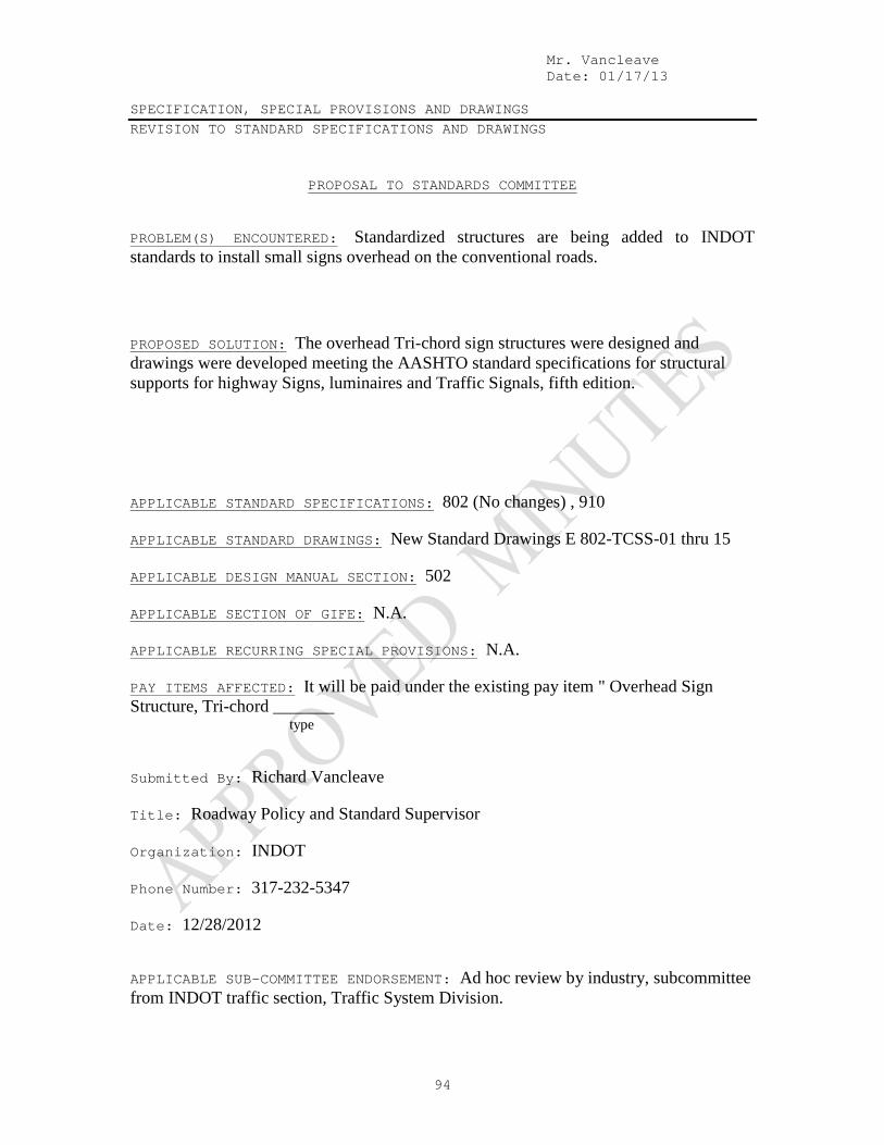
Mr. Vancleave Date: 01/17/13
SPECIFICATION, SPECIAL PROVISIONS AND DRAWINGS REVISION TO STANDARD SPECIFICATIONS AND DRAWINGS
94
PROPOSAL TO STANDARDS COMMITTEE
PROBLEM(S) ENCOUNTERED: Standardized structures are being added to INDOT standards to install small signs overhead on the conventional roads. PROPOSED SOLUTION: The overhead Tri-chord sign structures were designed and drawings were developed meeting the AASHTO standard specifications for structural supports for highway Signs, luminaires and Traffic Signals, fifth edition. APPLICABLE STANDARD SPECIFICATIONS: 802 (No changes) , 910 APPLICABLE STANDARD DRAWINGS: New Standard Drawings E 802-TCSS-01 thru 15 APPLICABLE DESIGN MANUAL SECTION: 502 APPLICABLE SECTION OF GIFE: N.A. APPLICABLE RECURRING SPECIAL PROVISIONS: N.A. PAY ITEMS AFFECTED: It will be paid under the existing pay item " Overhead Sign Structure, Tri-chord _______ type Submitted By: Richard Vancleave Title: Roadway Policy and Standard Supervisor Organization: INDOT Phone Number: 317-232-5347 Date: 12/28/2012 APPLICABLE SUB-COMMITTEE ENDORSEMENT: Ad hoc review by industry, subcommittee from INDOT traffic section, Traffic System Division.

Item No.03 01/17/13 (2012 SS) (contd.) Mr. Vancleave Date: 01/17/13 REVISION TO STANDARD SPECIFICATIONS AND DRAWINGS SECTION 910 – METAL MATERIALS 910.19 OVERHEAD SIGN STRUCTURES
95
(Note: Changes approved on 11/16/2012 and 12/20/2012 meetings shown as additions: italic and deletion: strikethrough. Proposed new changes shown highlighted in gray.)
The Standard Specifications are revised as follows: SECTION 910, BEGIN LINE 1266, DELETE AND INSERT AS FOLLOWS: 910.19 Overhead Sign Structures The complete structure with signs in place shall be able to withstand wind pressure in accordance with AASHTO Standard Specifications for Structural Supports for Highway Signs, Luminaires and Traffic Signals. The structure shall be designed to resist fatigue of the material in accordance with the AASHTO specifications. All prefabricated structural units shall be packed so that there is no injury or defacement during transportation to the point of destination. All bolts, nuts, and washers for bridge bracket assemblies shall be stainless steel in accordance with ASTM F 738M. Strain poles for cable span signs shall be in accordance with 922.05(a). Each strain pole shall include 3 band type attachments for span wire clamps. Such attachments shall be galvanized in accordance with ASTM A 153. Cable shall be in accordance with 922.06(b). Each cable shall include 3 wire rope clips at each end. Anchor bolts shall be in accordance with 922.05(c)6. All sign mounting hardware except for the extruded aluminum bar shall be galvanized in accordance with ASTM A 153. Gratings for the walkway shall be of aluminum in accordance with ASTM B 221, alloy 6061-T6 or 6063-T6. Cross bars and bent connecting bars shall be of aluminum in accordance with ASTM B 221, alloy 6061, 6063, or 3003 conforming to ASTM B 210. Material furnished under this specification shall be covered by a type C certification in accordance with 916. (a) Aluminum Trusses for Overhead Sign Structures, Box Truss and Bridge AttachedDynamic Message Sign Structure Truss Extruded tubes and other shapes shall be of aluminum in accordance with ASTM B 221 (B 221M), B 241 (B 241M), or B 429, alloy 6061-T6. All other castings shall be of aluminum in accordance with ASTM B 26 (B 26M), alloy 356.0-T6. Gusset, flange and stiffner Pplates shall be of aluminum in accordance with ASTM B 209 (B 209M), alloy 6061-T6. Plates shall be free of sharp edges and irregularities. Welding material and procedures shall be in accordance with 803 and applicable AWS provisions. Bolts, nuts, screws, and flat washers shall be passivated type 304 stainless steel. Bolts and screws shall be in accordance with ASTM A 193 (A 193M), grade B8.

Item No.03 01/17/13 (2012 SS) (contd.) Mr. Vancleave Date: 01/17/13 REVISION TO STANDARD SPECIFICATIONS AND DRAWINGS SECTION 910 – METAL MATERIALS 910.19 OVERHEAD SIGN STRUCTURES
96
Hexagon nuts and washers shall be in accordance with ASTM A 194 (A 194M), grade 8. High strength bolts, nuts and washers for chord splice connections, with matching lock nuts having steel inserts, shall be in accordance with 910.02(g) and shall be galvanized in accordance with AASHTO M 232, class C or D. The J hook shall consist of one 3/8-in. (10-mm) steel bar in accordance with ASTM A 307. It shall be spot welded to the inside of the end-support member. The J hook shall be hot-dip galvanized prior to welding or in the final assembly with the support column. Neoprene pads shall be ultraviolet rated and shall conform to the requirements in 915.04. The safety cable shall be in accordance with 922.06(b). Anchor bolts, nuts and washers shall be in accordance with ASTM F 1554, Grade 36. A hexagon nut, leveling nut, and flat washer shall be furnished with each anchor bolt. Top ends of anchor bolts and associated hardware as shown on the plans, shall be coated in accordance with ASTM A 153 or be mechanically galvanized and conform to the coating thickness, adherence, and quality requirements of ASTM A 153, class C. Welding material and procedures shall be in accordance with 803 and applicable AWS provisions. Certified proof of the qualifications for a minimum of 2 welders shall be presented after the contract is awarded and before fabrication is started. This certification shall be from a commercial or public testing laboratory and qualifications shall be based on welding of aluminum alloy, 6061-T6 with consumable electrode type welding using aluminum alloy ER5356 filler material. Welders shall qualify by passing the requirements of “Procedure and Performance Tests of Qualification Standard for Welding Procedures, Welders, and Welding Operations”, latest edition, formulated by the Boiler and Pressure Vessel Committee of the American Society of Mechanical Engineers. Welding shall be checked carefully by visual inspection. Poor welding workmanship as noted by visual inspection shall be sufficient cause for rejectioned. Each complete structure shall be warranted that it is free from any misfits or structural deficiencies prior to shipment. (b) Steel Overhead Sign Structures, Box Truss, Cantilever, Monotube, Tri-Chord, and Bridge Attached, and End Supports for Box Truss and Dynamic Message Sign Structure End-support members for box truss and dynamic message sign structure shall be fabricated from constant cross-section tubular steel or extruded steel shapes as indicated
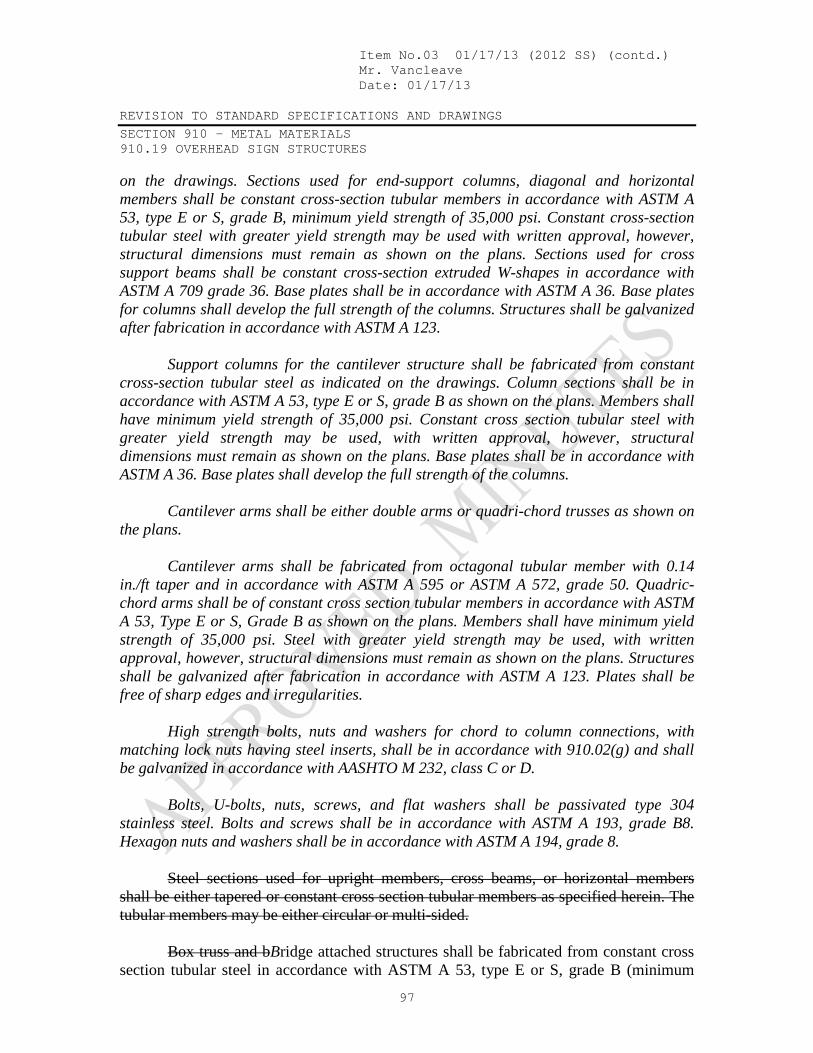
Item No.03 01/17/13 (2012 SS) (contd.) Mr. Vancleave Date: 01/17/13 REVISION TO STANDARD SPECIFICATIONS AND DRAWINGS SECTION 910 – METAL MATERIALS 910.19 OVERHEAD SIGN STRUCTURES
97
on the drawings. Sections used for end-support columns, diagonal and horizontal members shall be constant cross-section tubular members in accordance with ASTM A 53, type E or S, grade B, minimum yield strength of 35,000 psi. Constant cross-section tubular steel with greater yield strength may be used with written approval, however, structural dimensions must remain as shown on the plans. Sections used for cross support beams shall be constant cross-section extruded W-shapes in accordance with ASTM A 709 grade 36. Base plates shall be in accordance with ASTM A 36. Base plates for columns shall develop the full strength of the columns. Structures shall be galvanized after fabrication in accordance with ASTM A 123. Support columns for the cantilever structure shall be fabricated from constant cross-section tubular steel as indicated on the drawings. Column sections shall be in accordance with ASTM A 53, type E or S, grade B as shown on the plans. Members shall have minimum yield strength of 35,000 psi. Constant cross section tubular steel with greater yield strength may be used, with written approval, however, structural dimensions must remain as shown on the plans. Base plates shall be in accordance with ASTM A 36. Base plates shall develop the full strength of the columns. Cantilever arms shall be either double arms or quadri-chord trusses as shown on the plans. Cantilever arms shall be fabricated from octagonal tubular member with 0.14 in./ft taper and in accordance with ASTM A 595 or ASTM A 572, grade 50. Quadric-chord arms shall be of constant cross section tubular members in accordance with ASTM A 53, Type E or S, Grade B as shown on the plans. Members shall have minimum yield strength of 35,000 psi. Steel with greater yield strength may be used, with written approval, however, structural dimensions must remain as shown on the plans. Structures shall be galvanized after fabrication in accordance with ASTM A 123. Plates shall be free of sharp edges and irregularities. High strength bolts, nuts and washers for chord to column connections, with matching lock nuts having steel inserts, shall be in accordance with 910.02(g) and shall be galvanized in accordance with AASHTO M 232, class C or D. Bolts, U-bolts, nuts, screws, and flat washers shall be passivated type 304 stainless steel. Bolts and screws shall be in accordance with ASTM A 193, grade B8. Hexagon nuts and washers shall be in accordance with ASTM A 194, grade 8. Steel sections used for upright members, cross beams, or horizontal members shall be either tapered or constant cross section tubular members as specified herein. The tubular members may be either circular or multi-sided. Box truss and bBridge attached structures shall be fabricated from constant cross section tubular steel in accordance with ASTM A 53, type E or S, grade B (minimum

Item No.03 01/17/13 (2012 SS) (contd.) Mr. Vancleave Date: 01/17/13 REVISION TO STANDARD SPECIFICATIONS AND DRAWINGS SECTION 910 – METAL MATERIALS 910.19 OVERHEAD SIGN STRUCTURES
98
yield strength of 35,000 psi). Constant cross section tubular steel with greater yield strength may be used, with written approval. However, structural dimensions must remain as shown on the plans. Structures shall be galvanized after fabrication in accordance with ASTM A 123. Tri-chord truss, cantilever, and monotube structures shall be made of tapered tubular members in accordance with either ASTM A 595 or ASTM A 572, grade 50 (A 572M, grade 345), or of constant cross section tubular members in accordance with API High Test Line Pipe, grade X-52 ASTM A 53, type E or S, grade B minimum yield strength of 35,000 psi . Members shall have a minimum yield strength of 50,000 psi (345 MPa). Monotube structures shall be made of tapered tubular members in accordance with ASTM A 595 or ASTM A 572, grade 50. Structures shall be galvanized after fabrication in accordance with ASTM A 123. The J hook shall consist of one 3/8-in. steel bar in accordance with ASTM A 307. It shall be spot welded to the inside of the end-support member. The J hook shall be hot-dip galvanized prior to welding or in the final assembly with the support column. Anchor bolts, nuts, and washers shall be in accordance with ASTM F 1554, grade 36. A hexagon nut, leveling nut, and flat washer shall be furnished with each anchor bolt. Top ends of anchor bolts and associated hardware as shown on the plans, shall be coated in accordance with ASTM A 153 or be mechanically galvanized and conform to the coating thickness, adherence, and quality requirements of ASTM A 153, class C. Base plate skirts shall be 10 gage galvanized steel. Welding material and procedures shall be in accordance with 711.32 and applicable AWS provisions Welding shall be checked by visual inspection. Poor welding workmanship shall be rejected. Each complete structure shall be free from any misfits or structural deficiencies prior to shipment. Strain poles shall be anchor bolt type complete with hand-holes and pole top or cap. They shall meet the requirements set out above for cantilever sign structures. Each pole is to include 3 band type attachments for span wire clamps. The band shall be from material in accordance with ASTM A 572, grade 50 (A 572M, grade 345); ASTM A 606; or approved equal. The bands shall not be of the U-bolt type. The poles shall have maximum deflections as shown below when loaded 18 in. (450 mm) from the top with a 100 lb (445 N) load. Pole Size Deflection
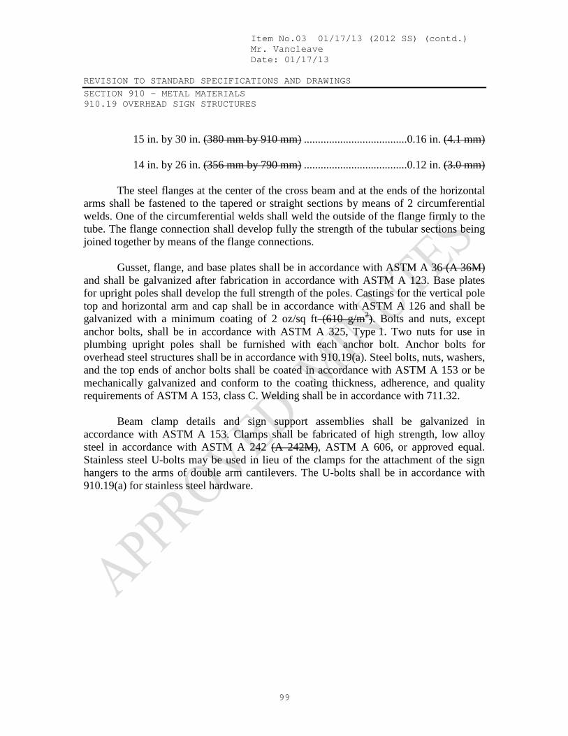
Item No.03 01/17/13 (2012 SS) (contd.) Mr. Vancleave Date: 01/17/13 REVISION TO STANDARD SPECIFICATIONS AND DRAWINGS SECTION 910 – METAL MATERIALS 910.19 OVERHEAD SIGN STRUCTURES
99
15 in. by 30 in. (380 mm by 910 mm) .....................................0.16 in. (4.1 mm) 14 in. by 26 in. (356 mm by 790 mm) .....................................0.12 in. (3.0 mm) The steel flanges at the center of the cross beam and at the ends of the horizontal arms shall be fastened to the tapered or straight sections by means of 2 circumferential welds. One of the circumferential welds shall weld the outside of the flange firmly to the tube. The flange connection shall develop fully the strength of the tubular sections being joined together by means of the flange connections. Gusset, flange, and base plates shall be in accordance with ASTM A 36 (A 36M) and shall be galvanized after fabrication in accordance with ASTM A 123. Base plates for upright poles shall develop the full strength of the poles. Castings for the vertical pole top and horizontal arm and cap shall be in accordance with ASTM A 126 and shall be galvanized with a minimum coating of 2 oz/sq ft (610 g/m2). Bolts and nuts, except anchor bolts, shall be in accordance with ASTM A 325, Type 1. Two nuts for use in plumbing upright poles shall be furnished with each anchor bolt. Anchor bolts for overhead steel structures shall be in accordance with 910.19(a). Steel bolts, nuts, washers, and the top ends of anchor bolts shall be coated in accordance with ASTM A 153 or be mechanically galvanized and conform to the coating thickness, adherence, and quality requirements of ASTM A 153, class C. Welding shall be in accordance with 711.32. Beam clamp details and sign support assemblies shall be galvanized in accordance with ASTM A 153. Clamps shall be fabricated of high strength, low alloy steel in accordance with ASTM A 242 (A 242M), ASTM A 606, or approved equal. Stainless steel U-bolts may be used in lieu of the clamps for the attachment of the sign hangers to the arms of double arm cantilevers. The U-bolts shall be in accordance with 910.19(a) for stainless steel hardware.

Item No.03 01/17/13 (2012 SS) (contd.) Mr. Vancleave Date: 01/17/13 REVISION TO STANDARD SPECIFICATIONS AND DRAWINGS SECTION 910 – METAL MATERIALS 910.19 OVERHEAD SIGN STRUCTURES
100
THIS PAGE LEFT INTENTIONALLY BLANK
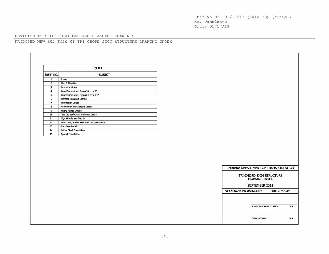
Item No.03 01/17/13 (2012 SS) (contd.) Mr. Vancleave Date: 01/17/13 REVISION TO SPECIFICATIONS AND STANDARD DRAWINGS PROPOSED NEW 802-TCSS-01 TRI-CHORD SIGN STRUCTURE DRAWING INDEX
101

Item No.03 01/17/13 (2012 SS) (contd.) Mr. Vancleave Date: 01/17/13 REVISION TO SPECIFICATIONS AND STANDARD DRAWINGS PROPOSED NEW 802-TCSS-02 TRI-CHORD SIGN STRUCTURE PLAN AND ELEVATION
102
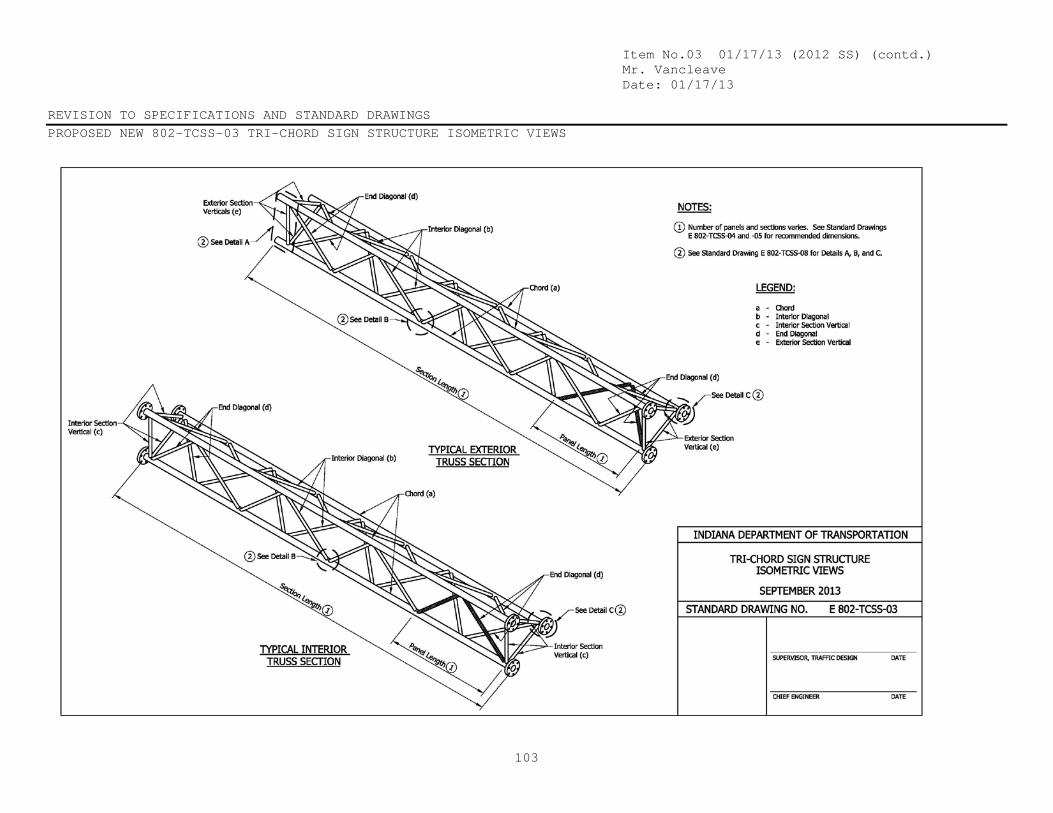
Item No.03 01/17/13 (2012 SS) (contd.) Mr. Vancleave Date: 01/17/13 REVISION TO SPECIFICATIONS AND STANDARD DRAWINGS PROPOSED NEW 802-TCSS-03 TRI-CHORD SIGN STRUCTURE ISOMETRIC VIEWS
103

Item No.03 01/17/13 (2012 SS) (contd.) Mr. Vancleave Date: 01/17/13 REVISION TO SPECIFICATIONS AND STANDARD DRAWINGS PROPOSED NEW 802-TCSS-04 TRI-CHORD SIGN STRUCTURE PANEL DIMENSIONS SPANS 36’ THRU 83’
104
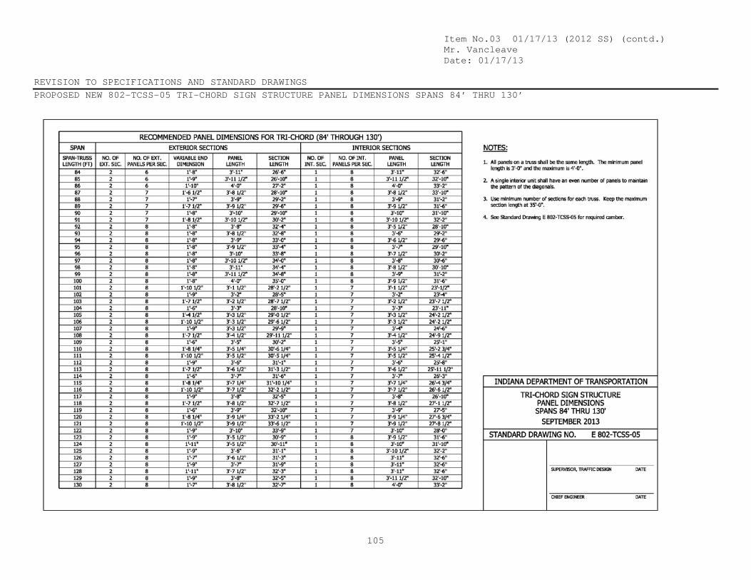
Item No.03 01/17/13 (2012 SS) (contd.) Mr. Vancleave Date: 01/17/13 REVISION TO SPECIFICATIONS AND STANDARD DRAWINGS PROPOSED NEW 802-TCSS-05 TRI-CHORD SIGN STRUCTURE PANEL DIMENSIONS SPANS 84’ THRU 130’
105
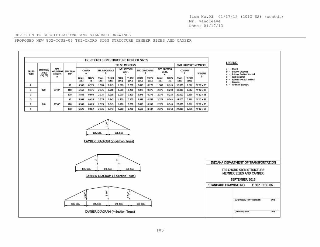
Item No.03 01/17/13 (2012 SS) (contd.) Mr. Vancleave Date: 01/17/13 REVISION TO SPECIFICATIONS AND STANDARD DRAWINGS PROPOSED NEW 802-TCSS-06 TRI-CHORD SIGN STRUCTURE MEMBER SIZES AND CAMBER
106

Item No.03 01/17/13 (2012 SS) (contd.) Mr. Vancleave Date: 01/17/13 REVISION TO SPECIFICATIONS AND STANDARD DRAWINGS PROPOSED NEW 802-TCSS-07 TRI-CHORD SIGN STRUCTURE CONNECTION DETAILS
107

Item No.03 01/17/13 (2012 SS) (contd.) Mr. Vancleave Date: 01/17/13 REVISION TO SPECIFICATIONS AND STANDARD DRAWINGS PROPOSED NEW 802-TCSS-08 TRI-CHORD SIGN STRUCTURE CONNECTION AND WELDING DETAILS
108
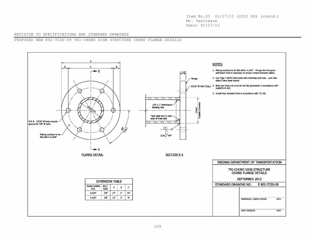
Item No.03 01/17/13 (2012 SS) (contd.) Mr. Vancleave Date: 01/17/13 REVISION TO SPECIFICATIONS AND STANDARD DRAWINGS PROPOSED NEW 802-TCSS-09 TRI-CHORD SIGN STRUCTURE CHORD FLANGE DETAILS
109

Item No.03 01/17/13 (2012 SS) (contd.) Mr. Vancleave Date: 01/17/13 REVISION TO SPECIFICATIONS AND STANDARD DRAWINGS PROPOSED NEW 802-TCSS-10 TRI-CHORD SIGN STRUCTURE TOP CAP AND CHORD END PLATE DETAILS
110

Item No.03 01/17/13 (2012 SS) (contd.) Mr. Vancleave Date: 01/17/13 REVISION TO SPECIFICATIONS AND STANDARD DRAWINGS PROPOSED NEW 802-TCSS-11 TRI-CHORD SIGN STRUCTURE SIGN ATTACHMENT DETAILS
111

Item No.03 01/17/13 (2012 SS) (contd.) Mr. Vancleave Date: 01/17/13 REVISION TO SPECIFICATIONS AND STANDARD DRAWINGS PROPOSED NEW 802-TCSS-12 TRI-CHORD SIGN STRUCTURE BASE PLATE, ANCHOR BOLT, AND I.D. TAG DETAILS
112

Item No.03 01/17/13 (2012 SS) (contd.) Mr. Vancleave Date: 01/17/13 REVISION TO SPECIFICATIONS AND STANDARD DRAWINGS PROPOSED NEW 802-TCSS-13 TRI-CHORD SIGN STRUCTURE HANDHOLE DETAILS
113

Item No.03 01/17/13 (2012 SS) (contd.) Mr. Vancleave Date: 01/17/13 REVISION TO SPECIFICATIONS AND STANDARD DRAWINGS PROPOSED NEW 802-TCSS-14 TRI-CHORD SIGN STRUCTURE DRILLED SHAFT FOUNDATION
114
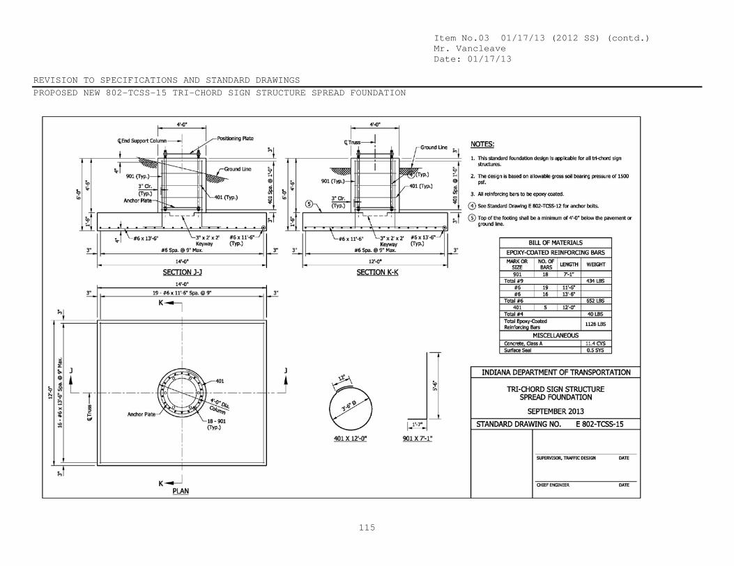
Item No.03 01/17/13 (2012 SS) (contd.) Mr. Vancleave Date: 01/17/13 REVISION TO SPECIFICATIONS AND STANDARD DRAWINGS PROPOSED NEW 802-TCSS-15 TRI-CHORD SIGN STRUCTURE SPREAD FOUNDATION
115

Item No.03 01/17/13 (2012 SS) (contd.) Mr. Vancleave Date: 01/17/13 COMMENTS AND ACTION 910.19 OVERHEAD SIGN STRUCTURES 802-TCSS-01 thru -15 TRI-CHORD SIGN STRUCTURE
116
DISCUSSION: This item was introduced by Mr. Vancleave who then cited the concerns related to the tri-chord sign structures. The intention is to create a standard which meets the AASHTO standards. Mr. Patel stated that this is already in the standard specs and they are merely trying to add standard drawings that reflect those standard specifications. Mr. Patel then explained the intentions and details behind each design shown. Mr. Patel explained that the existing 802 Recurring Special Provision will need to be revised to incorporate the new pay item. Mr. Patel also requested creating a new RPD for these tri-chord structures. Mr. Miller recommended bringing this back next month so the committee can look at the existing 802 RSP, as well as all other pertinent information.
Motion: Mr. Vancleave Second: Mr. Boruff Ayes: Nays:
Action: Passed as Submitted Passed as Revised X Withdrawn
Standard Specifications Sections affected:
910.19 pg 900 – 903.
Recurring Special Provision affected:
NONE Standard Sheets affected: PROPOSED NEW 802-TCSS-01 thru -15 Design Manual Sections affected:
SECTION 502. GIFE Sections cross-references:
NONE
2014 Standard Specifications Book
Revise Pay Items List Create RSP (No. ) Effective Letting RSP Sunset Date:
Revise RSP (No. ) Effective Letting RSP Sunset Date:
Standard Drawing Effective Create RPD (No. ) Effective Letting Technical Advisory
GIFE Update Req’d.? Y N By Addition or Revision
Frequency Manual Update Req’d? Y N By Addition or Revision Received FHWA Approval?
Related Documents