Optimization of a laser mitigation process in damaged fused silica S. Palmier a, *, L. Gallais a , M. Commandre ´ a , P. Cormont b , R. Courchinoux b , L. Lamaigne ` re b , J.L. Rullier b , P. Legros c a Institut Fresnel, CNRS, Ecole Centrale Marseille, Universite ´ Aix-Marseille, av. Escadrille Normandie 13397 Marseille Cedex 20, France b CEA, CESTA, BP 2, 33114 Le Barp, France c Plate-forme d’Imagerie Cellulaire, Institut Franc ¸ois Magendie, 146 Rue Le ´o-Saignat, 33077 Bordeaux, France 1. Introduction The French Atomic Energy Commission (CEA) has started to build the Europe’s biggest laser, known as Laser Me ´ ga Joule (LMJ) [1]. LMJ will consist of 30 bundles, each containing eight laser beams, and will deliver a total energy of 1.8 MJ with a pulse length of a few nanoseconds. The 240 beams will be focused onto micron- sized targets containing deuterium and tritium to initiate a thermonuclear fusion reaction. A prototype installation at scale 1 of the future LMJ, called the Ligne d’Inte ´ gration Laser (LIL), has been working for a few years [2]. It is intended to validate technological choices made for LMJ and to prepare its exploitation. The LIL consists of a complete laser bundle of 8 beamlines. Each laser beam of 40 cm 40 cm section is amplified at 1053 nm wavelength with pulses of duration a few nanoseconds. This wavelength is converted to 351 nm to be focused onto micron- sized targets. One of the major concerns encountered in the LIL exploitation is laser-induced damage of optical components [3], especially in the section where the beam wavelength is 351 nm. Although the polishing techniques of optical components have been considerably improved, defects that can initiate damage are still present in the material. Laser irradiations of these weak points lead to stress, cracks and absorption. The created damage growths under subsequent irradiations and makes the component unsui- table. The problem is that we still cannot predict why, when and where an optical component will be damaged. Because of the huge numbers, the large dimensions and the cost of optics present in the laser, it is impossible to plan to change them regularly. To avoid that, a process to improve the laser damage resistance was developed to be applied before the optics installation on line. This process, that we called stabilization, consists in finding the defects and mitigating their subsequent growth. To find defects, we irradiate the component with a table-top laser whose character- istics are comparable with LMJ beam parameters. After this step has been carried out, all sensitive zones have been damaged. The mitigation of damage growth is the most critical step. Several methods were tested on silica [4,5]: chemical treatment of the surface, the microwave or radio-frequency generated plasma etching, the laser or the micro-flame torch processing. One of the most promising methods consists in using a CO 2 laser operating at a 10.6 mm wavelength [6,7] to locally melt and evaporate the silica surface by producing typically smooth, Gaussian shaped pits [8– 10]. This process has been used to polish silica and to increase the laser damage resistance [11–13] by reducing defects on surface [14]. A technique capable of controlling the melting of silica was developed by Mendez et al. to repair damage caused in the surface Applied Surface Science 255 (2009) 5532–5536 ARTICLE INFO Article history: Available online 6 August 2008 PACS: 42.79.e 42.70.Ce 81.65.b Keywords: Laser mitigation process Silica Laser-induced damage ABSTRACT One of the major concerns encountered in high power laser is the laser-induced damage of optical components. This is a main issue of the development of the Europe’s biggest laser, known as Laser Me ´ga Joule (LMJ) especially in the section where the beam wavelength is 351 nm. This study deals with the development of a laser treatment process to improve the laser damage resistance of silica optical components. First, by irradiating the component at 355 nm in the nanosecond regime, defects of the silica optic are revealed and evolve as damage. Next, the damaged sites are irradiated with a CO 2 laser at a 10.6 mm wavelength in order to melt and evaporate the silica in the damage neighborhood. In this study, we performed a variation of the CO 2 laser parameters to obtain the most efficient stabilization. To check this stabilization, damage resistance tests were performed with an UV laser representative of the LMJ (at 355 nm/2.5 ns). The results show that we can stabilize weak points and thereby make the component resistant to subsequent UV laser irradiation. ß 2008 Elsevier B.V. All rights reserved. * Corresponding author. Tel.: +33 4 91 28 83 93; fax: +33 4 91 28 80 67. E-mail address: [email protected] (S. Palmier). Contents lists available at ScienceDirect Applied Surface Science journal homepage: www.elsevier.com/locate/apsusc 0169-4332/$ – see front matter ß 2008 Elsevier B.V. All rights reserved. doi:10.1016/j.apsusc.2008.07.178

Welcome message from author
This document is posted to help you gain knowledge. Please leave a comment to let me know what you think about it! Share it to your friends and learn new things together.
Transcript
Applied Surface Science 255 (2009) 5532–5536
Optimization of a laser mitigation process in damaged fused silica
S. Palmier a,*, L. Gallais a, M. Commandre a, P. Cormont b, R. Courchinoux b,L. Lamaignere b, J.L. Rullier b, P. Legros c
a Institut Fresnel, CNRS, Ecole Centrale Marseille, Universite Aix-Marseille, av. Escadrille Normandie 13397 Marseille Cedex 20, Franceb CEA, CESTA, BP 2, 33114 Le Barp, Francec Plate-forme d’Imagerie Cellulaire, Institut Francois Magendie, 146 Rue Leo-Saignat, 33077 Bordeaux, France
A R T I C L E I N F O
Article history:
Available online 6 August 2008
PACS:
42.79.�e
42.70.Ce
81.65.�b
Keywords:
Laser mitigation process
Silica
Laser-induced damage
A B S T R A C T
One of the major concerns encountered in high power laser is the laser-induced damage of optical
components. This is a main issue of the development of the Europe’s biggest laser, known as Laser Mega
Joule (LMJ) especially in the section where the beam wavelength is 351 nm. This study deals with the
development of a laser treatment process to improve the laser damage resistance of silica optical
components. First, by irradiating the component at 355 nm in the nanosecond regime, defects of the silica
optic are revealed and evolve as damage. Next, the damaged sites are irradiated with a CO2 laser at a
10.6 mm wavelength in order to melt and evaporate the silica in the damage neighborhood. In this study,
we performed a variation of the CO2 laser parameters to obtain the most efficient stabilization. To check
this stabilization, damage resistance tests were performed with an UV laser representative of the LMJ (at
355 nm/2.5 ns). The results show that we can stabilize weak points and thereby make the component
resistant to subsequent UV laser irradiation.
� 2008 Elsevier B.V. All rights reserved.
Contents lists available at ScienceDirect
Applied Surface Science
journa l homepage: www.e lsev ier .com/ locate /apsusc
1. Introduction
The French Atomic Energy Commission (CEA) has started tobuild the Europe’s biggest laser, known as Laser Mega Joule (LMJ)[1]. LMJ will consist of 30 bundles, each containing eight laserbeams, and will deliver a total energy of 1.8 MJ with a pulse lengthof a few nanoseconds. The 240 beams will be focused onto micron-sized targets containing deuterium and tritium to initiate athermonuclear fusion reaction. A prototype installation at scale 1of the future LMJ, called the Ligne d’Integration Laser (LIL), hasbeen working for a few years [2]. It is intended to validatetechnological choices made for LMJ and to prepare its exploitation.The LIL consists of a complete laser bundle of 8 beamlines. Eachlaser beam of 40 cm � 40 cm section is amplified at 1053 nmwavelength with pulses of duration a few nanoseconds. Thiswavelength is converted to 351 nm to be focused onto micron-sized targets. One of the major concerns encountered in the LILexploitation is laser-induced damage of optical components [3],especially in the section where the beam wavelength is 351 nm.Although the polishing techniques of optical components havebeen considerably improved, defects that can initiate damage are
* Corresponding author. Tel.: +33 4 91 28 83 93; fax: +33 4 91 28 80 67.
E-mail address: [email protected] (S. Palmier).
0169-4332/$ – see front matter � 2008 Elsevier B.V. All rights reserved.
doi:10.1016/j.apsusc.2008.07.178
still present in the material. Laser irradiations of these weak pointslead to stress, cracks and absorption. The created damage growthsunder subsequent irradiations and makes the component unsui-table. The problem is that we still cannot predict why, when andwhere an optical component will be damaged. Because of the hugenumbers, the large dimensions and the cost of optics present in thelaser, it is impossible to plan to change them regularly. To avoidthat, a process to improve the laser damage resistance wasdeveloped to be applied before the optics installation on line. Thisprocess, that we called stabilization, consists in finding the defectsand mitigating their subsequent growth. To find defects, weirradiate the component with a table-top laser whose character-istics are comparable with LMJ beam parameters. After this stephas been carried out, all sensitive zones have been damaged. Themitigation of damage growth is the most critical step. Severalmethods were tested on silica [4,5]: chemical treatment of thesurface, the microwave or radio-frequency generated plasmaetching, the laser or the micro-flame torch processing. One of themost promising methods consists in using a CO2 laser operating ata 10.6 mm wavelength [6,7] to locally melt and evaporate the silicasurface by producing typically smooth, Gaussian shaped pits [8–10]. This process has been used to polish silica and to increase thelaser damage resistance [11–13] by reducing defects on surface[14]. A technique capable of controlling the melting of silica wasdeveloped by Mendez et al. to repair damage caused in the surface

S. Palmier et al. / Applied Surface Science 255 (2009) 5532–5536 5533
of mirrors without any mass loss [15]. For our applications, aprocess capable to treat deep damage is needed and this stabilizedsite has to withstand the 351 nm, 3 ns beam power in operatingconditions.
In Section 2, the method and the experimental set-updeveloped for this aim are presented. In Section 3, a variation ofthe CO2 laser irradiation parameters is performed in order to obtainthe most efficient process capable to mitigate deep silica damages.In Section 4, these last results are compared to calculations anddiscussed. In Section 5, we analyze the laser damage resistance ofstabilized area and discuss the efficiency of the process.
2. Experimental tools
An experimental set-up has been developed to stabilize fusedsilica (Fig. 1). It allows the visualization of damage sites on samplesand their localized irradiation by a CO2 laser. The energy depositionof the laser can be easily varied (beam focus size, mean power,maximum power, and pulse length). The laser (Synrad FirestarV20) operates at a 10.6 mm wavelength with a 20 W maximumpower. Power control is achieved by pulsed width modulation at a5 kHz frequency: a duty cycle of 10% corresponds to a power of 2 Wand 100% to 20 W. The beam power is adjusted by two polarizers. Alaser diode, which emits at 650 nm, is used to align the optics andto center the zone of the substrate to treat. A phase mirror changesthe linear polarization of the CO2 laser into a circular polarizationfor optical isolation and to get symmetric craters. The beam isfocused with a ZnSe lens with a 10 in. focal length. The latter ismounted on a z translation stage to adjust the beam diameter onthe sample from 200 mm to 800 mm measured at 1/e2. The sampleis mounted on an x, y translation stage to select the zone tostabilize. The latter is observed by a microscope with a 50� to a500� magnification objectives in bright and dark field mode. Thedark field is particularly useful to observe debris deposit on thesurface during the process. Different diagnostics in the laser pathmeasure its power, and its temporal or spatial profile. Theoperation is assisted by computer.
Under irradiation a circular crater is created on the silicasurface, whose size depends on the laser parameters. Thedimensional characteristics of each crater are measured with asurface profiler (Talysurf CCI 300 nm) and a Nomarski microscope(Carl Zeiss Axiotech microscope).
Laser damage resistance tests are performed with a table-toplaser, whose main characteristics are comparable with the LMJ/LILlaser beams. The laser used is a Nd:YAG which delivers a pulse
Fig. 1. Experimental set up.
length of 2.5 ns at 355 nm with a 10 Hz repetition rate. The laserbeam is focused by a 5 m focal length lens to get a Gaussian spatialprofile with a diameter of 0.9 mm at 1/e2. Damages are detected in
situ with a mobile macroscope.
3. Parametric study
As it has been observed in several studies, after an irradiation ata 351 nm wavelength with a few nanosecond pulse length and thenominal fluence of LMJ, typical damages are 15 mm deep andcracks can propagate up to a 20 mm depth [16–18]. Therefore, thebest stabilization conditions correspond to the formation of a20 mm deep crater in order to remove any offending material andmake the surface area smooth and crackfree. To obtain it, theinfluence on the crater morphology of different CO2 laserparameters such as the diameter, the laser pulse length and thepower have to be studied.
This study has been carried out on a bare Heraeus S312 super-polished fused silica substrate of 50-mm diameter and 5-mmthickness. In a first experiment, the pulse length influence isanalyzed. The beam diameter and the power were respectively setat 200 mm and 1.25 W. On each crater, the depth and the diameterare measured and found reproducible among the 15 cratersobtained with the same parameters. From these experimentalresults, the depth and the diameter are plotted as functions of thepulse length in Fig. 2. For pulse lengths<0.25 s, the crater diameterremains stable at 70 mm and the depth increases linearly with thetime. For pulse lengths>0.25 s, the diameter increases slowly withthe time and the depth approaches a constant value. To explorethese two behaviors, we chose to work with the pulse lengths of0.25 s and 1 s.
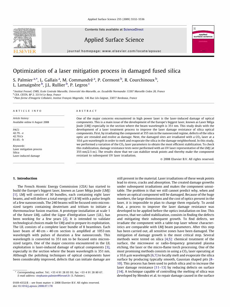
In a second experiment, to get a 20-mm deep crater with thesepulse lengths, the power and the diameter vary and their influencewas analyzed. During this step, most of craters created with a highpower and a small diameter are characterized by the presence ofdebris all around. This may evolve into new surface defects capableof initiating more damages. To avoid that, the power and thediameter are changed simultaneously. In Fig. 3, the crater depthand the diameter are represented as functions of the power; thecorresponding CO2 laser beam diameter is indicated in Fig. 3a.The crater diameter increases linearly with the power followingthe CO2 laser beam diameter increase and independently of thepulse length (Fig. 3a). For power >2 W (and a beam diameter of300 mm, 450 mm or 550 mm), the crater depth obtained with a 1 spulse length is much higher than 20 mm (Fig. 3b) while the cratersobtained with a 0.25 s pulse length are slightly higher than 20 mm.From this parametric study, we show that to get a crater whosedepth exceeds 20 mm, different sets of irradiating conditions maybe used.
Fig. 2. Measured diameter and depth as a function of the pulse length (200 mm at 1/
e2, 1.25 W).
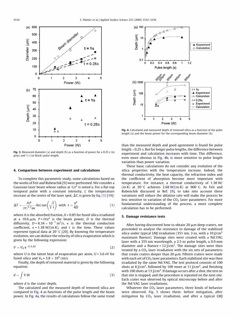
Fig. 4. Calculated and measured depth of removed silica as a function of the pulse
length (a) and the beam power for the corresponding beam diameter (b).
Fig. 3. Measured diameter (a) and depth (b) as a function of power for a 0.25 s (in
grey) and 1 s (in black) pulse length.
S. Palmier et al. / Applied Surface Science 255 (2009) 5532–55365534
4. Comparison between experiment and calculations
To complete this parametric study, some calculations based onthe works of Feit and Rubenchik [9] were performed. We consider aGaussian laser beam whose radius at 1/e2 is noted a. For a flat toptemporal pulse with a constant intensity, I, the temperatureincrease at the centre of the laser spot, DT, is given by Eq. (1) [19]:
DT ¼ A P
ðpÞ3=2akArc tan
ffiffiffit
t
r !with t ¼ a2
4D(1)
where A is the absorbed fraction, A = 0.85 for fused silica irradiatedat a 10.6 mm, P = Ipa2 is the beam power, D is the thermaldiffusivity, D = 8.34 � 10�7 m2/s, k is the thermal conductioncoefficient, k = 1.38 W/(m K), and t is the time. These valuesrepresent typical data at 20 8C [20]. By knowing the temperatureevolution, we can deduce the velocity of silica evaporation which isgiven by the following expression:
V ¼ V0 e�U=k DT (2)
where U is the latent heat of evaporation per atom, U = 3.6 eV forfused silica and V0 = 3.8 � 105 cm/s.
Finally, the depth of removed material is given by the followingequation:
d ¼Z
V dt (3)
where d is the crater depth.The calculated and the measured depth of removed silica are
compared in Fig. 4 as functions of the pulse length and the beampower. In Fig. 4a, the results of calculations follow the same trend
than the measured depth and good agreement is found for pulselength<0.25 s. But for longer pulse lengths, the difference betweenexperiment and calculation increases with time. This difference,even more obvious in Fig. 4b, is more sensitive to pulse lengthvariation than power variation.
These basic calculations do not consider any evolution of thesilica properties with the temperature increase. Indeed, thethermal conductivity, the heat capacity, the refraction index andthe coefficient of absorption become more important withtemperature. For instance, a thermal conductivity of 1.38 W/(m K) at 20 8C achieves 2.68 W/(m K) at 900 8C. As Feit andRubenchik discussed in Ref. [9], to take into account thesevariations will reduce the ablation rate will make the process beless sensitive to variation of the CO2 laser parameters. For morefundamental understanding of the process, a more completecalculation has to be performed.
5. Damage resistance tests
After having discovered how to obtain 20 mm deep craters, weproceeded to analyze the resistance to damage of the stabilizedsilica under typical LMJ irradiation (351 nm, 3 ns, with a 10 J/cm2
maximum fluence). Damage sites were created with a Nd:YAGlaser with a 355 nm wavelength, a 2.5 ns pulse length, a 0.9 mmdiameter and a fluence = 12 J/cm2. The damage sites were thentreated by a CO2 laser irradiation with the six sets of parametersthat create craters deeper than 20 mm. Fifteen craters were madewith each set of CO2 laser parameters. Each stabilized site was thenirradiated by the same Nd:YAG. The test protocol consists of 100shots at 8 J/cm2, followed by 100 more at 11 J/cm2, and finishingwith 100 shots at 13 J/cm2. If damage occurs after a shot, the test onthat site is stopped, and the procedure is repeated on the next site.Each crater was observed by optical microscopy before and afterthe Nd:YAG laser irradiations.
Whatever the CO2 laser parameters, three kinds of behaviorwere observed. Fig. 5 shows them: before mitigation, aftermitigation by CO2 laser irradiation, and after a typical LMJ

Fig. 5. Damages observed before mitigation, after mitigation and after an irradiation at a 355 nm wavelength and a 2.5 ns pulse length.
Fig. 6. Percentage of successful stabilization after 100 irradiations at 8 J/cm2, at 11 J/
cm2 and 13 J/cm2 with a wavelength of 355 nm and a pulse length of 2.5 ns.
S. Palmier et al. / Applied Surface Science 255 (2009) 5532–5536 5535
irradiation. In Fig. 5a, the stabilization crater was not deepenough to remove all the damaged silica and after oneirradiation at 8 J/cm2, three big fractures propagate from theprevious damage. Some fractures generated by the damage werenot mended in the silica melting and so the non-stabilized partof the damage continues to grow under irradiation. In Fig. 5b,the damage seems to have been removed, but after an 8 J/cm2
irradiation, a large damage appears. In Fig. 5c, the crater doesnot evolve even after 100 irradiations at 13 J/cm2. We considerthis case a success.
A statistical study of the crater damage resistance wasperformed. The successful stabilizations after 8 J/cm2, then at11 J/cm2 or 13 J/cm2 irradiations were counted. The percentages ofcraters without damage are determined and represented in Fig. 6as a function of the CO2 laser parameters. The measured craterdepth is also indicated. All the craters obtained with a CO2 laserirradiation whose pulse length is 1 s are damaged after 8 J/cm2
irradiations. These craters are also the deepest ones so the damageresistance may be linked with the depth or the pulse length. All thecraters obtained with a 0.25 s CO2 laser pulse have the same depth.Very good results are obtained for two kinds of craters with morethan 80% of resistant sites to 100 irradiations at 11 J/cm2. But thecrater created with the parameters, 2.5 W, 0.25 s, 300 mm seemstoo small in comparison with its depth to withstand typical LMJirradiations.
To explain why certain crater withstand typical LMJ irradiationsand others not, residual stress in the heated silica could beconsidered [21,22]. We assume that during the CO2 laserirradiation, silica surface is heated, melted, and bent. At the endof the CO2 laser pulse, the silica cools down and becomes taut thus
S. Palmier et al. / Applied Surface Science 255 (2009) 5532–55365536
creating stress in the material. The different parameters ofirradiation induce amounts of residual stress, which is animportant factor in the resistance of the site.
6. Conclusion
To stabilize optical components, a set-up has been developed andwas successfully used. At present, typical damage initiated in silicacomponents with comparable LMJ operating conditions are 20 mmdeep. Thanks to our parametric study, several sets of CO2 laserparameters were found to produce a crater deep enough to removethe damaged silica. But the necessity of laser damage resistancelimits this parameter range. Suitable parameters were found to get aprocess to treat deep damage and to make silica withstand typicalLMJ irradiations. Thus this efficient process can be used on realoptical components before coating. However, further studies areneeded to understand the behavior of the stabilized area.
References
[1] A. Bettinger, M. Decroisette, Fusion Eng. 46 (1999) 457.[2] P. Eyharts, J.M. Di-Nicola, C. Feral, E. Germain, H. Graillot, F. Jequier, E. Journot, X.
Julien, M. Luttmann, O. Lutz, G. Thiell, J. Phys. IV 133 (2006) 727.
[3] H. Bercegol, P. Bouchut, L. Lamaignere, B. Le Garrec, G. Raze, Proc. SPIE 5273 (2004)312.
[4] L.W. Hrubesh, M.A. Norton, W.A. Molander, E.E. Donohue, S.M. Maricle, B.M.penetrante, R.M. Brusasco, W. Grundler, J.A. Butler, J.W. Carr, R.M. Hill, L.J.Summers, M.D. Feit, A. Rubenchik, M.H. Key, P.J. Wegner, A.K. Burnham, L.A.Hacel, M.R. Kozlowki, Proc. SPIE 4679 (2002) 23.
[5] P. Bouchut, P. Garrec, C. Pelle, Proc. SPIE 4932 (2003) 103.[6] A.M. Rubenchik, M.D. Feit, Proc. SPIE 4679 (2002) 79.[7] P. Bouchut, L. Delrive, D. Decruppe, P. Garrec, Proc. SPIE 5273 (2004) 250.[8] C. Buerhop, B. Blumenthal, R. Weissmann, N. Lutz, S. Biermann, Appl. Surf. Sci. 46
(1990) 430.[9] M.D. Feit, A.M. Rubenchik, Proc. SPIE 4932 (2003) 91.
[10] J. Zhao, J. Sullivan, T.D. Bennett, Appl. Surf. Sci. 225 (2004) 250.[11] P.A. Temple, W.H. Lowdermilk, D. Milam, Appl. Opt. 21 (1982) 3249.[12] R. Brusasco, B. Penetrante, J. Butler, L. Hrubesh, Proc. SPIE 4679 (2002) 40.[13] K.N. Novak, H.J. Baker, D.R. Hall, Appl. Opt. 45 (2006) 162.[14] M.A. Stevens-Kalceff, J. Wong, J. Appl. Phys. 97 (2005) 113519.[15] E. Mendez, K.H. Nowak, H.J. Baker, D.R. Hall, Appl. Opt. 45 (2006) 5358.[16] M.A. Norton, J.J. Adams, C.W. Carr, E.E. Donohue, M.D. Feit, R.P. Hackel, W.G.
Hollingsworth, J.A. Jarboe, M.J. Matthews, A.M. Rubenchik, M.L. Spaeth, Proc. SPIE6720 (2007) 67200H.
[17] C.W. Carr, M.J. Matthews, J.D. Bude, M.L. Spaeth, Proc. SPIE 6403 (2007) 64030K.[18] J. Wong, J.L. Ferriera, E.F. Lindsey, D.L. Haupt, I.D. Hutcheon, J.H. Kinney, J. Non-
Crystal. Solids 352 (2006) 255.[19] M. Bass, Laser-materials interactions, in: R. Meyers (Ed.), Encyclopedia of Lasers
and Optical Technology, Academic Press, 1991.[20] Heraeus, Commercial leaflet.[21] P.A. Temple, W.H. Lowdermilk, D. Milam, Appl. Opt. 42 (1982) 3249.[22] H. Gong, C. Li, Appl. Opt. 46 (1997) 4954.
Related Documents