APPLIED PHYSICS EXPERIMENTS FOR REI.A.TED WOODWORKING TRADES

Welcome message from author
This document is posted to help you gain knowledge. Please leave a comment to let me know what you think about it! Share it to your friends and learn new things together.
Transcript

APPLIED
PHYSICS EXPERIMENTS FOR
REI.A.TED WOODWORKING TRADES

) (
APPLIED
( PHYSICS )!XPERIMENTS FOR OKLAlffl11 ~ AGRICULTUIUL & 1i!Eeh!1NltAL
RELATED WOODWORKING TRADES LIBRA Ry
NOV 8 1938
By
CHERYL H. PREWETT 11
Bachelor of Science
Oklahoma Agricultural and Mechanical College
Stillwater, Oklahoma
1933
1
Submitted to the Department ot Trade and Industrial Education
Oklahoma Agricultural and Mechanical College
In Partial Fulfillment of the Requirements
For the degree of
MASTER OF:sci!NCE0
: .:: · , . ,. . ' . . . . . ' ; "1. 19· ,;ta ... ·"'· · • .. · • • • .. ~ '- ~ . .. ... . ,:, , "I, • ,,I, , •• ., ••• V •• ., ., ... . .
, . •• • :v • • : •• : :... :· •• : : : ; •• ~~, . . . ... . ... . ... "' • • • • c; .; • • ., • • • •

ii
APPROVED: LIBit.ARY
... ga ~ .. In Charge of Thesis
Dean of the Division of Engineering
Dean of the Graduate School
iii
FORE"ilORD
The State Department of Education and Oklahoma Agricul
tural and Mechanical College authorities are interested in
promoting the efficiency of Vocational Educa:tion in the sec
ondary schools o.f the state. One method of improving this
program is through the compilation of currently valuable
instructional material.
The writer of this thesis has accepted an assignment
and has paved the way in preparing typical experiments and
has set the stage for further studies in the development of
applied. expel:"iments in physics valuable to workers and pro
speoti ve \Vorkers in related woodworking trades.
It is hoped that others will take advantage of this
opportunity to be o~ greater service to the program and will
carry on further studies related to other vocations.
H. A. Huntington Read of the Department o~ Trade and Industrial Education
ACKNOWLEDGMElfr
The writer wishes to acknowledge help given him from
the responses and information received in the survey, and
from the various books and bulletins studied in securing
information.
iv
An expression of appreciation is made to Mr. w. Fred
Heisler, Read of the School of Technical Training, for care•
:fully reading this manuscript and offering valuable scien
~ific suggestions.
Special acknowledgment is due .Professor H. A. Huntington,
Head of the Department of Trade and Industrial Education, for
his inspiring efforts and able assistance in the selection
and development of this study.
The writer is grateful to his wif".e, Golda Prewett, for
her inspiration and for her efficient, sympathetic assist
ance in the making of this study.
C.H. P.

----------- ----·~~
PREFACE
With practical courses of instruction being demanded
not only by vocational educators but also by academicians,
as shown by recent lists of boolc publishing companies, it
is apparent that the time has come for an intensive study
of the various subjects to determine their relation to
actual life applications.
V
The further expansion of' vocational education through
the recent George-Deen .Act has brought coordinators and
teachers of' related .subjects to the various colleges demand
ing that more related material be prepared to help them to
care .for the needs of the students in each type of vocation
al training taught in the public schools.
In the field o.f science there are at _present few avail
able textbooks and manuals which make the application or the
principles taught to actual life situations, or which re.late
abstract principles directly in the manner they will be used.
It is the plan of the writer to make a compilation of so:me
tew of the principles through experiri1ents and applications
~it,hich may be used to achieve the above purpose.
Such a study is a long task and one which is really in
exha.ustive. This study is intended for the related vmod
working trades, and the physics experiments compiled are
based upon the elementary principles ot science as recommend
ed by the State Vocational Department.. t'1ork is rapidly being
carried on in the preparation of such experiments in science,
manuals of experiments, and texts as here mentioned. ~he

----~- - ---·--~
vi
writer hopes this small contribution may aid in the.develop
ment of this study in science related to the woodwork and
related trades.
vii
CHAPTER I
Purpose and Extent of the Study ......................... Pages 1-5
Applied Experiments ................................. Page.s 6-94
1. Properties of Matter lA. Properties of Matter
2. Properties of 111aterials 3. Measurement 4. Specific Gravity 5. Forces 6. Parallel Forces 7. Parallelogram of Forces 8. Lever 9. Pulleys
10.. J.Jeehanical Devices 11. Wedge 12. J'a.ck Screw 13. Friction 14. Angular Forces 15. Counteracting Forees 16. Center of Gravity 1'1. Mechanics of Liquids 18 .• Expansion of Wood 19. Wood Shrinkage 2.0. Transmission of Heat 21. Seasoning Lumber 22~ Electricity .23. Strength of Materials 24. Beam Deflection 25. Sound 26. Color
CPlP-..PTER III
Conolus·ion ...................................... $ ••••• Pages 95-95·
BIBLIOGRAPHY .......................................... Pages 97-98
APPEN'DIX •••••••••••••.•••••.•. •- •.•••.• ,, ..••••.••. a- ••••..• .. Pages 99-10.5

The students in Trade and Industrial Educa:tion on the
ea:mpus du.ring the summer of 193'7 were very much interested.
in having more related science material developed. For
several years a deficiency in the knov1led.ge of the common
principles of science by students who have gone th1"'ough the
regular abstract courses in the science now give11, has been
:noted. These students, even those who have had all the
science offered in the lligh school, have trouble applying
1
the principles on the job~ Science to the:ni has been an ir<1-
p:ractica.l, uninteresting, toy tinkering proposition, and the
value or interest of these principles to the student has
ended v1hen he leaves the laboratory. The magnitude of ·this
situation, as it faces industrialized I,rnerica today, is seri
ous. Many employers are forced to send their prospective
employees to eompany schools, and they are holding evening
classes in applied science, to teach men science rela'ted to
their trade or work. In many occupations, it is necessary
for middle aged men and women to take these courses, if ad-
vancement is expected in their chosen line.
The problem is left for vocational education as general
education is not fitting the needs of its students in this
respect. Prosser and Allen state:
!:~or do they recognize, apparently, the misuse of public funds or.;. instruction he ·will 11ot use ancl does not expect

to u-se .. 1
Tlle organization of ·trade classes previously mentioned pro-
vides the necessary trans:i'tio11 tor the acquisition of the
principles of science, and men and women who have had these
praotice.l courses are advancing beeause of' the better under-
st.anding of their trade.
The definite need of this study is shrntm by analyzing
the reason why the majority of high school graduates have
failed to acquire the basic principles of science. fJcienca,
as taught in the regular high schools where 'the :masses are
educated, usually is stale and uninteresting. Fev,r practi-
cal experin1ents and applications o:t' the princi11les of
science, as used in earning a living, are studied. Science
as it is taught is a matter ot :memorizing long abstract
rules and performing theoretical ex:periments which many
students seldom under8tand, and in 1.srhich few can make the:m-
selves become interested. If the teacher can realize the
actualities of life that exist for the great masses; and can
assist the student to learn in a practimi1 way the basic
principles of science vri th which he is directly conceri:ued, he
iNill have helped t,he student to acquire funda1:1ental knowledge.
It is the _purpose of this study to help in the prepara-
tion of' material by ascertaining tho :need for supplemental
experiments in science; first, by ohtai11ing experiments from.
the file:J of 'the teachers of rela.te::i science in the st;ate;
14 Charles li.. Prosser and 01:mrles n. Alle:n. Vocational Education in !a. Democracy, p. 198. ' ,,, ~-- - · -

and second, by securing and compiling additional available
inf'or.m.ation.
Survey bla..11ks2 vmre mailed to seventeen teachers of re
lo:ted science in Oklaho1~m wit.h ·the specific purpose ot find
ing their needs, and also to obtain material about related
science and reference book lists that they used in teaching.
Seven returned the bla.nl{s while five filled in the survey
blanks and returned experiments and references.
Survey blanks3 in single page :tor.m, v1ere mailed to
twenty three teachers of related science in Oklahoma accom
panied by a letter of inS'truc'tions asking each to express his
need and include in a return addressed envelope a practical
experiment that he had. fout1d valuable in teaching related
science. Two returned blanlcs and sent seven experiments in
physics.
Then a. need was felt for information concerning what
other states had. done along this line. Twenty one inquir
ies4 were mailed to the training agencies in a selected
group of' trade centeri;i over the Un.i.ted States asking for
experb.1eti:ts, manuals, other materials concerning related
science, or references to persons who could supply such
Tila.terials .. Return letters were received from each giving
twenty nlne references of per,so11s who might be able to send
2. See appendix, For.m Ii pp. 99-101.
3. Il:dd. , J.i'orm II, p:p. 102-103.
4.. Ibid., Forro. III, p. 104.

specified rnaterialo.. Ver'/ little 1Jt1·terial pertaining to re
lated seienee was received from these ,a:olu.·oes.
1rhe twenty nine reftn•enoea 1;ver-e sent letters5 sh1ilar
to those mentioned above.. 1\pproxtn1ately three touxtns re
pli.ed but sent pract.i~ally no related instruetiortal materi ....
al.. 1flle fa.ilul'El to receive applied experiments raises the
question ".'lb.ether they are being usedt anti shows a further
need for this type of study. The replies sl1.owed that this
kind of material was ,muted defi.nitely, an.d that 1n most
1nstances it :t.s being prepared.
Due to the laok or practical t1aterial rece1 ved. in tl1e
£our surveys t ·the ,n-iter made a careful sur--,;ey of a\1'ail ...
able literature, and the experiments that follo.w are based
upon this related w.at,erial, as it. seemed this vrould provide
more ade,ptable, instructional applications or EJeienee.. Tbay
have been prepared. to sup:plelllent Mr. Fred Heisler's study of
3 1\!lementary Seienc.e for t,.h€l Student ot Iudu.steytt, wb.ieh 1s
commonly used a.s an introduction to applied science in Trade
and Industrial Training :Programs in Oklahon1a.
The _principles of science of the above ntn:aed tezt can
be t.r1.ught as a unit, or by any o·U1er practical me·thod. .rte ....
cording ·to the accepted method of :t.eacbing scie:t:we, the stu
dent r.iru.,s;t de14,o;nst1tate these principl~s to his satisfaction
by experimentation. To the studer1t. interested in \:voodwork
ing, these experim()nts vdll sbov; the :rela-tion ot the prin-
5. Ibid., • Form IV, p " 105.

5
eiples of scienc,s definitely to the 1Noodworki:ng trades, while
to the trade printing stude:nt, the principles should be re
lated directly to printing, and so forth.
The experiments prepared in this study are to be used
students interested in reli1ted v,roodworking trades. They
have been prcparecl a.nd compiled according to the sequence
i'ollowed in the previously s,tated reference. They may be
used in loose leaf order if desirerl. The writer realizes
that these supplemental experiments in physics prepared and
compiled for the rGlated vmodworking trades are incomplete;
however, it is believed that thls stud.y is a step in the
direction that vlill help lead to bErt~ter traird11g for trades-
men.

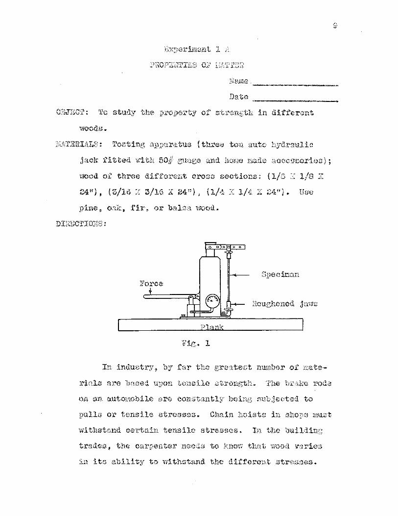
Thate --~--------------0 BJ" EC T: To study tl1e property of strength in different
wood.a.
2~1Y}. Uso plno r onk. fir, or balsa wood.
nniECTIO]IS:
4 f't.. .steel bar ( t X 1 'it}
Spee.ir11u1 to be tested
lank
In induatrt.r, by fear t.he greatest use of raatorinls
is based upon tensile S'trengt,h.. Th~ br.ake rods on an
automobile artl constantly being subjected to _pulls or
tensile stresses.. Ch&1n hoists in shops must wi tlurtand

7
certain tensile stresses. In the building trades, the
carpenter needs to know that wood varies in its ability
to ithstand the different stresses. Determining ten
sile stress also gives some idea of the ability of wood
to wtthstand bending (flexure) and compression stress-
es .
In the experiment several woods will be tested in
order that you may observe the comparative amounts or tension that they are able to withstand before break
ing. The pieces or .wood are fixed securely at both
ends of the apparatus and are subjected to a tensile
stress by pulling the lever. See Fig. 1. Test the
three pieces of pine first, then oak, etc . In des
cribing the tensile strength, use such terms as "the
least", "the most", "less", "more"• etc . , to denote
changes in the amount of pull .
RESULTS:
Force needed Ability to resist Material Cross- section to break tension

~able continued:
Jforee needed .P,Jillity to resist ~([ate rial Cross-section to break tension -
-- ---
Dooley: Science Training for Metal and Wood Trades, P.P• 227-242.
Deming and Herden: Sc.ience in the World of Work~ Vol .. I, pp .. 145-168 ...
COMCLUSION:
1. Would a variation in the a:mounts of pull required,
:mean a difference in the tensile strength of the
material?
8
2.. iJ,lhat effeet doe$ the size of a cross-section o:f.' the
aan1e kind of w-ood have on the pull needed to break
it'? Of different kinds of wood?
3. What effect on ten.sile strength is produced by vary
ing the length of the material?
4. What holds the molecules of wood together?
5. The u. s. Departmen.t of Commerce has set up certain
minimum live load$ for uze in buildings. What is
meant by this?
6. In what position does wood show its greatest unit
of strength?
7. The studs that support the roof or a building are
under what stress?
llama -------------------
Date -------------------
03JECT: To study ·the pro1)e1"ty of strength in different
woods.
TuDi}l:ERIALS: Testing n1n:iara.tus {three ton auto hydraulic
j~tck fitted wH;h 50//: guage and b.mna made accessories} ;
wood of three different cross sections: ( 1/8 ::1 1/a X.
24u), (3/16 :J: 3/16 X 24.U), (l/4 X 1/4 :C 24"}. Use
pine, oak, :fir, or balsa wood.
Speciman Foree
:aouehened jaws
Itig. l
ln induat!";'.r, by tar the grea:te,fft number of :ciate-
rials are based u.:pon -tenoile strer:1.g;tri.. 1fhe b1""a.ke :roda
on an. automobile are constantly being oubjected to
pulls or tensile stresses,. Che.in hoists in shop:a mist
withstand certn.in terI.Sile stresses. In the building
trades, the carpenter needs to !{now tlu.rt woo<i varie:.s
in its ability to withstand the different stresses ..

10
Determining tensile stress also gives a good idea of
the ability of wood to withstand bending {flexure) and
compression strains.
In the experiment several 'Noorls will be tested in
order that you may observe the comparative amounts of
tension that they are able to withstand before break-
ing. The pieces of wood are fixed securely at both ends
of the apparatus and are subjected to tensile stress by
pumping the lever. See Fig. 1. :fest the three pieces
of pine first, then oak, etc. Record reading of press-
ure guage. Obtain. diameters of tbe pistons of the hy-
draulic jack: from. instructor and calculate force exert
ed on wood by using formula:
A: FXA, a f' X a
where A equals area of large piston; a equals area or small piston; F equals force on large piston times A;
and f equals force on small piston or guage reading
times a.
Calculate the tensile strength of oach in pounds
per square inch.
RESULTS:
-~ Cross ]""orce needed 'fe:nsile .. ..,,.
strengtl1 N!aterial section to work n -oer sq_& in. ;'i

Table continued:
Cross Force needed Tensile strength M:aterial section to work # ner sq. in.
REFERENCES:
Dooley: Science Training for Metal and Wood Trades, pp. 22.,-242.
Deming and Nerden: Science in the World of Work , Vol. I, pp . 145-168.
CONCLUSION:
1. Would a variation in the amounts of pull required
mean a difference in the tensile strength of the
material? Why?
11
2. What effect does the size of a cross section of the
same kind of wood have on the pull needed to break
it? Of different kinds of wood?
3. What effect is produced in varying the length on
tensile strength? On compression? On bending?
4. What holds the molecules of wood together?
5. The U.S. Department of Coimnerce has set up cer
tain minimum live loads for use in building con-

12
structio11. What does the department mean by that?
6 .. In what position does wood show its greatest unit
of str~ngth'?
"I.. The studs that su.pport the roof of a building are
under what stress?,

Experiment 2
PROPERTIES OF ~TERIALS
}lame
Date
OBJECT: To study the weight per unit volume of different
kinds of wood .
MATERLU.S: Four, one inch cubes of white pine, basswood,
ebony, oak, walnut, cottonwood; spring balance; eyes.
DIRECTIONS;
13
The value or a material depends upon the pres
ence of very definite qualities. These qualities vary
in different materials and in the same materials such
as wood. Some substances are lighter than others, and
this makes them valuable for different uses. Light
ood, as balsa wood, used for toy airplanes, kites, and
insulating refrigerators, ls not usually as strong as a
heavier ood. Oak, a heavy, strong wood, is used in
the manufacture of furniture and refrigerators. ood
for this purpose must be capable of taking a high

14
polish and of withstanding long usage.
Compare the weight of the different woods listed
by actually weighing with a spring balance. Screw the
eyes in the ends of the different kinds of wood.
We igh each with the spring balance and record results
below:
RESULTS: Common Tensile
Kind of wood Weight Porousness uses strength
REFERENCES:
u. s . Department of Agriculture, Wood Handbook .
Heisler: Elementary Science tor Students of Industry, pp. 3-5, 10.
Deming and Nerden: Science in the World of Work, Vol. II, pp . 1-9.
CONCLUSION:
1. Show the comparative weights of the different kinds
ot wood studied by listing in order from the light
est to the heaviest.
2. Of what relative value are the weights of wood in
furniture, carpentry, airplane, and pattern making?
Of what relative value is porousness? Of what re
lative value is tensile strength?

3. Vvhat relation there bo'tvmen porousness and
weigbt of wood? VThat rf;lation is there betv,reen
porousness and tensile strengt,h?
4. trthat are the densit;r li!nits for hard ;;voods? ]'or
soft woods?
15
5. Calculate the density of one cubic foot of pine by
using the data of the experiment. Remember that
there are 1728 cubic inches in one cubie foot.

Experiment 3
MEASUREMENT
Date
OBJECT: To lay out lines for a building by means of the
3-4-5 rule.
MATERIALS: Stakes , two tapes.
DIRECTIONS:
w,
~ I~ z
3 I' z.,
' 4
I
' I
' I
' I
' I
' ' I
' I
' I
' I
' I
' I
' .,! I '
~ I ' ' Pro pert
' ' line I
' I \
I I ' I ' i ' I ' I \
I
' y be :±JY, I 2.'
VII X
ine
16
17
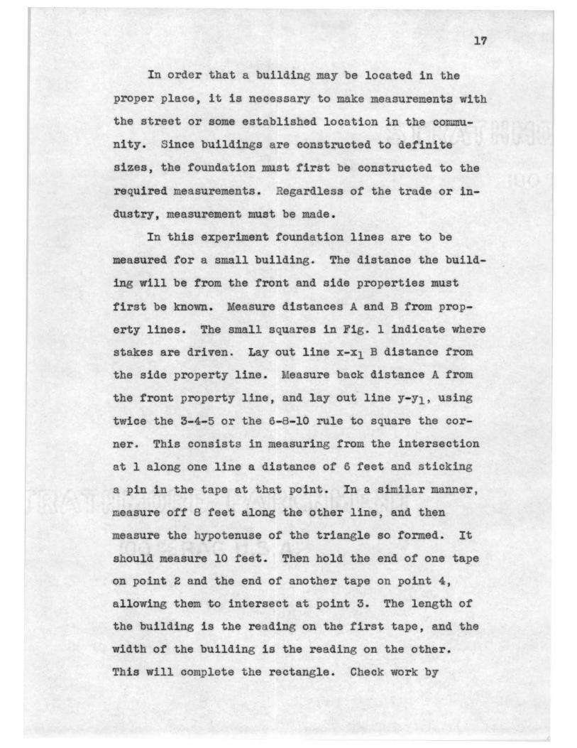
In order that a building may be located in the
proper place, i .t is necessary to make measurements with
the street or some established location in the commu
nity. Since buildings are constructed to definite
sizes, the foundation must first be constructed to the
required measurements. Regardless of the trade or in
dustry, measurement must be made.
In this experiment foundation lines are to be
measured for a small building. The distance the build
ing will be from the front and side properties must
first be known. Measure distances A and B from prop
erty lines. The small squares in Fig. l indicate where
stakes are driven. Lay out line x-x1 B distance from
the side property line. Measure back distance A from
the front property line, and lay out line Y-Y1, using
twice the 3-4-5 or the 6-8-10 rule to square the cor
ner. This consists in measuring from the intersection
at l along one line a distance of 6 feet and sticking
a pin in the tape at that point. In a similar manner,
measure off 8 feet along the other line, and then
measure the hypotenuse of the triangle so formed. It
should measure 10 feet. Then hold the end of one tape
on point 2 and the end of another tape on point 4,
allowing them to intersect at point 3. The length of
the building is the reading on the first tape, and the
width of the building is the reading on the other.
This will complete the rectangle. Check work by

measuring the diagonals 2-4 and 1-3. These should be
identical .
18
In laying out lines for construction which will
extend over a considerable period ot time, it is best
to build batter boards , as shown. In most cases, how
ever , stakes will serve quite satisfactorily.
RESULTS: Make a freehand sketch of your foundation plan and
place on it the dimensions used .
REFERENCES:
Griffith: Carpentry, pp •. 1-1'1 .
Heisler: Elementary Science tor the Student of Industry, pp . 11-12.
CONCLUSION:
l. What are the common units of measurement used by
the carpenter?
2. To what part of an inch in measuring would a car
penter consider accurate? Would that be accurate
to a machinest?
3 . What is a batter board?
4. Where buildings are large and important , the
foundation is usually marked off with what instru
ments? Who does the work?
5. How did the procedure you followed, show that the
lay out lines were a perfect rectangle?

Experiment 4
SPECIFIC GRAVITY
Name
19
~----~--~~---Date ~~--~--~~---
OBJECT: To determine the specific gravity of wood.
MATERIALS : White pine, oak, maple, and walnut pieces ex-
aetly 3" X 3" X 5"; scales; oven; Forest Products
Laboratory equation table.
DIRECTIONS: In the selection of wood, the carpenter is us
ually interested in its strength. The specific gravity
of wood affords an approximate indication of its
strength properties.
(a) Place the different wood blocks in an oven
at 212 degrees F., and dry until constant weight is
attained. Remove the blocks from the oven and weigh
each. Measure the length, breadth, and thickness ot
each with a rule and calculate volume. Compute the
specific gravity using the formula:
Sp. Gr.. • ' ,
where W equals weight of wood in grams, and V equals
volume in cc.
RESULTS:
Oak
White Pine
Maple
Walnut
Weight Dimensions after drying Volume
Specific gravity

20
REFERENCES:
Black and Davis: Elementary Practical Physics, p . 100.
Forest Products Laboratory, Madison , Wis . , Technical Notes , B- 14.
Heisler: Elementary Science for the Student of I ndustry , p . 13.
CONCLUSION:
1 . What is specific gravity?
2. Of what value is a knowledge of a wood ' s specific
gravity to a woodworker?
3 . How does the specific gravity of the different
woods tested compare with values in reference three?
4. List the four woods in the order of their indicated
strength .
5 . Compare the specific gravity of green wood and wet
wood .
6 . Use equation table and calculate for each : (a)
strength of speciman as a beam, (b) shock resisting
ability, (e) ability to withstand wear, (d) its
toughness, (e} and its shearing strength .
''

Experiment 5
FORCES
Name
21
~~-------------Date ~~--~--~-----
0 BJ'E CT: To study beam deflection in wood.
MATERIALS: Saw horses; weights; hite pine pieces:
1" X 3" X 10' , l" X 5" X 10' • 2" X 3" X 10 t •
DIRECTIONS:
wt
Fig . 1.
The builder is interested in building a house that
wil l not sag, as the owner wishes to have a strong
beautiful home . A bridge contractor must build a
bridge that will not give way under heavy loads.
In the experiment with parallel forces, the
principle used is that the sum of the pressures acting
downward on a beam is equal to the supporting forces, if
the beam is in equilibrium.. There is another principle
called beam deflection that 1s important, it states the
amount of deflection that ta.lees place when a beam is
subjected to a given stress. You will note this pro
perty of a beam as follows:
(a) Support a piece or white pine 1n X 3" X 10'
on two sawhorses as shown in Fig . 1. From a point
midway between the supports, suspend a weight of 15
pounds. Lay a straight edged board across the saw
horses and measure distance from weight to straight
edge. Place the sawhorses closer together, and
measure results.
22
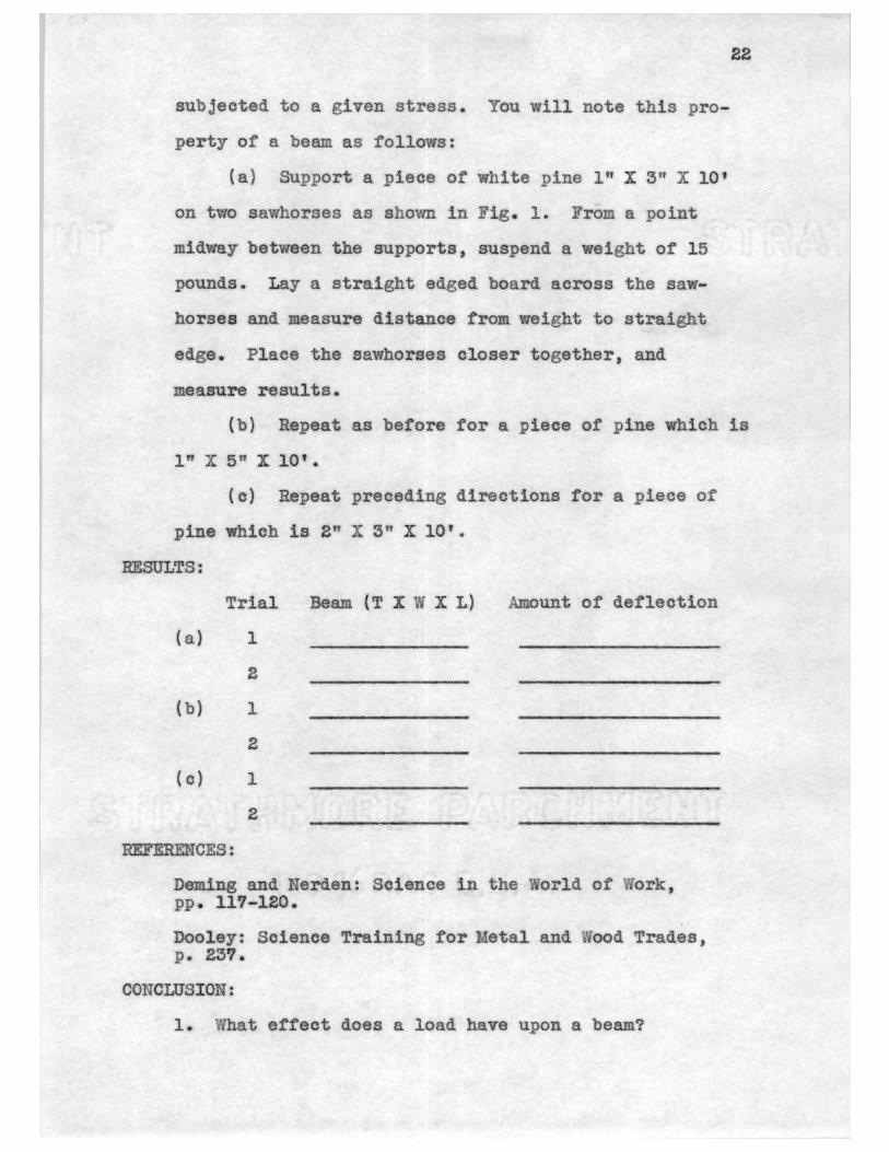
(b) Repeat as before for a piece of pine which is
1" X 5" X 10' •
(c) Repeat preceding directions tor a piece of
pine which is 2" X 3" X 10'.
RESULTS:
Trial Beam { T X ~ X L) Amount of deflection
(a) 1
2
(b) 1
2
( c) 1
2
REFERENCES:
Deming and Nerden: Science in the orld of Work, pp . ll'l-120 ..
Dooley: Science Training for Metal and ood Trades , P• 23'1.
CONCLUSION:
1. What effect does a load have upon a beam?

2. Would your general conclusion apply to a canti
lever beam? Why?
23
3. What would be the ettect on deflection, if the beam
is placed on its edge? If in doubt, experiment.
4. Did increasing the width of the beam influence de
flection? Increasing the thickness?
5. In some old factories and store buildings, it is a
general rule that the center aisle of' the building
must never be stocked with heayY cases, boxes,
trucks, etc . Explain why this rule is a safety
measure.
6. If a pine floor were sagging at its midpoint, and
the job became yours to remedy, explain in detail
the methods that might be used as remedies for the
situation.
7. What effect would different kinds of wood have upon
beam deflection? See references. 'lhy would a
bridge builder need to know this?
8. Explain why a heavy beam might not be as strong as
a lighter berun.

Experiment 6
PARALLEL FORCES
Name
Date
24
--------~--~~-~--~~~-------
OBJECT: To study the effect of parallel forces on wood that
is supported at each end.
MATERIALS : Pair of 25 pound spring balances; wood bar,
2 X 2 X 36"; weights.
DIRECTIO S:
A
Bar 3 ft. long
B 0 0 0 0 0 0 0
2.. 3
Fig. 1.
Nearly every day an automobile, a chair, or some
other object is called upon to support our weight. If
the thing that supports our weight does not break,
nothing is thought about what effect our eight has
upon the object. The carpenter must have a scaffold on
which to work. The painter uses a similar device. The
furniture builder considers the forces acting downward.
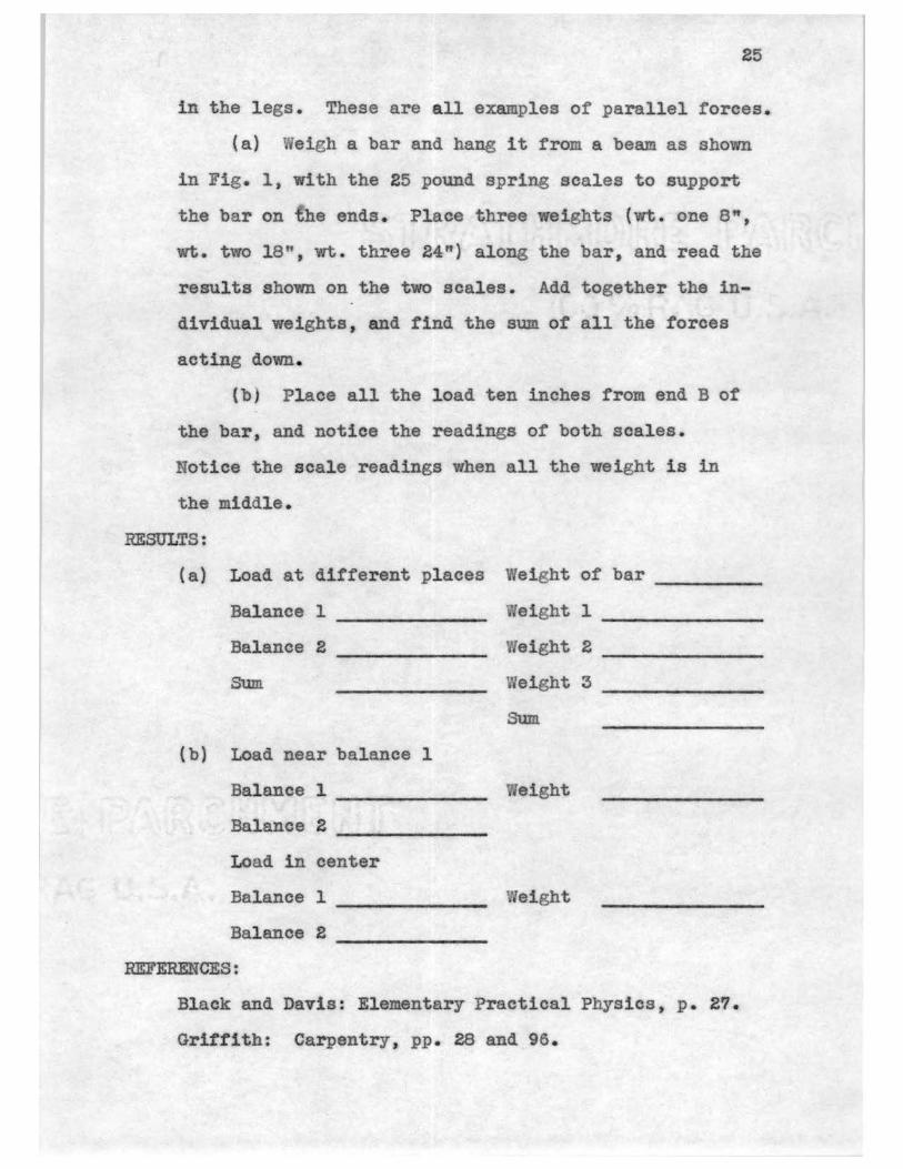
25
in the legs. These are all examples of parallel forces •.
{a) Weigh a bar and hang it from a beam as shown
in Fig. 1, with the 25 pound spring scales to support
the bar on the ends. Place three eights {vtt. one 8",
wt. two 18", wt. three 24") along the bar, and read the
results shown on the two scales. Add together the in
dividual weights, and find the sum of all the forces
acting down.
{b) Place all the load ten inches from end B of
the bar, and notice the readings of both scales.
Notice the scale readings when all the weight is in
the middle.
RESULTS:
(a) Load at different places Weight of bar--~~---
Balance 1 eight 1
Balance 2 eight 2
( b) Load near balance 1
Balance 1 -------Bala.nee 2 -------Load in center
Balance 1 -------Balance 2 -------
REFERENCES:
eight 3
Sum
eight
eight
--------------
Black and Davis: Elementary Practical Physics , p. 27.
Griff'ith: Carpentry, pp. 28 and 96.

Nerden and. Deming: Science in the orld of Vi ork, PP• 110-112
Voe. Board: C&rpentry, p. 30.
CONCLUSION:
26
1. What else besides the weight of the bar represents
the total force acting downward on the bar?
2. Does the sum ot the scale readings give the total
force acting upward on the bar?
3. Since the bar does not move, what could be assumed
about the strength of the opposing forces? Suppose
a building sagged, what would be the comparison?
4. When the weight was placed entirely at one end of
the bar, how did the reading of the scale on tha t
end compare with the reading of the scale for the
opposite end or the bar?
5. When the weight was placed in the middle of the
bar, how did the readings of both scales compare
with each other?
6. 'Wben pressure is put on a rigid wood beam, how does
it push down with respect to the supports at both
ends?
7. When would a carpenter be in the most dangerous
position on a scaffold in respect to the board
breaking?
8. Suppose a main beam in a barn has a center post,
how much of the eight of the barn does the center
post support?

Experiment 7
PARALLELOGRAM OF FORCES
Name
2'1
--~~------~~--Date --~~~----~----
OBJECT: To study the principle of parallelogram of forces ..
MATERIALS: Two spring balances, a weight of two pounds,
string, paper.
DIRECTIONS: When a carpenter or a fireman climbs a ladder,
it is subjected to several stresses. Cranes, derricks,
and other mechanical devices are acted upon by forces
at a point. A knowledge of the principle of forces is
necessary to operate the various machines safely and
A
AB:: 18"
B R
' ' N E 1000# C
M
4# w w
Fig. l Fig .• 2
w 1500ft
Fig. 3
successfully.
(a} At the top ot the blackboard are two hooks
which are twenty-four inches apart. From the hooks,

28
hang two spring balances, A and B, as in Fig. 1. Slip
a string about a yard long through a small ring and tie
the ends of the string to the spring balances. Now
suspend a weight of two pounds from this ring with
another string. The three forces acting at point C are
OK, ON, and OL which are represented by the strings.
Draw lines on the blackboard behind the strings to re
present the direction of each of the three forces. Re
cord the tension of each string which is shown by the
weight of Wand the readings of the spring balances.
Remove the apparatus and complete the parallelograms as
shown by the dotted lines in Fig. 1. Read page 168 of
the first reference, and choose some convenient scale
for the magnitude of forces. Measure on OW the distance
ON which represents the weight YI , and place an arrow at
N to indicate the direction the force is acting. In the
same way, measure on OA the distance OK corresponding
to the reading of the spring balance on that side.
:Place an arrowhead at Kand locate Lon OB. Then con
struct a parallelogram on OK and OL by drawing KF par
allel to OL and FL parallel to OK. Measure the diagonal
OF. ffllat is it called? How does it compare in length
with ON?
(b) Arrange a brace as .in Fig. 2. Hold a drawing
board covered with paper behind the apparatus and draw
lines AR, OB, and B . Using a convenient scale, draw a
parallelogram and calculate force on AB .
RESULTS:
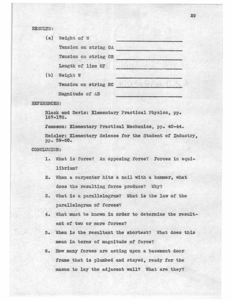
( a) Weight of W
Tension on string OA
Tension on string OB
Length of line OF
(b) We i ght ~
Tension on string BC
Magnitude of AB
REFERENCES:
Black and Davis: Elementary Practical Physics ., pp. 167-1178.
29
Jameson: Elementary Practical Mechanics, pp •. 40-44.
Heisler: Elementary Science for the Student of Industry, pp. 59-60.
CONCLUSION:
1. What is force? An opposing :force? Forces in equi-
librium?
2. Vhen a carpenter hits a nail with a hammer, what
does the resulting force produce? Why?
3. What is a parallelogram? What is the law of the
parallelogram of forces?
4. What must be known in order to determine the result-
ant of two or more forces?
5. V.~en is the resultant the shortest'? What does this
mean in terms of magnitude of force?
6. How many forces are acting upon a basement door
frame that is plumbed and stayed , ready for the
mason to lay the adjacent wall? What are they?

30
9. In part (a) of the experiment, how does the magni
tude of line OF compare with the weight of ?
Account for this.
a. The arm of the crane CD is attached to the wall of
a building under construction for lifting the heavy
rafters as in Fig. 3. The weight lifted is 1000#.
The tension on the horizontal cable CE is 500#.
What is the force exerted on CD? Solve by drawing
a parallelogram.
9. A man, who weighs 150#, has started to climb a
ladder twenty feet long, that has been placed away
from the side of the building at a distance one
fourth the length of the ladder. Draw to scale this
parallelogram of forces.
10. Fig. 4 below represents an unloading derrick. The
boom XY is 24 feet long, and the wire rope :XZ
happens at this instant to be 8 feet long and in a
horizontal position. While it is holding the two
ton load, what is the tension on the guy wire rope?
What is the force on the boom? z. 8' ---I X
C
A I}
s 40#=
4000#
y Fig. 4 Fig. 5

31
11. A .sign in front of a cabinet shop weiihs 40#, see
Fig. 5. It is hung from a post which is 4" square
by a vrooden bracket (AB) that is ten feet long. A
tight wire BC is fastened to the post at O wnieh
is three f'eet above A. What force is exerted on
the wire BC?

Experiment 8
LEVER
Name
Date
32
~~--~---------0 B JE CT: To study the claw hammer as a lever in pulling
nails.
MATERIALS: Claw hammer, nails, board, 25 pound spring
balance.
DIRECTIONS:
B
Fig. 1 Fig . 2
The world or ours is full of devices with which to
aid man i n accomplishing the necessary tasks of life.
The hunter uses a gun. the butcher a knife, the car
penter a hammer, etc. Perhaps the simplest of these
tools or machines is the lever of which the seesaw is
a good example.
An explanation of the aeesa~ , Fig . l, will aid us
in studying the hammer. If the point of turning
(fulcrum) is exactly in the center of the plank and the
boys are the same weight, they balance, or if one boy
is heavier than the other, he ould go down. If the
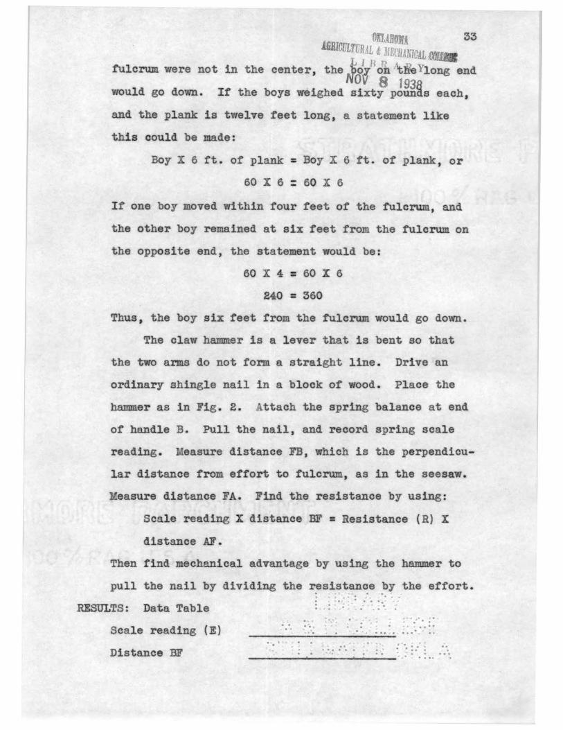
·OKLAHOMA 33 IJBIOULTURAL & MECIJANTCAL 00
L 1 BP fulcrum were not in the center, the bo.Y. oh J:iieYlong end . Nov 8 193R
would go down. If the boys weighed sixty pounas each,
and the plank: is twelve reet long, a statement like
this could be made:
Boy X 6 ft. of plank = Boy X 6 ft. of plank, or
60 X 6 : 60 X 6
If one boy moved within four feet of the fulcrum, and
the other boy remained at six feet from the fulcrum on
the opposite end, the statement would be:
60 X 4 = 60 X 6
240 = 360
Thus, the boy six feet from the fulcrum would go down.
The claw hammer is a lever that is bent so that
the two arms do not form a straight line. Drive an
ordinary shingle nail in a block of wood. Place the
hammer as in Fig. 2. Attach the spring balance at end
of handle B. Pull the nail, and record spring seale
reading. Measure distance FB, which is the perpendicu
lar distance from effort to fulcrum, as in the seesaw.
Measure distance FA. Find the resistance by using :
Scale reading X distance BF= Resistance (R) X
distance AF.
Then find mechanical advantage by using the hammer to
pull the nail by dividing the resistance by the effort. • - ,;J ~ • • , I. 0 .. • ,; ,.; • ,; "' . . . . . . . ., .,
RESULTS: Data Table : · : , . . : . '.; ·. :
Scale reading (E)
Distance BF
•1. c ~'"~ • ... .., "' ~ ~~"'/'• ;• . . . "'• . .. " . ... .. . ., " .., ... . \.c."• .J • ., .......... " •:, ..
:: (, .. • .. .. • .. . J " . .. . . : : : ... ,:, . . . . . !.J-:-, .,, . ~ . . .. ____________ .., . . . "" .
34
Distance .f\F
Resistance R
Mechanical advantage ~~~~--~~~--~~~
REFERENCES:
Heisl.er: Elementary Science for the Student of Industry, pp. 26-31.
Black and Davis: Elementary Practical Physics, p. 26.
CONCLUSIONS:
1. Define fulcrum. Where is it on the hammer?
2. What are the two shapes of levers mentioned in the
experiment?
3. Why is the hammer used in pulling nails?
4. In gaining an advantage with the hrumner, the effort
is less than the resistance. Compare the distances
moved .
5 . In securing a mechanical advantage with the claw
hannner, would distance be gained or lost?
6. Where is the force applied on the hammer?
7. Would a wrecking bar be considered a lever? Bow
many ways can it be used as such?

Experiment 9
PULLEYS
35
Name ~--~------~---Date ~------~--~~-
0 B JE CT: To study the principle of the sash cord window
pulley.
MATERIALS: Window pulley fastened in al" X 4" pine board,
4 feet of window sash cord, weight, 15 pound spring
balance.
DIRECTIONS:
Fig. 1
The pulley has many uses in different places. In
shops, it is used for lifting heavy steel shafts, rais
ing motors, moving machinery; outside the shops, the
pulley is frequently used tor jobs such as furniture

36
moving, raising and lowering painter's scaffolds, eto.
These are just a few of the many uses of this simple
machine.
It will be your task to examine the window sash
pulley. Thread the pulley with window cord rope.
Weigh the window weight, fasten eight to cord. Hook
the spring balance to the opposite end of cord, raise
the weight, and read on the balance the number of
pounds or force required to raise the weight. In rais
ing the weight one foot, how far did the effort or
balance travel? Physics defines 1 foot pound of work
done when l pound is raised 1 foot. It is easier to
pick up a heavy 2" X 10" beam and hold it than it is to
carry it. More work is done in the latter case because
the weight is being carried through a greater distance.
RESULTS:
Load (vlindow wt.)
Effort (spring balance)
Load distance
Effort distance
Load X load distance
Effort X effort distance
Mechanical adv. ot pulley
REFERENCES:
tt. lbs. -------ft. lbs. -------
Dooley: Science in the etal and Wood Trades, pp. 33-37.
Heisler : Elementary Science for the Student of Industry, pp. 35-37.

37
CONCLUSION:
1. What is a pulley?
2. In raising the window weight one foot, how far did
the effort force (spring balance) move?
3. Compare the spring balance reading with the weight
of the pulley. Ho1 do you account for this?
4. Does a single pulley give a mechanical advantage?
What is the purpose of the use of a single pulley?
5. Is the effort and the load on the pulley in equi
librium? Of what advantage is this in raising and
lowering the window?
6. Give two uses of the single pulley in your trade .

38
Experiment 10 ·, MECHANICAL DEVICES
Name
Date ----~----~--~-OBJECT: To study the advantage of arranging pulleys as need
ed for lifting or pulling as in moving a house.
MATERIALS: Single pulley, barbed wire stretchers, two tri
ple sheaved pulleys, small rope, weights as bricks,
pieces of iron, 25 pound spring balance.
DIRECTIONS:
B C D
E
(
wt
wt
wt wt
Fig. 1
In house moving, a block and tackle is a very
necessary tool. By fastening the block and tackle to
a dead-man (anchor placed in the ground from which to
pull), and by fastening it to the house to be moved
39
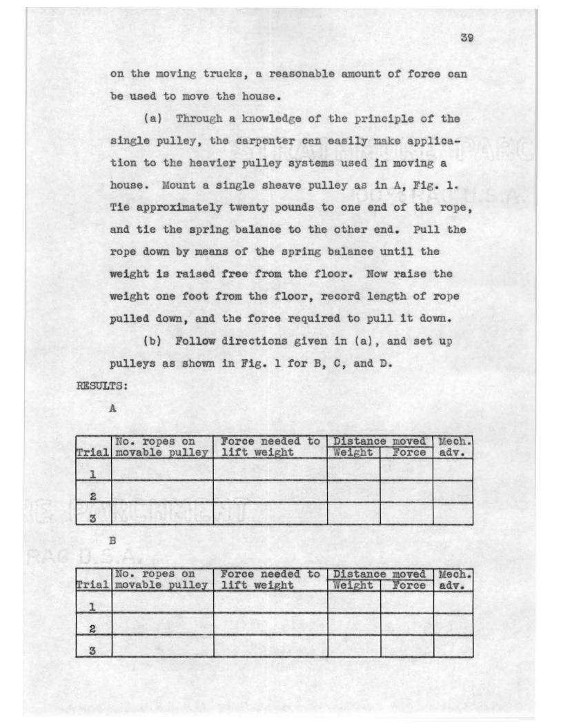
on the moving trucks, a reasonable amount of force can
be used to move the house.
(a} Through a knowledge or the principle or the
single pulley, the carpenter can easily make applica
tion to the heavier pulley systems used in moving a
house. ount a single sheave pulley as in A, Fig. 1.
Tie approximately twenty pounds to one end of the rope,
and tie the spring balance to the other end. Pull the
rope down by means of the spring balance until the
weight is raised free from the floor. Now raise the
weight one foot from the floor, record length of rope
pulled down, and the force required to pull it down.
{b) Follow directions given in (a), and set up
pulleys as shown in Fig. 1 for B, C, and D.
RESULTS:
A
No. ropes on i·orce needed to Distance moved Mech. Trial movable pulley lift weight Weight Force adv.
l
2
3
B
No. ropes on Force needed to Distance moved Mech. rrial movable pulley lift weip.:ht Wei,Q:ht Force adv.
l
2
3

40
C
No. ropes on Foree needed to Distance moved Mech. IT rial movable uullev lift wei&?ht Wei~ht Foree adv.
1
2
3
D
No . ropes on Force needed to Distance moved llech. Trial movable pulley litt weiP:ht Weii:rht Force adv.
1
2
3
REFERENCES:
Sears : Essentials of Physics, p. 135
Heisler: Elementary Science for the Student of Industry, p . 37 .
CONCLUSION:
1. What is the advantage of the arrangement of the
pulley in A? In B? In C? In D?
2. What is a block and tackle? Of hat use is it in
moving a house? Where else is it used?
3. What is mechanical advantage?
4. How can a carpenter tell hat mechanical advantage
his block and tackle will give?
5. What is a truck driven inch, and how does it operate?
Go to an automobile agency, and secure a picture or one. Try to find where one is in_use, and learn its
principle by seeing it operate.

41
6. Go to the auto mechanics shop, and get permission
to experiment with a truck differential. What is
a worm gear? fuere is the worm gear located?
Which turns the easier, the drive shaft or the
axle? How many times does the drive shaft turn to
one turn of the axle? What make of truck differ
ential did you use?
7. I s the worm gear of the winch connected to the
power take oft of the truck. Why?
a. How many pounds will some or the large winches pull?
Is that enough force to pull an ordinary six room
house? Answer by asking a lumberman how much such
a house weighs .

Experiment 11
WEDGE
OBJECT: To study the principle of the wedge.
42
MATERIALS: Five pound hammer, sharp mortise chisel, very
blunt mortise chisel of same brand, white pine trial
board, four wedges (Fig. 3), four wedges {Fig. 4),
heavy object to be lifted, sawhorse, ten pound weight,
1/4 inch rope.
DIRECTIONSO: ' 'I--' '(__
Fig. l
Fig . 2
Fig. 3
'I~ ~ • 12:· 4 ... , 1.g .

43
The wedge is a very common example of one of the
simple machines, which is a tapered device made of iron,
wood, or some other strong material. It is driven by
blows or by a steady force. All cutting and piercing
instruments, such as the ax, chisel, carpenter's plane,
and nails act as wedges. The carpenter uses wedges to
fasten the heads of hammers and axes on their handles.
The window sash lock 1s another example of a wedge, and
thus, the list could be continued.
(a} In order to learn about this device to deter
mine its mechanical advantage, measure the distance c
and f of the sharp chisel. ith hammer at position
shown in 1, Fig. 1, drive the chisel into the wood with
one blow. Measure depth chisel went into wood. Repeat
directions using blunt chisel.
Repeat procedures holding chisels in position 2,
Fig. 1.
(b) Place sawhorse at the corner of weight to be
lifted with wedges. Attach a ten pound weight to the
1/4 inch rope, and tie to sawhorse so that it will
strike all .of the wedge. Start wedge Fig. 3 under cor
ner of weight with hammer. Bring the weight back to a
measured position at h in Fig. 2. Count the blows that
str~ke wedge from this position to drive the wedge in
tlush with weight. Measure the distance through which
the force moves, and the di~tance through which the
load moves. The distance that the force moves is the

44
horizontal distance that each wedge slides along the
floor, and the weight distance is the vertical distance
the weight rises. Record data obtained in table.
Repeat directions using wedge Fig. 4.
RESULTS:
(a)
Chisels Position l Position 2 Sharp Dull Sharp Dull
Force required { rt. of hammer)
Distance chisel went into wood
Length of wedge (chisel's bevel, c)
Thickness of wedge (f)
M.A. Length ~c~ Height b
( b)
Wedge Fig. 3 Wedge Fig. 4
Amount of slope
Amount of force required ( number of blows)
Vertical distance weight moved through (m)
Distance force moved through (n}
Mechanical advantage (n divided by m)
REFERENCES:
Griffith: Carpentry, p. 25.
little
Foley: College Physics, pp. 110-111.
increased greatly
45
Black and Davis: Elementary Practical Physics, pp. 48-49
Dooley: Science Training for Metal and Wood Trades, PP• 506-512.
CONCLUSION:
1. What is a wedge?
2. Which chisel drove the easier? Which the harder?
Which has the greater mechanical advantage?
3. Explain the cutting action of the chisel in posi
tion 2.
4. Vlhy does the carpenter sharpen a stake before
driving?
5 . What other simple machine is similar to a wedge?
Why?
6 . Which wedge drove the easier in the experiment?
Why?
7. Which wedge took the more blows to drive? Why?
8. Which of the two wedges has the greater mechanical
advantage? How is the mechanical advantage found?
9. To what class of machines do the following belong:
ax, chisel, carpenter's plane, nails.
10. In using the wedge of Fig. 3 as in b, does the force
have to be applied through a greater or lesser dis
tance than that of the Fig . 4? Why?
Experiment 12
JACK SCREW
Name
46
~~~~~----~-
Date ~--~--~-------0 BJE CT: To study the jack screw that is used in house mov-
ing carpentry.
MATERIALS: Two small builder jack screws, grooved wheel
with two feet diameter attachable to the head of the
jack screw, 50 pound weight, 10 pound spring balance,
rope with 1/4" diameter and 8' length.
DIRECTIONS:
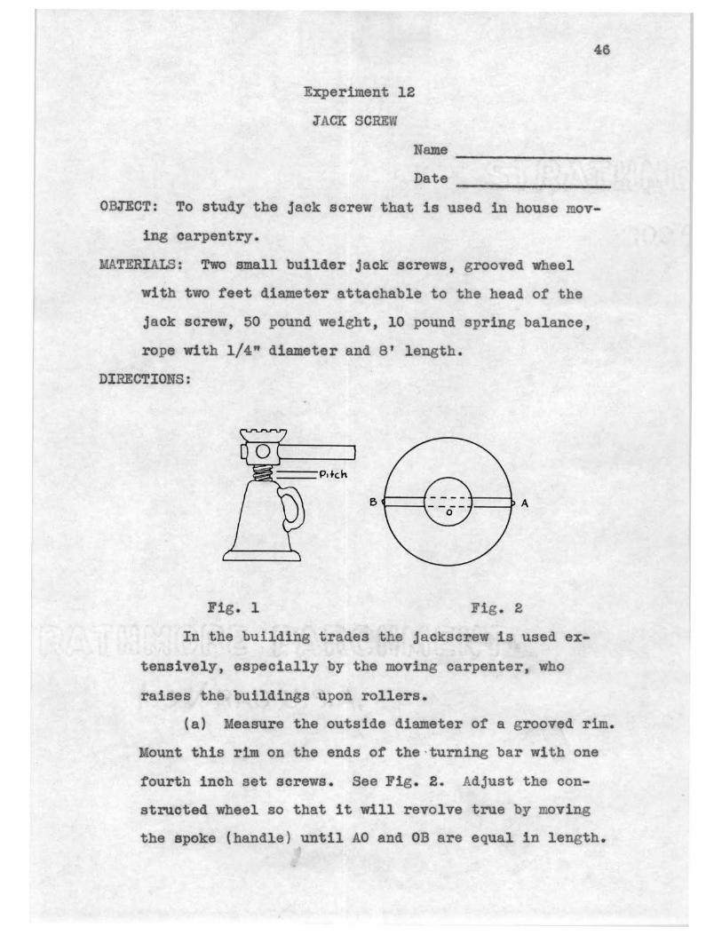
Fig . l Fig . 2
In the building trades the j ackscrew is used ex
tensively, especially by the moving carpenter, who
raises the buildings upon rollers.
(a) Measure the outside diameter of a grooved rim.
Mount this rim on the ends of the·turning bar with one
fourth inch set screws. See Fig. 2. Adjust the con
structed wheel so that it will revolve true by moving
the spoke (handle) until AO and OB are equal in length.

rap a small rope around the wheel rim to which a
spring balance is attached. This arrangement makes
possible a steady pull on the spring balance. Care
fully center the 50# weight on the head of the screw.
Pull gently on the spring balance, and record effort.
Measure the pitch of the screw threads. See Fig. 1.
easure the amount of rope needed to go around wheel
4?
once. Neglecting friction, figure the theoretical
mechanical advantage. With each complete turn of a
screw the work output is equal to the weight li~ed
times the pitch, and the work input is equal to the
effort times the distance through which it acts. This
distance is the circumference of the wheel. Then the
efficiency can be calculated by the formula:
Output *~eight X !itch~ = Efficiency Input (~ffort X c r. o wh.)
RESULTS:
Pitch of threads
Diameter of wheel
Circumference of wheel
Effort applied (spring balance}
Weight lifted
Mechanical advantage
Efficiency
REFERENCES:
Output Input
Black and Davia: Elementary Practical Physics, pp. 49-50.
Jameson: Elementary Practical Mechanics, pp. 212-214.

48
Heisler: Elementary Science for the Student of I ndustry , p. 37.
CONCLUSION:
1. What is a screw? Give an example of a type used by
the finish and trim carpenter.
2. What is a jack screw? How high will the head of a
builder's jack screw rise in one complete turn of
the handle?
3. lhy was a wheel substituted tor a handle in the
experiment?
4. In lifting a house off its foundation, why do the
carpenters keep the house plumb?
5. niat keeps the pressure or the house from unscrew-
ing the jack when the handle is not held?
6. From the standpoint of weight moved, how does the
jack screw compare with the builder's block and
tackle?
?. Why was the worm or power screw in the builder's
power driven winch, used in place of an ordinary
meshed gear?
8. What factors determine the ease with which a screw
turns'?
9. What is the difference between a continuous screw
and a rapidly acting bench vise?
10. Using the same length of handle, which woodworking
vise would have the greater clamping effect, one hav
ing the lead screw finely threaded, or one coarsely
threaded'? Why?

Experiment 13
FRICTION
Name
Date
49
OBJECT: To study reasons for placing casters under a table.
MATERIALS: 25 pound spring balance; table; 4 metal shoes;
4 pin, 4 ball, and 4 roller bearing casters.
DIRECTIONS:
Metal shoes
Casters Pin, ball, and roller
bearing type
Fig. 1
The front wheel of an automobile when jacked up
rolls easily, but pushing a sled along a dirt road is
difficult. Most furniture that is moved about in the
room has casters placed on the bottom of the legs. 11
of these are examples where friction is involved.
Let us find out why casters are used. Fasten the
spring balance to the table without casters, and pull
it at a uniform speed for about 10 feet. Record spring
balance reading. Repeat as above using iron shoes on
the table legs; using the various casters consecutively

on the table legs. Compare the results.
RESULTS:
Force needed to move table:
Without casters on legs
With metal shoes on legs
With pin bearing casters on legs
With ball bearing casters on legs
With roller bearing casters on legs
REFERENCES:
50
Heisler: Elementary Science for the Student of Industry, pp . 48-49.
Black and Davis: Elementary Practical Physics, pp. 58-62.
CONCLUSION:
1. What is friction? Name the kinds with which you
have worked.
2. Which force proved to be greater : that in starting
the table, or that applied after the table started
moving?
3. Make a general statement about starting and sliding
friction.
4. Would a man be helped or hindered by friction in
shingling a house?
5. Vlhat kind of friction would be involved in opening
an ordinary door?
6. What has been introduced in woodworking machinery to
reduce friction in bearings?
7. What is the friction advantage of V belt vs. flat

51
belt?
e. Why use paraffin on a plane?
9. \that is the purpose of lubrication?

Experiment 14
ANGULAR FORCES
Date
OBJECT: To study the forces that act on a simple brace.
MATERIALS: Simple truss as illustrated, spring balance,
weights.
DIRECTIONS:
Fig. 1 Fig.
The expression "this or that must be braced" has
52
been uttered by all of us. Houses, scaffolds, and any
structure that is made requires bracing to help with
stand the elements. Fig . 1 is an example of a very
common brace.
In this experiment the simple stick and tie brace
will be studied. Arrange the appara tus as shown in
Fig . 2. Place a weight of five pounds at W, and a

53
spring balance at A. The three forces in equilibrium
at point Bare : the weight acting downward, and the
other two forces acting in the direction of the arrows
placed along the cord AB and the stick BC. Record the
reading of spring balance L. Letting i inch equal one
pound, draw a parallelogram as shown in Fig. 2.
Measure BC and record on drawing. Decrease angle or stick BC with the board AC and note pull on spring
balance. Increase angle of the stick BC with the board
AC and note pull on spring balance.
RESULTS:
Reading spring balance
Weight W
Force BC is supporting
REFERENCES:
Sears: Essentials of Physics, pp. 147-148.
Heisler : Elementary Science for the Student of Industry, pp. 59-60.
CONCLUSION:
1. What is a parallelogram? What is the diagonal of a
parallelogram?
2. State the law of the parallelogram of forces.
3. lhat might BC of the brace be called in respect to a
parallelogram?
4. How much of a parallelogram does the brace BC re-
present?
5 . What kind of a force is acting on a board placed in

a similar position as that of' AB? Is it, compres
sion or tension?
6. VS"hat kind of forcrj is acting on the brace BC?
54
7. The brace BC takes the place of wha·t other two
boards? (Look at your constructed parallelogram}.
a. Design a properly braced one-half heieJ1t door. Ex
plain reason for your brac:tng.

Experiment 15
COUNTERACTING FORCES
Name
Date
55
--~~--~--~~~ ~--~----~~----
0 B JE CT: To determine the :forces which exist in the members
of a roof truss.
MATERIALS: Apparatus as shown, weights, spring balance,
turn buckle.
DIRECTIONS:
T e,
Fig. 2
Fig. 1
The beams or timbers that support the roof of a
simple wooden house or barn form an A, Fig. 2. The
weight of a roof, and in winter the additional weight
of snow upon the roof, tend to make the timbers spread
at the bottom and the ridge-pole to sink. The appara
tus, Fig . 1, that is used in this experiment is a simi
lar truss. W weighs 30 pounds. The truss is pivoted
at Band at C. A 15 pound spring balance is placed at

56
the end or the cord that connects A with C, and another
similar balance is placed between A and D. A turn
buckle is placed between the spring balance and D to
help raise and lower A. The hook D slides along the
rod F Fl, so that DA can be made vertical hen desired.
Adjust the apparatus so that AC is horizontal and DA is
vertical. Ask the instructor for the weight of each
one of the two wooden members or the truss. Place a
piece of cardboard behind the truss at B, and draw the
angle ABC upon it. Measure and record the value.
The downward force at Bis the weight plus 1/2
the weight of each of the members AB and BC . The other
half of the weight of member AB is pushing down vertical
ly at A, and the other half or the weight of BC is
pushing down vertically at C. On a sheet of paper, draw
a vertical line to represent the downward force at B.
Make it as many units long as there are pounds in the
downward force at B. Call this line INi. At B construct
an angle equal to angle ABC. Be sure to have half the
angle on the right side of BW, and the other half on
the left side. Complete the parallelogram.. Draw the
horizontal diagonal of the parallelogram. Find the
value of the horizontal diagonal in force units. Half
this value should equal the reading or spring balance
L. Why? What is the value in force units of one half
the vertical diagonal? This re pre sen.ts the vertical
component at A of the force BW. There is a downward
' J \

57
torce at A equal to one halt the weight of the member
AB. Then add one halt the weight of AB to the verti
cal component at A to get the total downvard force at
A. Compare this total force with the reading of
spring balance Ll. What line in your force diagram
represents the compression in AB? Measure that line,
and tind its value in force units. Show the value of
all forces on the diagram.
RESULTS:
Weight hung at B
Spring balance L
Spring balance Ll
Angle ABC
Weight of each member of the truss
REFERENCES:
Sears: Essentials of Physics, pp. 147-148~
Heisler: Elementary Science tor the Student of Industry, pp . 59-60.
Black and Davis: Elementary Praotioal Physics, pp. 167-177.
CONCLUSION:
l. What is the name of a roof forming an A?
.2. Answer all questions asked in the directions.
3. or what value is the joist in this form of roof?
4. In framing opening.a for French doors in houses, the
opening is quite often trussed above it. Why?
5. Fig. 3 represents a pair of sawhorses. If the same
load is applied to each horse, tell from the
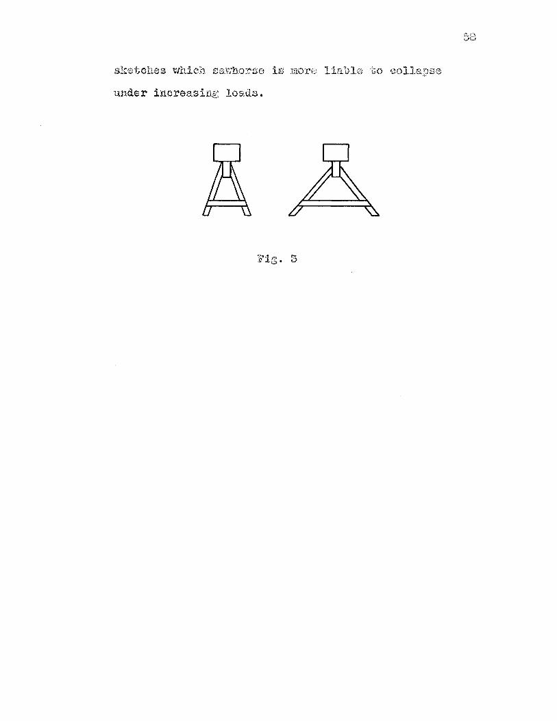
collapse
t.UJ.der increasing load.s.
Fig. 3

Experiment 16
CENTER OF GRAVITY
Name
59
------~~--~~-Date ~--~----~~---
0 BJ EC T: To show that the entire weight of the hammer may be
considered as acting at a single point (center of grav
ity), and to study the relation of the position of the
center of gravity to an object's stability.
MATERIALS: Claw hammer, device as shown, board 1 X 6 X 18",
two cylinderical blocks as shown in Fig . 2, string,
and weights.
DIRECTIONS:
Fig. 1
Fig . 2
Workers have their favorite tools. Two hammers
that look alike to a non-tradesman may feel entirely
different to the hand of a tradesman. Our job is to
find the reason for this.

60
(a) Balance the long irregularly shaped body,
similar to a hammer, on the edge of a triangular prism
as shown in Fig. 1. Measure the distance from the end
without weights to the center of gravity, and record on
diagram.
{b) The idea of the center of gravity also helps
to understand the problem of stability. Find the center
of gravity of the two cylinders, Fig. 2, by balancing
over knife and then drive a shingle nail at this point.
Fasten a plumb line from this center of gravity on each
cylinder. Incline board by laying on a thick block or
other object. Place block Con the inclined plane
(board) so that the plumb line will swing free. Note
the line falls within the base of the block. Now place
on the same inclined plane cylinderieal block D, which
has the same base but twice the height of c. The plumb
line from its center of gravity will fall outside the
base. What happens?
RESULTS:
(a) Diagram:

61
(b)
Block C Block D
Center of gravity from inclined plane ----Did block tip over?
REFERENCES:
Heisler: Elementary Science for the Student of Industry, p. 60.
Sears: Essentials of Physics, pp. 116-117.
Black and Davis: Elementary Practical Physics, pp. 30-33.
CONCLUSION:
l. Vlhat is meant by the center of gravity?
2. How many inches was the center of gravity from the
end or the handle?
3. If the experimental apparatus represented a claw
hammer or tack hammer, and the center ot gravity
was not concentrated at a single point, would the
hammer be hard or easy to use? Can you think of
one word that would describe the working qualities
of such a tool?
4. Do you like to use one of your father's hammers
better than .another? Does your father have a tool
that he likes to use, but you do not like it? What
and why?
5. Does every tradesman want the center or gravity of
his hammer in the same place? Why?
6 . How does the manufacturer change the center of
gravity of his tools?
7. Measure and record the center of gravity of a:
hammer, chisel, wrecking bar, screw driver,
hatchet.
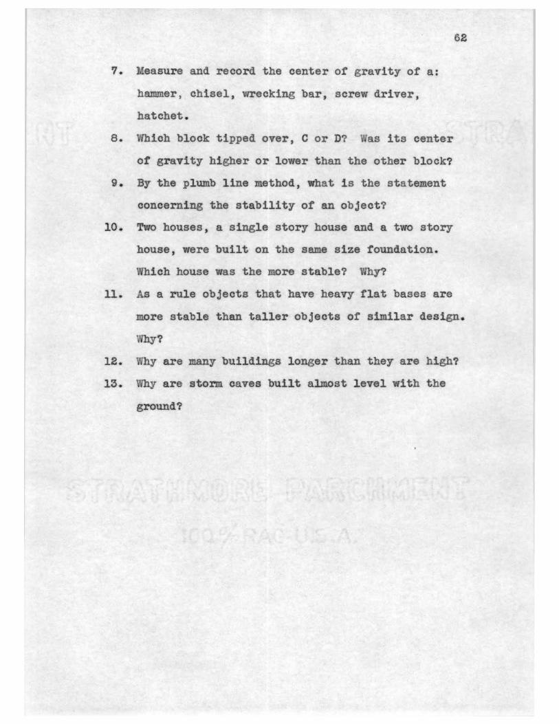
a. Which block tipped over, C or D? Was its center
ot gravity higher or lower than the other block?
9. By the plumb line method, what is the statement
concerning the stability of an object?
10. Two houses, a single story house and a two story
house, were built on the same size foundation.
Which house was the more stable? Why?
62
11. As a rule objects that have heavy flat bases are
more stable than taller objects of similar design.
Why?
12. Why are many buildings longer than they are high?
13. Why are stonn. caves built almost level with the
ground?
Experiment l't/
MECHANICS OF LIQUIDS
Name
63
~~~~~~-----
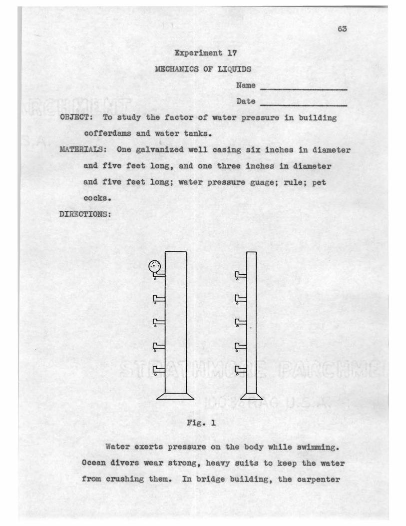
Date ~~----~----~-0 B JE CT: To study the factor of water pressure in building
cofferdams and water tanks.
MATERIALS: One galvanized well casing six inches in diameter
and five reet long, and one three inches in diameter
and five feet long; water pressure guage; rule; pet
cocks.
DIRECTIONS:
Fig. l
Water exerts pressure on the body while swimming.
Ocean divers wear strong, heavy suits to keep the water
from crushing them. In bridge building, th carpenter

has the problem of building structures, such as a
cofferdam, that must withstand the pressure of the
water at the bottom of rivers.
To find out something about water pressure,
64
assemble the apparatus as shown in Fig. 1. It con
sists of two individual pipes ot the same height with
different diameters fitted with petoocks and with a
guage. First, make sure that all of the petcocks are
closed tightly; then fill the large pipe to the top
with water. Record pressure from guage at the various
places provided along the pipe, starting at the top of
the pipe. Repeat the procedure by using the pipe of
smaller diameter.
RESULTS:
1.
2.
3.
4.
5.
REFERENCES:
Pressures (lbs. per sq. in.)
Large pipe Small pipe
Black and Davis: Elementary Practical Physics, pp. 71• 87.
Heisler: Elementary Science for the Student of Industry, pp. 13-14.
CONCLUSION:

65
1. Where was the water pressure the least? The most?
2. Compare the top and bottom pressure of the two
pipes. How do we account for this variation?
3. Does the amount of water in a river or pon.d have
any relation to the pressure of the water at the
bottom? What is the determing factor ot the
pressure?
4. When a hole is bored into a wooden tank, what causes
the water to spurt out?
5. What is the total force on the bottom ot a coffer
dam 15 feet in diameter and 20 feet long 1 it it is
sunk to the bottom of a river 15 feet in depth'?
If the water is very salty, what is the total force
at the bottom of the river? (Get density from the
table in the book of the second reference). Use
the formula: Total force (lbs.) equals (area in sq.
rt.) (depth in ft.) {density).
6. In a cylindrical tank, erected by a tank building
carpenter, why are the bands spaced closer at the
bottom?
66
Experiment 18
EXPANSION OF WOOD
Name ~~------~-----Date ~-----~~-------
0 BJE CT: To study the expansion or wood resulting from
moisture.
MATERIALS: ater, rule, one piece of pine and one piece of
cypress each l" X 6" X 18".
DIRECTIONS: The carpenter, in shingling a root. allows for
the expansion of shingles during wet weather to keep
them from buckling and cracking . It is necessary tor
him to know how much wood expands when it becomes wet .
Measure accurately the thickness ., width, and length or the two blocks. Weigh each piece. Place them in a
tank ot water until thoroughly wet • .Measure again,
weigh, and record . Leave the wood in the water during
the entire class period. Measure again for further
expansion.
RESULTS:
Weight
Thickness
Width
Length
Pine Cypress Dry \Vet Dry Wet
Note: Make corrections if the wood in the water expanded any more by the end of the class period.
REFERENCES:

6'7
Dooley: Science Training for the Metal and Wood Trades, pp . 497 .. 500.
Griffith: Carpentry, pp . 102-103.
CONCLUSION:
1. What causes expansion of wood due to moisture?
2. What is the effect or the weather on lumber?
3. How does a carpenter make allowance for expansion
1n shingling?
4 . Of what value is expansion of wood to the tank
carpenter?
5 . Why is building paper l.aid between the rough :floor
and the finish floor?
6. What makes drawers in furniture hard to open in
damp weather? How does the cabinet maker al.low
for this in constructing furniture?
7. How may wood be treated to prevent expansion?

Experiment 19
WOOD SHRINKAGE
Nrune
Da.te
OBJECT: To study the shrinkage of wood.
68
TERIALS: Rack with hooks for hanging wood samples, screw
eyes to screw into ends of wood samples, rule, scales,
green oak.
DIRECTIONS: Wood to be used in furniture construction must
be seasoned. The moisture content must be reduced to
a minimum, or the furniture will warp out of shape and
not give reasonable service.
(a) Prepare two samples of green oak. The samples
should be from eight to twelve inches long. One piece
should be five or six inches wide, and the other about
two inches wide. Carefully measure the thickness,
width, and length of each sample. Weigh each sample
and record weight. Then place a screw eye in end of
sample, and hang on rack. Identity samples. Measure
and weigh samples each day for one week. Weigh samples
again in two months.
(b) Ye i gh a piece of green oak, approximately 2"
X 8" X 8". Place it 1n an oven, and heat over low fire
until thoroughly dry. Weigh again, and calculate per
cent of moisture evaporated.
RESULTS:

(a} Sample 1
1 2 Thickness
Width
Length
Sample 2
1 2 Thickness
Width
Length
(b) Green Oak
Weight before placing in oven
Weight after placing in oven
Percent of moisture
REFERENCES:
3 4 5
3 4 5
Dooley: Science Training for Metal and Wood Trades, PP• 487-490.
Hunt: Handwoodworking, pp. 153-158.
CONCLUSION:
69
1. What causes shrinkage of wood? How does it effect
furniture and cabinet making?
2. What is the cause of the rapid change of size and
weight during first week?
3. How much will a green oak board eight inches wide
shrink in drying down to five percent moisture
content?
4. What are the two methods or drying wood? How long
does it take?
5. How much of the we·igbt of freshly cut lumber is

moisture?
6. Is the moisture content of cabinet woods always
constant? Why'?
'10
7. What causes warpage in a board? Can the furniture
maker stop this by finishing'? Why?
8. Which way does wood shrink the more, radially or
tangentially to annular ring?
9. What is the percent of moisture in kiln dried wood?
10. ·niy do large cabinet shops have a small kiln?
11. Will paint keep a board from shrinking? Why?
12. What causes wood to crack if allowed to dry in the
stick?

Experiment 20
TRANSMISSION OF BEAT
Name
'11
~--~~----------Date ----------------~
OBJECT: To study heat insulators used in house construction.
MATERIALS : Special box as shown, asbestos, magnesia, rock
wool, paper, uninsulated dipper, thermometers.
DIRECTIONS: Heat always tends to pass from warmer objects to
cooler objects. Through a knowledge of the properties
of heat insulators, .it is possible to save much heat
that is lost otherwise. The carpenter builds the walls
of the house with an air space to prevent waste of heat .
Tin or
wood
Screen wire bottom
I,.- ... ,
}- .,'
I I , I
Thermometers in each compartment Ditferent insulating
materials
i-+------24--------Insulation glued to ends
Fig. 1
Recently, carpenters have begun to construct houses
with insulating materials, as rock wool and Celotex,
by putting it between the walls and under the roof.
This ezperiment will supply some information re
lative to the ability of common insulators to prevent
conduction of heat.
Fill the compartments of the tray with: 1. asbestos

72
2. magnesia., 3. rock · ool, 4. p per, 5 . spun glass, 6.
uninsulated. Pl ee thermometers in each to the same
depth ill the insulating terials. In t he uninsulated
com.part ent, suspend the thermometer by a string. Turn
on lights and take readings every five minutes for
thirty minutes.
Prepare a table sho lng for each set of readings
the elapsed time fro the start, and the corresponding
temperature.
RESULTS:
Time Asbestos agnesia Rock wool Spun glass Uninsulated
.....JL ---- ---- ----- ----- -----
-1Q._ ---- ---- ----- ----- ----
_li. ---- ---- ----- ----------
_!Q__ ---- ---- ----- ----- ----
_g_§_ ---- ---- ----- ------ ------
30 ·- ---- ---- ----- ----- ------REFE CES:
Black and Davis: Elementary Practical Physics, pp. 255-250.
Heisler: Elementary Science for the Student of Industry, PP• 94-101.
CONCLUSION:
1. Prepare a graph sho ing the curves ot cool.1ng , by
using time as the abscissa (horizontal line) and
te per ture as an ordin te (vertical line}.
2. From data obtained, name the three best 1nsul tors
in order of their excellence.

73
3 . What are the three ways that heat is transmitted?
Give a practical example of eaeh .
4. In which heat transmission method is the insulation
carpenter most interested? Why?
5. From what is rock wool made?
6. What 1s meant by a dead air space in the walls of
a house? Ot what value is it in conserving heat?
7. It a house is properly insulated to keep 1n heat,
will it be cool in summer? Why?

Experiment 21
SEASONING LUMBER
Name
Date
'14
OBJECT: To learn the principles or seasoning lumber.
MATERIALS: Green, checked, casehardened, and honeycombed
pieces of wood, approximately 2 X 8 X 18"; microscope;
slides (cross sections of oak, pine, and walnut).
DIRECTIONS: Many carpenters have the duty of selecting lum
ber according to strength, texture, and beauty.
Through a knowledge of the principles of seasoning lum
ber, this problem can be made easier and more accurate .
(a) Examine the microscopic slides. Hold them
toward the light. What do you observe? In making these
slides, a very thin piece of tree trunk is placed be
tween two pieces of glass. By looking through the mi
croscope at the slide, an enlargement of the wood is
seen. Ask the instructor to help set up the microscope.
Examine carefully the magnified parts of the different
tree trunks.
(b) Observe carefully each piece of defective lum
ber. Draw accurate sketches or blocks containing sea
soning defects. Label each.
RESULTS: Make drawings on a separate sheet of paper.
REFERENCES:
Mersereau: Materials of Industry, pp. 32-42 .
Hunt: Manual for Hand Woodworking, pp. 153-156.

Dooley: Science Training for Metal and Wood Trades, pp. 487-490.
CONCLUSION:
'15
1. What is the smallest unit of a tree? How large is
tt, and what is its shape?
2. Under the microscope, did the tree trunk appear to
be hollow or solid? What do the hollow spaces of a
live tree contain?
3. What is green wood? What happens to the cell sap
when a tree is cut? Does this cause the tree to
shrink or expand? Why?
4. Why do carpenters demand seasoned lumber?
5. Can the kiln foreman control the shrinkage of the
lumber? Why?
6. What are the two methods of seasoning lumber?
7. Which type of seasoning is used for the general run
ot lumber for carpenters? How dry does this method
season lumber?
8. Which method is used tor seasoning interior and
cabinet woods? Why?
9. How is lumber stacked for open air seasoning to
permit eir circulation and prevent warping?
10. Why is air circulation needed in seasoning lumber?
11. What is a lumber kiln? What are the factors that
must be controlled in operating it? To produce
good lumber , who must operate a kiln?
12. Why does wood check when subjected to dry hot air?
How do carpenters overcome this ractor in Oklahoma.?

13. Why does wood warp in drying?
14. In the seasoning process, how is wood prevented
from checking 1n a kiln?
76
15. What is casehardening? How is it prevented in the
kiln?
16. What is honeycombing? How is it prevented in kiln
drying? Why does the carpenter reject lumber hav
ing this defect?
17. What causes decay? Which does it occur more read
ily in, seasoned lumber or unseasoned? Why?

Experiment 22
ELECTRICITY
Name
Date
7'1
•
~~~----~-----~~--~--~~~-
0 BJ EC T: To study the principle of the electric motor used
by the sawyer.
MATERIALS: Iron filings, #18 copper wire, #22 copper wire,
2 bar magnet, 4 dry cells, cork, old electric motor
which has 1/4 H. P.
DIRECTIONS:
Fig . 1
Fig. 2
The carpenter that operates the power saw must
maintain it. This includes making simple repairs on
the electric motor when necessary. To do this, he must
know something about electricity, and something about

78
the principle of the electric motor.
(a ) Place a bar magnet between two blocks ot wood
each 6" wide by 18" long and as thick as the magnet.
Lay a sheet of notebook paper over the magnet and board.
Scatter iron tilings lightly over the paper above the
magnet. Observe the appearance of the field of force
about the magnet. Note which end of the magnet is
marked N, and which is marked s, which means North and
South poles of the magnet. Repeat the procedure, by
using two permanent magnets placed about two inches
apart, in the place of one between the boards . Sprinkle
iron filings as before and observe. Place two magnets
as previously placed, but have like poles near each
other and repeat e:xperiment.
(b) Place a piece of #18 copperwire through a
sheet ot notebook paper, and connect wire to four dry
cells. See Fig. 2. Sprinkle iron filings around the
wire and observe the field of force about the wire.
Field coils
Armature
Brush
Fig. 3 Fig . 4
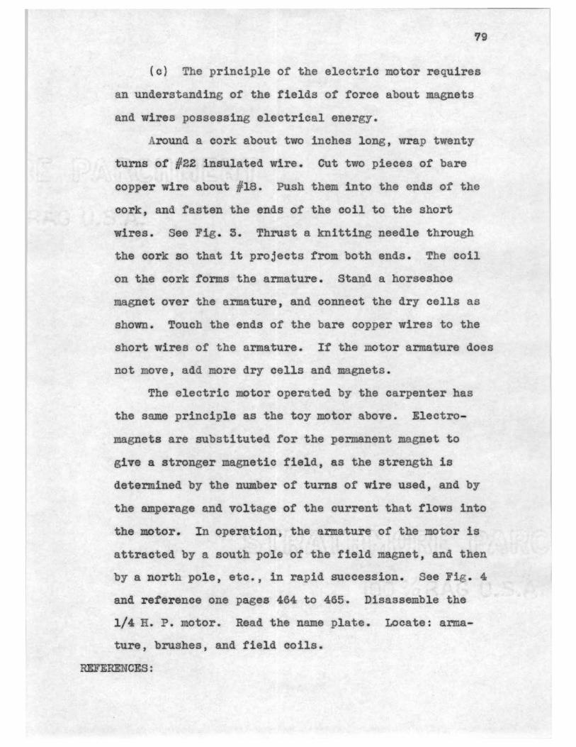
79
(c) The principle of the electric motor requires
an understanding of the fields of force about magnets
and wires possessing electrical energy.
Around a cork about two inches long, wrap twenty
turns of #22 insulated wire. Cut two pieces of bare
copper wire about #18. Push them into the ends of the
cork, and fasten the ends of the coil to the short
wires. See Fig. 3. Thrust a knitting needle through
the cork so that it projects from both ends. The coil
on the eork forms the armature. Stand a horseshoe
magnet over the armature, and connect the dry cells as
shown. Touch the ends of the bare copper wires to the
short wires of the armature. If the motor armature does
not move, add more dry cells and magnets.
The electric motor operated by the carpenter has
the same principle as the toy motor above. Electro
magnets are substituted for the perm.anent magnet to
give a stronger magnetic field, as the strength is
determined by the number of turns of wire used, and by
the amperage and voltage of the current that flows into
the motor. I n operation, the armature of the motor is
attracted by a south pole of the field magnet, and then
by a north pole, etc., in rapid succession. See Fig . 4
and reference one pages 464 to 465. Disassemble the
1/4 H.P. motor. Read the name plate. Locate: arma
ture, brushes, and field coils.
REFERENCES:

80
Bl a ck and Davis: Elementary Practical Physics, pp. 463-468.
Heisler: Elementary Science for the Student ot Industry, PP• 111-118.
CONCLUSION:
1. What is electricity?
2. What are the two common types of magnets? Which 1s
used in the 1/4 H.P. electric motor?
3. Which poles attract, like or unlike? Which repel?
4. Bow many poles does each magnet have?
5. 1¥b.y have the electro-magnets replaced the permanent
magnets in motors?
6. Why does the armature of a motor have to be cleaned
with sand paper occasionally?
7. Vlhy are brushes used in a motor?
8. How many poles have to be 1n the field coil ot a
motor before it runs?
9. 1hat is a volt? How many volts does the motor need
to operate? See name plate. What is an ampere?
10. Explain the reaction, if a carpenter in relocating
his saw, hooked the motor of the saw to a 550 volt
electric line.
11. If the motor stops operating suddenly, where does
the operator look for the trouble first'?
12. lb.at are the purposes of fuses? Name the two kinds.
13. If a woodworker came in contact with a power line
and was severely shocked, what kind of treatment
should be given?

Experiment 23
STRENGTH OF MATERIALS
Name
Date
81
--------~------OBJECT: To determine the strength of a glue joint.
MATERIALS: Vood hand screw; steel bar clamps; eight pieces
each of oak, white pine, and walnut which are l" X 4"
X 6".
DIRECTIONS:
E
Fig. l
Effort Arm - AC Resistance Arm - AB
Force needed to break: ACX spring balance reading equals AB X R.
In cabinet work and interior carpentry, glue is a
standard fastening material. A glued joint, to be sat-
isfactory, must be as strong as the wood and very dur
able. In this experiment several glue joints are to be
tested.
Prepare two :fresh pots of animal glue. Make one

82
of proper consistency labeling No. 1, and the other
of very thick consistency labeling No . 2. loin the
edges of two pieces of the same kind of wood with glue
from pot labeled No. 1. Apply pressure using a steel
bar clamp. Glue similarly two pieces of the same kind
of wood with glue from pot labeled No . 2.
After the joints have dried four or five days,
clamp in a vise and arrange apparatus as in Fig. 1.
Apply pressure at C and test to destruction. Calculate
resistance offered by wood or glued joint using the
principle of the lever.
Repeat procedure using casein glue .
RESULTS:
Oak
V hite Pine
Walnut
Oak
White Pine
Walnut
REFERENCES:
Animal Glue
Gl.ue Wood or Regular Thick joint broken Force applied No .. l No. 2 No . 1 No. 2 No. 1 No. 2
Casein Glue
Glue :ood or Regular Thick joint broken Force applied No. 1 No . 2 No . l No . 2 No . 1 No . 2

83
United States Department of Agriculture: Bulletin #1500 pp . 47-V3.
Heisler: Elementary Science for the Student of Industry, pp. 26-29.
CONCLUSION:
1. Which principle of physics is used in gluing,
adhesion or cohesion? Varity.
2. What is the composition of animal glue? Of casein
glue?
3. What does the cabinet-maker consider good shearing .. strength for an animal glued joint made or oak?
Of white pine? Of walnut?
4. What does the cabinet-maker consider good shearing
strength tor a casein glued joint made of oak? Of
white pine? Of walnut?
5. Why are the tests you made, a good test ot the
success of the gluing operation?
6. What are two other tests used by the manufacturer
of glue to prepare a satisfactory glue for the
carpenter?
7. Which proved to be the better, the glue of thick
eonsistency or the glue of thin consistency? hy?
8. Where does the woodworker need a ater proof glue
joint?
9. What effect does the quality of wood have on the
strength of the glued joint? Of the kind of wood?
10. there is fish glue used? or what is 1 t made?

84
Experiment 24
BEAM DEFLECTION
Date ~~~~~-------OBJECT: To study beam deflection or various kinds of beams.
MATERIALS: Beams of different cross sections; truss made or
slats, 1/4" X 2" X 60"; weights; sawhorses.
DIRECTIONS: Building contractors strive to make buildings
strong enough to bear the dead and live loads without
deflection (sagging). Deflection in a beam is the
~ 1 2 3 4 5 6
End views ...-~~~~~~ 5'~~~~~~--'-
Front view
Fig. 1 4' _____ _
Fig. 2
distance that a beam sags belo 'I the normal horizontal
level when bearing a load. Have you ever seen build-

85
ings whose beams have deflected? Where?
In this experiment different types of beams will
be studied to learn how strong buildings are made.
SUpport beam 1, Fig. 1, on two saw horses as shown in
Fig. 2. Measure from bottom of beam to floor and re
cord. From a point midway between the supports, sus
pend the load necessary to make berun deflect one inch.
This may be a box of bricks or heavy iron weights.
Observe what happens to the shape of the beam. Measure
the distance from the midpoint of the beam to the floor.
Substraot previous measurement for amount of deflection.
Repeat the procedure for each of the different beams
and for the truss shown in Fig. 1. In some cases it
may be necessary to nail boards in the sawhorses to
keep the beams from turning.
RESULTS:
Deflection Pounds of force needed
Beam l
Beam 2
Beam 3
Beam 4
Beam 5
Beam 6
Truss
REFERENCES:
Deming and Nerden: Science in the World of ~ ork, Vol. I, pp. 117-130.

Black and Davis: Elementary Praetical Physics, pp. 167-176.
Griffith: Carpentry, pp. 1-114.
86
Heisler: Elementary Science for the Student of Industry, pp. 120-124.
CONCLUSION:
l. What is a beam? Name two places where heavy beams
are needed 1n building a house.
2. Which of the beams tested were the hardest to de
flect? Which were the easiest?
3. How do these beams compare in flexing ability with
the beam tested in a previous experiment'? hy?
4. How did the truss compare in strength to the beams?
How do you account tor this?
5. Where is the L beam used in carpentry? tvhy?
6. .Show where three of these beams can be used in the
constra.ction industry and tell why they are used.
'l. Show different places where a truss can be used,
and tell why it is used instead of a beam.
8. Is steel used for beams and truss work in buildings?
In what type of buildings? Why?
9. In the building industry which is used the more,
steel beams and trusses or wood beams and trusses?
Why?
10. Vfhat is meant by a beam being under stress? Under
strain?

Experiment 25
SOUND
Name
Date
87
--~~----~------OBJECT: To study the theory of absorption of sounds by in
sulating materials.
MATERI ALS: Wooden box lined with insulite; battery; electric
bell; squares of: celotex, insulite, felt, velvet, and
plywood.
DIRECTIONS: In building construction, we not only find that
it is necessary to insulate buildings to prevent heat
Opening
0 For shutter
Fig. 1
losses, but in many cases to apply materials that ab
sorb sound. Several different types of materials that
absorb sound will be studied.
Connect dry cell to bell in the moden box lined
with insulite. With opening not closed, ring bell and
note volume of sound produced. With the bell ringing,
close opening consecutively with: plywood, celotex,
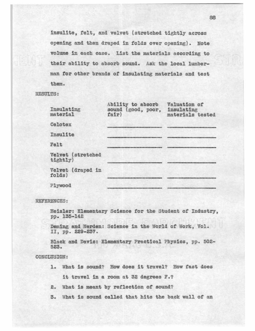
88
inaul1te, felt,. and velvet (stretched tightly across
opening and then dr ped in :folds over opening). Note
volume in each case. List the materials according to
their ability to absorb sound. /.,sk the looal 1 ber
man tor other brands ot insulating materials and test
them.
RESULTS:
Insulating material
Celotex
Irurulite
Felt
Velvet (stretched tightly)
Velvet (draped in folds)
Plywood
REFERENCES:
bility to absorb sound (good, poor, fa1r}
Valuation of insulati mater1 ls tested
Heisler: Elementary Science for the Student or Industry, PP • 155-14.2
Deming and Nerd.en: Science in the 3orld ot Work, Vol. II, pp. 229-257.
Black and Davis : E.lement ry Practical Physics, pp. 502-523.
CONCLUSION:
1. at is sound? Ro does it travel? How fast does
it travel in a room at 32 degrees F.?
2. hat is meant by- reflection of sound?
3. 1hat is sound ealled that hits the back wall or an
auditorium and reflects back to a person in the
room?
4. Compare the ability of velvet stretched tight and
velvet draped in folds to absorb sound. Account
for this.
5. Explain the reason for tiny holes in ceilings of
sound insulated rooms.
89
6. Vlhat is the general statement that explains the
effect any soft fibrous substance, like felt, vel
vet, drapes, insulate, celotex, etc., has on con
duction and reflection of sound.
7. Explain why a carpenter, doing acoustical work,
must cover accurately the spaces specified by the
blue print.
8. Give ways in which partitions and floors can be
ma.de more nearly sound proof in tenement houses.

Experiment 26
COLOR
Nwne
90
--------~~-----Date
OBJECT: To study the principle of selection of pleasing
colors in laying floor coverings.
MATERIALS: Assortment of colored construction paper:
standard color wheel and masks to tit each of the eight
commonly used color schemes.
DIRECTIONS: Study picture on next sheet, Fig. 2. The car
penter laying floor coverings, many times finds 1t
neoe-ssary to use various colors to make different har
monizing patterns. '!'his experiment should help make
this problem easier.
(a) Look through a prism toward sunlight. Try to
tind all colors listed in Fig. l. Read pages 619 to
middle of page 620; 627 to 632 in reference l. hat is
the source or color?
(b) Find the meaning of the following words:
color, analogous, hue, complementary color, primary
colors, contrast, and harmonize.
The basis of color harmony lies in the fact that
when the eye perceives a color, the observer feels a
need to see the remainder ot the primary colors.
Yellow, red, and blue are called the primary pigment
colors. All other colors can be made from combinations
of these three. Color harmonies are balanced relation-

ships between the varying hues or colors of the spec
trum. Two types of color combination give pleasing
91
results: schemes of closely related colors, and those
of widely contrasting colors. The majority of color
schemes will show one dominating color with sufficient
Fig. 1
Fig. 2
violet indigo blue green yellow orange red
contrast to the remaining colors to give point to the
scheme.
ethods will be given that will greatly aid in the
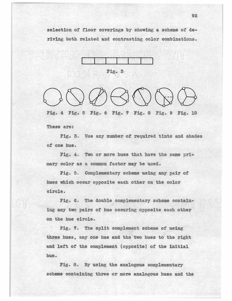
92
selection of floor coverings by showing a scheme of de
riving both related and contrasting color combinations.
Fig. 3
Fig. 4 Fig. 5 Fig. 6 Fig. 7 Fig. 8 Fig. 9 Fig. 10
These are:
Fig . 3. Use any number of required tints and shades
of one hue.
· Fig. 4. Two or more hues that have the same pri
mary color as a common factor may be used.
Fig. 5. Complementary scheme using any pair of
hues which occur opposite each other on the color
circle.
Fig. 6. The double complementary scheme contain
ing any two pairs of hue oceuring opposite each other
on the hue circle.
Fig. 7. The split complement scheme or using
three hues, any one hue and the two hues to the right
and left of the complement (opposite) of the initial
hue.
Fig. 8. By using the analogous complementary
scheme containi.ng three or more analogous hues and the

complement of the hue that is predominant among the
analogous group.
Fig. 9. The adjacent complementary color scheme
may be used , consisting of a complementary pair and
third hue that may be adjacent (next to) to the right
or left of either member of the pair.
93
Fig. 10. Triadic scheme, containing three colors
which occur at three points equidistant around the hue
circle.
The figures above indicate the location of the
various hues needed for each of the schemes . Fasten
the mask for the desired scheme to the center of the
color wheel and by revolving, colors exposed are the
combinations that may be used in that color scheme.
RESULTS: Make a pattern of construction paper blocks for a
covering 6" X 6" for each of the color schemes .
REFERENCES:
Elizabeth Burris-Meyer: Color and Design in the Decorative Arts, pp. 58-59; 103-114.
Black and Davi s: Elementary Practical Physics, pp. 619-620; 627- 632.
CONCLUSION:
1. What is color? Name five different colored floor
coverings that you have seen.
2. fhat are the colors of the spectrum (rainbow}?
3. What are primary colors?
4. Vhat does the c rpenter mean ho describes a floor
covering as one possessing a pleasing hue?
5. Observe the dominant color of three dovmtown de
partment stores. What is it? What color combi
nations does each have'?
6 .. Why is the red color red, and not green or some
other color?
7. What is the physicist's definition of red, green,
blaek, and wl1ite?

CHAPTER III
CONCLUSION
95
The importance of related science in industrial prac
tiee has for many years been recognized, along with related
mathematics, as fundamental 1n efficient preparation ot in
dustrial workers . Present day workerst whose daily task
deals with the practical principles of seience in industry,
have many deficiencies along this line. This study suggests
a method of remedying these deficiencies. A compilation of
experiments in physics for the related woodworking trades
has been made, based upon Mr . w. Fred Heisler ' s study, "Ele
mentary Science for the Student of Industry". This book is
commonly used as an introduction to applied science in Trade
and I ndustrial Programs in Oklahoma. I t should be definite
ly remembered, however, that principles in related science
which :may suit one trade may be of little value to workmen
in another occupation . The principles which are used in
teaching related science should apply to the trade itself.
The basic and abstract principles and laws that apply to the
trade should be presented to the student. supplemental ex
periments that further relate these principles of science
definitely to the trade may then be performed in the labora
tory . Students receiving such training will not only be
more interested in their school work, but more interested in
their trades, and will become more intelligent workers.
They will then not stop with the experiments given in class,
but will go into independent search of new truths. Thus, a

96
thorough grounding in the basic principles of science from
a practical standpoint and by a practical method, wil.l be
tangible assets for advancement in a trade. According to
Geo. P. Hambrechtl:
No community ever went bankrupt in doing something that pays.
The teaching of proper application of the principles or science is considered by many authorities as superior teach
ing, and as this faet is realized, science will be taught
more and more as this study proposes.
Evidence collected in this study shows a lack of ex
periments in applied science and a need for them as well as
considerable activity in the preparation of such instruction
al materials.
In keeping with current reconnnendations of industrial
educators, all such proposed content should be validated by
industrial committees before its final adoption in schools
to see that it illustrates current practices.
The compilation of similar supplemental experiments of
science for the various trades is needed as the vehicle for
diffusion of the principles of science as needed by trades
men other than woodworkers. These problems seem a worthy
basis for further investigation.
I.tis hoped that this study will not be considered com
plete for the related woodworking trades, but that it is a
means or better training tradesmen, and thus, will aid in
helping to make a happier, more useful citizen.
1. Geo. P. Hambreoht, "The Struggle Against Ignorance", p. 9.
•

97
BIBLIOGRAPHY
Black, Newton Henry and Davis, Harvey Nathaniel. Elementary Practical Physics. The Macmillan Company, New York, 1938.
Deming, Frank R. and Nerden, Joseph T. Science in the World of Work. Vol. I-II. McGraw-Hill Book Company, Inc ::-New York,1936.
Dooley, William H. Science Training for Metal and Wood Trades. The Ronald Press Company, New York, 19'37'":'" ~
Foley, Arthur L. College Physics. P. B1akiston1 s Son and Company, Inc., Philadelphia, 1933.
Gillum, Lulu w. Color and Design. The Gillum Publishing Company, Kansas City, Mo., 1931.
Grittith, Ira Samuel. Carpentry. The Manual Arts Press, Peoria, Illinois, 1916.
Hambrecht, George P., "The Struggle Against Ignorance." Wisconsin Magazine, Feb., 1927.
Heisler, W. Fred. Elementary Science for the Student of Industry. State Department, Trade and Industrial Education, 1934.
Hjorth, Herman. Principles or Woodworking. The Bruce Publishing Company, Chicago, Ill:', l930.
Hodgson, Fred T. Modern Carpentrz. Freder.ick J. Drake and Company, Chicago, Ill., 1913.
Hunt, Dewitt. A Manual for Hand Woodworking. Harlow Publishing Corporation, Oklahoma.--:crty, Okla., 1938.
Jameson, Joseph M. Elementary Practical Mechanics. John Wiley and Sons, Inc., 1937.
Lynde, Carleton John. Everydaz Physics. The Macmillan Company, New York, 1930.
Mersereau, Samuel Foster. Materials of Industry. McGrawHill Book Company, Inc., New York, 193!'.
Meyer, Elizabeth Burris. Color~ Design in~ Decorative ~. Prentice-Hall Inc., New York, 1935.
Prosser, Charles A. and Allen, Charles R. Vocational Education !!l~ Democracy. The Century Company, New York, 1925.
Sears, Frederick E. Essentials of Physics . Laurel Book Company, Chicago, Ill., 1933.
98
Stephenson, Reginald J. Explorins in Physics. The University or Chicago Press, Chicago, Ill., 1935.
United States Department of Agriculture, Bulletin No. 1500, Washington D. c., 1929.
Weed , Rexford, and Carroll. A Workbook and Laborator1 Manual . The John C. inston ~ompany, 0.hicago, Ill., 935 •
. Whitman, Walter G. Household Physics. John Wiley and Sons, Inc., New York, 1924.

APPErIDIJC

Dear SUpeni.aoJ.11':
DEPARTMENT OF INDUSTRIAL ARTS
C. H. PREWETT, SUPERVISO R
~~lnsnne\?, ®klnfroma
Feb. 2, 1~36
99
For.a I
'?he at dents on th ~ and • Campus during the summer
ot l93f were Tery much interested. in having more related
aoienoe uter1al de-veloped. It la the purpose or this study
to aeoertain. the need tor supp1emental aclenoe experiments
aa4 applloationa for the state prepare4 retereaoe "Elemen
tary Science tor the Stu.dent or Industry".
In orcler to prepare pract1oa1 functioning material in
applied so1eace, it 1a t1:ret neoeasar.r to know spec1t1cally
what ls needed by students tor etteot1Ye vocation.al prepara
tion. Will you please 11st. 70ur needs tor :mater1al such as
applied experiments:
e.14.a ---------------------------- and other
-------- ----------------• All into,:ma t1on
b.clu4-4 in thia study will be supplemented by studies of
the wriwr ant al1 suggestions 1D. the thesis 'Ifill be Yal1-
date4 by in4ustri.al1ata. The results ot this cooperative
s'tu47, wllen t1n1eh$d, may be secured through the A. and •
College Boolcatore at Stillw ter, Oklahoma.
o.te: The following blanks may be filled in by the aupeniaor, ooorclt.nator, related subjects teacher, shop te cher, or a combination ot these.
Your cooperation. 1n aaai.sting llr. Prewett 1n his study
will be gl'eatly appreciated and 1'111 eaable u:,, all to protit

100
more troa the material he prepares and au its tor graduate creclit •
. 1. ame and position ----~~-...~ ... ---...... -----(one ti11.!iii In bianiiJ 2. Address
------------------------------------------3. Type ot Tooatlonal education program 1n your school
•ptem: General In4.uetrial __ DiversU-ied Ooeupat1ons Day Trade __ Others _______ _
,. Retereno.ea you use 1D teaching app11ed aolenoe:
Author Title Publisher
5. ould you preter the :material tor related scleao.e claas
ea reau1ting f!'Olll thia study' to be prepared in loose
leaf __ or book tom __ ,
6. Pleaae rorward to the niter experiments that you use
and feel would help othe.r related scien-ce teache.rs, to
gether with this blank. (These may be general or they
may be applied to a apeoiflo TOCation.)
Note: Please uae experlaent torm s1mllar to enclosed aaaple.

Appl1oatJ.o1'l8:
Tb:per.iment
WA'flm AS A SOLVEl'l
Pioture or 1llus,tra tion
101

102
~elagonetl Jublic ~cqoois DEPARTMENT OF INDUSTRIAL ARTS
C. H. PREWETT, SUPERVI SOR l'orm Il:
arch 12, 1938
Dear S1r:
It is believed that eYer,- aoi nee teacher has an experilaent he uses that 1a eapee1ally praotieal tor teach-1ng related ao1ene.e 1n the indU.strial yocational tield.
You have been auggeated a.e one who wou..ld poaaibly be willlng to coop•rate 1n th1a atucly. You can assist by tlllblg in and returning the e110losed b1ank With an ex .. periaent.
The 1,cu1ulta ot thia s'tudy wi.11 be made anilable. Do you 4ea1N a copy?
Please aocep~ lll7 thanks tor your cooperation.
Sincerely yours,
C. H. Prewett

103
!'ILL IN AND RffU'BN THIS BLi
Approved -------
1. Bmae and position ----------------
a. Add.re•• ------------------------------------------
:1. Tn4t ot YOoat1onal eduo tion program in your echool
•m•z Omleral Illdustrial D1vera1t1ed Occupations
__ All Da7 Trade O~era ----- ------
4. The experbtent to be rilled 1n the blank tom below may
be gene_ral or lt may be applied to 8pecir1c voeat1on.
Apparaus nee4ed:
Results:
Application:

DEPARTMENT OF INDUSTRIAL ARTS
C. H. PREWETT, SUPERVI SOR :rom Ill ~elagntreij, ®klafroma:
March 30. 1938
Dear S1r:
A manual 1a being prepare4 to acoompany the textbook ot :rel ate4 science published by the Vocational Depart.ment ot the s~at e ot OklahoJla.
'!he purpose ot thia study is to tlnd What other o1t1es and atatea haYe done 1D thi• t1el4.
It will be greatly' appnoiai.cl 1:.t JOU will forward a cop7 ot a aanual or aoae ot t)le ex_per !aenta used b7 your oi t1 or state, or sen4 JWl9S and addre.sees ot peraou that ou supply available material.
The l'eil'Ul\a of th1e study will be •4• available through the State Vocational Department located at St-illwater, Oklaho •
Please a4Y1•• it there are any charges.
Sincerely yours,
c .. B .. Prewett
104

Dear Sa:
~elagouell Jublic ~drools DEPARTMENT OF INDUSTRIAL ARTS
C. H. PREWETT. S UPERVI SOR
~elagnne~, ®klaqnma
April 10, 1938
:rorm IV
A manual 1s being prepared to aocompaJ1y the tertbook ot related acienee published bf the Vocational Department et the St te of Oklahou located at stillwate~.
It 1a bel1eTe4 that eTery ~acher ot related acle.noe haa expertaents he uses that are eapeoially practical. tor t aching related cience 1n the 1ndustr1al Tocational tield.
You ha.Te een euggeet 4 aa one who woul.d possibly be wllllns to cooperate 1n th.is stwl7. You can us.tat by sending a JDaJmal or 80Jll8 experiments ued by your city or st te. Please advise lt t ere are ny charges.
The resul~s ot this study w1ll be ma.4e aTailable. Do you dea1re copy?
Accept BfT thanks tor your cooperation.
sacerel;r yours,
c. ll. Prewett
105

Typist
Golda Hamaker Prevmtt
Related Documents