Freescale Semiconductor Application Note AN2691 Rev. 1, 8/2005 © Freescale Semiconductor, Inc., 2004, 2005. All rights reserved. This application note demonstrates the matrix multiplication technique using the DSP563xx Enhanced Filter Coprocessor (EFCOP). The EFCOP is a general-purpose, fully programmable filter coprocessor that operates concurrently with DSP core operations and requires minimal CPU intervention. The EFCOP has dedicated modes of operation for performing real and complex finite impulse response (FIR) filtering, infinite impulse response (IIR) filtering, adaptive filtering, and multichannel FIR filtering. This application note demonstrates how to use the EFCOP multichannel FIR filtering to perform matrix multiplications. After a quick refresher on matrix multiplication basics, this application note describes two ways to perform matrix multiplication on the EFCOP, which are polling or DMA with interrupts. A basic knowledge of the DSP563xx EFCOP is assumed. 1 1. For details on EFCOP architecture and functionality, con- sult the following documents: EFCOP programming chap- ter in the DSP56321 Reference Manual (DSP56321RM) and the application note entitled Programming the DSP56300 Enhanced Filter Coprocessor (EFCOP) (APR39). CONTENTS 1 Matrix Multiplication Basics .................................. 2 2 Matrix Multiplication With EFCOP ....................... 2 3 Polling ..................................................................... 9 4 DMA with Interrupts ............................................. 13 Appendix A: Code for Polling ................................................................ 19 Appendix B: Code for DMA with Interrupts ......................................... 23 Applied Matrix Multiplication With the DSP563xx Enhanced Filter Coprocessor (EFCOP) By Dejan G. Minic

Welcome message from author
This document is posted to help you gain knowledge. Please leave a comment to let me know what you think about it! Share it to your friends and learn new things together.
Transcript

Freescale SemiconductorApplication Note
AN2691Rev. 1, 8/2005
CONTENTS
1 Matrix Multiplication Basics ..................................22 Matrix Multiplication With EFCOP .......................23 Polling ..................................................................... 94 DMA with Interrupts .............................................13
Appendix A: Code for Polling ................................................................19
Appendix B: Code for DMA with Interrupts .........................................23
Applied Matrix Multiplication With the DSP563xx Enhanced Filter Coprocessor (EFCOP)By Dejan G. Minic
This application note demonstrates the matrix multiplication technique using the DSP563xx Enhanced Filter Coprocessor (EFCOP). The EFCOP is a general-purpose, fully programmable filter coprocessor that operates concurrently with DSP core operations and requires minimal CPU intervention. The EFCOP has dedicated modes of operation for performing real and complex finite impulse response (FIR) filtering, infinite impulse response (IIR) filtering, adaptive filtering, and multichannel FIR filtering. This application note demonstrates how to use the EFCOP multichannel FIR filtering to perform matrix multiplications. After a quick refresher on matrix multiplication basics, this application note describes two ways to perform matrix multiplication on the EFCOP, which are polling or DMA with interrupts. A basic knowledge of the DSP563xx EFCOP is assumed.1
1. For details on EFCOP architecture and functionality, con-sult the following documents: EFCOP programming chap-ter in the DSP56321 Reference Manual (DSP56321RM) and the application note entitled Programming the DSP56300 Enhanced Filter Coprocessor (EFCOP) (APR39).
© Freescale Semiconductor, Inc., 2004, 2005. All rights reserved.
Matrix Multiplication Basics
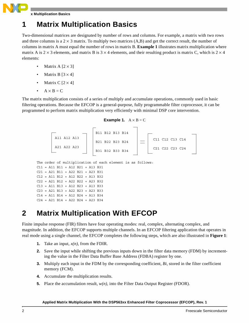
1 Matrix Multiplication BasicsTwo-dimensional matrices are designated by number of rows and columns. For example, a matrix with two rows and three columns is a 2 × 3 matrix. To multiply two matrices (A,B) and get the correct result, the number of columns in matrix A must equal the number of rows in matrix B. Example 1 illustrates matrix multiplication where matrix A is 2 × 3 elements, and matrix B is 3 × 4 elements, and their resulting product is matrix C, which is 2 × 4 elements:
• Matrix A [2 × 3]
• Matrix B [3 × 4]
• Matrix C [2 × 4]
• A × B = C
The matrix multiplication consists of a series of multiply and accumulate operations, commonly used in basic filtering operations. Because the EFCOP is a general-purpose, fully programmable filter coprocessor, it can be programmed to perform matrix multiplication very efficiently with minimal DSP core intervention.
Example 1. A × B = C
The order of multiplication of each element is as follows:C11 = A11 B11 + A12 B21 + A13 B31C21 = A21 B11 + A22 B21 + A23 B31C12 = A11 B12 + A12 B22 + A13 B32C22 = A21 B12 + A22 B22 + A23 B32C13 = A11 B13 + A12 B23 + A13 B33C23 = A21 B13 + A22 B23 + A23 B33C14 = A11 B14 + A12 B24 + A13 B34C24 = A21 B14 + A22 B24 + A23 B34
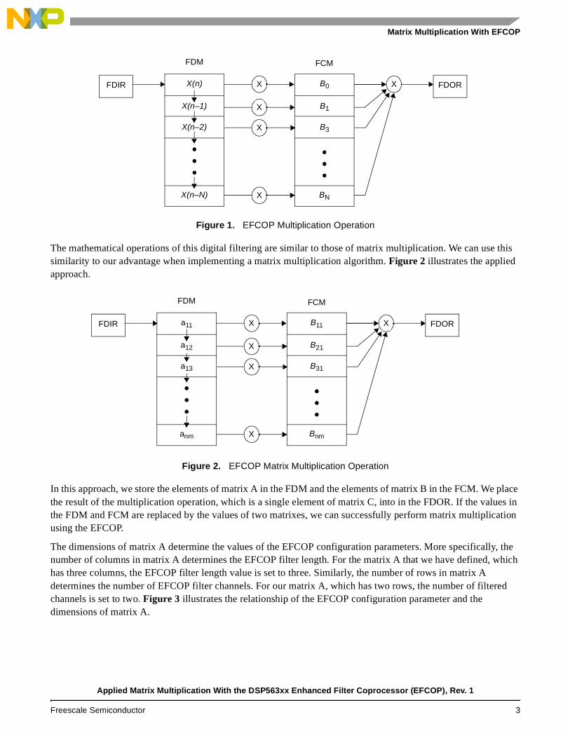
2 Matrix Multiplication With EFCOPFinite impulse response (FIR) filters have four operating modes: real, complex, alternating complex, and magnitude. In addition, the EFCOP supports multiple channels. In an EFCOP filtering application that operates in real mode using a single channel, the EFCOP completes the following steps, which are also illustrated in Figure 1:
1. Take an input, x(n), from the FDIR.
2. Save the input while shifting the previous inputs down in the filter data memory (FDM) by increment-ing the value in the Filter Data Buffer Base Address (FDBA) register by one.
3. Multiply each input in the FDM by the corresponding coefficient, Bi, stored in the filter coefficient memory (FCM).
4. Accumulate the multiplication results.
5. Place the accumulation result, w(n), into the Filter Data Output Register (FDOR).
A11 A12 A13
A21 A22 A23
B11 B12 B13 B14
B21 B22 B23 B24
B31 B32 B33 B34
C11 C12 C13 C14
C21 C22 C23 C24
Applied Matrix Multiplication With the DSP563xx Enhanced Filter Coprocessor (EFCOP), Rev. 1
2 Freescale Semiconductor
Matrix Multiplication With EFCOP
Figure 1. EFCOP Multiplication Operation
The mathematical operations of this digital filtering are similar to those of matrix multiplication. We can use this similarity to our advantage when implementing a matrix multiplication algorithm. Figure 2 illustrates the applied approach.
Figure 2. EFCOP Matrix Multiplication Operation
In this approach, we store the elements of matrix A in the FDM and the elements of matrix B in the FCM. We place the result of the multiplication operation, which is a single element of matrix C, into in the FDOR. If the values in the FDM and FCM are replaced by the values of two matrixes, we can successfully perform matrix multiplication using the EFCOP.
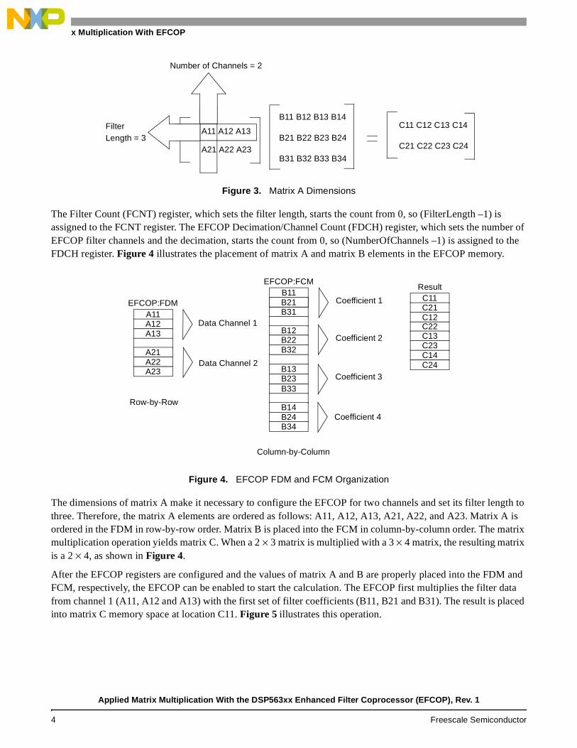
The dimensions of matrix A determine the values of the EFCOP configuration parameters. More specifically, the number of columns in matrix A determines the EFCOP filter length. For the matrix A that we have defined, which has three columns, the EFCOP filter length value is set to three. Similarly, the number of rows in matrix A determines the number of EFCOP filter channels. For our matrix A, which has two rows, the number of filtered channels is set to two. Figure 3 illustrates the relationship of the EFCOP configuration parameter and the dimensions of matrix A.
X(n)
X(n–1)
X(n–2)
X(n–N)
B0
B1
B3
BN
FDM FCM
FDIR FDORXX
X
X
X
a11
a12
a13
anm
B11
B21
B31
Bnm
FDM FCM
FDIR FDORXX
X
X
X
Applied Matrix Multiplication With the DSP563xx Enhanced Filter Coprocessor (EFCOP), Rev. 1
Freescale Semiconductor 3
Matrix Multiplication With EFCOP
Figure 3. Matrix A Dimensions
The Filter Count (FCNT) register, which sets the filter length, starts the count from 0, so (FilterLength –1) is assigned to the FCNT register. The EFCOP Decimation/Channel Count (FDCH) register, which sets the number of EFCOP filter channels and the decimation, starts the count from 0, so (NumberOfChannels –1) is assigned to the FDCH register. Figure 4 illustrates the placement of matrix A and matrix B elements in the EFCOP memory.
Figure 4. EFCOP FDM and FCM Organization
The dimensions of matrix A make it necessary to configure the EFCOP for two channels and set its filter length to three. Therefore, the matrix A elements are ordered as follows: A11, A12, A13, A21, A22, and A23. Matrix A is ordered in the FDM in row-by-row order. Matrix B is placed into the FCM in column-by-column order. The matrix multiplication operation yields matrix C. When a 2 × 3 matrix is multiplied with a 3 × 4 matrix, the resulting matrix is a 2 × 4, as shown in Figure 4.
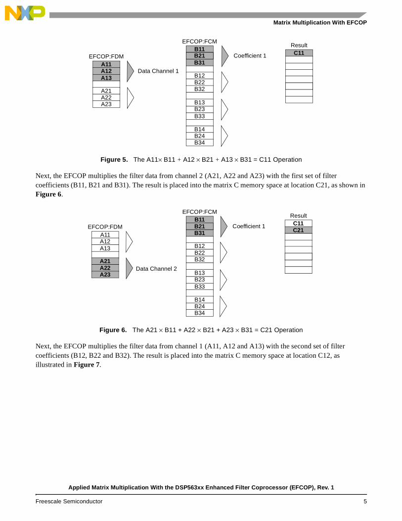
After the EFCOP registers are configured and the values of matrix A and B are properly placed into the FDM and FCM, respectively, the EFCOP can be enabled to start the calculation. The EFCOP first multiplies the filter data from channel 1 (A11, A12 and A13) with the first set of filter coefficients (B11, B21 and B31). The result is placed into matrix C memory space at location C11. Figure 5 illustrates this operation.
A21 A22 A23
B11 B12 B13 B14
B21 B22 B23 B24
B31 B32 B33 B34
C11 C12 C13 C14
C21 C22 C23 C24
Number of Channels = 2
FilterLength = 3
A11 A12 A13
A11A12A13
A21A22A23
B11B21B31
B12B22B32
B13B23B33
B14B24B34
C11C21C12
C13C23C14
C22
C24
Row-by-Row
Column-by-Column
B21
Data Channel 1
Data Channel 2
Coefficient 1
Coefficient 2
Coefficient 3
Coefficient 4
EFCOP:FDM
EFCOP:FCMResult
Applied Matrix Multiplication With the DSP563xx Enhanced Filter Coprocessor (EFCOP), Rev. 1
4 Freescale Semiconductor
Matrix Multiplication With EFCOP
Figure 5. The A11× B11 + A12 × B21 + A13 × B31 = C11 Operation
Next, the EFCOP multiplies the filter data from channel 2 (A21, A22 and A23) with the first set of filter coefficients (B11, B21 and B31). The result is placed into the matrix C memory space at location C21, as shown in Figure 6.
Figure 6. The A21 × B11 + A22 × B21 + A23 × B31 = C21 Operation
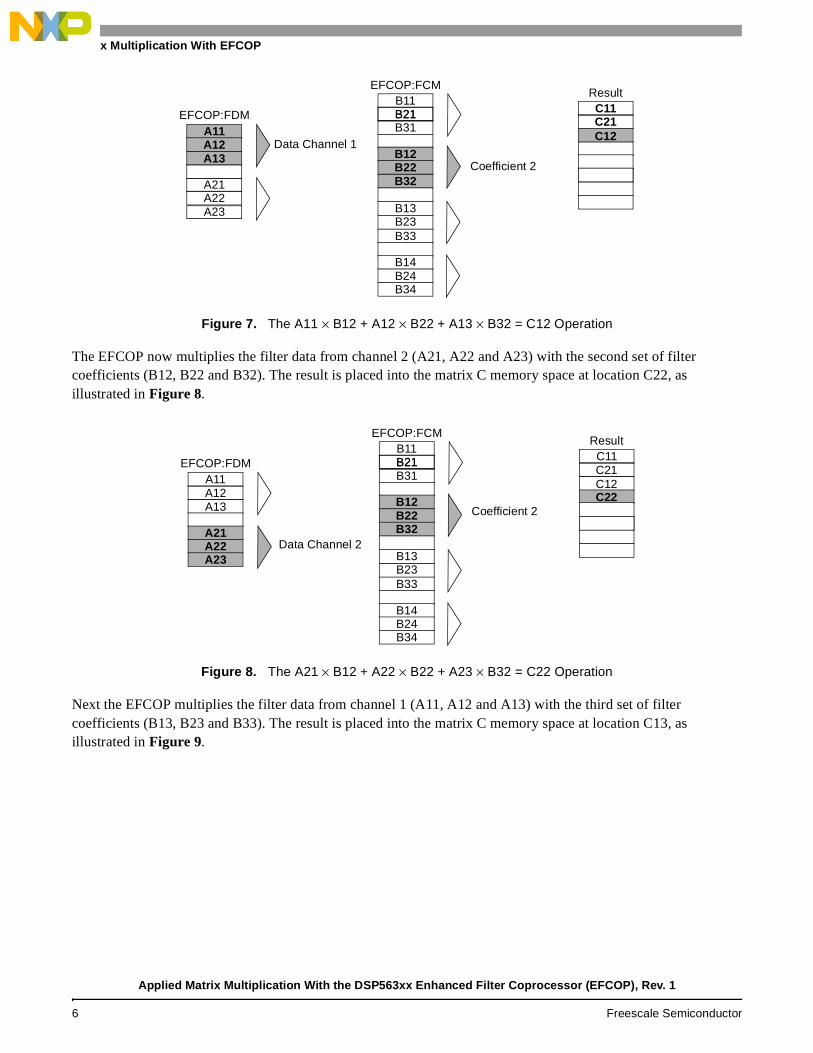
Next, the EFCOP multiplies the filter data from channel 1 (A11, A12 and A13) with the second set of filter coefficients (B12, B22 and B32). The result is placed into the matrix C memory space at location C12, as illustrated in Figure 7.
A11A12A13
A21A22A23
B11B21B31
B12B22B32
B13B23B33
B14B24B34
C11B21
Data Channel 1
Coefficient 1EFCOP:FDM
EFCOP:FCMResult
B21
A11A12A13
A21A22A23
B11B21B31
B12B22B32
B13B23B33
B14B24B34
C11B21 Coefficient 1EFCOP:FDM
EFCOP:FCMResult
C21
Data Channel 2
Applied Matrix Multiplication With the DSP563xx Enhanced Filter Coprocessor (EFCOP), Rev. 1
Freescale Semiconductor 5
Matrix Multiplication With EFCOP
Figure 7. The A11 × B12 + A12 × B22 + A13 × B32 = C12 Operation
The EFCOP now multiplies the filter data from channel 2 (A21, A22 and A23) with the second set of filter coefficients (B12, B22 and B32). The result is placed into the matrix C memory space at location C22, as illustrated in Figure 8.
Figure 8. The A21 × B12 + A22 × B22 + A23 × B32 = C22 Operation
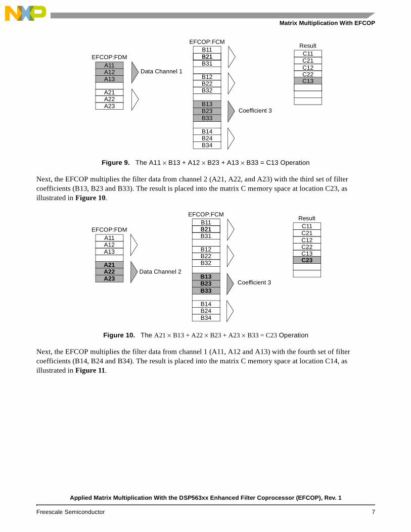
Next the EFCOP multiplies the filter data from channel 1 (A11, A12 and A13) with the third set of filter coefficients (B13, B23 and B33). The result is placed into the matrix C memory space at location C13, as illustrated in Figure 9.
A11A12A13
A21A22A23
B11B21B31
B12B22B32
B13B23B33
B14B24B34
C11B21
Coefficient 2
EFCOP:FDM
EFCOP:FCMResult
C21
Data Channel 1C12
A11A12A13
A21A22A23
B11B21B31
B12B22B32
B13B23B33
B14B24B34
C11B21
Coefficient 2
EFCOP:FDM
EFCOP:FCMResult
C21
Data Channel 2
C12C22
Applied Matrix Multiplication With the DSP563xx Enhanced Filter Coprocessor (EFCOP), Rev. 1
6 Freescale Semiconductor
Matrix Multiplication With EFCOP
Figure 9. The A11 × B13 + A12 × B23 + A13 × B33 = C13 Operation
Next, the EFCOP multiplies the filter data from channel 2 (A21, A22, and A23) with the third set of filter coefficients (B13, B23 and B33). The result is placed into the matrix C memory space at location C23, as illustrated in Figure 10.
Figure 10. The A21 × B13 + A22 × B23 + A23 × B33 = C23 Operation
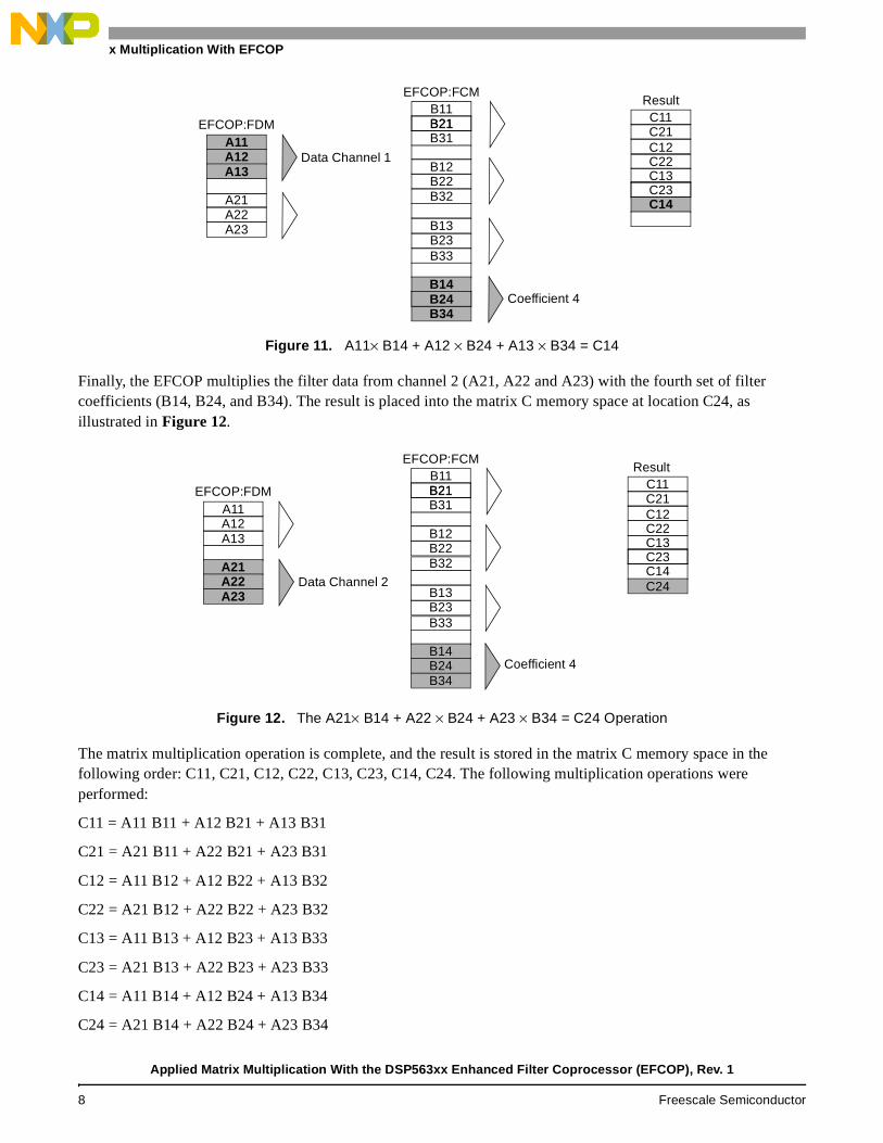
Next, the EFCOP multiplies the filter data from channel 1 (A11, A12 and A13) with the fourth set of filter coefficients (B14, B24 and B34). The result is placed into the matrix C memory space at location C14, as illustrated in Figure 11.
A11A12A13
A21A22A23
B11B21B31
B12B22B32
B13B23B33
B14B24B34
C11B21
Coefficient 3
EFCOP:FDM
EFCOP:FCMResult
C21
Data Channel 1C12C22C13
A11A12A13
A21A22A23
B11B21B31
B12B22B32
B13B23B33
B14B24B34
C11B21
Coefficient 3
EFCOP:FDM
EFCOP:FCMResult
C21
Data Channel 2
C12C22C13C23
Applied Matrix Multiplication With the DSP563xx Enhanced Filter Coprocessor (EFCOP), Rev. 1
Freescale Semiconductor 7
Matrix Multiplication With EFCOP
Figure 11. A11× B14 + A12 × B24 + A13 × B34 = C14
Finally, the EFCOP multiplies the filter data from channel 2 (A21, A22 and A23) with the fourth set of filter coefficients (B14, B24, and B34). The result is placed into the matrix C memory space at location C24, as illustrated in Figure 12.
Figure 12. The A21× B14 + A22 × B24 + A23 × B34 = C24 Operation
The matrix multiplication operation is complete, and the result is stored in the matrix C memory space in the following order: C11, C21, C12, C22, C13, C23, C14, C24. The following multiplication operations were performed:
C11 = A11 B11 + A12 B21 + A13 B31
C21 = A21 B11 + A22 B21 + A23 B31
C12 = A11 B12 + A12 B22 + A13 B32
C22 = A21 B12 + A22 B22 + A23 B32
C13 = A11 B13 + A12 B23 + A13 B33
C23 = A21 B13 + A22 B23 + A23 B33
C14 = A11 B14 + A12 B24 + A13 B34
C24 = A21 B14 + A22 B24 + A23 B34
A11A12A13
A21A22A23
B11B21B31
B12B22B32
B13B23B33
B14B24B34
C11B21
Coefficient 4
EFCOP:FDM
EFCOP:FCMResult
C21
Data Channel 1C12C22C13C23C14
B24
A11A12A13
A21A22A23
B11B21B31
B12B22B32
B13B23B33
B14B24B34
C11B21
Coefficient 4
EFCOP:FDM
EFCOP:FCMResult
C21
Data Channel 2
C12C22C13C23C14C24
Applied Matrix Multiplication With the DSP563xx Enhanced Filter Coprocessor (EFCOP), Rev. 1
8 Freescale Semiconductor
Polling
3 PollingPolling is one of the two ways discussed in this application note to perform matrix multiplication on the EFCOP. The other is DMA with interrupts, which is discussed in Section 4, DMA with Interrupts, on page 13. Polling is the simplest method of supplying and retrieving data to/from the EFCOP. For a polling implementation, the following operations are performed:
1. Initialize matrices A and B.
2. Initialize pointers to the memory addresses of matrices A, B, and C.
3. Configure the EFCOP.
4. Enable the EFCOP and load the first data.
5. Retrieve the multiplication result from the EFCOP.
6. Disable the EFCOP and increment the FCB address.
7. Re-initialize the EFCOP and memory pointers and re-enable the EFCOP.
8. Perform steps 4, 5, 6, 7, and 8 until the matrix calculation is complete.
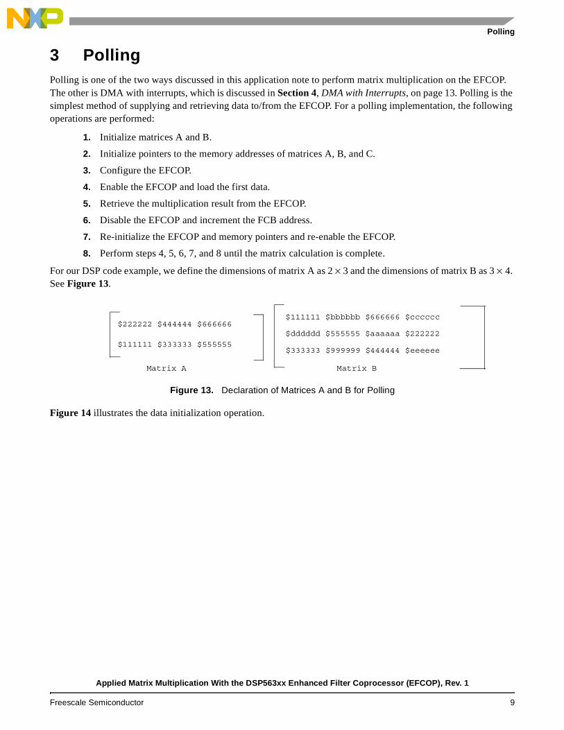
For our DSP code example, we define the dimensions of matrix A as 2 × 3 and the dimensions of matrix B as 3 × 4. See Figure 13.
Figure 13. Declaration of Matrices A and B for Polling
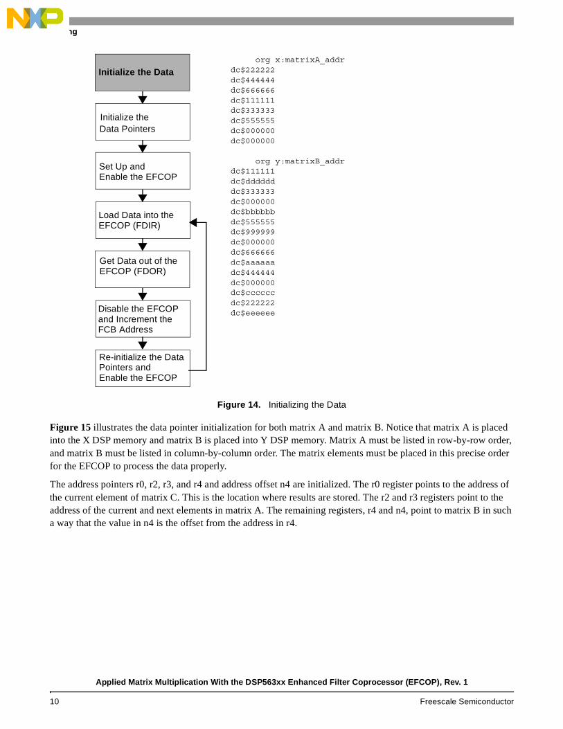
Figure 14 illustrates the data initialization operation.
$222222 $444444 $666666
$111111 $333333 $555555
Matrix A
$111111 $bbbbbb $666666 $cccccc
$dddddd $555555 $aaaaaa $222222
$333333 $999999 $444444 $eeeeee
Matrix B
Applied Matrix Multiplication With the DSP563xx Enhanced Filter Coprocessor (EFCOP), Rev. 1
Freescale Semiconductor 9
Polling
Figure 14. Initializing the Data
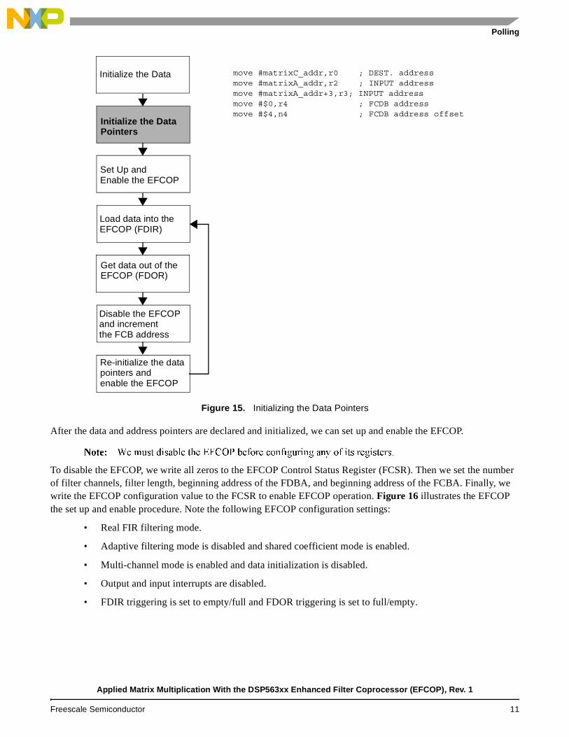
Figure 15 illustrates the data pointer initialization for both matrix A and matrix B. Notice that matrix A is placed into the X DSP memory and matrix B is placed into Y DSP memory. Matrix A must be listed in row-by-row order, and matrix B must be listed in column-by-column order. The matrix elements must be placed in this precise order for the EFCOP to process the data properly.
The address pointers r0, r2, r3, and r4 and address offset n4 are initialized. The r0 register points to the address of the current element of matrix C. This is the location where results are stored. The r2 and r3 registers point to the address of the current and next elements in matrix A. The remaining registers, r4 and n4, point to matrix B in such a way that the value in n4 is the offset from the address in r4.
Re-initialize the DataPointers andEnable the EFCOP
Disable the EFCOPand Increment theFCB Address
Get Data out of the
Load Data into the
Set Up and
Data Pointers
Initialize the Data
Enable the EFCOP
EFCOP (FDIR)
EFCOP (FDOR)
org x:matrixA_addrdc$222222 dc$444444dc$666666dc$111111dc$333333dc$555555dc$000000 dc$000000
org y:matrixB_addrdc$111111dc$dddddd dc$333333 dc$000000 dc$bbbbbb dc$555555 dc$999999 dc$000000 dc$666666dc$aaaaaa dc$444444 dc$000000dc$cccccc dc$222222 dc$eeeeee
Initialize the
Applied Matrix Multiplication With the DSP563xx Enhanced Filter Coprocessor (EFCOP), Rev. 1
10 Freescale Semiconductor
Polling
Figure 15. Initializing the Data Pointers
After the data and address pointers are declared and initialized, we can set up and enable the EFCOP.
����� ������������������ ��������������������������������������������
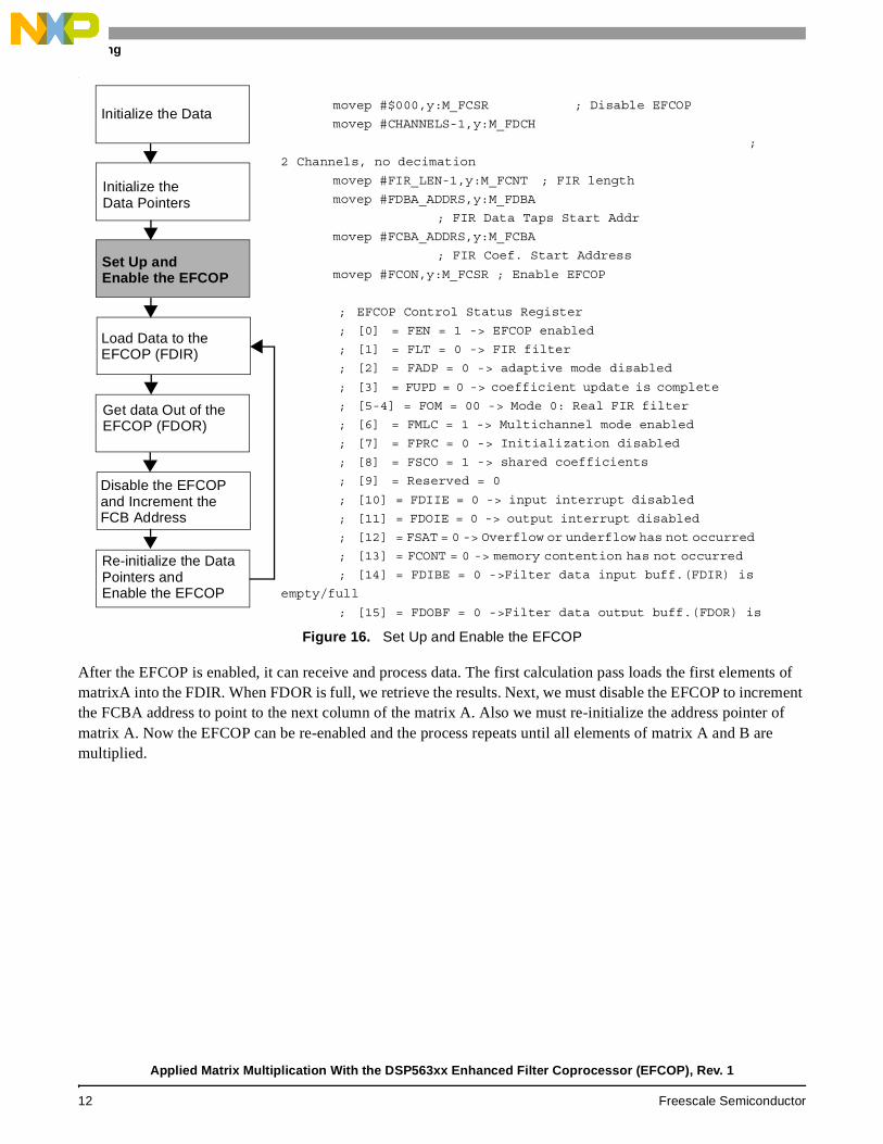
To disable the EFCOP, we write all zeros to the EFCOP Control Status Register (FCSR). Then we set the number of filter channels, filter length, beginning address of the FDBA, and beginning address of the FCBA. Finally, we write the EFCOP configuration value to the FCSR to enable EFCOP operation. Figure 16 illustrates the EFCOP the set up and enable procedure. Note the following EFCOP configuration settings:
• Real FIR filtering mode.
• Adaptive filtering mode is disabled and shared coefficient mode is enabled.
• Multi-channel mode is enabled and data initialization is disabled.
• Output and input interrupts are disabled.
• FDIR triggering is set to empty/full and FDOR triggering is set to full/empty.
Re-initialize the datapointers andenable the EFCOP
Disable the EFCOPand incrementthe FCB address
Get data out of the
Load data into the
Set Up and
Initialize the Data
Initialize the Data
Pointers
Enable the EFCOP
EFCOP (FDIR)
EFCOP (FDOR)
move #matrixC_addr,r0 ; DEST. addressmove #matrixA_addr,r2 ; INPUT addressmove #matrixA_addr+3,r3; INPUT addressmove #$0,r4 ; FCDB addressmove #$4,n4 ; FCDB address offset
Applied Matrix Multiplication With the DSP563xx Enhanced Filter Coprocessor (EFCOP), Rev. 1
Freescale Semiconductor 11
Polling
‘
Figure 16. Set Up and Enable the EFCOP
After the EFCOP is enabled, it can receive and process data. The first calculation pass loads the first elements of matrixA into the FDIR. When FDOR is full, we retrieve the results. Next, we must disable the EFCOP to increment the FCBA address to point to the next column of the matrix A. Also we must re-initialize the address pointer of matrix A. Now the EFCOP can be re-enabled and the process repeats until all elements of matrix A and B are multiplied.
Re-initialize the DataPointers andEnable the EFCOP
Disable the EFCOPand Increment theFCB Address
Get data Out of the
Load Data to the
Set Up and
Initialize the
Initialize the Data
Data Pointers
Enable the EFCOP
EFCOP (FDIR)
EFCOP (FDOR)
movep #$000,y:M_FCSR ; Disable EFCOP
movep #CHANNELS-1,y:M_FDCH
;
2 Channels, no decimation
movep #FIR_LEN-1,y:M_FCNT ; FIR length
movep #FDBA_ADDRS,y:M_FDBA
; FIR Data Taps Start Addr
movep #FCBA_ADDRS,y:M_FCBA
; FIR Coef. Start Address
movep #FCON,y:M_FCSR ; Enable EFCOP
; EFCOP Control Status Register
; [0] = FEN = 1 -> EFCOP enabled
; [1] = FLT = 0 -> FIR filter
; [2] = FADP = 0 -> adaptive mode disabled
; [3] = FUPD = 0 -> coefficient update is complete
; [5-4] = FOM = 00 -> Mode 0: Real FIR filter
; [6] = FMLC = 1 -> Multichannel mode enabled
; [7] = FPRC = 0 -> Initialization disabled
; [8] = FSCO = 1 -> shared coefficients
; [9] = Reserved = 0
; [10] = FDIIE = 0 -> input interrupt disabled
; [11] = FDOIE = 0 -> output interrupt disabled
; [12] = FSAT = 0 -> Overflow or underflow has not occurred
; [13] = FCONT = 0 -> memory contention has not occurred
; [14] = FDIBE = 0 ->Filter data input buff.(FDIR) is
empty/full
; [15] = FDOBF = 0 ->Filter data output buff.(FDOR) is
Applied Matrix Multiplication With the DSP563xx Enhanced Filter Coprocessor (EFCOP), Rev. 1
12 Freescale Semiconductor
DMA with Interrupts
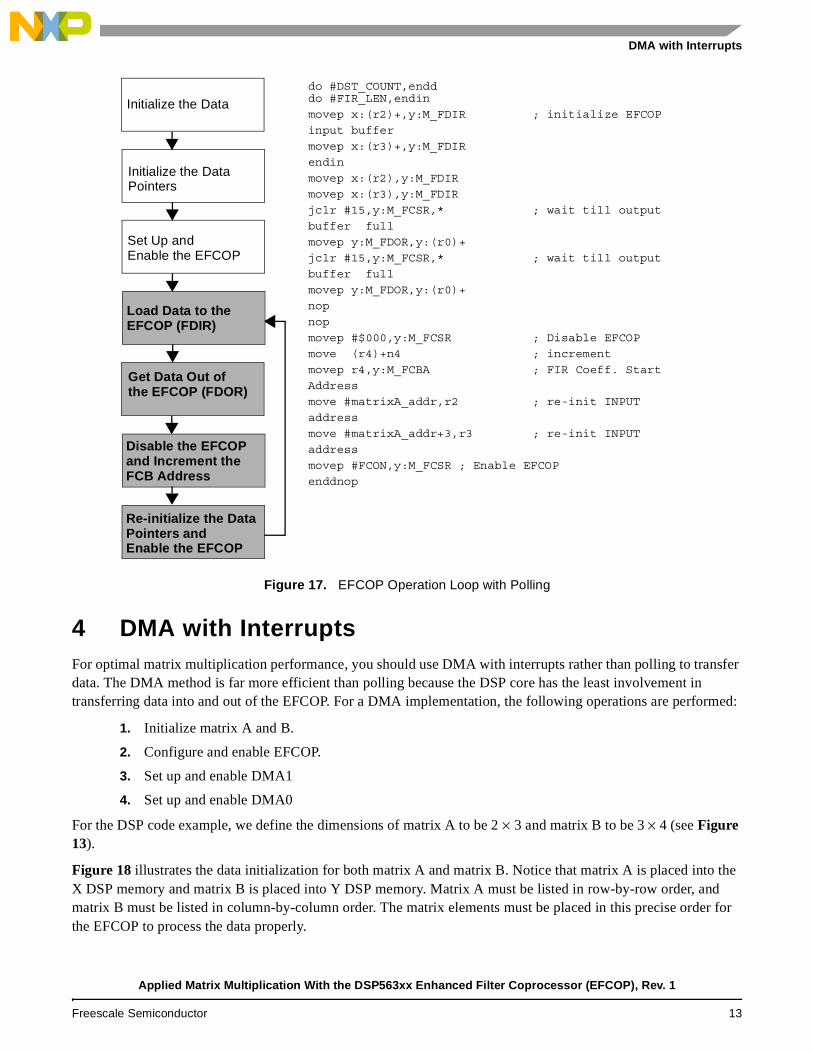
Figure 17. EFCOP Operation Loop with Polling
4 DMA with InterruptsFor optimal matrix multiplication performance, you should use DMA with interrupts rather than polling to transfer data. The DMA method is far more efficient than polling because the DSP core has the least involvement in transferring data into and out of the EFCOP. For a DMA implementation, the following operations are performed:
1. Initialize matrix A and B.
2. Configure and enable EFCOP.
3. Set up and enable DMA1
4. Set up and enable DMA0
For the DSP code example, we define the dimensions of matrix A to be 2 × 3 and matrix B to be 3 × 4 (see Figure 13).
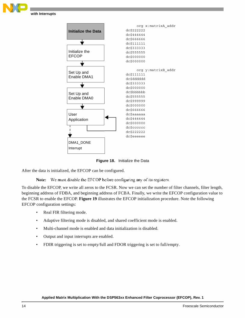
Figure 18 illustrates the data initialization for both matrix A and matrix B. Notice that matrix A is placed into the X DSP memory and matrix B is placed into Y DSP memory. Matrix A must be listed in row-by-row order, and matrix B must be listed in column-by-column order. The matrix elements must be placed in this precise order for the EFCOP to process the data properly.
Re-initialize datapointers andenable EFCOP
Disable the EFCOPand Increment theFCB Address
Get Data Out of
Load Data to the
Set Up and
Initialize the Data
Initialize the Data
Pointers
Enable the EFCOP
EFCOP (FDIR)
the EFCOP (FDOR)
do #DST_COUNT,endddo #FIR_LEN,endin
movep x:(r2)+,y:M_FDIR ; initialize EFCOP
input buffer
movep x:(r3)+,y:M_FDIR
endin
movep x:(r2),y:M_FDIR
movep x:(r3),y:M_FDIR
jclr #15,y:M_FCSR,* ; wait till output
buffer full
movep y:M_FDOR,y:(r0)+
jclr #15,y:M_FCSR,* ; wait till output
buffer full
movep y:M_FDOR,y:(r0)+
nop
nop
movep #$000,y:M_FCSR ; Disable EFCOP
move (r4)+n4 ; increment
movep r4,y:M_FCBA ; FIR Coeff. Start
Address
move #matrixA_addr,r2 ; re-init INPUT
address
move #matrixA_addr+3,r3 ; re-init INPUT
address
movep #FCON,y:M_FCSR ; Enable EFCOP
enddnop
Re-initialize the DataPointers andEnable the EFCOP
Applied Matrix Multiplication With the DSP563xx Enhanced Filter Coprocessor (EFCOP), Rev. 1
Freescale Semiconductor 13
DMA with Interrupts
Figure 18. Initialize the Data
After the data is initialized, the EFCOP can be configured.
����� ������������������ ��������������������������������������������
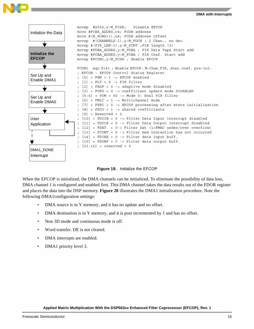
To disable the EFCOP, we write all zeros to the FCSR. Now we can set the number of filter channels, filter length, beginning address of FDBA, and beginning address of FCBA. Finally, we write the EFCOP configuration value to the FCSR to enable the EFCOP. Figure 19 illustrates the EFCOP initialization procedure. Note the following EFCOP configuration settings:
• Real FIR filtering mode.
• Adaptive filtering mode is disabled, and shared coefficient mode is enabled.
• Multi-channel mode is enabled and data initialization is disabled.
• Output and input interrupts are enabled.
• FDIR triggering is set to empty/full and FDOR triggering is set to full/empty.
DMA1_DONE
User
Set Up and
Set Up and
Initialize the
Initialize the Data
Enable DMA1
org x:matrixA_addrdc$222222 dc$444444dc$666666dc$111111dc$333333dc$555555dc$000000 dc$000000
org y:matrixB_addrdc$111111dc$dddddd dc$333333 dc$000000 dc$bbbbbb dc$555555 dc$999999 dc$000000 dc$666666dc$aaaaaa dc$444444 dc$000000dc$cccccc dc$222222 dc$eeeeee
EFCOP
Enable DMA0
Application
Interrupt
Applied Matrix Multiplication With the DSP563xx Enhanced Filter Coprocessor (EFCOP), Rev. 1
14 Freescale Semiconductor
DMA with Interrupts
Figure 19. Initialize the EFCOP
When the EFCOP is initialized, the DMA channels can be initialized. To eliminate the possibility of data loss, DMA channel 1 is configured and enabled first. This DMA channel takes the data results out of the FDOR register and places the data into the DSP memory. Figure 20 illustrates the DMA1 initialization procedure. Note the following DMA1configuration settings:
• DMA source is in Y memory, and it has no update and no offset.
• DMA destination is in Y memory, and it is post incremented by 1 and has no offset.
• Non 3D mode and continuous mode is off.
• Word transfer. DE is not cleared.
• DMA interrupts are enabled.
• DMA1 priority level 3.
DMA1_DONE
User
Set Up and
Set Up and
Initialize the
Initialize the Data
Enable DMA1
movep #$000,y:M_FCSR; Disable EFCOPmove #FCBA_ADDRS,r4; FCDB addressmove #(B_ROWS+1),n4; FCDB address offsetmovep #(CHANNELS-1),y:M_FDCH ; 2 Chan., no dec.movep #(FIR_LEN-1),y:M_FCNT ;FIR length (3)movep #FDBA_ADDRS,y:M_FDBA ; FIR Data Taps Start addmovep #FCBA_ADDRS,y:M_FCBA ; FIR Coef. Start addmovep #FCON1,y:M_FCSR ; Enable EFCOP
FCON1 equ $141 ; Enable EFCOP: M-Chan FIR, shar.coef, pre-ini. ; EFCON - EFCOP Control Status Register; [0] = FEN = 1 -> EFCOP enabled; [1] = FLT = 0 -> FIR filter; [2] = FADP = 0 -> adaptive mode disabled; [3] = FUPD = 0 -> coefficient update mode DISABLED; [5:4] = FOM = 00 -> Mode 0: Real FIR filter; [6] = FMLC = 1 -> Multichannel mode; [7] = FPRC = 0 -> EFCOP processing after state initialization; [8] = FSCO = 1 -> shared coefficients; [9] = Reserved = 0; [10] = FDIIE = 0 -> Filter Data Input interrupt disabled; [11] = FDOIE = 0 -> Filter Data Output interrupt disabled; [12] = FSAT = 0-> Filter Sat (1=FMAC under/over overflow); [13] = FCONT = 0 -> Filter mem contention has not occurred; [14] = FDIBE = 0 -> Filter data input buff. ; [15] = FDOBF = 0 -> Filter data output buff.; [23:16] = reserved = 0
EFCOP
Enable DMA0
Application
Interrupt
Applied Matrix Multiplication With the DSP563xx Enhanced Filter Coprocessor (EFCOP), Rev. 1
Freescale Semiconductor 15
DMA with Interrupts
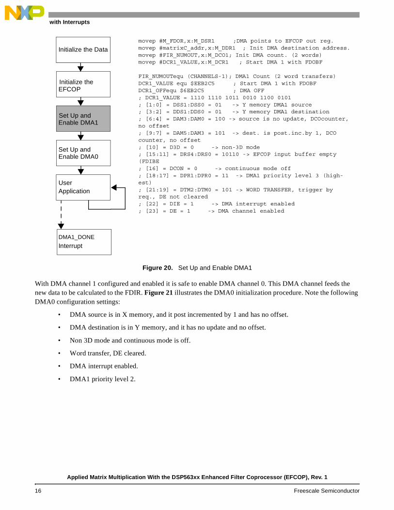
Figure 20. Set Up and Enable DMA1
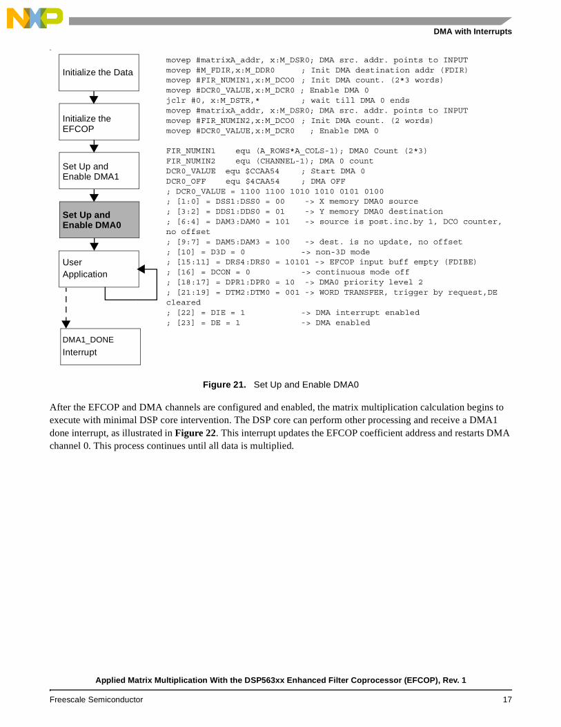
With DMA channel 1 configured and enabled it is safe to enable DMA channel 0. This DMA channel feeds the new data to be calculated to the FDIR. Figure 21 illustrates the DMA0 initialization procedure. Note the following DMA0 configuration settings:
• DMA source is in X memory, and it post incremented by 1 and has no offset.
• DMA destination is in Y memory, and it has no update and no offset.
• Non 3D mode and continuous mode is off.
• Word transfer, DE cleared.
• DMA interrupt enabled.
• DMA1 priority level 2.
movep #M_FDOR,x:M_DSR1 ;DMA points to EFCOP out reg.movep #matrixC_addr,x:M_DDR1 ; Init DMA destination address.movep #FIR_NUMOUT,x:M_DCO1; Init DMA count. (2 words)movep #DCR1_VALUE,x:M_DCR1 ; Start DMA 1 with FDOBF
FIR_NUMOUTequ (CHANNELS-1); DMA1 Count (2 word transfers)DCR1_VALUE equ $EEB2C5 ; Start DMA 1 with FDOBFDCR1_OFFequ $6EB2C5 ; DMA OFF ; DCR1_VALUE = 1110 1110 1011 0010 1100 0101 ; [1:0] = DSS1:DSS0 = 01 -> Y memory DMA1 source ; [3:2] = DDS1:DDS0 = 01 -> Y memory DMA1 destination; [6:4] = DAM3:DAM0 = 100 -> source is no update, DCOcounter, no offset ; [9:7] = DAM5:DAM3 = 101 -> dest. is post.inc.by 1, DCO counter, no offset ; [10] = D3D = 0 -> non-3D mode ; [15:11] = DRS4:DRS0 = 10110 -> EFCOP input buffer empty (FDIBE ; [16] = DCON = 0 -> continuous mode off ; [18:17] = DPR1:DPR0 = 11 -> DMA1 priority level 3 (high-est) ; [21:19] = DTM2:DTM0 = 101 -> WORD TRANSFER, trigger by req., DE not cleared ; [22] = DIE = 1 -> DMA interrupt enabled ; [23] = DE = 1 -> DMA channel enabled
DMA1_DONE
User
Set Up and
Set Up and
Initialize the
Initialize the Data
Enable DMA1
EFCOP
Enable DMA0
Application
Interrupt
Applied Matrix Multiplication With the DSP563xx Enhanced Filter Coprocessor (EFCOP), Rev. 1
16 Freescale Semiconductor
DMA with Interrupts
Se
Figure 21. Set Up and Enable DMA0
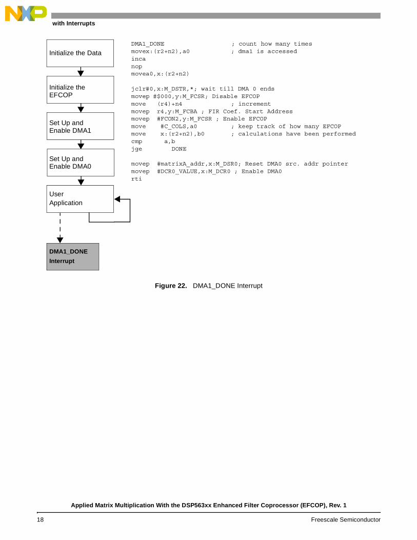
After the EFCOP and DMA channels are configured and enabled, the matrix multiplication calculation begins to execute with minimal DSP core intervention. The DSP core can perform other processing and receive a DMA1 done interrupt, as illustrated in Figure 22. This interrupt updates the EFCOP coefficient address and restarts DMA channel 0. This process continues until all data is multiplied.
DMA1_DONE
User
Set Up and
Set Up and
Initialize the
Initialize the Data
Enable DMA1
movep #matrixA_addr, x:M_DSR0; DMA src. addr. points to INPUTmovep #M_FDIR,x:M_DDR0 ; Init DMA destination addr (FDIR)movep #FIR_NUMIN1,x:M_DCO0 ; Init DMA count. (2*3 words)movep #DCR0_VALUE,x:M_DCR0 ; Enable DMA 0jclr #0, x:M_DSTR,* ; wait till DMA 0 endsmovep #matrixA_addr, x:M_DSR0; DMA src. addr. points to INPUTmovep #FIR_NUMIN2,x:M_DCO0 ; Init DMA count. (2 words)movep #DCR0_VALUE,x:M_DCR0 ; Enable DMA 0
FIR_NUMIN1 equ (A_ROWS*A_COLS-1); DMA0 Count (2*3)FIR_NUMIN2 equ (CHANNEL-1); DMA 0 count DCR0_VALUE equ $CCAA54 ; Start DMA 0DCR0_OFF equ $4CAA54 ; DMA OFF ; DCR0_VALUE = 1100 1100 1010 1010 0101 0100 ; [1:0] = DSS1:DSS0 = 00 -> X memory DMA0 source ; [3:2] = DDS1:DDS0 = 01 -> Y memory DMA0 destination ; [6:4] = DAM3:DAM0 = 101 -> source is post.inc.by 1, DCO counter, no offset ; [9:7] = DAM5:DAM3 = 100 -> dest. is no update, no offset ; [10] = D3D = 0 -> non-3D mode ; [15:11] = DRS4:DRS0 = 10101 -> EFCOP input buff empty (FDIBE); [16] = DCON = 0 -> continuous mode off ; [18:17] = DPR1:DPR0 = 10 -> DMA0 priority level 2 ; [21:19] = DTM2:DTM0 = 001 -> WORD TRANSFER, trigger by request,DE cleared ; [22] = DIE = 1 -> DMA interrupt enabled ; [23] = DE = 1 -> DMA enabled
EFCOP
Enable DMA0
Application
Interrupt
Applied Matrix Multiplication With the DSP563xx Enhanced Filter Coprocessor (EFCOP), Rev. 1
Freescale Semiconductor 17
DMA with Interrupts
Figure 22. DMA1_DONE Interrupt
DMA1_DONE
User
Set Up and
Set Up and
Initialize the
Initialize the Data
Enable DMA1
DMA1_DONE ; count how many timesmovex:(r2+n2),a0 ; dma1 is accessedincanopmovea0,x:(r2+n2)
jclr#0,x:M_DSTR,*; wait till DMA 0 endsmovep #$000,y:M_FCSR; Disable EFCOPmove (r4)+n4 ; increment movep r4,y:M_FCBA ; FIR Coef. Start Addressmovep #FCON2,y:M_FCSR ; Enable EFCOPmove #C_COLS,a0 ; keep track of how many EFCOPmove x:(r2+n2),b0 ; calculations have been performedcmp a,bjge DONE
movep #matrixA_addr,x:M_DSR0; Reset DMA0 src. addr pointermovep #DCR0_VALUE,x:M_DCR0 ; Enable DMA0rti
EFCOP
Enable DMA0
Application
Interrupt
Applied Matrix Multiplication With the DSP563xx Enhanced Filter Coprocessor (EFCOP), Rev. 1
18 Freescale Semiconductor
DMA with Interrupts
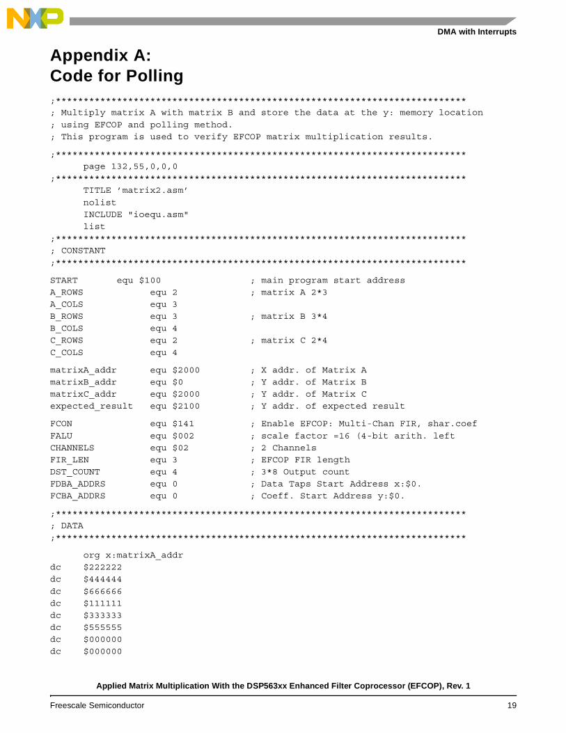
Appendix A: Code for Polling;************************************************************************** ; Multiply matrix A with matrix B and store the data at the y: memory location ; using EFCOP and polling method. ; This program is used to verify EFCOP matrix multiplication results.
;************************************************************************** page 132,55,0,0,0
;************************************************************************** TITLE ’matrix2.asm’ nolist INCLUDE "ioequ.asm" list
;************************************************************************** ; CONSTANT ;**************************************************************************
START equ $100 ; main program start address A_ROWS equ 2 ; matrix A 2*3 A_COLS equ 3 B_ROWS equ 3 ; matrix B 3*4 B_COLS equ 4 C_ROWS equ 2 ; matrix C 2*4 C_COLS equ 4
matrixA_addr equ $2000 ; X addr. of Matrix A matrixB_addr equ $0 ; Y addr. of Matrix B matrixC_addr equ $2000 ; Y addr. of Matrix C expected_result equ $2100 ; Y addr. of expected result
FCON equ $141 ; Enable EFCOP: Multi-Chan FIR, shar.coef FALU equ $002 ; scale factor =16 (4-bit arith. left CHANNELS equ $02 ; 2 Channels FIR_LEN equ 3 ; EFCOP FIR length DST_COUNT equ 4 ; 3*8 Output count FDBA_ADDRS equ 0 ; Data Taps Start Address x:$0. FCBA_ADDRS equ 0 ; Coeff. Start Address y:$0.
;************************************************************************** ; DATA ;**************************************************************************
org x:matrixA_addr dc $222222 dc $444444 dc $666666 dc $111111 dc $333333 dc $555555 dc $000000 dc $000000
Applied Matrix Multiplication With the DSP563xx Enhanced Filter Coprocessor (EFCOP), Rev. 1
Freescale Semiconductor 19
DMA with Interrupts
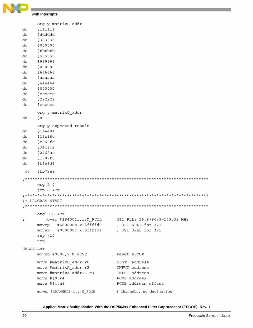
org y:matrixB_addr dc $111111 dc $dddddd dc $333333 dc $000000 dc $bbbbbb dc $555555 dc $999999 dc $000000 dc $666666 dc $aaaaaa dc $444444 dc $000000 dc $cccccc dc $222222 dc $eeeeee
org y:matrixC_addr ds $8
org y:expected_result dc $1b4e81 dc $16c16c dc $c962fc dc $d4c3b2 dc $2468ac dc $1907f6 dc $f6e5d4
dc $fb72ea
;************************************************************************** org P:0 jmp START
;************************************************************************** ;* PROGRAM START ;**************************************************************************
org P:START ; movep #$84004f,x:M_PCTL ; 311 PLL: 16.8*80/9=149.33 MHz
movep #$80000a,x:$ffffd0 ; 321 DPLL for 321 movep #$00000c,x:$ffffd1 ; 321 DPLL for 321 rep #10 nop
CALCSTART movep #$000,y:M_FCSR ; Reset EFCOP
move #matrixC_addr,r0 ; DEST. address move #matrixA_addr,r2 ; INPUT address move #matrixA_addr+3,r3 ; INPUT address move #$0,r4 ; FCDB address move #$4,n4 ; FCDB address offset
movep #CHANNELS-1,y:M_FDCH ; 3 Channels, no decimation
Applied Matrix Multiplication With the DSP563xx Enhanced Filter Coprocessor (EFCOP), Rev. 1
20 Freescale Semiconductor
DMA with Interrupts
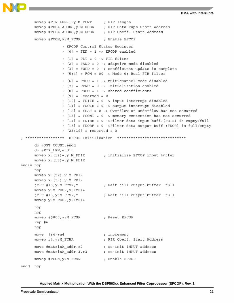
movep #FIR_LEN-1,y:M_FCNT ; FIR length movep #FDBA_ADDRS,y:M_FDBA ; FIR Data Taps Start Address movep #FCBA_ADDRS,y:M_FCBA ; FIR Coeff. Start Address
movep #FCON,y:M_FCSR ; Enable EFCOP
; EFCOP Control Status Register ; [0] = FEN = 1 -> EFCOP enabled
; [1] = FLT = 0 -> FIR filter ; [2] = FADP = 0 -> adaptive mode disabled ; [3] = FUPD = 0 -> coefficient update is complete ; [5:4] = FOM = 00 -> Mode 0: Real FIR filter
; [6] = FMLC = 1 -> Multichannel mode disabled ; [7] = FPRC = 0 -> Initialization enabled ; [8] = FSCO = 1 -> shared coefficients ; [9] = Reserved = 0 ; [10] = FDIIE = 0 -> input interrupt disabled ; [11] = FDOIE = 0 -> output interrupt disabled ; [12] = FSAT = 0 -> Overflow or underflow has not occurred ; [13] = FCONT = 0 -> memory contention has not occurred ; [14] = FDIBE = 0 ->Filter data input buff.(FDIR) is empty/full ; [15] = FDOBF = 0 ->Filter data output buff.(FDOR) is full/empty ; [23:16] = reserved = 0
; ***************** EFCOP Initilization ******************************
do #DST_COUNT,endd do #FIR_LEN,endin movep x:(r2)+,y:M_FDIR ; initialize EFCOP input buffer movep x:(r3)+,y:M_FDIR
endin nop nop movep x:(r2),y:M_FDIR movep x:(r3),y:M_FDIR jclr #15,y:M_FCSR,* ; wait till output buffer full movep y:M_FDOR,y:(r0)+ jclr #15,y:M_FCSR,* ; wait till output buffer full movep y:M_FDOR,y:(r0)+
nop nop movep #$000,y:M_FCSR ; Reset EFCOP rep #6 nop
move (r4)+n4 ; increment movep r4,y:M_FCBA ; FIR Coeff. Start Address
move #matrixA_addr,r2 ; re-init INPUT address move #matrixA_addr+3,r3 ; re-init INPUT address
movep #FCON,y:M_FCSR ; Enable EFCOP
endd nop
Applied Matrix Multiplication With the DSP563xx Enhanced Filter Coprocessor (EFCOP), Rev. 1
Freescale Semiconductor 21
DMA with Interrupts
nop nop jsr check
;****************************************************************** pass nop
debug nop
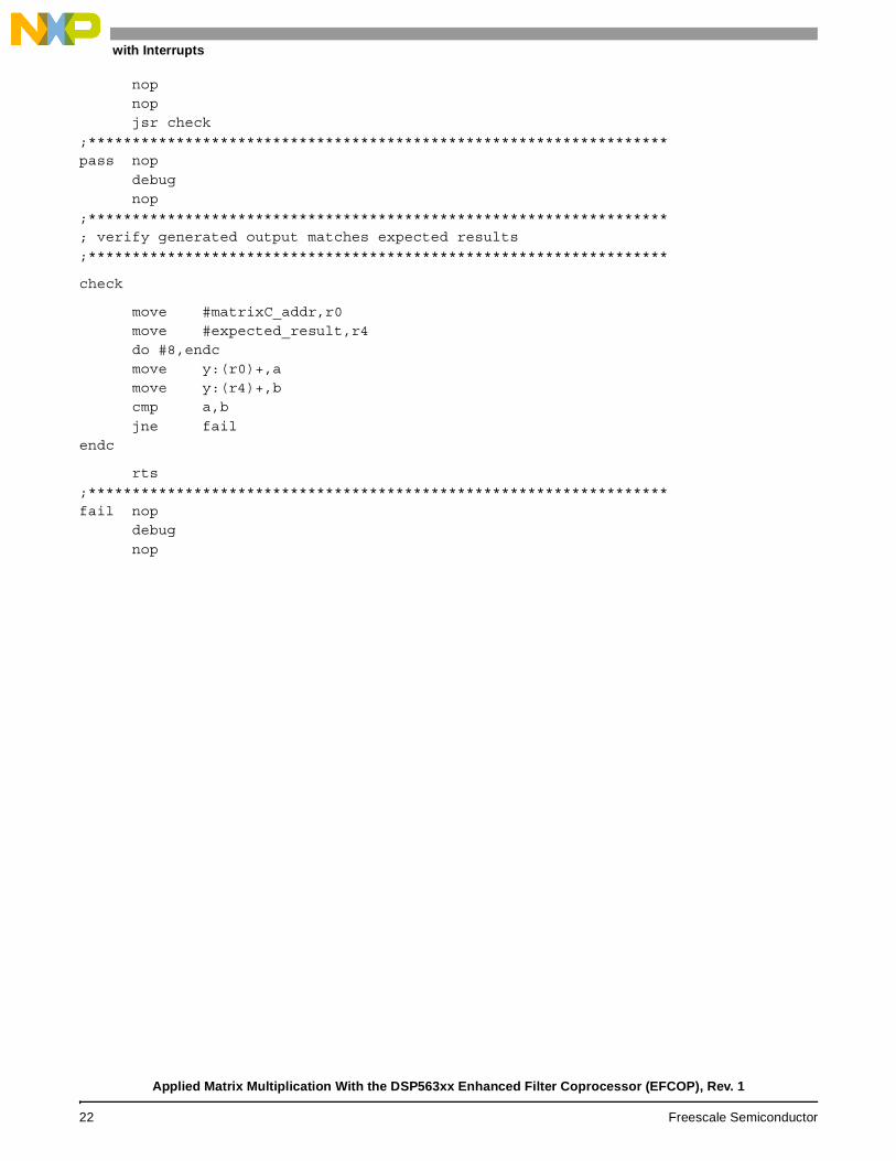
;****************************************************************** ; verify generated output matches expected results ;******************************************************************
check
move #matrixC_addr,r0 move #expected_result,r4 do #8,endc move y:(r0)+,a move y:(r4)+,b cmp a,b jne fail
endc
rts ;****************************************************************** fail nop
debug nop
Applied Matrix Multiplication With the DSP563xx Enhanced Filter Coprocessor (EFCOP), Rev. 1
22 Freescale Semiconductor

DMA with Interrupts
Appendix B: Code for DMA with Interrupts;**************************************************************************
; This program demonstrates EFCOP matrix multiplication.
; Multiply matrix A with matrix B and store the data at the y memory
; location using EFCOP, interrupt service routine and dma transfers.
;**************************************************************************
page 132,55,0,0,0
;**************************************************************************
TITLE ’matrixdma_int.asm’
nolist
INCLUDE "ioequ.asm"
INCLUDE "intequ.asm"
INCLUDE "equ.asm"
INCLUDE "data.asm"
list
include ’int.asm’
section matrixdma_int
;******************************************************************************
; External Variable Definitions
;******************************************************************************
; definitions of variables that are accessible by other routines external
; to this section
xdef PASS
xdef FAIL
xdef CALCSTART
xdef DONE
;**************************************************************************
Applied Matrix Multiplication With the DSP563xx Enhanced Filter Coprocessor (EFCOP), Rev. 1
Freescale Semiconductor 23
DMA with Interrupts
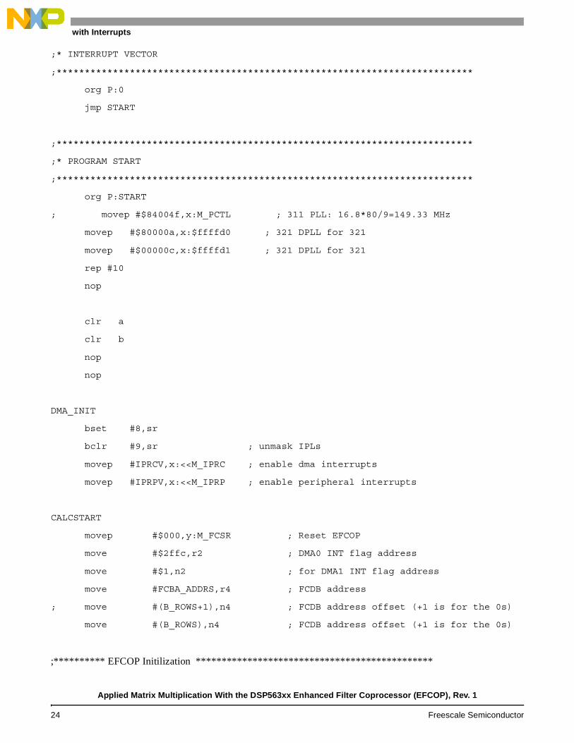
;* INTERRUPT VECTOR
;**************************************************************************
org P:0
jmp START
;**************************************************************************
;* PROGRAM START
;**************************************************************************
org P:START
; movep #$84004f,x:M_PCTL ; 311 PLL: 16.8*80/9=149.33 MHz
movep #$80000a,x:$ffffd0 ; 321 DPLL for 321
movep #$00000c,x:$ffffd1 ; 321 DPLL for 321
rep #10
nop
clr a
clr b
nop
nop
DMA_INIT
bset #8,sr
bclr #9,sr ; unmask IPLs
movep #IPRCV,x:<<M_IPRC ; enable dma interrupts
movep #IPRPV,x:<<M_IPRP ; enable peripheral interrupts
CALCSTART
movep #$000,y:M_FCSR ; Reset EFCOP
move #$2ffc,r2 ; DMA0 INT flag address
move #$1,n2 ; for DMA1 INT flag address
move #FCBA_ADDRS,r4 ; FCDB address
; move #(B_ROWS+1),n4 ; FCDB address offset (+1 is for the 0s)
move #(B_ROWS),n4 ; FCDB address offset (+1 is for the 0s)
;********** EFCOP Initilization **********************************************
Applied Matrix Multiplication With the DSP563xx Enhanced Filter Coprocessor (EFCOP), Rev. 1
24 Freescale Semiconductor
DMA with Interrupts
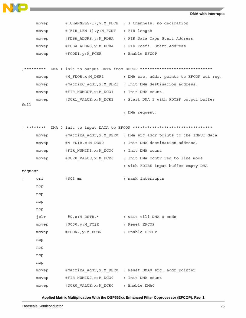
movep #(CHANNELS-1),y:M_FDCH ; 3 Channels, no decimation
movep #(FIR_LEN-1),y:M_FCNT ; FIR length
movep #FDBA_ADDRS,y:M_FDBA ; FIR Data Taps Start Address
movep #FCBA_ADDRS,y:M_FCBA ; FIR Coeff. Start Address
movep #FCON1,y:M_FCSR ; Enable EFCOP
;********* DMA 1 init to output DATA from EFCOP ******************************
movep #M_FDOR,x:M_DSR1 ; DMA src. addr. points to EFCOP out reg.
movep #matrixC_addr,x:M_DDR1 ; Init DMA destination address.
movep #FIR_NUMOUT,x:M_DCO1 ; Init DMA count.
movep #DCR1_VALUE,x:M_DCR1 ; Start DMA 1 with FDOBF output buffer
full
; DMA request.
; ******** DMA 0 init to input DATA to EFCOP *********************************
movep #matrixA_addr,x:M_DSR0 ; DMA src addr points to the INPUT data
movep #M_FDIR,x:M_DDR0 ; Init DMA destination address.
movep #FIR_NUMIN1,x:M_DCO0 ; Init DMA count
movep #DCR0_VALUE,x:M_DCR0 ; Init DMA contr reg to line mode
; with FDIBE input buffer empty DMA request.
; ori #$03,mr ; mask interrupts
nop
nop
nop
nop
jclr #0,x:M_DSTR,* ; wait till DMA 0 ends
movep #$000,y:M_FCSR ; Reset EFCOP
movep #FCON2,y:M_FCSR ; Enable EFCOP
nop
nop
nop
nop
movep #matrixA_addr,x:M_DSR0 ; Reset DMA0 src. addr pointer
movep #FIR_NUMIN2,x:M_DCO0 ; Init DMA count
movep #DCR0_VALUE,x:M_DCR0 ; Enable DMA0
Applied Matrix Multiplication With the DSP563xx Enhanced Filter Coprocessor (EFCOP), Rev. 1
Freescale Semiconductor 25
DMA with Interrupts
nop
nop
nop
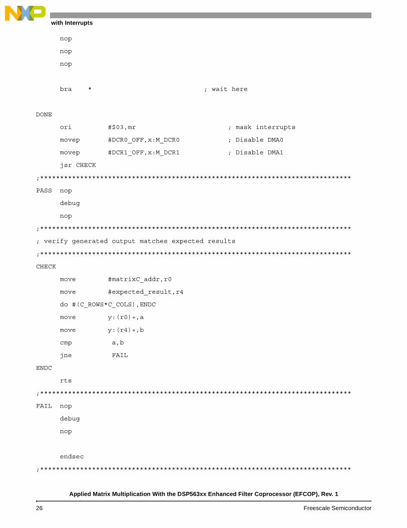
bra * ; wait here
DONE
ori #$03,mr ; mask interrupts
movep #DCR0_OFF,x:M_DCR0 ; Disable DMA0
movep #DCR1_OFF,x:M_DCR1 ; Disable DMA1
jsr CHECK
;******************************************************************************
PASS nop
debug
nop
;******************************************************************************
; verify generated output matches expected results
;******************************************************************************
CHECK
move #matrixC_addr,r0
move #expected_result,r4
do #(C_ROWS*C_COLS),ENDC
move y:(r0)+,a
move y:(r4)+,b
cmp a,b
jne FAIL
ENDC
rts
;******************************************************************************
FAIL nop
debug
nop
endsec
;******************************************************************************
Applied Matrix Multiplication With the DSP563xx Enhanced Filter Coprocessor (EFCOP), Rev. 1
26 Freescale Semiconductor
DMA with Interrupts
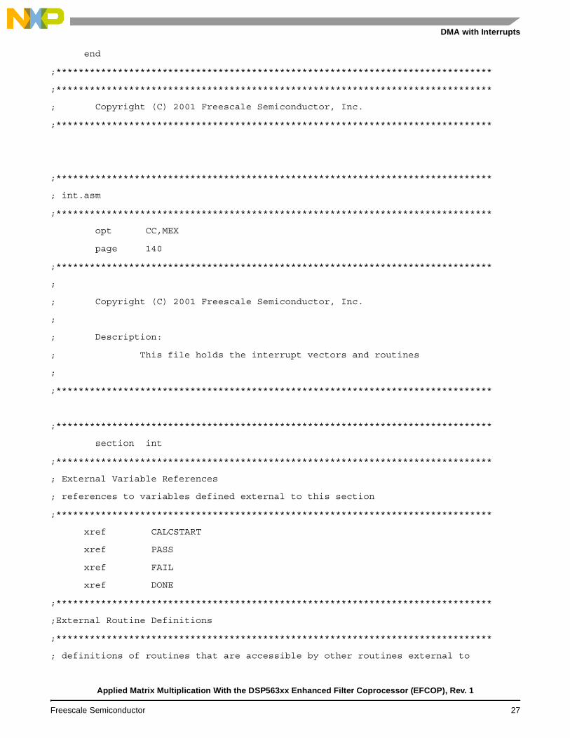
end
;******************************************************************************
;******************************************************************************
; Copyright (C) 2001 Freescale Semiconductor, Inc.
;******************************************************************************
;******************************************************************************
; int.asm
;******************************************************************************
opt CC,MEX
page 140
;******************************************************************************
;
; Copyright (C) 2001 Freescale Semiconductor, Inc.
;
; Description:
; This file holds the interrupt vectors and routines
;
;******************************************************************************
;******************************************************************************
section int
;******************************************************************************
; External Variable References
; references to variables defined external to this section
;******************************************************************************
xref CALCSTART
xref PASS
xref FAIL
xref DONE
;******************************************************************************
;External Routine Definitions
;******************************************************************************
; definitions of routines that are accessible by other routines external to
Applied Matrix Multiplication With the DSP563xx Enhanced Filter Coprocessor (EFCOP), Rev. 1
Freescale Semiconductor 27
DMA with Interrupts
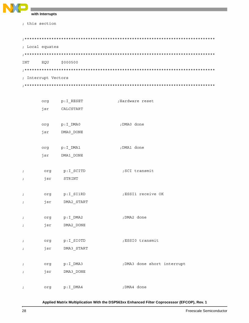
; this section
;******************************************************************************
; Local equates
;******************************************************************************
INT EQU $000500
;******************************************************************************
; Interrupt Vectors
;******************************************************************************
org p:I_RESET ;Hardware reset
jsr CALCSTART
org p:I_DMA0 ;DMA0 done
jsr DMA0_DONE
org p:I_DMA1 ;DMA1 done
jsr DMA1_DONE
; org p:I_SCITD ;SCI transmit
; jsr STRINT
; org p:I_SI1RD ;ESSI1 receive OK
; jsr DMA2_START
; org p:I_DMA2 ;DMA2 done
; jsr DMA2_DONE
; org p:I_SI0TD ;ESSI0 transmit
; jsr DMA3_START
; org p:I_DMA3 ;DMA3 done short interrupt
; jsr DMA3_DONE
; org p:I_DMA4 ;DMA4 done
Applied Matrix Multiplication With the DSP563xx Enhanced Filter Coprocessor (EFCOP), Rev. 1
28 Freescale Semiconductor
DMA with Interrupts
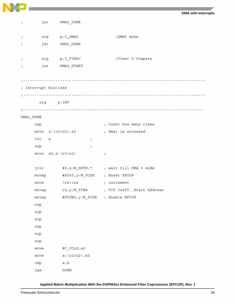
; jsr DMA4_DONE
; org p:I_DMA5 ;DMA5 done
; jsr DMA5_DONE
; org p:I_TIM0C ;Timer 0 Compare
; jsr DMA4_START
;-------------------------------------------------------------------------------
; Interrupt Routines
;-------------------------------------------------------------------------------
org p:INT
;------------------------------------------------------------------------------
DMA1_DONE
nop ; count how many times
move x:(r2+n2),a0 ; dma1 is accessed
inc a ;
nop ;
move a0,x:(r2+n2) ;
jclr #0,x:M_DSTR,* ; wait till DMA 0 ends
movep #$000,y:M_FCSR ; Reset EFCOP
move (r4)+n4 ; increment
movep r4,y:M_FCBA ; FIR Coeff. Start Address
movep #FCON2,y:M_FCSR ; Enable EFCOP
nop
nop
nop
nop
nop
nop
move #C_COLS,a0
move x:(r2+n2),b0
cmp a,b
jge DONE
Applied Matrix Multiplication With the DSP563xx Enhanced Filter Coprocessor (EFCOP), Rev. 1
Freescale Semiconductor 29
DMA with Interrupts
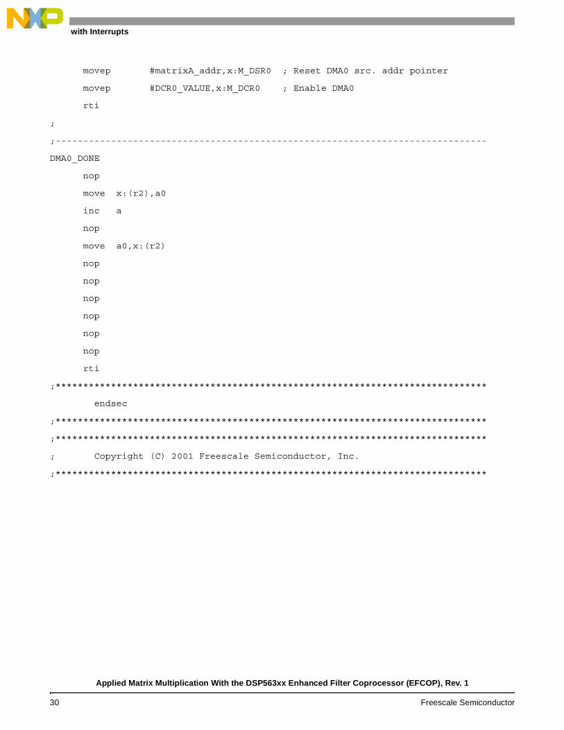
movep #matrixA_addr,x:M_DSR0 ; Reset DMA0 src. addr pointer
movep #DCR0_VALUE,x:M_DCR0 ; Enable DMA0
rti
;
;------------------------------------------------------------------------------
DMA0_DONE
nop
move x:(r2),a0
inc a
nop
move a0,x:(r2)
nop
nop
nop
nop
nop
nop
rti
;******************************************************************************
endsec
;******************************************************************************
;******************************************************************************
; Copyright (C) 2001 Freescale Semiconductor, Inc.
;******************************************************************************
Applied Matrix Multiplication With the DSP563xx Enhanced Filter Coprocessor (EFCOP), Rev. 1
30 Freescale Semiconductor

DMA with Interrupts
Applied Matrix Multiplication With the DSP563xx Enhanced Filter Coprocessor (EFCOP), Rev. 1
Freescale Semiconductor 31

Document Order No.: AN2691
Information in this document is provided solely to enable system and software implementers to use Freescale Semiconductor products. There are no express or implied copyright licenses granted hereunder to design or fabricate any integrated circuits or integrated circuits based on the information in this document.
Freescale Semiconductor reserves the right to make changes without further notice to any products herein. Freescale Semiconductor makes no warranty, representation or guarantee regarding the suitability of its products for any particular purpose, nor does Freescale Semiconductor assume any liability arising out of the application or use of any product or circuit, and specifically disclaims any and all liability, including without limitation consequential or incidental damages. “Typical” parameters which may be provided in Freescale Semiconductor data sheets and/or specifications can and do vary in different applications and actual performance may vary over time. All operating parameters, including “Typicals” must be validated for each customer application by customer’s technical experts. Freescale Semiconductor does not convey any license under its patent rights nor the rights of others. Freescale Semiconductor products are not designed, intended, or authorized for use as components in systems intended for surgical implant into the body, or other applications intended to support or sustain life, or for any other application in which the failure of the Freescale Semiconductor product could create a situation where personal injury or death may occur. Should Buyer purchase or use Freescale Semiconductor products for any such unintended or unauthorized application, Buyer shall indemnify and hold Freescale Semiconductor and its officers, employees, subsidiaries, affiliates, and distributors harmless against all claims, costs, damages, and expenses, and reasonable attorney fees arising out of, directly or indirectly, any claim of personal injury or death associated with such unintended or unauthorized use, even if such claim alleges that Freescale Semiconductor was negligent regarding the design or manufacture of the part.
Freescale™ and the Freescale logo are trademarks of Freescale Semiconductor, Inc. All other product or service names are the property of their respective owners.
© Freescale Semiconductor, Inc. 2004, 2005.
How to Reach Us:Home Page:www.freescale.com
E-mail:[email protected]
USA/Europe or Locations not listed:Freescale Semiconductor Technical Information Center, CH3701300 N. Alma School RoadChandler, Arizona 85224+1-800-521-6274 or [email protected]
Europe, Middle East, and Africa:Freescale Halbleiter Deutschland GMBHTechnical Information CenterSchatzbogen 781829 München, Germany+44 1296 380 456 (English)+46 8 52200080 (English)+49 89 92103 559 (German)+33 1 69 35 48 48 (French)[email protected]
Japan:Freescale Semiconductor Japan Ltd. HeadquartersARCO Tower 15F1-8-1, Shimo-Meguro, Meguro-ku,Tokyo 153-0064, Japan0120 191014 or +81 3 5437 [email protected]
Asia/Pacific:Freescale Semiconductor Hong Kong Ltd.Technical Information Center2 Dai King StreetTai Po Industrial EstateTai Po, N.T. Hong Kong+800 2666 8080
For Literature Requests Only:Freescale Semiconductor Literature Distribution CenterP.O. Box 5405Denver, Colorado 802171-800-441-2447 or 303-675-2140Fax: [email protected]
Rev. 18/2005
Related Documents