Applications of the Applications of the Kubelka-Munk Color Kubelka-Munk Color Model Model Kristen Hoffman Dr. Edul N. Dalal RIT Center for Imaging Science Xerox Corporation, Wilson Center for Research and Technology

Applications of the Kubelka-Munk Color Model Kristen Hoffman Dr. Edul N. Dalal RIT Center for Imaging Science Xerox Corporation, Wilson Center.
Dec 22, 2015
Welcome message from author
This document is posted to help you gain knowledge. Please leave a comment to let me know what you think about it! Share it to your friends and learn new things together.
Transcript

Applications of the Applications of the Kubelka-Munk Color ModelKubelka-Munk Color Model
Kristen Hoffman
Dr. Edul N. Dalal
RIT Center for Imaging Science
Xerox Corporation, Wilson Center for
Research and Technology

Introduction - Goals and AccomplishmentsIntroduction - Goals and Accomplishments
Goal: Ability to model the reflectance of a color xerographic sample
Developed: Predictive color model based on Kubelka-Munk theory
Model extended to– Bidirectional Measurement Geometry– MultiLayer Images– Xerographic Print Samples

Background: Kubelka-Munk Background: Kubelka-Munk TheoryTheoryColor reflection depends on
– Material properties - the absorption and scattering spectra, K() and S()
– Sample thickness, X– Substrate reflectance spectrum, Rp ()
Model applies to– Uniform thickness samples with complete
substrate coverage– Single color images

Background: Saunderson Background: Saunderson Correction ParametersCorrection ParametersTwo parameters
– k1 and k2 - corrections are made for reflections at the sample surface
– Derived for integrating sphere measurement geometry
– Applied to reflectance spectrum before the Kubelka-Munk model

Developed Color ModelDeveloped Color Model

Correction EquationsCorrection Equations
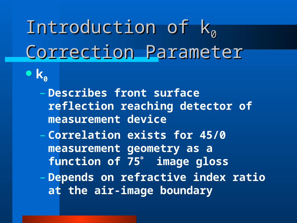
Introduction of kIntroduction of k00 Correction Correction
ParameterParameterk0
– Describes front surface reflection reaching detector of measurement device
– Correlation exists for 45/0 measurement geometry as a function of 75 image gloss
– Depends on refractive index ratio at the air-image boundary

Derived Correction Equations for Derived Correction Equations for Bidirectional Geometry SystemsBidirectional Geometry Systems
measured
measuredcorrected Rkkkkkkk
kRR
2202121
0
1
)(1
)1)(1(
2
210
corrected
correctedmeasured Rk
RkkkR
Link to Derivation:
http://www.cis.rit.edu/~kmh7483/index.html

Multi-Layer ImagesMulti-Layer Images

Examples of Image Layer Examples of Image Layer StructureStructure
Substrate Substrate
(a) Single colorant layer considered in the original Kubelka-Munk model
(b) Multiple colorant layers generally encountered in process color xerographic prints

Rp()
Rp()corr
R1()corr
R2()corr
Rn()corr
R()
k0, k1, k2 for substrate
k0, k1, k2 for toner
K, S for layer n
K, S for layer 2
K, S for layer 1
SaundersonCorrection
Kubelka-Munk
Kubelka-Munk
Kubelka-Munk
Inverse Saunderson
Substrate
Bottom-most toner layer
Second toner layer
Top-most toner layer
Calculated Sample Reflectance
Non Planar Toner LayersNon Planar Toner Layers

Image PhotomicrographsImage Photomicrographs

Toner Layer Thickness Toner Layer Thickness MeasurementsMeasurementsLayer structure digitized
electronically– Measurements made at every 0.5m – Small interval divides print into planar
sectionsK/M applied to each small planar
interval

ResultsResults

Fitted Absorption Spectra for Xerox 5760 CMY Toners
0
0.5
1
1.5
2
2.5
3
3.5
4
4.5
350 400 450 500 550 600 650 700
Wavelength (nm)
Ab
so
rpti
on
(m
g/c
m2
)
Cyan
Magenta
Yellow

Fitted Scattering Spectra for Xerox 5760 CMY Toners
0
0.05
0.1
0.15
0.2
0.25
350 400 450 500 550 600 650 700
Wavelength (nm)
Sc
att
eri
ng
(c
m2
/mg
)
Cyan
Magenta
Yellow

Results - Toner Layer Thickness Results - Toner Layer Thickness Probability Distribution ExampleProbability Distribution Example
0
00.0375
0.03750.075
0.0750.1125
0.11250.15
0.150.1875
0.18750.225
0.2250.2625
0.26250.3
0.3
Pro
b Pro
b
Example of Green Probability DistributionRank 1 Eqn 2501 z=3inc-gaw()

Results - Single Layer, 45/0Results - Single Layer, 45/0
dE*CIELAB Average C = 1.83 M = 1.77, Y = 1.26
0
1
2
3
4
0.3 0.35 0.4 0.45 0.5 0.55 0.6 0.8 1
Thickness
dE
* (C
IEL
AB
)
dE* Cyan
dE* Magenta
dE* Yellow

Results - Multi-Layer ImageResults - Multi-Layer Image
0
0.5
1
1.5
2
2.5
3
3.5
1
dE
* (C
IEL
AB
)
R G B

Results - Multilayer Non Planar Results - Multilayer Non Planar PrintPrint
0
2
4
6
8
10
1
dE
* (C
IEL
AB
)
Cyan
Magenta
Yellow
Red
Green
Blue
dE*CIELAB Average 5.1, RMS = 5.5

ConclusionsConclusions
Benefits of K/M Color Model– Based on physical parameters of toner
set– No print samples needed– Good predictions (low color error)
Related Documents


![Kasper Munk [Inglês]](https://static.cupdf.com/doc/110x72/58874cd51a28ab5a628b65bb/kasper-munk-ingles.jpg)