1 Application of the Finite-Element Analysis to the Pass Rolling Process General Director KOMMEK Ltd. www.kommek.ru [email protected] .ru Moscow State Institute of Electronics and Mathematics (Technical University), Dep. Mathematical Simulation www.miem.edu.ru [email protected] KOMMEK Professor, D.Sc. Chumachenko E.N. IKI Seminar « Mechanics, Control and Informatics » Moscow 2005

Application of the Finite-Element Analysis to the Pass Rolling Process
Dec 31, 2015
KOMMEK. Application of the Finite-Element Analysis to the Pass Rolling Process. Moscow State Institute of Electronics and Mathematics (Technical University), Dep. Mathematical Simulation www.miem.edu.ru [email protected]. Professor, D.Sc. Chumachenko E.N. General Director KOMMEK Ltd. - PowerPoint PPT Presentation
Welcome message from author
This document is posted to help you gain knowledge. Please leave a comment to let me know what you think about it! Share it to your friends and learn new things together.
Transcript

1
Applicationof the Finite-Element Analysis
to the Pass Rolling Process
General Director KOMMEK Ltd.
Moscow State Instituteof Electronics and Mathematics
(Technical University),Dep. Mathematical Simulation
KOMMEK
Professor, D.Sc. Chumachenko E.N.
IKI Seminar «Mechanics, Control and Informatics» Moscow 2005
2
Introduction
The basic ratios and results of pass rolling process simulation using the SPLEN computing system developed based on the finite-element method (FEM) are discussed.The computing system allows setting any configuration of a roll profile, and presently it is used for studying isothermal and non-isothermal rolling processes with two symmetric rolls. In this model a rigid-ductile statement of the problem and special system of friction implementation are used.The computer system simulating the process of metal deformation in passes allows avoiding labor-consuming and expensive industrial experiments and reduces the time of developing technological solutions. Besides, at the design stage already, one can reveal defects of the rolled product form and working degree of the metal and thereby maximally approach a technological draft to the working one.To increase a solution algorithm speed, the half-analytical finite-elements method was used.
KOMMEK
IKI Seminar «Mechanics, Control and Informatics» Moscow 2005
3
(2)
(3)
Then and condition entry (4)
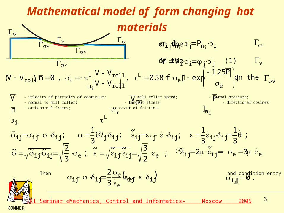
Boundary conditions
on the
on the (1)
on the
Mathematical model of form changing hot materials
KOMMEK
injnij iiPl
v
v
jjiiVV
iu
ijije
eijij 3
2
]P25.1
exp1[f58.0,VV
VV,0n)VV(
ee
L
roll
rollLroll
- velocity of particles of continuum; - mill roller speed; - normal pressure;
- normal to mill roller; - tangent stress; - directional cosines;
- orthonormal frames; - constant of friction.
;3
1;~
ijijijijij ;3
1
3
1;
~ijijijijij
;2
3~~~eijij eeijij 3
~2~ ;
3
2~~~eijij
.0j,ij
V rollV P
n inl
iL
IKI Seminar «Mechanics, Control and Informatics» Moscow 2005

4
The heat exchange of the strip with rolls and with environment is described by the following variational equation :
(5)
where - is heat conductance coefficient;
- is thermal capacity and density of the strip material;
- is a generalized parameter dependent on the temperature difference of the strip
and environment, Stephen-Boltsman constant, blackness coefficient of the body and on relative
position of the surfaces when radiating;
- is linear expansion coefficient for environment and rolls;;
- is relative speed module of the movement with friction;
- is a coefficient taking into account the part of released heat energy.
Heat exchange
KOMMEK
rdS]T)QTt
Tc()
z
T
z
T
r
T
r
T([
Spl
rdLT)}TT(])273T()273T[({ airairL
4roll
4
air
0dLrT]qTT[rollL
frrollroll
airroll LLS
,c
airroll ,
Lrollfr VV5.0q uuplpl kQ
rollVV
plk
IKI Seminar «Mechanics, Control and Informatics» Moscow 2005

5
n
n
d z z n
z+ dz
d z C o s
Z
Y
For an arbitrary element of the strain focal point of a little enough thickness, the value
characterizing relative elongation speed of the fibers in an element of the thickness dz, is
constant: . In this case constant C in each section has its own value. Speed
components of particles movement in any fixed element relative to the rolls surfaces look
like:
(6)
a)
b)
A diagram of a focal point of strain at a longitudinal rolling (a) and stresses (b) applying to a layer of an infinitesimal thickness.
KOMMEK
z
z
Cz~zz z~z
z
]zz,z[z;zCv);y,x(vv);y,x(vv zyyxx
IKI Seminar «Mechanics, Control and Informatics» Moscow 2005
6
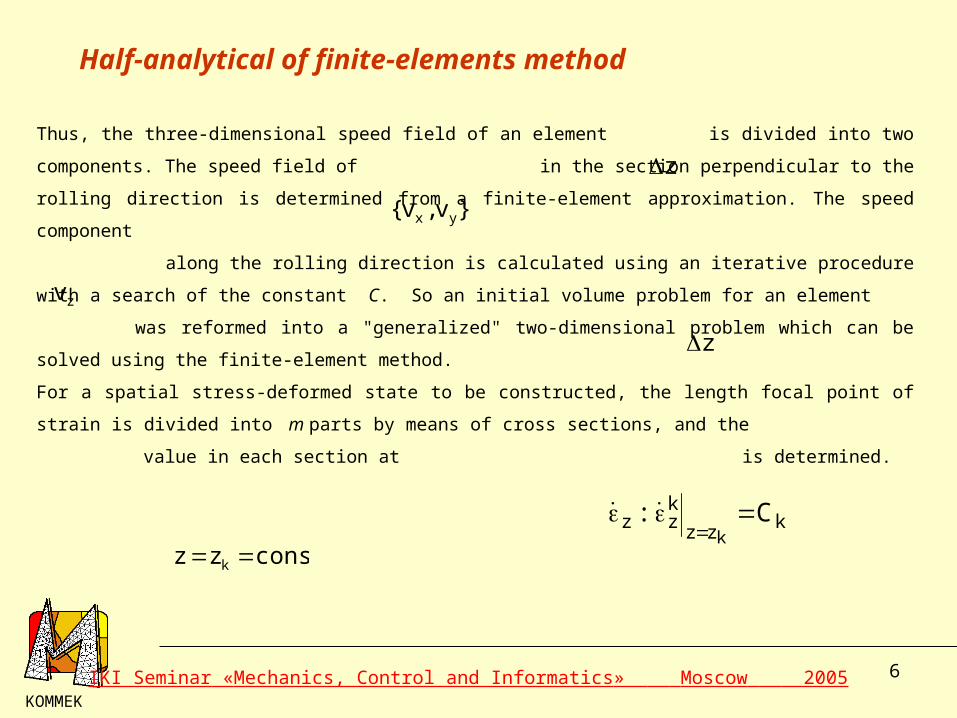
Half-analytical of finite-elements method
Thus, the three-dimensional speed field of an element is divided into two components. The
speed field of in the section perpendicular to the rolling direction is determined from a
finite-element approximation. The speed component
along the rolling direction is calculated using an iterative procedure with a search of the
constant C. So an initial volume problem for an element was reformed into a "generalized"
two-dimensional problem which can be solved using the finite-element method.
For a spatial stress-deformed state to be constructed, the length focal point of strain is divided into
m parts by means of cross sections, and the value in each section at
is determined.
KOMMEK
z
}v,v{ yx
zv
z
kzz
kzz C:
k
constzz k
IKI Seminar «Mechanics, Control and Informatics» Moscow 2005
7
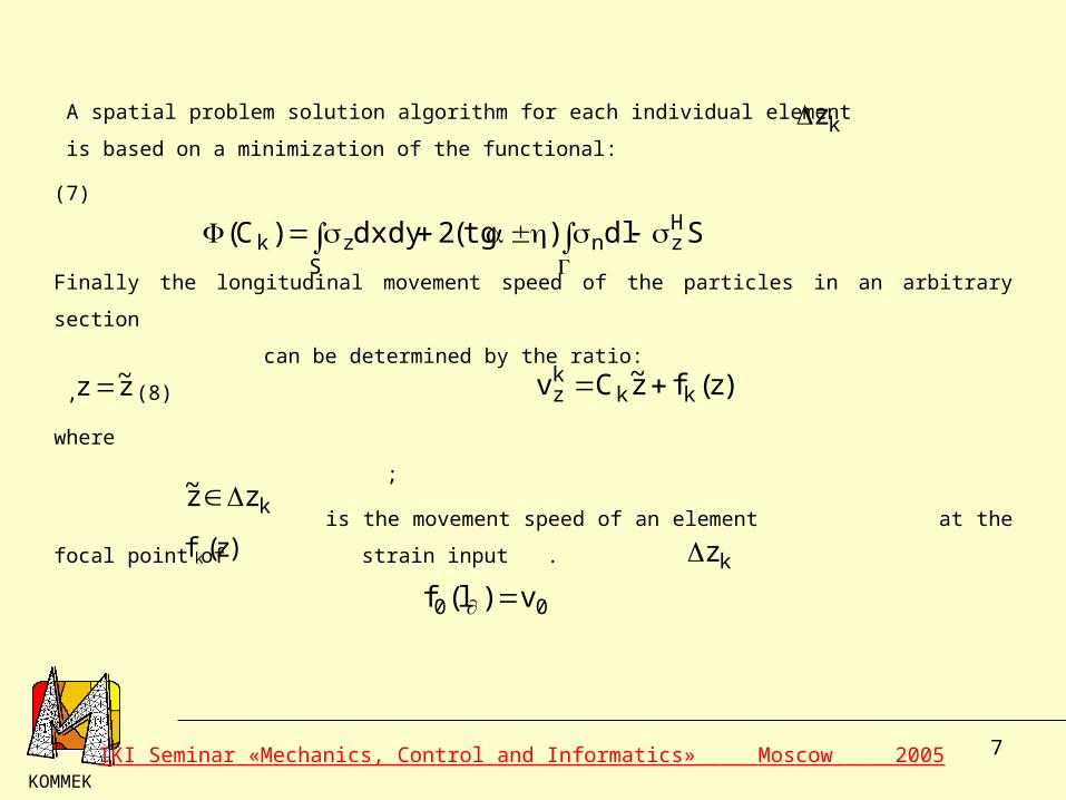
A spatial problem solution algorithm for each individual element is based on a
minimization of the functional:
(7)
Finally the longitudinal movement speed of the particles in an arbitrary section
can be determined by the ratio: , (8)
where
;
is the movement speed of an element at the focal point of
strain input .
KOMMEK
kz
Sdl)tg(2dxdy)C( Hzn
Szk
z~z )z(fz~Cv kkkz
kzz~
)z(fk
00 v)l(f
kz
IKI Seminar «Mechanics, Control and Informatics» Moscow 2005

8
Experimental verification
KOMMEK
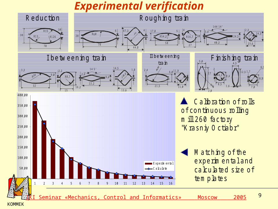
For model verification the experimental data obtained in expertises on study of a tension at rolling in smooth rolls, obtained earlier by professor Tarnovskiy I.J. utilized.
Н0 , W0 - initial height and width of a strip;WF - averaged finite width of a strip.
IKI Seminar «Mechanics, Control and Informatics» Moscow 2005
9
Experimental verification
0,00
50,00
100,00
150,00
200,00
250,00
300,00
350,00
400,00
1 2 3 4 5 6 7 8 9 10 11 12 13 14 15 16
Experim enta l
C alculate
Reduction Roughing tra in
I betw eening tra in II betw eening tra in
Finish ing tra in
38
70
R1 5
10R15
R126 28
78
6R60
47,334
44,8
4
58
17,8 5
R54,2
4
27
30R16,7
40,3
24,5
144 14’
3,42,3
17,8
23,6
24,5
R34
32
9,0
3,3 2,2
R8,7
16,215
14 5’
2,6
22,2
9,6
1,8
10,6
14,5
13,6
21,5
2,46,0
R26
11,0
11,9
4,5
1,6
12,5
7,0
1,7
6,9
6,9
2,0
5,0
17
R18
2
8,4
8,5
R4,2
Calibration of ro lls of continuous ro lling m ill 260 factory "K rasniy O ctiabr"
M atching of the experim ental and ca lculated size of tem plates
KOMMEK
IKI Seminar «Mechanics, Control and Informatics» Moscow 2005
10
KOMMEK
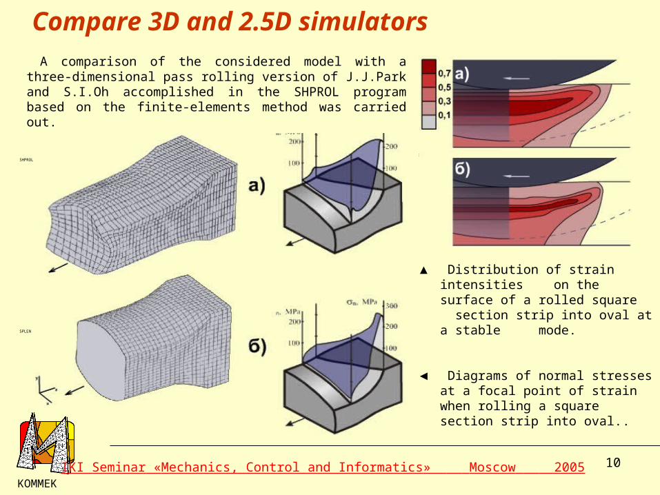
A comparison of the considered model with a three-dimensional pass rolling version of J.J.Park and S.I.Oh accomplished in the SHPROL program based on the finite-elements method was carried out.
SHPROL
▲ Distribution of strain intensities on the surface of a rolled square section strip into oval at a stable mode.
◄ Diagrams of normal stresses at a focal point of strain when rolling a square section strip into oval..
SPLEN
Compare 3D and 2.5D simulators
IKI Seminar «Mechanics, Control and Informatics» Moscow 2005
11
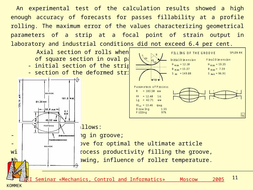
An experimental test of the calculation results showed a high enough accuracy of forecasts for
passes fillability at a profile rolling. The maximum error of the values characterizing geometrical
parameters of a strip at a focal point of strain output in laboratory and industrial conditions did
not exceed 6.4 per cent.
Axial section of rolls when rolling a strip of square section in oval pass:
- initial section of the strip; - section of the deformed strip.
System SPLEN allows:
- to model the rolling in groove;
- to analyze the groove for optimal the ultimate article
with respect to of process productivity filling the groove,
the friction, the drawing, influence of roller temperature.
KOMMEK
F I L L I N G O F T H E G R O O V E
P a r a me t e r s o f P r o c e s s
I n i t i a l D i me n s i o n F i n a l D i me n s i o n
SPLEN-RK
H = 12.10
B = 15 .37
S = 14 9.88
max
max
вх
R = 183.50 мм
= 12.40 1/сLg = 42.71 мм
= 13.46 град
D r a w I n g 1.55F i l l I n g 97%
H = 19.35
B = 7.59
S = 96.91
max
max
вых
Lg
R
Lg
Lg
IKI Seminar «Mechanics, Control and Informatics» Moscow 2005
12
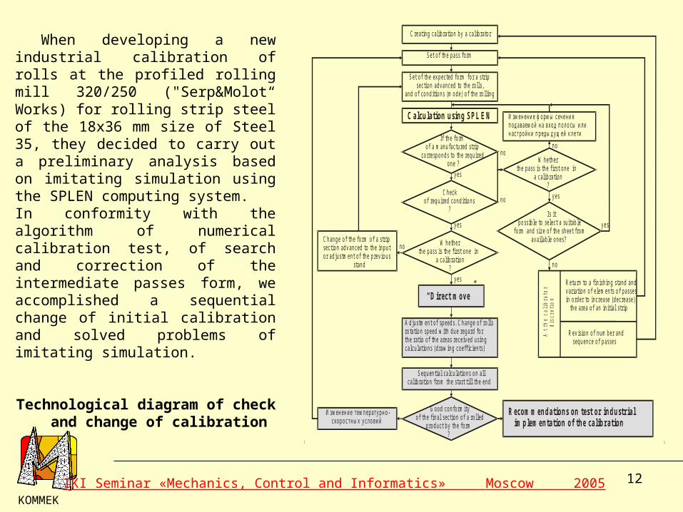
When developing a new industrial calibration of rolls at the profiled rolling mill 320/250 ("Serp&Molot“ Works) for rolling strip steel of the 18x36 mm size of Steel 35, they decided to carry out a preliminary analysis based on imitating simulation using the SPLEN computing system.In conformity with the algorithm of numerical calibration test, of search and correction of the intermediate passes form, we accomplished a sequential change of initial calibration and solved problems of imitating simulation.
Technological diagram of check and change of calibration
KOMMEK
C rea tin g ca lib ra tio n b y a ca lib ra to r
S e t o f th e p ass fo rm
S e t o f th e ex p ec ted fo rm fo r a s trip sec tio n ad v an ced to th e ro lls ,an d o f co n d itio n s (m o d e) o f th e ro llin g
C a lcu la tio n u sin g S P L E N
If th e fo rm o f a m an u fac tu red s tripco rre sp o n d s to th e req u ired o n e ?
C h ecko f req u ired co n d itio n s ?
W h e th e rth e p ass is th e f irs t o n e in a ca lib ra tio n ?
A d ju stm en t o f sp eed s. C h an g e o f ro llsro ta tio n sp eed w ith d u e reg a rd fo rth e ra tio o f th e a reas rece iv ed u s in gca lcu la tio n s (d raw in g co e ffic ien ts)
S eq u en tia l ca lcu la tio n s o n a llca lib ra tio n fro m th e s ta rt till th e en d
G o o d co n fo rm ityo f th e fin a l sec tio n o f a ro lled p ro d u c t b y th e fo rm ?
И зм ен ен и е тем п ер ату р н о - ско р о стн ы х у сл о в и й
R eco m m en d a tio n s o n test o r in d u str ia l im p lem en ta tio n o f th e ca lib ra tio n
C h an g e o f th e fo rm o f a s tripsec tio n ad v an ced to th e in p u to r ad ju stm en t o f th e p rev io u s s tan d
И зм ен ен и е ф о рм ы с еч ен и яп од аваем о й н а в ход п ол о сы и л ин аст р о й к и п р ед ы д у щ ей к л ети
R etu rn to a fin ish in g s tan d an dv aria tio n o f e lem en ts o f p assesin o rd e r to in c rease (d ecrease ) th e a rea o f an in itia l s trip
R ev is io n o f n u m b er an d seq u en ce o f p asses
At t
he c
alib
rato
r
dis
cret
ion
Is it p o ss ib le to se lec t a su itab lefo rm an d size o f th e sh ee t fro m av a ilab le o n es?
“ D irec t m o v e”
y es
n o
y es
y es
n o
y es
n o
n o
n o
y es
W h e th e rth e p ass is th e f irs t o n e in a ca lib ra tio n ?
IKI Seminar «Mechanics, Control and Informatics» Moscow 2005

13
Changes made Calculated section of a strip
Parameters form changing
Initial calibration
Hmax/2= 9.00 Bmax/2=18.57 S1/4= 162.7
elongation ratio 1.23 fillability 99.1 %
Reduction of a pass width by the bottom
Hmax/2= 9.00 Bmax/2= 18.07 S1/4= 159.2
elongation ratio 1.18 fillability 94.5 %
The general width of a pass is reduced
Hmax/2= 9.00 Bmax/2= 17.71 S1/4= 156.9
elongation ratio 1.19 fillability 90.8 %
0.0. 2. 4. 6. 8. 10. 12. 14. 16. 18.0.0.
2.
4.
6.
8.
0.0. 1. 2. 3. 4. 5. 6. 7. 8. 9. 10. 11. 12. 13. 14. 15. 16. 17. 18.0.0.
1.
2.
3.
4.
5.
6.
7.
8.
9.
0.0. 1. 2. 3. 4. 5. 6. 7. 8. 9. 10. 11. 12. 13. 14. 15. 16. 17.0.0.
1.
2.
3.
4.
5.
6.
7.
8.
9.
KOMMEK
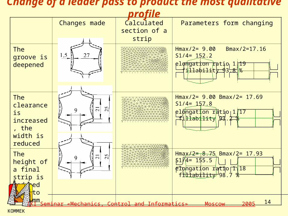
Change of a leader pass to product the most qualitative profile
IKI Seminar «Mechanics, Control and Informatics» Moscow 2005
14
Changes made Calculated section of a strip
Parameters form changing
The groove is deepened
Hmax/2= 9.00 Bmax/2=17.16 S1/4= 152.2
elongation ratio 1.19 fillability 93.8 %
The clearance is increased, the width is reduced
Hmax/2= 9.00 Bmax/2= 17.69 S1/4= 157.8
elongation ratio 1.17 fillability 93.2 %
The height of a final strip is reduced down to 17.5 mm
Hmax/2= 8.75 Bmax/2= 17.93 S1/4= 155.5
elongation ratio 1.18 fillability 98.7 %
KOMMEK
0.0. 1. 2. 3. 4. 5. 6. 7. 8. 9. 10. 11. 12. 13. 14. 15. 16. 17.0.0.
1.
2.
3.
4.
5.
6.
7.
8.
9.
0.0. 1. 2. 3. 4. 5. 6. 7. 8. 9. 10. 11. 12. 13. 14. 15. 16. 17.0.0.
1.
2.
3.
4.
5.
6.
7.
8.
9.
0.0. 1. 2. 3. 4. 5. 6. 7. 8. 9. 10. 11. 12. 13. 14. 15. 16. 17.0.0.
1.
2.
3.
4.
5.
6.
7.
8.
Change of a leader pass to product the most qualitative profile
IKI Seminar «Mechanics, Control and Informatics» Moscow 2005

15
KOMMEK
Physical simulation as result the mathematical simulation
According to the changed calibration, a rolling was carried out, as a result of which a strip
satisfying all preset requirements was manufactured. The deviation of the calculated results
from the contour of a real template at the same mill adjustment did not exceed 1.5 per cent.
The templates of a finish strip manufactured when rolling according
to an initial (a) and changed (b)
calibrations, and also according to a new
calibration when rolling strips with cross sections
of 18 x 36 (c), 20 x 32 (d) and 16 x 36 mm
(e)
a) b) c) d) e)
IKI Seminar «Mechanics, Control and Informatics» Moscow 2005
16
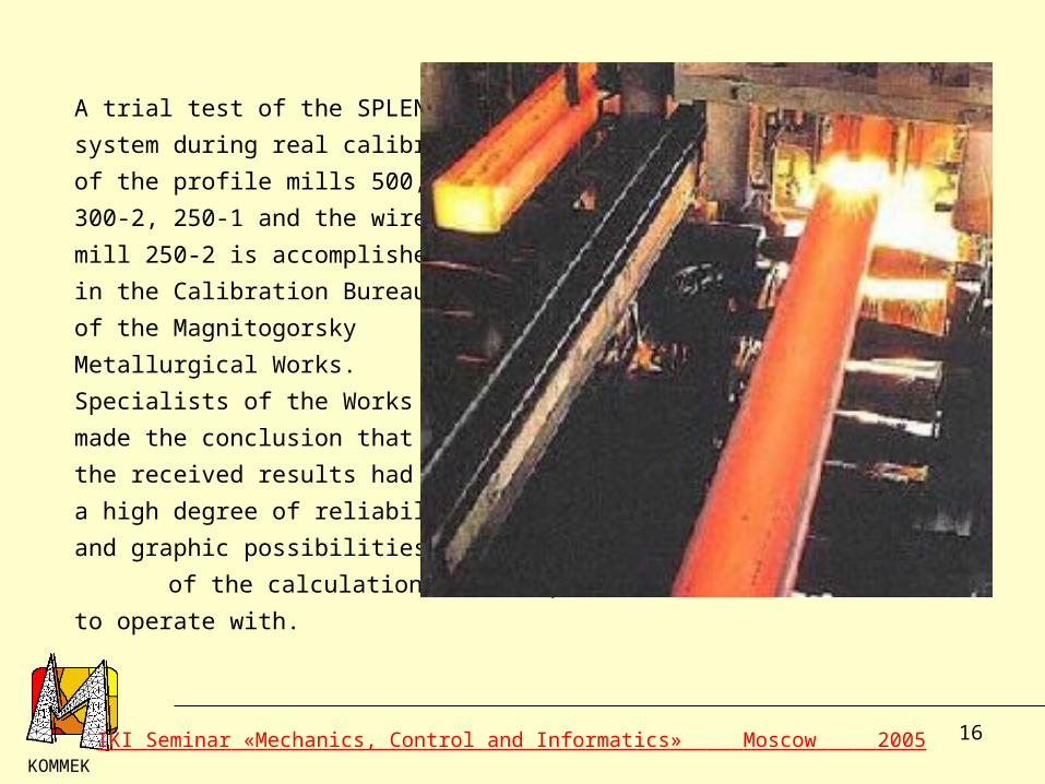
A trial test of the SPLEN
system during real calibrations
of the profile mills 500,
300-2, 250-1 and the wire
mill 250-2 is accomplished
in the Calibration Bureau
of the Magnitogorsky
Metallurgical Works.
Specialists of the Works
made the conclusion that
the received results had
a high degree of reliability,
and graphic possibilities
of the calculation results presentation are convenient to operate with.
KOMMEK
IKI Seminar «Mechanics, Control and Informatics» Moscow 2005

17
Resume
The mathematical model and algorithms define a
simulation of steadied calibrating process is
designed.
On the basis of the above-stated method of application the operations on
creation of a service system of simulation and optimization of manufacturing
processes of rolling calibrating process are carried on.
The response rate of designed systems on the degrees exceeds response rate of existing algorithms of spatial simulation calibrating process that is the important advantage at problem solving of optimization.
KOMMEK
IKI Seminar «Mechanics, Control and Informatics» Moscow 2005
18
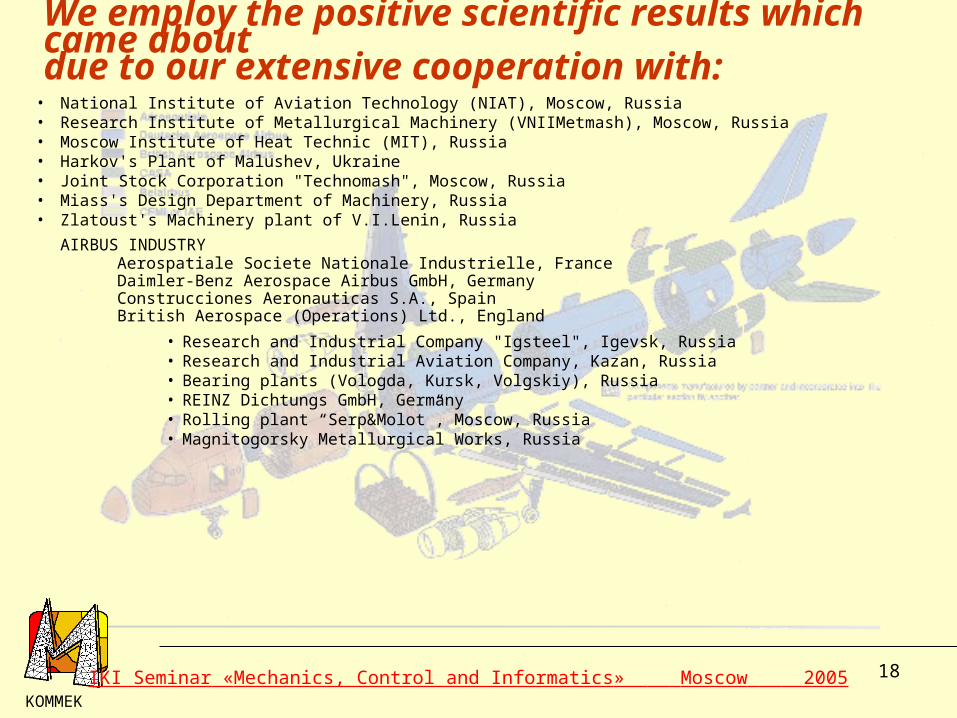
• National Institute of Aviation Technology (NIAT), Moscow, Russia• Research Institute of Metallurgical Machinery (VNIIMetmash), Moscow, Russia• Moscow Institute of Heat Technic (MIT), Russia• Harkov's Plant of Malushev, Ukraine• Joint Stock Corporation "Technomash", Moscow, Russia• Miass's Design Department of Machinery, Russia• Zlatoust's Machinery plant of V.I.Lenin, Russia
AIRBUS INDUSTRYAerospatiale Societe Nationale Industrielle, FranceDaimler-Benz Aerospace Airbus GmbH, GermanyConstrucciones Aeronauticas S.A., SpainBritish Aerospace (Operations) Ltd., England
• Research and Industrial Company "Igsteel", Igevsk, Russia• Research and Industrial Aviation Company, Kazan, Russia• Bearing plants (Vologda, Kursk, Volgskiy), Russia• REINZ Dichtungs GmbH, Germany• Rolling plant “Serp&Molot”, Moscow, Russia• Magnitogorsky Metallurgical Works, Russia
KOMMEK
We employ the positive scientific results which came aboutdue to our extensive cooperation with:
IKI Seminar «Mechanics, Control and Informatics» Moscow 2005
Related Documents