101 WOOD RESEARCH 60 (1): 2015 101-112 APPLICATION OF INNOVATIVE HEAT RECOVERY UNIT IN PAPER INDUSTRY WITH POTENTIAL UTILIZATION IN WOOD-PROCESSING AND FURNITURE INDUSTRY Andrej Pažitný, Štefan Boháček, Peter Medo, Jozef Balberčák Pulp and Paper Research Institute Bratislava, Slovak Republic (Received November 2014) ABSTRACT Heat consumption is very high in many branches of industry including paper industry. That is why innovation trends in paper industry also include heat energy saving that can be realized by enhancing of heat recovery efficiency. Some entertainments that produce paper in Slovak Republic have not built the heat recovery system which could be installed near a drying cover of a paper machine. The minor paper mills in Slovak Republic usually possess operating paper machines which use cogeneration units for heat and electricity production with output range between 400 and 500 kWh. Integration of innovative spiral heat recovery unit into the existing dryer section of paper machine in a paper mill will lead to decrease of heat consumption by 25 000 up to 31 000 GJ per year that means financially up to 625 000 EURO per year. KEYWORDS: Heat recovery, heat recovery efficiency, heat recovery unit, paper industry, paper machine, paper mill. INTRODUCTION With considerations about reducing of total costs in paper mills or other large industrial consumers of energy are often being linked two industrial solutions for the most effective reduction of energy consumption: cogeneration units by production of heat and electricity (Qu et al. 2014) and heat recovery systems with high heat recovery efficiency (Wallin and Claesson 2014a). A significant number of paper mills in Slovak Republic, however, do not possess any heat recovery system which includes the heat recovery unit and ventilation pipes joining the heat recovery unit with dryer section of paper machine. Although some larger paper mills possess the introduced heat recovery system, it is still possible the heat recovery efficiency to enlarge because the present amount of recovered heat in the form of low-potential heat is between 50 and 60 % of heat energy produced in the frame of Slovak paper mills. One of the most important solutions

Welcome message from author
This document is posted to help you gain knowledge. Please leave a comment to let me know what you think about it! Share it to your friends and learn new things together.
Transcript

101
WOOD RESEARCH 60 (1): 2015 101-112
APPLICATION OF INNOVATIVE HEAT RECOVERY UNIT
IN PAPER INDUSTRY WITH POTENTIAL UTILIZATION
IN WOOD-PROCESSING AND FURNITURE INDUSTRY
Andrej Pažitný, Štefan Boháček, Peter Medo, Jozef BalberčákPulp and Paper Research Institute
Bratislava, Slovak Republic
(Received November 2014)
ABSTRACT
Heat consumption is very high in many branches of industry including paper industry. That is why innovation trends in paper industry also include heat energy saving that can be realized by enhancing of heat recovery efficiency. Some entertainments that produce paper in Slovak Republic have not built the heat recovery system which could be installed near a drying cover of a paper machine. The minor paper mills in Slovak Republic usually possess operating paper machines which use cogeneration units for heat and electricity production with output range between 400 and 500 kWh. Integration of innovative spiral heat recovery unit into the existing dryer section of paper machine in a paper mill will lead to decrease of heat consumption by 25 000 up to 31 000 GJ per year that means financially up to 625 000 EURO per year.
KEYWORDS: Heat recovery, heat recovery efficiency, heat recovery unit, paper industry, paper machine, paper mill.
INTRODUCTION
With considerations about reducing of total costs in paper mills or other large industrial consumers of energy are often being linked two industrial solutions for the most effective reduction of energy consumption: cogeneration units by production of heat and electricity (Qu et al. 2014) and heat recovery systems with high heat recovery efficiency (Wallin and Claesson 2014a). A significant number of paper mills in Slovak Republic, however, do not possess any heat recovery system which includes the heat recovery unit and ventilation pipes joining the heat recovery unit with dryer section of paper machine. Although some larger paper mills possess the introduced heat recovery system, it is still possible the heat recovery efficiency to enlarge because the present amount of recovered heat in the form of low-potential heat is between 50 and 60 % of heat energy produced in the frame of Slovak paper mills. One of the most important solutions

102
WOOD RESEARCH
of the issue is to replace the existing heat recovery units based on heat exchange in tubes with spiral heat exchangers and this measure should increase average heat recovery efficiency by about 25 %. Today, there is a high interest in the research field of spiral heat exchangers because they ensure the entire countercurrent f low and the heat exchange surfaces will redouble in the heat exchange measuring unit (Roetzel and Spang 2010). An extensive research has been realized so far, evaluating the influence of internal dimensions, channel hydraulic diameter and velocity of airf low in spiral heat exchanger, in order to optimize the parameters of the spiral heat exchangers for utilization in the industry, according to the desired properties for many applications in the industry. The objective of this study is to evaluate the possibilities of location of terminal part of ventilation tube which is joined to the spiral heat exchanger according to the horizontal temperature profile of dryer section of operating paper machine, in order to elucidate the suitability of utilization of heat recovery system in paper mill. The main reason of that measure is the large heat recovery efficiency after application of the heat recovery unit into conditions of a pilot paper machine – nearly 94 %.
MATERIAL AND METHODS
MaterialsAll materials used in the construction of spiral heat exchanger were commercially available.
As heat exchange wall – the crucial part of the equipment – was used aluminium spiral shaped plate with 0.5 mm thickness and dimensions of formed area for heat transfer were 460 x 22.720 mm (Pažitný et al. 2013). The external planking was water-resistant with rubber lining and air tightness was ensured by polyethylene sheet. The current of hot air containing the hot aqueous vapour as a low-potential heat source was provided by dryer section of pilot or operating paper machine (year of recommissioning: 1998; country of origin: Germany). The paper machine included multi-cylinder dryer section with 20 cylinders. The current of cold air had been pumped from the environment of paper mill. Additionally, the heat recovery system was formed from pipes (2 x 10 m) and they consisted of two aluminium layers and one glass wool embedded between them as an insulation material. The internal diameter of the pipes was 0.1 m.
MethodsDelimitation of the horizontal temperature profile of dryer section of the operating paper
machine was realized by infrared thermometer (HD 500, Extech Instruments Corporation, USA). Velocity values of actual currents of hot and cold air for calculation of heat recovery efficiency of the spiral heat recovery unit were measured by laboratory anemometer (GM 816, Sinokit Enterprise Limited, China). Other data for heat recovery efficiency determination of spiral heat recovery unit, such as the actual temperature and relative humidity of the currents of hot and cold air – input and output, were collected by electronic equipment (KlimaLogg Pro Cat. No. 30.3039.IT, Elso Philips Service JSC, SR). Introduced data were detected by four specific sensors located in the spiral heat recovery unit and transferred by local wireless network specified under IEEE 802.11: 2012 to computational device with signal receiver of the wireless network. The recorded data from the computational device were further transferred to a computer using included USB wireless transceiver (Cat. No. 30.3175, Elso Philips Service JSC, SR). The data were recorded every 5 minutes and they were processed by software KlimaLogg Pro (TFA Dostmann LLP, Wertheim-Reicholzheim, Germany). Average value of atmospheric pressure in Slovak Republic for October 2014 was obtained from Slovak Hydrometeorological Institute and it was 98.885 Pa.
103
Vol. 60 (1): 2015
RESULTS AND DISCUSSION
Horizontal temperature profile of dryer section of operating paper machineDetermination of the temperature profile of dryer section of operating paper machine was
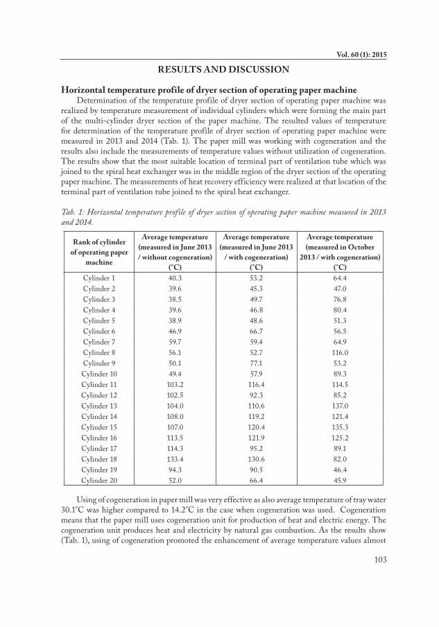
realized by temperature measurement of individual cylinders which were forming the main part of the multi-cylinder dryer section of the paper machine. The resulted values of temperature for determination of the temperature profile of dryer section of operating paper machine were measured in 2013 and 2014 (Tab. 1). The paper mill was working with cogeneration and the results also include the measurements of temperature values without utilization of cogeneration. The results show that the most suitable location of terminal part of ventilation tube which was joined to the spiral heat exchanger was in the middle region of the dryer section of the operating paper machine. The measurements of heat recovery efficiency were realized at that location of the terminal part of ventilation tube joined to the spiral heat exchanger.
Tab. 1: Horizontal temperature profile of dryer section of operating paper machine measured in 2013 and 2014.
Rank of cylinder of operating paper
machine
Average temperature (measured in June 2013 / without cogeneration)
(°C)
Average temperature (measured in June 2013
/ with cogeneration) (°C)
Average temperature (measured in October
2013 / with cogeneration) (°C)
Cylinder 1 40.3 53.2 64.4Cylinder 2 39.6 45.3 47.0Cylinder 3 38.5 49.7 76.8Cylinder 4 39.6 46.8 80.4Cylinder 5 38.9 48.6 51.3Cylinder 6 46.9 66.7 56.5Cylinder 7 59.7 59.4 64.9Cylinder 8 56.1 52.7 116.0Cylinder 9 50.1 77.1 53.2Cylinder 10 49.4 57.9 89.3Cylinder 11 103.2 116.4 114.5Cylinder 12 102.5 92.3 85.2Cylinder 13 104.0 110.6 137.0Cylinder 14 108.0 119.2 121.4Cylinder 15 107.0 120.4 135.3Cylinder 16 113.5 121.9 125.2Cylinder 17 114.3 95.2 89.1Cylinder 18 133.4 130.6 82.0Cylinder 19 94.3 90.5 46.4Cylinder 20 52.0 66.4 45.9
Using of cogeneration in paper mill was very effective as also average temperature of tray water 30.1°C was higher compared to 14.2°C in the case when cogeneration was used. Cogeneration means that the paper mill uses cogeneration unit for production of heat and electric energy. The cogeneration unit produces heat and electricity by natural gas combustion. As the results show (Tab. 1), using of cogeneration promoted the enhancement of average temperature values almost

104
WOOD RESEARCH
in the entire horizontal profile of dryer section of operating paper machine. In both cases, the most suitable location of terminal part of ventilation tube joined to the spiral heat exchanger was in the middle region of dryer section of operating paper machine. The technical possibilities of the drying cover of the paper machine allowed the location of terminal part of ventilation tube above the cylinder 11. The average temperature in the region between the drying cover of the paper machine and the eleventh drying cylinder of the dryer section of paper machine was 54.7°C. In that case, the cogeneration was also helpful because otherwise the average temperature value was 41.0°C. It is very important to mention that the maximum output of the cogeneration unit was 400 kWh, the maximum of heat output was about 340 kWh (average of 85 % of maximum output) and the residual energy was used for electricity production and losses of energy were included too in the residual energy. The large ratio of partial energy used as heat energy is very important because the paper making process is essentially a very large dewatering process where a diluted solution of pulp suspension with less than 0.5 % fibre solid is used and water is a material with large value of the specific heat of vaporization. The heat in the form of low-potential heat is the biggest potential energy waste which could be vented out into the atmosphere or to heat exchanger (Ghosh 2011). Our solution for such energy conservation in paper mill is spiral heat exchanger with countercurrent heat exchange.
Calculation of parameters of moist air f lowing from operating paper machineThe relative humidity of an air-water mixture is defined as a ratio of the partial pressure of
water vapour (pA) in the mixture to the equilibrium vapour pressure of water (pA0) or saturation vapour pressure, respectively, at a measured temperature. Relative humidity is dimensionless function of temperature and is calculated by using the following equation (Perry and Green 1999):
(1)
where: pA – partial pressure of water vapour in pascals (Pa), pA0 – saturation vapour pressure in pascals (Pa).
According to the Dalton’s law of partial pressures which states that in a mixture of non-reacting gases, the total pressure exerted is equal to the sum of the partial pressures of the individual gases, in the mathematical notation is written as follows (Silberberg 2009):
(2)
For moist air pressure, following equation is suitable:
(3)
where: p – pressure of moist air or atmospheric pressure, respectively, in pascals (Pa), pDA – pressure of dry air in pascals (Pa). The classical ideal gas law may be written (Florio 2014):
(4)
where: v – specific volume of the gas, mole based in m3.mol-1,

105
Vol. 60 (1): 2015
– universal gas constant in J.K-1.kmol-1, T – thermodynamic temperature in kelvins (K).
According to the equation (4), the following relationships for the density calculation of the moist air as an ideal gas can be concluded as follows:
(5)
where: V – volume of the moist air in m3, MW – molecular weight of the moist air in kg.kmol-1, m – weight of the moist air in kg, ς – density of moist air in kg.m-3, – constant for a particular substance in J.kg-1.K-1.
For both constants of dry air (rDA) and water vapour (rA), it can be concluded:
(6)
(7)
where: universal gas constant = 8314.3 J.kmol-1.K-,1 molecular weight of dry air MWDA = 28.96 kg.kmol-,1 molecular weight of water vapour MWA = 18.02 kg.kmol-1. Density of moist air is calculated by using the equations (3), (5), (6) and (7):
(8)
where: ςDA – density of dry air in kg.m-3, ςA – density of water vapour in kg.m-3.
Final equation for density calculation obtained by substitution with numerical values of the individual variables then can be written (Kalenský 2014):
(9)
Properties of moist air were calculated from the measured values of actual temperature and actual relative humidity. In calculation, as convenient basis of calculation the modified Antoine equation for water was used (Antoine 1888a; b; Langrish 2010):
(10)
Combination of equations (9) and (10) is resulted in the equation (11):
(11)

106
WOOD RESEARCH
Calculation of heat recovery efficiency of a spiral heat recovery unit Calculation of important parameters of a spiral heat recovery unit (Fig. 1) dimensioned
pursuant to the previous papers (Picón-Núñez et al. 2007; 2009; 2012) is based on the known parameters of moist air including the density calculated by using the equation (11). The calculation base for the heat recovery efficiency calculation is formed by the temperature and relative humidity values of the currents of hot and cold air in the spiral heat recovery unit, recorded by the system of four sensors located on input and output of this equipment and the computational device with signal receiver of the wireless network. As the spiral heat recovery unit was used for heat recovery in operating conditions of paper mill, it is also necessary to calculate the exact value of specific heat capacity of the moist air by following equation:
(12)
where: cpA – specific heat capacity of water vapour J.kg-1.K-1, cpDA - specific heat capacity of dry air in J.kg-1.K-1.
Dependence of specific heat capacity of pure water vapour and dry air on temperature is negligible. The specific heat capacity of pure water vapour (cpA) for temperature between 0 and 80°C is equal to 1.93 J.kg-1.K-1. The specific heat capacity of dry air (cpDA) for the same temperature range is equal to 1.01 J.kg-1.K-1.
Fig. 1: Spiral heat recovery unit with depicted countercurrent flow of two currents (left) – hot air current (red colour) and cold current (blue colour); detail of spiral in the heat recovery unit (right).
Heat recovery efficiency of the spiral heat recovery unit also depends on mass f low rate of air current which can be calculated according to the following equation (13):
(13)
where: – average velocity of air current measured on input or output to the spiral heat recovery unit in m.s-1, S – area of pipe cross-section on input or output of the spiral heat recovery unit in m2, ς – density of moist air calculated by using the equation (11) in kg.m-3.
Heat f low rate is defined as a function of mass f low rate, specific heat capacity and temperature difference between two points of the unit (Wallin and Claesson 2014b). In some

107
Vol. 60 (1): 2015
cases, the heat recovery efficiency can be defined as a ratio of temperature differences of the air currents on the input and output of the unit (Wang et al. 2014) because the difference between mass f low rate values of the air currents and the difference between specific heat capacity values of the air currents are negligible. In our case, however, heat f low rate of both air currents depended on different mass f low rate value and specific heat capacity value. That is why, finally, resulting mathematical relationship – equation (14) can be applied for the heat recovery efficiency calculation:
(14)
where: – average velocity of cold moist air current measured on input or output to the spiral heat recovery unit in m.s-1, – average density of cold moist air current calculated by using the equation (11) in kg.m-3, – average specific heat capacity of cold moist air current calculated by using the equation (12) in J.kg-1.K-1, – average velocity of hot moist air current measured on input or output to the spiral heat recovery unit in m.s-1, – average density of hot moist air current calculated by using the equation (11) in kg.m-3, – average specific heat capacity of hot moist air current calculated by using the equation (12) in J.kg-1.K-1, T1 – thermodynamic temperature of hot moist air current recorded on input into the spiral heat recovery unit in kelvins (K), T2 – thermodynamic temperature of hot moist air current recorded on output from the spiral heat recovery unit in kelvins (K), T3 – thermodynamic temperature of cold moist air current recorded on output from the spiral heat recovery unit in kelvins (K), T4 – thermodynamic temperature of cold moist air current recorded on input into the spiral heat recovery unit in kelvins (K), S – area of pipe cross-section on input or output of the spiral heat recovery unit in m2 – used pipes with internal diameter 0.1 m had cross-section 7.85 x 10⁻³ m2.
In general, for thermodynamic temperature is known relationship:
(15)
where: T (K) – thermodynamic temperature in K, T (°C) – Celsius temperature measured in degrees Celsius (°C).
It was found that values of average specific heat capacity of both moist hot and cold air current for each measurement was almost constant (1.01 J.kg-1.K-1) and were the same (cpcac = cphac = 1.01 J.kg-1.K-1), the heat recovery efficiency was calculated according to the following equation (16):
(16)

108
WOOD RESEARCH
Tab. 2 summarizes recorded data of average velocity, relative humidity and temperature of hot air current and cold air current recorded by four electronic sensors located in heat recovery unit. The obtained data show that relative humidity value reached the maximum difference in case of the hot moist air current coming from the drying cover of the paper machine by the pipe system into the heat recovery unit (72 %) what means the lowest stability of the air current parameter influenced by cyclic paper production. In contrast, the highest stability was in case of the cold moist air current coming from the environment of paper mill by the pipe system into the heat recovery unit. In context of the previous affirmations, the stability or instability of parameters of both moist air currents were mutually influenced as the difference between the lowest and the highest value of the relative humidity reduced rapidly in case of the hot moist air current coming from the heat recovery unit to the environment of paper mill (11 %) and increased dramatically in case of the cold moist air current coming from the heat recovery unit to the environment (48 %). Additionally, the results show that the relative humidity values decreased with increasing temperature which can be seen at each air current (Tab. 2).
Tab. 2: Measured values of average velocity, relative humidity and temperature of hot air current and cold air current recorded by four electronic sensors located in heat recovery unit.
Time (min) (m.s-1) (m.s-1)
φ1 (%)
φ2 (%)
φ3 (%)
φ4 (%)
T1
(°C)T2
(°C)T3
(°C)T4
(°C)0 2.0 1.5 29 39 65 45 35.6 29.5 27.9 23.05 2.0 2.0 27 38 63 47 36.4 29.5 26.9 22.510 2.1 2.5 27 38 60 47 36.4 29.3 26.6 22.515 2.1 2.5 27 38 55 47 36.3 29.2 26.6 22.520 2.1 2.5 26 38 52 46 36.1 29.0 26.6 22.425 2.2 2.5 27 38 50 47 35.4 28.7 26.4 22.230 2.1 2.5 27 38 51 47 35.3 28.4 26.3 22.135 2.1 2.8 27 38 51 46 35.8 28.4 26.2 22.240 2.1 3.2 26 38 50 46 36.1 28.6 26.1 22.145 2.2 3.6 26 37 51 46 36.1 28.5 26.1 22.050 1.9 3.3 26 37 49 46 36.3 28.6 26.0 22.055 2.0 3.5 26 37 49 46 36.3 28.5 26.0 22.060 2.1 3.5 26 37 49 46 36.2 28.5 26.0 21.965 1.6 3.4 25 36 51 46 38.2 28.8 25.9 21.970 1.8 3.5 34 40 61 46 38.6 29.6 26.1 22.075 1.9 3.5 24 35 49 45 37.8 29.3 26.2 22.180 1.7 3.5 24 35 51 46 39.4 29.6 26.2 22.085 1.6 3.5 22 33 50 45 41.0 30.1 26.3 22.090 1.4 3.5 20 32 52 45 44.0 31.1 26.5 22.095 1.4 3.5 18 30 50 45 45.7 32.1 26.8 22.1
100 1.6 3.5 18 31 49 45 45.4 32.5 27.0 21.9105 1.8 3.5 19 31 48 45 44.3 32.4 27.2 21.8110 1.9 3.5 19 31 48 45 43.6 32.2 27.2 21.7115 1.9 3.5 19 30 47 45 43.6 32.0 27.2 21.6120 1.8 3.5 18 31 48 45 44.6 32.3 27.3 21.7125 1.7 3.5 18 30 48 45 45.5 32.7 27.4 21.8130 1.6 3.5 22 30 55 45 46.8 33.2 27.6 21.8135 1.8 3.5 90 29 95 45 47.6 34.0 28.4 21.8

109
Vol. 60 (1): 2015
Tab. 3 shows the calculated thermodynamic quantities of hot and cold air current and resulted heat recovery efficiency calculated from average velocity values (Tab. 2) and other quantities by using the equation (16). It was found that the system of heat recovery did not have such a high level of stability as in our previous papers when the heat recovery unit was experimentally tested (Pažitný et al. 2013) but the system was stabilized at analogical trend. We believe that low stability of the heat recovery system was caused by the cyclic production of paper and unstable heat supply in the frame of operating paper machine. However, the heat recovery efficiency of the heat recovery unit reached high level (88.53 %) which is much higher than by heat recovery units normally used in operating paper machines.
Tab. 3: Calculated average thermodynamic quantities of hot air current and cold air current and heat recovery efficiency of heat recovery unit.
Time (min)
(kg.m-3)
(kg.m-3)
T1 (K)
T2 (K)
T3 (K)
T4 (K)
Heat recovery efficiency (%)
0 1.12 1.15 308.75 302.65 301.05 296.15 58.845 1.12 1.15 309.55 302.65 300.05 295.65 62.0410 1.12 1.15 309.55 302.45 299.75 295.65 66.8715 1.12 1.15 309.45 302.35 299.75 295.65 66.8920 1.12 1.15 309.25 302.15 299.75 295.55 68.5725 1.13 1.15 308.55 301.85 299.55 295.35 69.4230 1.13 1.15 308.45 301.55 299.45 295.25 70.6435 1.12 1.15 308.95 301.55 299.35 295.35 70.2040 1.12 1.16 309.25 301.75 299.25 295.25 79.0745 1.12 1.16 309.25 301.65 299.25 295.15 85.8850 1.12 1.16 309.45 301.75 299.15 295.15 87.7155 1.12 1.16 309.45 301.65 299.15 295.15 87.2660 1.12 1.16 309.35 301.65 299.15 295.05 86.2965 1.12 1.16 311.35 301.95 299.05 295.05 87.5570 1.12 1.16 311.75 302.75 299.25 295.15 85.5075 1.12 1.16 310.95 302.45 299.35 295.25 86.1180 1.12 1.16 312.55 302.75 299.35 295.15 85.2085 1.11 1.16 314.15 303.25 299.45 295.15 83.0690 1.10 1.15 317.15 304.25 299.65 295.15 83.4095 1.10 1.15 318.85 305.25 299.95 295.25 82.33
100 1.10 1.15 318.55 305.65 300.15 295.05 82.40105 1.10 1.15 317.45 305.55 300.35 294.95 84.25110 1.10 1.15 316.75 305.35 300.35 294.85 84.98115 1.10 1.15 316.75 305.15 300.35 294.75 85.04120 1.10 1.15 317.75 305.45 300.45 294.85 84.52125 1.10 1.15 318.65 305.85 300.55 294.95 85.82130 1.09 1.15 319.95 306.35 300.75 294.95 88.53135 1.07 1.15 320.75 307.15 301.55 294.95 87.77
Due to the high values of heat recovery efficiency, the introduced heat recovery unit or analogous equipments can be utilized in wood-processing and furniture industry. It is known the production of agglomerated materials such as medium-density fibreboard (MDF) or high-

110
WOOD RESEARCH
density fibreboard (HDF) which can be used in production of many types of furniture. According to the patented technology (Haas and Melzer 2009), high temperature is used in the process of fibreboard production. In this technology, the temperature is 210°C in the first stage of the fibreboard production and the second stage utilizes the temperatures ranging from 230 to 270°C. By that manner, strength of the fibreboard material is enlarged and the fibreboards are less prone to swelling (Haas and Melzer 2009).
CONCLUSIONS
Spiral heat recovery exchanger was used for the study of possibilities for enhancement of heat recovery efficiency of the operating paper machine. The moist hot air was withdrawn from the drying cover of the paper machine and the moist cold air was withdrawn from the paper mill environment. Both currents were led through the pipe system and they met in the spiral heat recovery exchanger with countercurrent f low of the currents.
We found that heat recovery efficiency depended on change of parameters of moist air currents. The monitored values of parameters such as the relative humidity and thermodynamic temperature of both moist hot and moist cold air currents were used in calculation of thermodynamic quantities such as density and average specific heat capacity of both moist air currents. For each measurement the average specific heat capacity values were almost constant (1.01 J.kg-1.K-1) and they were the same for both moist hot and moist cold air current. Changes of density values of both moist hot and moist cold air currents were not significant. However, reached changes of relative humidity values were rapid for each measurement and the maximum difference for relative humidity values was in case of the hot moist air current coming from the drying cover of the paper machine by the pipe system into the heat recovery unit (72 %). In contrast, the highest stability of the relative humidity values was in case of the cold moist air current coming from the environment of paper mill by the pipe system into the heat recovery unit. The stability or instability of parameters of the moist air currents were mutually influenced as the difference between lowest and highest value of the relative humidity reduced rapidly in case of the hot moist air current coming from the heat recovery unit to the environment of paper mill (11 %) and increased dramatically in case of the cold moist air current coming from the heat recovery unit to the environment (48 %).
Due to the high values of heat recovery efficiency with peak value 88.53 %, the introduced heat recovery unit or analogous equipments can be utilized in wood-processing and furniture industry which use some processes with high heat consumption.
ACKNOWLEDGMENTS
This work was supported by the Slovak Research and Development Agency under the contract No. APVV-0788-11.

111
Vol. 60 (1): 2015
REFERENCES
1. Antoine, C., 1888a: Vapour pressure: A new relationship between pressure and temperature. (Tensions des vapeurs: Nouvelle relation entre les tensions et les températures). In: Comptes rendus hebdomadaires des séances de l'Académie des Sciences 107 (ed. Académie des sciences, France). Pp 681-684 (in French).
2. Antoine, C., 1888b: Pressure calculation of various vapours. (Calcul des tensions de diverses vapeurs). In: Comptes rendus hebdomadaires des séances de l'Académie des Sciences 107 (ed. Académie des sciences, France). Pp 778-780 (in French).
3. Haas, G.V., Melzer, G., 2009: Method for continuous manufacturing of fiberboards from wood. (Spôsob kontinuálnej výroby dosiek z drevného doskového materiálu). Issued by the European Patent Office on May 28th, 2008; EP 1.688.230 B1 (in Slovak).
4. Florio, L.A., 2014: Effect of gas equation of state on CFD predictions for ignition characteristics of hydrogen escaping from a tank. International Journal of Hydrogen Energy 39(32): 18451-18471.
5. Ghosh, A.K., 2011: Fundamentals of paper drying – theory and application from industrial perspective. In: Evaporation, condensation and heat transfer (ed. Amimul Ahsan). InTech Europe, Rijeka, Croatia. Pp 535-583.
6. Kalenský, M., 2014: The analysis of a freeski jump. (Analýza freeskingového skoku). Bachelor thesis, Faculty of Civil Engineering of Czech Technical University in Prague, 63 pp (in Czech).
7. Langrish, T.A.G., 2010: Mathematical modeling spray dryers. In: Mathematical modeling of food processing (ed. Mohammed M. Farid). CRC Press, as an imprint of Taylor & Francis Group, an Informa business. Boca Raton. Pp 301-329.
8. Pažitný, A., Boháček, Š., Medo, P., 2013: Development of new technologies for heat recovery and their application in paper industry. (Vývoj nových technológií umožňujúcich rekuperáciu tepla a ich aplikácia v papierenskom priemysle). Energetika 63(8-9): 481-483 (in Slovak).
9. Perry, R.H., Green, D.W., 1999: Perry’s chemical engineers’ handbook. The McGraw-Hill Companies, Inc., 2582 pp.
10. Picón-Núñez, M., Canizalez-Dávalos, L., Martínez-Rodríguez, G., Polley, G.T., 2007: Shortcut design approach for spiral heat exchangers. Food and Bioproducts Processing 85(C4): 322-327.
11. Picón-Núñez, M., Canizalez-Dávalos, L., Medina-Flores, J.M., 2009: Alternative sizing methodology for compact heat exchangers of the spiral type. Heat Transfer Engineering 30(9): 744-750.
12. Picón-Núñez, M., Polley G.T., Riesco-Ávila, J.M., 2012: Design space for the sizing and selection of heat exchangers of the compact type. Chemical Engineering Transactions 29: 217-222.
13. Qu, M., Abdelaziz, O., Yin, H., 2014: New configurations of a heat recovery absorption heat pump integrated with a natural gas boiler for boiler efficiency improvement. Energy Conversion and Management 87: 175-184.
14. Roetzel, W., Spang, W., 2010: C1 Thermal design of heat exchangers. In: VDI heat atlas, second edition (ed. VDI Gesellschaft Verfahrenstechnik und Chemieingenieurwesen, Düsseldorf, Germany). Springer-Verlag, Berlin Heidelberg. Pp 33-66.
15. Silberberg, M.S., 2009: Chemistry: The molecular nature of matter and change (5th ed.). Boston: McGraw-Hill, 1108 pp.

112
WOOD RESEARCH
16. Wallin, J., Claesson, J., 2014a: Analyzing the efficiency of a heat pump assisted drain water heat recovery system that uses a vertical inline heat exchanger. Sustainable Energy Technologies and Assessments 8: 109-119.
17. Wallin, J., Claesson, J., 2014b: Investigating the efficiency of a vertical inline drain water heat recovery heat exchanger in a system boosted with a heat pump. Energy and Buildings 80: 7-16.
18. Wang, Y., Zhao F.Y., Kuckelkorn, J., Li, X.-H., Wang, H.-Q., 2014: Indoor air environment and night cooling energy efficiency of a southern German passive public school building operated by the heat recovery air conditioning unit. Energy and Buildings 81(10): 9-17.
Andrej Pažitný, Štefan Boháček, Peter Medo, Jozef BalberčákPulp and Paper Research Institute
Lamačská Cesta 3841 04 BratislavaSlovak Republic
Corresponding author: [email protected]: +421259418682
Related Documents


![Experimental study on an innovative enthalpy recovery ......air-to-air heat exchangers in China for different operations was thus given[6]. The existing heat recovery units are mainly](https://static.cupdf.com/doc/110x72/60bbd14a9fd6713e0a1b4b43/experimental-study-on-an-innovative-enthalpy-recovery-air-to-air-heat-exchangers.jpg)