Journal of Magnetism and Magnetic Materials 280 (2004) 184–201 Application of high gradient magnetic separation principles to magnetic drug targeting James A. Ritter*, Armin D. Ebner, Karen D. Daniel, Krystle L. Stewart Department of Chemical Engineering, Swearingen Engineering Center, University of South Carolina, Columbia, SC 29208, USA Received 12 August 2003; received in revised form 5 March 2004 Abstract A hypothetical magnetic drug targeting system, utilizing high gradient magnetic separation (HGMS) principles, was studied theoretically using FEMLAB simulations. This new approach uses a ferromagnetic wire placed at a bifurcation point inside a blood vessel and an externally applied magnetic field, to magnetically guide magnetic drug carrier particles (MDCP) through the circulatory system and then to magnetically retain them at a target site. Wire collection (CE) and diversion (DE) efficiencies were defined and used to evaluate the system performance. CE and DE both increase as the strength of the applied magnetic field (0.3–2:0 T), the amount of ferromagnetic material (iron) in the MDCP (20–100%) and the size of the MDCP (1–10 mm radius) increase, and as the average inlet velocity (0.1– 0:8ms 1 ), the size of the wire (50–250 mm radius) and the ratio (4–10) of the parent vessel radius (0.25–1:25 mm radius) to wire radius decrease. The effect of the applied magnetic field direction (0 and 90 ) on CE and DE was minimal. Under these plausible conditions, CEs as high as 70% were obtained, with DEs reaching only 30%; however, when the MDCPs were allowed to agglomerate (4–10 mm radius), CEs and DEs of 100% were indeed achieved. These results reveal that this new magnetic drug targeting approach for magnetically collecting MDCPs at a target site, even in arteries with very high velocities, is feasible and very promising; this new approach for magnetically guiding MDCPs through the circulatory system is also feasible but more limited. Overall, this study shows that magnetic drug targeting, based on HGMS principles, has considerable promise as an effective drug targeting tool with many potential applications. r 2004 Elsevier B.V. All rights reserved. Keywords: Magnetic drug targeting; Drug delivery; Magnetic drug particle carriers; Magnetic microspheres; High gradient magnetic separation; Applied magnetic fields; Circulatory system 1. Introduction One of the problems associated with drug administration is the inability to target a specific area of the body. To reach an acceptable therapeutic level at the desired site, large doses of the drug must be administered even though only a fraction of the dose will actually reach the intended organ or disease site. These high dosages can also cause toxic side effects at the non-target organs [1,2]. One solution to this problem is to develop drug delivery materials that can physically direct the drug to the desired site. Targeting specific sites in the body simplifies drug administration procedures, reduces the quantity of ARTICLE IN PRESS *Corresponding author. Tel.: +1-803-777-3590; fax: +1- 803-777-8265. E-mail address: [email protected] (J.A. Ritter). 0304-8853/$ - see front matter r 2004 Elsevier B.V. All rights reserved. doi:10.1016/j.jmmm.2004.03.012

Welcome message from author
This document is posted to help you gain knowledge. Please leave a comment to let me know what you think about it! Share it to your friends and learn new things together.
Transcript
ARTICLE IN PRESS
Journal of Magnetism and Magnetic Materials 280 (2004) 184–201
*Corresp
803-777-82
0304-8853/
doi:10.1016
Application of high gradient magnetic separation principles tomagnetic drug targeting
James A. Ritter*, Armin D. Ebner, Karen D. Daniel, Krystle L. Stewart
Department of Chemical Engineering, Swearingen Engineering Center, University of South Carolina, Columbia, SC 29208, USA
Received 12 August 2003; received in revised form 5 March 2004
Abstract
A hypothetical magnetic drug targeting system, utilizing high gradient magnetic separation (HGMS) principles, was
studied theoretically using FEMLAB simulations. This new approach uses a ferromagnetic wire placed at a bifurcation
point inside a blood vessel and an externally applied magnetic field, to magnetically guide magnetic drug carrier
particles (MDCP) through the circulatory system and then to magnetically retain them at a target site. Wire collection
(CE) and diversion (DE) efficiencies were defined and used to evaluate the system performance. CE and DE both
increase as the strength of the applied magnetic field (0.3–2:0 T), the amount of ferromagnetic material (iron) in the
MDCP (20–100%) and the size of the MDCP (1–10 mm radius) increase, and as the average inlet velocity (0.1–
0:8 m s�1), the size of the wire (50–250 mm radius) and the ratio (4–10) of the parent vessel radius (0.25–1:25 mm radius)
to wire radius decrease. The effect of the applied magnetic field direction (0� and 90�) on CE and DE was minimal.
Under these plausible conditions, CEs as high as 70% were obtained, with DEs reaching only 30%; however, when the
MDCPs were allowed to agglomerate (4–10 mm radius), CEs and DEs of 100% were indeed achieved. These results
reveal that this new magnetic drug targeting approach for magnetically collecting MDCPs at a target site, even in
arteries with very high velocities, is feasible and very promising; this new approach for magnetically guiding MDCPs
through the circulatory system is also feasible but more limited. Overall, this study shows that magnetic drug targeting,
based on HGMS principles, has considerable promise as an effective drug targeting tool with many potential
applications.
r 2004 Elsevier B.V. All rights reserved.
Keywords: Magnetic drug targeting; Drug delivery; Magnetic drug particle carriers; Magnetic microspheres; High gradient magnetic
separation; Applied magnetic fields; Circulatory system
1. Introduction
One of the problems associated with drugadministration is the inability to target a specificarea of the body. To reach an acceptable therapeutic
onding author. Tel.: +1-803-777-3590; fax: +1-
65.
address: [email protected] (J.A. Ritter).
$ - see front matter r 2004 Elsevier B.V. All rights reserve
/j.jmmm.2004.03.012
level at the desired site, large doses of the drug mustbe administered even though only a fraction of thedose will actually reach the intended organ or diseasesite. These high dosages can also cause toxic sideeffects at the non-target organs [1,2]. One solution tothis problem is to develop drug delivery materialsthat can physically direct the drug to the desired site.Targeting specific sites in the body simplifies drugadministration procedures, reduces the quantity of
d.
ARTICLE IN PRESS
Nomenclature
B magnetic flux (T)CE collection efficiency (%)DE diversion efficiency (%)fw magnetic force density of the wire
ðN m�3ÞFd drag force exerted on the MDCP (N)Fi inertial force of the MDCP and the
hydrodynamic effect associated with theMDCP accelerating in the surroundingfluid (N)
Fm magnetic force exerted on the MDCP(N)
H applied magnetic field strength ðA m�1ÞHo magnitude of the applied magnetic field
strength ðA m�1ÞMfm;p induced magnetization of the ferromag-
netic material in the MDCP ðA m�1ÞMfm;p;s saturation magnetization of the ferro-
magnetic material in the MDCP ðA m�1ÞMw induced magnetization of the wire
ðA m�1ÞMw;s saturation magnetization of the wire
ðA m�1ÞNEu Euler numberNRe Reynolds numberP pressure (Pa)Po outlet blood pressure (Pa)Rp MDCP radius (m)Rpv parent blood vessel radius (m)Rw wire radius (m)t time (s)uo average inlet velocity ðm s�1Þux dimensional blood velocity in the x-
direction ðm s�1Þuy dimensional blood velocity in the y-
direction ðm s�1ÞVm magnetic velocity ðm s�1ÞVp MDCP volume ðm3Þx horizontal direction (m)xfm;p mass fraction of the ferromagnetic ma-
terial in the MDCPy vertical direction (m)
Greek symbols
afm;p demagnetization factor of the ferromag-netic material in the MDCP
aw demagnetization factor of the wireb angle that specifies direction of the
applied magnetic fieldwfm;p volumetric magnetic susceptibility of the
ferromagnetic material in the MDCPwfm;p;o volumetric magnetic susceptibility of the
ferromagnetic material in the MDCP atHo ¼ 0
wm volumetric magnetic susceptibility of themedium surrounding the ferromagneticmaterial in MDCP
ww;o volumetric magnetic susceptibility of thewire at Ho ¼ 0
ep porosity of the MDCPZB blood viscosity (Pa s)j scalar magnetic potentialj1 scalar magnetic potential in the wirej2 scalar magnetic potential in the blood
vesselmo magnetic permeability of free space
ð4p� 10�7 Tm A�1Þm dimensionless blood velocitymp dimensionless particle velocitynx dimensionless component of the blood
velocity in the x-directionny dimensionless component of the blood
velocity in the y-directionnp;x dimensionless component of the MDCP
velocity in the x-directionnp;y dimensionless component of the MDCP
velocity in the y-directionofm;p volume fraction of the ferromagnetic
material in the MDCPrB blood density ðkg m�3Þrfm;p density of the ferromagnetic material in
the MDCP ðkg m�3Þrp MDCP density ðkg m�3Þrpol density of the polymer and/or drug in
the MDCP ðkg m�3Þ
J.A. Ritter et al. / Journal of Magnetism and Magnetic Materials 280 (2004) 184–201 185
ARTICLE IN PRESS
p dimensionless blood pressuret dimensionless timexpv ratio between the parent blood vessel
radius and the wire radiusxx dimensionless horizontal directionxx;w dimensionless horizontal coordinate of
the wire
xy dimensionless vertical directionxy;w dimensionless vertical coordinate of the
wirexy;max dimensionless upper boundary of the
capture cross section depicted in Fig. 1Bxy;min dimensionless lower boundary of the
capture cross section depicted in Fig. 1B
J.A. Ritter et al. / Journal of Magnetism and Magnetic Materials 280 (2004) 184–201186
drug required to reach therapeutic levels, decreasesthe concentration of the drug at non-target sites(possibly reducing side effects), and essentiallyincreases the concentration of the drug at targetsites [2]. Incorporating magnetic particles into drugcarriers [3–6] and using an externally appliedmagnetic field is one way to physically direct thesemagnetic drug carrier particles (MDCPs) to a site[2,3,6–11].
In fact, previous studies have shown that it ispossible to accumulate MDCPs in tissue with anexternally applied magnetic field [2,3,6–11]. De-spite these promising (but few) studies, there arestill several problems associated with magnetictargeting in humans. One limitation is associatedwith the influence of the blood flow rate at thetarget site on the accumulation of MDCPs [2].While previous studies have shown that it ispossible to retain MDCPs in tissues using rela-tively low magnetic field strengths of 0.01–0:5 T[7,9–11], the feasibility of retaining them in largearteries under similar conditions has not beendemonstrated. The linear velocity of blood in largearteries is 50–100 times faster than the blood flowin capillaries, which is about 0:5 cm s�1 [12–14];therefore, it is generally believed that muchstronger magnetic fields would be required toretain MDCPs in large arteries [2,15]. Anotherproblem associated with magnetic drug targetingin humans is the depth of the target site. Sites thatare more than 2 cm deep in the body are difficultto target because the strength of the magnetic fielddecreases with distance [16]. Also, almost all drugsare sent through the liver, where they may becomeinactive [3].
The objective of this paper is to introduce somenovel concepts based on high gradient magneticseparation (HGMS) principles that may allow for
magnetic guidance of MDCPs through the bloodstream to a target site and then magnetic retentionof them at this site. First, the hypotheticalmagnetic drug targeting system is described,followed by the development of the correspondingtheoretical model. Then, the methods used todefine the performance of the system in terms ofsystem efficiencies are given, along with typicalresults that characterize the performance of such asystem. Finally, the results from a parametricstudy are provided to reveal the effect of severalvariables on the performance of the magnetic drugtargeting system under both physically realisticand even somewhat extreme conditions. In thisway, the feasibility and limitations of applyingHGMS principles to magnetic drug targeting inthe human body are clearly exposed.
2. Hypothetical magnetic drug targeting system
A typical procedure where magnetic fields areused for targeting drugs, for example in thetreatment of cancer, is the direct and non-invasiveapplication of a permanent magnet to the skinlocated directly over the affected zone in the body[6–11]. The magnet creates a magnetic fieldwith intensity H and gradients rH thatare supposedly strong enough to retain MDCPsas they pass through a diseased or cancerousregion located at some distance below the skin.As discussed by Babincova et al. [17] from a drugtargeting point of view, increasing the strength ofthe magnetic field is not the only way to increasethe retention of MDCPs. The force exerted ona magnetic particle ðFmÞ is directly proportionalto both the strength (H) and the gradient of themagnetic field ðrHÞ; which has been known
ARTICLE IN PRESS
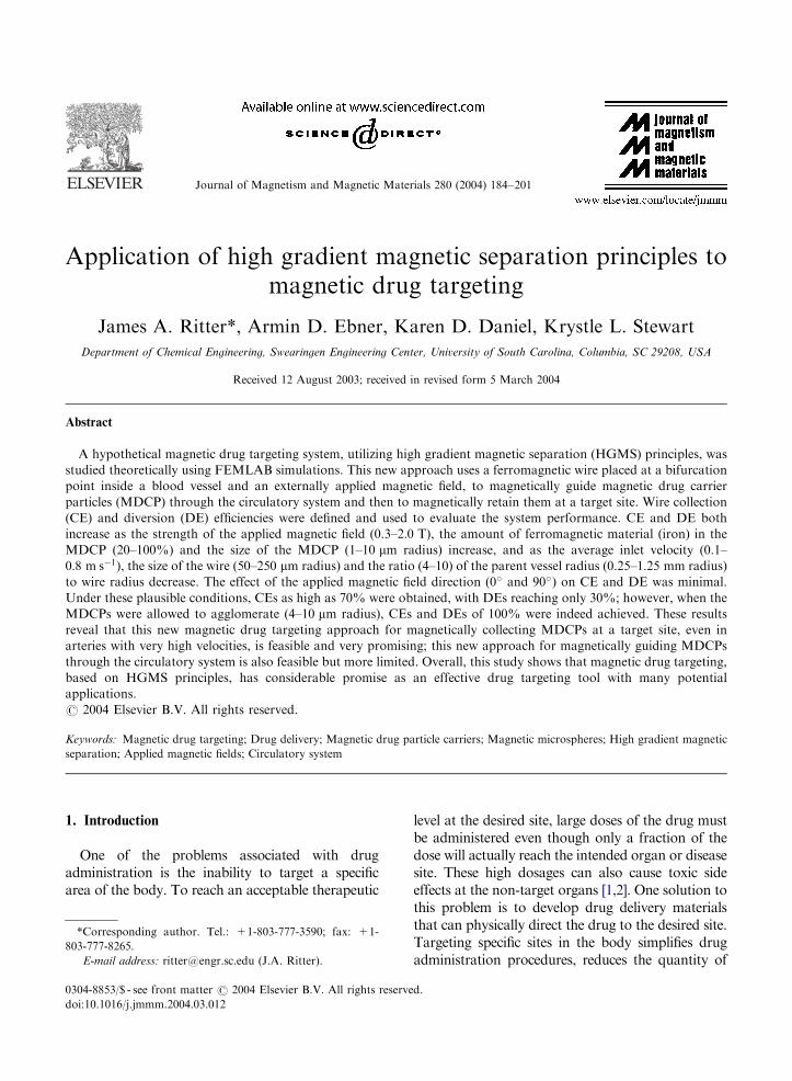
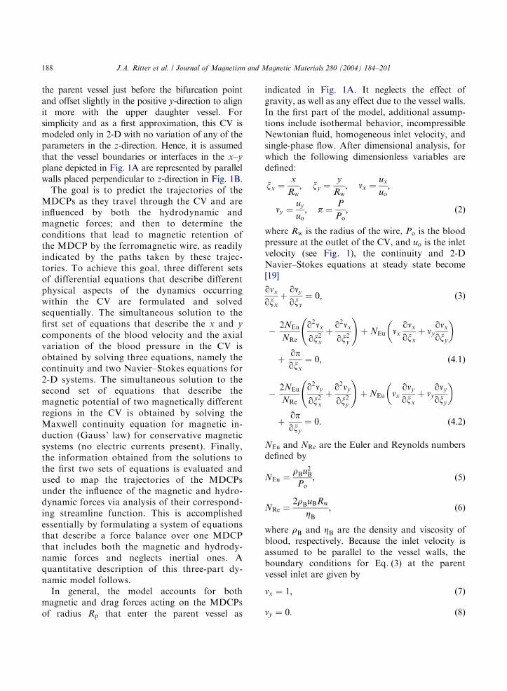
Fig. 1. (A) Schematic of the magnetic drug targeting system
with a ferromagnetic wire placed at a critical blood vessel
bifurcation point to preferentially divert magnetic drug carrier
particles (MDCPs) into one of the daughter vessels, to retain
the MDCPs at this target site in the circulatory system for
subsequent release of the drug, or to collect the MDCPs at this
site so they can be removed using a specially designed suction
probe. (B) Schematic of the dimensionless coordinate system
(with reference to the wire radius) of the CV defined by points
ABCD and utilized to solve the mathematical model in
FEMLAB. The wire is located at ðxx;w; xy;wÞ ¼ ð8:00; 1:35Þ;xmax and xmin are the upper and lower capture cross-sections for
the wire, xpv is the dimensionless parent blood vessel radius and
Ho is the applied magnetic field strength which is directed at an
angle b with respect to the horizontal line. Points E through M
define the dimensionless coordinates of the parent and daughter
blood vessels.
J.A. Ritter et al. / Journal of Magnetism and Magnetic Materials 280 (2004) 184–201 187
for many years in the HGMS literature (see, forexample, Ref. [18]), i.e.,
FmpH � rH: ð1Þ
where r ¼ ð@=@x; @=@yÞT is the dimensional gra-dient operator.
One way to locally increase the gradient of themagnetic field is to place a ferromagnetic wire inthe region of the magnetic field; in fact, the higherthe curvature of this wire (i.e., the smaller the
diameter), the larger the gradient of the magneticfield and hence the greater the force on the MDCP.It is hypothesized that his concept can be used tocreate effective magnetic drug targeting systemsfor treating disease in humans. These systemswould consist of a ferromagnetic probe (i.e., aneedle, catheter or even surgical implant), amagnetic field generator (i.e., an external perma-nent magnet or NMR system), and MDCPs.
Fig. 1A shows a single ferromagnetic filament ofcylindrical shape placed directly before a criticalbifurcation point in a blood vessel. The filamentbecomes magnetically energized when an externalmagnetic field is applied. This probe could be usedin a variety ways; three of them are introducedhere simply to show the flexibility of such a mildlyinvasive approach. First, it could be used to collectthe MDCPs at a target site in the circulatorysystem under constant application of the externalmagnetic field. In this case, the MDCPs would becollected on the wire for subsequent release of thedrug at this target site. Second, it could be used tostop the MDCPs from going to certain parts of thebody again under constant application of theexternal magnetic field. In this case, the MDCPswould also be collected on the wire for subsequentremoval from the body using a specially designedsuction probe. Third, it could be used to redirectMDCPs to a particular location of the body wherethey are most needed, and this could be done by aperiodic collection (field on) and release (field off)kind of procedure. For example, if the liver needsto be avoided to prevent drug deactivation [3], inprinciple, a ferromagnetic probe could simply beinserted at a critical blood vessel bifurcation pointto redirect and guide the MDCPs along a path thatwould bypass the liver.
3. Model development
A schematic of the control volume (CV) utilizedfor modeling the hypothetical magnetic drug target-ing system is depicted in Fig. 1B. The CV consists ofa 35 � 30 dimensionless box, with the radius of theferromagnetic cylindrical wire (placed perpendicularto the plane of the figure in the z-direction) chosen asthe characteristic length. This wire is located inside
ARTICLE IN PRESS
J.A. Ritter et al. / Journal of Magnetism and Magnetic Materials 280 (2004) 184–201188
the parent vessel just before the bifurcation pointand offset slightly in the positive y-direction to alignit more with the upper daughter vessel. Forsimplicity and as a first approximation, this CV ismodeled only in 2-D with no variation of any of theparameters in the z-direction. Hence, it is assumedthat the vessel boundaries or interfaces in the x–y
plane depicted in Fig. 1A are represented by parallelwalls placed perpendicular to z-direction in Fig. 1B.
The goal is to predict the trajectories of theMDCPs as they travel through the CV and areinfluenced by both the hydrodynamic andmagnetic forces; and then to determine theconditions that lead to magnetic retention ofthe MDCP by the ferromagnetic wire, as readilyindicated by the paths taken by these trajec-tories. To achieve this goal, three different setsof differential equations that describe differentphysical aspects of the dynamics occurringwithin the CV are formulated and solvedsequentially. The simultaneous solution to thefirst set of equations that describe the x and y
components of the blood velocity and the axialvariation of the blood pressure in the CV isobtained by solving three equations, namely thecontinuity and two Navier–Stokes equations for2-D systems. The simultaneous solution to thesecond set of equations that describe themagnetic potential of two magnetically differentregions in the CV is obtained by solving theMaxwell continuity equation for magnetic in-duction (Gauss’ law) for conservative magneticsystems (no electric currents present). Finally,the information obtained from the solutions tothe first two sets of equations is evaluated andused to map the trajectories of the MDCPsunder the influence of the magnetic and hydro-dynamic forces via analysis of their correspond-ing streamline function. This is accomplishedessentially by formulating a system of equationsthat describe a force balance over one MDCPthat includes both the magnetic and hydrody-namic forces and neglects inertial ones. Aquantitative description of this three-part dy-namic model follows.
In general, the model accounts for bothmagnetic and drag forces acting on the MDCPsof radius Rp that enter the parent vessel as
indicated in Fig. 1A. It neglects the effect ofgravity, as well as any effect due to the vessel walls.In the first part of the model, additional assump-tions include isothermal behavior, incompressibleNewtonian fluid, homogeneous inlet velocity, andsingle-phase flow. After dimensional analysis, forwhich the following dimensionless variables aredefined:
xx ¼x
Rw; xy ¼
y
Rw; nx ¼
ux
uo;
ny ¼uy
uo; p ¼
P
Po; ð2Þ
where Rw is the radius of the wire, Po is the bloodpressure at the outlet of the CV, and uo is the inletvelocity (see Fig. 1), the continuity and 2-DNavier–Stokes equations at steady state become[19]
qnx
qxx
þqny
qxy
¼ 0; ð3Þ
�2NEu
NRe
q2nx
qx2x
þq2nx
qx2y
!þ NEu nx
qnx
qxx
þ ny
qnx
qxy
� �
þqpqxx
¼ 0; ð4:1Þ
�2NEu
NRe
q2ny
qx2x
þq2ny
qx2y
!þ NEu nx
qny
qxx
þ ny
qny
qxy
� �
þqpqxy
¼ 0: ð4:2Þ
NEu and NRe are the Euler and Reynolds numbersdefined by
NEu ¼rBu2
B
Po; ð5Þ
NRe ¼2rBuBRw
ZB
; ð6Þ
where rB and ZB are the density and viscosity ofblood, respectively. Because the inlet velocity isassumed to be parallel to the vessel walls, theboundary conditions for Eq. (3) at the parentvessel inlet are given by
nx ¼ 1; ð7Þ
ny ¼ 0: ð8Þ
ARTICLE IN PRESS
J.A. Ritter et al. / Journal of Magnetism and Magnetic Materials 280 (2004) 184–201 189
At the outlet of each daughter vessel, the boundarycondition is
p ¼ 1: ð9Þ
Also, a non-slip boundary condition ðnx ¼ ny ¼ 0Þis applied to every interface in contact with theblood stream.
In the second part of the model, it is assumedthat the magnetic medium within the CV ispolytropic and that its magnetization is alwaysparallel to the applied magnetic field. It is alsoassumed that the magnetic field within the CV isdescribed by Maxwell’s equation for conservativefields
r2j ¼ 0; ð10Þ
where j is the scalar magnetic potential. Sincethe CV is comprised of two regions havingvery dissimilar magnetic behavior, namely, onewhich is strongly ferromagnetic and defined by thespace occupied by the ferromagnetic wire, andone which is weakly magnetic and defined by therest of the space in the CV including the spaceoccupied by the blood, the magnetic potentialis defined differently in each of these regions interms of the scalar potentials j1 and j2; respec-tively, i.e.,
r2j1 ¼ 0; ð11Þ
r2j2 ¼ 0: ð12Þ
For the wire and the rest of the space defined bythe CV in Fig. 1, the fluxes are, respectively,defined as [18]
B ¼ � mo
qjqx
;qjqy
� �
¼ mo ðMw þ HoÞ cos b�qj1
Rwqxx
; ðMw þ HoÞ�
� sin b�qj1
Rwqxy
�; ð13Þ
B ¼ � mo
qjqx
;qjqy
� �
¼ mo Ho cos b�qj2
Rwqxx
;Ho sin b�qj2
Rwqxy
� �;
ð14Þ
where Ho is the externally applied magnetic field, bspecifies the direction of the applied magnetic fieldas indicated in Fig. 1, Mw is the inducedmagnetization of the wire which is parallel to theapplied field, and mo is the magnetic permeabilityof free space ð4p� 10�7 T m AÞ: For a wire that isperpendicular to the applied magnetic field andmade of a soft ferromagnetic material, the inducedmagnetization is calculated from
Mw ¼ 2awHo; ð15Þ
where aw is the demagnetizing factor for aninfinitely long cylinder placed perpendicular tofield Ho and approximately given by [20]
aw ¼ minww;o
2 þ ww;o
;Mw;s
2Ho
� �; ð16Þ
ww;o and Mw;s are the magnetic susceptibility atzero magnetic field and the saturation magnetiza-tion of the wire, respectively. Since the wire iscompletely immersed in the non-magnetic region,the continuity condition of both the magnetic fluxB (i.e., the normal component) and the potential(i.e., j1 ¼ j2) at the interface (i.e., at the surface ofwire) fully determines j1 provided that j2 isknown. To obtain j2; it is assumed that theboundaries of the CV, defined by rectangle ABCDin Fig. 1B, are sufficiently far from the wire toassume that j2 ¼ 0 along these boundaries.
Hence, the first part of the model consists ofthree equations, i.e., the dimensionless forms ofthe mass continuity and Navier–Stokes equationsin Eqs. (3) and (4) (which accounts for twoequations) that are solved for three unknowns,namely the two dimensionless components of theblood velocity (i.e., nx and ny) and the dimension-less blood pressure (i.e, p). The second part of themodel consists of the two Laplacian equationsgiven in Eqs. (11) and (12), which are solved fortwo unknowns, i.e., j1 and j2: The scalarpotential j1 describes the magnetic potentialwithin the ferromagnetic wire whereas j2 describesthe magnetic potential in the rest of the CV. Thesefive equations are solved numerically using FEM-LAB for the five unknowns, i.e., the two compo-nents of the blood flow velocity, the blood pressureand the scalar magnetic potentials j1 and j2: Theparametric solution spaces of three of these five
ARTICLE IN PRESS
J.A. Ritter et al. / Journal of Magnetism and Magnetic Materials 280 (2004) 184–201190
variables, namely nx; ny and j2; are used in thethird part of the model to evaluate the streamlinesthat describe the trajectories of the MDCPs in theblood vessel.
For the third part of the model, the MDCPs aretreated as freely moving point masses in the CVfluid, i.e., in the blood; hence, they do not have tosatisfy the incompressible fluid form of thecontinuity equation. In other words, the concen-tration of the MDCPs is necessarily not constantand allowed to vary within the CV. Isothermalbehavior is also assumed. The streamlines areobtained directly from the yet to be determineddimensionless velocities of the MDCPs (i.e.,mp ¼ ðnp;x; np;yÞ) and the classic definition of thestreamline function in terms of these velocities, i.e.,
qcqy
¼ �np;x; ð17aÞ
qcqx
¼ np;y; ð17bÞ
where c is the so-called streamline function whichby definition is constant along every MDCPtrajectory. Explicit expressions for each of thecomponents of the MDCP velocities (i.e., np;x andnp;y) are obtained by applying Newton’s secondlaw of motion to an MDCP as it flows past amagnetically charged wire:
Fd þ Fm ¼ 6pZBRpuBðm � mpÞ þ 12ofm;pVp
� ðwfm;p � wmÞð1 � afm;pÞmo
1
Rwr0H2
¼ Fi ¼Vpu2
B
Rwrp þ
1
2rf
� �qmp
qt�
3
2rf m � r0m
� �;
ð18Þ
where Fd and Fm represent the drag and magneticforces acting on an MDCP of radius Rp; density rp
and volume Vp: t is the dimensionless time definedas uBt=Rs: ofm;p is the volume fraction occupied bythe ferromagnetic material inside the MDCP. Fi
includes the inertial force of the MDCP and thehydrodynamic effect associated with the MDCPaccelerating in the surrounding fluid [21]. r0 ¼ð@=@xx; @=@xyÞ
T is the dimensionless gradient op-erator. This material has magnetic susceptibilitywfm;p; magnetization Mfm;p and demagnetizingfactor afm;p: wm is the magnetic susceptibility of
the medium encompassing the ferromagneticmaterial, i.e., that of the organic polymer or drug,which like blood is assumed to be negligible. If theferromagnetic material inside the MDCPs isassumed to consist of spherical particles, Mfm;p;wfm;p and afm;p are given approximately by [20]
Mfm;p ¼ 3afm;pH; ð19Þ
wfm;p ¼ 3afm;p
1 � afm;p; ð20Þ
afm;p ¼ minwfm;p;o
3 þ wfm;p;o
;Mfm;p;s
3H
!; ð21Þ
where Mfm;p;s and wfm;p;o are the saturationmagnetization and magnetic susceptibility at zerointernal magnetic field of the material. H is themagnitude of the applied magnetic field at thelocation of the MDCP, which from Eq. (14) andthe relationship B ¼ moH; is given by
H ¼ffiffiffiffiffiffiffiffiffiffiffiffiH �H
p¼ Ho cos b�
qj2
Rwqxx
� �2"
þ Ho sin b�qj2
Rwqxy
� �2#0:5
: ð22Þ
By neglecting inertial forces in essentially anaqueous solution [18], the right-hand side ofEq. (18) can be set to zero as
Vpu2B
Rwrp þ
1
2rf
� �qmp
qt�
3
2rf m � r0m
� �¼ 0: ð23Þ
Also, by assuming wm to be negligible compared tothose of the wire and the ferromagnetic materialinside the MDCP, and by substituting Eqs. (19)and (20) into Eq. (18), rearranging, and utilizingthe expression for H in Eq. (22), the componentsof the MDCP velocity become
np;x ¼ nx þVm
uBMwH
1
Rw
qj2
qxx
� Ho cos b� �
1
Rw
�q2j2
qx2x
þ1
Rw
qj2
qxy
� Ho sin b� �
�1
Rw
q2j2
qxxqxy
; ð24aÞ
ARTICLE IN PRESS
J.A. Ritter et al. / Journal of Magnetism and Magnetic Materials 280 (2004) 184–201 191
np;y ¼ ny þVm
uBMwH
1
Rw
qj2
qxx
� Ho cos b� �
1
Rw
�q2j2
qxxqxy
1
Rw
qj2
qxy
� Ho sin b� �
�1
Rw
q2j2
qx2y
#; ð24bÞ
where Vm is the so-called magnetic velocity, whichis given by
Vm ¼2
9
R2p
Rw
mo
ZB
ð1 � epÞofm;pMfm;pMw: ð25Þ
Also, when b ¼ p=2; the applied magnetic field isunder the transversal configuration, meaning themagnetic field is perpendicular to the direction ofblood flow. When b ¼ p; the applied magnetic fieldis under the longitudinal configuration, meaningthe magnetic field is parallel to the direction ofblood flow. The parameter ep is the porosity of acluster of MDCPs, which is included here to allowfor the fact that the MDCPs may temporarilyagglomerate with each other due to the effect ofthe magnetic field. Finally, if rfm;p represents thedensity of the ferromagnetic material inside theMDCP and rpol;p represents the density of thepolymer and drug solution comprising the rest ofthe MDCP, then
ofm;p ¼ rp
xfm;p
rfm;p
; ð26Þ
rp ¼1
xfm;p=rfm;p þ ð1 � xfm;pÞ=rpol;p
: ð27Þ
Now, with the parametric space inside the CVcompletely resolved in terms of nx; ny and j2;FEMLAB is used in the third part of the model toevaluate np;x and np;y using Eqs. (24a) and (24b).The corresponding results are used within FEM-LAB again to solve Eq. (17) for c; which is thestreamline function that describes the trajectory ofa MDCP while it travels through the CV under theinfluence of both the magnetic and hydrodynamic(drag) forces.
4. Results and discussion
It must be emphasized at the outset that sincethe human body is very complex, the theoreticalmodel developed above is at best a highly idealizedrepresentation of the actual behavior of theMDCPs as they travel through and are retainedat target sites throughout the circulatory system.Nevertheless, through the application of judi-ciously chosen assumptions, this initial theoreticalstudy not only exposes the feasibility and limita-tions of magnetic drug targeting utilizing HGMSprinciples, but it also fosters a more completeunderstanding of the parameters that will mostlikely have a large impact on the efficiency of sucha system, as discussed in detail below. This initialstudy also represents the first attempt at quantita-tively applying the principles behind HGMS tomagnetic drug targeting. To this end, a commonmethod used to determine the strength of amagnetic device, in this case the ferromagneticwire subjected to an externally applied magneticfield, is based on evaluating the so-called magneticforce density function fw:
fw ¼ jmorH2j: ð28Þ
H is obtained from by Eq. (22), which again iseasily evaluated using FEMLAB, as described inthe Model development section. For the magneticdrug targeting system being studied here, fw is thecomponent of the magnetic force exerted on theMDCP that is due solely to the ferromagneticwire. This localized force, which exists only in theproximity of the wire, is referred to later as theHGMS effect. Clearly, in the application of anexternal magnetic field alone for drug targetingwith MDCPs, this potentially enabling forcewould not exist unless the wire is present.
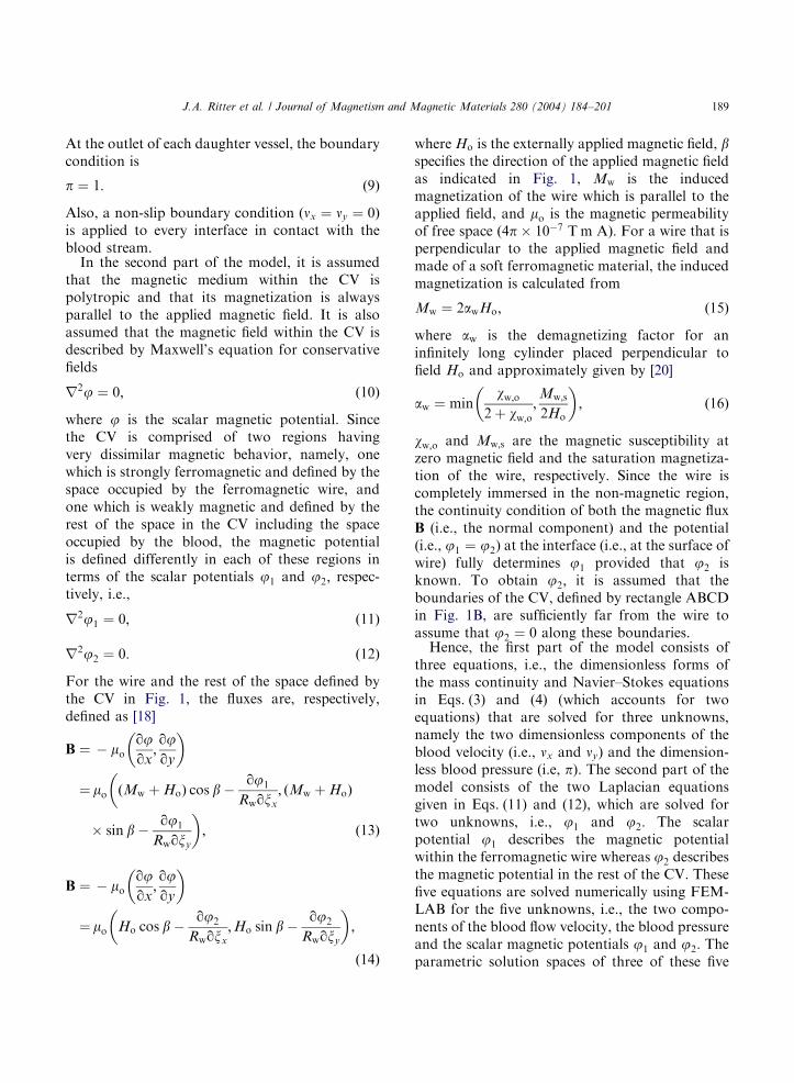
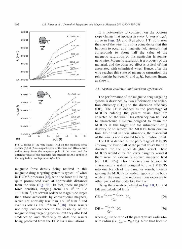
Fig. 2 displays the magnitude of the magneticforce density in terms of the external magnetic fieldapplied in the longitudinal configuration ðb ¼ 0�Þand for the range of wire radii investigated in thisstudy. Fig. 2A presents fw at the magnetic pole,i.e., at the surface of the wire, where the magneticforce is at its maximum, and Fig. 2B presents fw atone wire radius away from the magnetic pole,where the magnetic force is diminished from itsmaximum but still significant. The range of the
ARTICLE IN PRESS
(A)
(B)
0.0E+00
2.0E+10
4.0E+10
6.0E+10
8.0E+10
1.0E+11
1.2E+11
f w (
Nm
-3)
Rc = 50.0 µm
62.5 µm
83.3 µm
125.5 µm
187.5 µm
250.0 µm
0.0E+00
2.0E+09
4.0E+09
6.0E+09
8.0E+09
1.0E+10
1.2E+10
0.0 0.4 0.8 1.2 1.6 2.0 2.4
µoHo (T)
f w(N
m-3
)
Rc = 50.0 µm
62.5 µm
83.3 µm
125.5 µm
187.5 µm
250.0 µm
Rw
Ho
Rw
Ho
Rw
Fig. 2. Effect of the wire radius ðRwÞ on the magnetic force
density ðfwÞ at (A) a magnetic pole of the wire and (B) one wire
radius away from the magnetic pole of the wire, and for
different values of the magnetic field strength ðmoHoÞ applied in
the longitudinal configuration ðb ¼ 0�Þ:
J.A. Ritter et al. / Journal of Magnetism and Magnetic Materials 280 (2004) 184–201192
magnetic force density being realized in thismagnetic drug targeting system is typical of wiresin HGMS processes [18], with the force still beingquite pronounced even at appreciable distancesfrom the wire (Fig. 2B). In fact, these magneticforce densities, ranging from 1 � 109 to 1 �1011 N m�3; are several orders of magnitude largerthan those achievable by conventional magnets,which are normally less than 1 � 108 N m�3 andeven as low as 1 � 104 N m�3 [18]. These resultsnot only lend credence to the feasibility of themagnetic drug targeting system, but they also lendcredence to and effectively validate the resultsbeing predicted from the FEMLAB simulations.
It is noteworthy to comment on the obviousslope change that appears in every fw versus moHo
curve in Figs. 2A and B at about 1 T; no matterthe size of the wire. It is not a coincidence that thishappens to occur at a magnetic field strength thatcorresponds to about half the value of themagnetic saturation of this particular ferromag-netic wire. Magnetic saturation is a property of thematerial, and the observed effect is typical of thatassociated with cylindrical wires. Hence, after thewire reaches this state of magnetic saturation, therelationship between fw and moHo becomes linear,as shown.
4.1. System collection and diversion efficiencies
The performance of the magnetic drug targetingsystem is described by two efficiencies: the collec-tion efficiency (CE) and the diversion efficiency(DE). The CE is defined as the percentage ofMDCPs entering the parent vessel that arecollected on the wire. This efficiency can be usedto characterize a system designed to retain theMDCPs at this target site for subsequent drugdelivery or to remove the MDCPs from circula-tion. Note that in these situations, the placementof the wire is not restricted to a bifurcation point.
The DE is defined as the percentage of MDCPsentering the lower half of the parent vessel that arediverted into the upper daughter vessel. TheseMDCPs would enter the lower daughter vessel ifthere were no externally applied magnetic field(i.e., DE ¼ 0%). This efficiency can be used tocharacterize a system designed to divert MDCPsinto one branch of the daughter vessels, therebyguiding the MDCPs to needed regions of the bodywhile at the same time reducing their exposure toother parts of the body like the liver.
Using the variables defined in Fig. 1B, CE andDE are calculated from
CE ¼xy;max � xy;min
2xpv
100; ð29Þ
DE ¼�xy;min
xpv
100; ð30Þ
where xpv is the ratio of the parent vessel radius-to-wire radius (i.e, xpv ¼ Rpv=Rc). Note that because
ARTICLE IN PRESS
(A) Rp = 2 µm, εp = 0.0
(B) Rp = 2 µm, εp = 0.0
(C) Rp = 10 µm, εp = 0.4
µoHo = 0.0 T
µoHo = 2.0 T
µoHo = 2.0 T
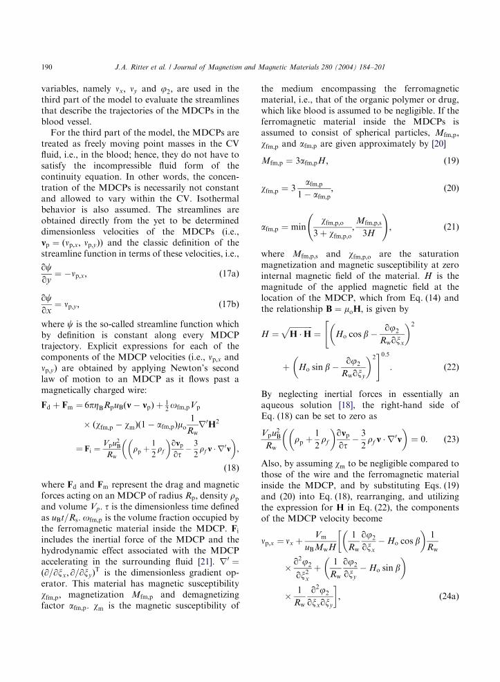
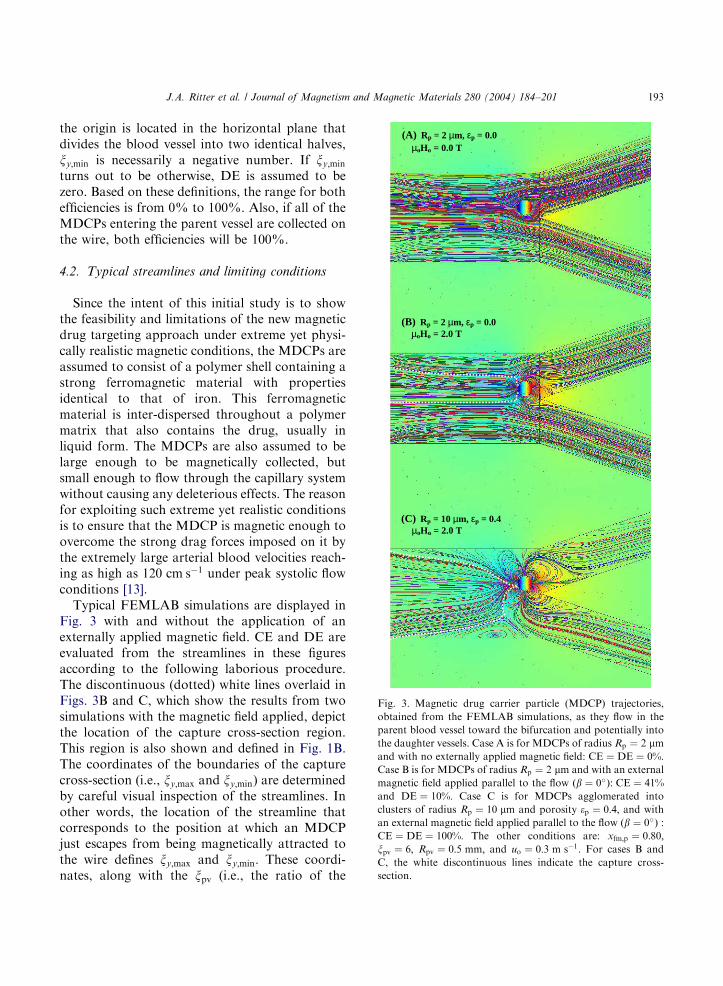
Fig. 3. Magnetic drug carrier particle (MDCP) trajectories,
obtained from the FEMLAB simulations, as they flow in the
parent blood vessel toward the bifurcation and potentially into
the daughter vessels. Case A is for MDCPs of radius Rp ¼ 2 mm
and with no externally applied magnetic field: CE ¼ DE ¼ 0%:Case B is for MDCPs of radius Rp ¼ 2 mm and with an external
magnetic field applied parallel to the flow ðb ¼ 0�Þ: CE ¼ 41%and DE ¼ 10%: Case C is for MDCPs agglomerated into
clusters of radius Rp ¼ 10 mm and porosity ep ¼ 0:4; and with
an external magnetic field applied parallel to the flow ðb ¼ 0�Þ :CE ¼ DE ¼ 100%: The other conditions are: xfm;p ¼ 0:80;xpv ¼ 6; Rpv ¼ 0:5 mm; and uo ¼ 0:3 m s�1: For cases B and
C, the white discontinuous lines indicate the capture cross-
section.
J.A. Ritter et al. / Journal of Magnetism and Magnetic Materials 280 (2004) 184–201 193
the origin is located in the horizontal plane thatdivides the blood vessel into two identical halves,xy;min is necessarily a negative number. If xy;min
turns out to be otherwise, DE is assumed to bezero. Based on these definitions, the range for bothefficiencies is from 0% to 100%. Also, if all of theMDCPs entering the parent vessel are collected onthe wire, both efficiencies will be 100%.
4.2. Typical streamlines and limiting conditions
Since the intent of this initial study is to showthe feasibility and limitations of the new magneticdrug targeting approach under extreme yet physi-cally realistic magnetic conditions, the MDCPs areassumed to consist of a polymer shell containing astrong ferromagnetic material with propertiesidentical to that of iron. This ferromagneticmaterial is inter-dispersed throughout a polymermatrix that also contains the drug, usually inliquid form. The MDCPs are also assumed to belarge enough to be magnetically collected, butsmall enough to flow through the capillary systemwithout causing any deleterious effects. The reasonfor exploiting such extreme yet realistic conditionsis to ensure that the MDCP is magnetic enough toovercome the strong drag forces imposed on it bythe extremely large arterial blood velocities reach-ing as high as 120 cm s�1 under peak systolic flowconditions [13].
Typical FEMLAB simulations are displayed inFig. 3 with and without the application of anexternally applied magnetic field. CE and DE areevaluated from the streamlines in these figuresaccording to the following laborious procedure.The discontinuous (dotted) white lines overlaid inFigs. 3B and C, which show the results from twosimulations with the magnetic field applied, depictthe location of the capture cross-section region.This region is also shown and defined in Fig. 1B.The coordinates of the boundaries of the capturecross-section (i.e., xy;max and xy;min) are determinedby careful visual inspection of the streamlines. Inother words, the location of the streamline thatcorresponds to the position at which an MDCPjust escapes from being magnetically attracted tothe wire defines xy;max and xy;min: These coordi-nates, along with the xpv (i.e., the ratio of the
ARTICLE IN PRESS
Table 1
Values and ranges of the parameters used in the model and the
parametric study
Parameter Units Value(s)
b — 0; p=2
ZB kg m�1 s�1 4:0 � 10�3
rB kg m�3 1000
wm — 0
uo m s�1 0.1–0.8
Rp mm 1.0–10.0
wfm;p;o SI 10 000
rfm;p kg m�3 7800
rpol;p kg m�3 1000
Mfm;p;s A m�1 1 500 000
xfm;p — 0.2–1.0
ep — 0.0, 0.4
Rw mm 50–250
ww;o SI 10 000
Mw;s A m�1 1 650 000
Rpv=Rw — 4, 6, 10
Rpv mm 0.25–1.25
moHo T 0.3–2.0
J.A. Ritter et al. / Journal of Magnetism and Magnetic Materials 280 (2004) 184–201194
parent vessel radius-to-wire radius), directly giveCE and DE from the definitions given in Eqs. (29)and (30).
Fig. 3A shows the streamlines for the situationwith no externally applied magnetic field ðmoHo ¼0:0 TÞ; where the MDCPs consist of single (non-porous) spheres containing 80 wt% ferromagneticmaterial with magnetic properties identical to thatof iron and described by Eq. (21). The otherconditions are Rp ¼ 2 mm; Rpv ¼ 0:5 mm; xpv ¼ 6and uo ¼ 0:3 m s�1; the remaining model para-meters are given in Table 1. Clearly, in this case theMDCPs are carried along at the velocity of theblood; hence, CE ¼ DE ¼ 0%: In contrast, Fig. 3Bshows the streamlines for the same base caseconditions as utilized in Fig. 3A, but now with anexternal magnetic field (i.e., moHo ¼ 2:0 T) appliedin the longitudinal configuration ðb ¼ 0Þ: For thesebase case conditions, xy;max ¼ 4:152 and xy;min ¼�0:603; putting these values into Eqs. (28) and(29) gives CE ¼ 41% and DE ¼ 10%: This is areasonable CE since the 59% of the MDCPs thatescape collection are expected to return severaltimes to this same location within a 24 h period. ADE of 10% means that 10% of the MDCPs
entering the lower half of the parent vessel arecollected on the wire, and will be released(diverted) into the upper daughter vessel whenthe applied magnetic field is removed. A DE of10% also means that around 55% instead of only50% of all the MDCPs in the parent vessel end upgoing to the upper daughter vessel under theseconditions. Diversion is possible since it isexpected that the streamlines around the wire willadopt the patterns shown in Fig. 3A every time themagnetic field is removed so that the collectedMDCPs will be released and diverted into theupper daughter vessel. For the same base caseconditions, Fig. 3C shows that if inter-magneticinteractions cause the MDCPs to agglomerate into10 mm radius spheres with porosity ep ¼ 0:4; thenCE and DE both increase to 100%.
These results reveal that both CE and DE aresensitive to changes in some of the parametersinvolved in the magnetic drug targeting system.Conversely, these results suggest that the efficiencyof the system can easily be optimized by slightlyaltering some of these parameters. Therefore, theresults of a parametric study are provided below toreveal the effect of some of the most importantsystem parameters on CE and DE, not only forphysically realistic conditions (Fig. 3B), but alsofor more extreme conditions (Fig. 3C), to fullyexpose the feasibility and limitations of the newmagnetic drug targeting approach.
4.3. Parametric study
Parameters of paramount importance to thesystem depicted in Fig. 1A include the intensityand direction of the magnetic field, the radius ofthe MDCP, the amount of ferromagnetic material(i.e., iron) in the MDCP, the inlet blood velocity,the radius of the parent vessel, and the ratio of theparent vessel radius-to-wire radius. The rangesexamined for each of these parameters, along withother important system and model parameters, aresummarized in Table 1. Table 2 lists typicalproperties of the circulatory system, and showsthat the values chosen for the velocity andviscosity are typical for human blood vessels ofthe sizes investigated here (i.e., with the parentvessel radius ranging from 0.50 to 2:50 mm) [13].
ARTICLE IN PRESS
0
20
40
60
80
100
0.0 0.4 0.8 1.2 1.6 2.0 2.4
µoHo (T)
Eff
icie
ncy
(%)
β = 0o
β = 90ox fm,p= 1.0x fm,p= 0.8x fm,p= 0.5x fm,p= 0.2
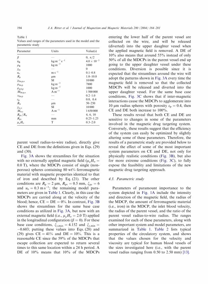
Fig. 4. Effect of the iron content ðxfm;pÞ in the MDCPs and the
orientation of the applied magnetic field ðbÞ on the collection
(empty symbols) and diversion efficiencies (solid symbols) for
different values of the applied magnetic field strength ðmoHoÞ:The other conditions are: Rp ¼ 2:0 mm; ep ¼ 0:0; xpv ¼ 4;Rpv ¼ 0:5 mm; and uo ¼ 0:3 m s�1: Note that for xfm;po1:0;DE ¼ 0%:
Table 2
Typical properties of the circulatory system [13]
Property Units Value(s)
Blood viscosity kg m�1 s�1 0.003–0.004
Blood density kg m�3 1000
Artery radius mm 0.08–7.5
Arteriole radius mm 0.005–0.07
Capillary radius mm 0.004
Average velocity in arteries m s�1 0.1–0.4
Peak velocity in arteries m s�1 0.4–1.2
Average velocity in arterioles m s�1 0.001–0.1
Average velocity in capillaries m s�1 o0:001
J.A. Ritter et al. / Journal of Magnetism and Magnetic Materials 280 (2004) 184–201 195
The first aspect investigated attempts to answerthe following question: How magnetic must theMDCPs be for the wire to operate adequately inan artery or vein of reasonable size? Fig. 4 showsthe effect of the amount of ferromagnetic materialin single (non-porous) 2 mm radius MCDPs, andthe effect of the direction of the applied magneticfield, on both CE and DE of the wire, in terms ofthe intensity of the externally applied magneticfield. The other conditions are uo ¼ 0:3 m s�1;Rpv ¼ 0:5 mm and xpv ¼ 4; the remaining modelparameters are given in Table 1. Under these
physically realistic conditions, the wire exhibitsconsiderable ability to magnetically collect theMDCPs, especially when considering the fact thatthe MDCPs are being subjected to very strongdrag forces (as a consequence of the largevelocities). The CE for the MDCPs containing80 wt% ferromagnetic material (which is about35 vol%) is about 45%. Also, a CE of about 10%is achieved with MDCPs containing only 20 wt%ferromagnetic material. In contrast, the ability ofthe wire to effectively divert the MDCPs in thelower half of the parent vessel into the upperdaughter vessel appears to be more limited. A DEgreater than zero is achieved only for the casewhere the MDCPs consist of pure ferromagneticmaterial, i.e., for xfm;po1:0; DE ¼ 0%: Never-theless, DEs greater than 30% are indeed achiev-able with magnetic field strengths of only 1 T:
It is important to state at this point that thesituation investigated in Fig. 4 probably comesvery close to representing the best case scenario forthe wire performance under physically plausibleconditions. Not only do the MDCPs contain alarge fraction of strong ferromagnetic material,but also they are relatively large ðRp ¼ 2:0 mmÞ:Hence, the trends observed in Fig. 4 provide areasonable sense of the limitations associated withusing a wire for magnetic drug targeting that isfour times smaller in diameter than the parentvessel.
Two other features can also be extracted fromthe results in Fig. 4. First, there is no considerabledifference in the performance of the wire eitherunder the longitudinal ðb ¼ 0Þ or transversal ðb ¼p=2Þ configuration. For the MDCPs containing alarge amount of ferromagnetic material the long-itudinal configuration exhibits slightly higher CEs,whereas for the MDCPs containing a smallamount of ferromagnetic material the transversalconfiguration exhibits slightly higher CEs. Also, itis apparent from the results in this figure (as well asin other subsequent figures), that CE and DE bothreach constant values as the applied magnetic fieldstrength increases beyond about 1:0 T: Thisinteresting behavior is simply due to the fact thatboth the wire and the ferromagnetic materialnaturally become magnetically saturated (i.e.,afm;p ¼ Mfm;p;s=3Hoo1; aw ¼ Mw;s=2Hoo1; and
ARTICLE IN PRESS
0
20
40
60
80
100
0.0 0.4 0.8 1.2 1.6 2.0 2.4µoHo (T)
Eff
icie
ncy
(%)
u o= 0.1 m s-1
u o= 0.8 m s-1u o= 0.5 m s-1u o= 0.3 m s-1
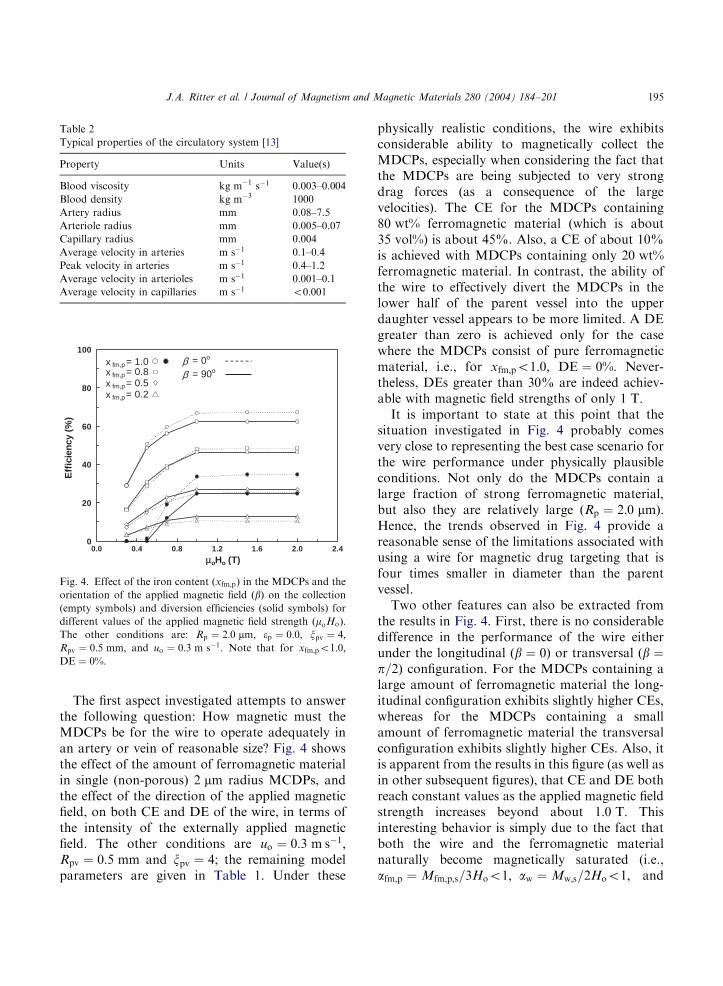
Fig. 5. Effect of the blood velocity ðuoÞ on the collection (empty
symbols) and diversion efficiencies (solid symbols) for different
values of the applied magnetic field strength ðmoHoÞ: The other
conditions are: xfm;p ¼ 0:8; Rp ¼ 2:0 mm; ep ¼ 0:0; b ¼ 0�;xpv ¼ 4; and Rpv ¼ 0:5 mm: Note that for uo > 0:1 m s�1;DE ¼ 0%:
J.A. Ritter et al. / Journal of Magnetism and Magnetic Materials 280 (2004) 184–201196
Vm becomes constant in Eq. (24)) as the magneticfield strength increases.
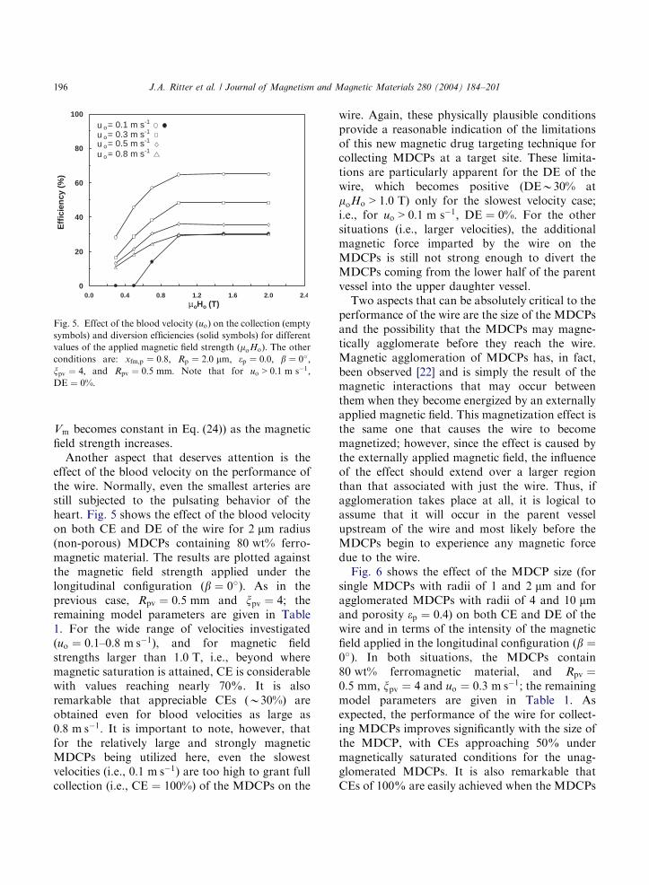
Another aspect that deserves attention is theeffect of the blood velocity on the performance ofthe wire. Normally, even the smallest arteries arestill subjected to the pulsating behavior of theheart. Fig. 5 shows the effect of the blood velocityon both CE and DE of the wire for 2 mm radius(non-porous) MDCPs containing 80 wt% ferro-magnetic material. The results are plotted againstthe magnetic field strength applied under thelongitudinal configuration ðb ¼ 0�Þ: As in theprevious case, Rpv ¼ 0:5 mm and xpv ¼ 4; theremaining model parameters are given in Table1. For the wide range of velocities investigated(uo ¼ 0:1–0:8 m s�1), and for magnetic fieldstrengths larger than 1:0 T; i.e., beyond wheremagnetic saturation is attained, CE is considerablewith values reaching nearly 70%. It is alsoremarkable that appreciable CEs ðB30%Þ areobtained even for blood velocities as large as0:8 m s�1: It is important to note, however, thatfor the relatively large and strongly magneticMDCPs being utilized here, even the slowestvelocities (i.e., 0:1 m s�1) are too high to grant fullcollection (i.e., CE ¼ 100%) of the MDCPs on the
wire. Again, these physically plausible conditionsprovide a reasonable indication of the limitationsof this new magnetic drug targeting technique forcollecting MDCPs at a target site. These limita-tions are particularly apparent for the DE of thewire, which becomes positive (DEB30% atmoHo > 1:0 T) only for the slowest velocity case;i.e., for uo > 0:1 m s�1; DE ¼ 0%: For the othersituations (i.e., larger velocities), the additionalmagnetic force imparted by the wire on theMDCPs is still not strong enough to divert theMDCPs coming from the lower half of the parentvessel into the upper daughter vessel.
Two aspects that can be absolutely critical to theperformance of the wire are the size of the MDCPsand the possibility that the MDCPs may magne-tically agglomerate before they reach the wire.Magnetic agglomeration of MDCPs has, in fact,been observed [22] and is simply the result of themagnetic interactions that may occur betweenthem when they become energized by an externallyapplied magnetic field. This magnetization effect isthe same one that causes the wire to becomemagnetized; however, since the effect is caused bythe externally applied magnetic field, the influenceof the effect should extend over a larger regionthan that associated with just the wire. Thus, ifagglomeration takes place at all, it is logical toassume that it will occur in the parent vesselupstream of the wire and most likely before theMDCPs begin to experience any magnetic forcedue to the wire.
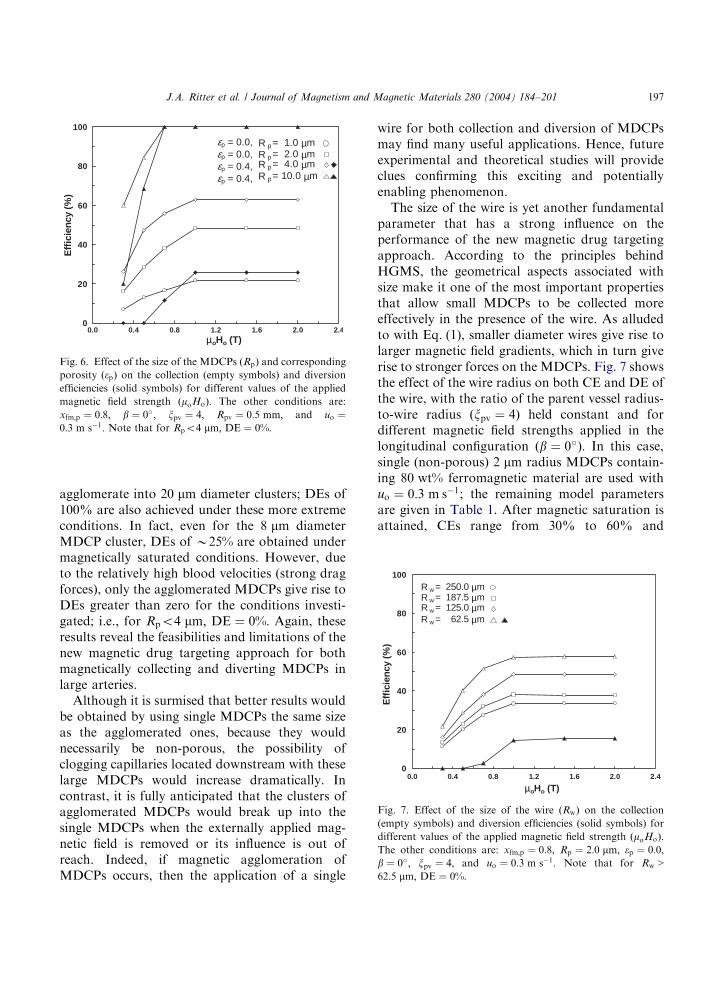
Fig. 6 shows the effect of the MDCP size (forsingle MDCPs with radii of 1 and 2 mm and foragglomerated MDCPs with radii of 4 and 10 mmand porosity ep ¼ 0:4) on both CE and DE of thewire and in terms of the intensity of the magneticfield applied in the longitudinal configuration ðb ¼0�Þ: In both situations, the MDCPs contain80 wt% ferromagnetic material, and Rpv ¼0:5 mm; xpv ¼ 4 and uo ¼ 0:3 m s�1; the remainingmodel parameters are given in Table 1. Asexpected, the performance of the wire for collect-ing MDCPs improves significantly with the size ofthe MDCP, with CEs approaching 50% undermagnetically saturated conditions for the unag-glomerated MDCPs. It is also remarkable thatCEs of 100% are easily achieved when the MDCPs
ARTICLE IN PRESS
0
20
40
60
80
100
0.0 0.4 0.8 1.2 1.6 2.0 2.4
µoHo (T)
Eff
icie
ncy
(%
)
R w = 62.5 µm
R w = 250.0 µm
R w = 125.0 µmR w = 187.5 µm
Fig. 7. Effect of the size of the wire ðRwÞ on the collection
(empty symbols) and diversion efficiencies (solid symbols) for
different values of the applied magnetic field strength ðmoHoÞ:The other conditions are: xfm;p ¼ 0:8; Rp ¼ 2:0 mm; ep ¼ 0:0;b ¼ 0�; xpv ¼ 4; and uo ¼ 0:3 m s�1: Note that for Rw >62:5 mm; DE ¼ 0%:
0
20
40
60
80
100
0.0 0.4 0.8 1.2 1.6 2.0 2.4µoHo (T)
Eff
icie
ncy
(%)
R p= 1.0 µm
R p= 10.0 µmR p= 4.0 µmR p= 2.0 µm
εp = 0.0,εp = 0.0,εp = 0.4,εp = 0.4,
Fig. 6. Effect of the size of the MDCPs ðRpÞ and corresponding
porosity ðepÞ on the collection (empty symbols) and diversion
efficiencies (solid symbols) for different values of the applied
magnetic field strength ðmoHoÞ: The other conditions are:
xfm;p ¼ 0:8; b ¼ 0�; xpv ¼ 4; Rpv ¼ 0:5 mm; and uo ¼0:3 m s�1: Note that for Rpo4 mm; DE ¼ 0%:
J.A. Ritter et al. / Journal of Magnetism and Magnetic Materials 280 (2004) 184–201 197
agglomerate into 20 mm diameter clusters; DEs of100% are also achieved under these more extremeconditions. In fact, even for the 8 mm diameterMDCP cluster, DEs of B25% are obtained undermagnetically saturated conditions. However, dueto the relatively high blood velocities (strong dragforces), only the agglomerated MDCPs give rise toDEs greater than zero for the conditions investi-gated; i.e., for Rpo4 mm; DE ¼ 0%: Again, theseresults reveal the feasibilities and limitations of thenew magnetic drug targeting approach for bothmagnetically collecting and diverting MDCPs inlarge arteries.
Although it is surmised that better results wouldbe obtained by using single MDCPs the same sizeas the agglomerated ones, because they wouldnecessarily be non-porous, the possibility ofclogging capillaries located downstream with theselarge MDCPs would increase dramatically. Incontrast, it is fully anticipated that the clusters ofagglomerated MDCPs would break up into thesingle MDCPs when the externally applied mag-netic field is removed or its influence is out ofreach. Indeed, if magnetic agglomeration ofMDCPs occurs, then the application of a single
wire for both collection and diversion of MDCPsmay find many useful applications. Hence, futureexperimental and theoretical studies will provideclues confirming this exciting and potentiallyenabling phenomenon.
The size of the wire is yet another fundamentalparameter that has a strong influence on theperformance of the new magnetic drug targetingapproach. According to the principles behindHGMS, the geometrical aspects associated withsize make it one of the most important propertiesthat allow small MDCPs to be collected moreeffectively in the presence of the wire. As alludedto with Eq. (1), smaller diameter wires give rise tolarger magnetic field gradients, which in turn giverise to stronger forces on the MDCPs. Fig. 7 showsthe effect of the wire radius on both CE and DE ofthe wire, with the ratio of the parent vessel radius-to-wire radius ðxpv ¼ 4Þ held constant and fordifferent magnetic field strengths applied in thelongitudinal configuration ðb ¼ 0�Þ: In this case,single (non-porous) 2 mm radius MDCPs contain-ing 80 wt% ferromagnetic material are used withuo ¼ 0:3 m s�1; the remaining model parametersare given in Table 1. After magnetic saturation isattained, CEs range from 30% to 60% and
ARTICLE IN PRESS
0
20
40
60
80
100
Eff
icie
ncy
(%)
R pv /R w = 6R pv /R w = 4
R pv /R w = 10
(A)
R pv = 0.5 mm
0
20
40
60
80
100
0.0 0.4 0.8 1.2 1.6 2.0 2.4
µoHo (T)
Eff
icie
ncy
(%
)
R pv /R w = 4
R pv /R w = 10R pv /R w = 6
(B)
R w = 125 µm
Fig. 8. Effect of the parent vessel radius to wire radius ratio
ðxpv ¼ Rpv=RwÞ on the collection (empty symbols) and diversion
efficiencies (solid symbols) for (A) Rpv fixed and (B) Rw fixed,
and for different values of the applied magnetic field strength
ðmoHoÞ: The other conditions are: xfm;p ¼ 0:8; Rp ¼ 2:0 mm;ep ¼ 0:0; b ¼ 0�; and uo ¼ 0:3 m s�1: Note that for Rpv=Rw ¼4; DE ¼ 0%:
J.A. Ritter et al. / Journal of Magnetism and Magnetic Materials 280 (2004) 184–201198
increase monotonically with a decrease in the wireradius. These results are very encouraging, as theyclearly reveal the feasibility of using the newmagnetic drug targeting technique for MDCPcollection, even in large arteries.
However, the results in Fig. 7 are not veryencouraging for guiding MDCPs through thecirculatory system to a target site. For example,a wire that is four times smaller than the parentvessel starts to become effective at divertingMDCPs only when its radius is around (and lessthan) 62:5 mm; i.e., for Rw > 62:5 mm; DE ¼ 0%; orin other words, when the parent vessel is 0:25 mmin radius, which is very close to the lower limit of0:08 mm (see Table 2). Again, these resultsindicate that unless other phenomena occur (suchas magnetic agglomeration of the MDCPs), theperformance of this technique for divertingMCDPs is limited to DEs of around 15–20%under physically realistic conditions.
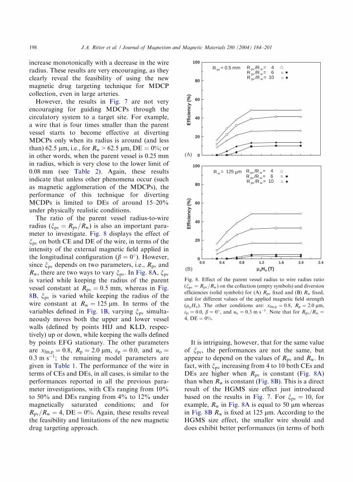
The ratio of the parent vessel radius-to-wireradius ðxpv ¼ Rpv=RwÞ is also an important para-meter to investigate. Fig. 8 displays the effect ofxpv on both CE and DE of the wire, in terms of theintensity of the external magnetic field applied inthe longitudinal configuration ðb ¼ 0�Þ: However,since xpv depends on two parameters, i.e., Rpv andRw; there are two ways to vary xpv: In Fig. 8A, xpv
is varied while keeping the radius of the parentvessel constant at Rpv ¼ 0:5 mm; whereas in Fig.8B, xpv is varied while keeping the radius of thewire constant at Rw ¼ 125 mm: In terms of thevariables defined in Fig. 1B, varying xpv simulta-neously moves both the upper and lower vesselwalls (defined by points HIJ and KLD, respec-tively) up or down, while keeping the walls definedby points EFG stationary. The other parametersare xfm;p ¼ 0:8; Rp ¼ 2:0 mm; ep ¼ 0:0; and uo ¼0:3 m s�1; the remaining model parameters aregiven in Table 1. The performance of the wire interms of CEs and DEs, in all cases, is similar to theperformances reported in all the previous para-meter investigations, with CEs ranging from 10%to 50% and DEs ranging from 4% to 12% undermagnetically saturated conditions; and forRpv=Rw ¼ 4; DE ¼ 0%: Again, these results revealthe feasibility and limitations of the new magneticdrug targeting approach.
It is intriguing, however, that for the same valueof xpv; the performances are not the same, butappear to depend on the values of Rpv and Rw: Infact, with xpv increasing from 4 to 10 both CEs andDEs are higher when Rpv is constant (Fig. 8A)than when Rw is constant (Fig. 8B). This is a directresult of the HGMS size effect just introducedbased on the results in Fig. 7. For xpv ¼ 10; forexample, Rw in Fig. 8A is equal to 50 mm whereasin Fig. 8B Rw is fixed at 125 mm: According to theHGMS size effect, the smaller wire should anddoes exhibit better performances (in terms of both
ARTICLE IN PRESS
J.A. Ritter et al. / Journal of Magnetism and Magnetic Materials 280 (2004) 184–201 199
CE and DE): at magnetic field strengths largerthan 1:0 T; a CE of 25% is obtained for Rw ¼50 mm compared to a CE of 17% with Rw ¼125 mm; under the same conditions, except for thesize of the parent vessel which is inconsequential inthis case because uo is fixed.
Another very interesting feature observed inboth situations (i.e., in Figs. 8A and B) is that thetrend observed between DE and xpv is unexpected,as it directly opposes that observed between CEand xpv: CE decreases with larger values of xpv; i.e.,for larger wires in smaller parent vessels. Thistrend is expected, since the wire takes up more ofthe cross-sectional area available for flow, which in
(A)
(B)
µoHo = 0.0 T
µoHo = 2.0 T ξpv = 4
ξpv = 4
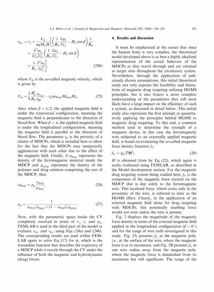
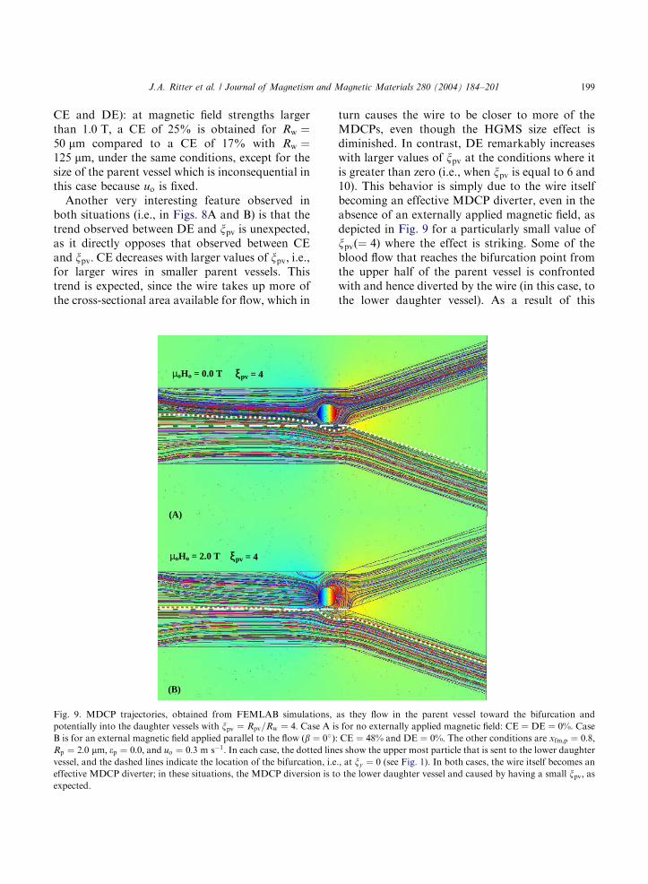
Fig. 9. MDCP trajectories, obtained from FEMLAB simulations,
potentially into the daughter vessels with xpv ¼ Rpv=Rw ¼ 4: Case A i
B is for an external magnetic field applied parallel to the flow ðb ¼ 0�ÞRp ¼ 2:0 mm; ep ¼ 0:0; and uo ¼ 0:3 m s�1: In each case, the dotted lin
vessel, and the dashed lines indicate the location of the bifurcation, i.e
effective MDCP diverter; in these situations, the MDCP diversion is t
expected.
turn causes the wire to be closer to more of theMDCPs, even though the HGMS size effect isdiminished. In contrast, DE remarkably increaseswith larger values of xpv at the conditions where itis greater than zero (i.e., when xpv is equal to 6 and10). This behavior is simply due to the wire itselfbecoming an effective MDCP diverter, even in theabsence of an externally applied magnetic field, asdepicted in Fig. 9 for a particularly small value ofxpvð¼ 4Þ where the effect is striking. Some of theblood flow that reaches the bifurcation point fromthe upper half of the parent vessel is confrontedwith and hence diverted by the wire (in this case, tothe lower daughter vessel). As a result of this
as they flow in the parent vessel toward the bifurcation and
s for no externally applied magnetic field: CE ¼ DE ¼ 0%: Case
: CE ¼ 48% and DE ¼ 0%: The other conditions are xfm;p ¼ 0:8;es show the upper most particle that is sent to the lower daughter
., at xy ¼ 0 (see Fig. 1). In both cases, the wire itself becomes an
o the lower daughter vessel and caused by having a small xpv; as
ARTICLE IN PRESS
J.A. Ritter et al. / Journal of Magnetism and Magnetic Materials 280 (2004) 184–201200
diversion, the flow and hence MDCP’s comingfrom the lower half of the parent vessel are pushedaway from and accelerated past the wire by thediverted flow coming from the upper half of theparent vessel. This wire diversion effect is veryapparent when no magnetic field is applied, asshown in Fig. 9A, and is still apparent, even inpresence of the externally applied magnetic field,as shown in Fig. 9B. This interesting situationprevents the wire from collecting MDCPs that itotherwise would collect, for example in the casewhere the wire does not take up so much of thecross-sectional area for flow, which is the situationat higher values of xpv ¼ Rpv=Rw:
5. Conclusions
A hypothetical magnetic drug targeting systemutilizing HGMS principles was studied theoreti-cally using FEMLAB simulations. This newmagnetic drug targeting approach involves usinga ferromagnetic wire placed at a critical bifurca-tion point inside a blood vessel and an externallyapplied magnetic field, to magnetically guideMDCP through the circulatory system and thento magnetically retain them at a target site. Aparametric study determined the behavior of thesystem and the effect of several variables on twosystem efficiencies: the CE defined as the percen-tage of MDCPs entering the parent vessel that arecollected on the wire, and the DE defined as thepercentage of MDCPs entering the lower half ofthe parent vessel that are diverted into the upperdaughter vessel. CE can be used to characterize asystem designed to retain the MDCPs at the targetsite or to remove the MDCPs from the circulatorysystem (with these two scenarios not necessarilybeing at a bifurcation point). DE can be used tocharacterize a system designed to divert MDCPsinto one branch of the daughter vessels, therebyeffectively guiding the MDCPs to a target sitewhile avoiding non-target sites.
Based on an extensive parametric study, it wasdetermined that both efficiencies increase as thestrength of the applied magnetic field, the amountof ferromagnetic material in the MDCP and thesize of the MDCP increase, and as the average
inlet velocity, the size of the wire and the ratio ofthe parent vessel radius-to-wire radius decrease.Also, for the conditions considered in this study,the effect of the direction of the applied magneticfield on the two efficiencies (CE and DE) wasfound to be minimal. Under physically plausibleconditions, CEs as high as 70% were obtained,whereas the DEs were much smaller, only reaching30% under the most favorable conditions. Incontrast, under the more extreme conditionsexplored in this study, where the MDCPs wereallowed to agglomerate, CEs and DEs of 100%were indeed obtained, but with the occurrence ofsuch results being more prevalent for CE than DE.These results clearly show that the new magneticdrug targeting approach may be very promisingfor magnetically collecting MDCPs at a target site,even in arteries with very high velocities. Theseresults also show that the new approach may bemore limited but still certainly feasible formagnetically guiding MDCPs through the circu-latory system.
Although the physical model of the circulatorysystem studied here was highly idealized, it issurmised that the theoretical results obtained fromsuch a model expose the feasibilities and limita-tions of magnetic drug targeting utilizing HGMSprinciples, and that they foster a more completeunderstanding of the parameters that will mostlikely have a large impact on the efficiency of sucha system. In future studies, more rigorous modelswill be developed in an attempt to more realisti-cally predict the system efficiencies and henceperformance. Other wire geometries and magneticimplant devices, such as magnetic stents, will alsobe developed and studied.
Overall, this initial study shows that this newmagnetic drug targeting approach, which capita-lizes on HGMS principles, has considerablepromise as an effective drug targeting tool in thehuman body. Even though it is mildly invasive,since it requires the insertion of a needle, syringeor catheter, it may offer significant advantagesover the more traditional, non-invasive but alsonot very effective, methods for collecting MDCPsat a target site, such as the application of anexternal magnet alone. Once perfected, it issurmised that applications for this kind of
ARTICLE IN PRESS
J.A. Ritter et al. / Journal of Magnetism and Magnetic Materials 280 (2004) 184–201 201
magnetic drug targeting technology will abound,especially in the treatment of localized disease sitessuch as cancerous tumors.
Acknowledgements
Funding provided by the NSF under Grant No.CTS-0314157, the NSF Graduate Research Fel-lowship to K.D.D., the NSF REU support toK.L.S. from Grant No. DMR-0353840, and theUSC NanoCenter is greatly appreciated.
References
[1] S. Farrell, R.P. Hesketh, Chem. Eng. Educ. 36 (3) (2002)
198.
[2] V.P. Torchilin, Eur. J. Pharm. Sci. 11 (Suppl. 2) (2000)
S81.
[3] C. Alexiou, W. Arnold, P. Hulin, R.J. Klein, H. Renz,
F.G. Parak, C. Bergemann, A.S. Lubbe, J. Magn. Magn.
Mater. 225 (2001) 187.
[4] J.L. Arias, V. Gallardo, S.A. Gomez-Lopera, R.C. Plaza,
A.V. Delgado, J. Control Release 77 (2001) 309.
[5] S.A. Gomez-Lopera, R.C. Plaza, A.V. Delgado, J. Colloid
Interface Sci. 240 (2001) 40.
[6] C.N. Ramchand, P. Pande, P. Kopcansky, R.V. Mehta,
Indian J. Pure Appl. Phys. 39 (10) (2001) 683.
[7] M. Babincova, V. Altanerova, M. Lampert, C. Altaner, E.
Machova, M. Sramka, P. Babinec, Z. Naturforsch. C. 55
(3–4) (2000) 278.
[8] C. Alexiou, W. Arnold, R.J. Klein, F.G. Parak, P. Hulin,
C. Bergemann, W. Erhardt, S. Wagenpfeil, A.S. Lubbe,
Cancer Res. 60 (2000) 6641.
[9] S. Goodwin, C. Peterson, C. Hoh, C. Bittner, J. Magn.
Magn. Mater. 194 (1999) 132.
[10] S. Rudge, C. Peterson, C. Vessely, J. Koda, S. Stevens, L.
Catterall, J. Control Release 74 (2001) 335.
[11] E. Viroonchatapan, H. Sato, M. Ueno, I. Adachi, K.
Tazawa, I. Horikoshi, Life Sci. 58 (24) (1996) 2251.
[12] A.S. Popel, Network models of peripheral circulation, in:
C. Skalak, S. Chien (Eds.), Handbook of Bioengineering,
McGraw-Hill, New York, 1987 (Chapter 20).
[13] S.A. Berger, W. Goldsmith, E.R. Lewis (Eds.), Introduc-
tion to Bioengineering, Oxford University Press, New
York, NY, 1996.
[14] W.M. Saltzman, Drug Delivery Engineering Principles for
Drug Delivery, Oxford University Press, New York, NY,
2001.
[15] S. Ghassabian, T. Ehtezazi, S.M. Forutan, S.A. Mortaza-
vi, Int. J. Pharm. 130 (1) (1996) 49.
[16] S.R. Rudge, T.L. Kurtz, C.R. Vessely, L.G. Catterall, D.L.
Williamson, Biomaterials 21 (2000) 1411.
[17] M. Babincova, P. Babinec, C. Bergemann, Z. Naturforsch.
56 (9–10) (2001) 909.
[18] R. Gerber, Magnetic separation, in: R. Gerber, C.D.
Wright, G. Asti (Eds.), Applied Magnetism, NATO ASI
Series, Series E: Applied Sciences, Vol. 253, Kluwer
Academic Publishers, Dordrecht, 1994, p. 165.
[19] R.B. Bird, W.E. Stewart, E.N. Lightfoot, Transport
Phenomena, 2nd Edition, Wiley, New York, 2002.
[20] J.H.P. Watson, IEEE Trans. Magn. 14 (1978) 392.
[21] N. Mordant, J.F. Pinton, Eur. Phys. J. B 18 (2000)
343.
[22] C.F. Driscoll, R.M. Morris, A.E. Senyei, K.J. Widder,
G.S. Heller, Microvasc. Res. 27 (1984) 353.
Related Documents