Application of High-Frequency Induction Heating Apparatus to Heat Treatment of 6061 Aluminum Alloy * Fang-ni Shang 1 , Eiji Sekiya 2 and Yoshihiro Nakayama 3 1 Science Education Department, Interdisciplinary Graduate School of Medicine and Engineering, University of Yamanashi, Kofu 400-8511, Japan 2 Research and Design Department, YS Electronics Co., Ltd., Kofu 400-0043, Japan 3 Science Research Department, Interdisciplinary Graduate School of Medicine and Engineering, University of Yamanashi, Kofu 400-8511, Japan A high-frequency induction heating apparatus was used for the heat treatment of a commercial 6061 aluminum alloy bar with the objective of improving the mechanical properties and productivity. Heating states of the 6061 alloy bar were examined in terms of temperature distribution, heating rate, overheating and temperature fluctuation; moreover, the mechanical properties of the alloy after heat treatment were also investigated. The results of this study are as follows. When the 6061 alloy bar was rapidly heated to the heat treatment temperature using the induction heating apparatus, temperature distribution and overheating of the sample were small as well as the temperature fluctuations in the holding process. A rapid heating rate of about 21 C/s heated the sample to the heat treatment temperature of 560 C in 26 s. The sample showed equivalent or superior mechanical properties compared with a sample heated by conventional electric furnace. Temperature and time of the heat treatment process greatly influenced the mechanical properties of the 6061 alloy, while there was no significant difference in mechanical properties of the sample heat-treated at various heating rates. [doi:10.2320/matertrans.L-M2011825] (Received September 30, 2010; Accepted August 20, 2011; Published October 13, 2011) Keywords: induction heating, 6061 aluminum alloy, heat treatment, rapid heating 1. Introduction Heat-treatable aluminum alloys must be solution-treated to increase their strength. An electric furnace (EF) is widely used for solution-treating these alloys due to ease of operation and equipment. However, the temperature con- trollability and energy efficiency of the EF are poor. High- temperature solution treatment saves time in the heat treatment process, increases productivity and improves mechanical properties as it increases the amount of solid solution atoms. 1) To realize high-temperature solution treat- ment, it is important to ensure rapid heating, no overheating during the temperature transition state from rising to holding, and stability of temperature in the holding process. Induction heating (IH) is also widely used for industrial applications due to its advantages of rapid heating, good controllability of temperature and energy savings. Microstructure control and mechanical properties of induction-heated and subsequently quenched carbon steel have been reported. 2) Komotori et al. studied the fatigue strength of super-rapid induction-heated and quenched steel. 3–5) The tensile and fatigue strength of titanium alloy were improved by short-time induction heat treatment. 6,7) Studies on continuous processing of aluminum alloys for sheet products reported significant grain refinement from 50–70 mm to 10–20 mm by rapid heating. 8,9) However, there have been few reports on the induction heating of bulk aluminum alloys. In the present study, we used an induction heating apparatus to heat treatment of heat-treatable aluminum alloys. Temperature profiles in the heat treatment process in terms of heating rate, overheating and temperature fluctuations were measured for commercial 6061 aluminum alloys. In general, the frequency of an induction heating apparatus for homogeneous heating of large-scale samples is less than 400 kHz, whereas a higher frequency is recom- mended for effective heating of small-scale products as well as local heating of industrial products. 10) In this study, a newly developed induction heating apparatus with a fre- quency of 2 MHz was used for the heat treatment of a 6061 alloy bar with a diameter of 10 mm and length of 150 mm. In induction heating, the temperature cannot be measured using a conventional thermocouple due to the magnetic field generated by the heating coil. Furthermore, temperature measurement using a radiation thermometer is difficult due to the unstable emissivity of aluminum alloys. Our previous study 11) investigated the effect of surface conditions on temperature measurement using a radiation thermometer and found that temperature could be precisely measured by spraying the sample surface with a black coating. In this paper we examined the heating states of a 6061 aluminum alloy bar in a rapid heating process using an induction heating apparatus. In addition, the mechanical properties of the induction-heated 6061 aluminum alloy were systematically investigated in terms of temperature, time and heating rate in the heat treatment process. The results were compared with those obtained using samples heated by a conventional electric furnace. Based on these results, we examined the feasibility of using the induction heating apparatus for the heat treatment of heat-treatable aluminum alloys. 2. Experimental Commercial A6061-T6 aluminum alloy bar (10 mm in diameter, 150 mm in length) fabricated by extrusion was used * The Paper Contains Partial Overlap with the ICAA12 Proceedings by USB under the Permission of the Editorial Committee. Materials Transactions, Vol. 52, No. 11 (2011) pp. 2052 to 2060 #2011 The Japan Institute of Light Metals

Welcome message from author
This document is posted to help you gain knowledge. Please leave a comment to let me know what you think about it! Share it to your friends and learn new things together.
Transcript

Application of High-Frequency Induction Heating Apparatus
to Heat Treatment of 6061 Aluminum Alloy*
Fang-ni Shang1, Eiji Sekiya2 and Yoshihiro Nakayama3
1Science Education Department, Interdisciplinary Graduate School of Medicine and Engineering,University of Yamanashi, Kofu 400-8511, Japan2Research and Design Department, YS Electronics Co., Ltd., Kofu 400-0043, Japan3Science Research Department, Interdisciplinary Graduate School of Medicine and Engineering,University of Yamanashi, Kofu 400-8511, Japan
A high-frequency induction heating apparatus was used for the heat treatment of a commercial 6061 aluminum alloy bar with the objectiveof improving the mechanical properties and productivity. Heating states of the 6061 alloy bar were examined in terms of temperaturedistribution, heating rate, overheating and temperature fluctuation; moreover, the mechanical properties of the alloy after heat treatment werealso investigated. The results of this study are as follows. When the 6061 alloy bar was rapidly heated to the heat treatment temperature using theinduction heating apparatus, temperature distribution and overheating of the sample were small as well as the temperature fluctuations in theholding process. A rapid heating rate of about 21�C/s heated the sample to the heat treatment temperature of 560�C in 26 s. The sample showedequivalent or superior mechanical properties compared with a sample heated by conventional electric furnace. Temperature and time of the heattreatment process greatly influenced the mechanical properties of the 6061 alloy, while there was no significant difference in mechanicalproperties of the sample heat-treated at various heating rates. [doi:10.2320/matertrans.L-M2011825]
(Received September 30, 2010; Accepted August 20, 2011; Published October 13, 2011)
Keywords: induction heating, 6061 aluminum alloy, heat treatment, rapid heating
1. Introduction
Heat-treatable aluminum alloys must be solution-treatedto increase their strength. An electric furnace (EF) is widelyused for solution-treating these alloys due to ease ofoperation and equipment. However, the temperature con-trollability and energy efficiency of the EF are poor. High-temperature solution treatment saves time in the heattreatment process, increases productivity and improvesmechanical properties as it increases the amount of solidsolution atoms.1) To realize high-temperature solution treat-ment, it is important to ensure rapid heating, no overheatingduring the temperature transition state from rising to holding,and stability of temperature in the holding process. Inductionheating (IH) is also widely used for industrial applicationsdue to its advantages of rapid heating, good controllability oftemperature and energy savings. Microstructure control andmechanical properties of induction-heated and subsequentlyquenched carbon steel have been reported.2) Komotori et al.studied the fatigue strength of super-rapid induction-heatedand quenched steel.3–5) The tensile and fatigue strength oftitanium alloy were improved by short-time induction heattreatment.6,7) Studies on continuous processing of aluminumalloys for sheet products reported significant grain refinementfrom 50–70 mm to 10–20 mm by rapid heating.8,9) However,there have been few reports on the induction heating of bulkaluminum alloys.
In the present study, we used an induction heatingapparatus to heat treatment of heat-treatable aluminumalloys. Temperature profiles in the heat treatment processin terms of heating rate, overheating and temperature
fluctuations were measured for commercial 6061 aluminumalloys. In general, the frequency of an induction heatingapparatus for homogeneous heating of large-scale samples isless than 400 kHz, whereas a higher frequency is recom-mended for effective heating of small-scale products as wellas local heating of industrial products.10) In this study, anewly developed induction heating apparatus with a fre-quency of 2 MHz was used for the heat treatment of a 6061alloy bar with a diameter of 10 mm and length of 150 mm.In induction heating, the temperature cannot be measuredusing a conventional thermocouple due to the magneticfield generated by the heating coil. Furthermore, temperaturemeasurement using a radiation thermometer is difficult dueto the unstable emissivity of aluminum alloys. Our previousstudy11) investigated the effect of surface conditions ontemperature measurement using a radiation thermometerand found that temperature could be precisely measured byspraying the sample surface with a black coating.
In this paper we examined the heating states of a 6061aluminum alloy bar in a rapid heating process using aninduction heating apparatus. In addition, the mechanicalproperties of the induction-heated 6061 aluminum alloy weresystematically investigated in terms of temperature, time andheating rate in the heat treatment process. The results werecompared with those obtained using samples heated by aconventional electric furnace. Based on these results, weexamined the feasibility of using the induction heatingapparatus for the heat treatment of heat-treatable aluminumalloys.
2. Experimental
Commercial A6061-T6 aluminum alloy bar (10 mm indiameter, 150 mm in length) fabricated by extrusion was used
*The Paper Contains Partial Overlap with the ICAA12 Proceedings by
USB under the Permission of the Editorial Committee.
Materials Transactions, Vol. 52, No. 11 (2011) pp. 2052 to 2060#2011 The Japan Institute of Light Metals

in this study. Figure 1 is a schematic diagram showing thearrangement of the specimen, induction heating coil, radia-tion thermometer and cooling water bath. The frequency andpower of the induction heating apparatus are 2 MHz and10 kW, respectively. The surface of the sample was sprayedwith a black coating to ensure precision temperaturemeasurement using a radiation thermometer with a meas-urable temperature range of more than 250�C. The radiationthermometer measured the temperature at the center of thesample. To investigate the temperature distribution in thesample immediately after the heating process, five thermo-couples (type K) were positioned in the length, width anddepth directions. A detailed schematic diagram of thethermocouple locations is shown in Fig. 2. Differentialscanning calorimetry analysis (DSC) was conducted using aSeiko Instruments DSC220 at a heating rate of 10�C/min fora sample weighing 10 mg. The upper limit of the heattreatment temperature was set at 590�C based on the solidustemperature of 596�C estimated from the DSC results. On theother hand, the lower limit of the temperature was chosenat 260�C. From this heat treatment with a wide range of
temperature, the microstructural change related to theprecipitation or the solution behaviors during heat treatmentmay be easily understood. In the present study, temperature,time and heating rate in the heat treatment process were alsosystematically varied to investigate the effect of the heattreatment conditions on the mechanical properties. The heattreatment conditions are summarized in Fig. 3. It should benoted that the heat treatment at temperatures above 400�C inthis study essentially means re-solution treatment since thesample was already heat treated in the T6 state. On the otherhand, that at temperatures less than 400�C may result in thecoarsening of precipitates, which corresponds to over-agingtreatment. After the heat treatment, the samples werequenched in water at 20�C located below the sample. Afterquenching, the samples were naturally aged for 48 h at roomtemperature (T4). One of them was artificially aged at 180�Cfor 8 h using an EF apparatus (T6). For comparison, heattreatment was also conducted using an EF apparatus underthe standard solution treatment conditions (530�C for30 min). Vickers microhardness test, tensile test, electricalconductivity measurement and microstructure observationwere performed after natural/artificial aging. Vickers micro-hardness was measured at a load of 100 g at a holding timeof 15 s. The tensile test specimen was prepared following theJIS-14A standard (diameter 6.0 mm, gauge length 30 mm)
Fig. 1 Schematic diagram of experimental apparatus.
Fig. 2 Detailed schematic illustration showing thermocouple location in
length (a), width (b) and depth direction (c).
Fig. 3 Summary of heat treatment conditions.
Application of High-Frequency Induction Heating Apparatus to Heat Treatment of 6061 Aluminum Alloy 2053

and subjected to the tensile test at a constant crosshead speedof 1.0 mm/min at room temperature. Electrical conductivitywas measured using a digital electrical conductivity meter(Autosigma 2000). Samples for optical microscopy observa-tion were prepared by the anodic oxidation method. Ascanning electron microscope operated at 15 kV (HitachiS-4500) was used for observing the fracture surface.
3. Results and Discussion
3.1 Temperature distribution in sampleThe effect of emissivity on the accuracy of temperature
measurement using a radiation thermometer was investigatedfor the aluminum sample with a black body and the resultswere as shown in Fig. 4. A thermocouple was inserted intothe sample to a depth of 0.2 mm from the surface, and theradiation thermometer measured the surface temperature ofthe sample simultaneously. When the temperature measuredby the radiation thermometer matched that of the thermo-couple, the emissivity value was considered to be the propermeasurement value. The temperature measured using theemissivity value of 0.78 is in good agreement with that ofthe thermocouple, as seen in Fig. 4. From this result, theemissivity value of 0.78 was adopted for the temperaturemeasurement using a radiation thermometer. Incidentally, thedistance L between the sample edge and the heating coil (seeFig. 1) is thought to significantly influence the temperaturedistribution in the length direction of the sample because themagnetic field strength varies with the location of the samplein the induction heating coil. Figure 5 shows the changes intemperature distribution in the length direction with distanceL (a), and those in the width and depth directions (b).Temperature was measured when the temperature of thespecimen surface measured by the radiation thermometerreached 560�C and the heating coil was turned off. The valueon the y-axis shows the temperature differences of eachchannel against that of channel 3 (see Fig. 2). As shown inFig. 5(a), the maximum difference appeared at L ¼ 0 mmand 30 mm. The temperature of channel 5 showed the highestvalue at L ¼ 0 mm and the lowest value at L ¼ 30 mm. Thesetemperature distributions indicate that the magnetic field
strength is high at either side of the heating coil. Since theminimum difference in temperature of less than 3�C wasobtained at L ¼ 18:5 or 22.0 mm, the following experimentswere conducted using either L value. In addition, thetemperature differences in the width and depth directionswere measured and are shown in Fig. 5(b). It can be seen thatthe temperature distribution in the width and depth directionsis small within the range of 3.5�C. Generally speaking, eddycurrents induced by induction heating apparatus are con-centrated on the surface layers facing the heating coil andheat generation may have occurred mainly in these surfacelayers (skin effect). The current penetration depth of the skineffect is dependent on the electrical and magnetic propertiesof the material and the frequency of the induction heatingapparatus.10) The calculated current penetration depth isestimated at about 71 mm. Although the regions of heatgeneration were thin, homogeneous heating was achieved inthe length, width and depth directions. It is considered thatthis homogeneous heating status is derived from the goodthermal conductivity of the aluminum alloys as well as thesmall sample size.
Fig. 4 Effect of emissivity on temperature measurement for aluminum
sample with black coating.
(a)
(b)
Fig. 5 Changes in the temperature difference of five thermometers in the
length direction with the distance L (a), and those in the width and depth
directions (b). The value on the y-axis shows the temperature difference of
each channel against that of channel 3.
2054 F. Shang, E. Sekiya and Y. Nakayama

To confirm the effect of temperature distribution existingin the sample, the hardness distribution was measured in thewidth and depth directions after heat treatment. Figure 6shows the Vickers microhardness distribution for the sampleheat-treated by the IH apparatus (heating rate: 21�C/s) andby the EF apparatus (heating rate: approximately 0.3�C/s).The samples were subjected to heat treatment at 530�C for5 min (IH) and 30 min (EF), and then quenched in water.In Fig. 6, the hardness distribution of an as-received sampleis also shown for reference. The inset in the figure shows aschematic illustration indicating the measurement directionand position of hardness. Hardness values in the width anddepth directions show almost the same values for theinduction-heated samples, suggesting no remarkable temper-ature distribution during the heat treatment. Moreover, thehardness distribution of the sample heat-treated by the EFapparatus is equivalent to that by the IH apparatus. Theaverage hardness values of the as-received sample and thesamples heat-treated by the EF and the IH apparatus were93, 71 and 69 HV, respectively. The decrease in hardnessfrom 93 to about 70 HV is considered to be due to thedisappearance of precipitates during the heat treatmentprocess. Since the hardness value of the sample heated bythe IH apparatus is equivalent to that heated by the EF, themicrostructures of the two samples may be almost the same.
It was also important to examine the heating characteristicsof each heating apparatus. Figure 7 shows the representativetemperature profiles and heating rates for the IH (a) and theEF (b) together with those of the salt bath (c). An enlarge-ment of the temperature profile immediately after thecompletion of temperature rise is inserted for the IH. In thecase of IH, the linear rise in temperature up to the heattreatment temperature was obtained by keeping the heatingrate at a constant value of about 21�C/s (a). Moreover, the
overheating generated during the temperature transition stagefrom rising to holding processes was about 4�C and thetemperature fluctuation in the holding process was about�2�C. On the other hand, the heating rate of the EF must bekept below 0.1�C/s to avoid marked overheating (b), so along time is needed for the temperature to reach the targettemperature. Moreover, a relatively large temperature fluc-tuation in the holding process results from the indirectheating of the EF apparatus. The heating rate of the salt bathshowed a remarkable value exceeding 60�C/s in the earlystage of the heating process but decreased markedly in thelatter stage; hence, the temperature difference between thesalt and the sample is small (c). It was difficult to control thetemperature of the sample during the heating and holdingprocesses because the salt was kept at a constant temperature.These results suggest that the induction heating apparatuspossesses excellent heating characteristics compared with theelectric furnace and the salt bath.
3.2 Effect of heat treatment temperatureHere, we describe the effect of the heat treatment tem-
perature on the mechanical properties after the sample washeat treated using the IH apparatus at a rapid heating rate of21�C/s. Figure 8 shows the temperature profile for variousheat treatment temperatures from 260�C to 590�C. Thetemperature at the sample surface (near the center in thelength direction, as shown in Fig. 1) was measured using theradiation thermometer. Since the measurable lower limittemperature of the radiation thermometer is 250�C, temper-atures above 250�C are shown in Fig. 8. A linear rise intemperature (21�C/s) up to the heat treatment temperaturein the heating process and small-scale overheating (2–4�C)during the temperature transition stage from heating toholding processes (except for 260�C) were achieved. Therewas no significant temperature fluctuation (�3�C) in theholding process. These temperature profiles show that theheat treatment at various temperatures using the inductionheating apparatus was processed properly. The hardnessobtained after T4 and T6 treatments at various heat treatmenttemperatures is shown in Fig. 9. There is a great variationin hardness at a heat treatment temperature of 440�C for theT4 and T6 treatments. In the case of T4 treatment, whenheat treatment was carried out below 380�C, the hardnessdecreased with the increase in heat treatment temperature.On the other hand, the hardness increased after heat treatmentat temperatures above 440�C. This decrease in hardness maybe the result of a growth in precipitates, while the increasein solid solute atoms such as Mg and Si with rising heattreatment temperature may have caused the increase inhardness. In relation to this, the artificial aging treatment ledto a significant increase in hardness for the samples heated attemperatures above 440�C. The hardness change shown inFig. 9 clearly indicates that heating temperatures below380�C are over-aging treatment whereas those above 440�Care solution treatment. There is a report12) describing that thenose temperature of a 6061 aluminum alloy is about 380�C.Therefore, it is considered that the rapid heating has nosignificant effect on the phase decomposition of this alloy.Incidentally, the samples heated by the EF apparatus showhardness values of 70 HV (T4 conditions) and 100 HV (T6
Fig. 6 Vickers microhardness distribution for samples heat-treated by
induction heating (heating rate: 21�C/s) and electric furnace (heating rate:
approximately 0.3�C/s). Heat treatment was carried out at 530�C for 5 min
(IH) and 30 min (EF). Inset shows a schematic illustration of the
measurement direction and position.
Application of High-Frequency Induction Heating Apparatus to Heat Treatment of 6061 Aluminum Alloy 2055

conditions), which are identical to those of samples heatedby the IH apparatus at 530�C. Because these samples weretreated by different heating rate and holding time, it is notreasonable to evaluate the effect of heating rate and holding
time on the hardness based on these measured hardnessvalues.
Figure 10 shows the variation in the 0.2% proof stresswith the heat treatment temperature. The change is almost
(a) (b)
(c)
Fig. 7 Temperature profiles and heating rates for induction heating (a), electric furnace (b) and salt bath (c), respectively. The inserted
diagram in Fig. 7(a) shows the temperature profile immediately after the completion of temperature rise to the heat treatment temperature.
The measurement location for the radiation thermometer was the center of the sample (near channel 3, see Fig. 2) and the measurable
limit was above 250�C under specification.
Fig. 8 Temperature profiles for various heat treatment temperatures from
260 to 590�C. Fig. 9 Hardness obtained after T4 and T6 treatment for various heat
treatment temperatures.
2056 F. Shang, E. Sekiya and Y. Nakayama

equivalent to that of the hardness shown in Fig. 9. The 0.2%proof stress after T4 and T6 treatment increased for heattreatment temperatures above 440�C, showing a peak valueat 530�C and then decreasing. The increase in the 0.2% proofstress may be explained by the solid solution hardening(T4) or the precipitation hardening (T6), respectively. Thedecrease in 0.2% proof stress at heat treatment temperatureabove 530�C is considered to be due to grain growth by thehigh-temperature solution treatment. The peak value of the0.2% proof stress (343 MPa) for the T6 sample heat-treatedat 530�C was higher than that of the as-received sample(268 MPa) and the T6 sample heated by the EF (282 MPa).The fracture elongation is shown in Fig. 11. The change infracture elongation with heat treatment temperature showsan almost opposite tendency to the proof stress, which is anordinary relationship between the proof stress and thefracture elongation. The fracture elongation of T6 samplesheat-treated at 530�C by the IH apparatus was slightly lowerthan that of the EF-treated sample. These experimentalresults for the proof stress and fracture elongation suggest
that the samples heat-treated by the IH apparatus had moreprecipitates than the EF-treated samples. The microstructurein the cross section is shown in Fig. 12 for the representativeheat treatment temperatures. As shown, grain growthappeared in the near surface of the sample and when heattreatment was conducted above 560�C, unstable grain growthalmost reached the center of the cross section, which maybe the cause of the decrease in proof stress and fractureelongation. On the other hand, there is no noticeable graingrowth in the center region of the sample. The relationshipbetween the heat treatment temperature and the electricalconductivity is presented in Fig. 13. Under T4 conditions,the conductivity of the sample heat-treated at above 440�Cshows a significant decrease resulting from the increasedamount of solid solute atoms in the matrix. In contrast, thesamples after artificial aging treatment show a slightly highervalue of conductivity compared with that before agingtreatment. This increase in the conductivity may be due tothe decrease in amount of solid solute atoms in the matrixaccompanied by the formation of precipitates during the
Fig. 10 Variations in 0.2% proof stress with heat treatment temperature.
Fig. 11 Fracture elongation for each heat treatment temperature.
Fig. 12 Microstructure in the cross section for typical heat treatment
temperatures.
Fig. 13 Relationship between heat treatment temperature and electrical
conductivity.
Application of High-Frequency Induction Heating Apparatus to Heat Treatment of 6061 Aluminum Alloy 2057
artificial aging. These changes in electrical conductivity withthe heat treatment and aging treatment correspond to thoseof the hardness, proof stress and fracture elongation.
Therefore, the heat treatment using the IH apparatus isconsidered to be a useful technique for the heat treatment ofheat-treatable aluminum alloys.
3.3 Effect of heat treatment timeHere, we discuss the effect of heat treatment time on the
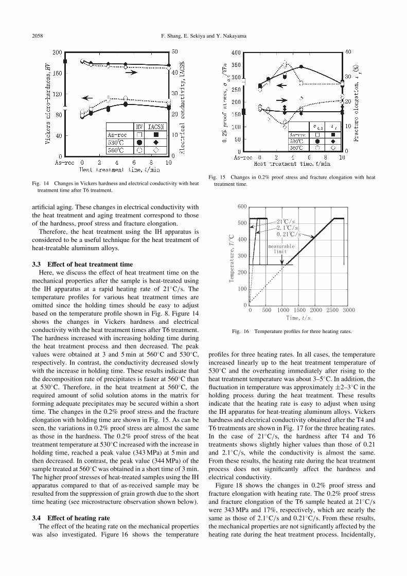
mechanical properties after the sample is heat-treated usingthe IH apparatus at a rapid heating rate of 21�C/s. Thetemperature profiles for various heat treatment times areomitted since the holding times should be easy to adjustbased on the temperature profile shown in Fig. 8. Figure 14shows the changes in Vickers hardness and electricalconductivity with the heat treatment times after T6 treatment.The hardness increased with increasing holding time duringthe heat treatment process and then decreased. The peakvalues were obtained at 3 and 5 min at 560�C and 530�C,respectively. In contrast, the conductivity decreased slowlywith the increase in holding time. These results indicate thatthe decomposition rate of precipitates is faster at 560�C thanat 530�C. Therefore, in the heat treatment at 560�C, therequired amount of solid solution atoms in the matrix forforming adequate precipitates may be secured within a shorttime. The changes in the 0.2% proof stress and the fractureelongation with holding time are shown in Fig. 15. As can beseen, the variations in 0.2% proof stress are almost the sameas those in the hardness. The 0.2% proof stress of the heattreatment temperature at 530�C increased with the increase inholding time, reached a peak value (343 MPa) at 5 min andthen decreased. In contrast, the peak value (344 MPa) of thesample treated at 560�C was obtained in a short time of 3 min.The higher proof stresses of heat-treated samples using the IHapparatus compared to that of as-received sample may beresulted from the suppression of grain growth due to the shorttime heating (see microstructure observation shown below).
3.4 Effect of heating rateThe effect of the heating rate on the mechanical properties
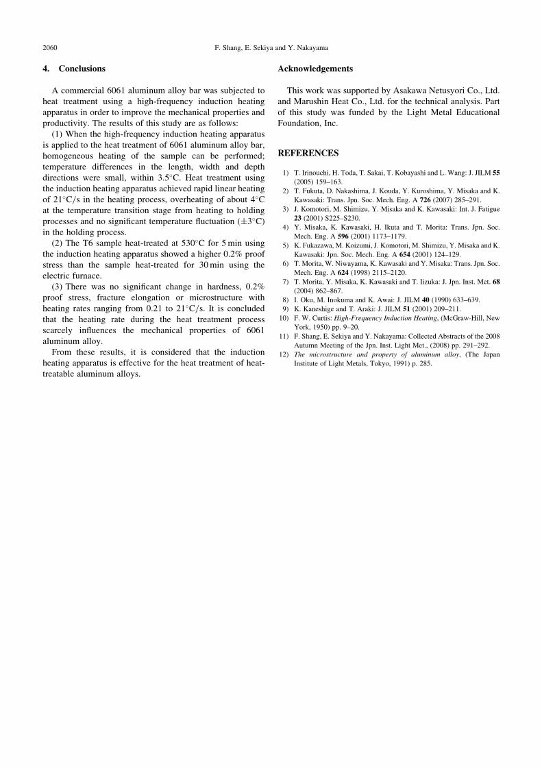
was also investigated. Figure 16 shows the temperature
profiles for three heating rates. In all cases, the temperatureincreased linearly up to the heat treatment temperature of530�C and the overheating immediately after rising to theheat treatment temperature was about 3–5�C. In addition, thefluctuation in temperature was approximately �2{3�C in theholding process during the heat treatment. These resultsindicate that the heating rate is easy to adjust when usingthe IH apparatus for heat-treating aluminum alloys. Vickershardness and electrical conductivity obtained after the T4 andT6 treatments are shown in Fig. 17 for the three heating rates.In the case of 21�C/s, the hardness after T4 and T6treatments shows slightly higher values than those of 0.21and 2.1�C/s, while the conductivity is almost the same.From these results, the heating rate during the heat treatmentprocess does not significantly affect the hardness andelectrical conductivity.
Figure 18 shows the changes in 0.2% proof stress andfracture elongation with heating rate. The 0.2% proof stressand fracture elongation of the T6 sample heated at 21�C/swere 343 MPa and 17%, respectively, which are nearly thesame as those of 2.1�C/s and 0.21�C/s. From these results,the mechanical properties are not significantly affected by theheating rate during the heat treatment process. Incidentally,
Fig. 14 Changes in Vickers hardness and electrical conductivity with heat
treatment time after T6 treatment.
Fig. 15 Changes in 0.2% proof stress and fracture elongation with heat
treatment time.
Fig. 16 Temperature profiles for three heating rates.
2058 F. Shang, E. Sekiya and Y. Nakayama

the fracture elongation under T4 conditions increased gentlywith the rise in heating rate. The fractured surface wasobserved for the samples heat-treated at a heating rate of
0.21�C/s and 21�C/s. Figure 19 shows SEM micrographs ofthe fractured surface under T4 and T6 conditions. Manylarger dimples were formed in the T6 samples, whereassmaller dimples were observed together with larger onesunder T4 conditions. However, there is no significantdifference in the fractured surface related to the heating rateduring the heat treatment process. To investigate thesemicrostructural features in detail, optical microscope imageswere taken of the cross section and inner section, and areshown in Fig. 20 for the as-received sample and samplesheat-treated at various heating rates. As can be seen in thefigure, the grain growth in the outer section is more clearlyrecognized for the samples heat-treated at various heatingrates compared to the as-received sample. There is nosignificant difference in grain size in the inner section relatedto the heating rate during the heat treatment process. Thesame applies to grain growth in the outer section. Based onthese results, it is concluded that the heating rate during theheat treatment process has little effect on the mechanicalproperties and microstructure of 6061 aluminum alloy.
Fig. 17 Vickers hardness and electrical conductivity after T4 and T6
treatment for three heating rates.
Fig. 18 Changes in 0.2% proof stress and fracture elongation with heating
rate.
Fig. 19 SEM micrographs showing effect of heating rate on fracture
surface after T4 and T6 treatment.
Fig. 20 Optical microscopic images showing microstructures in the cross section and inner section for three heating rates.
Application of High-Frequency Induction Heating Apparatus to Heat Treatment of 6061 Aluminum Alloy 2059
4. Conclusions
A commercial 6061 aluminum alloy bar was subjected toheat treatment using a high-frequency induction heatingapparatus in order to improve the mechanical properties andproductivity. The results of this study are as follows:
(1) When the high-frequency induction heating apparatusis applied to the heat treatment of 6061 aluminum alloy bar,homogeneous heating of the sample can be performed;temperature differences in the length, width and depthdirections were small, within 3.5�C. Heat treatment usingthe induction heating apparatus achieved rapid linear heatingof 21�C/s in the heating process, overheating of about 4�Cat the temperature transition stage from heating to holdingprocesses and no significant temperature fluctuation (�3�C)in the holding process.
(2) The T6 sample heat-treated at 530�C for 5 min usingthe induction heating apparatus showed a higher 0.2% proofstress than the sample heat-treated for 30 min using theelectric furnace.
(3) There was no significant change in hardness, 0.2%proof stress, fracture elongation or microstructure withheating rates ranging from 0.21 to 21�C/s. It is concludedthat the heating rate during the heat treatment processscarcely influences the mechanical properties of 6061aluminum alloy.
From these results, it is considered that the inductionheating apparatus is effective for the heat treatment of heat-treatable aluminum alloys.
Acknowledgements
This work was supported by Asakawa Netusyori Co., Ltd.and Marushin Heat Co., Ltd. for the technical analysis. Partof this study was funded by the Light Metal EducationalFoundation, Inc.
REFERENCES
1) T. Irinouchi, H. Toda, T. Sakai, T. Kobayashi and L. Wang: J. JILM 55
(2005) 159–163.
2) T. Fukuta, D. Nakashima, J. Kouda, Y. Kuroshima, Y. Misaka and K.
Kawasaki: Trans. Jpn. Soc. Mech. Eng. A 726 (2007) 285–291.
3) J. Komotori, M. Shimizu, Y. Misaka and K. Kawasaki: Int. J. Fatigue
23 (2001) S225–S230.
4) Y. Misaka, K. Kawasaki, H. Ikuta and T. Morita: Trans. Jpn. Soc.
Mech. Eng. A 596 (2001) 1173–1179.
5) K. Fukazawa, M. Koizumi, J. Komotori, M. Shimizu, Y. Misaka and K.
Kawasaki: Jpn. Soc. Mech. Eng. A 654 (2001) 124–129.
6) T. Morita, W. Niwayama, K. Kawasaki and Y. Misaka: Trans. Jpn. Soc.
Mech. Eng. A 624 (1998) 2115–2120.
7) T. Morita, Y. Misaka, K. Kawasaki and T. Iizuka: J. Jpn. Inst. Met. 68
(2004) 862–867.
8) I. Oku, M. Inokuma and K. Awai: J. JILM 40 (1990) 633–639.
9) K. Kaneshige and T. Araki: J. JILM 51 (2001) 209–211.
10) F. W. Curtis: High-Frequency Induction Heating, (McGraw-Hill, New
York, 1950) pp. 9–20.
11) F. Shang, E. Sekiya and Y. Nakayama: Collected Abstracts of the 2008
Autumn Meeting of the Jpn. Inst. Light Met., (2008) pp. 291–292.
12) The microstructure and property of aluminum alloy, (The Japan
Institute of Light Metals, Tokyo, 1991) p. 285.
2060 F. Shang, E. Sekiya and Y. Nakayama
Related Documents