Turkish Journal of Electrical Engineering and Computer Sciences Turkish Journal of Electrical Engineering and Computer Sciences Volume 29 Number 1 Article 7 1-1-2021 Application of fractional order PI controllers on a magnetic Application of fractional order PI controllers on a magnetic levitation system levitation system ERHAN YUMUK MÜJDE GÜZELKAYA İBRAHİM EKSİN Follow this and additional works at: https://dctubitak.researchcommons.org/elektrik Part of the Computer Engineering Commons, Computer Sciences Commons, and the Electrical and Computer Engineering Commons Recommended Citation Recommended Citation YUMUK, ERHAN; GÜZELKAYA, MÜJDE; and EKSİN, İBRAHİM (2021) "Application of fractional order PI controllers on a magnetic levitation system," Turkish Journal of Electrical Engineering and Computer Sciences: Vol. 29: No. 1, Article 7. https://doi.org/10.3906/elk-2003-101 Available at: https://dctubitak.researchcommons.org/elektrik/vol29/iss1/7 This Article is brought to you for free and open access by TÜBİTAK Academic Journals. It has been accepted for inclusion in Turkish Journal of Electrical Engineering and Computer Sciences by an authorized editor of TÜBİTAK Academic Journals.

Welcome message from author
This document is posted to help you gain knowledge. Please leave a comment to let me know what you think about it! Share it to your friends and learn new things together.
Transcript
Turkish Journal of Electrical Engineering and Computer Sciences Turkish Journal of Electrical Engineering and Computer Sciences
Volume 29 Number 1 Article 7
1-1-2021
Application of fractional order PI controllers on a magnetic Application of fractional order PI controllers on a magnetic
levitation system levitation system
ERHAN YUMUK
MÜJDE GÜZELKAYA
İBRAHİM EKSİN
Follow this and additional works at: https://dctubitak.researchcommons.org/elektrik
Part of the Computer Engineering Commons, Computer Sciences Commons, and the Electrical and
Computer Engineering Commons
Recommended Citation Recommended Citation YUMUK, ERHAN; GÜZELKAYA, MÜJDE; and EKSİN, İBRAHİM (2021) "Application of fractional order PI controllers on a magnetic levitation system," Turkish Journal of Electrical Engineering and Computer Sciences: Vol. 29: No. 1, Article 7. https://doi.org/10.3906/elk-2003-101 Available at: https://dctubitak.researchcommons.org/elektrik/vol29/iss1/7
This Article is brought to you for free and open access by TÜBİTAK Academic Journals. It has been accepted for inclusion in Turkish Journal of Electrical Engineering and Computer Sciences by an authorized editor of TÜBİTAK Academic Journals.
Turk J Elec Eng & Comp Sci(2021) 29: 98 – 109© TÜBİTAKdoi:10.3906/elk-2003-101
Turkish Journal of Electrical Engineering & Computer Sciences
http :// journa l s . tub i tak .gov . t r/e lektr ik/
Research Article
Application of fractional order PI controllers on a magnetic levitation system
Erhan YUMUK, Müjde GÜZELKAYA∗, İbrahim EKSİNDepartment of Control and Automation Engineering, Faculty of Electrical and Electronics Engineering,
İstanbul Technical University, İstanbul, Turkey
Received: 18.03.2020 • Accepted/Published Online: 24.08.2020 • Final Version: 27.01.2021
Abstract: Fractional order PI controllers based on two different analytical design methods are applied to a magneticlevitation system in this paper. The controller parameters are specified in order to fulfill specific frequency criteria. Thefirst design method utilizes a unity feedback reference model whose forward path includes Bode’s ideal loop transferfunction. The second method uses the reference model that has been obtained via delayed Bode’s ideal loop transferfunction. The achievement of these two controllers are contrasted with each other on the magnetic levitation systemusing various criteria.
Key words: Magnetic levitation system, delayed ideal Bode’s loop, ideal Bode’s loop, fractional order model, fractionalorder PI controllers
1. IntroductionFractional calculus has been a continuing subject for more than three centuries and its utilization in the fieldof control system design is an up-to-date issue. The modeling and control of systems using fractional calculusprovides certain advantages and flexibility when compared with their integer-order counterparts [1]. There existthree more cases with regard to the class of controllers and system models in the usage of fractional calculus,i.e. integer-order control for fractional-order models [2] and fractional-order control for integer-order models[3–7] and fractional-order models [8, 9].
The behavior of real-time systems are often expressed using higher-order differential equations. Thesehigher order models may be approximated to the low integer order with time delay models [10]. However,these low-order models cannot represent the dynamics of the higher order systems accurately. Therefore,the controllers developed using these low-order models exhibit inadequate closed loop performances. Theirfractional-order counterparts characterize the dynamic behavior of these systems more precisely because theyhave an additional parameter (i.e. fractional order) [1, 11–13]. Therefore, integer-order or fractional-ordercontrollers developed based on these fractional-order models would be more realistic. Moreover, fractional-order controllers would also be a good choice due to their some additional parameters (e.g., fractional integratoror derivative orders). The fractional controller design methods are commonly based on frequency domain criteriasuch as phase margin (ϕm ) and gain crossover frequency (ωc ). These methods are categorized into two parts:numerical [13, 14] and analytical methods [8, 9, 15].
There exist various application areas in which fractional calculus is utilized in control and modeling ofsystems. One of the most crucial application areas is magnetic levitation systems. Magnetic levitation systems∗Correspondence: [email protected]
This work is licensed under a Creative Commons Attribution 4.0 International License.98
YUMUK et al./Turk J Elec Eng & Comp Sci
are extensively employed in numerous areas such as magnetic levitation trains, rocket launch, artificial heartpumps, and magnetic levitation-based fans [16, 17]. Since magnetic levitation systems possess intrinsicallynonlinear dynamics and unstable structure, the modeling and control of these systems are tough issues. Thus,both linear and nonlinear techniques have been developed for various dynamics models [18–21].
Two fractional-order PI controllers which use two different analytical design methods [8, 9] are appliedto a magnetic levitation system in this study. In these analytical design methods, a type of fractional ordermodel is used. The parameters of controllers are designated in order to fulfill specific frequency domain criteria.The first design method utilizes a unity feedback reference model whose forward path obtains Bode’s ideal loop(BIL) transfer function [8]. In the second method, the reference model is obtained utilizing delayed BIL transferfunction in the forward path [9]. The success of these two controllers are examined on a magnetic levitationsystem using various specifications. In this respect, we have shown that these two analytical controller designmethods could be implemented successfully on a highly nonlinear system.
The rest of this paper is constructed as follows: Two fractional PI controller design methods are offeredin Section 2. Section 3 gives the description and modeling of the magnetic levitation system. In Section 4, thecontrollers’ design and their performance comparisons are included. Consequently, discussions and conclusionsare given in Section 5.
2. Fractional PI controllers’ design methods and their realizations
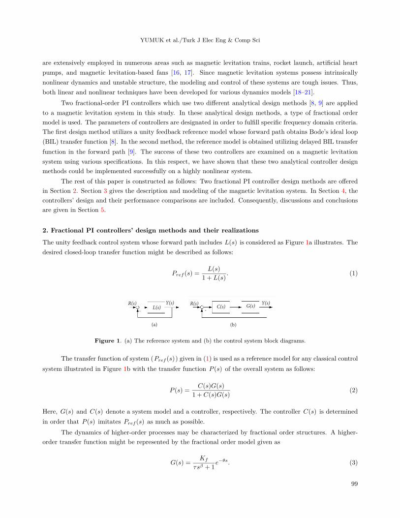
The unity feedback control system whose forward path includes L(s) is considered as Figure 1a illustrates. Thedesired closed-loop transfer function might be described as follows:
Pref (s) =L(s)
1 + L(s). (1)
R(s)L(s)
Y(s)
(a)
-
R(s)G(s)C(s)
Y(s)
(b)
-
Figure 1. (a) The reference system and (b) the control system block diagrams.
The transfer function of system (Pref (s)) given in (1) is used as a reference model for any classical controlsystem illustrated in Figure 1b with the transfer function P (s) of the overall system as follows:
P (s) =C(s)G(s)
1 + C(s)G(s)(2)
Here, G(s) and C(s) denote a system model and a controller, respectively. The controller C(s) is determinedin order that P (s) imitates Pref (s) as much as possible.
The dynamics of higher-order processes may be characterized by fractional order structures. A higher-order transfer function might be represented by the fractional order model given as
G(s) =Kf
τsβ + 1e−θs. (3)
99
YUMUK et al./Turk J Elec Eng & Comp Sci
In this manner, a higher-order process is expressed by only four system model parameters (Kf , τ, β, θ ). On theother hand, the general transfer function of fractional order PI controller is described as
C(s) = H(s)Kp
(1 +
1
Tisλ
)(4)
where Kp , Ti , and λ denote the controller gain, time constant of integrator, and integrator order, respectively.H(s) is the fractional filter.
2.1. The method based on Bode’s ideal loop transfer function
Here, we first consider the method presented in [8], which will be referred to as Method I hereafter. Thisstructure relies on internal model control (IMC). It is asserted in the literature that an IMC structure requiresfewer parameters than other classical structures. In this respect, L(s) given in Figure 1a is offered as BILtransfer function [22] as follows:
L(s) =K
sγ(5)
where γ ∈ R and K are the fractional order and the gain of system, respectively. BIL transfer function in Eq.(5) for γ > 0 and γ < 0 , respectively, describes fractional-order integrator and differentiator.
The controller C(s) in Figure 1b has to fulfill the following four specifications:
1. Gain crossover frequency (ωc ): |C(jωc)G(jωc| = 1 .
2. Phase margin (ϕm ): Arg(C(jωc)G(jωc)) = −π + ϕm .
3. Elimination of the steady-state error (SSE): SSE is eliminated by using fractional-order integrator.
4. Flat phase: The open loop system phase is flat around ωc . It is employed for robustness purposes.
dC(jω)G(jω)
dω|ω=ωc = 0.
Note that SSE specification is met in case of γ ≥ 1 . When γ < 1 , BIL transfer function is implemented asKs1−γ
s to eliminate steady-state error.When ωc and ϕm are given, γ and K in Eq. (5) are determined via the formulas below:
γ =π − ϕm
π/2(6)
andK = ωγ
c (7)
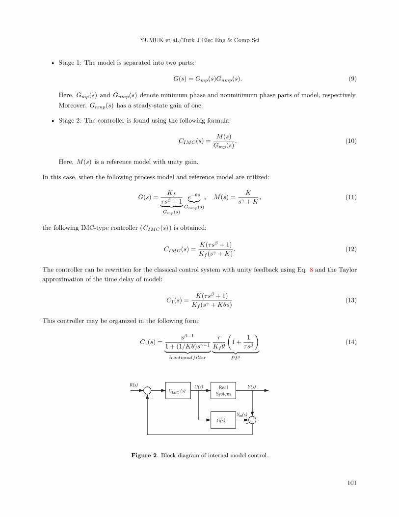
The internal model control(IMC) structure illustrated in Figure 2 is utilized to design a controller. Inthis figure, CIMC(s) and G(s) denote internal model controller and system model, respectively. The IMCcontroller is easily transformed into classical controller in Figure 1b using the following formula:
C(s) =CIMC(s)
1− CIMC(s)G(s). (8)
The design of IMC controller consists of two stages:
100
YUMUK et al./Turk J Elec Eng & Comp Sci
• Stage 1: The model is separated into two parts:
G(s) = Gmp(s)Gnmp(s). (9)
Here, Gmp(s) and Gnmp(s) denote minimum phase and nonminimum phase parts of model, respectively.Moreover, Gnmp(s) has a steady-state gain of one.
• Stage 2: The controller is found using the following formula:
CIMC(s) =M(s)
Gmp(s). (10)
Here, M(s) is a reference model with unity gain.
In this case, when the following process model and reference model are utilized:
G(s) =Kf
τsβ + 1︸ ︷︷ ︸Gmp(s)
e−θs︸︷︷︸Gnmp(s)
, M(s) =K
sγ +K, (11)
the following IMC-type controller (CIMC(s)) is obtained:
CIMC(s) =K(τsβ + 1)
Kf (sγ +K). (12)
The controller can be rewritten for the classical control system with unity feedback using Eq. 8 and the Taylorapproximation of the time delay of model:
C1(s) =K(τsβ + 1)
Kf (sγ +Kθs)(13)
This controller may be organized in the following form:
C1(s) =sβ−1
1 + (1/Kθ)sγ−1︸ ︷︷ ︸fractionalfilter
τ
Kfθ
(1 +
1
τsβ
)︸ ︷︷ ︸
PIβ
(14)
R(s)
G(s)
IMCC (s)
m
U(s) Y(s)
Y (s)
RealSystem
–
–
Figure 2. Block diagram of internal model control.
101
YUMUK et al./Turk J Elec Eng & Comp Sci
2.2. The method based on Bode’s ideal loop transfer function plus time delay
Secondly, we consider another method presented in [9], which will be referred to as Method II thereon after. Inthis method, L(s) given in Figure 1a is offered as delayed BIL transfer function as the following:
L(s) =K
sγe−θs. (15)
Here, θ denotes the model’s time delay in (3).The following three criteria met by the controller C(s) in Figure 1b are selected:
1. Gain crossover frequency (ωc ): |C(jωc)G(jωc| = 1 .
2. Phase margin (ϕm ): Arg(C(jωc)G(jωc)) = −π + ϕm .
3. Elimination of the steady-state error: SSE is eliminated using fractional order integrator again.
When ωc and ϕm are selected, and also θ is taken from fractional model, γ and K in (15) are respectivelycalculated via the following formulas:
γ =π − ϕm − ωcθ
π/2(16)
andK = ωγ
c . (17)
SSE specification is again satisfied in case of γ ≥ 1 . When the integrator order is less than 1, it iseliminated as in the previous method.
By utilizing the inverse of the fractional model in (3) without time delay in addition to BIL transferfunction, the controller is designed as follows:
C2(s) =K(τsβ + 1)
Kfsγ(18)
C2(s) may be rewritten in the following form:
C2(s) = sβ−γ︸ ︷︷ ︸fractionalfilter
Kτ
Kf
(1 +
1
τsβ
)︸ ︷︷ ︸
PIβ
(19)
2.3. Realization of fractional order operator
Oustaloup filter approximation is used to implement fractional operator in this study, which is given by:
sα ≈ O(sα) = K ′N∏
k=1
s+ ω′k
s+ ωk. (20)
102
YUMUK et al./Turk J Elec Eng & Comp Sci
Here N and α ∈ (0, 1) denote the order of the filter and the fractional order, respectively. Moreover, thegain(K ′ ), zeros(ω′
k ) and the poles(ωk ) of the filter are found by the following formulas:
K ′ = ωαh .
ω′k = ωl
(ωh
ωl
) 2k−1−α2N
, (21)
ωk = ωl
(ωh
ωl
) 2k−1+α2N
.
Here ωl and ωh denote the lower and upper frequency bound values, respectively. Throughout the study, theorder and frequency interval in the Oustaloup approximation are chosen as 11 and [103 , 10−3] . These orderand frequency interval values are considered to be adequate for a sufficient approximation of fractional orderoperator [25].
3. Magnetic levitation system3.1. Description of magnetic levitation plant
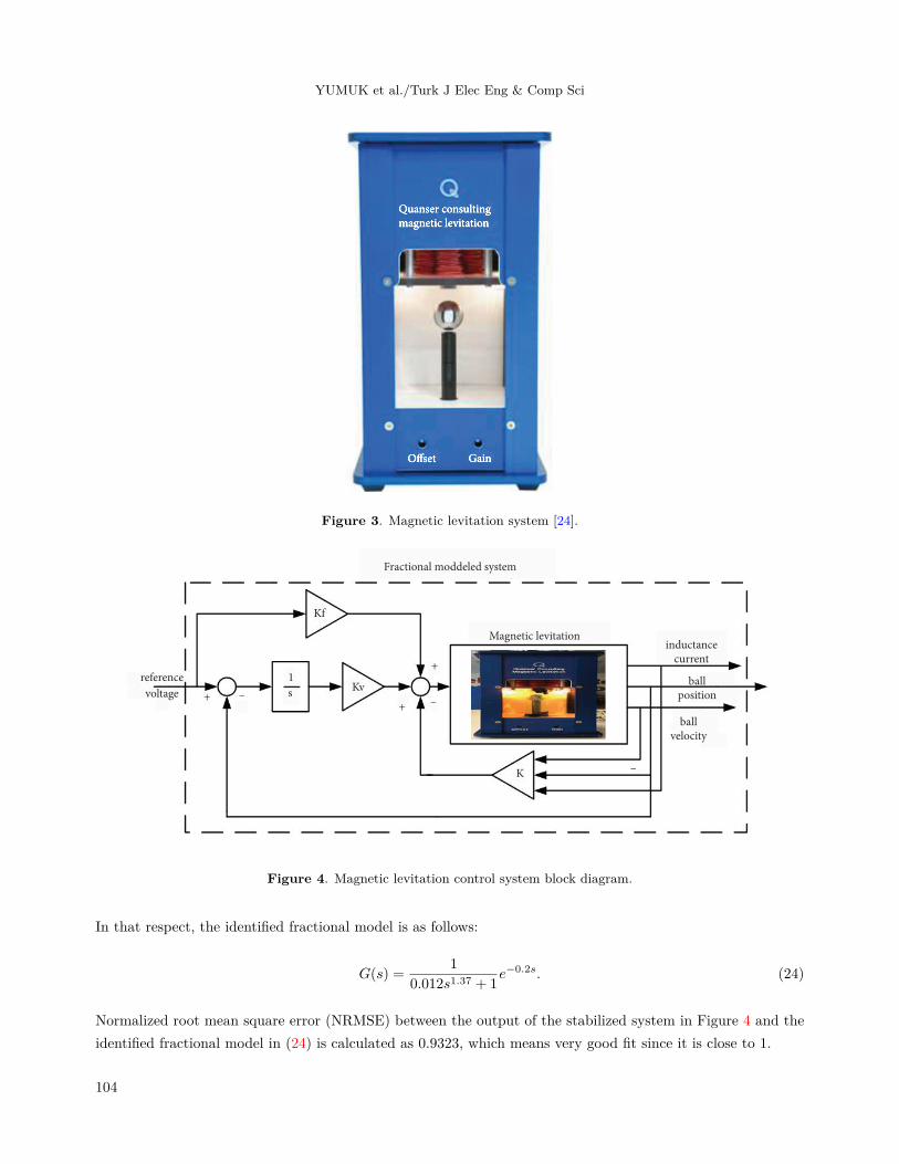
Figure 3 illustrates the magnetic levitation plant (MAGLEV). The aim of this plant is to control a one-inch solidball levitating in its magnetic field in the desired location. The MAGLEV is composed of three distinct parts.The upper part consists of a solenoid coil with a steel core, i.e. an electromagnet. The middle part contains acell in which the magnetic ball is suspended in the gap. One of the poles of the electromagnet faces the top of ablack post with a steel ball on it. The position of the ball is measured by a photo-sensitive sensor. The distancebetween the electromagnet pole face and the ball’s top hemisphere is 14 mm. Finally, in the bottom part ofthe plant, the required system’s conditioning circuitry is located. For example, gain and offset potentiometers,which belong to the ball position sensor, are situated to calibrate properly. It also includes a current resistorto measure the coil current.
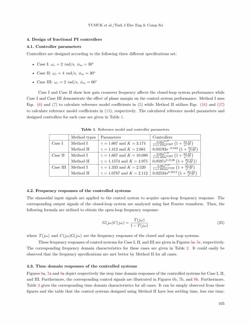
3.2. Magnetic levitation system stabilizationMAGLEV is a single input-single output unstable plant. However, the methods given in the previous sectionare all applicable to stable systems. For this reason, unstable MAGLEV plant has to be stabilized in order toapply these methods. In this respect, a state feedback controller with integrator and a feed-forward structureis utilized. The control system block diagram is illustrated in Figure 4.
3.3. Fractional order modeling of stabilized magnetic levitation systemThe step input ranging from 6.7 to 8.7 mm are applied to the system for system identification in time domain.The maximum overshoot (δ ) and the rise time (Tp ) of the system response are found as 0.18% and 0.121 s,respectively. The model parameters (Kf , τ , and β ) in (3) are calculated by means of the rule extracted fortime domain characteristics in [23]. There, maximum overshoot (δ ) and rise time (Tp ) are given as a function
of fractional order β and crossover frequency ωc . When ωc = τ1β , these formulas are obtained as
δ = 0.8(β − 1)(β − 0.75) (22)
Tp =1.106(β − 0.255)2τ
1β
β − 0.921(23)
103
YUMUK et al./Turk J Elec Eng & Comp Sci
Figure 3. Magnetic levitation system [24].
ballvelocity
ballposition
inductancecurrent
Magnetic levitation
Fractional moddeled system
K
Kv
Kf
reference
voltage
1
s
+
++ –
–
–
Figure 4. Magnetic levitation control system block diagram.
In that respect, the identified fractional model is as follows:
G(s) =1
0.012s1.37 + 1e−0.2s. (24)
Normalized root mean square error (NRMSE) between the output of the stabilized system in Figure 4 and theidentified fractional model in (24) is calculated as 0.9323, which means very good fit since it is close to 1.
104
YUMUK et al./Turk J Elec Eng & Comp Sci
4. Design of fractional PI controllers4.1. Controller parametersControllers are designed according to the following three different specifications set:
• Case I: ωc = 2 rad/s, ϕm = 30◦
• Case II: ωc = 4 rad/s, ϕm = 30◦
• Case III: ωc = 2 rad/s, ϕm = 60◦
Case I and Case II show how gain crossover frequency affects the closed-loop system performance whileCase I and Case III demonstrate the effect of phase margin on the control system performance. Method I usesEqs. (6) and (7) to calculate reference model coefficients in (5) while Method II utilizes Eqs. (16) and (17)to calculate reference model coefficients in (15), respectively. The calculated reference model parameters anddesigned controllers for each case are given in Table 1.
Table 1. Reference model and controller parameters.
Method types Parameters ControllersCase I Method I γ = 1.667 and K = 3.174 0.06s0.37
1+1.575s0.667
(1 + 83.33
s1.37
)Method II γ = 1.412 and K = 2.661 0.03193s−0.042
(1 + 83.33
s1.37
)Case II Method I γ = 1.667 and K = 10.080 0.06s0.37
1+0.496s0.667
(1 + 83.33
s1.37
)Method II γ = 1.1574 and K = 4.975 0.0597s0.2126
(1 + 83.33
s1.37
))
Case III Method I γ = 1.333 and K = 2.520 0.06s0.37
1+1.9843s0.333
(1 + 83.33
s1.37
)Method II γ = 1.0787 and K = 2.112 0.02534s0.2913
(1 + 83.33
s1.37
)
4.2. Frequency responses of the controlled systemsThe sinusoidal input signals are applied to the control system to acquire open-loop frequency response. Thecorresponding output signals of the closed-loop system are analyzed using fast Fourier transform. Then, thefollowing formula are utilized to obtain the open-loop frequency response:
G(jω)C(jω) =T (jω)
1− T (jω)(25)
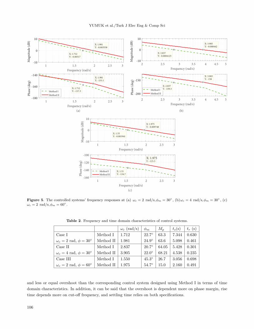
where T (jω) and C(jω)G(jω) are the frequency responses of the closed and open loop systems.These frequency responses of control systems for Case I, II, and III are given in Figures 5a–5c, respectively.
The corresponding frequency domain characteristics for these cases are given in Table 2. It could easily beobserved that the frequency specifications are met better by Method II for all cases.
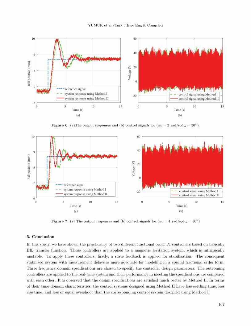
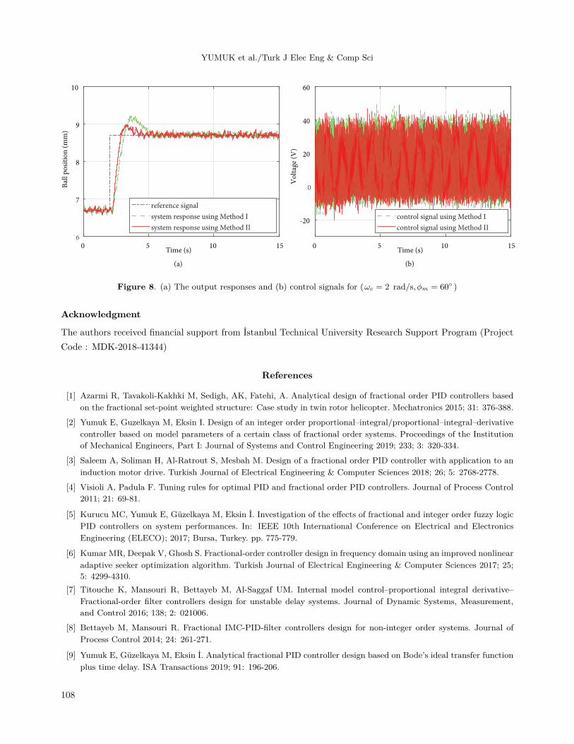
4.3. Time domain responses of the controlled systemsFigures 6a, 7a and 8a depict respectively the step time domain responses of the controlled systems for Case I, II,and III. Furthermore, the corresponding control signals are illustrated in Figures 6b, 7b, and 8b. Furthermore,Table 2 gives the corresponding time domain characteristics for all cases. It can be simply observed from thesefigures and the table that the control systems designed using Method II have less settling time, less rise time,
105
YUMUK et al./Turk J Elec Eng & Comp Sci
1 1.5 2 2.5 3
Frequency (rad/s)
-10
0
10
Mag
nit
ud
e (d
B)
1 1.5 2 2.5 3
Frequency (rad/s)
-180
-160
-140
Ph
ase
(deg
)
Method I
Method II
X: 1.712Y: -157.3
X: 1.712Y: -0.00517
X: 1.981Y: -0.003558
X: 1.981Y: -155.1
(a)
2 2.5 3 3.5 4 4.5 5
Frequency (rad/s)
-10
0
10
Mag
nit
ud
e (d
B)
2 2.5 3 3.5 4 4.5 5
Frequency (rad/s)
-200
-150
Ph
ase
(deg
)
Method I
Method II
X: 2.837Y: -0.0004125
X: 3.905Y: -0.008442
X: 2.837Y: -159.3
X: 3.903Y: -158
(b)
1 1.5 2 2.5 3
Frequency (rad/s)
-10
0
10
Mag
nit
ud
e (d
B)
1 1.5 2 2.5 3
Frequency (rad/s)
-160
-140
-120
-100
Ph
ase
(deg
)
Method I
Method II
X: 1.55Y: -0.001941
X: 1.975Y: -0.009748
X: 1.55Y: -134.7
X: 1.975Y: -125.3
(c)
Figure 5. The controlled systems’ frequency responses at (a) ωc = 2 rad/s,ϕm = 30◦ , (b)ωc = 4 rad/s,ϕm = 30◦ , (c)ωc = 2 rad/s,ϕm = 60◦ .
Table 2. Frequency and time domain characteristics of control systems.
ωc (rad/s) ϕm Mp ts(s) tr (s)Case I Method I 1.712 22.7◦ 63.3 7.344 0.630ωc = 2 rad, ϕ = 30◦ Method II 1.981 24.9◦ 63.6 5.098 0.461Case II Method I 2.837 20.7◦ 64.05 5.428 0.301ωc = 4 rad, ϕ = 30◦ Method II 3.905 22.0◦ 68.21 4.538 0.235Case III Method I 1.550 45.3◦ 26.7 3.056 0.698ωc = 2 rad, ϕ = 60◦ Method II 1.975 54.7◦ 15.0 2.160 0.491
and less or equal overshoot than the corresponding control system designed using Method I in terms of timedomain characteristics. In addition, it can be said that the overshoot is dependent more on phase margin, risetime depends more on cut-off frequency, and settling time relies on both specifications.
106
YUMUK et al./Turk J Elec Eng & Comp Sci
0 5 10 15Time (s)
6
7
8
9
10
Bal
l po
siti
on
(m
m)
reference signal
system response using Method I
system response using Method II
(a)
0 5 10 15Time (s)
-20
0
20
40
60
Vo
ltag
e (V
)
control signal using Method I
control signal using Method II
(b)
Figure 6. (a)The output responses and (b) control signals for (ωc = 2 rad/s,ϕm = 30◦ ).
6
7
8
9
10
Bal
l po
siti
on
(m
m)
reference signal
system response using Method I
system response using Method II
(a)
0 5 10 15
Time (s)
0 5 10 15
Time (s)
-20
0
20
40
60V
olt
age
(V)
control signal using Method I
control signal using Method II
(b)
Figure 7. (a) The output responses and (b) control signals for (ωc = 4 rad/s,ϕm = 30◦ )
5. Conclusion
In this study, we have shown the practicality of two different fractional order PI controllers based on basicallyBIL transfer function. These controllers are applied to a magnetic levitation system, which is intrinsicallyunstable. To apply these controllers, firstly, a state feedback is applied for stabilization. The consequentstabilized system with measurement delays is more adequate for modeling in a special fractional order form.Three frequency domain specifications are chosen to specify the controller design parameters. The outcomingcontrollers are applied to the real-time system and their performance in meeting the specifications are comparedwith each other. It is observed that the design specifications are satisfied much better by Method II. In termsof their time domain characteristics, the control systems designed using Method II have less settling time, lessrise time, and less or equal overshoot than the corresponding control system designed using Method I.
107
YUMUK et al./Turk J Elec Eng & Comp Sci
0 5 10 15Time (s)
6
7
8
9
10
Bal
l po
siti
on
(m
m)
reference signal
system response using Method I
system response using Method II
(a)
0 5 10 15Time (s)
-20
0
20
40
60
Vo
ltag
e (V
)
control signal using Method I
control signal using Method II
(b)
Figure 8. (a) The output responses and (b) control signals for (ωc = 2 rad/s,ϕm = 60◦ )
Acknowledgment
The authors received financial support from İstanbul Technical University Research Support Program (ProjectCode : MDK-2018-41344)
References
[1] Azarmi R, Tavakoli-Kakhki M, Sedigh, AK, Fatehi, A. Analytical design of fractional order PID controllers basedon the fractional set-point weighted structure: Case study in twin rotor helicopter. Mechatronics 2015; 31: 376-388.
[2] Yumuk E, Guzelkaya M, Eksin I. Design of an integer order proportional–integral/proportional–integral–derivativecontroller based on model parameters of a certain class of fractional order systems. Proceedings of the Institutionof Mechanical Engineers, Part I: Journal of Systems and Control Engineering 2019; 233; 3: 320-334.
[3] Saleem A, Soliman H, Al-Ratrout S, Mesbah M. Design of a fractional order PID controller with application to aninduction motor drive. Turkish Journal of Electrical Engineering & Computer Sciences 2018; 26; 5: 2768-2778.
[4] Visioli A, Padula F. Tuning rules for optimal PID and fractional order PID controllers. Journal of Process Control2011; 21: 69-81.
[5] Kurucu MC, Yumuk E, Güzelkaya M, Eksin İ. Investigation of the effects of fractional and integer order fuzzy logicPID controllers on system performances. In: IEEE 10th International Conference on Electrical and ElectronicsEngineering (ELECO); 2017; Bursa, Turkey. pp. 775-779.
[6] Kumar MR, Deepak V, Ghosh S. Fractional-order controller design in frequency domain using an improved nonlinearadaptive seeker optimization algorithm. Turkish Journal of Electrical Engineering & Computer Sciences 2017; 25;5: 4299-4310.
[7] Titouche K, Mansouri R, Bettayeb M, Al-Saggaf UM. Internal model control–proportional integral derivative–Fractional-order filter controllers design for unstable delay systems. Journal of Dynamic Systems, Measurement,and Control 2016; 138; 2: 021006.
[8] Bettayeb M, Mansouri R. Fractional IMC-PID-filter controllers design for non-integer order systems. Journal ofProcess Control 2014; 24: 261-271.
[9] Yumuk E, Güzelkaya M, Eksin İ. Analytical fractional PID controller design based on Bode’s ideal transfer functionplus time delay. ISA Transactions 2019; 91: 196-206.
108
YUMUK et al./Turk J Elec Eng & Comp Sci
[10] Skogestad S. Simple analytic rules for model reduction and PID controller tuning. Journal of Process Control 2003;13; 4: 291-309.
[11] Malek H, Luo Y, Chen YQ. Identification and tuning fractional order proportional integral controllers for timedelayed system with a fractional pole. Mechatronics 2013; 23: 746-754.
[12] Yumuk E, Güzelkaya M, Eksin İ. Fractional and integer models of a ball balancing table system based on itsfrequency domain response. In: 8th International Conference on Advanced Technologies (ICAT’19); Sarajevo, BosniaHerzegovina; 2019. pp. 1-6.
[13] Das S, Saha S, Das S, Gupta A. On the selection of tuning methodology of FOPID controllers for the control ofhigher order processes. ISA Transactions 2011; 50; 3: 376-388.
[14] Monje CA, Vinagre BM, Feliu V, Chen YQ. Tuning and auto-tuning of fractional order controllers for industryapplications. Control Engineering Practice 2008; 16: 798-812.
[15] Luo Y, Chen Y. Fractional order [proportional derivative] controller for a class of fractional order systems. Auto-matica 2009; 45; 10: 2446-2450.
[16] Muresan CI, Ionescu C, Folea S, De Keyser, R. Fractional order control of unstable processes: the magnetic levitationstudy case. Nonlinear Dynamics 2015; 80; 4: 1761-1772.
[17] Kim KB, Im SH, Um DY, Park GS. Comparison of magnetic levitation systems using ring-shaped permanentmagnets. IEEE Transactions on Magnetics, 2019; 55; 7: 1-4.
[18] de Jesús Rubio J, Zhang L, Lughofer E, Cruz P, Alsaedi A, Hayat T. Modeling and control with neural networksfor a magnetic levitation system. Neurocomputing 2017; 227: 113-121.
[19] Maji D, Biswas M, Bhattacharya A, Sarkar G, Mondal TK et al. Maglev system modeling and LQR controllerdesign in real time simulation. In: 2016 International Conference on Wireless Communications, Signal Processingand Networking (WiSPNET); New York, USA; 2016. pp. 1562-1567.
[20] Stettinger G, Benedikt M, Horn M, Zehetner J, Giebenhain C. Control of a magnetic levitation system withcommunication imperfections: A model-based coupling approach. Control Engineering Practice 2017; 58: 161-170.
[21] He G, Li J, Cui P. Nonlinear control scheme for the levitation module of maglev train. Journal of Dynamic Systems,Measurement, and Control 2016; 138; 7: 074503.
[22] Bode HW. Network analysis and feedback amplifier design. United States of America: van Nostrand, 1945.
[23] Barbosa RS, Machado JT, Ferreira IM. Tuning of PID controllers based on Bode’s ideal transfer function. NonlinearDynamics 2004; 38; 1-4: 305-321.
[24] Quanser Inc. Magnetic levitation experiment (User manual). 2008.
[25] Tepljakov A, Petlenkov E, Belikov J. FOMCOM: a MATLAB toolbox for fractional-order system identification andcontrol. International Journal of Microelectronics and Computer Science 2011; 2; 2: 51-62.
109
Related Documents