Application of Cavity Expansion Theory for Evaluating Skin Friction of Tapered Piles in Sands Suman Manandhar 1 ・ Noriyuki Yasufuku 2 * ・ Kiyoshi Omine 3 1 Post Doctoral Research Fellow, Faculty of Engineering, Kyushu University, Japan 2 Prof. of Geotechnical Engineering, Faculty of Engineering, Kyushu University, Japan 3 Prof. of Geotechnical Engineering, Faculty of Engineering, Nagasaki University, Japan ❚ Abstract ❚ This paper discusses the effects of tapered pile penetration in sandy soils after having obtained evidence of its merits over straight-sided cylindrical piles in evaluating skin friction. Experimental model tests confirmed that a slight increase in the angle of tapering also led to a major increase in skin friction. Based on this evidence, the authors adopted an analytical solution to evaluate the skin friction of tapered piles. The cylindrical cavity expansion theory is an appropriate analytical closed-form solution in determining the skin friction of tapered piles at different phases of soils at different relative densities. A new arrangement was inserted by introducing a stress-dilatancy relationship in the ideal elastic-plastic model of cavity expansion application. In general, for easy computation, the angle of internal friction or dilatancy angle is assumed to be constant to compute the skin friction. This drawback was improved upon and both properties considered in evaluating skin friction at each depth iteratively. This paper assesses the results of parametric studies on different types of model tests, prototype tests and real type pile tests in order to predict the proposed model. The proposed extended model validates the determination of skin friction using a stress-dilatancy relationship. Keywords : Tapered piles, Skin friction, Cavity expansion theory, Stress-dilatancy relationship, Sands *Corresponding author to Noriyuki Yasufuku, Prof. of Geotechnical Engineering, Faculty of Engineering, Kyushu University, Japan Tel : +81-92-802-3381, Fax : +81-92-802-3378 E-mail : [email protected] Received 20 June 2012; Accepted 20 September 2012 International Journal of Geo-Engineering 4(3) : 5-17 (2012) 1. INTRODUCTION When a tapered pile settles down, it causes an enlargement of the hole in the ground and serves to confine any additional friction that increases on the shaft of the pile, which in turn leads to a significant increase in shaft resistance. Consequently, skin friction and radial stress increase due to differences in axial diameter at its top and bottom. A slight increase in the tapering angle can result in higher skin friction. It has been noted that there is an increment in the overall resistance of piles by a factor of 5-9 when mobilized towards depth (Dmokhovskii, 1927). Similarly, the mechanism of tapered piles is such that they also have good pressing effects towards the depth of penetration (Manandhar et al., 2009). In addition Manandhar et al. (2009, 2010) noted that not only will increase the normalized skin friction, but normalized horizontal stresses also increase due to tapering and wedging effects. However, in reality, the use of tapered piles has been limited to only a handful of researchers, which may be due to a lack of awareness of their basic existence together with a lack of modern and reliable analytical methods for estimating their bearing capacity (Horvath and Trochalides, 2004). An analytical method has been applied that evaluates the axial capacity of tapered piles over straight piles when the tapered piles are driven into sands (Norlund, 1963). Despite this, as of yet no accurate model to derive the axial capacity of tapered piles in context to deep foundations has been identified to any satisfactory degree. There are some methodologies which can evaluate the skin friction of 5

Welcome message from author
This document is posted to help you gain knowledge. Please leave a comment to let me know what you think about it! Share it to your friends and learn new things together.
Transcript
Application of Cavity Expansion Theory for Evaluating Skin Friction of Tapered Piles in Sands
Suman Manandhar1 ・ Noriyuki Yasufuku2* ・ Kiyoshi Omine3
1Post Doctoral Research Fellow, Faculty of Engineering, Kyushu University, Japan2Prof. of Geotechnical Engineering, Faculty of Engineering, Kyushu University, Japan
3Prof. of Geotechnical Engineering, Faculty of Engineering, Nagasaki University, Japan
❚ Abstract❚This paper discusses the effects of tapered pile penetration in sandy soils after having obtained evidence of its merits
over straight-sided cylindrical piles in evaluating skin friction. Experimental model tests confirmed that a slight increase in the angle of tapering also led to a major increase in skin friction. Based on this evidence, the authors adopted an analytical solution to evaluate the skin friction of tapered piles. The cylindrical cavity expansion theory is an appropriate analytical closed-form solution in determining the skin friction of tapered piles at different phases of soils at different relative densities. A new arrangement was inserted by introducing a stress-dilatancy relationship in the ideal elastic-plastic model of cavity expansion application. In general, for easy computation, the angle of internal friction or dilatancy angle is assumed to be constant to compute the skin friction. This drawback was improved upon and both properties considered in evaluating skin friction at each depth iteratively. This paper assesses the results of parametric studies on different types of model tests, prototype tests and real type pile tests in order to predict the proposed model. The proposed extended model validates the determination of skin friction using a stress-dilatancy relationship.
Keywords : Tapered piles, Skin friction, Cavity expansion theory, Stress-dilatancy relationship, Sands
*Corresponding author to Noriyuki Yasufuku, Prof. of Geotechnical Engineering, Faculty of Engineering, Kyushu University, JapanTel : +81-92-802-3381, Fax : +81-92-802-3378E-mail : [email protected] Received 20 June 2012; Accepted 20 September 2012
International Journal of Geo-Engineering 4(3) : 5-17 (2012)
1. INTRODUCTION
When a tapered pile settles down, it causes an enlargement of the hole in the ground and serves to confine any additional friction that increases on the shaft of the pile, which in turn leads to a significant increase in shaft resistance. Consequently, skin friction and radial stress increase due to differences in axial diameter at its top and bottom. A slight increase in the tapering angle can result in higher skin friction. It has been noted that there is an increment in the overall resistance of piles by a factor of 5-9 when mobilized towards depth (Dmokhovskii, 1927). Similarly, the mechanism of tapered piles is such
that they also have good pressing effects towards the depth of penetration (Manandhar et al., 2009). In addition Manandhar et al. (2009, 2010) noted that not only will increase the normalized skin friction, but normalized horizontal stresses also increase due to tapering and wedging effects. However, in reality, the use of tapered piles has been limited to only a handful of researchers, which may be due to a lack of awareness of their basic existence together with a lack of modern and reliable analytical methods for estimating their bearing capacity (Horvath and Trochalides, 2004). An analytical method has been applied that evaluates the axial capacity of tapered piles over straight piles when the tapered piles are driven into sands (Norlund, 1963). Despite this, as of yet no accurate model to derive the axial capacity of tapered piles in context to deep foundations has been identified to any satisfactory degree. There are some methodologies which can evaluate the skin friction of
5
6 ∙ Suman Manandhar, Noriyuki Yasufuku, Kiyoshi Omine
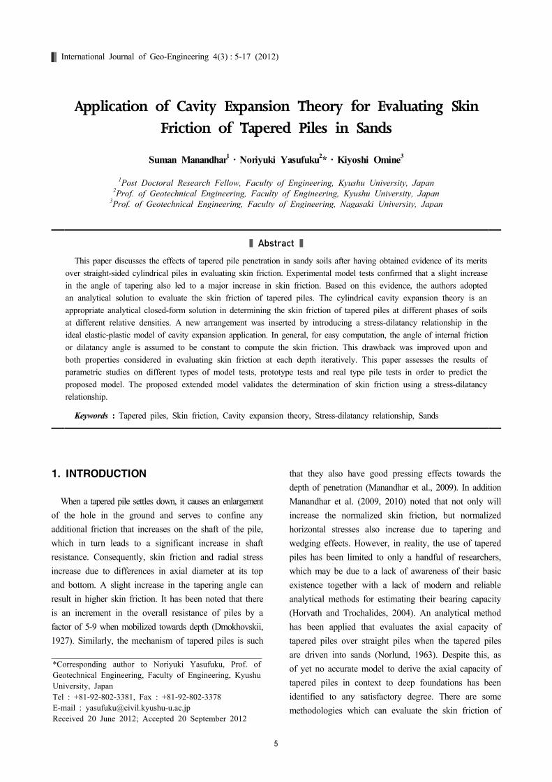
(a) Pile model chamber (b) Types of steel model piles (c) Cast-in-place pile set up and loading
Fig. 1. Geometry of the pile load apparatus, types of steel model piles, and cast-in-place pile set up and loading
tapered piles. Researchers and practitioners generally utilize empirical solutions, finite element methods and constituting modeling to interpret the behavior of the skin friction of tapered piles. Later on, some pioneers in the field of geotechnics proposed a series of theoretical methods on geomechanics, specializing in cavity expansion theory (Vesic`, 1972; Baligh, 1976; Hughes et al., 1977; Yu and Houslby, 1991). The most closed form of solution for large straining conditions and the complete solution for cylindrical cavity expansion in ideal elastic-plastic models in the non-associated flow rule postulated by Yu and Houslby (1991) have been widely adopted by researchers compared to solutions by other researchers (Kodikara and Moore (1993)). In this respect, this research paper focuses on the cylindrical cavity expansion theory so as to obtain a closed-form solution. In general, one of the soil parameters (angle of internal friction or dilatancy angle) is assumed to be constant for the ease of computation. However, the stress-dilatancy relationship is interdependent on the confining pressure, relative density and angle of internal friction. Therefore, a new concept was proposed in order to extend the idea proposed by Kodikara and Moore (1993), as well as a cavity expansion theory to estimate the skin friction of tapered piles by introducing the stress-dilatancy relationship postulated by Bolton (1986, 1987). In the proposed stress-dilatancy relationship, a rise in confining pressure serves to increase the relative density along with the angle of internal friction and dilatancy. All these parameters were successfully inserted in the cylindrical cavity expansion theory propounded by
Yu and Houlsby (1991), making it possible to compute at each segment of the pile during pile penetration (Manandhar, 2010; Manandhar and Yasufuku, 2011). This research considers axial cylindrical pile loading tests in the model tests so as to understand their behavior at certain depths in which size effects are not taken into consideration. Following this, the proposed extended model was applied to proto-type and real type models to predict and the results verified using various sources from research papers.
2. EXPERIMENTAL EVIDENCE FROM
THE MODEL TEST
2.1 Experimental Procedures
Two different types of air-dried sand were modeled - K-7 sand and typical Toyoura sand (TO) - at 60% and 80% relative density for smaller chromium plated model steel piles, the dimensions for which are set out in Table 1. One straight (S) and two tapered piles (T-1 and T-2) were used for the model tests to study the tapering effects that can measure load at the tip resistance and at the head connected by a cord. Table 2 shows the index parameters and strength parameters of both soils.
The cylindrical chamber for pile loading was 1000 mm in height and 750 mm in diameter, and was equipped with an air cylinder, displacement gauge, load jack and load cell. The load cell was connected to a rotation driving worm in which the pile cap had been adjusted. The upper plate transferred overburden pressure to the
Application of Cavity Expansion Theory for Evaluating Skin Friction of Tapered Piles in Sands ∙ 7
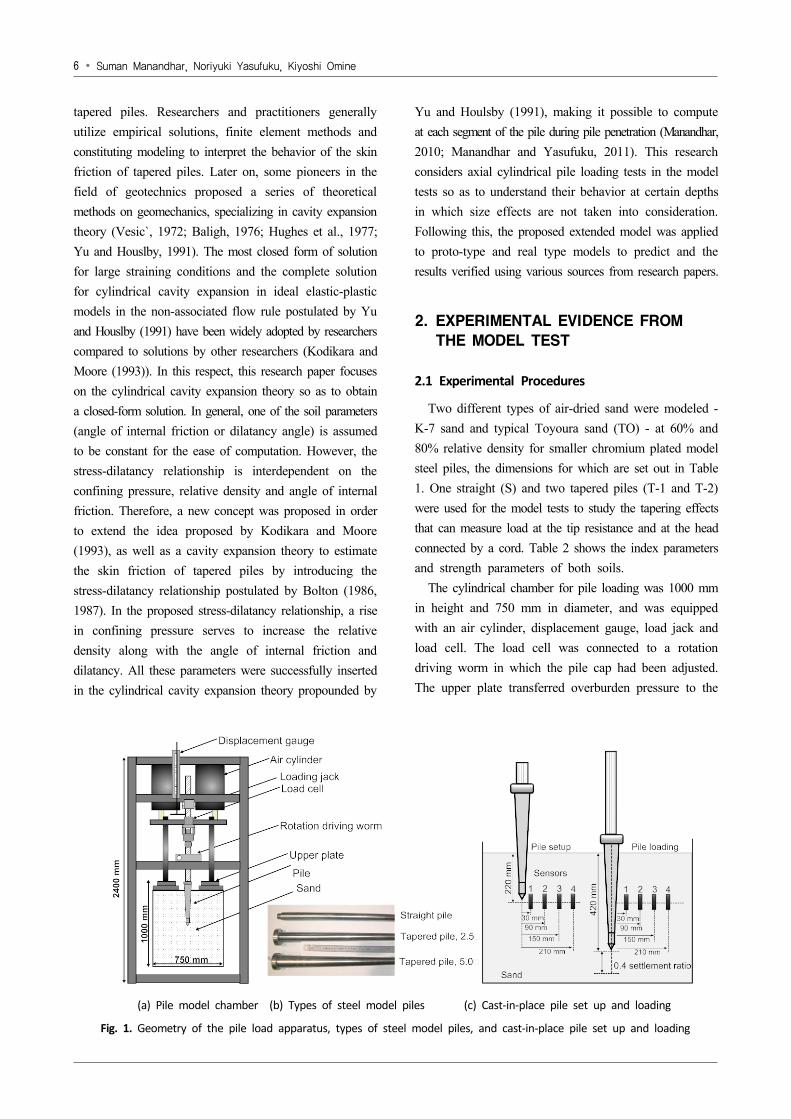
Table 1. Geometrical configuration of different types of piles
Types ofModelPiles
NamingL
mmDt
mmd
mm
˚FRP
reinforcement direction
Modulus of elasticity
(GPa)
Smaller model steel piles
S 500 25 25 0.00 na 2
T-1 500 35 25 0.70 na 2
T-2 500 45 25 1.40 na 2
PrototypeFRP iles
FC 1524 168.3 168.3 0.00 na 31.86
T-3 1524 170.0 198.0 0.53 0˚ 33.20
T-4 1524 159.0 197.0 0.71 0˚ 33.15
T-5 1524 155.0 215.0 1.13 0˚ 33.15
Note: L: length of pile; Dt: diameteratthepilehead; d: piletipdiameter; FRP: fiber-reinforcedpolymer; a: angle of tapering; na: not applicable.
Table 2. Index and Strength parameters of different types of soil
Descriptions TO K-7Fanshawe brick sand
(Sakr et al., 2004, 2005, 2007)
Density of particles, (kg/m3) 2,650 2,620 2,680
Maximum density, (kg/m3) max 1,640 1,600 1,772
Minimum density, (kg/m3) min 1,340 1,190 1,466
Density at ID80%, (kg/m3) 1,580 1,520 na
Density at ID60%, (kg/m3) 1,520 1,430 na
Maximum void ratio, max 0.98 1.20 0.794
Minimum void ratio, min 0.62 0.64 0.484
Void ratio at ID 90%, na na 0.68
Void ratio at ID 80%, 0.68 0.73 na
Void ratio at ID 60%, 0.74 0.83 na
Effective grain size, (mm) na na 0.14
Mean grain size, (mm) na na 0.26
Uniformity coefficient, 1.40 4.0 2.143
Coefficient of curvature, ′ 0.86 1.21 0.905
Percent fines, (%) 1.10 14 na
Peak stress, (deg)° 42.00 47.00 37.00
Critical stress state, (deg)° ′ 32.00 34.00 31.00 (assumed)
model ground vertically (Fig. 1a). The model grounds were prepared in line with Japanese Industrial System (JIS A 1224) and Japanese Geotechnical Standards (JGS 0161). The relative densities (ID) of K-7 sand and TO sand were modeled to 60% and 80%, respectively (Table 2). A sample preparation method using multiple sieving can give a wide range of specimen densities by controlling the falling height of sand and nozzle diameter (Miura and Toki, 1982). Thus, to prepare the model ground, air-dried silica sand was made to fall freely through the sieve with
a desired nozzle area at a determined height. In this case, K-7 sand and TO sand were allowed to fall freely and spread uniformly on the chamber through homogenous rotation so as to meet the required densities. Once it had been filled nearly 710 mm of soil from the bottom, the pile was set up at the center of the chamber. Then, four transducers were set up at equal intervals of 60 mm. The first transducer was installed close to pile tip. The transducers measure the earth’s pressure laterally. From the center of the pile, earth pressure sensors were installed at a distance
8 ∙ Suman Manandhar, Noriyuki Yasufuku, Kiyoshi Omine
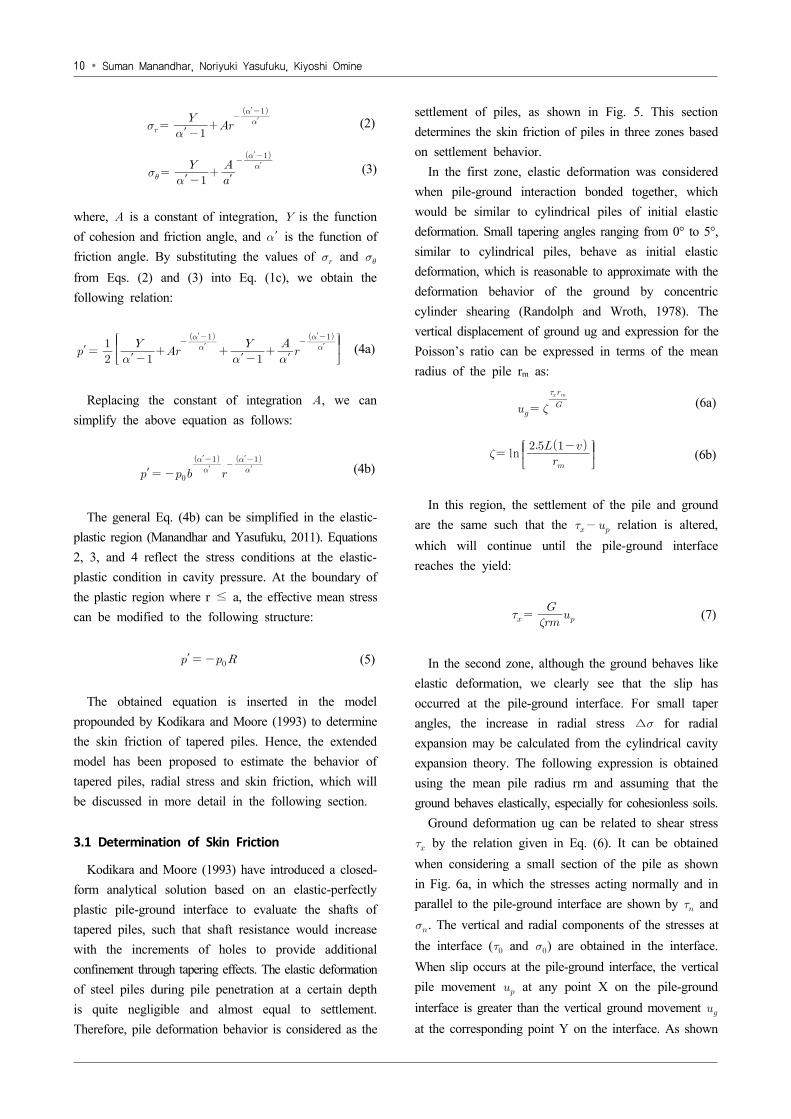
Fig. 4. Lateral stress distribution at 0.1 settlement ratio on K-7 sand and TO sand
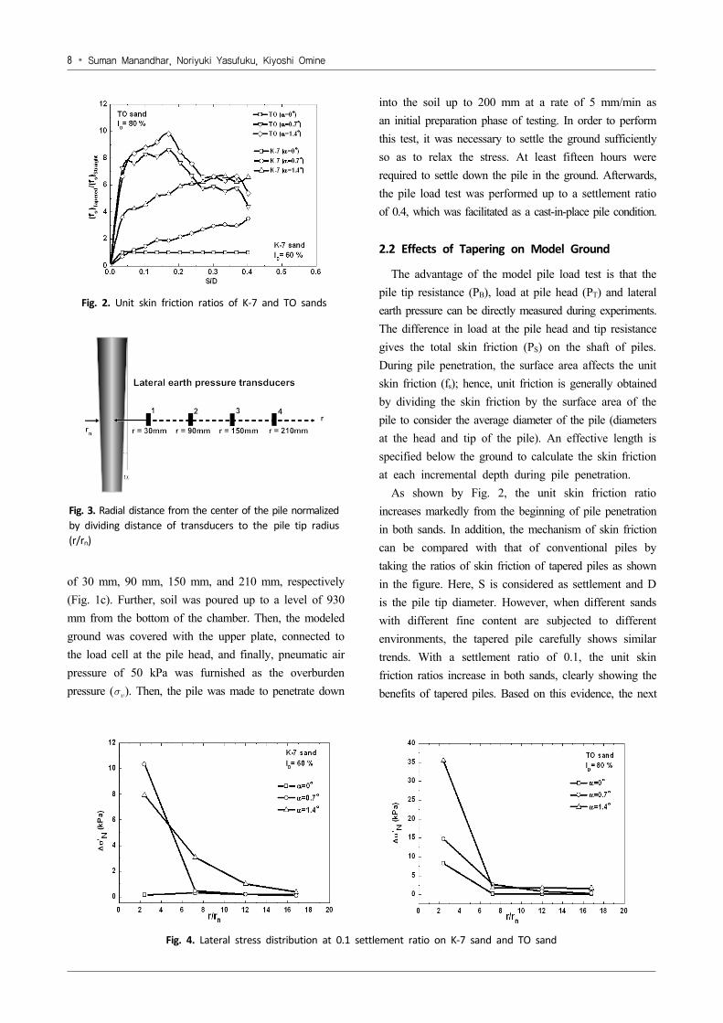
Fig. 2. Unit skin friction ratios of K-7 and TO sands
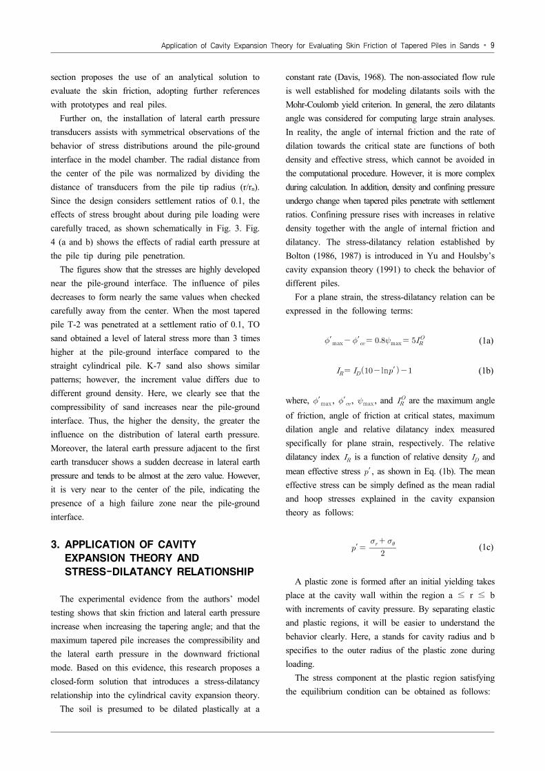
Fig. 3. Radial distance from the center of the pile normalizedby dividing distance of transducers to the pile tip radius (r/rn)
of 30 mm, 90 mm, 150 mm, and 210 mm, respectively (Fig. 1c). Further, soil was poured up to a level of 930 mm from the bottom of the chamber. Then, the modeled ground was covered with the upper plate, connected to the load cell at the pile head, and finally, pneumatic air pressure of 50 kPa was furnished as the overburden pressure (). Then, the pile was made to penetrate down
into the soil up to 200 mm at a rate of 5 mm/min as an initial preparation phase of testing. In order to perform this test, it was necessary to settle the ground sufficiently so as to relax the stress. At least fifteen hours were required to settle down the pile in the ground. Afterwards, the pile load test was performed up to a settlement ratio of 0.4, which was facilitated as a cast-in-place pile condition.
2.2 Effects of Tapering on Model Ground
The advantage of the model pile load test is that the pile tip resistance (PB), load at pile head (PT) and lateral earth pressure can be directly measured during experiments. The difference in load at the pile head and tip resistance gives the total skin friction (PS) on the shaft of piles. During pile penetration, the surface area affects the unit skin friction (fs); hence, unit friction is generally obtained by dividing the skin friction by the surface area of the pile to consider the average diameter of the pile (diameters at the head and tip of the pile). An effective length is specified below the ground to calculate the skin friction at each incremental depth during pile penetration.
As shown by Fig. 2, the unit skin friction ratio increases markedly from the beginning of pile penetration in both sands. In addition, the mechanism of skin friction can be compared with that of conventional piles by taking the ratios of skin friction of tapered piles as shown in the figure. Here, S is considered as settlement and D is the pile tip diameter. However, when different sands with different fine content are subjected to different environments, the tapered pile carefully shows similar trends. With a settlement ratio of 0.1, the unit skin friction ratios increase in both sands, clearly showing the benefits of tapered piles. Based on this evidence, the next
Application of Cavity Expansion Theory for Evaluating Skin Friction of Tapered Piles in Sands ∙ 9
section proposes the use of an analytical solution to evaluate the skin friction, adopting further references with prototypes and real piles.
Further on, the installation of lateral earth pressure transducers assists with symmetrical observations of the behavior of stress distributions around the pile-ground interface in the model chamber. The radial distance from the center of the pile was normalized by dividing the distance of transducers from the pile tip radius (r/rn). Since the design considers settlement ratios of 0.1, the effects of stress brought about during pile loading were carefully traced, as shown schematically in Fig. 3. Fig. 4 (a and b) shows the effects of radial earth pressure at the pile tip during pile penetration.
The figures show that the stresses are highly developed near the pile-ground interface. The influence of piles decreases to form nearly the same values when checked carefully away from the center. When the most tapered pile T-2 was penetrated at a settlement ratio of 0.1, TO sand obtained a level of lateral stress more than 3 times higher at the pile-ground interface compared to the straight cylindrical pile. K-7 sand also shows similar patterns; however, the increment value differs due to different ground density. Here, we clearly see that the compressibility of sand increases near the pile-ground interface. Thus, the higher the density, the greater the influence on the distribution of lateral earth pressure. Moreover, the lateral earth pressure adjacent to the first earth transducer shows a sudden decrease in lateral earth pressure and tends to be almost at the zero value. However, it is very near to the center of the pile, indicating the presence of a high failure zone near the pile-ground interface.
3. APPLICATION OF CAVITY
EXPANSION THEORY AND
STRESS-DILATANCY RELATIONSHIP
The experimental evidence from the authors’ model testing shows that skin friction and lateral earth pressure increase when increasing the tapering angle; and that the maximum tapered pile increases the compressibility and the lateral earth pressure in the downward frictional mode. Based on this evidence, this research proposes a closed-form solution that introduces a stress-dilatancy relationship into the cylindrical cavity expansion theory.
The soil is presumed to be dilated plastically at a
constant rate (Davis, 1968). The non-associated flow rule is well established for modeling dilatants soils with the Mohr-Coulomb yield criterion. In general, the zero dilatants angle was considered for computing large strain analyses. In reality, the angle of internal friction and the rate of dilation towards the critical state are functions of both density and effective stress, which cannot be avoided in the computational procedure. However, it is more complex during calculation. In addition, density and confining pressure undergo change when tapered piles penetrate with settlement ratios. Confining pressure rises with increases in relative density together with the angle of internal friction and dilatancy. The stress-dilatancy relation established by Bolton (1986, 1987) is introduced in Yu and Houlsby’s cavity expansion theory (1991) to check the behavior of different piles.
For a plane strain, the stress-dilatancy relation can be expressed in the following terms:
′max ′ max (1a)
ln′ (1b)
where, ′max , ′, max , and are the maximum angle
of friction, angle of friction at critical states, maximum dilation angle and relative dilatancy index measured specifically for plane strain, respectively. The relative dilatancy index is a function of relative density and mean effective stress ′ , as shown in Eq. (1b). The mean effective stress can be simply defined as the mean radial and hoop stresses explained in the cavity expansion theory as follows:
′ (1c)
A plastic zone is formed after an initial yielding takes place at the cavity wall within the region a ≤ r ≤ b with increments of cavity pressure. By separating elastic and plastic regions, it will be easier to understand the behavior clearly. Here, a stands for cavity radius and b specifies to the outer radius of the plastic zone during loading.
The stress component at the plastic region satisfying the equilibrium condition can be obtained as follows:
10 ∙ Suman Manandhar, Noriyuki Yasufuku, Kiyoshi Omine
′′ ′
′(3)
′
′′
(2)
where, is a constant of integration, is the function of cohesion and friction angle, and ′ is the function of friction angle. By substituting the values of and from Eqs. (2) and (3) into Eq. (1c), we obtain the following relation:
′
′
′′
′′′′
(4a)
Replacing the constant of integration , we can simplify the above equation as follows:
′ ′′
′′
(4b)
The general Eq. (4b) can be simplified in the elastic- plastic region (Manandhar and Yasufuku, 2011). Equations 2, 3, and 4 reflect the stress conditions at the elastic- plastic condition in cavity pressure. At the boundary of the plastic region where r ≤ a, the effective mean stress can be modified to the following structure:
′ (5)
The obtained equation is inserted in the model propounded by Kodikara and Moore (1993) to determine the skin friction of tapered piles. Hence, the extended model has been proposed to estimate the behavior of tapered piles, radial stress and skin friction, which will be discussed in more detail in the following section.
3.1 Determination of Skin Friction
Kodikara and Moore (1993) have introduced a closed- form analytical solution based on an elastic-perfectly plastic pile-ground interface to evaluate the shafts of tapered piles, such that shaft resistance would increase with the increments of holes to provide additional confinement through tapering effects. The elastic deformation of steel piles during pile penetration at a certain depth is quite negligible and almost equal to settlement. Therefore, pile deformation behavior is considered as the
settlement of piles, as shown in Fig. 5. This section determines the skin friction of piles in three zones based on settlement behavior.
In the first zone, elastic deformation was considered when pile-ground interaction bonded together, which would be similar to cylindrical piles of initial elastic deformation. Small tapering angles ranging from 0° to 5°, similar to cylindrical piles, behave as initial elastic deformation, which is reasonable to approximate with the deformation behavior of the ground by concentric cylinder shearing (Randolph and Wroth, 1978). The vertical displacement of ground ug and expression for the Poisson’s ratio can be expressed in terms of the mean radius of the pile rm as:
(6a)
ln
(6b)
In this region, the settlement of the pile and ground are the same such that the relation is altered, which will continue until the pile-ground interface reaches the yield:
(7)
In the second zone, although the ground behaves like elastic deformation, we clearly see that the slip has occurred at the pile-ground interface. For small taper angles, the increase in radial stress ∆ for radial expansion may be calculated from the cylindrical cavity expansion theory. The following expression is obtained using the mean pile radius rm and assuming that the ground behaves elastically, especially for cohesionless soils.
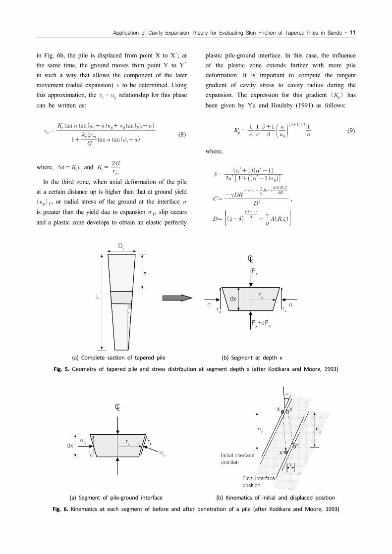
Ground deformation ug can be related to shear stress by the relation given in Eq. (6). It can be obtained when considering a small section of the pile as shown in Fig. 6a, in which the stresses acting normally and in parallel to the pile-ground interface are shown by and . The vertical and radial components of the stresses at the interface ( and ) are obtained in the interface. When slip occurs at the pile-ground interface, the vertical pile movement at any point X on the pile-ground interface is greater than the vertical ground movement at the corresponding point Y on the interface. As shown
Application of Cavity Expansion Theory for Evaluating Skin Friction of Tapered Piles in Sands ∙ 11
(a) Complete section of tapered pile (b) Segment at depth x
Fig. 5. Geometry of tapered pile and stress distribution at segment depth x (after Kodikara and Moore, 1993)
(a) Segment of pile-ground interface (b) Kinematics of initial and displaced position
Fig. 6. Kinematics at each segment of before and after penetration of a pile (after Kodikara and Moore, 1993)
in Fig. 6b, the pile is displaced from point X to X′ ; at the same time, the ground moves from point Y to Y′ in such a way that allows the component of the later movement (radial expansion) to be determined. Using this approximation, the relationship for this phase can be written as:
tan tan tan tan tan
(8)
where, Δσ and
In the third zone, when axial deformation of the pile at a certain distance up is higher than that at ground yield , or radial stress of the ground at the interface is greater than the yield due to expansion , slip occurs and a plastic zone develops to obtain an elastic perfectly
plastic pile-ground interface. In this case, the influence of the plastic zone extends farther with more pile deformation. It is important to compute the tangent gradient of cavity stress to cavity radius during the expansion. The expression for this gradient has been given by Yu and Houlsby (1991) as follows:
(9)
where,
′ ′ ′′
,
12 ∙ Suman Manandhar, Noriyuki Yasufuku, Kiyoshi Omine
and ∞ in which,
i f
and hence,
(10)
where, is an infinite series, ′, function of friction angle, , function of dilation angle, , , , and are functions of material properties. At this phase, a small increment in radial stress () can be written as:
(11)
The radial stress () can be expressed as:
(12)
where, can be computed from (12) using and which is vertical shear stress in Eq. (8) when . Then, the corresponding vertical shear stress, can be expressed as:
tan (13)
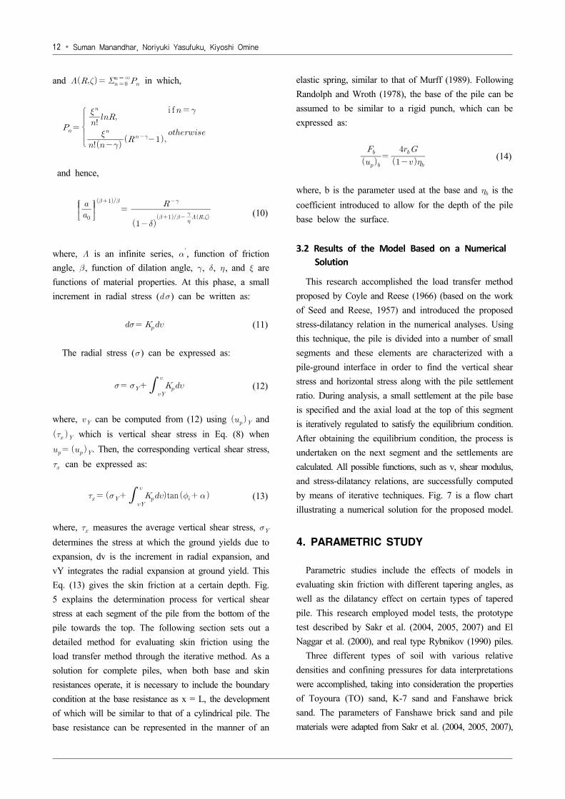
where, measures the average vertical shear stress, determines the stress at which the ground yields due to expansion, dv is the increment in radial expansion, and vY integrates the radial expansion at ground yield. This Eq. (13) gives the skin friction at a certain depth. Fig. 5 explains the determination process for vertical shear stress at each segment of the pile from the bottom of the pile towards the top. The following section sets out a detailed method for evaluating skin friction using the load transfer method through the iterative method. As a solution for complete piles, when both base and skin resistances operate, it is necessary to include the boundary condition at the base resistance as x = L, the development of which will be similar to that of a cylindrical pile. The base resistance can be represented in the manner of an
elastic spring, similar to that of Murff (1989). Following Randolph and Wroth (1978), the base of the pile can be assumed to be similar to a rigid punch, which can be expressed as:
(14)
where, b is the parameter used at the base and is the coefficient introduced to allow for the depth of the pile base below the surface.
3.2 Results of the Model Based on a Numerical Solution
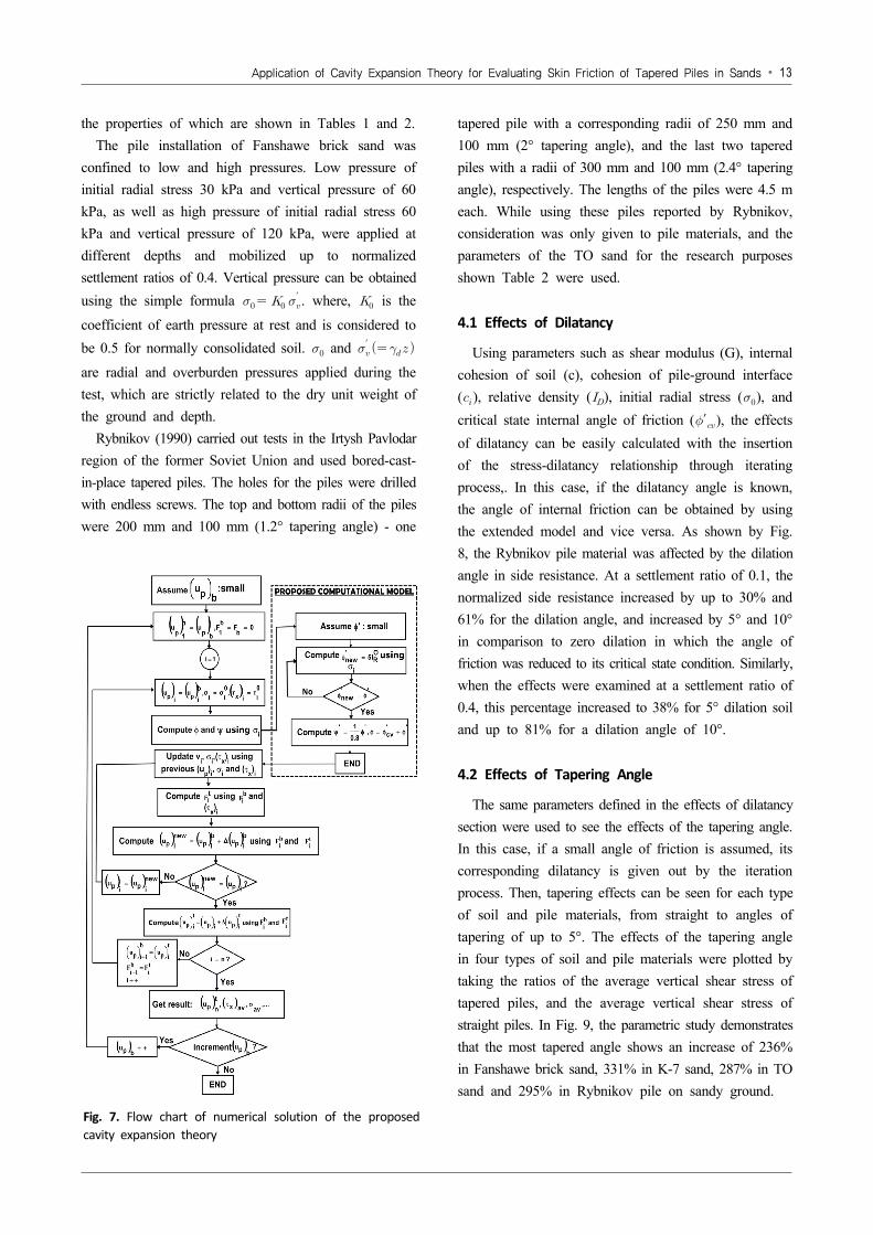
This research accomplished the load transfer method proposed by Coyle and Reese (1966) (based on the work of Seed and Reese, 1957) and introduced the proposed stress-dilatancy relation in the numerical analyses. Using this technique, the pile is divided into a number of small segments and these elements are characterized with a pile-ground interface in order to find the vertical shear stress and horizontal stress along with the pile settlement ratio. During analysis, a small settlement at the pile base is specified and the axial load at the top of this segment is iteratively regulated to satisfy the equilibrium condition. After obtaining the equilibrium condition, the process is undertaken on the next segment and the settlements are calculated. All possible functions, such as v, shear modulus, and stress-dilatancy relations, are successfully computed by means of iterative techniques. Fig. 7 is a flow chart illustrating a numerical solution for the proposed model.
4. PARAMETRIC STUDY
Parametric studies include the effects of models in evaluating skin friction with different tapering angles, as well as the dilatancy effect on certain types of tapered pile. This research employed model tests, the prototype test described by Sakr et al. (2004, 2005, 2007) and El Naggar et al. (2000), and real type Rybnikov (1990) piles.
Three different types of soil with various relative densities and confining pressures for data interpretations were accomplished, taking into consideration the properties of Toyoura (TO) sand, K-7 sand and Fanshawe brick sand. The parameters of Fanshawe brick sand and pile materials were adapted from Sakr et al. (2004, 2005, 2007),
Application of Cavity Expansion Theory for Evaluating Skin Friction of Tapered Piles in Sands ∙ 13
Fig. 7. Flow chart of numerical solution of the proposed cavity expansion theory
the properties of which are shown in Tables 1 and 2.The pile installation of Fanshawe brick sand was
confined to low and high pressures. Low pressure of initial radial stress 30 kPa and vertical pressure of 60 kPa, as well as high pressure of initial radial stress 60 kPa and vertical pressure of 120 kPa, were applied at different depths and mobilized up to normalized settlement ratios of 0.4. Vertical pressure can be obtained using the simple formula ′ . where, is the
coefficient of earth pressure at rest and is considered to be 0.5 for normally consolidated soil. and ′ are radial and overburden pressures applied during the test, which are strictly related to the dry unit weight of the ground and depth.
Rybnikov (1990) carried out tests in the Irtysh Pavlodar region of the former Soviet Union and used bored-cast- in-place tapered piles. The holes for the piles were drilled with endless screws. The top and bottom radii of the piles were 200 mm and 100 mm (1.2° tapering angle) - one
tapered pile with a corresponding radii of 250 mm and 100 mm (2° tapering angle), and the last two tapered piles with a radii of 300 mm and 100 mm (2.4° tapering angle), respectively. The lengths of the piles were 4.5 m each. While using these piles reported by Rybnikov, consideration was only given to pile materials, and the parameters of the TO sand for the research purposes shown Table 2 were used.
4.1 Effects of Dilatancy
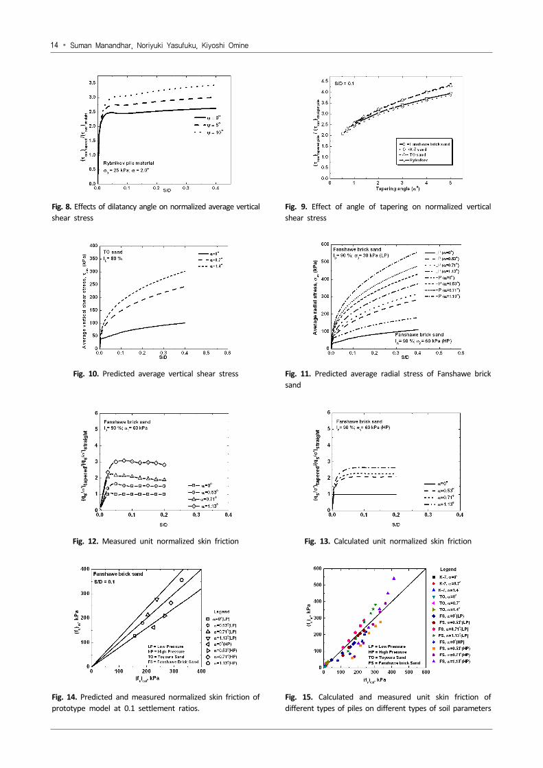
Using parameters such as shear modulus (G), internal cohesion of soil (c), cohesion of pile-ground interface (), relative density (), initial radial stress (), and critical state internal angle of friction (′), the effects of dilatancy can be easily calculated with the insertion of the stress-dilatancy relationship through iterating process,. In this case, if the dilatancy angle is known, the angle of internal friction can be obtained by using the extended model and vice versa. As shown by Fig. 8, the Rybnikov pile material was affected by the dilation angle in side resistance. At a settlement ratio of 0.1, the normalized side resistance increased by up to 30% and 61% for the dilation angle, and increased by 5° and 10° in comparison to zero dilation in which the angle of friction was reduced to its critical state condition. Similarly, when the effects were examined at a settlement ratio of 0.4, this percentage increased to 38% for 5° dilation soil and up to 81% for a dilation angle of 10°.
4.2 Effects of Tapering Angle
The same parameters defined in the effects of dilatancy section were used to see the effects of the tapering angle. In this case, if a small angle of friction is assumed, its corresponding dilatancy is given out by the iteration process. Then, tapering effects can be seen for each type of soil and pile materials, from straight to angles of tapering of up to 5°. The effects of the tapering angle in four types of soil and pile materials were plotted by taking the ratios of the average vertical shear stress of tapered piles, and the average vertical shear stress of straight piles. In Fig. 9, the parametric study demonstrates that the most tapered angle shows an increase of 236% in Fanshawe brick sand, 331% in K-7 sand, 287% in TO sand and 295% in Rybnikov pile on sandy ground.
14 ∙ Suman Manandhar, Noriyuki Yasufuku, Kiyoshi Omine
Fig. 8. Effects of dilatancy angle on normalized average verticalshear stress
Fig. 9. Effect of angle of tapering on normalized vertical shear stress
Fig. 10. Predicted average vertical shear stress Fig. 11. Predicted average radial stress of Fanshawe brick sand
Fig. 12. Measured unit normalized skin friction Fig. 13. Calculated unit normalized skin friction
Fig. 14. Predicted and measured normalized skin friction of prototype model at 0.1 settlement ratios.
Fig. 15. Calculated and measured unit skin friction of different types of piles on different types of soil parameters
Application of Cavity Expansion Theory for Evaluating Skin Friction of Tapered Piles in Sands ∙ 15
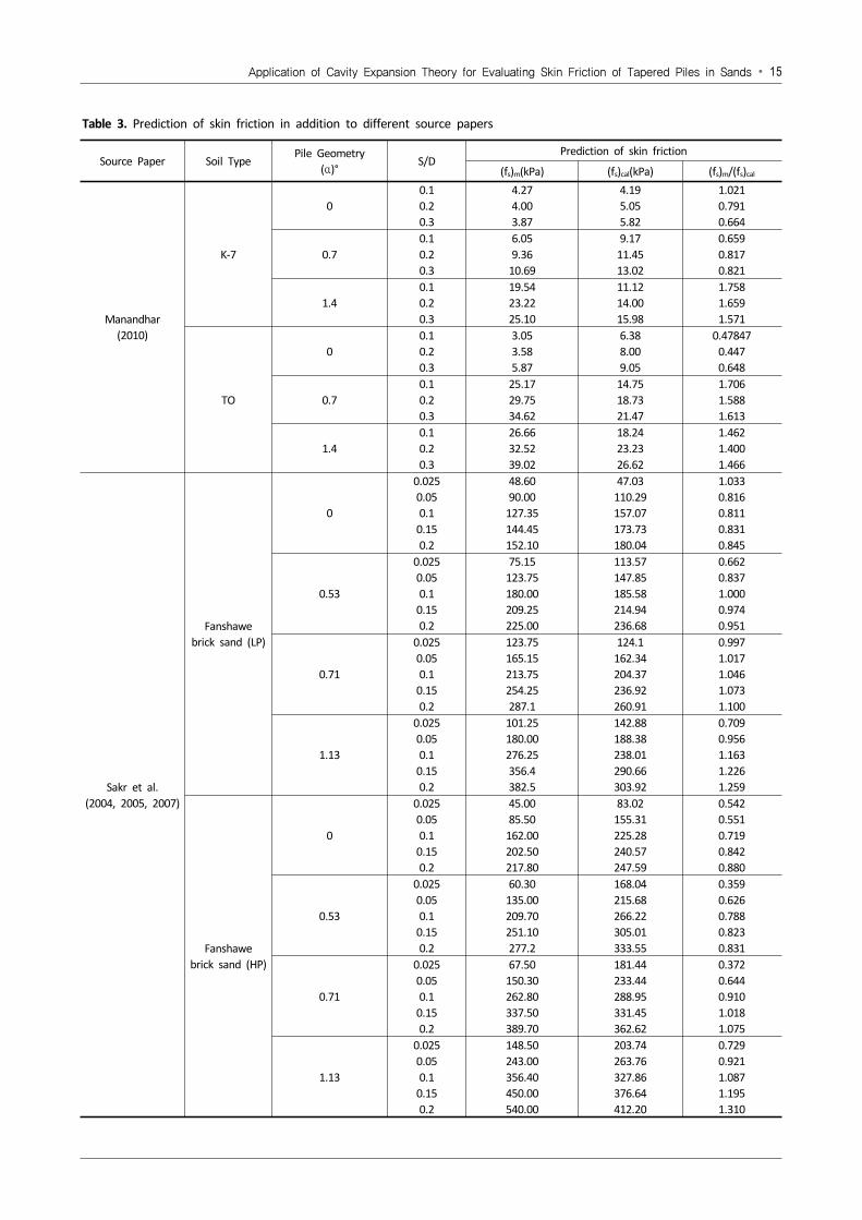
Table 3. Prediction of skin friction in addition to different source papers
Source Paper Soil TypePile Geometry
(α)°S/D
Prediction of skin friction
(fs)m(kPa) (fs)cal(kPa) (fs)m/(fs)cal
Manandhar (2010)
K-7
00.10.20.3
4.274.003.87
4.195.055.82
1.0210.7910.664
0.70.10.20.3
6.059.36
10.69
9.1711.4513.02
0.6590.8170.821
1.40.10.20.3
19.5423.2225.10
11.1214.0015.98
1.7581.6591.571
TO
00.10.20.3
3.053.585.87
6.388.009.05
0.478470.4470.648
0.70.10.20.3
25.1729.7534.62
14.7518.7321.47
1.7061.5881.613
1.40.10.20.3
26.6632.5239.02
18.2423.2326.62
1.4621.4001.466
Sakr et al.(2004, 2005, 2007)
Fanshawebrick sand (LP)
0
0.0250.050.1
0.150.2
48.6090.00
127.35144.45152.10
47.03110.29157.07173.73180.04
1.0330.8160.8110.8310.845
0.53
0.0250.050.1
0.150.2
75.15123.75180.00209.25225.00
113.57147.85185.58214.94236.68
0.6620.8371.0000.9740.951
0.71
0.0250.050.1
0.150.2
123.75165.15213.75254.25287.1
124.1162.34204.37236.92260.91
0.9971.0171.0461.0731.100
1.13
0.0250.050.1
0.150.2
101.25180.00276.25356.4382.5
142.88188.38238.01290.66303.92
0.7090.9561.1631.2261.259
Fanshawebrick sand (HP)
0
0.0250.050.1
0.150.2
45.0085.50
162.00202.50217.80
83.02155.31225.28240.57247.59
0.5420.5510.7190.8420.880
0.53
0.0250.050.1
0.150.2
60.30135.00209.70251.10277.2
168.04215.68266.22305.01333.55
0.3590.6260.7880.8230.831
0.71
0.0250.050.1
0.150.2
67.50150.30262.80337.50389.70
181.44233.44288.95331.45362.62
0.3720.6440.9101.0181.075
1.13
0.0250.050.1
0.150.2
148.50243.00356.40450.00540.00
203.74263.76327.86376.64412.20
0.7290.9211.0871.1951.310
16 ∙ Suman Manandhar, Noriyuki Yasufuku, Kiyoshi Omine
5. PREDICTION AND VERIFICATION OF
THE MODEL
This section shows the calculated results to observe the effects of the proposed model. Here, the authors undertooksmall model and prototype tests in order to predict and verify the model. Fig. 10 shows the results of the average vertical shear stress of the normalized pile settlement at ratios of 0.4. The fact that the same piles penetrated into Toyoura sand at a high relative density illustrates clearly that the average vertical shear stresses increase as the tapering angle increases. At a settlement ratio of 0.1, the average vertical shear stress increased up to 288% compared to straight piles. When checking the increment trend at settlement ratios of 0.4, the maximum tapered pile used in this model test shows that it increased by up to 298%. For determining the average radial stresses by tapered piles, the model predicted high radial stresses for high tapered angles, as shown in Fig. 11. Initial radial stresses of high and low pressures show similar trends, and tapering effects are higher for high pressures and lower for low pressures in ground consisting of Fanshawe brick sand when the same piles penetrated ground of same sandy soil at a higher relative density. Both types of ground measured similar increment trends. For instance, from the figure, we can clearly observe that at a settlement ratio of 0.1, for a maximum angle of tapering, radial stress increased by nearly 329% when compared with straight piles. Comparing this result with the high pressure ground result, the increment of radial stress is 339%, which is a difference of just 10% between the two grounds. Similarly, when checked at settlement ratios of 0.4, low pressure showed an almost 309% and high pressure a 311% increase in average radial stress, indicating a similar trend of increment with increasing settlement ratios.
Further, the unit skin friction normalized with the average radial stress and vertical stress, showing that the measured skin frictions govern peaks before the settlement ratio of 0.1 and increases along with the increasing tapering angle. However, as shown in Fig. 12, the rate of increase after the settlement ratio of 0.1 is almost constant. The ratio of the normalized unit skin friction of the tapered pile to that of the straight pile is almost constant after the peak (about 5% settlement ratio). As shown in Fig. 13, similar trends were observed when this result was verified with the calculated results of the same
high pressure of Fanshawe brick sand at the same relative density, indicating the model’s veracity in predicting and verifying the skin friction and radial stresses of different types of piles in different types of sand.
After predicting the results, the measured and calculated results of skin friction were verified. When verifying the model, various researchers’ reference data were added to validate the model accurately. The measured and predicted results of skin friction were then tabulated, measured in kPa, by quoting the source papers in Table 3. Fig. 14 shows that the predicted and measured unit skin friction is acceptable at a settlement ratio of 0.1 when observed in prototype tests. When comparing all available source data for all types of settlement ratios, Fig. 15 shows a remarkable fit between the proposed model of evaluating unit skin frictions and model tests. Different types of pile geometry were plotted with different types of sandy soils in a 1:1 ratio, and it was observed that the accuracy of the proposed model fits with the parameters used.
6. CONCLUSIONS
The experimental results show that the normalized radial distance of tapered piles with angles from 0° to 1.4° are affected at least eight times from the center of the pile. After careful observations of the benefits of tapered piles through evidence deriving from smaller model tests in the laboratory, it was found that an extended model which inserts a stress-dilatancy relationship can evaluate skin friction through a cylindrical cavity expansion theory in closed form solution. By applying the dilatancy index, it can accurately evaluate skin friction in relation to the tapering angle, the type of sandy grounds and the confining pressures. Applying these advantages to small model tests, proto type tests and real type pile tests allows the following important conclusions to be drawn:
(1) Parametric studies showed that the extended model can evaluate the trend of increasing skin friction with increasing angle of tapering. Skin friction also increases when dilatancy increases for different types of tapered piles. Hence, the characteristics of the extended model can evaluate the dilatancy property in closed forms, which is easy to apply by using the load transfer method. It was noted that all the parameters that need to compute skin friction are derived from the fundamental properties of tapered piles and sandy soils.
Application of Cavity Expansion Theory for Evaluating Skin Friction of Tapered Piles in Sands ∙ 17
(2) The extended model shows the same trend in increasing the average vertical shear stress and radial stress by increasing the tapering angle through both model and proto type tests.
(3) The unit skin friction of measured and calculated results of the models and proto type tests with different tapered angle exhibit good accordance at different settlement ratios. Use of the extended model is an excellent way of evaluating the different types of tapered piles, irrespective of relative density, confining pressure, and type of sandy soils at different settlement ratios.
ACKNOWLEDGEMENTS
The authors would like to extend their gratitude to laboratory assistant Mr Michio Nakashima and colleague Mr Toshio Ishimoto, who provided invaluable assistance in both experimental and computational work.
REFERENCES
Baligh, M. M. (1976). “Cavity Expansion in Sands with Curved Envelopes.” J. of Geotechnical Engineering Division, ASCE, 102(GT11), 1131-1145.
Bolton, M. D. (1986). “The Strength and Dilatancy of Sands.” Géotechnique, 36(1), 65-78.
Bolton, M. D. (1987). “Discussion on the Strength and Dilatancy of Sands.” Géotechnique, 37(2), 219-226.
Coyle, H. M., and Reese, L. C. (1966). “Load Transfer for Axially Loaded Piles in Clay.” Int. J. of Soil Mechanics and Foundation Division, ASCE, 92(1), 1-26.
Davis, E. H. (1968). Theories of Plasticity and the Failure of Soil Masses, in Soil Mechanics. Selected Topics, ed. I.K. Lee, Butterworth.
Dmokhovskii, V K. (1927). “On the Effect of the Geometric Shape of a Pile on its Capacity to resist.” Tr. Moskov. Inst. Inzh. Zheleznodor. Transp., 6.
Horvath, J. S. and Trochalides, T. (2004). “A Half Century of Tapered Pile Usage at the John F. Kennedy International Airport.” Presented at the Fifth Case History Conf. on Geotechnical Engineering, New York, U.S.A, Paper No. (11-02).
Hughes, J. M. O., Wroth, C. P., and Windle, D. (1977). “Pressuremeter Tests in Sands.” Geéotechnique, London, U.K., 27(4), 455-477.
Japanese Industrial System A 1224, Japanese Geotechnical Engineering Society, 0161. “The methods and description of soil tests.” First revised version, 59-64.
Kézdi, A. (1975). “Pile Foundation, Foundation Engineering Handbook.” 1st Ed., Ed. H. F. Winterkorn and H. Y. Fang. Van Nostrand Reinhold, New York, N.Y., 550-600.
Kodikara, K. K., and Moore, I. D. (1993). “Axial Response of Tapered Piles in Cohesive Frictional Ground.” J. of Geotechnical Engineering, ASCE, 119, 675-693.
Manandhar, S. (2010). “Bearing capacity of tapered piles in sands.” PhD Thesis, Department of Civil and Structural Engineering, Kyushu University (Unpublished).
Manandhar, S. and Yasufuku, N. (2011). “Evaluation of skin friction of tapered piles in sands based on Cavity Expansion Theory.” Memoirs of the Faculty of Engineering, Kyushu University, 71(4), 101-126.
Manandhar, S., Yasufuku N., and Omine, K. (2010). “Tapering effects of piles in cohesionless soil.” Proc., 4th Japan-China Geotechnical Symposium on Recent Developments of Geotechnical Engineering. Okinawa, Japan, 477-482.
Manandhar, S., Yasufuku N., and Shomura K. (2009). “Skin Friction of Taper-shaped Piles in Sands.” Proc., ASME, 28th Int. Conf. on Ocean, Offshore and Arctic Engineering (OMAE), OMAE2009-79078. Honolulu, Hawai, USA, 93-102.
Manandhar, S., Yasufuku N., Omine K., and Kobayashi, T. (2010). “Response of tapered piles in cohesionless soil based on model tests.” J. of Nepal Geological Society, 40, 85-92.
Manandhar, S., Yasufuku N., Omine K., and Qiang, L. (2009). “Mobilized mechanism of skin friction of tapered piles in sand.” Proc., International Joint Symposium on Geo-Disaster Prevention and Geoenvironment in Asia - JS-Fukuoka 2009, Fukuoka, Japan, 171-178.
Miura, S. and Toki, S. (1982). “A Sample Preparation Method and its Effect on Static and Cyclic Deformation-strength Properties of sand.” Soils and Foundations, Japanese Geotechnical Society, 22(1), 62-77.
Murff, J. D. (1989). “Response of Axially Loaded Piles.” J. of Geotechnical Engineering, ASCE, 101(3), 356-360.
Naggar, El M. H., Sakr, M., and Nehdi, M. L. (2000). “Evaluation of Axial Performance of Tapered Piles from Centrifuge Tests.” Can. Geotech. J., 37, 1295-1308.
Norlund, R. L. (1963). “Bearing Capacity of Piles in Cohesionless Soils.” J. of the Soil mechanics and Foundation Division, ASCE, 117(8), 1208-1226.
Randolph, M. F. and Wroth, C. P. (1978). “Analyses of Deformation of Vertically Loaded Piles.” J. of Geotechnical Engineering, ASCE, 104(12), 1465-1488.
Rybnikov, A. M. (1990). “Experimental Investigation of Bearing Capacity of Bored-cast-in-place Tapered Piles.” Soil Mechanics and Foundation Engineering, 27(2), 48-52.
Sakr, M., Naggar, M. H. El, and Nehdi, M. L. (2004). “Load Transfer of Fibre-reinforced Polymer (FRP) Composite Tapered Piles in Dense Sand.” Can. Geotech. J., 41(1), 70-88.
Sakr, M., Naggar, M. H. El, and Nehdi, M. L. (2005). “Uplift Performance of FRP Tapered Piles in Dense Sand.” Int. J. of Physical Modelling in Geotechnics, IJPMG, 2, 1-16.
Sakr, M., Naggar, M. H. El, and Nehdi, M. L. (2007). “Wave Equation Analyses of Tapered FRP-concrete Piles in Dense Sand.” Soil Dynamics and Earthquake Engineering, 27, 166-182.
Seed, H. B. and Reese, L. C. (1957). “The Action of Soft Clay on Friction Piles.” Trans. ASCE, 122, 731-754.
Vesic`, A. S. (1972). “Expansions of Cavities in Infinite Soil Mass.” J. of Soil Mechanics and Foundation Engineering, ASCE, 98(SM3), 265-290.
Yu, H. S. and Houlsby, G. (1991). “Finite Cavity Expansion in Dilatants Soils, Part 1, Loading Analysis.” Géotechnique, 41(2), 173-183.
Related Documents