CNH; Reviewed: SPOC 6/6/2016 Solution & Interoperability Test Lab Application Notes ©2016 Avaya Inc. All Rights Reserved. 1 of 64 VodafoneAura7 Avaya Solution & Interoperability Test Lab Application Notes for Vodafone Next Generation Services SIP Trunking Service with Avaya Aura® Communication Manager 7.0, Avaya Aura® Session Manager 7.0 and Avaya Session Border Controller for Enterprise 7.0 - Issue 1.0 Abstract These Application Notes illustrate a sample configuration of Avaya Aura® Communication Manager Release 7.0 and Avaya Aura® Session Manager 7.0 with SIP Trunks to the Avaya Session Border Controller for Enterprise (Avaya SBCE) when used to connect the Vodafone Next Generation Services SIP Trunking Service available from Vodafone (New Zealand). Purely as an example, the lab setup is configured in a non-redundant configuration. Additional resiliency could be built in as per the standard supported configurations documented in other Avaya publications. Readers should pay attention to Section 2, in particular the scope of testing as outlined in Section 2.1 as well as any observations noted in Section 2.2, to ensure that their own use cases are adequately covered by this scope and results. Information in these Application Notes has been obtained through DevConnect compliance testing and additional technical discussions. Testing was conducted via the DevConnect Program at the Avaya Solution and Interoperability Test Lab.

Welcome message from author
This document is posted to help you gain knowledge. Please leave a comment to let me know what you think about it! Share it to your friends and learn new things together.
Transcript
CNH; Reviewed:
SPOC 6/6/2016
Solution & Interoperability Test Lab Application Notes
©2016 Avaya Inc. All Rights Reserved.
1 of 64
VodafoneAura7
Avaya Solution & Interoperability Test Lab
Application Notes for Vodafone Next Generation Services
SIP Trunking Service with Avaya Aura® Communication
Manager 7.0, Avaya Aura® Session Manager 7.0 and Avaya
Session Border Controller for Enterprise 7.0 - Issue 1.0
Abstract
These Application Notes illustrate a sample configuration of Avaya Aura® Communication
Manager Release 7.0 and Avaya Aura® Session Manager 7.0 with SIP Trunks to the Avaya
Session Border Controller for Enterprise (Avaya SBCE) when used to connect the Vodafone
Next Generation Services SIP Trunking Service available from Vodafone (New Zealand).
Purely as an example, the lab setup is configured in a non-redundant configuration. Additional
resiliency could be built in as per the standard supported configurations documented in other
Avaya publications.
Readers should pay attention to Section 2, in particular the scope of testing as outlined in
Section 2.1 as well as any observations noted in Section 2.2, to ensure that their own use cases
are adequately covered by this scope and results.
Information in these Application Notes has been obtained through DevConnect compliance
testing and additional technical discussions. Testing was conducted via the DevConnect
Program at the Avaya Solution and Interoperability Test Lab.
CNH; Reviewed:
SPOC 6/6/2016
Solution & Interoperability Test Lab Application Notes
©2016 Avaya Inc. All Rights Reserved.
2 of 64
VodafoneAura7
Table of Contents
1. Introduction ............................................................................................................................. 4 2. General Test Approach and Test Results ................................................................................ 5
2.1 Interoperability Compliance Testing ................................................................................ 5 2.2 Test Results ...................................................................................................................... 5 2.3 Support ............................................................................................................................. 6
3. Reference Configuration ......................................................................................................... 6 4. Equipment and Software Validated ........................................................................................ 7
5. Configure Avaya Aura® Communication Manager ............................................................... 8 5.1 System-Parameters Customer-Options ............................................................................ 8 5.2 System-Parameters Features ............................................................................................ 9 5.3 Dial Plan ......................................................................................................................... 10
5.4 IP Node Names............................................................................................................... 11 5.5 IP Interface for Procr ...................................................................................................... 11 5.6 IP Network Regions ....................................................................................................... 12
5.7 IP Codec Parameters ...................................................................................................... 15 5.8 SIP Trunks ...................................................................................................................... 16
5.8.1 Signaling Group ...................................................................................................... 16 5.8.2 Trunk Group............................................................................................................ 17
5.9 Calling Party Information............................................................................................... 20 5.10 Incoming Call Handling Treatment ............................................................................ 21
5.11 Outbound Routing ...................................................................................................... 22 5.12 Avaya G450 Media Gateway Provisioning ................................................................ 24 5.13 Save Communication Manager Translations .............................................................. 25
6. Configure Avaya Aura® Session Manager .......................................................................... 25 6.1 Configure SIP Domain ................................................................................................... 26
6.2 Configure Locations ....................................................................................................... 27 6.3 Configure SIP Entities .................................................................................................... 28
6.3.1 Configure Session Manager SIP Entity .................................................................. 28 6.3.2 Configure Communication Manager SIP Entity ..................................................... 29
6.3.3 Configure Avaya SBCE SIP Entity ........................................................................ 30
6.4 Configure Entity Links ................................................................................................... 30
6.4.1 Configure Entity Link to Communication Manager ............................................... 31 6.4.2 Configure Entity Link for Avaya SBCE ................................................................. 32
6.5 Configure Routing Policies ............................................................................................ 32 6.5.1 Configure Routing Policy for Communication Manager ........................................ 32 6.5.2 Configure Routing Policy for Avaya SBCE ........................................................... 33
6.6 Configure Dial Patterns .................................................................................................. 34 7. Configure Avaya Session Border Controller for Enterprise ................................................. 36
7.1 System Management – Status ........................................................................................ 37 7.2 Global Profiles................................................................................................................ 38
CNH; Reviewed:
SPOC 6/6/2016
Solution & Interoperability Test Lab Application Notes
©2016 Avaya Inc. All Rights Reserved.
3 of 64
VodafoneAura7
7.2.1 Uniform Resource Identifier (URI) Groups ............................................................ 38 7.2.2 Server Interworking – Avaya .................................................................................. 38 7.2.3 Server Interworking – Vodafone ............................................................................ 42 7.2.4 Server Configuration – Session Manager ............................................................... 43
7.2.5 Server Configuration – Vodafone ........................................................................... 45 7.2.6 Routing – To Session Manager ............................................................................... 46 7.2.7 Routing – To Vodafone .......................................................................................... 47 7.2.8 Topology Hiding – Avaya ...................................................................................... 48 7.2.9 Topology Hiding – Vodafone ................................................................................. 48
7.2.10 Domain Policies ...................................................................................................... 49 7.2.11 Application Rules.................................................................................................... 49 7.2.12 Border Rules ........................................................................................................... 49
7.2.13 Media Rules ............................................................................................................ 50 7.2.14 Signaling Rules ....................................................................................................... 51 7.2.15 Endpoint Policy Groups .......................................................................................... 51
7.3 Device Specific Settings................................................................................................. 51 7.3.1 Network Management ............................................................................................. 51
7.3.2 Media Interfaces...................................................................................................... 52 7.3.3 Signaling Interface .................................................................................................. 53 7.3.4 Endpoint Flows – For Session Manager ................................................................. 53
7.3.5 Endpoint Flows – For Vodafone ............................................................................. 54 8. Verification Steps.................................................................................................................. 55
8.1 Avaya Session Border Controller for Enterprise............................................................ 55
8.2 Avaya Aura® Communication Manager ....................................................................... 59
8.3 Avaya Aura® Session Manager Status .......................................................................... 60 8.4 Telephony Services ........................................................................................................ 61
9. Conclusion ............................................................................................................................ 62 10. Additional References ........................................................................................................ 62
CNH; Reviewed:
SPOC 6/6/2016
Solution & Interoperability Test Lab Application Notes
©2016 Avaya Inc. All Rights Reserved.
4 of 64
VodafoneAura7
1. Introduction These Application Notes illustrate a sample configuration Avaya Aura® Communication
Manager Release 7.0 and Avaya Aura® Session Manager 7.0 with SIP Trunks to the Avaya
Session Border Controller for Enterprise (Avaya SBCE) when used to connect the Vodafone
Next Generation Services SIP Trunking Service available from Vodafone (New Zealand).
Avaya Aura® Session Manager 7.0 is a core SIP routing and integration engine that connects
disparate SIP devices and applications within an enterprise. Avaya Aura® Communication
Manager 7.0 is a telephony application server and is the point of connection between the
enterprise endpoints and Avaya Aura® Session Manager. The Avaya SBCE is the point of
connection between Avaya Aura® Session Manager and the Vodafone Next Generation Services
SIP Trunking Service and is used to not only secure the SIP trunk, but also to make adjustments
to VoIP traffic for interoperability.
The enterprise SIP Trunking Service available from Vodafone is one of many SIP-based Voice
over IP (VoIP) services offered to enterprises in New Zealand for a variety of voice
communications needs. The Vodafone Next Generation Services SIP Trunking Service allows
enterprises in New Zealand to place outbound local and long distance calls, receive inbound
Direct Inward Dialing (DID) calls from the PSTN, and place calls between an enterprise’s sites.
Purely as an example, the lab setup is configured in a non-redundant configuration (Single
Avaya Aura® Communication Manager, single Avaya Aura® Session Manager and a single
Avaya SBCE). Additional resiliency could be built in as per the standard supported
configurations documented in other Avaya publications.
On the private (enterprise) side, the Avaya Aura® Communication Manager “Processor
Ethernet” or “procr” interface of the Avaya Aura® Communication Manager is configured for
SIP Trunking and is a SIP entity with associated SIP entity links in Avaya Aura® Session
Manager. Additionally, the Avaya SBCE is also configured as a SIP entity and has associated
SIP entity links assigned within the Avaya Aura® Session Manager.
In the documented example, the “Processor Ethernet” of the Avaya server running Avaya Aura®
Communication Manager is configured for SIP Trunking to Avaya Aura® Session Manager and
the Avaya SBCE is utilizing TCP transport. The Avaya SBCE is connected to the Vodafone Next
Generation Services SIP Trunking Service, and as it is an industry default amongst SIP Service
Providers to use UDP for SIP signaling, the SIP signaling connectivity from the Avaya SBCE
toward Vodafone Next Generation Services uses UDP.
The Avaya SBCE performs conversion between TCP transport for SIP signaling used by Avaya
Aura® Session Manager to UDP transport commonly used by SIP Service Providers. The Avaya
SBCE also performs security and topology-hiding at the enterprise edge. In the sample
configuration, all SIP signaling and RTP media between the enterprise and Vodafone Next
Generation Services SIP Trunking Service solution flows through the Avaya SBCE.
CNH; Reviewed:
SPOC 6/6/2016
Solution & Interoperability Test Lab Application Notes
©2016 Avaya Inc. All Rights Reserved.
5 of 64
VodafoneAura7
A customer interested in SIP Trunk survivability may want a redundant pair of Avaya SBCEs at
each site. Although the sample configuration verified in these Application Notes used only a
single Avaya SBCE configuration, actual verification testing of the Avaya SBCE in a High
Availability configuration with Avaya Aura® Communication Manager has been performed as
part of Avaya DevConnect compliance testing.
2. General Test Approach and Test Results The general test approach was to make calls through the Avaya SBCE while DoS policies are in
place using various codec settings and exercising common and advanced PBX features.
DevConnect Compliance Testing is conducted jointly by Avaya and DevConnect members. The
jointly-defined test plan focuses on exercising APIs and/or standards-based interfaces pertinent
to the interoperability of the tested products and their functionalities. DevConnect Compliance
Testing is not intended to substitute full product performance or feature testing performed by
DevConnect members, nor is it to be construed as an endorsement by Avaya of the suitability or
completeness of a DevConnect member’s solution.
2.1 Interoperability Compliance Testing
The interoperability compliance testing focused on verifying inbound and outbound call flows
between Avaya Aura® Session Manager, Avaya Aura® Communication Manager, the Avaya
SBCE, and the Vodafone Next Generation Services SIP Trunking Service.
The compliance testing was based on a standard Avaya GSSCP test plan. The testing covered
functionality required for compliance as a solution supported on the Vodafone Next Generation
Services SIP Trunk network. Calls were made to and from the PSTN across the Vodafone Next
Generation Services network. The following standard features were tested as part of this effort:
SIP trunking (incoming and outgoing calls)
Passing of DTMF events and their recognition by navigating automated menus
(interacting with Avaya Aura® Messaging 6.3.3)
PBX features such as hold, resume, conference and transfer
EC500 – call extending to mobile
G.711A, G.711MU and G.729A audio
Network Call Redirection
Basic Call Center scenarios
Faxing (using T.38 and G.711 fallback)
Remote Worker scenarios
2.2 Test Results
Interoperability testing of Vodafone Next Generation Services SIP Trunking Service was
completed with successful results for all test cases with the exception of the
observations/limitations described below.
CNH; Reviewed:
SPOC 6/6/2016
Solution & Interoperability Test Lab Application Notes
©2016 Avaya Inc. All Rights Reserved.
6 of 64
VodafoneAura7
Faxing using T.38 is supported, and was tested successfully.
SIP Network Call Redirection using SIP 302 Redirection message – Inbound PSTN
calls to a Communication Manager vector which returns a SIP 302 response to Vodafone
with the new PSTN destination. Vodafone accepts the SIP 302; however, Vodafone keeps
sending INVITE to the vector instead of initiating new call to the new PSTN destination.
Vector redirect with REFER – Inbound PSTN calls to a Communication Manager
vector which are redirected by the vector to another PSTN destination fail.
Communication Manager performs the redirection by sending a SIP REFER message to
Vodafone with the new destination in the Refer-To header. The expectation is that
Vodafone will initiate a new connection to the number in the Refer-To header. However,
after the REFER message is sent, Vodafone sends a NOTIFY message containing 500
Server Internal Error and the call is not redirected.
Investigation at Vodafone shows that the REFER failure due to the interconnects with
other carriers are not widely supported, the REFER is actually getting rejected from
downstream carriers and the 500 error is being passed as received.
2.3 Support
Avaya: Avaya customers may obtain documentation and support for Avaya products by
visiting http://support.avaya.com
Vodafone: Customers should contact their Vodafone Business representative or follow
the support links available on http://vodafone.co.nz
3. Reference Configuration The reference configuration used in these Application Notes is shown in the diagram below and
consists of several components.
Avaya Aura® Communication Manager running on VMware ESXi 5.5.
Avaya Aura® Session Manager running on VMware ESXi 5.5.
Avaya Aura® System Manager running on VMware ESXi 5.5.
Avaya Aura® Messaging running on VMware ESXi 5.5.
Avaya G450 Media Gateway.
Avaya Aura® Media Server running on VMware ESXi 5.5. The Media Server can act as
a media gateway Gxxx series.
Avaya IP phones are represented with Avaya 9600 Series IP Telephones running
H.323/SIP software.
Avaya one-X® Communicator 6.2
Avaya Communicator for Windows 2.1
The Avaya SBCE provided Session Border Controller functionality, including, Network
Address Translation, SIP header manipulation, and Topology Hiding between the
Vodafone Next Generation Services SIP Trunking Service and the enterprise internal
network.
Outbound calls were originated from a phone provisioned on Avaya Aura®
Communication Manager. Signaling passed from Avaya Aura® Communication
CNH; Reviewed:
SPOC 6/6/2016
Solution & Interoperability Test Lab Application Notes
©2016 Avaya Inc. All Rights Reserved.
7 of 64
VodafoneAura7
Manager and Avaya Aura® Session Manager to the Avaya SBCE, before being sent to
the Telecom network for termination.
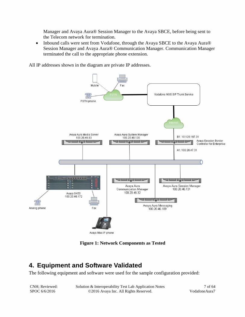
Inbound calls were sent from Vodafone, through the Avaya SBCE to the Avaya Aura®
Session Manager and Avaya Aura® Communication Manager. Communication Manager
terminated the call to the appropriate phone extension.
All IP addresses shown in the diagram are private IP addresses.
Figure 1: Network Components as Tested
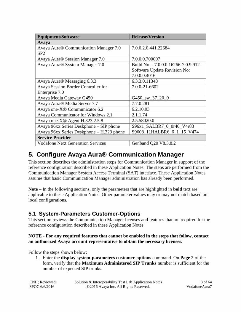
4. Equipment and Software Validated The following equipment and software were used for the sample configuration provided:
CNH; Reviewed:
SPOC 6/6/2016
Solution & Interoperability Test Lab Application Notes
©2016 Avaya Inc. All Rights Reserved.
8 of 64
VodafoneAura7
Equipment/Software Release/Version
Avaya
Avaya Aura® Communication Manager 7.0
SP2
7.0.0.2.0.441.22684
Avaya Aura® Session Manager 7.0 7.0.0.0.700007
Avaya Aura® System Manager 7.0 Build No. - 7.0.0.0.16266-7.0.9.912
Software Update Revision No:
7.0.0.0.4016
Avaya Aura® Messaging 6.3.3 6.3.3.0.11348
Avaya Session Border Controller for
Enterprise 7.0
7.0.0-21-6602
Avaya Media Gateway G450 G450_sw_37_20_0
Avaya Aura® Media Server 7.7 7.7.0.281
Avaya one-X® Communicator 6.2 6.2.10.03
Avaya Communicator for Windows 2.1 2.1.1.74
Avaya one-X® Agent H.323 2.5.8 2.5.58020.0
Avaya 96xx Series Deskphone – SIP phone S96x1_SALBR7_0_0r40_V4r83
Avaya 96xx Series Deskphone – H.323 phone S9608_11HALBR6_6_1_15_V474
Service Provider
Vodafone Next Generation Services Genband Q20 V8.3.8.2
5. Configure Avaya Aura® Communication Manager This section describes the administration steps for Communication Manager in support of the
reference configuration described in these Application Notes. The steps are performed from the
Communication Manager System Access Terminal (SAT) interface. These Application Notes
assume that basic Communication Manager administration has already been performed.
Note – In the following sections, only the parameters that are highlighted in bold text are
applicable to these Application Notes. Other parameter values may or may not match based on
local configurations.
5.1 System-Parameters Customer-Options This section reviews the Communication Manager licenses and features that are required for the
reference configuration described in these Application Notes.
NOTE - For any required features that cannot be enabled in the steps that follow, contact
an authorized Avaya account representative to obtain the necessary licenses.
Follow the steps shown below:
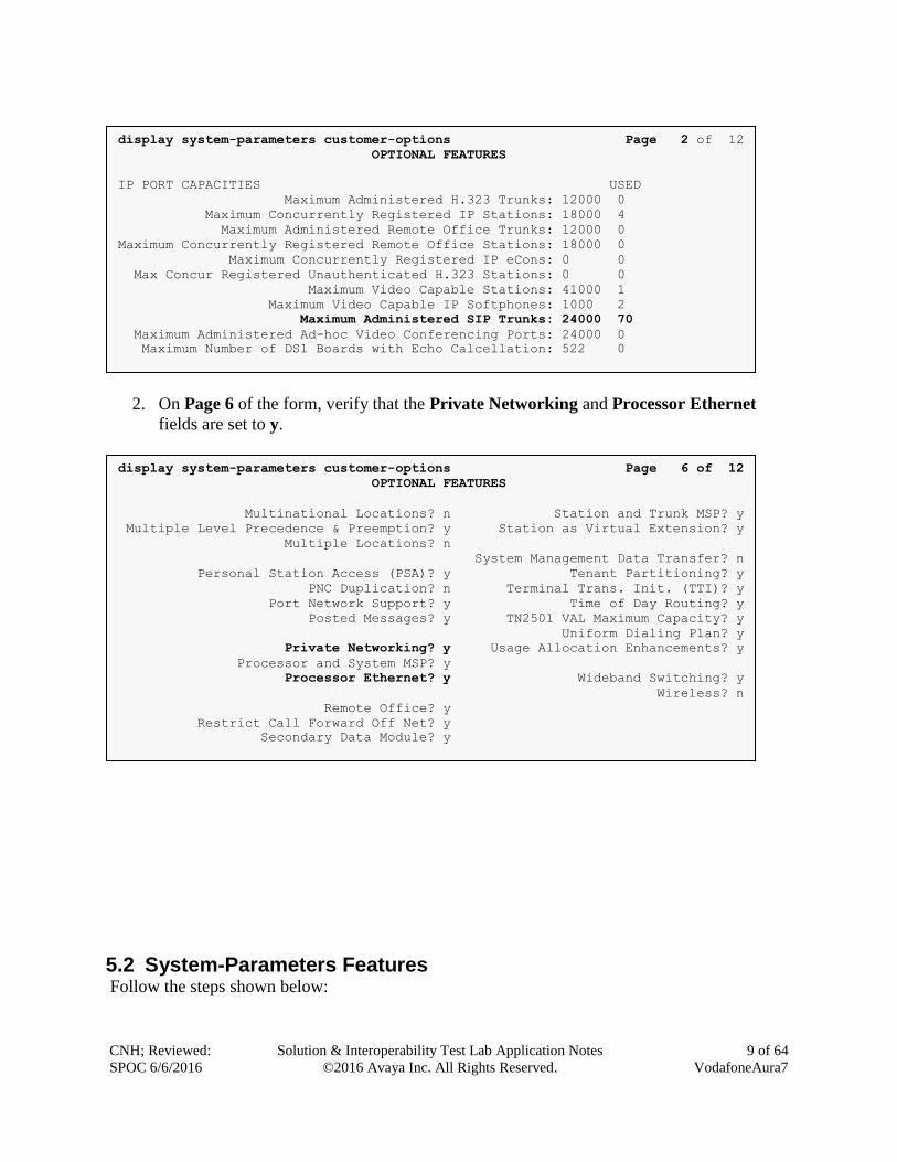
1. Enter the display system-parameters customer-options command. On Page 2 of the
form, verify that the Maximum Administered SIP Trunks number is sufficient for the
number of expected SIP trunks.
CNH; Reviewed:
SPOC 6/6/2016
Solution & Interoperability Test Lab Application Notes
©2016 Avaya Inc. All Rights Reserved.
9 of 64
VodafoneAura7
2. On Page 6 of the form, verify that the Private Networking and Processor Ethernet
fields are set to y.
5.2 System-Parameters Features Follow the steps shown below:
display system-parameters customer-options Page 6 of 12
OPTIONAL FEATURES
Multinational Locations? n Station and Trunk MSP? y
Multiple Level Precedence & Preemption? y Station as Virtual Extension? y
Multiple Locations? n
System Management Data Transfer? n
Personal Station Access (PSA)? y Tenant Partitioning? y
PNC Duplication? n Terminal Trans. Init. (TTI)? y
Port Network Support? y Time of Day Routing? y
Posted Messages? y TN2501 VAL Maximum Capacity? y
Uniform Dialing Plan? y
Private Networking? y Usage Allocation Enhancements? y
Processor and System MSP? y
Processor Ethernet? y Wideband Switching? y
Wireless? n
Remote Office? y
Restrict Call Forward Off Net? y
Secondary Data Module? y
display system-parameters customer-options Page 2 of 12
OPTIONAL FEATURES
IP PORT CAPACITIES USED
Maximum Administered H.323 Trunks: 12000 0
Maximum Concurrently Registered IP Stations: 18000 4
Maximum Administered Remote Office Trunks: 12000 0
Maximum Concurrently Registered Remote Office Stations: 18000 0
Maximum Concurrently Registered IP eCons: 0 0
Max Concur Registered Unauthenticated H.323 Stations: 0 0
Maximum Video Capable Stations: 41000 1
Maximum Video Capable IP Softphones: 1000 2
Maximum Administered SIP Trunks: 24000 70
Maximum Administered Ad-hoc Video Conferencing Ports: 24000 0
Maximum Number of DS1 Boards with Echo Calcellation: 522 0
CNH; Reviewed:
SPOC 6/6/2016
Solution & Interoperability Test Lab Application Notes
©2016 Avaya Inc. All Rights Reserved.
10 of 64
VodafoneAura7
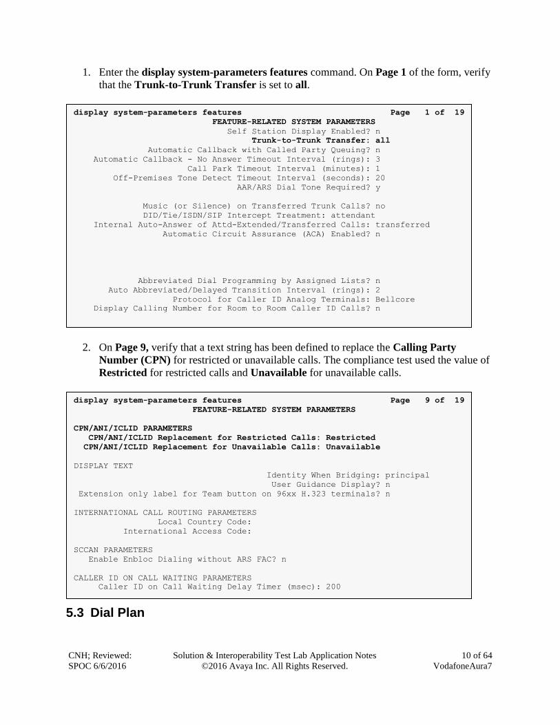
1. Enter the display system-parameters features command. On Page 1 of the form, verify
that the Trunk-to-Trunk Transfer is set to all.
2. On Page 9, verify that a text string has been defined to replace the Calling Party
Number (CPN) for restricted or unavailable calls. The compliance test used the value of
Restricted for restricted calls and Unavailable for unavailable calls.
5.3 Dial Plan
display system-parameters features Page 9 of 19
FEATURE-RELATED SYSTEM PARAMETERS
CPN/ANI/ICLID PARAMETERS
CPN/ANI/ICLID Replacement for Restricted Calls: Restricted
CPN/ANI/ICLID Replacement for Unavailable Calls: Unavailable
DISPLAY TEXT
Identity When Bridging: principal
User Guidance Display? n
Extension only label for Team button on 96xx H.323 terminals? n
INTERNATIONAL CALL ROUTING PARAMETERS
Local Country Code:
International Access Code:
SCCAN PARAMETERS
Enable Enbloc Dialing without ARS FAC? n
CALLER ID ON CALL WAITING PARAMETERS
Caller ID on Call Waiting Delay Timer (msec): 200
display system-parameters features Page 1 of 19
FEATURE-RELATED SYSTEM PARAMETERS
Self Station Display Enabled? n
Trunk-to-Trunk Transfer: all
Automatic Callback with Called Party Queuing? n
Automatic Callback - No Answer Timeout Interval (rings): 3
Call Park Timeout Interval (minutes): 1
Off-Premises Tone Detect Timeout Interval (seconds): 20
AAR/ARS Dial Tone Required? y
Music (or Silence) on Transferred Trunk Calls? no
DID/Tie/ISDN/SIP Intercept Treatment: attendant
Internal Auto-Answer of Attd-Extended/Transferred Calls: transferred
Automatic Circuit Assurance (ACA) Enabled? n
Abbreviated Dial Programming by Assigned Lists? n
Auto Abbreviated/Delayed Transition Interval (rings): 2
Protocol for Caller ID Analog Terminals: Bellcore
Display Calling Number for Room to Room Caller ID Calls? n
CNH; Reviewed:
SPOC 6/6/2016
Solution & Interoperability Test Lab Application Notes
©2016 Avaya Inc. All Rights Reserved.
11 of 64
VodafoneAura7
The dial plan defines how digit strings will be used locally by Communication Manager. The
following dial plan was used in the reference configuration.
Follow the steps shown below:
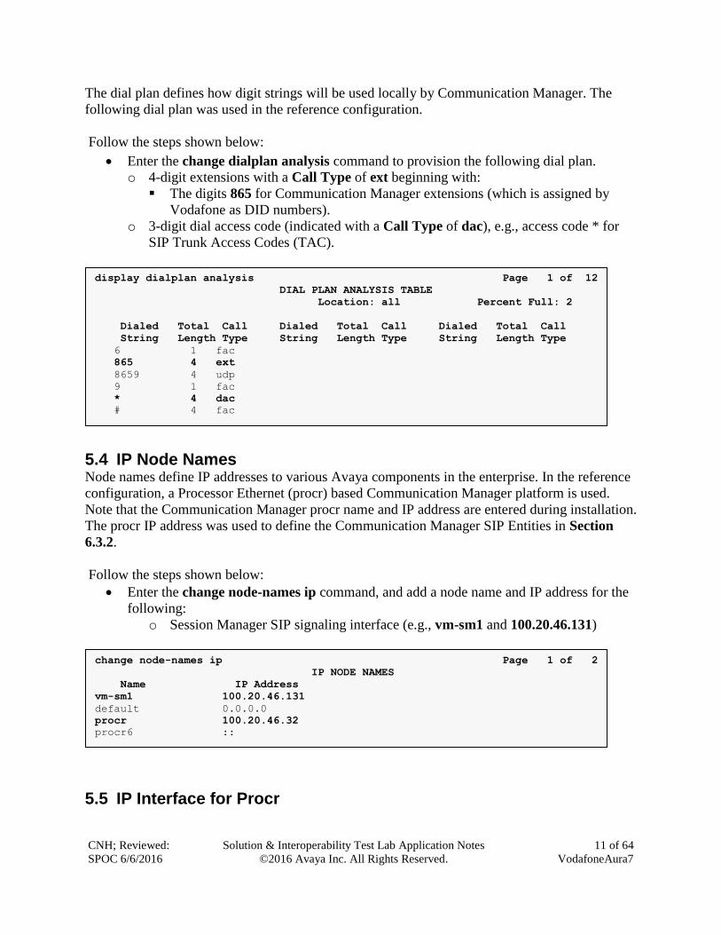
Enter the change dialplan analysis command to provision the following dial plan.
o 4-digit extensions with a Call Type of ext beginning with:
The digits 865 for Communication Manager extensions (which is assigned by
Vodafone as DID numbers).
o 3-digit dial access code (indicated with a Call Type of dac), e.g., access code * for
SIP Trunk Access Codes (TAC).
5.4 IP Node Names Node names define IP addresses to various Avaya components in the enterprise. In the reference
configuration, a Processor Ethernet (procr) based Communication Manager platform is used.
Note that the Communication Manager procr name and IP address are entered during installation.
The procr IP address was used to define the Communication Manager SIP Entities in Section
6.3.2.
Follow the steps shown below:
Enter the change node-names ip command, and add a node name and IP address for the
following:
o Session Manager SIP signaling interface (e.g., vm-sm1 and 100.20.46.131)
5.5 IP Interface for Procr
change node-names ip Page 1 of 2
IP NODE NAMES
Name IP Address
vm-sm1 100.20.46.131
default 0.0.0.0
procr 100.20.46.32
procr6 ::
display dialplan analysis Page 1 of 12
DIAL PLAN ANALYSIS TABLE
Location: all Percent Full: 2
Dialed Total Call Dialed Total Call Dialed Total Call
String Length Type String Length Type String Length Type
6 1 fac
865 4 ext
8659 4 udp
9 1 fac
* 4 dac
# 4 fac
CNH; Reviewed:
SPOC 6/6/2016
Solution & Interoperability Test Lab Application Notes
©2016 Avaya Inc. All Rights Reserved.
12 of 64
VodafoneAura7
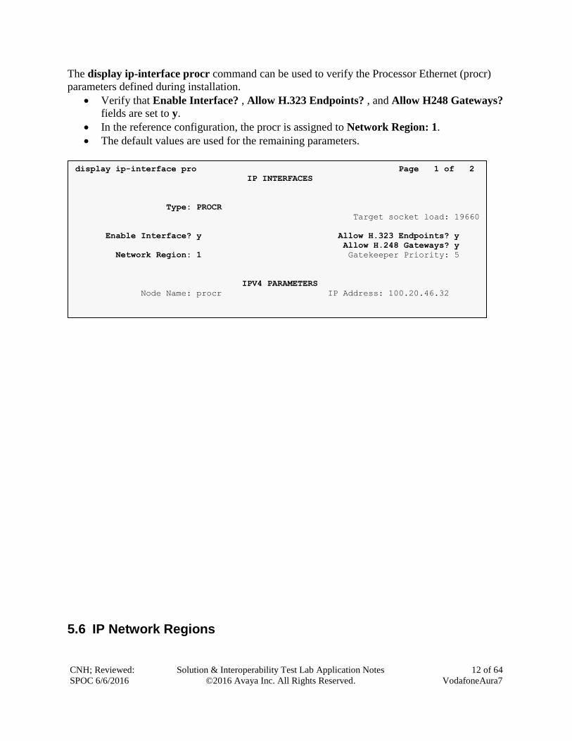
The display ip-interface procr command can be used to verify the Processor Ethernet (procr)
parameters defined during installation.
Verify that Enable Interface? , Allow H.323 Endpoints? , and Allow H248 Gateways?
fields are set to y.
In the reference configuration, the procr is assigned to Network Region: 1.
The default values are used for the remaining parameters.
5.6 IP Network Regions
display ip-interface pro Page 1 of 2
IP INTERFACES
Type: PROCR
Target socket load: 19660
Enable Interface? y Allow H.323 Endpoints? y
Allow H.248 Gateways? y
Network Region: 1 Gatekeeper Priority: 5
IPV4 PARAMETERS
Node Name: procr IP Address: 100.20.46.32
Subnet Mask: /24
CNH; Reviewed:
SPOC 6/6/2016
Solution & Interoperability Test Lab Application Notes
©2016 Avaya Inc. All Rights Reserved.
13 of 64
VodafoneAura7
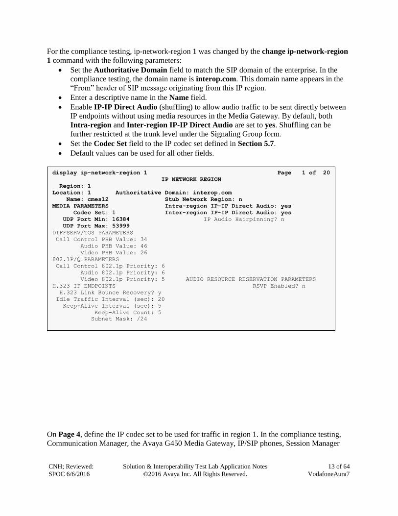
For the compliance testing, ip-network-region 1 was changed by the change ip-network-region
1 command with the following parameters:
Set the Authoritative Domain field to match the SIP domain of the enterprise. In the
compliance testing, the domain name is interop.com. This domain name appears in the
“From” header of SIP message originating from this IP region.
Enter a descriptive name in the Name field.
Enable IP-IP Direct Audio (shuffling) to allow audio traffic to be sent directly between
IP endpoints without using media resources in the Media Gateway. By default, both
Intra-region and Inter-region IP-IP Direct Audio are set to yes. Shuffling can be
further restricted at the trunk level under the Signaling Group form.
Set the Codec Set field to the IP codec set defined in Section 5.7.
Default values can be used for all other fields.
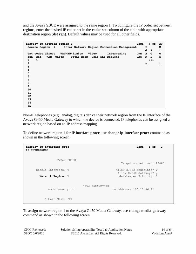
On Page 4, define the IP codec set to be used for traffic in region 1. In the compliance testing,
Communication Manager, the Avaya G450 Media Gateway, IP/SIP phones, Session Manager
display ip-network-region 1 Page 1 of 20
IP NETWORK REGION
Region: 1
Location: 1 Authoritative Domain: interop.com
Name: cmes12 Stub Network Region: n
MEDIA PARAMETERS Intra-region IP-IP Direct Audio: yes
Codec Set: 1 Inter-region IP-IP Direct Audio: yes
UDP Port Min: 16384 IP Audio Hairpinning? n
UDP Port Max: 53999
DIFFSERV/TOS PARAMETERS
Call Control PHB Value: 34
Audio PHB Value: 46
Video PHB Value: 26
802.1P/Q PARAMETERS
Call Control 802.1p Priority: 6
Audio 802.1p Priority: 6
Video 802.1p Priority: 5 AUDIO RESOURCE RESERVATION PARAMETERS
H.323 IP ENDPOINTS RSVP Enabled? n
H.323 Link Bounce Recovery? y
Idle Traffic Interval (sec): 20
Keep-Alive Interval (sec): 5
Keep-Alive Count: 5
Subnet Mask: /24
CNH; Reviewed:
SPOC 6/6/2016
Solution & Interoperability Test Lab Application Notes
©2016 Avaya Inc. All Rights Reserved.
14 of 64
VodafoneAura7
and the Avaya SBCE were assigned to the same region 1. To configure the IP codec set between
regions, enter the desired IP codec set in the codec set column of the table with appropriate
destination region (dst rgn). Default values may be used for all other fields.
Non-IP telephones (e.g., analog, digital) derive their network region from the IP interface of the
Avaya G450 Media Gateway to which the device is connected. IP telephones can be assigned a
network region based on an IP address mapping.
To define network region 1 for IP interface procr, use change ip-interface procr command as
shown in the following screen.
To assign network region 1 to the Avaya G450 Media Gateway, use change media-gateway
command as shown in the following screen.
display ip-interface proc Page 1 of 2
IP INTERFACES
Type: PROCR
Target socket load: 19660
Enable Interface? y Allow H.323 Endpoints? y
Allow H.248 Gateways? y
Network Region: 1 Gatekeeper Priority: 5
IPV4 PARAMETERS
Node Name: procr IP Address: 100.20.46.32
Subnet Mask: /24
display ip-network-region 1 Page 4 of 20
Source Region: 1 Inter Network Region Connection Management I M
G A t
dst codec direct WAN-BW-limits Video Intervening Dyn A G c
rgn set WAN Units Total Norm Prio Shr Regions CAC R L e
1 1 all
2 n t
3
4
5
6
7
8
9
10
11
12
13
14
15
CNH; Reviewed:
SPOC 6/6/2016
Solution & Interoperability Test Lab Application Notes
©2016 Avaya Inc. All Rights Reserved.
15 of 64
VodafoneAura7
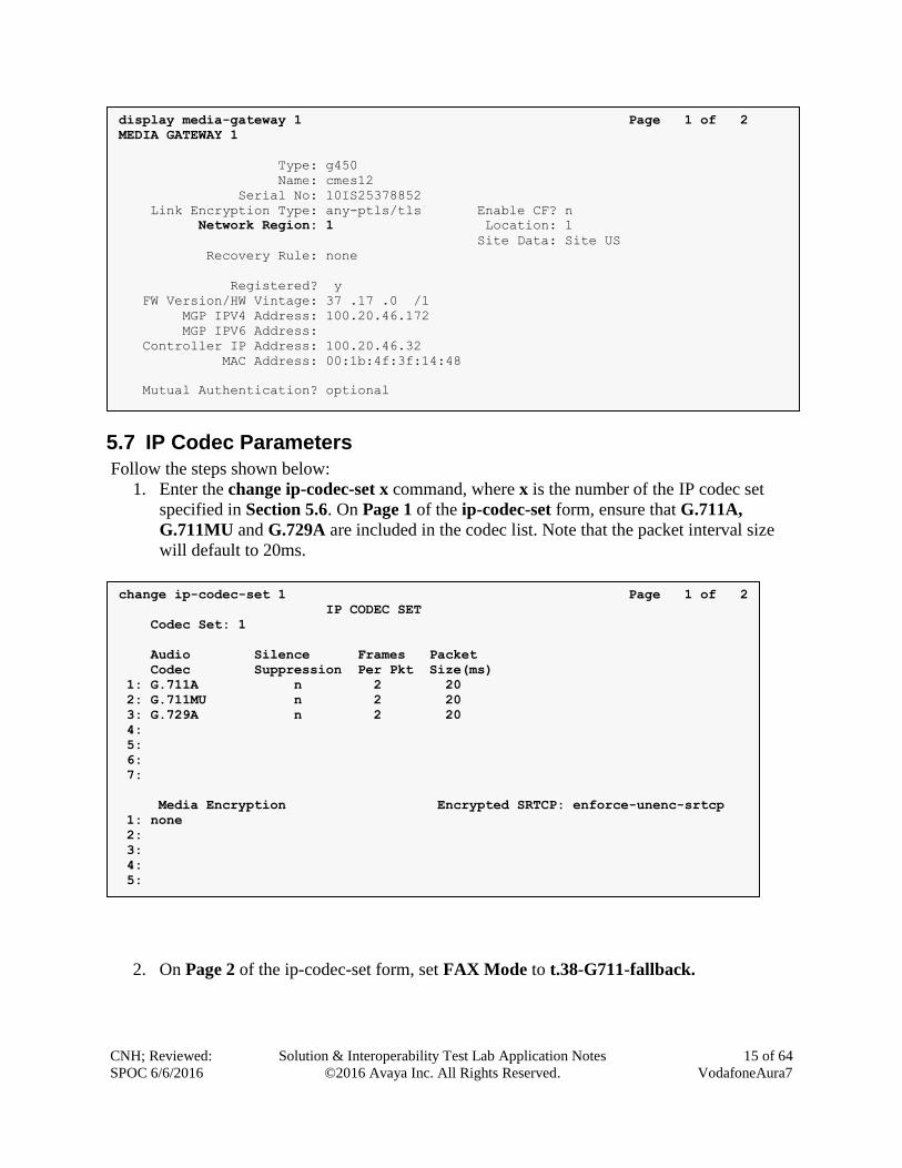
5.7 IP Codec Parameters
Follow the steps shown below:
1. Enter the change ip-codec-set x command, where x is the number of the IP codec set
specified in Section 5.6. On Page 1 of the ip-codec-set form, ensure that G.711A,
G.711MU and G.729A are included in the codec list. Note that the packet interval size
will default to 20ms.
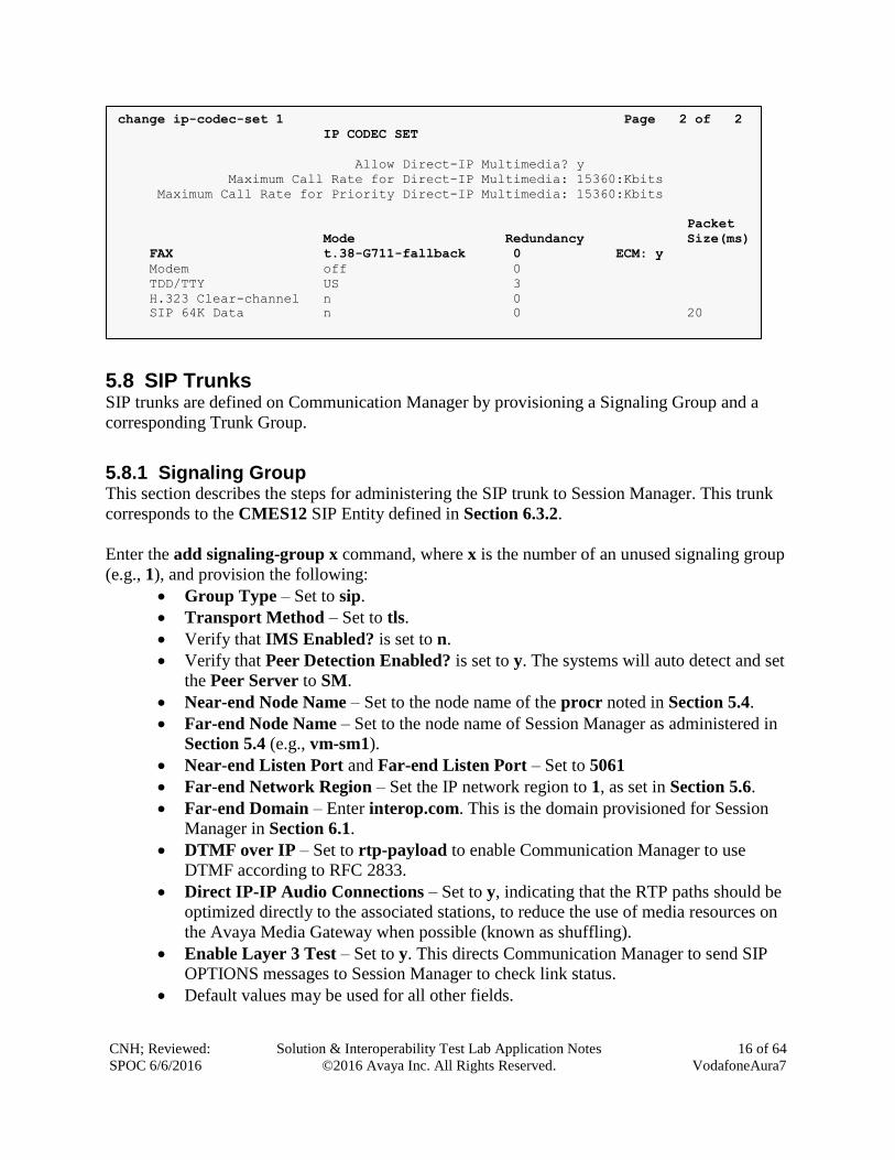
2. On Page 2 of the ip-codec-set form, set FAX Mode to t.38-G711-fallback.
change ip-codec-set 1 Page 1 of 2
IP CODEC SET
Codec Set: 1
Audio Silence Frames Packet
Codec Suppression Per Pkt Size(ms)
1: G.711A n 2 20
2: G.711MU n 2 20
3: G.729A n 2 20
4:
5:
6:
7:
Media Encryption Encrypted SRTCP: enforce-unenc-srtcp
1: none
2:
3:
4:
5:
display media-gateway 1 Page 1 of 2
MEDIA GATEWAY 1
Type: g450
Name: cmes12
Serial No: 10IS25378852
Link Encryption Type: any-ptls/tls Enable CF? n
Network Region: 1 Location: 1
Site Data: Site US
Recovery Rule: none
Registered? y
FW Version/HW Vintage: 37 .17 .0 /1
MGP IPV4 Address: 100.20.46.172
MGP IPV6 Address:
Controller IP Address: 100.20.46.32
MAC Address: 00:1b:4f:3f:14:48
Mutual Authentication? optional
CNH; Reviewed:
SPOC 6/6/2016
Solution & Interoperability Test Lab Application Notes
©2016 Avaya Inc. All Rights Reserved.
16 of 64
VodafoneAura7
5.8 SIP Trunks SIP trunks are defined on Communication Manager by provisioning a Signaling Group and a
corresponding Trunk Group.
5.8.1 Signaling Group This section describes the steps for administering the SIP trunk to Session Manager. This trunk
corresponds to the CMES12 SIP Entity defined in Section 6.3.2.
Enter the add signaling-group x command, where x is the number of an unused signaling group
(e.g., 1), and provision the following:
Group Type – Set to sip.
Transport Method – Set to tls.
Verify that IMS Enabled? is set to n.
Verify that Peer Detection Enabled? is set to y. The systems will auto detect and set
the Peer Server to SM.
Near-end Node Name – Set to the node name of the procr noted in Section 5.4.
Far-end Node Name – Set to the node name of Session Manager as administered in
Section 5.4 (e.g., vm-sm1).
Near-end Listen Port and Far-end Listen Port – Set to 5061
Far-end Network Region – Set the IP network region to 1, as set in Section 5.6.
Far-end Domain – Enter interop.com. This is the domain provisioned for Session
Manager in Section 6.1.
DTMF over IP – Set to rtp-payload to enable Communication Manager to use
DTMF according to RFC 2833.
Direct IP-IP Audio Connections – Set to y, indicating that the RTP paths should be
optimized directly to the associated stations, to reduce the use of media resources on
the Avaya Media Gateway when possible (known as shuffling).
Enable Layer 3 Test – Set to y. This directs Communication Manager to send SIP
OPTIONS messages to Session Manager to check link status.
Default values may be used for all other fields.
change ip-codec-set 1 Page 2 of 2
IP CODEC SET
Allow Direct-IP Multimedia? y
Maximum Call Rate for Direct-IP Multimedia: 15360:Kbits
Maximum Call Rate for Priority Direct-IP Multimedia: 15360:Kbits
Packet
Mode Redundancy Size(ms)
FAX t.38-G711-fallback 0 ECM: y
Modem off 0
TDD/TTY US 3
H.323 Clear-channel n 0
SIP 64K Data n 0 20

CNH; Reviewed:
SPOC 6/6/2016
Solution & Interoperability Test Lab Application Notes
©2016 Avaya Inc. All Rights Reserved.
17 of 64
VodafoneAura7
5.8.2 Trunk Group
Enter the add trunk-group x command, where x is the number of an unused trunk group (e.g.,
1). On Page 1 of the trunk-group form, provision the following:
TAC – Enter a trunk access code that is consistent with the dial plan (e.g., *001).
Direction – Set to two-way.
Service Type – Set to public-ntwrk.
Signaling Group – Set to the signaling group administered in Step 1 (e.g., 1).
Number of Members – Enter the maximum number of simultaneous calls desired on
this trunk group (based on licensing) (e.g., 255).
On Page 2, the Redirect On OPTIM Failure value is the amount of time (in milliseconds) that
Communication Manager will wait for a response (other than 100 Trying) to a pending INVITE
sent to an EC500 remote endpoint before selecting another route. If another route is not defined,
display trunk-group 1 Page 1 of 22
TRUNK GROUP
Group Number: 1 Group Type: sip CDR Reports: y
Group Name: PRIV-TO-SM1 COR: 1 TN: 1 TAC: *001
Direction: two-way Outgoing Display? y
Dial Access? n Night Service:
Queue Length: 0
Service Type: public-ntwrk Auth Code? n
Member Assignment Method: auto
Signaling Group: 1
Number of Members: 255
display signaling-group 1 Page 1 of 3
SIGNALING GROUP
Group Number: 1 Group Type: sip
IMS Enabled? n Transport Method: tls
Q-SIP? n
IP Video? y Priority Video? y Enforce SIPS URI for SRTP? y
Peer Detection Enabled? y Peer Server: SM
Prepend '+' to Outgoing Calling/Alerting/Diverting/Connected Public Numbers? y
Remove '+' from Incoming Called/Calling/Alerting/Diverting/Connected Numbers? n
Alert Incoming SIP Crisis Calls? n
Near-end Node Name: procr Far-end Node Name: vm-sm1
Near-end Listen Port: 5061 Far-end Listen Port: 5061
Far-end Network Region: 1
Far-end Domain: interop.com
Bypass If IP Threshold Exceeded? n
Incoming Dialog Loopbacks: eliminate RFC 3389 Comfort Noise? n
DTMF over IP: rtp-payload Direct IP-IP Audio Connections? y
Session Establishment Timer(min): 3 IP Audio Hairpinning? n
Enable Layer 3 Test? y Initial IP-IP Direct Media? n
H.323 Station Outgoing Direct Media? n Alternate Route Timer(sec): 30
CNH; Reviewed:
SPOC 6/6/2016
Solution & Interoperability Test Lab Application Notes
©2016 Avaya Inc. All Rights Reserved.
18 of 64
VodafoneAura7
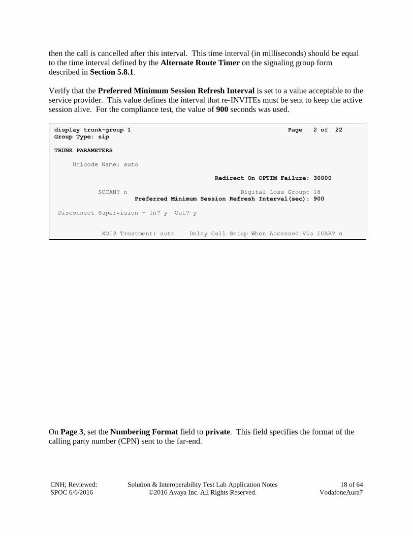
then the call is cancelled after this interval. This time interval (in milliseconds) should be equal
to the time interval defined by the Alternate Route Timer on the signaling group form
described in Section 5.8.1.
Verify that the Preferred Minimum Session Refresh Interval is set to a value acceptable to the
service provider. This value defines the interval that re-INVITEs must be sent to keep the active
session alive. For the compliance test, the value of 900 seconds was used.
On Page 3, set the Numbering Format field to private. This field specifies the format of the
calling party number (CPN) sent to the far-end.
display trunk-group 1 Page 2 of 22
Group Type: sip
TRUNK PARAMETERS
Unicode Name: auto
Redirect On OPTIM Failure: 30000
SCCAN? n Digital Loss Group: 18
Preferred Minimum Session Refresh Interval(sec): 900
Disconnect Supervision - In? y Out? y
XOIP Treatment: auto Delay Call Setup When Accessed Via IGAR? n
Caller ID for Service Link Call to H.323 1xC: station-extension
CNH; Reviewed:
SPOC 6/6/2016
Solution & Interoperability Test Lab Application Notes
©2016 Avaya Inc. All Rights Reserved.
19 of 64
VodafoneAura7
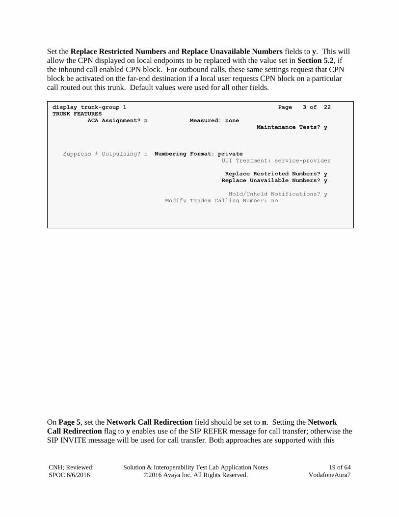
Set the Replace Restricted Numbers and Replace Unavailable Numbers fields to y. This will
allow the CPN displayed on local endpoints to be replaced with the value set in Section 5.2, if
the inbound call enabled CPN block. For outbound calls, these same settings request that CPN
block be activated on the far-end destination if a local user requests CPN block on a particular
call routed out this trunk. Default values were used for all other fields.
On Page 5, set the Network Call Redirection field should be set to n. Setting the Network
Call Redirection flag to y enables use of the SIP REFER message for call transfer; otherwise the
SIP INVITE message will be used for call transfer. Both approaches are supported with this
display trunk-group 1 Page 3 of 22
TRUNK FEATURES
ACA Assignment? n Measured: none
Maintenance Tests? y
Suppress # Outpulsing? n Numbering Format: private
UUI Treatment: service-provider
Replace Restricted Numbers? y
Replace Unavailable Numbers? y
Hold/Unhold Notifications? y
Modify Tandem Calling Number: no
Show ANSWERED BY on Display? y
DSN Term? n SIP ANAT Supported? n
CNH; Reviewed:
SPOC 6/6/2016
Solution & Interoperability Test Lab Application Notes
©2016 Avaya Inc. All Rights Reserved.
20 of 64
VodafoneAura7
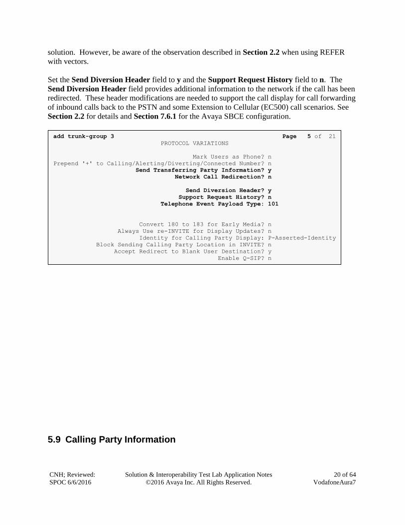
solution. However, be aware of the observation described in Section 2.2 when using REFER
with vectors.
Set the Send Diversion Header field to y and the Support Request History field to n. The
Send Diversion Header field provides additional information to the network if the call has been
redirected. These header modifications are needed to support the call display for call forwarding
of inbound calls back to the PSTN and some Extension to Cellular (EC500) call scenarios. See
Section 2.2 for details and Section 7.6.1 for the Avaya SBCE configuration.
5.9 Calling Party Information
add trunk-group 3 Page 5 of 21
PROTOCOL VARIATIONS
Mark Users as Phone? n
Prepend '+' to Calling/Alerting/Diverting/Connected Number? n
Send Transferring Party Information? y
Network Call Redirection? n
Send Diversion Header? y
Support Request History? n
Telephone Event Payload Type: 101
Convert 180 to 183 for Early Media? n
Always Use re-INVITE for Display Updates? n
Identity for Calling Party Display: P-Asserted-Identity
Block Sending Calling Party Location in INVITE? n
Accept Redirect to Blank User Destination? y
Enable Q-SIP? n
Interworking of ISDN Clearing with In-Band Tones: keep-channel-active
Request URI Contents: may-have-extra-digits
Interworking of ISDN Clearing with In-Band Tones: keep-channel-active
CNH; Reviewed:
SPOC 6/6/2016
Solution & Interoperability Test Lab Application Notes
©2016 Avaya Inc. All Rights Reserved.
21 of 64
VodafoneAura7
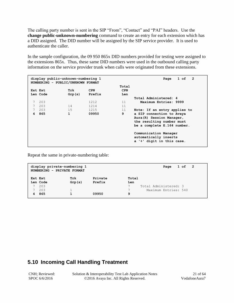
The calling party number is sent in the SIP “From”, “Contact” and “PAI” headers. Use the
change public-unknown-numbering command to create an entry for each extension which has
a DID assigned. The DID number will be assigned by the SIP service provider. It is used to
authenticate the caller.
In the sample configuration, the 09 950 865x DID numbers provided for testing were assigned to
the extensions 865x. Thus, these same DID numbers were used in the outbound calling party
information on the service provider trunk when calls were originated from these extensions.
Repeat the same in private-numbering table:
5.10 Incoming Call Handling Treatment
display private-numbering 1 Page 1 of 2
NUMBERING - PRIVATE FORMAT
Ext Ext Trk Private Total
Len Code Grp(s) Prefix Len
7 203 7 Total Administered: 3
7 203 1 7 Maximum Entries: 540
4 865 1 09950 9
display public-unknown-numbering 1 Page 1 of 2
NUMBERING - PUBLIC/UNKNOWN FORMAT
Total
Ext Ext Trk CPN CPN
Len Code Grp(s) Prefix Len
Total Administered: 4
7 203 1212 11 Maximum Entries: 9999
7 203 14 1214 11
7 203 15 1215 11 Note: If an entry applies to
4 865 1 09950 9 a SIP connection to Avaya
Aura(R) Session Manager,
the resulting number must
be a complete E.164 number.
Communication Manager
automatically inserts
a '+' digit in this case.
CNH; Reviewed:
SPOC 6/6/2016
Solution & Interoperability Test Lab Application Notes
©2016 Avaya Inc. All Rights Reserved.
22 of 64
VodafoneAura7
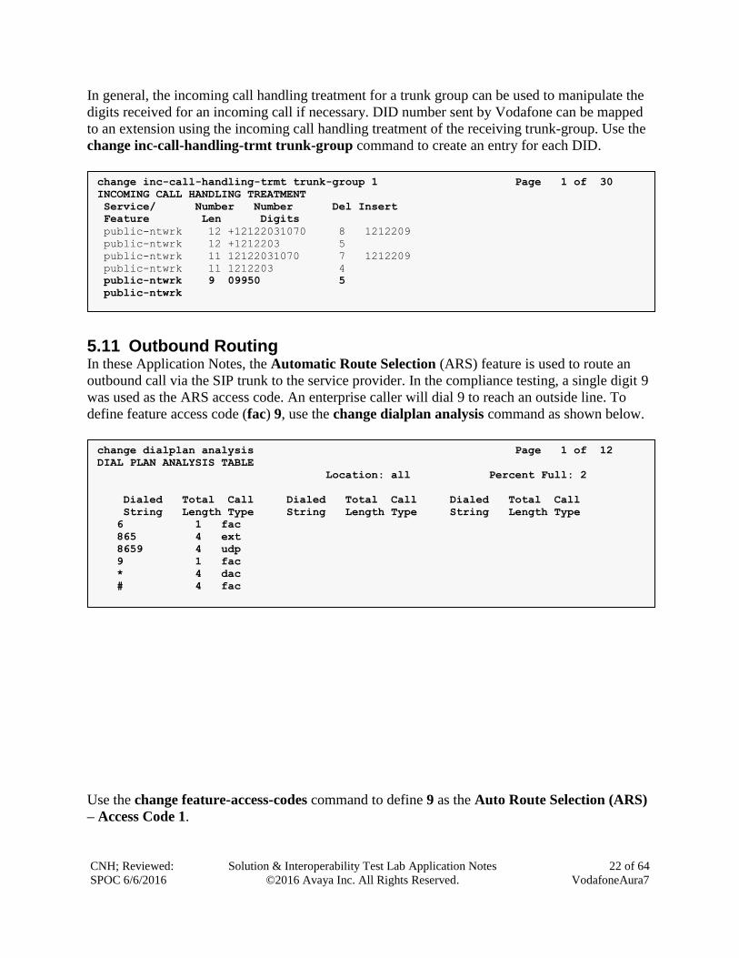
In general, the incoming call handling treatment for a trunk group can be used to manipulate the
digits received for an incoming call if necessary. DID number sent by Vodafone can be mapped
to an extension using the incoming call handling treatment of the receiving trunk-group. Use the
change inc-call-handling-trmt trunk-group command to create an entry for each DID.
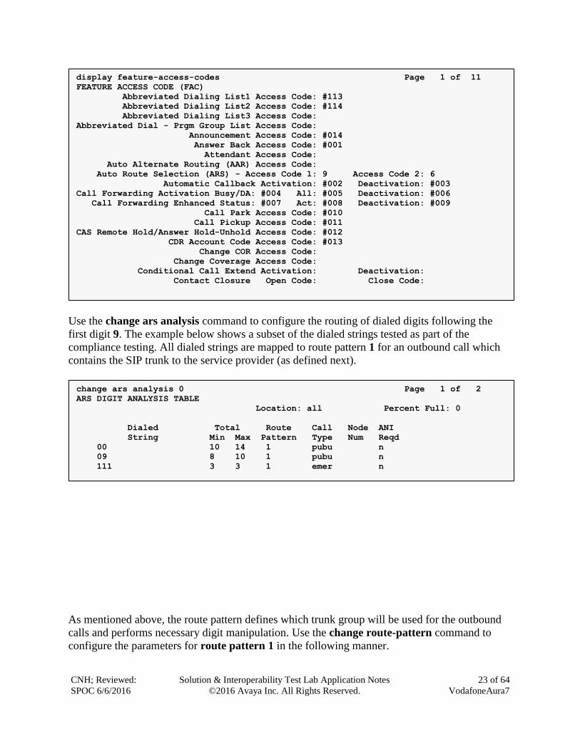
5.11 Outbound Routing In these Application Notes, the Automatic Route Selection (ARS) feature is used to route an
outbound call via the SIP trunk to the service provider. In the compliance testing, a single digit 9
was used as the ARS access code. An enterprise caller will dial 9 to reach an outside line. To
define feature access code (fac) 9, use the change dialplan analysis command as shown below.
Use the change feature-access-codes command to define 9 as the Auto Route Selection (ARS)
– Access Code 1.
change dialplan analysis Page 1 of 12
DIAL PLAN ANALYSIS TABLE
Location: all Percent Full: 2
Dialed Total Call Dialed Total Call Dialed Total Call
String Length Type String Length Type String Length Type
6 1 fac
865 4 ext
8659 4 udp
9 1 fac
* 4 dac
# 4 fac
change inc-call-handling-trmt trunk-group 1 Page 1 of 30
INCOMING CALL HANDLING TREATMENT
Service/ Number Number Del Insert
Feature Len Digits
public-ntwrk 12 +12122031070 8 1212209
public-ntwrk 12 +1212203 5
public-ntwrk 11 12122031070 7 1212209
public-ntwrk 11 1212203 4
public-ntwrk 9 09950 5
public-ntwrk
CNH; Reviewed:
SPOC 6/6/2016
Solution & Interoperability Test Lab Application Notes
©2016 Avaya Inc. All Rights Reserved.
23 of 64
VodafoneAura7
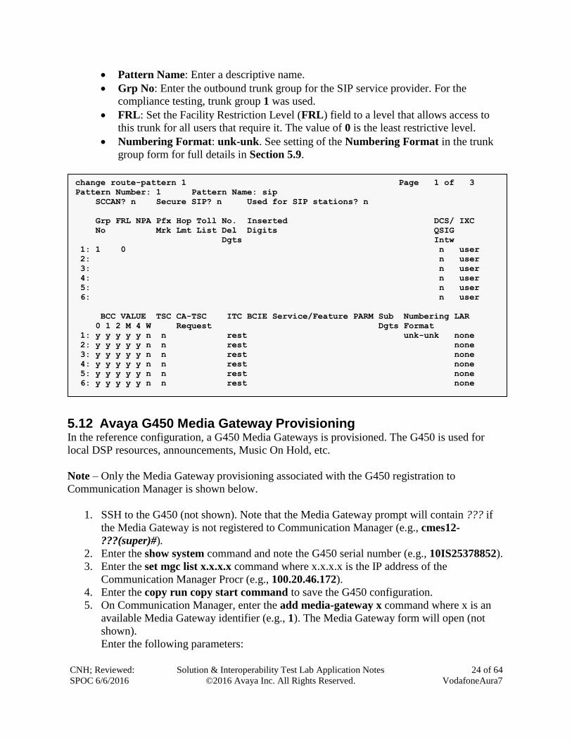
Use the change ars analysis command to configure the routing of dialed digits following the
first digit 9. The example below shows a subset of the dialed strings tested as part of the
compliance testing. All dialed strings are mapped to route pattern 1 for an outbound call which
contains the SIP trunk to the service provider (as defined next).
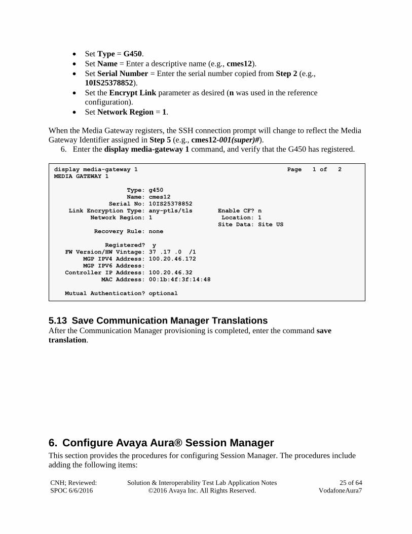
As mentioned above, the route pattern defines which trunk group will be used for the outbound
calls and performs necessary digit manipulation. Use the change route-pattern command to
configure the parameters for route pattern 1 in the following manner.
change ars analysis 0 Page 1 of 2
ARS DIGIT ANALYSIS TABLE
Location: all Percent Full: 0
Dialed Total Route Call Node ANI
String Min Max Pattern Type Num Reqd
00 10 14 1 pubu n
09 8 10 1 pubu n
111 3 3 1 emer n
display feature-access-codes Page 1 of 11
FEATURE ACCESS CODE (FAC)
Abbreviated Dialing List1 Access Code: #113
Abbreviated Dialing List2 Access Code: #114
Abbreviated Dialing List3 Access Code:
Abbreviated Dial - Prgm Group List Access Code:
Announcement Access Code: #014
Answer Back Access Code: #001
Attendant Access Code:
Auto Alternate Routing (AAR) Access Code:
Auto Route Selection (ARS) - Access Code 1: 9 Access Code 2: 6
Automatic Callback Activation: #002 Deactivation: #003
Call Forwarding Activation Busy/DA: #004 All: #005 Deactivation: #006
Call Forwarding Enhanced Status: #007 Act: #008 Deactivation: #009
Call Park Access Code: #010
Call Pickup Access Code: #011
CAS Remote Hold/Answer Hold-Unhold Access Code: #012
CDR Account Code Access Code: #013
Change COR Access Code:
Change Coverage Access Code:
Conditional Call Extend Activation: Deactivation:
Contact Closure Open Code: Close Code:
CNH; Reviewed:
SPOC 6/6/2016
Solution & Interoperability Test Lab Application Notes
©2016 Avaya Inc. All Rights Reserved.
24 of 64
VodafoneAura7
Pattern Name: Enter a descriptive name.
Grp No: Enter the outbound trunk group for the SIP service provider. For the
compliance testing, trunk group 1 was used.
FRL: Set the Facility Restriction Level (FRL) field to a level that allows access to
this trunk for all users that require it. The value of 0 is the least restrictive level.
Numbering Format: unk-unk. See setting of the Numbering Format in the trunk
group form for full details in Section 5.9.
5.12 Avaya G450 Media Gateway Provisioning In the reference configuration, a G450 Media Gateways is provisioned. The G450 is used for
local DSP resources, announcements, Music On Hold, etc.
Note – Only the Media Gateway provisioning associated with the G450 registration to
Communication Manager is shown below.
1. SSH to the G450 (not shown). Note that the Media Gateway prompt will contain ??? if
the Media Gateway is not registered to Communication Manager (e.g., cmes12-
???(super)#).
2. Enter the show system command and note the G450 serial number (e.g., 10IS25378852).
3. Enter the set mgc list x.x.x.x command where x.x.x.x is the IP address of the
Communication Manager Procr (e.g., 100.20.46.172).
4. Enter the copy run copy start command to save the G450 configuration.
5. On Communication Manager, enter the add media-gateway x command where x is an
available Media Gateway identifier (e.g., 1). The Media Gateway form will open (not
shown).
Enter the following parameters:
change route-pattern 1 Page 1 of 3
Pattern Number: 1 Pattern Name: sip
SCCAN? n Secure SIP? n Used for SIP stations? n
Grp FRL NPA Pfx Hop Toll No. Inserted DCS/ IXC
No Mrk Lmt List Del Digits QSIG
Dgts Intw
1: 1 0 n user
2: n user
3: n user
4: n user
5: n user
6: n user
BCC VALUE TSC CA-TSC ITC BCIE Service/Feature PARM Sub Numbering LAR
0 1 2 M 4 W Request Dgts Format
1: y y y y y n n rest unk-unk none
2: y y y y y n n rest none
3: y y y y y n n rest none
4: y y y y y n n rest none
5: y y y y y n n rest none
6: y y y y y n n rest none
CNH; Reviewed:
SPOC 6/6/2016
Solution & Interoperability Test Lab Application Notes
©2016 Avaya Inc. All Rights Reserved.
25 of 64
VodafoneAura7
Set Type = G450.
Set Name = Enter a descriptive name (e.g., cmes12).
Set Serial Number = Enter the serial number copied from Step 2 (e.g.,
10IS25378852).
Set the Encrypt Link parameter as desired (n was used in the reference
configuration).
Set Network Region = 1.
When the Media Gateway registers, the SSH connection prompt will change to reflect the Media
Gateway Identifier assigned in Step 5 (e.g., cmes12-001(super)#).
6. Enter the display media-gateway 1 command, and verify that the G450 has registered.
5.13 Save Communication Manager Translations After the Communication Manager provisioning is completed, enter the command save
translation.
6. Configure Avaya Aura® Session Manager This section provides the procedures for configuring Session Manager. The procedures include
adding the following items:
display media-gateway 1 Page 1 of 2
MEDIA GATEWAY 1
Type: g450
Name: cmes12
Serial No: 10IS25378852
Link Encryption Type: any-ptls/tls Enable CF? n
Network Region: 1 Location: 1
Site Data: Site US
Recovery Rule: none
Registered? y
FW Version/HW Vintage: 37 .17 .0 /1
MGP IPV4 Address: 100.20.46.172
MGP IPV6 Address:
Controller IP Address: 100.20.46.32
MAC Address: 00:1b:4f:3f:14:48
Mutual Authentication? optional
CNH; Reviewed:
SPOC 6/6/2016
Solution & Interoperability Test Lab Application Notes
©2016 Avaya Inc. All Rights Reserved.
26 of 64
VodafoneAura7
SIP domain
Logical/physical Location that can be used by SIP Entities
SIP Entities corresponding to Communication Manager, Session Manager and the Avaya
SBCE
Entity Links, which define the SIP trunk parameters used by Session Manager when
routing calls to/from SIP Entities
Routing Policies, which control call routing between the SIP Entities
Dial Patterns, which govern to which SIP Entity a call is routed
Session Manager, corresponding to the Session Manager server to be managed by System
Manager
It may not be necessary to configure all the items above when creating a connection to the
service provider since some of these items would have already been defined as part of the initial
Session Manager installation. This includes items such as certain SIP domains, locations, SIP
entities, and Session Manager itself. However, each item should be reviewed to verify the
configuration.
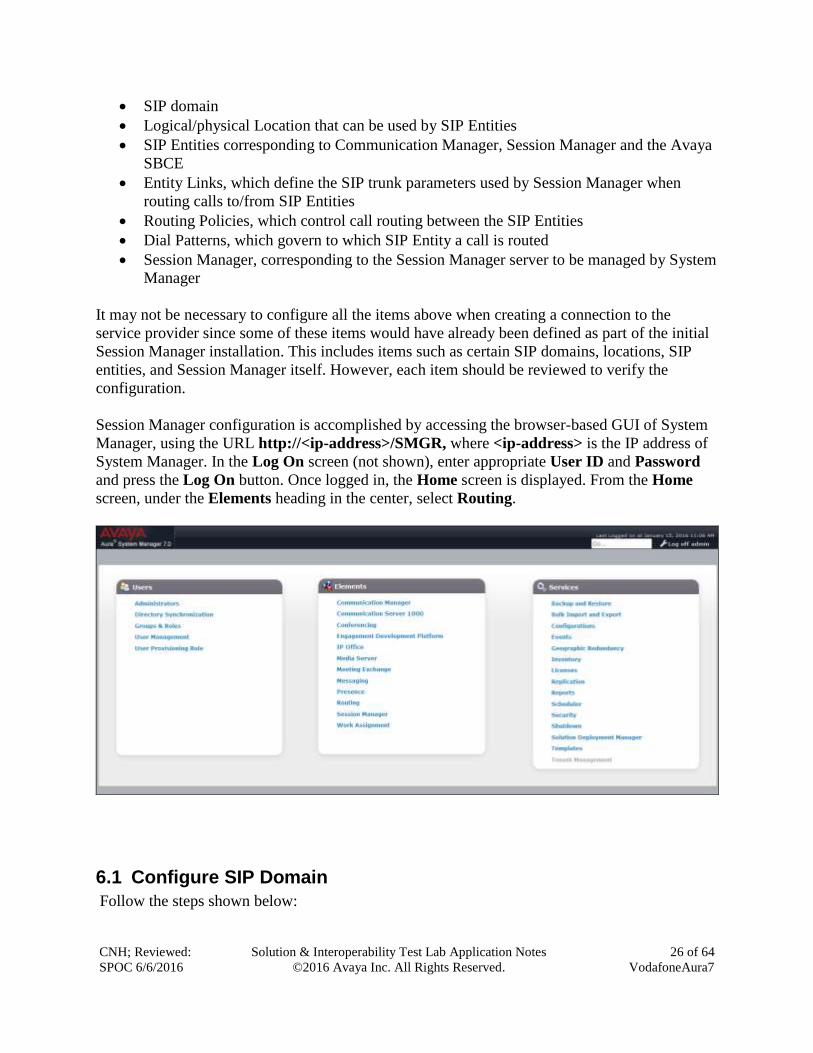
Session Manager configuration is accomplished by accessing the browser-based GUI of System
Manager, using the URL http://<ip-address>/SMGR, where <ip-address> is the IP address of
System Manager. In the Log On screen (not shown), enter appropriate User ID and Password
and press the Log On button. Once logged in, the Home screen is displayed. From the Home
screen, under the Elements heading in the center, select Routing.
6.1 Configure SIP Domain
Follow the steps shown below:
CNH; Reviewed:
SPOC 6/6/2016
Solution & Interoperability Test Lab Application Notes
©2016 Avaya Inc. All Rights Reserved.
27 of 64
VodafoneAura7
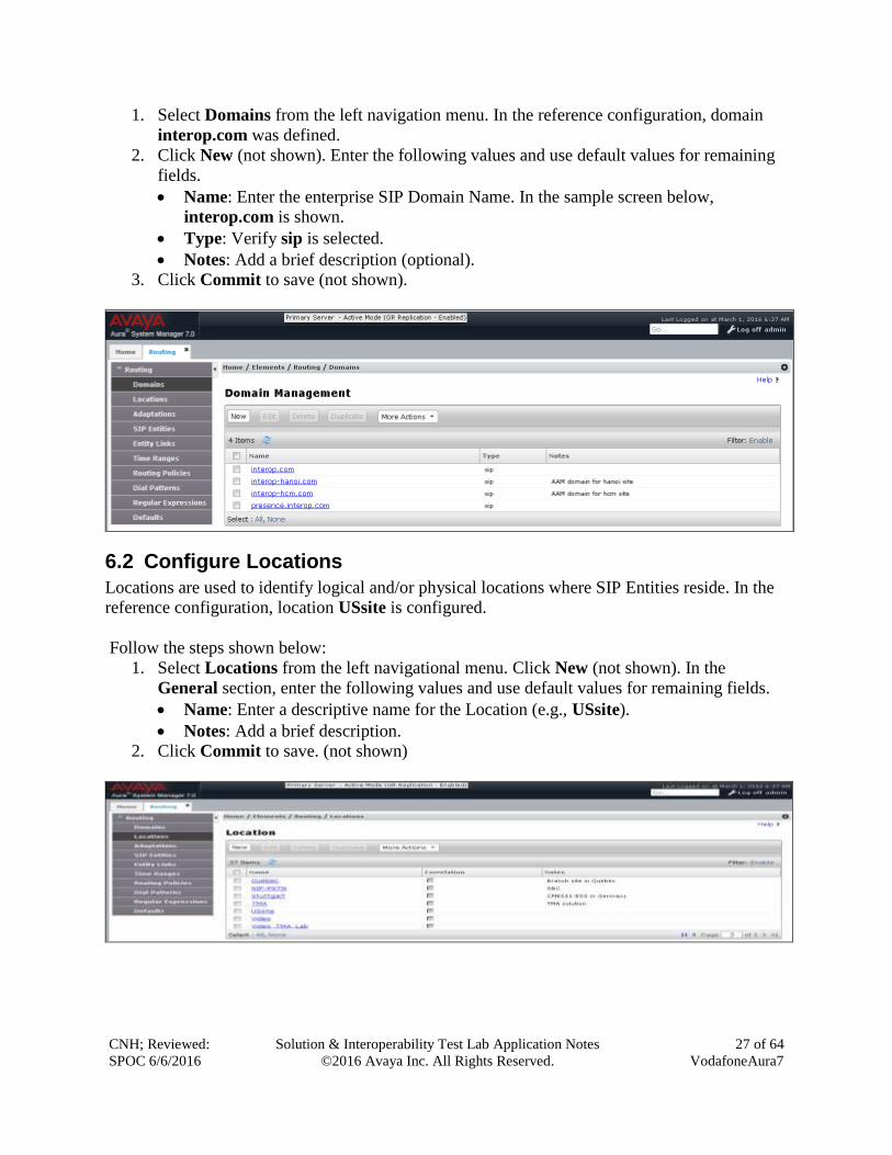
1. Select Domains from the left navigation menu. In the reference configuration, domain
interop.com was defined.
2. Click New (not shown). Enter the following values and use default values for remaining
fields.
Name: Enter the enterprise SIP Domain Name. In the sample screen below,
interop.com is shown.
Type: Verify sip is selected.
Notes: Add a brief description (optional).
3. Click Commit to save (not shown).
6.2 Configure Locations
Locations are used to identify logical and/or physical locations where SIP Entities reside. In the
reference configuration, location USsite is configured.
Follow the steps shown below:
1. Select Locations from the left navigational menu. Click New (not shown). In the
General section, enter the following values and use default values for remaining fields.
Name: Enter a descriptive name for the Location (e.g., USsite).
Notes: Add a brief description.
2. Click Commit to save. (not shown)
CNH; Reviewed:
SPOC 6/6/2016
Solution & Interoperability Test Lab Application Notes
©2016 Avaya Inc. All Rights Reserved.
28 of 64
VodafoneAura7
6.3 Configure SIP Entities
A SIP Entity must be added for Session Manager and for each SIP telephony system connected
to it which includes Communication Manager and Avaya SBCE.
6.3.1 Configure Session Manager SIP Entity
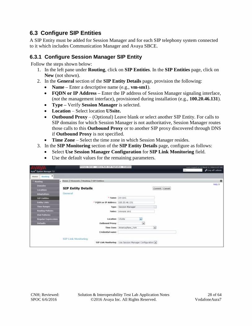
Follow the steps shown below:
1. In the left pane under Routing, click on SIP Entities. In the SIP Entities page, click on
New (not shown).
2. In the General section of the SIP Entity Details page, provision the following:
Name – Enter a descriptive name (e.g., vm-sm1).
FQDN or IP Address – Enter the IP address of Session Manager signaling interface,
(not the management interface), provisioned during installation (e.g., 100.20.46.131).
Type – Verify Session Manager is selected.
Location – Select location USsite.
Outbound Proxy – (Optional) Leave blank or select another SIP Entity. For calls to
SIP domains for which Session Manager is not authoritative, Session Manager routes
those calls to this Outbound Proxy or to another SIP proxy discovered through DNS
if Outbound Proxy is not specified.
Time Zone – Select the time zone in which Session Manager resides.
3. In the SIP Monitoring section of the SIP Entity Details page, configure as follows:
Select Use Session Manager Configuration for SIP Link Monitoring field.
Use the default values for the remaining parameters.
CNH; Reviewed:
SPOC 6/6/2016
Solution & Interoperability Test Lab Application Notes
©2016 Avaya Inc. All Rights Reserved.
29 of 64
VodafoneAura7
6.3.2 Configure Communication Manager SIP Entity
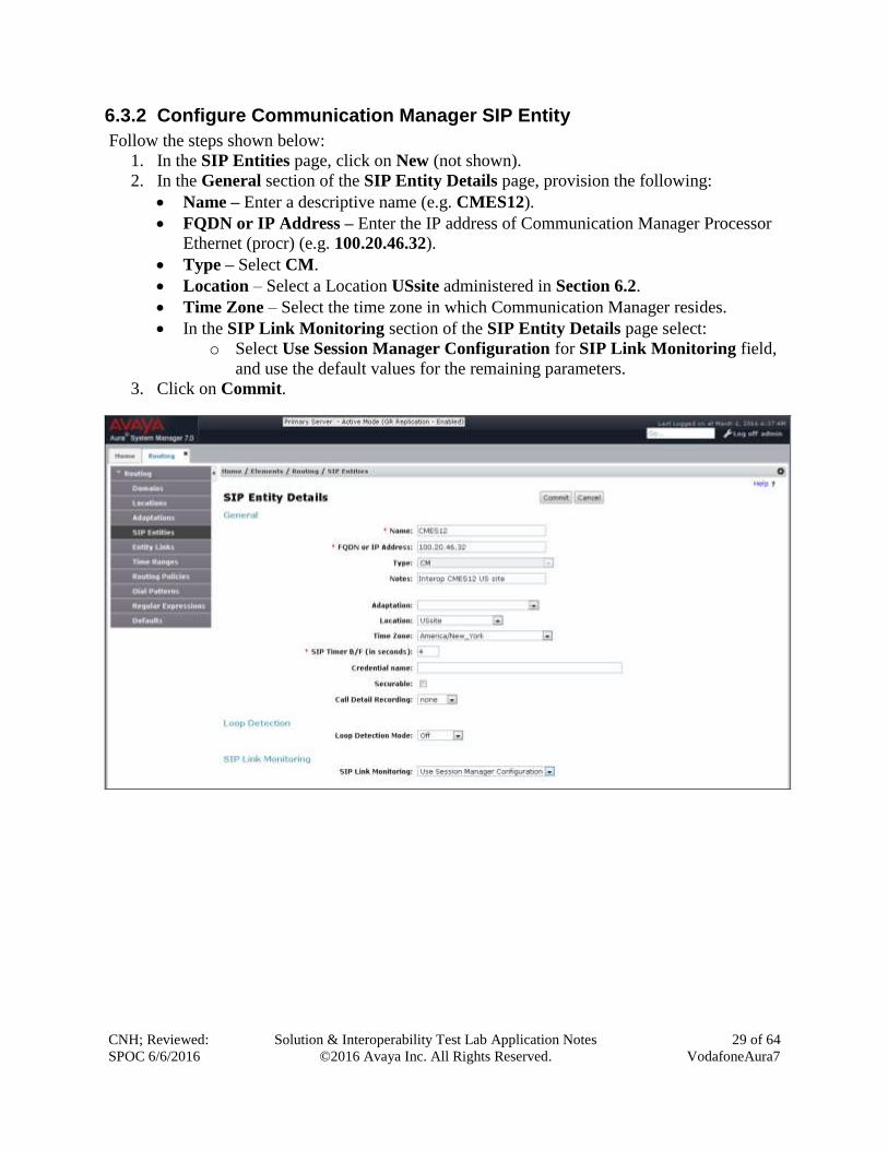
Follow the steps shown below:
1. In the SIP Entities page, click on New (not shown).
2. In the General section of the SIP Entity Details page, provision the following:
Name – Enter a descriptive name (e.g. CMES12).
FQDN or IP Address – Enter the IP address of Communication Manager Processor
Ethernet (procr) (e.g. 100.20.46.32).
Type – Select CM.
Location – Select a Location USsite administered in Section 6.2.
Time Zone – Select the time zone in which Communication Manager resides.
In the SIP Link Monitoring section of the SIP Entity Details page select:
o Select Use Session Manager Configuration for SIP Link Monitoring field,
and use the default values for the remaining parameters.
3. Click on Commit.
CNH; Reviewed:
SPOC 6/6/2016
Solution & Interoperability Test Lab Application Notes
©2016 Avaya Inc. All Rights Reserved.
30 of 64
VodafoneAura7
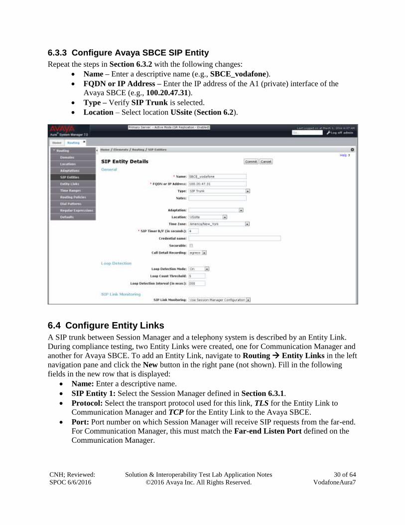
6.3.3 Configure Avaya SBCE SIP Entity
Repeat the steps in Section 6.3.2 with the following changes:
Name – Enter a descriptive name (e.g., SBCE_vodafone).
FQDN or IP Address – Enter the IP address of the A1 (private) interface of the
Avaya SBCE (e.g., 100.20.47.31).
Type – Verify SIP Trunk is selected.
Location – Select location USsite (Section 6.2).
6.4 Configure Entity Links
A SIP trunk between Session Manager and a telephony system is described by an Entity Link.
During compliance testing, two Entity Links were created, one for Communication Manager and
another for Avaya SBCE. To add an Entity Link, navigate to Routing Entity Links in the left
navigation pane and click the New button in the right pane (not shown). Fill in the following
fields in the new row that is displayed:
Name: Enter a descriptive name.
SIP Entity 1: Select the Session Manager defined in Section 6.3.1.
Protocol: Select the transport protocol used for this link, TLS for the Entity Link to
Communication Manager and TCP for the Entity Link to the Avaya SBCE.
Port: Port number on which Session Manager will receive SIP requests from the far-end.
For Communication Manager, this must match the Far-end Listen Port defined on the
Communication Manager.
CNH; Reviewed:
SPOC 6/6/2016
Solution & Interoperability Test Lab Application Notes
©2016 Avaya Inc. All Rights Reserved.
31 of 64
VodafoneAura7
SIP Entity 2: Select the name of the other systems. For Communication Manager, select
the Communication Manager SIP Entity defined in Section 6.3.2. For Avaya SBCE,
select Avaya SBCE SIP Entity defined in Section 6.3.3
Port: Port number on which the other system receives SIP requests from Session
Manager. For Communication Manager, this must match the Near-end Listen Port
defined on the Communication Manager.
Connection Policy: Select Trusted.
Click Commit to save.
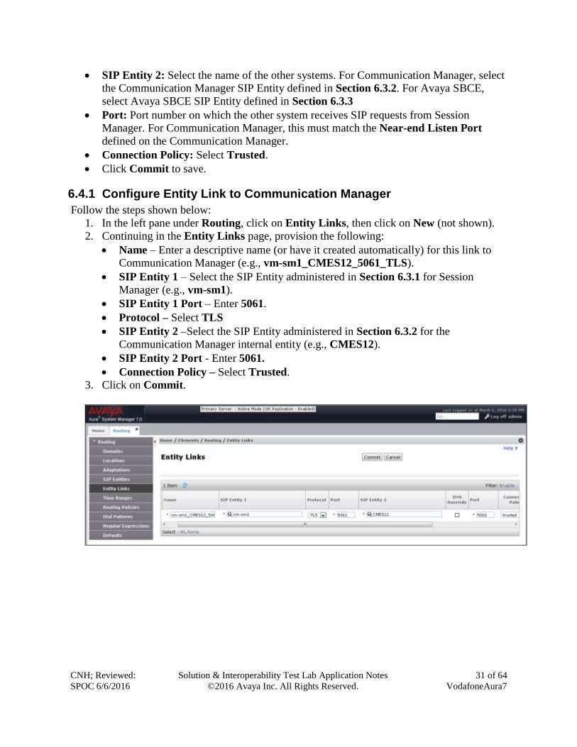
6.4.1 Configure Entity Link to Communication Manager
Follow the steps shown below:
1. In the left pane under Routing, click on Entity Links, then click on New (not shown).
2. Continuing in the Entity Links page, provision the following:
Name – Enter a descriptive name (or have it created automatically) for this link to
Communication Manager (e.g., vm-sm1_CMES12_5061_TLS).
SIP Entity 1 – Select the SIP Entity administered in Section 6.3.1 for Session
Manager (e.g., vm-sm1).
SIP Entity 1 Port – Enter 5061.
Protocol – Select TLS
SIP Entity 2 –Select the SIP Entity administered in Section 6.3.2 for the
Communication Manager internal entity (e.g., CMES12).
SIP Entity 2 Port - Enter 5061.
Connection Policy – Select Trusted.
3. Click on Commit.
CNH; Reviewed:
SPOC 6/6/2016
Solution & Interoperability Test Lab Application Notes
©2016 Avaya Inc. All Rights Reserved.
32 of 64
VodafoneAura7
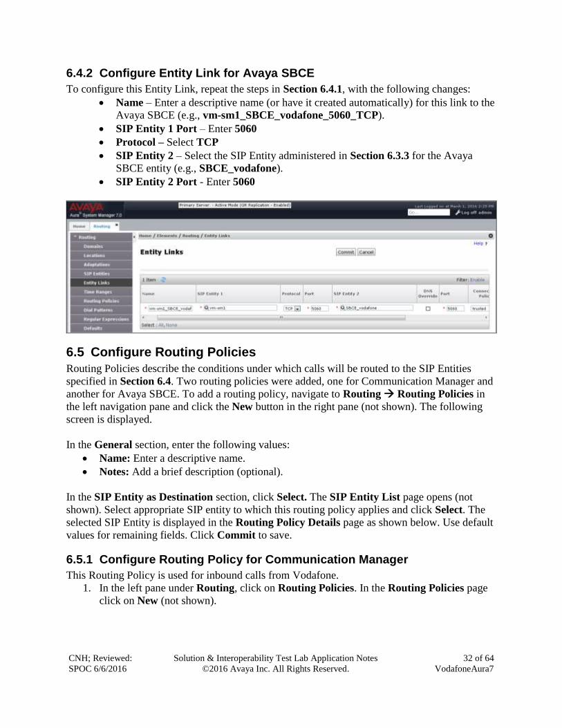
6.4.2 Configure Entity Link for Avaya SBCE
To configure this Entity Link, repeat the steps in Section 6.4.1, with the following changes:
Name – Enter a descriptive name (or have it created automatically) for this link to the
Avaya SBCE (e.g., vm-sm1_SBCE_vodafone_5060_TCP).
SIP Entity 1 Port – Enter 5060
Protocol – Select TCP
SIP Entity 2 – Select the SIP Entity administered in Section 6.3.3 for the Avaya
SBCE entity (e.g., SBCE_vodafone).
SIP Entity 2 Port - Enter 5060
6.5 Configure Routing Policies
Routing Policies describe the conditions under which calls will be routed to the SIP Entities
specified in Section 6.4. Two routing policies were added, one for Communication Manager and
another for Avaya SBCE. To add a routing policy, navigate to Routing Routing Policies in
the left navigation pane and click the New button in the right pane (not shown). The following
screen is displayed.
In the General section, enter the following values:
Name: Enter a descriptive name.
Notes: Add a brief description (optional).
In the SIP Entity as Destination section, click Select. The SIP Entity List page opens (not
shown). Select appropriate SIP entity to which this routing policy applies and click Select. The
selected SIP Entity is displayed in the Routing Policy Details page as shown below. Use default
values for remaining fields. Click Commit to save.
6.5.1 Configure Routing Policy for Communication Manager
This Routing Policy is used for inbound calls from Vodafone.
1. In the left pane under Routing, click on Routing Policies. In the Routing Policies page
click on New (not shown).
CNH; Reviewed:
SPOC 6/6/2016
Solution & Interoperability Test Lab Application Notes
©2016 Avaya Inc. All Rights Reserved.
33 of 64
VodafoneAura7
2. In the General section of the Routing Policy Details page, enter a descriptive Name for
routing Vodafone calls to Communication Manager (e.g., Policy_CMES12), and ensure
that the Disabled checkbox is unchecked to activate this Routing Policy.
3. In the SIP Entity as Destination section of the Routing Policy Details page, click on
Select and the SIP Entity list page will open.
4. In the SIP Entity List page, select the SIP Entity administered in Section 6.3.2 for the
Communication Manager SIP Entity (CMES12), and click on Select.
5. Note that once the Dial Patterns are defined they will appear in the Dial Pattern section
of this form.
6. No Regular Expressions were used in the reference configuration.
7. Click on Commit.
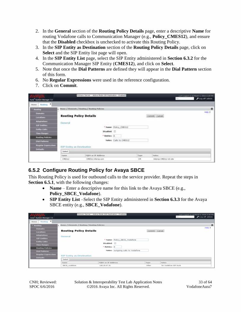
6.5.2 Configure Routing Policy for Avaya SBCE
This Routing Policy is used for outbound calls to the service provider. Repeat the steps in
Section 6.5.1, with the following changes:
Name – Enter a descriptive name for this link to the Avaya SBCE (e.g.,
Policy_SBCE_Vodafone).
SIP Entity List –Select the SIP Entity administered in Section 6.3.3 for the Avaya
SBCE entity (e.g., SBCE_Vodafone).
CNH; Reviewed:
SPOC 6/6/2016
Solution & Interoperability Test Lab Application Notes
©2016 Avaya Inc. All Rights Reserved.
34 of 64
VodafoneAura7
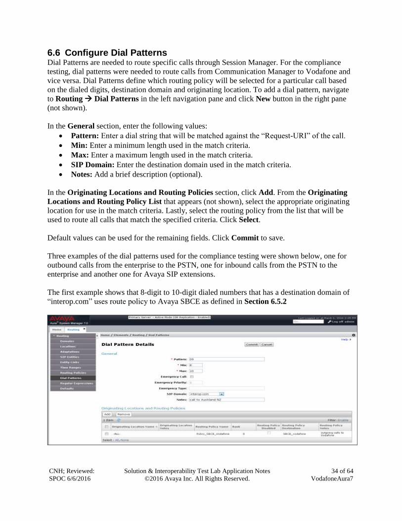
6.6 Configure Dial Patterns Dial Patterns are needed to route specific calls through Session Manager. For the compliance
testing, dial patterns were needed to route calls from Communication Manager to Vodafone and
vice versa. Dial Patterns define which routing policy will be selected for a particular call based
on the dialed digits, destination domain and originating location. To add a dial pattern, navigate
to Routing Dial Patterns in the left navigation pane and click New button in the right pane
(not shown).
In the General section, enter the following values:
Pattern: Enter a dial string that will be matched against the “Request-URI” of the call.
Min: Enter a minimum length used in the match criteria.
Max: Enter a maximum length used in the match criteria.
SIP Domain: Enter the destination domain used in the match criteria.
Notes: Add a brief description (optional).
In the Originating Locations and Routing Policies section, click Add. From the Originating
Locations and Routing Policy List that appears (not shown), select the appropriate originating
location for use in the match criteria. Lastly, select the routing policy from the list that will be
used to route all calls that match the specified criteria. Click Select.
Default values can be used for the remaining fields. Click Commit to save.
Three examples of the dial patterns used for the compliance testing were shown below, one for
outbound calls from the enterprise to the PSTN, one for inbound calls from the PSTN to the
enterprise and another one for Avaya SIP extensions.
The first example shows that 8-digit to 10-digit dialed numbers that has a destination domain of
“interop.com” uses route policy to Avaya SBCE as defined in Section 6.5.2
CNH; Reviewed:
SPOC 6/6/2016
Solution & Interoperability Test Lab Application Notes
©2016 Avaya Inc. All Rights Reserved.
35 of 64
VodafoneAura7
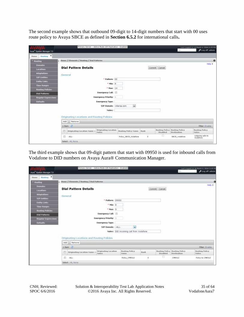
The second example shows that outbound 09-digit to 14-digit numbers that start with 00 uses
route policy to Avaya SBCE as defined in Section 6.5.2 for international calls.
The third example shows that 09-digit pattern that start with 09950 is used for inbound calls from
Vodafone to DID numbers on Avaya Aura® Communication Manager.
CNH; Reviewed:
SPOC 6/6/2016
Solution & Interoperability Test Lab Application Notes
©2016 Avaya Inc. All Rights Reserved.
36 of 64
VodafoneAura7
7. Configure Avaya Session Border Controller for Enterprise
Note: The installation and initial provisioning of the Avaya SBCE is beyond the scope of this
document.
IMPORTANT! – During the Avaya SBCE installation, the Management interface of the
Avaya SBCE must be provisioned on a different subnet than either of the Avaya SBCE
private and public network interfaces (e.g., A1 and B1). If this is not the case, contact your
Avaya representative to get this condition resolved.
As described in Section 3, the reference configuration places the private interface (A1) of the
Avaya SBCE in the Common site, (100.20.47.29), with access to the USsite site. The connection
to Vodafone uses the Avaya SBCE public interface B1 (IP address 10.128.197.31). The follow
provisioning is performed via the Avaya SBCE GUI interface, using the “M1” management
LAN connection on the chassis.
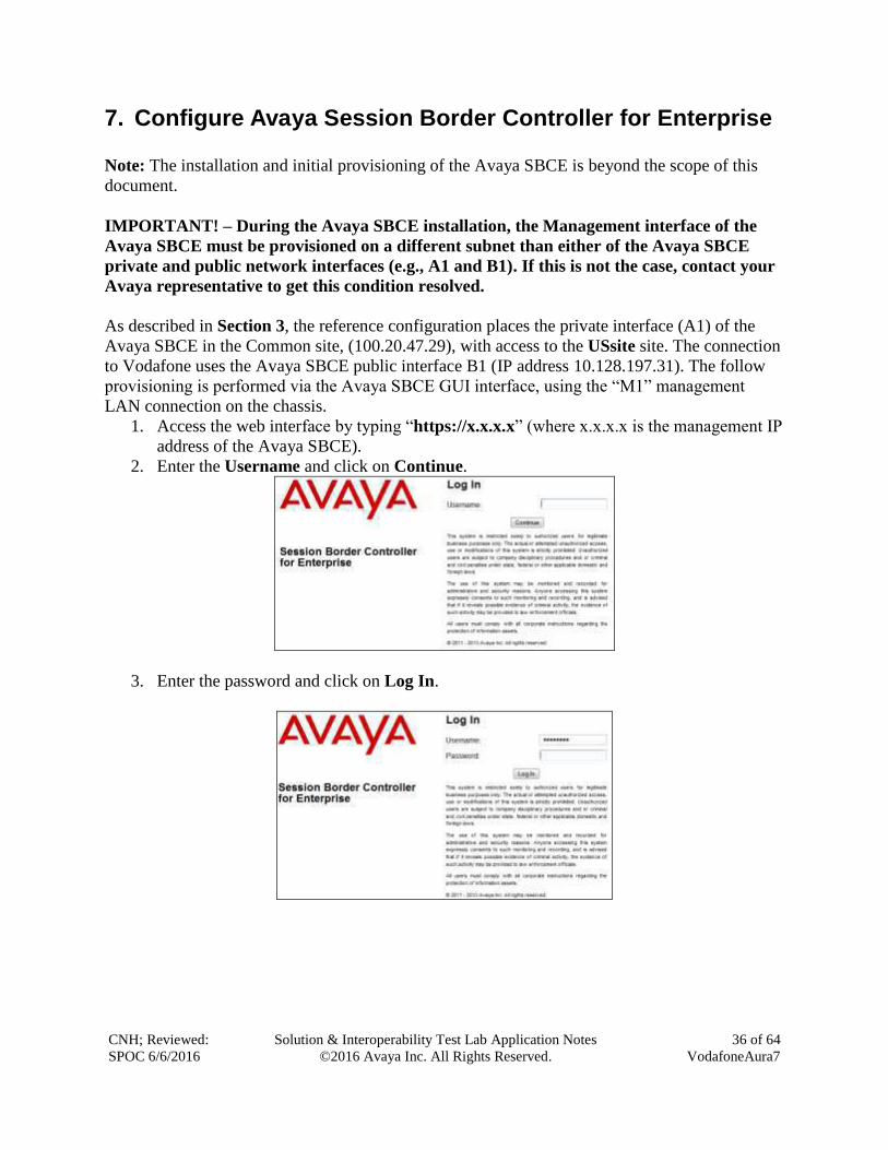
1. Access the web interface by typing “https://x.x.x.x” (where x.x.x.x is the management IP
address of the Avaya SBCE).
2. Enter the Username and click on Continue.
3. Enter the password and click on Log In.
CNH; Reviewed:
SPOC 6/6/2016
Solution & Interoperability Test Lab Application Notes
©2016 Avaya Inc. All Rights Reserved.
37 of 64
VodafoneAura7
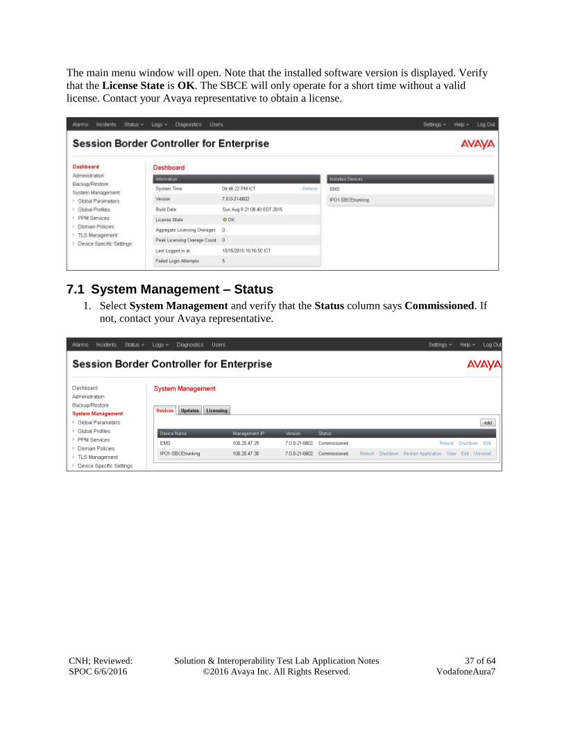
The main menu window will open. Note that the installed software version is displayed. Verify
that the License State is OK. The SBCE will only operate for a short time without a valid
license. Contact your Avaya representative to obtain a license.
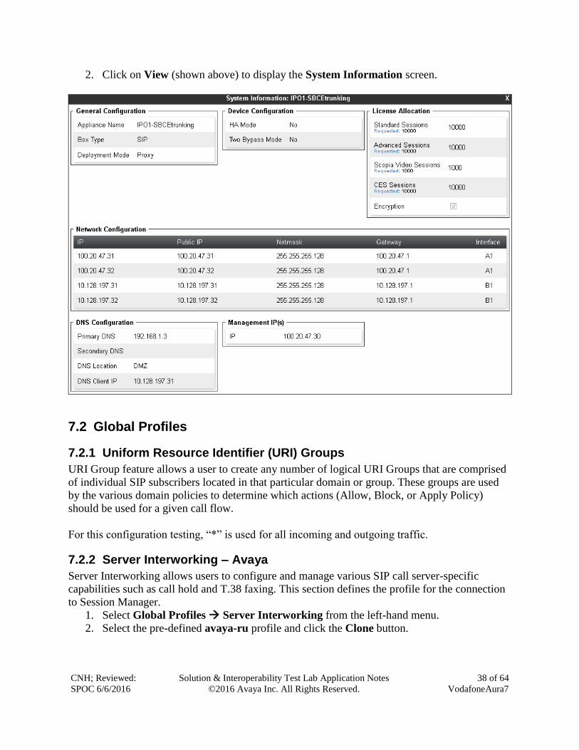
7.1 System Management – Status
1. Select System Management and verify that the Status column says Commissioned. If
not, contact your Avaya representative.
CNH; Reviewed:
SPOC 6/6/2016
Solution & Interoperability Test Lab Application Notes
©2016 Avaya Inc. All Rights Reserved.
38 of 64
VodafoneAura7
2. Click on View (shown above) to display the System Information screen.
7.2 Global Profiles
7.2.1 Uniform Resource Identifier (URI) Groups
URI Group feature allows a user to create any number of logical URI Groups that are comprised
of individual SIP subscribers located in that particular domain or group. These groups are used
by the various domain policies to determine which actions (Allow, Block, or Apply Policy)
should be used for a given call flow.
For this configuration testing, “*” is used for all incoming and outgoing traffic.
7.2.2 Server Interworking – Avaya
Server Interworking allows users to configure and manage various SIP call server-specific
capabilities such as call hold and T.38 faxing. This section defines the profile for the connection
to Session Manager.
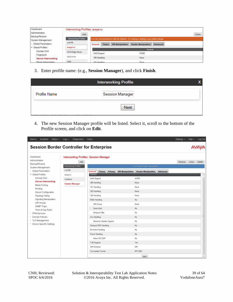
1. Select Global Profiles Server Interworking from the left-hand menu.
2. Select the pre-defined avaya-ru profile and click the Clone button.
CNH; Reviewed:
SPOC 6/6/2016
Solution & Interoperability Test Lab Application Notes
©2016 Avaya Inc. All Rights Reserved.
39 of 64
VodafoneAura7
3. Enter profile name: (e.g., Session Manager), and click Finish.
4. The new Session Manager profile will be listed. Select it, scroll to the bottom of the
Profile screen, and click on Edit.
CNH; Reviewed:
SPOC 6/6/2016
Solution & Interoperability Test Lab Application Notes
©2016 Avaya Inc. All Rights Reserved.
40 of 64
VodafoneAura7
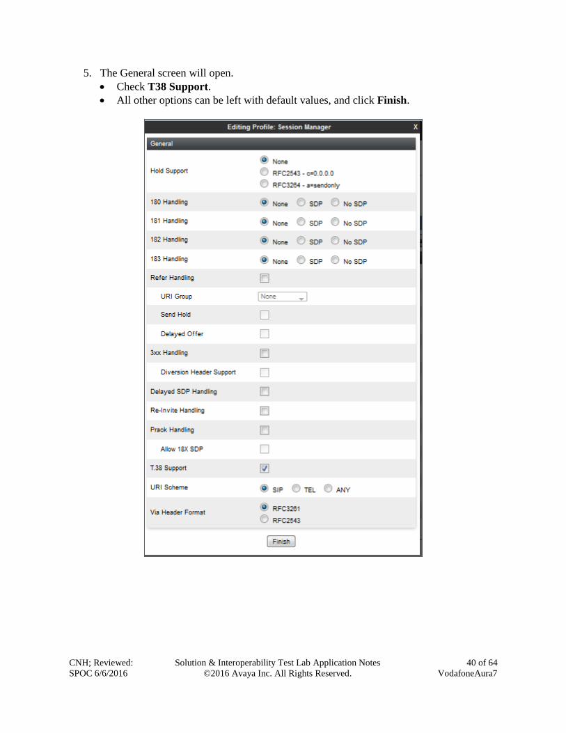
5. The General screen will open.
Check T38 Support.
All other options can be left with default values, and click Finish.
CNH; Reviewed:
SPOC 6/6/2016
Solution & Interoperability Test Lab Application Notes
©2016 Avaya Inc. All Rights Reserved.
41 of 64
VodafoneAura7
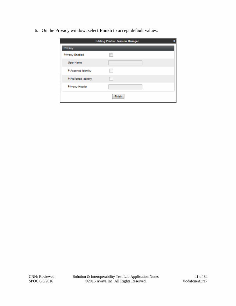
6. On the Privacy window, select Finish to accept default values.
CNH; Reviewed:
SPOC 6/6/2016
Solution & Interoperability Test Lab Application Notes
©2016 Avaya Inc. All Rights Reserved.
42 of 64
VodafoneAura7
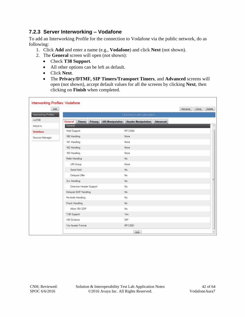
7.2.3 Server Interworking – Vodafone
To add an Interworking Profile for the connection to Vodafone via the public network, do as
following:
1. Click Add and enter a name (e.g., Vodafone) and click Next (not shown).
2. The General screen will open (not shown):
Check T38 Support.
All other options can be left as default.
Click Next.
The Privacy/DTMF, SIP Timers/Transport Timers, and Advanced screens will
open (not shown), accept default values for all the screens by clicking Next, then
clicking on Finish when completed.
CNH; Reviewed:
SPOC 6/6/2016
Solution & Interoperability Test Lab Application Notes
©2016 Avaya Inc. All Rights Reserved.
43 of 64
VodafoneAura7
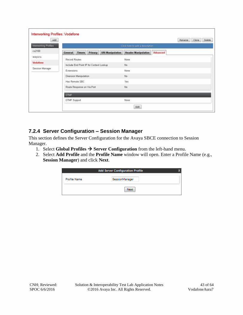
7.2.4 Server Configuration – Session Manager
This section defines the Server Configuration for the Avaya SBCE connection to Session
Manager.
1. Select Global Profiles Server Configuration from the left-hand menu.
2. Select Add Profile and the Profile Name window will open. Enter a Profile Name (e.g.,
Session Manager) and click Next.
CNH; Reviewed:
SPOC 6/6/2016
Solution & Interoperability Test Lab Application Notes
©2016 Avaya Inc. All Rights Reserved.
44 of 64
VodafoneAura7
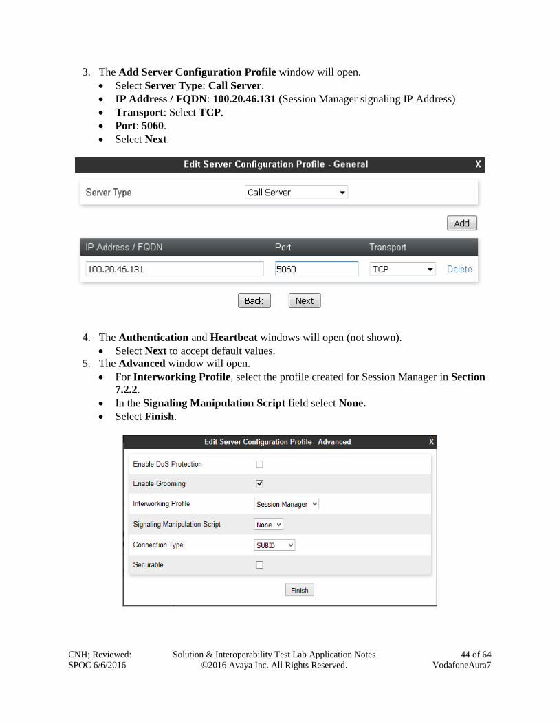
3. The Add Server Configuration Profile window will open.
Select Server Type: Call Server.
IP Address / FQDN: 100.20.46.131 (Session Manager signaling IP Address)
Transport: Select TCP.
Port: 5060.
Select Next.
4. The Authentication and Heartbeat windows will open (not shown).
Select Next to accept default values.
5. The Advanced window will open.
For Interworking Profile, select the profile created for Session Manager in Section
7.2.2.
In the Signaling Manipulation Script field select None.
Select Finish.
CNH; Reviewed:
SPOC 6/6/2016
Solution & Interoperability Test Lab Application Notes
©2016 Avaya Inc. All Rights Reserved.
45 of 64
VodafoneAura7
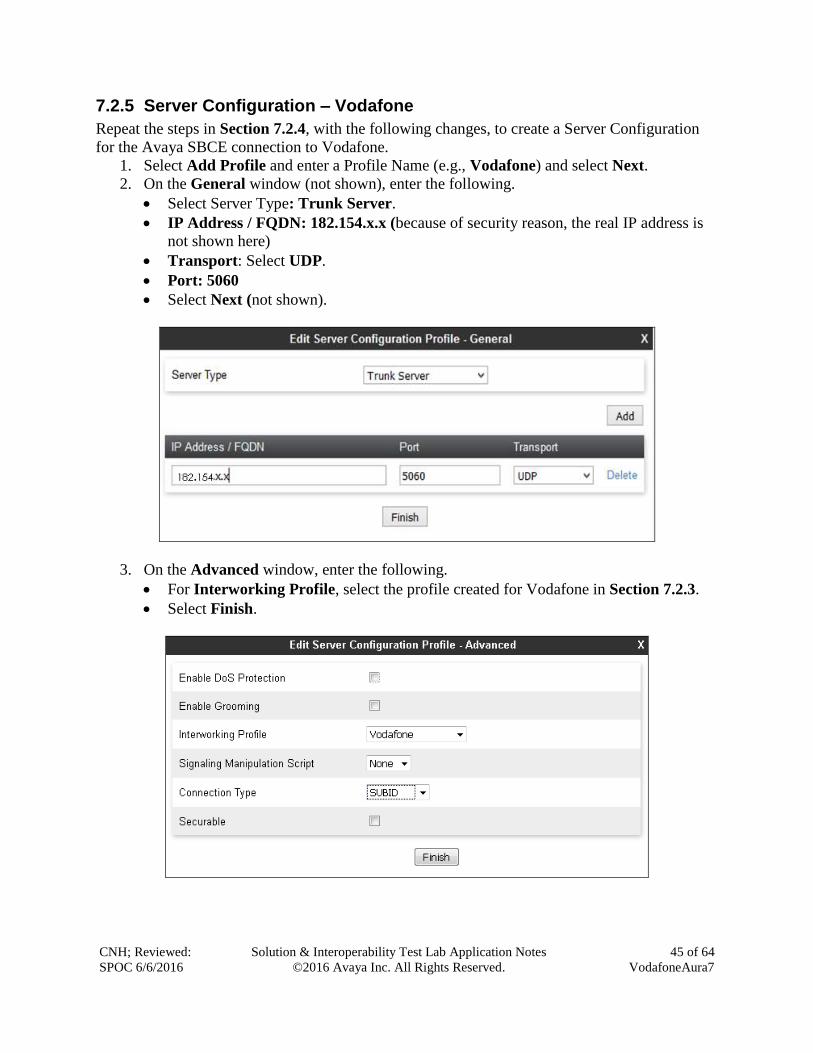
7.2.5 Server Configuration – Vodafone
Repeat the steps in Section 7.2.4, with the following changes, to create a Server Configuration
for the Avaya SBCE connection to Vodafone.
1. Select Add Profile and enter a Profile Name (e.g., Vodafone) and select Next.
2. On the General window (not shown), enter the following.
Select Server Type: Trunk Server.
IP Address / FQDN: 182.154.x.x (because of security reason, the real IP address is
not shown here)
Transport: Select UDP.
Port: 5060
Select Next (not shown).
3. On the Advanced window, enter the following.
For Interworking Profile, select the profile created for Vodafone in Section 7.2.3.
Select Finish.
CNH; Reviewed:
SPOC 6/6/2016
Solution & Interoperability Test Lab Application Notes
©2016 Avaya Inc. All Rights Reserved.
46 of 64
VodafoneAura7
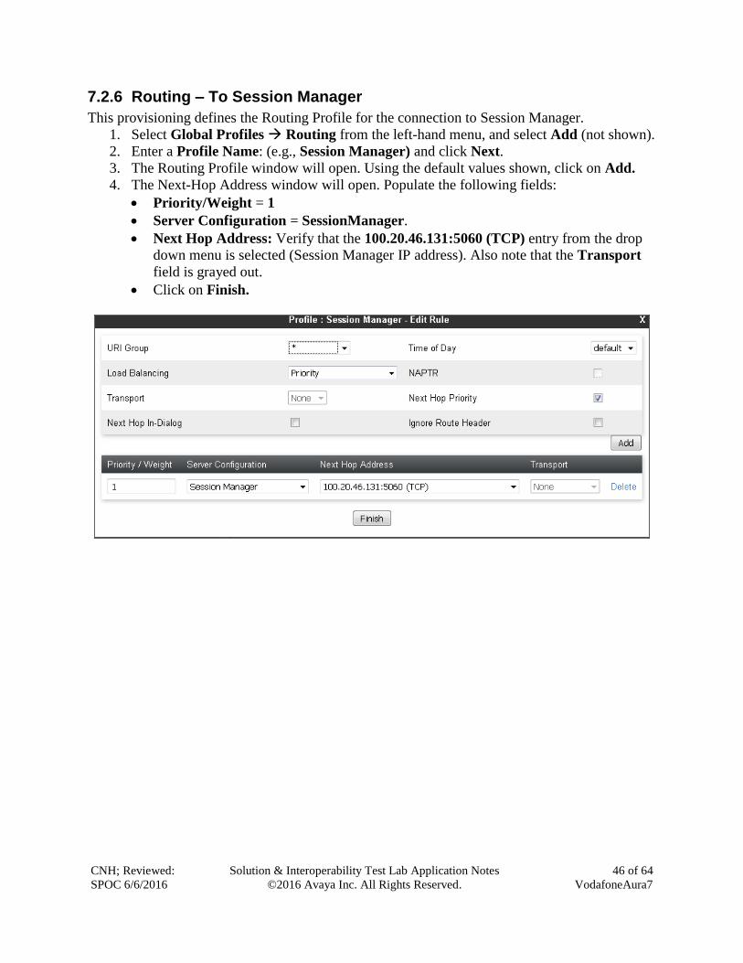
7.2.6 Routing – To Session Manager
This provisioning defines the Routing Profile for the connection to Session Manager.
1. Select Global Profiles Routing from the left-hand menu, and select Add (not shown).
2. Enter a Profile Name: (e.g., Session Manager) and click Next.
3. The Routing Profile window will open. Using the default values shown, click on Add.
4. The Next-Hop Address window will open. Populate the following fields:
Priority/Weight = 1
Server Configuration = SessionManager.
Next Hop Address: Verify that the 100.20.46.131:5060 (TCP) entry from the drop
down menu is selected (Session Manager IP address). Also note that the Transport
field is grayed out.
Click on Finish.
CNH; Reviewed:
SPOC 6/6/2016
Solution & Interoperability Test Lab Application Notes
©2016 Avaya Inc. All Rights Reserved.
47 of 64
VodafoneAura7
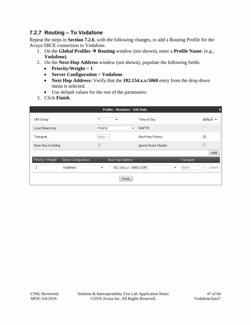
7.2.7 Routing – To Vodafone
Repeat the steps in Section 7.2.6, with the following changes, to add a Routing Profile for the
Avaya SBCE connection to Vodafone.
1. On the Global Profiles Routing window (not shown), enter a Profile Name: (e.g.,
Vodafone).
2. On the Next-Hop Address window (not shown), populate the following fields:
Priority/Weight = 1
Server Configuration = Vodafone.
Next Hop Address: Verify that the 182.154.x.x:5060 entry from the drop down
menu is selected.
Use default values for the rest of the parameters.
3. Click Finish.
CNH; Reviewed:
SPOC 6/6/2016
Solution & Interoperability Test Lab Application Notes
©2016 Avaya Inc. All Rights Reserved.
48 of 64
VodafoneAura7
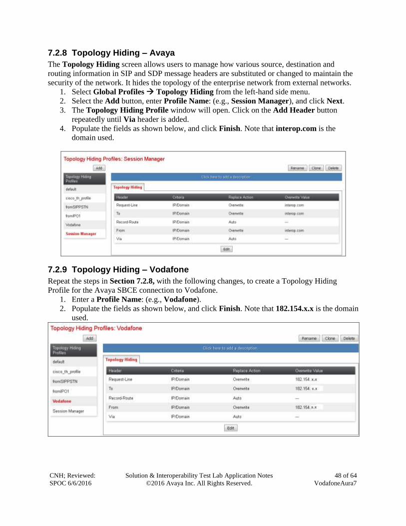
7.2.8 Topology Hiding – Avaya
The Topology Hiding screen allows users to manage how various source, destination and
routing information in SIP and SDP message headers are substituted or changed to maintain the
security of the network. It hides the topology of the enterprise network from external networks.
1. Select Global Profiles Topology Hiding from the left-hand side menu.
2. Select the Add button, enter Profile Name: (e.g., Session Manager), and click Next.
3. The Topology Hiding Profile window will open. Click on the Add Header button
repeatedly until Via header is added.
4. Populate the fields as shown below, and click Finish. Note that interop.com is the
domain used.
7.2.9 Topology Hiding – Vodafone
Repeat the steps in Section 7.2.8, with the following changes, to create a Topology Hiding
Profile for the Avaya SBCE connection to Vodafone.
1. Enter a Profile Name: (e.g., Vodafone).
2. Populate the fields as shown below, and click Finish. Note that 182.154.x.x is the domain
used.
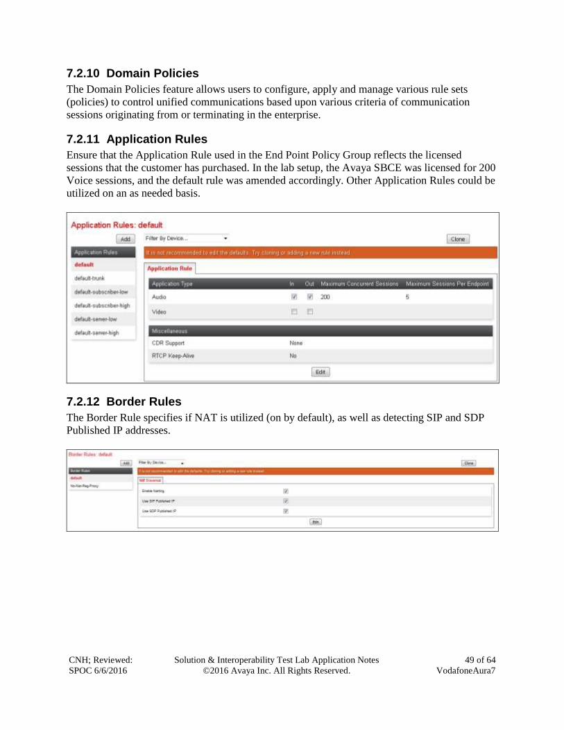
CNH; Reviewed:
SPOC 6/6/2016
Solution & Interoperability Test Lab Application Notes
©2016 Avaya Inc. All Rights Reserved.
49 of 64
VodafoneAura7
7.2.10 Domain Policies
The Domain Policies feature allows users to configure, apply and manage various rule sets
(policies) to control unified communications based upon various criteria of communication
sessions originating from or terminating in the enterprise.
7.2.11 Application Rules
Ensure that the Application Rule used in the End Point Policy Group reflects the licensed
sessions that the customer has purchased. In the lab setup, the Avaya SBCE was licensed for 200
Voice sessions, and the default rule was amended accordingly. Other Application Rules could be
utilized on an as needed basis.
7.2.12 Border Rules
The Border Rule specifies if NAT is utilized (on by default), as well as detecting SIP and SDP
Published IP addresses.
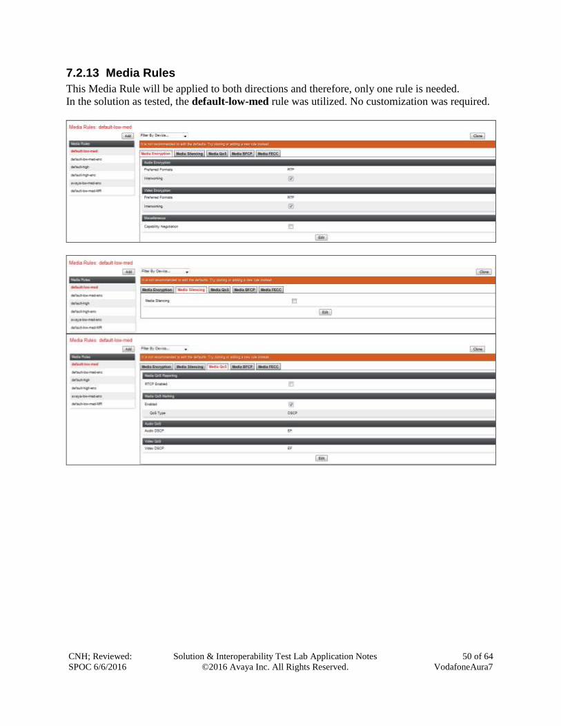
CNH; Reviewed:
SPOC 6/6/2016
Solution & Interoperability Test Lab Application Notes
©2016 Avaya Inc. All Rights Reserved.
50 of 64
VodafoneAura7
7.2.13 Media Rules
This Media Rule will be applied to both directions and therefore, only one rule is needed.
In the solution as tested, the default-low-med rule was utilized. No customization was required.
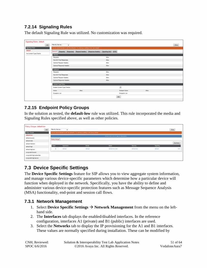
CNH; Reviewed:
SPOC 6/6/2016
Solution & Interoperability Test Lab Application Notes
©2016 Avaya Inc. All Rights Reserved.
51 of 64
VodafoneAura7
7.2.14 Signaling Rules
The default Signaling Rule was utilized. No customization was required.
7.2.15 Endpoint Policy Groups
In the solution as tested, the default-low rule was utilized. This rule incorporated the media and
Signaling Rules specified above, as well as other policies.
7.3 Device Specific Settings
The Device Specific Settings feature for SIP allows you to view aggregate system information,
and manage various device-specific parameters which determine how a particular device will
function when deployed in the network. Specifically, you have the ability to define and
administer various device-specific protection features such as Message Sequence Analysis
(MSA) functionality, end-point and session call flows.
7.3.1 Network Management
1. Select Device Specific Settings Network Management from the menu on the left-
hand side.
2. The Interfaces tab displays the enabled/disabled interfaces. In the reference
configuration, interfaces A1 (private) and B1 (public) interfaces are used.
3. Select the Networks tab to display the IP provisioning for the A1 and B1 interfaces.
These values are normally specified during installation. These can be modified by
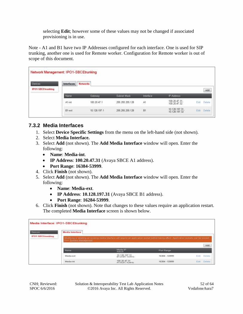
CNH; Reviewed:
SPOC 6/6/2016
Solution & Interoperability Test Lab Application Notes
©2016 Avaya Inc. All Rights Reserved.
52 of 64
VodafoneAura7
selecting Edit; however some of these values may not be changed if associated
provisioning is in use.
Note - A1 and B1 have two IP Addresses configured for each interface. One is used for SIP
trunking, another one is used for Remote worker. Configuration for Remote worker is out of
scope of this document.
7.3.2 Media Interfaces
1. Select Device Specific Settings from the menu on the left-hand side (not shown).
2. Select Media Interface.
3. Select Add (not shown). The Add Media Interface window will open. Enter the
following:
Name: Media-int.
IP Address: 100.20.47.31 (Avaya SBCE A1 address).
Port Range: 16384-53999.
4. Click Finish (not shown).
5. Select Add (not shown). The Add Media Interface window will open. Enter the
following:
Name: Media-ext.
IP Address: 10.128.197.31 (Avaya SBCE B1 address).
Port Range: 16284-53999.
6. Click Finish (not shown). Note that changes to these values require an application restart.
The completed Media Interface screen is shown below.
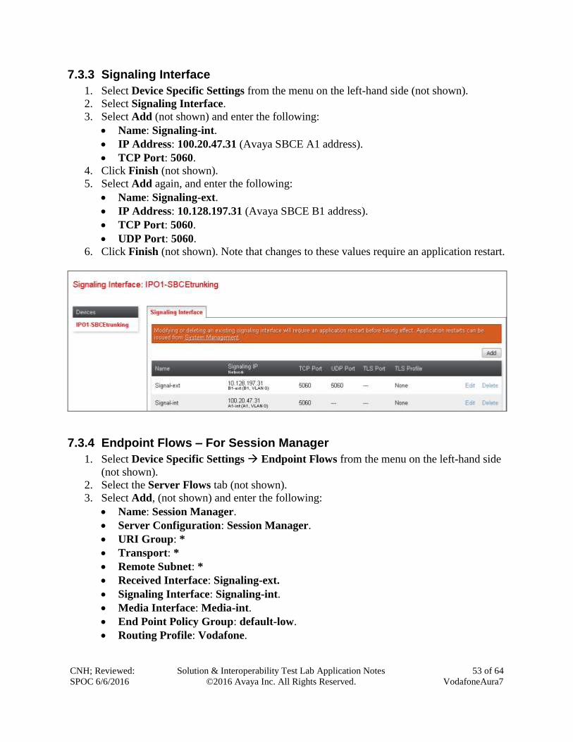
CNH; Reviewed:
SPOC 6/6/2016
Solution & Interoperability Test Lab Application Notes
©2016 Avaya Inc. All Rights Reserved.
53 of 64
VodafoneAura7
7.3.3 Signaling Interface
1. Select Device Specific Settings from the menu on the left-hand side (not shown).
2. Select Signaling Interface.
3. Select Add (not shown) and enter the following:
Name: Signaling-int.
IP Address: 100.20.47.31 (Avaya SBCE A1 address).
TCP Port: 5060.
4. Click Finish (not shown).
5. Select Add again, and enter the following:
Name: Signaling-ext.
IP Address: 10.128.197.31 (Avaya SBCE B1 address).
TCP Port: 5060.
UDP Port: 5060.
6. Click Finish (not shown). Note that changes to these values require an application restart.
7.3.4 Endpoint Flows – For Session Manager
1. Select Device Specific Settings Endpoint Flows from the menu on the left-hand side
(not shown).
2. Select the Server Flows tab (not shown).
3. Select Add, (not shown) and enter the following:
Name: Session Manager.
Server Configuration: Session Manager.
URI Group: *
Transport: *
Remote Subnet: *
Received Interface: Signaling-ext.
Signaling Interface: Signaling-int.
Media Interface: Media-int.
End Point Policy Group: default-low.
Routing Profile: Vodafone.
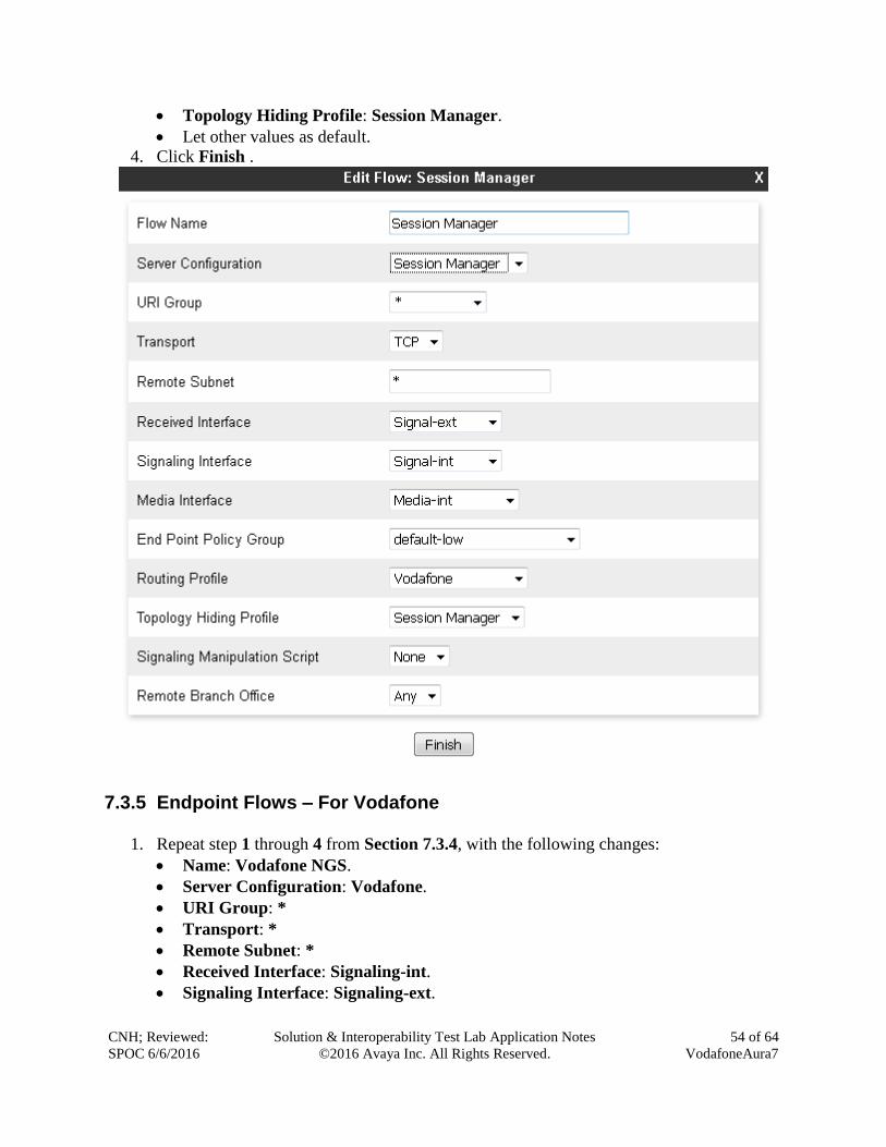
CNH; Reviewed:
SPOC 6/6/2016
Solution & Interoperability Test Lab Application Notes
©2016 Avaya Inc. All Rights Reserved.
54 of 64
VodafoneAura7
Topology Hiding Profile: Session Manager.
Let other values as default.
4. Click Finish .
7.3.5 Endpoint Flows – For Vodafone
1. Repeat step 1 through 4 from Section 7.3.4, with the following changes:
Name: Vodafone NGS.
Server Configuration: Vodafone.
URI Group: *
Transport: *
Remote Subnet: *
Received Interface: Signaling-int.
Signaling Interface: Signaling-ext.
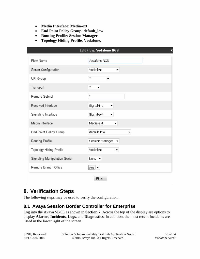
CNH; Reviewed:
SPOC 6/6/2016
Solution & Interoperability Test Lab Application Notes
©2016 Avaya Inc. All Rights Reserved.
55 of 64
VodafoneAura7
Media Interface: Media-ext
End Point Policy Group: default_low.
Routing Profile: Session Manager.
Topology Hiding Profile: Vodafone.
8. Verification Steps The following steps may be used to verify the configuration.
8.1 Avaya Session Border Controller for Enterprise
Log into the Avaya SBCE as shown in Section 7. Across the top of the display are options to
display Alarms, Incidents, Logs, and Diagnostics. In addition, the most recent Incidents are
listed in the lower right of the screen.
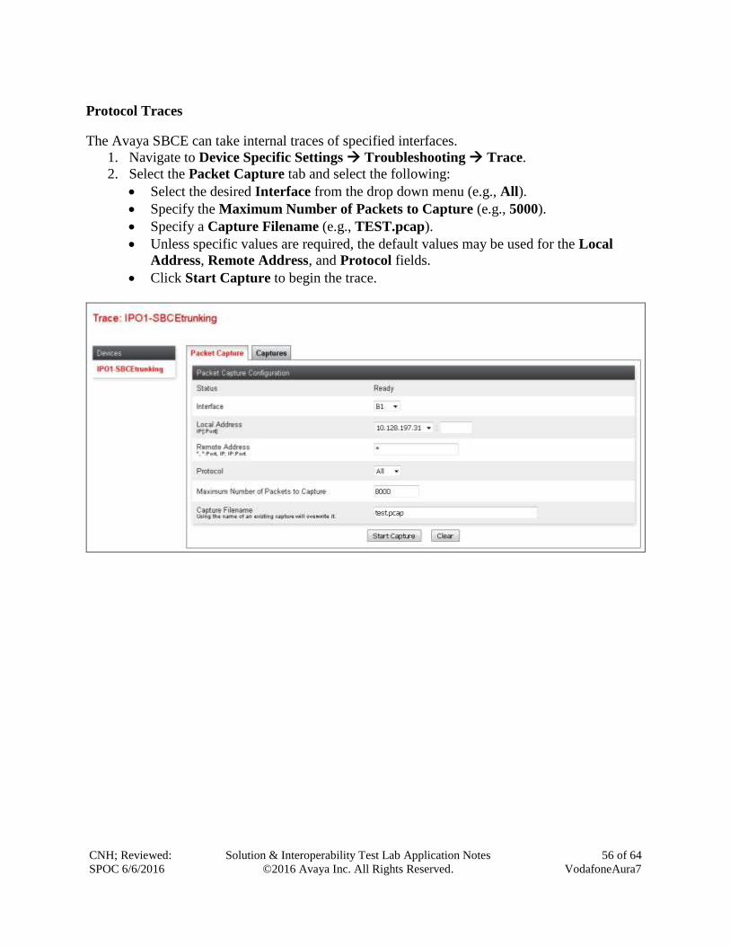
CNH; Reviewed:
SPOC 6/6/2016
Solution & Interoperability Test Lab Application Notes
©2016 Avaya Inc. All Rights Reserved.
56 of 64
VodafoneAura7
Protocol Traces
The Avaya SBCE can take internal traces of specified interfaces.
1. Navigate to Device Specific Settings Troubleshooting Trace.
2. Select the Packet Capture tab and select the following:
Select the desired Interface from the drop down menu (e.g., All).
Specify the Maximum Number of Packets to Capture (e.g., 5000).
Specify a Capture Filename (e.g., TEST.pcap).
Unless specific values are required, the default values may be used for the Local
Address, Remote Address, and Protocol fields.
Click Start Capture to begin the trace.
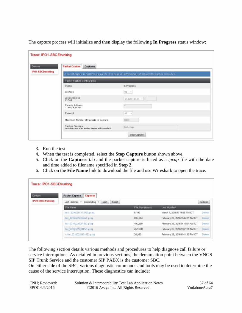
CNH; Reviewed:
SPOC 6/6/2016
Solution & Interoperability Test Lab Application Notes
©2016 Avaya Inc. All Rights Reserved.
57 of 64
VodafoneAura7
The capture process will initialize and then display the following In Progress status window:
3. Run the test.
4. When the test is completed, select the Stop Capture button shown above.
5. Click on the Captures tab and the packet capture is listed as a .pcap file with the date
and time added to filename specified in Step 2.
6. Click on the File Name link to download the file and use Wireshark to open the trace.
The following section details various methods and procedures to help diagnose call failure or
service interruptions. As detailed in previous sections, the demarcation point between the VNGS
SIP Trunk Service and the customer SIP PABX is the customer SBC.
On either side of the SBC, various diagnostic commands and tools may be used to determine the
cause of the service interruption. These diagnostics can include:
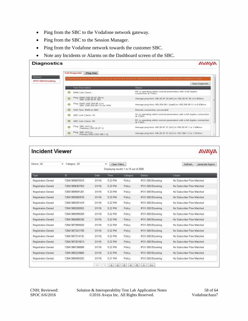
CNH; Reviewed:
SPOC 6/6/2016
Solution & Interoperability Test Lab Application Notes
©2016 Avaya Inc. All Rights Reserved.
58 of 64
VodafoneAura7
Ping from the SBC to the Vodafone network gateway.
Ping from the SBC to the Session Manager.
Ping from the Vodafone network towards the customer SBC.
Note any Incidents or Alarms on the Dashboard screen of the SBC.
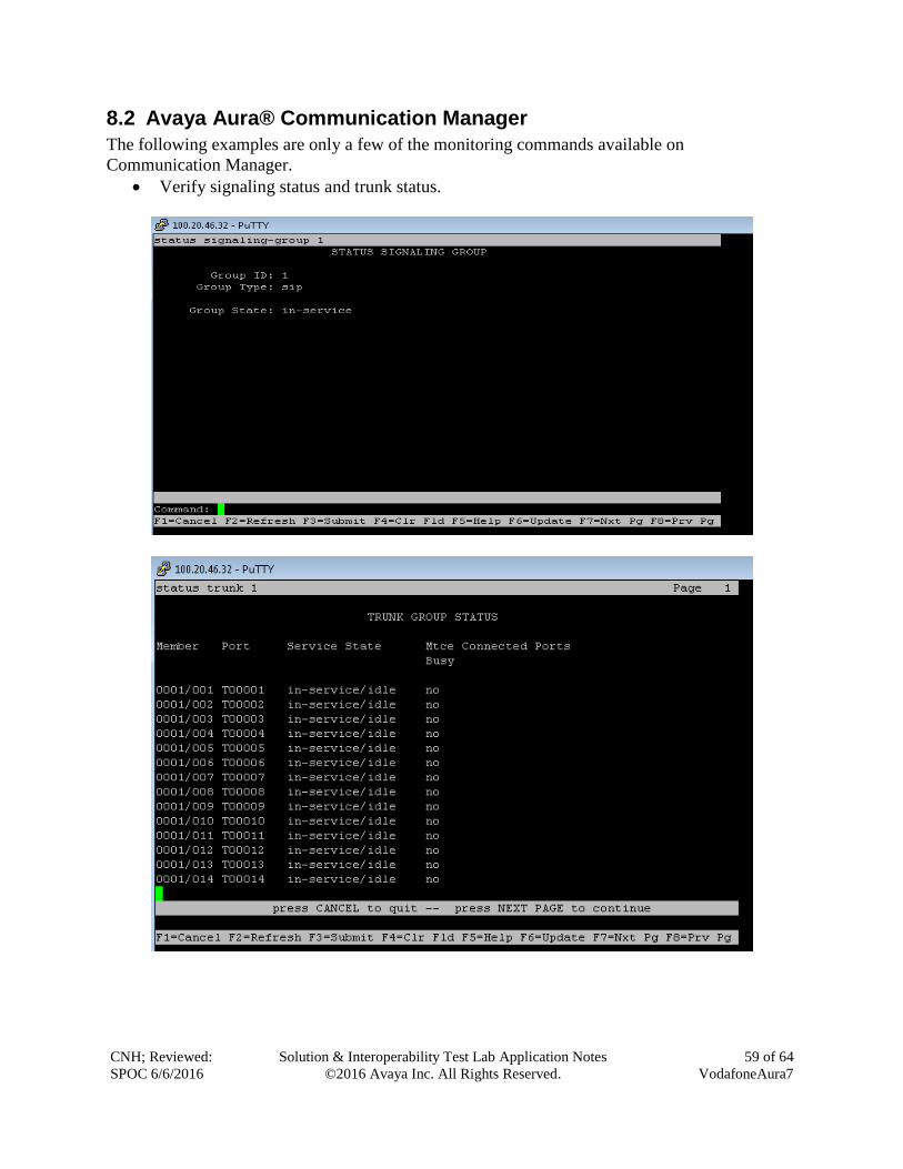
CNH; Reviewed:
SPOC 6/6/2016
Solution & Interoperability Test Lab Application Notes
©2016 Avaya Inc. All Rights Reserved.
59 of 64
VodafoneAura7
8.2 Avaya Aura® Communication Manager
The following examples are only a few of the monitoring commands available on
Communication Manager.
Verify signaling status and trunk status.
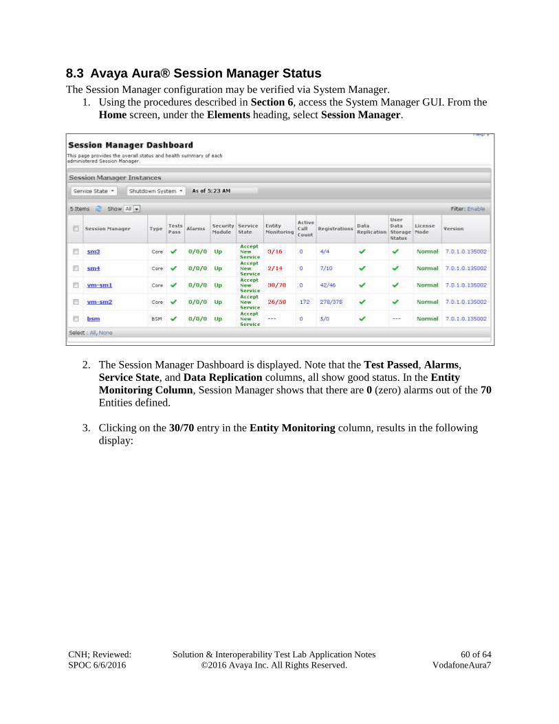
CNH; Reviewed:
SPOC 6/6/2016
Solution & Interoperability Test Lab Application Notes
©2016 Avaya Inc. All Rights Reserved.
60 of 64
VodafoneAura7
8.3 Avaya Aura® Session Manager Status
The Session Manager configuration may be verified via System Manager.
1. Using the procedures described in Section 6, access the System Manager GUI. From the
Home screen, under the Elements heading, select Session Manager.
2. The Session Manager Dashboard is displayed. Note that the Test Passed, Alarms,
Service State, and Data Replication columns, all show good status. In the Entity
Monitoring Column, Session Manager shows that there are 0 (zero) alarms out of the 70
Entities defined.
3. Clicking on the 30/70 entry in the Entity Monitoring column, results in the following
display:
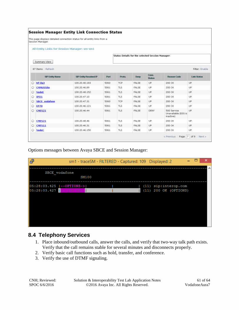
CNH; Reviewed:
SPOC 6/6/2016
Solution & Interoperability Test Lab Application Notes
©2016 Avaya Inc. All Rights Reserved.
61 of 64
VodafoneAura7
Options messages between Avaya SBCE and Session Manager:
8.4 Telephony Services
1. Place inbound/outbound calls, answer the calls, and verify that two-way talk path exists.
Verify that the call remains stable for several minutes and disconnects properly.
2. Verify basic call functions such as hold, transfer, and conference.
3. Verify the use of DTMF signaling.
CNH; Reviewed:
SPOC 6/6/2016
Solution & Interoperability Test Lab Application Notes
©2016 Avaya Inc. All Rights Reserved.
62 of 64
VodafoneAura7
9. Conclusion As illustrated in these Application Notes, Avaya Aura® Communication Manager 7.0, Avaya
Aura® Session Manager 7.0, and Avaya Session Border Control for Enterprise 7.0 can be
configured to interoperate successfully with Vodafone Next Generation Services SIP Trunking
service. This solution allows enterprise users access to the PSTN using the Vodafone Next
Generation Services SIP Trunking service connection. Please refer to Section 2.2 for exceptions.
10. Additional References This section references the documentation relevant to these Application Notes. Avaya product
documentation is available at http://support.avaya.com.
[1] What’s New in Avaya Aura Release 7.0, Release 7.0, 03-601818, Issue 1, August 2015.
[2] Deploying Avaya Aura® System Manager, Release 7.0, Issue 1, October 2015.
[3] Administering Avaya Aura® System Manager for Release 7.0, Issue 1, August 2015.
[4] Administering Avaya Aura® Session Manager, Release 7.0, Issue 1, August 2015.
[5] Deploying Avaya Aura Communication Manager in Virtualized Environment, Release7, Issue
1, August 2015.
[6] Avaya Session Border Controller for Enterprise Overview and Specification, Release 7.0,
Issue
1, August 2015.
[7] Deploying Avaya Session Border Controller for Enterprise, Release 7.0, Issue 1, August
2015.
[8] Deploying Avaya Session Border Controller in Virtualized Environment, Release 7.0, Issue 1,
August 2015.
[9] Administering Avaya Session Border Controller for Enterprise, Release 7.0, Issue 1, August
2015.
[10] Deploying and Updating Avaya Aura Media Server Appliance, Release 7.7, Issue 1, August
2015.
[11] Quick Start Guide to Using the Avaya Aura® Media Server with Avaya Aura®
Communication Manager, Release 7.7, August 2015.
[12] Deploying Avaya Aura® Messaging for Single Server Systems 6.3.3, Release 6.3.3, August
2015.
[13] Administering Avaya Aura® Messaging 6.3.3, Release 6.3.3, August 2015.
[14] 9600 Series IP Deskphones Overview and Specification, Release 7.0, Issue 1, August 2015.
[15] Installing and Maintaining Avaya 9601/9608/9611G/9621G/9641G/9641GS IP Deskphones
SIP, Release 7.0, Issue 1, August 2015.
[16] Administering Avaya 9601/9608/9611G/9621G/9641G/9641GS IP Deskphones SIP, Release
7.0, Issue 2, August 2015.
[17] Administering Avaya one-X® Communicator, Release 6.2, April 2015.
[18] Configuring Remote Workers with Avaya Session Border Controller for Enterprise Rel. 6.2,
Avaya Aura® Communication Manager Rel. 6.3 and Avaya Aura® Session Managers Rel. 6.3.
Issue 1.
[19] RFC 3261 SIP: Session Initiation Protocol, http://www.ietf.org/
[20] RFC 3515, The Session Initiation Protocol (SIP) Refer Method, http://www.ietf.org/
CNH; Reviewed:
SPOC 6/6/2016
Solution & Interoperability Test Lab Application Notes
©2016 Avaya Inc. All Rights Reserved.
63 of 64
VodafoneAura7
[21] RFC 2833 RTP Payload for DTMF Digits, Telephony Tones and Telephony Signals,
http://www.ietf.org/
Product documentation for Vodafone Next Generation Services SIP Trunking Solution is
available from Vodafone.
CNH; Reviewed:
SPOC 6/6/2016
Solution & Interoperability Test Lab Application Notes
©2016 Avaya Inc. All Rights Reserved.
64 of 64
VodafoneAura7
©2016 Avaya Inc. All Rights Reserved.
Avaya and the Avaya Logo are trademarks of Avaya Inc. All trademarks identified by ® and
™ are registered trademarks or trademarks, respectively, of Avaya Inc. All other trademarks
are the property of their respective owners. The information provided in these Application
Notes is subject to change without notice. The configurations, technical data, and
recommendations provided in these Application Notes are believed to be accurate and
dependable, but are presented without express or implied warranty. Users are responsible for
their application of any products specified in these Application Notes.
Please e-mail any questions or comments pertaining to these Application Notes along with the
full title name and filename, located in the lower right corner, directly to the Avaya
DevConnect Program at [email protected].
Related Documents
![Juphoon SIP Stack · Juphoon SIP Introduction Juphoon. Classified Page 6 Of 41 [24] RFC3960: Early Media and Ringing Tone Generation in the SIP [25] RFC3911: The Session Initiation](https://static.cupdf.com/doc/110x72/5f14414ee956852c743336ab/juphoon-sip-stack-juphoon-sip-introduction-juphoon-classified-page-6-of-41-24.jpg)


