RDC; Reviewed: SPOC 12/14/2012 Solution & Interoperability Test Lab Application Notes ©2012 Avaya Inc. All Rights Reserved. 1 of 37 HP_AA62 Avaya Solution & Interoperability Test Lab Application Notes for Avaya Aura® Telephony Infrastructure in a Converged VoIP and Data Network using HP Networking Switches configured with Link Layer Discovery Protocol (LLDP), Quality of Service (QoS), and Power over Ethernet (PoE) - Issue 1.0 Abstract These Application Notes describe the configuration of a Voice over IP (VoIP) solution including an Avaya Aura® Telephony Infrastructure running in a converged VoIP and data network built with HP Networking Ethernet switches. The HP Networking switches were compliance-tested with Avaya Aura® Communication Manager, Avaya Aura® Session Manager and Avaya Aura® Communication Manager Messaging. Emphasis was placed on verifying interoperability with LLDP, L2/L3 QoS, and PoE. Information in these Application Notes has been obtained through DevConnect compliance testing and additional technical discussions. Testing was conducted via the DevConnect Program at the Avaya Solution and Interoperability Test Lab.

Welcome message from author
This document is posted to help you gain knowledge. Please leave a comment to let me know what you think about it! Share it to your friends and learn new things together.
Transcript

RDC; Reviewed:
SPOC 12/14/2012
Solution & Interoperability Test Lab Application Notes
©2012 Avaya Inc. All Rights Reserved.
1 of 37
HP_AA62
Avaya Solution & Interoperability Test Lab
Application Notes for Avaya Aura® Telephony
Infrastructure in a Converged VoIP and Data Network
using HP Networking Switches configured with Link Layer
Discovery Protocol (LLDP), Quality of Service (QoS), and
Power over Ethernet (PoE) - Issue 1.0
Abstract
These Application Notes describe the configuration of a Voice over IP (VoIP) solution
including an Avaya Aura® Telephony Infrastructure running in a converged VoIP and data
network built with HP Networking Ethernet switches. The HP Networking switches were
compliance-tested with Avaya Aura® Communication Manager, Avaya Aura® Session
Manager and Avaya Aura® Communication Manager Messaging. Emphasis was placed on
verifying interoperability with LLDP, L2/L3 QoS, and PoE.
Information in these Application Notes has been obtained through DevConnect compliance
testing and additional technical discussions. Testing was conducted via the DevConnect
Program at the Avaya Solution and Interoperability Test Lab.

RDC; Reviewed:
SPOC 12/14/2012
Solution & Interoperability Test Lab Application Notes
©2012 Avaya Inc. All Rights Reserved.
2 of 37
HP_AA62
1. Introduction These Application Notes describe the configuration of a Voice over IP (VoIP) solution including
an Avaya Aura® Telephony Infrastructure running in a converged VoIP and data network built
with HP Networking 5400zl, 3800, 2620, 2915, and 2910 Series Switches. Compliance testing
verified multiple methods for configuring Voice VLAN and Quality of Service (QoS), including
Aura® Communication Manager forms, settings files, and Link Layer Discovery Protocol for
Media Endpoint Devices (LLDP-MED). Power over Ethernet (PoE) was also verified. Quality of
Service (QoS) based on Layer 2 Priority (802.1p) and Layer 3 Differentiated Services (Diffserv)
was implemented across the network to prioritize voice traffic over data traffic. The Avaya IP
Telephones received QoS priority settings from Avaya Aura® Communication Manager and
were enforced across the network by the HP Switches. Additionally QoS parameters were
verified based on configuration file settings and LLDP auto discovery. To verify proper QoS
policies, VoIP traffic was given priority over data traffic, and tests were performed by over
subscribing the LAN interfaces with low priority data traffic and verifying that acceptable voice
quality was achieved when calls were routed over all of the LAN interfaces. PoE was also
verified on the HP Networking switches.
2. General Test Approach and Test Results DevConnect Compliance Testing is conducted jointly by Avaya and DevConnect members. The
jointly-defined test plan focuses on exercising APIs and/or standards-based interfaces pertinent
to the interoperability of the tested products and their functionalities. DevConnect Compliance
Testing is not intended to substitute full product performance or feature testing performed by
DevConnect members, nor is it to be construed as an endorsement by Avaya of the suitability or
completeness of a DevConnect member’s solution.
2.1. Interoperability Compliance Testing
The interoperability compliance testing included the following:
All test cases were performed manually.
LAN connectivity between the Avaya and HP Networking products.
Registration of Avaya H.323 endpoints with Communication Manager.
Registration of Avaya SIP endpoints with Session Manager.
VoIP calls, including, hold, transfer and conferencing.
QoS for voice signaling and voice media received higher priority based on 802.1p and
DSCP settings.
Configuration of QoS parameters using Avaya Communication Manager
Auto discovery of QoS parameters using LLDP-MED
Auto discovery of Voice VLAN using LLDP-MED
Avaya Communication Manager Messaging voicemail and MWI works properly.

RDC; Reviewed:
SPOC 12/14/2012
Solution & Interoperability Test Lab Application Notes
©2012 Avaya Inc. All Rights Reserved.
3 of 37
HP_AA62
Compliance testing focused on the QoS, VLAN, and PoE implementation in the Avaya/HP
Networking configuration. Specifically, compliance testing verified that when the HP
Networking switch interfaces were oversubscribed with low priority data traffic, the higher
priority VoIP media and signaling traffic still got through and achieved good voice quality.
Prioritization of voice traffic was achieved by implementing Layer 3 DiffServ-based QoS and
Layer 2 priority (801.p). Voice and data traffic were segmented in the enterprise network using
VLANs. Auto discovery of Voice VLAN, and QoS parameters, using LLDP were also verified
along with the ability to power Avaya IP telephones via PoE.
2.2. Test Results
The test objectives listed in Section 2.1 were verified. QoS and performance testing was verified
by making voice calls while a traffic generator generated low priority data traffic to simulate a
congested network. At the end of the performance test, it was verified that the network devices
continued to operate successfully. Additionally tests were repeated using the configuration
settings discovered via LLDP.
Serviceability testing was conducted to verify the ability of the Avaya/HP Networking VoIP
solution to recover from adverse conditions, such as power cycling network devices and
disconnecting/reconnecting cables between the LAN interfaces. In all cases, the ability to
recover after the network normalized was verified.
All feature functionality, serviceability, and performance test cases passed. The HP Networking
implementation prioritized VoIP traffic and yielded good voice quality without dropping any
calls.
PoE parameters were verified using HP Networking show commands and fell within acceptable
ranges.
All of HP Networking products used in the compliance testing successfully passed.
2.3. Support
For technical support on HP Networking products, consult the following support pages by
contacting HP Networking customer support at:
Contact us: http://h17007.www1.hp.com/us/en/contact
Website Support: http://h17007.www1.hp.com/us/en/support/converter/index.aspx
Website Product Information: http://h17007.www1.hp.com/us/en/index.aspx
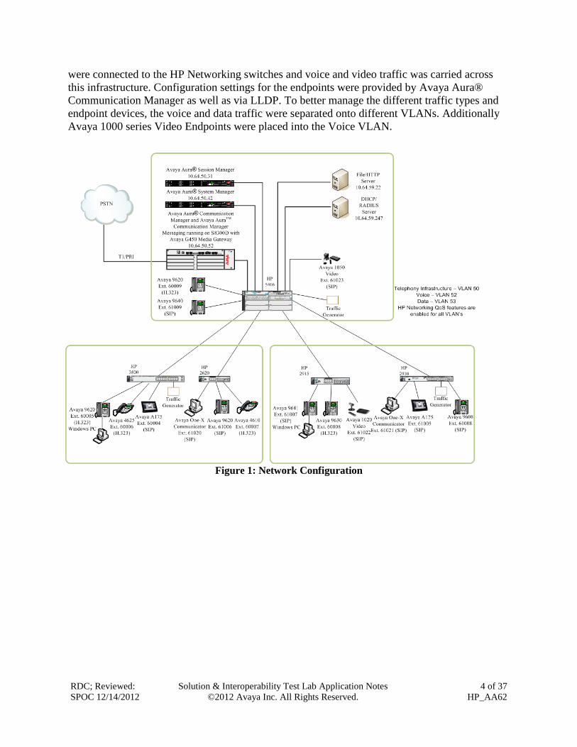
3. Reference Configuration Figure 1 illustrates the configuration used for compliance testing. The network consisted of
Avaya Aura® Communication Manager Server running on an S8300D card that was installed in
the G450 Media gateway, Avaya Aura® Session Manager, and IP endpoints including, Avaya IP
Telephones, Avaya one-X communicator, and Avaya video endpoints. All Avaya components
RDC; Reviewed:
SPOC 12/14/2012
Solution & Interoperability Test Lab Application Notes
©2012 Avaya Inc. All Rights Reserved.
4 of 37
HP_AA62
were connected to the HP Networking switches and voice and video traffic was carried across
this infrastructure. Configuration settings for the endpoints were provided by Avaya Aura®
Communication Manager as well as via LLDP. To better manage the different traffic types and
endpoint devices, the voice and data traffic were separated onto different VLANs. Additionally
Avaya 1000 series Video Endpoints were placed into the Voice VLAN.
Figure 1: Network Configuration

RDC; Reviewed:
SPOC 12/14/2012
Solution & Interoperability Test Lab Application Notes
©2012 Avaya Inc. All Rights Reserved.
5 of 37
HP_AA62
4. Equipment and Software Validated The following equipment and software were used for the sample configuration provided:
Equipment Software/Firmware
Avaya PBX Products
Avaya S8300D Server running Avaya Aura®
Communication Manager
Avaya Aura® Communication Manager 6.0.1 with
SP5.0.1(Patch 19303)
Avaya G450 Media Gateway MGP
MM710 T1 Module
MM711 Analog Module
MM712 DCP Media Module
MP80 VoIP-DSP
HW 2 FW 31.20.0
HW 5 FW 22
HW 23 FW 73
HW 7 FW 14
HW 6 FW 67
Avaya Aura® Session Manager
Avaya Aura® Session Manager HP Proliant
DL360 G7 6.1 with SP5
Avaya Aura® System Manager HP Proliant
DL360 G7 6.1 with SP5
Avaya Messaging (Voice Mail) Products
Avaya Aura® Communication Manager
Messaging (CMM) 6.0
Avaya Endpoints
Avaya 96xx Series IP Telephones (H.323 3.1SP2), (SIP 2.6.6.0)
Avaya 96x1 Series IP Telephones (H.323 S6.010f), (SIP 6.0.3)
Avaya 46xx Series IP Telephones 2_9_1
Avaya One-X Communicator 6.1
Avaya A175Video Endpoint 1.1.0
Avaya 1020 Video Endpoint 4.8.3 (24)
Avaya 1050 Video Endpoint 4.8.3 (24)
HP Networking Products
HP 3800
https://h10145.www1.hp.com/downloads/SoftwareRe
leases.aspx?ProductNumber=J9573A
KA.15.03.3006
HP 2620
https://h10145.www1.hp.com/downloads/SoftwareRe
leases.aspx?ProductNumber=J9623A
RA.15.06.0009
HP 2915
https://h10145.www1.hp.com/downloads/SoftwareRe
leases.aspx?ProductNumber=J9562A
A.14.15
RDC; Reviewed:
SPOC 12/14/2012
Solution & Interoperability Test Lab Application Notes
©2012 Avaya Inc. All Rights Reserved.
6 of 37
HP_AA62
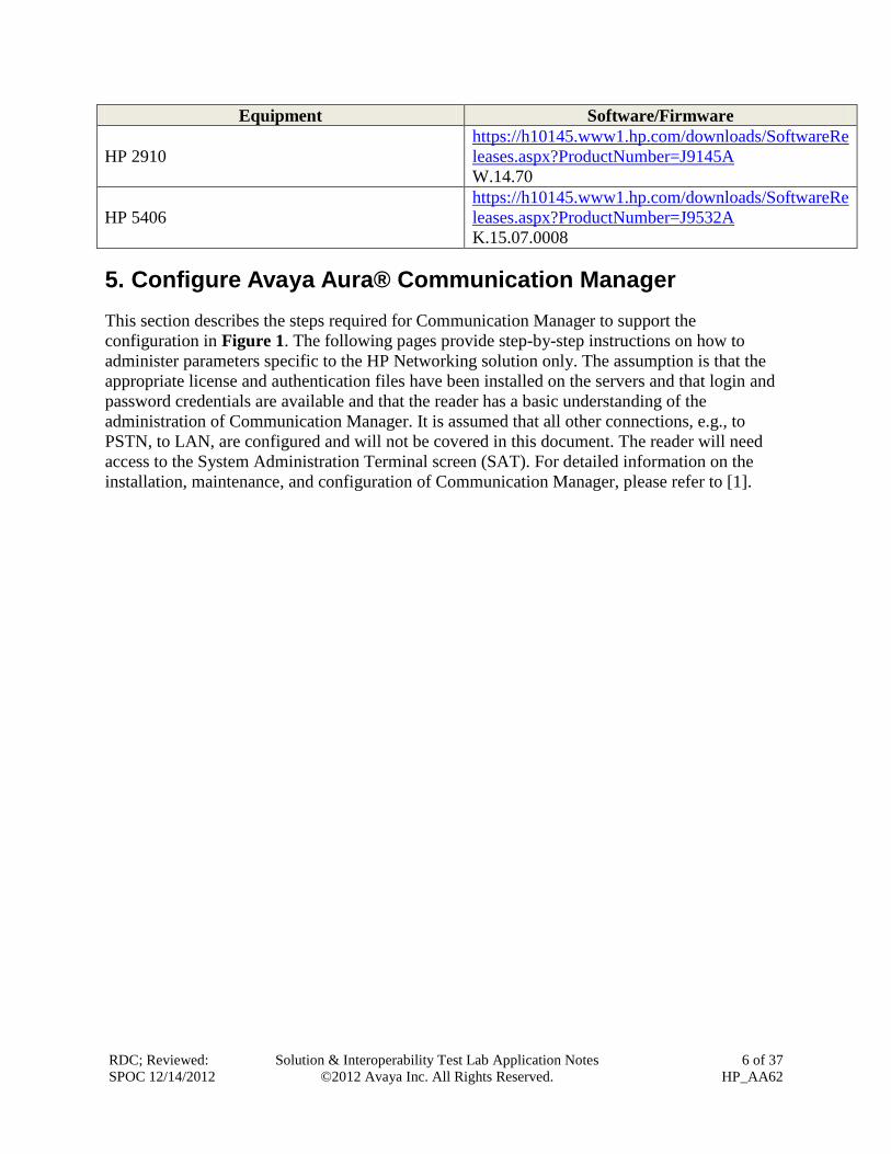
Equipment Software/Firmware
HP 2910
https://h10145.www1.hp.com/downloads/SoftwareRe
leases.aspx?ProductNumber=J9145A
W.14.70
HP 5406
https://h10145.www1.hp.com/downloads/SoftwareRe
leases.aspx?ProductNumber=J9532A
K.15.07.0008
5. Configure Avaya Aura® Communication Manager
This section describes the steps required for Communication Manager to support the
configuration in Figure 1. The following pages provide step-by-step instructions on how to
administer parameters specific to the HP Networking solution only. The assumption is that the
appropriate license and authentication files have been installed on the servers and that login and
password credentials are available and that the reader has a basic understanding of the
administration of Communication Manager. It is assumed that all other connections, e.g., to
PSTN, to LAN, are configured and will not be covered in this document. The reader will need
access to the System Administration Terminal screen (SAT). For detailed information on the
installation, maintenance, and configuration of Communication Manager, please refer to [1].
RDC; Reviewed:
SPOC 12/14/2012
Solution & Interoperability Test Lab Application Notes
©2012 Avaya Inc. All Rights Reserved.
7 of 37
HP_AA62
5.1. Configure QoS on Communication Manager for H.323 Telephones
IP networks were originally designed to carry data on a best-effort delivery basis, which meant
that all traffic had equal priority and an equal chance of being delivered in a timely manner. As a
result, all traffic had an equal chance of being dropped when congestion occurred. To insure
reliable delivery of latency sensitive voice and video traffic, QoS is utilized and should be
implemented consistently throughout the entire network.
In order to achieve prioritization of VoIP traffic, the VoIP traffic must be classified. The Avaya
IP endpoints support both Layer 2 802.1.p priority and Layer 3 DiffServ.
In the compliance test all network components were in network region 1. The DiffServ and
802.1p values configured here will be downloaded to the Avaya H.323 IP telephones via
Communication Manager.
Note: Avaya SIP endpoints can get QoS settings by downloading the 46xxsettings.txt file from
the HTTP server. See Section 6.
LLDP can also be used for auto discovering the voice VLAN and QoS settings and is covered in
Section 12.
For more information on QoS settings, please refer to [1].
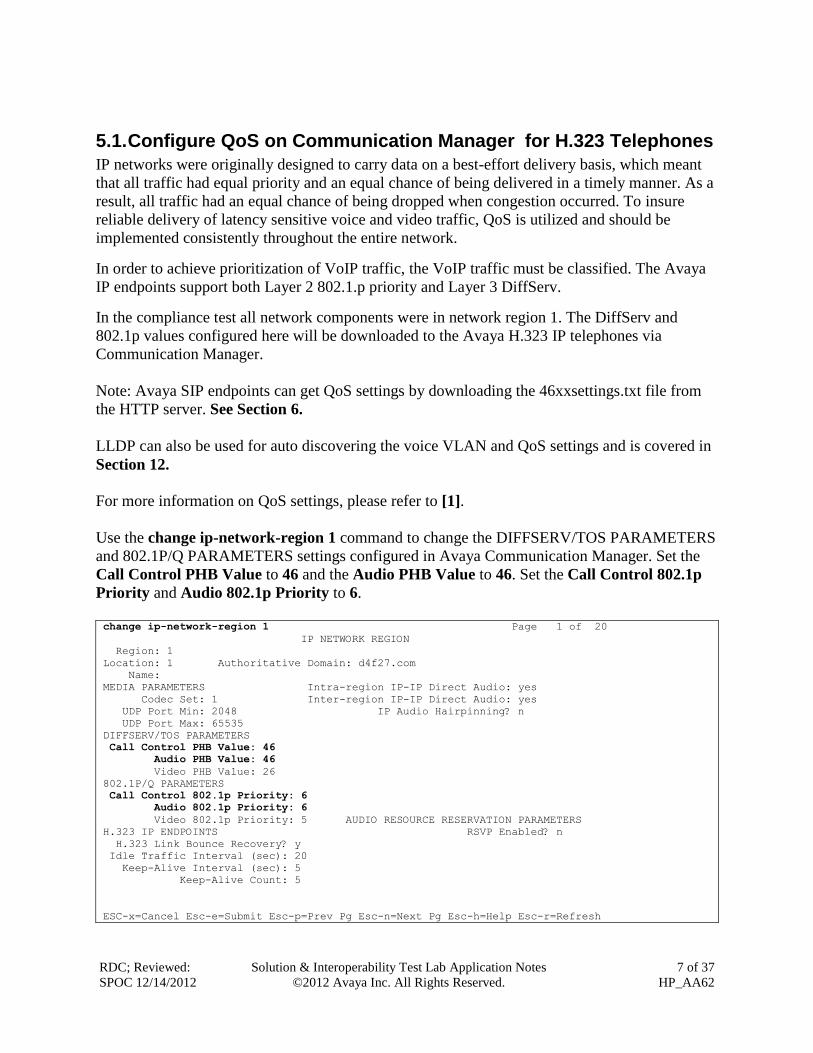
Use the change ip-network-region 1 command to change the DIFFSERV/TOS PARAMETERS
and 802.1P/Q PARAMETERS settings configured in Avaya Communication Manager. Set the
Call Control PHB Value to 46 and the Audio PHB Value to 46. Set the Call Control 802.1p
Priority and Audio 802.1p Priority to 6.
change ip-network-region 1 Page 1 of 20
IP NETWORK REGION
Region: 1
Location: 1 Authoritative Domain: d4f27.com
Name:
MEDIA PARAMETERS Intra-region IP-IP Direct Audio: yes
Codec Set: 1 Inter-region IP-IP Direct Audio: yes
UDP Port Min: 2048 IP Audio Hairpinning? n
UDP Port Max: 65535
DIFFSERV/TOS PARAMETERS
Call Control PHB Value: 46
Audio PHB Value: 46
Video PHB Value: 26
802.1P/Q PARAMETERS
Call Control 802.1p Priority: 6
Audio 802.1p Priority: 6
Video 802.1p Priority: 5 AUDIO RESOURCE RESERVATION PARAMETERS
H.323 IP ENDPOINTS RSVP Enabled? n
H.323 Link Bounce Recovery? y
Idle Traffic Interval (sec): 20
Keep-Alive Interval (sec): 5
Keep-Alive Count: 5
ESC-x=Cancel Esc-e=Submit Esc-p=Prev Pg Esc-n=Next Pg Esc-h=Help Esc-r=Refresh
RDC; Reviewed:
SPOC 12/14/2012
Solution & Interoperability Test Lab Application Notes
©2012 Avaya Inc. All Rights Reserved.
8 of 37
HP_AA62
The Differentiated Services Code Point (DSCP) value of 46 is used for both the signaling and
audio Per Hob Behavior (PHB) values for voice. DSCP 26 and 802.1p priority 5 is used for
video with the Avaya A175. DSCP 46 represents the Traffic Class of Expedited Forwarding (EF)
and the Traffic Type Voice.
Note: The 802.1p and DSCP values used above (i.e. 6 and 46) will be used consistently
throughout the configuration of the HP Networking switches. The DSCP value used above is in
decimal whereas the value used for HP Networking switch configuration later will be in binary
(i.e. 101110).
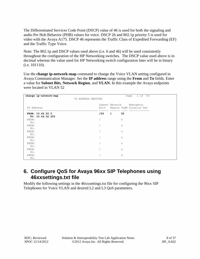
Use the change ip-network-map command to change the Voice VLAN setting configured in
Avaya Communication Manager. Set the IP address range using the From and To fields. Enter
a value for Subnet Bits, Network Region, and VLAN. In this example the Avaya endpoints
were located in VLAN 52
change ip-network-map Page 1 of 63
IP ADDRESS MAPPING
Subnet Network Emergency
IP Address Bits Region VLAN Location Ext
--------------------------------------------- ------ ------ ---- -------------
FROM: 10.64.52.0 /24 1 52
TO: 10.64.52.255
FROM: / n
TO:
FROM: / n
TO:
FROM: / n
TO:
FROM: / n
TO:
FROM: / n
TO:
FROM: / n
TO:
FROM: / n
TO:
6. Configure QoS for Avaya 96xx SIP Telephones using 46xxsettings.txt file
Modify the following settings in the 46xxsettings.txt file for configuring the 96xx SIP
Telephones for Voice VLAN and desired L2 and L3 QoS parameters.

RDC; Reviewed:
SPOC 12/14/2012
Solution & Interoperability Test Lab Application Notes
©2012 Avaya Inc. All Rights Reserved.
9 of 37
HP_AA62
################## 802.1P/Q SETTINGS ###################
##
## Voice VLAN Identifier
## VLAN identifier to be used by IP telephones. This
## parameter should only be set when IP telephones are to
## use a VLAN that is separate from the default data VLAN.
## If the VLAN identifier is to be configured via H.323
## signaling based on Avaya Communication Manager
## administration forms, it should not be set here.
## This parameter may also be changed via LLDP.
## Note : This setting is applicable for 1603 SIP phones also.
SET L2QVLAN 52
##
## Audio Priority Value
## Sets the layer 2 priority value for audio packets
## from the phone. (0-7)
## For H.323 phones, this parameter may also be
## changed from Communication Manager. For 96xx SIP
## phones, this parameter may also be changed via LLDP.
## Note : This setting is applicable for 1603 SIP phones also.
SET L2QAUD 6
##
## Signaling Priority Value
## Sets the layer 2 priority value for signaling
## protocol messages from the phone. (0-7)
## For H.323 phones, this parameter may also be
## changed from Communication Manager. For 96xx SIP
## phones, this parameter may also be changed via LLDP.
## Note : This setting is applicable for 1603 SIP phones also.
SET L2QSIG 6
##
## DSCPAUD Sets the DiffServ value for audio streams from the phone.
## The default is 46 and valid values are 0-63.
## For 96xx SIP phones, this parameter may also be changed via LLDP.
## Note: This setting is also applicable for 1603 SIP phones and 364x SIP phones.
SET DSCPAUD 46
##
## DSCPSIG Sets the DiffServ value for signaling protocol
## messages from the phone. The default is 34 and valid
## values are 0-63. For 96xx SIP phones, this parameter
## may also be changed via LLDP.
## Note: This setting is also applicable for 1603 SIP phones and 364x SIP phones.
SET DSCPSIG 46
##
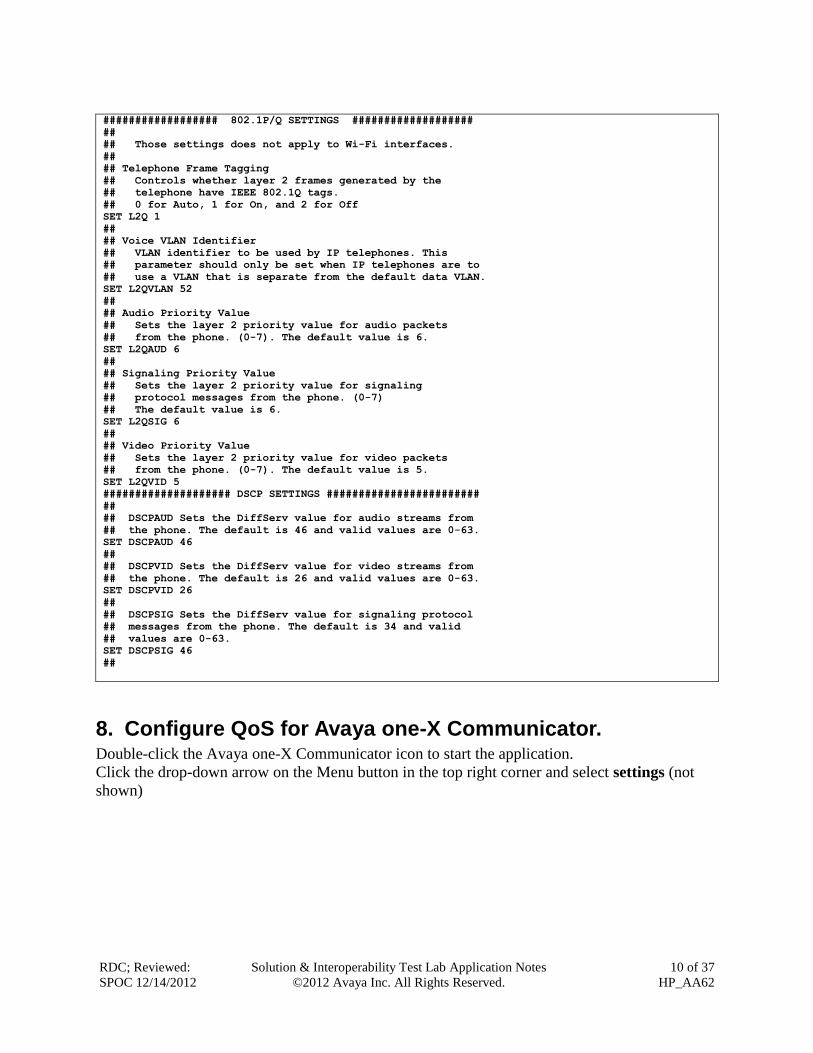
7. Configure QoS for Avaya A175 SIP Telephone using Axxxsettings.txt file
Modify the following setting in the Axxxsettings.txt file for configuring the A175 SIP
Telephones for Voice VLAN and desired L2 and L3 QoS parameters for voice and video.
RDC; Reviewed:
SPOC 12/14/2012
Solution & Interoperability Test Lab Application Notes
©2012 Avaya Inc. All Rights Reserved.
10 of 37
HP_AA62
################## 802.1P/Q SETTINGS ###################
##
## Those settings does not apply to Wi-Fi interfaces.
##
## Telephone Frame Tagging
## Controls whether layer 2 frames generated by the
## telephone have IEEE 802.1Q tags.
## 0 for Auto, 1 for On, and 2 for Off
SET L2Q 1
##
## Voice VLAN Identifier
## VLAN identifier to be used by IP telephones. This
## parameter should only be set when IP telephones are to
## use a VLAN that is separate from the default data VLAN.
SET L2QVLAN 52
##
## Audio Priority Value
## Sets the layer 2 priority value for audio packets
## from the phone. (0-7). The default value is 6.
SET L2QAUD 6
##
## Signaling Priority Value
## Sets the layer 2 priority value for signaling
## protocol messages from the phone. (0-7)
## The default value is 6.
SET L2QSIG 6
##
## Video Priority Value
## Sets the layer 2 priority value for video packets
## from the phone. (0-7). The default value is 5.
SET L2QVID 5
#################### DSCP SETTINGS ########################
##
## DSCPAUD Sets the DiffServ value for audio streams from
## the phone. The default is 46 and valid values are 0-63.
SET DSCPAUD 46
##
## DSCPVID Sets the DiffServ value for video streams from
## the phone. The default is 26 and valid values are 0-63.
SET DSCPVID 26
##
## DSCPSIG Sets the DiffServ value for signaling protocol
## messages from the phone. The default is 34 and valid
## values are 0-63.
SET DSCPSIG 46
##
8. Configure QoS for Avaya one-X Communicator. Double-click the Avaya one-X Communicator icon to start the application.
Click the drop-down arrow on the Menu button in the top right corner and select settings (not
shown)

RDC; Reviewed:
SPOC 12/14/2012
Solution & Interoperability Test Lab Application Notes
©2012 Avaya Inc. All Rights Reserved.
11 of 37
HP_AA62
From the left pane of the General Settings screen select Telephony. In the right pane click the
radio button for the desired protocol. Continue by entering an Extension: and Password: in the
appropriate fields, configuring Server List: by clicking the Add button and providing the IP
Address of the Proxy Server (not shown), and entering the Domain: name used for SIP.
The compliance test used SIP.
Note: Default values are ok for the remaining fields.

RDC; Reviewed:
SPOC 12/14/2012
Solution & Interoperability Test Lab Application Notes
©2012 Avaya Inc. All Rights Reserved.
12 of 37
HP_AA62
From the left pane of the General Settings screen select Network. Configure desired QoS
parameters in the right pane.

RDC; Reviewed:
SPOC 12/14/2012
Solution & Interoperability Test Lab Application Notes
©2012 Avaya Inc. All Rights Reserved.
13 of 37
HP_AA62
9. Configure QoS for Avaya 1000 series Video Conferencing Unit.
From a web browser enter the IP address of the Avaya 1000 series Video Conferencing Unit
(VCU) in the URL field to display the login page. Enter the proper login credentials and click the
Submit button.

RDC; Reviewed:
SPOC 12/14/2012
Solution & Interoperability Test Lab Application Notes
©2012 Avaya Inc. All Rights Reserved.
14 of 37
HP_AA62
RDC; Reviewed:
SPOC 12/14/2012
Solution & Interoperability Test Lab Application Notes
©2012 Avaya Inc. All Rights Reserved.
15 of 37
HP_AA62
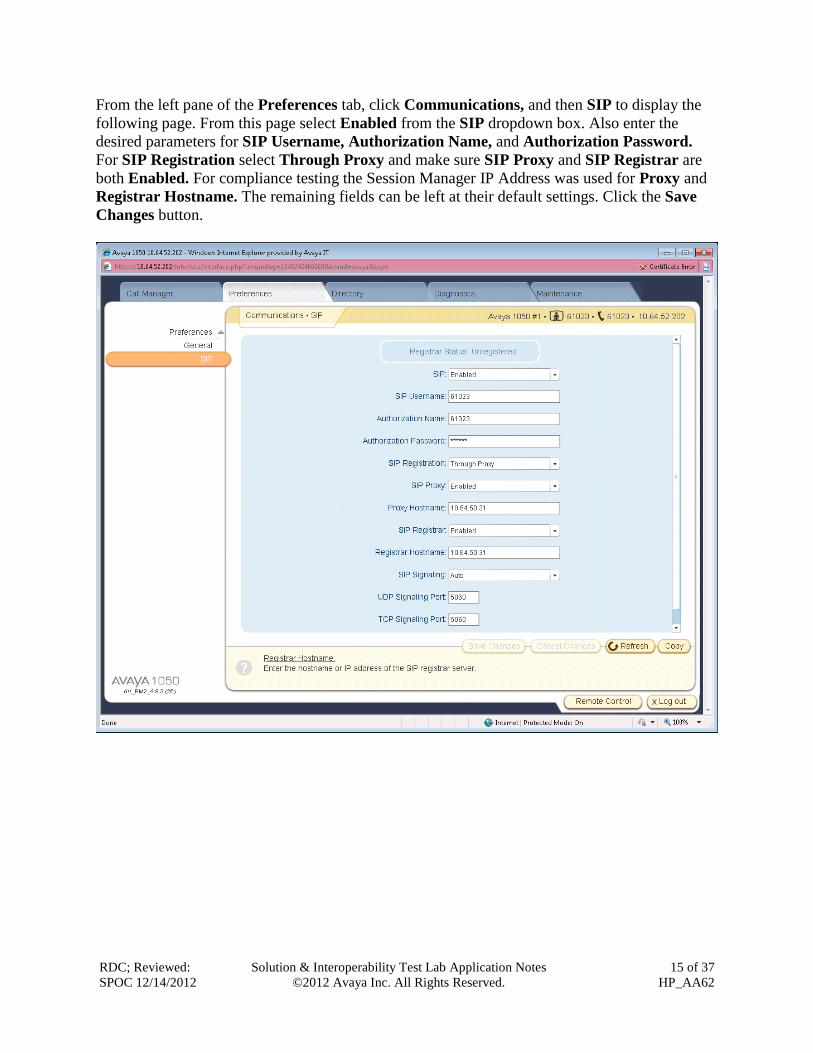
From the left pane of the Preferences tab, click Communications, and then SIP to display the
following page. From this page select Enabled from the SIP dropdown box. Also enter the
desired parameters for SIP Username, Authorization Name, and Authorization Password.
For SIP Registration select Through Proxy and make sure SIP Proxy and SIP Registrar are
both Enabled. For compliance testing the Session Manager IP Address was used for Proxy and
Registrar Hostname. The remaining fields can be left at their default settings. Click the Save
Changes button.

RDC; Reviewed:
SPOC 12/14/2012
Solution & Interoperability Test Lab Application Notes
©2012 Avaya Inc. All Rights Reserved.
16 of 37
HP_AA62
From the left pane of the Preferences tab, click Network, then Network QoS to display the
following page. From this page select DiffServ from the Network QoS dropdown box. Also
enter the desired parameters for DiffServ Audio Priority, DiffServ Video Priority, and
DiffServ Data Priority and click the Save Changes button.
RDC; Reviewed:
SPOC 12/14/2012
Solution & Interoperability Test Lab Application Notes
©2012 Avaya Inc. All Rights Reserved.
17 of 37
HP_AA62
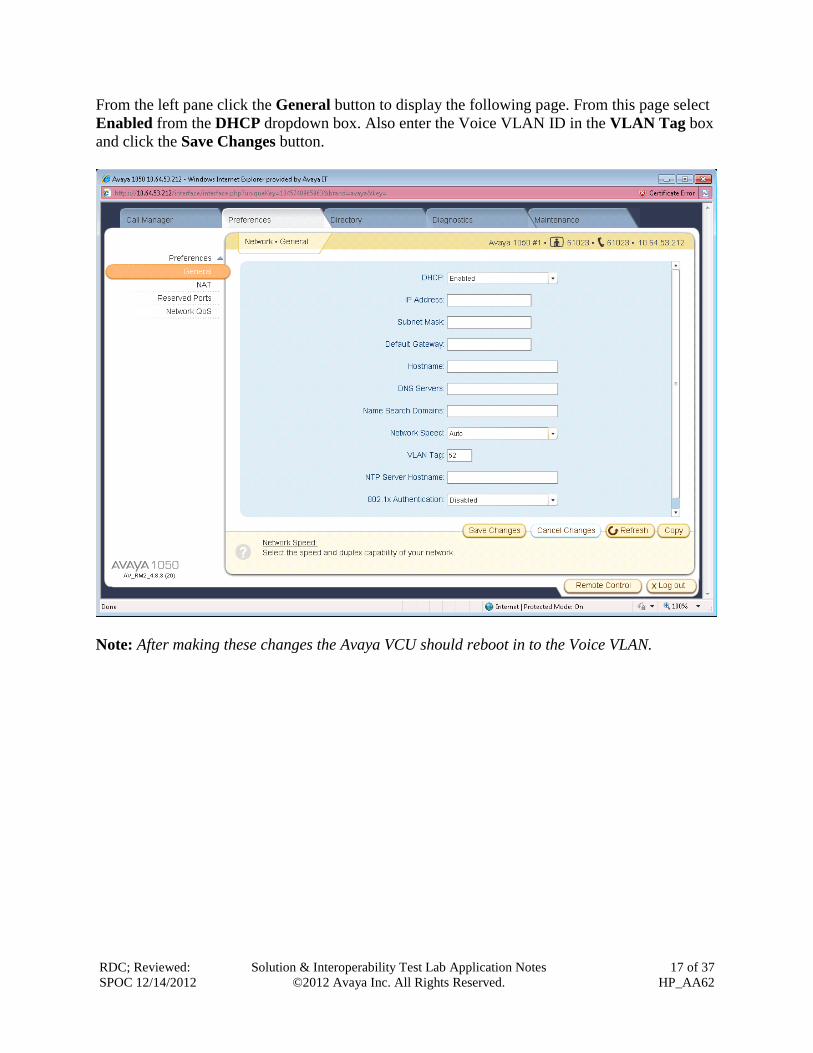
From the left pane click the General button to display the following page. From this page select
Enabled from the DHCP dropdown box. Also enter the Voice VLAN ID in the VLAN Tag box
and click the Save Changes button.
Note: After making these changes the Avaya VCU should reboot in to the Voice VLAN.
RDC; Reviewed:
SPOC 12/14/2012
Solution & Interoperability Test Lab Application Notes
©2012 Avaya Inc. All Rights Reserved.
18 of 37
HP_AA62
10. Configure the HP Networking 5406zl Core Switch This section addresses how to configure the HP Networking 5406zl Switch for enforcing QoS
policies.
To configure the HP Networking switch, connect a PC or laptop to the serial port of the switch.
Run a terminal emulation program with the following configuration:
Bits per second: 9600
Data bits: 8
Parity: None
Stop bits: 1
Flow Control: None
RDC; Reviewed:
SPOC 12/14/2012
Solution & Interoperability Test Lab Application Notes
©2012 Avaya Inc. All Rights Reserved.
19 of 37
HP_AA62
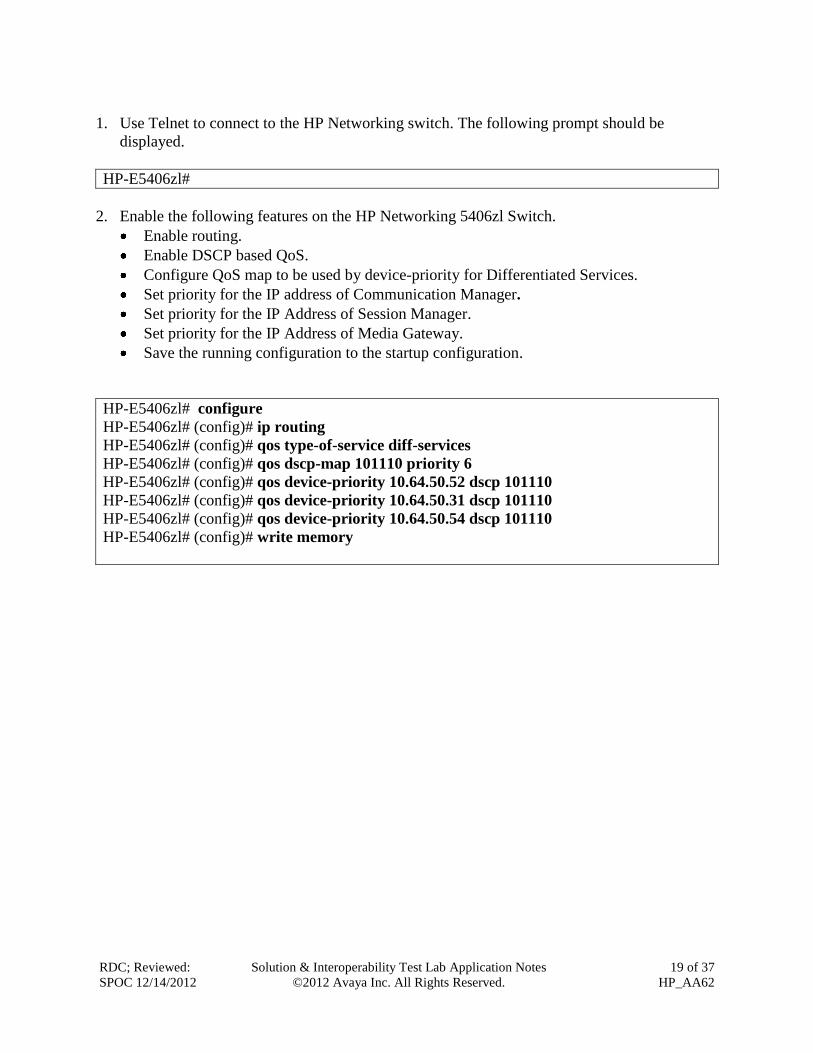
1. Use Telnet to connect to the HP Networking switch. The following prompt should be
displayed.
HP-E5406zl#
2. Enable the following features on the HP Networking 5406zl Switch.
Enable routing.
Enable DSCP based QoS.
Configure QoS map to be used by device-priority for Differentiated Services.
Set priority for the IP address of Communication Manager.
Set priority for the IP Address of Session Manager.
Set priority for the IP Address of Media Gateway.
Save the running configuration to the startup configuration.
HP-E5406zl# configure
HP-E5406zl# (config)# ip routing
HP-E5406zl# (config)# qos type-of-service diff-services
HP-E5406zl# (config)# qos dscp-map 101110 priority 6
HP-E5406zl# (config)# qos device-priority 10.64.50.52 dscp 101110
HP-E5406zl# (config)# qos device-priority 10.64.50.31 dscp 101110
HP-E5406zl# (config)# qos device-priority 10.64.50.54 dscp 101110
HP-E5406zl# (config)# write memory

RDC; Reviewed:
SPOC 12/14/2012
Solution & Interoperability Test Lab Application Notes
©2012 Avaya Inc. All Rights Reserved.
20 of 37
HP_AA62
3. Create and configure the telephony VLAN where all of the Avaya telephony infrastructure
equipment and servers are located.
Assign a VLAN ID for the telephony VLAN.
Assign a name for the telephony VLAN.
Assign an IP address for the telephony VLAN.
Assign ports to the telephony VLAN.
HP-E5406zl# configure
HP-E5406zl(config)# vlan 50
HP-E5406zl(vlan-50)# name Telephony_Infrastructure_AA
HP-E5406zl(vlan-50)# ip address 10.64.50.64/24
HP-E5406zl(vlan-50)# untagged A14-A18
HP-E5406zl(vlan-50)# tagged A21
HP-E5406zl(vlan-50)# end
HP-E5406zl#
4. Create and configure the voice VLAN.
Assign a VLAN ID for the voice VLAN.
Assign a name for the voice VLAN.
Assign voice option.
Assign an IP address for the voice VLAN.
Set an IP helper address for DHCP.
Assign ports to the voice VLAN.
HP-E5406zl# configure
HP-E5406zl(config)# vlan 52
HP-E5406zl(vlan-52)# name Voice
HP-E5406zl(vlan-52)# ip address 10.64.52.1/24
HP-E5406zl(vlan-52)# ip helper-address 10.64.59.247
HP-E5406zl(vlan-52)# tagged A1-A5,A11-A13
HP-E5406zl(vlan-52)# end
HP-E5406zl#

RDC; Reviewed:
SPOC 12/14/2012
Solution & Interoperability Test Lab Application Notes
©2012 Avaya Inc. All Rights Reserved.
21 of 37
HP_AA62
5. Create and configure the data VLAN.
Assign a VLAN ID for the data VLAN.
Assign a name for the data VLAN.
Assign an IP address for the data VLAN.
Set an IP helper address for DHCP.
Assign ports to the data VLAN.
HP-E5406zl# configure
HP-E5406zl(config)# vlan 53
HP-E5406zl(vlan-53)# ip address 10.64.53.1/24
HP-E5406zl(vlan-53)# ip helper-address 10.64.59.247
HP-E5406zl(vlan-53)# tagged A1-A5,A11-A13
HP-E5406zl(vlan-53)# end
HP-E5406zl#
6. Save the running configuration to the startup configuration. HP-E5406zl# write memory
HP-E5406zl#
11. Configure HP Networking Distribution/Access Switches This section addresses configuring the HP 3800, 2620, 2915, and 2910 switches to support the
configuration shown in Figure 1.
Note: The purpose of this compliance test was to validate interoperability with each HP
switch. Since each of the distribution/access switches were configured the same way, only the
HP 3800 configuration is shown. To configure the other switches shown in Figure 1, repeat
the same configuration commands on each switch.
To configure the HP Networking switch, connect a PC or laptop to the serial port of the switch.
Run a terminal emulation program with the following configuration:
Bits per second: 9600
Data bits: 8
Parity: None
Stop bits: 1
Flow Control: None
HP Stack E3800#
1. Enable the following features on the HP 3800 switch.
Enable DSCP based QoS.
Configure QoS map to be used by device-priority for Differentiated Services.
RDC; Reviewed:
SPOC 12/14/2012
Solution & Interoperability Test Lab Application Notes
©2012 Avaya Inc. All Rights Reserved.
22 of 37
HP_AA62
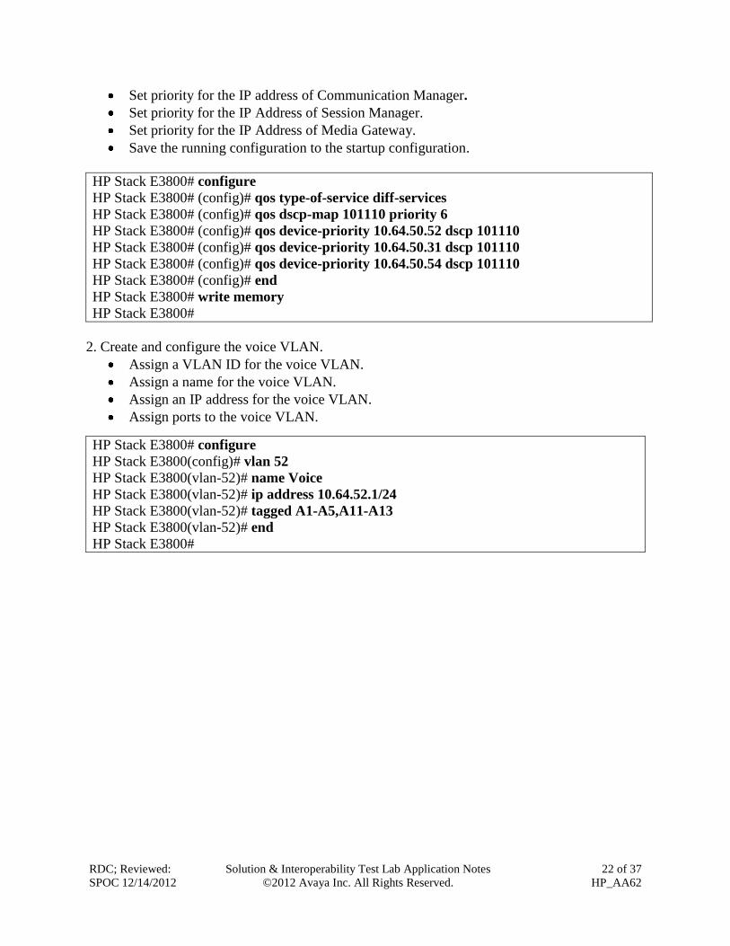
Set priority for the IP address of Communication Manager.
Set priority for the IP Address of Session Manager.
Set priority for the IP Address of Media Gateway.
Save the running configuration to the startup configuration.
HP Stack E3800# configure
HP Stack E3800# (config)# qos type-of-service diff-services
HP Stack E3800# (config)# qos dscp-map 101110 priority 6
HP Stack E3800# (config)# qos device-priority 10.64.50.52 dscp 101110
HP Stack E3800# (config)# qos device-priority 10.64.50.31 dscp 101110
HP Stack E3800# (config)# qos device-priority 10.64.50.54 dscp 101110
HP Stack E3800# (config)# end
HP Stack E3800# write memory
HP Stack E3800#
2. Create and configure the voice VLAN.
Assign a VLAN ID for the voice VLAN.
Assign a name for the voice VLAN.
Assign an IP address for the voice VLAN.
Assign ports to the voice VLAN.
HP Stack E3800# configure
HP Stack E3800(config)# vlan 52
HP Stack E3800(vlan-52)# name Voice
HP Stack E3800(vlan-52)# ip address 10.64.52.1/24
HP Stack E3800(vlan-52)# tagged A1-A5,A11-A13
HP Stack E3800(vlan-52)# end
HP Stack E3800#
RDC; Reviewed:
SPOC 12/14/2012
Solution & Interoperability Test Lab Application Notes
©2012 Avaya Inc. All Rights Reserved.
23 of 37
HP_AA62
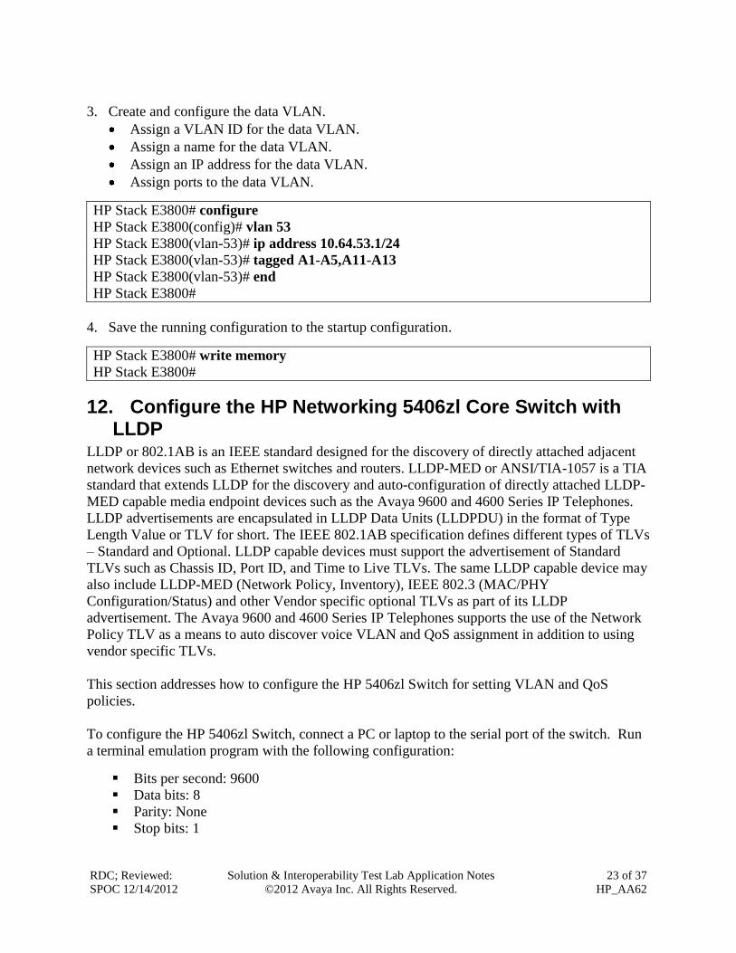
3. Create and configure the data VLAN.
Assign a VLAN ID for the data VLAN.
Assign a name for the data VLAN.
Assign an IP address for the data VLAN.
Assign ports to the data VLAN.
HP Stack E3800# configure
HP Stack E3800(config)# vlan 53
HP Stack E3800(vlan-53)# ip address 10.64.53.1/24
HP Stack E3800(vlan-53)# tagged A1-A5,A11-A13
HP Stack E3800(vlan-53)# end
HP Stack E3800#
4. Save the running configuration to the startup configuration. HP Stack E3800# write memory
HP Stack E3800#
12. Configure the HP Networking 5406zl Core Switch with LLDP
LLDP or 802.1AB is an IEEE standard designed for the discovery of directly attached adjacent
network devices such as Ethernet switches and routers. LLDP-MED or ANSI/TIA-1057 is a TIA
standard that extends LLDP for the discovery and auto-configuration of directly attached LLDP-
MED capable media endpoint devices such as the Avaya 9600 and 4600 Series IP Telephones.
LLDP advertisements are encapsulated in LLDP Data Units (LLDPDU) in the format of Type
Length Value or TLV for short. The IEEE 802.1AB specification defines different types of TLVs
– Standard and Optional. LLDP capable devices must support the advertisement of Standard
TLVs such as Chassis ID, Port ID, and Time to Live TLVs. The same LLDP capable device may
also include LLDP-MED (Network Policy, Inventory), IEEE 802.3 (MAC/PHY
Configuration/Status) and other Vendor specific optional TLVs as part of its LLDP
advertisement. The Avaya 9600 and 4600 Series IP Telephones supports the use of the Network
Policy TLV as a means to auto discover voice VLAN and QoS assignment in addition to using
vendor specific TLVs.
This section addresses how to configure the HP 5406zl Switch for setting VLAN and QoS
policies.
To configure the HP 5406zl Switch, connect a PC or laptop to the serial port of the switch. Run
a terminal emulation program with the following configuration:
Bits per second: 9600
Data bits: 8
Parity: None
Stop bits: 1
RDC; Reviewed:
SPOC 12/14/2012
Solution & Interoperability Test Lab Application Notes
©2012 Avaya Inc. All Rights Reserved.
24 of 37
HP_AA62
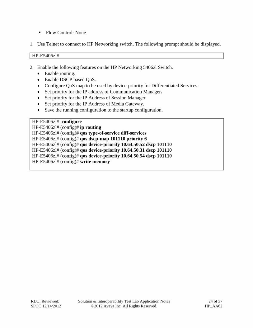
Flow Control: None
1. Use Telnet to connect to HP Networking switch. The following prompt should be displayed.
HP-E5406zl#
2. Enable the following features on the HP Networking 5406zl Switch.
Enable routing.
Enable DSCP based QoS.
Configure QoS map to be used by device-priority for Differentiated Services.
Set priority for the IP address of Communication Manager.
Set priority for the IP Address of Session Manager.
Set priority for the IP Address of Media Gateway.
Save the running configuration to the startup configuration.
HP-E5406zl# configure
HP-E5406zl# (config)# ip routing
HP-E5406zl# (config)# qos type-of-service diff-services
HP-E5406zl# (config)# qos dscp-map 101110 priority 6
HP-E5406zl# (config)# qos device-priority 10.64.50.52 dscp 101110
HP-E5406zl# (config)# qos device-priority 10.64.50.31 dscp 101110
HP-E5406zl# (config)# qos device-priority 10.64.50.54 dscp 101110
HP-E5406zl# (config)# write memory
RDC; Reviewed:
SPOC 12/14/2012
Solution & Interoperability Test Lab Application Notes
©2012 Avaya Inc. All Rights Reserved.
25 of 37
HP_AA62
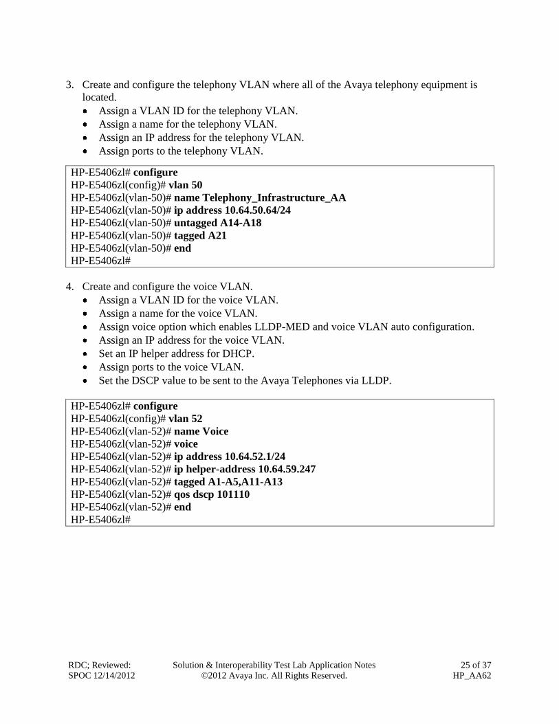
3. Create and configure the telephony VLAN where all of the Avaya telephony equipment is
located.
Assign a VLAN ID for the telephony VLAN.
Assign a name for the telephony VLAN.
Assign an IP address for the telephony VLAN.
Assign ports to the telephony VLAN.
HP-E5406zl# configure
HP-E5406zl(config)# vlan 50
HP-E5406zl(vlan-50)# name Telephony_Infrastructure_AA
HP-E5406zl(vlan-50)# ip address 10.64.50.64/24
HP-E5406zl(vlan-50)# untagged A14-A18
HP-E5406zl(vlan-50)# tagged A21
HP-E5406zl(vlan-50)# end
HP-E5406zl#
4. Create and configure the voice VLAN.
Assign a VLAN ID for the voice VLAN.
Assign a name for the voice VLAN.
Assign voice option which enables LLDP-MED and voice VLAN auto configuration.
Assign an IP address for the voice VLAN.
Set an IP helper address for DHCP.
Assign ports to the voice VLAN.
Set the DSCP value to be sent to the Avaya Telephones via LLDP.
HP-E5406zl# configure
HP-E5406zl(config)# vlan 52
HP-E5406zl(vlan-52)# name Voice
HP-E5406zl(vlan-52)# voice
HP-E5406zl(vlan-52)# ip address 10.64.52.1/24
HP-E5406zl(vlan-52)# ip helper-address 10.64.59.247
HP-E5406zl(vlan-52)# tagged A1-A5,A11-A13
HP-E5406zl(vlan-52)# qos dscp 101110
HP-E5406zl(vlan-52)# end
HP-E5406zl#
RDC; Reviewed:
SPOC 12/14/2012
Solution & Interoperability Test Lab Application Notes
©2012 Avaya Inc. All Rights Reserved.
26 of 37
HP_AA62
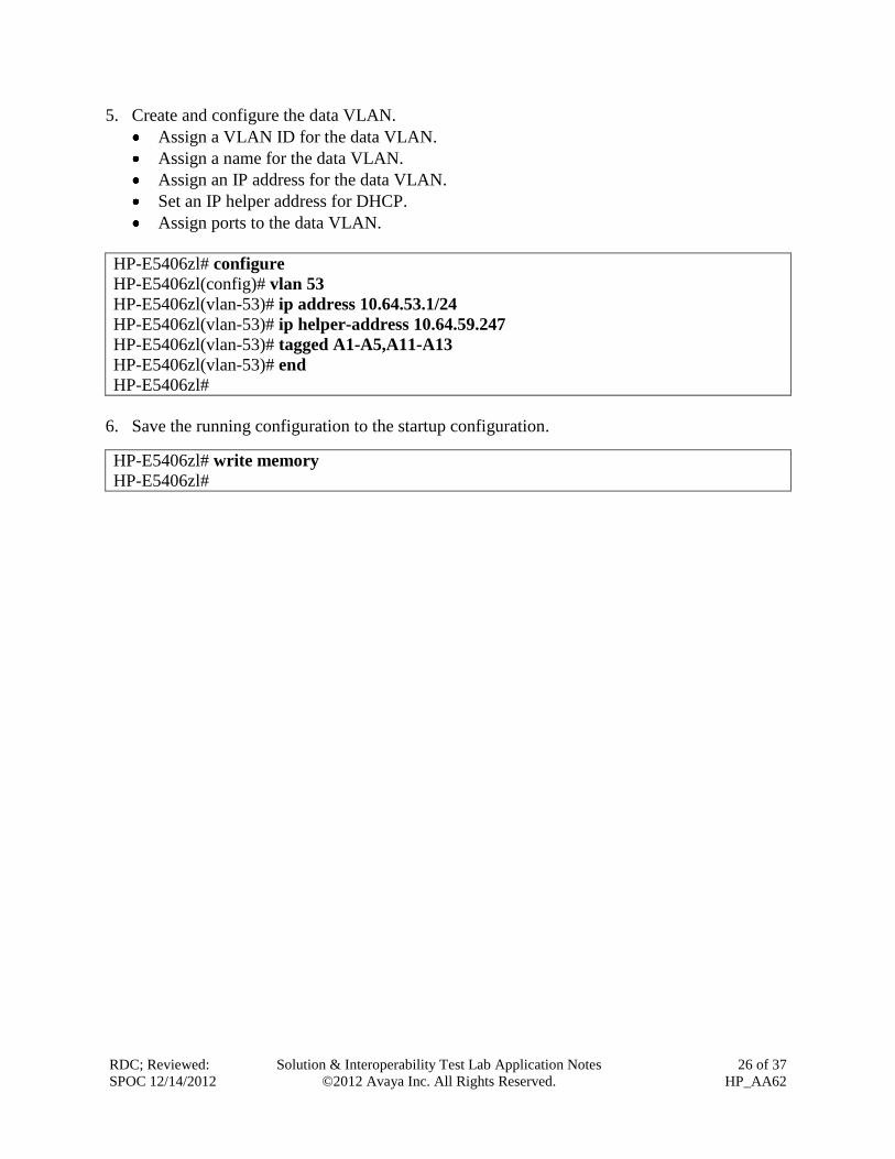
5. Create and configure the data VLAN.
Assign a VLAN ID for the data VLAN.
Assign a name for the data VLAN.
Assign an IP address for the data VLAN.
Set an IP helper address for DHCP.
Assign ports to the data VLAN.
HP-E5406zl# configure
HP-E5406zl(config)# vlan 53
HP-E5406zl(vlan-53)# ip address 10.64.53.1/24
HP-E5406zl(vlan-53)# ip helper-address 10.64.59.247
HP-E5406zl(vlan-53)# tagged A1-A5,A11-A13
HP-E5406zl(vlan-53)# end
HP-E5406zl#
6. Save the running configuration to the startup configuration. HP-E5406zl# write memory
HP-E5406zl#

RDC; Reviewed:
SPOC 12/14/2012
Solution & Interoperability Test Lab Application Notes
©2012 Avaya Inc. All Rights Reserved.
27 of 37
HP_AA62
13. Configure HP Networking Distribution/Access Switches with LLDP
This section addresses configuring the HP 3800, 2620, 2915, and 2910 switches to support the
configuration shown in Figure 1.
Note: The purpose of this compliance test was to validate interoperability with each HP
switch. Since each of the distribution/access switches were configured the same way only the
HP 3800 configuration is shown. To configure the other switches shown in Figure 1, repeat
the same configuration commands on each switch.
To configure the switches, connect a PC or laptop to the serial port. Run a terminal emulation
program with the following configuration:
Bits per second: 9600
Data bits: 8
Parity: None
Stop bits: 1
Flow Control: None
HP Stack E3800#
1. Enable the following features on the HP 3800 switch.
Enable DSCP based QoS.
Configure QoS map to be used by device-priority for Differentiated Services.
Set priority for the IP address of Communication Manager.
Set priority for the IP Address of Session Manager.
Set priority for the IP Address of Media Gateway.
Save the running configuration to the startup configuration.
HP Stack E3800# configure
HP Stack E3800# (config)# qos type-of-service diff-services
HP Stack E3800# (config)# qos dscp-map 101110 priority 6
HP Stack E3800# (config)# qos device-priority 10.64.50.52 dscp 101110
HP Stack E3800# (config)# qos device-priority 10.64.50.31 dscp 101110
HP Stack E3800# (config)# qos device-priority 10.64.50.54 dscp 101110
HP Stack E3800# (config)# end
HP Stack E3800# write memory
HP Stack E3800#
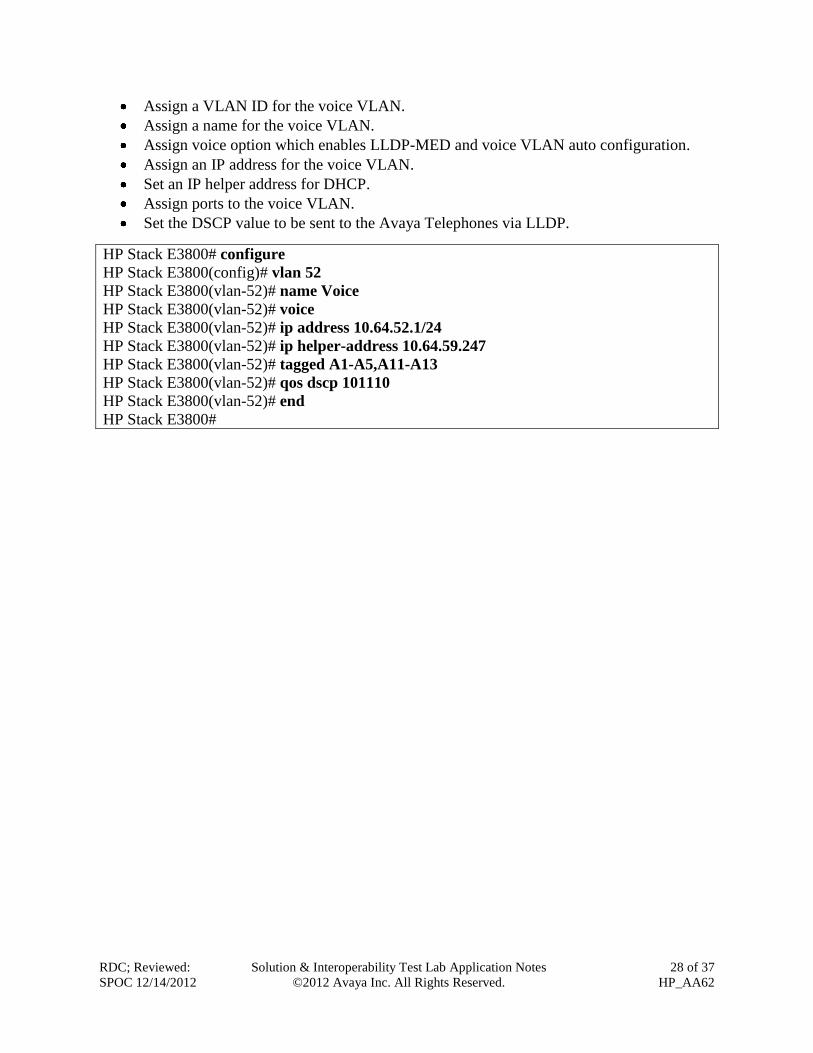
2. Create and configure the voice VLAN.
RDC; Reviewed:
SPOC 12/14/2012
Solution & Interoperability Test Lab Application Notes
©2012 Avaya Inc. All Rights Reserved.
28 of 37
HP_AA62
Assign a VLAN ID for the voice VLAN.
Assign a name for the voice VLAN.
Assign voice option which enables LLDP-MED and voice VLAN auto configuration.
Assign an IP address for the voice VLAN.
Set an IP helper address for DHCP.
Assign ports to the voice VLAN.
Set the DSCP value to be sent to the Avaya Telephones via LLDP.
HP Stack E3800# configure
HP Stack E3800(config)# vlan 52
HP Stack E3800(vlan-52)# name Voice
HP Stack E3800(vlan-52)# voice
HP Stack E3800(vlan-52)# ip address 10.64.52.1/24
HP Stack E3800(vlan-52)# ip helper-address 10.64.59.247
HP Stack E3800(vlan-52)# tagged A1-A5,A11-A13
HP Stack E3800(vlan-52)# qos dscp 101110
HP Stack E3800(vlan-52)# end
HP Stack E3800#

RDC; Reviewed:
SPOC 12/14/2012
Solution & Interoperability Test Lab Application Notes
©2012 Avaya Inc. All Rights Reserved.
29 of 37
HP_AA62
3. Create and configure the data VLAN.
Assign a VLAN ID for the data VLAN.
Assign a name for the data VLAN.
Assign an IP address for the data VLAN.
Assign ports to the data VLAN.
HP Stack E3800# configure
HP Stack E3800(config)# vlan 53
HP Stack E3800(vlan-53)# ip address 10.64.53.1/24
HP Stack E3800(vlan-53)# tagged A1-A5,A11-A13
HP Stack E3800(vlan-53)# end
HP Stack E3800#
4. Save the running configuration to the startup configuration. HP-E5406zl# write memory
HP-E5406zl#
14. Configure HP Networking Distribution/Access Switches with PoE
Power over Ethernet (PoE) allows both power and data to be simultaneously carried over
standard Ethernet cables. PoE-enabled Ethernet switches can supply power directly to Ethernet
devices, thereby simplifying installation and removing the need for separate power supplies for
those devices. The IEEE 802.3af-2003 standard defines the mechanisms for Power Sourcing
Equipment (PSE), such as PoE-enabled Ethernet switches, to detect, classify, and supply up to
15.4W of power per port to Powered Devices (PDs), such as PoE-enabled IP telephones. In the
compliance-tested configuration described in these Application Notes, the HP Networking
Switches were configured to supply inline PoE to Avaya PDs. Many HP Networking Switches
also support the IEEE 802.3at-2009 standard for Power over Ethernet Plus (PoE+), which can
provide up to 30W per port.
The default configuration for the HP Networking switches has PoE/PoE+ enabled. If you need to
make modifications or disable PoE or control per-port PoE priority please refer to the HP
Networking Switch manuals for more information.
15. Verification Steps
15.1. Verify QoS
The following steps may be used to verify the configuration:
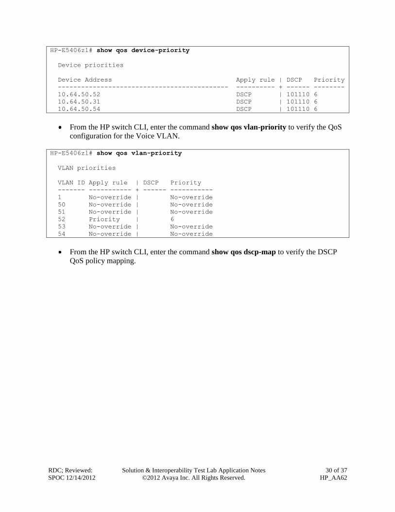
From the HP switch CLI, enter the command show qos device-priority to verify the QoS
configuration for packets being sent to and from the Avaya Telephony Infrastructure
devices.
RDC; Reviewed:
SPOC 12/14/2012
Solution & Interoperability Test Lab Application Notes
©2012 Avaya Inc. All Rights Reserved.
30 of 37
HP_AA62
HP-E5406zl# show qos device-priority
Device priorities
Device Address Apply rule | DSCP Priority
-------------------------------------------- ---------- + ------ --------
10.64.50.52 DSCP | 101110 6
10.64.50.31 DSCP | 101110 6
10.64.50.54 DSCP | 101110 6
From the HP switch CLI, enter the command show qos vlan-priority to verify the QoS
configuration for the Voice VLAN.
HP-E5406zl# show qos vlan-priority
VLAN priorities
VLAN ID Apply rule | DSCP Priority
------- ----------- + ------ -----------
1 No-override | No-override
50 No-override | No-override
51 No-override | No-override
52 Priority | 6
53 No-override | No-override
54 No-override | No-override
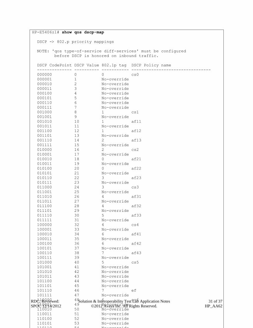
From the HP switch CLI, enter the command show qos dscp-map to verify the DSCP
QoS policy mapping.
RDC; Reviewed:
SPOC 12/14/2012
Solution & Interoperability Test Lab Application Notes
©2012 Avaya Inc. All Rights Reserved.
31 of 37
HP_AA62
HP-E5406zl# show qos dscp-map
DSCP -> 802.p priority mappings
NOTE: 'qos type-of-service diff-services' must be configured
before DSCP is honored on inbound traffic.
DSCP CodePoint DSCP Value 802.1p tag DSCP Policy name
-------------- ---------- ----------- --------------------------------
000000 0 0 cs0
000001 1 No-override
000010 2 No-override
000011 3 No-override
000100 4 No-override
000101 5 No-override
000110 6 No-override
000111 7 No-override
001000 8 1 cs1
001001 9 No-override
001010 10 1 af11
001011 11 No-override
001100 12 1 af12
001101 13 No-override
001110 14 2 af13
001111 15 No-override
010000 16 2 cs2
010001 17 No-override
010010 18 0 af21
010011 19 No-override
010100 20 0 af22
010101 21 No-override
010110 22 3 af23
010111 23 No-override
011000 24 3 cs3
011001 25 No-override
011010 26 4 af31
011011 27 No-override
011100 28 4 af32
011101 29 No-override
011110 30 5 af33
011111 31 No-override
100000 32 4 cs4
100001 33 No-override
100010 34 6 af41
100011 35 No-override
100100 36 6 af42
100101 37 No-override
100110 38 7 af43
100111 39 No-override
101000 40 5 cs5
101001 41 No-override
101010 42 No-override
101011 43 No-override
101100 44 No-override
101101 45 No-override
101110 46 7 ef
101111 47 No-override
110000 48 6 cs6
110001 49 No-override
110010 50 No-override
110011 51 No-override
110100 52 No-override
110101 53 No-override
110110 54 No-override
RDC; Reviewed:
SPOC 12/14/2012
Solution & Interoperability Test Lab Application Notes
©2012 Avaya Inc. All Rights Reserved.
32 of 37
HP_AA62
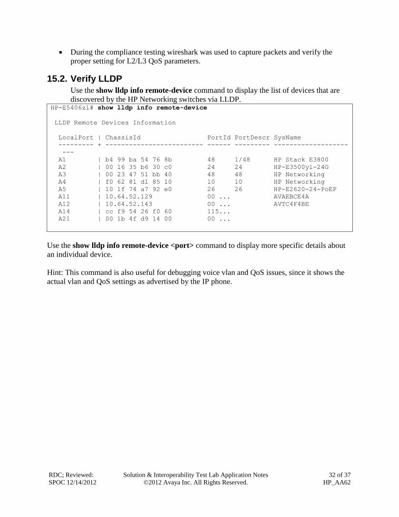
During the compliance testing wireshark was used to capture packets and verify the
proper setting for L2/L3 QoS parameters.
15.2. Verify LLDP
Use the show lldp info remote-device command to display the list of devices that are
discovered by the HP Networking switches via LLDP. HP-E5406zl# show lldp info remote-device
LLDP Remote Devices Information
LocalPort | ChassisId PortId PortDescr SysName
--------- + ------------------------- ------ --------- -------------------
---
A1 | b4 99 ba 54 76 8b 48 1/48 HP Stack E3800
A2 | 00 16 35 b6 30 c0 24 24 HP-E3500yl-24G
A3 | 00 23 47 51 bb 40 48 48 HP Networking
A4 | f0 62 81 d1 85 10 10 10 HP Networking
A5 | 10 1f 74 a7 92 e0 26 26 HP-E2620-24-PoEP
A11 | 10.64.52.129 00 ... AVAEBCE4A
A12 | 10.64.52.143 00 ... AVTC4F4BE
A14 | cc f9 54 26 f0 60 115...
A21 | 00 1b 4f d9 14 00 00 ...
Use the show lldp info remote-device <port> command to display more specific details about
an individual device.
Hint: This command is also useful for debugging voice vlan and QoS issues, since it shows the
actual vlan and QoS settings as advertised by the IP phone.

RDC; Reviewed:
SPOC 12/14/2012
Solution & Interoperability Test Lab Application Notes
©2012 Avaya Inc. All Rights Reserved.
33 of 37
HP_AA62
HP-E5406zl# show lldp info remote-device A12
LLDP Remote Device Information Detail
Local Port : A12
ChassisType : network-address
ChassisId : 10.64.52.143
PortType : mac-...
PortId : 00 07 3b c4 f4 be
SysName : AVTC4F4BE
System Descr :
PortDescr :
Pvid :
System Capabilities Supported : bridge, telephone
System Capabilities Enabled : bridge
Remote Management Address
Type : ipv4
Address : 10.64.52.143
MED Information Detail
EndpointClass :Class3
Media Policy Vlan id :52
Media Policy Priority :6
Media Policy Dscp :46
Media Policy Tagged :True
Poe Device Type :PD
Power Requested :5.3 W
Power Source :From PSE
Power Priority :High
RDC; Reviewed:
SPOC 12/14/2012
Solution & Interoperability Test Lab Application Notes
©2012 Avaya Inc. All Rights Reserved.
34 of 37
HP_AA62
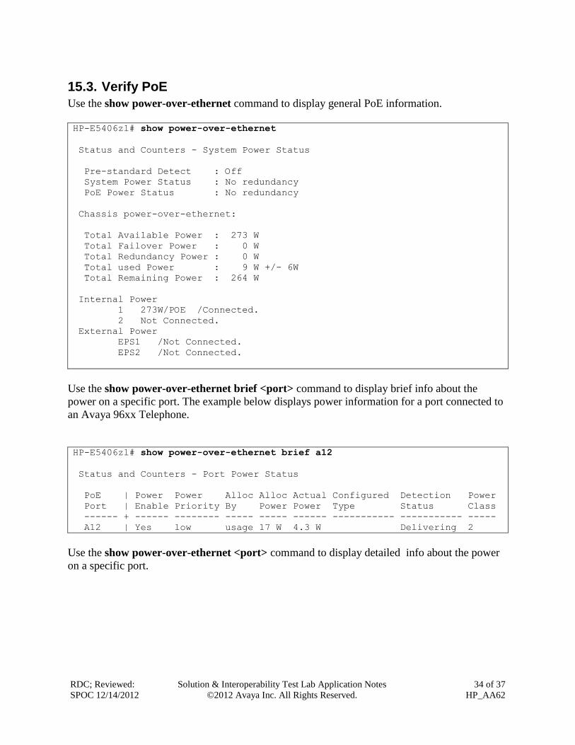
15.3. Verify PoE
Use the show power-over-ethernet command to display general PoE information.
HP-E5406zl# show power-over-ethernet
Status and Counters - System Power Status
Pre-standard Detect : Off
System Power Status : No redundancy
PoE Power Status : No redundancy
Chassis power-over-ethernet:
Total Available Power : 273 W
Total Failover Power : 0 W
Total Redundancy Power : 0 W
Total used Power : 9 W +/- 6W
Total Remaining Power : 264 W
Internal Power
1 273W/POE /Connected.
2 Not Connected.
External Power
EPS1 /Not Connected.
EPS2 /Not Connected.
Use the show power-over-ethernet brief <port> command to display brief info about the
power on a specific port. The example below displays power information for a port connected to
an Avaya 96xx Telephone.
HP-E5406zl# show power-over-ethernet brief a12
Status and Counters - Port Power Status
PoE | Power Power Alloc Alloc Actual Configured Detection Power
Port | Enable Priority By Power Power Type Status Class
------ + ------ -------- ----- ----- ------ ----------- ----------- -----
A12 | Yes low usage 17 W 4.3 W Delivering 2
Use the show power-over-ethernet <port> command to display detailed info about the power
on a specific port.

RDC; Reviewed:
SPOC 12/14/2012
Solution & Interoperability Test Lab Application Notes
©2012 Avaya Inc. All Rights Reserved.
35 of 37
HP_AA62
HP-E5406zl# show power-over-ethernet a12
Status and Counters - Port Power Status for port A12
Power Enable : Yes
LLDP Detect : enabled
Priority : low Configured Type :
AllocateBy : usage Value : 17 W
Detection Status : Delivering Power Class : 2
Over Current Cnt : 0 MPS Absent Cnt : 0
Power Denied Cnt : 1 Short Cnt : 0
Voltage : 50.7 V Current : 87 mA
Power : 4.3 W
16. Conclusion These Application Notes describe a compliance-tested configuration comprised of Avaya Aura®
Telephony Infrastructure connected to HP Networking Switches. The HP Networking Switches
enforced L2/L3 QoS parameters that were configured via settings files and LLDP. Additionally
HP Networking Switches provided Power over Ethernet for the Avaya Telephones. Prioritization
of VoIP traffic and good voice quality was successfully achieved in the Avaya/HP Networking
configuration described in Figure 1. HP Networking successfully passed the compliance test.
Refer to Section 2.2 for more details and listed observations.
17. Additional References The documents referenced below were used for additional support and configuration
information.
The following Avaya product documentation can be found at http://support.avaya.com.
[1] Administering Avaya Aura® Communication Manager, June 2010, Release 6.0, Issue 6.0,
Document Number 03-300509, available at http://support.avaya.com.
[2] Administering Avaya Aura® Session Manager, October 2010, Issue 1.1, Release 6.1,
Document Number 03-603324, available at http://support.avaya.com.
[3] Avaya one-X Deskphone Edition for 9600 Series IP Telephones Administrator Guide
Release 3.1, November 2009, Document Number 16-300698.
[4] Administering Avaya one-X® Communicator, October 2011
[5] Avaya 1010 and1020 User and Administrator Guide, May 2011
[6] Avaya 1030, 1040, and 1050 Video Conferencing Systems User and Administrator Guide,
February, 2011
[7] Implementing and Administering the Avaya A175 Desktop Video Device with the Avaya
Flare® Experience Release 1.1, Document Number 16-603739Issue 2March, 2012
Product information for the HP Networking Switches may be found at
http://h17007.www1.hp.com/us/en/products/switches/index.aspx

RDC; Reviewed:
SPOC 12/14/2012
Solution & Interoperability Test Lab Application Notes
©2012 Avaya Inc. All Rights Reserved.
36 of 37
HP_AA62

RDC; Reviewed:
SPOC 12/14/2012
Solution & Interoperability Test Lab Application Notes
©2012 Avaya Inc. All Rights Reserved.
37 of 37
HP_AA62
©2012 Avaya Inc. All Rights Reserved.
Avaya and the Avaya Logo are trademarks of Avaya Inc. All trademarks identified by ® and
™ are registered trademarks or trademarks, respectively, of Avaya Inc. All other trademarks
are the property of their respective owners. The information provided in these Application
Notes is subject to change without notice. The configurations, technical data, and
recommendations provided in these Application Notes are believed to be accurate and
dependable, but are presented without express or implied warranty. Users are responsible for
their application of any products specified in these Application Notes.
Please e-mail any questions or comments pertaining to these Application Notes along with the
full title name and filename, located in the lower right corner, directly to the Avaya
DevConnect Program at [email protected].
Related Documents