Copyright Cirrus Logic, Inc. 2012 (All Rights Reserved) Cirrus Logic, Inc. http://www.cirrus.com Application Note Using the CS5480/84/90 Energy Measurement IC with Rogowski Coil Current Sensors 1. Introduction Rogowski coil, or di/dt, current sensors have been increasingly implemented in AC power and energy measurement applications because of their exceptional linearity, high current capacity and dynamic range, light weight, and electrical isolation. The Cirrus Logic energy measurement ICs CS5480, CS5484 and CS5490 support various types of Rogowski coils. This application note presents accuracy results from testing the CS5480 with three different types of Rogowski coil sensor. The CS5484 and CS5490 use the same core technology. Testing results of the CS5484 and CS5490 show nearly identical results. Comparable power meters were constructed using the CS5480 and three Rogowski coils: Pulse Electronics PA3202NL, TAEHWATRANS TR9L, and Sentec Mobius. Accuracy test results are presented that demonstrate that the CS5480 can achieve an energy measurement accuracy of 0.1% over a 4000:1 dynamic range when interfaced to a Rogowski coil. 2. Rogowski Coil Overview A Rogowski coil current sensor is a helical coil of wire wrapped around an AC line conductor and used to measure the flow of electric charge through the conductor. Since a Rogowski coil has an air core instead of an iron core, the measurements show excellent linearity with practically no saturation problems. In addition, the Rogowski coil rates highly for electrical isolation from the buss bar, and is light weight with low material cost. The Rogowski coil is increasingly being implemented when measuring high-current AC power and energy. A v(t) i(t) R Figure 1. Rogowski Coil Current Sensor AN365 MAR’12 AN365REV1

Welcome message from author
This document is posted to help you gain knowledge. Please leave a comment to let me know what you think about it! Share it to your friends and learn new things together.
Transcript
AN365
Application Note
Using the CS5480/84/90 Energy Measurement ICwith Rogowski Coil Current Sensors
1. Introduction
Rogowski coil, or di/dt, current sensors have been increasingly implemented in AC power and energy measurementapplications because of their exceptional linearity, high current capacity and dynamic range, light weight, andelectrical isolation. The Cirrus Logic energy measurement ICs CS5480, CS5484 and CS5490 support various typesof Rogowski coils.
This application note presents accuracy results from testing the CS5480 with three different types of Rogowski coilsensor. The CS5484 and CS5490 use the same core technology. Testing results of the CS5484 and CS5490 shownearly identical results. Comparable power meters were constructed using the CS5480 and three Rogowski coils:Pulse Electronics PA3202NL, TAEHWATRANS TR9L, and Sentec Mobius. Accuracy test results are presented thatdemonstrate that the CS5480 can achieve an energy measurement accuracy of 0.1% over a 4000:1 dynamic rangewhen interfaced to a Rogowski coil.
2. Rogowski Coil Overview
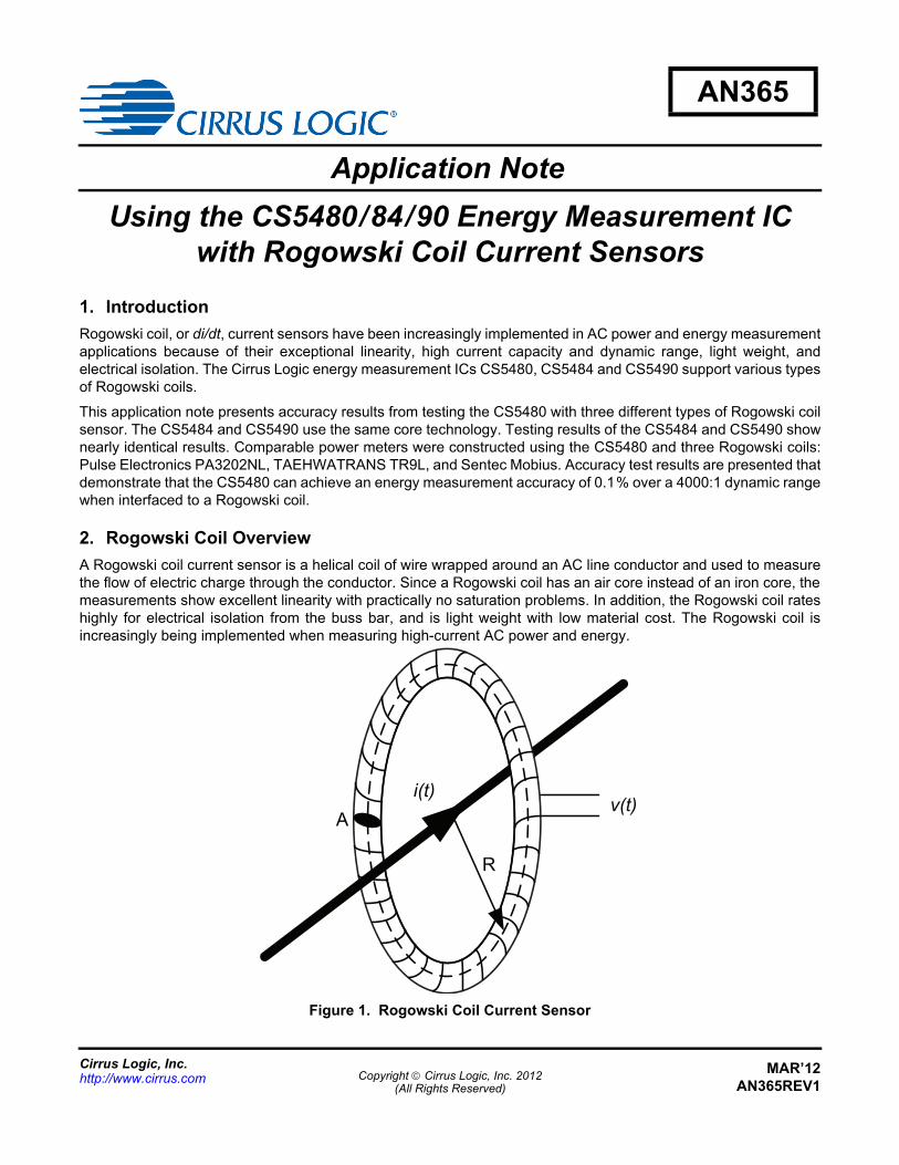
A Rogowski coil current sensor is a helical coil of wire wrapped around an AC line conductor and used to measurethe flow of electric charge through the conductor. Since a Rogowski coil has an air core instead of an iron core, themeasurements show excellent linearity with practically no saturation problems. In addition, the Rogowski coil rateshighly for electrical isolation from the buss bar, and is light weight with low material cost. The Rogowski coil isincreasingly being implemented when measuring high-current AC power and energy.
Av(t)
i(t)
R
Figure 1. Rogowski Coil Current Sensor
Copyright Cirrus Logic, Inc. 2012(All Rights Reserved)
Cirrus Logic, Inc.http://www.cirrus.com
MAR’12AN365REV1
AN365
The voltage v(t) that is induced in the Rogowski coil is proportional to the rate of the charge of current (di(t)/dt) andis based on Faraday's law. The voltage v(t) produced by a Rogowski coil is calculated using Equation 1:
where,
A = Area of each small loop
N = Number of turns
l = 2R and is the length of the winding
µ0 = Permeability of free space
When the AC line current, I, is a 50Hz or 60Hz sinusoidal, Equation 1 can be simplified to Equation 2.
where
k = Sensitivity constant that represents the output voltage per ampere at 50Hz or 60Hz.
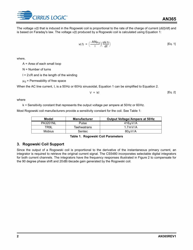
Most Rogowski coil manufacturers provide a sensitivity constant for the coil. See Table 1:
3. Rogowski Coil Support
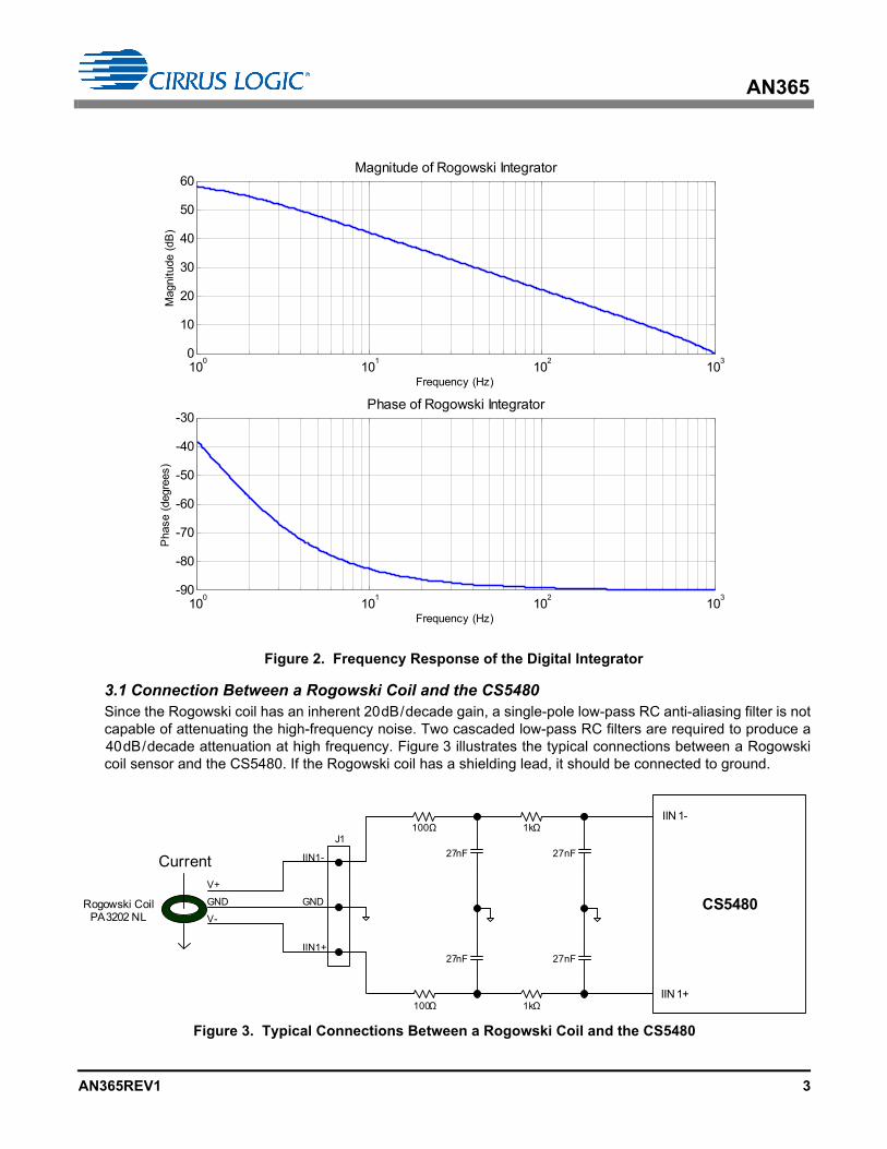
Since the output of a Rogowski coil is proportional to the derivative of the instantaneous primary current, anintegrator is required to retrieve the original current signal. The CS5480 incorporates selectable digital integratorsfor both current channels. The integrators have the frequency responses illustrated in Figure 2 to compensate forthe 90 degree phase shift and 20dB/decade gain generated by the Rogowski coil.
Model Manufacturer Output Voltage/Ampere at 50HzPA3201NL Pulse 416µV/A
TR9L Taehwatrans 1.7mV/AMobius Sentec 80µV/A
Table 1. Rogowski Coil Parameters
v t AN0–
l------------------ di t
dt----------- = [Eq. 1]
V kI= [Eq. 2]
2 AN365REV1
AN365
3.1 Connection Between a Rogowski Coil and the CS5480Since the Rogowski coil has an inherent 20dB/decade gain, a single-pole low-pass RC anti-aliasing filter is notcapable of attenuating the high-frequency noise. Two cascaded low-pass RC filters are required to produce a40dB/decade attenuation at high frequency. Figure 3 illustrates the typical connections between a Rogowskicoil sensor and the CS5480. If the Rogowski coil has a shielding lead, it should be connected to ground.
100
101
102
103
-90
-80
-70
-60
-50
-40
-30
Frequency (Hz)
Pha
se (
degr
ees)
Phase of Rogowski Integrator
100
101
102
103
0
10
20
30
40
50
60
Frequency (Hz)
Mag
nitu
de (
dB)
Magnitude of Rogowski Integrator
Figure 2. Frequency Response of the Digital Integrator
CS5480
IIN 1-
IIN 1+
27nF
27nF
27nF
27nF
V+
V-
GND GND
IIN1-
IIN1+
J1
Rogowski Coil PA3202 NL
Current
1kΩ100Ω
1kΩ100Ω
Figure 3. Typical Connections Between a Rogowski Coil and the CS5480
AN365REV1 3

AN365
3.2 PGA Selection on the Current ChannelThe CS5480 current channel incorporates a programmable gain amplifier (PGA) with two selectable input gains.The Config0 register bits I1PGA[1:0] select either 10x or 50x gain for the current channel. The two PGA settingsdictate the maximum input voltage that can be applied to the IIN± inputs.
The Rogowski coil output voltage produced with the maximum AC line current (Imax) should not exceed the max-imum input voltages listed in Table 2. Some margin should be considered according design requirements.
3.3 Filter SelectionThe CS5480 high-pass filter (HPF) and integrator are set using the Config2 register. To support a Rogowski coil,HPF must be enabled on the voltage channel and the integrator must be enabled on the current channel.
3.4 Calibration and CompensationTo compensate for the tolerances and variations in components and to remove the residual offset and noise inthe system, a gain calibration, phase compensation, AC offset calibration, and power offset correction shouldbe performed. For more information, see the CS5480 data sheet, entitled Three Channel Energy MeasurementIC, for details regarding the calibration and compensations process.
4. Measurement Accuracy Results with Rogowski Coils
The CS5480 load performance (measurement accuracy under different load conditions) has been tested with threedifferent types of Rogowski coil. The active and reactive energy load performance is tested with a single energypulse. The meter constant is set at 2000 impulses per kWh, or 2000 impulses per kVarh. The IRMS load performanceis calculated based on CS5480 IRMS register values. All of the tests were conducted at room temperature and withUn = 240V and line frequency of 50Hz.
CS5480 I-channel PGA Maximum Input Voltage
10x 167mVRMS
50x 35mVRMS
Table 2. PGA Settings
4 AN365REV1
AN365
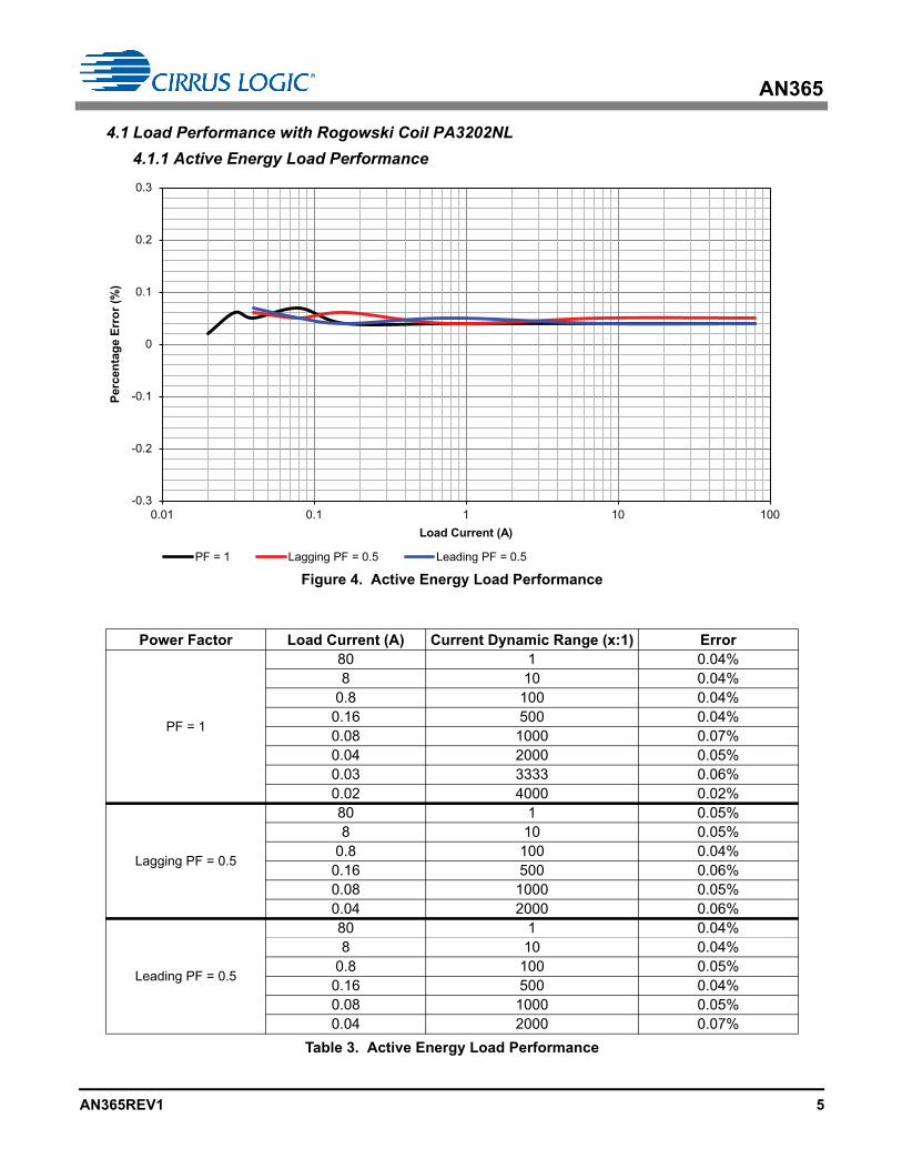
4.1 Load Performance with Rogowski Coil PA3202NL
4.1.1 Active Energy Load Performance
Power Factor Load Current (A) Current Dynamic Range (x:1) Error
PF = 1
80 1 0.04%8 10 0.04%
0.8 100 0.04%0.16 500 0.04%0.08 1000 0.07%0.04 2000 0.05%0.03 3333 0.06%0.02 4000 0.02%
Lagging PF = 0.5
80 1 0.05%8 10 0.05%
0.8 100 0.04%0.16 500 0.06%0.08 1000 0.05%0.04 2000 0.06%
Leading PF = 0.5
80 1 0.04%8 10 0.04%
0.8 100 0.05%0.16 500 0.04%0.08 1000 0.05%0.04 2000 0.07%
Table 3. Active Energy Load Performance
-0.3
-0.2
-0.1
0
0.1
0.2
0.3
0.01 0.1 1 10 100
Perc
enta
ge E
rror
(%)
Load Current (A)
PF = 1 Lagging PF = 0.5 Leading PF = 0.5
Figure 4. Active Energy Load Performance
AN365REV1 5
AN365
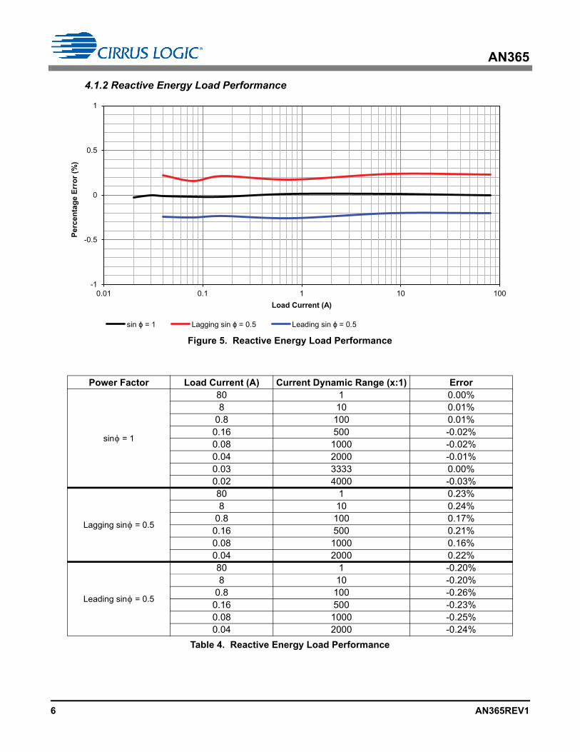
4.1.2 Reactive Energy Load Performance
Power Factor Load Current (A) Current Dynamic Range (x:1) Error
sin = 1
80 1 0.00%8 10 0.01%
0.8 100 0.01%0.16 500 -0.02%0.08 1000 -0.02%0.04 2000 -0.01%0.03 3333 0.00%0.02 4000 -0.03%
Lagging sin = 0.5
80 1 0.23%8 10 0.24%
0.8 100 0.17%0.16 500 0.21%0.08 1000 0.16%0.04 2000 0.22%
Leading sin = 0.5
80 1 -0.20%8 10 -0.20%
0.8 100 -0.26%0.16 500 -0.23%0.08 1000 -0.25%0.04 2000 -0.24%
Table 4. Reactive Energy Load Performance
-1
-0.5
0
0.5
1
0.01 0.1 1 10 100
Perc
enta
ge E
rror
(%)
Load Current (A)
sin = 1 Lagging sin = 0.5 Leading sin = 0.5
Figure 5. Reactive Energy Load Performance
6 AN365REV1
AN365
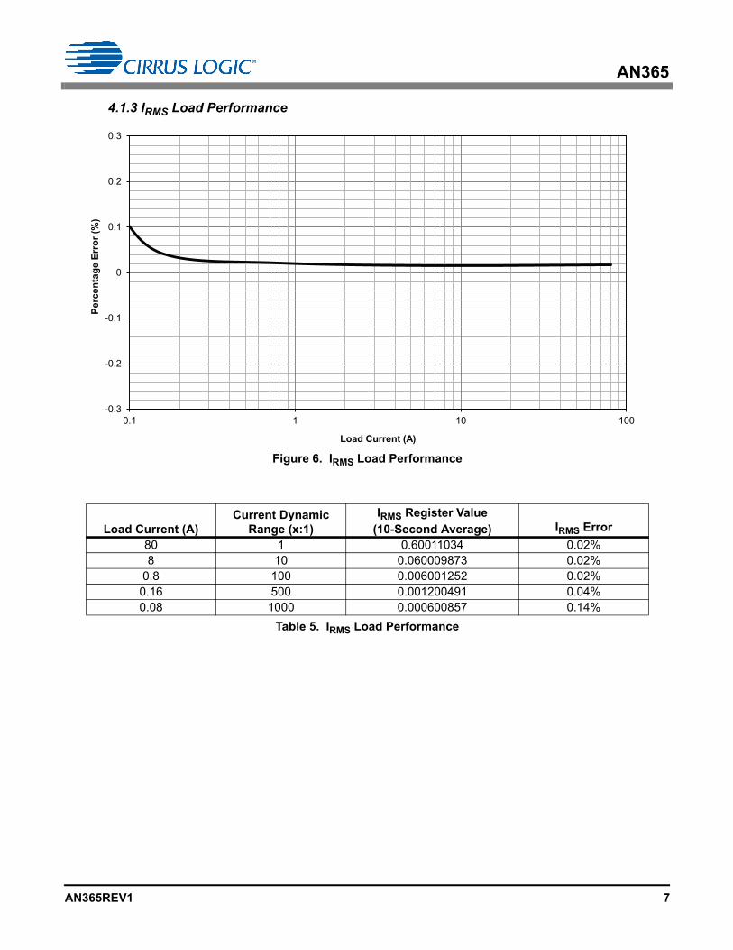
4.1.3 IRMS Load Performance
Load Current (A)Current Dynamic
Range (x:1)IRMS Register Value
(10-Second Average) IRMS Error
80 1 0.60011034 0.02%8 10 0.060009873 0.02%
0.8 100 0.006001252 0.02%0.16 500 0.001200491 0.04%0.08 1000 0.000600857 0.14%
Table 5. IRMS Load Performance
-0.3
-0.2
-0.1
0
0.1
0.2
0.3
0.1 1 10 100
Perc
enta
ge E
rror
(%)
Load Current (A)
Figure 6. IRMS Load Performance
AN365REV1 7
AN365
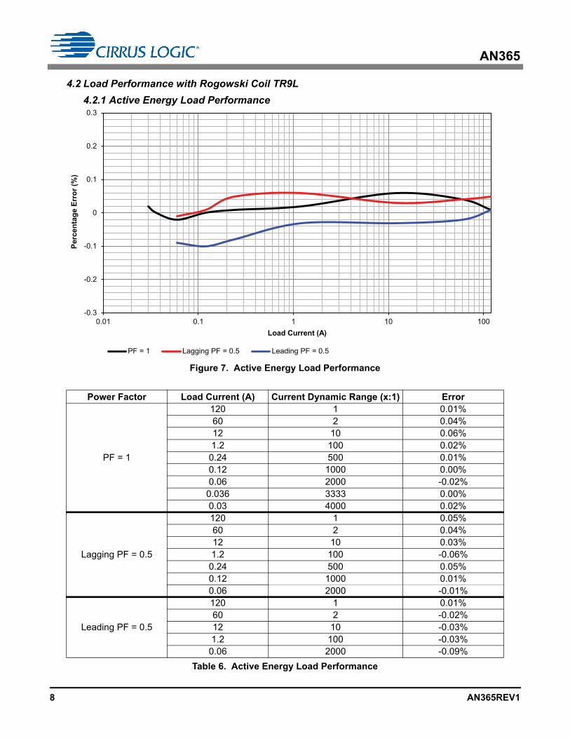
4.2 Load Performance with Rogowski Coil TR9L
4.2.1 Active Energy Load Performance
Power Factor Load Current (A) Current Dynamic Range (x:1) Error
PF = 1
120 1 0.01%60 2 0.04%12 10 0.06%1.2 100 0.02%0.24 500 0.01%0.12 1000 0.00%0.06 2000 -0.02%0.036 3333 0.00%0.03 4000 0.02%
Lagging PF = 0.5
120 1 0.05%60 2 0.04%12 10 0.03%1.2 100 -0.06%0.24 500 0.05%0.12 1000 0.01%0.06 2000 -0.01%
Leading PF = 0.5
120 1 0.01%60 2 -0.02%12 10 -0.03%1.2 100 -0.03%0.06 2000 -0.09%
Table 6. Active Energy Load Performance
-0.3
-0.2
-0.1
0
0.1
0.2
0.3
0.01 0.1 1 10 100
Perc
enta
ge E
rror
(%)
Load Current (A)
PF = 1 Lagging PF = 0.5 Leading PF = 0.5
Figure 7. Active Energy Load Performance
8 AN365REV1
AN365
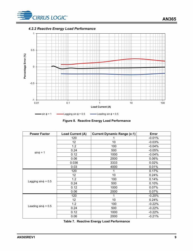
4.2.2 Reactive Energy Load Performance
Power Factor Load Current (A) Current Dynamic Range (x:1) Error
sin = 1
120 1 -0.01%12 10 -0.03%1.2 100 -0.04%0.24 500 -0.05%0.12 1000 -0.04%0.06 2000 0.06%0.036 3333 0.02%0.03 4000 0.01%
Lagging sin = 0.5
120 1 0.17%12 10 0.24%1.2 100 0.14%0.24 500 0.10%0.12 1000 0.07%0.06 2000 0.07%
Leading sin = 0.5
120 1 -0.20%12 10 0.24%1.2 100 -0.22%0.24 500 -0.22%0.12 1000 -0.22%0.06 2000 -0.21%
Table 7. Reactive Energy Load Performance
-1
-0.5
0
0.5
1
0.01 0.1 1 10 100
Perc
enta
ge E
rror
(%)
Load Current (A)
sin = 1 Lagging sin = 0.5 Leading sin = 0.5
Figure 8. Reactive Energy Load Performance
AN365REV1 9
AN365
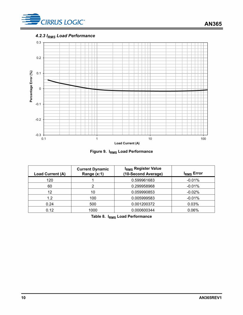
4.2.3 IRMS Load Performance
Load Current (A)Current Dynamic
Range (x:1)IRMS Register Value
(10-Second Average) IRMS Error
120 1 0.599961683 -0.01%
60 2 0.299958968 -0.01%
12 10 0.059990853 -0.02%
1.2 100 0.005999583 -0.01%
0.24 500 0.001200372 0.03%
0.12 1000 0.000600344 0.06%
Table 8. IRMS Load Performance
-0.3
-0.2
-0.1
0
0.1
0.2
0.3
0.1 1 10 100
Perc
enta
ge E
rror
(%)
Load Current (A)
Figure 9. IRMS Load Performance
10 AN365REV1
AN365
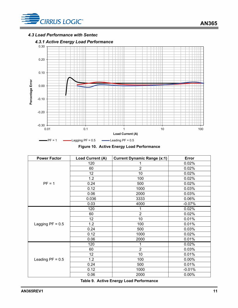
4.3 Load Performance with Sentec
4.3.1 Active Energy Load Performance
Power Factor Load Current (A) Current Dynamic Range (x:1) Error
PF = 1
120 1 0.02%60 2 0.02%12 10 0.02%1.2 100 0.02%0.24 500 0.02%0.12 1000 0.03%0.06 2000 0.03%0.036 3333 0.06%0.03 4000 -0.07%
Lagging PF = 0.5
120 1 0.02%60 2 0.02%12 10 0.01%1.2 100 0.01%0.24 500 0.03%0.12 1000 0.02%0.06 2000 0.01%
Leading PF = 0.5
120 1 0.02%60 2 0.03%12 10 0.01%1.2 100 0.00%0.24 500 0.01%0.12 1000 -0.01%0.06 2000 0.00%
Table 9. Active Energy Load Performance
-0.30
-0.20
-0.10
0.00
0.10
0.20
0.30
0.01 0.1 1 10 100
Perc
enta
ge E
rror
Load Current (A)
Leading PF = 0.5Lagging PF = 0.5PF = 1
Figure 10. Active Energy Load Performance
AN365REV1 11
AN365
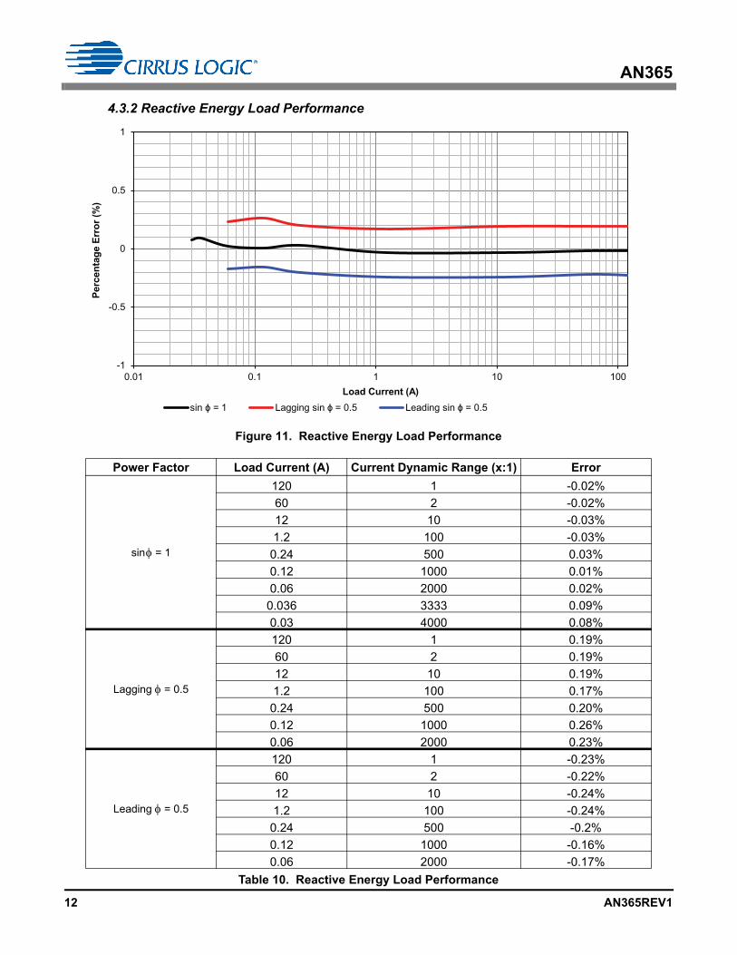
4.3.2 Reactive Energy Load Performance
Figure 11. Reactive Energy Load Performance
Power Factor Load Current (A) Current Dynamic Range (x:1) Error
sin = 1
120 1 -0.02%
60 2 -0.02%
12 10 -0.03%
1.2 100 -0.03%
0.24 500 0.03%
0.12 1000 0.01%
0.06 2000 0.02%
0.036 3333 0.09%
0.03 4000 0.08%
Lagging = 0.5
120 1 0.19%
60 2 0.19%
12 10 0.19%
1.2 100 0.17%
0.24 500 0.20%
0.12 1000 0.26%
0.06 2000 0.23%
Leading = 0.5
120 1 -0.23%
60 2 -0.22%
12 10 -0.24%
1.2 100 -0.24%
0.24 500 -0.2%
0.12 1000 -0.16%
0.06 2000 -0.17%
Table 10. Reactive Energy Load Performance
-1
-0.5
0
0.5
1
0.01 0.1 1 10 100
Perc
enta
ge E
rror
(%)
Load Current (A)sin = 1 Lagging sin = 0.5 Leading sin = 0.5
12 AN365REV1
AN365
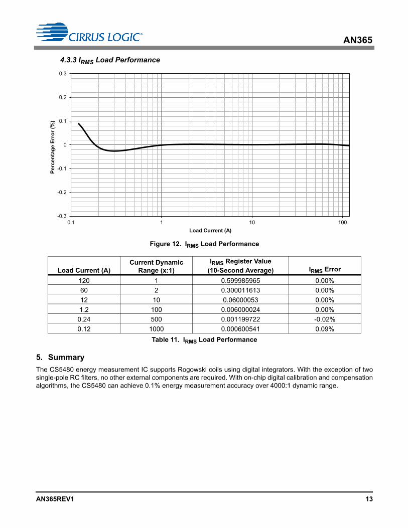
4.3.3 IRMS Load Performance
Figure 12. IRMS Load Performance
5. Summary
The CS5480 energy measurement IC supports Rogowski coils using digital integrators. With the exception of twosingle-pole RC filters, no other external components are required. With on-chip digital calibration and compensationalgorithms, the CS5480 can achieve 0.1% energy measurement accuracy over 4000:1 dynamic range.
Load Current (A)Current Dynamic
Range (x:1)IRMS Register Value
(10-Second Average) IRMS Error
120 1 0.599985965 0.00%
60 2 0.300011613 0.00%
12 10 0.06000053 0.00%
1.2 100 0.006000024 0.00%
0.24 500 0.001199722 -0.02%
0.12 1000 0.000600541 0.09%
Table 11. IRMS Load Performance
-0.3
-0.2
-0.1
0
0.1
0.2
0.3
0.1 1 10 100
Perc
enta
ge E
rror
(%)
Load Current (A)
AN365REV1 13
AN365
Revision History
Revision Date Changes
REV1 MAR 2012 Initial Release.
Contacting Cirrus Logic SupportFor all product questions and inquiries contact a Cirrus Logic Sales Representative. To find one nearest you go to http://www.cirrus.com
IMPORTANT NOTICE
Cirrus Logic, Inc. and its subsidiaries ("Cirrus") believe that the information contained in this document is accurate and reliable. However, the information is subjectto change without notice and is provided "AS IS" without warranty of any kind (express or implied). Customers are advised to obtain the latest version of relevantinformation to verify, before placing orders, that information being relied on is current and complete. All products are sold subject to the terms and conditions of salesupplied at the time of order acknowledgment, including those pertaining to warranty, indemnification, and limitation of liability. No responsibility is assumed by Cirrusfor the use of this information, including use of this information as the basis for manufacture or sale of any items, or for infringement of patents or other rights of thirdparties. This document is the property of Cirrus and by furnishing this information, Cirrus grants no license, express or implied under any patents, mask work rights,copyrights, trademarks, trade secrets or other intellectual property rights. Cirrus owns the copyrights associated with the information contained herein and gives con-sent for copies to be made of the information only for use within your organization with respect to Cirrus integrated circuits or other products of Cirrus. This consentdoes not extend to other copying such as copying for general distribution, advertising or promotional purposes, or for creating any work for resale.
CERTAIN APPLICATIONS USING SEMICONDUCTOR PRODUCTS MAY INVOLVE POTENTIAL RISKS OF DEATH, PERSONAL INJURY, OR SEVERE PROP-ERTY OR ENVIRONMENTAL DAMAGE ("CRITICAL APPLICATIONS"). CIRRUS PRODUCTS ARE NOT DESIGNED, AUTHORIZED OR WARRANTED FOR USEIN PRODUCTS SURGICALLY IMPLANTED INTO THE BODY, AUTOMOTIVE SAFETY OR SECURITY DEVICES, LIFE SUPPORT PRODUCTS OR OTHER CRIT-ICAL APPLICATIONS. INCLUSION OF CIRRUS PRODUCTS IN SUCH APPLICATIONS IS UNDERSTOOD TO BE FULLY AT THE CUSTOMER'S RISK ANDCIRRUS DISCLAIMS AND MAKES NO WARRANTY, EXPRESS, STATUTORY OR IMPLIED, INCLUDING THE IMPLIED WARRANTIES OF MERCHANTABILITYAND FITNESS FOR PARTICULAR PURPOSE, WITH REGARD TO ANY CIRRUS PRODUCT THAT IS USED IN SUCH A MANNER. IF THE CUSTOMER ORCUSTOMER'S CUSTOMER USES OR PERMITS THE USE OF CIRRUS PRODUCTS IN CRITICAL APPLICATIONS, CUSTOMER AGREES, BY SUCH USE, TOFULLY INDEMNIFY CIRRUS, ITS OFFICERS, DIRECTORS, EMPLOYEES, DISTRIBUTORS AND OTHER AGENTS FROM ANY AND ALL LIABILITY, INCLUD-ING ATTORNEYS' FEES AND COSTS, THAT MAY RESULT FROM OR ARISE IN CONNECTION WITH THESE USES.
Cirrus Logic, Cirrus, the Cirrus Logic logo designs, EXL Core, and the EXL Core logo design are trademarks of Cirrus Logic, Inc. All other brand and product namesin this document may be trademarks or service marks of their respective owners.
14 AN365REV1
Related Documents