1 Radar cross section RCS is the measure of an object's ability to reflect radar signal in the direction of the radar receiver i.e. it is the measure of the ratio of backscatter per steradian (unit solid angle) in the direction of the radar (from the target) to the power density that is intercepted by the target. This application note describes how a modern battery-powered / portable Microwave Vector Network Analyzer with Time Domain Gating can make it easy to do RCS tests on the flight line or in the field. The RCS of a target can be visualized as a comparison of the power of the reflected signal from a target to the reflected signal from a perfectly conducting smooth sphere of RCS area of 1 m 2 as shown in figure (1). Application Note Measurement of Radar Cross Section Using the “VNA Master” Handheld VNA Radar Target Sphere Radar Figure 1. Concept of Radar Cross Section. The RCS of a sphere is independent of frequency provided that the wavelength l is much less than the range R >15 l to the sphere and the effective sphere radius r s >15 l. By Martin I. Grace

Welcome message from author
This document is posted to help you gain knowledge. Please leave a comment to let me know what you think about it! Share it to your friends and learn new things together.
Transcript

1
Radar cross section RCS is the measure of an object's ability to reflect radar signal in the direction of the radar receiver i.e. it is the measure of the ratio of backscatter per steradian (unit solid angle) in the direction of the radar (from the target) to the power density that is intercepted by the target. This application note describes how a modern battery-powered / portable Microwave Vector Network Analyzer with Time Domain Gating can make it easy to do RCS tests on the flight line or in the field.
The RCS of a target can be visualized as a comparison of the power of the reflected signal from a target to the reflected signal from a perfectly conducting smooth sphere of RCS area of 1 m2 as shown in figure (1).
Application Note
Measurement of Radar Cross Section Using the “VNA Master” Handheld VNA
RadarTarget
SphereRadar
Figure 1. Concept of Radar Cross Section.
The RCS of a sphere is independent of frequency provided that the wavelength l is much less than the range R >15 l to the sphere and the effective sphere radius rs >15 l.
By Martin I. Grace

2
Radar Range Equation The radar system as described in figure (2) transmits a pulse of energy through the transmit antenna of gain Gt. The amplitude of the signal at the output of the transmit antenna is reduced by the free space propagation loss. At the target some of the power (backscatter) is reflected back towards the radar. The ratio of the backscatter power to the incident power is the RCS (stgt) of the target. The amplitude is then again further reduced by the free space propagation loss. The signal is then received by the receive antenna with gain Gr and detected in the receiver. The power level Pr in the receiver is1:
Pt • Gt • Gr • σtarget • λ2
(4π)3 • R4Pr =
Pt
PtGt
Gt
Pr
PrGr
Gr
γt
γr
Targetβ
Eth
EtvEt
Erh
ErvEr
Figure 2. Typical Radar showing transmitter and receiver separated by the angle b, for a monostatic radar both transmit and receive antenna are identical (angle b = 0) and are located a distance R from the target. Arbitrary transmitted and received polarizations may be resolved as shown.
Most radars operate in a monostatic configuration, where both transmit and receive antenna are common and a duplexer is used to separate transmit and receive signals.
1 www.tscm.com/2waymon.pdf

3
The block diagram describing the physical representation of the radar is shown in figure (3).
PtGtPtGtλ2/(4πR)2
GtPt
PtGtσλ2
PtGtσ/4πR2(4π)3R4
Gr Free Space Lossλ
λ2
4 • π • Ri
4 • π • σ
2
Free Space Lossλ
4 • π • Ri
2
Pr
GrPtGtσλ2
(4π)3R4Pr =
Figure 3. Physical Block diagram for the RCS measurement.
Pt = Radar transmitter powerPr = Radar receive powerGt = Radar transmit antenna gainGr = Radar Receive antenna gainGs = equivalent Gain of the RCSAe = Radar Receive antenna effective area (meters)2
R = Range to target (meters)l = Wavelength (meters)stgt = Radar Cross Section of the target (meters)2 (Defined as kPr/Pt where k is a constant)
The RCS is given by:
Pr
Ptσtarget =
Pr
Pt•
(4π)3 • R4
Gt • Gr • λ2= k •
The equivalent circuit description of the Radar is shown in figure (4). The transmit and receive antenna gains are represented by amplifiers as is the RCS of the target.
PtGt
Pt • Gt •
GtPt
Gr
λ2
4 • π • σ
λ2
4 • π • σ
λ2
4 • π • σ
λ4 • π • R
2
Pt • Gt • λ
4 • π • R
2
λ(4 • π)3 • R4
2
Pt • Gt • λ
4 • π • R
2
λ4 • π • R
2
λ4 • π • R
2
Pr
Pr = Pt • Gt • σ • • Gr =
α = Free Space Loss
λ4 • π • R
2α = Free Space Loss Gσ =
• •
•
Figure 4. Circuit Block Diagram for the RCS measurement.
4
Resistors are used to represent the propagation losses. The VNA system when used to measure S21 has the same equivalent circuit description as the radar. The VNA measures the frequency domain response S21 of the system when Port 1 of the VNA is connected to the transmit antenna and Port 2 is connected to the receive antenna.
Although Vector Network Analyzers are most commonly used to provide measurements vs. frequency, the addition of Time Domain analysis and Time Gating help simulate pulsed radar functionality by removing reflections distances not associated with the target. The 12 term error correction of the VNA will minimize the systematic errors due to mismatch, leakage and accurately establish a reference plane.
Polarization2
The polarization of the electric field vector of the reflected signal can be different than that of the transmitted radar signal. The shape of the target is responsible for the depolarizing characteristics (angular difference gt - gr) as described in figure (2).
To correct for the depolarization, full polarization matrix imaging is utilized by measuring both the vertical and horizontal components of the electric field independently. This will require two transmit and two receive polarizations (horizontal H and vertical V).
Transmit ReceiveVertical Polarization Vertical Polarization/ Horizontal PolarizationHorizontal Vertical Polarization/ Horizontal Polarization
From the above measurements a polarization matrix is generated to describe the effect of the polarization to correct for the depolarization.
Et = Etv • cos (γ t) + Eth • sin (γ t) Er = Erv • cos (γ r) + Erh • sin (γ r)
Erv = Sw • Etv + Shv • Eth
Erh = Svh • Etv + Shh • Eth
Et and Er are decomposed to:
2 Radar cross section measurements Eugene F. Knott - 2006 - Technology & Engineering – pages 17-21
Sxx is a complex number defining the 4 possible measurement conditions
S = Svv Shv
Svh Shh
Where:
Svv: transmit vertical polarization, receive vertical polarizationSvh: transmit vertical polarization, receive horizontal polarizationShv: transmit horizontal polarization, receive vertical polarizationShh: transmit horizontal polarization, receive horizontal polarization
The resulting RCS:
σ =σvv σhv
σvh σhh
If the transmit antenna is vertically polarized, the RCS is:
σ = (Prv + Prh) /Pt

5
VNA MeasurementsThe VNA shown in figure (5) measures the S-parameters in the frequency domain. The frequency range for the measurements is chosen to correspond to the radar frequency band (8.2 – 12.4 GHz for WR-90 X-band waveguide). The time domain function of the VNA will transform the S-parameter frequency domain measurement (G vs. frequency) to the time domain (G vs. time or distance).
Figure 5. Photograph of the MS2028C/2038C with waveguide antennas.
A property of the transform process is the Alias Free Range (AFR). The transform is a circular function and repeats itself periodically outside of its inherent time range that is t = 1/(Frequency Step Size). The frequency step size is proportional to the frequency span and inversely proportional to the number of data points.
Inherent time range: t = (N-1)/(Frequency Span)
For example at X-band using a 4.0 GHz. frequency span and 4,001 data points, the (AFR) is: 4000/4.0 GHz = 1000 nanoseconds corresponding to a 300 meter alias free range. The 300 meter range is the round trip time thus the target should not be placed more than 150 meters from the VNA.

6
A typical aircraft RCS measurement configuration using a VNA is shown in figure (6). The transmit antenna (connected to port 1 of the VNA) and receive antenna (connected to port 2 of the VNA) are positioned in the same plane as shown. The measurement target consists of the aircraft either mounted on a low reflection pedestal or a stand alone on a flight line.
The operation of a S21(f) measurement for the VNA is shown to be the equivalent to Radar when configured as shown. The coaxial cable output of port 1 is connected to the coax to rectangular waveguide transition (E field in the vertical direction). The output of port 2 is connected to the output of the receive waveguide antenna. Both antennas are located as close as possible, in either the vertical or horizontal plane. To develop the polarization matrix both transmit and receive antenna should be capable of 90 degree rotation.
The target should be located at a distance less that AFR/2 but far enough from the antenna to insure that the entire target is within in the beam of the antennas.
VNAPort 1 Port 2
Calibration Reference PlaneReceive Antenna
Transmit Antenna
SP2TAntenna Polarization
Range
Backscatter
Target
Incident Power
Figure 6. Block diagram for VNA measurement of RCS.
Antenna System CalibrationThe RCS of known target geometries and their corresponding cross-section are shown in figure (7). The ideal standard to use is a conducting sphere of a known diameter. For example a 1.13 m diameter sphere has a RCS of 1 m2 that is independent of frequency. You can choose the diameter of the sphere whose RCS corresponds closely to the expected RCS. You can use any other geometry if so desired.
Flat PlateRCS = 14,000 m2 at 10 GHz or140 m2 1 GHz
SphereRCS = 1 m2 Independent of Frquency
Small Flat PlateRCS = 1 m2 at 10 GHzor 0.01 m2 at 1 GHz
Flat Plateσ = 4πw2h2/λ2
Sphere σ = πr2
0.093 m
0.093 m
1 m
1 m
1.13 m
Figure 7. RCS vs. Physical Geometry.
7
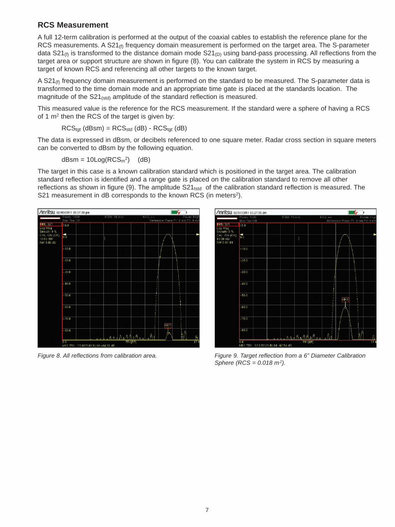
RCS MeasurementA full 12-term calibration is performed at the output of the coaxial cables to establish the reference plane for the RCS measurements. A S21(f) frequency domain measurement is performed on the target area. The S-parameter data S21(f) is transformed to the distance domain mode S21(D) using band-pass processing. All reflections from the target area or support structure are shown in figure (8). You can calibrate the system in RCS by measuring a target of known RCS and referencing all other targets to the known target.
A S21(f) frequency domain measurement is performed on the standard to be measured. The S-parameter data is transformed to the time domain mode and an appropriate time gate is placed at the standards location. The magnitude of the S21(std) amplitude of the standard reflection is measured.
This measured value is the reference for the RCS measurement. If the standard were a sphere of having a RCS of 1 m2 then the RCS of the target is given by:
RCStgt (dBsm) = RCSstd (dB) - RCStgt (dB)
The data is expressed in dBsm, or decibels referenced to one square meter. Radar cross section in square meters can be converted to dBsm by the following equation.
dBsm = 10Log(RCSm2) (dB)
The target in this case is a known calibration standard which is positioned in the target area. The calibration standard reflection is identified and a range gate is placed on the calibration standard to remove all other reflections as shown in figure (9). The amplitude S21tstd of the calibration standard reflection is measured. The S21 measurement in dB corresponds to the known RCS (in meters2).
Figure 8. All reflections from calibration area. Figure 9. Target reflection from a 6” Diameter Calibration Sphere (RCS = 0.018 m2).

8
Measurement Procedure for non-polarizing targetSet up for VNA based RCS measurement system S21 measurement
VNA
Port 1 Port 2
D
D
Inc.
Refl.
Calibration Area
Target
Figure 10. Set-up for the RCS measurement system using VNA (assuming non - polarization effects).
1. Connect port 1 to the Transmit S21(V) antenna and port 2 connections to the corresponding receive S21(V)waveguide horn antenna. Both antennas will have the same polarization
2. Measure the S21(f) reflection of the target area or target support structure (str). This is accomplished byremoving the target from the area or pointing the antennas in a direction away from the target and insuring thatthere are no objects at the same distance from the antenna. (See figure 10).
3. Measure the S21(f) parameter. Transform the data to the distance domain S21(D) and store to memory (insurethat D> 20l and that the target dimensions are within –1 dB azimuth and elevation angles of the antenna beamdimensions). Place a time gate centered at the distance (D) to the target and set gate width greater than theobserved size of the target.
4. If a target support structure is used, measure S21(D) of the target support structure with the target removed.The measured value should be less than 20 dB lower than that of the estimated targetRCS (S21support structure << S21target). If not add additional microwave absorbing material around the supportstructure to reduce it’s RCS to the acceptable value.
5. Measure the calibration standard at the above location specified and plot S21(D) in time domain with the rangegate set at the target distance and apply to the target S21(D). Store the distance domain S21std into the tracememory. The RCS of the standard should be slightly smaller than the estimated RCS of the target.

9
Pstr(4 π)3 • R4
Pt • Gt • Gr • λ2 • σstr= Pstd
(4 π)3 • R4
Pt • Gt • Gr • λ2 • σstd= Ptgt
(4 π)3 • R4
Pt • Gt • Gr • λ2 • σtgt=
Where: std refers to the RCS standard, tgt refers to the target and str refers to the target support structure.
Pt
Pstd10 • logS21std =Pt
Ptgt10 • logS21tgt =Pt
Pstr10 • logS21str =
Pt
PstdS21std
= 10 10
Pt
PtgtS21tgt
= 10 10
Pt
PstrS21str
= 10 10
To calculate the RCS of the Target the following equations are applied.
10
S21tgt –S21std
Pstd
Ptgt
σstd
σtgt= = 10 10
S21tgt –S21std
σstdσtgt = • 10
Figure 11. Measured S21tgt for 12” sphere.
Example of a RCS measurement
Figure (11) shows the RCS measurement for the target (12’' diameter sphere) and figure (9) shows the RCS for the calibration standard (6” diameter sphere). The difference in dBsm = (Ptgt - Pstd).
The RCS of the target in m2 is given by;
10
S21tgt –S21std
σstdσtgt = • 10 = 0.06 m2
The theoretical value for the 12” sphere is 0.073 m2. The percentage measurement error is 17.8 % or 0.77 dB in dBsm. Most of the error was attributed to small movements in the VNA support structure during the measurement.
6. Replace the calibration standard with the target or rotate the antennas toward the target and repeat step (4).Measure the S21tgt and perform the trace math (memory – data) = [S21std – S21tgt]
7. The RCS of the target is calculated using the VNA trace math following derivation from the Radar Range equations:

10
Notes

11
Notes

Anritsu Corporation5-1-1 Onna, Atsugi-shi, Kanagawa, 243-8555 Japan Phone: +81-46-223-1111 Fax: +81-46-296-1238
• U.S.A. Anritsu Company1155 East Collins Boulevard, Suite 100, Richardson, TX, 75081 U.S.A. Toll Free: 1-800-ANRITSU (267-4878) Phone: +1-972-644-1777 Fax: +1-972-671-1877• Canada Anritsu Electronics Ltd.700 Silver Seven Road, Suite 120, Kanata, Ontario K2V 1C3, Canada Phone: +1-613-591-2003 Fax: +1-613-591-1006
• Brazil Anritsu Electrônica Ltda.Praça Amadeu Amaral, 27 - 1 Andar 01327-010 - Bela Vista - São Paulo - SP - Brasil Phone: +55-11-3283-2511 Fax: +55-11-3288-6940
• Mexico Anritsu Company, S.A. de C.V.Av. Ejército Nacional No. 579 Piso 9, Col. Granada 11520 México, D.F., México Phone: +52-55-1101-2370 Fax: +52-55-5254-3147
• U.K. Anritsu EMEA Ltd.200 Capability Green, Luton, Bedfordshire LU1 3LU, U.K. Phone: +44-1582-433280 Fax: +44-1582-731303
• France Anritsu S.A.12 Avenue du Québec, Bâtiment Iris 1-Silic 638, 91140 VILLEBON SUR YVETTE, France Phone: +33-1-60-92-15-50 Fax: +33-1-64-46-10-65
• Germany Anritsu GmbHNemetschek Haus, Konrad-Zuse-Platz 1 81829 München, Germany Phone: +49 (0) 89 442308-0 Fax: +49 (0) 89 442308-55
• Italy Anritsu S.p.A.Via Elio Vittorini, 129, 00144 Roma, Italy Phone: +39-06-509-9711 Fax: +39-06-502-2425
• Sweden Anritsu ABBorgafjordsgatan 13, 164 40 KISTA, Sweden Phone: +46-8-534-707-00 Fax: +46-8-534-707-30
• Finland Anritsu ABTeknobulevardi 3-5, FI-01530 VANTAA, Finland Phone: +358-20-741-8100 Fax: +358-20-741-8111
• Denmark Anritsu A/S (for Service Assurance) Anritsu AB (for Test & Measurement)Kirkebjerg Allé 90 DK-2605 Brøndby, Denmark Phone: +45-7211-2200 Fax: +45-7211-2210
• RussiaAnritsu EMEA Ltd. Representation Office in RussiaTverskaya str. 16/2, bld. 1, 7th floor. Russia, 125009, Moscow Phone: +7-495-363-1694 Fax: +7-495-935-8962
• United Arab Emirates Anritsu EMEA Ltd. Dubai Liaison OfficeP O Box 500413 - Dubai Internet City Al Thuraya Building, Tower 1, Suite 701, 7th Floor Dubai, United Arab Emirates Phone: +971-4-3670352 Fax: +971-4-3688460
• Singapore Anritsu Pte. Ltd.60 Alexandra Terrace, #02-08, The Comtech (Lobby A) Singapore 118502 Phone: +65-6282-2400 Fax: +65-6282-2533
• India Anritsu Pte. Ltd. India Branch Office3rd Floor, Shri Lakshminarayan Niwas, #2726, 80 ft Road, HAL 3rd Stage, Bangalore - 560 075, India Phone: +91-80-4058-1300 Fax: +91-80-4058-1301
• P. R. China (Hong Kong) Anritsu Company Ltd.Units 4 & 5, 28th Floor, Greenfield Tower, Concordia Plaza, No. 1 Science Museum Road, Tsim Sha Tsui East, Kowloon, Hong Kong, P.R. China Phone: +852-2301-4980 Fax: +852-2301-3545
• P. R. China (Beijing) Anritsu Company Ltd. Beijing Representative OfficeRoom 2008, Beijing Fortune Building, No. 5 , Dong-San-Huan Bei Road, Chao-Yang District, Beijing 100004, P.R. China Phone: +86-10-6590-9230Fax: +86-10-6590-9235
• Korea Anritsu Corporation, Ltd.8F Hyunjuk Bldg. 832-41, Yeoksam-Dong, Kangnam-ku, Seoul, 135-080, Korea Phone: +82-2-553-6603 Fax: +82-2-553-6604
• Australia Anritsu Pty Ltd.Unit 21/270 Ferntree Gully Road, Notting Hill Victoria, 3168, Australia Phone: +61-3-9558-8177 Fax: +61-3-9558-8255
• Taiwan Anritsu Company Inc.7F, No. 316, Sec. 1, Neihu Rd., Taipei 114, Taiwan Phone: +886-2-8751-1816 Fax: +886-2-8751-1817
11410-00604, Rev. B Printed in United States 2011-09©2011 Anritsu Company. All Rights Reserved.
® Anritsu All trademarks are registered trademarks of their respective companies. Data subject to change without notice. For the most recent specifications visit: www.anritsu.com
Related Documents