Establish LTE & 2G/3G connections to HEAD acoustics equipment via Anritsu MD8475A Application Note

Welcome message from author
This document is posted to help you gain knowledge. Please leave a comment to let me know what you think about it! Share it to your friends and learn new things together.
Transcript

Establish LTE & 2G/3G connections to HEAD acoustics equipment via Anritsu MD8475A
Application Note


Application Note
Establish LTE & 2G/3G connections to HEAD acoustics equipment via Anritsu MD8475A
Revision: 0

4
Application Note
Legal notices:
Copyright:
© HEAD acoustics GmbH 2018. All rights reserved. Subject to change.All rights derived from this, also for partial use, are reserved by HEAD acoustics GmbH, Germany. Reproducing or distributing the manual or parts of it in any form is not allowed without express permission from HEAD acoustics GmbH.
Trademarks:
HEAD acoustics® is a registered trademark.

5
Application Note
Table of Contents1 Introduction ..................................................................................................................................................6
1.1 Brief description ....................................................................................................................................61.2 Acronyms and abbreviations ................................................................................................................6
2 LTEconfiguration ........................................................................................................................................72.1 Equipment list .......................................................................................................................................7
2.1.1 HEAD acoustics equipment .....................................................................................................72.1.2 Anritsu equipment ....................................................................................................................72.1.3 Third party equipment ..............................................................................................................7
2.2 Configurationoverview .........................................................................................................................82.3 Cabling to Anritsu MD8475A .................................................................................................................82.4 LTE connection establishment ..............................................................................................................9
2.4.1 Preparations .............................................................................................................................92.4.2 Connection procedure ..............................................................................................................9
3 2G/3Gconfiguration ................................................................................................................................153.1 Equipment list .....................................................................................................................................15
3.1.1 HEAD acoustics equipment ...................................................................................................153.1.2 Anritsu equipment ..................................................................................................................153.1.3 Third party equipment ............................................................................................................15
3.2 Configurationoverview .......................................................................................................................163.3 Cabling to Anritsu MD8475A ...............................................................................................................163.4 2G connection establishment .............................................................................................................17
3.4.1 Preparation .............................................................................................................................173.4.2 Connection procedure ............................................................................................................17
3.5 3G connection establishment .............................................................................................................223.5.1 Preparation .............................................................................................................................223.5.2 Connection procedure ............................................................................................................22

Introduction
6
Application Note
1 Introduction
1.1 Brief descriptionThis application note approaches the connection establishment between the Anritsu radio communication tester MD8475A,HEADacousticsequipmentandthetestobject.Thepresentedconfigurationsintendtestingmobiledevices with current mobile communication standards (LTE, 3G, 2G).The document consists of two main chapters. One for the LTE connection and the other one for the 2G / 3G connection.Thestructureofthemainchaptersissimilar.Thefirstsub-chapterillustratestheinterconnectionofallnecessaryhardware.Afterwards,thenextsub-chapterguidesstepbystepthroughtheprocedureforasuccessful connection establishment.The application requires an advanced user knowledge of HEAD acoustics equipment as well as the Anritsu MD8475A. HEAD acoustics will not respond to support requests concerning general handling and technical configurationoftheAnritsuMD8475A.
1.2 Acronyms and abbreviations
Acronym / Abbreviation Description
ACQUA Advanced Communication Quality Analysis
AES Audio Engineering Society
AMR-WB Adaptivemulti-ratewideband
APN Access point name
BNC Bayonet Neill Concelman
DUT Device under test
GSM / GPRS Global System for Mobile Communications / General Packet Radio Service
GSM-EFR GlobalSystemforMobileCommunications-Enhancedfullrate
HHP HEAD handset positioner
HMS HEAD measurement system
IMS IP multimedia subsytem
IPsec Internet protocol security
IPv4 Internet protocol version 4
IPv6 Internet protocol version 6
LED Light-emittingdiode
LTE Long Term Evolution
MCC Mobile county code
MFE Measurement front end
MNC Mobile network code
PDN Packet data network
QCI QoSclassidentifier
RF Radio frequency
RTP Real-timetransportprotocol
SIM Subscriber identity module
SIP Session initiation protocol
UIM User identity module
VoIP Voice over internet protocol
W-CDMA WidebandCodeDivisionMultipleAccess
XLR Ground-left-right

7
LTE configuration Application Note
2 LTEconfiguration
2.1 Equipment list
2.1.1 HEAD acoustics equipment
- ACQUA software
- HMS II.3
- HHP IV or HHP III.1
- MFEVI.1
- MFEVIII.1withAMRcodecandnetworkimpairmentsoftware
- CDMVcable(D-Subto2xXLR+2xBNC)
2.1.2 Anritsu equipment
- Anritsu MD8475A signaling tester
- Multi-signallingUnit
- SmartStudio©
- LTEFDDOption
- ExtendedCSCFOption
- LTE Simulation Software
- LTEFDDOption
- MX847550A 1 Year Support Service
2.1.3 Third party equipment
- Ethernet switch
- 3 x Ethernet cable
- RFantenna
- PC for ACQUA software
- Test object (DUT)
- Test SIM card

LTE configuration
8
Application Note
2.2 Configurationoverview
2.3 Cabling to Anritsu MD8475A
Ethernet
AES / EBU
RFLTE / 4G
DUT
MFE VI.1
MFE VIII.1
Anritsu MD8475A(IMS Server in-built)
MouthUSB
RF antenna
HMS II.3HHP IV
(or HHP III.1)
Ear
AcousticUSB
= Audio signal= Control and / or audio signal= Acoustic signal

9
LTE configuration Application Note
2.4 LTE connection establishment
2.4.1 Preparations
- Interconnect the hardware according to section 2.2 & section 2.3.
- Boot up Anritsu MD8475A.
- Open SmartStudio© on Anritsu MD8475A.
- Boot up PC and start ACQUA.
- Boot up HEAD acoustics front end(s).
- Insert test SIM card into test object and boot up test object.
2.4.2 Connection procedure
Anritsu MD8475A: Simulation parameter setup
1. Open SmartStudio© on Anritsu MD8475A.
2. Select to open simulation parameter setup.
3. If available, load existing simulation parameter setup by selecting .
4. Select “Simulation”.
5. Set “Simulation Model” to LTE.
6. Select “UIM/SIM”.
7. Check if the UIM/SIM settings apply to the SIM card of the test object.
8. If desired, save the simulation parameter setup by selecting .
9. Confirm simulation parameter setup with byselecting .
Anritsu MD8475A: Cell parameter setup
1. Select to open cell parameter setup.
2. If available, load existing cell parameter setup by selecting .

LTE configuration
10
Application Note
3. Select LTE from the “Cell list”.
4. Unfold “Common” in “Cell parameter”.
5. Set the external attenuation (DL Ref Power and UL Ref Power). It shall match the attenuation of theRFantennaandtheantennacable.
6. Set the operating band (“E-UTRABand”)according to the test object.
7. Set the network identity MCC to 001.
8. SetthenetworkidentityMNCto01F.
9. If desired, save the simulation parameter setup by selecting .
10. Confirm cell parameter setup by selecting.
Anritsu MD8475A: IPsec and authentication settings
1. Select from the windows taskbar to open IMS services.
2. Highlight “IPsec settings” from the “Property” list.
3. Select to edit IPsec settings.
4. Check the “IPsec active” box and edit the settings according to the test object. or Uncheck the “IPsec active” box to deactivate IPsec.
5. Select toconfirm“IPsecsettings”.
6. Set “IMS authentication” to either “True” or “False”,accordingtothetestobject.

11
LTE configuration Application Note
Anritsu MD8475A: PDN parameter setup
1. Select from the windows taskbar to switch back to SmartStudio© main screen.
2. Select to start the simulation.
3. Select the “Packet” icon to display the PDN information window.
4. Double-click on the row of test object that isconnected via LTE connection to the radio tester. The “PDN Parameter Setup” of the test object pops up.
5. ConfirmtheAPNnameat“CheckAPN”.Changeit if necessary.
6. ConfirmtheIPtype.Changeifnecessary.
7. Select the tab “User equipment”. Check and confirmtheIPv6addressofthetestobject.
8. Select the tab “Bearer”.
9. Confirmthevalue“5”fortheQCIofthedefaultservice.
10. Select the tab “Network”
11. The default settings apply.
12. Select toconfirmandfinish“PDNParameter Setup”.

LTE configuration
12
Application Note
Anritsu MD8475A: IMS server
1. Select from the windows taskbar to open IMS services.
2. Set the test object in offline mode / airplanemode.
3. Select the “User Info” tab.
4. Select to unlock IMS authentication.
ACQUAPC:Hardwareconfiguration&radiotesterwizard
1. Start“HardwareConfiguration”.
2. SetMFEVI.1asprimaryfrontendandaAESconnectiontotheMFEVIII.1.
3. SelectMFEVI.1.
4. Set the connection path according to the configuration(cf.screenshot).

13
LTE configuration Application Note
5. SelectMFEVIII.1.
6. Select the tile “VoIP”.
7. Select the tab “Call”.
8. Enable the automatic jitter buffer reset function.
9. Select to start the radio tester wizard.
10. Select the Anritsu MD8475A. The Internet protocol (IPv4, IPv6) depends on the test object.
11. Select “RTP Settings”.
12. Select the desired codec.

LTE configuration
14
Application Note
13. Select “Check parameters”. Check if all parameter are correct.
14. If IPsec is active at Anritsu MD8475A: Select to lock IMS authentication.
Do not lock IMS authentication if IPsec is inactive at Anritsu MD8475A and not required by the test object.
15. Select“Finish”toregistertheMFEVIII.1atAnritsu MD8475A.
16. A green LED at the bottom confirms thesuccessful registration.
17. TheSIPaddressofMFEVIII.1appears in the“Registered List” on Anritsu MD8475A.
Anritsu MD8475A: IMS server
1. Set test object back online and force it to register on IMS server.
2. The SIP address of the test object appears in the “Registered List” on Anritsu MD8475A.
3. Check if test object andMFE VIII.1 have thesame public identity address ([email protected]) in the “Registered List”.
ACQUA PC: Call execution
1. Enter the SIP address of the test object in ACQUA and select “Call” to connect test object andMFEVIII.1.
2. Theconnectionthroughouttheconfigurationisestablished.

15
2G / 3G configuration Application Note
3 2G/3Gconfiguration
3.1 Equipment list
3.1.1 HEAD acoustics equipment
- ACQUA software
- HMS II.3 (HEAD measurement system)
- HHP IV (or HHP III.1) (HEAD handset positioner)
- MFEVI.1
- MFEVIII.1withAMRcodecandnetworkimpairmentsoftware
- CDMVcable(D-Subto2xXLR+2xBNC)
3.1.2 Anritsu equipment
GSM
- Anritsu MD8475A signaling tester
- SmartStudio©
- GSM Option
- GSM/GPRS Simulation Software
- GSM Signalling Unit
- MX847520A 1 Year Support Service
W-CDMA
- Anritsu MD8475A signaling tester
- SmartStudio©
- W-CDMAOption
- Multi Signaling Unit
- W-CDMASimulationSoftware
- MX847510A 1 Year Support Service
3.1.3 Third party equipment
- Ethernet switch
- 3 x Ethernet cable
- RFantenna
- PC for ACQUA software
- Test object (DUT)
- Test SIM card

2G / 3G configuration
16
Application Note
3.2 Configurationoverview
3.3 Cabling to Anritsu MD8475A
= Audio signal= Control and / or audio signal= Acoustic signal
Ethernet
AES / EBU
RFLTE / 4G
DUT
MFE VI.1
MFE VIII.1
Anritsu MD8475A(IMS Server in-built)
Acoustic
MouthUSB
RF antenna
HMS II.3HHP IV
(or HHP III.1)
Ear
Pulse
USB

17
2G / 3G configuration Application Note
3.4 2G connection establishment
3.4.1 Preparation
- Interconnectthehardwareaccordingtotheconfigurationoverview.
- Boot up Anritsu MD8475A.
- Open SmartStudio© on Anritsu MD8475A.
- Boot up PC and start ACQUA.
- Boot up HEAD acoustics front end(s).
- Insert test SIM card into test object and boot up test object.
3.4.2 Connection procedure
ACQUAPC:Hardwareconfiguration
1. Start “HardwareConfiguration”on theACQUAPC.
2. SetMFEVI.1asprimaryfrontendandaAESconnectiontotheMFEVIII.1.
3. SelectMFEVI.1.
4. Set the connection path according to the configuration(cf.screenshot).
5. SelectMFEVIII.1.
6. Set “extern Pulse (48 kHz)”.
7. Select the tile “VoIP”.

2G / 3G configuration
18
Application Note
8. Select the tab “Call”.
9. Enable the automatic jitter buffer reset function.
Anritsu MD8475A: Connection parameters
1. Open SmartStudio© on Anritsu MD8475A.
2. Select to open simulation parameter setup.
3. If available, load existing simulation parameter setup by selecting .
4. Select “Simulation”.
5. Set “Simulation Model” to GSM/GPRS.
6. Select “UIM/SIM”.
7. Check if the UIM/SIM settings apply to the SIM card of the test object.
8. If desired, save the simulation parameter setup by selecting .
9. Confirm simulation parameter setup with byselecting .
10. Select to open cell parameter setup.
11. If available, load existing cell parameter setup by selecting .

19
2G / 3G configuration Application Note
12. Select GSM/GPRS from the “Cell list”.
13. Unfold “Common” in “Cell parameter”.
14. Set the external attenuation (DL Ref Power and UL Ref Power). It shall match the attenuation of theRFantennaandtheantennacable.
15. Set the network identity MCC to 001.
16. SetthenetworkidentityMNCto01F.
17. If desired, save the simulation parameter setup by selecting .
18. Confirm cell parameter setup by selecting.
19. Select the voice codec GSM in SmartStudio©.
20. Open “SIPviaMD8475”.
21. Set “GSM” as “Simulation Type”.
22. Set“GSM-EFR”as“VoiceCodec”.
23. Select “Register”.
24. Select to start the simulation.
2G / 3G configuration
20
Application Note
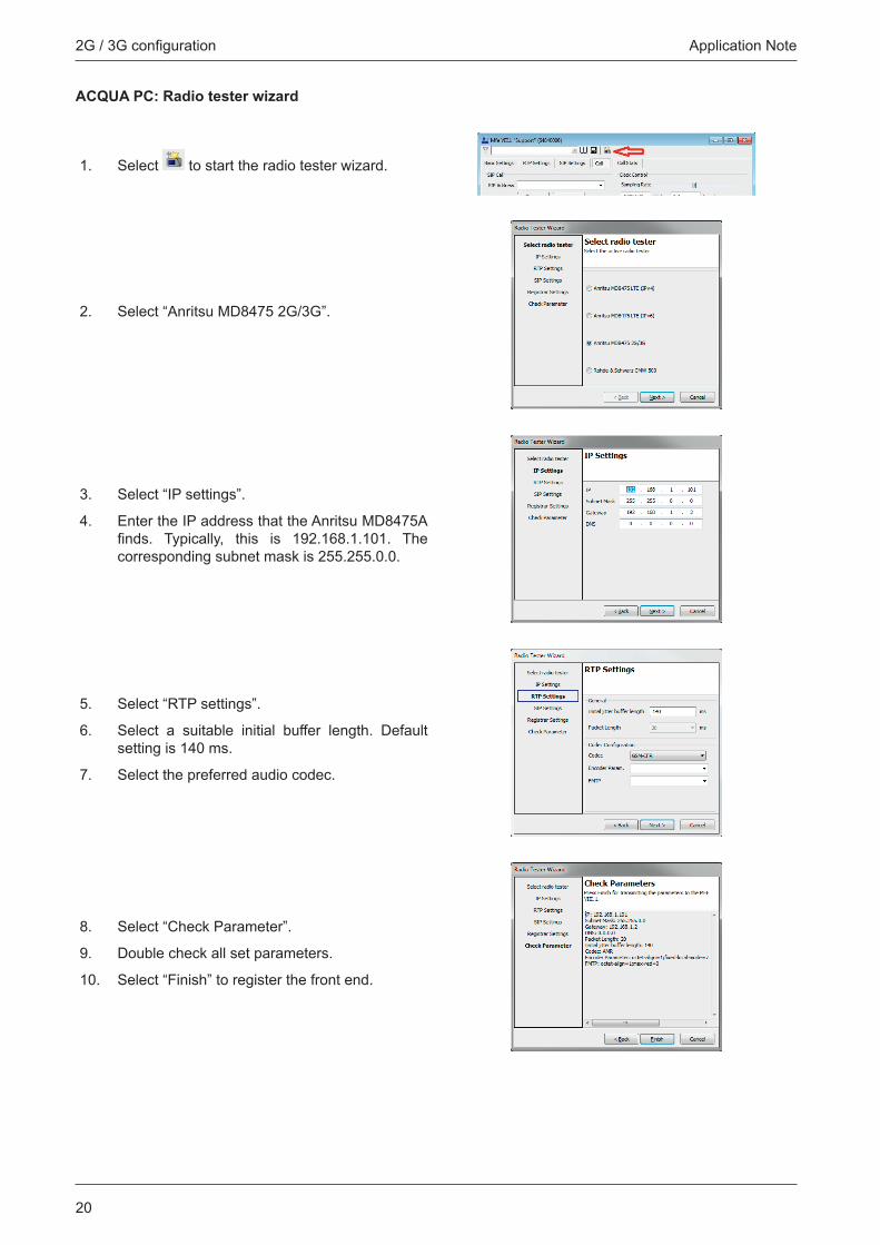
ACQUAPC:Radiotesterwizard
1. Select to start the radio tester wizard.
2. Select “Anritsu MD8475 2G/3G”.
3. Select “IP settings”.
4. Enter the IP address that the Anritsu MD8475A finds. Typically, this is 192.168.1.101. Thecorresponding subnet mask is 255.255.0.0.
5. Select “RTP settings”.
6. Select a suitable initial buffer length. Default setting is 140 ms.
7. Select the preferred audio codec.
8. Select “Check Parameter”.
9. Double check all set parameters.
10. Select“Finish”toregisterthefrontend.

21
2G / 3G configuration Application Note
Anritsu MD8475A: Call execution
1. Go to SmartStudio© main screen. The status of the test object (“UE stauts”) is idle.
2. Enter any number (e.g. 123) on the keypad of the virtual phone on the screen.
3. Select the green call button to initiate call. The radio tester waits for the call acceptance of the test object.
4. Accept the call at the test object.
5. The status of the test object switches from “Termination” to “Communication”.

2G / 3G configuration
22
Application Note
3.5 3G connection establishment
3.5.1 Preparation
- Interconnectthehardwareaccordingtotheconfigurationoverview.
- Boot up Anritsu MD8475A.
- Open SmartStudio© on Anritsu MD8475A.
- Boot up PC and start ACQUA.
- Boot up HEAD acoustics front end(s).
- Insert sim card into test object and boot up test object.
3.5.2 Connection procedure
ACQUAPC:Hardwareconfiguration
1. Start “HardwareConfiguration”on theACQUAPC.
2. SetMFEVI.1asprimaryfrontendandaAESconnectiontotheMFEVIII.1.
3. SelectMFEVI.1.
4. Set the connection path according to the configuration(cf.screenshot).
5. SelectMFEVIII.1.
6. Set “extern Pulse (48 kHz)”.
7. Select the tile “VoIP”.

23
2G / 3G configuration Application Note
8. Select the tab “Call”.
9. Enable the automatic jitter buffer reset function.
Anristsu MD8475A: Connection parameters
1. Open SmartStudio© on Anritsu MD8475A.
2. Select to open simulation parameter setup.
3. If available, load existing simulation parameter setup by selecting .
4. Select “Simulation”.
5. Set“SimulationModel”toW-CDMA.
6. Select “UIM/SIM”.
7. Check if the UIM/SIM settings apply to the SIM card of the test object.
8. If desired, save the simulation parameter setup by selecting .
9. Confirm simulation parameter setup with byselecting .
10. Select to open cell parameter setup.
11. If available, load existing cell parameter setup by selecting .

2G / 3G configuration
24
Application Note
12. SelectW-CDMAfromthe“Celllist”.
13. Unfold “Common” in “Cell parameter”.
14. Set the external attenuation (DL Ref Power and UL Ref Power). It shall match the attenuation of theRFantennaandtheantennacable.
15. Set the network identity MCC to 001.
16. SetthenetworkidentityMNCto01F.
17. If desired, save the simulation parameter setup by selecting .
18. Confirm cell parameter setup by selecting.
19. Set the voice codec AMR in SmartStudio©.
20. Open “SIPviaMD8475”.
21. Set“WCDMA”as“SimulationType”.
22. Set“AMR-WB”as“VoiceCodec”.
23. Select “Register”.
24. Select to start the simulation.

25
2G / 3G configuration Application Note
ACQUAPC:Radiotesterwizard
1. Select to start the radio tester wizard.
2. Select “Anritsu MD8475 2G/3G”.
3. Select “IP settings”.
4. Enter the IP address that the Anritsu MD8475A finds. Typically, this is 192.168.1.101. Thecorresponding subnet mask is 255.255.0.0.
5. Select “RTP settings”.
6. Select a suitable initial buffer length. Default setting is 140 ms.
7. Select the preferred audio codec.
8. Select “Check Parameter”.
9. Double check all set parameters.
10. Select“Finish”toregisterthefrontend.

2G / 3G configuration
26
Application Note
Anritsu MD8475A: Call execution
1. Go to SmartStudio© main screen. The status of the test object (“UE stauts”) is idle.
2. Enter any number (e.g. 123) on the keypad of the virtual phone on the screen.
3. Select the green call button to initiate call. The radio tester waits for the call acceptance of the test object.
4. Accept the call at the test object.
5. The status of the test object switches from “Termination” to “Communication”.

27
2G / 3G configuration Application Note

HEAD acoustics GmbHEbertstraße 30a52134 Herzogenrath
[email protected].: +49 2407 577-0Fax: +49 2407 577-99
Related Documents