FREETARGET Application Note: Building freETarget SUMMARY This application is a one document starting point for building freETarget from scratch. The document is organized as: • Building the target frame • Installing the circuit • Downloading the PC software • Starting up • Trouble shooting The example shown here is made from plywood and plastic. You may choose to assemble it with different materials. REQUIRED • freETarget circuit • Internet connection • Hand tools • Patience INTRODUCTION freETarget is an open source project to provide shooters with a low cost electronic target. One of the objectives is that the materials needed to make the target will be sourced from around the world and will be dependent on what is available locally. To do this, much of the initiative to tailor the construction to your skills and parts availability is comes from people like you. This application note provides the basics to construct freETarget. Read all of the instructions before starting. You may have to change materials or operations based on what you have at hand.

Welcome message from author
This document is posted to help you gain knowledge. Please leave a comment to let me know what you think about it! Share it to your friends and learn new things together.
Transcript
FREETARGET
Application Note: Building freETarget
SUMMARY
This application is a one document starting point for building freETarget from scratch. The document is organized as:
• Building the target frame • Installing the circuit • Downloading the PC software • Starting up • Trouble shooting
The example shown here is made from plywood and plastic. You may choose to assemble it with different materials.
REQUIRED
• freETarget circuit • Internet connection • Hand tools • Patience
INTRODUCTION
freETarget is an open source project to provide shooters with a low cost electronic target. One of the objectives is that the materials needed to make the target will be sourced from around the world and will be dependent on what is available locally. To do this, much of the initiative to tailor the construction to your skills and parts availability is comes from people like you.
This application note provides the basics to construct freETarget. Read all of the instructions before starting. You may have to change materials or operations based on what you have at hand.

BUILDING THE TARGET FRAME
The target frame holds the target and sensors in the correct position to record the shot. The assembly can be made of anything local, such as
• Plywood • Plastic • Metal • 3D Printing • Cardboard
A side view of the target assembly is shown in Figure 1.
Item Description Notes Front Face Face plate used to protect the circuitry
and sensors Should be made from a material that will withstand a pellet strike
LED Illumination LED lightning strip attached to the front face to light the target
Can be obtained from a local hardware store
Face Sensor Duplicate sensor mounted to the front face to detect a shot to the front face
Operation dependent on the material used for the front face.
Sensor Four microphones located around the target to detect the shot
Pay careful attention to the locations stenciled on the circuit board. Sensors may be located anywhere between the front face and pellet trap.
Flat Cable Routes from the Arduino board to the sensors
End marked with an A is the Arduino end of the cable
High Pass Filter Small board that installs between the flat cable and Arduino
Used to attenuate report from gun
Sensor Block Mounting block to hold sensor parallel to direction of shot
May be any non-conductive material.
Sensor Support Back frame to hold the sensors in the correct location and orientation
Target Target May be located anywhere between the front face and pellet trap.
Pellet Trap Pellet Trap Used to collect pellets after shooting. May be omitted if shooting on a range with a berm.
USB Cable Fifteen meter USB cable May be purchased locally or on line
IMPORTANT
The orientation of the sensors NORTH to WEST is as seen looking from the firing point through to the pellet trap. If you choose to mount the sensors behind sensor support the orientation will appear reversed.

Figure 1: freETarget Layout
The only thing that is important is that the sensors be mounted at the corners of the target at a distance of 230 mm sensor-to-sensor. Figure 2 illustrates the geometry of the sensors as viewed from the firing point
FrontFace
LEDIllumination
FlatCable
SensorSupport
Arduino
SensorBlock
FaceSensor
Sensor1 of 4
Target
Pellet Trap
USB Cable
High PassFilter
Shot

Figure 2: Sensor Geometry
The example shown in this Application Note is made from plywood and plastic. Figure 3 is an illustration of a target holder. Figure 4 shows a sample sensor block
EASTNORTH
SOUTH
WEST
230 mm Dia
43mm
14mm
2.54 mm5 mm
MicrophoneMounting Holes
8 mm
Sensor Module4x used on Target1x used on Face
Arduino
Connector
FACE
230mm165mm

Figure 3: Plywood Target Holder
Figure 4: Sensor Block
Begin by cutting a rectangular frame and square target hole. The frame can be as large as you like, and the target hole has to be big enough to hold the target in place. The stencil given in Appendix A may be used to locate the parts.
IMPORTANT
You may need to scale the printed stencil for your printer. The 50mm reference is provide for this purpose.
The sensor mounting blocks are rectangular blocks of plastic 12mm x 25 mm x 27mm. Yours can be larger or smaller or made of any non-conducting material that you have available. Drill two holes in the top of the sensor block to mount the sensor boards (See Figure 5).
Attach the sensor blocks to the target frame in the correct location.
Attach the sensors to the blocks using the mounting holes. Use 5 minute epoxy to attach the mounting blocks to the target holder on the lines marked above. Before the epoxy cures, align the sensors to the diagonal lines and make sure that they are 230mm apart.
Once the epoxy hardens put an additional bead around the base to prevent any movement.
Locate the bullet trap behind the target holder.

INSTALLING THE SENSORS
The next step is to install the sensors.
Note that the sensors are marked
• NORTH • EAST • SOUTH • WEST • FACE (more about that later)
Install each of the pellet sensors as shown in Figure 5 Sensor Installation
Figure 5: Sensor Installation
Install the Arduino at the bottom of the target holder and install the flat cable around all of the sensors as shown in Figure 6.
Note the location of the high pass filter. The flat cable is inserted into the pins on the filter board, and the board inserts into the cable socket. Be careful to center the cable into the board and the board into Arduino board. On later versions of the high pass filter the connectors are polarized and the red stripe will be on the opposite side.

Figure 6: Flat Cable Installation. Note Location of High Pass Filter
INSTALLING THE FACE SENSOR
The face sensor detects the sound of the pellet striking the case. The face sensor works best on a metal case, and not so well on plastic or wooden structures. Depending on the material used, the face sensor may not work at all.
Attach the face sensor facing the door and with a solid material between the door and the microphone. Figure 7 illustrates the attachment.

Figure 7: Face Sensor Installation
DOWNLOADING AND INSTALLING PC SOFTWARE
Click the link below to go to the downloads page
https://free-e-target.com/downloads/
Look for the PC Software section and download the software (Figure 8)
Figure 8: Download Software
Unzip the software and install on your PC.
Connect the USB cable between the target holder and the PC.

STARTING UP
Launch the PC program and look for the setup icon (GEAR WHEEL) in the upper right corner (See Figure 9)
Figure 9: Setup Icon Location
Enter all of the setup information needed in Figures 9, 10, 11, and 12
Figure 10: General Settings
Figure 11: Target Settings
Figure 12: Sensor Adjustment
Figure 13: Hardware Interface
Figure 10: This allows you to enter the shooter name and how information will be stored.
Figure 11: Choose the target you will be shooting against and the colours you will be using.
Figure 12: Fine tune the sensor position to adjust for assembly errors
Figure 13: Interface to the target hardware.
Press to begin a session.
Refer to the Commissioning Instructions from the web site. This will give you a quick summary of how the system is working
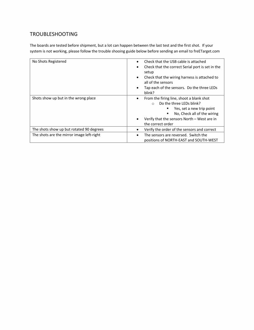
TROUBLESHOOTING
The boards are tested before shipment, but a lot can happen between the last test and the first shot. If your system is not working, please follow the trouble shooing guide below before sending an email to freETarget.com
No Shots Registered • Check that the USB cable is attached • Check that the correct Serial port is set in the
setup • Check that the wiring harness is attached to
all of the sensors • Tap each of the sensors. Do the three LEDs
blink? Shots show up but in the wrong place • From the firing line, shoot a blank shot
o Do the three LEDs blink? § Yes, set a new trip point § No, Check all of the wiring
• Verify that the sensors North – West are in the correct order
The shots show up but rotated 90 degrees • Verify the order of the sensors and correct The shots are the mirror image left-right • The sensors are reversed. Switch the
positions of NORTH-EAST and SOUTH-WEST

APPENDIX A – Mounting Stencil
IMPORTANT
This stencil may not print to scale on your printer.
Scale the printer output so that the 50x50 print reference is printed as a 50mm x 50mm square
45.5
2.51415
3dia
7.5
23
7.5
CUT
OUT
50mmx50mm
PrintReference
230239All dimensions
in mm
165
InnerSensorFace
OuterBlockFace
Related Documents