Bound-T time and stack analyzer Application Note Atmel AVR Version 1 TR-AN-AVR-001 2010-02-14 Tidorum Ltd. Tid rum

Welcome message from author
This document is posted to help you gain knowledge. Please leave a comment to let me know what you think about it! Share it to your friends and learn new things together.
Transcript
BoundT time and stack analyzer
Application Note
Atmel AVR
Version 1TRANAVR001 20100214 Tidorum Ltd.
Tidrum
Tidorum Ltdwww.tidorum.fiTiirasaarentie 32FI00200 HelsinkiFinland
This document was written at Tidorum Ltd. by Niklas Holsti.The document is currently maintained by the same team.
Copyright © 2009, 2010 Tidorum Ltd.This document can be copied and distributed freely, in any format, provided that it is kept entire, with no deletions, insertions or changes, and that this copyright notice is included, prominently displayed, and made applicable to all copies.
Document reference: TRANAVR001Document issue: Version 1Document issue date: 20100214BoundT/AVR version: 4a2Last change included: BTCH0219Web location: http://www.boundt.com/appnotes/anavr.pdf
Trademarks:BoundT is a trademark of Tidorum Ltd.AVR is a trademark of Atmel Corporation.
Credits:This document was created with the free OpenOffice.org software, http://www.openoffice.org/.
ii
Tidrum
Preface
The information in this document is believed to be complete and accurate when the document is issued. However, Tidorum Ltd. reserves the right to make future changes in the technical specifications of the product BoundT described here. For the most recent version of this document, please refer to the web address http://www.boundt.com/.
If you have comments or questions on this document or the product, they are welcome via electronic mail to the address [email protected], or via telephone, telefax or ordinary mail to the address given below.
Please note that our office is located in the timezone GMT + 2 hours, and office hours are 9:00 16:00 local time.
Cordially,
Tidorum Ltd.
Telephone: +358 (0) 40 563 9186Fax: +358 (0) 42 563 9186Web: http://www.tidorum.fi/
http://www.boundt.com/Mail: [email protected]
Post: Tiirasaarentie 32FI00200 HELSINKIFinland
Credits
The BoundT tool was first developed by Space Systems Finland Ltd. (http://www.ssf.fi/) with support from the European Space Agency (ESA/ESTEC). Free software has played an important role; we are grateful to Ada Core Technology for the Gnat compiler, to William Pugh and his group at the University of Maryland for the Omega system, to Michel Berkelaar for the lpsolve program, to Mats Weber and EPFLDILGL for Ada component libraries, and to Ted Dennison for the OpenToken package. Callgraphs and flowgraphs from BoundT are displayed with the dot tool from AT&T Bell Laboratories. Some versions of BoundT emit XML data with the XML_EZ_Out package written by Marc Criley at McKae Technologies.
iii
Contents
1 INTRODUCTION 1
1.1 Purpose and scope...................................................................................................11.2 Overview...................................................................................................................11.3 References................................................................................................................21.4 Abbreviations and acronyms.....................................................................................31.5 Typographic conventions..........................................................................................3
2 USING BOUND-T FOR AVR 4
2.1 Overview...................................................................................................................42.2 Support overview......................................................................................................42.3 Input formats.............................................................................................................52.4 Command arguments and options............................................................................52.5 Supported AVR devices............................................................................................92.6 Choice of procedure calling protocol.......................................................................10
3 WRITING ASSERTIONS 11
3.1 Overview.................................................................................................................113.2 Naming items by address........................................................................................113.3 Instruction roles.......................................................................................................133.4 Properties................................................................................................................14
4 THE AVR AND TIMING ANALYSIS 15
4.1 The AVR..................................................................................................................154.2 Static execution-time analysis on the AVR.............................................................17
5 SUPPORTED AVR FEATURES 19
5.1 Overview.................................................................................................................195.2 Reminder of generic limitations...............................................................................195.3 Main assumptions...................................................................................................205.4 Instructions and computations................................................................................205.5 Computations with 16-bit numbers..........................................................................215.6 Control-transfer instructions....................................................................................245.7 Stack-usage analysis..............................................................................................24
6 SUPPORTED COMPILERS 26
6.1 Introduction.............................................................................................................266.2 Procedure calls in the AVR.....................................................................................266.3 The IAR C/EC++ compiler.......................................................................................286.4 The ImageCraft ICCV7 compiler.............................................................................306.5 The GNU GCC compiler..........................................................................................31
7 WARNINGS AND ERRORS FOR AVR 34
7.1 Warning messages.................................................................................................347.2 Error messages.......................................................................................................37
iv
Index of tablesTable 1: Supported AVR features, tools, formats........................................................................................4Table 2: Command Options for AVR..........................................................................................................6Table 3: Supported Target Program File Formats......................................................................................8Table 4: Options for Specific File Formats..................................................................................................8Table 5: Supported Calling Protocols.........................................................................................................8Table 6: AVRSpecific trace Options..........................................................................................................9Table 7: Supported AVR devices...............................................................................................................10Table 8: Naming Variables by Address.....................................................................................................12Table 9: Meaning of Pointer Variable.......................................................................................................13Table 10: Assertable Properties................................................................................................................14Table 11: Data Memory Map....................................................................................................................17Table 12: Generic Limitations of BoundT................................................................................................19Table 13: Chainable Instruction Pairs.......................................................................................................22Table 14: IAR Options for SwitchCase Statements..................................................................................30Table 15: GCC Register Usage..................................................................................................................32Table 16: Warning Messages....................................................................................................................34Table 17: Error Messages..........................................................................................................................37
v

Document change logIssue Section Changes
1 All First issue.
vi
1 INTRODUCTION
1.1 Purpose and scope
BoundT is a tool for computing bounds on the worstcase execution time and stack usage of realtime programs by means of a static analysis of the machine code of the program. There are different versions of BoundT for different target processors. This Application Note supplements the general BoundT manuals (references [1] and [2]) by giving additional information and advice on using BoundT for one particular target processor, the processor architecture known as the Atmel AVR [4]. This information includes:
• the kinds of input files (executable programs) that BoundT for AVR can read,
• the AVR devices (chips, models) that BoundT for AVR supports,
• the crosscompilers that BoundT for AVR supports,
• the AVRspecific commandline options for BoundT,
• the AVRspecific details of the BoundT assertion language, and
• the AVRspecific warning and error messages that BoundT can emit.
Furthermore, the Application Note details how the analysis in BoundT handles the features of the AVR architecture, with emphasis on features for which the analysis is approximate or even absent.
There may be other BoundT Application Notes on issues that are not limited to the AVR, but nevertheless can be relevant when using BoundT on AVR programs. For example, there may be Application Notes dealing with the targetindependent properties of certain crosscompilers, or the targetindependent aspects of how BoundT reads and interprets certain executableprogram formats. Check the BoundT website http://www.boundt.com/ for such information.
1.2 Overview
The reader is assumed to be familiar with the general principles and usage of BoundT, as described in the BoundT Reference Manual [1] and the BoundT User Guide [2]. The User Guide contains a glossary of terms, many of which will be used in this Application Note.
In a nutshell, here is how BoundT bounds the worstcase execution time (WCET) of a subprogram: Starting from the executable, binary form of the program, BoundT decodes the machine instructions, constructs the controlflow graph, identifies loops, and (partially) interprets the arithmetic operations to find the "loopcounter" variables that control the loops, such as n in "for (n = 1; n < 20; n++) { ... }".
By comparing the initial value, step and limit value of the loopcounter variables, BoundT computes an upper bound on the number of times each loop is repeated. Combining the looprepetition bounds with the execution times of the subprogram's instructions gives an upper bound on the worstcase execution time of the whole subprogram. If the subprogram calls other subprograms, BoundT constructs the callgraph and bounds the worstcase execution time of the called subprograms in the same way.
When the program under analysis contains complex loops that BoundT cannot analyse automatically the user must set the repetition bounds for these loops. This is done by writing assertions in the BoundT assertion language. Assertions can also guide and help the analysis in other ways.
Bound-T for AVR Introduction 1
This Application Note explains how BoundT has been adapted to the architecture of the AVR processor and how to use BoundT to analyse programs for this processor. To make full use of this information, the reader should be familiar with the register set and instruction set of this processor, as presented in reference [4].
The remainder of this Application Note is divided into a user guide part and reference part.The user guide part consists of chapters 2 through 3 and is structured as follows:
• Chapter 2 explains those BoundT command arguments and options that are wholly specific to the AVR or that have a specific interpretation for this processor.
• Chapter 3 explains how to write assertions to guide the analysis of AVR program. This extends the BoundT Assertion Language manual [3] with AVRspecific details.
The remainder of the Application Note forms the reference part as follows:
• Chapter 4 describes the main features of the AVR architecture and how they relate to the functions of BoundT.
• Chapter 5 defines in detail the set of AVR instructions and registers that is supported by BoundT.
• Chapter 6 presents the supported crosscompilers and explains the procedure calling standards (conventions, protocols) that BoundT supports.
• Chapter 7 lists all the AVRspecific warning and error messages that BoundT may emit, explains what the messages mean and what the underluying problem may be, and suggests some ways to correct these problems.
1.3 References
[1] BoundT Reference Manual.Tidorum Ltd., Doc.ref. TRRM001.http://www.boundt.com/manuals/refmanual.pdf
[2] BoundT User Guide.Tidorum Ltd., Doc.ref. TRUG001.http://www.boundt.com/manuals/userguide.pdf
[3] BoundT Assertion Language.Tidorum Ltd., Doc.ref. TRUM003.http://www.boundt.com/manuals/assertionlang.pdf
[4] 8bit AVR Instruction Set.Atmel Corporation 2002, ref. 0856D AVR 08/02.
[5] AVRLibc.http://www.nongnu.org/avrlibc/usermanual/.
[6] ICC V7 for AVR – C Cross Compiler for the Atmel AVR.ImageCraft Creations Inc., December 3, 2006.
[7] AVR COFF (Common Object File Format) Specification. Preliminary release.Jo Inge Lamo, version 1.0, January 5, 1998.
[8] AVR IAR C/EC++ Compiler Reference Guide for Atmel Corporation's AVR Microcontroller.IAR Systems, February 2005 (fourth edition), Part number CAVR4.
[9] Analysing SwitchCase Tables by Partial Evaluation.N. Holsti, Tidorum Ltd. Presented at the 7th International Workshop on WorstCase Execution Time Analysis (WCET'2007), Pisa, Italy, July 3, 2007.http://www.tidorum.fi/boundt/reports/wcet2007/abstract.html.
2 Introduction Bound-T for AVR
1.4 Abbreviations and acronyms
See also reference [2] for terms specific to BoundT and reference [4] for the mnemonic operation codes and register names of the AVR.
COFF Common Object File Format [7]ELF Executable and Linking FormatIAR The C/EC++ compiler from IAR Systems [8]
ICCV7 The C crosscompiler from ImageCraft [6]RISC Reduced Instruction Set ComputerSREG Status Register.TBA To Be AddedTBC To Be ConfirmedTBD To Be DeterminedUBROF Universal Binary Relocatable Object FormatV Overflow flag (in the SREG)WCET WorstCase Execution TimeX The X register, formed by the register pair r27:r26Y The Y register, formed by the register pair r29:r28Z 1. The Z register, formed by the register pair r31:r30
2. The zero flag (in the SREG)
1.5 Typographic conventions
We use the following fonts and styles to show the role of pieces of the text:
register The name of an AVR register embedded in prose.
instruction An AVR instruction.
option A commandline option for BoundT or other tools.
symbol A mathematical symbol or variable.
text Text quoted from a text / source file or command.
identifier An identifier from a program.
Bound-T for AVR Introduction 3
2 USING BOUND-T FOR AVR
2.1 Overview
This chapter begins the “user guide” part of this Application Note. It starts by giving an overview of the AVR features and tools that BoundT currently supports and continues by describing the input formats and listing and explaining all AVRspecific commandline options.
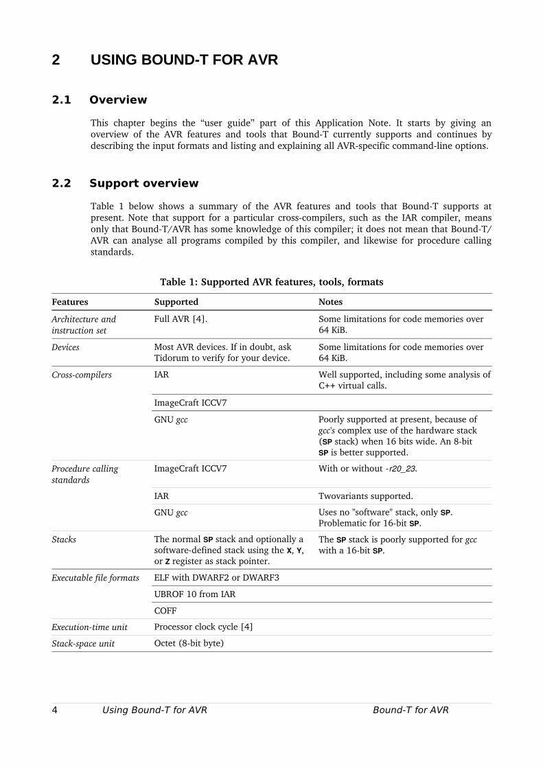
2.2 Support overview
Table 1 below shows a summary of the AVR features and tools that BoundT supports at present. Note that support for a particular crosscompilers, such as the IAR compiler, means only that BoundT/AVR has some knowledge of this compiler; it does not mean that BoundT/AVR can analyse all programs compiled by this compiler, and likewise for procedure calling standards.
Table 1: Supported AVR features, tools, formats
Features Supported Notes
Architecture and instruction set
Full AVR [4]. Some limitations for code memories over 64 KiB.
Devices Most AVR devices. If in doubt, ask Tidorum to verify for your device.
Some limitations for code memories over 64 KiB.
Crosscompilers IAR Well supported, including some analysis of C++ virtual calls.
ImageCraft ICCV7
GNU gcc Poorly supported at present, because of gcc's complex use of the hardware stack (SP stack) when 16 bits wide. An 8bit SP is better supported.
Procedure calling standards
ImageCraft ICCV7 With or without r20_23.
IAR Twovariants supported.
GNU gcc Uses no "software" stack, only SP. Problematic for 16bit SP.
Stacks The normal SP stack and optionally a softwaredefined stack using the X, Y, or Z register as stack pointer.
The SP stack is poorly supported for gcc with a 16bit SP.
Executable file formats ELF with DWARF2 or DWARF3
UBROF 10 from IAR
COFF
Executiontime unit Processor clock cycle [4]
Stackspace unit Octet (8bit byte)
4 Using Bound-T for AVR Bound-T for AVR
2.3 Input formats
Executable targetprogram files
The target program executable file can be supplied in three formats: standard ELF, standard COFF, or the proprietary UBROF format defined by IAR Systems. BoundT can usually detect the actual file format automatically, but it can also be chosen with commandline options as explained later in this chapter.
The quantity and detail of the symbolic (debugging) information differs between the three formats. In particular, only the UBROF format includes information about virtual function calls, thus BoundT can analyse such calls (find the set of possible callees) only for UBROF programs. If an ELF or COFF program contains such calls you must use assertions to tell BoundT about the possible callees for each such call.
Patch files not supported
BoundT provides the general option patch filename that names a file that contains patches to be applied to the loaded targetprogram memory image before analysis starts. The format of the patch file is specific to the target processor. The AVR version of BoundT does not currently support patching and so no patchfile format is defined.
2.4 Command arguments and options
Generic options and arguments
The generic BoundT command format, options and arguments are explained in the BoundT Reference Manual [1] and apply without modification to the AVR version of BoundT. The command line usually has the form
boundt_avr options targetprogramfile rootsubprogramnames
For example, to analyse the execution time on the AVR device ATmega64 of the main subprogram in the target program stored as the ELF file prog.elf under the option trace calls, the command line is
boundt_avr device atmega64 trace calls prog.elf main
Root subprograms can be named by the link identifier, if present in the program symboltable, or by the entry address in hexadecimal form. Thus, if the entry address of the main subprogram is 12A0 (hex), the above command can also be given as
boundt_avr device atmega64 trace calls prog.elf 12A0
All the generic BoundT options apply. There are additional AVRspecific options as explained below. The generic option help makes BoundT list all its options, including the targetspecific options.
AVRspecific options
The additional AVRspecific options are explained in Table 2 below. Note that a targetspecific option must be written as one string with no embedded blanks, so the optionname and its numeric or symbolic parameter, if any, are contiguous and separated only by the equal sign (=) but not by white space. For example, the form " format=elf" is correct, " format = elf" is not. In addition to the options in Table 2 there are some options specific to certain executable file formats; these are listed separately in Table 4.
Bound-T for AVR Using Bound-T for AVR 5
The device option is a general BoundT option, but its values – the device names – are targetspecific. Section 2.5 lists the presently supported AVR devices and discusses any restrictions or devicespecific options.
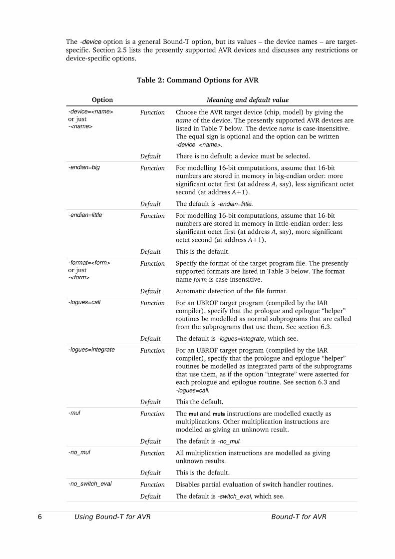
Table 2: Command Options for AVR
Option Meaning and default value
device=<name>or just<name>
Function Choose the AVR target device (chip, model) by giving the name of the device. The presently supported AVR devices are listed in Table 7 below. The device name is caseinsensitive. The equal sign is optional and the option can be writtendevice <name>.
Default There is no default; a device must be selected.
endian=big Function For modelling 16bit computations, assume that 16bit numbers are stored in memory in bigendian order: more significant octet first (at address A, say), less significant octet second (at address A+1).
Default The default is endian=little.
endian=little Function For modelling 16bit computations, assume that 16bit numbers are stored in memory in littleendian order: less significant octet first (at address A, say), more significant octet second (at address A+1).
Default This is the default.
format=<form>or just<form>
Function Specify the format of the target program file. The presently supported formats are listed in Table 3 below. The format name form is caseinsensitive.
Default Automatic detection of the file format.
logues=call Function For an UBROF target program (compiled by the IAR compiler), specify that the prologue and epilogue “helper” routines be modelled as normal subprograms that are called from the subprograms that use them. See section 6.3.
Default The default is logues=integrate, which see.
logues=integrate Function For an UBROF target program (compiled by the IAR compiler), specify that the prologue and epilogue “helper” routines be modelled as integrated parts of the subprograms that use them, as if the option “integrate” were asserted for each prologue and epilogue routine. See section 6.3 and logues=call.
Default This the default.
mul Function The mul and muls instructions are modelled exactly as multiplications. Other multiplication instructions are modelled as giving an unknown result.
Default The default is no_mul.
no_mul Function All multiplication instructions are modelled as giving unknown results.
Default This is the default.
no_switch_eval Function Disables partial evaluation of switch handler routines.
Default The default is switch_eval, which see.
6 Using Bound-T for AVR Bound-T for AVR
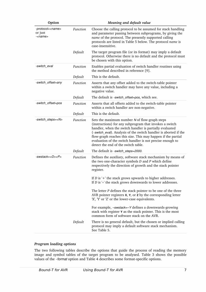
Option Meaning and default value
protocol=<name>or just<name>
Function Choose the calling protocol to be assumed for stack handling and parameter passing between subprograms, by giving the name of the protocol. The presently supported calling protocols are listed in Table 5 below. The protocol name is caseinsensitive.
Default The target program file (or its format) may imply a default protocol. Otherwise there is no default and the protocol must be chosen with this option.
switch_eval Function Enables partial evaluation of switch handler routines using the method described in reference [9].
Default This is the default.
switch_offset=any Function Asserts that any offset added to the switchtable pointer within a switch handler may have any value, including a negative value.
Default The default is switch_offset=pos, which see.
switch_offset=pos Function Asserts that all offsets added to the switchtable pointer within a switch handler are nonnegative.
Default This is the default.
switch_steps=<N> Function Sets the maximum number N of flowgraph steps (instructions) for any subprogram that invokes a switch handler, when the switch handler is partially evaluated (switch_eval). Analysis of the switch handler is aborted if the flowgraph reaches this size. This may happen if the partial evaluation of the switch handler is not precise enough to detect the end of the switch table.
Default The default is switch_steps=2000.
swstack=<D><P> Function Defines the auxiliary, software stack mechanism by means of the two onecharacter symbols D and P which define respectively the direction of growth and the stack pointer register.
If D is '+' the stack grows upwards to higher addresses.If D is '–' the stack grows downwards to lower addresses.
The letter P defines the stack pointer to be one of the three AVR pointer registers X, Y, or Z by the corresponding letter 'X', 'Y' or 'Z' or the lowercase equivalents.
For example, –swstack=–Y defines a downwardsgrowing stack with register Y as the stack pointer. This is the most common form of software stack on the AVR.
Default There is no general default, but the chosen or implied calling protocol may imply a default software stack mechanism. See Table 5.
Program loading options
The two following tables describe the options that guide the process of reading the memory image and symbol tables of the target program to be analysed. Table 3 shows the possible values of the format option and Table 4 describes some formatspecific options.
Bound-T for AVR Using Bound-T for AVR 7
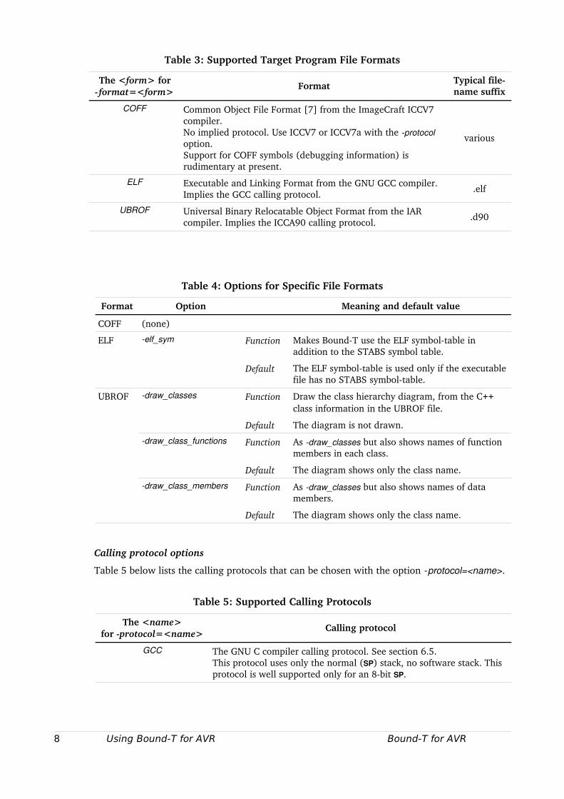
Table 3: Supported Target Program File Formats
The <form> for format=<form>
Format Typical filename suffix
COFF Common Object File Format [7] from the ImageCraft ICCV7 compiler.No implied protocol. Use ICCV7 or ICCV7a with the protocol option.Support for COFF symbols (debugging information) is rudimentary at present.
various
ELF Executable and Linking Format from the GNU GCC compiler.Implies the GCC calling protocol. .elf
UBROF Universal Binary Relocatable Object Format from the IAR compiler. Implies the ICCA90 calling protocol. .d90
Table 4: Options for Specific File Formats
Format Option Meaning and default value
COFF (none)
ELF elf_sym Function Makes BoundT use the ELF symboltable in addition to the STABS symbol table.
Default The ELF symboltable is used only if the executable file has no STABS symboltable.
UBROF draw_classes Function Draw the class hierarchy diagram, from the C++ class information in the UBROF file.
Default The diagram is not drawn.
draw_class_functions Function As draw_classes but also shows names of function members in each class.
Default The diagram shows only the class name.
draw_class_members Function As draw_classes but also shows names of data members.
Default The diagram shows only the class name.
Calling protocol options
Table 5 below lists the calling protocols that can be chosen with the option protocol=<name>.
Table 5: Supported Calling Protocols
The <name>for protocol=<name>
Calling protocol
GCC The GNU C compiler calling protocol. See section 6.5.This protocol uses only the normal (SP) stack, no software stack. This protocol is well supported only for an 8bit SP.
8 Using Bound-T for AVR Bound-T for AVR
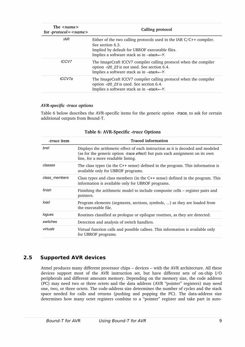
The <name>for protocol=<name>
Calling protocol
IAR Either of the two calling protocols used in the IAR C/C++ compiler. See section 6.3.Implied by default for UBROF executable files.Implies a software stack as in –stack=–Y.
ICCV7 The ImageCraft ICCV7 compiler calling protocol when the compiler option r20_23 is not used. See section 6.4.Implies a software stack as in –stack=–Y.
ICCV7a The ImageCraft ICCV7 compiler calling protocol when the compiler option r20_23 is used. See section 6.4.Implies a software stack as in –stack=–Y.
AVRspecific trace options
Table 6 below describes the AVRspecific items for the generic option trace, to ask for certain additional outputs from BoundT.
Table 6: AVRSpecific trace Options
trace item Traced information
bref Displays the arithmetic effect of each instruction as it is decoded and modeled (as for the generic option trace effect) but puts each assignment on its own line, for a more readable listing.
classes The class types (in the C++ sense) defined in the program. This information is available only for UBROF programs.
class_members Class types and class members (in the C++ sense) defined in the program. This information is available only for UBROF programs.
finish Finishing the arithmetic model to include composite cells – register pairs and pointers.
load Program elements (segments, sections, symbols, ...) as they are loaded from the executable file.
logues Routines classified as prologue or epilogue routines, as they are detected.
switches Detection and analysis of switch handlers.
virtuals Virtual function calls and possible callees. This information is available only for UBROF programs.
2.5 Supported AVR devices
Atmel produces many different processor chips – devices – with the AVR architecture. All these devices support most of the AVR instruction set, but have different sets of onchip I/O peripherals and different amounts memory. Depending on the memory size, the code address (PC) may need two or three octets and the data address (AVR “pointer” registers) may need one, two, or three octets. The codeaddress size determines the number of cycles and the stack space needed for calls and returns (pushing and popping the PC). The dataaddress size determines how many octet registers combine to a “pointer” register and take part in auto
Bound-T for AVR Using Bound-T for AVR 9
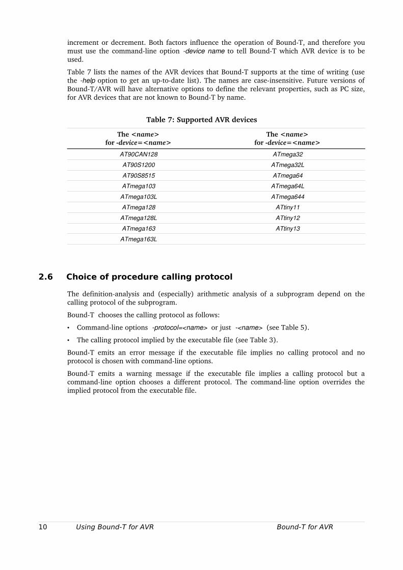
increment or decrement. Both factors influence the operation of BoundT, and therefore you must use the commandline option device name to tell BoundT which AVR device is to be used.
Table 7 lists the names of the AVR devices that BoundT supports at the time of writing (use the help option to get an uptodate list). The names are caseinsensitive. Future versions of BoundT/AVR will have alternative options to define the relevant properties, such as PC size, for AVR devices that are not known to BoundT by name.
Table 7: Supported AVR devices
The <name>for device=<name>
The <name>for device=<name>
AT90CAN128 ATmega32
AT90S1200 ATmega32L
AT90S8515 ATmega64
ATmega103 ATmega64L
ATmega103L ATmega644
ATmega128 ATtiny11
ATmega128L ATtiny12
ATmega163 ATtiny13
ATmega163L
2.6 Choice of procedure calling protocol
The definitionanalysis and (especially) arithmetic analysis of a subprogram depend on the calling protocol of the subprogram.
BoundT chooses the calling protocol as follows:
• Commandline options protocol=<name> or just <name> (see Table 5).
• The calling protocol implied by the executable file (see Table 3).
BoundT emits an error message if the executable file implies no calling protocol and no protocol is chosen with commandline options.
BoundT emits a warning message if the executable file implies a calling protocol but a commandline option chooses a different protocol. The commandline option overrides the implied protocol from the executable file.
10 Using Bound-T for AVR Bound-T for AVR
3 WRITING ASSERTIONS
3.1 Overview
If you use BoundT to analyse nontrivial programs you nearly always have to write assertions to control and guide the analysis. The most common role of assertions is to set bounds on some aspects of the behaviour of the target program, for example bounds on loop iterations, that BoundT cannot deduce automatically. Assertions must identify the relevant parts of the target program, for example subprograms and variables. The assertion language has a generic highlevel syntax [3] in which some elements with targetspecific syntax appear as the contents of quoted strings:
• subprogram names,
• code addresses and address offsets,
• variable names,
• data addresses and register names,
• instruction roles, and
• names of targetspecific properties of program parts.
In practice the names (identifiers) of subprograms and variables are either identical to the names used in the source code, or some “mangled” form of the sourcecode identifiers where the mangling depends on the crosscompiler and not on BoundT. However, BoundT defines a targetspecific way to write the addresses of code and data in assertions. Register names are considered a kind of “data address” and are targetspecific.
This chapter continues the userguide part of this Application Note by defining the AVRspecific aspects of the assertion language.
3.2 Naming items by address
Subprograms and code addresses
A subprogram can be named by giving its entry address in hexadecimal and in octet units. For example, the following assertion applies to the subprogram that is entered at the octet address A6E2 hex, corresponding to the instruction word address 5371 hex:
subprogram “a6e2” loop repeats 10 times; end loop;end “a6e2”;
The octet address must be an even number since it is the address of an instruction word. An odd address will be rejected with an error message.
Other code addresses (eg. for loop identification) are also given in octet units as hexadecimal numbers.
Codeaddress offsets
Some forms of assertions define code addresses by giving a code offset relative to a base address. For BoundT/AVR a code offset is written as a hexadecimal number possibly preceded by a sign, '–' or '+', to indicate a negative or positive offset. If there is no sign the offset is considered positive.
Bound-T for AVR Writing Assertions 11
Assume, for example, that the subprogram Rerun has the entry address 14AC hexadecimal and the subprogram Abandon has the entry address 157B hexadecimal. The subprogram with the entry address 14D2 hexadecimal can then be identified in any of the following ways, among many others:
• Using the absolute address:
subprogram address "14D2"
• Using a positive hexadecimal offset relative to the entry point of Rerun:
subprogram "Rerun" offset "26"
• Using a negative hexadecimal offset relative to the entry point of Abandon:
subprogram "Abandon" offset "A9"
Note that the sign, if used, is placed within the string quotes, not before the string.
Variables: registers and memory locations
Assertions can refer to program variables using machinelevel names or addresses. For example, the assertion
variable address “p6” <= 102;
states that the 16bit variable represented by the AVR register pair r7:r6 has a value less or equal to 102.
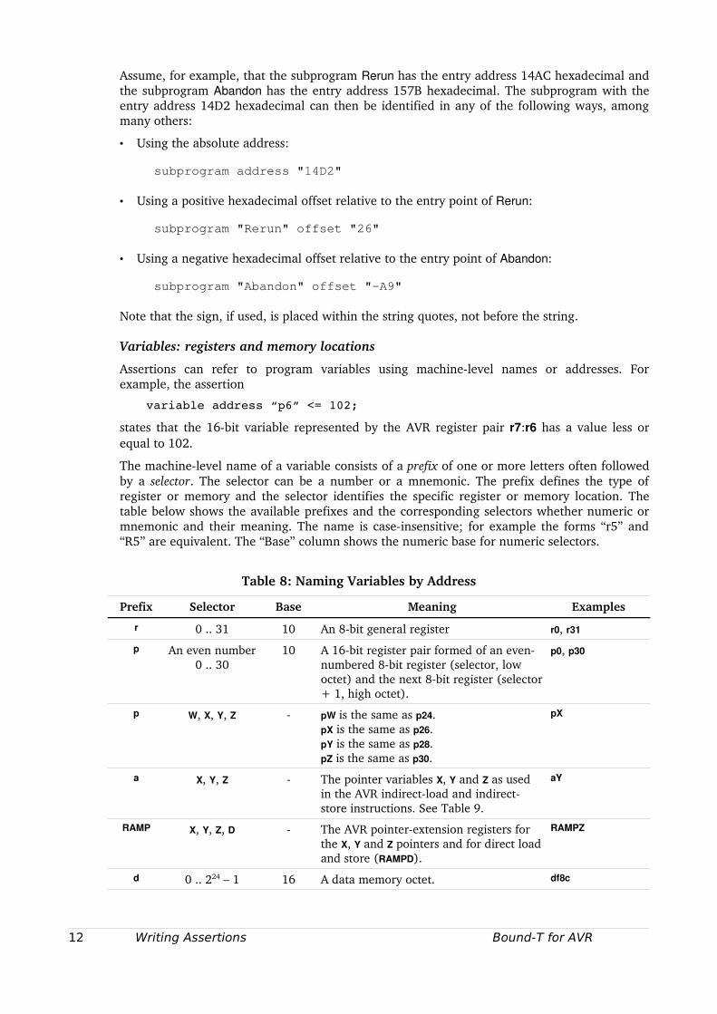
The machinelevel name of a variable consists of a prefix of one or more letters often followed by a selector. The selector can be a number or a mnemonic. The prefix defines the type of register or memory and the selector identifies the specific register or memory location. The table below shows the available prefixes and the corresponding selectors whether numeric or mnemonic and their meaning. The name is caseinsensitive; for example the forms “r5” and “R5” are equivalent. The “Base” column shows the numeric base for numeric selectors.
Table 8: Naming Variables by Address
Prefix Selector Base Meaning Examples
r 0 .. 31 10 An 8bit general register r0, r31
p An even number 0 .. 30
10 A 16bit register pair formed of an evennumbered 8bit register (selector, low octet) and the next 8bit register (selector + 1, high octet).
p0, p30
p W, X, Y, Z pW is the same as p24.pX is the same as p26.pY is the same as p28.pZ is the same as p30.
pX
a X, Y, Z The pointer variables X, Y and Z as used in the AVR indirectload and indirectstore instructions. See Table 9.
aY
RAMP X, Y, Z, D The AVR pointerextension registers for the X, Y and Z pointers and for direct load and store (RAMPD).
RAMPZ
d 0 .. 224 – 1 16 A data memory octet. df8c
12 Writing Assertions Bound-T for AVR
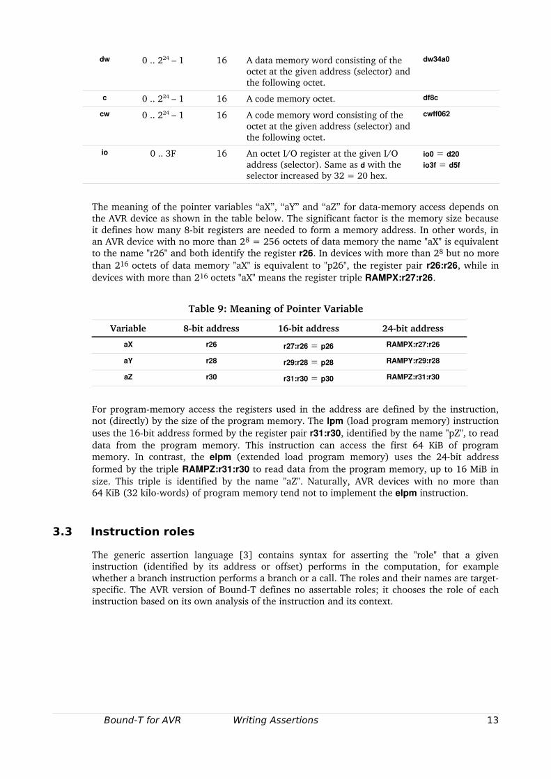
dw 0 .. 224 – 1 16 A data memory word consisting of the octet at the given address (selector) and the following octet.
dw34a0
c 0 .. 224 – 1 16 A code memory octet. df8c
cw 0 .. 224 – 1 16 A code memory word consisting of the octet at the given address (selector) and the following octet.
cwff062
io 0 .. 3F 16 An octet I/O register at the given I/O address (selector). Same as d with the selector increased by 32 = 20 hex.
io0 = d20io3f = d5f
The meaning of the pointer variables “aX”, “aY” and “aZ” for datamemory access depends on the AVR device as shown in the table below. The significant factor is the memory size because it defines how many 8bit registers are needed to form a memory address. In other words, in an AVR device with no more than 28 = 256 octets of data memory the name "aX" is equivalent to the name "r26" and both identify the register r26. In devices with more than 28 but no more than 216 octets of data memory "aX" is equivalent to "p26", the register pair r26:r26, while in devices with more than 216 octets "aX" means the register triple RAMPX:r27:r26.
Table 9: Meaning of Pointer Variable
Variable 8bit address 16bit address 24bit address
aX r26 r27:r26 = p26 RAMPX:r27:r26
aY r28 r29:r28 = p28 RAMPY:r29:r28
aZ r30 r31:r30 = p30 RAMPZ:r31:r30
For programmemory access the registers used in the address are defined by the instruction, not (directly) by the size of the program memory. The lpm (load program memory) instruction uses the 16bit address formed by the register pair r31:r30, identified by the name "pZ", to read data from the program memory. This instruction can access the first 64 KiB of program memory. In contrast, the elpm (extended load program memory) uses the 24bit address formed by the triple RAMPZ:r31:r30 to read data from the program memory, up to 16 MiB in size. This triple is identified by the name "aZ". Naturally, AVR devices with no more than 64 KiB (32 kilowords) of program memory tend not to implement the elpm instruction.
3.3 Instruction roles
The generic assertion language [3] contains syntax for asserting the "role" that a given instruction (identified by its address or offset) performs in the computation, for example whether a branch instruction performs a branch or a call. The roles and their names are targetspecific. The AVR version of BoundT defines no assertable roles; it chooses the role of each instruction based on its own analysis of the instruction and its context.
Bound-T for AVR Writing Assertions 13
3.4 Properties
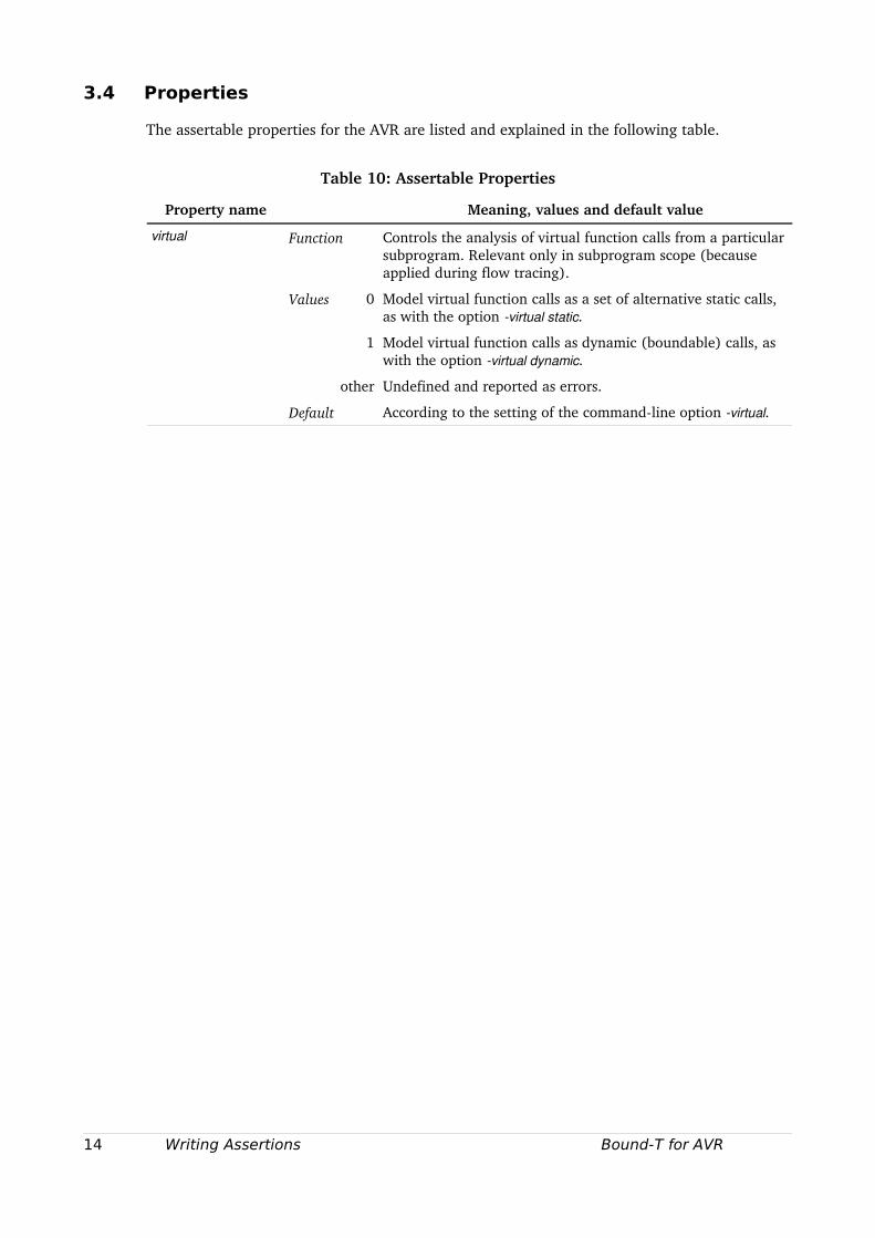
The assertable properties for the AVR are listed and explained in the following table.
Table 10: Assertable Properties
Property name Meaning, values and default value
virtual Function Controls the analysis of virtual function calls from a particular subprogram. Relevant only in subprogram scope (because applied during flow tracing).
Values 0 Model virtual function calls as a set of alternative static calls, as with the option virtual static.
1 Model virtual function calls as dynamic (boundable) calls, as with the option virtual dynamic.
other Undefined and reported as errors.
Default According to the setting of the commandline option virtual.
14 Writing Assertions Bound-T for AVR
4 THE AVR AND TIMING ANALYSIS
4.1 The AVR
An 8bit RISC microcontroller
The AVR [4] is an 8bit microcontroller core. It has a "Harvard" architecture (separate program and data memories) and a twostage pipeline with separate fetch and execute cycles. Computational instructions use register and immediate operands and destinations; there are separate load and store instructions, as in RISC processors.
The size of the program and data addresses depends on the particular AVR device, according to the size of the program and data memories. A program address is 16 or 22 bits. A data address is 8, 16 or 24 bits.
Integer addition, subtraction and multiplication are supported in hardware but division is not. Integer operands are 8 or 16 bits long. The core AVR does not support hardware floating point operations.
Data memory is addressed by octet. Load and store instructions operate on 8bit quantities. To load or store multioctet values as many load or store instructions must be used. This means that there is no hardwaredefined endianness in memory. The software (compiler) decides if multioctet values are stored in littleendian or bigendian form. (However, the I/O area may contain some 16bit quantities with a hardwaredefined endianness, see below.)
Data memory cannot be bitaddressed (except for the I/O space, see below) but registers can be. Data octets must be brought into registers for bit operations.
Program memory is addressed by 16bit word when fetching instructions. The program counter is a word address and thus increments by one for 16bit instructions. However, data (constants) can be fetched from the program memory using octet addressing and one of the pointer registers (Z) about which more below.
Most instructions are 16 bits long. Some instructions have a second word and are thus 32 bits long.
Registers
There are 32 general 8bit registers, r0 through r31, but the instruction set is not entirely symmetric and some registers have special roles. Some instructions operate on register pairs where an evennumbered register holds the low octet of a 16bit quantity and the next register holds the high octet. For example, the symbol r31:r30 denotes the register pair formed of the registers r30 (low octet) and r31 (high octet). The eight highestnumbered registers form four pairs that have special roles and are called W = r25:r24, X = r27:r26, Y = r29:r28, Z = r31:r30. The X, Y and Z registerpairs can be used as data address registers (index registers) with optional autoincrement or autodecrement. The Z register can be used as a code address register for indirect jumps and calls and to load constant data from the program memory with octet addressing (the lpm and elpm instructions).
The 32 general registers are also mapped in the start of the data address space at addresses 0 through 31. This means that registers can also be accessed indirectly.
In addition to the general registers, there is a Program Counter (PC) register, a Stack Pointer (SP) register and a Status Register (SREG) that contains the condition flags and interrupt masks.
The Program Counter PC points to the next instruction in the program memory. Depending on the AVR model (size of code memory) the PC is either 16 bits or 22 bits wide. This influences the timing of some instructions and the stack space required for return addresses.
Bound-T for AVR AVR Timing Analysis 15
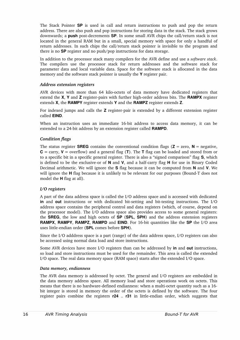
The Stack Pointer SP is used in call and return instructions to push and pop the return address. There are also push and pop instructions for storing data in the stack. The stack grows downwards; a push postdecrements SP. In some small AVR chips the call/return stack is not located in the general RAM but in a small, special memory with space for only a handful of return addresses. In such chips the call/return stack pointer is invisible to the program and there is no SP register and no push/pop instructions for data storage.
In addition to the processor stack many compilers for the AVR define and use a software stack. The compilers use the processor stack for return addresses and the software stack for parameter data and local variable data. Space for the software stack is allocated in the data memory and the software stack pointer is usually the Y register pair.
Address extension registers
AVR devices with more than 64 kilooctets of data memory have dedicated registers that extend the X, Y and Z registerpairs with further highorder address bits. The RAMPX register extends X, the RAMPY register extends Y and the RAMPZ register extends Z.
For indexed jumps and calls the Z registerpair is extended by a different extension register called EIND.
When an instruction uses an immediate 16bit address to access data memory, it can be extended to a 24bit address by an extension register called RAMPD.
Condition flags
The status register SREG contains the conventional condition flags (Z = zero, N = negative, C = carry, V = overflow) and a general flag (T). The T flag can be loaded and stored from or to a specific bit in a specific general register. There is also a “signed comparison” flag S, which is defined to be the exclusiveor of N and V, and a halfcarry flag H for use in Binary Coded Decimal arithmetic. We will ignore the S flag because it can be computed from N and V. We will ignore the H flag because it is unlikely to be relevant for our purposes (BoundT does not model the H flag at all).
I/O registers
A part of the data address space is called the I/O address space and is accessed with dedicated in and out instructions or with dedicated bitsetting and bittesting instructions. The I/O address space contains the peripheral control and data registers (which, of course, depend on the processor model). The I/O address space also provides access to some general registers: the SREG, the low and high octets of SP (SPL, SPH) and the address extension registers RAMPX, RAMPY, RAMPZ, RAMPD and EIND. For 16bit quantities like the SP the I/O area uses littleendian order (SPL comes before SPH).
Since the I/O adddress space is a part (range) of the data address space, I/O registers can also be accessed using normal data load and store instructions.
Some AVR devices have more I/O registers than can be addressed by in and out instructions, so load and store instructions must be used for the remainder. This area is called the extended I/O space. The real data memory space (RAM space) starts after the extended I/O space.
Data memory, endianness
The AVR data memory is addressed by octet. The general and I/O registers are embedded in the data memory address space. All memory load and store operations work on octets. This means that there is no hardwaredefined endianness: when a multioctet quantity such as a 16bit integer is stored in memory the order of the octets is defined by the software. The four register pairs combine the registers r24 .. r31 in littleendian order, which suggests that
16 AVR Timing Analysis Bound-T for AVR
software should use littleendian order in general. Moreover, when the SP is 16 bits its two 8bit parts SPL and SPH are also mapped as I/O registers in littleendian order. On the other hand, the call instruction stores the return address on the stack in bigendian order.
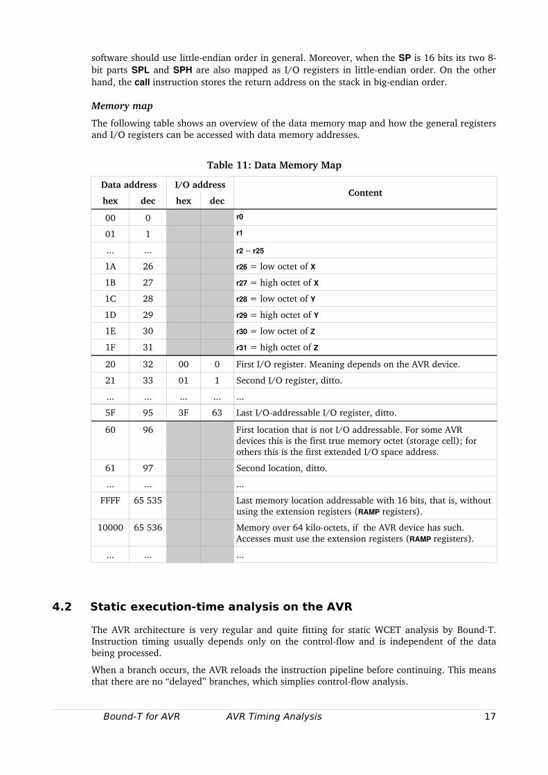
Memory map
The following table shows an overview of the data memory map and how the general registers and I/O registers can be accessed with data memory addresses.
Table 11: Data Memory Map
Data address I/O address
hex dec hex decContent
00 0 r0
01 1 r1
... ... r2 – r25
1A 26 r26 = low octet of X
1B 27 r27 = high octet of X
1C 28 r28 = low octet of Y
1D 29 r29 = high octet of Y
1E 30 r30 = low octet of Z
1F 31 r31 = high octet of Z
20 32 00 0 First I/O register. Meaning depends on the AVR device.
21 33 01 1 Second I/O register, ditto.
... ... ... ... ...
5F 95 3F 63 Last I/Oaddressable I/O register, ditto.
60 96 First location that is not I/O addressable. For some AVR devices this is the first true memory octet (storage cell); for others this is the first extended I/O space address.
61 97 Second location, ditto.
... ... ...
FFFF 65 535 Last memory location addressable with 16 bits, that is, without using the extension registers (RAMP registers).
10000 65 536 Memory over 64 kilooctets, if the AVR device has such. Accesses must use the extension registers (RAMP registers).
... ... ...
4.2 Static execution-time analysis on the AVR
The AVR architecture is very regular and quite fitting for static WCET analysis by BoundT. Instruction timing usually depends only on the controlflow and is independent of the data being processed.
When a branch occurs, the AVR reloads the instruction pipeline before continuing. This means that there are no “delayed” branches, which simplies controlflow analysis.
Bound-T for AVR AVR Timing Analysis 17
The following architectural features can lead to approximate (overestimated) execution times for the concerned instructions:
• Memory wait states that vary in number depending on the address, because some addresses map to onchip, internal memory and others slower offchip, external memory.
• Flashmemory access and buffering delays, when the AVR device uses some kind of buffering, caching, or prefetching for the flash memory.
18 AVR Timing Analysis Bound-T for AVR
5 SUPPORTED AVR FEATURES
5.1 Overview
This section specifies which AVR instructions, registers and status flags are supported and modelled by BoundT. We will first describe the extent of support in general terms, with exceptions listed later. Note that in addition to the specific limitations concerning the AVR, BoundT also has generic limitations as described in the BoundT Reference Manual [1]. For reference, these are briefly listed in section 5.2.
General support level
In general, when BoundT is analysing a target program for the AVR, it can decode and correctly time all instructions, with minor approximations except for coprocessor instructions.
BoundT can construct the controlflow graphs and callgraphs for all instructions, assuming that the program obeys one of the supported procedure calling standards listed in chapter 6. Note that there are generic limitations on the analysis of jumps and calls that use a dynamically computed target address or a dynamically computed return address.
When analysing loops to find the loopcounter variables, BoundT is able to track all the integer additions and subtractions for 8bit and 16bit integers, but not for wider integers, for example not for 32bit integers. BoundT correctly detects when this 8/16bit integer computation is overridden by other computations, such as multiplications or wider integer computations. Note that there are generic limitations on the analysis of pointers to variables (aliasing).
In summary, for a program written in a compiled language such as Ada or C with a compiler that uses one of the supported procedure calling standards, the BoundT user should not meet with any AVRspecific constraints for 8bit and 16bit integers but may be disappointed by the lack of analysis of wider integers, for example 32bit integers.
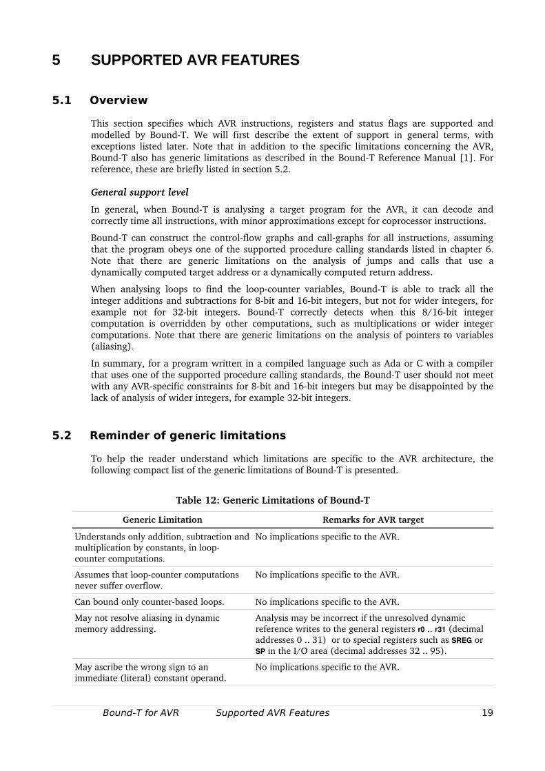
5.2 Reminder of generic limitations
To help the reader understand which limitations are specific to the AVR architecture, the following compact list of the generic limitations of BoundT is presented.
Table 12: Generic Limitations of BoundT
Generic Limitation Remarks for AVR target
Understands only addition, subtraction and multiplication by constants, in loopcounter computations.
No implications specific to the AVR.
Assumes that loopcounter computations never suffer overflow.
No implications specific to the AVR.
Can bound only counterbased loops. No implications specific to the AVR.
May not resolve aliasing in dynamic memory addressing.
Analysis may be incorrect if the unresolved dynamic reference writes to the general registers r0 .. r31 (decimal addresses 0 .. 31) or to special registers such as SREG or SP in the I/O area (decimal addresses 32 .. 95).
May ascribe the wrong sign to an immediate (literal) constant operand.
No implications specific to the AVR.
Bound-T for AVR Supported AVR Features 19
5.3 Main assumptions
BoundT for the AVR makes the following AVRspecific assumptions about the target program under analysis:
• The registers r0 .. r31, the status register SREG, the stack pointer register SP, and the addressextension registers RAMPX, RAMPY, RAMPZ, RAMPD, and EIND are not changed by indirect access (access via pointers).
• The program memory is readonly. If the program reads data from the program memory, using an lpm or elpm instruction, and BoundT can resolve the address that is read, and the executable file under analysis statically defines a value for address, this value is returned by the lpm or elpm.
• The ret and reti instructions always perform a return from the current subprogram (interrupt handler, for reti). The use of ret as a dynamic branch or call, to whatever address is pushed on the stack before the ret, is not now supported.
• The choice of crosscompiler and/or calling protocol may imply further assumptions.
5.4 Instructions and computations
BoundT for the AVR models the main computational effect of most AVR instructions accurately, within the generic limitations of BoundT and within the current AVRspecific limitation to 8bit and 16bit computations. This section describes the computational effects that are modelled approximately or not at all. However, note that some generic analyses in BoundT may introduce generic approximations. For example, the loopbounds analysis based on Presburger Arithmetic assumes that loopcounter computations do not overflow.
Registers and memory
Most registers and memory locations in the AVR are modelled. The following are modelled in limited ways:
• The absolute value of the SP register is generally opaque; only the changes in SP are modelled. The same holds when a pointer register is used as the stack pointer for a compilerspecific software stack.
• All memory locations, except I/O registers, are currently assumed to have ordinary nonvolatile memory semantics, that is, reading the location returns the lastwritten value.
• Only the wellknown I/O registers SPL, SPH, RAMPX, RAMPY, RAMPZ, RAMPD, and EIND are modelled as nonvolatile storage, for which an in instruction returns the value written by the last out instruction. For all other I/O registers the result of in is opaque (an unknown value) and out is assumed to have no effect.
• Status register SREG flags V, H, I are not modelled. Their values are considered unknown.
Future versions of BoundT will provide means to define which memory locations and I/O registers are “volatile” and which are not. Even when a memory location or register is physically nonvolatile, for the analysis of a single thread in a multithread system it may appear to be volatile if its value is changed at unpredictable times by other threads running concurrently.
Instructions with unknown result
The swap (swap nibbles) and ror (rotate right through carry) instruction are currently given an unknown computational result in the affected register.
20 Supported AVR Features Bound-T for AVR
The instructions that change a single bit in an 8bit octet are modelled as setting the whole octet to an unknown value. These instructions are bld, cbi, sbi.
Under default options, all multiplication instructions are given an unknown computational result. Under the option mul, the instructions mul (multiply two unsigned numbers) and muls (multiply two signed numbers) are modelled as such multiplications, but the mulsu (multiply signed with unsigned) instruction, and all fractional multiplication instructions (fmul, fmuls, fmulsu), are still given unknown computational results.
Since the program memory is assumed to be readonly, the spm (store program memory) instruction is assumed to have no effect on any computation that is important for the analysis. Thus is it modelled as a nooperation instruction (with a warning).
Instructions with unknown timing
The break and sleep instructions have a nondeterministic effect on the real execution time. If they occur in code subject to timing analysis, BoundT emits a warning.
The spm (store program memory) instruction writes to flash memory and has a variable execution time. BoundT assumes only one cycle for the execution time of this instruction, and emits a warning for every spm.
Stack Pointer SP
The value of SP is tracked mainly relative to its value on entry to the subprogram under analysis (the local stack height in the subprogram).
For AVR devices with a 16bit SP register, if the program changes the value of SP by out instructions that separately change the low and/or high octets SPL and SPH, BoundT may not be able to compute the actual change in SP and the resulting stack usage. This problem currently happens for gcc and subprograms with large local variables.
5.5 Computations with 16-bit numbers
The problem
The main problem in modelling the arithmetic computations in AVR programs is the management of 8bit registers vs 16bit register pairs. In this section we explain the problem and (briefly) what BoundT does about it and how.
Most AVR instructions operate on 8bit operands (octets, bytes). The few instructions that operate on 16bit operands (register pairs) are adiw (add immediate word) and subiw (subtract immediate word) in which the other operand is an immediate constant of limited magnitude, and movw (move word) which is just a registertoregister copy. The autoincrement and autodecrement options in the indirect load and store instructions also operate on 16bit (or even 24bit) address values in the (possibly extended) X, Y and Z registers, but there it ends.
Therefore, most arithmetic on 16bit or larger numbers in an AVR program must be implemented by chains of 8bit operations such as add followed by adc (add with carry). If we did not detect and model such operation chains we would be unable to find loopbounds automatically for loops with counters larger than 8 bits.
The detection and modelling of operation chains in BoundT/AVR is currently implemented in AVRspecific ways. In the future, it will be implemented by generic, processorindependent methods.
Bound-T for AVR Supported AVR Features 21
Register pairs for 16bit values
In principle a 16bit value could be held in any two 8bit registers, for example with the less significant octet (also called the low octet) in r2 and the more significant (high) octet in r5. However, AVR compilers tend to follow the example set by the AVR pointer registers X, Y, Z which are composed of register pairs with adjacent numbers, with the low octet in a register with an even number and the high octet in the next (oddnumbered) register. For example, the X pointer consists of the register pair r27:r26, using the notation (high octet):(low octet).
Following this example, AVR compilers seem to keep all 16bit values in even:odd register pairs, such as r1:r0. BoundT detects and models 16bit computations only under this condition, that register operands are odd:even register pairs.
Memory octet pairs for 16bit values
As for registers, 16bit values could be stored in memory using any pair of octets, but we assume that compilers will always use adjacent memory octets to store the low and high octets of a 16bit value, and will use the same endianness (octet order) for all 16bit values. However, different compilers may use different endianness, so the endianness that BoundT assumes can be set by the commandline option endian.
BoundT thus detects and models 16bit accesses to memory and I/O register only when the memory locations involved are adjacent and in the right endianness order.
Chaining 8bit operations into 16bit operations
BoundT for the AVR detects and models some pairs (twostep chains) of 8bit operations that implement 16bit computations. When the two instructions are consecutive, such as an add immediately followed by an adc, the chain is detected and modelled on the fly as instructions are decoded and entered in the flowgraph. Nonconsecutive chainable instructions are detected in a later phase based on dataflow analysis of the whole flowgraph.
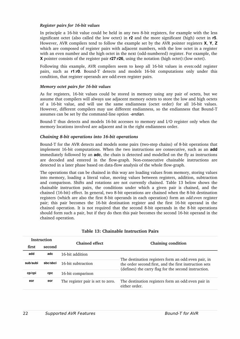
The operations that can be chained in this way are loading values from memory, storing values into memory, loading a literal value, moving values between registers, addition, subtraction and comparison. Shifts and rotations are not currently chained. Table 13 below shows the chainable instruction pairs, the conditions under which a given pair is chained, and the chained (16bit) effect. In general, two 8bit operations are chained when the 8bit destination registers (which are also the first 8bit operands in each operation) form an odd:even register pair; this pair becomes the 16bit destination register and the first 16bit operand in the chained operation. It is not required that the second 8bit operands in the 8bit operations should form such a pair, but if they do then this pair becomes the second 16bit operand in the chained operation.
Table 13: Chainable Instruction Pairs
Instruction
first secondChained effect Chaining condition
add adc 16bit addition
sub/subi sbc/sbci 16bit subtraction
cp/cpi cpc 16bit comparison
The destination registers form an odd:even pair, in the order second:first, and the first instruction sets (defines) the carry flag for the second instruction.
eor eor The register pair is set to zero. The destination registers form an odd:even pair in either order.
22 Supported AVR Features Bound-T for AVR
Instruction
first secondChained effect Chaining condition
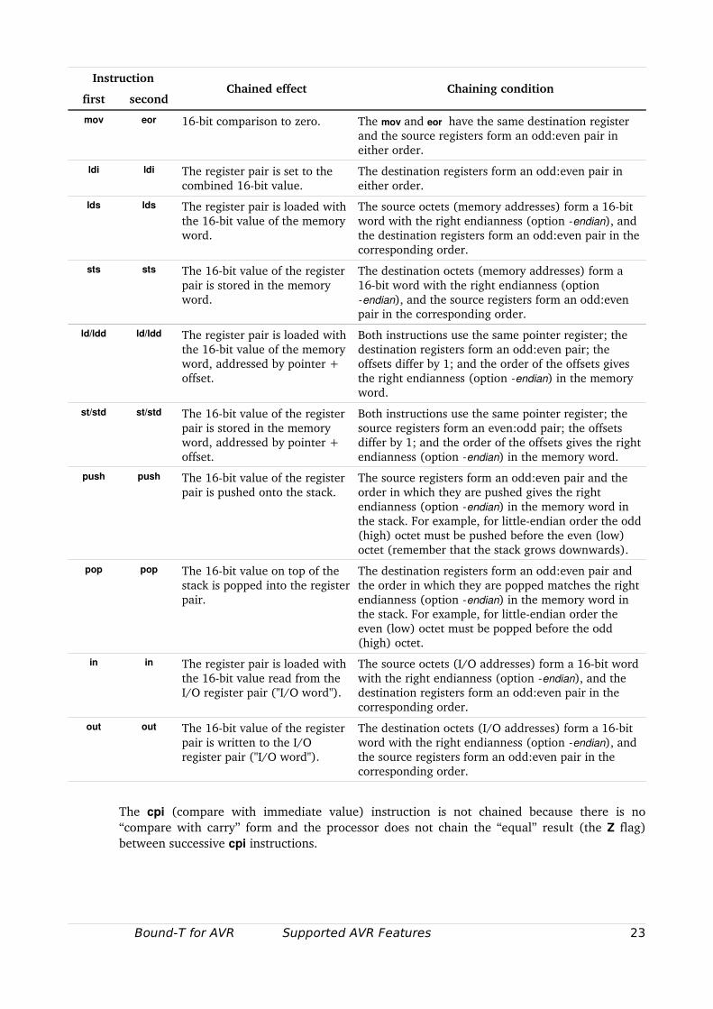
mov eor 16bit comparison to zero. The mov and eor have the same destination register and the source registers form an odd:even pair in either order.
ldi ldi The register pair is set to the combined 16bit value.
The destination registers form an odd:even pair in either order.
lds lds The register pair is loaded with the 16bit value of the memory word.
The source octets (memory addresses) form a 16bit word with the right endianness (option endian), and the destination registers form an odd:even pair in the corresponding order.
sts sts The 16bit value of the register pair is stored in the memory word.
The destination octets (memory addresses) form a 16bit word with the right endianness (option endian), and the source registers form an odd:even pair in the corresponding order.
ld/ldd ld/ldd The register pair is loaded with the 16bit value of the memory word, addressed by pointer + offset.
Both instructions use the same pointer register; the destination registers form an odd:even pair; the offsets differ by 1; and the order of the offsets gives the right endianness (option endian) in the memory word.
st/std st/std The 16bit value of the register pair is stored in the memory word, addressed by pointer + offset.
Both instructions use the same pointer register; the source registers form an even:odd pair; the offsets differ by 1; and the order of the offsets gives the right endianness (option endian) in the memory word.
push push The 16bit value of the register pair is pushed onto the stack.
The source registers form an odd:even pair and the order in which they are pushed gives the right endianness (option endian) in the memory word in the stack. For example, for littleendian order the odd (high) octet must be pushed before the even (low) octet (remember that the stack grows downwards).
pop pop The 16bit value on top of the stack is popped into the register pair.
The destination registers form an odd:even pair and the order in which they are popped matches the right endianness (option endian) in the memory word in the stack. For example, for littleendian order the even (low) octet must be popped before the odd (high) octet.
in in The register pair is loaded with the 16bit value read from theI/O register pair ("I/O word").
The source octets (I/O addresses) form a 16bit word with the right endianness (option endian), and the destination registers form an odd:even pair in the corresponding order.
out out The 16bit value of the register pair is written to the I/O register pair ("I/O word").
The destination octets (I/O addresses) form a 16bit word with the right endianness (option endian), and the source registers form an odd:even pair in the corresponding order.
The cpi (compare with immediate value) instruction is not chained because there is no “compare with carry” form and the processor does not chain the “equal” result (the Z flag) between successive cpi instructions.
Bound-T for AVR Supported AVR Features 23
5.6 Control-transfer instructions
The first and critical phase in BoundT's analysis is to construct the controlflow graphs and the call graph of all the subprograms to be analyzed. This requires a decoding and modelling of all controltransfer instructions. Most AVR controltransfer instructions, such as jmp and call and the conditional branch instructions like breq, statically define the target address and pose no problem. In contrast, the indirect controltransfer instructions ijmp and icall and their extended variants eijmp and eicall use a dynamically computed target address which may or may not be resolved by BoundT's analysis. The return instruction ret also uses a dynamically defined target address, in this case popped from the stack.
Indirect jumps
The ijmp instruction is modelled properly as a jump to the address defined by the Z register pair. BoundT analyses this instruction as a possible jump to a table of further jumps, a code idiom sometimes generated for switchcase statements.
The eijmp instruction is not supported because it relies on 24bit computation of the extended pointer EIND:Z. An error message is given for this instruction.
Indirect calls
An icall or eicall instruction is usually modelled as a dynamic call that cannot be resolved by analysis. Thus it must be resolved by an assertion that lists the possible callees.
However, if the icall or eicall represents a virtualfunction call in a C++ program compiled by the IAR compiler, the possible callees can be found from the UBROF file because the UBROF debugging information contains the C++ class structure which identifies all the subclasses and their actual implementations of the virtual function. The model used then depends on the setting of the generic commandline option virtual:
• Under virtual static, BoundT models the icall/eicall as a nondeterministic choice between static calls to each of the implementations of the virtual function, as defined in the UBROF file. BoundT does not try to reduce the set of callees by analysis, for example by analysing the actual class of the "this" object.
• Under virtual dynamic, BoundT models the icall/eicall as a dynamic call that cannot be resolved by analysis. An assertion is then necessary to resolve the call.
The latter case (virtual dynamic) lets the user decide which subclasses can really occur at this place in the program, by listing only the corresponding subset of possible callees.
Return instructions
At present, all ret and reti instructions are modelled as a return from the current subprogram. They cannot be modelled as other kinds of dynamic transfer of control.
5.7 Stack-usage analysis
Processor stack (SP)
BoundT analyzes stack usage on the normal SP stack by analyzing how the analyzed code changes the SP register. The absolute value of the SP register is seldom visible to the analysis, and is not an objective of the analysis.
The instructions that change the SP as a whole are the call instructions (call, icall, eicall); the return instructions (ret, reti); and the push and pop instructions. All these instructions change the SP by constant amounts and pose no problems for the stackusage analysis.
24 Supported AVR Features Bound-T for AVR
However, in most AVR devices the low and high octets of the SP register, SPL and SPH, are also accessible as I/O registers and can thus be changed by out instructions. When a program needs to change the SP by a largish amount, say decrease it by 713 to allocate 713 octets of local stack space for the current subprogram, the program will read the SP by two in instructions from SPH:SPL into a register pair, use a pair of sub (or subi) and sbc (or sbci) instructions to subtract 713 from the register pair, and write the result back to the SP by two out instructions. In its present form, BoundT/AVR does not always model such computations (especially if optimized in some way) well enough to deduce the resulting overall change in the value of SP. This hampers stackusage analysis for gcccompiled programs, because gcc uses the SP stack for local variables.
Software stacks
Because the AVR provides no direct SPrelative addressing, many AVR crosscompilers define a second, "software" or "data" stack for local variables and parameters, and use the SP stack only for return addresses. BoundT/AVR supports the use of any one of the three pointer registers, X, Y, Z as the stack pointer. The stack can grow upwards or downwards. The stack pointer and the growth direction are set by the commandline option swstack, or by default for the chosen compiler, as described in section 2.4.
As for the SP stack, the analysis of stack usage in a software stack focuses on the changes in the stack pointer, not the absolute value of the pointer. The code that manages software stacks tends to be rather easier for BoundT to analyze, than the corresponding code for the SP stack, and so stackusage analysis currently works better for compilers that use a software stack (in addition to the SP stack).
Bound-T for AVR Supported AVR Features 25
6 SUPPORTED COMPILERS
6.1 Introduction
BoundT analyses the binary code following the definition of the AVR instruction set. Ideally this should make it possible to analyse any code, produced by any compiler or by manual coding in assembly language. In practice, the analysis methods in BoundT make certain assumptions on how the code behaves which means that some forms of code cannot be analysed or are difficult to analyse. The assumptions concern the following aspects:
• Procedure calling conventions and parameterpassing conventions.
• Stack usage conventions.
• Use of dynamic (indirect) jumps and calls, in particular for switchcase statements or virtual function calls.
This chapter explains the assumptions that BoundT for the AVR makes on these aspects of the code to be analysed and how these assumptions are satisfied for the following compilers:
• The IAR C/EC++ compiler for AVR [8]
• The ImageCraft ICC V7 C compiler for AVR [6]
• The GNU C compiler for AVR [5].
The information in this chapter is to some extent preliminary and may be incomplete or describe foreseen rather than currently implemented functionality in BoundT for the AVR.
6.2 Procedure calls in the AVR
In this chapter, we discuss how AVR programs use subprograms (procedures and functions) and explain how BoundT identifies subprograms and analyses the controlflow and dataflow across subprogram calls and returns. For the AVR architecture this is a little more complex than usual, for reasons that will be explained below. This means that you should know a little about the procedure calling standards and should know or choose the standard used in your program before using BoundT.
Calling protocols
The AVR instruction set has dedicated instructions for calling subprograms (call, rcall, icall, eicall) and for returning from subprograms (ret, reti). All other aspects of subprogram calling, such as the passing of parameters, the saving and restoring of registers, and the use of the stack, are defined by software rules. Such rules are usually called a procedure calling standard or calling convention or calling protocol.
This flexibility (or weak standardisation) means that BoundT must be told which calling protocol is used in the target program to be analysed. Moreover, BoundT understands and supports only a limited set of calling protocols, as follows:
• Both protocols that can be used in the IAR C/EC++ compiler for the AVR [8].
• The protocol used in the ImageCraft ICC V7 compiler for the AVR [6], in two forms depending on the ICC V7 compiler option r20_23.
• The protocol used in the GNU C compiler for the AVR [5], although support for this protocol is quite limited at present.
26 Compilers Bound-T for AVR
In the remaining subsections of this chapter, we explain each supported calling protocol and how BoundT interprets it. Note that a calling protocol usually contains some rules that BoundT does not rely on for its analysis; thus we in fact support a superset of the calling protocol in which these rules need not be followed.
The supported protocols have several common features:
• The general registers are divided into two groups, the volatile registers that can be changed by any subprogram, and the preserved registers that are assumed to preserve their value across any subprogram call (thus the callee must save and restore these registers if it uses them).
• The return address is always passed in the hardware stack using the SP register as defined for the AVR instructions call, ret and so on.
• Parameters may be passed in certain registers or in a stack.
• Function results are returned in certain registers, or indirectly through a passed pointer to a result area allocated by the caller.
• The stack for parameters (and local variables) may be the hardware stack or a software stack which is a RAM area allocated by the compiler and accessed through a dedicated pointer register, usually the Y register.
Auxiliary software stacks
Several compilers use the AVR hardware stack only for return addresses and define an additional, auxiliary softwaremanaged stack for passing parameters and holding local variables. BoundT can analyse six kinds of software stack, as follows:
• The stack pointer can be one of the three index registers X, Y or Z.
• The stack can grow up, towards higher memory addresses, or down, towards lower memory addresses.
The kind of software stack used in a given target program can be implied by the choice of calling protocol or it can be defined by the commandline option swstack=<D><P> where D defines the direction ('+' for up, ' –' for down) and P is 'X', 'Y' or 'Z' (or the lowercase equivalents) to define the stack pointer register. The most common form is swstack=–Y, a stack that grows downwards and uses register Y as the stack pointer.
The definition of the software stack determines the instructions that BoundT models as stack pushes, stack pops, or accesses to stackallocated data (parameters or local variables). For example, in a “–Y” stack, a push is an st instruction of the form st Y,rn (decrement Y and then store register rn in memory at address Y) and a pop is an ld instruction of the form ld rn,Y+ (load register rn from memory at address Y and then increment Y).
Prologue and epilogue routines
Subprograms using these calling protocols often start by storing several calleesave registers on the stack and end by restoring the same registers from the stack. The compilers therefore usually provide several library routines, here called prologue and epilogue routines, that can be called to store and restore registers in this way. The compiler often inserts calls to these routines in subprograms that use calleesave registers.
The prologue routines push calleesave registers on the stack and the epilogue routines pop them from the stack. Thus, these routines do not themselves follow the calling protocol (instead, they implement parts of this protocol). It would be contradictory for BoundT to model these routines as ordinary subprograms which are expected to following the protocol, for example to preserve the height of the stack. Therefore, BoundT tries to analyse all
Bound-T for AVR Compilers 27
prologue and epilogue routines as “integrated” routines. This means that the instructions in the prologue or epilogue routine are modelled as integrated parts (steps) of the flowgraph of a subprogram that calls the prologue or epilogue.
Consequently, the prologue and epilogue routines are not given flowgraphs of their own, all their execution time and stack usage is included in the execution time and stack usage of the subprograms that call them, and they do not appear in the callgraph of the program.
BoundT can use two methods to classify a given subprogram as a normal subprogram or a prologue or epilogue routine:
• the symbolic name (identifier) of the subprogram, or
• the instructions in the subprogram.
Which method(s) are used can depend on the chosen (or implied) calling protocol and on BoundT commandline options.
When BoundT uses the instructions in a subprogram to detect prologues and epilogues it generally uses the following definition:
• A routine that consists entirely of a sequence instructions that push different registers on the stack, followed by a ret instruction, is a prologue routine.
• A routine that consists entirely of a sequence instructions that pop different registers from the stack, followed by a ret instruction, is an epilogue routine.
A compiler often implements a call to an epilogue routine as a jump instruction, instead of a call instruction, because the call is a “tail call”. For such epilogue “calls” BoundT always integrates the epilogue routine in the caller's flowgraph because BoundT does not recognise the jump as a call.
Note that integrated decoding can be requested for specific subprograms by means of an “integrate” assertion as explained in the BoundT Assertion Language Manual [3].
6.3 The IAR C/EC++ compiler
General
BoundT can TBA.
The IAR C/EC++ compiler provides a choice of two calling protocols, called “calling conventions” in [8]:
• the original or “version 1” protocol, also called ICCA90 and activated with the commandline option version1_calls,
• the new calling protocol, which is the default.
BoundT can analyse programs that use either protocol. Both protocols use the same sets of volatile and preserved registers and use the processor stack and the auxiliary software stack in the same general way; the protocols differ only in the algorithm that chooses which parameters to pass in registers. BoundT does not depend on this algorithm and thus both IAR protocols are equivalent to BoundT.
The IAR Calling Protocols
Introduction
The two IAR calling protocols have many common features that are described in this section.
28 Compilers Bound-T for AVR
Stacks
Both protocols use the processor stack (SP stack) for return addresses, but not for data such as local variables or parameters; data are placed on the compilerdefined software stack with the Y register as the stack pointer.
Data on the software stack are stored in littleendian order: the least significant octet has a small address than the more significant octets.
Parameter passing
When parameters are passed on the stack (that is, the compilerdefined software stack with the Y register as the stack pointer) they are pushed on the stack in some order. The choice of parameters to be passed in the stack and the order of pushing can differ between the two IAR protocols.
For multioctet data the octets are pushed in decreasing significance order which results in littleendian storage order.
Return from subprogram
The callee is responsible for popping the stacked parameters (that were pushed by the caller). Thus, the overall effect of a subprogram usually decreases the height of the software stack (more pops than pushes).
The callee returns with the normal ret instruction. Interrupt subprograms return with the reti instruction. These instructions pop the return address (and the SREG, for reti) from the processor stack, so the overall effect of a subprogram usually decreases the height of the processor stack.
IAR Prologue and Epilogue Routines
The IAR compiler uses several prologue and epilogue routines that push calleesave registers on the Ystack or pop them from the Ystack. As discussed above (section 6.2) these routines should be decoded as integrated parts of the calling subprograms.
BoundT uses the symbolic name (identifier) of a routine to classify it as a normal subprogram or a prologue or epilogue. When a program is loaded from an UBROF file, any routine with a name that starts with the string ?PROLOGUE is considered a prologue routine, and any routine with a name that starts with the string ?EPILOGUE is considered an epilogue routine.
This default behaviour (integrating all prologue and epilogue calls) can be disabled with the commandline option logues=call. This option turns off the detection of prologue and epilogue routines which means that calls to these routines are modelled in the normal way (as references to the callee's flowgraph) unless integrated decoding is specifically requested for specific routines by means of an “integrate” assertion as explained in the User Manual [].
However, the IAR compiler often implements a call to an epilogue routine as a jump instruction, instead of a call instruction, because the call is a “tail call”. For such epilogue “calls” BoundT always integrates the epilogue routine in the caller's flowgraph, even under the option logues=call.
IAR SwitchCase Statements
The IAR compiler can generate several different types of code for switchcase statements, depending on the form of the statement and on compilation options. Table 14 below lists these forms, shows the value to be used in the IAR option force_switch_type to make the compiler generate this form, and explains if and how BoundT can analyse each form.
Bound-T for AVR Compilers 29
Table 14: IAR Options for SwitchCase Statements
Form of code force_switch_type Analysis in BoundT
Library call with switch table 0 Analysed by partially evaluating the library routine (the switch handler) with respect to the (constant) switch table. See [9]. Depends on the BoundT option switch_eval, see Table 2.
Inline code with switch table 1 Under investigation.
Inline compare/jump logic 2 Analysed as part of the normal controlflow analysis. No special action is necessary.
The switchtable form (force_switch_type 0) may reduce the code size if the program has many switchcase statements, but the inline compare/jump logic (force_switch_type 2) is typically much faster in execution.
6.4 The ImageCraft ICCV7 compiler
General
BoundT can analyse programs created with the ImageCraft ICCV7 compiler [6], provided that the linker is set to generate the executable program as a COFF file [7].
The ICCV7 Calling Protocol
The caller pushes stacked parameters on the software stack (Y is stack pointer).
Parameter and result passing
Scalar parameters are passed in registers r16 r19 allocating them in order of increasing number but using two registers also for 8bit parameters (the highoctet, oddnumbered register is then not used).
If r16 and r17 are used to pass the first parameter and the second parameter is a 32bit type (long or float) the lower half of the second parameter is passed in r18 and r19 and the upper half is passed on the software stack. However, this is not relevant to BoundT because BoundT models neither long nor float values.
The remaining parameters are passed on the software stack. The Y register is the softwarestack pointer.
Structure parameters passed by value are always passed on the software stack, never in registers. Structure parameter passed by reference are of course (scalar) pointers and may be passed in registers or on the software stack.
A scalar result of a function is returned in registers r16 .. r19 in the same way. For functions that return structures the caller passes a pointer to storage allocated in the caller and the function stores its results through this pointer, as if the structure were passed by reference.
Preserved registers
The ICCV7 compiler assumes that the registers r10 r15, r20 r23 and r28 29 (Y) are preserved across a call. (To be precise, the manual [6] says that assembly language subprograms must preserve these registers; it is unclear if this applies to C functions in globally optimized C programs.)
30 Compilers Bound-T for AVR
The compiler option r20_r23 makes the ICCV7 compiler leave registers r20 r23 unused, which means that the application programmer is free to use these registers in any way, and they need not be preserved across calls. BoundT uses the name “ICCV7a” for this variation of the ICCV7 protocol (see Table 5, Supported Calling Protocols).
Volatile registers
The SREG and the general registers that are not preserved, thus r0 r9, r16 r19, r24 r27 and r30 r31, are considered volatile and can be changed by any subprogram call. If option r20_23 is used then BoundT considers registers r20 r23 to be volatile too.
Return from subprogram
The callee pops the stacked parameters from the software stack. Note that this means that register Y is not preserved across all calls (TBC with ImageCraft).
ICCV7 prologue and epilogue routines
The ICCV7 compiler uses several prologue and epilogue routines to push or pop calleesave registers and parameter registers onto or off the software stack, with Y as the stack pointer. As discussed above (section 6.2) these routines should be decoded as integrated parts of the calling subprograms.
The symbolic debug information in a COFF file from ICCV7 does not give any symbolic names (identifiers) to the prologue and epilogue routines. Therefore BoundT inspects the routine contents (instructions) to detect prologues and epilogues as described in section 6.2.
ICCV7 switchcase statements
Under investigation.
6.5 The GNU GCC compiler
General
The GNU gcc compiler is widely used for AVR programming. Although gcc is commonly considered to be more adapted to 32bit processors the AVR port of gcc seems to be quite good, even compared to more specialized compilers. Unfortunately, at present BoundT/AVR supports gcc poorly, because gcc generates code that is rather different from that generated by other AVR compilers – one major difference being that gcc uses the SP stack for parameters and local variables, where other compilers use softwaredefined stacks.
GCC Calling Protocol
Introduction
This section explains the procedure calling protocol (also called the “calling standard”) used by the gcc compiler for the AVR. The description is taken from the AVRLibc documentation [5]. The AVR gcc calling protocol has the following features:
• The hardware stack (SP register) is used for parameters and local variables as well as for return addresses. There is no auxiliary softwaredefined stack.
• Prologue and epilogue sequences can be generated inline (default) or as shared routines that are invoked from the application subprograms (compiler option mcallprologues).
• For inline prologues, the option mtinystack makes the compiler generate push/pop code that changes only the low octet (SPL) of the stack pointer (see section 6.5).
Bound-T for AVR Compilers 31
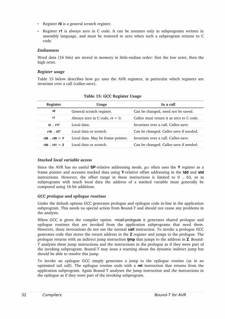
• Register r0 is a general scratch register.
• Register r1 is always zero in C code. It can be nonzero only in subprograms written in assembly language, and must be restored to zero when such a subprogram returns to C code.
Endianness
Word data (16 bits) are stored in memory in littleendian order: first the low octet, then the high octet.
Register usage
Table 15 below describes how gcc uses the AVR registers, in particular which registers are invariant over a call (calleesave).
Table 15: GCC Register Usage
Register Usage In a call
r0 General scratch register. Can be changed, need not be saved.
r1 Always zero in C code, r1 = 0. Callee must return it as zero to C code.
r2 .. r17 Local data. Invariant over a call. Calleesave.
r18 .. r27 Local data or scratch. Can be changed. Callersave if needed.
r28 .. r29 = Y Local data. May be frame pointer. Invariant over a call. Calleesave.
r30 .. r31 = Z Local data or scratch. Can be changed. Callersave if needed.
Stacked local variable access
Since the AVR has no useful SPrelative addressing mode, gcc often uses the Y register as a frame pointer and accesses stacked data using Yrelative offset addressing in the ldd and std instructions. However, the offset range in these instructions is limited to 0 .. 63, so in subprograms with much local data the address of a stacked variable must generally be computed using 16bit additions.
GCC prologue and epilogue routines
Under the default options GCC generates prologue and epilogue code inline in the application subprogram. This needs no special action from BoundT and should not cause any problems in the analysis.
When GCC is given the compiler option mcallprologues it generates shared prologue and epilogue routines that are invoked from the application subprograms that need them. However, these invocations do not use the normal call instruction. To invoke a prologue GCC generates code that stores the return address in the Z register and jumps to the prologue. The prologue returns with an indirect jump instruction ijmp that jumps to the address in Z. BoundT analyses these jump instructions and the instructions in the prologue as if they were part of the invoking subprogram. BoundT may issue a warning about the dynamic indirect jump but should be able to resolve this jump.
To invoke an epilogue GCC simply generates a jump to the epilogue routine (as in an optimised tail call). The epilogue routine ends with a ret instruction that returns from the application subprogram. Again BoundT analyses the jump instruction and the instructions in the epilogue as if they were part of the invoking subprogram.
32 Compilers Bound-T for AVR
In summary, GCC prologues and epilogues pose no special problems for the analysis. The BoundT commandline option logues=call has no effect on the analysis of GCC programs because BoundT does not recognize that prologues or epilogues are involved in these jumps. Prologues and epilogues are always analysed as if the option were logues=integrate.
Stackusage analysis
Stackusage analysis works poorly at present for gccgenerated code, because the instruction sequences that gcc generates to allocate and deallocate stack frames use 16bit arithmetic with the SPH:SPL pair in ways that BoundT currently cannot analyse well.
GCC option mtinystack
This option works under the assumption that the stack usage is never more than 255 TBC octets and that there is no carry from the low octet to the high octet (SPH), for example because the stack is allocated starting at a 256octet boundary (SPL initial value is zero).
Note that gcc still assumes that the SP is 16 bits in size. For example, when gcc sets the Y register to be the frame pointer it sets Y to SPH:SPL, using both the high and low octet of the SP.
Support for this option in BoundT is under investigation.
GCC switchcase statements
BoundT cannot currently analyse gcc code for switchcase statements if the compiler has generated a table of address for use with the ijmp instruction. Such tables tend to appear when the switchcase statement has a densely numbered set of case values.
Support for such switchcase code is planned.
Bound-T for AVR Compilers 33
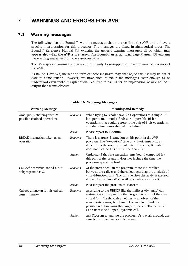
7 WARNINGS AND ERRORS FOR AVR
7.1 Warning messages
The following lists the BoundT warning messages that are specific to the AVR or that have a specific interpretation for this processor. The messages are listed in alphabetical order. The BoundT Reference Manual [1] explains the generic warning messages, all of which may appear also when the AVR is the target. The BoundT Assertion Language Manual [3] explains the warning messages from the assertion parser.
The AVRspecific warning messages refer mainly to unsupported or approximated features of the AVR.
As BoundT evolves, the set and form of these messages may change, so this list may be out of date to some extent. However, we have tried to make the messages clear enough to be understood even without explanation. Feel free to ask us for an explanation of any BoundT output that seems obscure.
Table 16: Warning Messages
Warning Message Meaning and Remedy
Ambiguous chaining with N possible chained operations.
Reasons While trying to “chain” two 8bit operations to a single 16bit operation, BoundT finds N > 1 possible 16bit operations that could represent the pair of 8bit operations, and therefore leaves the pair unchained.
Action Please report to Tidorum.
BREAK instruction taken as nooperation
Reasons There is a break instruction at this point in the AVR program. The “execution” time of a break instruction depends on the occurrence of external events; BoundT does not include this time in the analysis.
Action Understand that the executiontime bound computed for this part of the program does not include the time the processor spends in break.
Call defines virtual mood C but subprogram has S.
Reasons At the present call in the program, there is a conflict between the calleer and the callee regarding the analysis of virtualfunction calls. The call specifies the analysis method defined by the “mood” C, while the callee specifies S.
Action Please report the problem to Tidorum.
Callees unknown for virtual call:class | function
Reasons According to the UBROF file, the indirect (dynamic) call instruction at this point in the program is a call of the C++ virtual function through a pointer to an object of the compiletime class, but BoundT is unable to find the possible real functions that might be called. The call is left as an unresolved (open) dynamic call.
Action Ask Tidorum to analyse the problem. As a workaround, use assertions to list the possible callees.
34 Warning Messages Bound-T for AVR
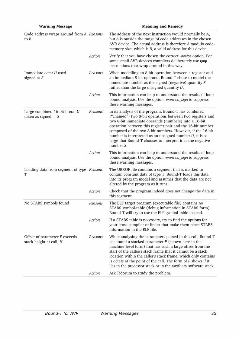
Warning Message Meaning and Remedy
Code address wraps around from A to B
Reasons The address of the next instruction would normally be A, but A is outside the range of code addresses in the chosen AVR device. The actual address is therefore A modulo codememory size, which is B, a valid address for this device.
Action Verify that you have chosen the correct device option. For some small AVR devices compilers deliberately use rjmp instructions that wrap around in this way.
Immediate octet U used signed = S
Reasons When modelling an 8bit operation between a register and an immediate 8bit operand, BoundT chose to model the immediate number as the signed (negative) quantity S rather than the large unsigned quantity U.
Action This information can help to understand the results of loopbound analysis. Use the option warn no_sign to suppress these warning messages.
Large combined 16bit literal U taken as signed = S
Reasons In its analysis of the program, BoundT has combined (“chained”) two 8bit operations between two registers and two 8bit immediate operands (numbers) into a 16bit operation between this register pair and the 16bit number composed of the two 8bit numbers. However, if the 16bit number is interpreted as an unsigned number U, it is so large that BoundT chooses to interpret it as the negative number S.
Action This information can help to understand the results of loopbound analysis. Use the option warn no_sign to suppress these warning messages.
Loading data from segment of type T
Reasons The UBROF file contains a segment that is marked to contain constant data of type T. BoundT loads this data into its program model and assumes that the data are not altered by the program as it runs.
Action Check that the program indeed does not change the data in this segment.
No STABS symbols found Reasons The ELF target program (executable file) contains no STABS symboltable (debug information in STABS form). BoundT will try to use the ELF symboltable instead.
Action If a STABS table is necessary, try to find the options for your crosscompiler or linker that make them place STABS information in the ELF file.
Offset of parameter P exceeds stack height at call, H
Reasons While analysing the parameters passed in this call, BoundT has found a stacked parameter P (shown here in the machinelevel form) that has such a large offset from the start of the callee's stack frame that it cannot be a stack location within the caller's stack frame, which only contains H octets at the point of the call. The form of P shows if it lies in the processor stack or in the auxiliary software stack.
Action Ask Tidorum to study the problem.
Bound-T for AVR Warning Messages 35
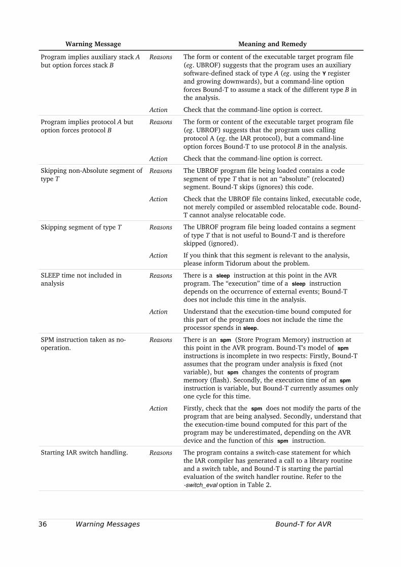
Warning Message Meaning and Remedy
Program implies auxiliary stack A but option forces stack B
Reasons The form or content of the executable target program file (eg. UBROF) suggests that the program uses an auxiliary softwaredefined stack of type A (eg. using the Y register and growing downwards), but a commandline option forces BoundT to assume a stack of the different type B in the analysis.
Action Check that the commandline option is correct.
Program implies protocol A but option forces protocol B
Reasons The form or content of the executable target program file (eg. UBROF) suggests that the program uses calling protocol A (eg. the IAR protocol), but a commandline option forces BoundT to use protocol B in the analysis.
Action Check that the commandline option is correct.
Skipping nonAbsolute segment of type T
Reasons The UBROF program file being loaded contains a code segment of type T that is not an “absolute” (relocated) segment. BoundT skips (ignores) this code.
Action Check that the UBROF file contains linked, executable code, not merely compiled or assembled relocatable code. BoundT cannot analyse relocatable code.
Skipping segment of type T Reasons The UBROF program file being loaded contains a segment of type T that is not useful to BoundT and is therefore skipped (ignored).
Action If you think that this segment is relevant to the analysis, please inform Tidorum about the problem.
SLEEP time not included in analysis
Reasons There is a sleep instruction at this point in the AVR program. The “execution” time of a sleep instruction depends on the occurrence of external events; BoundT does not include this time in the analysis.
Action Understand that the executiontime bound computed for this part of the program does not include the time the processor spends in sleep.
SPM instruction taken as nooperation.
Reasons There is an spm (Store Program Memory) instruction at this point in the AVR program. BoundT's model of spm instructions is incomplete in two respects: Firstly, BoundT assumes that the program under analysis is fixed (not variable), but spm changes the contents of program memory (flash). Secondly, the execution time of an spm instruction is variable, but BoundT currently assumes only one cycle for this time.
Action Firstly, check that the spm does not modify the parts of the program that are being analysed. Secondly, understand that the executiontime bound computed for this part of the program may be underestimated, depending on the AVR device and the function of this spm instruction.
Starting IAR switch handling. Reasons The program contains a switchcase statement for which the IAR compiler has generated a call to a library routine and a switch table, and BoundT is starting the partial evaluation of the switch handler routine. Refer to the switch_eval option in Table 2.
36 Warning Messages Bound-T for AVR
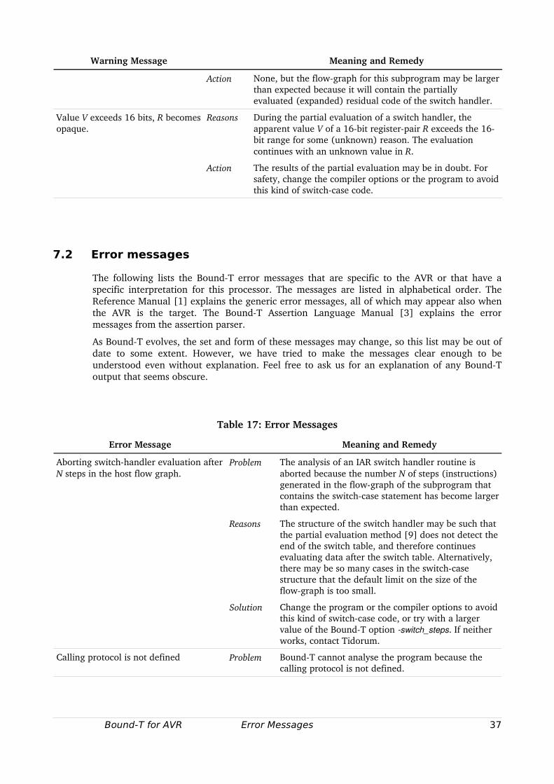
Warning Message Meaning and Remedy
Action None, but the flowgraph for this subprogram may be larger than expected because it will contain the partially evaluated (expanded) residual code of the switch handler.
Value V exceeds 16 bits, R becomes opaque.
Reasons During the partial evaluation of a switch handler, the apparent value V of a 16bit registerpair R exceeds the 16bit range for some (unknown) reason. The evaluation continues with an unknown value in R.
Action The results of the partial evaluation may be in doubt. For safety, change the compiler options or the program to avoid this kind of switchcase code.
7.2 Error messages
The following lists the BoundT error messages that are specific to the AVR or that have a specific interpretation for this processor. The messages are listed in alphabetical order. The Reference Manual [1] explains the generic error messages, all of which may appear also when the AVR is the target. The BoundT Assertion Language Manual [3] explains the error messages from the assertion parser.
As BoundT evolves, the set and form of these messages may change, so this list may be out of date to some extent. However, we have tried to make the messages clear enough to be understood even without explanation. Feel free to ask us for an explanation of any BoundT output that seems obscure.
Table 17: Error Messages
Error Message Meaning and Remedy
Aborting switchhandler evaluation after N steps in the host flow graph.
Problem The analysis of an IAR switch handler routine is aborted because the number N of steps (instructions) generated in the flowgraph of the subprogram that contains the switchcase statement has become larger than expected.
Reasons The structure of the switch handler may be such that the partial evaluation method [9] does not detect the end of the switch table, and therefore continues evaluating data after the switch table. Alternatively, there may be so many cases in the switchcase structure that the default limit on the size of the flowgraph is too small.
Solution Change the program or the compiler options to avoid this kind of switchcase code, or try with a larger value of the BoundT option switch_steps. If neither works, contact Tidorum.
Calling protocol is not defined Problem BoundT cannot analyse the program because the calling protocol is not defined.
Bound-T for AVR Error Messages 37
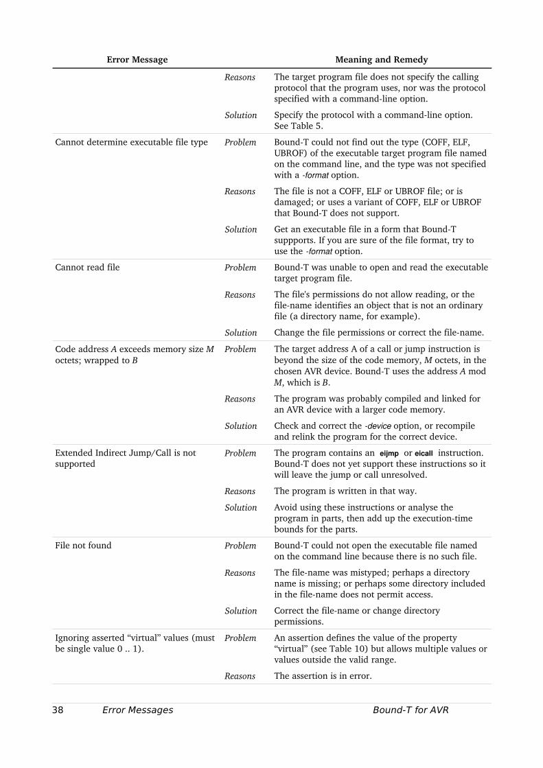
Error Message Meaning and Remedy
Reasons The target program file does not specify the calling protocol that the program uses, nor was the protocol specified with a commandline option.
Solution Specify the protocol with a commandline option. See Table 5.
Cannot determine executable file type Problem BoundT could not find out the type (COFF, ELF, UBROF) of the executable target program file named on the command line, and the type was not specified with a format option.
Reasons The file is not a COFF, ELF or UBROF file; or is damaged; or uses a variant of COFF, ELF or UBROF that BoundT does not support.
Solution Get an executable file in a form that BoundT suppports. If you are sure of the file format, try to use the format option.
Cannot read file Problem BoundT was unable to open and read the executable target program file.
Reasons The file's permissions do not allow reading, or the filename identifies an object that is not an ordinary file (a directory name, for example).
Solution Change the file permissions or correct the filename.
Code address A exceeds memory size M octets; wrapped to B
Problem The target address A of a call or jump instruction is beyond the size of the code memory, M octets, in the chosen AVR device. BoundT uses the address A mod M, which is B.
Reasons The program was probably compiled and linked for an AVR device with a larger code memory.
Solution Check and correct the device option, or recompile and relink the program for the correct device.
Extended Indirect Jump/Call is not supported
Problem The program contains an eijmp or eicall instruction. BoundT does not yet support these instructions so it will leave the jump or call unresolved.
Reasons The program is written in that way.
Solution Avoid using these instructions or analyse the program in parts, then add up the executiontime bounds for the parts.
File not found Problem BoundT could not open the executable file named on the command line because there is no such file.
Reasons The filename was mistyped; perhaps a directory name is missing; or perhaps some directory included in the filename does not permit access.
Solution Correct the filename or change directory permissions.
Ignoring asserted “virtual” values (must be single value 0 .. 1).
Problem An assertion defines the value of the property “virtual” (see Table 10) but allows multiple values or values outside the valid range.
Reasons The assertion is in error.
38 Error Messages Bound-T for AVR
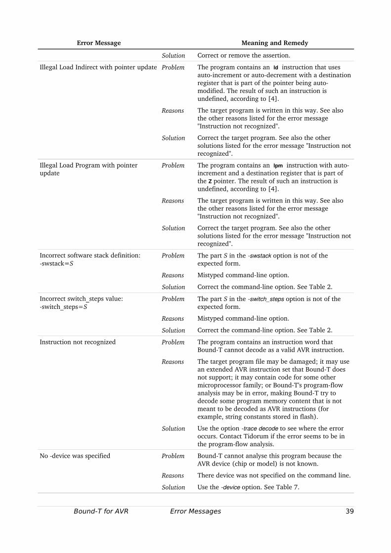
Error Message Meaning and Remedy
Solution Correct or remove the assertion.
Illegal Load Indirect with pointer update Problem The program contains an ld instruction that uses autoincrement or autodecrement with a destination register that is part of the pointer being automodified. The result of such an instruction is undefined, according to [4].
Reasons The target program is written in this way. See also the other reasons listed for the error message "Instruction not recognized".
Solution Correct the target program. See also the other solutions listed for the error message "Instruction not recognized".
Illegal Load Program with pointer update
Problem The program contains an lpm instruction with autoincrement and a destination register that is part of the Z pointer. The result of such an instruction is undefined, according to [4].
Reasons The target program is written in this way. See also the other reasons listed for the error message "Instruction not recognized".
Solution Correct the target program. See also the other solutions listed for the error message "Instruction not recognized".
Incorrect software stack definition: swstack=S
Problem The part S in the swstack option is not of the expected form.
Reasons Mistyped commandline option.
Solution Correct the commandline option. See Table 2.
Incorrect switch_steps value: switch_steps=S
Problem The part S in the switch_steps option is not of the expected form.
Reasons Mistyped commandline option.
Solution Correct the commandline option. See Table 2.
Instruction not recognized Problem The program contains an instruction word that BoundT cannot decode as a valid AVR instruction.
Reasons The target program file may be damaged; it may use an extended AVR instruction set that BoundT does not support; it may contain code for some other microprocessor family; or BoundT's programflow analysis may be in error, making BoundT try to decode some program memory content that is not meant to be decoded as AVR instructions (for example, string constants stored in flash).
Solution Use the option trace decode to see where the error occurs. Contact Tidorum if the error seems to be in the programflow analysis.
No device was specified Problem BoundT cannot analyse this program because the AVR device (chip or model) is not known.
Reasons There device was not specified on the command line.
Solution Use the device option. See Table 7.
Bound-T for AVR Error Messages 39
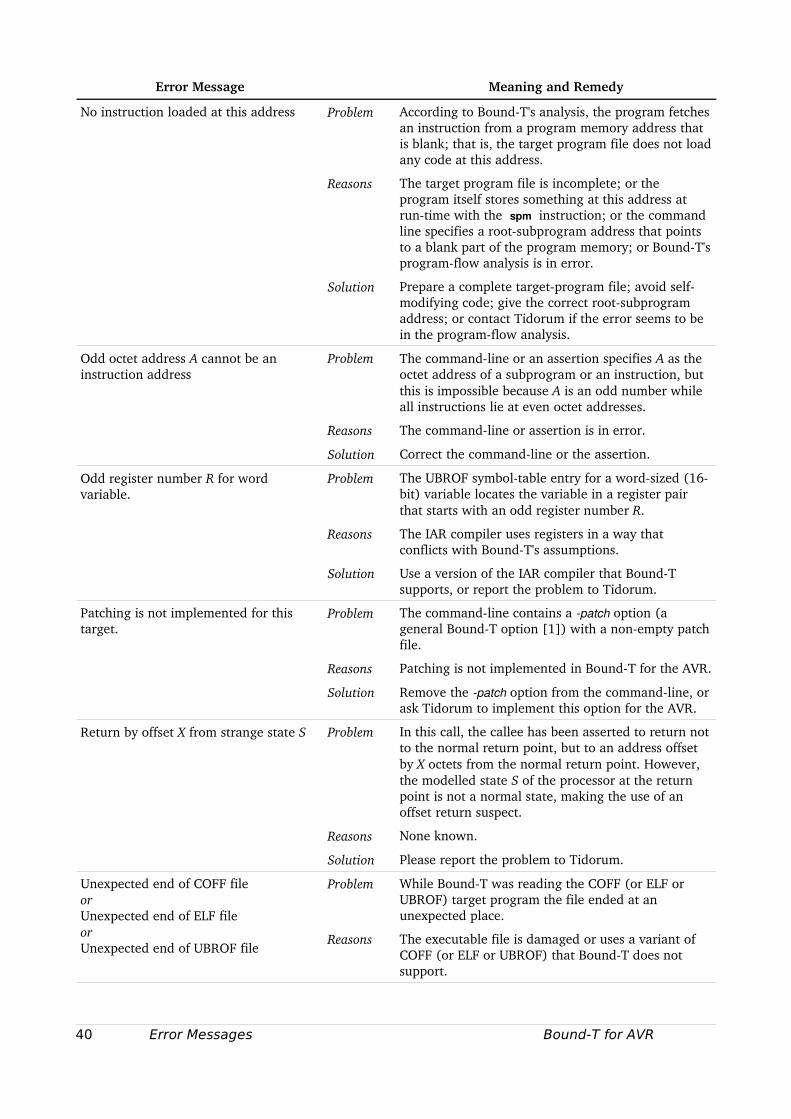
Error Message Meaning and Remedy
No instruction loaded at this address Problem According to BoundT's analysis, the program fetches an instruction from a program memory address that is blank; that is, the target program file does not load any code at this address.
Reasons The target program file is incomplete; or the program itself stores something at this address at runtime with the spm instruction; or the command line specifies a rootsubprogram address that points to a blank part of the program memory; or BoundT's programflow analysis is in error.
Solution Prepare a complete targetprogram file; avoid selfmodifying code; give the correct rootsubprogram address; or contact Tidorum if the error seems to be in the programflow analysis.
Odd octet address A cannot be an instruction address
Problem The commandline or an assertion specifies A as the octet address of a subprogram or an instruction, but this is impossible because A is an odd number while all instructions lie at even octet addresses.
Reasons The commandline or assertion is in error.
Solution Correct the commandline or the assertion.
Odd register number R for word variable.
Problem The UBROF symboltable entry for a wordsized (16bit) variable locates the variable in a register pair that starts with an odd register number R.
Reasons The IAR compiler uses registers in a way that conflicts with BoundT's assumptions.
Solution Use a version of the IAR compiler that BoundT supports, or report the problem to Tidorum.
Patching is not implemented for this target.
Problem The commandline contains a patch option (a general BoundT option [1]) with a nonempty patch file.
Reasons Patching is not implemented in BoundT for the AVR.
Solution Remove the patch option from the commandline, or ask Tidorum to implement this option for the AVR.
Return by offset X from strange state S Problem In this call, the callee has been asserted to return not to the normal return point, but to an address offset by X octets from the normal return point. However, the modelled state S of the processor at the return point is not a normal state, making the use of an offset return suspect.
Reasons None known.
Solution Please report the problem to Tidorum.
Unexpected end of COFF fileorUnexpected end of ELF fileorUnexpected end of UBROF file
Problem While BoundT was reading the COFF (or ELF or UBROF) target program the file ended at an unexpected place.
Reasons The executable file is damaged or uses a variant of COFF (or ELF or UBROF) that BoundT does not support.
40 Error Messages Bound-T for AVR
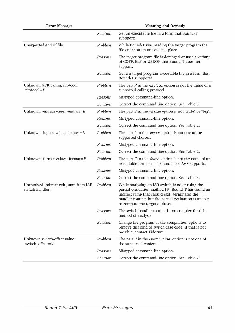
Error Message Meaning and Remedy
Solution Get an executable file in a form that BoundT suppports.
Unexpected end of file Problem While BoundT was reading the target program the file ended at an unexpected place.
Reasons The target program file is damaged or uses a variant of COFF, ELF or UBROF that BoundT does not support.
Solution Get a a target program executable file in a form that BoundT suppports.
Unknown AVR calling protocol: protocol=P
Problem The part P in the protocol option is not the name of a supported calling protocol.
Reasons Mistyped commandline option.
Solution Correct the commandline option. See Table 5.
Unknown endian vaue: endian=E Problem The part E in the endian option is not "little" or "big".
Reasons Mistyped commandline option.
Solution Correct the commandline option. See Table 2.
Unknown logues value: logues=L Problem The part L in the logues option is not one of the supported choices.
Reasons Mistyped commandline option.
Solution Correct the commandline option. See Table 2.
Unknown format value: format=F Problem The part F in the format option is not the name of an executable format that BoundT for AVR supports.
Reasons Mistyped commandline option.
Solution Correct the commandline option. See Table 3.
Unresolved indirect exitjump from IAR switch handler.
Problem While analysing an IAR switch handler using the partialevaluation method [9] BoundT has found an indirect jump that should exit (terminate) the handler routine, but the partial evaluation is unable to compute the target address.
Reasons The switch handler routine is too complex for this method of analysis.
Solution Change the program or the compilation options to remove this kind of switchcase code. If that is not possible, contact Tidorum.
Unknown switchoffset value: switch_offset=V
Problem The part V in the switch_offset option is not one of the supported choices.
Reasons Mistyped commandline option.
Solution Correct the commandline option. See Table 2.
Bound-T for AVR Error Messages 41

Tidorum Ltd
Tiirasaarentie 32FI00200 HelsinkiFinland
[email protected]. +358 (0) 40 563 9186Fax +358 (0) 42 563 9186VAT FI 18688130
42 Bound-T for AVR
Tidrum
Related Documents