siemens.com/tip-cs Totally Integrated Power Application Models for Power Distribution Hospitals

Welcome message from author
This document is posted to help you gain knowledge. Please leave a comment to let me know what you think about it! Share it to your friends and learn new things together.
Transcript
Tota
lly
Inte
gra
ted
Po
we
r A
pp
lica
tio
n M
od
els
for
Po
wer
Dis
trib
uti
on
– H
osp
ita
ls
siemens.com/tip-cs
Totally Integrated Power
Application Models for Power DistributionHospitals

2 Totally Integrated Power – Contents
Contents5 Usage-specific Power Supply Design 62
5.1 Central Technical Systems 64
5.2 Usage-specific Installations 66
5.3 Specific Power Demand for Room Groups 76
6 Model Networks for SIMARIS design 80
6.1 Examples of Infeed Network Structures 80
6.2 Equivalent Impedance for IT Isolating Transformer 84
6.3 Ward Distribution Examples 86
7 Designing and Configuring the Main Compo nents of Electric Power Distribution Systems 90
7.1 GEAFOL Distribution Transformers 91
7.2 Medium-voltage Switchgear 92
7.3 Low-voltage Switchgear 94
7.4 Distribution Boards 96
7.5 Busbar Trunking Systems 97
8 Annex 100
8.1 List of Standards Cited 100
8.2 Lighting Specifications for Rooms in Hospitals According to DIN 5035-3 104
8.3 List of Abbreviations 106
8.4 Literature References 110
Publisher’s details 112
Vital and Cost-effective – Integrated Power Supply in Hospitals 4
1 Trends and Categorisation in Hospital Planning 8
1.1 Definition 8
1.2 Statistics and Trends 8
1.3 Development in Demand 13
1.4 Categorisation 14
2 Basic Planning Considerations 18
2.1 Architectural and Work Planning Factors Underlying Electric Power Distribution 19
2.2 Estimation of Space Requirements 22
3 Experience in Electrical Energy and Power Demand 30
3.1 Energy Consumption 32
3.2 Electric Power Demand for a Hospital 34
4 Structuring of Hospital Power Supply 40
4.1 Structure of Power Distribution in a Hospital and Estimation of Power Demand for Individual Functional Areas 40
4.2 Grouping of Hospital Areas with Regard to the Operation of Medical Electrical Equipment and Associated Hazards 42
4.3 Classification by Permissible Changeover Period to a Power Supply for Safety Purposes 45
4.4 Protection Requirements in Hospital Power Supply 47
4.5 Schematic of a Power Supply Structure in a Hospital 50
IntroductionVital and Cost-effective – Integrated Power Supply in Hospitals
Totally Integrated Power – Vital and Cost-effective – Integrated Power Supply in Hospitals4
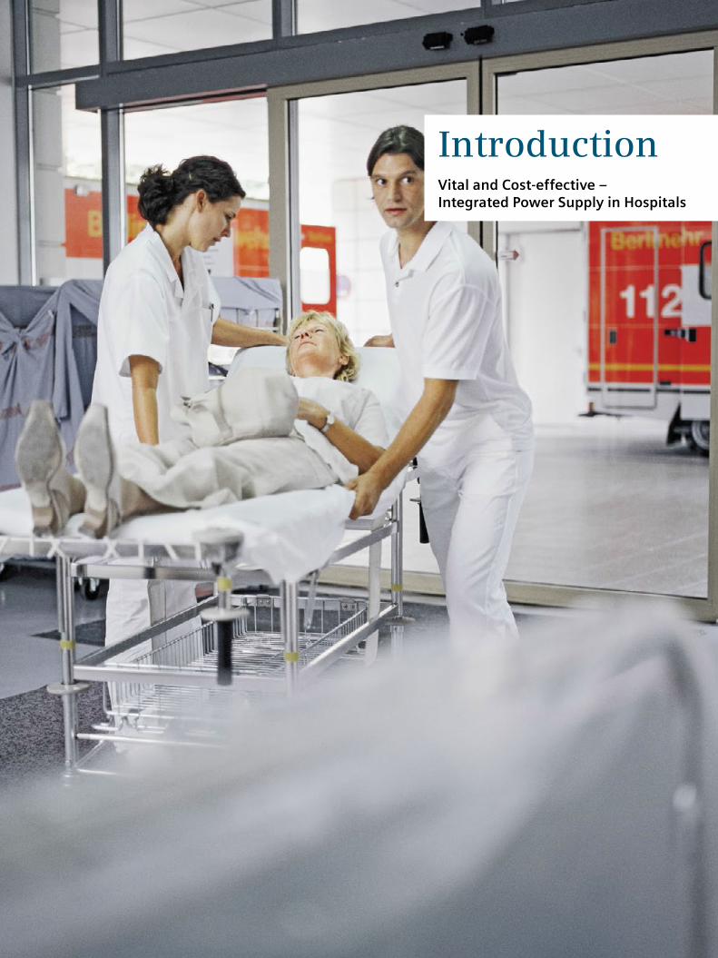
Hospitals nowadays are subject to the increasing cost pressure in the healthcare sector. Yet at the same time, capital investment in innovative medical technology and infrastructure is essential. That is why cost-efficient opera-tion is at the focus of efforts, though of course not to the detriment of medical quality. The conflicting aims of opti-mizing operating costs and maintaining absolute availabil-ity of the medical equipment pose new challenges to hospital managers.
From a hospital to a health centre
The demands on hospitals are becoming ever more complex:• Overarching concepts covering different medical
disciplines as well as outpatient, inpatient, and partial-inpatient care structures have to be integrated
• Specialist staff need to be provided with optimum support in their day-to-day work by suitable infrastructure
• Patients need to feel like customers – and be treated with the same respect
Vital and Cost-effective – Integrated Power Supply in Hospitals
$
kw
Totally Integrated Power (TIP)
Totally Integrated Automation (TIA) Total Building Solutions (TBS)
MES SEM
TIP05_15_057_EN
Managementlevel
Operationlevel
Controllevel
Fieldlevel
Electrical power lineData line
(Sustainability and energy management)
Smart grid solutions
(Manufacturing execution systems)
Enterprise level
Management level
Automation level
Field level

Totally Integrated Power – Vital and Cost-effective – Integrated Power Supply in Hospitals 5
• Environmental pollution needs to be minimized by careful use of resources
• Unused buildings on hospital sites have to be reconfigured for future usage, for example, as:
– Doctors’ housing – Offices with sanitary amenities and pharmacy – Wellness centres or spas – Preventative care centres for quick and detailed health checking
– Patient hotels – Hospices and elderly care homes
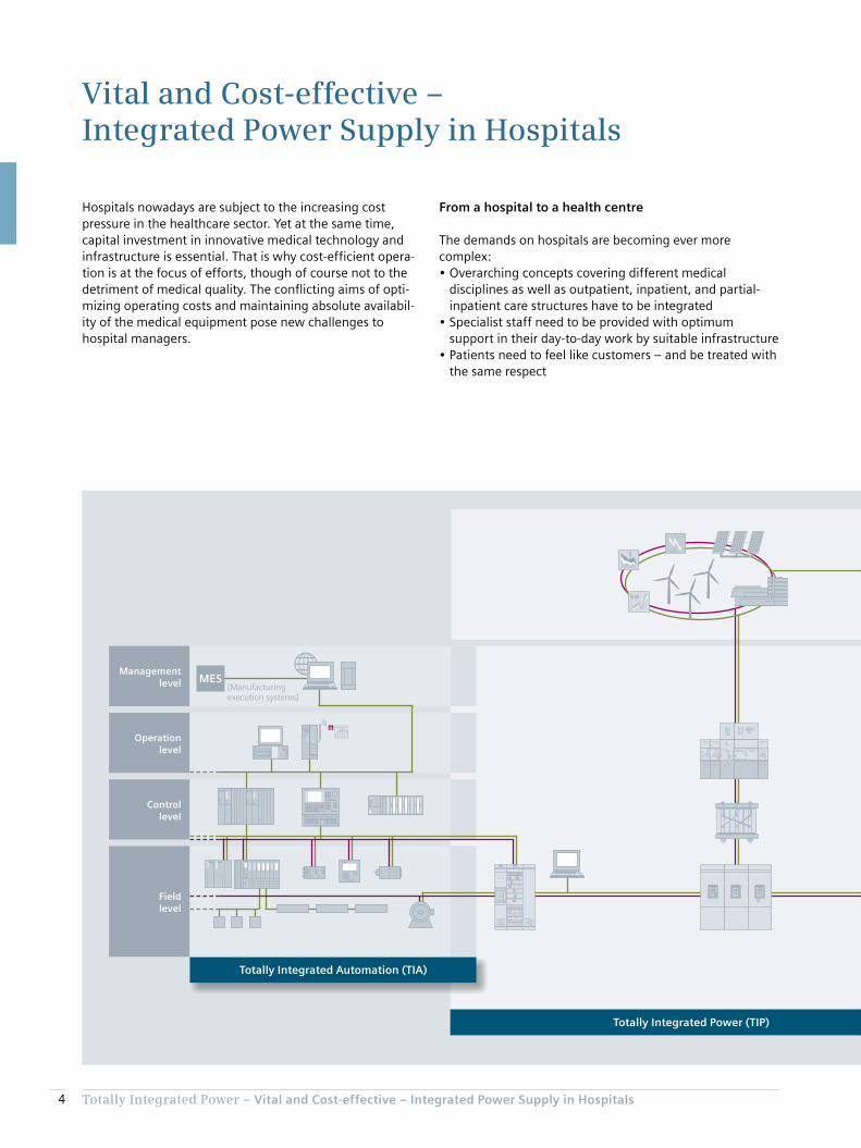
Totally Integrated Power (TIP) – incorporating comprehen-sive, cost-efficient, safe power distribution in buildings – provides the necessary future-proofing and flexibility based on reliable, optimized power supply. It also has a positive effect on a hospital’s operating costs – specifically with regard to the wide-ranging medical equipment that has to be powered reliably and cost-efficiently, round the clock. Our high-end coordinated products and systems enable electric power distribution in hospitals to be fully inte-grated, ensuring optimized installation and operation. This forms the basis for long-term reductions in power supply costs as part of the operating costs.
$
kw
Totally Integrated Power (TIP)
Totally Integrated Automation (TIA) Total Building Solutions (TBS)
MES SEM
TIP05_15_057_EN
Managementlevel
Operationlevel
Controllevel
Fieldlevel
Electrical power lineData line
(Sustainability and energy management)
Smart grid solutions
(Manufacturing execution systems)
Enterprise level
Management level
Automation level
Field level
Integrated power distribution solutions from Siemens with TIP, TIA, and TBS

Totally Integrated Power – Vital and Cost-effective – Integrated Power Supply in Hospitals6
TIP offers tools and support for planning and configuration, a complete coordinated portfolio of products and systems for electric power distribution, as well as the ability to interface with higher-level control, monitoring, and man-agement systems. By the linkage to Totally Integrated Automation (TIA) and Total Building Solutions (TBS), as shown schematically in the diagram, Siemens is pursuing an all-embracing approach for buildings and infrastructure systems. TIP also links to the Siemens Smart Grid solutions, and so to grid companies and distributors.
This opens up the possibility for major savings throughout the project cycle. The potential for optimisation of an integrated solution in all project phases – from investment, through planning and installation, to operation – delivers substantial added value for all project stakeholders.
Chapter 1Trends and Categorisation in Hospital Planning
1.1 Definition 8
1.2 Statistics and Trends 8
1.3 Development in Demand 13
1.4 Categorisation 14
Totally Integrated Power – Trends and Categorisation in Hospital Planning
1
8
1 Trends and Categorisation in Hospital Planning
Germany’s Hospital Financing Act (“KHG”, section 2, clause 1) [2] similarly defines a hospital (“Krankenhaus”) as:
“An institution which provides medical and nursing services to diagnose, cure, or mitigate illnesses, conditions, or physical injuries, or provides maternity services, in which patients are accommodated and catered for.”
1.2 Statistics and Trends
Planning procedures apply statistical ratios between economic data (such as the gross domestic product [GDP] of the country concerned) and hospital-specific data (such as the number of beds and the time patients spend in hospital). Fig. 1/1 and Fig. 1/2 set out typical data [3] (OECD statistics) such as expenditure on healthcare and numbers of beds in hospitals, and the trends in those figures, for a number of countries. It is estimated that hospitals account for over 25 % of a European country’s total healthcare costs [4].
This Application Manual relates to the planning of electric power distribution systems for hospitals. Some basic infor-mation is provided initially for the sake of greater understanding.
1.1 Definition
Hospitals are key medical infrastructure elements of the healthcare system. Since the health of the general population has a major influence on a country’s economic strength and social well-being, many countries and regions around the world have established a planning framework for hospitals. According to the Austrian Federal Hospitals Act (KAKuG) [1], hospitals (as well as clinics and convales-cent facilities) are classed as “institutions which
1. diagnose and monitor health based on examination
2. carry out surgical procedures (operations)
3. prevent, improve, and cure illnesses through treatment
4. provide maternity services
5. provide medical fertility treatment
6. provide organs for the purposes of transplantation.
Clinics are further classed as medical care centres, and as centres providing special care services for the chronically ill.”

Totally Integrated Power – Trends and Categorisation in Hospital Planning
1
9
Fig. 1/1: Trend in healthcare expenditure of individual countries as a percentage of GDP [3]
% o
f G
DP
Year
USA
France
Germany
Netherlands
Switzerland
Austria
Canada
Belgium
Portugal
Spain
Italy
United Kingdom
Turkey
4
2000 2001 2002 2003 2004 2005 2006 2007 2008 2009 2010 2011
TIP0
5_1
5_0
01
_EN
6
8
10
12
14
16
18
Fig. 1/2: Trend in healthcare expenditure of individual countries referred to the number of hospital beds per head of population [3]
Germany
Austria
France
Belgium
Switzerland
Netherlands
Italy
Portugal
Spain
USA
United Kingdom
Canada
Turkey
0
2
8
5
3
4
6
1
7
9
10
Ho
spit
al b
ed
s p
er
1,0
00
he
ad o
f p
op
ula
tio
n
Year
2000 2001 2002 2003 2004 2005 2006 2007 2008 2009 2010 2011
TIP0
5_1
5_0
02
_EN

Totally Integrated Power – Trends and Categorisation in Hospital Planning
1
10
Another factor to be considered in line with this is that the numbers of imaging systems and radiotherapy units is increasing (Fig. 1/4 to Fig. 1/7). The use of such equipment might in principle result in higher power demand within a smaller space in hospitals, though this will not in practice be the case, as the efficiency of the equipment is continu-ally improving. This trend towards more advanced technol-ogy in hospitals is being boosted both by the demographic trends in most industrialized countries and by the growth of the hospital-related service sector as part of general economic development. Inpatient care is personnel-inten-sive, and the home environment is normally more benefi-cial to patients’ recovery.
At the same time, new treatment methods, improved medical equipment, as well as demographic, socio-eco-nomic, and regional factors also play a role in hospital planning – particularly when it comes to remodelling and updating existing facilities. Factors that planning needs to consider include, for example, urbanisation and demo-graphic changes in age structures, the need for helicopter transport, and advances in follow-up treatment techniques. A typical effect of modernisation and the relocation of care services outside of hospitals is the decrease in the numbers of beds in many countries (Fig. 1/2) – mostly also linked to shorter hospital stays (Fig. 1/3). Ultimately, there is an upward trend in the numbers of treatments – and thus in the numbers of patients – even though fewer care facilities are available.
Fig. 1/3: Duration of patient stay in hospital for various countries [3]
Switzerland
Germany
France
Portugal
Belgium
Italy
Austria
Spain
United Kingdom
USA
Turkey
Ave
rag
e d
ays’
sta
y in
ho
spit
al
0
2
10
4
6
8
12
14
Year
2000 2001 2002 2003 2004 2005 2006 2007 2008 2009 2010 2011
TIP0
5_1
5_0
03
_EN

Totally Integrated Power – Trends and Categorisation in Hospital Planning
1
11
Fig. 1/4: Numbers of imaging systems in hospitals [3]: computer tomography (CT) scanners
USA
Italy
Switzerland
Austria
Germany
Portugal
Spain
Canada
Belgium
Netherlands
France
CT
sca
nn
ers
pe
r m
illi
on
he
ad
of
po
pu
lati
on
0
5
30
10
25
15
20
Year
2000 2001 2002 2003 2004 2005 2006 2007 2008 2009 2010 2011
TIP0
5_1
5_0
04
_EN
Switzerland
Italy
Netherlands
Belgium
Germany
Austria
Spain
Canada
Portugal
France
MR
sca
nn
ers
pe
r m
illi
on
he
ad
of
po
pu
lati
on
0
5
30
10
25
15
20
Year
2000 2001 2002 2003 2004 2005 2006 2007 2008 2009 2010 2011
TIP0
5_1
5_0
05
_EN
Fig. 1/5: Numbers of imaging systems in hospitals [3]: magnetic resonance (MR) scanners

Totally Integrated Power – Trends and Categorisation in Hospital Planning
1
12
Netherlands
Switzerland
Belgium
Italy
Austria
Germany
Spain
Canada
France
PE
T s
can
ne
rs p
er
mil
lio
n h
ea
d o
f p
op
ula
tio
n
0
1
6
2
5
3
4
Year
2000 2001 2002 2003 2004 2005 2006 2007 2008 2009 2010 2011
TIP0
5_1
5_0
06
_EN
Fig. 1/6: Numbers of imaging systems in hospitals [3]: positron emission tomography (PET) scanners
Belgium
France
Switzerland
Italy
Germany
Austria
Spain
Rad
ioth
erap
y u
nit
s p
er m
illio
n h
ead
of
po
pu
lati
on
0
4
18
8
12
2
16
6
10
14
Year
2000 2001 2002 2003 2004 2005 2006 2007 2008 2009 2010 2011
TIP0
5_1
5_0
07_
EN
Fig. 1/7: Numbers of radiotherapy units in hospitals [3]

Totally Integrated Power – Trends and Categorisation in Hospital Planning
1
13
A survey by the Bremen Energy Institute [6] into the need for renovation of existing and construction of new infra-structure buildings between 2012 and 2020 in Germany assumes a wide spread in terms of the age structure (Tab. 1/1) of hospital buildings. It states the need for some 80 new hospital buildings a year, corresponding to around 2.4 % p.a. of the total number. Compared to other building types, this is a relatively high percentage in the relation between new buildings and existing building stocks (in [6], an average life of 66 years is indicated for hospitals), be-cause some of the hospitals can no longer feasibly be renovated after a period of 30 years due to a substantial change in their underlying conditions. The number of buildings to be renovated per year [6] thus drops in corre-spondingly dramatic fashion from an estimated 155 to around 50 to 60 (some 45 additional new buildings a year instead of renovations, and around 50 additional hospital closures a year). This does not consider, however, that the average service life of much technical equipment in hospi-tals is usually substantially less than 30 years.
For example, Austria’s Health Structure Plan (ÖSG) [5] stipulates guideline ranges [5] for the number of people served by each major item of medical equipment, such as computer tomography (CT) and magnetic resonance (MR) scanners, as well as access times within which at least 90 % of the population should be able to reach the nearest location providing services employing the equipment category in question [5]. This can be applied to derive the targeted performance capability of a hospital.
An increasing trend at present is also that patients are no longer transported to the relevant equipment for examina-tion, but rather the physician travels to the patient’s care location with mobile equipment. For this, the necessary electric power to run the equipment must be available in the patient’s room with the required safety of supply (see chapter 4), or the equipment must itself be capable of assuring the necessary quality of power supply. If bat-tery-powered or battery-based equipment is used, it is normally charged at a central location. As is made clear in chapter 4, no equipment used in application group 2 medical locations (as per IEC 60364-7-710) may be charged at a non-central location.
1.3 Development in Demand
In view of the statistical decrease in hospital numbers, the impression might be created that major planning efforts will no longer be needed in future. Yet remodelling and updating of hospitals is an essential task when the factors of age structure, new therapies, new patterns of illness, technological advances, and shortages of medical and nursing staff are considered. The hospital must always be attractive to doctors, staff, and patients if it is to be viable over the long term. This interest should also be factored-in by public funding bodies and operators.
The industrial nations are still benefiting from the develop-ment of well-functioning healthcare systems in past years, and today are at risk of suffering an investment backlog, with little construction being undertaken (the construction boom in Germany ended sometime around the mid-1980s). Another factor is that the shift in population be-tween urban and rural areas might lead to more concentra-tion of medical services in specialist centres – like hospitals, in fact. In the widely privatized healthcare system in the Netherlands, for example, it is clear to see that ever closer links are being forged between health insurance funds and hospital operators against the background of a need to optimize costs, service demand, and service performance in the system.
Tab. 1/1: Age structure of hospital buildings in Germany as per [6]
Year of constructionNumber of buildings
Average number of buildings per year in the
period
Before 1945 500 –
1946–1977 1,200 39
1978–1999 1,300 62
2000–2010 350 35
Total 3,350
Totally Integrated Power – Trends and Categorisation in Hospital Planning
1
14
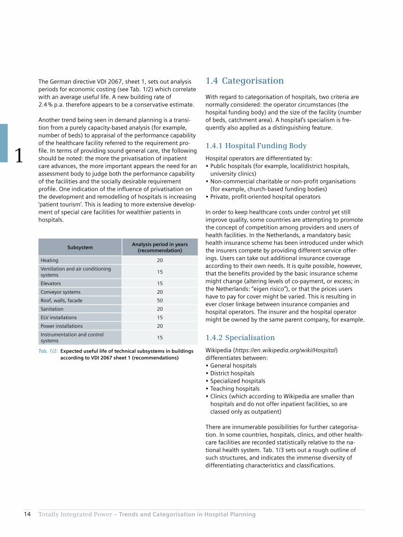
1.4 Categorisation
With regard to categorisation of hospitals, two criteria are normally considered: the operator circumstances (the hospital funding body) and the size of the facility (number of beds, catchment area). A hospital’s specialism is fre-quently also applied as a distinguishing feature.
1.4.1 Hospital Funding Body
Hospital operators are differentiated by:• Public hospitals (for example, local/district hospitals,
university clinics)• Non-commercial charitable or non-profit organisations
(for example, church-based funding bodies)• Private, profit-oriented hospital operators
In order to keep healthcare costs under control yet still improve quality, some countries are attempting to promote the concept of competition among providers and users of health facilities. In the Netherlands, a mandatory basic health insurance scheme has been introduced under which the insurers compete by providing different service offer-ings. Users can take out additional insurance coverage according to their own needs. It is quite possible, however, that the benefits provided by the basic insurance scheme might change (altering levels of co-payment, or excess; in the Netherlands: “eigen risico”), or that the prices users have to pay for cover might be varied. This is resulting in ever closer linkage between insurance companies and hospital operators. The insurer and the hospital operator might be owned by the same parent company, for example.
1.4.2 Specialisation
Wikipedia (https://en.wikipedia.org/wiki/Hospital) differentiates between:• General hospitals• District hospitals• Specialized hospitals• Teaching hospitals• Clinics (which according to Wikipedia are smaller than
hospitals and do not offer inpatient facilities, so are classed only as outpatient)
There are innumerable possibilities for further categorisa-tion. In some countries, hospitals, clinics, and other health-care facilities are recorded statistically relative to the na-tional health system. Tab. 1/3 sets out a rough outline of such structures, and indicates the immense diversity of differentiating characteristics and classifications.
The German directive VDI 2067, sheet 1, sets out analysis periods for economic costing (see Tab. 1/2) which correlate with an average useful life. A new building rate of 2.4 % p.a. therefore appears to be a conservative estimate.
Another trend being seen in demand planning is a transi-tion from a purely capacity-based analysis (for example, number of beds) to appraisal of the performance capability of the healthcare facility referred to the requirement pro-file. In terms of providing sound general care, the following should be noted: the more the privatisation of inpatient care advances, the more important appears the need for an assessment body to judge both the performance capability of the facilities and the socially desirable requirement profile. One indication of the influence of privatisation on the development and remodelling of hospitals is increasing ‘patient tourism’. This is leading to more extensive develop-ment of special care facilities for wealthier patients in hospitals.
Tab. 1/2: Expected useful life of technical subsystems in buildings according to VDI 2067 sheet 1 (recommendations)
SubsystemAnalysis period in years
(recommendation)
Heating 20
Ventilation and air conditioning systems
15
Elevators 15
Conveyor systems 20
Roof, walls, facade 50
Sanitation 20
ELV installations 15
Power installations 20
Instrumentation and control systems
15

Totally Integrated Power – Trends and Categorisation in Hospital Planning
1
15
Tab. 1/3: Classification of hospitals in various countries
Country Organisation Classification Characteristics
Japan Ministry of Health Hospitals More than 20 beds, differentiation• General hospitals• Specialized hospitals• District hospitals• Mental health hospitals• Tuberculosis hospitals
Clinics No beds, or 1–19 beds
Austria Federal Ministry of Health
General medical care centres
Specialist medical care centres
For examining and treating people with specific illnesses, or people in specific age groups, or for specific purposes
Care centres Centres providing care services for the chronically ill, requiring medical care from a doctor and specialized care
Sanatoriums With special facilities for higher demands with regard to catering and accommodation
Germany Hospital Plan of the state of Rhine-land-Palatinate
General hospitals • Basic healthcare (up to 250 planned beds; usually surgery and internal medicine departments)
• Standard healthcare (251 to 500 planned beds; surgery, internal medicine plus one additional main department)
• Special-focus hospitals (501 to 800 planned beds; surgery, internal medicine plus at least six additional main departments)
• Maximum-care hospitals (more than 800 planned beds; surgery, internal medicine plus at least 10 additional main departments)
Specialist hospitals Particularly for psychiatry, neurology, and internal medicine
Switzerland Federal Statistical Office (BFS)
Hospitals for general care • Basic care• Centralized care
Specialist clinics • Mental health clinics• Rehabilitation clinics• Other specialist clinics
Portugal National Health Service (NHS)
Central hospitals (CH)
District hospitals (DH)
District level 1 hospitals (DH1; fewer specialist departments and smaller catchment area than DH)
University hospitals
Canada Canadian Institute for Health Information (CIHI)
Hospitals for acute treatment
• Public general hospitals without long-term care, paediatric clinics, and private clinics
• Public general hospitals with long-term care• Teaching hospitals• Hospitals for short-term psychiatric treatment; other specialist or
rehabilitation clinics
Care hospitals and hospitals for lengthier psychiatric treatment
USA American Hospital Association (AHA)
Public hospitals
Private hospitals • General hospitals (short stay, and other specialist clinics)• Mental health clinics• Hospitals for long-term care
Medical centres of specialist institutions

Totally Integrated Power – Trends and Categorisation in Hospital Planning
1
16
For an arithmetic estimate of the required number of hospital beds in a region, the Hill-Burton Formula (HBF) can be used. It takes account of the following influencing factors:• Population size (P)• Stay time (ST):
Average number of days an inpatient spends in hospital (admission and release counted as one day)
• Hospital frequency (HF): Ratio of number of inpatient treatment cases to population size
• Bed utilisation rate (BU): Ratio of patient care days per year to the number of beds provided for them as stipulated for planning purposes (expressed as a percentage, the figure must be divided by 100)
Bed requirement according to the Hill-Burton Formula:
= P · KF · ST
BU · 365Bed requirement
Simple example: For a region with a population of approximately 2 million, statistical evaluation of hospital stays reveals a hospital frequency rate of 7,000 inpatient treatments per 100,000 head of population and an average stay time of eight days. The bed capacity is to be calculated for a utilisation rate of 85 %.
= 2,000,000 · 0.07 · 8
85 % · 365
Bed requirement
= 3,610 Beds
Even in a major city, considerations of accessibility mean it would make little sense to plan a single hospital complex with 3,610 beds. Rather, area coverage is planned by way of access radii for general care services, and special-focus care is located conveniently in terms of transport links.
In the international statistics of the Organisation for Eco-nomic Co-operation and Development (OECD), the World Health Organization (WHO), and the European hospitals association Hospitals for Europe (HOPE), hospitals are generally not subcategorized, owing to the innumerable possibilities of differentiation. Only the OECD [3] makes a distinction:• General hospitals (HP 1.1)• Mental health hospitals (HP 1.2)• Specialized hospitals (HP 1.3)
1.4.3 Accessibility and Number of Beds
The demand in terms of the number of beds in hospitals is primarily determined as function of regional characteristics such as age and population structure. Austria’s Hospital Structure Plan [5] stipulates numbers of beds for individual medical disciplines based on population structure, popula-tion density, accessibility by road, capacity utilisation of existing facilities, trends in medicine, and other specific features of healthcare. This is used as the basis for planning healthcare structures and corresponding hospital sizes.
The research report “Krankenhausplanung 2.0” (Hospital Planning 2.0) [7] stipulates accessibility dependent on levels of care:• Basic and standard care:
Maximum 30 minutes travel by car• Special focus and maximum care:
Approximately 60 minutes travel by car• Emergency care:
Maximum 12 minutes for arrival of ambulance

Chapter 2Basic Planning Considerations
2.1 Architectural and Work Planning Factors Underlying Electric Power Distribution 19
2.2 Estimation of Space Requirements 22

18 Totally Integrated Power – Basic Planning Considerations
2
2 Basic Planning Considerations
C Target/actual comparison
1) Cross-check of framework program against available primary areas
2) Assessment of discrepancies3) Recommendations for the primary areas to be planned
D Development of goal planning with variants
1) Full-scale schematic plan2) Breakdown into construction phases3) Assessment of variants4) Recommendation for further planning5) Rough cost estimate
Factors to be considered for optimum preliminary planning:• Forecast medium- and long-term trends in hospital
operations and demographic effects (from which are derived aspects of change over time, such as upgrades, extensions, or remodelling)
• Material and people flows in hospital operations (for example, visitor routes, bed transport, patient transport, utilities, and waste disposal)
• Functional interdependencies (for example, delivery, preparation and waste disposal of food, drugs, or sterile products)
• Needs-based variability (for example, variation between general care, intensive care, and treatment)
• Specific local conditions including – Cultural constraints – Technical conditions – Patient and visitor behaviour (more privatisation promotes viewing of patients/visitors as customers)
– Requirements of a specific medical facility and the clinic personnel (competition for good specialist staff)
– Special features and requirements of the surrounding area (for example, neighbourhoods, utility infrastructure, transport links)
– Underlying conditions for processes and procedures (for example, health and safety legislation)
The starting points for planning are the various require-ments of the different hospital “users”, such as patients, visitors, doctors, nurses, administrators, service providers, utility providers, operators, and investors. They have to be harmonized with the underlying functional conditions and translated into a kind of design and outfitting program:
Planning assumptions –> Functional conditions –> Design program –> Outfitting program
The results can be used, for example, to implement the planning steps stipulated by the German Fee Code for Architects and Engineers (HOAI) or the service provision model “SIA 112” of the Swiss Engineers and Architects Association (SIA): preliminary planning and surveys, fol-lowed by design and project planning.
To that end, supplementary sheet 4 to the German stand-ard DIN 13080 stipulates four planning stages as the start-ing point for preliminary planning and surveys:
A Review and appraisal of current status
1) Medical tasks2) Organisation (services, processes, personnel, equip-
ment, etc.)3) Functional relationships (allocation of functional areas
and departments)4) Areas (primary areas, circulation areas, functional
areas)5) Structural condition (buildings, exterior installations,
building systems, medical equipment)6) Underlying conditions (urban planning, organisational,
legal, financial, health policy framework, etc.)
B Goal setting
1) Medical goals2) Outline organisational structure3) Creation of a framework program (broken down by
department)4) Determination of required capacities
19Totally Integrated Power – Basic Planning Considerations
2
2.1 Architectural and Work Planning Factors Underlying Electric Power Distribution
In view of the wide range of planning parameters, it makes sense to structure planning goals with regard to:• Functional assignment• Building design• Operational organisation and assignment of functional
areas
2.1.1 Functional Assignment
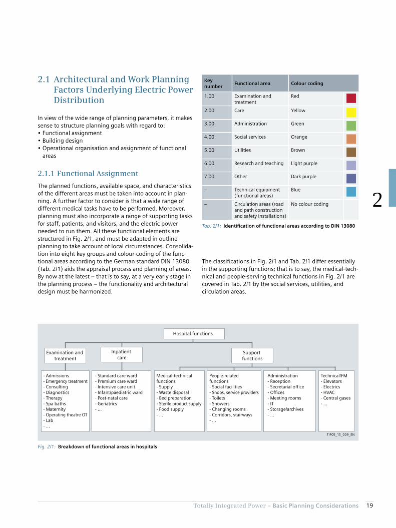
The planned functions, available space, and characteristics of the different areas must be taken into account in plan-ning. A further factor to consider is that a wide range of different medical tasks have to be performed. Moreover, planning must also incorporate a range of supporting tasks for staff, patients, and visitors, and the electric power needed to run them. All these functional elements are structured in Fig. 2/1, and must be adapted in outline planning to take account of local circumstances. Consolida-tion into eight key groups and colour-coding of the func-tional areas according to the German standard DIN 13080 (Tab. 2/1) aids the appraisal process and planning of areas. By now at the latest – that is to say, at a very early stage in the planning process – the functionality and architectural design must be harmonized.
The classifications in Fig. 2/1 and Tab. 2/1 differ essentially in the supporting functions; that is to say, the medical-tech-nical and people-serving technical functions in Fig. 2/1 are covered in Tab. 2/1 by the social services, utilities, and circulation areas.
Fig. 2/1: Breakdown of functional areas in hospitals
- Admissions- Emergency treatment- Consulting- Diagnostics- Therapy- Spa baths- Maternity- Operating theatre OT- Lab- ...
- Standard care ward- Premium care ward- Intensive care unit- Infant/paediatric ward- Post-natal care- Geriatrics- ...
Hospital functions
Support functions
Inpatient care
Examination and treatment
Medical-technical functions- Supply- Waste disposal- Bed preparation- Sterile product supply- Food supply- ...
People-related functions- Social facilities- Shops, service providers- Toilets- Showers- Changing rooms- Corridors, stairways- ...
Administration- Reception- Secretarial office- Offices- Meeting rooms- IT- Storage/archives- ...
Technical/FM- Elevators- Electrics- HVAC- Central gases- ...
TIP05_15_009_EN
Tab. 2/1: Identification of functional areas according to DIN 13080
Key number
Functional area Colour coding
1.00 Examination and treatment
Red
2.00 Care Yellow
3.00 Administration Green
4.00 Social services Orange
5.00 Utilities Brown
6.00 Research and teaching Light purple
7.00 Other Dark purple
– Technical equipment (functional areas)
Blue
– Circulation areas (road and path construction and safety installations)
No colour coding
20 Totally Integrated Power – Basic Planning Considerations
2
here only a theoretical outline is presented, which planners can apply to the circumstances encountered in practice.
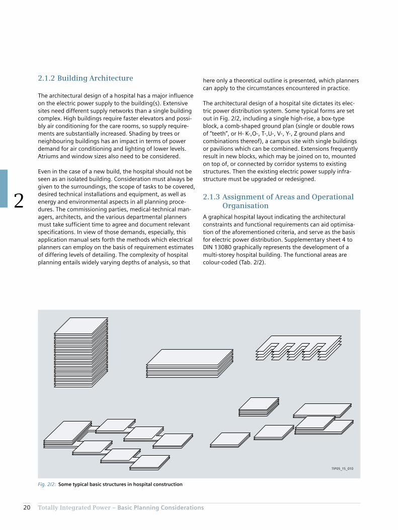
The architectural design of a hospital site dictates its elec-tric power distribution system. Some typical forms are set out in Fig. 2/2, including a single high-rise, a box-type block, a comb-shaped ground plan (single or double rows of “teeth”, or H- K-,O-, T-,U-, V-, Y-, Z ground plans and combinations thereof), a campus site with single buildings or pavilions which can be combined. Extensions frequently result in new blocks, which may be joined on to, mounted on top of, or connected by corridor systems to existing structures. Then the existing electric power supply infra-structure must be upgraded or redesigned.
2.1.3 Assignment of Areas and Operational Organisation
A graphical hospital layout indicating the architectural constraints and functional requirements can aid optimisa-tion of the aforementioned criteria, and serve as the basis for electric power distribution. Supplementary sheet 4 to DIN 13080 graphically represents the development of a multi-storey hospital building. The functional areas are colour-coded (Tab. 2/2).
2.1.2 Building Architecture
The architectural design of a hospital has a major influence on the electric power supply to the building(s). Extensive sites need different supply networks than a single building complex. High buildings require faster elevators and possi-bly air conditioning for the care rooms, so supply require-ments are substantially increased. Shading by trees or neighbouring buildings has an impact in terms of power demand for air conditioning and lighting of lower levels. Atriums and window sizes also need to be considered.
Even in the case of a new build, the hospital should not be seen as an isolated building. Consideration must always be given to the surroundings, the scope of tasks to be covered, desired technical installations and equipment, as well as energy and environmental aspects in all planning proce-dures. The commissioning parties, medical-technical man-agers, architects, and the various departmental planners must take sufficient time to agree and document relevant specifications. In view of those demands, especially, this application manual sets forth the methods which electrical planners can employ on the basis of requirement estimates of differing levels of detailing. The complexity of hospital planning entails widely varying depths of analysis, so that
Fig. 2/2: Some typical basic structures in hospital construction
TIP05_15_010
21Totally Integrated Power – Basic Planning Considerations
2
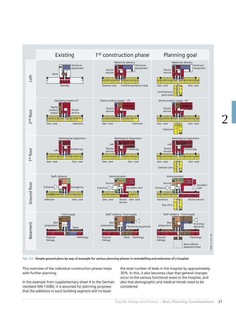
This overview of the individual construction phases helps with further planning.
In the example from supplementary sheet 4 to the German standard DIN 13080, it is assumed for planning purposes that the additions in each building segment will increase
the total number of beds in the hospital by approximately 30 %. In this, it also becomes clear that general changes occur to the various functional areas in the hospital, and also that demographic and medical trends need to be considered.
Technical equipment
Staff cafeteria
Physicaltherapy
Food supply
Area withoutbasement level
Pathology
Bedpreparation
Incomingdeliveries
Store
Doctor service
Day clinic
Administration
AccidentcareEntrance
GeriatricsInfection
Staff cafeteria
EmergencyEntrance
Gen. care Gen. care Gen. care
Gen. care Gen. care Gen. care Gen. care
Physicaltherapy
Pathology
Store
Physicaltherapy
Pathology
Bedpreparation
Food supply Staff cafeteria
Bedpreparation
Food supply
ServiceService
Doctorservice
Administration
Accident careEntrance
Gen. care Gen. care
Gen. care Gen. care
General care
Gen. care Gen. care
Gen. care Intensive Gen. care
General care Confinement/post-natal
Intensive
Intensive
Operating theatre OT OT OT
Doctorservice
DoctorserviceDoctor
service
Sterileproduct
supply
Sterile product supply Sterile product supply
Radiological diagnosticsRadiological diagnosticsRadiological diagnostics
Lab
Lab
Doctorservice
Endoscopy
Lab
Doctorservice
EndoscopyEndoscopy
Standby
Technicalequipment
Store
Technicalequipment
Technicalequipment
Confinement/post-natal
Maternity deliveryMaternity delivery
Doctorservice
Doctorservice
Existing 1st construction phase Planning goal
Base
men
tG
rou
nd
floo
r1
st fl
oor
2n
d fl
oor
Loft
TIP0
5_1
5_0
11_E
N
Tab. 2/2: Simple ground plans by way of example for various planning phases in remodelling and extension of a hospital

22 Totally Integrated Power – Basic Planning Considerations
2
2.2 Estimation of Space Requirements
Based on the many existing hospitals, extensive data is available regarding the allocation of space in hospitals. Often a relationship is specified between surface area and number of beds. The area referenced is rarely made clear, however. The standard EN 15221-6 provides graphical representations of the relationships between spaces and areas, illustrated by examples. EN 15221-6 also stipulates a usage-specific subdivision by primary area (PA) in a build-ing. Tab. 2/4 adopts the modes of representation and abbreviations of table 1 from EN 15221-6.
For the relationship between the number of beds in the hospital and the net or gross floor area, only an approxima-tion of a unified approach is given, as the numbers of parameters are practically infinite. A range of publications and studies make clear that the relationship depends heavily on the specified purpose of the hospital, and on the planned comfort levels for patients, staff, and visitors.
The following specifies a link between hospital areas and care beds from the representation of hospital development stages set out in DIN 13080. To do so, the areas of the ground plans in Tab. 2/2 are roughly evaluated and total-ized for the functional areas as per Tab. 2/1. Fig. 2/3 illus-trates the breakdown of the various areas based on the size of the windows.
Emergency rooms and day-clinics are additional destina-tions within the surrounding area, which entail greater density of care provision and quicker accessibility. Quick access is also a key reason for installing a maternity unit with confinement beds and post-natal care services. Cen-tralized treatment of infectious diseases in a self-contained department is practicable in a larger, supra-regional hospi-tal, so avoiding the need for a quarantine department in small to medium-sized hospitals. The shift in age structures and increasing life expectancy necessitate the establish-ment of geriatric departments. Excessive centralisation of such services is not desirable, so as to minimize travel demands on family members.
The individual fields in Tab. 2/2 show the two-stage devel-opment process for each floor of a hospital, with restructur-ing of the specialist departments in every stage. Tab. 2/3 sets out the number of patient beds entailed by the various development stages by way of example. This of course also entails changes to medical treatment, medical-technical functions, and people-serving technical functions. Based on this knowledge, planners must consider the necessary variability and upgradeability of products and systems, so as to enable optimum planning in line with the develop-ment of the building and its technical usage.
Tab. 2/3: Link between patient beds and remodelling in relation to the hospital example from DIN 13080 sheet 4
Number of beds
Existing 1st con-struction
phase
Planning goal
General care 150 190 224
Intensive care unit 6 6 12
Infectious diseases ward 10 0 0
Confinement beds 0 26 25
Day-clinic 0 0 18
Geriatric ward 0 0 20
Total number of beds 166 222 299

23Totally Integrated Power – Basic Planning Considerations
2
Fig. 2/3: Area breakdowns for ground plans from DIN 13080
19.3 %
7.7 %
33.0 %
7.3 %
2.2 % 1.0 %
29.6 %
25.5 %
8.2 %
28.9 %
6.4 %
2.7 % 1.6 %
26.7 %
23.7 %
7.2 %
29.5 %
4.9 %
2.1 % 1.2 %31.4 %
Examination and treatment
Care
Administration
Social services
Utilities
Technical equipment
Circulation areas
1:
2:
3:
4:
5:TI
P05
_15
_013
_EN
Final state:Construction phase 1:Initial situation:
Tab. 2/4: Definition of the various floor areas according to EN 15221-6
Level area (LA)
Gross floor area (GFA)
Internal floor area (IFA)
Net floor area (NFA)
Net room area (NRA)
Technical area(TA)
Circulation area(CA)
Amenity area(AA)
Primary area(PA)
Non
-fu
nct
ion
al le
vel a
rea
(NLA
)
Exte
rior
con
stru
ctio
n a
rea
(EC
A)
Inte
rior
con
stru
ctio
n a
rea
(IC
A)
Part
itio
n w
all a
rea
(PW
A)
Un
rest
rict
edte
chn
ical
are
a (U
TA)
Rest
rict
edte
chn
ical
are
a (R
TA)
Un
rest
rict
edci
rcu
lati
on
are
a (U
CA
)
Rest
rict
edci
rcu
lati
on
are
a (R
CA
)
Un
rest
rict
edam
enit
y ar
ea (
UA
A)
Rest
rict
edam
enit
y ar
ea (
RAA
)
Un
rest
rict
edpr
imar
y ar
ea (
UPA
)
Rest
rict
edpr
imar
y ar
ea (
RPA
)
+
–
––
–
+
+ +
+ + +
TIP05_15_012_EN

24 Totally Integrated Power – Basic Planning Considerations
2
Note: There is no unambiguous correlation between the areas in DIN 13080 and the floor areas defined in EN 15221-6. Whereas in DIN 13080 functional depart-ments are collated into the areas in Tab. 2/1, the break-down in EN 15221-6 is based on the functionality of the individual rooms:• Amenity areas: showers, changing rooms, toilets, rooms
for cleaning staff, …• Primary areas: general areas (reception and waiting areas,
restaurants, archives, stockrooms and break rest areas, etc.), special office areas, special hospital areas (medical areas, operating theatres, diagnostic rooms, etc.), …
These areas are integrated into different functional areas in DIN 13080. Consequently, it is not the link between func-tional area and primary area which is unambiguous, but only that between functional area and the sum of primary area and amenity area. Nor is there any simple correlation of areas between DIN 277 and DIN 13080. A more detailed breakdown is required when considering the various areas.
The percentage decrease in areas for technical equipment is made clear. It is noticeable that the areas for treatment and examination are particularly enlarged in the first con-struction phase, while in the second phase toward the planning goal the number of beds can then be increased to a greater extent thanks to the improved care potential. Overall, the percentages of medically used areas in usage groups 1 and 2 become larger in each construction phase. The gross floor area per bed is shown in Tab. 2/5.
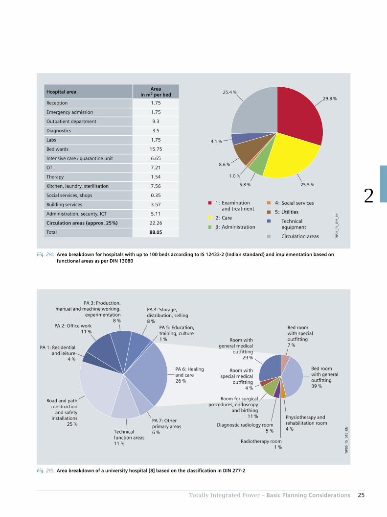
Similar stipulations are made in the Indian standard IS 12433-2. From it, areas for planning can be estimated (Fig. 2/4), which result in a distribution as shown in Tab. 2/5. The data from IS 12433-2 can be implemented in line with the classification from DIN 13080 (see Fig. 2/5). The close match of the distribution structure with that in Fig. 2/3 is identifiable.
As a further comparison, Fig. 2/5 plots an exemplary break-down of primary areas in a hospital as per [8] in accord-ance with DIN 277-2. In this, “healing and care” as per DIN 277-2 must of course not be equated with the func-tional areas 1 (examination and treatment) and 2 (care) as per DIN 13080. The division of space for functional areas 1 and 2 in supplementary sheet 2 to DIN 13080 makes clear that those functional areas are also assigned other area components as per DIN 277-2 (for example from primary areas PA 2 and PA 7 in Fig. 2/5).
Tab. 2/5: Specific areas per bed for the various functional areas as per DIN 13080
Existing1st construction
phasePlanning goal
Number of beds 166 222 299
Functional area
Areas per bed in m2 1 16.3 21.5 19.1
2 25.1 22.5 25.3
3 0.8 1.4 1.0
4 1.8 2.3 1.7
5 6.5 6.9 5.8
TA 6.2 5.4 3.9
CA 28.0 24.4 23.8
Total 84.8 84.5 80.4
25Totally Integrated Power – Basic Planning Considerations
2
Fig. 2/5: Area breakdown of a university hospital [8] based on the classification in DIN 277-2
TIP0
5_1
5_0
15_E
N
Room withgeneral medical
outfitting29 %
Bed roomwith generaloutfitting39 %
PA 1: Residentialand leisure
4 %
Technicalfunction areas11 %
PA 7: Otherprimary areas6 %
PA 6: Healingand care26 %
PA 5: Education,training, culture1 %
PA 4: Storage,distribution, selling8 %
PA 3: Production,manual and machine working,
experimentation8 %
PA 2: Office work11 %
Road and pathconstruction
and safetyinstallations
25 %
Room for surgicalprocedures, endoscopy
and birthing11 %
Diagnostic radiology room5 %
Radiotherapy room1 %
Room withspecial medical
outfitting4 %
Bed roomwith specialoutfitting7 %
Physiotherapy andrehabilitation room4 %
Fig. 2/4: Area breakdown for hospitals with up to 100 beds according to IS 12433-2 (Indian standard) and implementation based on functional areas as per DIN 13080
29.8 %
8.6 %
25.4 %
4.1 %
1.0 %
5.8 % 25.5 %
Examination and treatment
Care
Administration
Social services
Utilities
Technical equipment
Circulation areas
1:
2:
3:
4:
5:
TIP0
5_1
5_0
14_E
N
Hospital areaArea
in m2 per bed
Reception 1.75
Emergency admission 1.75
Outpatient department 9.3
Diagnostics 3.5
Labs 1.75
Bed wards 15.75
Intensive care / quarantine unit 6.65
OT 7.21
Therapy 1.54
Kitchen, laundry, sterilisation 7.56
Social services, shops 0.35
Building services 3.57
Administration, security, ICT 5.11
Circulation areas (approx. 25 %) 22.26
Total 88.05

26 Totally Integrated Power – Basic Planning Considerations
2
an estimate for the breakdown of floor area into functional areas (Tab. 2/6 can provide assistance in this), and on that basis estimate the electric power demand.
The following assumes 80 m2 for the gross floor area per bed, although many publications stipulate widely differing figures, as are summarized in Tab. 2/6 and Fig. 2/6. The wide variation makes it clear that planners need to coordi-nate with their commissioning clients right from the initial estimate stage. It there seems advisable to draw up at least
Tab. 2/6: Figures from literature for bed-specific area requirement in hospitals
Country BedsSpecific area
in m2 per bed (GFA)Features, types Reference
China (Hong Kong)
Not cited60 Hospital for rehabilitation and recovery, care home
[9]80 District and regional hospital
China20–499 45 and more Area 1 1)
[10]500 and more 60 and more Area 2 1)
Taiwan 900 86 Medical centre, Taipei City [11]
Germany
300 80With factor GFA/NFA = 1.7
[12]50–800 80–255
1,000–3,200 500 For university hospitals, with factor GFA/NFA = 1.7
Not cited 65–83.92 [13]
66–1,092 71.5–130.3Span for 13 hospitals in Hesse, with factor GFA/PA = 1.706 minimum and GFA/PA = 1.894 maximum from [13]
[14]
USA 220 169 [15]
Canada 200 250 [16]
Austriaup to 250 20–100
[17]above 250 30–137.5
France 45–631 90–217 [18]
United Kingdom 68–600 39–159 [18]
1) For breakdown of areas see Fig. 2/6

27Totally Integrated Power – Basic Planning Considerations
2
Fig. 2/6: Area requirement per bed according to figures from Tab. 2/5, Tab. 2/6, and references from Tab. 2/6
300
250
200
150
100
50
00 500
TIP0
5_1
5_0
16_E
N
Legend:
Are
a re
qu
irem
ent
in m
2 p
er b
ed
1,000 1,500 2,000
Number of beds
As per Tab. 2/5 based on evaluation of DIN 13080
Area 1 from Tab. 2/6
Area 2 from Tab. 2/6
“Baumanagement und Bauökonomie: Aktuelle Entwicklungen” [Construction management and economics: latest trends; a guide for the construction sector], 2007, published by: J. Liebchen, M. Viering, C. Zanner
As per Tab. 2/6 and related sources
“Nutzen und Grenzen von betriebswirtschaftlichen Kennzahlen – eine Benchmarking-Methode für den praktischen Einsatz im Krankenhaus” [Benefits and limitations of financial/economic data – a benchmarking method for practical application in hospitals], 2008 – T. Förstemann, C. Hartung, in presentations to TK 2008 Technology in Hospitals, Medical Academy Hanover

28 Totally Integrated Power – Basic Planning Considerations
2
Chapter 3Experience in Electrical Energy and Power Demand
3.1 Energy Consumption 32
3.2 Electric Power Demand for a Hospital 34

30 Totally Integrated Power – Experience in Electrical Energy and Power Demand
3
3 Experience in Electrical Energy and Power Demand
In terms of electric power supply, the most important task in the early planning phases is to estimate the power requirements. In order to achieve high efficiency of the facility’s electric power consumption, the components should be run at approximately 70 to 80 % of maximum capacity on average: underdimensioning will result in malfunctions; overdimensioning in excessive costs.
Alongside low capital investment costs, commissioning parties in most cases also seek to reduce operating costs. Energy costs (see Fig. 3/2) represent only a small portion of the total material and consumption costs, which are in turn only part of the overall costs [19].
But they do form part of the operating costs which planners have to consider. This becomes clear when one compares the operating costs of different infrastructure facilities (Fig. 3/1). The cumulative operating costs of a hospital normally surpass the investment costs within just a few years. This is due to higher maintenance costs and higher energy costs compared to other types of facility. Accordingly, a wide range of studies and data surveys have been carried out on the energy consumption of hospitals.
Current planning of electric power supply for hospitals is focused on capital investment costs. But that is not neces-sarily justified, as operating costs including energy can be a major cost factor over the full useful life of the facility (see Fig. 3/1).
The responsibility of electrical planners is to design power supply systems taking into account the needs of operating safety and energy efficiency. The performance delivered must be in line with generally recognized technical stand-ards. This means that planning procedures must conform to all rules, regulations, and relevant normative frameworks (IEC, EN, DIN, ÖNORM, CEI, BS, SN, NEN, NF, GOST, GB, ...), as well as ensure that all consents and test certificates are obtained across all technical functions and disciplines involved. There are options to support the increasingly complex planning tasks nowadays, including Totally Inte-grated Power (TIP), which provide aids to working based on comprehensive solutions for power distribution and effi-cient engineering tools.
Planning procedures and construction works must comply with numerous technical standards, regulations, and guidelines in addition to the specifications of the facility managers and the distribution grid operators. The stand-ards and regulations vary from country to country, so international projects planners must orientate their work to the location of the facility concerned.
Fig. 3/1: Schematic comparison of operating costs between hospitals and other facility types
Imp
le-
men
-ta
tio
n
TIP0
5_1
5_0
17_E
N
Co
sts
in %
Hospitals
Indoor swimming pools
Production facilities
Residential buildings
Investment
Office buildings
Years
Efficient operation focused on operating costs
Usa
ge
600
500
400
300
200
100
00 10 20 30 40 50 60
Hospitals are amongthe most complexbuilding types. Theiroperating costs are muchhigher than those ofother building types.

31Totally Integrated Power – Experience in Electrical Energy and Power Demand
3
Fig. 3/2: Costs in hospital operations [19]
Medical durablesand consumables 13.1 %
Personnel costs52 %
Non-medicaldurables andconsumables
1.8 %
Energy1.4 %
Imputed investmentcapital costs 10.6 %
Levies, contributions,fees and other costs 10.4 %
Outsourcedmedical services 1.5 %
Outsourcednon-medical services 9.3 %
TIP0
5_1
5_0
18_E
N
Fig. 3/3: Breakdown of energy consumption in a hospital [21]
Emergencypower diesel
Processheat
Room heating
Hot water
ElectricityFuels
Motorized beds
Medical-technical equipment
X-ray/ultrasound machines
Bed lifts
Passenger lifts
Cold stores,chillers
Dishwashers
Washing machines,dryers
Heating pumpsAir conditioning,splitter units
Ventilation
Lighting
Officeequipment
Other electricalequipment
TIP0
5_1
5_0
19_E
N

32 Totally Integrated Power – Experience in Electrical Energy and Power Demand
3
3.1 Energy Consumption
The split across electric power consumption and energy consumption for heating and air conditioning by oil, gas, or other fuel sources is heavily influenced by the project -specific circumstances. Many reference sources (including [20]) estimate electricity consumption at around 40 % of the total energy consumption in a hospital. A detailed breakdown is provided in a study carried out for Germany’s Federal Ministry for Economic Affairs and Energy (BMWi) [21] (see Fig. 3/3). The data from that study indicates a specific gross floor area (GFA) requirement of 81.5 m2
per bed.
Since every hospital project is characterized by its own framework conditions, the breakdown in Fig. 3/3 can only serve as an example. For instance, the proportions are shifted by different climatic conditions and the types of room air-conditioning systems installed, as well as by the characteristics of the electrical equipment and electric powered systems such as elevators, lighting, PCs, servers, medical electrical (ME) equipment, entertainment elec-tronics in patients’ rooms, and much more. As a concrete example, a report by the US Energy Information Adminis-tration (EIA) [22] sets out the dependencies on the various climate zones in the USA. The percentage of energy costs for hot water varies between 22 and 32 %, and for heating between 16 and 42 %, depending on climate zone, mean-ing that the overall fluctuation in fact corresponds to a difference in energy consumption – and thus in the associ-ated energy costs – of around 50 %. As electric power is also required to provide heat, refrigeration, and hot water, the electricity demand also varies correspondingly widely depending on the climatic conditions.
Moreover, electric power consumption is influenced by technical equipment, comfort systems, structural character-istics, as well as local ambient conditions in and around the hospital. It is therefore understandable that evaluations of floor area, numbers of beds, and electricity consumption in hospitals do not present a consistent picture (Fig. 3/4).
Another interesting aspect is the variation in national data as shown in [20], which reveals that the space needed per patient bed, specifically, varies very widely from country to country (Tab. 3/1).
Compared to VDI 3807 sheet 2 (2014), the stipulations – apart from in Switzerland – are at least twice as high, and in some cases even four to six times as high. Although the publication date back in 1997 is likely to be an important consideration, it cannot in itself explain the wide differences.
Tab. 3/1: Electricity consumption of hospitals in various countries [20]
Country
Electricity consumption
in MWh per bed per year
Electricity consumption
in kWh per m2 GFA per year
Italy approx. 5.1
Switzerland approx. 65
Netherlands approx. 9.8 approx. 85
Belgium approx. 10.2 approx. 85
Sweden approx. 20 approx. 100
United Kingdom approx. 105
Greece approx. 110
Canada approx. 23 approx. 335
USA approx. 230
Australia approx. 27.5 approx. 175

33Totally Integrated Power – Experience in Electrical Energy and Power Demand
3
Fig. 3/4: Annual electricity consumption per patient bed dependent on the number of beds
Legend:
According to VDI 3807-2 (2014), guide value data
According to VDI 3807-2 (2014), average value data
According to ENERGIEAGENTUR NRW [23]
According to ENERGIEAGENTUR NRW [24]
Derived from Förstemann, Hartung [8]
Austrian Society for Environment and Technology (ÖGUT) [25]
30
25
20
15
10
5
00 500
TIP0
5_1
5_0
20
_EN
1,000 1,500 2,000
Number of beds
Elec
tric
ity
cons
umpt
ion
per
bed
and
year
in M
Wh
per
bed
and
year

34 Totally Integrated Power – Experience in Electrical Energy and Power Demand
3
3.2.1 Estimation of an Average Specific Power Demand
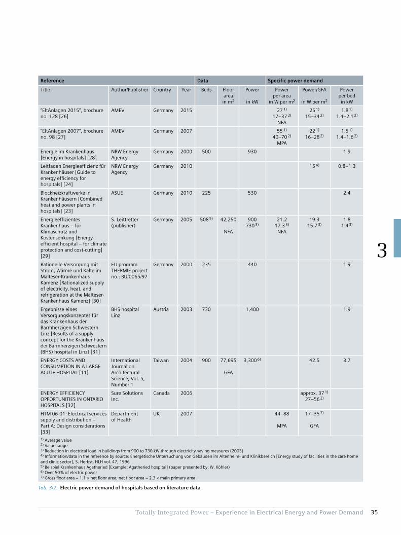
In the literature, there are few stipulations for electric power demand specific to hospitals (Tab. 3/2). The ones that do exist are mostly referred to the number of beds. As in the case of energy consumption, therefore, the ratio of patient bed to floor area is again important for planning of area-specific power, though particular attention must be paid to the labelling of the area (gross floor area [GFA], net floor area [NFA], primary area [PA], main primary area [MPA], …). Consequently, Tab. 3/2 lists both values cited by the German Local Authorities Mechanical and Electrical Engineering Working Group (AMEV) in its brochures num-ber 128 from 2015 [26] and number 98 from 2007 [27].
The transition from main primary area (in German “Haupt-nutzfläche”/“HNF”) to net floor area NFA (in German “Netto-grundfläche”/“NGF”) in the AMEV brochures is understanda-ble, as the term “Hauptnutzfläche”/“HNF” is no longer defined in the later versions of the DIN 277 standard. The AMEV specifications from 2007 and 2015 accordingly make clear the differences between main primary area / “Haupt-nutzfläche” and net floor area / “Nettogrundfläche” (NFA ≈ 2.3 × MPA for hospitals).
For better comparability, the area-specific values – where available – are converted to gross floor area GFA (in Ger-man “Bruttogrundfläche”/“BGF”). A factor of 1.1 is assumed for the ratio of GFA to NFA.
3.2 Electric Power Demand for a Hospital
In estimating power demand, differing depths of analysis of the hospital building structure result in three different approaches. Planners should always agree on the choice of one of the following approaches with the commissioning customer:
1. Estimation of an average specific power demand per area or bed, based on the floor area of the hospital or the planned number of beds, provides an adequate specification of peak power for pre-planning purposes.
2. To design and plan the power distribution based on criteria of energy efficiency and operating conditions in a smart building, an average power consumption and a peak factor are determined from the load profile. With the desired power reserve, planners can dimension systems to handle the peak power levels encountered in practice.
3. In considering the functional areas according to DIN 13080, empirical values for the power demand of different consumer groups in the individual functional areas of a hospital are applied. The procedure is de-scribed in section 3.3.2 based on the example from DIN 13080-4 (see Tab. 2/2 and Tab. 2/5).
35Totally Integrated Power – Experience in Electrical Energy and Power Demand
3
Tab. 3/2: Electric power demand of hospitals based on literature data
Reference Data Specific power demand
Title Author/Publisher Country Year Beds Floor areain m2
Power
in kW
Power per area
in W per m2
Power/GFA
in W per m2
Power per bedin kW
“EltAnlagen 2015”, brochure no. 128 [26]
AMEV Germany 2015 27 1)
17–37 2)
NFA
25 1)
15–34 2)1.8 1)
1.4–2.1 2)
“EltAnlagen 2007”, brochure no. 98 [27]
AMEV Germany 2007 55 1)
40–70 2)
MPA
22 1)
16–28 2)1.5 1)
1.4–1.6 2)
Energie im Krankenhaus [Energy in hospitals] [28]
NRW Energy Agency
Germany 2000 500 930 1.9
Leitfaden Energieeffizienz für Krankenhäuser [Guide to energy efficiency for hospitals] [24]
NRW Energy Agency
Germany 2010 15 4) 0.8–1.3
Blockheizkraftwerke in Krankenhäusern [Combined heat and power plants in hospitals] [23]
ASUE Germany 2010 225 530 2.4
Energieeffizientes Krankenhaus – für Klimaschutz und Kostensenkung [Energy-efficient hospital – for climate protection and cost-cutting] [29]
S. Leittretter (publisher)
Germany 2005 508 5) 42,250
NFA
900730 3)
21.217.3 3)
NFA
19.315.7 3)
1.81.4 3)
Rationelle Versorgung mit Strom, Wärme und Kälte im Malteser-Krankenhaus Kamenz [Rationalized supply of electricity, heat, and refrigeration at the Malteser-Krankenhaus Kamenz] [30]
EU program THERMIE project no.: BU/0065/97
Germany 2000 235 440 1.9
Ergebnisse eines Versorgungskonzeptes für das Krankenhaus der Barmherzigen Schwestern Linz [Results of a supply concept for the Krankenhaus der Barmherzigen Schwestern (BHS) hospital in Linz) [31]
BHS hospital Linz
Austria 2003 730 1,400 1.9
ENERGY COSTS AND CONSUMPTION IN A LARGE ACUTE HOSPITAL [11]
International Journal on Architectural Science, Vol. 5, Number 1
Taiwan 2004 900 77,695
GFA
3,300 6) 42.5 3.7
ENERGY EFFICIENCY OPPORTUNITIES IN ONTARIO HOSPITALS [32]
Sure Solutions Inc.
Canada 2006 approx. 37 1)
27–56 2)
HTM 06-01: Electrical services supply and distribution – Part A: Design considerations [33]
Department of Health
UK 2007 44–88
MPA
17–35 7)
GFA
1) Average value2) Value range3) Reduction in electrical load in buildings from 900 to 730 kW through electricity-saving measures (2003)4) Information/data in the reference by source: Energetische Untersuchung von Gebäuden im Altenheim- und Klinikbereich [Energy study of facilities in the care home and clinic sector], S. Herbst, HLH vol. 47, 19965) Beispiel Krankenhaus Agatheried [Example: Agatheried hospital] (paper presented by: W. Köhler)6) Over 50 % of electric power7) Gross floor area = 1.1 × net floor area; net floor area = 2.3 × main primary area

36 Totally Integrated Power – Experience in Electrical Energy and Power Demand
3
3.2.2 Estimation of Power Demand by Way of an Average Energy Consumption and a Specifically Selected Peak Factor
The specific power demand of a hospital can be estimated from the energy consumption data with the aid of load profiles. This must take account of the energy consumption data tolerances as described in chapter 3.1, as well as the variance in the profiles showing energy consumption over time. The analysis is heavily influenced, for example, by the extent and technical characteristics of ancillary functions such as kitchens, laundries, restaurants/cafeterias, as well as by climatic conditions and the complexity of medical technical equipment and systems.
The power demand can be estimated from the average energy consumption (per bed or area) by identifying the relationship between the peak value and the integral mean value from the profile. That is to say that – apart from the intended consumption situation – two estimates lead to one power demand value for pre-planning purposes:• Estimation of the average energy consumption (per bed
or area)• Estimation of the relationship between average power
demand and peak power
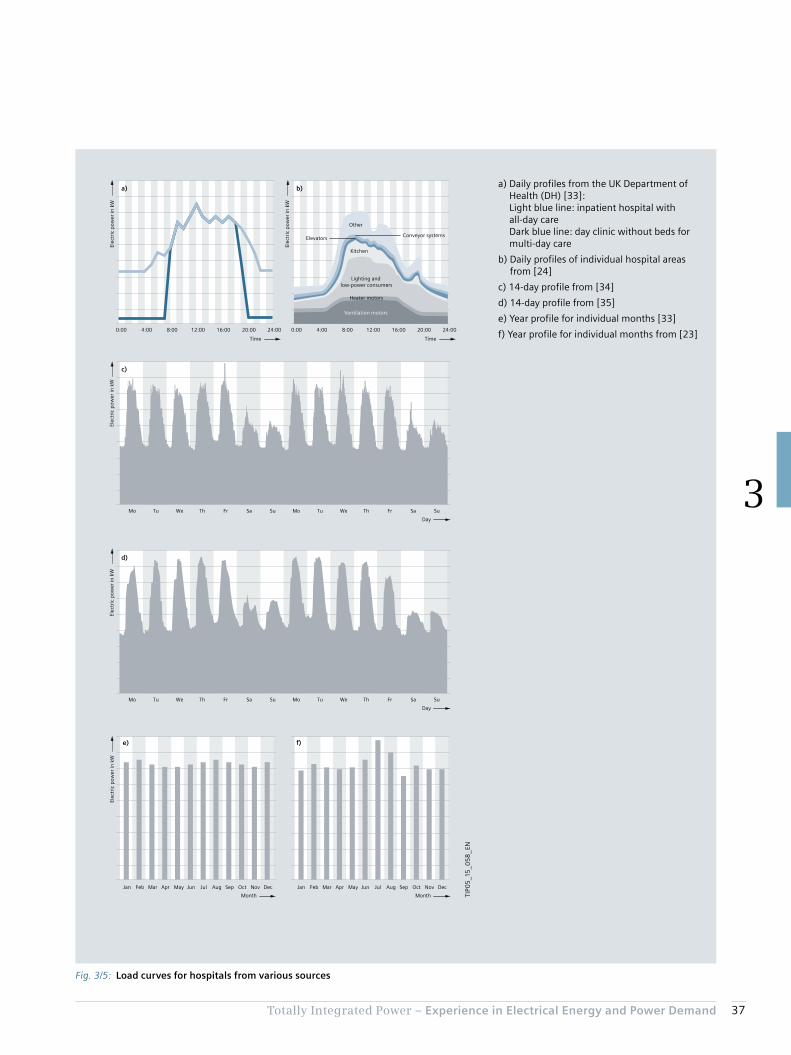
The profile’s curve form together with the average energy consumption (per bed or area) enables the maximum required power (per bed or area) to be calculated. An additional reserve should also be factored-in. Fig. 3/5 shows some examples of common load profiles in hospi-tals. Unfortunately, the European standard EN 15232, indicating a constant load profile for hospitals over the entire 24-hours-a-day period, does not provide a very realistic estimation of the actual situation.
For the peak factor with no reserve factor, the load curves a) to d) from Fig. 3/5 are evaluated:• Peak factor (a – inpatient hospital) = 1/0.70 = 1.43• Peak factor (a – day clinic) = 1/0.44 = 2.27• Peak factor (b) = 1/0.59 = 1.69• Peak factor (c) = 1/0.60 = 1.67• Peak factor (d) = 1/0.65 = 1.54
The monthly differences in consumption indicate climatic factors of influence. While Fig. 3/5 e) shows no major differences in energy consumption for summer and winter months owing to the UK’s year-round temperate climate, for Germany (literature reference [23] originates from the state of North Rhine-Westphalia) the influence of air condi-tioning on power consumption in the hot months of July and August is indicated (Fig. 3/5 f). Such monthly fluctua-tions can be taken into account by means of a seasonal tolerance factor for the difference between average energy consumption and peak power.
With an annual energy consumption between 4.425 and 13.605 MWh per bed as per VDI 3807 sheet 2, and allowing a seasonal factor of 1.25 (see Fig. 3/5 e) and f)) and a power reserve of 20 %, with an average peak factor of 1.72 provides a span of 1.3 kW per bed up to 4.0 kW per bed (average value is 1.5 kW per bed, as the average for the power consumption is 5 MWh per bed as per VDI 3807 sheet 2). This value range closely matches the data in Tab. 3/2. For the expansion stages of the notional hospital model as per DIN 13080 (Tab. 2/5), the following spans of power demand result:• Starting situation (166 beds):
From 216 kW to 664 kW – average: 250 kW• Expansion phase 1 (222 beds):
From 289 kW to 888 kW – average: 333 kW• End state (299 beds):
From 390 kW to 1,246 kW – average: 450 kW
37Totally Integrated Power – Experience in Electrical Energy and Power Demand
3
Fig. 3/5: Load curves for hospitals from various sources
a)
f)e)
d)
c)
b)
Ventilation motors
Heater motors
Lighting and low-power consumers
Kitchen
Elevators Conveyor systems
Other
Elec
tric
pow
er in
kW
TimeTime
0:00 4:00 8:00 12:00 16:00 20:00 24:00
Elec
tric
pow
er in
kW
0:00 4:00 8:00 12:00 16:00 20:00 24:00
Elec
tric
pow
er in
kW
Mo Tu We Th Fr Sa Su Mo Tu We Th Fr Sa Su
Mo Tu We Th Fr Sa Su Mo Tu We Th Fr Sa Su
Elec
tric
pow
er in
kW
Elec
tric
pow
er in
kW
Jan Feb Mar Apr May Jun Jul Aug Sep Oct Nov Dec
Day
Day
Month
Jan Feb Mar Apr May Jun Jul Aug Sep Oct Nov Dec
Month TIP0
5_1
5_0
58
_EN
a) Daily profiles from the UK Department of Health (DH) [33]: Light blue line: inpatient hospital with all-day care Dark blue line: day clinic without beds for multi-day care
b) Daily profiles of individual hospital areas from [24]
c) 14-day profile from [34]
d) 14-day profile from [35]
e) Year profile for individual months [33]
f) Year profile for individual months from [23]

38 Totally Integrated Power – Experience in Electrical Energy and Power Demand
3
3.2.3 Estimation of Power Demand Based On Empirical Values for Functional Areas as per DIN 13080
It must be stressed once again at this point that all energy and power demand data can only provide rough guides. The data must be replaced by project-specific power de-mand specifications as part of project planning procedures. The data in Tab. 3/3 incorporates experience from hospital planning in order to integrate a more detailed insight into the power distribution structure of a hospital. Nevertheless, the specific conditions in terms of the electric power de-mand for the technical building systems and for the hospi-tal’s medical technical equipment must be included as accurately as possible in the estimate. Tab. 3/3 thus pre-sents minimum and maximum data specifications based on empirical values. Average capacity utilisation factors are included in the power specifications, though the planners themselves should draw up a realistic classification, which may also quite feasibly be beyond the specified limits.
With the area data for the expansion stages described in Tab. 2/5 as per DIN 13080 and the data from Tab. 3/3, the total NPS and SPS demand can be estimated:• Estimated NPS demand 0.9 to 3.8 kW per bed• Estimated SPS demand 0.45 to 1.9 kW per bed
This results in a power demand between 1.4 and 5.7 kW per bed.
This value range closely matches the previous estimates.
Tab. 3/3: Empirical values for area-specific power demand and related diversity factors (DF) for the functional areas in a hospital as per DIN 13080
Lights NPS Lights SPS Wall sockets NPS Wall sockets SPS
Power in W per m2
GFA
DF Power in W per m2
GFA
DF Power in W per m2
GFA
DF Power in W per m2
GFA
DF
Functional area
1 6 0.7 3 0.7 11 0.4 8 0.3
2 6 3 11 8
3 6–12 3–6 11 8
4 6–9 3–6 11 8
5 4–7 2–4 11 8
Technical areas 2–3 1.3–2 11 8
Circulation areas 4 2 11 8
Med.tech.equipment NPS Med.tech.equipment SPS Building systems NPS Building systems SPS
Power in W per m2
GFA
DF Power in W per m2
GFA
DF Power in W per m2
GFA
DF Power in W per m2
GFA
DF
Functional area
1 6–50 0.4–0.6 20–75 0.2–0.6 0–9 0.7
2 0–10 0.4–0.6 0–12 0.2–0.6 0–12
3 0–6 0–20 0.5
4 20–60
5 0–120 0.4–0.6 0–9 0.2–0.6 6–12
Technical areas 60–350 15–70 0.5
Circulation areas 1.3–12 0.5
Chapter 4Structuring of Hospital Power Supply
4.1 Structure of Power Distribution in a Hospital and Estimation of Power Demand for Individual Functional Areas 40
4.2 Grouping of Hospital Areas with Regard to the Operation of Medical Electrical Equipment and Associated Hazards 42
4.3 Classification by Permissible Changeover Period to a Power Supply for Safety Purposes 45
4.4 Protection Requirements in Hospital Power Supply 47
4.5 Schematic of a Power Supply Structure in a Hospital 50

40 Totally Integrated Power – Structuring of Hospital Power Supply
4
4 Structuring of Hospital Power Supply
Specifications for systematic classification of the different medical areas with regard to electric power supply require-ments are laid down in IEC 60364-7-710. One aspect given particular weight is that the classification must always be made in consultation with the medical staff and the re-sponsible health and safety managers.
Early, task-specific estimation of power demand is useful to concept planning. This then results in a division into power circuits (see [36]). The general requirements for power supply to safety systems in facilities are laid down in IEC 60364-5-56. The requirements for operating facilities, rooms, and installations of special kinds are laid down in the 700s series of standards, and requirements for medical locations in IEC 60364-7-710.
In accordance with this standard, special power supply and distribution facilities are required for medical locations in hospitals, which must be integrated into a power distribu-tion plan together with a safety power supply (such as for emergency lighting, fire extinguishing systems, fire-fight-ing lifts) and an uninterruptible power supply (UPS; such as for critical ICT systems). IEC 60364-7-710 allocates medical locations to groups and classes, and specifies correspond-ing requirements.
The estimates of power demand previously made take account only roughly of the structuring, layout, different functions, and many other conditions underlying the planning of electric power distribution for a hospital. Consequently, wide spans must be allowed for the guide values given in chapter 3. Planners do, of course, have an interest in obtaining reliable estimates based on increas-ingly refined analysis of the safety and functional require-ments and the interaction between the various systems. To provide an overview, the functional areas familiar from the DIN 13080 standard can be broken down specific to task.
4.1 Structure of Power Distribution in a Hospital and Estimation of Power Demand for Individual Functional Areas
According to the specific tasks and functions, hospital planning involves classification into typical wards and departments, which also differ substantially in their outfit-ting and power demand. This breakdown of primary areas pursuant to DIN 13080 is presented in Tab. 4/1.

41Totally Integrated Power – Structuring of Hospital Power Supply
4
Tab. 4/1: Hospital subdivision according to DIN 13080
1 Examination and treatment 4 Social services
1.1 Admissions and emergency care 4.1 Service facilities
1.2 Doctor service 4.2 Welfare and social services
1.3 Functional diagnostics 4.3 Staff changing
1.4 Endoscopy 4.4 Staff catering
1.5 Laboratory medicine
1.6 Pathology 5 Utilities
1.7 Radiological diagnostics 5.1 Pharmacy
1.8 Nuclear medicine diagnostics 5.2 Sterile product supply
1.9 Operation 5.3 Equipment supply
1.10 Maternity 5.4 Bed preparation
1.11 Radiotherapy 5.5 Food supply
1.12 Nuclear medical therapy 5.6 Linen supply
1.13 Physical therapy 5.7 Storage and goods handling
1.14 Ergotherapy 5.8 Maintenance and repair
1.15 On-call service 5.9 Waste disposal
5.10 Janitorial and transport services
2 Care 6 Research and teaching
2.1 General care 6.1 Research
2.2 Confinement and post-natal care 6.2 Teaching
2.3 Intensive medicine 6.3 Education and training
2.4 Dialysis
2.5 Post-natal/paediatric care
2.6 Infectious disease care 7 Other
2.7 Psychiatric care 7.1 Emergency service
2.8 Care – nuclear medicine 7.2 Limited-care dialysis
2.9 Admission care 7.3 Child care
2.10 Care – Geriatrics 7.4 External services rendered
2.11 Day-clinic 7.5 External services procured
7.6 Residential
3 Administration
3.1 Management and administration
3.2 Archiving
3.3 Information and documentation
3.4 Library

42 Totally Integrated Power – Structuring of Hospital Power Supply
4
4.2 Grouping of Hospital Areas with Regard to the Operation of Medical Electrical Equipment and Associated Hazards
Classifications must be in line with the use of medical electrical (ME) equipment as per IEC 60601-1 in the rele-
vant areas, with allocation to group 0, 1, or 2 (or 0, 1, 2, or 3 in the Netherlands according to NEN 1010-7-710) as per IEC 60364-7-710. The requirements stipulated by the standard must then be met for those groups. Differences in the classification characteristics for the three internationally applied groups between the German predecessor standard VDE 0107 and the current IEC 60364-7-710 are set out in Tab. 4/2.
Tab. 4/2: Allocation of medical locations to groups according to different standards (DIN: Germany; NEN: Netherlands; ÖVE/ÖNORM: Austria)
Use of ME equipment Risk to patients ErrorAllowable restrictions on use
Group 0 IEC 60364-7-710 • No use of applied parts of ME equipment which come into touch contact with the patient in normal use
No danger to life if power supply is interrupted
DIN VDE 0100-710Bbl1 (informative)
• No use or• ME equipment with no
connection to the patient
No danger to life if power supply is interrupted
Shutdown of the electrical system in the event of any single fault condition (fault to frame or earth fault) or failure of the general supply is permissible
Examinations and treatments can be interrupted at any time for any length of time
DIN VDE 0107(not up to date)
• No use or• ME equipment with no
connection to the patient or
• ME equipment which according to accompanying documentation is also approved for use outside medical locations, or ME equipment which is supplied solely from integrated power sources
ÖVE/ÖNORM E 8007
• No use or• ME equipment which
according to accompanying documentation is also approved for use outside medical locations, or
• ME equipment which is supplied solely from integrated power sources
NEN 1010-7-710 • No use of applied parts of ME equipment which come into touch contact with the patient in normal use
No danger to life if power supply is interrupted
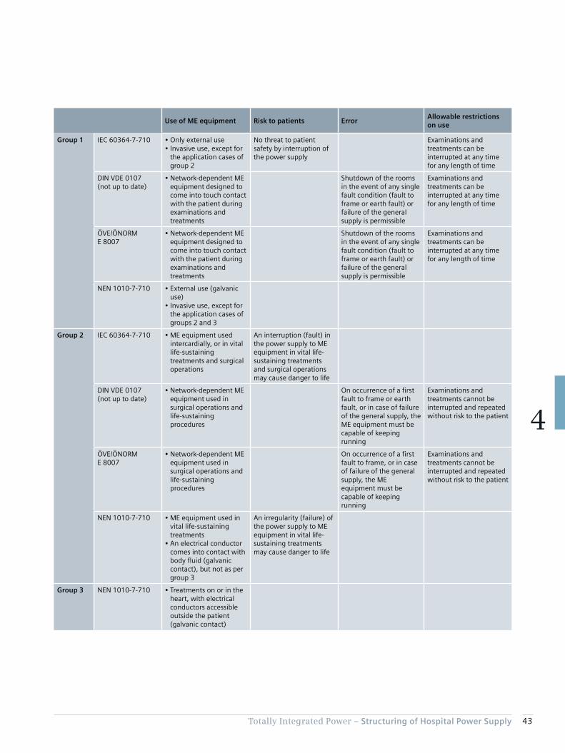
43Totally Integrated Power – Structuring of Hospital Power Supply
4
Use of ME equipment Risk to patients ErrorAllowable restrictions on use
Group 1 IEC 60364-7-710 • Only external use• Invasive use, except for
the application cases of group 2
No threat to patient safety by interruption of the power supply
Examinations and treatments can be interrupted at any time for any length of time
DIN VDE 0107(not up to date)
• Network-dependent ME equipment designed to come into touch contact with the patient during examinations and treatments
Shutdown of the rooms in the event of any single fault condition (fault to frame or earth fault) or failure of the general supply is permissible
Examinations and treatments can be interrupted at any time for any length of time
ÖVE/ÖNORM E 8007
• Network-dependent ME equipment designed to come into touch contact with the patient during examinations and treatments
Shutdown of the rooms in the event of any single fault condition (fault to frame or earth fault) or failure of the general supply is permissible
Examinations and treatments can be interrupted at any time for any length of time
NEN 1010-7-710 • External use (galvanic use)
• Invasive use, except for the application cases of groups 2 and 3
Group 2 IEC 60364-7-710 • ME equipment used intercardially, or in vital life-sustaining treatments and surgical operations
An interruption (fault) in the power supply to ME equipment in vital life-sustaining treatments and surgical operations may cause danger to life
DIN VDE 0107 (not up to date)
• Network-dependent ME equipment used in surgical operations and life-sustaining procedures
On occurrence of a first fault to frame or earth fault, or in case of failure of the general supply, the ME equipment must be capable of keeping running
Examinations and treatments cannot be interrupted and repeated without risk to the patient
ÖVE/ÖNORM E 8007
• Network-dependent ME equipment used in surgical operations and life-sustaining procedures
On occurrence of a first fault to frame, or in case of failure of the general supply, the ME equipment must be capable of keeping running
Examinations and treatments cannot be interrupted and repeated without risk to the patient
NEN 1010-7-710 • ME equipment used in vital life-sustaining treatments
• An electrical conductor comes into contact with body fluid (galvanic contact), but not as per group 3
An irregularity (failure) of the power supply to ME equipment in vital life-sustaining treatments may cause danger to life
Group 3 NEN 1010-7-710 • Treatments on or in the heart, with electrical conductors accessible outside the patient (galvanic contact)

44 Totally Integrated Power – Structuring of Hospital Power Supply
4
In order to differentiate the requirements of group 0 more clearly, a German supplementary sheet (DIN VDE 0100-710 sheet 1) was published in 2014. It is included along with the current applicable standards in Austria (ÖVE/ÖNORM E 8007) and the Netherlands (NEN 1010-7-710) in Tab. 4/2.
The comparison in Tab. 4/2 regarding the use of ME equip-ment between IEC 60364-7-710, DIN VDE 0107, and ÖVE/ÖNORM E 8007 illustrates the different restrictions. For allocation to group 2, IEC 60364-7-710 stresses the danger to the patient’s life, whereas in DIN VDE 0107 and ÖVE/ÖNORM E 8007 an interruption of the examination or treatment potentially leading to a “risk to the patient” is sufficient. It should be noted that comparable room types can be allocated to different groups depending on the usage of a room.
In the Netherlands (NEN 1010-7-710), group 2 is subdi-vided into group 2 and group 3. Group 3 separates out from group 2 the treatments listed in IEC 60364-7-710, whereby an electrical conductor can come into contact with the heart, with the said conductor being accessible outside of the patient’s body. In addition to the require-
ments for group 2, further measures are stipulated for group 3 locations, such as protection by means of a non-conductive environment, which entails special effort and expense to insulate such areas (see chapter 4.4). The inclusion of group 3 must also be taken into account for the Netherlands in relation to the further explanatory notes on group 2 medical locations – such as regarding safety meas-ures, installations, and equipment.
British standard BS 7671 orientates its classification by group and class in its informative annex A710 to IEC 60364-7-710, but also makes reference to HTM 06-01 (Part A) [33]. It defines risk categories for so-called clinical risk, as well as for non-clinical and business continuity risk (see overview in Tab. 4/3). Clinical risk categories 3, 4, and 5 correspond to groups 0, 1, and 2 of IEC 60364-7-710. According to HTM 06-01 (Part A), no medical treatment is carried out in the medical locations of categories 1 (support service circulation) and 2 (ambulant care and diagnostics). At most, consultation or non-outpatient services can be provided. There is, however, no unambiguous allocation of areas to categories 1 and 2, so in the following this is likewise omitted, and an allocation to normal power supply (NPS) and to safety power supply (SPS) is applied as usual.
Tab. 4/3: Risk categories (part a) for clinical, and part b) for non-clinical risk) according to British Memorandum HTM 06-01 (Part A) [33], and for part a) classification as per IEC 60364-7-710
b)
Risk category 1 2 3 4
“ Non-clinical risk and general operational risk” Business support services
Building services safety and security
Building services environmental control
Medical support services
Examples Kitchen, laundry, shops, and workshops
Areas with ICT use such as administration, reception, mailroom, and telephone exchange
Building systems for HVAC, hot water, electricity, and energy management
Areas for sterilisation, labs, physiotherapy, image analysis, and editing
1) MRI = Magnetic Resonance Imaging; CT = Computer Tomograph; PET = Positron Emission Tomograph
a)
Risk category 1 2 3 4 5
Clinical risk Support service circulation
Ambulant care and diagnostics
Emergency care and diagnostics
Patients in special medical locations
Life support or complex surgery
Examples Waiting areas, service areas, labs, offices, administration areas
Consulting rooms, areas not directly used for treatment
Medical care with occasional use of ME equipment (only patient skin contact)
Maternity delivery, endoscopy, accident, radiology, urology, pre-op, and imaging
Operating theatres, intensive care areas, isolation areas, heart treatment, reception rooms for MRI, CT, PET 1), and similar
“Group allocation for medical locations according to IEC 60364-7-710”
Not specified Not specified 0 1 2

45Totally Integrated Power – Structuring of Hospital Power Supply
4
must be agreed with the medical staff and the responsible health and safety managers (comparable to Tab. 4/4).
Applications that are relevant to hospital operations and for which a changeover period may last longer than 15 seconds (class > 15; long break) must be capable of switching to a safety power supply (with a minimum operating time of 24 hours) either automatically or by the operating personnel. This includes:• Sterilisation facilities• Technical building systems (ventilation, heating, air
conditioning, utilities, and waste disposal systems)• Cooling/chilling facilities• Kitchen equipment• Battery chargers
A table providing an informative guide to the classification of medical locations is set out in IEC 60364-7-710 (Tab. 4/4).
4.3 Classification by Permissible Changeover Period to a Power Supply for Safety Purposes
In the event of a fault in the normal power supply (NPS), the consumers provided for safety purposes must, according to IEC 60364-5-56 (DIN VDE 0100-560), be switched auto-matically to the safety power supply (SPS). The classifica-tion of medical locations with regard to changeover period
Tab. 4/4: Allocation of medical locations by group and class according to IEC 60364-7-710
Group Class
0 1 2 ≤ 0.5 s > 0.5 s and ≤ 15 s
Massage room × × ×
Bed room × ×
Delivery room × × a) ×
ECG, EEG, and EHG room × ×
Endoscopy room × b) × × b)
Examination and treatment room × × ×
Urology room × b) × × b)
Radiological diagnostics and treatment room × × ×
Hydrotherapy room × ×
Physiotherapy room × ×
Anaesthesia room × × a) ×
Operating theatre × × a) ×
Pre-op room × × a) ×
Plaster room × × a) ×
Recovery room × × a) ×
Cardiac catheter room × × a) ×
Intensive care room × × a) ×
Angiography room × × a) ×
Haemodialysis room × ×
MRI room × × × ×
Nuclear medicine room × ×
Premature babies’ room × × a) ×
Interim care ward × × ×a) Lighting and life-sustaining medical electrical equipment requiring power supply within 0.5 s or faster.b) If not an operating theatre.
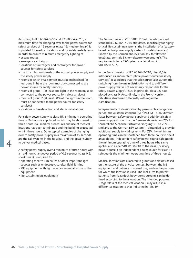
46 Totally Integrated Power – Structuring of Hospital Power Supply
4
The German version VDE 0100-710 of the international standard IEC 60364-7-710 stipulates, specifically for highly critical life-sustaining systems, the installation of a “battery-based central power supply system for safety services” (known by the German abbreviation BSV for “Batterie-gestützte, zentrale Sicherheitsstromversorgung”). The requirements for a BSV system are laid down in VDE 0558-507.
In the French version of IEC 60364-7-710, class 0,5 is introduced as an “uninterruptible power source for safety services”. It stipulates that the said source “aids automatic switching from the main distribution grid to a different power supply that is not necessarily responsible for the safety power supply”. Thus, in principle, class 0,5 is re-placed by class 0. Accordingly, in the French version, Tab. 4/4 is structured differently with regard to classification.
Independently of classification by permissible changeover period, the Austrian standard ÖVE/ÖNORM E 8007 differen-tiates between safety power supply and additional safety power supply (known by the German abbreviation ZSV for “Zusätzliche Sicherheitsstromversorgung”). The ZSV – similarly to the German BSV system – is intended to provide additional supply to vital systems. For ZSV, the minimum operating time can be shortened from three hours to one if an additional independent safety power source safeguards the minimum operating time of three hours (the same applies also as per VDE 0100-710 to the class 0,5 safety power source if an independent power source for class 15 safeguards the minimum operating time of three hours).
Medical locations are allocated to groups and classes based on the nature of the physical contact between the ME equipment and patients in normal use, and on the purpose for which the location is used. The measures to protect patients from hazardous body-borne currents can be de-fined according to the allocation. The intended purpose – regardless of the medical location – may result in a different allocation to that indicated in Tab. 4/4.
According to IEC 60364-5-56 and IEC 60364-7-710, a maximum time for changing over to the power source for safety services of 15 seconds (class 15; medium break) is stipulated for medical locations and for safety installations in order to ensure minimum emergency lighting of• escape routes• emergency exit signs• locations of switchgear and controlgear for power
sources for safety services• main distribution boards of the normal power supply and
the safety power supply • rooms in which vital services must be maintained (at
least one light in the room must be connected to the power source for safety services)
• rooms of group 1 (at least one light in the room must be connected to the power source for safety services)
• rooms of group 2 (at least 50 % of the lights in the room must be connected to the power source for safety services)
• locations of fire detection and alarm installations
For safety power supply to class 15, a minimum operating time of 24 hours is stipulated, which may be shortened to three hours if all medical procedures and use of medical locations has been terminated and the building evacuated within three hours. Other typical examples of changing over to safety power supply in a maximum of 15 seconds are the call systems in the hospital, and the power supply to deliver medical gases.
A safety power supply over a minimum of three hours with a maximum changeover period of 0.5 seconds (class 0,5; short break) is required for• operating theatre luminaires or other important light
sources such as endoscopic-surgical field lighting• ME equipment with light sources essential to use of the
equipment• life-sustaining ME equipment
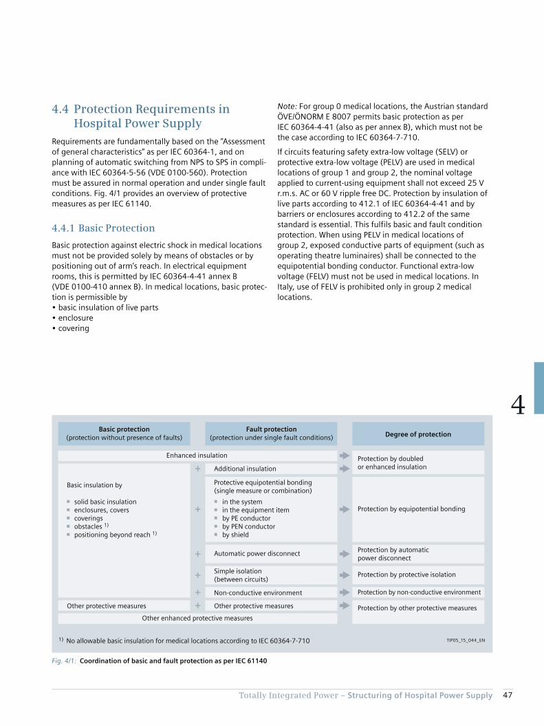
47Totally Integrated Power – Structuring of Hospital Power Supply
4
4.4 Protection Requirements in Hospital Power Supply
Requirements are fundamentally based on the “Assessment of general characteristics” as per IEC 60364-1, and on planning of automatic switching from NPS to SPS in compli-ance with IEC 60364-5-56 (VDE 0100-560). Protection must be assured in normal operation and under single fault conditions. Fig. 4/1 provides an overview of protective measures as per IEC 61140.
4.4.1 Basic Protection
Basic protection against electric shock in medical locations must not be provided solely by means of obstacles or by positioning out of arm’s reach. In electrical equipment rooms, this is permitted by IEC 60364-4-41 annex B (VDE 0100-410 annex B). In medical locations, basic protec-tion is permissible by• basic insulation of live parts• enclosure• covering
Note: For group 0 medical locations, the Austrian standard ÖVE/ÖNORM E 8007 permits basic protection as per IEC 60364-4-41 (also as per annex B), which must not be the case according to IEC 60364-7-710.
If circuits featuring safety extra-low voltage (SELV) or protective extra-low voltage (PELV) are used in medical locations of group 1 and group 2, the nominal voltage applied to current-using equipment shall not exceed 25 V r.m.s. AC or 60 V ripple free DC. Protection by insulation of live parts according to 412.1 of IEC 60364-4-41 and by barriers or enclosures according to 412.2 of the same standard is essential. This fulfils basic and fault condition protection. When using PELV in medical locations of group 2, exposed conductive parts of equipment (such as operating theatre luminaires) shall be connected to the equipotential bonding conductor. Functional extra-low voltage (FELV) must not be used in medical locations. In Italy, use of FELV is prohibited only in group 2 medical locations.
Fig. 4/1: Coordination of basic and fault protection as per IEC 61140
TIP05_15_044_EN
Protection by doubledor enhanced insulation
Protection by non-conductive environment
Protection by automaticpower disconnect
Protection by equipotential bonding
Protection by other protective measures
Enhanced insulation
solid basic insulationenclosures, coverscoveringsobstacles 1)
positioning beyond reach 1)
Basic insulation by
Basic protection
Additional insulation
(protection without presence of faults)Fault protection
(protection under single fault conditions)
Protective equipotential bonding(single measure or combination)
in the systemin the equipment itemby PE conductorby PEN conductorby shield
Automatic power disconnect
Simple isolation(between circuits)
Non-conductive environment
Other protective measures Other protective measures
Other enhanced protective measures
Degree of protection
Protection by protective isolation
1) No allowable basic insulation for medical locations according to IEC 60364-7-710
48 Totally Integrated Power – Structuring of Hospital Power Supply
4
All other circuits in group 2 medical locations must be powered from a medical IT system (see chapter 4.4.3).
In the medical locations of groups 1 and 2, depending on the potentially occurring fault current, only RCDs of type A or B (see [36]) may be used. Supplementary sheet Bbl1 to VDE 0100-710 published in 2014 recommends using RCDs of type B for group 2 medical locations, particularly when the load characteristic with regard to DC voltage fault currents above 6 mA is not known. When using RCDs, it must be ensured that no unwanted operation can occur when multiple consumers are connected simultaneously to the same circuit.
TT system
Internationally (according to IEC 60364-7-710), the stand-ard stipulates for medical locations of groups 1 and 2 that TT systems are to be treated in the same way as TN sys-tems. In Germany, no TT systems may be set up for group 2 medical locations.
4.4.3 Medical IT System
The medical IT system supplies branch circuits of ME equip-ment and systems in medical locations of group 2 used for life-sustaining functions, surgical applications, as well as for other electric powered equipment in the “patient environ-ment” (see IEC 60601-1) – except for the circuits for RCD operation in group 2 cited under “TN systems”. The special-ist book [37] sets out typical characteristics which differen-tiate the medical IT system from the IT system based on the type of earth connections as per IEC 60364-1 and IEC 60364-4-41.
Insulation monitoring device and alarm system
For each room group with the same function, at least one separate medical IT system is required. It must be equipped with an insulation monitoring device (IMD) according to IEC 61557-8 plus the requirements of IEC 60364-7-710. The device should be installed as close as possible to the transformer of the medical IT system (Fig. 4/2). By contrast, the German standard VDE 0100-710 omits the following stipulations, as they are stated explicitly in annex A to German standard VDE 0413-8 (corresponding to IEC 61557-8):
4.4.2 Fault Protection
Protection under fault conditions in non-medical locations and in group 0 locations must comply with the require-ments of IEC 60364-4-41 (see Fig. 4/1). In medical loca-tions of group 1 and group 2, the conventional touch voltage UL for IT, TN, and TT systems shall not exceed 25 V. For TN and IT systems, the disconnecting times as per IEC 60364-4-41 also apply. The protective measures de-scribed in annex C to IEC 60364-4-41 (non-conductive environment, earth-free local protective equipotential bonding, protective separation with more than one item of current-using equipment) are not permitted in medical locations.
In the Netherlands, it must be ensured in respect of group 3 medical locations that external conductive parts and at-tached accessible metal parts of the installation are insu-lated from the building structure (the resistance of those parts must be at least 3 kΩ). Pipes carrying liquids in group 3 locations must be made of plastic. Metal pipes carrying gases must be provided with insulated joints at the points where they enter or exit the location.
TN system
In branch circuits of a TN system with overcurrent protection devices rated up to 32 A, residual current protective devices (RCDs) with a maximum tripping current of ≤ 30 mA shall be used in group 1 medical locations. Normally, RCDs with a maximum tripping current of ≤ 30 mA should also be used in group 0 medical locations.
In TN-S systems, monitoring of the insulation resistance against earth is recommended. For medical locations of group 2 (in Austria only in the patient areas of such loca-tions), RCDs may only be used for the following circuits:• Circuits providing supply to operating tables (in Spain,
circuits providing supply to operating tables must be connected to a medical IT system (chapter 4.4.3) – as would indeed also make sense for all other countries
• Circuits for X-ray machines (mainly for mobile systems)• Circuits for large consumers with rated power demand
above 5 kVA• Circuits for non-critical (not life-sustaining) equipment
– this point does not apply in Germany

49Totally Integrated Power – Structuring of Hospital Power Supply
4
• The AC internal resistance shall be at least 100 kΩ• The peak value of the measuring voltage shall not be
greater than 25 V DC• The measuring current shall not be greater than 1 mA
peak, even under fault conditions• The warning indication shall take place at the latest when
the insulation resistance has decreased to below 50 kΩ• An acoustic and visual alarm system (Fig. 4/2) is also
required, signalling to the technical staff the following situations:
– A green signal lamp to indicate normal operation – A yellow signal lamp which lights when the minimum value of the insulation resistance (at least 50 kΩ) is reached; it shall not be possible for this light to be cancelled or disconnected
– An audible alarm which sounds when the minimum value set for the insulation resistance is reached; this audible alarm may have provisions to be silenced under alarm conditions
– The yellow signal shall be cancelled on removal of the fault, and normal condition shall be indicated by the green lamp
It is common practice that the yellow signal lamp lights on exceeding of the permissible transformer load, and the audible alarm sounds on exceeding of the permissible transformer load or the permissible transformer tempera-ture. Indication if the earth connection or the connection to the system to be monitored is lost is recommended in the German VDE 0413-8, and the recommendation is included as a note in IEC 61557-8.
Transformers for medical IT systems
Transformers for medical IT systems must conform to IEC 61558-2-15 (VDE 0570-2-15), and be housed in an enclosure in the immediate vicinity of, or inside the medi-cal location to which power is being supplied (the German VDE 0100-710 does not stipulate any enclosure). The rated power output is between 0.5 kVA and 10 kVA. Monitoring of overload and overtemperature is stipulated (Fig. 4/2). Capacitors must not be used in transformers for medical IT systems.
Fig. 4/2: Schematic of a medical IT system with supplementary equipotential bonding
TIP0
5_1
5_0
45
_EN
Insulationmonitoring system
Transformer formedical IT system
to distribution boardor ZSV/BSV
Protective earth bar
Equipotential bonding bar (EBB) Taps
andpipes Antistatic grid
Alarm panel
Medical gases
Temperaturesensor
OT light
Power sockets
50 Totally Integrated Power – Structuring of Hospital Power Supply
4
• Two independent supply infeeds• Supply via a ring with an infeed capable of taking over
supply (in Germany, this item is not applicable, as VDE 0100-710 stipulates: “with a ring structure, adequate selectivity cannot be attained”)
• Local supplementary power supply systems• Other equally effective measures
IEC 60364-4-41 recommends that single fault conditions be eliminated as rapidly as possible.
4.4.6 Lightning Protection
The commonly applied lightning protection measures for buildings are orientated to the requirements of the IEC 62305 standard series. As described in [36], both external and internal lightning protection must be pro-vided. The external lightning protection system must be connected to the building’s main equipotential bonding bar. For internal lightning protection, lightning current and overvoltage surge protective devices (SPDs) form a protec-tive system which is constructed according to the zone concept described in [36].
4.5 Schematic of a Power Supply Structure in a Hospital
The concept can be designed similarly to the network planning modules in [36]. For a distribution concept featur-ing centralized power sources and division into multiple hospital buildings, a star-shaped network structure as described in [39] should be chosen.
For larger, more extensive campus-type hospitals, concepts featuring medium-voltage supplies can frequently be planned. With cable lengths exceeding 150 m, especially, problems with voltage quality and disconnect conditions can make low-voltage supply difficult.
Typically, the NPS is routed from the medium-voltage infeed via a medium-voltage line to the buildings, while the SPS is a distributed system with low-voltage generators as the power source (Fig. 4/3). Alternatively, for an extensive site with high SPS demand, a medium-voltage distribution with a centralized generator set-up for the SPS can also be implemented.
For a medical IT system supplying three-phase loads, a separate three-phase IT transformer must be provided. The rated output voltage (secondary-side voltage between the outer phases) must not exceed 250 V AC for single-phase or three-phase transformers. In Germany, there is no power limit for the use of three-phase IT transformers. Instead, VDE 0100-710 restricts the power of single-phase trans-formers to a range between 3.15 kVA and 8 kVA. In Italy, the circuits supplied by the transformer must be separated from the other circuits by protective isolation. The older, no longer applicable version of the German standard VDE 0100-710:2002 recommends the use of single-phase transformers.
According to the Austrian standard ÖVE/ÖNORM E8007, single-phase transformers must always be used for medical IT systems. The transformers must be located outside the medical premises. Medical IT systems supplying three-phase current consumers must have their own three-phase current transformers.
4.4.4 Supplementary Equipotential Bonding
Supplementary equipotential bonding must be provided in every medical location of groups 1 and 2. The equipotential bonding bar (Fig. 4/2) must be located inside the medical location or in its vicinity. Adequate numbers of supplemen-tary equipotential bonding points must be provided for the connection of ME equipment.
According to IEC 60364-7-710, the electrical resistance of the protective conductors, including the connections between protective earth conductor distributors and the equipotential bonding bar, must not exceed• 0.7 Ω for medical locations of group 1• 0.2 Ω for medical locations of group 2
Application of national standards providing equivalent safety is allowable. These limits do not apply in Germany, but should be observed. In Italy, only the value 0.7 Ω is not applicable to group 1. A star- or tree-shaped structure is recommended.
4.4.5 Single Fault Condition
No total failure of the power supply may occur in a single fault condition in medical locations of group 2. In the Netherlands, this applies correspondingly to groups 2 and 3. Appropriate measures to safeguard the power supply must be implemented from the power source up to and including the ME equipment. According to IEC 60364-7-710, this includes:

51Totally Integrated Power – Structuring of Hospital Power Supply
4
Fig. 4/3: Schematic network planning concept for a hospital campus
21 3
21 3
21 3
G3~
3~
3~G
TIP05_15_046_EN
Buildingwith infeed
M
LVMD
MV
NPS BSVZSV
BSVZSV
BSVZSV
BSVZSV
NPS-SD NPS-SD
NPS-MD
NPS-SD NPS-SD
NPS-MD
SPS-MD
SPS-MD
Building1
LVMD
MV
NPS BSVZSV
BSVZSV
BSVZSV
BSVZSV
NPS-SD NPS-SD
NPS-MD
NPS-SD NPS-SD
NPS-MD
SPS-MD
SPS-MD
Building2
LVMD
MV
NPS SPS BSVZSV
BSVZSV
BSVZSV
BSVZSV
NPS-SD NPS-SD
NPS-MD
NPS-SD NPS-SD
NPS-MD
SPS-SD SPS-SD
SPS-MD
SPS-SD SPS-SD
SPS-MD
G
BSVZSV
BSVZSV
BSVZSV
NPS Normal power supply
BSV Battery-based central power supply system for safety services
G Generator
MD Main distribution board
MV Medium-voltage switchgear
LVMD Low-voltage main distribution board
SPS Safety power supply
SD Sub-distribution board
ZSV Additional safety power supply
DGO Distribution grid operator
M Measuring device
From DGO
SPS-SD SPS-SD
SPS-SD SPS-SD
SPS-SD SPS-SD
SPS-SD SPS-SD
SPS
SPS
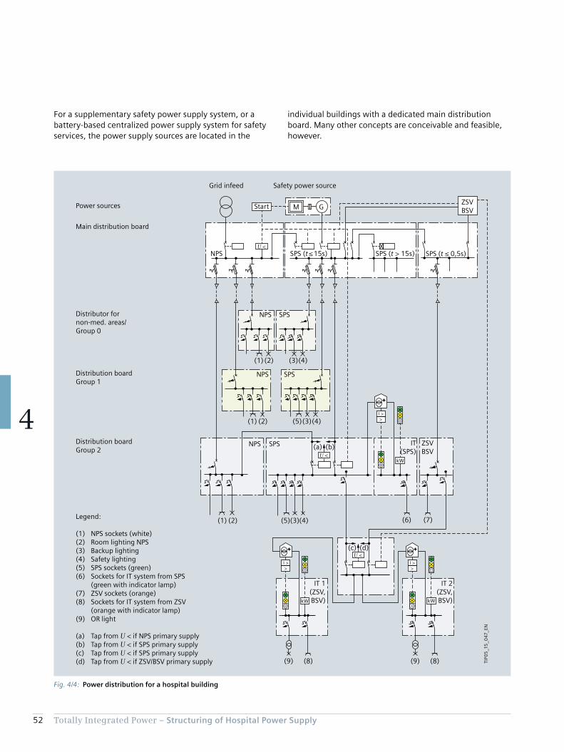
52 Totally Integrated Power – Structuring of Hospital Power Supply
4
individual buildings with a dedicated main distribution board. Many other concepts are conceivable and feasible, however.
For a supplementary safety power supply system, or a battery-based centralized power supply system for safety services, the power supply sources are located in the
Fig. 4/4: Power distribution for a hospital building
>Ι >
>Ι >
>Ι >
(6) (7)(1) (2) (4)(3)(5)
(a) (b)
(8)(9)(8)(9)
(c) (d)
(1) (2)
(1) (2)
(3)
(4)(3)(5)
(4)
kWkW
kW
TIP0
5_1
5_0
47_E
N
NPS SPS (t > 15s)SPS (t ≤ 15s)
Safety power sourceGrid infeed
SPS (t ≤ 0,5s)
ZSVBSV
Distribution board Group 2
Distribution boardGroup 1
Distributor fornon-med. areas/Group 0
Main distribution board
Power sources
NPS SPS
NPS SPS
NPS SPS ZSVBSV
IT(SPS)
IT 2(ZSV,BSV)
IT 1(ZSV,BSV)
Legend:
(1) NPS sockets (white)(2) Room lighting NPS(3) Backup lighting(4) Safety lighting(5) SPS sockets (green)(6) Sockets for IT system from SPS (green with indicator lamp)(7) ZSV sockets (orange)(8) Sockets for IT system from ZSV (orange with indicator lamp)(9) OR light
(a) Tap from U < if NPS primary supply(b) Tap from U < if SPS primary supply(c) Tap from U < if SPS primary supply(d) Tap from U < if ZSV/BSV primary supply
Start
U <
U <
M G
U <

53Totally Integrated Power – Structuring of Hospital Power Supply
4
According to the requirements previously detailed in chap-ter 4.2 and chapter 4.3, the power distribution system must also be designed in terms of classification and group alloca-tion for the medical locations. Particular attention must be paid to the integration of the medical IT systems. Fig. 4/4 shows a simplified distribution network structure for the individual medical location groups. It is based on diagrams from the old German standard VDE 0107 and the Austrian standard ÖVE/ÖNORM E 8007.
Safety lighting is required for:• Locations for switchgear and controlgear for emergency
power generators and for NPS and SPS main distribution boards
• Areas intended for life-sustaining services (at least one light powered by the SPS source)
• Fire alarm control boards and monitoring systems• Rooms in group 1 medical locations (at least one light
must be powered by the SPS source)• Rooms in group 2 medical locations (at least 50 % of the
lights must be powered by the SPS source)
For safety lighting, even non-medical locations in addition to medical locations of group 0 must have a SPS connection of class 15, as shown in Fig. 4/4. Furthermore, single fault safety must be ensured for the BSV supply as stipulated by VDE 0100-710. To that end, two BSV systems can be oper-ated as standby or parallel redundant systems [40].
Single fault safety must be ensured for medical IT systems in particular. This is stipulated in more detail in the Austrian standard ÖVE/ÖNORM E 8007. It clearly specifies that a medical IT system may only be fed via an IT transformer if:• Short-circuit and earth-fault-proof cables are used for the
incoming feeder and outgoing transformer lines without protective devices. The selectivity for the incoming feeder must be assured.
• Basic protection is provided for the IT transformer by one of the following measures:
– Protective insulation – Protection by non-conductive environment – Protection by suitable installation (transformer protection class I, isolated installation; IT transformer physically separated or barriered off from the distribution board; access only for qualified electricians, and appropriate warning notices on the enclosure and on the transformer)
If these requirements are not met, in the event of a fault the preferential supply must be switchable to a second IT system (Fig. 4/4). For operating theatre luminaires, fail-safety to IEC 60601-2-41 (VDE 0750-2-41) is stipulated. The standard cites three examples. Fig. 4/4, example b, embodies diagram 201.101 from the standard.
In Note 1 to the item on “Distribution” in IEC 60364-7-710, separate distribution boards are stipulated for NPS and SPS in medical locations of group 2. In Italy, the main power supply and safety power supply are allowed to be in the same distribution board.
For consumers of class > 15, such as sterilisation and cooling equipment or technical building installations, the safety power source does not have to be connected faster than after 15 seconds – in Fig. 4/4 the SPS (t > 15 s). The connection may be automatic or manual. The power source must be able to supply the connected consumers for at least 24 hours.
Note: In Germany, VDE 0100-560 stipulates that the con-nection must be automatic. Thus, as described in the German supplementary sheet VDE 0100-710 Bbl1, manual changeover is not permitted.
Note: Restricting the duration of supply from 24 hours to at least three hours, as would be possible for class 15 by terminating all medical treatment and evacuating the building in less than three hours, is not permissible for the power sources of class > 15.
The division into SPS (t ≤ 15 s) and SPS (t > 15 s) enables load shedding of the non-safety-related consumers, and safe start-up of the safety power supply generators. Ulti-mately, the electrical consumers in a hospital are to be split across five different power distribution networks for supply to branch circuits.
For all distribution boards downstream of the building’s main distribution board, the Austrian standard ÖVE/ÖNORM E 8007 stipulates extensive subdivision into separate distribution networks, or areas for NPS, SPS, and ZSV. Moreover, due consideration must be given to maintaining functionality, and to the significance of the powered safety systems. Fig. 4/4 does not show the integration of an SPS to non-life-sustaining consumers in the sub-distribution boards of groups 1 and 2 by way of a rotating ZSV, as described in ÖVE/ÖNORM E 8007.

54 Totally Integrated Power – Structuring of Hospital Power Supply
4
a limit period of time in the event of failure or malfunction of the normal power supply.
4.5.1 Network Changeover
IEC 60364-7-710 stipulates only changeover from NPS to SPS for the complete power supply system. This is under-standable as no stipulation is made as to how the various changeover periods are to be implemented in line with the classification of automatic supply as per annex A in the international standard (it makes no explicit mention ZSV or BSV). The latest version of IEC 60364-7-710 no longer stipulates supply to the medical locations of group 2 via a preferential line and a second line directly from the main distribution board, with automatic network changeover in-between. This should be provided, however, and is described in the Austrian standard ÖVE/ÖNORM E 8007, as well as in the outdated German standard VDE 0100-710 from 2002. The current German standard VDE 0100-710 from 2012 stipulates a changeover device directly at each
In many cases, a dedicated supply via central UPS systems is set up for electronic data processing (EDP) or information technology (IT) in a hospital. Power sockets to which EDP equipment can be connected are frequently executed in red. A critical factor to be considered is the connection of computers and IT equipment to standard UPS systems when they are of importance for life-sustaining ME equip-ment. Supply via a ZSV or a BSV is the right choice for this.
Subject to the proviso that safety of supply is not put at risk, the standard EDP supply, parts of the general lighting, and supply to other not necessarily life-sustaining equip-ment can also be provided via a ZSV. For example, the ZSV system should be adequately rated, and verification should be provided to ensure that co-supply to other consumers does not result in any critical line harmonics [41]. As op-posed to the ZSV system, a BSV according to VDE 0558-507 is only intended to power medical locations, operating theatre luminaires and comparable lights, as well as medi-cal electrical equipment and medical electrical systems for
Fig. 4/5: Automatic changeover of power supply for group 2 medical locations
TIP0
5_1
5_0
48
_EN
Main distribution NPS Main distribution SPS
NPS load
NPS SPSPreferred line2nd line
Changeover unit
ZSV / BSV
Medically used location group 2
t < 0.5 s
II
IT
> I kW
24 V
I < U< U
55Totally Integrated Power – Structuring of Hospital Power Supply
4
distribution point (main distribution board and distribution boards for group 2 medical locations). This explicitly in-cludes reliable separation of the systems.
Automatic changeover devices should conform to IEC 60947-6-1. Fig. 4/5 shows the integration of a changeo-ver device in the power distribution system. As opposed to Fig. 4/4, in which the changeover takes place between SPS and ZSV/BSV, in Fig. 4/5 the changeover is between NPS and SPS. The SPS should be set by the switch position as the preferred line, even if that is not explicitly stipulated in IEC 60364-7-710.
For the automatic changeover device, the stipulation as per IEC 60364-7-710 is:• Safe separation of the incoming feeders. To that end, for
example, the maximum total disconnect time (from occurrence of the first fault until quenching of the switching arc) may be less than the minimum changeover delay of the automatic changeover device, which VDE 0100-710 stipulates as a must
• The electrical cables between the automatic changeover device and the downstream overcurrent protection device must be short-circuit- and earth-fault-proof
• Short-time interruptions should lead to a changeover
Ideally, the coupling switch should be located in the SPS distribution board. This is not stipulated in the standard, however.
According to IEC 60364-7-710, calculation of the networks, listing of current-using equipment and verification of selective disconnection of protection devices are essential requirements. Evidencing documentation must be pro-vided. When planning using SIMARIS design, the changeo-ver connection between the normal power supply and the safety power supply can be mapped and dimensioned as appropriate.
4.5.2 Switching the Neutral Conductor
To avoid splitting the currents across the neutral conductors of two networks in the TN-S system, changeover of the neutral conductor must also be considered. As it can be assumed that the NPS and SPS distribution boards for a hospital building’s main distribution are located not too far apart, NPS-to-SPS changeover in the main distribution board can be assumed as using a common central earthing point (CEP), so the N conductor is not switched.
There is, however, another changeover in the sub-distribu-tion network (between NPS and SPS, see Fig. 4/5). Fig. 4/6 on the next page shows the 5-wire conductor layout, and the individual switches for the NPS and SPS at the two distribution levels. On switching between NPS and SPS in the sub-distribution network, the N conductor must be switched with the phases, so that in the event of failure of the “preferential line I” and changeover to the “second line II” back-flowing currents are not split across both N conduc-tors, whether due to asymmetrically distributed sin-gle-phase consumers or consumers with harmonic content.
It should be noted that no distinction is made any more between “active” and “passive” SPS systems. Although not explicitly mentioned in IEC 60364-7-710, the “active” system has become established (coupling switch between NPS and SPS in the building’s main distribution board is closed; the NPS and SPS networks in the building are oper-ated separately; see chapter 6), as is stated in the German supplementary sheet VDE 0100-710 Bbl1.
The potential scope of network calculations needed to verify compliance with the requirement of selectivity becomes clear already at this point. Firstly, the calculations must normally be made for branched networks with lots of power supply routes and distribution levels, and secondly, all configurations for normal operation and the many fault possibilities must also be calculated.

56 Totally Integrated Power – Structuring of Hospital Power Supply
4
For supply to class 0,5 (in France, in place of class 0,5, an uninterruptible power source for safety services is stipu-lated, and a list of classification examples given with classes 0, 15, and > 15), IEC 60364-7-710 stipulates the supply period of at least three hours (may be reduced to one hour if an independent power source conforming to the standard, which is not the SPS source, is at the ready for class 15). The standard stipulates that the following be connected to the power source for safety services of class 0,5:• Operating theatre luminaires• ME equipment with light sources and other equipment,
such as monitors, essential for use of the ME equipment• Life-sustaining ME equipment
4.5.3 BSV, UPS, and ZSV
As already described, IEC 60364-7-710 stipulates no spe-cific power supply systems such as BSV (VDE 0100-710) and ZSV (ÖVE/ÖNORM E 8007), as class 0 is not specified for power supply sources. In the version for France, instead of the power supply with a maximum changeover period of 0.5 s, an uninterruptible power source is stipulated, though it may only be an installation “which facilitates automatic changeover from the main distribution network to a differ-ent power supply, not necessarily for the safety power supply”. No further stipulations are made as to the uninter-ruptible power source.
Fig. 4/6: 3-pole changeover in the building’s main distribution board, and 4-pole changeover in the sub-distribution board
L1L2L3
PENPE
NPE
L1L2L3
PENPE
L1L2L3
NPE
L1L2L3
TIP0
5_1
5_0
49
_EN
SPSNPS
Bu
ildin
g m
ain
dis
trib
uti
on
bo
ard
Sou
rce
Protective equipotential bonding – transformer
Equipotential bonding –generator
Sub
-dis
trib
uti
on
bo
ard
SPSNPS
PreferredlineI
Secondline
II
Centralearthingpoint
Main earthing conductor
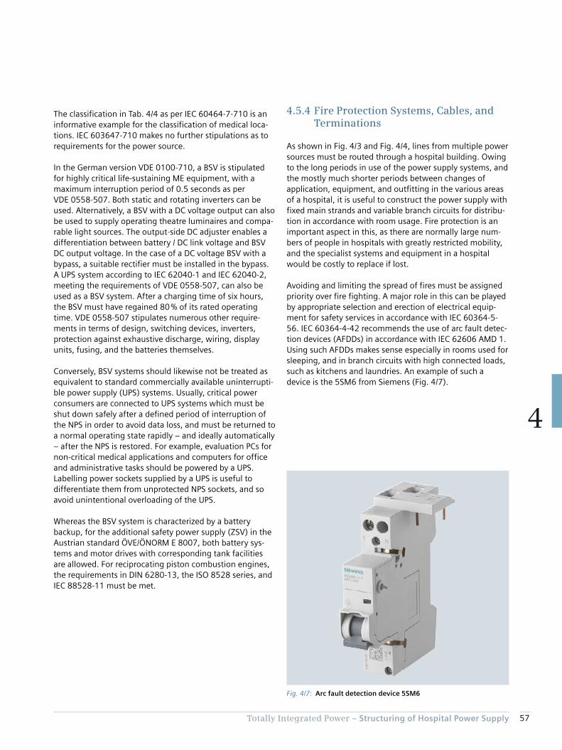
57Totally Integrated Power – Structuring of Hospital Power Supply
4
The classification in Tab. 4/4 as per IEC 60464-7-710 is an informative example for the classification of medical loca-tions. IEC 603647-710 makes no further stipulations as to requirements for the power source.
In the German version VDE 0100-710, a BSV is stipulated for highly critical life-sustaining ME equipment, with a maximum interruption period of 0.5 seconds as per VDE 0558-507. Both static and rotating inverters can be used. Alternatively, a BSV with a DC voltage output can also be used to supply operating theatre luminaires and compa-rable light sources. The output-side DC adjuster enables a differentiation between battery / DC link voltage and BSV DC output voltage. In the case of a DC voltage BSV with a bypass, a suitable rectifier must be installed in the bypass. A UPS system according to IEC 62040-1 and IEC 62040-2, meeting the requirements of VDE 0558-507, can also be used as a BSV system. After a charging time of six hours, the BSV must have regained 80 % of its rated operating time. VDE 0558-507 stipulates numerous other require-ments in terms of design, switching devices, inverters, protection against exhaustive discharge, wiring, display units, fusing, and the batteries themselves.
Conversely, BSV systems should likewise not be treated as equivalent to standard commercially available uninterrupti-ble power supply (UPS) systems. Usually, critical power consumers are connected to UPS systems which must be shut down safely after a defined period of interruption of the NPS in order to avoid data loss, and must be returned to a normal operating state rapidly – and ideally automatically – after the NPS is restored. For example, evaluation PCs for non-critical medical applications and computers for office and administrative tasks should be powered by a UPS. Labelling power sockets supplied by a UPS is useful to differentiate them from unprotected NPS sockets, and so avoid unintentional overloading of the UPS.
Whereas the BSV system is characterized by a battery backup, for the additional safety power supply (ZSV) in the Austrian standard ÖVE/ÖNORM E 8007, both battery sys-tems and motor drives with corresponding tank facilities are allowed. For reciprocating piston combustion engines, the requirements in DIN 6280-13, the ISO 8528 series, and IEC 88528-11 must be met.
4.5.4 Fire Protection Systems, Cables, and Terminations
As shown in Fig. 4/3 and Fig. 4/4, lines from multiple power sources must be routed through a hospital building. Owing to the long periods in use of the power supply systems, and the mostly much shorter periods between changes of application, equipment, and outfitting in the various areas of a hospital, it is useful to construct the power supply with fixed main strands and variable branch circuits for distribu-tion in accordance with room usage. Fire protection is an important aspect in this, as there are normally large num-bers of people in hospitals with greatly restricted mobility, and the specialist systems and equipment in a hospital would be costly to replace if lost.
Avoiding and limiting the spread of fires must be assigned priority over fire fighting. A major role in this can be played by appropriate selection and erection of electrical equip-ment for safety services in accordance with IEC 60364-5-56. IEC 60364-4-42 recommends the use of arc fault detec-tion devices (AFDDs) in accordance with IEC 62606 AMD 1. Using such AFDDs makes sense especially in rooms used for sleeping, and in branch circuits with high connected loads, such as kitchens and laundries. An example of such a device is the 5SM6 from Siemens (Fig. 4/7).
Fig. 4/7: Arc fault detection device 5SM6
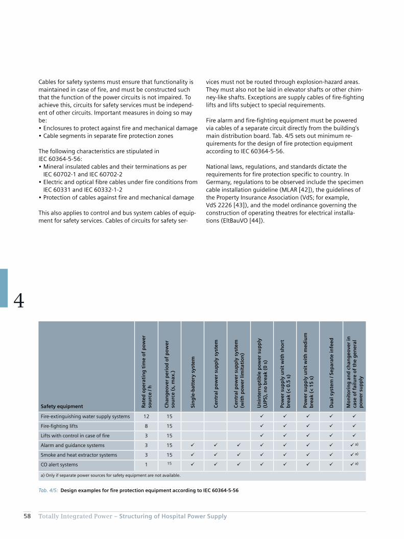
58 Totally Integrated Power – Structuring of Hospital Power Supply
4
vices must not be routed through explosion-hazard areas. They must also not be laid in elevator shafts or other chim-ney-like shafts. Exceptions are supply cables of fire-fighting lifts and lifts subject to special requirements.
Fire alarm and fire-fighting equipment must be powered via cables of a separate circuit directly from the building’s main distribution board. Tab. 4/5 sets out minimum re-quirements for the design of fire protection equipment according to IEC 60364-5-56.
National laws, regulations, and standards dictate the requirements for fire protection specific to country. In Germany, regulations to be observed include the specimen cable installation guideline (MLAR [42]), the guidelines of the Property Insurance Association (VdS; for example, VdS 2226 [43]), and the model ordinance governing the con struction of operating theatres for electrical installa-tions (EltBauVO [44]).
Cables for safety systems must ensure that functionality is maintained in case of fire, and must be constructed such that the function of the power circuits is not impaired. To achieve this, circuits for safety services must be independ-ent of other circuits. Important measures in doing so may be:• Enclosures to protect against fire and mechanical damage• Cable segments in separate fire protection zones
The following characteristics are stipulated in IEC 60364-5-56:• Mineral insulated cables and their terminations as per
IEC 60702-1 and IEC 60702-2• Electric and optical fibre cables under fire conditions from
IEC 60331 and IEC 60332-1-2• Protection of cables against fire and mechanical damage
This also applies to control and bus system cables of equip-ment for safety services. Cables of circuits for safety ser-
Tab. 4/5: Design examples for fire protection equipment according to IEC 60364-5-56
Safety equipment Rat
ed o
per
atin
g t
ime
of
po
wer
so
urc
e / h
Ch
ang
eove
r p
erio
d o
f p
ow
er
sou
rce
(s, m
ax.)
Sin
gle
-bat
tery
sys
tem
Cen
tral
po
wer
su
pp
ly s
yste
m
Cen
tral
po
wer
su
pp
ly s
yste
m
(wit
h p
ow
er li
mit
atio
n)
Un
inte
rru
pti
ble
po
wer
su
pp
ly
(UPS
), n
o b
reak
(0
s)
Pow
er s
up
ply
un
it w
ith
sh
ort
b
reak
(<
0.5
s)
Pow
er s
up
ply
un
it w
ith
med
ium
b
reak
(<
15
s)
Du
al s
yste
m /
Sep
arat
e in
feed
Mo
nit
ori
ng
an
d c
han
geo
ver
in
case
of
failu
re o
f th
e g
ener
al
po
wer
su
pp
ly
Fire-extinguishing water supply systems 12 15 ü ü ü ü ü
Fire-fighting lifts 8 15 ü ü ü ü ü
Lifts with control in case of fire 3 15 ü ü ü ü ü
Alarm and guidance systems 3 15 ü ü ü ü ü ü ü ü a)
Smoke and heat extractor systems 3 15 ü ü ü ü ü ü ü ü a)
CO alert systems 1 15 ü ü ü ü ü ü ü ü a)
a) Only if separate power sources for safety equipment are not available.

59Totally Integrated Power – Structuring of Hospital Power Supply
4
In Italy, the Ministry of the Interior has issued fire protec-tion regulations which stipulate the time for which safety equipment must provide resistance to fire (reference in the Italian version of IEC 60364-5-56). The Italian regulations particularly advise dividing the interiors of buildings into fire protection zones. A key element of this is that moving patients to different fire protection zones has medical and organisational advantages over evacuation [45].
The use of type-tested busbar trunking systems is a good way to reduce fire loads. They offer the following advan-tages over cables:• Greater flexibility in response to network changes [36]• Better future-proofing thanks to convertible tap-off units
with communication-capable measuring devices and interfacing to building automation systems
• More favourable EMC characteristics (Fig. 4/8)
Regarding the time for which the functionality of electrical cable installations is maintained, the German version VDE 0100-560 of the international standard IEC 60364-5-56 explicitly refers to the MLAR guideline. The Austrian standard ÖVE/ÖNORM E 8007 makes similar stipulations.
Maintaining functionality for 90 minutes is stipulated for:• Fire-extinguishing water supply systems (except sprinkler
systems)• Ventilation systems for safety stairwells, interior
stairwells, elevator shafts, safety airlocks, and motor rooms of fire-fighting lifts
• Mechanical smoke and heat extractor systems, and compressed air ventilation systems
• Fire-fighting lifts and passenger elevators in high-rise buildings (definition differs according to county or country; for example, 25 m high in Lower Austria and above 35 m in Vienna)
• ZSV (only in ÖVE/ÖNORM E 8007 for Austria; except branch circuits, which by failing do not impair other areas; note: requirement to maintain functionality is fulfilled if SPS and ZSV cables are routed in different fire protection zones upstream of the changeover device)
Fig. 4/8: EMC adequacy of cables and busbar trunking systems (interference limits for electrocardiograms (ECG), electroencephalograms (EEG), and electromyograms (EMG) are stipulated in IEC 60364-7-710)
Conductor arrangements
Mag
net
ic fl
ux
den
sity
B in
µT
Distance to source of interference in m
Interference limit ECG
Interference limit EEG
Interference limit EMG
TIP04_13_016_EN
0.1
1
1 10 505 100
10
100
3 cm
3 cm
3 cm
L1
L1
L1L2L3 L3L2L1PENN
L2 L3 LN PE LDA & LDC
L1 = 1,000 A e-j0°
L2 = 1,000 A e-j120°
L3 = 1,000 A e-j240°
L1 = 1,000 A e-j0°
L2 = 1,000 A e-j120°
L3 = 1,000 A e-j240°
L1 = 200 A e-j0°
L2 = 200 A e-j120°
L3 = 200 A e-j240°
L1 = 1,100 A e-j0°
L2 = 1,100 A e-j120°
L3 = 1,100 A e-j240°
LDA & LDCL1 = 2,500 A e-j0°
L2 = 2,500 A e-j120°
L3 = 2,500 A e-j240°
L2L3
10 cm
10 cm
L1
L2
L3
10 cm
10 cm
L1
L2
L3
L1 = 1,000 A e-j0°
L2 = 1,000 A e-j120°
L3 = 950 A e-j240°
10 cm
10 cm
L1
L2
L3
0.01

60 Totally Integrated Power – Structuring of Hospital Power Supply
4
British standard BS7671 stipulates that power sockets of medical IT systems must be blue, with the inscription “Medical Equipment Only”. For power socket circuits in medical IT systems for medical locations of group 2, IEC 60364-7-710 stipulates:• Power sockets for ME equipment must feature a power
indicator (green indicator lamp)• At each patient treatment station, either each socket
must be powered individually by a separately protected circuit, or multiple sockets must be divided across at least two separate circuits
• Power sockets of the medical IT system must not be switchable if TN-S or TT circuits are used in the same area. In addition, sockets must be labelled, or the possibility of confusion with the other systems must be ruled out by design
Maintaining functionality for 30 minutes is stipulated for:• Alarm and guidance systems for visitors and staff• Safety lighting (see also [36])• Cables for external alarm relaying, if they are routed
through non-monitored areas• Natural smoke extraction systems• Passenger elevators and bed lifts (not belonging to the
group with 90 minutes’ maintaining of functionality)
For maintaining of functionality, the requirements of DIN 4102-12 must be met. According to MLAR, the cables must be laid either in the ground or on a raw ceiling (below the screed) at least 30 mm thick.
The requirements for maintaining functionality of distribu-tion boards are similar to those for cable installations. Unfortunately, such instructions are lacking in the interna-tional standard IEC 60364-7-710. Instead, it makes global reference to regulations which in themselves do not have to be unified on a national level. The question has to be asked whether the fire protection requirements for electri-cal installations should not be formulated more clearly and stringently. In particular when operating theatre luminaires and life-sustaining ME equipment are to be maintained in operation for at least one hour by a safety power supply in the event of a fault, and a period of at least three hours is allowed for evacuation of the hospital.
Labelling of terminals for the various power supplies is advisable. There is, however, no standardisation or regula-tion for this. A commonly used colour-coding of power sockets is similar to [41]:• NPS: white• EDP via UPS: white, imprinted UPS
(or red, imprinted UPS)• SPS: green (Fig. 4/9)• IT supply via SPS: green with indicator lamp• BSV/ZSV: orange• IT supply via BSV/ZSV: orange with indicator lamp
Fig. 4/9: Green socket for connection to SPS
Chapter 5Usage-specific Power Supply Design
5.1 Central Technical Systems 64
5.2 Usage-specific Installations 66
5.3 Specific Power Demand for Room Groups 76

62 Totally Integrated Power – Usage-specific Power Supply Design
5
5 Usage-specific Power Supply Design
In accordance with the specifications of the developer and the mandatory requirements resulting from the usage of the building, the power must be divided across the various supply sources, such as normal power supply, safety power supply and additional safety power supply, or battery-based power supply for safety services. In designing the power sources in a hospital, the focus cannot be placed solely on high energy efficiency. Availability is of higher priority, necessitating redundant configuration which in turn im-pacts on energy efficiency. Precise dimensioning, taking into account all consumer data with their characteristic properties within the overall operation is absolutely essen-tial in this, as under-dimensioning can lead to malfunctions entailing far-reaching consequences.
A specific supply concept must be selected and designed based on usage-specific needs and the facility’s space conditions. For the sake of greater clarity, an outline sche-matic line diagram can initially be drawn up, in which key functional units are linked to the various power supply lines relevant to them in the hospital (Fig. 5/1).
The network structure is specified depending on the differ-ent supply tasks required in a hospital. It is important to locate the power sources as close as possible to the con-sumers in order to avoid power losses in transit.
Fig. 5/1: Schematic branch plan for a hospital with two adjacent buildings
NXCHX...E90
E90
E90
NXCHX...E90
E90
E90
E90
NXCHX...E90
E90
NXCHX...E90
TIP05_15_021_EN
Room air system
Electroacoustic system
Fire alarm system
Smoke and heat vents
NPS busbar tap box
SPS busbar tap box
RAS
EAS
FAS
SHV
Unit for battery-based/additional safety power supply
Main distribution board unitControl Control
Standby power supply system
Busb
ar
Operation
Intensive care
Laboratory
X-rayOperation
Recovery room
Cafeteria
Cold - Pathology
Med. gases
FAS
EAS
Sprinkler supply
Operation
General
On call roomMain kitchendistribution board
Busb
arBu
sbar
NPS main story distribution board
General
Doctor's room II
Doctor's room I
Medical dept. II
Medical dept. I
General
SPS main story distribution board
Operation
Operation
Endoscopy
Busb
ar
X-ray
Recovery room
Operation
X-ray
Operation
Busb
ar
Hospital ward
Hospital ward
Hospital ward
Hospital ward
Hospital wardHospital ward
Heating
Air-conditioning machineRAS Elevator 2
Elevator 1
Building 1Building 2
Cold
Cooling tower
Recooling unit
BSV/ZSV main storydistribution board
MV feed-in
Medium-voltage switchgear
Transformers
1st floor
2nd floor
3rd floor
4th floor
Equipment
Basement
SHV
Hospital ward
Hospital ward
Hospital ward
Hospital ward
Hospital ward
Elevator 2
Elevator 1
Main distribution board SPS
Ground floor
Canteen
ConferenceGeneral
Physicians
Physicians
Administration
Busb
ar
Dispensary
AdministrationRecreation
Administration
GeneralGeneral
Busb
ar
General
Reception
Busb
ar
IT administration
IT medical
Endoscopy
Medical dept. IIIDoctor's room
Medical dept. IIExamination III
Medical dept. IExamination II
Examination I
Busb
ar
Hospital ward
BSV/ZSV main story distribution board
Changing room/sanitary
SPS main story distribution board
MD-NPS main distribution boardNormal power supply
SD-NPS sub-distribution boardHospital ward
MD-SPS main distribution boardSafety power supply
SD-SPS sub-distribution boardHospital ward
MD-BSV/ZSV main distribution boardBattery-based/additional safety power supply
SD-NPS sub-distribution boardGeneral area
SD-NPS sub-distribution boardKitchen equipment
SD-NPS sub-distribution boardGas, heating, cold
SD-NPS/-SPSSmall distribution boards
SD-NPS/-SPSTechnical building systems
SD-SPS/-BSV/-ZSVIT medical technology
SD-NPS/-SPS/-BSV/-ZSVCritical medical technology
Building 1Building 2
Building 1Building 2
NPS main story distribution board
BSV/ZSV main story distribution board SPS main story
distribution board
Main distribution board NPS Main distribution board NPS Main distribution board SPS Main distributionboard BSV/ZSV
BSV/ZSV main storydistribution board
Main distribution board BSV/ZSV
SPS main story distribution board NPS main story distribution boardNPS main story
distribution board

63Totally Integrated Power – Usage-specific Power Supply Design
5
Standard supply to all parts of the installation is provided by way of transformers which feed into the normal power supply NPS (black) and safety power supply SPS (red). From there, the additional safety power supply BSV/ZSV (green) is supported.
When constructing the supply structure, attention must always be paid to the internal processes which can be covered by the established network topology. In view of the short service lives of medical technology equipment (often < 6 years) relative to the electrical installation (> 25 years), network planning should incorporate some allowance for flexible upgrading. Consequently, the distribution points should not be chosen too large in terms of load volume and catchment area. This also helps comply with the rule that the “final level” electrical distribution boards must be capable of being operated by the medical staff. An essen-tial requirement is accessibility, such as is provided by niche distribution boards on the corridors of the various departments.
The safety power supply is fed in via backup power supply units which must meet the special requirements of hospital operations in terms of availability, standby and bridging times, overload capacity, and reliability. Supply is provided to consumers which are essential for alarm generation, emergency rescue, and combating danger. The power is carried by special cables or reinforced cable runs which guarantee maintained functionality of the system for up to 90 minutes (shown in Fig. 5/1 as red lines). Typical con-nected consumers are safety and emergency exit lighting, as well as parts of the technical building systems which perform safety functions. Fire alarm systems and elec-troacoustic systems provide for early detection of fires and alarm signalling. Evacuation is assisted by smoke/heat exhaust systems, electroacoustic systems, and smoke extractors. Targeted fire-fighting is aided by sprinklers, fire-fighting lifts, smoke/heat exhaust systems, and smoke extractors.
Other consumers connected to the SPS are those essential for reliably maintaining emergency operation of the hospi-tal. The object of this is then not only to provide a bridging time until people can be evacuated, but to maintain medi-cal care operations to a pre-determined extent, such as over several days or weeks. Some of the technical building systems, such as refrigeration, gases, sanitary installations, air conditioning, and heating then assume a different significance. When dimensioning SPS consumer groups, the need to maintain them in terms of time and perfor-mance must be precisely analysed and matched to opera-tional practice.
Selected NPS consumers are frequently also allocated to an emergency power supply in line with operational require-ments. Appropriate measures must be taken to ensure that when the safety and emergency power is provided by one power supply unit, absolute priority is assigned to SPS, such as by load shedding of less important consumers. The safer and more flexible variant is to isolate those consumers from the SPS by feeding their power from the emergency power supply by way of an additional backup power supply unit. This supply does not have to meet the same safety stand-ards as the SPS.
A detailed configuration of the technical systems for all the rooms in a hospital would exceed the bounds of this appli-cation document. The following outlines the technical systems in line with the hospital function units included in the planning objective presented in Tab. 2/2.

64 Totally Integrated Power – Usage-specific Power Supply Design
5
phone and data networks, mobile communications systems, TV and radio reception systems, public-address and intercom systems, alarm systems
• Building management systems• Lighting systems
According to IEC 60364-7-710, dedicated self-contained facilities must be provided for:• Switchgear with rated voltages above 1 kV
(medium-voltage switchgear)• Power transformers (distribution transformers)• NPS main distribution board• SPS main distribution boards• Stationary safety power supply generators• Central batteries for safety power supply, if required by
the battery design, as well as inverter and control cabinets for additional safety power supply
Planning programmes and guidelines frequently also lay down appropriate basic requirements for central technical systems. For example, [47] presents outline recommenda-
5.1 Central Technical Systems
The central technical systems must also be selected and the associated power demand specified, depending on the size and operating conditions of the hospital. As shown in Fig. 5/1, this includes:• Hot and cold water supply• Heating, ventilation, air conditioning• Smoke and fire alarms, and fire-fighting systems• Compressed air and medical gases• Power distribution systems, such as medium-voltage
switchgear, distribution transformers, generators, and low-voltage main distribution boards
• Sources of SPS and BSV, or ZSV and associated supply, monitoring, exhaust gas discharge, and changeover systems
• Door openers/closers• Elevator/lift installations (fire service, bed transport, staff,
visitors, freight)• Information and communications technology (ICT)
systems such as telephone exchanges, data centres,
Fig. 5/2: Central components of electric power distribution in a hospital
10–30 kV
≤ 110kV
U<
TIP05_15_022_EN
Cafeteria
Reception desk,IT
AOS radio
FAC
Other
Offices
Other
MD kitchen
MD launderette
Ventilation sys.
Nurse callMedicalgas supply
Vacuumsupply
Narcoticsuction
Access controlsystemSome consumersdirectly supplied byLVMD acc. toIEC 60364-7-718
SD MD
Medium-voltageswitchgear
Transformer 2
Sprinkler
n li
nes
LVMD-UPS UPS system LVMD-NPS LVMD-SPS
SD-UPS
SHV
Transformer 1
SPS-NPS coupling
Standby generating set 1for building / facility supply
SDSDSDSD
OT light
Intensive care rooms
OT area
Endoscopy
Other
Operating status
Load indication
Insulationmonitor
BCS
Overloadindication
Standby generating set 2for the supply of medical facilities
MD generator 1
ZSV, BSV
MD generator 2
ZSV, BSV 1st floor Distr. boardIT system
Control panel
Mobilegenerator
Intensive care 1
Intensive care 2separate feeding lines
Intensive care nseparate feeding lines
Patient ward nSeparate feeding lines
SPS 1st floorNPS 1st floor
Patient ward 2Separate feeding lines
Patient ward 1
MD
Firemen‘s liftEAS
NPS = Normal power supplySPS = Safety power supply = BatteryFAC = Fire alarm controlAOS = Authorities, officials, security (“TETRA“)EAS = Electroacoustic system
BCS = Building control systemMD = Main distribution boardLVMD = Low-voltage main distribution boardSD = Sub-distribution boardSHV = Smoke and heat ventsUPS = Uninterruptible power supply
U< = Voltage monitor and changeover switchZSV = Additional safety power supplyBSV = Central battery-based power supply (DIN VDE 0558-507)z = Insulation monitor
Fire lobbies have not been taken intoaccount.
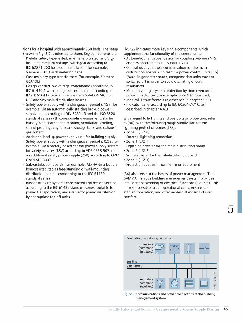
65Totally Integrated Power – Usage-specific Power Supply Design
5
tions for a hospital with approximately 250 beds. The setup shown in Fig. 5/2 is oriented to them. Key components are:• Prefabricated, type-tested, internal-arc-tested, and SF6-
insulated medium-voltage switchgear according to IEC 62271-200 for indoor installation (for example, Siemens 8DJH) with metering panel
• Cast-resin dry-type transformers (for example, Siemens GEAFOL)
• Design verified low-voltage switchboards according to IEC 61439-1 with arcing test certification according to IEC/TR 61641 (for example, Siemens SIVACON S8), for NPS and SPS main distribution boards
• Safety power supply with a changeover period ≤ 15 s, for example, via an automatically starting backup power supply unit according to DIN 6280-13 and the ISO 8528 standard series with corresponding equipment: starter battery with charger and monitor, ventilation, cooling, sound-proofing, day tank and storage tank, and exhaust gas system
• Additional backup power supply unit for building supply• Safety power supply with a changeover period ≤ 0.5 s, for
example, via a battery-based central power supply system for safety services (BSV) according to VDE 0558-507, or an additional safety power supply (ZSV) according to ÖVE/ÖNORM E 8007
• Sub-distribution boards (for example, ALPHA distribution boards) executed as free-standing or wall-mounting distribution boards, conforming to the IEC 61439 standard series
• Busbar trunking systems constructed and design verified according to the IEC 61439 standard series, suitable for power transportation, and usable for power distribution by appropriate tap-off units
Fig. 5/2 indicates more key single components which supplement the functionality of the central units:• Automatic changeover device for coupling between NPS
and SPS according to IEC 60364-7-710• Central reactive power compensation for the main
distribution boards with reactive power control units [36] (Note: in generator mode, compensation units must be switched off in order to avoid oscillating-circuit resonance)
• Medium-voltage system protection by time-overcurrent protection devices (for example, SIPROTEC Compact)
• Medical IT transformers as described in chapter 4.4.3• Indicator panel according to IEC 60364-7-710, as
described in chapter 4.4.3
With regard to lightning and overvoltage protection, refer to [36], with the following rough subdivision for the lightning protection zones (LPZ):• Zone 0 (LPZ 0)
External lightning protection• Zone 1 (LPZ 1)
Lightning arrester for the main distribution board• Zone 2 (LPZ 2)
Surge arrester for the sub-distribution board• Zone 3 (LPZ 3)
Protection upstream from terminal equipment
[36] also sets out the basics of power management. The GAMMA instabus building management system provides intelligent networking of electrical functions (Fig. 5/3). This makes it possible to cut operational costs, ensure safe, efficient operation, and offer modern standards of user comfort.
Fig. 5/3: Communications and power connections of the building management system
TIP0
5_1
5_0
23
_EN
Actuators(command
receivers)
Bus line
230 / 400 V
Sensors(command
initiators)
Controlling, monitoring, signalling
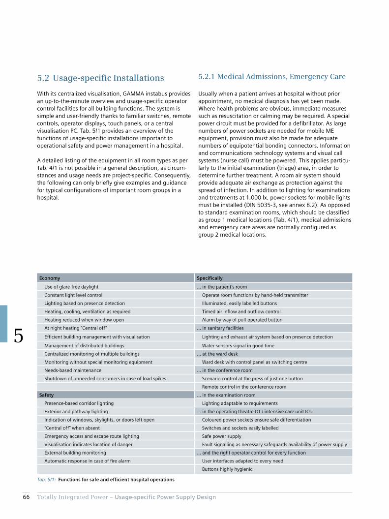
66 Totally Integrated Power – Usage-specific Power Supply Design
5
5.2.1 Medical Admissions, Emergency Care
Usually when a patient arrives at hospital without prior appointment, no medical diagnosis has yet been made. Where health problems are obvious, immediate measures such as resuscitation or calming may be required. A special power circuit must be provided for a defibrillator. As large numbers of power sockets are needed for mobile ME equipment, provision must also be made for adequate numbers of equipotential bonding connectors. Information and communications technology systems and visual call systems (nurse call) must be powered. This applies particu-larly to the initial examination (triage) area, in order to determine further treatment. A room air system should provide adequate air exchange as protection against the spread of infection. In addition to lighting for examinations and treatments at 1,000 lx, power sockets for mobile lights must be installed (DIN 5035-3, see annex 8.2). As opposed to standard examination rooms, which should be classified as group 1 medical locations (Tab. 4/1), medical admissions and emergency care areas are normally configured as group 2 medical locations.
5.2 Usage-specific Installations
With its centralized visualisation, GAMMA instabus provides an up-to-the-minute overview and usage-specific operator control facilities for all building functions. The system is simple and user-friendly thanks to familiar switches, remote controls, operator displays, touch panels, or a central visualisation PC. Tab. 5/1 provides an overview of the functions of usage-specific installations important to operational safety and power management in a hospital.
A detailed listing of the equipment in all room types as per Tab. 4/1 is not possible in a general description, as circum-stances and usage needs are project-specific. Consequently, the following can only briefly give examples and guidance for typical configurations of important room groups in a hospital.
Tab. 5/1: Functions for safe and efficient hospital operations
Economy Specifically
Use of glare-free daylight … in the patient’s room
Constant light level control Operate room functions by hand-held transmitter
Lighting based on presence detection Illuminated, easily labelled buttons
Heating, cooling, ventilation as required Timed air inflow and outflow control
Heating reduced when window open Alarm by way of pull-operated button
At night heating “Central off” ... in sanitary facilities
Efficient building management with visualisation Lighting and exhaust air system based on presence detection
Management of distributed buildings Water sensors signal in good time
Centralized monitoring of multiple buildings ... at the ward desk
Monitoring without special monitoring equipment Ward desk with control panel as switching centre
Needs-based maintenance ... in the conference room
Shutdown of unneeded consumers in case of load spikes Scenario control at the press of just one button
Remote control in the conference room
Safety ... in the examination room
Presence-based corridor lighting Lighting adaptable to requirements
Exterior and pathway lighting ... in the operating theatre OT / intensive care unit ICU
Indication of windows, skylights, or doors left open Coloured power sockets ensure safe differentiation
“Central off” when absent Switches and sockets easily labelled
Emergency access and escape route lighting Safe power supply
Visualisation indicates location of danger Fault signalling as necessary safeguards availability of power supply
External building monitoring ... and the right operator control for every function
Automatic response in case of fire alarm User interfaces adapted to every need
Buttons highly hygienic
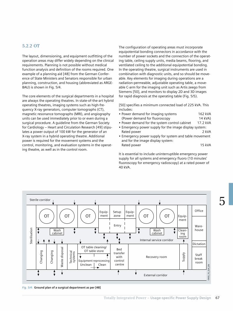
67Totally Integrated Power – Usage-specific Power Supply Design
5
The configuration of operating areas must incorporate equipotential bonding connectors in accordance with the number of power sockets and the connection of the operat-ing table, ceiling supply units, media beams, flooring, and ventilated ceiling to the additional equipotential bonding. In the operating theatre, surgical instruments are used in combination with diagnostic units, and so should be move-able. Key elements for imaging during operations are a radiation-permeable, adjustable operating table, a move-able C-arm for the imaging unit such as Artis zeego from Siemens [50], and monitors to display 2D and 3D images for rapid diagnosis at the operating table (Fig. 5/5).
[50] specifies a minimum connected load of 225 kVA. This includes:• Power demand for imaging systems 162 kVA
(Power demand for fluoroscopy 14 kVA)• Power demand for the system control cabinet 17.2 kVA• Emergency power supply for the image display system:
Rated power 2 kVA• Emergency power supply for system and table movement
and for the image display system: Rated power 15 kVA
It is essential to include uninterruptible emergency power supply for all systems and emergency fluoro (10 minutes’ fluoroscopy for emergency radioscopy) at a rated power of 40 kVA.
5.2.2 OT
The layout, dimensioning, and equipment outfitting of the operation areas may differ widely depending on the clinical requirements. Planning is not possible without medical function analysis and definition of the rooms required. One example of a planning aid [48] from the German Confer-ence of State Ministers and Senators responsible for urban planning, construction, and housing (abbreviated as ARGE-BAU) is shown in Fig. 5/4.
The core elements of the surgical departments in a hospital are always the operating theatres. In state-of-the-art hybrid operating theatres, imaging systems such as high-fre-quency X-ray generators, computer tomographs (CT), magnetic resonance tomographs (MRI), and angiography units can be used immediately prior to or even during a surgical procedure. A guideline from the German Society for Cardiology – Heart and Circulation Research [49] stipu-lates a power output of 100 kW for the generator of an X-ray system in a hybrid operating theatre. Additional power is required for the movement systems and the control, monitoring, and evaluation systems in the operat-ing theatre, as well as in the control room.
Fig. 5/4: Ground plan of a surgical department as per [48]
OT OTOTOT OT
Ch
ang
ing
Was
te d
isp
osa
l
Dictation
Ch
ang
ing
Equipment reprocessing
Tech
nic
alsy
stem
s
OT table cleaning/OT table store
Equip-ment
Entry
Staff break room
Recovery room
Office
Bed transfer
with control centre
Ware-houseWash
cabinetWash
cabinetClean-
ingroom
Sup
ply
Equip-ment
Equip-ment
Setupzone
Internal service corridor
External corridor
Ster
ilisa
tio
n
Sterile corridor
Unclean Clean
TIP0
5_1
5_0
24_E
N

68 Totally Integrated Power – Usage-specific Power Supply Design
5
• Special lighting systems (surgical luminaires) according to IEC 60601-2-41 for lighting of operating fields (10,000 to 160,000 lx), lamps for lighting of the immediate vicinity within 3 × 3 m around the operating table (2,000 lx) and of the rest of the room (1,000 lx) according to DIN 5035-3
The ambient lighting for diagnostics or analysis on moni-tors must be glare-free and adjustable. The adjustment of the illuminance must also be reproducible (for example, dimmer with scale). No mirroring or reflections of win-dows, lamps, or showcases may occur in the monitor’s normal operating position.
In addition to the actual operating theatre, technical rooms and evaluation rooms for the imaging systems must be provided, and the normal entry and pre-op rooms as well as airlocks and sterile areas planned (Fig. 5/4 and Fig. 5/6). The lighting layout of these rooms must be in accordance with annex 2.
There is a large number of different imaging system types and vendors. For example, the span of connected loads extends from 15 kVA for smaller MRI units to 140 kVA and more for so-called 3-Tesla units (equipment characterisa-tion by magnetic field strength) or larger. Similar require-ments apply to X-ray and CT units. A typical power range for hybrid imaging systems (such as the BIOGRAPH series from Siemens), combining CT with PET or MRI with PET, is between 110 and 160 kVA.
Other electrical consumers which should be given consider-ation where appropriate in the surgical department are:• Hanging lamps, including with electrical connections,
possibly also for the medical IT system• Door control• Communications systems• Motor drives for room blackout systems• Fire alarm systems• Power sockets for the various supply systems
Fig. 5/5: Hybrid operating theatre with moveable Artis zeego robot for medical imaging

69Totally Integrated Power – Usage-specific Power Supply Design
5
Fig. 5/6: System layout for a surgical department with hybrid operating theatre
A
Instr.
Filt
er
Filt
er
*1*1
*1*1
*1
*1
*2
R415
R150
B
Inst
r.
TIP05_15_025_EN
Bed station
Sterile corridor
Exit
Entry
Male change
Female change
Staff washroom
Switching and evaluation
An
aes-
thes
ia
Hybrid OT Examination
LAF field
Sterilearea
Sterile storeroom
UPS
ATS
Battery
Technical room
Hand disin-fection
Table in op position
Airlock unclean
*1 Doors with reciprocal interlocking to maintain clean air in the hybrid OT*2 Service door – opened only for servicing
Hand disin-fection
Hand disin-fection
Was
te
Ult
ra-
sou
nd
Hea
rt-lu
ng
mac
hin
e
IABP
Coo
l-bo
x
Min
imal
lyin
vasi
ve
70 Totally Integrated Power – Usage-specific Power Supply Design
5
There must be connection facilities in the patients’ rooms for monitoring, diagnostic, and treatment units, such as a defibrillator. The lighting level must be adaptable to the specific care situation [53]. State-of-the-art lighting sys-tems employ dynamic light control:• General lighting: 100 lx• Lighting for simple examination: 300 lx• Lighting for examination and treatment: 1,000 lx• Night-time monitoring: 20 lx
Infection risk plays a key role in the design of room air systems [54]. In Germany, such systems must conform to DIN 1946-4.
Along with the patient rooms, as a minimum the procedure room, emergency care and resuscitation room, and where appropriate a treatment or recovery room must be classed as group 2 medical locations. For the critical life-sustaining systems in those rooms – as in the nursing ward and in any control room used to monitor the procedure room – plan-ning must incorporate the installation of BSV/ZSV system.
5.2.4 Nursing Ward
The bed rooms in a nursing ward are mostly classed as group 1 medical locations as per Tab. 4/4. The patients’ rooms normally have daylight, and are naturally venti-lated. In multi-storey bed facilities and hospitals in busy inner city areas, room ventilation may be necessary, conforming to DIN 1946-4. With regard to safety lighting, IEC 60364-7-710 stipulates that at least one light must be connected to the safety power supply. The rooms are lit by indirect lighting at a minimum of 100 lx. Dazzling of patients by glare must be avoided [53]. A 300 lx reading light must be provided. For night-lighting, 5 lx is sufficient.
The heat loss from electrical equipment, the heat intro-duced by people, the room/ambient climate conditions, and the air exchange necessary for hygiene must be consid-ered when designing the ventilation and air-conditioning systems for operating theatres. The specific installation situation influences the required air flow rates, and thus the electric power demand for the fans [51]. When design-ing fans, it must be ensured that they meet the ventilation flow requirements with regard to turbulence and air speed of the specified room class (in Germany according to DIN 1946-4), whereby the electric power demand rises quadratically with the air flow rate.
[51] indicates that a low-cost, low-specification ventilation duct delivers a cost saving of around 20 % on purchase, but necessitates a more than 50 % higher flow rate. As a result, the power demand of the fans is increased by almost 250 %, virtually doubling the overall electric power demand in the surgical department. It further states that the ar-ea-specific power demand of a surgical department rises from around 135 W/m2 under “normal” ventilation condi-tions to 255 W/m2 if the ventilation ducts are of a low specification. Consequently, when remodelling a surgical department – as shown in Tab. 2/2, for example – the power supply requirements of the heating, ventilation, and air conditioning should always be reassessed and given due consideration.
5.2.3 Intensive Care Unit
The intensive care unit is normally located close to the radiological diagnostics and/or surgical department. It should also be quickly accessible from the Accident & Emergency department. Through-traffic should be avoided. Fig. 5/7 on page 72 shows a schematic floor plan for an intensive care unit. In addition to the personnel require-ment, the German Interdisciplinary Association for Inten-sive and Emergency Medicine (DIVI = Deutsche inter-disziplinäre Vereinigung für Intensiv- und Notfallmedizin) has issued recommendations regarding the constructional and equipment requirements for intensive care units [52]. Tab. 5/2 sets out key components for electric power supply to intensive care units.
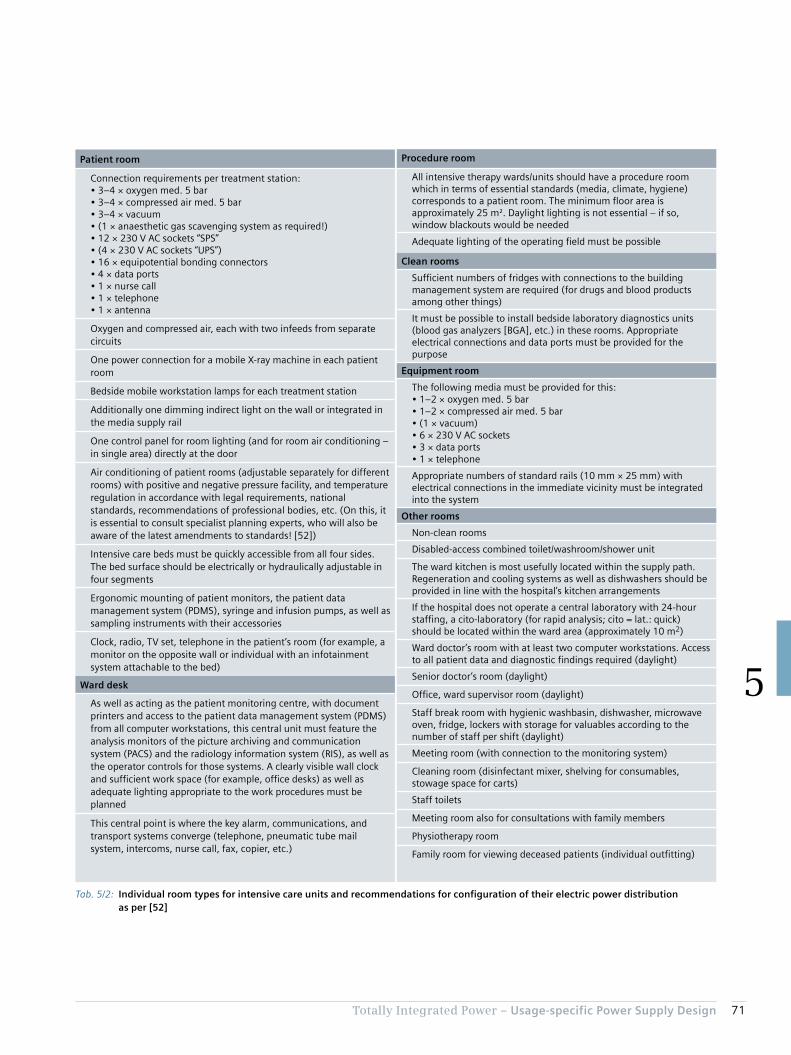
71Totally Integrated Power – Usage-specific Power Supply Design
5
Patient room
Connection requirements per treatment station:• 3–4 × oxygen med. 5 bar• 3–4 × compressed air med. 5 bar• 3–4 × vacuum• (1 × anaesthetic gas scavenging system as required!)• 12 × 230 V AC sockets “SPS”• (4 × 230 V AC sockets “UPS”)• 16 × equipotential bonding connectors• 4 × data ports• 1 × nurse call• 1 × telephone• 1 × antenna
Oxygen and compressed air, each with two infeeds from separate circuits
One power connection for a mobile X-ray machine in each patient room
Bedside mobile workstation lamps for each treatment station
Additionally one dimming indirect light on the wall or integrated in the media supply rail
One control panel for room lighting (and for room air conditioning – in single area) directly at the door
Air conditioning of patient rooms (adjustable separately for different rooms) with positive and negative pressure facility, and temperature regulation in accordance with legal requirements, national standards, recommendations of professional bodies, etc. (On this, it is essential to consult specialist planning experts, who will also be aware of the latest amendments to standards! [52])
Intensive care beds must be quickly accessible from all four sides. The bed surface should be electrically or hydraulically adjustable in four segments
Ergonomic mounting of patient monitors, the patient data management system (PDMS), syringe and infusion pumps, as well as sampling instruments with their accessories
Clock, radio, TV set, telephone in the patient’s room (for example, a monitor on the opposite wall or individual with an infotainment system attachable to the bed)
Ward desk
As well as acting as the patient monitoring centre, with document printers and access to the patient data management system (PDMS) from all computer workstations, this central unit must feature the analysis monitors of the picture archiving and communication system (PACS) and the radiology information system (RIS), as well as the operator controls for those systems. A clearly visible wall clock and sufficient work space (for example, office desks) as well as adequate lighting appropriate to the work procedures must be planned
This central point is where the key alarm, communications, and transport systems converge (telephone, pneumatic tube mail system, intercoms, nurse call, fax, copier, etc.)
Procedure room
All intensive therapy wards/units should have a procedure room which in terms of essential standards (media, climate, hygiene) corresponds to a patient room. The minimum floor area is approximately 25 m². Daylight lighting is not essential – if so, window blackouts would be needed
Adequate lighting of the operating field must be possible
Clean rooms
Sufficient numbers of fridges with connections to the building management system are required (for drugs and blood products among other things)
It must be possible to install bedside laboratory diagnostics units (blood gas analyzers [BGA], etc.) in these rooms. Appropriate electrical connections and data ports must be provided for the purpose
Equipment room
The following media must be provided for this:• 1–2 × oxygen med. 5 bar• 1–2 × compressed air med. 5 bar• (1 × vacuum)• 6 × 230 V AC sockets• 3 × data ports• 1 × telephone
Appropriate numbers of standard rails (10 mm × 25 mm) with electrical connections in the immediate vicinity must be integrated into the system
Other rooms
Non-clean rooms
Disabled-access combined toilet/washroom/shower unit
The ward kitchen is most usefully located within the supply path. Regeneration and cooling systems as well as dishwashers should be provided in line with the hospital’s kitchen arrangements
If the hospital does not operate a central laboratory with 24-hour staffing, a cito-laboratory (for rapid analysis; cito = lat.: quick) should be located within the ward area (approximately 10 m2)
Ward doctor’s room with at least two computer workstations. Access to all patient data and diagnostic findings required (daylight)
Senior doctor’s room (daylight)
Office, ward supervisor room (daylight)
Staff break room with hygienic washbasin, dishwasher, microwave oven, fridge, lockers with storage for valuables according to the number of staff per shift (daylight)
Meeting room (with connection to the monitoring system)
Cleaning room (disinfectant mixer, shelving for consumables, stowage space for carts)
Staff toilets
Meeting room also for consultations with family members
Physiotherapy room
Family room for viewing deceased patients (individual outfitting)
Tab. 5/2: Individual room types for intensive care units and recommendations for configuration of their electric power distribution as per [52]

72 Totally Integrated Power – Usage-specific Power Supply Design
5
Fig. 5/7: Schematic example of an intensive care unit
TIP0
5_1
5_0
26

73Totally Integrated Power – Usage-specific Power Supply Design
5
For simple examinations and treatments, lighting at a minimum of 300 lx in the bed room is sufficient. The rooms should likewise provide a number of 230 V AC connections for communications and entertainment electronics. In-house call and signalling systems should be provided in all bed rooms.
The wet cells linked to the bed rooms are mostly provided with artificial lighting and ventilation. At least one power socket and the connection to the call system should be provided.
As examinations are frequently conducted in bed rooms, such as to avoid transporting the patient, connections for mobile X-ray machines and other mobile ME equipment must be provided. Planning must also consider the equipo-tential bonding connector. A connection to a hospital information system in order to access updated electronic patient records at the patient’s bedside (see also chapter 5.2.3 Intensive Care Unit) is an integral part of a state-of-
the-art care concept, which means the patient does not have to be continually transported around the hospital.
The other areas of a bed ward (Fig. 5/8) are subject to similar requirements as the rooms in an intensive care unit. They typically include:• Doctor’s room• Nurses’ station• Staff break room• Ward kitchen• Work rooms, clean/non-clean• Staff/visitor toilets• Storerooms• Visitor and patient communal area
Fig. 5/8: Structure of a nursing ward
Nurses’station
2-bedroom
1-bedroom
2-bedroom
2-bedroom
1-bedroom
2-bedroom
2-bedroom
2-bedroom
Maletoilet
Femaletoilet
StoreWork roomKitchen
TIP0
5_1
5_0
27_
EN

74 Totally Integrated Power – Usage-specific Power Supply Design
5
5.2.5 Other Hospital Areas
The other medical locations from Tab. 4/1 can be largely either allocated to the areas previously described, or the electric power distribution requirements can be estimated as for a comparable room usage, such as for an office or storeroom. For special room types such as kitchens, laun-dries, or radiology, the equipment outfitting is key. For example, the radiology department of a university hospital will have more high-end technical equipment than that of a district hospital. The required electrical connected load is also dictated by the performance capability of the various equipment types and sizes, and by the differing needs for the associated evaluation systems. Fig. 5/9 compares the installation areas of various MR scanners. The Siemens MAGNETOM C!, with a magnetic field strength of 0.35 T, requires a connected load of around 15 kVA, while the 1.5-T MAGNETOM ESSENZA MRI scanner requires a con-nected load of 45 kVA. 110 kVA should be planned for connection of the 3-T MAGNETOM Skyra.
Computer tomographs (CT scanners) are differentiated by units with one or two X-ray sources. Accordingly, the power demand for units with two X-ray generators can be around twice as high (Tab. 5/3). Radiology departments with high-performance imaging systems are normally a focus point of load, and should be connected to a dedicated medium-voltage supply with a separate transformer and low-voltage distribution.
Depending on the room layout or infrastructure conditions, some of the utility supply and waste disposal functions (see chapter 2 and Tab. 4/1) can or must under certain circum-stances be relocated. The scope of the functions and their characteristic features also vary widely, so Tab. 5/4 can only provide rough guidance. In some cases, as a less costly alternative, food is prepared on the wards rather than in a central kitchen. In such a system, some of the meals are delivered-in, and only special dietary requirements are met in the decentralized kitchens.
Fig. 5/9: Room requirement and magnetic field distribution for different MRI scanners
1
1
2
2
3
1
2
3
1
2
3
3
TIP0
5_1
5_0
28
_EN
0.05 mT
0.1 mT
0.15 mT
0.3 mT
0.5 mT
1 mT
0.2 mT
0.05 mT0.15 mT 0.2 mT
0.5 mT 1 mT 3 mT
0.05 mT
0.1 mT0.15 mT
0.3 mT0.5 mT
1 mT
3 mT
Siemens MAGNETOM C!
Siemens MAGNETOM ESSENZA
Siemens MAGNETOM Skyra
Equipment room
Examination room
Control room
Tab. 5/3: Room requirement and magnetic field distribution for different CT scanners
Unit name Number of X-ray sources
Connected load
SOMATOM Scope, SOMATOM Spirit
1 40 kVA
SOMATOM Perspective, SOMATOM Emotion
1 70 kVA
SOMATOM Definition Edge, SOMATOM Definition AS
1 160 kVA
SOMATOM Definition Flash 2 340 kVA
SOMATOM Force 2 395 kVA
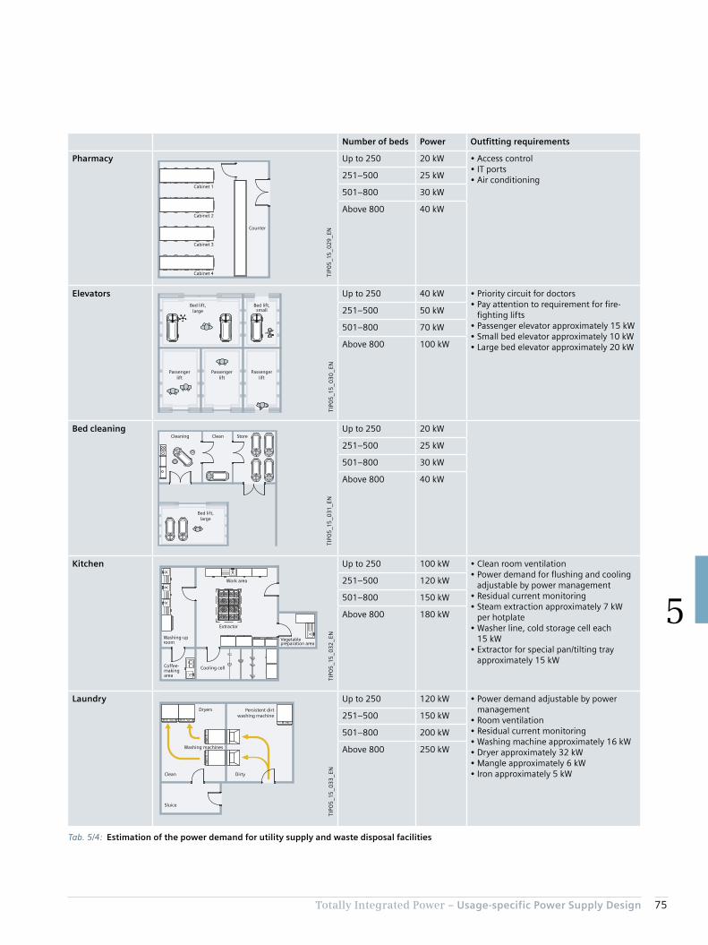
75Totally Integrated Power – Usage-specific Power Supply Design
5
Tab. 5/4: Estimation of the power demand for utility supply and waste disposal facilities
Number of beds Power Outfitting requirements
Pharmacy
TIP0
5_1
5_0
29
_ENCounter
Cabinet 1
Cabinet 2
Cabinet 3
Cabinet 4
Up to 250 20 kW • Access control• IT ports• Air conditioning251–500 25 kW
501–800 30 kW
Above 800 40 kW
Elevators
TIP0
5_1
5_0
30
_EN
Passengerlift
Passengerlift
Passengerlift
Bed lift,large
Bed lift,small
Up to 250 40 kW • Priority circuit for doctors• Pay attention to requirement for fire-
fighting lifts• Passenger elevator approximately 15 kW• Small bed elevator approximately 10 kW• Large bed elevator approximately 20 kW
251–500 50 kW
501–800 70 kW
Above 800 100 kW
Bed cleaning
TIP0
5_1
5_0
31_E
N
Cleaning Clean Store
Bed lift,large
Up to 250 20 kW
251–500 25 kW
501–800 30 kW
Above 800 40 kW
Kitchen
TIP0
5_1
5_0
32
_EN
Coffee-making area
Washing-up room
Work area
Extractor
Vegetable preparation area
Cooling cell
Up to 250 100 kW • Clean room ventilation• Power demand for flushing and cooling
adjustable by power management• Residual current monitoring• Steam extraction approximately 7 kW
per hotplate• Washer line, cold storage cell each
15 kW• Extractor for special pan/tilting tray
approximately 15 kW
251–500 120 kW
501–800 150 kW
Above 800 180 kW
Laundry
TIP0
5_1
5_0
33
_EN
Dryers
Washing machines
Persistent dirtwashing machine
DirtyClean
Sluice
Up to 250 120 kW • Power demand adjustable by power management
• Room ventilation• Residual current monitoring• Washing machine approximately 16 kW• Dryer approximately 32 kW• Mangle approximately 6 kW• Iron approximately 5 kW
251–500 150 kW
501–800 200 kW
Above 800 250 kW
76 Totally Integrated Power – Usage-specific Power Supply Design
5
As the climatic and other ambient conditions, as well as the medical systems installed, are not known, power ranges are specified for the room air systems and for the power supply to medical equipment. For medical equipment, the prod-uct-specific power demand must be considered (see chap-ter 5.2.2). The data must be defined specifically to the project in the planning process. For use of UPS to supply IT systems, consider the extent to which laptops or tablets are in use.
5.3 Specific Power Demand for Room Groups
With empirical values from planning projects and the estimates previously made, for the room groups listed in Tab. 4/1 (as per DIN 13080), a table (Tab. 5/5) with area-specific power data can be constructed. The specifications relate to the net floor areas of the medical locations listed. With room layouts as shown in Tab. 2/2, the requirements of the power distribution structure (for NPS, SPS, UPS, BSV, or ZSV, as well as the medical IT network) can be collated, and a system solution can be specified with the aid of calculation tools (see chapter 6).
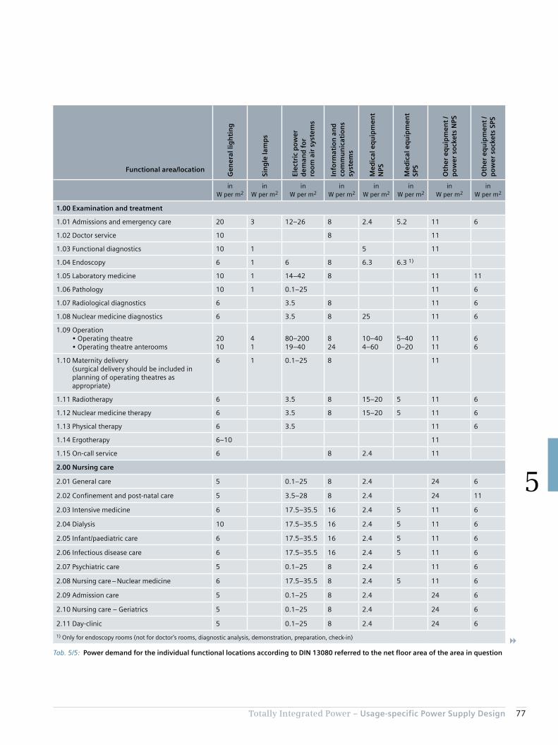
77Totally Integrated Power – Usage-specific Power Supply Design
5
Tab. 5/5: Power demand for the individual functional locations according to DIN 13080 referred to the net floor area of the area in question
Functional area/location
Gen
eral
lig
hti
ng
Sin
gle
lam
ps
Elec
tric
po
wer
d
eman
d f
or
roo
m a
ir s
yste
ms
Info
rmat
ion
an
d
com
mu
nic
atio
ns
syst
ems
Med
ical
eq
uip
men
t N
PS
Med
ical
eq
uip
men
t SP
S
Oth
er e
qu
ipm
ent
/ p
ow
er s
ock
ets
NPS
Oth
er e
qu
ipm
ent
/ p
ow
er s
ock
ets
SPS
in W per m2
in W per m2
in W per m2
in W per m2
in W per m2
in W per m2
in W per m2
in W per m2
1.00 Examination and treatment
1.01 Admissions and emergency care 20 3 12–26 8 2.4 5.2 11 6
1.02 Doctor service 10 8 11
1.03 Functional diagnostics 10 1 5 11
1.04 Endoscopy 6 1 6 8 6.3 6.3 1)
1.05 Laboratory medicine 10 1 14–42 8 11 11
1.06 Pathology 10 1 0.1–25 11 6
1.07 Radiological diagnostics 6 3.5 8 11 6
1.08 Nuclear medicine diagnostics 6 3.5 8 25 11 6
1.09 Operation • Operating theatre • Operating theatre anterooms
2010
41
80–20019–40
824
10–404–60
5–400–20
1111
66
1.10 Maternity delivery (surgical delivery should be included in planning of operating theatres as appropriate)
6 1 0.1–25 8 11
1.11 Radiotherapy 6 3.5 8 15–20 5 11 6
1.12 Nuclear medicine therapy 6 3.5 8 15–20 5 11 6
1.13 Physical therapy 6 3.5 11 6
1.14 Ergotherapy 6–10 11
1.15 On-call service 6 8 2.4 11
2.00 Nursing care
2.01 General care 5 0.1–25 8 2.4 24 6
2.02 Confinement and post-natal care 5 3.5–28 8 2.4 24 11
2.03 Intensive medicine 6 17.5–35.5 16 2.4 5 11 6
2.04 Dialysis 10 17.5–35.5 16 2.4 5 11 6
2.05 Infant/paediatric care 6 17.5–35.5 16 2.4 5 11 6
2.06 Infectious disease care 6 17.5–35.5 16 2.4 5 11 6
2.07 Psychiatric care 5 0.1–25 8 2.4 11 6
2.08 Nursing care – Nuclear medicine 6 17.5–35.5 8 2.4 5 11 6
2.09 Admission care 5 0.1–25 8 2.4 24 6
2.10 Nursing care – Geriatrics 5 0.1–25 8 2.4 24 6
2.11 Day-clinic 5 0.1–25 8 2.4 24 6
1) Only for endoscopy rooms (not for doctor’s rooms, diagnostic analysis, demonstration, preparation, check-in)
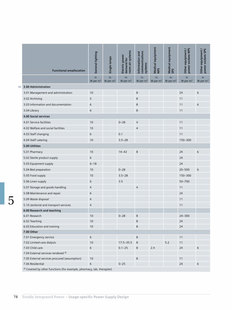
78 Totally Integrated Power – Usage-specific Power Supply Design
5
Functional area/location
Gen
eral
lig
hti
ng
Sin
gle
lam
ps
Elec
tric
po
wer
d
eman
d f
or
roo
m a
ir s
yste
ms
Info
rmat
ion
an
d
com
mu
nic
atio
ns
syst
ems
Med
ical
eq
uip
men
t N
PS
Med
ical
eq
uip
men
t SP
S
Oth
er e
qu
ipm
ent
/ p
ow
er s
ock
ets
NPS
Oth
er e
qu
ipm
ent
/ p
ow
er s
ock
ets
SPS
in W per m2
in W per m2
in W per m2
in W per m2
in W per m2
in W per m2
in W per m2
in W per m2
3.00 Administration
3.01 Management and administration 10 8 24 6
3.02 Archiving 5 8 11
3.03 Information and documentation 6 8 11 6
3.04 Library 6 8 11
4.00 Social services
4.01 Service facilities 10 0–28 4 11
4.02 Welfare and social facilities 10 4 11
4.03 Staff changing 6 0.1 11
4.04 Staff catering 10 3.5–28 150–300
5.00 Utilities
5.01 Pharmacy 10 14–42 8 24 6
5.02 Sterile product supply 6 24
5.03 Equipment supply 6–18 24
5.04 Bed preparation 10 0–28 20–500 6
5.05 Food supply 10 3.5–28 150–300
5.06 Linen supply 6 3.5 50–700
5.07 Storage and goods handling 4 4 11
5.08 Maintenance and repair 6 24
5.09 Waste disposal 4 11
5.10 Janitorial and transport services 4 11
6.00 Research and teaching
6.01 Research 10 0–28 8 24–300
6.02 Teaching 10 8 24
6.03 Education and training 10 8 24
7.00 Other
7.01 Emergency service 6 8 11
7.02 Limited-care dialysis 10 17.5–35.5 8 5.2 11
7.03 Child care 6 0.1–25 8 2.4 24 6
7.04 External services rendered 2)
7.05 External services procured (assumption) 10 8 11
7.06 Residential 6 0–25 24 6
2) Covered by other functions (for example, pharmacy, lab, therapies)
Chapter 6Model Networks for SIMARIS design
6.1 Examples of Infeed Network Structures 80
6.2 Equivalent Impedance for IT Isolating Transformer 84
6.3 Ward Distribution Examples 86
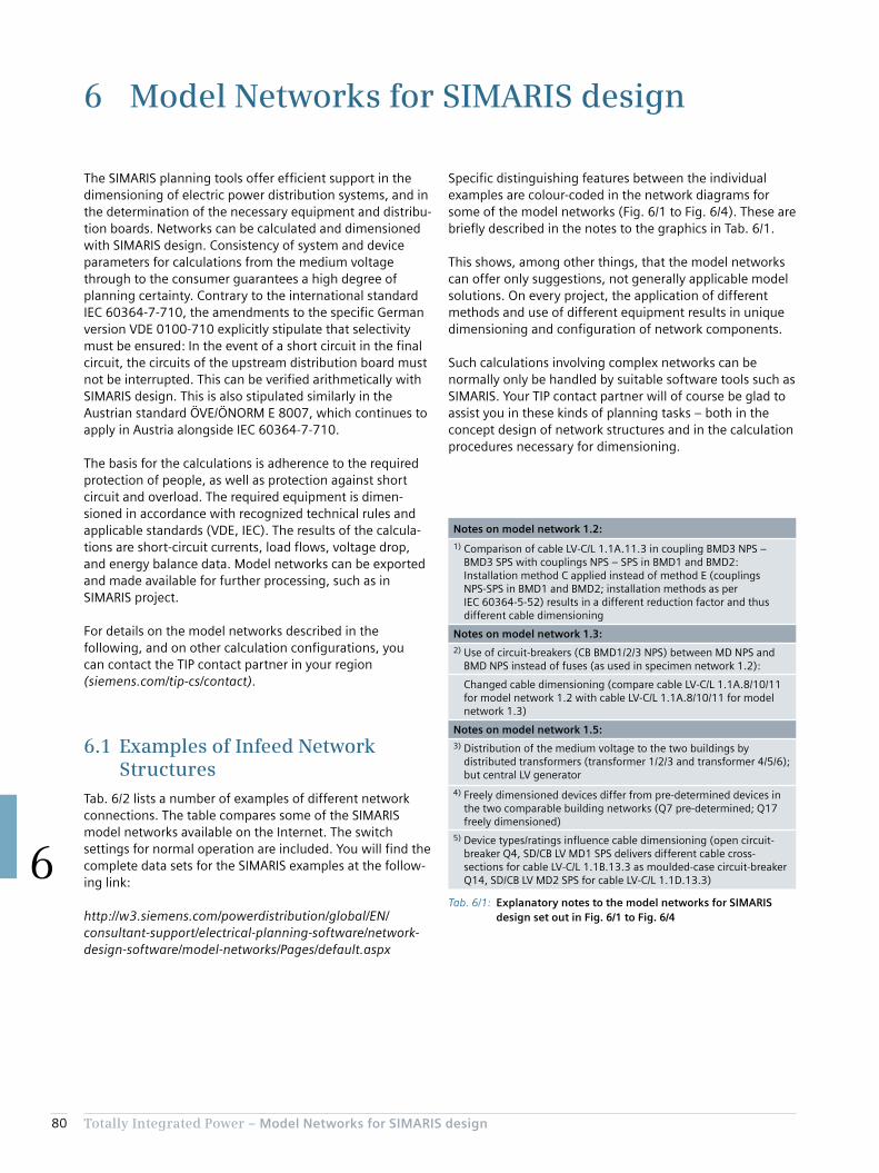
80 Totally Integrated Power – Model Networks for SIMARIS design
6
6 Model Networks for SIMARIS design
Specific distinguishing features between the individual examples are colour-coded in the network diagrams for some of the model networks (Fig. 6/1 to Fig. 6/4). These are briefly described in the notes to the graphics in Tab. 6/1.
This shows, among other things, that the model networks can offer only suggestions, not generally applicable model solutions. On every project, the application of different methods and use of different equipment results in unique dimensioning and configuration of network components.
Such calculations involving complex networks can be normally only be handled by suitable software tools such as SIMARIS. Your TIP contact partner will of course be glad to assist you in these kinds of planning tasks – both in the concept design of network structures and in the calculation procedures necessary for dimensioning.
The SIMARIS planning tools offer efficient support in the dimensioning of electric power distribution systems, and in the determination of the necessary equipment and distribu-tion boards. Networks can be calculated and dimensioned with SIMARIS design. Consistency of system and device parameters for calculations from the medium voltage through to the consumer guarantees a high degree of planning certainty. Contrary to the international standard IEC 60364-7-710, the amendments to the specific German version VDE 0100-710 explicitly stipulate that selectivity must be ensured: In the event of a short circuit in the final circuit, the circuits of the upstream distribution board must not be interrupted. This can be verified arithmetically with SIMARIS design. This is also stipulated similarly in the Austrian standard ÖVE/ÖNORM E 8007, which continues to apply in Austria alongside IEC 60364-7-710.
The basis for the calculations is adherence to the required protection of people, as well as protection against short circuit and overload. The required equipment is dimen-sioned in accordance with recognized technical rules and applicable standards (VDE, IEC). The results of the calcula-tions are short-circuit currents, load flows, voltage drop, and energy balance data. Model networks can be exported and made available for further processing, such as in SIMARIS project.
For details on the model networks described in the following, and on other calculation configurations, you can contact the TIP contact partner in your region (siemens.com/tip-cs/contact).
6.1 Examples of Infeed Network Structures
Tab. 6/2 lists a number of examples of different network connections. The table compares some of the SIMARIS model networks available on the Internet. The switch settings for normal operation are included. You will find the complete data sets for the SIMARIS examples at the follow-ing link:
http://w3.siemens.com/powerdistribution/global/EN/ consultant-support/electrical-planning-software/network- design-software/model-networks/Pages/default.aspx
Tab. 6/1: Explanatory notes to the model networks for SIMARIS design set out in Fig. 6/1 to Fig. 6/4
Notes on model network 1.2:
1) Comparison of cable LV-C/L 1.1A.11.3 in coupling BMD3 NPS – BMD3 SPS with couplings NPS – SPS in BMD1 and BMD2: Installation method C applied instead of method E (couplings NPS-SPS in BMD1 and BMD2; installation methods as per IEC 60364-5-52) results in a different reduction factor and thus different cable dimensioning
Notes on model network 1.3:2) Use of circuit-breakers (CB BMD1/2/3 NPS) between MD NPS and
BMD NPS instead of fuses (as used in specimen network 1.2):
Changed cable dimensioning (compare cable LV-C/L 1.1A.8/10/11 for model network 1.2 with cable LV-C/L 1.1A.8/10/11 for model network 1.3)
Notes on model network 1.5:3) Distribution of the medium voltage to the two buildings by
distributed transformers (transformer 1/2/3 and transformer 4/5/6); but central LV generator
4) Freely dimensioned devices differ from pre-determined devices in the two comparable building networks (Q7 pre-determined; Q17 freely dimensioned)
5) Device types/ratings influence cable dimensioning (open circuit-breaker Q4, SD/CB LV MD1 SPS delivers different cable cross-sections for cable LV-C/L 1.1B.13.3 as moulded-case circuit-breaker Q14, SD/CB LV MD2 SPS for cable LV-C/L 1.1D.13.3)

81Totally Integrated Power – Model Networks for SIMARIS design
6
Tab. 6/2: Description of SIMARIS model networks as shown in Fig. 6/1 to Fig. 6/4
Model network 1.1 1.2 1.3 1.5
Infeed NPS: central 2TSPS: 1G
NPS: central 3TSPS: 1G
NPS: central 3TSPS: 1G
NPS: distributed, 2 × 3TSPS: 1G
Distribution NPS MD NPS MD NPS3 × BMD NPS
MD NPS3 × BMD NPS
2 × MD NPS2 × BMD NPS
Distribution SPS MD SPS MD SPS3 BMD SPS
MD SPS3 BMD SPS
MD BPS2 × MD SPS2 × 1 BMD SPS
Coupling MD MD NPS – MD SPS:Busbar1 circuit-breaker +1 switch-disconnector
MD NPS – MD SPS:Busbar1 circuit-breaker +1 switch-disconnector
MD NPS – MD SPS:Busbar1 circuit-breaker +1 switch-disconnector
MD NPS – MD SPS:Busbar1 circuit-breaker +1 switch-disconnector
Coupling BMD BMD NPS – BMD SPS:Cable1 fuse +1 switch-disconnector
BMD NPS – BMD SPS:Cable1 fuse +1 switch-disconnector
2 × (BMD NPS – BMD SPS):Cable1 fuse +1 switch-disconnector
Tap-offs MD – BMD
Fuses Circuit-breaker Circuit-breaker
Normal operation
G
TIP05_15_034_EN
LV MD SPSLV MD NPS
G
TIP05_15_035_EN
LV MD SPSLV MD NPS
BMD1 NPS BMD2 NPS BMD3 NPS BMD1 SPS BMD2 SPS BMD3 SPS
G
TIP05_15_036_EN
LV MD2 SPS LV MD1 SPSLV MD2 NPSLV MD2 NPS
BMD1 NPS BMD2 NPS BMD2 SPS BMD1 SPS
MD ESPS
Basic rule: TN-S network with central earthing point and insulated PEN conductor
NPS: Normal power supply SPS: Safety power supply MD: Main distribution board BMD: Building main distribution board T: Transformer G: Generator BPS: Backup power supply
Fig. 6/1: Infeed network structure from SIMARIS design for model network 1.1
P P P P P P P
G
P P
TIP0
5_1
5_0
37_E
N
LV-C/L 1.1A.2Cable/line40 mCu 3(3x240/240/120)
LV-C/L 1.1A.3Cable/line75 mCu 1(3x185/185/95)
MV-C/L 1.1A.2N2XS2Y15 mXLPE 3 x 50
Q1.2, LV-CB Trafo 2Circuit-breakerIn = 1,000 A3WL11102EB311AA2/LSIN
SD-F 1.1A.3aSw. disc. with fuseIn = 300 A3 x 3NA3250 size 23NJ61403MA010BB0 size 2
Dummy fuse 300A-NPSInner zoneIn = 100 AUn = 400 V3+N-pole
LV-C/L 1.1A.4Cable/line75 mCu 1(3x300/300/150)
SD-F 1.1A.4aSw. disc. with fuseIn = 400 A3 x 3NA3360 size 33NJ61603MA010BB0 size 3
Dummy fuse 400A-NPSInner zoneIn = 100 AUn = 400 V3+N-pole
LV-C/L 1.1B.6Cable/line75 mCu 1(3x150/150/70)
SD-F 1.1B.6aSw. disc. with fuseIn = 200 A3 x 3NA3140 size 13NJ61203MA010BB0 size 1
Dummy fuse 200A-SPSInner zoneIn = 50 AUn = 400 V3+N-pole
LV-C/L 1.1A.9Cable/line75 mCu 2(3x150/150/70)
CB 1Circuit-breakerIn = 1,000 A3WL11102EB311AA2/LSIN
Dummy CB 1,000A-NPSInner zoneIn = 100 AUn = 400 V3+N-pole
Trafo 2Sn = 630 kVAukr = 6 %10/0.4 kV Dyn54GB58443DA001AA0
LV-C/L 1.1B.1Cable/line40 mCu 3(3x185/185/95)
Q3, LV-CB Genset 1Circuit-breakerIn = 1,000 A3WL11102NB411AA2/LSIN
Generator 1Pn = 480 kWSn = 600 kVAUn = 400 V
S 1.1A.2Busbar40 mLDA1623
Feeder LV MD SPSCircuit-breakerIn = 1,000 A3WL11102EB311AA2/LSIN
MV-CB 1.1A.2Circuit-breaker CB-f ARIn (switch) = 630 ATransformer current = 50/1 ADMT: 7SJ8001
LV-C/L 1.1A.1Cable/line40 mCu 3(3x240/240/120)
LV-C/L 1.1A.11Cable/line75 mCu 1(3x150/150/70)
MV-C/L 1.1A.1N2XS2Y15 mXLPE 3 x 50
Q1.1, LV-CB Trafo 1Circuit-breakerIn = 1,000 A3WL11102EB311AA2/LSIN
SD-F 1.1A.11aSw. disc. with fuseIn = 200 A3 x 3NA3140 size 13NJ61203MA010BB0 size 1
Dummy fuse 200A-NPSInner zoneIn = 50 AUn = 400 V3+N-pole
Trafo 1Sn = 630 kVAukr = 6 %10/0.4 kV Dyn54GB58443DA001AA0
MV-CB 1.1A.1Circuit-breaker CB-f ARIn (switch) = 630 ATransformer current = 50/1 ADMT: 7SJ8001
DL NPSDummy loadIn = 33 AUn = 400 V3-pole
LV-C/L 1.1B.2Cable/line75 mCu 1(3x185/185/95)
SD-F 1.1B.2aSw. disc. with fuseIn = 250 A3 x 3NA3240 size 23NJ61403MA010BB0 size 2
Dummy fuse 250A-SPSInner zoneIn = 50 AUn = 400 V3+N-pole
LV-C/L 1.1B.4Cable/line75 mCu 2(3x120/120/70)
CB 1Circuit-breakerIn = 1,000 A3WL11102EB311AA2/LSIN
Dummy CB 500A-SPSInner zoneIn = 50 AUn = 400 V3+N-pole
DL SPSDummy loadIn = 33 AUn = 400 V3-pole
LV MD NPS
TN-S Un = 400 V
LV MD SPS
TN-S Un = 400 V
Q2, NPS/SPS bus couplerNon-automatic CBIn = 1,000 A3WL11102AA411AA2

82 Totally Integrated Power – Model Networks for SIMARIS design
6
Fig. 6/2: Infeed network structure from SIMARIS design for model network 1.2 (ref. 1), see Tab. 6/1)
G
PPPP P P P
P P P P
P
1)
P P
P
P P P P PP
TIP05_15_038_EN
LV-C/L 1.1A.3Cable/line40 mCu 3(3x240/240/120)
LV-C/L 1.1A.12Cable/line75 mCu 1(3x300/300/150)
MV-C/L 1.1A.3N2XS2Y15 mXLPE 3 x 50
Q1.3, LV-CB Trafo 3Circuit-breakerIn = 1,000 A3WL11102EB311AA2/LSIN
SD-F 1.1A.12aSw. disc. with fuseIn = 400 A3 x 3NA3360 size 33NJ61603MA010BB0 size 3
Dummy fuse 400A-NPSInner zoneIn = 33 AUn = 400 V3+N-pole
LV-C/L 1.1A.13Cable/line75 mCu 1(3x185/185/95)
SD-F 1.1A.13aSw. disc. with fuseIn = 250 A3 x 3NA3244 size 23NJ61403MA010BB0 size 2
Dummy fuse 250A-NPSInner zoneIn = 33 AUn = 400 V3+N-pole
LV-C/L 1.1B.1Cable/line75 mCu 1(3x150/150/70)
SD-F 1.1B.1Sw. disc. with fuseIn = 200 A3 x 3NA3140 size 13NJ61203MA010BB0 size 1
Dummy fuse 200A-SPSInner zoneIn = 33 AUn = 400 V3+N-pole
LV-C/L 1.1A.6Cable/line75 mCu 2(3x150/150/150)
CB A.6Circuit-breakerIn = 1,000 A3WL11102EB311AA2/LSIN
Dummy CB 1.000A-NPSInner zoneIn = 33 AUn = 400 V3+N-pole
Trafo 3Sn = 630 kVAukr = 6 %10/0.4 kV Dyn54GB58443DA001AA0
LV-C/L 1.1B.1Cable/line40 mCu 3(3x240/240/120)
Q3, LV-CB Genset 1Circuit-breakerIn = 1,000 A3WL11102NB411AA2/LSIN
Generator 1Pn = 480 kWSn = 600 kVAUn = 400 V
BB 1.1A.1Busbar20 mLDA1623
Feeder LV MD SPSCircuit-breakerIn = 1,000 A3WL11102EB311AA2/LSIN
MV-CB 1.1A.3Circuit-breaker CB-f ARIn (switch) = 630 ATransformer current = 50/1 ADMT: 7SJ6101
LV-C/L 1.1A.2Cable/line40 mCu 3(3x240/240/120)
LV-C/L 1.1A.11Cable/line75 mCu 1(3x185/185/95)
MV-C/L 1.1A.2N2XS2Y15 mXLPE 3 x 50
Q1.2, LV-CB Trafo 2Circuit-breakerIn = 1,000 A3WL11102EB311AA2/LSIN
SD-F 1.1A.11aSw. disc. with fuseIn = 300 A3 x 3NA3250 size 23NJ61403MA010BB0 size 2
Dummy fuse 300A-NPSInner zoneIn = 33 AUn = 400 V3+N-pole
Trafo 2Sn = 630 kVAukr = 6 %10/0.4 kV Dyn54GB58443DA001AA0
MV-CB 1.1A.2Circuit-breaker CB-f ARIn (switch) = 630 ATransformer current = 50/1 ADMT: 7SJ6101
LV-C/L 1.1A.1Cable/line40 mCu 3(3x240/240/120)
MV-C/L 1.1A.1N2XS2Y15 mXLPE 3 x 50
Q1.1, LV-CB Trafo 1Circuit-breakerIn = 1,000 A3WL11102EB311AA2/LSIN
Trafo 1Sn = 630 kVAukr = 6 %10/0.4 kV Dyn54GB58443DA001AA0
MV-CB 1.1A.1Circuit-breaker CB-f ARIn (switch) = 630 ATransformer current = 50/1 ADMT: 7SJ6101
DL NPSDummy loadIn = 33 AUn = 400 V3-pole
LV-C/L 1.1B.8Cable/line75 mCu 1(3x185/185/95)
SD-F 1.1B.8Sw. disc. with fuseIn = 250 A3 x 3NA3244 size 23NJ61403MA010BB0 size 2
Dummy fuse 250A-SPSInner zoneIn = 33 AUn = 400 V3+N-pole
LV-C/L 1.1B.4Cable/line75 mCu 2(3x120/120/70)
CB B.4Circuit-breakerIn = 1,000 A3WL11102EB311AA2/LSIN
Dummy CB 500A-SPSInner zoneIn = 33 AUn = 400 V3+N-pole
DL SPSDummy loadIn = 33 AUn = 400 V3-pole
LV MD NPS
TN-S Un = 400 V
LV MD SPS
TN-S Un = 400 V
Q2, NPS/SPS bus couplerNon-automatic CBIn = 1,000 A3WL11102AA411AA2
LV-C/L 1.1A.10Cable/line125 mCu 2(3x150/150/70)
SD-F BMD2 NPSSw. disc. with fuseIn = 400 A3 x 3NA3360 size 33NJ61603MA010BB0 size 3
LV-C/L 1.1A.11Cable/line125 mCu 2(3x150/150/70)
SD-F BMD3 NPSSw. disc. with fuseIn = 400 A3 x 3NA3360 size 33NJ61603MA010BB0 size 3
LV-C/L 1.1A.8Cable/line125 mCu 2(3x150/150/70)
SD-F BMD1 NPSSw. disc. with fuseIn = 400 A3 x 3NA3360 size 33NJ61603MA010BB0 size 3
LV-C/L 1.1B.9Cable/line125 mCu 1(3x185/185/95)
SD-F BMD2 SPSSw. disc. with fuseIn = 224 A3 x 3NA3242 size 23NJ61403MA010BB0 size 2
LV-C/L 1.1B.12Cable/line125 mCu 1(3x185/185/95)
SD-F BMD3 SPSSw. disc. with fuseIn = 224 A3 x 3NA3242 size 23NJ61403MA010BB0 size 2
LV-C/L 1.1B.6Cable/line125 mCu 1(3x185/185/95)
SD-F BMD1 NPSSw. disc. with fuseIn = 224 A3 x 3NA3242 size 23NJ61403MA010BB0 size 2
LV-C/L 1.1A.8.2Cable/line75 mCu 1(3x120/120/70)
SD-F 1.1A.8.2Sw. disc. with fuseIn = 250 A3 x 3NA3244 size 23NJ61403MA010BB0 size 2
Dummy 250A-BMD1 NPSInner zoneIn = 33 AUn = 400 V3+N-pole
DL NPSDummy loadIn = 33 AUn = 400 V3-pole
LV-C/L 1.1A.8.3Cable/line10 mCu 1(3x185/185/185)
Feeder BMD1 SPSSw. disc. with fuseIn = 224 A3 x 3NA3242 size 23NJ61403MA010BB0 size 2
Q7, NPS/SPS bus couplerNon-automatic CBIn = 630 A3VL57631EE460AA0
Feed-in BMD1 NPS
TN-S Un = 400 V
Feed-in BMD1 NPS
TN-S Un = 400 V
NACB/SD BMD1 NPSNon-automatic CBIn = 630 A3VL57631DE360AA0
LV-C/L 1.1B.6.2Cable/line75 mCu 1(3x50/50/25)
SD-F 1.1B.6.2Sw. disc. with fuseIn = 125 A3 x 3NA38328 size 0003NJ61103MA010BB0 size 00
Dummy 125A-BMD1 SPSInner zoneIn = 33 AUn = 400 V3+N-pole
DL SPSDummy loadIn = 33 AUn = 400 V3-pole
Q8, NACB/SD BMD1 SPSNon-automatic CBIn = 630 A3VL57631EE460AA0
LV-C/L 1.1A.10.2Cable/line75 mCu 1(3x120/120/70)
SD-F 1.1A.10.2Sw. disc. with fuseIn = 250 A3 x 3NA3244 size 23NJ61403MA010BB0 size 2
Dummy 250A-BMD2 NPSInner zoneIn = 33 AUn = 400 V3+N-pole
DL BMD2 NPSDummy loadIn = 33 AUn = 400 V3-pole
LV-C/L 1.1A.8.3Cable/line10 mCu 1(3x185/185/185)
Feeder BMD2 SPSSw. disc. with fuseIn = 224 A3 x 3NA3242 size 23NJ61403MA010BB0 size 2
Q9, NPS/SPS bus couplerNon-automatic CBIn = 630 A3VL57631EE460AA0
Feed-in BMD1 NPS
TN-S Un = 400 V
Feed-in BMD2 SPS
TN-S Un = 400 V
NACB/SD BMD2 NPSNon-automatic CBIn = 630 A3VL57631DE360AA0
LV-C/L 1.1B.6.2Cable/line75 mCu 1(3x50/50/25)
SD-F 1.1B.6.2Sw. disc. with fuseIn = 125 A3 x 3NA38328 size 0003NJ61103MA010BB0 size 00
Dummy 125A-BMD1 SPSInner zoneIn = 33 AUn = 400 V3+N-pole
DL SPSDummy loadIn = 33 AUn = 400 V3-pole
Q10, NACB/SD BMD2 SPSNon-automatic CBIn = 630 A3VL57631DE360AA0
LV-C/L 1.1A.11.2Cable/line75 mCu 1(3x120/120/70)
SD-F 1.1A.11.2Sw. disc. with fuseIn = 250 A3 x 3NA3244 size 23NJ61403MA010BB0 size 2
Dummy 250A-BMD3 NPSInner zoneIn = 33 AUn = 400 V3+N-pole
DL BMD3 NPSDummy loadIn = 33 AUn = 400 V3-pole
LV-C/L 1.1A.11.3Cable/line10 mCu 1(3x120/120/120)
Feeder BMD3 SPSSw. disc. with fuseIn = 224 A3 x 3NA3242 size 23NJ61403MA010BB0 size 2
Q11, NPS/SPS bus couplerNon-automatic CBIn = 630 A3VL57631EE460AA0
Feed-in BMD3 NPS
TN-S Un = 400 V
Feed-in BMD1 SPS
TN-S Un = 400 V
NACB/SD BMD3 NPSNon-automatic CBIn = 630 A3VL57631DE360AA0
LV-C/L 1.1B.12.2Cable/line75 mCu 1(3x50/50/25)
SD-F 1.1B.12.2Sw. disc. with fuseIn = 125 A3 x 3NA32328 size 0003NJ61103MA010BB0 size 00
Dummy 125A-BMD3 SPSInner zoneIn = 33 AUn = 400 V3+N-pole
DL BMD3 SPSDummy loadIn = 33 AUn = 400 V3-pole
Q12, NACB/SD BMD3 SPSNon-automatic CBIn = 630 A3VL57631EE460AA0
Fig. 6/3: Infeed network structure from SIMARIS design for model network 1.3 (ref. 2), see Tab. 6/1)
G
2)
PPPP
P
PPPP
P
PPP
PP P P P P
PPP
TIP05_15_039_EN
LV-C/L 1.1A.3Cable/line40 mCu 3(3x240/240/120)
LV-C/L 1.1A.12Cable/line75 mCu 1(3x300/300/150)
MV-C/L 1.1A.3N2XS2Y15 mXLPE 3 x 50
Q1.3, LV-CB Trafo 3Circuit-breakerIn = 1,000 A3WL11102EB311AA2/LSIN
SD-F 1.1A.12aSw. disc. with fuseIn = 400 A3 x 3NA3360 size 33NJ61603MA010BB0 size 3
Dummy fuse 400A-NPSInner zoneIn = 33 AUn = 400 V3+N-pole
LV-C/L 1.1A.13Cable/line75 mCu 1(3x185/185/95)
SD-F 1.1A.13aSw. disc. with fuseIn = 250 A3 x 3NA3244 size 23NJ61403MA010BB0 size 2
Dummy fuse 250A-NPSInner zoneIn = 33 AUn = 400 V3+N-pole
LV-C/L 1.1B.1Cable/line75 mCu 1(3x150/150/70)
SD-F 1.1B.1Sw. disc. with fuseIn = 200 A3 x 3NA3140 size 13NJ61203MA010BB0 size 1
Dummy fuse 200A-SPSInner zoneIn = 33 AUn = 400 V3+N-pole
LV-C/L 1.1A.6Cable/line75 mCu 2(3x150/150/150)
CB A.6Circuit-breakerIn = 1,000 A3WL11102EB311AA2/LSIN
Dummy CB 1.000A-NPSInner zoneIn = 33 AUn = 400 V3+N-pole
Trafo 3Sn = 630 kVAukr = 6 %10/0.4 kV Dyn54GB58443DA001AA0
LV-C/L 1.1B.1Cable/line40 mCu 4(3x240/240/120)
Q3, LV-CB Genset 1Circuit-breakerIn = 1,600 A3WL11162NB411AA2/LSIN
Generator 1Pn = 704 kWSn = 880 kVAUn = 400 V
BB 1.1A.1Busbar20 mLDA3623
Feeder LV MD SPSCircuit-breakerIn = 1,600 A3WL11162EB311AA2/LSIN
MV-CB 1.1A.3Circuit-breaker CB-f ARIn (switch) = 630 ATransformer current = 50/1 ADMT: 7SJ6101
LV-C/L 1.1A.2Cable/line40 mCu 3(3x240/240/120)
LV-C/L 1.1A.11Cable/line75 mCu 1(3x185/185/95)
MV-C/L 1.1A.2N2XS2Y15 mXLPE 3 x 50
Q1.2, LV-CB Trafo 2Circuit-breakerIn = 1,000 A3WL11102EB311AA2/LSIN
SD-F 1.1A.11aSw. disc. with fuseIn = 300 A3 x 3NA3250 size 23NJ61403MA010BB0 size 2
Dummy fuse 300A-NPSInner zoneIn = 33 AUn = 400 V3+N-pole
Trafo 2Sn = 630 kVAukr = 6 %10/0.4 kV Dyn54GB58443DA001AA0
MV-CB 1.1A.2Circuit-breaker CB-f ARIn (switch) = 630 ATransformer current = 50/1 ADMT: 7SJ6101
LV-C/L 1.1A.1Cable/line40 mCu 3(3x240/240/120)
MV-C/L 1.1A.1N2XS2Y15 mXLPE 3 x 50
Q1.1, LV-CB Trafo 1Circuit-breakerIn = 1,000 A3WL11102EB311AA2/LSIN
Trafo 1Sn = 630 kVAukr = 6 %10/0.4 kV Dyn54GB58443DA001AA0
MV-CB 1.1A.1Circuit-breaker CB-f ARIn (switch) = 630 ATransformer current = 50/1 ADMT: 7SJ6101
DL NPSDummy loadIn = 33 AUn = 400 V3-pole
LV-C/L 1.1B.8Cable/line75 mCu 1(3x185/185/95)
SD-F 1.1B.8Sw. disc. with fuseIn = 250 A3 x 3NA3244 size 23NJ61403MA010BB0 size 2
Dummy fuse 250A-SPSInner zoneIn = 33 AUn = 400 V3+N-pole
LV-C/L 1.1B.3Cable/line75 mCu 1(3x300/300/150)
SD-F 1.1B.3Sw. disc. with fuseIn = 300 A3 x 3NA3250 size 23NJ61403MA010BB0 size 2
Dummy fuse 300A-SPSInner zoneIn = 33 AUn = 400 V3+N-pole
LV-C/L 1.1B.4Cable/line75 mCu 2(3x120/120/70)
CB B.4Circuit-breakerIn = 1,000 A3WL11102EB311AA2/LSIN
CB BMD1 SPSCircuit-breakerIn = 1,000 A3WL11102EB311AA2/LSIN
CB BMD2 SPSCircuit-breakerIn = 1,000 A3WL11102EB311AA2/LSIN
CB BMD3 SPSCircuit-breakerIn = 1,000 A3WL11102EB311AA2/LSIN
Dummy CB 1,000A-SPSInner zoneIn = 33 AUn = 400 V3+N-pole
DL SPSDummy loadIn = 33 AUn = 400 V3-pole
LV MD NPS
TN-S Un = 400 V
LV MD SPS
TN-S Un = 400 V
Q2, NPS/SPS bus couplerNon-automatic CBIn = 1,600 A3WL11162AA411AA2
LV-C/L 1.1A.10Cable/line125 mCu 2(3x300/300/150)
CB BMD2 NPSCircuit-breakerIn = 1,000 A3WL11102EB311AA2/LSIN
LV-C/L 1.1A.11Cable/line125 mCu 2(3x300/300/150)
CB BMD3 NPSCircuit-breakerIn = 1,000 A3WL11102EB311AA2/LSIN
LV-C/L 1.1A.8Cable/line125 mCu 2(3x300/300/150)
CB BMD1 NPSCircuit-breakerIn = 1,000 A3WL11102EB311AA2/LSIN
LV-C/L 1.1B.9Cable/line125 mCu 2(3x185/185/95)
LV-C/L 1.1B.12Cable/line125 mCu 2(3x185/185/95)
LV-C/L 1.1B.6Cable/line125 mCu 2(3x185/185/95)
LV-C/L 1.1A.8.2Cable/line75 mCu 1(3x120/120/70)
SD-F 1.1A.8.2Sw. disc. with fuseIn = 250 A3 x 3NA3244 size 23NJ61403MA010BB0 size 2
Dummy 250A-BMD1 NPSInner zoneIn = 33 AUn = 400 V3+N-pole
DL NPSDummy loadIn = 33 AUn = 400 V3-pole
LV-C/L 1.1A.8.3Cable/line10 mCu 1(3x185/185/185)
Feeder BMD1 SPSSw. disc. with fuseIn = 224 A3 x 3NA3242 size 23NJ61403MA010BB0 size 2
Q7, NPS/SPS bus couplerNon-automatic CBIn = 630 A3VL57631EE460AA0
Feed-in BMD1 NPS
TN-S Un = 400 V
Feed-in BMD1 SPS
TN-S Un = 400 V
NACB/SD BMD1 NPSNon-automatic CBIn = 630 A3VL57631DE360AA0
LV-C/L 1.1B.6.2Cable/line75 mCu 1(3x50/50/25)
SD-F 1.1B.6.2Sw. disc. with fuseIn = 125 A3 x 3NA38328 size 0003NJ61103MA010BB0 size 00
Dummy 125A-BMD1 SPSInner zoneIn = 33 AUn = 400 V3+N-pole
DL SPSDummy loadIn = 33 AUn = 400 V3-pole
Q8, NACB/SD BMD1 SPSNon-automatic CBIn = 630 A3VL57631EE460AA0
LV-C/L 1.1A.10.2Cable/line75 mCu 1(3x120/120/70)
SD-F 1.1A.10.2Sw. disc. with fuseIn = 250 A3 x 3NA3244 size 23NJ61403MA010BB0 size 2
Dummy 250A-BMD2 NPSInner zoneIn = 33 AUn = 400 V3+N-pole
DL BMD2 NPSDummy loadIn = 33 AUn = 400 V3-pole
LV-C/L 1.1A.8.3Cable/line10 mCu 1(3x185/185/185)
Feeder BMD2 SPSSw. disc. with fuseIn = 224 A3 x 3NA3242 size 23NJ61403MA010BB0 size 2
Q9, NPS/SPS bus couplerNon-automatic CBIn = 630 A3VL57631EE460AA0
Feed-in BMD2 NPS
TN-S Un = 400 V
Feed-in BMD2 SPS
TN-S Un = 400 V
NACB/SD BMD2 NPSNon-automatic CBIn = 630 A3VL57631DE360AA0
LV-C/L 1.1B.6.2Cable/line75 mCu 1(3x50/50/25)
SD-F 1.1B.6.2Sw. disc. with fuseIn = 125 A3 x 3NA38328 size 0003NJ61103MA010BB0 size 00
Dummy 125A-BMD1 SPSInner zoneIn = 33 AUn = 400 V3+N-pole
DL SPSDummy loadIn = 33 AUn = 400 V3-pole
Q10, NACB/SD BMD2 SPSNon-automatic CBIn = 630 A3VL57631EE460AA0
LV-C/L 1.1A.11.2Cable/line75 mCu 1(3x120/120/70)
SD-F 1.1A.11.2Sw. disc. with fuseIn = 250 A3 x 3NA3244 size 23NJ61403MA010BB0 size 2
Dummy 250A-BMD3 NPSInner zoneIn = 33 AUn = 400 V3+N-pole
DL BMD3 NPSDummy loadIn = 33 AUn = 400 V3-pole
LV-C/L 1.1A.11.3Cable/line10 mCu 1(3x185/185/185)
Feeder BMD3 SPSSw. disc. with fuseIn = 224 A3 x 3NA3242 size 23NJ61403MA010BB0 size 2
Q11, NPS/SPS bus couplerNon-automatic CBIn = 630 A3VL57631EE460AA0
Feed-in BMD3 NPS
TN-S Un = 400 V
Feed-in BMD3 SPS
TN-S Un = 400 V
NACB/SD BMD3 NPSNon-automatic CBIn = 630 A3VL57631DE360AA0
LV-C/L 1.1B.12.2Cable/line75 mCu 1(3x50/50/25)
SD-F 1.1B.12.2Sw. disc. with fuseIn = 125 A3 x 3NA32328 size 0003NJ61103MA010BB0 size 00
Dummy 125A-BMD3 SPSInner zoneIn = 33 AUn = 400 V3+N-pole
DL BMD3 SPSDummy loadIn = 33 AUn = 400 V3-pole
Q12, NACB/SD BMD3 SPSNon-automatic CBIn = 630 A3VL57631EE460AA0
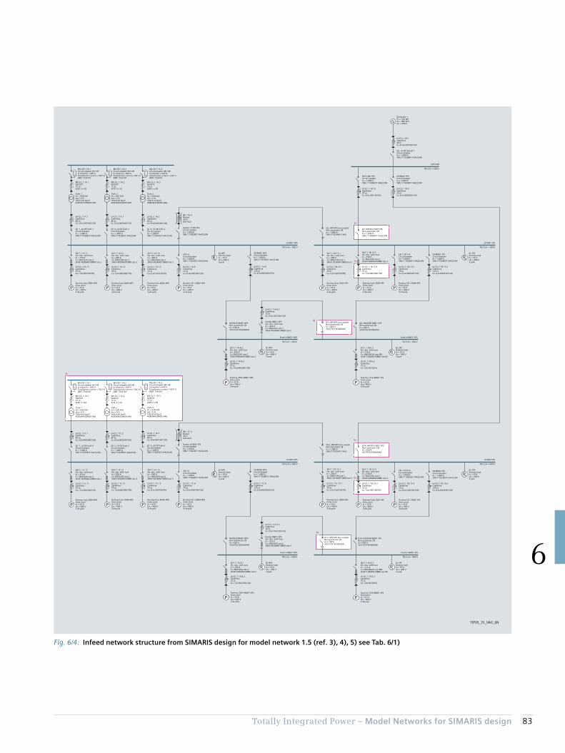
83Totally Integrated Power – Model Networks for SIMARIS design
6
Fig. 6/4: Infeed network structure from SIMARIS design for model network 1.5 (ref. 3), 4), 5) see Tab. 6/1)
3)
4)
4)
5)
5)
5)
5)
P P
P P
PP
P P
PP
G
P P P P P
PP
P P P P P P P
PP
TIP05_15_040_EN
LV-C/L 1.1A.3Cable/line40 mCu 3(3x240/240/120)
LV-C/L 1.1A.12Cable/line75 mCu 1(3x300/300/150)
MV-C/L 1.1A.3N2XS2Y15 mXLPE 3 x 50
Q1.3, LV-CB Trafo 3Circuit-breakerIn = 1,000 A3WL11102EB311AA2/LSIN
SD-F 1.1A.12Sw. disc. with fuseIn = 300 A3 x 3NA3250 size 23NJ61403MA010BB0 size 2
Dummy fuse 300A-NPSInner zoneIn = 33 AUn = 400 V3+N-pole
LV-C/L 1.1A.13Cable/line75 mCu 2(3x150/150/70)
SD-F 1.1A.13Sw. disc. with fuseIn = 400 A3 x 3NA3360 size 33NJ61603MA010BB0 size 3
Dummy fuse 400A-NPSInner zoneIn = 33 AUn = 400 V3+N-pole
LV-C/L 1.1B.13.1Cable/line75 mCu 1(3x150/150/70)
SD-F 1.1B.13.1Sw. disc. with fuseIn = 200 A3 x 3NA3140 size 13NJ61203MA010BB0 size 1
Dummy fuse 200A-SPSInner zoneIn = 33 AUn = 400 V3+N-pole
LV-C/L 1.1A.6Cable/line75 mCu 3(3x240/240/120)
CB A.6Circuit-breakerIn = 1,000 A3WL11102EB311AA2/LSIN
Dummy CB 1.000A-NPSInner zoneIn = 33 AUn = 400 V3+N-pole
Trafo 3Sn = 630 kVAukr = 6 %10/0.4 kV Dyn54GB58443DA001AA0
Q4, NACB LV MD1 SPSNon-automatic CBIn = 1,000 A3WL11102NB411AA2/LSIN
BB 1.1A.4Busbar20 mLDA1623
Feeder LV MD SPSCircuit-breakerIn = 1,000 A3WL11102EB311AA2/LSIN
MV-CB 1.1A.3Circuit-breaker CB-f ARIn (switch) = 630 ATransformer current = 50/1 ADMT: 7SJ6101
LV-C/L 1.1A.2Cable/line40 mCu 3(3x240/240/120)
LV-C/L 1.1A.11Cable/line75 mCu 1(3x185/185/95)
MV-C/L 1.1A.2N2XS2Y15 mXLPE 3 x 50
Q1.2, LV-CB Trafo 2Circuit-breakerIn = 1,000 A3WL11102EB311AA2/LSIN
SD-F 1.1A.11Sw. disc. with fuseIn = 250 A3 x 3NA3244 size 23NJ61403MA010BB0 size 2
Dummy fuse 250A-NPSInner zoneIn = 33 AUn = 400 V3+N-pole
Trafo 2Sn = 630 kVAukr = 6 %10/0.4 kV Dyn54GB58443DA001AA0
MV-CB 1.1A.2Circuit-breaker CB-f ARIn (switch) = 630 ATransformer current = 50/1 ADMT: 7SJ6101
LV-C/L 1.1A.1Cable/line40 mCu 3(3x240/240/120)
MV-C/L 1.1A.1N2XS2Y15 mXLPE 3 x 50
Q1.1, LV-CB Trafo 1Circuit-breakerIn = 1,000 A3WL11102EB311AA2/LSIN
Trafo 1Sn = 630 kVAukr = 6 %10/0.4 kV Dyn54GB58443DA001AA0
MV-CB 1.1A.1Circuit-breaker CB-f ARIn (switch) = 630 ATransformer current = 50/1 ADMT: 7SJ6101
DL NPSDummy loadIn = 33 AUn = 400 V3-pole
LV-C/L 1.1B.13.3Cable/line75 mCu 1(3x300/300/150)
SD-F 1.1B.13.3Sw. disc. with fuseIn = 250 A3 x 3NA3244 size 23NJ61403MA010BB0 size 2
Dummy fuse 250A-SPSInner zoneIn = 33 AUn = 400 V3+N-pole
LV-C/L 1.1B.13.4Cable/line75 mCu 2(3x240/240/120)
CB 1.1B13.4Circuit-breakerIn = 1,000 A3WL11102EB311AA2/LSIN
Dummy CB 1,000A-SPSInner zoneIn = 33 AUn = 400 V3+N-pole
CB BMD1 SPSCircuit-breakerIn = 1,000 A3WL11102EB311AA2/LSIN
DL SPSDummy loadIn = 33 AUn = 400 V3-pole
LV MD1 NPS
TN-S Un = 400 V
LV MD1 SPS
TN-S Un = 400 V
Q2, NPS/SPS bus couplerNon-automatic CBIn = 1,000 A3WL11102AA411AA2
LV-C/L 1.1A.8Cable/line125 mCu 2(3x300/300/150)
CB BMD1 NPSCircuit-breakerIn = 1,000 A3WL11102EB311AA2/LSIN
LV-C/L 1.1B.13.6Cable/line125 mCu 2(3x240/240/120)
LV-C/L 1.1A.8.2Cable/line75 mCu 1(3x240/240/120)
SD-F 1.1A.8.2Sw. disc. with fuseIn = 250 A3 x 3NA3244 size 23NJ61403MA010BB0 size 2
Dummy 250A-BMD1 NPSInner zoneIn = 33 AUn = 400 V3+N-pole
DL NPSDummy loadIn = 33 AUn = 400 V3-pole
LV-C/L 1.1A.8.3Cable/line10 mCu 1(3x120/120/120)
Feeder BMD1 SPSSw. disc. with fuseIn = 224 A3 x 3NA3242 size 23NJ61403MA010BB0 size 2
Q7, NPS/SPS bus couplerNon-automatic CBIn = 630 A3VL57631EE460AA0
Feed-in BMD1 NPS
TN-S Un = 400 V
Feed-in BMD1 SPS
TN-S Un = 400 V
NACB/SD BMD1 NPSNon-automatic CBIn = 630 A3VL57631DE360AA0
LV-C/L 1.1B.6.2Cable/line75 mCu 1(3x70/70/35)
SD-F 1.1B.6.2Sw. disc. with fuseIn = 125 A3 x 3NA38328 size 0003NJ61103MA010BB0 size 00
Dummy 125A-BMD1 SPSInner zoneIn = 33 AUn = 400 V3+N-pole
DL SPSDummy loadIn = 33 AUn = 400 V3-pole
Q8, NACB/SD BMD1 SPSNon-automatic CBIn = 630 A3VL57631EE460AA0
LV-C/L 1.1B.1Cable/line40 mCu 4(3x240/240/120)
Q3, LV-CB Genset 1Circuit-breakerIn = 1,600 A3WL11162NB411AA2/LSIN
Generator 1Pn = 704 kWSn = 880 kVAUn = 400 V
ESPS MD
TN-S Un = 400 V
LV-C/L 1.1B.13Cable/line75 mCu 3(3x185/185/95)
CB LV MD SPSCircuit-breakerIn = 1,000 A3WL11102NB311AA2/LSIN
LV-C/L 1.1B.9Cable/line75 mCu 3(3x300/300/150)
CB BMD2 SPSCircuit-breakerIn = 1,000 A3WL11102NB311AA2/LSIN
LV-C/L 1.1C.3Cable/line40 mCu 3(3x240/240/120)
LV-C/L 1.1C.12Cable/line75 mCu 1(3x300/300/150)
MV-C/L 1.1A.3N2XS2Y15 mXLPE 3 x 50
Q1.3, LV-CB Trafo 6Circuit-breakerIn = 1,000 A3WL11102EB311AA2/LSIN
SD-F 1.1C.12Sw. disc. with fuseIn = 300 A3 x 3NA3250 size 23NJ61403MA010BB0 size 2
Dummy fuse 300A-NPSInner zoneIn = 33 AUn = 400 V3+N-pole
LV-C/L 1.1C.13Cable/line75 mCu 2(3x150/150/70)
SD-F 1.1C.13Sw. disc. with fuseIn = 400 A3 x 3NA3360 size 33NJ61603MA010BB0 size 3
Dummy fuse 400A-NPSInner zoneIn = 33 AUn = 400 V3+N-pole
LV-C/L 1.1D.13.1Cable/line75 mCu 1(3x150/150/70)
SD-F 1.1D.13.1Sw. disc. with fuseIn = 200 A3 x 3NA3140 size 13NJ61203MA010BB0 size 1
Dummy fuse 200A-SPSInner zoneIn = 33 AUn = 400 V3+N-pole
LV-C/L 1.1C.6Cable/line75 mCu 3(3x240/240/120)
CB C.6Circuit-breakerIn = 1,000 A3WL11102EB311AA2/LSIN
Dummy CB 1.000A-NPSInner zoneIn = 33 AUn = 400 V3+N-pole
Trafo 3Sn = 630 kVAukr = 6 %10/0.4 kV Dyn54GB58443DA001AA0
Q14, NACB LV MD2 SPSNon-automatic CBIn = 630 A3VL57631EE460AA0
BB 1.1C.4Busbar20 mLDA1623
Feeder LV MD2 SPSCircuit-breakerIn = 1,000 A3WL11102EB311AA2/LSIN
MV-CB 1.1A.3Circuit-breaker CB-f ARIn (switch) = 630 ATransformer current = 50/1 ADMT: 7SJ6101
LV-C/L 1.1C.2Cable/line40 mCu 3(3x240/240/120)
LV-C/L 1.1C.11Cable/line75 mCu 1(3x240/240/120)
MV-C/L 1.1A.2N2XS2Y15 mXLPE 3 x 50
Q1.2, LV-CB Trafo 5Circuit-breakerIn = 1,000 A3WL11102EB311AA2/LSIN
SD-F 1.1C.11Sw. disc. with fuseIn = 250 A3 x 3NA3244 size 23NJ61403MA010BB0 size 2
Dummy fuse 250A-NPSInner zoneIn = 33 AUn = 400 V3+N-pole
Trafo 2Sn = 630 kVAukr = 6 %10/0.4 kV Dyn54GB58443DA001AA0
MV-CB 1.1A.2Circuit-breaker CB-f ARIn (switch) = 630 ATransformer current = 50/1 ADMT: 7SJ6101
LV-C/L 1.1C.1Cable/line40 mCu 3(3x240/240/120)
MV-C/L 1.1A.1N2XS2Y15 mXLPE 3 x 50
Q1.1, LV-CB Trafo 4Circuit-breakerIn = 1,000 A3WL11102EB311AA2/LSIN
Trafo 1Sn = 630 kVAukr = 6 %10/0.4 kV Dyn54GB58443DA001AA0
MV-CB 1.1A.1Circuit-breaker CB-f ARIn (switch) = 630 ATransformer current = 50/1 ADMT: 7SJ6101
DL NPSDummy loadIn = 33 AUn = 400 V3-pole
LV-C/L 1.1D.13.3Cable/line75 mCu 1(3x185/185/95)
SD-F 1.1D.13.3Sw. disc. with fuseIn = 250 A3 x 3NA3244 size 23NJ61403MA010BB0 size 2
Dummy fuse 250A-SPSInner zoneIn = 33 AUn = 400 V3+N-pole
LV-C/L 1.1D.13.4Cable/line75 mCu 2(3x240/240/120)
CB 1.1D13.4Circuit-breakerIn = 1,000 A3WL11102EB311AA2/LSIN
Dummy CB 1,000A-SPSInner zoneIn = 33 AUn = 400 V3+N-pole
CB BMD2 SPSCircuit-breakerIn = 1,000 A3WL11102EB311AA2/LSIN
DL SPSDummy loadIn = 33 AUn = 400 V3-pole
LV MD2 NPS
TN-S Un = 400 V
LV MD2 SPS
TN-S Un = 400 V
Q12, NPS/SPS bus couplerNon-automatic CBIn = 1,000 A3WL11102AA411AA2
LV-C/L 1.1C.8Cable/line125 mCu 2(3x300/300/150)
CB BMD2 NPSCircuit-breakerIn = 1,000 A3WL11102EB311AA2/LSIN
LV-C/L 1.1D.13.6Cable/line125 mCu 2(3x240/240/120)
LV-C/L 1.1A.8.2Cable/line75 mCu 1(3x240/240/120)
SD-F 1.1A.8.2Sw. disc. with fuseIn = 250 A3 x 3NA3244 size 23NJ61403MA010BB0 size 2
Dummy 250A-BMD1 NPSInner zoneIn = 33 AUn = 400 V3+N-pole
DL NPSDummy loadIn = 33 AUn = 400 V3-pole
LV-C/L 1.1A.8.3Cable/line10 mCu 1(3x120/120/120)
Feeder BMD1 SPSSw. disc. with fuseIn = 224 A3 x 3NA3242 size 23NJ61403MA010BB0 size 2
Q17, NPS/SPS bus couplerNon-automatic CBIn = 100 A3VL27101EE430AA0
Feed-in BMD1 NPS
TN-S Un = 400 V
Feed-in BMD1 SPS
TN-S Un = 400 V
NACB/SD BMD1 NPSNon-automatic CBIn = 630 A3VL57631DE360AA0
LV-C/L 1.1D.6.2Cable/line75 mCu 1(3x70/70/35)
SD-F 1.1D.6.2Sw. disc. with fuseIn = 125 A3 x 3NA38328 size 0003NJ61103MA010BB0 size 00
Dummy 125A-BMD1 SPSInner zoneIn = 33 AUn = 400 V3+N-pole
DL SPSDummy loadIn = 33 AUn = 400 V3-pole
Q18, NACB/SD BMD1 SPSNon-automatic CBIn = 630 A3VL57631EE460AA0
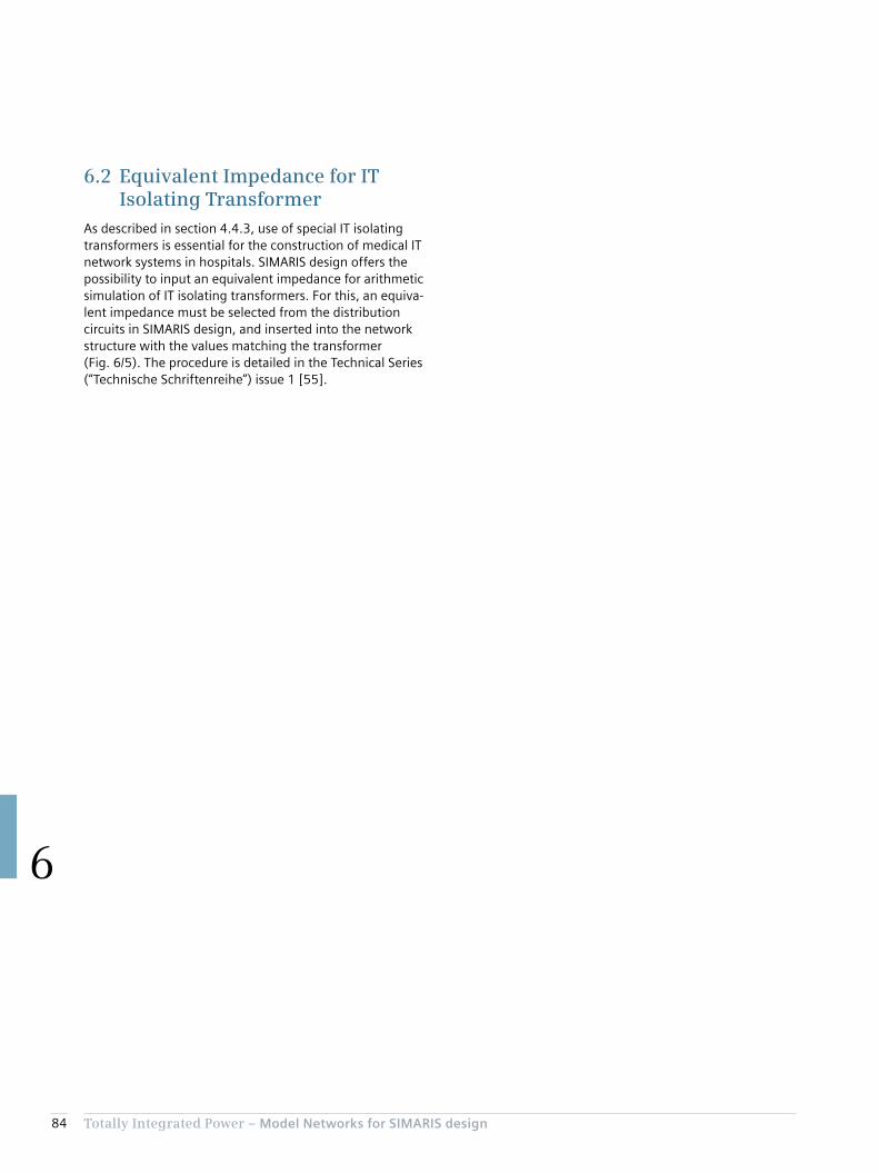
84 Totally Integrated Power – Model Networks for SIMARIS design
6
6.2 Equivalent Impedance for IT Isolating Transformer
As described in section 4.4.3, use of special IT isolating transformers is essential for the construction of medical IT network systems in hospitals. SIMARIS design offers the possibility to input an equivalent impedance for arithmetic simulation of IT isolating transformers. For this, an equiva-lent impedance must be selected from the distribution circuits in SIMARIS design, and inserted into the network structure with the values matching the transformer (Fig. 6/5). The procedure is detailed in the Technical Series (“Technische Schriftenreihe”) issue 1 [55].
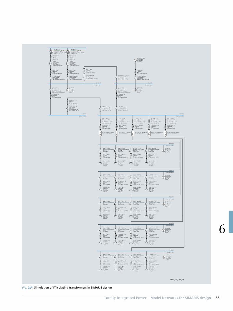
85Totally Integrated Power – Model Networks for SIMARIS design
6
Fig. 6/5: Simulation of IT isolating transformers in SIMARIS design
P
P
P
P
P
P
P
G
IT 3150VA
TN-S Un = 400 V
IT 5000VA
TN-S Un = 400 V
IT 4000VA
TN-S Un = 400 V
IT 8000VA
TN-S Un = 400 V
IT 6300VA
TN-S Un = 400 V
TIP05_15_041_EN
LV-C/L 1.1B.1aCable/line75 mCu 1(3x150/150/70)
SD-F 1.1B.1aSw. disc. with fuseIn = 200 A3 x 3NA3140 size 13NJ61203MA010BB0 size 1
LV-C/L 1.1A.3Cable/line10 mCu 3(3x185/185/95)
Feeder LV MD SPSCircuit-breakerIn = 1,000 A3WL11102EB311AA2/LSIN
LV-C/L 1.1A.2Cable/line40 mCu 3(3x240/240/120)
LV-C/L 1.1A.11Cable/line75 mCu 1(3x185/185/95)
MV-C/L 1.1A.2N2XS2Y15 mXLPE 3 x 50
Q1.2, LV-CB Trafo 2Circuit-breakerIn = 1,000 A3WL11102EB311AA2/LSIN
SD-F 1.1A.11aSw. disc. with fuseIn = 300 A3 x 3NA3250 size 23NJ61403MA010BB0 size 2
Trafo 2Sn = 630 kVAukr = 6 %10/0.4 kV Dyn54GB58443DA001AA0
MV-CB 1.1A.2Circuit-breaker CB-f ARIn (switch) = 630 ATransformer current = 50/1 ADMT: 7SJ6101
LV-C/L 1.1A.1Cable/line40 mCu 3(3x240/240/120)
MV-C/L 1.1A.1N2XS2Y15 mXLPE 3 x 50
Q1.1, LV-CB Trafo 1Circuit-breakerIn = 1,000 A3WL11102EB311AA2/LSIN
Trafo 1Sn = 630 kVAukr = 6 %10/0.4 kV Dyn54GB58443DA001AA0
MV-CB 1.1A.1Circuit-breaker CB-f ARIn (switch) = 630 ATransformer current = 50/1 ADMT: 7SJ6101
DL MD NPSDummy loadIn = 500 AUn = 400 V3-pole
DL MD SPSDummy loadIn = 500 AUn = 400 V3-pole
LV MD NPS
TN-S Un = 400 V
Q2, NPS/SPS bus couplerNon-automatic CBIn = 1,600 A3WL11162AA411AA2
LV-C/L 1.1B.1Cable/line40 mCu 4(3x240/240/120)
Q3, LV-CB Genset 1Circuit-breakerIn = 1,600 A3WL11162NB411AA2/LSIN
Generator 1.1B.1Pn = 480 kWSn = 880 kVAUn = 400 V
LV MD SPS
TN-S Un = 400 V
Q2.2, SD bus couplerNon-automatic CBIn = 160 A3VL27161EE430AA0
LTS1.1B.2Non-automatic CBIn = 160 A3VL27161EE430AA0
LV-C/L 1.1A.2.1.aCable/line10 mCu 1(3x50/50/25)
F-SwD 1.1A.2.1aFuse sw. disc.In = 125 A3 x 3NA3832 Gr. 003NJ41033BF01 Gr. 00
LV SD NPS
TN-S Un = 400 V
LV SD SPS
TN-S Un = 400 V
LV-C/L 1.1A.2.5.aCable/line2 mCu 1(3x16/16/16)
Bender ES 710, IT 3150 VAeqivalent impedance
F-So 1.1A.2.5aFuse with socketIn = 25 A3 x 3NA3810 size 0003NH4030 size 000
LV-C/L 1.1A.2.4.aCable/line2 mCu 1(3x25/25/25)
Bender ES 710, IT 4000 VAeqivalent impedance
F-So 1.1A.2.4aFuse with socketIn = 35 A3 x 3NA3814 size 0003NH4030 size 000
LV-C/L 1.1A.2.3.aCable/line2 mCu 1(3x25/25/25)
Bender ES 710, IT 5000 VAeqivalent impedance
F-So 1.1A.2.3aFuse with socketIn = 50 A3 x 3NA3820 size 0003NH4030 size 000
LV-C/L 1.1A.2.2.aCable/line2 mCu 1(3x25/25/25)
Bender ES 710, IT 6300 VAeqivalent impedance
F-So 1.1A.2.2aFuse with socketIn = 50 A3 x 3NA3820 size 0003NH4030 size 000
LV-C/L 1.1A.2.1.aCable/line2 mCu 1(3x25/25/25)
Bender ES 710, IT 8000 VAeqivalent impedance
F-So 1.1A.2.1aFuse with socketIn = 63 A3 x 3NA3822 size 0003NH4030 size 000
MCB 1.1B.2.5.1aMiniature circuit-breakerIn = 6 A5SY62066/B
LV-C/L 1.1B.2.5.1Cable/line30 mCu 1(1x1x4/4/4)
3 x IT loadDummy loadIn = 15.2 AUn = 400 V3-pole
Load 1.1B.2.5.1Inner zoneIn = 4.5 AUn = 230 V1+N-pole
MCB 1.1B.2.5.2aMiniature circuit-breakerIn = 10 A5SY62106/B
LV-C/L 1.1B.2.5.2Cable/line30 mCu 1(1x1x1.5/1.5/1.5)
Load 1.1B.2.5.1Inner zoneIn = 8 AUn = 230 V1+N-pole
MCB 1.1B.2.5.3aMiniature circuit-breakerIn = 13 A5SY62136/B
LV-C/L 1.1B.2.5.3Cable/line30 mCu 1(1x1x1.5/1.5/1.5)
Load 1.1B.2.5.1Inner zoneIn = 11 AUn = 230 V1+N-pole
MCB 1.1B.2.5.4aMiniature circuit-breakerIn = 16 A5SY62166/B
LV-C/L 1.1B.2.5.4Cable/line30 mCu 1(1x1x1.5/1.5/1.5)
Load 1.1B.2.5.1Inner zoneIn = 14 AUn = 230 V1+N-pole
MCB 1.1B.2.3.1aMiniature circuit-breakerIn = 6 A5SY62066/B
LV-C/L 1.1B.2.3.1Cable/line30 mCu 1(1x1x4/4/4)
3 x IT loadDummy loadIn = 24 AUn = 400 V3-pole
Load 1.1B.2.3.1Inner zoneIn = 4.5 AUn = 230 V1+N-pole
MCB 1.1B.2.3.2aMiniature circuit-breakerIn = 10 A5SY62106/B
LV-C/L 1.1B.2.3.2Cable/line30 mCu 1(1x1x1.5/1.5/1.5)
Load 1.1B.2.3.2Inner zoneIn = 8 AUn = 230 V1+N-pole
MCB 1.1B.2.3.3aMiniature circuit-breakerIn = 13 A5SY62136/B
LV-C/L 1.1B.2.3.3Cable/line30 mCu 1(1x1x1.5/1.5/1.5)
Load 1.1B.2.3.3Inner zoneIn = 11 AUn = 230 V1+N-pole
MCB 1.1B.2.3.4aMiniature circuit-breakerIn = 16 A5SY62166/B
LV-C/L 1.1B.2.3.4Cable/line30 mCu 1(1x1x1.5/1.5/1.5)
Load 1.1B.2.3.4Inner zoneIn = 14 AUn = 230 V1+N-pole
MCB 1.1B.2.4.1aMiniature circuit-breakerIn = 6 A5SY62066/B
LV-C/L 1.1B.2.4.1Cable/line30 mCu 1(1x1x4/4/4)
3 x IT loadDummy loadIn = 19.2 AUn = 400 V3-pole
Load 1.1B.2.4.1Inner zoneIn = 4.5 AUn = 230 V1+N-pole
MCB 1.1B.2.4.2aMiniature circuit-breakerIn = 10 A5SY62106/B
LV-C/L 1.1B.2.4.2Cable/line30 mCu 1(1x1x1.5/1.5/1.5)
Load 1.1B.2.4.2Inner zoneIn = 8 AUn = 230 V1+N-pole
MCB 1.1B.2.4.3aMiniature circuit-breakerIn = 13 A5SY62136/B
LV-C/L 1.1B.2.4.3Cable/line30 mCu 1(1x1x1.5/1.5/1.5)
Load 1.1B.2.4.3Inner zoneIn = 11 AUn = 230 V1+N-pole
MCB 1.1B.2.4.4aMiniature circuit-breakerIn = 16 A5SY62166/B
LV-C/L 1.1B.2.4.4Cable/line30 mCu 1(1x1x1.5/1.5/1.5)
Load 1.1B.2.4.4Inner zoneIn = 14 AUn = 230 V1+N-pole
MCB 1.1B.2.1.1aMiniature circuit-breakerIn = 6 A5SY62066/B
LV-C/L 1.1B.2.1.1Cable/line30 mCu 1(1x1x4/4/4)
3 x IT loadDummy loadIn = 43.3 AUn = 400 V3-pole
Load 1.1B.2.1.1Inner zoneIn = 4.5 AUn = 230 V1+N-pole
MCB 1.1B.2.1.2aMiniature circuit-breakerIn = 10 A5SY62106/B
LV-C/L 1.1B.2.1.2Cable/line30 mCu 1(1x1x1.5/1.5/1.5)
Load 1.1B.2.1.1Inner zoneIn = 8 AUn = 230 V1+N-pole
MCB 1.1B.2.1.3aMiniature circuit-breakerIn = 13 A5SY62136/B
LV-C/L 1.1B.2.1.3Cable/line30 mCu 1(1x1x1.5/1.5/1.5)
Load 1.1B.2.1.1Inner zoneIn = 11 AUn = 230 V1+N-pole
MCB 1.1B.2.1.4aMiniature circuit-breakerIn = 16 A5SY62166/B
LV-C/L 1.1B.2.1.4Cable/line30 mCu 1(1x1x1.5/1.5/1.5)
Load 1.1B.2.1.1Inner zoneIn = 14 AUn = 230 V1+N-pole
MCB 1.1B.2.2.1aMiniature circuit-breakerIn = 6 A5SY62066/B
LV-C/L 1.1B.2.2.1Cable/line30 mCu 1(1x1x4/4/4)
3 x IT loadDummy loadIn = 30.3 AUn = 400 V3-pole
Load 1.1B.2.2.1Inner zoneIn = 4.5 AUn = 230 V1+N-pole
MCB 1.1B.2.2.2aMiniature circuit-breakerIn = 10 A5SY62106/B
LV-C/L 1.1B.2.2.2Cable/line30 mCu 1(1x1x1.5/1.5/1.5)
Load 1.1B.2.2.2Inner zoneIn = 8 AUn = 230 V1+N-pole
MCB 1.1B.2.2.3aMiniature circuit-breakerIn = 13 A5SY62136/B
LV-C/L 1.1B.2.2.3Cable/line30 mCu 1(1x1x1.5/1.5/1.5)
Load 1.1B.2.2.3Inner zoneIn = 11 AUn = 230 V1+N-pole
MCB 1.1B.2.2.4aMiniature circuit-breakerIn = 16 A5SY62166/B
LV-C/L 1.1B.2.2.4Cable/line30 mCu 1(1x1x1.5/1.5/1.5)
Load 1.1B.2.2.4Inner zoneIn = 14 AUn = 230 V1+N-pole
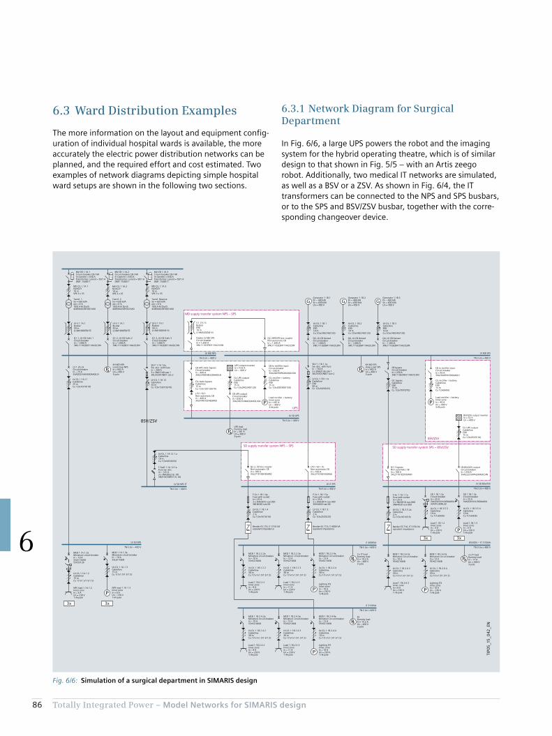
86 Totally Integrated Power – Model Networks for SIMARIS design
6
6.3.1 Network Diagram for Surgical Department
In Fig. 6/6, a large UPS powers the robot and the imaging system for the hybrid operating theatre, which is of similar design to that shown in Fig. 5/5 – with an Artis zeego robot. Additionally, two medical IT networks are simulated, as well as a BSV or a ZSV. As shown in Fig. 6/4, the IT transformers can be connected to the NPS and SPS busbars, or to the SPS and BSV/ZSV busbar, together with the corre-sponding changeover device.
6.3 Ward Distribution Examples
The more information on the layout and equipment config-uration of individual hospital wards is available, the more accurately the electric power distribution networks can be planned, and the required effort and cost estimated. Two examples of network diagrams depicting simple hospital ward setups are shown in the following two sections.
Fig. 6/6: Simulation of a surgical department in SIMARIS design
PP
P
3x3x
3x 3x
P
PP
P
P
P
P P
P
P
G G G
TIP0
5_1
5_0
42_E
N
LTS1.1B.1.1bNon-automatic CBIn = 100 A3VL27101EE430AA0
LV SD NPS
TN-S Un = 400 V
LV-C/L 1.1B.1.4Cable/line2 mCu 1(3x16/16/16)
Bender ES 710, IT 3150 VAeqivalent impedance
F-So 1.1B.1.4aFuse with socketIn = 25 A3 x 3NA3810 size 0003NH4030 size 00
LV-C/L 1.1B.1.5Cable/line2 mCu 1(3x25/25/25)
Bender ES 710, IT 4000 VAeqivalent impedance
F-So 1.1B.1.5aFuse with socketIn = 35 A3 x 3NA3814 size 0003NH4030 size 00
3 x IT loadDummy loadIn = 19.2 AUn = 400 V3-pole
MCB 1.1B.2.2.2aMiniature circuit-breakerIn = 10 A5SY62106/B
LV-C/L 1.1B.2.2.2Cable/line30 mCu 1(1x1x1.5/1.5/1.5)
Load 1.1B.2.2.2Inner zoneIn = 8 AUn = 230 V1+N-pole
MCB 1.1B.2.2.3aMiniature circuit-breakerIn = 13 A5SY62136/B
LV-C/L 1.1B.2.2.3Cable/line30 mCu 1(1x1x1.5/1.5/1.5)
Load 1.1B.2.2.3Inner zoneIn = 11 AUn = 230 V1+N-pole
MCB 1.1B.2.2.4aMiniature circuit-breakerIn = 13 A5SY62136/B
LV-C/L 1.1B.2.2.4Cable/line30 mCu 1(1x1x1.5/1.5/1.5)
CB to rectifier inputCircuit-breakerIn = 40 A3VA20405HL360AA0/LI
C/L rectifier + batteryCable/lineE9015 mCu 1(3x6/6/6)
Load rectifier + batteryInner zoneIn = 40 AUn = 400 V3+N-pole
BSV/ZSV output inverterIn = 32 AUn = 400 V
C/L UPS outputCable/lineE9015 mCu 1(3x25/25/16)
CB BSV/ZSV outputCircuit-breakerIn = 250 A3VA22255KP420AA0/LSIN
LV-C/L 1.1B.1.1aCable/lineE9050 mCu 1(3x50/50/25)
SD-F 1.1B.1.1aSw. disc. with fuseIn = 160 A3 x 3NA3136 size 13KL55301AB01 size 2
LV-C/L 1.1A.11Cable/line25 mCu 1(3x10/10/10)
Q1.2, LV-CB Trafo 2Circuit-breakerIn = 1,000 A3WL11102EB311AA2/LSIN
MV-CB 1.1A.2Circuit-breaker CB-f ARIn (switch) = 630 ATransformer current = 50/1 ADMT: 7SJ8011
Q1.3, LV-CB Trafo 3Circuit-breakerIn = 1,000 A3WL11102EB311AA2/LSIN
MV-CB 1.1A.3Circuit-breaker CB-f ARIn (switch) = 630 ATransformer current = 50/1 ADMT: 7SJ8011
Q1.1, LV-CB Trafo 1Circuit-breakerIn = 1,000 A3WL11102EB311AA2/LSIN
MV-CB 1.1A.1Circuit-breaker CB-f ARIn (switch) = 630 ATransformer current = 50/1 ADMT: 7SJ8011
LV MD NPS
TN-S Un = 400 V
Q4, LV-CB GensetCircuit-breakerIn = 1,000 A3WL11102EB411AA2/LSIN
Generator 1.1B.2Pn = 480 kWSn = 600 kVAUn = 400 V
Q4, LV-CB GensetCircuit-breakerIn = 1,000 A3WL11102EB411AA2/LSIN
Generator 1.1B.3Pn = 480 kWSn = 600 kVAUn = 400 V
Q3, LV-CB GensetCircuit-breakerIn = 1,000 A3WL11102EB411AA2/LSIN
Generator 1.1B.1Pn = 480 kWSn = 600 kVAUn = 400 V
LV MD SPS
TN-S Un = 400 V
Q2.2, SD bus couplerNon-automatic CBIn = 100 A3VL27101EE430AA0
LV-C/L 1.1A.12.1.aCable/line10 mCu 1(3x50/50/50)
F-SwD 1.1A.12.1aFuse sw. disc.In = 125 A3 x 3NA3832 Gr. 003NJ41033BF01 Gr. 00
LV SD NPS IT
TN-S Un = 400 V
LV SD BSV/ZSV
TN-S Un = 400 V
LV-C/L 1.1B.3.5.2aCable/line2 mCu 1(3x16/16/16)
Bender ES 710, IT 3150 VAeqivalent impedance
SD-F 1.1A.12aSw. disc. with fuseIn = 200 A3 x 3NA3140 size 13KL55301AB01 size 2
Lighting IT2Inner zoneIn = 10 AUn = 230 V1+N-pole
DLDummy loadIn = 15.2 AUn = 400 V3-pole
MCB 1.1B.2.4.2aMiniature circuit-breakerIn = 10 A5SY62106/B
LV-C/L 1.1B.2.4.2Cable/line30 mCu 1(1x1x1.5/1.5/1.5)
Load 1.1B.2.4.2Inner zoneIn = 8 AUn = 230 V1+N-pole
MCB 1.1B.2.4.3aMiniature circuit-breakerIn = 13 A5SY62136/B
LV-C/L 1.1B.2.4.3Cable/line30 mCu 1(1x1x1.5/1.5/1.5)
Load 1.1B.2.4.3Inner zoneIn = 11 AUn = 230 V1+N-pole
MCB 1.1B.2.4.4aMiniature circuit-breakerIn = 13 A5SY62136/B
LV-C/L 1.1B.2.4.4Cable/line10 mCu 1(1x1x1.5/1.5/1.5)
Lighting IT4Inner zoneIn = 10 AUn = 230 V1+N-pole
3 x IT loadDummy loadIn = 17 AUn = 400 V3-pole
MCB 1.1B.2.6.3aMiniature circuit-breakerIn = 10 A5SY62106/B
LV-C/L 1.1B.2.6.3Cable/line30 mCu 1(1x1.5/1.5/1.5)
Load 1.1B.2.6.3Inner zoneIn = 8 AUn = 230 V1+N-pole
MCB 1.1B.2.6.4aMiniature circuit-breakerIn = 13 A5SY62136/B
LV-C/L 1.1B.2.6.4Cable/line30 mCu 1(1x1.5/1.5/1.5)
CB to rectifier inputCircuit-breakerIn = 630 A3VA24635KP420AA0/LSIN
C/L rectifier + batteryCable/lineE9015 mCu 1(3x300/300/150)
Load rectifier + batteryInner zoneIn = 487 AUn = 400 V3+N-pole
CB UPS static bypass Circuit-breakerIn = 400 A3VA23405HN320AA0/LSI
LV IT SPS
TN-S Un = 400 V
UPS output inverterIn = 433 AUn = 400 V
C/L UPS outputCable/lineE9015 mCu 1(3x240/240/120)
LV SD UPS
TN-S Un = 400 V
UPS loadDummy loadIn = 361 AUn = 400 V3-pole
LV-C/L 1.1A.1.2Cable/line15 mCu 1(1x1.5/1.5/1.5)
NPS load 1.1A.1.2Inner zoneIn = 6 AUn = 230 V1+N-pole
MCB 1.1A.1.3aMiniature circuit-breakerIn = 10 A5SL61106/B
NPS load 1.1A.1.3Inner zoneIn = 6 AUn = 230 V1+N-pole
CB 1.1B.1.2aCircuit-breakerIn = 25 A3VA20255HL360AA0/LI3VA91230RL30
LV-C/L 1.1B.3.5.3Cable/line10 mCu 1(1x6/6/6)
Load 1.1B.1.2Inner zoneIn = 4 AUn = 230 V1+N-pole
CB 1.1B.1.3aCircuit-breakerIn = 25 A3VA20255HL360AA0/LI
LV-C/L 1.1B.3.5.4Cable/line10 mCu 1(1x6/6/6)
Load 1.1B.1.3Inner zoneIn = 6 AUn = 230 V1+N-pole
LTS1.1B.5Non-automatic CBIn = 400 A3VL47401EE460AA0
LV-C/L 1.1B.2Cable/lineE9010 mCu 2(3x240/240/120)
LV-C/L 1.1B.3Cable/lineE9010 mCu 2(3x240/240/120)
LV-C/L 1.1B.1Cable/lineE9010 mCu 2(3x240/240/120)
IT 4000VA
TN-S Un = 400 V
IT 3150VA
TN-S Un = 400 V
BSV/ZSV – IT 3150VA
TN-S Un = 400 V
BSV/ZSV
BSV/ZSV
UPS
SD supply transfer system NPS – SPS SD supply transfer system SPS – BSV/ZSV
MD supply transfer system NPS – SPS
MV-C/L 1.1A.1N2XS2Y10 mVPE 3 x 35
Transf. 1Sn = 630 kVAukr = 6 %10/0.4 kV Dyn54GB58443DY001AA0
Transf. 2Sn = 630 kVAukr = 6 %10/0.4 kV Dyn54GB58443DY001AA0
MV-C/L 1.1A.2N2XS2Y10 mVPE 3 x 35
MV-C/L 1.1A.3N2XS2Y10 mVPE 3 x 35
Transf. ReserveSn = 630 kVAukr = 6 %10/0.4 kV Dyn54GB58443DY001AA0
LV-S 1.1A.1Busbar50 mLI-AM10005B-55
LV-C/L 1.1A.12Cable/line50 mCu 1(3x150/150/70)
KH MD NPSLoad Hosp NPSIn = 902 AUn = 400 V3-pole
LS 1.2A.2aCircuit-breakerIn = 25 A3VA20255HN360AA0/LSI
LV-S 1.1A.1Busbar50 mLI-AM10005B-55
LV-S 1.1A.1Busbar50 mLI-AM10005B-55
S 1.1A.13BusbarE9010 mLI-AM32005B-55
Feeder LV MD SPSCircuit-breakerIn = 1,600 A3WL11162EB311AA2/LSIN
C/L static bypassCable/line15 mCu 1(3x120/120/70)
CB UPS outputCircuit-breakerIn = 630 A3VA24635HM420AA0/LIGN
Q2, NPS/SPS bus couplerNon-automatic CBIn = 1,600 A3WL11162EB411AA2/LSIN
KH MD SPSHosp-Load SPSIn = 902 AUn = 400 V3-pole
CB bypass Circuit-breakerIn = 250 A3WL11062EB311AA2/LSIN
C/L bypassCable/lineE9015 mCu 1(3x70/70/70)
MCB 1.1A.1.2aMiniature circuit-breakerIn = 10 A5SL61106/B5SV33126
LV-C/L 1.1A.1.3Cable/line15 mCu 1(1x1.5/1.5/1.5)
Q2.3 bypassNon-automatic CBIn = 100 A3VL27101EE430AA0
F-So 1.1A.1.1aFuse with socketIn = 25 A3 x 3NA3810 size 0003NH4030 size 000
Lighting IT3Inner zoneIn = 10 AUn = 230 V1+N-pole
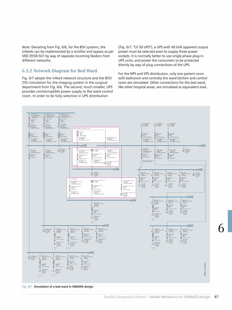
87Totally Integrated Power – Model Networks for SIMARIS design
6
Note: Deviating from Fig. 6/6, for the BSV systems, the infeeds can be implemented by a rectifier and bypass as per VDE 0558-507 by way of separate incoming feeders from different networks.
6.3.2 Network Diagram for Bed Ward
Fig. 6/7 adopts the infeed network structure and the BSV/ZSV simulation for the imaging system in the surgical department from Fig. 6/6. The second, much smaller, UPS provides uninterruptible power supply to the ward control room. In order to be fully selective in UPS distribution
(Fig. 6/1: “LV SD UPS”), a UPS with 40 kVA apparent output power must be selected even to supply three power sockets. It is normally better to use single-phase plug-in UPS units, and power the consumers to be protected directly by way of plug connections of the UPS.
For the NPS and SPS distribution, only one patient room with bathroom and centrally the ward kitchen and control room are simulated. Other connections for the bed ward, like other hospital areas, are simulated as equivalent load.
Fig. 6/7: Simulation of a bed ward in SIMARIS design
P
P
P
P
P
P
P
P P
P PPP
PP
IT 5000VA
TN-S Un = 400 V
2x4x
3x
2x2x
2x
2x
G G G
P
TIP0
5_1
5_0
43_E
N
Q1.2, LV-CB Trafo 2Circuit-breakerIn = 1,000 A3WL11102EB311AA2/LSIN
MV-CB 1.1A.2Circuit-breaker CB-f ARIn (switch) = 630 ATransformer current = 50/1 ADMT: 7SJ8011
Q1.3, LV-CB Trafo 3Circuit-breakerIn = 1,000 A3WL11102EB311AA2/LSIN
MV-CB 1.1A.3Circuit-breaker CB-f ARIn (switch) = 630 ATransformer current = 50/1 ADMT: 7SJ8011
Q1.1, LV-CB Trafo 1Circuit-breakerIn = 1,000 A3WL11102EB311AA2/LSIN
MV-CB 1.1A.1Circuit-breaker CB-f ARIn (switch) = 630 ATransformer current = 50/1 ADMT: 7SJ8011
LV MD NPS
TN-S Un = 400 V
LV-C/L 1.1B.2Cable/lineE9010 mCu 2(3x240/240/120)
Q5, LV-CB Genset 1.1B.2Circuit-breakerIn = 1,000 A3WL11102EB411AA2/LSIN
Generator 1.1B.2Pn = 480 kWSn = 600 kVAUn = 400 V
LV-C/L 1.1B.3Cable/lineE9010 mCu 2(3x240/240/120)
Q6, LV-CB Genset 1.1B.3Circuit-breakerIn = 1,000 A3WL11102EB411AA2/LSIN
LV-C/L 1.1B.1Cable/lineE9010 mCu 2(3x240/240/120)
Q4, LV-CB Genset 1.1B.1Circuit-breakerIn = 1,000 A3WL11102EB411AA2/LSIN
Generator 1.1B.1Pn = 480 kWSn = 600 kVAUn = 400 V
LV MD SPS
TN-S Un = 400 V
CB to rectifier input 1.1E.3aCircuit-breakerIn = 630 A3VA24635KP420AA0/LSIN
C/L rectifier + battery 1.1E.3Cable/lineE9015 mCu 1(3x300/300/150)
Load rectifier + battery 1.1E.3Inner zoneIn = 487 AUn = 400 V3+N-pole
CB UPS static bypass 1.1E.1a Circuit-breakerIn = 400 A3VA23405JP320AA0/LSI
UPS output inverter 1.1E.2In = 433 AUn = 400 V
C/L UPS output 1.1E.2Cable/lineE9015 mCu 1(3x240/240/120)
CB UPS output 1.1E.2Circuit-breakerIn = 630 A3VL57631TN460AA0/LING
LV SD UPS
TN-S Un = 400 V
UPS loadDummy loadIn = 361 AUn = 400 V3-pole
LTS1.1E.1aNon-automatic CBIn = 400 A3VL47401EE460AA0
Load rectifier + battery 1.1D.3Inner zoneIn = 72,2 AUn = 400 V3+N-pole
C/L static bypass 1.1D.1Cable/line15 mCu 1(3x6/6/6)
CB UPS static bypass 1.1D.1a Circuit-breakerIn = 400 A3VA23405HN320AA0/LSI
UPS2 output inverter 1.1D.2In = 60 AUn = 400 V
C/L UPS output 1.1D.2Cable/lineE905 mCu 1(3x10/10/10)
CB UPS output 1.1D.2Circuit-breakerIn = 63 A3VA20635JP460AA0/LSIN
LV SD UPS
TN-S Un = 400 V
LTS 1.1D.1Non-automatic CBIn = 100 A3VL47401EE460AA0
LV-C/L 1.2B.3Cable/line2 mCu 1(3x25/25/25)
Bender ES 710, IT 5000 VAeqivalent impedance
F-So 1.2B.3aFuse with socketIn = 50 A3 x 3NA3820 size 0003NH4030 size 00
3 x IT loadDummy loadIn = 24 AUn = 400 V3-pole
MCB 1.3B.1aMiniature circuit-breakerIn = 6 A5SY62066/B
LV-C/L 1.3B.1Cable/lineE9030 mCu 1(1x1.5/1.5/1.5)
Load 1.3B.1Inner zoneIn = 4.5 AUn = 230 V1+N-pole
MCB 1.3B.2aMiniature circuit-breakerIn = 10 A5SY62106/B
LV-C/L 1.3B.2Cable/lineE9030 mCu 1(1x1.5/1.5/1.5)
Load 1.3B.2Inner zoneIn = 8 AUn = 230 V1+N-pole
Load 1.3B.3Inner zoneIn = 11 AUn = 230 V1+N-pole
MCB 1.3B.3aMiniature circuit-breakerIn = 13 A5SY62136/B
LV-C/L 1.3B.3Cable/lineE9030 mCu 1(1x1.5/1.5/1.5)
Load 1.3B.4Inner zoneIn = 14 AUn = 230 V1+N-pole
MCB 1.3B.4aMiniature circuit-breakerIn = 16 A5SY62166/B
LV SD1 NPS
TN-S Un = 400 V
LV-C/L 1.3A.6Cable/line15 mCu 1(1x1.5/1.5/1.5)
NPS load 1.1A.3.6Inner zoneIn = 6 AUn = 230 V1+N-pole
LV-C/L 1.3A.5Cable/line15 mCu 1(1x1.5/1.5/1.5)
NPS load 1.1A.3.5Inner zoneIn = 16 AUn = 230 V1+N-pole
MCB 1.3A.7aMiniature circuit-breakerIn = 13 A5SL61136/B
LV-C/L 1.3A.7Cable/line15 mCu 1(1x1.5/1.5/1.5)
NPS lighting roomInner zoneIn = 10 AUn = 230 V1+N-pole
MCB 1.3A.8aMiniature circuit-breakerIn = 10 A5SL61106/B
LV-C/L 1.3A.8Cable/line15 mCu 1(1x1.5/1.5/1.5)
NPS lighting bathInner zoneIn = 6 AUn = 230 V1+N-pole
Kitchen, storageDummy loadIn = 10 AUn = 400 V3-pole
LV-C/L 1.2D.1Cable/lineE9015 mCu 1(1x1.5/1.5/1.5)
NPS load 1.2D.1Inner zoneIn = 6 AUn = 230 V1+N-pole
LV SD2 NPS
TN-S Un = 400 V
LV-C/L 1.3A.2Cable/line15 mCu 1(1x1.5/1.5/1.5)
Outlets kitchenInner zoneIn = 6 AUn = 230 V1+N-pole
LV-C/L 1.3A.1Cable/line15 mCu 1(1x1.5/1.5/1.5)
Kitchen coolingInner zoneIn = 10 AUn = 230 V1+N-pole
MCB 1.3A.3aMiniature circuit-breakerIn = 13 A5SL63136/B
LV-C/L 1.3A.3Cable/line15 mCu 1(3x1.5/1.5/1.5)
CookersInner zoneIn = 10 AUn = 400 V3+N-pole
MCB 1.3A.4aMiniature circuit-breakerIn = 10 A5SL61106/B
LV-C/L 1.3A.4Cable/line15 mCu 1(1x1.5/1.5/1.5)
Lighting kitchenInner zoneIn = 6 AUn = 230 V1+N-pole
Kitchen, storageDummy loadIn = 10 AUn = 400 V3-pole
LV SD SPS1.4B
TN-S Un = 400 V
LV-C/L 1.4B.1Cable/lineE9015 mCu 1(1x4/4/4)
SPS Outlet 1.4B.1Inner zoneIn = 10 AUn = 230 V1+N-pole
MCB 1.4B.2aMiniature circuit-breakerIn = 6 A5SL61066/B
LV-C/L 1.4B.2Cable/lineE9015 mCu 1(1x1.5/1.5/1.5)
Nurse callInner zoneIn = 2 AUn = 230 V1+N-pole
MCB 1.4B.3aMiniature circuit-breakerIn = 6 A5SL61066/B
LV-C/L 1.4B.3Cable/lineE9015 mCu 1(1x1.5/1.5/1.5)
SPS lightingInner zoneIn = 2 AUn = 230 V1+N-pole
LV SD SPS1.5B
TN-S Un = 400 V
LV-C/L 1.5B.1Cable/lineE9015 mCu 1(1x4/4/4)
Station centerInner zoneIn = 10 AUn = 230 V1+N-pole
MCB 1.5B.2aMiniature circuit-breakerIn = 10 A5SL61106/B
LV-C/L 1.5B.2Cable/lineE9015 mCu 1(1x2.5/2.5/2.5)
Nurse callInner zoneIn = 6 AUn = 230 V1+N-pole
MCB 1.5B.3aMiniature circuit-breakerIn = 6 A5SL61066/B
LV-C/L 1.5B.3Cable/lineE9015 mCu 1(1x1.5/1.5/1.5)
SPS lightingInner zoneIn = 2 AUn = 230 V1+N-pole
LV-C/L 1.2A.4Cable/line25 mCu 1(3x6/6/6)
CB 1.2A.4aCircuit-breakerIn = 63 A3VA20635JP360AA0/LSI
CB 1.2A.5aCircuit-breakerIn = 100 A3VA20105JP360AA0/LSI
LV-C/L 1.2B.4Cable/lineE9015 mCu 1(3x6/6/6)
CB SPS 1.2B.4aCircuit-breakerIn = 25 A3VA20255JP360AA0/LSI
LV-C/L 1.2B.5Cable/lineE9015 mCu 1(3x6/6/6)
CB SPS 1.2B.5aCircuit-breakerIn = 40 A3VA20405JP360AA0/LSI
Supply transfer system NPS – SPS
UPS OR
UPS station
Transf. ReserveSn = 630 kVAukr = 6 %10/0.4 kV Dyn54GB58443DY001AA0
LV-S 1.1A.2Busbar50 mLI-AM10005B-55
LV-S 1.1A.3Busbar50 mLI-AM10005B-55
LV-S 1.1A.1Busbar50 mLI-AM10005B-55
LV-C/L 1.2A.5Cable/line25 mCu 1(3x16/16/16)
DL 1.1A.2Dummy loadIn = 902 AUn = 400 V3-pole
S 1.1A.13BusbarE9010 mLI-AM32005B-55
Feeder LV MD SPSCircuit-breakerIn = 1,600 A3WL11162EB311AA2/LSIN
Q2, NPS/SPS bus couplerNon-automatic CBIn = 1,600 A3WL11162EB411AA2/LSIN
C/L static bypass 1.1E.1Cable/lineE9015 mCu 1(3x150/150/70)
MCB 1.2D.1aMiniature circuit-breakerIn = 10 A5SL61106/B5SV33126
CB to rectifier input 1.1D.3aCircuit-breakerIn = 100 A3VA20205HL360AA0/LI
C/L rectifier + battery 1.1D.3Cable/lineE9015 mCu 1(3x16/16/16)
MCB 1.3A.6aMiniature circuit-breakerIn = 10 A5SL61106/B5SV33126
MCB 1.3A.5aMiniature circuit-breakerIn = 20 A5SL61206/B5SV33126
MCB 1.3A.2aMiniature circuit-breakerIn = 10 A5SL61106/B5SV33126
MCB 1.3A.1aMiniature circuit-breakerIn = 13 A5SL61136/B5SV33126
Generator ReservePn = 480 kWSn = 600 kVAUn = 400 V
LV-C/L 1.3B.4Cable/lineE9030 mCu 1(1x2.5/2.5/2.5)
MCB 1.4B.1aMiniature circuit-breakerIn = 13 A5SL61136/B5SV33126
DL 1.2A.6Dummy loadIn = 500 AUn = 400 V3-pole
MCB 1.5B.1aMiniature circuit-breakerIn = 13 A5SL61136/B5SV33126
MV-C/L 1.1A.1N2XS2Y10 mVPE 3 x 35
Transf. 1Sn = 630 kVAukr = 6 %10/0.4 kV Dyn54GB58443DY001AA0
MV-C/L 1.1A.2N2XS2Y10 mVPE 3 x 35
Transf. 2Sn = 630 kVAukr = 6 %10/0.4 kV Dyn54GB58443DY001AA0
MV-C/L 1.1A.3N2XS2Y10 mVPE 3 x 35

88 Totally Integrated Power – Model Networks for SIMARIS design
6

Chapter 7Designing and Configuring the Main Components of Electric Power Distribution Systems
7.1 GEAFOL Distribution Transformers 91
7.2 Medium-voltage Switchgear 92
7.3 Low-voltage Switchgear 94
7.4 Distribution Boards 96
7.5 Busbar Trunking Systems 97
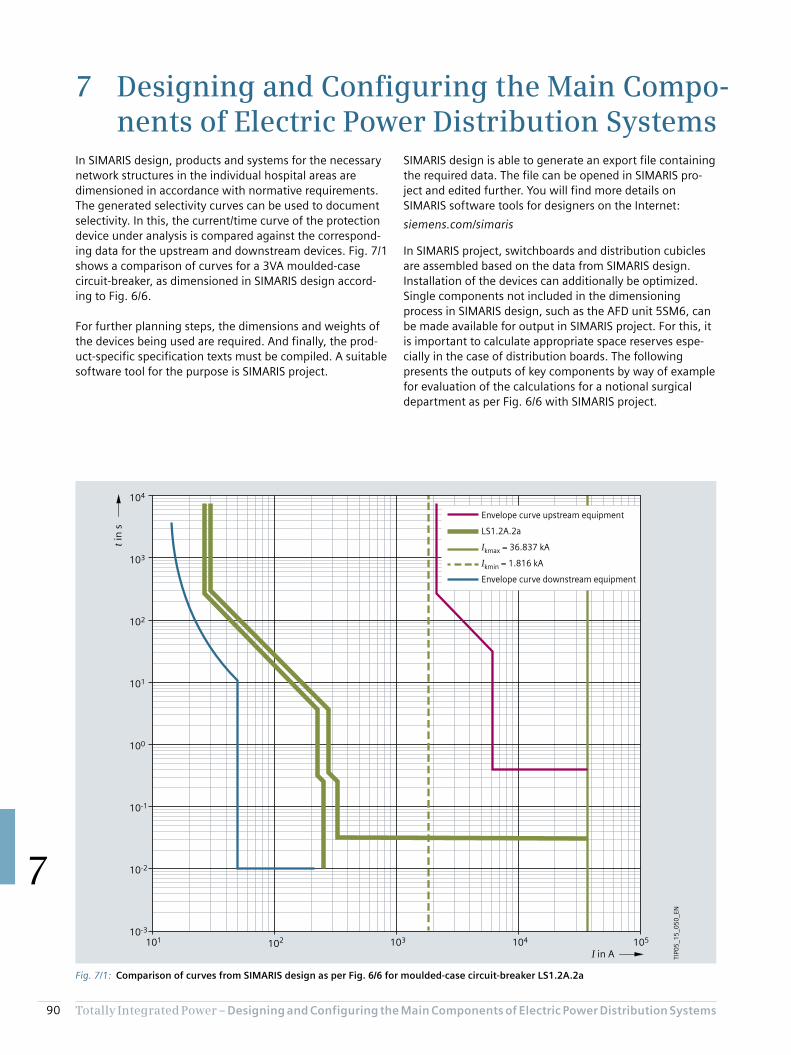
90 Totally Integrated Power – Designing and Configuring the Main Compo nents of Electric Power Distribution Systems
7
7 Designing and Configuring the Main Compo-nents of Electric Power Distribution Systems
SIMARIS design is able to generate an export file containing the required data. The file can be opened in SIMARIS pro-ject and edited further. You will find more details on SIMARIS software tools for designers on the Internet:
siemens.com/simaris
In SIMARIS project, switchboards and distribution cubicles are assembled based on the data from SIMARIS design. Installation of the devices can additionally be optimized. Single components not included in the dimensioning process in SIMARIS design, such as the AFD unit 5SM6, can be made available for output in SIMARIS project. For this, it is important to calculate appropriate space reserves espe-cially in the case of distribution boards. The following presents the outputs of key components by way of example for evaluation of the calculations for a notional surgical department as per Fig. 6/6 with SIMARIS project.
In SIMARIS design, products and systems for the necessary network structures in the individual hospital areas are dimensioned in accordance with normative requirements. The generated selectivity curves can be used to document selectivity. In this, the current/time curve of the protection device under analysis is compared against the correspond-ing data for the upstream and downstream devices. Fig. 7/1 shows a comparison of curves for a 3VA moulded-case circuit-breaker, as dimensioned in SIMARIS design accord-ing to Fig. 6/6.
For further planning steps, the dimensions and weights of the devices being used are required. And finally, the prod-uct-specific specification texts must be compiled. A suitable software tool for the purpose is SIMARIS project.
Fig. 7/1: Comparison of curves from SIMARIS design as per Fig. 6/6 for moulded-case circuit-breaker LS1.2A.2a
105104101 102 103
10-2
10-3
100
10-1
101
102
103
104
Envelope curve upstream equipment
LS1.2A.2a
Ikmax = 36.837 kA
Ikmin = 1.816 kA
Envelope curve downstream equipment
I in A
t in
s
TIP0
5_1
5_0
50
_EN

91Totally Integrated Power – Designing and Configuring the Main Compo nents of Electric Power Distribution Systems
7
7.1 GEAFOL Distribution Transformers
As described in [36], with a line connection above 250 A, supply to the building with medium voltage and transfor-mation to the building’s low-voltage distribution network by distribution transformers is preferred. For installation in the immediate vicinity of people, GEAFOL transformers (Fig. 7/2) are selected. SIMARIS project provides the specifi-cation text:
Cast-resin insulated dry-type transformers (GEAFOL) have the following characteristics: Flame-retardant and self-extinguishing according to IEC 60076-11, VDE 0532-76-11, DIN EN 60076-11. No toxic or explosive gases must escape in case of fire. A fire damage assessment with smoke gas analysis must be submitted. High power-frequency withstand voltage and impulse strength. It has to be proved by measurement that the windings are free of internal partial discharge up to 2 × Un. In this context, the background noise level must not exceed 5 pC.
Winding construction
HV: Aluminium foil winding cast under vacuum in insulation class F with a permissible average temperature rise of 100 K.
LV: Prepreg-insulated aluminium strip winding (to reduce the axial short-circuit forces) in insulation class F with a permissible average temperature rise of 100 K.
Technical data
• Fire behaviour class F1• Environmental class E2• Climatic class C2• Indoor installation• Site altitude up to up to 1,000 m• Insulation class HV/LV F/F• Insulation level for HV 10 kV: AC 28 kV, LI 75 kV• Insulation level for HV 20 kV: AC 50 kV, LI 95 kV• Maximum ambient temperature 40 °C• Rated frequency 50 Hz• Mode of operation DB (continuous operation)• Cooling type AN (Air Natural)• Degree of protection IP00• Optional power increase up to 40 % due to installation of
fans (as of 630 kVA)• Optionally for each rating, there is a tested protective
housing available without power reduction up to IP23• Including:
– Two temperature monitoring systems for warning and tripping, consisting of two PTC (Positive Temperature Coefficient) sensors per limb, and one tripping device AC/DC (24 – 240 V, 50 – 60 Hz) as supplementary equipment
– Two earthing connections M12 at the lower clamping frame, convertible rollers for lengthways and sideways travel
Fig. 7/2: CAD views for GEAFOL transformer from SIMARIS project
1
2
7
8
9
5
3
6
44
H1
B1e
A1e
2U, 2V, 2W
1W1V1U
A1*) 1,520 mmB1*) 845 mmH1*) 1,315 mme*) 520 mm (100-250 kVA) 670 mm (315-800 kVA) 820 mm (1,000-1,600 kVA) 1,070 mm (2,000-2,500 kVA)
TIP0
5_1
5_0
51
_EN
1 Rating plate2 HV connection straps3 Terminals for temperature monitoring4 Earth connection (M12)5 Pulling lug6 Lifting lug7 LV connections8 HV connections9 Optional fans
*) Dimensions are non-binding, subject to design modifications; rollers can be turned 90°
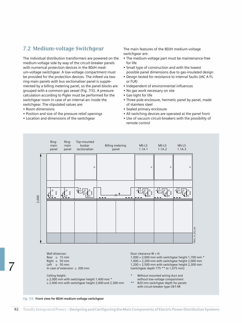
92 Totally Integrated Power – Designing and Configuring the Main Compo nents of Electric Power Distribution Systems
7
The main features of the 8DJH medium-voltage switchgear are:• The medium-voltage part must be maintenance-free
for life• Small type of construction and with the lowest
possible panel dimensions due to gas-insulated design• Design tested for resistance to internal faults (IAC A FL
or FLR)• Independent of environmental influences• No gas work necessary on site• Gas-tight for life• Three-pole enclosure, hermetic panel by panel, made
of stainless steel• Sealed primary enclosure• All switching devices are operated at the panel front• Use of vacuum circuit-breakers with the possibility of
remote control
7.2 Medium-voltage Switchgear
The individual distribution transformers are powered on the medium-voltage side by way of the circuit-breaker panels with numerical protection devices in the 8DJH medi-um-voltage switchgear. A low-voltage compartment must be provided for the protection devices. The infeed via two ring-main panels with bus sectionaliser panel is supple-mented by a billing metering panel, so the panel blocks are grouped with a common gas vessel (Fig. 7/3). A pressure calculation according to Pigler must be performed for the switchgear room in case of an internal arc inside the switchgear. The stipulated values are:• Room dimensions• Position and size of the pressure relief openings• Location and dimensions of the switchgear
Fig. 7/3: Front view for 8DJH medium-voltage switchgear
TIP0
5_1
5_0
52
_EN
2,0
00
Wall distances:Rear ≥ 15 mmRight ≥ 50 mmLeft ≥ 50 mmIn case of extension ≥ 200 mm
Ceiling height:≥ 2,000 mm with switchgear height 1,400 mm *≥ 2,400 mm with switchgear height 2,000 and 2,300 mm
Ring-mainpanel
Ring-mainpanel
Top-mountedbusbar
sectionaliserBilling metering
panelMS-LS1.1A.1
MS-LS1.1A.3
MS-LS1.1A.2
Door clearance W × H:1,000 × 2,000 mm with switchgear height 1,700 mm *1,000 × 2,200 mm with switchgear height 2,000 mm1,200 × 2,500 mm with switchgear height 2,300 mm (switchgear depth 775 ** to 1,075 mm)
* Without mounted wiring duct and without low-voltage compartment** 820 mm switchgear depth for panels with circuit-breaker type CB-f AR
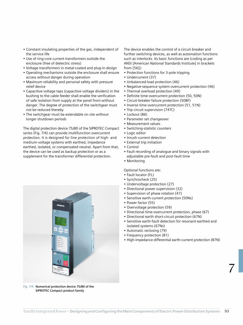
93Totally Integrated Power – Designing and Configuring the Main Compo nents of Electric Power Distribution Systems
7
• Constant insulating properties of the gas, independent of the service life
• Use of ring-core current transformers outside the enclosure (free of dielectric stress)
• Voltage transformers in metal-coated and plug-in design• Operating mechanisms outside the enclosure shall ensure
access without danger during operation• Maximum reliability and personal safety with pressure
relief device• Capacitive voltage taps (capacitive voltage dividers) in the
bushing to the cable feeder shall enable the verification of safe isolation from supply at the panel front without danger. The degree of protection of the switchgear must not be reduced thereby
• The switchgear must be extendable on site without longer shutdown periods
The digital protection device 7SJ80 of the SIPROTEC Compact series (Fig. 7/4) can provide multifunction overcurrent protection. It is designed for line protection of high- and medium-voltage systems with earthed, impedance earthed, isolated, or compensated neutral. Apart from that, the device can be used as backup protection or as a supplement for the transformer differential protection.
The device enables the control of a circuit-breaker and further switching devices, as well as automation functions such as interlocks. Its basic functions are (coding as per ANSI [American National Standards Institute] in brackets from [56]):• Protection functions for 3-pole tripping• Undercurrent (37)• Unbalanced-load protection (46)• Negative-sequence system overcurrent protection (46)• Thermal overload protection (49)• Definite time-overcurrent protection (50, 50N)• Circuit-breaker failure protection (50BF)• Inverse time-overcurrent protection (51, 51N)• Trip circuit supervision (74TC)• Lockout (86)• Parameter set changeover• Measurement values• Switching-statistic counters• Logic editor• Inrush-current detection• External trip initiation• Control• Fault recording of analogue and binary signals with
adjustable pre-fault and post-fault time• Monitoring
Optional functions are:• Fault locator (FL)• Synchrocheck (25)• Undervoltage protection (27)• Directional power supervision (32)• Supervision of phase rotation (47)• Sensitive earth-current protection (50Ns)• Power factor (55)• Overvoltage protection (59)• Directional time-overcurrent protection, phase (67)• Directional earth short-circuit protection (67N)• Sensitive earth-fault detection for resonant-earthed and
isolated systems (67Ns)• Automatic reclosing (79)• Frequency protection (81)• High-impedance differential earth-current protection (87N)
Fig. 7/4: Numerical protection device 7SJ80 of the SIPROTEC Compact product family

94 Totally Integrated Power – Designing and Configuring the Main Compo nents of Electric Power Distribution Systems
7
The NPS-SPS coupling cubicle is also equipped with a 3WL air circuit-breaker. For measurements and measurement display, the incoming feeder and coupling cubicles each feature three instrument transformers and a 7KM PAC3200 multifunctional measuring device for flush mounting (Fig. 7/6).
The outgoing feeder cubicle in universal mounting design accommodates the three outgoing feeders of the switchboard in fixed-mounted design, with a front door each. The assembly kit height for the 3KL55 switch-disconnector with fuses is 300 mm; for the 3VA20 moulded-case circuit-breaker, 150 mm is specified; and 200 mm for the 3VA23 (Fig. 7/7). The moulded-case circuit-breakers are installed in lying position (connections on the left and right).
7.3 Low-voltage Switchgear
Fig. 7/5 shows the SIVACON S8 low-voltage switchboard for normal power supply to the surgical department presented in Fig. 6/6 as an example of a main distribution board. This is a design verified power switchgear and controlgear assembly according to IEC 61439-2.
For infeed to the three transformers, incoming feeder cubicles with 3WL air circuit-breakers in withdrawable design are used. A cubicle comprises the following func-tional compartments:• Device compartment• Auxiliary or measuring device compartment• Cable or busbar connection compartment• Busbar compartment• Cross-wiring compartment
Fig. 7/5: Front view of NPS low-voltage switchboard SIVACON S8
SIEMENSSIVACON
SIEMENSSIVACON
SIEMENSSIVACON
SIEMENSSIVACON
SIEMENSSIVACON
TIP0
5_1
5_0
53
_EN
Incoming feederQ1.1
Incoming feederQ1.2
Incoming feederQ1.3
Bus couplerNPS-SPS
Outgoing feedersFSD 1.1A.12a
CB 1.2A.2aCB UPS Bypass
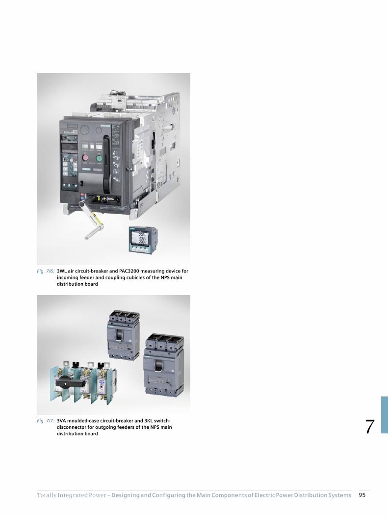
95Totally Integrated Power – Designing and Configuring the Main Compo nents of Electric Power Distribution Systems
7
Fig. 7/6: 3WL air circuit-breaker and PAC3200 measuring device for incoming feeder and coupling cubicles of the NPS main distribution board
Fig. 7/7: 3VA moulded-case circuit-breaker and 3KL switch-disconnector for outgoing feeders of the NPS main distribution board

96 Totally Integrated Power – Designing and Configuring the Main Compo nents of Electric Power Distribution Systems
7
7.4 Distribution Boards
By way of example for the many distribution boards identified in project design with the SIMARIS planning tools for the surgical department, the following considers the ALPHA 400 distribution board for outgoing distribution of the BSV/ZSV. In SIMARIS project, a 2.70 m wide wall distribution board (in accordance with IEC 61439-1/-2/-3, DIN VDE 0603-1 standards) is created (Fig. 7/8a). The program places the devices in the largest possible panel, and inserts a second panel to obtain the space reserve of 20 % and the terminal area reserve of 30 %. If the user reduces both values to 10 % in the program, one panel is sufficient (Fig. 7/8b). However, the reserves are then very tight.
As an alternative, the user can select a different panel width in SIMARIS project. With a panel width of 800 mm, the space requirements can be met, provided the terminal area reserve is only reduced a little, to 25 % (Fig. 7/8c). The 20 % space reserve remains unchanged. Your TIP contact partner will help you find the optimum solution using the SIMARIS software tools (siemens.com/tip-cs/contact).
For residual-current protection, the 3VA2 moulded-case circuit-breakers can be supplemented for power socket circuits with differential current protection devices RCD820 (Advanced type A). Tripping by RCD820 can be read from the LCD display of the ETU.
Other devices in the distribution board in addition to the 3VA2 moulded-case circuit-breakers are the 3VL switch-disconnector for connection of the BSV/ZSV manual bypass and the 3NP1 fuse-switch-disconnector to the transformer for the medical IT network.
Fig. 7/8: Front view for ALPHA 400 distribution board from SIMARIS project a) Unchanged output of the file imported from SIMARIS design b) Output if reserve values each reduced to 10 % c) Output for an unchanged space reserve of 20 % and a terminal area reserve of 25 % with a panel width of 800 mm
a)
b) c)
TIP05_15_054_EN1,350 mm 1,350 mm
1,4
00
mm
1,350 mm
1,4
00
mm
800 mm 800 mm
1,4
00
mm
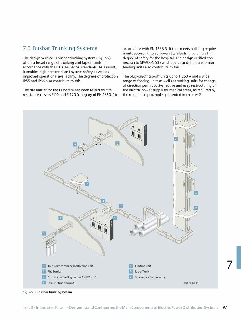
97Totally Integrated Power – Designing and Configuring the Main Compo nents of Electric Power Distribution Systems
7
accordance with EN 1366-3. It thus meets building require-ments according to European Standards, providing a high degree of safety for the hospital. The design verified con-nection to SIVACON S8 switchboards and the transformer feeding units also contribute to this.
The plug-on/off tap-off units up to 1,250 A and a wide range of feeding units as well as trunking units for change of direction permit cost-effective and easy restructuring of the electric power supply for medical areas, as required by the remodelling examples presented in chapter 2.
7.5 Busbar Trunking Systems
The design verified LI busbar trunking system (Fig. 7/9) offers a broad range of trunking and tap-off units in accordance with the IEC 61439-1/-6 standards. As a result, it enables high personnel and system safety as well as improved operational availability. The degrees of protection IP55 and IP66 also contribute to this.
The fire barrier for the LI system has been tested for fire resistance classes EI90 and EI120 (category of EN 13501) in
Fig. 7/9: LI busbar trunking system
6
5
1
4
3
2
1
2
3
4
5
6
7
2
7
7
6
2
Transformer connection/feeding unit
Fire barrier
Connection/feeding unit to SIVACON S8
Straight trunking unit
Junction unit
Tap-off unit
Accessories for mounting
TIP05_15_055_EN

98 Totally Integrated Power – Designing and Configuring the Main Compo nents of Electric Power Distribution Systems
7
With the different conductor configurations with PE, neutral, and clean-earth execution (insulated PE; Fig. 7/10), network requirements relating to neutral conductor loading can be met. If higher rated currents are required, the LI busbar trunking system can be used as a double body (Fig. 7/10 bottom).
For descriptions of other systems, products, and compo-nents, refer to other Siemens planning manuals, such as [36]. The download centre accessible via a link from:
siemens.com/tip-cs
provides a number of downloadable PDF files of such manuals. The associated specification lists are available via the outputs from SIMARIS project or from:
siemens.com/specifications
Your TIP contact partner will be able to help you in estimating the efficiency of your planning and in budgeting:
siemens.com/tip-cs/contact
Fig. 7/10: Clean-Earth conductor configurations for LI busbar trunking system: Top: LI single body (left: single N conductor; right: double N conductor; CPE = Clean Earth PE conductor Bottom: LI double body
1 2 3 4 5 6
155 mm
1 2 3 4 5 6
1 2 3 4 5 6 7
155 mm
1 2 3 4 5 6
410 mm
7
N L1 L2 L3 CPE PEoutg. N L1N L2 L3 CPE PEoutg.
TIP05_15_056_EN

Chapter 8Annex
8.1 List of Standards Cited 100
8.2 Lighting Specifications for Rooms in Hospitals According to DIN 5035-3 104
8.3 List of Abbreviations 106
8.4 Literature References 110
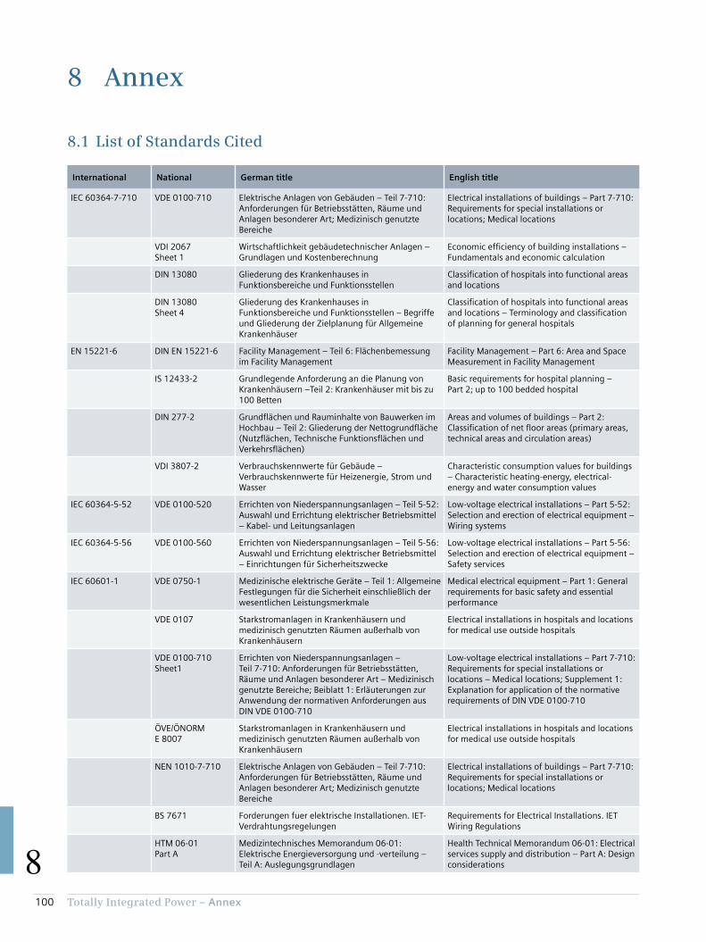
100 Totally Integrated Power – Annex
8
8 Annex
8.1 List of Standards Cited
International National German title English title
IEC 60364-7-710 VDE 0100-710 Elektrische Anlagen von Gebäuden – Teil 7-710: Anforderungen für Betriebsstätten, Räume und Anlagen besonderer Art; Medizinisch genutzte Bereiche
Electrical installations of buildings – Part 7-710: Requirements for special installations or locations; Medical locations
VDI 2067 Sheet 1
Wirtschaftlichkeit gebäudetechnischer Anlagen – Grundlagen und Kostenberechnung
Economic efficiency of building installations – Fundamentals and economic calculation
DIN 13080 Gliederung des Krankenhauses in Funktionsbereiche und Funktionsstellen
Classification of hospitals into functional areas and locations
DIN 13080 Sheet 4
Gliederung des Krankenhauses in Funktionsbereiche und Funktionsstellen – Begriffe und Gliederung der Zielplanung für Allgemeine Krankenhäuser
Classification of hospitals into functional areas and locations – Terminology and classification of planning for general hospitals
EN 15221-6 DIN EN 15221-6 Facility Management – Teil 6: Flächenbemessung im Facility Management
Facility Management – Part 6: Area and Space Measurement in Facility Management
IS 12433-2 Grundlegende Anforderung an die Planung von Krankenhäusern –Teil 2: Krankenhäuser mit bis zu 100 Betten
Basic requirements for hospital planning – Part 2; up to 100 bedded hospital
DIN 277-2 Grundflächen und Rauminhalte von Bauwerken im Hochbau – Teil 2: Gliederung der Nettogrundfläche (Nutzflächen, Technische Funktionsflächen und Verkehrsflächen)
Areas and volumes of buildings – Part 2: Classification of net floor areas (primary areas, technical areas and circulation areas)
VDI 3807-2 Verbrauchskennwerte für Gebäude – Verbrauchskennwerte für Heizenergie, Strom und Wasser
Characteristic consumption values for buildings – Characteristic heating-energy, electrical-energy and water consumption values
IEC 60364-5-52 VDE 0100-520 Errichten von Niederspannungsanlagen – Teil 5-52: Auswahl und Errichtung elektrischer Betriebsmittel – Kabel- und Leitungsanlagen
Low-voltage electrical installations – Part 5-52: Selection and erection of electrical equipment – Wiring systems
IEC 60364-5-56 VDE 0100-560 Errichten von Niederspannungsanlagen – Teil 5-56: Auswahl und Errichtung elektrischer Betriebsmittel – Einrichtungen für Sicherheitszwecke
Low-voltage electrical installations – Part 5-56: Selection and erection of electrical equipment – Safety services
IEC 60601-1 VDE 0750-1 Medizinische elektrische Geräte – Teil 1: Allgemeine Festlegungen für die Sicherheit einschließlich der wesentlichen Leistungsmerkmale
Medical electrical equipment – Part 1: General requirements for basic safety and essential performance
VDE 0107 Starkstromanlagen in Krankenhäusern und medizinisch genutzten Räumen außerhalb von Krankenhäusern
Electrical installations in hospitals and locations for medical use outside hospitals
VDE 0100-710 Sheet1
Errichten von Niederspannungsanlagen – Teil 7-710: Anforderungen für Betriebsstätten, Räume und Anlagen besonderer Art – Medizinisch genutzte Bereiche; Beiblatt 1: Erläuterungen zur Anwendung der normativen Anforderungen aus DIN VDE 0100-710
Low-voltage electrical installations – Part 7-710: Requirements for special installations or locations – Medical locations; Supplement 1: Explanation for application of the normative requirements of DIN VDE 0100-710
ÖVE/ÖNORM E 8007
Starkstromanlagen in Krankenhäusern und medizinisch genutzten Räumen außerhalb von Krankenhäusern
Electrical installations in hospitals and locations for medical use outside hospitals
NEN 1010-7-710 Elektrische Anlagen von Gebäuden – Teil 7-710: Anforderungen für Betriebsstätten, Räume und Anlagen besonderer Art; Medizinisch genutzte Bereiche
Electrical installations of buildings – Part 7-710: Requirements for special installations or locations; Medical locations
BS 7671 Forderungen fuer elektrische Installationen. IET-Verdrahtungsregelungen
Requirements for Electrical Installations. IET Wiring Regulations
HTM 06-01 Part A
Medizintechnisches Memorandum 06-01: Elektrische Energieversorgung und -verteilung – Teil A: Auslegungsgrundlagen
Health Technical Memorandum 06-01: Electrical services supply and distribution – Part A: Design considerations
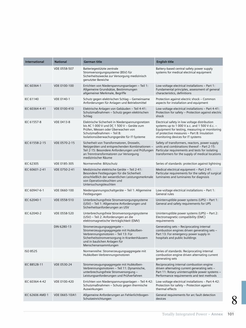
101Totally Integrated Power – Annex
8
International National German title English title
VDE 0558-507 Batteriegestützte zentrale Stromversorgungssysteme (BSV) für Sicherheitszwecke zur Versorgung medizinisch genutzter Bereiche
Battery-based central safety power supply systems for medical electrical equipment
IEC 60364-1 VDE 0100-100 Errichten von Niederspannungsanlagen – Teil 1: Allgemeine Grundsätze, Bestimmungen allgemeiner Merkmale, Begriffe
Low-voltage electrical installations – Part 1: Fundamental principles, assessment of general characteristics, definitions
IEC 61140 VDE 0140-1 Schutz gegen elektrischen Schlag – Gemeinsame Anforderungen für Anlagen und Betriebsmittel
Protection against electric shock – Common aspects for installation and equipment
IEC 60364-4-41 VDE 0100-410 Elektrische Anlagen von Gebäuden – Teil 4-41: Schutzmaßnahmen – Schutz gegen elektrischen Schlag
Low-voltage electrical installations – Part 4-41: Protection for safety – Protection against electric shock
IEC 61557-8 VDE 0413-8 Elektrische Sicherheit in Niederspannungsnetzen bis AC 1 000 V und DC 1 500 V – Geräte zum Prüfen, Messen oder Überwachen von Schutzmaßnahmen – Teil 8: Isolationsüberwachungsgeräte für IT-Systeme
Electrical safety in low voltage distribution systems up to 1 000 V a.c. and 1 500 V d.c. – Equipment for testing, measuring or monitoring of protective measures – Part 8: Insulation monitoring devices for IT systems
IEC 61558-2-15 VDE 0570-2-15 Sicherheit von Transformatoren, Drosseln, Netzgeräten und entsprechenden Kombinationen – Teil 2-15: Besondere Anforderungen und Prüfungen an Trenntransformatoren zur Versorgung medizinischer Räume
Safety of transformers, reactors, power supply units and combinations thereof – Part 2-15: Particular requirements and tests for isolating transformers for the supply of medical locations
IEC 62305 VDE 0185-305 Normenreihe: Biltzschutz Series of standards: protection against lightning
IEC 60601-2-41 VDE 0750-2-41 Medizinische elektrische Geräte – Teil 2-41: Besondere Festlegungen für die Sicherheit einschließlich der wesentlichen Leistungsmerkmale von Operationsleuchten und Untersuchungsleuchten
Medical electrical equipment – Part 2-41:Particular requirements for the safety of surgical luminaires and luminaires for diagnosis
IEC 60947-6-1 VDE 0660-100 Niederspannungsschaltgeräte – Teil 1: Allgemeine Festlegungen
Low-voltage electrical installations – Part 1: General rules
IEC 62040-1 VDE 0558-510 Unterbrechungsfreie Stromversorgungssysteme (USV) – Teil 1: Allgemeine Anforderungen und Sicherheitsanforderungen an USV
Uninterruptible power systems (UPS) – Part 1: General and safety requirements for UPS
IEC 62040-2 VDE 0558-520 Unterbrechungsfreie Stromversorgungssysteme (USV) – Teil 2: Anforderungen an die elektromagnetische Verträglichkeit (EMV)
Uninterruptible power systems (UPS) – Part 2: Electromagnetic compatibility (EMC) requirements
DIN 6280-13 Stromerzeugungsaggregate – Stromerzeugungsaggregate mit Hubkolben-Verbrennungsmotoren – Teil 13: Für Sicherheitsstromversorgung in Krankenhäusern und in baulichen Anlagen für Menschenansammlungen
Generating sets – Reciprocating internal combustion engines driven generating sets – Part 13: For emergency power supply in hospitals and public buildings
ISO 8525 Normenreihe: Stromerzeugungsaggregate mit Hubkolben-Verbrennungsmotoren
Series of standards: Reciprocating internal combustion engine driven alternating current generating sets
IEC 88528-11 VDE 0530-24 Stromerzeugungsaggregate mit Hubkolben-Verbrennungsmotoren – Teil 11: Dynamische, unterbrechungsfreie Stromversorgung – Leistungsanforderungen und Prüfverfahren
Reciprocating internal combustion engine driven alternating current generating sets – Part 11: Rotary uninterruptible power systems – Performance requirements and test methods
IEC 60364-4-42 VDE 0100-420 Errichten von Niederspannungsanlagen – Teil 4-42: Schutzmaßnahmen – Schutz gegen thermische Auswirkungen
Low-voltage electrical installations – Part 4-42: Protection for safety – Protection against thermal effects
IEC 62606 AMD 1 VDE 0665-10/A1 Allgemeine Anforderungen an Fehlerlichtbogen-Schutzeinrichtungen
General requirements for arc fault detection devices

102 Totally Integrated Power – Annex
8
International National German title English title
IEC 60702-1 VDE 0284-1 Mineralisolierte Leitungen mit einer Nennspannung bis 750 V – Teil 1: Leitungen
Mineral insulated cables and their terminations with a rated voltage not exceeding 750 V – Part 1: Cables
IEC 60702-2 VDE 0284-2 Mineralisolierte Leitungen mit einer Nennspannung bis 750 V – Teil 2: Endverschlüsse
Mineral insulated cables and their terminations with a rated voltage not exceeding 750 V – Part 2: Terminations
IEC 60331 Normenreihe: Prüfungen an Kabeln und isolierten Leitungen im Brandfall – Isolationserhalt
Series of standards: Tests for electric cables under fire conditions – Circuit integrity
IEC 60332-1-2 VDE 0482-332-1-2 Prüfungen an Kabeln, isolierten Leitungen und Glasfaserkabeln im Brandfall – Teil 1-2: Prüfung der vertikalen Flammenausbreitung an einer Ader, einer isolierten Leitung oder einem Kabel – Prüfverfahren mit 1-kW-Flamme mit Gas/Luft-Gemisch
Tests on electric and optical fibre cables under fire conditions – Part 1-2: Test for vertical flame propagation for a single insulated wire or cable – Procedure for 1 kW pre-mixed flame
MLAR Muster-Leitungsanlagen-Richtlinie Sample directive on fireproofing requirements for conduits and line systems
VdS 2226 Krankenhäuser, Pflegeheime und ähnliche Einrichtungen zur Unterbringung oder Behandlung von Personen – Richtlinien für den Brandschutz
Hospitals, care homes and similar facilities for the accommodation or treatment of people – guidelines for fire protection
EltBauVO Verordnung über den Bau von Betriebsräumen für elektrische Anlagen
Ordinance governing the construction of operating theatres for electrical installations
DIN 4102-12 Brandverhalten von Baustoffen und Bauteilen – Teil 12: Funktionserhalt von elektrischen Kabelanlagen; Anforderungen und Prüfungen
Fire behaviour of building materials and building components; pipe encasements, pipe bushings, service shafts and ducts, and barriers across inspection openings; terminology, requirements and testing
IEC 62271-200 VDE 0671-200 Hochspannungs-Schaltgeräte und -Schaltanlagen – Teil 200: Metallgekapselte Wechselstrom-Schaltanlagen für Bemessungsspannungen über 1 kV bis einschließlich 52 kV
High-voltage switchgear and controlgear – Part 200: AC metal-enclosed switchgear and controlgear for rated voltages above 1 kV and up to and including 52 kV
IEC/TR 61641 Niederspannungs-Schaltgerätekombinationen in geschlossener Bauform – Leitfaden für die Prüfung unter Störlichtbogenbedingungen durch einen inneren Fehler
Enclosed low-voltage switchgear and controlgear assemblies – Guide for testing under conditions of arcing due to internal faults
DIN 5035 Normenreihe: Beleuchtung mit künstlichem Licht Series of standards: Artificial lighting
DIN 5035-3 Beleuchtung mit künstlichem Licht – Teil 3: Beleuchtung im Gesundheitswesen
Artificial lighting – Part 3: Lighting of health care premises
IEC 61439 VDE 0660-600 Normenreihe: Niederspannungs-Schaltgerätekombinationen
Series of standards: Low-voltage switchgear and controlgear assemblies
IEC 61439-1 VDE 0660-600-1 Niederspannungs-Schaltgerätekombinationen – Teil 1: Allgemeine Festlegungen
Low-voltage switchgear and controlgear assemblies – Part 1: General rules
IEC 61439-2 VDE 0660-600-2 Niederspannungs-Schaltgerätekombinationen – Teil 2: Energie-Schaltgerätekombinationen
Low-voltage switchgear and controlgear assemblies – Part 2: Power switchgear and controlgear assemblies
IEC 61439-3 VDE 0660-600-3 Niederspannungs-Schaltgerätekombinationen – Teil 3: Installationsverteiler für die Bedienung durch Laien (DBO)
Low-voltage switchgear and controlgear assemblies – Part 3: Distribution boards intended to be operated by ordinary persons (DBO)
IEC 61439-6 VDE 0660-600-6 Niederspannungs-Schaltgerätekombinationen – Teil 6: Schienenverteilersysteme (busways)
Low-voltage switchgear and controlgear assemblies – Part 6: Busbar trunking systems (busways)

103Totally Integrated Power – Annex
8
International National German title English title
DIN 1946-4 Raumlufttechnik – Teil 4: Raumlufttechnische Anlagen in Gebäuden und Räumen des Gesundheitswesens
Ventilation and air conditioning – Part 4: Ventilation in buildings and rooms of health care
IEC 60076-11 VDE 0532-76-11 Leistungstransformatoren – Teil 11: Trockentransformatoren
Power transformers – Part 10: Determination of sound levels
VDE 0603-1 Installationsverteiler und Zählerplätze AC 400 V; Installationskleinverteiler und Zählerplätze
Consumer units and meter panels AC 400 V; consumer units and meter panels
EN 13501 Normenreihe: Klassifizierung von Bauprodukten und Bauarten zu ihrem Brandverhalten
Series of standards: Fire classification of construction products and building elements
EN 1366-3 Feuerwiderstandsprüfungen für Installationen – Teil 3: Abschottungen
Fire resistance tests for service installations – Part 3: Penetration seals
EN 12464-1 Licht und Beleuchtung – Beleuchtung von Arbeitsstätten – Teil 1: Arbeitsstätten in Innenräumen
Light and lighting – Lighting of work places – Part 1: Indoor work places
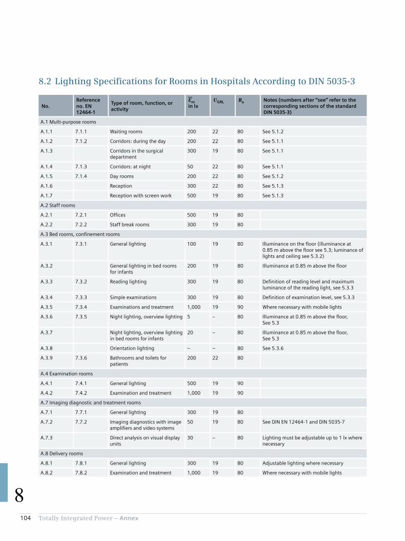
104 Totally Integrated Power – Annex
8
8.2 Lighting Specifications for Rooms in Hospitals According to DIN 5035-3
No.Reference no. EN 12464-1
Type of room, function, or activity
Emin lx
UGRL Ra Notes (numbers after “see” refer to the corresponding sections of the standard DIN 5035-3)
A.1 Multi-purpose rooms
A.1.1 7.1.1 Waiting rooms 200 22 80 See 5.1.2
A.1.2 7.1.2 Corridors: during the day 200 22 80 See 5.1.1
A.1.3 Corridors in the surgical department
300 19 80 See 5.1.1
A.1.4 7.1.3 Corridors: at night 50 22 80 See 5.1.1
A.1.5 7.1.4 Day rooms 200 22 80 See 5.1.2
A.1.6 Reception 300 22 80 See 5.1.3
A.1.7 Reception with screen work 500 19 80 See 5.1.3
A.2 Staff rooms
A.2.1 7.2.1 Offices 500 19 80
A.2.2 7.2.2 Staff break rooms 300 19 80
A.3 Bed rooms, confinement rooms
A.3.1 7.3.1 General lighting 100 19 80 Illuminance on the floor (illuminance at 0.85 m above the floor see 5.3; luminance of lights and ceiling see 5.3.2)
A.3.2 General lighting in bed rooms for infants
200 19 80 Illuminance at 0.85 m above the floor
A.3.3 7.3.2 Reading lighting 300 19 80 Definition of reading level and maximum luminance of the reading light, see 5.3.3
A.3.4 7.3.3 Simple examinations 300 19 80 Definition of examination level, see 5.3.3
A.3.5 7.3.4 Examinations and treatment 1,000 19 90 Where necessary with mobile lights
A.3.6 7.3.5 Night lighting, overview lighting 5 – 80 Illuminance at 0.85 m above the floor, See 5.3
A.3.7 Night lighting, overview lighting in bed rooms for infants
20 – 80 Illuminance at 0.85 m above the floor, See 5.3
A.3.8 Orientation lighting – – 80 See 5.3.6
A.3.9 7.3.6 Bathrooms and toilets for patients
200 22 80
A.4 Examination rooms
A.4.1 7.4.1 General lighting 500 19 90
A.4.2 7.4.2 Examination and treatment 1,000 19 90
A.7 Imaging diagnostic and treatment rooms
A.7.1 7.7.1 General lighting 300 19 80
A.7.2 7.7.2 Imaging diagnostics with image amplifiers and video systems
50 19 80 See DIN EN 12464-1 and DIN 5035-7
A.7.3 Direct analysis on visual display units
30 – 80 Lighting must be adjustable up to 1 lx where necessary
A.8 Delivery rooms
A.8.1 7.8.1 General lighting 300 19 80 Adjustable lighting where necessary
A.8.2 7.8.2 Examination and treatment 1,000 19 80 Where necessary with mobile lights

105Totally Integrated Power – Annex
8
No.Reference no. EN 12464-1
Type of room, function, or activity
Emin lx
UGRL Ra Notes (numbers after “see” refer to the corresponding sections of the standard DIN 5035-3)
A.9 Treatment rooms (general)
A.9.1 7.9.1 Dialysis– Entry and exit
500 19 80 Lighting should be adjustable, see 5.4.3.6.
A.9.2 – General lighting 100 19 80 See 5.3.2 and 5.4.3.6
A.9.3 – Reading lighting 300 19 80 See 5.3.3 and 5.4.3.6
A.9.4 7.9.2 Dermatology 500 19 90 See 5.4.3.7
A.9.5 7.9.3 Endoscopy rooms 300 19 80 See 5.4.3.8
A.9.6 Endoscopic examinations 50 19 80 Lighting where necessary adjustable to even lower illuminances
A.9.7 7.9.4 First-aid rooms 500 19 80
A.9.8 7.9.5 Medical baths 300 19 80 See 5.4.3.9
A.9.9 7.9.6 Massage and radiotherapy 300 19 80
A.10 Surgical department
A.10.1 7.10.1 Pre-op and recovery rooms 500 19 90
A.10.2 Recovery phase 100 Glare-free for the prone patient
A.10.3 Additional lighting 1,000 19 85 See 5.5.4
A.10.4 7.10.2 Operating theatres 1,000 19 90
A.10.5 Operating table surroundings 2,000 19 90 Target maintenance value of illuminance 2,000 lx
A.10.6 7.10.3 Operating area – – – EC = 40,000 lx to 160,000 lx; see EN 60601-2-41
A.11 Intensive care unit
A.11.1 7.11.1 General lighting 100 19 90 Illuminance on the floor (illuminance at 0.85 m above the floor see 5.3; luminance of lights and ceiling see 5.3.2)
A.11.2 7.11.2 Simple examinations 300 19 90 Illuminance on the bed
A.11.3 7.11.3 Examinations and treatment 1,000 19 90 Illuminance on the bed
A.11.4 7.11.4 Night-time monitoring 20 19 90 Illuminance at 0.85 m above the floor, see 5.3
A.14 Laboratories and pharmacies
A.14.1 7.13.1 General lighting 500 19 80
A.14.2 7.13.2 Colour testing 1,000 19 90 Colour temperature ≥ 6,000 K
A 14.3 Shelf/cabinet lighting 200 19 80 Where necessary with additional lighting
A.15 Sterile rooms
A.15.1 7.14.1 Sterilisation rooms 300 22 80
A.15.2 7.14.2 Disinfection rooms 300 22 80
A.16 Autopsy rooms and mortuaries
A.16.1 7.15.1 General lighting 500 19 90
A.16.2 7.15.2 Autopsy and dissecting table 5,000 – 90 Values higher than 5,000 lx may be required
Em Maintenance value of illuminance in lxUGRL Unified glare ratingRa Colour rendering index
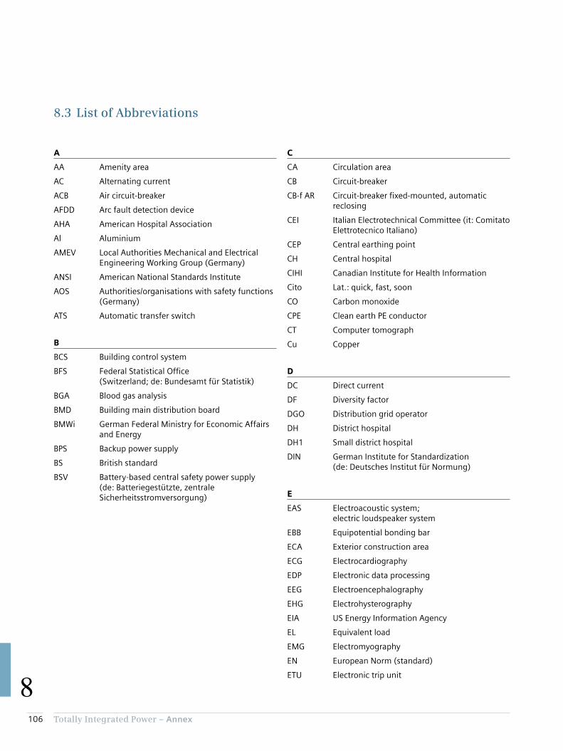
106 Totally Integrated Power – Annex
8
8.3 List of Abbreviations
C
CA Circulation area
CB Circuit-breaker
CB-f AR Circuit-breaker fixed-mounted, automatic reclosing
CEI Italian Electrotechnical Committee (it: Comitato Elettrotecnico Italiano)
CEP Central earthing point
CH Central hospital
CIHI Canadian Institute for Health Information
Cito Lat.: quick, fast, soon
CO Carbon monoxide
CPE Clean earth PE conductor
CT Computer tomograph
Cu Copper
D
DC Direct current
DF Diversity factor
DGO Distribution grid operator
DH District hospital
DH1 Small district hospital
DIN German Institute for Standardization (de: Deutsches Institut für Normung)
E
EAS Electroacoustic system; electric loudspeaker system
EBB Equipotential bonding bar
ECA Exterior construction area
ECG Electrocardiography
EDP Electronic data processing
EEG Electroencephalography
EHG Electrohysterography
EIA US Energy Information Agency
EL Equivalent load
EMG Electromyography
EN European Norm (standard)
ETU Electronic trip unit
A
AA Amenity area
AC Alternating current
ACB Air circuit-breaker
AFDD Arc fault detection device
AHA American Hospital Association
Al Aluminium
AMEV Local Authorities Mechanical and Electrical Engineering Working Group (Germany)
ANSI American National Standards Institute
AOS Authorities/organisations with safety functions (Germany)
ATS Automatic transfer switch
B
BCS Building control system
BFS Federal Statistical Office (Switzerland; de: Bundesamt für Statistik)
BGA Blood gas analysis
BMD Building main distribution board
BMWi German Federal Ministry for Economic Affairs and Energy
BPS Backup power supply
BS British standard
BSV Battery-based central safety power supply (de: Batteriegestützte, zentrale Sicherheitsstromversorgung)

107Totally Integrated Power – Annex
8
F
FAC Fire alarm control
FAS Fire alarm system
FELV Functional extra-low voltage
FFL Fire-fighting lift
FM Facility Management
FSD Fuse-switch-disconnector
G
GB National standard in China (cn: Guobiao)
GDP Gross domestic product
GFA Gross floor area
GOST Russian standard (ru: Gossudarstwenny Standart)
H
HBF Hill-Burton Formula
HOAI Fee regulations for architects and engineers (Germany)
HOPE Hospitals for Europe
HTM Health Technical Memorandum (UK)
HV High voltage
HVAC Heating, ventilation, air conditioning
I
I&C Instrumentation and control
IABP Intra-aortal balloon pump
IAC Internal arc classification
ICA Interior construction area
ICT Information and communications technology
IEC International Electrotechnical Commission
IEC/TR Technical Report by the International Electrotechnical Commission
IFA Internal floor area
IMD Insulation monitoring device
IS Indian standard
ISO International Organisation for Standardization
K
KAKuG Federal Hospitals Act (Austria)
KHG Hospital Financing Act (Germany)
L
LA Level area
LAA Limited use amenity area
LAF Laminar air flow
LCA Limited use circulation area
LPA Limited use primary area
LPZ Lightning protection zone
LTA Limited use technical area
LV Low voltage
LVMD Low-voltage main distribution board
M
MCB Miniature circuit-breaker
MCCB Moulded-case circuit-breaker
MD Main distribution board
ME Medical-electrical
MES Manufacturing execution system
MLAR Specimen cable installation guideline (Germany)
MR Magnetic resonance
MRI Magnetic resonance imaging
MV Medium voltage

108 Totally Integrated Power – Annex
8
N
NEN Dutch standard (nl: Nederlandse Norm)
NF French standard (fr: Norme française)
NFA Net floor area
NLA Non-functional level area
NPS Normal power supply
NRA Net room area
O
OECD Organisation for Economic Co-operation and Development
ÖSG Austrian Health Structure Plan
ÖVE/ Standard of the Austrian ÖNORM Electrotechnical Association
OT Operating theatre
P
PA Primary area
PACS Picture archiving and communication system
PDMS Patient data management system
PE Protective earth
PELV Protective extra low voltage
PET Positron emission tomograph
PWA Partition wall area
R
RAA Restricted amenity area
RAS Room air system
RCA Restricted circulation area
RCD Residual current device
RPA Restricted primary area
RTA Restricted technical area
S
SD Sub-distribution board
SDF Switch-disconnector with fuse
SELV Safety extra-low voltage
SEM Sustainability and energy management
SF6 Sulphur hexafluoride
SHV Smoke and heat vents
SIA Swiss engineers’ and architects’ association
SN Swiss standard
SNS National health authority of Portugal (pt: Serviço Nacional de Saúde)
SPS Safety power supply
T
TA Technical area
TBS Total Building Solutions
TIA Totally Integrated Automation
TIP Totally Integrated Power
U
UAA Unrestricted use amenity area
UCA Unrestricted use circulation area
UPA Unrestricted use primary area
UPS Uninterruptible power supply
UTA Unrestricted use technical area
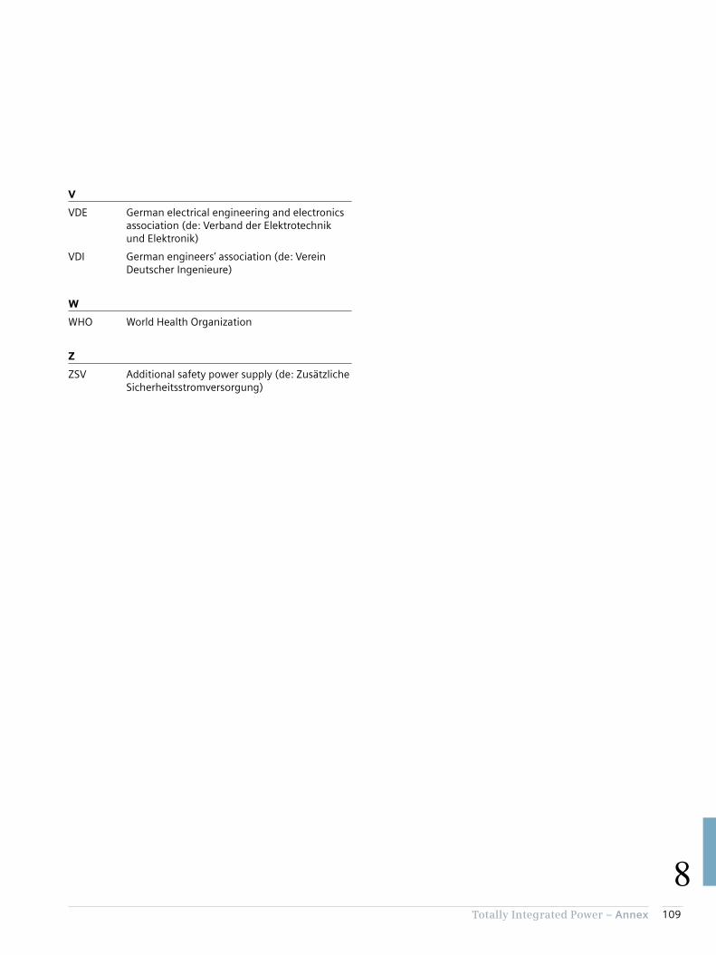
109Totally Integrated Power – Annex
8
V
VDE German electrical engineering and electronics association (de: Verband der Elektrotechnik und Elektronik)
VDI German engineers’ association (de: Verein Deutscher Ingenieure)
W
WHO World Health Organization
Z
ZSV Additional safety power supply (de: Zusätzliche Sicherheitsstromversorgung)

110 Totally Integrated Power – Annex
8
8.4 Literature References
[1] “Bundesgesetz über Krankenanstalten und Kuranstalten” (KAKuG) [Austrian Federal Hospitals Act] Federal Gazette No. 1/1957 available at http://www.ris.bka.gv.at
[2] “Gesetz zur wirtschaftlichen Sicherung der Krankenhäuser und zur Regelung der Krankenhauspflegesätze (Krankenhausfinanzierungsgesetz – KHG)” [Law governing the economic safeguarding of hospitals and regulating hospital care rates (Hospital Financing Act – KHG)] (Germany) available at http://www.juris.de
[3] OECD Health Statistics 2015; http://www.oecd.org/els/health-systems/health-data.htm
[4] Hospitals in the 27 Member States of the European Union; HOPE, 2009
[5] “Österreichischer Strukturplan Gesundheit” [Austrian Health Structure Plan] 2012;GESUNDHEIT ÖSTERREICH GMBH (GÖG), 2012
[6] “Der energetische Sanierungsbedarf und der Neubaubedarf von Gebäuden der kommunalen und sozialen Infrastruktur” [Energy upgrade requirement and need for new buildings in municipal and communal infrastructure]; Bremen Energy Institute, 2011
[7] “RWI Materialien”, volume 84: “Krankenhausplanung 2.0” [Hospital planning 2.0]; Rhine-Westphalia Institute for Economic Research, 2014
[8] Presentation by K. Lennerts “Nachhaltige Krankenhäuser” [Sustainable hospitals]; at the 33rd German Hospitals Conference 2010, published at http://www.deutscher-krankenhaustag.de/de/vortraege/meldungen/2010_10_25_76272757_meldung.php?navid=4
[9] Hong Kong Planning Standards and Guidelines – Summary; Planning Department Government of the Hong Kong Special Administrative Region, 2014
[10] Global hospital Management Survey – China; China Center for Health Economics Research, Peking University, 2014
[11] ENERY COST AND CONSUMPTION IN A LARGE ACUTE HOSPITAL; S.C. Hu, J.D. Chen and Y.K. Chuah – Int. Journal on Architectural Science, Vol. 5, No. 1, 2004
[12] “Benchmarking im Krankenhaus – Schwerpunkte Energie und Instandhaltung” [Benchmarking in hospitals – focus points energy and maintenance]; Diez K., Lennerts K. (Conference papers, Facility Management trade fair and congress, Frankfurt am Main), 2010
[13] “Baumanagement und Bauökonomie” [Construction management and economics]; Teubner-Verlag (publ.: Liebchen, Jens; Viering, Markus G.; Zanner, Christian), 2007
[14] “Vierundzwanzigster Zusammenfassender Bericht ‘Gesundheitswesen – Kliniken’” [24th Summary Report on Healthcare Clinics]; Hessischer Rechnungshof (Audit Office of the State of Hesse) (publ.: M. Eibelshäuser, President, Hessischer Rechnungshof), 2013
[15] ENERGY STAR® Score for Hospitals in the United States; U.S. Environmental Protection Agency, 2014
[16] ENERGY STAR® Score for Hospitals in Canada; U.S. Environmental Protection Agency, 2014
[17] “Kennzahlen zum Energieverbrauch in Dienstleistungsgebäuden” [Data on energy consumption in service facilities]; ÖGUT, 2011
[18] Learning from French hospital design (2004) – BDP
[19] “Krankenanstalten in Zahlen 2013” [Healthcare facilities in figures 2013]; Austrian Federal Ministry of Health, 2014
[20] Energy Efficiency in Hospitals, Maxi Brochure 05; Caddet, 1997
[21] Project number 53/09: “Energieverbrauch des Sektors Gewerbe, Handel, Dienstleistungen (GHD) in Deutschland für die Jahre 2007 bis 2010” [Energy consumption of the commercial/light industrial, retail and service sectors in Germany for the years 2007 to 2010], final report to the Federal Ministry for Economic Affairs and Energy (BMWi); 2013, IREES, GfK, IfE, Fraunhofer ISI, BASE-ING.
[22] Managing energy costs in hospitals; US National Grid, 2002
[23] “Blockheizkraftwerke in Krankenhäusern” [Combined heat and power plants in hospitals]; ASUE, 2010
[24] “Leitfaden Energieeffizienz für Krankenhäuser” [Guide to energy efficiency for hospitals]; EnergieAgentur.NRW [Energy Agency of the State of North Rhine-Westphalia], 2010
[25] “Kennzahlen zum Energieverbrauch in Dienstleistungsgebäuden” [Data on energy consumption in service facilities]; ÖGUT, 2011
[26] Brochure no. 128: “EltAnlagen 2015” [Electrical installations 2015]; German Local Authorities Mechanical and Electrical Engineering Working Group (AMEV), 2015
[27] Brochure no. 98: “Elt. Anlagen 2007” [Electrical installations 2007]; German Local Authorities Mechanical and Electrical Engineering Working Group (AMEV), 2007
[28] “Energie im Krankenhaus” [Energy in hospitals]; ENERGIEAGENTUR NRW [Energy Agency of the State of North Rhine-Westphalia], 2000
[29] “Präsentation von Best-Practise-Beispielen zu Energieeinsparung und Kostensenkung in Krankenhäusern” [Presentation of best-practice examples for energy saving and cost cutting in hospitals]; W. Köhler in “Energieeffizientes Krankenhaus – für Klimaschutz und Kostensenkung” [Energy-efficient hospital – for climate protection and cost cutting], ehbs 154 (publ. S. Leittretter), 2005
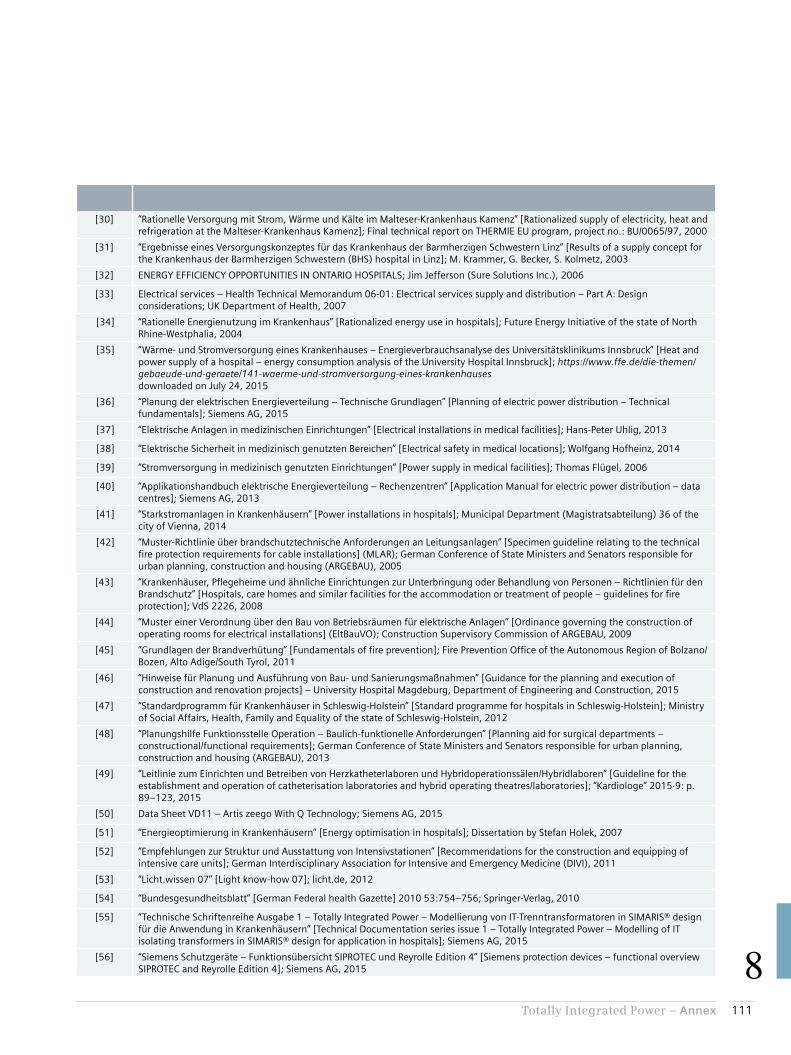
111Totally Integrated Power – Annex
8
[30] “Rationelle Versorgung mit Strom, Wärme und Kälte im Malteser-Krankenhaus Kamenz” [Rationalized supply of electricity, heat and refrigeration at the Malteser-Krankenhaus Kamenz]; Final technical report on THERMIE EU program, project no.: BU/0065/97, 2000
[31] “Ergebnisse eines Versorgungskonzeptes für das Krankenhaus der Barmherzigen Schwestern Linz” [Results of a supply concept for the Krankenhaus der Barmherzigen Schwestern (BHS) hospital in Linz]; M. Krammer, G. Becker, S. Kolmetz, 2003
[32] ENERGY EFFICIENCY OPPORTUNITIES IN ONTARIO HOSPITALS; Jim Jefferson (Sure Solutions Inc.), 2006
[33] Electrical services – Health Technical Memorandum 06-01: Electrical services supply and distribution – Part A: Design considerations; UK Department of Health, 2007
[34] “Rationelle Energienutzung im Krankenhaus” [Rationalized energy use in hospitals]; Future Energy Initiative of the state of North Rhine-Westphalia, 2004
[35] “Wärme- und Stromversorgung eines Krankenhauses – Energieverbrauchsanalyse des Universitätsklinikums Innsbruck” [Heat and power supply of a hospital – energy consumption analysis of the University Hospital Innsbruck]; https://www.ffe.de/die-themen/gebaeude-und-geraete/141-waerme-und-stromversorgung-eines-krankenhauses downloaded on July 24, 2015
[36] “Planung der elektrischen Energieverteilung – Technische Grundlagen” [Planning of electric power distribution – Technical fundamentals]; Siemens AG, 2015
[37] “Elektrische Anlagen in medizinischen Einrichtungen” [Electrical installations in medical facilities]; Hans-Peter Uhlig, 2013
[38] “Elektrische Sicherheit in medizinisch genutzten Bereichen” [Electrical safety in medical locations]; Wolfgang Hofheinz, 2014
[39] “Stromversorgung in medizinisch genutzten Einrichtungen” [Power supply in medical facilities]; Thomas Flügel, 2006
[40] “Applikationshandbuch elektrische Energieverteilung – Rechenzentren” [Application Manual for electric power distribution – data centres]; Siemens AG, 2013
[41] “Starkstromanlagen in Krankenhäusern” [Power installations in hospitals]; Municipal Department (Magistratsabteilung) 36 of the city of Vienna, 2014
[42] “Muster-Richtlinie über brandschutztechnische Anforderungen an Leitungsanlagen” [Specimen guideline relating to the technical fire protection requirements for cable installations] (MLAR); German Conference of State Ministers and Senators responsible for urban planning, construction and housing (ARGEBAU), 2005
[43] “Krankenhäuser, Pflegeheime und ähnliche Einrichtungen zur Unterbringung oder Behandlung von Personen – Richtlinien für den Brandschutz” [Hospitals, care homes and similar facilities for the accommodation or treatment of people – guidelines for fire protection]; VdS 2226, 2008
[44] “Muster einer Verordnung über den Bau von Betriebsräumen für elektrische Anlagen” [Ordinance governing the construction of operating rooms for electrical installations] (EltBauVO); Construction Supervisory Commission of ARGEBAU, 2009
[45] “Grundlagen der Brandverhütung” [Fundamentals of fire prevention]; Fire Prevention Office of the Autonomous Region of Bolzano/Bozen, Alto Adige/South Tyrol, 2011
[46] “Hinweise für Planung und Ausführung von Bau- und Sanierungsmaßnahmen” [Guidance for the planning and execution of construction and renovation projects] – University Hospital Magdeburg, Department of Engineering and Construction, 2015
[47] “Standardprogramm für Krankenhäuser in Schleswig-Holstein” [Standard programme for hospitals in Schleswig-Holstein]; Ministry of Social Affairs, Health, Family and Equality of the state of Schleswig-Holstein, 2012
[48] “Planungshilfe Funktionsstelle Operation – Baulich-funktionelle Anforderungen” [Planning aid for surgical departments – constructional/functional requirements]; German Conference of State Ministers and Senators responsible for urban planning, construction and housing (ARGEBAU), 2013
[49] “Leitlinie zum Einrichten und Betreiben von Herzkatheterlaboren und Hybridoperationssälen/Hybridlaboren” [Guideline for the establishment and operation of catheterisation laboratories and hybrid operating theatres/laboratories]; “Kardiologe” 2015·9: p. 89–123, 2015
[50] Data Sheet VD11 – Artis zeego With Q Technology; Siemens AG, 2015
[51] “Energieoptimierung in Krankenhäusern” [Energy optimisation in hospitals]; Dissertation by Stefan Holek, 2007
[52] “Empfehlungen zur Struktur und Ausstattung von Intensivstationen” [Recommendations for the construction and equipping of intensive care units]; German Interdisciplinary Association for Intensive and Emergency Medicine (DIVI), 2011
[53] “Licht.wissen 07” [Light know-how 07]; licht.de, 2012
[54] “Bundesgesundheitsblatt” [German Federal health Gazette] 2010 53:754–756; Springer-Verlag, 2010
[55] “Technische Schriftenreihe Ausgabe 1 – Totally Integrated Power – Modellierung von IT-Trenntransformatoren in SIMARIS® design für die Anwendung in Krankenhäusern” [Technical Documentation series issue 1 – Totally Integrated Power – Modelling of IT isolating transformers in SIMARIS® design for application in hospitals]; Siemens AG, 2015
[56] “Siemens Schutzgeräte – Funktionsübersicht SIPROTEC und Reyrolle Edition 4” [Siemens protection devices – functional overview SIPROTEC and Reyrolle Edition 4]; Siemens AG, 2015

112 Totally Integrated Power – Annex
8
Publisher’s detailsTotally Integrated Power – Consultant Support Applications for Electric Power Distribution in Hospitals
Published by
Siemens AGEnergy Management Medium Voltage & Systems
Editorial
Siemens AG: Dr. Siegbert Hopf E-mail: [email protected]
Technical support
Siemens AG: Ulrike Fleischmann, Wolfgang Fruth, Ralf Gluth
GNUSE Ingenieurbüro für Krankenhaustechnik GmbH & Co. KG: Dipl.-Ing. Andreas Spies
Publisher
PublicisPixelpark Nägelsbachstr. 33 D-91052 Erlangen
Image rights
All pictures and graphics © Siemens AG.
Printed by
Kösel GmbH & Co. KG Am Buchweg 1 D-87452 Altusried-Krugzell


Tota
lly
Inte
gra
ted
Po
we
r A
pp
lica
tio
n M
od
els
for
Po
wer
Dis
trib
uti
on
– H
osp
ita
ls
Subject to changes and errors. The information given in this document only contains general descriptions and/or performance features which may not always specifically reflect those described, or which may undergo modification in the course of further development of the products. The requested performance features are binding only when they are expressly agreed upon in the concluded contract.
Artis zeego, GEAFOL, MAGNETOM, MAGNETOM Essenza, MAGNETOM Skyra, SIMARIS, SIPROTEC, SIVACON, TIA, and TIP Totally Integrated Power are registered trademarks of Siemens AG. Any unauthorized use is prohibited. All other designations in this document may represent trademarks whose use by third parties for their own purposes may violate the proprietary rights of the owner.
Published by© Siemens AG 2016
Energy Management
Medium Voltage & Systems
Mozartstr. 31c
91052 Erlangen, Germany
For more information please contact
E-mail: [email protected]
Article No.: EMMS-T90001-00-7600
Printed in Germany
Dispo 27616
06161.5
All rights reserved. Nominal fee of €3. All data and circuit examples without engagement.
Related Documents