Minia Application manual Switching devices

Welcome message from author
This document is posted to help you gain knowledge. Please leave a comment to let me know what you think about it! Share it to your friends and learn new things together.
Transcript

Any changes reserved
www.oez.com
SP3-2014-A
Minia
Application manualSwitching devices

OEZ s.r.o.Šedivská 339561 51 LetohradCzech Republictel.: +420 465 672 111 +420 465 672 101fax: +420 465 672 398 +420 465 672 151e-mail: [email protected]
www.oez.com
CONTENTS
THEORETICAL PART
Minia
1
1. Basic parameters of switching devices .................................................. 3
1.1. Type and number of main contacts .............................................. 3
1.2. Control voltage ................................................................................ 3
1.3. Noise ................................................................................................... 4
1.4. Rated operating current ................................................................. 4
1.5. Utilization category ......................................................................... 4
1.6. Time functions of the time relays .................................................. 6
1.7. Monitoring functions of the monitoring relays ......................... 6
1.8. Switching modes of timers ............................................................ 7
2. Installation contactors RSI and installation relays RPI ......................... 8
2.1. Control voltage ................................................................................. 8
2.2. Noise and switched power.............................................................. 8
2.3. Description of RSI and RPI .............................................................. 9
2.4. Examples of application ................................................................. 9
3. Impulse memory relays MIG and MIR .................................................. 10
3.1. Control voltage ............................................................................... 10
3.2. Noise and switched power ........................................................... 10
3.3. Description of MIG and MIR ......................................................... 11
3.4. Examples of application ................................................................ 11
4. Time relays MCR .................................................................................... 12
4.1. Control voltage ................................................................................ 12
4.2. Switched power ............................................................................... 14
4.3. Description of MCR ......................................................................... 14
4.4. Examples of application ................................................................ 15
5. Monitoring, level and thermal relays MMR .......................................... 16
5.1. Voltage monitoring relays MMR-U3, X3 ..................................... 16
5.2. Level relays MMR-HL ...................................................................... 17
5.3. Thermal relays MMR-T1 (thermistor) ........................................... 17
5.4. Thermal relays MMR-T2 (double thermostats) .......................... 18
5.5. Thermal relays MMR-TD (diff erential thermostats) .................. 18
5.6. Example of application of the diff erential thermostat ............ 19
6. Timers MAE, MAN and MAA ................................................................. 20
6.1. Economical MAE .............................................................................. 20
6.2. Examples of application ................................................................ 20
6.3. Standard MAN .................................................................................. 21
6.4. Examples of application ................................................................ 21
6.5. Astro MAA ......................................................................................... 21
6.6. Examples of application ................................................................ 22
Theoretical part Switching devices
Minia
2
CONTENTS
CATALOGUE PARTINSTALLATION CONTACTORS RSI-A WITH AC CONTROL VOLTAGE .......... 23
Installation contactors – standard .………………………….…….. 23
Installation contactors with manual control – standard ......……. 24
INSTALLATION CONTACTORS RSI-X WITH AC/DC CONTROL VOLTAGE …. 27
Installation contactors – quiet …...………………………………... 27
Installation contactors with manual control – quiet.…………….. 28
INSTALLATION RELAYS RPI.…….………………………............………….. 36
Installation relays - extra quiet ..……………….………………….. 36
IMPULSE MEMORY RELAYS MIG …………………………................…….. 38
Impulse memory relays – quiet .…………….………....………….. 38
IMPULSE MEMORY RELAYS MIR .……………………………………..…….. 46
Impulse memory relay - extra quiet ……………..……………….. 46
TIME RELAYS MCR …………………………...……….…………….. 50
Multiple-function time relays …………………….……………….. 50
Timing relays ……………….………............…….……………….. 50
MONITORING, LEVEL AND THERMAL RELAYS MMR ……..………...…... 53
Voltage monitoring relay ….…….……………..………………….. 53
Level relays ...…………………………….……..….…………….. 53
Thermal relays (thermistor) ……………………………………….. 53
Thermal relays (thermostats) …………………………………….. 53
TIMERS MAE, MAN and MAA ...………………………………..........…….. 57
Economical timers ………………………………………………….. 57
Standard timers …………………………………………….……… 57
Astro timers ………………………………………………………… 57
Theoretical part Switching devices
BASIC PROPERTIES OF SWITCHING DEVICES
Minia
3
Theoretical part
ForewordSwitching process is nowadays part of everyday life. It is not
always easy to select an optimal device for specifi c circuit. This manual describes basic characteristics of switching device and its purpose is to help the reader select suitable switching devices for concrete application easily.
Most frequently we encounter simple switching devices such as light switches, push-button switches of various electric devices, or similar. These switching elements are controlled directly in place of their installation. These elements directly give the command to switch on or switch off the electrical circuit.
However, in most applications we need to control electrical circuits remotely. To do this, we use switching devices, which are controlled by application of voltage, impulse, a set function, or other physical quantity, by means of a sensor or a saved program. To simplify the description, let us call the above stimuli control signals.
First of all let us discuss some of the basic properties of the switching devices.
1. BASIC PARAMETERS OF SWITCHING DEVICES
For proper selection of an appropriate device it is necessary to specify what is to be switched. There are a lot of options. The following parameters should help us:
1. 1. Type and number of main contacts
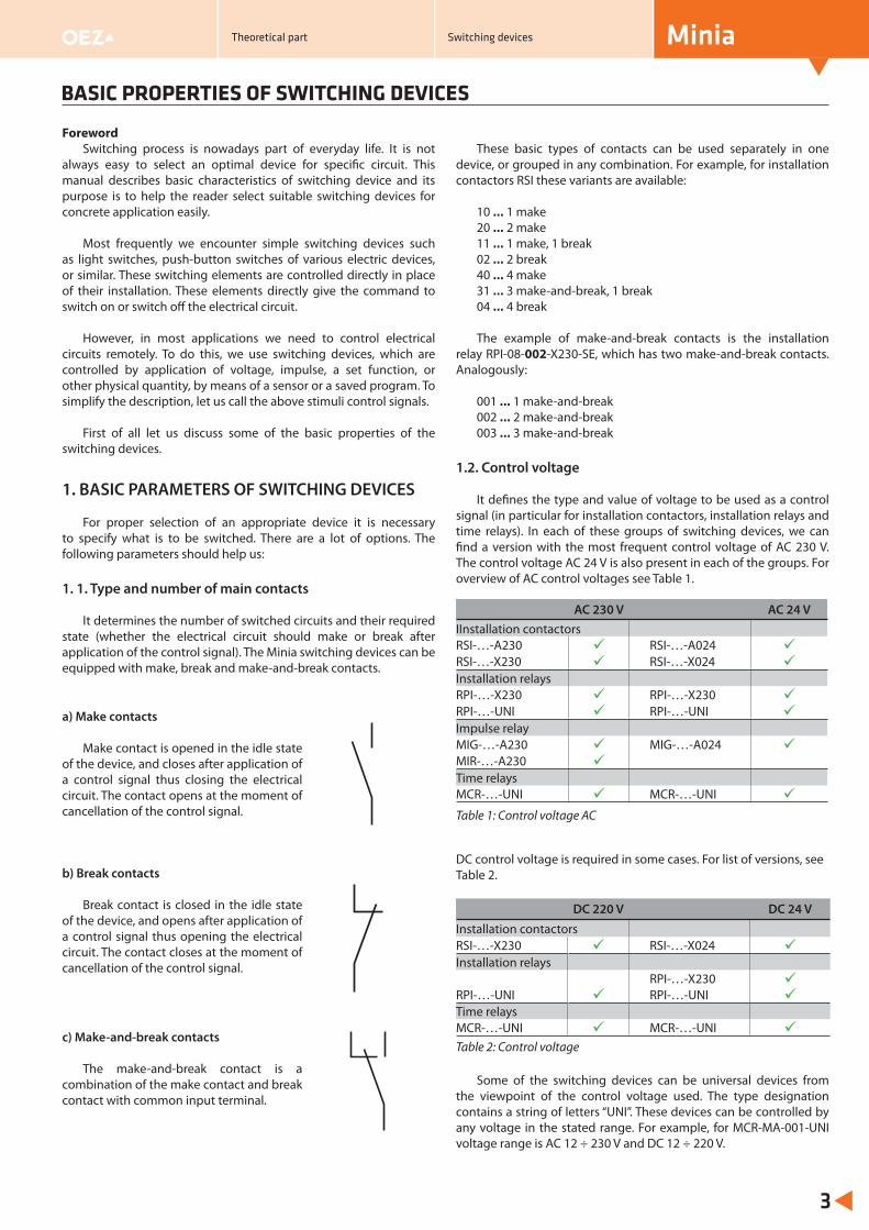
It determines the number of switched circuits and their required state (whether the electrical circuit should make or break after application of the control signal). The Minia switching devices can be equipped with make, break and make-and-break contacts.
These basic types of contacts can be used separately in one device, or grouped in any combination. For example, for installation contactors RSI these variants are available:
10 … 1 make20 … 2 make11 … 1 make, 1 break02 … 2 break40 … 4 make31 … 3 make-and-break, 1 break04 … 4 break
The example of make-and-break contacts is the installation relay RPI-08-002-X230-SE, which has two make-and-break contacts. Analogously:
001 … 1 make-and-break002 … 2 make-and-break003 … 3 make-and-break
1.2. Control voltage
It defi nes the type and value of voltage to be used as a control signal (in particular for installation contactors, installation relays and time relays). In each of these groups of switching devices, we can fi nd a version with the most frequent control voltage of AC 230 V. The control voltage AC 24 V is also present in each of the groups. For overview of AC control voltages see Table 1.
DC control voltage is required in some cases. For list of versions, see Table 2.
Some of the switching devices can be universal devices from the viewpoint of the control voltage used. The type designation contains a string of letters “UNI”. These devices can be controlled by any voltage in the stated range. For example, for MCR-MA-001-UNI voltage range is AC 12 ÷ 230 V and DC 12 ÷ 220 V.
a) Make contacts
Make contact is opened in the idle state of the device, and closes after application of a control signal thus closing the electrical circuit. The contact opens at the moment of cancellation of the control signal.
b) Break contacts
Break contact is closed in the idle state of the device, and opens after application of a control signal thus opening the electrical circuit. The contact closes at the moment of cancellation of the control signal.
c) Make-and-break contacts
The make-and-break contact is a combination of the make contact and break contact with common input terminal.
AC 230 V AC 24 VIInstallation contactorsRSI-…-A230 RSI-…-A024 RSI-…-X230 RSI-…-X024 Installation relaysRPI-…-X230 RPI-…-X230 RPI-…-UNI RPI-…-UNI Impulse relayMIG-…-A230 MIG-…-A024 MIR-…-A230 Time relaysMCR-…-UNI MCR-…-UNI Table 1: Control voltage AC
DC 220 V DC 24 VInstallation contactorsRSI-…-X230 RSI-…-X024 Installation relays
RPI-…-X230 RPI-…-UNI RPI-…-UNI Time relaysMCR-…-UNI MCR-…-UNI Table 2: Control voltage
Switching devices
BASIC PROPERTIES OF SWITCHING DEVICES
Minia
4
1.3. Noise
The installation contactors RSI and impulse memory relays click audibly in contact closing or opening. This is caused by contact mechanism, which must ensure suffi ciently quick and good pressing of contact areas of the contacts. The click is due to high switched power (rated operating current up to 63 A per one contact) and possibility of switching loads also in utilization categories other than AC-1 and DC-1.
For AC control of the coil of the RSI-A contacts, there can be “hum” in closed state with frequency of 50 Hz, which is caused by power supply of the coil. We call this basic group “Standard” from the noise point of view; it includes the RSI-A installation contactors.
Simple solution to decrease the “hum” are RSI-X contactors, which suppress the hum completely thanks to their internal design. The devices sound only in contact closing or opening. We call this group “Quiet”. It includes the RSI-X contactors and impulse memory relays in mechanical design - MIG. In case of MIG, the coil is supplied only in change of contact state. Thus it cannot “hum”, although it is supplied by AC voltage.
The last, third group is defi ned, from the noise point of view, as “Extra quiet”. It includes, above all, the RPI installation relays and MIR electronic impulse relays, which can be used switching circuits up to 16 A in utilization category AC-1 (DC-1).
1.4. Rated operating current
The current, by which a contact can be loaded, is very important parameter. This parameter relates to switched power.
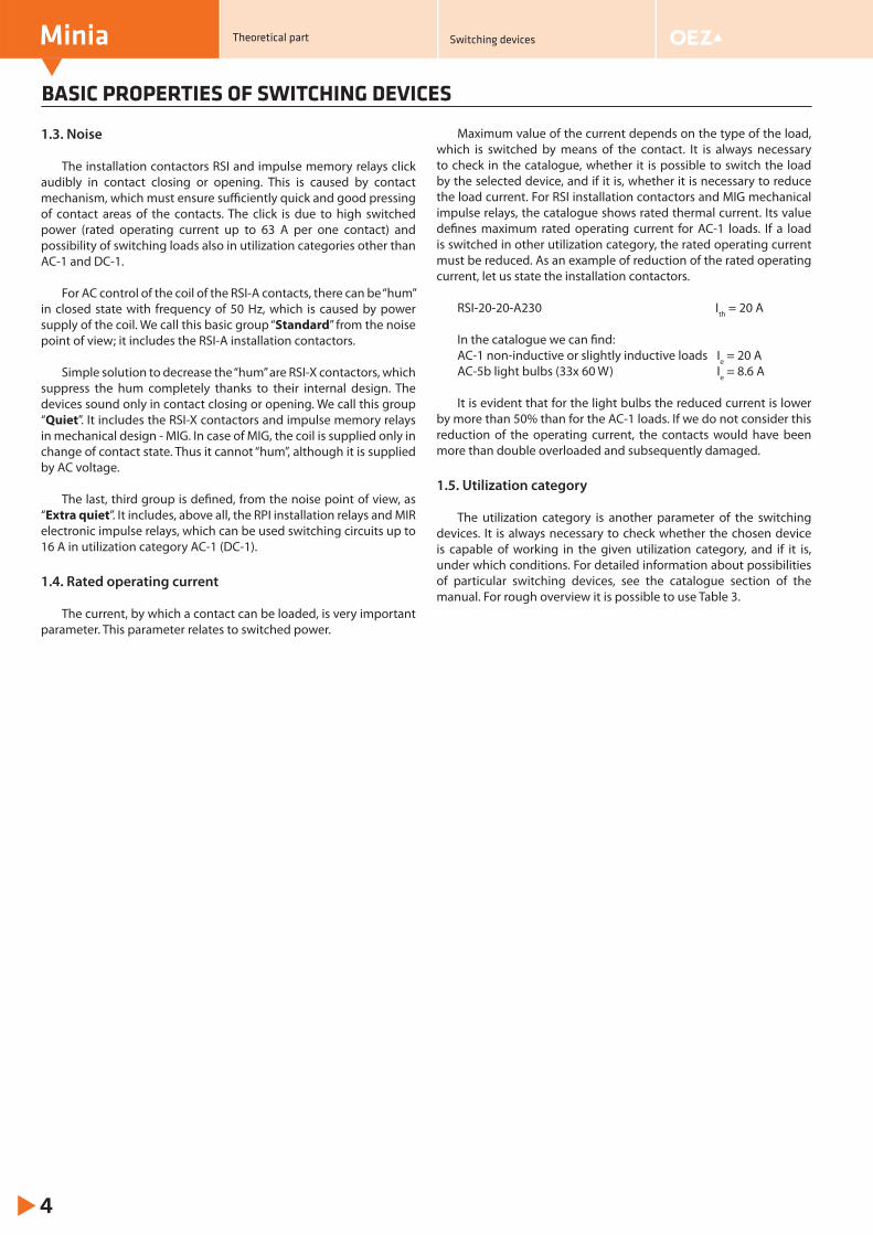
Maximum value of the current depends on the type of the load, which is switched by means of the contact. It is always necessary to check in the catalogue, whether it is possible to switch the load by the selected device, and if it is, whether it is necessary to reduce the load current. For RSI installation contactors and MIG mechanical impulse relays, the catalogue shows rated thermal current. Its value defi nes maximum rated operating current for AC-1 loads. If a load is switched in other utilization category, the rated operating current must be reduced. As an example of reduction of the rated operating current, let us state the installation contactors.
RSI-20-20-A230 Ith = 20 A
In the catalogue we can fi nd:AC-1 non-inductive or slightly inductive loads Ie = 20 AAC-5b light bulbs (33x 60 W) Ie = 8.6 A
It is evident that for the light bulbs the reduced current is lower by more than 50% than for the AC-1 loads. If we do not consider this reduction of the operating current, the contacts would have been more than double overloaded and subsequently damaged.
1.5. Utilization category
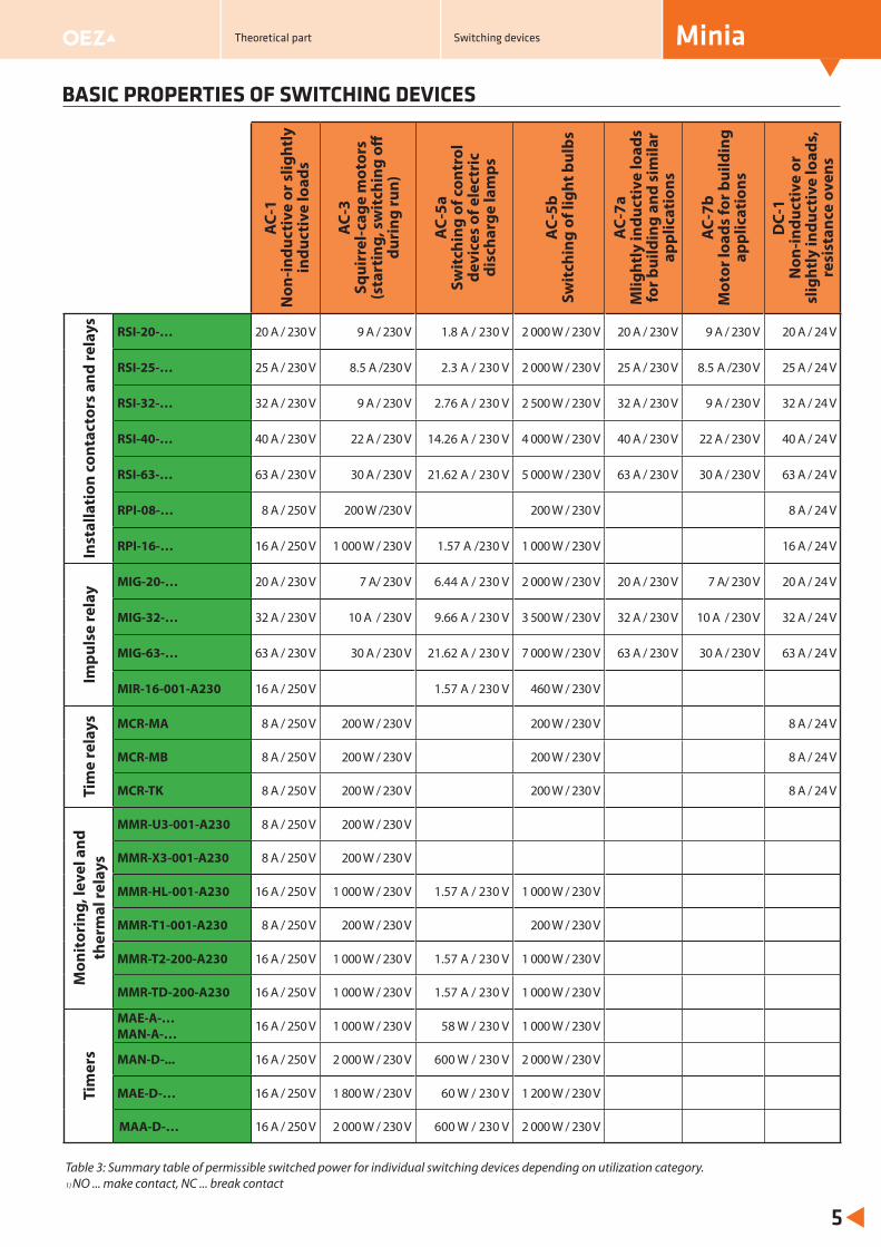
The utilization category is another parameter of the switching devices. It is always necessary to check whether the chosen device is capable of working in the given utilization category, and if it is, under which conditions. For detailed information about possibilities of particular switching devices, see the catalogue section of the manual. For rough overview it is possible to use Table 3.
Theoretical part Switching devices
BASIC PROPERTIES OF SWITCHING DEVICES
Minia
5
Table 3: Summary table of permissible switched power for individual switching devices depending on utilization category. 1) NO ... make contact, NC ... break contact
Theoretical part Switching devices
AC-
1N
on-in
duct
ive
or s
light
ly
indu
ctiv
e lo
ads
AC-
3Sq
uirr
el-c
age
mot
ors
(sta
rtin
g, s
wit
chin
g off
du
ring
run)
AC-
5aSw
itch
ing
of c
ontr
ol
devi
ces
of e
lect
ric
disc
harg
e la
mps
AC-
5bSw
itch
ing
of li
ght b
ulbs
AC-
7aM
light
ly in
duct
ive
load
s fo
r bui
ldin
g an
d si
mila
r ap
plic
atio
ns
AC-
7bM
otor
load
s fo
r bui
ldin
g ap
plic
atio
ns
DC-
1N
on-in
duct
ive
or
slig
htly
indu
ctiv
e lo
ads,
re
sist
ance
ove
ns
Inst
alla
tion
con
tact
ors
and
rela
ys RSI-20-… 20 A / 230 V 9 A / 230 V 1.8 A / 230 V 2 000 W / 230 V 20 A / 230 V 9 A / 230 V 20 A / 24 V
RSI-25-… 25 A / 230 V 8.5 A /230 V 2.3 A / 230 V 2 000 W / 230 V 25 A / 230 V 8.5 A /230 V 25 A / 24 V
RSI-32-… 32 A / 230 V 9 A / 230 V 2.76 A / 230 V 2 500 W / 230 V 32 A / 230 V 9 A / 230 V 32 A / 24 V
RSI-40-… 40 A / 230 V 22 A / 230 V 14.26 A / 230 V 4 000 W / 230 V 40 A / 230 V 22 A / 230 V 40 A / 24 V
RSI-63-… 63 A / 230 V 30 A / 230 V 21.62 A / 230 V 5 000 W / 230 V 63 A / 230 V 30 A / 230 V 63 A / 24 V
RPI-08-… 8 A / 250 V 200 W /230 V 200 W / 230 V 8 A / 24 V
RPI-16-… 16 A / 250 V 1 000 W / 230 V 1.57 A /230 V 1 000 W / 230 V 16 A / 24 V
Impu
lse
rela
y MIG-20-… 20 A / 230 V 7 A/ 230 V 6.44 A / 230 V 2 000 W / 230 V 20 A / 230 V 7 A/ 230 V 20 A / 24 V
MIG-32-… 32 A / 230 V 10 A / 230 V 9.66 A / 230 V 3 500 W / 230 V 32 A / 230 V 10 A / 230 V 32 A / 24 V
MIG-63-… 63 A / 230 V 30 A / 230 V 21.62 A / 230 V 7 000 W / 230 V 63 A / 230 V 30 A / 230 V 63 A / 24 V
MIR-16-001-A230 16 A / 250 V 1.57 A / 230 V 460 W / 230 V
Tim
e re
lays MCR-MA 8 A / 250 V 200 W / 230 V 200 W / 230 V 8 A / 24 V
MCR-MB 8 A / 250 V 200 W / 230 V 200 W / 230 V 8 A / 24 V
MCR-TK 8 A / 250 V 200 W / 230 V 200 W / 230 V 8 A / 24 V
Mon
itor
ing,
leve
l and
th
erm
al re
lays
MMR-U3-001-A230 8 A / 250 V 200 W / 230 V
MMR-X3-001-A230 8 A / 250 V 200 W / 230 V
MMR-HL-001-A230 16 A / 250 V 1 000 W / 230 V 1.57 A / 230 V 1 000 W / 230 V
MMR-T1-001-A230 8 A / 250 V 200 W / 230 V 200 W / 230 V
MMR-T2-200-A230 16 A / 250 V 1 000 W / 230 V 1.57 A / 230 V 1 000 W / 230 V
MMR-TD-200-A230 16 A / 250 V 1 000 W / 230 V 1.57 A / 230 V 1 000 W / 230 V
Tim
ers
MAE-A-…MAN-A-… 16 A / 250 V 1 000 W / 230 V 58 W / 230 V 1 000 W / 230 V
MAN-D-... 16 A / 250 V 2 000 W / 230 V 600 W / 230 V 2 000 W / 230 V
MAE-D-… 16 A / 250 V 1 800 W / 230 V 60 W / 230 V 1 200 W / 230 V
MAA-D-… 16 A / 250 V 2 000 W / 230 V 600 W / 230 V 2 000 W / 230 V
1.6. Time functions of the time relays
Each function is defi ned by time sequence of changes in contact state after pressing a push-button or applying the supply voltage.
a) Start after push-button pressing
The selected time sequence starts by pressing the push-button. The relay performs required sequence of action, then goes back to the idle state and is waiting for the next „start“. Generally, one time delay, which is connected with the leading or trailing edge of the push-button impulse, is set.
b) Start after application of supply voltage
The selected time sequence starts by renewal of supply voltage. The relay performs required sequence of action, then goes back to the idle state and is waiting for the next „start“.
c) Combination of a) and b)
Time sequence is started either by the push-button or by renewal of supply voltage.
The example shows the function “impulse after switching on” (F1).
Immediately following applying supply voltage or impulse, the contact switches over, and subsequently returns automatically after expiration of the set time.
Further possible division of functions is monostable and astable ones. The functions stated in paragraphs a) and b) are monostable. The relay performs the required function and puts itself in idle state.
For astable functions, after the start of the relay (by the push-button or supply voltage), the contacts are switched over periodically until disconnection of power supply of the relay. These functions can be called timing ones. The MCR-MB multi-functional relays perform timing with mark-to-space ratio 1:1. If we require other ratio, we can use the MCR-TK timing relay, which enables setting two independent times and thus an arbitrary mark-to-space ratio.
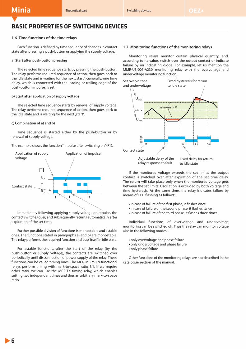
1.7. Monitoring functions of the monitoring relays
Monitoring relays monitor certain physical quantity, and, according to its value, switch over the output contact or indicate failure by an indicating diode. For example, let us mention the MMR-U3-001-A230 monitoring relay with the overvoltage and undervoltage monitoring function.
If the monitored voltage exceeds the set limits, the output contact is switched over after expiration of the set time delay. The return will take place only when the monitored voltage gets between the set limits. Oscillation is excluded by both voltage and time hysteresis. At the same time, the relay indicates failure by means of LED fl ashing as follows:
• in case of failure of the fi rst phase, it fl ashes once• in case of failure of the second phase, it fl ashes twice• in case of failure of the third phase, it fl ashes three times
Individual functions of overvoltage and undervoltage monitoring can be switched off . Thus the relay can monitor voltage also in the following modes:
• only overvoltage and phase failure• only undervoltage and phase failure• only phase failure
Other functions of the monitoring relays are not described in the catalogue section of the manual.
BASIC PROPERTIES OF SWITCHING DEVICES
Minia
6
Application of supply voltage
Application of impulse
Contact state
t t t
F1Un
TR e
Theoretical part Switching devices
Umax.
Umin.
U
t
hysteresis 5 V
1518
16
5s t 5s
230 V
Set overvoltage and undervoltage
Fixed hysteresis for return to idle state
Contact state
Adjustable delay of the relay response to fault
Fixed delay for return to idle state
BASIC PROPERTIES OF SWITCHING DEVICES
Minia
7
1.8. Switching modes of timers
Generally, timers switch output contacts depending on the program set by the user. The timers can work in daily or weekly modes.
a) Daily mode
The same sequence of switching on and off is performed daily. In most cases it can be done by a simply adjustable analog timer. The program is set by the switches on the disk of the timer.
b) Weekly mode
To control the weekly mode, it is necessary to use a digital timer. This is used, for instance, in applications which require switching depending on a day in the week or automatic change to summer//winter time.
The digital timer is set by means of push-buttons and display. For detailed description see the instruction for use, which is part of the package.
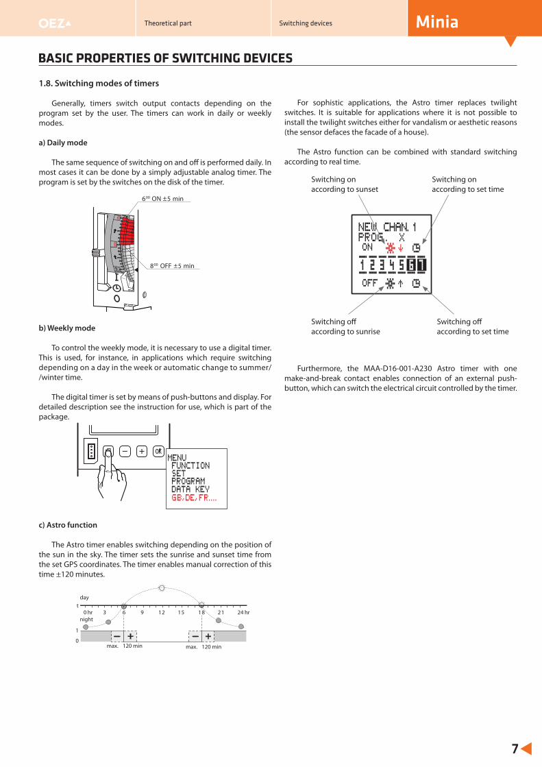
c) Astro function
The Astro timer enables switching depending on the position of the sun in the sky. The timer sets the sunrise and sunset time from the set GPS coordinates. The timer enables manual correction of this time ±120 minutes.
For sophistic applications, the Astro timer replaces twilight switches. It is suitable for applications where it is not possible to install the twilight switches either for vandalism or aesthetic reasons (the sensor defaces the facade of a house).
The Astro function can be combined with standard switching according to real time.
Furthermore, the MAA-D16-001-A230 Astro timer with one make-and-break contact enables connection of an external push-button, which can switch the electrical circuit controlled by the timer.
Switching on according to sunset
Switching on according to set time
Switching off according to sunrise
Switching off according to set time
6 ON00
8 OFF00
0 hr 3 21 24 hrt
1
0max. 120 minmax. 120 min
6 9 12 15 18
day
night
Theoretical part Switching devices
INSTALLATION CONTACTORS AND INSTALLATION RELAYS
Minia
8
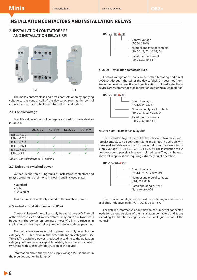
2. INSTALLATION CONTACTORS RSI AND INSTALLATION RELAYS RPI
RSI RPI
The make contacts close and break contacts open by applying voltage to the control coil of the device. As soon as the control impulse ceases, the contacts are returned to the idle state.
2.1. Control voltage
Possible values of control voltage are stated for these devices in Table 4.
Table 4: Control voltage of RSI and PRI
2.2. Noise and switched power
We can defi ne three subgroups of installation contactors and relays according to their noise in closing and in closed state:
• Standard• Quiet• Extra quiet
This division is also closely related to the switched power.
a) Standard – Installation contactors RSI-A
Control voltage of the coil can only be alternating (AC). The coil of the device “clicks”, and in closed state it may “hum” due to network frequency. The contactors are used most of all, in particular in applications without special requirements for noiseless operation.
The contactors can switch high power not only in utilization category AC-1, but also in the other utilization categories, see Table 3. The switched power is reduced according to the utilization category; otherwise unacceptable loading takes place in contact switching with subsequent destruction of the device.
Information about the type of supply voltage (AC) is shown in the type designation by letter “A”.
RSI–25–40–A230
b) Quiet – Installation contactors RSI-X
Control voltage of the coil can be both alternating and direct (AC/DC). Although the coil of the device “clicks”, it does not “hum” like in the previous case thanks to rectifi cation in closed state. These devices are recommended for applications requiring quiet operation.
RSI–25–40–X230
c) Extra quiet – Installation relays RPI The control voltage of the coil of the relay with two make-and-
-break contacts can be both alternating and direct. The version with three make-and-break contacts is universal from the viewpoint of supply voltage (AC 24 ÷ 230 V, DC 24 ÷ 220 V). The installation relays does not sound perceivable, even in closed state. They can be used above all in applications requiring extremely quiet operation.
RPI–16–001–X230
The installation relays can be used for switching non-inductive or slightly inductive loads (AC-1, DC-1) up to 16 A.
For detailed information about maximum number of connected loads for various versions of the installation contactors and relays according to utilization category, see the catalogue section of the manual.
AC 230 V AC 24 V DC 220 V DC 24 V
RSI-…-A230 RSI-…-A024 RSI-…-X230 RSI-…-X024 RPI-…-X230 RPI-…-UNI
Rated thermal current (20, 25, 32, 40, 63 A)
Number and type of contacts (10, 20, 11, 02, 40, 31, 04)
Control voltage (AC 24, 230 V)
Rated thermal current (20, 25, 32, 40, 63 A)
Number and type of contacts (10, 20, 11, 02, 40, 31, 04)
Control voltage (AC/DC 24, 230 V)
Rated operating current (8, 16 A) pro AC-1
Number and type of contacts (001, 002, 003)
Control voltage (AC/DC 24, AC 230 V, UNI)
Theoretical part Switching devices
INSTALLATION CONTACTORS AND INSTALLATION RELAYS
Minia
9
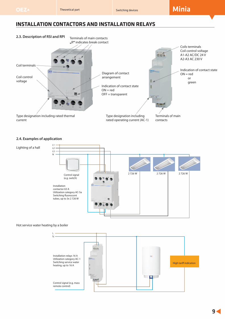
2.4. Examples of application
Coil terminals
Indication of contact stateON = redOFF = transparent
Coils terminalsCoil control voltageA1-A2 AC/DC 24 VA2-A3 AC 230 V
Coil control voltage
Diagram of contact arrangement
Terminals of main contacts
Indication of contact stateON = red
orgreen
Type designation including rated operating current (AC-1)
Type designation including rated thermal current
2.3. Description of RSI and RPI
l di t d th l
Hot service water heating by a boiler
Lighting of a hallL1L2L3N
Řídící signál(např. vypína )č
Instalační stykač 63 AKategorie u ití AC-5aSpínání zářiveka 3 x
ž
ž
2 726 W 2 726 W 2 726 W
2 726 W
Terminals of main contacts „R“ indicates break contact
Theoretical part Switching devices
Control signal (e.g. switch)
Installation contactor 63 AUtilization category AC-5aSwitching fl uorescent tubes, up to 3x 2 726 W
Installation relays 16 A Utilization category AC-1Switching service water heating, up to 16 A
Control signal (e.g. mass remote control)
High tariff indication
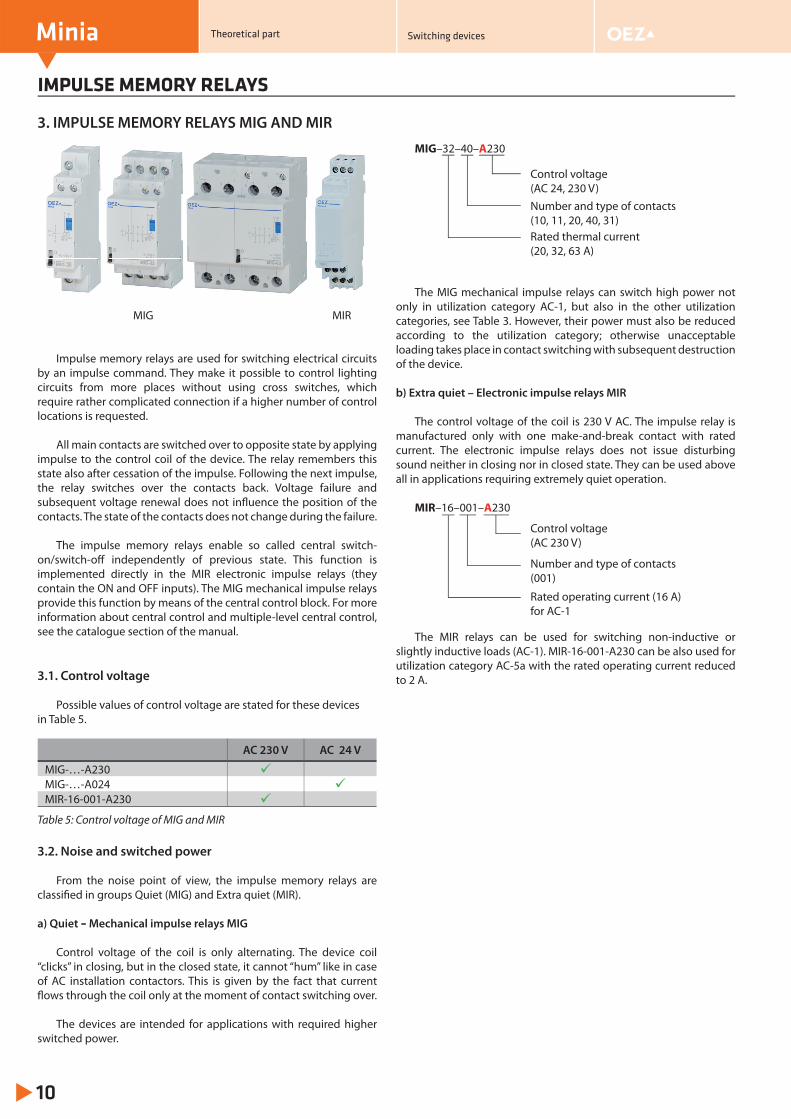
3. IMPULSE MEMORY RELAYS MIG AND MIR
MIG MIR
Impulse memory relays are used for switching electrical circuits by an impulse command. They make it possible to control lighting circuits from more places without using cross switches, which require rather complicated connection if a higher number of control locations is requested.
All main contacts are switched over to opposite state by applying impulse to the control coil of the device. The relay remembers this state also after cessation of the impulse. Following the next impulse, the relay switches over the contacts back. Voltage failure and subsequent voltage renewal does not infl uence the position of the contacts. The state of the contacts does not change during the failure.
The impulse memory relays enable so called central switch-on/switch-off independently of previous state. This function is implemented directly in the MIR electronic impulse relays (they contain the ON and OFF inputs). The MIG mechanical impulse relays provide this function by means of the central control block. For more information about central control and multiple-level central control, see the catalogue section of the manual.
3.1. Control voltage
Possible values of control voltage are stated for these devices in Table 5.
Table 5: Control voltage of MIG and MIR
3.2. Noise and switched power
From the noise point of view, the impulse memory relays are classifi ed in groups Quiet (MIG) and Extra quiet (MIR).
a) Quiet – Mechanical impulse relays MIG
Control voltage of the coil is only alternating. The device coil “clicks” in closing, but in the closed state, it cannot “hum” like in case of AC installation contactors. This is given by the fact that current fl ows through the coil only at the moment of contact switching over.
The devices are intended for applications with required higher switched power.
MIG–32–40–A230
The MIG mechanical impulse relays can switch high power not
only in utilization category AC-1, but also in the other utilization categories, see Table 3. However, their power must also be reduced according to the utilization category; otherwise unacceptable loading takes place in contact switching with subsequent destruction of the device.
b) Extra quiet – Electronic impulse relays MIR The control voltage of the coil is 230 V AC. The impulse relay is
manufactured only with one make-and-break contact with rated current. The electronic impulse relays does not issue disturbing sound neither in closing nor in closed state. They can be used above all in applications requiring extremely quiet operation.
MIR–16–001–A230
The MIR relays can be used for switching non-inductive or slightly inductive loads (AC-1). MIR-16-001-A230 can be also used for utilization category AC-5a with the rated operating current reduced to 2 A.
IMPULSE MEMORY RELAYS
Minia
10
AC 230 V AC 24 V
MIG-…-A230 MIG-…-A024 MIR-16-001-A230
Rated thermal current(20, 32, 63 A)
Number and type of contacts (10, 11, 20, 40, 31)
Control voltage (AC 24, 230 V)
Rated operating current (16 A) for AC-1
Number and type of contacts (001)
Control voltage (AC 230 V)
Theoretical part Switching devices
IMPULSE MEMORY RELAYS
Minia
11
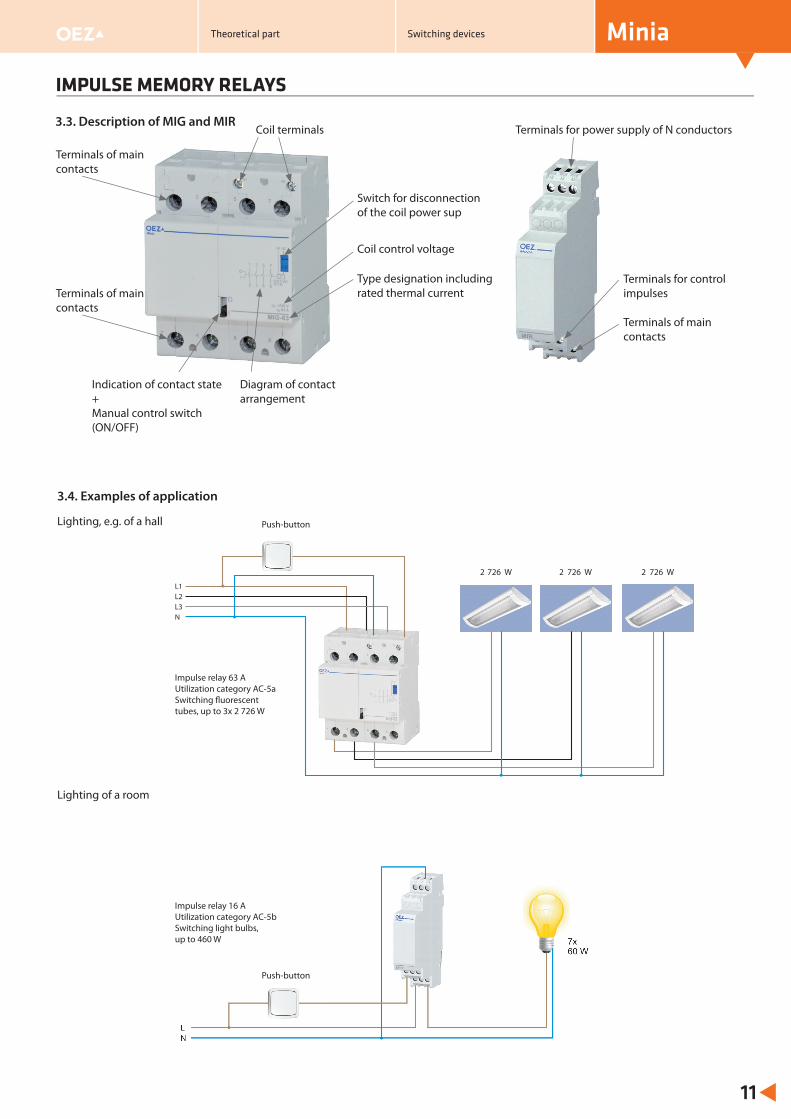
Terminals for control impulses
Type designation including rated thermal current
Terminals of main contacts
Switch for disconnection of the coil power sup
Coil control voltage
Diagram of contact arrangement
Terminals of main contacts
Indication of contact state+Manual control switch (ON/OFF)
3.3. Description of MIG and MIR
3.4. Examples of application
Lighting, e.g. of a hall
Lighting of a room
Coil terminals
Terminals of main contacts
Theoretical part Switching devices
Tlačítko
Impulzní relé 63 AKategorie u ití AC-5aSpínání zářiveka 3 x 2 726 W
ž
ž
2 726 W 2 726 W 2 726 W
L1L2L3N
Terminals for power supply of N conductors
Impulse relay 63 AUtilization category AC-5aSwitching fl uorescent tubes, up to 3x 2 726 W
Impulse relay 16 AUtilization category AC-5bSwitching light bulbs, up to 460 W
Push-button
Push-button
TIME RELAYS
Minia
12
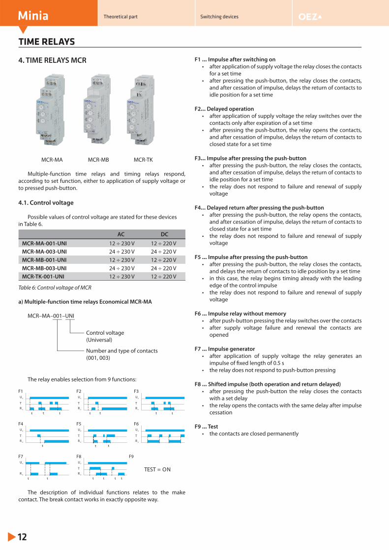
4. TIME RELAYS MCR
MCR-MA MCR-MB MCR-TK
Multiple-function time relays and timing relays respond, according to set function, either to application of supply voltage or to pressed push-button.
4.1. Control voltage
Possible values of control voltage are stated for these devices in Table 6.
Table 6: Control voltage of MCR
a) Multiple-function time relays Economical MCR-MA
MCR–MA–001–UNI
The relay enables selection from 9 functions:
The description of individual functions relates to the make contact. The break contact works in exactly opposite way.
F1 … Impulse after switching on• after application of supply voltage the relay closes the contacts
for a set time• after pressing the push-button, the relay closes the contacts,
and after cessation of impulse, delays the return of contacts to idle position for a set time
F2… Delayed operation• after application of supply voltage the relay switches over the
contacts only after expiration of a set time• after pressing the push-button, the relay opens the contacts,
and after cessation of impulse, delays the return of contacts to closed state for a set time
F3… Impulse after pressing the push-button• after pressing the push-button, the relay closes the contacts,
and after cessation of impulse, delays the return of contacts to idle position for a set time
• the relay does not respond to failure and renewal of supply voltage
F4… Delayed return after pressing the push-button• after pressing the push-button, the relay opens the contacts,
and after cessation of impulse, delays the return of contacts to closed state for a set time
• the relay does not respond to failure and renewal of supply voltage
F5 … Impulse after pressing the push-button• after pressing the push-button, the relay closes the contacts,
and delays the return of contacts to idle position by a set time• in this case, the relay begins timing already with the leading
edge of the control impulse• the relay does not respond to failure and renewal of supply
voltage
F6 … Impulse relay without memory• after push-button pressing the relay switches over the contacts• after supply voltage failure and renewal the contacts are
opened
F7 … Impulse generator• after application of supply voltage the relay generates an
impulse of fi xed length of 0.5 s• the relay does not respond to push-button pressing
F8 … Shifted impulse (both operation and return delayed)• after pressing the push-button the relay closes the contacts
with a set delay• the relay opens the contacts with the same delay after impulse
cessation
F9 … Test• the contacts are closed permanently
AC DC
MCR-MA-001-UNI 12 ÷ 230 V 12 ÷ 220 VMCR-MA-003-UNI 24 ÷ 230 V 24 ÷ 220 VMCR-MB-001-UNI 12 ÷ 230 V 12 ÷ 220 VMCR-MB-003-UNI 24 ÷ 230 V 24 ÷ 220 VMCR-TK-001-UNI 12 ÷ 230 V 12 ÷ 220 V
t t t
F1Un
TR e
TEST = ON
F9
t t
F2Un
TR e
t t
F3Un
TR e
t
F4Un
TR e
t t
F5Un
TR e
F6Un
TR e
t t
F7Un
R e
t t
F8Un
TR e
t t
Control voltage (Universal)
Number and type of contacts(001, 003)
Theoretical part Switching devices
TIME RELAYS
Minia
13
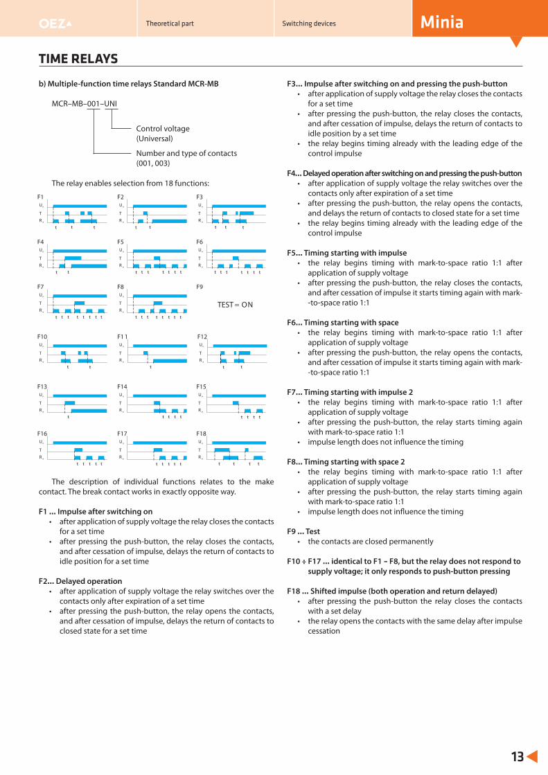
b) Multiple-function time relays Standard MCR-MB
MCR–MB–001–UNI
The relay enables selection from 18 functions:
The description of individual functions relates to the make contact. The break contact works in exactly opposite way.
F1 … Impulse after switching on• after application of supply voltage the relay closes the contacts
for a set time• after pressing the push-button, the relay closes the contacts,
and after cessation of impulse, delays the return of contacts to idle position for a set time
F2… Delayed operation• after application of supply voltage the relay switches over the
contacts only after expiration of a set time• after pressing the push-button, the relay opens the contacts,
and after cessation of impulse, delays the return of contacts to closed state for a set time
F3… Impulse after switching on and pressing the push-button• after application of supply voltage the relay closes the contacts
for a set time• after pressing the push-button, the relay closes the contacts,
and after cessation of impulse, delays the return of contacts to idle position by a set time
• the relay begins timing already with the leading edge of the control impulse
F4… Delayed operation after switching on and pressing the push-button• after application of supply voltage the relay switches over the
contacts only after expiration of a set time• after pressing the push-button, the relay opens the contacts,
and delays the return of contacts to closed state for a set time• the relay begins timing already with the leading edge of the
control impulse
F5… Timing starting with impulse• the relay begins timing with mark-to-space ratio 1:1 after
application of supply voltage• after pressing the push-button, the relay closes the contacts,
and after cessation of impulse it starts timing again with mark--to-space ratio 1:1
F6… Timing starting with space• the relay begins timing with mark-to-space ratio 1:1 after
application of supply voltage• after pressing the push-button, the relay opens the contacts,
and after cessation of impulse it starts timing again with mark--to-space ratio 1:1
F7… Timing starting with impulse 2• the relay begins timing with mark-to-space ratio 1:1 after
application of supply voltage• after pressing the push-button, the relay starts timing again
with mark-to-space ratio 1:1• impulse length does not infl uence the timing
F8… Timing starting with space 2• the relay begins timing with mark-to-space ratio 1:1 after
application of supply voltage• after pressing the push-button, the relay starts timing again
with mark-to-space ratio 1:1• impulse length does not infl uence the timing
F9 … Test• the contacts are closed permanently
F10 ÷ F17 … identical to F1 – F8, but the relay does not respond to supply voltage; it only responds to push-button pressing
F18 … Shifted impulse (both operation and return delayed)• after pressing the push-button the relay closes the contacts
with a set delay• the relay opens the contacts with the same delay after impulse
cessation
t t t
F1Un
TR e
TEST = ON
F9
t t
F2Un
TR e
t t
F3Un
TR e
t t
F4Un
TR e
t
F14Un
TR e
t
F15Un
TR e
t t t t t t
t t
F10Un
TR e
t
t t
F7Un
TR e
t t t t t t t t
F8Un
TR e
tt t t t
t
F1 1Un
TR e
t t
F12Un
TR e
t t
F18Un
TR e
t t
t
F13Un
TR e
t t
F5Un
TR e
t t
F6Un
TR e
t t t t t tt t t t
t
F16Un
TR e
t t t t t
F17Un
TR e
t t t t
t
Number and type of contacts(001, 003)
Control voltage (Universal)
Theoretical part Switching devices
TIME RELAYS
Minia
14
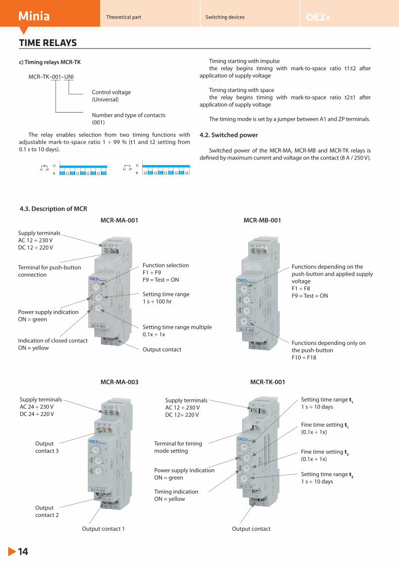
4.3. Description of MCR
MCR-MA-001 MCR-MB-001
MCR-MA-003 MCR-TK-001
Function selectionF1 ÷ F9F9 = Test = ON
Supply terminalsAC 12 ÷ 230 VDC 12 ÷ 220 V
Terminal for push-button connection
Power supply indication ON = green
Indication of closed contactON = yellow Output contact
Setting time range 1 s ÷ 100 hr
Setting time range multiple 0.1x ÷ 1x
Functions depending only on the push-buttonF10 ÷ F18
Functions depending on the push-button and applied supply voltageF1 ÷ F8F9 = Test = ON
Supply terminalsAC 24 ÷ 230 VDC 24 ÷ 220 V
Output contact 3
Output contact 2
Output contact 1
Supply terminalsAC 12 ÷ 230 VDC 12÷ 220 V
Fine time setting t1(0.1x ÷ 1x)
Fine time setting t2(0.1x ÷ 1x)
Setting time range t11 s ÷ 10 days
Setting time range t2 1 s ÷ 10 days
Output contact
Power supply indication ON = green
Terminal for timing mode setting
Timing indicationON = yellow
c) Timing relays MCR-TK
MCR–TK–001–UNI
The relay enables selection from two timing functions with adjustable mark-to-space ratio 1 ÷ 99 % (t1 and t2 setting from 0.1 s to 10 days).
Timing starting with impulsethe relay begins timing with mark-to-space ratio t1:t2 after
application of supply voltage
Timing starting with spacethe relay begins timing with mark-to-space ratio t2:t1 after
application of supply voltage
The timing mode is set by a jumper between A1 and ZP terminals.
4.2. Switched power
Switched power of the MCR-MA, MCR-MB and MCR-TK relays is defi ned by maximum current and voltage on the contact (8 A / 250 V).
Number and type of contacts(001)
Control voltage(Universal)
A1 ZPU
R t1 t1 t1 t1 t1t2 t2 t2 t2A1 ZP
U
R t2 t2 t2 t2 t2t1 t1 t1 t1
Theoretical part Switching devices
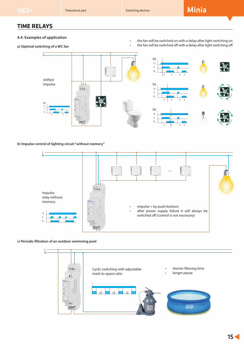
4.4. Examples of application
a) Optimal switching of a WC fan
b) Impulse control of lighting circuit “without memory”
c) Periodic fi ltration of an outdoor swimming pool
t t
F8Un
TR e
t t
t t
F8Un
TR e
t t
t t
F8Un
TR e
t t
t t
F8Un
TR e
t t
NL
Un
TR e
...
NL
t1 t1 t1 t1t2 t2 t2
NL
TIME RELAYS
Minia
15
• impulse = by push-buttons• after power supply failure it will always be
switched off (control is not necessary)
• the fan will be switched on with a delay after light switching on• the fan will be switched off with a delay after light switching off
shifted impulse
Impulse relay without memory
• shorter fi ltering time• longer pause
Cyclic switching with adjustable mark-to-space ratio
Theoretical part Switching devices
MONITORING, LEVEL AND THERMAL RELAYS
Minia
16
5. MONITORING, LEVEL AND THERMAL RELAYS MMR
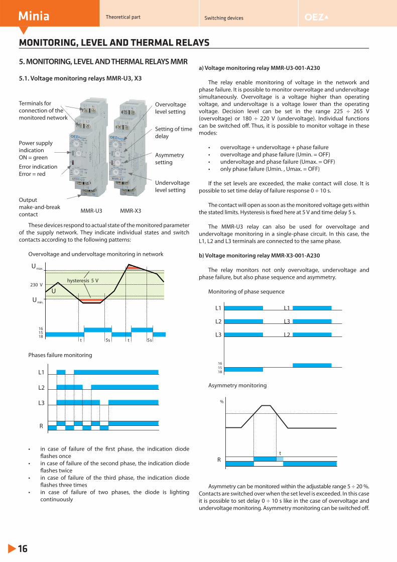
5.1. Voltage monitoring relays MMR-U3, X3
MMR-U3 MMR-X3
These devices respond to actual state of the monitored parameter of the supply network. They indicate individual states and switch contacts according to the following patterns:
Overvoltage and undervoltage monitoring in network
Phases failure monitoring
• in case of failure of the fi rst phase, the indication diode fl ashes once
• in case of failure of the second phase, the indication diode fl ashes twice
• in case of failure of the third phase, the indication diode fl ashes three times
• in case of failure of two phases, the diode is lighting continuously
a) Voltage monitoring relay MMR-U3-001-A230
The relay enable monitoring of voltage in the network and phase failure. It is possible to monitor overvoltage and undervoltage simultaneously. Overvoltage is a voltage higher than operating voltage, and undervoltage is a voltage lower than the operating voltage. Decision level can be set in the range 225 ÷ 265 V (overvoltage) or 180 ÷ 220 V (undervoltage). Individual functions can be switched off . Thus, it is possible to monitor voltage in these modes:
• overvoltage + undervoltage + phase failure• overvoltage and phase failure (Umin. = OFF)• undervoltage and phase failure (Umax. = OFF)• only phase failure (Umin. , Umax. = OFF)
If the set levels are exceeded, the make contact will close. It is possible to set time delay of failure response 0 ÷ 10 s.
The contact will open as soon as the monitored voltage gets within the stated limits. Hysteresis is fi xed here at 5 V and time delay 5 s.
The MMR-U3 relay can also be used for overvoltage and undervoltage monitoring in a single-phase circuit. In this case, the L1, L2 and L3 terminals are connected to the same phase.
b) Voltage monitoring relay MMR-X3-001-A230
The relay monitors not only overvoltage, undervoltage and phase failure, but also phase sequence and asymmetry.
Monitoring of phase sequence
Asymmetry monitoring
Asymmetry can be monitored within the adjustable range 5 ÷ 20 %. Contacts are switched over when the set level is exceeded. In this case it is possible to set delay 0 ÷ 10 s like in the case of overvoltage and undervoltage monitoring. Asymmetry monitoring can be switched off .
Terminals for connection of the monitored network
Power supply indication ON = green
Overvoltage level setting
Setting of time delay
Error indicationError = red
Asymmetry setting
Undervoltage level setting
Output make-and-break contact
Umax.
Umin.
U
t
hysteresis 5 V
1518
16
5s t 5s
230 V
L1
L2
L3
R
tR
%
Theoretical part Switching devices
1518
16
L2
L2
L1
L3
L1
L3
MONITORING, LEVEL AND THERMAL RELAYS
Minia
17
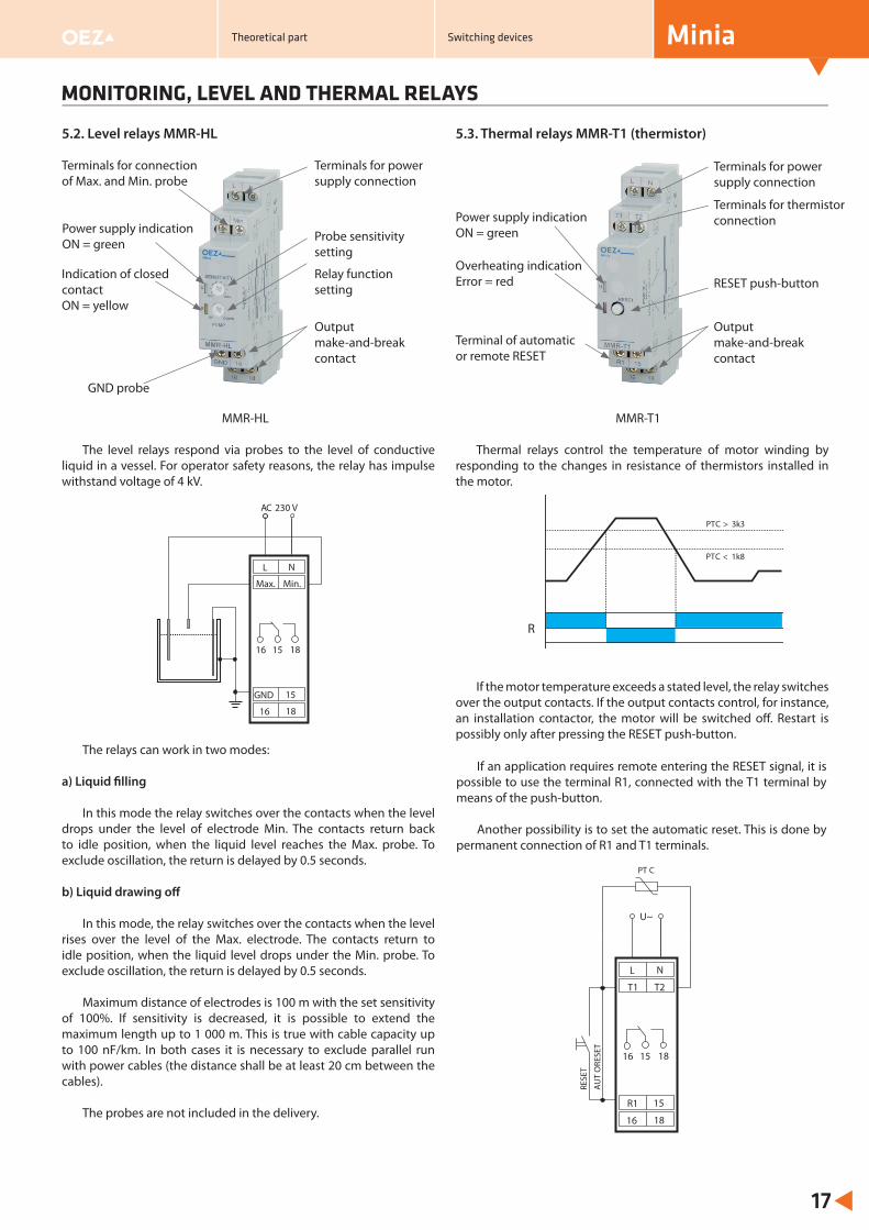
5.2. Level relays MMR-HL
MMR-HL
The level relays respond via probes to the level of conductive liquid in a vessel. For operator safety reasons, the relay has impulse withstand voltage of 4 kV.
The relays can work in two modes:
a) Liquid fi lling
In this mode the relay switches over the contacts when the level drops under the level of electrode Min. The contacts return back to idle position, when the liquid level reaches the Max. probe. To exclude oscillation, the return is delayed by 0.5 seconds.
b) Liquid drawing off
In this mode, the relay switches over the contacts when the level rises over the level of the Max. electrode. The contacts return to idle position, when the liquid level drops under the Min. probe. To exclude oscillation, the return is delayed by 0.5 seconds.
Maximum distance of electrodes is 100 m with the set sensitivity of 100%. If sensitivity is decreased, it is possible to extend the maximum length up to 1 000 m. This is true with cable capacity up to 100 nF/km. In both cases it is necessary to exclude parallel run with power cables (the distance shall be at least 20 cm between the cables).
The probes are not included in the delivery.
5.3. Thermal relays MMR-T1 (thermistor)
MMR-T1
Thermal relays control the temperature of motor winding by responding to the changes in resistance of thermistors installed in the motor.
If the motor temperature exceeds a stated level, the relay switches over the output contacts. If the output contacts control, for instance, an installation contactor, the motor will be switched off . Restart is possibly only after pressing the RESET push-button.
Terminals for connection of Max. and Min. probe
Power supply indication ON = green
Indication of closed contactON = yellow
GND probe
Terminals for power supply connection
Probe sensitivity setting
Relay function setting
Output make-and-break contact
Overheating indicationError = red
Output make-and-break contact
Terminals for power supply connection
Power supply indication ON = green
Terminal of automatic or remote RESET
Terminals for thermistor connection
RESET push-button
on
nn
L
Max. Min.
GND
16 18
N
15
230 V
16 15 18
AC
PTC > 3k3
PTC < 1k8
R
L
T1 T2
R1
16 18
N
15
U~
16 15 18
RESE
T
AU
TO
RESE
T
PT C
If an application requires remote entering the RESET signal, it is possible to use the terminal R1, connected with the T1 terminal by means of the push-button.
Another possibility is to set the automatic reset. This is done by permanent connection of R1 and T1 terminals.
Theoretical part Switching devices
MONITORING, LEVEL AND THERMAL RELAYS
Minia
18
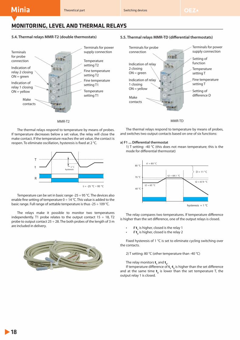
5.4. Thermal relays MMR-T2 (double thermostats)
MMR-T2
The thermal relays respond to temperature by means of probes. If temperature decreases below a set value, the relay will close the make contact. If the temperature reaches the set value, the contact is reopen. To eliminate oscillation, hysteresis is fi xed at 2 °C.
Temperature can be set in basic range -25 ÷ 95 °C. The devices also enable fi ne setting of temperature 0 ÷ 14 °C. This value is added to the basic range. Full range of settable temperature is thus -25 ÷ 109 °C.
The relays make it possible to monitor two temperatures independently. T1 probe relates to the output contact 15 ÷ 18, T2 probe to output contact 25 ÷ 28. The both probes of the length of 3 m are included in delivery.
5.5. Thermal relays MMR-TD (diff erential thermostats)
MMR-TD The thermal relays respond to temperature by means of probes,
and switches two output contacts based on one of six functions:
a) F1 … Diff erential thermostat1) T setting: -40 °C (this does not mean temperature; this is the mode for diff erential thermostat)
The relay compares two temperatures. If temperature diff erence is higher than the set diff erence, one of the output relays is closed.
• if t1 is higher, closed is the relay 1• if t2 is higher, closed is the relay 2
Fixed hysteresis of 1 °C is set to eliminate cycling switching over the contacts.
2) T setting: 80 °C (other temperature than -40 °C)
The relay monitors t1 and t2.If temperature diff erence of t1-t2 is higher than the set diff erence
and at the same time t2 is lower than the set temperature T, the output relay 1 is closed.
Terminals for probe connection
Indication of relay 2 closingON = green
Indication of relay 1 closingON = yellow
Make contacts
Temperature setting T2
Fine temperature setting T2
Setting of function
Terminals for power supply connection
Terminals for probe connection
Indication of relay 2 closingON = green
Indication of relay 1 closingON = yellow
Make contacts
Temperature setting T
Fine temperature setting T
Terminals for power supply connection
Setting of diff erence D
be
R
t -25 °C= 95 C°
2 ° Chysteresis
t
T
÷
D = 11 ° C
t1 = 80 ° C
t2 = 65 ° C
t2 = 69.1 °C
t2 = 67.9 °C
80 °C
60 °C
70 °C
hysteresis = 1 °C
Temperature setting T1
Fine temperature setting T1
Theoretical part Switching devices
MONITORING, LEVEL AND THERMAL RELAYS
Minia
19
b) F2 … Two-stage thermostat (1)
One temperature is monitored, and relay contacts are opened gradually with decreasing temperature depending on the set temperature T and diff erence D.
t1 > T … R1 ON, R2 ONt1 < T … R1 ON, R2 OFFt1 < T - D … R1 OFF, R2 OFF
c) F3 … Two-stage thermostat (2)
One temperature is monitored, and relay contacts are opened gradually with decreasing temperature depending on the set temperature T and diff erence D.
t1 > T … R1 OFF, R2 ONt1 < T … R1 ON, R2 OFFt1 < T - D … R1 OFF, R2 OFF
d) F4 … Single-channel zone thermostat
One temperature is monitored. If the set temperature T is reached, the output contact relay 1 opens. The output contact closes if the temperature decreases below the value of T – D.
If the T2 and C terminals are interconnected, the both output contacts (relay 1 and relay 2) switch simultaneously. If the terminals are not interconnected, only the output contact (relay 1) switches.
e) F5 … Two-channel zone thermostat
Two temperatures are monitored. The output contacts of the relays switch in the same way as for function F4, while each of them is assigned to one of the monitored temperatures.
f) F6 … Thermostat is heating/cooling
One temperature is monitored. Relay contacts are switched depending on the set temperature T and diff erence D. If the monitored temperature is higher than T, the output contact of relay 1 makes. If the temperature is lower than T – D, the output contact of relay 2 makes. If we connect the relay 1 contact to cooling and the relay 2 contact to heating, we are able to regulate temperature within a defi ned range. Fixed hysteresis: 2 °C.
Another four functions are service functions:
g) F7 … Service relay 1Relay1 (contact 15 - 18) is closed.
h) F8 … Service relay 2Relay 2 (contact 25 - 28) is closed.
i) F9 … Service sensor 1Test of probe 1
j) F10 … Service sensor 2Test of probe 2
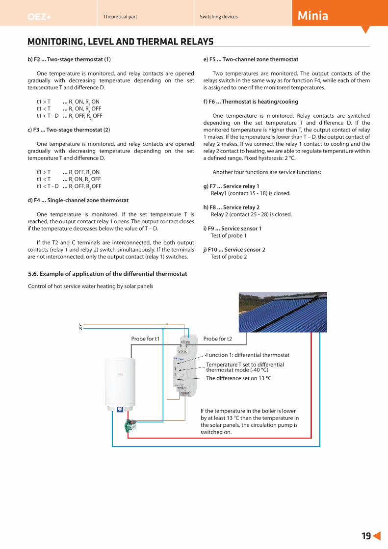
5.6. Example of application of the diff erential thermostat
Control of hot service water heating by solar panels
If the temperature in the boiler is lower by at least 13 °C than the temperature in the solar panels, the circulation pump is switched on.
Function 1: diff erential thermostat
Temperature T set to diff erential thermostat mode (-40 °C)The diff erence set on 13 °C
Theoretical part Switching devices
Probe for t1 Probe for t2
TIMERS
Minia
20
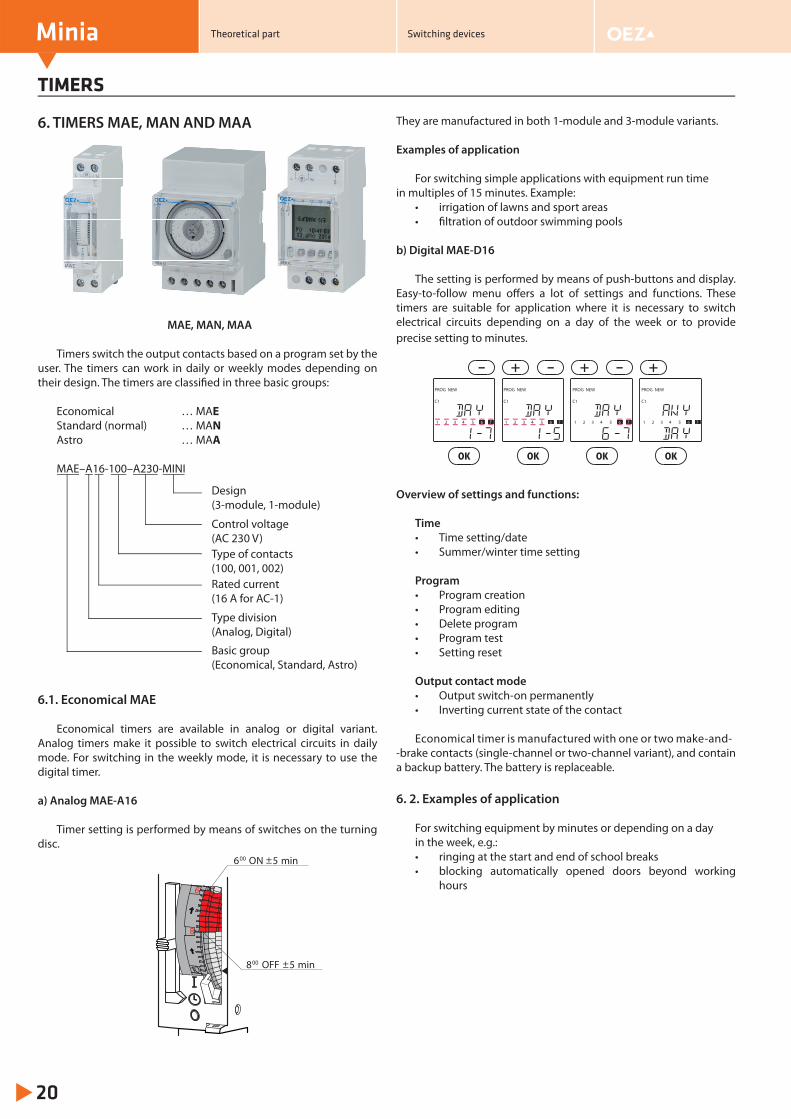
6. TIMERS MAE, MAN AND MAA
MAE, MAN, MAA
Timers switch the output contacts based on a program set by the user. The timers can work in daily or weekly modes depending on their design. The timers are classifi ed in three basic groups:
Economical … MAEStandard (normal) … MANAstro … MAA
MAE–A16-100–A230-MINI
6.1. Economical MAE
Economical timers are available in analog or digital variant. Analog timers make it possible to switch electrical circuits in daily mode. For switching in the weekly mode, it is necessary to use the digital timer.
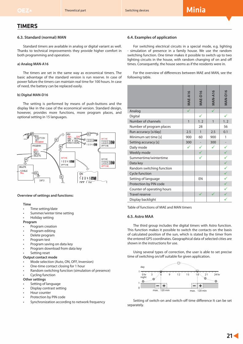
a) Analog MAE-A16
Timer setting is performed by means of switches on the turning disc.
They are manufactured in both 1-module and 3-module variants.
Examples of application
For switching simple applications with equipment run time in multiples of 15 minutes. Example:
• irrigation of lawns and sport areas• fi ltration of outdoor swimming pools
b) Digital MAE-D16
The setting is performed by means of push-buttons and display. Easy-to-follow menu off ers a lot of settings and functions. These timers are suitable for application where it is necessary to switch electrical circuits depending on a day of the week or to provide precise setting to minutes.
Overview of settings and functions:
Time• Time setting/date• Summer/winter time setting
Program• Program creation• Program editing• Delete program• Program test• Setting reset
Output contact mode• Output switch-on permanently• Inverting current state of the contact
Economical timer is manufactured with one or two make-and--brake contacts (single-channel or two-channel variant), and contain a backup battery. The battery is replaceable.
6. 2. Examples of application
For switching equipment by minutes or depending on a day in the week, e.g.:• ringing at the start and end of school breaks• blocking automatically opened doors beyond working
hours
Basic group(Economical, Standard, Astro)
Type division(Analog, Digital)
Rated current(16 A for AC-1)
Type of contacts(100, 001, 002)
Control voltage(AC 230 V)
Design(3-module, 1-module)
6 ON00
8 OFF00
PROG NEW
C1
1 32 4 5 6 7
PROG NEW
C1
1 32 4 5 6 7
PROG NEW
C1
1 32 4 5 6 7
PROG NEW
C1
1 32 4 5 6 7
Theoretical part Switching devices
TIMERS
Minia
21
6.3. Standard (normal) MAN
Standard timers are available in analog or digital variant as well. Thanks to technical improvements they provide higher comfort in both programming and operation.
a) Analog MAN-A16
The timers are set in the same way as economical timers. The basic advantage of the standard version is run reserve. In case of power failure the timers can maintain real time for 100 hours. In case of need, the battery can be replaced easily.
b) Digital MAN-D16
The setting is performed by means of push-buttons and the display like in the case of the economical version. Standard design, however, provides more functions, more program places, and optional setting in 15 languages.
Overview of settings and functions:
Time• Time setting/date• Summer/winter time setting• Holiday settingProgram• Program creation• Program editing• Delete program• Program test• Program saving on data key• Program download from data key• Setting resetOutput contact mode• Mode selection (Auto, ON, OFF, Inversion)• One-time contact closing for 1 hour• Random switching function (simulation of presence)• Cycling functionOther settings• Setting of language• Display contrast setting• Hour counter• Protection by PIN code• Synchronization according to network frequency
6.4. Examples of application
For switching electrical circuits in a special mode, e.g. lighting - simulation of presence in a family house. We use the random switching function. One timer makes it possible to switch up to two lighting circuits in the house, with random changing of on and off times. Consequently, the house seems as if the residents were in.
For the overview of diff erences between MAE and MAN, see the following table.
Table of functions of MAE and MAN timers
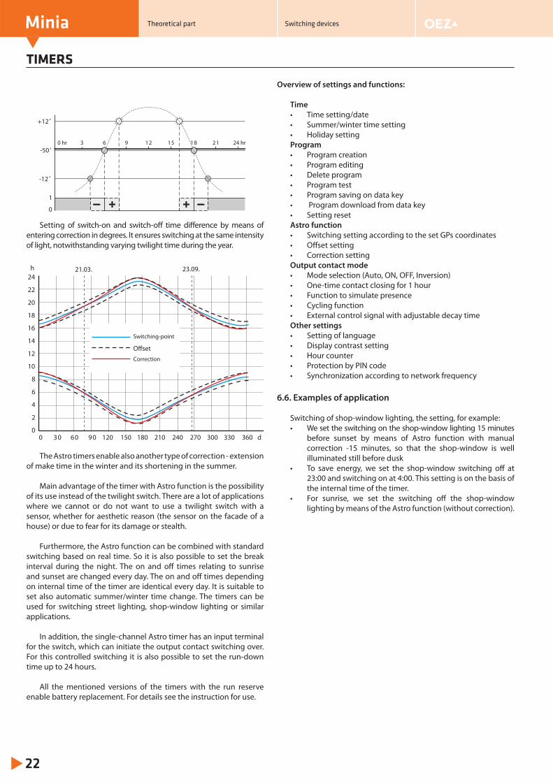
6.5. Astro MAA
The third group includes the digital timers with Astro function. This function makes it possible to switch the contacts on the basis of calculated position of the sun, which is stated by the timer from the entered GPS coordinates. Geographical data of selected cities are shown in the instructions for use.
Using several types of correction, the user is able to set precise time of switching on/off suitable for given application.
Setting of switch-on and switch-off time diff erence It can be set separately.
MA
E-A
16
MA
E-D
16
MA
N-A
16
MA
N-D
16
Analog Digital Number of channels 1 1. 2 1 1. 2Number of program places 28 56Run accuracy [s/day] 2.5 1 2.5 0.1Minimum set time [s] 900 60 900 1Setting accuracy [s] 300 - 300 -Daily mode Weekly mode Summertime/wintertime Data key Random switching function Cycle function Setting of language EN Protection by PIN code Counter of operating hours Travel reserve Display backlight
0 hr 3 21 24 hrt
1
0max. 120 minmax. 120 min
6 9 12 15 18
day
night
Theoretical part Switching devices
day
night
TIMERS
Minia Theoretical part Switching devices
22
Setting of switch-on and switch-off time diff erence by means of entering correction in degrees. It ensures switching at the same intensity of light, notwithstanding varying twilight time during the year.
The Astro timers enable also another type of correction - extension of make time in the winter and its shortening in the summer.
Main advantage of the timer with Astro function is the possibility of its use instead of the twilight switch. There are a lot of applications where we cannot or do not want to use a twilight switch with a sensor, whether for aesthetic reason (the sensor on the facade of a house) or due to fear for its damage or stealth.
Furthermore, the Astro function can be combined with standard switching based on real time. So it is also possible to set the break interval during the night. The on and off times relating to sunrise and sunset are changed every day. The on and off times depending on internal time of the timer are identical every day. It is suitable to set also automatic summer/winter time change. The timers can be used for switching street lighting, shop-window lighting or similar applications.
In addition, the single-channel Astro timer has an input terminal for the switch, which can initiate the output contact switching over. For this controlled switching it is also possible to set the run-down time up to 24 hours.
All the mentioned versions of the timers with the run reserve enable battery replacement. For details see the instruction for use.
Overview of settings and functions:
Time• Time setting/date• Summer/winter time setting• Holiday settingProgram• Program creation• Program editing• Delete program• Program test• Program saving on data key• Program download from data key• Setting resetAstro function• Switching setting according to the set GPs coordinates• Off set setting• Correction settingOutput contact mode• Mode selection (Auto, ON, OFF, Inversion)• One-time contact closing for 1 hour• Function to simulate presence• Cycling function• External control signal with adjustable decay timeOther settings• Setting of language• Display contrast setting• Hour counter• Protection by PIN code• Synchronization according to network frequency
6.6. Examples of application
Switching of shop-window lighting, the setting, for example:• We set the switching on the shop-window lighting 15 minutes
before sunset by means of Astro function with manual correction -15 minutes, so that the shop-window is well illuminated still before dusk
• To save energy, we set the shop-window switching off at 23:00 and switching on at 4:00. This setting is on the basis of the internal time of the timer.
• For sunrise, we set the switching off the shop-window lighting by means of the Astro function (without correction).
0 hr 3 6 9 12 15 18 21 24 hr
1
0
+12˚
-50 ’
-12 ˚
0 30 60 90 120 150 180 210 240 270 300 330 360
24
22
20
18
16
14
12
10
8
6
4
2
0
21.03. 23.09.h
d
OffsetCorrection
Switching-point
INSTALLATION CONTACTORS RSI-A WITH AC CONTROL VOLTAGE
Minia
23
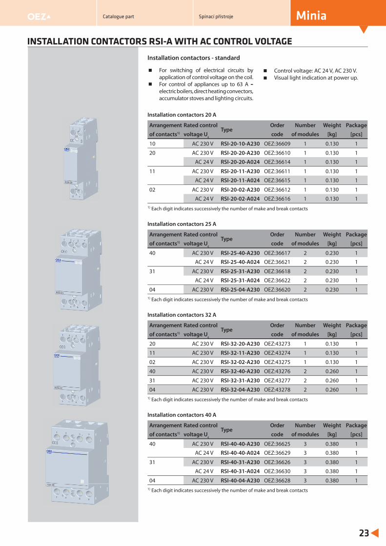
Installation contactors - standard
For switching of electrical circuits by application of control voltage on the coil.For control of appliances up to 63 A – electric boilers, direct heating convectors, accumulator stoves and lighting circuits.
Control voltage: AC 24 V, AC 230 V.Visual light indication at power up.
Installation contactors 20 A
Arrangement Rated controlType
Order Number Weight Package
of contacts1) voltage Uc code of modules [kg] [pcs]
10 AC 230 V RSI-20-10-A230 OEZ:36609 1 0.130 1
20 AC 230 V RSI-20-20-A230 OEZ:36610 1 0.130 1
AC 24 V RSI-20-20-A024 OEZ:36614 1 0.130 1
11 AC 230 V RSI-20-11-A230 OEZ:36611 1 0.130 1
AC 24 V RSI-20-11-A024 OEZ:36615 1 0.130 1
02 AC 230 V RSI-20-02-A230 OEZ:36612 1 0.130 1
AC 24 V RSI-20-02-A024 OEZ:36616 1 0.130 11) Each digit indicates successively the number of make and break contacts
Installation contactors 25 A
Arrangement Rated controlType
Order Number Weight Package
of contacts1) voltage Uc code of modules [kg] [pcs]
40 AC 230 V RSI-25-40-A230 OEZ:36617 2 0.230 1
AC 24 V RSI-25-40-A024 OEZ:36621 2 0.230 1
31 AC 230 V RSI-25-31-A230 OEZ:36618 2 0.230 1
AC 24 V RSI-25-31-A024 OEZ:36622 2 0.230 1
04 AC 230 V RSI-25-04-A230 OEZ:36620 2 0.230 11) Each digit indicates successively the number of make and break contacts
Installation contactors 32 A
Arrangement Rated controlType
Order Number Weight Package
of contacts1) voltage Uc code of modules [kg] [pcs]
20 AC 230 V RSI-32-20-A230 OEZ:43273 1 0.130 1
11 AC 230 V RSI-32-11-A230 OEZ:43274 1 0.130 1
02 AC 230 V RSI-32-02-A230 OEZ:43275 1 0.130 1
40 AC 230 V RSI-32-40-A230 OEZ:43276 2 0.260 1
31 AC 230 V RSI-32-31-A230 OEZ:43277 2 0.260 1
04 AC 230 V RSI-32-04-A230 OEZ:43278 2 0.260 11) Each digit indicates successively the number of make and break contacts
Installation contactors 40 A
Arrangement Rated controlType
Order Number Weight Package
of contacts1) voltage Uc code of modules [kg] [pcs]
40 AC 230 V RSI-40-40-A230 OEZ:36625 3 0.380 1
AC 24 V RSI-40-40-A024 OEZ:36629 3 0.380 1
31 AC 230 V RSI-40-31-A230 OEZ:36626 3 0.380 1
AC 24 V RSI-40-31-A024 OEZ:36630 3 0.380 1
04 AC 230 V RSI-40-04-A230 OEZ:36628 3 0.380 11) Each digit indicates successively the number of make and break contacts
Catalogue part Spínací přístroje
INSTALLATION CONTACTORS RSI-A WITH AC CONTROL VOLTAGE
Minia
24
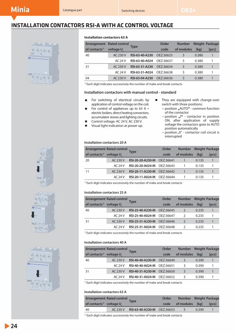
For switching of electrical circuits by application of control voltage on the coil.For control of appliances up to 63 A – electric boilers, direct heating convectors, accumulator stoves and lighting circuits.Control voltage: AC 24 V, AC 230 V.Visual light indication at power up.
They are equipped with change-over switch with three positions:• position „AUTO“ - common function
of the contactor• position „I“ - contactor in position
ON, after application of supply voltage the contactors goes to AUTO position automatically
• position „0“ - contactor coil circuit is interrupted
Installation contactors with manual control - standard
Installation contactors 63 A
Arrangement Rated controlType
Order Number Weight Package
of contacts1) voltage Uc code of modules [kg] [pcs]
40 AC 230 V RSI-63-40-A230 OEZ:36633 3 0.380 1
AC 24 V RSI-63-40-A024 OEZ:36637 3 0.380 1
31 AC 230 V RSI-63-31-A230 OEZ:36634 3 0.380 1
AC 24 V RSI-63-31-A024 OEZ:36638 3 0.380 1
04 AC 230 V RSI-63-04-A230 OEZ:36636 3 0.380 11) Each digit indicates successively the number of make and break contacts
Installation contactors 20 A
Arrangement Rated controlType
Order Number Weight Package
of contacts1) voltage Uc code of modules [kg] [pcs]
20 AC 230 V RSI-20-20-A230-M OEZ:36641 1 0.135 1
AC 24 V RSI-20-20-A024-M OEZ:36643 1 0.135 1
11 AC 230 V RSI-20-11-A230-M OEZ:36642 1 0.135 1
AC 24 V RSI-20-11-A024-M OEZ:36644 1 0.135 11) Each digit indicates successively the number of make and break contacts
Installation contactors 25 A
Arrangement Rated controlType
Order Number Weight Package
of contacts1) voltage Uc code of modules [kg] [pcs]
40 AC 230 V RSI-25-40-A230-M OEZ:36645 2 0.235 1
AC 24 V RSI-25-40-A024-M OEZ:36647 2 0.235 1
31 AC 230 V RSI-25-31-A230-M OEZ:36646 2 0.235 1
AC 24 V RSI-25-31-A024-M OEZ:36648 2 0.235 11) Each digit indicates successively the number of make and break contacts
Installation contactors 40 A
Arrangement Rated controlType
Order Number Weight Package
of contacts1) voltage Uc code of modules [kg] [pcs]
40 AC 230 V RSI-40-40-A230-M OEZ:36649 3 0.390 1
AC 24 V RSI-40-40-A024-M OEZ:36651 3 0.390 1
31 AC 230 V RSI-40-31-A230-M OEZ:36650 3 0.390 1
AC 24 V RSI-40-31-A024-M OEZ:36652 3 0.390 11) Each digit indicates successively the number of make and break contacts
Installation contactors 63 A
Arrangement Rated controlType
Order Number Weight Package
of contacts1) voltage Uc code of modules [kg] [pcs]
40 AC 230 V RSI-63-40-A230-M OEZ:36653 3 0.390 11) Each digit indicates successively the number of make and break contacts
Catalogue part Switching devices
Minia
25
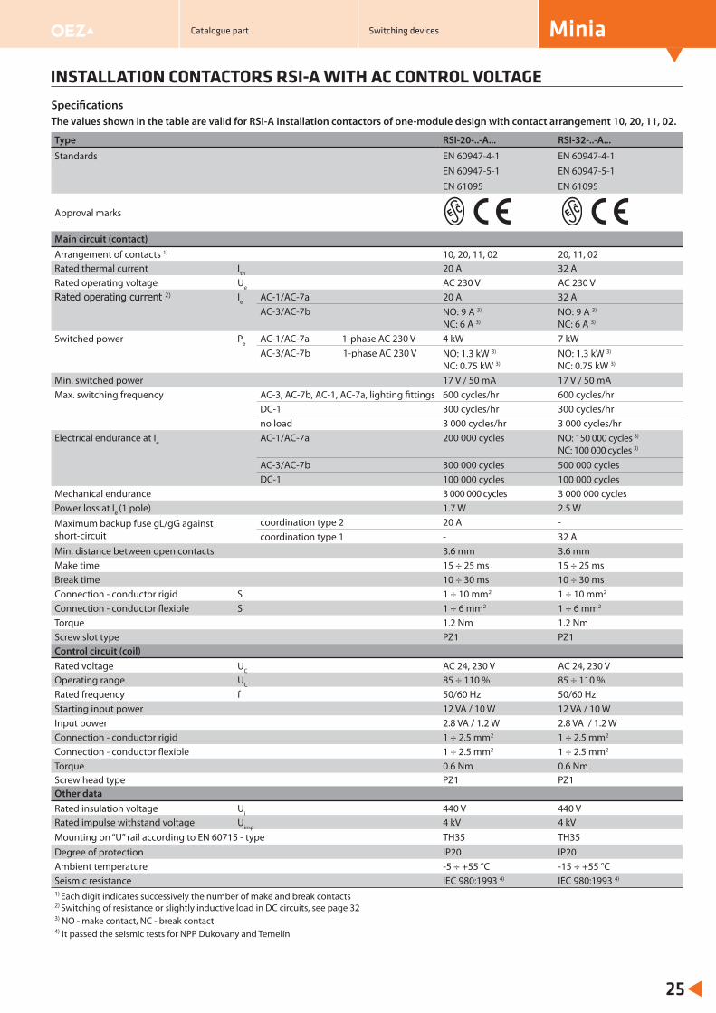
INSTALLATION CONTACTORS RSI-A WITH AC CONTROL VOLTAGE
The values shown in the table are valid for RSI-A installation contactors of one-module design with contact arrangement 10, 20, 11, 02.
Type RSI-20-..-A... RSI-32-..-A...
Standards EN 60947-4-1 EN 60947-4-1EN 60947-5-1 EN 60947-5-1EN 61095 EN 61095
Approval marks
Main circuit (contact)Arrangement of contacts 1) 10, 20, 11, 02 20, 11, 02Rated thermal current Ith 20 A 32 ARated operating voltage Ue AC 230 V AC 230 VRated operating current 2) Ie AC-1/AC-7a 20 A 32 A
AC-3/AC-7b NO: 9 A 3)
NC: 6 A 3)NO: 9 A 3)
NC: 6 A 3)
Switched power Pe AC-1/AC-7a 1-phase AC 230 V 4 kW 7 kWAC-3/AC-7b 1-phase AC 230 V NO: 1.3 kW 3)
NC: 0.75 kW 3)NO: 1.3 kW 3)
NC: 0.75 kW 3)
Min. switched power 17 V / 50 mA 17 V / 50 mAMax. switching frequency AC-3, AC-7b, AC-1, AC-7a, lighting fi ttings 600 cycles/hr 600 cycles/hr
DC-1 300 cycles/hr 300 cycles/hr no load 3 000 cycles/hr 3 000 cycles/hr
Electrical endurance at Ie AC-1/AC-7a 200 000 cycles NO: 150 000 cycles 3)
NC: 100 000 cycles 3)
AC-3/AC-7b 300 000 cycles 500 000 cycles DC-1 100 000 cycles 100 000 cycles
Mechanical endurance 3 000 000 cycles 3 000 000 cycles Power loss at Ie (1 pole) 1.7 W 2.5 WMaximum backup fuse gL/gG against short-circuit
coordination type 2 20 A -coordination type 1 - 32 A
Min. distance between open contacts 3.6 mm 3.6 mmMake time 15 ÷ 25 ms 15 ÷ 25 msBreak time 10 ÷ 30 ms 10 ÷ 30 msConnection - conductor rigid S 1 ÷ 10 mm2 1 ÷ 10 mm2
Connection - conductor flexible S 1 ÷ 6 mm2 1 ÷ 6 mm2
Torque 1.2 Nm 1.2 NmScrew slot type PZ1 PZ1Control circuit (coil)Rated voltage UC AC 24, 230 V AC 24, 230 VOperating range UC 85 ÷ 110 % 85 ÷ 110 %Rated frequency f 50/60 Hz 50/60 HzStarting input power 12 VA / 10 W 12 VA / 10 WInput power 2.8 VA / 1.2 W 2.8 VA / 1.2 WConnection - conductor rigid 1 ÷ 2.5 mm2 1 ÷ 2.5 mm2
Connection - conductor flexible 1 ÷ 2.5 mm2 1 ÷ 2.5 mm2
Torque 0.6 Nm 0.6 NmScrew head type PZ1 PZ1Other dataRated insulation voltage Ui 440 V 440 VRated impulse withstand voltage Uimp 4 kV 4 kVMounting on “U” rail according to EN 60715 - type TH35 TH35Degree of protection IP20 IP20Ambient temperature -5 ÷ +55 °C -15 ÷ +55 °CSeismic resistance IEC 980:1993 4) IEC 980:1993 4)
1) Each digit indicates successively the number of make and break contacts
Specifi cations
2) Switching of resistance or slightly inductive load in DC circuits, see page 323) NO - make contact, NC - break contact4) It passed the seismic tests for NPP Dukovany and Temelín
Catalogue part Switching devices
Minia
26
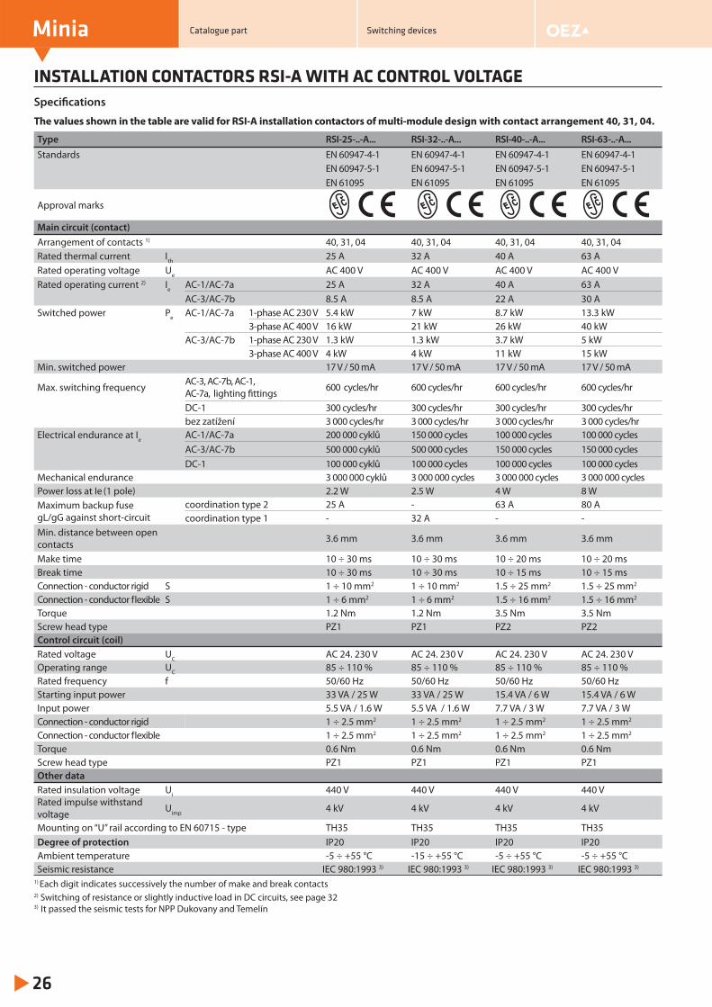
INSTALLATION CONTACTORS RSI-A WITH AC CONTROL VOLTAGESpecifi cations
The values shown in the table are valid for RSI-A installation contactors of multi-module design with contact arrangement 40, 31, 04.
Type RSI-25-..-A... RSI-32-..-A... RSI-40-..-A... RSI-63-..-A...Standards EN 60947-4-1 EN 60947-4-1 EN 60947-4-1 EN 60947-4-1
EN 60947-5-1 EN 60947-5-1 EN 60947-5-1 EN 60947-5-1EN 61095 EN 61095 EN 61095 EN 61095
Approval marks
Main circuit (contact)Arrangement of contacts 1) 40, 31, 04 40, 31, 04 40, 31, 04 40, 31, 04Rated thermal current Ith 25 A 32 A 40 A 63 ARated operating voltage Ue AC 400 V AC 400 V AC 400 V AC 400 V Rated operating current 2) Ie AC-1/AC-7a 25 A 32 A 40 A 63 A
AC-3/AC-7b 8.5 A 8.5 A 22 A 30 ASwitched power Pe AC-1/AC-7a 1-phase AC 230 V 5.4 kW 7 kW 8.7 kW 13.3 kW
3-phase AC 400 V 16 kW 21 kW 26 kW 40 kWAC-3/AC-7b 1-phase AC 230 V 1.3 kW 1.3 kW 3.7 kW 5 kW
3-phase AC 400 V 4 kW 4 kW 11 kW 15 kWMin. switched power 17 V / 50 mA 17 V / 50 mA 17 V / 50 mA 17 V / 50 mA
Max. switching frequency AC-3, AC-7b, AC-1, AC-7a, lighting fi ttings 600 cycles/hr 600 cycles/hr 600 cycles/hr 600 cycles/hr
DC-1 300 cycles/hr 300 cycles/hr 300 cycles/hr 300 cycles/hr bez zatížení 3 000 cycles/hr 3 000 cycles/hr 3 000 cycles/hr 3 000 cycles/hr
Electrical endurance at Ie AC-1/AC-7a 200 000 cyklů 150 000 cycles 100 000 cycles 100 000 cyclesAC-3/AC-7b 500 000 cyklů 500 000 cycles 150 000 cycles 150 000 cyclesDC-1 100 000 cyklů 100 000 cycles 100 000 cycles 100 000 cycles
Mechanical endurance 3 000 000 cyklů 3 000 000 cycles 3 000 000 cycles 3 000 000 cyclesPower loss at Ie (1 pole) 2.2 W 2.5 W 4 W 8 WMaximum backup fuse gL/gG against short-circuit
coordination type 2 25 A - 63 A 80 Acoordination type 1 - 32 A - -
Min. distance between open contacts 3.6 mm 3.6 mm 3.6 mm 3.6 mm
Make time 10 ÷ 30 ms 10 ÷ 30 ms 10 ÷ 20 ms 10 ÷ 20 msBreak time 10 ÷ 30 ms 10 ÷ 30 ms 10 ÷ 15 ms 10 ÷ 15 msConnection - conductor rigid S 1 ÷ 10 mm2 1 ÷ 10 mm2 1.5 ÷ 25 mm2 1.5 ÷ 25 mm2
Connection - conductor flexible S 1 ÷ 6 mm2 1 ÷ 6 mm2 1.5 ÷ 16 mm2 1.5 ÷ 16 mm2
Torque 1.2 Nm 1.2 Nm 3.5 Nm 3.5 NmScrew head type PZ1 PZ1 PZ2 PZ2Control circuit (coil)Rated voltage UC AC 24. 230 V AC 24. 230 V AC 24. 230 V AC 24. 230 V Operating range UC 85 ÷ 110 % 85 ÷ 110 % 85 ÷ 110 % 85 ÷ 110 %Rated frequency f 50/60 Hz 50/60 Hz 50/60 Hz 50/60 HzStarting input power 33 VA / 25 W 33 VA / 25 W 15.4 VA / 6 W 15.4 VA / 6 WInput power 5.5 VA / 1.6 W 5.5 VA / 1.6 W 7.7 VA / 3 W 7.7 VA / 3 WConnection - conductor rigid 1 ÷ 2.5 mm2 1 ÷ 2.5 mm2 1 ÷ 2.5 mm2 1 ÷ 2.5 mm2
Connection - conductor flexible 1 ÷ 2.5 mm2 1 ÷ 2.5 mm2 1 ÷ 2.5 mm2 1 ÷ 2.5 mm2
Torque 0.6 Nm 0.6 Nm 0.6 Nm 0.6 NmScrew head type PZ1 PZ1 PZ1 PZ1Other dataRated insulation voltage Ui 440 V 440 V 440 V 440 VRated impulse withstand voltage Uimp 4 kV 4 kV 4 kV 4 kV
Mounting on “U” rail according to EN 60715 - type TH35 TH35 TH35 TH35Degree of protection IP20 IP20 IP20 IP20Ambient temperature -5 ÷ +55 °C -15 ÷ +55 °C -5 ÷ +55 °C -5 ÷ +55 °CSeismic resistance IEC 980:1993 3) IEC 980:1993 3) IEC 980:1993 3) IEC 980:1993 3)
1) Each digit indicates successively the number of make and break contacts
Catalogue part Switching devices
2) Switching of resistance or slightly inductive load in DC circuits, see page 323) It passed the seismic tests for NPP Dukovany and Temelín
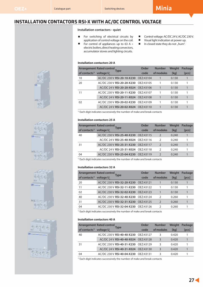
INSTALLATION CONTACTORS RSI-X WITH AC/DC CONTROL VOLTAGE
For switching of electrical circuits by application of control voltage on the coil.For control of appliances up to 63 A – electric boilers, direct heating convectors, accumulator stoves and lighting circuits.
Control voltage: AC/DC 24 V, AC/DC 230 V.Visual light indication at power up.In closed state they do not „hum“.
Installation contactors - quiet
Installation contactors 20 A
Arrangement Rated controlType
Order Number Weight Package
of contacts1) voltage Uc code of modules [kg] [pcs]
10 AC/DC 230 V RSI-20-10-X230 OEZ:43104 1 0.130 1
20 AC/DC 230 V RSI-20-20-X230 OEZ:43105 1 0.130 1
AC/DC 24 V RSI-20-20-X024 OEZ:43106 1 0.130 1
11 AC/DC 230 V RSI-20-11-X230 OEZ:43107 1 0.130 1
AC/DC 24 V RSI-20-11-X024 OEZ:43108 1 0.130 1
02 AC/DC 230 V RSI-20-02-X230 OEZ:43109 1 0.130 1
AC/DC 24 V RSI-20-02-X024 OEZ:43110 1 0.130 11) Each digit indicates successively the number of make and break contacts
Installation contactors 25 A
Arrangement Rated controlType
Order Number Weight Package
of contacts1) voltage Uc code of modules [kg] [pcs]
40 AC/DC 230 V RSI-25-40-X230 OEZ:43115 2 0.240 1
AC/DC 24 V RSI-25-40-X024 OEZ:43116 2 0.240 1
31 AC/DC 230 V RSI-25-31-X230 OEZ:43117 2 0.240 1
AC/DC 24 V RSI-25-31-X024 OEZ:43118 2 0.240 1
04 AC/DC 230 V RSI-25-04-X230 OEZ:43119 2 0.240 11) Each digit indicates successively the number of make and break contacts
Installation contactors 32 A
Arrangement Rated controlType
Order Number Weight Package
of contacts1) voltage Uc code of modules [kg] [pcs]
20 AC/DC 230 V RSI-32-20-X230 OEZ:43121 1 0.130 1
11 AC/DC 230 V RSI-32-11-X230 OEZ:43122 1 0.130 1
02 AC/DC 230 V RSI-32-02-X230 OEZ:43123 1 0.130 1
40 AC/DC 230 V RSI-32-40-X230 OEZ:43124 2 0.260 1
31 AC/DC 230 V RSI-32-31-X230 OEZ:43125 2 0.260 1
04 AC/DC 230 V RSI-32-04-X230 OEZ:43126 2 0.260 11) Each digit indicates successively the number of make and break contacts
Installation contactors 40 A
Arrangement Rated controlType
Order Number Weight Package
of contacts1) voltage Uc code of modules [kg] [pcs]
40 AC/DC 230 V RSI-40-40-X230 OEZ:43127 3 0.420 1
AC/DC 24 V RSI-40-40-X024 OEZ:43128 3 0.420 1
31 AC/DC 230 V RSI-40-31-X230 OEZ:43129 3 0.420 1
AC/DC 24 V RSI-40-31-X024 OEZ:43130 3 0.420 1
04 AC/DC 230 V RSI-40-04-X230 OEZ:43131 3 0.420 11) Each digit indicates successively the number of make and break contacts
Minia
27
Catalogue part Switching devices
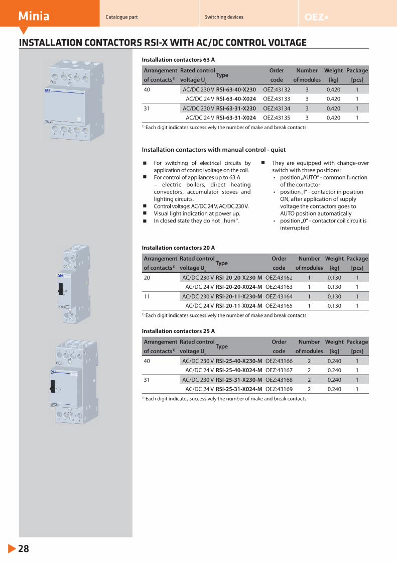
INSTALLATION CONTACTORS RSI-X WITH AC/DC CONTROL VOLTAGE
For switching of electrical circuits by application of control voltage on the coil.For control of appliances up to 63 A – electric boilers, direct heating convectors, accumulator stoves and lighting circuits.Control voltage: AC/DC 24 V, AC/DC 230 V.Visual light indication at power up.In closed state they do not „hum“.
They are equipped with change-over switch with three positions:• position „AUTO“ - common function of the contactor• position „I“ - contactor in position ON, after application of supply voltage the contactors goes to AUTO position automatically• position „0“ - contactor coil circuit is
interrupted
Installation contactors with manual control - quiet
Installation contactors 20 A
Arrangement Rated controlType
Order Number Weight Package
of contacts1) voltage Uc code of modules [kg] [pcs]
20 AC/DC 230 V RSI-20-20-X230-M OEZ:43162 1 0.130 1
AC/DC 24 V RSI-20-20-X024-M OEZ:43163 1 0.130 1
11 AC/DC 230 V RSI-20-11-X230-M OEZ:43164 1 0.130 1
AC/DC 24 V RSI-20-11-X024-M OEZ:43165 1 0.130 11) Each digit indicates successively the number of make and break contacts
Installation contactors 25 A
Arrangement Rated controlType
Order Number Weight Package
of contacts1) voltage Uc code of modules [kg] [pcs]
40 AC/DC 230 V RSI-25-40-X230-M OEZ:43166 2 0.240 1
AC/DC 24 V RSI-25-40-X024-M OEZ:43167 2 0.240 1
31 AC/DC 230 V RSI-25-31-X230-M OEZ:43168 2 0.240 1
AC/DC 24 V RSI-25-31-X024-M OEZ:43169 2 0.240 11) Each digit indicates successively the number of make and break contacts
Installation contactors 63 A
Arrangement Rated controlType
Order Number Weight Package
of contacts1) voltage Uc code of modules [kg] [pcs]
40 AC/DC 230 V RSI-63-40-X230 OEZ:43132 3 0.420 1
AC/DC 24 V RSI-63-40-X024 OEZ:43133 3 0.420 1
31 AC/DC 230 V RSI-63-31-X230 OEZ:43134 3 0.420 1
AC/DC 24 V RSI-63-31-X024 OEZ:43135 3 0.420 11) Each digit indicates successively the number of make and break contacts
Minia
28
Catalogue part Switching devices
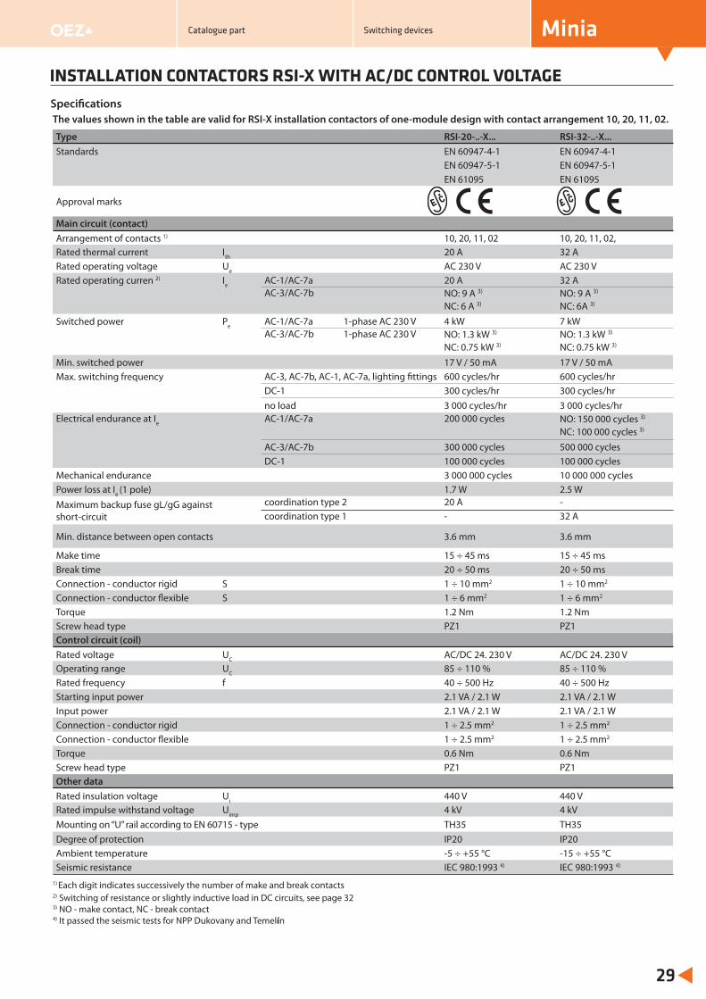
INSTALLATION CONTACTORS RSI-X WITH AC/DC CONTROL VOLTAGE
Minia
29
Specifi cationsThe values shown in the table are valid for RSI-X installation contactors of one-module design with contact arrangement 10, 20, 11, 02.
Type RSI-20-..-X... RSI-32-..-X...Standards EN 60947-4-1 EN 60947-4-1
EN 60947-5-1 EN 60947-5-1EN 61095 EN 61095
Approval marks
Main circuit (contact)Arrangement of contacts 1) 10, 20, 11, 02 10, 20, 11, 02,Rated thermal current Ith 20 A 32 ARated operating voltage Ue AC 230 V AC 230 V Rated operating curren 2) Ie AC-1/AC-7a 20 A 32 A
AC-3/AC-7b NO: 9 A 3) NC: 6 A 3)
NO: 9 A 3) NC: 6A 3)
Switched power Pe AC-1/AC-7a 1-phase AC 230 V 4 kW 7 kWAC-3/AC-7b 1-phase AC 230 V NO: 1.3 kW 3)
NC: 0.75 kW 3) NO: 1.3 kW 3) NC: 0.75 kW 3)
Min. switched power 17 V / 50 mA 17 V / 50 mAMax. switching frequency AC-3, AC-7b, AC-1, AC-7a, lighting fi ttings 600 cycles/hr 600 cycles/hr
DC-1 300 cycles/hr 300 cycles/hr no load 3 000 cycles/hr 3 000 cycles/hr
Electrical endurance at Ie AC-1/AC-7a 200 000 cycles NO: 150 000 cycles 3) NC: 100 000 cycles 3)
AC-3/AC-7b 300 000 cycles 500 000 cyclesDC-1 100 000 cycles 100 000 cycles
Mechanical endurance 3 000 000 cycles 10 000 000 cyclesPower loss at Ie (1 pole) 1.7 W 2.5 WMaximum backup fuse gL/gG against short-circuit
coordination type 2 20 A -coordination type 1 - 32 A
Min. distance between open contacts 3.6 mm 3.6 mm
Make time 15 ÷ 45 ms 15 ÷ 45 msBreak time 20 ÷ 50 ms 20 ÷ 50 msConnection - conductor rigid S 1 ÷ 10 mm2 1 ÷ 10 mm2
Connection - conductor flexible S 1 ÷ 6 mm2 1 ÷ 6 mm2
Torque 1.2 Nm 1.2 NmScrew head type PZ1 PZ1Control circuit (coil)Rated voltage UC AC/DC 24. 230 V AC/DC 24. 230 VOperating range UC 85 ÷ 110 % 85 ÷ 110 %Rated frequency f 40 ÷ 500 Hz 40 ÷ 500 HzStarting input power 2.1 VA / 2.1 W 2.1 VA / 2.1 WInput power 2.1 VA / 2.1 W 2.1 VA / 2.1 WConnection - conductor rigid 1 ÷ 2.5 mm2 1 ÷ 2.5 mm2
Connection - conductor flexible 1 ÷ 2.5 mm2 1 ÷ 2.5 mm2
Torque 0.6 Nm 0.6 NmScrew head type PZ1 PZ1Other dataRated insulation voltage Ui 440 V 440 VRated impulse withstand voltage Uimp 4 kV 4 kVMounting on “U” rail according to EN 60715 - type TH35 TH35Degree of protection IP20 IP20Ambient temperature -5 ÷ +55 °C -15 ÷ +55 °CSeismic resistance IEC 980:1993 4) IEC 980:1993 4)
1) Each digit indicates successively the number of make and break contacts2) Switching of resistance or slightly inductive load in DC circuits, see page 323) NO - make contact, NC - break contact4) It passed the seismic tests for NPP Dukovany and Temelín
Catalogue part Switching devices
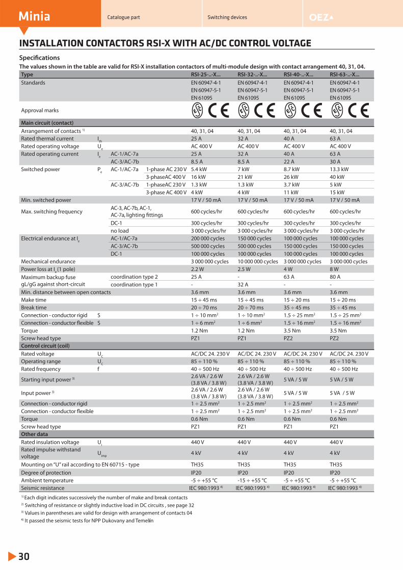
INSTALLATION CONTACTORS RSI-X WITH AC/DC CONTROL VOLTAGE
Minia
30
The values shown in the table are valid for RSI-X installation contactors of multi-module design with contact arrangement 40, 31, 04.Type RSI-25-..-X... RSI-32-..-X... RSI-40-..-X... RSI-63-..-X...Standards EN 60947-4-1 EN 60947-4-1 EN 60947-4-1 EN 60947-4-1
EN 60947-5-1 EN 60947-5-1 EN 60947-5-1 EN 60947-5-1EN 61095 EN 61095 EN 61095 EN 61095
Approval marks
Main circuit (contact)Arrangement of contacts 1) 40, 31, 04 40, 31, 04 40, 31, 04 40, 31, 04Rated thermal current Ith 25 A 32 A 40 A 63 ARated operating voltage Ue AC 400 V AC 400 V AC 400 V AC 400 VRated operating current Ie AC-1/AC-7a 25 A 32 A 40 A 63 A
AC-3/AC-7b 8.5 A 8.5 A 22 A 30 ASwitched power Pe AC-1/AC-7a 1-phase AC 230 V 5.4 kW 7 kW 8.7 kW 13.3 kW
3-phaseAC 400 V 16 kW 21 kW 26 kW 40 kWAC-3/AC-7b 1-phaseAC 230 V 1.3 kW 1.3 kW 3.7 kW 5 kW
3-phase AC 400 V 4 kW 4 kW 11 kW 15 kWMin. switched power 17 V / 50 mA 17 V / 50 mA 17 V / 50 mA 17 V / 50 mA
Max. switching frequency AC-3, AC-7b, AC-1, AC-7a, lighting fi ttings 600 cycles/hr 600 cycles/hr 600 cycles/hr 600 cycles/hr
DC-1 300 cycles/hr 300 cycles/hr 300 cycles/hr 300 cycles/hr no load 3 000 cycles/hr 3 000 cycles/hr 3 000 cycles/hr 3 000 cycles/hr
Electrical endurance at Ie AC-1/AC-7a 200 000 cycles 150 000 cycles 100 000 cycles 100 000 cyclesAC-3/AC-7b 500 000 cycles 500 000 cycles 150 000 cycles 150 000 cyclesDC-1 100 000 cycles 100 000 cycles 100 000 cycles 100 000 cycles
Mechanical endurance 3 000 000 cycles 10 000 000 cycles 3 000 000 cycles 3 000 000 cyclesPower loss at Ie (1 pole) 2.2 W 2.5 W 4 W 8 WMaximum backup fuse gL/gG against short-circuit
coordination type 2 25 A - 63 A 80 Acoordination type 1 - 32 A - -
Min. distance between open contacts 3.6 mm 3.6 mm 3.6 mm 3.6 mmMake time 15 ÷ 45 ms 15 ÷ 45 ms 15 ÷ 20 ms 15 ÷ 20 msBreak time 20 ÷ 70 ms 20 ÷ 70 ms 35 ÷ 45 ms 35 ÷ 45 msConnection - conductor rigid S 1 ÷ 10 mm2 1 ÷ 10 mm2 1.5 ÷ 25 mm2 1.5 ÷ 25 mm2
Connection - conductor flexible S 1 ÷ 6 mm2 1 ÷ 6 mm2 1.5 ÷ 16 mm2 1.5 ÷ 16 mm2
Torque 1.2 Nm 1.2 Nm 3.5 Nm 3.5 NmScrew head type PZ1 PZ1 PZ2 PZ2Control circuit (coil)Rated voltage UC AC/DC 24. 230 V AC/DC 24. 230 V AC/DC 24. 230 V AC/DC 24. 230 VOperating range UC 85 ÷ 110 % 85 ÷ 110 % 85 ÷ 110 % 85 ÷ 110 %Rated frequency f 40 ÷ 500 Hz 40 ÷ 500 Hz 40 ÷ 500 Hz 40 ÷ 500 Hz
Starting input power 3) 2.6 VA / 2.6 W (3.8 VA / 3.8 W)
2.6 VA / 2.6 W(3.8 VA / 3.8 W) 5 VA / 5 W 5 VA / 5 W
Input power 3) 2.6 VA / 2.6 W (3.8 VA / 3.8 W)
2.6 VA / 2.6 W(3.8 VA / 3.8 W) 5 VA / 5 W 5 VA / 5 W
Connection - conductor rigid 1 ÷ 2.5 mm2 1 ÷ 2.5 mm2 1 ÷ 2.5 mm2 1 ÷ 2.5 mm2
Connection - conductor flexible 1 ÷ 2.5 mm2 1 ÷ 2.5 mm2 1 ÷ 2.5 mm2 1 ÷ 2.5 mm2
Torque 0.6 Nm 0.6 Nm 0.6 Nm 0.6 NmScrew head type PZ1 PZ1 PZ1 PZ1Other dataRated insulation voltage Ui 440 V 440 V 440 V 440 VRated impulse withstand voltage Uimp 4 kV 4 kV 4 kV 4 kV
Mounting on “U” rail according to EN 60715 - type TH35 TH35 TH35 TH35Degree of protection IP20 IP20 IP20 IP20Ambient temperature -5 ÷ +55 °C -15 ÷ +55 °C -5 ÷ +55 °C -5 ÷ +55 °CSeismic resistance IEC 980:1993 4) IEC 980:1993 4) IEC 980:1993 4) IEC 980:1993 4)
1) Each digit indicates successively the number of make and break contacts2) Switching of resistance or slightly inductive load in DC circuits , see page 323) Values in parentheses are valid for design with arrangement of contacts 044) It passed the seismic tests for NPP Dukovany and Temelín
Specifi cations
Catalogue part Switching devices
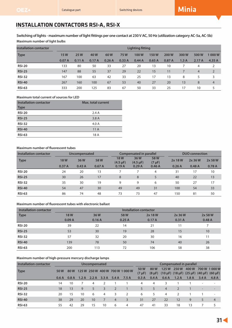
INSTALLATION CONTACTORS RSI-A, RSI-X
Minia
31
Maximum number of light bulbs
Installation contactor Lighting fi tting
Type 15 W 25 W 40 W 60 W 75 W 100 W 150 W 200 W 300 W 500 W 1 000 W
0.07 A 0.11 A 0.17 A 0.26 A 0.33 A 0.44 A 0.65 A 0.87 A 1.3 A 2.17 A 4.35 A
RSI-20 133 80 50 33 27 20 13 10 7 4 2
RSI-25 147 88 55 37 29 22 15 11 7 4 2
RSI-32 167 100 63 42 33 25 17 13 8 5 3
RSI-40 267 160 100 67 53 40 27 20 13 8 4
RSI-63 333 200 125 83 67 50 33 25 17 10 5
Switching of lights - maximum number of light fi ttings per one contact at 230 V AC, 50 Hz (utilization category AC-5a, AC-5b)
Maximum total current of sources for LEDInstallation contactor Max. total currentType
RSI-20 2.4 A
RSI-25 3.8 A
RSI-32 4.0 A
RSI-40 11 A
RSI-63 18 A
Maximum number of fl uorescent tubes
Installation contactor Uncompensated Compensated in parallel DUO connection
Type 18 W 36 W 58 W 18 W(4.5 μF)
36 W(4.5 μF)
58 W(7 μF) 2x 18 W 2x 36 W 2x 58 W
0.37 A 0.43 A 0.67 A 0.19 A 0.29 A 0.46 A 0.26 A 0.48 A 0.78 A
RSI-20 24 20 13 7 7 4 31 17 10
RSI-25 30 26 17 8 8 5 40 22 13
RSI-32 35 30 19 9 9 6 50 27 17
RSI-40 54 47 30 49 49 31 100 54 33
RSI-63 86 74 48 73 73 47 150 81 50
Maximum number of fl uorescent tubes with electronic ballast
Installation contactor Installation contactor Type 18 W 36 W 58 W 2x 18 W 2x 36 W 2x 58 W
0.09 A 0.16 A 0.25 A 0.17 A 0.31 A 0.48 A
RSI-20 39 22 14 21 11 7
RSI-25 53 30 19 28 15 10
RSI-32 57 32 20 30 16 11
RSI-40 139 78 50 74 40 26
RSI-63 200 113 72 106 58 38
Maximum number of high-pressure mercury discharge lamps
Installation contactor Uncompensated Compensated in parallel
Type 50 W 80 W 125 W 250 W 400 W 700 W 1 000 W 50 W(7 μF)
80 W(8 μF)
125 W(10 μF)
250 W(18 μF)
400 W(25 μF)
700 W(40 μF)
1 000 W(60 μF)
0.6 A 0.8 A 1.2 A 2.2 A 3.3 A 5.4 A 7.5 A 0.3 A 0.4 A 0.6 A 1.2 A 1.8 A 3.4 A 4.8 A
RSI-20 14 10 7 4 2 1 1 4 4 3 1 1 - -
RSI-25 18 13 9 5 3 2 1 5 5 4 2 1 - -
RSI-32 20 15 10 6 4 3 2 6 5 4 2 1 1 -
RSI-40 38 29 20 10 7 4 3 31 27 22 12 9 5 4
RSI-63 55 42 29 15 10 6 4 47 41 33 18 13 7 5
Catalogue part Switching devices
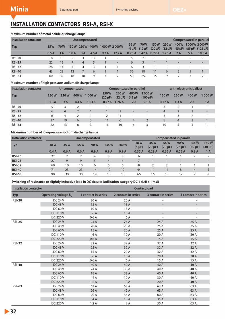
INSTALLATION CONTACTORS RSI-A, RSI-X
Minia
32
Maximum number of metal halide discharge lamps
Installation contactor Uncompensated Compensated in parallel
Typ 35 W 70 W 150 W 250 W 400 W 1 000 W 2 000 W 35 W(6 μF)
70 W(12 μF)
150 W(20 μF)
250 W(32 μF)
400 W(45 μF)
1 000 W(85 μF)
2 000 W(125 μF)
0.5 A 1 A 1.8 A 3 A 4.6 A 9.7 A 12.2 A 0.23 A 0.42 A 0.77 A 1.26 A 2 A 5 A 10.5 ARSI-20 18 10 5 3 3 1 - 5 2 1 - - - -RSI-25 22 12 7 4 3 1 - 6 3 1 1 - - -RSI-32 28 14 7 4 3 1 1 6 3 1 1 - - -RSI-40 43 23 12 7 6 2 1 36 18 11 6 5 2 1RSI-63 60 32 18 10 9 3 2 50 25 15 9 7 3 2
Maximum number of high-pressure sodium discharge lamps
Installation contactor Uncompensated Compensated in parallel with electronic ballast
Typ 150 W 250 W 400 W 1 000 W 150 W(20 μF)
250 W(32 μF)
400 W(45 μF)
1 000 W(100 μF) 150 W 250 W 400 W 1 000 W
1.8 A 3 A 4.4 A 10.3 A 0.77 A 1.26 A 2 A 5.1 A 0.72 A 1.3 A 2 A 5 ARSI-20 5 3 2 - 1 - - - 3 2 1 -RSI-25 6 4 2 1 1 1 - - 4 2 1 -RSI-32 6 4 2 1 2 1 - - 5 3 2 -RSI-40 17 10 6 3 11 6 4 2 8 4 3 1RSI-63 22 13 8 3 16 10 6 3 10 5 4 1
Maximum number of low-pressure sodium discharge lamps
Installation contactor Uncompensated Compensated in parallel
Typ 18 W 35 W 55 W 90 W 135 W 180 W 18 W(5 μF)
35 W(20 μF)
55 W(20 μF)
90 W(26 μF)
135 W(40 μF)
180 W(40 μF)
0.4 A 0.6 A 0.6 A 0.9 A 0.9 A 0.9 A 0.35 A 0.28 A 0.35 A 0.55 A 0.8 A 1 ARSI-20 22 7 7 4 3 3 6 1 1 1 - -RSI-25 27 9 9 5 4 4 7 1 1 1 - -RSI-32 60 10 10 6 5 5 8 2 2 1 1 1RSI-40 71 23 23 14 10 10 44 11 11 8 4 5RSI-63 90 30 30 19 13 13 66 16 13 12 7 8
Switching of resistance or slightly inductive load in DC circuits (utilization category DC-1 (L/R ≤ 1 ms))
Installation contactor Contact load
Typ Operating voltage Ue 1 contact in series 2 contact in series 3 contact in series 4 contact in series
RSI-20 DC 24 V 20 A 20 A - -DC 48 V 15 A 18 A - -DC 60 V 10 A 15 A - -
DC 110 V 6 A 10 A - -DC 220 V 0.6 A 6 A - -
RSI-25 DC 24 V 25 A 25 A 25 A 25 ADC 48 V 20 A 25 A 25 A 25 ADC 60 V 15 A 20 A 25 A 25 A
DC 110 V 6 A 10 A 20 A 20 ADC 220 V 0.6 A 6 A 15 A 15 A
RSI-32 DC 24 V 32 A 32 A 32 A 32 ADC 48 V 25 A 32 A 32 A 32 ADC 60 V 15 A 20 A 32 A 32 A
DC 110 V 6 A 10 A 20 A 20 ADC 220 V 0.6 A 6 A 15 A 15 A
RSI-40 DC 24 V 40 A 40 A 40 A 40 ADC 48 V 24 A 38 A 40 A 40 ADC 60 V 18 A 32 A 40 A 40 A
DC 110 V 4 A 10 A 30 A 40 ADC 220 V 1.2 A 8 A 20 A 40 A
RSI-63 DC 24 V 63 A 63 A 63 A 63 ADC 48 V 26 A 42 A 63 A 63 ADC 60 V 20 A 34 A 60 A 63 A
DC 110 V 4 A 10 A 35 A 63 ADC 220 V 1.2 A 8 A 30 A 63 A
Catalogue part Switching devices
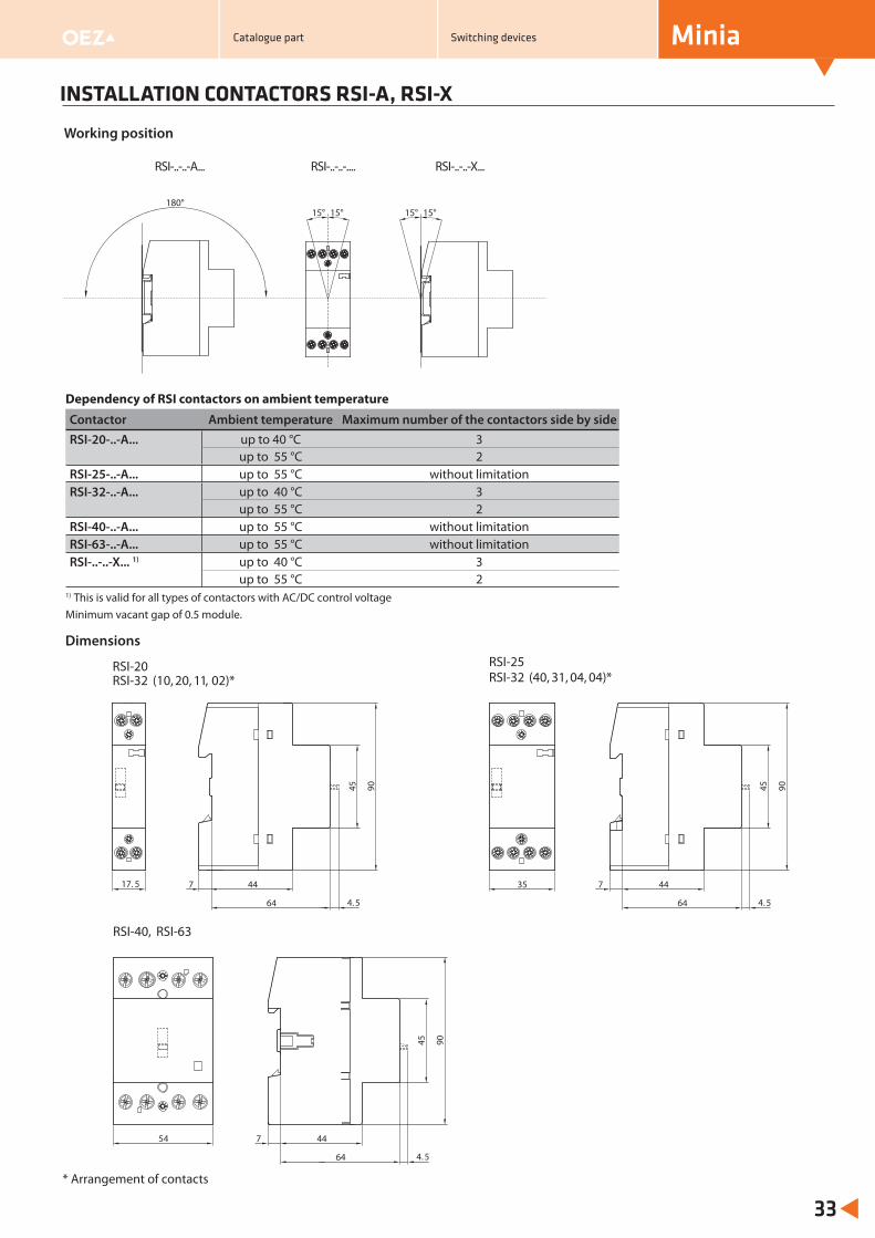
54 447
64
45 90
RSI-40, RSI-63
4. 5
INSTALLATION CONTACTORS RSI-A, RSI-X
Minia
33
Working position
Catalogue part Switching devices
Dependency of RSI contactors on ambient temperature
Contactor Ambient temperature Maximum number of the contactors side by sideRSI-20-..-A... up to 40 °C 3
up to 55 °C 2RSI-25-..-A... up to 55 °C without limitationRSI-32-..-A... up to 40 °C 3
up to 55 °C 2RSI-40-..-A... up to 55 °C without limitationRSI-63-..-A... up to 55 °C without limitationRSI-..-..-X... 1) up to 40 °C 3
up to 55 °C 21) This is valid for all types of contactors with AC/DC control voltage
15° 15°15° 15°180°
17. 5
45 90
44
64
7
4. 5
RSI-20RSI-32 (10, 20, 11, 02)*
35 447
64
45 90
4. 5
RSI-25RSI-32 (40, 31, 04, 04)*
Dimensions
* Arrangement of contacts
RSI-..-..-A... RSI-..-..-.... RSI-..-..-X...
Minimum vacant gap of 0.5 module.
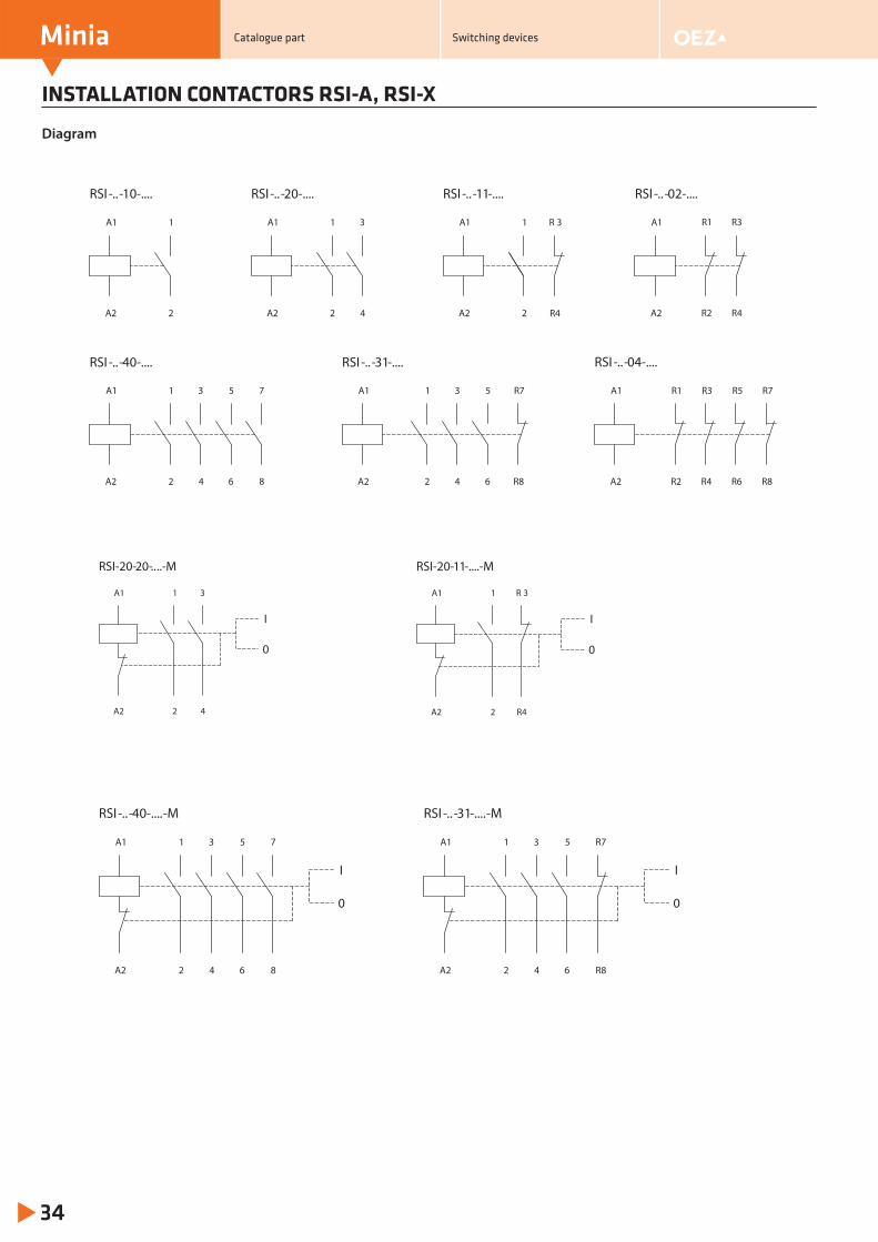
INSTALLATION CONTACTORS RSI-A, RSI-X
Minia
34
Diagram
..RSI - -10-.... RSI - -02-......
2
1
A2
A1
A2
A1
842 6
1 3 75
A2
A1
42 6
531
R8A2
A1 R7
R8R2 R4 R6
R7R5R3R1
A2
A1
RSI- -20-......
42
1 3
A2
A1
RSI- -11-......
R42
1 R 3A1
A2 R4R2
R1 R3
RSI- - -...... 40 RSI- - -...... 31 RSI- - -...... 04
RSI- -40-...... -M RSI- - -...... 31 -M
842 6
1 3 75
A2
A1
R842 6
1 3 R75
A2
A1
I
0
I
0
RSI-20-11-....-M
R42
1 R 3A1
A2
I
0
Catalogue part Switching devices
RSI-20- ..20- ..-M
42
1 3
A2
A1
I
0
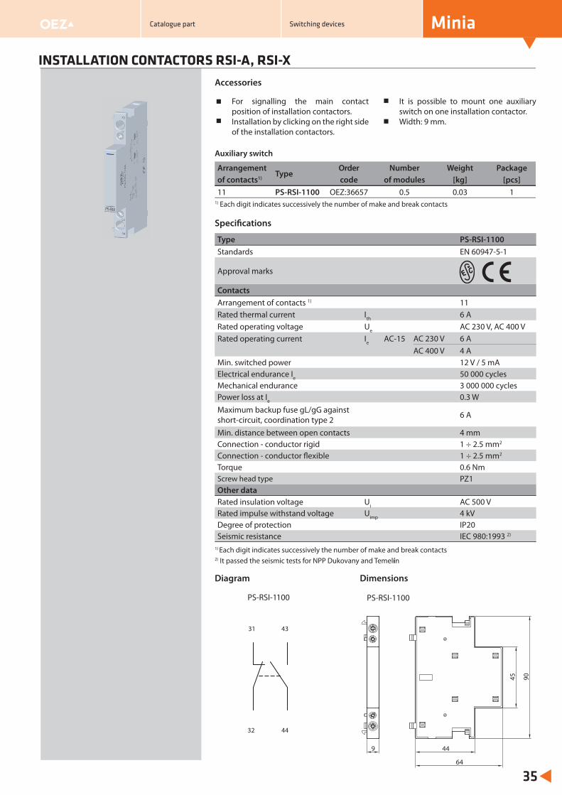
INSTALLATION CONTACTORS RSI-A, RSI-X
Minia
35
For signalling the main contact position of installation contactors.Installation by clicking on the right side of the installation contactors.
It is possible to mount one auxiliary switch on one installation contactor.Width: 9 mm.
Accessories
32 44
31 43
PS-RSI-1100
Diagram
Type PS-RSI-1100Standards EN 60947-5-1
Approval marks
ContactsArrangement of contacts 1) 11Rated thermal current Ith 6 ARated operating voltage Ue AC 230 V, AC 400 VRated operating current Ie AC-15 AC 230 V 6 A
AC 400 V 4 AMin. switched power 12 V / 5 mAElectrical endurance Ie 50 000 cyclesMechanical endurance 3 000 000 cyclesPower loss at Ie 0.3 WMaximum backup fuse gL/gG against short-circuit, coordination type 2 6 A
Min. distance between open contacts 4 mmConnection - conductor rigid 1 ÷ 2.5 mm2
Connection - conductor flexible 1 ÷ 2.5 mm2
Torque 0.6 NmScrew head type PZ1Other dataRated insulation voltage Ui AC 500 V Rated impulse withstand voltage Uimp 4 kVDegree of protection IP20Seismic resistance IEC 980:1993 2)
1) Each digit indicates successively the number of make and break contacts2) It passed the seismic tests for NPP Dukovany and Temelín
Auxiliary switch
Arrangement Type
Order Number Weight Packageof contacts1) code of modules [kg] [pcs]11 PS-RSI-1100 OEZ:36657 0.5 0.03 1
1) Each digit indicates successively the number of make and break contacts
Specifi cations
45 90
44
64
9
PS-RSI-1100
Dimensions
Catalogue part Switching devices
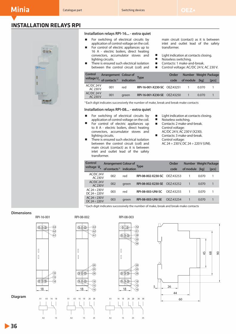
INSTALLATION RELAYS RPI
Minia
36
For switching of electrical circuits by application of control voltage on the coil.For control of electric appliances up to 16 A - electric boilers, direct heating convectors, accumulator stoves and lighting circuits.There is ensured such electrical isolation between the control circuit (coil) and
main circuit (contact) as it is between inlet and outlet lead of the safety transformer.
Light indication at contacts closing.Noiseless switching.Contacts: 1 make-and-break.Control voltage: AC/DC 24 V, AC 230 V.
Installation relays RPI-16... - extra quiet
For switching of electrical circuits by application of control voltage on the coil.For control of electric appliances up to 8 A - electric boilers, direct heating convectors, accumulator stoves and lighting circuits.There is ensured such electrical isolation between the control circuit (coil) and main circuit (contact) as it is between inlet and outlet lead of the safety transformer.
Light indication at contacts closing.Noiseless switching.Contacts: 2 make-and-break.Control voltage: AC/DC 24 V, AC 230 V (X230).Contacts: 3 make-and-break.Control voltage: AC 24 ÷ 230 V, DC 24 ÷ 220 V (UNI).
Installation relays RPI-08... - extra quiet
Control voltage Ue
Arrangement Colour of Type
Order Number Weight Package
of contacts 1) indication code of module [kg] [pcs]
AC/DC 24 V AC 230 V 001 red RPI-16-001-X230-SC OEZ:43251 1 0.070 1
AC/DC 24 V AC 230 V 001 green RPI-16-001-X230-SE OEZ:43250 1 0.070 1
1) Each digit indicates successively the number of make, break and break-make contacts
1) Each digit indicates successively the number of make, break and break-make contacts
Control voltage Ue
Arrangement Colour of Type
Order Number Weight Package
of contacts 1) indication code of module [kg] [pcs]
AC/DC 24 VAC 230 V 002 red RPI-08-002-X230-SC OEZ:43253 1 0.070 1
AC/DC 24 VAC 230 V 002 green RPI-08-002-X230-SE OEZ:43252 1 0.070 1
AC 24 ÷ 230 V DC 24 ÷ 220 V 003 red RPI-08-003-UNI-SC OEZ:43255 1 0.070 1
AC 24 ÷ 230 V DC 24 ÷ 220 V 003 green RPI-08-003-UNI-SE OEZ:43254 1 0.070 1
Dimensions906845
26
44
60
5
15
18A1
A2
16A3A3
15
18A1
A2
16
25
2826
25
2826
15
18A1
A2
16
35
3836Diagram
18
A2
A1
38
35
36
18
15
16
25
28
26
18
A3
A2
A1
18
15
16
25
28
26
18
A3
A2
A1
16
15
18
Catalogue part Switching devices
RPI-16-001 RPI-08-002 RPI-08-003
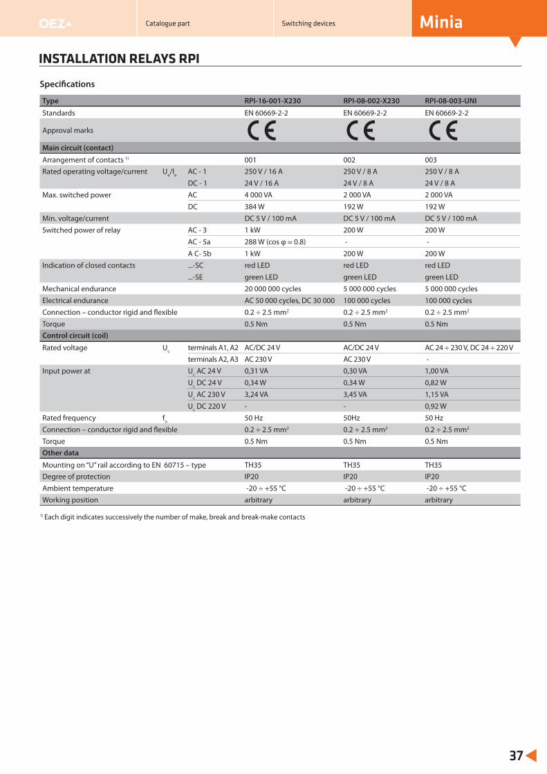
Type RPI-16-001-X230 RPI-08-002-X230 RPI-08-003-UNI
Standards EN 60669-2-2 EN 60669-2-2 EN 60669-2-2
Approval marks
Main circuit (contact)
Arrangement of contacts 1) 001 002 003Rated operating voltage/current Ue/Ie AC - 1 250 V / 16 A 250 V / 8 A 250 V / 8 A
DC - 1 24 V / 16 A 24 V / 8 A 24 V / 8 AMax. switched power AC 4 000 VA 2 000 VA 2 000 VA
DC 384 W 192 W 192 WMin. voltage/current DC 5 V / 100 mA DC 5 V / 100 mA DC 5 V / 100 mASwitched power of relay AC - 3 1 kW 200 W 200 W
AC - 5a 288 W (cos φ = 0.8) - -
A C- 5b 1 kW 200 W 200 WIndication of closed contacts ...-SC red LED red LED red LED
...-SE green LED green LED green LED Mechanical endurance 20 000 000 cycles 5 000 000 cycles 5 000 000 cycles Electrical endurance AC 50 000 cycles, DC 30 000 100 000 cycles 100 000 cycles Connection – conductor rigid and flexible 0.2 ÷ 2.5 mm2 0.2 ÷ 2.5 mm2 0.2 ÷ 2.5 mm2
Torque 0.5 Nm 0.5 Nm 0.5 NmControl circuit (coil)
Rated voltage Uc terminals A1, A2 AC/DC 24 V AC/DC 24 V AC 24 ÷ 230 V, DC 24 ÷ 220 Vterminals A2, A3 AC 230 V AC 230 V -
Input power at Uc AC 24 V 0,31 VA 0,30 VA 1,00 VA
Uc DC 24 V 0,34 W 0,34 W 0,82 WUc AC 230 V 3,24 VA 3,45 VA 1,15 VA
Uc DC 220 V - - 0,92 WRated frequency fn 50 Hz 50Hz 50 HzConnection – conductor rigid and flexible 0.2 ÷ 2.5 mm2 0.2 ÷ 2.5 mm2 0.2 ÷ 2.5 mm2
Torque 0.5 Nm 0.5 Nm 0.5 NmOther data
Mounting on “U” rail according to EN 60715 – type TH35 TH35 TH35Degree of protection IP20 IP20 IP20Ambient temperature -20 ÷ +55 °C -20 ÷ +55 °C -20 ÷ +55 °CWorking position arbitrary arbitrary arbitrary
INSTALLATION RELAYS RPI
Minia
37
Specifi cations
1) Each digit indicates successively the number of make, break and break-make contacts
Catalogue part Switching devices
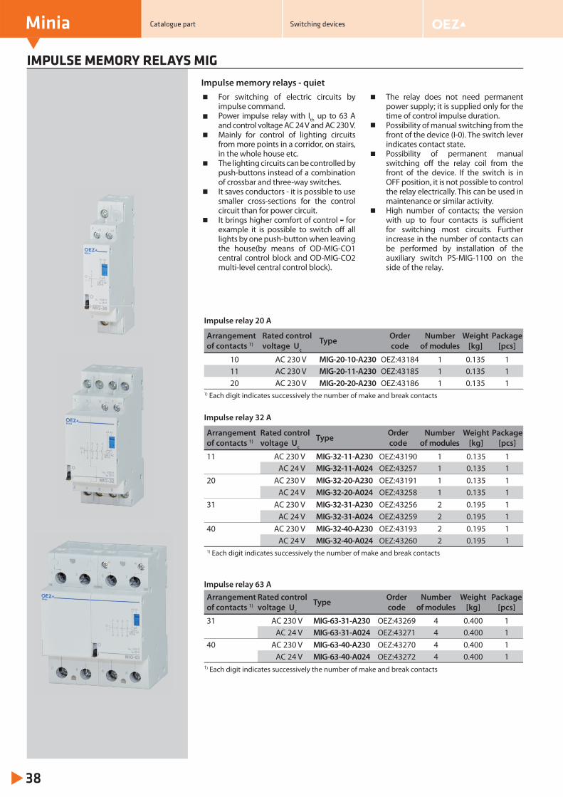
IMPULSE MEMORY RELAYS MIG
Minia
38
For switching of electric circuits by impulse command.Power impulse relay with Ith up to 63 A and control voltage AC 24 V and AC 230 V.Mainly for control of lighting circuits from more points in a corridor, on stairs, in the whole house etc.The lighting circuits can be controlled by push-buttons instead of a combination of crossbar and three-way switches.It saves conductors - it is possible to use smaller cross-sections for the control circuit than for power circuit.It brings higher comfort of control – for example it is possible to switch off all lights by one push-button when leaving the house(by means of OD-MIG-CO1 central control block and OD-MIG-CO2 multi-level central control block).
The relay does not need permanent power supply; it is supplied only for the time of control impulse duration.Possibility of manual switching from the front of the device (I-0). The switch lever indicates contact state.Possibility of permanent manual switching off the relay coil from the front of the device. If the switch is in OFF position, it is not possible to control the relay electrically. This can be used in maintenance or similar activity.High number of contacts; the version with up to four contacts is suffi cient for switching most circuits. Further increase in the number of contacts can be performed by installation of the auxiliary switch PS-MIG-1100 on the side of the relay.
Impulse memory relays - quiet
Impulse relay 20 A
Arrangement of contacts 1)
Rated control voltage Uc
Type Ordercode
Number of modules
Weight[kg]
Package [pcs]
10 AC 230 V MIG-20-10-A230 OEZ:43184 1 0.135 111 AC 230 V MIG-20-11-A230 OEZ:43185 1 0.135 120 AC 230 V MIG-20-20-A230 OEZ:43186 1 0.135 1
1) Each digit indicates successively the number of make and break contacts
Impulse relay 32 A
Arrangement of contacts 1)
Rated control voltage Uc
Type Ordercode
Number of modules
Weight[kg]
Package [pcs]
11 AC 230 V MIG-32-11-A230 OEZ:43190 1 0.135 1AC 24 V MIG-32-11-A024 OEZ:43257 1 0.135 1
20 AC 230 V MIG-32-20-A230 OEZ:43191 1 0.135 1AC 24 V MIG-32-20-A024 OEZ:43258 1 0.135 1
31 AC 230 V MIG-32-31-A230 OEZ:43256 2 0.195 1AC 24 V MIG-32-31-A024 OEZ:43259 2 0.195 1
40 AC 230 V MIG-32-40-A230 OEZ:43193 2 0.195 1AC 24 V MIG-32-40-A024 OEZ:43260 2 0.195 1
1) Each digit indicates successively the number of make and break contacts
Impulse relay 63 AArrangement of contacts 1)
Rated control voltage Uc
Type Order code
Number of modules
Weight[kg]
Package [pcs]
31 AC 230 V MIG-63-31-A230 OEZ:43269 4 0.400 1AC 24 V MIG-63-31-A024 OEZ:43271 4 0.400 1
40 AC 230 V MIG-63-40-A230 OEZ:43270 4 0.400 1AC 24 V MIG-63-40-A024 OEZ:43272 4 0.400 1
1) Each digit indicates successively the number of make and break contacts
Catalogue part Switching devices
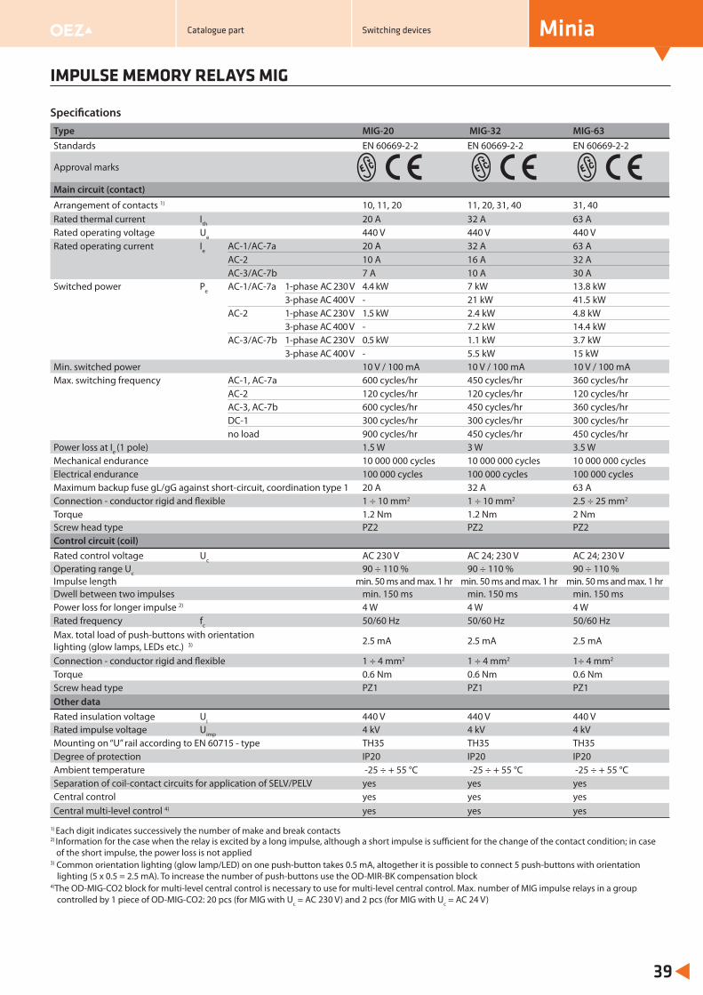
Minia
39
IMPULSE MEMORY RELAYS MIG
Specifi cationsType MIG-20 MIG-32 MIG-63Standards EN 60669-2-2 EN 60669-2-2 EN 60669-2-2
Approval marks
Main circuit (contact)
Arrangement of contacts 1) 10, 11, 20 11, 20, 31, 40 31, 40Rated thermal current Ith 20 A 32 A 63 ARated operating voltage Ue 440 V 440 V 440 VRated operating current Ie AC-1/AC-7a 20 A 32 A 63 A
AC-2 10 A 16 A 32 AAC-3/AC-7b 7 A 10 A 30 A
Switched power Pe AC-1/AC-7a 1-phase AC 230 V 4.4 kW 7 kW 13.8 kW3-phase AC 400 V - 21 kW 41.5 kW
AC-2 1-phase AC 230 V 1.5 kW 2.4 kW 4.8 kW3-phase AC 400 V - 7.2 kW 14.4 kW
AC-3/AC-7b 1-phase AC 230 V 0.5 kW 1.1 kW 3.7 kW3-phase AC 400 V - 5.5 kW 15 kW
Min. switched power 10 V / 100 mA 10 V / 100 mA 10 V / 100 mAMax. switching frequency AC-1, AC-7a 600 cycles/hr 450 cycles/hr 360 cycles/hr
AC-2 120 cycles/hr 120 cycles/hr 120 cycles/hr AC-3, AC-7b 600 cycles/hr 450 cycles/hr 360 cycles/hr DC-1 300 cycles/hr 300 cycles/hr 300 cycles/hr no load 900 cycles/hr 450 cycles/hr 450 cycles/hr
Power loss at Ie (1 pole) 1.5 W 3 W 3.5 WMechanical endurance 10 000 000 cycles 10 000 000 cycles 10 000 000 cyclesElectrical endurance 100 000 cycles 100 000 cycles 100 000 cyclesMaximum backup fuse gL/gG against short-circuit, coordination type 1 20 A 32 A 63 AConnection - conductor rigid and flexible 1 ÷ 10 mm2 1 ÷ 10 mm2 2.5 ÷ 25 mm2
Torque 1.2 Nm 1.2 Nm 2 NmScrew head type PZ2 PZ2 PZ2Control circuit (coil)Rated control voltage Uc AC 230 V AC 24; 230 V AC 24; 230 VOperating range Uc 90 ÷ 110 % 90 ÷ 110 % 90 ÷ 110 %Impulse length min. 50 ms and max. 1 hr min. 50 ms and max. 1 hr min. 50 ms and max. 1 hr Dwell between two impulses min. 150 ms min. 150 ms min. 150 msPower loss for longer impulse 2) 4 W 4 W 4 WRated frequency fc 50/60 Hz 50/60 Hz 50/60 HzMax. total load of push-buttons with orientation lighting (glow lamps, LEDs etc.) 3) 2.5 mA 2.5 mA 2.5 mA
Connection - conductor rigid and flexible 1 ÷ 4 mm2 1 ÷ 4 mm2 1÷ 4 mm2
Torque 0.6 Nm 0.6 Nm 0.6 NmScrew head type PZ1 PZ1 PZ1Other dataRated insulation voltage Ui 440 V 440 V 440 VRated impulse voltage Uimp 4 kV 4 kV 4 kVMounting on “U” rail according to EN 60715 - type TH35 TH35 TH35Degree of protection IP20 IP20 IP20Ambient temperature -25 ÷ + 55 °C -25 ÷ + 55 °C -25 ÷ + 55 °CSeparation of coil-contact circuits for application of SELV/PELV yes yes yes Central control yes yes yes Central multi-level control 4) yes yes yes
1) Each digit indicates successively the number of make and break contacts2) Information for the case when the relay is excited by a long impulse, although a short impulse is suffi cient for the change of the contact condition; in case of the short impulse, the power loss is not applied3) Common orientation lighting (glow lamp/LED) on one push-button takes 0.5 mA, altogether it is possible to connect 5 push-buttons with orientation
lighting (5 x 0.5 = 2.5 mA). To increase the number of push-buttons use the OD-MIR-BK compensation block4)The OD-MIG-CO2 block for multi-level central control is necessary to use for multi-level central control. Max. number of MIG impulse relays in a group
controlled by 1 piece of OD-MIG-CO2: 20 pcs (for MIG with Uc = AC 230 V) and 2 pcs (for MIG with Uc = AC 24 V)
Catalogue part Switching devices
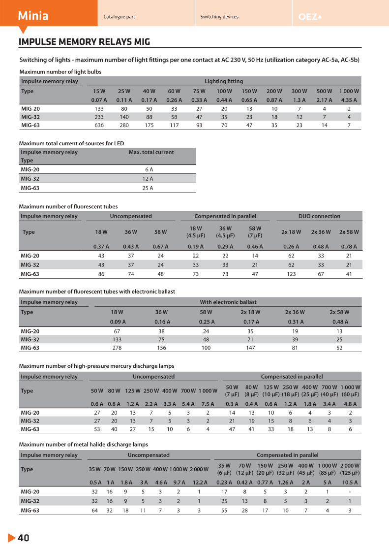
IMPULSE MEMORY RELAYS MIG
Minia
40
Maximum number of light bulbs
Impulse memory relay Lighting fi tting
Type 15 W 25 W 40 W 60 W 75 W 100 W 150 W 200 W 300 W 500 W 1 000 W0.07 A 0.11 A 0.17 A 0.26 A 0.33 A 0.44 A 0.65 A 0.87 A 1.3 A 2.17 A 4.35 A
MIG-20 133 80 50 33 27 20 13 10 7 4 2MIG-32 233 140 88 58 47 35 23 18 12 7 4MIG-63 636 280 175 117 93 70 47 35 23 14 7
Switching of lights - maximum number of light fi ttings per one contact at AC 230 V, 50 Hz (utilization category AC-5a, AC-5b)
Maximum total current of sources for LEDImpulse memory relay Max. total currentType
MIG-20 6 A
MIG-32 12 A
MIG-63 25 A
Maximum number of fl uorescent tubes
Impulse memory relay Uncompensated Compensated in parallel DUO connection
Type 18 W 36 W 58 W 18 W(4.5 μF)
36 W(4.5 μF)
58 W(7 μF) 2x 18 W 2x 36 W 2x 58 W
0.37 A 0.43 A 0.67 A 0.19 A 0.29 A 0.46 A 0.26 A 0.48 A 0.78 A
MIG-20 43 37 24 22 22 14 62 33 21
MIG-32 43 37 24 33 33 21 62 33 21
MIG-63 86 74 48 73 73 47 123 67 41
Maximum number of fl uorescent tubes with electronic ballast
Impulse memory relay With electronic ballast
Type 18 W 36 W 58 W 2x 18 W 2x 36 W 2x 58 W
0.09 A 0.16 A 0.25 A 0.17 A 0.31 A 0.48 A
MIG-20 67 38 24 35 19 13MIG-32 133 75 48 71 39 25MIG-63 278 156 100 147 81 52
Maximum number of high-pressure mercury discharge lamps
Impulse memory relay Uncompensated Compensated in parallel
Type 50 W 80 W 125 W 250 W 400 W 700 W 1 000 W 50 W(7 μF)
80 W(8 μF)
125 W(10 μF)
250 W(18 μF)
400 W(25 μF)
700 W(40 μF)
1 000 W(60 μF)
0.6 A 0.8 A 1.2 A 2.2 A 3.3 A 5.4 A 7.5 A 0.3 A 0.4 A 0.6 A 1.2 A 1.8 A 3.4 A 4.8 AMIG-20 27 20 13 7 5 3 2 14 13 10 6 4 3 2MIG-32 27 20 13 7 5 3 2 21 19 15 8 6 4 3MIG-63 53 40 27 15 10 6 4 47 41 33 18 13 8 6
Maximum number of metal halide discharge lamps
Impulse memory relay Uncompensated Compensated in parallel
Type 35 W 70 W 150 W 250 W 400 W 1 000 W 2 000 W 35 W(6 μF)
70 W(12 μF)
150 W(20 μF)
250 W(32 μF)
400 W(45 μF)
1 000 W(85 μF)
2 000 W(125 μF)
0.5 A 1 A 1.8 A 3 A 4.6 A 9.7 A 12.2 A 0.23 A 0.42 A 0.77 A 1.26 A 2 A 5 A 10.5 A
MIG-20 32 16 9 5 3 2 1 17 8 5 3 2 1 -
MIG-32 32 16 9 5 3 2 1 25 13 8 5 3 2 1
MIG-63 64 32 18 11 7 3 3 55 28 17 10 7 4 3
Catalogue part Switching devices
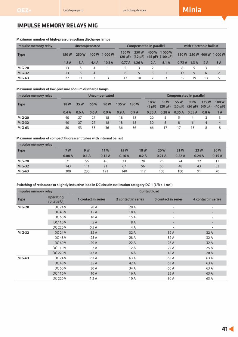
IMPULSE MEMORY RELAYS MIG
Minia
41
Maximum number of high-pressure sodium discharge lamps
Impulse memory relay Uncompensated Compensated in parallel with electronic ballast
Type 150 W 250 W 400 W 1 000 W 150 W(20 μF)
250 W(32 μF)
400 W(45 μF)
1 000 W(100 μF) 150 W 250 W 400 W 1 000 W
1.8 A 3 A 4.4 A 10.3 A 0.77 A 1.26 A 2 A 5.1 A 0.72 A 1.3 A 2 A 5 AMIG-20 13 5 4 1 5 3 2 - 8 5 3 1MIG-32 13 5 4 1 8 5 3 1 17 9 6 2MIG-63 27 11 7 3 17 10 7 3 35 19 13 5
Maximum number of low-pressure sodium discharge lamps
Impulse memory relay Uncompensated Compensated in parallel
Type 18 W 35 W 55 W 90 W 135 W 180 W 18 W(5 μF)
35 W(20 μF)
55 W(20 μF)
90 W(26 μF)
135 W(40 μF)
180 W(40 μF)
0.4 A 0.6 A 0.6 A 0.9 A 0.9 A 0.9 A 0.35 A 0.28 A 0.35 A 0.55 A 0.8 A 1 AMIG-20 40 27 27 18 18 18 20 5 5 4 3 3MIG-32 40 27 27 18 18 18 30 8 8 6 4 4MIG-63 80 53 53 36 36 36 66 17 17 13 8 8
Maximum number of compact fl uorescent tubes with internal ballast
Impulse memory relay
Type 7 W 9 W 11 W 15 W 18 W 20 W 21 W 23 W 30 W0.08 A 0.1 A 0.12 A 0.16 A 0.2 A 0.21 A 0.22 A 0.24 A 0.15 A
MIG-20 71 56 45 33 28 25 24 22 17MIG-32 143 111 91 67 56 50 48 43 33MIG-63 300 233 191 140 117 105 100 91 70
Switching of resistance or slightly inductive load in DC circuits (utilization category DC-1 (L/R ≤ 1 ms))
Impulse memory relay Contact load
Type Operating voltage Ue
1 contact in series 2 contact in series 3 contact in series 4 contact in series
MIG-20 DC 24 V 20 A 20 A - -DC 48 V 15 A 18 A - -
DC 60 V 10 A 15 A - -DC110 V 5 A 8 A - -
DC 220 V 0.5 A 4 A - -MIG-32 DC 24 V 32 A 32 A 32 A 32 A
DC 48 V 25 A 28 A 32 A 32 ADC 60 V 20 A 22 A 28 A 32 A
DC 110 V 7 A 12 A 22 A 25 ADC 220 V 0.7 A 6 A 18 A 20 A
MIG-63 DC 24 V 63 A 63 A 63 A 63 ADC 48 V 35 A 42 A 63 A 63 ADC 60 V 30 A 34 A 60 A 63 A
DC 110 V 10 A 16 A 35 A 63 ADC 220 V 1.2 A 10 A 30 A 63 A
Catalogue part Switching devices
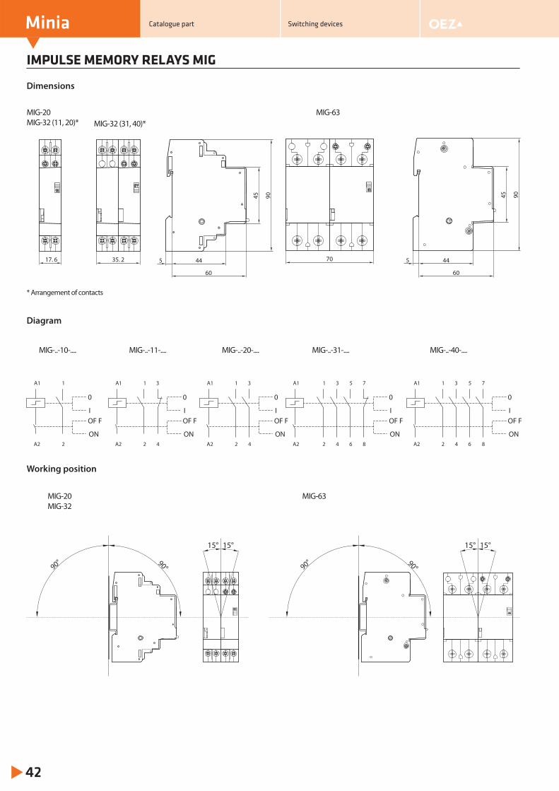
IMPULSE MEMORY RELAYS MIG
Minia
42
Dimensions
445
60
45 9070 445
60
45 90
Diagram
15° 15°
90° 90°
15° 15°
90° 90°
Working position
35. 217. 6
Catalogue part Switching devices
2
1
A2
A1
42 6
531
8A2
A1 7
42
1 3A1
A2 842 6
1 3 75
A2
A1
42
1 3
A2
A1
0
I
0
I
0
I
0
I
0
I
OF F
ON
OF F
ON
OF F
ON
OF F
ON
OF F
ON
MIG-20MIG-32 (11, 20)*
MIG-63MIG-32 (31, 40)*
MIG-..-10-.... MIG-..-11-.... MIG-..-20-.... MIG-..-31-.... MIG-..-40-....
* Arrangement of contacts
MIG-63MIG-20MIG-32
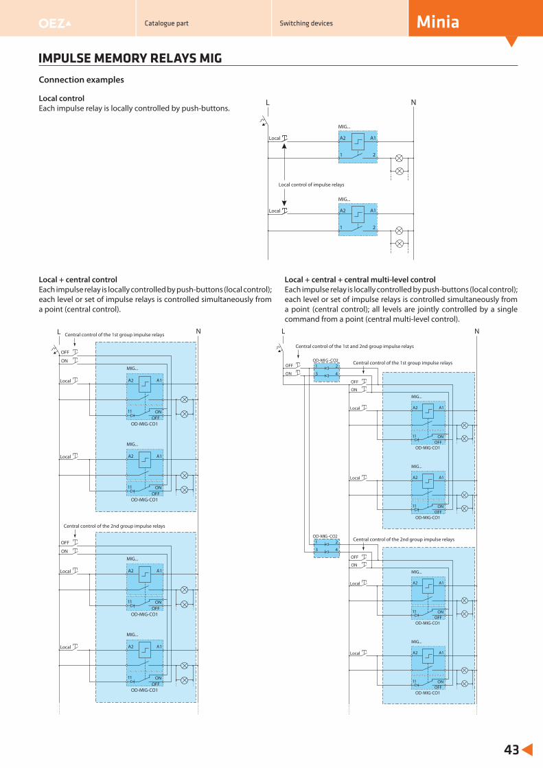
IMPULSE MEMORY RELAYS MIG
Minia
43
Central control of the 1st group impulse relays
Central control of the 2nd group impulse relays
L N
OFF
ON
OFFOD-MIG-CO1
MIG...
Local A1A2
ON11
OFFOD-MIG-CO1
MIG...
Local A1A2
ON11
OFF
ON
OFFOD-MIG-CO1
MIG...
Local A1A2
ON11
OFFOD-MIG-CO1
MIG...
Local A1A2
ON11
L N
Local
MIG...
A1A2
1 2
Local
MIG...
A1A2
1 2
Local control of impulse relays
Local + central controlEach impulse relay is locally controlled by push-buttons (local control); each level or set of impulse relays is controlled simultaneously from a point (central control).
Local + central + central multi-level controlEach impulse relay is locally controlled by push-buttons (local control); each level or set of impulse relays is controlled simultaneously from a point (central control); all levels are jointly controlled by a single command from a point (central multi-level control).
Connection examples
OFF
ON
OFFOD-MIG-CO1
MIG...
Local A1A2
ON11
OFFOD-MIG-CO1
MIG...
Local A1A2
ON11
OFF
ON
OFFOD-MIG-CO1
MIG...
Local A1A2
ON11
OFFOD-MIG-CO1
MIG...
Local A1A2
ON11
NL
OFF
ON
OD-MI -C21
43
OD-MI21
43
Central control of the 1st and 2nd group impulse relays
Central control of the 1st group impulse relays
Central control of the 2nd group impulse relays
Local controlEach impulse relay is locally controlled by push-buttons.
Catalogue part Switching devices
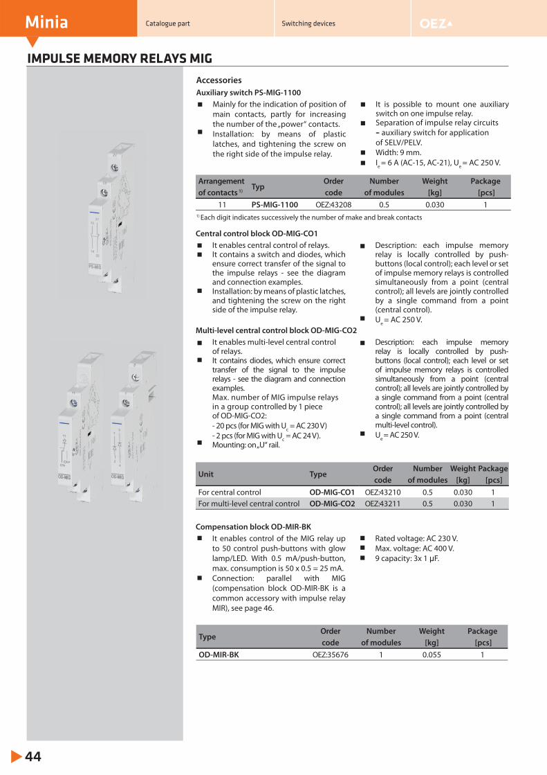
Minia
44
IMPULSE MEMORY RELAYS MIG
Mainly for the indication of position of main contacts, partly for increasing the number of the „power“ contacts.Installation: by means of plastic latches, and tightening the screw on the right side of the impulse relay.
It is possible to mount one auxiliary switch on one impulse relay.Separation of impulse relay circuits – auxiliary switch for application of SELV/PELV.Width: 9 mm.Ie = 6 A (AC-15, AC-21), Ue = AC 250 V.
Accessories
Auxiliary switch PS-MIG-1100
It enables central control of relays.It contains a switch and diodes, which ensure correct transfer of the signal to the impulse relays - see the diagram and connection examples.Installation: by means of plastic latches, and tightening the screw on the right side of the impulse relay.
Description: each impulse memory relay is locally controlled by push-buttons (local control); each level or set of impulse memory relays is controlled simultaneously from a point (central control); all levels are jointly controlled by a single command from a point (central control).Ue = AC 250 V.
Central control block OD-MIG-CO1
It enables multi-level central control of relays.It contains diodes, which ensure correct transfer of the signal to the impulse relays - see the diagram and connection examples.Max. number of MIG impulse relays in a group controlled by 1 piece of OD-MIG-CO2:- 20 pcs (for MIG with Uc = AC 230 V)- 2 pcs (for MIG with Uc = AC 24 V).Mounting: on „U“ rail.
Description: each impulse memory relay is locally controlled by push-buttons (local control); each level or set of impulse memory relays is controlled simultaneously from a point (central control); all levels are jointly controlled by a single command from a point (central control); all levels are jointly controlled by a single command from a point (central multi-level control).Ue = AC 250 V.
Multi-level central control block OD-MIG-CO2
It enables control of the MIG relay up to 50 control push-buttons with glow lamp/LED. With 0.5 mA/push-button, max. consumption is 50 x 0.5 = 25 mA.Connection: parallel with MIG (compensation block OD-MIR-BK is a common accessory with impulse relay MIR), see page 46.
Rated voltage: AC 230 V.Max. voltage: AC 400 V.9 capacity: 3x 1 μF.
Compensation block OD-MIR-BK
ArrangementTyp
Order Number Weight Package of contacts 1) code of modules [kg] [pcs]
11 PS-MIG-1100 OEZ:43208 0.5 0.030 1
Unit TypeOrder Number Weight Package code of modules [kg] [pcs]
For central control OD-MIG-CO1 OEZ:43210 0.5 0.030 1For multi-level central control OD-MIG-CO2 OEZ:43211 0.5 0.030 1
TypeOrder Number Weight Package code of modules [kg] [pcs]
OD-MIR-BK OEZ:35676 1 0.055 1
1) Each digit indicates successively the number of make and break contacts
Catalogue part Switching devices
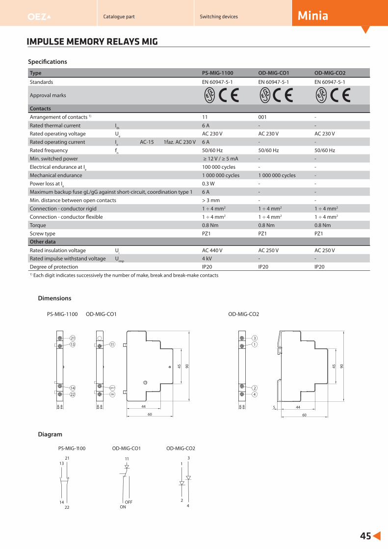
IMPULSE MEMORY RELAYS MIG
Minia
45
OD-MIG-CO2
8. 8 44
60
5
45 901
3
4
2
PS-MIG-1100 OD-MIG-CO1 OD-MIG-CO2
14
13
22
21
24
13
ON
11
OFF
Dimensions
Diagram
Type PS-MIG-1100 OD-MIG-CO1 OD-MIG-CO2
Standards EN 60947-5-1 EN 60947-5-1 EN 60947-5-1
Approval marks
Contacts
Arrangement of contacts 1) 11 001 -
Rated thermal current Ith 6 A - -Rated operating voltage Ue AC 230 V AC 230 V AC 230 VRated operating current Ie AC-15 1faz. AC 230 V 6 A - -Rated frequency fn 50/60 Hz 50/60 Hz 50/60 HzMin. switched power ≥ 12 V / ≥ 5 mA - -Electrical endurance at Ie 100 000 cycles - -Mechanical endurance 1 000 000 cycles 1 000 000 cycles -Power loss at Ie 0.3 W - -Maximum backup fuse gL/gG against short-circuit, coordination type 1 6 A - -Min. distance between open contacts > 3 mm - -Connection - conductor rigid 1 ÷ 4 mm2 1 ÷ 4 mm2 1 ÷ 4 mm2
Connection - conductor flexible 1 ÷ 4 mm2 1 ÷ 4 mm2 1 ÷ 4 mm2
Torque 0.8 Nm 0.8 Nm 0.8 NmScrew type PZ1 PZ1 PZ1Other data
Rated insulation voltage Ui AC 440 V AC 250 V AC 250 VRated impulse withstand voltage Uimp 4 kV - -Degree of protection IP20 IP20 IP201) Each digit indicates successively the number of make, break and break-make contacts
Specifi cations
PS-MIG-1100
8. 8 44
60
45 90
8. 8
13
21
22
14
11
ON
OF F
OD-MIG-CO1
Catalogue part Switching devices
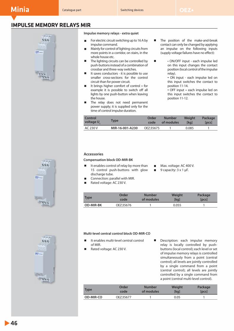
IMPULSE MEMORY RELAYS MIR
Minia
46
For electric circuit switching up to 16 A by impulse command.Mainly for control of lighting circuits from more points in a corridor, on stairs, in the whole house etc.The lighting circuits can be controlled by push-buttons instead of a combination of crossbar and three-way switches.It saves conductors - it is possible to use smaller cross-sections for the control circuit than for power circuit.It brings higher comfort of control – for example it is possible to switch off all lights by one push-button when leaving the house.The relay does not need permanent power supply; it is supplied only for the time of control impulse duration.
The position of the make-and-break contact can only be changed by applying an impulse on the following inputs (supply voltage failures have no eff ect):
• ON/OFF input - each impulse led on this input changes the contact position (local control of the impulse relay).• ON input - each impulse led on this input switches the contact to position 11-14.• OFF input – each impulse led on this input switches the contact to position 11-12.
ControlType
Order Number Weight Packagevoltage Uc code of modules [kg] [pcs]
AC 230 V MIR-16-001-A230 OEZ:35675 1 0.085 1
It enables control of relay by more than 15 control push-buttons with glow discharge tube.Connection: parallel with MIR.Rated voltage: AC 230 V.
Max. voltage: AC 400 V.9 capacity: 3 x 1 μF.
Accessories
TypeOrder Number Weight Packagecode of modules [kg] [pcs]
OD-MIR-BK OEZ:35676 1 0.055 1
TypeOrder Number Weight Packagecode of modules [kg] [pcs]
OD-MIR-CO OEZ:35677 1 0.05 1
Impulse memory relays - extra quiet
It enables multi-level central control of MIR.Rated voltage: AC 230 V.
Description: each impulse memory relay is locally controlled by push-buttons (local control); each level or set of impulse memory relays is controlled simultaneously from a point (central control); all levels are jointly controlled by a single command from a point (central control); all levels are jointly controlled by a single command from a point (central multi-level control).
Compensation block OD-MIR-BK
Multi-level central control block OD-MIR-CO
Catalogue part Switching devices
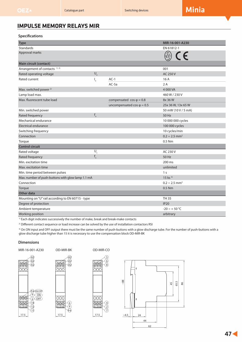
IMPULSE MEMORY RELAYS MIR
Minia
47
Type MIR-16-001-A230Standards EN 61812-1Approval marks
Main circuit (contact)Arrangement of contacts 1) 2) 001Rated operating voltage Ue AC 250 VRated current In AC-1 16 A
AC-5a 2 AMax. switched power 2) 4 000 VALamp load max. 460 W / 230 VMax. fl uorescent tube load compensated cos φ = 0.8 8x 36 W
uncompensated cos φ = 0.5 25x 36 W, 13x 65 WMin. switched power 50 mW (10 V / 5 mA)Rated frequency fn 50 HzMechanical endurance 10 000 000 cyclesElectrical endurance 100 000 cyclesSwitching frequency 10 cycles/minConnection 0.2 ÷ 2.5 mm2
Torque 0.5 NmControl circuitRated voltage Uc AC 230 VRated frequency fn 50 HzMin. excitation time 200 msMax. excitation time unlimitedMin. time period between pulses 1 sMax. number of push-buttons with glow lamp 1.1 mA 15 ks 3)
Connection 0.2 ÷ 2.5 mm2
Torque 0.5 NmOther dataMounting on “U” rail according to EN 60715 - type TH 35Degree of protection IP20Ambient temperature -20 ÷ + 50 °CWorking position arbitrary1) Each digit indicates successively the number of make, break and break-make contacts2) Diff erent contact sequence or load increase can be solved by the use of installation contactors RSI3) On ON input and OFF output there must be the same number of push-buttons with a glow discharge tube. For the number of push-buttons with a glow discharge tube higher than 15 it is necessary to use the compensation block OD-MIR-BK
Specifi cations
Dimensions
17.517.517.5
~88
24~4.5
44
62
45 65.5
86
8
27
4
A2A26A2A25A2A2
OD-MIR-COOD-MIR-BKMIR-16-001-A230
ON/OFF
ONOFF
141211
Catalogue part Switching devices
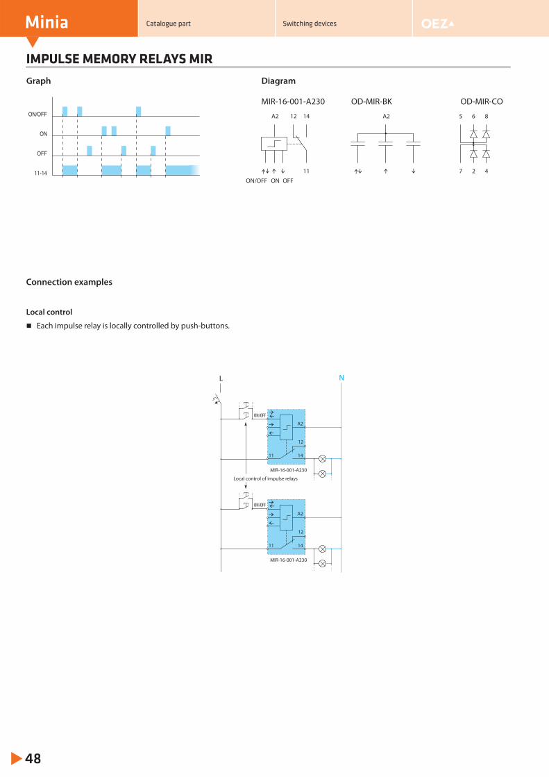
IMPULSE MEMORY RELAYS MIR
Minia
48
Connection examples
Graph Diagram
Local control
Each impulse relay is locally controlled by push-buttons.
ON/OFF
ON
OFF
11-14
MIR-16-001-A230
A2
ONON/OFF OFF
1412
11
A2 5
7
6
2
8
4
OD-MIR-BK OD-MIR-CO
L N
Local control of impulse relays
MIR-16-001-A230
A2
14
12
11
MIR-16-001-A230
A2
14
12
11
ON/OFF
ON/OFF
Catalogue part Switching devices
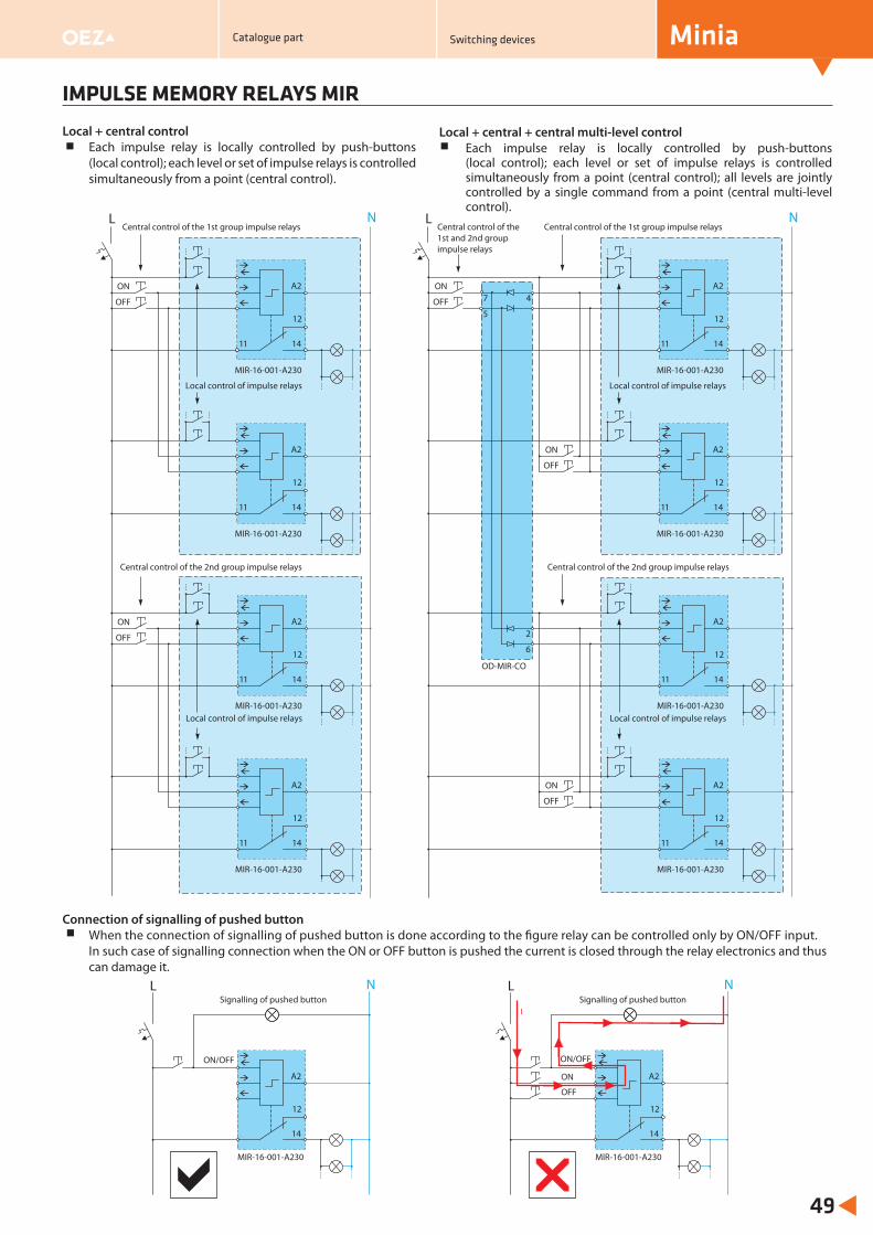
IMPULSE MEMORY RELAYS MIR
Minia
49
Local + central controlEach impulse relay is locally controlled by push-buttons (local control); each level or set of impulse relays is controlled simultaneously from a point (central control).
Local + central + central multi-level controlEach impulse relay is locally controlled by push-buttons (local control); each level or set of impulse relays is controlled simultaneously from a point (central control); all levels are jointly controlled by a single command from a point (central multi-level control).
Connection of signalling of pushed buttonWhen the connection of signalling of pushed button is done according to the fi gure relay can be controlled only by ON/OFF input. In such case of signalling connection when the ON or OFF button is pushed the current is closed through the relay electronics and thus can damage it.
L N
MIR-16-001-A230
A2
14
12
11
ON/OFF
ON
OFF
L N
MIR-16-001-A230
A2
14
12
11
ON/OFF
Signalling of pushed button Signalling of pushed buttonI
Central control of the 1st and 2nd group impulse relays
Central control of the 1st group impulse relaysL N
MIR-16-001-A230
A2
14
12
11
MIR-16-001-A230
A2
14
12
11
MIR-16-001-A230
A2
14
12
11
MIR-16-001-A230
A2
14
12
11
5
7 4
2
6
OD-MIR-CO
OFF
ON
Central control of the 1st group impulse relays
Central control of the 2nd group impulse relays
L N
Local control of impulse relays
MIR-16-001-A230
A2
14
12
11
MIR-16-001-A230
A2
14
12
11
OFF
ON
MIR-16-001-A230
A2
14
12
11
MIR-16-001-A230
A2
14
12
11
OFF
ON
OFF
ON
OFF
ON
Local control of impulse relays
Local control of impulse relays
Local control of impulse relays
Central control of the 2nd group impulse relays
Catalogue part Switching devices
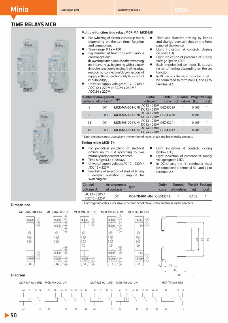
TIME RELAYS MCR
50
For switching of electric circuits up to 8 A depending on the set time, function and connection.Time range: 0.1 s ÷ 100 hr.Big number of functions with various control options:delayed operation, impulse after switching on, interval relay beginning with a pause//impulse, reaction to leading/trailing edge, reaction to connection/disconnection of supply voltage, reaction only to a control impulse edge,...Universal supply voltage: AC 12 ÷ 230 V / / DC 12 ÷ 220 V or AC 24 ÷ 230 V / / DC 24 ÷ 220 V.
Time and function setting by knobs and change-over switches on the front panel of the device.Light indication at contacts closing (yellow LED).Light indication of presence of supply voltage (green LED).Each impulse led on input TL causes restart of timing depending on the set function.In DC circuits the (+) conductor must be connected to terminal A1, and (-) to terminal A2.
Multiple-function time relays MCR-MA, MCR-MB
For periodical switching of electrical circuits up to 8 A according to two mutually independent set times.Time range: 0.1 s ÷ 10 days.Universal supply voltage: AC 12 ÷ 230 V / / DC 12 ÷ 220 V.Possibility of selection of start of timing - delayed operation / impulse for switching on.
Light indication at contacts closing (yellow LED).Light indication of presence of supply voltage (green LED).In DC circuits the (+) conductor must be connected to terminal A1, and (-) to terminal A2.
Timing relays MCR- TK
Number of Arrangement Type
Control Order Number Weight Package functions of contacts 1) voltage Ue code of modules [kg] [pcs]
9 001 MCR-MA-001-UNI AC 12 ÷ 230 V DC 12 ÷ 220 V OEZ:43239 1 0.105 1
9 003 MCR-MA-003-UNI AC 24 ÷ 230 V DC 24 ÷ 220 V OEZ:43240 1 0.105 1
18 001 MCR-MB-001-UNI AC 12 ÷ 230 V DC 12 ÷ 220 V OEZ:43241 1 0.105 1
18 003 MCR-MB-003-UNI AC 24 ÷ 230 V DC 24 ÷ 220 V OEZ:43242 1 0.105 1
Control Arrangement Type
Order Number Weight Package voltage Ue of contacts 1) code of modules [kg] [pcs]
AC 12 ÷ 230 V / / DC 12 ÷ 220 V 001 MCR-TK-001-UNI OEZ:43243 1 0.105 1
1) Each digit indicates successively the number of make, break and break-make contacts
1) Each digit indicates successively the number of make, break and break-make contacts
Dimensions
MCR-MA-003-UNI MCR-MB-001-UNI
18 26
44
60
5
18
15
1618
TL
A2
A1
16
15
18
MCR-MA-001-UNI
18
38
35
36
18
15
16
25
28
26
18
A2
A1
MCR-MB-003-UNI MCR-TK-001-UNI
18
TL
A1
38
35
36
18
15
16
25
28
26
A2
TL
A2
A1
TL
A1
A2
18
16
ZP
15
906845
MCR-MA-003-UNI MCR-MB-001-UNIMCR-MA-001-UNI MCR-MB-003-UNI MCR-TK-001-UNI
TL
15
18A1
A2
16 TL
15
18A1
A2
16
25
2826
35
3836
T T T
TL
15
18A1
A2
16
T
TL
15
18A1
A2
16
25
2826
35
3836
T
15
18A1
A2
16
Diagram
Minia Catalogue part Switching devices
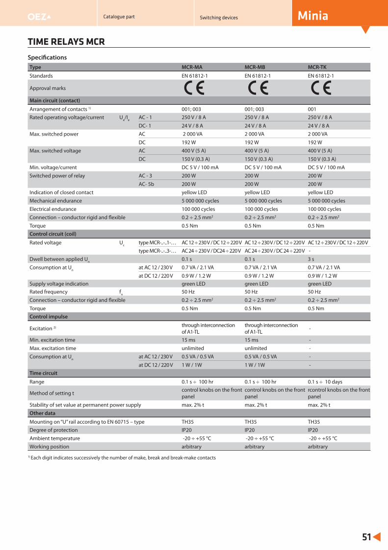
Type MCR-MA MCR-MB MCR-TK
Standards EN 61812-1 EN 61812-1 EN 61812-1
Approval marks
Main circuit (contact)
Arrangement of contacts 1) 001; 003 001; 003 001Rated operating voltage/current Ue/Ie AC - 1 250 V / 8 A 250 V / 8 A 250 V / 8 A
DC- 1 24 V / 8 A 24 V / 8 A 24 V / 8 AMax. switched power AC 2 000 VA 2 000 VA 2 000 VA
DC 192 W 192 W 192 WMax. switched voltage AC 400 V (5 A) 400 V (5 A) 400 V (5 A)
DC 150 V (0.3 A) 150 V (0.3 A) 150 V (0.3 A)Min. voltage/current DC 5 V / 100 mA DC 5 V / 100 mA DC 5 V / 100 mASwitched power of relay AC - 3 200 W 200 W 200 W
AC- 5b 200 W 200 W 200 WIndication of closed contact yellow LED yellow LED yellow LEDMechanical endurance 5 000 000 cycles 5 000 000 cycles 5 000 000 cycles Electrical endurance 100 000 cycles 100 000 cycles 100 000 cycles Connection – conductor rigid and flexible 0.2 ÷ 2.5 mm2 0.2 ÷ 2.5 mm2 0.2 ÷ 2.5 mm2
Torque 0.5 Nm 0.5 Nm 0.5 NmControl circuit (coil)
Rated voltage Uc type MCR-..-..1-… AC 12 ÷ 230 V / DC 12 ÷ 220 V AC 12 ÷ 230 V / DC 12 ÷ 220 V AC 12 ÷ 230 V / DC 12 ÷ 220 V type MCR-..-..3-… AC 24 ÷ 230 V / DC24 ÷ 220 V AC 24 ÷ 230 V / DC 24 ÷ 220 V -
Dwell between applied Un 0.1 s 0.1 s 3 sConsumption at Un at AC 12 / 230 V 0.7 VA / 2.1 VA 0.7 VA / 2.1 VA 0.7 VA / 2.1 VA
at DC 12 / 220 V 0.9 W / 1.2 W 0.9 W / 1.2 W 0.9 W / 1.2 WSupply voltage indication green LED green LED green LEDRated frequency fn 50 Hz 50 Hz 50 HzConnection – conductor rigid and flexible 0.2 ÷ 2.5 mm2 0.2 ÷ 2.5 mm2 0.2 ÷ 2.5 mm2
Torque 0.5 Nm 0.5 Nm 0.5 NmControl impulse
Excitation 2) through interconnection of A1-TL
through interconnection of A1-TL -
Min. excitation time 15 ms 15 ms -Max. excitation time unlimited unlimited -Consumption at Un at AC 12 / 230 V 0.5 VA / 0.5 VA 0.5 VA / 0.5 VA -
at DC 12 / 220 V 1 W / 1W 1 W / 1W -Time circuit
Range 0.1 s ÷ 100 hr 0.1 s ÷ 100 hr 0.1 s ÷ 10 days
Method of setting t control knobs on the front panel
control knobs on the front panel
rcontrol knobs on the front panel
Stability of set value at permanent power supply max. 2% t max. 2% t max. 2% tOther data
Mounting on “U” rail according to EN 60715 – type TH35 TH35 TH35Degree of protection IP20 IP20 IP20Ambient temperature -20 ÷ +55 °C -20 ÷ +55 °C -20 ÷ +55 °CWorking position arbitrary arbitrary arbitrary
TIME RELAYS MCR
51
1) Each digit indicates successively the number of make, break and break-make contacts
Specifi cations
MiniaCatalogue part Switching devices
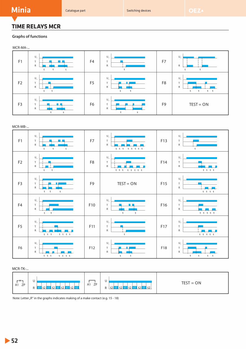
TIME RELAYS MCR
52
Graphs of functions
t t
Un
TR
t t
t
Un
TR
t t t t
t
Un
TR
t t t t
t
Un
TR
t t t
t
Un
TR
t t t
t
Un
TR
t t
Un
TR
t
Un
TR
t t
Un
TR
t t
Un
TR
tt t t t t
t t
Un
TR
t t t t t t
t t
Un
TR
tt t t t
t t
Un
TR
t t t t t
t t
Un
TR
t t
Un
TR
t
t t
Un
TR
t t t
Un
TR
t t
Un
TR
t t
t t
Un
R
t t
Un
TR
t
Un
TR
t t
Un
TR
t t
Un
TR
t t t
Un
TR
F6
F4
F5
TEST = ONF9
F7
F8
F1
F2
F3
MCR-MA-...
F1
F4
F2
F5
F3
F6
F13
F16
F14
F17
F15
F18
MCR-MB-...
F7
F8
TEST = ONF9
F10
F11
F12
t t
Un
TR
U
R t1 t1 t1 t1 t1t2 t2 t2 t2
U
R t2 t2 t2 t2 t2t1 t1 t1 t1
MCR-TK-...
ZPA1 ZPA1 TEST = ON
Note: Letter „R“ in the graphs indicates making of a make contact (e.g. 15 - 18)
Minia Catalogue part Switching devices
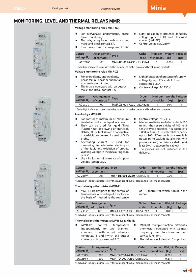
For overvoltage, undervoltage, phase failure monitoring.The relay is equipped with an output make-and-break contact 8 A.It can be also used for one-phase circuits.
Light indication of presence of supply voltage (green LED) and of closed contact (red LED).Control voltage: AC 230 V.
Voltage monitoring relay MMR-U3
MONITORING, LEVEL AND THERMAL RELAYS MMR
53
For control of maximum or minimum level of a conductive liquid in a tank.They can be used for liquid fi lling (function UP) or drawing off (function DOWN). If the tank is from a conductive material, it can be used instead of GND probe.Alternating current is used for measuring to eliminate electrolysis of the liquid and oxidation of probes. Working voltage in the measuring loop is 12 V.Light indication of presence of supply voltage (green LED).
Control voltage: AC 230 V.Maximum distance of electrodes is 100 m with the set sensitivity of 100 %. If sensitivity is decreased, it is possible to 1 000 m. This is true with cable capacity up to 100 nF/km. In both cases it is necessary to exclude parallel run with power cables (the distance shall be at least 20 cm between the cables).The probes are not included in the delivery.
Level relays MMR-HL
MMR-T1 are designed for the control of temperature of winding of a motor on the basis of measuring the resistance
of PTC thermistor, which is built in the motor.
Thermal relays (thermistor) MMR-T1
1) Each digit indicates successively the number of make, break and break-make contacts
1) Each digit indicates successively the number of make, break and break-make contacts
Control Arrangement Type
Order Number Weight Package voltage Ue of contacts 1) code of modules [kg] [pcs]
AC 230 V 001 MMR-U3-001-A230 OEZ:43244 1 0.091 1
Control Arrangement Type Order Number Weight Package voltage Ue of contacts 1) code of modules [kg] [pcs]AC 230 V 001 MMR-HL-001-A230 OEZ:43246 1 0.091 1
Control Arrangement Type
Order Number Weight Package voltage Ue of contacts 1) code of modules [kg] [pcs]AC 230 V 001 MMR-T1-001-A230 OEZ:43247 1 0.081 1
For overvoltage, undervoltage, phase failure, phase sequence and asymmetry monitoring.The relay is equipped with an output make-and-break contact 8 A.
Light indication of presence of supply voltage (green LED) and of closed contact (red LED).Control voltage: AC 230 V.
Voltage monitoring relay MMR-X3
1) Each digit indicates successively the number of make, break and break-make contacts
Control Arrangement Type
Order Number Weight Package voltage Ue of contacts 1) code of modules [kg] [pcs]
AC 230 V 001 MMR-X3-001-A230 OEZ:43245 1 0.091 1
MMR-T2 control temperature independently for two channels, compare it with a set reference temperature, and switch the output contacts with hysteresis of 2 °C.
MMR-TD multiple-function diff erential thermostats equipped with six most frequently used functions and four service functions. The delivery includes two 3 m probes.
Thermal relays (thermostats) MMR-T2, MMR-TD
Control Arrangement Type
Order Number Weight Package voltage Ue of contacts 1) code of modules [kg] [pcs]
AC 230 V 200 MMR-T2-200-A230 OEZ:43248 1 0.211 1AC 230 V 200 MMR-TD-200-A230 OEZ:43249 1 0.211 1
1) Each digit indicates successively the number of make, break and break-make contacts
1) Each digit indicates successively the number of make, break and break-make contacts
MiniaCatalogue part Switching devices
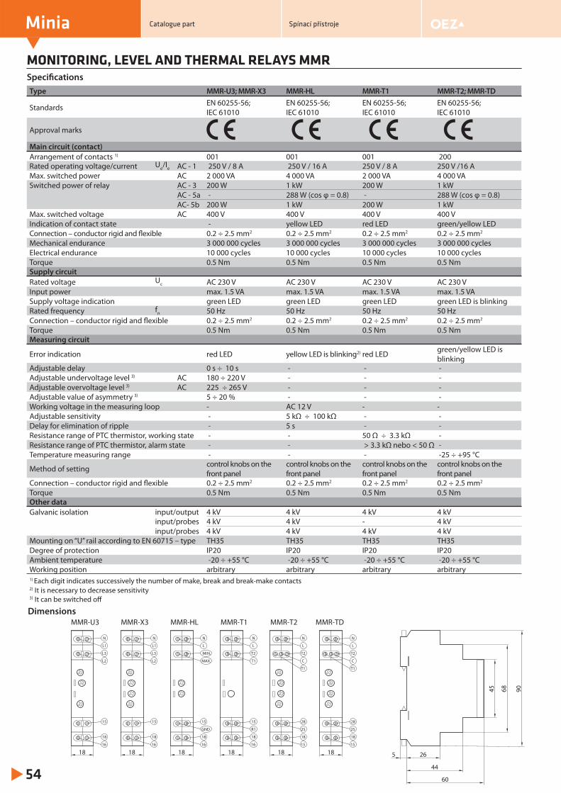
Type MMR-U3; MMR-X3 MMR-HL MMR-T1 MMR-T2; MMR-TD
Standards EN 60255-56; IEC 61010
EN 60255-56; IEC 61010
EN 60255-56; IEC 61010
EN 60255-56; IEC 61010
Approval marks
Main circuit (contact)Arrangement of contacts 1) 001 001 001 200Rated operating voltage/current Ue/Ie AC - 1 250 V / 8 A 250 V / 16 A 250 V / 8 A 250 V /16 AMax. switched power AC 2 000 VA 4 000 VA 2 000 VA 4 000 VASwitched power of relay AC - 3 200 W 1 kW 200 W 1 kW
AC - 5a - 288 W (cos φ = 0.8) - 288 W (cos φ = 0.8)AC- 5b 200 W 1 kW 200 W 1 kW
Max. switched voltage AC 400 V 400 V 400 V 400 V Indication of contact state - yellow LED red LED green/yellow LEDConnection – conductor rigid and flexible 0.2 ÷ 2.5 mm2 0.2 ÷ 2.5 mm2 0.2 ÷ 2.5 mm2 0.2 ÷ 2.5 mm2
Mechanical endurance 3 000 000 cycles 3 000 000 cycles 3 000 000 cycles 3 000 000 cycles Electrical endurance 10 000 cycles 10 000 cycles 10 000 cycles 10 000 cycles Torque 0.5 Nm 0.5 Nm 0.5 Nm 0.5 NmSupply circuitRated voltage Uc AC 230 V AC 230 V AC 230 V AC 230 VInput power max. 1.5 VA max. 1.5 VA max. 1.5 VA max. 1.5 VASupply voltage indication green LED green LED green LED green LED is blinkingRated frequency fn 50 Hz 50 Hz 50 Hz 50 HzConnection – conductor rigid and flexible 0.2 ÷ 2.5 mm2 0.2 ÷ 2.5 mm2 0.2 ÷ 2.5 mm2 0.2 ÷ 2.5 mm2
Torque 0.5 Nm 0.5 Nm 0.5 Nm 0.5 NmMeasuring circuit
Error indication red LED yellow LED is blinking2) red LED green/yellow LED is blinking
Adjustable delay 0 s ÷ 10 s - - -Adjustable undervoltage level 3) AC 180 ÷ 220 V - - -Adjustable overvoltage level 3) AC 225 ÷ 265 V - - -Adjustable value of asymmetry 3) 5 ÷ 20 % - - -Working voltage in the measuring loop - AC 12 V - -Adjustable sensitivity - 5 kΩ ÷ 100 kΩ - -Delay for elimination of ripple - 5 s - -Resistance range of PTC thermistor, working state - - 50 Ω ÷ 3.3 kΩ -Resistance range of PTC thermistor, alarm state - - > 3.3 kΩ nebo < 50 Ω -Temperature measuring range - - - -25 ÷ +95 °C
Method of setting control knobs on the front panel
control knobs on the front panel
control knobs on the front panel
control knobs on thefront panel
Connection – conductor rigid and flexible 0.2 ÷ 2.5 mm2 0.2 ÷ 2.5 mm2 0.2 ÷ 2.5 mm2 0.2 ÷ 2.5 mm2
Torque 0.5 Nm 0.5 Nm 0.5 Nm 0.5 NmOther dataGalvanic isolation input/output 4 kV 4 kV 4 kV 4 kV
input/probes 4 kV 4 kV - 4 kVinput/probes 4 kV 4 kV 4 kV 4 kV
Mounting on “U” rail according to EN 60715 – type TH35 TH35 TH35 TH35Degree of protection IP20 IP20 IP20 IP20Ambient temperature -20 ÷ +55 °C -20 ÷ +55 °C -20 ÷ +55 °C -20 ÷ +55 °CWorking position arbitrary arbitrary arbitrary arbitrary1) Each digit indicates successively the number of make, break and break-make contacts2) It is necessary to decrease sensitivity3) It can be switched off
MONITORING, LEVEL AND THERMAL RELAYS MMR
Minia
54
Specifi cations
Dimensions
18
N
L1
MMR-U3
18
16
L3
L2
15
MMR-X3
N
L
MMR-HL
18
16
MIN.
MAX.
15
GND
18
N
L1
18
16
L3
L2
15
18 26
44
60
5
906845
N
L
MMR-T1
18
16
T2
T1
15
R1
18
MMR-T2
18
N
L
18
15
28
T2
C
T1
25
MMR-TD
18
N
L
18
15
28
T2
C
T1
25
Catalogue part Spínací přístroje
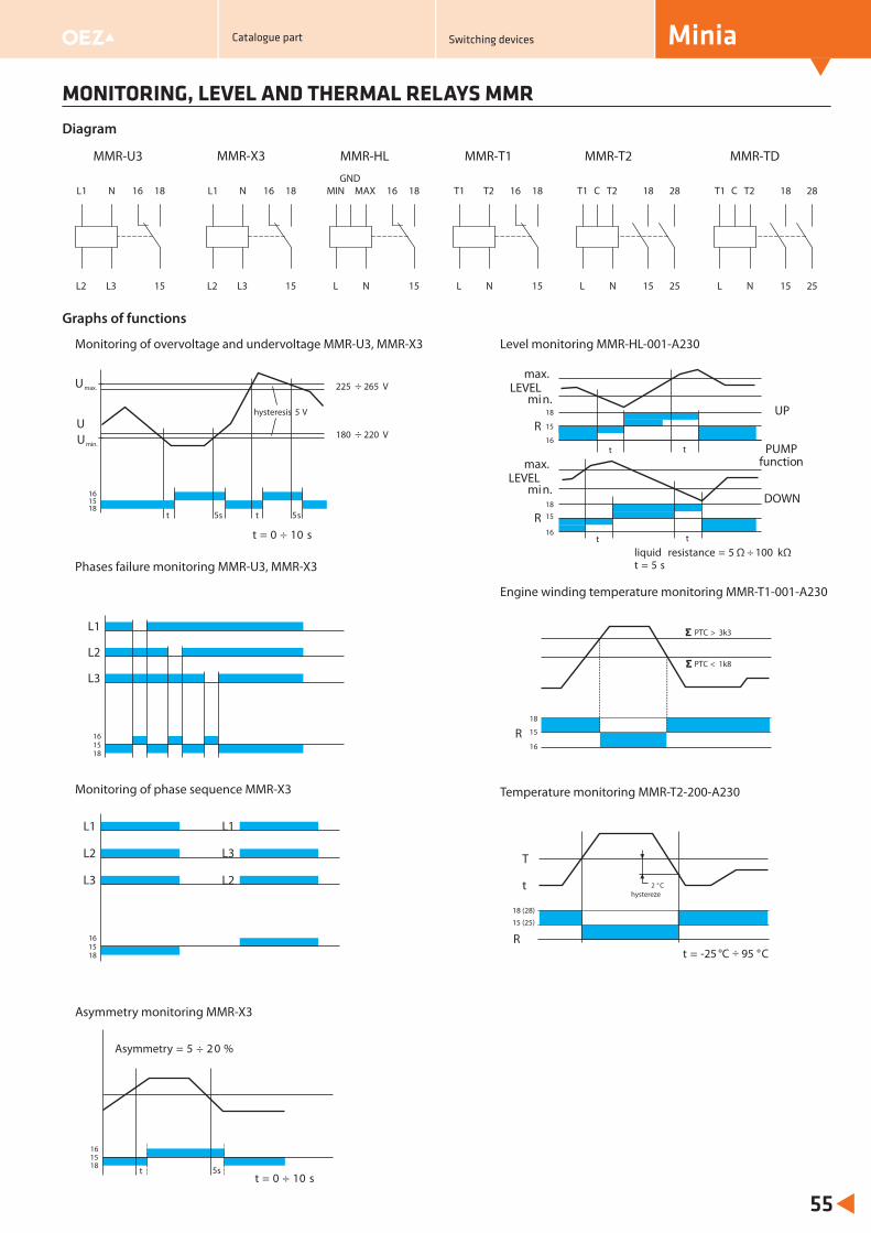
MONITORING, LEVEL AND THERMAL RELAYS MMR
55
Diagram
MMR-U3 MMR-X3 MMR-HL MMR-T1 MMR-TDMMR-T2
N
15
18L1
L2
16
L3
N
15
18L1
L2
16
L3
MAX
15
18MIN
L
16
N
GNDT2
15
18T1
L
16
N
T2
15
18T1
L N
C
25
28 T2
15
18T1
L N
C
25
28
max.
min.
R
LEVEL
tt
max.
min.
R
LEVEL
tt
UP
PUMPfunction
DOWN
liquid resistance = 5 ÷ 100 kt = 5 s
Ω Ω
1518
16
L2
L2
L1
L3
L1
L3
t = 0 ÷ 10 s
Asymmetry = 5 ÷ 2 0 %
1518
16
t
t = 0 ÷ 10 s
Umax.
Umin.
U
t
hysteresis 5 V
1518
16
5s t 5s
225 265 V÷
180 220 V÷
PTC > 3k3
PTC < 1k8
R1518
16
L2
L1
L3
Rt -25 °C °= 95 C
2 ° Chystereze
t
T
5s
15 (25)
18 (28)
15
18
16
15
18
16
15
18
16
÷
Graphs of functions
Monitoring of overvoltage and undervoltage MMR-U3, MMR-X3 Level monitoring MMR-HL-001-A230
Phases failure monitoring MMR-U3, MMR-X3
Engine winding temperature monitoring MMR-T1-001-A230
Monitoring of phase sequence MMR-X3
Asymmetry monitoring MMR-X3
Temperature monitoring MMR-T2-200-A230
MiniaCatalogue part Switching devices
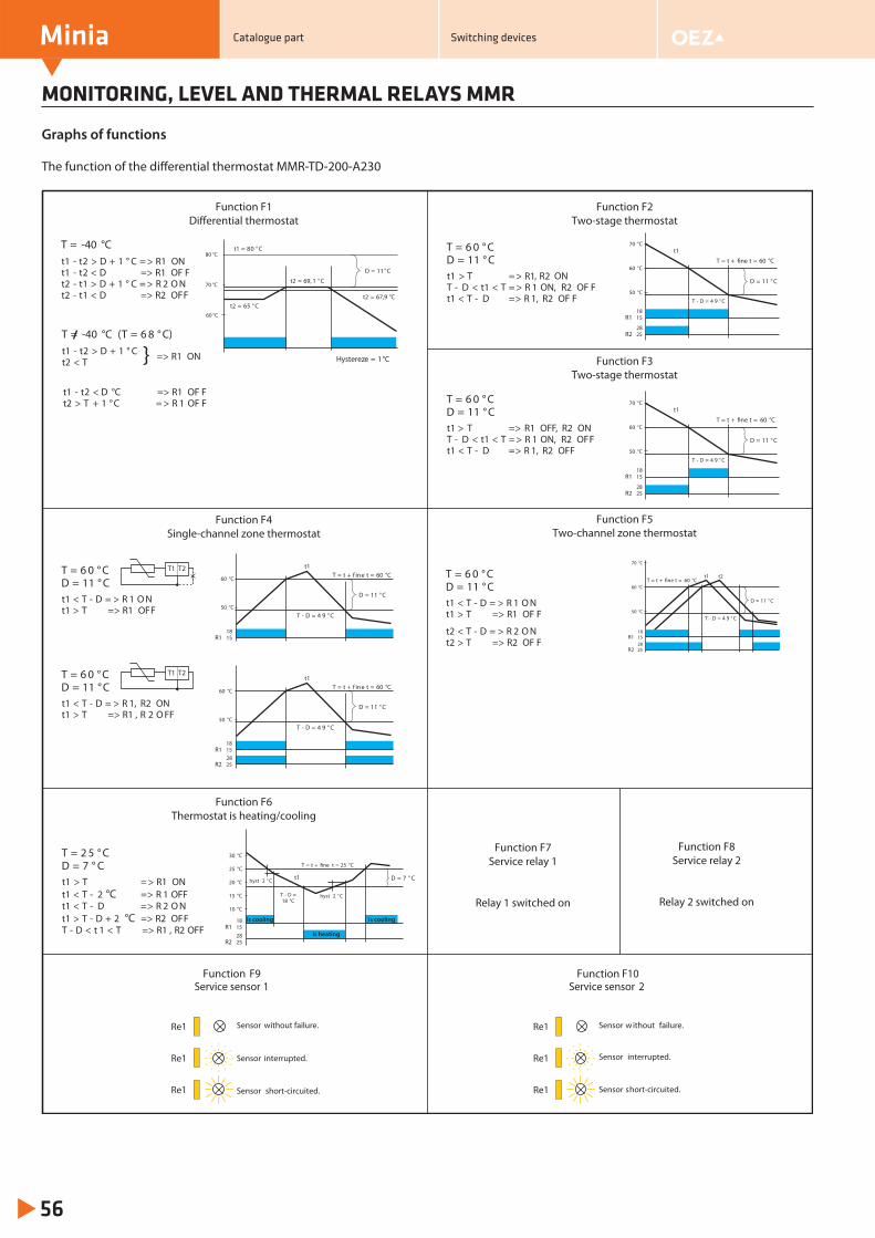
MONITORING, LEVEL AND THERMAL RELAYS MMR
Minia
56
Graphs of functions
D = 11 ° C
T = t + fine t = 60 °C
T - D = 4 9 ° C
t1
60 °C
50 °C
1518
R1
2528
R2
70 °C
t2
T = -40 °Ct1 - t2 D + 1 ° C => > R1 ONt1 - t2 < D => R1 OF Ft2 - t1 > D + 1 ° C = > R 2 O Nt2 - t1 < D => R2 OFF
T = 6 0 ° CD = 11 ° Ct1 T = , R2T - D
R1 ON< t1 < T = > R 1 ON, R2 OF F
t1 < T - D => R 1, R2 OF F
T = 6 0 ° CD = 11 ° Ct1 T = OFF, R2T - D
> > R1 ON< t1 < T = > R 1 ON, R2 OFF
t1 < T - D => R 1, R2 OFF
T = 6 0 ° CD = 11 ° Ct1 < T - D = > R 1 O Nt1 > T => R1 OFF
T = 6 0 ° CD = 11 ° Ct1 < T - D = > R 1, R2 ONt1 > T => R1 , R 2 O FF
T1 T2
T1 T2
T = 2 5 ° CD = 7 ° Ct1 T => > R1 ONt1 < T - 2 => R 1 OFFt1 < T - D => R 2 O Nt1 > T - D + 2 => R2 OFFT - D < t 1 < T => R1 , R2 OFF
°C
°C
T = 6 0 ° CD = 11 ° Ct1 < T - D = > R 1 O Nt1 > T => R1 OF F
t2 < T - D = > R 2 O Nt2 > T => R2 OF F
Function F6Thermostat is heating/cooling
Function F8Service relay 2
Relay 2 switched on
Function F7Service relay 1
Relay 1 switched on
D = 11°C
t1 = 80 ° C
t2 = 65 ° C
t2 = 69, 1 ° C
t2 = 67,9 °C
80 °C
60 °C
70 °C
Hystereze = 1°C
D = 11 ° C
T = t + f ine t = 60 °C
T - D = 4 9 ° C
t1
60 °C
50 °C
1518
R1
2528
R2
D = 11 ° C
T = t + f ine t = 60 °C
T - D = 4 9 ° C
t1
60 °C
50 °C
1518
R1
1518
R1
2528
R2
is cooling is cooling
is heating
30 °C
25 °C
20 °C
15 °C
10 °C
hyst 2 ° C
hyst 2 ° C
t1 D = 7 ° C
T = t + fine t = 25 °C
T - D =18 °C
60 °C
70 °C
50 °C
1518
R1
2528
R2
T = t + fine t = 60 °C
t1
T - D = 4 9 ° C
D = 11 ° C
60 °C
70 °C
50 °C
1518
R1
2528
R2
T = t + fine t = 60 °C
t1
T - D = 4 9 ° C
D = 11 ° C
Function F1Differential thermostat
Function F2Two-stage thermostat
Function F3Two-stage thermostat
Function F4Single-channel zone thermostat
Function F5Two-channel zone thermostat
T = -40 °C (T = 6 8 ° C)
t1 - t2 D + 1 ° C>t2 T< }
t1 - t2 D °C => R1 OF Ft2 + 1 ° C = > R OF F
<> T 1
=> R1 ON
F9Service sensor 1
Function F102
Re1
Re1
Re1
Sensor without failure.
Sensor short-circuited.
Sensor interrupted. Re1
Re1
Re1
Sensor without failure.
Sensor short-circuited.
Sensor interrupted.
FunctionService sensor
The function of the diff erential thermostat MMR-TD-200-A230
Catalogue part Switching devices
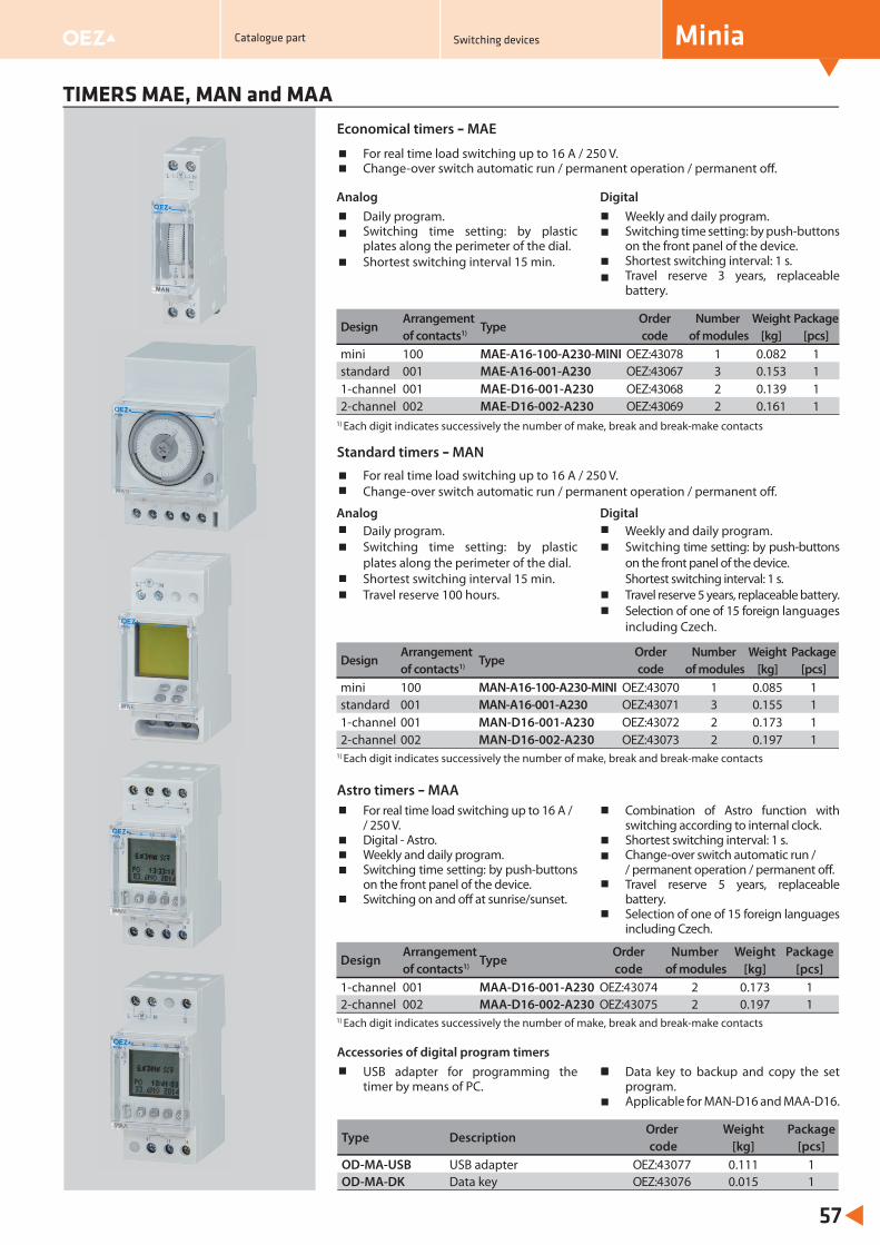
Daily program.Switching time setting: by plastic plates along the perimeter of the dial.Shortest switching interval 15 min.
Weekly and daily program.Switching time setting: by push-buttons on the front panel of the device.Shortest switching interval: 1 s.Travel reserve 3 years, replaceable battery.
TIMERS MAE, MAN and MAA
57
Economical timers – MAE
Daily program.Switching time setting: by plastic plates along the perimeter of the dial.Shortest switching interval 15 min.Travel reserve 100 hours.
Weekly and daily program.Switching time setting: by push-buttons on the front panel of the device.Shortest switching interval: 1 s.Travel reserve 5 years, replaceable battery.Selection of one of 15 foreign languages including Czech.
USB adapter for programming the timer by means of PC.
Data key to backup and copy the set program.Applicable for MAN-D16 and MAA-D16.
Accessories of digital program timers
Type DescriptionOrder Weight Package code [kg] [pcs]
OD-MA-USB USB adapter OEZ:43077 0.111 1OD-MA-DK Data key OEZ:43076 0.015 1
Design Arrangement
TypeOrder Number Weight Package
of contacts1) code of modules [kg] [pcs]mini 100 MAE-A16-100-A230-MINI OEZ:43078 1 0.082 1standard 001 MAE-A16-001-A230 OEZ:43067 3 0.153 11-channel 001 MAE-D16-001-A230 OEZ:43068 2 0.139 12-channel 002 MAE-D16-002-A230 OEZ:43069 2 0.161 1
1) Each digit indicates successively the number of make, break and break-make contacts
Analog
Digital
Standard timers – MAN
For real time load switching up to 16 A / 250 V.Change-over switch automatic run / permanent operation / permanent off .
Analog Digital
Design Arrangement
TypeOrder Number Weight Package
of contacts1) code of modules [kg] [pcs]mini 100 MAN-A16-100-A230-MINI OEZ:43070 1 0.085 1standard 001 MAN-A16-001-A230 OEZ:43071 3 0.155 11-channel 001 MAN-D16-001-A230 OEZ:43072 2 0.173 12-channel 002 MAN-D16-002-A230 OEZ:43073 2 0.197 1
1) Each digit indicates successively the number of make, break and break-make contacts
Astro timers – MAAFor real time load switching up to 16 A / / 250 V.Digital - Astro.Weekly and daily program.Switching time setting: by push-buttons on the front panel of the device.Switching on and off at sunrise/sunset.
Combination of Astro function with switching according to internal clock.Shortest switching interval: 1 s.Change-over switch automatic run / / permanent operation / permanent off .Travel reserve 5 years, replaceable battery.Selection of one of 15 foreign languages including Czech.
Design Arrangement
TypeOrder Number Weight Package
of contacts1) code of modules [kg] [pcs]1-channel 001 MAA-D16-001-A230 OEZ:43074 2 0.173 12-channel 002 MAA-D16-002-A230 OEZ:43075 2 0.197 1
1) Each digit indicates successively the number of make, break and break-make contacts
For real time load switching up to 16 A / 250 V.Change-over switch automatic run / permanent operation / permanent off .
MiniaCatalogue part Switching devices
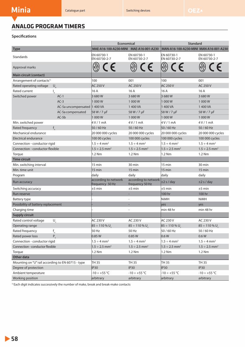
ANALOG PROGRAM TIMERS
Minia
58
Specifi cations
Economical StandardType MAE-A16-100-A230-MINI MAE-A16-001-A230 MAN-A16-100-A230-MINI MAN-A16-001-A230
Standards EN 60730-1EN 60730-2-7
EN 60730-1EN 60730-2-7
EN 60730-1EN 60730-2-7
EN 60730-1EN 60730-2-7
Approval marks
Main circuit (contact)
Arrangement of contacts1) 100 001 100 001Rated operating voltage Ue AC 250 V AC 250 V AC 250 V AC 250 VRated current Ie 16 A 16 A 16 A 16 ASwitched power AC-1 3 680 W 3 680 W 3 680 W 3 680 W
AC-3 1 000 W 1 000 W 1 000 W 1 000 WAC-5a uncompensated 1 400 VA 1 400 VA 1 400 VA 1 400 VAAC-5a compensated 58 W / 7 μF 58 W / 7 μF 58 W / 7 μF 58 W / 7 μF
AC-5b 1 000 W 1 000 W 1 000 W 1 000 WMin. switched power 4 V / 1 mA 4 V / 1 mA 4 V / 1 mA 4 V / 1 mARated frequency fn 50 / 60 Hz 50 / 60 Hz 50 / 60 Hz 50 / 60 HzMechanical endurance 20 000 000 cycles 20 000 000 cycles 20 000 000 cycles 20 000 000 cyclesElectrical endurance 100 00 cycles 100 000 cycles 100 000 cycles 100 000 cyclesConnection - conductor rigid 1.5 ÷ 4 mm2 1.5 ÷ 4 mm2 1.5 ÷ 4 mm2 1.5 ÷ 4 mm2
Connection - conductor flexible 1.5 ÷ 2.5 mm2 1.5 ÷ 2.5 mm2 1.5 ÷ 2.5 mm2 1.5 ÷ 2.5 mm2
Torque 1.2 Nm 1.2 Nm 1.2 Nm 1.2 NmTime circuit
Min. switching interval 15 min 30 min 15 min 30 minMin. time unit 15 min 15 min 15 min 15 minProgram daily daily daily daily
Run accuracy according to network frequency 50 Hz
according to network frequency 50 Hz ±2 s / day ±2 s / day
Switching accuracy ±5 min ±5 min ±5 min ±5 minRun reserve - - 100 hr 100 hr Battery type - - NiMH NiMHPossibility of battery replacement - - yes yes
Charging time - - min 48 hr min 48 hr Supply circuit
Rated control voltage Uc AC 230 V AC 230 V AC 230 V AC 230 VOperating range 85 ÷ 110 % Uc 85 ÷ 110 % Uc 85 ÷ 110 % Uc 85 ÷ 110 % Uc
Rated frequency fn 50 Hz 50 Hz 50 / 60 Hz 50 / 60 HzRated power loss Pv 0.85 W 0.85 W 0.6 W 0.6 WConnection - conductor rigid 1.5 ÷ 4 mm2 1.5 ÷ 4 mm2 1.5 ÷ 4 mm2 1.5 ÷ 4 mm2
Connection - conductor flexible 1.5 ÷ 2.5 mm2 1.5 ÷ 2.5 mm2 1.5 ÷ 2.5 mm2 1.5 ÷ 2.5 mm2
Torque 1.2 Nm 1.2 Nm 1.2 Nm 1.2 NmOther data
Mounting on “U” rail according to EN 60715 - type TH 35 TH 35 TH 35 TH 35Degree of protection IP30 IP30 IP30 IP30Ambient temperature -10 ÷ +55 °C -10 ÷ +55 °C -10 ÷ +55 °C -10 ÷ +55 °CWorking position arbitrary arbitrary arbitrary arbitrary
1) Each digit indicates successively the number of make, break and break-make contacts
Catalogue part Switching devices
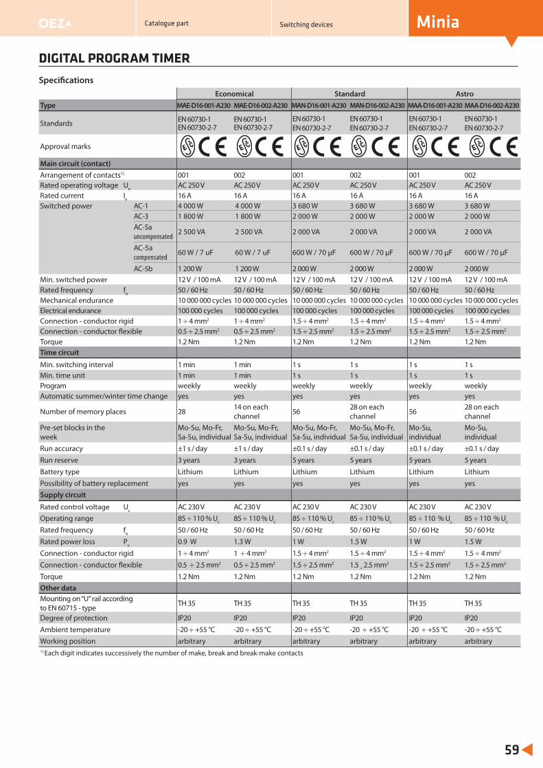
Economical Standard AstroType MAE-D16-001-A230 MAE-D16-002-A230 MAN-D16-001-A230 MAN-D16-002-A230 MAA-D16-001-A230 MAA-D16-002-A230
Standards EN 60730-1EN 60730-2-7
EN 60730-1EN 60730-2-7
EN 60730-1EN 60730-2-7
EN 60730-1EN 60730-2-7
EN 60730-1EN 60730-2-7
EN 60730-1EN 60730-2-7
Approval marks
Main circuit (contact)Arrangement of contacts1) 001 002 001 002 001 002Rated operating voltage Ue AC 250 V AC 250 V AC 250 V AC 250 V AC 250 V AC 250 VRated current Ie 16 A 16 A 16 A 16 A 16 A 16 ASwitched power AC-1 4 000 W 4 000 W 3 680 W 3 680 W 3 680 W 3 680 W
AC-3 1 800 W 1 800 W 2 000 W 2 000 W 2 000 W 2 000 WAC-5a uncompensated
2 500 VA 2 500 VA 2 000 VA 2 000 VA 2 000 VA 2 000 VA
AC-5a compensated
60 W / 7 uF 60 W / 7 uF 600 W / 70 μF 600 W / 70 μF 600 W / 70 μF 600 W / 70 μF
AC-5b 1 200 W 1 200 W 2 000 W 2 000 W 2 000 W 2 000 WMin. switched power 12 V / 100 mA 12 V / 100 mA 12 V / 100 mA 12 V / 100 mA 12 V / 100 mA 12 V / 100 mARated frequency fn 50 / 60 Hz 50 / 60 Hz 50 / 60 Hz 50 / 60 Hz 50 / 60 Hz 50 / 60 HzMechanical endurance 10 000 000 cycles 10 000 000 cycles 10 000 000 cycles 10 000 000 cycles 10 000 000 cycles 10 000 000 cycles Electrical endurance 100 000 cycles 100 000 cycles 100 000 cycles 100 000 cycles 100 000 cycles 100 000 cycles Connection - conductor rigid 1 ÷ 4 mm2 1 ÷ 4 mm2 1.5 ÷ 4 mm2 1.5 ÷ 4 mm2 1.5 ÷ 4 mm2 1.5 ÷ 4 mm2
Connection - conductor flexible 0.5 ÷ 2.5 mm2 0.5 ÷ 2.5 mm2 1.5 ÷ 2.5 mm2 1.5 ÷ 2.5 mm2 1.5 ÷ 2.5 mm2 1.5 ÷ 2.5 mm2
Torque 1.2 Nm 1.2 Nm 1.2 Nm 1.2 Nm 1.2 Nm 1.2 NmTime circuit
Min. switching interval 1 min 1 min 1 s 1 s 1 s 1 sMin. time unit 1 min 1 min 1 s 1 s 1 s 1 sProgram weekly weekly weekly weekly weekly weekly Automatic summer/winter time change yes yes yes yes yes yes
Number of memory places 28 14 on each channel 56 28 on each
channel 56 28 on each channel
Pre-set blocks in the week
Mo-Su, Mo-Fr,Sa-Su, individual
Mo-Su, Mo-Fr,Sa-Su, individual
Mo-Su, Mo-Fr,Sa-Su, individual
Mo-Su, Mo-Fr,Sa-Su, individual
Mo-Su, individual
Mo-Su, individual
Run accuracy ±1 s / day ±1 s / day ±0.1 s / day ±0.1 s / day ±0.1 s / day ±0.1 s / day Run reserve 3 years 3 years 5 years 5 years 5 years 5 years Battery type Lithium Lithium Lithium Lithium Lithium LithiumPossibility of battery replacement yes yes yes yes yes yesSupply circuit
Rated control voltage Uc AC 230 V AC 230 V AC 230 V AC 230 V AC 230 V AC 230 VOperating range 85 ÷ 110 % Uc 85 ÷ 110 % Uc 85 ÷ 110 % Uc 85 ÷ 110 % Uc 85 ÷ 110 % Uc 85 ÷ 110 % Uc
Rated frequency fn 50 / 60 Hz 50 / 60 Hz 50 / 60 Hz 50 / 60 Hz 50 / 60 Hz 50 / 60 HzRated power loss Pv 0.9 W 1.3 W 1 W 1.5 W 1 W 1.5 WConnection - conductor rigid 1 ÷ 4 mm2 1 ÷ 4 mm2 1.5 ÷ 4 mm2 1.5 ÷ 4 mm2 1.5 ÷ 4 mm2 1.5 ÷ 4 mm2
Connection - conductor flexible 0.5 ÷ 2.5 mm2 0.5 ÷ 2.5 mm2 1.5 ÷ 2.5 mm2 1.5 ¸ 2.5 mm2 1.5 ÷ 2.5 mm2 1.5 ÷ 2.5 mm2
Torque 1.2 Nm 1.2 Nm 1.2 Nm 1.2 Nm 1.2 Nm 1.2 NmOther dataMounting on “U” rail according to EN 60715 - type TH 35 TH 35 TH 35 TH 35 TH 35 TH 35
Degree of protection IP20 IP20 IP20 IP20 IP20 IP20Ambient temperature -20 ÷ +55 °C -20 ÷ +55 °C -20 ÷ +55 °C -20 ÷ +55 °C -20 ÷ +55 °C -20 ÷ +55 °CWorking position arbitrary arbitrary arbitrary arbitrary arbitrary arbitrary1) Each digit indicates successively the number of make, break and break-make contacts
DIGITAL PROGRAM TIMER
59
Specifi cations
MiniaCatalogue part Switching devices
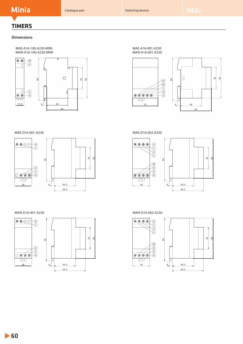
TIMERS
Minia
60
Dimensions
MAN-D16-001-A230 MAN-D16-002-A230
36 44. 5 366
64. 5
89 45 83
44. 56
64. 5
89 45 83
2
1
4
N
L
6
5
8
N
1
2
L
4
MAE-A16-001-A230MAN-A16-001-A230
1
4
2
53 44
64
6
89 45 83
U1
U2
MAE-A16-100-A230-MINIMAN-A16-100-A230-MINI
17. 8 44
64
6
88 45 83
1
4
N
L
MAE-D16-001-A230 MAE-D16-002-A230
36 44. 5 366
64. 5
89 45 83
44. 56
64. 5
89 45 83
2
1
4
N
L
6
5
8
N
1
2
L
4
Catalogue part Switching devices
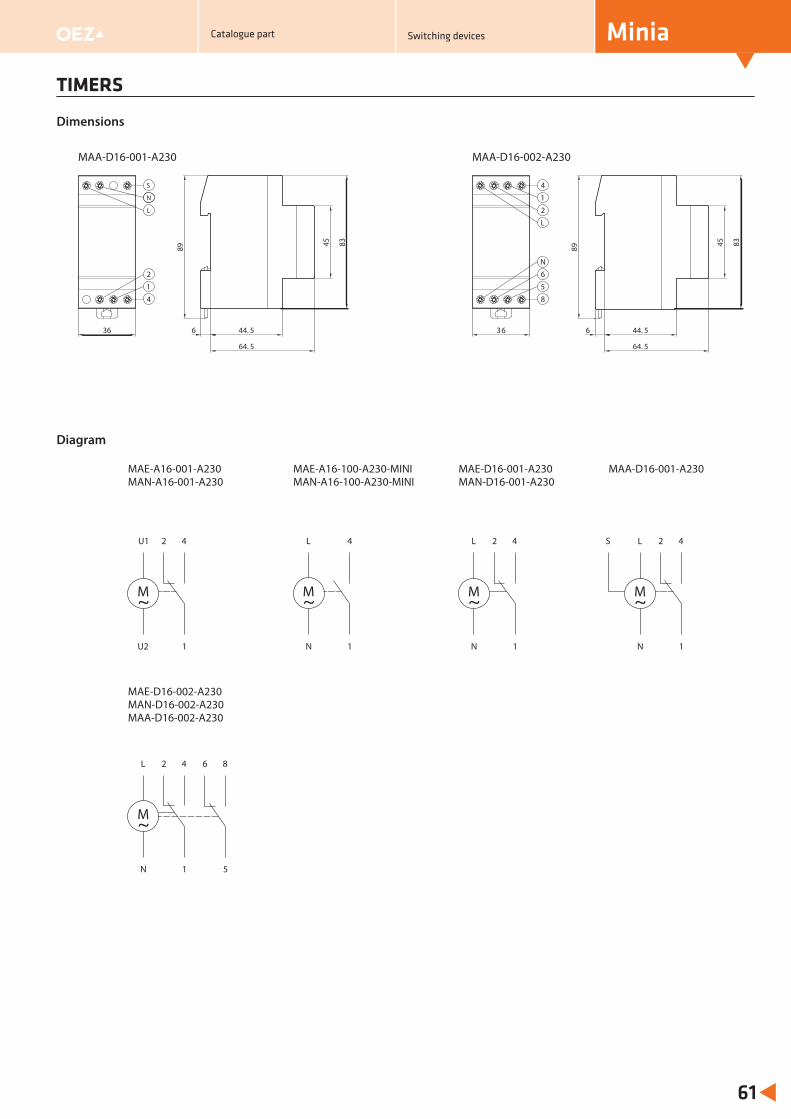
TIMERS
61
Dimensions
N
MAA-D16-001-A230 MAA-D16-002-A230
36 44. 5 366
64. 5
89 45 8344. 56
64. 5
89 45 83
2
1
4
S
6
5
8
N
1
2
L
4
L
Diagram
MAE-A16-001-A230MAN-A16-001-A230
U1
U2
2 4
1
~M
L
N
4
1
~M
L
N
2 4
1
~M
L
N
2 4
1
~M
6 8
5
MAE-A16-100-A230-MINIMAN-A16-100-A230-MINI
MAE-D16-001-A230MAN-D16-001-A230
MAE-D16-002-A230MAN-D16-002-A230MAA-D16-002-A230
L
N
2 4
1
~M
MAA-D16-001-A230
S
MiniaCatalogue part Switching devices

NOTES
Minia
62
Catalogue part Switching devices

63
NOTES
MiniaCatalogue part Switching devices

Minia
64
NOTES
Catalogue part Switching devices
OEZ s.r.o.Šedivská 339561 51 LetohradCzech Republictel.: +420 465 672 111 +420 465 672 101fax: +420 465 672 398 +420 465 672 151e-mail: [email protected]
www.oez.com

Any changes reserved
www.oez.com
SP3-2014-A
Minia
Application manualSwitching devices
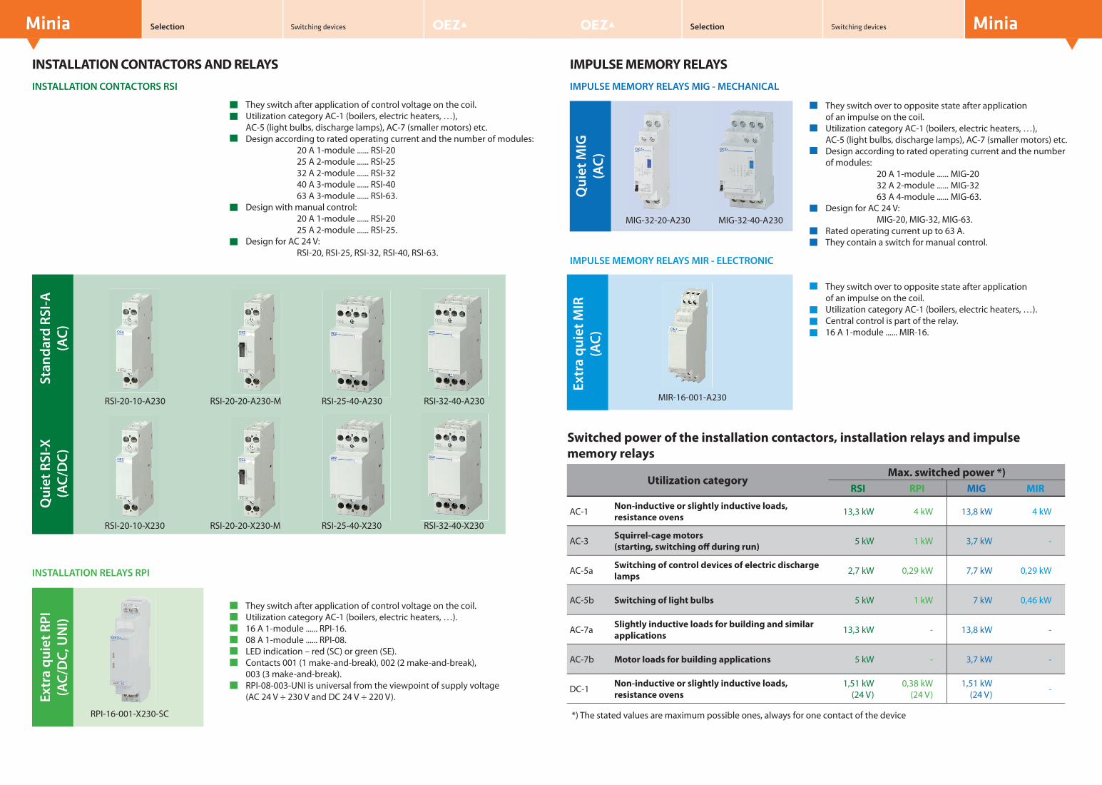
Minia Selection Switching devices
INSTALLATION CONTACTORS AND RELAYS
They switch after application of control voltage on the coil.Utilization category AC-1 (boilers, electric heaters, …),AC-5 (light bulbs, discharge lamps), AC-7 (smaller motors) etc.Design according to rated operating current and the number of modules:
20 A 1-module ...... RSI-2025 A 2-module ...... RSI-2532 A 2-module ...... RSI-3240 A 3-module ...... RSI-4063 A 3-module ...... RSI-63.
Design with manual control:20 A 1-module ...... RSI-2025 A 2-module ...... RSI-25.
Design for AC 24 V:RSI-20, RSI-25, RSI-32, RSI-40, RSI-63.
Stan
dard
RSI
-A
(AC)
MiniaSwitching devices Selection
INSTALLATION CONTACTORS RSI
Qui
et R
SI-X
(A
C/D
C)Ex
tra
quie
t RPI
(A
C/D
C, U
NI)
INSTALLATION RELAYS RPIQ
uiet
MIG
(A
C)They switch after application of control voltage on the coil.Utilization category AC-1 (boilers, electric heaters, …).16 A 1-module ...... RPI-16.08 A 1-module ...... RPI-08.LED indication – red (SC) or green (SE).Contacts 001 (1 make-and-break), 002 (2 make-and-break), 003 (3 make-and-break).RPI-08-003-UNI is universal from the viewpoint of supply voltage(AC 24 V ÷ 230 V and DC 24 V ÷ 220 V).
RPI-16-001-X230-SC
MIG-32-20-A230 MIG-32-40-A230
RSI-25-40-A230 RSI-32-40-A230
RSI-20-10-X230 RSI-20-20-X230-M RSI-25-40-X230 RSI-32-40-X230
IMPULSE MEMORY RELAYS
They switch over to opposite state after application of an impulse on the coil.Utilization category AC-1 (boilers, electric heaters, …),AC-5 (light bulbs, discharge lamps), AC-7 (smaller motors) etc.Design according to rated operating current and the number of modules:
20 A 1-module ...... MIG-2032 A 2-module ...... MIG-3263 A 4-module ...... MIG-63.
Design for AC 24 V:MIG-20, MIG-32, MIG-63.
Rated operating current up to 63 A.They contain a switch for manual control.
IMPULSE MEMORY RELAYS MIG - MECHANICAL
RSI-20-10-A230 RSI-20-20-A230-M
Extr
a qu
iet M
IR
(AC)
MIR-16-001-A230
IMPULSE MEMORY RELAYS MIR - ELECTRONIC
*) The stated values are maximum possible ones, always for one contact of the device
They switch over to opposite state after application of an impulse on the coil.Utilization category AC-1 (boilers, electric heaters, …).Central control is part of the relay.16 A 1-module ...... MIR-16.
Utilization categoryMax. switched power *)
RSI RPI MIG MIR
AC-1 Non-inductive or slightly inductive loads, resistance ovens 13,3 kW 4 kW 13,8 kW 4 kW
AC-3 Squirrel-cage motors (starting, switching off during run) 5 kW 1 kW 3,7 kW -
AC-5a Switching of control devices of electric discharge lamps 2,7 kW 0,29 kW 7,7 kW 0,29 kW
AC-5b Switching of light bulbs 5 kW 1 kW 7 kW 0,46 kW
AC-7a Slightly inductive loads for building and similar applications 13,3 kW - 13,8 kW -
AC-7b Motor loads for building applications 5 kW - 3,7 kW -
DC-1 Non-inductive or slightly inductive loads, resistance ovens
1,51 kW (24 V)
0,38 kW(24 V)
1,51 kW(24 V) -
Switched power of the installation contactors, installation relays and impulse memory relays
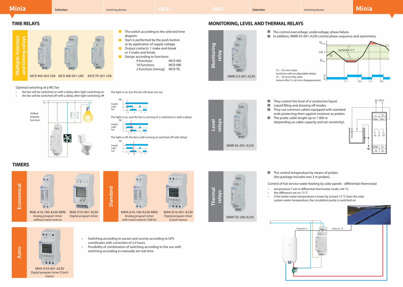
Mon
itori
ng
rela
y
Stan
dard
Econ
omic
al
NL
Probe for t1 Probe for t2
Minia Selection Switching devices
TIME RELAYS
MiniaSwitching devices Selection
MONITORING, LEVEL AND THERMAL RELAYS
t t
F8
t t
t t
F8
t t
t t
F8
t t
The light is on, but the fan still does not run
SupplyLightFan
SupplyLightFan
SupplyLightFan
The light is on, and the fan is running (it is switched on with a delay)
The light is off, the fan is still running (is switched off with delay)
• the fan will be switched on with a delay after light switching on• the fan will be switched off with a delay after light switching off
TIMERS
MAE-A16-100-A230-MINIAnalog program timer without travel reserve
MAE-D16-001-A230Digital program timer
MAN-A16-100-A230-MINIAnalog program timer
with travel reserve (100 hr)
MAN-D16-001-A230Digital program timer
(Czech menu)
• Switching according to sunset and sunrise according to GPS coordinates with correction of ±2 hours.
• Possibility of combination of switching according to the sun with switching according to manually set real time.
A A MAN D16 001 A23
The control overvoltage, undervoltage, phase failure.In addition, MMR-X3-001-A230 control phase sequence and asymmetry.
They control the level of a conductive liquid.Liquid fi lling and drawing off modes.They use common cables equipped with standard ends protecting them against moisture as probes.The probe cable length up to 1 000 m (depending on cable capacity and set sensitivity).
Control of hot service water heating by solar panels - diff erential thermostat
The control temperature by means of probes (the package includes two 3 m probes).
Umax.
Umin.
U
t
hystereze 5 V
1518
16
5s t 5s
230 V
L
Max. Min.
GND
16 18
N
15
230 V AC
16 15 18
MMR-U3-001-A230
• temperature T set to diff erential thermostat mode (-40 °C)• the diff erence set on 13 °C• if the boiler water temperature is lower by at least 13 °C than the solar
system water temperature, the circulation pump is switched on
15 – 16: error state(switches with an adjustable delay)15 – 18: error-free state(return after 5 s of error disappearance)
Mul
tiple
-fun
ctio
n an
d tim
ing
rela
ys
MCR-MA-003-UNI MCR-MB-001-UNI MCR-TK-001-UNI
Optimal switching of a WC fan
N
L
shifted impulse function
Ast
ro
MAA-D16-001-A230Digital program timer (Czech
menu)
Leve
l re
lays
MMR-HL-001-A230
Ther
mal
re
lays
MMR-TD-200-A230
The switch according to the selected time diagram.Start is performed by the push-button or by application of supply voltage.Output contacts: 1 make-and-break or 3 make-and-break.Design according to functions:
9 functions MCR-MA18 functions MCR-MB2 functions (timing) MCR-TK.
Related Documents