ROBOTICS Application manual Controller software IRC5

Welcome message from author
This document is posted to help you gain knowledge. Please leave a comment to let me know what you think about it! Share it to your friends and learn new things together.
Transcript

ROBOTICS
Application manualController software IRC5

Trace back information:Workspace 22A version a4Checked in 2022-02-23Skribenta version 5.4.005
Application manualController software IRC5
RobotWare 6.13.02
Document ID: 3HAC050798-001Revision: Q
© Copyright 2014-2022 ABB. All rights reserved.Specifications subject to change without notice.

The information in this manual is subject to change without notice and should notbe construed as a commitment by ABB. ABB assumes no responsibility for any errorsthat may appear in this manual.Except as may be expressly stated anywhere in this manual, nothing herein shall beconstrued as any kind of guarantee or warranty by ABB for losses, damage to personsor property, fitness for a specific purpose or the like.In no event shall ABB be liable for incidental or consequential damages arising fromuse of this manual and products described herein.This manual and parts thereof must not be reproduced or copied without ABB'swritten permission.Keep for future reference.Additional copies of this manual may be obtained from ABB.
Original instructions.
© Copyright 2014-2022 ABB. All rights reserved.Specifications subject to change without notice.
Table of contents11Overview of this manual ...................................................................................................................
151 Introduction to RobotWare
172 RobotWare-OS172.1 Advanced RAPID ..............................................................................................172.1.1 Introduction to Advanced RAPID ................................................................182.1.2 Bit functionality .......................................................................................182.1.2.1 Overview ...................................................................................192.1.2.2 RAPID components ......................................................................202.1.2.3 Bit functionality example ...............................................................212.1.3 Data search functionality ..........................................................................212.1.3.1 Overview ...................................................................................222.1.3.2 RAPID components ......................................................................232.1.3.3 Data search functionality examples .................................................242.1.4 Alias I/O signals ......................................................................................242.1.4.1 Overview ...................................................................................252.1.4.2 RAPID components ......................................................................262.1.4.3 Alias I/O functionality example .......................................................272.1.5 Configuration functionality ........................................................................272.1.5.1 Overview ...................................................................................282.1.5.2 RAPID components ......................................................................292.1.5.3 Configuration functionality example ................................................302.1.6 Power failure functionality .........................................................................302.1.6.1 Overview ...................................................................................312.1.6.2 RAPID components and system parameters .....................................322.1.6.3 Power failure functionality example .................................................332.1.7 Process support functionality ....................................................................332.1.7.1 Overview ...................................................................................342.1.7.2 RAPID components ......................................................................352.1.7.3 Process support functionality examples ...........................................372.1.8 Interrupt functionality ...............................................................................372.1.8.1 Overview ...................................................................................382.1.8.2 RAPID components ......................................................................392.1.8.3 Interrupt functionality examples .....................................................402.1.9 User message functionality .......................................................................402.1.9.1 Overview ...................................................................................412.1.9.2 RAPID components ......................................................................422.1.9.3 User message functionality examples ..............................................442.1.9.4 Text table files ............................................................................452.1.10 RAPID support functionality ......................................................................452.1.10.1 Overview ...................................................................................462.1.10.2 RAPID components ......................................................................472.1.10.3 RAPID support functionality examples .............................................482.2 Analog Signal Interrupt .......................................................................................482.2.1 Introduction to Analog Signal Interrupt ........................................................492.2.2 RAPID components .................................................................................502.2.3 Code example ........................................................................................512.3 Cyclic bool .......................................................................................................512.3.1 Cyclically evaluated logical conditions ........................................................542.3.2 Cyclic bool examples ...............................................................................572.3.3 System parameters .................................................................................582.3.4 RAPID components .................................................................................592.4 Electronically Linked Motors ................................................................................592.4.1 Overview ...............................................................................................612.4.2 Configuration .........................................................................................612.4.2.1 System parameters ......................................................................
Application manual - Controller software IRC5 53HAC050798-001 Revision: Q
© Copyright 2014-2022 ABB. All rights reserved.
Table of contents
632.4.2.2 Configuration example ..................................................................642.4.3 Managing a follower axis ..........................................................................642.4.3.1 Using the service program ............................................................662.4.3.2 Calibrate follower axis position .......................................................682.4.3.3 Reset follower axis ......................................................................692.4.4 Tuning a torque follower ...........................................................................692.4.4.1 Torque follower descriptions ..........................................................702.4.4.2 Using the service program ............................................................722.4.5 Data setup .............................................................................................722.4.5.1 Set up data for service program .....................................................742.4.5.2 Example of data setup ..................................................................762.5 Fixed Position Events ........................................................................................762.5.1 Overview ...............................................................................................772.5.2 RAPID components and system parameters .................................................802.5.3 Code examples .......................................................................................822.6 File and I/O device handling ................................................................................822.6.1 Introduction to file and I/O device handling ...................................................832.6.2 Binary and character based communication .................................................832.6.2.1 Overview ...................................................................................842.6.2.2 RAPID components ......................................................................852.6.2.3 Code examples ...........................................................................872.6.3 Raw data communication ..........................................................................872.6.3.1 Overview ...................................................................................882.6.3.2 RAPID components ......................................................................892.6.3.3 Code examples ...........................................................................912.6.4 File and directory management ..................................................................912.6.4.1 Overview ...................................................................................922.6.4.2 RAPID components ......................................................................932.6.4.3 Code examples ...........................................................................952.7 Device Command Interface .................................................................................952.7.1 Introduction to Device Command Interface ...................................................962.7.2 RAPID components and system parameters .................................................972.7.3 Code example ........................................................................................992.8 Logical Cross Connections .................................................................................992.8.1 Introduction to Logical Cross Connections ...................................................
1002.8.2 Configuring Logical Cross Connections .......................................................1012.8.3 Examples ..............................................................................................1032.8.4 Limitations .............................................................................................1042.9 Connected Services ...........................................................................................1042.9.1 Overview ...............................................................................................1062.9.2 Connected Services connectivity ................................................................1082.9.3 Configuration - system parameters .............................................................1102.9.4 Configuring Connected Services ................................................................1132.9.5 Configuring Connected Services using gateway box ......................................1172.9.6 Connected Services on LAN 3 ...................................................................1192.9.7 Connected Services registration ................................................................1212.9.8 Connected Services information ................................................................1262.10 User logs .........................................................................................................1262.10.1 Introduction to User logs ..........................................................................
1273 Motion performance1273.1 Absolute Accuracy [603-1, 603-2] .........................................................................1273.1.1 About Absolute Accuracy .........................................................................1303.1.2 Useful tools ............................................................................................1313.1.3 Configuration .........................................................................................1333.1.4 Maintenance ..........................................................................................1333.1.4.1 Maintenance that affect the accuracy ..............................................1353.1.4.2 Loss of accuracy .........................................................................
6 Application manual - Controller software IRC53HAC050798-001 Revision: Q
© Copyright 2014-2022 ABB. All rights reserved.
Table of contents
1363.1.5 Compensation theory ...............................................................................1363.1.5.1 Error sources ..............................................................................1373.1.5.2 Absolute Accuracy compensation ...................................................1393.1.6 Preparation of Absolute Accuracy robot ......................................................1393.1.6.1 ABB calibration process ................................................................1413.1.6.2 Birth certificate ............................................................................1423.1.6.3 Compensation parameters ............................................................1433.1.7 Cell alignment ........................................................................................1433.1.7.1 Overview ...................................................................................1443.1.7.2 Measure fixture alignment .............................................................1453.1.7.3 Measure robot alignment ..............................................................1463.1.7.4 Frame relationships .....................................................................1473.1.7.5 Tool calibration ...........................................................................1483.2 Advanced Robot Motion [687-1] ...........................................................................1493.3 Advanced Shape Tuning [included in 687-1] ...........................................................1493.3.1 About Advanced Shape Tuning ..................................................................1503.3.2 Automatic friction tuning ...........................................................................1523.3.3 Manual friction tuning ..............................................................................1543.3.4 System parameters .................................................................................1543.3.4.1 System parameters ......................................................................1553.3.4.2 Setting tuning system parameters ...................................................1563.3.5 RAPID components .................................................................................1573.4 Motion Process Mode [included in 687-1] ...............................................................1573.4.1 About Motion Process Mode .....................................................................1593.4.2 User-defined modes ................................................................................1613.4.3 General information about robot tuning .......................................................1643.4.4 Additional information ..............................................................................1653.5 Wrist Move [included in 687-1] .............................................................................1653.5.1 Introduction to Wrist Move ........................................................................1673.5.2 Cut plane frame ......................................................................................1693.5.3 RAPID components .................................................................................1703.5.4 RAPID code, examples .............................................................................1723.5.5 Troubleshooting ......................................................................................
1734 Motion coordination1734.1 Machine Synchronization [607-1], [607-2] ...............................................................1734.1.1 Overview ...............................................................................................1754.1.2 What is needed .......................................................................................1774.1.3 Synchronization features ..........................................................................1784.1.4 General description of the synchronization process .......................................1794.1.5 Limitations .............................................................................................1804.1.6 Hardware installation for Sensor Synchronization ..........................................1804.1.6.1 Encoder specification ...................................................................1814.1.6.2 Encoder description .....................................................................1824.1.6.3 Installation recommendations ........................................................1834.1.6.4 Connecting encoder and encoder interface unit .................................1854.1.7 Hardware installation for Analog Synchronization ..........................................1854.1.7.1 Required hardware ......................................................................1864.1.8 Software installation ................................................................................1864.1.8.1 Sensor installation .......................................................................1884.1.8.2 Reloading saved Motion parameters ...............................................1894.1.8.3 Installation of several sensors ........................................................1904.1.9 Programming the synchronization ..............................................................1904.1.9.1 General issues when programming with the synchronization option ......1924.1.9.2 Programming examples ................................................................1944.1.9.3 Entering and exiting coordinated motion in corner zones ....................1954.1.9.4 Use several sensors .....................................................................1964.1.9.5 Finepoint programming .................................................................1974.1.9.6 Drop sensor object ......................................................................
Application manual - Controller software IRC5 73HAC050798-001 Revision: Q
© Copyright 2014-2022 ABB. All rights reserved.
Table of contents
1984.1.9.7 Information on the FlexPendant ......................................................1994.1.9.8 Programming considerations .........................................................2014.1.9.9 Modes of operation ......................................................................2034.1.10 Robot to robot synchronization ..................................................................2034.1.10.1 Introduction ................................................................................2044.1.10.2 The concept of robot to robot synchronization ..................................2054.1.10.3 Master robot configuration parameters ............................................2084.1.10.4 Slave robot configuration parameters ..............................................2114.1.10.5 Programming example for master robot ...........................................2134.1.10.6 Programming example for slave robot .............................................2144.1.11 Synchronize with hydraulic press using recorded profile .................................2144.1.11.1 Introduction ................................................................................2154.1.11.2 Configuration of system parameters ................................................2174.1.11.3 Program example ........................................................................2184.1.12 Synchronize with molding machine using recorded profile ..............................2184.1.12.1 Introduction ................................................................................2194.1.12.2 Configuration of system parameters ................................................2214.1.12.3 Program example ........................................................................2224.1.13 Supervision ............................................................................................2234.1.14 System parameters .................................................................................2264.1.15 I/O signals .............................................................................................2274.1.16 RAPID components .................................................................................
2295 Motion Events2295.1 World Zones [608-1] ..........................................................................................2295.1.1 Overview of World Zones ..........................................................................2315.1.2 RAPID components .................................................................................2335.1.3 Code examples .......................................................................................
2356 Motion functions2356.1 Independent Axis [610-1] ....................................................................................2356.1.1 Overview ...............................................................................................2376.1.2 System parameters .................................................................................2386.1.3 RAPID components .................................................................................2396.1.4 Code examples .......................................................................................2416.2 Path Recovery [611-1] ........................................................................................2416.2.1 Overview ...............................................................................................2426.2.2 RAPID components .................................................................................2436.2.3 Store current path ...................................................................................2496.2.4 Path recorder .........................................................................................2566.3 Path Offset [612-1] .............................................................................................2566.3.1 Overview ...............................................................................................2586.3.2 RAPID components .................................................................................2596.3.3 Related RAPID functionality ......................................................................2606.3.4 Code example ........................................................................................
2617 Motion Supervision2617.1 Collision Detection [613-1] ..................................................................................2617.1.1 Overview ...............................................................................................2637.1.2 Limitations .............................................................................................2647.1.3 What happens at a collision .......................................................................2667.1.4 Additional information ..............................................................................2677.1.5 Configuration and programming facilities .....................................................2677.1.5.1 System parameters ......................................................................2697.1.5.2 RAPID components ......................................................................2707.1.5.3 Signals ......................................................................................2717.1.6 How to use Collision Detection ..................................................................2717.1.6.1 Set up system parameters .............................................................
8 Application manual - Controller software IRC53HAC050798-001 Revision: Q
© Copyright 2014-2022 ABB. All rights reserved.
Table of contents
2727.1.6.2 Adjust supervision from FlexPendant ..............................................2737.1.6.3 Adjust supervision from RAPID program ..........................................2747.1.6.4 How to avoid false triggering .........................................................2757.1.7 Collision Avoidance ................................................................................2777.2 SafeMove Assistant ...........................................................................................
2798 Communication2798.1 FTP Client [614-1] .............................................................................................2798.1.1 Introduction to FTP Client .........................................................................2818.1.2 System parameters .................................................................................2828.1.3 Examples ..............................................................................................2838.2 SFTP Client [614-1] ............................................................................................2838.2.1 Introduction to SFTP Client .......................................................................2858.2.2 System parameters .................................................................................2868.2.3 Examples ..............................................................................................2878.3 NFS Client [614-1] .............................................................................................2878.3.1 Introduction to NFS Client .........................................................................2898.3.2 System parameters .................................................................................2908.3.3 Examples ..............................................................................................2918.4 PC Interface [616-1] ...........................................................................................2918.4.1 Introduction to PC Interface .......................................................................2928.4.2 Send variable from RAPID ........................................................................2948.4.3 ABB software using PC Interface ...............................................................2958.5 Socket Messaging [616-1] ...................................................................................2958.5.1 Introduction to Socket Messaging ..............................................................2968.5.2 Schematic picture of socket communication .................................................2978.5.3 Technical facts about Socket Messaging .....................................................2988.5.4 RAPID components .................................................................................3008.5.5 Code examples for Socket Messaging .........................................................3028.6 RAPID Message Queue [included in 616-1, 623-1] ...................................................3028.6.1 Introduction to RAPID Message Queue .......................................................3038.6.2 RAPID Message Queue behavior ...............................................................3078.6.3 System parameters .................................................................................3088.6.4 RAPID components .................................................................................3098.6.5 Code examples .......................................................................................
3139 Engineering tools3139.1 Multitasking [623-1] ...........................................................................................3139.1.1 Introduction to Multitasking .......................................................................3159.1.2 System parameters .................................................................................3179.1.3 RAPID components .................................................................................3189.1.4 Task configuration ...................................................................................3189.1.4.1 Debug strategies for setting up tasks ..............................................3209.1.4.2 Priorities ....................................................................................3229.1.4.3 Task Panel Settings .....................................................................3239.1.4.4 Select which tasks to start with START button ..................................3259.1.5 Communication between tasks ..................................................................3259.1.5.1 Persistent variables .....................................................................3279.1.5.2 Waiting for other tasks ..................................................................3299.1.5.3 Synchronizing between tasks .........................................................3319.1.5.4 Using a dispatcher .......................................................................3339.1.6 Other programming issues ........................................................................3339.1.6.1 Share resource between tasks .......................................................3349.1.6.2 Test if task controls mechanical unit ................................................3359.1.6.3 taskid ........................................................................................3369.1.6.4 Avoid heavy loops .......................................................................3379.2 Sensor Interface [628-1] .....................................................................................3379.2.1 Introduction to Sensor Interface .................................................................
Application manual - Controller software IRC5 93HAC050798-001 Revision: Q
© Copyright 2014-2022 ABB. All rights reserved.
Table of contents

3389.2.2 Configuring sensors ................................................................................3389.2.2.1 About the sensors .......................................................................3399.2.2.2 Configuring sensors on serial channels ...........................................3409.2.2.3 Configuring sensors on Ethernet channels .......................................3419.2.3 RAPID ...................................................................................................3419.2.3.1 RAPID components ......................................................................3449.2.4 Examples ..............................................................................................3449.2.4.1 Code examples ...........................................................................3469.3 Robot Reference Interface [included in 689-1] ........................................................3469.3.1 Introduction to Robot Reference Interface ....................................................3479.3.2 Installation .............................................................................................3479.3.2.1 Connecting the communication cable ..............................................3489.3.2.2 Prerequisites ..............................................................................3499.3.2.3 Data orchestration .......................................................................3519.3.2.4 Supported data types ...................................................................3529.3.3 Configuration .........................................................................................3529.3.3.1 Interface configuration ..................................................................3539.3.3.2 Interface settings .........................................................................3549.3.3.3 Device description .......................................................................3579.3.3.4 Device configuration ....................................................................3609.3.4 Configuration examples ............................................................................3609.3.4.1 RAPID programming ....................................................................3619.3.4.2 Example configuration ..................................................................3669.3.5 RAPID components .................................................................................3679.4 Auto Acknowledge Input .....................................................................................
36910 Tool control options36910.1 Servo Tool Change [630-1] ..................................................................................36910.1.1 Overview ...............................................................................................37010.1.2 Requirements and limitations ....................................................................37210.1.3 Configuration .........................................................................................37310.1.4 Connection relay .....................................................................................37510.1.5 Tool change procedure ............................................................................37610.1.6 Jogging servo tools with activation disabled .................................................37710.2 Tool Control [1180-1] .........................................................................................37710.2.1 Overview ...............................................................................................37810.2.2 Servo tool movements .............................................................................37910.2.3 Tip management .....................................................................................38110.2.4 Supervision ............................................................................................38210.2.5 RAPID components .................................................................................38310.2.6 System parameters .................................................................................38810.2.7 Commissioning and service ......................................................................39010.2.8 Mechanical unit calibrations ......................................................................39110.2.9 RAPID code example ...............................................................................39210.2.10 Using tool control for gripper applications ....................................................39410.3 I/O Controlled Axes [included in 1180-1] ................................................................39410.3.1 Overview ...............................................................................................39510.3.2 Contouring error .....................................................................................39610.3.3 Correcting the position .............................................................................39710.3.4 Tool changing .........................................................................................39810.3.5 Installation .............................................................................................39910.3.6 Configuration .........................................................................................40110.3.7 System parameters .................................................................................40310.3.8 RAPID programming ................................................................................
405Index
10 Application manual - Controller software IRC53HAC050798-001 Revision: Q
© Copyright 2014-2022 ABB. All rights reserved.
Table of contents

Overview of this manualAbout this manual
This manual explains the basics of when and how to use various RobotWare optionsand functions.
UsageThis manual can be used either as a reference to find out if an option is the rightchoice for solving a problem, or as a description of how to use an option. Detailedinformation regarding syntax for RAPID routines, and similar, is not described here,but can be found in the respective reference manual.
Who should read this manual?This manual is intended for robot programmers.
PrerequisitesThe reader should...
• be familiar with industrial robots and their terminology.• be familiar with the RAPID programming language.• be familiar with system parameters and how to configure them.
References
Document IDReference
3HAC050945-001Product specification - Controller software IRC5IRC5 with main computer DSQC1000 (or later) and RobotWare 6.
3HAC047400-001Product specification - Controller IRC5IRC5 with main computer DSQC1000 or later.
3HAC032104-001Operating manual - RobotStudio
3HAC050941-001Operating manual - IRC5 with FlexPendant
3HAC050917-001Technical reference manual - RAPID Instructions, Functions andData types
3HAC050947-001Technical reference manual - RAPID Overview
3HAC050948-001Technical reference manual - System parameters
Revisions
DescriptionRevision
Released with RobotWare 6.0.-First release.
Released with RobotWare 6.01.• Added Auto Acknowledge Input, see Auto Acknowledge Input on
page 367.• The functionality of RAPID Message Queue is corrected, see RAPID
Message Queue [included in 616-1, 623-1] on page 302.• Minor corrections.
A
Continues on next pageApplication manual - Controller software IRC5 113HAC050798-001 Revision: Q
© Copyright 2014-2022 ABB. All rights reserved.
Overview of this manual
DescriptionRevision
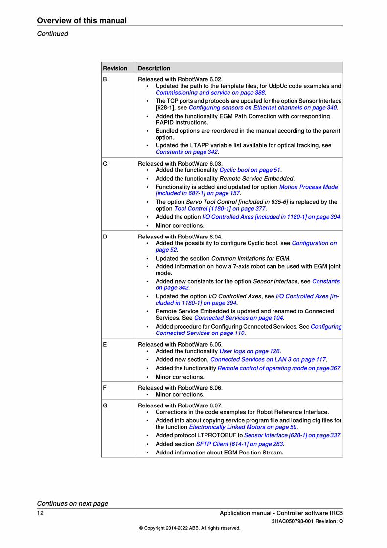
Released with RobotWare 6.02.• Updated the path to the template files, for UdpUc code examples and
Commissioning and service on page 388.• The TCP ports and protocols are updated for the option Sensor Interface
[628-1], see Configuring sensors on Ethernet channels on page 340.• Added the functionality EGM Path Correction with corresponding
RAPID instructions.• Bundled options are reordered in the manual according to the parent
option.• Updated the LTAPP variable list available for optical tracking, see
Constants on page 342.
B
Released with RobotWare 6.03.• Added the functionality Cyclic bool on page 51.• Added the functionality Remote Service Embedded.• Functionality is added and updated for option Motion Process Mode
[included in 687-1] on page 157.• The option Servo Tool Control [included in 635-6] is replaced by the
option Tool Control [1180-1] on page 377.• Added the option I/O Controlled Axes [included in 1180-1] on page394.• Minor corrections.
C
Released with RobotWare 6.04.• Added the possibility to configure Cyclic bool, see Configuration on
page 52.• Updated the section Common limitations for EGM.• Added information on how a 7-axis robot can be used with EGM joint
mode.• Added new constants for the option Sensor Interface, see Constants
on page 342.• Updated the option I/O Controlled Axes, see I/O Controlled Axes [in-
cluded in 1180-1] on page 394.• Remote Service Embedded is updated and renamed to Connected
Services. See Connected Services on page 104.• Added procedure for Configuring Connected Services. SeeConfiguring
Connected Services on page 110.
D
Released with RobotWare 6.05.• Added the functionality User logs on page 126.• Added new section, Connected Services on LAN 3 on page 117.• Added the functionalityRemote control of operatingmode on page367.• Minor corrections.
E
Released with RobotWare 6.06.• Minor corrections.
F
Released with RobotWare 6.07.• Corrections in the code examples for Robot Reference Interface.• Added info about copying service program file and loading cfg files for
the function Electronically Linked Motors on page 59.• Added protocol LTPROTOBUF toSensor Interface [628-1] on page337.• Added section SFTP Client [614-1] on page 283.• Added information about EGM Position Stream.
G
Continues on next page12 Application manual - Controller software IRC5
3HAC050798-001 Revision: Q© Copyright 2014-2022 ABB. All rights reserved.
Overview of this manualContinued
DescriptionRevision
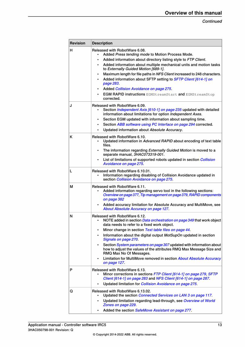
Released with RobotWare 6.08.• Added Press tending mode to Motion Process Mode.• Added information about directory listing style to FTP Client.• Added information about multiple mechanical units and motion tasks
to Externally Guided Motion [689-1].• Maximum length for file paths inNFSClient increased to 248 characters.• Added information about SFTP setting to SFTP Client [614-1] on
page 283.• Added Collision Avoidance on page 275.• EGM RAPID instructions EGMStreamStart and EGMStreamStop
corrected.
H
Released with RobotWare 6.09.• Section Independent Axis [610-1] on page 235 updated with detailed
information about limitations for option Independent Axes.• Section EGM updated with information about sampling time.• Section ABB software using PC Interface on page 294 corrected.• Updated information about Absolute Accuracy.
J
Released with RobotWare 6.10.• Updated information in Advanced RAPID about encoding of text table
files.• The information regarding Externally Guided Motion is moved to a
separate manual, 3HAC073319-001.• List of limitations of supported robots updated in section Collision
Avoidance on page 275.
K
Released with RobotWare 6.10.01.• Information regarding disabling of Collision Avoidance updated in
section Collision Avoidance on page 275.
L
Released with RobotWare 6.11.• Added information regarding servo tool in the following sections:
Overviewonpage377,Tipmanagement onpage379,RAPIDcomponentson page 382
• Added accuracy limitation for Absolute Accuracy and MultiMove, seeAbout Absolute Accuracy on page 127.
M
Released with RobotWare 6.12.• NOTE added in sectionData orchestration on page349 that work object
data needs to refer to a fixed work object.• Minor change in section Text table files on page 44.• Information about the digital output MotSupOn updated in section
Signals on page 270.• SectionSystemparameters on page307 updated with information about
how to adjust the values of the attributes RMQ Max Message Size andRMQ Max No Of Messages.
• Limitation for MultiMove removed in section About Absolute Accuracyon page 127.
N
Released with RobotWare 6.13.• Minor corrections in sections FTP Client [614-1] on page 279, SFTP
Client [614-1] on page 283 and NFS Client [614-1] on page 287.• Updated limitation for Collision Avoidance on page 275.
P
Released with RobotWare 6.13.02.• Updated the section Connected Services on LAN 3 on page 117.• Updated limitation regarding lead-through, see Overview of World
Zones on page 229.• Added the section SafeMove Assistant on page 277.
Q
Application manual - Controller software IRC5 133HAC050798-001 Revision: Q
© Copyright 2014-2022 ABB. All rights reserved.
Overview of this manualContinued

This page is intentionally left blank

1 Introduction to RobotWareSoftware products
RobotWare is a family of software products from ABB Robotics. The products aredesigned to make you more productive and lower your cost of owning and operatinga robot. ABB Robotics has invested many years into the development of theseproducts and they represent knowledge and experience based on several thousandsof robot installations.
Product classesWithin the RobotWare family, there are different classes of products:
DescriptionProduct classes
This is the operating system of the robot. RobotWare-OS providesall the necessary features for fundamental robot programming andoperation. It is an inherent part of the robot, but can be providedseparately for upgrading purposes.
RobotWare-OS
For a description of RobotWare-OS, see the product specificationfor the robot controller.
These products are options that run on top of RobotWare-OS. Theyare intended for robot users that need additional functionality formotion control, communication, system engineering, or applications.
Note
Not all RobotWare options are described in this manual. Some op-tions are more comprehensive and are therefore described in sep-arate manuals.
RobotWare options
These are extensive packages for specific process application likespot welding, arc welding, and dispensing. They are primarily de-signed to improve the process result and to simplify installation andprogramming of the application.
Process applicationoptions
The process application options are all described in separatemanuals.
A RobotWare Add-in is a self-contained package that extends thefunctionality of the robot system.
RobotWare Add-ins
Some software products from ABB Robotics are delivered as Add-ins. For example track motion IRBT, positioner IRBP, and standalone controller. For more information see the product specificationfor the robot controller.The purpose of RobotWare Add-ins is also that a robot programdeveloper outside of ABB can create options for the ABB robotsystems, and sell the options to their customers. For more informa-tion on creating RobotWare Add-ins, contact your local ABB Roboticsrepresentative at www.abb.com/contacts.
Continues on next pageApplication manual - Controller software IRC5 153HAC050798-001 Revision: Q
© Copyright 2014-2022 ABB. All rights reserved.
1 Introduction to RobotWare
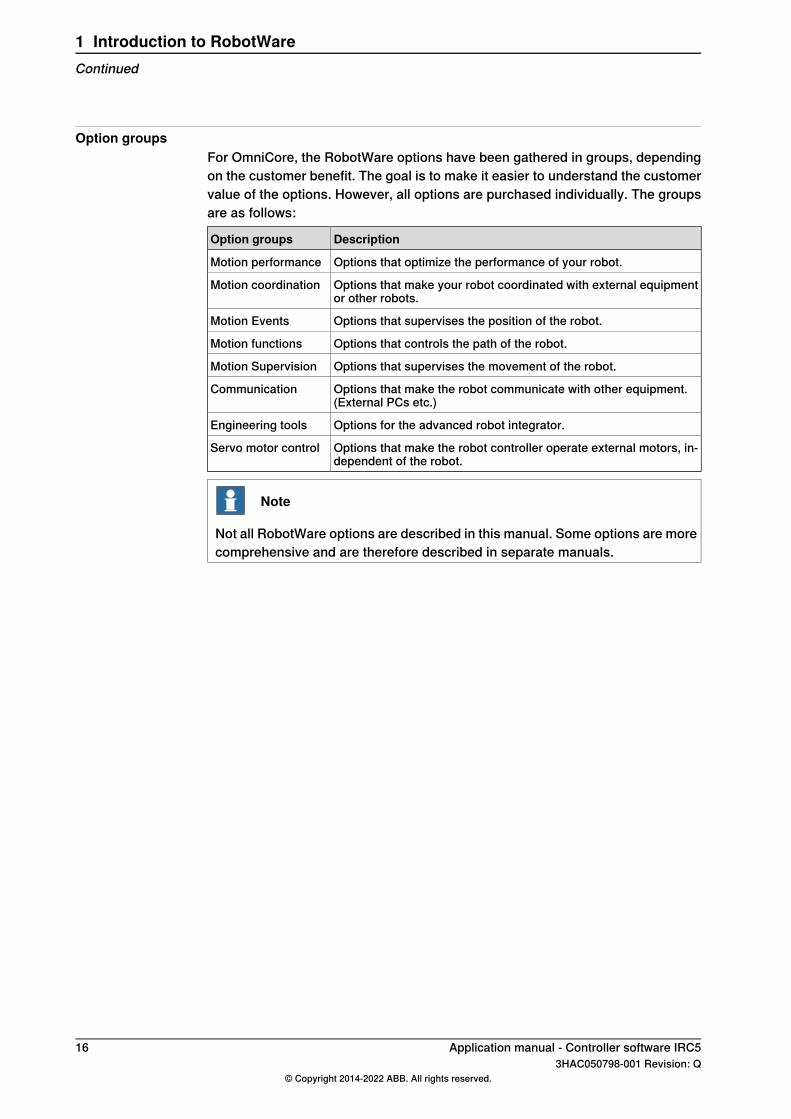
Option groupsFor OmniCore, the RobotWare options have been gathered in groups, dependingon the customer benefit. The goal is to make it easier to understand the customervalue of the options. However, all options are purchased individually. The groupsare as follows:
DescriptionOption groups
Options that optimize the performance of your robot.Motion performance
Options that make your robot coordinated with external equipmentor other robots.
Motion coordination
Options that supervises the position of the robot.Motion Events
Options that controls the path of the robot.Motion functions
Options that supervises the movement of the robot.Motion Supervision
Options that make the robot communicate with other equipment.(External PCs etc.)
Communication
Options for the advanced robot integrator.Engineering tools
Options that make the robot controller operate external motors, in-dependent of the robot.
Servo motor control
Note
Not all RobotWare options are described in this manual. Some options are morecomprehensive and are therefore described in separate manuals.
16 Application manual - Controller software IRC53HAC050798-001 Revision: Q
© Copyright 2014-2022 ABB. All rights reserved.
1 Introduction to RobotWareContinued
2 RobotWare-OS2.1 Advanced RAPID
2.1.1 Introduction to Advanced RAPID
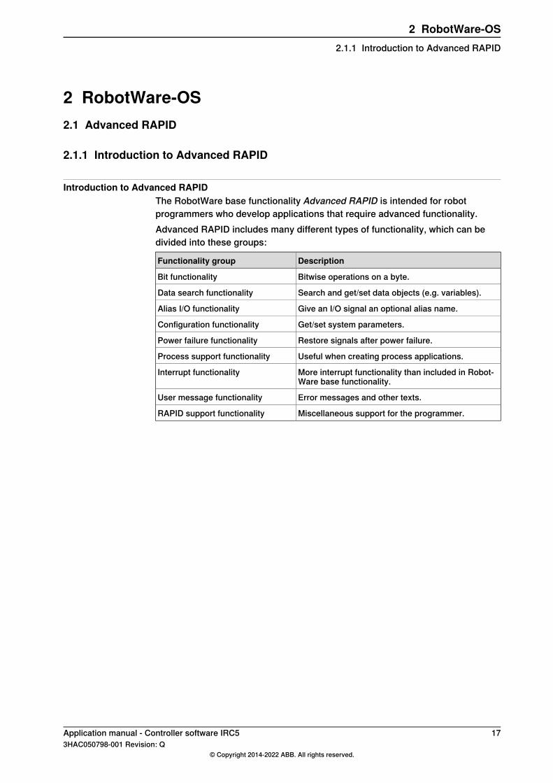
Introduction to Advanced RAPIDThe RobotWare base functionality Advanced RAPID is intended for robotprogrammers who develop applications that require advanced functionality.Advanced RAPID includes many different types of functionality, which can bedivided into these groups:
DescriptionFunctionality group
Bitwise operations on a byte.Bit functionality
Search and get/set data objects (e.g. variables).Data search functionality
Give an I/O signal an optional alias name.Alias I/O functionality
Get/set system parameters.Configuration functionality
Restore signals after power failure.Power failure functionality
Useful when creating process applications.Process support functionality
More interrupt functionality than included in Robot-Ware base functionality.
Interrupt functionality
Error messages and other texts.User message functionality
Miscellaneous support for the programmer.RAPID support functionality
Application manual - Controller software IRC5 173HAC050798-001 Revision: Q
© Copyright 2014-2022 ABB. All rights reserved.
2 RobotWare-OS2.1.1 Introduction to Advanced RAPID

2.1.2 Bit functionality
2.1.2.1 Overview
PurposeThe purpose of the bit functionality is to be able to make operations on a byte,seen as 8 digital bits. It is possible to get or set a single bit, or make logicaloperations on a byte. These operations are useful, for example, when handlingserial communication or group of digital I/O signals.
What is includedBit functionality includes:
• The data type byte.• Instructions used set a bit value: BitSet and BitClear.• Function used to get a bit value: BitCheck.• Functions used to make logical operations on a byte: BitAnd, BitOr,
BitXOr, BitNeg, BitLSh, and BitRSh.
18 Application manual - Controller software IRC53HAC050798-001 Revision: Q
© Copyright 2014-2022 ABB. All rights reserved.
2 RobotWare-OS2.1.2.1 Overview

2.1.2.2 RAPID components
Data typesThis is a brief description of each data type used for the bit functionality. For moreinformation, see the respective data type in Technical reference manual - RAPIDInstructions, Functions and Data types.
DescriptionData type
The data type byte represent a decimal value between 0 and 255.byte
InstructionsThis is a brief description of each instruction used for the bit functionality. For moreinformation, see the respective instruction in Technical reference manual - RAPIDInstructions, Functions and Data types.
DescriptionInstruction
BitSet is used to set a specified bit to 1 in a defined byte data.BitSet
BitClear is used to clear (set to 0) a specified bit in a defined byte data.BitClear
FunctionsThis is a brief description of each function used for the bit functionality. For moreinformation, see the respective function in Technical reference manual - RAPIDInstructions, Functions and Data types.
DescriptionFunction
BitAnd is used to execute a logical bitwise AND operation on data typesbyte.
BitAnd
BitOr is used to execute a logical bitwise OR operation on data types byte.BitOr
BitXOr (Bit eXclusive Or) is used to execute a logical bitwise XOR operationon data types byte.
BitXOr
BitNeg is used to execute a logical bitwise negation operation (one’scomplement) on data types byte.
BitNeg
BitLSh (Bit Left Shift) is used to execute a logical bitwise left shift operationon data types byte.
BitLSh
BitRSh (Bit Right Shift) is used to execute a logical bitwise right shift oper-ation on data types byte.
BitRSh
BitCheck is used to check if a specified bit in a defined byte data is set to1.
BitCheck
Tip
Even though not part of the option, the functions for conversion between a byteand a string, StrToByte and ByteToStr, are often used together with the bitfunctionality.
Application manual - Controller software IRC5 193HAC050798-001 Revision: Q
© Copyright 2014-2022 ABB. All rights reserved.
2 RobotWare-OS2.1.2.2 RAPID components

2.1.2.3 Bit functionality example
Program codeCONST num parity_bit := 8;
!Set data1 to 00100110
VAR byte data1 := 38;
!Set data2 to 00100010
VAR byte data2 := 34;
VAR byte data3;
!Set data3 to 00100010
data3 := BitAnd(data1, data2);
!Set data3 to 00100110
data3 := BitOr(data1, data2);
!Set data3 to 00000100
data3 := BitXOr(data1, data2);
!Set data3 to 11011001
data3 := BitNeg(data1);
!Set data3 to 10011000
data3 := BitLSh(data1, 2);
!Set data3 to 00010011
data3 := BitRSh(data1, 1);
!Set data1 to 10100110
BitSet data1, parity_bit;
!Set data1 to 00100110
BitClear data1, parity_bit;
!If parity_bit is 0, set it to 1
IF BitCheck(data1, parity_bit) = FALSE THEN
BitSet data1, parity_bit;
ENDIF
20 Application manual - Controller software IRC53HAC050798-001 Revision: Q
© Copyright 2014-2022 ABB. All rights reserved.
2 RobotWare-OS2.1.2.3 Bit functionality example

2.1.3 Data search functionality
2.1.3.1 Overview
PurposeThe purpose of the data search functionality is to search and get/set values fordata objects of a certain type.Here are some examples of applications for the data search functionality:
• Setting a value to a variable, when the variable name is only available in astring.
• List all variables of a certain type.• Set a new value for a set of similar variables with similar names.
What is includedData search functionality includes:
• The data type datapos.• Instructions used to find a set of data objects and get or set their
values:SetDataSearch, GetDataVal, SetDataVal, and SetAllDataVal.• A function for traversing the search result: GetNextSym.
Application manual - Controller software IRC5 213HAC050798-001 Revision: Q
© Copyright 2014-2022 ABB. All rights reserved.
2 RobotWare-OS2.1.3.1 Overview
2.1.3.2 RAPID components
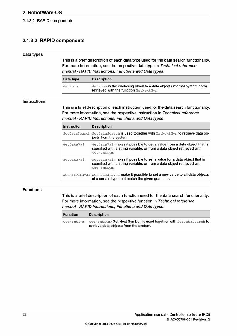
Data typesThis is a brief description of each data type used for the data search functionality.For more information, see the respective data type in Technical referencemanual - RAPID Instructions, Functions and Data types.
DescriptionData type
datapos is the enclosing block to a data object (internal system data)retrieved with the function GetNextSym.
datapos
InstructionsThis is a brief description of each instruction used for the data search functionality.For more information, see the respective instruction in Technical referencemanual - RAPID Instructions, Functions and Data types.
DescriptionInstruction
SetDataSearch is used together with GetNextSym to retrieve data ob-jects from the system.
SetDataSearch
GetDataVal makes it possible to get a value from a data object that isspecified with a string variable, or from a data object retrieved withGetNextSym.
GetDataVal
SetDataVal makes it possible to set a value for a data object that isspecified with a string variable, or from a data object retrieved withGetNextSym.
SetDataVal
SetAllDataVal make it possible to set a new value to all data objectsof a certain type that match the given grammar.
SetAllDataVal
FunctionsThis is a brief description of each function used for the data search functionality.For more information, see the respective function in Technical referencemanual - RAPID Instructions, Functions and Data types.
DescriptionFunction
GetNextSym (Get Next Symbol) is used together with SetDataSearch toretrieve data objects from the system.
GetNextSym
22 Application manual - Controller software IRC53HAC050798-001 Revision: Q
© Copyright 2014-2022 ABB. All rights reserved.
2 RobotWare-OS2.1.3.2 RAPID components

2.1.3.3 Data search functionality examples
Set unknown variableThis is an example of how to set the value of a variable when the name of thevariable is unknown when programming, and only provided in a string.
VAR string my_string;
VAR num my_number;
VAR num new_value:=10;
my_string := "my_number";
!Set value to 10 for variable specified by my_string
SetDataVal my_string,new_value;
Reset a range of variablesThis is an example where all numeric variables starting with "my" is reset to 0.
VAR string my_string:="my.*";
VAR num zerovar:=0;
SetAllDataVal "num"\Object:=my_string,zerovar;
List/set certain variablesIn this example, all numeric variables in the module "mymod" starting with "my"are listed on the FlexPendant and then reset to 0.
VAR datapos block;
VAR string name;
VAR num valuevar;
VAR num zerovar:=0;
!Search for all num variables starting with "my" in the module"mymod"
SetDataSearch "num"\Object:="my.*"\InMod:="mymod";
!Loop through the search result
WHILE GetNextSym(name,block) DO
!Read the value from each found variable
GetDataVal name\Block:=block,valuevar;
!Write name and value for each found variable
TPWrite name+" = "\Num:=valuevar;
!Set the value to 0 for each found variables
SetDataVal name\Block:=block,zerovar;
ENDWHILE
Application manual - Controller software IRC5 233HAC050798-001 Revision: Q
© Copyright 2014-2022 ABB. All rights reserved.
2 RobotWare-OS2.1.3.3 Data search functionality examples
2.1.4 Alias I/O signals
2.1.4.1 Overview
PurposeThe Alias I/O functionality gives the programmer the ability to use any name on asignal and connect that name to a configured I/O signal.This is useful when a RAPID program is reused between different systems. Insteadof rewriting the code, using a signal name that exist on the new system, the signalname used in the program can be defined as an alias name.
What is includedAlias I/O functionality consists of the instruction AliasIO.
24 Application manual - Controller software IRC53HAC050798-001 Revision: Q
© Copyright 2014-2022 ABB. All rights reserved.
2 RobotWare-OS2.1.4.1 Overview
2.1.4.2 RAPID components
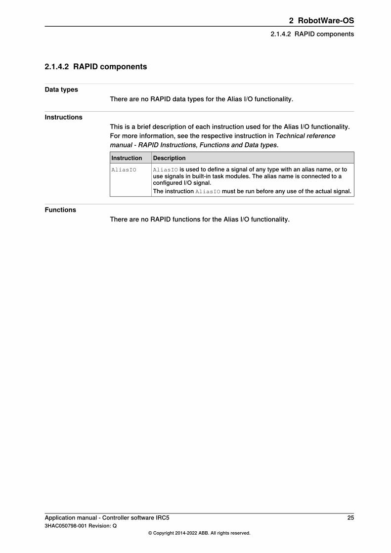
Data typesThere are no RAPID data types for the Alias I/O functionality.
InstructionsThis is a brief description of each instruction used for the Alias I/O functionality.For more information, see the respective instruction in Technical referencemanual - RAPID Instructions, Functions and Data types.
DescriptionInstruction
AliasIO is used to define a signal of any type with an alias name, or touse signals in built-in task modules. The alias name is connected to aconfigured I/O signal.
AliasIO
The instruction AliasIO must be run before any use of the actual signal.
FunctionsThere are no RAPID functions for the Alias I/O functionality.
Application manual - Controller software IRC5 253HAC050798-001 Revision: Q
© Copyright 2014-2022 ABB. All rights reserved.
2 RobotWare-OS2.1.4.2 RAPID components

2.1.4.3 Alias I/O functionality example
Assign alias name to signalThis example shows how to define the digital output signal alias_do to beconnected to the configured digital output I/O signal config_do.The routine prog_start is connected to the START event.This will ensure that "alias_do" can be used in the RAPID code even though thereis no configured signal with that name.
VAR signaldo alias_do;
PROC prog_start()
AliasIO config_do, alias_do;
ENDPROC
26 Application manual - Controller software IRC53HAC050798-001 Revision: Q
© Copyright 2014-2022 ABB. All rights reserved.
2 RobotWare-OS2.1.4.3 Alias I/O functionality example

2.1.5 Configuration functionality
2.1.5.1 Overview
PurposeThe configuration functionality gives the programmer access to the systemparameters at run time. The parameter values can be read and edited. The controllercan be restarted in order for the new parameter values to take effect.
What is includedConfiguration functionality includes the instructions:ReadCfgData, WriteCfgData,and WarmStart.
Application manual - Controller software IRC5 273HAC050798-001 Revision: Q
© Copyright 2014-2022 ABB. All rights reserved.
2 RobotWare-OS2.1.5.1 Overview

2.1.5.2 RAPID components
Data typesThere are no RAPID data types for the configuration functionality.
InstructionsThis is a brief description of each instruction used for the configuration functionality.For more information, see the respective instruction in Technical referencemanual - RAPID Instructions, Functions and Data types.
DescriptionInstruction
ReadCfgData is used to read one attribute of a named system parameter(configuration data).
ReadCfgData
WriteCfgData is used to write one attribute of a named system para-meter (configuration data).
WriteCfgData
WarmStart is used to restart the controller at run time.WarmStart
This is useful after changing system parameters with the instructionWriteCfgData.
FunctionsThere are no RAPID functions for the configuration functionality.
28 Application manual - Controller software IRC53HAC050798-001 Revision: Q
© Copyright 2014-2022 ABB. All rights reserved.
2 RobotWare-OS2.1.5.2 RAPID components
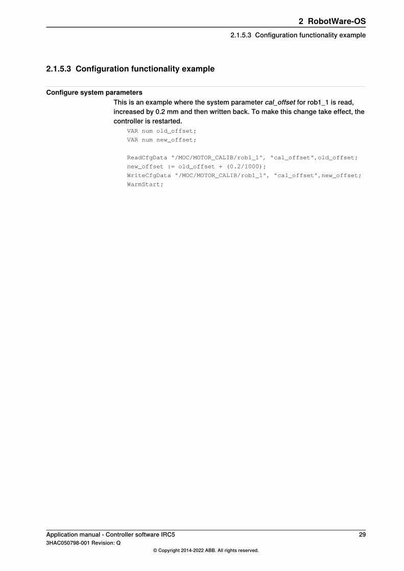
2.1.5.3 Configuration functionality example
Configure system parametersThis is an example where the system parameter cal_offset for rob1_1 is read,increased by 0.2 mm and then written back. To make this change take effect, thecontroller is restarted.
VAR num old_offset;
VAR num new_offset;
ReadCfgData "/MOC/MOTOR_CALIB/rob1_1", "cal_offset",old_offset;
new_offset := old_offset + (0.2/1000);
WriteCfgData "/MOC/MOTOR_CALIB/rob1_1", "cal_offset",new_offset;
WarmStart;
Application manual - Controller software IRC5 293HAC050798-001 Revision: Q
© Copyright 2014-2022 ABB. All rights reserved.
2 RobotWare-OS2.1.5.3 Configuration functionality example

2.1.6 Power failure functionality
2.1.6.1 Overview
PurposeIf the robot was in the middle of a path movement when the power fail occurred,some extra actions may need to be taken when the robot motion is resumed. Thepower failure functionality helps you detect if the power fail occurred during a pathmovement.
Note
For more information see the type Signal Safe Level, which belongs to the topicI/O System, in Technical reference manual - System parameters.
What is includedThe power failure functionality includes a function that checks for interrupted path:PFRestart
30 Application manual - Controller software IRC53HAC050798-001 Revision: Q
© Copyright 2014-2022 ABB. All rights reserved.
2 RobotWare-OS2.1.6.1 Overview

2.1.6.2 RAPID components and system parameters
Data typesThere are no RAPID data types in the power failure functionality.
InstructionsThere are no RAPID instructions in the power failure functionality.
FunctionsThis is a brief description of each function in the power failure functionality. Formore information, see the respective function in Technical referencemanual - RAPIDInstructions, Functions and Data types.
DescriptionFunction
PFRestart (Power Failure Restart) is used to check if the path was inter-rupted at power failure. If so it might be necessary to make some specificactions. The function checks the path on current level, base level or on in-terrupt level.
PFRestart
System parametersThere are no system parameters in the power failure functionality. However,regardless of whether you have any options installed, you can use the parameterStore signal at power fail.For more information, see Technical reference manual - System parameters.
Application manual - Controller software IRC5 313HAC050798-001 Revision: Q
© Copyright 2014-2022 ABB. All rights reserved.
2 RobotWare-OS2.1.6.2 RAPID components and system parameters

2.1.6.3 Power failure functionality example
Test for interrupted pathWhen resuming work after a power failure, this example tests if the power failureoccurred during a path (i.e. when the robot was moving).
!Test if path was interrupted
IF PFRestart() = TRUE THEN
SetDO do5,1;
ELSE
SetDO do5,0;
ENDIF
32 Application manual - Controller software IRC53HAC050798-001 Revision: Q
© Copyright 2014-2022 ABB. All rights reserved.
2 RobotWare-OS2.1.6.3 Power failure functionality example

2.1.7 Process support functionality
2.1.7.1 Overview
PurposeProcess support functionality provides some RAPID instructions that can be usefulwhen creating process applications. Examples of its use are:
• Analog output signals, used in continuous process application, can be setto be proportional to the robot TCP speed.
• A continuous process application that is stopped with program stop oremergency stop can be continued from where it stopped.
What is includedThe process support functionality includes:
• The data type restartdata.• Instruction for setting analog output signal: TriggSpeed.• Instructions used in connection with restart: TriggStopProc and
StepBwdPath.
LimitationsThe instruction TriggSpeed can only be used if you have the base functionalityFixed Position Events.
Application manual - Controller software IRC5 333HAC050798-001 Revision: Q
© Copyright 2014-2022 ABB. All rights reserved.
2 RobotWare-OS2.1.7.1 Overview
2.1.7.2 RAPID components
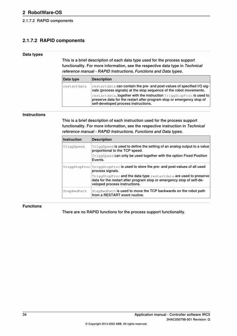
Data typesThis is a brief description of each data type used for the process supportfunctionality. For more information, see the respective data type in Technicalreference manual - RAPID Instructions, Functions and Data types.
DescriptionData type
restartdata can contain the pre- and post-values of specified I/O sig-nals (process signals) at the stop sequence of the robot movements.
restartdata
restartdata, together with the instruction TriggStopProc is used topreserve data for the restart after program stop or emergency stop ofself-developed process instructions.
InstructionsThis is a brief description of each instruction used for the process supportfunctionality. For more information, see the respective instruction in Technicalreference manual - RAPID Instructions, Functions and Data types.
DescriptionInstruction
TriggSpeed is used to define the setting of an analog output to a valueproportional to the TCP speed.
TriggSpeed
TriggSpeed can only be used together with the option Fixed PositionEvents.
TriggStopProc is used to store the pre- and post-values of all usedprocess signals.
TriggStopProc
TriggStopProc and the data type restartdata are used to preservedata for the restart after program stop or emergency stop of self-de-veloped process instructions.
StepBwdPath is used to move the TCP backwards on the robot pathfrom a RESTART event routine.
StepBwdPath
FunctionsThere are no RAPID functions for the process support functionality.
34 Application manual - Controller software IRC53HAC050798-001 Revision: Q
© Copyright 2014-2022 ABB. All rights reserved.
2 RobotWare-OS2.1.7.2 RAPID components

2.1.7.3 Process support functionality examples
Signal proportional to speedIn this example, the analog output signal that controls the amount of glue is set tobe proportional to the speed.Any speed dip by the robot is time compensated in such a way that the analogoutput signal glue_ao is affected 0.04 s before the TCP speed dip occurs. Ifoverflow of the calculated logical analog output value in glue_ao, the digital outputsignal glue_err is set.
VAR triggdata glueflow;
!The glue flow is set to scale value 0.8 0.05 s before point p1
TriggSpeed glueflow, 0, 0.05, glue_ao, 0.8 \DipLag=:0.04,\ErrDO:=glue_err;
TriggL p1, v500, glueflow, z50, gun1;
!The glue flow is set to scale value 1 10 mm plus 0.05 s
! before point p2
TriggSpeed glueflow, 10, 0.05, glue_ao, 1;
TriggL p2, v500, glueflow, z10, gun1;
!The glue flow ends (scale value 0) 0.05 s before point p3
TriggSpeed glueflow, 0, 0.05, glue_ao, 0;
TriggL p3, v500, glueflow, z50, gun1;
Tip
Note that it is also possible to create self-developed process instructions withTriggSpeed using the NOSTEPIN routine concept.
Resume signals after stopIn this example, an output signal resumes its value after a program stop oremergency stop.The procedure supervise is defined as a POWER ON event routine andresume_signals as a RESTART event routine.
PERS restartdata myproc_data :=[FALSE,FALSE,0,0,0,0,0,0,0,0,0,0,0,0,0];
...
PROC myproc()
MoveJ p1, vmax, fine, my_gun;
SetDO do_close_gun, 1;
MoveL p2,v1000,z50,my_gun;
MoveL p3,v1000,fine,my_gun;
SetDO do_close_gun, 0;
ENDPROC
...
PROC supervise()
TriggStopProc myproc_data \DO1:=do_close_gun, do_close_gun;
Continues on next pageApplication manual - Controller software IRC5 353HAC050798-001 Revision: Q
© Copyright 2014-2022 ABB. All rights reserved.
2 RobotWare-OS2.1.7.3 Process support functionality examples
ENDPROC
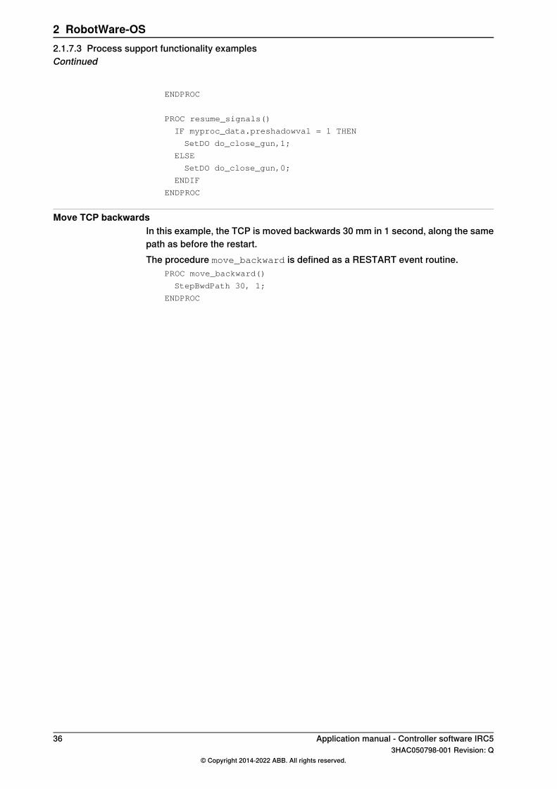
PROC resume_signals()
IF myproc_data.preshadowval = 1 THEN
SetDO do_close_gun,1;
ELSE
SetDO do_close_gun,0;
ENDIF
ENDPROC
Move TCP backwardsIn this example, the TCP is moved backwards 30 mm in 1 second, along the samepath as before the restart.The procedure move_backward is defined as a RESTART event routine.
PROC move_backward()
StepBwdPath 30, 1;
ENDPROC
36 Application manual - Controller software IRC53HAC050798-001 Revision: Q
© Copyright 2014-2022 ABB. All rights reserved.
2 RobotWare-OS2.1.7.3 Process support functionality examplesContinued
2.1.8 Interrupt functionality
2.1.8.1 Overview
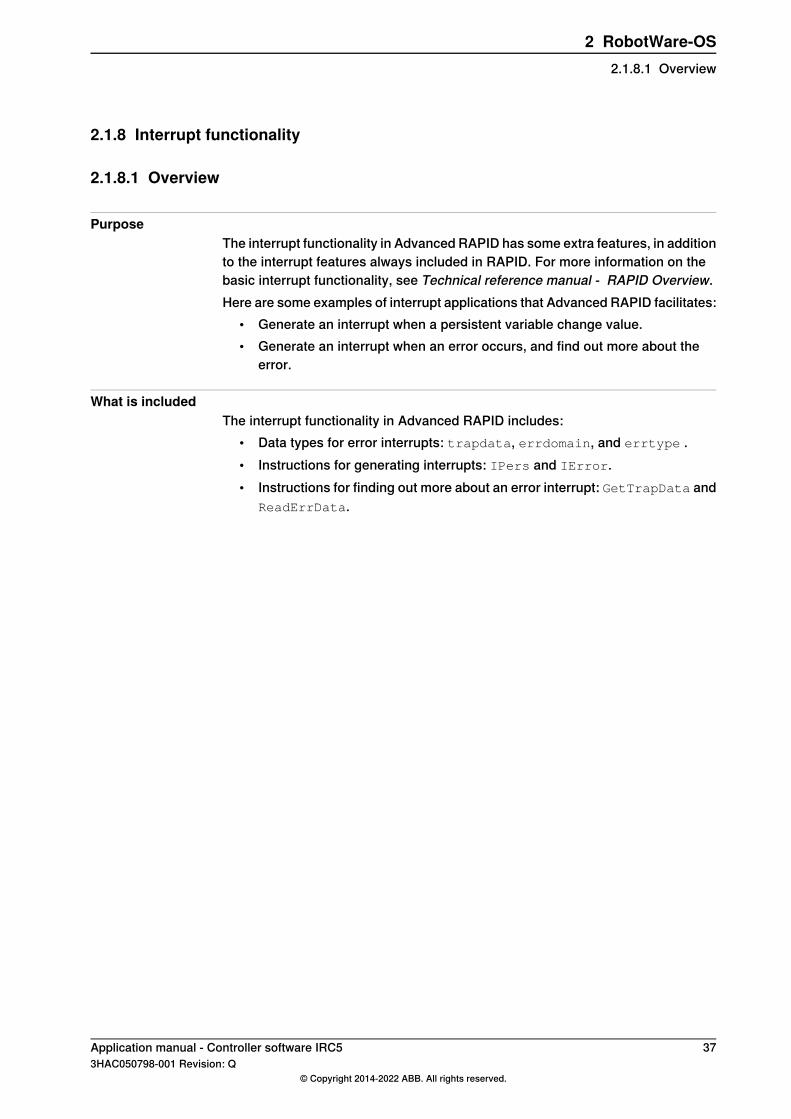
PurposeThe interrupt functionality in Advanced RAPID has some extra features, in additionto the interrupt features always included in RAPID. For more information on thebasic interrupt functionality, see Technical reference manual - RAPID Overview.Here are some examples of interrupt applications that Advanced RAPID facilitates:
• Generate an interrupt when a persistent variable change value.• Generate an interrupt when an error occurs, and find out more about the
error.
What is includedThe interrupt functionality in Advanced RAPID includes:
• Data types for error interrupts: trapdata, errdomain, and errtype .• Instructions for generating interrupts: IPers and IError.• Instructions for finding out more about an error interrupt: GetTrapData and
ReadErrData.
Application manual - Controller software IRC5 373HAC050798-001 Revision: Q
© Copyright 2014-2022 ABB. All rights reserved.
2 RobotWare-OS2.1.8.1 Overview

2.1.8.2 RAPID components
Data typesThis is a brief description of each data type in the interrupt functionality. For moreinformation, see the respective data type in Technical reference manual - RAPIDInstructions, Functions and Data types.
DescriptionData type
trapdata represents internal information related to the interrupt that causedthe current trap routine to be executed.
trapdata
errdomain is used to specify an error domain. Depending on the natureof the error, it is logged in different domains.
errdomain
errtype is used to specify an error type (error, warning, state change).errtype
InstructionsThis is a brief description of each instruction in the interrupt functionality. For moreinformation, see the respective instruction in Technical reference manual - RAPIDInstructions, Functions and Data types.
DescriptionInstruction
IPers (Interrupt Persistent) is used to order an interrupt to be generatedeach time the value of a persistent variable is changed.
IPers
IError (Interrupt Errors) is used to order an interrupt to be generated eachtime an error occurs.
IError
GetTrapData is used in trap routines generated by the instruction IError.GetTrapData obtains all information about the interrupt that caused thetrap routine to be executed.
GetTrapData
ReadErrData is used in trap routines generated by the instruction IError.ReadErrData read the information obtained by GetTrapData.
ReadErrData
ErrRaise is used to create an error in the program and the call the errorhandler of the routine.ErrRaise can also be used in the error handler topropagate the current error to the error handler of the calling routine.
ErrRaise
FunctionsThere are no RAPID functions for the interrupt functionality.
38 Application manual - Controller software IRC53HAC050798-001 Revision: Q
© Copyright 2014-2022 ABB. All rights reserved.
2 RobotWare-OS2.1.8.2 RAPID components
2.1.8.3 Interrupt functionality examples
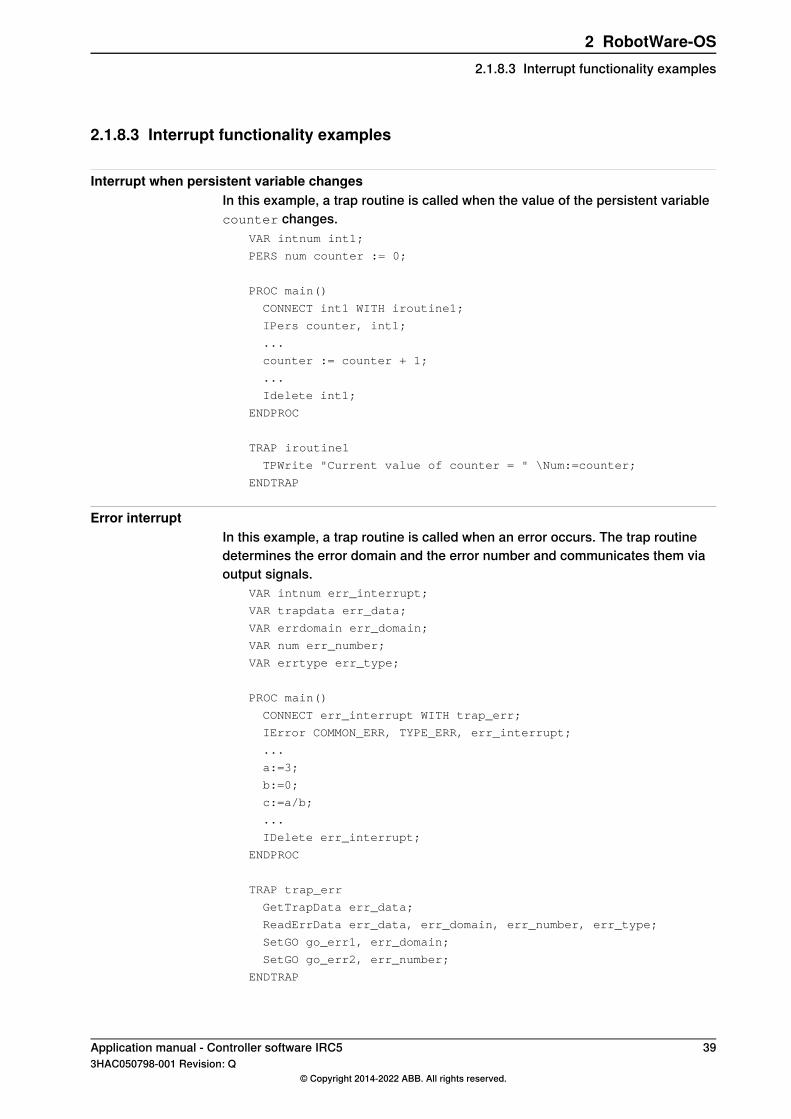
Interrupt when persistent variable changesIn this example, a trap routine is called when the value of the persistent variablecounter changes.
VAR intnum int1;
PERS num counter := 0;
PROC main()
CONNECT int1 WITH iroutine1;
IPers counter, int1;
...
counter := counter + 1;
...
Idelete int1;
ENDPROC
TRAP iroutine1
TPWrite "Current value of counter = " \Num:=counter;
ENDTRAP
Error interruptIn this example, a trap routine is called when an error occurs. The trap routinedetermines the error domain and the error number and communicates them viaoutput signals.
VAR intnum err_interrupt;
VAR trapdata err_data;
VAR errdomain err_domain;
VAR num err_number;
VAR errtype err_type;
PROC main()
CONNECT err_interrupt WITH trap_err;
IError COMMON_ERR, TYPE_ERR, err_interrupt;
...
a:=3;
b:=0;
c:=a/b;
...
IDelete err_interrupt;
ENDPROC
TRAP trap_err
GetTrapData err_data;
ReadErrData err_data, err_domain, err_number, err_type;
SetGO go_err1, err_domain;
SetGO go_err2, err_number;
ENDTRAP
Application manual - Controller software IRC5 393HAC050798-001 Revision: Q
© Copyright 2014-2022 ABB. All rights reserved.
2 RobotWare-OS2.1.8.3 Interrupt functionality examples

2.1.9 User message functionality
2.1.9.1 Overview
PurposeThe user message functionality is used to set up event numbers and facilitate thehandling of event messages and other texts to be presented in the user interface.Here are some examples of applications:
• Get user messages from a text table file, which simplifies updates andtranslations.
• Add system error number to be used as error recovery constants in RAISEinstructions and for test in ERROR handlers.
What is includedThe user message functionality includes:
• Text table operating instruction TextTabInstall.• Text table operating functions: TextTabFreeToUse, TextTabGet, and
TextGet.• Instruction for error number handling: BookErrNo.
40 Application manual - Controller software IRC53HAC050798-001 Revision: Q
© Copyright 2014-2022 ABB. All rights reserved.
2 RobotWare-OS2.1.9.1 Overview
2.1.9.2 RAPID components
Data typesThere are no RAPID data types for the user message functionality.
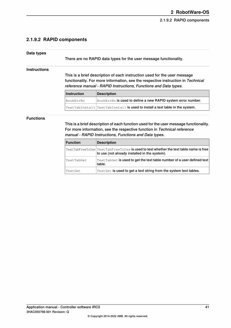
InstructionsThis is a brief description of each instruction used for the user messagefunctionality. For more information, see the respective instruction in Technicalreference manual - RAPID Instructions, Functions and Data types.
DescriptionInstruction
BookErrNo is used to define a new RAPID system error number.BookErrNo
TextTabInstall is used to install a text table in the system.TextTabInstall
FunctionsThis is a brief description of each function used for the user message functionality.For more information, see the respective function in Technical referencemanual - RAPID Instructions, Functions and Data types.
DescriptionFunction
TextTabFreeToUse is used to test whether the text table name is freeto use (not already installed in the system).
TextTabFreeToUse
TextTabGet is used to get the text table number of a user defined texttable.
TextTabGet
TextGet is used to get a text string from the system text tables.TextGet
Application manual - Controller software IRC5 413HAC050798-001 Revision: Q
© Copyright 2014-2022 ABB. All rights reserved.
2 RobotWare-OS2.1.9.2 RAPID components
2.1.9.3 User message functionality examples
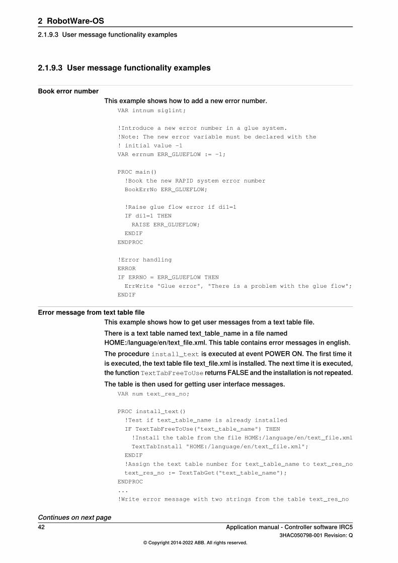
Book error numberThis example shows how to add a new error number.
VAR intnum sig1int;
!Introduce a new error number in a glue system.
!Note: The new error variable must be declared with the
! initial value -1
VAR errnum ERR_GLUEFLOW := -1;
PROC main()
!Book the new RAPID system error number
BookErrNo ERR_GLUEFLOW;
!Raise glue flow error if di1=1
IF di1=1 THEN
RAISE ERR_GLUEFLOW;
ENDIF
ENDPROC
!Error handling
ERROR
IF ERRNO = ERR_GLUEFLOW THEN
ErrWrite "Glue error", "There is a problem with the glue flow";
ENDIF
Error message from text table fileThis example shows how to get user messages from a text table file.There is a text table named text_table_name in a file namedHOME:/language/en/text_file.xml. This table contains error messages in english.The procedure install_text is executed at event POWER ON. The first time itis executed, the text table file text_file.xml is installed. The next time it is executed,the function TextTabFreeToUse returns FALSE and the installation is not repeated.The table is then used for getting user interface messages.
VAR num text_res_no;
PROC install_text()
!Test if text_table_name is already installed
IF TextTabFreeToUse("text_table_name") THEN
!Install the table from the file HOME:/language/en/text_file.xml
TextTabInstall "HOME:/language/en/text_file.xml";
ENDIF
!Assign the text table number for text_table_name to text_res_no
text_res_no := TextTabGet("text_table_name");
ENDPROC
...
!Write error message with two strings from the table text_res_no
Continues on next page42 Application manual - Controller software IRC5
3HAC050798-001 Revision: Q© Copyright 2014-2022 ABB. All rights reserved.
2 RobotWare-OS2.1.9.3 User message functionality examples

ErrWrite TextGet(text_res_no, 1), TextGet(text_res_no, 2);
Application manual - Controller software IRC5 433HAC050798-001 Revision: Q
© Copyright 2014-2022 ABB. All rights reserved.
2 RobotWare-OS2.1.9.3 User message functionality examples
Continued

2.1.9.4 Text table files
OverviewA text table is stored in an XML file (each file can contain one table in one language).This table can contain any number of text strings with encoding ISO-8859-1.
Explanation of the text table fileThis is a description of the XML tags and arguments used in the text table file.
DescriptionArgumentTag
Represents a text table. A file can only contain one instance ofResource.
Resource
The name of the text table. Used by the RAPID instructionTextTabGet.
Name
Language code for the language of the text strings.LanguageCurrently this argument is not being used. The RAPID instructionTextTabInstall can only handle English texts.
Represents a text string.Text
The number of the text string in the table.Name
The text string to be used.Value
Comments about the text string and its usage.Comment
Example of text table file<?xml version="1.0" encoding="iso-8859-1" ?>
<Resource Name="text_table_name" Language="en">
<Text Name="1">
<Value>This is a text that is </Value>
<Comment>The first part of my text</Comment>
</Text>
<Text Name="2">
<Value>displayed in the user interface.</Value>
<Comment>The second part of my text</Comment>
</Text>
</Resource>
44 Application manual - Controller software IRC53HAC050798-001 Revision: Q
© Copyright 2014-2022 ABB. All rights reserved.
2 RobotWare-OS2.1.9.4 Text table files

2.1.10 RAPID support functionality
2.1.10.1 Overview
PurposeThe RAPID support functionality consists of miscellaneous routines that might behelpful for an advanced robot programmer.Here are some examples of applications:
• Activate a new tool, work object or payload.• Find out what an argument is called outside the current routine.• Test if the program pointer has been moved during the last program stop.
What is includedRAPID support functionality includes:
• Instruction for activating specified system data: SetSysData.• Function that gets original data object name: ArgName.• Function for information about program pointer movement:
IsStopStateEvent.
Application manual - Controller software IRC5 453HAC050798-001 Revision: Q
© Copyright 2014-2022 ABB. All rights reserved.
2 RobotWare-OS2.1.10.1 Overview
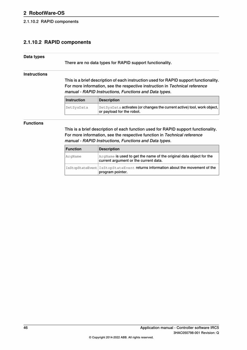
2.1.10.2 RAPID components
Data typesThere are no data types for RAPID support functionality.
InstructionsThis is a brief description of each instruction used for RAPID support functionality.For more information, see the respective instruction in Technical referencemanual - RAPID Instructions, Functions and Data types.
DescriptionInstruction
SetSysData activates (or changes the current active) tool, work object,or payload for the robot.
SetSysData
FunctionsThis is a brief description of each function used for RAPID support functionality.For more information, see the respective function in Technical referencemanual - RAPID Instructions, Functions and Data types.
DescriptionFunction
ArgName is used to get the name of the original data object for thecurrent argument or the current data.
ArgName
IsStopStateEvent returns information about the movement of theprogram pointer.
IsStopStateEvent
46 Application manual - Controller software IRC53HAC050798-001 Revision: Q
© Copyright 2014-2022 ABB. All rights reserved.
2 RobotWare-OS2.1.10.2 RAPID components
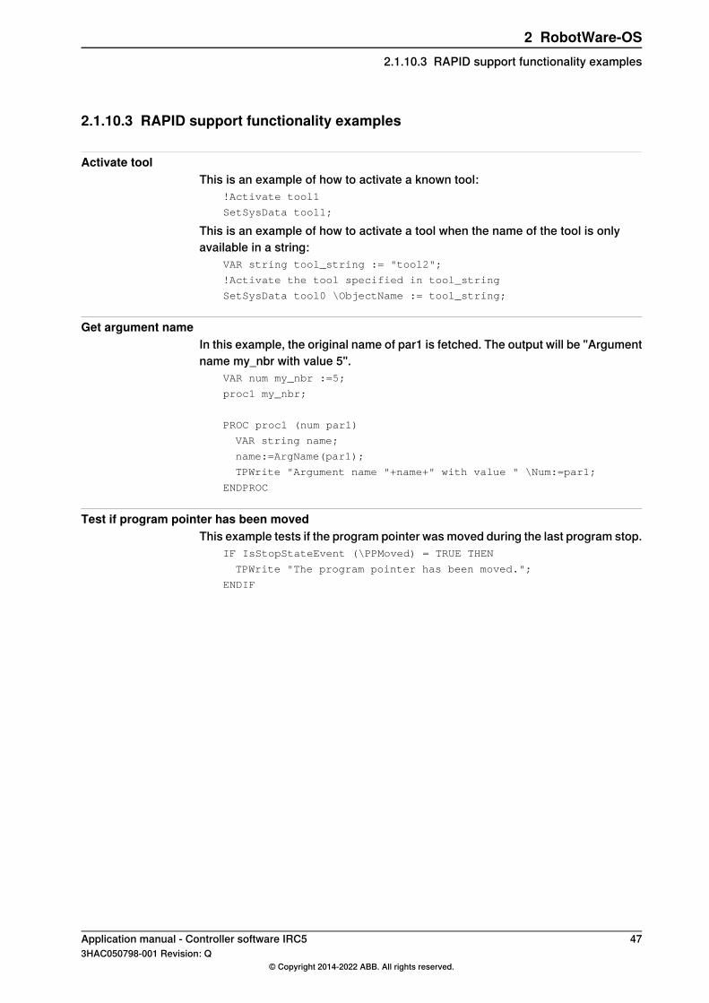
2.1.10.3 RAPID support functionality examples
Activate toolThis is an example of how to activate a known tool:
!Activate tool1
SetSysData tool1;
This is an example of how to activate a tool when the name of the tool is onlyavailable in a string:
VAR string tool_string := "tool2";
!Activate the tool specified in tool_string
SetSysData tool0 \ObjectName := tool_string;
Get argument nameIn this example, the original name of par1 is fetched. The output will be "Argumentname my_nbr with value 5".
VAR num my_nbr :=5;
proc1 my_nbr;
PROC proc1 (num par1)
VAR string name;
name:=ArgName(par1);
TPWrite "Argument name "+name+" with value " \Num:=par1;
ENDPROC
Test if program pointer has been movedThis example tests if the program pointer was moved during the last program stop.
IF IsStopStateEvent (\PPMoved) = TRUE THEN
TPWrite "The program pointer has been moved.";
ENDIF
Application manual - Controller software IRC5 473HAC050798-001 Revision: Q
© Copyright 2014-2022 ABB. All rights reserved.
2 RobotWare-OS2.1.10.3 RAPID support functionality examples
2.2 Analog Signal Interrupt
2.2.1 Introduction to Analog Signal Interrupt
PurposeThe purpose of Analog Signal Interrupt is to supervise an analog signal andgenerate an interrupt when a specified value is reached.Analog Signal Interrupt is faster, easier to implement, and require less computercapacity than polling methods.Here are some examples of applications:
• Save cycle time with better timing (start robot movement exactly when asignal reach the specified value, instead of waiting for polling).
• Show warning or error messages if a signal value is outside its allowed range.• Stop the robot if a signal value reaches a dangerous level.
What is includedThe RobotWare base functionality Analog Signal Interrupt gives you access to theinstructions:
• ISignalAI
• ISignalAO
Basic approachThis is the general approach for using Analog Signal Interrupt. For a more detailedexample of how this is done, see Code example on page 50.
1 Create a trap routine.2 Connect the trap routine using the instruction CONNECT.3 Define the interrupt conditions with the instruction ISignalAI or ISignalAO.
LimitationsAnalog signals can only be used if you have an industrial network option (forexample DeviceNet).
48 Application manual - Controller software IRC53HAC050798-001 Revision: Q
© Copyright 2014-2022 ABB. All rights reserved.
2 RobotWare-OS2.2.1 Introduction to Analog Signal Interrupt

2.2.2 RAPID components
Data typesAnalog Signal Interrupt includes no data types.
InstructionsThis is a brief description of each instruction in Analog Signal Interrupt. For moreinformation, see the respective instruction in Technical reference manual - RAPIDInstructions, Functions and Data types.
DescriptionInstruction
Defines the values of an analog input signal, for which an interrupt routineshall be called.
ISignalAI
An interrupt can be set to occur when the signal value is above or below aspecified value, or inside or outside a specified range. It can also be spe-cified if the interrupt shall occur once or repeatedly.
Defines the values of an analog output signal, for which an interrupt routineshall be called.
ISignalAO
An interrupt can be set to occur when the signal value is above or below aspecified value, or inside or outside a specified range. It can also be spe-cified if the interrupt shall occur once or repeatedly.
FunctionsAnalog Signal Interrupt includes no RAPID functions.
Application manual - Controller software IRC5 493HAC050798-001 Revision: Q
© Copyright 2014-2022 ABB. All rights reserved.
2 RobotWare-OS2.2.2 RAPID components

2.2.3 Code example
Temperature surveillanceIn this example a temperature sensor is connected to the signal ai1.An interrupt routine with a warning is set to execute every time the temperaturerises 0.5 degrees in the range 120-130 degrees. Another trap routine, stopping therobot, is set to execute as soon as the temperature rise above 130 degrees.
VAR intnum ai1_warning;
VAR intnum ai1_exeeded;
PROC main()
CONNECT ai1_warning WITH temp_warning;
CONNECT ai1_exeeded WITH temp_exeeded;
ISignalAI ai1, AIO_BETWEEN, 130, 120, 0.5, \DPos, ai1_warning;
ISignalAI \Single, ai1, AIO_ABOVE_HIGH, 130, 120, 0, ai1_exeeded;
...
IDelete ai1_warning;
IDelete ai1_exeeded;
ENDPROC
TRAP temp_warning
TPWrite "Warning: Temperature is "\Num:=ai1;
ENDTRAP
TRAP temp_exeeded
TPWrite "Temperature is too high";
Stop;
ENDTRAP
50 Application manual - Controller software IRC53HAC050798-001 Revision: Q
© Copyright 2014-2022 ABB. All rights reserved.
2 RobotWare-OS2.2.3 Code example

2.3 Cyclic bool
2.3.1 Cyclically evaluated logical conditions
PurposeThe purpose of cyclically evaluated logical conditions, Cyclic bool, is to allow aRAPID programmer to connect a logical condition to a persistent boolean variable.The logical condition will be evaluated every 12 ms and the result will be writtento the connected variable.
What is includedThe RobotWare base functionality Cyclic bool includes:
• instructions for setting up Cyclic bool: SetupCyclicBool,RemoveCyclicBool, RemoveAllCyclicBool
• functions for retrieving the status of Cyclic bool:GetMaxNumberOfCyclicBool, GetNextCyclicBool,GetNumberOfCyclicBool.
Basic approachThis is the general approach for using Cyclic bool. For more detailed examples ofhow this is done, see Cyclic bool examples on page 54.
1 Declare a persistent boolean variable, for example:PERS bool cyclicbool1;
2 Connect a logical condition to the variable, for example:SetupCyclicBool cyclicbool1, doSafetyIsOk = 1;
3 Use the variable when programming, for example:WHILE cyclicbool1 = 1 DO
! Do what’s only allowed when all safety is ok
...
ENDWHILE
4 Remove connection when no longer useful, for example:RemoveCyclicBool cyclicbool1;
Restart and reset behaviorThe table below describes the functionality of Cyclic bool when the program pointeris moved or when the controller is restarted.
DescriptionAction
The behavior when the program pointer is set to main is configur-able, see Configuration on page 52.
Program pointer tomain
This will have no effect.Restart or power failAll connected Cyclic bool conditions will remain and the evaluationwill be restarted immediately.
This will remove all connected Cyclic bool conditions.Reset RAPID
Reset system
Continues on next pageApplication manual - Controller software IRC5 513HAC050798-001 Revision: Q
© Copyright 2014-2022 ABB. All rights reserved.
2 RobotWare-OS2.3.1 Cyclically evaluated logical conditions

ConfigurationThe following behavior of the Cyclic bool functionality can be configured:
DescriptionParameter
It is possible to configure if the cyclically evaluated logical conditionsshall be removed or not when setting the program pointer to main.
• On - remove.• Off - do not remove (default behavior).
RemoveAtPpToMain
It is possible to configure which error mode to use when the evalu-ation of a Cyclic bool fails.
• SysStopError i - stop RAPID execution and produce an errorlog (default behavior).
• Warning - produce a warning log.• None - do nothing.
ErrorMode
It is possible to configure if a failing Cyclic bool shall be recoveredor not.
• On - try to recover the evaluation of a failing Cyclic bool (de-fault behavior).
• Off - do not try to recover the evaluation of a Cyclic bool.
RecoveryMode
i Error mode SysStopError can only be combined with RecoveryMode - "On".For more information, see System parameters on page 57.
Syntax
SetupCyclicBool Flag Cond [\Signal]
Flag shall be of:• Data type: bool
- Object type: PERS or TASK PERSCond shall be a bool expression that may consist of:
• Data types: num, dnum and bool
- Object type: PERS, TASK PERS, or CONST• Data types: signaldi, signaldo or physical di and do
- Object type: VAR• Operands: 'NOT', 'AND', 'OR', 'XOR', '=', '(', ')'
\Signal shall be of:• Object type: signaldo
RemoveCyclicBool Flag
Flag shall be of:• Data type: bool
- Object type: PERS or TASK PERS
Limitations• Records and arrays are not allowed in the logical condition.• A maximum of 60 conditions can be connected at the same time.
Continues on next page52 Application manual - Controller software IRC5
3HAC050798-001 Revision: Q© Copyright 2014-2022 ABB. All rights reserved.
2 RobotWare-OS2.3.1 Cyclically evaluated logical conditionsContinued

• Any PERS num or dnum, CONST num or dnum or literal num or dnum used in acondition must be of integer type. If using any decimal value this will causea fatal error.
Application manual - Controller software IRC5 533HAC050798-001 Revision: Q
© Copyright 2014-2022 ABB. All rights reserved.
2 RobotWare-OS2.3.1 Cyclically evaluated logical conditions
Continued
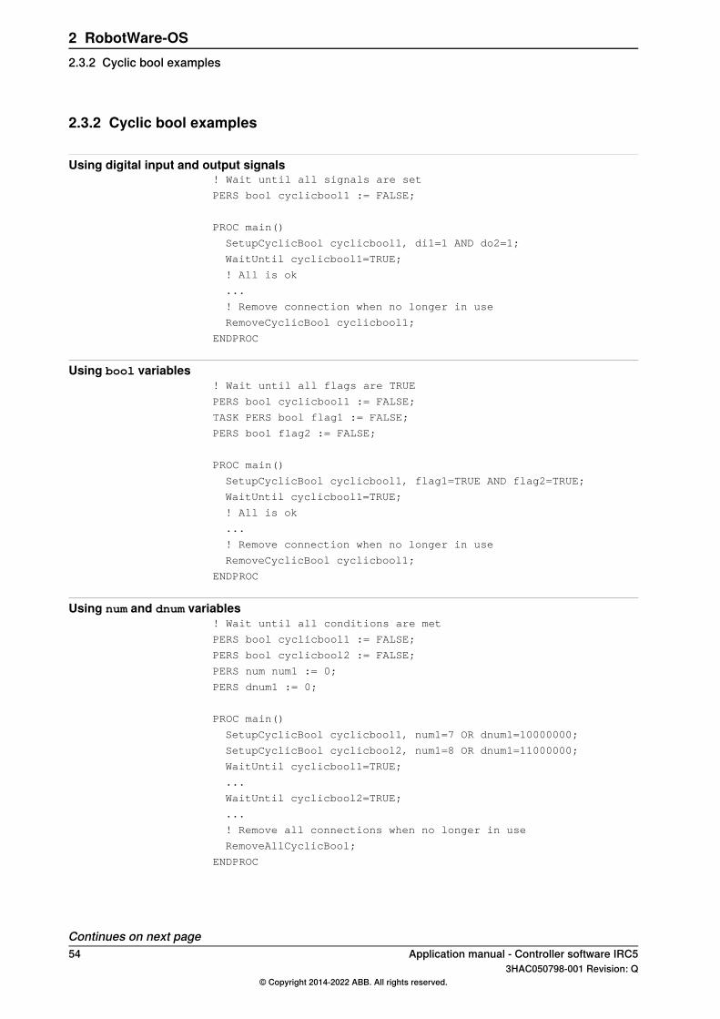
2.3.2 Cyclic bool examples
Using digital input and output signals! Wait until all signals are set
PERS bool cyclicbool1 := FALSE;
PROC main()
SetupCyclicBool cyclicbool1, di1=1 AND do2=1;
WaitUntil cyclicbool1=TRUE;
! All is ok
...
! Remove connection when no longer in use
RemoveCyclicBool cyclicbool1;
ENDPROC
Using bool variables! Wait until all flags are TRUE
PERS bool cyclicbool1 := FALSE;
TASK PERS bool flag1 := FALSE;
PERS bool flag2 := FALSE;
PROC main()
SetupCyclicBool cyclicbool1, flag1=TRUE AND flag2=TRUE;
WaitUntil cyclicbool1=TRUE;
! All is ok
...
! Remove connection when no longer in use
RemoveCyclicBool cyclicbool1;
ENDPROC
Using num and dnum variables! Wait until all conditions are met
PERS bool cyclicbool1 := FALSE;
PERS bool cyclicbool2 := FALSE;
PERS num num1 := 0;
PERS dnum1 := 0;
PROC main()
SetupCyclicBool cyclicbool1, num1=7 OR dnum1=10000000;
SetupCyclicBool cyclicbool2, num1=8 OR dnum1=11000000;
WaitUntil cyclicbool1=TRUE;
...
WaitUntil cyclicbool2=TRUE;
...
! Remove all connections when no longer in use
RemoveAllCyclicBool;
ENDPROC
Continues on next page54 Application manual - Controller software IRC5
3HAC050798-001 Revision: Q© Copyright 2014-2022 ABB. All rights reserved.
2 RobotWare-OS2.3.2 Cyclic bool examples
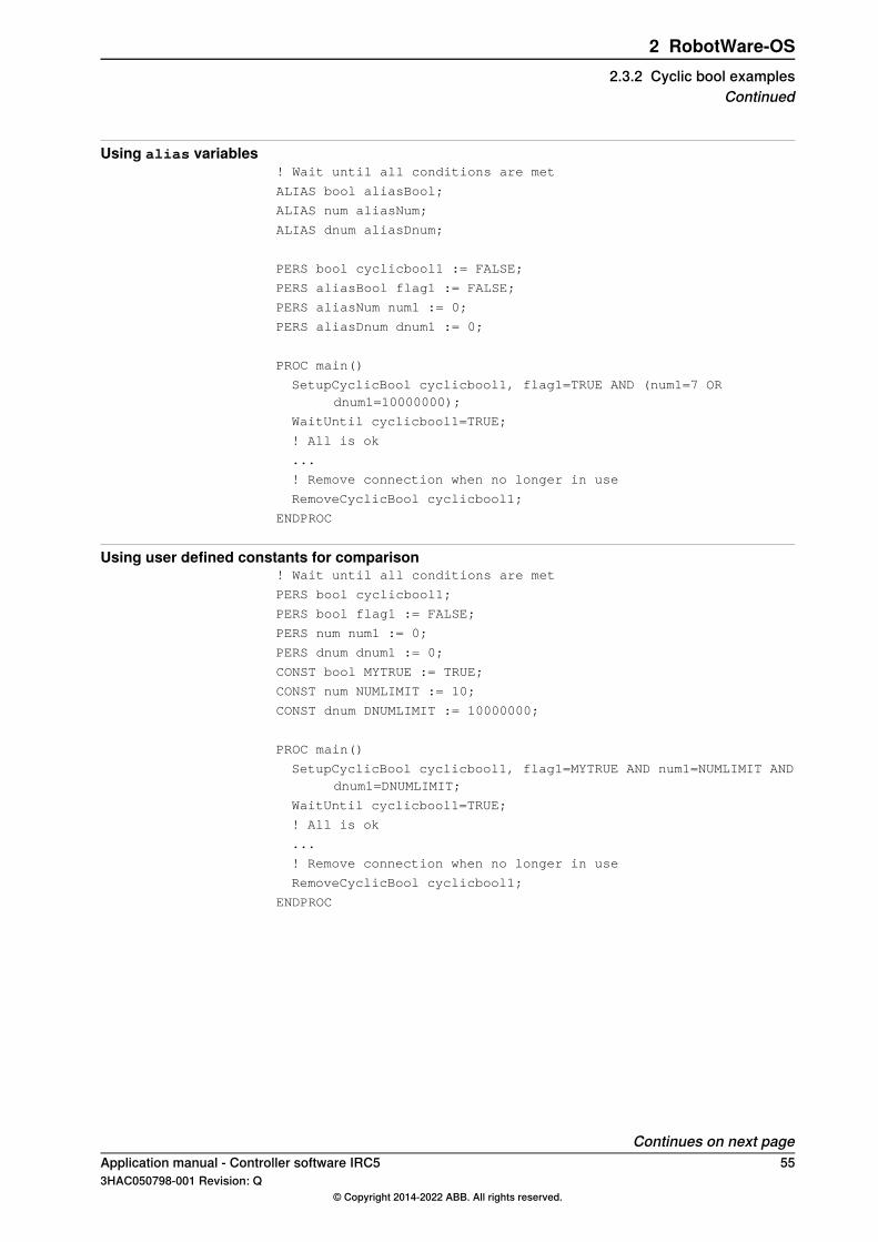
Using alias variables! Wait until all conditions are met
ALIAS bool aliasBool;
ALIAS num aliasNum;
ALIAS dnum aliasDnum;
PERS bool cyclicbool1 := FALSE;
PERS aliasBool flag1 := FALSE;
PERS aliasNum num1 := 0;
PERS aliasDnum dnum1 := 0;
PROC main()
SetupCyclicBool cyclicbool1, flag1=TRUE AND (num1=7 ORdnum1=10000000);
WaitUntil cyclicbool1=TRUE;
! All is ok
...
! Remove connection when no longer in use
RemoveCyclicBool cyclicbool1;
ENDPROC
Using user defined constants for comparison! Wait until all conditions are met
PERS bool cyclicbool1;
PERS bool flag1 := FALSE;
PERS num num1 := 0;
PERS dnum dnum1 := 0;
CONST bool MYTRUE := TRUE;
CONST num NUMLIMIT := 10;
CONST dnum DNUMLIMIT := 10000000;
PROC main()
SetupCyclicBool cyclicbool1, flag1=MYTRUE AND num1=NUMLIMIT ANDdnum1=DNUMLIMIT;
WaitUntil cyclicbool1=TRUE;
! All is ok
...
! Remove connection when no longer in use
RemoveCyclicBool cyclicbool1;
ENDPROC
Continues on next pageApplication manual - Controller software IRC5 553HAC050798-001 Revision: Q
© Copyright 2014-2022 ABB. All rights reserved.
2 RobotWare-OS2.3.2 Cyclic bool examples
Continued
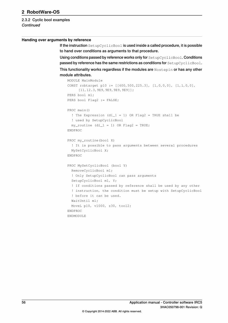
Handing over arguments by referenceIf the instruction SetupCyclicBool is used inside a called procedure, it is possibleto hand over conditions as arguments to that procedure.Using conditions passed by reference works only for SetupCyclicBool. Conditionspassed by reference has the same restrictions as conditions for SetupCyclicBool.This functionality works regardless if the modules are Nostepin or has any othermodule attributes.
MODULE MainModule
CONST robtarget p10 := [[600,500,225.3], [1,0,0,0], [1,1,0,0],[11,12.3,9E9,9E9,9E9,9E9]];
PERS bool m1;
PERS bool Flag2 := FALSE;
PROC main()
! The Expression (di_1 = 1) OR Flag2 = TRUE shall be
! used by SetupCyclicBool
my_routine (di_1 = 1) OR Flag2 = TRUE;
ENDPROC
PROC my_routine(bool X)
! It is possible to pass arguments between several procedures
MySetCyclicBool X;
ENDPROC
PROC MySetCyclicBool (bool Y)
RemoveCyclicBool m1;
! Only SetupCyclicBool can pass arguments
SetupCyclicBool m1, Y;
! If conditions passed by reference shall be used by any other
! instruction, the condition must be setup with SetupCyclicBool
! before it can be used.
WaitUntil m1;
MoveL p10, v1000, z30, tool2;
ENDPROC
ENDMODULE
56 Application manual - Controller software IRC53HAC050798-001 Revision: Q
© Copyright 2014-2022 ABB. All rights reserved.
2 RobotWare-OS2.3.2 Cyclic bool examplesContinued
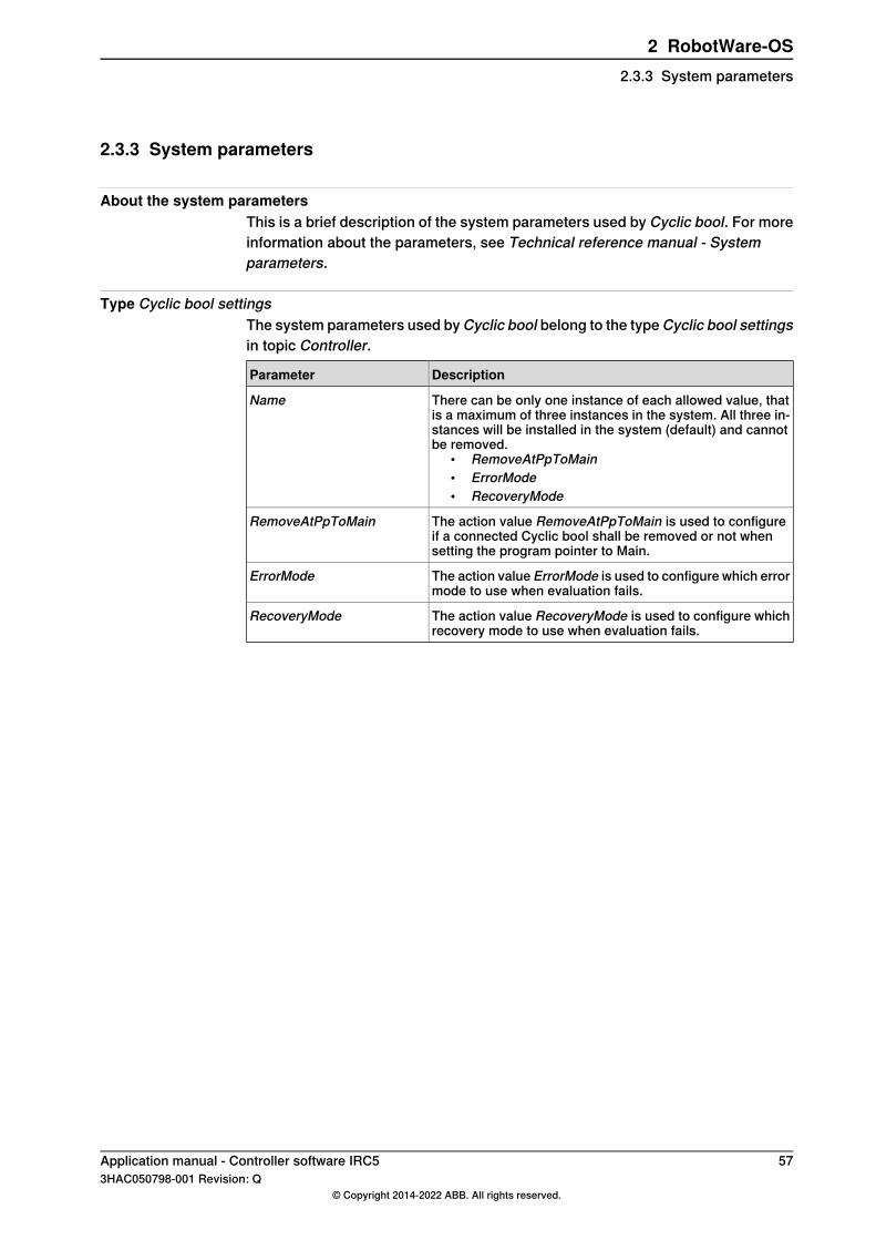
2.3.3 System parameters
About the system parametersThis is a brief description of the system parameters used by Cyclic bool. For moreinformation about the parameters, see Technical reference manual - Systemparameters.
Type Cyclic bool settingsThe system parameters used by Cyclic bool belong to the type Cyclic bool settingsin topic Controller.
DescriptionParameter
There can be only one instance of each allowed value, thatis a maximum of three instances in the system. All three in-stances will be installed in the system (default) and cannotbe removed.
• RemoveAtPpToMain• ErrorMode• RecoveryMode
Name
The action value RemoveAtPpToMain is used to configureif a connected Cyclic bool shall be removed or not whensetting the program pointer to Main.
RemoveAtPpToMain
The action value ErrorMode is used to configure which errormode to use when evaluation fails.
ErrorMode
The action value RecoveryMode is used to configure whichrecovery mode to use when evaluation fails.
RecoveryMode
Application manual - Controller software IRC5 573HAC050798-001 Revision: Q
© Copyright 2014-2022 ABB. All rights reserved.
2 RobotWare-OS2.3.3 System parameters

2.3.4 RAPID components
About the RAPID componentsThis is an overview of all RAPID instructions, functions, and data types in Cyclicbool.For more information, see Technical reference manual - RAPID Instructions,Functions and Data types
Instructions
DescriptionInstruction
SetupCyclicBool connects a logical condition to a booleanvariable.
SetupCyclicBool
RemoveCyclicBool removes a specific connected logical con-dition.
RemoveCyclicBool
RemoveAllCyclicBool removes all connected logical condi-tions.
RemoveAllCyclicBool
Functions
DescriptionFunction
GetMaxNumberOfCyclicBool retrieves the maximumnumber of cyclically evaluated logical condition that canbe connected at the same time.
GetMaxNumberOfCyclicBool
GetNextCyclicBool retrieves the name of a connectedcyclically evaluated logical condition.
GetNextCyclicBool
GetNumberOfCyclicBool retrieves the number of aconnected cyclically evaluated logical condition.
GetNumberOfCyclicBool
IsCyclicBool is used to test if a persistent boolean isa Cyclic bool or not, i.e. if a logical condition has beenconnected to the persistent boolean variable with theinstruction SetupCyclicBool.
IsCyclicBool
Data typesCyclic bool includes no data types.
58 Application manual - Controller software IRC53HAC050798-001 Revision: Q
© Copyright 2014-2022 ABB. All rights reserved.
2 RobotWare-OS2.3.4 RAPID components
2.4 Electronically Linked Motors
2.4.1 Overview
DescriptionElectronically Linked Motors makes a master/follower configuration of motors (forexample two additional axes). The follower axis will continuously follow the masteraxis in terms of position, velocity, and acceleration.For stiff mechanical connection between the master and followers, the torquefollower function can be used. Instead of regulating to exactly the same positionfor the master and follower, the torque is distributed between the axes. A smallposition error between master and follower will occur depending on backlash andmechanical misalignment.
PurposeThe primary purpose of Electronically Linked Motors is to replace driving shaftsof gantry machines, but the base functionality can be used to control any other setof motors as well.
What is includedThe RobotWare base functionality Electronically Linked Motors gives you accessto:
• a service program for defining linked motor groups and trimming the axispositions
• system parameters used to configure a follower axis
Basic approachThis is the general approach for setting up Electronically Linked Motors. For amore detailed description of how this is done, see the respective section.
1 Configure the additional axes as a mechanical unit. See Applicationmanual - Additional axes and stand alone controller.
2 Configure tolerance limits in the system parameters, in the types Linked MProcess, Process, and Joint.
3 Restart the controller for the changes to take effect.4 Set values to data variables, defining the linked motor group and connecting
follower and master axes.5 Use the service program to trim positions or reset follower after position
error.
LimitationsThere can be up to 5 follower axes. The follower axes can be configured to followone master each, or several followers can follow one master, but the total numberof follower axes cannot be more than 5.The follower axis cannot be an ABB robot (IRB robot). The master axis can beeither an additional axis or a robot axis.
Continues on next pageApplication manual - Controller software IRC5 593HAC050798-001 Revision: Q
© Copyright 2014-2022 ABB. All rights reserved.
2 RobotWare-OS2.4.1 Overview
The torque follower function can only be used if the follower axis is connected tothe same drive module as the master axis.Using the torque follower functionality might reduce the number of follower axesdepending on the number of axes that are available in the drive module wheremaster axis is configured.The RAPID instruction IndReset (Independent Reset) cannot be used incombination with Electronically Linked Motors.
60 Application manual - Controller software IRC53HAC050798-001 Revision: Q
© Copyright 2014-2022 ABB. All rights reserved.
2 RobotWare-OS2.4.1 OverviewContinued

2.4.2 Configuration
2.4.2.1 System parameters
About the system parametersThis is a brief description of each parameter used for the option ElectronicallyLinked Motors. For more information, see the respective parameter in Technicalreference manual - System parameters.
JointThese parameters belong to the topic Motion and the type Joint.
DescriptionParameter
Specifies which master axis this axis shall follow. Refers to the parameterName in the type Joint. Robot axes are referred to as rob1 followed byunderscore and the axis number (for example rob1_6).
Follower to Joint
Id name of the process that is called. Refers to the parameter Name inthe type Process.
Use Process
A flag that locks the axis so it is not used in the path interpolation.Lock Joint in IpolThis parameter must be set to TRUE when the axis is electronically linkedto another axis.
ProcessThese parameters belong to the topic Motion and the type Process.
DescriptionParameter
Id name of the process.Name
Id name of electronically linked motor process. Refers to the parameterName in the type Linked M Process.
Use Linked MotorProcess
Linked M ProcessThese parameters belong to the topic Motion and the type Linked M Process.
DescriptionParameter
Id name for the linked motor process.Name
Time delay from control on until the follower starts to follow themaster.
Offset Adjust DelayTime
This can be used to give the master time to stabilize before thefollower starts following.
The maximum allowed difference in distance (in radians or meters)between master and follower.
Max Follower Offset
If Max Follower Offset is exceeded, emergency stop is activated.
The maximum allowed difference in speed (in rad/s or m/s) betweenmaster and follower.
Max Offset Speed
If Max Offset Speed is exceeded, emergency stop is activated.
Defines how large part of the Max Offset Speed that can be usedto compensate for position error.
Offset Speed Ratio
Continues on next pageApplication manual - Controller software IRC5 613HAC050798-001 Revision: Q
© Copyright 2014-2022 ABB. All rights reserved.
2 RobotWare-OS2.4.2.1 System parameters
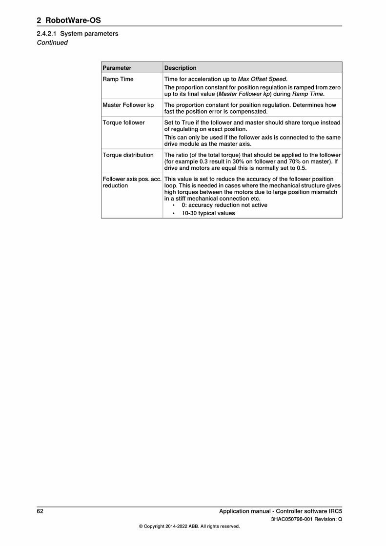
DescriptionParameter
Time for acceleration up to Max Offset Speed.Ramp TimeThe proportion constant for position regulation is ramped from zeroup to its final value (Master Follower kp) during Ramp Time.
The proportion constant for position regulation. Determines howfast the position error is compensated.
Master Follower kp
Set to True if the follower and master should share torque insteadof regulating on exact position.
Torque follower
This can only be used if the follower axis is connected to the samedrive module as the master axis.
The ratio (of the total torque) that should be applied to the follower(for example 0.3 result in 30% on follower and 70% on master). Ifdrive and motors are equal this is normally set to 0.5.
Torque distribution
This value is set to reduce the accuracy of the follower positionloop. This is needed in cases where the mechanical structure giveshigh torques between the motors due to large position mismatchin a stiff mechanical connection etc.
• 0: accuracy reduction not active• 10-30 typical values
Follower axis pos. acc.reduction
62 Application manual - Controller software IRC53HAC050798-001 Revision: Q
© Copyright 2014-2022 ABB. All rights reserved.
2 RobotWare-OS2.4.2.1 System parametersContinued

2.4.2.2 Configuration example
About this exampleThis is an example of how to configure the additional axis M8DM1 to be a followerto the axis M7DM1 and axis M9DM1 to be a follower to robot axis 6.
Joint
Lock Joint in IpolUse ProcessFollower to JointName
M7DM1
TrueELM_1M7DM1M8DM1
TrueELM_2rob1_6M9DM1
Process
Use Linked Motor ProcessName
Linked_m_1ELM_1
Linked_m_2ELM_2
Linked M Process
Master Fol-lower kp
RampTime
OffsetSpeed Ra-tio
MaxOffsetSpeed
Max Follow-er Offset
Offset AdjustDelay Time
Name
0.0510.330.050.050.2Linked_m_1
0.081.50.40.10.10.1Linked_m_2
Application manual - Controller software IRC5 633HAC050798-001 Revision: Q
© Copyright 2014-2022 ABB. All rights reserved.
2 RobotWare-OS2.4.2.2 Configuration example
2.4.3 Managing a follower axis
2.4.3.1 Using the service program
About the service programWhen the follower axis is configured as a mechanical unit and connected to amaster axis, the service program can be used to:
• calibrate the follower axis• reset follower after a position error• tune a torque follower axis, see Tuning a torque follower on page 69.
Copy service program file to HOMECopy the file linked_m.sys from directory:hd0a\<active system>\PRODUCTS\RobotWare_6.0x.xxxx\utility\LinkedMotorsto the HOME directory of the active system.
Load cfg filesLoad the configuration files LINKED_M_MMC.cfg and LINKED_M_SYS.cfg. Theseare located in the directory:hd0a\<active system>\PRODUCTS\RobotWare_6.0x.xxxx\utility\LinkedMotors.Loading configuration files can be done with RobotStudio or FlexPendant. How todo this is described in:
Description of loading cfg filesTool
Section Loading a configuration file in Operating manual - RobotStudio.RobotStudio
Section Loading system parameters in Operating manual - IRC5 Integ-rator's guide.
FlexPendant
Restart the controller after loading the configuration files.
Data variablesWhen the service routine starts, it will read values from system parameters andset the values for a set of data variables used by the service routine. These variablesonly need to be set manually if something goes wrong, see Data setup on page72.
Start service program
Note
The controller must be in manual or auto mode to run this service program.
ActionStep
In the program view, tap Debug and select Call Routine....1
Select Linked_m and tap Go to.2
Press the RUN button to start the service program.The service program is shown on the screen.
3
Continues on next page64 Application manual - Controller software IRC5
3HAC050798-001 Revision: Q© Copyright 2014-2022 ABB. All rights reserved.
2 RobotWare-OS2.4.3.1 Using the service program
ActionStep
Tap Menu 1.The follower axes that are set up in the system are shown in the task bar.
4
Tap the follower axis you want to use the service program for.The main menu of the service program is now shown.
5
Menu buttons
DescriptionButton
Automatically moves the follower axis to the position corresponding to themaster axis, see Reset follower automatically on page 68.
AUTO
Stops the movement of the follower axis. Can be used when jogging or usingAUTO and the movement must be stopped immediately.
STOP
Manual stepwise movement of the follower axis, see Jog follower axis on page66.JOGIf the follower axis is synchronized with the master axis, it will resume its positionwhen you tap AUTO or when you exit the service program.
Used to suspend the synchronization between follower axis and master axis,see Unsynchronize on page 66.
UNSYNC
Show some help for how to use the service program. The button Next showsthe next help subject.
HELP
Application manual - Controller software IRC5 653HAC050798-001 Revision: Q
© Copyright 2014-2022 ABB. All rights reserved.
2 RobotWare-OS2.4.3.1 Using the service program
Continued
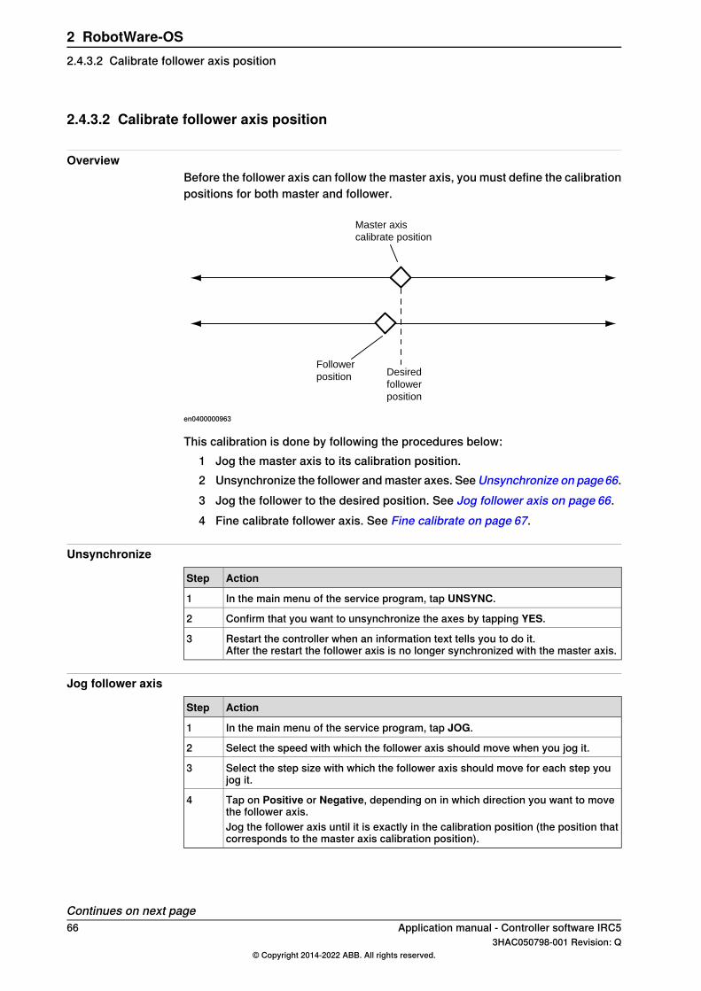
2.4.3.2 Calibrate follower axis position
OverviewBefore the follower axis can follow the master axis, you must define the calibrationpositions for both master and follower.
Master axis
calibrate position
Desired
follower
position
Follower
position
en0400000963
This calibration is done by following the procedures below:1 Jog the master axis to its calibration position.2 Unsynchronize the follower and master axes. See Unsynchronize on page66.3 Jog the follower to the desired position. See Jog follower axis on page 66.4 Fine calibrate follower axis. See Fine calibrate on page 67.
Unsynchronize
ActionStep
In the main menu of the service program, tap UNSYNC.1
Confirm that you want to unsynchronize the axes by tapping YES.2
Restart the controller when an information text tells you to do it.After the restart the follower axis is no longer synchronized with the master axis.
3
Jog follower axis
ActionStep
In the main menu of the service program, tap JOG.1
Select the speed with which the follower axis should move when you jog it.2
Select the step size with which the follower axis should move for each step youjog it.
3
Tap on Positive or Negative, depending on in which direction you want to movethe follower axis.
4
Jog the follower axis until it is exactly in the calibration position (the position thatcorresponds to the master axis calibration position).
Continues on next page66 Application manual - Controller software IRC5
3HAC050798-001 Revision: Q© Copyright 2014-2022 ABB. All rights reserved.
2 RobotWare-OS2.4.3.2 Calibrate follower axis position

Fine calibrate
ActionStep
In the ABB menu, select Calibration.1
Select the mechanical unit that the follower axis belongs to.2
Tap the button Calib. Parameters.3
Tap Fine Calibration....4
In the warning dialog that appears, tap Yes.5
Select the axis that is used as follower axis and tap Calibrate.6
In the warning dialog that appears, tap Calibrate.The follower axis is now calibrated. As soon as the follower is calibrated, it is alsosynchronized with the master again.
7
Application manual - Controller software IRC5 673HAC050798-001 Revision: Q
© Copyright 2014-2022 ABB. All rights reserved.
2 RobotWare-OS2.4.3.2 Calibrate follower axis position
Continued

2.4.3.3 Reset follower axis
OverviewIf the follower offset exceeds its tolerance limits (configured with the systemparameter Max follower offset), the service program must be used to move thefollower back within the tolerance limits. This can be done automatically in theservice program if the follower is within the AUTO range. Otherwise the followermust be manually jogged.The range where AUTO can be used is determined by the system parameter MaxFollower Offset multiplied with the data variable offset_ratio.
Master axis
position
Desired
follower
position
Range where follower
automatically follow master
Range where AUTO in service program can be used
Max Follower
Offset
Max Follower Offset * offset_ratio
en0400000962
Reset follower automatically
ActionStep
In the main menu of the service program, tap AUTO.1
Select the speed with which the follower axis should move to its desired position.2
Reset follower by manual jogging
ActionStep
In the main menu of the service program, tap JOG.1
Select the speed with which the follower axis should move when you jog it.2
Select the step size with which the follower axis should move for each step youjog it.
3
Tap on Positive or Negative, depending on which direction you want to move thefollower axis.
4
Jog the follower until it is within the tolerance of Max Follower Offset (or use AUTOwhen you are close enough).
68 Application manual - Controller software IRC53HAC050798-001 Revision: Q
© Copyright 2014-2022 ABB. All rights reserved.
2 RobotWare-OS2.4.3.3 Reset follower axis
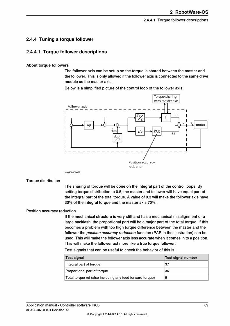
2.4.4 Tuning a torque follower
2.4.4.1 Torque follower descriptions
About torque followersThe follower axis can be setup so the torque is shared between the master andthe follower. This is only allowed if the follower axis is connected to the same drivemodule as the master axis.Below is a simplified picture of the control loop of the follower axis.
en0900000679
Torque distributionThe sharing of torque will be done on the integral part of the control loops. Bysetting torque distribution to 0.5, the master and follower will have equal part ofthe integral part of the total torque. A value of 0.3 will make the follower axis have30% of the integral torque and the master axis 70%.
Position accuracy reductionIf the mechanical structure is very stiff and has a mechanical misalignment or alarge backlash, the proportional part will be a major part of the total torque. If thisbecomes a problem with too high torque difference between the master and thefollower the position accuracy reduction function (PAR in the illustration) can beused. This will make the follower axis less accurate when it comes in to a position.This will make the follower act more like a true torque follower.Test signals that can be useful to check the behavior of this is:
Test signal numberTest signal
37Integral part of torque
36Proportional part of torque
9Total torque ref (also including any feed forward torque)
Application manual - Controller software IRC5 693HAC050798-001 Revision: Q
© Copyright 2014-2022 ABB. All rights reserved.
2 RobotWare-OS2.4.4.1 Torque follower descriptions
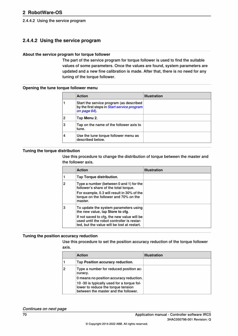
2.4.4.2 Using the service program
About the service program for torque followerThe part of the service program for torque follower is used to find the suitablevalues of some parameters. Once the values are found, system parameters areupdated and a new fine calibration is made. After that, there is no need for anytuning of the torque follower.
Opening the tune torque follower menu
IllustrationAction
Start the service program (as describedby the first steps in Start service programon page 64).
1
Tap Menu 2.2
Tap on the name of the follower axis totune.
3
Use the tune torque follower menu asdescribed below.
4
Tuning the torque distributionUse this procedure to change the distribution of torque between the master andthe follower axis.
IllustrationAction
Tap Torque distribution.1
Type a number (between 0 and 1) for thefollower’s share of the total torque.
2
For example, 0.3 will result in 30% of thetorque on the follower and 70% on themaster.
To update the system parameters usingthe new value, tap Store to cfg.
3
If not saved to cfg, the new value will beused until the robot controller is restar-ted, but the value will be lost at restart.
Tuning the position accuracy reductionUse this procedure to set the position accuracy reduction of the torque followeraxis.
IllustrationAction
Tap Position accuracy reduction.1
Type a number for reduced position ac-curacy.
2
0 means no position accuracy reduction.10 -30 is typically used for a torque fol-lower to reduce the torque tensionbetween the master and the follower.
Continues on next page70 Application manual - Controller software IRC5
3HAC050798-001 Revision: Q© Copyright 2014-2022 ABB. All rights reserved.
2 RobotWare-OS2.4.4.2 Using the service program

IllustrationAction
To update the system parameters usingthe new value, tap Store to cfg.
3
If not saved to cfg, the new value will beused until the robot controller is restar-ted, but the value will be lost at restart.
Tuning the temporary position deltaUse this procedure to tune the position delta of the torque follower axis. This deltavalue is then used to adjust the fine calibration of the follower axis.
IllustrationAction
Tap Temp. position delta.1
Type a number (degrees on motor side)that will be added to the position refer-ence for the follower axis.
2
Test which value results in the lowesttorque tension and make a fine calibra-tion of the master axis. This will updatethe follower axis with the current positiondelta.
3
Application manual - Controller software IRC5 713HAC050798-001 Revision: Q
© Copyright 2014-2022 ABB. All rights reserved.
2 RobotWare-OS2.4.4.2 Using the service program
Continued

2.4.5 Data setup
2.4.5.1 Set up data for service program
OverviewAt start of the service routine for Electronically Linked Motors, some data variablesare read from the linked motor configuration. These variables are used by theservice program. If they are not read correctly, the variables need to be edited inthe service program.
Data descriptions
DescriptionData variable
A name for the follower axis that will be displayed on the FlexPendant.l_f_axis_nameString array with 5 elements, one for each follower axis. If you only haveone linked motor, use only the first element.
The name of the mechanical unit for the follower axis. Refers to the systemparameter Name in the type Mechanical Unit.
l_f_mecunt_n
String array with 5 elements, one for each follower axis. If you only haveone linked motor, use only the first element.
Defines which axis in the mechanical unit (l_f_mecunt_n) is the followeraxis.
l_f_axis_no
Num array with 5 elements, one for each follower axis. If you only haveone linked motor, use only the first element.
The name of the mechanical unit for the master axis. Refers to the systemparameter Name in the type Mechanical Unit.
l_m_mecunt_n
String array with 5 elements, one for each master axis. If you only haveone linked motor, use only the first element.
Defines which axis in the mechanical unit (l_m_mecunt_n) is the masteraxis.
l_m_axis_no
Num array with 5 elements, one for each master axis. If you only haveone linked motor, use only the first element.
Defines the range where the AUTO function in the service program resetthe follower axis. offset_ratio defines this range as a multiple of therange where the follower automatically follow the master (defined withthe parameter Max Follow Offset).
offset_ratio
If the follower has a position error that is larger than Max Follower Offset* offset_ratio, the follower must be reset manually. For more informa-tion, see Reset follower axis on page 68.
Defines the speed of the follower axis when controlled by the serviceprogram. The values are given as a part of the maximum allowed manualspeed (that is, the value 0.5 means half the max manual speed).
speed_ratio
Num array with 20 elements. Elements 1-5 define the speed "very slow"for each follower axis. Elements 6-10 define "slow", elements 11-15 define"normal" and elements 16-20 define "fast". If you only have one linkedmotor, use only elements 1, 6, 11 and 16.
Continues on next page72 Application manual - Controller software IRC5
3HAC050798-001 Revision: Q© Copyright 2014-2022 ABB. All rights reserved.
2 RobotWare-OS2.4.5.1 Set up data for service program
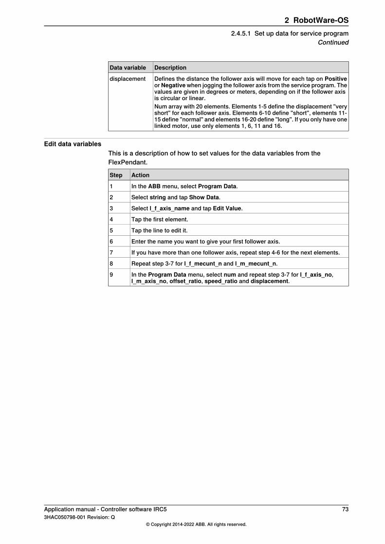
DescriptionData variable
Defines the distance the follower axis will move for each tap on Positiveor Negativewhen jogging the follower axis from the service program. Thevalues are given in degrees or meters, depending on if the follower axisis circular or linear.
displacement
Num array with 20 elements. Elements 1-5 define the displacement "veryshort" for each follower axis. Elements 6-10 define "short", elements 11-15 define "normal" and elements 16-20 define "long". If you only have onelinked motor, use only elements 1, 6, 11 and 16.
Edit data variablesThis is a description of how to set values for the data variables from theFlexPendant.
ActionStep
In the ABB menu, select Program Data.1
Select string and tap Show Data.2
Select l_f_axis_name and tap Edit Value.3
Tap the first element.4
Tap the line to edit it.5
Enter the name you want to give your first follower axis.6
If you have more than one follower axis, repeat step 4-6 for the next elements.7
Repeat step 3-7 for l_f_mecunt_n and l_m_mecunt_n.8
In the Program Data menu, select num and repeat step 3-7 for l_f_axis_no,l_m_axis_no, offset_ratio, speed_ratio and displacement.
9
Application manual - Controller software IRC5 733HAC050798-001 Revision: Q
© Copyright 2014-2022 ABB. All rights reserved.
2 RobotWare-OS2.4.5.1 Set up data for service program
Continued

2.4.5.2 Example of data setup
About this exampleThis is an example of how to set up the data variables for two follower axis. Thefirst follower axis is M8C1B1, which is a follower to the additional axis M7C1B1.The second follower axis is M9C1B1, which is a follower to robot axis 6.
l_f_axis_name
Element and value in l_f_axis_nameRepresented axis
{1}: "follow_external"Follower 1
{2}: "follow_axis6"Follower 2
{3}: ""Follower 3
{4}: ""Follower 4
{5}: ""Follower 5
l_f_mecunt_n
Element and value in l_f_mecunt_nRepresented axis
{1}: "M8DM1"Follower 1
{2}: "M9DM1"Follower 2
{3}: ""Follower 3
{4}: ""Follower 4
{5}: ""Follower 5
l_f_axis_no
Element and value in l_f_axis_noRepresented axis
{1}: 1Follower 1
{2}: 1Follower 2
{3}: 0Follower 3
{4}: 0Follower 4
{5}: 0Follower 5
l_m_mecunt_n
Element and value in l_m_mecunt_nRepresented axis
{1}: "M7DM1"Master 1
{2}: "rob1"Master 2
{3}: ""Master 3
{4}: ""Master 4
{5}: ""Master 5
Continues on next page74 Application manual - Controller software IRC5
3HAC050798-001 Revision: Q© Copyright 2014-2022 ABB. All rights reserved.
2 RobotWare-OS2.4.5.2 Example of data setup
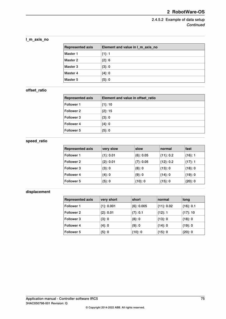
l_m_axis_no
Element and value in l_m_axis_noRepresented axis
{1}: 1Master 1
{2}: 6Master 2
{3}: 0Master 3
{4}: 0Master 4
{5}: 0Master 5
offset_ratio
Element and value in offset_ratioRepresented axis
{1}: 10Follower 1
{2}: 15Follower 2
{3}: 0Follower 3
{4}: 0Follower 4
{5}: 0Follower 5
speed_ratio
fastnormalslowvery slowRepresented axis
{16}: 1{11}: 0.2{6}: 0.05{1}: 0.01Follower 1
{17}: 1{12}: 0.2{7}: 0.05{2}: 0.01Follower 2
{18}: 0{13}: 0{8}: 0{3}: 0Follower 3
{19}: 0{14}: 0{9}: 0{4}: 0Follower 4
{20}: 0{15}: 0{10}: 0{5}: 0Follower 5
displacement
longnormalshortvery shortRepresented axis
{16}: 0.1{11}: 0.02{6}: 0.005{1}: 0.001Follower 1
{17}: 10{12}: 1{7}: 0.1{2}: 0.01Follower 2
{18}: 0{13}: 0{8}: 0{3}: 0Follower 3
{19}: 0{14}: 0{9}: 0{4}: 0Follower 4
{20}: 0{15}: 0{10}: 0{5}: 0Follower 5
Application manual - Controller software IRC5 753HAC050798-001 Revision: Q
© Copyright 2014-2022 ABB. All rights reserved.
2 RobotWare-OS2.4.5.2 Example of data setup
Continued
2.5 Fixed Position Events
2.5.1 Overview
PurposeThe purpose of Fixed Position Events is to make sure a program routine is executedwhen the position of the TCP is well defined.If a move instruction is called with the zone argument set to fine, the next routineis always executed once the TCP has reached its target. If a move instruction iscalled with the zone argument set to a distance (for example z20), the next routinemay be executed before the TCP is even close to the target. This is because thereis always a delay between the execution of RAPID instructions and the robotmovements.Calling the move instruction with zone set to fine will slow down the movements.With Fixed Position Events, a routine can be executed when the TCP is at aspecified position anywhere on the TCP path without slowing down the movement.
What is includedThe RobotWare base functionality Fixed Position Events gives you access to:
• instructions used to define a position event• instructions for moving the robot and executing the position event at the
same time• instructions for moving the robot and calling a procedure while passing the
target, without first defining a position event
Basic approachFixed Position Events can either be used with one simplified instruction calling aprocedure or it can be set up following these general steps. For more detailedexamples of how this is done, see Code examples on page 80.
1 Declare the position event.2 Define the position event:
• when it shall occur, compared to the target position• what it shall do
3 Call a move instruction that uses the position event. When the TCP is asclose to the target as defined, the event will occur.
76 Application manual - Controller software IRC53HAC050798-001 Revision: Q
© Copyright 2014-2022 ABB. All rights reserved.
2 RobotWare-OS2.5.1 Overview

2.5.2 RAPID components and system parameters
Data typesThis is a brief description of each data type in Fixed Position Events. For moreinformation, see the respective data type in Technical reference manual - RAPIDInstructions, Functions and Data types.
DescriptionData type
triggdata is used to store data about a position event.triggdata
A position event can take the form of setting an output signal or run-ning an interrupt routine at a specific position along the movementpath of the robot.triggdata also contains information on when the action shall occur,for example when the TCP is at a defined distance from the target.triggdata is a non-value data type.
triggios is used to store data about a position event used by theinstruction TriggLIOs.
triggios
triggios sets the value of an output signal using a num value.
triggiosdnum is used to store data about a position event used bythe instruction TriggLIOs.
triggiosdnum
triggiosdnum sets the value of an output signal using a dnum value.
triggstrgo is used to store data about a position event used by theinstruction TriggLIOs.
triggstrgo
triggstrgo sets the value of an output signal using a stringdigvalue (string containing a number).
InstructionsThis is a brief description of each instruction in Fixed Position Events. For moreinformation, see the respective instruction in Technical reference manual - RAPIDInstructions, Functions and Data types.
DescriptionInstruction
TriggIO defines the setting of an output signal and when to set thatsignal. The definition is stored in a variable of type triggdata.
TriggIO
TriggIO can define the setting of the signal to occur at a certaindistance (in mm) from the target, or a certain time from the target. Itis also possible to set the signal at a defined distance or time fromthe starting position.By setting the distance to 0 (zero), the signal will be set when the TCPis as close to the target as it gets (the middle of the corner path).
TriggEquipworks like TriggIO, with the difference that TriggEquipcan compensate for the internal delay of the external equipment.
TriggEquip
For example, the signal to a glue gun must be set a short time beforethe glue is pressed out and the gluing begins.
TriggInt defines when to run an interrupt routine. The definition isstored in a variable of type triggdata.
TriggInt
TriggInt defines at what distance (in mm) from the target (or fromthe starting position) the interrupt routine shall be called. By settingthe distance to 0 (zero), the interrupt will occur when the TCP is asclose to the target as it gets (the middle of the corner path).
Continues on next pageApplication manual - Controller software IRC5 773HAC050798-001 Revision: Q
© Copyright 2014-2022 ABB. All rights reserved.
2 RobotWare-OS2.5.2 RAPID components and system parameters

DescriptionInstruction
TriggCheckIO defines a test of an input or output signal, and whento perform that test. The definition is stored in a variable of typetriggdata.
TriggCheckIO
TriggCheckIO defines a test, comparing an input or output signalwith a value. If the test fails, an interrupt routine is called. As an optionthe robot movement can be stopped when the interrupt occurs.TriggCheckIO can define the test to occur at a certain distance (inmm) from the target, or a certain time from the target. It is also possibleto perform the test at a defined distance or time from the starting po-sition.By setting the distance to 0 (zero), the interrupt routine will be calledwhen the TCP is as close to the target as it gets (the middle of thecorner path).
TriggRampAO defines the ramping up or down of an analog outputsignal and when this ramping is performed. The definition is storedin a variable of type triggdata.
TriggRampAO
TriggRampIO defines where the ramping of the signal is to start andthe length of the ramping.
TriggL is a move instruction, similar to MoveL. In addition to themovement the TriggL instruction can set output signals, run interruptroutines and check input or output signals at fixed positions.
TriggL
TriggL executes up to 8 position events stored as triggdata. Thesemust be defined before calling TriggL.
TriggC is a move instruction, similar to MoveC. In addition to themovement the TriggC instruction can set output signals, run interruptroutines and check input or output signals at fixed positions.
TriggC
TriggC executes up to 8 position events stored as triggdata. Thesemust be defined before calling TriggC.
TriggJ is a move instruction, similar to MoveJ. In addition to themovement the TriggJ instruction can set output signals, run interruptroutines and check input or output signals at fixed positions.
TriggJ
TriggJ executes up to 8 position events stored as triggdata. Thesemust be defined before calling TriggJ.
TriggLIOs is a move instruction, similar to MoveL. In addition to themovement the TriggLIOs instruction can set output signals at fixedpositions.
TriggLIOs
TriggLIOs is similar to the combination of TriggEquip and TriggL.The difference is that TriggLIOs can handle up to 50 position eventsstored as an array of datatype triggios, triggiosdnum, ortriggstrgo.
MoveLSync is a linear move instruction that calls a procedure in themiddle of the corner path.
MoveLSync
MoveCSync is a circular move instruction that calls a procedure inthe middle of the corner path.
MoveCSync
MoveJSync is a joint move instruction that calls a procedure in themiddle of the corner path.
MoveJSync
FunctionsFixed Position Events includes no RAPID functions.
Continues on next page78 Application manual - Controller software IRC5
3HAC050798-001 Revision: Q© Copyright 2014-2022 ABB. All rights reserved.
2 RobotWare-OS2.5.2 RAPID components and system parametersContinued

System parametersThis is a brief description of each parameter in Fixed Position Events. For moreinformation, see the respective parameter in Technical reference manual - Systemparameters.
DescriptionParameter
TriggEquip takes advantage of the delay between the RAPID exe-cution and the robot movement, which is about 70 ms. If the delay ofthe equipment is longer than 70 ms, then the delay of the robotmovement can be increased by configuring Event preset time.
Event Preset Time
Event preset time belongs to the type Motion System in the topicMotion.
Application manual - Controller software IRC5 793HAC050798-001 Revision: Q
© Copyright 2014-2022 ABB. All rights reserved.
2 RobotWare-OS2.5.2 RAPID components and system parameters
Continued

2.5.3 Code examples
Example without Fixed Position EventsWithout the use of Fixed Position Events, the code can look like this:
MoveJ p1, vmax, fine, tool1;
MoveL p2, v1000, z20, tool1;
SetDO do1, 1;
MoveL p3, v1000, fine, tool1;
ResultThe code specifies that the TCP should reach p2 before setting do1. Because therobot path is delayed compared to instruction execution, do1 is set when the TCPis at the position marked with X (see illustration).
xx0300000151
Example with TriggIO and TriggL instructionsSetting the output signal 30 mm from the target can be arranged by defining theposition event and then moving the robot while the system is executing the positionevent.
VAR triggdata do_set;
!Define that do1 shall be set when 30 mm from target
TriggIO do_set, 30 \DOp:=do1, 1;
MoveJ p1, vmax, fine, tool1;
!Move to p2 and let system execute do_set
TriggL p2, v1000, do_set, z20, tool1;
MoveL p3, v1000, fine, tool1;
Continues on next page80 Application manual - Controller software IRC5
3HAC050798-001 Revision: Q© Copyright 2014-2022 ABB. All rights reserved.
2 RobotWare-OS2.5.3 Code examples
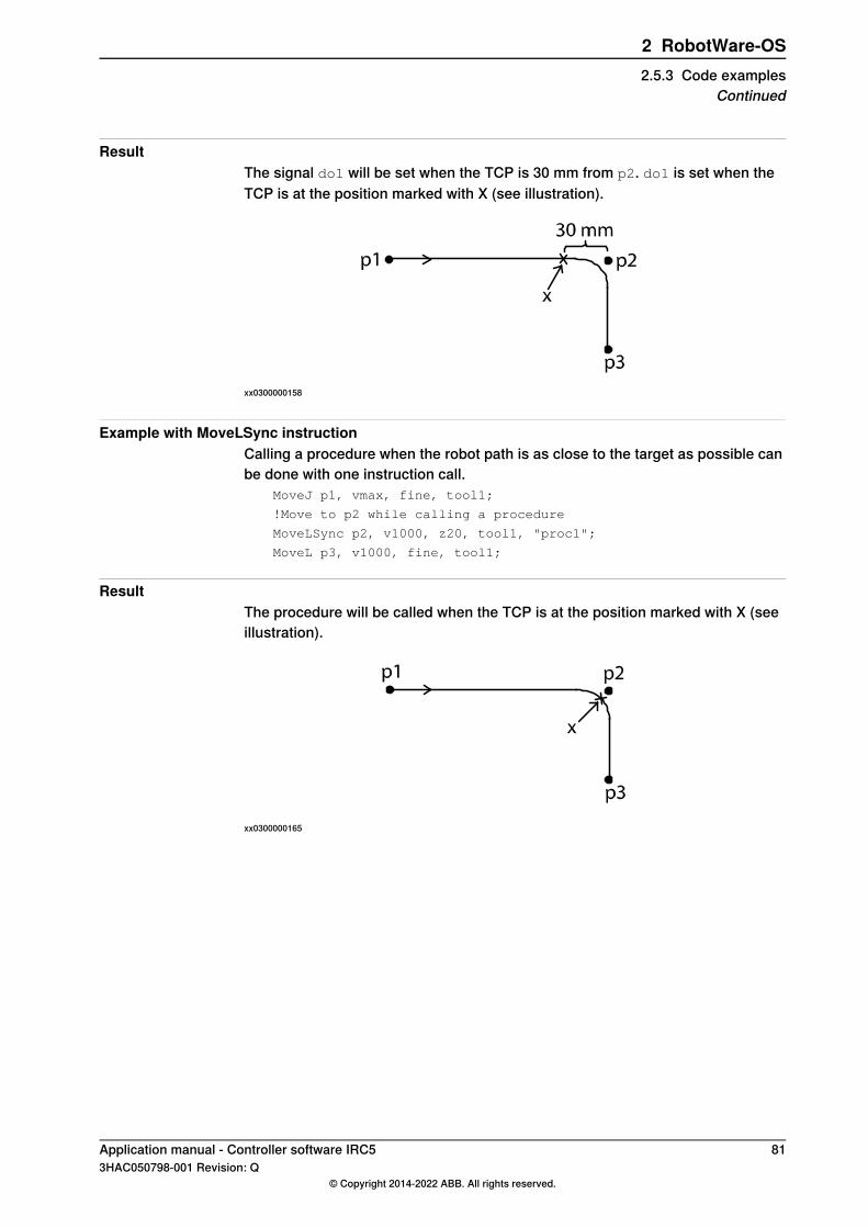
ResultThe signal do1 will be set when the TCP is 30 mm from p2. do1 is set when theTCP is at the position marked with X (see illustration).
xx0300000158
Example with MoveLSync instructionCalling a procedure when the robot path is as close to the target as possible canbe done with one instruction call.
MoveJ p1, vmax, fine, tool1;
!Move to p2 while calling a procedure
MoveLSync p2, v1000, z20, tool1, "proc1";
MoveL p3, v1000, fine, tool1;
ResultThe procedure will be called when the TCP is at the position marked with X (seeillustration).
xx0300000165
Application manual - Controller software IRC5 813HAC050798-001 Revision: Q
© Copyright 2014-2022 ABB. All rights reserved.
2 RobotWare-OS2.5.3 Code examples
Continued
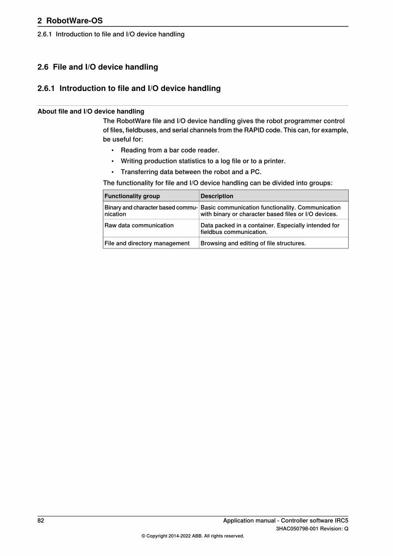
2.6 File and I/O device handling
2.6.1 Introduction to file and I/O device handling
About file and I/O device handlingThe RobotWare file and I/O device handling gives the robot programmer controlof files, fieldbuses, and serial channels from the RAPID code. This can, for example,be useful for:
• Reading from a bar code reader.• Writing production statistics to a log file or to a printer.• Transferring data between the robot and a PC.
The functionality for file and I/O device handling can be divided into groups:
DescriptionFunctionality group
Basic communication functionality. Communicationwith binary or character based files or I/O devices.
Binary and character based commu-nication
Data packed in a container. Especially intended forfieldbus communication.
Raw data communication
Browsing and editing of file structures.File and directory management
82 Application manual - Controller software IRC53HAC050798-001 Revision: Q
© Copyright 2014-2022 ABB. All rights reserved.
2 RobotWare-OS2.6.1 Introduction to file and I/O device handling

2.6.2 Binary and character based communication
2.6.2.1 Overview
PurposeThe purpose of binary and character based communication is to:
• store information in a remote memory or on a remote disk• let the robot communicate with other devices
What is includedTo handle binary and character based communication, RobotWare gives you accessto:
• instructions for manipulations of a file or I/O device• instructions for writing to file or I/O device• instruction for reading from file or I/O device• functions for reading from file or I/O device.
Basic approachThis is the general approach for using binary and character based communication.For a more detailed example of how this is done, see Code examples on page 85.
1 Open a file or I/O device.2 Read or write to the file or I/O device.3 Close the file or I/O device.
LimitationsAccess to files and I/O devices cannot be performed from different RAPID taskssimultaneously. Such an access is performed by all instruction in binary andcharacter based communication, as well as WriteRawBytes and ReadRawBytes.E.g. if a ReadBin instruction is executed in one task, it must be ready before aWriteRawBytes can execute in another task.
Application manual - Controller software IRC5 833HAC050798-001 Revision: Q
© Copyright 2014-2022 ABB. All rights reserved.
2 RobotWare-OS2.6.2.1 Overview
2.6.2.2 RAPID components
Data typesThis is a brief description of each data type used for binary and character basedcommunication. For more information, see the respective data type in Technicalreference manual - RAPID Instructions, Functions and Data types.
DescriptionData type
iodev contains a reference to a file or I/O device. It can be linked to thephysical unit with the instruction Open and then used for reading andwriting.
iodev
InstructionsThis is a brief description of each instruction used for binary and character basedcommunication. For more information, see the respective instruction in Technicalreference manual - RAPID Instructions, Functions and Data types.
DescriptionInstruction
Open is used to open a file or I/O device for reading or writing.Open
Close is used to close a file or I/O device.Close
Rewind sets the file position to the beginning of the file.Rewind
ClearIOBuff is used to clear the input buffer of a serial channel. Allbuffered characters from the input serial channel are discarded.
ClearIOBuff
Write is used to write to a character based file or I/O device.Write
WriteBin is used to write a number of bytes to a binary I/O device orfile.
WriteBin
WriteStrBin is used to write a string to a binary I/O device or file.WriteStrBin
WriteAnyBin is used to write any type of data to a binary I/O device orfile.
WriteAnyBin
ReadAnyBin is used to read any type of data from a binary I/O deviceor file.
ReadAnyBin
FunctionsThis is a brief description of each function used for binary and character basedcommunication. For more information, see the respective instruction in Technicalreference manual - RAPID Instructions, Functions and Data types.
DescriptionFunction
ReadNum is used to read a number from a character based file or I/O device.ReadNum
ReadStr is used to read a string from a character based file or I/O device.ReadStr
ReadBin is used to read a byte (8 bits) from a file or I/O device. This functionworks on both binary and character based files or I/O devices.
ReadBin
ReadStrBin is used to read a string from a binary I/O device or file.ReadStrBin
84 Application manual - Controller software IRC53HAC050798-001 Revision: Q
© Copyright 2014-2022 ABB. All rights reserved.
2 RobotWare-OS2.6.2.2 RAPID components
2.6.2.3 Code examples
Communication with character based fileThis example shows writing and reading to and from a character based file. Theline "The number is :8" is written to FILE1.DOC. The contents of FILE1.DOC is thenread and the output to the FlexPendant is "The number is :8" followed by "Thenumber is 8".
PROC write_to_file()
VAR iodev file;
VAR num number:= 8;
Open "HOME:" \File:= "FILE1.DOC", file;
Write file, "The number is :"\Num:=number;
Close file;
ENDPROC
PROC read_from_file()
VAR iodev file;
VAR num number;
VAR string text;
Open "HOME:" \File:= "FILE1.DOC", file \Read;
TPWrite ReadStr(file);
Rewind file;
text := ReadStr(file\Delim:=":");
number := ReadNum(file);
Close file;
TPWrite text \Num:=number;
ENDPROC
Communication with binary fileIn this example, the string "Hello", the current robot position and the string "Hi" iswritten to the binary file.
PROC write_bin_chan()
VAR iodev file1;
VAR num out_buffer{20};
VAR num input;
VAR robtarget target;
Open "HOME:" \File:= "FILE1.DOC", file1 \Bin;
! Write control character enq
out_buffer{1} := 5;
WriteBin file1, out_buffer, 1;
! Wait for control character ack
input := ReadBin (file1 \Time:= 0.1);
IF input = 6 THEN
! Write "Hello" followed by new line
WriteStrBin file1, "Hello\0A";
Continues on next pageApplication manual - Controller software IRC5 853HAC050798-001 Revision: Q
© Copyright 2014-2022 ABB. All rights reserved.
2 RobotWare-OS2.6.2.3 Code examples

! Write current robot position
target := CRobT(\Tool:= tool1\WObj:= wobj1);
WriteAnyBin file1, target;
! Set start text character (2=start text)
out_buffer{1} := 2;
! Set character "H" (72="H")
out_buffer{2} := 72;
! Set character "i"
out_buffer{3} := StrToByte("i"\Char);
! Set new line character (10=new line)
out_buffer{4} := 10;
! Set end text character (3=end text)
out_buffer{5} := 3;
! Write the buffer with the line "Hi"
! to the file
WriteBin file1, out_buffer, 5;
ENDIF
Close file1;
ENDPROC
86 Application manual - Controller software IRC53HAC050798-001 Revision: Q
© Copyright 2014-2022 ABB. All rights reserved.
2 RobotWare-OS2.6.2.3 Code examplesContinued

2.6.3 Raw data communication
2.6.3.1 Overview
PurposeThe purpose of raw data communication is to pack different type of data into acontainer and send it to a file or I/O device, and to read and unpack data. This isparticularly useful when communicating via a fieldbus, such as DeviceNet.
What is includedTo handle raw data communication, RobotWare gives you access to:
• instructions used for handling the contents of a rawbytes variable• instructions for reading and writing raw data• a function to get the valid data length of a rawbytes variable.
Basic approachThis is the general approach for raw data communication. For a more detailedexample of how this is done, see Write and read rawbytes on page 89.
1 Pack data into a rawbytes variable (data of type num, byte or string).2 Write the rawbytes variable to a file or I/O device.3 Read a rawbytes variable from a file or I/O device.4 Unpack the rawbytes variable to num, byte or string.
LimitationsDevice command communication also require the base functionality DeviceCommand Interface and the option for the industrial network in question.Access to files and I/O devices cannot be performed from different RAPID taskssimultaneously. Such an access is performed by all instruction in binary andcharacter based communication, as well as WriteRawBytes and ReadRawBytes.For example, if a ReadBin instruction is executed in one task, then it must be readybefore a WriteRawBytes instruction can execute in another task.
Application manual - Controller software IRC5 873HAC050798-001 Revision: Q
© Copyright 2014-2022 ABB. All rights reserved.
2 RobotWare-OS2.6.3.1 Overview
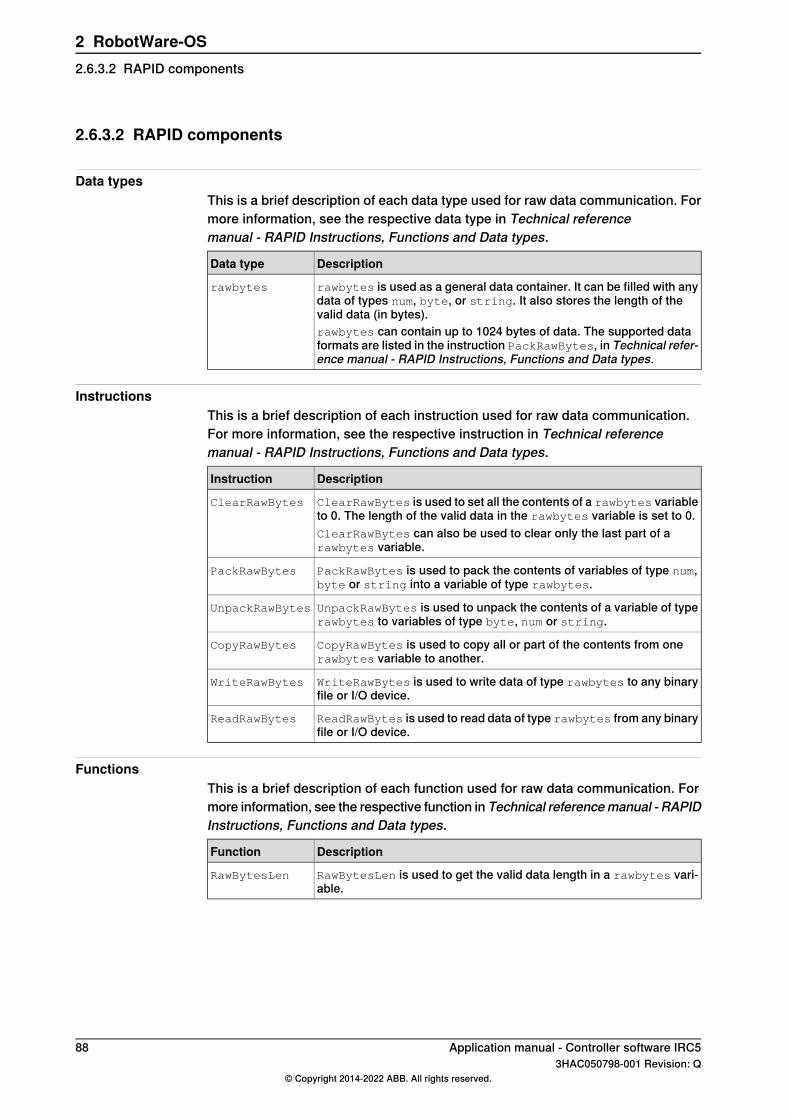
2.6.3.2 RAPID components
Data typesThis is a brief description of each data type used for raw data communication. Formore information, see the respective data type in Technical referencemanual - RAPID Instructions, Functions and Data types.
DescriptionData type
rawbytes is used as a general data container. It can be filled with anydata of types num, byte, or string. It also stores the length of thevalid data (in bytes).
rawbytes
rawbytes can contain up to 1024 bytes of data. The supported dataformats are listed in the instruction PackRawBytes, in Technical refer-ence manual - RAPID Instructions, Functions and Data types.
InstructionsThis is a brief description of each instruction used for raw data communication.For more information, see the respective instruction in Technical referencemanual - RAPID Instructions, Functions and Data types.
DescriptionInstruction
ClearRawBytes is used to set all the contents of a rawbytes variableto 0. The length of the valid data in the rawbytes variable is set to 0.
ClearRawBytes
ClearRawBytes can also be used to clear only the last part of arawbytes variable.
PackRawBytes is used to pack the contents of variables of type num,byte or string into a variable of type rawbytes.
PackRawBytes
UnpackRawBytes is used to unpack the contents of a variable of typerawbytes to variables of type byte, num or string.
UnpackRawBytes
CopyRawBytes is used to copy all or part of the contents from onerawbytes variable to another.
CopyRawBytes
WriteRawBytes is used to write data of type rawbytes to any binaryfile or I/O device.
WriteRawBytes
ReadRawBytes is used to read data of type rawbytes from any binaryfile or I/O device.
ReadRawBytes
FunctionsThis is a brief description of each function used for raw data communication. Formore information, see the respective function in Technical referencemanual - RAPIDInstructions, Functions and Data types.
DescriptionFunction
RawBytesLen is used to get the valid data length in a rawbytes vari-able.
RawBytesLen
88 Application manual - Controller software IRC53HAC050798-001 Revision: Q
© Copyright 2014-2022 ABB. All rights reserved.
2 RobotWare-OS2.6.3.2 RAPID components
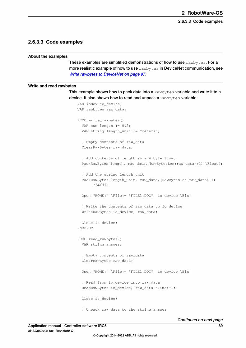
2.6.3.3 Code examples
About the examplesThese examples are simplified demonstrations of how to use rawbytes. For amore realistic example of how to use rawbytes in DeviceNet communication, seeWrite rawbytes to DeviceNet on page 97.
Write and read rawbytesThis example shows how to pack data into a rawbytes variable and write it to adevice. It also shows how to read and unpack a rawbytes variable.
VAR iodev io_device;
VAR rawbytes raw_data;
PROC write_rawbytes()
VAR num length := 0.2;
VAR string length_unit := "meters";
! Empty contents of raw_data
ClearRawBytes raw_data;
! Add contents of length as a 4 byte float
PackRawBytes length, raw_data,(RawBytesLen(raw_data)+1) \Float4;
! Add the string length_unit
PackRawBytes length_unit, raw_data,(RawBytesLen(raw_data)+1)\ASCII;
Open "HOME:" \File:= "FILE1.DOC", io_device \Bin;
! Write the contents of raw_data to io_device
WriteRawBytes io_device, raw_data;
Close io_device;
ENDPROC
PROC read_rawbytes()
VAR string answer;
! Empty contents of raw_data
ClearRawBytes raw_data;
Open "HOME:" \File:= "FILE1.DOC", io_device \Bin;
! Read from io_device into raw_data
ReadRawBytes io_device, raw_data \Time:=1;
Close io_device;
! Unpack raw_data to the string answer
Continues on next pageApplication manual - Controller software IRC5 893HAC050798-001 Revision: Q
© Copyright 2014-2022 ABB. All rights reserved.
2 RobotWare-OS2.6.3.3 Code examples

UnpackRawBytes raw_data, 1, answer \ASCII:=10;
ENDPROC
Copy rawbytesIn this example, all data from raw_data_1 and raw_data_2 is copied toraw_data_3.
VAR rawbytes raw_data_1;
VAR rawbytes raw_data_2;
VAR rawbytes raw_data_3;
VAR num my_length:=0.2;
VAR string my_unit:=" meters";
PackRawBytes my_length, raw_data_1, 1 \Float4;
PackRawBytes my_unit, raw_data_2, 1 \ASCII;
! Copy all data from raw_data_1 to raw_data_3
CopyRawBytes raw_data_1, 1, raw_data_3, 1;
! Append all data from raw_data_2 to raw_data_3
CopyRawBytes raw_data_2, 1, raw_data_3,(RawBytesLen(raw_data_3)+1);
90 Application manual - Controller software IRC53HAC050798-001 Revision: Q
© Copyright 2014-2022 ABB. All rights reserved.
2 RobotWare-OS2.6.3.3 Code examplesContinued
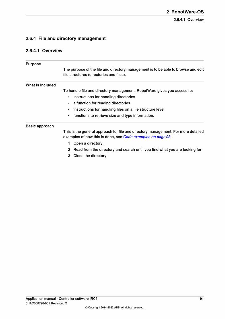
2.6.4 File and directory management
2.6.4.1 Overview
PurposeThe purpose of the file and directory management is to be able to browse and editfile structures (directories and files).
What is includedTo handle file and directory management, RobotWare gives you access to:
• instructions for handling directories• a function for reading directories• instructions for handling files on a file structure level• functions to retrieve size and type information.
Basic approachThis is the general approach for file and directory management. For more detailedexamples of how this is done, see Code examples on page 93.
1 Open a directory.2 Read from the directory and search until you find what you are looking for.3 Close the directory.
Application manual - Controller software IRC5 913HAC050798-001 Revision: Q
© Copyright 2014-2022 ABB. All rights reserved.
2 RobotWare-OS2.6.4.1 Overview
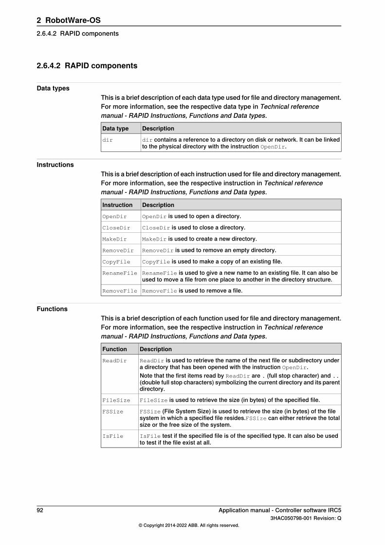
2.6.4.2 RAPID components
Data typesThis is a brief description of each data type used for file and directory management.For more information, see the respective data type in Technical referencemanual - RAPID Instructions, Functions and Data types.
DescriptionData type
dir contains a reference to a directory on disk or network. It can be linkedto the physical directory with the instruction OpenDir.
dir
InstructionsThis is a brief description of each instruction used for file and directory management.For more information, see the respective instruction in Technical referencemanual - RAPID Instructions, Functions and Data types.
DescriptionInstruction
OpenDir is used to open a directory.OpenDir
CloseDir is used to close a directory.CloseDir
MakeDir is used to create a new directory.MakeDir
RemoveDir is used to remove an empty directory.RemoveDir
CopyFile is used to make a copy of an existing file.CopyFile
RenameFile is used to give a new name to an existing file. It can also beused to move a file from one place to another in the directory structure.
RenameFile
RemoveFile is used to remove a file.RemoveFile
FunctionsThis is a brief description of each function used for file and directory management.For more information, see the respective instruction in Technical referencemanual - RAPID Instructions, Functions and Data types.
DescriptionFunction
ReadDir is used to retrieve the name of the next file or subdirectory undera directory that has been opened with the instruction OpenDir.
ReadDir
Note that the first items read by ReadDir are . (full stop character) and ..(double full stop characters) symbolizing the current directory and its parentdirectory.
FileSize is used to retrieve the size (in bytes) of the specified file.FileSize
FSSize (File System Size) is used to retrieve the size (in bytes) of the filesystem in which a specified file resides.FSSize can either retrieve the totalsize or the free size of the system.
FSSize
IsFile test if the specified file is of the specified type. It can also be usedto test if the file exist at all.
IsFile
92 Application manual - Controller software IRC53HAC050798-001 Revision: Q
© Copyright 2014-2022 ABB. All rights reserved.
2 RobotWare-OS2.6.4.2 RAPID components

2.6.4.3 Code examples
List filesThis example shows how to list the files in a directory, excluding the directory itselfand its parent directory (. and ..).
PROC lsdir(string dirname)
VAR dir directory;
VAR string filename;
! Check that dirname really is a directory
IF IsFile(dirname \Directory) THEN
! Open the directory
OpenDir directory, dirname;
! Loop though the files in the directory
WHILE ReadDir(directory, filename) DO
IF (filename <> "." AND filename <> ".." THEN
TPWrite filename;
ENDIF
ENDWHILE
! Close the directory
CloseDir directory;
ENDIF
ENDPROC
Move file to new directoryThis is an example where a new directory is created, a file renamed and moved tothe new directory and the old directory is removed.
VAR dir directory;
VAR string filename;
! Create the directory newdir
MakeDir "HOME:/newdir";
! Rename and move the file
RenameFile "HOME:/olddir/myfile", "HOME:/newdir/yourfile";
! Remove all files in olddir
OpenDir directory, "HOME:/olddir";
WHILE ReadDir(directory, filename) DO
IF (filename <> "." AND filename <> ".." THEN
RemoveFile "HOME:/olddir/" + filename;
ENDIF
ENDWHILE
CloseDir directory;
! Remove the directory olddir (which must be empty)
RemoveDir "HOME:/olddir";
Continues on next pageApplication manual - Controller software IRC5 933HAC050798-001 Revision: Q
© Copyright 2014-2022 ABB. All rights reserved.
2 RobotWare-OS2.6.4.3 Code examples

Check sizesIn this example, the size of the file is compared with the remaining free space onthe file system. If there is enough space, the file is copied.
VAR num freefsyssize;
VAR num f_size;
! Get the size of the file
f_size := FileSize("HOME:/myfile");
! Get the free size on the file system
freefsyssize := FSSize("HOME:/myfile" \Free);
! Copy file if enough space free
IF f_size < freefsyssize THEN
CopyFile "HOME:/myfile", "HOME:/yourfile";
ENDIF
94 Application manual - Controller software IRC53HAC050798-001 Revision: Q
© Copyright 2014-2022 ABB. All rights reserved.
2 RobotWare-OS2.6.4.3 Code examplesContinued
2.7 Device Command Interface
2.7.1 Introduction to Device Command Interface
PurposeDevice Command Interface provides an interface to communicate with I/O deviceson industrial networks.This interface is used together with raw data communication, see Raw datacommunication on page 87.
What is includedThe RobotWare base functionality Device Command Interface gives you accessto:
• Instruction used to create a DeviceNet header.
Basic approachThis is the general approach for using Device Command Interface. For a moredetailed example of how this is done, see Write rawbytes to DeviceNet on page97.
1 Add a DeviceNet header to a rawbytes variable.2 Add the data to the rawbytes variable.3 Write the rawbytes variable to the DeviceNet I/O.4 Read data from the DeviceNet I/O to a rawbytes variable.5 Extract the data from the rawbytes variable.
LimitationsDevice command communication require the option for the industrial network inquestion.Device Command Interface is supported by the following type of industrial networks:
• DeviceNet• EtherNet/IP
Application manual - Controller software IRC5 953HAC050798-001 Revision: Q
© Copyright 2014-2022 ABB. All rights reserved.
2 RobotWare-OS2.7.1 Introduction to Device Command Interface

2.7.2 RAPID components and system parameters
Data typesThere are no RAPID data types for Device Command Interface.
InstructionsThis is a brief description of each instruction in Device Command Interface. Formore information, see the respective instruction in Technical referencemanual - RAPID Instructions, Functions and Data types.
DescriptionInstruction
PackDNHeader adds a DeviceNet header to a rawbytes variable. Theheader specifies a service to be done (e.g. set or get) and a parameteron a DeviceNet I/O device.
PackDNHeader
FunctionsThere are no RAPID functions for Device Command Interface.
System parametersThere are no specific system parameters in Device Command Interface. Forinformation on system parameters in general, see Technical referencemanual - System parameters.
96 Application manual - Controller software IRC53HAC050798-001 Revision: Q
© Copyright 2014-2022 ABB. All rights reserved.
2 RobotWare-OS2.7.2 RAPID components and system parameters
2.7.3 Code example
Write rawbytes to DeviceNetIn this example, data packed as a rawbytes variable is written to a DeviceNet I/Odevice. For more details regarding rawbytes, see Raw data communication onpage 87.
PROC set_filter_value()
VAR iodev dev;
VAR rawbytes rawdata_out;
VAR rawbytes rawdata_in;
VAR num input_int;
VAR byte return_status;
VAR byte return_info;
VAR byte return_errcode;
VAR byte return_errcode2;
! Empty contents of rawdata_out and rawdata_in
ClearRawBytes rawdata_out;
ClearRawBytes rawdata_in;
! Add DeviceNet header to rawdata_out with service
! "SET_ATTRIBUTE_SINGLE" and path to filter attribute on
! DeviceNet I/O device
PackDNHeader "10", "6,20 1D 24 01 30 64,8,1", rawdata_out;
! Add filter value to send to DeviceNet I/O device
input_int:= 5;
PackRawBytes input_int, rawdata_out,(RawBytesLen(rawdata_out) +1) \IntX := USINT;
! Open I/O device
Open "/FCI1:" \File:="board328", dev \Bin;
! Write the contents of rawdata_out to the I/O device
WriteRawBytes dev, rawdata_out \NoOfBytes :=RawBytesLen(rawdata_out);
! Read the answer from the I/O device
ReadRawBytes dev, rawdata_in;
! Close the I/O device
Close dev;
! Unpack rawdata_in to the variable return_status
UnpackRawBytes rawdata_in, 1, return_status \Hex1;
IF return_status = 144 THEN
TPWrite "Status OK from device. Status code:"\Num:=return_status;
Continues on next pageApplication manual - Controller software IRC5 973HAC050798-001 Revision: Q
© Copyright 2014-2022 ABB. All rights reserved.
2 RobotWare-OS2.7.3 Code example
ELSE
! Unpack error codes from device answer
UnpackRawBytes rawdata_in, 2, return_errcode \Hex1;
UnpackRawBytes rawdata_in, 3, return_errcode2 \Hex1;
TPWrite "Error code from device: " \Num:=return_errcode;
TPWrite "Additional error code from device: "\Num:=return_errcode2;
ENDIF
ENDPROC
98 Application manual - Controller software IRC53HAC050798-001 Revision: Q
© Copyright 2014-2022 ABB. All rights reserved.
2 RobotWare-OS2.7.3 Code exampleContinued

2.8 Logical Cross Connections
2.8.1 Introduction to Logical Cross Connections
PurposeThe purpose of Logical Cross Connections is to check and affect combinations ofdigital I/O signals (DO, DI) or group I/O signals (GO, GI). This can be used to verifyor control process equipment that are external to the robot. The functionality canbe compared to the one of a simple PLC.By letting the I/O system handle logical operations with I/O signals, a lot of RAPIDcode execution can be avoided. Logical Cross Connections can replace the processof reading I/O signal values, calculate new values and writing the values to I/Osignals.Here are some examples of applications:
• Interrupt program execution when either of three input signals is set to 1.• Set an output signal to 1 when both of two input signals are set to 1.
DescriptionLogical Cross Connections are used to define the dependencies of an I/O signalto other I/O signals. The logical operators AND, OR, and inverted signal valuescan be used to configure more complex dependencies.The I/O signals that constitute the logical expression (actor I/O signals) and theI/O signal that is the result of the expression (resultant I/O signal) can be eitherdigital I/O signals (DO, DI) or group I/O signals (GO, GI).
What is includedLogical Cross Connections allows you to build logical expressions with up to 5actor I/O signals and the logical operations AND, OR, and inverted signal values.
Application manual - Controller software IRC5 993HAC050798-001 Revision: Q
© Copyright 2014-2022 ABB. All rights reserved.
2 RobotWare-OS2.8.1 Introduction to Logical Cross Connections

2.8.2 Configuring Logical Cross Connections
System parametersThis is a brief description of the parameters for cross connections. For moreinformation, see the respective parameter inConfiguring Logical Cross Connectionson page 100.These parameters belong to the type Cross Connection in the topic I/O System.
DescriptionParameter
Specifies the name of the cross connection.Name
The I/O signal that receive the result of the cross connection as its newvalue.
Resultant
The first I/O signal to be used in the evaluation of the Resultant.Actor 1
If Invert actor 1 is set to Yes, then the inverted value of Actor 1 is used inthe evaluation of the Resultant.
Invert actor 1
Operand between Actor 1 and Actor 2.Operator 1Can be either of the operands:
• AND - Results in the value 1 if both input values are 1.• OR - Results in the value 1 if at least one of the input values are 1.
Note
The operators are calculated left to right (Operator 1 first and Operator 4last).
The second I/O signal (if more than one) to be used in the evaluation of theResultant.
Actor 2
If Invert actor 2 is set to Yes, then the inverted value of Actor 2 is used inthe evaluation of the Resultant.
Invert actor 2
Operand between Actor 2 and Actor 3.Operator 2See Operator 1.
The third I/O signal (if more than two) to be used in the evaluation of theResultant.
Actor 3
If Invert actor 3 is set to Yes, then the inverted value of Actor 3 is used inthe evaluation of the Resultant.
Invert actor 3
Operand between Actor 3 and Actor 4.Operator 3See Operator 1.
The fourth I/O signal (if more than three) to be used in the evaluation of theResultant.
Actor 4
If Invert actor 4 is set to Yes, then the inverted value of Actor 4 is used inthe evaluation of the Resultant.
Invert actor 4
Operand between Actor 4 and Actor 5.Operator 4See Operator 1.
The fifth I/O signal (if all five are used) to be used in the evaluation of theResultant.
Actor 5
If Invert actor 5 is set to Yes, then the inverted value of Actor 5 is used inthe evaluation of the Resultant.
Invert actor 5
100 Application manual - Controller software IRC53HAC050798-001 Revision: Q
© Copyright 2014-2022 ABB. All rights reserved.
2 RobotWare-OS2.8.2 Configuring Logical Cross Connections
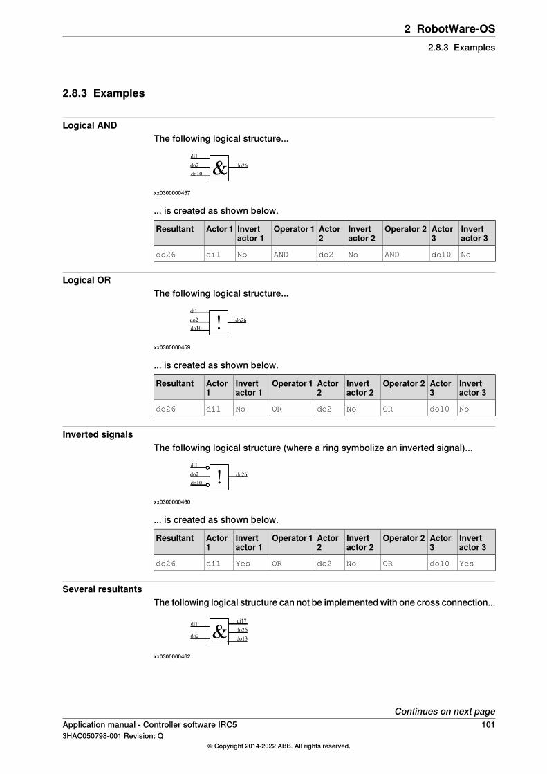
2.8.3 Examples
Logical ANDThe following logical structure...
xx0300000457
... is created as shown below.
Invertactor 3
Actor3
Operator 2Invertactor 2
Actor2
Operator 1Invertactor 1
Actor 1Resultant
Nodo10ANDNodo2ANDNodi1do26
Logical ORThe following logical structure...
xx0300000459
... is created as shown below.
Invertactor 3
Actor3
Operator 2Invertactor 2
Actor2
Operator 1Invertactor 1
Actor1
Resultant
Nodo10ORNodo2ORNodi1do26
Inverted signalsThe following logical structure (where a ring symbolize an inverted signal)...
xx0300000460
... is created as shown below.
Invertactor 3
Actor3
Operator 2Invertactor 2
Actor2
Operator 1Invertactor 1
Actor1
Resultant
Yesdo10ORNodo2ORYesdi1do26
Several resultantsThe following logical structure can not be implemented with one cross connection...
xx0300000462
Continues on next pageApplication manual - Controller software IRC5 1013HAC050798-001 Revision: Q
© Copyright 2014-2022 ABB. All rights reserved.
2 RobotWare-OS2.8.3 Examples

... but with three cross connections it can be implemented as shown below.
Invert actor 2Actor 2Operator 1Invert actor 1Actor 1Resultant
Nodo2ANDNodi1di17
Nodo2ANDNodi1do26
Nodo2ANDNodi1do13
Complex conditionsThe following logical structure...
xx0300000461
... is created as shown below.
Invertactor 3
Actor3
Operator 2Invertactor 2
Actor 2Operator 1Invertactor 1
Actor1
Resultant
Nodo3ANDNodi2do11
Yesdo3ANDNodi12do14
Nodo3ANDNodi13di11
Nodo3ANDNodi13do23
Nodo3ANDNodi13do17
Yesdi11ORNodo14ORNodo11do15
Nodo23ANDNodi11do33
Nodo3ANDNodo17do61
Yesdo33ORNodo15do54
102 Application manual - Controller software IRC53HAC050798-001 Revision: Q
© Copyright 2014-2022 ABB. All rights reserved.
2 RobotWare-OS2.8.3 ExamplesContinued
2.8.4 Limitations
Evaluation orderIf more than two actor I/O signals are used in one cross connection, the evaluationis made from left to right. This means that the operation between Actor 1 and Actor2 is evaluated first and the result from that is used in the operation with Actor 3.If all operators in one cross connection are of the same type (only AND or onlyOR) the evaluation order has no significance. However, mixing AND and ORoperators, without considering the evaluation order, may give an unexpected result.
Tip
Use several cross connections instead of mixing AND and OR in the same crossconnection.
Maximum number of actor I/O signalsA cross connection may not have more than five actor I/O signals. If more actorI/O signals are required, use several cross connections.
Maximum number of cross connectionsThe maximum number of cross connections handled by the robot system is 300.
Maximum depthThe maximum allowed depth of cross connection evaluations is 20.A resultant from one cross connection can be used as an actor in another crossconnection. The resultant from that cross connection can in its turn be used as anactor in the next cross connection. However, this type of chain of dependent crossconnections cannot be deeper than 20 steps.
Do not create a loopCross connections must not form closed chains since that would cause infiniteevaluation and oscillation. A closed chain appears when cross connections areinterlinked so that the chain of cross connections forms a circle.
Do not have the same resultant more than onceAmbiguous resultant I/O signals are not allowed since the outcome would dependon the order of evaluation (which cannot be controlled). Ambiguous resultant I/Osignals occur when the same I/O signal is resultant in several cross connections.
Overlapping device mapsThe resultant I/O signal in a cross connection must not have an overlapping devicemap with any inverted actor I/O signals defined in the cross connection. Using I/Osignals with overlapping device map in a cross connection can cause infinity signalsetting loops.
Application manual - Controller software IRC5 1033HAC050798-001 Revision: Q
© Copyright 2014-2022 ABB. All rights reserved.
2 RobotWare-OS2.8.4 Limitations

2.9 Connected Services
2.9.1 Overview
DescriptionConnected Services (was known as Remote Service previously) is a functionalityavailable for ABB robot controllers that connects to ABB cloud.Earlier the Connected Services functionality had been implemented on an externalhardware (Remote Service Box) connected to the Service port of the controller.Remote Service Box had provided service data collection and the externalconnectivity (Wireless GPRS, 3G, or wired).Connected Services is the software version of Remote Service Box insideRobotWare.
PurposeThe primary purpose of Connected Services is to remove the need of externalhardware if the robot controller are connected to Internet by the customer on itsWAN port.Connected Services is then available natively as a plug and connect solution inRobotWare. The setup concept will be:
• Provide internet connectivity to the controller.• Enable and register the connected controller to Connected Services.
An ABB 3G/4G/WiFi gateway or other external devices will be made available inthe future to use wireless connectivity.
What is includedThe RobotWare base functionality Connected Services gives you access to:
• a Connected Services Agent software to manage the connectivity and theService data collection.
• System Parameters used to enable and configure the connectivity.• dedicated event logs for key events of Connected Services.• status and information pages available in System Info.
PrerequisitesThe Connected Services function requires the controller to be defined in a ServiceAgreement. Contact the local ABB Service to create a Service Agreement with theConnected Services and get access to MyRobot website to perform the registrationafter the connection.
Note
MyRobot is the ABB website which gives access to the Service information of aRobot Controller under a Service Agreement.
Continues on next page104 Application manual - Controller software IRC5
3HAC050798-001 Revision: Q© Copyright 2014-2022 ABB. All rights reserved.
2 RobotWare-OS2.9.1 Overview

Basic workflowFollowing is the basic workflow for setting up Connected Services.
1 Configure Internet connectivity to the robot controller.2 Enable Connected Services and startup connection.3 Register the controller through MyRobot registration page.
Once Connected Services is connected and registered, the service data collectionwill run transparently in the background.
Note
UseSystem InfoConnected Services pages for information and local registration.Use MyRobot website for all Connected Service features and connected serviceside registration
LimitationsFollowing are the limitations of Connected Services:
• The controller identification is done using the controller serial number andmust match the serial number defined in the Service Level Agreement.
• The customer must also provide for the robot controller the connectivity topublic internet , use the ABB wireless gateway or third party supplier whenavailable.
Application manual - Controller software IRC5 1053HAC050798-001 Revision: Q
© Copyright 2014-2022 ABB. All rights reserved.
2 RobotWare-OS2.9.1 Overview
Continued

2.9.2 Connected Services connectivity
Connected Services connection conceptThe concept of Connected Services is that a virtual Software Agent is implementedinside the controller and it communicates securely with the ABB Connected Servicescloud through Internet. The communication is secured and encrypted using HTTPS(Secure HTTP) and only from the controller to ABB CSC connector to keep thecustomer network isolated from any external Internet access. The following figuredescribes these concepts:
xx1500003224
Continues on next page106 Application manual - Controller software IRC5
3HAC050798-001 Revision: Q© Copyright 2014-2022 ABB. All rights reserved.
2 RobotWare-OS2.9.2 Connected Services connectivity
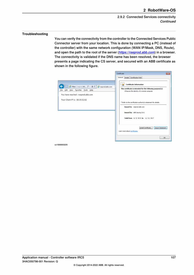
TroubleshootingYou can verify the connectivity from the controller to the Connected Services PublicConnector server from your location. This is done by connecting a PC (instead ofthe controller) with the same network configuration (WAN IP/Mask, DNS, Route),and open the path to the root of the server (https://rseprod.abb.com) in a browser.The connectivity is validated if the DNS name has been resolved, the browserpresents a page indicating the CS server, and secured with an ABB certificate asshown in the following figure.
xx1500003225
Application manual - Controller software IRC5 1073HAC050798-001 Revision: Q
© Copyright 2014-2022 ABB. All rights reserved.
2 RobotWare-OS2.9.2 Connected Services connectivity
Continued

2.9.3 Configuration - system parameters
Connected Services ConnectionThe following parameters belong to the topic Communication and the typeConnected Services. For more information, see Technical referencemanual - System parameters.
DescriptionParameter
Enable or disable CS. If CS is disabled there will be no communica-tion from the Controller.
Enabled
Indicates if the communication is done on Customer Network or byusing ABB Mobile Gateway Solution (to be implemented in futuredeliveries).
Connection Type
Adapt the polling rates and traffic volume to the type of connectivityavailable:
• Command polling (low) 1 min, (medium) 10 min, (high) 1 hour.• Register polling (low) 10 min, (medium) 30 min, (high) 2 hour.
Connection Cost
Indicates if a proxy is required to access Internet and its name andport.
Proxy Used, Name,Port
Defines if the proxy is authenticated or not, with related credentials(user, password).
WARNING
The proxy password is stored in plain text.
Proxy Auth, User,password
IP address of the ABB Mobile Gateway Solution if used (to come infuture deliveries).
Gateway IP Address
WAN configurationThe WAN IP/Mask/Gateway configuration is done in theBoot Application Settings.The WAN Ethernet port configuration which gives access to the Internet needs tobe done on the controller. The port is defined by its IP, Mask, and possible Gateway.For details about WAN configuration, see Hardware overview in the Applicationmanual - EtherNet/IP Scanner/Adapter.
DNS configurationThese parameters belong to the topic Communication and the type DNS Client. ADNS server need to be defined to resolve the name of the ABB Connected ServicesConnector (rseprod.abb.com) to its IP address if ABB Mobile Gateway is not used.For more details, see Type DNS Client in Technical reference manual - Systemparameters.
Note
For quick testing, use DNS as 8.8.8.8 (Google DNS) , then switch to customerrecommended DNS server IP.
Continues on next page108 Application manual - Controller software IRC5
3HAC050798-001 Revision: Q© Copyright 2014-2022 ABB. All rights reserved.
2 RobotWare-OS2.9.3 Configuration - system parameters

IP Routing configurationThese parameters belong to the topic Communication and the type IP Routing. Insome cases it is necessary to define some routing parameters to indicate whichspecific external device is used as a gateway to access the Internet on customernetwork. By default, an IP route is created based on the gateway defined on theWAN Port. But it is possible to add a specific route if the default gateway shouldnot be used. For more details, see Type IP Route in Technical referencemanual - System parameters.
Note
If the Internet Gateway is not the main Gateway, the traffic to rseprod.abb.comand the DNS must be defined as additional routes.For example, if Internet Gateway has IP address 100.100.100.22, rseprod.abb.comhas IP address 138.227.175.43 (verify by nslookup) and DNS has IP address8.8.8.8, then you must define the following two routes:
• Route 138.227.175.43/31 to 100.100.100.22• Route 8.8.8.8/31 to 100.100.100.22
Application manual - Controller software IRC5 1093HAC050798-001 Revision: Q
© Copyright 2014-2022 ABB. All rights reserved.
2 RobotWare-OS2.9.3 Configuration - system parameters
Continued

2.9.4 Configuring Connected Services
OverviewThis section explains how the Connected Services is configured with the controller,when Internet is available on the default gateway. There are two separate networksetups:
• Direct internet connection without proxy.• Internet connectivity through a proxy.
Direct internet connectionThe following procedure provides information about configuring the ConnectedServices from the FlexPendant when there is direct internet connection from thecontroller.
IllustrationAction
In the ABB menu, select Control Panel.1
Select Configuration.2
From Topics, select Communication.3
xx1600001326
Select Connected Services and editRSCON.
4
xx1600001327
In Enabled, select Yes5
Tap OK and restart the controller to takeeffect of the changes.
6
Continues on next page110 Application manual - Controller software IRC5
3HAC050798-001 Revision: Q© Copyright 2014-2022 ABB. All rights reserved.
2 RobotWare-OS2.9.4 Configuring Connected Services

Direct internet connection with manual DNSThe following procedure provides information about configuring the ConnectedServices from the FlexPendant when there is direct internet connection with manualDNS.
IllustrationAction
In the ABB menu, select Control Panel.1
Select Configuration.2
From Topics, select Communication.3
xx1600001329
Select DNS Client and edit DNS Client.4
xx1600001330
Edit 1st Name Server5
Tap OK and restart the controller to takeeffect of the changes.
6
Internet connection with proxyThe following procedure provides information about configuring the ConnectedServices from the FlexPendant when there is internet connection with proxy.
IllustrationAction
In the ABB menu, select Control Panel.1
Tap Configuration.2
From Topics, select Communication.3
SelectConnected Services and inProxyUsed, select Yes.
4
Continues on next pageApplication manual - Controller software IRC5 1113HAC050798-001 Revision: Q
© Copyright 2014-2022 ABB. All rights reserved.
2 RobotWare-OS2.9.4 Configuring Connected Services
Continued

IllustrationAction
xx1600001331
InProxyAuth, selectNone for no authen-tication from the drop-down list.
5
xx1600001332
In Proxy Auth , select Basic for basicauthentication from the drop-down list.
• Define the proxy name, proxy port,user name, and password for thebasic authentication.
6
Tap OK and restart the controller to takeeffect of the changes.
7
Note
Manually define the DNS, if it is not provided automatically when proxy is used.
112 Application manual - Controller software IRC53HAC050798-001 Revision: Q
© Copyright 2014-2022 ABB. All rights reserved.
2 RobotWare-OS2.9.4 Configuring Connected ServicesContinued
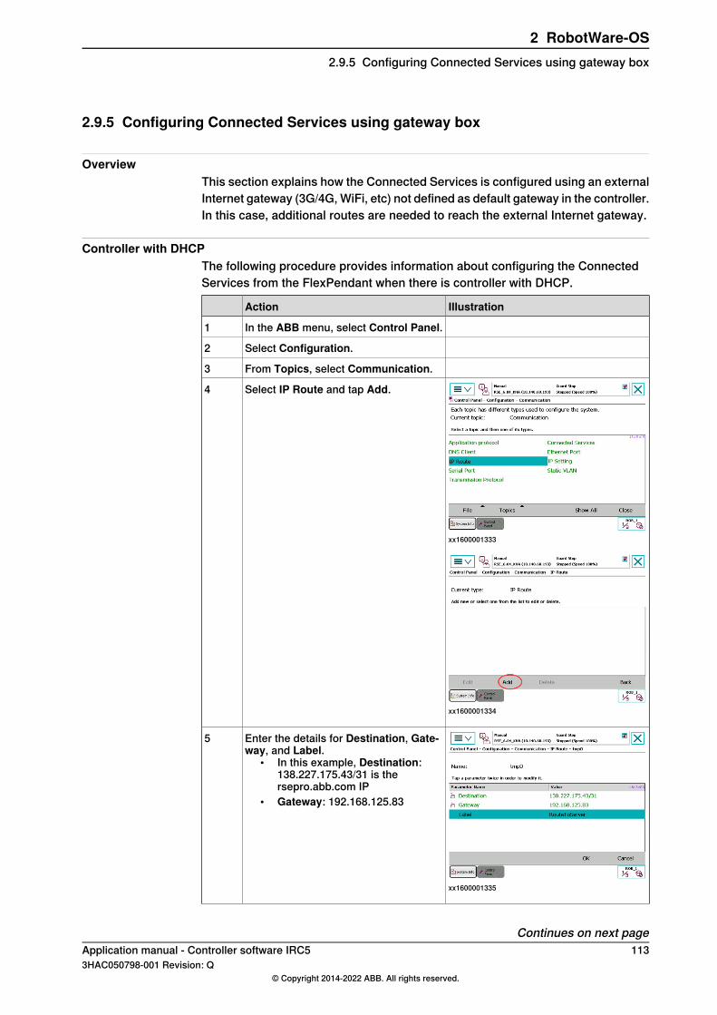
2.9.5 Configuring Connected Services using gateway box
OverviewThis section explains how the Connected Services is configured using an externalInternet gateway (3G/4G, WiFi, etc) not defined as default gateway in the controller.In this case, additional routes are needed to reach the external Internet gateway.
Controller with DHCPThe following procedure provides information about configuring the ConnectedServices from the FlexPendant when there is controller with DHCP.
IllustrationAction
In the ABB menu, select Control Panel.1
Select Configuration.2
From Topics, select Communication.3
xx1600001333
Select IP Route and tap Add.4
xx1600001334
xx1600001335
Enter the details for Destination, Gate-way, and Label.
• In this example, Destination:138.227.175.43/31 is thersepro.abb.com IP
• Gateway: 192.168.125.83
5
Continues on next pageApplication manual - Controller software IRC5 1133HAC050798-001 Revision: Q
© Copyright 2014-2022 ABB. All rights reserved.
2 RobotWare-OS2.9.5 Configuring Connected Services using gateway box

IllustrationAction
Tap OK and restart the controller to takeeffect of the changes.
6
Controller with DHCP and manual DNSThe following procedure provides information about configuring the ConnectedServices from the FlexPendant for controller with DHCP and manual DNS.
IllustrationAction
In the ABB menu, select Control Panel.1
Select Configuration.2
From Topics, select Communication.3
Select IP Route and tap Add.4
xx1600001337
Enter the details for Destination, Gate-way, and Label.
• If DNS IP is entered manually, addthe routing for the DNS IP.
• In this example, Destination:8.8.8.8/31 is Google DNS.
5
Tap OK and restart the controller to takeeffect of the changes.
6
Continues on next page114 Application manual - Controller software IRC5
3HAC050798-001 Revision: Q© Copyright 2014-2022 ABB. All rights reserved.
2 RobotWare-OS2.9.5 Configuring Connected Services using gateway boxContinued
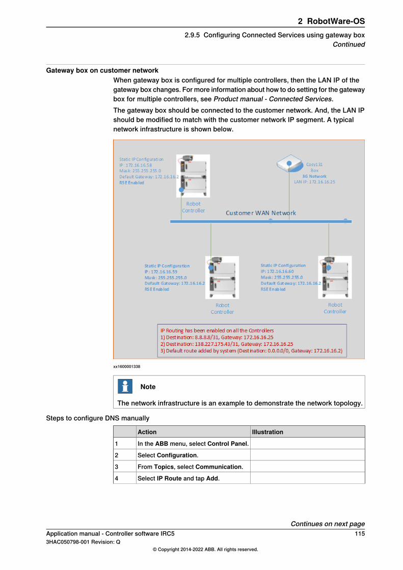
Gateway box on customer networkWhen gateway box is configured for multiple controllers, then the LAN IP of thegateway box changes. For more information about how to do setting for the gatewaybox for multiple controllers, see Product manual - Connected Services.The gateway box should be connected to the customer network. And, the LAN IPshould be modified to match with the customer network IP segment. A typicalnetwork infrastructure is shown below.
xx1600001338
Note
The network infrastructure is an example to demonstrate the network topology.
Steps to configure DNS manually
IllustrationAction
In the ABB menu, select Control Panel.1
Select Configuration.2
From Topics, select Communication.3
Select IP Route and tap Add.4
Continues on next pageApplication manual - Controller software IRC5 1153HAC050798-001 Revision: Q
© Copyright 2014-2022 ABB. All rights reserved.
2 RobotWare-OS2.9.5 Configuring Connected Services using gateway box
Continued
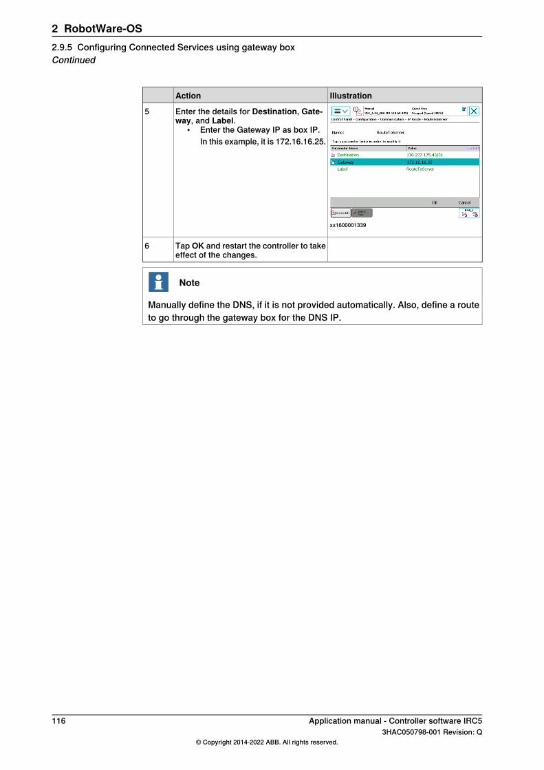
IllustrationAction
xx1600001339
Enter the details for Destination, Gate-way, and Label.
• Enter the Gateway IP as box IP.In this example, it is 172.16.16.25.
5
Tap OK and restart the controller to takeeffect of the changes.
6
Note
Manually define the DNS, if it is not provided automatically. Also, define a routeto go through the gateway box for the DNS IP.
116 Application manual - Controller software IRC53HAC050798-001 Revision: Q
© Copyright 2014-2022 ABB. All rights reserved.
2 RobotWare-OS2.9.5 Configuring Connected Services using gateway boxContinued

2.9.6 Connected Services on LAN 3
OverviewWhen internet is not provided on production WAN network, we can configure anduse LAN 3 to connect with the Connected Services server.LAN 3 (available on port X5) acts as a separate switch and its IP can be configuredmanually.
Note
There is a risk of conflict between PROFINET and LAN 3 in some configuration.It is not possible to use Connected Services in LAN 3, if PROFINET is set up inisolated mode. For more details, see section Isolated LAN 3 or LAN 3 as partof the private network in Application manual - PROFINET Controller/Device.
Note
It is not possible to use LAN 3 in RW 6.07. Only WAN port is supported for thisrelease.
Steps to configure LAN 3To configure the IP manually, follow the steps below:
ActionStep
In the ABB menu, select Control Panel.1
Select Configuration2
From Topics, select Communication
Select IP Settings and tap Add• Enter the details for IP Address, Interface, and Label.• Change the Interface to LAN3.
3
Tap OK and restart the controller to take effect of the changes.4
Continues on next pageApplication manual - Controller software IRC5 1173HAC050798-001 Revision: Q
© Copyright 2014-2022 ABB. All rights reserved.
2 RobotWare-OS2.9.6 Connected Services on LAN 3
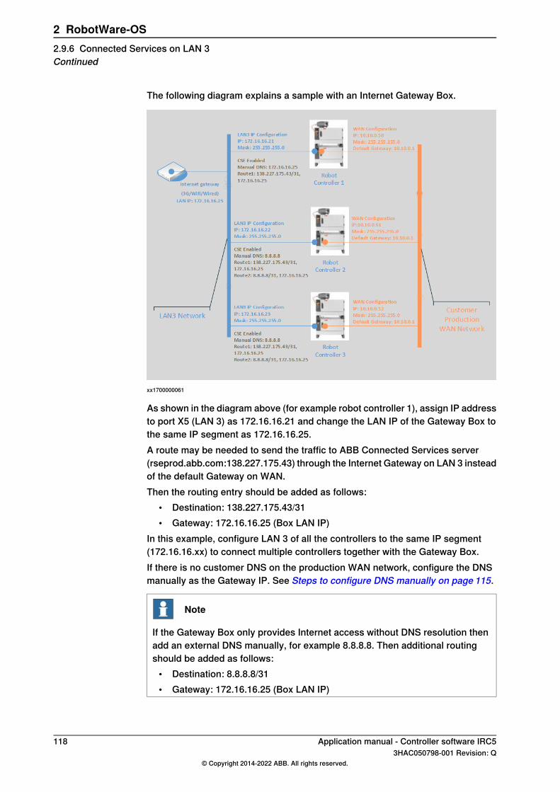
The following diagram explains a sample with an Internet Gateway Box.
xx1700000061
As shown in the diagram above (for example robot controller 1), assign IP addressto port X5 (LAN 3) as 172.16.16.21 and change the LAN IP of the Gateway Box tothe same IP segment as 172.16.16.25.A route may be needed to send the traffic to ABB Connected Services server(rseprod.abb.com:138.227.175.43) through the Internet Gateway on LAN 3 insteadof the default Gateway on WAN.Then the routing entry should be added as follows:
• Destination: 138.227.175.43/31• Gateway: 172.16.16.25 (Box LAN IP)
In this example, configure LAN 3 of all the controllers to the same IP segment(172.16.16.xx) to connect multiple controllers together with the Gateway Box.If there is no customer DNS on the production WAN network, configure the DNSmanually as the Gateway IP. See Steps to configure DNS manually on page 115.
Note
If the Gateway Box only provides Internet access without DNS resolution thenadd an external DNS manually, for example 8.8.8.8. Then additional routingshould be added as follows:
• Destination: 8.8.8.8/31• Gateway: 172.16.16.25 (Box LAN IP)
118 Application manual - Controller software IRC53HAC050798-001 Revision: Q
© Copyright 2014-2022 ABB. All rights reserved.
2 RobotWare-OS2.9.6 Connected Services on LAN 3Continued

2.9.7 Connected Services registration
Connected Services startupThe Connected Services startup is based on the following steps:
• (0) Connected Services preparation• (1) Connected Services configuration• (2) Connected Services connectivity• (3) Connected Services registration• (4) Connected Services connected and registered
When these steps are done, the software Agent is securely connected and identifiedwith a client certificate. The following figure describes these concepts:
xx1500003226
Connected Services preparation• Verify the controller serial number with the serial number found in the
controller module cabinet.• Verify and provide Internet connectivity to the robot controller.• Verify that the service agreement for this controller is available with ABB
Robotics Service.
Connected Services configuration• Configure the connectivity parameters.• Enable Connected Services
Connected Services connectivity• Software Agent connects to the ABB Connected Services Center.• An initial registration process starts at low polling rate.
Continues on next pageApplication manual - Controller software IRC5 1193HAC050798-001 Revision: Q
© Copyright 2014-2022 ABB. All rights reserved.
2 RobotWare-OS2.9.7 Connected Services registration
• The initial registration is incomplete and not yet fully trusted.• A registration code is received to finalize the trust relation.• The registration code is made available on the Connected Services
registration page.
Connected Services registration• The customer/ABB on site provides the controller serial number and
registration code to the Connected Services Administrator for registration.• The Connected Services Administrator validates this registration code in
MyRobot on its service agreement.• The registration trust starts and implements a client certificate in the
controller.
Connected Services connected and registered• The controller is connected, registered, and identified in the service
agreement.• The connection is trusted with a client certificate.• Connected Services is now actively running on the robot controller.
120 Application manual - Controller software IRC53HAC050798-001 Revision: Q
© Copyright 2014-2022 ABB. All rights reserved.
2 RobotWare-OS2.9.7 Connected Services registrationContinued

2.9.8 Connected Services information
Connected Services pages
IntroductionThe Connected Services information pages are available under System Info >Software resources > Communication > Connected Services. The following arethe 4 Connected Services information pages:
• Overview• Server Connection• Registration• Advanced
Note
The information on a page can be refreshed by changing the page or by pressingthe Refresh button. The Refresh button also forces a connection with the serverif the software agent is waiting. (for example, wait for registrationacknowledgement from MyRobot). This is useful in case of slow polling whenconnection cost is set to High.
Overview pageThe Overview page provides a summary of the Connected Services status andinformation. If the status is not active then the other pages provide more detailedinformation.
ExamplePossible valuesDescriptionField
YesYes/NoDisplays the value of the masterconfiguration switch for turning theConnected Services on/off.
Enabled
Active"-"Displays the current status to seewhether there is a need to navigateto the Server connection page orRegistration page.
StatusFailedInitializingShutdownRegistration inprogressTrying to connectActive
12-45678Controller Serialnumber
Displays the identifier that is usedto identify the controller in Connec-ted Service.
Serial number
6.03.0088RobotWare ver-sion name
Displays the RobotWare version thatis sent to the server.
RobotWare ver-sion
20-NDisplays the number of times thesoftware Agent been auto-restarted.This is used to see if watchdog hasrestarted the by it.
Restart counterIf not Enabled,then display: 0
0116/ROBOT-WARE-6.02.0000+/5196
"Data CollectorScript name""-"
Displays the downloaded data col-lector code version.
Script version
Continues on next pageApplication manual - Controller software IRC5 1213HAC050798-001 Revision: Q
© Copyright 2014-2022 ABB. All rights reserved.
2 RobotWare-OS2.9.8 Connected Services information
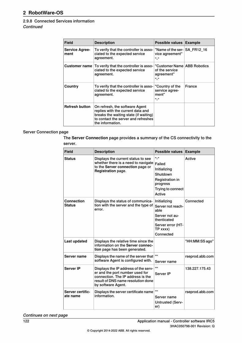
ExamplePossible valuesDescriptionField
SA_FR12_16"Name of the ser-vice agreement"
To verify that the controller is asso-ciated to the expected serviceagreement.
Service Agree-ment
"-"
ABB Robotics"Customer Nameof the serviceagreement"
To verify that the controller is asso-ciated to the expected serviceagreement.
Customer name
"-"
France"Country of theservice agree-ment"
To verify that the controller is asso-ciated to the expected serviceagreement.
Country
"-"
On refresh, the software Agentreplies with the current data andbreaks the waiting state (if waiting)to contact the server and refreshesthe information.
Refresh button
Server Connection pageThe Server Connection page provides a summary of the CS connectivity to theserver.
ExamplePossible valuesDescriptionField
Active"-"Displays the current status to seewhether there is a need to navigateto the Server connection page orRegistration page.
StatusFailedInitializingShutdownRegistration inprogressTrying to connectActive
ConnectedInitializingDisplays the status of communica-tion with the server and the type oferror.
ConnectionStatus Server not reach-
ableServer not au-thenticatedServer error (HT-TP xxxx)Connected
"HH:MM:SS ago"Displays the relative time since theinformation on the Server connec-tion page has been generated.
Last updated
rseprod.abb.com""Displays the name of the server thatsoftware Agent is configured with.
Server nameServer name
138.227.175.43""Displays the IP address of the serv-er and the port number used forconnection. The IP address is theresult of DNS name resolution doneby software Agent.
Server IPServer IP
rseprod.abb.com""Displays the server certificate nameinformation.
Server certific-ate name Server name
Untrusted (Serv-er)
Continues on next page122 Application manual - Controller software IRC5
3HAC050798-001 Revision: Q© Copyright 2014-2022 ABB. All rights reserved.
2 RobotWare-OS2.9.8 Connected Services informationContinued
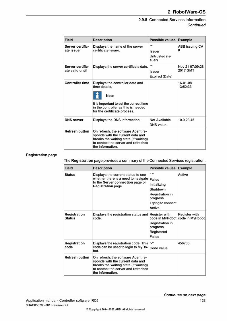
ExamplePossible valuesDescriptionField
ABB issuing CA6
""Issuer
Displays the name of the servercertificate issuer.
Server certific-ate issuer
Untrusted (Is-suer)
Nov 21 07:09:282017 GMT
""Issuer
Displays the server certificate date.Server certific-ate valid until
Expired (Date)
16-01-0813:52:33
Displays the controller date andtime details.
Note
It is important to set the correct timein the controller as this is neededfor the certificate process.
Controller time
10.0.23.45Not AvailableDisplays the DNS information.DNS serverDNS value
On refresh, the software Agent re-sponds with the current data andbreaks the waiting state (if waiting)to contact the server and refreshesthe information.
Refresh button
Registration pageTheRegistration page provides a summary of the Connected Services registration.
ExamplePossible valuesDescriptionField
Active"-"Displays the current status to seewhether there is a need to navigateto the Server connection page orRegistration page.
StatusFailedInitializingShutdownRegistration inprogressTrying to connectActive
Register withcode in MyRobot
Register withcode in MyRobot
Displays the registration status andcode.
RegistrationStatus
Registration inprogressRegisteredFailed
456735"-"Displays the registration code. Thiscode can be used to login to MyRo-bot.
Registrationcode Code value
On refresh, the software Agent re-sponds with the current data andbreaks the waiting state (if waiting)to contact the server and refreshesthe information.
Refresh button
Continues on next pageApplication manual - Controller software IRC5 1233HAC050798-001 Revision: Q
© Copyright 2014-2022 ABB. All rights reserved.
2 RobotWare-OS2.9.8 Connected Services information
Continued

Advanced pageThe Advanced page provides advanced information about the dialog betweensoftware Agent and server.
ExamplePossible valuesDescriptionField
GetMessageRegisterDisplays the last message sent.Last HTTP mes-sage CheckRegister
GetLoginInfoGetMessage...
Sent hh:mm:ssago
Displays the date and time when thelast message was sent.
Last HTTP mes-sage time
Not AvailableNot AvailableDisplays the HTTP error when thelast message was sent and themessage ID if 4XX.
Last HTTP errorError HTTP XXX+ Message
GetMessage in70 seconds
Displays the next message to sendand the date to send the message.
Next message
Not AvailableNot AvailableDisplays the last command receivedfrom server.
Last commandRebootResetPingDiagnostic...
On refresh, the software Agent re-sponds with the current data andbreaks the waiting state (if waiting)to contact the server and refreshesthe information.
Refresh button
0/1/0/3/4/0/10-N for eachserver error
Displays a count of the followingservers errors:
• Timeout errors• Request errors• Connection errors• Connection not Available er-
rors• Unknown errors• Authentication errors• Proxy errors
Server Errors
Connected Services logsThe software Agent generates some event logs in the central controller event log.Event logs are generated during starting, registering, unregistering, losingconnectivity, and during other key events.The events logs are in the range of 170XXX and are described with all the othercontroller event logs documentation. For more details, see Operatingmanual - Troubleshooting IRC5.
Continues on next page124 Application manual - Controller software IRC5
3HAC050798-001 Revision: Q© Copyright 2014-2022 ABB. All rights reserved.
2 RobotWare-OS2.9.8 Connected Services informationContinued

Force a reset of the software agentIt is possible to reset the software agent. When you reset, the software agent erasesall its internal information including the registration information, the data collectorscript, and all the locally stored service information. The configuration will not bereset, but a new registration is required to reactivate the Connected Services.Use the following procedure to reset the software agent:
Action
Tap the ABB button to display the ABB menu.Process applications are listed in the menu.
1
Tap Program Editor -> Debug -> Call Routine.
Note
Tap PP to Main if Debug is disabled.
2
TapConnected Services Reset ->Go to. Press theMotors on button on the controller.3
Press the Play button to execute the reset routine - > tap Reset.4
Application manual - Controller software IRC5 1253HAC050798-001 Revision: Q
© Copyright 2014-2022 ABB. All rights reserved.
2 RobotWare-OS2.9.8 Connected Services information
Continued
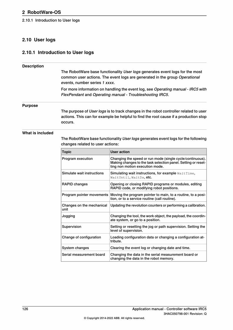
2.10 User logs
2.10.1 Introduction to User logs
DescriptionThe RobotWare base functionality User logs generates event logs for the mostcommon user actions. The event logs are generated in the group Operationalevents, number series 1 xxxx.For more information on handling the event log, see Operating manual - IRC5 withFlexPendant and Operating manual - Troubleshooting IRC5.
PurposeThe purpose of User logs is to track changes in the robot controller related to useractions. This can for example be helpful to find the root cause if a production stopoccurs.
What is includedThe RobotWare base functionality User logs generates event logs for the followingchanges related to user actions:
User actionTopic
Changing the speed or run mode (single cycle/continuous).Making changes to the task selection panel. Setting or reset-ting non motion execution mode.
Program execution
Simulating wait instructions, for example WaitTime,WaitUntil, WaitDx, etc.
Simulate wait instructions
Opening or closing RAPID programs or modules, editingRAPID code, or modifying robot positions.
RAPID changes
Moving the program pointer to main, to a routine, to a posi-tion, or to a service routine (call routine).
Program pointer movements
Updating the revolution counters or performing a calibration.Changes on the mechanicalunit
Changing the tool, the work object, the payload, the coordin-ate system, or go to a position.
Jogging
Setting or resetting the jog or path supervision. Setting thelevel of supervision.
Supervision
Loading configuration data or changing a configuration at-tribute.
Change of configuration
Clearing the event log or changing date and time.System changes
Changing the data in the serial measurement board orchanging the data in the robot memory.
Serial measurement board
126 Application manual - Controller software IRC53HAC050798-001 Revision: Q
© Copyright 2014-2022 ABB. All rights reserved.
2 RobotWare-OS2.10.1 Introduction to User logs

3 Motion performance3.1 Absolute Accuracy [603-1, 603-2]
3.1.1 About Absolute Accuracy
PurposeAbsolute Accuracy is a calibration concept that improves TCP accuracy. Thedifference between an ideal robot and a real robot can be several millimeters,resulting from mechanical tolerances and deflection in the robot structure. AbsoluteAccuracy compensates for these differences.Here are some examples of when this accuracy is important:
• Exchangeability of robots• Offline programming with no or minimum touch-up• Online programming with accurate movement and reorientation of tool• Accurate cell alignment for MultiMove coordinated motion• Programming with accurate offset movement in relation to eg. vision system
or offset programming• Re-use of programs between applications
The option Absolute Accuracy is integrated in the controller algorithms and doesnot need external equipment or calculation.
Note
The performance data is applicable to the corresponding RobotWare version ofthe individual robot.
xx1800002701
Continues on next pageApplication manual - Controller software IRC5 1273HAC050798-001 Revision: Q
© Copyright 2014-2022 ABB. All rights reserved.
3 Motion performance3.1.1 About Absolute Accuracy
What is includedEvery Absolute Accuracy robot is delivered with:
• compensation parameters saved on the robot’s serial measurement board• a birth certificate representing the Absolute Accuracy measurement protocol
for the calibration and verification sequence.A robot with Absolute Accuracy calibration has a label with this information on themanipulator.Absolute Accuracy supports floor mounted, wall mounted and ceiling mountedinstallations. Compensation parameters saved in the robot’s serial measurementboard differ depending on which Absolute Accuracy option is selected.
When is Absolute Accuracy being usedAbsolute Accuracy works on a robot target in Cartesian coordinates, not on theindividual joints. Therefore, joint based movements (e.g. MoveAbsJ) will not beaffected.If the robot is inverted, the Absolute Accuracy calibration must be performed whenthe robot is inverted.
Absolute Accuracy activeAbsolute Accuracy will be active in the following cases:
• Any motion function based on robtargets (e.g. MoveL) and ModPos onrobtargets
• Reorientation jogging• Linear jogging• Tool definition (4, 5, 6 point tool definition, room fixed TCP, stationary tool)• Work object definition
Absolute Accuracy not activeThe following are examples of when Absolute Accuracy is not active:
• Any motion function based on a jointtarget (MoveAbsJ)• Independent joint• Joint based jogging• Additional axes• Track motion
Note
In a robot system with, for example, an additional axis or track motion, theAbsolute Accuracy is active for the manipulator but not for the additional axis ortrack motion.
RAPID instructionsThere are no RAPID instructions included in this option.
Continues on next page128 Application manual - Controller software IRC5
3HAC050798-001 Revision: Q© Copyright 2014-2022 ABB. All rights reserved.
3 Motion performance3.1.1 About Absolute AccuracyContinued
Absolute Accuracy and MultiMoveIf the main robot in a MultiMove system has the Absolute Accuracy option, it opensup Absolute Accuracy capability for all the robots in the system. However, eachrobot needs to be calibrated individually.
Note
Note that this is the only RobotWare option that is relevant for an additional robot.
Note
It is possible to mix robots with and without the option Absolute Accuracyarbitrarily in a MultiMove system.
Application manual - Controller software IRC5 1293HAC050798-001 Revision: Q
© Copyright 2014-2022 ABB. All rights reserved.
3 Motion performance3.1.1 About Absolute Accuracy
Continued
3.1.2 Useful tools
OverviewThe following products are recommended for operation and maintenance ofAbsolute Accurate robots:
• Load Identification• CalibWare (Absolute Accuracy calibration tool)
Load IdentificationAbsolute Accuracy calculates the robot's deflection depending on payload. It isvery important to have an accurate description of the load.Load Identification is a tool that determines the mass, center of gravity, and inertiaof the payload.For more information, see Operating manual - IRC5 with FlexPendant.
CalibWareCalibWare, provided by ABB, is a tool for calibrating Absolute Accuracy. Thedocumentation to CalibWare describes the Absolute Accuracy calibration procedurein detail.CalibWare is used at initial calibration and when servicing the robot.
130 Application manual - Controller software IRC53HAC050798-001 Revision: Q
© Copyright 2014-2022 ABB. All rights reserved.
3 Motion performance3.1.2 Useful tools

3.1.3 Configuration
Activate Absolute AccuracyUse RobotStudio and follow these steps (see Operating manual - RobotStudio formore information):
1 If you do not already have write access, click Request Write Access andwait for grant from the FlexPendant.
2 Click Configuration Editor and select Motion.3 Click the type Robot.4 For the parameter Use Robot Calibration, change the value to r1_calib.5 For a MultiMove system, configure the parameter Use Robot Calibration for
each robot. It should be set to r2_calib for robot 2, r3_calib for robot 3, andr4_calib for robot 4.
6 Restart the controller for the changes to take effect.
Tip
To verify that Absolute Accuracy is active, look at the Jogging window on theFlexPendant. When Absolute Accuracy is active, the text "Absolute AccuracyOn" is shown in the left window. In a MultiMove system, check this status for allmechanical units.
Deactivate Absolute AccuracyUse RobotStudio and follow these steps (see Operating manual - RobotStudio formore information):
1 If you do not already have write access, click Request Write Access andwait for grant from the FlexPendant.
2 Click Configuration Editor and select the topic Motion.3 Click the type Robot.4 Configure the parameter Use Robot Calibration and change the value to
"r1_uncalib".5 For a MultiMove system, repeat step 3 and 4 for each robot. Use Robot
Calibration is then set to "r2_uncalib" for robot 2, "r3_uncalib" for robot 3and "r4_uncalib" for robot 4.
6 Restart the controller for the changes to take effect.
Change calibration dataIf you exchange the manipulator, the calibration data for the new manipulator mustbe loaded. This is done by copying the calibration data from the robot’s serialmeasurement board to the robot controller.Use the FlexPendant and follow these steps (for more information, see Operatingmanual - IRC5 with FlexPendant):
Action
Tap the ABB menu and then Calibration.1
Continues on next pageApplication manual - Controller software IRC5 1313HAC050798-001 Revision: Q
© Copyright 2014-2022 ABB. All rights reserved.
3 Motion performance3.1.3 Configuration

Action
Tap on the robot you wish to update.2
Tap the tab Robot Memory.3
Tap Advanced.4
Tap Clear Controller Memory.5
Tap Clear and then confirm by tapping Yes.6
Tap Close.7
Tap Update.8
Tap Cabinet or robot has been exchanged and confirm by tapping Yes.9
132 Application manual - Controller software IRC53HAC050798-001 Revision: Q
© Copyright 2014-2022 ABB. All rights reserved.
3 Motion performance3.1.3 ConfigurationContinued

3.1.4 Maintenance
3.1.4.1 Maintenance that affect the accuracy
OverviewThis section will focus on those maintenance activities that directly affect theaccuracy of the robot, summarized as follows:
• Tool recalibration• Motor replacement• Wrist replacement (large robots)• Arm replacement (lower arm, upper arm, gearbox, foot)• Manipulator replacement• Loss of accuracy
Note
If the RobotWare version on the controller must be downgraded, then contactyour local ABB for support regarding compatible versions of Absolute Accuracy.
Tool recalibrationFor information about tool recalibration, see Tool calibration on page 147.
Motor replacementReplacement of all motors requires a re-calibration of the corresponding resolveroffset parameter using the standard calibration method for the respective robot.This is described in the product manual for the robot.If the motor replacement requires disassembly of the arm, then see Armreplacement or disassembly on page 133.
Wrist replacementReplacement of the wrist unit requires a re-calibration of the resolver offsets foraxes 5 and 6 using the standard calibration method for the respective robot.
Arm replacement or disassemblyReplacement of any of the robot arms, or other mechanical structure (excludingwrist), changes the structure of the robot to the extent that a robot recalibration isrequired. It is recommended that, after an arm replacement, the entire robot shouldbe recalibrated to ensure optimal Absolute Accuracy functionality. This is typicallyperformed with CalibWare and a separate measurement system. CalibWare canbe used together with any generic 3Dmeasurement system.For more information about the calibration process, see documentation forCalibWare.
Continues on next pageApplication manual - Controller software IRC5 1333HAC050798-001 Revision: Q
© Copyright 2014-2022 ABB. All rights reserved.
3 Motion performance3.1.4.1 Maintenance that affect the accuracy

A summary of the calibration process is presented as follows:
Action
Replace the affected component.1
Perform a resolver offset calibration for all axes. See the product manual for therespective robot.
2
Recalibrate the TCP.3
Check the accuracy by comparison to a fixed reference point in the cell.4
Check the accuracy of the work objects.
Note
An update of the defined work objects will make the deviation less in positioning.
5
Check the accuracy of the positions in the current application.6
If the accuracy still is unsatisfactory, perform an Absolute Accuracy calibration ofthe entire robot. See documentation for CalibWare.
7
Manipulator replacementWhen a robot manipulator is replaced without replacing the controller cabinet, itis necessary to update the Absolute Accuracy parameters in the controller cabinetand realign the robot to the cell. The Absolute Accuracy parameters are updatedby loading the replacement robot’s calibration parameters into the controller asdescribed in Change calibration data on page131. Ensure that the calibration datais loaded and that Absolute Accuracy is activated.The alignment of the replacement robot to the cell depends on the robot alignmenttechnique chosen at installation. If the robot mounting pins are aligned to the cellthen the robot need only be placed on the pins - no further alignment is necessary.If the robot was aligned using a robot program then it is necessary to measure thecell fixture(s) and measure the robot in several positions (for best results use thesame program as the original robot). See Measure robot alignment on page 145.
134 Application manual - Controller software IRC53HAC050798-001 Revision: Q
© Copyright 2014-2022 ABB. All rights reserved.
3 Motion performance3.1.4.1 Maintenance that affect the accuracyContinued

3.1.4.2 Loss of accuracy
Cause and actionLoss of accuracy usually occur after robot collision or large temperature variations.It is necessary to determine the cause of the errors, and take adequate action.
...then...If...
recalibrate if the TCP has changed.the tool is not prop-erly calibrated
run Load Identification to ensure correct mass, centre of gravity andinertia for the active tool.
the tool load is notcorrectly defined
1 Check that the axis scales show that the robot stands correctlyin the home position.
2 If the indicators are not aligned, move the robot to correct posi-tion and update the revolution counters.
3 If the indicators are close to aligned but not correct, re-calibratewith the standard calibration for the robot.
the resolver offsetsare no longer valid
1 Check by moving the robot to a predefined position on the fix-ture(s).
2 Visually assessing whether the deviation is excessive.3 If excessive, realign robot to fixture(s).
the robot’s relation-ship to the fix-ture(s) haschanged
1 Visually assess whether the robot is damaged.2 If damaged then replace entire manipulator -or- replace affected
arm(s) -or- recalibrate affected arm(s).
the robot structurehas changed
Application manual - Controller software IRC5 1353HAC050798-001 Revision: Q
© Copyright 2014-2022 ABB. All rights reserved.
3 Motion performance3.1.4.2 Loss of accuracy
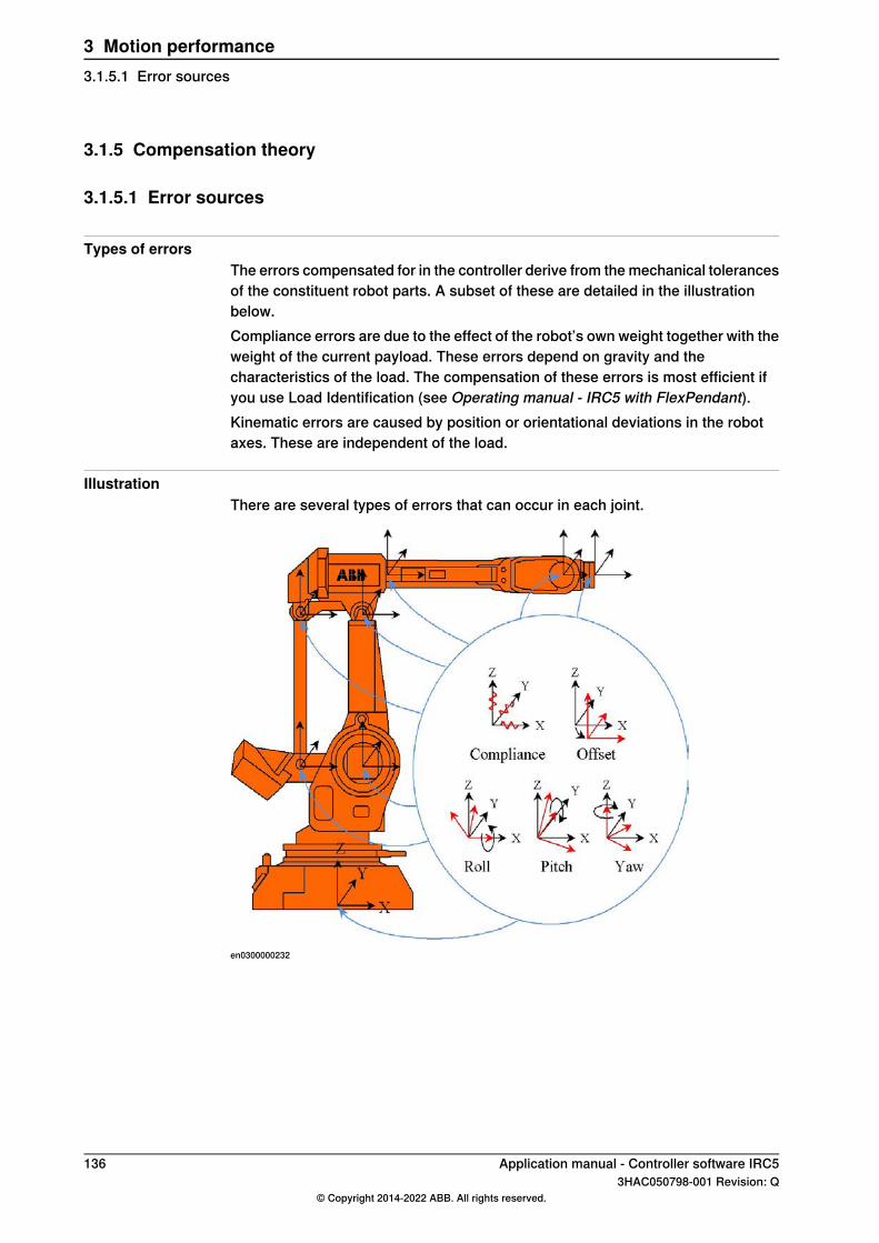
3.1.5 Compensation theory
3.1.5.1 Error sources
Types of errorsThe errors compensated for in the controller derive from the mechanical tolerancesof the constituent robot parts. A subset of these are detailed in the illustrationbelow.Compliance errors are due to the effect of the robot’s own weight together with theweight of the current payload. These errors depend on gravity and thecharacteristics of the load. The compensation of these errors is most efficient ifyou use Load Identification (see Operating manual - IRC5 with FlexPendant).Kinematic errors are caused by position or orientational deviations in the robotaxes. These are independent of the load.
IllustrationThere are several types of errors that can occur in each joint.
en0300000232
136 Application manual - Controller software IRC53HAC050798-001 Revision: Q
© Copyright 2014-2022 ABB. All rights reserved.
3 Motion performance3.1.5.1 Error sources
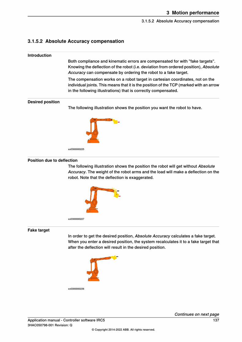
3.1.5.2 Absolute Accuracy compensation
IntroductionBoth compliance and kinematic errors are compensated for with "fake targets".Knowing the deflection of the robot (i.e. deviation from ordered position), AbsoluteAccuracy can compensate by ordering the robot to a fake target.The compensation works on a robot target in cartesian coordinates, not on theindividual joints. This means that it is the position of the TCP (marked with an arrowin the following illustrations) that is correctly compensated.
Desired positionThe following illustration shows the position you want the robot to have.
xx0300000225
Position due to deflectionThe following illustration shows the position the robot will get without AbsoluteAccuracy. The weight of the robot arms and the load will make a deflection on therobot. Note that the deflection is exaggerated.
xx0300000227
Fake targetIn order to get the desired position, Absolute Accuracy calculates a fake target.When you enter a desired position, the system recalculates it to a fake target thatafter the deflection will result in the desired position.
xx0300000226
Continues on next pageApplication manual - Controller software IRC5 1373HAC050798-001 Revision: Q
© Copyright 2014-2022 ABB. All rights reserved.
3 Motion performance3.1.5.2 Absolute Accuracy compensation

Compensated positionThe actual position will be the same as your desired position. As a user you willnot notice the fake target or the deflection. The robot will behave as if it had nodeflection.
xx0300000224
138 Application manual - Controller software IRC53HAC050798-001 Revision: Q
© Copyright 2014-2022 ABB. All rights reserved.
3 Motion performance3.1.5.2 Absolute Accuracy compensationContinued

3.1.6 Preparation of Absolute Accuracy robot
3.1.6.1 ABB calibration process
OverviewThis section describes the calibration process that ABB performs on each AbsoluteAccuracy robot, regardless of robot type or family, before it is delivered.The process can be divided in four steps:
1 Resolver offset calibration2 Absolute Accuracy calibration3 Calibration data stored on the serial measurement board4 Absolute Accuracy verification5 Generation of a birth certificate
Resolver offset calibrationThe resolver offset calibration process is used to calibrate the resolver offsetparameters.For information on how to do this, see the product manual for the respective robot.
Absolute Accuracy calibrationThe Absolute Accuracy calibration is performed on top of the resolver offsetcalibration, hence the importance of having repeatable methods for both processes.Each robot is calibrated with maximum load to ensure that the correct compensationparameters are detected (calibration at lower load might not result in a correctdetermination of the robot flexibility parameters.) The process runs the robot to100 jointtarget poses and measures each corresponding measurement pointcoordinate. The list of poses and measurements are fed into the CalibWarecalibration core and a set of robot compensation parameters are created.
Continues on next pageApplication manual - Controller software IRC5 1393HAC050798-001 Revision: Q
© Copyright 2014-2022 ABB. All rights reserved.
3 Motion performance3.1.6.1 ABB calibration process
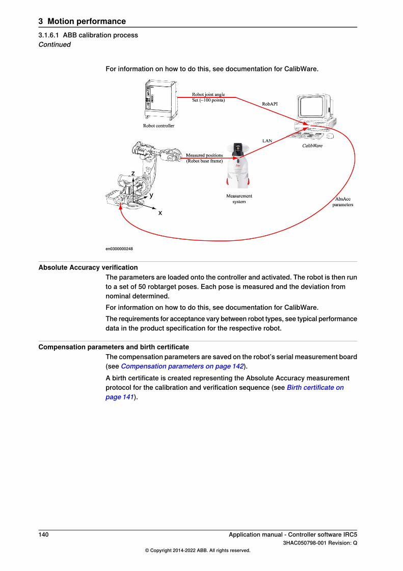
For information on how to do this, see documentation for CalibWare.
en0300000248
Absolute Accuracy verificationThe parameters are loaded onto the controller and activated. The robot is then runto a set of 50 robtarget poses. Each pose is measured and the deviation fromnominal determined.For information on how to do this, see documentation for CalibWare.The requirements for acceptance vary between robot types, see typical performancedata in the product specification for the respective robot.
Compensation parameters and birth certificateThe compensation parameters are saved on the robot’s serial measurement board(see Compensation parameters on page 142).A birth certificate is created representing the Absolute Accuracy measurementprotocol for the calibration and verification sequence (see Birth certificate onpage 141).
140 Application manual - Controller software IRC53HAC050798-001 Revision: Q
© Copyright 2014-2022 ABB. All rights reserved.
3 Motion performance3.1.6.1 ABB calibration processContinued
3.1.6.2 Birth certificate
About the birth certificateAll Absolute Accuracy robots are shipped with a birth certificate. It represents theAbsolute Accuracy measurement protocol for the calibration and verificationsequence.The birth certificate contains the following information:
• Robot information (robot type, serial number, version of Absolute Accuracy)• Accuracy information (maximum, average and standard deviation for finepoint
error distribution)• Tool information (TCP, mass, center of gravity)• Description of measurement protocol (measurement and calibration system,
number of points, measurement point location)
Application manual - Controller software IRC5 1413HAC050798-001 Revision: Q
© Copyright 2014-2022 ABB. All rights reserved.
3 Motion performance3.1.6.2 Birth certificate
3.1.6.3 Compensation parameters
About the compensation parametersAll Absolute Accuracy robots are shipped with a set of compensation parameters,as part of the system parameters (configuration). As the resolver offset calibrationis integral in the Absolute Accuracy calibration, the resolver offset parameters arealso stored on the robot’s serial measurement board.
The compensation parametersThe compensation parameters are defined in the following configuration types:
• ROBOT_CALIB• ARM_CALIB• JOINT_CALIB• PARALLEL_ARM_CALIB• TOOL_INTERFACE• MOTOR_CALIB
The type ROBOT_CALIB defines the top level of the calibration structure. Theinstance r1_calib activates the Absolute Accuracy functionality by specifying theflag -absacc. See Activate Absolute Accuracy on page 131.The types ARM_CALIB, JOINT_CALIB, PARALLEL_ARM_CALIB, andMOTOR_CALIB are reserved by the system and are only shown when the AbsoluteAccuracy option is selected in Installation Manager. The parameter values can bechanged by importing a new configuration file.The compensation parameters are included in a backup, in the file moc.cfg.
142 Application manual - Controller software IRC53HAC050798-001 Revision: Q
© Copyright 2014-2022 ABB. All rights reserved.
3 Motion performance3.1.6.3 Compensation parameters
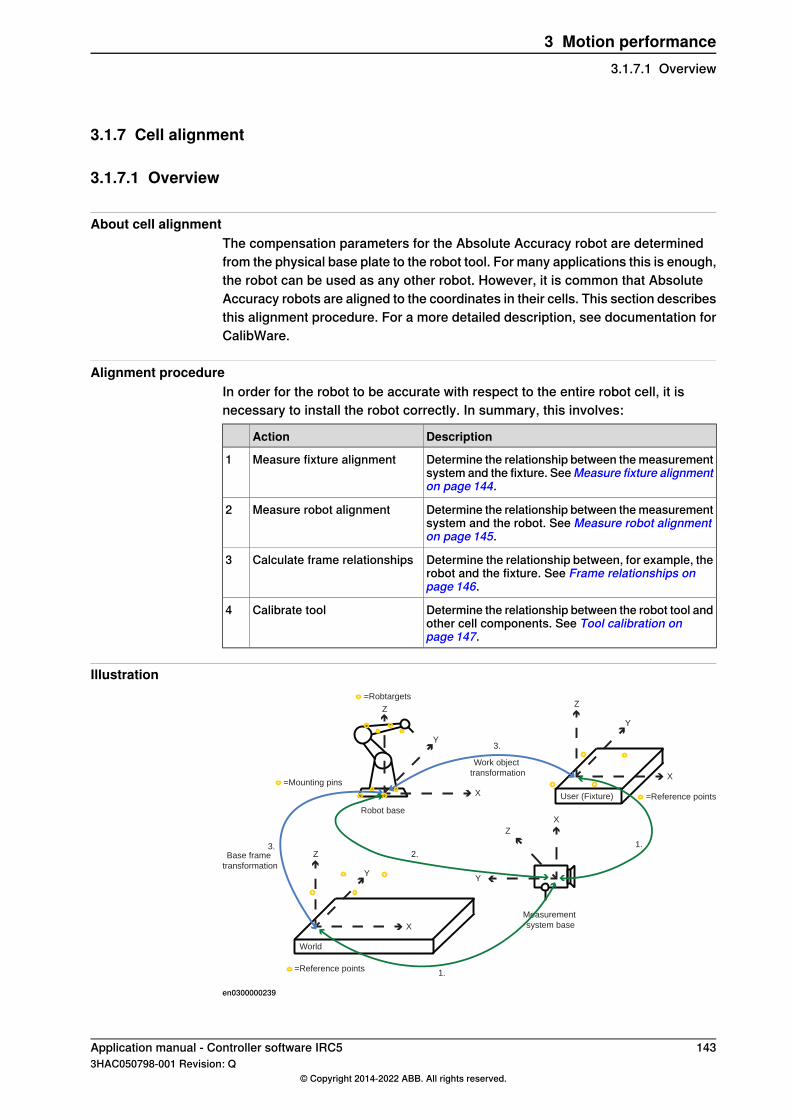
3.1.7 Cell alignment
3.1.7.1 Overview
About cell alignmentThe compensation parameters for the Absolute Accuracy robot are determinedfrom the physical base plate to the robot tool. For many applications this is enough,the robot can be used as any other robot. However, it is common that AbsoluteAccuracy robots are aligned to the coordinates in their cells. This section describesthis alignment procedure. For a more detailed description, see documentation forCalibWare.
Alignment procedureIn order for the robot to be accurate with respect to the entire robot cell, it isnecessary to install the robot correctly. In summary, this involves:
DescriptionAction
Determine the relationship between the measurementsystem and the fixture. SeeMeasure fixture alignmenton page 144.
Measure fixture alignment1
Determine the relationship between the measurementsystem and the robot. See Measure robot alignmenton page 145.
Measure robot alignment2
Determine the relationship between, for example, therobot and the fixture. See Frame relationships onpage 146.
Calculate frame relationships3
Determine the relationship between the robot tool andother cell components. See Tool calibration onpage 147.
Calibrate tool4
Illustration
User (Fixture)
Measurement
system base
=Reference points
=Mounting pinsX
Y
Z
X
Y
Z
World
=Reference points
X
Y
Z
X
Y
Z
Robot base
=Robtargets
1.
1.
2.3.
3.
Work object
transformation
Base frame
transformation
en0300000239
Application manual - Controller software IRC5 1433HAC050798-001 Revision: Q
© Copyright 2014-2022 ABB. All rights reserved.
3 Motion performance3.1.7.1 Overview

3.1.7.2 Measure fixture alignment
About fixture alignmentA fixture is defined as a cell component that is associated with a particularcoordinate system. The interaction between the robot and the fixture requires anaccurate relationship in order to ensure Absolute Accuracy.Absolute Accuracy fixtures must be equipped with at least three (preferably four)reference points, each with clearly marked position information.
Fixture measurement procedureThe alignment of the fixture is done in the following steps:
1 Enter the reference point names and positions into the alignment software.2 Measure the reference points and assign the same names.3 Use the alignment software to match the reference to measured points and
determine the relationship frame. All measurement systems support thisform of transformation.
Illustration
User (Fixture)
Measurement
system base
1
23
4
=Reference points
X
Y
Z
X
Y
Z
en0300000237
Frame relationshipReference positionsMeasurement positions
1) RobotStudio work objectPos1: 100, 100, 100Pos1: 100, 100, 200(0,0,-100,0,0,0)Pos2: 100, 200, 100Pos2: 100, 200, 200(x,y,z,roll,pitch,yaw
Pos3: 200, 200, 100Pos3: 200, 200, 200
Pos4: 200, 100, 100Pos4: 200, 100, 200
144 Application manual - Controller software IRC53HAC050798-001 Revision: Q
© Copyright 2014-2022 ABB. All rights reserved.
3 Motion performance3.1.7.2 Measure fixture alignment
3.1.7.3 Measure robot alignment
Select methodThe relationship between the measurement system and the robot can be determinedin the following ways:
DescriptionAlignment procedure
The equivalent to the fixture alignment in which the physicalbase pins are measured and aligned with respect to the ref-erence positions detailed in the product manual for the re-spective robot.
Alignment to physical base
Measuring several robot poses and letting the alignmentsoftware determine the robot alignment.
Alignment to theoretical base
Alignment to physical baseThe advantage of aligning the robot as a fixture is in its simplicity - the robot istreated as another fixture in the cell and its base points measured accordingly.The disadvantage is that small errors in the subsequent placement of the robot onthe pins can result is large TCP errors due to the reach of the robot (i.e. theplacement of the robot is not calibrated.)In order to determine the reference point coordinates, it is necessary to consultthe product manual for that robot type.Once the correct point have been measured, the alignment software is used todetermine the frame relationship between the measurement system and robotbase.
Alignment to theoretical baseThe advantage of aligning the robot to a theoretical base is that any errors resultingfrom mounting the robot can be eliminated. Furthermore, the alignment processdetails the robot accuracy at the measured points, confirming correct AbsoluteAccuracy functionality. The disadvantage is that a robot program must be created(either manually or automatically from CalibWare) and the robot measured (ideallywith correct tool however the TCP can also be calibrated as a part of this procedure.)Once the correct point is measured, the alignment software is used to determinethe frame relationship between the measurement system and robot base.
Application manual - Controller software IRC5 1453HAC050798-001 Revision: Q
© Copyright 2014-2022 ABB. All rights reserved.
3 Motion performance3.1.7.3 Measure robot alignment

3.1.7.4 Frame relationships
About frame relationshipsOnce the relationships between the measurement system and all other cellcomponents are measured, the relationships between cell components can bedetermined.The relationship between the world coordinate system and the robot shall be storedin the robot base. The relationship between the robot and the fixture shall be storedin the workobject data type.The measurement system is initially the active coordinate system as both worldand robot are measured relative to the measurement system.
Determine robot baseUse a standard measurement system software to determine the robot base in worldcoordinates:
1 Set the world coordinate system to be active (the origin).2 Read the coordinates of the robot base frame (now relative to the world).
The fixture relationship is similarly determined by setting the robot to beactive and reading the coordinates of the fixture frame.
146 Application manual - Controller software IRC53HAC050798-001 Revision: Q
© Copyright 2014-2022 ABB. All rights reserved.
3 Motion performance3.1.7.4 Frame relationships

3.1.7.5 Tool calibration
About tool calibrationThe Absolute Accuracy robot compensation parameters are calculated to be toolindependent. This allows any tool with a correctly pre-defined TCP to be connectedto the robot flange and used without requiring a tool re-calibration. In practice,however, it is difficult to perform a correct TCP calibration with, for example, aCoordinate Measurement Machine (CMM) as this does not take into account theconnection of the tool to the robot nor the tool flexibility.Each tool should be calibrated on a regular basis to ensure optimal robot accuracy.
Tool calibration proceduresSuggested tool recalibration procedures are detailed as follows:
• SBCU (Single Beam Calibration Unit) such as the ABB BullsEye forarc-welding or spot-welding applications.
• Geometry calibration such as the 4, 5 or 6 Point tool center point calibrationroutine available in the controller. A measurement system can be used toensure that the single point used is accurate.
• RAPID tool calibration routines: MToolTCPCalib (calibration of TCP for movingtool), SToolTCPCalib (calibration of TCP for stationary tool), MToolRotCalib(calibration of rotation for moving tool), SToolRotCalib (calibration of TCPand rotation for stationary tool.)
• Using theoretical data, for example from a CAD model.
Tip
As the tool load characteristics are used in the Absolute Accuracy models, it isessential that all parameters be as accurate as possible. Use of Load Identificationis an efficient method of determining tool load characteristics.
Application manual - Controller software IRC5 1473HAC050798-001 Revision: Q
© Copyright 2014-2022 ABB. All rights reserved.
3 Motion performance3.1.7.5 Tool calibration

3.2 Advanced Robot Motion [687-1]
About Advanced Robot MotionThe option Advanced Robot Motion gives you access to:
• Advanced Shape Tuning, see Advanced Shape Tuning [included in 687-1]on page 149.
• Changing Motion Process Mode from RAPID, see Motion Process Mode[included in 687-1] on page 157.
• Wrist Move, see Wrist Move [included in 687-1] on page 165.
148 Application manual - Controller software IRC53HAC050798-001 Revision: Q
© Copyright 2014-2022 ABB. All rights reserved.
3 Motion performance3.2 Advanced Robot Motion [687-1]
3.3 Advanced Shape Tuning [included in 687-1]
3.3.1 About Advanced Shape Tuning
PurposeThe purpose of Advanced Shape Tuning is to reduce the path deviation causedby joint friction of the robot.Advanced Shape Tuning is useful for low speed cutting (10-100 mm/s) of, forexample, small circles. Effects of robot joint friction can cause path deviation oftypically 0.5 mm in these cases. By tuning parameters of a friction model in thecontroller, the path deviation can be reduced to the repeatability level of the robot,for example, 0.1 mm for a medium sized robot.
What is includedAdvanced Shape Tuning is included in the RobotWare option Advanced robotmotion and gives you access to:
• Instructions FricIdInit, FricIdEvaluate and FricIdSetFricLevels
that automatically optimize the joint friction model parameters for aprogrammed path.
• The system parameters Friction FFW On, Friction FFW level and FrictionFFW Ramp for manual tuning of the joint friction parameters.
• The tune types tune_fric_lev and tune_fric_ramp that can be usedwith the instruction TuneServo.
Basic approachThis is a brief description of how Advanced Shape Tuning is most commonly used:
1 Set system parameter Friction FFW On to TRUE. See System parameterson page 154.
2 Perform automatic tuning of the joint friction levels using the instructionsFricIdInit and FricIdEvaluate. See Automatic friction tuning onpage 150.
3 Compensate for the friction using the instruction FricIdSetFricLevels.
Application manual - Controller software IRC5 1493HAC050798-001 Revision: Q
© Copyright 2014-2022 ABB. All rights reserved.
3 Motion performance3.3.1 About Advanced Shape Tuning

3.3.2 Automatic friction tuning
About automatic friction tuningA robot’s joint friction levels are automatically tuned with the instructionsFricIdInit and FricIdEvaluate. These instructions will tune each joint’sfriction level for a specific sequence of movements.The automatically tuned levels are applied for friction compensation with theinstruction FricIdSetFricLevels.
Program executionTo perform automatic tuning for a sequence of movements, the sequence mustbegin with the instruction FricIdInit and end with the instructionFricIdEvaluate. When program execution reaches FricIdEvaluate, the robotwill repeat the movement sequence until the best friction level for each joint axisis found. Each iteration consists of a backward and a forward motion, both followingthe programmed path. Typically the sequence has to be repeated approximately20-30 times, in order to iterate to correct joint friction levels.If the program execution is stopped in any way while the program pointer is on theinstruction FricIdEvaluate and then restarted, the results will be invalid. Aftera stop, friction identification must therefore be restarted from the beginning.Once the correct friction levels are found they have to be set with the instructionFricIdSetFricLevels, otherwise they will not be used. Note that the frictionlevels are tuned for the particular movement between FricIdInit andFricIdEvaluate. For movements in another region in the robot’s working area,a new tuning is needed to obtain the correct friction levels.For a detailed description of the instructions, see Technical referencemanual - RAPID Instructions, Functions and Data types.
LimitationsThere are the following limitations for friction tuning:
• Friction tuning cannot be combined with synchronized movement. That is,SyncMoveOn is not allowed between FricIdInit and FricIdEvaluate.
• The movement sequence for which friction tuning is done must begin andend with a finepoint. If not, finepoints will automatically be inserted duringthe tuning process.
• Automatic friction tuning works only for TCP robots.• Automatic joint friction tuning can only be done for one robot at a time.• Tuning can be made to a maximum of 500%. If that is not enough, set a higher
value for the parameter Friction FFW Level, see Starting with an estimatedvalue on page 155.
• It is not possible to view any test signals with TuneMaster during automaticfriction tuning.
• The movement sequence between FricIdInit and FricIdEvaluate
cannot be longer than 10 seconds.
Continues on next page150 Application manual - Controller software IRC5
3HAC050798-001 Revision: Q© Copyright 2014-2022 ABB. All rights reserved.
3 Motion performance3.3.2 Automatic friction tuning
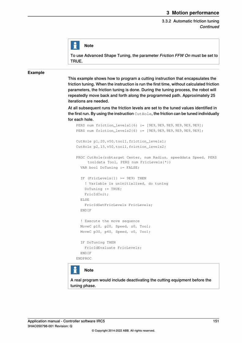
Note
To use Advanced Shape Tuning, the parameter Friction FFW On must be set toTRUE.
ExampleThis example shows how to program a cutting instruction that encapsulates thefriction tuning. When the instruction is run the first time, without calculated frictionparameters, the friction tuning is done. During the tuning process, the robot willrepeatedly move back and forth along the programmed path. Approximately 25iterations are needed.At all subsequent runs the friction levels are set to the tuned values identified inthe first run. By using the instruction CutHole, the friction can be tuned individuallyfor each hole.
PERS num friction_levels1{6} := [9E9,9E9,9E9,9E9,9E9,9E9];
PERS num friction_levels2{6} := [9E9,9E9,9E9,9E9,9E9,9E9];
CutHole p1,20,v50,tool1,friction_levels1;
CutHole p2,15,v50,tool1,friction_levels2;
PROC CutHole(robtarget Center, num Radius, speeddata Speed, PERStooldata Tool, PERS num FricLevels{*})
VAR bool DoTuning := FALSE;
IF (FricLevels{1} >= 9E9) THEN
! Variable is uninitialized, do tuning
DoTuning := TRUE;
FricIdInit;
ELSE
FricIdSetFricLevels FricLevels;
ENDIF
! Execute the move sequence
MoveC p10, p20, Speed, z0, Tool;
MoveC p30, p40, Speed, z0, Tool;
IF DoTuning THEN
FricIdEvaluate FricLevels;
ENDIF
ENDPROC
Note
A real program would include deactivating the cutting equipment before thetuning phase.
Application manual - Controller software IRC5 1513HAC050798-001 Revision: Q
© Copyright 2014-2022 ABB. All rights reserved.
3 Motion performance3.3.2 Automatic friction tuning
Continued

3.3.3 Manual friction tuning
OverviewIt is possible to make a manual tuning of a robot's joint friction (instead of automaticfriction tuning). The friction level for each joint can be tuned using the instructionTuneServo. How to do this is described in this section.There is usually no need to make changes to the friction ramp.
Note
To use Advanced Shape Tuning, the parameter Friction FFW On must be set toTRUE.
Tune typesA tune type is used as an argument to the instruction TuneServo. For moreinformation, see tunetype in Technical reference manual - RAPID Instructions,Functions and Data types.There are two tune types that are used expressly for Advanced Shape Tuning:
DescriptionTune type
By calling the instruction TuneServo with the argumentTUNE_FRIC_LEV the friction level for a robot joint can be adjustedduring program execution. A value is given in percent (between 1and 500) of the friction level defined by the parameter Friction FFWLevel.
TUNE_FRIC_LEV
By calling the instruction TuneServo with the argumentTUNE_FRIC_RAMP the motor shaft speed at which full friction com-pensation is reached can be adjusted during program execution. Avalue is given in percent (between 1 and 500) of the friction rampdefined by the parameter Friction FFW Ramp.
TUNE_FRIC_RAMP
There is normally no need to tune the friction ramp.
Configure friction levelThe friction level is set for each robot joint. Perform the following steps for onejoint at a time:
Action
Test the robot by running it through the most demanding parts of its tasks (the mostadvanced shapes). If the robot shall be used for cutting, then test it by cutting with thesame tool as at manufacturing.
1
Observe the path deviations and test if the joint friction levels need to be increasedor decreased.
Tune the friction level with the RAPID instruction TuneServo and the tune typeTUNE_FRIC_LEV. The level is given in percent of the Friction FFW Level value.
2
Example: The instruction for increasing the friction level with 20% looks like this:TuneServo MHA160R1, 1, 120 \Type:= TUNE_FRIC_LEV;
Repeat step 1 and 2 until you are satisfied with the path deviation.3
Continues on next page152 Application manual - Controller software IRC5
3HAC050798-001 Revision: Q© Copyright 2014-2022 ABB. All rights reserved.
3 Motion performance3.3.3 Manual friction tuning
Action
The final tuning values can be transferred to the system parameters.4Example: The Friction FFW Level is 0.5 and the final tune value (TUNE_FRIC_LEV) is120%. Set Friction FFW Level to 0.6 and tune value to 100% (default value), which isequivalent.
Tip
Tuning can be made to a maximum of 500%. If that is not enough, set a highervalue for the parameter Friction FFWLevel, seeSetting tuning system parameterson page 155.
Application manual - Controller software IRC5 1533HAC050798-001 Revision: Q
© Copyright 2014-2022 ABB. All rights reserved.
3 Motion performance3.3.3 Manual friction tuning
Continued

3.3.4 System parameters
3.3.4.1 System parameters
About the system parametersThis is a brief description of each parameter in the optionAdvanced Shape Tuning.For more information, see the respective parameter in Technical referencemanual - System parameters.
Friction Compensation / Control ParametersThese parameters belong to the type Friction Compensation in the topic Motion,except for the robots IRB 1400 and IRB 1410 where they belong to the type ControlParameters in the topic Motion.
DescriptionParameter
Advanced Shape Tuning is active when Friction FFW On is set toTRUE.
Friction FFW On
Friction FFW Level is the friction level for the robot joint. See illustra-tion below.
Friction FFW Level
Friction FFW Ramp is the speed of the robot motor shaft, at whichthe friction has reached the friction level defined by Friction FFWLevel. See illustration below.
Friction FFW Ramp
There is normally no need to make changes to Friction FFW Ramp.
Illustration
en0900000117
154 Application manual - Controller software IRC53HAC050798-001 Revision: Q
© Copyright 2014-2022 ABB. All rights reserved.
3 Motion performance3.3.4.1 System parameters

3.3.4.2 Setting tuning system parameters
Automatic tuning rarely requires changes in system parametersFor automatic tuning, if the friction levels are saved in a persistent array, the tuningis maintained after a power failure. The automatic tuning can also be used to setdifferent tuning levels for different robot movement sequences, which cannot beachieved with system parameters. When using automatic tuning, there is no needto change the system parameters unless the default values are very much off, seeStarting with an estimated value on page 155.
Transfer tuning to system parametersWhen using manual tuning, the tuning values are reset to default (100%) at powerfailure. System parameter settings are, however, permanent.If a temporary tuning is made, that is only valid for a part of the program execution,it should not be transferred.To transfer the friction level tuning value (TUNE_FRIC_LEV) to the parameterFriction FFW Level follow these steps:
Action
In RobotStudio, open the Configuration Editor, Motion topic, and select the typeFriction comp (except for the robots IRB 1400 and IRB 1410 where they belong to thetype Control parameters).
1
Multiply Friction FFW Level with the tuning value. Set this value as the new FrictionFFW Level and set the tuning value (TUNE_FRIC_LEV) to 100%.
2
Example: The Friction FFW Level is 0.5 and the final tune value (TUNE_FRIC_LEV) is120%. Set Friction FFW Level to 0.6 (1.20x0.5) and the tuning value to 100% (defaultvalue), which is equivalent.
Restart the controller for the changes to take effect.3
Starting with an estimated valueThe parameter Friction FFW Level will be the starting value for the tuning. If thisvalue is very far from the correct value, tuning to the correct value might beimpossible. This is unlikely to happen, since Friction FFW Level is by default setto a value approximately correct for most situations.If the Friction FFW Level value, for some reason, is too far from the correct value,it can be changed to an new estimated value.
Action
In RobotStudio, open the Configuration Editor, Motion topic, and select the typeFriction comp (except for the robots IRB 1400 and IRB 1410 where they belong to thetype Control parameters).
1
Set the parameter Friction FFW Level to an estimated value. Do not set the value 0(zero), because that will make tuning impossible.
2
Restart the controller for the changes to take effect.3
Application manual - Controller software IRC5 1553HAC050798-001 Revision: Q
© Copyright 2014-2022 ABB. All rights reserved.
3 Motion performance3.3.4.2 Setting tuning system parameters
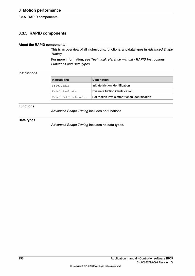
3.3.5 RAPID components
About the RAPID componentsThis is an overview of all instructions, functions, and data types in Advanced ShapeTuning.For more information, see Technical reference manual - RAPID Instructions,Functions and Data types.
Instructions
DescriptionInstructions
Initiate friction identificationFricIdInit
Evaluate friction identificationFricIdEvaluate
Set friction levels after friction identificationFricIdSetFricLevels
FunctionsAdvanced Shape Tuning includes no functions.
Data typesAdvanced Shape Tuning includes no data types.
156 Application manual - Controller software IRC53HAC050798-001 Revision: Q
© Copyright 2014-2022 ABB. All rights reserved.
3 Motion performance3.3.5 RAPID components
3.4 Motion Process Mode [included in 687-1]
3.4.1 About Motion Process Mode
PurposeThe purpose of Motion Process Mode is to simplify application specific tuning, i.e.to optimize the performance of the robot for a specific application.For most applications the default mode is the best choice.
Available motion process modesA motion process mode consists of a specific set of tuning parameters for a robot.Each tuning parameter set, that is each mode, optimizes the robot tuning for aspecific class of applications.There following modes are predefined:
• Optimal cycle time mode – this mode gives the shortest possible cycle timeand is normally the default mode.
• Accuracy mode – this mode improves path accuracy. The cycle time will beslightly increased compared to Optimal cycle time mode. This is therecommended choice for improving path accuracy on small and medium sizerobots, for example IRB 2400 and IRB 2600.
• Low speed accuracy mode – this mode improves path accuracy. The cycletime will be slightly increased compared to Accuracy mode. This is therecommended choice for improving path accuracy on large size robots, forexample IRB 4600.
• Low speed stiff mode - this mode is recommended for contact applicationswhere maximum servo stiffness is important. Could also be used in somelow speed applications, where a minimum of path vibrations is desired. Thecycle time will be increased compared to Low speed accuracy mode.
• Press tending mode – Changes the Kv Factor, Kp Factor and Ti Factor inorder to mitigate tool vibrations. This mode is primarily intended for use inpress tending applications where flexible grippers with a large extension inthe y-direction are used.
There are also four modes available for application specific user tuning:• MPM User mode 1 – 4
Selection of modeThe default mode is automatically selected and can be changed by changing thesystem parameter Use Motion Process Mode for type Robot.Changing the Motion Process Mode from RAPID is only possible if the optionAdvanced Robot Motion is installed. The mode can only be changed when therobot is standing still, otherwise a fine point is enforced.The following example shows a typical use of the RAPID instructionMotionProcessModeSet.
MotionProcessModeSet OPTIMAL_CYCLE_TIME_MODE;
! Do cycle-time critical movement
Continues on next pageApplication manual - Controller software IRC5 1573HAC050798-001 Revision: Q
© Copyright 2014-2022 ABB. All rights reserved.
3 Motion performance3.4.1 About Motion Process Mode

MoveL *, vmax, ...;
...
MotionProcessModeSet ACCURACY_MODE;
! Do cutting with high accuracy
MoveL *, v50, ...;
...
Limitations• The Motion Process Mode concept is currently available for all six- and
seven-axes robots except paint robots.• The Mounting Stiffness Factor parameters are only available for the following
robots:IRB 120, IRB 140, IRB 1200, IRB 1520, IRB 1600, IRB 2600, IRB 4600, IRB6620 (not LX), IRB 6640, IRB 6700.
• For IRB 1410, only the Accset and the geometric accuracy parameters areavailable.
• The following robot models do not support the use of World Acc Factor (i.e.only World Acc Factor = -1 is allowed):IRB 340, IRB 360, IRB 540, IRB 1400, IRB 1410
158 Application manual - Controller software IRC53HAC050798-001 Revision: Q
© Copyright 2014-2022 ABB. All rights reserved.
3 Motion performance3.4.1 About Motion Process ModeContinued
3.4.2 User-defined modes
Available tune parametersIf a more specific tuning is needed, some tuning parameters can be modified ineach motion process mode. The predefined modes and the user modes can all bemodified. In this way, the user can create a specific tuning for a specific application.The following list contains a short description of the available tune parameters.
• Use Motion Process Mode Type - selects predefined parameters for a usermode.
• Accset Acc Factor – changes acceleration• Accset Ramp Factor – changes acceleration ramp• Accset Fine Point Ramp Factor – changes deceleration ramp in fine points• Joint Acc Factor - changes acceleration for a specific joint.• World Acc Factor - activates dynamic world acceleration limitation if positive,
typical value is 1, deactivated if -1.• Geometric Accuracy Factor - improves geometric accuracy if reduced.• Dh Factor – changes path smoothness (effective system bandwidth)• Df Factor – changes the predicted resonance frequency for a particular axis• Kp Factor – changes the equivalent gain of the position controller for a
particular axis• Kv Factor – changes the equivalent gain of the speed controller for a particular
axis• Ti Factor – changes the integral time of the controller for a particular axis• Mounting Stiffness Factor X – describes the stiffness of the robot foundation
in x direction• Mounting Stiffness Factor Y – describes the stiffness of the robot foundation
in y direction• Mounting Stiffness Factor Z – describes the stiffness of the robot foundation
in z directionFor a detailed description, see Motion Process Mode in Technical referencemanual - System parameters.
Tuning parameters from RAPIDMost parameters can also be changed using the TuneServo and AccSet
instructions.
Note
All parameter settings are relative adjustments of the predefined parametervalues. Although it is possible to combine the use of motion process modes andTuneServo/Accset instructions, it is recommended to choose either motionprocess modes or TuneServo/AccSet.
Continues on next pageApplication manual - Controller software IRC5 1593HAC050798-001 Revision: Q
© Copyright 2014-2022 ABB. All rights reserved.
3 Motion performance3.4.2 User-defined modes

Example 1Relative adjustment of acceleration = [Predefined AccSet Acc Factor] * [AccSetAcc Factor] * [AccSet instruction acceleration factor / 100]
Example 2Relative adjustment of Kv = [Predefined Kv Factor] * [Kv Factor] * [Tune value ofTuneServo(TYPE_KV) instruction / 100]
Predefined parameter valuesThe predefined parameter values for each mode varies for different robot types.Generally, all predefined parameters are set to 1.0 for Optimal cycle time mode.For Low speed accuracy mode and Low speed stiff mode, the AccSet and Dhparameters are lowered for a smoother movement and a more accurate path, andthe Kv Factor, Kp Factor, and Ti Factor are changed for higher servo stiffness.For some robots, it might not be possible to increase the Kv Factor in Low speedaccuracy mode and Low speed stiff mode. Always be careful and be observant forincreased motor noise level when adjusting Kv Factor and do not use higher valuesthan needed for fulfilling the application requirement. A Kp Factor which is toohigh, or a Ti Factor which is too low, can also increase vibrations due to mechanicalresonances.Accuracy Mode uses a dynamic world acceleration limitation (World Acc Factor)and increased geometric accuracy (Geometric Accuracy Factor) to improve thepath accuracy.The Df Factor and the Mounting Stiffness Factors are always set to 1.0 in thepredefined modes, since the optimal values of these parameters depends thespecific installation, for example, the stiffness of the foundation on which the robotis mounted. These parameters can be optimized using TuneMaster. Moreinformation can be found in the TuneMaster application. Also note the limitationsof Mounting Stiffness Factor.
WARNING
Incorrect setting of the Motion Process Mode parameters can cause oscillatingmovements or torques that can damage the robot.
160 Application manual - Controller software IRC53HAC050798-001 Revision: Q
© Copyright 2014-2022 ABB. All rights reserved.
3 Motion performance3.4.2 User-defined modesContinued

3.4.3 General information about robot tuning
Minimizing cycle timeFor best possible cycle time, the motion process mode Optimal cycle time modeshould be used. This mode is normally the default mode. The user only needs todefine the tool load, payload, and arm loads if any. Once the robot path has beenprogrammed, the ABB QuickMove motion technology automatically computes theoptimal accelerations and speeds along the path. This results in a time-optimalpath with the shortest possible cycle time. Hence, no tuning of acceleration isneeded. The only way to improve the cycle time is to change the geometry of thepath or to work in another region of the work space. This type of optimization, ifneeded, can be performed by simulation in RobotStudio.
Increasing path accuracy and reducing vibrationsFor most applications, the Optimal cycle time mode will result in a satisfactorybehavior in terms of path accuracy and vibrations. This is due to the ABB TrueMovemotion technology. However, there are applications where the accuracy needs tobe improved by modifying the tuning of the robot. This tuning has previously beenperformed by using the TuneServo and AccSet instructions in the RAPID program.The concept of motion process modes will simplify this application specific tuningand the four predefined modes should be useful in many cases with no furtheradjustments needed.Here follows some general advice for solving accuracy problems, assuming thatthe default choice Optimal cycle time mode has been tested and that accuracyproblems have been noticed:
1 Verify that tool load, payload, and arm loads are properly defined.2 Inspect tool and process equipment attached to the robot arms. Make sure
that everything is properly fastened and that rigidity of the tool is adequate.3 Inspect the foundation on which the robot is mounted, see Compensating
for foundation flexibility on page 161.
Compensating for foundation flexibilityIf the foundation does not fulfill the stiffness requirement of the robot productmanual, then the foundation flexibility should be compensated for. See sectionRequirements on foundation, Minimum resonance frequency in the robot productmanual.This is performed by Df Factor for axis 1 and 2 or Mounting Stiffness Factordepending on robot type, see Limitations on page 164.
Continues on next pageApplication manual - Controller software IRC5 1613HAC050798-001 Revision: Q
© Copyright 2014-2022 ABB. All rights reserved.
3 Motion performance3.4.3 General information about robot tuning
TuneMaster is used for finding the optimal value of Df Factor / Mounting StiffnessFactor. The obtained Df Factor / Mounting Stiffness Factor is then defined for theMotion Process Modes used.
Note
A foundation that does not fulfill the requirements always impairs the accuracyto some extent, even if the described compensation is used. If the foundationrigidity is very low, there might not be possible to solve the problem using DfFactor / Mounting Stiffness Factor.In this case, the foundation must be improved or any of the solutions below used,for example, Optimal cycle time mode with a low Dh Factor, Accset Acc Factor,or Accset Fine Point Ramp Factor depending on the application.
WARNING
Incorrect tuning for a very low mounting stiffness can cause oscillatingmovements or torques that can damage the robot.
If accuracy still needs to be improved• For applications with high demands on path accuracy, for example cutting,
Advanced Shape Tuning and Accuracy mode/Low speed accuracy modeshould be used. The choice of motion mode depends both on the robot typeand the specific application. In general, Accuracy mode is recommended forsmall and medium size robots (up to IRB 2400/2600) and Low speed accuracymode is recommended for larger robots.
• If the path accuracy still needs improvement, the accuracy modes can beadjusted with the tune parameters, some examples:
- Tuning of Accuracy mode for improved accuracy:1) Reduce World Acc Factor, for example from 1 to 0.5.2) Reduce Dh Factor to 0.5 or lower. Note that a low value of Dh factorcan change the corner zones at high speed.
- Tuning of Low speed accuracy mode for improved accuracy:1) Set World Acc Factor to 1, and set Geometric Accuracy Factor to0.1.2) Reduce Dh Factor to 0.5 or lower.
• The programmed speed must sometimes be reduced for best possibleaccuracy, e.g. in cutting applications. For example, a circle with radius 1 mmshould not be programmed with a higher speed than 20 mm/s.
• For contact applications, for example milling and pre-machining, Low speedstiff mode is recommended. This mode can also be useful for large robotsin some low speed applications (up to 100 mm/s) where a minimum of pathvibrations is required, for example below 0.1 mm. Note that this mode has avery stiff servo tuning and that there may be cases where the Kv Factorneeds to be reduced due to motor vibrations and noise.
Continues on next page162 Application manual - Controller software IRC5
3HAC050798-001 Revision: Q© Copyright 2014-2022 ABB. All rights reserved.
3 Motion performance3.4.3 General information about robot tuningContinued
• If overshoots and vibrations in fine points needs to be reduced. Use Optimalcycle time mode and decrease the value of Accset Fine Point Ramp Factoror Dh Factor until the problem is solved.
• If accuracy problems occur when starting or ending reorientation. Define anew zone with increased pzone_ori and pzone_eax. These should alwayshave the same value, even if there are no external axes in the system. Alsoincrease zone_ori. Always strive for smooth reorientations whenprogramming.
• Finally, if the cycle time needs to be reduced after the tuning for accuracy isfinished. Use different motion process modes in different sections of theRAPID program.
Application manual - Controller software IRC5 1633HAC050798-001 Revision: Q
© Copyright 2014-2022 ABB. All rights reserved.
3 Motion performance3.4.3 General information about robot tuning
Continued
3.4.4 Additional information
Motion Process Mode compared to TuneServo and AccSetMotion process modes simplifies application specific tuning and makes it possibleto define the tuning by system parameters instead of the RAPID program.In general, motion process modes should be the first choice for solving accuracyproblems. However, application specific tuning can still be performed using theTuneServo and AccSet instructions in the RAPID program.There are a few situations where TuneServo and AccSetmight be a better choice.One example of this is if an acceleration reduction in a section of the RAPIDprogram solves the accuracy problem and the cycle time is to be optimized. In thiscase it might be better to use AccSet which can be changed without fine pointwhereas change of motion process mode requires a fine point.
Limitations• The Motion Process Mode concept is currently available for all six- and
seven-axes robots except paint robots.• The Mounting Stiffness Factor parameters are only available for the following
robots:IRB 120, IRB 140, IRB 1200, IRB 1520, IRB 1600, IRB 2600, IRB 4600, IRB6620 (not LX), IRB 6640, IRB 6700.
• For IRB 1410, only the Accset and the geometric accuracy parameters areavailable.
• The following robot models do not support the use of World Acc Factor (i.e.only World Acc Factor = -1 is allowed):IRB 340, IRB 360, IRB 540, IRB 1400, IRB 1410
Related information
SeeFor information about
Technical referencemanual - System paramet-ers
Configuration of Motion Process Modeparameters.
Technical reference manual - RAPID Instruc-tions, Functions and Data types
RAPID instructions:• AccSet - Reduces the acceleration• MotionProcessModeSet - Set mo-
tion process mode• TuneServo - Tuning servos
164 Application manual - Controller software IRC53HAC050798-001 Revision: Q
© Copyright 2014-2022 ABB. All rights reserved.
3 Motion performance3.4.4 Additional information
3.5 Wrist Move [included in 687-1]
3.5.1 Introduction to Wrist Move
PurposeThe purpose ofWrist Move is to improve the path accuracy when cutting geometrieswith small dimensions. For geometrical shapes like small holes, friction effectsfrom the main axes (1-3) of the robot often degrade the visual appearance of theshape. The key idea is that instead of controlling the robot's TCP, a wrist movementcontrols the point of intersection between the laser beam (or water jet or routingspindle, etc) and the cutting plane. For controlling the point of intersection, onlytwo wrist axes are needed. Instead of using all axes of the robot, only two wristaxes are used, thereby minimizing the friction effects on the path. Which wrist axispair to be used is decided by the programmer.
Using Wrist MoveWrist Move is included in the RobotWare option Advanced robot motion.Wrist Move is used together with the RAPID instruction CirPathMode andmovement instructions for circular arcs, that is, MoveC, TrigC, CapC etc. The wristmovement mode is activated by the instruction CirPathMode together with oneof the flags Wrist45, Wrist46, or Wrist56. With this mode activated, allsubsequent MoveC instructions will result in a wrist movement. To go back tonormal MoveC behavior, then CirPathMode has to be set with a flag other thanWrist45, Wrist46, and Wrist56, for example, PathFrame.
Note
During a wrist movement, the TCP height above the surface will vary. This is anunavoidable consequence of using only two axes. The height variation will dependon the robot position, the tool definition, and the radius of the circular arc. Thelarger the radius, the larger the height variation will be. Due to the height variationit is recommended that the movement is run at a very low speed the first time toverify that the height variation does not become too large. Otherwise it is possiblethat the cutting tool collides with the surface being cut.
LimitationsThe Wrist Move option cannot be used if:
• The work object is moving• The robot is mounted on a track or another manipulator that is moving
The Wrist Move option is only supported for robots running QuickMove, secondgeneration.The tool will not remain at right angle against the surface during the cutting. As aconsequence, the holes cut with this method will be slightly conical. Usually thiswill not be a problem for thin plates, but for thick plates the conicity will becomeapparent.
Continues on next pageApplication manual - Controller software IRC5 1653HAC050798-001 Revision: Q
© Copyright 2014-2022 ABB. All rights reserved.
3 Motion performance3.5.1 Introduction to Wrist Move

The height of the TCP above the surface will vary during the cut. The height variationwill increase with the size of the shape being cut. What limits the possible size ofthe shape are therefore, beside risk of collision, process characteristics like focallength of the laser beam or the water jet.
166 Application manual - Controller software IRC53HAC050798-001 Revision: Q
© Copyright 2014-2022 ABB. All rights reserved.
3 Motion performance3.5.1 Introduction to Wrist MoveContinued
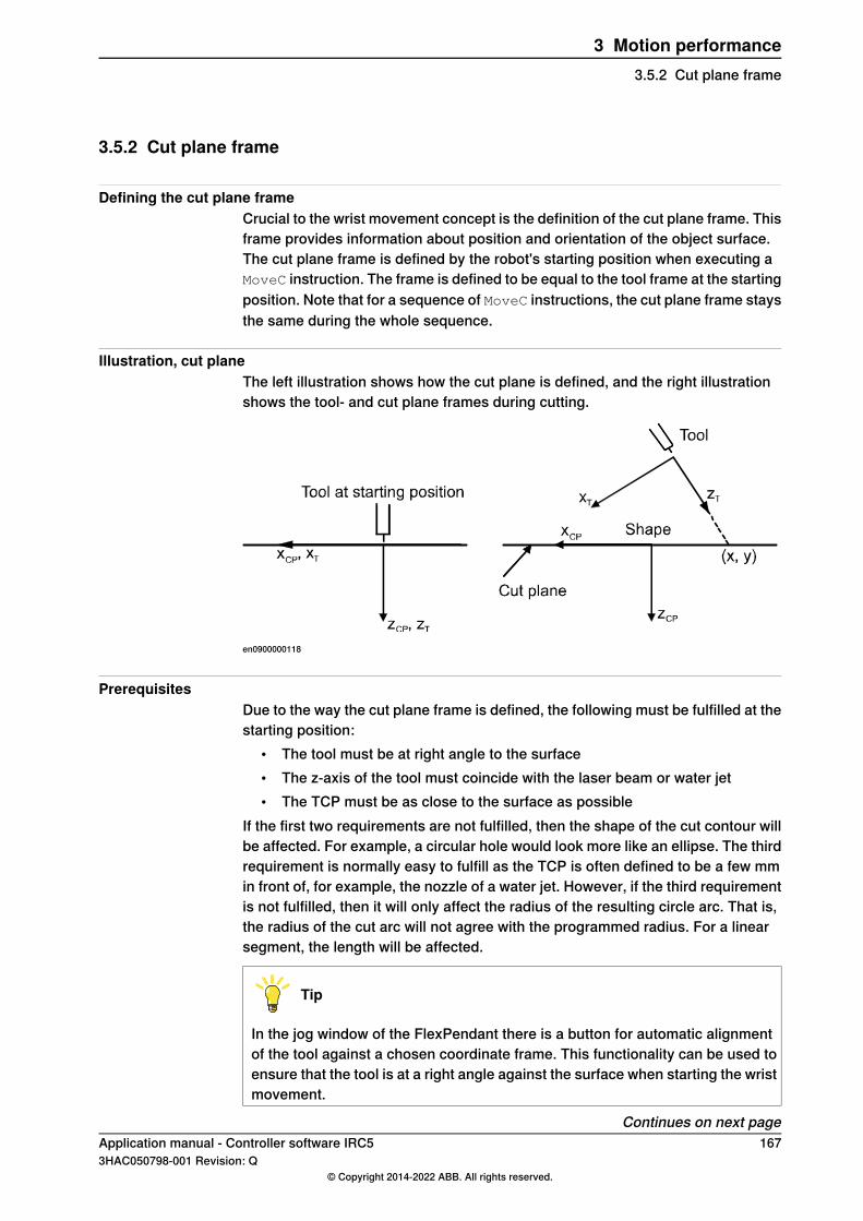
3.5.2 Cut plane frame
Defining the cut plane frameCrucial to the wrist movement concept is the definition of the cut plane frame. Thisframe provides information about position and orientation of the object surface.The cut plane frame is defined by the robot's starting position when executing aMoveC instruction. The frame is defined to be equal to the tool frame at the startingposition. Note that for a sequence of MoveC instructions, the cut plane frame staysthe same during the whole sequence.
Illustration, cut planeThe left illustration shows how the cut plane is defined, and the right illustrationshows the tool- and cut plane frames during cutting.
en0900000118
PrerequisitesDue to the way the cut plane frame is defined, the following must be fulfilled at thestarting position:
• The tool must be at right angle to the surface• The z-axis of the tool must coincide with the laser beam or water jet• The TCP must be as close to the surface as possible
If the first two requirements are not fulfilled, then the shape of the cut contour willbe affected. For example, a circular hole would look more like an ellipse. The thirdrequirement is normally easy to fulfill as the TCP is often defined to be a few mmin front of, for example, the nozzle of a water jet. However, if the third requirementis not fulfilled, then it will only affect the radius of the resulting circle arc. That is,the radius of the cut arc will not agree with the programmed radius. For a linearsegment, the length will be affected.
Tip
In the jog window of the FlexPendant there is a button for automatic alignmentof the tool against a chosen coordinate frame. This functionality can be used toensure that the tool is at a right angle against the surface when starting the wristmovement.
Continues on next pageApplication manual - Controller software IRC5 1673HAC050798-001 Revision: Q
© Copyright 2014-2022 ABB. All rights reserved.
3 Motion performance3.5.2 Cut plane frame

Tip
Wrist movement is not limited to circular arcs only: If the targets of MoveC arecollinear, then a straight line will be achieved.
168 Application manual - Controller software IRC53HAC050798-001 Revision: Q
© Copyright 2014-2022 ABB. All rights reserved.
3 Motion performance3.5.2 Cut plane frameContinued

3.5.3 RAPID components
InstructionThis is a brief description of the instruction used in Wrist Move. For moreinformation, see the description of the instruction in Technical referencemanual - RAPID Instructions, Functions and Data types.
DescriptionsInstruction
CirPathMode makes it possible to select different modes toreorientate the tool during circular movements.
CirPathMode
The arguments Wrist45, Wrist46, and Wrist56 are usedspecifically for the Wrist Move option.
Application manual - Controller software IRC5 1693HAC050798-001 Revision: Q
© Copyright 2014-2022 ABB. All rights reserved.
3 Motion performance3.5.3 RAPID components
3.5.4 RAPID code, examples
Basic exampleThis example shows how to do two circular arcs, first using axes 4 and 5, and thenusing axes 5 and 6. After the two arcs, wrist movement is deactivated byCirPathMode.
! This position will define the cut plane frame
MoveJ p10, v100, fine, tWaterJet;
CirPathMode \Wrist45;
MoveC p20, p30, v50, z0, tWaterJet;
! The cut-plane frame remains the same in a sequence of MoveC
CirPathMode \Wrist56;
MoveC p40, p50, v50, fine, tWaterJet;
! Deactivate Wrist Movement, could use \ObjectFrame
! or \CirPointOri as well
CirPathMode \PathFrame;
Advanced exampleThis example shows how to cut a slot with end radius R and length L+2R, usingwrist movement. See Illustration, pSlot and wSlot on page 171. The slot bothbegins and ends at the position pSlot, which is the center of the left semi-circle.To avoid introducing oscillations in the robot, the cut begins and ends withsemi-circular lead-in and lead-out paths that connect smoothly to the slot contour.All coordinates are given relative the work object wSlot.
! Set the dimensions of the slot
R := 5;
L := 30;
! This position defines the cut plane frame, it must be normal
! to the surface
MoveJ pSlot, v100, z1, tLaser, \wobj := wSlot;
CirPathMode \Wrist45;
! Lead-in curve
MoveC Offs(pSlot, R/2, R/2, 0), Offs(pSlot, 0, R, 0), v50, z0,tLaser, \wobj := wSlot;
! Left semi-circle
MoveC Offs(pSlot, -R, 0, 0), Offs(pSlot, 0, -R, 0), v50, z0, tLaser,\wobj := wSlot;
! Lower straight line, circle point passes through the mid-point
! of the line
MoveC Offs(pSlot, L/2, -R, 0), Offs(pSlot, L, -R, 0), v50, z0,tLaser, \wobj := wSlot;
Continues on next page170 Application manual - Controller software IRC5
3HAC050798-001 Revision: Q© Copyright 2014-2022 ABB. All rights reserved.
3 Motion performance3.5.4 RAPID code, examples
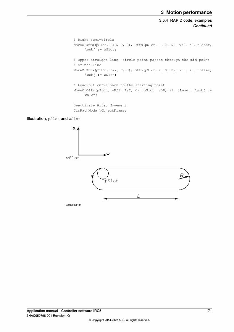
! Right semi-circle
MoveC Offs(pSlot, L+R, 0, 0), Offs(pSlot, L, R, 0), v50, z0, tLaser,\wobj := wSlot;
! Upper straight line, circle point passes through the mid-point
! of the line
MoveC Offs(pSlot, L/2, R, 0), Offs(pSlot, 0, R, 0), v50, z0, tLaser,\wobj := wSlot;
! Lead-out curve back to the starting point
MoveC Offs(pSlot, -R/2, R/2, 0), pSlot, v50, z1, tLaser, \wobj :=wSlot;
Deactivate Wrist Movement
CirPathMode \ObjectFrame;
Illustration, pSlot and wSlot
wSlot
pSlot
xx0900000111
Application manual - Controller software IRC5 1713HAC050798-001 Revision: Q
© Copyright 2014-2022 ABB. All rights reserved.
3 Motion performance3.5.4 RAPID code, examples
Continued
3.5.5 Troubleshooting
Unexpected cut shapeIf the cut shape is not the expected, then check the following:
• The tool z-axis coincides with the laser beam or the water jet• The tool z-axis is at right angle to the surface at the starting position of the
first MoveC• If you have the option Advanced Shape Tuning, then try tuning the friction
for the involved wrist axes.
Mismatching radiusIf the radius of the circular arc does not agree with the programmed radius, thencheck that the TCP is as close to the surface as possible at the starting position.
Impossible movement with chosen axis pairIf the movement is not possible with the selected axis pair, then try activatinganother pair by using one of the flags Wrist45, Wrist46, or Wrist56. As a lastresort, try reaching the starting position with another robot configuration.
172 Application manual - Controller software IRC53HAC050798-001 Revision: Q
© Copyright 2014-2022 ABB. All rights reserved.
3 Motion performance3.5.5 Troubleshooting

4 Motion coordination4.1 Machine Synchronization [607-1], [607-2]
4.1.1 Overview
Two optionsMachine Synchronization consists of two options, Sensor Synchronization andAnalog Synchronization. The functionality is very similar for both these options, itis the hardware and configuration that differs.The difference between the two options is that:
• Analog Synchronization is used together with a sensor that shows the positionof the external mechanical unit as an analog signal.
• Sensor Synchronization requires an encoder that counts pulses as theexternal mechanical unit move, and an encoder interface unit whichtransforms the pulses into a sensor position.
All information in this chapter refers to both options, unless something else isspecified. The term synchronization option refers to both options. Information thatis only valid for one of the options is said to be specific for Sensor Synchronizationor Analog Synchronization.
PurposeThe synchronization option adjusts the robot speed to an external moving device(for example a press or conveyor) with the help of a sensor. It can also be used tosynchronize two robots with each other.
DescriptionFor the synchronization, a sensor is used to detect the movements of a press door,conveyor, turn table or similar device. The speed of the robot TCP will be adjustedin correlation to the sensor output, so that the robot will reach its programmedtarget at the same time as the external device reaches its programmed position.The synchronization with the external device does not affect the path of the robotTCP, but it affects the speed at which the robot moves along this path.
FunctionalityThe external device connected to the sensor cannot be controlled by the robotcontroller. However, in some ways it has similarities with a mechanical unitcontrolled by the robot controller:
• the sensor positions appears in the Jogging Window on the FlexPendant• the sensor positions appears in the robtarget when a MODPOS operation
is performed• the mechanical unit may be activated, and deactivated
Continues on next pageApplication manual - Controller software IRC5 1733HAC050798-001 Revision: Q
© Copyright 2014-2022 ABB. All rights reserved.
4 Motion coordination4.1.1 Overview
Basic approachThis is the general approach for setting up the synchronization option. For a moredetailed description of how this is done, see the respective section.
• Install and connect hardware.• Install the synchronization software.• Configure the system parameters.• Write a program that connects to the sensor and uses synchronization for
robot movements (or a program for a master/slave robot application).
174 Application manual - Controller software IRC53HAC050798-001 Revision: Q
© Copyright 2014-2022 ABB. All rights reserved.
4 Motion coordination4.1.1 OverviewContinued

4.1.2 What is needed
Sensor SynchronisationThe Sensor Synchronization application consist of the following components:
A
B
C
D E
F
en0400000655
External device that dictates the robot speed, e.g. a press doorA
Synchronization switchB
EncoderC
Encoder interface unit (DSQC 377)D
ControllerE
RobotF
Act as a sensor, giving input to the controllerB+C+D
Continues on next pageApplication manual - Controller software IRC5 1753HAC050798-001 Revision: Q
© Copyright 2014-2022 ABB. All rights reserved.
4 Motion coordination4.1.2 What is needed

Analog SynchronizationThe Analog Synchronization application consist of the following components:
xx0700000431
Mold press that dictates the robot speedA
Analog sensor for press positionB
ControllerC
RobotD
176 Application manual - Controller software IRC53HAC050798-001 Revision: Q
© Copyright 2014-2022 ABB. All rights reserved.
4 Motion coordination4.1.2 What is neededContinued
4.1.3 Synchronization features
FeaturesThe synchronization option provides the following features:
DescriptionFeature
In Auto operation at constant sensor speed, the Tool Center Point (TCP)of the robot will stay within the programmed position corresponding tothe sensor, with an error margin of:
• +/- 50 ms for Sensor Synchronization• +/- 100 ms for Analog Synchronization
This is valid as long as the robot is within its dynamic limits with the addedsensor motion. This figure depends on the calibration of the robot andsensor and is applicable for linear synchronization only.
Accuracy
Only for Sensor Synchronization:Object queueEach time the external device trigger the synchronization switch, a sensorobject is created in the object queue. The encoder interface unit willmaintain the object queue, although for Sensor Synchronization the queuenormally does not contain more than one object.
A RAPID program has access to the current position and speed of theexternal device, via the sensor.
RAPID accessto sensor data
Up to 2 sensors are supported.Multiplesensors For Sensor Synchronization, each sensor must have a DSQC 377.
Application manual - Controller software IRC5 1773HAC050798-001 Revision: Q
© Copyright 2014-2022 ABB. All rights reserved.
4 Motion coordination4.1.3 Synchronization features
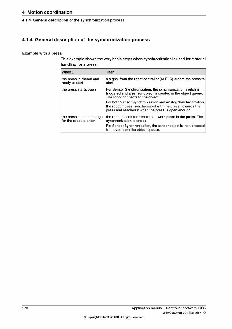
4.1.4 General description of the synchronization process
Example with a pressThis example shows the very basic steps when synchronization is used for materialhandling for a press.
Then...When...
a signal from the robot controller (or PLC) orders the press tostart.
the press is closed andready to start
For Sensor Synchronization, the synchronization switch istriggered and a sensor object is created in the object queue.The robot connects to the object.
the press starts open
For both Sensor Synchronization and Analog Synchronization,the robot moves, synchronized with the press, towards thepress and reaches it when the press is open enough.
the robot places (or removes) a work piece in the press. Thesynchronization is ended.
the press is open enoughfor the robot to enter
For Sensor Synchronization, the sensor object is then dropped(removed from the object queue).
178 Application manual - Controller software IRC53HAC050798-001 Revision: Q
© Copyright 2014-2022 ABB. All rights reserved.
4 Motion coordination4.1.4 General description of the synchronization process

4.1.5 Limitations
Limitations on additional axesEach sensor is considered an additional axis. Thus the system limitation of 6 activeadditional axes must be reduced by the number of active and installed sensors.The first installed sensor will use measurement node 6 and the second sensor willuse measurement node 5. These measurement nodes are not available for additionalaxes and no resolvers should be connected to these nodes on any additional axesmeasurement boards.
Object queue lost on warm start or power failureOnly for Sensor Synchronization:The object queue is kept on the encoder interface unit (DSQC 377). If the systemis restarted or if the power supply to either the controller or the encoder interfaceunit fails, then the object queue will be lost.
Minimum speedIn order to maintain a smooth and accurate motion, there is a minimum speed ofthe external device that is detected. The device is considered to be still if itsmovement is slower than the minimum speed. This speed depends on the selectionof encoder. It can vary from 4mm/s - 8mm/s.
Maximum speedThere is no determined maximum speed for the external device. Accuracy willdecrease at speeds over those specified, and the robot will no longer be able tofollow the sensor at very high sensor speeds (>1000mm/s) or with robot dynamiclimitations.
Compatibility with the option Conveyor TrackingIf both Machine Synchronization and Conveyor Tracking options are installed, onlyone of the mechanical units SSYNC1 and CNV2 should be active at the same time.For Machine Synchronization (Sensor Synchronization or Analog Synchronization),CNV2 must be deactivated.For Conveyor Tracking, SSYNC1 must be deactivated.
Application manual - Controller software IRC5 1793HAC050798-001 Revision: Q
© Copyright 2014-2022 ABB. All rights reserved.
4 Motion coordination4.1.5 Limitations
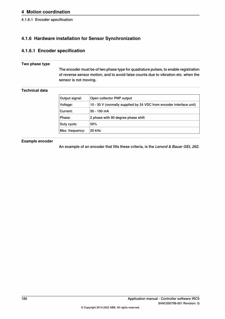
4.1.6 Hardware installation for Sensor Synchronization
4.1.6.1 Encoder specification
Two phase typeThe encoder must be of two phase type for quadrature pulses, to enable registrationof reverse sensor motion, and to avoid false counts due to vibration etc. when thesensor is not moving.
Technical data
Open collector PNP outputOutput signal:
10 - 30 V (normally supplied by 24 VDC from encoder interface unit)Voltage:
50 - 100 mACurrent:
2 phase with 90 degree phase shiftPhase:
50%Duty cycle:
20 kHzMax. frequency:
Example encoderAn example of an encoder that fills these criteria, is the Lenord & Bauer GEL 262.
180 Application manual - Controller software IRC53HAC050798-001 Revision: Q
© Copyright 2014-2022 ABB. All rights reserved.
4 Motion coordination4.1.6.1 Encoder specification

4.1.6.2 Encoder description
OverviewThe encoder provides a series of pulses indicating the motion detected by thesensor. This is used to synchronize the motion between the robot and the externaldevice.
Pulse channelsThe encoder has two pulse channels, A and B which differ in phase by 90°. Eachchannel will send a fixed number of pulses per revolution depending on theconstruction of the encoder.
• The number of pulses per revolution for the encoder must be selected inrelation to the gear reduction between the moving devices.
• The pulse ratio from the encoder should be in the range of 1250 - 2500 pulsesper meter of sensor motion.
• The pulses from channel A and B are used in quadrature to multiply the pulseratio by four to get counts.
This means that the control software will measure 5000 - 10000 counts per meterfor an encoder with the pulse ratio 1250 - 2500.
en0300000556
SynchronizationTo get an accurate synchronization, the movements of the external device mustremain within some limits relative to robot movements. For every meter the robotmoves, the external device movement must be between 0.2 and 5 meters (orradians).
Application manual - Controller software IRC5 1813HAC050798-001 Revision: Q
© Copyright 2014-2022 ABB. All rights reserved.
4 Motion coordination4.1.6.2 Encoder description
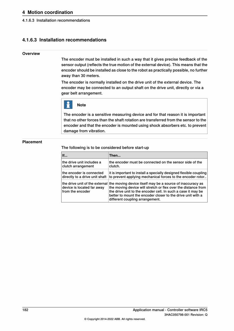
4.1.6.3 Installation recommendations
OverviewThe encoder must be installed in such a way that it gives precise feedback of thesensor output (reflects the true motion of the external device). This means that theencoder should be installed as close to the robot as practically possible, no furtheraway than 30 meters.The encoder is normally installed on the drive unit of the external device. Theencoder may be connected to an output shaft on the drive unit, directly or via agear belt arrangement.
Note
The encoder is a sensitive measuring device and for that reason it is importantthat no other forces than the shaft rotation are transferred from the sensor to theencoder and that the encoder is mounted using shock absorbers etc. to preventdamage from vibration.
PlacementThe following is to be considered before start-up
Then...If...
the encoder must be connected on the sensor side of theclutch.
the drive unit includes aclutch arrangement
it is important to install a specially designed flexible couplingto prevent applying mechanical forces to the encoder rotor..
the encoder is connecteddirectly to a drive unit shaft
the moving device itself may be a source of inaccuracy asthe moving device will stretch or flex over the distance fromthe drive unit to the encoder cell. In such a case it may bebetter to mount the encoder closer to the drive unit with adifferent coupling arrangement.
the drive unit of the externaldevice is located far awayfrom the encoder
182 Application manual - Controller software IRC53HAC050798-001 Revision: Q
© Copyright 2014-2022 ABB. All rights reserved.
4 Motion coordination4.1.6.3 Installation recommendations

4.1.6.4 Connecting encoder and encoder interface unit
OverviewIf the cable from the robot to the encoder is too long, the inductance in the cablewill produce spike pulses on the encoder signal. This signal will over a period oftime damage the opto couplers in the encoder interface unit.See Product manual - IRC5 for details on connecting to the encoder interface unit.
Reduce noiseTo reduce noise, connect the encoder with a screened cable.
Reduce spike pulsesTo reduce spike pulses, install a capacitor between the signal wire and ground foreach of the two phases. The correct capacitance value can be determined byviewing the encoder signal on an oscilloscope.The capacitor:
• should be connected on the terminal board where the encoder is connected.• values are 100 nF - 1 µF, depending on the length of the cable.
Encoder power supplyThe encoder is normally supplied with 24 VDC from the encoder interface unit.When connecting two encoder interface units to the same encoder, let only one ofthe encoder interface units supply power to the encoder. If both encoder interfaceunits supply power, a diode must be installed on each of the 24 V DC connectionsto make sure the power supplies do not interfere with each other.
Connecting encoder and the synchronization switchThe following procedure describes how to install the encoder and thesynchronization switch to the encoder interface unit.
• One encoder can be connected to several encoder interface units.• each controller must have an encoder interface unit if more than one robot
is to use the sensor.
IllustrationAction
en0300000611
Connect the encoder to the encoder interfaceunit (DSQC 377) on the controller.
1
Continues on next pageApplication manual - Controller software IRC5 1833HAC050798-001 Revision: Q
© Copyright 2014-2022 ABB. All rights reserved.
4 Motion coordination4.1.6.4 Connecting encoder and encoder interface unit

IllustrationAction
Connect the synchronization switch to the en-coder interface unit (DSQC 377) on the control-ler.
2
Finding the Encoder rotating directionThe following procedure describes how to find the encoder rotating direction.
IllustrationAction
On the FlexPendant, tap Inputs and Outputs.1
Tap View and select I/O Units2
Scroll down and selected Qtrack - d3773
Scroll down to c1position4
Encoder 1
+2-AX12
29
17
19
20
21
22
P_ENC1_A+
P_ENC1_A–
P_ENC1_B+
P_ENC1_B–
0 Volt
+24 VDC
30
18
23
24
25
26
Connection for PNP encoder
B (90°)
A (0°)
0V
24VDC
Encoder 2
P_ENC2_A+
P_ENC2_A–
P_ENC2_B+
P_ENC2_B–
0 Volt
+24 VDC
B (90°)
A (0°)
0V
24VDC
en0300000584
Run the encoder in forward direction whilechecking the value for C1Position.If the number counts up:
• No action is required.If the number counts down:
• the connection of the two encoder faces(0° and 90°) must be interchanged.
5
184 Application manual - Controller software IRC53HAC050798-001 Revision: Q
© Copyright 2014-2022 ABB. All rights reserved.
4 Motion coordination4.1.6.4 Connecting encoder and encoder interface unitContinued

4.1.7 Hardware installation for Analog Synchronization
4.1.7.1 Required hardware
Analog input boardAn analog input board is required, for example DSQC355A. See Applicationmanual - DeviceNet Master/Slave.
Analog linear sensorAn analog linear sensor is required, with analog signal input between 0 and 10 V.
Application manual - Controller software IRC5 1853HAC050798-001 Revision: Q
© Copyright 2014-2022 ABB. All rights reserved.
4 Motion coordination4.1.7.1 Required hardware
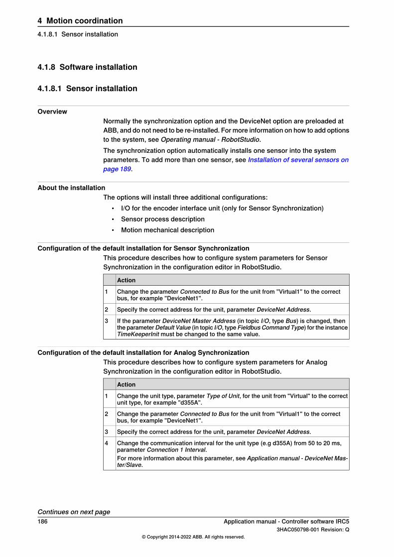
4.1.8 Software installation
4.1.8.1 Sensor installation
OverviewNormally the synchronization option and the DeviceNet option are preloaded atABB, and do not need to be re-installed. For more information on how to add optionsto the system, see Operating manual - RobotStudio.The synchronization option automatically installs one sensor into the systemparameters. To add more than one sensor, see Installation of several sensors onpage 189.
About the installationThe options will install three additional configurations:
• I/O for the encoder interface unit (only for Sensor Synchronization)• Sensor process description• Motion mechanical description
Configuration of the default installation for Sensor SynchronizationThis procedure describes how to configure system parameters for SensorSynchronization in the configuration editor in RobotStudio.
Action
Change the parameter Connected to Bus for the unit from "Virtual1" to the correctbus, for example "DeviceNet1".
1
Specify the correct address for the unit, parameter DeviceNet Address.2
If the parameter DeviceNet Master Address (in topic I/O, type Bus) is changed, thenthe parameterDefault Value (in topic I/O, type Fieldbus Command Type) for the instanceTimeKeeperInit must be changed to the same value.
3
Configuration of the default installation for Analog SynchronizationThis procedure describes how to configure system parameters for AnalogSynchronization in the configuration editor in RobotStudio.
Action
Change the unit type, parameter Type of Unit, for the unit from "Virtual" to the correctunit type, for example "d355A".
1
Change the parameter Connected to Bus for the unit from "Virtual1" to the correctbus, for example "DeviceNet1".
2
Specify the correct address for the unit, parameter DeviceNet Address.3
Change the communication interval for the unit type (e.g d355A) from 50 to 20 ms,parameter Connection 1 Interval.
4
For more information about this parameter, see Application manual - DeviceNet Mas-ter/Slave.
Continues on next page186 Application manual - Controller software IRC5
3HAC050798-001 Revision: Q© Copyright 2014-2022 ABB. All rights reserved.
4 Motion coordination4.1.8.1 Sensor installation

How to add a sensor manually for Sensor SynchronizationUse the following procedure to add a sensor manually.
Action
Connect the encoder interface unit to the CAN bus. Note the address on the CAN bus.1
In RobotStudio, click Load Parameters.2
Select: Load Parameters if no duplicates and click Open.3
Installation of a master sensor, connected to DeviceNet1 (first board).4Load the following files one by one from the OPTIONS/CNV directory:
• syvm1_eio.cfg• syvm1_prc.cfg• syvm1_moc.cfg
Installation of a slave sensor, connected to DeviceNet2 (second board).5Load the following files one by one from the OPTIONS/CNV directory:
• syvs1_eio.cfg• syvs1_prc.cfg• syvs1_moc.cfg
Restart the system.6
If necessary, correct the address for the new encoder interface units. The default ad-dresses in the file syvxx_eio.cfg should be replaced by the actual address of theboard.
7
How to add a sensor manually for Analog SynchronizationThere are no prepared files for adding a sensor for Analog Synchronization. It canbe accomplished by copying the following files and edit them for the second sensor:
• synvaileio.cfg• synvailprc.cfg• syim1.moc
Application manual - Controller software IRC5 1873HAC050798-001 Revision: Q
© Copyright 2014-2022 ABB. All rights reserved.
4 Motion coordination4.1.8.1 Sensor installation
Continued
4.1.8.2 Reloading saved Motion parameters
OverviewDuring installation of the synchronization option, a specific sensor configurationfor additional axes will be loaded into the Motion system parameters.
Note
If these parameters were loaded before the synchronization option, then themechanical unit SSYNC1 will not appear on the FlexPendant under the Joggingwindow.
Reloading the SSYNC1 parameterUse RobotStudio and follow these steps (see Operating manual - RobotStudio formore information):
Action
Open the Configuration Editor and select the topic Motion.1
Select the type File.2
Click Load parameters and select mode.3
Click Open and select the file syn1_moc from the RobotWare installation.4
Restart the controller for the changes to take effect.5
ResultThe mechanical unit SSYNC1 should now be available on the FlexPendant underthe Jogging window.
188 Application manual - Controller software IRC53HAC050798-001 Revision: Q
© Copyright 2014-2022 ABB. All rights reserved.
4 Motion coordination4.1.8.2 Reloading saved Motion parameters

4.1.8.3 Installation of several sensors
About the installationNormally the synchronization option and the DeviceNet option are preloaded atABB, and do not need to be re-installed. For more information how to add optionsto the system, see Operating manual - RobotStudio.The synchronization option automatically installs one sensor into the systemparameters.
DeviceNet Dual optionWhen DeviceNet Dual is included, the following three sensors will be installed inthe system:
• One sensor with "Robot to press syncro type": SSYNC1• One virtual master sensor: SSYNM1• One virtual slave sensor: SSYNCS1
Adding sensors manuallyUp to four sensors can be used with the same controller, but the parameters forthe three extra sensors must be loaded manually.Use the following procedure to load the sensors manually.
Action
For Sensor Synchronization, connect the encoder interface unit to the CAN bus. Notethe address on the CAN bus.
1
Use RobotStudio to add new parameters.2
Click Load Parameters.3
Select: Load Parameters if no duplicates and click Open.4
Installation of a master sensor, connected to DeviceNet1 (first board).5Load the following files one by one from the OPTION/CNV directory:
• for second sensor: syvm2_eio.cfg, syvm2_prc and syvm2_moc.cfg• for third sensor: syvm3_eio.cfg, syvm3_prc.cfg and syvm3_moc.cfg• for fourth sensor: syvm4_eio.cfg, syvm4_prc.cfg and syvm4_moc.cfg
Installation of a slave sensor, connected to DeviceNet2 (second board).6Load the following files one by one from the OPTION/CNV directory:
• for second sensor: syvs2_eio.cfg, syvs2_prc.cfg and syvs2_moc.cfg• for third sensor: syvs3_eio.cfg, syvs3_prc.cfg and syvs3_moc.cfg• for fourth sensor: syvs4_eio.cfg, syvs4_prc.cfg and syvs4_moc.cfg
Restart the system.7
For Sensor Synchronization: If necessary, correct the address for the new encoderinterface units. Find the respective encoder interface unit in the system parametersunder the topic I/O. The default addresses in the file syvxx_eio.cfg should be replacedby the actual address of the board.
8
Available sensorsThe second and third sensor (SSYNC2, SSYNC3) should now appear inMotion/mechanical unit and in the Jogging window on the FlexPendant.
Application manual - Controller software IRC5 1893HAC050798-001 Revision: Q
© Copyright 2014-2022 ABB. All rights reserved.
4 Motion coordination4.1.8.3 Installation of several sensors
4.1.9 Programming the synchronization
4.1.9.1 General issues when programming with the synchronization option
Activate sensorThe sensor must be activated before it may be used for work object coordination,just like any other mechanical unit. The usual ActUnit instruction is used toactivate the sensor and DeactUnit is used to deactivate the sensor.By default, the sensor is installed inactive on start. If desired, the sensor may beconfigured to always be active upon start. See Mechanical unit on page 225.
Automatic connectionOnly for Sensor Synchronization:When a sensor mechanical unit is activated, it first checks the state of the encoderinterface unit to see whether the sensor was previously connected. If the encoderinterface unit, via the I/O signal c1Connected, indicates connection, then the sensorwill automatically be connected upon activation. The purpose of this feature is toautomatically reconnect in case of a power failure with power backup on the encoderinterface unit.
Connection via WaitSensor instructionMotions that are to be synchronized with the external device cannot be programmeduntil an object has been connected to the sensor with a WaitSensor instruction.If the object is already connected with a previous WaitSensor instruction, or ifconnection was established during activation, then execution of a secondWaitSensor instruction will cause an error.After connection to an object with a WaitSensor instruction the synchronizedmotion is started using SyncToSensor\On instruction.For details about the instructions WaitSensor and SyncToSensor\On, seeTechnical reference manual - RAPID Instructions, Functions and Data types.
Programming Sensor SynchronizationIn the following instructions, there are references to programming examples.
InformationAction
Create a program with the following instructions:ActUnit SSYNC1;
1
MoveL waitp, v1000, fine, tool;
WaitSensor SSYNC1;
The instruction will return ifthere is an object in the objectqueue. If the is no object, theexecution will stop while wait-ing for an object (i.e. a syncsignal).
Single-step the program past the WaitSensor instruc-tion.
2
Continues on next page190 Application manual - Controller software IRC5
3HAC050798-001 Revision: Q© Copyright 2014-2022 ABB. All rights reserved.
4 Motion coordination4.1.9.1 General issues when programming with the synchronization option
InformationAction
The program should exit theWaitSensor and is now“connected” to the object.
Run the external device until a sync signal is generatedby the synchronization switch.
3
Stop the external device in the position that shouldcorrespond to the robot target you are about to pro-gram.
4
Start the synchronized motion with a SyncToSensorSSYNC1\On instruction. See Programming exampleson page 192.
5
Use corner zones for themove instructions, seeFinepoint programming onpage 196.
Program move instructions.For every time you modify a position, run the externaldevice to the position that should correspond to therobot target.
6
End the synchronized motion with a SyncToSensorSSYNC1\Off instruction. See Programming exampleson page 192.
7
Only for Sensor Synchronization:8Program a DropSensor SSYNC1; instruction. SeeProgramming examples on page 192.
Program a DeactUnit SSYNC1; instruction if this isthe end of the program, or if the sensor is no longerneeded. See Programming examples on page 192.
9
Synchronize the sensorIf it is not possible to move the external device to the desired position, modify theposition first and then edit the sensor value in the robtarget (as for any additionalaxis).
Application manual - Controller software IRC5 1913HAC050798-001 Revision: Q
© Copyright 2014-2022 ABB. All rights reserved.
4 Motion coordination4.1.9.1 General issues when programming with the synchronization option
Continued

4.1.9.2 Programming examples
Sensor Synchronization programMoveJ p0, vmax, fine, tool1;
!Activate sensor
ActUnit SSYNC1;
!Connect to the object
WaitSensor SSYNC1;
!Start the Synchronized motion
SyncToSensor SSYNC1\On;
!Instructions with coordinated robot targets
MoveL p10, v1000, z20, tool1;
MoveL p20, v1000, z20, tool1;
MoveL p30, v1000, z20, tool1;
!Stop the synchronized motion
SyncToSensor SSYNC1\Off;
!Exit coordinated motion
MoveL p40, v1000, fine, tool1;
!Disconnect from current object
DropSensor SSYNC1;
MoveL p0, v1000, fine;
!Deactivate sensor
DeactUnit SSYNC1;
Analog Synchronization programVAR num startdist := 600;
MoveJ p0, vmax, fine, tool1;
!Activate sensor
ActUnit SSYNC1;
WaitSensor SSYNC1 \RelDist:=startdist;
!Start the Synchronized motion
SyncToSensor SSYNC1\On;
!Instructions with coordinated robot targets
MoveL p10, v1000, z20, tool1;
MoveL p20, v1000, z20, tool1;
MoveL p30, v1000, z20, tool1;
Continues on next page192 Application manual - Controller software IRC5
3HAC050798-001 Revision: Q© Copyright 2014-2022 ABB. All rights reserved.
4 Motion coordination4.1.9.2 Programming examples
!Exit coordinated motion
MoveL p40, v1000, fine, tool1;
!Stop the synchronized motion
SyncToSensor SSYNC1\Off;
MoveL p0, v1000, fine;
!Deactivate sensor
DeactUnit SSYNC1;
Application manual - Controller software IRC5 1933HAC050798-001 Revision: Q
© Copyright 2014-2022 ABB. All rights reserved.
4 Motion coordination4.1.9.2 Programming examples
Continued

4.1.9.3 Entering and exiting coordinated motion in corner zones
Corner zones can be usedOnce a WaitSensor instruction is connected to an object it is possible to enterand exit synchronized motion with the sensor via corner zones.
Dropping object after corner zoneIf an instruction using a corner zone is used to exit coordinated motion, it cannotbe followed directly by the DropSensor instruction. This would cause the objectto be dropped before the robot has left the corner zone, when the motion stillrequires the conveyor coordinated work object.If the work object is dropped when motion still requires its position, then a stopwill occur.To avoid this, either call a finepoint instruction or at least two corner zoneinstructions before dropping the work object.
Correct exampleThis is an example of how to enter and exit coordinated motion via corner zones.
MoveL p10, v1000, fine, tool1;
WaitSensor SSYNC1;
MoveL p20, v500, z50, tool1;
!start synchronization after zone around p20
SyncToSensor SSYNC1\On
MoveL p30, v500, z20, tool1;
MoveL p40, v500, z20, tool1;
MoveL p50, v500, z20, tool1;
MoveL p60, v500, z50, tool1;
!Exit synchronization after zone around p60
SyncToSensor SSYNC1\Off;
MoveL p70, v500, fine, tool1;
DropSensor SSYNC1;
MoveL p10, v500, fine, tool1;
Incorrect exampleThis is an incorrect example of exiting coordination in corner zones. This will causethe program to stop with an error.
MoveL p50, v500, z20, tool1;
MoveL p60, v500, z50, tool1;
!Exit coordination in zone
SyncToSensor SSYNC1\Off;
DropSensor SSYNC1;
If coordinated motion is ended in a corner zone, another move instruction must beexecuted before the sensor is dropped.
194 Application manual - Controller software IRC53HAC050798-001 Revision: Q
© Copyright 2014-2022 ABB. All rights reserved.
4 Motion coordination4.1.9.3 Entering and exiting coordinated motion in corner zones

4.1.9.4 Use several sensors
OverviewWhen several sensors are used the program must have at least one moveinstruction without any synchronization between parts of the path that aresynchronized with two different sensors.
Program example!Connect to the object
WaitSensor SSYNC1\RelDist:=Pickdist;
!Start the Synchronized motion
SyncToSensor SSYNC1\MaxSync:=1653\On;
!Instructions with coordinated robot targets
MoveL p30, v400, z20, currtool;
!Stop the synchronized motion
SyncToSensor SSYNC1\Off;
!Instructions with coordinated robot targets
MoveL p31, v400, z20, currtool;
!Connect to the object
WaitSensor SSYNC2\RelDist:=1720;
!Instructions with coordinated robot targets
MoveL p32, v400, z50, currtool;
!Start the Synchronized motion
SyncToSensor SSYNC2\MaxSync:=2090\On;
!Instructions with coordinated robot targets
MoveL p33, v400, z20, currtool;
!Stop the synchronized motion
SyncToSensor SSYNC2\Off;
Application manual - Controller software IRC5 1953HAC050798-001 Revision: Q
© Copyright 2014-2022 ABB. All rights reserved.
4 Motion coordination4.1.9.4 Use several sensors

4.1.9.5 Finepoint programming
OverviewAvoid the use of fine points when using synchronized motion. The robot will stopand lose the synchronization with the sensor for 100 ms. Then the RAPID executionwill continue.Finepoint programming can be used on the last synchronized move instruction ifthe synchronization does not need to be accurate at the last target.
Program exampleThe following program example shows how synchronized motion may be stopped.
WaitSensor SSYNC1;
SyncToSensor SSYNC1 \On;
MoveL p1, v500, z20, tool1;
MoveL p2, v500, fine, tool1;
SyncToSensor SSYNC1 \Off;
MoveL p3, v500, z20, tool1;
MoveL p4, v500, fine, tool1;
DropSensor SSYNC1;
At p4 the robot is no longer synchronized with the external device, and there areno restrictions for using fine points.At p2 the synchronization will end and a fine point can be used, but the accuracyof the synchronization will be reduced.
196 Application manual - Controller software IRC53HAC050798-001 Revision: Q
© Copyright 2014-2022 ABB. All rights reserved.
4 Motion coordination4.1.9.5 Finepoint programming
4.1.9.6 Drop sensor object
OverviewFor Sensor Synchronization, a connected object may be dropped, with aDropSensor instruction, once the synchronized motion has ended.Example: DropSensor SSYNC1;For Analog Synchronization, the instruction DropSensor must not be used.
ConsiderationsThe following considerations must be considered when dropping an object:
• It is important to make sure that the robot motion is no longer using thesensor position when the object is dropped. If robot motion still requires thesensor position then a stop will occur when the object is dropped.
• As long as the SyncToSensor \Off instruction has not been issued, therobot motion will be synchronized with the sensor.
• It is not necessary to be connected in order to execute a DropSensor
instruction. No error will be returned if there was no connected object.
Application manual - Controller software IRC5 1973HAC050798-001 Revision: Q
© Copyright 2014-2022 ABB. All rights reserved.
4 Motion coordination4.1.9.6 Drop sensor object
4.1.9.7 Information on the FlexPendant
OverviewThe user has access to the sensor position and speed via the FlexPendant
Jogging windowThe position (in millimeters) of the sensor object is shown in the Jogging window.This value will be negative if a Queue Tracking Distance is defined. When thesynchronization switch is triggered, the position will automatically be updated inthe Jogging window.
I/O window
Sensor SynchronizationFrom the I/O window the user has access to all the signals that are defined on theencoder interface unit. From this window it is possible to view the sensor objectposition (in meters) and the sensor object speed (in m/s). The speed will be 0 m/suntil the synchronization switch registers a sensor object.
Analog SynchronizationFor Analog Synchronization, only the sensor position is shown in the I/O window.
198 Application manual - Controller software IRC53HAC050798-001 Revision: Q
© Copyright 2014-2022 ABB. All rights reserved.
4 Motion coordination4.1.9.7 Information on the FlexPendant

4.1.9.8 Programming considerations
Performance limitsThe synchronization will be lost if joint speed limits are reached, particularly insingularities. It is the responsibility of the programmer to ensure that the pathduring synchronized movement does not exceed the speed and motion capabilitiesof the robot.
Motion commandsAll motion commands are allowed during synchronization.
Manual modeThe synchronization is not active in manual mode.
Speed reduction % buttonThe synchronization works only with 100% speed. As the robot speed is adjustedto sensor movements the defined robot speed percentage will be overridden.
Programmed speedThe best performance of the synchronization will be obtained if the programmedspeed is near the real execution speed. The programmed speed should be chosenas the most probable execution speed. Large changes in speed between two moveinstructions should be avoided.
FinepointsFinepoints are allowed during synchronization motion, but the robot will stop atthe fine point and the synchronization will be lost if the external device is stillmoving. See Finepoint programming on page 196.
Position warningsIf robot_to_sensor position ratio is higher than 10 or lower than 0.1 a warningwill appear. The user should modify the robtarget position or the sensor valuein the robtarget according to the warning text.
Speed warningsIf programmed sensor_speed is higher than:
• (max_sync_speed*sensor_nominal_speed)/robot_tcp_speed
then a speed warning will appear and the user should modify robot speed orsensor_nominal_speed or max_sync_speed according to the warning text.If the programmed sensor_speed is lower than:
• (min_sync_speed*sensor_nominal_speed)/robot_tcp_speed
a similar warning will appear:• Programmed_sensor_speed equals sensor_distance/robot_interpolation_time.
Continues on next pageApplication manual - Controller software IRC5 1993HAC050798-001 Revision: Q
© Copyright 2014-2022 ABB. All rights reserved.
4 Motion coordination4.1.9.8 Programming considerations
Change of toolsChanging the tool is not allowed during synchronization if corvec is used.
Instructions that will deactivate the synchronizationThe instructions ActUnit, DeactUnit, and ClearPath will deactivate anySyncToSensor or SupSyncSensorOn instruction. So the instructions ActUnit,DeactUnit, and ClearPath should not be used between SyncToSensor orSupSyncSensorOn instruction and the move instructions related to synchronizedpath or supervised path.The correct order is:
ActUnit SSYNC1;
WaitSensor SSYNC1;
SyncToSensor SSYNC1\On;
! move instructions
...
SyncToSensor SSYNC1\Off;
Other RAPID limitations• The commands, StorePath, RestoPath do not work during synchronization.• EoffsSet, EoffsOn, EoffsOff have an effect on the sensor taught position.• Power fail restart is not possible with the synchronization option.
200 Application manual - Controller software IRC53HAC050798-001 Revision: Q
© Copyright 2014-2022 ABB. All rights reserved.
4 Motion coordination4.1.9.8 Programming considerationsContinued

4.1.9.9 Modes of operation
Operation in manual reduced speed mode (< 250 mm/s)The forward and backward hard buttons can be used to step through the program.New instructions may be added and MODPOS may be used to modify programmedpositions.The robot will recover as normal if the three-position enabling device is releasedduring motion.The robot will not perform synchronized motions to the sensor while in ManualReduced Speed mode.
Operation in automatic modeOnce a SyncToSensor instruction has been executed, then it is no longer possibleto step through the program with the forward and backward buttons while thesensor is moving.
Start/StopThe robot will stop and loose synchronization with the sensor if the STOP buttonis pressed or if RAPID instruction Stop or StopMove is executed between theSyncToSensor and DropSensor instructions.The sensor object will not be lost but if the sensor is moving then the object willquickly move out of the max dist. Restart synchronization from the currentinstruction is not allowed if sensor is moving. The program must be restarted fromMAIN. If a restart is forced the robot will stop with max_dist error where the sensorhas stopped.
Emergency Stop/RestartWhen the emergency stop is pressed the robot will stop immediately. If the programwas stopped after a SyncToSensor then the sensor object will not be lost but ifthe sensor is moving then the object will quickly move out of the max distance.Restart synchronization from the current instruction is not possible and the programmust be restarted from MAIN. If a restart is forced after the question “Do you wantto regain“, the robot will move unsynchronized to the sensor at programmed speed.
Operation under manual full speed mode (100%)Operation in manual full speed mode is similar to operation in automatic mode.The program may be run by pressing and holding the start button, but once aSyncToSensor instruction has been executed then it is no longer possible to stepthrough the program with the forward or backward buttons while the sensor ismoving.
Hold to run buttonPressing and releasing the hold to run button will make the robot stop and restart.The synchronization is lost at robot stop. At restart the robot will try to regainsynchronization at max_adjustment_speed.
Continues on next pageApplication manual - Controller software IRC5 2013HAC050798-001 Revision: Q
© Copyright 2014-2022 ABB. All rights reserved.
4 Motion coordination4.1.9.9 Modes of operation
Stop/RestartWhen the stop button is pressed, or emergency stop is pressed, the robot will stopimmediately. If the program was stopped after a SyncToSensor then thesynchronized object will not be lost but if the sensor is moving then the object willquickly move out of the max distance. Restart from the current instruction is notpossible and the program must be restarted from MAIN.
202 Application manual - Controller software IRC53HAC050798-001 Revision: Q
© Copyright 2014-2022 ABB. All rights reserved.
4 Motion coordination4.1.9.9 Modes of operationContinued

4.1.10 Robot to robot synchronization
4.1.10.1 Introduction
OverviewIt is possible to synchronize two robot systems in a synchronization application.This is done with a master and a slave robot setup.
RequirementsFor cable connection and setup, see Applicationmanual - DeviceNet Master/Slave.
Application manual - Controller software IRC5 2033HAC050798-001 Revision: Q
© Copyright 2014-2022 ABB. All rights reserved.
4 Motion coordination4.1.10.1 Introduction

4.1.10.2 The concept of robot to robot synchronization
DescriptionThe basic idea of robot to robot synchronization is that two robot should use acommon virtual sensor. The master robot controls the virtual motion of this sensor.The slave robot uses the sensor’s virtual position and speed to adjust its speed.The synchronization is achieved by defining positions where the two robots shouldbe at the same time, and assigning a sensor value for each of these points.
Illustration
0 200 400 800600 1000
A
B
C
1
4
3
2
1
2
3
4
1 2 3 4
xx0400001145
204 Application manual - Controller software IRC53HAC050798-001 Revision: Q
© Copyright 2014-2022 ABB. All rights reserved.
4 Motion coordination4.1.10.2 The concept of robot to robot synchronization

4.1.10.3 Master robot configuration parameters
OverviewUse the following parameters to set up the master robot.Use RobotStudio to change the parameters.
Topic: Motion
ValueSINGLE_TYPE/Parameter
SSYNC2Name
SS_LINmechanics
SSYNC2process_name
PSSYNCuse_path
Topic: Process
ValueSENSOR_SYSTEM/Parameter
SSYNC1Name
CANsensor_type
CAN1use_sensor
1000adjustment_speed
600min_dist
20000max_dist
10correction_vector_ramp_length
Topic: I/O
EIO_UNIT
ValueEIO_UNIT/Parameter
MASTER1Name
DN_SLAVEUnitType
DeviceNet1Bus
1DN_Address
EIO_SIGNAL
ValueEIO_SIGNAL/Parameter
ao1PositionName
AOSignalType
MASTER1Unit
0-15UnitMap
10.0MaxLog
1MaxPhys
1MaxPhysLimit
Continues on next pageApplication manual - Controller software IRC5 2053HAC050798-001 Revision: Q
© Copyright 2014-2022 ABB. All rights reserved.
4 Motion coordination4.1.10.3 Master robot configuration parameters

ValueEIO_SIGNAL/Parameter
32767MaxBitVal
-10.0MinLog
-1MinPhys
-1MinPhysLimit
-32767MinBitVal
ValueEIO_SIGNAL/Parameters
ao1SpeedName
AOSignalType
MASTER1Unit
16-31UnitMap
10.0MaxLog
1MaxPhys
1MaxPhysLimit
32767MaxBitVal
-10.0MinLog
-1MinPhys
-1MinPhysLimit
-32767MinBitVal
ValueEIO_SIGNAL/Parameters
ao1PredTimeName
AOSignalType
MASTER1Unit
32-47UnitMap
10.0MaxLog
1MaxPhys
1MaxPhysLimit
32767MaxBitVal
-10.0MinLog
-1MinPhys
-1MinPhysLimit
-32767MinBitVal
ValueEIO_SIGNAL/Parameters
do1DreadyName
DOSignalType
MASTER1Unit
48UnitMap
Continues on next page206 Application manual - Controller software IRC5
3HAC050798-001 Revision: Q© Copyright 2014-2022 ABB. All rights reserved.
4 Motion coordination4.1.10.3 Master robot configuration parametersContinued
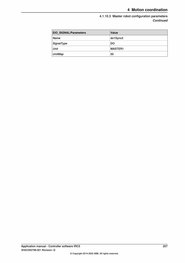
ValueEIO_SIGNAL/Parameters
do1Sync2Name
DOSignalType
MASTER1Unit
50UnitMap
Application manual - Controller software IRC5 2073HAC050798-001 Revision: Q
© Copyright 2014-2022 ABB. All rights reserved.
4 Motion coordination4.1.10.3 Master robot configuration parameters
Continued

4.1.10.4 Slave robot configuration parameters
OverviewFor default configuration, see System parameters on page 223.Use RobotStudio to change the parameters and to set up the slave robot.
DescriptionTo make the slave robot stop and restart synchronized with the master robot:
• Set the parameter value min_sync_speed to 0.0The slave robot will also stop if a fine point is defined in the master robot path.
Topic: Process
SENSOR_SYSTEM
ValueSENSOR_SYSTEM/Parameter
SSYNCS1Name
CANsensor_type
CAN1use_sensor
1000adjustment_speed
600min_dist
20000max_dist
10correction_vector_ramp_length
1000nominal_speed
CAN_INTERFACE
ValueCAN_INTERFACE/Parameters
CAN1Name
34Signal delay
c1ConnectedConnected signal
c1PositionPosition signal
c1SpeedVelocity signal
c1NullSpeedNull speed signal
Data ready signal
c1WaitWObjWaitwobj signal
c1DropWobjDropwobj signal
c1DTimestampData Time stamp
c1RemAllPObjRemAllPObj signal
NOVirtual sensor
0,33Sensor Speed filter
Continues on next page208 Application manual - Controller software IRC5
3HAC050798-001 Revision: Q© Copyright 2014-2022 ABB. All rights reserved.
4 Motion coordination4.1.10.4 Slave robot configuration parameters
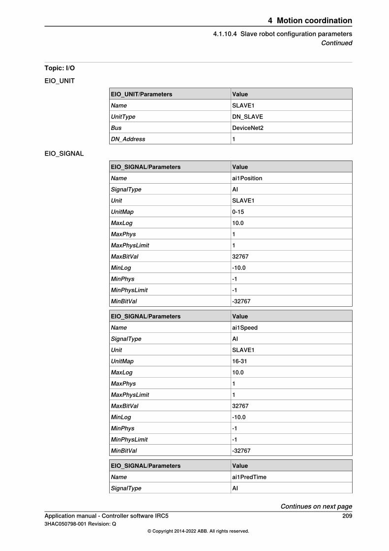
Topic: I/O
EIO_UNIT
ValueEIO_UNIT/Parameters
SLAVE1Name
DN_SLAVEUnitType
DeviceNet2Bus
1DN_Address
EIO_SIGNAL
ValueEIO_SIGNAL/Parameters
ai1PositionName
AISignalType
SLAVE1Unit
0-15UnitMap
10.0MaxLog
1MaxPhys
1MaxPhysLimit
32767MaxBitVal
-10.0MinLog
-1MinPhys
-1MinPhysLimit
-32767MinBitVal
ValueEIO_SIGNAL/Parameters
ai1SpeedName
AISignalType
SLAVE1Unit
16-31UnitMap
10.0MaxLog
1MaxPhys
1MaxPhysLimit
32767MaxBitVal
-10.0MinLog
-1MinPhys
-1MinPhysLimit
-32767MinBitVal
ValueEIO_SIGNAL/Parameters
ai1PredTimeName
AISignalType
Continues on next pageApplication manual - Controller software IRC5 2093HAC050798-001 Revision: Q
© Copyright 2014-2022 ABB. All rights reserved.
4 Motion coordination4.1.10.4 Slave robot configuration parameters
Continued

ValueEIO_SIGNAL/Parameters
SLAVE1Unit
32-47UnitMap
10.0MaxLog
1MaxPhys
1MaxPhysLimit
32767MaxBitVal
-10.0MinLog
-1MinPhys
-1MinPhysLimit
-32767MinBitVal
ValueEIO_SIGNAL/Parameters
di1DreadyName
DISignalType
SLAVE1Unit
48UnitMap
ValueEIO_SIGNAL/Parameters
di1Sync2Name
DISignalType
SLAVE1Unit
50UnitMap
210 Application manual - Controller software IRC53HAC050798-001 Revision: Q
© Copyright 2014-2022 ABB. All rights reserved.
4 Motion coordination4.1.10.4 Slave robot configuration parametersContinued

4.1.10.5 Programming example for master robot
OverviewThe following program is an example of how to program a master robot.
Master robot programmingsyncstart:=20;
Syncpos1:=300;
Syncpos2:=600;
Syncpos3:=900;
Syncpos4:=1200;
!Synchronized motion between master and slave
robpos1.extax.eax_e:=syncpos1;
robpos2.extax.eax_e:=syncpos2;
robpos3.extax.eax_e:=syncpos3;
robpos4.extax.eax_e:=syncpos4;
robpos5.extax.eax_e:=syncstart;
!Init of external axis
pOutsideNext.extax.eax_e:=syncstart;
!Activate sensor
ActUnit SSYNC1;
!Instruction with coordinated robot targets
MoveJ pOutsideNext, v1000, fine, tool1;
!Init of external axis
robposstart.extax.eax_e:=syncstart;
!Set digital output
SetDO Dosync 1,0
!Instructions with coordinated robot targets
MoveJ robposstart, v2000, z50, tool1;
!Set digital output
PulseDO\PLength:= 0.1, doSync1;
!Instructions with coordinated robot targets
MoveJ robpos1, v2000, z10, tool1;
MoveJ robpos2, v2000, z10, tool1;
MoveJ robpos3, v2000, z10, tool1;
MoveJ robpos4, v2000, z10, tool1;
MoveJ robpos5, v2000, z10, tool1;
Continues on next pageApplication manual - Controller software IRC5 2113HAC050798-001 Revision: Q
© Copyright 2014-2022 ABB. All rights reserved.
4 Motion coordination4.1.10.5 Programming example for master robot

ConsiderationsThe following is to be considered
• The values of extax.eax_e should increase for every robtarget duringsynchronization. The first move instruction of the master robot, after thesynchronization, should also have a higher extax.eax_e value than theprevious instruction. Otherwise the value of extax.eax_e may decrease,and the synchronization end, before the slave robot has reached its target.
• The movement back to syncstart (move instruction to robpos5 in theexample) may be slower than the ordered speed (v2000). If this robotmovement is short and the value of extax.eax_e is large, the maximumspeed will be limited by the virtual sensor speed.
• Do not use WaitSensor or DropSensor.• Verify that the virtual sensor max speed (speed_out) is less than 1m/s.
212 Application manual - Controller software IRC53HAC050798-001 Revision: Q
© Copyright 2014-2022 ABB. All rights reserved.
4 Motion coordination4.1.10.5 Programming example for master robotContinued
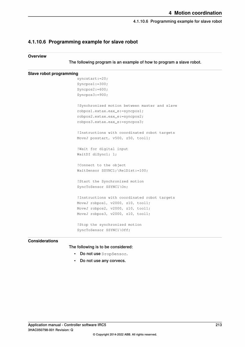
4.1.10.6 Programming example for slave robot
OverviewThe following program is an example of how to program a slave robot.
Slave robot programmingsyncstart:=20;
Syncpos1:=300;
Syncpos2:=600;
Syncpos3:=900;
!Synchronized motion between master and slave
robpos1.extax.eax_e:=syncpos1;
robpos2.extax.eax_e:=syncpos2;
robpos3.extax.eax_e:=syncpos3;
!Instructions with coordinated robot targets
MoveJ posstart, v500, z50, tool1;
!Wait for digital input
WaitDI diSync1; 1;
!Connect to the object
WaitSensor SSYNC1;\RelDist:=100;
!Start the Synchronized motion
SyncToSensor SSYNC1\On;
!Instructions with coordinated robot targets
MoveJ robpos1, v2000, z10, tool1;
MoveJ robpos2, v2000, z10, tool1;
MoveJ robpos3, v2000, z10, tool1;
!Stop the synchronized motion
SyncToSensor SSYNC1\Off;
ConsiderationsThe following is to be considered:
• Do not use DropSensor.• Do not use any corvecs.
Application manual - Controller software IRC5 2133HAC050798-001 Revision: Q
© Copyright 2014-2022 ABB. All rights reserved.
4 Motion coordination4.1.10.6 Programming example for slave robot

4.1.11 Synchronize with hydraulic press using recorded profile
4.1.11.1 Introduction
OverviewThis section describes how to use a recorded machine profile to improve theaccuracy of robot’s synchronization with a hydraulic press. This profile is used formodeling of press path. Not using a recorded profile will require a bigger distancebetween robot and press model when teaching the path.
Principles of hydraulic press synchronization1 Record the movement of the hydraulic press.2 Activate the record to be used in the next cycle.3 Activate the sensor synchronization with the RAPID instruction
SyncToSensor.
214 Application manual - Controller software IRC53HAC050798-001 Revision: Q
© Copyright 2014-2022 ABB. All rights reserved.
4 Motion coordination4.1.11.1 Introduction

4.1.11.2 Configuration of system parameters
IntroductionThis section describes how to configure the parameters to get the best result whenusing recorded sensor profiles with a hydraulic press. Start the tuning with thegeneral settings. If the system is not using a DSQC377A encoder, see Settings foranalog input with no DSQC377A encoder on page 215 If the sensor is using groupinput, see Settings for sensor using Group input on page 216. Descriptions of thesystem parameters are found in System parameters on page 223.
General settingsThis parameter belong to the configuration type Fieldbus Command in the topicI/O.
ValueParameter
10-15 Hz, Change this value to get good accuracy during startand stop.
Parameter Value for the in-stance where Type ofFieldbus Command isIIRFFP.
This parameter belong to the configuration type Path Sensor Synchronization inthe topic Motion.
ValueParameter
ROBOT_TO_HPRESSynchronization Type
The parameters belong to the configuration type Sensor systems in the topicProcess.
ValueParameter
Type the name of the I/O signalSensor start signal
Type the name of the I/O signalStop press signal
Type the name of the I/O signalSync Alarm signal
Settings for analog input with no DSQC377A encoderThe parameters belong to the configuration type Can Interface in the topic Process.
ValueParameter
YesVirtual sensor
Type the name of the analog input.Position signal
Note
All other signals except Position signal should be empty (i.e. "").
Tip
WaitSensor and DropSensor are not needed in the RAPID program.
Continues on next pageApplication manual - Controller software IRC5 2153HAC050798-001 Revision: Q
© Copyright 2014-2022 ABB. All rights reserved.
4 Motion coordination4.1.11.2 Configuration of system parameters

Settings for sensor using Group inputThe parameters belong to the configuration type Sensor systems in the topicProcess.
ValueParameter
Define the number of input data per meter, the default value isset to 10000.
Pos Group IO scale
The parameters belong to the configuration type Can Interface in the topic Process.
ValueParameter
YesVirtual sensor
Type the name of the used group input.Position signal
Note
All other signals except Position signal should be empty (i.e. "")
Tip
WaitSensor and DropSensor are not needed in the RAPID program.
216 Application manual - Controller software IRC53HAC050798-001 Revision: Q
© Copyright 2014-2022 ABB. All rights reserved.
4 Motion coordination4.1.11.2 Configuration of system parametersContinued

4.1.11.3 Program example
OverviewThis section describes the programming cycles that are typical for programminga hydraulic press.
Program example
First press cycleA pulse on sensor_start_signal will start storing position in a record array.During this cycle the robot is not synchronized with press.
ActUnit SSYNC1;
WaitSensor SSYNC1;
! Set up a recording for 2 seconds
PrxStartRecord SSYNC1, 2, PRX_HPRESS_PROF;
! Process waiting for sensor_start_signal
! then waiting for press movement and record it during 2 sec.
Second press cycleA pulse on sensor_start_signal is needed to synchronize readings of record andactual positions for each cycle.During press opening the robot moves synchronized with press.
PrxActivAndStoreRecord SSYNC1, 0, "profile.log";
WaitSensor Ssync1;
MoveL p10, v1000, z10, tool, \WObj:=wobj0;
SyncToSensor Ssync1\On;
MoveL p20, v1000, z20, tool, \WObj:=wobj0;
MoveL p30, v1000, z20, tool, \WObj:=wobj0;
SyncToSensor Ssync1\Off;
Third press cycleNo special instruction is needed, but a pulse on sensor_start_signal is needed tosynchronize readings of record and actual positions for each cycle. A new recordcan also be started.During press opening the robot moves synchronized with press.
WaitSensor Ssync1;
MoveL p10, v1000, z10, tool, \WObj:=wobj0;
SyncToSensor Ssync1\On;
MoveL p20, v1000, z20, tool, \WObj:=wobj0;
MoveL p30, v1000, z20, tool, \WObj:=wobj0;
SyncToSensor Ssync1\Off;
Application manual - Controller software IRC5 2173HAC050798-001 Revision: Q
© Copyright 2014-2022 ABB. All rights reserved.
4 Motion coordination4.1.11.3 Program example
4.1.12 Synchronize with molding machine using recorded profile
4.1.12.1 Introduction
OverviewThis section describes how to use a recorded machine profile to improve theaccuracy of a robot’s synchronization with a molding machine. This profile is usedfor modeling of mold path. Not using a recorded profile will require a bigger distancebetween robot and machine model when teaching the path.
Principles of mold synchronization1 Record the movement of the Molding machine.2 Activate the record to be used in the next cycle.3 Activate the sensor synchronization with the RAPID instruction
SynctoSensor.
Tip
When the molding machine is closing, supervision can be used instead ofsynchronization. For more information, see Supervision on page 222.
218 Application manual - Controller software IRC53HAC050798-001 Revision: Q
© Copyright 2014-2022 ABB. All rights reserved.
4 Motion coordination4.1.12.1 Introduction
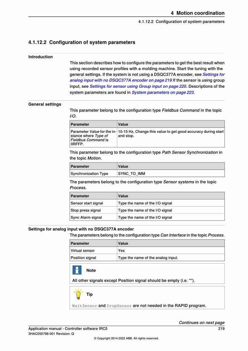
4.1.12.2 Configuration of system parameters
IntroductionThis section describes how to configure the parameters to get the best result whenusing recorded sensor profiles with a molding machine. Start the tuning with thegeneral settings. If the system is not using a DSQC377A encoder, see Settings foranalog input with no DSQC377A encoder on page 219 If the sensor is using groupinput, see Settings for sensor using Group input on page 220. Descriptions of thesystem parameters are found in System parameters on page 223.
General settingsThis parameter belong to the configuration type Fieldbus Command in the topicI/O.
ValueParameter
10-15 Hz, Change this value to get good accuracy during startand stop.
Parameter Value for the in-stance where Type ofFieldbus Command isIIRFFP.
This parameter belong to the configuration type Path Sensor Synchronization inthe topic Motion.
ValueParameter
SYNC_TO_IMMSynchronization Type
The parameters belong to the configuration type Sensor systems in the topicProcess.
ValueParameter
Type the name of the I/O signalSensor start signal
Type the name of the I/O signalStop press signal
Type the name of the I/O signalSync Alarm signal
Settings for analog input with no DSQC377A encoderThe parameters belong to the configuration type Can Interface in the topic Process.
ValueParameter
YesVirtual sensor
Type the name of the analog input.Position signal
Note
All other signals except Position signal should be empty (i.e. "").
Tip
WaitSensor and DropSensor are not needed in the RAPID program.
Continues on next pageApplication manual - Controller software IRC5 2193HAC050798-001 Revision: Q
© Copyright 2014-2022 ABB. All rights reserved.
4 Motion coordination4.1.12.2 Configuration of system parameters
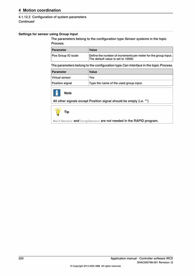
Settings for sensor using Group inputThe parameters belong to the configuration type Sensor systems in the topicProcess.
ValueParameter
Define the number of increments per meter for the group input.The default value is set to 10000.
Pos Group IO scale
The parameters belong to the configuration type Can Interface in the topic Process.
ValueParameter
YesVirtual sensor
Type the name of the used group input.Position signal
Note
All other signals except Position signal should be empty (i.e. "")
Tip
WaitSensor and DropSensor are not needed in the RAPID program.
220 Application manual - Controller software IRC53HAC050798-001 Revision: Q
© Copyright 2014-2022 ABB. All rights reserved.
4 Motion coordination4.1.12.2 Configuration of system parametersContinued
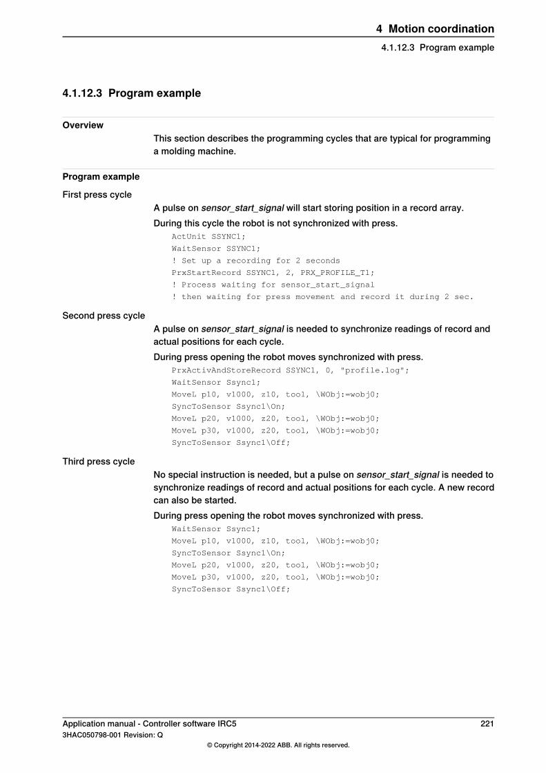
4.1.12.3 Program example
OverviewThis section describes the programming cycles that are typical for programminga molding machine.
Program example
First press cycleA pulse on sensor_start_signal will start storing position in a record array.During this cycle the robot is not synchronized with press.
ActUnit SSYNC1;
WaitSensor SSYNC1;
! Set up a recording for 2 seconds
PrxStartRecord SSYNC1, 2, PRX_PROFILE_T1;
! Process waiting for sensor_start_signal
! then waiting for press movement and record it during 2 sec.
Second press cycleA pulse on sensor_start_signal is needed to synchronize readings of record andactual positions for each cycle.During press opening the robot moves synchronized with press.
PrxActivAndStoreRecord SSYNC1, 0, "profile.log";
WaitSensor Ssync1;
MoveL p10, v1000, z10, tool, \WObj:=wobj0;
SyncToSensor Ssync1\On;
MoveL p20, v1000, z20, tool, \WObj:=wobj0;
MoveL p30, v1000, z20, tool, \WObj:=wobj0;
SyncToSensor Ssync1\Off;
Third press cycleNo special instruction is needed, but a pulse on sensor_start_signal is needed tosynchronize readings of record and actual positions for each cycle. A new recordcan also be started.During press opening the robot moves synchronized with press.
WaitSensor Ssync1;
MoveL p10, v1000, z10, tool, \WObj:=wobj0;
SyncToSensor Ssync1\On;
MoveL p20, v1000, z20, tool, \WObj:=wobj0;
MoveL p30, v1000, z20, tool, \WObj:=wobj0;
SyncToSensor Ssync1\Off;
Application manual - Controller software IRC5 2213HAC050798-001 Revision: Q
© Copyright 2014-2022 ABB. All rights reserved.
4 Motion coordination4.1.12.3 Program example
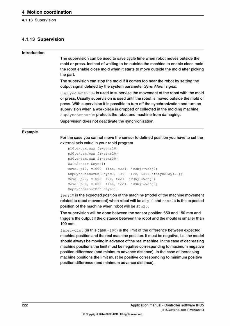
4.1.13 Supervision
IntroductionThe supervision can be used to save cycle time when robot moves outside themold or press. Instead of waiting to be outside the machine to enable close moldthe robot enable close mold when it starts to move outside the mold after pickingthe part.The supervision can stop the mold if it comes too near the robot by setting theoutput signal defined by the system parameter Sync Alarm signal.SupSyncSensorOn is used to supervise the movement of the robot with the moldor press. Usually supervision is used until the robot is moved outside the mold orpress. With supervision it is possible to turn off the synchronization and turn onsupervision when a workpiece is dropped or collected in the molding machine.SupSyncSensorOn protects the robot and machine from damaging.Supervision does not deactivate the synchronization.
ExampleFor the case you cannot move the sensor to defined position you have to set theexternal axis value in your rapid program
p10.extax.eax_f:=sens10;
p20.extax.eax_f:=sens20;
p30.extax.eax_f:=sens30;
WaitSensor Ssync1;
MoveL p10, v1000, fine, tool, \WObj:=wobj0;
SupSyncSensorOn Ssync1, 150, -100, 650\SafetyDelay:=0;;
MoveL p20, v1000, z20, tool, \WObj:=wobj0;
MoveL p30, v1000, fine, tool, \WObj:=wobj0;
SupSyncSensorOff Ssync1;
Sens10 is the expected position of the machine (model of the machine movementrelated to robot movement) when robot will be at p10 and sens20 is the expectedposition of the machine when robot will be at p20.The supervision will be done between the sensor position 650 and 150 mm andtriggers the output if the distance between the robot and the mould is smaller than100 mm.Safetydist (in this case -100) is the limit of the difference between expectedmachine position and the real machine position. It must be negative, i.e. the modelshould always be moving in advance of the real machine. In the case of decreasingmachine positions the limit must be negative corresponding to maximum negativeposition difference (and minimum advance distance). In the case of increasingmachine positions the limit must be positive corresponding to minimum positiveposition difference (and minimum advance distance).
222 Application manual - Controller software IRC53HAC050798-001 Revision: Q
© Copyright 2014-2022 ABB. All rights reserved.
4 Motion coordination4.1.13 Supervision
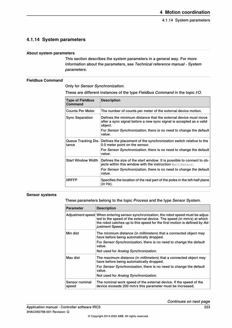
4.1.14 System parameters
About system parametersThis section describes the system parameters in a general way. For moreinformation about the parameters, see Technical reference manual - Systemparameters.
Fieldbus CommandOnly for Sensor Synchronization.These are different instances of the type Fieldbus Command in the topic I/O.
DescriptionType of FieldbusCommand
The number of counts per meter of the external device motion.Counts Per Meter
Defines the minimum distance that the external device must moveafter a sync signal before a new sync signal is accepted as a validobject.
Sync Separation
For Sensor Synchronization, there is no need to change the defaultvalue.
Defines the placement of the synchronization switch relative to the0.0 meter point on the sensor.
Queue Tracking Dis-tance
For Sensor Synchronization, there is no need to change the defaultvalue.
Defines the size of the start window. It is possible to connect to ob-jects within this window with the instruction WaitSensor.
Start Window Width
For Sensor Synchronization, there is no need to change the defaultvalue.
Specifies the location of the real part of the poles in the left-half plane(in Hz).
IIRFFP
Sensor systemsThese parameters belong to the topic Process and the type Sensor System.
DescriptionParameter
When entering sensor synchronization, the robot speed must be adjus-ted to the speed of the external device. The speed (in mm/s) at whichthe robot catches up to this speed for the first motion is defined by Ad-justment Speed.
Adjustment speed
The minimum distance (in millimeters) that a connected object mayhave before being automatically dropped.
Min dist
For Sensor Synchronization, there is no need to change the defaultvalue.Not used for Analog Synchronization.
The maximum distance (in millimeters) that a connected object mayhave before being automatically dropped.
Max dist
For Sensor Synchronization, there is no need to change the defaultvalue.Not used for Analog Synchronization.
The nominal work speed of the external device. If the speed of thedevice exceeds 200 mm/s this parameter must be increased.
Sensor nominalspeed
Continues on next pageApplication manual - Controller software IRC5 2233HAC050798-001 Revision: Q
© Copyright 2014-2022 ABB. All rights reserved.
4 Motion coordination4.1.14 System parameters

DescriptionParameter
Name of the digital input signal telling that press is stopping. This signalis needed for safe stop of robot.
Stop press signal
Name of the digital input signal to synchronize recorded profile andnew machine movement. The signal must be set before start of machinemovement. The signal must be triggered 100 ms before the press moves.
Sensor start sig-nal
Defines for how many calculation steps the position error may exceedMax Advance Distance. During this ramping period, the position errormay be 5 times Max Advance Distance.
Start ramp
Name of the digital output signal to stop the synchronized machine.Thissignal may be set during supervision of sync sensor.
Sync Alarm signal
CAN InterfaceThese parameters belong to the topic Process and the type CAN Interface.
DescriptionParameter
Name of the digital input signal for connection.Connected signalNot used for Analog Synchronization.
Name of the analog input signal for sensor position.Position signal
Name of the analog input signal for sensor speed.Velocity signal
Name of the digital input signal indicating zero speed on the sensor.Null speed signalNot used for Analog Synchronization.
Name of the digital input signal indicating a poll of the encoder unit.Data ready signalNot used for Analog Synchronization.
Name of the digital output signal to indicate that a connection is desiredto an object in the queue.
Waitwobj signal
Not used for Analog Synchronization.
Name of the digital output signal to drop a connected object on theencoder unit
Dropwobj signal
Not used for Analog Synchronization.
Name of the digital output signal to indicate that an object has gonepast the start window without being connected.
PassStartW signal
Not used for Analog Synchronization.
Time (in ms) at which the synchronization process read the sensorposition.
Pos Update time
Motion PlannerThese parameters belong to the topic Motion and the type Motion planner.
DescriptionParameter
The period at which steps along the path are calculated.Path resolution
The time (in seconds) at which the sensor process updates therobot kinematics on the sensor position.
Process update time
CPU load equalization needs to be lowered for the synchronizationoption. The default value is 2 but for the synchronization optionit should be set equal to 1 to have a stable synchronization speed.
CPU load equalization
Continues on next page224 Application manual - Controller software IRC5
3HAC050798-001 Revision: Q© Copyright 2014-2022 ABB. All rights reserved.
4 Motion coordination4.1.14 System parametersContinued

Mechanical unitThese parameters belong to the topic Motion and the type Mechanical unit.
DescriptionParameter
The name of the unit (max. 7 characters).Name
The sensor is to be activated automatically at start up.Activate at start up
The sensor cannot be deactivated.Deactivate Forbidden
Single typeThis parameter belongs to the topic Motion and the type Single type.
DescriptionParameter
Specifies the mechanical structure of the sensor.Mechanics
TransmissionThis parameter belong to the topic Motion and the type Transmission.
DescriptionParameter
Specifies if the sensor is rotating (Yes) or linear (No).Rotating move
Path Sensor SynchronizationThese parameters belong to the topic Motion and the type Path SensorSynchronization. They are used to set allowed deviation between calculated andactual position of the external device, and minimum/maximum TCP speed for therobot.
DescriptionParameter
The max advance distance allowed from calculated position to ac-tual position of the external device.
Max Advance Distance
The max delay distance allowed from calculated position to actualposition of the external device.
Max Delay Distance
The max robot TCP speed allowed in m/s.Max SynchronizationSpeed
The min robot TCP speed allowed in m/s.Min SynchronizationSpeed
Application manual - Controller software IRC5 2253HAC050798-001 Revision: Q
© Copyright 2014-2022 ABB. All rights reserved.
4 Motion coordination4.1.14 System parameters
Continued

4.1.15 I/O signals
OverviewSensor Synchronization provides several I/O signals which allow a user or RAPIDprogram to monitor and control the object queue on the encoder interface unit.The object queue is designed for the option Conveyor Tracking and has morefunctionality than required by Sensor Synchronization. Since each closing of apress is considered an object in the object queue, signals for the object queuemay occasionally be useful.
Object queue signalsThe following table shows the I/O signals in the encoder unit DSQC 354 whichimpact the object queue.
DescriptionInstruction
Group input showing the number of objects in the object queue. Theseobjects are registered by the synchronization switch and have not beendropped.
c1ObjectsInQ
Digital output that removes the first pending object from the object queue.Pending objects are objects that are in the queue but are not connectedto a work object.
c1Rem1PObj
Digital output that removes all pending objects. If an object is connected,then it is not removed.
c1RemAllPObj
Digital output that will cause the encoder interface unit to drop the trackedobject and disconnect it. The object is removed from the queue.
c1DropWObj
Do not use c1DropWObj in RAPID code. Use the DropWobj instructioninstead.
226 Application manual - Controller software IRC53HAC050798-001 Revision: Q
© Copyright 2014-2022 ABB. All rights reserved.
4 Motion coordination4.1.15 I/O signals

4.1.16 RAPID components
About the RAPID componentsThis is an overview of all instructions, functions, and data types in MachineSynchronization.For more information, see Technical reference manual - RAPID Instructions,Functions and Data types.
Instructions
DescriptionInstructions
Drop object on sensorDropSensor
Activate and store the recorded profile dataPrxActivAndStoreRecord
Activate the recorded profile dataPrxActivRecord
Store and debug the recorded profile dataPrxDbgStoreRecord
Deactivate a recordPrxDeactRecord
Reset the zero position of the sensorPrxResetPos
Reset and deactivate all recordsPrxResetRecords
Set a reference position for the sensorPrxSetPosOffset
Set the sample time for recording a profilePrxSetRecordSampleTime
Set sync alarm behaviorPrxSetSyncalarm
Record a new profilePrxStartRecord
Stop recording a profilePrxStopRecord
Store the recorded profile dataPrxStoreRecord
Use the recorded profile dataPrxUseFileRecord
Stop synchronized sensor supervisionSupSyncSensorOff
Start synchronized sensor supervisionSupSyncSensorOn
Sync to sensorSyncToSensor
Wait for connection on sensorWaitSensor
Functions
DescriptionFunctions
Get the maximum sensor positionPrxGetMaxRecordpos
Data typesMachine Synchronization includes no data types.
Application manual - Controller software IRC5 2273HAC050798-001 Revision: Q
© Copyright 2014-2022 ABB. All rights reserved.
4 Motion coordination4.1.16 RAPID components

This page is intentionally left blank
5 Motion Events5.1 World Zones [608-1]
5.1.1 Overview of World Zones
PurposeThe purpose of World Zones is to stop the robot or set an output signal if the robotis inside a special user-defined zone. Here are some examples of applications:
• When two robots share a part of their respective work areas. The possibilityof the two robots colliding can be safely eliminated by World Zonessupervision.
• When a permanent obstacle or some temporary external equipment is locatedinside the robot’s work area. A forbidden zone can be created to prevent therobot from colliding with this equipment.
• Indication that the robot is at a position where it is permissible to start programexecution from a Programmable Logic Controller (PLC).
A world zone is supervised during robot movements both during program executionand jogging. If the robot’s TCP reaches the world zone or if the axes reaches theworld zone in joints, the movement is stopped or a digital output signal is set.
WARNING
For safety reasons, this software shall not be used for protection of personnel.Use hardware protection equipment for that.
What is includedThe RobotWare option World Zones gives you access to:
• instructions used to define volumes of various shapes• instructions used to define joint zones in coordinates for axes• instructions used to define and enable world zones
Basic approachThis is the general approach for setting up World Zones. For a more detailedexample of how this is done, see Code examples on page 233.
1 Declare the world zone as stationary or temporary.2 Declare the shape variable.3 Define the shape that the world zone shall have.4 Define the world zone (that the robot shall stop or that an output signal shall
be set when reaching the volume).
Continues on next pageApplication manual - Controller software IRC5 2293HAC050798-001 Revision: Q
© Copyright 2014-2022 ABB. All rights reserved.
5 Motion Events5.1.1 Overview of World Zones

LimitationsSupervision of a volume only works for the TCP. Any other part of the robot maypass through the volume undetected. To be certain to prevent this, you cansupervise a joint world zone (defined byWZLimJointDef or WZHomeJointDef).A variable of type wzstationary or wztemporary can not be redefined. Theycan only be defined once (with WZLimSup or WZDOSet).World Zones supervision is not accessible when lead-through is active.
230 Application manual - Controller software IRC53HAC050798-001 Revision: Q
© Copyright 2014-2022 ABB. All rights reserved.
5 Motion Events5.1.1 Overview of World ZonesContinued
5.1.2 RAPID components
Data typesThis is a brief description of each data type in World Zones. For more information,see respective data type in Technical reference manual - RAPID Instructions,Functions and Data types.
DescriptionData type
wztemporary is used to identify a temporary world zone and can beused anywhere in the RAPID program.
wztemporary
Temporary world zones can be disabled, enabled again, or erasedvia RAPID instructions. Temporary world zones are automaticallyerased when a new program is loaded or when program executionstart from the beginning in the MAIN routine.
wzstationary is used to identify a stationary world zone and canonly be used in an event routine connected to the event POWER ON.For information on defining event routines, see Operating manu-al - IRC5 with FlexPendant.
wzstationary
A stationary world zone is always active and is reactivated by a restart(switch power off then on, or change system parameters). It is notpossible to disable, enable or erase a stationary world zone viaRAPID instructions.Stationary world zones shall be used if security is involved.
shapedata is used to describe the geometry of a world zone.shapedataWorld zones can be defined in 4 different geometrical shapes:
• a straight box, with all sides parallel to the world coordinatesystem
• a cylinder, parallel to the z axis of the world coordinate system• a sphere• a joint angle area for the robot axes and/or external axes
InstructionsThis is a brief description of each instruction in World Zones. For more information,see respective instruction in Technical reference manual - RAPID Instructions,Functions and Data types.
DescriptionInstruction
WZBoxDef is used to define a volume that has the shape of a straightbox with all its sides parallel to the axes of the world coordinate sys-tem. The definition is stored in a variable of type shapedata.
WZBoxDef
The volume can also be defined as the inverse of the box (all volumeoutside the box).
WZCylDef is used to define a volume that has the shape of a cylinderwith the cylinder axis parallel to the z-axis of the world coordinatesystem. The definition is stored in a variable of type shapedata.
WZCylDef
The volume can also be defined as the inverse of the cylinder (allvolume outside the cylinder).
WZSphDef is used to define a volume that has the shape of a sphere.The definition is stored in a variable of type shapedata.
WZSphDef
The volume can also be defined as the inverse of the sphere (allvolume outside the sphere).
Continues on next pageApplication manual - Controller software IRC5 2313HAC050798-001 Revision: Q
© Copyright 2014-2022 ABB. All rights reserved.
5 Motion Events5.1.2 RAPID components

DescriptionInstruction
WZLimJointDef is used to define joint coordinate for axes, to beused for limitation of the working area. Coordinate limits can be setfor both the robot axes and external axes.
WZLimJointDef
For each axis WZLimJointDef defines an upper and lower limit. Forrotational axes the limits are given in degrees and for linear axes thelimits are given in mm.The definition is stored in a variable of type shapedata.
WZHomeJointDef is used to define joint coordinates for axes, to beused to identify a position in the joint space. Coordinate limits can beset for both the robot axes and external axes.
WZHomeJointDef
For each axis WZHomeJointDef defines a joint coordinate for themiddle of the zone and the zones delta deviation from the middle. Forrotational axes the coordinates are given in degrees and for linearaxes the coordinates are given in mm.The definition is stored in a variable of type shapedata.
WZLimSup is used to define, and enable, stopping the robot with anerror message when the TCP reaches the world zone. This supervisionis active both during program execution and when jogging.
WZLimSup
When calling WZLimSup you specify whether it is a stationary worldzone, stored in a wzstationary variable, or a temporary world zone,stored in a wztemporary variable.
WZDOSet is used to define, and enable, setting a digital output signalwhen the TCP reaches the world zone.
WZDOSet
When callingWZDOSet you specify whether it is a stationary worldzone, stored in a wzstationary variable, or a temporary world zone,stored in a wztemporary variable.
WZDisable is used to disable the supervision of a temporary worldzone.
WZDisable
WZEnable is used to re-enable the supervision of a temporary worldzone.
WZEnable
A world zone is automatically enabled on creation. Enabling is onlynecessary after it has been disabled with WZDisable.
WZFree is used to disable and erase a temporary world zone.WZFree
FunctionsWorld Zones does not include any RAPID functions.
232 Application manual - Controller software IRC53HAC050798-001 Revision: Q
© Copyright 2014-2022 ABB. All rights reserved.
5 Motion Events5.1.2 RAPID componentsContinued

5.1.3 Code examples
Create protected boxTo prevent the robot TCP from moving into stationary equipment, set up a stationaryworld zone around the equipment.The routine my_power_on should then be connected to the event POWER ON.For information on how to do this, read about defining event routines in Operatingmanual - IRC5 with FlexPendant.
xx0300000178
VAR wzstationary obstacle;
PROC my_power_on()
VAR shapedata volume;
CONST pos p1 := [200, 100, 100];
CONST pos p2 := [600, 400, 400];
!Define a box between the corners p1 and p2
WZBoxDef \Inside, volume, p1, p2;
!Define and enable supervision of the box
WZLimSup \Stat, obstacle, volume;
ENDPROC
Signal when robot is in positionWhen two robots share a work area it is important to know when a robot is out ofthe way, letting the other robot move freely.This example defines a home position where the robot is in a safe position andsets an output signal when the robot is in its home position. The robot is standingon a travel track, handled as external axis 1. No other external axes are active.
Continues on next pageApplication manual - Controller software IRC5 2333HAC050798-001 Revision: Q
© Copyright 2014-2022 ABB. All rights reserved.
5 Motion Events5.1.3 Code examples
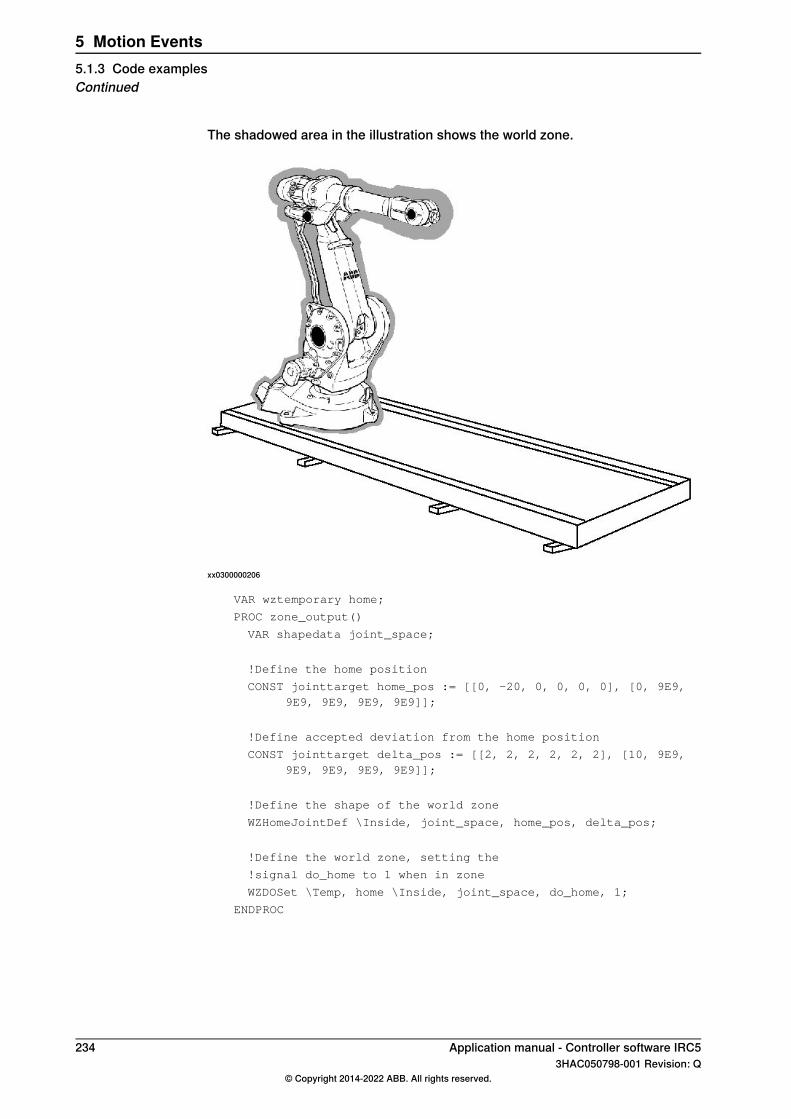
The shadowed area in the illustration shows the world zone.
xx0300000206
VAR wztemporary home;
PROC zone_output()
VAR shapedata joint_space;
!Define the home position
CONST jointtarget home_pos := [[0, -20, 0, 0, 0, 0], [0, 9E9,9E9, 9E9, 9E9, 9E9]];
!Define accepted deviation from the home position
CONST jointtarget delta_pos := [[2, 2, 2, 2, 2, 2], [10, 9E9,9E9, 9E9, 9E9, 9E9]];
!Define the shape of the world zone
WZHomeJointDef \Inside, joint_space, home_pos, delta_pos;
!Define the world zone, setting the
!signal do_home to 1 when in zone
WZDOSet \Temp, home \Inside, joint_space, do_home, 1;
ENDPROC
234 Application manual - Controller software IRC53HAC050798-001 Revision: Q
© Copyright 2014-2022 ABB. All rights reserved.
5 Motion Events5.1.3 Code examplesContinued
6 Motion functions6.1 Independent Axis [610-1]
6.1.1 Overview
PurposeThe purpose of Independent Axis is to move an axis independently of other axesin the robot system. Some examples of applications are:
• Move an external axis holding an object (for example rotating an object whilethe robot is spray painting it).
• Save cycle time by performing a robot task at the same time as an externalaxis performs another.
• Continuously rotate robot axis 6 (for polishing or similar tasks).• Reset the measurement system after an axis has rotated multiple revolutions
in the same direction. Saves cycle time compared to physically winding back.An axis can move independently if it is set to independent mode. An axis can bechanged to independent mode and later back to normal mode again.
What is includedThe RobotWare option Independent Axis gives you access to:
• instructions used to set independent mode and specify the movement for anaxis
• an instruction for changing back to normal mode and/or reset themeasurement system
• functions used to verify the status of an independent axis• system parameters for configuration.
Basic approachThis is the general approach for moving an axis independently. For detailedexamples of how this is done, see Code examples on page 239.
1 Call an independent move instruction to set the axis to independent modeand move it.
2 Let the robot execute another instruction at the same time as the independentaxis moves.
3 When both robot and independent axis has stopped, reset the independentaxis to normal mode.
Reset axisEven without being in independent mode, an axis might rotate only in one directionand eventually loose precision. The measurement system can then be reset withthe instruction IndReset.The recommendation is to reset the measurement system for an axis before itsmotor has rotated 10000 revolutions in the same direction.
Continues on next pageApplication manual - Controller software IRC5 2353HAC050798-001 Revision: Q
© Copyright 2014-2022 ABB. All rights reserved.
6 Motion functions6.1.1 Overview

LimitationsA mechanical unit may not be deactivated when one of its axes is in independentmode.Axes in independent mode cannot be jogged.The only robot axis that can be used as an independent axis is axis number 6. OnIRB 1600, 2600 and 4600 models (except ID version), the instruction IndReset
can also be used for axis 4.Internal and customer cabling and equipment may limit the ability to useindependent axis functionality on axis 4 and 6.The option is not possible to use in combination with:
• SafeMove I
• Track Motion (IRBT)• Positioners (IRBP) on Interchange axes
I Independent Axis can in some cases be combined with SafeMove2 if the additional axis does notmove the robot, and the additional axis is not monitored by SafeMove. Contact your local ABBsales office team for additional information.
The following is deactivated when option Independent Axes is used:• Collision detection
Note
The collision detection is deactivated on all axes in a motion planner if oneof them is run in independent mode.
236 Application manual - Controller software IRC53HAC050798-001 Revision: Q
© Copyright 2014-2022 ABB. All rights reserved.
6 Motion functions6.1.1 OverviewContinued

6.1.2 System parameters
About the system parametersThis is a brief description of each parameter in the option Independent Axis. Formore information, see the respective parameter in Technical referencemanual - System parameters.
ArmThese parameters belongs to the type Arm in the topic Motion.
DescriptionParameter
Flag that determines if independent mode is allowed for the axis.Independent Joint
Defines the upper limit of the working area for the joint when operatingin independent mode.
Independent UpperJoint Bound
Defines the lower limit of the working area for the joint when operatingin independent mode.
Independent LowerJoint Bound
TransmissionThese parameters belong to the type Transmission in the topic Motion.
DescriptionParameter
Independent Axes requires high resolution in transmission gear ratio,which is therefore defined as Transmission Gear High divided byTransmission Gear Low. If no smaller number can be used, thetransmission gear ratio will be correct if Transmission Gear High isset to the number of cogs on the robot axis side, and TransmissionGear Low is set to the number of cogs on the motor side.
Transmission GearHigh
See Transmission Gear High.Transmission GearLow
Application manual - Controller software IRC5 2373HAC050798-001 Revision: Q
© Copyright 2014-2022 ABB. All rights reserved.
6 Motion functions6.1.2 System parameters

6.1.3 RAPID components
Data typesThere are no data types for Independent Axis.
InstructionsThis is a brief description of each instruction in Independent Axis. For moreinformation, see respective instruction in Technical reference manual - RAPIDInstructions, Functions and Data types.An independent move instruction is executed immediately, even if the axis is beingmoved at the time. If a new independent move instruction is executed before thelast one is finished, the new instruction immediately overrides the old one.
DescriptionInstruction
IndAMove (Independent Absolute position Movement) change anaxis to independent mode and move the axis to a specified position.
IndAMove
IndCMove (Independent Continuous Movement) change an axis toindependent mode and start moving the axis continuously at a spe-cified speed.
IndCMove
IndDMove (Independent Delta position Movement) change an axis toindependent mode and move the axis a specified distance.
IndDMove
IndRMove (Independent Relative position Movement) change a rota-tional axis to independent mode and move the axis to a specific pos-ition within one revolution.
IndRMove
Because the revolution information in the position is omitted,IndRMove never rotates more than one axis revolution.
IndReset is used to change an independent axis back to normalmode.
IndReset
IndReset can move the measurement system for a rotational axis anumber of axis revolutions. The resolution of positions is decreasedwhen moving away from logical position 0, and winding the axis backwould take time. By moving the measurement system the resolutionis maintained without physically winding the axis back.Both the independent axis and the robot must stand still when callingIndReset.
FunctionsThis is a brief description of each function in Independent Axis. For moreinformation, see respective function in Technical reference manual - RAPIDInstructions, Functions and Data types.
DescriptionFunction
IndInposindicates whether an axis has reached the selected position.IndInpos
IndSpeed indicates whether an axis has reached the selected speed.IndSpeed
238 Application manual - Controller software IRC53HAC050798-001 Revision: Q
© Copyright 2014-2022 ABB. All rights reserved.
6 Motion functions6.1.3 RAPID components

6.1.4 Code examples
Save cycle timeAn object in station A needs welding in two places. The external axis for station Acan turn the object in position for the second welding while the robot is weldingon another object. This saves cycle time compared to letting the robot wait whilethe external axis moves.
!Perform first welding in station A
!Call subroutine for welding
weld_stationA_1;
!Move the object in station A, axis 1, with
!independent movement to position 90 degrees
!at the speed 20 degrees/second
IndAMove Station_A,1\ToAbsNum:=90,20;
!Let the robot perform another task while waiting
!Call subroutine for welding
weld_stationB_1;
!Wait until the independent axis is in position
WaitUntil IndInpos(Station_A,1 ) = TRUE;
WaitTime 0.2;
!Perform second welding in station A
!Call subroutine for welding
weld_stationA_2;
Polish by rotating axis 6To polish an object the robot axis 6 can be set to continuously rotate.Set robot axis 6 to independent mode and continuously rotate it. Move the robotover the area you want to polish. Stop movement for both robot and independentaxis before changing back to normal mode. After rotating the axis many revolutions,reset the measurement system to maintain the resolution.Note that, for this example to work, the parameter Independent Joint for rob1_6must be set to Yes.
PROC Polish()
!Change axis 6 of ROB_1 to independent mode and
!rotate it with 180 degrees/second
IndCMove ROB_1, 6, 180;
!Wait until axis 6 is up to speed
WaitUntil IndSpeed(ROB_1,6\InSpeed);
WaitTime 0.2;
!Move robot where you want to polish
MoveL p1,v10, z50, tool1;
MoveL p2,v10, fine, tool1;
Continues on next pageApplication manual - Controller software IRC5 2393HAC050798-001 Revision: Q
© Copyright 2014-2022 ABB. All rights reserved.
6 Motion functions6.1.4 Code examples
!Stop axis 6 and wait until it's still
IndCMove ROB_1, 6, 0;
WaitUntil IndSpeed(ROB_1,6\ZeroSpeed);
WaitTime 0.2;
!Change axis 6 back to normal mode and
!reset measurement system (close to 0)
IndReset ROB_1, 6 \RefNum:=0 \Short;
ENDPROC
Reset an axisThis is an example of how to reset the measurement system for axis 1 in stationA. The measurement system will change a whole number of revolutions, so it isclose to zero (±180°).
IndReset Station_A, 1 \RefNum:=0 \Short;
240 Application manual - Controller software IRC53HAC050798-001 Revision: Q
© Copyright 2014-2022 ABB. All rights reserved.
6 Motion functions6.1.4 Code examplesContinued
6.2 Path Recovery [611-1]
6.2.1 Overview
PurposePath Recovery is used to store the current movement path, perform some robotmovements and then restore the interrupted path. This is useful when an error orinterrupt occurs during the path movement. An error handler or interrupt routinecan perform a task and then recreate the path.For applications like arc welding and gluing, it is important to continue the workfrom the point where the robot left off. If the robot started over from the beginning,then the work piece would have to be scrapped.If a process error occurs when the robot is inside a work piece, moving the robotstraight out might cause a collision. By using the path recorder, the robot caninstead move out along the same path it came in.
What is includedThe RobotWare option Path Recovery gives you access to:
• instructions to suspend and resume the coordinated synchronized movementmode on the error or interrupt level.
• a path recorder, with the ability to move the TCP out from a position alongthe same path it came.
LimitationsThe instructions StorePath and RestoPath only handles movement path data.The stop position must also be stored.Movements using the path recorder has to be performed on trap-level, i.e.StorePath has to be executed prior to PathRecMoveBwd.
Application manual - Controller software IRC5 2413HAC050798-001 Revision: Q
© Copyright 2014-2022 ABB. All rights reserved.
6 Motion functions6.2.1 Overview

6.2.2 RAPID components
Data typesThis is a brief description of each data type in Path Recovery. For more information,see the respective data type in Technical reference manual - RAPID Instructions,Functions and Data types.
DescriptionData type
pathrecid is used to identify a breakpoint for the path recorder.pathrecid
InstructionsThis is a brief description of each instruction in Path Recovery. For moreinformation, see the respective instruction in Technical reference manual - RAPIDInstructions, Functions and Data types.
DescriptionInstruction
StorePath is used to store the movement path being executed whenan error or interrupt occurs.
StorePath
StorePath is included in RobotWare base.
RestoPath is used to restore the path that was stored by StorePath.RestoPathRestoPath is included in RobotWare base.
PathRecStart is used to start recording the robot’s path. The pathrecorder will store path information during execution of the robotprogram.
PathRecStart
PathRecStop is used to stop recording the robot's path.PathRecStop
PathRecMoveBwd is used to move the robot backwards along a recor-ded path.
PathRecMoveBwd
PathRecMoveFwd is used to move the robot back to the positionwhere PathRecMoveBwd was executed.
PathRecMoveFwd
It is also possible to move the robot partly forward by supplying anidentifier that has been passed during the backward movement.
SyncMoveSuspend is used to suspend synchronized movementsmode and set the system to independent movement mode.
SyncMoveSuspend
SyncmoveResume is used to go back to synchronized movementsfrom independent movement mode.
SyncMoveResume
FunctionsThis is a brief description of each function in Path Recovery. For more information,see the respective function in Technical reference manual - RAPID Instructions,Functions and Data types.
DescriptionFunction
PathRecValidBwd is used to check if the path recorder is active andif a recorded backward path is available.
PathRecValidBwd
PathRecValidFwd is used to check if the path recorder can be usedto move forward. The ability to move forward with the path recorderimplies that the path recorder must have been ordered to movebackwards earlier.
PathRecValidFwd
242 Application manual - Controller software IRC53HAC050798-001 Revision: Q
© Copyright 2014-2022 ABB. All rights reserved.
6 Motion functions6.2.2 RAPID components

6.2.3 Store current path
Why store the path?The simplest way to use Path Recovery is to only store the current path to be ableto restore it after resolving an error or similar action.Let's say that an error occur during arc welding. To resolve the error the robotmight have to be moved away from the part. When the error is resolved, the weldingshould be continued from the point it left off. This is solved by storing the pathinformation and the position of the robot before moving away from the path. Thepath can then be restored and the welding resumed after the error has beenhandled.
Basic approachThis is the general approach for storing the current path:
1 At the start of an error handler or interrupt routine:stop the movementstore the movement pathstore the stop position
2 At the end of the error handler or interrupt routine:move to the stored stop positionrestore the movement pathstart the movement
ExampleThis is an example of how to use Path Recovery in error handling. First the pathand position is stored, the error is corrected and then the robot is moved back inposition and the path is restored.
MoveL p100, v100, z10, gun1;
...
ERROR
IF ERRNO=MY_GUN_ERR THEN
gun_cleaning();
ENDIF
...
PROC gun_cleaning()
VAR robtarget p1;
!Stop the robot movement, if not already stopped.
StopMove;
!Store the movement path and current position
StorePath;
p1 := CRobT(\Tool:=gun1\WObj:=wobj0);
!Correct the error
MoveL pclean, v100, fine, gun1;
Continues on next pageApplication manual - Controller software IRC5 2433HAC050798-001 Revision: Q
© Copyright 2014-2022 ABB. All rights reserved.
6 Motion functions6.2.3 Store current path

...
!Move the robot back to the stored position
MoveL p1, v100, fine, gun1;
!Restore the path and start the movement
RestoPath;
StartMove;
RETRY;
ENDPROC
Store path in a MultiMove systemIn a MultiMove system the robots can keep the synchronized movement modeafter StorePath with the argument KeepSync. However the robots can’t switchfrom independent mode to synchronized mode, only the other way around.After a Multimove system is set with the argument KeepSync, the system canchange between synchronized, semi coordinated and independent mode on theStorePath level. The changes are made with the instructions SyncMoveResumeand SyncMoveSuspend.
SyncArc example with coordinated synchronized movementThis is an example on how to use Path Recovery and keep synchronized mode inthe error handler for a MultiMove system. Two robots perform arc welding on thesame work piece. To make the example simple and general, we use moveinstructions instead of weld instructions. The work object is rotated by a positioner.For more information on the SyncArc example, seeApplicationmanual - MultiMove.
T_ROB1 task programMODULE module1
VAR syncident sync1;
VAR syncident sync2;
VAR syncident sync3;
PERS tasks all_tasks{3} := [["T_ROB1"],["T_ROB2"],["T_STN1"]];
PERS wobjdata wobj_stn1 := [ FALSE, FALSE, "STN_1", [ [0, 0, 0],[1, 0, 0 ,0] ], [ [0, 0, 250], [1, 0, 0, 0] ] ];
TASK PERS tooldata tool1 := ...
CONST robtarget p100 := ...
CONST robtarget p199 := ...
PROC main()
...
SyncMove;
ENDPROC
PROC SyncMove()
MoveJ p100, v1000, z50, tool1;
WaitSyncTask sync1, all_tasks;
MoveL p101, v500, fine, tool1;
SyncMoveOn sync2, all_tasks;
MoveL p102\ID:=10, v300, z10, tool1 \WObj:=wobj_stn1;
MoveC p103, p104\ID:=20, v300, z10, tool1 \WObj:=wobj_stn1;
MoveL p105\ID:=30, v300, z10, tool1 \WObj:=wobj_stn1;
Continues on next page244 Application manual - Controller software IRC5
3HAC050798-001 Revision: Q© Copyright 2014-2022 ABB. All rights reserved.
6 Motion functions6.2.3 Store current pathContinued

MoveC p106, p101\ID:=40, v300, fine, tool1 \WObj:=wobj_stn1;
SyncMoveOff sync3;
MoveL p199, v1000, fine, tool1;
ERROR
IF ERRNO = ERR_PATH_STOP THEN
gun_cleaning();
ENDIF
UNDO
SyncMoveUndo;
ENDPROC
PROC gun_cleaning()
VAR robtarget p1;
!Store the movement path and current position
! and keep syncronized mode.
StorePath \KeepSync;
p1 := CRobT(\Tool:=tool1 \WObj:=wobj_stn1);
!Correct the error
MoveL pclean1 \ID:=50, v100, fine, tool1 \WObj:=wobj_stn1;
...
!Move the robot back to the stored position
MoveL p1 \ID:=60, v100, fine, tool1 \WObj:=wobj_stn1;
!Restore the path and start the movement
RestoPath;
StartMove;
RETRY;
ENDPROC
ENDMODULE
T_ROB2 task programMODULE module2
VAR syncident sync1;
VAR syncident sync2;
VAR syncident sync3;
PERS tasks all_tasks{3};
PERS wobjdata wobj_stn1;
TASK PERS tooldata tool2 := ...
CONST robtarget p200 := ...
CONST robtarget p299 := ...
PROC main()
...
SyncMove;
ENDPROC
PROC SyncMove()
MoveJ p200, v1000, z50, tool2;
WaitSyncTask sync1, all_tasks;
MoveL p201, v500, fine, tool2;
SyncMoveOn sync2, all_tasks;
MoveL p202\ID:=10, v300, z10, tool2 \WObj:=wobj_stn1;
MoveC p203, p204\ID:=20, v300, z10, tool2 \WObj:=wobj_stn1;
MoveL p205\ID:=30, v300, z10, tool2 \WObj:=wobj_stn1;
Continues on next pageApplication manual - Controller software IRC5 2453HAC050798-001 Revision: Q
© Copyright 2014-2022 ABB. All rights reserved.
6 Motion functions6.2.3 Store current path
Continued
MoveC p206, p201\ID:=40, v300, fine, tool2 \WObj:=wobj_stn1;
SyncMoveOff sync3;
MoveL p299, v1000, fine, tool2;
ERROR
IF ERRNO = ERR_PATH_STOP THEN
gun_cleaning();
ENDIF
UNDO
SyncMoveUndo;
ENDPROC
PROC gun_cleaning()
VAR robtarget p2;
!Store the movement path and current position.
StorePath \KeepSync;
p2 := CRobT(\Tool:=tool2 \WObj:=wobj_stn1);
!Correct the error
MoveL pclean2 \ID:=50, v100, fine, tool2 \WObj:=wobj_stn1;
...
!Move the robot back to the stored position.
MoveL p2 \ID:=60, v100, fine, tool2 \WObj:=wobj_stn1;
!Restore the path and start the movement
RestoPath;
StartMove;
RETRY;
ENDPROC
ENDMODULE
T_STN1 task programMODULE module3
VAR syncident sync1;
VAR syncident sync2;
VAR syncident sync3;
PERS tasks all_tasks{3};
CONST jointtarget angle_neg20 :=[ [ 9E9, 9E9, 9E9, 9E9, 9E9,9E9], [ -20, 9E9, 9E9, 9E9, 9E9, 9E9] ];
...
CONST jointtarget angle_340 :=[ [ 9E9, 9E9, 9E9, 9E9, 9E9, 9E9],[340, 9E9, 9E9, 9E9, 9E9, 9E9] ];
PROC main()
...
SyncMove;
...
ENDPROC
PROC SyncMove()
MoveExtJ angle_neg20, vrot50, fine;
WaitSyncTask sync1, all_tasks;
! Wait for the robots
SyncMoveOn sync2, all_tasks;
MoveExtJ angle_20\ID:=10, vrot100, z10;
MoveExtJ angle_160\ID:=20, vrot100, z10;
MoveExtJ angle_200\ID:=30, vrot100, z10;
Continues on next page246 Application manual - Controller software IRC5
3HAC050798-001 Revision: Q© Copyright 2014-2022 ABB. All rights reserved.
6 Motion functions6.2.3 Store current pathContinued
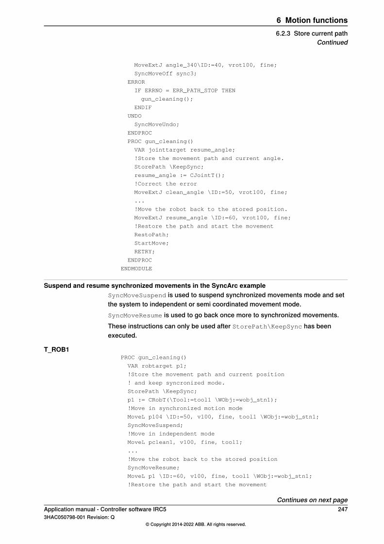
MoveExtJ angle_340\ID:=40, vrot100, fine;
SyncMoveOff sync3;
ERROR
IF ERRNO = ERR_PATH_STOP THEN
gun_cleaning();
ENDIF
UNDO
SyncMoveUndo;
ENDPROC
PROC gun_cleaning()
VAR jointtarget resume_angle;
!Store the movement path and current angle.
StorePath \KeepSync;
resume_angle := CJointT();
!Correct the error
MoveExtJ clean_angle \ID:=50, vrot100, fine;
...
!Move the robot back to the stored position.
MoveExtJ resume_angle \ID:=60, vrot100, fine;
!Restore the path and start the movement
RestoPath;
StartMove;
RETRY;
ENDPROC
ENDMODULE
Suspend and resume synchronized movements in the SyncArc exampleSyncMoveSuspend is used to suspend synchronized movements mode and setthe system to independent or semi coordinated movement mode.SyncMoveResume is used to go back once more to synchronized movements.These instructions can only be used after StorePath\KeepSync has beenexecuted.
T_ROB1PROC gun_cleaning()
VAR robtarget p1;
!Store the movement path and current position
! and keep syncronized mode.
StorePath \KeepSync;
p1 := CRobT(\Tool:=tool1 \WObj:=wobj_stn1);
!Move in synchronized motion mode
MoveL p104 \ID:=50, v100, fine, tool1 \WObj:=wobj_stn1;
SyncMoveSuspend;
!Move in independent mode
MoveL pclean1, v100, fine, tool1;
...
!Move the robot back to the stored position
SyncMoveResume;
MoveL p1 \ID:=60, v100, fine, tool1 \WObj:=wobj_stn1;
!Restore the path and start the movement
Continues on next pageApplication manual - Controller software IRC5 2473HAC050798-001 Revision: Q
© Copyright 2014-2022 ABB. All rights reserved.
6 Motion functions6.2.3 Store current path
Continued

RestoPath;
StartMove;
RETRY;
ENDPROC
T_ROB2PROC gun_cleaning()
VAR robtarget p2;
!Store the movement path and current position.
StorePath \KeepSync;
p2 := CRobT(\Tool:=tool2 \WObj:=wobj_stn1);
!Move in synchronized motion mode
MoveL p104 \ID:=50, v100, fine, tool2 \WObj:=wobj_stn1;
SyncMoveSuspend;
!Move in independent mode
MoveL pclean2 v100, fine, tool2;
...
!Move the robot back to the stored position.
SyncMoveResume;
!Move in synchronized motion mode
MoveL p2 \ID:=60, v100, fine, tool2 \WObj:=wobj_stn1;
!Restore the path and start the movement
RestoPath;
StartMove;
RETRY;
ENDPROC
T_STN1PROC gun_cleaning()
VAR jointtarget resume_angle;
!Store the movement path and current angle.
StorePath \KeepSync;
resume_angle := CJointT();
!Move in synchronized motion mode
MoveExtJ p1clean_angle \ID:=50, vrot100, fine;
SyncMoveSuspend;
! Move in independent mode
MoveExtJ p2clean_angle,vrot, fine;
...
!Move the robot back to the stored position.
SyncMoveResume;
! Move in synchronized motion mode
MoveExtJ resume_angle \ID:=60, vrot100, fine;
!Restore the path and start the movement
RestoPath;
StartMove;
RETRY;
ENDPROC
248 Application manual - Controller software IRC53HAC050798-001 Revision: Q
© Copyright 2014-2022 ABB. All rights reserved.
6 Motion functions6.2.3 Store current pathContinued

6.2.4 Path recorder
What is the path recorderThe path recorder can memorize a number of move instructions. This memory canthen be used to move the robot backwards along that same path.
How to use the path recorderThis is the general approach for using the path recorder:
1 Start the path recorder2 Move the robot with regular move, or process, instructions3 Store the current path4 Move backwards along the recorded path5 Resolve the error6 Move forward along the recorded path7 Restore the interrupted path
Lift the toolWhen the robot moves backward in its own track, you may want to avoid scrapingthe tool against the work piece. For a process like arc welding, you want to stayclear of the welding seam.By using the argument ToolOffs in the instructions PathRecMoveBwd andPathRecMoveFwd, you can set an offset for the TCP. This offset is set in toolcoordinates, which means that if it is set to [0,0,10] the tool will be 10mm from thework object when it moves back along the recorded path.
xx0400000828
Note
When a MultiMove system is in synchronized mode all tasks must use ToolOffsif a tool is going to be lifted.However if you only want to lift one tool, set ToolOffs=[0,0,0] in the othertasks.
Simple exampleIf an error occurs between p1 and p4, the robot will return to p1 where the errorcan be resolved. When the error has been resolved, the robot continues from wherethe error occurred.
Continues on next pageApplication manual - Controller software IRC5 2493HAC050798-001 Revision: Q
© Copyright 2014-2022 ABB. All rights reserved.
6 Motion functions6.2.4 Path recorder

When p4 is reached without any error, the path recorder is switched off. The robotthen moves from p4 to p5 without the path recorder.
...
VAR pathrecid start_id;
...
MoveL p1, vmax, fine, tool1;
PathRecStart start_id;
MoveL p2, vmax, z50, tool1;
MoveL p3, vmax, z50, tool1;
MoveL p4, vmax, fine, tool1;
PathRecStop \Clear;
MoveL p5, vmax, fine, tool1;
ERROR
StorePath;
PathRecMoveBwd;
! Fix the problem
PathRecMoveFwd;
RestoPath;
StartMove;
RETRY;
ENDIF
...
Complex exampleIn this example, the path recorder is used for two purposes:
• If an error occurs, the operator can choose to back up to p1 or to p2. Whenthe error has been resolved, the interrupted movement is resumed.
• Even if no error occurs, the path recorder is used to move the robot from p4to p1. This technique is useful when the robot is in a narrow position that isdifficult to move out of.
Note that if an error occurs during the first move instruction, between p1 and p2,it is not possible to go backwards to p2. If the operator choose to go back to p2,PathRecValidBwd is used to see if it is possible. Before the robot is moved forwardto the position where it was interrupted, PathRecValidFwd is used to see if it ispossible (if the robot never backed up it is already in position).
...
VAR pathrecid origin_id;
VAR pathrecid corner_id;
VAR num choice;
...
MoveJ p1, vmax, z50, tool1;
PathRecStart origin_id;
MoveJ p2, vmax, z50, tool1;
PathRecStart corner_id;
MoveL p3, vmax, z50, tool1;
MoveL p4, vmax, fine, tool1;
! Use path record to move safely to p1
Continues on next page250 Application manual - Controller software IRC5
3HAC050798-001 Revision: Q© Copyright 2014-2022 ABB. All rights reserved.
6 Motion functions6.2.4 Path recorderContinued
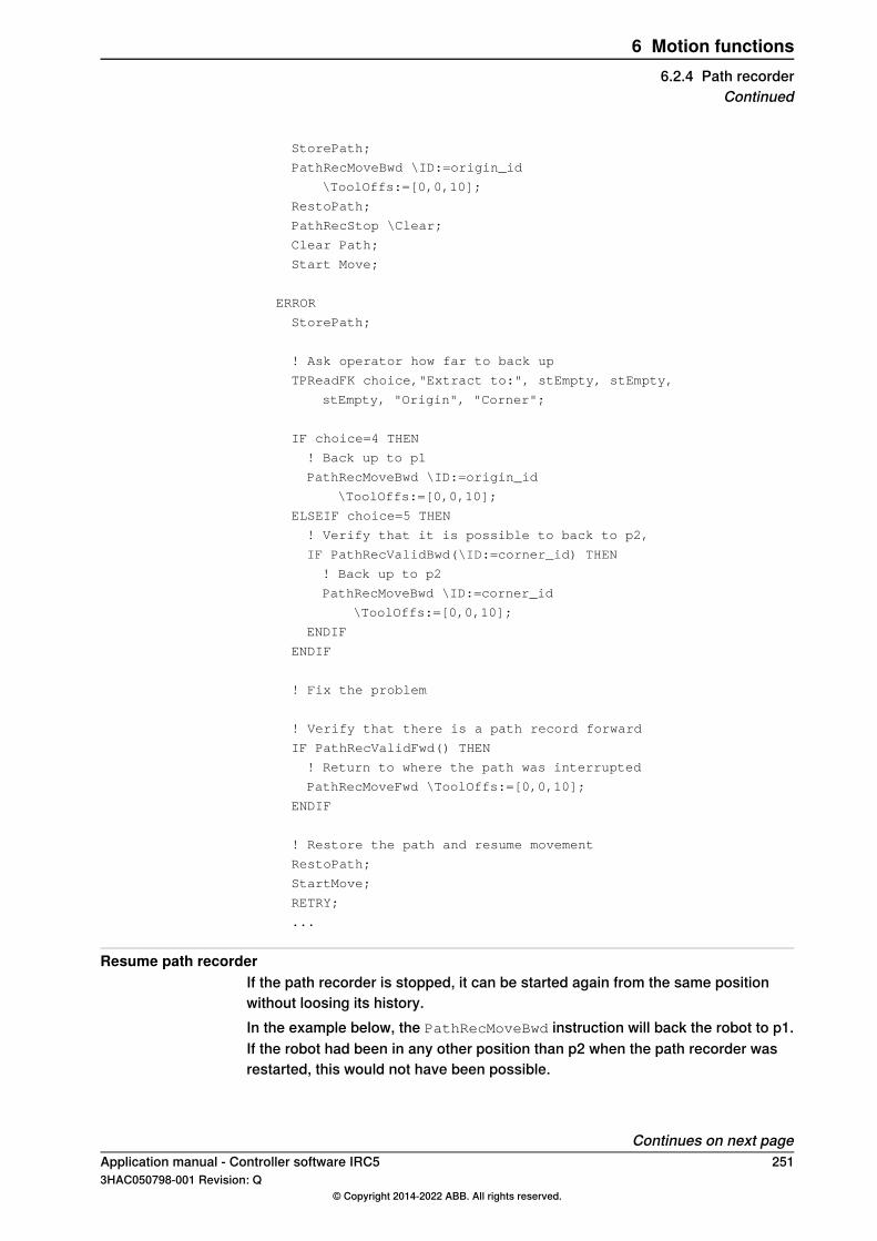
StorePath;
PathRecMoveBwd \ID:=origin_id
\ToolOffs:=[0,0,10];
RestoPath;
PathRecStop \Clear;
Clear Path;
Start Move;
ERROR
StorePath;
! Ask operator how far to back up
TPReadFK choice,"Extract to:", stEmpty, stEmpty,
stEmpty, "Origin", "Corner";
IF choice=4 THEN
! Back up to p1
PathRecMoveBwd \ID:=origin_id
\ToolOffs:=[0,0,10];
ELSEIF choice=5 THEN
! Verify that it is possible to back to p2,
IF PathRecValidBwd(\ID:=corner_id) THEN
! Back up to p2
PathRecMoveBwd \ID:=corner_id
\ToolOffs:=[0,0,10];
ENDIF
ENDIF
! Fix the problem
! Verify that there is a path record forward
IF PathRecValidFwd() THEN
! Return to where the path was interrupted
PathRecMoveFwd \ToolOffs:=[0,0,10];
ENDIF
! Restore the path and resume movement
RestoPath;
StartMove;
RETRY;
...
Resume path recorderIf the path recorder is stopped, it can be started again from the same positionwithout loosing its history.In the example below, the PathRecMoveBwd instruction will back the robot to p1.If the robot had been in any other position than p2 when the path recorder wasrestarted, this would not have been possible.
Continues on next pageApplication manual - Controller software IRC5 2513HAC050798-001 Revision: Q
© Copyright 2014-2022 ABB. All rights reserved.
6 Motion functions6.2.4 Path recorder
Continued
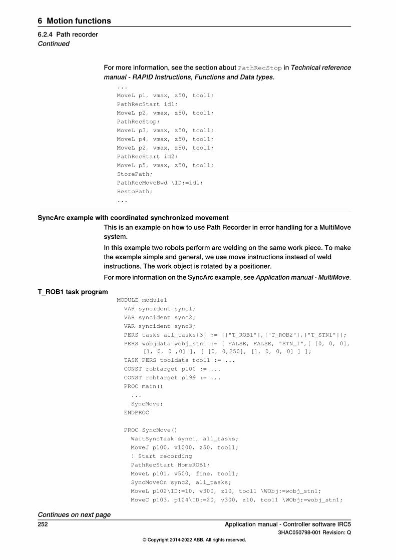
For more information, see the section about PathRecStop in Technical referencemanual - RAPID Instructions, Functions and Data types.
...
MoveL p1, vmax, z50, tool1;
PathRecStart id1;
MoveL p2, vmax, z50, tool1;
PathRecStop;
MoveL p3, vmax, z50, tool1;
MoveL p4, vmax, z50, tool1;
MoveL p2, vmax, z50, tool1;
PathRecStart id2;
MoveL p5, vmax, z50, tool1;
StorePath;
PathRecMoveBwd \ID:=id1;
RestoPath;
...
SyncArc example with coordinated synchronized movementThis is an example on how to use Path Recorder in error handling for a MultiMovesystem.In this example two robots perform arc welding on the same work piece. To makethe example simple and general, we use move instructions instead of weldinstructions. The work object is rotated by a positioner.For more information on the SyncArc example, seeApplicationmanual - MultiMove.
T_ROB1 task programMODULE module1
VAR syncident sync1;
VAR syncident sync2;
VAR syncident sync3;
PERS tasks all_tasks{3} := [["T_ROB1"],["T_ROB2"],["T_STN1"]];
PERS wobjdata wobj_stn1 := [ FALSE, FALSE, "STN_1",[ [0, 0, 0],[1, 0, 0 ,0] ], [ [0, 0,250], [1, 0, 0, 0] ] ];
TASK PERS tooldata tool1 := ...
CONST robtarget p100 := ...
CONST robtarget p199 := ...
PROC main()
...
SyncMove;
ENDPROC
PROC SyncMove()
WaitSyncTask sync1, all_tasks;
MoveJ p100, v1000, z50, tool1;
! Start recording
PathRecStart HomeROB1;
MoveL p101, v500, fine, tool1;
SyncMoveOn sync2, all_tasks;
MoveL p102\ID:=10, v300, z10, tool1 \WObj:=wobj_stn1;
MoveC p103, p104\ID:=20, v300, z10, tool1 \WObj:=wobj_stn1;
Continues on next page252 Application manual - Controller software IRC5
3HAC050798-001 Revision: Q© Copyright 2014-2022 ABB. All rights reserved.
6 Motion functions6.2.4 Path recorderContinued

MoveL p105\ID:=30, v300, z10, tool1 \WObj:=wobj_stn1;
MoveC p106, p101\ID:=40, v300, fine, tool1 \WObj:=wobj_stn1;
!Stop recording
PathRecStop \Clear;
SyncMoveOff sync3;
MoveL p199, v1000, fine, tool1;
ERROR
! Weld error in this program task
IF ERRNO = AW_WELD_ERR THEN
gun_cleaning();
ENDIF
UNDO
SyncMoveUndo;
ENDPROC
PROC gun_cleaning()
VAR robtarget p1;
!Store the movement path
IF IsSyncMoveOn() THEN
StorePath \KeepSync;
ELSE
StorePath;
ENDIF
!Move this robot backward to p100.
PathRecMoveBwd \ID:=HomeROB1 \ToolOffs:=[0,0,10];
!Correct the error
MoveJ pclean1 ,v100, fine, tool1;
...
!Move the robot back to p100
MoveJ p100, v100, fine, tool1;
PathRecMoveFwd \ToolOffs:=[0,0,10];
!Restore the path and start the movement
RestoPath;
StartMove;
RETRY;
ENDPROC
ENDMODULE
T_ROB2 task programMODULE module2
VAR syncident sync1;
VAR syncident sync2;
VAR syncident sync3;
PERS tasks all_tasks{3};
PERS wobjdata wobj_stn1;
TASK PERS tooldata tool2 := ...
CONST robtarget p200 := ...
CONST robtarget p299 := ...
PROC main()
...
SyncMove;
ENDPROC
Continues on next pageApplication manual - Controller software IRC5 2533HAC050798-001 Revision: Q
© Copyright 2014-2022 ABB. All rights reserved.
6 Motion functions6.2.4 Path recorder
Continued

PROC SyncMove()
WaitSyncTask sync1, all_tasks;
MoveJ p200, v1000, z50, tool2;
PathRecStart HomeROB2;
MoveL p201, v500, fine, tool2;
SyncMoveOn sync2, all_tasks;
MoveL p202\ID:=10, v300, z10, tool2 \WObj:=wobj_stn1;
MoveC p203, p204\ID:=20, v300, z10, tool2 \WObj:=wobj_stn1;
MoveL p205\ID:=30, v300, z10, tool2 \WObj:=wobj_stn1;
MoveC p206, p201\ID:=40, v300, fine, tool2 \WObj:=wobj_stn1;
PathRecStop \Clear;
SyncMoveOff sync3;
MoveL p299, v1000, fine, tool2;
ERROR
IF ERRNO = ERR_PATH_STOP THEN
gun_move_out();
ENDIF
UNDO
SyncMoveUndo;
ENDPROC
PROC gun_move_out()
IF IsSyncMoveOn() THEN
StorePath \KeepSync;
ELSE
StorePath;
ENDIF
! Move this robot backward to p201
PathRecMoveBwd \ToolOffs:=[0,0,10];
! Wait for the other gun to get clean
PathRecMoveFwd \ToolOffs:=[0,0,10];
!Restore the path and start the movement
RestoPath;
StartMove;
RETRY;
ENDPROC
ENDMODULE
T_STN1 task programMODULE module3
VAR syncident sync1;
VAR syncident sync2;
VAR syncident sync3;
PERS tasks all_tasks{3};
CONST jointtarget angle_neg20 :=[ [ 9E9, 9E9, 9E9, 9E9, 9E9,9E9], [ -20, 9E9, 9E9, 9E9, 9E9, 9E9] ];
...
CONST jointtarget angle_340 :=[ [ 9E9, 9E9, 9E9, 9E9, 9E9, 9E9],[340, 9E9, 9E9, 9E9,9E9, 9E9] ];
PROC main()
...
SyncMove;
Continues on next page254 Application manual - Controller software IRC5
3HAC050798-001 Revision: Q© Copyright 2014-2022 ABB. All rights reserved.
6 Motion functions6.2.4 Path recorderContinued

...
ENDPROC
PROC SyncMove()
WaitSyncTask sync1, all_tasks;
MoveExtJ angle_neg20, vrot50, fine;
PathRecStart HomeSTN1;
SyncMoveOn sync2, all_tasks;
MoveExtJ angle_20\ID:=10, vrot100, z10;
MoveExtJ angle_160\ID:=20, vrot100, z10;
MoveExtJ angle_200\ID:=30, vrot100, z10;
MoveExtJ angle_340\ID:=40, vrot100, fine;
PathRecStop \Clear;
SyncMoveOff sync3;
ERROR
IF ERRNO = ERR_PATH_STOP THEN
gun_move_out();
ENDIF
UNDO
SyncMoveUndo;
ENDPROC
PROC gun_move_out()
!Store the movement
IF IsSyncMoveOn() THEN
StorePath \KeepSync;
ELSE
StorePath;
ENDIF
!Move the manipulator backward to angle_neg 20
PathRecMoveBwd \ToolOffs:=[0,0,0];
...
!Wait for the gun to get clean
PathRecMoveFwd \ToolOffs:=[0,0,0];
RestoPath;
StartMove;
RETRY;
ENDPROC
Application manual - Controller software IRC5 2553HAC050798-001 Revision: Q
© Copyright 2014-2022 ABB. All rights reserved.
6 Motion functions6.2.4 Path recorder
Continued
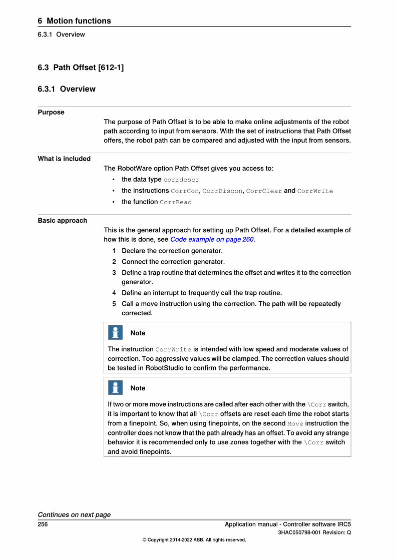
6.3 Path Offset [612-1]
6.3.1 Overview
PurposeThe purpose of Path Offset is to be able to make online adjustments of the robotpath according to input from sensors. With the set of instructions that Path Offsetoffers, the robot path can be compared and adjusted with the input from sensors.
What is includedThe RobotWare option Path Offset gives you access to:
• the data type corrdescr
• the instructions CorrCon, CorrDiscon, CorrClear and CorrWrite
• the function CorrRead
Basic approachThis is the general approach for setting up Path Offset. For a detailed example ofhow this is done, see Code example on page 260.
1 Declare the correction generator.2 Connect the correction generator.3 Define a trap routine that determines the offset and writes it to the correction
generator.4 Define an interrupt to frequently call the trap routine.5 Call a move instruction using the correction. The path will be repeatedly
corrected.
Note
The instruction CorrWrite is intended with low speed and moderate values ofcorrection. Too aggressive values will be clamped. The correction values shouldbe tested in RobotStudio to confirm the performance.
Note
If two or more move instructions are called after each other with the \Corr switch,it is important to know that all \Corr offsets are reset each time the robot startsfrom a finepoint. So, when using finepoints, on the second Move instruction thecontroller does not know that the path already has an offset. To avoid any strangebehavior it is recommended only to use zones together with the \Corr switchand avoid finepoints.
Continues on next page256 Application manual - Controller software IRC5
3HAC050798-001 Revision: Q© Copyright 2014-2022 ABB. All rights reserved.
6 Motion functions6.3.1 Overview

LimitationsIt is possible to connect several correction generators at the same time (for instanceone for corrections along the Z axis and one for corrections along the Y axis).However, it is not possible to connect more than 5 correction generators at thesame time.After a controller restart, the correction generators have to be defined once again.The definitions and connections do not survive a controller restart.The instructions can only be used in motion tasks.
Application manual - Controller software IRC5 2573HAC050798-001 Revision: Q
© Copyright 2014-2022 ABB. All rights reserved.
6 Motion functions6.3.1 Overview
Continued

6.3.2 RAPID components
Data typesThis is a brief description of each data type in the option Path Offset. For moreinformation, see the respective data type in Technical reference manual - RAPIDInstructions, Functions and Data types.
DescriptionData type
corrdescr is a correction generator descriptor that is used as thereference to the correction generator.
corrdescr
InstructionsThis is a brief description of each instruction in the option Path Offset. For moreinformation, see the respective instruction in Technical reference manual - RAPIDInstructions, Functions and Data types.
DescriptionInstruction
CorrCon activates path correction. Calling CorrCon will connect acorrection generator. Once this connection is made, the path can becontinuously corrected with new offset inputs (for instance from asensor).
CorrCon
CorrDiscon deactivates path correction. Calling CorrDiscon willdisconnect a correction generator.
CorrDiscon
CorrClear deactivate path correction. Calling CorrClear will dis-connect all correction generators.
CorrClear
CorrWrite sets the path correction values. Calling CorrWrite willset the offset values to a correction generator.
CorrWrite
FunctionsThis is a brief description of each function in the option Path Offset. For moreinformation, see the respective function in Technical reference manual - RAPIDInstructions, Functions and Data types.
DescriptionFunction
CorrRead reads the total correction made by a correction generator.CorrRead
258 Application manual - Controller software IRC53HAC050798-001 Revision: Q
© Copyright 2014-2022 ABB. All rights reserved.
6 Motion functions6.3.2 RAPID components

6.3.3 Related RAPID functionality
The argument \CorrThe optional argument\Corrcan be set for some move instructions. This will enablepath corrections while the move instruction is executed.The following instructions have the optional argument\Corr:
• MoveL• MoveC• SearchL• SearchC• TriggL (only if the controller is equipped with the base functionality Fixed
Position Events)• TriggC (only if the controller is equipped with the base functionality Fixed
Position Events)• CapL (only if the controller is equipped with the option Continuous Application
Platform)• CapC (only if the controller is equipped with the option Continuous Application
Platform)• ArcL (only if the controller is equipped with the option RobotWare Arc)• ArcC (only if the controller is equipped with the option RobotWare Arc)
For more information on these instructions, see respective instruction in Technicalreference manual - RAPID Instructions, Functions and Data types.
InterruptsTo create programs using Path Offset, you need to be able to handle interrupts.For more information on interrupts, see Technical reference manual - RAPIDOverview.
Application manual - Controller software IRC5 2593HAC050798-001 Revision: Q
© Copyright 2014-2022 ABB. All rights reserved.
6 Motion functions6.3.3 Related RAPID functionality

6.3.4 Code example
Linear movement with correctionThis is a simple example of how to program a linear path with online path correction.This is done by having an interrupt 5 times per second, calling a trap routine whichmakes the offset correction.
Program codeVAR intnum int_no1;
VAR corrdescr id;
VAR pos sens_val;
PROC PathRoutine()
!Connect to the correction generator
CorrCon id;
!Setup a 5 Hz timer interrupt.
CONNECT int_no1 WITH UpdateCorr;
ITimer\Single, 0.2, int_no1
!Position for start of contour tracking
MoveJ p10,v100,z10,tool1;
!Run MoveL with correction.
MoveL p20,v100,z10,tool1\Corr;
!Remove the correction generator.
CorrDiscon id;
!Remove the timer interrupt.
IDelete int_no1;
ENDPROC
TRAP UpdateCorr
!Call a routine that read the sensor
ReadSensor sens_val.x, sens_val.y, sens_val.z;
!Execute correction
CorrWrite id, sens_val;
!Setup interrupt again
IDelete int_no1;
CONNECT int_no1 WITH UpdateCorr;
ITimer\Single, 0.2, int_no1;
ENDTRAP
260 Application manual - Controller software IRC53HAC050798-001 Revision: Q
© Copyright 2014-2022 ABB. All rights reserved.
6 Motion functions6.3.4 Code example
7 Motion Supervision7.1 Collision Detection [613-1]
7.1.1 Overview
PurposeCollision Detection is a software option that reduces collision impact forces on therobot. This helps protecting the robot and external equipment from severe damage.
WARNING
Collision Detection cannot protect equipment from damage at a full speedcollision.
DescriptionThe software option Collision Detection identifies a collision by high sensitivity,model based supervision of the robot. Depending on what forces you deliberatelyapply on the robot, the sensitivity can be tuned as well as turned on and off.Because the forces on the robot can vary during program execution, the sensitivitycan be set on-line in the program code.Collision detection is more sensitive than the ordinary supervision and has extrafeatures. When a collision is detected, the robot will immediately stop and relievethe residual forces by moving in reversed direction a short distance along its path.After a collision error message has been acknowledged, the movement can continuewithout having to press Motors on on the controller.
What is includedThe RobotWare option Collision Detection gives you access to:
• system parameters for defining if Collision Detection should be active andhow sensitive it should be (without the option you can only turn detection onand off for Auto mode)
• instruction for on-line changes of the sensitivity:MotionSup
Basic approachCollision Detection is by default always active when the robot is moving. In manycases this means that you can use Collision Detection without having to take anyactive measures.If necessary, you can turn Collision Detection on and off or change its sensitivityin two ways:
• temporary changes can be made on-line with the RAPID instructionMotionSup
• permanent changes are made through the system parameters.
Continues on next pageApplication manual - Controller software IRC5 2613HAC050798-001 Revision: Q
© Copyright 2014-2022 ABB. All rights reserved.
7 Motion Supervision7.1.1 Overview
Collision detection for YuMi robotsAs default YuMi will have collision detection active at stand still. It also has anotherstop ramp compared to other robots to be able to release clamping forces.
Note
If the tool data is wrong, false collisions might be triggered and the robot armmight drop a short distance during the stop ramp.
Collision detection for MultiMove robotsThe default behavior when a collision is detected for one robot in a MultiMoveconfiguration is that all robots are stopped.One reason for this behavior is that when a collision is detected, there is a big riskthat it was two robots that collided. Another reason is that if one robot stops andanother continues, this might cause another collision.This behavior can be changed with the system parameter Ind collision stop withoutbrake. If this parameter is set to TRUE and the robots are running in independentRAPID tasks when a collision is detected, only the robot that detected the collisionwill be stopped.
262 Application manual - Controller software IRC53HAC050798-001 Revision: Q
© Copyright 2014-2022 ABB. All rights reserved.
7 Motion Supervision7.1.1 OverviewContinued

7.1.2 Limitations
Load definitionIn order to detect collisions properly, the payload of the robot must be correctlydefined.
Tip
Use Load Identification to define the payload. For more information, seeOperatingmanual - IRC5 with FlexPendant.
Robot axes onlyCollision Detection is only available for the robot axes. It is not available for trackmotions, orbit stations, or any other external axes.
Independent jointThe collision detection is deactivated when at least one axis is run in independentjoint mode. This is also the case even when it is an external axis that is run as anindependent joint.
Soft servoThe collision detection may trigger without a collision when the robot is used insoft servo mode. Therefore, it is recommended to turn the collision detection offwhen the robot is in soft servo mode.
No change until the robot movesIf the RAPID instruction MotionSup is used to turn off the collision detection, thiswill only take effect once the robot starts to move. As a result, the digital outputMotSupOn may temporarily have an unexpected value at program start before therobot starts to move.
Reversed movement distanceThe distance the robot is reversed after a collision is proportional to the speed ofthe motion before the collision. If repeated low speed collisions occur, the robotmay not be reversed sufficiently to relieve the stress of the collision. As a result,it may not be possible to jog the robot without the supervision triggering. In thiscase, turn Collision Detection off temporarily and jog the robot away from theobstacle.
Delay before reversed movementIn the event of a stiff collision during program execution, it may take a few secondsbefore the robot starts the reversed movement.
Robot on track motionIf the robot is mounted on a track motion the collision detection should bedeactivated when the track motion is moving. If it is not deactivated, the collisiondetection may trigger when the track moves, even if there is no collision.
Application manual - Controller software IRC5 2633HAC050798-001 Revision: Q
© Copyright 2014-2022 ABB. All rights reserved.
7 Motion Supervision7.1.2 Limitations
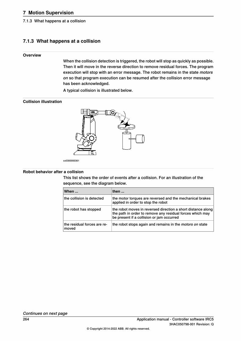
7.1.3 What happens at a collision
OverviewWhen the collision detection is triggered, the robot will stop as quickly as possible.Then it will move in the reverse direction to remove residual forces. The programexecution will stop with an error message. The robot remains in the state motorson so that program execution can be resumed after the collision error messagehas been acknowledged.A typical collision is illustrated below.
Collision illustration
xx0300000361
Robot behavior after a collisionThis list shows the order of events after a collision. For an illustration of thesequence, see the diagram below.
then ...When ...
the motor torques are reversed and the mechanical brakesapplied in order to stop the robot
the collision is detected
the robot moves in reversed direction a short distance alongthe path in order to remove any residual forces which maybe present if a collision or jam occurred
the robot has stopped
the robot stops again and remains in the motors on statethe residual forces are re-moved
Continues on next page264 Application manual - Controller software IRC5
3HAC050798-001 Revision: Q© Copyright 2014-2022 ABB. All rights reserved.
7 Motion Supervision7.1.3 What happens at a collision
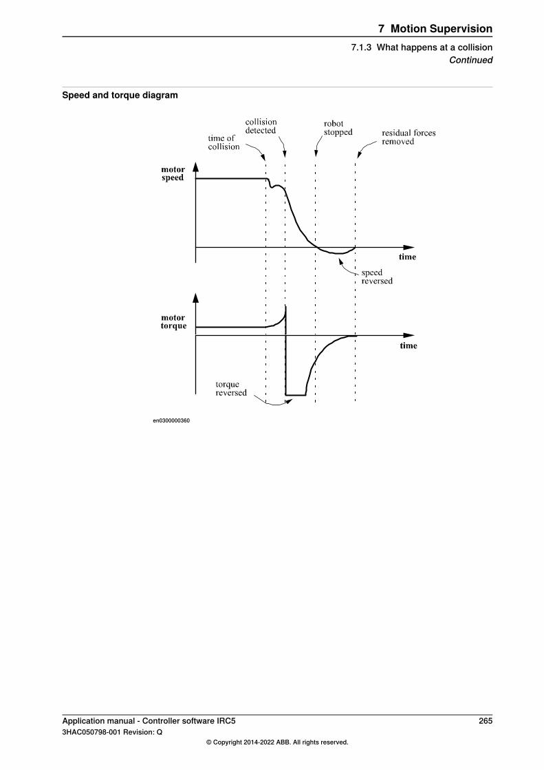
Speed and torque diagram
en0300000360
Application manual - Controller software IRC5 2653HAC050798-001 Revision: Q
© Copyright 2014-2022 ABB. All rights reserved.
7 Motion Supervision7.1.3 What happens at a collision
Continued
7.1.4 Additional information
Motion error handlingFor more information regarding error handling for a collision, see Technicalreference manual - RAPID kernel.
266 Application manual - Controller software IRC53HAC050798-001 Revision: Q
© Copyright 2014-2022 ABB. All rights reserved.
7 Motion Supervision7.1.4 Additional information
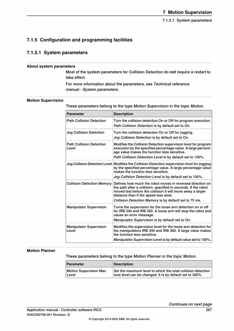
7.1.5 Configuration and programming facilities
7.1.5.1 System parameters
About system parametersMost of the system parameters for Collision Detection do not require a restart totake effect.For more information about the parameters, see Technical referencemanual - System parameters.
Motion SupervisionThese parameters belong to the type Motion Supervision in the topic Motion.
DescriptionParameter
Turn the collision detection On or Off for program execution.Path Collision DetectionPath Collision Detection is by default set to On.
Turn the collision detection On or Off for jogging.Jog Collision DetectionJog Collision Detection is by default set to On.
Modifies the Collision Detection supervision level for programexecution by the specified percentage value. A large percent-age value makes the function less sensitive.
Path Collision DetectionLevel
Path Collision Detection Level is by default set to 100%.
Modifies the Collision Detection supervision level for joggingby the specified percentage value. A large percentage valuemakes the function less sensitive.
Jog Collision Detection Level
Jog Collision Detection Level is by default set to 100%.
Defines how much the robot moves in reversed direction onthe path after a collision, specified in seconds. If the robotmoved fast before the collision it will move away a largerdistance than if the speed was slow.
Collision Detection Memory
Collision Detection Memory is by default set to 75 ms.
Turns the supervision for the loose arm detection on or offfor IRB 340 and IRB 360. A loose arm will stop the robot andcause an error message.
Manipulator Supervision
Manipulator Supervision is by default set to On.
Modifies the supervision level for the loose arm detection forthe manipulators IRB 340 and IRB 360. A large value makesthe function less sensitive.
Manipulator SupervisionLevel
Manipulator Supervision Level is by default value set to 100%.
Motion PlannerThese parameters belong to the type Motion Planner in the topic Motion.
DescriptionParameter
Set the maximum level to which the total collision detectiontune level can be changed. It is by default set to 300%.
Motion Supervision MaxLevel
Continues on next pageApplication manual - Controller software IRC5 2673HAC050798-001 Revision: Q
© Copyright 2014-2022 ABB. All rights reserved.
7 Motion Supervision7.1.5.1 System parameters

Motion SystemThis parameter belongs to the type Motion System in the topic Motion.
DescriptionParameter
This parameter is only valid for systems using the MultiMoveoption. If this parameter is set to TRUE, detected collisions willbe handled independently in RAPID tasks that are executedindependently.
Ind collision stop withoutbrake
A restart is required for this parameter to take effect.
General RAPIDThese parameters belong to the type General RAPID in the topic Controller.
DescriptionParameter
Enables RAPID error handling for collision. Collision ErrorHandler is default set to Off.
Collision Error Handler
For more information regarding error handling for a collision,see Technical reference manual - RAPID kernel
268 Application manual - Controller software IRC53HAC050798-001 Revision: Q
© Copyright 2014-2022 ABB. All rights reserved.
7 Motion Supervision7.1.5.1 System parametersContinued
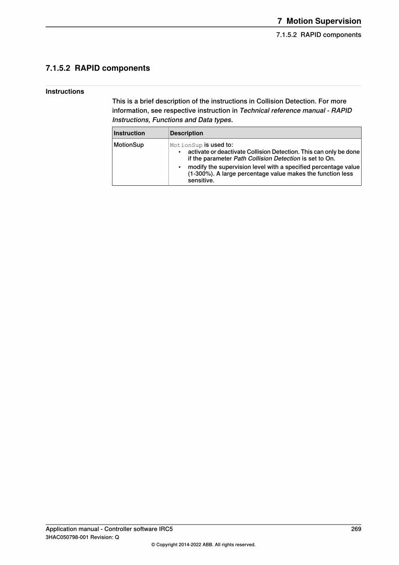
7.1.5.2 RAPID components
InstructionsThis is a brief description of the instructions in Collision Detection. For moreinformation, see respective instruction in Technical reference manual - RAPIDInstructions, Functions and Data types.
DescriptionInstruction
MotionSup is used to:• activate or deactivate Collision Detection. This can only be done
if the parameter Path Collision Detection is set to On.• modify the supervision level with a specified percentage value
(1-300%). A large percentage value makes the function lesssensitive.
MotionSup
Application manual - Controller software IRC5 2693HAC050798-001 Revision: Q
© Copyright 2014-2022 ABB. All rights reserved.
7 Motion Supervision7.1.5.2 RAPID components

7.1.5.3 Signals
Digital outputsThis is a brief description of the digital outputs in Collision Detection. For moreinformation, see respective digital output in Technical reference manual - Systemparameters.
DescriptionDigital output
MotSupOn is high when Collision Detection is active and low when itis not active.
MotSupOn
Note that a change in the state takes effect when a motion starts. Thus,if Collision Detection is active and the robot is moving, MotSupOn ishigh. If the robot is stopped and Collision Detection is turned off, Mot-SupOn is still high. When the robot starts to move, MotSupOn switchesto low.Before the first Motors On order after a restart of the robot controller,MotSupOnwill reflect the value of the corresponding system parameterPath Collision Detection:
• If Path Collision Detection is set to On, MotSupOn will be high.• If Path Collision Detection is set to Off, MotSupOn will be low.
MotSupTrigg goes high when the collision detection triggers. It stayshigh until the error code is acknowledged from the FlexPendant.
MotSupTrigg
270 Application manual - Controller software IRC53HAC050798-001 Revision: Q
© Copyright 2014-2022 ABB. All rights reserved.
7 Motion Supervision7.1.5.3 Signals

7.1.6 How to use Collision Detection
7.1.6.1 Set up system parameters
Activate supervisionTo be able to use Collision Detection during program execution, the parameterPath Collision Detection must be set to On.To be able to use Collision Detection during jogging, the parameter Jog CollisionDetection must be set to On.
Define supervision levelsSet the parameter Path Collision Detection Level to the percentage value you wantas default during program execution.Set the parameter Jog Collision Detection Level to the percentage value you wantas default during jogging.
Application manual - Controller software IRC5 2713HAC050798-001 Revision: Q
© Copyright 2014-2022 ABB. All rights reserved.
7 Motion Supervision7.1.6.1 Set up system parameters
7.1.6.2 Adjust supervision from FlexPendant
Speed adjusted supervision levelCollision Detection uses a variable supervision level. At low speeds it is moresensitive than at high speeds. For this reason, no tuning of the function should berequired by the user during normal operating conditions. However, it is possibleto turn the function on and off and to tune the supervision levels.Separate tuning parameters are available for jogging and program execution. Theseparameters are described in System parameters on page 267.
Set jog supervision on FlexPendantOn the FlexPendant, select Control Panel from the ABB menu and then tapSupervision.Supervision can be turned on or off and the sensitivity can be adjusted for bothprogrammed paths and jogging. The sensitivity level is set in percentage. A largevalue makes the function less sensitive.If the motion supervision for jogging is turned off in the dialog box and a programis executed, Collision Detection can still be active during execution of the program.
Note
The supervision settings correspond to system parameters of the type MotionSupervision. These can be set using the supervision settings on the FlexPendant,as described above. They can also be changed using RobotStudio or FlexPendantconfiguration editor or Quickset Mechanical unit menu.
272 Application manual - Controller software IRC53HAC050798-001 Revision: Q
© Copyright 2014-2022 ABB. All rights reserved.
7 Motion Supervision7.1.6.2 Adjust supervision from FlexPendant

7.1.6.3 Adjust supervision from RAPID program
Default valuesIf Collision Detection is activated with the system parameters, it is by default activeduring program execution with the tune value 100%. These values are setautomatically:
• when using the restart mode Reset system.• when a new program is loaded.• when starting program execution from the beginning.
Note
If tune values are set in the system parameters and in the RAPID instruction,both values are taken into consideration.Example: If the tune value in the system parameters is set to 150% and the tunevalue is set to 200% in the RAPID instruction the resulting tune level will be 300%.
Temporarily deactivate supervisionIf external forces will affect the robot during a part of the program execution,temporarily deactivate the supervision with the following instruction:
MotionSup \Off;
Reactivate supervisionIf the supervision has been temporarily deactivated, it can be activated with thefollowing instruction:
MotionSup \On;
Note
If the supervision is deactivated with the system parameters, it cannot be activatedwith RAPID instructions.
TuningThe supervision level can be tuned during program execution with the instructionMotionSup. The tune values are set in percent of the basic tuning where 100%corresponds to the basic values. A higher percentage gives a less sensitive system.This is an example of an instruction that increase the supervision level to 200%:
MotionSup \On \TuneValue:=200;
Application manual - Controller software IRC5 2733HAC050798-001 Revision: Q
© Copyright 2014-2022 ABB. All rights reserved.
7 Motion Supervision7.1.6.3 Adjust supervision from RAPID program
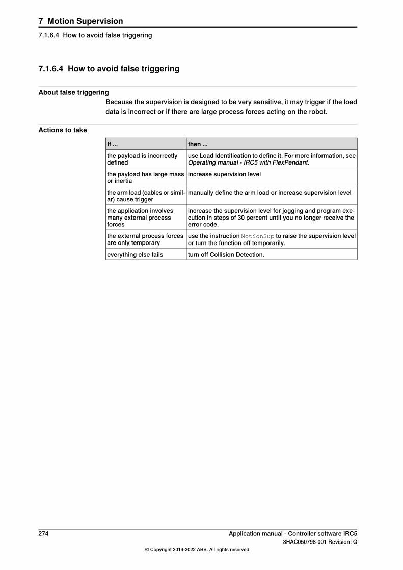
7.1.6.4 How to avoid false triggering
About false triggeringBecause the supervision is designed to be very sensitive, it may trigger if the loaddata is incorrect or if there are large process forces acting on the robot.
Actions to take
then ...If ...
use Load Identification to define it. For more information, seeOperating manual - IRC5 with FlexPendant.
the payload is incorrectlydefined
increase supervision levelthe payload has large massor inertia
manually define the arm load or increase supervision levelthe arm load (cables or simil-ar) cause trigger
increase the supervision level for jogging and program exe-cution in steps of 30 percent until you no longer receive theerror code.
the application involvesmany external processforces
use the instruction MotionSup to raise the supervision levelor turn the function off temporarily.
the external process forcesare only temporary
turn off Collision Detection.everything else fails
274 Application manual - Controller software IRC53HAC050798-001 Revision: Q
© Copyright 2014-2022 ABB. All rights reserved.
7 Motion Supervision7.1.6.4 How to avoid false triggering
7.1.7 Collision Avoidance
IntroductionThe function Collision Avoidance monitors a detailed geometric model of the robot.By defining additional geometrical models of bodies in the robot workarea, thecontroller will warn about a predicted collision and stops the robot if two bodiescome too close to each other. The system parameter Coll-Pred Safety Distancedetermines at what distance the two objects are considered to be in collision.The functionCollision Avoidance is useful for example when setting up and testingprograms, or for programs where positions are not static but created from sensors,such as cameras (non-deterministic programs).Besides the robot itself the function will monitor up 10 objects that is created viathe configurator in RobotStudio. Typical objects to be monitored are tool mountedon the robot flange, additional equipment mounted on the robot arm (typically axis3) or static volume around the robot.The geometric models are set up in RobotStudio.The functionality is activated by the system input Collision Avoidance. A high signalwill activate the functionality and a low signal will deactivate the functionality. Thefunctionality is by default active if no signal has been assigned to the system inputCollision Avoidance.Collision Avoidance is active both during jogging and when running programs.Also, the RAPID function IsCollFree provides a way to check possible collisionsbefore moving into a position.
CAUTION
Always be careful to avoid collisions with external equipment, since a collisioncould damage the mechanical structure of the arm.Collision Avoidance is no guarantee for avoiding collisions.
LimitationsCollision Avoidance is a function included in the option Collision Detection.Paint robots, IRB 6620LX, and IRB 360 are not supported.Collision Avoidance cannot be used in manual mode together with responsivejogging. The system parameter Jog Mode must be changed to Standard.The Collision Avoidance functionality between 2 robots (or more) can only beachieved when using a MultiMove system.
CAUTION
Collision Avoidance shall not be used for safety of personnel.
Continues on next pageApplication manual - Controller software IRC5 2753HAC050798-001 Revision: Q
© Copyright 2014-2022 ABB. All rights reserved.
7 Motion Supervision7.1.7 Collision Avoidance

False collision warningThere are different ways to lower the sensitivity of the function Collision Avoidanceto avoid false warnings.
• Temporarily disable Collision Avoidance, see Disabling Collision Avoidanceon page 276.
• For IRB 14000, decrease the safety distance for the arm or geometric modelthat triggers the false collision warning, see Decrease sensitivity betweenlinks for IRB 14000 on page 276.
• Decrease the general safety distance with the system parameter Coll-PredSafety Distance.
Disabling Collision AvoidanceIt is possible to temporarily disable the function Collision Avoidance if the robothas already collided or is within the default safety distance, or when the robot armsneed to be very close and the risk of collision is acceptable.Set the system input signal Collision Avoidance to 0 to disable CollisionAvoidance. It is recommended to enable it (set Collision Avoidance to 1) assoon as the work is done that required Collision Avoidance to be disabled.
Decrease sensitivity between links for IRB 14000For dual arm robots, the sensitivity can be decreased between individual robotarm links. This is useful if two links come close to each other, but the general safetydistance should be maintained.Open the file irb_14000_common_config.xml located in the folder<SystemName>\PRODUCT\ROBOTWARE_6.XX.XXXX\robots\CA\irb_14000.For example, to decrease the safety distance between the left arm's link 3 and theright arm's link 4 to 1 mm, add the following row:
<Pair object1="ROB_L_Link3" object2="ROB_R_Link4"safetyDistance="0.001"/>
To decrease the safety distance between the left arm's link 5 and the robot baseto 2 mm, add the following row:
<Pair object1="ROB_L_Link5" object2="Base" safetyDistance="0.002"/>
To disable collision avoidance between the left arm's link 2 and the right arm's link3, add the following row:
<Pair object1="ROB_L_Link2" object2="ROB_R_Link3" exclude="true"/>
Note
The safety distance between two links can be decreased by adding a row to thisXML file, but it cannot be increased to a higher value than defined by the systemparameter Coll-Pred Safety Distance.
276 Application manual - Controller software IRC53HAC050798-001 Revision: Q
© Copyright 2014-2022 ABB. All rights reserved.
7 Motion Supervision7.1.7 Collision AvoidanceContinued
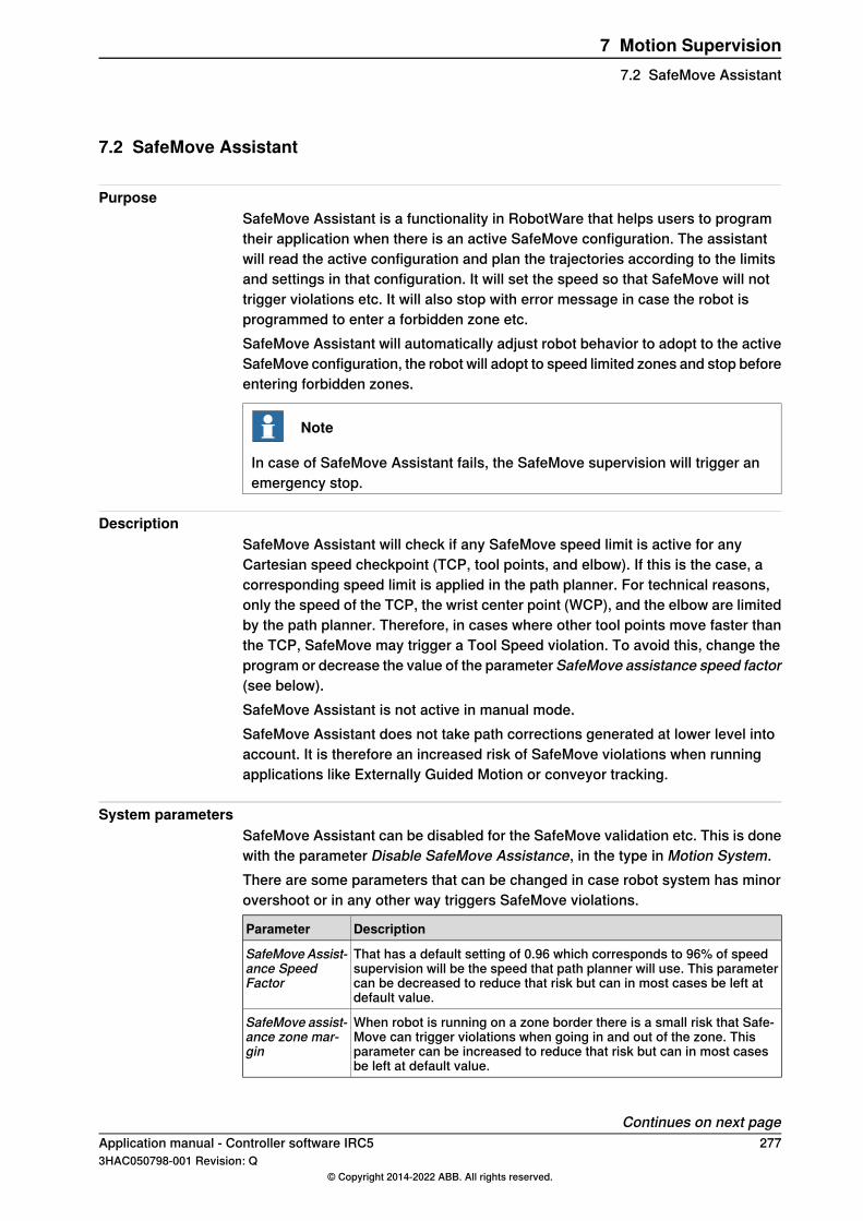
7.2 SafeMove Assistant
PurposeSafeMove Assistant is a functionality in RobotWare that helps users to programtheir application when there is an active SafeMove configuration. The assistantwill read the active configuration and plan the trajectories according to the limitsand settings in that configuration. It will set the speed so that SafeMove will nottrigger violations etc. It will also stop with error message in case the robot isprogrammed to enter a forbidden zone etc.SafeMove Assistant will automatically adjust robot behavior to adopt to the activeSafeMove configuration, the robot will adopt to speed limited zones and stop beforeentering forbidden zones.
Note
In case of SafeMove Assistant fails, the SafeMove supervision will trigger anemergency stop.
DescriptionSafeMove Assistant will check if any SafeMove speed limit is active for anyCartesian speed checkpoint (TCP, tool points, and elbow). If this is the case, acorresponding speed limit is applied in the path planner. For technical reasons,only the speed of the TCP, the wrist center point (WCP), and the elbow are limitedby the path planner. Therefore, in cases where other tool points move faster thanthe TCP, SafeMove may trigger a Tool Speed violation. To avoid this, change theprogram or decrease the value of the parameter SafeMove assistance speed factor(see below).SafeMove Assistant is not active in manual mode.SafeMove Assistant does not take path corrections generated at lower level intoaccount. It is therefore an increased risk of SafeMove violations when runningapplications like Externally Guided Motion or conveyor tracking.
System parametersSafeMove Assistant can be disabled for the SafeMove validation etc. This is donewith the parameter Disable SafeMove Assistance, in the type in Motion System.There are some parameters that can be changed in case robot system has minorovershoot or in any other way triggers SafeMove violations.
DescriptionParameter
That has a default setting of 0.96 which corresponds to 96% of speedsupervision will be the speed that path planner will use. This parametercan be decreased to reduce that risk but can in most cases be left atdefault value.
SafeMoveAssist-ance SpeedFactor
When robot is running on a zone border there is a small risk that Safe-Move can trigger violations when going in and out of the zone. Thisparameter can be increased to reduce that risk but can in most casesbe left at default value.
SafeMove assist-ance zone mar-gin
Continues on next pageApplication manual - Controller software IRC5 2773HAC050798-001 Revision: Q
© Copyright 2014-2022 ABB. All rights reserved.
7 Motion Supervision7.2 SafeMove Assistant

For more information, see the parameters in the type Motion System described inTechnical reference manual - System parameters.
278 Application manual - Controller software IRC53HAC050798-001 Revision: Q
© Copyright 2014-2022 ABB. All rights reserved.
7 Motion Supervision7.2 SafeMove AssistantContinued

8 Communication8.1 FTP Client [614-1]
8.1.1 Introduction to FTP Client
PurposeThe purpose of FTP Client is to enable the robot to access remote mounted disks,for example a hard disk drive on a PC.Here are some examples of applications:
• Backup to a remote computer.• Load programs from a remote computer.
Network illustration
en0300000505
DescriptionSeveral robots can access the same computer over an Ethernet network.Once the FTP application protocol is configured, the remote computer can beaccessed in the same way as the controller's internal hard disk.
What is includedThe RobotWare option FTP and NFS Client gives you access to the systemparameter typeApplication protocol and its parameters:Name, Type, Transmissionprotocol, Server address, Server type, Trusted, Local path, Server path, Username,Password, and Show Device.
Basic approachThis is the general approach for using FTP Client. For more detailed examples ofhow this is done, see Examples on page 282.
1 Configure an Application protocol to point out a disk or directory on a remotecomputer that will be accessible from the robot.
Continues on next pageApplication manual - Controller software IRC5 2793HAC050798-001 Revision: Q
© Copyright 2014-2022 ABB. All rights reserved.
8 Communication8.1.1 Introduction to FTP Client
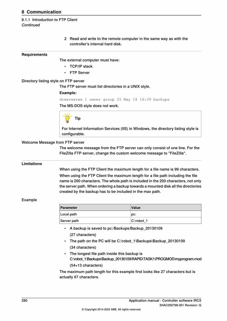
2 Read and write to the remote computer in the same way as with thecontroller's internal hard disk.
RequirementsThe external computer must have:
• TCP/IP stack• FTP Server
Directory listing style on FTP serverThe FTP server must list directories in a UNIX style.Example:drwxrwxrwx 1 owner group 25 May 18 16:39 backups
The MS-DOS style does not work.
Tip
For Internet Information Services (IIS) in Windows, the directory listing style isconfigurable.
Welcome Message from FTP serverThe welcome message from the FTP server can only consist of one line. For theFileZilla FTP server, change the custom welcome message to "FileZilla".
LimitationsWhen using the FTP Client the maximum length for a file name is 99 characters.When using the FTP Client the maximum length for a file path including the filename is 200 characters. The whole path is included in the 200 characters, not onlythe server path. When ordering a backup towards a mounted disk all the directoriescreated by the backup has to be included in the max path.
Example
ValueParameter
pc:Local path
C:\robot_1Server path
• A backup is saved to pc:/Backups/Backup_20130109(27 characters)
• The path on the PC will be C:\robot_1\Backups\Backup_20130109(34 characters)
• The longest file path inside this backup isC:\robot_1\Backups\Backup_20130109\RAPID\TASK1\PROGMOD\myprogram.mod(54+13 characters)
The maximum path length for this example first looks like 27 characters but isactually 67 characters.
280 Application manual - Controller software IRC53HAC050798-001 Revision: Q
© Copyright 2014-2022 ABB. All rights reserved.
8 Communication8.1.1 Introduction to FTP ClientContinued
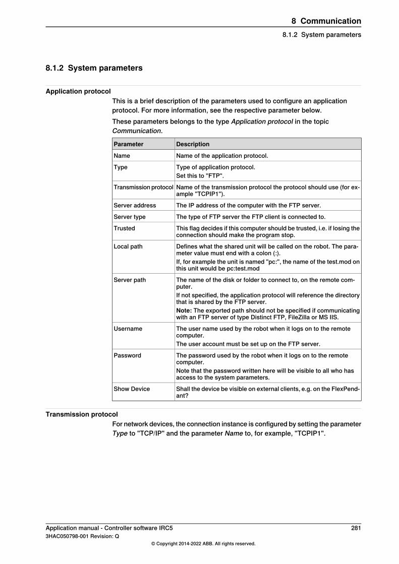
8.1.2 System parameters
Application protocolThis is a brief description of the parameters used to configure an applicationprotocol. For more information, see the respective parameter below.These parameters belongs to the type Application protocol in the topicCommunication.
DescriptionParameter
Name of the application protocol.Name
Type of application protocol.TypeSet this to "FTP".
Name of the transmission protocol the protocol should use (for ex-ample "TCPIP1").
Transmission protocol
The IP address of the computer with the FTP server.Server address
The type of FTP server the FTP client is connected to.Server type
This flag decides if this computer should be trusted, i.e. if losing theconnection should make the program stop.
Trusted
Defines what the shared unit will be called on the robot. The para-meter value must end with a colon (:).
Local path
If, for example the unit is named "pc:", the name of the test.mod onthis unit would be pc:test.mod
The name of the disk or folder to connect to, on the remote com-puter.
Server path
If not specified, the application protocol will reference the directorythat is shared by the FTP server.Note: The exported path should not be specified if communicatingwith an FTP server of type Distinct FTP, FileZilla or MS IIS.
The user name used by the robot when it logs on to the remotecomputer.
Username
The user account must be set up on the FTP server.
The password used by the robot when it logs on to the remotecomputer.
Password
Note that the password written here will be visible to all who hasaccess to the system parameters.
Shall the device be visible on external clients, e.g. on the FlexPend-ant?
Show Device
Transmission protocolFor network devices, the connection instance is configured by setting the parameterType to "TCP/IP" and the parameter Name to, for example, "TCPIP1".
Application manual - Controller software IRC5 2813HAC050798-001 Revision: Q
© Copyright 2014-2022 ABB. All rights reserved.
8 Communication8.1.2 System parameters

8.1.3 Examples
Example configurationThis is an example of how an application protocol can be configured for FTP.
ValueParameter
my_FTP_protocolName
FTPType
TCPIP1Transmission protocol
100.100.100.100Server address
NotSetServer type
NoTrusted
pc:Local path
C:\robot_1Server path
Robot1Username
robot1Password
Note: The value of Server path should exclude the exported path if communicatingwith an FTP server of type Distinct FTP, FileZilla or MS IIS.
Example with FlexPendantThis example shows how to use the FlexPendant to make a backup to the remotePC. We assume that the configuration is done according to the exampleconfiguration shown above.
1 Tap ABB and select Backup and Restore.2 Tap on Backup Current System.3 Save the backup to pc:/Backup/Backup_20031008 (the path on the PC will
be C:\robot_1\Backup\Backup_20031008).
Example with RAPID codeThe following examples show how to open the file C:\robot_1\files\file1.txt on theremote PC from a RAPID program on the controller. We assume that theconfiguration is done according to the example configuration shown above.For the home directory on IRC5:
Open "HOME:" \FILE:="file1.txt", file;
For the directory on the PC (e.g. C: \ ABB which is specified in the server):Open "pc:" \FILE:="file1.txt", file;
282 Application manual - Controller software IRC53HAC050798-001 Revision: Q
© Copyright 2014-2022 ABB. All rights reserved.
8 Communication8.1.3 Examples

8.2 SFTP Client [614-1]
8.2.1 Introduction to SFTP Client
PurposeThe purpose of SFTP Client is to enable the robot to access remote mounted disks,for example a hard disk drive on a PC.Here are some examples of applications:
• Backup to a remote computer.• Load programs from a remote computer.
Network illustration
en0300000505
DescriptionSeveral robots can access the same computer over an Ethernet network.Once the SFTP application protocol is configured, the remote computer can beaccessed in the same way as the controller's internal hard disk.
What is includedThe RobotWare option FTP and NFS Client gives you access to the systemparameter typeApplication protocol and its parameters:Name, Type, Transmissionprotocol, Server address, Trusted, Local path, Server path, Username, Password,Show Device, and FingerPrint.
Basic approachThis is the general approach for using SFTP Client. For more detailed examplesof how this is done, see Examples on page 282.
1 Configure an Application protocol to point out a disk or directory on a remotecomputer that will be accessible from the robot.
2 Read and write to the remote computer in the same way as with thecontroller's internal hard disk.
Continues on next pageApplication manual - Controller software IRC5 2833HAC050798-001 Revision: Q
© Copyright 2014-2022 ABB. All rights reserved.
8 Communication8.2.1 Introduction to SFTP Client

SFTP supports the following servers:• Rebex version 1.0.3• CompleteFTP version 11.0.0• Cerberus version 9.0.4.0
In certain SFTP servers, as Complete SFTP server, there is a configuration setting,Timeout for idle sessions, which defines the time that the connection can be idle.If no client requests are made during this time interval, the connection is closed.Setting the value as No timeout will keep the connection alive, even though clientrequests are not made.
RequirementsThe external computer must have:
• TCP/IP stack• SFTP Server
LimitationsWhen using the SFTP Client the maximum length for a file name is 99 characters.When using the SFTP Client the maximum length for a file path including the filename is 200 characters. The whole path is included in the 200 characters, not onlythe server path. When ordering a backup towards a mounted disk all the directoriescreated by the backup has to be included in the max path.
Example
ValueParameter
pc:Local path
• A backup is saved to pc:/Backups/Backup_20130109(27 characters)
• The path on the PC will be \Backups\Backup_20130109(24 characters)
• The longest file path inside this backup is\Backups\Backup_20130109\RAPID\TASK1\PROGMOD\myprogram.mod(44+13 characters)
The maximum path length for this example first looks like 27 characters but isactually 57 characters.
284 Application manual - Controller software IRC53HAC050798-001 Revision: Q
© Copyright 2014-2022 ABB. All rights reserved.
8 Communication8.2.1 Introduction to SFTP ClientContinued

8.2.2 System parameters
Application protocolThis is a brief description of the parameters used to configure an applicationprotocol. For more information, see the respective parameter below.These parameters belongs to the type Application protocol in the topicCommunication.
DescriptionParameter
Name of the application protocol.Name
Type of application protocol.TypeSet this to "SFTP".
Name of the transmission protocol the protocol should use (for ex-ample "TCPIP1").
Transmission protocol
The IP address of the computer with the SFTP server.Server address
This flag decides if this computer should be trusted, i.e. if losing theconnection should make the program stop.
Trusted
Defines what the shared unit will be called on the robot. The para-meter value must end with a colon (:).
Local path
If, for example the unit is named "pc:", the name of the test.mod onthis unit would be pc:test.mod
The user name used by the robot when it logs on to the remotecomputer.
Username
The user account must be set up on the SFTP server.
The password used by the robot when it logs on to the remotecomputer.
Password
Note that the password written here will be visible to all who hasaccess to the system parameters.
Shall the device be visible on external clients, e.g. on the FlexPend-ant?
Show Device
To guarantee that the controller connects to the expected SFTPserver, and not a malicious server, a server fingerprint can be used.
FingerPrint
Transmission protocolFor network devices, the connection instance is configured by setting the parameterType to "TCP/IP" and the parameter Name to, for example, "TCPIP1".
Application manual - Controller software IRC5 2853HAC050798-001 Revision: Q
© Copyright 2014-2022 ABB. All rights reserved.
8 Communication8.2.2 System parameters
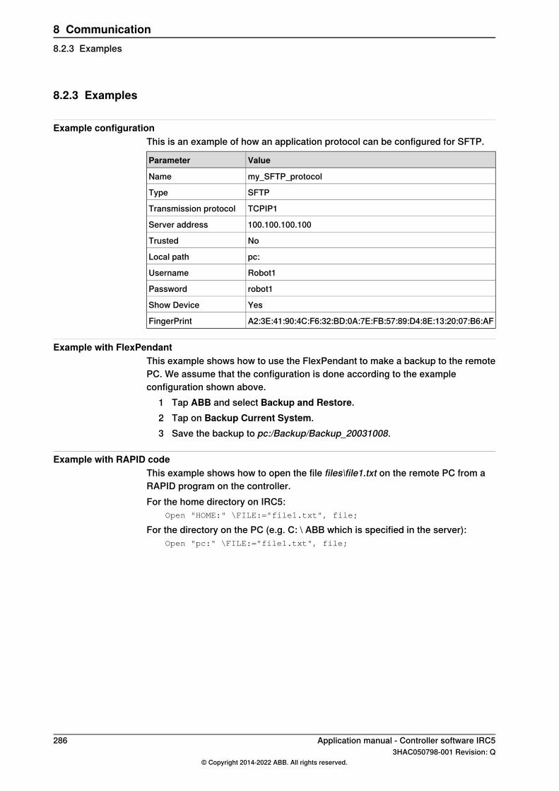
8.2.3 Examples
Example configurationThis is an example of how an application protocol can be configured for SFTP.
ValueParameter
my_SFTP_protocolName
SFTPType
TCPIP1Transmission protocol
100.100.100.100Server address
NoTrusted
pc:Local path
Robot1Username
robot1Password
YesShow Device
A2:3E:41:90:4C:F6:32:BD:0A:7E:FB:57:89:D4:8E:13:20:07:B6:AFFingerPrint
Example with FlexPendantThis example shows how to use the FlexPendant to make a backup to the remotePC. We assume that the configuration is done according to the exampleconfiguration shown above.
1 Tap ABB and select Backup and Restore.2 Tap on Backup Current System.3 Save the backup to pc:/Backup/Backup_20031008.
Example with RAPID codeThis example shows how to open the file files\file1.txt on the remote PC from aRAPID program on the controller.For the home directory on IRC5:
Open "HOME:" \FILE:="file1.txt", file;
For the directory on the PC (e.g. C: \ ABB which is specified in the server):Open "pc:" \FILE:="file1.txt", file;
286 Application manual - Controller software IRC53HAC050798-001 Revision: Q
© Copyright 2014-2022 ABB. All rights reserved.
8 Communication8.2.3 Examples
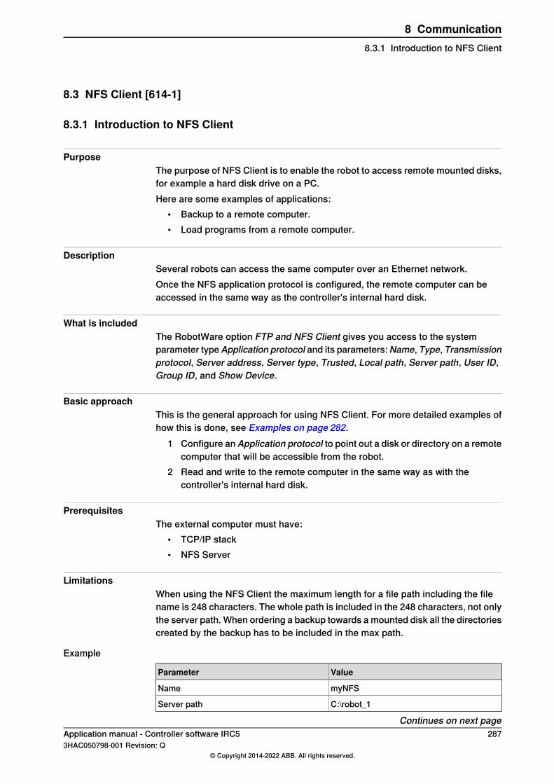
8.3 NFS Client [614-1]
8.3.1 Introduction to NFS Client
PurposeThe purpose of NFS Client is to enable the robot to access remote mounted disks,for example a hard disk drive on a PC.Here are some examples of applications:
• Backup to a remote computer.• Load programs from a remote computer.
DescriptionSeveral robots can access the same computer over an Ethernet network.Once the NFS application protocol is configured, the remote computer can beaccessed in the same way as the controller's internal hard disk.
What is includedThe RobotWare option FTP and NFS Client gives you access to the systemparameter typeApplication protocol and its parameters:Name, Type, Transmissionprotocol, Server address, Server type, Trusted, Local path, Server path, User ID,Group ID, and Show Device.
Basic approachThis is the general approach for using NFS Client. For more detailed examples ofhow this is done, see Examples on page 282.
1 Configure an Application protocol to point out a disk or directory on a remotecomputer that will be accessible from the robot.
2 Read and write to the remote computer in the same way as with thecontroller's internal hard disk.
PrerequisitesThe external computer must have:
• TCP/IP stack• NFS Server
LimitationsWhen using the NFS Client the maximum length for a file path including the filename is 248 characters. The whole path is included in the 248 characters, not onlythe server path. When ordering a backup towards a mounted disk all the directoriescreated by the backup has to be included in the max path.
Example
ValueParameter
myNFSName
C:\robot_1Server path
Continues on next pageApplication manual - Controller software IRC5 2873HAC050798-001 Revision: Q
© Copyright 2014-2022 ABB. All rights reserved.
8 Communication8.3.1 Introduction to NFS Client

• A backup is saved to myNFS/Backups/Backup_20130109(27 characters)
• The path on the PC will be C:\robot_1\Backups\Backup_20130109(34 characters)
• The longest file path inside this backup isC:\robot_1\Backups\Backup_20130109\RAPID\TASK1\PROGMOD\myprogram.mod(54+13 characters)
The maximum path length for this example first looks like 27 characters but isactually 67 characters.
288 Application manual - Controller software IRC53HAC050798-001 Revision: Q
© Copyright 2014-2022 ABB. All rights reserved.
8 Communication8.3.1 Introduction to NFS ClientContinued
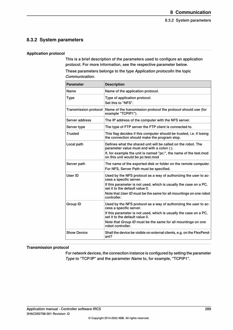
8.3.2 System parameters
Application protocolThis is a brief description of the parameters used to configure an applicationprotocol. For more information, see the respective parameter below.These parameters belongs to the type Application protocolin the topicCommunication.
DescriptionParameter
Name of the application protocol.Name
Type of application protocol.TypeSet this to "NFS".
Name of the transmission protocol the protocol should use (forexample "TCPIP1").
Transmission protocol
The IP address of the computer with the NFS server.Server address
The type of FTP server the FTP client is connected to.Server type
This flag decides if this computer should be trusted, i.e. if losingthe connection should make the program stop.
Trusted
Defines what the shared unit will be called on the robot. Theparameter value must end with a colon (:).
Local path
If, for example the unit is named "pc:", the name of the test.modon this unit would be pc:test.mod
The name of the exported disk or folder on the remote computer.Server pathFor NFS, Server Path must be specified.
Used by the NFS protocol as a way of authorizing the user to ac-cess a specific server.
User ID
If this parameter is not used, which is usually the case on a PC,set it to the default value 0.Note that User ID must be the same for all mountings on one robotcontroller.
Used by the NFS protocol as a way of authorizing the user to ac-cess a specific server.
Group ID
If this parameter is not used, which is usually the case on a PC,set it to the default value 0.Note that Group ID must be the same for all mountings on onerobot controller.
Shall the device be visible on external clients, e.g. on the FlexPend-ant?
Show Device
Transmission protocolFor network devices, the connection instance is configured by setting the parameterType to "TCP/IP" and the parameter Name to, for example, "TCPIP1".
Application manual - Controller software IRC5 2893HAC050798-001 Revision: Q
© Copyright 2014-2022 ABB. All rights reserved.
8 Communication8.3.2 System parameters
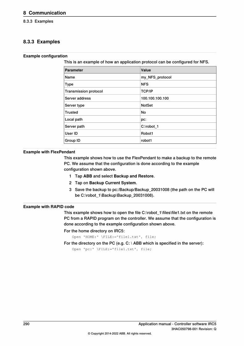
8.3.3 Examples
Example configurationThis is an example of how an application protocol can be configured for NFS.
ValueParameter
my_NFS_protocolName
NFSType
TCP/IPTransmission protocol
100.100.100.100Server address
NotSetServer type
NoTrusted
pc:Local path
C:\robot_1Server path
Robot1User ID
robot1Group ID
Example with FlexPendantThis example shows how to use the FlexPendant to make a backup to the remotePC. We assume that the configuration is done according to the exampleconfiguration shown above.
1 Tap ABB and select Backup and Restore.2 Tap on Backup Current System.3 Save the backup to pc:/Backup/Backup_20031008 (the path on the PC will
be C:\robot_1\Backup\Backup_20031008).
Example with RAPID codeThis example shows how to open the file C:\robot_1\files\file1.txt on the remotePC from a RAPID program on the controller. We assume that the configuration isdone according to the example configuration shown above.For the home directory on IRC5:
Open "HOME:" \FILE:="file1.txt", file;
For the directory on the PC (e.g. C: \ ABB which is specified in the server):Open "pc:" \FILE:="file1.txt", file;
290 Application manual - Controller software IRC53HAC050798-001 Revision: Q
© Copyright 2014-2022 ABB. All rights reserved.
8 Communication8.3.3 Examples

8.4 PC Interface [616-1]
8.4.1 Introduction to PC Interface
PurposePC Interface is used for communication between the controller and a PC.The option PC Interface is required when connecting to a controller over LAN withRobotStudio.With PC Interface, data can be sent to and from a PC. This is, for example, usedfor:
• Backup.• Production statistics logging.• Operator information presented on a PC.• Send command to the robot from a PC operator interface.• RobotStudio add-in that performs operations on the controller.
Note
If connecting over the service port, then the functionality is available without theoption PC Interface.
What is includedThe RobotWare option PC Interface gives you access to:
• An Ethernet communication interface, which is used by some ABB softwareproducts.
Basic approachThe general approach for using PC Interface is the same as setting up a PC SDKclient application on a PC. For more information, see http://developercenter.robot-studio.com.
Application manual - Controller software IRC5 2913HAC050798-001 Revision: Q
© Copyright 2014-2022 ABB. All rights reserved.
8 Communication8.4.1 Introduction to PC Interface

8.4.2 Send variable from RAPID
SCWrite instructionThe instruction SCWrite (Superior ComputerWrite) can be used to send persistentvariables to a client application on a PC. For more information, see Technicalreference manual - RAPID Instructions, Functions and Data types.The PC must have a client application that can subscribe to the information thatis sent to or from the controller.
Code exampleIn this example the robot moves objects to a position where they can be treatedby a process that is controlled by the PC. When the object is ready the robot movesit to its next station.The program uses SCWrite to inform the PC when the object is in position andwhen it has been moved to the next station. It also sends a message to the PCabout how many objects that have been handled.
RAPID module for the senderVAR rmqslot destination_slot;
VAR user_def
RMQFindSlot destination_slot,"RMQ_Task2";
WHILE TRUE DO
! Wait for next object
WaitDI di1,1;
! Call first routine
move_obj_to_pos();
! Send message to PC that object is in position
user_def = 0;
in_position:=TRUE;
RMQSendMessage destination_slot, in_position \UserDef:=user_def;
! Wait for object to be ready
WaitDI di2,1;
! Call second routine
move_obj_to_next();
! Send message to PC that object is gone
in_position:=FALSE;
RMQSendMessage destination_slot, in_position \UserDef:=user_def;
! Inform PC how many object has been handled
nbr_objects:= nbr_objects+1;
user_def = 1;
Continues on next page292 Application manual - Controller software IRC5
3HAC050798-001 Revision: Q© Copyright 2014-2022 ABB. All rights reserved.
8 Communication8.4.2 Send variable from RAPID

RMQSendMessage destination_slot, nbr_objects \UserDef:=user_def;
ENDWHILE
PC SDK for the receiverpublic void ReceiveObjectPosition()
{
const string destination_slot = "RMQ_Task2";
IpcQueue queue = Controller.Ipc.CreateQueue(destination_slot,16, Ipc.MaxMessageSize);
// Until application is closed
while (uiclose)
{
IpcMessage message = new IpcMessage();
IpcReturnType retValue = IpcReturnType.Timeout;
retValue = queue.Receive(1000, message);
if (IpcReturnType.OK == retValue)
{
string receivemessage = message.Data.ToString().ToLower();
// if message.UserDef is 0 means Object position data elsenumber of objects
if (message.UserDef == 0)
{
if (receivemessage == "true")
{
// Object is in position
}
else
{
// Object is not in position
}
}
else
{
// number of objects in receivemessage
}
}
}
Application manual - Controller software IRC5 2933HAC050798-001 Revision: Q
© Copyright 2014-2022 ABB. All rights reserved.
8 Communication8.4.2 Send variable from RAPID
Continued
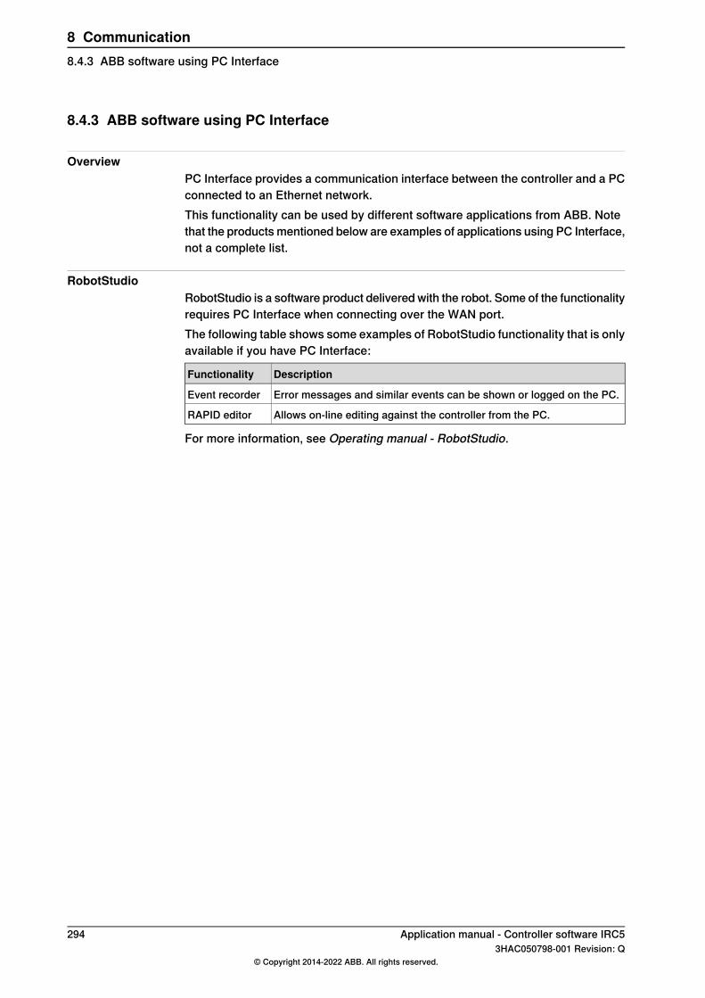
8.4.3 ABB software using PC Interface
OverviewPC Interface provides a communication interface between the controller and a PCconnected to an Ethernet network.This functionality can be used by different software applications from ABB. Notethat the products mentioned below are examples of applications using PC Interface,not a complete list.
RobotStudioRobotStudio is a software product delivered with the robot. Some of the functionalityrequires PC Interface when connecting over the WAN port.The following table shows some examples of RobotStudio functionality that is onlyavailable if you have PC Interface:
DescriptionFunctionality
Error messages and similar events can be shown or logged on the PC.Event recorder
Allows on-line editing against the controller from the PC.RAPID editor
For more information, see Operating manual - RobotStudio.
294 Application manual - Controller software IRC53HAC050798-001 Revision: Q
© Copyright 2014-2022 ABB. All rights reserved.
8 Communication8.4.3 ABB software using PC Interface
8.5 Socket Messaging [616-1]
8.5.1 Introduction to Socket Messaging
PurposeThe purpose of Socket Messaging is to allow a RAPID programmer to transmitapplication data between computers, using the TCP/IP network protocol. A socketrepresents a general communication channel, independent of the network protocolbeing used.Socket communication is a standard that has its origin in Berkeley SoftwareDistribution Unix. Besides Unix, it is supported by, for example, Microsoft Windows.With Socket Messaging, a RAPID program on a robot controller can, for example,communicate with a C/C++ program on another computer.
What is includedThe RobotWare functionality Socket Messaging gives you access to RAPID datatypes, instructions and functions for socket communication between computers.
Basic approachThis is the general approach for using Socket Messaging. For a more detailedexample of how this is done, seeCode examples for SocketMessaging on page300.
1 Create a socket, both on client and server. A robot controller can be eitherclient or server.
2 Use SocketBind and SocketListen on the server, to prepare it for aconnection request.
3 Order the server to accept incoming socket connection requests.4 Request socket connection from the client.5 Send and receive data between client and server.
Application manual - Controller software IRC5 2953HAC050798-001 Revision: Q
© Copyright 2014-2022 ABB. All rights reserved.
8 Communication8.5.1 Introduction to Socket Messaging
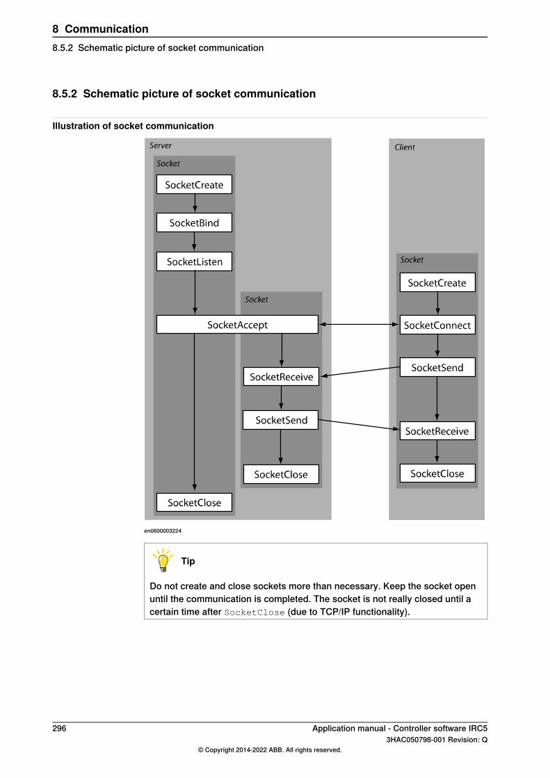
8.5.2 Schematic picture of socket communication
Illustration of socket communication
en0600003224
Tip
Do not create and close sockets more than necessary. Keep the socket openuntil the communication is completed. The socket is not really closed until acertain time after SocketClose (due to TCP/IP functionality).
296 Application manual - Controller software IRC53HAC050798-001 Revision: Q
© Copyright 2014-2022 ABB. All rights reserved.
8 Communication8.5.2 Schematic picture of socket communication
8.5.3 Technical facts about Socket Messaging
OverviewWhen using the functionality Socket Messaging to communicate with a client orserver that is not a RAPID task, the following information can be useful.
No string terminationWhen sending a data message, no string termination sign is sent in the message.The number of bytes sent is equal to the return value of the function strlen(str)in the programming language C.
Unintended merge of messagesIf sending two messages with no delay between them, the result can be that thesecond message is appended to the first. The result is one big message insteadof two messages. To avoid this, use acknowledge messages from the receiver ofthe data, if the client/server is just receiving messages.
Non printable charactersIf a client that is not a RAPID task needs to receive non printable characters (binarydata) in a string from a RAPID task, this can be done by RAPID as shown in theexample below.
SocketSend socket1 \Str:="\0D\0A";
For more information, see Technical reference manual - RAPID kernel, sectionString literals.
Application manual - Controller software IRC5 2973HAC050798-001 Revision: Q
© Copyright 2014-2022 ABB. All rights reserved.
8 Communication8.5.3 Technical facts about Socket Messaging
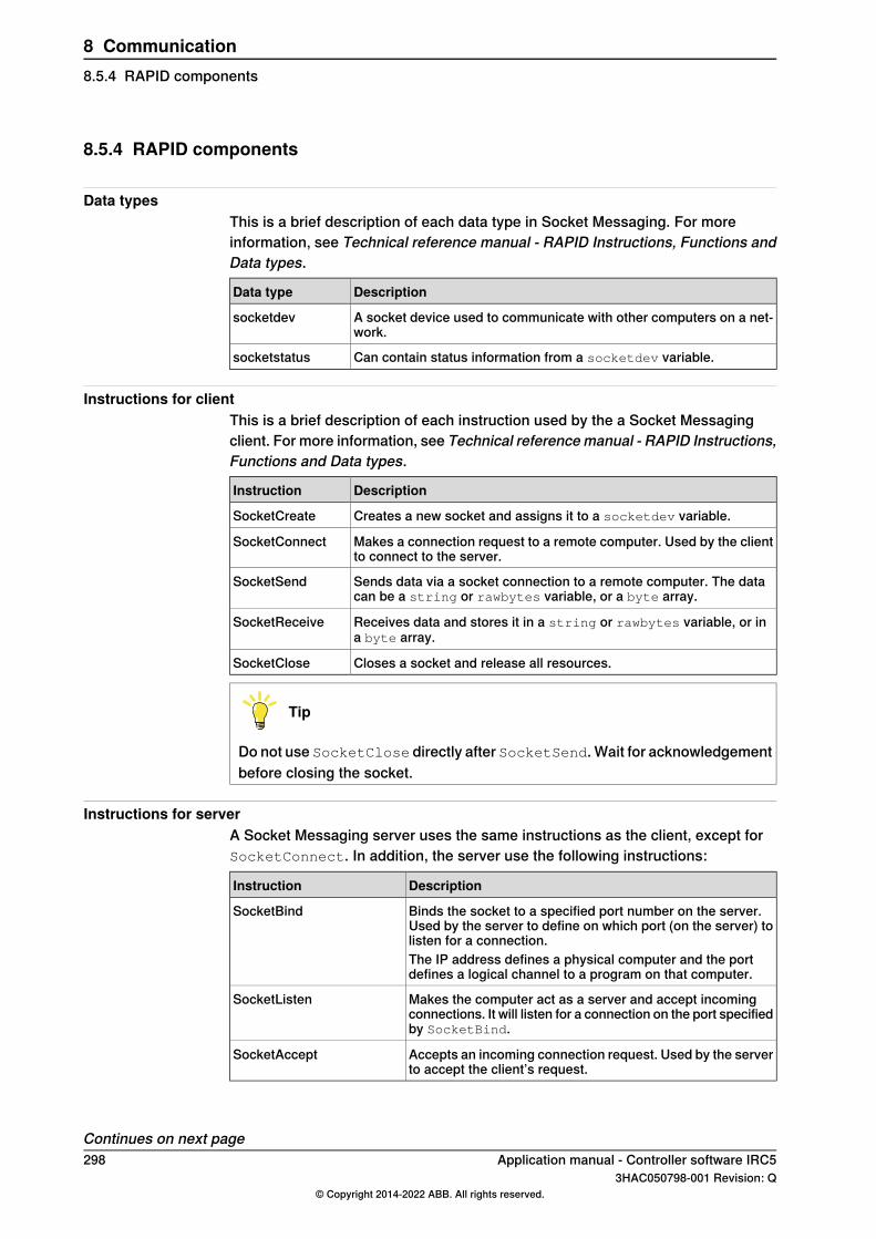
8.5.4 RAPID components
Data typesThis is a brief description of each data type in Socket Messaging. For moreinformation, see Technical reference manual - RAPID Instructions, Functions andData types.
DescriptionData type
A socket device used to communicate with other computers on a net-work.
socketdev
Can contain status information from a socketdev variable.socketstatus
Instructions for clientThis is a brief description of each instruction used by the a Socket Messagingclient. For more information, see Technical referencemanual - RAPID Instructions,Functions and Data types.
DescriptionInstruction
Creates a new socket and assigns it to a socketdev variable.SocketCreate
Makes a connection request to a remote computer. Used by the clientto connect to the server.
SocketConnect
Sends data via a socket connection to a remote computer. The datacan be a string or rawbytes variable, or a byte array.
SocketSend
Receives data and stores it in a string or rawbytes variable, or ina byte array.
SocketReceive
Closes a socket and release all resources.SocketClose
Tip
Do not use SocketClose directly after SocketSend. Wait for acknowledgementbefore closing the socket.
Instructions for serverA Socket Messaging server uses the same instructions as the client, except forSocketConnect. In addition, the server use the following instructions:
DescriptionInstruction
Binds the socket to a specified port number on the server.Used by the server to define on which port (on the server) tolisten for a connection.
SocketBind
The IP address defines a physical computer and the portdefines a logical channel to a program on that computer.
Makes the computer act as a server and accept incomingconnections. It will listen for a connection on the port specifiedby SocketBind.
SocketListen
Accepts an incoming connection request. Used by the serverto accept the client’s request.
SocketAccept
Continues on next page298 Application manual - Controller software IRC5
3HAC050798-001 Revision: Q© Copyright 2014-2022 ABB. All rights reserved.
8 Communication8.5.4 RAPID components
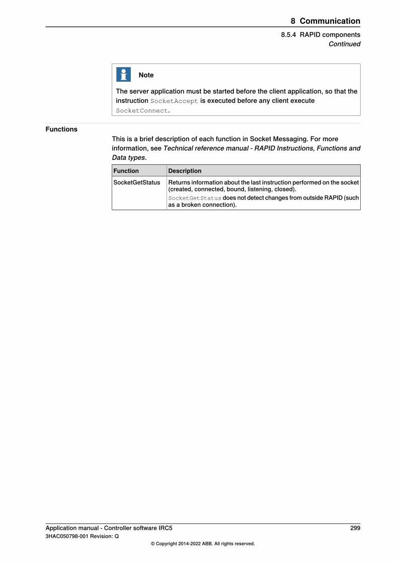
Note
The server application must be started before the client application, so that theinstruction SocketAccept is executed before any client executeSocketConnect.
FunctionsThis is a brief description of each function in Socket Messaging. For moreinformation, see Technical reference manual - RAPID Instructions, Functions andData types.
DescriptionFunction
Returns information about the last instruction performed on the socket(created, connected, bound, listening, closed).
SocketGetStatus
SocketGetStatus does not detect changes from outside RAPID (suchas a broken connection).
Application manual - Controller software IRC5 2993HAC050798-001 Revision: Q
© Copyright 2014-2022 ABB. All rights reserved.
8 Communication8.5.4 RAPID components
Continued
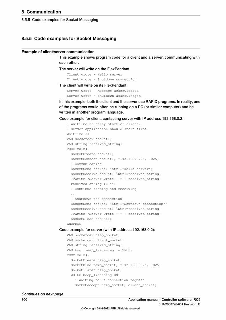
8.5.5 Code examples for Socket Messaging
Example of client/server communicationThis example shows program code for a client and a server, communicating witheach other.The server will write on the FlexPendant:
Client wrote - Hello server
Client wrote - Shutdown connection
The client will write on its FlexPendant:Server wrote - Message acknowledged
Server wrote - Shutdown acknowledged
In this example, both the client and the server use RAPID programs. In reality, oneof the programs would often be running on a PC (or similar computer) and bewritten in another program language.Code example for client, contacting server with IP address 192.168.0.2:
! WaitTime to delay start of client.
! Server application should start first.
WaitTime 5;
VAR socketdev socket1;
VAR string received_string;
PROC main()
SocketCreate socket1;
SocketConnect socket1, "192.168.0.2", 1025;
! Communication
SocketSend socket1 \Str:="Hello server";
SocketReceive socket1 \Str:=received_string;
TPWrite "Server wrote - " + received_string;
received_string := "";
! Continue sending and receiving
...
! Shutdown the connection
SocketSend socket1 \Str:="Shutdown connection";
SocketReceive socket1 \Str:=received_string;
TPWrite "Server wrote - " + received_string;
SocketClose socket1;
ENDPROC
Code example for server (with IP address 192.168.0.2):VAR socketdev temp_socket;
VAR socketdev client_socket;
VAR string received_string;
VAR bool keep_listening := TRUE;
PROC main()
SocketCreate temp_socket;
SocketBind temp_socket, "192.168.0.2", 1025;
SocketListen temp_socket;
WHILE keep_listening DO
! Waiting for a connection request
SocketAccept temp_socket, client_socket;
Continues on next page300 Application manual - Controller software IRC5
3HAC050798-001 Revision: Q© Copyright 2014-2022 ABB. All rights reserved.
8 Communication8.5.5 Code examples for Socket Messaging

! Communication
SocketReceive client_socket \Str:=received_string;
TPWrite "Client wrote - " + received_string;
received_string := "";
SocketSend client_socket \Str:="Message acknowledged";
! Shutdown the connection
SocketReceive client_socket \Str:=received_string;
TPWrite "Client wrote - " + received_string;
SocketSend client_socket \Str:="Shutdown acknowledged";
SocketClose client_socket;
ENDWHILE
SocketClose temp_socket;
ENDPROC
Example of error handlerThe following error handlers will take care of power failure or broken connection.Error handler for client in previous example:
! Error handler to make it possible to handle power fail
ERROR
IF ERRNO=ERR_SOCK_TIMEOUT THEN
RETRY;
ELSEIF ERRNO=ERR_SOCK_CLOSED THEN
SocketClose socket1;
! WaitTime to delay start of client.
! Server application should start first.
WaitTime 10;
SocketCreate socket1;
SocketConnect socket1, "192.168.0.2", 1025;
RETRY;
ELSE
TPWrite "ERRNO = "\Num:=ERRNO;
Stop;
ENDIF
Error handler for server in previous example:! Error handler for power fail and connection lost
ERROR
IF ERRNO=ERR_SOCK_TIMEOUT THEN
RETRY;
ELSEIF ERRNO=ERR_SOCK_CLOSED THEN
SocketClose temp_socket;
SocketClose client_socket;
SocketCreate temp_socket;
SocketBind temp_socket, "192.168.0.2", 1025;
SocketListen temp_socket;
SocketAccept temp_socket, client_socket;
RETRY;
ELSE
TPWrite "ERRNO = "\Num:=ERRNO;
Stop;
ENDIF
Application manual - Controller software IRC5 3013HAC050798-001 Revision: Q
© Copyright 2014-2022 ABB. All rights reserved.
8 Communication8.5.5 Code examples for Socket Messaging
Continued

8.6 RAPID Message Queue [included in 616-1, 623-1]
8.6.1 Introduction to RAPID Message Queue
PurposeThe purpose of RAPID Message Queue is to communicate with another RAPIDtask or PC application using PC SDK.Here are some examples of applications:
• Sending data between two RAPID tasks.• Sending data between a RAPID task and a PC application.
RAPID Message Queue can be defined for interrupt or synchronous mode. Defaultsetting is interrupt mode.
What is includedThe RAPID Message Queue functionality is included in the RobotWare options:
• PC Interface• Multitasking
RAPID Message Queue gives you access to RAPID instructions, functions, anddata types for sending and receiving data.
Basic approachThis is the general approach for using RAPID Message Queue. For a more detailedexample of how this is done, see Code examples on page 309.
1 For interrupt mode: The receiver sets up a trap routine that reads a messageand connects an interrupt so the trap routine is called when a new messageappears.For synchronous mode: The message is handled by a waiting or the nextexecuted RMQReadWait instruction.
2 The sender looks up the slot identity of the queue in the receiver task.3 The sender sends the message.
302 Application manual - Controller software IRC53HAC050798-001 Revision: Q
© Copyright 2014-2022 ABB. All rights reserved.
8 Communication8.6.1 Introduction to RAPID Message Queue
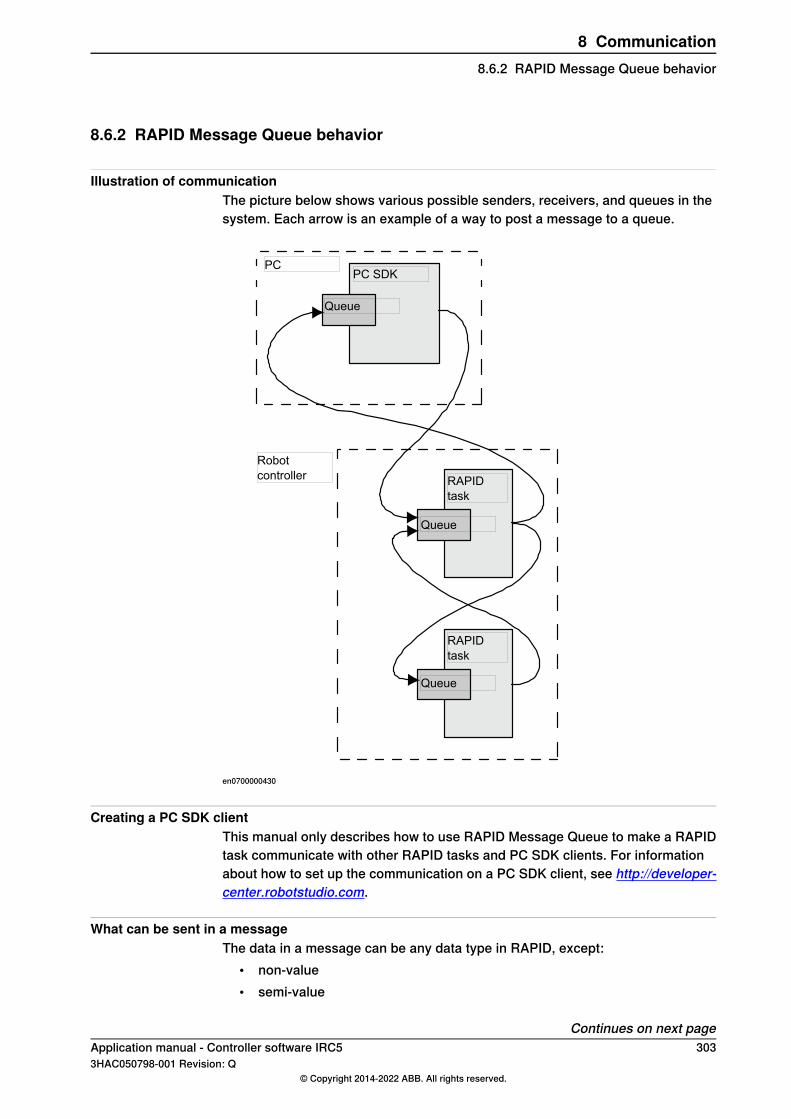
8.6.2 RAPID Message Queue behavior
Illustration of communicationThe picture below shows various possible senders, receivers, and queues in thesystem. Each arrow is an example of a way to post a message to a queue.
PCPC SDK
Queue
Robotcontroller
Queue
Queue
RAPIDtask
RAPIDtask
en0700000430
Creating a PC SDK clientThis manual only describes how to use RAPID Message Queue to make a RAPIDtask communicate with other RAPID tasks and PC SDK clients. For informationabout how to set up the communication on a PC SDK client, see http://developer-center.robotstudio.com.
What can be sent in a messageThe data in a message can be any data type in RAPID, except:
• non-value• semi-value
Continues on next pageApplication manual - Controller software IRC5 3033HAC050798-001 Revision: Q
© Copyright 2014-2022 ABB. All rights reserved.
8 Communication8.6.2 RAPID Message Queue behavior

• motsetdata
The data in a message can also be an array of a data type.User defined records are allowed, but both sender and receiver must have identicaldeclarations of the record.
Tip
To keep backward compatibility, do not change a user defined record once it isused in a released product. It is better to create a new record. This way, it ispossible to receive messages from both old and new applications.
Queue nameThe name of the queue configured for a RAPID task is the same as the name ofthe task with the prefix RMQ_, for example RMQ_T_ROB1. This name is used bythe instruction RMQFindSlot.
Queue handlingMessages in queues are handled in the order that they are received. This is knownas FIFO, first in first out. If a message is received while a previous message isbeing handled, the new message is placed in the queue. As soon as the firstmessage handling is completed, the next message in the queue is handled.
Queue modesThe queue mode is defined with the system parameterRMQMode. Default behavioris interrupt mode.
Interrupt modeIn interrupt mode the messages are handled depending on data type. Messagesare only handled for connected data types.A cyclic interrupt must be set up for each data type that the receiver should handle.The same trap routine can be called from more than one interrupt, that is for morethan one data type.Messages of a data type with no connected interrupt will be discarded with only awarning message in the event log.Receiving an answer to the instruction RMQSendWait does not result in an interrupt.No interrupt needs to be set up to receive this answer.
Synchronous modeIn synchronous mode, the task executes an RMQReadWait instruction to receivea message of any data type. All messages are queued and handled in order theyarrive.If there is a waiting RMQReadWait instruction, the message is handled immediately.If there is no waiting RMQReadWait instruction, the next executed RMQReadWait
instruction will handle the message.
Continues on next page304 Application manual - Controller software IRC5
3HAC050798-001 Revision: Q© Copyright 2014-2022 ABB. All rights reserved.
8 Communication8.6.2 RAPID Message Queue behaviorContinued
Message contentA RAPID Message Queue message consists of a header, containing receiveridentity, and a RAPID message. The RAPID message is a pretty-printed string withdata type name (and array dimensions) followed by the actual data value.RAPID message examples:
"robtarget;[[930,0,1455],[1,0,0,0],[0,0,0,0],[9E9,9E9,9E9,9E9,9E9,9E9]]"
"string;"A message string""
"msgrec;[100,200]"
"bool{2,2};[[TRUE,TRUE],[FALSE,FALSE]]"
RAPID task not executingIt is possible to post messages to a RAPID task queue even though the RAPIDtask containing the queue is not currently executing. The interrupt will not beexecuted until the RAPID task is executing again.
Message size limitationsBefore a message is sent, the maximum size (for the specific data type anddimension) is calculated. If the size is greater than 5000 bytes, the message willbe discarded and an error will be raised. The sender can get same error if thereceiver is a PC SDK client with a maximum message size smaller than 400 bytes.Sending a message of a specific data type with specific dimensions will eitheralways be possible or never possible.When a message is received (when calling the instruction RMQGetMsgData), themaximum size (for the specific data type and dimension) is calculated. If the sizeis greater than the maximum message size configured for the queue of this task,the message will be discarded and an error will be logged. Receiving a messageof a specific data type with specific dimensions will either always be possible ornever possible.
Message lostIn interrupt mode, any messages that cannot be received by a RAPID task will bediscarded. The message will be lost and a warning will be placed in the event log.Example of reasons for discarding a message:
• The data type that is sent is not supported by the receiving task.• The receiving task has not set up an interrupt for the data type that is sent,
and no RMQSendWait instruction is waiting for this data type.• The interrupt queue of the receiving task is full
Queue lostThe queue is cleared at power fail.When the execution context in a RAPID task is lost, for example when the programpointer is moved to main, the corresponding queue is emptied.
Continues on next pageApplication manual - Controller software IRC5 3053HAC050798-001 Revision: Q
© Copyright 2014-2022 ABB. All rights reserved.
8 Communication8.6.2 RAPID Message Queue behavior
Continued
Related informationFor more information on queues and messages, see Technical referencemanual - RAPID kernel.
306 Application manual - Controller software IRC53HAC050798-001 Revision: Q
© Copyright 2014-2022 ABB. All rights reserved.
8 Communication8.6.2 RAPID Message Queue behaviorContinued

8.6.3 System parameters
About the system parametersThis is a brief description of each parameter in the functionality RAPID MessageQueue. For more information, see the respective parameter in Technical referencemanual - System parameters.
Type TaskThese parameters belong to the type Task in the topic Controller.
DescriptionParameter
Can have one of the following values:• None - Disable all communication with RAPID Message
Queue for this RAPID task.• Internal - Enable the receiving of RAPID Message
Queue messages from other tasks on the controller,but not from external clients (FlexPendant and PC ap-plications). The task is still able to send messages toexternal clients.
• Remote - Enable communication with RAPID MessageQueue for this task, both with other tasks on the con-troller and external clients (FlexPendant and PC applic-ations).
The default value is None.
RMQ Type
Defines the mode of the queue.RMQ ModeCan have one of the following values:
• Interrupt - A message can only be received by connect-ing a trap routine to a specified message type.
• Synchronous - A message can only be received byexecuting an RMQReadWait instruction.
Default value is Interrupt.
The maximum data size, in bytes, for a RAPID MessageQueue message.
RMQ Max Message Size
An integer between 400 and 3000. The default value is 400.
Note
The value cannot be changed in RobotStudio or on the Flex-Pendant. The only way to change the value is to edit thesys.cfg file by adding the attribute RmqMaxMsgSize with thedesired value.
The maximum number of RAPID Message Queue messagesin the queue to this task.
RMQ Max No Of Messages
An integer between 1 and 10. The default value is 5.
Note
The value cannot be changed in RobotStudio or on the Flex-Pendant. The only way to change the value is to edit thesys.cfg file by adding the attribute RmqMaxNoOfMsgwith thedesired value.
Application manual - Controller software IRC5 3073HAC050798-001 Revision: Q
© Copyright 2014-2022 ABB. All rights reserved.
8 Communication8.6.3 System parameters

8.6.4 RAPID components
About the RAPID componentsThis is a brief description of each instruction, function, and data type in RAPIDMessage Queue. For more information, see the respective parameter in Technicalreference manual - RAPID Instructions, Functions and Data types.
Instructions
DescriptionInstruction
Find the slot identity number of the queue configured for aRAPID task or Robot Application Builder client.
RMQFindSlot
Send data to the queue configured for a RAPID task or RobotApplication Builder client.
RMQSendMessage
Order and enable cyclic interrupts for a specific data type.IRMQMessage
Get the first message from the queue of this task. Can onlybe used if RMQ Mode is defined as Interrupt.
RMQGetMessage
Get the header part from a message.RMQGetMsgHeader
Get the data part from a message.RMQGetMsgData
Send a message and wait for the answer. Can only be usedif RMQ Mode is defined as Interrupt.
RMQSendWait
Wait for a message. Can only be used if RMQMode is definedas Synchronous.
RMQReadWait
Empty the queue.RMQEmptyQueue
Functions
DescriptionFunction
Get the name of the queue configured for a RAPID task orRobot Application Builder client, given a slot identity number,i.e. given a rmqslot.
RMQGetSlotName
Data types
DescriptionData type
Slot identity of a RAPID task or Robot Application Builderclient.
rmqslot
A message used to store data in when communicating withRAPID Message Queue. It contains information about whattype of data is sent, the slot identity of the sender, and theactual data.
rmqmessage
Note: rmqmessage is a large data type. Declaring too manyvariables of this data type can lead to memory problems.Reuse the same rmqmessage variables as much as possible.
The rmqheader describes the message and can be read bythe RAPID program.
rmqheader
308 Application manual - Controller software IRC53HAC050798-001 Revision: Q
© Copyright 2014-2022 ABB. All rights reserved.
8 Communication8.6.4 RAPID components
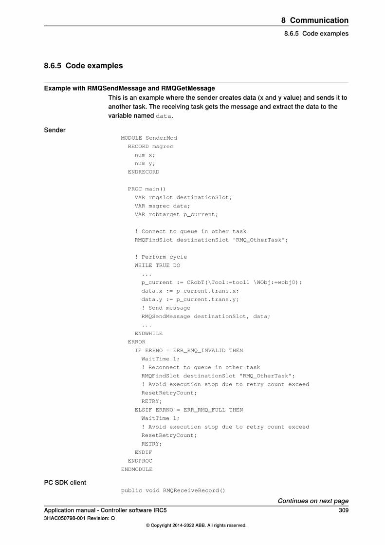
8.6.5 Code examples
Example with RMQSendMessage and RMQGetMessageThis is an example where the sender creates data (x and y value) and sends it toanother task. The receiving task gets the message and extract the data to thevariable named data.
SenderMODULE SenderMod
RECORD msgrec
num x;
num y;
ENDRECORD
PROC main()
VAR rmqslot destinationSlot;
VAR msgrec data;
VAR robtarget p_current;
! Connect to queue in other task
RMQFindSlot destinationSlot "RMQ_OtherTask";
! Perform cycle
WHILE TRUE DO
...
p_current := CRobT(\Tool:=tool1 \WObj:=wobj0);
data.x := p_current.trans.x;
data.y := p_current.trans.y;
! Send message
RMQSendMessage destinationSlot, data;
...
ENDWHILE
ERROR
IF ERRNO = ERR_RMQ_INVALID THEN
WaitTime 1;
! Reconnect to queue in other task
RMQFindSlot destinationSlot "RMQ_OtherTask";
! Avoid execution stop due to retry count exceed
ResetRetryCount;
RETRY;
ELSIF ERRNO = ERR_RMQ_FULL THEN
WaitTime 1;
! Avoid execution stop due to retry count exceed
ResetRetryCount;
RETRY;
ENDIF
ENDPROC
ENDMODULE
PC SDK clientpublic void RMQReceiveRecord()
Continues on next pageApplication manual - Controller software IRC5 3093HAC050798-001 Revision: Q
© Copyright 2014-2022 ABB. All rights reserved.
8 Communication8.6.5 Code examples

{
const string destination_slot = "RMQ_OtherTask";
IpcQueue queue = Controller.Ipc.CreateQueue(destination_slot,16, Ipc.MaxMessageSize);
// Till application is closed
while (uiclose)
{
IpcMessage message = new IpcMessage();
IpcReturnType retValue = IpcReturnType.Timeout;
retValue = queue.Receive(1000, message);
if (IpcReturnType.OK == retValue)
{
// PCSDK App will receive following record
// RECORD msgrec
// num x;
// num y;
// ENDRECORD
// num data type in RAPID is 3 bytes long, hence will receive6 bytes for x and y
// first byte do left shift by 16,
// second byte do left shift by 8 and OR all three byte toget x
// do similar for y
Int32 x = (message.Data[0] << 16) | (message.Data[1] << 8)| message.Data[2];
Int32 y = (message.Data[3] << 16) | (message.Data[4] << 8)| message.Data[5];
// Display x and y
}
}
if (Controller.Ipc.Exists(destination_slot))
Controller.Ipc.DeleteQueue(Controller.Ipc.GetQueueId(destination_slot));
}
Example with RMQSendWaitThis is an example of a RAPID program that sends a message and wait for ananswer before execution continues by getting the answer message.
MODULE SendAndReceiveMod
VAR rmqslot destinationSlot;
VAR rmqmessage recmsg;
VAR string send_data := "How many units should be produced?";
VAR num receive_data;
PROC main()
! Connect to queue in other task
RMQFindSlot destinationSlot "RMQ_OtherTask";
Continues on next page310 Application manual - Controller software IRC5
3HAC050798-001 Revision: Q© Copyright 2014-2022 ABB. All rights reserved.
8 Communication8.6.5 Code examplesContinued
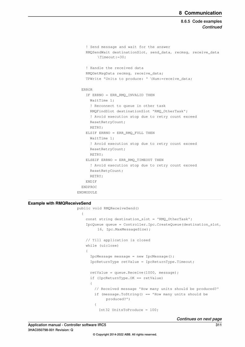
! Send message and wait for the answer
RMQSendWait destinationSlot, send_data, recmsg, receive_data\Timeout:=30;
! Handle the received data
RMQGetMsgData recmsg, receive_data;
TPWrite "Units to produce: " \Num:=receive_data;
ERROR
IF ERRNO = ERR_RMQ_INVALID THEN
WaitTime 1;
! Reconnect to queue in other task
RMQFindSlot destinationSlot "RMQ_OtherTask";
! Avoid execution stop due to retry count exceed
ResetRetryCount;
RETRY;
ELSIF ERRNO = ERR_RMQ_FULL THEN
WaitTime 1;
! Avoid execution stop due to retry count exceed
ResetRetryCount;
RETRY;
ELSEIF ERRNO = ERR_RMQ_TIMEOUT THEN
! Avoid execution stop due to retry count exceed
ResetRetyCount;
RETRY;
ENDIF
ENDPROC
ENDMODULE
Example with RMQReceiveSendpublic void RMQReceiveSend()
{
const string destination_slot = "RMQ_OtherTask";
IpcQueue queue = Controller.Ipc.CreateQueue(destination_slot,16, Ipc.MaxMessageSize);
// Till application is closed
while (uiclose)
{
IpcMessage message = new IpcMessage();
IpcReturnType retValue = IpcReturnType.Timeout;
retValue = queue.Receive(1000, message);
if (IpcReturnType.OK == retValue)
{
// Received message "How many units should be produced?"
if (message.ToString() == "How many units should beproduced?")
{
Int32 UnitsToProduce = 100;
Continues on next pageApplication manual - Controller software IRC5 3113HAC050798-001 Revision: Q
© Copyright 2014-2022 ABB. All rights reserved.
8 Communication8.6.5 Code examples
Continued

// num data type in Rapid is 3 bytes long, hence willsend 3 bytes to Rapid Module
byte[] @bytes = new byte[3];
bytes[0] = (byte)(UnitsToProduce >> 16);
bytes[1] = (byte)(UnitsToProduce >> 8);
bytes[2] = (byte)UnitsToProduce;
// Send UnitsToProduce to Rapid Module
message.SetData(@bytes);
queue.Send(message);
}
}
}
if (Controller.Ipc.Exists(destination_slot))
Controller.Ipc.DeleteQueue(Controller.Ipc.GetQueueId(destination_slot));
}
312 Application manual - Controller software IRC53HAC050798-001 Revision: Q
© Copyright 2014-2022 ABB. All rights reserved.
8 Communication8.6.5 Code examplesContinued

9 Engineering tools9.1 Multitasking [623-1]
9.1.1 Introduction to Multitasking
PurposeThe purpose of the option Multitasking is to be able to execute more than oneprogram at a time.Examples of applications to run in parallel with the main program:
• Continuous supervision of signals, even if the main program has stopped.This can in some cases take over the job of a PLC. However, the responsetime will not match that of a PLC.
• Operator input from the FlexPendant while the robot is working.• Control and activation/deactivation of external equipment.
Basic descriptionUp to 20 tasks can be run at the same time.Each task consists of one program (with several program modules) and severalsystem modules. The modules are local in the respective task.
en0300000517
Variables and constants are local in the respective task, but persistents are not.Every task has its own trap handling and event routines are triggered only on itsown task system states.
What is includedThe RobotWare option Multitasking gives you access to:
• The possibility to run up to 20 programs in parallel (one per task).• The system parameters: The type Task and all its parameters.• The data types: taskid, syncident, and tasks.
Continues on next pageApplication manual - Controller software IRC5 3133HAC050798-001 Revision: Q
© Copyright 2014-2022 ABB. All rights reserved.
9 Engineering tools9.1.1 Introduction to Multitasking

• The instruction: WaitSyncTask.• The functions: TestAndSet, TaskRunMec, and TaskRunRob.
Note
TestAndSet, TaskRunMec, and TaskRunRob can be used without the optionMultitasking, but they are much more useful together with Multitasking.
Basic approachThis is the basic approach for setting up Multitasking. For more information, seeDebug strategies for setting up tasks on page 318, and RAPID components onpage 317.
1 Define the tasks you need.2 Write RAPID code for each task.3 Specify which modules to load in each task.
314 Application manual - Controller software IRC53HAC050798-001 Revision: Q
© Copyright 2014-2022 ABB. All rights reserved.
9 Engineering tools9.1.1 Introduction to MultitaskingContinued
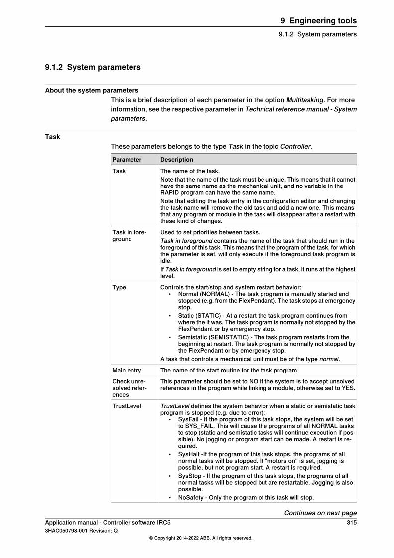
9.1.2 System parameters
About the system parametersThis is a brief description of each parameter in the option Multitasking. For moreinformation, see the respective parameter in Technical reference manual - Systemparameters.
TaskThese parameters belongs to the type Task in the topic Controller.
DescriptionParameter
The name of the task.TaskNote that the name of the task must be unique. This means that it cannothave the same name as the mechanical unit, and no variable in theRAPID program can have the same name.Note that editing the task entry in the configuration editor and changingthe task name will remove the old task and add a new one. This meansthat any program or module in the task will disappear after a restart withthese kind of changes.
Used to set priorities between tasks.Task in fore-ground Task in foreground contains the name of the task that should run in the
foreground of this task. This means that the program of the task, for whichthe parameter is set, will only execute if the foreground task program isidle.If Task in foreground is set to empty string for a task, it runs at the highestlevel.
Controls the start/stop and system restart behavior:• Normal (NORMAL) - The task program is manually started and
stopped (e.g. from the FlexPendant). The task stops at emergencystop.
• Static (STATIC) - At a restart the task program continues fromwhere the it was. The task program is normally not stopped by theFlexPendant or by emergency stop.
• Semistatic (SEMISTATIC) - The task program restarts from thebeginning at restart. The task program is normally not stopped bythe FlexPendant or by emergency stop.
A task that controls a mechanical unit must be of the type normal.
Type
The name of the start routine for the task program.Main entry
This parameter should be set to NO if the system is to accept unsolvedreferences in the program while linking a module, otherwise set to YES.
Check unre-solved refer-ences
TrustLevel defines the system behavior when a static or semistatic taskprogram is stopped (e.g. due to error):
• SysFail - If the program of this task stops, the system will be setto SYS_FAIL. This will cause the programs of all NORMAL tasksto stop (static and semistatic tasks will continue execution if pos-sible). No jogging or program start can be made. A restart is re-quired.
• SysHalt -If the program of this task stops, the programs of allnormal tasks will be stopped. If "motors on" is set, jogging ispossible, but not program start. A restart is required.
• SysStop - If the program of this task stops, the programs of allnormal tasks will be stopped but are restartable. Jogging is alsopossible.
• NoSafety - Only the program of this task will stop.
TrustLevel
Continues on next pageApplication manual - Controller software IRC5 3153HAC050798-001 Revision: Q
© Copyright 2014-2022 ABB. All rights reserved.
9 Engineering tools9.1.2 System parameters
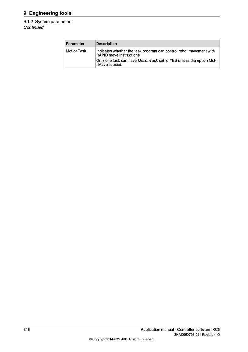
DescriptionParameter
Indicates whether the task program can control robot movement withRAPID move instructions.
MotionTask
Only one task can have MotionTask set to YES unless the option Mul-tiMove is used.
316 Application manual - Controller software IRC53HAC050798-001 Revision: Q
© Copyright 2014-2022 ABB. All rights reserved.
9 Engineering tools9.1.2 System parametersContinued
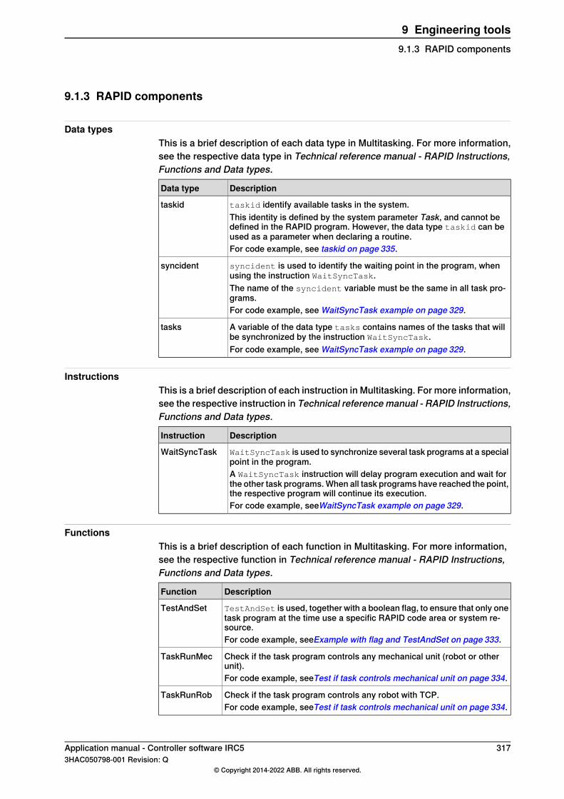
9.1.3 RAPID components
Data typesThis is a brief description of each data type in Multitasking. For more information,see the respective data type in Technical reference manual - RAPID Instructions,Functions and Data types.
DescriptionData type
taskid identify available tasks in the system.taskidThis identity is defined by the system parameter Task, and cannot bedefined in the RAPID program. However, the data type taskid can beused as a parameter when declaring a routine.For code example, see taskid on page 335.
syncident is used to identify the waiting point in the program, whenusing the instruction WaitSyncTask.
syncident
The name of the syncident variable must be the same in all task pro-grams.For code example, see WaitSyncTask example on page 329.
A variable of the data type tasks contains names of the tasks that willbe synchronized by the instruction WaitSyncTask.
tasks
For code example, see WaitSyncTask example on page 329.
InstructionsThis is a brief description of each instruction in Multitasking. For more information,see the respective instruction in Technical reference manual - RAPID Instructions,Functions and Data types.
DescriptionInstruction
WaitSyncTask is used to synchronize several task programs at a specialpoint in the program.
WaitSyncTask
A WaitSyncTask instruction will delay program execution and wait forthe other task programs. When all task programs have reached the point,the respective program will continue its execution.For code example, seeWaitSyncTask example on page 329.
FunctionsThis is a brief description of each function in Multitasking. For more information,see the respective function in Technical reference manual - RAPID Instructions,Functions and Data types.
DescriptionFunction
TestAndSet is used, together with a boolean flag, to ensure that only onetask program at the time use a specific RAPID code area or system re-source.
TestAndSet
For code example, seeExample with flag and TestAndSet on page 333.
Check if the task program controls any mechanical unit (robot or otherunit).
TaskRunMec
For code example, seeTest if task controls mechanical unit on page 334.
Check if the task program controls any robot with TCP.TaskRunRobFor code example, seeTest if task controls mechanical unit on page 334.
Application manual - Controller software IRC5 3173HAC050798-001 Revision: Q
© Copyright 2014-2022 ABB. All rights reserved.
9 Engineering tools9.1.3 RAPID components

9.1.4 Task configuration
9.1.4.1 Debug strategies for setting up tasks
Tip
The instructions below show the safe way to make updates. By setting theparameter Type to NORMAL and TrustLevel to NoSafety the task program willbe easier to test and any error that may occur will be easier to correct.If you are certain that the code you introduce is correct, you can skip changingvalues for Type and TrustLevel. If you do not change any system parametersyou may not have to do any restart mode.
Setting up tasksFollow this instruction when adding a new task to your system.
1 Define the new task by adding an instance of the system parameter typeTask, in the topic Controller.
2 Set the parameter Type to NORMAL.This will make it easier to create and test the modules in the task.
3 Create the modules that should be in the task, either from the FlexPendantor offline, and save them.
4 In the system parameters for topic Controller and type Automatic loading ofModules, specify all modules that should be preloaded to the new task.For NORMAL tasks the modules can be loaded later, but STATIC orSEMISTATIC tasks the modules must be preloaded.
5 Stop the controller.6 In Motors on state, test and debug the modules until the functionality is
satisfactory.7 Change the parameters Type and TrustLevel to desired values (e.g.
SEMISTATIC and SysFail).8 Restart the system.
Make changes to task programFollow this instruction when editing a program in an existing task with Type set toSTATIC or SEMISTATIC.
Action
Change the system parameter TrustLevel to NoSafety.1This will make it possible to change and test the modules in the task.
If the system parameter needed to be changed, restart the controller.2
On the FlexPendant, start theControl Panel from the ABB menu. Then tap FlexPendantand Task Panel Settings. Select All tasks and tap OK.
3
In the Quickset menu, select which tasks to start and stop manually. See Select whichtasks to start with START button on page 323.
4
Continues on next page318 Application manual - Controller software IRC5
3HAC050798-001 Revision: Q© Copyright 2014-2022 ABB. All rights reserved.
9 Engineering tools9.1.4.1 Debug strategies for setting up tasks

Action
Press the STOP button to stop the selected STATIC and SEMISTATIC tasks.5
Start the Program Editor.6The STATIC and SEMISTATIC tasks are now also editable.
Change, test, and save the modules.7
Start the Control Panel again and open the Task Panel Settings. Select Only Normaltasks and tap OK.
8
Change the parameter TrustLevel back to desired value (e.g. SysFail).9
Restart the system.10
Application manual - Controller software IRC5 3193HAC050798-001 Revision: Q
© Copyright 2014-2022 ABB. All rights reserved.
9 Engineering tools9.1.4.1 Debug strategies for setting up tasks
Continued

9.1.4.2 Priorities
How priorities workThe default behavior is that all task programs run at the same priority, in a RoundRobin way.It is possible to change the priority of one task by setting it in the background ofanother task. Then the program of the background task will only execute when theforeground task program is idle, waiting for an event, for example. Another situationwhen the background task program will execute is when the foreground taskprogram has executed a move instruction, as the foreground task will then haveto wait until the robot has moved .To set a task in the background of another task, use the parameter Task inforeground.
Example of priorities6 tasks are used, with Task in foreground set as shown in the table below.
Task in foregroundTask name
MAIN
MAINBACK1
BACK1BACK2
BACK1BACK3
SUP1
SUP1SUP2
The priority structure will then look like this:
en0300000451
The programs of the tasks MAIN and SUP1 will take turns in executing an instructioneach (Case 1 in figure below).If the MAIN task program is idle, the programs of BACK1 and SUP1 will take turnsin executing an instruction each (Case 2 in figure below).
Continues on next page320 Application manual - Controller software IRC5
3HAC050798-001 Revision: Q© Copyright 2014-2022 ABB. All rights reserved.
9 Engineering tools9.1.4.2 Priorities

If both MAIN and BACK1 task programs are idle, the programs of BACK2, BACK3,and SUP1 will take turns in executing an instruction each (Case 3 in figure below).
en0300000479
Application manual - Controller software IRC5 3213HAC050798-001 Revision: Q
© Copyright 2014-2022 ABB. All rights reserved.
9 Engineering tools9.1.4.2 Priorities
Continued
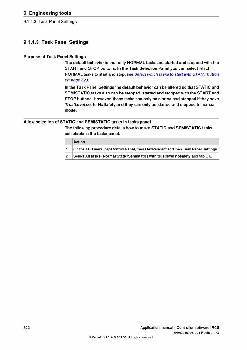
9.1.4.3 Task Panel Settings
Purpose of Task Panel SettingsThe default behavior is that only NORMAL tasks are started and stopped with theSTART and STOP buttons. In the Task Selection Panel you can select whichNORMAL tasks to start and stop, see Select which tasks to start with START buttonon page 323.In the Task Panel Settings the default behavior can be altered so that STATIC andSEMISTATIC tasks also can be stepped, started and stopped with the START andSTOP buttons. However, these tasks can only be started and stopped if they haveTrustLevel set to NoSafety and they can only be started and stopped in manualmode.
Allow selection of STATIC and SEMISTATIC tasks in tasks panelThe following procedure details how to make STATIC and SEMISTATIC tasksselectable in the tasks panel.
Action
On theABBmenu, tapControl Panel, then FlexPendant and then Task Panel Settings.1
Select All tasks (Normal/Static/Semistatic) with trustlevel nosafety and tap OK.2
322 Application manual - Controller software IRC53HAC050798-001 Revision: Q
© Copyright 2014-2022 ABB. All rights reserved.
9 Engineering tools9.1.4.3 Task Panel Settings
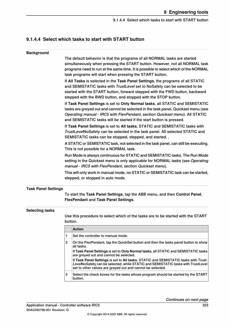
9.1.4.4 Select which tasks to start with START button
BackgroundThe default behavior is that the programs of all NORMAL tasks are startedsimultaneously when pressing the START button. However, not all NORMAL taskprograms need to run at the same time. It is possible to select which of the NORMALtask programs will start when pressing the START button.If All Tasks is selected in the Task Panel Settings, the programs of all STATICand SEMISTATIC tasks with TrustLevel set to NoSafety can be selected to bestarted with the START button, forward stepped with the FWD button, backwardstepped with the BWD button, and stopped with the STOP button.If Task Panel Settings is set to Only Normal tasks, all STATIC and SEMISTATICtasks are greyed out and cannot be selected in the task panel, Quickset menu (seeOperating manual - IRC5 with FlexPendant, section Quickset menu). All STATICand SEMISTATIC tasks will be started if the start button is pressed.If Task Panel Settings is set to All tasks, STATIC and SEMISTATIC tasks withTrustLevelNoSafety can be selected in the task panel. All selected STATIC andSEMISTATIC tasks can be stopped, stepped, and started. .A STATIC or SEMISTATIC task, not selected in the task panel, can still be executing.This is not possible for a NORMAL task.Run Mode is always continuous for STATIC and SEMISTATIC tasks. The Run Modesetting in the Quickset menu is only applicable for NORMAL tasks (see Operatingmanual - IRC5 with FlexPendant, section Quickset menu).This will only work in manual mode, no STATIC or SEMISTATIC task can be started,stepped, or stopped in auto mode.
Task Panel SettingsTo start the Task Panel Settings, tap the ABB menu, and then Control Panel,FlexPendant and Task Panel Settings.
Selecting tasksUse this procedure to select which of the tasks are to be started with the STARTbutton.
Action
Set the controller to manual mode.1
On the FlexPendant, tap the QuickSet button and then the tasks panel button to showall tasks.
2
If Task Panel Settings is set toOnly Normal tasks, all STATIC and SEMISTATIC tasksare greyed out and cannot be selected.If Task Panel Settings is set to All tasks, STATIC and SEMISTATIC tasks with Trust-LevelNoSafety can be selected, while STATIC and SEMISTATIC tasks with TrustLevelset to other values are grayed out and cannot be selected.
Select the check boxes for the tasks whose program should be started by the STARTbutton.
3
Continues on next pageApplication manual - Controller software IRC5 3233HAC050798-001 Revision: Q
© Copyright 2014-2022 ABB. All rights reserved.
9 Engineering tools9.1.4.4 Select which tasks to start with START button

Resetting debug settings in manual modeUse this procedure to resume normal execution manual mode.
Action
Select Only Normal tasks in the Task Panel Settings.1
Press START button.2All STATIC and SEMISTATIC will run continuously and not be stopped by the STOPbutton or emergency stop.
Switching to auto modeWhen switching to auto mode, all STATIC and SEMISTATIC tasks will be deselectedfrom the tasks panel. The stopped STATIC and SEMISTATIC tasks will start nexttime any of the START, FWD or BWD button are pressed. These tasks will thenrun continuously forward and not be stopped by the STOP button or emergencystop.What happens with NORMAL tasks that has been deselected in the tasks paneldepends on the system parameter Reset in type Auto Condition Reset in topicController. If Reset is set to Yes, all NORMAL tasks will be selected in the taskspanel and be started with the START button. If Reset is set to No, only thoseNORMAL tasks selected in tasks panel will be started by the START button.
Note
Note that changing the value of the system parameter Reset will affect all thedebug resettings (for example speed override and simulated I/O). For moreinformation, see Technical reference manual - System parameters, section AutoCondition Reset.
Restarting the controllerIf the controller is restarted, all NORMAL tasks will keep their status while allSTATIC and SEMISTATIC tasks will be deselected from the tasks panel. As thecontroller starts up all STATIC and SEMISTATIC tasks will be started and then runcontinuously.
Deselect task in synchronized modeIf a task is in a synchronized mode, that is program pointer between SyncMoveOn
and SyncMoveOff, the task can be deselected but not reselected. The task cannotbe selected until the synchronization is terminated. If the execution continues, thesynchronization will eventually be terminated for the other tasks, but not for thedeselected task. The synchronization can be terminated for this task by movingthe program pointer to main or to a routine.If the system parameter Reset is set to Yes, any attempt to change to Auto modewill fail while a deselected task is in synchronized mode. Changing to Auto modeshould make all NORMAL tasks selected, and when this is not possible it is notpossible to change to Auto mode.
324 Application manual - Controller software IRC53HAC050798-001 Revision: Q
© Copyright 2014-2022 ABB. All rights reserved.
9 Engineering tools9.1.4.4 Select which tasks to start with START buttonContinued

9.1.5 Communication between tasks
9.1.5.1 Persistent variables
About persistent variablesTo share data between tasks, use persistent variables.A persistent variable is global in all tasks where it is declared. The persistentvariable must be declared as the same type and size (array dimension) in all tasks.Otherwise a runtime error will occur.It is sufficient to specify an initial value for the persistent variable in one task. Ifinitial values are specified in several tasks, only the initial value of the first moduleto load will be used.
Tip
When a program is saved, the current value of a persistent variable will be usedas initial value in the future. If this is not desired, reset the persistent variabledirectly after the communication.
Example with persistent variableIn this example the persistent variables startsync and stringtosend areaccessed by both tasks, and can therefore be used for communication betweenthe task programs.Main task program:
MODULE module1
PERS bool startsync:=FALSE;
PERS string stringtosend:="";
PROC main()
stringtosend:="this is a test";
startsync:= TRUE
ENDPROC
ENDMODULE
Background task program:MODULE module2
PERS bool startsync;
PERS string stringtosend;
PROC main()
WaitUntil startsync;
IF stringtosend = "this is a test" THEN
...
ENDIF
!reset persistent variables
startsync:=FALSE;
stringtosend:="";
ENDPROC
ENDMODULE
Continues on next pageApplication manual - Controller software IRC5 3253HAC050798-001 Revision: Q
© Copyright 2014-2022 ABB. All rights reserved.
9 Engineering tools9.1.5.1 Persistent variables
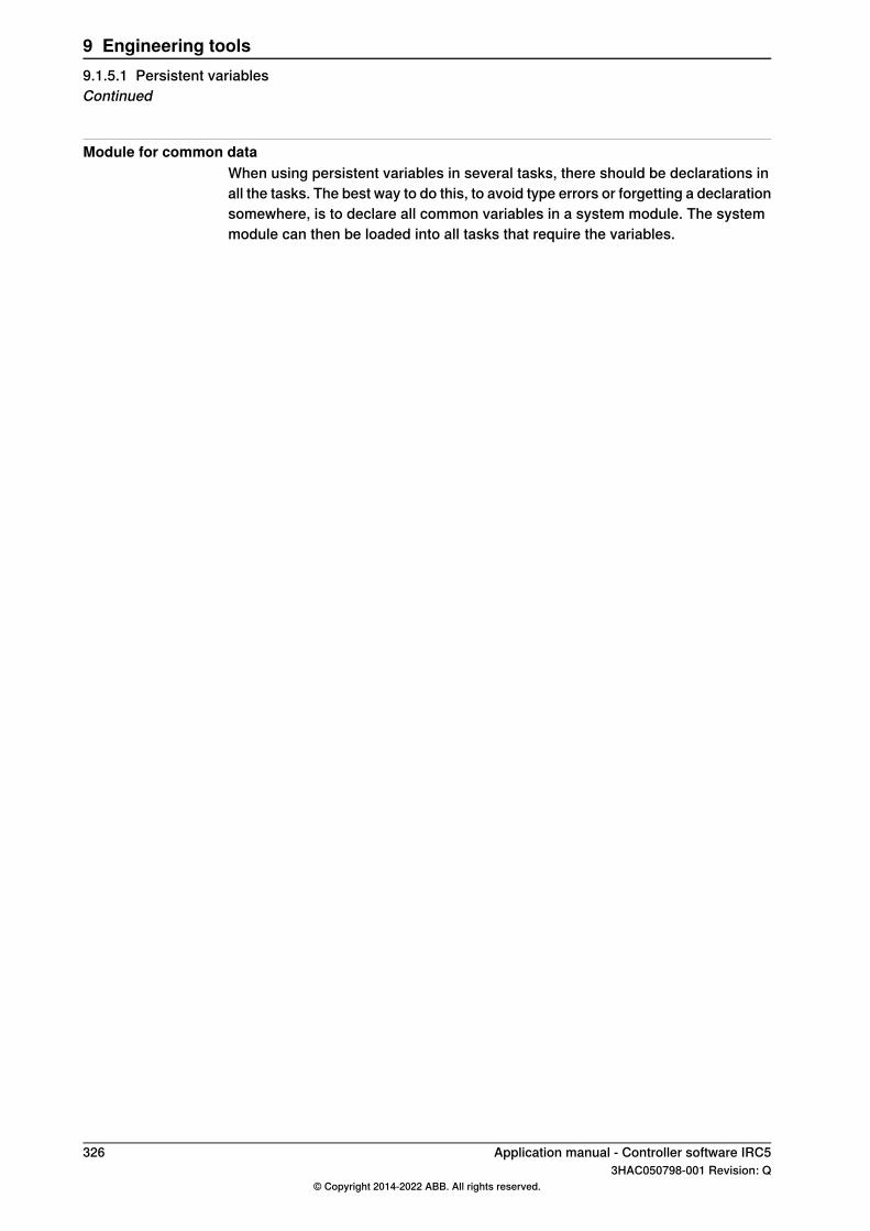
Module for common dataWhen using persistent variables in several tasks, there should be declarations inall the tasks. The best way to do this, to avoid type errors or forgetting a declarationsomewhere, is to declare all common variables in a system module. The systemmodule can then be loaded into all tasks that require the variables.
326 Application manual - Controller software IRC53HAC050798-001 Revision: Q
© Copyright 2014-2022 ABB. All rights reserved.
9 Engineering tools9.1.5.1 Persistent variablesContinued

9.1.5.2 Waiting for other tasks
Two techniquesSome applications have task programs that execute independently of other tasks,but often task programs need to know what other tasks are doing.A task program can be made to wait for another task program. This is accomplishedeither by setting a persistent variable that the other task program can poll, or bysetting a signal that the other task program can connect to an interrupt.
PollingThis is the easiest way to make a task program wait for another, but the performancewill be the slowest. Persistent variables are used together with the instructionsWaitUntil or WHILE.If the instruction WaitUntil is used, it will poll internally every 100 ms.
CAUTION
Do not poll more frequently than every 100 ms. A loop that polls without a waitinstruction can cause overload, resulting in lost contact with the FlexPendant.
Polling exampleMain task program:
MODULE module1
PERS bool startsync:=FALSE;
PROC main()
startsync:= TRUE;
...
ENDPROC
ENDMODULE
Background task program:MODULE module2
PERS bool startsync:=FALSE;
PROC main()
WaitUntil startsync;
! This is the point where the execution
! continues after startsync is set to TRUE
...
ENDPROC
ENDMODULE
InterruptBy setting a signal in one task program and using an interrupt in another taskprogram, quick response is obtained without the work load caused by polling.The drawback is that the code executed after the interrupt must be placed in a traproutine.
Continues on next pageApplication manual - Controller software IRC5 3273HAC050798-001 Revision: Q
© Copyright 2014-2022 ABB. All rights reserved.
9 Engineering tools9.1.5.2 Waiting for other tasks
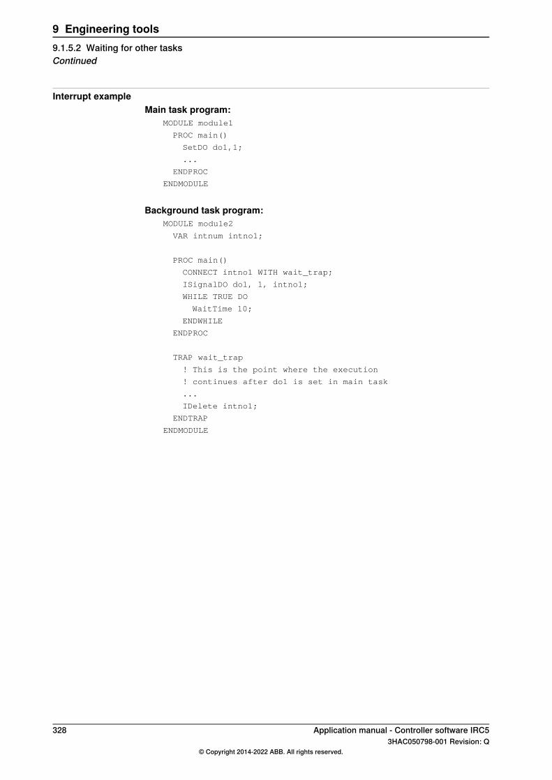
Interrupt exampleMain task program:
MODULE module1
PROC main()
SetDO do1,1;
...
ENDPROC
ENDMODULE
Background task program:MODULE module2
VAR intnum intno1;
PROC main()
CONNECT intno1 WITH wait_trap;
ISignalDO do1, 1, intno1;
WHILE TRUE DO
WaitTime 10;
ENDWHILE
ENDPROC
TRAP wait_trap
! This is the point where the execution
! continues after do1 is set in main task
...
IDelete intno1;
ENDTRAP
ENDMODULE
328 Application manual - Controller software IRC53HAC050798-001 Revision: Q
© Copyright 2014-2022 ABB. All rights reserved.
9 Engineering tools9.1.5.2 Waiting for other tasksContinued
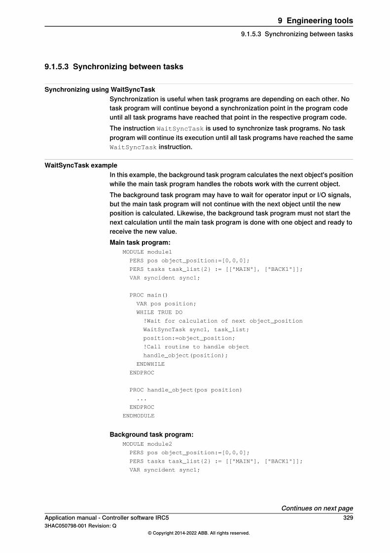
9.1.5.3 Synchronizing between tasks
Synchronizing using WaitSyncTaskSynchronization is useful when task programs are depending on each other. Notask program will continue beyond a synchronization point in the program codeuntil all task programs have reached that point in the respective program code.The instruction WaitSyncTask is used to synchronize task programs. No taskprogram will continue its execution until all task programs have reached the sameWaitSyncTask instruction.
WaitSyncTask exampleIn this example, the background task program calculates the next object's positionwhile the main task program handles the robots work with the current object.The background task program may have to wait for operator input or I/O signals,but the main task program will not continue with the next object until the newposition is calculated. Likewise, the background task program must not start thenext calculation until the main task program is done with one object and ready toreceive the new value.Main task program:
MODULE module1
PERS pos object_position:=[0,0,0];
PERS tasks task_list{2} := [["MAIN"], ["BACK1"]];
VAR syncident sync1;
PROC main()
VAR pos position;
WHILE TRUE DO
!Wait for calculation of next object_position
WaitSyncTask sync1, task_list;
position:=object_position;
!Call routine to handle object
handle_object(position);
ENDWHILE
ENDPROC
PROC handle_object(pos position)
...
ENDPROC
ENDMODULE
Background task program:MODULE module2
PERS pos object_position:=[0,0,0];
PERS tasks task_list{2} := [["MAIN"], ["BACK1"]];
VAR syncident sync1;
Continues on next pageApplication manual - Controller software IRC5 3293HAC050798-001 Revision: Q
© Copyright 2014-2022 ABB. All rights reserved.
9 Engineering tools9.1.5.3 Synchronizing between tasks

PROC main()
WHILE TRUE DO
!Call routine to calculate object_position
calculate_position;
!Wait for handling of current object
WaitSyncTask sync1, task_list;
ENDWHILE
ENDPROC
PROC calculate_position()
...
object_position:= ...
ENDPROC
ENDMODULE
330 Application manual - Controller software IRC53HAC050798-001 Revision: Q
© Copyright 2014-2022 ABB. All rights reserved.
9 Engineering tools9.1.5.3 Synchronizing between tasksContinued

9.1.5.4 Using a dispatcher
What is a dispatcher?A digital signal can be used to indicate when another task should do something.However, it cannot contain information about what to do.Instead of using one signal for each routine, a dispatcher can be used to determinewhich routine to call. A dispatcher can be a persistent string variable containingthe name of the routine to execute in another task.
Dispatcher exampleIn this example, the main task program calls routines in the background task bysetting routine_string to the routine name and then setting do5 to 1. In thisway, the main task program initialize that the background task program shouldexecute the routine clean_gun first and then routine1.Main task program:
MODULE module1
PERS string routine_string:="";
PROC main()
!Call clean_gun in background task
routine_string:="clean_gun";
SetDO do5,1;
WaitDO do5,0;
!Call routine1 in background task
routine_string:="routine1";
SetDO do5,1;
WaitDO do5,0;
...
ENDPROC
ENDMODULE
Background task program:MODULE module2
PERS string routine_string:="";
PROC main()
WaitDO do5,1;
%routine_string%;
SetDO do5,0;
ENDPROC
PROC clean_gun()
...
ENDPROC
PROC routine1()
...
Continues on next pageApplication manual - Controller software IRC5 3313HAC050798-001 Revision: Q
© Copyright 2014-2022 ABB. All rights reserved.
9 Engineering tools9.1.5.4 Using a dispatcher

ENDPROC
ENDMODULE
332 Application manual - Controller software IRC53HAC050798-001 Revision: Q
© Copyright 2014-2022 ABB. All rights reserved.
9 Engineering tools9.1.5.4 Using a dispatcherContinued
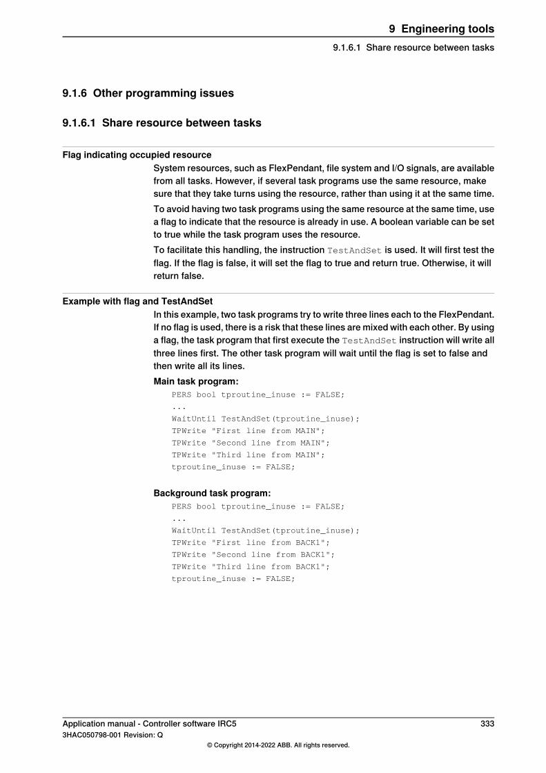
9.1.6 Other programming issues
9.1.6.1 Share resource between tasks
Flag indicating occupied resourceSystem resources, such as FlexPendant, file system and I/O signals, are availablefrom all tasks. However, if several task programs use the same resource, makesure that they take turns using the resource, rather than using it at the same time.To avoid having two task programs using the same resource at the same time, usea flag to indicate that the resource is already in use. A boolean variable can be setto true while the task program uses the resource.To facilitate this handling, the instruction TestAndSet is used. It will first test theflag. If the flag is false, it will set the flag to true and return true. Otherwise, it willreturn false.
Example with flag and TestAndSetIn this example, two task programs try to write three lines each to the FlexPendant.If no flag is used, there is a risk that these lines are mixed with each other. By usinga flag, the task program that first execute the TestAndSet instruction will write allthree lines first. The other task program will wait until the flag is set to false andthen write all its lines.Main task program:
PERS bool tproutine_inuse := FALSE;
...
WaitUntil TestAndSet(tproutine_inuse);
TPWrite "First line from MAIN";
TPWrite "Second line from MAIN";
TPWrite "Third line from MAIN";
tproutine_inuse := FALSE;
Background task program:PERS bool tproutine_inuse := FALSE;
...
WaitUntil TestAndSet(tproutine_inuse);
TPWrite "First line from BACK1";
TPWrite "Second line from BACK1";
TPWrite "Third line from BACK1";
tproutine_inuse := FALSE;
Application manual - Controller software IRC5 3333HAC050798-001 Revision: Q
© Copyright 2014-2022 ABB. All rights reserved.
9 Engineering tools9.1.6.1 Share resource between tasks

9.1.6.2 Test if task controls mechanical unit
Two functions for inquiringThere are functions for checking if the task program has control of any mechanicalunit, TaskRunMec, or of a robot, TaskRunRob.TaskRunMecwill return true if the task program controls a robot or other mechanicalunit. TaskRunRob will only return true if the task program controls a robot withTCP.TaskRunMec and TaskRunRob are useful when using MultiMove. With MultiMoveyou can have several tasks controlling mechanical units, see Applicationmanual - MultiMove.
Note
For a task to have control of a robot, the parameter Type must be set to normal,and the typeMotionTaskmust be set to YES. SeeSystemparameters on page315.
Example with TaskRunMec and TaskRunRobIn this example, the maximum speed for external equipment is set. If the taskprogram controls a robot, the maximum speed for external equipment is set to thesame value as the maximum speed for the robot. If the task program controlsexternal equipment but no robot, the maximum speed is set to 5000 mm/s.
IF TaskRunMec() THEN
IF TaskRunRob() THEN
!If task controls a robot
MaxExtSpeed := MaxRobSpeed();
ELSE
!If task controls other mech unit than robot
MaxExtSpeed := 5000;
ENDIF
ENDIF
334 Application manual - Controller software IRC53HAC050798-001 Revision: Q
© Copyright 2014-2022 ABB. All rights reserved.
9 Engineering tools9.1.6.2 Test if task controls mechanical unit
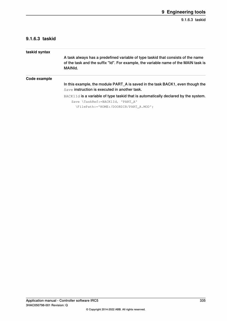
9.1.6.3 taskid
taskid syntaxA task always has a predefined variable of type taskid that consists of the nameof the task and the suffix "Id". For example, the variable name of the MAIN task isMAINId.
Code exampleIn this example, the module PART_A is saved in the task BACK1, even though theSave instruction is executed in another task.BACK1Id is a variable of type taskid that is automatically declared by the system.
Save \TaskRef:=BACK1Id, "PART_A"
\FilePath:="HOME:/DOORDIR/PART_A.MOD";
Application manual - Controller software IRC5 3353HAC050798-001 Revision: Q
© Copyright 2014-2022 ABB. All rights reserved.
9 Engineering tools9.1.6.3 taskid
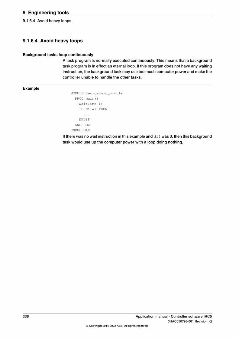
9.1.6.4 Avoid heavy loops
Background tasks loop continuouslyA task program is normally executed continuously. This means that a backgroundtask program is in effect an eternal loop. If this program does not have any waitinginstruction, the background task may use too much computer power and make thecontroller unable to handle the other tasks.
ExampleMODULE background_module
PROC main()
WaitTime 1;
IF di1=1 THEN
...
ENDIF
ENDPROC
ENDMODULE
If there was no wait instruction in this example and di1was 0, then this backgroundtask would use up the computer power with a loop doing nothing.
336 Application manual - Controller software IRC53HAC050798-001 Revision: Q
© Copyright 2014-2022 ABB. All rights reserved.
9 Engineering tools9.1.6.4 Avoid heavy loops
9.2 Sensor Interface [628-1]
9.2.1 Introduction to Sensor Interface
PurposeThe option Sensor Interface is used for communication with external sensors viaa serial or Ethernet channel.The sensor may be accessed using a package of RAPID instructions that providethe ability to read and write raw sensor data.An interrupt feature allows subscriptions on changes in sensor data.
Tip
The communication provided by Sensor Interface is integrated in arc weldinginstructions for seam tracking and adaptive control of process parameters. Theseinstructions handle communication and corrections for you, whereas with SensorInterface you handle this yourself. For more information, see Applicationmanual - Arc and Arc Sensor and Application manual - Continuous ApplicationPlatform.
What is includedThe RobotWare option Sensor Interface gives you access to:
• ABB supported sensor protocols.• Instruction used to connect to a sensor device: SenDevice.• Instruction used to set up interrupt, based on input from the
sensor:IVarValue.• Instruction used to write to a sensor: WriteVar.• Function for reading from a sensor: ReadVar.• Laser Tracker Calibration (LTC) functionality for optical sensor calibration.
Basic approachThis is the basic approach for using Sensor Interface.
1 Configure the sensor. See Configuring sensors on page 338.2 Use interrupts in the RAPID code to make adjustments according to the input
from the sensor. For an example, see Interrupt welding to adjust settings onpage 344.
LimitationsInterrupts with IVarValue is only possible to use with the instructions ArcL, ArcC,CapL, and CapC. The switch Track must be used. That is, the controller must beequipped with either RobotWare Arc or Continuous Application Platform togetherwith Optical Tracking, or with the option Weldguide.
Application manual - Controller software IRC5 3373HAC050798-001 Revision: Q
© Copyright 2014-2022 ABB. All rights reserved.
9 Engineering tools9.2.1 Introduction to Sensor Interface
9.2.2 Configuring sensors
9.2.2.1 About the sensors
Supported sensorsSensor Interface supports:
• Sensors connected via serial channels using the RTP1 protocol. Forconfiguration, see Configuring sensors on serial channels on page 339.
• Sensors connected to Ethernet using the RoboCom Light protocol fromServo-Robot Inc, the LTAPP or the LTPROTOBUF protocol from ABB. Forconfiguration, see Configuring sensors on Ethernet channels on page 340.
338 Application manual - Controller software IRC53HAC050798-001 Revision: Q
© Copyright 2014-2022 ABB. All rights reserved.
9 Engineering tools9.2.2.1 About the sensors

9.2.2.2 Configuring sensors on serial channels
OverviewSensor Interface communicates with a maximum of one sensor over serial channelsusing the RTP1 protocol.
System parametersThis is a brief description of the parameters used when configuring a sensor. Formore information about the parameters, see Technical reference manual - Systemparameters.These parameters belong to the type Transmission Protocol in the topicCommunication.
DescriptionParameter
The name of the transmission protocol.NameFor a sensor the name must end with ":". For example "laser1:" or"swg:".
The type of transmission protocol.TypeFor a sensor using serial channel, it must be "RTP1".
The name of the serial port that will be used for the sensor. This refersto the parameter Name in the type Serial Port.
Serial Port
For information on how to configure a serial port, see Technical refer-ence manual - System parameters.
Configuration exampleThis is an example of how a transmission protocol can be configured for a sensor.We assume that there already is a serial port configured with the name "COM1".
Serial PortTypeName
COM1RTP1laser1:
Application manual - Controller software IRC5 3393HAC050798-001 Revision: Q
© Copyright 2014-2022 ABB. All rights reserved.
9 Engineering tools9.2.2.2 Configuring sensors on serial channels

9.2.2.3 Configuring sensors on Ethernet channels
OverviewSensor Interface can communicate with a maximum of six sensors over Ethernetchannel using the RoboCom Light protocol version E04 (from Servo-Robot Inc),the LTAPP or the LTPROTOBUF protocol (from ABB). RoboCom Light is an XMLbased protocol using TCP/IP.The sensor acts as a server, the robot controller acts as a client. I.e. the robotcontroller initiates the connection to the sensor.RoboCom Light has the default TCP port 6344 on the external sensor side, andLTAPPTCP has the default TCP port 5020.
System parametersThis is a brief description of the parameters used when configuring a sensor. Formore information about the parameters, see Technical reference manual - Systemparameters.These parameters belong to the type Transmission Protocol in the topicCommunication.
DescriptionParameter
The name of the transmission protocol.NameFor a sensor the name must end with ":". For example "laser1:" or"swg:".
The type of transmission protocol.TypeFor RoboCom Light the protocol type SOCKDEV has to be configured,and for LTAPPTCP it is LTAPPTCP.
The name of the serial port that will be used for the sensor. This refersto the parameter Name in the type Serial Port.
Serial Port
For information on how to configure a serial port, see Technical refer-ence manual - System parameters.For IP based transmission protocols (i.e. Type has value TCP/IP,SOCKDEV, LTAPPTCP or UDPUC), Serial Port is not used and hasthe value N/A.
The IP address of the sensor. This refers to the type Remote Address.Remote AddressFor information on how to configure Remote Address, see Technicalreference manual - System parameters.
Remote Port specifies the port number on the network node identifiedby Remote Address with which the connection shall be established.
Remote Port
The default value for SOCKDEV is 6344, and for LTAPPTCP it is 5020.
Configuration examplesThese are examples of how a transmission protocol can be configured for a sensor.
Remote PortRemote AddressSerial PortTypeName
6344192.168.125.101N/ASOCKDEVlaser2:
5020192.168.125.102N/ALTAPPTCPlaser3:
340 Application manual - Controller software IRC53HAC050798-001 Revision: Q
© Copyright 2014-2022 ABB. All rights reserved.
9 Engineering tools9.2.2.3 Configuring sensors on Ethernet channels

9.2.3 RAPID
9.2.3.1 RAPID components
Data typesThere are no data types for Sensor Interface.
InstructionsThis is a brief description of each instruction in Sensor Interface. For moreinformation, see respective instruction in Technical reference manual - RAPIDInstructions, Functions and Data types.
DescriptionInstruction
SenDevice is used, to connect to a physical sensor device.SenDevice
IVarVal (Interrupt Variable Value) is used to order and enable an interruptwhen the value of a variable accessed via the sensor interface is changed.
IVarValue
ReadBlock is used to read a block of data from a device connected to theserial sensor interface. The data is stored in a file.
ReadBlock
ReadBlock can only be used with a serial channel connected sensor (notEthernet connected sensor.)
WriteBlock is used to write a block of data to a device connected to theserial sensor interface. The data is fetched from a file.
WriteBlock
WriteBlock can only be used with a serial channel connected sensor (notEthernet connected sensor.)
WriteVar is used to write a variable to a device connected to the sensorinterface.
WriteVar
FunctionsThis is a brief description of each function in Sensor Interface. For more information,see respective function in Technical reference manual - RAPID Instructions,Functions and Data types.
DescriptionFunction
ReadVar is used to read a variable from a device connected to the sensorinterface.
ReadVar
ModulesThe option Sensor Interface includes one system module, LTAPP__Variables. Thismodule contains the variable numbers defined in the protocol LTAPP. It isautomatically loaded as SHARED and makes the variables (CONST num) availablein all RAPID tasks.Note! A copy of the module is placed in the robot system directory HOME/LTC,but the copy is NOT the loaded module.
Continues on next pageApplication manual - Controller software IRC5 3413HAC050798-001 Revision: Q
© Copyright 2014-2022 ABB. All rights reserved.
9 Engineering tools9.2.3.1 RAPID components
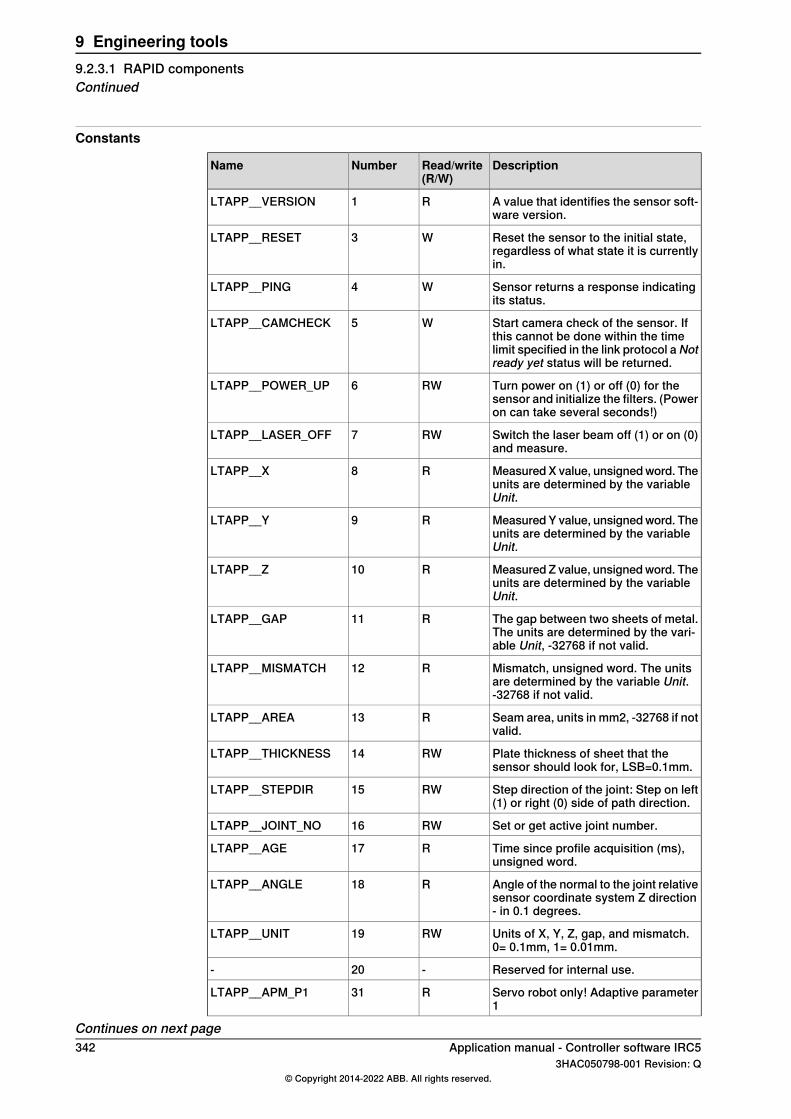
Constants
DescriptionRead/write(R/W)
NumberName
A value that identifies the sensor soft-ware version.
R1LTAPP__VERSION
Reset the sensor to the initial state,regardless of what state it is currentlyin.
W3LTAPP__RESET
Sensor returns a response indicatingits status.
W4LTAPP__PING
Start camera check of the sensor. Ifthis cannot be done within the timelimit specified in the link protocol a Notready yet status will be returned.
W5LTAPP__CAMCHECK
Turn power on (1) or off (0) for thesensor and initialize the filters. (Poweron can take several seconds!)
RW6LTAPP__POWER_UP
Switch the laser beam off (1) or on (0)and measure.
RW7LTAPP__LASER_OFF
Measured X value, unsigned word. Theunits are determined by the variableUnit.
R8LTAPP__X
Measured Y value, unsigned word. Theunits are determined by the variableUnit.
R9LTAPP__Y
Measured Z value, unsigned word. Theunits are determined by the variableUnit.
R10LTAPP__Z
The gap between two sheets of metal.The units are determined by the vari-able Unit, -32768 if not valid.
R11LTAPP__GAP
Mismatch, unsigned word. The unitsare determined by the variable Unit.-32768 if not valid.
R12LTAPP__MISMATCH
Seam area, units in mm2, -32768 if notvalid.
R13LTAPP__AREA
Plate thickness of sheet that thesensor should look for, LSB=0.1mm.
RW14LTAPP__THICKNESS
Step direction of the joint: Step on left(1) or right (0) side of path direction.
RW15LTAPP__STEPDIR
Set or get active joint number.RW16LTAPP__JOINT_NO
Time since profile acquisition (ms),unsigned word.
R17LTAPP__AGE
Angle of the normal to the joint relativesensor coordinate system Z direction- in 0.1 degrees.
R18LTAPP__ANGLE
Units of X, Y, Z, gap, and mismatch.0= 0.1mm, 1= 0.01mm.
RW19LTAPP__UNIT
Reserved for internal use.-20-
Servo robot only! Adaptive parameter1
R31LTAPP__APM_P1
Continues on next page342 Application manual - Controller software IRC5
3HAC050798-001 Revision: Q© Copyright 2014-2022 ABB. All rights reserved.
9 Engineering tools9.2.3.1 RAPID componentsContinued
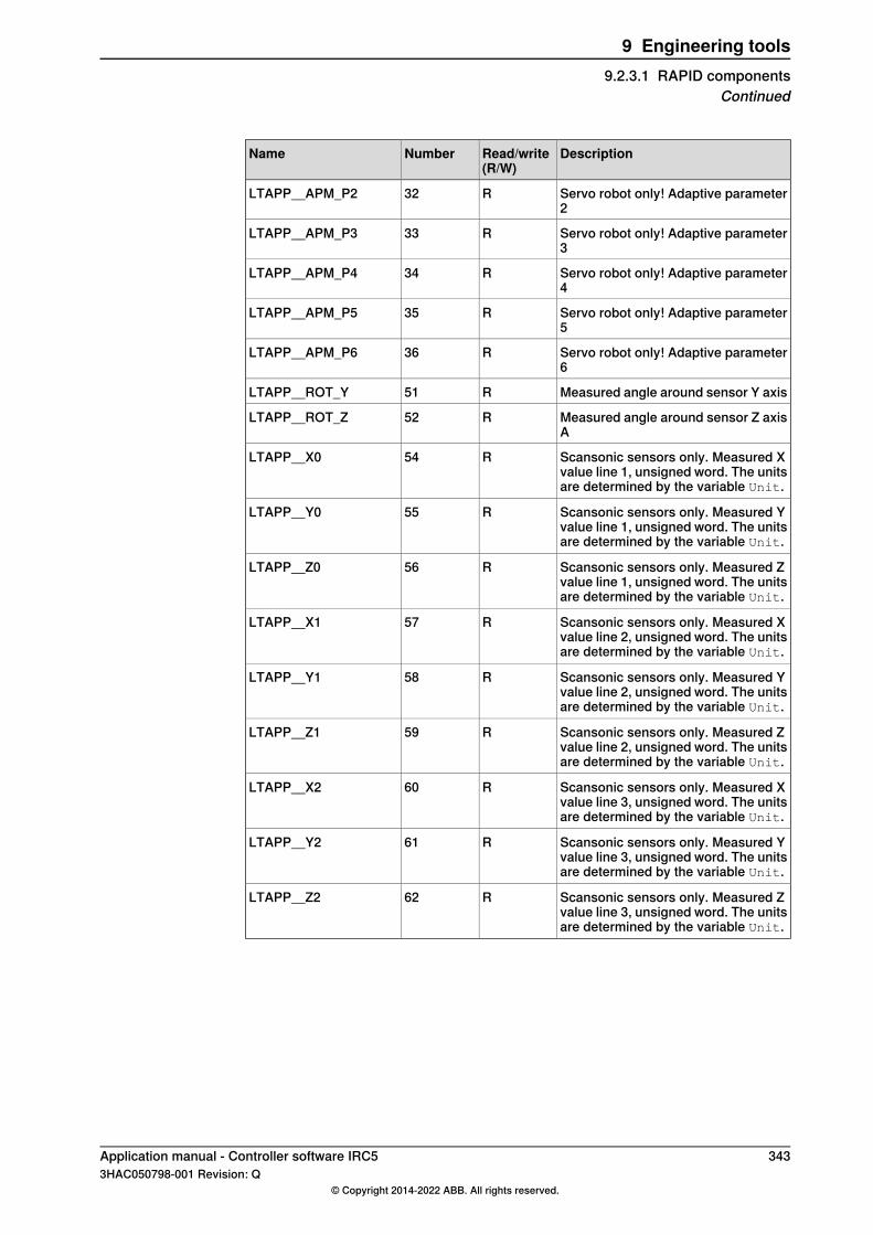
DescriptionRead/write(R/W)
NumberName
Servo robot only! Adaptive parameter2
R32LTAPP__APM_P2
Servo robot only! Adaptive parameter3
R33LTAPP__APM_P3
Servo robot only! Adaptive parameter4
R34LTAPP__APM_P4
Servo robot only! Adaptive parameter5
R35LTAPP__APM_P5
Servo robot only! Adaptive parameter6
R36LTAPP__APM_P6
Measured angle around sensor Y axisR51LTAPP__ROT_Y
Measured angle around sensor Z axisA
R52LTAPP__ROT_Z
Scansonic sensors only. Measured Xvalue line 1, unsigned word. The unitsare determined by the variable Unit.
R54LTAPP__X0
Scansonic sensors only. Measured Yvalue line 1, unsigned word. The unitsare determined by the variable Unit.
R55LTAPP__Y0
Scansonic sensors only. Measured Zvalue line 1, unsigned word. The unitsare determined by the variable Unit.
R56LTAPP__Z0
Scansonic sensors only. Measured Xvalue line 2, unsigned word. The unitsare determined by the variable Unit.
R57LTAPP__X1
Scansonic sensors only. Measured Yvalue line 2, unsigned word. The unitsare determined by the variable Unit.
R58LTAPP__Y1
Scansonic sensors only. Measured Zvalue line 2, unsigned word. The unitsare determined by the variable Unit.
R59LTAPP__Z1
Scansonic sensors only. Measured Xvalue line 3, unsigned word. The unitsare determined by the variable Unit.
R60LTAPP__X2
Scansonic sensors only. Measured Yvalue line 3, unsigned word. The unitsare determined by the variable Unit.
R61LTAPP__Y2
Scansonic sensors only. Measured Zvalue line 3, unsigned word. The unitsare determined by the variable Unit.
R62LTAPP__Z2
Application manual - Controller software IRC5 3433HAC050798-001 Revision: Q
© Copyright 2014-2022 ABB. All rights reserved.
9 Engineering tools9.2.3.1 RAPID components
Continued
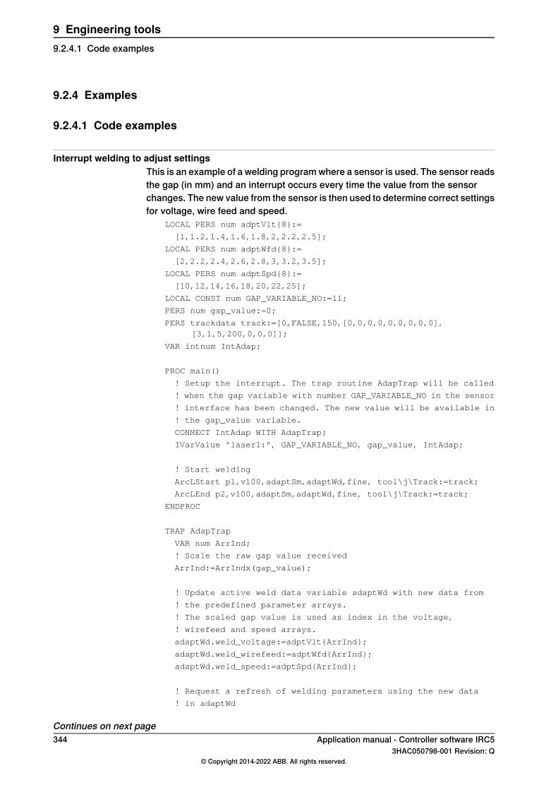
9.2.4 Examples
9.2.4.1 Code examples
Interrupt welding to adjust settingsThis is an example of a welding program where a sensor is used. The sensor readsthe gap (in mm) and an interrupt occurs every time the value from the sensorchanges. The new value from the sensor is then used to determine correct settingsfor voltage, wire feed and speed.
LOCAL PERS num adptVlt{8}:=
[1,1.2,1.4,1.6,1.8,2,2.2,2.5];
LOCAL PERS num adptWfd{8}:=
[2,2.2,2.4,2.6,2.8,3,3.2,3.5];
LOCAL PERS num adptSpd{8}:=
[10,12,14,16,18,20,22,25];
LOCAL CONST num GAP_VARIABLE_NO:=11;
PERS num gap_value:=0;
PERS trackdata track:=[0,FALSE,150,[0,0,0,0,0,0,0,0,0],[3,1,5,200,0,0,0]];
VAR intnum IntAdap;
PROC main()
! Setup the interrupt. The trap routine AdapTrap will be called
! when the gap variable with number GAP_VARIABLE_NO in the sensor
! interface has been changed. The new value will be available in
! the gap_value variable.
CONNECT IntAdap WITH AdapTrap;
IVarValue "laser1:", GAP_VARIABLE_NO, gap_value, IntAdap;
! Start welding
ArcLStart p1,v100,adaptSm,adaptWd,fine, tool\j\Track:=track;
ArcLEnd p2,v100,adaptSm,adaptWd,fine, tool\j\Track:=track;
ENDPROC
TRAP AdapTrap
VAR num ArrInd;
! Scale the raw gap value received
ArrInd:=ArrIndx(gap_value);
! Update active weld data variable adaptWd with new data from
! the predefined parameter arrays.
! The scaled gap value is used as index in the voltage,
! wirefeed and speed arrays.
adaptWd.weld_voltage:=adptVlt{ArrInd};
adaptWd.weld_wirefeed:=adptWfd{ArrInd};
adaptWd.weld_speed:=adptSpd{ArrInd};
! Request a refresh of welding parameters using the new data
! in adaptWd
Continues on next page344 Application manual - Controller software IRC5
3HAC050798-001 Revision: Q© Copyright 2014-2022 ABB. All rights reserved.
9 Engineering tools9.2.4.1 Code examples

ArcRefresh;
ENDTRAP
FUNC ArrIndx(num value)
IF value < 0.5 THEN RETURN 1;
ELSEIF value < 1.0 THEN RETURN 2;
ELSEIF value < 1.5 THEN RETURN 3;
ELSEIF value < 2.0 THEN RETURN 4;
ELSEIF value < 2.5 THEN RETURN 5;
ELSEIF value < 3.0 THEN RETURN 6;
ELSEIF value < 3.5 THEN RETURN 7;
ELSE RETURN 8;
ENDIF
ENDFUNC
Reading positions from sensorIn this example, the sensor is turned on and the coordinates are read from thesensor.
! Define variable numbers
CONST num SensorOn := 6;
CONST num YCoord := 9;
CONST num ZCoord := 10;
! Define the transformation matrix
CONST pose SensorMatrix := [[100,0,0],[1,0,0,0]];
VAR pos SensorPos;
VAR pos RobotPos;
! Request start of sensor measurements
WriteVar SensorOn, 1;
! Read a Cartesian position from the sensor
SensorPos.x := 0;
SensorPos.y := ReadVar (YCoord);
SensorPos.z := ReadVar (ZCoord);
! Stop sensor
WriteVar SensorOn, 0;
! Convert to robot coordinates
RobotPos := PoseVect(SensorMatrix, SensorPos);
Application manual - Controller software IRC5 3453HAC050798-001 Revision: Q
© Copyright 2014-2022 ABB. All rights reserved.
9 Engineering tools9.2.4.1 Code examples
Continued

9.3 Robot Reference Interface [included in 689-1]
9.3.1 Introduction to Robot Reference Interface
IntroductionRobot Reference Interface is included in the RobotWare option Externally GuidedMotion. It can be used for 4-axis, 6-axis, and 7-axis robots.Robot Reference Interface supports data exchange on the cyclic channel. It providesthe possibility to periodically send planned and actual robot position data from therobot controller, as well as the exchange of other RAPID variables from and to therobot controller. The message contents are represented in XML format and areconfigured using appropriate sensor configuration files.
Robot Reference InterfaceThe cyclic communication channel (TCP or UDP) can be executed in the high-prioritynetwork environment of the IRC5 Controller which ensures a stable data exchangeup to 250Hz.
Robot Sensor
Rapid data
Motion data
RRICyclic channel (TCP or UDP)
read/write Receive commands,
parameters and
robot data
Return parameters
and sensor data
read only
Cabinet status read only
xx0800000128
346 Application manual - Controller software IRC53HAC050798-001 Revision: Q
© Copyright 2014-2022 ABB. All rights reserved.
9 Engineering tools9.3.1 Introduction to Robot Reference Interface

9.3.2 Installation
9.3.2.1 Connecting the communication cable
OverviewThis section describes where to connect the communication cable on the controller.For further instructions, see the corresponding product manual for your robotsystem.
Location
A
B
xx1300000609
Service port on the computer unit (connected to the service port on the controller)A
WAN port on the computer unitB
NoteAction
Note
The service connection can only beused if it is free.
Use one of these two connections (A or B).1
Application manual - Controller software IRC5 3473HAC050798-001 Revision: Q
© Copyright 2014-2022 ABB. All rights reserved.
9 Engineering tools9.3.2.1 Connecting the communication cable

9.3.2.2 Prerequisites
OverviewThis section describes the prerequisites for using Robot Reference Interface.
UDP/IP or TCP IPRobot Reference Interface supports the communication over the standard IPprotocols UDP or TCP.
RecommendationsThe delay in the overall communication mostly depends on the topology of theemployed network. In a switched network the transmission will be delayed due tobuffering of the messages in the switches. In a parallel network collisions withmultiple communication partners will lead to messages being resent.Therefore we recommended using a dedicated Ethernet link between the externalsystem and the robot controller to provide the required performance for real-timeapplications. Robot Reference Interface can be used to communicate with anyprocessor-based devices, that support IP via Ethernet and can serialize data intoXML format.
348 Application manual - Controller software IRC53HAC050798-001 Revision: Q
© Copyright 2014-2022 ABB. All rights reserved.
9 Engineering tools9.3.2.2 Prerequisites

9.3.2.3 Data orchestration
OverviewThe outgoing message can be combined from any data from the RAPID level andinternal data from the cabinet and motion topic. The orchestration of the data isdefined in the device configuration by setting the Link attribute of internally linkeddata to Intern.
Illustration
xx0800000178
Data from the Controller topic
CommentDescriptionTypeName
The mapping of the members for the Op-Mode type can be defined in the configura-tion file.
Operation modeof the robot.
OpModeOperationMode
Data from the Motion topic
CommentDescriptionTypeName
There is a delay of approxim-ately 8ms.
Time stamp for the robot posi-tion from drive feedback.
TimeFeedbackTime
Current tool and workobjectare used for calculation.
Note
The work object data needs torefer to a fixed work object.For example, it will not workwith conveyor tracking. Formore information aboutwobjdata, see Technical ref-erencemanual - RAPID Instruc-tions, Functions and Datatypes.
Robot TCP calculated fromdrive feedback.
FrameFeedbackPose
Robot joint values gatheredfrom drive feedback.
JointsFeedbackJoints
Continues on next pageApplication manual - Controller software IRC5 3493HAC050798-001 Revision: Q
© Copyright 2014-2022 ABB. All rights reserved.
9 Engineering tools9.3.2.3 Data orchestration

CommentDescriptionTypeName
Prediction time from approxim-ately 24ms to 60ms dependingon robot type.
Timestamp for planned robotTCP position and joint values.
TimePredictedTime
Current tool and workobjectare used for calculation.
Planned robot TCP.FramePlannedPose
Planned robot joint values.JointsPlannedJoints
350 Application manual - Controller software IRC53HAC050798-001 Revision: Q
© Copyright 2014-2022 ABB. All rights reserved.
9 Engineering tools9.3.2.3 Data orchestrationContinued
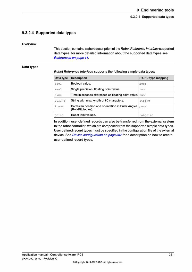
9.3.2.4 Supported data types
OverviewThis section contains a short description of theRobot Reference Interface supporteddata types, for more detailed information about the supported data types seeReferences on page 11.
Data typesRobot Reference Interface supports the following simple data types:
RAPID type mappingDescriptionData type
boolBoolean value.bool
numSingle precision, floating point value.real
numTime in seconds expressed as floating point value.time
stringString with max length of 80 characters.string
poseCartesian position and orientation in Euler Angles(Roll-Pitch-Jaw).
frame
robjointRobot joint values.joint
In addition, user-defined records can also be transferred from the external systemto the robot controller, which are composed from the supported simple data types.User defined record types must be specified in the configuration file of the externaldevice. See Device configuration on page 357 for a description on how to createuser-defined record types.
Application manual - Controller software IRC5 3513HAC050798-001 Revision: Q
© Copyright 2014-2022 ABB. All rights reserved.
9 Engineering tools9.3.2.4 Supported data types

9.3.3 Configuration
9.3.3.1 Interface configuration
Configuration filesThe configuration and settings files for the interface must be located in the folderHOME/GSI. This ensures that the configuration files are included in system backups.
xx0800000177
Related informationFor more detailed information of the Settings.xml file see Interface settings onpage 353.For more detailed information of the Description.xml file see Device descriptionon page 354.For more detailed information of the Configuration.xml file see Device configurationon page 357.
352 Application manual - Controller software IRC53HAC050798-001 Revision: Q
© Copyright 2014-2022 ABB. All rights reserved.
9 Engineering tools9.3.3.1 Interface configuration

9.3.3.2 Interface settings
OverviewThis section describes the use of the xml file Settings.xml.
Settings.xmlThe settings file Settings.xml contains the general settings for the GSI interface.It is located in the folder HOME/GSI. For the option Robot Reference Interface thisfile refers to a list of all communication clients for external systems installed in thecontroller. The Settings.xml file can be defined according to the XML schemaSettings.xsd.
ExampleFor each communication client installed on the controller, the file Settings.xml mustcontain a Client entry in the Clients section. The Convention attribute identifies theprotocol convention used by the client, for the Robot Reference Interface optiononly CDP is supported. The Name attribute identifies the name of the client andalso specifies the folder with the device related configuration files.
<?xml version="1.0" encoding="UTF-8"?>
<Settings>
<Clients>
<Client Convention="CDP" Name="MySensor" />
</Clients>
</Settings>
CDP stands for cyclic data protocol and is the internal name of the protocol, onwhich Robot Reference Interface messages are transferred.An internal client node of the interface module will be created, which is able toconnect to the external system MySensor that runs a data server application andcan communicate via Robot Reference Interface with the robot.For each sensor system, a subdirectory named with the sensor system identifier,for example MySensor, contains further settings.
Application manual - Controller software IRC5 3533HAC050798-001 Revision: Q
© Copyright 2014-2022 ABB. All rights reserved.
9 Engineering tools9.3.3.2 Interface settings

9.3.3.3 Device description
OverviewThis section describes the use of the xml file Description.xml.
Description.xmlThe device description file Description.xml is located in the correspondingsubdirectory of the device. It specifies the general device parameters, networkconnection and CDP specific communication settings for an installed device. Adevice description can be defined according to the XML schema Description.xsd.
ExampleThis is an example of a device description:
<?xml version="1.0" encoding="utf-8"?>
<Description>
<Name>AnyDevice</Name>
<Convention>CDP</Convention>
<Type>IntelligentCamera</Type>
<Class>MachineVision</Class>
<Network Address="10.49.65.74" Port="Service">
<Channel Type="Cyclic" Protocol="Udp" Port="3002" />
</Network>
<Settings>
<TimeOut>2000</TimeOut>
<MaxLost>30</MaxLost>
<DryRun>false</DryRun>
</Settings>
</Description>
NameThe first section defines the general device parameters. The Name elementidentifies the name of the device and should correspond to the device namespecified in the settings file. It must correspond to the identifier specified for thedevice descriptor on the RAPID level, because the descriptor name will be usedinitially to refer to the device in the RAPID instructions.
CommentValueDescriptionAttributeElement
Maximum 16 charactersAny stringDevice identifierName
ConventionThe Convention element identifies the protocol that should be used by the device,for the Robot Reference Interface option only the Cyclic Data Protocol (CDP) issupported.
CommentValueDescriptionAttributeElement
CDPProtocol typeConvention
Continues on next page354 Application manual - Controller software IRC5
3HAC050798-001 Revision: Q© Copyright 2014-2022 ABB. All rights reserved.
9 Engineering tools9.3.3.3 Device description
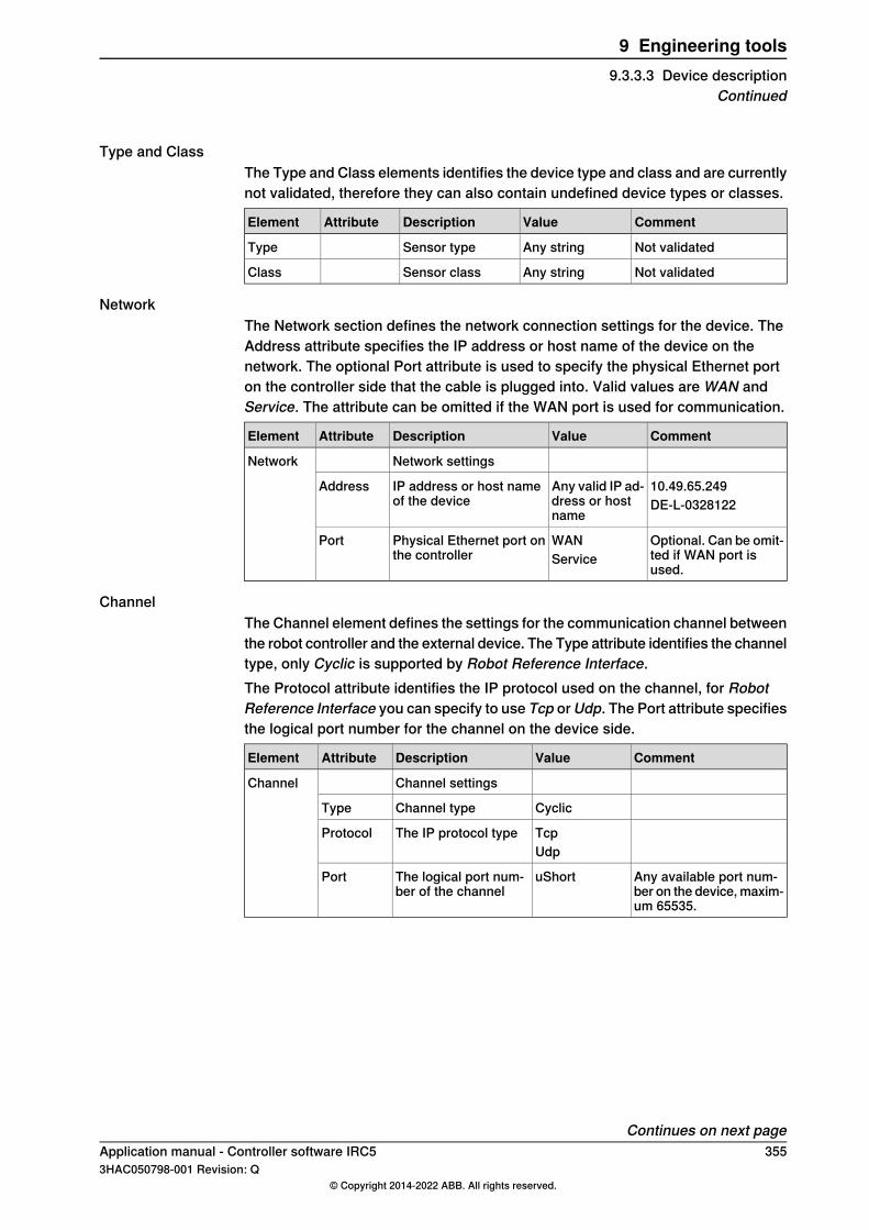
Type and ClassThe Type and Class elements identifies the device type and class and are currentlynot validated, therefore they can also contain undefined device types or classes.
CommentValueDescriptionAttributeElement
Not validatedAny stringSensor typeType
Not validatedAny stringSensor classClass
NetworkThe Network section defines the network connection settings for the device. TheAddress attribute specifies the IP address or host name of the device on thenetwork. The optional Port attribute is used to specify the physical Ethernet porton the controller side that the cable is plugged into. Valid values are WAN andService. The attribute can be omitted if the WAN port is used for communication.
CommentValueDescriptionAttributeElement
Network settingsNetwork
10.49.65.249Any valid IP ad-dress or hostname
IP address or host nameof the device
AddressDE-L-0328122
Optional. Can be omit-ted if WAN port isused.
WANService
Physical Ethernet port onthe controller
Port
ChannelThe Channel element defines the settings for the communication channel betweenthe robot controller and the external device. The Type attribute identifies the channeltype, only Cyclic is supported by Robot Reference Interface.The Protocol attribute identifies the IP protocol used on the channel, for RobotReference Interface you can specify to use Tcp or Udp. The Port attribute specifiesthe logical port number for the channel on the device side.
CommentValueDescriptionAttributeElement
Channel settingsChannel
CyclicChannel typeType
TcpThe IP protocol typeProtocolUdp
Any available port num-ber on the device, maxim-um 65535.
uShortThe logical port num-ber of the channel
Port
Continues on next pageApplication manual - Controller software IRC5 3553HAC050798-001 Revision: Q
© Copyright 2014-2022 ABB. All rights reserved.
9 Engineering tools9.3.3.3 Device description
Continued
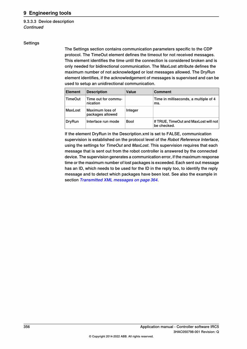
SettingsThe Settings section contains communication parameters specific to the CDPprotocol. The TimeOut element defines the timeout for not received messages.This element identifies the time until the connection is considered broken and isonly needed for bidirectional communication. The MaxLost attribute defines themaximum number of not acknowledged or lost messages allowed. The DryRunelement identifies, if the acknowledgement of messages is supervised and can beused to setup an unidirectional communication.
CommentValueDescriptionElement
Time in milliseconds, a multiple of 4ms.
Time out for commu-nication
TimeOut
IntegerMaximum loss ofpackages allowed
MaxLost
If TRUE, TimeOut and MaxLost will notbe checked.
BoolInterface run modeDryRun
If the element DryRun in the Description.xml is set to FALSE, communicationsupervision is established on the protocol level of the Robot Reference Interface,using the settings for TimeOut and MaxLost. This supervision requires that eachmessage that is sent out from the robot controller is answered by the connecteddevice. The supervision generates a communication error, if the maximum responsetime or the maximum number of lost packages is exceeded. Each sent out messagehas an ID, which needs to be used for the ID in the reply too, to identify the replymessage and to detect which packages have been lost. See also the example insection Transmitted XML messages on page 364.
356 Application manual - Controller software IRC53HAC050798-001 Revision: Q
© Copyright 2014-2022 ABB. All rights reserved.
9 Engineering tools9.3.3.3 Device descriptionContinued

9.3.3.4 Device configuration
OverviewThe device configuration file Configuration.xml is located in the correspondingsubdirectory of the device. It defines the enumerated and complex types used bythe device and identifies the available parameters, which can be subscribed forcyclic transmission. The configuration file can be defined according to the XMLschema Configuration.xsd. The following document shows a simplified deviceconfiguration.
Example<?xml version="1.0" encoding="utf-8"?>
<Configuration>
<Enums>
<Enum Name="opmode" Link="Intern">
<Member Name="ReducedSpeed" Alias="Alias"/>
</Enum>
</Enums>
<Records>
<Record Name="senddata">
<Field Name="PlannedPose" Type="Pose" Link="Intern" />
</Record>
</Records>
<Properties>
<Property Name="DataToSend" Type="senddata" Flag="WriteOnly"/>
</Properties>
</Configuration>
EnumsIn the Enums section each Enum element defines an enumerated type. The Nameattribute of the Enum element specifies the name of the enumerated type, theoptional Link attribute identifies if the members of the enumerated type have internallinkage.
CommentValueDescriptionsAttributeElement
Maximum 16 characters.A valid RAPIDsymbol name
Name of enumer-ated type
NameEnum
Optional. Can be omitted ifmembers only have RAPIDlinkage.
InternLinkage of mem-bers of enumer-ated type
Link
Continues on next pageApplication manual - Controller software IRC5 3573HAC050798-001 Revision: Q
© Copyright 2014-2022 ABB. All rights reserved.
9 Engineering tools9.3.3.4 Device configuration

MemberEach Member element defines a member element of the enumerated type. TheName attribute specifies the name of the member on the controller side (on RAPIDlevel). The Alias attribute identifies the name of the member on the device side(and in the transmitted message).
CommentValueDescriptionsAttributeElement
Maximum 16 characters.Validinternal RAPID symbolnames. See Data orchestra-tion on page 349.
A valid RAPIDsymbol name
Name of enumer-ated type mem-ber
NameMember
Optional. The alias name isused on the device side andin message
StringAlias name ofenumerated typemember
Alias
RecordIn the Records section each Record element defines a declaration of a complextype. In RAPID this complex type will be represented as a RECORD declaration.The Name attribute identifies the name of the complex type on the controller side.The Alias attribute defines the alias name of the type on the device side and in themessage.
CommentValueDescriptionsAttributeElement
Maximum 16 characters.A valid RAPIDsymbol name
Name of the com-plex type.
NameRecord
Optional. The alias name isused on the device side andin message.
StringAlias name ofcomplex type.
Alias
FieldEach Field element defines a field element of a complex type. The Name attributeidentifies the name of the field. The Type attribute identifies the enumerated,complex or simple type associated with the field. The Size attribute defines thesize of a multi-dimensional field. The Link attribute identifies if the field has internallinkage.
CommentValueDescriptionsAttributeElement
Maximum 16 characters.Validinternal RAPID symbolnames. See Data orchestra-tion on page 349.
A valid RAPIDsymbol name
Name of the com-plex type field
NameField
Described in section Suppor-ted data types on page 351.
All supporteddata types
Data type of thefield
Type
Optional. Only basic typescan be defined as array.
IntegerDimensions ofthe field (size ofarray)
Size
Optional. Can be omitted iffield has RAPID linkage.
InternLinkage of com-plex type field
Link
Optional. The alias name isused on device side and inmessage.
StringAlias name ofcomplex typefield
Alias
Continues on next page358 Application manual - Controller software IRC5
3HAC050798-001 Revision: Q© Copyright 2014-2022 ABB. All rights reserved.
9 Engineering tools9.3.3.4 Device configurationContinued
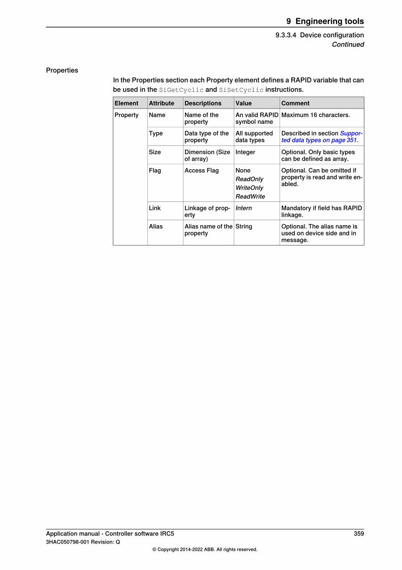
PropertiesIn the Properties section each Property element defines a RAPID variable that canbe used in the SiGetCyclic and SiSetCyclic instructions.
CommentValueDescriptionsAttributeElement
Maximum 16 characters.An valid RAPIDsymbol name
Name of theproperty
NameProperty
Described in section Suppor-ted data types on page 351.
All supporteddata types
Data type of theproperty
Type
Optional. Only basic typescan be defined as array.
IntegerDimension (Sizeof array)
Size
Optional. Can be omitted ifproperty is read and write en-abled.
NoneReadOnlyWriteOnly
Access FlagFlag
ReadWrite
Mandatory if field has RAPIDlinkage.
InternLinkage of prop-erty
Link
Optional. The alias name isused on device side and inmessage.
StringAlias name of theproperty
Alias
Application manual - Controller software IRC5 3593HAC050798-001 Revision: Q
© Copyright 2014-2022 ABB. All rights reserved.
9 Engineering tools9.3.3.4 Device configuration
Continued
9.3.4 Configuration examples
9.3.4.1 RAPID programming
RAPID moduleA RAPID module containing the corresponding RAPID record declarations andvariable declarations must be created and loaded.The FlexPendant user interface is not included in RobotWare.
360 Application manual - Controller software IRC53HAC050798-001 Revision: Q
© Copyright 2014-2022 ABB. All rights reserved.
9 Engineering tools9.3.4.1 RAPID programming

9.3.4.2 Example configuration
OverviewThe files Settings.xml, Description.xml, and Configuration.xml are located in thefolder HOME\GSI\
xx0800000177
Note
The name of the folder must correspond to the name of the device. See Devicedescription on page 354. In this example we have used the name AnyDevice.The network address used in Description.xml is to the PC running the server,not the robot controller. See Device description on page 354.
Settings.xml<?xml version="1.0" encoding="utf-8"?>
<Settings>
<Servers>
<Servers/>
<Clients>
<Client Convention="CDP" Name="AnyDevice" />
</Clients>
</Settings
Description.xml<?xml version="1.0" encoding="utf-8"?>
<Description>
<Name>AnyDevice</Name>
<Convention>CDP</Convention>
<Type>IntelligentCamera</Type>
<Class>MachineVision</Class>
<Network Address="10.49.65.74" Port="Service">
<Channel Type="Cyclic" Protocol="Udp" Port="3002" />
</Network>
<Settings>
<TimeOut>2000</TimeOut>
Continues on next pageApplication manual - Controller software IRC5 3613HAC050798-001 Revision: Q
© Copyright 2014-2022 ABB. All rights reserved.
9 Engineering tools9.3.4.2 Example configuration
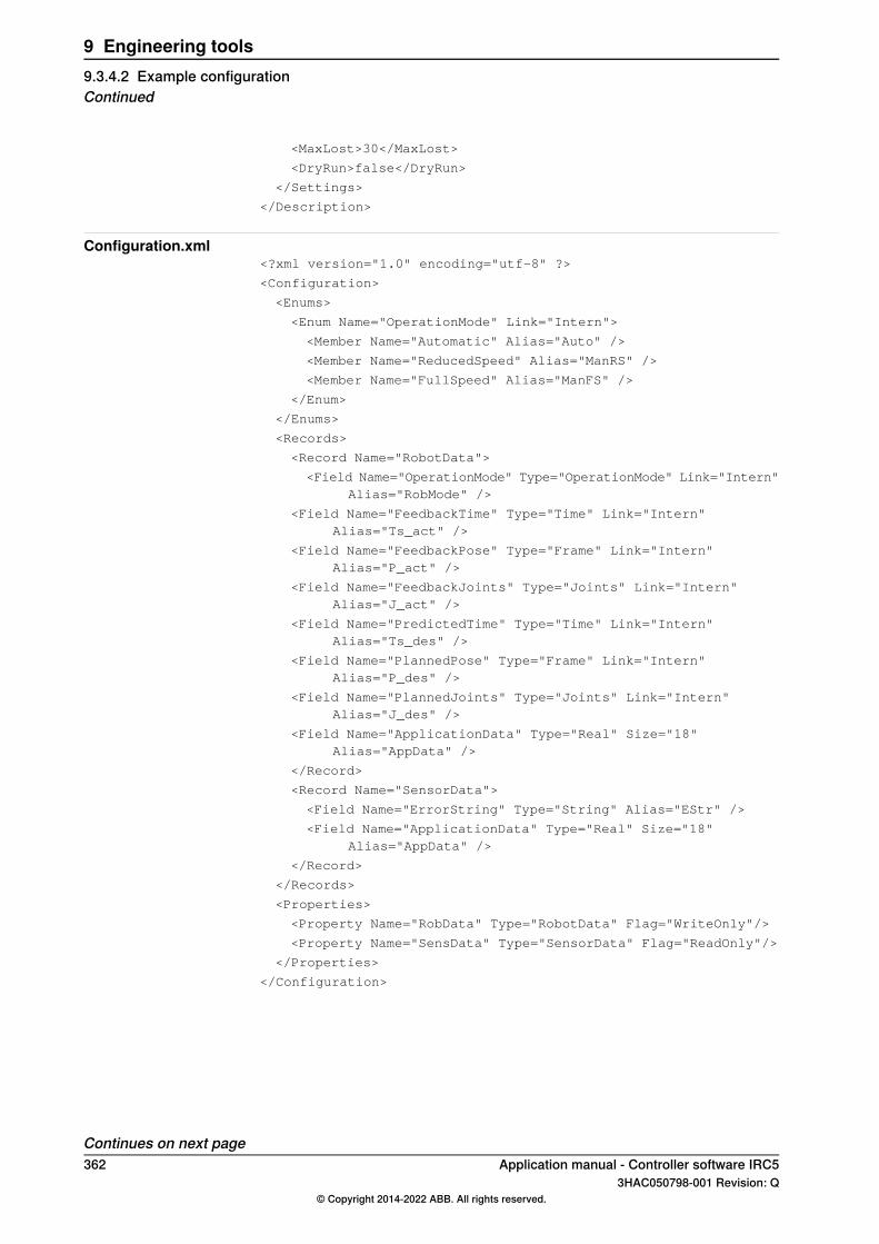
<MaxLost>30</MaxLost>
<DryRun>false</DryRun>
</Settings>
</Description>
Configuration.xml<?xml version="1.0" encoding="utf-8" ?>
<Configuration>
<Enums>
<Enum Name="OperationMode" Link="Intern">
<Member Name="Automatic" Alias="Auto" />
<Member Name="ReducedSpeed" Alias="ManRS" />
<Member Name="FullSpeed" Alias="ManFS" />
</Enum>
</Enums>
<Records>
<Record Name="RobotData">
<Field Name="OperationMode" Type="OperationMode" Link="Intern"Alias="RobMode" />
<Field Name="FeedbackTime" Type="Time" Link="Intern"Alias="Ts_act" />
<Field Name="FeedbackPose" Type="Frame" Link="Intern"Alias="P_act" />
<Field Name="FeedbackJoints" Type="Joints" Link="Intern"Alias="J_act" />
<Field Name="PredictedTime" Type="Time" Link="Intern"Alias="Ts_des" />
<Field Name="PlannedPose" Type="Frame" Link="Intern"Alias="P_des" />
<Field Name="PlannedJoints" Type="Joints" Link="Intern"Alias="J_des" />
<Field Name="ApplicationData" Type="Real" Size="18"Alias="AppData" />
</Record>
<Record Name="SensorData">
<Field Name="ErrorString" Type="String" Alias="EStr" />
<Field Name="ApplicationData" Type="Real" Size="18"Alias="AppData" />
</Record>
</Records>
<Properties>
<Property Name="RobData" Type="RobotData" Flag="WriteOnly"/>
<Property Name="SensData" Type="SensorData" Flag="ReadOnly"/>
</Properties>
</Configuration>
Continues on next page362 Application manual - Controller software IRC5
3HAC050798-001 Revision: Q© Copyright 2014-2022 ABB. All rights reserved.
9 Engineering tools9.3.4.2 Example configurationContinued

RAPID configurationThis is an example for an RRI implementation. The out data uses an array of 18num (robdata). The in data receives a string and an array of 18 num (sensdata).This needs to defined according the file configuration.xml.
RECORD applicationdata
num Item1;
num Item2;
num Item3;
num Item4;
num Item5;
num Item6;
num Item7;
num Item8;
num Item9;
num Item10;
num Item11;
num Item12;
num Item13;
num Item14;
num Item15;
num Item16;
num Item17;
num Item18;
ENDRECORD
RECORD RobotData
applicationdata AppData;
ENDRECORD
RECORD SensorData
string ErrString;
applicationdata AppData;
ENDRECORD
! Sensor Declarations
PERS sensor AnyDevice := [1,4,0];
PERS RobotData RobData := [[0,0,0,0,0,0,0,0,0,0,0,0,0,0,0,0,0,0]];
PERS SensorData SensData :=["No",[0,0,0,0,0,0,0,0,0,0,0,0,0,0,0,0,0,0]];
! Setup Interface Procedure
PROC RRI_Open()
SiConnect AnyDevice;
! Send and receive data cyclic with 64 ms rate
SiGetCyclic AnyDevice, SensData, 64;
SiSetCyclic AnyDevice, RobData, 64;
ENDPROC
! Close Interface Procedure
PROC RRI_Close()
! Close the connection
SiClose RsMaster;
ENDPROC
ENDMODULE
Continues on next pageApplication manual - Controller software IRC5 3633HAC050798-001 Revision: Q
© Copyright 2014-2022 ABB. All rights reserved.
9 Engineering tools9.3.4.2 Example configuration
Continued
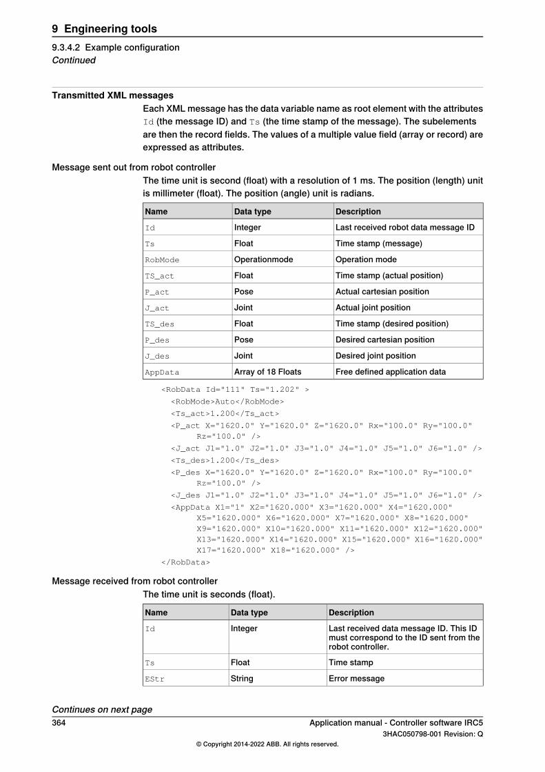
Transmitted XML messagesEach XML message has the data variable name as root element with the attributesId (the message ID) and Ts (the time stamp of the message). The subelementsare then the record fields. The values of a multiple value field (array or record) areexpressed as attributes.
Message sent out from robot controllerThe time unit is second (float) with a resolution of 1 ms. The position (length) unitis millimeter (float). The position (angle) unit is radians.
DescriptionData typeName
Last received robot data message IDIntegerId
Time stamp (message)FloatTs
Operation modeOperationmodeRobMode
Time stamp (actual position)FloatTS_act
Actual cartesian positionPoseP_act
Actual joint positionJointJ_act
Time stamp (desired position)FloatTS_des
Desired cartesian positionPoseP_des
Desired joint positionJointJ_des
Free defined application dataArray of 18 FloatsAppData
<RobData Id="111" Ts="1.202" >
<RobMode>Auto</RobMode>
<Ts_act>1.200</Ts_act>
<P_act X="1620.0" Y="1620.0" Z="1620.0" Rx="100.0" Ry="100.0"Rz="100.0" />
<J_act J1="1.0" J2="1.0" J3="1.0" J4="1.0" J5="1.0" J6="1.0" />
<Ts_des>1.200</Ts_des>
<P_des X="1620.0" Y="1620.0" Z="1620.0" Rx="100.0" Ry="100.0"Rz="100.0" />
<J_des J1="1.0" J2="1.0" J3="1.0" J4="1.0" J5="1.0" J6="1.0" />
<AppData X1="1" X2="1620.000" X3="1620.000" X4="1620.000"X5="1620.000" X6="1620.000" X7="1620.000" X8="1620.000"X9="1620.000" X10="1620.000" X11="1620.000" X12="1620.000"X13="1620.000" X14="1620.000" X15="1620.000" X16="1620.000"X17="1620.000" X18="1620.000" />
</RobData>
Message received from robot controllerThe time unit is seconds (float).
DescriptionData typeName
Last received data message ID. This IDmust correspond to the ID sent from therobot controller.
IntegerId
Time stampFloatTs
Error messageStringEStr
Continues on next page364 Application manual - Controller software IRC5
3HAC050798-001 Revision: Q© Copyright 2014-2022 ABB. All rights reserved.
9 Engineering tools9.3.4.2 Example configurationContinued

DescriptionData typeName
Free defined application dataArray of 18 floatsAppData
The corresponding XML message on the network would look like this:<SensData Id="111" Ts="1.234">
<EStr>xxxx</Estr>
<AppData X1="232.661" X2="1620.293" X3="463.932"
X4="1231.053" X5="735.874" X6="948.263" X7="2103.584"
X8="574.228" X9="65.406" X10="2372.633" X11="20.475"
X12="96.729" X13="884.382" X14="927.954" X15="748.294"
X16="3285.574" X17="583.293" X18="684.338" />
</SensData>
Application manual - Controller software IRC5 3653HAC050798-001 Revision: Q
© Copyright 2014-2022 ABB. All rights reserved.
9 Engineering tools9.3.4.2 Example configuration
Continued

9.3.5 RAPID components
About the RAPID componentsThis is an overview of all instructions, functions, and data types in Robot ReferenceInterface.For more information, see Technical reference manual - RAPID Instructions,Functions and Data types.
Instructions
DescriptionInstructions
Sensor Interface ConnectSiConnect
Sensor Interface CloseSiClose
Sensor Interface Get CyclicSiGetCyclic
Sensor Interface Set CyclicSiSetCyclic
FunctionsRobot Reference Interface includes no functions.
Data types
DescriptionData types
External device descriptorsensor
Communication state of the devicesensorstate
366 Application manual - Controller software IRC53HAC050798-001 Revision: Q
© Copyright 2014-2022 ABB. All rights reserved.
9 Engineering tools9.3.5 RAPID components
9.4 Auto Acknowledge Input
DescriptionThe RobotWare base functionalityAuto Acknowledge Input is an option that enablesa system input which will acknowledge the dialog presented on the FlexPendantwhen switching the operator mode from manual to auto with the key switch on therobot controller.
WARNING
Note that using such an input will be contrary to the regulations in the safetystandard ISO 10218-1 chapter 5.3.5 Single point of control with following text:"The robot control system shall be designed and constructed so that when therobot is placed under local pendant control or other teaching device control,initiation of robot motion or change of local control selection from any othersource shall be prevented."Thus it is absolutely necessary to use other means of safety to maintain therequirements of the standard and the machinery directive and also to make arisk assessment of the completed cell. Such additional arrangements and riskassessment is the responsibility of the system integrator and the system mustnot be put into service until these actions have been completed.
Remote control of operating modeFor information about using the safety module and a PLC for remote control ofoperating mode, see Application manual - Functional safety and SafeMove2.
LimitationsThe system parameter cannot be defined using the FlexPendant or RobotStudio,only with a text string in the I/O configuration file.
Activate Auto Acknowledge InputThe robot system must be installed with the optionAuto Acknowledge Input enabledin Installation Manager.Use the following procedure to activate the system input for Auto AcknowledgeInput.
Action
Save a copy of the I/O configuration file, eio.cfg, using the FlexPendant or RobotStudio.1
Edit the I/O configuration file, eio.cfg, using a text editor. Add the following line in thegroup SYSSIG_IN:
-Signal "my_signal_name" -Action "AckAutoMode"
2
my_signal_name is the name of the configured digital input signal that should beused as the system input.
Save the file and reload it to the controller.3
Restart the system to activate the signal.4
Application manual - Controller software IRC5 3673HAC050798-001 Revision: Q
© Copyright 2014-2022 ABB. All rights reserved.
9 Engineering tools9.4 Auto Acknowledge Input

This page is intentionally left blank

10 Tool control options10.1 Servo Tool Change [630-1]
10.1.1 Overview
PurposeThe purpose of Servo Tool Change is to be able to change tools on-line.With the option Servo Tool Change it is possible to disconnect the cables to themotor of an additional axis and connect them to the motor of another additionalaxis. This can be done on the run, in production.This option is designed with servo tools in mind, but can be used for any type ofadditional axes.Examples of advantages are:
• One robot can handle several tools.• Less equipment is needed since one drive-measurement system is shared
by several tools.
What is includedThe RobotWare option Servo Tool Change enables you to:
• change tool on-line• have up to 8 different servo tools to change between.
Note that the option Servo Tool Change only provides the software functionality.Hardware, such as a tool changer is not included.
Basic approachThis is the general approach for using Servo Tool Change. For a more detaileddescription of how this is done, see Tool change procedure on page 375.
1 Deactivate the first tool.2 Disconnect the first tool from the cables.3 Connect the second tool to the cables.4 Activate the second tool.
Application manual - Controller software IRC5 3693HAC050798-001 Revision: Q
© Copyright 2014-2022 ABB. All rights reserved.
10 Tool control options10.1.1 Overview
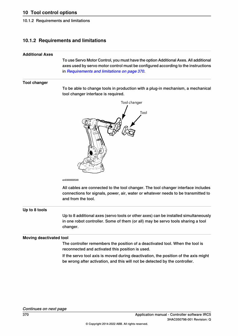
10.1.2 Requirements and limitations
Additional AxesTo use Servo Motor Control, you must have the option Additional Axes. All additionalaxes used by servo motor control must be configured according to the instructionsin Requirements and limitations on page 370.
Tool changerTo be able to change tools in production with a plug-in mechanism, a mechanicaltool changer interface is required.
en0300000549
All cables are connected to the tool changer. The tool changer interface includesconnections for signals, power, air, water or whatever needs to be transmitted toand from the tool.
Up to 8 toolsUp to 8 additional axes (servo tools or other axes) can be installed simultaneouslyin one robot controller. Some of them (or all) may be servo tools sharing a toolchanger.
Moving deactivated toolThe controller remembers the position of a deactivated tool. When the tool isreconnected and activated this position is used.If the servo tool axis is moved during deactivation, the position of the axis mightbe wrong after activation, and this will not be detected by the controller.
Continues on next page370 Application manual - Controller software IRC5
3HAC050798-001 Revision: Q© Copyright 2014-2022 ABB. All rights reserved.
10 Tool control options10.1.2 Requirements and limitations
The position after activation will be correct if the axis has not been moved, or ifthe movement is less than 0.5 motor revolutions.
Tip
If you have the Spot Servo option you can use tool change calibration.After a tool is activated, call the instruction STCalib to calibrate the tool. Thiswill adjust any positional error caused by tool movements during deactivation.
Activating wrong toolIt is important not to activate a mechanical unit that is not connected.An activation of the wrong mechanical unit may cause unexpected movements orerrors. The same errors occur if a tool is activated when no tool at all is connected.
Tip
A connection relay can be configured so that activation of a mechanical unit isonly allowed when it is connected. See Connection relay on page 373.
Application manual - Controller software IRC5 3713HAC050798-001 Revision: Q
© Copyright 2014-2022 ABB. All rights reserved.
10 Tool control options10.1.2 Requirements and limitations
Continued

10.1.3 Configuration
Configuration overviewThe option Servo Tool Change allows configuration of several tools for the sameadditional axis.One individual set of parameters is installed for each gun tool.
How to configure each toolEach tool is configured the same way as if it was the only tool. For information onhow to do this, see Applicationmanual - Additional axes and stand alone controller.The parameter Deactivate PTC superv. at disconnect, in the type Mechanical Unit,must be set to Yes.The parameter Disconnect at Deactivate, in the type Measurement Channel, mustbe set to Yes.The parameter Logical Axis, in the type Joint, can be set to the same number forseveral tools. Since the tools are never used at the same time, the tools are allowedto use the same logical axis.The parameter allow_activation_from_any_motion_task, in the type MechanicalUnit, must be set for the specific servo gun. The servo gun .cfg files are createdby the servo gun manufacturer.For a detailed description of the respective parameter, see Technical referencemanual - System parameters.
372 Application manual - Controller software IRC53HAC050798-001 Revision: Q
© Copyright 2014-2022 ABB. All rights reserved.
10 Tool control options10.1.3 Configuration
10.1.4 Connection relay
OverviewTo make sure a disconnected mechanical unit is not activated, a connection relaycan be used. A connection relay can prevent a mechanical unit from being activatedunless a specified digital signal is set.Some tool changers support I/O signals that specify which gun is currentlyconnected. Then a digital input signal from the tool changer is used by theconnection relay.If the tool changer does not support I/O signals, a similar behavior can be createdwith RAPID instructions. Set a digital output signal to 1 with the instruction SetDO
each time the tool is connected, and set the signal to 0 when the tool isdisconnected.
System parametersThis is a brief description of each parameter used to configure a connection relay.For more information, see the respective parameter inConnection relay on page373The following parameters have to be set for the type Mechanical Unit in the topicMotion:
DescriptionParameter
The name of the relay to use.Use ConnectionRelay Corresponds to the name specified in the parameter Name in the type
Relay.
The following parameters must be set for the type Relay in the topic Motion:
DescriptionParameter
Name of the relay.NameUsed by the parameter Use Connection Relay in the type Mechanical Unit.
The name of the digital signal used to indicate if it should be possible toactivate the mechanical unit.
Input Signal
Example of connection relay configurationThis is an example of how to configure connection relays for two gun tools. gun1can only be activated when signal di1 is 1, and gun2 can only be activated whendi2 is 1.If the tool changer sets di1 to 1 only when gun1 is connected, and di2 to 1 onlywhen gun2 is connected, there is no risk of activating the wrong gun.The following parameter values are set for gun1 and gun2 in the typeMechanicalUnit:
Use Connection RelayName
gun1_relaygun1
gun2_relaygun2
Continues on next pageApplication manual - Controller software IRC5 3733HAC050798-001 Revision: Q
© Copyright 2014-2022 ABB. All rights reserved.
10 Tool control options10.1.4 Connection relay

The following parameter values are set for gun1 and gun2 in the typeRelay:
Input SignalName
di1gun1_relay
di2gun2_relay
374 Application manual - Controller software IRC53HAC050798-001 Revision: Q
© Copyright 2014-2022 ABB. All rights reserved.
10 Tool control options10.1.4 Connection relayContinued

10.1.5 Tool change procedure
How to change toolThis is a description of how to change from gun1 to gun2.
ActionStep
Deactivate gun1 with the instruction: DeactUnit gun1;1
Disconnect gun1 from the tool changer.2
Connect gun2 to the tool changer.3
Activate gun2 with the instruction: ActUnit gun2;4
Optional but recommended:5Calibrate gun2 with the instruction: STCalib gun1 \ToolChg;Note that this calibration requires option Servo Tool Control or Spot Servo .
Application manual - Controller software IRC5 3753HAC050798-001 Revision: Q
© Copyright 2014-2022 ABB. All rights reserved.
10 Tool control options10.1.5 Tool change procedure
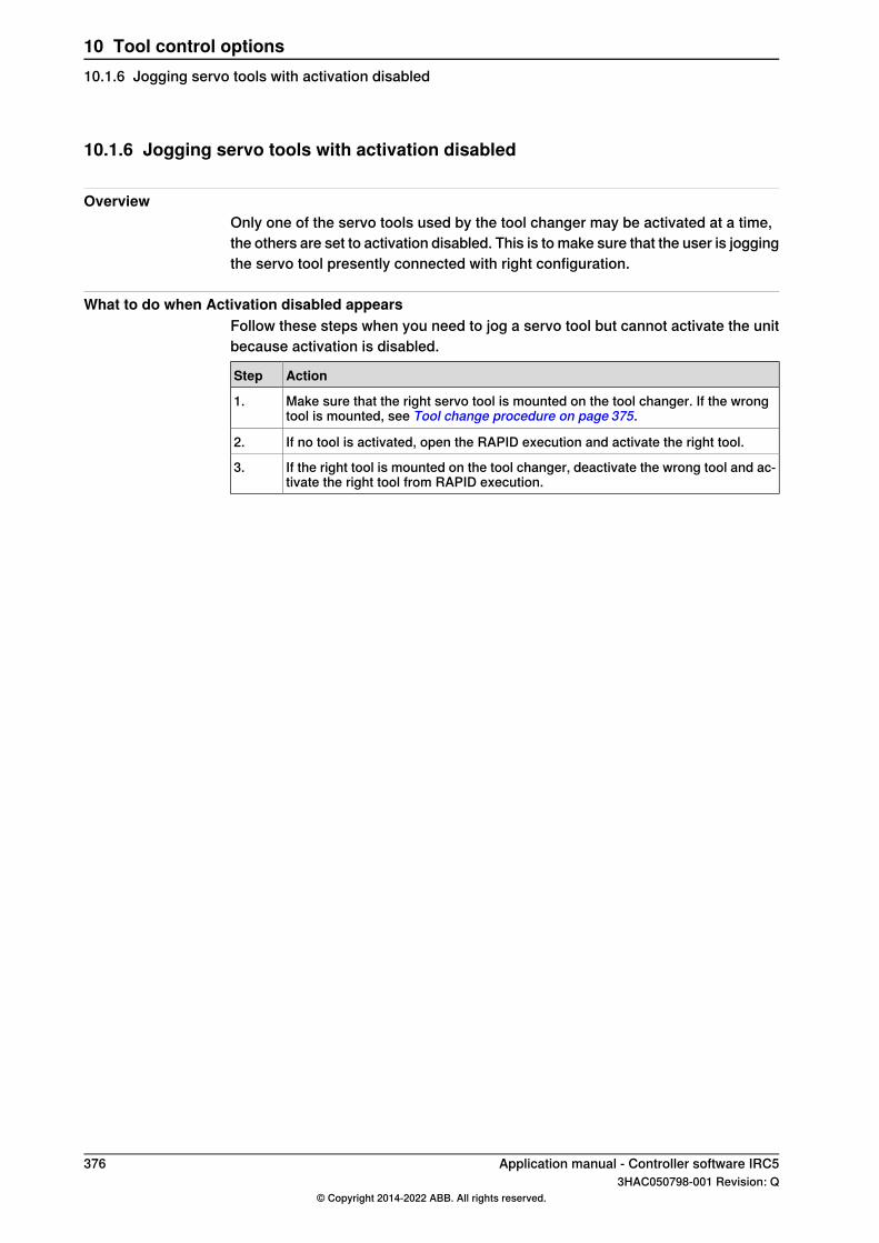
10.1.6 Jogging servo tools with activation disabled
OverviewOnly one of the servo tools used by the tool changer may be activated at a time,the others are set to activation disabled. This is to make sure that the user is joggingthe servo tool presently connected with right configuration.
What to do when Activation disabled appearsFollow these steps when you need to jog a servo tool but cannot activate the unitbecause activation is disabled.
ActionStep
Make sure that the right servo tool is mounted on the tool changer. If the wrongtool is mounted, see Tool change procedure on page 375.
1.
If no tool is activated, open the RAPID execution and activate the right tool.2.
If the right tool is mounted on the tool changer, deactivate the wrong tool and ac-tivate the right tool from RAPID execution.
3.
376 Application manual - Controller software IRC53HAC050798-001 Revision: Q
© Copyright 2014-2022 ABB. All rights reserved.
10 Tool control options10.1.6 Jogging servo tools with activation disabled
10.2 Tool Control [1180-1]
10.2.1 Overview
PurposeTool Control can be used to control a servo tool, for example in a spot weld orServo Gripper Application. Tool Control makes it possible to close the tool to aspecific plate thickness and force, and maintain the force during the process untilthe tool is requested to be opened.
What is includedTool Control gives you access to:
• RAPID instructions to open, close and calibrate servo tools• RAPID instructions for tuning system parameter values• RAPID functions for checking status of servo tools• system parameters to configure servo tools
Basic approachThis is the general approach for using Tool Control.
1 Configure and calibrate the servo tool.2 Perform a force calibration.3 Create the RAPID program.
PrerequisitesA servo tool is an additional axis. The option Additional Axes must be present onthe robot system using a servo tool. Required hardware, such as drive module andmeasurement board, is specified in Application manual - Additional axes and standalone controller.
Application manual - Controller software IRC5 3773HAC050798-001 Revision: Q
© Copyright 2014-2022 ABB. All rights reserved.
10 Tool control options10.2.1 Overview

10.2.2 Servo tool movements
Closing and opening of a servo toolThe servo tool can be closed to a predefined thickness and tool force. When thetool reaches the programmed contact position, the movement is stopped and thereis an immediate switch from position control mode to force control mode. In theforce control mode a motor torque will be applied to achieve the desired tool force.The force remains constant until an opening is ordered. Opening of the tool willreduce the tool force to zero and move the tool arm back to the pre-close position.
Synchronous and asynchronous movementsNormally a servo tool axis is moved synchronous with the robot movements insuch a way that both movements will be completed exactly at the same time.However the servo tool may be closed asynchronously (independent of currentrobot movement). The closing will immediately start to run the tool arm to theexpected contact position (thickness). The closing movement will interrupt anon-going synchronous movement of the tool arm.The tool opening may also take place while the robot is moving. But it is not possibleif the robot movement includes a synchronized movement of the servo tool axis.A motion error, "tool opening could not synchronize with robot movement", willoccur.
378 Application manual - Controller software IRC53HAC050798-001 Revision: Q
© Copyright 2014-2022 ABB. All rights reserved.
10 Tool control options10.2.2 Servo tool movements
10.2.3 Tip management
About tip management
Note
This is not needed when controlling a gripper.
The tip management functionality will find and calibrate the contact position of thetool tips automatically. It will also update and monitor the total tip wear of the tooltips.The tips can be calibrated using the RAPID instruction STCalib (see Instructionson page 382). Typically, two tool closings will be performed during a calibration.Three different types of calibrations are supported: tip wear, tip change and toolchange. All three will calibrate the contact position of the tips. The total tip wearwill, however, be updated differently by these methods.
Tip wear calibrationAs the tips are worn down, for example when spot welding, they need to be dressed.After the tip dressing, a tip wear calibration is required. The tool contact positionis calibrated and the total tip wear of the tool is updated. The calibration movementsare fast and the switch to force control mode will take place at the zero position.This method must only be used to make small position adjustments (< 3 mm)caused by tip wear/tip dressing.
Tip
A variable in your RAPID program can keep track of the tip wear and inform youwhen the tips needs to be replaced.
Tip change calibrationThe tip change calibration is to be used after mounting a new pair of tips, forexample when spot welding. The tool contact position is calibrated and the totaltip wear of the tool is reset. The first calibration movement is slow in order to findthe unknown contact position and switch to force control. The second calibrationmovement is fast. This calibration method will handle big position adjustments ofthe servo tool.This calibration may be followed by a tool closing in order to squeeze the tips inplace. A new tip change calibration is then done to update possible positiondifferences after the tip squeeze.
Tool change calibrationThe tool change calibration is to be used after reconnecting and activating a servotool. The tool contact position is calibrated and the total tip wear of the tool remainsunchanged. The first calibration movement is slow in order to find the unknowntip collision position and switch to force control. The second calibration movementis fast. This calibration method will handle big position adjustments of the tool.
Continues on next pageApplication manual - Controller software IRC5 3793HAC050798-001 Revision: Q
© Copyright 2014-2022 ABB. All rights reserved.
10 Tool control options10.2.3 Tip management

The method should always be used after reconnecting a tool since the activationwill restore the latest known position of the tool, and that position may be differentfrom the actual tool position; the tool arm may have been moved whendisconnected. This calibration method will handle big position adjustments of thetool.
Tip
Tool change calibration is most commonly used together with the RobotWareoption Servo Tool Change.
380 Application manual - Controller software IRC53HAC050798-001 Revision: Q
© Copyright 2014-2022 ABB. All rights reserved.
10 Tool control options10.2.3 Tip managementContinued
10.2.4 Supervision
Max and min strokeAn out of range supervision will stop the movement if the tool is reaching maxstroke or if it is closed to contact with the tips (reaching min stroke). See UpperJoint Bound and Lower Joint Bound in Arm on page 385.
Motion supervisionDuring the position control phase of the closing/opening, motion supervision isactive for the servo tool to detect if the arm collides or gets stuck. A collision willcause a motion error and the motion will be stopped.During the force control phase, the motion supervision will supervise the tool armposition not to exceed a certain distance from the expected contact position. Seeparameter Max Force Control Position Error in Supervision Type on page 386.
Maximum torqueThere is a maximum motor torque for the servo tool that never will be exceededin order to protect the tool from damage. If the force is programmed out of rangeaccording to the tools force-torque table, the output force will be limited to thismaximum allowed motor torque and a motion warning will be logged. See parameterMax Force Control Motor Torque in SG Process on page 383.
Speed limitDuring the force control phase there is a speed limitation. The speed limitation willgive a controlled behavior of the tool even if the force control starts before the toolis completely closed. See Speed limit 1- 6 in Force Master Control on page 384.
Application manual - Controller software IRC5 3813HAC050798-001 Revision: Q
© Copyright 2014-2022 ABB. All rights reserved.
10 Tool control options10.2.4 Supervision
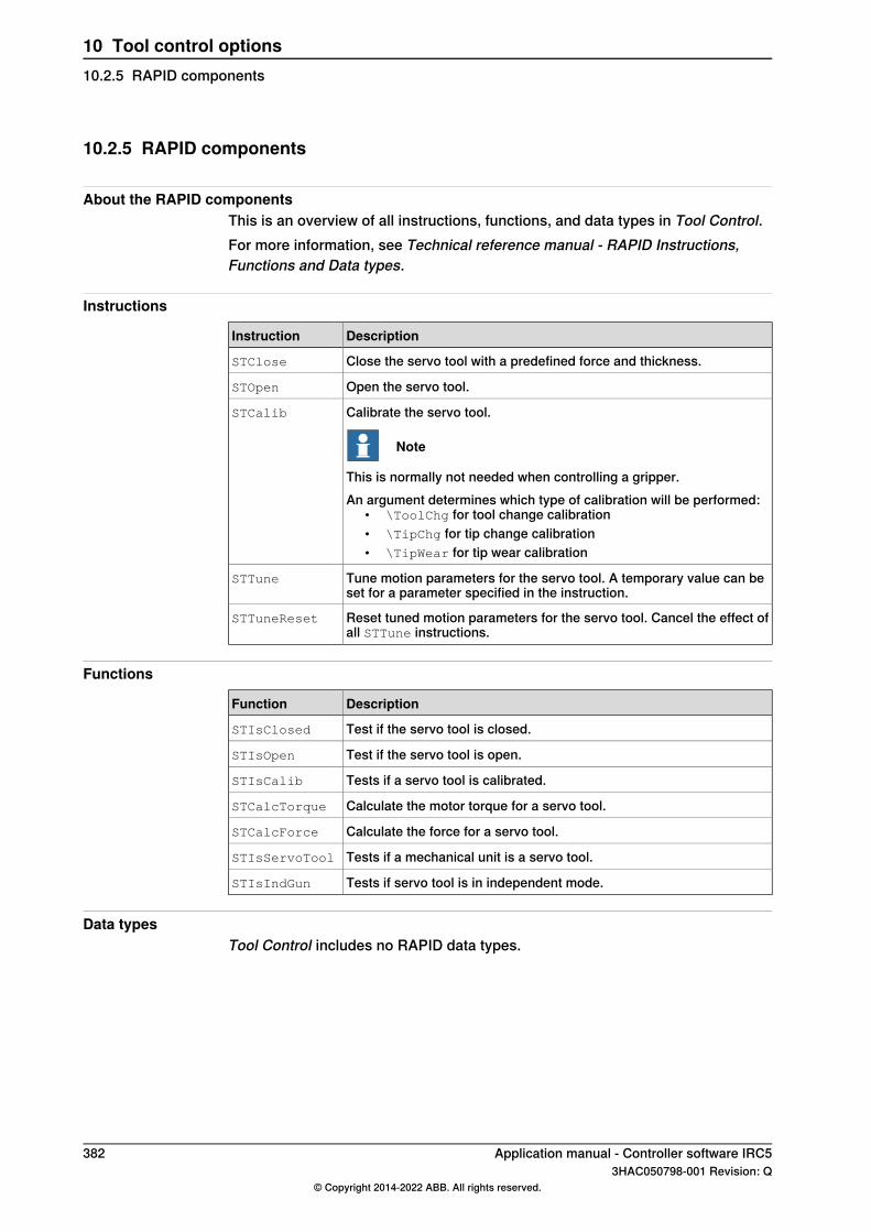
10.2.5 RAPID components
About the RAPID componentsThis is an overview of all instructions, functions, and data types in Tool Control.For more information, see Technical reference manual - RAPID Instructions,Functions and Data types.
Instructions
DescriptionInstruction
Close the servo tool with a predefined force and thickness.STClose
Open the servo tool.STOpen
Calibrate the servo tool.
Note
This is normally not needed when controlling a gripper.
STCalib
An argument determines which type of calibration will be performed:• \ToolChg for tool change calibration• \TipChg for tip change calibration• \TipWear for tip wear calibration
Tune motion parameters for the servo tool. A temporary value can beset for a parameter specified in the instruction.
STTune
Reset tuned motion parameters for the servo tool. Cancel the effect ofall STTune instructions.
STTuneReset
Functions
DescriptionFunction
Test if the servo tool is closed.STIsClosed
Test if the servo tool is open.STIsOpen
Tests if a servo tool is calibrated.STIsCalib
Calculate the motor torque for a servo tool.STCalcTorque
Calculate the force for a servo tool.STCalcForce
Tests if a mechanical unit is a servo tool.STIsServoTool
Tests if servo tool is in independent mode.STIsIndGun
Data typesTool Control includes no RAPID data types.
382 Application manual - Controller software IRC53HAC050798-001 Revision: Q
© Copyright 2014-2022 ABB. All rights reserved.
10 Tool control options10.2.5 RAPID components

10.2.6 System parameters
About the system parametersWhen using a servo tool, a motion parameter file for the tool is normally installedon the controller. A servo tool is a specific variant of an additional axis and thedescription of how to configure the servo tool is found in Applicationmanual - Additional axes and stand alone controller.In this section, the parameters used in combination with Tool Control is brieflydescribed. For more information, see the respective parameter in Technicalreference manual - System parameters.
SG ProcessThese parameters belong to the type SG Process in the topic Motion.SG Process is used to configure the behavior of a servo gun (or other servo tool,such as a gripper).For gripper control, most of these parameters can be set to default values fromthe template files.
DescriptionParameter
Adjustment of the ordered minimum close time of the gun.Close Time Adjust
Adjustment of the ordered position (plate thickness) where forcecontrol should start, when closing the gun.
Close Position Adjust
Delays the close ready event after achieving the ordered force.Force Ready Delay
Max allowed motor torque for force control. Commanded force willbe reduced, if the required motor torque is higher than this value.
Max Force ControlMotor Torque
Anticipation of the open ready event. This can be used to synchron-ize the gun opening with the next robot movement.
Post-synchronizationTime
Defines the number of times the servo gun closes during a tip wearcalibration.
Calibration Mode
The minimum tip force used during a tip wear calibration.Calibration Force Low
The maximum tip force used during a tip wear calibration.Calibration ForceHigh
The time that the servo gun waits in closed position during calibra-tion.
Calibration Time
Defines the number of points in the force-torque relation specifiedin Tip Force 1 - 10 and Motor Torque 1 - 10.
Number of StoredForces
Tip Force 1 defines the tip force that corresponds to the motor torquein Motor Torque 1.
Tip Force 1 - 10
Tip Force 2 corresponds to Motor Torque 2, etc.
Motor Torque 1 defines the motor torque that corresponds to thetip force in Tip Force 1.
Motor Torque 1- 10
Motor Torque 2 corresponds to Tip Force 2, etc.
Defines the joint position at each force level in the force calibrationtable.
Squeeze Position 1 -10
Defines how long the force will be maintained if a soft stop occursduring constant force.
Soft Stop Timeout
Continues on next pageApplication manual - Controller software IRC5 3833HAC050798-001 Revision: Q
© Copyright 2014-2022 ABB. All rights reserved.
10 Tool control options10.2.6 System parameters
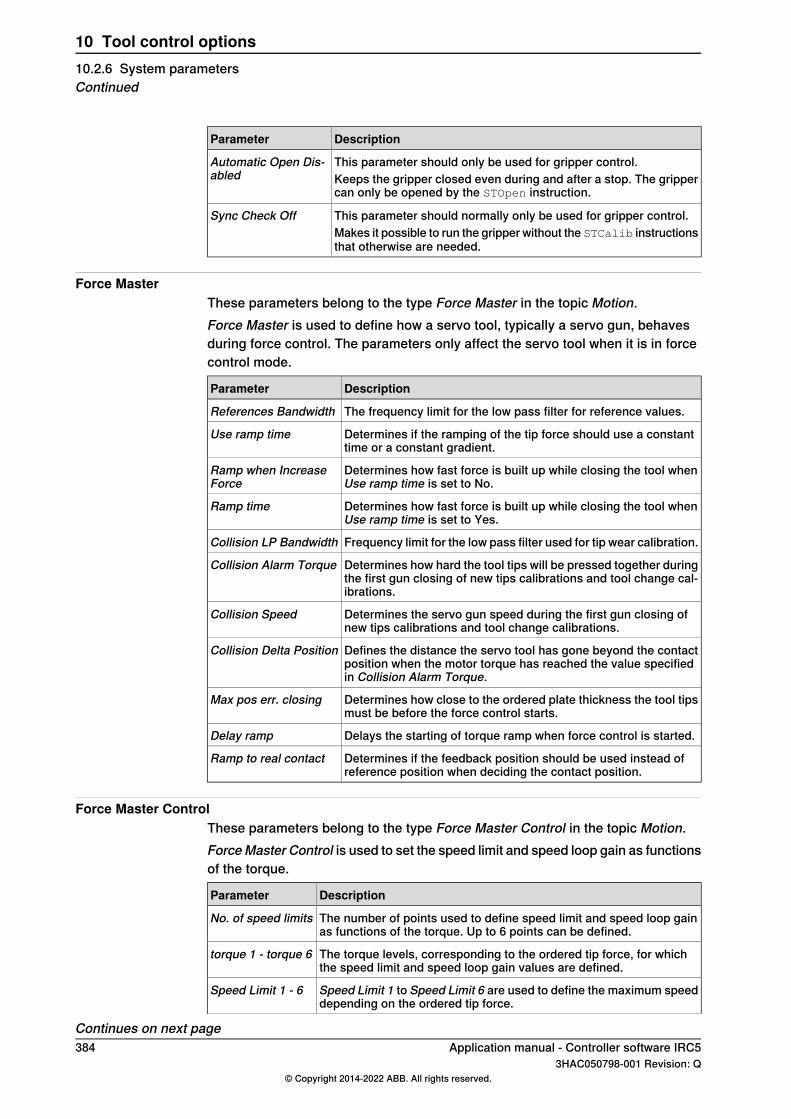
DescriptionParameter
This parameter should only be used for gripper control.Automatic Open Dis-abled Keeps the gripper closed even during and after a stop. The gripper
can only be opened by the STOpen instruction.
This parameter should normally only be used for gripper control.Sync Check OffMakes it possible to run the gripper without the STCalib instructionsthat otherwise are needed.
Force MasterThese parameters belong to the type Force Master in the topic Motion.Force Master is used to define how a servo tool, typically a servo gun, behavesduring force control. The parameters only affect the servo tool when it is in forcecontrol mode.
DescriptionParameter
The frequency limit for the low pass filter for reference values.References Bandwidth
Determines if the ramping of the tip force should use a constanttime or a constant gradient.
Use ramp time
Determines how fast force is built up while closing the tool whenUse ramp time is set to No.
Ramp when IncreaseForce
Determines how fast force is built up while closing the tool whenUse ramp time is set to Yes.
Ramp time
Frequency limit for the low pass filter used for tip wear calibration.Collision LP Bandwidth
Determines how hard the tool tips will be pressed together duringthe first gun closing of new tips calibrations and tool change cal-ibrations.
Collision Alarm Torque
Determines the servo gun speed during the first gun closing ofnew tips calibrations and tool change calibrations.
Collision Speed
Defines the distance the servo tool has gone beyond the contactposition when the motor torque has reached the value specifiedin Collision Alarm Torque.
Collision Delta Position
Determines how close to the ordered plate thickness the tool tipsmust be before the force control starts.
Max pos err. closing
Delays the starting of torque ramp when force control is started.Delay ramp
Determines if the feedback position should be used instead ofreference position when deciding the contact position.
Ramp to real contact
Force Master ControlThese parameters belong to the type Force Master Control in the topic Motion.ForceMaster Control is used to set the speed limit and speed loop gain as functionsof the torque.
DescriptionParameter
The number of points used to define speed limit and speed loop gainas functions of the torque. Up to 6 points can be defined.
No. of speed limits
The torque levels, corresponding to the ordered tip force, for whichthe speed limit and speed loop gain values are defined.
torque 1 - torque 6
Speed Limit 1 to Speed Limit 6 are used to define the maximum speeddepending on the ordered tip force.
Speed Limit 1 - 6
Continues on next page384 Application manual - Controller software IRC5
3HAC050798-001 Revision: Q© Copyright 2014-2022 ABB. All rights reserved.
10 Tool control options10.2.6 System parametersContinued

DescriptionParameter
Kv 1 to Kv 6 are used to define the speed loop gain for reducing thespeed when the speed limit is exceeded.
Kv 1 - 6
ArmThese parameters belong to the type Arm in the topic Motion.The type Arm defines the characteristics of an arm.
DescriptionParameter
Defines the upper limit of the working area for the joint.Upper Joint Bound
Defines the lower limit of the working area for the joint.Lower Joint Bound
Acceleration DataThese parameters belong to the type Acceleration Data in the topic Motion.Acceleration Data is used to specify some acceleration characteristics for axeswithout any dynamic model.
DescriptionParameter
Worst case motor acceleration.Nominal Acceleration
Worst case motor deceleration.Nominal Deceleration
Indicates how fast the acceleration can be increased.Acceleration Derivate Ratio
Indicates how fast the deceleration can be increased.Deceleration Derivate Ratio
Motor TypeThese parameters belong to the type Motor Type in the topic Motion.Motor Type is used to describe characteristics for a motor.
DescriptionParameter
Defines the number of pole pairs for the motor.Pole Pairs
The inertia of the motor, including the resolver but excluding thebrake.
Inertia
The continuous stall torque, i.e. the torque the motor can produce atno speed and during an infinite time.
Stall Torque
Nominal voltage constant. The induced voltage (phase to phase) thatcorresponds to the speed 1 rad/s.
ke Phase to Phase
Max current without irreversible magnetization.Max Current
Nominal winding resistance per phase at 20 degrees Celsius.Phase Resistance
Nominal winding inductance per phase at zero current.Phase Inductance
Motor CalibrationThese parameters belong to the type Motor Calibration in the topic Motion.Motor Calibration is used to calibrate a motor.
DescriptionParameter
Defines the position of the motor (resolver) when the rotor is in theelectrical zero position relative to the stator.
Commutator Offset
Continues on next pageApplication manual - Controller software IRC5 3853HAC050798-001 Revision: Q
© Copyright 2014-2022 ABB. All rights reserved.
10 Tool control options10.2.6 System parameters
Continued
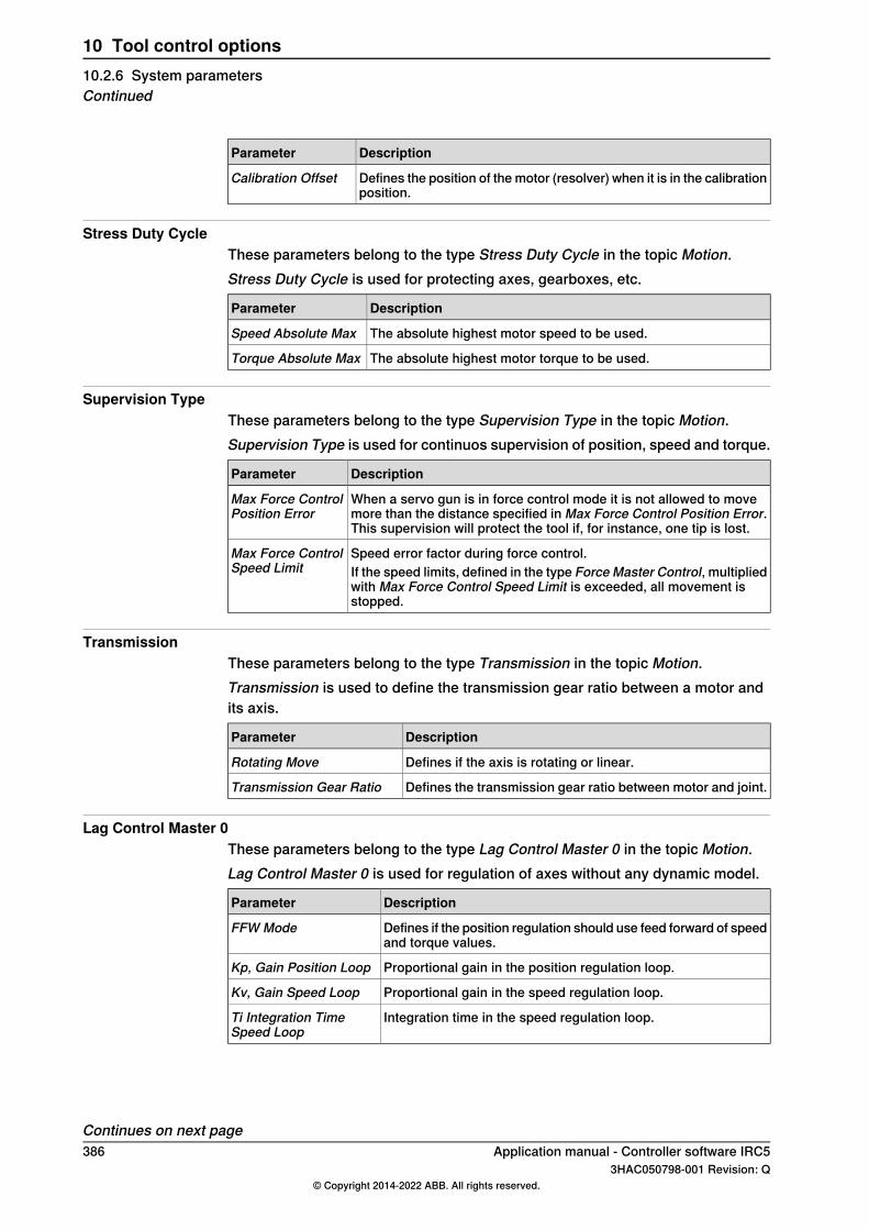
DescriptionParameter
Defines the position of the motor (resolver) when it is in the calibrationposition.
Calibration Offset
Stress Duty CycleThese parameters belong to the type Stress Duty Cycle in the topic Motion.Stress Duty Cycle is used for protecting axes, gearboxes, etc.
DescriptionParameter
The absolute highest motor speed to be used.Speed Absolute Max
The absolute highest motor torque to be used.Torque Absolute Max
Supervision TypeThese parameters belong to the type Supervision Type in the topic Motion.Supervision Type is used for continuos supervision of position, speed and torque.
DescriptionParameter
When a servo gun is in force control mode it is not allowed to movemore than the distance specified in Max Force Control Position Error.This supervision will protect the tool if, for instance, one tip is lost.
Max Force ControlPosition Error
Speed error factor during force control.Max Force ControlSpeed Limit If the speed limits, defined in the type Force Master Control, multiplied
with Max Force Control Speed Limit is exceeded, all movement isstopped.
TransmissionThese parameters belong to the type Transmission in the topic Motion.Transmission is used to define the transmission gear ratio between a motor andits axis.
DescriptionParameter
Defines if the axis is rotating or linear.Rotating Move
Defines the transmission gear ratio between motor and joint.Transmission Gear Ratio
Lag Control Master 0These parameters belong to the type Lag Control Master 0 in the topic Motion.Lag Control Master 0 is used for regulation of axes without any dynamic model.
DescriptionParameter
Defines if the position regulation should use feed forward of speedand torque values.
FFW Mode
Proportional gain in the position regulation loop.Kp, Gain Position Loop
Proportional gain in the speed regulation loop.Kv, Gain Speed Loop
Integration time in the speed regulation loop.Ti Integration TimeSpeed Loop
Continues on next page386 Application manual - Controller software IRC5
3HAC050798-001 Revision: Q© Copyright 2014-2022 ABB. All rights reserved.
10 Tool control options10.2.6 System parametersContinued
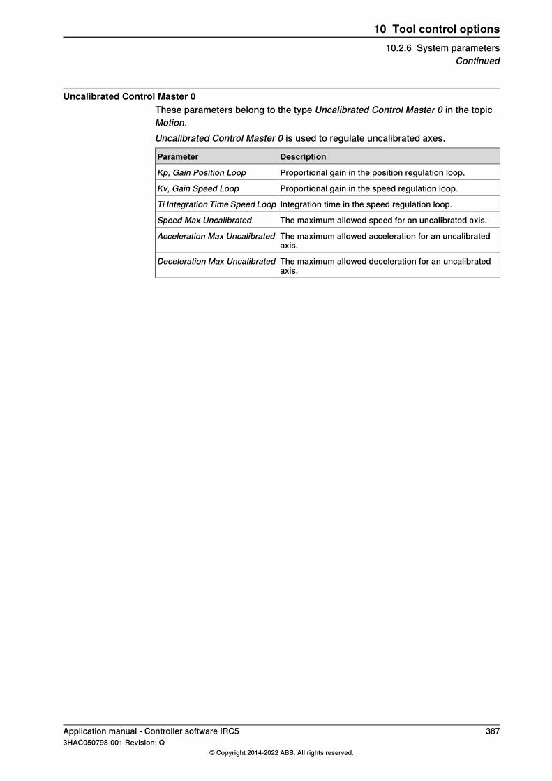
Uncalibrated Control Master 0These parameters belong to the type Uncalibrated Control Master 0 in the topicMotion.Uncalibrated Control Master 0 is used to regulate uncalibrated axes.
DescriptionParameter
Proportional gain in the position regulation loop.Kp, Gain Position Loop
Proportional gain in the speed regulation loop.Kv, Gain Speed Loop
Integration time in the speed regulation loop.Ti Integration Time Speed Loop
The maximum allowed speed for an uncalibrated axis.Speed Max Uncalibrated
The maximum allowed acceleration for an uncalibratedaxis.
Acceleration Max Uncalibrated
The maximum allowed deceleration for an uncalibratedaxis.
Deceleration Max Uncalibrated
Application manual - Controller software IRC5 3873HAC050798-001 Revision: Q
© Copyright 2014-2022 ABB. All rights reserved.
10 Tool control options10.2.6 System parameters
Continued
10.2.7 Commissioning and service
Commissioning the servo toolFor a new servo tool, follow these steps for installing and commissioning:
ActionStep
Install the servo tool according to the description in Application manual - Additionalaxes and stand alone controller.
1
Load a .cfg file with the servo tool configuration. For detailed description on howto do this, see Operating manual - RobotStudio.
2
If you do not have any .cfg file for the servo tool, you can load a template file andconfigure the system parameters with the values of your servo tool. Template filesare found in the RobotWare distribution, see Template file locations on page 388.
Use the RAPID instruction STTune and iterate to find the optimal parameter values.Once found, these optimal values should be written to the system parameters tobe permanent.
3
Fine calibrate the servo tool, see Fine calibration on page 390.4
Unless force calibration was included in a loaded .cfg file, perform a force calibra-tion.
5
Template file locationsThe template files can be obtained from the PC or the IRC5 controller.
• In the RobotWare installation folder in RobotStudio: ...\RobotPackages\RobotWare_RPK_<version>\utility\AdditionalAxis\
• On the IRC5 Controller:<SystemName>\PRODUCTS\<RobotWare_xx.xx.xxxx>\utility\AdditionalAxis\
Note
Navigate to the RobotWare installation folder from the RobotStudio Add-Ins tab,by right-clicking on the installed RobotWare version in the Add-Ins browser andselecting Open Package Folder.
Disconnect/reconnect a servo toolIf the servo tool is deactivated, using the DeactUnit instruction, it may bedisconnected and removed. The tool position at deactivation will be restored whenthe tool is connected and reactivated. Make a tool change calibration to make surethe tip position is OK.The whole process of changing a tool can be performed by a RAPID program ifyou use the RobotWare option Servo Tool Change and the instruction STCalib.
Recover from accidental disconnectionIf the motor cables are disconnected by accident when the servo tool is active, thesystem will go into system failure state. After restart of the system the servo toolmust be deactivated in order to jog the robot to a service position.Deactivation may be performed from the Joggingwindow. Tap onActivate..., selectthe servo tool and tap on Deactivate.
Continues on next page388 Application manual - Controller software IRC5
3HAC050798-001 Revision: Q© Copyright 2014-2022 ABB. All rights reserved.
10 Tool control options10.2.7 Commissioning and service

After service / repair the revolution counter must be updated since the positionhas been lost, see Update revolution counter on page 390.
Application manual - Controller software IRC5 3893HAC050798-001 Revision: Q
© Copyright 2014-2022 ABB. All rights reserved.
10 Tool control options10.2.7 Commissioning and service
Continued

10.2.8 Mechanical unit calibrations
Fine calibrationFine calibration must be performed when installing a new servo tool, or if the servotool axis is in state ‘Not Calibrated’.For a gripper, it is sufficient with a normal calibration at a position where the fingersare touching, but are not squeezed together. In this case, STCalib instructionsare not needed.For this, it is recommended to create a service routine using the followinginstructions:
STCalib "ToolName" \TipChg;
STCalib "ToolName" \TipWear;
Update revolution counterAn update of the revolution counter must be performed if the position of the axisis lost. If this happens, this is indicated by the calibration state ‘Rev. Counter notupdated’.For this, it is recommended to use the same service routine as for the finecalibration.
390 Application manual - Controller software IRC53HAC050798-001 Revision: Q
© Copyright 2014-2022 ABB. All rights reserved.
10 Tool control options10.2.8 Mechanical unit calibrations
10.2.9 RAPID code example
How to use the code packageThe normal programming technique for Tool Control is to customize shell routinesbased on the example code below. These shell routines are then called from yourprogram.
Using shell routinesThis example shows a main routine in combination with a customized routine(rMoveSpot) that uses the standard servo tool instructions. The external process(for example a weld timer) is indicated with the routine rWeld.
PROC main()
MoveJ p1, v500, z50, weldtool;
MoveL p2, v1000, z50, weldtool;
! Perform weld process
rMoveSpot weldpos1, v2000, curr_gun_name, 1000, 2, 1,
weldtool\WObj:=weldwobj;
rMoveSpot weldpos2, v2000, curr_gun_name, 1000, 2, 1,
weldtool\WObj:=weldwobj;
rMoveSpot weldpos3, v2000, curr_gun_name, 1500, 3, 1,
weldtool\WObj:=weldwobj;
MoveL p3, v1000, z50, weldtool;
ENDPROC
PROC rMoveSpot (robtarget ToPoint,
speeddata Speed,
gunname Gun,
num Force,
num Thickness,
PERS tooldata Tool
\PERS wobjdata WObj)
! Move the gun to weld position.
! Always use FINE point to prevent too early closing.
MoveL ToPoint, Speed, FINE, weldtool \WOIbj=WObj;
STClose Gun, Thickness;
rWeld;
STOpen Gun;
ENDPROC
PROC rWeld()
! Request weld start from weld timer
SetDO doWeldstart,1;
! Wait until weld is performed
WaitDI diWeldready,1;
SetDO doWeldstart,0;
ENDPROC
Application manual - Controller software IRC5 3913HAC050798-001 Revision: Q
© Copyright 2014-2022 ABB. All rights reserved.
10 Tool control options10.2.9 RAPID code example
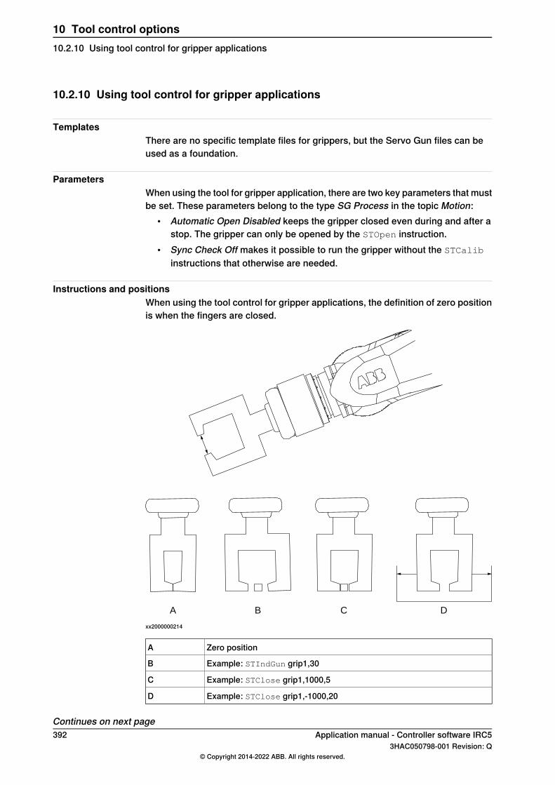
10.2.10 Using tool control for gripper applications
TemplatesThere are no specific template files for grippers, but the Servo Gun files can beused as a foundation.
ParametersWhen using the tool for gripper application, there are two key parameters that mustbe set. These parameters belong to the type SG Process in the topic Motion:
• Automatic Open Disabled keeps the gripper closed even during and after astop. The gripper can only be opened by the STOpen instruction.
• Sync Check Off makes it possible to run the gripper without the STCalib
instructions that otherwise are needed.
Instructions and positionsWhen using the tool control for gripper applications, the definition of zero positionis when the fingers are closed.
A B C D
xx2000000214
Zero positionA
Example: STIndGun grip1,30B
Example: STClose grip1,1000,5C
Example: STClose grip1,-1000,20D
Continues on next page392 Application manual - Controller software IRC5
3HAC050798-001 Revision: Q© Copyright 2014-2022 ABB. All rights reserved.
10 Tool control options10.2.10 Using tool control for gripper applications

STIndGun instructions can be used to move the gripper independent of the normalmovement instructions.
xx0500002342
If the gripper should squeeze in the opposite direction, the sign of the force shouldbe negative.
Application manual - Controller software IRC5 3933HAC050798-001 Revision: Q
© Copyright 2014-2022 ABB. All rights reserved.
10 Tool control options10.2.10 Using tool control for gripper applications
Continued

10.3 I/O Controlled Axes [included in 1180-1]
10.3.1 Overview
PurposeThe purpose of I/O Controlled Axes is to control an axis from the robot controllerby using an I/O interface instead of having the axis integrated into the IRC5 drivesystem.For operation and programming, an I/O controlled axis acts just like an integratedprocess axis. The difference is that the drive unit of the I/O controlled axis is notdirectly connected to the drive system of the robot controller. The motionconfiguration provides an I/O interface, which connects the robot controller to anexternal servo regulator.The robot controller can take and release control of the additional axis duringprogram execution. The additional axis can be moved synchronously to the robot(while controlled by the robot controller) or independently of the robot (whilecontrolled by an external PLC).Some examples of applications are:
• Servo guns• Grippers
What is includedThe RobotWare option I/O Controlled Axes gives you access to system parametersfor configuring I/O controlled axes.
Basic approachThis is the general approach for setting up I/O Controlled Axes.
1 Configure the system parameters for the axis to be controlled via I/O. SeeConfiguration on page 399.
2 Operate the axis (jog, program etc.) just like any additional axis. See RAPIDprogramming on page 403.For additional axis in general, also see Operating manual - IRC5 withFlexPendant and Application manual - Additional axes and stand alonecontroller.
394 Application manual - Controller software IRC53HAC050798-001 Revision: Q
© Copyright 2014-2022 ABB. All rights reserved.
10 Tool control options10.3.1 Overview

10.3.2 Contouring error
What is a contouring errorA contouring error is generated if an I/O controlled axis on the programmed robotpath of the robtarget is not reached based on the bus delay and acceleration. Ifthis event occurs, the robot’s movement stops on the path. An error entry is madein the error log.Possible causes for the occurrence of a contouring error:
• Robot collisions• An external axis that is difficult to move or faulty• Incorrect value of system parameter Bus delay time in ms
Error handling1 Error – acknowledgement at the external process unit.
For that, each application needs to provide a reset button. The process unitneeds to be ready before the program can be started.
2 Motors On / Program startIf automatic movement back to path is allowed, the robot will move backautomatically to path before the program continues with the instruction thatwas canceled. In case automatic movement is not allowed, a error messageoccurs. A selection menu provides possibilities to accept the movement orto cancel the start event.In case the start event is canceled, the operator needs to change the operationmode to manual.Now the operator can specify a further procedure before the robot programcan be restarted. For example:
• move the robot manual out of collision area• move to a previous move instruction
For more information, see topic Controller, type Path Return Region in Technicalreference manual - System parameters.
Application manual - Controller software IRC5 3953HAC050798-001 Revision: Q
© Copyright 2014-2022 ABB. All rights reserved.
10 Tool control options10.3.2 Contouring error

10.3.3 Correcting the position
Correcting the positionCorrecting (teaching) a robot position (robtarget) is done using the buttonModifyPosition in the program editor (as for the robot axes).For the following states, the modified position of the I/O controlled axis will not bethe current position, but the last valid feedback position:
• Axis is not referenced• Servo regulator is not operative• Actual position of the I/O interface invalid• Position is outside the operating range
The position correction is adopted for activated axes only. If an available axis isnot activated, this axis is ignored. This means the robtarget substitute symbolfor the axis in question remains unchanged. This state does not lead to an error.
396 Application manual - Controller software IRC53HAC050798-001 Revision: Q
© Copyright 2014-2022 ABB. All rights reserved.
10 Tool control options10.3.3 Correcting the position
10.3.4 Tool changing
Tool changingIf a tool is deactivated with the instruction DeactUnit, it is necessary to set thesignal unit disable. When the tool is disabled (can be verified with signalunit_disabled), it is possible to disconnect the power supply to the tool, for exampleundock a spotwelding gun.It is possible to configure the same logical axis number for different tools, but thisrequires the RobotWare option Servo Tool Change.
Application manual - Controller software IRC5 3973HAC050798-001 Revision: Q
© Copyright 2014-2022 ABB. All rights reserved.
10 Tool control options10.3.4 Tool changing

10.3.5 Installation
InstallationAfter installation of the robot system, the I/O controlled axes needs to be loadedin the system parameters.Each required axis needs to be loaded separately. The specific motion file includesdefault motion parameters. Parameterization and adjustments of the loaded axisis described in more detail in Configuration on page 399.
398 Application manual - Controller software IRC53HAC050798-001 Revision: Q
© Copyright 2014-2022 ABB. All rights reserved.
10 Tool control options10.3.5 Installation

10.3.6 Configuration
Template configuration filesTemplate configuration files are available for setting up the I/O controlled axes.The files can be loaded to the controller, using RobotStudio or the FlexPendant,to facilitate and speed up the configuration.The template configuration files can be obtained from RobotStudio or the IRC5controller.
• In the RobotWare installation folder in RobotStudio: ...\RobotPackages\RobotWare_RPK_<version>\utility\ioctrlaxis\
• On the IRC5 Controller: <SystemName>\PRODUCTS\<RobotWare_xx.xx.xxxx>\utility\ioctrlaxis\
Note
Navigate to the RobotWare installation folder from the RobotStudio Add-Ins tab,by right-clicking on the installed RobotWare version in the Add-Ins browser andselecting Open Package Folder.
Adding the I/O controlled axisLoading the template configuration files for I/O controlled axis will install amechanical unit called EXTCTL1 with default signal names defined in the typeExternal Control Process Data, topic Motion.
1 Load one of the template motion configuration files for axis 1, select betweenlogical axis number 7, 8, or 9.(ioctrl1_mn7_l7_moc.cfg, ioctrl1_mn7_l8_moc.cfg, ioctrl1_mn7_l9_moc.cfg)
2 Load one of the template I/O configuration files depending on the industrialnetwork.(ioctrl1_eio.cfg, ioctrl1_pnet_eio.cfg)
3 Edit the I/O configuration and change from virtual signals to real signalsaccording to the current setup.
Mandatory settings for the I/O controlled axisThe following configuration must be done with data for the mechanical unit thatshould be used as an I/O controlled axis.
1 In type Transmission, set Transmission Gear Ratio. See Type Transmissionon page 402.
2 In type Acceleration Data, set Nominal Acceleration, Nominal Deceleration,Acceleration Derivate Ratio and Deceleration Derivate Ratio. See TypeAcceleration Data on page 401.
3 In type Arm, set Upper Joint Bound and Lower Joint Bound. See Type Armon page 402.
4 In type Stress Duty Cycle, set Speed Absolute Max. See Type Stress DutyCycle on page 402.
Continues on next pageApplication manual - Controller software IRC5 3993HAC050798-001 Revision: Q
© Copyright 2014-2022 ABB. All rights reserved.
10 Tool control options10.3.6 Configuration

5 In typeSupervision Type, set static_position_limit and dynamic_position_limit.See Type Supervision Type on page 402.
6 In type External Control Process Data, set Bus delay time in ms. See TypeExternal Control Process Data on page 401.
Optional customization settingsIf other values than the default values are preferred, any of the following settingscan be changed.
• To change the logical axis number, change the value for Logical Axis. SeeType Joint on page 402.
• To change the names of the signals used to communicate with the I/Ocontrolled axis, change the settings in the type External Control ProcessData, see Type External Control Process Data on page 401.
• To use an activation relay, set the parameter Use Activation Relay. See TypeMechanical Unit on page 402.
Adding another axisFor a second or third I/O controlled axis, EXTCTL2 and EXTCTL3, the correspondingconfiguration files must be loaded from the template folder.
1 Load one of the template configuration files for axis 2 or 3.2 Make the same configurations as for the first I/O controlled axis.
Note
Several mechanical units may use the same logical axis number, but this requiresthe RobotWare option Servo Tool Change.
Settings for PROFINETIf a PROFINET bus is used, the parameter Reduction ratio should be set to 4 msor 2 ms for the I/O controlled unit. See Application manual - PROFINETController/Device.
400 Application manual - Controller software IRC53HAC050798-001 Revision: Q
© Copyright 2014-2022 ABB. All rights reserved.
10 Tool control options10.3.6 ConfigurationContinued

10.3.7 System parameters
About the system parametersThis is a brief description of each parameter in the option I/O Controlled Axes. Formore information, see the respective parameter in Technical referencemanual - System parameters.
Type External Control Process DataThese parameters belongs to the type External Control Process Data in the topicMotion.
DescriptionParameter
Parameter for bus delay time.Bus delay time in ms
Output signal for activation of the I/O controlled unit.Regulator activation signal
Output signal for allowing external control of the unit.Ext Controller output signal
Output signal with positioning reference for the I/O con-trolled axis.
Pos_ref output signal
Output signal with sign (+ or -) of the positioning referencefor the I/O controlled axis.
Pos_ref sign signal
Output signal that signals that the positioning reference isa valid signal and the axis needs to follow the referencesignal.
Pos_ref valid signal
Input signal that indicates if the I/O controlled unit is en-abled and ready.
Regulator is activated signal
Input signal that signals if the required positioning refer-ence is out of range.
Req pos is out of range inputsignal
Input signal with position feedback from the I/O controlledaxis.
Pos_fdb input signal
Input signal with with sign (+ or -) of the position feedbackfrom the I/O controlled axis.
Pos_fdb sign signal
Input signal that indicates that the position feedback signalis valid.
Pos_fdb_valid signal
Input signal from I/O controlled unit indicating that it isready.
Unit_ready input signal
Input signal indicating that the external unit is in controlof the movement. The robot controller is not allowed tomove the external unit.
Ext Controller input signal
The program pointer does not need to be moved after thean error.
No program pointer move aftererror
Type Acceleration DataThese parameters belongs to the type Acceleration Data in the topic Motion.
DescriptionParameter
Worst case motor acceleration.Nominal Acceleration
Worst case motor deceleration.Nominal Deceleration
Defines how fast the acceleration can build up, i.e. an in-dication of the derivative of the acceleration.
Acceleration Derivate Ratio
Continues on next pageApplication manual - Controller software IRC5 4013HAC050798-001 Revision: Q
© Copyright 2014-2022 ABB. All rights reserved.
10 Tool control options10.3.7 System parameters

DescriptionParameter
Defines how fast the deceleration can build up, i.e. an in-dication of the derivative of the deceleration.
Deceleration Derivate Ratio
Type ArmThese parameters belongs to the type Arm in the topic Motion.
DescriptionParameter
Defines the upper limit of the working area for this joint.Upper Joint Bound
Defines the lower limit of the working area for this joint.Lower Joint Bound
Type JointThese parameters belongs to the type Joint in the topic Motion.
DescriptionParameter
Defines the axis number as seen by a RAPID program.Logical AxisTwo mechanical units can have the same value set forLogical Axis, but then they cannot be activated at the same.
Type Mechanical UnitThese parameters belongs to the type Mechanical Unit in the topic Motion.
DescriptionParameter
Points out a relay that will be activated or deactivated whenthe mechanical unit is activated or deactivated.
Use Activation Relay
Type Stress Duty CycleThese parameters belongs to the type Stress Duty Cycle in the topic Motion.
DescriptionParameter
The absolute highest motor speed to be used inmeters/second.
Speed Absolute Max
Type Supervision TypeThese parameters belongs to the type Supervision Type in the topic Motion.
DescriptionParameter
Position error limit at zero speed, in meters on motor side.static_position_limit
Position error limit (max lag) at max speed, in meters onmotor side.
dynamic_position_limit
Type TransmissionThese parameters belongs to the type Transmission in the topic Motion.
DescriptionParameter
Defines the transmission gear ratio between motor andjoint. For most axis this parameter is set to 1.
Transmission Gear Ratio
402 Application manual - Controller software IRC53HAC050798-001 Revision: Q
© Copyright 2014-2022 ABB. All rights reserved.
10 Tool control options10.3.7 System parametersContinued
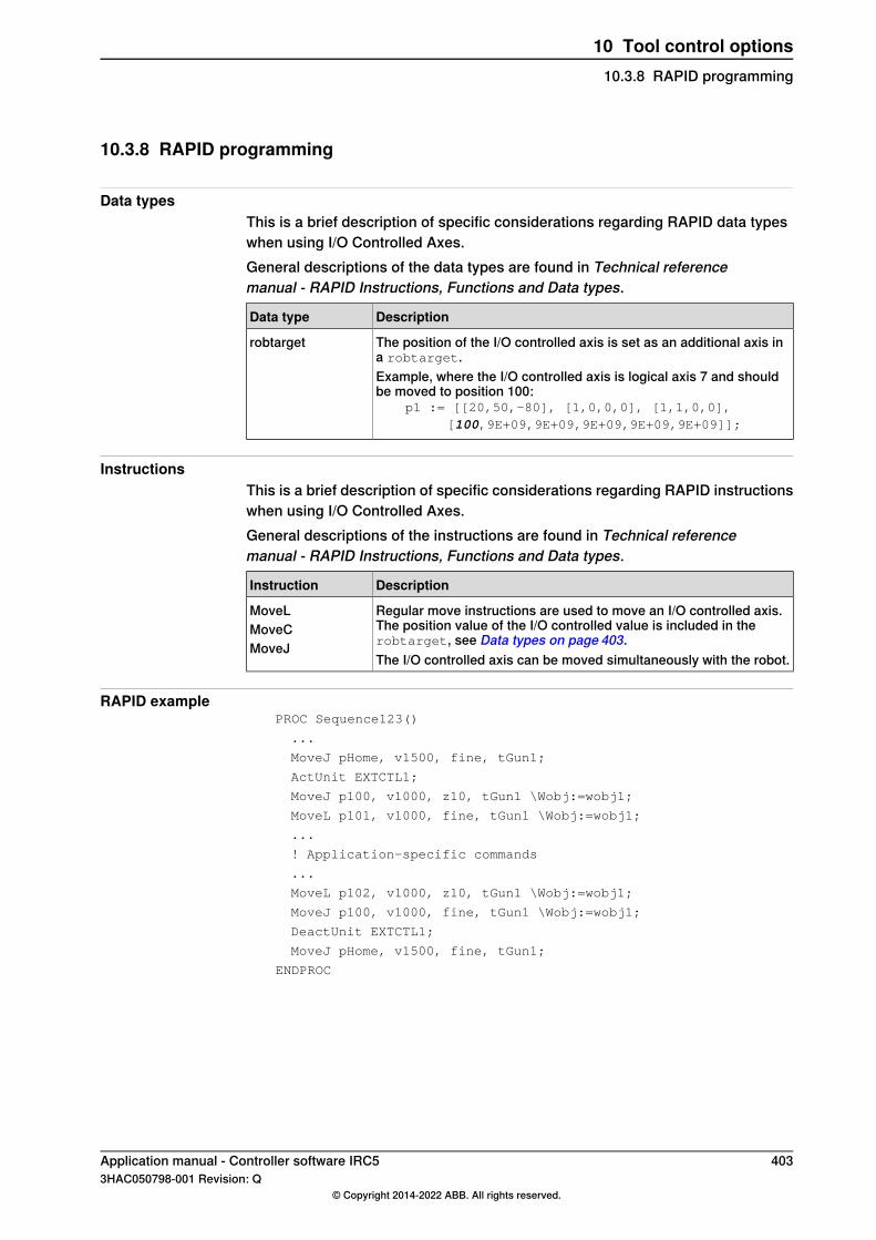
10.3.8 RAPID programming
Data typesThis is a brief description of specific considerations regarding RAPID data typeswhen using I/O Controlled Axes.General descriptions of the data types are found in Technical referencemanual - RAPID Instructions, Functions and Data types.
DescriptionData type
The position of the I/O controlled axis is set as an additional axis ina robtarget.
robtarget
Example, where the I/O controlled axis is logical axis 7 and shouldbe moved to position 100:
p1 := [[20,50,-80], [1,0,0,0], [1,1,0,0],[100,9E+09,9E+09,9E+09,9E+09,9E+09]];
InstructionsThis is a brief description of specific considerations regarding RAPID instructionswhen using I/O Controlled Axes.General descriptions of the instructions are found in Technical referencemanual - RAPID Instructions, Functions and Data types.
DescriptionInstruction
Regular move instructions are used to move an I/O controlled axis.The position value of the I/O controlled value is included in therobtarget, see Data types on page 403.
MoveLMoveCMoveJ
The I/O controlled axis can be moved simultaneously with the robot.
RAPID examplePROC Sequence123()
...
MoveJ pHome, v1500, fine, tGun1;
ActUnit EXTCTL1;
MoveJ p100, v1000, z10, tGun1 \Wobj:=wobj1;
MoveL p101, v1000, fine, tGun1 \Wobj:=wobj1;
...
! Application-specific commands
...
MoveL p102, v1000, z10, tGun1 \Wobj:=wobj1;
MoveJ p100, v1000, fine, tGun1 \Wobj:=wobj1;
DeactUnit EXTCTL1;
MoveJ pHome, v1500, fine, tGun1;
ENDPROC
Application manual - Controller software IRC5 4033HAC050798-001 Revision: Q
© Copyright 2014-2022 ABB. All rights reserved.
10 Tool control options10.3.8 RAPID programming

This page is intentionally left blank

IndexAAbsolute Accuracy, 127
MultiMove, 129Absolute Accuracy calibration, 139Absolute Accuracy compensation, 137Absolute Accuracy verification, 140Acceleration Data, 385, 399, 401Acceleration Derivate Ratio, 385, 401Acceleration Max Uncalibrated, 387accidental disconnection, 388acknowledge messages, 297activate Absolute Accuracy, 131Activate at start up, 225activate supervision, 273activation disabled, 376actor signals, 99–100additional axes, 377additional axis, 59Add or replace parameters, 188Adjustment Speed, 223Advanced RAPID, 17Advanced Shape Tuning, 149AliasIO, 24–25alignment, 143analog signal, 48Analog Signal Interrupt, 48Analog Synchronization, 173AND, 100Application protocol, 281, 285, 289ArgName, 46argument name, 46Arm, 385, 399, 402arm replacement, 133asynchronous movements, 378Auto acknowledge input, 11, 367automatic friction tuning, 150Automatic Open Disabled , 384Auto mode, 324axis, 235axis reset, 235
Bbinary communication, 83binary data, 297birth certificate, Absolute Accuracy, 141BitAnd, 19BitCheck, 19BitClear, 19bit functionality, 18BitLSh, 19BitNeg, 19BitOr, 19BitRSh, 19BitSet, 19BitXOr, 19BookErrNo, 41bool, 351Bus delay time in ms, 401byte, 19ByteToStr, 19
Ccalibrate follower axis, 66calibrate tool, 147
calibration data, 131Calibration Force High, 383Calibration Force Low, 383Calibration Mode, 383Calibration Offset, 386calibration process, 139Calibration Time, 383calibration tools, 130CalibWare, 130cell alignment, 143certificate, Absolute Accuary, 141change calibration data, 131change of tool, Machine Synchronization, 200channel, 355character based communication, 83Check unresolved references, Task type, 315CirPathMode, 169class, 355ClearIOBuff, 84ClearRawBytes, 88Close, 84CloseDir, 92Close position adjust, 383Close time adjust, 383code example, 391collision, 264Collision Alarm Torque, 384Collision Avoidance, 275Collision Delta Position, 384collision detection
MultiMove, 262YuMi robots, 262
Collision Detection Memory, 267Collision Error Handler, 268Collision LP Bandwidth, 384Collision Speed, 384commissioning, 388common data, 326communication, 82communication channel, 346communication client, 353Commutator Offset, 385compensation, 137compensation parameters, 128, 142compliance errors, 136comunication cable
connecting, 347configuration
Absolute Accuracy, 131configuration.xml, 357configuration example, 361configuration files, 352configuration functionality, 27configure Collision Detection, 271configuring
sensors, 338tasks, 318
Connected signal, 224connection relay, 373constants
Sensor Interface, 342convention, 354coordinate systems, 143CopyFile, 92CopyRawBytes, 88Corr argument, 259
Application manual - Controller software IRC5 4053HAC050798-001 Revision: Q
© Copyright 2014-2022 ABB. All rights reserved.
Index

CorrClear, 258CorrCon, 258corrdescr, 258CorrDiscon, 258correction generator, 256CorrRead, 258CorrWrite, 258Counts Per Meter, 223CPU_load_equalization, 224creating tasks, 318cross connections, 99cut plane, 167cut shape, 172Cyclic bool, 51Cyclic bool settings, 57Cyclic bool system parameters, 57
Ddata, 303data exchange, 346datapos, 22Data ready signal, 224data search functionality, 21data types
Multitasking, 317supported, 351
data variable exampleElectronically Linked Motors, 74
data variablesElectronically Linked Motors, 72
Deactivate PTC superv. at disconnect, 372deactivate supervision, 273deactivate tasks, 323debugging
strategies, 318Deceleration Derivate Ratio, 385, 402Deceleration Max Uncalibrated, 387declarations, 326deflection, 137Delay ramp, 384description.xml, 354digital I/O signals, 99dir, 92directory management, 91discarded message, 305Disconnect at Deactivate, 372disconnection, 388dispatcher, 331displacement, 73Do not allow deact, 225dynamic_position_limit , 402
EElectronically Linked Motors, 59elements
channel, 355class, 355convention, 354enum, 357field, 358member, 358network, 355property, 359record, 358settings, 356type, 355
enums element, 357
errdomain, 38error interrupts, 37error sources in accuracy, 136ErrRaise, 38errtype, 38Ethernet, 279, 283, 287Ethernet link, 348event messages, 40event number, 40Event Preset Time, 79Event recorder, 294Ext Controller input signal, 401Ext Controller output signal, 401external axes, 263external axis, 235External Control Process Data, 400–401
Ffake target, 137false triggering, 274FeedbackJoints, 349FeedbackPose, 349FeedbackTime, 349FFW Mode, 386Fieldbus Command, 223Fieldbus Command Interface, 95field element, 358FIFO, 304file communication, 82file management, 91FileSize, 92file structures, 91fine calibration, 390finepoints, Machine Synchronization, 199FingerPrint, 285fixed position events, 76fixture alignment, 144FlexPendant, 333follower, 59Follower to Joint, 61Force Master, 384Force Master Control, 384Force Ready Delay, 383frame, 351frame relationships, 146frames, 143FricIdEvaluate, 156FricIdInit, 156FricIdSetFricLevels, 156friction compensation, 149Friction FFW Level, 154Friction FFW On, 154Friction FFW Ramp, 154friction level tuning, 150FSSize, 92functions
Advanced RAPID, 46Multitasking, 317Sensor Interface, 341
GGeneral RAPID, 268GetDataVal, 22GetMaxNumberOfCyclicBool, 58GetNextCyclicBool, 58GetNextSym, 22GetNumberOfCyclicBool, 58
406 Application manual - Controller software IRC53HAC050798-001 Revision: Q
© Copyright 2014-2022 ABB. All rights reserved.
Index

GetTrapData, 38group I/O signals, 99Group ID, 289
Hhydraulic press, 214
II/O Controlled Axes, 394IError, 38IIRFFP, 223IndAMove, 238IndCMove, 238Ind collision stop without brake, 268IndDMove, 238Independent Axes, 235independent joint, 263Independent Joint, 237Independent Lower Joint Bound, 237independent movement, 235Independent Upper Joint Bound, 237IndInpos, 238IndReset, 238IndRMove, 238IndSpeed, 238Inertia, 385Input Signal, 373installation, 388instructions
Advanced RAPID, 46Multitasking, 317Sensor Interface, 341
interrupt, 48, 304, 327, 341, 344interrupt functionality, 37iodev, 84IPers, 38IP protocols, 348IRMQMessage, 308IsCyclicBool, 58IsFile, 92ISignalAI, 49ISignalAO, 49IsStopStateEvent, 46IVarValue, 341
JJog Collision Detection, 267, 271Jog Collision Detection Level, 267Jog Collision Detection Level, 271joint, 351Joint, 61, 400, 402joint zones, 229
Kke Phase to Phase, 385kinematic errors, 136Kp, Gain Position Loop, 386–387Kv 1 - 6, 385Kv, Gain Speed Loop, 386Kv, Gain Speed Loop, 387
Ll_f_axis_name, 72l_f_axis_no, 72l_f_mecunt_n, 72l_m_axis_no, 72l_m_mecunt_n, 72
Lag Control Master 0, 386Linked M Process, 61load calibration data, 131Load Identification, 130Local path, 281, 285, 289Lock Joint in Ipol, 61logical AND, 101Logical Axis, 372, 402–403Logical Cross Connections, 99logical operations, 99logical OR, 101loss of accuracy, 135lost message, 305lost queue, 305Lower Joint Bound, 385, 402LTAPP, 340
MMain entry, Task type, 315maintenance, 133MakeDir, 92manipulator replacement, 134Manipulator Supervision, 267Manipulator Supervision Level, 267manual friction tuning, 152manual mode, Machine Synchronization, 199, 201master, 59Master Follower kp, 62Max Advance Distence, 224–225Max Current, 385Max Delay Distance, 225Max Follower Offset, 61Max Force Control Motor Torque, 383Max Force Control Position Error, 386Max Force Control Speed Limit, 386Max Offset Speed, 61Max pos err. closing, 384Max Synchronization Speed, 225measurement system, 238mechanical unit, 334Mechanical Unit, 400, 402Mechanics, 225member element, 358merge of messages, 297messages
outgoing, 349received, 364sent, 364
Min Synchronization Speed, 225modes of operation, Machine Synchronization, 201modules
Sensor Interface, 341molding machine, 218motion commands, Machine Synchronization, 199Motion Planner, 267Motion Process Mode, 157MotionSup, 269, 273Motion Supervision, 267Motion Supervision Max Level, 267Motion System, 268MotionTask, Task type, 316Motor Calibration, 385motor replacement, 133Motor Torque 1- 10, 383Motor Type, 385MotSupOn, 270MotSupTrigg, 270
Application manual - Controller software IRC5 4073HAC050798-001 Revision: Q
© Copyright 2014-2022 ABB. All rights reserved.
Index

MoveC, 403MoveCSync, 78MoveJ, 403MoveJSync, 78MoveL, 403MoveLSync, 78MultiMove
collision detection, 262Multitasking, 313
NName, 225, 281, 285, 289Name, Transmission Protocol type, 339–340network, 355NFS Client, 287No. of speed limits, 384Nominal Acceleration, 385, 401Nominal Deceleration, 385, 401Nominal Speed, 223non printable characters, 297No program pointer move after error, 401NORMAL, 315NoSafety, 315NOT, 101Not Calibrated, 390Null speed signal, 224num, 351Number of Stored Forces, 383
Oobject queue, 178offset_ratio, 72Offset Adjust Delay Time, 61Offset Speed Ratio, 61Open, 84OpenDir, 92OperationMode, 349OR, 100outgoing message, 349
PPackDNHeader, 96PackRawBytes, 88parameters
accuracy compensation, 142Password, 281, 285path, 31Path Collision Detection, 267, 271Path Collision Detection Level, 267, 271path correction, 256path offset, 256pathrecid, 242PathRecMoveBwd, 242PathRecMoveFwd, 242path recorder, 249Path Recovery, 241PathRecStart, 242PathRecStop, 242PathRecValidBwd, 242PathRecValidFwd, 242Path resolution, 224PC Interface, 291PC SDK client, 303performance limits, Machine Synchronization, 199persistent variables, 325PFRestart, 31Phase Inductance, 385
Phase Resistance, 385pitch, 136PlannedJoints, 350PlannedPose, 350Pole Pairs, 385polling, 327Pos_fdb_valid signal, 401Pos_fdb input signal, 401Pos_fdb sign signal, 401Pos_ref output signal, 401Pos_ref sign signal, 401Pos_ref valid signal, 401pose, 351position accuracy reduction, 69position event, 76Position signal, 224position warnings, Machine Synchronization, 199Post-synchronization Time, 383power failure functionality, 31PredictedTime, 350prerequisites, 348priorities, 320Process, 61process support functionality, 33Process update time, 224programmed speed, Machine Synchronization, 199program pointer, 46programs
editing, 318property element, 359proportional signal, 34protocols
Ethernet, 340serial channels, 339
Qqueue handling, 304queue name, 304
Rr1_calib, 131Ramp time, 384Ramp Time, 62Ramp to real contact, 384Ramp when Increase Force, 384RAPID components
Advanced RAPID, 46Multitasking, 317Sensor Interface, 341
RAPID editor, 294RAPID limitations, Machine Synchronization, 200RAPID Message Queue, 302RAPID support functionality, 45RAPID variables, 346rawbytes, 88RawBytesLen, 88raw data, 87ReadAnyBin, 84ReadBin, 84ReadBlock, 341ReadCfgData, 28ReadDir, 92ReadErrData, 38ReadNum, 84ReadRawBytes, 88ReadStr, 84ReadStrBin, 84
408 Application manual - Controller software IRC53HAC050798-001 Revision: Q
© Copyright 2014-2022 ABB. All rights reserved.
Index

ReadVar, 341real, 351received message, 364reconnect a servo tool, 388record, 303recorded path, 249recorded profile, 214, 218record element, 358recover path, 241References Bandwidth, 384Regulator activation signal, 401Regulator is activated signal, 401relay, 373Remote Address, 340Remote Port, 340RemoveAllCyclicBool, 58RemoveCyclicBool, 58RemoveDir, 92RemoveFile, 92RenameFile, 92replacements, 133Req pos is out of range input signal, 401reset, 238reset axis, 235reset follower axis, 68resolver offset calibration, 139restartdata, 34RestoPath, 242resultant signal, 99–100resume signals, 35Rev. Counter not updated, 390reversed movement, 264Rewind, 84RMQEmptyQueue, 308RMQFindSlot, 308RMQGetMessage, 308RMQGetMsgData, 308RMQGetMsgHeader, 308RMQGetSlotName, 308rmqheader, 308RMQ Max Message Size, 307RMQ Max No Of Messages, 307rmqmessage, 308RMQ Mode, 307RMQReadWait, 308RMQSendMessage, 308RMQSendWait, 308rmqslot, 308RMQ Type, 307robjoint, 351RoboCom Light, 340robot alignment, 145RobotStudio, 294robtarget, 403roll, 136Rotating move, 225Rotating Move, 386routine call, 331RTP1 protocol, 339
SSafeMove Assistant, 277SCWrite, 292select tasks, 323SEMISTATIC, 315SenDevice, 341send message, 364
sensor, 256, 337sensor_speed, 199Sensor Interface, 337sensor object, 178sensors
configuring, 338Sensor Synchronization, 173Sensor systems, 223Serial Port, Transmission Protocol type, 339–340Server address, 281, 285, 289Server path, 281, 289Server type, 281, 289service, 388service connection, 347service program, 64Servo Tool Change, 369SetAllDataVal, 22SetDataSearch, 22SetDataVal, 22SetSysData, 46settings.xml, 353settings element, 356setting up tasks, 318set up Collision Detection, 271SetupCyclicBool, 58SG Process, 383shapedata, 231shared resources, 333Show Device, 281, 285, 289signal, 327, 331SiTool, 360SiWobj, 360SocketAccept, 298SocketBind, 298SocketClose, 298SocketConnect, 298SocketCreate, 298socketdev, 298SocketGetStatus, 299SocketListen, 298Socket Messaging, 295SocketReceive, 298SocketSend, 298socketstatus, 298soft servo, 263Soft Stop Timeout, 383speed, 265speed_ratio, 72Speed Absolute Max, 386, 402Speed Limit 1 - 6, 384Speed Max Uncalibrated, 387speed reduction % button, MachineSynchronization, 199speed warnings, Machine Synchronization, 199Squeeze Position 1 -10, 383Stall Torque, 385STATIC, 315static_position_limit , 402stationary world zone, 231STCalcForce, 382STCalcTorque, 382STCalib, 382STClose, 382StepBwdPath, 34STIsCalib, 382STIsClosed, 382
Application manual - Controller software IRC5 4093HAC050798-001 Revision: Q
© Copyright 2014-2022 ABB. All rights reserved.
Index

STIsIndGun, 382STIsOpen, 382STIsServoTool, 382STOpen, 382StorePath, 242Stress Duty Cycle, 386, 399, 402string, 351string termination, 297StrToByte, 19STTune, 382STTuneReset, 382supervision level, 267, 269, 273Supervision Type, 386, 400, 402Sync Check Off, 384synchronizing tasks, 329synchronous movements, 378syncident, 329syncident, data type, 317SyncMoveResume, 242SyncMoveSuspend, 242SysFail, 315SysHalt, 315SysStop, 315system parameters
configuration functionality, 27Controller topic, 349Motion topic, 349Multitasking, 315Sensor Interface, 339–340
system resources, 333
TTask, Task type, 315Task, type, 315taskid, 317, 335taskid, data type, 317Task in foreground, 320Task in foreground, Task type, 315Task Panel Settings, 322task priorities, 320TaskRunMec, 334TaskRunMec, function, 317TaskRunRob, 334TaskRunRob, function, 317tasks, 313, 323, 329
adding, 318data type, 317editing programs, 318setting up, 318
tasks, data type, 317template configuration files, 399temporary world zone, 231TestAndSet, 333TestAndSet, function, 317TextGet, 41TextTabFreeToUse, 41TextTabGet, 41TextTabInstall, 41text table file, 40Ti Integration Time Speed Loop, 386–387time, 351tip change calibration, 379Tip Force 1 - 10, 383tip wear calibration, 379tool, 370tool calibration, 147tool change calibration, 379
tool changer, 370tools, 130torque, 265torque 1 - torque 6, 384Torque Absolute Max, 386torque distribution, 69torque follower, 69track motion, 263Transmission, 386, 399, 402Transmission Gear High, 237Transmission Gear Low, 237Transmission Gear Ratio, 386, 402Transmission protocol, 281, 285, 289Transmission protocol, 281, 285, 289Transmission Protocol, type, 339–340trapdata, 38trap routine, 304TriggC, 78TriggCheckIO, 78triggdata, 77TriggEquip, 77triggering, 274TriggInt, 77TriggIO, 77triggios, 77triggiosdnum, 77TriggJ, 78TriggL, 78TriggLIOs, 78TriggRampAO, 78TriggSpeed, 34TriggStopProc, 34triggstrgo, 77Trusted, 281, 285, 289TrustLevel, Task type, 315TUNE_FRIC_LEV, 152TUNE_FRIC_RAMP, 152TuneServo, 152tuning, 273tuning, automatic, 150tuning, manual, 152type, 355Type, 281, 285, 289Type, Task type, 315Type, Transmission Protocol type, 339–340
Uuncalib, 131Uncalibrated Control Master 0, 387Unit_ready input signal, 401UnpackRawBytes, 88unsynchronize, 66Update revolution counter, 390Upper Joint Bound, 385, 402Use Activation Relay, 402Use Connection Relay, 373Use Linked Motor Process, 61Use Process, 61Use ramp time, 384User ID, 289user message functionality, 40Username, 281, 285Use Robot Calibration, 131
VVelocity signal, 224verification, 140
410 Application manual - Controller software IRC53HAC050798-001 Revision: Q
© Copyright 2014-2022 ABB. All rights reserved.
Index

Wwaiting for tasks, 329WaitSyncTask, 329WaitSyncTask, instruction, 317WaitUntil, 327WAN port, 347WarmStart, 28world zones, 229Wrist Move, 165wrist replacement, 133Write, 84WriteAnyBin, 84WriteBin, 84WriteBlock, 341WriteCfgData, 28WriteRawBytes, 88WriteStrBin, 84WriteVar, 341
WZBoxDef, 231WZCylDef, 231WZDisable, 232WZDOSet, 232WZEnable, 232WZFree, 232WZHomeJointDef, 232WZLimJointDef, 232WZLimSup, 232WZSphDef, 231wzstationary, 231wztemporary, 231
Yyaw, 136
Zzones, 229
Application manual - Controller software IRC5 4113HAC050798-001 Revision: Q
© Copyright 2014-2022 ABB. All rights reserved.
Index


ABB ABRobotics & Discrete AutomationS-721 68 VÄSTERÅS, SwedenTelephone +46 (0) 21 344 400
ABB ASRobotics & Discrete AutomationNordlysvegen 7, N-4340 BRYNE, NorwayBox 265, N-4349 BRYNE, NorwayTelephone: +47 22 87 2000
ABB Engineering (Shanghai) Ltd.Robotics & Discrete AutomationNo. 4528 Kangxin HighwayPuDong DistrictSHANGHAI 201319, ChinaTelephone: +86 21 6105 6666
ABB Inc.Robotics & Discrete Automation1250 Brown RoadAuburn Hills, MI 48326USATelephone: +1 248 391 9000
abb.com/robotics
3HAC050798-001,Rev
Q,en
© Copyright 2014-2022 ABB. All rights reserved.Specifications subject to change without notice.
Related Documents