Application Guide AG 31-003 Chiller Plant Design SECONDARY PUMP VFD PRIMARY PUMP 44°F 3200 gpm COMMON PIPE 3200 gpm LOAD 800 TONS 50°F A B 49°F 44°F 49°F 44°F 400 TONS 1920 gpm 3840 gpm 50°F 3840 gpm CHILLER CHILLER 400 TONS 49°F 44°F 44°F 640 gpm PRIMARY PUMP 1920 gpm (DECOUPLER) LOADS 3-WAY VALVES CHILLER 1 CHILLER 2 CHILLED WATER PUMP COOLING TOWER 94.1°F 89.2°F 85°F 44°F 48.5°F 54°F CONDENSER PUMP

Welcome message from author
This document is posted to help you gain knowledge. Please leave a comment to let me know what you think about it! Share it to your friends and learn new things together.
Transcript
Application Guide AG 31-003
Chiller Plant
Design
SECONDARY PUMP
VFD
PRIMARY PUMP
44°F
3200 gpm
COMMONPIPE
3200 gpm
LOAD800 TONS
50°F
A
B
49°F
44°F
49°F
44°F
400 TONS
1920 gpm
3840 gpm
50°F3840 gpm
CHI
LLE
R
CHI
LLE
R
400 TONS
49°F
44°F
44°F640 gpm
PRIMARY PUMP
1920 gpm
(DECOUPLER)
LOADS
3-WAYVALVES
CHILLER 1 CHILLER 2CHILLEDWATERPUMP
COOLINGTOWER
94.1°F 89.2°F 85°F
44°F48.5°F54°F
CONDENSERPUMP

2 Application Guide AG 31-003
Table of ContentsIntroduction........................................................................................................................... 3
Typical Piping Design Concepts ............................................................................................. 3
Single Chiller Loop............................................................................................................................................................3Parallel Chillers...................................................................................................................................................................9
Water-Side Free Cooling..................................................................................................... 18
Hybrid Plants....................................................................................................................... 19
Variable Flow Design........................................................................................................... 20
Document Number: AG 31-003
Revision: February 2001
NOTICE
The information contained within this document represents the opinions and suggestions ofMcQuay International. Equipment, and the application of the equipment and system suggestionsare offered by McQuay International as suggestions only, and McQuay International does notassume responsibility for the performance of any system as a result of these suggestions. Thesystem engineer is responsible for system design and performance.
"McQuay " is a registered trademark of McQuay International2001 McQuay International
"Illustrations, information, and data cover McQuay International products at the time of publication and we reserve the right to makechanges in design and construction at anytime without notice"

Application Guide AG 31-003 3
Introduction
Using chilled water to cool a building or process is efficient and flexible. A two inchschedule 40 pipe of chilled water can supply as much comfort cooling as 42" diameter roundair duct. The use of chillers allows the design engineer to produce chilled water in a centralbuilding location or even on the roof and distribute the water economically and without theuse of large duct shafts. Chilled water also provides accurate temperature control that isespecially useful for VAV applications.
The purpose of this manual is discuss various piping and control strategies commonly usedwith chilled water systems including variable flow pumping systems.
Typical Piping Design Concepts
The most common piping strategies for HVAC systems are:
• single chiller loop
• parallel chillers
• series chillers
• primary/secondary (or decoupled) systems.
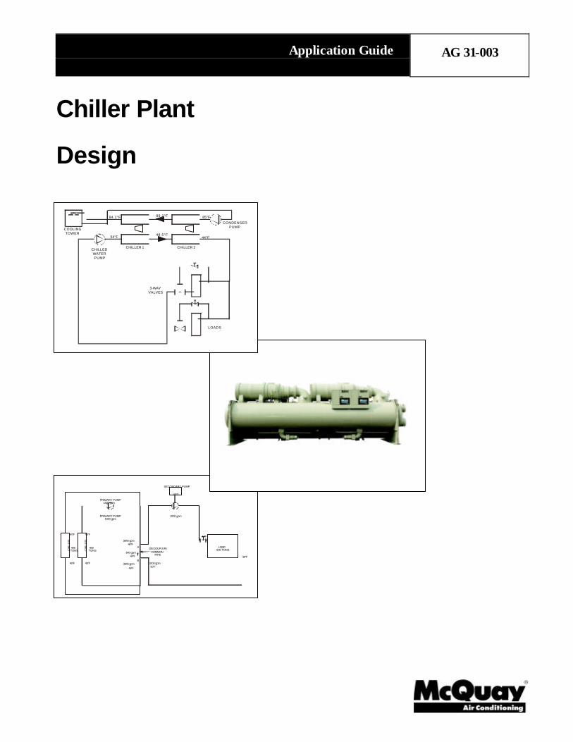
Single Chiller LoopFigure 1 shows a basic chiller loop with a water-cooled chiller. The system consists of achiller, cooling tower, cooling load, chilled water and condensing water pumps and piping.
Figure 1, Single Chiller Loop
ChillerThe chiller can be either air- or water-cooled.The compressor types typically are recipro-cating, scroll, screw or centrifugal. Theevaporator can be remote from the condensingsection on air-cooled units. This has theadvantage of keeping the chilled water loopinside the building envelope when using anoutdoor chiller.
The chilled water flows through the evaporatorof the chiller. The evaporator is a heatexchanger where the chilled water gives up itssensible heat (the water temperature drops)and transfers the heat to the refrigerant aslatent energy (the refrigerant evaporates orboils).

4 Application Guide AG 31-003
For air conditioning applications, the common design conditions are 44°F supply watertemperature and 2.4 gpm/ton. The temperature change in the fluid for either the condenseror the evaporator can be described using the following formula ;
Q = W x C x ∆T (1)
Where
Q = Quantity of heat exchanged (btu/hr or kW)
W= flow rate of fluid (USgpm or l/s)
C= specific heat of fluid (btu/lb °F or kJ/(kg °K))
∆T= temperature change of fluid (°F or °C)
Assuming the fluid is water, the formula takes the more common form of;
Load (btu/hr) = Flow(USgpm) x (°Fin – °Fout) x 500 (2)
Or
Load (tons) = Flow(USgpm) x (°Fin – °Fout)/24 (3)
Using this equation and the above design conditions, the temperature change in theevaporator is found to be 10°F. The water temperature entering the evaporator is then 54°F.
Most air conditioning design conditions are based on 75°F and 50% RH in the occupiedspace. The dew point for air at this condition is 55.08°F. Most HVAC designs are based oncooling the air to this dewpoint to maintain the proper RH in the space. Using a 10°Fapproach at the cooling coil means the supply chilled water needs to be around 44°F or 45°F.
The designer is not tied to these design conditions. In fact, more energy efficient solutionscan be found by modifying the design conditions as the project requires.
Changing the chilled water flow rate affects a specific chiller's performance. Too low aflow rate lowers the chiller efficiency and ultimately leads to laminar flow. The minimumflow rate is typically around 3 fps (feet per second). Too high a flow rate leads to vibration,noise and tube erosion. The maximum flow rate is typically around 12 fps. The chilledwater flow rate should be maintained between these two limits.
The condenser water flows through the condenser of the chiller. The condenser is also aheat exchanger. In this case the heat absorbed from the building plus the work ofcompression leaves the refrigerant (condensing the refrigerant) and enters the condenserwater (raising its temperature). The condenser has the same limitations to flow change asthe evaporator.
PipingThe piping is usually steel, copper or plastic. The chilled water piping is a closed loop. Aclosed loop is not open to atmosphere. Figure 2 shows a simple closed loop with the pump atthe bottom of the loop. Notice the static pressure created by the change in elevation is equalon both sides of the pump. In a closed loop, the pump needs only to overcome the frictionloss in the piping and components. The pump does not need to “lift” the water to the top ofthe loop.

Application Guide AG 31-003 5
Figure 2, Closed Loop Figure 3, Open Loop
An expansion tank is required in the chilled waterloop to allow for the thermal expansion of the water. Chilled water piping is insulated sincethe water and hence the piping is below the dewpoint temperature. Condensate would formon it and heat loss would occur.
The condenser water piping is an open loop. Figure 3 shows an open loop with the wateropen to the atmosphere. When the pump is not running, the level in the supply and returnpiping will be even at the level of the sump. When the pump operates, it needs to overcomethe friction loss in the system and “lift” the water from the sump level to the top of the loop.Condenser water piping is typically not insulated since there will be negligible heat gain orloss and sweating will not occur. However, if the piping is exposed to cold ambientconditions it could need to be insulated and heat traced to avoid freezing.
Chilled Water and Condenser Water PumpsTypically centrifugal type pumps are used for both condenser water and chilled watersystems. They can be either inline or base mounted. The pumps must be sized to maintainthe system dynamic head and the required flow rate. The pump selection and location musttake into account Net Positive Suction Head (NPSH). NPSH is usually a bigger issue on thecondenser pumps. Normally, the pumps are located so they discharge into the chiller heatexchangers.
To provide redundancy, multiple pumps are used. Common approaches are (1) a completefull-sized stand-by pump, or (2) the design flow is met by two pumps with a third stand-bypump sized at half the load. When multiple pumps are used in parallel, check valves on thedischarge of each pump are required to avoid “short circuiting”.
Cooling TowersCooling towers are used in conjunction with water-cooled chillers. Air-cooled chillers do notrequire cooling towers. A cooling tower rejects the heat collected from the building plus thework of compression from the chiller. Since it is common (but not necessary) to use atemperature range of 10°F, the cooling tower flow rate will be 3.0 gpm/ton compared to thechilled water flow rate which is 2.4 gpm/ton. The extra condenser water flow rate isrequired to accommodate the heat from the work of compression.
EXPANSION TANKCOOLING
LOADS2 FLOORND
1 FLOORST
BASEMENTCHILLER
CW PUMP
WATERCOLUMN
WATERCOLUMN
COOLING TOWER
LIFT
CONDENSER
2 FLOORND
1 FLOORST
BASEMENT

6 Application Guide AG 31-003
Cooling towers differ from closed circuit coolers in that closed-circuit coolers reject heatsensibly while cooling towers reject heat latently. Consider ambient design conditions of95°F DB and 78°F wb. If closed circuit coolers are used, the condenser water must bewarmer than the ambient dry bulb (typically 10°F warmer or 105°F). This raises thecondensing pressure in the chiller and requires more overall power for cooling. Closedcircuit coolers are larger than cooling towers for the same capacity and can be difficult tolocate on the roof.
Cooling towers expose the condenser water directly to the ambient air in a process thatresembles a waterfall. Approximately 1% of the design condenser water flow isevaporated. The latent energy required to evaporate the water lowers the remaining waterssensible temperature. The process is based on the ambient wet bulb temperature (78°F wbin the example) rather than the dry bulb temperature. ARI standard conditions at full loadare based on 85°F entering condenser water temperature and 3.0 US gpm per ton. Lowercondenser water temperatures can be produced in many climates with low wet bulbtemperatures.
LoadsFigure 4, Air Handling Equipment
Chilled water coils are used to transfer the heat from the building air to the chilled water.The coils can be located in air handling units, fan coils, induction units, etc. The air is cooledand dehumidified as it passes through the coils. The chilled water temperature rises duringthe process.
Process loads can reject heat in the chilled water in a variety of ways. A common processload is a cooling jacket in machinery such as injection molding equipment. Here the chilledwater absorbs the sensible heat of the process.
ControlsThere are two parameters that need to be considered for the chilled water loop. These aretemperature and flow. The loop supply temperature is controlled at the chiller. The unitcontroller on the chiller will monitor and maintain the supply chilled water temperature(within it’s capacity range). The accuracy to which the chiller can maintain the set point isbased on the chiller type, controller quality (a DDC controller with a PID loop is the best),compressor cycle times, the volume of fluid in the system, etc. Systems with fast changingloads (especially process loads) and small fluid volumes (close coupled) require specialconsideration.

Application Guide AG 31-003 7
Figure 5, Chiller Controller
The system flow control occurs at the load. To maintain the correct space condition, three-way or two-way control valves are used. Three-way control valves direct chilled watereither through or around the coil to maintain the desired condition. If all the loads on the loopuse three-way valves then the chilled water flow is constant. The temperature range variesdirectly with the load. That is, if the design chilled water Delta-T is 10°F, then every 10%drop in system load represents 1°F drop in Delta-T.
Figure 6, Three-way Valves

8 Application Guide AG 31-003
DiversityA system incorporating three-way control valves is easy to design and operate. However,the system pumps all the water all the time, which requires more pump horsepower. In mostcases the chiller is sized for the building peak load. Due to diversity, not all the connectedloads will “peak” at the same time as the building peak load. However, the pumps and pipingsystem must be designed for full flow to all the control valves all the time. Since the chillerflow rate is the same as the flow rate through all the loads (they’re connected by the samepiping system and pump) the diversity is applied to the chillerDelta-T.
For example, consider a building with an 80-ton peak load. However, summing all theconnected loads adds up to 100 tons. In short, this building has a diversity of 80%. Using adelta of 10°F at each control valve, the total system flow rate is;
Flow = 24 x 100 tons/10°F = 240 gpm
However, an 80-ton chiller with 240 gpm will only have a Delta-T of 8°F. The lower chillerDelta-T is not a problem for the chiller operation, but it will lower the chiller efficiency. Caremust be taken to select the chiller at the proper Delta-T.
Figure 7, Two-way Valves
When two-way modulating control valves are used, the flow to the coil is restricted ratherthan bypassed. If all the valves in the system are two-way type, the flow will vary with theload. If the valves are properly selected, the temperature range remains constant and theflow varies directly with the load. In this case the diversity is applied to the chilled waterflow rate.
Using the previous example, the peak load is 80 tons and the design flow is 2.4 x 80 tons or192 gpm. The connected load is still 100 tons and requires 240 gpm if all the two-way

Application Guide AG 31-003 9
control valves are open at the same time. The 80% diversity assumes only 80% of thevalves will be open at the peak load.
The advantage of two-way control valves is both the pump and the piping are sized for asmaller flow rate offering both first cost and operating savings. The difficulty is the chillerand control system must be designed for variable flow. The chiller has a minimum flow rateso the piping design has to allow for enough flow during all operating conditions to meet thechiller minimum flow rate. Using two-way valves at the loads is the main building block fora variable flow system.
Parallel Chillers
Figure 8, Parallel ChillersTo provide some redundancy in theHVAC design, most designers willrequire two or more chillers. Multiplechillers also offer the opportunity toimprove on overall system part loadperformance and reduce energyconsumption.
Figure 8 shows two chillers in paralleland three-way valves at the loads. Thechilled water temperature differencevaries directly with the load. The othersystem components are the same as theprevious example. The difficulty withthis parallel arrangement is the systempart load performance.
Consider the system operating at 50%. From a chiller performance aspect, turning off onechiller and operating the other at full capacity is desirable. However, this will not happen.At 50% capacity, the return water will be 49°F. The chiller that is turned off, will let thewater pass through it unchanged. The operating chiller will only see a 50% load (49°F returnwater), and will cool the water down to the set point of 44°F. The two chilled water streamswill then mix to 46.5°F supply temperature.
If the system is operated in this manner, the warmer chilled water will cause the controlvalves to open (increase flow) to meet the space requirements. The return watertemperature will rise affecting the supply system supply water temperature. An iterativeprocess will occur and the system can stabilize. The issue is whether the cooling coils canmeet the local loads with the higher chilled water temperature. Depending on the actualdesign conditions, the building sensible load could be met but high chilled water temperaturewill make it difficult to meet the latent load. Since this scenario is likely to occur duringshoulder weather, dehumidification can not be an issue. In areas where humidity is an issue,this arrangement will result in high humidity within the space.
One solution is to operate both chillers all the time. This works and is a simple solution,however, it is not energy efficient and causes unnecessary equipment wear.
Another possibility is to lower the operating chiller’s set point to offset the mixed watertemperature. This too works but has some difficulties. Lowering the chilled water set point

10 Application Guide AG 31-003
requires the chiller to work harder lowering its efficiency. In extreme conditions, it cancause chiller stability issues.
Figure 9, Parallel Chillers with Isolating ValvesFigure 9 shows a modified version ofparallel chillers. This concept incorporatesisolating valves for each chiller. Thechilled water pump includes a VariableFrequency Drive (VFD). The loads nowhave two-way valves.
In this design concept, as the system loaddecreases, the flow is reduced until one ofthe chillers can be shut down and itsisolating valve is closed. Supply watertemperature remains constant.
This design requires careful chillerselection to provide good flowcharacteristics over the required operating
range. More sophisticated controls are required to operate the system. See Variable FlowDesign for further details.
Series Chillers
Figure 10, Series ChillersFigure 10 shows twochillers in series. Thisdesign concept resolves themixed flow issues found inparallel chiller designs. Itis simple to design andoperate. However, it alsohas some challenges toovercome.
All the system flow goesthrough both chillers. Ifboth chillers are the sameand the condensers arepiped in parallel, the leadchiller will accomplishabout 45% of the system load and the lag chiller will accomplish about 55% of the systemload. This occurs because the lead chiller is supplying chiller water at the system set point(typically 44°F). The lag chiller is supplying chilled water at approximately 48.5°F to the leadchiller. The reduced lift for the lag chiller allows it to provide more cooling capacity.
A problem with series chillers is the high flow rate and the low Delta T through the chillers.The high flow rate can result in high water pressure drops. Since the chillers are in series,the pressure drops of the chillers must be added. If the typical 10°F system temperature
Application Guide AG 31-003 11
difference is maintained, then single pass evaporators should be considered. This will lowerthe pressure drop to an acceptable level.
There is an opportunity to optimize series chillers and improve overall system performanceby connecting the condensers in series as well. Figure 10 shows the condensers connectedin series with the condenser flow counter flow to the chilled water flow.
Table 1, System Efficiency Comparison
CAPEVAPEWT
EVAPLWT
EVAPFLOW
CONDEWT
CONDLWT
CONDFLOW
POWER PERF.CHILLER VESSELPIPING
(tons) (°F) (°F) (GPM) (°F) (°F) (GPM)MODEL
(kW) (kW/T)PARALLEL CH-1 400 54 44 960 85 94.2 1200 WSC087 218.0 0.547PARALLEL CH-2 400 54 44 960 85 94.2 1200 WSC087 218.0 0.547SYSTEM TOTAL 800 54 44 1920 85 94.2 2400 - 436.0 0.547SERIES OPT 1 CH-1 440 54 48.5 1920 85 95.1 1200 WSC087 205.6 0.520SERIES OPT 1 CH-2 370 48.5 44 1920 85 93.5 1200 WSC087 228.6 0.556SYSTEM TOTAL 810 54 44 1920 85 94.2 2400 - 434.2 0.536SERIES OPT 2 CH-1 440 54 48.5 1920 89.1 94.1 2400 WSC087 232.7 0.529SEREIS OPT 2 CH-2 370 48.5 44 1920 85 89.2 2400 WSC087 193.6 0.523SYSTEM TOTAL 810 54 44 1920 85 94.1 2400 - 426.3 0.526
Table 1 compares a parallel system with two versions of series systems for an 800 tondesign load. The full load penalty for series option 1 compared to the parallel system isnegligible. Series Option 2 shows chillers with series condenser flow. It provides the bestoverall system performance and either chiller can be the lead chiller. Series condensers andseries evaporators are an excellent means to provide lower temperature, high Delta-T chilledwater.
It should not be concluded that parallel systems have no value. In applications where mostof the operating hours occur above 50% load, a parallel system typically does better. Aseries system does better when there lots of run hours below 50% such as an HVAC systemwithout air side economizers.
Series Chillers ControlsAs before, the chiller controllers maintain the system supply water temperature and the loadcontrols maintain the system flow rate. For series chillers, the controlling sensors for bothchillers should be located downstream of the chillers and the chiller control panels digitallylinked together. With the panels linked together, either chiller can be used to meet up toabout 45% of the system load. Once both chillers are required, the amp draws can bebalanced between the two chillers.
The MicroTech Controllers on McQuay chillers can communicate directly and can loadbalance based on amperage. Using the load balance feature means when both chillersoperate, the power consumption is evenly distributed between the two chillers. The loadbalance feature offers about 3% savings conventional control.
Primary/Secondary SystemsFor large chillers or where more than 2 chillers are anticipated, primary/secondary (alsocalled decoupled) piping systems are used. To reduce installation and operating costs, it isdesirable to apply diversity to system flow. With diversity applied to flow, the pumps andpiping will be smaller. To accomplish this, two-way control valves are used at the loads. Atthe same time it is necessary to provide constant flow through the chillers to maintain chillerstability. The solution is primary/secondary piping.

12 Application Guide AG 31-003
Figure 11, Primary/Secondary Loop at Full Load
Primary/Secondary Loop BasicsFigure 11 shows a basic primary/secondary loop operating at full load. In this example, thesystem design load is 800 tons, the flow rates and temperatures are at standard ARIconditions and the load has a two-way control valve. The loop with the chiller is called theprimary loop. The loop with the load is the secondary loop. The common pipe is sometimesreferred to as the decoupler.
At full load, the design flow of 1920 gpm passes through the chiller, the two pumps, the load,and back to the chiller. There is no flow through the common pipe. At first, it would appearthat the flow is being pumped twice. Although this is true, the total head is split between thetwo pumps. The primary pump is only sized for the primary loop of which the chiller is mainpressure drop. The secondary pump is sized for the pressure drop “outside the mechanicalroom”. The higher pressure drops and larger piping arrangements in the secondary loopjustify the variable flow.
Figure 12, Primary/Secondary Loop at 50% Load
SECONDARY PUMP
VFD
PRIMARY PUMP
44°F
1920 gpm
COMMONPIPE
1920 gpm
LOAD800 TONS
54°F
1920 gpm
A
B
54°F
44°F
0 gpm
54°F
44°F
800 TONS
1920 gpm
CH
ILL
ER
(DECOUPLER)
SECONDARY PUMP
VFD
PRIMARY PUMP
44°F
960 gpm
COMMONPIPE
960 gpm
LOAD400 TONS
54°F
1920 gpm
A
B49°F
44°F
960 gpm
49°F
44°F
400 TONS
1920 gpm
1920 gpm
54°F
CH
ILL
ER
(DECOUPLER)
Application Guide AG 31-003 13
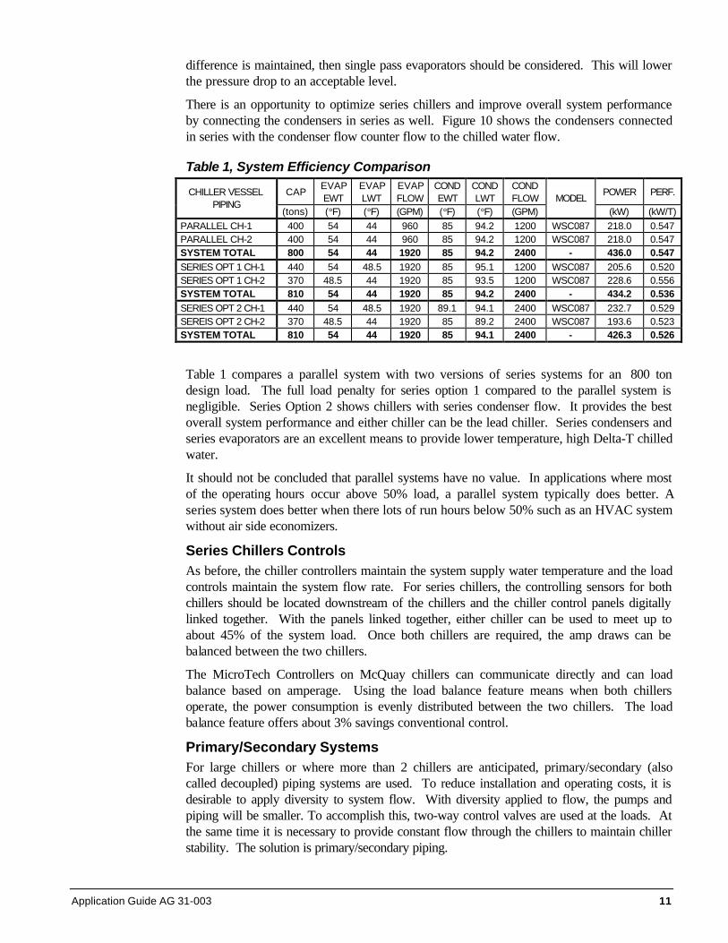
Figure 12 shows the same example operating at 50% capacity. The two-way control valveat the load has reduced the flow in the secondary loop to 960 gpm. The Delta-T across theload remains at 10°F. The primary pump is a constant flow pump sized for the chiller designflow. It remains constant at 1920 gpm. The additional flow not required in the secondaryloop passes through the common pipe to the chiller return line. The 44°F fluid from thecommon pipe mixes with the 54°F return fluid to 49°F. The chiller maintains its design flowof 1920 gpm with 49°F RWT and 44°F LWT. The chiller sees a 50% load.
The example in Figure 12 demonstrates how diversity is applied to flow in the secondaryloop. The variable flow in the secondary loop offers excellent pump operating savings andfirst cost saving in pipe sizing. The constant flow in the primary loop provides the chiller withstable operating conditions.
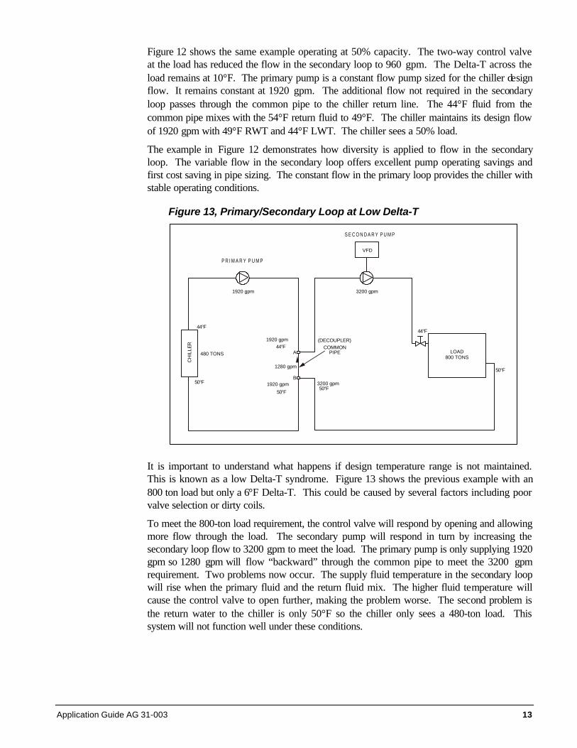
Figure 13, Primary/Secondary Loop at Low Delta-T
It is important to understand what happens if design temperature range is not maintained.This is known as a low Delta-T syndrome. Figure 13 shows the previous example with an800 ton load but only a 6°F Delta-T. This could be caused by several factors including poorvalve selection or dirty coils.
To meet the 800-ton load requirement, the control valve will respond by opening and allowingmore flow through the load. The secondary pump will respond in turn by increasing thesecondary loop flow to 3200 gpm to meet the load. The primary pump is only supplying 1920gpm so 1280 gpm will flow “backward” through the common pipe to meet the 3200 gpmrequirement. Two problems now occur. The supply fluid temperature in the secondary loopwill rise when the primary fluid and the return fluid mix. The higher fluid temperature willcause the control valve to open further, making the problem worse. The second problem isthe return water to the chiller is only 50°F so the chiller only sees a 480-ton load. Thissystem will not function well under these conditions.
S E C O N D A R Y P U M P
VFD
P R I M A R Y P U M P
44°F
3200 gpm
COMMONPIPE
3200 gpm
LOAD800 TONS
50°F
A
B
50°F
44°F
1280 gpm
50°F
44°F
480 TONS
1920 gpm
1920 gpm
50°F1920 gpm
(DECOUPLER)
CH
ILLE
R

14 Application Guide AG 31-003
Figure 14, Primary/Secondary Loop with Low Delta-T Reality
Obviously the above example can’t occur. Figure 14 shows what does happen. A secondchiller has to be started to balance the flow in the primary loop with the flow in thesecondary loop.
Although running two chillers provides a working solution, many of the features of theprimary/secondary approach are lost. The flow in the secondary is high, wasting pumpingenergy. Two primary pumps have to operate when only one should be doubling the primarypump horsepower. Finally, two chillers are operating (and their condenser water pumps)when only one should be.
Primary Loop Details
Figure 15, Standard Primary Loop LayoutThe most common arrangementis to have dedicated pumps foreach chiller. In addition, eachchiller requires an isolating valve.It is also possible to have a mainprimary pump outfitted either withmultiple speeds or a variablefrequency drive. The issue withthe latter is there is minimal to noredundancy available.
The chillers can have differentcapacities and be manufacturedby different vendors. However,they must have the same supplywater set point and the samechilled water Delta-T.
SECONDARY PUMP
VFD
PRIMARY PUMP
44°F
3200 gpm
COMMONPIPE
3200 gpm
LOAD800 TONS
50°F
A
B
49°F
44°F
49°F
44°F
400 TONS
1920 gpm
3840 gpm
50°F3840 gpm
CH
ILLE
R
CH
ILLE
R
400 TONS
49°F
44°F
44°F640 gpm
PRIMARY PUMP
1920 gpm
(DECOUPLER)

Application Guide AG 31-003 15
Decoupler LocationThe location of the decoupler line will change how the chillers are loaded. Figure 15 showsthe typical layout. In this situation, each chiller sees the same return water temperature evenat part load conditions.
Figure 16 shows the decoupler line in a different location. Locating the chillers between thesecondary loop and the decoupler line causes the return water temperature to each chiller tovary. Chiller 2 in Figure 16 will see close to the secondary loop return water temperature.Chiller 1 will see a mixture of supply water and return water. The result is Chiller 2 is moreheavily loaded than Chiller 1.
Figure 16, Optional Primary Loop Layout
Relocating the decoupler can make sense if one or more of the chillers is a dual compressormodel. The dual compressor chiller has very good part load performance. Singlecompressor chillers typically work best when fully loaded. By locating the dual compressorchiller close to the decoupler line and the single compressor chiller furthest away, thestrengths of each chiller can be maximized. Table 2 shows the chiller plant performance forFigures 15 and 16. By base loading the single compressor chiller and taking advantage ofthe dual’s part load performance, the power input can be cut by up to 10 percent.

16 Application Guide AG 31-003
Table 2, Table 2 Chiller Plant Performance vs. Decoupler Location
Figure 15 Cap. (tons) RWT (°F) SWT (°F) Power (kw)CH-1 300 51.5 44 124.6CH-2 300 51.5 44 124.6Total 600 51.5 44 249.2
Figure 16CH-1 200 49 44 73.2CH-2 400 54 44 151.7Total 600 44 224.9
Secondary Loop Details
Figure 17, Basic Secondary Loop
The secondary loop must be variable flow.Traditionally, multiple pumps were staged on to varythe flow. More recently, variable frequency drivesare used. The primary/secondary arrangementallows the engineer a great deal of flexibility whendesigning the distribution piping. Figure 17 shows thebasic design. Multiple secondary pumps are used toprovide some redundancy.
Figure 18, Multiple Secondary Loops
Figure 18 shows dedicated pumps for various loops.Multiple loops can serve areas with differentoperating schedules or widely different fluidpressure drops (such as a building on the far side ofa campus). The individual loops can be scheduledoff when not required.
Controlling the secondary pumps is a subject ofsome debate. Most systems today use somemethod of pressure differential across thesecondary loop. The location for the pressuresensors is critical. Proper system operation requiresthat the load control valves be properly sized andthe pressure sensors properly located. This is a
discussion in itself and is beyond the scope of this manual.

Application Guide AG 31-003 17
Reverse Return/Direct Return PipingThe examples used in this manual show reverse return piping. The secondary piping isdesigned such that any path through any load is the same length and therefore hasapproximately the same fluid pressure drop. Reverse return piping is inherently self-balancing. It also requires more piping and consequently is more expensive.
Direct return piping results in the load closest to the chiller plant to have the shortest pathand therefore the lowest fluid pressure drop. Depending on the piping design, the differencein pressure drops between a load near the chiller plant and a load at the end of the piping runcan be substantial. Balancing the system can be difficult. The advantage of direct returnpiping is the pipe savings.
The decision whether to use direct or reverse return piping should be based on systemoperability vs. first cost. Where direct return piping is used, flow-balancing valves should becarefully located so that the system can be balanced.
Varying Chiller SizesOne advantage of primary/secondary systems is varying the chiller sizes. As long as thesupply water temperature and the design Delta-T are the same, the chillers can havedifferent capacities.
Varying the chiller sizes allows chillers to be selected so the chiller plant is at maximumperformance when the run-hours are highest. For example, consider a chiller plant wheretwo chillers can be used. However, the bulk of the run-hours will be at 50% to 70% ofdesign capacity. This will require the two chillers to operate between 50% and 70% of theirdesign capacity. By varying the chiller sizes to one at 800 tons and one at 400 tons. Thesystem load can be met with one chiller for the bulk of the operating time.
System Expansion
Figure 19, Expanding the SystemPrimary/secondary piping allowseasy expansion both in the chillerplant (primary loop) and the building(secondary loop). To expand thechiller plant capacity, another chillercan be added to the loop as shownin Figure 19. By strategicallylocating the decoupler and the newchiller (see Figure 16), it is possibleto apply a greater load on the newchiller. This can be advantageous ifthe new chiller is more efficientthan the rest of the plant.
If the building load is increased, anew loop can be added. The pumpfor the new loop can be sized tomeet the new loop’s pressure droprequirements.
18 Application Guide AG 31-003
Water-Side Free Cooling
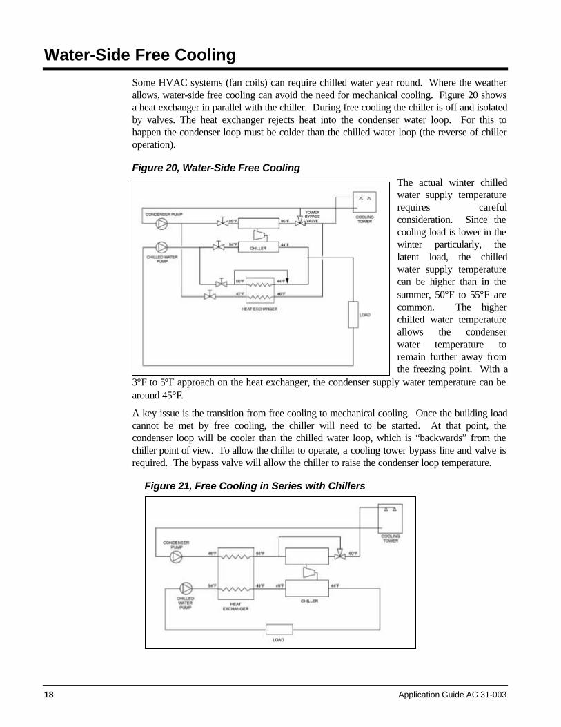
Some HVAC systems (fan coils) can require chilled water year round. Where the weatherallows, water-side free cooling can avoid the need for mechanical cooling. Figure 20 showsa heat exchanger in parallel with the chiller. During free cooling the chiller is off and isolatedby valves. The heat exchanger rejects heat into the condenser water loop. For this tohappen the condenser loop must be colder than the chilled water loop (the reverse of chilleroperation).
Figure 20, Water-Side Free CoolingThe actual winter chilledwater supply temperaturerequires carefulconsideration. Since thecooling load is lower in thewinter particularly, thelatent load, the chilledwater supply temperaturecan be higher than in thesummer, 50°F to 55°F arecommon. The higherchilled water temperatureallows the condenserwater temperature toremain further away fromthe freezing point. With a
3°F to 5°F approach on the heat exchanger, the condenser supply water temperature can bearound 45°F.
A key issue is the transition from free cooling to mechanical cooling. Once the building loadcannot be met by free cooling, the chiller will need to be started. At that point, thecondenser loop will be cooler than the chilled water loop, which is “backwards” from thechiller point of view. To allow the chiller to operate, a cooling tower bypass line and valve isrequired. The bypass valve will allow the chiller to raise the condenser loop temperature.
Figure 21, Free Cooling in Series with Chillers

Application Guide AG 31-003 19
Figure 21 shows a different free cooling arrangement with the chiller in series with the heatexchanger. Since the heat exchanger operates with a higher chilled water temperature, theoperating season is longer, offering more annual savings. The chiller trims the chilled watertemperature and operates with significant condenser water relief. This arrangement worksvery well with process loads.
Hybrid Plants
Mixing and matching different chiller types increases the designer’s option in chiller plantdesign. To meet small winter chilled water loads, an air cooled chiller might be included inthe chiller plant. The operator does not have to run the cooling towers in winter and thechiller is properly sized for the winter load. This is common in health care applications withwater cooled equipment (MRIs, linear accelerators, etc.) The air-cooled chiller must beproperly selected for winter operation.
To diversify the chiller plant on energy sources, an absorption chiller is often incorporatedinto the chiller plant design. The absorption chiller can operate on either plant steam ordirectly on natural gas. Either allows the operator to shave demand peaks for the electricalload. The absorption chiller can be in series or parallel (primary/secondary) with the electricchiller.
In a series application, the absorption chiller can be upstream of the electric chiller. Thewarmer return chilled water improves the efficiency of the absorption chiller by as much as30%. This arrangement automatically base loads the electric chiller. Until the return waterreaches 49°F, the absorption chiller won’t operate. Once the building load climbs above50%, the electrical demand is avoided, by using the absorption chiller. In shoulder weather,either chiller can be operated. (reset the absorption chiller set point to 44°F).
The condenser water needs of the absorption chiller are different from the electric chiller.Whereas electric chiller typically operates with 3 gpm/ton on the condenser side, anabsorption chiller operates with 4.5 gpm/ton. Condenser water temperature stability andreset are also more critical with an absorption chiller. Care must be taken to properlyintegrate an absorption chiller into the chiller plant design.
20 Application Guide AG 31-003
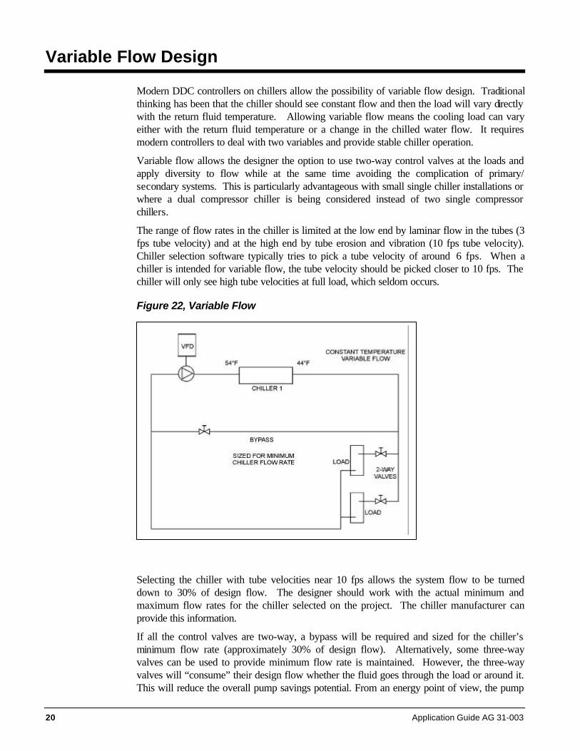
Variable Flow Design
Modern DDC controllers on chillers allow the possibility of variable flow design. Traditionalthinking has been that the chiller should see constant flow and then the load will vary directlywith the return fluid temperature. Allowing variable flow means the cooling load can varyeither with the return fluid temperature or a change in the chilled water flow. It requiresmodern controllers to deal with two variables and provide stable chiller operation.
Variable flow allows the designer the option to use two-way control valves at the loads andapply diversity to flow while at the same time avoiding the complication of primary/secondary systems. This is particularly advantageous with small single chiller installations orwhere a dual compressor chiller is being considered instead of two single compressorchillers.
The range of flow rates in the chiller is limited at the low end by laminar flow in the tubes (3fps tube velocity) and at the high end by tube erosion and vibration (10 fps tube velocity).Chiller selection software typically tries to pick a tube velocity of around 6 fps. When achiller is intended for variable flow, the tube velocity should be picked closer to 10 fps. Thechiller will only see high tube velocities at full load, which seldom occurs.
Figure 22, Variable Flow
Selecting the chiller with tube velocities near 10 fps allows the system flow to be turneddown to 30% of design flow. The designer should work with the actual minimum andmaximum flow rates for the chiller selected on the project. The chiller manufacturer canprovide this information.
If all the control valves are two-way, a bypass will be required and sized for the chiller’sminimum flow rate (approximately 30% of design flow). Alternatively, some three-wayvalves can be used to provide minimum flow rate is maintained. However, the three-wayvalves will “consume” their design flow whether the fluid goes through the load or around it.This will reduce the overall pump savings potential. From an energy point of view, the pump

Application Guide AG 31-003 21
motor savings below 30% are minimal due to VFD losses and reduced motor efficiency.Operating at frequencies below 20 hz (33%) also puts unnecessary wear on the motors.
Figure 23, Variable Flow with Parallel Chillers
Variable flow can also be applied to chillers in parallel. Figure 23 shows two chillers inparallel with VFDs on the primary pumps. Variable flow allows the option of operating onlyone chiller when the system load is within the range of one chiller. The second chiller can beshut down and all the flow directed through the remaining chiller. Variable flow resolvesmost of the issues of parallel chiller design.
The bypass should be sized for the highest minimum flow rate of the chillers being used.
The critical issue for variable flow with parallel chillers is controlling the cycling of thechillers. This is best accomplished by measuring system flow. When the system load andflow rate can be met by a single chiller, the other chiller can be shut down. With onepump/chiller combination off line, the other pump will increase speed/flow until the requiredchilled water loop pressure differential is obtained. If the single chiller minimum flow cannotbe met (the two valves are all nearly closed) the bypass line control valve can be opened toprovide minimum chiller flow. Chiller/pump cycling should be controlled with anti-cycle timedelays.
Even with modern chiller controllers, care should be taken that the system flow changes areslow. Slow flow changes will allow the chiller controller time to respond and provide stablesystem operation. Although each project is different, a good rule of thumb is to limit the rateof change to 10% of design flow per minute.

22 Application Guide AG 31-003


Post Office Box 2510, Staunton, Virginia 24402 USA • (800) 432-1342 • www.mcquay.com
Related Documents